JP3590387B2 - Communication device and program - Google Patents
Communication device and program Download PDFInfo
- Publication number
- JP3590387B2 JP3590387B2 JP2002020449A JP2002020449A JP3590387B2 JP 3590387 B2 JP3590387 B2 JP 3590387B2 JP 2002020449 A JP2002020449 A JP 2002020449A JP 2002020449 A JP2002020449 A JP 2002020449A JP 3590387 B2 JP3590387 B2 JP 3590387B2
- Authority
- JP
- Japan
- Prior art keywords
- address
- predetermined
- node
- packet
- echonet
- Prior art date
- Legal status (The legal status is an assumption and is not a legal conclusion. Google has not performed a legal analysis and makes no representation as to the accuracy of the status listed.)
- Expired - Lifetime
Links
Images


Classifications
-
- H—ELECTRICITY
- H04—ELECTRIC COMMUNICATION TECHNIQUE
- H04L—TRANSMISSION OF DIGITAL INFORMATION, e.g. TELEGRAPHIC COMMUNICATION
- H04L61/00—Network arrangements, protocols or services for addressing or naming
- H04L61/09—Mapping addresses
- H04L61/10—Mapping addresses of different types
- H04L61/103—Mapping addresses of different types across network layers, e.g. resolution of network layer into physical layer addresses or address resolution protocol [ARP]
-
- H—ELECTRICITY
- H04—ELECTRIC COMMUNICATION TECHNIQUE
- H04L—TRANSMISSION OF DIGITAL INFORMATION, e.g. TELEGRAPHIC COMMUNICATION
- H04L65/00—Network arrangements, protocols or services for supporting real-time applications in data packet communication
- H04L65/40—Support for services or applications
-
- H—ELECTRICITY
- H04—ELECTRIC COMMUNICATION TECHNIQUE
- H04L—TRANSMISSION OF DIGITAL INFORMATION, e.g. TELEGRAPHIC COMMUNICATION
- H04L61/00—Network arrangements, protocols or services for addressing or naming
-
- H—ELECTRICITY
- H04—ELECTRIC COMMUNICATION TECHNIQUE
- H04L—TRANSMISSION OF DIGITAL INFORMATION, e.g. TELEGRAPHIC COMMUNICATION
- H04L69/00—Network arrangements, protocols or services independent of the application payload and not provided for in the other groups of this subclass
- H04L69/22—Parsing or analysis of headers
-
- H—ELECTRICITY
- H04—ELECTRIC COMMUNICATION TECHNIQUE
- H04L—TRANSMISSION OF DIGITAL INFORMATION, e.g. TELEGRAPHIC COMMUNICATION
- H04L12/00—Data switching networks
- H04L12/28—Data switching networks characterised by path configuration, e.g. LAN [Local Area Networks] or WAN [Wide Area Networks]
- H04L12/2803—Home automation networks
-
- H—ELECTRICITY
- H04—ELECTRIC COMMUNICATION TECHNIQUE
- H04L—TRANSMISSION OF DIGITAL INFORMATION, e.g. TELEGRAPHIC COMMUNICATION
- H04L61/00—Network arrangements, protocols or services for addressing or naming
- H04L61/50—Address allocation
- H04L61/5038—Address allocation for local use, e.g. in LAN or USB networks, or in a controller area network [CAN]
-
- H—ELECTRICITY
- H04—ELECTRIC COMMUNICATION TECHNIQUE
- H04L—TRANSMISSION OF DIGITAL INFORMATION, e.g. TELEGRAPHIC COMMUNICATION
- H04L61/00—Network arrangements, protocols or services for addressing or naming
- H04L61/50—Address allocation
- H04L61/5092—Address allocation by self-assignment, e.g. picking addresses at random and testing if they are already in use
-
- H—ELECTRICITY
- H04—ELECTRIC COMMUNICATION TECHNIQUE
- H04W—WIRELESS COMMUNICATION NETWORKS
- H04W8/00—Network data management
- H04W8/26—Network addressing or numbering for mobility support
-
- H—ELECTRICITY
- H04—ELECTRIC COMMUNICATION TECHNIQUE
- H04W—WIRELESS COMMUNICATION NETWORKS
- H04W80/00—Wireless network protocols or protocol adaptations to wireless operation
Landscapes
- Engineering & Computer Science (AREA)
- Computer Networks & Wireless Communication (AREA)
- Signal Processing (AREA)
- Computer Security & Cryptography (AREA)
- Multimedia (AREA)
- Small-Scale Networks (AREA)
- Mobile Radio Communication Systems (AREA)
Abstract
Description
【0001】
【発明の属する技術分野】
本発明は、IP等のネットワークレイヤプロトコルのネットワーク上でのエコーネット等の制御プロトコルによる通信を行う通信装置及びプログラムに関する。
【0002】
【従来の技術】
近年、情報家電の発展が急である。本分野は、白物家電、AV家電、パソコン等の情報機器、モバイル機器等の多岐にわたり、それぞれにおいてデジタル技術を応用した様々な応用が考えられている。
【0003】
その1つのアプリケーションがホームネットワークの利用である。ホームネットワークは、家庭内におけるネットワーク技術であり、上記様々な情報家電同士を相互に接続する。
【0004】
このホームネットワーク技術として、特に最近注目を集めているのがインターネット技術である。例えば、音楽配信やホームページ閲覧、電子メール等、次々とホームネットワークユーザにとって魅力的なアプリケーションが開発され、そのユーザ数は増加の一途である。
【0005】
一方、ホームネットワークの1つの応用例が設備系ネットワーク、あるいはホームオートメーションとしての利用である。これらのネットワークには、エアコンや照明、白物家電等が接続され、機器の状態監視や遠隔制御等がアプリケーションとして考えられる。この設備系ネットワークの日本におけるデファクトスタンダードになると期待されているのがエコーネットである。エコーネットは、電灯線、ツイストペア線等の様々な物理媒体上で、設備系機器(白物家電等)を制御するためのコマンド、プロトコル、オブジェクト、API等を規定している(例えば、http://www.echonet.or.jpにて取得可能に開示されている文書に説明が詳しい)。このエコーネットは、日本国内の複数の電機メーカを中心に設立されたコンソーシアムがその標準化を担っており、既にバージョン1のスペック等が発行され、商品化も始まろうとしている。
【0006】
【発明が解決しようとする課題】
エコーネットは、それ自体がアドレス体系を持ち、「インターネット」のアドレス体系の上に「エコーネット」のアドレス体系を乗せる、といった工夫を行なう必要がある。そのため、「エコーネットアドレス」と「インターネットアドレス」との間の対応関係の決定等、これまでに無い考慮が必要となってくる。これを行なうのが「エコーネットアドレス初期化」手続きである。
【0007】
エコーネットアドレスを決定する場合には、該アドレスを決定する「エコーネットアドレスサーバ」なるサーバが必ずしも存在しないことが想定されるため、自立的にエコーネットアドレスを定める機構を用意することが必要である。この機構として、例えば、「エコーネットアドレスとなる値の候補を選択し、これをローカル網上にブロードキャストすることで、アドレスの重複を調査する」というものがある。この機構では、「アドレスの仮の値の選択→調査→重複の発見→最初に戻る」のループにしばらくはまってしまう可能性が考えられる。このため、立ち上げからしばらくの間、自分のエコーネットアドレスが決定できない、という事態が考えられる。
【0008】
特に、本機構がBluetooth等の無線方式に搭載された場合、Bluetoothでは同時にアクティブに通信できるノード数(スレーブ数)が7以下という制約があるため、上記のループがブロードキャスト処理を伴うだけに、多くの時間を費やす必要に迫られる可能性がある。
【0009】
本発明は、上記事情を考慮してなされたもので、自装置のエコーネットアドレスを効率的に決定できるようにした通信装置及びプログラムを提供することを目的とする。
【0011】
【課題を解決するための手段】
本発明は、所定のネットワークレイヤプロトコルのネットワーク上での所定の制御プロトコルによる通信を行う通信装置であって、前記所定のネットワークレイヤプロトコルのネットワークに接続するためのインタフェース手段と、前記所定のネットワークレイヤプロトコルのネットワークを介して送受信される前記所定の制御プロトコルのデータに関する処理を行うための制御プロトコル処理手段と、前記所定の制御プロトコルのパケットをカプセル化した、前記所定のネットワークレイヤプロトコルのパケットの送受信を行うための送受信手段と、前記所定の制御プロトコルで使用すべき所定のアドレスを決定するにあたり、前記所定のネットワークレイヤプロトコルのネットワークに接続された、前記所定の制御プロトコルが稼動する他の通信装置に対して問い合わせパケットを送信するための送信手段とを備え、前記問い合わせパケットは、自装置が前記所定の制御プロトコルで使用すべき所定のアドレスの候補として、自装置が以前に使用していた前記所定のアドレスが存在する場合には、その値を、存在しない場合には、自装置が持つリンクレイヤアドレスの所定のビット列の値を選択し、該所定のビット列の値について、前記他の通信装置に対して、該他の通信装置が使用している前記所定のアドレスと同一であるかを問い合わせる機能と、前記他の通信装置が使用しているリンクレイヤアドレス、ネットワークレイヤアドレス又は前記所定のアドレスの少なくとも1つを、自装置に対して通知するように要請する機能と、前記所定のネットワークレイヤプロトコルのネットワークにおいて前記所定のアドレスの割り当てを行なうアドレスサーバが存在するか否かについて問い合わせる機能とを併せ持つものであることを特徴とする。
好ましくは、前記他の通信装置から前記問い合わせるパケットに対する応答として返信される返信には、該他の通信装置がその時点で認識している、現在使用中の前記所定のアドレスの一覧を示す情報が含まれるようにしてもよい。
好ましくは、前記問い合わせパケットに対する応答から、前記所定のアドレスと同一でないと判断された場合には、前記値を、自装置が前記所定の制御プロトコルで使用すべき所定のアドレスとして決定する決定手段を更に備えるようにしてもよい。
好ましくは、前記決定手段は、前記所定のビット列の値が、前記他の通信装置が使用している前記所定のアドレスと同一であると判断された場合には、前記他の通信装置から前記問い合わせるパケットに対する応答として返信された前記パケットに含まれる前記アドレスに基づいて、自装置が前記所定の制御プロトコルで使用すべき所定のアドレスを決定するようにしてもよい。
好ましくは、前記決定手段は、前記問い合わせパケットに対する前記アドレスサーバからの応答によって、前記アドレスサーバの存在が確認された場合には、他の通信装置からの応答に関わらず、前記アドレスサーバから割当てられたアドレスを、自装置が前記所定の制御プロトコルで使用すべき前記所定のアドレスとして決定するようにしてもよい。
好ましくは、前記送受信手段は、前記所定の制御プロトコルのパケットをカプセル化した、前記所定のネットワークレイヤプロトコルのパケットの送受信を、イーサフレーム上で行うようにしてもよい。
好ましくは、前記インタフェース手段は、前記所定のネットワークレイヤプロトコルのパケットの転送物理媒体としてBluetoothインタフェースを持つようにしてもよい。
好ましくは、前記所定のネットワークレイヤプロトコルは、インターネット・プロトコルであり、前記ネットワークレイヤアドレスは、IPアドレスであるようにしてもよい。
好ましくは、前記所定の制御プロトコルは、エコーネットプロトコルであるようにしてもよい。
好ましくは、前記所定の制御プロトコルで使用すべき所定のアドレスは、エコーネットアドレスのノード識別子であるようにしてもよい。
また、本発明は、所定のネットワークレイヤプロトコルのネットワーク上での所定の制御プロトコルによる通信を行う通信装置としてコンピュータを機能させるためのプログラムにおいて、前記プログラムは、前記所定のネットワークレイヤプロトコルのネットワークに接続するためのインタフェース機能と、前記所定のネットワークレイヤプロトコルのネットワークを介して送受信される前記所定の制御プロトコルのデータに関する処理を行うための制御プロトコル処理機能と、前記所定の制御プロトコルのパケットをカプセル化した、前記所定のネットワークレイヤプロトコルのパケットの送受信を行うための送受信機能と、前記所定の制御プロトコルで使用すべき所定のアドレスを決定するにあたり、前記所定のネットワークレイヤプロトコルのネットワークに接続された、前記所定の制御プロトコルが稼動する他の通信装置に対して問い合わせパケットを送信するための送信機能とをコンピュータに実行させるとともに、前記送信機能において、前記問い合わせパケットは、自装置が前記所定の制御プロトコルで使用すべき所定のアドレスの候補として、自装置が以前に使用していた前記所定のアドレスが存在する場合には、その値を、存在しない場合には、自装置が持つリンクレイヤアドレスの所定のビット列の値を選択し、該所定のビット列の値について、前記他の通信装置に対して、該他の通信装置が使用している前記所定のアドレスと同一であるかを問い合わせる機能と、前記他の通信装置が使用しているリンクレイヤアドレス、ネットワークレイヤアドレス又は前記所定のアドレスの少なくとも1つを、自装置に対して通知するように要請する機能と、前記所定のネットワークレイヤプロトコルのネットワークにおいて前記所定のアドレスの割り当てを行なうアドレスサーバが存在するか否かについて問い合わせる機能とを併せ持つものであることを特徴とする。
【0012】
また、本発明は、所定のネットワークレイヤプロトコルのネットワーク上での所定の制御プロトコルによる通信を行う通信装置であって、前記所定のネットワークレイヤプロトコルのネットワークに接続するためのインタフェース手段と、前記所定のネットワークレイヤプロトコルのネットワークを介して送受信される前記所定の制御プロトコルのデータに関する処理を行うための制御プロトコル処理手段と、前記所定のネットワークレイヤプロトコルのネットワークに接続された自装置及び他の通信装置について、当該通信装置が前記所定のネットワークレイヤプロトコルのネットワークで使用すべきネットワークレイヤ・アドレス及び当該通信装置が前記所定の制御プロトコルで使用すべき所定のアドレスを対応付けて記憶するための記憶手段と、前記所定の制御プロトコルのパケットをカプセル化した、前記所定のネットワークレイヤプロトコルのパケットの送受信を行うための送受信手段と、前記所定のネットワークレイヤプロトコルのネットワークに接続された他の通信装置に対して、該他の通信装置が使用している前記所定のアドレスを問い合わせるパケットを送信し、その後、所定の待時間待つ間に、該他の通信装置から返送されてきた前記所定のアドレスを含むパケットを受信し、受信されたパケットに含まれる該所定のアドレスに基づいて、自装置が前記所定の制御プロトコルで使用すべき所定のアドレスを決定するための決定手段とを備え、前記他の通信装置は、前記パケットを受信した場合、該他の通信装置の使用している前記所定のアドレスに応じて決まる待機時間だけ待機した後に、前記パケットを返送するものであり、前記所定の待時間は、該待機時間の決定方法に基づいて決定されたものであることを特徴とする。
【0013】
また、本発明は、所定のネットワークレイヤプロトコルのネットワーク上での所定の制御プロトコルによる通信を行う通信装置であって、前記所定のネットワークレイヤプロトコルのネットワークに接続するためのインタフェース手段と、前記所定のネットワークレイヤプロトコルのネットワークを介して送受信される前記所定の制御プロトコルのデータに関する処理を行うための制御プロトコル処理手段と、前記所定のネットワークレイヤプロトコルのネットワークに接続された自装置及び他の通信装置について、当該通信装置が前記所定のネットワークレイヤプロトコルのネットワークで使用すべきネットワークレイヤ・アドレス及び当該通信装置が前記所定の制御プロトコルで使用すべき所定のアドレスを対応付けて記憶するための記憶手段と、前記所定の制御プロトコルのパケットをカプセル化した、前記所定のネットワークレイヤプロトコルのパケットの送受信を行うための送受信手段と、自装置が持つネットワークレイヤプロトコルアドレスの所定のビット列の値を、自装置が前記所定の制御プロトコルで使用すべき所定のアドレスの候補とし、該所定のビット列の値について、前記所定のネットワークレイヤプロトコルのネットワークに接続された他の通信装置に対して、該他の通信装置が使用している前記所定のアドレスと同一であるかを問い合わせるパケットを送信し、同一でないと判断された場合には、前記値を、自装置が前記所定の制御プロトコルで使用すべき所定のアドレスとして決定する決定手段とを備えたことを特徴とする。
【0014】
また、本発明は、所定のネットワークレイヤプロトコルのネットワーク上での所定の制御プロトコルによる通信を行う通信装置であって、前記所定のネットワークレイヤプロトコルが稼動するデータリンクレイヤネットワークに接続するためのインタフェース手段と、前記所定のネットワークレイヤプロトコルのネットワークを介して送受信される前記所定の制御プロトコルのデータに関する処理を行うための制御プロトコル処理手段と、前記所定のネットワークレイヤプロトコルのネットワークに接続された自装置及び他の通信装置について、当該通信装置の持つデータリンクレイヤプロトコルアドレスと、当該通信装置が前記所定のネットワークレイヤプロトコルのネットワークで使用すべきネットワークレイヤ・アドレスと、当該通信装置が前記所定の制御プロトコルで使用すべき所定のアドレスとを対応付けて記憶するための記憶手段と、前記所定の制御プロトコルのパケットをカプセル化した、前記所定のネットワークレイヤプロトコルのパケットの送受信を行うための送受信手段と、自装置が持つデータリンクレイヤプロトコルアドレスの所定のビット列の値を、自装置が前記所定の制御プロトコルで使用すべき所定のアドレスの候補とし、該所定のビット列の値について、前記所定のネットワークレイヤプロトコルのネットワークに接続された他の通信装置に対して、該他の通信装置が使用している前記所定のアドレスと同一であるかを問い合わせるパケットを送信し、同一でないと判断された場合には、前記値を、自装置が前記所定の制御プロトコルで使用すべき所定のアドレスとして決定する決定手段とを備えたことを特徴とする。
【0015】
また、本発明は、所定のネットワークレイヤプロトコルのネットワーク上での所定の制御プロトコルによる通信を行う通信装置であって、前記所定のネットワークレイヤプロトコルのネットワークに接続するためのインタフェース手段と、前記所定のネットワークレイヤプロトコルのネットワークを介して送受信される前記所定の制御プロトコルのデータに関する処理を行うための制御プロトコル処理手段と、前記所定のネットワークレイヤプロトコルのネットワークに接続された自装置及び他の通信装置について、当該通信装置が前記所定のネットワークレイヤプロトコルのネットワークで使用すべきネットワークレイヤ・アドレス及びリンクレイヤアドレス並びに当該通信装置が前記所定の制御プロトコルで使用すべき所定のアドレスを対応付けて記憶するための記憶手段と、前記所定の制御プロトコルのパケットをカプセル化した、前記所定のネットワークレイヤプロトコルのパケットの送受信を行うための送受信手段と、自装置が前記所定の制御プロトコルで使用すべき所定のアドレスの候補として、自装置が以前に使用していた前記所定のアドレスが存在する場合には、その値を、存在しない場合には、自装置が持つネットワークレイヤプロトコルアドレス又はリンクレイヤアドレスの所定のビット列の値を選択し、該所定のビット列の値について、前記所定のネットワークレイヤプロトコルのネットワークに接続された他の通信装置に対して、該他の通信装置が使用している前記所定のアドレスと同一であるかを問い合わせるパケットを送信し、同一でないと判断された場合には、前記値を、自装置が前記所定の制御プロトコルで使用すべき所定のアドレスとして決定する決定手段とを備えたことを特徴とする。
【0016】
また、本発明は、所定のネットワークレイヤプロトコルのネットワーク上での所定の制御プロトコルによる通信を行うための通信制御方法であって、前記所定のネットワークレイヤプロトコルのネットワークに接続された他の通信装置から、自装置が使用している前記所定のアドレスに関係する所定の応答を求めるパケットを受信し、受信された前記パケットに応答する場合、自装置の使用している前記所定のアドレスに応じて決まる待機時間だけ待機し、受信した前記パケットに応答するパケットを返送することを特徴とする。
【0017】
また、本発明は、所定のネットワークレイヤプロトコルのネットワーク上での所定の制御プロトコルによる通信を行うための通信制御方法であって、前記所定のネットワークレイヤプロトコルのネットワークに接続された他の通信装置に対して、該他の通信装置が使用している前記所定のアドレスを問い合わせるパケットを送信するステップと、所定の待時間待つ間に、該他の通信装置から返送されてきた前記所定のアドレスを含むパケットを受信ステップと、受信されたパケットに含まれる該所定のアドレスに基づいて、自装置が前記所定の制御プロトコルで使用すべき所定のアドレスを決定するステップとを有し、前記他の通信装置は、前記パケットを受信した場合、該他の通信装置の使用している前記所定のアドレスに応じて決まる待機時間だけ待機した後に、前記パケットを返送するものであり、前記所定の待時間は、該待機時間の決定方法に基づいて決定されたものであることを特徴とする。
【0018】
また、本発明は、所定のネットワークレイヤプロトコルのネットワーク上での所定の制御プロトコルによる通信を行う通信装置としてコンピュータを機能させるためのプログラムであって、前記所定のネットワークレイヤプロトコルのネットワークに接続するためのインタフェース機能と、前記所定のネットワークレイヤプロトコルのネットワークを介して送受信される前記所定の制御プロトコルのデータに関する処理を行うための制御プロトコル処理機能と、前記所定のネットワークレイヤプロトコルのネットワークに接続された自装置及び他の通信装置について、当該通信装置が前記所定のネットワークレイヤプロトコルのネットワークで使用すべきネットワークレイヤ・アドレス及び当該通信装置が前記所定の制御プロトコルで使用すべき所定のアドレスを対応付けて記憶するための記憶機能と、前記所定の制御プロトコルのパケットをカプセル化した、前記所定のネットワークレイヤプロトコルのパケットの送受信を行うための送受信機能と、自装置が前記所定の制御プロトコルで使用すべき所定のアドレスを決定するための決定機能と、前記所定のネットワークレイヤプロトコルのネットワークに接続された他の通信装置から、自装置が使用している前記所定のアドレスに関係する所定の応答を求めるパケットを受信し、これに応答する場合、自装置の使用している前記所定のアドレスに応じて決まる待機時間だけ待機した後に、受信したパケットに応答するパケットを返送する応答機能とをコンピュータに実現させるためのプログラムである。
【0019】
また、本発明は、所定のネットワークレイヤプロトコルのネットワーク上での所定の制御プロトコルによる通信を行う通信装置としてコンピュータを機能させるためのプログラムであって、前記所定のネットワークレイヤプロトコルのネットワークに接続するためのインタフェース機能と、前記所定のネットワークレイヤプロトコルのネットワークを介して送受信される前記所定の制御プロトコルのデータに関する処理を行うための制御プロトコル処理機能と、前記所定のネットワークレイヤプロトコルのネットワークに接続された自装置及び他の通信装置について、当該通信装置が前記所定のネットワークレイヤプロトコルのネットワークで使用すべきネットワークレイヤ・アドレス及び当該通信装置が前記所定の制御プロトコルで使用すべき所定のアドレスを対応付けて記憶するための記憶機能と、前記所定の制御プロトコルのパケットをカプセル化した、前記所定のネットワークレイヤプロトコルのパケットの送受信を行うための送受信機能と、前記所定のネットワークレイヤプロトコルのネットワークに接続された他の通信装置であってパケットの受信からこれに応答するパケットの返送まで該他の通信装置の使用している前記所定のアドレスに応じて決まる待機時間だけ待機するものに対して、該他の通信装置が使用している前記所定のアドレスを問い合わせるパケットを送信し、その後、該待機時間の決定方法に基づいて決定されたものである所定の待時間待つ間に、該他の通信装置から返送されてきた前記所定のアドレスを含むパケットを受信し、受信されたパケットに含まれる該所定のアドレスに基づいて、自装置が前記所定の制御プロトコルで使用すべき所定のアドレスを決定するための決定機能とをコンピュータに実現させるためのプログラムである。
【0020】
なお、装置に係る本発明は方法に係る発明としても成立し、方法に係る本発明は装置に係る発明としても成立する。
また、装置または方法に係る本発明は、コンピュータに当該発明に相当する手順を実行させるための(あるいはコンピュータを当該発明に相当する手段として機能させるための、あるいはコンピュータに当該発明に相当する機能を実現させるための)プログラムとしても成立し、該プログラムを記録したコンピュータ読取り可能な記録媒体としても成立する。
【0021】
本発明によれば、自通信装置のエコーネットアドレスを効率的に決定できるようになる。
【0022】
【発明の実施の形態】
以下、図面を参照しながら発明の実施の形態を説明する。
【0023】
(第1の実施形態)
本実施形態では、エコーネットプロトコルをIP(例えば、IPv4でも良いし、IPv6でも良い)上にマッピングして、エコーネットプロトコルをIPネットワーク上にて稼動する場合を例にとって説明する。
【0024】
また、本実施形態では、Bluetoothと呼ばれるローカル無線ネットワーク技術により、各ノード(例えば、各種のいわゆる白物家電等や、そのコントローラ等)を接続する構成を例にとる。ここで、Bluetoothとは、低コスト、低消費電力を特徴とするローカル無線ネットワークであり、例えば、http://www.bluetooth.comにて取得可能に開示されている文書に説明が詳しい。なお、以下で、BTは、Bluetoothの略である。
【0025】
また、Bluetooth上では、PAN(パーソナルエリアネットワーク)のプロファイルにて、「IP over Bluetooth」の方式が規定されているが、本実施形態では、この方式を用いる場合を例にとって説明する。ここで、PANとは、Bluetooth上で定義されるイーサネットエミュレーションの規格であり、この仕組みを用いることにより、イーサネットフレームのやり取りをBluetooth上でできるようになる。
【0026】
図1に、本実施形態のホームネットワークシステムの構成例を示す。
【0027】
図1に示されるように、Bluetoothの基地局(PAN基地局ともいう)1と、複数のエコーネット機器3(図1の例では、A,B,Cの3つ)が、Bluetoothにより相互接続されている。
【0028】
Bluetoothの基地局(PAN基地局ともいう)1は、Bluetoothピコネットのマスターにあたる。本実施形態では、このBluetooth基地局1は、エコーネットノードではないものとして説明している(ただし、Bluetooth基地局1がエコーネットノードであっても構わない)。
【0029】
エコーネット機器3は、エコーネットをサポートするものであれば、家電機器、AV機器、パソコンその他の情報機器など、どのような機器でもよい。
【0030】
なお、Bluetooth基地局1は、Bluetoothを通して、エコーネット機器3の制御(あるいは監視等)を行う機能を持っていてもよい。また、図示しない他のノードがBluetoothを通して、エコーネット機器3の制御(あるいは監視等)を行う機能を持っていてもよい。
【0031】
これら全ての機器(図1では、基地局1、機器A,B,C)は、それぞれ、IPアドレスを持つ。IPアドレスは、IPv4アドレスでも良いし、IPv6アドレスでも良い。なお、ここでは、IPアドレスは、リンクローカルアドレスであるものとして説明する。リンクローカルアドレスとは、そのリンク(本例ではBluetooth)上でのみ使うことのできる、特殊なIPアドレスである。グローバルユニークなIPアドレスを与える必要が無い一方、ローカルなネットワーク(リンクネットワーク)上で、IPの特定のアプリケーションを動作させる場合に用いられる方式である。エコーネットプロトコルは、ローカルネットワークを前提、対象に開発されたプロトコルであるため、IP上でもリンクローカルアドレスの使用が望ましいと共に、未然に自宅外からの家電製品、エコーネット稼動範囲への悪意のあるアクセスや間違いアクセスを未然に防ぐことが可能となる。
【0032】
図2に、エコーネット機器3の内部構造例を示す。
【0033】
図2に示されるように、エコーネット機器3は、Bluetoothにより無線通信するためのBluetoothインタフェース31、エコーネットの処理を行うエコーネット処理部32、所定のプロトコルの処理を行う他プロトコル処理部33を含む。
【0034】
エコーネット処理部32は、Bluetoothインタフェース11とイーサフレームの送受信のやり取りを行うイーサフレーム送受信部321、インターネットパケットの送受信のやり取りを行なうインターネット処理部327、エコーネット on Bluetoothの初期化処理を行う初期化処理部326、エコーネットアドレスとIPアドレスとの間のアドレス解決を行うアドレス解決部325、IPアドレスとエコーネットアドレスとを対応付けて記憶するアドレステーブル323、エコーネットのコマンド処理やミドルウエア処理一般を行うエコーネット制御処理部322、液晶画面やタッチパネルやキーボード等からなるユーザインタフェース324を含む。
【0035】
次に、図3に、本実施形態のアドレステーブルの内部構造例を示す。
【0036】
図3(a)に示されるように、本実施形態のアドレステーブル323は、そのIPサブネット(具体的には、そのリンクローカルの空間)内にあるエコーネットノードのIPアドレス(本例の場合、リンクローカルアドレス)と、そのノードのエコーネットアドレス(のノードID(ノード識別子))とを対応付けて記憶する。
【0037】
また、エコーネット機器3は、図3(b)に示されるように、ある時点で他のエコーネット機器3が既に使用しているエコーネットアドレス群を保持するためのテーブルを持つ。
【0038】
ここで、エコーネットアドレスは、8ビット長の論理的な識別子であり、エコーネット仕様書にてその仕様が定められる(エコーネット仕様書では、ネットIDなるネットワーク識別子も定義されているが、本実施形態では、ネットIDは固定と考えて、ノード別に割り当てられるノードIDに着目して説明する)。この値も、場合によって異なる値が割り当てられる可能性がある。
【0039】
なお、図3(a)の例において、添え字の0は、図1のBluetooth基地局1に対応するものを示し、添え字のa,bは、図1のエコーネット機器A,Bに対応するものをそれぞれ示している。
【0040】
なお、本実施形態において、Bluetooth基地局(PAN基地局)1がエコーネットノードである場合のその内部構造例は、基本的には、図1のエコーネット機器3のそれと同様である。ただし、イーサフレーム送受信部内に、イーサフレームのルーチングを行う機能(イーサフレームルーチング部)を含む。このイーサフレームルーチング部は、例えば、以下のような処理を行う。すなわち、受信したイーサフレームが自ノード宛のものであるかどうかを調べ、自ノード宛のものでない場合には宛先へ向けて送信し、自ノード宛のものである場合には、イーサタイプのフィールドを参照するなどして、内部の該当する処理部へ転送する。なお、この場合、エコーネットノードである基地局1のエコーネットアドレスの値を、例えば0や1等の固定値としてもよい。本実施形態のBluetoothのように、Bluetoothマスターの位置に立つノードは、エコーネットノードとして特別な役割(イーサフレームのルーチングやアドレス解決、初期化処理等)を行うことから、特別なエコーネットアドレスを固定的に割り当てることで処理の簡便化をはかることができる。
【0041】
以下では、エコーネットアドレス初期化手続きについて説明する。
【0042】
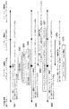
図4に、エコーネットアドレス初期化シーケンスの例を示す。
【0043】
また、図5に、エコーネット機器3における、エコーネットアドレス決定の処理手順の一例を示す。また、図6に、エコーネット機器3における、他のエコーネット機器3からの問い合わせに回答する際の処理手順の一例を示す。
【0044】
ここでは、PAN基地局1がマスターとなっているピコネットに、当初、エコーネット機器Aとエコーネット機器Bとが所属しているとする。つまり、このピコネットには、機器Aと機器Bの2つのエコーネットノードがこの時点では存在しているものとする。そして、エコーネット機器Cが本ローカルネットに加わろうとする場合を例にとる。
【0045】
この例では、まず、エコーネット機器Cが周囲にInquiryをかけ(S1)、これにBTマスターとなっているPAN基地局1が答える(S2)。Inquiryを受けたBTマスター(PAN基地局1)は、必要に応じてマスター/スレーブ変換等を行って、該エコーネット機器Cを配下に収める。
【0046】
次に、BTマスター(PAN基地局1)とエコーネット機器Cとの間でサービス発見手続きが行われる(S3)。この結果、エコーネット機器Cは、BTマスター(PAN基地局1)がPAN(TCP/IP)をサポートしているノードであることを発見、認識する(S4)。この時点では、まだエコーネット機器Cのエコーネットアドレスは決定していない。
【0047】
次に、BTマスター(PAN基地局1)とエコーネット機器Cとの間で、PANの初期化手続きが行われる(S5)。この結果、両機器間で、Bluetooth上のPANを使ったTCP/IP通信が実現される。このIP通信は、IPv4でも良いし、IPv6でも良い。
【0048】
次に、エコーネット機器Cは、自分のエコーネットアドレスを決定するための手順に移る。
【0049】
まず、エコーネット機器Cは、そのローカルネット(サブネット)内のエコーネットノードが持っているアドレスを知るために、エコーネットアドレス問合せパケットを、全てのエコーネットノードが受信するように予め割当てられたIPマルチキャストアドレスに対して送信する(S6,S21)。このようにすることで、該パケットがエコーネットノード以外のノードに送信されることを未然に防ぐことができる。なお、(ローカル網上などの所定の範囲に)ブロードキャストを行うことも可能である。
【0050】
このエコーネットアドレス問合せパケットを受信したエコーネット機器3(図1の例では、機器Aと機器B)は、このパケットを送信したノード(本例のエコーネット機器C)に対して、自分のエコーネットアドレスの値(特にノードIDの値)を通知してやらなくてはならない。ただし、そのサブネット内に複数のエコーネットノードが同時に存在する場合には、このリプライが同時に行なわれてしまうと、アドレスを通知するためのパケットが一気にエコーネット機器Cに集中し、エコーネット機器Cが輻輳の状態になってしまう。よって、これを未然に防ぐため、エコーネットアドレス問合せパケットを受信(S31)したエコーネットノードは、ある単位時間Tに、自分のエコーネットアドレス(のノードIDの部分)の値を乗じた値に相当する待機時間だけ待ち(S7,S9,S32,S33)、その後、自エコーネットアドレスを含む応答パケットを返送する(S8,S10,S34)。このようにすることで、該アドレス問合せパケットを送ったノードへのリプライの瞬間的な集中を未然に防ぐことが可能になる。
【0051】
一方、アドレス問合せを送ったエコーネット機器Cの側も、そのローカルネットに存在し得る最大ノード数(エコーネットの場合、255)の数に上記単位時間を乗じた値T’(に相当する待時間)だけ待てば(S22)、存在し得る全て(あるいはほとんど)のノードからのリプライが返ってくるものと期待できる。これは、エコーネットサブネット内のノード数が256と限定された数であり、これに上記単位時間を乗じた数もリーズナブルな時間に収まることから、このような受信待ちが可能となる。捕捉したエコーネットアドレスは、図3(b)の既利用エコーネットアドレスの一覧に記入する。
【0052】
なお、上記の手順は、エコーネットアドレス問合せパケットや次のエコーノード確認パケットだけでなく、マルチキャストあるいはブロードキャストされた他のパケットを受信し、これに対する応答パケットを返送する場合にも適用可能である。
【0053】
ここで、上記エコーネットアドレス問合せパケットが何らかの都合(例えば劣悪な無線環境)により到着しない場合も考えられ、応答できないノードが存在する可能性を考慮する必要がある。このため、下記に説明するように、上記エコーネットアドレス問合せに対する応答パケットで収集したエコーネットアドレスと重複しないアドレスを選択するだけでなく、選択したアドレス(ノードID)が本当にそのIPサブネット内で使われていないかどうかを、再度確認する作業が行なわれる。
【0054】
このようにして、該ローカルネット上の全て(あるいはほとんど)のエコーネットノードのエコーネットアドレスを収集したエコーネット機器Cは、続いて、自分のエコーネットアドレスの候補を決める(S11,S23)。この場合、エコーネット機器Cは、存在する全ての(または所定の一部の)エコーネットアドレスのうちから、それまでに通知されたエコーネットアドレス(該ローカルネット上に既に存在すると考えられるエコーネットアドレス)の値以外の値を選択し、これを仮の自分のエコーネットアドレスとする。つまり、存在する全ての(または所定の一部の)エコーネットアドレスのうちから、図3(b)の既利用エコーネットアドレスの一覧に書いてある値以外の値を、所定の方法で(例えば、ランダムに、最も値の小さいものを、最も値の大きいものを、など種々の方法がある)、1つ選択する。
【0055】
エコーネット機器Cは、自分でエコーネットアドレスの候補を決定し、この値を含むエコーノード確認パケットを、ローカルリンクにブロードキャスト(エコーネットノードに割当てられたIPマルチキャストアドレスでもよい)して、該エコーネットアドレスの値の重複を調査する(S12)。このようなパケットを、送信し、上記のように確認先のエコーネット機器の待機時間を考慮して、所定の待時間(例えば、上記のT’)だけ待ち(S13)、その時間の間、リプライが無ければ、該サブネットには同様のエコーネットアドレスを持ったノードは他にはいないと判断して、該アドレスを、そのノードのエコーネットアドレスとして用いることに決定する(S14,S24,S25)。なお、確認パケットの送信と、所定の待時間だけ待つことを、所定回数(複数数回)繰り返してもなおリプライが無ければ、該アドレスを、そのノードのエコーネットアドレスとして用いることに決定するようにしてもよい。
【0056】
他に、同じエコーネットアドレスがいる(つまり「そのアドレスは使用中」という意味のパケットが返ってきた場合)場合には、それ以外の新しい値を選択して、同様にアドレスの重複を検査する(S11〜S14,S25〜S28)。
【0057】
本実施形態では、上記「既に自分がそのエコーネットアドレスの値は使っている」という意味のメッセージは、エコーネットアドレス重複メッセージとして通知される。
【0058】
なお、存在し得る最大ノード数(エコーネットの場合、255)の数に上記単位時間を乗じた値T’に相当する待時間だけ待つ代わりに、例えば、図3(a)のアドレステーブル323に登録されたエコーネットアドレス(のノードID)の最大値に上記単位時間を乗じた値T”に相当する待時間だけ待つ方法なども可能である。
【0059】
このようにしてエコーネットアドレス(Ec)が決定すると、その後は、エコーネットパケットをIPパケットにカプセル化する形で、エコーネットパケットのやり取りが、エコーネットノード間にて行われる。本実施形態では、エコーネットパケットは、UDPパケットにカプセル化される。
【0060】
図7に、IPパケットにカプセル化されるパケット(エコーネットパケットやエコーネットARPパケット)のフォーマットの一例を示す。図7に示されるように、一般のエコーネットパケットがIPパケットにカプセル化される他、その他のエコーネットアドレス決定や通知の場合の制御パケットや、アドレス解決のためのパケットなども、このパケットフォーマットに含まれる。エコーネットパケットも、エコーネットに関連する制御パケットも、共に同一のポート番号(本例では、UDPポート)にマッピングされ、パケット種別のフィールドを参照することにより、それがエコーネットパケットなのか、それともエコーネットの初期化用の制御パケットなのかの区別を行うようになっていても良い。また、例えば、エコーネットパケットやエコーARPパケットなどで異なるポート番号にマッピングされるようにしてもよい。
【0061】
ところで、上記では、マルチキャストあるいはブロードキャストされた他のパケットを受信した(問い合わせ先あるいは確認先などとなる)エコーネット機器(受信側エコーネット機器と呼ぶ)は、これに対する応答パケットを返送する際の待機時間として、ある単位時間Tに、自分のエコーネットアドレスのノードIDの部分の値を乗じた値を使用したが、待機時間の決定方法は、これに限定されず、種々のバリエーションが可能である。また、マルチキャストあるいはブロードキャストされた他のパケットを送信した(問い合わせ元あるいは確認元などとなる)エコーネット機器(送信側エコーネット機器と呼ぶ)における所定の待時間の決定方法のついても、待機時間の決定方法に応じて、種々のバリエーションが可能である。以下、幾つかのバリエーションを例示する。
【0062】
(1)受信側エコーネット機器では、自装置のエコーネットアドレスのノードIDの部分の値をそのまま用いる代わりに、例えば、自装置のエコーネットアドレスのノードIDの部分の値に1対1に対応して予め定められている値(例えばエコーネットアドレスのノードIDの取り得る値のうちのいずれかの値)を用いるようにしてもよい。
送信側エコーネット機器では、該ノードIDのMAX値に単位時間を乗じた値を待時間とするのではなく、例えば、図3(a)のアドレステーブル323に登録されたエコーネットアドレスのノードIDに上記の対応を適用した場合の対応値の最大値に単位時間を乗じた値を待時間としてもよい。
【0063】
(2)受信側エコーネット機器では、自装置のエコーネットアドレスのノードIDの部分の値をそのまま用いる代わりに、例えば、自装置のエコーネットアドレスのノードIDの部分の値を次のような関数に入力して得られる値を用いるようにしてもよい。この関数は、エコーネットアドレスのノードIDの部分の値を、エコーネットアドレスのノードIDのMAX値より小さい値の範囲に写像するものである。例えば、該ノードIDを定数nで除して得られる商を出力するものである。また、例えば、ノードIDを定数nで除して得られる剰余を出力するものである。また、この写像は、出力を均等に分布させるものでなくてもよい。 送信側エコーネット機器では、該ノードIDのMAX値に単位時間を乗じた値を待時間とするのではなく、例えば、写像範囲のMAX値に単位時間を乗じた値を待時間としてもよい。あるいは、例えば、図3(a)のアドレステーブル323に登録されたエコーネットアドレスのノードIDに上記関数を適用した場合の写像値の最大値に単位時間を乗じた値を待時間としてもよい。
【0064】
(3)受信側エコーネット機器では、自装置のエコーネットアドレスのノードIDの部分の値をそのまま用いる代わりに、例えば、自装置のエコーネットアドレスのノードIDの部分の値をピークとする分布関数を持つ乱数によって発生した乱数値を用いるようにしてもよい。
送信側エコーネット機器では、該ノードIDのMAX値に単位時間を乗じた値を待時間とするのではなく、例えば、図3(a)のアドレステーブル323に登録されたエコーネットアドレスのノードIDに上記の乱数を適用した場合の乱数値の最大値に単位時間を乗じた値を待時間としてもよい。
【0065】
(4)受信側エコーネット機器では、自装置のエコーネットアドレスのノードIDの部分の値(あるいは上記のような方法で得られる値)に、単位時間を乗じて、待機時間を求める代わりに、例えば、自装置のエコーネットアドレスのノードIDの部分の値(あるいは上記のような方法で得られる値)を、所定の関数(単位時間を乗じる関数を除く)に入力して得られる値を、待機時間としてもよい。
送信側エコーネット機器では、例えば、該ノードIDのMAX値を上記所定の関数に入力した値を待時間としてもよい。また、例えば、図3(a)のアドレステーブル323に登録されたエコーネットアドレスのノードIDを上記所定の関数に入力した値を待時間としてもよい。
【0066】
ところで、上記では、受信側エコーネット機器における待機時間や送信側エコーネット機器における待時間を予め1種類決定しておくものとしたが、その代わりに、待機時間の決定方法と待時間の決定方法との組を複数を搭載しておき(あるいは、例えば、上記の(2)のnをパラメータとした方法を搭載しておき)、送信側エコーネット機器が問い合わせパケットや確認パケットなどを受信側エコーネット機器にブロードキャストあるいはマルチキャストする際に、いずれの方法を使用するか(あるいは、例えば、上記の(2)のnとしてどのような値を使用するか)を指定する情報を該パケットに記述し、受信側エコーネット機器は指定された方法で待機時間を決定し、送信側エコーネット機器も同じ方法で待時間を決定するようにしてよい。
【0067】
例えば、待機時間の決定方法と待時間の決定方法との組が、互いに、受信側エコーネット機器における待機時間の分散の仕方(その結果として、送信側エコーネット機器におけるリプライの集中の程度)が異なるものである場合に、送信側エコーネット機器は、自装置のメモリ容量の大小等に応じて、複数の受信側エコーネット機器における待機時間が短期間により集中するような方法や、より長期間にわたって分散する方法などを、適宜選択するようにしてもよい。
【0068】
なお、上記の受信側エコーネット機器のエコーネットアドレスのノードIDの部分の値に単位時間を乗じて得られる値を待機時間とするような方法において、該単位時間をパラメータとして、送信側エコーネット機器が指定する方法も可能である。
【0069】
なお、以上では、エコーネットアドレスのIPアドレスとして、リンクローカルアドレスを用いるものとして説明したが、グローバルユニークIPアドレスや、プライベートIPアドレスなどを用いてもよい(IPv4アドレスでもIPv6アドレスでも良い)。
【0070】
(第2の実施形態)
以下では、第1の実施形態と相違する点を中心に説明する(本実施形態のホームネットワークシステムの構成例については図1を、エコーネット機器3の内部構造例については図2を、アドレステーブルの内部構造例については図3を、IPパケットにカプセル化されるパケットのフォーマット例については図7を参照)。
【0071】
エコーネットアドレス(ノードID)を、IPアドレスの一部、例えば下8ビットの値を用いることを基本とし、もし同一サブネット内に同じノードIDを持つノードが存在する場合に、該値を用いるとエコーネットアドレス(ノードID)の値の重複がサブネット内で発生することから、本実施形態では、そのような場合において、これまで説明してきた方法を利用して、自分のエコーネットアドレス(ノードID)を決定する。
【0072】
図8及び図9に、この場合のエコーネットアドレス初期化シーケンスの例を示す(図8及び図9は、1つのシーケンスを分図したものである)。
【0073】
ここでも、図4〜図6の場合の具体例と同様とする。すなわち、PAN基地局1がBTマスターとなっているピコネットに、当初、エコーネット機器Aとエコーネット機器Bとが所属しているとする。つまり、このピコネットには、機器Aと機器Bの2つのエコーネットノードがこの時点では存在しているものとする。そして、エコーネット機器Cが本ローカルネットに加わろうとする場合を例にとる。
【0074】
さて、エコーネット機器Cは、自分に割当てられたIPアドレスの下8ビットの値を、エコーネットアドレス(ノードID)の候補とする(S41)。
【0075】
なお、IPv4アドレスのクラスCアドレスであれば、この時点で重複はないことになる。それ以外のIPアドレスである場合には、同一サブネットの他のノードに割当てられているIPアドレスの下8ビットが同一である場合が考えられるため、ノードIDの重複が発生する可能性が考えられる。このため、これを確認するために図4のS12と同様のエコーネットノード確認パケット等を用いて、図5の手順を開始する。
【0076】
すなわち、エコーネット機器Cは、上記のIPアドレスの下8ビットの値を含むエコーノード確認パケットを、ローカルリンクにブロードキャスト(エコーネットノードに割当てられたIPマルチキャストアドレスでもよい)して、該エコーネットアドレスの値の重複を調査する(S42)。
【0077】
ここで、問い合わされた値と同一のエコーネットアドレス(ノードID)を使用している旨を示す応答パケットが返送されなければ、重複がないと判断して、該値(IPアドレスの下8ビットの値)を、自装置が使用するエコーネットアドレス(ノードID)と決定する。
【0078】
一方、該パケットを受信したエコーネット機器は、問い合わされた値と同一のエコーネットアドレス(ノードID)を使用しているならば、エコーネット機器Cへ、その旨を示す応答パケットを送信する(S43)。
【0079】
例えば、上記のIPアドレスの下8ビットの値が、エコーネット機器Aが使用しているエコーネットアドレス(ノードID)=Eaと同一であったような場合には、該パケットを受信したエコーネット機器Aが、問い合わされた値と同一のエコーネットアドレス(ノードID)を使用している旨を示す応答パケットを送信する。
【0080】
エコーネット機器Cは、この応答パケットにより、問い合わせたエコーネットアドレス(ノードID)の候補が、他のエコーネット機器により使用されていると判断されると、サブネット内の全ノードIDの調査に移る(S44)。
【0081】
以降の処理は、図4〜図6の場合と、基本的には同様である。
【0082】
すなわち、エコーネット機器Cは、そのローカルネット(サブネット)内のエコーネットノードが持っているアドレスを知るために、エコーネットアドレス問合せパケットを、マルチキャストあるいはブロードキャストする(S45)。
【0083】
このエコーネットアドレス問合せパケットを受信したエコーネット機器A,Bは、このパケットを送信したエコーネット機器Cに対して、前述のような所定の待機時間だけ待った(S46,S48)後に、自分のエコーネットアドレス(ノードID)を通知する(S47,S49)。
【0084】
エコーネット機器Cは、前述のような所定の待時間の間に、応答パケットの受信を行う。
【0085】
エコーネット機器Cは、サブネットで利用中のエコーネットアドレスをすべて(あるいは大まかに)把握する(S50)。
【0086】
次いで、前述と同様に(エコーネットアドレス問合せパケットに応答できないノードが存在する可能性を考慮し)、エコーネットアドレス問合せに対する応答パケットで収集したエコーネットアドレスと重複しないアドレスを選択するだけでなく、選択したアドレス(ノードID)が本当にそのIPサブネット内で使われていないかどうかを、再度確認する作業が行なわれる。
【0087】
すなわち、まず、他のエコーネット機器との重複がないように、自分のエコーネットアドレスの候補を決める(S51)。
【0088】
エコーネット機器Cは、自分でエコーネットアドレスの候補の値を含むエコーノード確認パケットを、マルチキャストあるいはブロードキャストして、該エコーネットアドレスの候補の値の重複を調査する(S52)。
【0089】
このエコーノード確認パケットを受信したエコーネット機器A,Bは、このパケットを送信したエコーネット機器Cに対して同一のエコーネットアドレス(ノードID)を使用している旨を示す応答パケットを返送する場合には、前述のような所定の待機時間だけ待った後に、該返送を行う。
【0090】
エコーネット機器Cは、前述のような所定の待時間だけ待ち(S53)、その時間の間、リプライが無ければ、該サブネットには同様のエコーネットアドレスを持ったノードは他にはいないと判断して、該エコーネットアドレスの候補を、その自分のエコーネットアドレスとして用いることに決定する(S54)。なお、確認パケットの送信と、所定の待時間だけ待つことを、所定回数(複数数回)繰り返してもなおリプライが無ければ、該アドレスを、そのノードのエコーネットアドレスとして用いることに決定するようにしてもよい。
【0091】
他に、同じエコーネットアドレスがいる(つまり「そのアドレスは使用中」という意味のパケットが返ってきた場合)場合には、それ以外の新しい値を選択して、同様にアドレスの重複を検査する(S52〜S54)。
【0092】
(第3の実施形態)
以下では、第1、第2の実施形態と相違する点を中心に説明する(本実施形態のホームネットワークシステムの構成例については図1を、エコーネット機器3の内部構造例については図2を参照)。
【0093】
第2の実施形態では、IPアドレスの一部(例えば下8ビットの値)を利用して、自ノードのエコーネットアドレス(ノードID)を決定する例について説明したが、本実施形態では、Bluetoothアドレスの一部(例えば下8ビットの値)を利用して、自ノードのエコーネットアドレス(ノードID)を決定する例について説明する。Bluetoothアドレスは不変のアドレスであるため、この方法は、例えば、なるべく同じノードに対して同じエコーネットアドレスを割当てたいエコーネットの要求により合致する。
【0094】
なお、ここでは、まず前回利用したノードIDの値を自ノードIDの候補として利用するようにしている。また、自ノードでアドレスを決定する前に、ネットワーク上にエコーネットアドレスの割り当てを行なってくれるアドレスサーバ(エコーネット版のDHCPサーバ)が存在するかどうかを確かめるようにしている。
【0095】
本実施形態のホームネットワークシステムのBluetooth基地局(PAN基地局)及びエコーネット機器(図1では、基地局1、機器A,B,C)は、それぞれ、BluetoothアドレスとIPアドレスを持つ。
【0096】
Bluetoothアドレスは、あらかじめBluetoothインタフェースに付与された変更不可能なハードウエアアドレスであり、通常48ビットのIEEE802アドレスが割り当てられている。
【0097】
IPアドレスは、IPv4アドレスでも良いし、IPv6アドレスでも良い。なお、本実施形態では、IPv4の場合、IPアドレスは、クラスCのアドレスであるものとして説明するが、クラスA、クラスBのIPv4アドレスであっても良い。また、IPv6の場合は、IPアドレスは例えばIPv6のリンクローカルアドレスであるものとしてもよい。リンクローカルアドレスは、前述したように、そのリンク(本例ではBluetooth)上でのみ使うことのできる、特殊なIPアドレスである。グローバルユニークなIPアドレスを与える必要が無い一方、ローカルなネットワーク(リンクネットワーク)上で、IPの特定のアプリケーションを動作させる場合に用いられる方式である。エコーネットプロトコルは、ローカルネットワークを前提、対象に開発されたプロトコルであるため、IP上でもリンクローカルアドレスの使用が望ましいと共に、未然に自宅外からの家電製品、エコーネット稼動範囲への悪意のあるアクセスや間違いアクセスを未然に防ぐことが可能となる。
【0098】
図10に、本実施形態のアドレステーブルの内部構造例を示す。
【0099】
図10(a)に示されるように、本実施形態のアドレステーブル323は、そのIPサブネット(具体的には、そのリンクローカルの空間)内にあるエコーネットノードのIPアドレスと、そのノードのハードウエアアドレス(具体的にはBluetoothアドレス)と、そのノードのエコーネットアドレス(のノードID(ノード識別子))とを対応付けて記憶する。
【0100】
また、エコーネット機器3は、図10(b)に示されるように、ある時点で他のエコーネット機器3が既に使用しているエコーネットアドレス群を保持するためのテーブルを持つ。
【0101】
なお、図10(a)のテーブルを使用する代わりに、例えば、ハードウエアアドレスとIPアドレスとの対応テーブルと、IPアドレスとエコーネットアドレスとの対応テーブルの2つのテーブルを使用するようにしてもよい(なお、ハードウエアアドレスとエコーネットアドレスとの対応テーブルと、エコーネットアドレスとIPアドレスとの対応テーブルの2つのテーブルに分割する方法や、エコーネットアドレスとハードウエアアドレスとの対応テーブルと、ハードウエアアドレスとIPアドレスとの対応テーブルの2つのテーブルに分割する方法も可能である)。
【0102】
以下では、エコーネットアドレス初期化手続きについて説明する。
【0103】
図11及び図12に、エコーネットアドレス初期化シーケンスの例を示す(図11及び図12は、1つのシーケンスを分図したものである)。
【0104】
ここでも、PAN基地局1がマスターとなっているピコネットに、当初、エコーネット機器Aとエコーネット機器Bとが所属しているとする。つまり、このピコネットには、機器Aと機器Bの2つのエコーネットノードがこの時点では存在しているものとする。そして、エコーネット機器Cが本ローカルネットに加わろうとする場合を例にとる。
【0105】
なお、図11及び図12のシーケンス例でも、Bluetooth通信の初期化に必要な手順(インクワイアリやサービス発見プロトコル等)や、TCP/IP通信の初期化に必要な手順(IPアドレスの取得等)については既に終了しているものとしその後に必要な手順についてのみ説明している(図4のS1〜S5参照)。
【0106】
さて、エコーネット機器Cは、自分のエコーネットアドレスを決定するための手順に移る。
【0107】
まず、エコーネット機器Cは、そのIPサブネット内にネットアドレスサーバ確認パケットをブロードキャスト(あるいは、エコーネットノードに対してのみマルチキャスト)して、エコーネットアドレス(ノードID)の割り当てを行なってくれるエコーネットアドレスサーバ(図示せず)の存在を確認する(S61)。
【0108】
ここで、エコーネットアドレスサーバは、内部に例えば図10で説明したようなアドレステーブルを持ち、要求に応じてエコーネットアドレス(ノードID)の値を割り振るためのサーバである。
【0109】
エコーネットアドレスサーバが、そのIPサブネット内に存在する場合は、このサーバにエコーネットアドレスを割当ててもらえばよいため、以降の手順は不要となる。この場合、エコーネットアドレスサーバを用いたエコーネットアドレスの割当て手順は、エコーネット規格の種々の物理媒体(例えば電灯線やLON等)にて定められた方法や、TCP/IP規格にて定められた方法(例えばDHCPサーバによる方法)に順ずるものとする。
【0110】
ここで、アドレスサーバが存在する場合について説明する。一部のエコーネット機器(例えば、電灯線や赤外線、ツイストペア線上に定義されたエコーネット等)は、エコーネットアドレスの値(ノードIDの値)が、どのような場合であっても(あるいは、ほとんどの場合に)変わらない様な前提で作られてきた。これは、それぞれのネットワーク上(電灯線ネットワーク、赤外線ネットワーク、ツイストペア線ネットワーク等)において、必ずアドレスサーバが存在し、このアドレスサーバが常時稼動し、どのノードに対してどのノードIDの値を与えたかどうかを記憶しておく仕組みを持っている。このため、同一のノードが同一のネットワーク上で立ち上がった場合、それが始めての稼動ではなく、複数回目の稼動であったとしても、アドレスサーバは、そのノードの識別子(例えばハードウエアアドレス、またはデータリンクレイヤアドレス、又は固有の識別子)と、エコーネットアドレス(ノードID)との組み合わせを予め記憶しておき、必ず同一のノードIDの値を与えるようにして、これを達成する。このようなネットワークに接続しているノードは、「エコーネット機器のエコーネットアドレス(ノードID)の値は変わらない」という解釈をしている可能性がある。
【0111】
これに対して、本実施例で説明するアドレス割当て方式は、「ノードIDの値が変わる可能性のある」方式である。これは、前記既存のネットワークに接続された機器が対応できない可能性が出てきてしまう。例えば、前記既存のネットワークに接続された機器が、本IPネットワーク上のエコーネット機器のノードIDの値が、長期にわたって不変であると解釈する場合である。
【0112】
このため、既存のネットワークに接続された機器が接続される場合、つまり、本実施例の「IPネットワーク」と既存ネットワークが接続されて、エコーネットが構成される場合には,必ず、「IPネットワークと既存ネットワークを接続するノード」であるエコーネットルータにアドレスサーバを配置することにすれば,アドレスサーバは配布するノードIDの値が基本的に不変であるため,本IPネットワーク上に配置されるエコーネット機器のエコーネットアドレス(ノードID)の値も不変であることを保証できる。ただし、このエコーネットルータ上に配置されるアドレスサーバも、データリンクレイヤアドレス(本実施例の場合Bluetoothアドレス)とノードIDの間でテーブルを作成して、アドレスの対応関係を記憶しておくものとする。
【0113】
以上が、アドレスサーバが存在する場合の説明であった。
【0114】
一方、そのIPサブネット内にエコーネットアドレスサーバが存在しない場合について続けて説明する。
【0115】
さて、エコーネットアドレスサーバ確認パケットを送信したエコーネット機器Cは、一定の時間の間にエコーネットアドレスサーバからの返信が無い場合には(S62)、エコーネットアドレスサーバが存在しないものと判断する(S63)。
【0116】
エコーネットアドレスサーバが存在しないと判断された場合、エコーネットアドレスは、エコーネット機器Cが自律的に決定することになる。その際、既にそのIPサブネット(エコーネットサブネット)内に、同じ値のエコーネットアドレスの機器が存在する場合には、その値を使わないようにする必要がある。これは、アドレスの重複が発生してしまうと、エコーネットアドレスを用いたノードの識別が不可能になってしまうからである。
【0117】
まず、エコーネット機器Cが自ノードのエコーネットアドレスの候補として使用する値を、以前自ノードがエコーネット機器としてネットワーク上で稼動した際に利用したノードIDの値とする(S64)。ここで、この値がEbであったものとする。
【0118】
なお、この場合に、エコーネット機器の移動が考えられるため、サブネットIDの値が一致した場合にのみ、この値の確認(S65,S66)を行なっても良い。これは、サブネットIDの値が、以前の値と異なる場合には、その機器がサブネットを移動したと考えられ、「以前使用していたノードIDの値」に意味がないからである(この場合には、S65,S66をスキップして、S67に進んでも良い)。
【0119】
エコーネット機器Cは、エコーノード確認パケットにより、この値をサブネット全体に通知して、既にこの値を使っているノードが存在するかどうかについての調査を行なう(あるいは、サブネットIDの値が一致した場合に、この値をサブネット全体に通知して、既にこの値を使っているノードが存在するかどうかについての調査を行なう)。このため、「エコーネットノード確認」という種別のパケットを、サブネット内にブロードキャスト(あるいは、エコーネットノードに対してのみマルチキャスト)する(S65)。
【0120】
エコーネットノード確認パケットを送信したエコーネット機器Cは、一定の時間の間にアドレスの重複を通知するリプライパケットが届かない場合には、該ノードIDを使っているノードは、そのサブネット内には存在しないものと判断して、該ノードIDを、正式なエコーネットアドレス(のノードID)として使用するものと決定する。その場合には、そのためのトリガとして、該アドレスの利用開始や、自装置の属性を他ノードに通知するためのパケットをサブネット内に送出しても良い。
【0121】
なお、確認パケットの送信と一定の時間待つことを、所定回数(複数数回)繰り返してもなおリプライが無かった場合に、該アドレスを、そのノードのエコーネットアドレスとして用いることに決定するようにしてもよい。
【0122】
本例では、エコーネット機器Bが既に同一の値(Eb)を使用中であることから、これを通知するパケット(エコーネットノード確認応答)が転送され(S66)、該値は使用できないことがわかる。
【0123】
前回利用したノードIDの値が既に使用中である場合、エコーネット機器Cは、次に自ノードのハードウエアアドレス(本実施形態の場合Bluetoothアドレス)の一部、例えば下8ビットの値を、自ノードのノードIDの値の候補とする(S67)。自ノードのハードウエアアドレスの一部を用いることにより、ノードIDの値の変動の可能性を低く押さえることが可能となる。
【0124】
ここでも同様に、エコーネット機器Cは、エコーノード確認パケットにより、この値をサブネット全体に通知して、既にこの値を使っているノードが存在するかどうかについての調査を行なう(S68)。もし、一定の時間の間にアドレスの重複を通知するリプライパケットが届かない場合には、該ノードIDを使っているノードは、そのサブネット内には存在しないものと判断して、該ノードIDを、正式なエコーネットアドレス(のノードID)として使用する。
【0125】
なお、確認パケットの送信と一定の時間待つことを、所定回数(複数数回)繰り返してもなおリプライが無かった場合に、該アドレスを、そのノードのエコーネットアドレスとして用いることに決定するようにしてもよい。
【0126】
本例では、エコーネット機器Aが既に同一の値(Ea)を使用中であることから、これを通知するパケット(エコーネットノード確認応答)が転送され(S69)、該値は使用できないことがわかる。
【0127】
「自ノードが以前使用していたノードIDの値」と「自ノードのハードウエアアドレスの一部(例えば下8ビット)の値」のいずれも使用できないことが分かった場合には、エコーネット機器Cは、サブネット内の全ノードIDの調査に移る(S70)。
【0128】
以降の処理は、図4〜図6の場合(あるいは図8及び図9のS45〜S54)と、基本的には同様である。
【0129】
すなわち、エコーネット機器Cは、そのローカルネット(サブネット)内のエコーネットノードが持っているアドレスを知るために、エコーネットアドレス問合せパケットを、全てのエコーネットノードが受信するように予め割当てられたIPマルチキャストアドレス、又はブロードキャストアドレスに対して送信する(S71)。
【0130】
このエコーネットアドレス問合せパケットを受信(S71)したエコーネット機器A,Bは、このパケットを送信したエコーネット機器Cに対して、前述のような所定の待機時間だけ待った(S72,S74)後に、自ノードのエコーネットアドレス(ノードID)を通知する(S73,S75)。
【0131】
アドレス問合せを送ったエコーネット機器Cは、前述のような所定の待時間の間に、応答パケットの受信を行って、サブネットで利用中のエコーネットアドレスをすべて(あるいは大まかに)把握する(S76)。捕捉したエコーネットアドレスは、図10(b)の既利用エコーネットアドレスの一覧に記入する。
【0132】
ただし、上記エコーネットアドレス問合せパケットが何らかの都合(例えば劣悪な無線環境)により到着しない場合も考えられ、応答できないノードが存在する可能性を考慮する必要がある。このため、下記に説明するように、上記エコーネットアドレス問合せに対する応答パケットで収集したエコーネットアドレスと重複しないアドレスを選択するだけでなく、選択したアドレス(ノードID)が本当にそのIPサブネット内で使われていないかどうかを、再度確認する作業が行なわれる。
【0133】
このようにして、該ローカルネット上の全て(あるいはほとんど)のエコーネットノードのエコーネットアドレスを収集したエコーネット機器Cは、続いて、自ノードのエコーネットアドレスの候補を決める。この場合、エコーネット機器Cは、存在する全ての(または所定の一部の)エコーネットアドレスのうちから、それまでに通知されたエコーネットアドレス(該ローカルネット上に既に存在すると考えられるエコーネットアドレス)の値以外の値を選択し、これを仮の自ノードのエコーネットアドレスとする(S77)。つまり、存在する全ての(または所定の一部の)エコーネットアドレスのうちから、図10(b)の既利用エコーネットアドレスの一覧に書いてある値以外の値を、所定の方法で(例えば、ランダムに、最も値の小さいものを、最も値の大きいものを、など種々の方法がある)、1つ選択する。
【0134】
エコーネット機器Cは、自ノードでエコーネットアドレスの候補を決定し、この値を含むエコーノード確認パケットを、ローカルリンクにブロードキャスト(エコーネットノードに割当てられたIPマルチキャストアドレスでもよい)して、該エコーネットアドレスの値の重複を調査する(S78)。
【0135】
このエコーノード確認パケットを受信したエコーネット機器A,Bは、このパケットを送信したエコーネット機器Cに対して同一のエコーネットアドレス(ノードID)を使用している旨を示す応答パケットを返送する場合には、前述のような所定の待機時間だけ待った後に、該返送を行う。
【0136】
エコーネット機器Cは、前述のような所定の待時間だけ待ち(S79)、その時間の間、リプライが無ければ、該サブネットには同様のエコーネットアドレスを持ったノードは他にはいないと判断して、該アドレスを、そのノードのエコーネットアドレスとして用いることに決定する(S80)。なお、確認パケットの送信と、所定の待時間だけ待つことを、所定回数(複数数回)繰り返してもなおリプライが無ければ、該アドレスを、そのノードのエコーネットアドレスとして用いることに決定するようにしてもよい。
【0137】
他に、同じエコーネットアドレスがいる(つまり「そのアドレスは使用中」という意味のパケットが返ってきた場合)場合には、それ以外の新しい値を選択して、同様にアドレスの重複を検査する(S77〜S79)。
【0138】
本実施形態でも、上記「既に自ノードがそのエコーネットアドレスの値は使っている」という意味のメッセージは、エコーネットアドレス重複メッセージとして通知される。
【0139】
なお、上記において、「アドレスサーバが存在するかどうか確認し、存在する場合には、該アドレスサーバに要求して、アドレスの割当てを受ける」手順(S61〜S63参照)と、「前回利用したノードIDの値を自ノードIDの候補として利用する」手順(S64〜S66)と、「自ノードのハードウェアアドレスの一部の値を自ノードIDの候補として利用する」手順(S67〜S69)の3種類の手順のうちの、いずれか1つ又は2つを省いた構成も可能である。
【0140】
このようにしてエコーネットアドレス(Ec)が決定すると、その後は、エコーネットパケットをIPパケットにカプセル化する形で、エコーネットパケットのやり取りが、エコーネットノード間にて行われる。
【0141】
図13に、IPパケットにカプセル化されるパケット(エコーネットパケットやエコーネットARPパケット)のフォーマットの一例を示す。図13に示されるように、一般のエコーネットパケットがIPパケットにカプセル化される他、その他のエコーネットアドレス決定や通知の場合の制御パケットや、アドレス解決のためのパケットなども、このパケットフォーマットに含まれる。エコーネットパケットも、エコーネットに関連する制御パケットも、共に同一のポート番号(本例では、UDPポート)にマッピングされ、パケット種別のフィールドを参照することにより、それがエコーネットパケットなのか、それともエコーネットの初期化用の制御パケットなのかの区別を行うようになっていても良い。また、例えば、エコーネットパケットやエコーARPパケットなどで異なるポート番号にマッピングされるようにしてもよい。
【0142】
(第4の実施形態)
以下、第4の実施形態について、第1、第2、第3の実施形態と相違する点を中心に説明する。本実施形態のホームネットワークシステムの構成例については図1、エコーネット機器3の内部構造例については図2と同様とする。アドレステーブルの内部構造例については図10と同様とする。IPパケットにカプセル化されるパケットのフォーマット例については図13と同様とする(ただし、パケット種別の内容が異なり、エコーネットアドレス初期化、エコーネットアドレスサーバ応答、エコーネットアドレス応答、ネットID取得要求、ネットID応答、エコーネットアドレス通知等となる)。なお、これまで説明した相手からの応答の返送を伴うパケットを送信したエコーネット機器の待時間や、そのようなパケットを受信してこれに対する応答を返送するエコーネット機器の待機時間などについても、これまでと同様である。
【0143】
ここでは、エコーネットアドレスサーバたるエコーネット機器S(図示せず)が存在する(し得る)ことを仮定する。エコーネットアドレスの取得を欲するノード(本例ではエコーネット機器Cとする)は、「エコーネットアドレスサーバを探すためのブロードキャストパケット」、「自分が仮に決めたノードIDの値(エコーネットアドレスの値)を、そのまま使っても良いか(他に、同じノードID(エコーネットアドレス)の値を使っているノードが、サブネット内にいないかどうかを確かめるためのブロードキャストパケット」、「サブネット内に存在する別のノードに対して、そのノードに関する情報(エコーネットアドレスやノードID、IPアドレス、Bluetoothアドレス(802アドレス、EUI64アドレス等のリンクレイヤアドレス)の送信を促すために送信するブロードキャストパケット」の3つの意味を含んだパケットを、サブネット内の全エコーネットノードに対してブロードキャストする。このブロードキャストは、エコーネットノードにのみ届けば良いため、エコーネットノードのみが加入してるIPマルチキャストアドレス、またはIPブロードキャストアドレス宛てに送信される。このパケットを「エコーネットアドレス初期化パケット」と呼ぶことにする。
【0144】
以下、エコーネットアドレス初期化手続きについて説明する。
【0145】
図14に、集中制御の形で、サブネット内のエコーネットアドレス(ノードID)の値を管理し、エコーネットノードIDの値を要求された場合に、この値の付与を行なう機能を持つエコーネットアドレスサーバが存在する場合についてのシーケンス例を示す。
【0146】
ここでは、エコーネット機器Sが、エコーネットアドレスサーバの機能を有するものとする。エコーネットアドレスサーバたるエコーネット機器SのBluetoothアドレス、IPアドレス、エコーネットアドレス(ノードID)は、それぞれ、「Ls」、「IPs」、「Es」とする。
【0147】
また、PAN基地局1がマスターとなっているピコネットにおいて、既に、エコーネットアドレスサーバたるエコーネット機器Sと、エコーネット機器Bとが存在しており(もちろん、エコーネット機器Aなど他のエコーネット機器が存在していてもよいが、ここでは、エコーネット機器Bで代表させて説明する)、エコーネット機器Cが本ローカルネットに加わろうとする場合を例にとる。
【0148】
また、図14のシーケンス例でも、Bluetooth通信の初期化に必要な手順(インクワイアリやサービス発見プロトコル等)などについては既に終了しているものとしその後に必要な手順についてのみ説明している(図4のS1〜S5参照)。
【0149】
さて、エコーネット機器Cは、自分のエコーネットアドレスを決定するための手順に移る。
【0150】
まず、エコーネットアドレスを決定したいエコーネット機器Cは、自分のノードIDの候補である仮ノードIDを最初に決める(SA1)。
【0151】
図15に、その際の手順例を示す。図15のように、そのノードが、前回用いたノードIDの値を保持している場合には、その前回用いたノードIDの値を用いるものとする(S101,S102)。このようにすることにより、そのサブネットにおける、そのノードが同じエコーネットアドレス(ノードID)の値を持ち続けることが可能になるため、サブネット内の他のノードが、そのノードの昔のノードIDの値を用いた何らかのテーブルを持っている場合等、アドレスの値の変化にロバストでない機器にとって、アドレス変更のリスクを少なくすることができるようになる。また、「1の値から数字の順にエコーネットノードIDの値を決めていく」といった単純な方法と比べて、他のノードとのアドレス重複の可能性を低くすることも可能である。
【0152】
一方、前回のノードIDの値を保持していない場合(例えば、そのサブネットで初めてネットワークに加入する場合や、購入最初の立ち上げの場合等)には、これまでの実施形態と同様に、自分のBluetoothアドレス等のリンクレイヤアドレス(ハードウエアアドレス)の下8ビットの値を初期値とする(S101,S103)。このようにすることによっても、他のノードとのアドレス重複の可能性を低くすることが可能となる。これは、ハードウエアアドレスの下8ビットの値は、適当に散らばっていることが期待できるためである。
【0153】
ここでは、一例として、図15の手順にしたがって、仮ノードIDの値として「Eb」の値が選択されたものとする。
【0154】
さて、このエコーネットアドレス初期化のパケット(SA2)を受け取ったエコーネットアドレスサーバ(すなわちエコーネット機器S)は、このパケットに対して「自分がエコーネットアドレスサーバであること」、「そのアドレスの使用の許可(あるいは不許可)を、そのノード(エコーネット機器C)に対して通知すること」を目的として、エコーネットアドレスサーバ応答パケットを送信する(SA3)。このパケットには、エコーネット機器Cが使用すべきエコーネットアドレス(ノードID)の値(図14の例では、「Ec」)が含まれている。
【0155】
本実施形態では、サブネット内にエコーネットアドレスの重複が無い(つまり、「Ec」の値を用いている他のノードが存在しない)ものとしているため、エコーネットアドレスサーバ(エコーネット機器S)は、内部のアドレステーブルを参照して、エコーネットアドレス(ノードID)の重複が、そのサブネット内に確かに無いことを確認した上で、その値の使用の許可を与える意味で、このパケットをエコーネット機器Cに送信する。
【0156】
そのサブネット内に、同じエコーネットアドレス(ノードID)=「Ec」の値を使っているノードが存在している場合(エコーネットアドレスサーバ内のアドレステーブルに、既に「Eb」の値が登録されている場合)には、エコーネットアドレスサーバ(エコーネット機器S)は、エコーネットアドレスサーバ応答のパケットを使用して、エコーネット機器Cが使用すべきエコーネットアドレス(ノードID)として、そのサブネットにて未使用のノードIDの値を選択した上で、この値を「使用すべきエコーネットノードID」の値に入れた上で、エコーネット機器Cに対して送信する。
【0157】
図14は、エコーネット機器Cが選択した「Eb」が既に登録されているので、未使用の値として「Ec」が選択された例を示している。
【0158】
他方、サブネット内の他のエコーネット機器(図14の例では、エコーネット機器B)も、「自分のノードに関する情報を、エコーネット機器Cに対して通知する」ことを目的としたパケットである「エコーネットアドレス応答」を、前記エコーネットアドレス初期化パケットの応答として送信する(SA4)。このパケットの応答は、これまで説明しているように、エコーネットアドレス初期化のパケットを受信してから、一定の待機時間(例えば、自分のエコーネットノードIDの値と、定数Tの値の積の値)を待った後に、送信するものとしても良い。このようにすることにより、エコーネット機器Cに、一斉に同返送が集中することを未然に防ぐことが可能となる。
【0159】
このパケットは、サブネット内の全てのノードが返送するため、エコーネット機器Cは、サブネット内の全てのエコーネット機器のBluetoothアドレス、IPアドレス、エコーネットアドレスについての情報を入手することが可能である。このことにより、エコーネット機器Cは、内部に持つアドレステーブルを、立ち上げ時には、常に最新の値にアップデートすることが可能になる。これは、本実施形態のように、エコーネットアドレスの値(やIPアドレスの値)が変更される可能性のあるネットワークにとって、非常に有効である。
【0160】
また、これまで説明しているように、このような「エコーネットアドレス応答」のパケットが、サブネット内の全てのエコーネットノードから返送されてくることを期待するため、エコーネット機器Cは、一定の待時間(例えば時間T’)の間、待つようにしてもよい。この場合、一定の待時間T’の間、待った時点で、「全てのノードは、エコーネットアドレス応答(またはエコーネットアドレスサーバ応答)を返送してくれた」と判断する(SA5)。
【0161】
なお、この「エコーネットアドレス初期化」パケットは、1回のみブロードキャストするのではなく、2回以上ブロードキャストしても良い。また、その場合、続けてブロードキャストをしても良いし、例えば、上記の一定の待時間T’の間、待ってからブロードキャストを行なっても良い。また、これら数回の「エコーネットアドレス初期化パケット」に対して、応答するノードについても、一度応答したのであれば、2回目以降(応答してから、一定の時間)は、応答をせずに、このパケットを無視しても良い。
【0162】
さて、このようにして、エコーネットアドレスサーバ(エコーネット機器S)よりエコーネットノードIDの値「Ec」の使用を許可されたエコーネット機器Cは(SA6)、次に、ネットIDの取得要求パケットをブロードキャストする(SA7)。何らかのノード(例えばエコーネットルータ)から、ネットIDの値の通知を受けた(SA8)エコーネット機器Cは、それらのアドレスを組み合わせることで、自分の全体のエコーネットアドレス(NID+Ec)を決定する(SA9)。
【0163】
なお、SA3あるいはSA4のような他のエコーネット機器からの応答からネットIDの値を取得することによって、SA7およびSA8を省略してもよい。
【0164】
最後に、エコーネット機器Cは、このエコーネットアドレス(NID+Ec)の値を、サブネット、あるいはエコーネット全体に対してブロードキャストして、自分がエコーネットに加入したことを通知する(SA10)。
【0165】
次に、エコーネットアドレス初期化の他の例として、エコーネットアドレスサーバが存在しない分散方式の例について説明する。
【0166】
図16及び図17に、この場合のシーケンス例を示す。なお、図16は、アドレスの重複が発生した場合であり、図17は、アドレスの重複が発生しない場合である。なお、ここでは、図14の場合と相違する点を中心に説明する。
【0167】
最初に、図16のシーケンスを参照しながら、アドレスの重複が発生した場合を例にとって説明する。
【0168】
さて、エコーネット機器Cは、自分のエコーネットアドレスを決定するための手順に移る。
【0169】
まず、エコーネットアドレスを決定したいエコーネット機器Cは、図14のSA1と同様に、自分のノードIDの候補である仮ノードIDを最初に決める(SB1)。ここでは、一例として、図15の手順にしたがって、仮ノードIDの値として「Ea」の値が選択されたものとする。
【0170】
次いで、ここでも、エコーネットアドレスの取得を欲するノードであるエコーネット機器Cは、図14のSA2と同様のエコーネットアドレス初期化パケット(エコーネットアドレスサーバ検索、ノードIDの重複の確認、アドレス情報の通知の要求の3つの意味を含んだパケット)を、サブネットに対してブロードキャストする(SB2)。
【0171】
今回は、サブネット内にエコーネットアドレスサーバは存在しないため、エコーネットアドレスサーバ応答を送信するノードは存在しない。なお、予めエコーネットアドレスサーバは存在していたが、現在は、何らかの事情(例えば故障)により、そのサーバ機能が停止している場合や、サーバ機能を持ったノードがサブネット内に存在しない場合にも、このシーケンス例(図16、図17)が適用される。
【0172】
サブネット内の他のエコーネット機器(本例の場合、エコーネット機器A,B)は、「自分のノードに関する情報を、エコーネット機器Cに対して通知する」ことを目的としたパケットである「エコーネットアドレス応答」を、前記エコーネットアドレス初期化パケットの応答として送信する(SB3,SB4)。このパケットの応答も、これまで説明しているように、エコーネットアドレス初期化パケットの受信後、所定の待機時間(例えば、自分のエコーネットノードIDの値と、定数Tの値の積の値)を待った後に、送信するものとしても良い。
【0173】
なお、この場合、エコーネット機器Cが当初に定めた仮ノードIDの値(=「Ea」)は、エコーネット機器AのエコーネットノードIDの値と一致しているため、エコーネット機器Aが返答するエコーネットアドレス応答パケット(SB3)には、「ノードID=Eaの値は、私が使っていますよ」という意味を含むことになる。
【0174】
なお、このエコーネットアドレス応答には、おのおののエコーネットノードが認識している、「現在、そのサブネット内で使われているエコーネットノードのノードIDの値全て」が含まれているようにしてもよい。例えば、ノードIDの値が0〜255まで存在しうるのであれば、それぞれに相当する256ビット長のビット列を用意し、「現在、サブネット内に存在すると思われるノードのノードIDに相当するビット列の順番のビットを1とし、存在しないと思われるノードに相当するビットを0とする」形で、返答すれば、256ビット長の情報ですむことになる。
【0175】
このパケットは、サブネット内の全てのノードが返送するため、エコーネット機器Cは、サブネット内の全てのエコーネット機器のBluetoothアドレス、IPアドレス、エコーネットアドレスについての情報を入手することが可能である。このことにより、エコーネット機器Cは、内部に持つアドレステーブルを、立ち上げ時には、常に最新の値にアップデートすることが可能になる。
【0176】
また、これまで説明しているように、このような「エコーネットアドレス応答」のパケットが、サブネット内の全てのエコーネットノードから返送されてくることを期待するため、エコーネット機器Cは、一定の待時間(例えば時間T’)の間、待つようにしてもよい。この場合、一定の待時間T’の間、待った時点で、「全てのノードは、エコーネットアドレス応答(またはエコーネットアドレスサーバ応答)を返送してくれた」と判断する(SB5)。
【0177】
ここで、自分の仮ノードID(=「Ea」)の値を、他のノードが使っていることが判明した場合には、これまでに受信したエコーネットアドレス応答のパケットから、現在そのサブネット内で使われていないエコーネットアドレス(ノードID)の値を算出する。これを、新しい仮ノードIDとする。ここでは、新しい仮ノードIDを「Ec」としたとする(SB6)。
【0178】
エコーネット機器Cは、この「Ec」の値の重複を調査するため、「サブネット内に重複するエコーネットノードIDの値を持ったノードが存在しないかどうかを確認するため」のパケットである「エコーネットノード確認」パケットを、サブネット内にブロードキャストする(SB7)。重複するノードが存在する場合には、この手順(SB6〜SB9の手順)を、エコーネットノードIDの値が決定するまで繰り返す。本例においては、サブネット内に重複するノードIDを持ったノードが存在しないため、例えば一定時間T’待った後(SB8)に、そのノードID(=「Ec」)を、自分のエコーネットノードIDとして、正式に決定する(SB9)。
【0179】
その後は、図14のシーケンス例の場合と同様に、ネットIDの取得を行い(SB10,SB11)、エコーネットアドレス全体を決定した後(SB12)、そのアドレスをエコーネット全体に通知するためのブロードキャスト(ドメイン内ブロードキャスト)を行なう(SB13)。
【0180】
なお、SB3あるいはSB4のような他のエコーネット機器からの応答からネットIDの値を取得することによって、SB10およびSB11を省略してもよい。
【0181】
一方、そのサブネット内に重複したエコーネットノードID(=「Ec」)を持つノードが存在しなかった場合のシーケンスは、図17のようになる。
【0182】
この場合には、エコーネットアドレス初期化パケット(SC2)に対する応答を全て収集し(SC3〜5)、サブネット内に、同ノードIDの値を使っているノードが存在しない(同ノードIDを持ったノードからの応答も無ければ、各ノードから通知されてくる使用中ノードID一覧の中にも無い場合)ことが確認できたため、この時点で、ノードID=Ecを、自分のエコーネットノードIDとして決定している(SC6)。
【0183】
以降の手順は、図16の場合と同様である。なお、この場合も、SC3あるいはSC4のような他のエコーネット機器からの応答からネットIDの値を取得することによって、SC7およびSC8を省略してもよい。
【0184】
また、以上では、ネットワークに接続された機器の制御のためのプロトコルとして、エコーネットプロトコルを用いたが、これに限定されるものではなく、本発明は、他の種々の制御プロトコルについて適用可能である。
また、以上では、ローカルエリアネットワークとしてBluetoothあるいはIP(IP over Bluetooth)を例にとったが、他の方式のネットワークであっても本発明は適用可能である。
また、以上では、ローカルエリアネットワークとしてホームネットワークを例にとって説明したが、もちろん、企業内網など他のローカルネットワークであっても本発明は同様に適用可能である。
【0185】
なお、以上の各機能は、ソフトウェアとして実現可能である。
また、本実施形態は、コンピュータに所定の手段を実行させるための(あるいはコンピュータを所定の手段として機能させるための、あるいはコンピュータに所定の機能を実現させるための)プログラムとして実施することもでき、該プログラムを記録したコンピュータ読取り可能な記録媒体として実施することもできる。
【0186】
なお、この発明の実施の形態で例示した構成は一例であって、それ以外の構成を排除する趣旨のものではなく、例示した構成の一部を他のもので置き換えたり、例示した構成の一部を省いたり、例示した構成に別の機能あるいは要素を付加したり、それらを組み合わせたりすることなどによって得られる別の構成も可能である。また、例示した構成と論理的に等価な別の構成、例示した構成と論理的に等価な部分を含む別の構成、例示した構成の要部と論理的に等価な別の構成なども可能である。また、例示した構成と同一もしくは類似の目的を達成する別の構成、例示した構成と同一もしくは類似の効果を奏する別の構成なども可能である。
また、この発明の実施の形態で例示した各種構成部分についての各種バリエーションは、適宜組み合わせて実施することが可能である。
また、この発明の実施の形態は、個別装置としての発明、関連を持つ2以上の装置についての発明、システム全体としての発明、個別装置内部の構成部分についての発明、またはそれらに対応する方法の発明等、種々の観点、段階、概念またはカテゴリに係る発明を包含・内在するものである。
従って、この発明の実施の形態に開示した内容からは、例示した構成に限定されることなく発明を抽出することができるものである。
【0187】
本発明は、上述した実施の形態に限定されるものではなく、その技術的範囲において種々変形して実施することができる。
【0188】
【発明の効果】
本発明によれば、自通信装置のエコーネットアドレスを効率的に決定できるようになる。
【図面の簡単な説明】
【図1】本発明の一実施形態に係るホームネットワークシステムの構成例を示す図
【図2】同実施形態に係るエコーネット機器の構成例を示す図
【図3】同実施形態に係るエコーネット機器のアドレステーブルの構成例を示す図
【図4】同実施形態に係るホームネットワークシステムの全体のシーケンスの一例を示す図
【図5】同実施形態に係るエコーネット機器のエコーネットアドレス決定の処理手順の一例を示すフローチャート
【図6】同実施形態に係るエコーネット機器のマルチキャスト又はブロードキャストパケット受信時の処理手順の一例を示すフローチャート
【図7】同実施形態に係るカプセル化されたエコーネットパケットのフォーマットの一例を示す図
【図8】同実施形態に係るホームネットワークシステムの全体のシーケンスの他の例を示す図
【図9】同実施形態に係るホームネットワークシステムの全体のシーケンスの他の例を示す図
【図10】同実施形態に係るエコーネット機器のアドレステーブルの構成例を示す図
【図11】同実施形態に係るホームネットワークシステムの全体のシーケンスのさらに他の例を示す図
【図12】同実施形態に係るホームネットワークシステムの全体のシーケンスのさらに他の例を示す図
【図13】同実施形態に係るカプセル化されたエコーネットパケットのフォーマットの一例を示す図
【図14】同実施形態に係るホームネットワークシステムの全体のシーケンスのさらに他の例を示す図
【図15】同実施形態に係るエコーネット機器の仮ノードIDの初期値を決定する処理手順の一例を示すフローチャート
【図16】同実施形態に係るホームネットワークシステムの全体のシーケンスのさらに他の例を示す図
【図17】同実施形態に係るホームネットワークシステムの全体のシーケンスのさらに他の例を示す図
【符号の説明】
1…PAN基地局
3…エコーネット機器
31…Bluetoothインタフェース
32…エコーネット処理部
33…他プロトコル処理部
321…イーサフレーム送受信部
322…エコーネット制御処理部
323…アドレステーブル
324…ユーザインタフェース
325…アドレス解決部
326…初期化処理部
327…インターネット処理部[0001]
TECHNICAL FIELD OF THE INVENTION
The present invention relates to a communication device and a program for performing communication using a control protocol such as an echo net on a network of a network layer protocol such as an IP.
[0002]
[Prior art]
In recent years, the development of information home appliances has been rapid. This field covers a wide variety of white goods, AV home appliances, information devices such as personal computers, mobile devices, and the like, and various applications using digital technology are considered in each case.
[0003]
One such application is the use of a home network. A home network is a network technology in a home, and connects the various information home appliances to one another.
[0004]
Internet technology has recently attracted attention as a home network technology. For example, applications that are attractive to home network users, such as music distribution, homepage browsing, and e-mail, are being developed one after another, and the number of users is constantly increasing.
[0005]
On the other hand, one application example of a home network is use as a facility network or home automation. An air conditioner, lighting, white goods and the like are connected to these networks, and applications such as device state monitoring and remote control are considered. Echonet is expected to become the de facto standard for this equipment network in Japan. Echonet defines commands, protocols, objects, APIs, and the like for controlling equipment (white goods, etc.) on various physical media such as a power line and a twisted pair line (for example, http: Http://www.echonet.or.jp for a detailed explanation in the document disclosed and obtainable). A consortium established mainly by a plurality of electrical manufacturers in Japan is responsible for standardizing this echo net, and the specifications of
[0006]
[Problems to be solved by the invention]
Echonet has its own address system, and it is necessary to take measures such as putting the "Echonet" address system on top of the "Internet" address system. Therefore, unprecedented considerations such as the determination of the correspondence between the “echo net address” and the “internet address” are required. This is the "Echo net address initialization" procedure.
[0007]
When determining an echonet address, it is assumed that there is not necessarily a server called “echonet address server” for determining the address, so it is necessary to prepare a mechanism for independently setting the echonet address. is there. As this mechanism, for example, there is a mechanism of "selecting a candidate for a value to be an echonet address and broadcasting it on a local network to check for address duplication". With this mechanism, there is a possibility that a loop of “selection of a temporary address value → investigation → duplication detection → return to the beginning” will be stuck for a while. For this reason, there may be a situation in which one's own echonet address cannot be determined for a while after startup.
[0008]
In particular, when this mechanism is installed in a wireless system such as Bluetooth, the number of nodes (slaves) that can simultaneously and actively communicate with Bluetooth is limited to 7 or less. May need to spend some time.
[0009]
The present invention has been made in consideration of the above circumstances, and has as its object to provide a communication device and a program capable of efficiently determining the own device's echonet address.
[0011]
[Means for Solving the Problems]
The present invention is a communication device for performing communication according to a predetermined control protocol on a network of a predetermined network layer protocol, comprising: interface means for connecting to the network of the predetermined network layer protocol; Control protocol processing means for performing processing relating to data of the predetermined control protocol transmitted and received via a protocol network, and transmission and reception of the predetermined network layer protocol packet encapsulating the predetermined control protocol packet Transmitting and receiving means for performing the predetermined control protocol, the predetermined control protocol connected to the network of the predetermined network layer protocol is operated to determine a predetermined address to be used in the predetermined control protocol. Transmitting means for transmitting an inquiry packet to the communication device of the present invention, wherein the inquiry packet is used by the own device as a candidate for a predetermined address to be used in the predetermined control protocol. If the predetermined address exists, the value is selected. If not, the value of the predetermined bit string of the link layer address of the own apparatus is selected. A function of inquiring as to whether the communication device is the same as the predetermined address used by the other communication device, a link layer address used by the other communication device, a network layer address or the A function of requesting the own device to notify at least one of predetermined addresses, and the predetermined network layer protocol And characterized in that having both a function of inquiring whether address server for assignment of the predetermined address in the network exists.
Preferably, the reply returned as a response to the inquiry packet from the other communication device includes information indicating a list of the predetermined addresses currently used by the other communication device, which are currently recognized. It may be included.
Preferably, when it is determined from the response to the inquiry packet that the address is not the same as the predetermined address, a determination unit that determines the value as a predetermined address to be used by the own device in the predetermined control protocol is provided. Further provision may be made.
Preferably, when it is determined that the value of the predetermined bit string is the same as the predetermined address used by the other communication device, the determination unit makes the inquiry from the other communication device. The own device may determine a predetermined address to be used in the predetermined control protocol based on the address included in the packet returned as a response to the packet.
Preferably, when the presence of the address server is confirmed by a response from the address server to the inquiry packet, the determination unit is assigned from the address server regardless of a response from another communication device. The determined address may be determined as the predetermined address to be used by the own device in the predetermined control protocol.
Preferably, the transmission / reception unit may perform transmission / reception of the packet of the predetermined network layer protocol, which encapsulates the packet of the predetermined control protocol, on an Ethernet frame.
Preferably, the interface means may have a Bluetooth interface as a physical transfer medium of the packet of the predetermined network layer protocol.
Preferably, the predetermined network layer protocol is an Internet protocol, and the network layer address is an IP address.
Preferably, the predetermined control protocol may be an echonet protocol.
Preferably, the predetermined address to be used in the predetermined control protocol may be a node identifier of an echo net address.
The present invention also relates to a program for causing a computer to function as a communication device that performs communication according to a predetermined control protocol on a network of a predetermined network layer protocol, wherein the program is connected to a network of the predetermined network layer protocol. A control protocol processing function for performing processing relating to the data of the predetermined control protocol transmitted / received via the network of the predetermined network layer protocol, and encapsulates the packet of the predetermined control protocol. A transmission / reception function for transmitting / receiving packets of the predetermined network layer protocol and a predetermined address to be used in the predetermined control protocol. Connected to the network of Tokor, and causes the computer to execute a transmission function for transmitting an inquiry packet to another communication device on which the predetermined control protocol operates, and in the transmission function, the inquiry packet includes: If the given address previously used by the own device is present as a candidate for the given address to be used by the own device in the given control protocol, its value is used. A value of a predetermined bit string of a link layer address of the apparatus is selected, and the value of the predetermined bit string is the same as the predetermined address used by the other communication apparatus with respect to the other communication apparatus. A function for inquiring whether there is a link layer address, a network layer address or A function of requesting the own device to notify at least one of the predetermined addresses, and whether or not there is an address server for allocating the predetermined address in the network of the predetermined network layer protocol. It is characterized by having both the function of inquiring.
[0012]
Further, the present invention is a communication device for performing communication according to a predetermined control protocol on a network of a predetermined network layer protocol, wherein the interface means for connecting to the network of the predetermined network layer protocol; Control protocol processing means for performing processing relating to the data of the predetermined control protocol transmitted and received via the network of the network layer protocol, and its own device and other communication devices connected to the network of the predetermined network layer protocol A communication layer for storing a network layer address to be used by the communication device in the network of the predetermined network layer protocol and a predetermined address to be used by the communication device in the predetermined control protocol. Means, a transmission / reception means for encapsulating the packet of the predetermined control protocol, for transmitting and receiving the packet of the predetermined network layer protocol, and another communication device connected to the network of the predetermined network layer protocol. On the other hand, a packet for inquiring the predetermined address used by the other communication device is transmitted, and after that, while waiting for a predetermined waiting time, the packet includes the predetermined address returned from the other communication device. Determining means for receiving a packet and determining a predetermined address to be used in the predetermined control protocol based on the predetermined address included in the received packet; When the device receives the packet, it is determined according to the predetermined address used by the other communication device. After waiting for a waiting time, which returns the packet, the predetermined waiting time is characterized in that which is determined based on the method of determining the 該待 machine time.
[0013]
Further, the present invention is a communication device for performing communication according to a predetermined control protocol on a network of a predetermined network layer protocol, wherein the interface means for connecting to the network of the predetermined network layer protocol; Control protocol processing means for performing processing relating to the data of the predetermined control protocol transmitted and received via the network of the network layer protocol, and its own device and other communication devices connected to the network of the predetermined network layer protocol A communication layer for storing a network layer address to be used by the communication device in the network of the predetermined network layer protocol and a predetermined address to be used by the communication device in the predetermined control protocol. Means for transmitting and receiving packets of the predetermined network layer protocol encapsulating the packets of the predetermined control protocol, and a value of a predetermined bit string of a network layer protocol address of the own device. The device is used as a candidate for a predetermined address to be used in the predetermined control protocol, and the value of the predetermined bit string is transmitted to another communication device connected to a network of the predetermined network layer protocol in response to the other communication. A packet for inquiring whether or not the address is the same as the predetermined address used by the device is transmitted. Determining means for determining the address.
[0014]
The present invention also relates to a communication device for performing communication according to a predetermined control protocol on a network of a predetermined network layer protocol, and an interface means for connecting to a data link layer network on which the predetermined network layer protocol operates. Control protocol processing means for performing processing related to the data of the predetermined control protocol transmitted and received via the network of the predetermined network layer protocol, and its own device connected to the network of the predetermined network layer protocol; For another communication device, a data link layer protocol address of the communication device, a network layer address to be used by the communication device in the network of the predetermined network layer protocol, Storage means for storing a predetermined address to be used in the predetermined control protocol in association with the predetermined control protocol, and transmitting and receiving the packet of the predetermined network layer protocol which encapsulates the packet of the predetermined control protocol. Transmitting and receiving means for performing, a value of a predetermined bit string of a data link layer protocol address of the own apparatus as a candidate of a predetermined address to be used by the own apparatus in the predetermined control protocol, and a value of the predetermined bit string. Transmitting a packet inquiring to another communication device connected to the network of the predetermined network layer protocol as to whether the address is the same as the predetermined address used by the other communication device. If determined, the value should be used by the own device in the predetermined control protocol. Characterized by comprising a determination means for determining as a constant address.
[0015]
Further, the present invention is a communication device for performing communication according to a predetermined control protocol on a network of a predetermined network layer protocol, wherein the interface means for connecting to the network of the predetermined network layer protocol; Control protocol processing means for performing processing relating to the data of the predetermined control protocol transmitted and received via the network of the network layer protocol, and its own device and other communication devices connected to the network of the predetermined network layer protocol A network layer address and a link layer address that the communication device should use in the network of the predetermined network layer protocol, and a predetermined address that the communication device should use in the predetermined control protocol. Storage means for storing in association with, transmission / reception means for transmitting / receiving packets of the predetermined network layer protocol which encapsulates packets of the predetermined control protocol, If the predetermined address previously used by the own device is present as a candidate for the predetermined address to be used, the value of the predetermined address is used. A value of a predetermined bit string of a layer address is selected, and the value of the predetermined bit string is used by another communication apparatus connected to a network of the predetermined network layer protocol with respect to another communication apparatus. A packet for inquiring whether the address is the same as the predetermined address is transmitted. In this case, the value, the own apparatus is characterized in that a determination means for determining as a predetermined address to be used by said predetermined control protocol.
[0016]
Further, the present invention is a communication control method for performing communication according to a predetermined control protocol on a network of a predetermined network layer protocol, wherein the communication control method comprises the steps of: Receiving a packet requesting a predetermined response related to the predetermined address used by the own device, and responding to the received packet, depending on the predetermined address used by the own device It is characterized by waiting for a waiting time and returning a packet responding to the received packet.
[0017]
Further, the present invention is a communication control method for performing communication by a predetermined control protocol on a network of a predetermined network layer protocol, wherein the communication control method includes: Transmitting a packet inquiring about the predetermined address used by the other communication device, and including the predetermined address returned from the other communication device while waiting for a predetermined waiting time. Receiving the packet, and determining, based on the predetermined address included in the received packet, a predetermined address to be used by the own device in the predetermined control protocol, the other communication device When the packet is received, the waiting determined according to the predetermined address used by the other communication device. After waiting for a time, which returns the packet, the predetermined waiting time is characterized in that which is determined based on the method of determining the 該待 machine time.
[0018]
Further, the present invention is a program for causing a computer to function as a communication device for performing communication according to a predetermined control protocol on a network of a predetermined network layer protocol, the program being for connecting to a network of the predetermined network layer protocol. An interface function, a control protocol processing function for performing processing relating to data of the predetermined control protocol transmitted and received via the network of the predetermined network layer protocol, and a control protocol processing function connected to the network of the predetermined network layer protocol. For the own device and other communication devices, the communication device uses a network layer address to be used in the network of the predetermined network layer protocol and the communication device uses the network layer address in the predetermined control protocol. A storage function for storing a predetermined address in association with a predetermined address, a transmission / reception function for transmitting and receiving a packet of the predetermined network layer protocol that encapsulates a packet of the predetermined control protocol, A determination function for determining a predetermined address to be used in a predetermined control protocol; and from another communication device connected to the network of the predetermined network layer protocol, the predetermined address used by the own device is When receiving a packet requesting a related predetermined response and responding to it, after waiting for a standby time determined according to the predetermined address used by the own device, a packet responding to the received packet is returned. This is a program for causing a computer to implement the response function.
[0019]
Further, the present invention is a program for causing a computer to function as a communication device for performing communication according to a predetermined control protocol on a network of a predetermined network layer protocol, the program being for connecting to a network of the predetermined network layer protocol. An interface function, a control protocol processing function for performing processing relating to data of the predetermined control protocol transmitted and received via the network of the predetermined network layer protocol, and a control protocol processing function connected to the network of the predetermined network layer protocol. For the own device and other communication devices, the communication device uses a network layer address to be used in the network of the predetermined network layer protocol and the communication device uses the network layer address in the predetermined control protocol. A storage function for storing a predetermined address in association with a predetermined address, a transmission / reception function for transmitting and receiving a packet of the predetermined network layer protocol, in which a packet of the predetermined control protocol is encapsulated; and Another communication device connected to the layer protocol network, which waits for a waiting time determined according to the predetermined address used by the other communication device from reception of a packet to return of a packet in response to the packet. A packet that inquires about the predetermined address used by the other communication device, and then waits for a predetermined waiting time that is determined based on the method of determining the waiting time. Receiving a packet including the predetermined address returned from the other communication device, and receiving the received packet. Based on the predetermined address contained in a program for the device itself to realize a determining function for determining a predetermined address to be used in the predetermined control protocol to the computer.
[0020]
Note that the present invention relating to the apparatus is also realized as an invention relating to a method, and the present invention relating to a method is also realized as an invention relating to an apparatus.
Further, the present invention according to an apparatus or a method has a function of causing a computer to execute a procedure corresponding to the present invention (or causing a computer to function as means corresponding to the present invention, or a computer having a function corresponding to the present invention) The present invention is also realized as a program (for realizing the program), and is also realized as a computer-readable recording medium on which the program is recorded.
[0021]
According to the present invention, it is possible to efficiently determine the echo net address of the own communication device.
[0022]
BEST MODE FOR CARRYING OUT THE INVENTION
Hereinafter, embodiments of the invention will be described with reference to the drawings.
[0023]
(1st Embodiment)
In the present embodiment, an example will be described in which the Echonet protocol is mapped on IP (for example, IPv4 or IPv6) and the Echonet protocol is operated on an IP network.
[0024]
In the present embodiment, a configuration in which each node (for example, various so-called white goods, a controller thereof, and the like) is connected by a local wireless network technology called Bluetooth is taken as an example. Here, Bluetooth is a local wireless network characterized by low cost and low power consumption. For example, http: // www. Bluetooth. The details are described in a document disclosed so as to be obtainable on the web site. In the following, BT is an abbreviation for Bluetooth.
[0025]
In addition, on Bluetooth, a method of “IP over Bluetooth” is defined in a profile of a PAN (Personal Area Network), but in the present embodiment, an example in which this method is used will be described. Here, PAN is a standard of Ethernet emulation defined on Bluetooth, and by using this mechanism, it becomes possible to exchange Ethernet frames on Bluetooth.
[0026]
FIG. 1 shows a configuration example of a home network system according to the present embodiment.
[0027]
As shown in FIG. 1, a Bluetooth base station (also referred to as a PAN base station) 1 and a plurality of echo net devices 3 (in the example of FIG. 1, three of A, B, and C) are interconnected by Bluetooth. Have been.
[0028]
A Bluetooth base station (also referred to as a PAN base station) 1 is a master of a Bluetooth piconet. In the present embodiment, the
[0029]
The echo
[0030]
Note that the
[0031]
All of these devices (in FIG. 1,
[0032]
FIG. 2 shows an example of the internal structure of the echo
[0033]
As shown in FIG. 2, the
[0034]
The echo
[0035]
Next, FIG. 3 shows an example of the internal structure of the address table of the present embodiment.
[0036]
As shown in FIG. 3A, the address table 323 of the present embodiment stores the IP address of the Echonet node in the IP subnet (specifically, the link local space). The link local address) is stored in association with (the node ID (node identifier) of) the echo net address of the node.
[0037]
Further, as shown in FIG. 3B, the echo
[0038]
Here, the Echonet address is a logical identifier having a length of 8 bits, and its specification is defined in the Echonet specification. (In the Echonet specification, a network identifier called a net ID is also defined. In the embodiment, the description will be given focusing on the node ID assigned to each node, assuming that the net ID is fixed.) This value may also be assigned a different value in some cases.
[0039]
In addition, in the example of FIG. 3A, the suffix 0 corresponds to the
[0040]
In this embodiment, when the Bluetooth base station (PAN base station) 1 is an echonet node, an example of the internal structure thereof is basically the same as that of the
[0041]
Hereinafter, the echo net address initialization procedure will be described.
[0042]
FIG. 4 shows an example of the echo net address initialization sequence.
[0043]
FIG. 5 shows an example of a processing procedure for determining an echonet address in the
[0044]
Here, it is assumed that the echo net device A and the echo net device B initially belong to the piconet whose
[0045]
In this example, first, the echo net device C applies inquiry to the surroundings (S1), and the
[0046]
Next, a service discovery procedure is performed between the BT master (PAN base station 1) and the echo net device C (S3). As a result, the echo net device C discovers and recognizes that the BT master (PAN base station 1) is a node supporting PAN (TCP / IP) (S4). At this point, the echonet address of the echonet device C has not been determined yet.
[0047]
Next, a PAN initialization procedure is performed between the BT master (PAN base station 1) and the echo net device C (S5). As a result, TCP / IP communication using the PAN on Bluetooth is realized between the two devices. This IP communication may be IPv4 or IPv6.
[0048]
Next, the echo net device C proceeds to a procedure for determining its own echo net address.
[0049]
First, in order to know the address of the Echonet node in the local net (subnet), the Echonet device C is assigned in advance so that all Echonet nodes receive the Echonet address inquiry packet. It transmits to the IP multicast address (S6, S21). By doing so, it is possible to prevent the packet from being transmitted to a node other than the Echonet node. It is also possible to broadcast (to a predetermined range such as on a local network).
[0050]
The Echonet device 3 (the devices A and B in the example of FIG. 1) that has received the Echonet address inquiry packet sends its own echo to the node (the Echonet device C of the present example) that transmitted this packet. The value of the net address (particularly the value of the node ID) must be notified. However, if a plurality of Echonet nodes exist in the subnet at the same time, if this reply is made simultaneously, packets for notifying the address will be concentrated on the Echonet device C at once, and the Echonet device C Becomes congested. Therefore, in order to prevent this, the Echonet node that has received the Echonet address inquiry packet (S31) multiplies a value obtained by multiplying a certain unit time T by the value of its own Echonet address (the node ID portion thereof). It waits for a corresponding waiting time (S7, S9, S32, S33), and then returns a response packet including its own echo net address (S8, S10, S34). By doing so, it is possible to prevent instantaneous concentration of replies to the node that sent the address inquiry packet.
[0051]
On the other hand, the echo-net device C that has sent the address inquiry also has a waiting time corresponding to the value T ′ () obtained by multiplying the maximum number of nodes (255 in the case of the echo-net) by the unit time described above. After waiting for (time) (S22), it can be expected that replies from all (or almost) possible nodes will be returned. This is a number in which the number of nodes in the Echonet subnet is limited to 256, and the number obtained by multiplying the number by the unit time falls within a reasonable time, so that such reception waiting becomes possible. The captured echo net address is entered in the list of used echo net addresses in FIG.
[0052]
The above procedure can be applied not only to the echo net address inquiry packet and the next echo node confirmation packet, but also to a case where another multicast or broadcast packet is received and a response packet is returned.
[0053]
Here, the echo net address inquiry packet may not arrive for some reason (for example, poor wireless environment), and it is necessary to consider the possibility that there is a node that cannot respond. For this reason, as described below, in addition to selecting an address that does not overlap with the echonet address collected in the response packet to the above-mentioned echonet address inquiry, the selected address (node ID) is actually used within the IP subnet. A check is made again to see if it has been done.
[0054]
In this way, the echonet device C that has collected the echonet addresses of all (or almost) echonet nodes on the local net determines its own echonet address candidates (S11, S23). In this case, the echo net device C selects, from all (or a predetermined part of) the existing echo net addresses, the echo net address notified so far (the echo net address considered to already exist on the local net). Address), and use this as a temporary own echo net address. That is, among all (or a predetermined part of) existing echo net addresses, values other than the values written in the list of used echo net addresses in FIG. There are various methods, such as randomly selecting the one with the smallest value and the one with the largest value.) One is selected.
[0055]
The echo-net device C itself determines a candidate for an echo-net address, broadcasts an echo-node confirmation packet including this value to a local link (or an IP multicast address assigned to the echo-net node), and The duplication of the value of the net address is checked (S12). Such a packet is transmitted and waits for a predetermined waiting time (for example, the above T ') in consideration of the waiting time of the echo-net device of the confirmation destination as described above (S13). If there is no reply, it is determined that there is no other node having the same echonet address in the subnet, and the address is determined to be used as the echonet address of the node (S14, S24, S25). ). It should be noted that if the transmission of the confirmation packet and the waiting for a predetermined waiting time are repeated a predetermined number of times (a plurality of times) and there is no reply yet, the address is determined to be used as the echo net address of the node. It may be.
[0056]
If there is another echonet address (that is, a packet meaning "the address is in use" is returned), select another new value and check for duplicate addresses in the same way. (S11 to S14, S25 to S28).
[0057]
In the present embodiment, the above-mentioned message indicating that "it already uses the value of the echo net address" is notified as an echo net address duplicate message.
[0058]
Note that instead of waiting for a waiting time corresponding to a value T ′ obtained by multiplying the maximum number of nodes that can exist (255 in the case of an echo net) by the unit time, for example, the address table 323 in FIG. A method of waiting for a waiting time corresponding to a value T ″ obtained by multiplying the maximum value of (the node ID of) the registered echo net address by the unit time is also possible.
[0059]
After the Echonet address (Ec) is determined in this way, the exchange of the Echonet packet is performed between the Echonet nodes in such a manner that the Echonet packet is encapsulated in the IP packet. In the present embodiment, the echo net packet is encapsulated in a UDP packet.
[0060]
FIG. 7 shows an example of the format of a packet (echo net packet or echo net ARP packet) encapsulated in an IP packet. As shown in FIG. 7, a general echonet packet is encapsulated in an IP packet, and other control packets for determining and notifying an echonet address, packets for address resolution, and the like are also in this packet format. include. Both the echo net packet and the control packet related to the echo net are mapped to the same port number (UDP port in this example), and by referring to the packet type field, whether the packet is an echo net packet or A distinction may be made between control packets for initialization of the echo net. Also, for example, mapping may be performed to a different port number in an echo net packet or an echo ARP packet.
[0061]
By the way, in the above, the echo-net device (referred to as an inquiry destination or a confirmation destination) that has received another multicast or broadcast packet (referred to as a reception-side echo net device) waits for returning a response packet to the echo-net device. As the time, a value obtained by multiplying a certain unit time T by the value of the node ID portion of the own echo net address is used. However, the method of determining the standby time is not limited to this, and various variations are possible. . Also, the method of determining a predetermined waiting time in an echo net device (referred to as a transmitting side echo net device) that has transmitted another multicast or broadcast packet (to be an inquiry source or a confirmation source) is also described. Various variations are possible according to the determination method. Hereinafter, some variations will be exemplified.
[0062]
(1) Instead of using the value of the node ID portion of the own device's echonet address in the receiving-side echonet device, for example, the reception-side echonet device has a one-to-one correspondence with the value of the node ID portion of the own device's echonet address. Then, a predetermined value (for example, any one of the possible values of the node ID of the echo net address) may be used.
The transmission-side echo net device does not use the value obtained by multiplying the MAX value of the node ID by the unit time as the waiting time. For example, the node ID of the echo net address registered in the address table 323 of FIG. The value obtained by multiplying the maximum value of the corresponding value when the above-described response is applied by a unit time may be used as the waiting time.
[0063]
(2) Instead of using the value of the node ID portion of the own device's echonet address in the receiving-side echonet device, for example, the value of the node ID portion of the own device's echonet address is replaced by the following function May be used. This function maps the value of the node ID part of the echo net address to a range of values smaller than the MAX value of the node ID of the echo net address. For example, it outputs a quotient obtained by dividing the node ID by a constant n. In addition, for example, it outputs a remainder obtained by dividing the node ID by a constant n. Also, this mapping does not have to distribute the output evenly. In the transmission-side echo net device, instead of the value obtained by multiplying the MAX value of the node ID by the unit time as the waiting time, for example, the value obtained by multiplying the MAX value of the mapping range by the unit time may be used as the waiting time. Alternatively, for example, the waiting time may be a value obtained by multiplying the maximum value of the mapping value when the above function is applied to the node ID of the echo net address registered in the address table 323 of FIG.
[0064]
(3) Instead of using the value of the node ID portion of the own device's echonet address in the receiving-side echonet device, for example, a distribution function having a peak at the value of the node ID portion of the own device's echonet address May be used.
The transmission-side echo net device does not use the value obtained by multiplying the MAX value of the node ID by the unit time as the waiting time. For example, the node ID of the echo net address registered in the address table 323 of FIG. The value obtained by multiplying the maximum value of the random number value in the case of applying the above random number by a unit time may be used as the waiting time.
[0065]
(4) Instead of multiplying the value of the node ID part (or the value obtained by the method described above) of the node ID part of the echo net address of the receiving apparatus by the unit time to obtain the standby time, For example, the value obtained by inputting the value of the node ID portion of the own device's echo net address (or the value obtained by the above method) into a predetermined function (excluding the function of multiplying by unit time) is: The waiting time may be used.
In the transmitting-side echo net device, for example, a value obtained by inputting the MAX value of the node ID into the predetermined function may be used as the waiting time. Further, for example, a value obtained by inputting the node ID of the echo net address registered in the address table 323 of FIG.
[0066]
By the way, in the above description, one type of waiting time in the receiving-side echo net device and one type of waiting time in the transmitting-side echo net device are determined in advance. Instead, a method of determining the waiting time and a method of determining the waiting time are used instead. (Or, for example, a method using n in (2) above as a parameter) is mounted, and the transmitting-side echo net device transmits an inquiry packet or confirmation packet to the receiving-side echo network. When broadcasting or multicasting to the network device, information specifying which method to use (or, for example, what value to use as n in the above (2)) is described in the packet, The receiving echonet device determines the waiting time in the specified method, and the transmitting echonet device determines the waiting time in the same way. There.
[0067]
For example, the combination of the method of determining the waiting time and the method of determining the waiting time are different from each other in the manner of dispersing the waiting time in the receiving-side echo net device (as a result, the concentration of replies in the transmitting-side echo net device). If they are different, the transmitting-side echo-net device may use a method in which the waiting time in a plurality of receiving-side echo-net devices is more concentrated in a short period of time, or a longer The method of dispersing over the range may be appropriately selected.
[0068]
In the above method in which the value obtained by multiplying the value of the node ID part of the echo net address of the receiving echo net device by the unit time is used as the standby time, the unit time is used as a parameter, A method specified by the device is also possible.
[0069]
In the above description, the link local address is used as the IP address of the echo net address. However, a global unique IP address, a private IP address, or the like may be used (an IPv4 address or an IPv6 address may be used).
[0070]
(Second embodiment)
The following description focuses on differences from the first embodiment (FIG. 1 shows an example of the configuration of the home network system of the present embodiment, FIG. 2 shows an example of the internal structure of the
[0071]
The echo net address (node ID) is based on using a part of the IP address, for example, the value of the lower 8 bits, and if there is a node having the same node ID in the same subnet, the value is used. Since the value of the echo net address (node ID) is duplicated in the subnet, in this embodiment, in such a case, the own echo net address (node ID) is used by using the method described above. ).
[0072]
FIGS. 8 and 9 show examples of the echo net address initialization sequence in this case (FIGS. 8 and 9 show one sequence separated).
[0073]
Here, too, it is the same as the specific example in the case of FIGS. That is, it is assumed that the echo net device A and the echo net device B initially belong to the piconet in which the
[0074]
The echo net device C sets the lower 8 bits of the IP address assigned to itself as a candidate for an echo net address (node ID) (S41).
[0075]
If the address is a class C address of the IPv4 address, there is no duplication at this time. If the IP address is any other IP address, the lower 8 bits of the IP address assigned to another node in the same subnet may be the same, so that the node ID may be duplicated. . Therefore, the procedure of FIG. 5 is started by using the same echo net node confirmation packet as in S12 of FIG. 4 to confirm this.
[0076]
That is, the echo net device C broadcasts an echo node confirmation packet including the lower 8 bits of the above IP address to a local link (or an IP multicast address assigned to the echo net node), and The duplication of the address value is checked (S42).
[0077]
Here, if a response packet indicating that the same echo net address (node ID) as the inquired value is used is not returned, it is determined that there is no duplication, and the value (lower 8 bits of the IP address) is determined. Is determined as the echo net address (node ID) used by the own device.
[0078]
On the other hand, if the echo-net device that has received the packet uses the same echo-net address (node ID) as the queried value, it sends a response packet to that effect to the echo-net device C ( S43).
[0079]
For example, if the value of the lower 8 bits of the above IP address is the same as the echo net address (node ID) = Ea used by the echo net device A, the The device A transmits a response packet indicating that the same echo net address (node ID) as the inquired value is used.
[0080]
When it is determined from the response packet that the echo-net address (node ID) candidate inquired is being used by another echo-net device, the echo-net device C proceeds to check all the node IDs in the subnet. (S44).
[0081]
Subsequent processes are basically the same as those in FIGS.
[0082]
That is, the echonet device C multicasts or broadcasts an echonet address inquiry packet in order to know the address of the echonet node in the local net (subnet) (S45).
[0083]
After receiving the echonet address inquiry packet, the echonet devices A and B wait for the above-described predetermined waiting time with respect to the echonet device C that has transmitted the packet (S46, S48), and then return to their own echonet devices. A net address (node ID) is notified (S47, S49).
[0084]
The echo net device C receives the response packet during the predetermined waiting time as described above.
[0085]
The echo net device C grasps (or roughly) all the echo net addresses used in the subnet (S50).
[0086]
Next, in the same manner as described above (considering the possibility that there is a node that cannot respond to the echonet address inquiry packet), in addition to selecting an address that does not overlap with the echonet address collected in the response packet to the echonet address inquiry, An operation to confirm again whether the selected address (node ID) is really used in the IP subnet is performed.
[0087]
That is, first, a candidate for the own echo net address is determined so that there is no overlap with other echo net devices (S51).
[0088]
The echo net device C itself multicasts or broadcasts an echo node confirmation packet including the value of the echo net address candidate, and checks the duplication of the value of the echo net address candidate (S52).
[0089]
The echonet devices A and B that have received the echo node confirmation packet return a response packet indicating that the same echonet address (node ID) is used to the echonet device C that has transmitted the packet. In this case, the return is performed after waiting for a predetermined standby time as described above.
[0090]
The echo net device C waits for the predetermined waiting time as described above (S53), and if there is no reply during that time, it is determined that there is no other node having the same echo net address in the subnet. Then, it is determined that the candidate for the echo net address is used as its own echo net address (S54). It should be noted that if the transmission of the confirmation packet and the waiting for a predetermined waiting time are repeated a predetermined number of times (a plurality of times) and there is no reply yet, the address is determined to be used as the echo net address of the node. It may be.
[0091]
If there is another echonet address (that is, a packet meaning "the address is in use" is returned), select another new value and check for duplicate addresses in the same way. (S52 to S54).
[0092]
(Third embodiment)
The following description focuses on the differences from the first and second embodiments (FIG. 1 shows an example of the configuration of the home network system of the present embodiment, and FIG. 2 shows an example of the internal structure of the echo net device 3). reference).
[0093]
In the second embodiment, an example has been described in which the echo net address (node ID) of the own node is determined by using a part of the IP address (for example, the value of the lower 8 bits). However, in the present embodiment, Bluetooth is used. An example will be described in which an echonet address (node ID) of the own node is determined using a part of the address (for example, the value of the lower 8 bits). Since the Bluetooth address is an immutable address, this method is more suitable, for example, for echonet requests that want to assign the same echonet address to the same node as much as possible.
[0094]
Here, first, the value of the node ID used last time is used as a candidate for the own node ID. In addition, before deciding an address in the own node, it is checked whether or not there is an address server (Echonet version DHCP server) that assigns an Echonet address on the network.
[0095]
The Bluetooth base station (PAN base station) and the echo net device (the
[0096]
The Bluetooth address is an unchangeable hardware address previously assigned to the Bluetooth interface, and is normally assigned a 48-bit IEEE 802 address.
[0097]
The IP address may be an IPv4 address or an IPv6 address. In the present embodiment, in the case of IPv4, the IP address will be described as a class C address, but may be a class A or class B IPv4 address. In the case of IPv6, the IP address may be, for example, an IPv6 link local address. As described above, the link local address is a special IP address that can be used only on the link (in this example, Bluetooth). This is a method used when a specific application of IP is operated on a local network (link network) without giving a globally unique IP address. Since the Echonet protocol is a protocol developed on the premise of a local network, it is desirable to use a link local address even over IP, and there is a possibility that home appliances from outside the home and the range of operation of EchoNet will be malicious in advance. Access and incorrect access can be prevented.
[0098]
FIG. 10 shows an example of the internal structure of the address table of the present embodiment.
[0099]
As shown in FIG. 10A, the address table 323 of the present embodiment includes the IP address of the Echonet node in the IP subnet (specifically, the link local space) and the hardware address of the node. A wear address (specifically, a Bluetooth address) and an echo net address of the node (a node ID (node identifier) thereof) are stored in association with each other.
[0100]
Further, as shown in FIG. 10B, the
[0101]
Instead of using the table of FIG. 10A, for example, two tables of a correspondence table between a hardware address and an IP address and a correspondence table between an IP address and an echo net address may be used. Good (note that a method of dividing into two tables, a correspondence table between hardware addresses and echonet addresses, and a correspondence table between echonet addresses and IP addresses, a correspondence table between echonet addresses and hardware addresses, It is also possible to divide the table into two tables of a correspondence table between the hardware address and the IP address.)
[0102]
Hereinafter, the echo net address initialization procedure will be described.
[0103]
FIGS. 11 and 12 show examples of the echo net address initialization sequence (FIGS. 11 and 12 illustrate one sequence).
[0104]
Also here, it is assumed that the echo net device A and the echo net device B initially belong to the piconet whose
[0105]
Note that also in the sequence examples of FIGS. 11 and 12, procedures necessary for initializing Bluetooth communication (such as an inquiry and a service discovery protocol) and procedures necessary for initializing TCP / IP communication (such as obtaining an IP address). It is assumed that has already been completed, and only the procedures necessary thereafter are described (see S1 to S5 in FIG. 4).
[0106]
Now, the echo net device C proceeds to a procedure for determining its own echo net address.
[0107]
First, the echo net device C broadcasts (or multicasts only to the echo net node) a net address server confirmation packet in the IP subnet, and assigns an echo net address (node ID). The presence of an address server (not shown) is confirmed (S61).
[0108]
Here, the echonet address server is a server that internally has, for example, an address table as described in FIG. 10 and allocates the value of the echonet address (node ID) in response to a request.
[0109]
If an echonet address server exists in the IP subnet, the server need only be assigned an echonet address, so that the subsequent steps are unnecessary. In this case, the procedure for assigning the Echonet address using the Echonet address server is defined by a method defined by various physical media (for example, a power line or LON) of the Echonet standard or by the TCP / IP standard. (For example, a method using a DHCP server).
[0110]
Here, a case where an address server exists will be described. Some echo net devices (for example, an echo net defined on a power line, an infrared ray, a twisted pair wire, etc.) are provided with an echo net address value (node ID value) in any case (or It has been made on the assumption that it does not change (in most cases). This is because, on each network (power line network, infrared network, twisted pair line network, etc.), there is always an address server, this address server is always running, and which node ID value is given to which node Has a mechanism to remember whether or not. For this reason, if the same node starts up on the same network, even if it is not the first operation but a plurality of operations, the address server will determine the identifier (for example, hardware address or data) of the node. This is achieved by storing in advance a combination of a link layer address or a unique identifier) and an echo net address (node ID) and always giving the same node ID value. A node connected to such a network may have interpreted that "the value of the echonet address (node ID) of the echonet device does not change".
[0111]
On the other hand, the address assignment method described in the present embodiment is a method in which the value of the node ID may change. This raises the possibility that devices connected to the existing network cannot cope. For example, there is a case where a device connected to the existing network interprets that the value of the node ID of the echonet device on the present IP network is unchanged for a long time.
[0112]
For this reason, when a device connected to the existing network is connected, that is, when the “IP network” of the present embodiment is connected to the existing network to form an echo net, the “IP network” is always used. If an address server is placed on the Echonet router, which is a node connecting the existing network and the existing network, the address server is placed on this IP network because the value of the node ID to be distributed is basically unchanged. It can be guaranteed that the value of the echonet address (node ID) of the echonet device is also unchanged. However, the address server arranged on the Echonet router also creates a table between the data link layer address (Bluetooth address in this embodiment) and the node ID, and stores the correspondence between the addresses. And
[0113]
The above is the description when the address server exists.
[0114]
On the other hand, the case where the echo net address server does not exist in the IP subnet will be described continuously.
[0115]
The Echonet device C that has transmitted the Echonet address server confirmation packet determines that there is no Echonet address server if there is no reply from the Echonet address server within a predetermined time (S62). (S63).
[0116]
If it is determined that there is no echonet address server, the echonet address is autonomously determined by the echonet device C. At this time, if a device having the same value of the echo net address already exists in the IP subnet (echo net subnet), it is necessary not to use the value. This is because if address duplication occurs, it becomes impossible to identify a node using an echo net address.
[0117]
First, the value used as a candidate for the echo net address of the own node by the echo net device C is set as the value of the node ID used when the own node previously operated as the echo net device on the network (S64). Here, it is assumed that this value is Eb.
[0118]
In this case, since the echo net device may be moved, the value may be confirmed (S65, S66) only when the subnet ID value matches. This is because if the value of the subnet ID is different from the previous value, it is considered that the device has moved the subnet, and the “value of the node ID used before” has no meaning (in this case, May skip S65 and S66 and proceed to S67).
[0119]
The echo net device C notifies this value to the entire subnet by using the echo node confirmation packet, and checks whether or not there is a node that already uses this value (or if the value of the subnet ID matches. In this case, this value is notified to the entire subnet, and a check is made to determine whether any nodes already use this value.) For this reason, a packet of the type "echo net node confirmation" is broadcast in the subnet (or multicast only to the echo net node) (S65).
[0120]
If the echonet device C that has transmitted the echonet node confirmation packet does not receive a reply packet notifying of address duplication within a certain period of time, the node using the node ID will It is determined that it does not exist, and the node ID is determined to be used as (a node ID of) the formal echo net address. In that case, a packet for notifying the start of use of the address or notifying the attribute of the own device to another node may be transmitted to the subnet as a trigger for that.
[0121]
In addition, when the transmission of the confirmation packet and the waiting for a certain time are repeated a predetermined number of times (a plurality of times) and there is no reply yet, the address is determined to be used as the echo net address of the node. You may.
[0122]
In this example, since the same value (Eb) is already being used by the echo net device B, a packet (echo net node acknowledgment) notifying this is transferred (S66), and the value cannot be used. Understand.
[0123]
If the value of the node ID used last time is already in use, the echo-net device C then transfers a part of the hardware address of its own node (the Bluetooth address in the present embodiment), for example, the value of the lower 8 bits, It is set as a candidate for the node ID value of the own node (S67). By using a part of the hardware address of the own node, the possibility of a change in the value of the node ID can be reduced.
[0124]
Also in this case, similarly, the echo net device C notifies this value to the entire subnet by using the echo node confirmation packet, and checks whether there is a node that already uses this value (S68). If a reply packet notifying of address duplication does not arrive within a certain period of time, the node using the node ID judges that it does not exist in the subnet, and sets the node ID to , The formal ECHONET address (node ID of).
[0125]
In addition, when the transmission of the confirmation packet and the waiting for a certain time are repeated a predetermined number of times (a plurality of times) and there is no reply yet, the address is determined to be used as the echo net address of the node. You may.
[0126]
In this example, since the same value (Ea) is already being used by the echo net device A, a packet (echo net node acknowledgment) for notifying this is transferred (S69), and the value cannot be used. Understand.
[0127]
If it is found that neither "the value of the node ID previously used by the own node" nor "the value of a part (for example, lower 8 bits) of the hardware address of the own node" can be used, the ECHONET device C moves on to investigate all node IDs in the subnet (S70).
[0128]
Subsequent processes are basically the same as those in FIGS. 4 to 6 (or S45 to S54 in FIGS. 8 and 9).
[0129]
That is, in order to know the address of the Echonet node in the local net (subnet), the Echonet device C is assigned in advance so that all the Echonet nodes receive the Echonet address inquiry packet. It transmits to an IP multicast address or a broadcast address (S71).
[0130]
After receiving the echonet address inquiry packet (S71), the echonet devices A and B wait for the above-described predetermined waiting time with respect to the echonet device C that has transmitted the packet (S72, S74). The echo node address (node ID) of the own node is notified (S73, S75).
[0131]
The echonet device C that has sent the address inquiry receives the response packet during the predetermined waiting time as described above, and grasps (or roughly) all the echonet addresses in use on the subnet (S76). ). The captured echo net address is entered in the list of used echo net addresses in FIG.
[0132]
However, the echo net address inquiry packet may not arrive for some reason (for example, poor wireless environment), and it is necessary to consider the possibility that there is a node that cannot respond. For this reason, as described below, in addition to selecting an address that does not overlap with the echonet address collected in the response packet to the above-mentioned echonet address inquiry, the selected address (node ID) is actually used within the IP subnet. A check is made again to see if it has been done.
[0133]
In this way, the echonet device C that has collected the echonet addresses of all (or almost) echonet nodes on the local net subsequently determines candidates for the own node's echonet address. In this case, the echo net device C selects, from all (or a predetermined part of) the existing echo net addresses, the echo net address notified so far (the echo net address considered to already exist on the local net). The value other than the value of (address) is selected, and this is set as the temporary echo net address of the own node (S77). That is, a value other than the value written in the list of the used echo net addresses in FIG. 10B is determined by a predetermined method from among all (or a predetermined part of) existing echo net addresses. There are various methods, such as randomly selecting the one with the smallest value and the one with the largest value.) One is selected.
[0134]
The echo-net device C determines a candidate for the echo-net address at its own node, broadcasts an echo-node confirmation packet including this value to a local link (or an IP multicast address assigned to the echo-net node), and The duplication of the value of the echo net address is checked (S78).
[0135]
The echonet devices A and B that have received the echo node confirmation packet return a response packet indicating that the same echonet address (node ID) is used to the echonet device C that has transmitted the packet. In this case, the return is performed after waiting for a predetermined standby time as described above.
[0136]
The echo net device C waits for the predetermined waiting time as described above (S79), and if there is no reply during that time, it is determined that there is no other node having the same echo net address in the subnet. Then, it is determined that the address is used as the echo net address of the node (S80). It should be noted that if the transmission of the confirmation packet and the waiting for a predetermined waiting time are repeated a predetermined number of times (a plurality of times) and there is no reply yet, the address is determined to be used as the echo net address of the node. It may be.
[0137]
If there is another echonet address (that is, a packet meaning "the address is in use" is returned), select another new value and check for duplicate addresses in the same way. (S77-S79).
[0138]
Also in the present embodiment, the above-mentioned message indicating that "the own node already uses the value of the echo net address" is notified as an echo net address duplicate message.
[0139]
Note that, in the above, a procedure of “confirming whether an address server exists, and if so, requesting the address server and receiving an address assignment” (see S61 to S63); Use of ID value as candidate of own node ID "procedure (S64 to S66) and procedure of using part of hardware address of own node as candidate of own node ID" procedure (S67 to S69) A configuration in which one or two of the three types of procedures are omitted is also possible.
[0140]
After the Echonet address (Ec) is determined in this way, the exchange of the Echonet packet is performed between the Echonet nodes in such a manner that the Echonet packet is encapsulated in the IP packet.
[0141]
FIG. 13 shows an example of the format of a packet (echo net packet or echo net ARP packet) encapsulated in an IP packet. As shown in FIG. 13, a general echonet packet is encapsulated in an IP packet, and other control packets for determining and notifying an echonet address, packets for address resolution, and the like are also in this packet format. include. Both the echo net packet and the control packet related to the echo net are mapped to the same port number (UDP port in this example), and by referring to the packet type field, whether the packet is an echo net packet or A distinction may be made between control packets for initialization of the echo net. Also, for example, mapping may be performed to a different port number in an echo net packet or an echo ARP packet.
[0142]
(Fourth embodiment)
Hereinafter, the fourth embodiment will be described focusing on differences from the first, second, and third embodiments. It is assumed that a configuration example of the home network system of the present embodiment is the same as that of FIG. An example of the internal structure of the address table is the same as in FIG. The format example of the packet encapsulated in the IP packet is the same as that in FIG. 13 (however, the contents of the packet type are different, and the echo net address initialization, the echo net address server response, the echo net address response, the net ID acquisition request) , A net ID response, an echo net address notification, etc.). It should be noted that the waiting time of the Echonet device that transmitted the packet accompanied by the return of the response from the partner described above and the waiting time of the Echonet device that receives such a packet and returns a response to the packet are also described. Same as before.
[0143]
Here, it is assumed that an echonet device S (not shown) as an echonet address server exists (can be). The node that wants to acquire the echonet address (in this example, the echonet device C) is “broadcast packet for searching for an echonet address server”, “the node ID value determined by itself (echonet address value) ) May be used as is (otherwise, a broadcast packet for confirming whether or not a node using the same node ID (echo net address) value is in the subnet), "existing in the subnet A broadcast packet transmitted to prompt another node to transmit information about the node (echo net address, node ID, IP address, Bluetooth address (802 address, link layer address such as EUI64 address)). Packets with meaning The broadcast is broadcast to all the Echonet nodes in the subnet, and since the broadcast need only be delivered to the Echonet node, the broadcast is transmitted to the IP multicast address or the IP broadcast address to which only the Echonet node has subscribed. The packet will be referred to as an "Echonet address initialization packet".
[0144]
Hereinafter, the echo net address initialization procedure will be described.
[0145]
FIG. 14 shows an echo net having a function of managing the value of an echo net address (node ID) in a subnet in the form of centralized control and assigning this value when the value of the echo net node ID is requested. An example of a sequence when an address server is present will be described.
[0146]
Here, it is assumed that the echo net device S has a function of an echo net address server. The Bluetooth address, the IP address, and the echonet address (node ID) of the echonet device S as the echonet address server are “Ls”, “IPs”, and “Es”, respectively.
[0147]
Further, in the piconet in which the
[0148]
Also, in the sequence example of FIG. 14, it is assumed that the procedure (such as the inquiry and the service discovery protocol) necessary for initializing the Bluetooth communication has already been completed, and only the procedure necessary thereafter is described (FIG. 4). S1 to S5).
[0149]
Now, the echo net device C proceeds to a procedure for determining its own echo net address.
[0150]
First, the echo net device C that wants to determine an echo net address first determines a temporary node ID which is a candidate for its own node ID (SA1).
[0151]
FIG. 15 shows an example of the procedure at that time. As shown in FIG. 15, when the node holds the value of the previously used node ID, the value of the previously used node ID is used (S101, S102). By doing so, it is possible for the node in the subnet to keep the same value of the echo net address (node ID), so that the other nodes in the subnet have the old node ID of the node. For example, a device that is not robust to a change in the value of an address, such as when there is some table using the value, the risk of address change can be reduced. Further, it is possible to reduce the possibility of address duplication with other nodes as compared with a simple method such as “deciding the value of the echo net node ID in the order of numbers from the value of 1”.
[0152]
On the other hand, when the value of the previous node ID is not held (for example, when joining the network for the first time in the subnet or when starting up the purchase for the first time), the same as in the previous embodiment, The value of the lower 8 bits of the link layer address (hardware address) such as the Bluetooth address is set as an initial value (S101, S103). By doing so, it is possible to reduce the possibility of address duplication with other nodes. This is because the lower eight bits of the hardware address can be expected to be scattered appropriately.
[0153]
Here, as an example, it is assumed that the value of “Eb” is selected as the value of the temporary node ID according to the procedure of FIG.
[0154]
The Echonet address server (that is, the Echonet device S) that has received the Echonet address initialization packet (SA2) responds to the packet by saying that it is an Echonet address server, Notifying the node (Echonet device C) of the permission (or non-permission) of use, transmits an Echonet address server response packet (SA3). This packet contains the value of the echo net address (node ID) to be used by the echo net device C (“Ec” in the example of FIG. 14).
[0155]
In the present embodiment, it is assumed that there is no duplication of the Echonet address in the subnet (that is, there is no other node using the value of “Ec”), so the Echonet address server (Echonet device S) After referring to the internal address table and confirming that there is no duplicate echo net address (node ID) in the subnet, this packet is echoed in the sense of giving permission to use the value. Send it to network device C.
[0156]
When there is a node using the same value of the echo net address (node ID) = “Ec” in the subnet (the value of “Eb” has already been registered in the address table in the echo net address server). ), The echo net address server (Echo net device S) uses the packet of the echo net address server response as the echo net address (node ID) to be used by the echo net device C, and After selecting an unused node ID value, the value is entered in the value of “echo net node ID to be used” and transmitted to the echo net device C.
[0157]
FIG. 14 shows an example in which “Ec” is selected as an unused value because “Eb” selected by the echo net device C has already been registered.
[0158]
On the other hand, another echonet device (echonet device B in the example of FIG. 14) in the subnet is a packet for the purpose of “notifying the echonet device C of information on its own node”. An "echo net address response" is transmitted as a response to the echo net address initialization packet (SA4). As described above, the response to this packet is a predetermined waiting time (for example, the value of the own echo net node ID and the value of the constant T) after the reception of the packet for initializing the echo net address. The value may be transmitted after waiting for (product value). By doing so, it is possible to prevent the simultaneous return transmission from being concentrated on the echo net device C beforehand.
[0159]
Since this packet is returned by all nodes in the subnet, the echonet device C can obtain information on the Bluetooth address, IP address, and echonet address of all the echonet devices in the subnet. . As a result, the echo net device C can always update the internal address table to the latest value at the time of startup. This is very effective for a network in which the value of the echonet address (or the value of the IP address) may be changed as in the present embodiment.
[0160]
Further, as described above, since it is expected that such a packet of the “Echonet address response” is returned from all the Echonet nodes in the subnet, the Echonet device C May be waited for the waiting time (for example, time T ′). In this case, it is determined that "all the nodes have returned the echo net address response (or the echo net address server response)" at the point of waiting for a certain waiting time T '(SA5).
[0161]
The "Echo net address initialization" packet may be broadcast not only once but also two or more times. In that case, the broadcast may be continuously performed, or the broadcast may be performed after waiting for the predetermined waiting time T ′, for example. Also, if the node that responds to these several "Echo net address initialization packets" responds once, it does not respond after the second time (after a certain time). Alternatively, this packet may be ignored.
[0162]
By the way, in this way, the Echonet device C permitted to use the Echonet node ID value “Ec” from the Echonet address server (Echonet device S) (SA6), and then receives a net ID acquisition request. Broadcast the packet (SA7). The echo net device C that has received the notification of the value of the net ID from some node (for example, an echo net router) (SA8) determines its own echo net address (NID + Ec) by combining the addresses (S8). SA9).
[0163]
Note that SA7 and SA8 may be omitted by acquiring the value of the net ID from a response from another echo net device such as SA3 or SA4.
[0164]
Finally, the echo net device C broadcasts the value of the echo net address (NID + Ec) to the subnet or the entire echo net, and notifies that it has joined the echo net (SA10).
[0165]
Next, as another example of the echo net address initialization, a description will be given of an example of a distributed system without an echo net address server.
[0166]
16 and 17 show a sequence example in this case. FIG. 16 shows the case where the address overlap occurs, and FIG. 17 shows the case where the address overlap does not occur. Here, the points different from the case of FIG. 14 will be mainly described.
[0167]
First, an example in which addresses are duplicated will be described with reference to the sequence of FIG.
[0168]
Now, the echo net device C proceeds to a procedure for determining its own echo net address.
[0169]
First, the echo net device C whose echo net address is to be determined first determines a temporary node ID which is a candidate for its own node ID, as in SA1 of FIG. 14 (SB1). Here, as an example, it is assumed that the value of “Ea” is selected as the value of the temporary node ID according to the procedure of FIG.
[0170]
Next, also in this case, the echo net device C, which is a node that wants to acquire an echo net address, sends an echo net address initialization packet (echo net address server search, node ID duplication confirmation, address information Is transmitted to the subnet (SB2).
[0171]
This time, since there is no Echonet address server in the subnet, there is no node that sends the Echonet address server response. Note that the Echonet address server has existed in advance, but at present the server function is stopped for some reason (for example, failure) or the node with the server function does not exist in the subnet. Also, this sequence example (FIGS. 16 and 17) is applied.
[0172]
The other echonet devices in the subnet (in this example, the echonet devices A and B) are packets intended to “notify the echonet device C of information about its own node”. "Echo net address response" is transmitted as a response to the echo net address initialization packet (SB3, SB4). As described above, the response of this packet also takes a predetermined waiting time (for example, the value of the product of the value of the own echo net node ID and the value of the constant T) after the reception of the echo net address initialization packet. ) May be sent after waiting.
[0173]
In this case, since the value of the temporary node ID (= “Ea”) initially determined by the echo net device C matches the value of the echo net node ID of the echo net device A, the echo net device A The reply echo net address response packet (SB3) has the meaning of "I use the value of node ID = Ea".
[0174]
It should be noted that this echo net address response includes "all the node ID values of the echo net nodes currently used in the subnet" recognized by each echo net node. Is also good. For example, if the value of the node ID can exist from 0 to 255, a bit string having a 256-bit length corresponding to each of them is prepared, and “the bit string corresponding to the node ID of the node currently considered to exist in the subnet” is prepared. In this case, the bit of the order is set to 1, and the bit corresponding to the node which is considered to be non-existent is set to 0. "
[0175]
Since this packet is returned by all nodes in the subnet, the echonet device C can obtain information on the Bluetooth address, IP address, and echonet address of all the echonet devices in the subnet. . As a result, the echo net device C can always update the internal address table to the latest value at the time of startup.
[0176]
Further, as described above, since it is expected that such a packet of the “Echonet address response” is returned from all the Echonet nodes in the subnet, the Echonet device C May be waited for the waiting time (for example, time T ′). In this case, it is determined that "all the nodes have returned the echonet address response (or the echonet address server response)" at the point of time when the predetermined waiting time T 'is waited (SB5).
[0177]
Here, if it is determined that another node is using the value of its own temporary node ID (= “Ea”), the packet of the echo net address response received so far is Calculate the value of the echo net address (node ID) not used in. This is set as a new temporary node ID. Here, it is assumed that the new temporary node ID is “Ec” (SB6).
[0178]
The echo net device C is a packet for “confirming whether there is a node having a duplicate echo net node ID value in a subnet” in order to investigate the duplication of the value of “Ec”. An "Echonet node confirmation" packet is broadcast in the subnet (SB7). If there is a duplicate node, this procedure (the procedures of SB6 to SB9) is repeated until the value of the echo net node ID is determined. In this example, since there is no node having a duplicate node ID in the subnet, for example, after waiting for a certain time T ′ (SB8), the node ID (= “Ec”) is changed to the own echo net node ID. Is formally determined (SB9).
[0179]
Thereafter, as in the case of the sequence example of FIG. 14, a net ID is obtained (SB10, SB11), and after determining the entire echo net address (SB12), a broadcast for notifying the entire echo net of the address is performed. (Intra-domain broadcast) (SB13).
[0180]
Note that SB10 and SB11 may be omitted by acquiring the value of the net ID from a response from another echo net device such as SB3 or SB4.
[0181]
On the other hand, the sequence in the case where there is no node having the duplicated echo net node ID (= “Ec”) in the subnet is as shown in FIG.
[0182]
In this case, all responses to the echo net address initialization packet (SC2) are collected (SC3 to SC5), and there is no node using the value of the node ID in the subnet (the node having the node ID has If there is no response from the node, it can be confirmed that the node ID is not present in the in-use node ID list notified from each node). At this time, the node ID = Ec is set as the own echo net node ID. Determined (SC6).
[0183]
Subsequent procedures are the same as those in FIG. Also in this case, SC7 and SC8 may be omitted by acquiring the value of the net ID from the response from another echo net device such as SC3 or SC4.
[0184]
Further, in the above, the Echonet protocol was used as a protocol for controlling devices connected to the network. However, the present invention is not limited to this, and the present invention is applicable to various other control protocols. is there.
In the above description, Bluetooth or IP (IP over Bluetooth) is taken as an example of the local area network. However, the present invention is applicable to networks of other schemes.
Further, in the above, the home network has been described as an example of the local area network. However, the present invention is naturally applicable to other local networks such as a corporate network.
[0185]
Each of the above functions can be realized as software.
Also, the present embodiment can be implemented as a program for causing a computer to execute predetermined means (or for causing a computer to function as predetermined means, or for causing a computer to realize predetermined functions), The present invention can also be implemented as a computer-readable recording medium on which the program is recorded.
[0186]
It should be noted that the configuration illustrated in the embodiment of the present invention is an example, and is not intended to exclude other configurations. Some of the illustrated configuration may be replaced with another, or one of the illustrated configurations may be replaced. Other configurations obtained by omitting parts, adding other functions or elements to the illustrated configuration, or combining them are also possible. Further, another configuration that is logically equivalent to the illustrated configuration, another configuration that includes a portion that is logically equivalent to the illustrated configuration, another configuration that is logically equivalent to the main part of the illustrated configuration, and the like are also possible. is there. Further, another configuration that achieves the same or similar purpose as the illustrated configuration, another configuration that has the same or similar effect as the illustrated configuration, and the like are also possible.
Further, various variations of the various components exemplified in the embodiments of the present invention can be implemented in appropriate combinations.
Further, the embodiments of the present invention relate to an invention as an individual device, an invention about two or more related devices, an invention as a whole system, an invention about components inside an individual device, or a method corresponding thereto. It encompasses and includes inventions related to various aspects, stages, concepts or categories, such as inventions.
Therefore, the present invention can be extracted from the contents disclosed in the embodiments of the present invention without being limited to the illustrated configuration.
[0187]
The present invention is not limited to the above-described embodiment, and can be implemented with various modifications within the technical scope thereof.
[0188]
【The invention's effect】
According to the present invention, it is possible to efficiently determine the echo net address of the own communication device.
[Brief description of the drawings]
FIG. 1 is a diagram showing a configuration example of a home network system according to an embodiment of the present invention.
FIG. 2 is an exemplary view showing a configuration example of an echo net device according to the embodiment;
FIG. 3 is an exemplary view showing an example of the configuration of an address table of the echo net device according to the embodiment;
FIG. 4 is an exemplary view showing an example of the entire sequence of the home network system according to the embodiment;
FIG. 5 is an exemplary flowchart illustrating an example of a processing procedure of echo net address determination of the echo net device according to the embodiment.
FIG. 6 is an exemplary flowchart illustrating an example of a processing procedure of the Echonet device according to the embodiment when receiving a multicast or broadcast packet.
FIG. 7 is an exemplary view showing an example of a format of an encapsulated echo net packet according to the embodiment;
FIG. 8 is an exemplary view showing another example of the entire sequence of the home network system according to the embodiment;
FIG. 9 is an exemplary view showing another example of the entire sequence of the home network system according to the embodiment;
FIG. 10 is an exemplary view showing a configuration example of an address table of the Echonet device according to the embodiment;
FIG. 11 is an exemplary view showing still another example of the entire sequence of the home network system according to the embodiment;
FIG. 12 is an exemplary view showing still another example of the entire sequence of the home network system according to the embodiment;
FIG. 13 is a view showing an example of the format of an encapsulated echo net packet according to the embodiment;
FIG. 14 is an exemplary view showing still another example of the entire sequence of the home network system according to the embodiment;
FIG. 15 is an exemplary flowchart illustrating an example of a processing procedure for determining an initial value of a temporary node ID of the echo net device according to the embodiment.
FIG. 16 is an exemplary view showing still another example of the entire sequence of the home network system according to the embodiment;
FIG. 17 is an exemplary view showing still another example of the entire sequence of the home network system according to the embodiment;
[Explanation of symbols]
1: PAN base station
3. Echo net equipment
31 ... Bluetooth interface
32 ... Echo net processing unit
33: Other protocol processing unit
321 ... Ether frame transmitting / receiving unit
322 ... Echo net control processing unit
323 ... Address table
324: User interface
325: Address resolution unit
326: Initialization processing unit
327: Internet processing unit
Claims (11)
前記所定のネットワークレイヤプロトコルのネットワークに接続するためのインタフェース手段と、
前記所定のネットワークレイヤプロトコルのネットワークを介して送受信される前記所定の制御プロトコルのデータに関する処理を行うための制御プロトコル処理手段と、
前記所定の制御プロトコルのパケットをカプセル化した、前記所定のネットワークレイヤプロトコルのパケットの送受信を行うための送受信手段と、
前記所定の制御プロトコルで使用すべき所定のアドレスを決定するにあたり、前記所定のネットワークレイヤプロトコルのネットワークに接続された、前記所定の制御プロトコルが稼動する他の通信装置に対して問い合わせパケットを送信するための送信手段とを備え、
前記問い合わせパケットは、自装置が前記所定の制御プロトコルで使用すべき所定のアドレスの候補として、自装置が以前に使用していた前記所定のアドレスが存在する場合には、その値を、存在しない場合には、自装置が持つリンクレイヤアドレスの所定のビット列の値を選択し、該所定のビット列の値について、前記他の通信装置に対して、該他の通信装置が使用している前記所定のアドレスと同一であるかを問い合わせる機能と、前記他の通信装置が使用しているリンクレイヤアドレス、ネットワークレイヤアドレス又は前記所定のアドレスの少なくとも1つを、自装置に対して通知するように要請する機能と、前記所定のネットワークレイヤプロトコルのネットワークにおいて前記所定のアドレスの割り当てを行なうアドレスサーバが存在するか否かについて問い合わせる機能とを併せ持つものであることを特徴とする通信装置。A communication device that performs communication according to a predetermined control protocol on a network of a predetermined network layer protocol,
Interface means for connecting to a network of the predetermined network layer protocol;
Control protocol processing means for performing processing relating to the data of the predetermined control protocol transmitted and received through the network of the predetermined network layer protocol ,
The packet before Symbol predetermined control protocol encapsulated, and receiving means for transmitting and receiving packets of said predetermined network layer protocol,
In determining a predetermined address to be used in the predetermined control protocol, an inquiry packet is transmitted to another communication device connected to the network of the predetermined network layer protocol and running the predetermined control protocol. Transmission means for
The inquiry packet, as a candidate for a predetermined address to be used by the own device in the predetermined control protocol, when the predetermined address used by the own device exists, the value does not exist. in this case, the device itself selects a value of a predetermined bit string of lifting hanging link layer address, the value of the predetermined bit sequence, to said other communication device, said other communication device is used or the inquiry Ru function is identical to the predetermined address, said other link layer address communication device is used, at least one of the network layer address or the predetermined address, notifies the host apparatus Server for making a request as described above and allocating the predetermined address in the network of the predetermined network layer protocol Communication device comprising a call in which both of a function for inquiring whether present.
前記プログラムは、
前記所定のネットワークレイヤプロトコルのネットワークに接続するためのインタフェース機能と、
前記所定のネットワークレイヤプロトコルのネットワークを介して送受信される前記所定の制御プロトコルのデータに関する処理を行うための制御プロトコル処理機能と、
前記所定の制御プロトコルのパケットをカプセル化した、前記所定のネットワークレイヤプロトコルのパケットの送受信を行うための送受信機能と、
前記所定の制御プロトコルで使用すべき所定のアドレスを決定するにあたり、前記所定のネットワークレイヤプロトコルのネットワークに接続された、前記所定の制御プロトコルが稼動する他の通信装置に対して問い合わせパケットを送信するための送信機能とをコンピュータに実行させるとともに、
前記送信機能において、前記問い合わせパケットは、自装置が前記所定の制御プロトコルで使用すべき所定のアドレスの候補として、自装置が以前に使用していた前記所定のアドレスが存在する場合には、その値を、存在しない場合には、自装置が持つリンクレイヤアドレスの所定のビット列の値を選択し、該所定のビット列の値について、前記他の通信装置に対して、該他の通信装置が使用している前記所定のアドレスと同一であるかを問い合わせる機能と、前記他の通信装置が使用しているリンクレイヤアドレス、ネットワークレイヤアドレス又は前記所定のアドレスの少なくとも1つを、自装置に対して通知するように要請する機能と、前記所定のネットワークレイヤプロトコルのネットワークにおいて前記所定のアドレスの割り当てを行なうアドレスサーバが存在するか否かについて問い合わせる機能とを併せ持つものであることを特徴とするプログラム。In a program for causing a computer to function as a communication device that performs communication according to a predetermined control protocol on a network of a predetermined network layer protocol ,
The program is
And interface for connecting to the network before Symbol predetermined network layer protocol,
A control protocol processing function for performing processing relating to the data of the predetermined control protocol transmitted and received through the network of the predetermined network layer protocol ,
The packet before Symbol predetermined control protocol encapsulated, and transmission and reception functions for transmitting and receiving packets of said predetermined network layer protocol,
In determining a predetermined address to be used in the predetermined control protocol, an inquiry packet is transmitted to another communication device connected to the network of the predetermined network layer protocol and running the predetermined control protocol. Rutotomoni to execute the transmission function to the computer for,
In the transmission function, the inquiry packet, as a predetermined address candidate to be used by the own device in the predetermined control protocol, if there is the predetermined address previously used by the own device, values, if not, the device itself selects a value of a predetermined bit string of lifting hanging link layer address, the value of the predetermined bit sequence, to said other communication device, said other communication device There and in which the Ru inquire whether the same as the predetermined address function using the other link layer address communication device is used, at least one of the network layer address or the predetermined address, the own device And a function of requesting to be notified of the predetermined address in the network of the predetermined network layer protocol Program characterized and this in which both of a function for inquiring whether address server exists to perform.
Priority Applications (4)
| Application Number | Priority Date | Filing Date | Title |
|---|---|---|---|
| JP2002020449A JP3590387B2 (en) | 2001-11-01 | 2002-01-29 | Communication device and program |
| US10/283,176 US7136928B2 (en) | 2001-11-01 | 2002-10-30 | Communication device and communication control method using efficient Echonet address determination scheme |
| KR10-2002-0067489A KR100488205B1 (en) | 2001-11-01 | 2002-11-01 | Communication device and communication control method using efficient echonet address determination scheme |
| US11/548,541 US8103784B2 (en) | 2001-11-01 | 2006-10-11 | Communication device and communication control method using efficient echonet address determination scheme |
Applications Claiming Priority (5)
| Application Number | Priority Date | Filing Date | Title |
|---|---|---|---|
| JP2001336966 | 2001-11-01 | ||
| JP2001-336966 | 2001-11-01 | ||
| JP2001361350 | 2001-11-27 | ||
| JP2001-361350 | 2001-11-27 | ||
| JP2002020449A JP3590387B2 (en) | 2001-11-01 | 2002-01-29 | Communication device and program |
Publications (3)
| Publication Number | Publication Date |
|---|---|
| JP2003229856A JP2003229856A (en) | 2003-08-15 |
| JP2003229856A5 JP2003229856A5 (en) | 2004-09-24 |
| JP3590387B2 true JP3590387B2 (en) | 2004-11-17 |
Family
ID=27347773
Family Applications (1)
| Application Number | Title | Priority Date | Filing Date |
|---|---|---|---|
| JP2002020449A Expired - Lifetime JP3590387B2 (en) | 2001-11-01 | 2002-01-29 | Communication device and program |
Country Status (3)
| Country | Link |
|---|---|
| US (2) | US7136928B2 (en) |
| JP (1) | JP3590387B2 (en) |
| KR (1) | KR100488205B1 (en) |
Families Citing this family (26)
| Publication number | Priority date | Publication date | Assignee | Title |
|---|---|---|---|---|
| JP3872368B2 (en) | 2002-03-27 | 2007-01-24 | インターナショナル・ビジネス・マシーンズ・コーポレーション | Information processing apparatus, network configuration method including the information processing apparatus, and program for the network configuration method |
| JP2004021325A (en) * | 2002-06-12 | 2004-01-22 | Toshiba Corp | Communication control device and communication control method |
| JP2004048175A (en) * | 2002-07-09 | 2004-02-12 | Toshiba Corp | Communication device, communication system and communication method |
| JP2004282119A (en) * | 2003-03-12 | 2004-10-07 | Fanuc Ltd | Network address setting method |
| GB0308021D0 (en) * | 2003-04-07 | 2003-05-14 | Aerstream Technology Ltd | Spray electrode |
| JP4092692B2 (en) * | 2003-06-06 | 2008-05-28 | ソニー株式会社 | COMMUNICATION SYSTEM, COMMUNICATION DEVICE, COMMUNICATION METHOD, AND PROGRAM |
| JP4481079B2 (en) * | 2003-06-12 | 2010-06-16 | パナソニック株式会社 | Bluetooth master selection method, Bluetooth master selection program, and Bluetooth device |
| FR2857542B1 (en) * | 2003-07-11 | 2006-03-17 | Axces | METHOD AND SYSTEM FOR QUICKLY ESTABLISHING COMMUNICATION BETWEEN A READER AND A PLURALITY OF COMMUNICATING OBJECTS |
| KR20050008953A (en) * | 2003-07-14 | 2005-01-24 | 엘지전자 주식회사 | Home appliance network system and its method for the same |
| ITTO20030753A1 (en) * | 2003-09-26 | 2005-03-27 | Marco Rigat | MULTI-FUNCTION TELEMARK BOOT |
| KR100643761B1 (en) * | 2005-01-28 | 2006-11-10 | 삼성전자주식회사 | Method and system of address assignment in ad hoc network |
| US8090807B2 (en) * | 2006-01-23 | 2012-01-03 | Lg Electronics Inc. | Home code setting method for home network system |
| KR100781523B1 (en) * | 2006-04-25 | 2007-12-03 | 삼성전자주식회사 | IP identification packet configuration and IP allocation apparatus, IP identification packet configuration and IP allocation method using the same |
| US9888817B2 (en) | 2014-12-17 | 2018-02-13 | Omachron Intellectual Property Inc. | Surface cleaning apparatus |
| JP4984898B2 (en) * | 2007-01-11 | 2012-07-25 | 株式会社日立製作所 | Equipment management device |
| US7881205B2 (en) * | 2007-01-24 | 2011-02-01 | Viasat, Inc. | Configurable delay limit for error control communications |
| JP4391536B2 (en) * | 2007-02-27 | 2009-12-24 | 富士通株式会社 | Communication device control program, communication device |
| JP4569649B2 (en) * | 2008-03-19 | 2010-10-27 | ソニー株式会社 | Information processing apparatus, information reproducing apparatus, information processing method, information reproducing method, information processing system, and program |
| JP5208327B1 (en) * | 2012-04-27 | 2013-06-12 | 三菱電機株式会社 | Transmission line address duplication detection method and slave station terminal used for the method |
| US9433016B2 (en) | 2013-06-25 | 2016-08-30 | Futurewei Technologies, Inc. | System and method for detecting and resolving conflicts |
| US10136778B2 (en) | 2014-12-17 | 2018-11-27 | Omachron Intellectual Property Inc. | Surface cleaning apparatus |
| WO2017022833A1 (en) * | 2015-08-06 | 2017-02-09 | 日本電気株式会社 | Vnf provision system, vnf id management device, method for managing vnf id, and program |
| US10165914B2 (en) | 2016-01-08 | 2019-01-01 | Omachron Intellectual Property Inc. | Hand carryable surface cleaning apparatus |
| US20170196423A1 (en) | 2016-01-08 | 2017-07-13 | Omachron Intellectual Property Inc. | Hand carryable surface cleaning apparatus |
| KR101907901B1 (en) * | 2016-06-14 | 2018-10-16 | 한국전자통신연구원 | Apparatus, method and system for low power wireless network configuration |
| JP7612028B1 (en) * | 2023-02-10 | 2025-01-10 | 三菱電機株式会社 | COMMUNICATION SYSTEM, COMMUNICATION CONTROL METHOD, AND PROGRAM |
Family Cites Families (24)
| Publication number | Priority date | Publication date | Assignee | Title |
|---|---|---|---|---|
| JPS5757057A (en) | 1980-09-24 | 1982-04-06 | Fujitsu Ltd | System for automatic gathering of office number |
| JPH03135130A (en) | 1989-10-19 | 1991-06-10 | Brother Ind Ltd | electronic equipment |
| JPH0482439A (en) | 1990-07-25 | 1992-03-16 | Nec Corp | Terminal equipment |
| JP3135130B2 (en) | 1991-03-01 | 2001-02-13 | 帝人製機株式会社 | Magnetic medium and method of manufacturing the same |
| JP3731263B2 (en) * | 1996-09-11 | 2006-01-05 | ソニー株式会社 | Communication method and electronic device |
| KR19990010976A (en) * | 1997-07-19 | 1999-02-18 | 윤종용 | LAN matching device and connection method |
| JPH11205338A (en) | 1998-01-19 | 1999-07-30 | Nec Corp | Multimedia bus exchange and method |
| US6532217B1 (en) * | 1998-06-29 | 2003-03-11 | Ip Dynamics, Inc. | System for automatically determining a network address |
| US6947398B1 (en) * | 1998-11-13 | 2005-09-20 | Lucent Technologies Inc. | Addressing scheme for a multimedia mobile network |
| US6457061B1 (en) * | 1998-11-24 | 2002-09-24 | Pmc-Sierra | Method and apparatus for performing internet network address translation |
| KR100275707B1 (en) * | 1998-11-26 | 2000-12-15 | 윤종용 | Home networl system and node id assignment method thereof |
| EP1018821A1 (en) * | 1999-01-08 | 2000-07-12 | TELEFONAKTIEBOLAGET L M ERICSSON (publ) | Communication device and method |
| JP2000269991A (en) | 1999-03-15 | 2000-09-29 | Yokogawa Electric Corp | Network address setting system and network address setting method |
| JP3668047B2 (en) * | 1999-05-20 | 2005-07-06 | 株式会社東芝 | Mobile communication method, mobile computer device and encrypted communication device |
| US6892230B1 (en) * | 1999-06-11 | 2005-05-10 | Microsoft Corporation | Dynamic self-configuration for ad hoc peer networking using mark-up language formated description messages |
| JP2001045007A (en) | 1999-07-26 | 2001-02-16 | Fuji Xerox Co Ltd | Communication unit to dynamically acquire network parameter and method for acquiring the network parameter |
| US6801507B1 (en) * | 1999-07-27 | 2004-10-05 | Samsung Electronics Co., Ltd. | Device discovery and configuration in a home network |
| US7096257B2 (en) * | 2000-06-15 | 2006-08-22 | Forster Energy Llc | Automatic assignment of addresses to nodes in a network |
| US20020083331A1 (en) * | 2000-12-21 | 2002-06-27 | 802 Systems, Inc. | Methods and systems using PLD-based network communication protocols |
| JP4571332B2 (en) * | 2001-04-17 | 2010-10-27 | 株式会社エネゲート | Electronic device integration apparatus, computer terminal, and home information system |
| JP2002319949A (en) * | 2001-04-20 | 2002-10-31 | Toshiba Corp | Communication control device and communication control method |
| JP2003008585A (en) * | 2001-04-20 | 2003-01-10 | Toshiba Corp | Communication control device, communication control method, communication device, and communication method |
| JP2004007567A (en) * | 2002-04-17 | 2004-01-08 | Toshiba Corp | Communication device, communication method, and communication program |
| JP2004048175A (en) * | 2002-07-09 | 2004-02-12 | Toshiba Corp | Communication device, communication system and communication method |
-
2002
- 2002-01-29 JP JP2002020449A patent/JP3590387B2/en not_active Expired - Lifetime
- 2002-10-30 US US10/283,176 patent/US7136928B2/en not_active Expired - Fee Related
- 2002-11-01 KR KR10-2002-0067489A patent/KR100488205B1/en not_active Expired - Fee Related
-
2006
- 2006-10-11 US US11/548,541 patent/US8103784B2/en not_active Expired - Fee Related
Also Published As
| Publication number | Publication date |
|---|---|
| US20030093542A1 (en) | 2003-05-15 |
| US8103784B2 (en) | 2012-01-24 |
| US20070091908A1 (en) | 2007-04-26 |
| US7136928B2 (en) | 2006-11-14 |
| KR100488205B1 (en) | 2005-05-10 |
| KR20030036098A (en) | 2003-05-09 |
| JP2003229856A (en) | 2003-08-15 |
Similar Documents
| Publication | Publication Date | Title |
|---|---|---|
| JP3590387B2 (en) | Communication device and program | |
| US8094655B2 (en) | Communication scheme with arbitration mechanism for cases of address initialization and server setting | |
| US6961762B1 (en) | Automatic switching network points based on configuration profiles | |
| JP2003008585A (en) | Communication control device, communication control method, communication device, and communication method | |
| KR100796865B1 (en) | Mobile communication terminal and network access system using same and method thereof | |
| JP2005051754A (en) | Distance-aware service discovery mechanism for determining availability of remote service in wireless personal area network | |
| JP2006520548A (en) | Mobile internet protocol communication system and method using dual stack conversion mechanism | |
| WO2006132142A1 (en) | Remote access system and its ip address allocation method | |
| JP5049069B2 (en) | Wireless communication terminal device and communication network program | |
| CN105091198A (en) | Method and device for realizing networking for wireless communication of indoor and outdoor units of air conditioner | |
| JP2007509566A (en) | Handover method, handover apparatus, and information recording medium having instructions for performing the handover method under DHCPv4 environment | |
| JP4345565B2 (en) | Mobile router, location management server, mobile network management system, and mobile network management method | |
| CN106254407A (en) | The method and device that a kind of home network service is shared | |
| CN114125995B (en) | Data transmission method and device | |
| KR100639939B1 (en) | How to build a home network | |
| JP3406768B2 (en) | Packet transfer method and packet transfer device | |
| JP2003283536A (en) | Portable router device | |
| JP4713420B2 (en) | Communication system and network device sharing method | |
| JP5777464B2 (en) | COMMUNICATION DEVICE, COMMUNICATION SYSTEM, COMMUNICATION METHOD, AND PROGRAM | |
| JP2009225287A (en) | Communication system, server device, client device, communication method, program, and recording medium | |
| CN112994996A (en) | Home network sharing method, MEC server, computer device, and medium | |
| JP5054666B2 (en) | VPN connection device, packet control method, and program | |
| JP4940707B2 (en) | IP address assignment system and IP address assignment method | |
| JP4482011B2 (en) | COMMUNICATION DEVICE, COMMUNICATION SYSTEM, AND COMMUNICATION METHOD | |
| JP2002319949A (en) | Communication control device and communication control method |
Legal Events
| Date | Code | Title | Description |
|---|---|---|---|
| A871 | Explanation of circumstances concerning accelerated examination |
Free format text: JAPANESE INTERMEDIATE CODE: A871 Effective date: 20040325 |
|
| A975 | Report on accelerated examination |
Free format text: JAPANESE INTERMEDIATE CODE: A971005 Effective date: 20040517 |
|
| A131 | Notification of reasons for refusal |
Free format text: JAPANESE INTERMEDIATE CODE: A131 Effective date: 20040525 |
|
| A521 | Request for written amendment filed |
Free format text: JAPANESE INTERMEDIATE CODE: A523 Effective date: 20040726 |
|
| TRDD | Decision of grant or rejection written | ||
| A01 | Written decision to grant a patent or to grant a registration (utility model) |
Free format text: JAPANESE INTERMEDIATE CODE: A01 Effective date: 20040817 |
|
| A61 | First payment of annual fees (during grant procedure) |
Free format text: JAPANESE INTERMEDIATE CODE: A61 Effective date: 20040819 |
|
| R151 | Written notification of patent or utility model registration |
Ref document number: 3590387 Country of ref document: JP Free format text: JAPANESE INTERMEDIATE CODE: R151 |
|
| FPAY | Renewal fee payment (event date is renewal date of database) |
Free format text: PAYMENT UNTIL: 20070827 Year of fee payment: 3 |
|
| FPAY | Renewal fee payment (event date is renewal date of database) |
Free format text: PAYMENT UNTIL: 20080827 Year of fee payment: 4 |
|
| FPAY | Renewal fee payment (event date is renewal date of database) |
Free format text: PAYMENT UNTIL: 20090827 Year of fee payment: 5 |
|
| FPAY | Renewal fee payment (event date is renewal date of database) |
Free format text: PAYMENT UNTIL: 20090827 Year of fee payment: 5 |
|
| FPAY | Renewal fee payment (event date is renewal date of database) |
Free format text: PAYMENT UNTIL: 20100827 Year of fee payment: 6 |
|
| FPAY | Renewal fee payment (event date is renewal date of database) |
Free format text: PAYMENT UNTIL: 20100827 Year of fee payment: 6 |
|
| FPAY | Renewal fee payment (event date is renewal date of database) |
Free format text: PAYMENT UNTIL: 20110827 Year of fee payment: 7 |
|
| FPAY | Renewal fee payment (event date is renewal date of database) |
Free format text: PAYMENT UNTIL: 20120827 Year of fee payment: 8 |
|
| FPAY | Renewal fee payment (event date is renewal date of database) |
Free format text: PAYMENT UNTIL: 20130827 Year of fee payment: 9 |
|
| S111 | Request for change of ownership or part of ownership |
Free format text: JAPANESE INTERMEDIATE CODE: R313111 |
|
| S111 | Request for change of ownership or part of ownership |
Free format text: JAPANESE INTERMEDIATE CODE: R313114 |
|
| S111 | Request for change of ownership or part of ownership |
Free format text: JAPANESE INTERMEDIATE CODE: R313117 |
|
| S111 | Request for change of ownership or part of ownership |
Free format text: JAPANESE INTERMEDIATE CODE: R313113 |
|
| R350 | Written notification of registration of transfer |
Free format text: JAPANESE INTERMEDIATE CODE: R350 |
|
| R350 | Written notification of registration of transfer |
Free format text: JAPANESE INTERMEDIATE CODE: R350 |
|
| R350 | Written notification of registration of transfer |
Free format text: JAPANESE INTERMEDIATE CODE: R350 |
|
| R350 | Written notification of registration of transfer |
Free format text: JAPANESE INTERMEDIATE CODE: R350 |
|
| S111 | Request for change of ownership or part of ownership |
Free format text: JAPANESE INTERMEDIATE CODE: R313113 |
|
| R350 | Written notification of registration of transfer |
Free format text: JAPANESE INTERMEDIATE CODE: R350 |
|
| EXPY | Cancellation because of completion of term |