JP3590053B1 - Blood glucose measurement device - Google Patents
Blood glucose measurement device Download PDFInfo
- Publication number
- JP3590053B1 JP3590053B1 JP2004048546A JP2004048546A JP3590053B1 JP 3590053 B1 JP3590053 B1 JP 3590053B1 JP 2004048546 A JP2004048546 A JP 2004048546A JP 2004048546 A JP2004048546 A JP 2004048546A JP 3590053 B1 JP3590053 B1 JP 3590053B1
- Authority
- JP
- Japan
- Prior art keywords
- measurement
- body surface
- button
- blood
- unit
- Prior art date
- Legal status (The legal status is an assumption and is not a legal conclusion. Google has not performed a legal analysis and makes no representation as to the accuracy of the status listed.)
- Expired - Fee Related
Links
Images


Classifications
-
- A—HUMAN NECESSITIES
- A61—MEDICAL OR VETERINARY SCIENCE; HYGIENE
- A61B—DIAGNOSIS; SURGERY; IDENTIFICATION
- A61B5/00—Measuring for diagnostic purposes; Identification of persons
- A61B5/01—Measuring temperature of body parts ; Diagnostic temperature sensing, e.g. for malignant or inflamed tissue
-
- A—HUMAN NECESSITIES
- A61—MEDICAL OR VETERINARY SCIENCE; HYGIENE
- A61B—DIAGNOSIS; SURGERY; IDENTIFICATION
- A61B5/00—Measuring for diagnostic purposes; Identification of persons
- A61B5/145—Measuring characteristics of blood in vivo, e.g. gas concentration or pH-value ; Measuring characteristics of body fluids or tissues, e.g. interstitial fluid or cerebral tissue
- A61B5/14532—Measuring characteristics of blood in vivo, e.g. gas concentration or pH-value ; Measuring characteristics of body fluids or tissues, e.g. interstitial fluid or cerebral tissue for measuring glucose, e.g. by tissue impedance measurement
-
- A—HUMAN NECESSITIES
- A61—MEDICAL OR VETERINARY SCIENCE; HYGIENE
- A61B—DIAGNOSIS; SURGERY; IDENTIFICATION
- A61B5/00—Measuring for diagnostic purposes; Identification of persons
- A61B5/145—Measuring characteristics of blood in vivo, e.g. gas concentration or pH-value ; Measuring characteristics of body fluids or tissues, e.g. interstitial fluid or cerebral tissue
- A61B5/1455—Measuring characteristics of blood in vivo, e.g. gas concentration or pH-value ; Measuring characteristics of body fluids or tissues, e.g. interstitial fluid or cerebral tissue using optical sensors, e.g. spectral photometrical oximeters
-
- A—HUMAN NECESSITIES
- A61—MEDICAL OR VETERINARY SCIENCE; HYGIENE
- A61B—DIAGNOSIS; SURGERY; IDENTIFICATION
- A61B5/00—Measuring for diagnostic purposes; Identification of persons
- A61B5/74—Details of notification to user or communication with user or patient; User input means
- A61B5/7475—User input or interface means, e.g. keyboard, pointing device, joystick
-
- G—PHYSICS
- G01—MEASURING; TESTING
- G01K—MEASURING TEMPERATURE; MEASURING QUANTITY OF HEAT; THERMALLY-SENSITIVE ELEMENTS NOT OTHERWISE PROVIDED FOR
- G01K13/00—Thermometers specially adapted for specific purposes
- G01K13/20—Clinical contact thermometers for use with humans or animals
Landscapes
- Health & Medical Sciences (AREA)
- Life Sciences & Earth Sciences (AREA)
- Physics & Mathematics (AREA)
- General Health & Medical Sciences (AREA)
- Veterinary Medicine (AREA)
- Engineering & Computer Science (AREA)
- Biomedical Technology (AREA)
- Heart & Thoracic Surgery (AREA)
- Medical Informatics (AREA)
- Molecular Biology (AREA)
- Surgery (AREA)
- Animal Behavior & Ethology (AREA)
- Biophysics (AREA)
- Public Health (AREA)
- Pathology (AREA)
- Optics & Photonics (AREA)
- Emergency Medicine (AREA)
- Spectroscopy & Molecular Physics (AREA)
- General Physics & Mathematics (AREA)
- Measurement Of The Respiration, Hearing Ability, Form, And Blood Characteristics Of Living Organisms (AREA)
- Investigating Or Analyzing Materials Using Thermal Means (AREA)
- Investigating Or Analysing Biological Materials (AREA)
- Investigating Or Analysing Materials By Optical Means (AREA)
- Radiation Pyrometers (AREA)
- Measuring Pulse, Heart Rate, Blood Pressure Or Blood Flow (AREA)
- Measuring And Recording Apparatus For Diagnosis (AREA)
Abstract
【課題】温度測定に基づいて無侵襲に血糖値測定を行う。
【解決手段】体表面に由来する複数の温度を測定し、体表面からの熱放散に関する情報を得る熱量測定部と、血中酸素量に関する情報を得る酸素量測定部と、前期複数の温度及び前記血中酸素量に各々対応するパラメータと血糖値との関係を記憶する記憶部と、前記熱量測定部及び前記酸素量測定部から入力される複数の測定値を前記パラメータへ変換し、前記パラメータを前記記憶部に記憶した前記関係に適用して血糖値を演算する演算部とを有する血糖値測定装置。
【選択図】図2A blood glucose level is measured non-invasively based on temperature measurement.
Kind Code: A1 A calorimeter that obtains information on heat dissipation from a body surface by measuring a plurality of temperatures originating from a body surface, an oxygen amount measurement unit that obtains information on a blood oxygen amount, A storage unit that stores a relationship between a parameter and a blood glucose level that respectively correspond to the blood oxygen amount, and a plurality of measurement values input from the calorie measurement unit and the oxygen amount measurement unit are converted into the parameter, and the parameter And a calculating unit that calculates a blood glucose level by applying the relationship to the relationship stored in the storage unit.
[Selection diagram] FIG.
Description
本発明は、採血せずに生体中のグルコース濃度を測定する無侵襲血糖値測定装置に関する。 The present invention relates to a noninvasive blood glucose level measuring device for measuring a glucose concentration in a living body without collecting blood.
Hilsonらは、糖尿病患者にグルコースを静脈注射すると、その後に顔面及び舌下温度が変化することを報告している(非特許文献1)。Scottらは、糖尿病患者と体温調節の問題を論じている(非特許文献2)。これらの研究知見に基づき、Choらは、採血を伴わずに、温度測定によって血中グルコース濃度を求める方法及び装置を提案している(特許文献1,2)。
Hilson et al. Report that intravenous glucose injection in diabetic patients subsequently changes the temperature of the face and sublingual temperature (Non-Patent Document 1). Scott et al. Discuss the issue of thermoregulation with diabetics (Non-Patent Document 2). Based on these findings, Cho et al. Have proposed a method and apparatus for determining blood glucose concentration by temperature measurement without blood collection (
また、採血を伴わないグルコース濃度の算出に関してはさらに様々な試みがなされている。例えば、測定部位へ3つの波長の近赤外光を照射して透過光強度を検出するとともに生体温度を検出し、吸光度の2次微分値の代表値を求め、予め定めた基準温度からの生体温度のずれに対応して上記代表値を補正し、補正された代表値に相当する血糖濃度を求める方法が提案されている(特許文献3)。また、測定部位において生体温度をモニタしながら加熱もしくは冷却を行い、温度が変化する瞬間に光照射に基づく減光度を測定して、減光度の温度依存性の原因となっているグルコース濃度を測定する装置が提供されている(特許文献4)。また、参照光と試料に照射した後の透過光との出力比を取り、出力比の対数と生体の温度との1次式からグルコース濃度を算出する装置が報告されている(特許文献5)。
血液中のグルコース(血糖)は細胞内でグルコース酸化反応に使われ、生体の維持に必要なエネルギーを産生する。特に基礎代謝の状態においては、産生されたエネルギーの大部分は体温を維持するための熱エネルギーとなるのであるから、血中グルコース濃度と体温との間には何らかの関係があることは予想されるところではある。しかし、病気による発熱を考えれば明らかなように、体温は血中グルコース濃度以外の要因によっても変動する。従来、採血を伴わずに温度測定によって血中グルコース濃度を求める方法が提案されてはいたが、十分な精度を有するものとは言い難かった。 Glucose (blood sugar) in blood is used in cells for a glucose oxidation reaction to produce energy necessary for maintaining the living body. Especially in the state of basal metabolism, since most of the energy produced is heat energy to maintain body temperature, it is expected that there is some relationship between blood glucose concentration and body temperature By the way. However, as is evident in view of fever caused by disease, body temperature also fluctuates due to factors other than blood glucose concentration. Conventionally, a method of obtaining blood glucose concentration by temperature measurement without blood sampling has been proposed, but it has been difficult to say that the method has sufficient accuracy.
本発明は、被験者の温度データをもとに採血を伴わずに高精度で血中グルコース濃度を求める方法及び装置を提供することを目的とする。 An object of the present invention is to provide a method and an apparatus for obtaining a blood glucose concentration with high accuracy without blood sampling based on temperature data of a subject.
血糖は、血管系、特に毛細血管によって全身の細胞に供給されている。ヒトの体内には複雑な代謝経路が存在するが、グルコース酸化は、根源的には血糖と酸素が反応し、水と二酸化炭素とエネルギーを産生する反応である。ここでいう酸素とは血液から細胞へ供給される酸素であり、酸素供給量は血液中のヘモグロビン濃度と、ヘモグロビン酸素飽和度と、血流量によって決まる。一方、グルコース酸化によって体内で産生した熱は、対流、熱輻射、伝導等の形で体から奪われる。我々は、体温は体内でのグルコース燃焼によるエネルギー産生量、すなわち熱産生とこれら熱放散のバランスによって決まると考え、次のようなモデルを考えた。
(1)熱産生量と熱放散量とは同等視される。
(2)熱産生量は、血中グルコース濃度と酸素供給量の関数である。
(3)酸素供給量は、血中ヘモグロビン濃度と、血中ヘモグロビン酸素飽和度と、毛細血管内の血流量によって決まる。
(4)熱放散量は、主に熱対流と熱輻射とによって決まる。
Blood sugar is supplied to cells throughout the body by the vasculature, especially capillaries. Although there are complex metabolic pathways in the human body, glucose oxidation is basically a reaction in which blood sugar and oxygen react to produce water, carbon dioxide, and energy. The oxygen referred to here is oxygen supplied from the blood to the cells, and the oxygen supply amount is determined by the hemoglobin concentration in the blood, the hemoglobin oxygen saturation, and the blood flow. On the other hand, heat generated in the body by glucose oxidation is removed from the body in the form of convection, heat radiation, conduction, and the like. We believe that body temperature is determined by the amount of energy produced by glucose combustion in the body, that is, the balance between heat production and these heat dissipation.
(1) The amount of heat production and the amount of heat dissipation are regarded as equivalent.
(2) Heat production is a function of blood glucose concentration and oxygen supply.
(3) The oxygen supply amount is determined by the blood hemoglobin concentration, the blood hemoglobin oxygen saturation, and the blood flow in the capillaries.
(4) The amount of heat dissipation is mainly determined by heat convection and heat radiation.
このモデルに従い、体表を熱測定し、同時に血液中の酸素濃度に関するパラメータ及び血流量に関するパラメータを測定し、これらの測定結果を用いて血糖値を高精度に求めることができることを見出し、本発明を完成した。一例として、上記パラメータを求めるための測定は、ヒトの体の一部、例えば指先を測定対象として行うことができる。対流と輻射に関するパラメータは指先を熱測定することにより求めることができる。血中ヘモグロビン濃度および血中ヘモグロビン酸素飽和度に関するパラメータは、血液中のヘモグロビンを分光学的に測定し、酸素と結合しているヘモグロビンと結合していないヘモグロビンの比率により求めることができる。なお、血中ヘモグロビン濃度及び血中ヘモグロビン酸素飽和度に関するパラメータに関しては、特に測定を行わず予め記憶した定数を用いても測定精度を大きく損なうことはない。血流量に関するパラメータは、皮膚からの熱移動量を測定することにより求めることができる。 According to this model, the body surface is thermally measured, and at the same time, the parameter relating to the oxygen concentration in the blood and the parameter relating to the blood flow are measured, and it has been found that the blood glucose level can be determined with high accuracy using these measurement results. Was completed. As an example, the measurement for obtaining the parameters can be performed on a part of a human body, for example, a fingertip. Parameters related to convection and radiation can be obtained by measuring the heat of the fingertip. The parameters relating to blood hemoglobin concentration and blood hemoglobin oxygen saturation can be determined by measuring the hemoglobin in blood spectroscopically and determining the ratio of hemoglobin bound to oxygen to hemoglobin not bound. Regarding the parameters relating to the blood hemoglobin concentration and the blood hemoglobin oxygen saturation, the measurement accuracy is not significantly impaired even if a constant stored in advance is used without performing the measurement. The parameter relating to blood flow can be obtained by measuring the amount of heat transfer from the skin.
本発明による血糖値測定装置は、一例として、体表面に由来する複数の温度を測定し、体表面からの熱放散に関する対流伝熱量と輻射伝熱量との算出に用いる情報を得る熱量測定部と、血中酸素量に関する情報を得る酸素量測定部と、複数の温度及び血中酸素量に各々対応するパラメータと血糖値との関係を記憶した記憶部と、熱量測定部及び酸素量測定部から入力される複数の測定値を前記パラメータへ各々変換し、前記パラメータを記憶部に記憶した前記関係に適用して血糖値を演算する演算部と、演算部によって算出された血糖値を表示する表示部と、測定の開始を指示する測定開始ボタンと測定開始の指示以外の制御を行う制御ボタンとからなる複数の操作ボタンと、操作ボタンからの入力信号を処理するボタン信号処理用フィルター機構とを備え、酸素量測定部は、血流量に関する情報を得る血流量測定部と、血中のヘモグロビン濃度、ヘモグロビン酸素飽和度を得る光学測定部とを有し、血流量測定部は、体表面接触部と、体表面接触部に隣接して設けられた隣接温度検出器と、体表面接触部から離れた位置の温度を検出する間接温度検出器と、体表面接触部と間接温度検出器とをつなげる熱伝導部材を有する。 The blood glucose measurement device according to the present invention, as an example, a plurality of temperatures derived from the body surface, and a calorie measurement unit that obtains information used for calculating convection heat transfer and radiant heat transfer related to heat dissipation from the body surface. From an oxygen amount measurement unit that obtains information on blood oxygen amount, a storage unit that stores a relationship between a plurality of temperatures and parameters corresponding to blood oxygen amounts and a blood glucose level, and a calorie measurement unit and an oxygen amount measurement unit. A calculation unit that converts a plurality of input measurement values into the parameters, calculates the blood sugar level by applying the parameters to the relationship stored in the storage unit, and a display that displays the blood sugar level calculated by the calculation unit Unit, a plurality of operation buttons including a measurement start button for instructing the start of measurement and a control button for performing control other than the measurement start instruction, and a button signal processing filter for processing an input signal from the operation button Mechanism, the oxygen amount measurement unit has a blood flow measurement unit that obtains information about the blood flow, a hemoglobin concentration in blood, an optical measurement unit that obtains hemoglobin oxygen saturation, the blood flow measurement unit, A surface contact portion, an adjacent temperature detector provided adjacent to the body surface contact portion, an indirect temperature detector for detecting a temperature at a position distant from the body surface contact portion, and a body surface contact portion and an indirect temperature detector And a heat conducting member that connects the two.
本発明による血糖値測定装置の他の構成例では、環境温度を測定する環境温度測定器と、体表面が接触する体表面接触部と、体表面からの輻射熱を測定する輻射熱検出器と、体表面接触部に接して設けられる熱伝導部材と、体表面接触部に隣接して設けられた隣接温度検出器と、熱伝導部材に隣接しかつ体表面接触部から離れた位置に設けられ、体表面接触部から離れた位置の温度を検出する間接温度検出器と、体表面接触部に向けて少なくとも2つの異なる波長の光を照射する光源と、光が体表面で反射されて生じる反射光を検出する光検出器と、隣接温度検出器、間接温度検出器、環境温度測定器、輻射熱検出器及び光検出器各々の出力を各々パラメータに変換する変換部と、前記パラメータと血糖値との関係を予め記憶し、前記パラメータを前記関係に適用して血糖値を算出する処理部とを有する演算部と、演算部から出力される血糖値を表示する表示部と、測定の開始を指示する測定開始ボタンと測定開始の指示以外の制御を行う制御ボタンとからなる複数の操作ボタンと、操作ボタンからの入力信号を処理するボタン信号処理用フィルター機構とを備える。 In another configuration example of the blood sugar level measuring device according to the present invention, an environmental temperature measuring device that measures an environmental temperature, a body surface contact portion where a body surface is in contact, a radiant heat detector that measures radiant heat from the body surface, A heat conductive member provided in contact with the surface contact portion, an adjacent temperature detector provided adjacent to the body surface contact portion, and a body provided at a position adjacent to the heat conductive member and away from the body surface contact portion; An indirect temperature detector for detecting a temperature at a position distant from the surface contact portion; a light source for irradiating at least two different wavelengths of light toward the body surface contact portion; and a reflected light generated by the light being reflected on the body surface. A photodetector to be detected, an adjacent temperature detector, an indirect temperature detector, an environmental temperature measuring device, a radiant heat detector, and a conversion unit that converts each output of the photodetector into a parameter, and a relationship between the parameter and the blood glucose level Is stored in advance, and the parameter A calculation unit having a processing unit that calculates a blood sugar level by applying the data to the relationship, a display unit that displays the blood sugar level output from the calculation unit, a measurement start button for instructing the start of measurement, and a measurement start button. The control device includes a plurality of operation buttons including control buttons for performing control other than the instruction, and a button signal processing filter mechanism for processing an input signal from the operation button.
本発明による血糖値測定装置は、他の構成例として、環境温度を測定する環境温度測定器と、体表面が接触する体表面接触部と、体表面からの輻射熱を測定する輻射熱検出器と、体表面接触部に接して設けられる熱伝導部材と、体表面接触部に隣接して設けられた隣接温度検出器と、熱伝導部材に隣接しかつ体表面接触部から離れた位置に設けられ、体表面接触部から離れた位置の温度を検出する間接温度検出器と、血中のヘモグロビン濃度とヘモグロビン酸素飽和度に関する情報を記憶した記憶部と、隣接温度検出器、間接温度検出器、環境温度測定器、輻射熱検出器の出力を複数のパラメータに変換する変換部と、前記パラメータと血糖値との関係を予め記憶し、前記パラメータを前記関係に適用して血糖値を算出する処理部とを有する演算部と、演算部から出力される血糖値を表示する表示部と、測定の開始を指示する測定開始ボタンと測定開始の指示以外の制御を行う制御ボタンとからなる複数の操作ボタンと、操作ボタンからの入力信号を処理するボタン信号処理用フィルター機構とを備える。 The blood glucose level measuring device according to the present invention, as another configuration example, an environmental temperature measuring device that measures the environmental temperature, a body surface contact portion where the body surface is in contact, and a radiant heat detector that measures radiant heat from the body surface, A heat conductive member provided in contact with the body surface contact portion, an adjacent temperature detector provided adjacent to the body surface contact portion, and provided at a position adjacent to the heat conductive member and away from the body surface contact portion, An indirect temperature detector that detects the temperature at a position distant from the body surface contact part, a storage unit that stores information on blood hemoglobin concentration and hemoglobin oxygen saturation, an adjacent temperature detector, an indirect temperature detector, and an environmental temperature A measuring unit, a conversion unit that converts the output of the radiant heat detector into a plurality of parameters, and a processing unit that stores a relationship between the parameter and the blood sugar level in advance and calculates the blood sugar level by applying the parameter to the relationship. Have A calculation unit, a display unit for displaying the blood glucose level output from the calculation unit, a plurality of operation buttons including a measurement start button for instructing the start of measurement, and a control button for performing control other than the measurement start instruction. A button signal processing filter mechanism for processing an input signal from the button.
ボタン信号処理用フィルター機構は、測定待機中、測定開始ボタン以外の操作ボタンからの入力信号を無効化し、測定中、全ての操作ボタンからの入力信号を無効化する。また、測定開始ボタンは装置の電源ボタンを兼用していてもよい。 The button signal processing filter mechanism invalidates input signals from operation buttons other than the measurement start button during measurement standby, and invalidates input signals from all operation buttons during measurement. Further, the measurement start button may double as the power button of the device.
本発明によると、無侵襲測定でありながら従来の侵襲法と変わらない精度で血糖値を求めることが可能になる。 ADVANTAGE OF THE INVENTION According to this invention, it becomes possible to obtain | require a blood glucose level with the same accuracy as a conventional invasive method, although it is a non-invasive measurement.
以下、図面を参照して本発明の実施の形態を説明する。
最初に、前記モデルの具体化について説明する。熱放散量について考えると、その主要な要因である対流熱伝達は、環境温度(室温)と体表温の間の温度差が関係し、他の主要な要因である輻射による熱放散量はシュテファン・ボルツマンの法則より体表温の4乗に比例する。従って、人体からの熱放散量には、室温と体表温が関係していることが分かる。一方、熱産生量に関係するもう一つの要因である酸素供給量は、ヘモグロビン濃度と、ヘモグロビン酸素飽和度と、血流量の積として表される。
Hereinafter, embodiments of the present invention will be described with reference to the drawings.
First, the embodiment of the model will be described. Considering the amount of heat dissipation, the main factor, convective heat transfer, is related to the temperature difference between the ambient temperature (room temperature) and the body surface temperature, and the other major factor, the amount of heat dissipation due to radiation, is Stefan.・ It is proportional to the fourth power of body surface temperature according to Boltzmann's law. Therefore, it is understood that the amount of heat dissipated from the human body is related to the room temperature and the body surface temperature. On the other hand, oxygen supply, which is another factor related to heat production, is expressed as the product of hemoglobin concentration, hemoglobin oxygen saturation, and blood flow.
ここで、ヘモグロビン濃度は、酸素結合型ヘモグロビンと還元(脱酸素)型ヘモグロビンのモル吸光係数が等しくなる波長(等吸光波長)の吸光度より測定できる。ヘモグロビン酸素飽和度は、上記の等吸光波長の吸光度と、酸素結合型ヘモグロビンと還元(脱酸素)型ヘモグロビンのモル吸光係数の比が既知の最低限他の1波長の吸光度を測定し、連立方程式を解くことにより測定できる。すなわち、ヘモグロビン濃度と、ヘモグロビン酸素飽和度は、最低2波長の吸光度測定によって得ることができる。 Here, the hemoglobin concentration can be measured from the absorbance at a wavelength (equal absorption wavelength) at which the molar extinction coefficient of oxygen-bound hemoglobin and reduced (deoxygenated) hemoglobin becomes equal. Hemoglobin oxygen saturation is measured by measuring the absorbance at the other wavelengths at least, where the ratio between the absorbance at the above-mentioned equal absorption wavelength and the molar extinction coefficient of oxygen-bound hemoglobin and reduced (deoxygenated) hemoglobin is known. Can be measured by solving That is, the hemoglobin concentration and the hemoglobin oxygen saturation can be obtained by measuring absorbance of at least two wavelengths.
残るのは血液の流量である。血流量は種々の方法で測定することが可能であるが、その測定方法の一例について以下に説明する。 What remains is the blood flow. The blood flow can be measured by various methods, and an example of the measuring method will be described below.
図1は、ある程度の熱容量を有する固体ブロックを体表面に一定時間接触してから離したときの、体表面からブロックへの熱移動を説明するモデル図である。ブロックの材質はプラスチック等の樹脂、例えば塩化ビニルとすることができる。ここでは、ブロックの体表面と接触した部分の温度T1の時間変化と、ブロック上の体表面から離れた位置における温度T2の時間変化に着目する。血流量は主に温度T2(ブロック上の空間的に離れた点の温度)の時間変化を追跡することで推定することができる。以下に詳細を説明する。 FIG. 1 is a model diagram illustrating heat transfer from a body surface to a block when a solid block having a certain heat capacity is brought into contact with the body surface for a certain period of time and then separated. The material of the block can be a resin such as plastic, for example, vinyl chloride. Here, attention is focused on the time change of the temperature T 2 temporal change of the temperature T 1 of the portion in contact with the body surface of the block, at a position away from the body surface on the block. The blood flow can be estimated mainly by tracking the time change of the temperature T 2 (the temperature of a spatially separated point on the block). The details will be described below.
ブロックが体表面と接触する前には、ブロックの2点の温度T1,T2は室温Trに等しい。体表温Tsが室温Trより高い場合、ブロックが体表面と接触すると、温度T1は皮膚からの熱移動によって速やかに上昇し、体表面温度Tsに近づく。一方、温度T2は、ブロック内を伝導してきた熱がブロック表面から放熱されるため、T1よりも減衰され、かつ穏やかに上昇する。温度T1,T2の時間変化は、体表面からブロックへの熱移動量に依存する。体表面からブロックへの熱移動量は、皮膚下を流れる毛細血管中の血流量に依存する。毛細血管を熱交換器とみなせば、毛細血管から周囲の細胞組織への熱伝達係数は、血流量の関数として与えられる。従って、温度T1,T2の時間変化を追跡することによって、体表面からブロックへの熱移動量を測定すれば、毛細血管から細胞組織への熱伝達量を推定でき、これから血流量を推定することが出来る。従って、T1,T2の温度変化を時間的に追跡することによって、体表面からブロックへの熱移動量を測定すれば、毛細血管から細胞組織への熱伝達量を推定でき、これから血流量を推定することが出来る。 Before the block comes into contact with the body surface, the temperatures T 1 , T 2 at the two points of the block are equal to the room temperature Tr . When a body-surface temperature T s is higher than the room temperature T r, the block comes into contact with the body surface, the temperature T 1 swiftly rises due to the transfer of heat from the skin, it approaches the body-surface temperature T s. On the other hand, the temperature T 2 are, since the heat conducted through the block is dissipated from the block surface, it is attenuated than T 1, and gently rises. The time change of the temperatures T 1 and T 2 depends on the amount of heat transfer from the body surface to the block. The amount of heat transfer from the body surface to the block depends on the blood flow in the capillaries flowing under the skin. If we consider the capillaries as heat exchangers, the coefficient of heat transfer from the capillaries to the surrounding tissue is given as a function of blood flow. Therefore, if the amount of heat transfer from the body surface to the block is measured by tracking the time change of the temperatures T 1 and T 2 , the amount of heat transfer from the capillaries to the cell tissues can be estimated, and the blood flow can be estimated from this. You can do it. Therefore, if the amount of heat transfer from the body surface to the block is measured by temporally tracking the temperature changes of T 1 and T 2, the amount of heat transfer from the capillaries to the cell tissues can be estimated, and the blood flow can be estimated from this. Can be estimated.
図2は、ブロックにおける体表面と接触した部分の温度T1、および体表面接触位置から離れたブロック上の位置の温度T2の測定値の時間変化を示す図である。ブロックを体表面に接触させるとT1測定値は速やかに立ち上がり、離すと緩やかに立ち下がる。 FIG. 2 is a diagram showing a time change of a measured value of a temperature T 1 of a portion of the block in contact with the body surface and a temperature T 2 of a position on the block away from the body surface contact position. When contacting the block to the body surface T 1 measured value swiftly rises, and it gradually drops as release.
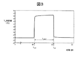
図3には、輻射温度検出器によって測定した温度T3の測定値の時間変化を示す。温度T3としては体表面からの輻射による温度を測定するので、他のセンサよりも温度変化に対して敏感に反応する。輻射熱は電磁波として伝播するものであるから、瞬時に温度変化を伝えることができるものである。 3 shows the chronological variation of the measured values of the temperature T 3 measured by a radiation temperature detector. Since the temperature T 3 for measuring the temperature due to radiation from the body surface, it is more sensitive to temperature changes than other sensors. Since the radiant heat propagates as an electromagnetic wave, it can transmit a temperature change instantaneously.
つづいて、時刻tstartと時刻tendの間のT1測定値をS字曲線、例えばロジスティック曲線で近似する。ロジスティック曲線は温度をT、時刻をtとして、下記の式で表される。 Then, S-curve the T 1 measured value between time t start and time t end The, for example, is approximated by a logistic curve. The logistic curve is represented by the following equation, where T is time and t is time.
非線形最小二乗法により係数a,b,c,dを求めることで測定値を近似することができる。求めた近似式に対して、Tを時刻tstartから時刻tendで積分した値をS1とする。 The measured values can be approximated by obtaining the coefficients a, b, c, and d by the non-linear least square method. For the resultant approximate expression, integrated value at time t end a T from the time t start to S 1.
同様にして、T2測定値から積分値S2を算出する。このとき、(S1−S2)が小さいほど、指表面からT2の位置への熱移動量が大きいことを意味する。また、(S1−S2)は指接触時間tCONT(=tend−tstart)が長いほど大きくなる。そこで、e5を比例係数として、e5/(tCONT×(S1−S2))を血流量を示唆するパラメータX5とする。 Similarly, an integrated value S 2 is calculated from the T 2 measured value. At this time, the smaller the value of (S 1 -S 2 ), the greater the amount of heat transfer from the finger surface to the position of T 2 . Further, (S 1 -S 2 ) increases as the finger contact time t CONT (= t end -t start ) increases. Therefore, the e 5 as a proportional coefficient, e 5 / a (t CONT × (S 1 -S 2)) to indicate the parameter X 5 blood flow.
以上の説明から、前記モデルによって血中グルコース濃度を求めるために必要な測定量は、室温(環境温度)、体表面温度、体表面に接触されるブロックの温度変化、体表面からの輻射による温度及び最低限2波長の吸光度であることが分かる。 From the above description, the measurement quantities necessary for obtaining the blood glucose concentration by the model are room temperature (environmental temperature), body surface temperature, temperature change of a block in contact with the body surface, and temperature due to radiation from the body surface. It can be seen that the absorbance is at least two wavelengths.
図4は、各種センサによる測定値と、それから導出されるパラメータとの関係を図示した説明図である。体表面と接触するブロックを用意し、その2箇所に設置した2個の温度センサよって2種類の温度T1とT2の時間変化を測定する。別途、体表面の輻射温度T3と室温T4を測定する。また、ヘモグロビンの吸収に関係する少なくとも2種類の波長で吸光度A1,A2を測定する。温度T1,T2,T3,T4から血流量に関するパラメータが得られる。温度T3から輻射伝熱量に関するパラメータが得られ、温度T3と温度T4から対流伝熱量に関するパラメータが得られる。また吸光度A1からヘモグロビン濃度に関するパラメータが得られ、吸光度A1とA2からヘモグロビン酸素飽和度に関するパラメータが得られる。 FIG. 4 is an explanatory diagram illustrating a relationship between measured values obtained by various sensors and parameters derived therefrom. A block is brought into contact with the body surface, to measure the time variation of by two temperature sensors provided at two locations in two kinds of temperatures T 1 and T 2. Separately, the radiation temperature T 3 on the body surface and the room temperature T 4 are measured. Further, absorbances A 1 and A 2 are measured at at least two kinds of wavelengths related to hemoglobin absorption. From the temperatures T 1 , T 2 , T 3 , T 4 , parameters relating to blood flow can be obtained. It provides a parameter related amount of heat transferred by radiation from the temperature T 3, provide parameters related to the amount of heat transferred by convection from the temperature T 3 and the temperature T 4. Provides a parameter related to the hemoglobin concentration from the absorbance A 1, parameters are obtained from the absorbance A 1 and A 2 relates to the hemoglobin oxygen saturation.
T1の温度変化を時間的に観察することで、ブロックに体表面が触れたタイミングを検知する。温度変化の変化量を計算し、その変化量がある閾値の間に入っている場合には体表面が触れたと判定する。変化量は体表面からブロックに伝わる熱移動量と比例関係にある。熱は血液によってもたらされるので、血流量が多い人は傾きが大きくなり、血流量が少ない人は変化量が小さくなる。ただし、人間が取りえる血流量には範囲があり、それに伴い変化量にも範囲がある。たとえば運動後には血流量は増え、安静時には血流量は減少する。 By observing the change in temperature of T 1 time, it detects the timing at which the body surface touches the block. The amount of change in temperature change is calculated, and if the amount of change is within a certain threshold, it is determined that the body surface has been touched. The amount of change is proportional to the amount of heat transfer from the body surface to the block. Since heat is provided by the blood, a person with a high blood flow has a larger slope and a person with a low blood flow has a smaller change. However, there is a range in the blood flow that can be taken by humans, and accordingly, the amount of change also has a range. For example, blood flow increases after exercise and decreases at rest.
一方、T3の温度変化を観察することで、ブロックから体表面が離れたタイミングを検知する。T1では体表面が離れてもブロックに熱が残り大きな温度変化が生じないため、体表面がタイミングの検知にはT3を用いる方が精度が向上する。 On the other hand, by observing the change in temperature of T 3, it detects a timing apart the body surface from the block. Since T 1 at the body surface is not large temperature change remaining heat is generated in the block away, the body surface is better to use a T 3 is increased accuracy in the detection of timing.
次に、本発明の原理に従って無侵襲血糖値測定を実現する具体的な装置構成について説明する。 Next, a specific device configuration for realizing non-invasive blood glucose measurement according to the principle of the present invention will be described.
図5は、本発明による無侵襲血糖値測定装置の上面図と側断面図である。この装置では、体表面として指先の腹の皮膚を使うが、他の体表面を使うことも可能である。 FIG. 5 is a top view and a side sectional view of the noninvasive blood glucose level measuring device according to the present invention. In this device, the skin of the belly of the fingertip is used as the body surface, but other body surfaces can be used.
装置上面には、操作部11、測定対象となる指が置かれる測定部12、測定結果の表示、装置の状態や測定値などを表示する表示部13が設けられている。操作部11には、装置の操作を行うための4個の押しボタン11a〜11dが配置されている。このなかの一つたとえば11dが測定開始ボタンである。測定部12にはカバー14が設けられ、カバー14を開けると(図はカバーを開けた状態を示す)、楕円型の周縁を持つ指置き部15がある。指置き部15の中には、輻射温度センサ部の開口端16と接触温度センサ部17と光学センサ部18がある。また、色で装置の状態や測定タイミングなどを知らせるLED19と、音で装置の状態や測定タイミングを知らせるブザーがある。
On the upper surface of the apparatus, there are provided an
装置断面図を用いて装置内部を説明する。測定部12には体表面を置くための体表面接触部51と、室温などを測定する温度センサ部53、光学センサ部18がある。センサはセンサケース54で覆われ、センサとセンサカバーは基盤56aに装着されている。表示部とLEDは基盤56bに固定されている。基盤56cは外ケース57に固定されている。基盤56cには基盤56aや基盤56bのほかに、測定データを計算する演算部や各部を統括制御する制御部を備えた、マイクロプロセッサ55も装着されている。
The inside of the device will be described with reference to the device sectional view. The
装置の電源を投入して測定開始ボタン11dを指などで押すと、測定開始ボタン11dの信号がオンになってマイクロプロセッサ55に入力される。さらに、測定部12に指などの体表面が接触したときの信号がマイクロプロセッサ55に入力されると、マイクロプロセッサ55は測定用の制御ルーチンを開始する。このとき、液晶表示部にカウントダウンが表示される。カウントダウンと同時期に信号用LEDを点灯させてもよい。また、カウントダウンの間には測定用の発光ダイオードが点灯される。カウントダウンが終了すると、液晶表示部に「指を離してください」と表示される。なお、測定開始11dボタンを一定時間、例えば3秒以上長押しすることで装置の電源を投入するようにして、測定開始11dボタンが電源スイッチを兼用するようにしてもよい。
When the power of the apparatus is turned on and the
測定部から指が離れると、装置はそのタイミングの良し悪しを判断して、そのタイミングが適当なとき、液晶表示部に「データ処理中」が表示される。液晶表示部に「指を離してください」と表示される前に指を離すと、液晶表示部に「指はカウントダウン終了前に離さないで下さい」と表示され、5秒以上経過して離した場合は、液晶表示部に「指はカウントダウン終了後速やかに離してください」と表示される。このとき、測定開始11dボタンを押すことでエラーメッセージを解消しても良い。正常に指置き、指離しが実施されると、装置は血糖値を液晶表示部に表示する。
When the finger separates from the measurement unit, the apparatus determines the timing of the timing, and when the timing is appropriate, “data processing” is displayed on the liquid crystal display unit. If you release your finger before the message "Please release your finger" is displayed on the LCD, "Please do not release your finger before the countdown ends" is displayed on the LCD and release it after 5 seconds or more. In this case, the message "Please release your finger immediately after the countdown ends" is displayed on the liquid crystal display. At this time, the error message may be canceled by pressing the
電源を切断する際には、電源スイッチを押すが、測定開始11dボタンで電源スイッチを兼用する場合には、測定開始11dボタンを例えば3秒以上長押しすることで電源が切れるように設計する。また、測定部に指を、例えば0.3から1.0秒の間に2回小刻みに置くことで、電源を切断するように設計しても良い。
When the power is turned off, the power switch is pressed. However, when the
このように、体表面が例えば指であったときに、指一本の動作で測定開始から終了まで装置を動作させることができる。さらに電源の投入、切断までの操作も指一本で実施することもできる。図6に指動作をトリガーにした測定のフローを示す。 In this way, when the body surface is, for example, a finger, the device can be operated from the start to the end of the measurement by the operation of one finger. Further, the operations up to turning on and off the power can be performed with one finger. FIG. 6 shows a measurement flow triggered by a finger movement.
ボタン11a,11b,11cは血糖値測定以外の機能である時間設定や履歴参照などを実施するための設定ボタンである。装置の電源を投入した後に、装置はウォーミングアップを開始する。ウォーミングアップを開始して30秒以上経過すると装置は初期状態になる。このタイミングでボタン11a,11b,11cのいずれかが押されると、装置は測定以外の機能モードに移行する。初期状態から所定の時間が経過すると、装置は測定待ちの状態になる。この測定待ちの待機状態のとき、設定用ボタン11a,11b,11cが押されても装置はこのボタン入力を無視し、測定待ちの状態を継続する。この機能を達成するために装置にはボタン信号処理用フィルターがある。測定開始ボタン11dの入力がONのとき、ボタン信号処理用フィルターは常にボタン11a,11b,11cからの入力信号を無効にする。
The
測定が開始されたときには、ボタン信号処理用フィルターのモードが切り替わり、全てのボタン入力信号を無効にする。したがって、測定中にはどのボタンが押されても装置は測定を中断することは無い。測定開始から10秒以下でかつ指が測定部12に置かれているときは、測定を継続する。すなわち、測定開始から任意の時間(10秒程度以下)、指が測定部12に置かれていることを、T1の温度変化やT3の温度変化等を検出する検出器群からなる指接触認識機構により判定し、測定を継続するための信号として扱うことができる。測定が終了したら、装置は血糖値を計算して、ディスプレイに血糖値を表示する。
When the measurement is started, the mode of the button signal processing filter is switched, and all button input signals are invalidated. Therefore, the device does not interrupt the measurement regardless of which button is pressed during the measurement. If the finger is placed on the
図7に、ボタン入力に伴う装置の動作フローを示す。ここでは、測定開始ボタン11dが電源スイッチを兼ねているものとして説明する。また、他のボタン11a,11b,11cは装置の設定や履歴参照などに利用するボタンであるとする。
FIG. 7 shows an operation flow of the apparatus in response to a button input. Here, a description will be given assuming that the
血糖値測定を行う被検者は、最初にボタン11dを3秒以上長押しする。この操作によって、装置の電源が入る。すると、装置は自動的に30秒間のウォーミングアップを開始し、初期状態になる。このタイミングで、ボタン11a,11b,11cのいずれかを押すと、装置の設定を行うための設定機能モードに移行する。装置設定が終了すると、再び初期状態に戻る。初期状態の後、装置は測定のための待機状態になる。待機状態になると、ボタン信号処理用フィルター機構がONになり、ボタン11d以外のボタン入力を受け付けなくなる。その後、ボタン11dを押し、測定部に指を置くと、装置はそれを検知して測定を開始する。測定が開始されると、ボタン信号処理用フィルター機構の働きにより、全てのボタン11a,11b,11c,11dの入力を無効にする。その後、測定が終わって、演算された血糖値が液晶表示部に表示されると、ボタン信号処理用フィルター機構はOFFになり、ボタン入力を受け付けるようになる。この状態で、被検者がボタン11dを3秒以上長押しすると、装置の電源が切れる。
The subject who measures the blood sugar level first presses and holds the
図8は測定部の詳細例を示す図であり、(a)は上面図、(b)はそのXX断面図、(c)はそのYY断面図である。 8A and 8B are diagrams showing a detailed example of the measurement unit, in which FIG. 8A is a top view, FIG. 8B is an XX sectional view thereof, and FIG. 8C is a YY sectional view thereof.
最初に、本発明の無侵襲血糖値測定装置による温度測定について説明する。被検部(指の腹)が接触する部分には熱伝導率の高い材料、例えば金でできた薄いプレート21が配置され、そのプレート21に熱的に接続されたプレート21より熱伝導率の低い材料、例えばポリ塩化ビニルからなる棒状の熱伝導部材22が装置内部に伸びている。温度センサとしては、プレート21の温度を測定し、被検部に対して隣接的な温度検出器であるサーミスタ23と、プレート21から一定距離だけ離れた熱伝導部材の部分の温度を測定し、被検部に対して間接的な温度検出器であるサーミスタ24とが設けられている。指置き部15に置かれた被検部(指の腹)を見通せる装置内部の位置に赤外線レンズ25が配され、赤外線レンズ25の下方に赤外線透過窓26を介して焦電検出器27が配置されている。また、焦電検出器27に近接して別のサーミスタ28が設置されている。
First, temperature measurement by the non-invasive blood sugar level measuring device of the present invention will be described. A
このように測定部の温度センサ部は4個の温度センサを有し、次の4種類の温度を測定する。
(1)指表面の温度(サーミスタ23):T1
(2)熱伝導部材の温度(サーミスタ24):T2
(3)指の輻射温度(焦電検出器27):T3
(4)室温(サーミスタ28):T4
Thus, the temperature sensor section of the measuring section has four temperature sensors and measures the following four types of temperatures.
(1) Finger surface temperature (thermistor 23): T 1
(2) Temperature of the heat conducting member (thermistor 24): T 2
(3) Radiation temperature of the finger (pyroelectric detector 27): T 3
(4) Room temperature (Thermistor 28): T 4
測定部上部に何らかの物体が近づくと、焦電検出器27はその輻射熱を感知する。またサーミスタ23は測定部に指などの被検部が接触すると、その熱を感知する。したがって、焦電検出器27の出力が上昇して、かつサーミスタ23の温度が上昇変化したときに、被検部が測定部に接触したことがわかる。サーミスタ23の温度が上昇もしくは上昇から平衡状態にあるときは、被検部が測定に接触し続けていることがわかる。図3においてtstartで焦電検出器27の温度が上昇しており、図2において、tstartでは温度が上昇変化していることがわかる。このときtstartにおいて披検部が測定部に接触したことがわかる。また、センサ下部に圧力センサやスイッチなどを取り付けて、指が置かれたことを圧力センサの信号変化やスイッチの投入で判断してもよい。
When any object approaches the upper part of the measurement unit, the
測定部から指が離れると、焦電検出器27の信号が急激に下降し、サーミスタ23の温度も下降を開始する。このようにして指が離れたことを感知する。図2においてtendにいたるまで温度が上昇してやや平衡状態になっていることから、tendで被検部が測定部から離れたことがわかる。なお、センサ下部に圧力センサやスイッチなどを取り付けて、指が離れたことを圧力センサの信号変化やスイッチの切断で判断してもよい。
When the finger separates from the measuring unit, the signal of the
次に、光学センサ部18について説明する。光学センサ部は、酸素供給量を求めるために必要なヘモグロビン濃度とヘモグロビン酸素飽和度とを測定するためのものである。ヘモグロビン濃度とヘモグロビン酸素飽和度を測定するには最低2波長での吸光度測定が必要であり、図8(c)は2個の光源33,34と1個の検出器35によって2波長測定を行うための構成例を示している。
Next, the
光学センサ部18には、2個の光ファイバー31,32の端部が位置する。光ファイバー31は光照射用の光ファイバーであり、光ファイバー32は受光用の光ファイバーである。図8(c)に示すように、光ファイバー31は支線となるファイバー31a,31bにつながり、それらの末端には2つの波長の発光ダイオード33,34が配されている。受光用光ファイバー32の末端には、フォトダイオード35が配されている。発光ダイオード33は波長810nmの光を出射し、発光ダイオード34は波長950nmの光を出射する。波長810nmは、酸素結合型ヘモグロビンと還元型(脱酸素)型ヘモグロビンのモル吸光係数が等しくなる等吸光波長であり、波長950nmは酸素結合型ヘモグロビンと還元型ヘモグロビンのモル吸光係数の差が大きい波長である。
In the
2個の発光ダイオード33,34は指が指置き部に置かれたタイミングをトリガーとして、時分割的に発光し、発光ダイオード33,34から発生された光は光照射用光ファイバー31から被検者の指に照射される。指に照射された光は、指の皮膚で反射し、受光用光ファイバー32に入射してフォトダイオード35によって検出される。指に照射された光が指の皮膚で反射されるとき、一部の光は皮膚を通して組織内部に侵入し、毛細血管を流れる血液中のヘモグロビンによる吸収を受ける。フォトダイオード35による測定データは反射率Rであり、吸光度は近似的にlog(1/R)で計算される。波長810nmと波長950nmの光について各々照射を行い、各々につきRを測定し、かつlog(1/R)を求めることにより、波長810nmの吸光度A1と波長950nmの吸光度A2が測定される。
The two
還元型ヘモグロビン濃度を[Hb]、酸素結合型ヘモグロビン濃度を[HbO2]とすると、吸光度A1および吸光度A2は次式で表される。 The reduced hemoglobin concentration [Hb], when the oxy-hemoglobin concentration and [HbO 2], absorbance A 1 and absorbance A 2 are expressed by the following equation.
AHb(810nm)とAHb(950nm)、AHbO2(810nm)とAHbO2(950nm)はそれぞれ還元型ヘモグロビン、酸素結合型ヘモグロビンのモル吸光係数であり各波長で既知である。aは比例係数である。ヘモグロビン濃度([Hb]+[HbO2])、ヘモグロビン酸素飽和度{[HbO2]/([Hb]+[HbO2])}は上式から次のように求められる。 A Hb (810 nm) and A Hb (950nm), A HbO2 (810nm) and A HbO2 (950 nm), respectively deoxyhemoglobin, be a molar extinction coefficient of oxy-hemoglobin is known at each wavelength. a is a proportionality coefficient. The hemoglobin concentration ([Hb] + [HbO 2 ]) and the hemoglobin oxygen saturation {[HbO 2 ] / ([Hb] + [HbO 2 ])} are obtained from the above equations as follows.
なお、ここでは2波長による吸光度測定によってヘモグロビン濃度とヘモグロビン酸素飽和度を測定する例について説明したが、3波長以上で吸光度を測定することによって、妨害成分の影響を低減し測定精度を高めることも可能である。 Here, an example in which the hemoglobin concentration and hemoglobin oxygen saturation are measured by measuring the absorbance at two wavelengths has been described. However, by measuring the absorbance at three or more wavelengths, it is possible to reduce the influence of interfering components and increase the measurement accuracy. It is possible.
図9は、装置内におけるデータ処理の流れを示す概念図である。本例の装置には、サーミスタ23、サーミスタ24、焦電検出器27、サーミスタ28、フォトダイオード35からなる5個のセンサがある。フォトダイオード35では波長810nmの吸光度と波長950nmの吸光度を測定するため、装置には6種類の測定値が入力されることになる。
FIG. 9 is a conceptual diagram showing a flow of data processing in the device. The device of this example has five sensors including a
5種類のアナログ信号は、それぞれA1〜A5の増幅器を経由して、AD1〜AD5のアナログ・デジタル変換器によってデジタル変換される。デジタル変換された値からパラメータxi(i=1,2,3,4,5)が計算される。xiを具体的に表記すると以下のとおりとなる。(e1〜e5は比例係数) The five types of analog signals are digitally converted by AD1-AD5 analog / digital converters via amplifiers A1-A5, respectively. A parameter x i (i = 1, 2, 3, 4, 5) is calculated from the digitally converted value. The specific notation of xi is as follows. (E 1 to e 5 are proportional coefficients)
つづいて、実際の多数の健常者および糖尿病患者のデータから得られたパラメータxiの平均値と標準偏差から正規化パラメータを算出する。各パラメータxiから正規化パラメータXi(i=1,2,3,4,5)を次の式で計算する。 Then, it calculates the normalized parameters from the actual number of healthy subjects and the mean value and the standard deviation of parameter x i obtained from diabetic patients data. From each parameter x i , a normalization parameter X i (i = 1, 2, 3, 4, 5) is calculated by the following equation.
前述の5つの正規化パラメータをもって、最終的な表示を行うためのグルコース濃度への変換計算が行われる。図10は、装置内部の構成例を示す模式図である。指置き部15に指を置いたときに、使用者の視野に入る位置に液晶表示器13、信号用LED19を配置する。また、押しボタン11a〜11dはそれぞれマイクロプロセッサ55と接続されている。マイクロプロセッサ55はソフトウェアを格納するROMを内蔵している。またマイクロプロセッサ55は、ボタン11a〜11dを押すことによって、外部からの指令を受けることができる。
With the above-described five normalization parameters, conversion calculation into glucose concentration for final display is performed. FIG. 10 is a schematic diagram showing a configuration example inside the device. The
処理計算に必要なプログラムは、装置に組み込まれたマイクロプロセッサ55に内蔵されたROMに記憶されている。また、処理計算に必要なメモリー領域は、同様に装置に組み込まれているRAM42に確保される。センサ部のアナログ信号はアナログ・デジタル変換器AD1〜AD5によってデジタル信号になり、バスライン44を経由して転送され、ROMに格納された関数を利用してマイクロプロセッサで計算処理される。計算処理の結果に応じて、信号用LED19が点灯もしくは点滅する。センサ部の信号が指置きを意味するとき、リアルタイムクロック45からの命令で液晶表示部にカウントダウンが表示され、それと同時にROMに記憶された血糖測定プログラムを開始する。計算処理された結果は、液晶表示部に表示されると同時に、ICカード43に保存することもできる。また、バッテリー41の残量が少なくなった場合には、液晶表示部に警告を表示したり、信号用LEDを点灯もしくは点滅させることもできる。
A program necessary for the processing calculation is stored in a ROM built in a
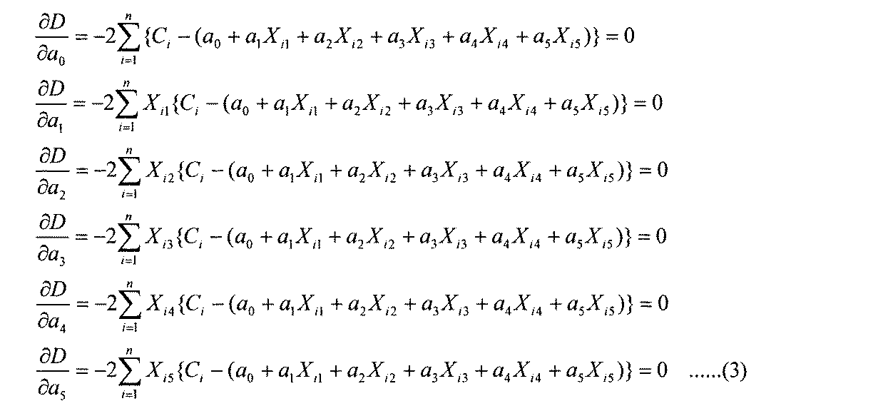
ROMには処理計算に必要なプログラム構成要素として、特にグルコース濃度Cを求めるための関数が入っている。この関数は以下のように定められたものである。まず、Cは以下の式(1)で表現される。ai(i=0,1,2,3,4,5)は、複数の測定データから前もって決定されている。aiを求める手順は以下のとおりである。
(1)正規化パラメータとグルコース濃度Cの関係を示す重回帰式を作成する。
(2)最小二乗法によって得られた式から正規化パラメータに関する正規方程式(連立方程式)を求める。
(3)正規方程式から係数ai(i=0,1,2,3,4,5)の値を求め、重回帰式に代入する。
The ROM contains a function for determining the glucose concentration C as a program component necessary for the processing calculation. This function is defined as follows. First, C is expressed by the following equation (1). a i (i = 0, 1, 2, 3, 4, 5) is determined in advance from a plurality of measurement data. The procedure for obtaining a i is as follows.
(1) Create a multiple regression equation showing the relationship between the normalization parameter and the glucose concentration C.
(2) A normal equation (simultaneous equation) relating to the normalization parameter is obtained from the equation obtained by the least square method.
(3) The value of the coefficient a i (i = 0, 1, 2, 3, 4, 5) is obtained from the normal equation and substituted into the multiple regression equation.
初めに、グルコース濃度Cと正規化パラメータX1,X2,X3,X4,X5の関係を示す次の回帰式(1)を作る。 Initially, the glucose concentration C and the normalized parameters X 1, X 2, X 3 , X 4, the following regression equation showing the relationship between X 5 (1).
つづいて、酵素電極法によるグルコース濃度測定値Ciとの誤差が最小になるような重回帰式を求めるため、最小二乗法を用いる。残差の二乗和をDとすると、Dは次式(2)で表される。 Then, to determine the multiple regression equation, such as the error between the glucose concentration measurement values C i by the enzyme electrode method is minimized, using the least squares method. Assuming that the sum of squares of the residual is D, D is represented by the following equation (2).
残差の二乗和Dが最小になるのは、式(2)をa0,a2,…,a5で偏微分してゼロとなるときなので、次式が得られる。 Since the sum of squares D of the residual is minimized when the equation (2) is partially differentiated by a 0 , a 2 ,..., A 5 and becomes zero, the following equation is obtained.
C,X1〜X5の平均値をそれぞれCmean,X1mean〜X5meanとすると、Ximean=0(i=1〜5)であるので、式(1)から式(4)が得られる。
C, respectively a mean value of
また、正規化パラメータ間の変動・共変動は、式(5)で表され、正規化パラメータXi(i=1〜5)とCとの共変動は式(6)で表される。 The variation / co-variation between the normalization parameters is represented by Expression (5), and the co-variation between the normalization parameter X i (i = 1 to 5) and C is represented by Expression (6).
式(4)(5)(6)を式(3)に代入して整理すると、連立方程式(正規方程式)(7)が得られ、これを解くことでa1〜a5が求まる。 By substituting equations (4), (5), and (6) into equation (3) and rearranging, simultaneous equations (normal equations) (7) are obtained, and by solving these, a 1 to a 5 are obtained.
定数項a0は、式(4)を用いて求める。以上で求めたai(i=0,1,2,3,4,5)は装置製造時にROMに格納されている。装置による実際の測定では、測定値から求めた正規化パラメータX1〜X5を回帰式(1)に代入することで、グルコース濃度Cが算出される。 Constant term a 0 is obtained by using Equation (4). The ai (i = 0, 1, 2, 3, 4, 5) obtained above is stored in the ROM at the time of manufacturing the device. In actual measurement using the apparatus, by substituting normalized parameters X 1 to X 5 obtained from the measured values in regression equation (1), the glucose concentration C is calculated.
以下にグルコース濃度の算出過程の具体例を示す。予め健常者および糖尿病患者に対して測定した多数のデータから回帰式(1)の係数が決められており、マイクロプロセッサのROMには下記のグルコース濃度の算出式が格納されている。 A specific example of the process of calculating the glucose concentration will be described below. The coefficient of the regression equation (1) is determined in advance from a large number of data measured for healthy subjects and diabetic patients, and the following formula for calculating the glucose concentration is stored in the ROM of the microprocessor.
![]()
![]()
X1〜X5はパラメータx1〜x5を正規化したものである。パラメータの分布が正規分布であると仮定すると、正規化パラメータの95%は−2から+2の間の値をとる。 X 1 to X 5 are obtained by normalizing the parameters x 1 to x 5 . Assuming that the distribution of the parameters is normal, 95% of the normalized parameters take values between -2 and +2.
健常者の測定値の一例として、正規化パラメータX1=−0.06、X2=+0.04、X3=+0.05、X4=−0.12、X5=+0.10を上記の式に代入するとC=96mg/dlとなる。また、糖尿病患者の測定値の一例として、正規化パラメータX1=+1.15、X2=−1.02、X3=−0.83、X4=−0.91、X5=−1.24を上記の式に代入するとC=213mg/dlとなる。
As an example of a measurement value of a healthy person, the normalization parameters X 1 = −0.06, X 2 = + 0.04, X 3 = + 0.05, X 4 = −0.12, X 5 = + 0.10 are described above. Substituting into the equation, C = 96 mg / dl. As an example of measured values for a diabetic patient, substituting normalized parameters X 1 = + 1.15, X 2 = -1.02,
従来の測定方法である、採血によって得た血液を試薬と反応させ、この反応によって発生した電子量を測定して血糖値を測定する酵素電極法による測定結果と本発明の一実施例による測定結果について以下に述べる。健常者の測定値の一例として、酵素電極法によるグルコース濃度が89mg/dlのとき、同時刻に本法による測定から得た正規化パラメータX1=−0.06、X2=+0.04、X3=+0.05、X4=−0.12、X5=+0.10を上記の式に代入するとC=96mg/dlとなる。また、糖尿病患者の測定値の例として、酵素電極法によるグルコース濃度が238mg/dlのとき、同時刻に本法による測定から得た正規化パラメータX1=+1.15、X2=−1.02、X3=−0.83、X4=−0.91、X5=−1.24を上記の式に代入するとC=213mg/dlとなる。上記の結果より、本発明による方法によって、高精度でグルコース濃度を求められることが確認された。
A conventional measurement method, the blood obtained by blood collection is reacted with a reagent, the measurement result by the enzyme electrode method of measuring the amount of electrons generated by this reaction to measure the blood glucose level, and the measurement result by one embodiment of the present invention Is described below. As an example of a measurement value of a healthy person, when the glucose concentration by the enzyme electrode method is 89 mg / dl, the normalized parameters X 1 = −0.06, X 2 = + 0.04 obtained from the measurement by the present method at the same time. Substituting X 3 = + 0.05, X 4 = −0.12, and X 5 = + 0.10 into the above equation gives C = 96 mg / dl. Further, as an example of a measured value of a diabetic patient, when the glucose concentration by the enzyme electrode method is 238 mg / dl, the normalized parameters X 1 = + 1.15 and X 2 = −1. 02, X 3 = -0.83, X 4 = -0.91, a C = 213 mg / dl when the
図11は、縦軸を本法によるグルコース濃度の算出値、横軸を酵素電極法によるグルコース濃度の測定値として、複数の患者に対してそれぞれの測定値をプロットした図である。本法の様に酸素供給量・血流量を測定することで良好な相関が得られる(相関係数=0.9324)。 FIG. 11 is a diagram in which the measured values are plotted for a plurality of patients, with the ordinate as the calculated value of the glucose concentration by the present method and the abscissa as the measured value of the glucose concentration by the enzyme electrode method. A good correlation can be obtained by measuring the amount of oxygen supply and blood flow as in this method (correlation coefficient = 0.9324).
以上説明した実施例では、血中ヘモグロビン濃度及び血中ヘモグロビン酸素飽和度に関するパラメータは、血液中のヘモグロビンを分光学的に測定することにより求めた。ところで、ヘモグロビン濃度は、貧血、出血及び赤血球増加症などの症状が無い人であれば安定していること、また、ヘモグロビン濃度は男性で13〜18g/dL、女性で12〜17g/dLが正常値であり、ヘモグロビン濃度の正常値からの変化幅の範囲は5〜6%であること、前述の血糖値算出式で血流量に関する項の重みが他の項より小さいことから、定数として扱っても測定精度を大きく損なうことがない。同様に、ヘモグロビン酸素飽和度についても、大気圧下で空気呼吸を行い、安静にし、リラックスした状態であれば97〜98%で安定していることから、定数として扱うことが可能である。よってヘモグロビン濃度及びヘモグロビン酸素飽和度は定数として扱うことができ、酸素供給量はヘモグロビン濃度定数と、ヘモグロビン酸素飽和度定数と、血流量との積から求めることができる。 In the examples described above, the parameters relating to the blood hemoglobin concentration and the blood hemoglobin oxygen saturation were determined by spectroscopically measuring the hemoglobin in the blood. By the way, hemoglobin concentration is stable if there are no symptoms such as anemia, bleeding and erythrocytosis, and hemoglobin concentration is 13-18 g / dL in men and 12-17 g / dL in women. It is treated as a constant because the range of change from the normal value of the hemoglobin concentration is 5 to 6% and the weight of the term relating to blood flow is smaller than the other terms in the aforementioned blood sugar level calculation formula. The measurement accuracy is not significantly impaired. Similarly, the hemoglobin oxygen saturation can be treated as a constant since it is stable at 97 to 98% when air is breathed under atmospheric pressure, is at rest, and is relaxed. Therefore, the hemoglobin concentration and the hemoglobin oxygen saturation can be treated as constants, and the oxygen supply amount can be obtained from the product of the hemoglobin concentration constant, the hemoglobin oxygen saturation constant, and the blood flow.
ヘモグロビン濃度及びヘモグロビン酸素飽和度を定数として扱うことにより、血糖値測定に用いるセンサ構成について、光学センサ等を外して簡単化することができる。また光学的測定の時間及び光学的測定結果処理の時間を略することにより、血糖値測定一連の迅速化を図ることができる。 By treating the hemoglobin concentration and the hemoglobin oxygen saturation as constants, the sensor configuration used for measuring the blood sugar level can be simplified by removing the optical sensor and the like. By omitting the optical measurement time and the optical measurement result processing time, the series of blood glucose measurement can be speeded up.
なお、ヘモグロビン酸素飽和度については特に安静時に安定した値となることから、ヘモグロビン濃度及びヘモグロビン酸素飽和度を定数として扱えば、特に安静時の血糖値測定において測定精度を高め、かつ血糖値測定一連の迅速化を図ることができる。ここで、安静時とは、椅子に座ったり体を横たえたりすることにより体を殆ど動かさない状態で、5分程度経過した時のことをいう。 Since the hemoglobin oxygen saturation is a stable value particularly at rest, treating the hemoglobin concentration and hemoglobin oxygen saturation as constants increases the measurement accuracy, especially in blood glucose measurement at rest, and increases the blood glucose measurement series. Can be accelerated. Here, at rest refers to a time when about 5 minutes have passed without moving the body by sitting on a chair or lying down.
以下、血中ヘモグロビン濃度及び血中ヘモグロビン酸素飽和度を定数として扱う実施例について説明する。本実施例は、血中ヘモグロビン濃度及び血中ヘモグロビン酸素飽和度を定数として扱う点以外は、上記実施例と同様であるため、ここでは主として前述の実施例と異なる点について説明する。 Hereinafter, an example will be described in which the blood hemoglobin concentration and the blood hemoglobin oxygen saturation are treated as constants. This embodiment is the same as the above embodiment except that the blood hemoglobin concentration and the blood hemoglobin oxygen saturation are treated as constants. Therefore, the differences from the above embodiment will be mainly described here.
本実施例は、図4の説明図におけるヘモグロビン濃度とヘモグロビン酸素飽和度を測定することなく、定数として扱うものである。従って、本実施例の測定部は、図12に示すように、図8に示した前述の実施例の測定部から光源33,34、フォトダイオード35及び光ファイバー31,32を除去した構造とする。本実施例で使用するパラメータは熱輻射に比例したパラメータx1、熱対流に比例したパラメータx2、及び酸素供給量に比例したパラメータx3(以下、酸素供給量に比例したパラメータをx3と表記する)であり、これらのパラメータから前述のようにして正規化パラメータを算出し、その3個の正規化パラメータXi(i=1,2,3)をもとにグルコース濃度を演算する。データ処理においては、前述の実施例では必要であった「光学計測データから正規化パラメータへの変換処理」(図9参照)を省略できる。
In this embodiment, the hemoglobin concentration and the hemoglobin oxygen saturation in the explanatory diagram of FIG. 4 are not measured but are treated as constants. Therefore, as shown in FIG. 12, the measuring section of this embodiment has a structure in which the
図13は、本実施例による装置の機能ブロック図を示す図である。この装置はバッテリー41で駆動される。温度センサで構成されるセンサ部48で測定した信号は各々の信号に対応して設置されるアナログ・デジタル変換器44(アナログ・デジタル変換器AD1〜AD4)へ入りデジタル信号へ変換される。マイクロプロセッサ55の周辺回路としては、アナログ・デジタル変換器AD1〜AD4、液晶表示器13、RAM42があり、これらは各バスライン46を介してマイクロプロセッサ55からアクセスされる。また、押しボタン11a〜11dはそれぞれマイクロプロセッサ55と接続されている。マイクロプロセッサ55はソフトウェアを格納するROMを内蔵している。またマイクロプロセッサ55は、ボタン11a〜11dを押すことによって、外部からの指令を受けることができる。
FIG. 13 is a functional block diagram of the device according to the present embodiment. This device is driven by a
マイクロプロセッサ55に内蔵されたROM47は、処理計算に必要なプログラムを記憶する。すなわち、演算部の機能を有する。マイクロプロセッサ55はさらに、ヘモグロビン濃度の定数を格納するヘモグロビン濃度定数格納部50と、ヘモグロビン酸素飽和度の定数を格納するヘモグロビン酸素飽和度定数格納部49を内蔵している。計算プログラムは指の測定終了後、ヘモグロビン定数格納部50およびヘモグロビン酸素飽和度定数格納部49から最適定数を呼び出して計算する。また、処理計算に必要なメモリー領域は、同様に装置に組み込まれているRAM42に確保される。計算処理された結果は、液晶表示部に表示される。
The
ROMには処理計算に必要なプログラム構成要素として、特にグルコース濃度Cを求めるための関数が入っている。この関数は以下のように定められたものである。まず、Cは以下の式(8)で表現される。ai(i=0,1,2,3)は、複数の測定データから前もって決定されている。aiを求める手順は以下のとおり。
(1)正規化パラメータとグルコース濃度Cの関係を示す重回帰式を作成する。
(2)最小二乗法によって得られた式から正規化パラメータに関する正規方程式(連立方程式)を求める。
(3)正規方程式から係数ai(i=0,1,2,3)の値を求め、重回帰式に代入する。
The ROM contains a function for determining the glucose concentration C as a program component necessary for the processing calculation. This function is defined as follows. First, C is expressed by the following equation (8). a i (i = 0, 1, 2, 3) is determined in advance from a plurality of measurement data. The procedure for obtaining a i is as follows.
(1) Create a multiple regression equation showing the relationship between the normalization parameter and the glucose concentration C.
(2) A normal equation (simultaneous equation) relating to the normalization parameter is obtained from the equation obtained by the least square method.
(3) The value of the coefficient a i (i = 0,1,2,3) is obtained from the normal equation and substituted into the multiple regression equation.
初めに、グルコース濃度Cと正規化パラメータX1,X2,X3の関係を示す次の回帰式(8)を作る。 First, the following regression equation (8) showing the relationship between the glucose concentration C and the normalization parameters X 1 , X 2 , X 3 is created.
つづいて、酵素電極法によるグルコース濃度測定値Ciとの誤差が最小になるような重回帰式を求めるため、最小二乗法を用いる。残差の二乗和をDとすると、Dは次式(9)で表される。 Then, to determine the multiple regression equation, such as the error between the glucose concentration measurement values C i by the enzyme electrode method is minimized, using the least squares method. Assuming that the sum of squares of the residual is D, D is represented by the following equation (9).
残差の二乗和Dが最小になるのは、式(9)をa0〜a3で偏微分してゼロとなるときなので、次式が得られる。 The square sum D of the residual is minimized, so when a zero partial differentiation equation (9) in a 0 ~a 3, the following equation is obtained.
C、X1〜X3の平均値をそれぞれCmean、X1mean〜X3meanとするとXimean=0(i=1〜3)であるので、式(8)から式(11)が得られる。
C,
また、正規化パラメータ間の変動・共変動は、式(12)で表され、正規化パラメータXi(i=1〜3)とCとの共変動は式(13)で表される。 The variation / covariation between the normalization parameters is represented by Expression (12), and the covariation between the normalization parameter X i (i = 1 to 3) and C is represented by Expression (13).
式(11)(12)(13)を式(10)に代入して整理すると、連立方程式(正規方程式)(14)が得られ、これを解くことでa1〜a3が求まる。 By substituting equations (11), (12), and (13) into equation (10) and rearranging, simultaneous equations (normal equations) (14) are obtained, and by solving them, a 1 to a 3 are obtained.
定数項a0は、式(11)を用いて求める。以上で求めた ai(i=0,1,2,3)は装置製造時にROMに格納されている。装置による実際の測定では、測定値から求めた正規化パラメータX1〜X3を回帰式(8)に代入することで、グルコース濃度Cが算出される。 Constant term a 0 is obtained by using equation (11). The ai (i = 0, 1, 2, 3) obtained as described above is stored in the ROM at the time of manufacturing the device. In actual measurement using the apparatus, the normalized parameters X 1 to X 3 obtained from the measured values by substituting the regression equation (8), the glucose concentration C is calculated.
以下にグルコース濃度の算出過程の具体例を示す。予め健常者および糖尿病患者に対して測定した多数のデータから回帰式(8)の係数が決められており、マイクロプロセッサのROMには下記のグルコース濃度の算出式が格納されている。 A specific example of the process of calculating the glucose concentration will be described below. The coefficient of the regression equation (8) is previously determined from a large number of data measured for healthy subjects and diabetic patients, and the following formula for calculating the glucose concentration is stored in the ROM of the microprocessor.
![]()
![]()
X1〜X3はパラメータx1〜x3を正規化したものである。パラメータの分布が正規分布であると仮定すると、正規化パラメータの95%は−2から+2の間の値をとる。 X 1 to X 3 are obtained by normalizing the parameters x 1 to x 3 . Assuming that the distribution of the parameters is normal, 95% of the normalized parameters take values between -2 and +2.
健常者の測定値の1例として、正規化パラメータX1=-0.06、X2=+0.04、X3=+0.10 を上記の式に代入するとC=101mg/dlとなる。また、糖尿病患者の測定値の1例として、正規化パラメータX1=+1.35、X2=-1.22、X3=-1.24 を上記の式に代入するとC=181mg/dlとなる。なお、上記の式ではヘモグロビン濃度を15g/dL、ヘモグロビン酸素飽和度を97%として定数化した。 As an example of a measurement value of a healthy person, when the normalization parameters X 1 = −0.06, X 2 = + 0.04, and X 3 = + 0.10 are substituted into the above expression, C = 101 mg / dl. Further, as an example of the measured value of a diabetic patient, when the normalization parameters X 1 = + 1.35, X 2 = −1.22, and X 3 = −1.24 are substituted into the above equation, C = 181 mg / dl. In the above equation, the hemoglobin concentration was set to 15 g / dL, and the hemoglobin oxygen saturation was set to 97%, and the constants were used.
従来の測定方法である、採血によって得た血液を試薬と反応させ、この反応によって発生した電子量を測定して血糖値を測定する酵素電極法による測定結果と本発明の1実施例による測定結果について以下に述べる。健常者の測定値の1例として、酵素電極法によるグルコース濃度が93mg/dlのとき、同時刻に本法による測定から得た正規化パラメータX1=-0.06、X2=+0.04、X3=+0.10 を上記の式に代入するとC=101mg/dlとなる。また、糖尿病患者の測定値の例として、酵素電極法によるグルコース濃度が208mg/dlのとき、同時刻に本法による測定から得た正規化パラメータX1=+1.35、X2=-1.22、X3=-1.24 を上記の式に代入するとC=181mg/dlとなる。この計算結果は約13%の誤差を示しているが、一般に血糖測定のための装置は通常15〜20%の誤差は許容されるものとして扱われているため、このレベルの精度であれば十分な精度と考えられる。上記の結果より、本発明による方法によって、高精度でグルコース濃度を求められることが確認された。 A conventional measurement method, in which blood obtained by blood collection is reacted with a reagent, and the amount of electrons generated by this reaction is measured to measure the blood glucose level. The measurement result by the enzyme electrode method and the measurement result by one embodiment of the present invention. Is described below. As an example of a measurement value of a healthy person, when the glucose concentration by the enzyme electrode method is 93 mg / dl, the normalized parameters X 1 = −0.06, X 2 = + 0.04, X 3 obtained from the measurement at the same time at the same time. Substituting = + 0.10 into the above equation gives C = 101 mg / dl. Further, as an example of the measurement value of a diabetic patient, when the glucose concentration by the enzyme electrode method is 208 mg / dl, the normalized parameters X 1 = + 1.35, X 2 = −1.22, X 2 obtained from the measurement by the present method at the same time. Substituting 3 = -1.24 into the above equation gives C = 181 mg / dl. This calculation result shows an error of about 13%. However, in general, an apparatus for measuring blood glucose is usually regarded as having an error of 15 to 20%. Accuracy. From the above results, it was confirmed that the glucose concentration can be determined with high accuracy by the method according to the present invention.
図14は、縦軸を本法によるグルコース濃度の算出値、横軸を酵素電極法によるグルコース濃度の測定値として、複数の患者に対してそれぞれの測定値をプロットした図である。本法の様に測定することで良好な相関が得られる(相関係数=0.8932)。 FIG. 14 is a diagram in which measured values are plotted for a plurality of patients, with the vertical axis representing the calculated value of glucose concentration by the present method and the horizontal axis representing the measured value of glucose concentration by the enzyme electrode method. A good correlation can be obtained by measuring as in the present method (correlation coefficient = 0.8932).
11…操作部、12…測定部、13…表示部、15…指置き部、16…輻射温度センサ部の開口端、17…接触温度センサ部、18…光学センサ部、19…信号用LED、21…プレート、22…熱伝導部材、23…サーミスタ、24…サーミスタ、25…赤外線レンズ、26…赤外線透過窓、27…焦電検出器、28…サーミスタ、31,32…光ファイバー、33,34…光源、35…フォトダイオード Reference numeral 11: operation unit, 12: measurement unit, 13: display unit, 15: finger placement unit, 16: open end of the radiation temperature sensor unit, 17: contact temperature sensor unit, 18: optical sensor unit, 19: LED for signal, Reference numeral 21: plate, 22: heat conducting member, 23: thermistor, 24: thermistor, 25: infrared lens, 26: infrared transmission window, 27: pyroelectric detector, 28: thermistor, 31, 32: optical fiber, 33, 34 ... Light source, 35 ... photodiode
Claims (12)
血中酸素量に関する情報を得る酸素量測定部と、
前記複数の温度及び前記血中酸素量に各々対応するパラメータと血糖値との関係を記憶した記憶部と、
前記熱量測定部及び前記酸素量測定部から入力される複数の測定値を前記パラメータへ各々変換し、前記パラメータを前記記憶部に記憶した前記関係に適用して血糖値を演算する演算部と、
前記演算部によって算出された血糖値を表示する表示部と、
測定の開始を指示する測定開始ボタンと測定開始の指示以外の制御を行う制御ボタンとからなる複数の操作ボタンと、
前記操作ボタンからの入力信号を処理するボタン信号処理用フィルター機構とを備え、
前記酸素量測定部は、血流量に関する情報を得る血流量測定部と、血中のヘモグロビン濃度、ヘモグロビン酸素飽和度を得る光学測定部とを有し、
前記血流量測定部は、体表面接触部と、前記体表面接触部に隣接して設けられた隣接温度検出器と、前記体表面接触部から離れた位置の温度を検出する間接温度検出器と、前記体表面接触部と前記間接温度検出器とをつなげる熱伝導部材を有することを特徴とする血糖値測定装置。 A calorie measurement unit that measures a plurality of temperatures derived from the body surface and obtains information used for calculating a convection heat transfer amount and a radiant heat transfer amount related to heat dissipation from the body surface,
An oxygen amount measurement unit that obtains information about the blood oxygen amount,
A storage unit that stores a relationship between the plurality of temperatures and the parameters respectively corresponding to the blood oxygen amount and the blood glucose level,
A computing unit that converts a plurality of measurement values input from the calorie measuring unit and the oxygen amount measuring unit into the parameters, and calculates a blood glucose level by applying the parameters to the relationship stored in the storage unit.
A display unit that displays the blood sugar level calculated by the calculation unit,
A plurality of operation buttons including a measurement start button for instructing the start of measurement and a control button for performing control other than the measurement start instruction,
A button signal processing filter mechanism for processing an input signal from the operation button,
The oxygen content measurement unit has a blood flow measurement unit that obtains information about the blood flow, a hemoglobin concentration in blood, and an optical measurement unit that obtains hemoglobin oxygen saturation.
The blood flow measurement unit, a body surface contact portion, an adjacent temperature detector provided adjacent to the body surface contact portion, and an indirect temperature detector that detects a temperature at a position away from the body surface contact portion And a heat conducting member for connecting the body surface contact portion and the indirect temperature detector.
体表面が接触する体表面接触部と、
前記体表面からの輻射熱を測定する輻射熱検出器と、
前記体表面接触部に接して設けられる熱伝導部材と、
前記体表面接触部に隣接して設けられた隣接温度検出器と、
前記熱伝導部材に隣接しかつ前記体表面接触部から離れた位置に設けられ、前記体表面接触部から離れた位置の温度を検出する間接温度検出器と、
前記体表面接触部に向けて少なくとも2つの異なる波長の光を照射する光源と、
前記光が前記体表面で反射されて生じる反射光を検出する光検出器と、
前記隣接温度検出器、前記間接温度検出器、前記環境温度測定器、前記輻射熱検出器及び前記光検出器各々の出力を各々パラメータに変換する変換部と、前記パラメータと血糖値との関係を予め記憶し、前記パラメータを前記関係に適用して血糖値を算出する処理部とを有する演算部と、
前記演算部から出力される血糖値を表示する表示部と、
測定の開始を指示する測定開始ボタンと測定開始の指示以外の制御を行う制御ボタンとからなる複数の操作ボタンと、
前記操作ボタンからの入力信号を処理するボタン信号処理用フィルター機構とを備えることを特徴とする血糖値測定装置。 An environmental temperature measuring device for measuring the environmental temperature;
A body surface contact portion with which the body surface contacts,
A radiant heat detector that measures radiant heat from the body surface,
A heat conductive member provided in contact with the body surface contact portion,
An adjacent temperature detector provided adjacent to the body surface contact portion,
An indirect temperature detector is provided adjacent to the heat conducting member and at a position away from the body surface contact portion, and detects a temperature at a position away from the body surface contact portion,
A light source for irradiating at least two different wavelengths of light toward the body surface contact portion;
A light detector that detects reflected light generated by the light being reflected by the body surface,
A conversion unit that converts the output of each of the adjacent temperature detector, the indirect temperature detector, the environmental temperature measurement device, the radiant heat detector, and the photodetector into a parameter, and preliminarily determines the relationship between the parameter and the blood glucose level. An arithmetic unit that stores and stores a processing unit that calculates a blood glucose level by applying the parameter to the relationship,
A display unit that displays a blood glucose level output from the calculation unit,
A plurality of operation buttons including a measurement start button for instructing the start of measurement and a control button for performing control other than the measurement start instruction,
And a button signal processing filter mechanism for processing an input signal from the operation button.
体表面が接触する体表面接触部と、
前記体表面からの輻射熱を測定する輻射熱検出器と、
前記体表面接触部に接して設けられる熱伝導部材と、
前記体表面接触部に隣接して設けられた隣接温度検出器と、
前記熱伝導部材に隣接しかつ前記体表面接触部から離れた位置に設けられ、前記体表面接触部から離れた位置の温度を検出する間接温度検出器と、
血中のヘモグロビン濃度とヘモグロビン酸素飽和度に関する情報を記憶した記憶部と、
前記隣接温度検出器、前記間接温度検出器、前記環境温度測定器、前記輻射熱検出器の出力を複数のパラメータに変換する変換部と、前記パラメータと血糖値との関係を予め記憶し、前記パラメータを前記関係に適用して血糖値を算出する処理部とを有する演算部と、
前記演算部から出力される血糖値を表示する表示部と、
測定の開始を指示する測定開始ボタンと測定開始の指示以外の制御を行う制御ボタンとからなる複数の操作ボタンと、
前記操作ボタンからの入力信号を処理するボタン信号処理用フィルター機構とを備えることを特徴とする血糖値測定装置。 An environmental temperature measuring device for measuring the environmental temperature;
A body surface contact portion with which the body surface contacts,
A radiant heat detector that measures radiant heat from the body surface,
A heat conductive member provided in contact with the body surface contact portion,
An adjacent temperature detector provided adjacent to the body surface contact portion,
An indirect temperature detector is provided adjacent to the heat conducting member and at a position away from the body surface contact portion, and detects a temperature at a position away from the body surface contact portion,
A storage unit that stores information on hemoglobin concentration and hemoglobin oxygen saturation in blood,
The adjacent temperature detector, the indirect temperature detector, the environmental temperature measuring device, a conversion unit that converts the output of the radiant heat detector into a plurality of parameters, and stores in advance the relationship between the parameters and the blood glucose level, the parameter An arithmetic unit having a processing unit that calculates a blood sugar level by applying the relationship to the relationship,
A display unit that displays a blood glucose level output from the calculation unit,
A plurality of operation buttons including a measurement start button for instructing the start of measurement and a control button for performing control other than the measurement start instruction,
And a button signal processing filter mechanism for processing an input signal from the operation button.
Priority Applications (4)
| Application Number | Priority Date | Filing Date | Title |
|---|---|---|---|
| JP2004048546A JP3590053B1 (en) | 2004-02-24 | 2004-02-24 | Blood glucose measurement device |
| EP04007593A EP1568309A1 (en) | 2004-02-24 | 2004-03-29 | Blood sugar level measuring apparatus |
| US10/811,894 US20050187442A1 (en) | 2004-02-24 | 2004-03-30 | Blood sugar level measuring apparatus |
| CNB2004100316547A CN1323640C (en) | 2004-02-24 | 2004-03-31 | Blood sugar level measuring apparatus |
Applications Claiming Priority (1)
| Application Number | Priority Date | Filing Date | Title |
|---|---|---|---|
| JP2004048546A JP3590053B1 (en) | 2004-02-24 | 2004-02-24 | Blood glucose measurement device |
Publications (2)
| Publication Number | Publication Date |
|---|---|
| JP3590053B1 true JP3590053B1 (en) | 2004-11-17 |
| JP2005237484A JP2005237484A (en) | 2005-09-08 |
Family
ID=33509226
Family Applications (1)
| Application Number | Title | Priority Date | Filing Date |
|---|---|---|---|
| JP2004048546A Expired - Fee Related JP3590053B1 (en) | 2004-02-24 | 2004-02-24 | Blood glucose measurement device |
Country Status (4)
| Country | Link |
|---|---|
| US (1) | US20050187442A1 (en) |
| EP (1) | EP1568309A1 (en) |
| JP (1) | JP3590053B1 (en) |
| CN (1) | CN1323640C (en) |
Families Citing this family (133)
| Publication number | Priority date | Publication date | Assignee | Title |
|---|---|---|---|---|
| US8641644B2 (en) | 2000-11-21 | 2014-02-04 | Sanofi-Aventis Deutschland Gmbh | Blood testing apparatus having a rotatable cartridge with multiple lancing elements and testing means |
| US9427532B2 (en) | 2001-06-12 | 2016-08-30 | Sanofi-Aventis Deutschland Gmbh | Tissue penetration device |
| US7041068B2 (en) | 2001-06-12 | 2006-05-09 | Pelikan Technologies, Inc. | Sampling module device and method |
| US9226699B2 (en) | 2002-04-19 | 2016-01-05 | Sanofi-Aventis Deutschland Gmbh | Body fluid sampling module with a continuous compression tissue interface surface |
| US9795747B2 (en) * | 2010-06-02 | 2017-10-24 | Sanofi-Aventis Deutschland Gmbh | Methods and apparatus for lancet actuation |
| US6966880B2 (en) * | 2001-10-16 | 2005-11-22 | Agilent Technologies, Inc. | Universal diagnostic platform |
| US9314194B2 (en) | 2002-04-19 | 2016-04-19 | Sanofi-Aventis Deutschland Gmbh | Tissue penetration device |
| US8784335B2 (en) | 2002-04-19 | 2014-07-22 | Sanofi-Aventis Deutschland Gmbh | Body fluid sampling device with a capacitive sensor |
| US9795334B2 (en) | 2002-04-19 | 2017-10-24 | Sanofi-Aventis Deutschland Gmbh | Method and apparatus for penetrating tissue |
| US9248267B2 (en) | 2002-04-19 | 2016-02-02 | Sanofi-Aventis Deustchland Gmbh | Tissue penetration device |
| US7713214B2 (en) | 2002-04-19 | 2010-05-11 | Pelikan Technologies, Inc. | Method and apparatus for a multi-use body fluid sampling device with optical analyte sensing |
| US8702624B2 (en) | 2006-09-29 | 2014-04-22 | Sanofi-Aventis Deutschland Gmbh | Analyte measurement device with a single shot actuator |
| US8579831B2 (en) | 2002-04-19 | 2013-11-12 | Sanofi-Aventis Deutschland Gmbh | Method and apparatus for penetrating tissue |
| US20120296233A9 (en) * | 2002-09-05 | 2012-11-22 | Freeman Dominique M | Methods and apparatus for an analyte detecting device |
| US8574895B2 (en) | 2002-12-30 | 2013-11-05 | Sanofi-Aventis Deutschland Gmbh | Method and apparatus using optical techniques to measure analyte levels |
| US8066639B2 (en) | 2003-06-10 | 2011-11-29 | Abbott Diabetes Care Inc. | Glucose measuring device for use in personal area network |
| WO2006001797A1 (en) | 2004-06-14 | 2006-01-05 | Pelikan Technologies, Inc. | Low pain penetrating |
| US8282576B2 (en) | 2003-09-29 | 2012-10-09 | Sanofi-Aventis Deutschland Gmbh | Method and apparatus for an improved sample capture device |
| US9351680B2 (en) | 2003-10-14 | 2016-05-31 | Sanofi-Aventis Deutschland Gmbh | Method and apparatus for a variable user interface |
| US7299082B2 (en) | 2003-10-31 | 2007-11-20 | Abbott Diabetes Care, Inc. | Method of calibrating an analyte-measurement device, and associated methods, devices and systems |
| WO2005065414A2 (en) | 2003-12-31 | 2005-07-21 | Pelikan Technologies, Inc. | Method and apparatus for improving fluidic flow and sample capture |
| CA2556331A1 (en) | 2004-02-17 | 2005-09-29 | Therasense, Inc. | Method and system for providing data communication in continuous glucose monitoring and management system |
| US9775553B2 (en) | 2004-06-03 | 2017-10-03 | Sanofi-Aventis Deutschland Gmbh | Method and apparatus for a fluid sampling device |
| EP1765194A4 (en) | 2004-06-03 | 2010-09-29 | Pelikan Technologies Inc | METHOD AND APPARATUS FOR MANUFACTURING A DEVICE FOR SAMPLING LIQUIDS |
| JP2006115947A (en) * | 2004-10-19 | 2006-05-11 | Hitachi Ltd | Blood glucose level measuring device |
| US9636450B2 (en) | 2007-02-19 | 2017-05-02 | Udo Hoss | Pump system modular components for delivering medication and analyte sensing at seperate insertion sites |
| US7697967B2 (en) | 2005-12-28 | 2010-04-13 | Abbott Diabetes Care Inc. | Method and apparatus for providing analyte sensor insertion |
| US9788771B2 (en) | 2006-10-23 | 2017-10-17 | Abbott Diabetes Care Inc. | Variable speed sensor insertion devices and methods of use |
| US8880138B2 (en) | 2005-09-30 | 2014-11-04 | Abbott Diabetes Care Inc. | Device for channeling fluid and methods of use |
| JP2007105329A (en) * | 2005-10-14 | 2007-04-26 | Hitachi Ltd | Blood glucose level measuring device and metabolic rate measuring device |
| JP4754931B2 (en) * | 2005-10-14 | 2011-08-24 | 株式会社日立製作所 | Metabolism measuring device |
| US7766829B2 (en) | 2005-11-04 | 2010-08-03 | Abbott Diabetes Care Inc. | Method and system for providing basal profile modification in analyte monitoring and management systems |
| US11298058B2 (en) | 2005-12-28 | 2022-04-12 | Abbott Diabetes Care Inc. | Method and apparatus for providing analyte sensor insertion |
| US7736310B2 (en) | 2006-01-30 | 2010-06-15 | Abbott Diabetes Care Inc. | On-body medical device securement |
| US7826879B2 (en) | 2006-02-28 | 2010-11-02 | Abbott Diabetes Care Inc. | Analyte sensors and methods of use |
| US7885698B2 (en) | 2006-02-28 | 2011-02-08 | Abbott Diabetes Care Inc. | Method and system for providing continuous calibration of implantable analyte sensors |
| US7981034B2 (en) | 2006-02-28 | 2011-07-19 | Abbott Diabetes Care Inc. | Smart messages and alerts for an infusion delivery and management system |
| JP4549995B2 (en) * | 2006-03-27 | 2010-09-22 | 日本電信電話株式会社 | Component concentration measuring device |
| US8374668B1 (en) | 2007-10-23 | 2013-02-12 | Abbott Diabetes Care Inc. | Analyte sensor with lag compensation |
| US8226891B2 (en) | 2006-03-31 | 2012-07-24 | Abbott Diabetes Care Inc. | Analyte monitoring devices and methods therefor |
| US8346335B2 (en) | 2008-03-28 | 2013-01-01 | Abbott Diabetes Care Inc. | Analyte sensor calibration management |
| US9392969B2 (en) | 2008-08-31 | 2016-07-19 | Abbott Diabetes Care Inc. | Closed loop control and signal attenuation detection |
| US8140312B2 (en) | 2007-05-14 | 2012-03-20 | Abbott Diabetes Care Inc. | Method and system for determining analyte levels |
| US8473022B2 (en) | 2008-01-31 | 2013-06-25 | Abbott Diabetes Care Inc. | Analyte sensor with time lag compensation |
| US7653425B2 (en) | 2006-08-09 | 2010-01-26 | Abbott Diabetes Care Inc. | Method and system for providing calibration of an analyte sensor in an analyte monitoring system |
| US7618369B2 (en) | 2006-10-02 | 2009-11-17 | Abbott Diabetes Care Inc. | Method and system for dynamically updating calibration parameters for an analyte sensor |
| US8478557B2 (en) | 2009-07-31 | 2013-07-02 | Abbott Diabetes Care Inc. | Method and apparatus for providing analyte monitoring system calibration accuracy |
| US9339217B2 (en) | 2011-11-25 | 2016-05-17 | Abbott Diabetes Care Inc. | Analyte monitoring system and methods of use |
| US7620438B2 (en) | 2006-03-31 | 2009-11-17 | Abbott Diabetes Care Inc. | Method and system for powering an electronic device |
| US8932216B2 (en) | 2006-08-07 | 2015-01-13 | Abbott Diabetes Care Inc. | Method and system for providing data management in integrated analyte monitoring and infusion system |
| US8206296B2 (en) | 2006-08-07 | 2012-06-26 | Abbott Diabetes Care Inc. | Method and system for providing integrated analyte monitoring and infusion system therapy management |
| US8732188B2 (en) | 2007-02-18 | 2014-05-20 | Abbott Diabetes Care Inc. | Method and system for providing contextual based medication dosage determination |
| US8930203B2 (en) | 2007-02-18 | 2015-01-06 | Abbott Diabetes Care Inc. | Multi-function analyte test device and methods therefor |
| US8123686B2 (en) | 2007-03-01 | 2012-02-28 | Abbott Diabetes Care Inc. | Method and apparatus for providing rolling data in communication systems |
| US9204827B2 (en) | 2007-04-14 | 2015-12-08 | Abbott Diabetes Care Inc. | Method and apparatus for providing data processing and control in medical communication system |
| CA2683962C (en) | 2007-04-14 | 2017-06-06 | Abbott Diabetes Care Inc. | Method and apparatus for providing data processing and control in medical communication system |
| EP2146624B1 (en) | 2007-04-14 | 2020-03-25 | Abbott Diabetes Care Inc. | Method and apparatus for providing data processing and control in medical communication system |
| CA2683863C (en) | 2007-04-14 | 2019-01-15 | Abbott Diabetes Care Inc. | Method and apparatus for providing data processing and control in medical communication system |
| US8456301B2 (en) | 2007-05-08 | 2013-06-04 | Abbott Diabetes Care Inc. | Analyte monitoring system and methods |
| US8461985B2 (en) | 2007-05-08 | 2013-06-11 | Abbott Diabetes Care Inc. | Analyte monitoring system and methods |
| US8665091B2 (en) | 2007-05-08 | 2014-03-04 | Abbott Diabetes Care Inc. | Method and device for determining elapsed sensor life |
| US7928850B2 (en) | 2007-05-08 | 2011-04-19 | Abbott Diabetes Care Inc. | Analyte monitoring system and methods |
| US8600681B2 (en) | 2007-05-14 | 2013-12-03 | Abbott Diabetes Care Inc. | Method and apparatus for providing data processing and control in a medical communication system |
| US8260558B2 (en) | 2007-05-14 | 2012-09-04 | Abbott Diabetes Care Inc. | Method and apparatus for providing data processing and control in a medical communication system |
| US8560038B2 (en) | 2007-05-14 | 2013-10-15 | Abbott Diabetes Care Inc. | Method and apparatus for providing data processing and control in a medical communication system |
| US8239166B2 (en) | 2007-05-14 | 2012-08-07 | Abbott Diabetes Care Inc. | Method and apparatus for providing data processing and control in a medical communication system |
| US8103471B2 (en) | 2007-05-14 | 2012-01-24 | Abbott Diabetes Care Inc. | Method and apparatus for providing data processing and control in a medical communication system |
| US8444560B2 (en) | 2007-05-14 | 2013-05-21 | Abbott Diabetes Care Inc. | Method and apparatus for providing data processing and control in a medical communication system |
| US9125548B2 (en) | 2007-05-14 | 2015-09-08 | Abbott Diabetes Care Inc. | Method and apparatus for providing data processing and control in a medical communication system |
| US10002233B2 (en) | 2007-05-14 | 2018-06-19 | Abbott Diabetes Care Inc. | Method and apparatus for providing data processing and control in a medical communication system |
| AU2008265542B2 (en) | 2007-06-21 | 2014-07-24 | Abbott Diabetes Care Inc. | Health monitor |
| US8597188B2 (en) | 2007-06-21 | 2013-12-03 | Abbott Diabetes Care Inc. | Health management devices and methods |
| US8160900B2 (en) | 2007-06-29 | 2012-04-17 | Abbott Diabetes Care Inc. | Analyte monitoring and management device and method to analyze the frequency of user interaction with the device |
| US8834366B2 (en) | 2007-07-31 | 2014-09-16 | Abbott Diabetes Care Inc. | Method and apparatus for providing analyte sensor calibration |
| EP2198268B1 (en) * | 2007-10-04 | 2022-03-16 | St. Louis Medical Devices, Inc. | Optical apparatus for determining a blood characteristic |
| US8409093B2 (en) | 2007-10-23 | 2013-04-02 | Abbott Diabetes Care Inc. | Assessing measures of glycemic variability |
| US8377031B2 (en) | 2007-10-23 | 2013-02-19 | Abbott Diabetes Care Inc. | Closed loop control system with safety parameters and methods |
| US20090164239A1 (en) | 2007-12-19 | 2009-06-25 | Abbott Diabetes Care, Inc. | Dynamic Display Of Glucose Information |
| US20090209883A1 (en) * | 2008-01-17 | 2009-08-20 | Michael Higgins | Tissue penetrating apparatus |
| IL197532A0 (en) | 2008-03-21 | 2009-12-24 | Lifescan Scotland Ltd | Analyte testing method and system |
| US20110004080A1 (en) | 2008-04-11 | 2011-01-06 | Glucovista, Llc | Method for non-invasive analysis of a substance concentration within a body |
| US8611975B2 (en) * | 2009-10-28 | 2013-12-17 | Gluco Vista, Inc. | Apparatus and method for non-invasive measurement of a substance within a body |
| US8924159B2 (en) | 2008-05-30 | 2014-12-30 | Abbott Diabetes Care Inc. | Method and apparatus for providing glycemic control |
| US8591410B2 (en) | 2008-05-30 | 2013-11-26 | Abbott Diabetes Care Inc. | Method and apparatus for providing glycemic control |
| WO2010009172A1 (en) | 2008-07-14 | 2010-01-21 | Abbott Diabetes Care Inc. | Closed loop control system interface and methods |
| US20100057040A1 (en) | 2008-08-31 | 2010-03-04 | Abbott Diabetes Care, Inc. | Robust Closed Loop Control And Methods |
| US8622988B2 (en) | 2008-08-31 | 2014-01-07 | Abbott Diabetes Care Inc. | Variable rate closed loop control and methods |
| US8734422B2 (en) | 2008-08-31 | 2014-05-27 | Abbott Diabetes Care Inc. | Closed loop control with improved alarm functions |
| US9943644B2 (en) | 2008-08-31 | 2018-04-17 | Abbott Diabetes Care Inc. | Closed loop control with reference measurement and methods thereof |
| US8986208B2 (en) | 2008-09-30 | 2015-03-24 | Abbott Diabetes Care Inc. | Analyte sensor sensitivity attenuation mitigation |
| US8103456B2 (en) | 2009-01-29 | 2012-01-24 | Abbott Diabetes Care Inc. | Method and device for early signal attenuation detection using blood glucose measurements |
| US9375169B2 (en) | 2009-01-30 | 2016-06-28 | Sanofi-Aventis Deutschland Gmbh | Cam drive for managing disposable penetrating member actions with a single motor and motor and control system |
| US9402544B2 (en) | 2009-02-03 | 2016-08-02 | Abbott Diabetes Care Inc. | Analyte sensor and apparatus for insertion of the sensor |
| US10136816B2 (en) | 2009-08-31 | 2018-11-27 | Abbott Diabetes Care Inc. | Medical devices and methods |
| WO2010121084A1 (en) | 2009-04-15 | 2010-10-21 | Abbott Diabetes Care Inc. | Analyte monitoring system having an alert |
| WO2010127050A1 (en) | 2009-04-28 | 2010-11-04 | Abbott Diabetes Care Inc. | Error detection in critical repeating data in a wireless sensor system |
| WO2010127051A1 (en) | 2009-04-29 | 2010-11-04 | Abbott Diabetes Care Inc. | Method and system for providing real time analyte sensor calibration with retrospective backfill |
| US8597274B2 (en) | 2009-05-22 | 2013-12-03 | Abbott Diabetes Care Inc. | Usability features for integrated insulin delivery system |
| US9184490B2 (en) | 2009-05-29 | 2015-11-10 | Abbott Diabetes Care Inc. | Medical device antenna systems having external antenna configurations |
| EP4289355A3 (en) | 2009-07-23 | 2024-02-28 | Abbott Diabetes Care Inc. | Continuous analyte measurement system |
| DK3173014T3 (en) | 2009-07-23 | 2021-09-13 | Abbott Diabetes Care Inc | Real-time control of data on physiological control of glucose levels |
| FI3988470T3 (en) | 2009-08-31 | 2023-08-18 | Abbott Diabetes Care Inc | Displays for a medical device |
| WO2011026148A1 (en) | 2009-08-31 | 2011-03-03 | Abbott Diabetes Care Inc. | Analyte monitoring system and methods for managing power and noise |
| US9314195B2 (en) | 2009-08-31 | 2016-04-19 | Abbott Diabetes Care Inc. | Analyte signal processing device and methods |
| US9320461B2 (en) | 2009-09-29 | 2016-04-26 | Abbott Diabetes Care Inc. | Method and apparatus for providing notification function in analyte monitoring systems |
| US8903466B2 (en) | 2009-10-28 | 2014-12-02 | Glucovista Inc. | Apparatus and method for non-invasive measurement of a substance within a body |
| US8965476B2 (en) | 2010-04-16 | 2015-02-24 | Sanofi-Aventis Deutschland Gmbh | Tissue penetration device |
| JP5244261B2 (en) * | 2010-09-29 | 2013-07-24 | パナソニック株式会社 | Biological sample measuring device |
| WO2012048168A2 (en) | 2010-10-07 | 2012-04-12 | Abbott Diabetes Care Inc. | Analyte monitoring devices and methods |
| WO2012154286A1 (en) | 2011-02-28 | 2012-11-15 | Abbott Diabetes Care Inc. | Devices, systems, and methods associated with analyte monitoring devices and devices incorporating the same |
| US10136845B2 (en) | 2011-02-28 | 2018-11-27 | Abbott Diabetes Care Inc. | Devices, systems, and methods associated with analyte monitoring devices and devices incorporating the same |
| EP3556285B1 (en) | 2011-06-16 | 2022-08-31 | Abbott Diabetes Care, Inc. | Temperature-compensated analyte monitoring devices, systems, and methods thereof |
| WO2013066873A1 (en) | 2011-10-31 | 2013-05-10 | Abbott Diabetes Care Inc. | Electronic devices having integrated reset systems and methods thereof |
| JP5749806B2 (en) * | 2011-11-01 | 2015-07-15 | パナソニックヘルスケアホールディングス株式会社 | Biological sample measuring device |
| JP6443802B2 (en) | 2011-11-07 | 2018-12-26 | アボット ダイアベティス ケア インコーポレイテッドAbbott Diabetes Care Inc. | Analyte monitoring apparatus and method |
| US8710993B2 (en) | 2011-11-23 | 2014-04-29 | Abbott Diabetes Care Inc. | Mitigating single point failure of devices in an analyte monitoring system and methods thereof |
| US9317656B2 (en) | 2011-11-23 | 2016-04-19 | Abbott Diabetes Care Inc. | Compatibility mechanisms for devices in a continuous analyte monitoring system and methods thereof |
| EP4344633B1 (en) | 2011-12-11 | 2025-06-04 | Abbott Diabetes Care, Inc. | Analyte sensor assemblies |
| US9939403B2 (en) * | 2012-01-10 | 2018-04-10 | Sanofi-Aventis Deutschland Gmbh | Blood analysis meter |
| WO2014035732A1 (en) | 2012-08-30 | 2014-03-06 | Abbot Diabetes Care Inc. | Dropout detection in continuous analyte monitoring data during data excursions |
| US9968306B2 (en) | 2012-09-17 | 2018-05-15 | Abbott Diabetes Care Inc. | Methods and apparatuses for providing adverse condition notification with enhanced wireless communication range in analyte monitoring systems |
| EP2901153A4 (en) | 2012-09-26 | 2016-04-27 | Abbott Diabetes Care Inc | Method and apparatus for improving lag correction during in vivo measurement of analyte concentration with analyte concentration variability and range data |
| EP3089666B1 (en) | 2013-12-31 | 2020-08-19 | Abbott Diabetes Care Inc. | Self-powered analyte sensor and devices using the same |
| CN104224193B (en) * | 2014-09-12 | 2016-05-18 | 北京玉峰生物技术有限公司 | A kind of non-invasive blood-sugar detecting instrument |
| KR102335739B1 (en) | 2014-12-19 | 2021-12-06 | 삼성전자주식회사 | Apparatus and method for measuring a blood glucose in a noninvasive manner |
| WO2017011346A1 (en) | 2015-07-10 | 2017-01-19 | Abbott Diabetes Care Inc. | System, device and method of dynamic glucose profile response to physiological parameters |
| RU2629796C1 (en) * | 2016-05-23 | 2017-09-04 | Общество с ограниченной ответственностью "Лаборатория межклеточных технологий "Интерсел Рэнд" (ООО "Интерсел Рэнд") | Method and multisensor device for noninvasive monitoring of glucose level in blood |
| CN110461217B (en) | 2017-01-23 | 2022-09-16 | 雅培糖尿病护理公司 | Systems, devices, and methods for analyte sensor insertion |
| EP3600014B1 (en) | 2017-03-21 | 2025-07-30 | Abbott Diabetes Care Inc. | Devices and system for providing diabetic condition diagnosis |
| CN107132220A (en) * | 2017-06-20 | 2017-09-05 | 大连大学 | A kind of portable oxygen content high speed detector |
| ES3026571T3 (en) | 2018-06-07 | 2025-06-11 | Abbott Diabetes Care Inc | Analyte monitoring systems |
| US12521041B2 (en) | 2018-12-21 | 2026-01-13 | Abbott Diabetes Care Inc. | Systems, devices, and methods for analyte sensor insertion |
| EP4203819B1 (en) | 2020-08-31 | 2024-07-31 | Abbott Diabetes Care Inc. | Systems, devices, and methods for analyte sensor insertion |
Family Cites Families (32)
| Publication number | Priority date | Publication date | Assignee | Title |
|---|---|---|---|---|
| US3856245A (en) * | 1973-03-14 | 1974-12-24 | Viking Industries | Pipe mounting clamp |
| GB1502056A (en) * | 1976-06-25 | 1978-02-22 | American Med Electronics | Automatic on-off electronic switch |
| US4306569A (en) * | 1979-10-10 | 1981-12-22 | Institute Of Critical Care Medicine | Apparatus and method for assessing the condition of critically ill patients |
| US4333803A (en) * | 1980-10-03 | 1982-06-08 | Aluminum Company Of America | Method and apparatus for controlling the heat balance in aluminum reduction cells |
| CA1240052A (en) * | 1984-11-30 | 1988-08-02 | Motoji Shiozumi | Method of and apparatus for determining glossinesses of surface of body |
| IL79541A (en) * | 1986-07-29 | 1991-01-31 | Jerusalem College Tech | Method for carrying out blood flow measurements and a probe therefor |
| CA2010165A1 (en) * | 1989-03-13 | 1990-09-13 | Richard L. Hurtle | Compact semi-programmable device for reading reagent test strips and method relating thereto |
| CA2028261C (en) * | 1989-10-28 | 1995-01-17 | Won Suck Yang | Non-invasive method and apparatus for measuring blood glucose concentration |
| IL107396A (en) * | 1992-11-09 | 1997-02-18 | Boehringer Mannheim Gmbh | Method and apparatus for analytical determination of glucose in a biological matrix |
| DE4342105A1 (en) * | 1993-12-12 | 1995-06-14 | Cho Ok Kyung | Method and device for the non-invasive determination of the concentration of glucose in parts of the human body, in particular in human blood, by performing highly accurate temperature measurements of the human body |
| DE4423663A1 (en) * | 1994-07-06 | 1996-01-11 | Med Science Gmbh | Method and device for detecting thermal interactions between the human body and the device according to the invention and their correlation with the glucose concentration in human blood |
| JP3564843B2 (en) * | 1995-05-26 | 2004-09-15 | 株式会社デンソー | Engine warm-up device for vehicles |
| US5743262A (en) * | 1995-06-07 | 1998-04-28 | Masimo Corporation | Blood glucose monitoring system |
| US6240306B1 (en) * | 1995-08-09 | 2001-05-29 | Rio Grande Medical Technologies, Inc. | Method and apparatus for non-invasive blood analyte measurement with fluid compartment equilibration |
| US5769784A (en) * | 1995-11-27 | 1998-06-23 | Hill-Rom, Inc. | Skin perfusion evaluation apparatus and method |
| US5725480A (en) * | 1996-03-06 | 1998-03-10 | Abbott Laboratories | Non-invasive calibration and categorization of individuals for subsequent non-invasive detection of biological compounds |
| US5732711A (en) * | 1996-08-27 | 1998-03-31 | Air-Shields, Inc. | Body function measuring apparatus |
| US6270455B1 (en) * | 1997-03-28 | 2001-08-07 | Health Hero Network, Inc. | Networked system for interactive communications and remote monitoring of drug delivery |
| US6269314B1 (en) * | 1997-08-19 | 2001-07-31 | Omron Corporation | Blood sugar measuring device |
| JP2000037355A (en) * | 1998-07-24 | 2000-02-08 | Fuji Photo Film Co Ltd | Method for measuring glucose concentration and apparatus therefor |
| US6353226B1 (en) * | 1998-11-23 | 2002-03-05 | Abbott Laboratories | Non-invasive sensor capable of determining optical parameters in a sample having multiple layers |
| US6615061B1 (en) * | 1998-11-23 | 2003-09-02 | Abbott Laboratories | Optical sensor having a selectable sampling distance for determination of analytes |
| US6280381B1 (en) * | 1999-07-22 | 2001-08-28 | Instrumentation Metrics, Inc. | Intelligent system for noninvasive blood analyte prediction |
| WO2001028414A2 (en) * | 1999-10-20 | 2001-04-26 | Kaufmann-Kim, Yun-Oak | Device for carrying out the non-invasive determination of the concentration of constituents in the blood |
| JP3566276B1 (en) * | 2003-05-07 | 2004-09-15 | 株式会社日立製作所 | Blood glucose meter |
| JP3566277B1 (en) * | 2003-06-23 | 2004-09-15 | 株式会社日立製作所 | Blood glucose meter |
| JP3566278B1 (en) * | 2003-07-11 | 2004-09-15 | 株式会社日立製作所 | Blood glucose meter |
| JP3557425B1 (en) * | 2004-02-17 | 2004-08-25 | 株式会社日立製作所 | Blood glucose meter |
| JP3557424B1 (en) * | 2004-02-17 | 2004-08-25 | 株式会社日立製作所 | Blood glucose meter |
| JP3590054B1 (en) * | 2004-02-26 | 2004-11-17 | 株式会社日立製作所 | Blood glucose measurement device |
| US7251517B2 (en) * | 2004-06-30 | 2007-07-31 | Hitachi, Ltd. | Blood sugar level measuring apparatus |
| US7215983B2 (en) * | 2004-06-30 | 2007-05-08 | Hitachi, Ltd. | Blood sugar level measuring apparatus |
-
2004
- 2004-02-24 JP JP2004048546A patent/JP3590053B1/en not_active Expired - Fee Related
- 2004-03-29 EP EP04007593A patent/EP1568309A1/en not_active Withdrawn
- 2004-03-30 US US10/811,894 patent/US20050187442A1/en not_active Abandoned
- 2004-03-31 CN CNB2004100316547A patent/CN1323640C/en not_active Expired - Fee Related
Also Published As
| Publication number | Publication date |
|---|---|
| JP2005237484A (en) | 2005-09-08 |
| CN1660014A (en) | 2005-08-31 |
| CN1323640C (en) | 2007-07-04 |
| EP1568309A1 (en) | 2005-08-31 |
| US20050187442A1 (en) | 2005-08-25 |
Similar Documents
| Publication | Publication Date | Title |
|---|---|---|
| JP3590053B1 (en) | Blood glucose measurement device | |
| JP3590054B1 (en) | Blood glucose measurement device | |
| JP3557424B1 (en) | Blood glucose meter | |
| JP3557425B1 (en) | Blood glucose meter | |
| JP3566276B1 (en) | Blood glucose meter | |
| JP3612324B1 (en) | Blood glucose level display method and apparatus | |
| EP1522254A1 (en) | Blood sugar level measuring method and apparatus | |
| US20060015022A1 (en) | Blood sugar level measuring apparatus | |
| US20060004268A1 (en) | Blood sugar level measuring apparatus | |
| JP2006115948A (en) | Blood glucose level measuring device | |
| JP3884036B2 (en) | Blood glucose level measuring device | |
| EP1642524A1 (en) | Method and apparatus for measuring blood sugar levels | |
| JP3868963B2 (en) | Blood glucose level measuring device | |
| JP3590049B1 (en) | Blood glucose measurement device | |
| JP3874743B2 (en) | Temperature measuring device | |
| JP2006115947A (en) | Blood glucose level measuring device | |
| JP3623498B6 (en) | Blood glucose level measuring device | |
| JP3623500B6 (en) | Blood glucose measurement system and blood glucose measurement device | |
| JP3623500B1 (en) | Blood glucose measurement system and blood glucose measurement device |
Legal Events
| Date | Code | Title | Description |
|---|---|---|---|
| TRDD | Decision of grant or rejection written | ||
| A01 | Written decision to grant a patent or to grant a registration (utility model) |
Free format text: JAPANESE INTERMEDIATE CODE: A01 Effective date: 20040810 |
|
| A61 | First payment of annual fees (during grant procedure) |
Free format text: JAPANESE INTERMEDIATE CODE: A61 Effective date: 20040818 |
|
| FPAY | Renewal fee payment (event date is renewal date of database) |
Free format text: PAYMENT UNTIL: 20070827 Year of fee payment: 3 |
|
| FPAY | Renewal fee payment (event date is renewal date of database) |
Free format text: PAYMENT UNTIL: 20080827 Year of fee payment: 4 |
|
| FPAY | Renewal fee payment (event date is renewal date of database) |
Free format text: PAYMENT UNTIL: 20080827 Year of fee payment: 4 |
|
| FPAY | Renewal fee payment (event date is renewal date of database) |
Free format text: PAYMENT UNTIL: 20090827 Year of fee payment: 5 |
|
| LAPS | Cancellation because of no payment of annual fees |