JP3585419B2 - Master arm device - Google Patents
Master arm device Download PDFInfo
- Publication number
- JP3585419B2 JP3585419B2 JP2000116665A JP2000116665A JP3585419B2 JP 3585419 B2 JP3585419 B2 JP 3585419B2 JP 2000116665 A JP2000116665 A JP 2000116665A JP 2000116665 A JP2000116665 A JP 2000116665A JP 3585419 B2 JP3585419 B2 JP 3585419B2
- Authority
- JP
- Japan
- Prior art keywords
- elbow
- axis
- arm
- master arm
- link
- Prior art date
- Legal status (The legal status is an assumption and is not a legal conclusion. Google has not performed a legal analysis and makes no representation as to the accuracy of the status listed.)
- Expired - Fee Related
Links
Images


Landscapes
- Manipulator (AREA)
Description
【0001】
【発明が属する技術分野】
本発明は、マスタースレーブマニピュレータに用いられる7自由度を有するマスターアームに関し、特にスレーブアームの肘の位置を制御できるようにした7自由度マスターアームに関する。
【0002】
【従来の技術】
6自由度のマニピュレータにおいては、手先の位置と姿勢を決定すると全ての自由度が規定されてしまい、肩から手先の間におけるアームの状態を変更するととができない。このため、手先の位置と姿勢を決めた状態では障害物回避や特異点回避を行うことができない。
一方、人間の腕は7個の自由度を持っており、手先の位置姿勢が決められても肘の位置を任意に選ぶことができ、障害物があっても腕がぶつからないようにそれを避けることができる。
そこで、マスタースレーブマニピュレータのスレーブアームに7個の自由度を持たせることによって、冗長自由度を活用して人間の腕と同じような動きをさせて、特異点回避や障害物回避を行えるようにすることができる。
【0003】
マスタースレーブマニピュレータにおけるマスターアームは、スレーブアームを操縦するためのもので、操縦者がマスターアームの先端にある把持部を移動させると、その動きを指令値として伝えてスレーブアームに同じ動きをさせることができる。
従来、マスターアームは、操縦者が把持する手の位置と姿勢の6自由度について教示するものであって、冗長な自由度を有する7自由度ロボットの操縦を行うためには、もう一方の手で操作する押しボタンやレバーなど別の手段を用いて第7番目の自由度に関する指示を行う必要があった。
【0004】
なお、特開平5−345291には、マスターアームで手先の位置を制御する場合にスレーブアームの肘位置が自由に選択できることに注目して、スレーブアームの肘位置を検出して予め定めた領域と干渉するおそれがある場合に干渉回避を行わせるようにした7自由度ロボットが開示されている。
しかし、上記公開公報に開示された7自由度ロボットは、スレーブアームの制御器がマスターアームとは関係なく肘位置を決めるものであって、操縦者の意図を冗長自由度に反映させるものではなかった。
【0005】
【発明が解決しようとする課題】
そこで、本発明が解決しようとする課題は、操縦者の手の位置姿勢ばかりでなく肘の動きも反映できるようなマスターアームを提供し、マスタースレーブマニピュレータにおける7自由度スレーブアームの全ての自由度を操縦者が片方の腕だけで制御できるようにすることである。
【0006】
【課題を解決するための手段】
上記課題を解決するため、本発明のマスターアーム装置は、肩部における3軸がほぼ1点で交わり手首部における3軸がほぼ1点で交わり肘部を持った7自由度マスターアームであって、肘部に操縦者の肘の位置を検出する肘センサを備え、さらに肘部を駆動する駆動装置を備えて、肘部の追従制御を行うことを特徴とする。
【0007】
本発明のマスターアーム装置は、肩部において3軸が1点で交わり、手首部においても3軸が1点で交わって、それぞれボールジョイントと等価な関節機能を有するため、7番目の自由度を担う肘部の移動は、肩部の軸交点と手首部の軸交点と肘で形成される平面三角形の2つの軸交点を結ぶ直線を軸にした回転で表すことができる。この平面三角形の回転角を肘角と呼ぶ。
本発明においては、マスターアームの肘部に操縦者の肘の動きを検出するセンサを備え、かつ肘部を駆動する装置を備えて、操縦者の動きに追従してマスターアームの肘部を移動させることができる。したがって、スレーブアームが外部環境物と干渉しそうなときには操縦者の判断により衝突しないように肘を動かせば、マスターアーム装置は肘部の位置情報を用いてスレーブマニピュレータを制御して干渉を回避することができる。
【0008】
本発明のマスターアーム装置では、操縦者の片方の腕だけで7自由度マニピュレータの全ての自由度を制御することができるので、近時研究が進んでいる双腕型ロボットなどのように操縦者の2本の腕がそれぞれマニピュレータの腕の操縦をしなければならないときにも手先の位置姿勢に加えて肘部の位置制御ができるようになる。
また、例えば、工作対象物を搭載した作業台にマニピュレータの前腕が干渉しそうなときにも肘部を水平方向によけることができ、ロボットの配置に自由度が増して、狭い空間でも作業ができるようになるなどの利点がある。
【0009】
また、マスターアームの各軸を駆動軸として、スレーブアームで検知する力を操縦者に提示するようにしても良い。
さらに、マスターアームの第1軸の回転軸方向を重力方向とほぼ一致させ、第2軸を第1軸と直交し肘の動きに追従する駆動軸とし、さらに第3軸と第4軸の回転軸を平行にして、第3軸の回転軸に第4軸のカウンタウェイトを配置し、カウンタウェイトを平行リンク機構を介して第4軸と連動させるようにしてもよい。
また、肘センサは、マスターアームのリンクに設けられ、操縦者の腕がリンクに対して相対的に動く方向を検出するものであることが好ましい。
なお、肘センサは複数の光電スイッチを並べたものであってもよい。
肘センサをこのように簡単な構成にすることにより、制御のアルゴリズムも単純化し、極めて低廉にセンサ部および制御部を構成することができる。
【0010】
【発明の実施の形態】
以下、本発明について実施例に基づき図面を参照して詳細に説明する。
図1は本発明のマスターアーム装置の1実施例の構成を説明する軸配置図、図2は本実施例に用いる肘センサの1例を示す説明図、図3は肘センサの別の例を示す説明図、図4は本実施例に用いるカウンターバランスの配置例を説明する軸配置図、図5は第4軸用カウンターバランスの構成図、図6は本実施例のマスターアーム装置の側面図、図7は本実施例のマスターアーム装置の平面図、図8は本実施例のマスターアーム装置における操縦者の姿勢を表す図面、図9は本実施例を用いたマスタースレーブマニピュレータ装置の制御装置を表すブロック図である。
【0011】
本実施例のマスターアーム装置は、マスタースレーブマニピュレータの7自由度スレーブアームを操縦するためのものである。マスターアームは7個の自由度を持ったリンク機構を有する。
操縦者がマスターアームの手首部を把持して手首部の位置姿勢を変化させると、肩部から手首部までに設けられた軸の回転角により手首部の位置姿勢が決定でき、その情報をマニピュレータの制御装置に伝送してスレーブアームをマスターアームの動きに追従するように制御する。
スレーブアームの手首部の位置姿勢だけでは6自由度しか規定できないため、残りの1自由度を肘に繋がる腕の傾きで決定する。
【0012】
人の肩と手首は3個の回転軸が1点で交わるボールジョイントのような球面関節に近似することができ、肩と手首に対して上腕と前腕で繋がっている肘の位置は、肩と手首の位置が決まれば、肩と手首を結ぶ線を軸にした回転角すなわち肘角で指定することができる。なお、肘角は、鉛直面など適当な基準位置から計った回転角で表示することが取り扱い上便利である。
本実施例のマスターアーム装置は、マスターアームが人の腕と同様な動きをするようにするため、肩部に3個の回転軸を軸が1点で交差するように設け、手首部に3個の回転軸を軸が1点で交差するように設け、肩部に取り付けた上腕リンクと手首部に取り付けた前腕リンクを両リンクが平面内で屈曲するような回転軸で結合して肘としている。
【0013】
本実施例におけるマスターアームの7個の回転軸は、図1に示したように配置される。
肩部の第1回転軸1は重力方向に軸を持ち、固定部材に支持されている。また、第1回転軸1の回転部分に第1のリンクを介して第2回転軸2が連結されている。第2回転軸2は水平方向に軸を持ち、軸は第1回転軸1の軸と交差する。
第2回転軸2の回転部には第2リンク8を介して第3回転軸3が結合されている。第3回転軸3の軸は第2回転軸2の軸とほぼ直交し、さらに第1回転軸1と第2回転軸2の交点を通るように配置されている。
【0014】
上記のような構成により、マスターアームの肩部は回転軸の交点を中心とするボールジョイントと等価の動きを行うことができる。なお、第1から第3の回転軸の配置は機構上の性能が実現できる程度にルーズであっても良いことはいうまでもない。
また、第2リンク8は若干の長さを有し、マスターアームの肩部付近に操縦者の肩が納まるようになっている。
【0015】
第3回転軸3の回転部には上腕となる第3リンク9が取り付けられており、第3リンク9の先端には第4回転軸4が設けられている。第4回転軸4の軸は第3回転軸3の軸と平行に設けられる。
第4回転軸4の回転部には前腕となる第4リンク10が取り付けられており、その先端には手首部における初めの回転軸である第5回転軸5が第4回転軸4と平行に設けられている。
【0016】
第5回転軸5には第5リンクを介して第6回転軸6が結合されており、第6回転軸6には第7回転軸7が結合されている。第5回転軸5と第6回転軸6と第7回転軸7の各軸はほぼ1点で交わるように配設されて、手首部の3自由度関節を形成している。
【0017】
本実施例のマスターアーム装置では、さらに前腕に相当する第4リンク10に操縦者の肘の動きを検出する肘センサ11が取り付けられている。
肘センサ11は、操縦者30の前腕31が第4リンク10に対して相対的に動く方向を検出すれば足りるので、例えば図2に示すような複数の光電スイッチであっても良い。図では、光電スイッチを4個用いて、これらを腕の動きに対して垂直に並べてある。腕31が適当な位置にあるときは内側の2個の光電スイッチが腕を検知しているが、腕31が第4リンク10に近付く方向に動けば図中左側の光電スイッチが検出信号を出し、逆に腕31が第4リンクから遠ざかる方向に動く場合には図中右側の光電スイッチが働いて動きを検出する。
なお、肘センサ11は第4リンク10のどこに取り付けてもよいが、検出感度等を考慮して決めることが好ましい。
【0018】
また、図3は本発明に用いる肘センサの別の例を示す図面である。
図3に示した肘センサはマイクロリニアスケールを利用したもので、リニアスケール本体12をマスターアームの第4リンク10に固定し、操縦者30の前腕31に巻いたバンド13にスケールの端を結びつけて、第4リンク10と操縦者の前腕31の距離を測るものである。両者間の距離が一定になるように調整することによりマスターアームを操縦者の腕に追従させることができる。
【0019】
第2回転軸2には肘センサー11の測定信号に対応して回転する駆動モータ14が取り付けられている。
操縦者の肘が外側に持ち上がるときは駆動モータ14により上腕リンク9が外側に広げられ、操縦者の肘が下がるときは上腕リンク9も内側にすぼめられる。したがって、操縦者の肘が常に肘センサ11の光電スイッチ群の中央に位置するようにマスターアームを移動させることによって、肘部の追従制御を行うことができる。
【0020】
マスターアーム装置は上記の構成を有するマスターアームを左右1対備えて、双腕型ロボットを操縦することができる。本実施例のマスターアーム装置によりスレーブアームを操縦するときには、操縦者が装置に搭乗して左右のマスターアームの手首部にあるジョイスティックを握り、手首部の位置姿勢を所望の通り導く。
【0021】
すると、マスターアーム装置は、マスターアームの各回転軸に設けたエンコーダで回転角を検出することにより、手首部の位置および姿勢を算定して、スレーブアームの制御装置に伝送する。これによって操縦者の手先の動きの6自由度と肘位置の1自由度の情報をスレーブアームに伝達することが可能となる。
なお、スレーブアームの位置姿勢の指示は、マスターアームを操作する操縦者の操作力とスレーブアームがワークから受ける反力との差が解消するように動作させるようにして、ワークに無理な力が作用しないようにしてもよい。
【0022】
スレーブアーム制御装置はマスターアームの手首部の位置姿勢と肘角の情報に基づいて逆運動学計算を行いスレーブアームの各軸の回転量を算出してサーボ制御を行う。これにより、操縦者の指示通りにスレーブアームの手首部の位置姿勢を定めることができる。
さらに、操縦者の肘の動きを検出して、マスターアームの肘部を追従させるようにしてあるため、スレーブアームの腕や肘が周囲の物体と干渉しそうなときには、操縦者が肘を動かすとマスターアームの動きを介してスレーブアームの肘部が追従して動いて、干渉を回避することができる。
【0023】
マスターアームの肘部の動きを操縦者の肘と対応させるためには、肘角を同じ値にすればよい。
本実施例のマスターアーム装置は、操縦者の肘の動きに対応してマスターアームの第2回転軸2のみが能動的に動き上腕リンク9の開き角を調整するようになっている。肘角の基準軸は手先の動きに従って変化するので、上腕リンク9の開き角がそのまま肘角になるわけではない。しかし、両者の差は受動的な他の回転軸が操縦者の腕に追従することにより吸収することができる。操縦者の腕の動きに従って第2回転軸2と他の回転軸が変化し、所定の状態になった結果として求められる各回転軸の回転角に基づいて、逆運動学計算を行いスレーブアームの各関節を制御すれば、操縦者の意図に従って肘部が運動することになる。
【0024】
マスターアームのリンク機構は、適当な強度を持たせるため頑丈に構成されるので、そのままでは操縦者が操作するためには重量が大きくなって、自由に引き回すことが困難になる。
この困難を解消させるため、本実施例のマスターアーム装置は、図4に示すようにカウンタバランスを配置することができる。なお、第4リンク10より手先の部分については、それぞれの部品が小さくなりカウンタバランスの役割は相対的に小さくなるので、図4における表示を省略してある。
カウンタバランスは、それぞれの回転軸に付属させるようにしても良いが、カウンタバランスは機構全体の重量を増加させて慣性力を大きくするので、重いものを多数使用することは好ましくない。
【0025】
ある軸構成において、全ての回転軸にカウンタウェイトを配置することにすれば、腕の根元から手先までの全ての重量を受けなければならない第1回転軸に設けるべきカウンタウェイトが最も大きくなる。本実施例では、第1回転軸1の軸を重力方向に配置することにより、カウンタウェイトを省略してある。また、カウンタウェイトの重量が2番目に大きくなるはずの第2回転軸2には肘角に応じて上腕を駆動する駆動モータ14を付設して、カウンタウェイトを省略した。
第3回転軸3には、第3リンク9より手先側のモーメントを適度に相殺する第1のカウンタウェイト15を設けた。
【0026】
次に、第3回転軸3と第4回転軸4を回転軸が平行になるように配置すると共に、第3回転軸3と第4回転軸4の間に平行リンク17を構成して、第4回転軸4に関する第2のカウンタウェイト16を第3回転軸3の軸周りに配設した。
第2カウンタウェイト16を第3回転軸の周りに配置することにより、第2カウンタウェイトの重量による第3軸周りのモーメントが小さくなり、それと釣り合わせるべき第1カウンタウェイトの重量を小さくできる。したがって、普通に行われるように第4回転軸4の軸を挟んで対称の位置に配置した場合と比較して、操縦者30の腕に掛かる負荷が著しく軽減されるため、操縦がより容易になる。
【0027】
図5は、第4回転軸のカウンタウェイトを第3回転軸に設けるために設置される平行リンクの例を表現する機構図である。
第4回転軸4の回転軸に第1のプーリを固定し、第3回転軸3に第1プーリと同じ径を有する第2のプーリを回転可能に軸支する。第2プーリには第2カウンタウェイトが固定されている。第1プーリと第2プーリの間には金属バンド18,19が渡され、固定ボルト21によりそれぞれの端部がプーリに固定されている。第1プーリと第2プーリの間には張力コントローラ20がセットされて、金属ベルト18,19に弛みがないようにされている。
【0028】
操縦者が手首部に設けられたジョイスティック22を握った手を動かして、第4リンク10が第4回転軸の周りに回転すると、この回転が金属ベルト18,19を介して第2プーリに伝達し、第2カウンタウェイト16が動く。第2カウンタウェイト16は、主に第4リンク10から手先までのリンク機構のモーメントを相殺する。また、第2カウンタウェイト16を第3軸付近に配置することで第1カウンタウェイト15の重量が低減しているために、操縦者の腕に対する負担は小さい。
また、図示された平行リンク機構は、構成上付加する部品も少なくコンパクトで、第3リンク9の幅の中に収まるように形成することが可能であるため、操縦者と機構の干渉領域を低減することができる。
【0029】
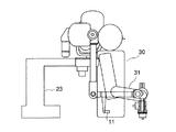
図6と図7は、本実施例のマスターアーム装置の立面図と平面図である。
第1軸から第3軸は肩部の回転中心点で交差しており、第5軸から第7軸は手先の位置で交差している。第4軸は上腕リンク9と前腕リンク10を回動可能に結合している。第3軸から第5軸は互いに平行に配設されている。第3軸の回転部は肩部の回転中心から肩リンク8の距離だけ外側に張り出している。また、第5軸の回転部から手首部の回転中心までの距離も間に介在する機構により肩リンク8と同じ距離になるように構成されている。
第2軸には駆動モータ14が結合されていて、リンク9の肘部の開き角を調整する。
【0030】
また、第3軸の周りには、第1カウンタウェイト15と第2カウンタウェイト16が取り付けられている。
第1カウンタウェイト15は上腕リンク9以下の手先部分全体のモーメントをほぼ相殺するように、第3軸に関して上腕リンク9に対する点対称位置に設けられている。また、第2カウンタウェイト16は、上腕リンク9内に設けられる平行リンク機構により前腕リンク10と連動して前腕リンク10以下の機構部分のモーメントをほぼ相殺する機能を有する。
また、前腕リンク10には操縦者の腕の動きを検出する肘センサ11が設けられている。
【0031】
図8は、図6と図7に示した本実施例のマスターアーム装置に操縦者が搭乗して操作する状態を模式的に示したものである。マスターアーム装置は第1回転軸の固定部を架台23に固定することによって固定される。
操縦者30が装置に搭乗してマスターアームのジョイステックを把持したときに、操縦者の肩の回転中心とマスターアームの肩部回転中心が十分近く、上腕リンクと前腕リンクが操縦者の腕31に沿って配置されれ、操縦者の腕31の動きは肘センサ11によって検出される。
操縦者が手先の位置を変えずに肘を動かすときは、肩部回転中心と手首部回転中心を結ぶ直線と操縦者の肩と手首を結ぶ直線がほぼ一致するようになるため、肘角の対応関係が単純化する。
【0032】
また、第1軸から第7軸の各々にモータを配置して、力提示を行えるようにすることも可能である。力提示とは、スレーブアームに力センサを装備してワークに接触したときに発生する力を操縦者に提示する機能である。また、マスターアームの手首部にある把持部に力センサを備えて、操縦者の手がマスターアームに及ぼす操作力を検出してスレーブアームとワークの間に操作力に応じた力を発生させることもできる。
【0033】
図9は、本実施例のマスターアーム装置を用いたマスタースレーブマニピュレータ装置の制御機構を表したブロック図である。図面の上半分がマスターアームの駆動制御部、下半分がスレーブアームの駆動制御部を表している。
肘角指令値は、肘センサ41、操縦者の肘位置の方向算出部42、肘角の現在位置算出部43、および加算器44により算出される。
肘センサ41が操縦者の腕とマスターアームの腕リンクの相対的位置の変化を検出して、方向算出部42に検出信号を入力し、方向算出部42が操縦者の肘位置の移動方向とマスターアームの肘部が追従するために必要な移動量を算出する。積分器44によりこの移動量を積分することで肘角指令値を算出する。
【0034】
肘角指令値は、マスターアームの逆運動学計算部45に送られ、ここで各軸の回転量が算出されて、それに基づいてサーボ制御部46により駆動モータを駆動してマスターアームを操縦者の腕の動きに追従させる。
肘角指令値は、また、スレーブアームの逆運動学計算部52に送られて、算出された駆動量に基づいて各軸サーボ制御部53を介してスレーブアームの各軸を駆動し、スレーブアームを操縦者の腕に追従させる。
【0035】
一方、マスターアームに設けられた力センサ47が操縦者の操作力を測定し、スレーブアームに設けられた力センサ48がワークの反力を測定する。減算器49が操縦者の操作力とワークの反力の差を算出して、積分器50がその差を積分する。スレーブアームのアーム位置初期値を各軸の回転値から算出して、これを加算器51で積分器50の出力に加算する。加算器51の出力は、操縦者の力がワーク反力に一致する方向に手先位置を変化させ、両者が一致するとその状態の位置を保持するような手先位置指令値となる。
手先位置指令値は、スレーブアームの逆運動学計算部52に送られ、算出された駆動量に基づいて各軸サーボ制御部53がスレーブアームの各軸を駆動し、スレーブアームを操縦者の腕に追従させる。また、マスターアームの逆運動学計算部45に送られ、それに基づいてサーボ制御部46により駆動モータを駆動してマスターアームをスレーブアームに追従させると共に、操縦者に力提示を行う。
【0036】
【発明の効果】
以上説明した通り、本発明のマスターアーム装置は、7自由度を持つスレーブアームに対して、手先の位置だけではなく肘位置についても教示することができるようになるので、例えば、双腕型ロボットにおけるマスタースレーブマニピュレータ装置に対しても、操縦者が現場の状況を見ながら肘を動かしてスレーブアームの障害物回避を行えるようにすることができる。
【図面の簡単な説明】
【図1】本発明のマスターアーム装置の実施例の構成を説明する軸配置図である。
【図2】本実施例に用いる肘センサの1例を示す説明図である。
【図3】本実施例に用いる肘センサの別の例を示す説明図である。
【図4】本実施例に用いるカウンターバランスの配置を説明する軸配置図である。
【図5】本実施例に用いる第4軸用カウンターバランスの構成図である。
【図6】本実施例のマスターアーム装置の側面図である。
【図7】本実施例のマスターアーム装置の平面図である。
【図8】本実施例のマスターアーム装置における操縦者の姿勢を表す図面である。
【図9】本実施例を用いたマスタースレーブマニピュレータ装置の制御装置を表すブロック図である。
【符号の説明】
1,2,3,4,5,6,7 回転軸
8,9,10 リンク
11 肘センサ
12 リニアスケール本体
13 リニアスケール用バンド
14 駆動モータ
15,16 カウンタウェイト
17 平行リンク
18,19 金属ベルト
20 張力コントローラ
21 固定ボルト
22 ジョイスティック
23 架台
30 操縦者
31 操縦者の前腕[0001]
TECHNICAL FIELD OF THE INVENTION
The present invention relates to a master arm having seven degrees of freedom used for a master-slave manipulator, and more particularly, to a seven-degree-of-freedom master arm capable of controlling the position of an elbow of a slave arm.
[0002]
[Prior art]
In the manipulator having six degrees of freedom, when the position and posture of the hand are determined, all degrees of freedom are defined, and it is impossible to change the state of the arm between the shoulder and the hand. For this reason, obstacle avoidance and singularity avoidance cannot be performed in a state where the position and posture of the hand are determined.
On the other hand, the human arm has seven degrees of freedom, so that the position of the elbow can be arbitrarily selected even if the position and posture of the hand is determined, so that the arm does not hit even if there is an obstacle. Can be avoided.
Therefore, by giving the slave arm of the master-slave manipulator seven degrees of freedom, it is possible to make use of redundant degrees of freedom to make it move in the same way as a human arm, and to avoid singularities and obstacles. can do.
[0003]
The master arm in the master-slave manipulator is used to operate the slave arm.When the operator moves the gripper at the tip of the master arm, the movement is transmitted as a command value and the slave arm performs the same movement. Can be.
Conventionally, the master arm teaches six degrees of freedom of the position and posture of the hand held by the operator. To operate a seven-degree-of-freedom robot having redundant degrees of freedom, the other arm is used. It is necessary to give an instruction regarding the seventh degree of freedom using another means such as a push button or a lever operated by the user.
[0004]
Note that Japanese Patent Application Laid-Open No. 5-345291 discloses that the elbow position of the slave arm can be freely selected when the position of the hand is controlled by the master arm. A seven-degree-of-freedom robot has been disclosed in which interference avoidance is performed when there is a possibility of interference.
However, in the seven-degree-of-freedom robot disclosed in the above publication, the controller of the slave arm determines the elbow position independently of the master arm, and does not reflect the intention of the operator in the redundant degree of freedom. Was.
[0005]
[Problems to be solved by the invention]
Therefore, the problem to be solved by the present invention is to provide a master arm capable of reflecting not only the position and orientation of the operator's hand but also the movement of the elbow, and all degrees of freedom of the seven-degree-of-freedom slave arm in the master-slave manipulator. Is to be controlled by the operator with only one arm.
[0006]
[Means for Solving the Problems]
In order to solve the above-mentioned problem, a master arm device of the present invention is a seven-degree-of-freedom master arm having an elbow portion where three axes at a shoulder intersect at almost one point and three axes at a wrist intersect at almost one point. The elbow is provided with an elbow sensor for detecting the position of the elbow of the pilot, and a driving device for driving the elbow is provided to control the following of the elbow.
[0007]
In the master arm device of the present invention, since the three axes intersect at one point in the shoulder and the three axes intersect at one point in the wrist, each has a joint function equivalent to a ball joint. The movement of the elbow to be carried can be represented by rotation about a straight line connecting two axis intersections of a plane triangle formed by the axis intersection of the shoulder, the axis intersection of the wrist, and the elbow. The angle of rotation of this plane triangle is called the elbow angle.
In the present invention, the elbow of the master arm is provided with a sensor for detecting the movement of the elbow of the pilot, and a device for driving the elbow is provided, and the elbow of the master arm is moved following the movement of the pilot. Can be done. Therefore, when the slave arm is likely to interfere with the external environment, if the elbow is moved so as not to collide according to the judgment of the pilot, the master arm device controls the slave manipulator using the position information of the elbow to avoid the interference. Can be.
[0008]
In the master arm device of the present invention, since all the degrees of freedom of the seven-degree-of-freedom manipulator can be controlled with only one arm of the operator, the operator is required to operate the manipulator like a dual-arm robot, which has recently been researched. When the two arms need to control the manipulator arms, the position of the elbow can be controlled in addition to the position and orientation of the hand.
Also, for example, even when the forearm of the manipulator is likely to interfere with the work table on which the work object is mounted, the elbow can be moved in the horizontal direction, so that the degree of freedom in the arrangement of the robot increases, and work can be performed even in a narrow space. There are advantages such as being able to.
[0009]
In addition, each axis of the master arm may be used as a drive axis, and the force detected by the slave arm may be presented to the operator.
Further, the direction of the rotation axis of the first axis of the master arm is made substantially coincident with the direction of gravity, the second axis is a drive axis that is orthogonal to the first axis and follows the movement of the elbow, and the rotation of the third axis and the fourth axis The axes may be parallel to each other, and the counterweight of the fourth axis may be arranged on the rotation axis of the third axis, and the counterweight may be linked to the fourth axis via a parallel link mechanism.
Preferably, the elbow sensor is provided on the link of the master arm, and detects the direction in which the driver's arm moves relative to the link.
Note that the elbow sensor may be one in which a plurality of photoelectric switches are arranged.
With such a simple configuration of the elbow sensor, the control algorithm can be simplified, and the sensor unit and the control unit can be configured at extremely low cost.
[0010]
BEST MODE FOR CARRYING OUT THE INVENTION
Hereinafter, the present invention will be described in detail based on embodiments with reference to the drawings.
FIG. 1 is a shaft arrangement diagram for explaining the configuration of one embodiment of a master arm device of the present invention, FIG. 2 is an explanatory diagram showing one example of an elbow sensor used in this embodiment, and FIG. 3 is another example of an elbow sensor. FIG. 4 is a shaft arrangement diagram for explaining an arrangement example of a counterbalance used in the present embodiment, FIG. 5 is a configuration diagram of a fourth shaft counterbalance, and FIG. 6 is a side view of a master arm device of the present embodiment. 7, FIG. 7 is a plan view of the master arm device of the present embodiment, FIG. 8 is a drawing showing the attitude of the operator in the master arm device of the present embodiment, and FIG. 9 is a control device of the master-slave manipulator device using the present embodiment. It is a block diagram showing.
[0011]
The master arm device of the present embodiment is for manipulating a seven-degree-of-freedom slave arm of a master-slave manipulator. The master arm has a link mechanism with seven degrees of freedom.
When the operator changes the position and orientation of the wrist by gripping the wrist of the master arm, the position and orientation of the wrist can be determined by the rotation angle of the axis provided from the shoulder to the wrist, and the information is used as a manipulator. To control the slave arm to follow the movement of the master arm.
Since only six degrees of freedom can be defined only by the position and orientation of the wrist of the slave arm, the remaining one degree of freedom is determined by the inclination of the arm connected to the elbow.
[0012]
The shoulder and wrist of a person can be approximated to a spherical joint such as a ball joint where three axes of rotation intersect at one point, and the position of the elbow connected by the upper arm and forearm to the shoulder and wrist is Once the position of the wrist is determined, it can be designated by a rotation angle around a line connecting the shoulder and the wrist, that is, an elbow angle. It is convenient for handling that the elbow angle is indicated by a rotation angle measured from an appropriate reference position such as a vertical plane.
In the master arm device of this embodiment, three rotation axes are provided on the shoulder so that the axes intersect at one point, and three wrists are provided on the wrist in order to make the master arm perform the same movement as a human arm. The two rotation axes are provided so that the axes intersect at one point, and the upper arm link attached to the shoulder and the forearm link attached to the wrist are joined by a rotation axis such that both links bend in a plane to form an elbow I have.
[0013]
The seven rotation axes of the master arm in the present embodiment are arranged as shown in FIG.
The
The third
[0014]
With the above configuration, the shoulder of the master arm can perform a movement equivalent to a ball joint about the intersection of the rotation axes. Needless to say, the arrangement of the first to third rotating shafts may be loose enough to achieve mechanical performance.
Further, the
[0015]
A
A
[0016]
A
[0017]
In the master arm device of the present embodiment, an
Since the
The
[0018]
FIG. 3 is a drawing showing another example of an elbow sensor used in the present invention.
The elbow sensor shown in FIG. 3 uses a micro linear scale. The
[0019]
A
When the operator's elbow is lifted outward, the
[0020]
The master arm device is provided with a pair of left and right master arms having the above configuration, and can operate a dual-arm robot. When manipulating the slave arm by the master arm device of the present embodiment, the operator gets on the device and grasps the joysticks at the wrists of the left and right master arms to guide the position and orientation of the wrist as desired.
[0021]
Then, the master arm device calculates the position and orientation of the wrist by detecting the rotation angle with encoders provided on each rotation axis of the master arm, and transmits the calculated position and posture to the control device of the slave arm. This makes it possible to transmit information of six degrees of freedom of the movement of the operator's hand and one degree of freedom of the elbow position to the slave arm.
The position and orientation of the slave arm is instructed so that the difference between the operating force of the operator operating the master arm and the reaction force received by the slave arm from the work is eliminated. It may not work.
[0022]
The slave arm control device performs inverse kinematics calculation based on the information on the position and orientation of the wrist of the master arm and the elbow angle, calculates the amount of rotation of each axis of the slave arm, and performs servo control. Thus, the position and orientation of the wrist of the slave arm can be determined as instructed by the operator.
Furthermore, since the movement of the pilot's elbow is detected and the elbow of the master arm is made to follow, when the arm or elbow of the slave arm is likely to interfere with surrounding objects, if the pilot moves the elbow, The elbow of the slave arm follows and moves through the movement of the master arm, so that interference can be avoided.
[0023]
In order to make the movement of the elbow of the master arm correspond to the elbow of the pilot, the elbow angle may be set to the same value.
In the master arm device according to the present embodiment, only the
[0024]
Since the link mechanism of the master arm is ruggedly configured to have an appropriate strength, it becomes heavy for the operator to operate as it is, and it is difficult to freely move the link mechanism.
In order to solve this difficulty, the master arm device of the present embodiment can arrange a counter balance as shown in FIG. Note that, for the portion nearer to the end than the
The counter balance may be attached to each rotating shaft. However, since the counter balance increases the weight of the entire mechanism and increases the inertial force, it is not preferable to use many heavy counterweights.
[0025]
In a certain shaft configuration, if the counterweights are arranged on all the rotating shafts, the counterweight to be provided on the first rotating shaft, which must receive all the weights from the base of the arm to the hand, becomes the largest. In this embodiment, the counterweight is omitted by arranging the first
The third
[0026]
Next, the third
By arranging the
[0027]
FIG. 5 is a mechanism diagram illustrating an example of a parallel link installed to provide a counter weight of the fourth rotating shaft on the third rotating shaft.
A first pulley is fixed to the rotation shaft of the
[0028]
When the operator moves the hand holding the
In addition, the illustrated parallel link mechanism has a small number of additional components and can be formed so as to fit within the width of the
[0029]
6 and 7 are an elevation view and a plan view of the master arm device of the present embodiment.
The first to third axes intersect at the center of rotation of the shoulder, and the fifth to seventh axes intersect at the hand position. The fourth shaft rotatably connects the
A
[0030]
A
The
The
[0031]
FIG. 8 schematically shows a state in which a pilot operates and rides on the master arm device of the present embodiment shown in FIGS. 6 and 7. The master arm device is fixed by fixing the fixing portion of the first rotation shaft to the
When the
When the pilot moves the elbow without changing the position of the hand, the straight line connecting the shoulder rotation center and the wrist rotation center almost coincides with the straight line connecting the pilot's shoulder and wrist. The correspondence is simplified.
[0032]
Further, it is also possible to arrange a motor on each of the first axis to the seventh axis so that the force can be presented. The force presentation is a function of presenting a force generated when a slave arm is equipped with a force sensor and coming into contact with a workpiece to a driver. In addition, a force sensor is provided on a grip portion at a wrist portion of the master arm to detect an operation force exerted by the operator's hand on the master arm and generate a force according to the operation force between the slave arm and the work. You can also.
[0033]
FIG. 9 is a block diagram illustrating a control mechanism of a master-slave manipulator device using the master arm device of the present embodiment. The upper half of the drawing shows the drive control unit of the master arm, and the lower half shows the drive control unit of the slave arm.
The elbow angle command value is calculated by the
The
[0034]
The elbow angle command value is sent to the inverse kinematics calculation unit 45 of the master arm, where the amount of rotation of each axis is calculated, and the servo motor is driven by the
The elbow angle command value is also sent to the inverse
[0035]
On the other hand, a force sensor 47 provided on the master arm measures the operating force of the driver, and a
The hand position command value is sent to the inverse
[0036]
【The invention's effect】
As described above, the master arm device of the present invention can teach not only the position of the hand but also the position of the elbow to the slave arm having seven degrees of freedom. With respect to the master-slave manipulator device of the above, the operator can move the elbow while observing the situation at the site to avoid obstacles of the slave arm.
[Brief description of the drawings]
FIG. 1 is a shaft arrangement diagram for explaining a configuration of an embodiment of a master arm device of the present invention.
FIG. 2 is an explanatory diagram illustrating an example of an elbow sensor used in the present embodiment.
FIG. 3 is an explanatory diagram showing another example of the elbow sensor used in the present embodiment.
FIG. 4 is an axial arrangement diagram illustrating an arrangement of a counter balance used in the present embodiment.
FIG. 5 is a configuration diagram of a fourth axis counterbalance used in the present embodiment.
FIG. 6 is a side view of the master arm device of the present embodiment.
FIG. 7 is a plan view of the master arm device of the present embodiment.
FIG. 8 is a drawing showing a posture of a pilot in the master arm device of the present embodiment.
FIG. 9 is a block diagram illustrating a control device of a master-slave manipulator device using the present embodiment.
[Explanation of symbols]
1, 2, 3, 4, 5, 6, 7
Claims (5)
Priority Applications (1)
| Application Number | Priority Date | Filing Date | Title |
|---|---|---|---|
| JP2000116665A JP3585419B2 (en) | 2000-04-18 | 2000-04-18 | Master arm device |
Applications Claiming Priority (1)
| Application Number | Priority Date | Filing Date | Title |
|---|---|---|---|
| JP2000116665A JP3585419B2 (en) | 2000-04-18 | 2000-04-18 | Master arm device |
Publications (2)
| Publication Number | Publication Date |
|---|---|
| JP2001300871A JP2001300871A (en) | 2001-10-30 |
| JP3585419B2 true JP3585419B2 (en) | 2004-11-04 |
Family
ID=18628101
Family Applications (1)
| Application Number | Title | Priority Date | Filing Date |
|---|---|---|---|
| JP2000116665A Expired - Fee Related JP3585419B2 (en) | 2000-04-18 | 2000-04-18 | Master arm device |
Country Status (1)
| Country | Link |
|---|---|
| JP (1) | JP3585419B2 (en) |
Cited By (1)
| Publication number | Priority date | Publication date | Assignee | Title |
|---|---|---|---|---|
| CN103895040A (en) * | 2014-04-10 | 2014-07-02 | 安凯 | Method for detecting collision between spatial mechanical arm connecting rods |
Families Citing this family (13)
| Publication number | Priority date | Publication date | Assignee | Title |
|---|---|---|---|---|
| JP2006334695A (en) * | 2005-05-31 | 2006-12-14 | Kyoto Univ | Remote control device |
| JP4950522B2 (en) * | 2006-03-08 | 2012-06-13 | 花王株式会社 | Work following device |
| JP5282874B2 (en) * | 2007-07-09 | 2013-09-04 | 花王株式会社 | Manipulator system |
| WO2009096408A1 (en) * | 2008-02-01 | 2009-08-06 | Kyokko Electric Co, Ltd. | Articulated structure teaching device |
| JP5135069B2 (en) * | 2008-06-12 | 2013-01-30 | 三鷹光器株式会社 | Medical instrument holding arm device |
| JP5093498B2 (en) * | 2008-07-09 | 2012-12-12 | 花王株式会社 | Manipulator system |
| ES2338623B1 (en) * | 2008-08-05 | 2012-02-07 | Universidad Miguel Hernandez | ROBOTIC ARM. |
| US8126114B2 (en) * | 2008-09-12 | 2012-02-28 | Accuray Incorporated | Seven or more degrees of freedom robotic manipulator having at least one redundant joint |
| JP6201126B2 (en) | 2013-11-07 | 2017-09-27 | 株式会社人機一体 | Master-slave system |
| KR20160040005A (en) * | 2014-10-02 | 2016-04-12 | 주식회사 고영테크놀러지 | Stand for medical instrument |
| JP6507094B2 (en) * | 2015-12-28 | 2019-04-24 | 株式会社東芝 | manipulator |
| CN106393074A (en) * | 2016-11-25 | 2017-02-15 | 东莞市天合机电开发有限公司 | Multi-degree-of-freedom main manipulator with connecting rod mechanism |
| JP7208752B2 (en) | 2018-09-26 | 2023-01-19 | ソニー・オリンパスメディカルソリューションズ株式会社 | Medical observation system, medical observation device, and control method |
Family Cites Families (4)
| Publication number | Priority date | Publication date | Assignee | Title |
|---|---|---|---|---|
| JPH0694110B2 (en) * | 1985-05-01 | 1994-11-24 | 株式会社アマダ | Master-slave system robot |
| JPH0540956Y2 (en) * | 1987-04-09 | 1993-10-18 | ||
| JP3263939B2 (en) * | 1994-04-11 | 2002-03-11 | 株式会社安川電機 | Manipulator operation device |
| WO1996021994A1 (en) * | 1995-01-11 | 1996-07-18 | Shaw Christopher D | Tactile interface system |
-
2000
- 2000-04-18 JP JP2000116665A patent/JP3585419B2/en not_active Expired - Fee Related
Cited By (1)
| Publication number | Priority date | Publication date | Assignee | Title |
|---|---|---|---|---|
| CN103895040A (en) * | 2014-04-10 | 2014-07-02 | 安凯 | Method for detecting collision between spatial mechanical arm connecting rods |
Also Published As
| Publication number | Publication date |
|---|---|
| JP2001300871A (en) | 2001-10-30 |
Similar Documents
| Publication | Publication Date | Title |
|---|---|---|
| JP3585419B2 (en) | Master arm device | |
| US6738691B1 (en) | Control handle for intelligent assist devices | |
| EP2744629B1 (en) | Haptic manipulation system for wheelchairs | |
| EP3481599B1 (en) | Parallel link device, industrial robot, and haptic presentation device | |
| EP2617530B1 (en) | Master operation input device and master-slave manipulator | |
| US5673595A (en) | Four degree-of-freedom manipulator | |
| JP5282874B2 (en) | Manipulator system | |
| US6889116B2 (en) | Manipulator | |
| CA2176899C (en) | Mechanism for control of position and orientation in three dimensions | |
| US20030005786A1 (en) | Parallel mechanism | |
| KR20190085160A (en) | Teaching System of Dual-Arm Robot and Method of Teaching Dual-Arm Robot | |
| US20130013108A1 (en) | Robotic Agile Lift System With Extremity Control | |
| CN110561403A (en) | wearable three-degree-of-freedom human body auxiliary outer mechanical arm | |
| JP2013505147A (en) | Humanoid robot | |
| JP2012128795A (en) | Lateral side setting type inner force sense presentation interface | |
| WO2019194138A1 (en) | Robot control device | |
| JP6717921B2 (en) | Robot operating device with handle for operating the robot | |
| JP2014018912A (en) | Robot control device, robot control method, robot control program and robot system | |
| JP2010017804A (en) | Manipulator system | |
| EP0200091B1 (en) | Master manipulator | |
| JP2014117783A (en) | Hand guide system for robot, and hand guide device | |
| JP6936712B2 (en) | Operating device | |
| WO2012149402A2 (en) | Robotic agile lift system with extremity control | |
| JPH07276265A (en) | Manipulator operating device | |
| JP3612085B2 (en) | Master arm device for master / slave system |
Legal Events
| Date | Code | Title | Description |
|---|---|---|---|
| A131 | Notification of reasons for refusal |
Free format text: JAPANESE INTERMEDIATE CODE: A131 Effective date: 20040106 |
|
| A521 | Written amendment |
Free format text: JAPANESE INTERMEDIATE CODE: A523 Effective date: 20040302 |
|
| TRDD | Decision of grant or rejection written | ||
| A01 | Written decision to grant a patent or to grant a registration (utility model) |
Free format text: JAPANESE INTERMEDIATE CODE: A01 Effective date: 20040803 |
|
| A61 | First payment of annual fees (during grant procedure) |
Free format text: JAPANESE INTERMEDIATE CODE: A61 Effective date: 20040803 |
|
| R150 | Certificate of patent or registration of utility model |
Free format text: JAPANESE INTERMEDIATE CODE: R150 |
|
| FPAY | Renewal fee payment (event date is renewal date of database) |
Free format text: PAYMENT UNTIL: 20080813 Year of fee payment: 4 |
|
| FPAY | Renewal fee payment (event date is renewal date of database) |
Free format text: PAYMENT UNTIL: 20090813 Year of fee payment: 5 |
|
| FPAY | Renewal fee payment (event date is renewal date of database) |
Free format text: PAYMENT UNTIL: 20100813 Year of fee payment: 6 |
|
| FPAY | Renewal fee payment (event date is renewal date of database) |
Free format text: PAYMENT UNTIL: 20110813 Year of fee payment: 7 |
|
| LAPS | Cancellation because of no payment of annual fees |