JP3585174B2 - IC card programming device - Google Patents
IC card programming device Download PDFInfo
- Publication number
- JP3585174B2 JP3585174B2 JP51533294A JP51533294A JP3585174B2 JP 3585174 B2 JP3585174 B2 JP 3585174B2 JP 51533294 A JP51533294 A JP 51533294A JP 51533294 A JP51533294 A JP 51533294A JP 3585174 B2 JP3585174 B2 JP 3585174B2
- Authority
- JP
- Japan
- Prior art keywords
- card
- carriage
- programming
- separation
- module
- Prior art date
- Legal status (The legal status is an assumption and is not a legal conclusion. Google has not performed a legal analysis and makes no representation as to the accuracy of the status listed.)
- Expired - Fee Related
Links
Images


Classifications
-
- G—PHYSICS
- G06—COMPUTING OR CALCULATING; COUNTING
- G06K—GRAPHICAL DATA READING; PRESENTATION OF DATA; RECORD CARRIERS; HANDLING RECORD CARRIERS
- G06K17/00—Methods or arrangements for effecting co-operative working between equipments covered by two or more of main groups G06K1/00 - G06K15/00, e.g. automatic card files incorporating conveying and reading operations
Landscapes
- Physics & Mathematics (AREA)
- General Physics & Mathematics (AREA)
- Engineering & Computer Science (AREA)
- Theoretical Computer Science (AREA)
- Conveying Record Carriers (AREA)
- Credit Cards Or The Like (AREA)
- Control Of Vending Devices And Auxiliary Devices For Vending Devices (AREA)
Description
発明の分野
本発明は、ときに「スマートカード」と呼ばれるICカード(集積回路カード)をプログラミングするためのICカードのプログラミング装置に関するものである。
発明の背景
本発明は、ICカードをプログラミングするためのICカードのプログラミング装置に関するものである。ICカードは、しばしばクレジットカードあるいは身分証明カードとして使用される。クレジットカードの様に、ICカードは、その表面に浮き出し刷りされた文字や、印刷や、データを保管するための磁気ストライプを有しているかもしれない。集積回路は、磁気ストライプと同様の目的を果たすが、一般的にデータの保管のためのより大きい容量を有し、より安定な記憶媒体である。
Bonnemoyに対する米国特許第4,866,259号やLindenに対する米国特許第4,827,425号に開示されているような従来の回路カードのプログラミング装置は、表裏のどちらにも回路が配置されたICカードをプログラミングするための手段は備えていなかった。さらに、BonnemoyあるいはLindenのどちらも、フランス規格あるいはISO規格の位置に集積回路が配置されたICカードをプログラミング可能な装置は開示されていない。
発明の概要
本発明は、フランス規格及びISO規格の双方の位置にカードをプログラムすることが出来る分離ステーションを有するICカードのプログラミング装置を提供することにより、従来例に存在する問題点を解決するものである。分離ステーションはまたICカードのどちらの面にもプログラムを行うために180゜回転可能である。本発明のICカードのプログラミング装置は、ベースと、カード入力台と、搬送部を含む。搬送部は、ベースに接続され、回転軸回りに回転可能に取り付けられている。搬送部は、回転軸に対して放射状に配置された搬送アームを含む。搬送アームは、末端部と基端部とを有し、基端部は回転軸の付近にある。カードピッカーキャリッジは、末端部付近の第1の位置と基端部付近の第2の位置の間で移動出来るように搬送アーム上に取り付けられている。1つあるいは複数の分離ステーションが回転軸の回りに放射状に配置されている。
カードピッカーキャリッジは、第1の位置において入力台からカードを把持することが出来る。カードピッカーキャリッジは、そののち第2の位置にむかって移動され、搬送部は回転軸の回りに、分離ステーションのうちの1つと半径方向の位置が一致する位置まで回転される。そして、カードピッカーキャリッジは、カードを、カードをプログラムするための分離ステーションに置くために第1の位置に移動される。
本発明はまた、ICカードを把持するための改良されたピッカーキャリッジを含む。ピッカーキャリッジは、シャーシと、シャーシに接続されたバックストップとを含む。ピッカーキャリッジは、また、2本のピッカーアームを有している。それぞれのピッカーアームは、バックストップと対向して配置されたピッカー端と第2の端部とを有している。それぞれのピッカーアームは第1の端部と第2の端部との間でシャーシに対して回転可能に接続されている。ピッカーキャリッジは、また、互いに対向して配置された第1及び第2の端部を有する軸部材を含む。1つのピッカーアームの第2の端部は、軸部材の第1の端部に回転可能に接続されており、もう一方のピッカーアームの第2の端部は、軸部材の第2の端部に回転可能に接続されている。軸部材の第1の端部と第2の端部の間に配置された部分は、アーチ状の表面を有し軸部材に接続されている。
キャリッジは、また、ピッカーアームを駆動するためのアクチュエータを含む。アクチュエータは、アーチ状の表面の末端部にアクチュエータロッドを有している。アーチ状の末端部は、表面同士を付勢するための付勢手段により、軸部材のアーチ状の表面に対して保持されている。アーチ状の末端部とアーチ状の表面は、ピッカーアームをピッカー端がバックストップと離間した第1の位置から、カードをピッカー端とバックストップとの間で把持するためにピッカー端がバックストップと近接した第2の位置に回転させるために、アクチュエータのアーチ状の末端部が軸部材のアーチ状の表面を押すことが出来るように略同心状にされている。
本発明は、また、ICカードをプログラミングするための改良された分離ステーションを含む。分離ステーションは、ICカードのプログラミング装置ベースに接続可能な分離ステーションベースを含む。このステーションは、また、プログラムされるべきICカードを把持するためのカード受け取り手段を含む。カード受け取り手段は、カードに配置された集積回路と対面する少なくとも一つの接点を有する。このステーションは、また、カード受け取り手段をベース上に取り付けるための反転取り付け手段を含む。反転取り付け手段は、カード受け取り手段を、ベース上において、接点がベースの第1のサイド上に位置する第1の位置と、接点がベースの対向する第2のサイド上に位置する様にカード受け取り手段が回転軸の回りに略180゜回転した第2の位置とに取り付けることが出来る。
本発明は、また、接点をフランス規格に対応する第1の位置とISO規格に対応する第2の位置とに取り付けるための接点ピンハウジングを有し、上記したものに類似した分離ステーションに関するものである。接点ピンハウジングは、反転取り付け手段と合体した分離ステーション上で使用されるかもしれないし、反転取り付け手段と合体していない分離ステーション上で使用されるかもしれない。
【図面の簡単な説明】
図1は、本発明に従うICカードのプログラミング装置の斜視図;
図2は、図1に示すICカードのプログラミング装置の断面図;
図3は、図2に示すICカードのプログラミング装置の断面図の端面図;
図4は、ピッカーキャリッジの斜視図;
図5は、分離ステーションの斜視図;
図6は、分離ステーションの端面図;
図7は、分離ステーションの側面図;
図8は、ICカードのプログラミング装置の制御システムとその種々のインプットとアウトプットを示すブロック図;
図9は、カード処理システムを示す図;
図10Aは、ICカードのプログラミングモジュールのシステムコントロールを示す図;
図10Bは、リーダーボードとカードヘッドブレイクアウトボードを示す図;
図11は、カードを分離する手順を示す図;
図12は、リーダーモジュールにより行われる処理を示すロジックフローダイアグラム;
図13は、サンプルキーカードリーダーへの応用を示す図;
図14は、リーダーコントローラとICカードのプログラミングモジュールコントローラとの間の通信を示すロジックフローダイアグラム;
図15は、ICカードとその分離データのICカードモジュールへの到着を示すフローダイアグラム;
図16は、把持機構によるICカードの動きを示すフローダイアグラムである。
好適な実施例の説明
いくつかの図中の参照番号で識別される部分又は対応する部分について、図面を参照すると、図1は、ICカードのプログラミング装置10の概略斜視図である。プログラム装置10は、基部14に回動自在に設けられたカード搬送機構12を含む。搬送機構12は、基台14に略垂直な回転軸の中心に位置する延設された軸部材16を有する。また、搬送機構12は、当該搬送機構12の回転軸から略放射状に配設された搬送アーム18を有する。カードピックアップキャリッジ26は搬送アーム18に摺動可能に取付けられている。
また、ICカードのプログラミング装置10は、カード入力台22とカード出力台24を含む。また、カード搬送機構12の回転軸から略放射状に配設されているのは、1つ又は複数の分離ステーション20である。
キャリッジ駆動モータ28、搬送機構駆動モータ30、出力台駆動モータ32を含む3つの駆動モータは、ICカードのプログラミング装置10を介してICカード34を移動させる。キャリッジ駆動モータ28は、搬送アーム18の先端部に近接した第1の位置(図1参照)と搬送アーム18に近接した端部又は出力端部に近接した第2の位置との間において、当該搬送アームに沿ってキャリッジ26を移動させる。搬送機構駆動モータ30はギヤ36により回転軸まわりにカード搬送機構12を回動させる。そして、出力台駆動モータ32は出力ローラ37を駆動する。
また、ICカードのプログラミング装置10は、複数のセンサを有するコントローラを含む。これらのセンサは好ましくはフォトセンサ又はホール素子であるが、他の仕様のセンサを使用してもよい。ICカードのプログラミング装置10は、好ましくはキャリッジ入力センサ38、カード入力センサ40、キャリッジホームポジションセンサ42、キャリッジ回転ホームポジションセンサ44、夫々の分離ステーション20に配設された1つのステーションにおけるカード位置センサ46、出力ローラ37に近接した出力センサとを具備する。キャリッジ回転ホームポジションセンサ44は、旗状プレート48のまわりに配置されている。また、コントロール手段は1つ又は複数のキーカードリーダー50を含む。
図2は、図1のICカードのプログラミング装置10の断面図を示す。明確には、分離ステーション20は図示されていない。図2に詳細に示されるものは、カード搬送機構12、カード入力台22、カード出力台24である。
図3は、図2に示す断面の側面図を示す。
図4は、キャリッジ26の外観斜視図である。
図2〜図4に示すように、搬送アーム18は2つの互いに対向する位置に配設されたレール51を有する。キャリッジ26は2つの対になって溝に嵌合するローラ52と共にレール51に配設されている。キャリッジ26は、プーリシステム54を用いたキャリッジ駆動モータ28によって、搬送アーム18の先端部に近接した第1の位置(図2参照)と搬送アーム18に近接した端部との間を移動される。また、図2は軸部材16と共に搬送アーム18に駆動可能に接続されたブラケット56に取付けられた搬送アームを示している。
カード入力台22は図2及び図3に示すように、カード保持溝58を含む。このカード保持溝58は、好ましくは傾斜した取り入れ口60を有する。カード保持溝58の下方に設けられているものはカード押し出し機62である。カード押し出し機62は、全体がL字状の押し出しレバー70に回動可能に取付けられた第1の軸受け68に対して突き出せる位置に配置されたアクチュエータロッド66を有するソレノイドアクチュエータ64を含む。L字状の押し出しレバー70は、ピン72のまわりにおいて、カード搬送台22に回動可能に接続されている。押し出しレバー70の第1の端部に新設する部分には、第2の軸受け76がある。
押し出しレバー70は、図2に示すように、第1の位置から第2の位置に回動可能になっている。第1の位置では、押し出しレバー70の第1の端部に配設された第2の軸受け76は、溝58から離れた位置にあり、押し出しレバー70の第2の端部78は、溝58の底の部分より高い位置に配置されている。第2の位置では、第2の軸受け76は溝58の上部及び内側に配置され、押し出しレバー70の第2の端部78は溝58の底の部分より下方に配置される。スプリング74は、第1の位置方向にL字状の押し出しレバー70を付勢する。
カード出力台24は、入力台22の溝58に並列にカード保持溝80を有する。これら溝58、80の底の部分は、好ましくは同一平面状にある必要はない。カード保持溝80は、傾斜した取り入れ口82を有する。カード出力台24は、好ましくは回動動作に対応するようにアーム18に駆動可能に接続されている。出力台24の下方に配設されているものは、軸部材支持ブロック17である。
図3及び図4に示すように、ピックアップキャリッジ26はピン88のまわりのピックアップキャリッジ架台86に回動自在に取付けられた2つのピックアップアーム84を有する。夫々のピックアップアーム84は、第1のピックアップ端部98と第2の端部を有する。また、ピックアップキャリッジ26は、ピックアップアーム84を駆動するための駆動手段90を含む。駆動手段90はアクチュエータロッド94を有するソレノイド92を含む。傾斜した取り入れ口85と後方ストッパー96を有するピックアップ溝83は、ピックアップキャリッジ26の架台86に駆動可能に接続されている。後方ストッパー96は、図4の後方に示すように、架台86と一体的に形成されるか、分離されて形成される部分となりうる。
また、カードピックアップキャリッジ26は、第1の端部と相対する位置に配設された第2の端部を有する全体が円筒状の軸部材102を含む。部材102の夫々の端部は該方に配設されたピン104を有する。ピックアップアーム84の第2の端部100は、ピン104のまわりの相対する位置に配置された軸部材102の端部に回動駆動可能に接続されている。軸部材102の第1の端部と第2の端部の間に配置されるものは、アーチ状の表面を有する部材106である。アクチュエータロッド94は、アーチ状の表面を有する部材106の先端部108を有する。アーチ状の先端部108は表面108と106とを固着させるための固着手段110により軸部材102のアーチ状の表面108に対して保持されている。アーチ状の先端部108と表面106とは、互いに相対的に摺動可能なように十分に弛みを持たせて固着手段110により一緒に保持されている。固着手段110は、好ましくはら旋状のスプリングである。アーチ状の先端部108とアーチ状の表面106とは、共に保持されているときに略同軸を有する。アーチ状の表面106は凹状であり、先端部108は凸状であるか、あるいはアーチ状の表面106は凸状であり、先端部108は凹状である。
図4は、ピックアップ端部98が後方ストッパー96から離れた間隔を置いた第1の位置におけるピックアップアーム84を示している。図3では、ピックアップ端部98は、当該ピックアップ端部98と後方ストッパー96との間でカードを把持するためにバックストッパー96に近接した第2の位置にある。
図5は、分離ステーション20の外観斜視図である。図1に示す分離ステーション20の概略図と異なって、図5に示すように、分離ステーション20は、分離ステーション機部112を有する。この分離ステーション機部112は、好ましくは開口部114にねじを挿入することにより基台14に駆動可能に接続されている。また、分離ステーション20は、プログラム可能に1枚のカードを把持するためにカード保持手段116を含む。
カード保持手段116は、延設された倒立部118を含む。倒立部118は、基部に操作可能に接続される第1の端部と、カード保持トレイ120に操作可能に接続された第2の端部を有する。図6に示すように、カード保持トレイ120は、長手方向にカード保持溝122を有する。図7に示すように、カード保持トレイ120は、2つの相対する位置に配された傾斜した端部124、126を有する。トレイ120から離れて垂直に延長され、カード保持溝122に並列に近接して配設されているものは、カード後方ストッパープレート128である。
カード保持手段116の倒立部118に回動自在に設けられているのは、接触レバー130である。この接触レバー130は、ピン132のまわりにおいて、カード保持手段116に回動操作可能に接続されている。接触レバー130は、カード保持トレイ120は近接した第1の端部と基部112に近接して配置された第2の端部とを有する。レバー130の第1の端部に近接して配設され、操作可能に接続されているものは、接触ピンハウジング134である。この接触ピンハウジング134は、カード後方ストッパープレート128の方向に配された複数の接触ピン136を有する。接触ピン136は、従来技術により周知な方法により配置されている。
また、レバー130の第1の端部に近接して配設され、操作可能に接続されているものは、把持プレート138である。この把持プレート138は、好ましくは少なくとも1つのバンパー140を有する。把持プレート138に略垂直に延長されているものは、リーダーボード144と接触ピンハウジング134との間の電気的な接続(不図示)を保持するケーブル支持プレート142である。
図6に示すように、接触レバー130の第2の端部に近接して配設されているものは、第1と第2の位置との間で接触レバー130を作動させるための駆動手段146である。駆動手段146は、カード保持手段116に操作可能に接続されている。駆動手段146は、アクチュエータロッド150を有するソレノイド148を含む。アクチュエータロッド150は、ピン152のまわりにおいて、接触レバー130の第2の端部に回動可能に接続されている。図5に示すように、接触レバー130が第1の位置にある時、接触ピン136は、カード34にプログラムするためにカード後方ストッパープレート128に近接した位置にあり、把持プレート138はカード後方ストッパープレート128に略並列した位置にある。図6に示すように、接触レバー130が第2の位置にある時、接触ピン136は、カード後方ストッパープレート128から離れた間隔を置いた位置にあり、把持プレート138はカード後方ストッパープレート128の斜め方向にある。固着手段149は、第1の位置の方向に接触レバー130を固着するためにカード保持手段116及び接触レバー130に操作可能に接続されている。固着手段149は、好ましくはスプリングである。
また、分離ステーション20は、カード保持手段116を第1の位置と第2の位置とに設置するために反転駆動される取り付け手段154を含む。第1の位置では、カードの前面に接触させるためにカード保持手段116のカード保持溝122はカード搬送機構12の軸部材16の回転軸のまわりにおいて放射状に配設され、接触ピンハウジング134は軸部材16の方向に配設されている。第2の位置では、カードの裏面に接触させるためにカード保持手段116のカード保持溝122が今まで通りカード搬送機構12の軸部材16の回転軸のまわりにおいて放射状に配設されるように180゜回動した位置にあるが、接触ピンハウジング134はカード搬送機構12の軸部材16から離れた位置に配設されている。
本好適な実施例では、反転取り付け手段154は、好ましくは凹み部分又は円周溝157を有する全体に延設された円筒状のピン155を含む。また、取り付け手段154は、保持手段116に開口部159を含む。開口部159は、全体が円筒形状を有し、円筒ピン155より僅かに大きい。開口部159に延設されているのは、ピン155が開口部159に挿入されたときに溝157に嵌合するように配置されたボールと移動止めのような固着ピン160である。また、反転取り付け手段154は、好ましくは2つのピン155に略並列した基部112からのび、ピン155の相対する側部に配設された短いピン161を含む。取り付け手段154は、保持手段116内部に開口部159に略並列に1つの付加的な小さい開口部162を含む。小さい開口部162は短いピン161に僅かに大きいが略同じ大きさである。
図7に示すように、ステーションにおけるカード位置センサ46とピンハウジング134は、親指大ボルト156、158によりカード保持手段116に夫々操作可能に接続されている。センサ46は、カード保持手段116が第1の位置に設置されている場合、カード保持溝122の傾斜した端部124に近接し、接触ピンハウジング134から離れた位置にカード保持手段116に係止可能である。センサ46は、カード保持手段116が第2の位置に設置されている場合、カード保持溝122の傾斜した端部126と接触ピンハウジング134に近接してカード保持手段116に取付可能である。
また、接触ピンハウジング134は、第1の位置と第2の位置とを含む。第1の位置では、接触ピンハウジング134は、図7に示すように、レバー130の溝164に挿入され、ピン136はカード34の上部に近接して配されている。接触ピンハウジング134が第1の位置にある場合、親指大ボルト158はレバー130の第1の開口部166に挿通される。接触ピンハウジング134が第2の位置にある場合、第1の位置から180゜回動され、ピン136は、カード34の中央部に近接して配設される。第2の位置では、親指大ボルト158はレバー130の第2の開口部168に引っ掛けられる。第1の位置は、カード34のIC35に対してフランス規格の位置に対応する。第2の位置は、カード34のIC35に対してISO規格の位置に対応する。フランス規格とISO規格とは、従来技術により周知なものである。
使用に際して、ICカードのプログラミング装置10は、反転取り付け手段154によってカード34の表面または裏面、若しくはフランス規格またはISO規格の位置のいずれかに配されるIC35を有するプログラムICカードに用いられる。
一般な技術では、今まで言及していなかったコントローラ、ICカードのプログラミング装置10はカードピックアップキャリッジ26によりカード入力大22に置かれた1つのICカードをピックアップすることにより操作される。このとき、キャリッジ26とICカード34は、搬送アーム18の端部とキャリッジホームポジションセンサ42に近接した方向に移動される。カード搬送機構12は、保持溝83が予め選択された空の分離ステーション20のカード保持溝122に位置調整されるまで、軸部材16のまわりにおいて回動される。その時、キャリッジ26とカード34は、カード34が予め選択された分離ステーション20に置かれるように、搬送アーム18の先端部の方向に移送される。
前もって置かれたカード34が分離ステーション20でプログラムされている間、カード搬送機構12は他の分離ステーション20カードを移動させ、置くために利用される。好ましくは、ICカードのプログラミング装置10は、FIFOを基本に操作され、それは、1つの分離ステーションに置かれた第1のカードがプログラムされた第1のカードとなり、それが取り除かれて、2番目の分離ステーションに置かれた第2のカードがプログラムされた第2のカードとなり、それが分離ステーションから取り除かれるというようになる。
プログラムが終了すると、カードピックアップキャリッジ26は、カード34を取り除く。カード34とキャリッジ26とは、その時、カード出力台24の上に置かれ、その後出力ローラ37により取り除かれながら、搬送アーム18の端部に近接した方向に移送される。
全体的には、ICカードのプログラミング装置10の全ての分離ステーション20は何らかのカード34が1つの分離ステーション20から取り除かれる前に、カード34を保持する。全ての分離ステーション20が最初に保持されたカードを持つと、置かれたカード34は、分離ステーション20から取り除かれ、もう1つのカードをそこに置く。
ICカードのプログラミング装置10を通してカードのバッチ処理を実行するときには、最初のカード34のプログラム処理時間は、好ましくは軸部材16のまわりにおいて時計回りに最も離れた位置に配された分離ステーション20にて開始される。第1及びその後のカード処理時間は軸部材16のまわりにおいて、反時計回りに進んでより離れた分離ステーション20にカード34が置かれる。しかしながら、分離ステーション20の他の処理を命令することは可能である。
カード処理が開始されると、キャリッジ26は、センサ38の位置にカード入力台22の上部に直接配置される。その時、カード34は、カード入力台22のカード保持溝58とカードピックアップキャリッジ26のピックアップ溝83に挿入される。ピックアップ溝83の傾斜した端部85とカード保持溝58の傾斜した取り入れ口60とは溝83及び58にカード34を導入するのに有効である。カード34が、最初にカード保持溝58に挿入されると、押し出しレバー70は第1の位置にあり、押し出しレバー70の第2の端部78は、カード入力台22からカード34がすべり落ちないように溝の底部より高い位置に配されている。
カード入力センサ40は溝58内のカードの存在を検出する。その時、カード押し出し機構62はピックアップ溝83に確実にカード34を押し上げる。これがなされると、軸受け68に対してアクチュエータロッド66を押し上げて、押し出しレバー70を第1の位置から第2の位置へ回動するようにソレノイド64が作動される。第2の位置では、押し出しレバー70の第1の端部に配された軸受け76がピックアップ溝83に安定するようにカード34に圧力を付与しカードを押す。
カード34がピックアップ溝83内に安定して固定されると、カードピックアップキャリッジ26の駆動手段90は、ピックアップアーム84のピックアップ端部98と後方ストッパー96の間にカードを把持するために第1の位置から第2の位置へピックアップアーム84を回動させるように駆動される。キャリッジ26とカード34とは、その時キャリッジ駆動モータ28とプーリシステム54によって、キャリッジ26の第1の位置と第2の位置との間の中間の位置に移送される。キャリッジ26が中間の位置に達し、スプリング74が押し出しレバー70を第1の位置に戻すと、カード34の後縁部はカード入力センサ40を通過するので、ソレノイド64は非作動となる。
搬送駆動モータ30は、その時、ピックアップ溝83が予め決定された分離ステーション20のカード保持溝122に放射状に配列するように、カード搬送機構12を回動する。駆動手段146は、その時カード34が接触ピン136とカード後方ストッパプレート128との間の溝122に挿入可能なように、第1の位置から第2の位置へ接触レバー130を移動するように駆動される。
キャリッジ駆動モータ28とプーリシステム54とは、その時分離ステーション20の方向へキャリッジ26とカード34を駆動させる。カードリーダー入力センサ46は、接触ピン136がIC35に接触するように、カード34が分離ステーション20に正確に配置されているかどうか分離ステーション20内にカードが存在するか検出する。カード34が正確に配列されていると、駆動手段146のソレノイド148は非作動となり、固着手段149は第1の位置に接触レバー130を戻し、接触ピン136はカード34のIC35に接触する。カードキャリッジ26の駆動手段90はその時非作動となり、カード34の解放動作とプログラム処理が開始される。
カード34がプログラムされている間、キャリッジ26は、他のカード34をピックアップして他の分離ステーション20にてプログラムするためにカード入力台22に戻されるか、前にプログラム済みのカードを取り除くために他の分離ステーションに戻される。
カード34がプログラムされた後、分離ステーション20からカード34を取り除くために、キャリッジ26は、カード34上方に再度配置される。駆動手段90はピックアップアーム84をカード34を把握する第2の位置に回動させるように駆動される。駆動手段146は、その時カード34から離れるように接触ピン136を移動させながら、第2の位置に接触レバー130を回動させる。キャリッジ駆動モータ28とプーリシステム54とは、その時中央の位置にキャリッジ26を後退させる。
搬送駆動モータ30は、その時キャリッジの回動軌道上のホームポジションセンサ44と旗状プレート48により検出して、搬送機構12を回動軌道上のホームポジションに回動する。回動軌道上のホームポジションでは、カード出力台24のキャリッジ溝83とカード保持溝80とは、カード入力台22のカード保持溝58と共に、カード搬送機構12の回動軸のまわりに放射状に配列している。
キャリッジ26は、その時キャリッジ駆動モータ28とプーリシステム54によって、ホームポジションセンサ42を第2または出力位置に搬送する。出力センサはカード34の存在を検出する。駆動手段90はカード出力台24の保持溝80においてカード34を解放し、出力モータ32はカード34をICカードのプログラミング装置10から取り除くためにローラ37を駆動する。
ICカードのプログラミング装置の他の実施例としては、上述のように、カード入力台軸部材16に近接して配置され、カード出力台は入力台22の最適な位置に近接して配置される。このような実施例においては、上述のように、カードは軸部材に近接してプログラム装置に入り、入力台22の位置に近接した出力台において、搬送アームの先端に近接したプログラム装置から出ることになる。
図4に示すように、アーム18に近接した矢印は、アーム18の近接端及び先端との間のキャリッジ26の動作を示している。矢印は、ソレノイド92の並列なアクチュエータロッド94の動作方向を示している。軸部材102に近接したアーチ状の矢印、軸部材とアーチ状の表面を有する先端部108に近接した残りの矢印とは、先端部108と表面106との間で相対的に動作可能な方向を全体的に示している。先端部108と表面106との間に付与される相対的な動作は、アクチュエータロッド94が不正確に駆動したり、ピックアップアーム84を曲げたり損傷したりするのを見込んで与えられている。
図8は、ICカードプログラミング装置のシステム制御部200、及びそのセンサーやキーカードリーダー等の入力、そして幾つかのモーター、ICカードの分離ステーションにおけるICカード分離リーダー、そしてICカードプログラミング装置のソレノイドへの出力を示したブロック図である。ICカードプログラミング装置は、幾つかのカード処理モジュールを備えた典型的なカード処理システム210全体の一部といえることを評価されるであろう。このようなステーションの一例として図9に概略図を示す。図9は、カード処理システム210を示しており、ICカードプログラミングモジュールに加え、システムコントローラ220、入力ホッパーモジュール222、磁気エンコーダーモジュール224、エンボス加工モジュール226、トッパーモジュール228、そして出力ホッパーモジュール230を備えている。ICカードプログラミング装置10は、ICカードプログラミングモジュール227として表わしている。本システムにおいて、どんな数やタイプのカード処理でも扱えることが評価されるであろう。
システムコントローラ220は、カード処理システムの全体的なオペレーションの制御に対して責任を持ち、コモンデータバス232により幾つものモジュールと内部結合されている。処理されるカードは、入力ホッパーモジュール222から幾つかのモジュールへ、それぞれのモジュールにおける適切な処理のために、カード翻訳パス234に沿って翻訳され、そしてカード処理の完了又は欠陥の有るカードの発見に向けて出力ホッパーモジュール230に届けられる。典型的に出力ホッパーモジュール230は、2つの独立したホッパー、すなわち処理を無事完了したカードのためのホッパーと欠陥等に排除されたカードのためのホッパーを維持管理する。本実施例においてプログラミングモジュールが連携動作するであろう一つのカード処理システムは、DataCard Corporation DDC 9000カード処理システムである。
プログラミングモジュールの制御は、種々の方法により実施されることが評価されるであろう。システムコントローラ220は、典型的にカード処理システムの全体的な制御に対して責任を持つであろう。更に、システムコントローラ220は、データ管理、エラー処理、カードの分離制御等に対して責任を持つであろう。
図10A−Bに示す装置において、ICカードプログラミングモジュールのシステム制御部250は、モジュールコントローラー252として述べたフロントエンドマイクロプロセッサ80188、そしてモーションコントローラー254として述べたバックエンドマイクロプロセッサ80C152を備えており、それらはメインボード256にマウントされている。モジュールコントローラ252は、コミュニケーションバス232に沿ったシステムコントローラ220との通信処理、ICカードプログラミングモジュール内部のカードの配置の管理、ICカードリーダーとキーカードリーダーを備えた、独立したICカードリーダーステーションとの通信、そして更にカードの初期化又はプログラミング周期に対して責任を持つであろう。
モーションコントローラー254は、システムコントローラ220からのカード情報の受信とモジュールコントローラ252への送信、モジュールコントローラからのコマンド上のカードの抽出と配置、そしてICカードプログラミングモジュールの物理的な状態の監視に対して責任を持つであろう。
モジュールシステム制御部250は、更にICカードプログラミングモジュール内部のそれぞれのカードリーダーと連携して動作する80C32マイクロプロセッサを備えた一つのリーダーコントローラー258を備える。リーダーコントローラ258は、リーダーボード260上にマウントされている。リーダーコントローラ258は、連携して動作するカードリーダーにマウントされた集積回路(IC)カードへの読み込みと書き込みに対して責任を持つ。モジュールコントローラ252とリーダーボードバス262は直接通信を行なう。システムコントローラからキーカードリーダーとICカード分離リーダーにリーダーモジュールを備えているそれぞれのリーダーモジュールへのアプリケーションのダウンロードは、リーダーモジュールがカードの分離を可能とするために必要である。
上述により明らかなように、ICカード分離リーダーは、集積回路(IC)カードの分離又はプログラミングが役務である。これらのリーダーは、カードをモーションコントローラー254の内外に操作可能な唯一のものである。カードは、手でキーカードリーダーに置かれ、特定のカード処理アプリケーションがなされる間そのままそこに置かれる。全てのICカードリーダーは、バッチ処理が行われる間に同じアプリケーションを行なわなければならない。ICカードリーダーは、キーカードリーダーと副バーサ(Versa)と通信しても良い。一方、ICカード分離リーダーは、お互いに通信してはいけない。
本実施例において、備え付けられた集積回路(IC)カードとアクセスするキーカードリーダーは4つまで存在しても良い。これらのキーカードリーダーは、それらと連携して動作するリーダーコントロラーを備えており、リーダーボードバス262によりモジュールコントローラ252と内部結合されている。これらのICカードは、モーションコントローラにより操作されない。むしろこれらのカードは、特定のカード処理バッチの実行する間固定されている。キーカードリーダーは、ほぼどんな目的のアプリケーションにも使用され、一般的に以下のことに使用される。
正しいカードが使用されたかを確かめるためのバッチ処理の確認
発行機の特定のデータを得るための発行機の確認及びデータ
セキュリティーの生成又は保護キーのパスワードの有効化
典型的なカードのバッチを処理する生産ジョブは、カードの分離に使用する分離されていないカードとデータのセットといっしょにアプリケーションコードを構成する。システムコントローラ220は、典型的に、アプリケーション特定のためのコンフィグレーションを行なうためのダイナミックリンクライブラリ(dynamic link library:DLL)、アプリケーション特定のためのデータ準備等を備えたアプリケーションプログラムを備えている。分離データは、システムコントローラからモジュールコントローラへ、リーダーコントローラにダウンロードするために送られる。アプリケーションコードもアプリケーションにより必要とされているので、それぞれのキーカードリーダのために生成されるであろう。
典型的なカード処理システムにおいて、システムコントローラ220は、色々なコマンドをICカードプログラミングモジュールに送信することが可能である。主なコマンドとして、
RESET:カード処理モジュールのタイプの判断及びICカード処理モジュールを知られている状態にするため、システムコントローラにより使用される。
PROCESS:カード処理システムの与えられたモジュールにおいて、カードとデータ処理を始めるため、システムコントローラにより使用される。それぞれのカードに対しICカード処理モジュールに送信された1つの処理コマンドが有る。システムコントローラは、厳密にFIFO形式でカードとデータどちらも注意して操作するためにカード処理システムのそれぞれのモジュールを要求する。
STATUS:モジュールステータスを要求するために、システムコントローラにより使用される。
DIAG:モジュール診断コマンドを送信するために、システムコントローラにより使用される。
MODULE:モジュール特定コマンドを送信するために、システムコントローラにより使用される。
CONFIG:コンフィグレーションと初期化データをモジュールに送信するために、システムコントローラにより使用される。
特定の生産ジョブを実行するために、システムコントローラは、以下のコマンドのシーケンスをそれぞれのモジュールに送信する(RESET;CONFIG;カードデータに沿ってPROCESSコマンドの順位に従って)。PROCESSコマンドは、それぞれのカードに対して処理されるため、又はエラーが起こるまで送信される。
ICカードプログラミングモジュールにおけるモジュールコントローラは、以下のような形式でシステムコントローラに応答する。
RESET:システムモジュールコントローラは、有効なICカード分離リーダーの数を報告する。更に、システム制御モジュールは、把持機構に戻る。モジュールのカードキューは、論理的に空の状態にされる。モジュール内部でRESETコマンドを受信したカードは、どれも分離されないであろう。要求されたとしても、モジュール内部にロードされたアプリケーションは、どれも消去されるであろう。
CONFIG:ICカードリーダーのオフセットのような機械動作制御のためのパラメータは、モジュールコントローラへ送信される。ICカードプログラミングモジュールは、実行すべきアプリケーションが既にロードされているかを確認される。もしロードされていなければ、キーカードリーダーの場合と同様に、それぞれのICカード分離リーダーに対して新しいアプリケーションがダウンロードされる。そこで、ダイナミックリンク言語(dynamic linking language:DLL)は、キーカードリーダーとICカード分離リーダーを備えたどのリーダーの内部においてもアプリケーションを形成するために使用される。幾つもの具体例においてICカード分離リーダーのみ、又はキーカードリーダーのみが形成されることが評価されるであろう。
PROCESS:カードの分離データと一緒に、カードはモジュール内部に同時に入力される。カードは、シーケンスにより次の空きICカード分離リーダーの内部に設置される。そしてデータは、アプリケーションを作用させるためにICカード分離リーダーに送信される。そしてモジュールコントローラは、システムコントローラ220に対する全ての機械的な操作のステータスと同様に、特定のカードの分離のステータスを完了させ、そして戻すために次のICカード分離リーダーを待つ。
以下に、PROCESSコマンドのシーケンスの結果を示す。この特定の例において、ICカードプログラミングモジュールは、本実施例の目的のために3つのICカード分離リーダーだけを備えている。しかし、特定のパターンがICカード分離リーダーの数がどれだけであっても保持されることが評価されるであろう。S1,S2そしてS3は、3つのICカード分離リーダーである。時間の経過は、行の順番による。この特定の例は、7つのPROCESSコマンドのそれぞれが、ICカードプログラミングモジュールのモジュールコントローラによって実行された後の結果を示している。
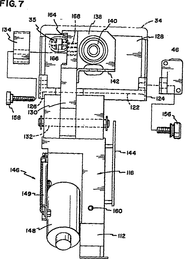
図11は、ICカード分離リーダーの1つがカードを分離する手順を示している。工程のこの部分において、カードはICカード分離リーダーに配られる。ステップ260において、ICカードリーダーはコンフィグレーションされる。このことは、どのような種類の分離が行われるか、例えば、メモリーカード、ICカード等、どのような種類のキーがアプリケーションの中で利用されているか、そしてどのアプリケーションコードがリーダーモジュールに対してダウンロードされるかについての表示を含んでいる。ステップ262において、ICカードは、電源投入される。ステップ264において、ICカードのシリアル番号(SN)と製造識別番号(ID)が読み込まれる。ステップ266A、B、そしてCにおいて、3つの並行タスクが、キーカードリーダーからのキー情報の入手を開始する。ステップ268において、ICカードの鍵を解除し、そしてステップ270において、アプリケーションデータがICカードに書き込まれる。ステップ272において、発行機のデータとキーがICカードに書き込まれる。ステップ274において、RSAの標記によるキーがICカードに書き込まれる。ステップ276において、データ保護がセットされ、そしてICカードは動作状態にされる。ステップ278において、カードはベリファイされ、そしてステップ280においてカードの電源が切られる。
図12は、ICカード分離リーダーのリーダーモジュールにより実行される操作のフローチャートである。図中、2重線は外部のモジュール又はタスクとの通信を表わし、破線はエラー処理を表わす。
図13は、キーカードリーダーのアプリケーション例を示している。図中、カード識別番号(ID)は、カードID情報に基づいてベリファイされる。このカードID情報は、プログラムされたカードがあるICカード分離リーダーにおけるICカードプログラミングモジュールのリーダーコントローラーより受け取る。
図14は、特定のリーダーのリーダーコントローラとICカードプログラミングモジュールのモジュールコントローラ間の通信を示すフローチャートである。
図15は、ICカードプログラミングモジュールへのICカードとそのデータの到着、そして動作コントローラ(MC)による特定のICカードリーダーへのカードの移動、及びそこから出口への移動を示したフローチャートである。
図16は、把持機構(ピッカーキャリッジ)によるリーダーN、そして(又は)リーダーNへのカードの移動を示したフローチャートである。
本発明では、好適な実施例の関係において表現されているので、実施例への種々の変更は明らで容易であることが理解される。そして本発明は、それについてのどんな改良又は派生をも包含するであろう。本発明は、クレームとその同等物にのみ限定されることを明らかに意図する。Field of the invention
The present invention relates to an IC card programming device for programming an IC card (integrated circuit card) sometimes called a “smart card”.
Background of the Invention
The present invention relates to an IC card programming device for programming an IC card. IC cards are often used as credit or identification cards. Like credit cards, IC cards may have embossed characters on their surface, or magnetic stripes for printing or storing data. Integrated circuits serve a similar purpose as magnetic stripes, but generally have more capacity and are more stable storage media for data storage.
Conventional circuit card programming devices, such as those disclosed in U.S. Pat.No. 4,866,259 to Bonnemoy and U.S. Pat. I didn't have it. Further, neither Bonnemoy nor Linden discloses a device capable of programming an IC card having an integrated circuit arranged in a position of French standard or ISO standard.
Summary of the Invention
The present invention solves the problems present in the prior art by providing an IC card programming device having a separation station that can program the card in both French and ISO standard locations. The separation station can also be rotated 180 ° to program either side of the IC card. The IC card programming device of the present invention includes a base, a card input table, and a transport unit. The transport unit is connected to the base and is mounted so as to be rotatable about a rotation axis. The transfer unit includes a transfer arm arranged radially with respect to the rotation axis. The transfer arm has a distal end and a proximal end, where the proximal end is near the axis of rotation. The card picker carriage is mounted on the transport arm such that it can move between a first position near the distal end and a second position near the proximal end. One or more separation stations are radially arranged around the axis of rotation.
The card picker carriage can grip the card from the input table at the first position. The card picker carriage is then moved toward the second position and the transport is rotated about the axis of rotation to a position where the radial position coincides with one of the separation stations. The card picker carriage is then moved to a first position to place the card at a separation station for programming the card.
The present invention also includes an improved picker carriage for gripping an IC card. The picker carriage includes a chassis and a backstop connected to the chassis. The picker carriage also has two picker arms. Each picker arm has a picker end opposite the backstop and a second end. Each picker arm is rotatably connected to the chassis between a first end and a second end. The picker carriage also includes a shaft member having first and second ends disposed opposite each other. The second end of one picker arm is rotatably connected to the first end of the shaft member, and the second end of the other picker arm is connected to the second end of the shaft member. Is rotatably connected to A portion located between the first end and the second end of the shaft member has an arched surface and is connected to the shaft member.
The carriage also includes an actuator for driving the picker arm. The actuator has an actuator rod at the distal end of the arched surface. The arched end is held against the arched surface of the shaft member by biasing means for biasing the surfaces together. The arcuate end and the arcuate surface are connected to the picker arm from a first position where the picker end is separated from the backstop by the picker end having a backstop to grip the card between the picker end and the backstop. The arcuate distal end of the actuator is substantially concentric so as to be able to push against the arcuate surface of the shaft member for rotation to a second, proximal position.
The invention also includes an improved separation station for programming an IC card. The separation station includes a separation station base that can be connected to an IC card programming device base. The station also includes card receiving means for gripping the IC card to be programmed. The card receiving means has at least one contact facing the integrated circuit located on the card. The station also includes flip mounting means for mounting the card receiving means on the base. The reversing attachment means receives the card so that the card receiving means has a first position on the base where the contacts are located on a first side of the base and a contact located on an opposing second side of the base. The means may be mounted in a second position substantially 180 ° rotated about the axis of rotation.
The invention also relates to a separation station similar to the one described above, which has a contact pin housing for mounting the contacts in a first position corresponding to the French standard and a second position corresponding to the ISO standard. is there. The contact pin housing may be used on a separation station that is integrated with the inverted mounting means, or may be used on a separation station that is not integrated with the inverted mounting means.
[Brief description of the drawings]
1 is a perspective view of an IC card programming device according to the present invention;
2 is a cross-sectional view of the IC card programming device shown in FIG. 1;
3 is an end view of a cross-sectional view of the IC card programming device shown in FIG. 2;
Figure 4 is a perspective view of the picker carriage;
Figure 5 is a perspective view of the separation station;
Figure 6 is an end view of the separation station;
Figure 7 is a side view of the separation station;
FIG. 8 is a block diagram showing a control system of an IC card programming device and various inputs and outputs thereof;
FIG. 9 shows a card processing system;
FIG. 10A is a diagram showing system control of a programming module of an IC card;
FIG. 10B shows a leader board and a card head breakout board;
FIG. 11 is a diagram showing a procedure for separating a card;
FIG. 12 is a logic flow diagram showing processing performed by the reader module;
Figure 13 shows a sample key card reader application;
FIG. 14 is a logic flow diagram showing communication between a reader controller and a programming module controller of an IC card;
FIG. 15 is a flow diagram showing the arrival of the IC card and its separated data to the IC card module;
FIG. 16 is a flowchart showing the movement of the IC card by the gripping mechanism.
Description of the preferred embodiment
With reference to the drawings, in which reference is made to parts or corresponding parts identified by reference numerals in some of the figures, FIG. 1 is a schematic perspective view of a
In addition, the IC
Three drive motors including a
Further, the IC
FIG. 2 shows a sectional view of the
FIG. 3 shows a side view of the section shown in FIG.
FIG. 4 is an external perspective view of the
As shown in FIGS. 2 to 4, the
The card input table 22 includes a
The pushing
The card output stand 24 has a
As shown in FIGS. 3 and 4, the
In addition, the
FIG. 4 shows the pick-up
FIG. 5 is an external perspective view of the
The card holding means 116 includes an
The
Also disposed close to the first end of the
As shown in FIG. 6, disposed adjacent the second end of the
In the presently preferred embodiment, the reversing mounting means 154 includes a generally extending
As shown in FIG. 7, the
In addition, the
In use, the IC
In the general technique, a controller, an IC
While the
When the program ends, the
Overall, all
When performing batch processing of cards through the IC
When the card processing is started, the
When the
At that time, the
Carriage drive
While the
After the
At this time, the
As another embodiment of the IC card programming device, as described above, the card input table is arranged close to the
As shown in FIG. 4, the arrow near the
FIG. 8 shows an input of the system controller 200 of the IC card programming device, its sensors and a key card reader, etc., and several motors, an IC card separation reader at an IC card separation station, and a solenoid of the IC card programming device. FIG. 4 is a block diagram showing an output of the embodiment. It will be appreciated that the IC card programming device may be part of an overall typical
It will be appreciated that the control of the programming module is implemented in various ways.
10A-B, the
The
The module
As is apparent from the above, the IC card separation reader is tasked with separating or programming the integrated circuit (IC) card. These readers are the only ones that can operate the card in and out of the
In this embodiment, there may be up to four key card readers that access the integrated circuit (IC) card provided. These key card readers include a reader controller that operates in cooperation with them, and are internally connected to a module controller 252 by a
Check batch processing to make sure the correct card was used
Issuer confirmation and data to obtain specific data for the issuer
Generate security or enable password for protection key
A production job that processes a typical batch of cards constitutes the application code together with the non-separated card and data set used to separate the cards. The
In a typical card processing system, the
RESET: Used by the system controller to determine the type of card processing module and bring the IC card processing module to a known state.
PROCESS: Used by the system controller to initiate card and data processing at a given module of the card processing system. There is one processing command sent to the IC card processing module for each card. The system controller requires each module of the card processing system to carefully operate both card and data in strict FIFO format.
STATUS: Used by the system controller to request module status.
DIAG: Used by the system controller to send module diagnostic commands.
MODULE: Used by the system controller to send module specific commands.
CONFIG: Used by the system controller to send configuration and initialization data to the module.
To perform a particular production job, the system controller sends the following sequence of commands to each module (RESET; CONFIG; according to the order of the PROCESS command along the card data). The PROCESS command is sent for processing for each card or until an error occurs.
The module controller in the IC card programming module responds to the system controller in the following format.
RESET: The system module controller reports the number of valid IC card separation readers. Further, the system control module returns to the gripping mechanism. The module's card queue is logically emptied. Any card that receives a RESET command inside the module will not be isolated. Any applications loaded inside the module, even if requested, will be erased.
CONFIG: Parameters for machine operation control, such as IC card reader offset, are sent to the module controller. The IC card programming module is checked whether the application to be executed has already been loaded. If not, a new application is downloaded for each IC card separation reader, as with a key card reader. Thus, a dynamic linking language (DLL) is used to form applications inside any reader with a key card reader and an IC card separation reader. It will be appreciated that in some embodiments only an IC card separation reader or only a key card reader is formed.
PROCESS: Along with the separation data of the card, the card is simultaneously input into the module. The card is placed inside the next empty IC card separation reader according to the sequence. The data is then sent to an IC card separation reader to activate the application. The module controller then completes the status of the separation of the particular card, as well as the status of all mechanical operations on the
The following shows the result of the PROCESS command sequence. In this particular example, the smart card programming module comprises only three smart card separation readers for the purpose of this embodiment. However, it will be appreciated that the particular pattern is retained no matter how many smart card separation readers. S1, S2 and S3 are three IC card separation readers. The passage of time depends on the order of the rows. This particular example shows the result after each of the seven PROCESS commands has been executed by the module controller of the IC card programming module.
FIG. 11 shows a procedure in which one of the IC card separation readers separates the card. In this part of the process, the cards are dealt to an IC card separation reader. In
FIG. 12 is a flowchart of the operation executed by the reader module of the IC card separation reader. In the figure, a double line indicates communication with an external module or task, and a broken line indicates error processing.
FIG. 13 shows an application example of a key card reader. In the figure, a card identification number (ID) is verified based on card ID information. This card ID information is received from the reader controller of the IC card programming module in the IC card separation reader having the programmed card.
FIG. 14 is a flowchart showing communication between a reader controller of a specific reader and a module controller of an IC card programming module.
FIG. 15 is a flowchart showing the arrival of the IC card and its data to the IC card programming module, the movement of the card to a specific IC card reader by the operation controller (MC), and the movement from there to the exit.
FIG. 16 is a flowchart showing movement of the reader N and / or the card to the reader N by the gripping mechanism (picker carriage).
In the present invention, it is understood that various modifications to the embodiments are obvious and easy because they are expressed in the context of the preferred embodiment. And the present invention will cover any modifications or derivations thereof. It is expressly intended that this invention be limited only to the claims and the equivalents.
Claims (4)
ベースと、
カード入力台と、
ベースに接続され、回転軸の回りに回転可能に取り付けられた搬送部であって、前記回転軸から放射状に設けられ末端部と前記回転軸付近に位置する基端部とを有する搬送アームと、該アーム上に設けられ前記末端部付近の第1の位置と前記基端部付近の第2の位置との間で移動するカードピッカーキャリッジとを有する搬送部と、
前記ピッカーキャリッジが前記第1の位置において、前記入力台からカードを把持し、前記ピッカーキャリッジが前記第2の位置に向かって移動され、前記搬送部が分 離ステーションのうちの1つと半径方向の位置が一致する位置に前記回転軸の回りに回転し、前記カードを、前記カードをプログラムするための前記分離ステーション内に位置させるために、前記ピッカーキャリッジが前記第1の位置に向かって移動される様に、前記回転軸の回りに放射状に配置された1つ以上の分離ステーションと、
を具備することを特徴とするICカードのプログラミング装置。An IC card programming device for programming an IC card,
Base and
Card input stand,
A transfer unit connected to the base and rotatably mounted around a rotation axis, the transfer arm having a distal end provided radially from the rotation axis and a base end positioned near the rotation axis, A transfer unit provided on the arm and having a card picker carriage that moves between a first position near the distal end and a second position near the proximal end;
In the picker carriage said first position, to grip the card from said input stage, said picker carriage is moved toward the second position, the one radial direction of the conveying portion of the separation station The picker carriage is moved toward the first position to rotate about the axis of rotation to a coincident position and to position the card in the separation station for programming the card. One or more separation stations radially disposed about the axis of rotation,
A programming device for an IC card, comprising:
ベースと、
カード入力台と、
ベースに接続され、回転軸の回りに回転可能に取り付けられた搬送部であって、前記回転軸から放射状に設けられ末端部と前記回転軸付近に位置する基端部とを有する搬送アームと、該アーム上に設けられ前記末端部付近の第1の位置と前記基端部付近の第2の位置との間で移動するカードピッカーキャリッジとを有する搬送部と、
前記ピッカーキャリッジが前記第2の位置において、前記入力台からカードを把持し、前記搬送部が分離ステー ションのうちの1つと半径方向の位置が一致する位置に前記回転軸の回りに回転し、前記カードを、前記カードをプログラムするための前記分離ステーション内に位置させるために、前記ピッカーキャリッジが前記第1の位置に向かって移動される様に、前記回転軸の回りに放射状に配置された1つ以上の分離ステーションと、
を具備することを特徴とするICカードのプログラミング装置。An IC card programming device for programming an IC card,
Base and
Card input stand,
A transfer unit connected to the base and rotatably mounted around a rotation axis, the transfer arm having a distal end provided radially from the rotation axis and a base end positioned near the rotation axis, A transfer unit provided on the arm and having a card picker carriage that moves between a first position near the distal end and a second position near the proximal end;
In the picker carriage is the second position, gripping the card from the input stage, the transport unit is rotated about said rotary shaft in one radial position coincides position of the separating station, The card is radially arranged around the axis of rotation such that the picker carriage is moved toward the first position to position the card in the separation station for programming the card. One or more separation stations;
A programming device for an IC card, comprising:
Applications Claiming Priority (3)
| Application Number | Priority Date | Filing Date | Title |
|---|---|---|---|
| US07/993,105 | 1992-12-18 | ||
| US07/993,105 US5332889A (en) | 1992-12-18 | 1992-12-18 | Integrated circuit card programming device |
| PCT/US1993/012347 WO1994015306A1 (en) | 1992-12-18 | 1993-12-16 | Integrated circuit card programming device |
Publications (2)
| Publication Number | Publication Date |
|---|---|
| JPH08504990A JPH08504990A (en) | 1996-05-28 |
| JP3585174B2 true JP3585174B2 (en) | 2004-11-04 |
Family
ID=25539096
Family Applications (1)
| Application Number | Title | Priority Date | Filing Date |
|---|---|---|---|
| JP51533294A Expired - Fee Related JP3585174B2 (en) | 1992-12-18 | 1993-12-16 | IC card programming device |
Country Status (5)
| Country | Link |
|---|---|
| US (3) | US5332889A (en) |
| EP (1) | EP0674791B1 (en) |
| JP (1) | JP3585174B2 (en) |
| DE (1) | DE69333203D1 (en) |
| WO (1) | WO1994015306A1 (en) |
Families Citing this family (99)
| Publication number | Priority date | Publication date | Assignee | Title |
|---|---|---|---|---|
| US5332889A (en) * | 1992-12-18 | 1994-07-26 | Datacard Corporation | Integrated circuit card programming device |
| JPH0765134A (en) * | 1993-08-27 | 1995-03-10 | Tamura Electric Works Ltd | Data communication method |
| US7424731B1 (en) | 1994-10-12 | 2008-09-09 | Touchtunes Music Corporation | Home digital audiovisual information recording and playback system |
| US7188352B2 (en) | 1995-07-11 | 2007-03-06 | Touchtunes Music Corporation | Intelligent digital audiovisual playback system |
| DE69422647T2 (en) | 1994-10-12 | 2000-08-31 | Touchtunes Music Corp | INTELLIGENT SYSTEM FOR NUMERICAL AUDIO-VISUAL REPRODUCTION |
| DE19517818C2 (en) * | 1995-05-18 | 1997-12-18 | Angewandte Digital Elektronik | Method for issuing individual chip cards to a plurality of individual chip card users using a neutral chip card dispensing station |
| FR2740240B1 (en) * | 1995-10-20 | 1997-11-21 | Gemplus Card Int | CHIP CARD READER |
| US6678753B1 (en) * | 1995-12-20 | 2004-01-13 | Fujitsu Limited | IC card reading/writing apparatus and method for allowing use of multiple vendors |
| US5837991A (en) * | 1996-03-08 | 1998-11-17 | Card Technology Corporation | Card transport mechanism and method of operation |
| FR2746531B1 (en) * | 1996-03-19 | 1998-05-22 | Leroux Gilles Sa | HIGH-THROUGHPUT PERSONALIZATION MACHINE |
| US5889941A (en) | 1996-04-15 | 1999-03-30 | Ubiq Inc. | System and apparatus for smart card personalization |
| DE19634230A1 (en) * | 1996-08-23 | 1998-02-26 | Kubat Mechanik Gmbh | Reading and writing method and device for chip cards |
| FR2753868A1 (en) | 1996-09-25 | 1998-03-27 | Technical Maintenance Corp | METHOD FOR SELECTING A RECORDING ON AN AUDIOVISUAL DIGITAL REPRODUCTION SYSTEM AND SYSTEM FOR IMPLEMENTING THE METHOD |
| GB9621438D0 (en) * | 1996-10-15 | 1996-12-04 | Ncr Int Inc | Improved card reader/writer |
| US5780827A (en) * | 1996-10-16 | 1998-07-14 | Verifone, Inc. | Landing contact mechanism and card latch for smart card reader/writer |
| US6202155B1 (en) | 1996-11-22 | 2001-03-13 | Ubiq Incorporated | Virtual card personalization system |
| JPH10171935A (en) * | 1996-12-13 | 1998-06-26 | Nec Corp | Multi hopper embosser |
| US6317832B1 (en) * | 1997-02-21 | 2001-11-13 | Mondex International Limited | Secure multiple application card system and process |
| AU770900B2 (en) * | 1997-03-24 | 2004-03-04 | Visa International Service Association | A system and method for a multi-application smart card which can facilitate a post-issuance download of an application into the smart card |
| AU746459B2 (en) | 1997-03-24 | 2002-05-02 | Visa International Service Association | A system and method for a multi-application smart card which can facilitate a post-issuance download of an application onto the smart card |
| US5941522A (en) * | 1997-05-13 | 1999-08-24 | Fargo Electronics, Inc. | Printer with auxiliary operation |
| US7574727B2 (en) | 1997-07-23 | 2009-08-11 | Touchtunes Music Corporation | Intelligent digital audiovisual playback system |
| FR2766945B1 (en) * | 1997-07-29 | 1999-10-29 | Leroux Gilles Sa | HIGH-THROUGHPUT PERSONALIZATION MACHINE |
| FR2769165B1 (en) | 1997-09-26 | 2002-11-29 | Technical Maintenance Corp | WIRELESS SYSTEM WITH DIGITAL TRANSMISSION FOR SPEAKERS |
| EP0914001A1 (en) | 1997-10-28 | 1999-05-06 | CANAL+ Société Anonyme | Downloading of applications in a digital decoder |
| US5969318A (en) * | 1997-11-24 | 1999-10-19 | Mackenthun; Holger | Gateway apparatus for designing and issuing multiple application cards |
| DE19754914A1 (en) * | 1997-12-10 | 1999-06-24 | Amphenol Tuchel Elect | Smart card reader |
| FR2775098B1 (en) * | 1998-02-16 | 2000-05-12 | Leroux Gilles Sa | LINEAR PERSONALIZATION MACHINE |
| US6446832B1 (en) | 1998-03-27 | 2002-09-10 | Datacard Corporation | Virtual multihopper card feeder |
| JPH11309967A (en) * | 1998-04-27 | 1999-11-09 | Sony Corp | Card printing equipment |
| TW426630B (en) * | 1998-05-28 | 2001-03-21 | Asahi Seiko Co Ltd | IC card processing machine |
| US6360952B1 (en) * | 1998-05-29 | 2002-03-26 | Digital Privacy, Inc. | Card access system supporting multiple cards and card readers |
| FR2781582B1 (en) | 1998-07-21 | 2001-01-12 | Technical Maintenance Corp | SYSTEM FOR DOWNLOADING OBJECTS OR FILES FOR SOFTWARE UPDATE |
| US8028318B2 (en) | 1999-07-21 | 2011-09-27 | Touchtunes Music Corporation | Remote control unit for activating and deactivating means for payment and for displaying payment status |
| FR2781580B1 (en) | 1998-07-22 | 2000-09-22 | Technical Maintenance Corp | SOUND CONTROL CIRCUIT FOR INTELLIGENT DIGITAL AUDIOVISUAL REPRODUCTION SYSTEM |
| FR2781591B1 (en) | 1998-07-22 | 2000-09-22 | Technical Maintenance Corp | AUDIOVISUAL REPRODUCTION SYSTEM |
| US6481632B2 (en) | 1998-10-27 | 2002-11-19 | Visa International Service Association | Delegated management of smart card applications |
| US6220511B1 (en) | 1998-11-10 | 2001-04-24 | Datacard Corporation | Card issuance system and process |
| US7339690B2 (en) * | 1999-07-14 | 2008-03-04 | Fargo Electronics, Inc. | Identification card printer with client/server |
| FR2796482B1 (en) | 1999-07-16 | 2002-09-06 | Touchtunes Music Corp | REMOTE MANAGEMENT SYSTEM FOR AT LEAST ONE AUDIOVISUAL INFORMATION REPRODUCING DEVICE |
| JP3330355B2 (en) | 1999-08-31 | 2002-09-30 | ニスカ株式会社 | Card recording device |
| US6695205B1 (en) * | 1999-09-23 | 2004-02-24 | Datacard Corporation | Integrated circuit card programming modules, systems and methods |
| US6279901B1 (en) | 1999-10-29 | 2001-08-28 | Fargo Electronics, Inc. | Identification card inverter that maintains the card support plane |
| FR2805377B1 (en) | 2000-02-23 | 2003-09-12 | Touchtunes Music Corp | EARLY ORDERING PROCESS FOR A SELECTION, DIGITAL SYSTEM AND JUKE-BOX FOR IMPLEMENTING THE METHOD |
| US6588673B1 (en) * | 2000-02-08 | 2003-07-08 | Mist Inc. | Method and system providing in-line pre-production data preparation and personalization solutions for smart cards |
| FR2805060B1 (en) | 2000-02-16 | 2005-04-08 | Touchtunes Music Corp | METHOD FOR RECEIVING FILES DURING DOWNLOAD |
| FR2805072B1 (en) | 2000-02-16 | 2002-04-05 | Touchtunes Music Corp | METHOD FOR ADJUSTING THE SOUND VOLUME OF A DIGITAL SOUND RECORDING |
| FR2808906B1 (en) | 2000-05-10 | 2005-02-11 | Touchtunes Music Corp | DEVICE AND METHOD FOR REMOTELY MANAGING A NETWORK OF AUDIOVISUAL INFORMATION REPRODUCTION SYSTEMS |
| CN1386242A (en) * | 2000-06-09 | 2002-12-18 | 索尼株式会社 | IC card recording and/or reproducing device |
| JP4660901B2 (en) * | 2000-09-12 | 2011-03-30 | ソニー株式会社 | IC card recording and / or reproducing device |
| FR2811175B1 (en) | 2000-06-29 | 2002-12-27 | Touchtunes Music Corp | AUDIOVISUAL INFORMATION DISTRIBUTION METHOD AND AUDIOVISUAL INFORMATION DISTRIBUTION SYSTEM |
| FR2811114B1 (en) | 2000-06-29 | 2002-12-27 | Touchtunes Music Corp | DEVICE AND METHOD FOR COMMUNICATION BETWEEN A SYSTEM FOR REPRODUCING AUDIOVISUAL INFORMATION AND AN ELECTRONIC ENTERTAINMENT MACHINE |
| FR2814085B1 (en) | 2000-09-15 | 2005-02-11 | Touchtunes Music Corp | ENTERTAINMENT METHOD BASED ON MULTIPLE CHOICE COMPETITION GAMES |
| US7399131B2 (en) | 2001-03-05 | 2008-07-15 | Fargo Electronics, Inc. | Method and Device for forming an ink-receptive card substrate |
| FR2831147B1 (en) * | 2001-10-19 | 2004-02-06 | Leroux Gilles Sa | TRANSPORT DEVICE IN A CARD EMBOSSING SYSTEM |
| FR2832947B1 (en) | 2001-12-04 | 2004-03-19 | Briot Int | OPTICAL GLASS GRINDING MACHINE |
| US6902107B2 (en) * | 2002-01-28 | 2005-06-07 | Datacard Corporation | Card personalization system and method |
| US7430762B2 (en) * | 2002-03-01 | 2008-09-30 | Fargo Electronics, Inc. | Identification card manufacturing security |
| US7290146B2 (en) * | 2004-05-03 | 2007-10-30 | Fargo Electronics, Inc. | Managed credential issuance |
| US20040060984A1 (en) * | 2002-04-18 | 2004-04-01 | Connelly Paul J. | Smart card handling system |
| US8584175B2 (en) | 2002-09-16 | 2013-11-12 | Touchtunes Music Corporation | Digital downloading jukebox system with user-tailored music management, communications, and other tools |
| US12100258B2 (en) | 2002-09-16 | 2024-09-24 | Touchtunes Music Company, Llc | Digital downloading jukebox with enhanced communication features |
| US11029823B2 (en) | 2002-09-16 | 2021-06-08 | Touchtunes Music Corporation | Jukebox with customizable avatar |
| US7822687B2 (en) | 2002-09-16 | 2010-10-26 | Francois Brillon | Jukebox with customizable avatar |
| US9646339B2 (en) | 2002-09-16 | 2017-05-09 | Touchtunes Music Corporation | Digital downloading jukebox system with central and local music servers |
| US8332895B2 (en) | 2002-09-16 | 2012-12-11 | Touchtunes Music Corporation | Digital downloading jukebox system with user-tailored music management, communications, and other tools |
| US10373420B2 (en) | 2002-09-16 | 2019-08-06 | Touchtunes Music Corporation | Digital downloading jukebox with enhanced communication features |
| US7620815B2 (en) * | 2003-02-21 | 2009-11-17 | Fargo Electronics, Inc. | Credential production using a secured consumable supply |
| US20040193759A1 (en) * | 2003-03-31 | 2004-09-30 | Scott Roger M. | Method and system for providing a smart card scripting tool |
| WO2005026908A2 (en) * | 2003-09-11 | 2005-03-24 | Fargo Electronics, Inc. | Identification card manufacturing system supply ordering and diagnostic report |
| FR2862409B1 (en) * | 2003-11-17 | 2006-04-14 | Datacard Inc | ADAPTER ELEMENT FOR PROGRAMMABLE ELECTRONIC SUPPORTS |
| US8099187B2 (en) | 2005-08-18 | 2012-01-17 | Hid Global Corporation | Securely processing and tracking consumable supplies and consumable material |
| US20070043684A1 (en) * | 2005-08-18 | 2007-02-22 | Fargo Electronics, Inc. | Central Management of a Credential Production System |
| US7963438B2 (en) * | 2005-11-10 | 2011-06-21 | Magtek, Inc. | System and method for personalizing a card |
| CN101401110A (en) | 2006-01-25 | 2009-04-01 | 奥迪安有限公司 | Apparatus and process for producing document inlays |
| US7523495B2 (en) * | 2006-04-19 | 2009-04-21 | Multos Limited | Methods and systems for IC card application loading |
| US8544733B2 (en) * | 2006-04-28 | 2013-10-01 | Giesecke & Devrient Gmbh | Method and apparatus for personalizing portable data storage media |
| US9171419B2 (en) | 2007-01-17 | 2015-10-27 | Touchtunes Music Corporation | Coin operated entertainment system |
| US9330529B2 (en) | 2007-01-17 | 2016-05-03 | Touchtunes Music Corporation | Game terminal configured for interaction with jukebox device systems including same, and/or associated methods |
| US12450978B2 (en) | 2007-01-17 | 2025-10-21 | Touchtunes Music Company Llc. | Coin operated entertainment system |
| US9953481B2 (en) | 2007-03-26 | 2018-04-24 | Touchtunes Music Corporation | Jukebox with associated video server |
| US8332887B2 (en) | 2008-01-10 | 2012-12-11 | Touchtunes Music Corporation | System and/or methods for distributing advertisements from a central advertisement network to a peripheral device via a local advertisement server |
| US10290006B2 (en) | 2008-08-15 | 2019-05-14 | Touchtunes Music Corporation | Digital signage and gaming services to comply with federal and state alcohol and beverage laws and regulations |
| FR2923631A1 (en) * | 2007-11-12 | 2009-05-15 | Datacard Corp | METHOD AND SYSTEM FOR CUSTOMIZING SMART OBJECTS |
| WO2010005747A2 (en) * | 2008-06-16 | 2010-01-14 | Data I/O Corporation | Programmer actuator system and method of operation thereof |
| WO2010005569A1 (en) | 2008-07-09 | 2010-01-14 | Touchtunes Music Corporation | Digital downloading jukebox with revenue-enhancing features |
| US10564804B2 (en) | 2009-03-18 | 2020-02-18 | Touchtunes Music Corporation | Digital jukebox device with improved user interfaces, and associated methods |
| US10719149B2 (en) | 2009-03-18 | 2020-07-21 | Touchtunes Music Corporation | Digital jukebox device with improved user interfaces, and associated methods |
| WO2010107490A1 (en) | 2009-03-18 | 2010-09-23 | Touchtunes Music Corporation | Entertainment server and associated social networking services |
| US9292166B2 (en) | 2009-03-18 | 2016-03-22 | Touchtunes Music Corporation | Digital jukebox device with improved karaoke-related user interfaces, and associated methods |
| US12112093B2 (en) | 2009-03-18 | 2024-10-08 | Touchtunes Music Company, Llc | Entertainment server and associated social networking services |
| WO2010126994A1 (en) * | 2009-04-28 | 2010-11-04 | Mastercard International Incorporated | Apparatus, method, and computer program product for recovering torn smart payment device transactions |
| EP2568472A1 (en) | 2010-01-26 | 2013-03-13 | Touchtunes Music Corporation | Digital jukebox device with improved user interfaces, and associated methods |
| JP6002770B2 (en) | 2011-09-18 | 2016-10-05 | タッチチューンズ ミュージック コーポレーション | Digital jukebox device with karaoke and / or photo booth functions and related techniques |
| US11151224B2 (en) | 2012-01-09 | 2021-10-19 | Touchtunes Music Corporation | Systems and/or methods for monitoring audio inputs to jukebox devices |
| US9921717B2 (en) | 2013-11-07 | 2018-03-20 | Touchtunes Music Corporation | Techniques for generating electronic menu graphical user interface layouts for use in connection with electronic devices |
| CN119170060A (en) | 2014-03-25 | 2024-12-20 | 踏途音乐有限责任公司 | Digital on-demand device with improved user interface and related method |
| EP3238151A4 (en) * | 2014-12-22 | 2018-06-06 | Capital One Services, LLC | A system, method and apparatus for reprogramming a transaction card |
| EP4121900A4 (en) * | 2020-03-17 | 2024-04-10 | Entrust Corporation | PLASTIC CARD PROCESSING EQUIPMENT WITH BIOMETRIC CARD SENSOR VERIFICATION |
Family Cites Families (24)
| Publication number | Priority date | Publication date | Assignee | Title |
|---|---|---|---|---|
| US3433932A (en) * | 1964-11-30 | 1969-03-18 | Rca Corp | Punched card reader |
| FR2524251A1 (en) * | 1982-03-26 | 1983-09-30 | Outillages Scient Lab | MACHINE FOR AUTOMATICALLY INSERTING ELECTRONIC COMPONENTS, IN PARTICULAR INTEGRATED CIRCUITS, ON PRINTED CIRCUITS |
| US4431322A (en) * | 1982-09-20 | 1984-02-14 | Ncr Canada Ltd - Ncr Canada Ltee | Multiple path recording means |
| US4602351A (en) * | 1983-07-06 | 1986-07-22 | Tokyo Tatsuno Co., Ltd. | Device for reading and writing IC-external storage cards |
| JPS6031671A (en) * | 1983-08-01 | 1985-02-18 | Oki Electric Ind Co Ltd | Id card reading and writing device |
| JPS60167065A (en) * | 1984-02-09 | 1985-08-30 | Tokyo Tatsuno Co Ltd | Reader of plate storage medium |
| FR2575566B1 (en) * | 1984-12-28 | 1990-06-22 | Bull Sa | METHOD FOR CUSTOMIZING PORTABLE MEDIA SUCH AS CARDS |
| US4874935A (en) * | 1986-03-10 | 1989-10-17 | Data Card Coprporation | Smart card apparatus and method of programming same |
| US4814592A (en) * | 1986-05-29 | 1989-03-21 | Videomat Associates | Apparatus and method for storing and retrieving articles |
| DE3618091C1 (en) * | 1986-05-30 | 1987-09-10 | Allied Corp., Morristown, N.J., Us | |
| FR2602603B1 (en) * | 1986-08-08 | 1988-11-18 | Bonnemoy Marc | AUTOMATIC CARD PERSONALIZATION APPARATUS |
| US4827425A (en) * | 1986-10-31 | 1989-05-02 | Thorn Emi Malco, Incorporated | System for personalization of integrated circuit microchip cards |
| US4798945A (en) * | 1987-01-30 | 1989-01-17 | Ncr Corporation | Grabber mechanism for a badge reader terminal |
| US4810863A (en) * | 1987-08-03 | 1989-03-07 | Kabushikikaisha Nipponcoinco | Read/write apparatus for information memory card |
| JPH0161764U (en) * | 1987-10-09 | 1989-04-19 | ||
| US4871905A (en) * | 1987-10-09 | 1989-10-03 | Omron Tateisi Electronics Co. | IC card reader/writer |
| US4825054A (en) * | 1988-02-16 | 1989-04-25 | Datacard Corporation | Method and apparatus for parallel integrated circuit card initialization and embossing |
| JPH0823878B2 (en) * | 1988-04-21 | 1996-03-06 | 沖電気工業株式会社 | Card writing / reading device |
| US5146069A (en) * | 1988-09-19 | 1992-09-08 | Fuji Photo Film Co., Ltd. | Device for loading and unloading a memory cartridge using a sliding member |
| DE68926141T2 (en) * | 1988-10-14 | 1996-12-12 | Omron Tateisi Electronics Co | Card reader with locking mechanism |
| US4995501A (en) * | 1988-11-23 | 1991-02-26 | Datacard Corporation | Transport system and method for embossing apparatus |
| FR2659463B1 (en) * | 1990-03-08 | 1994-09-30 | Sagem | APPARATUS FOR READING THE TRACK OF IDENTIFICATION CHARACTERISTICS OF A CHECK. |
| US5161992A (en) * | 1992-01-17 | 1992-11-10 | Amp Incorporated | Electrical connector assembly for a card containing an integrated circuit chip |
| US5332889A (en) * | 1992-12-18 | 1994-07-26 | Datacard Corporation | Integrated circuit card programming device |
-
1992
- 1992-12-18 US US07/993,105 patent/US5332889A/en not_active Expired - Lifetime
-
1993
- 1993-12-16 WO PCT/US1993/012347 patent/WO1994015306A1/en not_active Ceased
- 1993-12-16 DE DE69333203T patent/DE69333203D1/en not_active Expired - Lifetime
- 1993-12-16 EP EP94904490A patent/EP0674791B1/en not_active Expired - Lifetime
- 1993-12-16 JP JP51533294A patent/JP3585174B2/en not_active Expired - Fee Related
-
1994
- 1994-01-12 US US08/180,657 patent/US5378884A/en not_active Expired - Lifetime
- 1994-10-20 US US08/326,330 patent/US5614707A/en not_active Expired - Fee Related
Also Published As
| Publication number | Publication date |
|---|---|
| US5378884A (en) | 1995-01-03 |
| DE69333203D1 (en) | 2003-10-16 |
| US5332889A (en) | 1994-07-26 |
| EP0674791A4 (en) | 1999-05-26 |
| EP0674791B1 (en) | 2003-09-10 |
| JPH08504990A (en) | 1996-05-28 |
| EP0674791A1 (en) | 1995-10-04 |
| US5614707A (en) | 1997-03-25 |
| WO1994015306A1 (en) | 1994-07-07 |
Similar Documents
| Publication | Publication Date | Title |
|---|---|---|
| JP3585174B2 (en) | IC card programming device | |
| US6345760B1 (en) | Machine for process for IC cards and apparatus for issuing IC cards | |
| US6141298A (en) | Programmable self-operating compact disk duplication system | |
| US4788419A (en) | Ticket processing terminal with a single-cylinder ticket advancing mechanism | |
| JP2001527677A (en) | Printer with auxiliary operation | |
| JP2011524060A (en) | How to handle storage devices | |
| US7145841B1 (en) | Programmable self-operating compact disk duplication system | |
| US20060138217A1 (en) | Smart card handling system | |
| US6027301A (en) | Semiconductor wafer testing apparatus with a combined wafer alignment/wafer recognition station | |
| CN111517143B (en) | Card stacker, card stacker assembly, and method of adding a card base to the bottom of a card stack | |
| US9460370B2 (en) | Card storage and ejection module | |
| US6822932B2 (en) | Programmable self-operating compact disk duplication system | |
| JP2000298707A (en) | Medium issuing device and card issuing device | |
| US6301204B1 (en) | Jukebox with control system to retry transfer if misalignment | |
| EP1979859B1 (en) | Apparatus and process for producing document core inlays | |
| JP3650443B2 (en) | Electronic component mounting method and apparatus | |
| JP4003006B2 (en) | IC card processing machine | |
| CN101124137B (en) | Document substrate rotator and processing module | |
| JPH01130358A (en) | Writing device for flexible disk | |
| JP2586669B2 (en) | Prepaid card processing device | |
| WO1993025979A1 (en) | Ticket processing terminal | |
| JP2000322633A (en) | Card processing device and card processing system | |
| JPH0962800A (en) | Card recovering device | |
| JPS62242286A (en) | Card reader/writer with discriminating function | |
| JP2001143022A (en) | Ic card issuing device |
Legal Events
| Date | Code | Title | Description |
|---|---|---|---|
| A521 | Request for written amendment filed |
Free format text: JAPANESE INTERMEDIATE CODE: A523 Effective date: 20040510 |
|
| TRDD | Decision of grant or rejection written | ||
| A01 | Written decision to grant a patent or to grant a registration (utility model) |
Free format text: JAPANESE INTERMEDIATE CODE: A01 Effective date: 20040706 |
|
| A61 | First payment of annual fees (during grant procedure) |
Free format text: JAPANESE INTERMEDIATE CODE: A61 Effective date: 20040802 |
|
| R150 | Certificate of patent or registration of utility model |
Free format text: JAPANESE INTERMEDIATE CODE: R150 |
|
| FPAY | Renewal fee payment (event date is renewal date of database) |
Free format text: PAYMENT UNTIL: 20080813 Year of fee payment: 4 |
|
| LAPS | Cancellation because of no payment of annual fees |