JP3579976B2 - Piping leak monitoring device - Google Patents
Piping leak monitoring device Download PDFInfo
- Publication number
- JP3579976B2 JP3579976B2 JP22004495A JP22004495A JP3579976B2 JP 3579976 B2 JP3579976 B2 JP 3579976B2 JP 22004495 A JP22004495 A JP 22004495A JP 22004495 A JP22004495 A JP 22004495A JP 3579976 B2 JP3579976 B2 JP 3579976B2
- Authority
- JP
- Japan
- Prior art keywords
- leak
- pipe
- flow
- monitoring device
- valve
- Prior art date
- Legal status (The legal status is an assumption and is not a legal conclusion. Google has not performed a legal analysis and makes no representation as to the accuracy of the status listed.)
- Expired - Fee Related
Links
Images


Landscapes
- Examining Or Testing Airtightness (AREA)
Description
【0001】
【産業上の利用分野】
本発明は、流体を輸送する輸送管路の流体漏洩の有無を自動的に検知する配管漏洩監視装置に関するものである。
【0002】
【従来の技術】
従来、流体を輸送する管路の漏洩監視装置は、特開平4−64787号公報や特開平4−363638号公報に示すようなガス供給配管の漏洩監視装置の構成が知られていた。以下、その構成について図10と図11を参照しながら説明する。
【0003】
まず、図10に示す従来例では、プロパンガスなどのガス供給源1と、ガス供給管2と、ガス供給源1からの供給ガス全体を積算する親ガスメーター3と、各供給先の個別ガス使用量を積算する個別ガスメーター4と、個々のガス器具5とで構成とされていた。ここで、親ガスメーター3には、流量検出機構6およびこの検出機構により検出されたデータを取り入れて正常であるか否かを判断するCPU7と、前記CPU7によって演算されたデータを信号線8を通じて取り出す通信制御器9を備え、そのデータを電話回線10を通じてセンター側のホストコンピューター11に送出している構成であった。ここで、12は圧力調整器、13はバルブである。
【0004】
このような構成において、親ガスメーター3に設置された流量検出機構6で流量を検出し、ガス使用減少時間帯、最低流量およびこれらの偏差値を学習し、これらの総合値と、現在データとを比較して現在データが正常の範囲に収まっているか否かを判断し、異常と見なされた場合に警報出力を発生するものである。
【0005】
また、図11に示す別の従来例では、ガス供給源1からの供給ガス全体を積算する親ガスメーター3と、ガス供給管2と、各供給先の個別ガスメーター4を経てガス器具5に供給するとともに、前記親ガスメーター3および個別ガスメーター4は、流量発信機能14を有し、前記各ガスメーターを管理する管理装置15との間に流量情報の交換自在なガス供給漏洩監視装置としていた。ここで、16は微小漏洩監視メーターである。
【0006】
このような構成において、一日のうちのガス使用量の少ない時間帯に所定時間の間のガス流量を各ガスメーター別に管理装置に流量発信機能により集め、親ガスメーター3の流量値Nsと、各個別ガスメーター4の流量値N1,N2,………Nnの和N1+N2+………+Nnとを比較し、Ns≦N1+N2+………+Nn …(式1)
の場合は漏洩無しと見なし、Ns>N1+N2+………+Nn …(式2)
の場合は漏洩ありとする漏洩判断方法を有する構成としていた。
【0007】
【発明が解決しようとする課題】
しかしながら従来例のような配管漏洩監視装置では、全宅のガス器具が同時に使用されない期間があるという前提の下に配管漏洩判別を行っているが、集合住宅の宅数が多くなり、居住者の生活形態が様々になってくると、本当に個別ガスメータの上流にガス漏れが有るのか、それとも実際にガスエアコンのようなガス器具が連続して使われているのかあいまいになり、配管漏洩判別手段による漏洩判断の信頼性が著しく低下してしまう課題、さらに、口火の連続使用があった場合でもガスメータ上流にガス漏れ有りと誤って判別してしまうという課題があった。
【0008】
また、別の従来例では、ガス流量計測で±3%程度の誤差があるため、各個別ガスメータの流量総和を求めるときに、各メーターの誤差が重畳して拡大し、漏洩判断の信頼性が著しく低下してしまう課題、そして、戸数が多くなってくると各個別メーターの流量の集計を同時刻に行うことが非常に困難で、親ガスメーターの計測時刻と異なる時刻に計測された各個別メーターの流量総和を比較しても漏洩を判断する情報としては信頼性が低いという課題があった。
【0009】
本発明は上記課題を解決するもので、遮断弁によって管路を閉塞して下流側圧力検出手段で管路内の圧力変動を測定して漏洩を確実に精度よく判定することを第1の目的としている。
【0010】
そして、遮断弁に並行したバイパス流路に減圧弁を設けることによって、下流側でガス器具が使用されたときでもガスを切らすことなく供給することを第2の目的としている。
【0011】
また、下流に設けられた複数個の個別流量計測手段によって管路内の流れ情報を検出することで既設管路への設置を容易にすることを第3の目的としている。
【0012】
さらに、下流に設けられた複数個のガス器具の運転情報によってガス使用情報を検出しガスの流れを確実に検知することを第4の目的としている。
【0013】
そして、遮断弁の上流側の上流圧力検出手段と下流圧力検出手段の2つの圧力比較によって管路内の流れ情報を検出することを第5の目的としている。
【0014】
また、減圧弁が開いたとき遮断弁も開口して漏洩判定を停止し、ガス供給を自動的に可能にすることを第6の目的としている。
【0015】
また、定期的に行う漏洩判定と、定期判定時刻の間の時間帯にガス使用パターンからガス使用が少ない時間帯に漏洩判定を行い判定精度を向上することを第7の目的としている。
【0016】
また、複数回の漏洩判定結果が全回一致したときに漏洩と判定することで漏洩判定精度を向上することを第8の目的としている。
【0017】
また、複数回の漏洩判定結果のうち1回でも漏洩と判定したときに漏洩判定とすることで安全側に判定して漏洩事故を防止することを第9の目的としている。
【0018】
また、複数個の個別流量計測手段と制御手段を無線通信によって情報交換することで漏洩監視装置の設置性を向上することを第10の目的としている。
【0019】
また、瞬時流量計測手段で管路内の流れが停止したことを判定するので遮断弁を閉止しても、ガス器具の失火などのトラブルを防止することを第11の目的としている。
【0020】
そして、漏洩ありと判定されたときデータ伝送装置によって通報することを第12の目的としている。
【0021】
【課題を解決するための手段】
本発明は上記課題を解決するために、制御手段は、上流圧力検出手段で検出された圧力値が下流圧力検出手段で検出された圧力値以下の時に遮断弁を閉止し、前記上流圧力検出手段で検出された圧力値が前記下流圧力検出手段で検出された圧力値より大きい時に漏洩監視を停止して前記遮断弁を開口する構成とした。
【0022】
【作用】
本発明は上記構成によって、遮断弁によって管路を閉塞して下流側圧力検出手段で管路内の圧力変動を測定して漏洩を確実に精度よく判定することができる。
【0023】
そして、遮断弁の上流側の上流圧力検出手段と下流圧力検出手段の2つの圧力比較によって管路内の流れ情報を検出することができる。
【0024】
【実施例】
以下、本発明の第1の実施例の配管漏洩監視装置を、図1から図5を参照して説明する。
【0025】
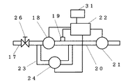
図1と図2に示すように、管路17に設けた遮断弁18と、前記遮断弁18の下流に備えた下流圧力検出手段19と、前記下流圧力検出手段19の更に下流側管路20に備えた管路内流れ検出手段としての瞬時流量計21と、前記瞬時流量計21によって下流側管路20内の流量が所定値以下になった時に遮断弁18を閉止し、前記下流圧力検出手段19の圧力変動を測定して漏洩を監視する制御手段22を備えた構成とした。そして、遮断弁18の上流側と下流側を別流路で接続するバイパス流路23と、前記バイパス流路23の途中に減圧弁24を備えた構成とした。ここで、25は主管路、26は手動式遮断弁、27は個別流量計測手段、28はガス器具、29は集合住宅、30は地面、31はデータ伝送装置としての無線電話装置である。
【0026】
このような構成において、制御手段22では、瞬時流量計21の情報によって流量を監視し、流量が所定値Q0以下になったときに、遮断弁18を閉止する。そして、下流側の圧力検出手段19によって測定された下流側管路20内の圧力変動が、図3に示すように、所定時間ΔT以内に所定値ΔP以上低下すれば漏洩と判定することができる。計測が完了すれば、遮断弁18は再び開きガスを正常に供給するものである。ここで、瞬時流量計21を使用しているため、流量が所定値以下になることを瞬時に判定することができ、遮断弁18を閉止してもガス器具28の失火などのトラブルを発生することがない。従来の膜式流量計では、1時間計測して流量が所定値以下であっても、今現在の流量がわからないので、遮断弁を閉止すると使用され始めたガス器具を失火させるという問題があった。
【0027】
そして、遮断弁18を閉止して圧力を計測している間に、もしもガス器具が使用された場合、図4に示すように、下流側管路20内の圧力が低下し、減圧弁に設定された所定の圧力P1に達すると、減圧弁24からガスが供給され、ガス器具は正常に運転することができる。減圧弁24が動作すれば、漏洩判定を停止すると共に遮断弁も開口し、ガス器具が最大燃焼になる前にガスは正常に供給され安全に運転することができるのである。
【0028】
また、漏洩判定は所定の間隔で定期的に行われるが、定期的に行う漏洩監視では、所定時刻T1になれば、その時刻T1より最初に流量がQ0以下になった時に漏洩監視を行うが、その場合には、比較的大きい流量状態の場合や短時間後にガス器具が使用されてうまく測定できないことがあり、判定の信頼性が悪くなる場合があった。しかし、その定期間隔の間にもパターン学習によって漏洩監視に最も適した時間帯を探し出して漏洩判定を行うことで漏洩監視の信頼性を高めることができる。それは、図5に示すように、制御手段によりガス流量を監視していて流量が、長時間に渡り所定流量Q0以下になる最も測定条件のよいときをパターン学習して検出する。そして、その時刻になれば遮断弁を閉止して、漏洩を監視する。このように、最も測定条件のよい時刻T0を検出して、漏洩監視することで判定精度と信頼性を向上することができるのである。
【0029】
さらに、前記漏洩監視を複数回行うことで、その複数回の判定結果を用いて、全回の判定結果が一致したときに、漏洩と判定することで判定精度を向上し、ガス供給の誤遮断を防止することができる。また、別のアルゴリズムでは1回でも漏洩と判定したときに、漏洩と判定することで、安全側に動作させてガス供給の安全性を高めることができる。これらのアルゴリズムは、状況に応じて使用することができ、漏洩監視装置を設置した直後は、全回一致のアルゴを採用して漏洩監視の適用性を確認しながら監視を行い、所定期間経過して漏洩監視が正常に行われるようになれば、漏洩判定を1回で決定するようにしていくことで誤動作を低減することができる。また、漏洩監視装置を設置してからの経過時間を見ながら、漏洩判定を行う回数や漏洩を決定する方法を変更していく機能を付加しておくことで、自動的に判定精度を向上していくことができる。
【0030】
そして、ここで漏洩と判定された場合、制御手段22に接続された無線電話装置31によって、漏洩警報がガス供給管理センターなどへ自動的に通報される。無線電話装置を用いることで配線工事がいらないし、電話番号を登録しておくことによって様々なところに容易に異常通報を行うことができる。
【0031】
次に、第2の実施例について図6と図7を用いて説明する。上記第一の実施例と同一構造で、かつ同一作用をする部分には同一符号を付して詳細な説明は略し、異なる部分を中心に説明する。
【0032】
図6と図7に示すように、遮断弁18の下流側に備えられた複数個の個別流量計測手段である各ガスメーター27の流量信号によって下流側管路20内の流れを判定する管路内流れ判定手段を備えた構成とした。ここで、32は第1の無線通信手段、33は第2の無線通信手段である。
【0033】
このような構成において、各ガスメーター27の流量情報を第1の無線通信手段32で送信し、制御手段22に備えた第2の無線通信手段33で受信する。各ガスメーター27の流量情報が全て所定値以下になったときに、流量停止と判定し、遮断弁18を閉止する。そして、下流側管路20内の圧力を測定して漏洩判定を行うのである。漏洩判定は、第1の実施例と同様に行うものである。そして、各ガスメーターのうち、1台でも流量を関知したとき、その情報を無線信号にて制御手段22に伝え、漏洩監視を停止すると共に、遮断弁を開口するものである。このように、ガスメーターが既に設置されている集合住宅の場合、無線通信手段を各ガスメーターに設置する工事を追加するだけでよく簡単に施工作業が行える効果がある。
【0034】
次に、第3の実施例について図8を用いて説明する。上記第一の実施例と同一構造で、かつ同一作用をする部分には同一符号を付して詳細な説明は略し、異なる部分を中心に説明する。
【0035】
図8に示すように、遮断弁18の下流側に備えられた複数個のガス器具28からの運転情報によって下流側管路20内の流れを判定する管路内流れ検出手段を備えた構成とした。
【0036】
このような構成において、各ガス器具28の運転情報を第1の無線通信手段32で送信し、制御手段22に備えた第2の無線通信手段33で受信する。各ガス器具28の運転情報が全て運転停止になったときに、流量停止と判定し、遮断弁18を閉止する。そして、下流側管路20内の圧力を測定して漏洩判定を行うことができるのである。漏洩判定は、第1の実施例と同様に行うものである。ここで、各ガス器具のうち、1台でも運転を関知したとき、その情報を無線信号にて制御手段22に伝え、漏洩監視を停止すると共に、遮断弁18を開口するものである。このように、ガスメーターが既に設置されている集合住宅の場合、無線通信手段を各ガス器具に設置する工事を追加するだけでよく簡単に施工作業が行える効果がある。
【0037】
次に、第4の実施例について図9を用いて説明する。上記第一の実施例と同一構造で、かつ同一作用をする部分には同一符号を付して詳細な説明は略し、異なる部分を中心に説明する。
【0038】
図9に示すように、遮断弁18の上流側に備えた上流圧力検出手段34で検出された第1の圧力値P1と下流圧力検出手段19で検出された第2の圧力値P2とが制御手段22に入力され、第1の圧力値P1と第2の圧力値P2とを比較することによって管路17内の流れを検出する管路内流れ検出手段を備えた構成とした。
【0039】
このような構成において、第1の圧力値P1と、第2の圧力値P2が、P1≦P2の関係になったときに、流量停止と判定し、遮断弁18を閉止する。そして、下流側管路20内の圧力を下流圧力検出手段19で測定して漏洩判定を行うことができるのである。漏洩判定は、第1の実施例と同様に行うものである。そして、P1>P2となった時、ガスが使用され始めたと判定し、漏洩監視を停止すると共に、遮断弁18を開口するものである。
【0040】
また、遮断弁18の上流側に上流圧力検出手段を設けることによって、遮断弁18が閉止されている場合でも、バイパス流路23が開口していれば、管路内の流れがどの方向に流れているかが判定できるものである。よって、減圧弁24が長時間、開口している状態が続いている場合でも、P1、P2によって管路の流れを監視することができ、その流量、すなわち圧力差が所定流量以下であれば、漏洩監視を行うこともできる。
【0041】
以上のように本発明の実施例を総括的に述べれば、次の効果が得られる。
【0042】
遮断弁によって管路を閉塞して下流側圧力検出手段で管路内の圧力変動を判定して漏洩を確実に精度よく判定することができる。
【0043】
また、遮断弁に並行したバイパス流路に減圧弁を設けることによって、下流側でガス器具が使用されたときでもガスを供給することができ、失火を防止することができる。
【0044】
また、下流に設けられた複数個の個別流量計測手段によって管路内の流れ情報を検出することで既設管路への設置を容易にすることができる。
【0045】
また、下流に設けられた複数個のガス器具の運転情報によってガス使用情報を検出しガスの使用情報を確実に検知することができる。
【0046】
また、遮断弁の上流側の上流圧力検出手段と下流圧力検出手段の2つの圧力比較によって管路内の流れ情報を検出することができる。
【0047】
また、減圧弁が開いたとき遮断弁も開口して漏洩判定を停止し、ガス使用を自動的に可能にすることができる。
【0048】
また、定期判定時刻の間の時間帯にガス使用パターンからガス使用が少ない時間帯に漏洩判定を行い判定精度を向上することができる。
【0049】
また、複数回の漏洩判定結果が全回一致したときに漏洩と判定することで漏洩判定精度を向上することができる。
【0050】
また、複数回の漏洩判定結果のうち1回でも漏洩と判定したときに漏洩判定とすることで安全側に判定して漏洩事故を防止することができる。
【0051】
また、複数個の個別流量計測手段と制御手段を無線通信によって情報交換することで漏洩監視装置の設置性を向上することができる。
【0052】
また、瞬時流量計測手段の情報により管路内の流れが停止したことを判定するので、現在の流れ状態とよく対応しているので、遮断弁を閉止してもガス器具の失火などのトラブルを防止することができる。そして、漏洩ありと判定されたとき電話回線によって通報することができ、様々なところに容易に通報することができる。
【0053】
【発明の効果】
以上のように本発明の配管漏洩監視装置によれば、遮断弁によって管路を閉塞して下流側圧力検出手段で管路内の圧力変動を判定して漏洩を確実に精度よく判定することができる。
【図面の簡単な説明】
【図1】本発明の実施例を示す配管漏洩監視装置の構成図
【図2】同装置の制御手段周辺の構成図
【図3】同装置の動作を説明する特性図
【図4】同装置の別の動作を説明する特性図
【図5】同装置のさらに別の動作を説明する特性図
【図6】本発明の他の実施例を示す配管漏洩監視装置の構成図
【図7】同装置の制御手段周辺の構成図
【図8】本発明の他の実施例を示す配管漏洩監視装置の構成図
【図9】本発明のさらに他の実施例を示す配管漏洩監視装置の構成図
【図10】従来の配管漏洩監視装置の構成図
【図11】従来の他の配管漏洩監視装置の構成図
【符号の説明】
17 管路
18 遮断弁
19 下流圧力検出手段
20 下流側管路
21 瞬時流量計(管路内流れ検出手段)
22 制御手段
23 バイパス流路
24 減圧弁
27 ガスメーター(個別流量計測手段)
28 ガス器具
31 無線電話装置(データ伝送装置)
32 第1の無線通信手段
33 第2の無線通信手段
34 上流側圧力検出手段[0001]
[Industrial applications]
The present invention relates to a pipe leakage monitoring device that automatically detects the presence or absence of a fluid leak in a transport pipeline that transports a fluid.
[0002]
[Prior art]
2. Description of the Related Art Conventionally, as a leak monitoring device for a pipeline for transporting a fluid, a configuration of a leak monitoring device for a gas supply pipe as disclosed in Japanese Patent Application Laid-Open Nos. 4-64787 and 4-36338 has been known. Hereinafter, the configuration will be described with reference to FIGS. 10 and 11.
[0003]
First, in the conventional example shown in FIG. 10, a
[0004]
In such a configuration, the flow rate is detected by the flow
[0005]
In another conventional example shown in FIG. 11, the gas is supplied to a
[0006]
In such a configuration, the gas flow rate during a predetermined time period during the day when the gas consumption is small is collected for each gas meter in the management device by the flow transmission function, and the flow rate value Ns of the
, Ns> N1 + N2 +... + Nn (Equation 2)
In the case of (1), the configuration is such that there is a leakage determination method that there is leakage.
[0007]
[Problems to be solved by the invention]
However, in a pipe leak monitoring device such as a conventional example, pipe leak determination is performed on the assumption that there is a period in which gas appliances in all houses are not used at the same time. As the lifestyle changes, it becomes unclear whether there is a gas leak upstream of the individual gas meter, or whether gas appliances such as gas air conditioners are actually used continuously. There is a problem that the reliability of the leak determination is significantly reduced, and furthermore, there is a problem that even when there is continuous use of a spark ignition, a gas leak is erroneously determined upstream of the gas meter.
[0008]
In another conventional example, there is an error of about ± 3% in the gas flow rate measurement. Therefore, when calculating the total flow rate of each individual gas meter, the error of each meter is superimposed and enlarged, and the reliability of the leak judgment is reduced. If the number of units increases, it is very difficult to calculate the flow rate of each individual meter at the same time, and each individual meter measured at a different time from the measurement time of the parent gas meter However, there is a problem that the reliability of the information for judging the leakage is low even when the sum of the flow rates is compared.
[0009]
A first object of the present invention is to solve the above-mentioned problems, and to provide a method for closing a pipe by a shutoff valve and measuring pressure fluctuations in the pipe by a downstream pressure detecting means to accurately and accurately determine a leak. And
[0010]
A second object of the present invention is to provide a pressure reducing valve in a bypass flow path parallel to a shutoff valve so that gas can be supplied without cutting even when a gas appliance is used on the downstream side.
[0011]
It is a third object of the present invention to facilitate installation in an existing pipeline by detecting flow information in the pipeline by a plurality of individual flow rate measuring means provided downstream.
[0012]
It is a fourth object of the present invention to detect gas usage information based on operation information of a plurality of gas appliances provided downstream and to reliably detect a gas flow.
[0013]
A fifth object is to detect flow information in the pipeline by comparing two pressures of an upstream pressure detection unit and a downstream pressure detection unit on the upstream side of the shutoff valve.
[0014]
It is a sixth object of the present invention to open the shut-off valve when the pressure reducing valve is opened, to stop the leak determination, and to automatically enable gas supply.
[0015]
It is a seventh object of the present invention to improve the determination accuracy by performing a leak determination performed periodically based on the gas usage pattern during a time period between the leak determination performed periodically and the periodic determination time based on the gas usage pattern, and improving the determination accuracy.
[0016]
It is an eighth object of the present invention to improve the accuracy of leak determination by determining a leak when a plurality of leak determination results match all times.
[0017]
A ninth object of the present invention is to prevent a leakage accident by making a leak determination when a leak is determined even once among a plurality of leak determination results.
[0018]
A tenth object is to improve the installability of the leak monitoring device by exchanging information between a plurality of individual flow rate measuring means and control means by wireless communication.
[0019]
An eleventh object is to prevent a trouble such as a misfire of a gas appliance even if the shutoff valve is closed, since the instantaneous flow rate measuring means determines that the flow in the pipeline has stopped.
[0020]
The twelfth object is to provide notification by the data transmission device when it is determined that there is leakage.
[0021]
[Means for Solving the Problems]
In order to solve the above-mentioned problems, the present invention provides a control device, comprising: closing a shut-off valve when a pressure value detected by an upstream pressure detection device is equal to or less than a pressure value detected by a downstream pressure detection device; and configured to open the shut-off valve detected pressure value in stops the detected pressure value greater than during leakage monitoring in the downstream pressure detection means.
[0022]
[ Action]
According to the above configuration of the invention, Ru can be determined and reliably accurate measurements to leak the pressure fluctuations in the conduit downstream pressure detection means closes the duct by shielding Danben.
[0023]
Their to, Ru can be detected flow information in the conduit by means of two pressure comparing the upstream side of the upstream pressure detection means and the downstream pressure detection means shielding sectional valve.
[0024]
[ Example]
Hereinafter, a pipe leakage monitoring device according to a first embodiment of the present invention will be described with reference to FIGS.
[0025]
As shown in FIGS. 1 and 2, a
[0026]
In such a configuration, the control means 22 monitors the flow rate based on the information of the
[0027]
If the gas appliance is used while the shut-off
[0028]
In addition, although the leak determination is periodically performed at a predetermined interval, in the leak monitoring that is periodically performed, when a predetermined time T1 is reached, the leak monitoring is performed when the flow rate becomes equal to or less than Q0 for the first time from the time T1. In such a case, the measurement may not be performed well due to the use of the gas appliance in a relatively large flow rate state or after a short time, and the reliability of the determination may be deteriorated. However, even during the regular interval, the reliability of leak monitoring can be improved by searching for the most suitable time zone for leak monitoring by pattern learning and performing leak determination. As shown in FIG. 5, the gas flow rate is monitored by the control means, and when the flow rate is equal to or less than the predetermined flow rate Q0 for a long time, the best measurement condition is detected by pattern learning and detected. Then, at that time, the shutoff valve is closed, and the leakage is monitored. As described above, the detection accuracy and reliability can be improved by detecting the time T0 having the best measurement condition and monitoring the leakage.
[0029]
Furthermore, by performing the leak monitoring a plurality of times, using the results of the plurality of determinations, when the determination results of all the times match, the determination accuracy is improved by determining the leakage, and the erroneous shutoff of the gas supply is improved. Can be prevented. Further, in another algorithm, when it is determined that there is a leak even once, it is determined to be a leak, so that it can be operated on the safe side and the safety of gas supply can be improved. These algorithms can be used depending on the situation. Immediately after the installation of the leak monitoring device, monitoring is performed while confirming the applicability of leak monitoring using an algorithm that matches all times, and after a predetermined period of time. If the leak monitoring can be performed normally, the malfunction can be reduced by determining the leak determination once. In addition, by adding the function of changing the number of leak determinations and the method of determining leaks while watching the elapsed time since the installation of the leak monitoring device, the accuracy of the determination is automatically improved. You can go.
[0030]
Then, if it is determined that there is a leak, a leak alarm is automatically notified to the gas supply management center or the like by the
[0031]
Next, a second embodiment will be described with reference to FIGS. Portions having the same structure and the same function as those in the first embodiment are denoted by the same reference numerals, detailed description is omitted, and different portions will be mainly described.
[0032]
As shown in FIGS. 6 and 7, the flow in the
[0033]
In such a configuration, the flow rate information of each
[0034]
Next, a third embodiment will be described with reference to FIG. Portions having the same structure and the same function as those in the first embodiment are denoted by the same reference numerals, detailed description is omitted, and different portions will be mainly described.
[0035]
As shown in FIG. 8, a configuration including a pipe flow detection unit that determines a flow in the
[0036]
In such a configuration, the operation information of each
[0037]
Next, a fourth embodiment will be described with reference to FIG. Portions having the same structure and the same function as those in the first embodiment are denoted by the same reference numerals, detailed description is omitted, and different portions will be mainly described.
[0038]
As shown in FIG. 9, the first pressure value P1 detected by the upstream pressure detecting means 34 provided on the upstream side of the
[0039]
In such a configuration, when the first pressure value P1 and the second pressure value P2 satisfy a relationship of P1 ≦ P2, it is determined that the flow is stopped, and the
[0040]
In addition, by providing the upstream pressure detecting means on the upstream side of the shut-off
[0041]
Stated embodiments of the present invention comprehensively as above, the following effects can Ru obtained.
[0042]
The closes the conduit by barrier Danben determines the pressure fluctuations in the line downstream pressure detection means leaks can be determined reliably and accurately.
[0043]
Further, by providing the pressure reducing valve in the bypass flow path parallel to the shutoff valve, gas can be supplied even when the gas appliance is used on the downstream side, and misfire can be prevented.
[0044]
Further, it is possible to facilitate installation on existing pipeline by detecting the flow information in the conduit by a plurality of individual flow rate measuring means provided in the lower stream.
[0045]
Further, it is possible to detect gas usage information based on operation information of a plurality of gas appliances provided downstream, and to reliably detect gas usage information.
[0046]
Further, flow information in the pipeline can be detected by comparing two pressures of the upstream pressure detection means and the downstream pressure detection means on the upstream side of the shutoff valve.
[0047]
Also, shut-off valve when the reducing valve is opened even opened to stop the leakage determination, it is possible to automatically allow the gas used.
[0048]
Further, it is possible to improve the determination accuracy perform leakage determination time zone gas used is small from the gas usage patterns in the time zone between periodic determination time.
[0049]
Further, it is possible to improve the leakage determination accuracy by several leakage determination result birefringence is determined to leak if they match all times.
[0050]
Further, it is possible to prevent leaks by determining the safe side by the leakage determination when it is determined that the leakage even once among the multiple times of leakage determination result.
[0051]
Further, it is possible to improve the installation of the leakage monitoring device by the information exchanging control means and multiple several individual flow rate measuring means by wireless communication.
[0052]
Further, since the judgment that the flow conduit by the information of instantaneous bandwagon amount measuring means has stopped, troubles such as the current because the flow conditions are well compatible, misfire gas appliance also closes the shut-off valve Can be prevented. Then, when it is determined that there is a leak, a report can be made via a telephone line, and a report can be easily made to various places.
[0053]
【The invention's effect】
As described above, according to the pipe leak monitoring device of the present invention, the pipe line is closed by the shutoff valve, and the pressure change in the pipe line is determined by the downstream pressure detecting means, so that the leak can be reliably and accurately determined. it can.
[Brief description of the drawings]
FIG. 1 is a configuration diagram of a pipe leakage monitoring device showing an embodiment of the present invention. FIG. 2 is a configuration diagram around control means of the device. FIG. 3 is a characteristic diagram illustrating the operation of the device. FIG. 5 is a characteristic diagram illustrating still another operation of the device. FIG. 6 is a configuration diagram of a pipe leakage monitoring device according to another embodiment of the present invention. FIG. 8 is a block diagram of a pipe leak monitoring device showing another embodiment of the present invention. FIG. 9 is a block diagram of a pipe leak monitoring device showing still another embodiment of the present invention. FIG. 10 is a block diagram of a conventional pipe leak monitoring device. FIG. 11 is a block diagram of another conventional pipe leak monitoring device.
17
22 control means 23
28
32 first wireless communication means 33 second wireless communication means 34 upstream pressure detecting means
Claims (11)
Priority Applications (1)
| Application Number | Priority Date | Filing Date | Title |
|---|---|---|---|
| JP22004495A JP3579976B2 (en) | 1995-08-29 | 1995-08-29 | Piping leak monitoring device |
Applications Claiming Priority (1)
| Application Number | Priority Date | Filing Date | Title |
|---|---|---|---|
| JP22004495A JP3579976B2 (en) | 1995-08-29 | 1995-08-29 | Piping leak monitoring device |
Publications (2)
| Publication Number | Publication Date |
|---|---|
| JPH0961284A JPH0961284A (en) | 1997-03-07 |
| JP3579976B2 true JP3579976B2 (en) | 2004-10-20 |
Family
ID=16745051
Family Applications (1)
| Application Number | Title | Priority Date | Filing Date |
|---|---|---|---|
| JP22004495A Expired - Fee Related JP3579976B2 (en) | 1995-08-29 | 1995-08-29 | Piping leak monitoring device |
Country Status (1)
| Country | Link |
|---|---|
| JP (1) | JP3579976B2 (en) |
Families Citing this family (25)
| Publication number | Priority date | Publication date | Assignee | Title |
|---|---|---|---|---|
| AT3027U1 (en) * | 1998-07-09 | 1999-08-25 | Heinrich Weingartner | METHOD AND DEVICE FOR CHECKING PIPING SYSTEMS |
| JP2003090777A (en) * | 2001-09-20 | 2003-03-28 | Ito Koki Kk | Gas leakage detector |
| KR100878681B1 (en) * | 2002-12-10 | 2009-01-13 | 주식회사 포스코 | Pneumatic Valve Driven Air Pressure Controller |
| KR200445590Y1 (en) * | 2009-05-12 | 2009-08-14 | 주식회사 에스티모빅 | Gas station monitoring device |
| US9851103B2 (en) | 2011-12-15 | 2017-12-26 | Honeywell International Inc. | Gas valve with overpressure diagnostics |
| US9846440B2 (en) | 2011-12-15 | 2017-12-19 | Honeywell International Inc. | Valve controller configured to estimate fuel comsumption |
| US9995486B2 (en) | 2011-12-15 | 2018-06-12 | Honeywell International Inc. | Gas valve with high/low gas pressure detection |
| US9557059B2 (en) | 2011-12-15 | 2017-01-31 | Honeywell International Inc | Gas valve with communication link |
| US9835265B2 (en) | 2011-12-15 | 2017-12-05 | Honeywell International Inc. | Valve with actuator diagnostics |
| US10422531B2 (en) | 2012-09-15 | 2019-09-24 | Honeywell International Inc. | System and approach for controlling a combustion chamber |
| CN103712755B (en) * | 2013-06-14 | 2016-06-29 | 清华大学 | A kind of simulate the assay device that natural gas leaks in soil |
| EP2868970B1 (en) | 2013-10-29 | 2020-04-22 | Honeywell Technologies Sarl | Regulating device |
| US10024439B2 (en) | 2013-12-16 | 2018-07-17 | Honeywell International Inc. | Valve over-travel mechanism |
| US9841122B2 (en) | 2014-09-09 | 2017-12-12 | Honeywell International Inc. | Gas valve with electronic valve proving system |
| US9645584B2 (en) | 2014-09-17 | 2017-05-09 | Honeywell International Inc. | Gas valve with electronic health monitoring |
| US10503181B2 (en) | 2016-01-13 | 2019-12-10 | Honeywell International Inc. | Pressure regulator |
| US10564062B2 (en) | 2016-10-19 | 2020-02-18 | Honeywell International Inc. | Human-machine interface for gas valve |
| CN107366834B (en) * | 2017-08-22 | 2024-03-26 | 上海科勒电子科技有限公司 | Water pipe water leakage detection method, storage medium and electronic equipment |
| US11073281B2 (en) | 2017-12-29 | 2021-07-27 | Honeywell International Inc. | Closed-loop programming and control of a combustion appliance |
| US10697815B2 (en) | 2018-06-09 | 2020-06-30 | Honeywell International Inc. | System and methods for mitigating condensation in a sensor module |
| CN109211478A (en) * | 2018-07-17 | 2019-01-15 | 中石化石油工程技术服务有限公司 | A kind of experimental system and method for simulation high sulfur-containing natural gas leakage environment |
| CN109372078A (en) * | 2018-10-30 | 2019-02-22 | 武汉圣禹排水系统有限公司 | A kind of flow control methods and control system of shunting well |
| JP7149458B2 (en) * | 2018-11-05 | 2022-10-07 | パナソニックIpマネジメント株式会社 | gas meter |
| CN113029471A (en) * | 2021-02-24 | 2021-06-25 | 佛山市三水燃气有限公司 | Intelligent gas pressure measuring method and device based on Internet of things |
| CN114484294A (en) * | 2021-12-29 | 2022-05-13 | 东本电气科技(苏州)有限公司 | Gas riser leak detection method and leak detection device |
-
1995
- 1995-08-29 JP JP22004495A patent/JP3579976B2/en not_active Expired - Fee Related
Also Published As
| Publication number | Publication date |
|---|---|
| JPH0961284A (en) | 1997-03-07 |
Similar Documents
| Publication | Publication Date | Title |
|---|---|---|
| JP3579976B2 (en) | Piping leak monitoring device | |
| CN102667422B (en) | From monitoring stream measuring device and the method for its operation | |
| US8448525B2 (en) | Differential pressure based flow measurement | |
| EA024948B1 (en) | Fluid leakage detection system | |
| JP3538989B2 (en) | Piping leak monitoring device | |
| KR20100075819A (en) | Flow rate metering device, flow rate measuring system, and flow rate measuring method | |
| JPH04363638A (en) | Monitoring method of leakage for gas supply system | |
| JP3901159B2 (en) | Gas pipe leak monitoring device | |
| KR100264677B1 (en) | Gas Leakage Detection Auto Alarm Control System | |
| JPH1164055A (en) | Flow-measuring instrument | |
| JP2604981B2 (en) | Gas leak monitoring device | |
| JP3438955B2 (en) | Gas leak detection device for common piping | |
| JPH0829289A (en) | Gas leak monitoring apparatus | |
| JP3393593B2 (en) | Gas leak detection device | |
| JP7523265B2 (en) | Gas supply abnormality detection system | |
| JP3042248B2 (en) | Gas supply equipment abnormality monitoring device | |
| JP2611083B2 (en) | Gas leak detection device | |
| JP7466390B2 (en) | Gas supply abnormality detection system | |
| JP2001337004A (en) | Gas leak inspection system | |
| JP3221556B2 (en) | Anomaly detection device, anomaly detection method, and medium recording anomaly detection program | |
| JP2009168739A (en) | Gas meter with self-diagnostic function | |
| JPH1151383A (en) | Safety device for gas burning appliance | |
| JPH0520568A (en) | Gas security equipment | |
| JPH0476309A (en) | Device to detect abnormality in gas supply facilities | |
| JPH07117473B2 (en) | Pipeline leak detector |
Legal Events
| Date | Code | Title | Description |
|---|---|---|---|
| A977 | Report on retrieval |
Free format text: JAPANESE INTERMEDIATE CODE: A971007 Effective date: 20031126 |
|
| A131 | Notification of reasons for refusal |
Free format text: JAPANESE INTERMEDIATE CODE: A131 Effective date: 20031209 |
|
| A521 | Written amendment |
Free format text: JAPANESE INTERMEDIATE CODE: A523 Effective date: 20040209 |
|
| A131 | Notification of reasons for refusal |
Free format text: JAPANESE INTERMEDIATE CODE: A131 Effective date: 20040330 |
|
| A521 | Written amendment |
Free format text: JAPANESE INTERMEDIATE CODE: A523 Effective date: 20040531 |
|
| TRDD | Decision of grant or rejection written | ||
| A01 | Written decision to grant a patent or to grant a registration (utility model) |
Free format text: JAPANESE INTERMEDIATE CODE: A01 Effective date: 20040629 |
|
| A61 | First payment of annual fees (during grant procedure) |
Free format text: JAPANESE INTERMEDIATE CODE: A61 Effective date: 20040712 |
|
| FPAY | Renewal fee payment (event date is renewal date of database) |
Free format text: PAYMENT UNTIL: 20070730 Year of fee payment: 3 |
|
| FPAY | Renewal fee payment (event date is renewal date of database) |
Free format text: PAYMENT UNTIL: 20080730 Year of fee payment: 4 |
|
| FPAY | Renewal fee payment (event date is renewal date of database) |
Free format text: PAYMENT UNTIL: 20090730 Year of fee payment: 5 |
|
| FPAY | Renewal fee payment (event date is renewal date of database) |
Free format text: PAYMENT UNTIL: 20090730 Year of fee payment: 5 |
|
| FPAY | Renewal fee payment (event date is renewal date of database) |
Free format text: PAYMENT UNTIL: 20100730 Year of fee payment: 6 |
|
| FPAY | Renewal fee payment (event date is renewal date of database) |
Free format text: PAYMENT UNTIL: 20110730 Year of fee payment: 7 |
|
| LAPS | Cancellation because of no payment of annual fees |