JP3570576B2 - 3D image synthesis and display device compatible with multi-modality - Google Patents
3D image synthesis and display device compatible with multi-modality Download PDFInfo
- Publication number
- JP3570576B2 JP3570576B2 JP15133695A JP15133695A JP3570576B2 JP 3570576 B2 JP3570576 B2 JP 3570576B2 JP 15133695 A JP15133695 A JP 15133695A JP 15133695 A JP15133695 A JP 15133695A JP 3570576 B2 JP3570576 B2 JP 3570576B2
- Authority
- JP
- Japan
- Prior art keywords
- dimensional
- image
- display
- data
- synthesizing
- Prior art date
- Legal status (The legal status is an assumption and is not a legal conclusion. Google has not performed a legal analysis and makes no representation as to the accuracy of the status listed.)
- Expired - Fee Related
Links
- 230000015572 biosynthetic process Effects 0.000 title claims description 51
- 238000003786 synthesis reaction Methods 0.000 title claims description 50
- 238000009877 rendering Methods 0.000 claims description 80
- 238000012545 processing Methods 0.000 claims description 52
- 238000000034 method Methods 0.000 claims description 42
- 230000002194 synthesizing effect Effects 0.000 claims description 34
- 230000008859 change Effects 0.000 claims description 12
- 230000009467 reduction Effects 0.000 claims description 4
- 238000013519 translation Methods 0.000 claims description 3
- 238000012935 Averaging Methods 0.000 claims 1
- 230000001131 transforming effect Effects 0.000 claims 1
- 230000006870 function Effects 0.000 description 45
- 239000002131 composite material Substances 0.000 description 38
- 238000004364 calculation method Methods 0.000 description 20
- 230000008569 process Effects 0.000 description 14
- 238000010586 diagram Methods 0.000 description 12
- 210000004204 blood vessel Anatomy 0.000 description 11
- 210000000988 bone and bone Anatomy 0.000 description 9
- 230000009466 transformation Effects 0.000 description 9
- 239000000203 mixture Substances 0.000 description 7
- 210000004556 brain Anatomy 0.000 description 4
- 238000000605 extraction Methods 0.000 description 4
- 238000003384 imaging method Methods 0.000 description 4
- 238000005259 measurement Methods 0.000 description 4
- 230000007246 mechanism Effects 0.000 description 4
- 238000012546 transfer Methods 0.000 description 4
- 238000002834 transmittance Methods 0.000 description 4
- 239000002473 artificial blood Substances 0.000 description 3
- 230000002238 attenuated effect Effects 0.000 description 2
- 230000000694 effects Effects 0.000 description 2
- 238000012800 visualization Methods 0.000 description 2
- PXFBZOLANLWPMH-UHFFFAOYSA-N 16-Epiaffinine Natural products C1C(C2=CC=CC=C2N2)=C2C(=O)CC2C(=CC)CN(C)C1C2CO PXFBZOLANLWPMH-UHFFFAOYSA-N 0.000 description 1
- 239000011165 3D composite Substances 0.000 description 1
- 101000666379 Homo sapiens Transcription factor Dp family member 3 Proteins 0.000 description 1
- 102100038129 Transcription factor Dp family member 3 Human genes 0.000 description 1
- 230000009471 action Effects 0.000 description 1
- 230000006978 adaptation Effects 0.000 description 1
- 238000002583 angiography Methods 0.000 description 1
- 238000013459 approach Methods 0.000 description 1
- 230000005540 biological transmission Effects 0.000 description 1
- 230000017531 blood circulation Effects 0.000 description 1
- 238000006243 chemical reaction Methods 0.000 description 1
- 230000000295 complement effect Effects 0.000 description 1
- 230000003902 lesion Effects 0.000 description 1
- 238000012886 linear function Methods 0.000 description 1
- 238000002156 mixing Methods 0.000 description 1
- 230000004048 modification Effects 0.000 description 1
- 238000012986 modification Methods 0.000 description 1
- 230000035790 physiological processes and functions Effects 0.000 description 1
- 238000007781 pre-processing Methods 0.000 description 1
- 238000002360 preparation method Methods 0.000 description 1
- 238000002271 resection Methods 0.000 description 1
- 230000011218 segmentation Effects 0.000 description 1
- 210000003625 skull Anatomy 0.000 description 1
- 210000004872 soft tissue Anatomy 0.000 description 1
Images


Classifications
-
- G—PHYSICS
- G09—EDUCATION; CRYPTOGRAPHY; DISPLAY; ADVERTISING; SEALS
- G09G—ARRANGEMENTS OR CIRCUITS FOR CONTROL OF INDICATING DEVICES USING STATIC MEANS TO PRESENT VARIABLE INFORMATION
- G09G1/00—Control arrangements or circuits, of interest only in connection with cathode-ray tube indicators; General aspects or details, e.g. selection emphasis on particular characters, dashed line or dotted line generation; Preprocessing of data
- G09G1/06—Control arrangements or circuits, of interest only in connection with cathode-ray tube indicators; General aspects or details, e.g. selection emphasis on particular characters, dashed line or dotted line generation; Preprocessing of data using single beam tubes, e.g. three-dimensional or perspective representation, rotation or translation of display pattern, hidden lines, shadows
-
- G—PHYSICS
- G06—COMPUTING; CALCULATING OR COUNTING
- G06T—IMAGE DATA PROCESSING OR GENERATION, IN GENERAL
- G06T15/00—3D [Three Dimensional] image rendering
- G06T15/06—Ray-tracing
-
- G—PHYSICS
- G06—COMPUTING; CALCULATING OR COUNTING
- G06T—IMAGE DATA PROCESSING OR GENERATION, IN GENERAL
- G06T15/00—3D [Three Dimensional] image rendering
- G06T15/08—Volume rendering
Landscapes
- Engineering & Computer Science (AREA)
- Physics & Mathematics (AREA)
- General Physics & Mathematics (AREA)
- Theoretical Computer Science (AREA)
- Computer Graphics (AREA)
- Remote Sensing (AREA)
- Radar, Positioning & Navigation (AREA)
- Computer Hardware Design (AREA)
- Image Generation (AREA)
- Magnetic Resonance Imaging Apparatus (AREA)
- Apparatus For Radiation Diagnosis (AREA)
- Image Processing (AREA)
- Image Analysis (AREA)
Description
【0001】
【産業上の利用の分野】
本発明は、X線CT装置やMRI装置や3D超音波診断装置やEmission CT装置により得られた複数の3次元ボリュームデータの3次元画像合成表示に関し、各データごとに同一の視線方向を合わせて表示表面深さ(Zバッファ)値を持つ3次元投影画像を計算する機能を備え、この3次元投影画像を複数用いることで3次元的に位置の正しい高画質な合成表示を得る3次元画像合成表示装置に関する。
【0002】
【従来の技術】
本発明に関連する公知例として以下の文献が挙げられる。
(1)M.Levoy:Efficient Ray Tracing of Volume Data, ACM Trans. on Graphics,Vol.9, No.3, (1990) pp245−261
(2)Newell, M.E.,Newell, R.G. and Sancha, T.L.:A New Approach to the Shaded Picture Problem,Proc.ACM.Nat.Conf.,(1972)pp.443
(3)石井光雄:映像化マシン、オーム社pp12
(4)西川克彦,桜庭孝弘,斉藤英樹,杉山淳一,松尾昭彦:高速高性能三次元システム「昴」−(4)高速描画機構−,1992年電子情報通信学会秋季大会講演論文集6,pp204
(5)特開昭64−37678号公報
(6)医用画像のディジタル化と三次元画像処理−旭化成情報システム(株)−, 映像情報(M)1994年5月, pp606−607
文献(1)では、3次元データのボリュームレンダリングを説明している。ボリュームレンダリングにおける3次元データは、半透明のボクセルから構成されると考える。視点から物体に向かいレイトレースしていき、半透明のボクセルに光が透過するとき、光の透過量が変化する度合いとして、各ボクセルに対し不透明度を定義し、ボクセルから反射される光の量の総和を投影面のピクセル値として投影する。
CGの技術として、透明、半透明の物体の合成を行う簡単な方法が(2)のNewellの方法である。この方法は、背後の物体の色と透明な物体の色を混ぜ合わせることにより、透明感を表現するものである。
文献(3)では、物体モデルをレンダリングする隠面処理としてZバッファの機能を用いている。ここでは、各物体モデルの表面位置とZバッファの値と比較して、すでにレンダリングされている物体より手前の物体ならZバッファとこの物体の投影値を書き換え、全ての物体について同様に計算し投影画像を得る。
文献(4)では、複数の描画機構を奥行きデータ制御機構を介して接続することにより、各描画機構で生成された画像を奥行き値に基づいて合成することができる。この方式では、3次元空間に定義される複数のプリミティブを複数の描画機構により分担し並列に複数の画像を生成し、それを合成し3次元画像を得るので、描画機能の台数により時間を短縮できる。
一般に複数の3次元データの合成表示する場合、それぞれのデータから表示したい部位を3次元的に抽出処理により、分離(セグメンテーション)し、統合したい3次元データに埋め込み、合成表示を行う必要があった。
このように、一つの3次元データに統一されたデータに対して、公知例(5)では、3次元データから任意の構造物を抽出し、その投影面からの距離を作成しておき、任意の形状に設定された切除領域の内外のサーフェス画像を一枚の画像に合成表示している。
文献(6)では、3D合成ソフト「Dr.View/Blender」を紹介しており、このソフトによれば自由な方向から見た表示が可能であり、その表示物体に割断面を入れることができ、この表示結果の3次元表面にモダリティの異なる画像をある割合で張り付けることができる。
【0003】
【発明が解決しようとする課題】
X線CT装置で患部を撮影する場合、様々な血管造影を行い、患部やその周辺の血管の走行状態、骨などの3次元情報を得る。また、MRIでは、軟部組織の病変や、血流などの3次元情報を低侵襲で得ることができる。さらに、Emission
CTでは、人体の生理機能を3次元情報として得ることができる。
このような様々な撮影方法により得られた3次元情報を有効利用し、互いのデータを補完し、合成表示を行い、診察や手術計画の際に役立てたいというニーズがある。
従来、単一の上記のような3次元データを高画質に可視化する方法として、文献(1)のような表示表面を一意に決めずに可視化するボリュームレンダリング法が知られているが、この方法では滑らかに変化する表示表面部の数ボクセルを投影値に関与させる可視化アルゴリズムなので表示表面深さ(Zバッファ)値を、一意に決定できない。また、複数の3次元データを合成するには、3次元空間に複数の3次元データを表現する必要がありメモリを多く消費する。さらに、この方法で各関心領域を半透明に表示するには、レンダリングパラメータが複雑になり最適なパラメータを得るのは非常に困難である。
また、公知例(5)は上記のように各々の3次元データから表示したい関心領域を抽出処理によりセグメンテーションし、統合したい3次元データの対応する位置に埋め込み、合成表示するものである。この方法では、異なるデータにセグメンテーションした結果を埋め込むため画像に不連続面が生じ、ボリュームレンダリングで合成表示する際、画質の悪化が予想される。
また、3次元CGでは、文献(2)(3)(4)のような、様々な画像合成テクニックが提案されているが、これらの方法では複数の3次元データの関心領域ごとに表面位置データなどの3次元座標データに変更し、一つの3次元ベクトルデータとして表現し、レンダリング処理する必要があり、このため、個々の関心領域に対し、画質の良いボリュームレンダリング法を選択できなかった。
また、文献(6)のような三次元データの投影結果に異なるデータの投影結果をある割合で単純に張り付け、画像の合成を行う方法では、3次元的に前後関係の合った合成をすることは不可能である。
【0004】
本発明の目的は、このような問題点を改善し、異なる複数の3次元データを統合し新たな3次元データを作成することなしに高画質なボリュームレンダリング合成表示を簡単に行うことが可能な、3次元画像合成表示装置を提供することにある。
さらに、各関心領域ごとに最適な可視化パラメータでボリュームレンダリングすることを可能とし、高画質なボリュームレンダリング画像の合成表示を行うことが可能とすることを目的とする。
さらに、各関心領域ごとにボリュームレンダリング画像作成時に最も表示に関与したボクセルの深さ値により表示表面深さ(Zバッファ)値を求めることができ、この値をもとにボリュームレンダリング合成表示を行うことで3次元的な前後関係の正しい3次元合成画像を得ることを目的とする。
さらに、各ボリュームレンダリング画像ごとに不透明度を任意に設定することで、任意の半透明合成画像や非透明合成画像を得ることを目的とする。
また、3次元機能データとの画像合成でも複数の3次元形態データから得たボリュームレンダリング合成画像上に画像合成できるようにすることを目的とする。
さらに、マルチモダリティデータの合成表示においては、各撮影装置ごとにボリュームレンダリングを行うプロセッサを持ち、それぞれの3次元投影画像を並列に計算可能にすることを目的とし、さらにその結果を画像合成装置に転送することで、画像合成ができ、データ量の大きい3次元ボリュームデータを転送しないことを目的とする。
【0005】
【課題を解決するための手段】
上記目的を達成するため、本発明の3次元画像合成装置は、3次元データを保管するハードディスク(図1の104)と、ボリュームレンダリング及び投影画像合成を行う計算機(図1の100)と、ディスプレイ(図1の103)と、ディスプレイの座標を入力する装置(図1の102)とを備えている。
さらに、計算機100には、3次元データを可視化するための、ボリュームレンダリング機能(図2の211)と、関心領域の抽出機能(図2の220)及びその抽出領域に対しボリュームレンダリングする機能(図2の221)と、これらレンダリングの際に表示表面深さ(Zバッファ)値を求める機能(図2の211、221)とを備えている。
上記ボリュームレンダリング機能211、221は、位置合わせの済んだ各々の3次元データごとの関心領域ごとに最適なレンダリングパラメータで3次元投影画像(図9参照)を得ると同時に、投影画像の画素ごとにレンダリング輝度値とともにこの輝度値に最も関与した光線追跡線上のボクセルの深さ値として表示表面深さ(Zバッファ)値(図10参照)を求めるものである。
さらに、複数の3次元データに対し、同一の視線方向からボリュームレンダリングし複数の3次元画像(Zバッファ付き)を得る機能と、同一の視線方向から複数のレンダリングパラメータで複数の3次元画像(Zバッファ付き)を得る機能を備えている。
さらに、このようなボリュームレンダリング機能により得た複数の同一の視線方向から投影計算された3次元投影画像を表示表面深さ(Zバッファ)値をもとに画素ごとに求めた前後関係と、各3次元投影画像ごとに設定された不透明度と、それぞれの画像の画素の輝度値とにより、合成画像の画素値への関与について計算を行い画像合成結果を得る機能(図13参照)を備えている。
さらに、同様に得られた同一視線方向の3次元画像(Zバッファ付き)を合成表示する機能に対し、各画像ごとに不透明度を設定する機能(図6の331)と、各画像ごとに輝度値を変更する機能(図6の360、370)と、各画像ごとに任意に線形変形する機能(図16の634、635)と、各画像ごとに表示表面深さ(Zバッファ)値を一様に変更する機能(図16の637)とを備えている。
上記のように得られた合成画像に対し、合成された3次元画像の表示表面深さ(Zバッファ)値の最大値を取ることで合成画像の表示表面深さ(Zバッファ)値を求め、この値とこの合成画像を計算した視線方向より、合成画像の表面に3次元機能データの値を合成し、機能情報合成画像を得る機能(図18参照)を備えている。
また、マルチモダリティの画像合成に対し、各撮影装置ごとにプロセッサ(図19の810、820、840、850)を備え、このプロセッサは共通の座標系に位置合わせする機能と、画像合成装置の指示する視線方向のボリュームレンダリングを行い3次元画像を求める機能と、表示表面深さ(Zバッファ)値を求める機能と、求めた3次元画像と表示表面深さ(Zバッファ)値を画像合成装置に転送し、合成画像を求める機能(図20参照)を備えている。
【0006】
【作用】
本発明では、複数の3次元データに対し、それぞれのデータで個別に同一視線方向からの3次元画像を作成し、その得られた3次元画像に対し合成計算を行うため、複数の3次元データを統合する必要がなく、簡単に合成画像を得ることができる。
さらに、各関心領域ごとに3次元画像を作成するため、各関心領域ごとに最適なボリュームレンダリングパラメータを選択することができ、高画質な合成表示を行うことができる。
さらに、ボリュームレンダリングでは、一意に決められない表示表面深さ(Zバッファ)値を表示に最も関与したボクセルの深さ値から求め、画像合成の際にこの値により3次元的前後位置関係を判定しこの結果に応じた合成を行うため、3次元位置関係の正しい合成表示を行うことができる。
さらに、各3次元画像ごとに不透明度をユーザーの入力により対話的に設定することができるため、任意の半透明合成表示や非透明合成表示(手前にある画像の画素値最優先表示)を行うことができる。
さらに、複数の3次元データから合成された画像の表示表面に3次元機能データの機能情報を合成表示することができる。
さらに、複数のモダリティごとに処理装置を設けてネットワーク構成とすることにより、処理装置の処理結果をネットワークを介して画像合成表示装置に転送しマルチモダリティの合成表示を行うことができる。
【0007】
【実施例】
本発明を実施例を用いて説明する。
図1は本発明のシステム構成の一例であって、各実施例における画像合成表示方法を適用するものである。
X線CT装置20で計測された3次元データはネットワーク70を介して、オンラインで3次元画像処理システム100のハードディスク104に転送される。または、計測された3次元データは光磁気ディスクMO12に記録され、オフラインで3次元画像処理システム100に接続されている光磁気ディスクMO101より読み出され、ハードディスク104に転送される。
同様な経路で、MRI装置10、3D超音波診断装置40、Emission CT30の各装置で計測された3次元データも3次元画像処理システム100のハードディスク104に転送される。
3次元画像処理装置100は、光磁気ディスク101と、ハードディスク104と、入力装置102と、ディスプレイ装置103を持つ。
【0008】
(実施例1)
実施例1では、複数の3次元データのボリュームレンダリング結果の画像合成について説明する。
図2は3次元画像処理装置100内での処理を示すフローチャートである。
ステップ200:上記のような手段により、3次元データを3次元画像処理装置100内に読み込む。
ステップ201:ステップ200で読み込まれた複数のデータに対し、位置や分解能、軸方向を合わせる処理やデータごとに最適な階調に変換する処理を前処理として行う。
ステップ211:ステップ201で生成されたデータに対し、3次元画像処理装置100でサポートしているボリュームレンダリング処理を行い、データごとの関心領域ごとに最適なパラメータでレンダリングを行い、3次元画像212を得る。
ステップ220:ステップ201で生成されたデータに対し、3次元画像処理装置100でサポートしている関心領域抽出処理により、データごとに関心領域をセグメンテーションする。
ステップ221:ステップ220でセグメンテーションされた関心領域ごとに、3次元画像処理装置100でサポートしているボリュームレンダリング処理を行い、3次元画像222を得る。
3次元画像212、222は、画素ごとに輝度を示す画素値と表示表面深さ(Zバッファ)値を持つ。また、この画像の輝度値は、画像の画素値とカラーマップテーブルにより任意の色の輝度値に決定されるものとする。このカラーマップテーブルは画像ごとにヘッダ情報として定義される。
こうして得られた3次元画像212、222を合成表示機能300に入力する。
【0009】
図3は合成表示に入力する3次元画像データの持つ表示表面深さ(Zバッファ)値の説明図である。
格子230は3次元データの任意のスライスのレンダリング座標系を示し、頭部のサジタル断面とする。この画像では脳領域の濃度値231を「100」、脳以外の頭部領域の濃度値232を「90」、空気領域の濃度値233を「0」とする。
矢印240はレンダリング処理の際の視線方向を示す。この方向からレンダリングした際の表示深さの目盛りを241に示した。
このようなデータを可視化する際、頭部を関心領域とする場合、レンダリングパラメータのしきい値を「85」以上に設定することにより、表示関与領域は頭部に限定され、頭部を可視化することができる。このようにレンダリング方向240に沿って格子230点ごとの画素値をレイトレースしていき、最初のしきい値「85」以上の座標点の表示表面深さ目盛り241の値を投影面のZバッファに記憶する。このとき、投影面の画素ごとに表示表面深さ(Zバッファ)値を求めた値が250である。
同様に脳を関心領域とする場合、しきい値を「95」以上に設定することにより、脳領域を可視化することができ、このとき、260のような表示表面深さ(Zバッファ)値を得る。
しかし、MRIやX線CTなどの計測データに適用し、以上のような濃度しきい値以上のサーフェスレンダリングを行うと計測ノイズのため、滑らかな投影画像を得ることができない。このため、表示表面付近の数画素を投影画像に関与させるボリュームレンダリング法を用い、高画質な投影画像を得る。
【0010】
ここで、ボリュームレンダリングについて説明する。
各ボクセルの不透明度αと反射度が等しく、光の透過率が(1ーα)であるとする。そして各点に配置されたボクセルで反射された光が投影面に対して前にある他のボクセルの透過率に従い透過して投影点に達するものとして、各ボクセルが投影値に影響を与える表示関与量Qを式1により求める。
【数1】

よって、Π(1ーα(j) )は、iの手前に配置された各ボクセル透過率の積であり、点iのボクセルで反射した光α(i)c(i)の投影面への透過率を示している。
この各ボクセルの投影値に与える表示関与量Qの総和が、ボリュームレンダリングの投影値となる。
以上で、投影面上の一つのピクセル値が求まったので、この計算をすべての投影面のピクセルに対し行い、ボリュームレンダリング画像を求める。
【0011】
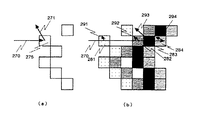
図4によって、このボリュームレンダリングとサーフェスレンダリングとを比較した。(a)はサーフェスレンダリング、(b)は、ボリュームレンダリングを光線追跡断面のモデル図に示したものである。
投影点270のサーフェスレンダリングにおいて、表示表面は275のように一つの投影点に一つのボクセルとなり、光の反射は271のようになる。
一方、ボリュームレンダリングでは、先に述べたように、同一の投影点270のレンダリングにおいて、表示表面は、281〜284のように数ボクセルとなり、291〜294のそれぞれの光の反射量とそれぞれに到達する光の量の積の和により投影値が決まる。この例では、不透明度αは、対話的に指定する傾きパラメータとボクセル濃度値の一次関数とした。この際の各ボクセルごとの表示関与量Qを図5にグラフで示す。
上記のように、ボリュームレンダリングでは、表示表面が数ボクセルに及んでいるため、一意に決定する方法が求められる。以下の方法が考えられる。
(イ)最初に表示に関与したボクセルの表示表面ボクセルとする。
(ロ)表示に関与した全てのボクセルの深さ値の平均を取る。
(ハ)表示に関与したボクセルの最大の関与量を示すボクセルを表示表面ボクセルとする。
本実施例では、想定する表面と誤差が最も小さいと思われる(ハ)の方法により、表示表面深さ値を定義する。この例の場合は、表示に関与したボクセルのなかで最大の関与量を示すボクセル283が表示表面となり、表示表面深さ値は「9」となる。なお(イ)の方法では、ボクセル281が表示表面となり、表示表面深さ値は「5」となる。また(ロ)の方法は、表示に関与したボクセル281〜284の深さ値の平均を取る方法で、表示表面深さ値は「(5+8+9+10)/4=8」となる。(イ)の方法が最もシンプルで処理も速く、(ハ)の方法が最も精度が高い合成表示が可能である。(ロ)の方法は、これらを折衷した方法である。
【0012】
図6に合成表示機能の構成の一例を示し、図7にその合成表示機能のメインルーチンを示す。
この実施例ではオブジェクト指向の概念に基づき構築されており、マウスやキーボードのイベント401により、各機能ごとのルーチンが起動される。
ウインドウ301に画像合成結果を表示する。
ウインドウ302で、同一の視線方向からレンダリングした3次元画像(図2の212、222)を複数枚読み込む。
読み込まれた各3次元画像ごとに、ラベル311に3次元画像名を表示し、ウインドウ321に3次元画像を参照表示し、スライダ331により、対応する3次元画像ごとの不透明度を設定、画像合成イベントを発行する。
プッシュボタン340は、マウスのクリックにより3次元画像の読み込みイベントを発行する。
プッシュボタン345は、マウスのクリックによりウィンドウ301で表示している合成表示結果をファイルに保存するイベントを発行する。
プッシュボタン350は、マウスのクリックによりウィンドウ302に表示している3次元画像の画像合成イベントを発行する。
プッシュボタン360は、マウスのクリックにより、任意の読み込んだ3次元画像の色変更イベントを発行する。
プッシュボタン370は、マウスのクリックにより、任意の読み込んだ3次元画像のLUT変更イベントを発行する。なお、マウスをクリックすることにより、予め登録してある輝度値変更テーブルを選択変更できるように構成されているものとする。
プッシュボタン380は、マウスのクリックにより、任意の読み込んだ3次元画像の変形・移動イベントを発行する。
プッシュボタン390は、マウスのクリックにより、合成表示機能終了イベントを発行する。
【0013】
図8に、画像読み込みイベントの処理ルーチンを示す。
ステップ410:画像読み込みイベントが発行されると(図7のステップ401)、まず、3次元画像選択ウィンドウを表示し、任意の3次元画像を選択する。
ステップ411:選択された3次元画像を合成表示機能(図2の300)に読み込む。
ステップ412:読み込んだ3次元画像をヘッダのカラーマップ情報などによりRGBデータに変換する。
ステップ413:読み込んだ3次元画像の表示表面深さ(Zバッファ)値により、各3次元画像の画素ごとの前後関係の順番をメモリ上に記録する。
【0014】
図9に具体的な合成表示を適用する画像の例を示す。
それぞれ、3次元画像213を頭画像、3次元画像214を骨画像、3次元画像223を血管画像とする。
図10に図9の眼孔の位置の縦軸平行線上の表示表面深さ(Zバッファ)値の変化の様子を示す。
ここでも、3次元画像213を頭の表示表面深さ(Zバッファ)値、3次元画像214を骨の表示表面深さ(Zバッファ)値、3次元画像223を血管の表示表面深さ(Zバッファ)値とする。さらに、合成投影点B501付近において、頭骨眼孔部を502とする。
図11で合成表示処理における光量減衰の過程の例を示す。
ここで、頭画像213の不透明度を「0.5」、骨画像214の不透明度を「0.5」、血管画像223の不透明度を「1.0」とする。
合成投影点A500では、光量初期値「1.0」510が、まず、不透明度「0.5」の頭画像213を通るため、通過後の光量511は、(1.0−0.5)=0.5となる。さらに、不透明度「0.5」の骨画像214を通るため、通過後の光量512は、0.5×(1.0−0.5)=0.25となる。
合成投影点B500では、合成投影点A501と同様に光量初期値「1.0」510が、まず不透明度「0.5」の頭画像213を通るため、通過後の光量511は、(1.0−0.5)=0.5となる。合成投影点B500では、眼孔部502であるため血管画像223の方が骨画像214より手前にあるため、不透明度「1.0」の血管画像223を通る。通過後の光量513は、0.5×(1.0−1.0)=0.0となる。
それぞれの画像の合成計算値への関与値は、画像の輝度と通過してきた光量とその画像の不透明度値の積算となる。
合成画像の画素値は、各3次元画像の関与値の総和となる。なお、画像の合成計算は(式2)のようになる。
【数2】
図12に画像合成処理実行ルーチンの処理フローを示す。
ステップ421:注目合成画素に対する合成計算初期値を代入する。
ステップ422:総和計算の終了条件判定を行い、ステップ423〜425を画像の枚数分繰り返す。この繰り返しは、各表示表面深さ(Zバッファ)値を比較し、手前にある画像から順に処理を行う。
ステップ423:各画像の画素値の合成計算値への関与値を求め、合成計算値に関与値をインクリメントし、最終的には総和を求め合成画素値を得る。ここで、関与値は次のようになる。
(関与値)=(画像の画素値)×(この画像に到達した光量)×(画像の不透明度)
なお、この画像に到達した光量は、初期値「1.0」として、ステップ424により、奥にある画像に対する光量程、前の画像の不透明度により減衰される。
ステップ424:対象となっている画像による光量の減衰結果を計算する。ここで、光量の減衰は次のようになる。
(減衰した光量)=(光量)×(1.0−画像の不透明度)
ステップ425:対象画像を次の画像に移し、ステップ422に戻る。
ステップ426:画像合成計算終了の判定を行う。終了していなければステップ427に進む。終了していればステップ428に進む。
ステップ427:次の合成計算画素に注目点を移し、ステップ421に戻る。
ステップ428:画像合成計算結果を表示するため画像の正規化を行う。
この合成計算は各3次元画像に対応する不透明度変更スライダ331の変更イベントが発行されたときと合成計算イベント(図6の350)が発行されたとき実行され、合成計算結果ウインドウ(図6の301)に表示する。
【0016】
図13に回転指定を含む合成表示機能の処理フローを示す。
ステップ500:合成計算の対象になっている3次元データを読み込む。
ステップ501:各関心領域表示のためのしきい値、ボリュームレンダリング不透明度、表示抽出領域、色(RGBの割合)などのパラメータをすべての関心領域にマルチに設定する。X線CTデータを例に説明すると、皮膚表示に対ししきい値をCT値「−300」以上で色を肌色に設定し、骨表示に対ししきい値をCT値「200」以上で色を白色に設定し、血管表示に対しあらかじめ血管領域を抽出しておき、赤色を設定する。
ステップ502:同一の視線方向から各関心領域ごとに3次元画像を作成する。この結果を合成表示機能300に渡す。
ステップ504:ステップ502の結果を画像合成する。
ステップ505:ステップ502の結果に対し、各3次元画像の不透明度を変更した場合、変更後のパラメータで画像合成を繰り返す。
ステップ506:視線方向パラメータの変更をした場合、ステップ502に戻り、各関心領域ごとに3次元画像を変更された視線方向で作成し、画像合成を繰り返す。
このような、フローにより、任意の視線方向からの合成結果を得る。
【0017】
なお、図14のような並列化により回転を含む画像合成を高速化が可能である。
ネットワーク570に接続された、いくつかのプロセッサ560で関心領域ごとにボリュームレンダリングの処理を分割し、並列にボリュームレンダリング画像を求める。この結果を特定の画像合成プロセッサ580に転送し、合成画像を得る。このとき、各ボリュームレンダリングプロセッサは、レンダリングが終了した投影画像の部分領域を逐次画像合成プロセッサに転送、画像合成プロセッサはデータの揃った画像の部分領域から合成を行うようにする。この結果、最も時間のかかる関心領域のボリュームレンダリング画像を求める時間とその画像転送時間と画像合成表示時間を足した時間で合成画像を求めることができる。
【0018】
(実施例2)
実施例2では、3次元ベクトルデータとの画像合成について例を示す。これは、人工血管や人工骨等を形成する前に、CTやMRI等の計測画像の3次元データの3次元画像上で人工血管等の3次元ベクトル(CAD)データを合成表示する場合を考える。これにより、人工血管や人工骨等の人工オブジェクトの適用箇所への適応状況をシミュレーションすることができる。
図15に3次元ベクトルデータと3次元データとの合成のフローチャートを示す。
ステップ600〜602:3次元データを読み込み、ボリュームレンダリング、Zバッファ付き3次元画像を得る。
ステップ603:3次元CADなどにより、形状をモデル化し、3次元ベクトルデータを作成する。
ステップ604:ステップ603のデータをステップ601のボリュームレンダリングの視線方向からレンダリングする。
このとき、表示表面深さ(Zバッファ)値も計算する。
ステップ605:Zバッファ付き3次元画像を得る。
ステップ610:(実施例1)と同様に画像を合成し、合成画像を得る。
ステップ620〜628に画像の変形、移動、干渉チェックなどの機能について説明する。
ステップ620:プッシュボタン(図6の380)により、変形・移動イベントが入力されたかチェックする。
ステップ621:画像変形・移動サブウィンドウを呼び出し、変形画像を指定する。
ステップ623:移動、回転、拡大・縮小、表示表面深さ(Zバッファ)値変更などの変形・移動の操作を行う。
ステップ624:変形対象画像に対し、変形・移動計算を行い、ステップ623の結果と変形対象外の3次元画像とを比較し、干渉し合っていないかチェックする。
ステップ625〜626:ステップ623の結果、干渉を受けている場合、変形・移動を停止し、干渉を受けている点をマーキングする。
ステップ628:受けていない場合、画像合成し、変形・移動の処理(ステップ623)を続ける。
【0019】
図16に変形・移動を行うサブウインドウを示す。
ウィンドウ630:変形後の結果合成画像を表示する。
ウィンドウ631:変形対象の画像を表示する。
プッシュボタン632:変形画像と変形対象以外の画像の合成画像とフリッカ表示(交互表示)を行う。
プッシュボタン634:拡大・縮小・回転指定イベントの発行を行う。
プッシュボタン635:平行移動指定イベントの発行を行う。
プッシュボタン634、635は、ウィンドウ631に対し、ポイントを指定し、変形・移動のパラメータを指定するため、どちらのパラメータを指定してするのかを切り替える役目を果たす。
トグルボタン636:干渉をチェックするかどうか切り替える。
スライダ637:変形画像の表示表面深さ(Zバッファ)値を一様に変更する変更量を指定する。
ラベル638:変形パラメータを数値で表示する。
【0020】
図17に変形のフローチャートを示す。(a)に拡大・縮小・回転のフローチャートを、(b)に平行移動のフローチャートを示す。この変形はボリュームレンダリング画像だけでなく、表示表面深さ(Zバッファ)値に対しても同様の操作で行うことで、前後の位置関係を保持する。
ステップ650:拡大・回転のイベントの発行を受け、このルーチンに入る。
ステップ651:変更画像エリア内でのマウスイベントの入力待ち状態にはいる。
ステップ652:変更画像エリア内のマウスイベントが最初の一点とするとき、このマウスイベントの座標を変形中心点と設定する。
ステップ653:変更画像エリア内のマウスイベントが2番目のとき、マウスボタンの押された座標と離された座標を得る。
ステップ654:ステップ653で押された座標を変形基準座標とし、離された座標を基準座標の変形後の座標点とする。
ステップ656:ステップ652〜654で得た、変形パラメータをもとにアフィン変換を行う。
ステップ657:変形後の画像を変更画像エリアに表示、次の変形指定を待つ。ステップ660:平行移動の発行を受け、このルーチンに入る。
ステップ661:変更画像エリア内でのマウスイベントの入力待ち状態にはいる。
ステップ662:変更画像エリア内のマウスイベントが入ったとき、マウスボタンの押された座標と離された座標を得る。
ステップ663:ステップ662で押された座標を変形基準座標とし、離された座標を基準座標の変形後の座標点とする。
ステップ664:ステップ652〜653で得た、変形パラメータをもとに平行移動変換を行う。
ステップ665:変形後の画像を変更画像エリアに表示、次の変形指定を待つ。
以上のような操作で画像の変形を対話的に指定する。
【0021】
(実施例3)
実施例3では、MRIやX線CTなどの3次元形態データとEmissionCTなどの3次元機能データの合成表示について説明する。ここでは、各データ間の位置合わせ等は終了しているものとする。
図18にそのフローチャートを示す。
ステップ701:ボリュームレンダリングの視線方向を指定する。
ステップ702:ステップ701で指定された視線方向より、複数の3次元データの複数の関心領域ごとにボリュームレンダリングを行い、Zバッファ付きのボリュームレンダリング画像を作成する。
ステップ703:ステップ702で作成されたボリュームレンダリング画像を合成し、Zバッファ付きで色指定のない合成画像を作成する。
ステップ704:ステップ701で指定された視線方向に機能データを回転する。
ステップ705:ステップ704で得た機能データにおいて、ステップ703で得た表示表面深さ(Zバッファ)の座標の持つ値に指定されている色をこのピクセルの色に設定し、機能情報合成画像を作成する。
以上のように、複数の3次元データと3次元機能データとの合成表示が可能となる。
【0022】
(実施例4)
本実施例では、マルチモダリティの画像合成について説明する。図19にシステムの構成例を示す。
X線CT装置20で計測された3次元データは、計測装置に直接接続された処理装置820へ転送される。
同様に、MRI装置10、3D超音波診断装置40、他計測装置830で計測されたそれぞれの3次元データはそれぞれの計測装置に直接接続された処理装置810、840、850に転送される。
転送されたそれぞれのデータは、処理装置により共通の座標系にレジストレーションされる。
各処理装置はLAN70、WAN860を介し、画像合成表示装置800と接続されている。画像合成表示装置は結果を表示するディスプレイ103と、入力装置102を持つ。
【0023】
図20に図19の構成例での画像合成表示方法のフローチャートを示す。
ステップ870:画像合成表示装置800により、視線方向の指定を行う。
ステップ880:ステップ870で指定された視線方向パラメータを合成の対象となっている3次元データを持つ処理装置810、820、840、850にLAN70、WAN860を介して転送する。
ステップ890:ステップ880で送られてきた視線方向パラメータに基づき、各処理装置810、820、840、850にて、ボリュームレンダリングを行い、投影画像と表示表面深さ(Zバッファ)値を計算する。
ステップ900:ステップ890で計算された投影画像と表示表面深さ(Zバッファ)値を画像合成表示装置800に転送する。
ステップ910:それぞれの処理装置により転送された結果に基づき(ステップ900)、画像合成表示装置において画像合成計算を行う。
ステップ920:ステップ910の画像合成結果をディスプレイ103に表示する。
【0024】
【発明の効果】
以上で詳細に説明した如く、本発明によれば、3次元データ上でデータを統合することなしに、高画質なボリュームレンダリング画像に対し表示表面深さ(Zバッファ)値を求めることができ、この値を投影画像合成に用いることで3次元位置関係を正しく画像合成でき、また、関心領域ごとに最適なレンダリングパラメータを選択できるためそれぞれ高画質に画像を作り合成表示でき、さらに関心領域ごとに任意の不透明度の合成を行う装置を実現できるという顕著な効果を奏するものである。
【図面の簡単な説明】
【図1】本発明の第1乃至第3の実施例における3次元画像合成表示システムの構成図である。
【図2】本発明の第1の実施例における3次元データ取得から画像合成までの処理を示すフローチャートである。
【図3】本発明の第1の実施例における表示表面深さ(Zバッファ)値の説明図である。
【図4】本発明の第1の実施例におけるボリュームレンダリングとサーフェスレンダリングとの比較を示す説明図である。
【図5】本発明の第1の実施例におけるボリュームレンダリングの表示関与量の棒グラフ図である。
【図6】本発明の第1の実施例における画像合成機能の画面構成を示す図である。
【図7】本発明の第1の実施例における画像合成機能を示すメインルーチンフローチャートである。
【図8】本発明の第1の実施例における画像合成のためのデータ準備ルーチン(画像読み込みイベントの処理ルーチン)フローチャートである。
【図9】本発明の第1の実施例における合成表示対象の3次元画像を示す図である。
【図10】図9の眼孔位置の縦軸平行線上の表示表面深さ(Zバッファ)値の変化を示す図である。
【図11】図10の画像合成計算時の光量減衰の過程の説明図である。
【図12】本発明の第1の実施例における画像合成処理実行ルーチンを示すフローチャートである。
【図13】本発明の第1の実施例における視線方向変更を含む画像合成表示機能の処理を示すフローチャートである。
【図14】本発明の第1の実施例における並列プロセッサの説明図である。
【図15】本発明の第2の実施例における変形・移動を含むCADデータと3次元データの画像合成を示すフローチャートである。
【図16】本発明の第2の実施例における変形・移動サブウィンドウの構成図である。
【図17】本発明の第2の実施例における変形・移動機能を示すフローチャートである。
【図18】本発明の第3の実施例における3次元機能データと3次元データの画像合成を示すフローチャートである。
【図19】本発明の第4の実施例における3次元画像合成表示システムの構成図である。
【図20】本発明の第4の実施例における画像合成表示機能を示すフローチャートである。
【符号の説明】
10:MRI装置、20:X線CT装置、30:Emission CT装置、40:3D超音波診断装置、50:画像データベース、60:CAD装置、100:3次元画像処理装置、11、21、31、41、101:光磁気ディスク、102:入力装置、103:ディスプレイ装置、104:ハードディスク装置。[0001]
[Industrial applications]
The present invention relates to a three-dimensional image synthesis display of a plurality of three-dimensional volume data obtained by an X-ray CT apparatus, an MRI apparatus, a 3D ultrasonic diagnostic apparatus, and an Emission CT apparatus, and the same line-of-sight direction is matched for each data. A function for calculating a three-dimensional projected image having a display surface depth (Z-buffer) value is provided. By using a plurality of three-dimensional projected images, a three-dimensional image is obtained in which a three-dimensionally correct high-quality composite display is obtained. It relates to a display device.
[0002]
[Prior art]
The following documents are known as known examples related to the present invention.
(1) M. Levoy: Efficient Ray Tracing of Volume Data, ACM Trans. on Graphics, Vol. 9, No. 3, (1990) pp 245-261.
(2) Newell, M .; E. FIG. , Newell, R .; G. FIG. and Sancha, T.W. L. : A New Approach to the Shaded Picture Problem, Proc. ACM. Nat. Conf. , (1972) pp. 443
(3) Mitsuo Ishii: Imaging machine, Ohmsha pp12
(4) Katsuhiko Nishikawa, Takahiro Sakuraba, Hideki Saito, Junichi Sugiyama, Akihiko Matsuo: High-speed high-performance three-dimensional system "Subaru"-(4) High-speed drawing mechanism-, Proceedings of IEICE Autumn Conference 1992, pp204
(5) JP-A-64-37678
(6) Digitization of medical images and three-dimensional image processing-Asahi Kasei Information System Co., Ltd., Video Information (M), May 1994, pp. 606-607
Document (1) describes volume rendering of three-dimensional data. It is assumed that three-dimensional data in volume rendering is composed of translucent voxels. Ray tracing from the viewpoint to the object, and when light is transmitted through the translucent voxel, opacity is defined for each voxel as the degree of change in the amount of light transmission, and the amount of light reflected from the voxel Are projected as pixel values on the projection plane.
As a technique of CG, a simple method of synthesizing a transparent or translucent object is the Newell method of (2). This method expresses a sense of transparency by mixing the color of the object behind and the color of the transparent object.
In the literature (3), the function of the Z buffer is used as hidden surface processing for rendering an object model. Here, the surface position of each object model is compared with the value of the Z buffer, and if the object is already before the already rendered object, the Z buffer and the projection value of this object are rewritten, and the same calculation and projection are performed for all objects. Get an image.
In Document (4), by connecting a plurality of drawing mechanisms via a depth data control mechanism, an image generated by each drawing mechanism can be synthesized based on a depth value. In this method, a plurality of primitives defined in a three-dimensional space are shared by a plurality of drawing mechanisms, a plurality of images are generated in parallel, and the resulting images are combined to obtain a three-dimensional image. it can.
In general, when a plurality of three-dimensional data are combined and displayed, it is necessary to separate (segment) a part to be displayed from each data by three-dimensional extraction processing, embed the three-dimensional data in the three-dimensional data to be integrated, and perform the combined display. .
As described above, with respect to the data unified into one three-dimensional data, in the known example (5), an arbitrary structure is extracted from the three-dimensional data, a distance from the projection plane is created, and an arbitrary structure is created. The surface images inside and outside the resection region set in the shape of are combined and displayed on one image.
Document (6) introduces 3D synthesis software "Dr. View / Blender", which allows display from any direction, and allows a cut plane to be inserted into the display object. Images with different modalities can be attached to the three-dimensional surface of the display result at a certain ratio.
[0003]
[Problems to be solved by the invention]
When imaging an affected part with an X-ray CT apparatus, various angiography is performed to obtain three-dimensional information such as a running state of the affected part and blood vessels around the affected part and bones. Further, in MRI, three-dimensional information such as lesions of soft tissue and blood flow can be obtained in a minimally invasive manner. In addition, Emission
In CT, the physiological function of the human body can be obtained as three-dimensional information.
There is a need to make effective use of three-dimensional information obtained by such various imaging methods, complement each other's data, perform composite display, and use it in medical examinations and surgical planning.
Conventionally, as a method of visualizing a single piece of three-dimensional data with high image quality, there is known a volume rendering method of visualizing a display surface without uniquely determining it, as described in reference (1). Since the visualization algorithm involves several voxels of the smoothly changing display surface portion in the projection value, the display surface depth (Z buffer) value cannot be uniquely determined. Further, in order to combine a plurality of three-dimensional data, it is necessary to represent a plurality of three-dimensional data in a three-dimensional space, which consumes a lot of memory. Furthermore, rendering each region of interest semi-transparently by this method complicates rendering parameters and makes it very difficult to obtain optimal parameters.
In the known example (5), as described above, a region of interest to be displayed is segmented from each of the three-dimensional data by extraction processing, embedded at a corresponding position of the three-dimensional data to be integrated, and combined and displayed. In this method, since the result of the segmentation is embedded in different data, a discontinuous surface is generated in the image, and the image quality is expected to deteriorate when combined and displayed by volume rendering.
In the three-dimensional CG, various image synthesizing techniques have been proposed as described in References (2), (3), and (4). However, in these methods, surface position data is obtained for each region of interest of a plurality of three-dimensional data. Therefore, it is necessary to change the data to three-dimensional coordinate data, express it as one three-dimensional vector data, and perform a rendering process. Therefore, it has not been possible to select a volume rendering method with high image quality for each region of interest.
Further, in a method of simply pasting a projection result of different data to a projection result of three-dimensional data at a certain ratio as in the literature (6) and combining images, it is necessary to perform a three-dimensional in-order composition. Is impossible.
[0004]
An object of the present invention is to solve such a problem and to easily perform high-quality volume rendering composite display without integrating a plurality of different three-dimensional data and creating new three-dimensional data. Another object of the present invention is to provide a three-dimensional image synthesis and display device.
Further, it is another object of the present invention to enable volume rendering with an optimal visualization parameter for each region of interest and to perform a composite display of a high-quality volume rendering image.
Further, the display surface depth (Z buffer) value can be obtained from the depth value of the voxel most involved in the display when the volume rendering image is created for each region of interest, and the volume rendering composite display is performed based on this value. Accordingly, it is an object to obtain a correct three-dimensional composite image in a three-dimensional context.
It is another object of the present invention to obtain an arbitrary translucent composite image or non-transparent composite image by arbitrarily setting the opacity for each volume rendering image.
It is another object of the present invention to be able to perform image synthesis on a volume rendering synthesized image obtained from a plurality of three-dimensional form data even in image synthesis with three-dimensional function data.
Furthermore, in the synthesis and display of multi-modality data, each imaging device has a processor that performs volume rendering, and the purpose is to enable calculation of each three-dimensional projection image in parallel. By transferring the image data, it is possible to combine the images and not transfer the three-dimensional volume data having a large data amount.
[0005]
[Means for Solving the Problems]
To achieve the above object, a three-dimensional image synthesizing apparatus according to the present invention includes a hard disk (104 in FIG. 1) for storing three-dimensional data, a computer (100 in FIG. 1) for volume rendering and projection image synthesis, and a display. (103 in FIG. 1) and a device (102 in FIG. 1) for inputting coordinates of a display.
Further, the
The volume rendering functions 211 and 221 obtain a three-dimensional projection image (see FIG. 9) with optimal rendering parameters for each region of interest for each aligned three-dimensional data, and at the same time, for each pixel of the projection image. The display surface depth (Z-buffer) value (see FIG. 10) is obtained as the depth value of the voxel on the ray tracing line most involved in the luminance value together with the rendering luminance value.
Furthermore, a function of obtaining a plurality of three-dimensional images (with a Z-buffer) by performing volume rendering on the plurality of three-dimensional data from the same line-of-sight direction and a function of obtaining a plurality of three-dimensional images (Z (With buffer).
Further, a three-dimensional projection image projected and calculated from a plurality of the same line-of-sight directions obtained by such a volume rendering function is obtained from each pixel based on a display surface depth (Z buffer) value. It has a function (see FIG. 13) of calculating the involvement in the pixel value of the synthesized image and obtaining an image synthesis result based on the opacity set for each three-dimensional projection image and the luminance value of the pixel of each image. I have.
Further, in addition to the function of synthesizing and displaying a similarly obtained three-dimensional image (with a Z-buffer) in the same line-of-sight direction, a function of setting opacity for each image (331 in FIG. 6) and a function of brightness for each image A function for changing the value (360, 370 in FIG. 6), a function for arbitrarily linearly deforming each image (634, 635 in FIG. 16), and a display surface depth (Z buffer) value for each image are set to one. (637 in FIG. 16).
The display surface depth (Z buffer) value of the synthesized image is obtained by taking the maximum value of the display surface depth (Z buffer) value of the synthesized three-dimensional image with respect to the synthesized image obtained as described above. A function for synthesizing the value of the three-dimensional function data on the surface of the composite image based on this value and the viewing direction in which the composite image has been calculated is provided (see FIG. 18).
In addition, a processor (810, 820, 840, 850 in FIG. 19) is provided for each photographing apparatus for multi-modality image synthesis, and this processor has a function of aligning with a common coordinate system and an instruction of the image synthesis apparatus. A function of obtaining a three-dimensional image by performing volume rendering in the line of sight direction, a function of obtaining a display surface depth (Z-buffer) value, and transmitting the obtained three-dimensional image and display surface depth (Z-buffer) value to an image synthesizing apparatus. It has a function of transferring and obtaining a composite image (see FIG. 20).
[0006]
[Action]
In the present invention, for each of a plurality of three-dimensional data, a three-dimensional image from the same line-of-sight direction is individually created with each data, and a composite calculation is performed on the obtained three-dimensional image. It is not necessary to integrate the images, and a composite image can be easily obtained.
Furthermore, since a three-dimensional image is created for each region of interest, an optimal volume rendering parameter can be selected for each region of interest, and a high-quality composite display can be performed.
Further, in the volume rendering, a display surface depth (Z-buffer) value that cannot be uniquely determined is obtained from the voxel depth value most involved in the display, and a three-dimensional front-back positional relationship is determined based on this value during image synthesis. However, since the composition is performed in accordance with the result, a correct composite display of the three-dimensional positional relationship can be performed.
Furthermore, since the opacity can be interactively set for each three-dimensional image by a user's input, an arbitrary translucent composite display or non-transparent composite display (the highest priority display of the pixel value of the image in front) is performed. be able to.
Further, the function information of the three-dimensional function data can be combined and displayed on the display surface of the image combined from the plurality of three-dimensional data.
Further, by providing a processing device for each of a plurality of modalities to form a network, the processing results of the processing device can be transferred to an image synthesizing and displaying device via a network to perform multi-modality synthesizing display.
[0007]
【Example】
The present invention will be described with reference to examples.
FIG. 1 shows an example of the system configuration of the present invention, to which the image combining and displaying method in each embodiment is applied.
The three-dimensional data measured by the
By the same route, the three-dimensional data measured by each of the
The three-dimensional
[0008]
(Example 1)
In the first embodiment, description will be given of image composition of a volume rendering result of a plurality of three-dimensional data.
FIG. 2 is a flowchart showing processing in the three-dimensional
Step 200: The three-dimensional data is read into the three-dimensional
Step 201: For the plurality of data read in
Step 211: A volume rendering process supported by the three-dimensional
Step 220: For the data generated in
Step 221: A volume rendering process supported by the three-dimensional
The three-
The three-
[0009]
FIG. 3 is an explanatory diagram of the display surface depth (Z buffer) value of the three-dimensional image data input to the composite display.
The
An
When visualizing such data, if the head is the region of interest, the display-related region is limited to the head by setting the threshold value of the rendering parameter to “85” or more, and the head is visualized. be able to. In this manner, the pixel value of each
Similarly, when the brain is the region of interest, the brain region can be visualized by setting the threshold to “95” or more. At this time, the display surface depth (Z buffer) value such as 260 obtain.
However, if the surface rendering is applied to measurement data such as MRI and X-ray CT and the density is not less than the above-described density threshold, a smooth projection image cannot be obtained due to measurement noise. Therefore, a high-quality projected image is obtained by using a volume rendering method in which several pixels near the display surface are involved in the projected image.
[0010]
Here, volume rendering will be described.
It is assumed that the opacity α and the reflectance of each voxel are equal and the light transmittance is (1−α). Then, assuming that the light reflected by the voxels arranged at each point is transmitted according to the transmittance of the other voxels in front of the projection surface and reaches the projection point, each voxel participates in the display affecting the projection value. The quantity Q is determined by
(Equation 1)
Therefore, Π (1−α (j)) is the product of the respective voxel transmittances arranged before i, and the light α (i) c (i) reflected by the voxel at point i is projected onto the projection surface. The transmittance is shown.
The sum of the display participation amounts Q given to the projection values of each voxel is the projection value of the volume rendering.
As described above, since one pixel value on the projection plane has been obtained, this calculation is performed on all the pixels on the projection plane to obtain a volume rendering image.
[0011]
FIG. 4 compares the volume rendering with the surface rendering. (A) shows a surface rendering, and (b) shows a volume rendering in a ray tracing section model diagram.
In the surface rendering of the
On the other hand, in the volume rendering, as described above, in rendering of the
As described above, in the volume rendering, since the display surface extends over several voxels, a method for uniquely determining it is required. The following methods are conceivable.
(A) The display surface voxel of the voxel that participated in the display first.
(B) Average the depth values of all voxels involved in the display.
(C) A voxel indicating the maximum amount of voxels involved in display is defined as a display surface voxel.
In the present embodiment, the display surface depth value is defined by the method (c) in which the error with the assumed surface is considered to be the smallest. In the case of this example, the
[0012]
FIG. 6 shows an example of the configuration of the composite display function, and FIG. 7 shows a main routine of the composite display function.
This embodiment is constructed based on the object-oriented concept, and a routine for each function is activated by an
The result of image synthesis is displayed in a
In the
For each read three-dimensional image, the three-dimensional image name is displayed on a
The
The
The
The
The
The
[0013]
FIG. 8 shows a processing routine of the image reading event.
Step 410: When an image reading event is issued (
Step 411: The selected three-dimensional image is read into the composite display function (300 in FIG. 2).
Step 412: The read three-dimensional image is converted into RGB data using the color map information of the header.
Step 413: The order of the order of each pixel of the three-dimensional image is recorded in the memory based on the display surface depth (Z buffer) value of the read three-dimensional image.
[0014]
FIG. 9 shows an example of an image to which a specific composite display is applied.
The three-
FIG. 10 shows how the display surface depth (Z-buffer) value changes on a line parallel to the vertical axis of the position of the eye in FIG.
Here, the three-
FIG. 11 shows an example of a process of light quantity attenuation in the composite display processing.
Here, the opacity of the
At the combined projection point A500, the light amount initial value “1.0” 510 first passes through the
At the combined projection point B500, the light amount initial value “1.0” 510 first passes through the
The value involved in the composite calculation value of each image is the sum of the luminance of the image, the amount of light that has passed, and the opacity value of the image.
The pixel value of the composite image is the sum of the contribution values of each three-dimensional image. Note that the image synthesis calculation is as shown in (Equation 2).
(Equation 2)
FIG. 12 shows a processing flow of the image synthesis processing execution routine.
Step 421: Substitute the initial value of the synthesis calculation for the target synthesis pixel.
Step 422: The end condition of the sum calculation is determined, and steps 423 to 425 are repeated for the number of images. In this repetition, each display surface depth (Z buffer) value is compared, and processing is performed in order from the image in front.
Step 423: Obtain a contribution value of the pixel value of each image to the composite calculation value, increment the contribution value to the composite calculation value, and finally obtain a sum to obtain a composite pixel value. Here, the participation values are as follows.
(Participation value) = (Pixel value of image) × (Light quantity reaching this image) × (Opacity of image)
In addition, the light amount reaching this image is set to an initial value “1.0”, and is attenuated in
Step 424: Calculate the attenuation result of the light amount by the target image. Here, the attenuation of the light amount is as follows.
(Attenuated light amount) = (light amount) × (1.0−opacity of image)
Step 425: Move the target image to the next image, and return to step 422.
Step 426: Judgment of completion of the image synthesis calculation is performed. If not, the process proceeds to step 427. If it has been completed, the process proceeds to step 428.
Step 427: Move the point of interest to the next composite calculation pixel, and return to step 421.
Step 428: Normalize the image to display the image synthesis calculation result.
This synthesis calculation is executed when a change event of the
[0016]
FIG. 13 shows a processing flow of the composite display function including the rotation designation.
Step 500: The three-dimensional data targeted for the synthesis calculation is read.
Step 501: Parameters such as a threshold value for each region of interest display, volume rendering opacity, display extraction region, and color (ratio of RGB) are set to all regions of interest. Explaining the X-ray CT data as an example, the color is set to the skin color when the threshold value for skin display is CT value “−300” or more, and the color is set for CT value “200” or more for bone display. White is set, a blood vessel region is extracted in advance for the blood vessel display, and red is set.
Step 502: Create a three-dimensional image for each region of interest from the same line-of-sight direction. This result is passed to the
Step 504: Image synthesis of the result of
Step 505: When the opacity of each three-dimensional image is changed with respect to the result of
Step 506: If the line-of-sight direction parameter is changed, the process returns to step 502, where a three-dimensional image is created for each region of interest in the changed line-of-sight direction, and image synthesis is repeated.
By such a flow, a synthesis result from an arbitrary line-of-sight direction is obtained.
[0017]
It is to be noted that image synthesis including rotation can be speeded up by parallelization as shown in FIG.
[0018]
(Example 2)
In the second embodiment, an example of image synthesis with three-dimensional vector data will be described. This is a case in which three-dimensional vector (CAD) data of an artificial blood vessel or the like is synthesized and displayed on a three-dimensional image of three-dimensional data of a measurement image such as CT or MRI before forming an artificial blood vessel or an artificial bone. . Thereby, it is possible to simulate an adaptation state of an artificial object such as an artificial blood vessel or an artificial bone to an application location.
FIG. 15 shows a flowchart for synthesizing three-dimensional vector data and three-dimensional data.
Step 603: The shape is modeled by three-dimensional CAD or the like, and three-dimensional vector data is created.
Step 604: The data of
At this time, the display surface depth (Z buffer) value is also calculated.
Step 605: Obtain a three-dimensional image with a Z buffer.
Step 610: Combine images as in (Example 1) to obtain a combined image.
In
Step 620: It is checked whether a deformation / movement event has been input by the push button (380 in FIG. 6).
Step 621: Call the image deformation / movement sub-window and specify the deformation image.
Step 623: Perform operations of deformation and movement such as movement, rotation, enlargement / reduction, and change of display surface depth (Z buffer) value.
Step 624: The transformation / movement calculation is performed on the transformation target image, and the result of
Step 628: If not received, image synthesis is performed, and the transformation / movement process (step 623) is continued.
[0019]
FIG. 16 shows a subwindow for performing deformation and movement.
Window 630: Displaying the resultant composite image after deformation.
Window 631: The image to be transformed is displayed.
Push button 632: Performs flicker display (alternate display) with a composite image of a deformed image and an image other than the deformed object.
Push button 634: Issue an enlargement / reduction / rotation designation event.
Push button 635: A parallel movement designation event is issued.
The
Toggle button 636: Switches whether to check for interference.
Slider 637: Specifies a change amount for uniformly changing the display surface depth (Z buffer) value of the deformed image.
Label 638: Deformation parameters are displayed numerically.
[0020]
FIG. 17 shows a flowchart of the modification. (A) shows a flowchart of enlargement / reduction / rotation, and (b) shows a flowchart of translation. This deformation is performed not only for the volume rendering image but also for the display surface depth (Z buffer) value by the same operation, thereby maintaining the front-back positional relationship.
Step 650: Receiving an enlargement / rotation event, the process enters this routine.
Step 651: Enter a state of waiting for input of a mouse event in the changed image area.
Step 652: When the mouse event in the changed image area is the first point, the coordinates of this mouse event are set as the transformation center point.
Step 653: When the mouse event in the changed image area is the second, the coordinates at which the mouse button is pressed and the coordinates at which the mouse button is released are obtained.
Step 654: The coordinates pressed in
Step 656: Perform affine transformation based on the deformation parameters obtained in
Step 657: Display the transformed image in the modified image area and wait for the next transformation designation. Step 660: The parallel movement is issued, and this routine is entered.
Step 661: Waiting for input of a mouse event in the changed image area.
Step 662: When a mouse event occurs in the changed image area, the coordinates of the pressed and released coordinates of the mouse button are obtained.
Step 663: The coordinates pressed in step 662 are set as deformation reference coordinates, and the released coordinates are set as coordinate points after deformation of the reference coordinates.
Step 664: Perform parallel translation conversion based on the deformation parameters obtained in
Step 665: Display the transformed image in the modified image area and wait for the next designation of transformation.
Through the above operation, the deformation of the image is specified interactively.
[0021]
(Example 3)
In a third embodiment, a description will be given of a combined display of three-dimensional form data such as MRI and X-ray CT and three-dimensional function data such as Emission CT. Here, it is assumed that the alignment between the data has been completed.
FIG. 18 shows the flowchart.
Step 701: Designate a line-of-sight direction for volume rendering.
Step 702: Perform volume rendering for each of a plurality of regions of interest of a plurality of three-dimensional data from the viewing direction designated in
Step 703: The volume rendering images created in
Step 704: The function data is rotated in the line-of-sight direction specified in
Step 705: In the function data obtained in
As described above, composite display of a plurality of three-dimensional data and three-dimensional function data can be performed.
[0022]
(Example 4)
In this embodiment, multi-modality image synthesis will be described. FIG. 19 shows a configuration example of the system.
The three-dimensional data measured by the
Similarly, the respective three-dimensional data measured by the
Each transferred data is registered in a common coordinate system by the processing device.
Each processing device is connected to the image
[0023]
FIG. 20 shows a flowchart of the image combining and displaying method in the configuration example of FIG.
Step 870: The gaze direction is specified by the image
Step 880: Transfer the gaze direction parameter specified in
Step 890: Each of the
Step 900: The projection image and the display surface depth (Z buffer) value calculated in
Step 910: Based on the result transferred by each processing device (Step 900), the image synthesis display device performs an image synthesis calculation.
Step 920: Display the image synthesis result of
[0024]
【The invention's effect】
As described in detail above, according to the present invention, a display surface depth (Z-buffer) value can be obtained for a high-quality volume rendering image without integrating data on three-dimensional data, By using this value in the projection image synthesis, the three-dimensional positional relationship can be correctly synthesized, and the optimum rendering parameters can be selected for each region of interest, so that high-quality images can be created and synthesized and displayed. This has a remarkable effect that an apparatus for synthesizing arbitrary opacity can be realized.
[Brief description of the drawings]
FIG. 1 is a configuration diagram of a three-dimensional image synthesis and display system according to first to third embodiments of the present invention.
FIG. 2 is a flowchart illustrating processing from acquisition of three-dimensional data to image synthesis in the first embodiment of the present invention.
FIG. 3 is an explanatory diagram of a display surface depth (Z buffer) value in the first embodiment of the present invention.
FIG. 4 is an explanatory diagram showing a comparison between volume rendering and surface rendering in the first embodiment of the present invention.
FIG. 5 is a bar graph of a display participation amount of volume rendering in the first embodiment of the present invention.
FIG. 6 is a diagram illustrating a screen configuration of an image composition function according to the first embodiment of the present invention.
FIG. 7 is a main routine flowchart illustrating an image combining function according to the first embodiment of the present invention.
FIG. 8 is a flowchart of a data preparation routine (image reading event processing routine) for image composition in the first embodiment of the present invention.
FIG. 9 is a diagram showing a three-dimensional image to be combined and displayed in the first embodiment of the present invention.
10 is a diagram showing a change in a display surface depth (Z buffer) value on a line parallel to the vertical axis of the position of the eye in FIG. 9;
11 is an explanatory diagram of a process of light amount attenuation at the time of image synthesis calculation in FIG.
FIG. 12 is a flowchart illustrating an image synthesis processing execution routine according to the first embodiment of the present invention.
FIG. 13 is a flowchart illustrating a process of an image combining and displaying function including a change in a line-of-sight direction according to the first embodiment of the present invention.
FIG. 14 is an explanatory diagram of a parallel processor according to the first embodiment of this invention.
FIG. 15 is a flowchart illustrating image synthesis of CAD data and three-dimensional data including deformation and movement according to the second embodiment of the present invention.
FIG. 16 is a configuration diagram of a deformation / movement sub window according to the second embodiment of the present invention.
FIG. 17 is a flowchart illustrating a transformation / movement function according to the second embodiment of the present invention.
FIG. 18 is a flowchart illustrating image synthesis of three-dimensional function data and three-dimensional data according to the third embodiment of the present invention.
FIG. 19 is a configuration diagram of a three-dimensional image composition display system according to a fourth embodiment of the present invention.
FIG. 20 is a flowchart illustrating an image combining and displaying function according to a fourth embodiment of the present invention.
[Explanation of symbols]
10: MRI apparatus, 20: X-ray CT apparatus, 30: Emission CT apparatus, 40: 3D ultrasonic diagnostic apparatus, 50: Image database, 60: CAD apparatus, 100: 3D image processing apparatus, 11, 21, 31, 41, 101: magneto-optical disk, 102: input device, 103: display device, 104: hard disk device.
Claims (9)
前記データのレンダリングにおいて同一光線追跡線上の複数ボクセルの値を投影値に関与させるボリュームレンダリング法により3次元投影画像を計算する演算手段と、
前記ボリュームレンダリングで、同一光線追跡線上の表示に関与した複数のボクセルのうち、最大の関与量を示したボクセルの深さ値を光線追跡線上単一の表示正面深さ値として求める演算手段と、
同一の視線方向から計算された複数の3次元投影画像と前記表示表面深さ値を基に画像を合成表示する演算手段と
を備えたことを特徴とした3次元画像合成表示装置。An image display device including a storage device for storing three-dimensional volume data composed of a three-dimensional array, a processing device for processing the data, a display for displaying a processing result, and a device for inputting position information on the display ,
Calculating means for calculating a three-dimensional projected image by a volume rendering method in which the values of a plurality of voxels on the same ray tracing line are involved in the projection value in rendering the data;
In the volume rendering, of a plurality of voxels involved in the display on the same ray tracing line, computing means for determining the depth value of the voxel showing the maximum amount of involvement as a single display front depth value on the ray tracing line,
A three-dimensional image synthesizing display device, comprising: a plurality of three-dimensional projection images calculated from the same line-of-sight direction; and arithmetic means for synthesizing and displaying images based on the display surface depth value.
前記データのレンダリングにおいて同一光線追跡線上の複数ボクセルの値を投影値に関与させるボリュームレンダリング法により3次元投影画像を計算する演算手段と、
前記ボリュームレンダリングで、同一光線追跡線上の表示に関与した全てのボクセルの深さ値の平均をとり、該平均を光線追跡線上単一の表示正面深さ値として求める演算手段と、
同一の視線方向から計算された複数の3次元投影画像と前記表示表面深さ値を基に画像を合成表示する演算手段と
を備えたことを特徴とした3次元画像合成表示装置。An image display device including a storage device for storing three-dimensional volume data composed of a three-dimensional array, a processing device for processing the data, a display for displaying a processing result, and a device for inputting position information on the display ,
Calculating means for calculating a three-dimensional projected image by a volume rendering method in which the values of a plurality of voxels on the same ray tracing line are involved in the projection value in rendering the data;
In the volume rendering, computing means for averaging the depth values of all voxels involved in the display on the same ray tracing line, and calculating the average as a single display front depth value on the ray tracing line,
A three-dimensional image synthesizing display device, comprising: a plurality of three-dimensional projection images calculated from the same line-of-sight direction; and arithmetic means for synthesizing and displaying images based on the display surface depth value.
同一の視線方向から前記表示表面深さ値を求めて得た複数のボリュームレンダリング画像の合成において、該表示表面深さ値をそれぞれの投影画像の前後関係の判定に用い、画素ごとの表示優先度に関与させるように構成したことを特徴とした3次元画像合成表示装置。The three-dimensional image synthesizing and displaying device according to claim 1 or 2,
In synthesizing a plurality of volume rendering images obtained by obtaining the display surface depth value from the same line-of-sight direction, the display surface depth value is used to determine the context of each projected image, and the display priority for each pixel is determined. A three-dimensional image synthesizing and displaying apparatus characterized in that the apparatus is configured to be involved in the image processing.
合成を行う各ボリュームレンダリング画像ごとにユーザの入力により不透明度を変更設定する制御手段を有し、各ボリュームレンダリング画像の深さ値に応じて前面より指定された不透明度に応じて表示の割合を指定するように構成したことを特徴とした3次元画像合成表示装置。The three-dimensional image synthesis display device according to any one of claims 1 to 3,
Control means for changing and setting the opacity by a user's input for each volume rendering image to be synthesized, and controlling the display ratio in accordance with the opacity specified from the front in accordance with the depth value of each volume rendering image A three-dimensional image synthesizing and displaying apparatus characterized in that it is configured to be designated.
3次元ボリュームデータから作成された前記表示表面深さ値を持つ複数のボリュームレンダリング画像と、ユーザーが設計した3次元座標により表現された3次元ベクトルデータから前記表示表面深さ値も併せて計算した3次元投影画像とを合成表示する演算手段を有することを特徴とした3次元画像合成表示装置。The three-dimensional image synthesizing and displaying device according to any one of claims 1 to 4,
The display surface depth value was also calculated from a plurality of volume rendering images having the display surface depth value created from three-dimensional volume data and three-dimensional vector data expressed by three-dimensional coordinates designed by the user. A three-dimensional image synthesizing and displaying apparatus, comprising a calculating means for synthesizing and displaying a three-dimensional projected image.
3次元投影画像を平行移動/回転/拡大・縮小して変形する制御手段を有し、
ユーザの入力により複数の3次元投影画像から任意の3次元投影画像を選択し、前記制御手段のパラメータを指定し、変形・移動結果を合成表示する
ように構成したことを特徴とした3次元画像合成表示装置。The three-dimensional image synthesizing and displaying device according to any one of claims 1 to 5,
Control means for transforming the three-dimensional projected image by translation / rotation / enlargement / reduction,
A three-dimensional image characterized in that an arbitrary three-dimensional projection image is selected from a plurality of three-dimensional projection images by a user's input, parameters of the control means are specified, and a deformation / movement result is synthesized and displayed. Synthetic display device.
複数の3次元投影画像のうち、任意の3次元投影画像の表示表面深さ値を一様に変更する制御手段を有し、ユーザの入力により変更パラメータを指定することにより、3次元的な前後位置関係を変更し合成表示するように構成したことを特徴とした3次元画像合成表示装置。The three-dimensional image synthesizing and displaying device according to any one of claims 1 to 6,
A control means for uniformly changing a display surface depth value of an arbitrary three-dimensional projection image among a plurality of three-dimensional projection images, and by specifying a change parameter by a user input, three-dimensional front-back A three-dimensional image synthesizing and displaying apparatus characterized in that the positional relationship is changed and synthesized and displayed.
複数のボリュームレンダリング画像の画像合成結果と該画像合成結果の表示表面深さ値より画素ごとに対応する3次元機能データの注目座標を求め、
該注目座標の値に設定された色を画像投影値の色に指定し、機能合成画像を得るように構成したことを特徴とした3次元画像合成表示装置。The three-dimensional image synthesizing and displaying apparatus according to claim 1,
From the image synthesis result of the plurality of volume rendering images and the display surface depth value of the image synthesis result, the attention coordinates of the three-dimensional function data corresponding to each pixel are obtained,
A three-dimensional image synthesizing display device characterized in that a color set as the value of the coordinate of interest is designated as a color of an image projection value, and a function synthesized image is obtained.
各処理装置は、共通の座標系にレジストレーションする演算手段と、請求項1から請求項9のいずれかに記載の3次元画像合成表示装置における3次元投影画像を計算する演算手段と、請求項1から請求項9のいずれかに記載の3次元画像合成表示装置における表示表面深さ値を求める演算手段とを持ち、3次元ボリュームデータの処理結果をネットワークを介し画像合成表示装置に転送し、
該画像合成表示装置において、各処理装置から転送されてきた3次元ボリュームデータの処理結果を用いてマルチモダリティの合成表示を行うように構成したことを特徴とした画像合成表示システム。A processing device set for each of a plurality of modalities, a network connecting the processing devices, and an image synthesis display device connected to the network;
10. A processing unit for registering to a common coordinate system, a processing unit for calculating a three-dimensional projection image in the three-dimensional image synthesizing and displaying apparatus according to claim 1, and a processing unit. Calculating means for obtaining a display surface depth value in the three-dimensional image synthesizing display device according to any one of claims 1 to 9, wherein a processing result of the three-dimensional volume data is transferred to the image synthesizing display device via a network;
An image synthesizing and displaying system, characterized in that the image synthesizing and displaying device is configured to perform multi-modality synthesizing display using a processing result of the three-dimensional volume data transferred from each processing device.
Priority Applications (2)
| Application Number | Priority Date | Filing Date | Title |
|---|---|---|---|
| JP15133695A JP3570576B2 (en) | 1995-06-19 | 1995-06-19 | 3D image synthesis and display device compatible with multi-modality |
| US08/665,986 US5995108A (en) | 1995-06-19 | 1996-06-19 | 3D image composition/display apparatus and composition method based on front-to-back order of plural 2D projected images |
Applications Claiming Priority (1)
| Application Number | Priority Date | Filing Date | Title |
|---|---|---|---|
| JP15133695A JP3570576B2 (en) | 1995-06-19 | 1995-06-19 | 3D image synthesis and display device compatible with multi-modality |
Publications (2)
| Publication Number | Publication Date |
|---|---|
| JPH096986A JPH096986A (en) | 1997-01-10 |
| JP3570576B2 true JP3570576B2 (en) | 2004-09-29 |
Family
ID=15516357
Family Applications (1)
| Application Number | Title | Priority Date | Filing Date |
|---|---|---|---|
| JP15133695A Expired - Fee Related JP3570576B2 (en) | 1995-06-19 | 1995-06-19 | 3D image synthesis and display device compatible with multi-modality |
Country Status (2)
| Country | Link |
|---|---|
| US (1) | US5995108A (en) |
| JP (1) | JP3570576B2 (en) |
Cited By (1)
| Publication number | Priority date | Publication date | Assignee | Title |
|---|---|---|---|---|
| US10290097B2 (en) | 2016-01-18 | 2019-05-14 | Samsung Medison Co., Ltd. | Medical imaging device and method of operating the same |
Families Citing this family (59)
| Publication number | Priority date | Publication date | Assignee | Title |
|---|---|---|---|---|
| US5986662A (en) * | 1996-10-16 | 1999-11-16 | Vital Images, Inc. | Advanced diagnostic viewer employing automated protocol selection for volume-rendered imaging |
| US6335732B1 (en) * | 1998-05-08 | 2002-01-01 | Mohammad Salim Shaikh | External recognition and rendering method |
| US6262738B1 (en) * | 1998-12-04 | 2001-07-17 | Sarah F. F. Gibson | Method for estimating volumetric distance maps from 2D depth images |
| US6633291B1 (en) * | 1999-03-02 | 2003-10-14 | Fujitsu Limited | Method and apparatus for displaying an image |
| US6591127B1 (en) * | 1999-03-15 | 2003-07-08 | General Electric Company | Integrated multi-modality imaging system and method |
| US6193661B1 (en) * | 1999-04-07 | 2001-02-27 | Agilent Technologies, Inc. | System and method for providing depth perception using single dimension interpolation |
| US20040075738A1 (en) * | 1999-05-12 | 2004-04-22 | Sean Burke | Spherical surveillance system architecture |
| US7620909B2 (en) * | 1999-05-12 | 2009-11-17 | Imove Inc. | Interactive image seamer for panoramic images |
| US6443894B1 (en) * | 1999-09-29 | 2002-09-03 | Acuson Corporation | Medical diagnostic ultrasound system and method for mapping surface data for three dimensional imaging |
| IL132266A0 (en) * | 1999-10-07 | 2001-03-19 | Elgems Ltd | Image navigation |
| WO2001043640A2 (en) * | 1999-12-15 | 2001-06-21 | Koninklijke Philips Electronics N.V. | Diagnostic imaging system with ultrasound probe |
| JP2001291091A (en) * | 2000-01-31 | 2001-10-19 | Mitsubishi Electric Corp | Device and method for processing image |
| KR20010086855A (en) * | 2000-03-03 | 2001-09-15 | 윤종용 | Method and apparatus of extraction of a interest region in tomography images |
| JP4397131B2 (en) * | 2000-04-03 | 2010-01-13 | 株式会社日立メディコ | 3D image display device |
| JP2001307065A (en) * | 2000-04-21 | 2001-11-02 | Mitsubishi Electric Corp | Image processor and image processing method |
| JP2002123530A (en) * | 2000-10-12 | 2002-04-26 | Hitachi Ltd | Method and apparatus for visualizing multidimensional data |
| AU2002218556A1 (en) * | 2000-11-25 | 2002-06-03 | Jin-Wook Chung | 3 dimensional slab rendering system, method and computer-readable medium |
| KR100561837B1 (en) | 2001-07-09 | 2006-03-16 | 삼성전자주식회사 | Method for Representing Information in Image-Based Rendering in Three-Dimensional Environments |
| DE10154799B4 (en) * | 2001-11-08 | 2005-08-18 | Siemens Ag | Medical diagnostic imaging apparatus and method for operating a magnetic resonance device in medicine |
| JP2004173077A (en) * | 2002-11-21 | 2004-06-17 | Canon Inc | Image processor |
| JP4653938B2 (en) * | 2003-01-14 | 2011-03-16 | ザイオソフト株式会社 | Volume rendering image processing method, volume rendering image processing apparatus, and program |
| US7432924B2 (en) * | 2003-08-28 | 2008-10-07 | Kabushiki Kaisha Toshiba | 3D digital subtraction angiography image processing apparatus |
| US20050049494A1 (en) * | 2003-08-29 | 2005-03-03 | Arthur Gritzky | Method and apparatus for presenting multiple enhanced images |
| DE10340544B4 (en) * | 2003-09-01 | 2006-08-03 | Siemens Ag | Device for visual support of electrophysiology catheter application in the heart |
| DE10340546B4 (en) * | 2003-09-01 | 2006-04-20 | Siemens Ag | Method and apparatus for visually assisting electrophysiology catheter application in the heart |
| WO2005073921A2 (en) * | 2003-11-03 | 2005-08-11 | Bracco Imaging S.P.A. | System and methods for screening a luminal organ |
| US7232409B2 (en) * | 2003-11-20 | 2007-06-19 | Karl Storz Development Corp. | Method and apparatus for displaying endoscopic images |
| US20050110793A1 (en) * | 2003-11-21 | 2005-05-26 | Steen Erik N. | Methods and systems for graphics processing in a medical imaging system |
| JP4383241B2 (en) * | 2004-05-07 | 2009-12-16 | 任天堂株式会社 | An image processing system that increases the number of drawn polygons |
| DE102005020871B4 (en) * | 2004-06-07 | 2013-03-28 | Siemens Aktiengesellschaft | Method for displaying medical image information on a display medium |
| EP1605408A1 (en) * | 2004-06-11 | 2005-12-14 | Saab Ab | Image-based rendering (IBR) |
| JP4644449B2 (en) * | 2004-07-12 | 2011-03-02 | 富士通株式会社 | Image display device and image display program |
| JP5676840B2 (en) * | 2004-11-17 | 2015-02-25 | コーニンクレッカ フィリップス エヌ ヴェ | Improved elastic image registration function |
| WO2006085266A1 (en) * | 2005-02-08 | 2006-08-17 | Philips Intellectual Property & Standard Gmbh | Medical image viewing protocols |
| JP4212564B2 (en) * | 2005-02-28 | 2009-01-21 | ザイオソフト株式会社 | Image processing method and image processing program |
| JP4267598B2 (en) * | 2005-07-11 | 2009-05-27 | ザイオソフト株式会社 | Image fusion processing method, image fusion processing program, and image fusion processing apparatus |
| US20070255137A1 (en) * | 2006-05-01 | 2007-11-01 | Siemens Medical Solutions Usa, Inc. | Extended volume ultrasound data display and measurement |
| WO2007138551A2 (en) * | 2006-05-31 | 2007-12-06 | Koninklijke Philips Electronics N.V. | Method and apparatus for volume rendering using depth weighted colorization |
| AU2008205061B2 (en) * | 2007-01-05 | 2013-06-06 | Landmark Graphics Corporation | Systems and methods for visualizing multiple volumetric data sets in real time |
| US8134556B2 (en) * | 2007-05-30 | 2012-03-13 | Elsberg Nathan | Method and apparatus for real-time 3D viewer with ray trace on demand |
| JP4772009B2 (en) | 2007-08-07 | 2011-09-14 | 三洋電機株式会社 | Digital camera |
| WO2009040719A2 (en) | 2007-09-26 | 2009-04-02 | Koninklijke Philips Electronics N.V. | Visualization of anatomical data |
| WO2009109205A1 (en) * | 2008-03-07 | 2009-09-11 | Georg-Friedemann Rust | Pictorial representation in virtual endoscopy |
| EP2281278B1 (en) * | 2008-06-06 | 2019-08-14 | Landmark Graphics Corporation, A Halliburton Company | Systems and methods for imaging a three-dimensional volume of geometrically irregular grid data representing a grid volume |
| JP5524458B2 (en) * | 2008-07-18 | 2014-06-18 | 富士フイルムRiファーマ株式会社 | Organ surface image display apparatus and method |
| JP5575620B2 (en) * | 2010-11-30 | 2014-08-20 | 株式会社東芝 | Image processing device |
| JP5520804B2 (en) * | 2010-12-20 | 2014-06-11 | 本田技研工業株式会社 | Surface mesh model generating apparatus, surface mesh model generating method and computer program for generating surface mesh model used in calculation of boundary element method |
| US9218687B2 (en) * | 2010-12-30 | 2015-12-22 | St. Jude Medical, Atrial Fibrillation Division, Inc. | Display of medical device position information in a volumetric rendering |
| JP5883378B2 (en) * | 2012-12-27 | 2016-03-15 | 株式会社東芝 | Image processing device |
| US10008026B2 (en) * | 2013-07-19 | 2018-06-26 | Toshiba Medical Systems Corporation | Apparatus for, and method of, rendering image data |
| JP6040193B2 (en) * | 2014-03-28 | 2016-12-07 | 富士フイルム株式会社 | Three-dimensional direction setting device, method and program |
| JP6301275B2 (en) * | 2015-02-27 | 2018-03-28 | 株式会社エクシング | Karaoke device and karaoke program |
| US10062200B2 (en) * | 2015-04-03 | 2018-08-28 | Dental Imaging Technologies Corporation | System and method for displaying volumetric images |
| JP6533687B2 (en) * | 2015-04-16 | 2019-06-19 | ザイオソフト株式会社 | MEDICAL IMAGE PROCESSING APPARATUS, MEDICAL IMAGE PROCESSING METHOD, AND MEDICAL IMAGE PROCESSING PROGRAM |
| US10467798B2 (en) | 2016-12-19 | 2019-11-05 | Canon Medical Systems Corporation | Rendering a global illumination image from a volumetric medical imaging data set |
| KR102002279B1 (en) * | 2017-04-06 | 2019-07-23 | 한국한의학연구원 | Apparatus for diaagnosing three dimensional face |
| JP6874484B2 (en) * | 2017-04-06 | 2021-05-19 | コニカミノルタ株式会社 | Dynamic image processing system |
| JP6981940B2 (en) * | 2018-08-29 | 2021-12-17 | 富士フイルム株式会社 | Diagnostic imaging support devices, methods and programs |
| CN117764541B (en) * | 2024-02-22 | 2024-12-03 | 北京国联视讯信息技术股份有限公司 | An interactive factory management system based on 3D visualization technology |
Family Cites Families (6)
| Publication number | Priority date | Publication date | Assignee | Title |
|---|---|---|---|---|
| CA1250064A (en) * | 1985-03-29 | 1989-02-14 | Kenichi Anjyo | Method for constructing three-dimensional polyhedron model |
| US4737921A (en) * | 1985-06-03 | 1988-04-12 | Dynamic Digital Displays, Inc. | Three dimensional medical image display system |
| JPS63271673A (en) * | 1987-04-30 | 1988-11-09 | Toshiba Corp | Three-dimensional display device |
| JPS6437678A (en) * | 1987-08-03 | 1989-02-08 | Toshiba Corp | Three-dimensional image processor |
| US5201035A (en) * | 1990-07-09 | 1993-04-06 | The United States Of America As Represented By The Secretary Of The Air Force | Dynamic algorithm selection for volume rendering, isocontour and body extraction within a multiple-instruction, multiple-data multiprocessor |
| US5377313A (en) * | 1992-01-29 | 1994-12-27 | International Business Machines Corporation | Computer graphics display method and system with shadow generation |
-
1995
- 1995-06-19 JP JP15133695A patent/JP3570576B2/en not_active Expired - Fee Related
-
1996
- 1996-06-19 US US08/665,986 patent/US5995108A/en not_active Expired - Fee Related
Cited By (1)
| Publication number | Priority date | Publication date | Assignee | Title |
|---|---|---|---|---|
| US10290097B2 (en) | 2016-01-18 | 2019-05-14 | Samsung Medison Co., Ltd. | Medical imaging device and method of operating the same |
Also Published As
| Publication number | Publication date |
|---|---|
| JPH096986A (en) | 1997-01-10 |
| US5995108A (en) | 1999-11-30 |
Similar Documents
| Publication | Publication Date | Title |
|---|---|---|
| JP3570576B2 (en) | 3D image synthesis and display device compatible with multi-modality | |
| US20230215060A1 (en) | Apparatus and method for visualizing digital breast tomosynthesis and other volumetric images | |
| US10631812B2 (en) | Apparatus and system for rule based visualization of digital breast tomosynthesis and other volumetric images | |
| Zhang et al. | Volume visualization: a technical overview with a focus on medical applications | |
| Stytz et al. | Three-dimensional medical imaging: algorithms and computer systems | |
| US4737921A (en) | Three dimensional medical image display system | |
| US7912264B2 (en) | Multi-volume rendering of single mode data in medical diagnostic imaging | |
| US8150111B2 (en) | Methods, systems, and computer program products for processing three-dimensional image data to render an image from a viewpoint within or beyond an occluding region of the image data | |
| EP3493161B1 (en) | Transfer function determination in medical imaging | |
| JP4267598B2 (en) | Image fusion processing method, image fusion processing program, and image fusion processing apparatus | |
| US20110228997A1 (en) | Medical Image Rendering | |
| JP2000182078A (en) | Three-dimensional (3d) imaging system and method for deciding boundary in threedimensional (3d) image | |
| US8427475B2 (en) | Silhouette blend rendering of anatomical structures | |
| JP2001014446A (en) | Medical image processor | |
| US7424140B2 (en) | Method, computer program product, and apparatus for performing rendering | |
| Haubner et al. | Virtual reality in medicine-computer graphics and interaction techniques | |
| Zhang et al. | Dynamic real-time 4D cardiac MDCT image display using GPU-accelerated volume rendering | |
| Englmeier et al. | Hybrid rendering of multidimensional image data | |
| JP2006000127A (en) | Image processing method, apparatus and program | |
| Turlington et al. | New techniques for efficient sliding thin-slab volume visualization | |
| KR100420791B1 (en) | Method for generating 3-dimensional volume-section combination image | |
| US9237849B1 (en) | Relative maximum intensity projection | |
| Zhang et al. | MR and ultrasound cardiac image dynamic visualization and synchronization over Internet for distributed heart function diagnosis | |
| US20230360314A1 (en) | Technique for real-time rendering of medical images using virtual spherical light sources | |
| Shekhar et al. | Cine MPR: interactive multiplanar reformatting of four-dimensional cardiac data using hardware-accelerated texture mapping |
Legal Events
| Date | Code | Title | Description |
|---|---|---|---|
| A131 | Notification of reasons for refusal |
Free format text: JAPANESE INTERMEDIATE CODE: A131 Effective date: 20040217 |
|
| A521 | Request for written amendment filed |
Free format text: JAPANESE INTERMEDIATE CODE: A523 Effective date: 20040414 |
|
| TRDD | Decision of grant or rejection written | ||
| A01 | Written decision to grant a patent or to grant a registration (utility model) |
Free format text: JAPANESE INTERMEDIATE CODE: A01 Effective date: 20040604 |
|
| A61 | First payment of annual fees (during grant procedure) |
Free format text: JAPANESE INTERMEDIATE CODE: A61 Effective date: 20040617 |
|
| R150 | Certificate of patent or registration of utility model |
Free format text: JAPANESE INTERMEDIATE CODE: R150 |
|
| S111 | Request for change of ownership or part of ownership |
Free format text: JAPANESE INTERMEDIATE CODE: R313117 |
|
| R360 | Written notification for declining of transfer of rights |
Free format text: JAPANESE INTERMEDIATE CODE: R360 |
|
| S531 | Written request for registration of change of domicile |
Free format text: JAPANESE INTERMEDIATE CODE: R313531 |
|
| R370 | Written measure of declining of transfer procedure |
Free format text: JAPANESE INTERMEDIATE CODE: R370 |
|
| R350 | Written notification of registration of transfer |
Free format text: JAPANESE INTERMEDIATE CODE: R350 |
|
| S111 | Request for change of ownership or part of ownership |
Free format text: JAPANESE INTERMEDIATE CODE: R313117 |
|
| R350 | Written notification of registration of transfer |
Free format text: JAPANESE INTERMEDIATE CODE: R350 |
|
| LAPS | Cancellation because of no payment of annual fees |