JP3565135B2 - Exhaust gas purification device for internal combustion engine - Google Patents
Exhaust gas purification device for internal combustion engine Download PDFInfo
- Publication number
- JP3565135B2 JP3565135B2 JP2000142323A JP2000142323A JP3565135B2 JP 3565135 B2 JP3565135 B2 JP 3565135B2 JP 2000142323 A JP2000142323 A JP 2000142323A JP 2000142323 A JP2000142323 A JP 2000142323A JP 3565135 B2 JP3565135 B2 JP 3565135B2
- Authority
- JP
- Japan
- Prior art keywords
- particulate filter
- exhaust gas
- amount
- temperature
- fine particles
- Prior art date
- Legal status (The legal status is an assumption and is not a legal conclusion. Google has not performed a legal analysis and makes no representation as to the accuracy of the status listed.)
- Expired - Fee Related
Links
- 238000002485 combustion reaction Methods 0.000 title claims description 164
- 238000000746 purification Methods 0.000 title claims description 5
- 239000007789 gas Substances 0.000 claims description 339
- 239000010419 fine particle Substances 0.000 claims description 239
- 229910052760 oxygen Inorganic materials 0.000 claims description 221
- QVGXLLKOCUKJST-UHFFFAOYSA-N atomic oxygen Chemical compound [O] QVGXLLKOCUKJST-UHFFFAOYSA-N 0.000 claims description 219
- 239000001301 oxygen Substances 0.000 claims description 219
- 239000000446 fuel Substances 0.000 claims description 120
- 238000010521 absorption reaction Methods 0.000 claims description 99
- 238000007254 oxidation reaction Methods 0.000 claims description 61
- 230000003647 oxidation Effects 0.000 claims description 57
- 230000002745 absorbent Effects 0.000 claims description 48
- 239000002250 absorbent Substances 0.000 claims description 48
- 239000002245 particle Substances 0.000 claims description 28
- 230000001590 oxidative effect Effects 0.000 claims description 26
- 230000003578 releasing effect Effects 0.000 claims description 25
- 239000007800 oxidant agent Substances 0.000 claims description 15
- BASFCYQUMIYNBI-UHFFFAOYSA-N platinum Chemical compound [Pt] BASFCYQUMIYNBI-UHFFFAOYSA-N 0.000 description 63
- 239000003795 chemical substances by application Substances 0.000 description 60
- 238000003860 storage Methods 0.000 description 57
- 238000000034 method Methods 0.000 description 32
- 238000002347 injection Methods 0.000 description 31
- 239000007924 injection Substances 0.000 description 31
- 238000005192 partition Methods 0.000 description 30
- 230000007423 decrease Effects 0.000 description 24
- FGIUAXJPYTZDNR-UHFFFAOYSA-N potassium nitrate Chemical compound [K+].[O-][N+]([O-])=O FGIUAXJPYTZDNR-UHFFFAOYSA-N 0.000 description 22
- 238000010586 diagram Methods 0.000 description 21
- 229910052697 platinum Inorganic materials 0.000 description 21
- 230000009471 action Effects 0.000 description 19
- ZLMJMSJWJFRBEC-UHFFFAOYSA-N Potassium Chemical compound [K] ZLMJMSJWJFRBEC-UHFFFAOYSA-N 0.000 description 18
- 239000011575 calcium Substances 0.000 description 18
- 239000011591 potassium Substances 0.000 description 18
- 229910052700 potassium Inorganic materials 0.000 description 18
- 239000000779 smoke Substances 0.000 description 16
- 230000006870 function Effects 0.000 description 14
- 238000007906 compression Methods 0.000 description 13
- 238000001816 cooling Methods 0.000 description 13
- 230000006835 compression Effects 0.000 description 12
- 230000000694 effects Effects 0.000 description 12
- 229910052939 potassium sulfate Inorganic materials 0.000 description 11
- OSGAYBCDTDRGGQ-UHFFFAOYSA-L calcium sulfate Chemical compound [Ca+2].[O-]S([O-])(=O)=O OSGAYBCDTDRGGQ-UHFFFAOYSA-L 0.000 description 10
- 229910052791 calcium Inorganic materials 0.000 description 9
- 229910052751 metal Inorganic materials 0.000 description 9
- 239000002184 metal Substances 0.000 description 9
- -1 potassium K Chemical class 0.000 description 9
- OYPRJOBELJOOCE-UHFFFAOYSA-N Calcium Chemical compound [Ca] OYPRJOBELJOOCE-UHFFFAOYSA-N 0.000 description 8
- 229930195733 hydrocarbon Natural products 0.000 description 8
- 150000002430 hydrocarbons Chemical class 0.000 description 8
- 235000010333 potassium nitrate Nutrition 0.000 description 8
- 239000004323 potassium nitrate Substances 0.000 description 8
- 230000002441 reversible effect Effects 0.000 description 8
- 239000003054 catalyst Substances 0.000 description 7
- 229910000510 noble metal Inorganic materials 0.000 description 7
- 239000004215 Carbon black (E152) Substances 0.000 description 6
- 229910052783 alkali metal Inorganic materials 0.000 description 6
- 150000001340 alkali metals Chemical class 0.000 description 6
- 230000008859 change Effects 0.000 description 6
- 239000011148 porous material Substances 0.000 description 6
- OTYBMLCTZGSZBG-UHFFFAOYSA-L potassium sulfate Chemical compound [K+].[K+].[O-]S([O-])(=O)=O OTYBMLCTZGSZBG-UHFFFAOYSA-L 0.000 description 6
- 235000011151 potassium sulphates Nutrition 0.000 description 6
- 229910052784 alkaline earth metal Inorganic materials 0.000 description 5
- 150000001342 alkaline earth metals Chemical class 0.000 description 5
- 229910052925 anhydrite Inorganic materials 0.000 description 5
- 229910052788 barium Inorganic materials 0.000 description 5
- DSAJWYNOEDNPEQ-UHFFFAOYSA-N barium atom Chemical compound [Ba] DSAJWYNOEDNPEQ-UHFFFAOYSA-N 0.000 description 5
- 238000000151 deposition Methods 0.000 description 5
- 239000004071 soot Substances 0.000 description 5
- 229910052712 strontium Inorganic materials 0.000 description 5
- WHXSMMKQMYFTQS-UHFFFAOYSA-N Lithium Chemical compound [Li] WHXSMMKQMYFTQS-UHFFFAOYSA-N 0.000 description 4
- 229910002651 NO3 Inorganic materials 0.000 description 4
- 229910052792 caesium Inorganic materials 0.000 description 4
- TVFDJXOCXUVLDH-UHFFFAOYSA-N caesium atom Chemical compound [Cs] TVFDJXOCXUVLDH-UHFFFAOYSA-N 0.000 description 4
- 239000000498 cooling water Substances 0.000 description 4
- 238000005520 cutting process Methods 0.000 description 4
- 230000003247 decreasing effect Effects 0.000 description 4
- 239000011261 inert gas Substances 0.000 description 4
- 229910052744 lithium Inorganic materials 0.000 description 4
- 229910052701 rubidium Inorganic materials 0.000 description 4
- IGLNJRXAVVLDKE-UHFFFAOYSA-N rubidium atom Chemical compound [Rb] IGLNJRXAVVLDKE-UHFFFAOYSA-N 0.000 description 4
- 239000011734 sodium Substances 0.000 description 4
- CIOAGBVUUVVLOB-UHFFFAOYSA-N strontium atom Chemical compound [Sr] CIOAGBVUUVVLOB-UHFFFAOYSA-N 0.000 description 4
- 238000011144 upstream manufacturing Methods 0.000 description 4
- 239000002699 waste material Substances 0.000 description 4
- 239000013618 particulate matter Substances 0.000 description 3
- DGAQECJNVWCQMB-PUAWFVPOSA-M Ilexoside XXIX Chemical compound C[C@@H]1CC[C@@]2(CC[C@@]3(C(=CC[C@H]4[C@]3(CC[C@@H]5[C@@]4(CC[C@@H](C5(C)C)OS(=O)(=O)[O-])C)C)[C@@H]2[C@]1(C)O)C)C(=O)O[C@H]6[C@@H]([C@H]([C@@H]([C@H](O6)CO)O)O)O.[Na+] DGAQECJNVWCQMB-PUAWFVPOSA-M 0.000 description 2
- NHNBFGGVMKEFGY-UHFFFAOYSA-N Nitrate Chemical compound [O-][N+]([O-])=O NHNBFGGVMKEFGY-UHFFFAOYSA-N 0.000 description 2
- 239000006096 absorbing agent Substances 0.000 description 2
- 230000001133 acceleration Effects 0.000 description 2
- PNEYBMLMFCGWSK-UHFFFAOYSA-N aluminium oxide Inorganic materials [O-2].[O-2].[O-2].[Al+3].[Al+3] PNEYBMLMFCGWSK-UHFFFAOYSA-N 0.000 description 2
- 150000001875 compounds Chemical class 0.000 description 2
- 230000003111 delayed effect Effects 0.000 description 2
- 238000009826 distribution Methods 0.000 description 2
- 229910052746 lanthanum Inorganic materials 0.000 description 2
- FZLIPJUXYLNCLC-UHFFFAOYSA-N lanthanum atom Chemical compound [La] FZLIPJUXYLNCLC-UHFFFAOYSA-N 0.000 description 2
- 230000007246 mechanism Effects 0.000 description 2
- 150000002739 metals Chemical class 0.000 description 2
- 239000000203 mixture Substances 0.000 description 2
- 230000002093 peripheral effect Effects 0.000 description 2
- 229910052708 sodium Inorganic materials 0.000 description 2
- 229910052723 transition metal Inorganic materials 0.000 description 2
- 150000003624 transition metals Chemical class 0.000 description 2
- 229910052727 yttrium Inorganic materials 0.000 description 2
- VWQVUPCCIRVNHF-UHFFFAOYSA-N yttrium atom Chemical compound [Y] VWQVUPCCIRVNHF-UHFFFAOYSA-N 0.000 description 2
- OKTJSMMVPCPJKN-UHFFFAOYSA-N Carbon Chemical compound [C] OKTJSMMVPCPJKN-UHFFFAOYSA-N 0.000 description 1
- UGFAIRIUMAVXCW-UHFFFAOYSA-N Carbon monoxide Chemical compound [O+]#[C-] UGFAIRIUMAVXCW-UHFFFAOYSA-N 0.000 description 1
- 229910052684 Cerium Inorganic materials 0.000 description 1
- QAOWNCQODCNURD-UHFFFAOYSA-L Sulfate Chemical compound [O-]S([O-])(=O)=O QAOWNCQODCNURD-UHFFFAOYSA-L 0.000 description 1
- NINIDFKCEFEMDL-UHFFFAOYSA-N Sulfur Chemical compound [S] NINIDFKCEFEMDL-UHFFFAOYSA-N 0.000 description 1
- 238000005054 agglomeration Methods 0.000 description 1
- 230000002776 aggregation Effects 0.000 description 1
- 150000001299 aldehydes Chemical class 0.000 description 1
- 239000002585 base Substances 0.000 description 1
- 230000002457 bidirectional effect Effects 0.000 description 1
- 239000011230 binding agent Substances 0.000 description 1
- 150000001669 calcium Chemical class 0.000 description 1
- 229910052799 carbon Inorganic materials 0.000 description 1
- 229910002091 carbon monoxide Inorganic materials 0.000 description 1
- 239000003575 carbonaceous material Substances 0.000 description 1
- GWXLDORMOJMVQZ-UHFFFAOYSA-N cerium Chemical compound [Ce] GWXLDORMOJMVQZ-UHFFFAOYSA-N 0.000 description 1
- 238000006243 chemical reaction Methods 0.000 description 1
- 229910052878 cordierite Inorganic materials 0.000 description 1
- 230000008021 deposition Effects 0.000 description 1
- 238000003795 desorption Methods 0.000 description 1
- JSKIRARMQDRGJZ-UHFFFAOYSA-N dimagnesium dioxido-bis[(1-oxido-3-oxo-2,4,6,8,9-pentaoxa-1,3-disila-5,7-dialuminabicyclo[3.3.1]nonan-7-yl)oxy]silane Chemical compound [Mg++].[Mg++].[O-][Si]([O-])(O[Al]1O[Al]2O[Si](=O)O[Si]([O-])(O1)O2)O[Al]1O[Al]2O[Si](=O)O[Si]([O-])(O1)O2 JSKIRARMQDRGJZ-UHFFFAOYSA-N 0.000 description 1
- 238000001914 filtration Methods 0.000 description 1
- 230000012447 hatching Effects 0.000 description 1
- 239000013067 intermediate product Substances 0.000 description 1
- 150000002500 ions Chemical class 0.000 description 1
- 150000002576 ketones Chemical class 0.000 description 1
- 239000010687 lubricating oil Substances 0.000 description 1
- 239000000463 material Substances 0.000 description 1
- 150000002978 peroxides Chemical class 0.000 description 1
- 230000009467 reduction Effects 0.000 description 1
- 230000004044 response Effects 0.000 description 1
- 230000000717 retained effect Effects 0.000 description 1
- 239000007787 solid Substances 0.000 description 1
- 229910052717 sulfur Inorganic materials 0.000 description 1
- 239000011593 sulfur Substances 0.000 description 1
- 230000002459 sustained effect Effects 0.000 description 1
Images


Classifications
-
- F—MECHANICAL ENGINEERING; LIGHTING; HEATING; WEAPONS; BLASTING
- F01—MACHINES OR ENGINES IN GENERAL; ENGINE PLANTS IN GENERAL; STEAM ENGINES
- F01N—GAS-FLOW SILENCERS OR EXHAUST APPARATUS FOR MACHINES OR ENGINES IN GENERAL; GAS-FLOW SILENCERS OR EXHAUST APPARATUS FOR INTERNAL COMBUSTION ENGINES
- F01N3/00—Exhaust or silencing apparatus having means for purifying, rendering innocuous, or otherwise treating exhaust
- F01N3/02—Exhaust or silencing apparatus having means for purifying, rendering innocuous, or otherwise treating exhaust for cooling, or for removing solid constituents of, exhaust
- F01N3/021—Exhaust or silencing apparatus having means for purifying, rendering innocuous, or otherwise treating exhaust for cooling, or for removing solid constituents of, exhaust by means of filters
- F01N3/023—Exhaust or silencing apparatus having means for purifying, rendering innocuous, or otherwise treating exhaust for cooling, or for removing solid constituents of, exhaust by means of filters using means for regenerating the filters, e.g. by burning trapped particles
- F01N3/0233—Exhaust or silencing apparatus having means for purifying, rendering innocuous, or otherwise treating exhaust for cooling, or for removing solid constituents of, exhaust by means of filters using means for regenerating the filters, e.g. by burning trapped particles periodically cleaning filter by blowing a gas through the filter in a direction opposite to exhaust flow, e.g. exposing filter to engine air intake
-
- F—MECHANICAL ENGINEERING; LIGHTING; HEATING; WEAPONS; BLASTING
- F01—MACHINES OR ENGINES IN GENERAL; ENGINE PLANTS IN GENERAL; STEAM ENGINES
- F01N—GAS-FLOW SILENCERS OR EXHAUST APPARATUS FOR MACHINES OR ENGINES IN GENERAL; GAS-FLOW SILENCERS OR EXHAUST APPARATUS FOR INTERNAL COMBUSTION ENGINES
- F01N3/00—Exhaust or silencing apparatus having means for purifying, rendering innocuous, or otherwise treating exhaust
- F01N3/08—Exhaust or silencing apparatus having means for purifying, rendering innocuous, or otherwise treating exhaust for rendering innocuous
- F01N3/0807—Exhaust or silencing apparatus having means for purifying, rendering innocuous, or otherwise treating exhaust for rendering innocuous by using absorbents or adsorbents
- F01N3/0828—Exhaust or silencing apparatus having means for purifying, rendering innocuous, or otherwise treating exhaust for rendering innocuous by using absorbents or adsorbents characterised by the absorbed or adsorbed substances
- F01N3/0842—Nitrogen oxides
-
- F—MECHANICAL ENGINEERING; LIGHTING; HEATING; WEAPONS; BLASTING
- F01—MACHINES OR ENGINES IN GENERAL; ENGINE PLANTS IN GENERAL; STEAM ENGINES
- F01N—GAS-FLOW SILENCERS OR EXHAUST APPARATUS FOR MACHINES OR ENGINES IN GENERAL; GAS-FLOW SILENCERS OR EXHAUST APPARATUS FOR INTERNAL COMBUSTION ENGINES
- F01N2570/00—Exhaust treating apparatus eliminating, absorbing or adsorbing specific elements or compounds
- F01N2570/16—Oxygen
-
- F—MECHANICAL ENGINEERING; LIGHTING; HEATING; WEAPONS; BLASTING
- F02—COMBUSTION ENGINES; HOT-GAS OR COMBUSTION-PRODUCT ENGINE PLANTS
- F02B—INTERNAL-COMBUSTION PISTON ENGINES; COMBUSTION ENGINES IN GENERAL
- F02B37/00—Engines characterised by provision of pumps driven at least for part of the time by exhaust
-
- F—MECHANICAL ENGINEERING; LIGHTING; HEATING; WEAPONS; BLASTING
- F02—COMBUSTION ENGINES; HOT-GAS OR COMBUSTION-PRODUCT ENGINE PLANTS
- F02M—SUPPLYING COMBUSTION ENGINES IN GENERAL WITH COMBUSTIBLE MIXTURES OR CONSTITUENTS THEREOF
- F02M26/00—Engine-pertinent apparatus for adding exhaust gases to combustion-air, main fuel or fuel-air mixture, e.g. by exhaust gas recirculation [EGR] systems
- F02M26/02—EGR systems specially adapted for supercharged engines
- F02M26/04—EGR systems specially adapted for supercharged engines with a single turbocharger
- F02M26/05—High pressure loops, i.e. wherein recirculated exhaust gas is taken out from the exhaust system upstream of the turbine and reintroduced into the intake system downstream of the compressor
-
- F—MECHANICAL ENGINEERING; LIGHTING; HEATING; WEAPONS; BLASTING
- F02—COMBUSTION ENGINES; HOT-GAS OR COMBUSTION-PRODUCT ENGINE PLANTS
- F02M—SUPPLYING COMBUSTION ENGINES IN GENERAL WITH COMBUSTIBLE MIXTURES OR CONSTITUENTS THEREOF
- F02M26/00—Engine-pertinent apparatus for adding exhaust gases to combustion-air, main fuel or fuel-air mixture, e.g. by exhaust gas recirculation [EGR] systems
- F02M26/13—Arrangement or layout of EGR passages, e.g. in relation to specific engine parts or for incorporation of accessories
- F02M26/22—Arrangement or layout of EGR passages, e.g. in relation to specific engine parts or for incorporation of accessories with coolers in the recirculation passage
- F02M26/23—Layout, e.g. schematics
Landscapes
- Engineering & Computer Science (AREA)
- Chemical & Material Sciences (AREA)
- Combustion & Propulsion (AREA)
- Mechanical Engineering (AREA)
- General Engineering & Computer Science (AREA)
- Filtering Of Dispersed Particles In Gases (AREA)
- Exhaust Gas Treatment By Means Of Catalyst (AREA)
- Exhaust Gas After Treatment (AREA)
- Processes For Solid Components From Exhaust (AREA)
Description
【0001】
【発明の属する技術分野】
本発明は内燃機関の排気浄化装置に関する。
【0002】
【従来の技術】
従来、燃焼室から排出された排気ガス中の微粒子を捕集するためのパティキュレートフィルタを機関排気通路内に配置し、排気ガスがパティキュレートフィルタを通過するときに排気ガス中の微粒子が捕集されるようになっている内燃機関の排気浄化装置が知られている。この種の内燃機関の排気浄化装置の例としては、例えば特公平7−106290号公報に記載されたものがある。
【0003】
【発明が解決しようとする課題】
ところが特開平7−106290号公報に記載された内燃機関の排気浄化装置では、パティキュレートフィルタを通過する排気ガスの流れが逆転されない。そのため、パティキュレートフィルタの壁に捕集される微粒子をパティキュレートフィルタの壁の一方の面と他方の面とに分散することができない。その結果、ある一定量以上の微粒子がパティキュレートフィルタの壁に捕集されると、微粒子を除去しようとする作用がすべての微粒子に十分に伝わらなくなってしまう。従って、特開平7−106290号公報に記載された内燃機関の排気浄化装置では、パティキュレートフィルタに流入する微粒子量がある一定量以上になると、そのすべての微粒子がパティキュレートフィルタの壁の一方の面に捕集されてしまうのに伴い、パティキュレートフィルタの有する微粒子除去作用がすべての微粒子に十分に伝わらなくなってしまい、その結果、微粒子がパティキュレートフィルタの壁に堆積してしまう。そのため、パティキュレートフィルタが目詰まりし、背圧が上昇してしまう。
【0004】
前記問題点に鑑み、本発明は、パティキュレートフィルタを通過する排気ガスの流れを逆転させ、パティキュレートフィルタの壁に捕集された微粒子を酸化除去する酸化除去作用をすべての微粒子に十分に伝えることにより微粒子がパティキュレートフィルタの壁に堆積してしまうのを阻止すると共に、排気ガス中のNOxを良好に浄化することができる内燃機関の排気浄化装置を提供することを目的とする。
【0005】
【課題を解決するための手段】
請求項1に記載の発明によれば、燃焼室から排出された排気ガス中の微粒子を捕集するためのパティキュレートフィルタを機関排気通路内に配置し、排気ガスがパティキュレートフィルタを通過するときに排気ガス中の微粒子が捕集されるようになっている内燃機関の排気浄化装置において、前記パティキュレートフィルタに一時的に捕集された微粒子を酸化するための活性酸素を放出する酸化剤を前記パティキュレートフィルタに担持し、前記パティキュレートフィルタを通過する排気ガスの流れを逆転させるための排気ガス逆流手段を設け、排気ガスが前記パティキュレートフィルタの一方の側と他方の側とから交互に前記パティキュレートフィルタを通過するようにし、リーンでNOxを吸収しストイキ又はリッチでNOxを放出するNOx吸収剤を前記パティキュレートフィルタに担持し、NOx吸収率が一定値以上となる温度範囲内にパティキュレートフィルタの温度を通常継続的に維持するようにした内燃機関の排気浄化装置が提供される。
【0006】
請求項1に記載の内燃機関の排気浄化装置では、パティキュレートフィルタに一時的に捕集された微粒子を酸化するための活性酸素を放出する酸化剤がパティキュレートフィルタに担持され、パティキュレートフィルタを通過する排気ガスの流れを逆転させることにより、排気ガスがパティキュレートフィルタの一方の側と他方の側とから交互にパティキュレートフィルタを通過せしめられる。そのため、パティキュレートフィルタ内に流入した微粒子の大部分が、パティキュレートフィルタの壁の一方の面において捕集されてしまうのを回避すると共に、パティキュレートフィルタの壁の方から排気ガス流れの下流側の微粒子に対し酸化除去作用を及ぼすことができる。更に請求項1に記載の内燃機関の排気浄化装置では、パティキュレートフィルタに担持されたNOx吸収剤によるNOx吸収率が一定値以上となる温度範囲内にパティキュレートフィルタの温度を通常継続的に維持される。そのため、排気ガス中の微粒子を酸化除去しつつ排気ガス中のNOxを浄化することができる。
【0007】
請求項2に記載の発明によれば、排気ガスが前記パティキュレートフィルタをバイパスするためのバイパス通路を設け、排気ガスが前記パティキュレートフィルタをバイパスされるか、あるいは、されないかを選択することにより、前記NOx吸収率が一定値以上となる温度範囲内にパティキュレートフィルタの温度を通常継続的に維持するようにした請求項1に記載の内燃機関の排気浄化装置が提供される。
【0008】
請求項2に記載の内燃機関の排気浄化装置では、排気ガスがパティキュレートフィルタをバイパスされるか、あるいは、されないかを選択することにより、NOx吸収率が一定値以上となる温度範囲内にパティキュレートフィルタの温度が通常継続的に維持される。例えば、NOx吸収率が一定値以上となる温度範囲よりも排気ガスの温度が低く、NOx吸収率が一定値以上となる温度範囲よりもパティキュレートフィルタの温度が低くなる可能性があるときに、排気ガスがパティキュレートフィルタをバイパスされることにより、NOx吸収率が一定値以上となる温度範囲内にパティキュレートフィルタの温度が維持される。また、NOx吸収率が一定値以上となる温度範囲よりも排気ガスの温度が高く、NOx吸収率が一定値以上となる温度範囲よりもパティキュレートフィルタの温度が高くなる可能性があるときに、排気ガスがパティキュレートフィルタをバイパスされることにより、NOx吸収率が一定値以上となる温度範囲内にパティキュレートフィルタの温度が維持される。一方、NOx吸収率が一定値以上となる温度範囲内に排気ガスの温度があり、NOx吸収率が一定値以上となる温度範囲からパティキュレートフィルタの温度が外れてしまう可能性がないときに、排気ガスがパティキュレートフィルタをバイパスされないことにより、NOx吸収率が一定値以上となる温度範囲内にパティキュレートフィルタの温度が維持される。そのため、例えば内燃機関の運転条件を変更できない場合であっても、NOx吸収率が一定値以上となる温度範囲内にパティキュレートフィルタの温度を維持し排気ガス中のNOxを浄化することができる。
【0009】
請求項3に記載の発明によれば、燃焼室から排出された排気ガスが前記パティキュレートフィルタ内に流入するための機関排気通路が第一通路と第二通路とを有し、前記第一通路を通過して前記パティキュレートフィルタ内に流入する排気ガスの温度よりも、前記第二通路を通過して前記パティキュレートフィルタ内に流入する排気ガスの温度が低くなるようにし、前記パティキュレートフィルタ内に流入する排気ガスが前記第一通路を通されるか、あるいは、前記第二通路を通されるかを選択することにより、前記NOx吸収率が一定値以上となる温度範囲内にパティキュレートフィルタの温度を通常継続的に維持するようにした請求項1に記載の内燃機関の排気浄化装置が提供される。
【0010】
請求項3に記載の内燃機関の排気浄化装置では、パティキュレートフィルタ内に流入する排気ガスの温度が高くなる第一通路とパティキュレートフィルタ内に流入する排気ガスの温度が低くなる第二通路とが設けられ、パティキュレートフィルタ内に流入する排気ガスが第一通路を通されるか、あるいは、第二通路を通されるかを選択することにより、NOx吸収率が一定値以上となる温度範囲内にパティキュレートフィルタの温度が通常継続的に維持される。例えば、NOx吸収率が一定値以上となる温度範囲内に排気ガスの温度があり、NOx吸収率が一定値以上となる温度範囲からパティキュレートフィルタの温度が外れてしまう可能性がないときに、排気ガスが第一通路を通されることによってパティキュレートフィルタに流入する排気ガスの温度が、NOx吸収率が一定値以上となる温度範囲内にそのまま維持されることにより、NOx吸収率が一定値以上となる温度範囲内にパティキュレートフィルタの温度が維持される。また、NOx吸収率が一定値以上となる温度範囲よりも排気ガスの温度が高く、NOx吸収率が一定値以上となる温度範囲よりもパティキュレートフィルタの温度が高くなる可能性があるときに、排気ガスが第二通路を通されることによってパティキュレートフィルタに流入する排気ガスの温度が、NOx吸収率が一定値以上となる温度範囲内の温度にされることにより、NOx吸収率が一定値以上となる温度範囲内にパティキュレートフィルタの温度が維持される。そのため、例えば内燃機関の運転条件を変更できない場合であっても、NOx吸収率が一定値以上となる温度範囲内にパティキュレートフィルタの温度を維持し排気ガス中のNOxを浄化することができる。
【0011】
請求項4に記載の発明によれば、排気ガスが前記パティキュレートフィルタをバイパスするためのバイパス通路を設け、燃料カット時であってパティキュレートフィルタの温度が前記NOx吸収率が一定値以上となる温度範囲内にあるときに排気ガスが前記パティキュレートフィルタをバイパスされ、燃料カット時であってパティキュレートフィルタの温度が前記NOx吸収率が一定値以上となる温度範囲よりも高いときに排気ガスが前記パティキュレートフィルタをバイパスされないようにすることにより、前記NOx吸収率が一定値以上となる温度範囲内にパティキュレートフィルタの温度を通常継続的に維持するようにした請求項1に記載の内燃機関の排気浄化装置が提供される。
【0012】
請求項4に記載の内燃機関の排気浄化装置では、燃料カット時であってパティキュレートフィルタの温度が、NOx吸収率が一定値以上となる温度範囲内にあるときに排気ガスがパティキュレートフィルタをバイパスされ、燃料カット時であってパティキュレートフィルタの温度が、NOx吸収率が一定値以上となる温度範囲よりも高いときに排気ガスがパティキュレートフィルタをバイパスされないようにすることにより、NOx吸収率が一定値以上となる温度範囲内にパティキュレートフィルタの温度が通常継続的に維持される。例えば、NOx吸収率が一定値以上となる温度範囲内にパティキュレートフィルタの温度があり、燃料カット時の排気ガスがパティキュレートフィルタ内に流入するとNOx吸収率が一定値以上となる温度範囲よりもパティキュレートフィルタの温度が低くなってしまう可能性があるときに、排気ガスがパティキュレートフィルタをバイパスされることにより、NOx吸収率が一定値以上となる温度範囲内にパティキュレートフィルタの温度が維持される。また、NOx吸収率が一定値以上となる温度範囲よりもパティキュレートフィルタの温度が高く、パティキュレートフィルタの温度を低下させる必要があるときに、排気ガスがパティキュレートフィルタをバイパスされず、燃料カット時の比較的温度の低い排気ガスがパティキュレートフィルタ内に流入せしめられることにより、NOx吸収率が一定値以上となる温度範囲内にパティキュレートフィルタの温度が入れられる。そのため、燃料カット時のような内燃機関の運転条件を変更できない場合であっても、NOx吸収率が一定値以上となる温度範囲内にパティキュレートフィルタの温度を維持し排気ガス中のNOxを浄化することができる。
【0013】
請求項5に記載の発明によれば、燃焼室から排出された排気ガス中の微粒子を捕集するためのパティキュレートフィルタを機関排気通路内に配置し、排気ガスがパティキュレートフィルタの壁を通過するときに排気ガス中の微粒子が捕集されるようになっている内燃機関の排気浄化装置において、前記パティキュレートフィルタの壁に一時的に捕集された微粒子を酸化するための活性酸素を放出する酸化剤を前記パティキュレートフィルタの壁に担持し、前記パティキュレートフィルタの壁を通過する排気ガスの流れを逆転させるための排気ガス逆流手段を設け、前記パティキュレートフィルタの壁を通過する排気ガスの流れを逆転させることにより、前記パティキュレートフィルタの壁に捕集される微粒子を前記パティキュレートフィルタの壁の一方の面と他方の面とに分散させ、それにより、前記パティキュレートフィルタの壁に捕集された微粒子が酸化除去されることなく堆積する可能性を低減し、リーンでNOxを吸収しストイキ又はリッチでNOxを放出するNOx吸収剤を前記パティキュレートフィルタに担持し、NOx吸収率が一定値以上となる温度範囲内にパティキュレートフィルタの温度を通常継続的に維持するようにした内燃機関の排気浄化装置が提供される。
【0014】
請求項5に記載の内燃機関の排気浄化装置では、パティキュレートフィルタの壁に一時的に捕集された微粒子を酸化するための活性酸素を放出する酸化剤がパティキュレートフィルタの壁に担持され、パティキュレートフィルタの壁を通過する排気ガスの流れを逆転させることにより、パティキュレートフィルタの壁に捕集される微粒子がパティキュレートフィルタの壁の一方の面と他方の面とに分散される。そのため、パティキュレートフィルタ内に流入した微粒子の大部分が、パティキュレートフィルタの壁の一方の面において捕集されてしまうのを回避すると共に、パティキュレートフィルタの壁の方から排気ガス流れの下流側の微粒子に対し酸化除去作用を及ぼすことができる。更に請求項5に記載の内燃機関の排気浄化装置では、パティキュレートフィルタの壁に捕集される微粒子がパティキュレートフィルタの壁の一方の面と他方の面とに分散されることにより、パティキュレートフィルタの壁に捕集された微粒子が酸化除去されることなく堆積する可能性が低減せしめられる。そのため、パティキュレートフィルタの壁に捕集された微粒子を活性酸素により酸化除去する酸化除去作用をすべての微粒子に十分に伝えることが可能になり、その結果、微粒子がパティキュレートフィルタの壁に堆積してしまうのを阻止することができる。また請求項5に記載の内燃機関の排気浄化装置では、パティキュレートフィルタに担持されたNOx吸収剤によるNOx吸収率が一定値以上となる温度範囲内にパティキュレートフィルタの温度を通常継続的に維持される。そのため、排気ガス中の微粒子を酸化除去しつつ排気ガス中のNOxを浄化することができる。
【0015】
請求項6に記載の発明によれば、前記酸化剤が前記パティキュレートフィルタの壁の内部に担持され、かつ、前記パティキュレートフィルタの壁を通過する排気ガスの流れを逆転させることにより、前記パティキュレートフィルタの壁の内部に一時的に捕集された微粒子を移動させるようにした請求項1〜5のいずれか一項に記載の内燃機関の排気浄化装置が提供される。
【0016】
請求項6に記載の内燃機関の排気浄化装置では、酸化剤がパティキュレートフィルタの壁の内部に担持されているため、パティキュレートフィルタの壁の内部の酸化剤によりパティキュレートフィルタの壁の内部の微粒子をパティキュレートフィルタの壁の内部において酸化除去することができる。更に、パティキュレートフィルタの壁を通過する排気ガスの流れを逆転させることにより、パティキュレートフィルタの壁の内部に一時的に捕集された微粒子が移動される。そのため、パティキュレートフィルタの壁の内部の酸化剤によりパティキュレートフィルタの壁の内部の微粒子を酸化除去する酸化除去作用を、パティキュレートフィルタの壁の内部に一時的に捕集された微粒子を移動させることによって促進することができる。
【0017】
請求項7に記載の発明によれば、前記パティキュレートフィルタとして、単位時間当たりに燃焼室から排出される排出微粒子量がパティキュレートフィルタ上において単位時間当たりに輝炎を発することなく酸化除去可能な酸化除去可能微粒子量よりも少ないときには排気ガス中の微粒子がパティキュレートフィルタに流入すると輝炎を発することなく酸化除去せしめられ、かつ前記排出微粒子量が一時的に前記酸化除去可能微粒子量より多くなったとしてもパティキュレートフィルタ上において微粒子が一定限度以下しか堆積しないときには前記排出微粒子量が前記酸化除去可能微粒子量よりも少なくなったときにパティキュレートフィルタ上の微粒子が輝炎を発することなく酸化除去せしめられるパティキュレートフィルタを用い、前記酸化除去可能微粒子量がパティキュレートフィルタの温度に依存しており、通常は継続的に前記排出微粒子量及びパティキュレートフィルタの温度を前記排出微粒子量が酸化除去可能微粒子量よりも少なくかつNOx吸収率が一定値以上となる温度範囲内の微粒子NOx同時処理領域内に維持するようにした請求項1〜6のいずれか一項に記載の内燃機関の排気浄化装置が提供される。
【0018】
請求項7に記載の内燃機関の排気浄化装置では、通常は継続的に排出微粒子量及びパティキュレートフィルタの温度が、排出微粒子量が酸化除去可能微粒子量よりも少なくかつNOx吸収率が一定値以上となる温度範囲内の微粒子NOx同時処理領域内に維持される。そのため、従来の場合のように微粒子がパティキュレートフィルタ上に積層状に堆積した後に輝炎を発してその微粒子を除去する必要なく、微粒子がパティキュレートフィルタ上に積層状に堆積する前に微粒子を酸化させることにより排気ガス中の微粒子を除去しつつ、排気ガス中のNOxを浄化することができる。
【0019】
請求項8に記載の発明によれば、前記排出微粒子量が前記酸化除去可能微粒子量よりも通常少なくなり、かつ前記排出微粒子量が一時的に前記酸化除去可能微粒子量より多くなったとしてもその後前記排出微粒子量が前記酸化除去可能微粒子量より少なくなったときに酸化除去しうる一定限度以下の量の微粒子しかパティキュレートフィルタ上に堆積しないように、前記排出微粒子量およびパティキュレートフィルタの温度を維持すべく内燃機関の運転条件を制御するようにした請求項7に記載の内燃機関の排気浄化装置が提供される。
【0020】
請求項8に記載の内燃機関の排気浄化装置では、排出微粒子量が酸化除去可能微粒子量よりも通常少なくなり、かつ排出微粒子量が一時的に酸化除去可能微粒子量より多くなったとしてもその後排出微粒子量が酸化除去可能微粒子量より少なくなったときに酸化除去しうる一定限度以下の量の微粒子しかパティキュレートフィルタ上に堆積しないように、排出微粒子量およびパティキュレートフィルタの温度を維持すべく内燃機関の運転条件が制御される。詳細には、排出微粒子量が酸化除去可能微粒子量よりも少なくなるように、あるいは、排出微粒子量が一時的に酸化除去可能微粒子量より多くなったとしてもその後排出微粒子量が酸化除去可能微粒子量より少なくなったときに酸化除去しうる一定限度以下の量の微粒子しかパティキュレートフィルタ上に堆積しないように、排出微粒子量およびパティキュレートフィルタの温度に基づき、内燃機関の運転条件が制御される。そのため、内燃機関の運転条件が、排出微粒子量が酸化除去可能微粒子量よりも少なくなる運転条件、あるいは、排出微粒子量が一時的に酸化除去可能微粒子量より多くなったとしてもその後排出微粒子量が酸化除去可能微粒子量より少なくなったときに酸化除去しうる一定限度以下の量の微粒子しかパティキュレートフィルタ上に堆積しない運転条件に偶然合致する場合と異なり、確実に、排出微粒子量を酸化除去可能微粒子量よりも少なくするか、あるいは、排出微粒子量が一時的に酸化除去可能微粒子量より多くなったとしてもその後排出微粒子量が酸化除去可能微粒子量より少なくなったときに酸化除去しうる一定限度以下の量の微粒子しかパティキュレートフィルタ上に堆積しないようにすることができる。それゆえ、内燃機関の運転条件が偶然合致する場合に比べ、微粒子がパティキュレートフィルタ上に積層状に堆積する前に微粒子をより一層確実に酸化させることができる。
【0021】
【発明の実施の形態】
以下、添付図面を用いて本発明の実施形態について説明する。
【0022】
図1は本発明の内燃機関の排気浄化装置を圧縮着火式内燃機関に適用した第一の実施形態を示している。なお、本発明は火花点火式内燃機関にも適用することもできる。図1を参照すると、1は機関本体、2はシリンダブロック、3はシリンダヘッド、4はピストン、5は燃焼室、6は電気制御式燃料噴射弁、7は吸気弁、8は吸気ポート、9は排気弁、10は排気ポートを夫々示す。吸気ポート8は対応する吸気枝管11を介してサージタンク12に連結され、サージタンク12は吸気ダクト13を介して排気ターボチャージャ14のコンプレッサ15に連結される。吸気ダクト13内にはステップモータ16により駆動されるスロットル弁17が配置され、更に吸気ダクト13周りには吸気ダクト13内を流れる吸入空気を冷却するための冷却装置18が配置される。図1に示される実施形態では機関冷却水が冷却装置18内に導びかれ、機関冷却水によって吸入空気が冷却される。一方、排気ポート10は排気マニホルド19及び排気管20を介して排気ターボチャージャ14の排気タービン21に連結され、排気タービン21の出口はパティキュレートフィルタ22を内蔵したケーシング23に連結される。
【0023】
パティキュレートフィルタ22は排気ガスを順流方向にも逆流方向にも流すことができるように構成されている。71は排気ガスがパティキュレートフィルタ22を順流方向に通過するときにパティキュレートフィルタ22の上流側通路となる第一通路、72は排気ガスがパティキュレートフィルタ22を逆流方向に通過するときにパティキュレートフィルタ22の上流側通路となる第二通路である。73は排気ガスの流れを順流方向と逆流方向とバイパス状態とで切り換えるための排気切換バルブ、74は排気切換バルブ駆動装置である。
【0024】
排気マニホルド19とサージタンク12とは排気ガス再循環(以下、EGRと称す)通路24を介して互いに連結され、EGR通路24内には電気制御式EGR制御弁25が配置される。また、EGR通路24周りにはEGR通路24内を流れるEGRガスを冷却するための冷却装置26が配置される。図1に示される実施形態では機関冷却水が冷却装置26内に導びかれ、機関冷却水によってEGRガスが冷却される。一方、各燃料噴射弁6は燃料供給管26を介して燃料リザーバ、いわゆるコモンレール27に連結される。このコモンレール27内へは電気制御式の吐出量可変な燃料ポンプ28から燃料が供給され、コモンレール27内に供給された燃料は各燃料供給管26を介して燃料噴射弁6に供給される。コモンレール27にはコモンレール27内の燃料圧を検出するための燃料圧センサ29が取付けられ、燃料圧センサ29の出力信号に基づいてコモンレール27内の燃料圧が目標燃料圧となるように燃料ポンプ28の吐出量が制御される。
【0025】
電子制御ユニット30はデジタルコンピュータからなり、双方向性バス31によって互いに接続されたROM(リードオンリメモリ)32、RAM(ランダムアクセスメモリ)33、CPU(マイクロプロセッサ)34、入力ポート35及び出力ポート36を具備する。燃料圧センサ29の出力信号は対応するAD変換器37を介して入力ポート35に入力される。また、ケーシング23にはパティキュレートフィルタ22の温度を検出するための温度センサ39が取付けられ、この温度センサ39の出力信号は対応するAD変換器37を介して入力ポート35に入力される。アクセルペダル40にはアクセルペダル40の踏込み量Lに比例した出力電圧を発生する負荷センサ41が接続され、負荷センサ41の出力電圧は対応するAD変換器37を介して入力ポート35に入力される。更に入力ポート35にはクランクシャフトが例えば30°回転する毎に出力パルスを発生するクランク角センサ42が接続される。一方、出力ポート36は対応する駆動回路38を介して燃料噴射弁6、スロットル弁駆動用ステップモータ16、EGR制御弁25、燃料ポンプ28及び排気切換バルブ駆動装置74に接続される。
【0026】
図2(A)は要求トルクTQと、アクセルペダル40の踏込み量Lと、機関回転数Nとの関係を示している。なお、図2(A)において各曲線は等トルク曲線を表しており、TQ=0で示される曲線はトルクが零であることを示しており、残りの曲線はTQ=a,TQ=b,TQ=c,TQ=dの順に次第に要求トルクが高くなる。図2(A)に示される要求トルクTQは図2(B)に示されるようにアクセルペダル40の踏込み量Lと機関回転数Nの関数としてマップの形で予めROM32内に記憶されている。本発明による実施形態では図2(B)に示すマップからアクセルペダル40の踏込み量Lおよび機関回転数Nに応じた要求トルクTQがまず初めに算出され、この要求トルクTQに基づいて燃料噴射量等が算出される。
【0027】
図3にパティキュレートフィルタ22の構造を示す。なお、図3において(A)はパティキュレートフィルタ22の正面図を示しており、(B)はパティキュレートフィルタ22の側面断面図を示している。図3(A)および(B)に示されるようにパティキュレートフィルタ22はハニカム構造をなしており、互いに平行をなして延びる複数個の排気流通路50,51を具備する。これら排気流通路は下流端が栓52により閉塞された排気ガス流入通路50と、上流端が栓53により閉塞された排気ガス流出通路51とにより構成される。なお、図3(A)においてハッチングを付した部分は栓53を示している。従って排気ガス流入通路50および排気ガス流出通路51は薄肉の隔壁54を介して交互に配置される。云い換えると排気ガス流入通路50および排気ガス流出通路51は各排気ガス流入通路50が4つの排気ガス流出通路51によって包囲され、各排気ガス流出通路51が4つの排気ガス流入通路50によって包囲されるように配置される。
【0028】
パティキュレートフィルタ22は例えばコージライトのような多孔質材料から形成されており、従って排気ガス流入通路50内に流入した排気ガスは図3(B)において矢印で示されるように周囲の隔壁54内を通って隣接する排気ガス流出通路51内に流出する。本発明による実施形態では各排気ガス流入通路50および各排気ガス流出通路51の周壁面、即ち各隔壁54の両側表面上および隔壁54内の細孔内壁面上には例えばアルミナからなる担体の層が形成されており、この担体上に貴金属触媒、および周囲に過剰酸素が存在すると酸素を取込んで酸素を保持しかつ周囲の酸素濃度が低下すると保持した酸素を活性酸素の形で放出する酸素吸蔵・活性酸素放出剤が担持されている。この場合、本発明による実施形態では貴金属触媒として白金Ptが用いられており、酸素吸蔵・活性酸素放出剤としてカリウムK、ナトリウムNa、リチウムLi、セシウムCs、ルビジウムRbのようなアルカリ金属、バリウムBa、カルシウムCa、ストロンチウムSrのようなアルカリ土類金属、ランタンLa、イットリウムY、セリウムCeのような希土類、および遷移金属から選ばれた少くとも一つが用いられている。なお、この場合酸素吸蔵・活性酸素放出剤としてはカルシウムCaよりもイオン化傾向の高いアルカリ金属又はアルカリ土類金属、即ちカリウムK、リチウムLi、セシウムCs、ルビジウムRb、バリウムBa、ストロンチウムSrを用いることが好ましい。
【0029】
次にパティキュレートフィルタ22による排気ガス中の微粒子除去作用について担体上に白金PtおよびカリウムKを担持させた場合を例にとって説明するが他の貴金属、アルカリ金属、アルカリ土類金属、希土類、遷移金属を用いても同様な微粒子除去作用が行われる。図1に示されるような圧縮着火式内燃機関では空気過剰のもとで燃焼が行われ、従って排気ガスは多量の過剰空気を含んでいる。即ち、吸気通路、燃焼室5および排気通路内に供給された空気と燃料との比を排気ガスの空燃比と称すると図1に示されるような圧縮着火式内燃機関では排気ガスの空燃比はリーンとなっている。また、燃焼室5内ではNOが発生するので排気ガス中にはNOが含まれている。また、燃料中にはイオウSが含まれており、このイオウSは燃焼室5内で酸素と反応してSO2 となる。従って排気ガス中にはSO2 が含まれている。従って過剰酸素、NOおよびSO2 を含んだ排気ガスがパティキュレートフィルタ22の排気ガス流入通路50内に流入することになる。
【0030】
図4(A)および(B)は排気ガス流入通路50の内周面および隔壁54内の細孔内壁面上に形成された担体層の表面の拡大図を模式的に表わしている。なお、図4(A)および(B)において60は白金Ptの粒子を示しており、61はカリウムKを含んでいる酸素吸蔵・活性酸素放出剤を示している。上述したように排気ガス中には多量の過剰酸素が含まれているので排気ガスがパティキュレートフィルタ22の排気ガス流入通路50内に流入すると図4(A)に示されるようにこれら酸素O2 がO2 − 又はO2−の形で白金Ptの表面に付着する。一方、排気ガス中のNOは白金Ptの表面上でO2 − 又はO2−と反応し、NO2 となる(2NO+O2 →2NO2 )。次いで生成されたNO2 の一部は白金Pt上で酸化されつつ酸素吸蔵・活性酸素放出剤61内に吸収され、カリウムKと結合しながら図4(A)に示されるように硝酸イオンNO3 − の形で酸素吸蔵・活性酸素放出剤61内に拡散し、一部の硝酸イオンNO3 − は硝酸カリウムKNO3 を生成する。
【0031】
一方、上述したように排気ガス中にはSO2 も含まれており、このSO2 もNOと同様なメカニズムによって酸素吸蔵・活性酸素放出剤61内に吸収される。即ち、上述したように酸素O2 がO2 − 又はO2−の形で白金Ptの表面に付着しており、排気ガス中のSO2 は白金Ptの表面でO2 − 又はO2−と反応してSO3 となる。次いで生成されたSO3 の一部は白金Pt上で更に酸化されつつ酸素吸蔵・活性酸素放出剤61内に吸収され、カリウムKと結合しながら硫酸イオンSO4 2−の形で酸素吸蔵・活性酸素放出剤61内に拡散し、硫酸カリウムK2 SO4 を生成する。このようにして酸素吸蔵・活性酸素放出触媒61内には硝酸カリウムKNO3 および硫酸カリウムK2 SO4 が生成される。
【0032】
一方、燃焼室5内においては主にカーボンCからなる微粒子が生成され、従って排気ガス中にはこれら微粒子が含まれている。排気ガス中に含まれているこれら微粒子は排気ガスがパティキュレートフィルタ22の排気ガス流入通路50内を流れているときに、或いは排気ガス流入通路50から排気ガス流出通路51に向かうときに図4(B)において62で示されるように担体層の表面、例えば酸素吸蔵・活性酸素放出剤61の表面上に接触し、付着する。このように微粒子62が酸素吸蔵・活性酸素放出剤61の表面上に付着すると微粒子62と酸素吸蔵・活性酸素放出剤61との接触面では酸素濃度が低下する。酸素濃度が低下すると酸素濃度の高い酸素吸蔵・活性酸素放出剤61内との間で濃度差が生じ、斯くして酸素吸蔵・活性酸素放出剤61内の酸素が微粒子62と酸素吸蔵・活性酸素放出剤61との接触面に向けて移動しようとする。その結果、酸素吸蔵・活性酸素放出剤61内に形成されている硝酸カリウムKNO3 がカリウムKと酸素OとNOとに分解され、酸素Oが微粒子62と酸素吸蔵・活性酸素放出剤61との接触面に向かい、NOが酸素吸蔵・活性酸素放出剤61から外部に放出される。外部に放出されたNOは下流側の白金Pt上において酸化され、再び酸素吸蔵・活性酸素放出剤61内に吸収される。
【0033】
一方、このとき酸素吸蔵・活性酸素放出剤61内に形成されている硫酸カリウムK2 SO4 もカリウムKと酸素OとSO2 とに分解され、酸素Oが微粒子62と酸素吸蔵・活性酸素放出剤61との接触面に向かい、SO2 が酸素吸蔵・活性酸素放出剤61から外部に放出される。外部に放出されたSO2 は下流側の白金Pt上において酸化され、再び酸素吸蔵・活性酸素放出剤61内に吸収される。但し、硫酸カリウムK2 SO4 は安定化しているため、硝酸カリウムKNO3 に比べ放出しづらい。一方、微粒子62と酸素吸蔵・活性酸素放出剤61との接触面に向かう酸素Oは硝酸カリウムKNO3 や硫酸カリウムK2 SO4 のような化合物から分解された酸素である。化合物から分解された酸素Oは高いエネルギを有しており、極めて高い活性を有する。従って微粒子62と酸素吸蔵・活性酸素放出剤61との接触面に向かう酸素は活性酸素Oとなっている。これら活性酸素Oが微粒子62に接触すると微粒子62は短時間のうちに輝炎を発することなく酸化せしめられ、微粒子62は消滅する。従って微粒子62はパティキュレートフィルタ22上に堆積することがない。なお、このようにパティキュレートフィルタ22上に付着した微粒子62は活性酸素Oによって酸化せしめられるがこれら微粒子62は排気ガス中の酸素によっても酸化せしめられる。
【0034】
パティキュレートフィルタ22上に積層状に堆積した微粒子が燃焼せしめられるときにはパティキュレートフィルタ22が赤熱し、火炎を伴って燃焼する。このような火炎を伴う燃焼は高温でないと持続せず、従ってこのような火炎を伴なう燃焼を持続させるためにはパティキュレートフィルタ22の温度を高温に維持しなければならない。これに対して本発明では微粒子62は上述したように輝炎を発することなく酸化せしめられ、このときパティキュレートフィルタ22の表面が赤熱することもない。即ち、云い換えると本発明ではかなり低い温度でもって微粒子62が酸化除去せしめられている。従って本発明による輝炎を発しない微粒子62の酸化による微粒子除去作用は火炎を伴う燃焼による微粒子除去作用と全く異なっている。
【0035】
ところで白金Ptおよび酸素吸蔵・活性酸素放出剤61はパティキュレートフィルタ22の温度が高くなるほど活性化するので単位時間当りに酸素吸蔵・活性酸素放出剤61が放出しうる活性酸素Oの量はパティキュレートフィルタ22の温度が高くなるほど増大する。従ってパティキュレートフィルタ22上において単位時間当りに輝炎を発することなく酸化除去可能な酸化除去可能微粒子量はパティキュレートフィルタ22の温度が高くなるほど増大する。
【0036】
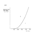
図6の実線は単位時間当りに輝炎を発することなく酸化除去可能な酸化除去可能微粒子量Gを示している。なお、図6において横軸はパティキュレートフィルタ22の温度TFを示している。単位時間当りに燃焼室5から排出される微粒子の量を排出微粒子量Mと称するとこの排出微粒子量Mが酸化除去可能微粒子Gよりも少ないとき、即ち図6の領域Iでは燃焼室5から排出された全ての微粒子がパティキュレートフィルタ22に接触するや否や短時間のうちにパティキュレートフィルタ22上において輝炎を発することなく酸化除去せしめられる。
【0037】
これに対し、排出微粒子量Mが酸化除去可能微粒子量Gよりも多いとき、即ち図6の領域IIでは全ての微粒子を酸化するには活性酸素量が不足している。図5(A)〜(C)はこのような場合の微粒子の酸化の様子を示している。即ち、全ての微粒子を酸化するには活性酸素量が不足している場合には図5(A)に示すように微粒子62が酸素吸蔵・活性酸素放出剤61上に付着すると微粒子62の一部のみが酸化され、十分に酸化されなかった微粒子部分が担体層上に残留する。次いで活性酸素量が不足している状態が継続すると次から次へと酸化されなかった微粒子部分が担体層上に残留し、その結果図5(B)に示されるように担体層の表面が残留微粒子部分63によって覆われるようになる。
【0038】
担体層の表面を覆うこの残留微粒子部分63は次第に酸化されにくいカーボン質に変質し、斯くしてこの残留微粒子部分63はそのまま残留しやすくなる。また、担体層の表面が残留微粒子部分63によって覆われると白金PtによるNO,SO2 の酸化作用および酸素吸蔵・活性酸素放出剤61による活性酸素の放出作用が抑制される。その結果、図5(C)に示されるように残留微粒子部分63の上に別の微粒子64が次から次へと堆積する。即ち、微粒子が積層状に堆積することになる。このように微粒子が積層状に堆積するとこれら微粒子は白金Ptや酸素吸蔵・活性酸素放出剤61から距離を隔てているためにたとえ酸化されやすい微粒子であってももはや活性酸素Oによって酸化されることがなく、従ってこの微粒子64上に更に別の微粒子が次から次へと堆積する。即ち、排出微粒子量Mが酸化除去可能微粒子量Gよりも多い状態が継続するとパティキュレートフィルタ22上には微粒子が積層状に堆積し、斯くして排気ガス温を高温にするか、或いはパティキュレートフィルタ22の温度を高温にしない限り、堆積した微粒子を着火燃焼させることができなくなる。このように図6の領域Iでは微粒子はパティキュレートフィルタ22上において輝炎を発することなく短時間のうちに酸化せしめられ、図6の領域IIでは微粒子がパティキュレートフィルタ22上に積層状に堆積する。従って微粒子がパティキュレートフィルタ22上に積層状に堆積しないようにするためには排出微粒子量Mを常時酸化除去可能微粒子量Gよりも少くしておく必要がある。
【0039】
図6からわかるように本発明の実施形態で用いられているパティキュレートフィルタ22ではパティキュレートフィルタ22の温度TFがかなり低くても微粒子を酸化させることが可能であり、従って図1に示す圧縮着火式内燃機関において排出微粒子量Mおよびパティキュレートフィルタ22の温度TFを排出微粒子量Mが酸化除去可能微粒子量Gよりも通常少なくなるように維持することが可能である。従って本発明による実施形態においては排出微粒子量Mおよびパティキュレートフィルタ22の温度TFを排出微粒子量Mが酸化除去可能微粒子量Gよりも通常少なくなるように維持するようにしている。このように排出微粒子量Mが酸化除去可能微粒子量Gよりも通常少なくなるように維持するとパティキュレートフィルタ22上に微粒子が全く堆積しなくなる。その結果、パティキュレートフィルタ22における排気ガス流の圧損は全くと言っていいほど変化することなくほぼ一定の最小圧損値に維持される。斯くして機関の出力低下を最小限に維持することができる。また、微粒子の酸化による微粒子除去作用はかなり低温でもって行われる。従ってパティキュレートフィルタ22の温度はさほど上昇せず、斯くしてパティキュレートフィルタ22が劣化する危険性はほとんどない。また、パティキュレートフィルタ22上に微粒子が全く堆積しないのでアッシュが凝集する危険性が少なく、従ってパティキュレートフィルタ22が目詰まりする危険性が少なくなる。
【0040】
ところでこの目詰まりは主に硫酸カルシウムCaSO4 によって生ずる。即ち、燃料や潤滑油はカルシウムCaを含んでおり、従って排気ガス中にカルシウムCaが含まれている。このカルシウムCaはSO3 が存在すると硫酸カルシウムCaSO4 を生成する。この硫酸カルシウムCaSO4 は固体であって高温になっても熱分解しない。従って硫酸カルシウムCaSO4 が生成され、この硫酸カルシウムCaSO4 によってパティキュレートフィルタ22の細孔が閉塞されると目詰まりを生ずることになる。しかしながらこの場合、酸素吸蔵・活性酸素放出剤61としてカルシウムCaよりもイオン化傾向の高いアルカリ金属又はアルカリ土類金属、例えばカリウムKを用いると酸素吸蔵・活性酸素放出剤61内に拡散するSO3 はカリウムKと結合して硫酸カリウムK2 SO4 を形成し、カルシウムCaはSO3 と結合することなくパティキュレートフィルタ22の隔壁54を通過して排気ガス流出通路51内に流出する。従ってパティキュレートフィルタ22の細孔が目詰まりすることがなくなる。従って前述したように酸素吸蔵・活性酸素放出剤61としてはカルシウムCaよりもイオン化傾向の高いアルカリ金属又はアルカリ土類金属、即ちカリウムK、リチウムLi、セシウムCs、ルビジウムRb、バリウムBa、ストロンチウムSrを用いることが好ましいことになる。
【0041】
さて、本発明による第一の実施形態では基本的に全ての運転状態において排出微粒子量Mが酸化除去可能微粒子量Gよりも少なくなるように維持することを意図している。しかしながら実際には全ての運転状態において排出微粒子量Mを酸化除去可能微粒子量Gよりも少くすることはほとんど不可能である。例えば機関始動時には通常パティキュレートフィルタ22の温度は低く、従ってこのときには通常排出微粒子量Mの方が酸化除去可能微粒子量Gよりも多くなる。従って本発明による第二の実施形態では機関始動直後のような特別の場合を除いて通常継続的に排出微粒子量Mが酸化除去可能微粒子量Gよりも少なくなるようにしている。
【0042】
なお、機関始動直後におけるように排出微粒子量Mの方が酸化除去可能微粒子量Gよりも多くなるとパティキュレートフィルタ22上に酸化されなかった微粒子部分が残留しはじめる。しかしながらこのように酸化されなかった微粒子部分が残留しはじめているときに、即ち微粒子が一定限度以下しか堆積していないときに排出微粒子量Mが酸化除去可能微粒子量Gよりも少くなるとこの残留微粒子部分は活性酸素Oによって輝炎を発することなく酸化除去される。従って本発明による第二の実施形態では機関始動直後のような特別の運転状態のときには、排出微粒子量Mが酸化除去可能微粒子量Gより少なくなったときに酸化除去しうる一定限度以下の量の微粒子しかパティキュレートフィルタ22上に積層しないように排出微粒子量Mおよびパティキュレートフィルタ22の温度TFが維持される。
【0043】
また、このように排出微粒子量Mおよびパティキュレートフィルタ22の温度TFを維持するようにしていたとしても何らかの理由によりパティキュレートフィルタ22上に微粒子が積層状に堆積する場合がある。このような場合であっても排気ガスの一部又は全体の空燃比が一時的にリッチにされるとパティキュレートフィルタ22上に堆積した微粒子は輝炎を発することなく酸化せしめられる。即ち、排気ガスの空燃比がリッチにされると、即ち排気ガス中の酸素濃度が低下せしめられると酸素吸蔵・活性酸素放出剤61から外部に活性酸素Oが一気に放出され、これら一気に放出された活性酸素Oによって堆積した微粒子が輝炎を発することなく一気に短時間で酸化除去せしめられる。
【0044】
つまり第二の実施形態では、排出微粒子量Mが酸化除去可能微粒子量Gよりも通常少なくなり、かつ排出微粒子量Mが一時的に酸化除去可能微粒子量Gより多くなったとしてもその後排出微粒子量Mが酸化除去可能微粒子量Gより少なくなったときに酸化除去しうる一定限度以下の量の微粒子しかパティキュレートフィルタ22上に堆積しないように、排出微粒子量Mおよびパティキュレートフィルタ22の温度TFを維持すべく内燃機関の運転条件が制御される。
【0045】
図7は図3(B)に示したパティキュレートフィルタ22の隔壁54の拡大断面図である。図7において、66は隔壁54の内部に広がっている排気ガス通路、67はパティキュレートフィルタの基材、261はパティキュレートフィルタの隔壁54の表面上に担持されている酸素吸蔵・活性酸素放出剤である。上述したように、この酸素吸蔵・活性酸素放出剤261はパティキュレートフィルタの隔壁54の表面上に一時的に捕集された微粒子を酸化する機能を有する。161はパティキュレートフィルタの隔壁54の内部に担持されている酸素吸蔵・活性酸素放出剤である。この酸素吸蔵・活性酸素放出剤161も、酸素吸蔵・活性酸素放出剤261と同様な酸化機能を有し、パティキュレートフィルタの隔壁54の内部に一時的に捕集された微粒子を酸化することができる。
【0046】
図8は図1に示したパティキュレートフィルタ22の拡大図である。詳細には、図8(A)はパティキュレートフィルタの拡大平面図、図8(B)はパティキュレートフィルタの拡大側面図である。図9は排気切換バルブの切換位置と排気ガスの流れとの関係を示した図である。詳細には、図9(A)は排気切換バルブ73が順流位置にあるときの図、図9(B)は排気切換バルブ73が逆流位置にあるときの図、図9(C)は排気切換バルブ73がバイパス位置にあるときの図である。排気切換バルブ73が順流位置にあるとき、図9(A)に示すように、排気切換バルブ73を通過してケーシング23内に流入した排気ガスは、まず第一通路71を通過し、次いでパティキュレートフィルタ22を通過し、最後に第二通路72を通過し、再び排気切換バルブ73を通過して排気管に戻される。排気切換バルブ73が逆流位置にあるとき、図9(B)に示すように、排気切換バルブ73を通過してケーシング23内に流入した排気ガスは、まず第二通路72を通過し、次いでパティキュレートフィルタ22を図9(A)に示した場合とは逆向きに通過し、最後に第一通路71を通過し、再び排気切換バルブ73を通過して排気管に戻される。排気切換バルブ73がバイパス位置にあるとき、図9(C)に示すように、第一通路71内の圧力と第二通路72内の圧力とが等しくなるために、排気切換バルブ73に到達した排気ガスはケーシング23内に流入することなくそのまま排気切換バルブ73を通過する。排気切換バルブ73の切換は、例えば内燃機関の減速運転毎に行われる。
【0047】
図10は排気切換バルブ73の位置が切り換えられるのに応じてパティキュレートフィルタの隔壁54の内部の微粒子が移動する様子を示した図である。詳細には、図10(A)は排気切換バルブ73が順流位置(図9(A)参照)にあるときのパティキュレートフィルタ22の隔壁54の拡大断面図、図10(B)は排気切換バルブ73が順流位置から逆流位置(図9(B)参照)に切り換えられたときのパティキュレートフィルタ22の隔壁54の拡大断面図である。図10(A)に示すように、排気切換バルブ73が順流位置に配置され、排気ガスが上側から下側に流れているとき、隔壁内部の排気ガス通路66内に存在する微粒子162は、排気ガスの流れによって隔壁内部の酸素吸蔵・活性酸素放出剤161に押しつけられ、その上に堆積してしまっている。そのため、酸素吸蔵・活性酸素放出剤161に直接接触していない微粒子162は、十分な酸化作用を受けていない。次に図10(B)に示すように排気切換バルブ73が順流位置から逆流位置に切り換えられて排気ガスが下側から上側に流れると、隔壁内部の排気ガス通路66内に存在する微粒子162は排気ガスの流れによって移動せしめられる。その結果、十分に酸化作用を受けていなかった微粒子162が、酸素吸蔵・活性酸素放出剤161に直接接触せしめられ、十分な酸化作用を受けるようになる。また、排気切換バルブ73が順流位置に配置されていたとき(図10(A)参照)にパティキュレートフィルタの隔壁表面の酸素吸蔵・活性酸素放出剤261上に堆積していた微粒子の一部は、排気切換バルブ73が順流位置から逆流位置に切り換えられることにより、パティキュレートフィルタの隔壁表面の酸素吸蔵・活性酸素放出剤261上から脱離する(図10(B)参照)。この微粒子の脱離量は、パティキュレートフィルタ22の温度が高いほど多くなり、また、排気ガス量が多いほど多くなる。パティキュレートフィルタ22の温度が高いほど微粒子の脱離量が多くなるのは、パティキュレートフィルタ22の温度が高くなるに従って、微粒子を堆積させているバインダとしてのSOFの結合力が弱くなるからである。
【0048】
本実施形態では、図9(A)に示す排気切換バルブ73の順流位置から図9(B)に示す逆流位置への切り換え、及び、図9(B)に示す逆流位置から図9(A)に示す順流位置への切り換えは、パティキュレートフィルタ22の隔壁54に捕集される微粒子をパティキュレートフィルタ22の隔壁54の上面と下面(図7参照)とに分散させるようにして行われる。そのように排気切換バルブ73の切換を行うことにより、パティキュレートフィルタ22の隔壁54に捕集された微粒子が酸化除去されることなく堆積する可能性が低減せしめられる。好適には、パティキュレートフィルタ22の隔壁54に捕集される微粒子は、パティキュレートフィルタ22の隔壁54の上面と下面とにほぼ同程度に分散される。
【0049】
さて、図6においては酸化除去可能微粒子量Gがパティキュレートフィルタ22の温度TFのみの関数として示されているがこの酸化除去可能微粒子量Gは実際には排気ガス中の酸素濃度、排気ガス中のNOx濃度、排気ガス中の未燃HC濃度、微粒子の酸化のしやすさの程度、パティキュレートフィルタ22内における排気ガス流の空間速度、排気ガス圧等の関数でもある。従って酸化除去可能微粒子量Gはパティキュレートフィルタ22の温度TFを含む上述の全ての因子の影響を考慮に入れて算出することが好ましい。
【0050】
しかしながらこれら因子のうちで酸化除去可能微粒子量Gに最も大きな影響を与えるのはパティキュレートフィルタ22の温度TFであり、比較的大きな影響を与えるのは排気ガス中の酸素濃度とNOx濃度である。図11(A)はパティキュレートフィルタ22の温度TFおよび排気ガス中の酸素が変化したときの酸化除去可能微粒子量Gの変化を示しており、図11(B)はパティキュレートフィルタ22の温度TFおよび排気ガス中のNOx濃度が変化したときの酸化除去可能微粒子量Gの変化を示している。なお、図11(A),(B)において破線は排気ガス中の酸素濃度およびNOx濃度が基準値であるときを示しており、図11(A)において〔O2 〕1 は基準値よりも排気ガス中の酸素濃度が高いとき、〔O2 〕2 は〔O2 〕1 よりも更に酸化濃度が高いときを夫々示しており、図11(B)において〔NO〕1 は基準値よりも排気ガス中のNOx濃度が高いとき、〔NO〕2 は〔NO〕1 よりも更にNOx濃度が高いときを夫々示している。
【0051】
排気ガス中の酸素濃度が高くなるとそれだけでも酸化除去可能微粒子量Gが増大するが更に酸素吸蔵・活性酸素放出剤61内に取込まれる酸素量が増大するので酸素吸蔵・活性酸素放出剤61から放出される活性酸素も増大する。従って図11(A)に示されるように排気ガス中の酸素濃度が高くなるほど酸化除去可能微粒子量Gは増大する。一方、排気ガス中のNOは前述したように白金Ptの表面上において酸化されてNO2 となる。このようにして生成されたNO2 の一部は酸素吸蔵・活性酸素放出剤61内に吸収され、残りのNO2 は白金Ptの表面から外部に離脱する。このとき微粒子はNO2 と接触すると酸化反応が促進され、従って図11(B)に示されるように排気ガス中のNOx濃度が高くなるほど酸化除去可能微粒子量Gは増大する。ただし、このNO2 による微粒子の酸化促進作用は排気ガス温がほぼ250℃からほぼ450℃の間でしか生じないので図11(B)に示されるように排気ガス中のNOx濃度が高くなるとパティキュレートフィルタ22の温度TFがほぼ250℃から450℃の間のときに酸化除去可能微粒子量Gが増大する。
【0052】
前述したように酸化除去可能微粒子量Gは酸化除去可能微粒子量Gに影響を与える全ての因子を考慮に入れて算出することが好ましい。しかしながら本発明による実施形態ではこれら因子のうちで酸化除去可能微粒子量Gに最も大きな影響を与えるパティキュレートフィルタ22の温度TFと、比較的大きな影響を与える排気ガス中の酸素濃度およびNOx濃度のみに基づいて酸化除去可能微粒子量Gを算出するようにしている。即ち、本発明による実施形態では図12の(A)から(F)に示されるようにパティキュレートフィルタ22の各温度TF(200℃、250℃、300℃、350℃、400℃、450℃)における酸化除去可能微粒子量Gが夫々排気ガス中の酸素濃度〔O2 〕と排気ガス中のNOx濃度〔NO〕の関数としてマップの形で予めROM32内に記憶されており、各パティキュレートフィルタ22の温度TF、酸化濃度〔O2 〕およびNOx濃度〔NO〕に応じた酸化除去可能微粒子量Gが図12の(A)から(F)に示されるマップから比例配分により算出される。
【0053】
なお、排気ガス中の酸素濃度〔O2 〕およびNOx濃度〔NO〕は酸素濃度センサおよびNOx濃度センサを用いて検出することができる。しかしながら本発明による実施形態では排気ガス中の酸素濃度〔O2 〕が要求トルクTQおよび機関回転数Nの関数として図13(A)に示すようなマップの形で予めROM32内に記憶されており、排気ガス中のNOx濃度〔NO〕も要求トルクTQおよび機関回転数Nの関数として図13(B)に示すようなマップの形で予めROM32内に記憶されており、これらのマップから排気ガス中の酸素濃度〔O2 〕およびNOx濃度〔NO〕が算出される。
【0054】
一方、排出微粒子量Mは機関の型式によって変化するが機関の型式が定まると要求トルクTQおよび機関回転数Nの関数となる。図14(A)は図1に示される内燃機関の排出微粒子量Mを示しており、各曲線M1 ,M2 ,M3 ,M4 ,M5 は等排出微粒子量(M1 <M2 <M3 <M4 <M5 )を示している。図14(A)に示される例では要求トルクTQが高くなるほど排出微粒子量Mが増大する。なお、図14(A)に示される排出微粒子量Mは要求トルクTQおよび機関回転数Nの関数として図14(B)に示すマップの形で予めROM32内に記憶されている。
【0055】
さて、前述したように本発明による実施形態ではパティキュレートフィルタ22の各隔壁54の両側面上および隔壁54内の細孔内壁面上には例えばアルミナからなる担体の層が形成されており、この担体上に貴金属触媒および酸素吸蔵・活性酸素放出剤が担持されている。更に本発明による実施形態ではこの担体上に貴金属触媒、およびパティキュレートフィルタ22に流入する排気ガスの空燃比がリーンのときには排気ガス中に含まれるNOxを吸収しパティキュレートフィルタ22に流入する排気ガスの空燃比が理論空燃比又はリッチになると吸収したNOxを放出するNOx吸収剤が担持されている。
【0056】
本発明による実施形態ではこの貴金属触媒として白金Ptが用いられており、NOx吸収剤としてカリウムK、ナトリウムNa、リチウムLi、セシウムCs、ルビジウムRbのようなアルカリ金属、バリウムBa、カルシウムCa、ストロンチウムSrのようなアルカリ土類、ランタンLa、イットリウムYのような希土類から選ばれた少くとも一つが用いられている。なお、前述した酸素吸蔵・活性酸素放出剤を構成する金属と比較すればわかるようにNOx吸収剤を構成する金属と、酸素吸蔵・活性酸素放出剤を構成する金属とは大部分が一致している。この場合、NOx吸収剤および酸素吸蔵・活性酸素放出剤として夫々異なる金属を用いることもできるし、同一の金属を用いることもできる。NOx吸収剤および酸素吸蔵・活性酸素放出剤として同一の金属を用いた場合にはNOx吸収剤としての機能と酸素吸蔵・活性酸素放出剤としての機能との双方の機能を同時に果すことになる。
【0057】
次に貴金属触媒として白金Ptを用い、NOx吸収剤としてカリウムKを用いた場合を例にとってNOxの吸放出作用について説明する。まず初めにNOxの吸収作用について検討するとNOxは図4(A)に示すメカニズムと同じメカニズムでもってNOx吸収剤に吸収される。ただし、この場合図4(A)において符号61はNOx吸収剤を示す。即ち、パティキュレートフィルタ22に流入する排気ガスの空燃比がリーンのときには排気ガス中に多量の過剰酸素が含まれているので排気ガスがパティキュレートフィルタ22の排気ガス流入通路50内に流入すると図4(A)に示されるようにこれら酸素O2 がO2 − 又はO2−の形で白金Ptの表面に付着する。一方、排気ガス中のNOは白金Ptの表面上でO2 − 又はO2−と反応し、NO2 となる(2NO+O2 →2NO2 )。次いで生成されたNO2 の一部は白金Pt上で酸化されつつNOx吸収剤61内に吸収され、カリウムKと結合しながら図4(A)に示されるように硝酸イオンNO3 − の形でNOx吸収剤61内に拡散し、一部の硝酸イオンNO3 − は硝酸カリウムKNO3 を生成する。このようにしてNOがNOx吸収剤61内に吸収される。
【0058】
一方、パティキュレートフィルタ22に流入する排気ガスがリッチになると硝酸イオンNO3 − は酸素とOとNOに分解され、次から次へとNOx吸収剤61からNOが放出される。従ってパティキュレートフィルタ22に流入する排気ガスの空燃比がリッチになると短時間のうちにNOx吸収剤61からNOが放出され、しかもこの放出されたNOが還元されるために大気中にNOが排出されることはない。なお、この場合、パティキュレートフィルタ22に流入する排気ガスの空燃比を理論空燃比にしてもNOx吸収剤61からNOが放出される。しかしながらこの場合にはNOx吸収剤61からNOが徐々にしか放出されないためにNOx吸収剤61に吸収されている全NOxを放出させるには若干長い時間を要する。
【0059】
ところで前述したようにNOx吸収剤および酸素吸蔵・活性酸素放出剤として夫々異なる金属を用いることができる。しかしながら本発明による実施形態ではNOx吸収剤および酸素吸蔵・活性酸素放出剤として同一の金属を用いている。この場合には前述したようにNOx吸収剤としての機能と酸素吸蔵・活性酸素放出剤としての機能との双方の機能を同時に果すことになり、このように双方の機能を同時に果すものを以下、活性酸素放出・NOx吸収剤と称する。従って本発明による実施形態では図4(A)における符号61は活性酸素放出・NOx吸収剤を示している。
【0060】
このような活性酸素放出・NOx吸収剤61を用いた場合、パティキュレートフィルタ22に流入する排気ガスの空燃比がリーンのときには排気ガス中に含まれるNOは活性酸素放出・NOx吸収剤61に吸収され、排気ガス中に含まれる微粒子が活性酸素放出・NOx吸収剤61に付着するとこの微粒子は排気ガス中に含まれる活性酸素および活性酸素放出・NOx吸収剤61から放出される活性酸素によって短時間のうちに酸化除去せしめられる。従ってこのとき排気ガス中の微粒子およびNOxの双方が大気中に排出されるのを阻止することができることになる。一方、パティキュレートフィルタ22に流入する排気ガスの空燃比がリッチになると活性酸素放出・NOx吸収剤61からNOが放出される。このNOは未燃HC,COにより還元され、斯くしてこのときにもNOが大気中に排出されることがない。また、このときパティキュレートフィルタ22上に微粒子が堆積していた場合にはこの微粒子は活性酸素放出・NOx吸収剤61から放出される活性酸素によって酸化除去せしめられる。
【0061】
ところで図6を参照しつつ既に説明したように酸素吸蔵・活性酸素放出剤61からの活性酸素の放出作用はパティキュレートフィルタ22の温度がかなり低いときから開始される。これは活性酸素放出・NOx吸収剤61を用いたときでも同じである。これに対してNOx吸収剤又は活性酸素放出・NOx吸収剤61へのNOxの吸収作用はパティキュレートフィルタ22の温度TFが活性酸素の放出開始温度よりも高くならないと開始されない。これは、活性酸素の放出は例えば硝酸カリウムKNO3 から酸素を奪えれば生ずるのに対してNOxの吸収作用は白金Ptが活性化しないと開始されないからであると考えられる。
【0062】
図15はNOx吸収剤又は活性酸素放出・NOx吸収剤61としてカリウムKを用いた場合の酸化除去可能微粒子量GとNOx吸収率とを示している。図15から活性酸素の放出作用はパティキュレートフィルタ22の温度TFが200℃以下から開始されるのに対してNOxの吸収作用はパティキュレートフィルタ22の温度TFが200℃以上にならないと開始されないことがわかる。一方、活性酸素の放出作用はパティキュレートフィルタ22の温度TFが高くなれば高くなるほど活発になる。これに対してNOxの吸収作用はパティキュレートフィルタ22の温度TFが高くなると消失する。即ち、パティキュレートフィルタ22の温度TFが一定温度、図15に示す例ではほぼ500℃を越えると硝酸イオンNO3 − 又は硝酸カリウムKNO3 が熱分解し、活性酸素放出・NOx吸収剤61からNOが放出される。このような状態になるとNOxの吸収量よりもNOの放出量が多くなり、斯くして図15に示されるようにNOx吸収率が低下する。
【0063】
図15はNOx吸収剤又は活性酸素放出・NOx吸収剤61としてカリウムKを用いた場合のNOx吸収率を示している。この場合、用いる金属によってNOx吸収率の高くなるパティキュレートフィルタ22の温度範囲は異なる。例えばNOx吸収剤又は活性酸素放出・NOx吸収剤61としてバリウムBaを用いた場合にはNOx吸収率の高くなるパティキュレートフィルタ22の温度範囲は図15に示されるカリウムKを用いた場合よりも狭くなる。
【0064】
ところで前述したように排気ガス中の微粒子をパティキュレートフィルタ22上において堆積することなく酸化除去せしめるためには排出微粒子量Mを酸化除去可能微粒子量Gよりも少なくする必要がある。しかしながら単に排出微粒子量Mを酸化除去可能微粒子量Gより少くしただけではNOx吸収剤又は活性酸素放出・NOx吸収剤61によるNOx吸収作用は行われず、NOx吸収剤又は活性酸素放出・NOx吸収剤61によるNOxの吸収作用を確保するにはパティキュレートフィルタ22の温度TFをNOxの吸収作用が行われる温度範囲内に維持する必要がある。この場合、NOx吸収作用が行われるパティキュレートフィルタ22の温度範囲はNOx吸収率が一定値以上、例えば50パーセント以上となる温度範囲とする必要があり、従ってNOx吸収剤又は活性酸素放出・NOx吸収剤61としてカリウムKを用いた場合には図15からわかるようにパティキュレートフィルタ22の温度TFをほぼ250℃から500℃の間に維持する必要がある。
【0065】
従って、本発明による実施形態では排気ガス中の微粒子をパティキュレートフィルタ22上において堆積することなく酸化除去せしめ、かつ排気ガス中のNOxを吸収するために、通常は継続的に排出微粒子量Mを酸化除去可能微粒子量Gよりも少なくなるように維持しかつパティキュレートフィルタ22の温度TFをパティキュレートフィルタ22のNOx吸収率が一定値以上となる温度範囲内に維持するようにしている。即ち、排出微粒子量Mおよびパティキュレートフィルタ22の温度TFを図15のハッチングで示す微粒子NOx同時処理領域内に維持するようにしている。
【0066】
ところでこのように排出微粒子量Mおよびパティキュレートフィルタ22の温度を微粒子NOx同時処理領域内に維持するようにしておいても排出微粒子量Mおよびパティキュレートフィルタ22の温度が微粒子NOx同時処理領域外にずれてしまう場合がある。このような場合、本発明による実施形態では排出微粒子量Mおよびパティキュレートフィルタ22の温度が微粒子NOx同時処理領域内となるように排出微粒子量M、酸化除去可能微粒子量G又はパティキュレートフィルタ22の温度TFの少くとも一つを制御するようにしている。次にこのことについて図16を参照しつつ説明する。
【0067】
まず初めに排出微粒子量Mおよびパティキュレートフィルタ22の温度TFが図16に示される微粒子NOx同時処理領域外のA点になった場合、即ち排出微粒子量Mが酸化除去可能微粒子量Gよりも多くなり、かつパティキュレートフィルタ22の温度TFが微粒子NOx同時処理領域の下限温度よりも低くなった場合について説明する。この場合には矢印で示すようにパティキュレートフィルタ22の温度TFを上昇させることによって排出微粒子量Mおよびパティキュレートフィルタ22の温度TFが微粒子NOx同時処理領域内に戻される。
【0068】
次に排出微粒子量Mおよびパティキュレートフィルタ22の温度TFが図16に示される微粒子NOx同時処理領域外のB点になった場合、即ち排出微粒子量Mが酸化除去可能微粒子量Gよりも多くなり、かつパティキュレートフィルタ22の温度TFが微粒子NOx同時処理領域の温度範囲内にある場合について説明する。この場合には矢印で示すように排出微粒子量Mを低下させることによって排出微粒子量Mおよびパティキュレートフィルタ22の温度TFが微粒子NOx同時処理領域内に戻される。
【0069】
次に排出微粒子量Mおよびパティキュレートフィルタ22の温度TFが図16に示される微粒子NOx同時処理領域外のC点になった場合、即ち排出微粒子量Mが酸化除去可能微粒子量Gよりも多くなり、かつパティキュレートフィルタ22の温度TFが微粒子NOx同時処理領域の上限温度よりも高くなった場合について説明する。この場合には矢印で示すように排出微粒子量Mを低下させかつパティキュレートフィルタ22の温度TFを低下させることによって排出微粒子量Mおよびパティキュレートフィルタ22の温度TFが微粒子NOx同時処理領域内に戻される。
【0070】
このように排出微粒子量Mおよびパティキュレートフィルタ22の温度が微粒子NOx同時処理領域外となったときには排出微粒子量Mを低下させるか、又はパティキュレートフィルタ22の温度TFを上昇或いは低下させることによって排出微粒子量Mおよびパティキュレートフィルタ22の温度が微粒子NOx同時処理領域内に戻される。なお、別の方法として、酸化除去可能微粒子量Gを増大させることによっても排出微粒子量Mおよびパティキュレートフィルタ22の温度を微粒子NOx同時処理領域内に戻すことができる。そこで次に排出微粒子量Mを低下させる方法、パティキュレートフィルタ22の温度TFを上昇或いは下降させる方法、および酸化除去可能微粒子量Gを増大させる方法について説明する。
【0071】
パティキュレートフィルタ22の温度TFを上昇させるのに有効な方法の一つは燃料噴射時期を圧縮上死点以後まで遅角させる方法である。即ち、通常主燃料Qm は図17において(I)に示されるように圧縮上死点付近で噴射される。この場合、図17の(II)に示されるように主燃料Qm の噴射時期が遅角されると後燃え期間が長くなり、斯くして排気ガス温が上昇する。排気ガス温が高くなるとそれに伴ってパティキュレートフィルタ22の温度TFが上昇する。この場合、燃料噴射時期の遅角量を少なくすればパティキュレートフィルタ22の温度TFを低下させることができる。また、パティキュレートフィルタ22の温度TFを上昇させるために図17の(III)に示されるように主燃料Qm に加え、吸気上死点付近において補助燃料Qv を噴射することもできる。このように補助燃料Qv を追加的に噴射すると補助燃料Qv 分だけ燃焼せしめられる燃料が増えるために排気ガス温が上昇し、斯くしてパティキュレートフィルタ22の温度TFが上昇する。
【0072】
一方、このように吸気上死点付近において補助燃料Qv を噴射すると圧縮行程中に圧縮熱によってこの補助燃料Qv からアルデヒド、ケトン、パーオキサイド、一酸化炭素等の中間生成物が生成され、これら中間生成物によって主燃料Qm の反応が加速される。従ってこの場合には図17の(III)に示されるように主燃料Qm の噴射時期を大巾に遅らせても失火を生ずることなく良好な燃焼が得られる。即ち、このように主燃料Qm の噴射時期を大巾に遅らせることができるので排気ガス温はかなり高くなり、斯くしてパティキュレートフィルタ22の温度TFをすみやかに上昇させることができる。この場合、補助燃料Qv の噴射を停止するか或いは補助燃料Qv の噴射量を減少させて主燃料Qm の噴射時期の遅角量を少なくすればパティキュレートフィルタ22の温度TFを低下させることができる。
【0073】
また、パティキュレートフィルタ22の温度TFを上昇させるために図17の(IV)に示されるように主燃料Qm に加え、膨張行程中又は排気行程中に補助燃料Qp を噴射することもできる。即ち、この場合、大部分の補助燃料Qp は燃焼することなく未燃HCの形で排気通路内に排出される。この未燃HCはパティキュレートフィルタ22上において過剰酸素により酸化され、このとき発生する酸化反応熱によってパティキュレートフィルタ22の温度TFが上昇せしめられる。この場合、補助燃料Qp の噴射量を減少させればパティキュレートフィルタ22の温度TFを低下させることができる。
【0074】
次に排出微粒子量Mおよびパティキュレートフィルタ22の温度TFを制御するために低温燃焼を用いる方法について説明する。図1に示される内燃機関ではEGR率(EGRガス量/(EGRガス量+吸入空気量))を増大していくとスモークの発生量が次第に増大してピークに達し、更にEGR率を高めていくと今度はスモークの発生量が急激に低下する。このことについてEGRガスの冷却度合を変えたときのEGR率とスモークとの関係を示す図18を参照しつつ説明する。なお、図18において曲線AはEGRガスを強力に冷却してEGRガス温をほぼ90℃に維持した場合を示しており、曲線Bは小型の冷却装置でEGRガスを冷却した場合を示しており、曲線CはEGRガスを強制的に冷却していない場合を示している。
【0075】
図18の曲線Aで示されるようにEGRガスを強力に冷却した場合にはEGR率が50パーセントよりも少し低いところでスモークの発生量がピークとなり、この場合にはEGR率をほぼ55パーセント以上にすればスモークがほとんど発生しなくなる。一方、図18の曲線Bで示されるようにEGRガスを少し冷却した場合にはEGR率が50パーセントよりも少し高いところでスモークの発生量がピークとなり、この場合にはEGR率をほぼ65パーセント以上にすればスモークがほとんど発生しなくなる。また、図18の曲線Cで示されるようにEGRガスを強制的に冷却していない場合にはEGR率が55パーセントの付近でスモークの発生量がピークとなり、この場合にはEGR率をほぼ70パーセント以上にすればスモークがほとんど発生しなくなる。このようにEGRガス率を55パーセント以上にするとスモークが発生しなくなるのは、EGRガスの吸熱作用によって燃焼時における燃料および周囲のガス温がさほど高くならず、即ち低温燃焼が行われ、その結果炭化水素が煤まで成長しないからである。
【0076】
この低温燃焼は、空燃比にかかわらずにスモークの発生を抑制しつつNOxの発生量を低減することができるという特徴を有する。即ち、空燃比がリッチにされると燃料が過剰となるが燃焼温度が低い温度に抑制されているために過剰な燃料は煤まで成長せず、斯くしてスモークが発生することがない。また、このときNOxも極めて少量しか発生しない。一方、平均空燃比がリーンのとき、或いは空燃比が理論空燃比のときでも燃焼温度が高くなれば少量の煤が生成されるが低温燃焼下では燃焼温度が低い温度に抑制されているためにスモークは全く発生せず、NOxも極めて少量しか発生しない。
【0077】
一方、この低温燃焼を行うと燃料およびその周囲のガス温は低くなるが排気ガス温は上昇する。このことについて図19(A),(B)を参照しつつ説明する。図19(A)の実線は低温燃焼が行われたときの燃焼室5内の平均ガス温Tgとクランク角との関係を示しており、図19(A)の破線は通常の燃焼が行われたときの燃焼室5内の平均ガス温Tgとクランク角との関係を示している。また、図19(B)の実線は低温燃焼が行われたときの燃料およびその周囲のガス温Tfとクランク角との関係を示しており、図19(B)の破線は通常の燃焼が行われたときの燃料およびその周囲のガス温Tfとクランク角との関係を示している。
【0078】
低温燃焼が行われているときには通常の燃焼が行われているときに比べてEGRガス量が多く、従って図19(A)に示されるように圧縮上死点前は、即ち圧縮工程中は実線で示す低温燃焼時における平均ガス温Tgのほうが破線で示す通常の燃焼時における平均ガス温Tgよりも高くなっている。なお、このとき図19(B)に示されるように燃料およびその周囲のガス温Tfは平均ガス温Tgとほぼ同じ温度になっている。次いで圧縮上死点付近において燃焼が開始されるがこの場合、低温燃焼が行われているときには図19(B)の実線で示されるようにEGRガスの吸熱作用により燃料およびその周囲のガス温Tfはさほど高くならない。これに対して通常の燃焼が行われている場合には燃料周りに多量の酸素が存在するために図19(B)の破線で示されるように燃料およびその周囲のガス温Tfは極めて高くなる。このように通常の燃焼が行われた場合には燃料およびその周囲のガス温Tfは低温燃焼が行われている場合に比べてかなり高くなるが大部分を占めるそれ以外のガスの温度は低温燃焼が行われている場合に比べて通常の燃焼が行われている場合の方が低くなっており、従って図19(A)に示されるように圧縮上死点付近における燃焼室5内の平均ガス温Tgは低温燃焼が行われている場合の方が通常の燃焼が行われている場合に比べて高くなる。その結果、図19(A)に示されるように燃焼が完了した後の燃焼室5内の既燃ガス温は低温燃焼が行われた場合の方が通常の燃焼が行われた場合に比べて高くなり、斯くして低温燃焼を行うと排気ガス温が高くなる。
【0079】
このように低温燃焼が行われるとスモークの発生量、即ち排出微粒子量Mが少なくなり、排気ガス温が上昇する。従って機関運転中に通常の燃焼から低温燃焼に切換えると排出微粒子量Mを減少させ、パティキュレートフィルタ22の温度TFを上昇させることができる。これに対し、低温燃焼から通常の燃焼に切換えるとパティキュレートフィルタ22の温度TFは低下する。ただし、このとき排出微粒子量Mは増大する。いずれにしても通常の燃焼と低温燃焼とを切換えることによって排出微粒子量Mおよびパティキュレートフィルタ22の温度を制御することができる。
【0080】
ところで機関の要求トルクTQが高くなると、即ち燃料噴射量が多くなると燃焼時における燃料および周囲のガス温が高くなるために低温燃焼を行うのが困難となる。即ち、低温燃焼を行いうるのは燃焼による発熱量が比較的少ない機関中低負荷運転時に限られる。図20において領域I’は煤の発生量がピークとなる不活性ガス量よりも燃焼室5の不活性ガス量が多い第1の燃焼、即ち低温燃焼を行わせることのできる運転領域を示しており、領域II’は煤の発生量がピークとなる不活性ガス量よりも燃焼室内の不活性ガス量が少ない第2の燃焼、即ち通常の燃焼しか行わせることのできない運転領域を示している。図21は運転領域I’において低温燃焼を行う場合の目標空燃比A/Fを示しており、図22は運転領域I’において低温燃焼を行う場合の要求トルクTQに応じたスロットル弁17の開度、EGR制御弁25の開度、EGR率、空燃比、噴射開始時期θS、噴射完了時期θE、噴射量を示している。なお、図22には運転領域II’において行われる通常の燃焼時におけるスロットル弁17の開度等も合わせて示している。図21および図22から運転領域I’において低温燃焼が行われているときにはEGR率が55パーセント以上とされ、空燃比A/Fが15.5から18程度のリーン空燃比とされることがわかる。なお、前述したように運転領域I’において低温燃焼が行われているときには空燃比をリッチにしてもスモークはほとんど発生しない。
【0081】
次にパティキュレートフィルタ22の温度TFを上昇させるための更に別の方法について説明する。図23はこの方法を実行するのに適した内燃機関を示している。図23を参照するとこの内燃機関では炭化水素供給装置70、170、270がそれぞれ排気管20、第一通路71、第二通路72内に配置されており、必要に応じてこの炭化水素供給装置70、170、270から炭化水素が供給される。炭化水素が供給されるとこの炭化水素はパティキュレートフィルタ22上において過剰酸素により酸化せしめられ、このときの酸化反応熱によってパティキュレートフィルタ22の温度TFが上昇せしめられる。この場合、炭化水素の供給量を減少させることによってパティキュレートフィルタ22の温度TFを低下させることができる。なお、この炭化水素供給装置70はパティキュレートフィルタ22と排気ポート10との間であればどこに配置してもよい。図23において83、183は空燃比センサである。
【0082】
次にパティキュレートフィルタ22の温度TFを上昇させるための更に別の方法について説明する。図24はこの方法を実行するのに適した内燃機関を示している。図24を参照するとこの内燃機関ではパティキュレートフィルタ22下流の排気管20内にアクチュエータ75により駆動される排気制御弁76が配置されている。この方法ではパティキュレートフィルタ22の温度TFを上昇すべきときに排気制御弁76がほぼ全閉とされ、排気制御弁76をほぼ全閉にすることによる機関出力トルクの低下を阻止するために主燃料Qm の噴射量が増大せしめられる。排気制御弁76をほぼ全閉にすると排気制御弁76上流の排気通路内の圧力、即ち背圧が上昇する。背圧が上昇すると燃焼室5内から排気ガスが排気ポート10内に排出されるときに排気ガスの圧力がさほど低下せず、従って温度もさほど低下しなくなる。しかもこのとき主燃料Qm の噴射量が増大せしめられているので燃焼室5内の既燃ガス温が高くなっており、従って排気ポート10内に排出された排気ガスの温度はかなり高くなる。その結果、パティキュレートフィルタ22の温度が急速に上昇せしめられる。この場合、排気制御弁73の開度を増大し、主燃料Qm の噴射量を減少させることによってパティキュレートフィルタ22の温度を低下させることができる。
【0083】
次にパティキュレートフィルタ22の温度TFを上昇させるための更に別の方法について説明する。図25はこの方法を実行するのに適した内燃機関を示している。図25を参照するとこの内燃機関では排気タービン21を迂回する排気バイパス通路77内にアクチュエータ78により制御されるウェストゲートバルブ79が配置されている。このアクチュエータ78は通常サージタンク12内の圧力、即ち過給圧に応動して過給圧が一定圧以上にならないようにウェストゲートバルブ79の開度を制御している。この方法ではパティキュレートフィルタ22の温度TFを上昇すべきときにウェストゲートバルブ79が全開せしめられる。排気ガスは排気タービン21を通過すると温度低下するがウェストゲートバルブ79を全開にすると大部分の排気ガスは排気バイパス通路77内を流れるために温度低下しなくなる。斯くしてパティキュレートフィルタ22の温度が上昇することになる。この場合、ウェストゲートバルブ79の開度を小さくすることによってパティキュレートフィルタ22の温度TFを低下させることができる。
【0084】
上述した実施形態では、例えば図15及び図16に示すようにNOx吸収率が50%以上となる温度範囲である250℃から500℃よりも排気ガスの温度が低く、NOx吸収率が50%以上となる温度範囲である250℃から500℃よりもパティキュレートフィルタ22の温度TFが低くなる可能性があるとき、図9(C)に示すように排気ガスがパティキュレートフィルタ22をバイパスされることにより、NOx吸収率が50%以上となる温度範囲内である250℃から500℃の間にパティキュレートフィルタ22の温度TFが維持される。また、NOx吸収率が50%以上となる温度範囲である250℃から500℃よりも排気ガスの温度が高く、NOx吸収率が50%以上となる温度範囲である250℃から500℃よりもパティキュレートフィルタ22の温度TFが高くなる可能性があるとき、同様に図9(C)に示すように排気ガスがパティキュレートフィルタ22をバイパスされることにより、NOx吸収率が50%以上となる温度範囲内である250℃から500℃の間にパティキュレートフィルタの温度が維持される。このような場合には例えば内燃機関の急加速運転時等が含まれ、急加速運転時か否かは例えばアクセル開度の変化度合い、角速度、エンジン回転数、トルク、排気温、吸入空気量等に基づいて判断することができる。一方、NOx吸収率が50%以上となる温度範囲内である250℃から500℃の間に排気ガスの温度があり、NOx吸収率が50%以上となる温度範囲である250℃から500℃の間からパティキュレートフィルタの温度が外れてしまう可能性がないとき、排気切換バルブ73が図9(A)又は図9(B)に示す位置に維持され、排気ガスがパティキュレートフィルタ22をバイパスされないことにより、NOx吸収率が50%以上となる温度範囲内である250℃から500℃の間にパティキュレートフィルタ22の温度TFが維持される。排気ガスの温度は実際に測定されてもよく、内燃機関の運転条件に基づいて推定してもよい。また、排気切換バルブ73の切換位置を切り換えることと、上述したように内燃機関の運転条件を変更することとを組み合わせることにより、NOx吸収率が50%以上となる温度範囲内である250℃から500℃の間にパティキュレートフィルタ22の温度TFを維持するようにしてもよい。
【0085】
また、NOx吸収率が50%以上となる温度範囲である250℃から500℃よりも排気ガスの温度が低くNOx吸収率が50%以上となる温度範囲である250℃から500℃よりもパティキュレートフィルタ22の温度TFが低いとき、上述したように内燃機関の運転条件を変更することにより排気ガスの温度を上昇させ、排気切換バルブ73を順流位置(図9(A))又は逆流位置(図9(B))に配置して昇温した排気ガスをパティキュレートフィルタ22内に流入させ、次いで、排気切換バルブ73をバイパス位置(図9(C))に配置し、昇温した排気ガスをパティキュレートフィルタ22内に閉じ込め、NOx吸収率が50%以上となる温度範囲内である250℃から500℃の間までパティキュレートフィルタ22の温度TFを上昇させることも可能である。この場合、温度センサ39によりパティキュレートフィルタ22の温度TFの変化を検出すると共にパティキュレートフィルタ22内の温度分布を推定し、それに基づいて、パティキュレートフィルタ22に排気ガスを流す方向及び炭化水素を供給するための炭化水素供給装置170、270を選択することも可能である。
【0086】
他の実施形態では、第二通路72(図1)に冷却フィン等の冷却装置(図示せず)が設けられている。NOx吸収率が50%以上となる温度範囲内である250℃から500℃の間に排気ガスの温度があり、NOx吸収率が50%以上となる温度範囲である250℃から500℃の間からパティキュレートフィルタ22の温度TFが外れてしまう可能性がないとき、排気ガスが冷却装置のない第一通路71を通されることによってパティキュレートフィルタ22に流入する排気ガスの温度が、NOx吸収率が50%以上となる温度範囲内である250℃から500℃の間にそのまま維持されることにより、NOx吸収率が50%以上となる温度範囲内である250℃から500℃の間にパティキュレートフィルタ22の温度TFが維持される。一方、NOx吸収率が50%以上となる温度範囲である250℃から500℃よりも排気ガスの温度が高く、NOx吸収率が50%以上となる温度範囲である250℃から500℃よりもパティキュレートフィルタ22の温度TFが高くなる可能性があるとき、排気ガスが冷却装置のある第二通路72を通されることによってパティキュレートフィルタ22に流入する排気ガスの温度が、NOx吸収率が50%以上となる温度範囲内である250℃から500℃の間の温度にされることにより、NOx吸収率が50%以上となる温度範囲内である250℃から500℃の間にパティキュレートフィルタ22の温度TFが維持される。
【0087】
図26は本発明の内燃機関の排気浄化装置の他の実施形態の図1と同様の概略構成図である。図26において123はケーシングを示している。上述した実施形態のように第二通路72に冷却装置を設ける代わりに、本実施形態では、第二通路172の排気ガス流路長さが第一通路171の排気ガス流路長さよりも長くなっている。本実施形態では、NOx吸収率が50%以上となる温度範囲内である250℃から500℃の間に排気ガスの温度があり、NOx吸収率が50%以上となる温度範囲である250℃から500℃の間からパティキュレートフィルタ122の温度TFが外れてしまう可能性がないとき、排気ガスが排気ガス流路長さの短い第一通路171を通されることによってパティキュレートフィルタ122に流入する排気ガスの温度が、NOx吸収率が50%以上となる温度範囲内である250℃から500℃の間にそのまま維持されることにより、NOx吸収率が50%以上となる温度範囲内である250℃から500℃の間にパティキュレートフィルタ122の温度TFが維持される。一方、NOx吸収率が50%以上となる温度範囲である250℃から500℃よりも排気ガスの温度が高く、NOx吸収率が50%以上となる温度範囲である250℃から500℃よりもパティキュレートフィルタ122の温度TFが高くなる可能性があるとき、排気ガスが排気ガス流路長さの長い第二通路172を通されることによってパティキュレートフィルタ122に流入する排気ガスの温度が、NOx吸収率が50%以上となる温度範囲内である250℃から500℃の間の温度にされることにより、NOx吸収率が50%以上となる温度範囲内である250℃から500℃の間にパティキュレートフィルタ122の温度TFが維持される。
【0088】
また上述した実施形態では、NOx吸収率が50%以上となる温度範囲内である250℃から500℃の間にパティキュレートフィルタ22の温度TFがあり、燃料カット時の排気ガスがパティキュレートフィルタ22内に流入するとNOx吸収率が50%以上となる温度範囲である250℃から500℃よりもパティキュレートフィルタ22の温度TFが低くなってしまう可能性があるとき、排気切換バルブ73がバイパス位置(図9(C))に配置されて排気ガスがパティキュレートフィルタ22をバイパスされることにより、NOx吸収率が50%以上となる温度範囲内である250℃から500℃の間にパティキュレートフィルタ22の温度TFが維持される。このときは燃料カット状態であるため、パティキュレートフィルタ22をバイパスさせてもNOxが車外に排出されることはない。また、NOx吸収率が50%以上となる温度範囲である250℃から500℃よりもパティキュレートフィルタ22の温度TFが高く、パティキュレートフィルタ22の温度TFを低下させる必要があるとき、排気切換バルブ73が順流位置(図9(A))又は逆流位置(図9(B))に配置され排気ガスがパティキュレートフィルタ22をバイパスされず、燃料カット時の比較的温度の低い排気ガスがパティキュレートフィルタ22内に流入せしめられることにより、NOx吸収率が50%以上となる温度範囲内である250℃から500℃の間にパティキュレートフィルタ22の温度TFが入れられる。このように排気ガスをバイパスさせるのが禁止される場合、つまり、燃料カット時であってパティキュレートフィルタ22の温度TFがNOx吸収率が50%以上となる温度範囲内である250℃から500℃よりも高い場合には、NOx吸収率が50%以上となる温度範囲である250℃から500℃よりもパティキュレートフィルタ22の温度TFが実際に高くなっている場合のみならず、上述したように排気ガスをバイパスさせることにより、NOx吸収率が50%以上となる温度範囲である250℃から500℃よりもパティキュレートフィルタ22の温度TFが高くなってしまうことが予測される場合も含まれる。
【0089】
次に排出微粒子量Mを低下させる方法について説明する。即ち、噴射燃料と空気とが十分に混合すればするほど、即ち、噴射燃料周りの空気量が多くなればなるほど噴射燃料は良好に燃焼せしめられるので微粒子は発生しなくなる。従って排出微粒子量Mを低下させるには噴射燃料と空気とがより一層十分に混合するようにしてやればよいことになる。ただし、噴射燃料と空気との混合をよくすると燃焼が活発になるためにNOxの発生量が増大する。従って排出微粒子量Mを低下させる方法は、別の言い方をするとNOxの発生量を増大させる方法と言える。いずれにしても排出微粒子量PMを低下させる方法も種々の方法があり、従ってこれら方法について順次説明する。
【0090】
排出微粒子量PMを低下させる方法として前述した低温燃焼を用いることもできるがその他の有効な方法としては燃料噴射を制御する方法が挙げられる。例えば燃料噴射量を低下させると噴射燃料周りに十分な空気が存在するようになり、斯くして排出微粒子量Mが低減する。また、噴射時期を進角すると噴射燃料周りに十分な空気が存在するようになり、斯くして排出微粒子量Mが低減する。また、コモンレール27内の燃料圧、即ち噴射圧を高めると噴射燃料が分散するので噴射燃料と空気との混合が良好となり、斯くして排出微粒子量Mが低減する。また、主燃料Qm の噴射直前の圧縮行程末期に補助燃料を噴射するようにしている場合、いわゆるパイロット噴射を行っている場合には補助燃料の燃焼により酸素が消費されるために主燃料Qm 周りの空気が不十分となる。従ってこの場合にはパイロット噴射を停止することによって排出微粒子量Mが低減する。即ち、燃料噴射を制御することによって排出微粒子量Mを低減するようにした場合には燃料噴射量が低下せしめられるか、又は燃料噴射時期が進角されるか、又は噴射圧が高められるか、又はパイロット噴射が停止される。
【0091】
次に排出微粒子量Mを低減するための別の方法について説明する。この方法では排出微粒子量Mを低減すべきときにはEGR率を低下させるためにEGR制御弁25の開度が低下せしめられる。EGR率が低下すると噴射燃料周りの空気量が増大し、斯くして排出微粒子量Mが減少する。
【0092】
次に排出微粒子量Mを低減するための更に別の方法について説明する。この方法では排出微粒子量Mを低減すべきときには過給圧を増大するためにウェストゲートバルブ79(図25)の開度が減少せしめられる。過給圧が増大すると噴射燃料周りの空気量が増大し、斯くして排出微粒子量Mが減少する。
【0093】
次に酸化除去可能微粒子量Gを増大するために排気ガス中の酸素濃度を増大させる方法について説明する。排気ガス中の酸素濃度が増大するとそれだけでも酸化除去可能微粒子量Gが増大するが更に活性酸素放出剤61内に取込まれる酸素量が増大するので活性酸素放出剤61から放出される活性酸素量が増大し、斯くして酸化除去可能微粒子量Gが増大する。この方法を実行するための方法としてはEGR率を制御する方法が挙げられる。即ち、酸化除去可能微粒子量Gを増大すべきときにはEGR率が低下するようにEGR制御弁25の開度が減少せしめられる。EGR率が低下するということは吸入空気中における吸入空気量の割合が増大することを意味しており、斯くしてEGR率が低下すると排気ガス中の酸素濃度が上昇する。その結果、酸化除去可能微粒子量Gが増大する。また、EGR率が低下すると前述したように排出微粒子量Mが減少する。従ってEGR率が低下すると排出微粒子量Mが酸化除去可能微粒子量Gよりも急速に小さくなる。
【0094】
次に排気ガス中の酸素濃度を増大させるために2次空気を用いる方法について説明する。図27に示す例では排気タービン21とパティキュレートフィルタ22との間の排気管83が2次空気供給導管80を介して吸気ダクト13に連結され、2次空気供給導管80内に供給制御弁81が配置される。また、図28に示す例では2次空気供給導管80が機関駆動のエアポンプ82に連結されている。なお、排気通路内への2次空気の供給位置はパティキュレートフィルタ22と排気ポート10との間であればどこでもよい。図22又は図23に示す内燃機関においては排気ガス中の酸素濃度を増大すべきときには供給制御弁81が開弁せしめられる。このとき、2次空気供給導管80から排気管83に2次空気が供給され、斯くして排気ガス中の酸素濃度が増大せしめられる。
【0095】
【発明の効果】
請求項1に記載の発明によれば、パティキュレートフィルタ内に流入した微粒子の大部分が、パティキュレートフィルタの壁の一方の面において捕集されてしまうのを回避すると共に、パティキュレートフィルタの壁の方から排気ガス流れの下流側の微粒子に対し酸化除去作用を及ぼすことができる。更に排気ガス中の微粒子を酸化除去しつつ排気ガス中のNOxを浄化することができる。
【0096】
請求項2に記載の発明によれば、例えば内燃機関の運転条件を変更できない場合であっても、NOx吸収率が一定値以上となる温度範囲内にパティキュレートフィルタの温度を維持し排気ガス中のNOxを浄化することができる。
【0097】
請求項3に記載の発明によれば、例えば内燃機関の運転条件を変更できない場合であっても、NOx吸収率が一定値以上となる温度範囲内にパティキュレートフィルタの温度を維持し排気ガス中のNOxを浄化することができる。
【0098】
請求項4に記載の発明によれば、燃料カット時のような内燃機関の運転条件を変更できない場合であっても、NOx吸収率が一定値以上となる温度範囲内にパティキュレートフィルタの温度を維持し排気ガス中のNOxを浄化することができる。
【0099】
請求項5に記載の発明によれば、パティキュレートフィルタ内に流入した微粒子の大部分が、パティキュレートフィルタの壁の一方の面において捕集されてしまうのを回避すると共に、パティキュレートフィルタの壁の方から排気ガス流れの下流側の微粒子に対し酸化除去作用を及ぼすことができる。更にパティキュレートフィルタの壁に捕集された微粒子を活性酸素により酸化除去する酸化除去作用をすべての微粒子に十分に伝えることが可能になり、その結果、微粒子がパティキュレートフィルタの壁に堆積してしまうのを阻止することができる。また排気ガス中の微粒子を酸化除去しつつ排気ガス中のNOxを浄化することができる。
【0100】
請求項6に記載の発明によれば、パティキュレートフィルタの壁の内部の酸化剤によりパティキュレートフィルタの壁の内部の微粒子をパティキュレートフィルタの壁の内部において酸化除去することができる。更にパティキュレートフィルタの壁の内部の酸化剤によりパティキュレートフィルタの壁の内部の微粒子を酸化除去する酸化除去作用を、パティキュレートフィルタの壁の内部に一時的に捕集された微粒子を移動させることによって促進することができる。
【0101】
請求項7に記載の発明によれば、従来の場合のように微粒子がパティキュレートフィルタ上に積層状に堆積した後に輝炎を発してその微粒子を除去する必要なく、微粒子がパティキュレートフィルタ上に積層状に堆積する前に微粒子を酸化させることにより排気ガス中の微粒子を除去しつつ、排気ガス中のNOxを浄化することができる。
【0102】
請求項8に記載の発明によれば、内燃機関の運転条件が、排出微粒子量が酸化除去可能微粒子量よりも少なくなる運転条件、あるいは、排出微粒子量が一時的に酸化除去可能微粒子量より多くなったとしてもその後排出微粒子量が酸化除去可能微粒子量より少なくなったときに酸化除去しうる一定限度以下の量の微粒子しかパティキュレートフィルタ上に堆積しない運転条件に偶然合致する場合と異なり、確実に、排出微粒子量を酸化除去可能微粒子量よりも少なくするか、あるいは、排出微粒子量が一時的に酸化除去可能微粒子量より多くなったとしてもその後排出微粒子量が酸化除去可能微粒子量より少なくなったときに酸化除去しうる一定限度以下の量の微粒子しかパティキュレートフィルタ上に堆積しないようにすることができる。それゆえ、内燃機関の運転条件が偶然合致する場合に比べ、微粒子がパティキュレートフィルタ上に積層状に堆積する前に微粒子をより一層確実に酸化させることができる。
【図面の簡単な説明】
【図1】内燃機関の全体図である。
【図2】機関の要求トルクを示す図である。
【図3】パティキュレートフィルタを示す図である。
【図4】微粒子の酸化作用を説明するための図である。
【図5】微粒子の堆積作用を説明するための図である。
【図6】酸化除去可能微粒子量とパティキュレートフィルタの温度との関係を示す図である。
【図7】図3(B)に示したパティキュレートフィルタの隔壁54の拡大断面図である。
【図8】図1に示したパティキュレートフィルタ22の拡大図である。
【図9】排気切換バルブの切換位置と排気ガスの流れとの関係を示した図である。
【図10】排気切換バルブ73の位置が切り換えられるのに応じてパティキュレートフィルタの隔壁54の内部の微粒子が移動する様子を示した図である。
【図11】酸化除去可能微粒子量を示す図である。
【図12】酸化除去可能微粒子量Gのマップを示す図である。
【図13】排気ガス中の酸素濃度およびNOx濃度のマップを示す図である。
【図14】排出微粒子量を示す図である。
【図15】微粒子NOx同時処理領域を示す図である。
【図16】微粒子の酸化除去方法を説明するための図である。
【図17】噴射制御を説明するための図である。
【図18】スモークの発生量を示す図である。
【図19】燃焼室内のガス温等を示す図である。
【図20】運転領域I’,II’を示す図である。
【図21】空燃比A/Fを示す図である。
【図22】スロットル弁開度等の変化を示す図である。
【図23】内燃機関の別の実施形態を示す全体図である。
【図24】内燃機関の更に別の実施形態を示す全体図である。
【図25】内燃機関の更に別の実施形態を示す全体図である。
【図26】内燃機関の更に別の実施形態を示す全体図である。
【図27】内燃機関の更に別の実施形態を示す全体図である。
【図28】内燃機関の更に別の実施形態を示す全体図である。
【符号の説明】
5…燃焼室
6…燃料噴射弁
20…排気管
22…パティキュレートフィルタ
25…EGR制御弁
54…隔壁
61…活性酸素放出・NOx吸収剤
62…微粒子
73…排気切換バルブ[0001]
TECHNICAL FIELD OF THE INVENTION
The present invention relates to an exhaust gas purification device for an internal combustion engine.
[0002]
[Prior art]
Conventionally, a particulate filter for collecting particulates in exhaust gas discharged from a combustion chamber is disposed in an engine exhaust passage, and the particulates in the exhaust gas are collected when the exhaust gas passes through the particulate filter. 2. Description of the Related Art There is known an exhaust gas purifying apparatus for an internal combustion engine. An example of this type of exhaust gas purifying apparatus for an internal combustion engine is disclosed in Japanese Patent Publication No. 7-106290.
[0003]
[Problems to be solved by the invention]
However, in the exhaust gas purifying apparatus for an internal combustion engine described in JP-A-7-106290, the flow of the exhaust gas passing through the particulate filter is not reversed. Therefore, the fine particles collected on the wall of the particulate filter cannot be dispersed on one side and the other side of the wall of the particulate filter. As a result, when a certain amount or more of the fine particles are collected on the wall of the particulate filter, the action of removing the fine particles is not sufficiently transmitted to all the fine particles. Therefore, in the exhaust gas purifying apparatus for an internal combustion engine described in Japanese Patent Application Laid-Open No. 7-106290, when the amount of particulates flowing into the particulate filter exceeds a certain amount, all the particulates are removed from one side of the wall of the particulate filter. As the particles are trapped on the surface, the particle removing action of the particulate filter is not sufficiently transmitted to all the particles, and as a result, the particles are deposited on the walls of the particulate filter. Therefore, the particulate filter is clogged and the back pressure increases.
[0004]
In view of the above problems, the present invention reverses the flow of exhaust gas passing through a particulate filter and sufficiently transmits an oxidizing / removing action of oxidizing and removing particulates trapped on a wall of the particulate filter to all the particulates. Accordingly, it is an object of the present invention to provide an exhaust gas purifying apparatus for an internal combustion engine that can prevent fine particles from accumulating on the wall of a particulate filter and satisfactorily purify NOx in exhaust gas.
[0005]
[Means for Solving the Problems]
According to the first aspect of the present invention, a particulate filter for collecting particulates in exhaust gas discharged from the combustion chamber is disposed in the engine exhaust passage, and when the exhaust gas passes through the particulate filter. In an exhaust gas purifying apparatus for an internal combustion engine, wherein particulates in exhaust gas are trapped, an oxidizing agent that releases active oxygen for oxidizing particulates temporarily trapped in the particulate filter is used. Exhaust gas backflow means for supporting the particulate filter and reversing the flow of exhaust gas passing through the particulate filter is provided, and the exhaust gas is alternately provided from one side and the other side of the particulate filter. Pass through the particulate filter, absorb NOx lean and release NOx stoichiometric or rich An exhaust purification device for an internal combustion engine is provided, in which an Ox absorbent is carried on the particulate filter, and the temperature of the particulate filter is normally continuously maintained within a temperature range in which the NOx absorption rate is equal to or higher than a predetermined value. .
[0006]
In the exhaust gas purifying apparatus for an internal combustion engine according to the first aspect, an oxidizing agent that releases active oxygen for oxidizing fine particles temporarily collected by the particulate filter is carried by the particulate filter. By reversing the flow of the passing exhaust gas, the exhaust gas is made to pass through the particulate filter alternately from one side and the other side of the particulate filter. Therefore, it is possible to prevent most of the fine particles flowing into the particulate filter from being trapped on one surface of the wall of the particulate filter, and to prevent the most of the fine particles from flowing toward the exhaust gas flow from the wall of the particulate filter. Can have an oxidative removal effect on the fine particles. Further, in the exhaust gas purifying apparatus for an internal combustion engine according to the first aspect, the temperature of the particulate filter is normally continuously maintained within a temperature range in which the NOx absorption rate of the NOx absorbent carried by the particulate filter becomes a certain value or more. Is done. Therefore, it is possible to purify NOx in the exhaust gas while oxidizing and removing the fine particles in the exhaust gas.
[0007]
According to the invention described in
[0008]
In the exhaust gas purifying apparatus for an internal combustion engine according to the second aspect, by selecting whether the exhaust gas is bypassed or not through the particulate filter, the exhaust gas is particulated within a temperature range in which the NOx absorption rate is equal to or higher than a predetermined value. The temperature of the curated filter is usually maintained continuously. For example, when the temperature of the exhaust gas is lower than the temperature range in which the NOx absorption rate is equal to or higher than a certain value, and the temperature of the particulate filter may be lower than the temperature range in which the NOx absorption rate is equal to or higher than a certain value, By the exhaust gas being bypassed through the particulate filter, the temperature of the particulate filter is maintained within a temperature range in which the NOx absorption rate is equal to or higher than a certain value. Further, when the temperature of the exhaust gas is higher than the temperature range in which the NOx absorption rate is equal to or higher than a certain value, and the temperature of the particulate filter may be higher than the temperature range in which the NOx absorption rate is equal to or higher than a certain value, By the exhaust gas being bypassed through the particulate filter, the temperature of the particulate filter is maintained within a temperature range in which the NOx absorption rate is equal to or higher than a certain value. On the other hand, when the temperature of the exhaust gas is within the temperature range where the NOx absorption rate is equal to or higher than a certain value, and there is no possibility that the temperature of the particulate filter deviates from the temperature range where the NOx absorption rate is equal to or higher than the certain value, Since the exhaust gas is not bypassed through the particulate filter, the temperature of the particulate filter is maintained within a temperature range in which the NOx absorption rate is equal to or higher than a certain value. Therefore, for example, even when the operating conditions of the internal combustion engine cannot be changed, the temperature of the particulate filter can be maintained within the temperature range where the NOx absorption rate is equal to or higher than a certain value, and NOx in the exhaust gas can be purified.
[0009]
According to the third aspect of the present invention, the engine exhaust passage through which the exhaust gas discharged from the combustion chamber flows into the particulate filter has the first passage and the second passage, and the first passage The temperature of the exhaust gas passing through the second passage and flowing into the particulate filter is lower than the temperature of the exhaust gas flowing through the particulate filter through the particulate filter. By selecting whether the exhaust gas flowing into the filter passes through the first passage or the second passage, the particulate filter is set within a temperature range in which the NOx absorption rate is equal to or higher than a predetermined value. The exhaust gas purifying apparatus for an internal combustion engine according to
[0010]
In the exhaust gas purifying apparatus for an internal combustion engine according to the third aspect, the first passage in which the temperature of the exhaust gas flowing into the particulate filter increases and the second passage in which the temperature of the exhaust gas flowing into the particulate filter decreases. Is provided, and by selecting whether the exhaust gas flowing into the particulate filter is passed through the first passage or the second passage, a temperature range in which the NOx absorption rate is equal to or more than a certain value is selected. The temperature of the particulate filter is usually maintained continuously. For example, when the temperature of the exhaust gas is within the temperature range where the NOx absorption rate is equal to or higher than a certain value, and there is no possibility that the temperature of the particulate filter deviates from the temperature range where the NOx absorption rate is equal to or higher than the certain value, Since the temperature of the exhaust gas flowing into the particulate filter by passing the exhaust gas through the first passage is maintained as it is within a temperature range where the NOx absorption rate is equal to or higher than a certain value, the NOx absorption rate becomes a constant value. The temperature of the particulate filter is maintained within the above temperature range. Further, when the temperature of the exhaust gas is higher than the temperature range in which the NOx absorption rate is equal to or higher than a certain value, and the temperature of the particulate filter may be higher than the temperature range in which the NOx absorption rate is equal to or higher than a certain value, When the temperature of the exhaust gas flowing into the particulate filter by passing the exhaust gas through the second passage is set to a temperature within a temperature range where the NOx absorption rate is equal to or higher than a certain value, the NOx absorption rate becomes a constant value. The temperature of the particulate filter is maintained within the above temperature range. Therefore, for example, even when the operating conditions of the internal combustion engine cannot be changed, the temperature of the particulate filter can be maintained within the temperature range where the NOx absorption rate is equal to or higher than a certain value, and NOx in the exhaust gas can be purified.
[0011]
According to the invention described in
[0012]
In the exhaust gas purifying apparatus for an internal combustion engine according to
[0013]
According to the fifth aspect of the present invention, a particulate filter for collecting particulates in the exhaust gas discharged from the combustion chamber is disposed in the engine exhaust passage, and the exhaust gas passes through a wall of the particulate filter. In an exhaust gas purifying apparatus for an internal combustion engine in which particulates in exhaust gas are trapped, active oxygen for oxidizing particulates temporarily trapped on the wall of the particulate filter is released. An oxidizing agent to be carried on the wall of the particulate filter, and an exhaust gas backflow means for reversing the flow of the exhaust gas passing through the wall of the particulate filter, wherein the exhaust gas passing through the wall of the particulate filter is provided. By reversing the flow of particles, the fine particles trapped on the wall of the particulate filter Dispersed on one side and the other side of the wall, thereby reducing the possibility of the particulates trapped on the wall of the particulate filter depositing without being oxidized, and absorbing NOx lean. An internal combustion engine in which a NOx absorbent that releases NOx in a stoichiometric or rich manner is supported on the particulate filter, and the temperature of the particulate filter is usually continuously maintained within a temperature range in which the NOx absorption rate is equal to or higher than a certain value. Is provided.
[0014]
In the exhaust gas purifying apparatus for an internal combustion engine according to
[0015]
According to the invention described in
[0016]
In the exhaust gas purifying apparatus for an internal combustion engine according to
[0017]
According to the seventh aspect of the present invention, as the particulate filter, the amount of particulates discharged from the combustion chamber per unit time can be oxidized and removed on the particulate filter without emitting a bright flame per unit time. When the amount is smaller than the oxidizable / removable particulate amount, when the particulates in the exhaust gas flow into the particulate filter, they are oxidized and removed without emitting a bright flame, and the discharged particulate amount temporarily exceeds the oxidizable / removable particulate amount. Even if the particulates accumulate below a certain limit on the particulate filter, the particulates on the particulate filter are oxidized and removed without emitting a bright flame when the amount of the discharged particulates is smaller than the amount of the oxidizable and removable particulates. Using a particulate filter The amount of the particulates that can be removed by filtration depends on the temperature of the particulate filter. Usually, the amount of the discharged particulates and the temperature of the particulate filter are continuously adjusted so that the amount of the discharged particulates is smaller than the amount of the particulates that can be removed by oxidation and the NOx absorption rate The exhaust gas purifying apparatus for an internal combustion engine according to any one of
[0018]
In the exhaust gas purifying apparatus for an internal combustion engine according to the seventh aspect, normally, the amount of exhaust particulates and the temperature of the particulate filter are continuously reduced, the amount of exhaust particulates is smaller than the amount of particulates that can be removed by oxidation, and the NOx absorption rate is equal to or higher than a certain value Is maintained in the particulate NOx simultaneous processing region within the temperature range as follows. Therefore, it is not necessary to emit a bright flame and remove the fine particles after the fine particles are deposited on the particulate filter as in the conventional case, and the fine particles are removed before the fine particles are deposited on the particulate filter. By oxidizing, NOx in the exhaust gas can be purified while removing fine particles in the exhaust gas.
[0019]
According to the invention as set forth in
[0020]
In the exhaust gas purifying apparatus for an internal combustion engine according to the present invention, even if the amount of the exhausted particulates is usually smaller than the amount of the oxidizable and removable particles, and the amount of the exhausted particulates temporarily exceeds the amount of the oxidizable and removable particles, the amount of the exhausted particles is thereafter reduced. In order to maintain the amount of discharged particulates and the temperature of the particulate filter, the internal pressure is maintained so that when the amount of particulates becomes smaller than the amount of particulates that can be removed by oxidation, only a certain amount of particulates that can be removed by oxidation is deposited on the particulate filter. The operating conditions of the engine are controlled. In detail, the amount of discharged fine particles is set to be smaller than the amount of fine particles that can be removed by oxidation, or even if the amount of discharged fine particles temporarily exceeds the amount of fine particles that can be removed by oxidation, The operating conditions of the internal combustion engine are controlled based on the amount of discharged particulates and the temperature of the particulate filter so that only a small amount of particulates, which can be oxidized and removed when the amount becomes smaller, is deposited on the particulate filter. For this reason, even if the operating conditions of the internal combustion engine are such that the amount of discharged particulates is smaller than the amount of fine particles that can be removed by oxidation, or if the amount of discharged fine particles temporarily exceeds the amount of fine particles that can be removed by oxidation, the amount of discharged fine particles will be Unlike the case where the amount of particulates that can be oxidized and removed is less than a certain limit that can be removed by oxidation when the amount becomes smaller than the amount that can be removed by oxidation, it accumulates on the particulate filter. Even if the amount of fine particles is smaller than the amount of fine particles or the amount of fine particles discharged temporarily exceeds the amount of fine particles that can be oxidized and removed, a certain limit that can be oxidized and removed when the amount of fine particles discharged subsequently becomes smaller than the amount of fine particles that can be oxidized and removed Only the following amount of fine particles can be prevented from being deposited on the particulate filter. Therefore, compared to the case where the operating conditions of the internal combustion engine coincide with each other, the fine particles can be more reliably oxidized before the fine particles are deposited on the particulate filter in a stacked state.
[0021]
BEST MODE FOR CARRYING OUT THE INVENTION
Hereinafter, embodiments of the present invention will be described with reference to the accompanying drawings.
[0022]
FIG. 1 shows a first embodiment in which the exhaust gas purifying apparatus for an internal combustion engine of the present invention is applied to a compression ignition type internal combustion engine. The present invention can also be applied to a spark ignition type internal combustion engine. Referring to FIG. 1, 1 is an engine body, 2 is a cylinder block, 3 is a cylinder head, 4 is a piston, 5 is a combustion chamber, 6 is an electrically controlled fuel injection valve, 7 is an intake valve, 8 is an intake port, 9 Denotes an exhaust valve, and 10 denotes an exhaust port. The
[0023]
The
[0024]
The
[0025]
The
[0026]
FIG. 2A shows the relationship between the required torque TQ, the depression amount L of the
[0027]
FIG. 3 shows the structure of the
[0028]
The
[0029]
Next, the action of removing particulates in exhaust gas by the
[0030]
FIGS. 4A and 4B schematically show enlarged views of the surface of the carrier layer formed on the inner peripheral surface of the exhaust
[0031]
On the other hand, as described above, SO2 is contained in the exhaust gas.2Is also included in this SO2Is absorbed into the oxygen storage / active
[0032]
On the other hand, in the
[0033]
On the other hand, at this time, potassium sulfate K formed in the oxygen storage / active
[0034]
When the particulates deposited in layers on the
[0035]
By the way, the platinum Pt and the oxygen storage / active
[0036]
The solid line in FIG. 6 indicates the amount G of oxidizable and removable fine particles that can be oxidized and removed without emitting a bright flame per unit time. In FIG. 6, the horizontal axis indicates the temperature TF of the
[0037]
On the other hand, when the amount M of discharged fine particles is larger than the amount G of fine particles that can be removed by oxidation, that is, in the region II in FIG. 6, the amount of active oxygen is insufficient to oxidize all the fine particles. FIGS. 5A to 5C show how the fine particles are oxidized in such a case. That is, when the amount of active oxygen is insufficient to oxidize all the fine particles, as shown in FIG. 5A, when the
[0038]
The residual
[0039]
As can be seen from FIG. 6, the
[0040]
By the way, this clogging is mainly caused by calcium sulfate CaSO4Caused by That is, the fuel and the lubricating oil contain calcium Ca, and thus the calcium Ca is contained in the exhaust gas. This calcium Ca is SO3In the presence of calcium sulfate CaSO4Generate This calcium sulfate CaSO4Is a solid and does not thermally decompose at high temperatures. Therefore, calcium sulfate CaSO4Is produced, and this calcium sulfate CaSO4If the fine pores of the
[0041]
The first embodiment according to the present invention intends to maintain the amount M of discharged particulates to be smaller than the amount G of particulates that can be removed by oxidation in basically all operating states. However, in practice, it is almost impossible to make the amount M of discharged fine particles smaller than the amount G of fine particles that can be removed by oxidation in all operating states. For example, when the engine is started, the temperature of the
[0042]
When the amount M of discharged fine particles is larger than the amount G of fine particles that can be removed by oxidation as immediately after the start of the engine, the non-oxidized fine particles begin to remain on the
[0043]
Even if the amount M of discharged particulates and the temperature TF of the
[0044]
In other words, in the second embodiment, even if the amount M of discharged fine particles is usually smaller than the amount G of fine particles removable by oxidation, and the amount M of discharged fine particles temporarily exceeds the amount G of fine particles removable by oxidation, the amount The amount M of discharged particulates and the temperature TF of the
[0045]
FIG. 7 is an enlarged sectional view of the
[0046]
FIG. 8 is an enlarged view of the
[0047]
FIG. 10 is a diagram showing a state in which the fine particles inside the
[0048]
In the present embodiment, switching from the forward flow position of the
[0049]
FIG. 6 shows the amount G of oxidizable and removable particles as a function of only the temperature TF of the
[0050]
However, among these factors, the temperature TF of the
[0051]
When the oxygen concentration in the exhaust gas increases, the amount G of fine particles that can be removed by oxidation alone increases, but the amount of oxygen taken into the oxygen storage / active
[0052]
As described above, it is preferable that the amount G of the oxidizable and removable particles is calculated in consideration of all the factors that affect the amount G of the oxidizable and removable particles. However, in the embodiment according to the present invention, of these factors, only the temperature TF of the
[0053]
The oxygen concentration in the exhaust gas [O2] And NOx concentration [NO] can be detected using an oxygen concentration sensor and a NOx concentration sensor. However, in the embodiment according to the present invention, the oxygen concentration in the exhaust gas [O2] Is stored in the
[0054]
On the other hand, the amount M of discharged particulates varies depending on the model of the engine, but when the model of the engine is determined, it becomes a function of the required torque TQ and the engine speed N. FIG. 14A shows the amount M of exhaust particulates of the internal combustion engine shown in FIG.1, M2, M3, M4, M5Is the amount of fine particles discharged (M1<M2<M3<M4<M5). In the example shown in FIG. 14A, the higher the required torque TQ, the greater the amount M of discharged particulates. The amount M of discharged particulate shown in FIG. 14A is stored in advance in the
[0055]
As described above, in the embodiment according to the present invention, a carrier layer made of, for example, alumina is formed on both side surfaces of each
[0056]
In the embodiment according to the present invention, platinum Pt is used as the noble metal catalyst, and alkali metals such as potassium K, sodium Na, lithium Li, cesium Cs, and rubidium Rb, barium Ba, calcium Ca, strontium Sr are used as the NOx absorbent. At least one selected from alkaline earths such as lanthanum La and rare earths such as yttrium Y is used. As can be seen from comparison with the metal constituting the oxygen storage / active oxygen release agent described above, the metal constituting the NOx absorbent and the metal constituting the oxygen storage / active oxygen release agent are almost the same. I have. In this case, different metals can be used as the NOx absorbent and the oxygen storage / active oxygen release agent, or the same metal can be used. When the same metal is used as the NOx absorbent and the oxygen storage / active oxygen release agent, both the function as the NOx absorber and the function as the oxygen storage / active oxygen release agent are simultaneously performed.
[0057]
Next, a description will be given of the NOx absorption / desorption operation using platinum Pt as the noble metal catalyst and potassium K as the NOx absorbent as an example. First, when the NOx absorbing action is examined, NOx is absorbed by the NOx absorbent by the same mechanism as shown in FIG. However, in this case, in FIG. 4A,
[0058]
On the other hand, when the exhaust gas flowing into the
[0059]
As described above, different metals can be used as the NOx absorbent and the oxygen storage / active oxygen release agent. However, in the embodiment according to the present invention, the same metal is used as the NOx absorbent and the oxygen storage / active oxygen release agent. In this case, as described above, both the function as a NOx absorbent and the function as an oxygen storage / active oxygen release agent will be simultaneously performed. Active oxygen release / NOx absorber. Therefore, in the embodiment according to the present invention,
[0060]
When such an active oxygen releasing /
[0061]
By the way, as already described with reference to FIG. 6, the action of releasing active oxygen from the oxygen storage / active
[0062]
FIG. 15 shows the amount G of fine particles that can be removed by oxidation and the NOx absorption rate when potassium K is used as the NOx absorbent or the active oxygen release /
[0063]
FIG. 15 shows the NOx absorption rate when potassium K is used as the NOx absorbent or the active oxygen release /
[0064]
By the way, as described above, in order to oxidize and remove the fine particles in the exhaust gas without accumulating on the
[0065]
Therefore, in the embodiment according to the present invention, the particulate matter in the exhaust gas is oxidized and removed without accumulating on the
[0066]
By the way, even if the amount M of discharged particulates and the temperature of the
[0067]
First, when the amount M of discharged particulates and the temperature TF of the
[0068]
Next, when the amount M of discharged particulates and the temperature TF of the
[0069]
Next, when the amount M of discharged particulates and the temperature TF of the
[0070]
As described above, when the amount M of discharged particulates and the temperature of the
[0071]
One of the effective methods for increasing the temperature TF of the
[0072]
On the other hand, in the vicinity of the intake top dead center, the auxiliary fuel QvWhen the auxiliary fuel Q is injected by the heat of compression during the compression stroke,vProduces intermediate products such as aldehydes, ketones, peroxides, and carbon monoxide from the main fuel Q.mReaction is accelerated. Therefore, in this case, as shown in FIG. 17 (III), the main fuel QmEven if the injection timing is greatly delayed, good combustion can be obtained without causing misfire. That is, the main fuel QmCan be greatly delayed, so that the exhaust gas temperature becomes considerably high, so that the temperature TF of the
[0073]
Further, in order to raise the temperature TF of the
[0074]
Next, a method of using low-temperature combustion to control the amount M of discharged fine particles and the temperature TF of the
[0075]
As shown by the curve A in FIG. 18, when the EGR gas is cooled strongly, the amount of smoke generation peaks at a point where the EGR rate is slightly lower than 50%. In this case, the EGR rate is increased to approximately 55% or more. Then, almost no smoke is generated. On the other hand, as shown by the curve B in FIG. 18, when the EGR gas is slightly cooled, the amount of smoke generation reaches a peak when the EGR rate is slightly higher than 50%, and in this case, the EGR rate is increased to about 65% or more. In this case, almost no smoke is generated. In addition, as shown by the curve C in FIG. 18, when the EGR gas is not forcibly cooled, the amount of smoke generation reaches a peak near the EGR rate of 55%, and in this case, the EGR rate becomes approximately 70%. Above a percentage, there is almost no smoke. When the EGR gas rate is set to 55% or more, the smoke is not generated because the endothermic effect of the EGR gas does not cause the temperature of the fuel and the surrounding gas at the time of combustion to be so high, that is, the low temperature combustion is performed. This is because hydrocarbons do not grow to soot.
[0076]
This low-temperature combustion has a feature that the generation amount of NOx can be reduced while suppressing the generation of smoke regardless of the air-fuel ratio. That is, when the air-fuel ratio is made rich, the fuel becomes excessive, but since the combustion temperature is suppressed to a low temperature, the excess fuel does not grow to soot, and thus no smoke is generated. At this time, only a very small amount of NOx is generated. On the other hand, when the average air-fuel ratio is lean, or even when the air-fuel ratio is the stoichiometric air-fuel ratio, a small amount of soot is generated when the combustion temperature increases, but under low-temperature combustion, the combustion temperature is suppressed to a low temperature. No smoke is generated and NOx is generated in a very small amount.
[0077]
On the other hand, when the low-temperature combustion is performed, the temperature of the fuel and the surrounding gas decreases, but the temperature of the exhaust gas increases. This will be described with reference to FIGS. The solid line in FIG. 19A shows the relationship between the average gas temperature Tg in the
[0078]
During low-temperature combustion, the amount of EGR gas is larger than during normal combustion. Therefore, as shown in FIG. 19A, before the compression top dead center, that is, during the compression process, a solid line is used. The average gas temperature Tg at the time of low-temperature combustion indicated by is higher than the average gas temperature Tg at the time of normal combustion indicated by the broken line. At this time, as shown in FIG. 19B, the temperature Tf of the fuel and the surrounding gas is almost the same as the average gas temperature Tg. Next, combustion starts near the compression top dead center. In this case, when low-temperature combustion is being performed, the fuel and its surrounding gas temperature Tf are absorbed by the endothermic effect of the EGR gas as shown by the solid line in FIG. Not so high. On the other hand, when normal combustion is performed, a large amount of oxygen exists around the fuel, so that the temperature of the fuel and its surrounding gas Tf becomes extremely high as shown by the broken line in FIG. 19B. . Thus, when normal combustion is performed, the temperature of the fuel and its surrounding gas Tf is considerably higher than in the case where low-temperature combustion is performed, but the temperature of the other gas that occupies most is low-temperature combustion. 19A is lower than in the case where normal combustion is performed, and therefore, as shown in FIG. 19A, the average gas in the
[0079]
When low-temperature combustion is performed in this manner, the amount of smoke generated, that is, the amount M of discharged particulates decreases, and the temperature of exhaust gas increases. Therefore, when switching from normal combustion to low-temperature combustion during engine operation, the amount M of discharged particulates can be reduced, and the temperature TF of the
[0080]
By the way, when the required torque TQ of the engine increases, that is, when the fuel injection amount increases, the temperature of the fuel and the surrounding gas during combustion increases, so that it becomes difficult to perform low-temperature combustion. That is, the low-temperature combustion can be performed only during the low-load operation in the engine in which the calorific value due to the combustion is relatively small. In FIG. 20, a region I ′ indicates an operation region in which the first combustion in which the amount of the inert gas in the
[0081]
Next, still another method for increasing the temperature TF of the
[0082]
Next, still another method for increasing the temperature TF of the
[0083]
Next, still another method for increasing the temperature TF of the
[0084]
In the above-described embodiment, for example, as shown in FIGS. 15 and 16, the temperature of the exhaust gas is lower than 250 ° C. to 500 ° C., which is the temperature range where the NOx absorption rate is 50% or more, and the NOx absorption rate is 50% or more. When there is a possibility that the temperature TF of the
[0085]
Further, the temperature of the exhaust gas is lower than 250 ° C. to 500 ° C., which is a temperature range in which the NOx absorption rate is 50% or more, and the particulates are more particulate than 250 ° C. to 500 ° C., a temperature range in which the NOx absorption rate is 50% or more. When the temperature TF of the
[0086]
In another embodiment, a cooling device (not shown) such as a cooling fin is provided in the second passage 72 (FIG. 1). The exhaust gas temperature is between 250 ° C. and 500 ° C., which is within the temperature range where the NOx absorption rate is 50% or more, and between 250 ° C. and 500 ° C., which is the temperature range where the NOx absorption rate is 50% or more. When there is no possibility that the temperature TF of the
[0087]
FIG. 26 is a schematic configuration diagram similar to FIG. 1 of another embodiment of the exhaust gas purifying apparatus for an internal combustion engine of the present invention. In FIG. 26, reference numeral 123 denotes a casing. Instead of providing the cooling device in the
[0088]
Further, in the above-described embodiment, the temperature TF of the
[0089]
Next, a method of reducing the amount M of discharged fine particles will be described. That is, the more the injected fuel and the air are sufficiently mixed, that is, the greater the amount of air around the injected fuel, the better the injected fuel is burned, so that no fine particles are generated. Therefore, in order to reduce the amount M of discharged fine particles, the injected fuel and the air need to be more sufficiently mixed. However, if the mixture of the injected fuel and air is improved, the combustion becomes active, so that the generation amount of NOx increases. Therefore, in other words, the method of reducing the amount M of discharged fine particles can be said to be a method of increasing the generation amount of NOx. In any case, there are various methods for reducing the amount PM of discharged fine particles, and these methods will be sequentially described.
[0090]
The low-temperature combustion described above can be used as a method for reducing the amount PM of discharged fine particles, but another effective method is a method for controlling fuel injection. For example, when the fuel injection amount is reduced, sufficient air exists around the injected fuel, and thus the amount M of discharged particulates is reduced. Further, when the injection timing is advanced, sufficient air exists around the injected fuel, and thus the amount M of discharged particulates is reduced. In addition, when the fuel pressure in the
[0091]
Next, another method for reducing the amount M of discharged fine particles will be described. In this method, when the amount M of discharged particulates is to be reduced, the opening of the
[0092]
Next, still another method for reducing the amount M of discharged fine particles will be described. In this method, when the amount M of discharged particulates is to be reduced, the opening of the waste gate valve 79 (FIG. 25) is reduced to increase the supercharging pressure. When the supercharging pressure increases, the amount of air around the injected fuel increases, and thus the amount M of discharged particulates decreases.
[0093]
Next, a method of increasing the oxygen concentration in the exhaust gas in order to increase the amount G of the oxidizable and removable particles will be described. When the oxygen concentration in the exhaust gas increases, the amount G of fine particles that can be removed by oxidation alone increases, but the amount of oxygen taken into the active
[0094]
Next, a method of using secondary air to increase the oxygen concentration in the exhaust gas will be described. In the example shown in FIG. 27, an
[0095]
【The invention's effect】
According to the first aspect of the present invention, most of the fine particles flowing into the particulate filter are prevented from being collected on one surface of the wall of the particulate filter, and the wall of the particulate filter is prevented. The oxidizing and removing action can be exerted on the fine particles downstream of the exhaust gas flow. Further, NOx in the exhaust gas can be purified while oxidizing and removing fine particles in the exhaust gas.
[0096]
According to the second aspect of the present invention, for example, even when the operating conditions of the internal combustion engine cannot be changed, the temperature of the particulate filter is maintained within the temperature range where the NOx absorption rate is equal to or higher than a certain value, and the NOx can be purified.
[0097]
According to the invention described in
[0098]
According to the fourth aspect of the present invention, even when the operating conditions of the internal combustion engine such as during fuel cut cannot be changed, the temperature of the particulate filter is kept within a temperature range where the NOx absorption rate is equal to or higher than a certain value. It is possible to maintain and purify NOx in the exhaust gas.
[0099]
According to the invention described in
[0100]
According to the invention described in
[0101]
According to the invention as set forth in
[0102]
According to the invention as set forth in
[Brief description of the drawings]
FIG. 1 is an overall view of an internal combustion engine.
FIG. 2 is a diagram showing a required torque of an engine.
FIG. 3 is a diagram showing a particulate filter.
FIG. 4 is a view for explaining an oxidizing action of fine particles.
FIG. 5 is a view for explaining a deposition action of fine particles.
FIG. 6 is a graph showing the relationship between the amount of fine particles that can be removed by oxidation and the temperature of a particulate filter.
FIG. 7 is an enlarged sectional view of a
8 is an enlarged view of the
FIG. 9 is a diagram showing a relationship between a switching position of an exhaust switching valve and a flow of exhaust gas.
FIG. 10 is a view showing a state in which fine particles inside a partition wall of a particulate filter move in accordance with the position of an
FIG. 11 is a diagram showing the amount of fine particles that can be removed by oxidation.
FIG. 12 is a diagram showing a map of the amount G of fine particles that can be removed by oxidation.
FIG. 13 is a diagram showing a map of oxygen concentration and NOx concentration in exhaust gas.
FIG. 14 is a diagram showing the amount of discharged fine particles.
FIG. 15 is a diagram showing a particulate NOx simultaneous processing region.
FIG. 16 is a diagram for explaining a method of oxidizing and removing fine particles.
FIG. 17 is a diagram for explaining injection control.
FIG. 18 is a diagram showing the amount of smoke generated.
FIG. 19 is a diagram showing a gas temperature and the like in a combustion chamber.
FIG. 20 is a diagram showing operation regions I 'and II'.
FIG. 21 is a diagram showing an air-fuel ratio A / F.
FIG. 22 is a diagram showing a change in a throttle valve opening and the like.
FIG. 23 is an overall view showing another embodiment of the internal combustion engine.
FIG. 24 is an overall view showing still another embodiment of the internal combustion engine.
FIG. 25 is an overall view showing still another embodiment of the internal combustion engine.
FIG. 26 is an overall view showing still another embodiment of the internal combustion engine.
FIG. 27 is an overall view showing still another embodiment of the internal combustion engine.
FIG. 28 is an overall view showing still another embodiment of the internal combustion engine.
[Explanation of symbols]
5. Combustion chamber
6 ... Fuel injection valve
20 ... exhaust pipe
22 ... Particulate filter
25 ... EGR control valve
54 ... partition wall
61 ... Reactive oxygen release / NOx absorbent
62 ... fine particles
73… Exhaust switching valve
Claims (8)
Priority Applications (6)
| Application Number | Priority Date | Filing Date | Title |
|---|---|---|---|
| JP2000142323A JP3565135B2 (en) | 2000-05-10 | 2000-05-10 | Exhaust gas purification device for internal combustion engine |
| US09/834,894 US6546721B2 (en) | 2000-04-18 | 2001-04-16 | Exhaust gas purification device |
| DE60114283T DE60114283T2 (en) | 2000-04-18 | 2001-04-17 | Device for exhaust gas purification |
| EP01109531A EP1148227B1 (en) | 2000-04-18 | 2001-04-17 | Exhaust gas purification device |
| KR10-2001-0020369A KR100437301B1 (en) | 2000-04-18 | 2001-04-17 | Exhaust gas purification device |
| CNB011170042A CN1222685C (en) | 2000-04-18 | 2001-04-18 | Exhaust purifier |
Applications Claiming Priority (1)
| Application Number | Priority Date | Filing Date | Title |
|---|---|---|---|
| JP2000142323A JP3565135B2 (en) | 2000-05-10 | 2000-05-10 | Exhaust gas purification device for internal combustion engine |
Publications (2)
| Publication Number | Publication Date |
|---|---|
| JP2001317336A JP2001317336A (en) | 2001-11-16 |
| JP3565135B2 true JP3565135B2 (en) | 2004-09-15 |
Family
ID=18649313
Family Applications (1)
| Application Number | Title | Priority Date | Filing Date |
|---|---|---|---|
| JP2000142323A Expired - Fee Related JP3565135B2 (en) | 2000-04-18 | 2000-05-10 | Exhaust gas purification device for internal combustion engine |
Country Status (1)
| Country | Link |
|---|---|
| JP (1) | JP3565135B2 (en) |
Families Citing this family (2)
| Publication number | Priority date | Publication date | Assignee | Title |
|---|---|---|---|---|
| CN1845780B (en) * | 2003-08-29 | 2010-06-16 | 陶氏环球技术公司 | Improved diesel exhaust filter |
| JP4449947B2 (en) * | 2006-07-05 | 2010-04-14 | トヨタ自動車株式会社 | Control device for internal combustion engine |
-
2000
- 2000-05-10 JP JP2000142323A patent/JP3565135B2/en not_active Expired - Fee Related
Also Published As
| Publication number | Publication date |
|---|---|
| JP2001317336A (en) | 2001-11-16 |
Similar Documents
| Publication | Publication Date | Title |
|---|---|---|
| EP1172532B1 (en) | Exhaust gas cleaning method | |
| EP1148227B1 (en) | Exhaust gas purification device | |
| US6823665B2 (en) | Exhaust gas purification device | |
| US6644022B2 (en) | Exhaust gas purification device of internal combustion engine | |
| JP3807234B2 (en) | Exhaust gas purification method and exhaust gas purification device | |
| JP3565135B2 (en) | Exhaust gas purification device for internal combustion engine | |
| JP3546950B2 (en) | Exhaust gas purification device for internal combustion engine | |
| JP3573094B2 (en) | Exhaust gas purification device | |
| JP3525871B2 (en) | Exhaust gas purification device for internal combustion engine | |
| JP3580223B2 (en) | Exhaust gas purification device | |
| JP3578102B2 (en) | Exhaust gas purification device for internal combustion engine | |
| JP3558046B2 (en) | Exhaust gas purification device for internal combustion engine | |
| JP3551128B2 (en) | Exhaust gas purification device for internal combustion engine | |
| JP3525857B2 (en) | Exhaust gas purification device for internal combustion engine | |
| JP3491601B2 (en) | Exhaust gas purification device for internal combustion engine | |
| JP2002038934A (en) | Exhaust gas purification device for internal combustion engine |
Legal Events
| Date | Code | Title | Description |
|---|---|---|---|
| A977 | Report on retrieval |
Free format text: JAPANESE INTERMEDIATE CODE: A971007 Effective date: 20040127 |
|
| A131 | Notification of reasons for refusal |
Free format text: JAPANESE INTERMEDIATE CODE: A131 Effective date: 20040210 |
|
| TRDD | Decision of grant or rejection written | ||
| A01 | Written decision to grant a patent or to grant a registration (utility model) |
Free format text: JAPANESE INTERMEDIATE CODE: A01 Effective date: 20040518 |
|
| A61 | First payment of annual fees (during grant procedure) |
Free format text: JAPANESE INTERMEDIATE CODE: A61 Effective date: 20040531 |
|
| R150 | Certificate of patent or registration of utility model |
Free format text: JAPANESE INTERMEDIATE CODE: R150 |
|
| FPAY | Renewal fee payment (event date is renewal date of database) |
Free format text: PAYMENT UNTIL: 20080618 Year of fee payment: 4 |
|
| FPAY | Renewal fee payment (event date is renewal date of database) |
Free format text: PAYMENT UNTIL: 20090618 Year of fee payment: 5 |
|
| FPAY | Renewal fee payment (event date is renewal date of database) |
Free format text: PAYMENT UNTIL: 20090618 Year of fee payment: 5 |
|
| FPAY | Renewal fee payment (event date is renewal date of database) |
Free format text: PAYMENT UNTIL: 20100618 Year of fee payment: 6 |
|
| LAPS | Cancellation because of no payment of annual fees |