JP3556265B2 - Image handling device and camera - Google Patents
Image handling device and camera Download PDFInfo
- Publication number
- JP3556265B2 JP3556265B2 JP05988494A JP5988494A JP3556265B2 JP 3556265 B2 JP3556265 B2 JP 3556265B2 JP 05988494 A JP05988494 A JP 05988494A JP 5988494 A JP5988494 A JP 5988494A JP 3556265 B2 JP3556265 B2 JP 3556265B2
- Authority
- JP
- Japan
- Prior art keywords
- image
- sub
- data
- file
- main
- Prior art date
- Legal status (The legal status is an assumption and is not a legal conclusion. Google has not performed a legal analysis and makes no representation as to the accuracy of the status listed.)
- Expired - Lifetime
Links
Images


Classifications
-
- G—PHYSICS
- G11—INFORMATION STORAGE
- G11B—INFORMATION STORAGE BASED ON RELATIVE MOVEMENT BETWEEN RECORD CARRIER AND TRANSDUCER
- G11B27/00—Editing; Indexing; Addressing; Timing or synchronising; Monitoring; Measuring tape travel
- G11B27/10—Indexing; Addressing; Timing or synchronising; Measuring tape travel
- G11B27/19—Indexing; Addressing; Timing or synchronising; Measuring tape travel by using information detectable on the record carrier
- G11B27/28—Indexing; Addressing; Timing or synchronising; Measuring tape travel by using information detectable on the record carrier by using information signals recorded by the same method as the main recording
- G11B27/30—Indexing; Addressing; Timing or synchronising; Measuring tape travel by using information detectable on the record carrier by using information signals recorded by the same method as the main recording on the same track as the main recording
- G11B27/3027—Indexing; Addressing; Timing or synchronising; Measuring tape travel by using information detectable on the record carrier by using information signals recorded by the same method as the main recording on the same track as the main recording used signal is digitally coded
-
- G—PHYSICS
- G06—COMPUTING OR CALCULATING; COUNTING
- G06F—ELECTRIC DIGITAL DATA PROCESSING
- G06F16/00—Information retrieval; Database structures therefor; File system structures therefor
- G06F16/50—Information retrieval; Database structures therefor; File system structures therefor of still image data
- G06F16/51—Indexing; Data structures therefor; Storage structures
-
- G—PHYSICS
- G11—INFORMATION STORAGE
- G11B—INFORMATION STORAGE BASED ON RELATIVE MOVEMENT BETWEEN RECORD CARRIER AND TRANSDUCER
- G11B27/00—Editing; Indexing; Addressing; Timing or synchronising; Monitoring; Measuring tape travel
- G11B27/10—Indexing; Addressing; Timing or synchronising; Measuring tape travel
- G11B27/102—Programmed access in sequence to addressed parts of tracks of operating record carriers
- G11B27/105—Programmed access in sequence to addressed parts of tracks of operating record carriers of operating discs
-
- G—PHYSICS
- G11—INFORMATION STORAGE
- G11B—INFORMATION STORAGE BASED ON RELATIVE MOVEMENT BETWEEN RECORD CARRIER AND TRANSDUCER
- G11B27/00—Editing; Indexing; Addressing; Timing or synchronising; Monitoring; Measuring tape travel
- G11B27/10—Indexing; Addressing; Timing or synchronising; Measuring tape travel
- G11B27/19—Indexing; Addressing; Timing or synchronising; Measuring tape travel by using information detectable on the record carrier
- G11B27/28—Indexing; Addressing; Timing or synchronising; Measuring tape travel by using information detectable on the record carrier by using information signals recorded by the same method as the main recording
- G11B27/32—Indexing; Addressing; Timing or synchronising; Measuring tape travel by using information detectable on the record carrier by using information signals recorded by the same method as the main recording on separate auxiliary tracks of the same or an auxiliary record carrier
- G11B27/322—Indexing; Addressing; Timing or synchronising; Measuring tape travel by using information detectable on the record carrier by using information signals recorded by the same method as the main recording on separate auxiliary tracks of the same or an auxiliary record carrier used signal is digitally coded
-
- G—PHYSICS
- G11—INFORMATION STORAGE
- G11B—INFORMATION STORAGE BASED ON RELATIVE MOVEMENT BETWEEN RECORD CARRIER AND TRANSDUCER
- G11B27/00—Editing; Indexing; Addressing; Timing or synchronising; Monitoring; Measuring tape travel
- G11B27/10—Indexing; Addressing; Timing or synchronising; Measuring tape travel
- G11B27/19—Indexing; Addressing; Timing or synchronising; Measuring tape travel by using information detectable on the record carrier
- G11B27/28—Indexing; Addressing; Timing or synchronising; Measuring tape travel by using information detectable on the record carrier by using information signals recorded by the same method as the main recording
- G11B27/32—Indexing; Addressing; Timing or synchronising; Measuring tape travel by using information detectable on the record carrier by using information signals recorded by the same method as the main recording on separate auxiliary tracks of the same or an auxiliary record carrier
- G11B27/326—Indexing; Addressing; Timing or synchronising; Measuring tape travel by using information detectable on the record carrier by using information signals recorded by the same method as the main recording on separate auxiliary tracks of the same or an auxiliary record carrier used signal is a video-frame or a video-field (P.I.P.)
-
- Y—GENERAL TAGGING OF NEW TECHNOLOGICAL DEVELOPMENTS; GENERAL TAGGING OF CROSS-SECTIONAL TECHNOLOGIES SPANNING OVER SEVERAL SECTIONS OF THE IPC; TECHNICAL SUBJECTS COVERED BY FORMER USPC CROSS-REFERENCE ART COLLECTIONS [XRACs] AND DIGESTS
- Y10—TECHNICAL SUBJECTS COVERED BY FORMER USPC
- Y10S—TECHNICAL SUBJECTS COVERED BY FORMER USPC CROSS-REFERENCE ART COLLECTIONS [XRACs] AND DIGESTS
- Y10S707/00—Data processing: database and file management or data structures
- Y10S707/99941—Database schema or data structure
- Y10S707/99944—Object-oriented database structure
- Y10S707/99945—Object-oriented database structure processing
-
- Y—GENERAL TAGGING OF NEW TECHNOLOGICAL DEVELOPMENTS; GENERAL TAGGING OF CROSS-SECTIONAL TECHNOLOGIES SPANNING OVER SEVERAL SECTIONS OF THE IPC; TECHNICAL SUBJECTS COVERED BY FORMER USPC CROSS-REFERENCE ART COLLECTIONS [XRACs] AND DIGESTS
- Y10—TECHNICAL SUBJECTS COVERED BY FORMER USPC
- Y10S—TECHNICAL SUBJECTS COVERED BY FORMER USPC CROSS-REFERENCE ART COLLECTIONS [XRACs] AND DIGESTS
- Y10S707/00—Data processing: database and file management or data structures
- Y10S707/99941—Database schema or data structure
- Y10S707/99948—Application of database or data structure, e.g. distributed, multimedia, or image
Landscapes
- Engineering & Computer Science (AREA)
- Theoretical Computer Science (AREA)
- Multimedia (AREA)
- Software Systems (AREA)
- Data Mining & Analysis (AREA)
- Databases & Information Systems (AREA)
- Physics & Mathematics (AREA)
- General Engineering & Computer Science (AREA)
- General Physics & Mathematics (AREA)
- Television Signal Processing For Recording (AREA)
- Studio Circuits (AREA)
Description
【0001】
【産業上の利用分野】
本発明は画像取扱装置及びカメラに関し、特に検索性及び操作性を改善した画像取扱装置及びカメラに関する。
【0002】
【従来の技術】
ICメモリカード、磁気媒体(ハードディスクやフロッピーディスク)、光磁気媒体等の記録媒体に画像データ、音声データ、制御データなどをファイルとして記録するデジタルスチルカメラが実用化されている。
【0003】
【発明が解決しようとする課題】
上記のようなデジタルスチルカメラ等の画像を取り扱う画像取扱装置は、画像を画像データとして取り込み、コンピュータによる処理や画像データ伝送が簡単に行なえるため、今後の利用分野の拡大が期待されている。
【0004】
かかる画像取扱装置では、ICカード等の記録媒体に記録されている画像データは、一枚分のデータであり、記録画像を検索する場合には、各画像データを順次読み出して再生する必要がある。しかしながら、一般的に、画像データはデータ量が多く、特にデータの読み込みスピードのおそいFD等の場合、データを読み込んで再生するのに時間がかかる。又、データ圧縮を使用することによって、データ量を減らすことが知られているが、画像を再生するには、読み出した個々の画像データを伸長処理しなければならず、再生処理に時間がかかり、高速な検索が困難であるという問題がある。
【0005】
【発明の目的】
そこで、本発明の目的は、高速な画像検索を可能とし、操作性を改善した画像取扱装置及びカメラを提供することにある。
【0006】
【課題を解決するための手段】
前記課題を解決するために、本発明による画像取扱装置は、撮影により生成され乃至は外部より供給された所定領域の画像から成る主画像の画像情報のうちの一部の画像情報を取り出して第1の副画像として生成する第1の副画像生成手段と、該第1の副画像生成手段に基づく第1の副画像の画像情報のうちの一部の画像情報を取り出して第2の副画像として生成する第2の副画像生成手段を備えて構成される。
【0007】
本発明の他の態様による画像取扱装置は、撮影により生成され乃至は外部より供給された所定領域の画像から成る主画像の画像情報のうちの一部の画像情報を取り出して副画像として生成する副画像生成手段を備える画像取扱装置であって、 前記副画像生成手段は、前記主画像の特定エリアの情報を前記一部の画像情報とするエリア選択手段を有する。
【0008】
ここで、前記エリア選択手段は、前記特定エリアのサイズを変更するサイズ変更手段と、前記特定エリアの位置を変更するエリア位置変更手段の少なくとも一方の手段を有する。
【0009】
また、前記第1の副画像生成手段は、前記主画像の特定エリアの情報を前記一部の画像情報とする第1エリア選択手段、又は前記主画像を縮小した縮小画像情報を前記一部の画像情報とする第1画像縮小手段を有し、前記第2の副画像生成手段は、前記第1の副画像の特定エリアの情報を前記一部の画像情報とする第2エリア選択手段、前記第1の副画像を縮小した縮小画像情報を前記一部の画像情報とする第2画像縮小手段又は前記第1の副画像のデータを圧縮して得られる圧縮画像情報を前記一部の画像情報とする画像圧縮手段の中から選ばれる少なくとも一つの手段を有する。
【0010】
本発明の他の態様によるカメラは、被写体画像を得るための光学系と、
前記光学系を介して得られた被写体画像を光電変換する撮像素子と、
前記撮像素子で光電変換された被写体画像を電気信号に変換する撮像回路と、
前記撮像回路からの電気信号をデジタルデータに変換するA/D変換回路と、
前記A/D変換回路で変換されたデジタルデータを符号化するコーダと、
前記コーダによって符号化されJPEG方式等で圧縮された画像データを記録する記憶手段と、
を有し、
前記記憶手段への記録に際して画像データをファイル形式で記録するにあたり、 各画像ファイルには、主画像と当該主画像の縮小画像から成る副画像とを記録すると共に、
前記各画像ファイルは、前記副画像の画像データ本体が記録されているファイルヘッダーと、当該ファイルヘッダー以外の領域に記録された主画像データ本体とを有する。
【0011】
ここで、前記画像ファイルは、副画像データ開始アドレスを有する。
【0028】
【作用】
上記列挙の各発明によれば、以下に述べるような種々の作用のうち各該当する作用が為されることになる。すなわち、主画像の画像情報のうちの一部の画像情報を取り出して生成さし、生成された副画像データと主画像データをそれぞれ関連付け、識別可能に記録する。また、記録された副画像を読み出し、再生し、又は単独に、又は主画像と関連付けて消去する。更に、生成された副画像のデータを伝送し、受信側からの応答信号に基づいて伝送した副画像に対応する主画像のデータを伝送する。
【0029】
【実施例】
次に、本発明の実施例について図面を参照しながら説明する。
図1は、本発明による画像取扱装置のデジタルスチルカメラへの適用例を示す構成ブロック図である。
被写体画像は、光学系(レンズ)1を介して、光電変換手段であるCCD等の撮像素子を有する撮像回路2で電気信号に変換される。この変換された電気信号は、クランプ回路3で所定のクランプ処理が施された後、A/D変換回路4でデジタルデータに変換され、フレームメモリ11に書き込まれる。フレームメモリ11の書き込みと読み出しは、システムコントローラ16からの制御を受けたメモリコントローラ10により制御される。フレームメモリ11から読み出された画像データは、デジタルプロセス回路5において、キャラクタジェネレータ9から送出されるキャラクタデータとともにデジタル処理された後、D/A変換回路6でアナログ信号に変換される。変換されたアナログ画像信号は、増幅回路7で増幅された後、外部端子EXTと電子ビューファインダ8に供給される。
【0030】
データ記録時には、フレームメモリ11から読み出された画像データは、DCT/IDCT(離散コサイン変換/逆離散コサイン変換)回路12で直交変換され、得られた直交係数がコーダ/デコーダ13で符号化され、JPEG方式等に準拠した圧縮方式で圧縮処理が施される。こうして圧縮された画像データが記憶手段としてのICメモリカード15に記録される。ここでこのメモリカードは、装置本体に対して着脱自在であっても、又、予め内蔵固定されていてもよいものである。
【0031】
再生時には、ICメモリカード15から読み出された画像データが、コーダ/デコーダ13とDCT/IDCT回路12の処理を介して伸長処理され、フレームメモリ11に書き込まれる。フレームメモリ11から読み出された画像データは、デジタルプロセス回路5、D/A変換回路6、増幅回路7を経て外部端子EXTと電子ビューファインダ8とに出力される。
【0032】
システムコントローラ16は、データバスB1を介してデータを授受し、カメラ動作の全体を制御する。例えば、LCD等よりなる表示部17の表示を制御するとともに、操作部18からの操作情報に基づいてカメラ動作を制御する。システムコントローラ16は、またキャラクタジェネレータ9を制御して所望のキャラクタ情報出力を制御し、データバスB2とデータ入出力部19を介して外部との通信を制御する。補助メモリ14は、データの各種処理の際に用いられるワークメモリである。
【0033】
図1に示すような構成において、本発明では、一枚の画像(以下、主画像と称する)についての画像情報の一部を取り出した一部画像情報から成る副画像(例えば、間引き画像、縮小画像等)を生成し、生成画像のメモリへの記憶、他の画像取扱装置への伝送等を行なう。
【0034】
かかる副画像のメモリへの記録は、システムコントローラ16の動作を介して行なわれ、以下に説明するような各種の記録態様がある。
【0035】
ところで、メモリカード、磁気媒体(ハードディスクやフロッピーディスク)及び光磁気媒体等の記録媒体に画像データ、音声データ及び制御データ等をファイルとして記録するデジタルスチルカメラでは、記録媒体にデータをもファイル形式で記録する場合がある。このとき、メモリ管理は、例えばデータ互換性の面でパーソナルコンピュータ等で標準的なDOS(ディスクオペレーティングシステム)形式で行なわれることが望ましい。そして記録媒体には、その動作を制御したり、各ファイル間の関連付けを行なったりするための制御情報を制御ファイル(コントロールファイルまたはリレーショナルファイルとも称するが、以下、リレーショナルファイルと称する)として記録することも検討されている。
【0036】
第1の記録態様は、上記ファイル形式での記録時に、画像ファイルに主画像データと副画像データを記録するものである。図2には3種類の記録態様例が示されている。かかる画像ファイルへの記録により、コマ番号が従来どおり管理でき、移動、コピー、削除等を主画像と副画像を意識せずに一緒に扱える。
図2(A)では、一枚の画像データを記録する際、画像ファイルにはファイルヘッダー部、主画像データ部、続いて副画像データ部が順次記録される。その結果、副画像だけの消去が容易となり、副画像を複数作成するときには追加が容易で、主画像の再生も容易となる。図2(B)では、ファイルヘッダー部、副画像データ部、続いて主画像データ部が順次記録される。したがって、副画像再生モードによる検索時に、より高速な検索が可能となる。また、図2(C)は、副画像が複数枚あるときの記録態様を示し、ファイルヘッダー部に続いて、主データ開始アドレスから主画像データが書き込まれ、副画像データ1開始アドレスから副画像データ1が書き込まれた後、副画像データ2開始アドレスから副画像データ2が書き込まれる。
【0037】
図3には、ファイルヘッダーの記入例が示されており、規格化されたフォーマットタプル、記録日付タプルに続いて、オプションタプル1に副画像データ1のパラメータが、オプションタプル2には副画像データ2のパラメータが記録され、画像データとして主画像データと副画像データが連続して記録されている。上記副画像データのパラメータとしては、副画像データ開始アドレス、副画像データタイプ(圧縮/非圧縮、画素サイズ等)、更には、主画像に対する縮小率1/(2のn乗)を副画像パラメータとすることができる。縮小副画像を作成したとき、画素サイズをパラメータとして記録するよりも、縮小率だけを記録する方が簡単であるし、データ量も少なくて済む。副画像データの作成日付等がある。こうして、上述の効果の他、主画像だけの抜き出しが容易となる。
【0038】
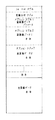
図4は、ファイルヘッダーへの記録フォーマット例を示す。フォーマットタプル、記録日付タプルに続いて、オプションタプル1には記録されている副画像データのパラメータが記録され、オプションタプル2には副画像データ1の本体が、オプションタプル3には副画像データ2の本体が記録されている。主画像データ本体が画像ファイルのファイルヘッダー以外の領域に記録されている。上記副画像データパラメータの例としては、副画像データの有無や個数、副画像データのタイプ(圧縮/非圧縮、画素サイズ、縮小率等)等がある。
【0039】
図5は、主画像データがパソコン用画像データフォーマットの一方式であるJPEG方式で圧縮され記録される場合の画像ヘッダー(JPEGヘッダー)への記録例を示す図である。
ファイルヘッダーに続くJPEGヘッダーには、SOI(Start of Image)マーカー等のデータ、APP(Application Marker)に副画像データ本体が、SOSマーカーに主画像データ本体がEOI(End of Image)マーカー部まで記録されている。こうすることにより、図2に示す例の場合と同様な効果が得られる。パソコン用画像データフォーマットとしては、JPEGの他、TIFF、PICT、BMP等があるが、これらの方式にも本発明が適用できる。
【0040】
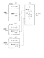
図6には、副画像データを主画像データと別ファイルに記録し、上記したリレーショナルファイルに当該データの関連付けデータを記録する例が示されている。別ファイルへの記録により1枚の画像が1つのファイルになるので、ファイル管理イメージで画像管理が行なえる。そして、このリレーショナルファイルによれば、関連付けの情報が一括して管理されるので、データの管理が容易になる。
【0041】
ファイル(FILE)1として、同図(A)に示すように、ファイルヘッダーと主画像データ本体から成る主画像ファイルが、ファイル2として、同図(B)に示すように、ファイルヘッダーと副画像データ1の本体から成る副画像1ファイルが、ファイル3として、同図(C)に示すように、ファイルヘッダーと副画像データ2の本体から成る副画像2ファイルが、それぞれ用意され、また同図(D)に示すようなリレーショナルファイルが用意されている。同図(D)のリレーショナルファイルには、例えば、”MAIN5”は5コマ目の主画像データが同図(A)のファイル(FILE)1に記録されていることを示し、”SUB5”で5コマ目の副画像データが同図(B)と(C)のファイル2とファイル3に記録されていることを示している。
【0042】
図7は、副画像データを主画像データ本体と別ファイルに記録し、主画像データ用のファイル(同図(A))のファイルヘッダーに、副画像データファイルについての関連情報を記録している例を示す。このファイルヘッダーは、フォーマットタプル、記録日付タプル、副画像ファイル名1が記録されているオプションタプル1、副画像ファイル名2が記録されているオプションタプル2を含んでいる。同図(B)には副画像データ1の本体が記録されているファイルが、同図(C)には副画像データ2の本体が記録されているファイルがそれぞれ示されている。こうすることによって、主画像を読めば必然的に副画像がわかる。また副画像データのファイルヘッダーと主画像データファイルについての関連情報を記録しておけば副画像から主画像の関連がわかり、余分なファイルを読まなくても良い。
【0043】
図8は、主画像データと副画像データをそれぞれ別ファイルに記録し、これらデータの識別、関連付けをファイル名により行なう例を示している。本例では、拡張子により主画像データファイルと副画像データファイルを区別している。その結果、主画像だけ再生、または副画像だけ再生する操作が容易となる。またファイルの画像を再生しなくともファイル名から判別できるようになるので、ファイル操作による画像管理がある程度可能となる。
【0044】
同図左側には、拡張子“J6I”が付された主画像データファイル例が示されている。拡張子“J6I”のうち“J”が圧縮方式であるJPEGを、“6”が68Pin を、“I”がImageであることを示す。
また、同図右側には、拡張子“T6N”(Nは自然数)が付された副画像データファイル例が示されている。拡張子“T6N”のうち“T”が“Thumbnail”(サムネイル)とされる副画像データを、“6”が68Pinを、”N”が当該副画像データのコマ番号を示す。
【0045】
図9は、同様に主画像データと副画像データを別ファイルに記録し、各ファイルの関連付けをディレクトリで行なうディレクトリ構造例を示す。このディレクトリを用いることにより、ファイル名を用いた場合と同様な効果だけでなく、コマ番号の管理も容易となる。これは、他の別ファイル記録の例と異なり、主画像のみ記録されるディレクトリが作成されるので、従来行なっているディレクトリエントリィでのコマ番号管理がそのまま行なえる。
【0046】
本例では、ディレクトリ“MAIN”に主画像データ群が含まれ、ディレクトリ“SUB1”に副画像1のデータ群が含まれ、ディレクトリ“SUB2”に副画像2のデータ群が含まれていることを示す。例えば、ファイル“DSC002.J6I”の副画像1は“¥SUB1 ¥DSC002.J6T”で、ファイル“DSC002.J6I”の副画像2は“¥SUB2¥DSC002.J6T”で表示される。
【0047】
図10は、主画像データと副画像データを別ファイルに記録し、主画像ファイルは別個のファイルとするが、副画像ファイルは一括ファイルに格納している例を示す。この方法によれば、副画像データを一括ファイルにすることによって、インデックス表示(副画像のみの再生)等が容易に行なえる。又、副画像の一括消去等を容易に行なえる。
【0048】
同図(A)には、フォーマットタプル、記録日付タプル、オプションタプル、副画像データオフセットアドレスが記録されたヘッダー部に続いて、主画像データが記録された主画像ファイルDSC001.J6Iの例が示され、同図(B)には、フォーマットタプル、記録日付タプル、オプションタプル、副画像データオフセットアドレスが記録されたヘッダー部に続いて、主画像データが記録された主画像ファイルDSC011.J6Iの例が示され、また同図(C)には、これらの主画像データについての副画像データを記録する唯一つの副画像ファイルが示されている。同図(C)の副画像ファイルには、ファイルヘッダーに続いて、ファイルDSC001.J6Iの副画像が副画像データ1として、以下、同様に、副画像データ2、副画像データ3、…として記録され、例えば、DSC011.J6Iの副画像が副画像データ11として記録され、副画像データ12まで記録されている。
【0049】
上記副画像一括ファイルのファイルヘッダーとしては、副画像の個数、副画像の画像パラメータ、それぞれの副画像データの先頭アドレスや終了アドレス、それぞれの副画像に対する主画像のファイル名等があり、副画像一括ファイルをインデックスファイルとして用いたとき、副画像から主画像を検索できる。
【0050】
図11には、画像データ記録開始アドレスをクラスタ単位で指定する例が示されている。クラスタ1にファイルヘッダーが、クラスタ2,3,…に主画像データが、クラスタ10,11,…に副画像データ1が、クラスタ20,21,…に副画像データ2が記録されている。本実施例によれば、副画像データ1を消去するときには、副画像データ自体は一切操作することなく、画像ファイルのFATチェーン中の副画像部分を消去し、FATチェーンを書き換えるだけで済む。一方、従来の記録開始アドレスを指定する場合には、副画像データ1だけを消去するには、副画像データ1を消去後、消去した場所へ副画像データ2を詰める作業が必要となる。従って、記録開始アドレスを2のn乗バイトにすることにより、画像の高速検索、主画像のみの抜き出しが容易となり、更に、副画像データの消去も容易となる。
【0051】
次に、本発明の実施例におけるデジタルスチルカメラの動作シーケンスを図12のフローチャートを参照して説明する。
【0052】
パワーON後、ズーミング初期化等、カメラ動作条件の初期化処理をし(ステップS1)、副画像作成モードにあるか否かを判定し(ステップS2)、あれば、副画像作成モードであることを表示部17に表示するとともに、その旨を示すフラグをセットした後(ステップS3)、主画像から副画像として取り出すべきエリアを選択するエリア選択モードか否かを判定する(ステップS4)。ステップS2において、副画像作成モードでなければ、後述するステップS13の処理に移行する。
【0053】
ステップS4において、エリア選択モードであれば、エリア選択モードであることを表示するとともに、その旨を示すフラグをセットし(ステップS5)、画像を縮小する画像縮小化モードか否かを判定する(ステップS6)。またエリア選択モードでないときもステップS6に移行する。ここで、画像縮小化モードであれば、画像縮小化モードである旨の表示とフラグセットを行なった後(ステップS7)、また、画像縮小化モードでないときは、次に画像圧縮モードか否かを判定する(ステップS8)。上記縮小化により、小サイズで全体イメージをつかむことができる。
【0054】
ステップS8において、画像圧縮モードであれば、圧縮の際に用いられる手法として、圧縮率を一定化する手法と、サイズ(データ量)を一定化する手法のいずれの手法が設定されているのかを判定するため、サイズ一定モードか否かを判定する(ステップS9)。ここで、サイズ一定モードであれば、圧縮後、サイズ一定である旨を表示するとともにフラグをセットし(ステップS10)、サイズ一定モードでなければ、圧縮率一定モードであるから圧縮率一定モードである旨を表示するとともにフラグをセットする(ステップS11)。ステップS8で画像圧縮モードでないと判定されると、非圧縮モードである旨を表示するとともにフラグをセットする(ステップS12)。
【0055】
ステップS10〜S12の処理の後、操作部18からの操作による操作入力が検出され(ステップS13)、パワーOFFを判定し(ステップS14)、パワーOFFであれば、パワーをOFFとして動作を終了し、パワーOFFでなければ、入力操作に対応する各種の処理を実行して(ステップS15)、ステップS13の処理に戻る。
【0056】
図13は、主画像データ記録後に副画像データを記録する場合の画像データ記録処理シーケンスを示すフローチャートである。
【0057】
例えば、操作部18からの操作による記録指示を受けて処理が開始され、先ず、図1に示す光学系1、撮像回路2、クランプ回路3、A/D変換回路4による処理に続く、フレームメモリ11への書き込み処理を含む撮像処理が実行され(ステップS21)、フレームメモリ11から読み出した主画像データについてDCT/IDCT回路12及びコーダ/デコーダ13による主画像圧縮処理が実行された後(ステップS22)、圧縮された主画像データがICメモリカード15に記録される(ステップS23)。次に、副画像を作成するか否かを判定する(ステップS24)。この判定は、例えば、図12のステップS3における副画像作成モードとしてセットされたフラグの有無に基づいて行なわれる。
【0058】
ステップS24において、副画像を作成すると判定されると、副画像の作成処理が実行され(ステップS25)、ICメモリカードへの副画像記録処理(ステップS26)の後、ファイルメンテナンス処理を実行して(ステップS27)、処理を終了する。ステップS24において、副画像を作成しないと判定されたときには、そのままステップS27のファイルメンテナンス処理が実行される。ファイルメンテナンス処理としては、例えば、ファイルをDOSフォーマットで管理して記録する場合には、ディレクトリエントリ、FAT等のフォーマット書込み処理がある。
【0059】
図14は、図13のステップS25における副画像作成処理の作成シーケンスを示すフローチャートである。
先ず、主画像に対する副画像作成エリアを選択するエリア選択モードか否かを判定し(ステップS31)、エリア選択モードであれば、エリアのサイズを変更するエリアサイズ変更処理(ステップS32)し、エリアの位置を変更するエリア位置変更処理(ステップS33)を実行した後、ステップS34の判定を行なうが、この場合、ステップS31において、エリア選択モードでないと判定した場合にも、同様に、画像を縮小するか否かを判定する。ここで、画像を縮小化すると判定されたときには、フレームメモリ11からの画像データの間引き読み出し等により画像の縮小化処理を実行した後(ステップS35)、またステップS34において、画像を縮小化しないと判定したときは、画像を圧縮するか否かを判定する(ステップS36)。ここで、画像を圧縮すると判定すると、圧縮の際、圧縮率を一定化するかサイズ(データ量)を一定化するかを判別するために、サイズ一定が指示されているか否かを判定する(ステップS37)。
【0060】
ステップS37において、サイズ一定と判定されれば、圧縮後のサイズを一定とした圧縮処理を実行し(ステップS38)、サイズ一定と判定されなければ、圧縮率を一定として圧縮処理を実行して(ステップS39)、処理を終了する。ステップS36において、画像を圧縮しないと判定されると、フレームメモリ11から読み出した画像データを圧縮せずに、例えば、パソコン処理に必要なフォーマットへの変換等の非圧縮データ変換処理を実行して(ステップS40)、処理を終了する。この場合、カメラ内で画像データを扱うときには上記変換処理は実行せずに、そのまま画像データはICメモリに書き込まれる。縮小圧縮画像の作成は、DCT/IDCT回路12から出力される直交係数のうちDC成分のみを記録することにより、1/8縮小画像を得ても良い。この処理により、通常の間引き処理による縮小画像よりも再現性の高い、良好な画質が得られるばかりでなく、メモリ制御は主画像も副画像も同様で良いので、回路が簡略化される。
【0061】
上記した図14に示す例では、副画像生成手段として、エリア選択手段、画像縮小手段、画像圧縮手段の3つの具体的な副画像生成手段を有しており、操作者が、随時任意にこれらの3つの手段を取捨選択するようにして所望の副画像を生成するように構成してあるが、本発明に於いては上記した例に限定されることなく、例えば上記3つの手段のうちの1つ乃至は2つの手段を有するものや、或いは、上記3つの手段の処理順序を適宜入れ換えて構成しても勿論良いものである。この場合、先に処理される副画像生成手段を第1の副画像生成手段とし、この後に処理される副画像生成手段を第2の副画像生成手段とするものであるが、この第1の副画像生成手段と第2の副画像生成手段による現実のデータの処理タイミングについては、先のフレームメモリ11上で同時に処理したり又は時分割による処理を行なうことの何れもが含まれる。
【0062】
この非圧縮データ変換処理の手順が図15のフローチャートに示されている。
図15において、先ず、当該コンピュータのフォーマットで記憶するか否かを判定し(ステップS41)、当該コンピュータのフォーマットでなければ、そのまま処理を終了し、当該コンピュータのフォーマットであれば、パソコン用フォーマットに変換して(ステップS42)、処理を終了する。
非圧縮時のデータ記録方式としては、RGB方式とYCbCr方式の2つが一般的だが、RGB時はパソコンでの再生に適し、YCbCr時はカメラでの再生に適する。
【0063】
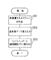
図13のステップS26における副画像記録処理は、図16に示すフローチャートの手順で実行される。すなわち、画像書き込みアドレスを作成し(ステップS51)、作成されたアドレスに副画像データを書き込み(ステップS52)、ファイルヘッダーに副画像開始アドレスを書き込み(ステップS53)、迅速な再生を可能とする。
【0064】
ファイルヘッダーへのデータの書き込みは図4でも説明したが、その処理手順は図17に示すように、先ず、ファイルヘッダーを解釈し(ステップS61)、副画像毎のオプションタプルを作成し(ステップS62)、このタプルに副画像データを書き込み(ステップS63)、タプルメンテナンスを実行して(ステップS64)、処理を終了する。このタプルメンテナンスは、書き込みが完了した後に定まるファイルヘッダーの大きさを書き込むような処理である。
【0065】
図18は、図5に示す副画像データのJPEGヘッダーへの記録処理手順を示すフローチャートである。先ず、JPEGヘッダーを解釈(JPEGフォーマットを解釈)し(ステップS71)、アプリケーション(APP)マーカーを作成し(ステップS72)、作成されたAPPマーカに副画像データを書き込む(ステップS73)。
【0066】
図19は、図6に示すリレーショナルファイルを用いた画像データ間の関連付けを行なう副画像記録シーケンスを示すフローチャートである。
先ず、副画像データファイルを作成し(ステップS81)、リレーショナルファイルの有無を判定する(ステップS82)、ここで、リレーショナルファイルが有れば、リレーショナルファイルを読み込み、解釈した後(ステップS83)、無ければ、リレーショナルファイルを作成した後(ステップS85)、主画像データとの関連情報を書き込んで(ステップS84)、処理を終了する。
【0067】
図20は、図7に示すファイルヘッダーによる関連付けを行なう副画像記録シーケンスを示すフローチャートである。
このシーケンスでは、副画像データファイルを作成し(ステップS91)、主画像データファイルヘッダーを解釈した後(ステップS92)、主画像ファイルヘッダーへ関連情報を書き込んで(ステップS93)、処理を終了する。
【0068】
図21は、図8に示すファイル名による関連付けを行なう副画像記録シーケンスを示すフローチャートである。
本シーケンスでは、ファイル名構成を確認して、その構成と矛盾しない適切なファイル名を作成し(ステップS101)、作成されたファイル名で副画像データファイルを作成して(ステップS102)、処理を終了する。
【0069】
図22は、図9に示すようにディレクトリでの関連付けを行なう副画像記録シーケンスを示すフローチャートである。
先ず、ディレクトリの有無を判定し(ステップS111)、有れば、副画像用ディレクトリを検索した後(ステップS112)、副画像の有無を判定する(ステップS113)。ここで、副画像が有れば、ステップS111の処理に戻り、次のディレクトリを検索し、無ければ副画像データファイル書き込み処理を実行して(ステップS114)、処理を終了する。また、ステップS111において、ディレクトリが無いと判定されると、副画像用ディレクトリを作成して(ステップS115)、ステップS114の処理に移行する。
【0070】
図23は、図10に示すように副画像用一括ファイルを利用した副画像データを記録するシーケンスを示すフローチャートである。
本シーケンスでは、先ず、副画像ファイルの有無を判定し(ステップS121)、有れば、副画像一括ファイルを検索して(ステップS122)、副画像の枚数やファイルヘッダー中に書き込まれているデータの確認等を行ない、副画像データ記録開始アドレスを作成する(ステップS123)。ステップS121において、副画像ファイルが無いと判定されると、副画像一括ファイルを作成して(ステップS124)、ステップS123の処理に移行する。ステップS123の処理の後、副画像データを書き込み(ステップS125)、主画像データとの関連情報を書き込んで(ステップS126)、処理を終了する。
【0071】
次に、デジタルスチルカメラによる連写時の動作について図24を参照して説明する。
シャッターボタン押下等に応答して記録動作が開始され、先ず、主画像データを得るための撮像処理を実行し(ステップS131)、得られた主画像データを圧縮し(ステップS132)、主画像データを記録した後(ステップS133)、副画像作成モードか否かを判定する(ステップS134)。ここで、副画像作成モードであれば、連写が設定されているか否かを判定し(ステップS135)、連写が設定されていれば、副画像の作成条件を判定する(ステップS136)。この判定は、連写により得られる主画像のうち、どの画像についての副画像を作成するかを決定するための処理である。
【0072】
その後、副画像を作成するか否かをフラグを検出することにより判定し(ステップS137)、副画像を作成するのであれば、副画像作成及び記録処理を実行し(ステップS138)、上述と同様なファイルメンテナンス処理を実行する(ステップS139)。また、ステップS134において、副画像作成モードでないと判定された場合及びステップS137において、副画像を作成しないと判定された場合は、そのままステップS139の処理に移行し、ステップS135において、連写でないと判定された場合は、ステップS138の処理に移行する。ステップS139においてファイルメンテナンス処理を実行した後、続けて記録するか(連写動作続行)否かを判定し(ステップS140)、続けて記録すると判定された場合には、ステップS131の撮像処理に戻り、続けて記録しないと判定された場合には、処理を終了する。
【0073】
図25には、図24のステップS136の連写時の副画像作成条件を判定するシーケンス例がフローチャートとして示されている。
本例は、連写で得られる複数の主画像のうち1枚目の主画像について副画像を作成する場合の動作を示し、作成する副画像は、複数の主画像のうちどの1枚を対象としても良い。
【0074】
すなわち、先ず、副画像を作成すべき主画像が得られているか否かを、連写1枚目か否かを判定し(ステップS141)、連写1枚目であれば副画像作成フラグをセットして(ステップS142)、処理を終了し、1枚目でなければ、副画像作成フラグをクリアして(ステップS143)、処理を終了する。尚、この例に於ける副画像を作成すべき主画像を、連写の最後の1枚目に設定してもよいものである。
【0075】
図26は、図25とは異なり、連写速度に合わせて複数の主画像から副画像を作成する主画像を自動的に選択して作成するシーケンスを示すフローチャートである。本例は、連写モードとして高速連写モードと低速連写モードが設定されており、高速連写モードでは4枚に1枚の主画像について、低速連写モードでは2枚に1枚の主画像についての副画像を得る例を示している。
【0076】
動作開始後、連写が1枚目か否かを判定し(ステップS151)、1枚目であれば、カウンタの値iを0に初期化し(ステップS152)、連写が高速連写モードか否かを判定する(ステップS153)。また、ステップS151において、1枚目でないと判定すると、ステップS153の処理にそのまま移行する。
【0077】
ステップS153において、高速連写モードであると判定されたときには、カウンタ値iが2より大きいか否かを判定し(ステップS154)、大きければ、副画像作成を指示するため副画像作成フラグをセットした後(ステップS155)、カウンタ値iを0に設定して(ステップS156)処理を終了する。
【0078】
ステップS153において、低速連写モードであると判定されると、カウンタ値iが0より大きいか否かを判定し(ステップS157)、大きければ、ステップS155の処理に移行し、0より大きくなければ、副画像作成フラグをクリアし(ステップS158)、カウンタ値iを1だけインクリメントして(ステップS159)、処理を終了する。ステップS154において、カウンタ値iが2より大きくなければ、ステップS158の処理に移行する。
【0079】
本実施例では、カウンタ値iを最初に0にリセットし、高速連写時にはステップS154で“2”との比較、低速連写時にはステップS157で“0”との比較を行なうことにより、高速連写時には4枚に1枚、低速連写時には2枚に1枚の副画像記録を自動的に指示、作成することができる。
【0080】
上述の処理により副画像データがICメモリカード等の記録媒体に記録されるが、記録された副画像データは、図1の電子ビューファインダー8や外部端子EXTに接続されているモニタ画面上に再生され、記録画像情報の検索性が向上される。
【0081】
図27には、モニタ上の主画像が表示されている画面内に副画像を同時に表示させる、いわゆるピクチャーINピクチャーの表示例が示されている。
【0082】
また、モニタ上に表示されている主画像画面の一部(右上部)にコマ番号と副画像の個数情報をキャラクタ表示する例が図28に示されている。
【0083】
更に、モニタ上に表示されている主画像から、所望により副画像として取り出すエリアを選択エリアとしてエリアの大/小とともに設定する例が図29と図30に示されている。
【0084】
図29(A)の表示主画像に対して、選択エリアで指定されている中央部分の画像が、エリアの大/小指定に基づいて、取り出され副画像として同図(B)に示すように表示される。
【0085】
また、図30(A)の主画像に対して選択された選択エリアの画像がエリア大/小指定及びエリア位置指定に基づいて、同図(B)に示すように表示される。
【0086】
図31は、図29と図30が主画像の一部を副画像としているのに対して、主画像を縮小し、更に圧縮処理した画像を副画像として用いる例を示し、同図(A)の主画像を、データサイズ30kBで縮小した副画像が同図(B)に、データサイズ30kBで縮小した副画像を更に圧縮することによってデータサイズ1kBにしたものが同図(C)に示されている。
【0087】
図32は、画像の再生シーケンスを示すフローチャートである。この再生シーケンスについて以下説明する。再生モード(コマ送りを含む)が設定され、再生動作が開始されると、先ず、ファイルの判別処理を行なって(ステップS161)、再生しようとしている当該コマのファイルを判別し、再生可能か否かを判定する(ステップS162)。ここで、再生可能であれば、その画像が主画像か否かを判定し(ステップS163)、主画像であれば、当該主画像を再生処理した後(ステップS164)、副画像の有無を判定する(ステップS165)。ステップS165において、副画像が有ると判定されると、図27や図28に示すように副画像情報を表示する処理を行なって(ステップS166)、処理を終了する。ステップS165において、副画像が無いと判定されると、副画像無しでの表示処理を実行する(ステップS167)。
【0088】
ステップS163において、主画像でないときは、副画像であるから、副画像のみ再生処理して(ステップS168)、処理を終了する。また、ステップS162において、再生が不可能と判定されたときは、当該ファイルは音声ファイルやパソコンのデータファイル等であるから、再生表示が不可能である旨の警告表示処理を実行して(ステップS169)、処理を終了する。
【0089】
図33には、再生時の副画像作成シーケンスのフローチャートが示されている。このシーケンスは、主画像が既に再生、表示されており、これから副画像を作成する例を想定している。この例によれば、装置が記録状態にあるときに副画像を生成するのに比べて、主画像をゆっくり観察しながら副画像を所望に応じて選択できるので、より適確な副画像が得られる。
【0090】
副画像の作成動作が開始されると、副画像が既に有るか否かを判定し(ステップS171)、副画像が既に有れば、副画像の追加準備処理を実行する(ステップS172)。この準備処理は、副画像データの書き込みフォーマット、主画像データへの副画像データの埋め込み等の準備処理である。ステップS171において、副画像が無いときには、ステップS172をスキップしてステップS173へ移行する。副画像作成処理(ステップS173)、副画像記録処理(ステップS174)を実行した後、ファイルメンテナンス処理(ステップS175)を実行して処理を終了する。
【0091】
ところで、インターバル再生時やマルチ再生時には、副画像のみを再生して、高速再生検索時に有効となり、副画像がないときは、スキップ、ミュート、キャラクタ表示等を行なうことができる。
【0092】
次に、副画像データの消去シーケンスを図34のフローチャートを参照して説明する。
消去コマンド入力等により消去動作が開始されると、先ず、副画像のみを消去するモードであるか否かを判定し(ステップS181)、そうであれば、副画像の有無を判定する(ステップS182)。ここで、副画像があれば、副画像は1枚か否かを判定し(ステップS183)、1枚であれば、当該副画像を消去して(ステップS184)、処理を終了し、1枚でなければ、複数枚の副画像のうちどの副画像を消去するかを選択する副画像選択処理を実行して(ステップS186)、ステップS184の処理に移行する。
【0093】
ステップS182において、副画像が無いと判定されると、副画像が無い旨をモニタ上に表示して警告する(ステップS187)。また、ステップS181において、副画像のみの消去モードでないと判定されると、主画像及び副画像の消去を行なって(ステップS188)、処理を終了する。
以上の処理において、主画像のみについての消去も可能であることは勿論である。
【0094】
図35は、別ファイルで副画像を書き込んだときの一括消去を行なうための実施例についてのシーケンスを示すフローチャートである。
【0095】
一括ファイルに副画像を記録した場合には、一括ファイルは同時消去可能であるが、別ファイルのときには主画像の消去に伴ない副画像も消去したい要望がある。本実施例は、この要望を満足させるシーケンスである。
【0096】
先ず、副画像を検索して、消去したい主画像に対応する副画像を検索する処理を、例えば、主画像のファイルヘッダーやリレーショナルファイルを用いて実行する(ステップS191)。次に、副画像の有無を判定し(ステップS192)、有れば、当該副画像を消去して(ステップS193)、ステップS191の処理に戻る。ステップS192において、副画像が無いと判定されると、主画像を消去して(ステップS194)、処理を終了する。
【0097】
次に、上述のような処理で得られた副画像データを電話回線等の有線回線や無線回線を介して伝送する画像取扱装置の実施例について説明する。
【0098】
図36は、副画像データと主画像データの伝送手順を示すフローチャートである。同図において、送信側では、送信動作のスタート後、先ず、副画像データのみを送信する(ステップS201)。受信側では、この副画像データを受信後、再生して(ステップS301)、必要な画像を選択し(ステップS302)、選択した画像のコマ番号やファイル名等の指定情報を送信側に伝送する(ステップS303)。
【0099】
この指定情報を受信した送信側では、指定されたコマ番号の主画像データを受信側に送信する(ステップS202)。受信側では、指定主画像データを受信し、再生して確認した後、動作終了を知らせる終了信号を送信側に送信して(ステップS304)、処理を終了する。
【0100】
図37は、副画像を受信側からの要求に応じてリアルタイムで自動作成して送信する実施例のフローチャートである。
【0101】
送信側では、縮小した副画像のデータを自動作成し(ステップS211)、作成した副画像データを送信する(ステップS212)。受信側では、この副画像を受信後、再生し(ステップS311)、画像の副画像作成モード(例えば、エリア選択等)を選択し(ステップS312)、選択した作成モードを送信側に伝送する(ステップS313)。
【0102】
送信側では、受信した作成モードで副画像を自動作成し(ステップS213)、作成した副画像を送信する(ステップS214)。
受信側では、この副画像を受信後、再生し(ステップS314)、通信終了信号を送信側に伝送して(ステップS315)、処理を終了する。
【0103】
図37に示すシーケンスについて図38を参照して具体的に説明すると、送信側で主画像(A1)から間引き処理により縮小画像(A2)を自動作成して副画像として伝送する(ステップS211,S212)。
【0104】
受信側では、この副画像を受信、再生し、再生された副画像(B1)に基づいて必要とする領域部分をエリア選択により選択し(B2)、エリア選択情報を送信側に伝送する(ステップS311〜S313)。
【0105】
送信側では、受信したエリア情報に基づいて、主画像(C1)のエリア選択部についての副画像(C2)を自動作成して受信側に伝送する(ステップS213,S214)。
【0106】
最後に、受信側では、受信した副画像を再生して(D)に示すような要求に合致した副画像を再生して、通信終了信号を伝送する(ステップS314,S315)。
【0107】
【発明の効果】
上述した実施態様によれば以下の如き各構成が得られる。
(1)撮影により生成され乃至は外部より供給された所定領域の画像から成る主画像の画像情報のうちの一部の画像情報を取り出して副画像として生成する副画像生成手段を備えて成る画像取扱装置。この構成によれば、検索性が格段に改善される。
【0108】
(2)撮影により生成され乃至は外部より供給された所定領域の画像から成る主画像の画像情報のうちの一部の画像情報を取り出して第1の副画像として生成する第1の副画像生成手段と、該第1の副画像生成手段に基づく第1の副画像の画像情報のうちの一部の画像情報を取り出して第2の副画像として生成する第2の副画像生成手段を備えて成る画像取扱装置。この構成によれば、副画像から更に副画像を作成することによって、より副画像作成の自由度が増し、必要なデータのみ取り出すことができる。
【0109】
(3)前記副画像生成手段は、前記主画像の特定エリアの情報を前記一部の画像情報とするエリア選択手段を有する画像取扱装置。この構成によれば、不必要なデータが削除され、検索性が改善される。
【0110】
(4)前記エリア選択手段は、前記特定エリアのサイズを変更するサイズ変更手段と、前記特定エリアの位置を変更するエリア位置変更手段の少なくとも一方の手段を有する(3)の画像取扱装置。この構成によれば、副画像から更に副画像を作成することによって、より副画像作成の自由度がまし、必要なデータのみ取り出すことができ、領域選択がより柔軟になる。
【0111】
(5)前記副画像生成手段は、前記主画像を縮小した縮小画像情報を前記一部の画像情報とする画像縮小手段を有する(1)の画像取扱装置。この構成によれば、小さいデータサイズで全体のイメージがわかり、検索性が改善される。
【0112】
(6)前記副画像生成手段は、前記主画像のデータを圧縮して得られる圧縮画像情報を前記一部の画像情報とする画像圧縮手段を有する(1)の画像取扱装置。この構成によれば、ほとんど同じ画質でより小さいデータサイズにすることができ、検索性が改善される。
【0113】
(7)前記第1の副画像生成手段は、前記主画像の特定エリアの情報を前記一部の画像情報とする第1エリア選択手段、又は前記主画像を縮小した縮小画像情報を前記一部の画像情報とする第1画像縮小手段を有し、前記第2の副画像生成手段は、前記第1の副画像の特定エリアの情報を前記一部の画像情報とする第2エリア選択手段、前記第1の副画像を縮小した縮小画像情報を前記一部の画像情報とする第2画像縮小手段又は前記第1の副画像のデータを圧縮して得られる圧縮画像情報を前記一部の画像情報とする画像圧縮手段の中から選ばれる少なくとも一つの手段を有する(2)の画像取扱装置。この構成によれば、よりサイズを小さくして本当に必要なデータを作成することができ、検索性も改善される。
【0114】
(8)前記画像圧縮手段は、画像データを直交変換してAC直交係数とDC直交係数を出力する手段を有し、前記DC直交係数のみを用いて副画像を生成する(6)または(7)の画像取扱装置。この構成によれば、単なる縮小化よりも画質が向上し、メモコンハードも簡略化され、検索性も改善される。
【0115】
(9)前記画像圧縮手段は、圧縮後のデータ量を一定として前記圧縮を行なう(6)または(7)の画像取扱装置。この構成によれば、副画像のデータ量を一定にできるのでアドレスの管理が容易にでき、検索性も改善される。
【0116】
(10)前記画像圧縮手段は、圧縮率を一定として前記圧縮を行なう(6)、(7)の画像取扱装置。この構成によれば、画質を一定にできるので、どの様な絵を撮影しても、記録画が破綻することがなく、検索性も改善される。
【0117】
(11)撮影により生成され乃至は外部より供給された所定領域の画像から成る主画像のデータと、該主画像の画像情報のうちの一部の画像情報から成る副画像のデータとを生成し、記録媒体に記録される前記主画像データの後に、前記副画像のデータを記録する手段を備えて成る画像取扱装置。この構成によれば、同一ファイルへの記録時などは、主画像を先に書くことによって副画像を追加する時や副画像だけを消去する時などに便利である。主画像が先頭にあるので、パソコン用の一般ソフト等で再生する時に主画像を再生することができる。
【0118】
(12)前記副画像生成手段は、生成した副画像のデータを当該コンピュータのフォーマットに適合するフォーマットのデータに変換するデータフォーマット手段を有する(1)の画像取扱装置。この構成によれば、パソコンでデータを取り扱う時、より簡単に、且つより高速に扱うことが可能であり、検索性も改善される。
【0119】
(13)撮影により生成され乃至は外部より供給された所定領域の画像から成る主画像の画像情報のうちの一部の画像情報を取り出して副画像として生成する手段と、生成された副画像のデータを、ファイルヘッダーをもつ画像ファイルのデータ記録部に書き込み、前記ファイルヘッダーに前記副画像の書き込み開始アドレスを書き込む手段を備えて成る画像取扱装置。この構成によれば、関連ファイルが一つのファイルになるので、移動やコピー、削除等時に主画像と副画像を常に一緒に扱うことができ、コマ番号が従来どうり管理できる。
【0120】
(14)撮影により生成され乃至は外部より供給された所定領域の画像から成る主画像の画像情報のうちの一部の画像情報を取り出して副画像として生成する手段と、生成された副画像のデータをファイルヘッダーをもつ画像ファイルに書き込む際、前記ファイルヘッダーに記録されているタプル情報を解釈し、副画像毎のオプションタプルを作成し、作成されたオプションタプルに前副画像のデータを書き込む手段を備えて成る画像取扱装置。この構成によれば、同一ファイルへの記録時などは、主画像を先に書くことによって副画像を追加する時や副画像だけを消去する時などに便利である。主画像が先頭にあるので、パソコン用の一般ソフト等で再生する時に主画像を再生することができる。また、ファイルヘッダーを削除すれば主画像だけ残るので、主画像の抜き出しに便利である。
【0121】
(15)撮影により生成され乃至は外部より供給された所定領域の画像から成る主画像の画像情報のうちの一部の画像情報を取り出して副画像として生成する手段と、前記主画像のデータをパソコン用画像データフォーマットに変換する手段と、生成された副画像データを前記変換された個々の主画像データ毎の画像ヘッダー部に書き込む際、前記個々の画像ヘッダー部に記録されている情報を解釈して前記画像ヘッダー部毎に前記副画像のデータを書き込む手段を備えて成る画像取扱装置。この構成によれば、同一ファイルへの記録時などは、主画像を先に書くことによって副画像を追加する時や副画像だけを消去する時などに便利である。主画像が先頭にあるので、パソコン用の一般ソフト等で再生する時に主画像を再生することができる。また、ファイルヘッダーと違い、1画像に1つの画像ヘッダーということを生かして、同一ファイルに主が複数ある様な場合、それぞれに副画像を規定することができる。
【0122】
(16)撮影により生成され乃至は外部より供給された所定領域の画像から成る複数の主画像のそれぞれに対応して、当該主画像の画像情報のうちの一部の画像情報から成る副画像を生成する副画像生成手段と、前記主画像のデータ及び生成された複数の副画像のデータをそれぞれ別個の画像ファイルに記録する手段とを備えて成る画像取扱装置。この構成によれば、1枚の画像が1つのファイルになるので、ファイルイメージで画像の管理が可能である。
【0123】
(17)撮影により生成され乃至は外部より供給された所定領域の画像から成る複数の主画像のそれぞれに対応して、当該主画像の画像情報のうちの一部の画像情報から成る副画像を生成する副画像生成手段と、前記主画像のデータ及び生成された複数の副画像のデータをそれぞれ別個の画像ファイルに記録するとともに、前記主画像のデータ及び副画像のデータの関連付け情報を特定の情報ファイルとしてのリレーショナルファイルに記録する手段とを備えて成る画像取扱装置。この構成によれば、関連付け情報が一括されているので、管理が簡単に行なえる。
【0124】
(18)撮影により生成され乃至は外部より供給された所定領域の画像から成る複数の主画像のそれぞれに対応して、当該主画像の画像情報のうちの一部の画像情報から成る副画像を生成する副画像生成手段と、前記主画像のデータ及び生成された複数の副画像のデータをそれぞれ別個の画像ファイルに記録するとともに、前記主画像のデータが記録されている画像ファイルのファイルヘッダーに前記副画像のデータの関連情報を記録することを特徴とする画像取扱装置。この構成によれば、主画像から副画像、副画像から主画像という様にイモズル式に関連がわかるので、余分なファイルを読まなくてもよく、高速に検索が行なえる。
【0125】
(19)撮影により生成され乃至は外部より供給された所定領域の画像から成る複数の主画像のそれぞれに対応して、当該主画像の画像情報のうちの一部の画像情報から成る副画像を生成する副画像生成手段と、前記主画像のデータ及び生成された複数の副画像のデータをそれぞれ別個の画像ファイルに記録するとともに、前記主画像のデータに基づく前記複数の副画像のデータは、互いに識別可能なファイル名を付して記録する手段とを特徴とする画像取扱装置。この構成によれば、主画像だけ再生、又は副画像だけ再生等がより簡単にでき、名前だけで主画像と副画像の区別がつき、関連もわかるので、再生しなくても簡単に管理ができる。
【0126】
(20)撮影により生成され乃至は外部より供給された所定領域の画像から成る複数の主画像のそれぞれに対応して、当該主画像の画像情報のうちの一部の画像情報から成る副画像を生成する副画像生成手段と、前記主画像のデータ及び生成された複数の副画像のデータをそれぞれ別個の画像ファイルに記録するとともに、前記主画像のデータ、前記副画像のデータのうち少なくとも副画像のデータは、互いに識別可能な異なるディレクトリに記録する手段とを備えて成る画像取扱装置。この構成によれば、関連付け情報が一括されているので管理が簡単に行なえ、コマ番号の管理が従来と同じにできる。
【0127】
(21)撮影により生成され乃至は外部より供給された所定領域の画像から成る複数の主画像のそれぞれに対応して、当該主画像の画像情報のうちの一部の画像情報から成る副画像を生成する副画像生成手段と、前記主画像のデータ及び生成された複数の副画像のデータをそれぞれ別個の画像ファイルに記録するとともに、前記主画像のデータ、前記副画像のデータのうち少なくとも副画像のデータは、一つの画像ファイルに一括して記録する手段とを備えて成る画像取扱装置。この構成によれば、主画像だけ、又は副画像だけの再生等に便利であり、特に副画像だけ再生し、インデックス再生時にその効果を発する。更に、副画像の一括消去にも有効である。
【0128】
(22)一定時間々隔で、それぞれが所定領域の画像から成る複数の主画像が連続的に得られる画像取扱装置において、前記連続的に得られる複数の主画像のうち特定の主画像についてのみ当該主画像の画像情報のうちの一部の画像情報から成る副画像を生成する副画像生成手段を備えて成る画像取扱装置。この構成によれば、連写は同じ様な一連の絵なので、代表的な画像に対する副画像を作成することによって、より容量を節約する。
【0129】
(23)前記特定の主画像は、前記連続的に得られる複数の主画像のうちの最初の一枚または最後の一枚である(22)の画像取扱装置。この構成によれば、副の作成が1回だけで済むので、連写のスピードがより高速にできる。また、関連付け情報が一括されているので管理が簡単に行なえ、コマ番号の管理が従来と同じにできる。
【0130】
(24)前記特定の主画像は、前記一定時間々隔の長さに応じて選択され、前記一定時間々隔が短い又は長いほど前記特定の主画像に対応する複数の主画像の枚数が減少又は増加するようにした(22)の画像取扱装置。この構成によれば、連写のスピードが遅い時は時間的に余裕があるので、副画像の作成間隔を短くすることが可能となり、連写のあき時間をうまく使用して副画像を作成することができる。
【0131】
(25)撮影により生成され乃至は外部より供給された所定領域の画像から成る主画像と、該主画像の画像情報の一部の画像情報から成る副画像を生成する手段を有するとともに、前記主画像の再生、表示時に、対応する副画像の有無情報を表示する画像取扱装置。この構成によれば、主画像を再生する時に副画像の有無を表示できれば、より使いがっても向上することができる。
【0132】
(26)撮影により生成され乃至は外部より供給された所定領域の画像から成る主画像と、該主画像の画像情報の一部の画像情報から成る副画像を生成する手段を有するとともに、該手段は、前記主画像の再生、表示時に、複数の対応する副画像を生成する画像取扱装置。この構成によれば、再生画を見ながら副画像を作成でき、より自由度の高い副画像を作成することができる。
【0133】
(27)撮影により生成され乃至は外部より供給された所定領域の画像から成る主画像のデータと、該主画像の画像情報の一部の画像情報から成る副画像のデータが記憶手段に記憶され、該記憶手段に記憶されている特定の副画像のデータのみ消去する手段を備えて成る画像取扱装置。この構成によれば、副画像のみの消去ができれ、不要な副画像を消去し、また作成し直すといったことも可能となる。
【0134】
(28)撮影により生成され乃至は外部より供給された所定領域の画像から成る主画像のデータと、該主画像の画像情報の一部の画像情報から成る副画像のデータが記憶手段に記憶され、該記憶手段に記憶されている複数の副画像を一括消去する手段を備えて成る画像取扱装置。この構成によれば、副画像だけの一括消去ができ、より使い勝手が向上する。
【0135】
(29)撮影により生成され乃至は外部より供給された所定領域の画像から成る主画像のデータと、該主画像の画像情報の一部の画像情報から成る副画像のデータが記憶手段に記憶され、該記憶手段に記憶されている主画像と該主画像に対応する副画像を一括して消去する手段を備えて成る画像取扱装置。この構成によれば、主画像と副画像が別ファイルの時などは、主画像を消去すると自動的に副画像も消去されると、より使い勝手が向上する。
【0136】
(30)撮影により生成され乃至は外部より供給された所定領域の画像から成る主画像の画像情報のうちの一部の画像情報から成る副画像を生成する副画像生成手段と、前記生成された副画像のデータを伝送する伝送手段とを備えて成る画像取扱装置。この構成によれば、主画像に対して副画像の方がデータサイズが小さいので伝送時には有利である。
【0137】
(31)撮影により生成され乃至は外部より供給された所定領域の画像から成る主画像の画像情報のうちの一部の画像情報から成る副画像を生成する副画像生成手段と、前記生成された副画像のデータを伝送する伝送手段とを備え、前記伝送された副画像のデータを受信した受信側からの応答信号を受け、該応答信号に基づいて前記伝送した副画像に対応する主画像のデータを伝送する画像取扱装置。この構成によれば、先ず、サイズの小さい副画像を送り、それから、相手の要望に合わせて主画像を送ることにより、本当に必要な主画像だけを送れば良いので、より経済的である。
【0138】
(32)撮影により生成され乃至は外部より供給された所定領域の画像から成る主画像の画像情報のうちの一部の画像情報から成る副画像を生成する副画像生成手段と、前記生成された副画像のデータを伝送する伝送手段とを備え、前記伝送された副画像のデータを受信した受信側からの作成モードを指定する指定信号を受け、該指定信号で指定された副画像の作成モードに従って前記副画像を生成して伝送することを特徴とする画像取扱装置。この構成によれば、受信側は、必ずしも主画像のすべてのデータを必要とするわけではないので、受信側の要望に合わせて副画像を作成して、その副画像を伝送することによって本当に必要なデータのみを伝送すれば良い。
【0139】
(33)撮影により生成され乃至は外部より供給された所定領域の画像から成る複数の主画像のそれぞれに対応して、当該主画像の画像情報のうちの一部の画像情報から成る副画像を生成する副画像生成手段を備え、前記主画像のデータ又は生成された副画像のデータを同一の画像ファイルにそれぞれ書込む際、各データの書込み開始アドレスが2n(nは整数)で表わされるアドレスである画像取扱装置。この構成によれば、画像データ自体の独立性が増すので、、各データごとの凡用性が向上する。また、画像データだけの抜き出しや消去等で役に立つ。更に、先頭アドレスの検索性も改善される。
【図面の簡単な説明】
【図1】本発明による画像取扱装置のデジタルスチルカメラへの適用例を示す構成ブロック図である。
【図2】本発明の実施例における3種類の記録態様例を示す図である。
【図3】本発明の実施例におけるファイルヘッダーの記入例を示す図である。
【図4】本発明の実施例におけるファイルヘッダーへの記録フォーマット例を示す図である。
【図5】本発明の実施例における主画像データがJPEG方式で圧縮されて記録される場合のJPEGヘッダーへの記録を示す図である。
【図6】本発明の実施例における副画像データを主画像データと別ファイルに記録し、リレーショナルファイルに当該データの関連付けデータを記録する例を示す図である。
【図7】本発明の実施例における副画像データを主画像データと別ファイルに記録し、主画像データ用のファイルのファイルヘッダーに、副画像データファイルについての関連情報を記録する例を示す図である。
【図8】本発明の実施例における主画像データと副画像データをそれぞれ別ファイルとして記録し、これらデータの識別、関連付けをファイル名により行なう例を示す図である。
【図9】本発明の実施例における主画像データと副画像データを別ファイルに記録し、各ファイルの関連付けをディレクトリで行なうディレクトリ構造例を示す図である。
【図10】本発明の実施例における主画像データと副画像データを別ファイルに記録し、主画像ファイルは別個のファイルとするが、副画像ファイルは一括ファイルに格納する例を示す図である。
【図11】本発明の実施例における画像データ記録開始アドレスをクラスタ単位で指定する例を示す図である。
【図12】本発明の実施例によるデジタルスチルカメラの動作シーケンスを示すフローチャートである。
【図13】本発明の実施例における主画像データ記録後に副画像データを記録する場合の画像データ記録処理シーケンスを示すフローチャートである。
【図14】図13のステップS25における副画像作成処理の作成シーケンスを示すフローチャートである。
【図15】図14における非圧縮データ変換処理の手順を示すフローチャートである。
【図16】図13のステップS26における副画像記録処理手順を示すフローチャートである。
【図17】ファイルヘッダーへのデータの書き込みの処理手順を示すフローチャートである。
【図18】図14に示す副画像データのJPEGヘッダーへの記録処理手順を示すフローチャートである。
【図19】図6に示すリレーショナルファイルを用いた画像データ間の関連付けを行なう副画像記録シーケンスを示すフローチャートである。
【図20】図7に示すファイルヘッダーによる関連付けを行なう副画像記録シーケンスを示すフローチャートである。
【図21】図8に示すファイル名による関連付けを行なう副画像記録シーケンスを示すフローチャートである。
【図22】図9に示すディレクトリでの関連付けを行なう副画像記録シーケンスを示すフローチャートである。
【図23】図10に示す副画像用一括ファイルを利用した副画像データを記録するシーケンスを示すフローチャートである。
【図24】本発明の実施例におけるデジタルスチルカメラの連写時の動作シーケンスを示すフローチャートである。
【図25】図24のステップS136の連写時の副画像作成条件を判定するシーケンス例を示すフローチャートである。
【図26】本発明の実施例における連写スピードに合わせて複数の主画像から副画像を作成するシーケンスを示すフローチャートである。
【図27】本発明の実施例におけるモニタ上の主画像が表示されている画面内に副画像を同時に表示させるピクチャーINピクチャー表示例を示す図である。
【図28】本発明の実施例におけるモニタ上に表示されている主画像画面の一部(右上部)にコマ番号と副画像の個数情報をキャラクタ表示する例を示す図である。
【図29】本発明の実施例におけるモニタ上に表示されている主画像から、所望により副画像として取り出すエリアを選択エリアとしてエリアの大/小とともに設定する例を示す図である。
【図30】本発明の実施例におけるモニタ上に表示されている主画像から、所望により副画像として取り出すエリアを選択エリアとしてエリアの大/小とともに設定する例を示す図である。
【図31】本発明の実施例における主画像を縮小し、更に圧縮処理した画像を副画像として用いる例を示す図である。
【図32】本発明の実施例における画像の再生シーケンスを示すフローチャートである。
【図33】本発明の実施例における再生時の副画像作成シーケンスを示すフローチャートである。
【図34】本発明の実施例における副画像の消去処理シーケンスを示すフローチャートである。
【図35】本発明の実施例における別ファイルで副画像を書き込んだときの一括消去を行なうシーケンスを示すフローチャートである。
【図36】本発明の実施例における副画像データと主画像データの伝送手順を示すフローチャートである。
【図37】本発明の実施例における副画像を受信側からの要求に応じてリアルタイムで自動作成して送信する処理手順を示すフローチャートである。
【図38】 図37のシーケンスを具体的に示す図である。
【符号の説明】
1 光学系レンズ
2 撮像回路
3 クランプ回路
4 A/D変換回路
5 デジタルプロセス回路
6 D/A変換回路
7 増幅回路
8 電子ビューファインダ
9 キャラクタジェネレータ
10 メモリコントローラ
11 フレームメモリ
12 DCT/IDCT(離散コサイン変換/逆離散コサイン変換)
13 コーダ/デコーダ
14 補助メモリ
15 ICメモリカード
16 システムコントローラ
17 表示部
18 操作部
19 データ入出力部[0001]
[Industrial applications]
The present invention relates to an image handling device.And cameraImage handling device with improved searchability and operabilityAnd cameraAbout.
[0002]
[Prior art]
Digital still cameras that record image data, audio data, control data, and the like as files on recording media such as IC memory cards, magnetic media (hard disks and floppy disks), and magneto-optical media have been put to practical use.
[0003]
[Problems to be solved by the invention]
An image handling apparatus such as a digital still camera for handling images, which captures images as image data and can easily perform processing and image data transmission by a computer, is expected to expand its field of application in the future.
[0004]
In such an image handling apparatus, the image data recorded on a recording medium such as an IC card is data for one sheet, and when searching for a recorded image, it is necessary to sequentially read and reproduce each image data. . However, in general, image data has a large data amount, and in particular, in the case of an FD or the like that has a low data reading speed, it takes time to read and reproduce the data. It is known that the amount of data can be reduced by using data compression. However, in order to reproduce an image, the readout individual image data must be decompressed, and the reproduction process takes time. However, there is a problem that high-speed search is difficult.
[0005]
[Object of the invention]
Therefore, an object of the present invention is to provide an image handling apparatus that enables high-speed image retrieval and improves operability.And cameraIs to provide.
[0006]
[Means for Solving the Problems]
In order to solve the above-described problems, an image handling device according to the present invention includes:First sub-image generation means for extracting a part of image information of the main image composed of an image of a predetermined area generated by imaging or supplied from the outside and generating it as a first sub-image; A second sub-image generating means for extracting a part of the image information of the first sub-image based on the first sub-image generating means and generating it as a second sub-image; .
[0007]
An image handling apparatus according to another aspect of the present invention includes:An image handling apparatus comprising: a sub-image generating unit configured to extract a part of image information of an image information of a main image including a predetermined area image generated by photographing or externally supplied and generate the extracted image information as a sub-image. The sub-image generation unit includes an area selection unit that uses information of a specific area of the main image as the partial image information.
[0008]
Here, the area selecting means has at least one of a size changing means for changing a size of the specific area and an area position changing means for changing a position of the specific area.
[0009]
The first sub-image generating means may be a first area selecting means that uses information of a specific area of the main image as the partial image information, or may output reduced image information obtained by reducing the main image to the partial image. A first image reduction unit configured to be image information, wherein the second sub-image generation unit is configured to use information of a specific area of the first sub-image as the partial image information; A second image reducing unit that uses reduced image information obtained by reducing the first sub-image as the partial image information or a compressed image information obtained by compressing the data of the first sub-image; At least one means selected from the image compression means.
[0010]
A camera according to another aspect of the present invention includes an optical system for obtaining a subject image,
An image sensor that photoelectrically converts a subject image obtained through the optical system,
An imaging circuit that converts a subject image photoelectrically converted by the imaging element into an electric signal,
An A / D conversion circuit that converts an electric signal from the imaging circuit into digital data,
A coder for encoding the digital data converted by the A / D conversion circuit;
Storage means for recording image data encoded by the coder and compressed by the JPEG method or the like;
Has,
When recording image data in a file format when recording in the storage means, each image file records a main image and a sub-image composed of a reduced image of the main image,
Each of the image files has a file header in which the image data body of the sub-image is recorded, and a main image data body recorded in an area other than the file header..
[0011]
Here, the image file has a sub-image data start address.
[0028]
[Action]
According to each of the above-listed inventions, among the various functions described below, corresponding functions are performed. That is, a part of the image information of the main image is extracted and generated, and the generated sub-image data and the main image data are associated with each other and recorded so as to be identifiable. In addition, the recorded sub-image is read, reproduced, or erased alone or in association with the main image. Further, the generated sub-image data is transmitted, and the main image data corresponding to the transmitted sub-image is transmitted based on a response signal from the receiving side.
[0029]
【Example】
Next, embodiments of the present invention will be described with reference to the drawings.
FIG. 1 is a configuration block diagram showing an application example of an image handling apparatus according to the present invention to a digital still camera.
The subject image is converted into an electric signal via an optical system (lens) 1 by an
[0030]
At the time of data recording, image data read from the frame memory 11 is orthogonally transformed by a DCT / IDCT (discrete cosine transform / inverse discrete cosine transform)
[0031]
At the time of reproduction, the image data read from the
[0032]
The
[0033]
In the configuration shown in FIG. 1, in the present invention, a sub-image (for example, a thinned image, a reduced image, or a reduced image) is obtained by extracting a part of image information of one image (hereinafter, referred to as a main image). Image, etc.), storing the generated image in a memory, transmitting the image to another image handling device, and the like.
[0034]
The recording of the sub-image in the memory is performed through the operation of the
[0035]
By the way, in a digital still camera that records image data, audio data, control data, and the like as a file on a recording medium such as a memory card, a magnetic medium (a hard disk or a floppy disk), and a magneto-optical medium, the data is also recorded on the recording medium in a file format. May be recorded. At this time, it is desirable that the memory management be performed in a standard DOS (disk operating system) format by a personal computer or the like in terms of data compatibility. Then, control information for controlling the operation and associating each file is recorded as a control file (also referred to as a control file or a relational file, hereinafter referred to as a relational file) on the recording medium. Are also being considered.
[0036]
The first recording mode is for recording main image data and sub-image data in an image file during recording in the file format. FIG. 2 shows three examples of recording modes. By recording in such an image file, the frame number can be managed as before, and movement, copying, deletion, etc. can be handled together without being conscious of the main image and the sub image.
In FIG. 2A, when one piece of image data is recorded, a file header portion, a main image data portion, and subsequently a sub-image data portion are sequentially recorded in the image file. As a result, it is easy to delete only the sub-images, to easily add a plurality of sub-images, and to easily reproduce the main image. In FIG. 2B, a file header portion, a sub-image data portion, and subsequently a main image data portion are sequentially recorded. Therefore, at the time of the search in the sub-image reproduction mode, a higher-speed search can be performed. FIG. 2C shows a recording mode when there are a plurality of sub-images. The main image data is written from the main data start address following the file header portion, and the sub-image data is written from the
[0037]
FIG. 3 shows an entry example of a file header. Following the standardized format tuple and recording date tuple, the
[0038]
FIG. 4 shows an example of a recording format for a file header. Following the format tuple and the recording date tuple, the parameters of the recorded sub-image data are recorded in the
[0039]
FIG. 5 is a diagram showing an example of recording in an image header (JPEG header) when the main image data is compressed and recorded in the JPEG format, which is a format of a personal computer image data format.
The JPEG header following the file header records data such as SOI (Start of Image) marker, APP (Application Marker) the sub image data main body, SOS marker the main image data main body to the EOI (End of Image) marker part. Have been. By doing so, the same effect as in the case of the example shown in FIG. 2 can be obtained. As image data formats for personal computers, in addition to JPEG, there are TIFF, PICT, BMP and the like, and the present invention can be applied to these methods.
[0040]
FIG. 6 shows an example in which the sub-image data is recorded in a separate file from the main image data, and the data associated with the data is recorded in the above-described relational file. Since one image becomes one file by recording in another file, image management can be performed with a file management image. According to this relational file, the association information is managed collectively, so that data management becomes easy.
[0041]
As shown in FIG. 1A, a main image file composed of a file header and main image data is defined as a file (FILE) 1 and a file header and sub-images are defined as a
[0042]
In FIG. 7, the sub-image data is recorded in a separate file from the main image data body, and the relevant information about the sub-image data file is recorded in the file header of the main image data file (FIG. 7A). Here is an example. The file header includes a format tuple, a recording date tuple, an
[0043]
FIG. 8 shows an example in which main image data and sub-image data are recorded in separate files, and these data are identified and associated by file names. In this example, the main image data file and the sub image data file are distinguished by the extension. As a result, the operation of reproducing only the main image or reproducing only the sub-image becomes easy. In addition, since the file can be identified from the file name without reproducing the image of the file, image management by file operation becomes possible to some extent.
[0044]
An example of a main image data file with an extension “J6I” is shown on the left side of FIG. In the extension “J6I”, “J” indicates JPEG which is a compression method, “6” indicates 68Pin, and “I” indicates Image.
On the right side of the drawing, an example of a sub-image data file with an extension “T6N” (N is a natural number) is shown. Of the extension “T6N”, “T” indicates the sub-image data whose “Thumbnail” (thumbnail), “6” indicates 68 Pin, and “N” indicates the frame number of the sub-image data.
[0045]
FIG. 9 shows an example of a directory structure in which the main image data and the sub-image data are similarly recorded in different files, and the files are associated in a directory. By using this directory, not only the same effect as in the case of using the file name but also the management of the frame number becomes easy. This is different from the other file recording example in that a directory in which only the main image is recorded is created, so that the frame number management in the conventional directory entry can be performed as it is.
[0046]
In this example, it is assumed that the directory “MAIN” includes the main image data group, the directory “SUB1” includes the data group of the
[0047]
FIG. 10 shows an example in which main image data and sub-image data are recorded in separate files, and the main image file is a separate file, but the sub-image file is stored in a batch file. According to this method, by displaying the sub-image data in a batch file, index display (reproduction of only the sub-image) and the like can be easily performed. In addition, batch deletion of sub-images and the like can be easily performed.
[0048]
FIG. 9A shows a header image in which a format tuple, a recording date tuple, an option tuple, and a sub-image data offset address are recorded, followed by a main image file DSC001. An example of J6I is shown, and FIG. 13B shows a main image file in which main image data is recorded, following a header in which a format tuple, recording date tuple, option tuple, and sub-image data offset address are recorded. DSC011. An example of J6I is shown, and FIG. 10C shows only one sub-image file for recording sub-image data of these main image data. Following the file header, the file DSC001. J6I sub-images are recorded as
[0049]
The file header of the sub-image batch file includes the number of sub-images, the image parameters of the sub-images, the start address and end address of each sub-image data, the file name of the main image for each sub-image, and the like. When the batch file is used as the index file, the main image can be searched from the sub image.
[0050]
FIG. 11 shows an example in which the image data recording start address is specified in cluster units. The main image data is recorded in
[0051]
Next, an operation sequence of the digital still camera according to the embodiment of the present invention will be described with reference to a flowchart of FIG.
[0052]
After power-on, initialization processing of camera operating conditions such as zooming initialization is performed (step S1), and it is determined whether or not the camera is in a sub-image creation mode (step S2). Is displayed on the
[0053]
In step S4, if the mode is the area selection mode, the fact that the mode is the area selection mode is displayed, a flag indicating that fact is set (step S5), and it is determined whether or not the mode is the image reduction mode for reducing the image (step S5). Step S6). When the mode is not the area selection mode, the process proceeds to step S6. Here, in the case of the image reduction mode, display indicating that the mode is the image reduction mode and flag setting are performed (step S7). Is determined (step S8). Due to the reduction, the whole image can be grasped in a small size.
[0054]
In step S8, in the case of the image compression mode, whether the compression rate is fixed or the size (data amount) is fixed as the technique used in the compression is determined. To determine, it is determined whether the mode is the fixed size mode (step S9). Here, in the case of the fixed size mode, after compression, the fact that the size is fixed is displayed and a flag is set (step S10). A message is displayed and a flag is set (step S11). If it is determined in step S8 that the mode is not the image compression mode, the fact that the mode is the non-compression mode is displayed and a flag is set (step S12).
[0055]
After the processing in steps S10 to S12, an operation input by an operation from the
[0056]
FIG. 13 is a flowchart showing an image data recording processing sequence when sub-image data is recorded after recording main image data.
[0057]
For example, the processing is started in response to a recording instruction by an operation from the
[0058]
If it is determined in step S24 that a sub-image is to be created, a sub-image creation process is executed (step S25). After the sub-image recording process on the IC memory card (step S26), a file maintenance process is executed. (Step S27), the process ends. If it is determined in step S24 that a sub-image is not to be created, the file maintenance process of step S27 is executed as it is. As a file maintenance process, for example, when a file is managed and recorded in the DOS format, there is a format writing process such as a directory entry or FAT.
[0059]
FIG. 14 is a flowchart showing the creation sequence of the sub-image creation process in step S25 of FIG.
First, it is determined whether or not the mode is an area selection mode for selecting a sub-image creation area for the main image (step S31). If the mode is the area selection mode, an area size change process for changing the size of the area (step S32) is performed. After executing the area position change process (step S33) for changing the position, the determination in step S34 is performed. In this case, if it is determined in step S31 that the mode is not the area selection mode, the image is similarly reduced. It is determined whether or not to perform. Here, when it is determined that the image is to be reduced, after the image is reduced by performing thinning-out reading of the image data from the frame memory 11 or the like (step S35), the image must be reduced in step S34. If determined, it is determined whether to compress the image (step S36). Here, when it is determined that the image is to be compressed, it is determined whether or not the fixed size is instructed in order to determine whether to compress the image or to fix the size (data amount) during compression ( Step S37).
[0060]
If it is determined in step S37 that the size is constant, a compression process is performed with the size after compression being constant (step S38). If it is not determined that the size is constant, the compression process is performed with a constant compression ratio (step S38). Step S39), the process ends. If it is determined in step S36 that the image is not to be compressed, the image data read from the frame memory 11 is not compressed, and an uncompressed data conversion process such as conversion to a format required for personal computer processing is executed. (Step S40), the process ends. In this case, when the image data is handled in the camera, the above conversion process is not executed, and the image data is written to the IC memory as it is. The reduced compressed image may be created by recording only the DC component of the orthogonal coefficients output from the DCT /
[0061]
In the example shown in FIG. 14 described above, the image processing apparatus has three specific sub-image generating means as the sub-image generating means, namely, an area selecting means, an image reducing means, and an image compressing means. However, the present invention is not limited to the above-described example. For example, the present invention is not limited to the above-described example. Of course, it is also possible to employ a configuration having one or two units, or a configuration in which the processing order of the three units is appropriately changed. In this case, the first processed sub-image generating means is the first sub-image generating means, and the second processed sub-image generating means is the second sub-image generating means. The processing timing of the actual data by the sub-image generation means and the second sub-image generation means includes simultaneous processing on the previous frame memory 11 or time-division processing.
[0062]
The procedure of this uncompressed data conversion processing is shown in the flowchart of FIG.
In FIG. 15, first, it is determined whether or not to store the data in the format of the computer (step S41). If the format is not the format of the computer, the process is terminated. The conversion is performed (step S42), and the process ends.
As the data recording method at the time of non-compression, there are two general methods, the RGB method and the YCbCr method. However, the RGB method is suitable for reproduction on a personal computer, and the YCbCr method is suitable for reproduction on a camera.
[0063]
The sub-image recording process in step S26 in FIG. 13 is executed according to the procedure of the flowchart shown in FIG. That is, an image write address is created (step S51), sub-image data is written to the created address (step S52), and a sub-image start address is written to a file header (step S53), thereby enabling rapid reproduction.
[0064]
Although the writing of data to the file header has been described with reference to FIG. 4, as shown in FIG. 17, first, the file header is interpreted (step S61), and an option tuple for each sub-image is created (step S62). ), The sub-image data is written into this tuple (step S63), tuple maintenance is executed (step S64), and the process is terminated. This tuple maintenance is a process of writing the size of a file header determined after the writing is completed.
[0065]
FIG. 18 is a flowchart showing a procedure for recording the sub-image data shown in FIG. 5 in the JPEG header. First, the JPEG header is interpreted (the JPEG format is interpreted) (step S71), an application (APP) marker is created (step S72), and sub-image data is written to the created APP marker (step S73).
[0066]
FIG. 19 is a flowchart showing a sub-image recording sequence for associating image data using the relational file shown in FIG.
First, a sub-image data file is created (step S81), and the presence or absence of a relational file is determined (step S82). If there is a relational file, the relational file is read and interpreted (step S83). For example, after creating a relational file (step S85), information related to the main image data is written (step S84), and the process ends.
[0067]
FIG. 20 is a flowchart showing a sub-image recording sequence for performing association by the file header shown in FIG.
In this sequence, a sub-image data file is created (step S91), and after interpreting the main image data file header (step S92), relevant information is written into the main image file header (step S93), and the process ends.
[0068]
FIG. 21 is a flowchart showing a sub-image recording sequence for performing the association by the file name shown in FIG.
In this sequence, the file name configuration is confirmed, an appropriate file name that does not contradict the configuration is created (step S101), and a sub-image data file is created with the created file name (step S102). finish.
[0069]
FIG. 22 is a flowchart showing a sub-image recording sequence for performing association in a directory as shown in FIG.
First, the presence / absence of a directory is determined (step S111). If there is, a directory for a sub-image is searched (step S112), and then the presence / absence of a sub-image is determined (step S113). If there is a sub-image, the process returns to step S111 to search the next directory. If there is no sub-image, a sub-image data file writing process is executed (step S114), and the process ends. If it is determined in step S111 that there is no directory, a sub image directory is created (step S115), and the process proceeds to step S114.
[0070]
FIG. 23 is a flowchart showing a sequence for recording sub-image data using the sub-image batch file as shown in FIG.
In this sequence, first, the presence or absence of a sub-image file is determined (step S121). If there is, a sub-image batch file is searched (step S122), and the number of sub-images and data written in the file header are determined. Is confirmed, and a sub-image data recording start address is created (step S123). If it is determined in step S121 that there is no sub-image file, a sub-image batch file is created (step S124), and the process proceeds to step S123. After the processing of step S123, the sub-image data is written (step S125), the relevant information with the main image data is written (step S126), and the processing ends.
[0071]
Next, the operation of the digital still camera during continuous shooting will be described with reference to FIG.
The recording operation is started in response to pressing of the shutter button or the like. First, an imaging process for obtaining main image data is executed (step S131), and the obtained main image data is compressed (step S132). Is recorded (step S133), it is determined whether or not the mode is the sub image creation mode (step S134). Here, in the sub-image creation mode, it is determined whether or not continuous shooting is set (step S135), and if continuous shooting is set, the creation condition of the sub-image is determined (step S136). This determination is a process for determining which image, of the main images obtained by continuous shooting, is to have a sub-image created.
[0072]
Thereafter, it is determined whether to create a sub-image by detecting a flag (step S137). If a sub-image is to be created, a sub-image creation and recording process is executed (step S138), and the same as described above. A simple file maintenance process is executed (step S139). If it is determined in step S134 that the mode is not the sub-image creation mode and if it is determined in step S137 that no sub-image is created, the process directly proceeds to step S139, and in step S135, it is determined that the mode is not continuous shooting. If it is determined, the process proceeds to a process of step S138. After executing the file maintenance processing in step S139, it is determined whether or not to continue recording (continuous shooting operation is continued) (step S140). If it is determined to continue recording, the process returns to the imaging processing in step S131. If it is determined that recording is not to be continued, the process ends.
[0073]
FIG. 25 is a flowchart illustrating an example of a sequence for determining the sub-image creation condition at the time of continuous shooting in step S136 in FIG.
This example shows an operation when a sub-image is created for the first main image of a plurality of main images obtained by continuous shooting, and the created sub-image is any one of the plurality of main images. It is good.
[0074]
That is, first, it is determined whether or not a main image for which a sub-image is to be created has been obtained or not (step S141). It is set (step S142), the processing is terminated, and if it is not the first sheet, the sub image creation flag is cleared (step S143), and the processing is terminated. In this example, the main image for which a sub-image is to be created may be set as the last image in the continuous shooting.
[0075]
FIG. 26 is a flowchart showing a sequence for automatically selecting and creating a main image for creating a sub-image from a plurality of main images in accordance with the continuous shooting speed, unlike FIG. In this example, a high-speed continuous shooting mode and a low-speed continuous shooting mode are set as the continuous shooting mode. One main image is output for every four images in the high-speed continuous shooting mode, and one main image is used for every two images in the low-speed continuous shooting mode. 9 shows an example of obtaining a sub-image for an image.
[0076]
After the start of the operation, it is determined whether or not the continuous shooting is the first image (step S151). If it is the first image, the counter value i is initialized to 0 (step S152), and the continuous shooting is in the high-speed continuous shooting mode. It is determined whether or not it is (step S153). If it is determined in step S151 that it is not the first sheet, the process directly proceeds to step S153.
[0077]
If it is determined in step S153 that the current mode is the high-speed continuous shooting mode, it is determined whether the counter value i is greater than 2 (step S154). After that (step S155), the counter value i is set to 0 (step S156), and the process ends.
[0078]
If it is determined in step S153 that the mode is the low-speed continuous shooting mode, it is determined whether or not the counter value i is larger than 0 (step S157). If it is larger, the process proceeds to step S155. Then, the sub-image creation flag is cleared (step S158), the counter value i is incremented by 1 (step S159), and the process ends. If it is determined in step S154 that the counter value i is not larger than 2, the process proceeds to step S158.
[0079]
In the present embodiment, the counter value i is first reset to 0, and during high-speed continuous shooting, comparison is made with "2" in step S154, and during low-speed continuous shooting, comparison is made with "0" in step S157. It is possible to automatically instruct and create one out of four sub-images at the time of shooting and one out of two at the time of low-speed continuous shooting.
[0080]
By the above-described processing, the sub-image data is recorded on a recording medium such as an IC memory card. The recorded sub-image data is reproduced on a monitor screen connected to the
[0081]
FIG. 27 shows a display example of a so-called picture IN picture in which a sub-image is simultaneously displayed in a screen on the monitor on which a main image is displayed.
[0082]
FIG. 28 shows an example in which a frame number and sub-image number information are displayed as characters in a part (upper right part) of the main image screen displayed on the monitor.
[0083]
Further, FIGS. 29 and 30 show examples in which an area to be taken out as a sub-image as desired from the main image displayed on the monitor is set as a selected area together with the size of the area.
[0084]
With respect to the display main image of FIG. 29A, the image of the central portion designated by the selected area is taken out as a sub-image based on the designation of the area as shown in FIG. Is displayed.
[0085]
The image of the selected area selected with respect to the main image of FIG. 30A is displayed as shown in FIG. 30B based on the area large / small designation and the area position designation.
[0086]
FIG. 31 shows an example in which a main image is reduced and a compressed image is used as a sub-image, while a part of the main image is used as a sub-image in FIGS. 29 and 30. (B) shows a sub-image obtained by reducing the main image shown in FIG. 3 at a data size of 30 kB, and FIG. (C) shows a sub-image obtained by further compressing a sub-image reduced at a data size of 30 kB. ing.
[0087]
FIG. 32 is a flowchart showing an image reproduction sequence. This reproduction sequence will be described below. When the reproduction mode (including frame advance) is set and the reproduction operation is started, first, a file discrimination process is performed (step S161), the file of the frame to be reproduced is determined, and whether or not the frame can be reproduced is determined. Is determined (step S162). Here, if the image can be reproduced, it is determined whether or not the image is the main image (step S163). If the image is the main image, the main image is reproduced (step S164), and then the presence or absence of the sub image is determined. (Step S165). If it is determined in step S165 that there is a sub-image, a process of displaying sub-image information is performed as shown in FIGS. 27 and 28 (step S166), and the process ends. If it is determined in step S165 that there is no sub-image, display processing without a sub-image is performed (step S167).
[0088]
If it is determined in step S163 that the image is not the main image, it is a sub-image, so that only the sub-image is reproduced (step S168), and the process ends. If it is determined in step S162 that the file cannot be reproduced, the file is an audio file, a data file of a personal computer, or the like. S169), and ends the processing.
[0089]
FIG. 33 shows a flowchart of the sub-image creation sequence at the time of reproduction. This sequence assumes an example in which a main image has already been reproduced and displayed, and a sub-image is to be created from this. According to this example, it is possible to select a sub-image as desired while observing the main image slowly, as compared with generating a sub-image when the apparatus is in a recording state. Can be
[0090]
When the sub-image creation operation is started, it is determined whether or not a sub-image already exists (step S171). If a sub-image already exists, a sub-image addition preparation process is executed (step S172). This preparation processing is preparation processing such as a writing format of the sub-image data and embedding of the sub-image data in the main image data. If there is no sub-image in step S171, step S172 is skipped and the process moves to step S173. After executing the sub-image creation process (step S173) and the sub-image recording process (step S174), the file maintenance process (step S175) is executed, and the process ends.
[0091]
By the way, at the time of interval reproduction or multi-reproduction, only the sub-image is reproduced, and this is effective at the time of high-speed reproduction search. When there is no sub-image, skip, mute, character display and the like can be performed.
[0092]
Next, the erasing sequence of the sub-image data will be described with reference to the flowchart in FIG.
When the erasing operation is started by inputting an erasing command or the like, first, it is determined whether or not the mode is for erasing only the sub-image (step S181), and if so, the presence or absence of the sub-image is determined (step S182). ). Here, if there is a sub image, it is determined whether or not there is one sub image (step S183). If there is one sub image, the sub image is deleted (step S184), the process is terminated, and one sub image is obtained. If not, a sub-image selection process of selecting which sub-image of the plurality of sub-images is to be deleted is executed (step S186), and the process proceeds to step S184.
[0093]
If it is determined in step S182 that there is no sub-image, a warning is displayed by displaying on the monitor that there is no sub-image (step S187). If it is determined in step S181 that the mode is not the erase mode for only the sub-image, the main image and the sub-image are erased (step S188), and the process ends.
In the above processing, it is of course possible to delete only the main image.
[0094]
FIG. 35 is a flowchart showing a sequence of an embodiment for performing batch erasure when a sub-image is written in another file.
[0095]
When a sub-image is recorded in a collective file, the collective file can be erased at the same time. However, in the case of another file, there is a demand to delete the sub-image accompanying the erasure of the main image. The present embodiment is a sequence that satisfies this demand.
[0096]
First, a process of searching for a sub-image and searching for a sub-image corresponding to the main image to be deleted is executed using, for example, a file header or a relational file of the main image (step S191). Next, it is determined whether or not there is a sub-image (step S192). If there is, the sub-image is deleted (step S193), and the process returns to step S191. If it is determined in step S192 that there is no sub image, the main image is deleted (step S194), and the process ends.
[0097]
Next, an embodiment of an image handling apparatus for transmitting the sub-image data obtained by the above-described processing via a wired line such as a telephone line or a wireless line will be described.
[0098]
FIG. 36 is a flowchart showing a transmission procedure of the sub-image data and the main image data. In the figure, on the transmission side, after starting the transmission operation, first, only the sub-image data is transmitted (step S201). After receiving the sub-image data, the receiving side reproduces the data (step S301), selects a necessary image (step S302), and transmits designation information such as a frame number and a file name of the selected image to the transmitting side. (Step S303).
[0099]
The transmitting side that has received the designation information transmits the main image data of the designated frame number to the receiving side (step S202). The receiving side receives the designated main image data, reproduces and confirms it, transmits an end signal notifying the end of the operation to the transmitting side (step S304), and ends the processing.
[0100]
FIG. 37 is a flowchart of an embodiment in which a sub-image is automatically created and transmitted in real time in response to a request from the receiving side.
[0101]
The transmitting side automatically creates the data of the reduced sub-image (step S211) and transmits the created sub-image data (step S212). After receiving the sub-image, the receiving side reproduces the image (step S311), selects a sub-image creation mode (for example, area selection) of the image (step S312), and transmits the selected creation mode to the transmission side (step S312). Step S313).
[0102]
The transmitting side automatically creates a sub-image in the received creation mode (step S213), and transmits the created sub-image (step S214).
After receiving the sub-image, the receiving side reproduces it (step S314), transmits a communication end signal to the transmitting side (step S315), and ends the processing.
[0103]
The sequence shown in FIG. 37 will be specifically described with reference to FIG. 38. The transmitting side automatically creates a reduced image (A2) from the main image (A1) by thinning processing and transmits it as a sub-image (steps S211 and S212). ).
[0104]
The receiving side receives and reproduces the sub-image, selects a required area portion based on the reproduced sub-image (B1) by area selection (B2), and transmits the area selection information to the transmitting side (step). S311 to S313).
[0105]
The transmitting side automatically creates a sub-image (C2) for the area selecting section of the main image (C1) based on the received area information and transmits it to the receiving side (steps S213 and S214).
[0106]
Finally, the receiving side reproduces the received sub-image, reproduces the sub-image meeting the request as shown in (D), and transmits a communication end signal (steps S314 and S315).
[0107]
【The invention's effect】
According to the above-described embodiment, the following configurations are obtained.
(1) An image provided with a sub-image generating means for extracting a part of image information of a main image composed of an image of a predetermined area generated by photographing or supplied from the outside and generating it as a sub-image Handling equipment. According to this configuration, searchability is remarkably improved.
[0108]
(2) First sub-image generation in which a part of image information of a main image generated by photographing or composed of an image of a predetermined area supplied from outside is taken out and generated as a first sub-image Means, and a second sub-image generating means for extracting a part of the image information of the first sub-image based on the first sub-image generating means and generating it as a second sub-image. Image handling device. According to this configuration, by creating a sub-image further from the sub-image, the degree of freedom in creating the sub-image is further increased, and only necessary data can be extracted.
[0109]
(3) The image handling apparatus, wherein the sub-image generation unit has an area selection unit that uses information of a specific area of the main image as the partial image information. According to this configuration, unnecessary data is deleted, and searchability is improved.
[0110]
(4) The image handling apparatus according to (3), wherein the area selecting means has at least one of a size changing means for changing a size of the specific area and an area position changing means for changing a position of the specific area. According to this configuration, by creating a sub-image further from the sub-image, the degree of freedom in creating the sub-image is further increased, only necessary data can be extracted, and the area selection becomes more flexible.
[0111]
(5) The image handling apparatus according to (1), wherein the sub-image generation unit includes an image reduction unit that uses reduced image information obtained by reducing the main image as the partial image information. According to this configuration, the entire image can be recognized with a small data size, and the searchability is improved.
[0112]
(6) The image handling apparatus according to (1), wherein the sub-image generation unit includes an image compression unit that uses compressed image information obtained by compressing data of the main image as the partial image information. According to this configuration, a smaller data size can be obtained with almost the same image quality, and searchability is improved.
[0113]
(7) The first sub-image generating means may be a first area selecting means that uses information of a specific area of the main image as the partial image information, or a part of reduced image information obtained by reducing the main image. A first image reduction unit that sets image information of the first sub image, a second area selection unit that sets information of a specific area of the first sub image as the partial image information, A second image reduction unit that uses reduced image information obtained by reducing the first sub-image as the partial image information or compressed image information obtained by compressing data of the first sub-image; The image handling apparatus according to (2), which has at least one means selected from image compression means used as information. According to this configuration, it is possible to create data that is really necessary with a smaller size, and the searchability is also improved.
[0114]
(8) The image compression means includes means for orthogonally transforming image data to output AC orthogonal coefficients and DC orthogonal coefficients, and generates a sub-image using only the DC orthogonal coefficients (6) or (7). ) Image handling device. According to this configuration, the image quality is improved as compared with the simple reduction, the memo control hardware is simplified, and the searchability is also improved.
[0115]
(9) The image handling apparatus according to (6) or (7), wherein the image compression means performs the compression while keeping the data amount after compression constant. According to this configuration, since the data amount of the sub-image can be made constant, the address can be easily managed, and the searchability is improved.
[0116]
(10) The image handling apparatus according to (6) or (7), wherein the image compression means performs the compression while keeping a compression ratio constant. According to this configuration, the image quality can be made constant, so that no matter what kind of picture is taken, the recorded picture does not break down and the searchability is improved.
[0117]
(11) Data of a main image composed of an image of a predetermined area generated by photographing or supplied from the outside, and data of a sub-image composed of partial image information of the image information of the main image are generated. An image handling apparatus comprising means for recording the data of the sub-image after the main image data recorded on a recording medium. According to this configuration, when recording in the same file or the like, it is convenient to add a sub-image by writing the main image first, or to delete only the sub-image. Since the main image is at the top, the main image can be reproduced when reproduced by general software for a personal computer or the like.
[0118]
(12) The image handling apparatus according to (1), wherein the sub-image generation means has data format means for converting the data of the generated sub-image into data of a format compatible with the format of the computer. According to this configuration, when data is handled by the personal computer, the data can be handled more easily and at higher speed, and the searchability is improved.
[0119]
(13) means for extracting a part of image information of the main image composed of an image of a predetermined area generated by photographing or supplied from the outside and generating it as a sub-image; An image handling apparatus comprising: means for writing data to a data recording section of an image file having a file header, and writing a write start address of the sub-image in the file header. According to this configuration, since the related file becomes one file, the main image and the sub-image can always be handled together at the time of moving, copying, deleting, etc., and the frame number can be managed as conventionally.
[0120]
(14) means for extracting a part of the image information of the main image composed of an image of a predetermined area generated by shooting or supplied from the outside and generating it as a sub-image; Means for interpreting tuple information recorded in the file header, creating option tuples for each sub-image, and writing data of the previous sub-image in the created option tuple when writing data to an image file having a file header An image handling device comprising: According to this configuration, when recording in the same file or the like, it is convenient to add a sub-image by writing the main image first, or to delete only the sub-image. Since the main image is at the top, the main image can be reproduced when reproduced by general software for a personal computer or the like. Also, if the file header is deleted, only the main image remains, which is convenient for extracting the main image.
[0121]
(15) means for extracting a part of the image information of the main image composed of an image of a predetermined area generated by photographing or supplied from the outside and generating it as a sub-image; Means for converting the image data into a personal computer image data format, and interpreting the information recorded in the individual image header section when writing the generated sub image data into the image header section for each of the converted individual main image data. An image handling apparatus for writing data of the sub-image for each of the image header sections. According to this configuration, when recording in the same file or the like, it is convenient to add a sub-image by writing the main image first, or to delete only the sub-image. Since the main image is at the top, the main image can be reproduced when reproduced by general software for a personal computer or the like. Also, unlike the file header, by utilizing one image header for one image, when there are a plurality of mains in the same file, a sub-image can be defined for each.
[0122]
(16) In correspondence with each of a plurality of main images composed of images of a predetermined area generated by photographing or supplied from the outside, a sub image composed of a part of image information of the main image is An image handling apparatus comprising: a sub-image generating unit for generating; and a unit for recording the data of the main image and the data of the generated plurality of sub-images in separate image files. According to this configuration, one image becomes one file, so that image management with file images is possible.
[0123]
(17) Corresponding to each of a plurality of main images composed of images of a predetermined area generated by photographing or supplied from the outside, a sub image composed of a part of image information of the main image is A sub-image generating unit that generates the data of the main image and the data of the generated plurality of sub-images, each in a separate image file, and specifies the association information between the data of the main image and the data of the sub-image. Means for recording information in a relational file as an information file. According to this configuration, since the association information is collected, management can be performed easily.
[0124]
(18) For each of a plurality of main images composed of images of a predetermined area generated by photography or supplied from the outside, a sub-image consisting of a part of image information of the main image is Generating a sub-image, and recording the data of the main image and the data of the plurality of generated sub-images in separate image files, and in a file header of the image file in which the data of the main image is recorded. An image handling apparatus characterized by recording related information of the data of the sub-image. According to this configuration, since the relation is found in the imozle formula from the main image to the sub-image and from the sub-image to the main image, it is not necessary to read an extra file, and the retrieval can be performed at high speed.
[0125]
(19) Corresponding to each of a plurality of main images composed of images of a predetermined area generated by photographing or supplied from the outside, a sub image composed of a part of image information of the main image is The sub-image generating means to generate, and while recording the data of the main image and the data of the generated plurality of sub-images in separate image files, the data of the plurality of sub-images based on the data of the main image, Means for recording with a mutually identifiable file name and recording. According to this configuration, it is easier to reproduce only the main image or only the sub-image, and the main image and the sub-image can be distinguished only by the name and the relation can be understood. it can.
[0126]
(20) In correspondence with each of a plurality of main images composed of images of a predetermined area generated by photographing or supplied from the outside, a sub-image composed of a part of image information of the main image is A sub-image generating means for generating the data of the main image and the data of the plurality of generated sub-images in separate image files, and at least a sub-image of the data of the main image and the data of the sub-image; Means for recording the data in different directories that can be distinguished from each other. According to this configuration, since the association information is collected, the management can be performed easily, and the management of the frame number can be performed in the same manner as in the related art.
[0127]
(21) Corresponding to each of a plurality of main images composed of images of a predetermined region generated by photography or supplied from the outside, a sub-image composed of a part of image information of the main image is A sub-image generating means for generating the data of the main image and the data of the plurality of generated sub-images in separate image files, and at least a sub-image of the data of the main image and the data of the sub-image; And a means for collectively recording the data in one image file. According to this configuration, it is convenient to reproduce only the main image or only the sub-image, etc. In particular, only the sub-image is reproduced, and the effect is exerted at the time of index reproduction. Further, it is also effective for batch erasing of sub-images.
[0128]
(22) In an image handling apparatus in which a plurality of main images each including an image of a predetermined area are continuously obtained at predetermined time intervals, only a specific main image of the plurality of continuously obtained main images is obtained. An image handling apparatus comprising: a sub-image generation unit configured to generate a sub-image including partial image information of the image information of the main image. According to this configuration, since the continuous shooting is a series of similar pictures, creating a sub-image for a representative image saves more space.
[0129]
(23) The image handling device according to (22), wherein the specific main image is a first one or a last one of the plurality of continuously obtained main images. According to this configuration, it is only necessary to create the sub once, so that the speed of continuous shooting can be further increased. Further, since the association information is collected, the management can be easily performed, and the management of the frame number can be performed in the same manner as in the related art.
[0130]
(24) The specific main image is selected according to the length of the certain time interval, and the number of the plurality of main images corresponding to the specific main image decreases as the certain time interval becomes shorter or longer. Alternatively, the image handling apparatus according to (22), wherein the number is increased. According to this configuration, when the speed of the continuous shooting is slow, there is a margin in time, so that it is possible to shorten the creation interval of the sub-images, and to use the blanking time of the continuous shooting to create the sub-images. be able to.
[0131]
(25) The image forming apparatus further includes means for generating a main image including an image of a predetermined area generated by photographing or supplied from the outside, and a sub image including partial image information of image information of the main image. An image handling device that displays presence / absence information of a corresponding sub-image at the time of image reproduction and display. According to this configuration, if it is possible to display the presence or absence of the sub-image when reproducing the main image, it is possible to improve the use of the main image.
[0132]
(26) A means for generating a main image composed of an image of a predetermined area generated by photographing or supplied from the outside and a sub-image composed of image information of a part of the image information of the main image, Is an image handling apparatus that generates a plurality of corresponding sub-images when reproducing and displaying the main image. According to this configuration, a sub-image can be created while watching a reproduced image, and a sub-image with a higher degree of freedom can be created.
[0133]
(27) Data of a main image composed of an image of a predetermined area generated by photographing or supplied from the outside, and data of a sub-image composed of a part of image information of the main image are stored in the storage means. An image handling apparatus comprising means for erasing only data of a specific sub-image stored in the storage means. According to this configuration, only the sub-image can be deleted, and unnecessary sub-images can be deleted and re-created.
[0134]
(28) Data of a main image composed of an image of a predetermined area generated by photographing or supplied from the outside and data of a sub-image composed of a part of image information of the main image are stored in the storage means. An image handling apparatus comprising: means for batch-erasing a plurality of sub-images stored in the storage means. According to this configuration, batch erasing of only the sub-images can be performed, and usability is further improved.
[0135]
(29) Data of a main image composed of an image of a predetermined area generated by photographing or supplied from the outside and data of a sub-image composed of a part of image information of the main image are stored in the storage means. An image handling apparatus comprising: means for batch-erasing a main image stored in the storage means and a sub-image corresponding to the main image. According to this configuration, when the main image and the sub-image are different files, if the main image is deleted and the sub-image is also automatically deleted, the usability is further improved.
[0136]
(30) a sub-image generating means for generating a sub-image composed of a part of image information of a main image composed of an image of a predetermined area generated by photographing or supplied from outside; An image handling device comprising: a transmission unit that transmits data of a sub-image. According to this configuration, the data size of the sub-image is smaller than that of the main image, which is advantageous during transmission.
[0137]
(31) a sub-image generating means for generating a sub-image composed of a part of image information of a main image composed of an image of a predetermined area generated by photographing or supplied from outside; Transmitting means for transmitting the data of the sub-image, receiving a response signal from the receiving side which has received the data of the transmitted sub-image, and based on the response signal, the main image corresponding to the transmitted sub-image. An image handling device that transmits data. According to this configuration, it is more economical to send only the really necessary main image by first sending the sub-image of small size and then sending the main image according to the request of the other party.
[0138]
(32) a sub-image generating means for generating a sub-image composed of a part of image information of a main image composed of an image of a predetermined area generated by photographing or externally supplied, and Transmitting means for transmitting the data of the sub-image, receiving a designation signal for designating a creation mode from a receiving side receiving the data of the transmitted sub-image, and generating a creation mode of the sub-image designated by the designation signal An image handling apparatus for generating and transmitting the sub-image according to the following. According to this configuration, since the receiving side does not necessarily need all the data of the main image, the sub-image is created according to the request of the receiving side and transmitted by transmitting the sub-image. It is only necessary to transmit the necessary data.
[0139]
(33) Corresponding to each of a plurality of main images composed of images of a predetermined area generated by photographing or supplied from the outside, a sub image composed of a part of image information of the main image is When writing the data of the main image or the data of the generated sub-image to the same image file, the writing start address of each data is 2nAn image handling device that is an address represented by (n is an integer). According to this configuration, the independence of the image data itself is increased, so that the generality of each data is improved. It is also useful for extracting or deleting only image data. Further, the searchability of the start address is also improved.
[Brief description of the drawings]
FIG. 1 is a configuration block diagram showing an application example of an image handling apparatus according to the present invention to a digital still camera.
FIG. 2 is a diagram illustrating three examples of recording modes according to an embodiment of the present invention.
FIG. 3 is a diagram showing an example of entry of a file header in the embodiment of the present invention.
FIG. 4 is a diagram illustrating an example of a recording format for a file header according to an embodiment of the present invention.
FIG. 5 is a diagram illustrating recording in a JPEG header when main image data is compressed and recorded by the JPEG method according to the embodiment of the present invention.
FIG. 6 is a diagram showing an example in which sub-image data is recorded in a separate file from main image data in an embodiment of the present invention, and data associated with the data is recorded in a relational file.
FIG. 7 is a diagram showing an example in which sub-image data is recorded in a separate file from main image data in the embodiment of the present invention, and relevant information about the sub-image data file is recorded in a file header of a main image data file. It is.
FIG. 8 is a diagram showing an example in which main image data and sub-image data are recorded as separate files in the embodiment of the present invention, and identification and association of these data are performed by file names.
FIG. 9 is a diagram illustrating an example of a directory structure in which main image data and sub-image data are recorded in separate files according to the embodiment of the present invention, and the files are associated in a directory.
FIG. 10 is a diagram illustrating an example in which main image data and sub-image data are recorded in separate files according to the embodiment of the present invention, and the main image file is a separate file, but the sub-image file is stored in a collective file. .
FIG. 11 is a diagram illustrating an example in which an image data recording start address is specified in cluster units in the embodiment of the present invention.
FIG. 12 is a flowchart showing an operation sequence of the digital still camera according to the embodiment of the present invention.
FIG. 13 is a flowchart illustrating an image data recording processing sequence when recording sub image data after recording main image data according to an embodiment of the present invention.
FIG. 14 is a flowchart showing a creation sequence of a sub-image creation process in step S25 of FIG.
FIG. 15 is a flowchart showing a procedure of an uncompressed data conversion process in FIG.
FIG. 16 is a flowchart showing a sub-image recording processing procedure in step S26 of FIG.
FIG. 17 is a flowchart illustrating a processing procedure for writing data to a file header.
18 is a flowchart illustrating a recording process procedure of the sub-image data illustrated in FIG. 14 in a JPEG header.
FIG. 19 is a flowchart showing a sub-image recording sequence for associating image data using the relational file shown in FIG. 6;
20 is a flowchart showing a sub-image recording sequence for performing association by the file header shown in FIG. 7;
FIG. 21 is a flowchart showing a sub-image recording sequence for performing the association by the file name shown in FIG. 8;
FIG. 22 is a flowchart showing a sub-image recording sequence for performing association in the directory shown in FIG. 9;
FIG. 23 is a flowchart showing a sequence for recording sub-image data using the sub-image batch file shown in FIG. 10;
FIG. 24 is a flowchart showing an operation sequence at the time of continuous shooting of the digital still camera in the embodiment of the present invention.
FIG. 25 is a flowchart illustrating an example of a sequence for determining a sub-image creation condition at the time of continuous shooting in step S136 in FIG. 24;
FIG. 26 is a flowchart illustrating a sequence for creating a sub-image from a plurality of main images in accordance with the continuous shooting speed in the embodiment of the present invention.
FIG. 27 is a diagram illustrating a display example of a picture IN picture in which a sub image is simultaneously displayed in a screen on a monitor on which a main image is displayed according to the embodiment of the present invention.
FIG. 28 is a diagram showing an example in which a frame number and sub-image number information are displayed as characters in a part (upper right part) of a main image screen displayed on a monitor according to an embodiment of the present invention.
FIG. 29 is a diagram illustrating an example of setting an area to be taken out as a sub-image as desired from a main image displayed on a monitor according to an embodiment of the present invention as a selection area along with the size of the area.
FIG. 30 is a diagram showing an example of setting an area to be taken out as a sub-image as desired from a main image displayed on a monitor according to an embodiment of the present invention as a selection area along with the size of the area.
FIG. 31 is a diagram illustrating an example in which a main image is reduced and a compressed image is used as a sub-image in the embodiment of the present invention.
FIG. 32 is a flowchart showing an image reproduction sequence according to the embodiment of the present invention.
FIG. 33 is a flowchart showing a sub-image creation sequence at the time of reproduction according to the embodiment of the present invention.
FIG. 34 is a flowchart showing a sub-image erasing process sequence according to the embodiment of the present invention.
FIG. 35 is a flowchart showing a sequence for performing batch erasure when a sub-image is written in another file in the embodiment of the present invention.
FIG. 36 is a flowchart showing a transmission procedure of sub-image data and main image data in the embodiment of the present invention.
FIG. 37 is a flowchart showing a processing procedure for automatically creating and transmitting a sub-image in real time in response to a request from a receiving side in the embodiment of the present invention.
FIG. 38 FIG. 38 is a diagram specifically illustrating the sequence in FIG. 37.
[Explanation of symbols]
1 Optical system lens
2 Imaging circuit
3 Clamp circuit
4 A / D conversion circuit
5 Digital process circuit
6 D / A conversion circuit
7 Amplifier circuit
8 Electronic viewfinder
9 Character Generator
10 Memory controller
11 Frame memory
12 DCT / IDCT (discrete cosine transform / inverse discrete cosine transform)
13 Coders / Decoders
14 Auxiliary memory
15 IC memory card
16 System controller
17 Display
18 Operation unit
19 Data input / output unit
Claims (6)
前記副画像生成手段は、前記主画像の特定エリアの情報を前記一部の画像情報とするエリア選択手段を有することを特徴とする画像取扱装置。The image handling apparatus according to claim 1, wherein the sub-image generation unit includes an area selection unit that uses information of a specific area of the main image as the partial image information.
前記第2の副画像生成手段は、前記第1の副画像の特定エリアの情報を前記一部の画像情報とする第2エリア選択手段、前記第1の副画像を縮小した縮小画像情報を前記一部の画像情報とする第2画像縮小手段又は前記第1の副画像のデータを圧縮して得られる圧縮画像情報を前記一部の画像情報とする画像圧縮手段の中から選ばれる少なくとも一つの手段を有することを特徴とする請求項1に記載の画像取扱装置。The second sub-image generating means includes a second area selecting means that uses information of a specific area of the first sub-image as the partial image information, and generates reduced image information obtained by reducing the first sub-image. At least one selected from a second image reduction unit as part of image information or an image compression unit as compressed image information obtained by compressing the data of the first sub-image as the part of image information 2. The image handling apparatus according to claim 1, further comprising means.
前記光学系を介して得られた被写体画像を光電変換する撮像素子と、
前記撮像素子で光電変換された被写体画像を電気信号に変換する撮像回路と、
前記撮像回路からの電気信号をデジタルデータに変換するA/D変換回路と、
前記A/D変換回路で変換されたデジタルデータを符号化するコーダと、
前記コーダによって符号化されJPEG方式等で圧縮された画像データを記録する記憶手段と、
を有し、
前記記憶手段への記録に際して画像データをファイル形式で記録するにあたり、 各画像ファイルには、主画像と当該主画像の縮小画像から成る副画像とを記録すると共に、
前記各画像ファイルは、前記副画像の画像データ本体が記録されているファイルヘッダーと、当該ファイルヘッダー以外の領域に記録された主画像データ本体とを有することを特徴とするカメラ。 An optical system for obtaining a subject image,
An image sensor that photoelectrically converts a subject image obtained through the optical system,
An imaging circuit that converts a subject image photoelectrically converted by the imaging element into an electric signal,
An A / D conversion circuit that converts an electric signal from the imaging circuit into digital data,
A coder for encoding the digital data converted by the A / D conversion circuit;
Storage means for recording image data encoded by the coder and compressed by the JPEG method or the like;
Has,
When recording image data in a file format when recording in the storage means, each image file records a main image and a sub-image composed of a reduced image of the main image,
A camera, wherein each of the image files has a file header in which the image data body of the sub-image is recorded, and a main image data body recorded in an area other than the file header .
Priority Applications (2)
| Application Number | Priority Date | Filing Date | Title |
|---|---|---|---|
| JP05988494A JP3556265B2 (en) | 1994-03-04 | 1994-03-04 | Image handling device and camera |
| US08/399,336 US5724579A (en) | 1994-03-04 | 1995-03-06 | Subordinate image processing apparatus |
Applications Claiming Priority (1)
| Application Number | Priority Date | Filing Date | Title |
|---|---|---|---|
| JP05988494A JP3556265B2 (en) | 1994-03-04 | 1994-03-04 | Image handling device and camera |
Related Child Applications (3)
| Application Number | Title | Priority Date | Filing Date |
|---|---|---|---|
| JP2003354210A Division JP3690748B2 (en) | 2003-10-14 | 2003-10-14 | camera |
| JP2003354212A Division JP3690749B2 (en) | 2003-10-14 | 2003-10-14 | Image handling device |
| JP2003354211A Division JP3679796B2 (en) | 2003-10-14 | 2003-10-14 | camera |
Publications (2)
| Publication Number | Publication Date |
|---|---|
| JPH07245723A JPH07245723A (en) | 1995-09-19 |
| JP3556265B2 true JP3556265B2 (en) | 2004-08-18 |
Family
ID=13126013
Family Applications (1)
| Application Number | Title | Priority Date | Filing Date |
|---|---|---|---|
| JP05988494A Expired - Lifetime JP3556265B2 (en) | 1994-03-04 | 1994-03-04 | Image handling device and camera |
Country Status (2)
| Country | Link |
|---|---|
| US (1) | US5724579A (en) |
| JP (1) | JP3556265B2 (en) |
Families Citing this family (102)
| Publication number | Priority date | Publication date | Assignee | Title |
|---|---|---|---|---|
| US5850490A (en) * | 1993-12-22 | 1998-12-15 | Xerox Corporation | Analyzing an image of a document using alternative positionings of a class of segments |
| US6111605A (en) | 1995-11-06 | 2000-08-29 | Ricoh Company Limited | Digital still video camera, image data output system for digital still video camera, frame for data relay for digital still video camera, data transfer system for digital still video camera, and image regenerating apparatus |
| EP1284449A1 (en) | 1996-01-29 | 2003-02-19 | Canon Kabushiki Kaisha | Digital camera and computer adapted for use therewith |
| JP3832089B2 (en) * | 1997-05-26 | 2006-10-11 | セイコーエプソン株式会社 | Digital camera and printing system |
| JP3832895B2 (en) * | 1996-05-28 | 2006-10-11 | キヤノン株式会社 | Image composition apparatus and image composition system |
| US20050158015A1 (en) * | 1996-10-03 | 2005-07-21 | Nikon Corporation | Information processing apparatus, information processing method and recording medium for electronic equipment including an electronic camera |
| JPH10233995A (en) * | 1997-02-20 | 1998-09-02 | Eastman Kodak Japan Kk | Electronic still camera and its reproduction display method |
| JPH114367A (en) | 1997-04-16 | 1999-01-06 | Seiko Epson Corp | High-speed image selection method and digital camera with high-speed image selection function |
| JP3993922B2 (en) * | 1997-05-30 | 2007-10-17 | 富士フイルム株式会社 | Image deformation apparatus and method |
| JPH10341411A (en) * | 1997-06-09 | 1998-12-22 | Sony Corp | Camera device |
| JPH10341402A (en) | 1997-06-09 | 1998-12-22 | Sony Corp | Image recording apparatus and method, and image reproducing apparatus and method |
| WO1998057294A1 (en) * | 1997-06-10 | 1998-12-17 | Flashpoint Technology, Inc. | A method and system for generating an enhanced image file in an image capture unit |
| US6215523B1 (en) | 1997-06-10 | 2001-04-10 | Flashpoint Technology, Inc. | Method and system for accelerating a user interface of an image capture unit during review mode |
| US6020920A (en) * | 1997-06-10 | 2000-02-01 | Flashpoint Technology, Inc. | Method and system for speculative decompression of compressed image data in an image capture unit |
| JP3177483B2 (en) | 1997-06-27 | 2001-06-18 | 三洋電機株式会社 | Digital camera |
| US5973734A (en) | 1997-07-09 | 1999-10-26 | Flashpoint Technology, Inc. | Method and apparatus for correcting aspect ratio in a camera graphical user interface |
| US6137534A (en) * | 1997-07-10 | 2000-10-24 | Flashpoint Technology, Inc. | Method and apparatus for providing live view and instant review in an image capture device |
| JPH1175150A (en) * | 1997-08-29 | 1999-03-16 | Hitachi Denshi Ltd | Moving image editing method, moving image editing device, and recording medium storing program for executing moving image editing operation |
| US6562077B2 (en) | 1997-11-14 | 2003-05-13 | Xerox Corporation | Sorting image segments into clusters based on a distance measurement |
| JPH11215455A (en) | 1998-01-27 | 1999-08-06 | Minolta Co Ltd | Image display device |
| US6784925B1 (en) * | 1998-03-24 | 2004-08-31 | Canon Kabushiki Kaisha | System to manage digital camera images |
| DE69930425T2 (en) * | 1998-05-01 | 2006-11-02 | Samsung Electronics Co., Ltd., Suwon | File operation method using real time recording / reproduction information |
| US7068918B1 (en) * | 1998-05-01 | 2006-06-27 | Samsung Electronics Co., Ltd. | Recording medium for storing real time recording/reproduction information, method and apparatus for recording and reproducing in real time, and file operating method using the same |
| US7142235B2 (en) * | 1998-07-30 | 2006-11-28 | Hewlett-Packard Development Company, L.P. | Opportunistic improvement of digital camera image quality |
| US6813394B1 (en) | 1998-08-31 | 2004-11-02 | Canon Kabushiki Kaisha | Image storage method and apparatus |
| JP4208300B2 (en) * | 1998-08-31 | 2009-01-14 | キヤノン株式会社 | Image storage method and apparatus |
| US7184081B1 (en) * | 1998-09-04 | 2007-02-27 | Fuji Photo Film Co., Ltd. | Image processing apparatus which prevents a panoramic image or sequence of consecutive images from being partially lost due to accidental erasure thereof |
| JP4580478B2 (en) | 1998-12-08 | 2010-11-10 | ソニー株式会社 | Camera device |
| US6317141B1 (en) | 1998-12-31 | 2001-11-13 | Flashpoint Technology, Inc. | Method and apparatus for editing heterogeneous media objects in a digital imaging device |
| JP3496559B2 (en) | 1999-01-06 | 2004-02-16 | 日本電気株式会社 | Image feature generation apparatus and image feature generation method |
| JP3931942B2 (en) * | 1999-02-02 | 2007-06-20 | 富士フイルム株式会社 | Image file device |
| US6847388B2 (en) | 1999-05-13 | 2005-01-25 | Flashpoint Technology, Inc. | Method and system for accelerating a user interface of an image capture unit during play mode |
| US7016595B1 (en) * | 1999-05-28 | 2006-03-21 | Nikon Corporation | Television set capable of controlling external device and image storage controlled by television set |
| JP4251757B2 (en) * | 1999-10-28 | 2009-04-08 | 三洋電機株式会社 | Digital camera |
| JP3311715B2 (en) * | 1999-12-01 | 2002-08-05 | 三洋電機株式会社 | Digital camera |
| US6928612B1 (en) * | 1999-12-01 | 2005-08-09 | Xerox Corporation | Creating multi-page documents using tiff files |
| US7064783B2 (en) * | 1999-12-31 | 2006-06-20 | Stmicroelectronics, Inc. | Still picture format for subsequent picture stitching for forming a panoramic image |
| US7593035B2 (en) * | 2000-04-14 | 2009-09-22 | Fujifilm Corporation | Image data transmitting device and method |
| JP4432233B2 (en) * | 2000-08-25 | 2010-03-17 | 株式会社ニコン | Electronic camera |
| US7016532B2 (en) * | 2000-11-06 | 2006-03-21 | Evryx Technologies | Image capture and identification system and process |
| US8218873B2 (en) | 2000-11-06 | 2012-07-10 | Nant Holdings Ip, Llc | Object information derived from object images |
| US8224078B2 (en) | 2000-11-06 | 2012-07-17 | Nant Holdings Ip, Llc | Image capture and identification system and process |
| US7899243B2 (en) * | 2000-11-06 | 2011-03-01 | Evryx Technologies, Inc. | Image capture and identification system and process |
| US7680324B2 (en) | 2000-11-06 | 2010-03-16 | Evryx Technologies, Inc. | Use of image-derived information as search criteria for internet and other search engines |
| US9310892B2 (en) | 2000-11-06 | 2016-04-12 | Nant Holdings Ip, Llc | Object information derived from object images |
| US7565008B2 (en) | 2000-11-06 | 2009-07-21 | Evryx Technologies, Inc. | Data capture and identification system and process |
| JP2002184114A (en) * | 2000-12-11 | 2002-06-28 | Toshiba Corp | Music data recording / reproducing system and music data storage medium |
| JP4399121B2 (en) | 2001-02-13 | 2010-01-13 | 富士フイルム株式会社 | Imaging system |
| US7392287B2 (en) * | 2001-03-27 | 2008-06-24 | Hemisphere Ii Investment Lp | Method and apparatus for sharing information using a handheld device |
| WO2002082799A2 (en) * | 2001-04-03 | 2002-10-17 | Emblaze Systems, Ltd. | A method for selective image acquisition and transmission |
| JP4815693B2 (en) * | 2001-05-22 | 2011-11-16 | 株式会社ニコン | Electronic camera |
| JP3643793B2 (en) * | 2001-07-04 | 2005-04-27 | 三洋電機株式会社 | Image recording device |
| JP3754364B2 (en) * | 2001-12-26 | 2006-03-08 | 三洋電機株式会社 | Digital camera |
| JP4551610B2 (en) * | 2002-08-02 | 2010-09-29 | 富士フイルム株式会社 | Digital camera |
| JP4240973B2 (en) * | 2002-09-26 | 2009-03-18 | ソニー株式会社 | Image processing system, image processing apparatus and method, recording medium, and program |
| JP3893346B2 (en) * | 2002-10-15 | 2007-03-14 | キヤノン株式会社 | Communication control method |
| US20040150840A1 (en) * | 2003-01-30 | 2004-08-05 | Farrell Michael E. | Methods and systems for structuring a raster image file for parallel streaming rendering by multiple processors |
| JP4398669B2 (en) * | 2003-05-08 | 2010-01-13 | シャープ株式会社 | Mobile phone equipment |
| FI114601B (en) * | 2003-06-11 | 2004-11-15 | Nokia Corp | Method and system for image processing, device and image recording |
| US20050012829A1 (en) * | 2003-07-17 | 2005-01-20 | Atsushi Tashiro | Resolution selector for image capturing system |
| JP2005039465A (en) * | 2003-07-18 | 2005-02-10 | Ricoh Co Ltd | Digital camera |
| CN101221567B (en) * | 2003-10-22 | 2012-07-04 | 奥林巴斯株式会社 | File creation method and file search method |
| US20050146631A1 (en) * | 2004-01-07 | 2005-07-07 | Shelton Michael J. | In-camera cropping to standard photo sizes |
| US8421872B2 (en) * | 2004-02-20 | 2013-04-16 | Google Inc. | Image base inquiry system for search engines for mobile telephones with integrated camera |
| US20070159522A1 (en) * | 2004-02-20 | 2007-07-12 | Harmut Neven | Image-based contextual advertisement method and branded barcodes |
| US7751805B2 (en) * | 2004-02-20 | 2010-07-06 | Google Inc. | Mobile image-based information retrieval system |
| US20060132855A1 (en) * | 2004-12-22 | 2006-06-22 | Murata Kikai Kabushiki Kaisha | Image processing device |
| KR20060112411A (en) * | 2005-04-27 | 2006-11-01 | 엘지전자 주식회사 | Bitmap file conversion device and method |
| JP2006340120A (en) * | 2005-06-03 | 2006-12-14 | Sony Corp | Imaging apparatus, imaging result processing method, image processing apparatus, imaging result processing method program, recording medium storing imaging result processing method program, and imaging result processing system |
| JP4538386B2 (en) * | 2005-07-06 | 2010-09-08 | 富士フイルム株式会社 | Target image recording apparatus, imaging apparatus, and control method thereof |
| JP2007150781A (en) * | 2005-11-29 | 2007-06-14 | Sony Corp | Information processing apparatus, information processing method, and program |
| US7917286B2 (en) | 2005-12-16 | 2011-03-29 | Google Inc. | Database assisted OCR for street scenes and other images |
| JP2008026879A (en) * | 2006-06-19 | 2008-02-07 | Seiko Epson Corp | Display system and display method |
| US9224145B1 (en) | 2006-08-30 | 2015-12-29 | Qurio Holdings, Inc. | Venue based digital rights using capture device with digital watermarking capability |
| TW200814747A (en) * | 2006-09-08 | 2008-03-16 | Benq Corp | Image processing methods and systems, and machine readable medium thereof |
| WO2008087914A1 (en) | 2007-01-15 | 2008-07-24 | Panasonic Corporation | Imaging device |
| JP4809294B2 (en) | 2007-06-11 | 2011-11-09 | 富士フイルム株式会社 | Image recording apparatus and image recording method |
| JP4809295B2 (en) * | 2007-06-12 | 2011-11-09 | 富士フイルム株式会社 | Image recording apparatus and image recording method |
| JP5214205B2 (en) * | 2007-09-28 | 2013-06-19 | 富士フイルム株式会社 | File generation apparatus and method, file display apparatus and method, and program |
| US7956904B2 (en) * | 2007-10-23 | 2011-06-07 | Panasonic Corporation | Image file reproduction device and image file reproduction method |
| JP2008118642A (en) * | 2007-10-29 | 2008-05-22 | Sony Corp | Camera device |
| JP2009246713A (en) * | 2008-03-31 | 2009-10-22 | Casio Comput Co Ltd | Image file processing apparatus, image file processing program and image file processing method |
| US8004582B2 (en) | 2007-12-14 | 2011-08-23 | Casio Computer Co., Ltd. | Image file processing apparatus, image file processing method, and storage medium |
| JP4861302B2 (en) * | 2007-12-26 | 2012-01-25 | オリンパスイメージング株式会社 | Image file creation apparatus and image file creation method |
| JP4918513B2 (en) * | 2008-02-27 | 2012-04-18 | オリンパスイメージング株式会社 | Multi-image file editing method and program |
| JP4913085B2 (en) * | 2008-03-04 | 2012-04-11 | オリンパスイメージング株式会社 | Multi-image file editing device, multi-image file editing program, and multi-image file editing method |
| JP5021546B2 (en) * | 2008-04-02 | 2012-09-12 | オリンパスイメージング株式会社 | Multi-image file creation device, multi-image file creation program, and multi-image file creation method |
| JP5065980B2 (en) * | 2008-04-24 | 2012-11-07 | 富士フイルム株式会社 | Image recording apparatus and image recording method |
| JP4995765B2 (en) * | 2008-04-28 | 2012-08-08 | 富士フイルム株式会社 | Image recording apparatus and image recording method |
| JP5163264B2 (en) * | 2008-05-07 | 2013-03-13 | 株式会社ニコン | camera |
| CN102027531A (en) * | 2008-05-12 | 2011-04-20 | 夏普株式会社 | Image display device, image display method, image display program, reproduction device, reproduction method, reproduction program, and recording medium |
| KR101475939B1 (en) * | 2008-07-02 | 2014-12-23 | 삼성전자 주식회사 | A control method of an image processing apparatus, an image processing apparatus, |
| JP5116595B2 (en) * | 2008-07-30 | 2013-01-09 | キヤノン株式会社 | Image processing apparatus, image processing method, and program |
| JP5239635B2 (en) * | 2008-08-28 | 2013-07-17 | 株式会社ニコン | Image file generation program and camera |
| JP4807446B2 (en) * | 2009-07-31 | 2011-11-02 | カシオ計算機株式会社 | Imaging apparatus, recording control method, and program |
| KR101607295B1 (en) * | 2009-07-31 | 2016-04-11 | 엘지전자 주식회사 | Method and apparatus for generating a compressed file, camera module associated with it, and terminal having the camera module |
| JP2010051035A (en) * | 2009-12-02 | 2010-03-04 | Casio Comput Co Ltd | Apparatus and method for processing image storage, and recording processing program |
| DE102011080582A1 (en) * | 2011-08-08 | 2013-02-14 | Robert Bosch Gmbh | Image capture device |
| US9197813B2 (en) * | 2013-05-15 | 2015-11-24 | Nokia Technologies Oy | Method and apparatus for obtaining a digital image |
| JP2015023317A (en) * | 2013-07-16 | 2015-02-02 | キヤノン株式会社 | Image management apparatus, control method therefor, program, and storage medium |
| US9910865B2 (en) | 2013-08-05 | 2018-03-06 | Nvidia Corporation | Method for capturing the moment of the photo capture |
| US20150036020A1 (en) * | 2013-08-05 | 2015-02-05 | Nvidia Corporation | Method for sharing original photos along with final processed image |
Family Cites Families (5)
| Publication number | Priority date | Publication date | Assignee | Title |
|---|---|---|---|---|
| JPS6063678A (en) * | 1983-09-16 | 1985-04-12 | Toshiba Corp | Image processor |
| US5165103A (en) * | 1986-09-12 | 1992-11-17 | Hitachi, Ltd. | Image data processing method for selective partial image storage |
| JPS6436374A (en) * | 1987-07-31 | 1989-02-07 | Ricoh Kk | Image retrieval system |
| JPH0636182B2 (en) * | 1988-02-06 | 1994-05-11 | 大日本スクリーン製造株式会社 | Image filing / search method and device |
| JPH02195480A (en) * | 1989-01-25 | 1990-08-02 | Hitachi Ltd | Retrieving system for image data |
-
1994
- 1994-03-04 JP JP05988494A patent/JP3556265B2/en not_active Expired - Lifetime
-
1995
- 1995-03-06 US US08/399,336 patent/US5724579A/en not_active Expired - Lifetime
Also Published As
| Publication number | Publication date |
|---|---|
| US5724579A (en) | 1998-03-03 |
| JPH07245723A (en) | 1995-09-19 |
Similar Documents
| Publication | Publication Date | Title |
|---|---|---|
| JP3556265B2 (en) | Image handling device and camera | |
| JP4347724B2 (en) | Image file generating apparatus and method, and image file reproducing apparatus and method | |
| JP4505870B2 (en) | Recording / playback device | |
| US8520231B2 (en) | Record/replay apparatus and method that display moving images and still images generated from moving images | |
| JP2001197429A (en) | Digital camera | |
| KR100971741B1 (en) | Imager | |
| JP3623983B2 (en) | Image file recording / reproducing apparatus and method | |
| JP2004362106A (en) | Electronic device, directory generation method, directory reading method, and computer program | |
| JPH114404A (en) | Digital still camera | |
| JP3302035B2 (en) | camera | |
| US8098296B2 (en) | Image display system | |
| KR20060113471A (en) | Imaging device, processing method of the device, and program for causing computer to execute the method | |
| JP3745363B2 (en) | camera | |
| JP3690748B2 (en) | camera | |
| JP3679796B2 (en) | camera | |
| JP3690749B2 (en) | Image handling device | |
| JP2010237911A (en) | Electronic apparatus | |
| JP2008219425A (en) | Image processing apparatus and image processing method | |
| JPH11136623A (en) | Digital still camera | |
| JP2005253100A (en) | Camera | |
| JP2005236496A (en) | Image recording and display system | |
| JP2005245018A (en) | Camera | |
| KR100631215B1 (en) | File information retrieval method of smart media card using digital still camera and its device | |
| JP2004200997A (en) | Information processing equipment | |
| JP2001119651A (en) | Image information processing device |
Legal Events
| Date | Code | Title | Description |
|---|---|---|---|
| TRDD | Decision of grant or rejection written | ||
| A01 | Written decision to grant a patent or to grant a registration (utility model) |
Free format text: JAPANESE INTERMEDIATE CODE: A01 Effective date: 20040427 |
|
| A61 | First payment of annual fees (during grant procedure) |
Free format text: JAPANESE INTERMEDIATE CODE: A61 Effective date: 20040512 |
|
| FPAY | Renewal fee payment (event date is renewal date of database) |
Free format text: PAYMENT UNTIL: 20080521 Year of fee payment: 4 |
|
| FPAY | Renewal fee payment (event date is renewal date of database) |
Free format text: PAYMENT UNTIL: 20080521 Year of fee payment: 4 |
|
| FPAY | Renewal fee payment (event date is renewal date of database) |
Free format text: PAYMENT UNTIL: 20090521 Year of fee payment: 5 |
|
| FPAY | Renewal fee payment (event date is renewal date of database) |
Free format text: PAYMENT UNTIL: 20100521 Year of fee payment: 6 |
|
| FPAY | Renewal fee payment (event date is renewal date of database) |
Free format text: PAYMENT UNTIL: 20100521 Year of fee payment: 6 |
|
| FPAY | Renewal fee payment (event date is renewal date of database) |
Free format text: PAYMENT UNTIL: 20110521 Year of fee payment: 7 |
|
| FPAY | Renewal fee payment (event date is renewal date of database) |
Free format text: PAYMENT UNTIL: 20120521 Year of fee payment: 8 |
|
| FPAY | Renewal fee payment (event date is renewal date of database) |
Free format text: PAYMENT UNTIL: 20130521 Year of fee payment: 9 |
|
| FPAY | Renewal fee payment (event date is renewal date of database) |
Free format text: PAYMENT UNTIL: 20140521 Year of fee payment: 10 |
|
| EXPY | Cancellation because of completion of term |