JP3555568B2 - IP telephone recording system - Google Patents
IP telephone recording system Download PDFInfo
- Publication number
- JP3555568B2 JP3555568B2 JP2000266920A JP2000266920A JP3555568B2 JP 3555568 B2 JP3555568 B2 JP 3555568B2 JP 2000266920 A JP2000266920 A JP 2000266920A JP 2000266920 A JP2000266920 A JP 2000266920A JP 3555568 B2 JP3555568 B2 JP 3555568B2
- Authority
- JP
- Japan
- Prior art keywords
- iptel
- recording
- packet
- telephone
- subscriber circuit
- Prior art date
- Legal status (The legal status is an assumption and is not a legal conclusion. Google has not performed a legal analysis and makes no representation as to the accuracy of the status listed.)
- Expired - Fee Related
Links
- 238000004891 communication Methods 0.000 claims description 31
- 230000005540 biological transmission Effects 0.000 claims description 23
- 238000012545 processing Methods 0.000 claims description 11
- 230000015654 memory Effects 0.000 description 18
- 230000005236 sound signal Effects 0.000 description 13
- 230000006870 function Effects 0.000 description 8
- 238000010586 diagram Methods 0.000 description 6
- 238000000034 method Methods 0.000 description 5
- 125000002066 L-histidyl group Chemical group [H]N1C([H])=NC(C([H])([H])[C@](C(=O)[*])([H])N([H])[H])=C1[H] 0.000 description 4
- 230000004044 response Effects 0.000 description 2
- 238000012546 transfer Methods 0.000 description 2
- 230000000295 complement effect Effects 0.000 description 1
- 230000000694 effects Effects 0.000 description 1
- 230000007257 malfunction Effects 0.000 description 1
- 238000011160 research Methods 0.000 description 1
- 239000013589 supplement Substances 0.000 description 1
Images


Classifications
-
- H—ELECTRICITY
- H04—ELECTRIC COMMUNICATION TECHNIQUE
- H04M—TELEPHONIC COMMUNICATION
- H04M3/00—Automatic or semi-automatic exchanges
- H04M3/42—Systems providing special services or facilities to subscribers
- H04M3/42221—Conversation recording systems
-
- H—ELECTRICITY
- H04—ELECTRIC COMMUNICATION TECHNIQUE
- H04M—TELEPHONIC COMMUNICATION
- H04M7/00—Arrangements for interconnection between switching centres
- H04M7/006—Networks other than PSTN/ISDN providing telephone service, e.g. Voice over Internet Protocol (VoIP), including next generation networks with a packet-switched transport layer
-
- H—ELECTRICITY
- H04—ELECTRIC COMMUNICATION TECHNIQUE
- H04M—TELEPHONIC COMMUNICATION
- H04M1/00—Substation equipment, e.g. for use by subscribers
- H04M1/253—Telephone sets using digital voice transmission
- H04M1/2535—Telephone sets using digital voice transmission adapted for voice communication over an Internet Protocol [IP] network
Landscapes
- Engineering & Computer Science (AREA)
- Signal Processing (AREA)
- Computer Networks & Wireless Communication (AREA)
- Data Exchanges In Wide-Area Networks (AREA)
- Telephonic Communication Services (AREA)
- Telephone Function (AREA)
Description
【0001】
【発明の属する技術分野】
本発明は、IP電話で送受信する音声を録音するための録音システムに関する。
【0002】
【従来の技術】
従来、IP(Internet Protocol)ネットワーク上で音声通信を行なう場合、音声データの送受信において、IPパケットをリアルタイムに処理することが必要である。ところが、IPネットワークは、所謂ベストエフォート型ネットワークであることから、音声信号をそのまま送受信しようとすると、音声信号の送受信に必要な周波数帯域を確保することができない。
このため、従来、一般的には、OSI(Open Systems Interconection)参照モデルのトランスポート層にて、UDP(UserDatagram Protocol)およびRTP(Realtime Transport Protocol)を使用することにより、IPネットワーク上での音声通信を行なうようにしている。
【0003】
ところが、このような方式のIPネットワーク上での音声通信においては、IPネットワーク上のトラフィック量によって、IPパケットの損失率が変化してしまうので、音声通信における品質が低下することになる。
【0004】
また、IPネットワーク上のトラフィック量は、常に変動しており、急激なトラフィック量の増大を予想することはできない。ここで、もし急激なトラフィック量の増大を予想できるとした場合、IPパケットに優先順位を付加する等の処理によって、トラフィックを制御することが可能であれば、音声通信におけるパケット負荷を軽減することが可能になる。
しかしながら、この場合、IPネットワークに接続されたルータの機能やネットワーク全体での制御が必要になるため、音声通信を行なう端末機器であるIP電話機の制御のみでは、音声パケットを優先的に、かつ確実に送受信することは困難である。
【0005】
さらに、トラフィック量の増大時に、音声通信におけるIPパケットの損失が大きくなった場合、IPパケット損失の際の再送や輻輳制御のような処理は行なわれず、RTPによるリアルタイム処理のみが行なわれる。したがって、IPパケットの損失が、音声再生の際に大きく影響を与えることになる。
【0006】
【発明が解決しようとする課題】
このため、IP電話機あるいはIP電話用加入者回路には、損失したIPパケットを補完する機能が設けられている。この補完処理は、前後のデータによって損失したIPパケットに含まれる音声データを予測することにより実現している。したがって、この予測により補完された音声データは、損失したIPパケットに含まれる音声データと完全に一致することはない。このような補完処理については、各種研究が行なわれているが、元の音声データを100%再現することは不可能である。
また、トラフィック量のさらなる増大等によって、IPパケットの損失率がより高くなった場合には、損失した音声データの補完は、より一層困難になる。このため、補完された音声データは、元の音声データとは大きく異なることになることから、音声として再生した場合に、音声に歪が生ずる可能性が大きくなる。
【0007】
このようにして、IPネットワーク上の音声通信においては、トラフィック量の変動によって、音声の品質が影響を受けることになるが、トラフィック量を制御することは不可能である。
したがって、IPネットワーク上の音声通信を従来の電話線による音声通信と同レベルの品質および遅延とするために、例えば一つの手法として、IPヘッダに含まれるTOS(Type of Service)フィールドによる制御が考えられる。このような制御を行なうためには、TOSフィールドを解釈することが可能な高性能のルータが、IPネットワーク全体に必要とされるので、実際に採用することは困難である。
【0008】
また、音声通信での不具合を補助する機能として、音声録音が考えられる。従来の電話線での通話録音は、受話器から発せられる音声をそのまま録音するものであるが、IP電話機で同様の録音を行なうと、IPネットワークのトラフィック量によるIPパケット損失等によって音声品質が低下してしまう可能性がある。したがって、IP電話機で受話器から発せられる音声をそのまま録音したとしても、損失した音声データを補完することはできない。
【0009】
本発明は、上記の問題を解決すべくなされたものであり、通話中にIPパケット損失により欠落した音声データを完全に補完して録音するようにしたIP電話録音システムの提供を目的とする。
【0010】
【課題を解決するための手段】
この目的を達成するため、本発明の請求項1記載のIP電話録音システムは、IPネットワークを介して、各ユーザのIPTELを交換機のIPTEL用加入者回路により相互接続または交換機を介して外部の接続先電話機に接続して、音声送受信を行なう際に、通話中の一つのIPTELおよびIPTEL用加入回路からの音声データを、IPネットワークに接続された記録部により記録するIP電話録音システムであって、当該IPTELおよびIPTEL用加入者回路が、音声送受信の際に、OSI参照モデルのトランスポート層にUDPおよびRTPを使用し、相互にリアルタイム処理により、通話用IPパケット送受信を行なうと共に、
当該IPTELおよびIPTEL用加入者回路が、OSI参照モデルのトランスポート層にTCPを使用して、記録部に対し、リアルタイム処理を行なわずに、IPパケット損失のない録音用IPパケット送信を行なう構成としてある。
【0011】
IP電話録音システムをこのような構成とすると、IPTELによる音声通信が従来と同様のリアルタイム処理によって行なわれると共に、同時にIPTELおよびIPTEL用加入者回路から記録部に対する録音用IPパケットの送信によって、IPパケット損失のない確実な音声データの送信が行なわれ、記録される。
したがって、IPTELの音声通信後に、記録部に記録された録音用IPパケットを読み出して、その音声データを再生することにより、IPパケット損失のない完全な音声データの再生を行なうことができる。これにより、従来のような損失したパケット部分を予測により補完するような不確定要素がなく、パケット損失を完全に補完することができるので、IPパケット損失による欠落のない通話を100%再現することができる。
【0012】
また、各IPTELおよびIPTEL用加入者回路からの録音用IPパケット送信が、OSI参照モデルのトランスポート層にTCP(Transmission Control Protocol)を使用して行うる構成としてあるので、IPパケット損失が発生した場合には、TCPによる当該IPパケットの再送等のエラー処理によって、実質的にIPパケット損失のない完全な音声通信を行なうことができる。
【0013】
また、各IPTELおよびIPTEL用加入者回路からの通話用IPパケット送信が、OSI参照モデルのトランスポート層にUDPおよびRTPを使用して行なわれる構成としてあるので、従来のIP電話と同様のリアルタイム処理が行なわれ、IPパケット損失が発生した場合には、前後の音声データにより損失したIPパケットの予測を行なって補完することにより、実質的にリアルタイムでの音声通信を行なうことができる。
【0014】
また、請求項2記載のIP電話録音システムは、上記記録部が、各IPTELのオフフック時からオンフック時まで記録可能である構成としてある。
IP電話録音システムをこのような構成とすると、オンフック時からオフフック時までのIP電話不使用時には、記録部が録音用IPパケットの記録を行なわない。これにより、記録部による無用な記録が行なわれないので、ランニングコストが低減される。
【0016】
また、請求項3記載のIP電話録音システムは、上記記録部が、各IPTELのオンフックによりIPパケットの記録を終了する構成としてある。
IP電話録音システムをこのような構成とすると、ユーザが通話終了時に自己のIPTELをオンフックしたとき、記録部が記録を終了する。これにより、通話後の無通信状態で記録部が記録を行なうようなことが防止される。
【0018】
また、請求項4記載のIP電話録音システムは、上記記録部が、互いに通話中の当該IPTELおよびIPTEL用加入者回路から送信されてくる録音用IPパケットをそれぞれ独立的に記録する構成としてある。
IP電話録音システムをこのような構成とすると、当該IPTELおよびIPTEL用加入者回路からの録音用IPパケットによる音声データが重なって聞き取りにくいような場合には、当該IPTELおよびIPTEL用加入者回路からの録音用IPパケットを別個に再生することにより、当該IPTELおよびIPTEL用加入者回路からの音声データを明確に聞き分けることができる。
【0019】
また、請求項5記載のIP電話録音システムは、上記記録部が、当該IPTELおよびIPTEL用加入者回路からの録音用IPパケットを記録する際に、それぞれ最初のIPパケットの実時間を記録しておく構成としてある。
IP電話録音システムをこのような構成とすると、当該IPTELおよびIPTEL用加入者回路からの録音用IPパケットのうち、それぞれ最初のIPパケットに実時間を記録しておくことにより、それぞれ独立的に記録された各IPTELからのIPパケットによる音声データの時系列を判別することができる。
【0020】
また、請求項6記載のIP電話録音システムは、上記記録部が、記録した当該IPTELおよびIPTEL用加入者回路からの録音用IPパケットの音声データを再生する際に、これらの実時間にしたがって、各IPパケットによる音声データの再生を行なう構成としてある。
IP電話録音システムをこのような構成とすると、当該IPTELおよびIPTEL用加入者回路からの録音用IPパケットの音声データを時系列で再生し、当該IPTELおよびIPTEL用加入者回路からのIPパケットの音声データによる通話を全体として再現することができる。
【0021】
また、請求項7記載のIP電話録音システムは、上記記録部が、IPネットワークに接続された情報端末機器とした構成としてある。
IP電話録音システムをこのような構成とすると、記録部として、IPネットワークに独立して接続されたパーソナルコンピュータや他のサーバ等の記憶装置を利用することにより、容易に録音用IPパケットの記録および再生を行なうことができる。
【0023】
【発明の実施の形態】
以下、本発明の実施の形態について、図面を参照して説明する。
【0024】
本発明のIP電話録音システムの一実施形態について、図1を参照して説明する。
図1は、本実施形態のIP電話録音システムの構成を示すブロック図である。図1に示すように、IP電話録音システム10は、IPTEL100と、交換機200と、IPTEL用管理サーバ300と、記録部としての録音用パソコン400と、IPネットワーク500と、を設けてある。
なお、図1においては、IPTEL100および録音用パソコン400は、一つだけ図示されているが、一つに限定されるものではない。
また、IPネットワーク500は、インターネットのネットワークであって、インターネット接続サービスを提供するものである。
【0025】
IPTEL100は、IPネットワーク500でパケット通信を行なうためのインタフェースを有する電話機端末であり、従来の電話機と同様に電話番号を付されている。
IPTEL100は、図2に示すように、送受話器110と、送信部120と、受信部130と、メモリ140と、IPネットワーク500に接続するためのインタフェース150と、を有する。
送受話器110は、ユーザの話声を集音するマイク111と、接続相手側からの音声信号を音声に変換するスピーカ112と、備えており、使用の際にユーザが手で送受話器110を持ち上げることにより、IPTEL100がオフフックとなり、また使用後にユーザが送受話器110をIPTEL100の本体上に置くことにより、オンフックとなる。
なお、IPTEL100は、いわゆる電話機である必要はなく、例えばパソコン上で稼動する電話機能を備えたアプリケーションにより構成されていてもよい。
【0026】
上記送信部120は、オフフックからオンフックまでの間で、非録音モード時には、送受話器110のマイク111で集音した音声信号をIPパケットに変換して、OSI参照モデルのトランスポート層にUDPおよびRTPを使用して、IPネットワーク500を介してIPTEL用加入者回路220に対して、通話用IPパケットを送信する。
【0027】
また、送信部120は、録音モード時には、送受話器110のマイク111で集音した音声信号をIPパケットに変換して、OSI参照モデルのトランスポート層にUDPおよびRTPを使用して、IPネットワーク500を介してIPTEL用加入者回路220に対して、通話用IPパケットを送信すると共に、上記IPパケットを一旦メモリ140に保持しておき、OSI参照モデルのトランスポート層にTCPを使用して、メモリ140からIPパケットを読み出しながら、IPネットワーク500を介して録音用パソコン400に対して、録音用IPパケットを送信する。
【0028】
これに対して、上記受信部130は、オフフックからオンフックまでの間で、非録音モード時および録音モード時には、IPネットワーク500を介してIPTEL用加入者回路220から送られて来る通話用IPパケットを受信して、送受話器110のスピーカ112に出力する。
【0029】
ここで、IPTEL100は、さらに録音ボタン160を備えており、録音ボタン160の操作によって、送信部120の録音モードと非録音モードとを交互に切り替えると共に、録音開始指令または録音停止指令のIPパケットを、録音用パソコン400に対して送出するようになっている。
この録音ボタン160は、例えばトグル式に作動して、一回目の操作により録音モードに切り替えて、録音開始指令を送出し、また次の操作により非録音モードに切り替えて、録音停止指令を送出し、さらに次の操作により録音モードに切り替えて、録音開始指令を送出するようになっている。
【0030】
さらに、録音ボタン160は、IPTEL100のオフフックからオンフックまでの録音可能な状態のとき、ランプが点灯することにより、録音可能であることを表示するようになっている。
ここで、録音ボタン160の点灯色は、好ましくは非録音モードと録音モードで点灯色を変更するように、例えば非録音モードでは緑色で点灯し、録音モードでは赤色で点灯するように構成されている。
なお、IPTEL100は、通話開始時には、非録音モードで動作するように設定されている。
【0031】
これにより、IPTEL100は、非録音モード(通常の通話)時には、図4にて符号Aで示すように、IPTEL側の音声データのIPパケットを、OSI参照モデルのトランスポート層にUDPおよびRTPを使用して、IPTEL用加入者回路220に対して通話用IPパケットとして送出する。
また、IPTEL100は、録音モード時には、IPTEL側の音声データのIPパケットを、図4にて符号Aで示すように、OSI参照モデルのトランスポート層にUDPおよびRTPを使用して、IPTEL用加入者回路220に対して通話用IPパケットとして送出すると共に、図4にて符号Bで示すように、メモリ140に保持したIPパケットを、OSI参照モデルのトランスポート層にTCPを使用して、録音用パソコン400に対して録音用IPパケットとして送出する。
【0032】
上記交換機200は、IPTEL100を収容する上位装置であって、TSW210と、IPTEL用加入者回路220と、を有する。
TSW210は、一般公衆回線網を介して、接続先TEL211に接続するためのものである。
ここで、接続先TEL211は、一般公衆回線網に接続された通常の電話機である。
【0033】
また、IPTEL用加入者回路220は、図3に示すように、送信部230と、受信部240と、メモリ250と、IPネットワーク500に接続するためのインタフェース260と、を有しており、IPネットワーク500を介してIPTEL100との通信と、TSW210を介して接続先TEL211への仲介を行なう。
【0034】
上記送信部230は、通話中のIPTEL100のオフフックからオンフックまでの間で、非録音モード時には、接続先TEL211または他のIPTEL100からの音声信号をIPパケットに変換して、OSI参照モデルのトランスポート層にUDPおよびRTPを使用して、IPネットワーク500を介して当該IPTEL100に対して、通話用IPパケットを送信する。
【0035】
また、送信部230は、録音モード時には、接続先TEL211または他のIPTEL100からの音声信号をIPパケットに変換して、OSI参照モデルのトランスポート層にUDPおよびRTPを使用して、IPネットワーク500を介して当該IPTEL100に対して、通話用IPパケットを送信すると共に、上記IPパケットを一旦メモリ250に保持しておき、OSI参照モデルのトランスポート層にTCPを使用して、メモリ250からIPパケットを読み出しながら、IPネットワーク500を介して録音用パソコン400に対して、録音用IPパケットを送信する。
【0036】
これに対して、上記受信部240は、通話中のIPTEL100のオフフックからオンフックまでの間で、非録音モード時および録音モード時に、IPネットワーク500を介して当該IPTEL100から送られて来る通話用IPパケットを受信して、他のIPTEL100またはTSW210を介して接続先TEL211に送信する。
ここで、IPTEL用加入者回路220は、録音用パソコン400からの録音開始指令または録音停止指令に基づいて、録音モードと非録音モードとを交互に切り替えるようになっている。
【0037】
これにより、IPTEL用加入者回路220は、当該IPTEL100との音声通信に関して、非録音モード(通常の通話)時には、図4にて符号Cで示すように、接続相手側の音声データのIPパケットを、OSI参照モデルのトランスポート層にUDPおよびRTPを使用して、IPTEL100に対して送出する。
また、IPTEL用加入者回路220は、録音モード時には、接続相手側の音声データのIPパケットを、図4にて符号Cで示すように、OSI参照モデルのトランスポート層にUDPおよびRTPを使用して、IPTEL100に対して送出すると共に、メモリ230に保持した音声データを、図4にて符号Dで示すように、OSI参照モデルのトランスポート層にTCPを使用して、録音用パソコン400に対して送出する。
【0038】
上記IPTEL用管理サーバ300は、IPネットワーク500に接続されており、例えばパソコン等の情報端末機器によって構成されている。
ここで、上記IPTEL用管理サーバ300は、IPネットワーク500に接続される各IPTEL100や交換機200のIPTEL用加入者回路220に対して、IPアドレスの振り分けや制御情報等の監視や管理を行なうものである。
なお、IPTEL用管理サーバ300は、独立して設けられているが、前述した交換機200のIPTEL用加入者回路220がIPTEL用管理サーバの機能を備えるようにしてもよい。
さらに、各IPTEL100およびIPTE用加入者回路220のIPアドレスが固定されている場合には、IPTEL用管理サーバ300は不要である。
【0039】
上記録音用パソコン400は、IPネットワーク500に接続されており、記録部として機能する。
なお、録音用パソコン400は、電話機能を備えたアプリケーションを稼動させることにより、IPTEL100の機能を有していてもよい。
【0040】
ここで、録音用パソコン400は、互いに通話中であって録音モードのIPTEL100およびIPTEL用加入者回路220からOSI参照モデルのトランスポート層にTCPを使用して送信されてくる音声データの録音用IPパケットを受信して、補助記憶装置410、例えばハードディスクドライブに記録する。その際、録音用パソコン400は、図5に示すように、IPTEL100およびIPTEL用加入者回路220の双方、すなわちIPTEL側および接続相手側からの録音用IPパケットに関して、それぞれ最初のIPパケットの実時間を当該IPパケットと関連付けて、ハードディスク410に記録する。
【0041】
そして、録音用パソコン400は、記録した音声データの録音用IPパケットの再生の際には、IPTEL100およびIPTEL用加入者回路220の双方からのIPパケットに関して、最先の実時間に関連付けられたIPパケットから音声データの再生を開始すると共に、この実時間を基準として内蔵時計を稼動させて、各IPパケットに関連付けられた実時間にしたがって、時系列で対応するIPパケットから音声データの再生を行なうようになっている。
【0042】
次に、本実施形態のIPTEL電話録音システム10の動作について、図6〜図7を参照して説明する。
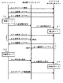
図6は、通常の通話(非録音モード)時の動作の流れを示すフローチャートである。
まず、符号A1で示すように、ユーザが自分のIPTEL100を使用してオフフックし、発呼することにより、IPTEL用加入者回路220から交換機200を介して、接続相手先のIPTEL100またはTSW210を介して外部の接続先TEL211に接続が行なわれる。
【0043】
これにより、IPTEL100とIPTEL用加入者回路220は、OSI参照モデルのトランスポート層にUDPおよびRTPを使用して、互いに音声送受信を行なう。
例えば、IPTEL100の送受話器110から音声信号が送信部120に入力されると、符号A2で示すように、送信部120は、この音声信号をIPパケットに変換して、IPネットワーク500を介してIPTEL用加入者回路220に通話用IPパケットとして送信する。
【0044】
これに対して、接続先のIPTEL100または外部の接続先TEL211から音声信号がIPTEL用加入者回路220に送信されてくると、符号A3で示すように、IPTEL用加入者回路220の送信部230は、この音声信号をIPパケットに変換して、IPネットワーク500を介して当該IPTEL100に通話用IPパケットとして送信する。
これにより、通常の双方向の通話が行なわれる。この場合、IPパケットの損失が生じたときには、受信したIPTEL用加入者回路220またはIPTEL100の受信部240,130が、リアルタイム処理により、従来と同様に、例えば前後のデータによって損失したパケットに含まれる音声データを予測して補完する。
【0045】
ここで、符号A4で示すように、ユーザが自分のIPTEL100の録音ボタン160を操作すると、IPTEL100が録音モードに切り替えられると共に、IPTEL100は、符号A5で示すように、送信部110から録音開始指令のIPパケットを、IPネットワーク500を介して録音用パソコン400に送信する。
これを受けて、録音用パソコン400は、符号A6で示すように、当該IPTEL100に関する録音開始指令のIPパケットを、IPネットワーク500を介してIPTEL用加入者回路220に対して送信する。
これにより、IPTEL用加入者回路220は、符号A7で示すように、録音用パソコン400からの録音開始指令のIPパケットを受信して、録音モードに切り替えられる。
【0046】
IPTEL100およびIPTEL用加入者回路220が録音モードに切り替えられると、OSI参照モデルのトランスポート層にUDPおよびRTPを使用して、互いに通話用IPパケットを送受信すると共に、OSI参照モデルのトランスポート層にTCPを使用して、録音用IPパケットをIPネットワーク500を介して録音用パソコン400に送信する。
【0047】
例えば、IPTEL100の送受話器110から音声信号が送信部120に入力されると、符号A8で示すように、送信部120は、この音声信号をIPパケットに変換して、IPネットワーク500を介してIPTEL用加入者回路220に通話用IPパケットとして送信すると共に、符号A9で示すように、送信部120は、このIPパケットをメモリ140に一旦保持した後、メモリ140からIPパケットを読み出しながら、IPネットワーク500を介して録音用パソコン400に録音用IPパケットとして送信する。
【0048】
これに対して、接続先のIPTEL100または外部の接続先TEL211から音声信号がIPTEL用加入者回路220に送信されてくると、符号A10で示すように、IPTEL用加入者回路220の送信部230は、この音声信号をIPパケットに変換して、IPネットワーク500を介して当該IPTEL100に通話用IPパケットとして送信すると共に、符号A11で示すように、IPTEL用加入者回路220の送信部230は、このIPパケットをメモリ250に一旦保持した後、メモリ250からこのIPパケットを読み出しながら、IPネットワーク500を介して録音用パソコン400に録音用IPパケットとして送信する。
【0049】
これにより、双方向の通話が行なわれると共に、通話内容が、IPTEL100およびIPTEL用加入者回路220から録音用IPパケットとして録音用パソコン400に送信される。
この場合、IPTEL100およびIPTEL用加入者回路220から送信される録音用IPパケットは、TCPを使用して送信される。したがって、IPパケットの損失が生じた場合には、TCPに従って、パケット再送が行なわれ、損失したIPパケットは完全に補完されることになる。
【0050】
なお、このようなIPパケット損失の際のパケット再送によって、録音用パソコン400に対する録音用IPパケットの転送時間は、IPTEL用加入者回路220またはIPTEL100に対する通話用IPパケットのリアルタイム処理による転送時間と比較して長くなるが、全IPパケットがメモリ140または250に一旦取り込まれることにより、これらのメモリ140,250がバッファメモリとして動作するので、全IPパケットが確実に送信されることになる。
【0051】
ここで、録音用パソコン400は、図5に示すように、IPTEL100およびIPTEL用加入者回路220からの録音用IPパケットについて、それぞれ最初のIPパケットの実時間と関連付けて、しかも独立的に、記録する。
例えば図示の場合、IPTEL側の録音用IPパケットに関して、音声データ:1に対して実時間TIME:XXA,音声データ:2に対して実時間TIME:XXB,・・・・のように、またIPTEL用加入者回路側(接続相手側)の録音用IPパケットに関して、音声データ:1に対して実時間TIME:YYA,音声データ:2に対して実時間TIME:YYB,・・・・のように、各IPパケットと実時間の関連付けが行なわれる。
このようにして、通話内容の録音が録音用パソコン400により行なわれる。
【0052】
そして、ユーザがIPTEL100の録音ボタン160を再度操作すると、符号A12で示すように、IPTEL100が非録音モードに切り替えられると共に、IPTEL100は、符号A13で示すように、送信部110から録音停止指令のIPパケットを、IPネットワーク500を介して録音用パソコン400に送信する。
これを受けて、録音用パソコン400は、符号A14で示すように、当該IPTEL100に関する録音停止指令のIPパケットを、IPネットワーク500を介してIPTEL用加入者回路220に対して送信する。
これにより、IPTEL用加入者回路220は、符号A15で示すように、録音用パソコン400からの録音停止指令のIPパケットを受信して、非録音モードに切り替えられ、前述したように通常の通話が行なわれる。
【0053】
最後に、ユーザが自分のIPTEL100を使用してオンフックすることにより、符号A14で示すように、IPTEL100のIPTEL用加入者回路220そして交換機200から接続相手先のIPTEL100またはTSW210を介して外部の接続先TEL211への接続が遮断され、通話が終了する。
【0054】
図7は、録音モード時にIPTELがオンフックした場合の動作の流れを示すフローチャートである。
符号B1で示すように、録音モード時に、ユーザがIPTEL100をオンフックすると、符号B2で示すように、IPTEL100が非録音モードに切り替えられると共に、符号B3で示すように、IPTEL100から録音停止指令のIPパケットが録音用パソコン400に送信される。
これを受けて、録音用パソコン400は、符号B4で示すように、IPTEL用加入者回路220に対して録音停止指令のIPパケットを送信する。
【0055】
これにより、IPTEL用加入者回路220は、符号B5で示すように、非録音モードに切り替えられる。
そして、IPTEL100は、符号B6で示すように、オンフックにより、IPTEL100のIPTEL用加入者回路220そして交換機200から接続相手先のIPTEL100またはTSW210を介して外部の接続先TEL211への接続が遮断され、通話が終了する。
【0056】
図8は、録音用パソコンにより録音された通話を再生するときの動作の流れを示すフローチャートである。
録音用パソコン400は、符号C1で示すように、ユーザの再生操作により、符号C2で示すように、指定された通話に関する一連のIPパケットをハードディスクから読み出して、符号C3で示すように、各IPパケットに関連付けられた実時間を検索する。
【0057】
そして、録音用パソコン400は、符号C4で示すように、最先の実時間を備えたIPパケットから音声信号を再生する。
例えば図9において、符号D1で示すように、最先の実時間を備えたIPパケットとして、実時間XXAを備えたIPTEL側の音声データのIPパケットを再生する。
このとき、録音用パソコン400は、図8にて符号C5で、また図9にて符号D2でそれぞれ示すように、この最先の実時間XXAを基準として、内部の時計カウンタを始動させる。
【0058】
そして、録音用パソコン400は、符号C6で示すように、時計カウンタによる時間と、各IPパケットに関連付けられた実時間とを比較して、時計カウンタによる時間が関連付けられた実時間と一致したとき、符号C7で示すように、そのIPパケットから音声信号を再生し、各IPパケットについて上記動作を繰り返す。
例えば図9において、符号D3で示すように、次の実時間を備えたIPパケットとして、実時間YYAを備えたIPTEL用加入者回路側(接続相手側)の音声データのIPパケットについて、時計カウンタがこの実時間YYAになっとたき、このIPパケットの音声データを再生する。
【0059】
このようにして、録音用パソコン400は、指定された通話に関する一連のIPパケットを、関連付けられた実時間の通りに、時系列で再生することにより、IPTEL100およびIPTEL用加入者回路220からの録音用IPパケットを互いに独立的に記録しながら、一連の通話を再現することができる。
ここで、録音用パソコン400は、IPTEL100およびIPTEL用加入者回路220から録音用IPパケットを、OSI参照モデルのトランスポート層にTCPを使用して、受信するので、IPネットワーク500のトラフィック量に影響されてパケット損失が生ずることなく、完全な音声データを録音することができる。
【0060】
さらに、IPTEL100およびIPTEL用加入者回路220から録音用IPパケットを録音用パソコン400に送信する際には、音声データのIPパケットは、それぞれ一旦メモリ110,250に保持されるので、録音用IPパケットの録音用パソコン400への伝送の際にパケット損失が発生して再送する場合でも、IPTEL100およびIPTEL用加入者回路220から送信すべき録音用IPパケットは、メモリ110,250に保持されることにより、取りこぼし等の発生が防止されるようになっている。
【0061】
【発明の効果】
以上のように、本発明によれば、IPTELによる音声通信が従来と同様のリアルタイム処理によって行なわれると共に、同時にIPTELおよびIPTEL用加入者回路から記録部に対する録音用IPパケットの送信によって、IPパケット損失のない確実な音声データの送信が行なわれ、記録される。
したがって、通話が聞き取りにくい場合等において、IPTELの音声通信後に、記録部に記録された録音用IPパケットを読み出して、その音声データを再生することにより、IPパケット損失のない完全な音声データの再生を行なうことができる。これにより、従来のような損失したパケット部分を予測により補完するような不確定要素がなく、パケット損失を完全に補完することができるので、IPパケット損失による欠落のない通話を100%再現することができる。
【図面の簡単な説明】
【図1】本発明によるIP電話録音システムの一実施形態の全体構成を示すブロック図である。
【図2】図1のIP電話録音システムで使用されるIPTELの構成例を示すブロック図である。
【図3】図1のIP電話録音システムで使用されるIPTEL用加入者回路の構成例を示すブロック図である。
【図4】図1のIP電話録音システムにおけるIPTEL,IPTEL用加入者回路と録音用パソコンとの間のパケット伝送を示す概略図である。
【図5】図1のIP電話録音システムで使用される録音用パソコンの録音状態を示す概略図である。
【図6】図1のIP電話録音システムにおける動作の流れを示すフローチャートである。
【図7】図1のIP電話録音システムにおける録音モードでオンフックしたときの動作の流れを示すフローチャートである。
【図8】図1のIP電話録音システムにおける録音用パソコンの通話再生時の動作の流れを示すフローチャートである。
【図9】図8の通話再生時の各IPパケットの再生タイミングを示すフローチャートである。
【符号の説明】
10 IPTEL電話録音システム
100 IPTEL
110 送受話器
111 マイク
112 スピーカ
120 送信部
130 受信部
140 メモリ
150 インタフェース
160 録音ボタン
200 交換機
210 TSW
211 接続先TEL
220 IPTEL用加入者回路
230 送信部
240 受信部
250 メモリ
260 インタフェース
300 IPTEL用管理サーバ
400 録音用パソコン
410 ハードディスク
500 IPネットワーク[0001]
TECHNICAL FIELD OF THE INVENTION
The present invention relates to a recording system for recording voice transmitted and received by an IP telephone.
[0002]
[Prior art]
2. Description of the Related Art Conventionally, when voice communication is performed on an IP (Internet Protocol) network, it is necessary to process IP packets in real time in transmitting and receiving voice data. However, since the IP network is a so-called best-effort network, if an audio signal is to be transmitted and received as it is, a frequency band necessary for transmitting and receiving the audio signal cannot be secured.
For this reason, conventionally, voice communication over an IP network is generally performed by using UDP (User Datagram Protocol) and RTP (Realtime Transport Protocol) in a transport layer of an OSI (Open Systems Interconnection) reference model. I do it.
[0003]
However, in voice communication on an IP network in such a system, the quality of voice communication is degraded because the loss rate of IP packets changes depending on the traffic volume on the IP network.
[0004]
Further, the traffic volume on the IP network is constantly fluctuating, and it is impossible to expect a rapid increase in the traffic volume. Here, if it is assumed that a sudden increase in traffic volume can be expected, if the traffic can be controlled by processing such as adding priority to IP packets, the packet load in voice communication should be reduced. Becomes possible.
However, in this case, it is necessary to control the function of the router connected to the IP network and the entire network. Therefore, only the control of the IP telephone, which is a terminal device for performing voice communication, gives priority to voice packets and secure It is difficult to send and receive.
[0005]
Further, when the loss of IP packets in voice communication increases when the traffic volume increases, processes such as retransmission and congestion control at the time of IP packet loss are not performed, and only real-time processing by RTP is performed. Therefore, the loss of the IP packet greatly affects the sound reproduction.
[0006]
[Problems to be solved by the invention]
For this reason, the IP telephone or the IP telephone subscriber circuit is provided with a function of complementing the lost IP packet. This complementing process is realized by predicting audio data included in an IP packet lost due to preceding and following data. Therefore, the audio data supplemented by this prediction does not completely match the audio data included in the lost IP packet. Various researches have been conducted on such a complementing process, but it is impossible to reproduce 100% of the original audio data.
Further, when the loss rate of the IP packet becomes higher due to a further increase in the traffic volume or the like, it becomes more difficult to supplement the lost voice data. For this reason, the supplemented audio data is greatly different from the original audio data, and thus, when reproduced as audio, the possibility of distortion occurring in the audio increases.
[0007]
In this way, in voice communication on the IP network, fluctuations in traffic volume affect voice quality, but it is impossible to control traffic volume.
Therefore, in order to make voice communication on an IP network the same level of quality and delay as voice communication over a conventional telephone line, for example, as one method, control using a TOS (Type of Service) field included in an IP header is considered. Can be In order to perform such control, a high-performance router capable of interpreting the TOS field is required for the entire IP network, and thus it is difficult to actually employ the router.
[0008]
In addition, voice recording may be considered as a function for assisting a malfunction in voice communication. Conventional telephone call recording involves recording the voice emitted from the handset as it is. However, if the same recording is performed using an IP telephone, the voice quality is degraded due to the IP packet loss due to the traffic volume of the IP network. Could be Therefore, even if the voice emitted from the receiver is recorded as it is by the IP telephone, the lost voice data cannot be complemented.
[0009]
SUMMARY OF THE INVENTION The present invention has been made to solve the above-described problem, and has as its object to provide an IP telephone recording system which completely complements and records voice data lost due to IP packet loss during a call.
[0010]
[Means for Solving the Problems]
In order to achieve this object, an IP telephone recording system according to the first aspect of the present invention provides an IP telephone recording system in which each user's IPTEL is interconnected by an IPTEL subscriber circuit via an IP network or externally connected via an exchange. An IP telephone recording system for recording voice data from one IPTEL and an IPTEL subscription circuit during a call by a recording unit connected to an IP network when performing voice transmission / reception by connecting to a destination telephone, When the IPTEL and the IPTEL subscriber circuit transmit and receive voice, Using UDP and RTP for the transport layer of the OSI reference model, Mutually transmit and receive call IP packets by real-time processing,
The IPTEL and the IPTEL subscriber circuit are: Using TCP for the transport layer of the OSI reference model, The configuration is such that recording IP packets are transmitted without IP packet loss without performing real-time processing.
[0011]
When the IP telephone recording system is configured as described above, voice communication by IPTEL is performed by the same real-time processing as in the past, and at the same time, the IP packet is transmitted from the IPTEL and the IPTEL subscriber circuit to the recording unit, so that the IP packet is transmitted. Lossless sound data transmission is performed and recorded.
Therefore, by reading the recording IP packet recorded in the recording unit after the IPTEL voice communication and reproducing the voice data, complete voice data without IP packet loss can be reproduced. As a result, since there is no uncertain element which complements the lost packet portion by prediction as in the conventional case, the packet loss can be completely complemented, so that a call without loss due to the IP packet loss can be reproduced 100%. Can be.
[0012]
Also, Since the IP packets for recording from each IPTEL and the IPTEL subscriber circuit are transmitted using TCP (Transmission Control Protocol) in the transport layer of the OSI reference model, if an IP packet loss occurs, By performing error processing such as retransmission of the IP packet by TCP, complete voice communication with substantially no IP packet loss can be performed.
[0013]
Also, Since the transmission of IP packets for communication from each IPTEL and the IPTEL subscriber circuit is performed using UDP and RTP in the transport layer of the OSI reference model, real-time processing similar to that of the conventional IP telephone is performed. When an IP packet loss has occurred, by performing prediction and compensating for the lost IP packet based on the preceding and following audio data, audio communication can be performed substantially in real time.
[0014]
Also,
With this configuration of the IP telephone recording system, the recording unit does not record the recording IP packet when the IP telephone is not used from the time of on-hook to the time of off-hook. As a result, unnecessary recording is not performed by the recording unit, so that the running cost is reduced.
[0016]
Also,
With such a configuration of the IP telephone recording system, when the user turns on his / her own IPTEL at the end of the call, the recording unit ends the recording. This prevents the recording unit from performing recording in a non-communication state after a call.
[0018]
Also, Claim 4 In the described IP telephone recording system, the recording unit is configured to independently record the recording IP packets transmitted from the IPTEL and the IPTEL subscriber circuit during a call with each other.
When the IP telephone recording system is configured as described above, if the audio data of the IPTEL and the IP packet for recording from the IPTEL subscriber circuit is difficult to hear due to overlapping, the IPTEL and the IPTEL subscriber circuit will not be able to hear. By separately reproducing the recording IP packet, the voice data from the IPTEL and the IPTEL subscriber circuit can be clearly distinguished.
[0019]
Also,
When the IP telephone recording system has such a configuration, the real time is recorded in the first IP packet of the IPTEL and the recording IP packet from the IPTEL subscriber circuit, so that the recording is performed independently. It is possible to determine the time series of the audio data based on the IP packets from the respective IPTELs.
[0020]
Also, Claim 6 In the described IP telephone recording system, when the recording unit reproduces the recorded audio data of the recording IP packet from the IPTEL and the IPTEL subscriber circuit, the recording unit reproduces the audio by each IP packet according to the actual time. It is configured to reproduce data.
With this configuration of the IP telephone recording system, the audio data of the recording IP packet from the IPTEL and the IPTEL subscriber circuit is reproduced in time series, and the audio of the IP packet from the IPTEL and the IPTEL subscriber circuit is reproduced. Calls with data can be reproduced as a whole.
[0021]
Also, Claim 7 The described IP telephone recording system has a configuration in which the recording unit is an information terminal device connected to an IP network.
When the IP telephone recording system is configured as described above, by using a storage device such as a personal computer or another server independently connected to an IP network as a recording unit, recording and recording of IP packets for recording can be easily performed. Reproduction can be performed.
[0023]
BEST MODE FOR CARRYING OUT THE INVENTION
Hereinafter, embodiments of the present invention will be described with reference to the drawings.
[0024]
One embodiment of the IP telephone recording system of the present invention will be described with reference to FIG.
FIG. 1 is a block diagram showing the configuration of the IP telephone recording system of the present embodiment. As shown in FIG. 1, the IP
In FIG. 1, only one
The
[0025]
As shown in FIG. 2, the
The handset 110 includes a microphone 111 that collects the voice of the user, and a speaker 112 that converts a voice signal from the connection partner into a voice, and the user lifts the handset 110 by hand when used. As a result, the
Note that the
[0026]
The transmitting
[0027]
Also, in the recording mode, the transmitting
[0028]
On the other hand, the receiving unit 130 transmits the call IP packet transmitted from the IPTEL subscriber circuit 220 via the
[0029]
Here, the
The
[0030]
Further, the
Here, the lighting color of the
Note that the
[0031]
Thus, in the non-recording mode (normal call), the
Further, in the recording mode, the
[0032]
The
The
Here, the connection destination TEL 211 is a normal telephone connected to a general public line network.
[0033]
Further, as shown in FIG. 3, the IPTEL subscriber circuit 220 includes a transmitting
[0034]
The
[0035]
In the recording mode, the
[0036]
On the other hand, the receiving
Here, the IPTEL subscriber circuit 220 alternately switches between a recording mode and a non-recording mode based on a recording start command or a recording stop command from the recording personal computer 400.
[0037]
As a result, the IPTEL subscriber circuit 220 transmits the IP packet of the voice data of the connection partner in the non-recording mode (normal call), as shown by the symbol C in FIG. 4, with respect to the voice communication with the
In addition, in the recording mode, the IPTEL subscriber circuit 220 uses UDP and RTP for the transport layer of the OSI reference model as shown by reference numeral C in FIG. The audio data transmitted to the
[0038]
The
Here, the
Although the
Further, when the IP addresses of the
[0039]
The recording personal computer 400 is connected to the
The recording personal computer 400 may have the function of the
[0040]
Here, the recording personal computer 400 is in communication with each other, and the recording IP of voice data transmitted from the
[0041]
Then, when reproducing the recording IP packet of the recorded audio data, the recording personal computer 400 relates to the IP packet from both the
[0042]
Next, the operation of the IPTEL
FIG. 6 is a flowchart showing the flow of the operation during a normal call (non-recording mode).
First, as shown by reference numeral A1, the user goes off-hook using his / her
[0043]
As a result, the
For example, when an audio signal is input from the handset 110 of the
[0044]
On the other hand, when an audio signal is transmitted from the
As a result, normal two-way communication is performed. In this case, when the loss of the IP packet occurs, the received IPTEL subscriber circuit 220 or the receiving
[0045]
Here, as indicated by reference numeral A4, when the user operates the
In response, the recording personal computer 400 transmits an IP packet of a recording start command relating to the
As a result, the IPTEL subscriber circuit 220 receives the recording start command IP packet from the recording personal computer 400 and switches to the recording mode, as indicated by reference numeral A7.
[0046]
When the
[0047]
For example, when an audio signal is input from the handset 110 of the
[0048]
On the other hand, when an audio signal is transmitted from the
[0049]
Thus, a two-way call is performed, and the contents of the call are transmitted from the
In this case, the recording IP packet transmitted from the
[0050]
Due to the packet retransmission in the event of such IP packet loss, the transfer time of the recording IP packet to the recording personal computer 400 is compared with the transfer time of the call IP packet to the IPTEL subscriber circuit 220 or
[0051]
Here, as shown in FIG. 5, the recording personal computer 400 records the recording IP packets from the
For example, in the case of the drawing, regarding the IP packet for recording on the IPTEL side, the real time TIME: XXA for the audio data: 1, the real time TIME: XXB,. , The real time TIME: YYA for voice data: 1, the real time TIME: YYB for voice data: 2, etc. , Each IP packet is associated with real time.
In this way, the contents of the call are recorded by the recording personal computer 400.
[0052]
Then, when the user operates the
In response to this, the recording personal computer 400 transmits an IP packet of a recording stop command relating to the
As a result, the IPTEL subscriber circuit 220 receives the recording stop command IP packet from the recording personal computer 400 and switches to the non-recording mode, as indicated by reference numeral A15. Done.
[0053]
Finally, when the user goes on-hook using his / her
[0054]
FIG. 7 is a flowchart showing a flow of operation when the IPTEL goes on-hook in the recording mode.
When the user turns on the
Receiving this, the recording personal computer 400 transmits an IP packet of a recording stop command to the IPTEL subscriber circuit 220, as indicated by reference numeral B4.
[0055]
As a result, the IPTEL subscriber circuit 220 is switched to the non-recording mode as indicated by reference numeral B5.
Then, the
[0056]
FIG. 8 is a flowchart showing a flow of operation when reproducing a call recorded by the recording personal computer.
The recording personal computer 400 reads a series of IP packets related to the specified call from the hard disk as indicated by reference numeral C2 by a user's reproduction operation as indicated by reference numeral C1, and transmits each IP packet as indicated by reference numeral C3. Find the real time associated with a packet.
[0057]
Then, the recording personal computer 400 reproduces the audio signal from the IP packet having the earliest real time, as indicated by reference numeral C4.
For example, in FIG. 9, as indicated by reference numeral D1, the IP packet of the audio data on the IPTEL side having the real time XXA is reproduced as the earliest real time IP packet.
At this time, the recording personal computer 400 starts an internal clock counter based on the earliest real time XXA, as indicated by reference numeral C5 in FIG. 8 and by reference numeral D2 in FIG.
[0058]
Then, the recording personal computer 400 compares the time by the clock counter with the real time associated with each IP packet, as indicated by reference numeral C6, and determines that the time by the clock counter matches the associated real time. , A voice signal is reproduced from the IP packet, and the above operation is repeated for each IP packet.
For example, in FIG. 9, as indicated by reference numeral D3, as an IP packet having the next real time, an IP packet of audio data on the IPTEL subscriber circuit side (connection partner side) having the real time YYA is referred to as a clock counter. When the time reaches the actual time YYA, the audio data of the IP packet is reproduced.
[0059]
In this way, the recording personal computer 400 reproduces a series of IP packets related to the designated call in chronological order according to the associated real time, thereby recording from the
Here, the recording personal computer 400 receives the recording IP packet from the
[0060]
Further, when transmitting the recording IP packet from the
[0061]
【The invention's effect】
As described above, according to the present invention, voice communication by IPTEL is performed by the same real-time processing as in the past, and at the same time, the transmission of the recording IP packet from the IPTEL and the subscriber circuit for the IPTEL to the recording unit causes the IP packet loss. The transmission of the sound data without any error is performed and recorded.
Therefore, in a case where it is difficult to hear a call, for example, by reading the recording IP packet recorded in the recording unit after the IPTEL voice communication and reproducing the voice data, complete voice data without IP packet loss can be reproduced. Can be performed. As a result, since there is no uncertain element which complements the lost packet portion by prediction as in the conventional case, the packet loss can be completely complemented, so that a call without loss due to the IP packet loss can be reproduced 100%. Can be.
[Brief description of the drawings]
FIG. 1 is a block diagram showing an overall configuration of an embodiment of an IP telephone recording system according to the present invention.
FIG. 2 is a block diagram showing a configuration example of an IPTEL used in the IP telephone recording system of FIG. 1;
FIG. 3 is a block diagram showing a configuration example of an IPTEL subscriber circuit used in the IP telephone recording system of FIG. 1;
4 is a schematic diagram showing packet transmission between an IPTEL, an IPTEL subscriber circuit, and a recording personal computer in the IP telephone recording system of FIG. 1;
FIG. 5 is a schematic diagram showing a recording state of a recording personal computer used in the IP telephone recording system of FIG. 1;
FIG. 6 is a flowchart showing a flow of operation in the IP telephone recording system of FIG. 1;
FIG. 7 is a flowchart showing a flow of an operation when on-hook in a recording mode in the IP telephone recording system of FIG. 1;
8 is a flowchart showing a flow of an operation of the recording personal computer in the IP telephone recording system of FIG. 1 at the time of call reproduction.
FIG. 9 is a flowchart showing a reproduction timing of each IP packet at the time of reproducing the call in FIG. 8;
[Explanation of symbols]
10 IPTEL telephone recording system
100 IPTEL
110 handset
111 microphone
112 speaker
120 transmission unit
130 Receiver
140 memory
150 interface
160 Record button
200 exchange
210 TSW
211 Connection TEL
220 IPTEL Subscriber Circuit
230 transmitter
240 receiver
250 memory
260 interface
300 IPTEL Management Server
400 PC for recording
410 Hard Disk
500 IP network
Claims (7)
当該IPTELおよびIPTEL用加入者回路が、音声送受信の際に、OSI参照モデルのトランスポート層にUDPおよびRTPを使用し、相互にリアルタイム処理により、通話用IPパケット送受信を行なうと共に、
当該IPTELおよびIPTEL用加入者回路が、OSI参照モデルのトランスポート層にTCPを使用して、記録部に対し、リアルタイム処理を行なわずに、IPパケット損失のない録音用IPパケット送信を行なうことを特徴とするIP電話録音システム。When the IPTEL of each user is connected to an external destination telephone via an IPTEL subscriber circuit of the exchange via an IP network or via an exchange via an IP network to perform voice transmission / reception, one IPTEL during a call and An IP telephone recording system for recording voice data from an IPTEL subscription circuit by a recording unit connected to an IP network,
The IPTEL and the IPTEL subscriber circuit use UDP and RTP in the transport layer of the OSI reference model when transmitting and receiving voice, and perform real-time mutual transmission and reception of communication IP packets.
The IPTEL and the IPTEL subscriber circuit use the TCP for the transport layer of the OSI reference model to transmit the recording IP packet without loss of the IP packet to the recording unit without performing the real-time processing. Characteristic IP telephone recording system.
Priority Applications (2)
| Application Number | Priority Date | Filing Date | Title |
|---|---|---|---|
| JP2000266920A JP3555568B2 (en) | 2000-09-04 | 2000-09-04 | IP telephone recording system |
| US09/944,187 US6795534B2 (en) | 2000-09-04 | 2001-09-04 | Data recording system for IP telephone communication |
Applications Claiming Priority (1)
| Application Number | Priority Date | Filing Date | Title |
|---|---|---|---|
| JP2000266920A JP3555568B2 (en) | 2000-09-04 | 2000-09-04 | IP telephone recording system |
Publications (2)
| Publication Number | Publication Date |
|---|---|
| JP2002077264A JP2002077264A (en) | 2002-03-15 |
| JP3555568B2 true JP3555568B2 (en) | 2004-08-18 |
Family
ID=18753928
Family Applications (1)
| Application Number | Title | Priority Date | Filing Date |
|---|---|---|---|
| JP2000266920A Expired - Fee Related JP3555568B2 (en) | 2000-09-04 | 2000-09-04 | IP telephone recording system |
Country Status (2)
| Country | Link |
|---|---|
| US (1) | US6795534B2 (en) |
| JP (1) | JP3555568B2 (en) |
Families Citing this family (34)
| Publication number | Priority date | Publication date | Assignee | Title |
|---|---|---|---|---|
| US7400579B2 (en) * | 2001-09-28 | 2008-07-15 | Intel Corporation | Method and apparatus for per-call filtering of H.323 packets |
| US20040190691A1 (en) * | 2001-12-05 | 2004-09-30 | Gustav Schoeman | Means and method for computerized call logging |
| GB2389736B (en) * | 2002-06-13 | 2005-12-14 | Nice Systems Ltd | A method for forwarding and storing session packets according to preset and/or dynamic rules |
| US7660297B2 (en) * | 2002-06-13 | 2010-02-09 | Nice Systems Ltd. | Voice over IP forwarding |
| US8165114B2 (en) * | 2002-06-13 | 2012-04-24 | Nice Systems Ltd. | Voice over IP capturing |
| US6891934B1 (en) * | 2002-08-20 | 2005-05-10 | Bellsouth Intellectual Property Corporation | IP handset-based voice mail notification |
| US7054420B2 (en) * | 2002-09-11 | 2006-05-30 | Telstrat International, Ltd. | Voice over IP telephone recording architecture |
| JP3981618B2 (en) * | 2002-10-10 | 2007-09-26 | 株式会社トヨタIt開発センター | MONITORING METHOD, MONITOR SYSTEM, PROGRAM, AND RECORDING MEDIUM |
| US8005918B2 (en) | 2002-11-12 | 2011-08-23 | Rateze Remote Mgmt. L.L.C. | Data storage devices having IP capable partitions |
| US7649880B2 (en) | 2002-11-12 | 2010-01-19 | Mark Adams | Systems and methods for deriving storage area commands |
| WO2004045149A1 (en) | 2002-11-12 | 2004-05-27 | Zetera Corporation | Communication protocols, systems and methods |
| US7170890B2 (en) | 2002-12-16 | 2007-01-30 | Zetera Corporation | Electrical devices with improved communication |
| US20040160975A1 (en) * | 2003-01-21 | 2004-08-19 | Charles Frank | Multicast communication protocols, systems and methods |
| JP4365653B2 (en) * | 2003-09-17 | 2009-11-18 | パナソニック株式会社 | Audio signal transmission apparatus, audio signal transmission system, and audio signal transmission method |
| CA2474083C (en) * | 2004-06-25 | 2011-01-25 | Sivakumaran Sanmugasuntharam | Caller id call memo system |
| US7702850B2 (en) | 2005-03-14 | 2010-04-20 | Thomas Earl Ludwig | Topology independent storage arrays and methods |
| US7738638B1 (en) * | 2005-04-05 | 2010-06-15 | At&T Intellectual Property Ii, L.P. | Voice over internet protocol call recording |
| US7620981B2 (en) | 2005-05-26 | 2009-11-17 | Charles William Frank | Virtual devices and virtual bus tunnels, modules and methods |
| US7916642B2 (en) * | 2005-08-11 | 2011-03-29 | Starent Networks Llc | System and method for congestion control signaling |
| US8819092B2 (en) | 2005-08-16 | 2014-08-26 | Rateze Remote Mgmt. L.L.C. | Disaggregated resources and access methods |
| US7743214B2 (en) * | 2005-08-16 | 2010-06-22 | Mark Adams | Generating storage system commands |
| US9270532B2 (en) | 2005-10-06 | 2016-02-23 | Rateze Remote Mgmt. L.L.C. | Resource command messages and methods |
| US7924881B2 (en) | 2006-04-10 | 2011-04-12 | Rateze Remote Mgmt. L.L.C. | Datagram identifier management |
| KR100810269B1 (en) * | 2006-04-18 | 2008-03-06 | 삼성전자주식회사 | Mobile terminal and method of performing video call service of the terminal |
| EP2171982B1 (en) * | 2007-10-19 | 2012-04-18 | Voxer IP LLC | Method and device for real-time media synchronisation across a network |
| US8103785B2 (en) * | 2007-12-03 | 2012-01-24 | Seafire Micros, Inc. | Network acceleration techniques |
| KR101044323B1 (en) * | 2008-02-20 | 2011-06-29 | 가부시키가이샤 엔.티.티.도코모 | Communication system for constructing speech database for speech synthesis, relay apparatus for same, and relay method therefor |
| KR101489426B1 (en) * | 2008-12-24 | 2015-02-03 | 삼성전자주식회사 | Apparatus and method for cellular call recording in Internet telephone system |
| EP2239973B1 (en) * | 2009-04-09 | 2016-04-06 | Airbus Defence and Space Oy | Recording communications |
| US8565125B2 (en) * | 2009-07-29 | 2013-10-22 | Honeywell International Inc. | Services based two way voice service recording and logging |
| JP5494129B2 (en) * | 2010-03-31 | 2014-05-14 | ブラザー工業株式会社 | Communication system and communication method |
| US8811281B2 (en) | 2011-04-01 | 2014-08-19 | Cisco Technology, Inc. | Soft retention for call admission control in communication networks |
| US9369570B1 (en) * | 2015-05-18 | 2016-06-14 | Nice-Systems Ltd | Concurrent recordings of telephonic interactions |
| CN110663244B (en) * | 2017-03-10 | 2021-05-25 | 株式会社Bonx | A communication system and portable communication terminal |
Family Cites Families (8)
| Publication number | Priority date | Publication date | Assignee | Title |
|---|---|---|---|---|
| GB2310970A (en) * | 1996-03-05 | 1997-09-10 | Ibm | Voice mail on the Internet |
| US6529501B1 (en) * | 1998-05-29 | 2003-03-04 | 3Com Corporation | Method and apparatus for internet telephony |
| US6487196B1 (en) * | 1998-05-29 | 2002-11-26 | 3Com Corporation | System and method for simulating telephone use in a network telephone system |
| US6539077B1 (en) * | 1998-06-05 | 2003-03-25 | Netnumber.Com, Inc. | Method and apparatus for correlating a unique identifier, such as a PSTN telephone number, to an internet address to enable communications over the internet |
| US6122665A (en) * | 1998-08-26 | 2000-09-19 | Sts Software System Ltd. | Communication management system for computer network-based telephones |
| JP3917767B2 (en) | 1998-11-05 | 2007-05-23 | 日立情報通信エンジニアリング株式会社 | Voice fluctuation correction control method, voice playback apparatus, and voice relay apparatus |
| US6366961B1 (en) * | 1999-03-03 | 2002-04-02 | Nokia Telecommunications, Oy | Method and apparatus for providing mini packet switching in IP based cellular access networks |
| JP4108863B2 (en) | 1999-03-31 | 2008-06-25 | 株式会社東芝 | Multimedia information communication system |
-
2000
- 2000-09-04 JP JP2000266920A patent/JP3555568B2/en not_active Expired - Fee Related
-
2001
- 2001-09-04 US US09/944,187 patent/US6795534B2/en not_active Expired - Fee Related
Also Published As
| Publication number | Publication date |
|---|---|
| US20020027977A1 (en) | 2002-03-07 |
| JP2002077264A (en) | 2002-03-15 |
| US6795534B2 (en) | 2004-09-21 |
Similar Documents
| Publication | Publication Date | Title |
|---|---|---|
| JP3555568B2 (en) | IP telephone recording system | |
| US7054420B2 (en) | Voice over IP telephone recording architecture | |
| EP1360799B1 (en) | Packet data recording method | |
| US6965562B2 (en) | System and method for managing a network to sustain the quality of voice over internet protocol communications | |
| US7379466B2 (en) | In band signal detection and presentation for IP phone | |
| WO2001031863A2 (en) | System, method and computer program product for point-to-point bandwidth conservation in an ip network | |
| Flanagan | VoIP and unified communications: internet telephony and the future voice network | |
| JP2003101662A (en) | Communication method, communication device, and communication terminal | |
| US8275944B1 (en) | Distributive network control | |
| US6678280B1 (en) | Voice packet transmission control method in gateway system and device therefor | |
| US20040062271A1 (en) | Method and system for providing control and monitoring functionality for a telecommunication switching domain | |
| WO2006075390A1 (en) | Repeating method, repeater, communication system, and computer program | |
| JP3821740B2 (en) | Audio data transmitter / receiver | |
| US20070258434A1 (en) | Duplicate media stream | |
| CN101159719A (en) | VoIP analog gateway and internal switching method for realizing calls under fault conditions | |
| JP4108863B2 (en) | Multimedia information communication system | |
| JP4462787B2 (en) | Call recording system for IP phone system | |
| JP4102683B2 (en) | Voice packet communication method and apparatus | |
| JP2011071853A (en) | Ip telephone system, communication content recorder and communication method | |
| CN101083695B (en) | Voice over internet protocol system and related wireless local area network device | |
| US6947412B2 (en) | Method of facilitating the playback of speech signals transmitted at the beginning of a telephone call established over a packet exchange network, and hardware for implementing the method | |
| JP2000354071A (en) | IP network voice communication device with backup function | |
| KR100283173B1 (en) | How to buffer jitter processing in vocoder | |
| JP2005167684A (en) | Transmission control device | |
| KR100376133B1 (en) | Method for Prevention of Data Transmission Delay |
Legal Events
| Date | Code | Title | Description |
|---|---|---|---|
| A977 | Report on retrieval |
Free format text: JAPANESE INTERMEDIATE CODE: A971007 Effective date: 20031217 |
|
| A131 | Notification of reasons for refusal |
Free format text: JAPANESE INTERMEDIATE CODE: A131 Effective date: 20031224 |
|
| A521 | Written amendment |
Free format text: JAPANESE INTERMEDIATE CODE: A523 Effective date: 20040219 |
|
| TRDD | Decision of grant or rejection written | ||
| A01 | Written decision to grant a patent or to grant a registration (utility model) |
Free format text: JAPANESE INTERMEDIATE CODE: A01 Effective date: 20040420 |
|
| A61 | First payment of annual fees (during grant procedure) |
Free format text: JAPANESE INTERMEDIATE CODE: A61 Effective date: 20040503 |
|
| R150 | Certificate of patent or registration of utility model |
Free format text: JAPANESE INTERMEDIATE CODE: R150 |
|
| S111 | Request for change of ownership or part of ownership |
Free format text: JAPANESE INTERMEDIATE CODE: R313111 |
|
| R350 | Written notification of registration of transfer |
Free format text: JAPANESE INTERMEDIATE CODE: R350 |
|
| FPAY | Renewal fee payment (event date is renewal date of database) |
Free format text: PAYMENT UNTIL: 20090521 Year of fee payment: 5 |
|
| FPAY | Renewal fee payment (event date is renewal date of database) |
Free format text: PAYMENT UNTIL: 20100521 Year of fee payment: 6 |
|
| FPAY | Renewal fee payment (event date is renewal date of database) |
Free format text: PAYMENT UNTIL: 20110521 Year of fee payment: 7 |
|
| FPAY | Renewal fee payment (event date is renewal date of database) |
Free format text: PAYMENT UNTIL: 20110521 Year of fee payment: 7 |
|
| FPAY | Renewal fee payment (event date is renewal date of database) |
Free format text: PAYMENT UNTIL: 20120521 Year of fee payment: 8 |
|
| FPAY | Renewal fee payment (event date is renewal date of database) |
Free format text: PAYMENT UNTIL: 20120521 Year of fee payment: 8 |
|
| FPAY | Renewal fee payment (event date is renewal date of database) |
Free format text: PAYMENT UNTIL: 20130521 Year of fee payment: 9 |
|
| FPAY | Renewal fee payment (event date is renewal date of database) |
Free format text: PAYMENT UNTIL: 20140521 Year of fee payment: 10 |
|
| S533 | Written request for registration of change of name |
Free format text: JAPANESE INTERMEDIATE CODE: R313533 |
|
| R350 | Written notification of registration of transfer |
Free format text: JAPANESE INTERMEDIATE CODE: R350 |
|
| LAPS | Cancellation because of no payment of annual fees |