JP3249585U - Medical devices for vascular hemostasis - Google Patents
Medical devices for vascular hemostasis Download PDFInfo
- Publication number
- JP3249585U JP3249585U JP2024600134U JP2024600134U JP3249585U JP 3249585 U JP3249585 U JP 3249585U JP 2024600134 U JP2024600134 U JP 2024600134U JP 2024600134 U JP2024600134 U JP 2024600134U JP 3249585 U JP3249585 U JP 3249585U
- Authority
- JP
- Japan
- Prior art keywords
- clamp
- control line
- connection
- arms
- sheath
- Prior art date
- Legal status (The legal status is an assumption and is not a legal conclusion. Google has not performed a legal analysis and makes no representation as to the accuracy of the status listed.)
- Active
Links
- 230000023597 hemostasis Effects 0.000 title claims abstract description 5
- 230000002792 vascular Effects 0.000 title claims description 3
- 238000003466 welding Methods 0.000 claims description 6
- 238000003825 pressing Methods 0.000 claims description 5
- 238000005219 brazing Methods 0.000 claims description 2
- 210000004204 blood vessel Anatomy 0.000 abstract description 8
- 230000008878 coupling Effects 0.000 description 12
- 238000010168 coupling process Methods 0.000 description 12
- 238000005859 coupling reaction Methods 0.000 description 12
- 230000000295 complement effect Effects 0.000 description 3
- 230000014759 maintenance of location Effects 0.000 description 2
- 208000012671 Gastrointestinal haemorrhages Diseases 0.000 description 1
- 208000032843 Hemorrhage Diseases 0.000 description 1
- 230000000740 bleeding effect Effects 0.000 description 1
- 239000008280 blood Substances 0.000 description 1
- 210000004369 blood Anatomy 0.000 description 1
- 238000007796 conventional method Methods 0.000 description 1
- 208000030304 gastrointestinal bleeding Diseases 0.000 description 1
- 210000001035 gastrointestinal tract Anatomy 0.000 description 1
- 238000004519 manufacturing process Methods 0.000 description 1
- 230000000149 penetrating effect Effects 0.000 description 1
- 230000007704 transition Effects 0.000 description 1
Images


Classifications
-
- A—HUMAN NECESSITIES
- A61—MEDICAL OR VETERINARY SCIENCE; HYGIENE
- A61B—DIAGNOSIS; SURGERY; IDENTIFICATION
- A61B17/00—Surgical instruments, devices or methods
- A61B17/12—Surgical instruments, devices or methods for ligaturing or otherwise compressing tubular parts of the body, e.g. blood vessels or umbilical cord
- A61B17/122—Clamps or clips, e.g. for the umbilical cord
-
- A—HUMAN NECESSITIES
- A61—MEDICAL OR VETERINARY SCIENCE; HYGIENE
- A61B—DIAGNOSIS; SURGERY; IDENTIFICATION
- A61B17/00—Surgical instruments, devices or methods
- A61B17/12—Surgical instruments, devices or methods for ligaturing or otherwise compressing tubular parts of the body, e.g. blood vessels or umbilical cord
- A61B17/128—Surgical instruments, devices or methods for ligaturing or otherwise compressing tubular parts of the body, e.g. blood vessels or umbilical cord for applying or removing clamps or clips
- A61B17/1285—Surgical instruments, devices or methods for ligaturing or otherwise compressing tubular parts of the body, e.g. blood vessels or umbilical cord for applying or removing clamps or clips for minimally invasive surgery
-
- A—HUMAN NECESSITIES
- A61—MEDICAL OR VETERINARY SCIENCE; HYGIENE
- A61B—DIAGNOSIS; SURGERY; IDENTIFICATION
- A61B17/00—Surgical instruments, devices or methods
- A61B2017/00477—Coupling
Landscapes
- Health & Medical Sciences (AREA)
- Surgery (AREA)
- Life Sciences & Earth Sciences (AREA)
- Heart & Thoracic Surgery (AREA)
- Nuclear Medicine, Radiotherapy & Molecular Imaging (AREA)
- Vascular Medicine (AREA)
- Engineering & Computer Science (AREA)
- Biomedical Technology (AREA)
- Reproductive Health (AREA)
- Medical Informatics (AREA)
- Molecular Biology (AREA)
- Animal Behavior & Ethology (AREA)
- General Health & Medical Sciences (AREA)
- Public Health (AREA)
- Veterinary Medicine (AREA)
- Surgical Instruments (AREA)
Abstract
内視鏡により血管を止血するための医療器具は、ハンドル(1)と、ハンドル(1)に取付けられたシース装置(2)と、シース装置(2)の遠位端に設けられたクランプケース(6)と少なくとも2つの、具体的に2つのクランプアーム(8a、8b)を含むクランプ装置(3)と、シース装置(2)を貫通して延在し、遠位側方向及び近位側方向に可逆的に移動可能な制御線(4)と、制御線(4)の近位端に接続され、制御線(4)が遠位側方向及び近位側方向に可逆的に移動するように動作可能なアクチュエータ(5)と、を含み、クランプアーム(8a、8b)は、それぞれ制御線(4)の遠位端に接続される。
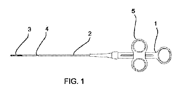
【選択図】図1
The medical instrument for endoscopic hemostasis of a blood vessel includes a handle (1), a sheath device (2) attached to the handle (1), a clamp device (3) including a clamp case (6) and at least two, specifically two clamp arms (8a, 8b) provided at a distal end of the sheath device (2), a control line (4) extending through the sheath device (2) and reversibly movable in a distal direction and a proximal direction, and an actuator (5) connected to a proximal end of the control line (4) and operable to reversibly move the control line (4) in a distal direction and a proximal direction, the clamp arms (8a, 8b) being connected to the distal ends of the control line (4), respectively.
[Selected Figure] Figure 1
Description
本開示は内視鏡により血管を止血するための医療器具に関する。 This disclosure relates to a medical device for stasis of blood vessels using an endoscope.
このような医療器具は、例えばEP1328199B1から知られており、特に胃腸管出血の治療に用いられる。具体的には、このような器具には、出血した血管を締め付けるための鉗子やクリップが設けられて、血管にその中を通過する血液の流れを制限又は中断するための十分な緊締力を提供するために用いられる。
Such medical devices are known, for example from
EP1328199B1から知られている医療器具は、ハンドルと、ハンドルに取付けられたシースと、を含む。制御線は、シースを貫通して延在しており、アクチュエータにより作動されることができ、このアクチュエータは、制御線の近位端に接続されて、制御線を遠位側方向及び近位側方向に可逆的に移動させる。この医療器具は、クランプ装置をさらに含み、このクランプ装置は、シースの遠位端に設けられたスリーブを含み、2つのクランプアームを有するクリップがJ字形フックを介して制御線の遠位端に接続される。クランプアームは、制御線が近位側方向に引っ張られるとクランプアームがスリーブの前縁に係合して内側に弾性変形して閉となり、制御線が遠位側方向に押されるとクランプアームが遠位側へスリーブから押し出されてその弾性復元力により自動的に再び開となるように、スリーブと協働する。クランプ装置が開閉を繰り返すことができるため、簡単の方式でクランプ装置を設けることができる。
The medical instrument known from
クランプ装置が正確な位置にセットされると、クランプアームを閉状態でロックする必要がある。このため、クランプアームに開口部が設けられており、スリーブの内面に形成された対応する突起部がこの開口部に係合されることができる。クランプアームを閉状態でロックするためには、制御線を近位側方向に引っ張って、突起がクランプアームに形成された開口部に係合するようにする。 Once the clamping device is set in the correct position, the clamping arm needs to be locked in the closed position. For this purpose, an opening is provided in the clamping arm, into which a corresponding projection formed on the inner surface of the sleeve can engage. To lock the clamping arm in the closed position, the control line is pulled in the proximal direction so that the projection engages the opening formed in the clamping arm.
また、クランプアーム及びスリーブを有するクランプ装置は、医療器具の他の部分から接続が解除されることができる。このため、クランプ装置が完全に閉となったとき、制御線がさらに引き戻されて、J字形フックが制動されてクランプアームと制御線との接続が解除される。また、制御線をさらに引き戻すことにより、制御線とスリーブとを接続しているリテーナを動作させて、リテーナによる制御線とスリーブとの接続を解除する。 The clamping device, which has a clamping arm and a sleeve, can also be disconnected from other parts of the medical instrument. Thus, when the clamping device is fully closed, the control line is pulled back further, braking the J-hook and disconnecting the clamping arm from the control line. Pulling back the control line further also operates the retainer connecting the control line to the sleeve, thereby disconnecting the control line from the sleeve by the retainer.
本開示は、上記従来技術に鑑み、操作が容易であるだけでなく、製造および組み立てが容易であり、かつ確実に動作する、上記種類の医療器具を提供することを目的とする。 In view of the above-mentioned conventional techniques, the present disclosure aims to provide a medical instrument of the above-mentioned type that is not only easy to operate, but also easy to manufacture and assemble, and operates reliably.
この目的は、クランプケースが接続管に対して長手方向の軸線を中心に回転できるように、クランプケースが接続管に直接かつ解放可能に接続される医療機器によって解決される。 This object is solved by a medical device in which the clamp case is directly and releasably connected to the connecting tube such that the clamp case can rotate about a longitudinal axis relative to the connecting tube.
血管止血用の医療器具であって、
ハンドルと、
ハンドルに取付けられたシース装置と、
シース装置の遠位端に設けられたクランプケースと、少なくとも2つの、具体的に2つのクランプアームと、を含むクランプ装置と、
シース装置を貫通して延在し、遠位側方向及び近位側方向に可逆的に移動可能な制御線と、
制御線の近位端に接続され、制御線が遠位側方向及び近位側方向に可逆的に移動するように動作可能なアクチュエータと、を含み、
クランプアームは、それぞれ制御線の遠位端に接続され、クランプ装置は、制御線の移動によりクランプアームが開閉するように動作可能であり、制御線の近位側方向への移動は、クランプアームの閉動作に変換され、制御線の遠位側方向への移動は、クランプアームの開動作に変換され、
シース装置は、好ましくは伸縮可能なコイル状シースであるシースと、長手方向の軸線を限定し、シースの遠位端に固定的に接続された接続管を含み、
クランプケースは、クランプケースが接続管に対して長手方向の軸線を中心に回転できるように、接続管に直接且つ解放可能に接続される。
A medical device for vascular hemostasis, comprising:
A handle and
a sheath device attached to the handle;
A clamping device including a clamp case provided at a distal end of the sheath device and at least two, specifically two, clamping arms;
a control line extending through the sheath apparatus and reversibly movable in a distal direction and a proximal direction;
an actuator connected to a proximal end of the control line and operable to reversibly move the control line in a distal direction and a proximal direction;
The clamp arms are each connected to a distal end of a control line, and the clamp device is operable such that movement of the control lines opens and closes the clamp arms, such that proximal movement of the control lines translates to a closing movement of the clamp arms and distal movement of the control lines translates to an opening movement of the clamp arms;
The sheath device includes a sheath, preferably an expandable coiled sheath, and a connecting tube defining a longitudinal axis and fixedly connected to a distal end of the sheath;
The clamp case is directly and releasably connected to the connecting tube such that the clamp case can rotate about a longitudinal axis relative to the connecting tube.
本開示は、クランプアームが人体内組織を把持できる位置に関する自由度を向上させるために、クランプ装置をシースに対して長手方向の軸線を中心に回転させる可能性を提供するという考えに基づくものである。従って、人体内部におけるクランプ装置の設置は、挟むべき血管の配向に適応することができる。クランプケースとシースに固定的に接続された接続管との間に中間素子を不要であるため、クランプケースと接続管との直接的な回転可能な接続は、コンパクトな設計と医療器具の遠位端の短い構造長さにつながる。 The present disclosure is based on the idea of providing the possibility to rotate the clamping device about its longitudinal axis relative to the sheath in order to improve the degree of freedom regarding the position at which the clamping arms can grip the tissue inside the human body. Thus, the placement of the clamping device inside the human body can be adapted to the orientation of the blood vessel to be clamped. The direct rotatable connection between the clamping case and the connecting tube leads to a compact design and a short structural length of the distal end of the medical instrument, since no intermediate elements are required between the clamping case and the connecting tube which is fixedly connected to the sheath.
従って、クランプケースは、シース装置の遠位端に形成された接続管に対して回転可能であり、この接続管は、耐トルク的な接続によりシースの遠位端に固定される。一方、クランプアームは、長手方向の軸線に関して相対的に回転が固定された状態でクランプケースに接続されることができる。さらに、クランプケースは、耐トルク的に制御線に接続されて、制御線のシース装置に対する回転によりクランプアームも長手方向の軸線を中心に回転することができ、クランプケースは、シース装置の接続管に対して回転することができる。従って、アクチュエータ及びハンドルは、制御線がシース装置に対してその長手方向の軸線を中心に回転できるように設計されることが好ましい。 The clamp case is therefore rotatable relative to a connecting tube formed at the distal end of the sheath device, and this connecting tube is fixed to the distal end of the sheath by a torque-resistant connection. Meanwhile, the clamp arm can be connected to the clamp case in a state where the relative rotation is fixed with respect to the longitudinal axis. Furthermore, the clamp case is torque-resistantly connected to the control line, so that rotation of the control line relative to the sheath device can also rotate the clamp arm about the longitudinal axis, and the clamp case can rotate relative to the connecting tube of the sheath device. Therefore, it is preferable that the actuator and the handle are designed so that the control line can rotate about its longitudinal axis relative to the sheath device.
本開示の好ましい実施形態によれば、クランプケースと接続管とは、押し込み式接続により互いに接続されて、接続管とクランプケースとの重なり部が形成され、内部素子としてのクランプケースが外部素子としての接続管に押し込まれるか、又は、内部素子としての接続管が外部素子としてのクランプケースに押し込まれ、内部素子の重なり部には、周方向に角度オフセットして設けられた少なくとも2つの貫通孔が形成されており、外部素子の重なり部には、内向きの環状溝が形成されており、クランプケースをシース装置に、シース装置の接続管に対して回転可能に接続するために、内部素子の少なくとも1つの貫通孔を貫通して外部素子の環状溝に係合する少なくとも1つの接続素子が設けられている。 According to a preferred embodiment of the present disclosure, the clamp case and the connecting tube are connected to each other by a push-in connection to form an overlap between the connecting tube and the clamp case, the clamp case as the internal element is pushed into the connecting tube as the external element, or the connecting tube as the internal element is pushed into the clamp case as the external element, the overlap of the internal element has at least two through holes that are angularly offset in the circumferential direction, the overlap of the external element has an inwardly facing annular groove, and at least one connecting element is provided that penetrates at least one through hole of the internal element and engages with the annular groove of the external element to rotatably connect the clamp case to the sheath device relative to the connecting tube of the sheath device.
従って、2つの素子のうちの外部又はメス素子を形成する1方の素子(すなわち、クランプケース又は接続管)は、内向きの環状溝を含み、内部又はオス素子を形成するもう他方の素子は、環状溝と同じ軸方向領域に貫通孔を含む。貫通孔を貫通して環状溝に係合される接続素子により、接続素子が貫通孔に係合されることで内部素子に対して周方向上で固定されるが、接続素子が環状溝に係合されることで外部素子に対して回転可能であるため、両素子の回転可能な接続を実現することができる。このような接続は、スペースを節約し、医療器具の遠位端部のコンパクトな設計を可能にする。 Thus, one of the two elements (i.e. the clamping case or the connecting tube) forming the outer or female element includes an inwardly facing annular groove, and the other element forming the inner or male element includes a through hole in the same axial region as the annular groove. A rotatable connection of both elements can be achieved by the connecting element passing through the through hole and engaging with the annular groove, since the connecting element is circumferentially fixed relative to the inner element by engaging with the through hole, but is rotatable relative to the outer element by engaging with the annular groove. Such a connection saves space and allows a compact design of the distal end of the medical device.
内部素子と外部素子とは、両素子間に隙間嵌め(clearance fit)が実現されるように設計されることが好ましい。従って、押し込み式接続は、容易に会場されることができ、また大きな力又は運動エネルギーを加えなくても、外部素子に対する内部素子の回転が可能となる。 The inner and outer elements are preferably designed to provide a clearance fit between the elements. Thus, the push-fit connection can be easily established and allows for rotation of the inner element relative to the outer element without the application of significant force or kinetic energy.
各接続素子と協働する解放装置を設けることができ、クランプアームが閉となったときに、特に制御線のクランプ装置との接続が解除されたときに、この解放装置は、接続素子が外部素子の環状溝から離脱されるように、制御線を近位側方向に移動させることにより動作可能であり、これによりクランプケースがシース装置から解放される。この設計は、クランプが体内に設置された後、クランプケースをシース装置から分離して、シース装置及びこのシース装置に配置された制御線を内視鏡の作業チャネルを通して体外に引き出す必要があり、これにより、クランプ装置は体内に残るという考えに基づくものである。 A release device can be provided which cooperates with each connection element and which, when the clamp arms are closed, in particular when the control lines are disconnected from the clamp device, can be operated by moving the control lines in a proximal direction so that the connection elements are disengaged from the annular grooves of the outer element, thereby releasing the clamp case from the sheath device. This design is based on the idea that after the clamp is placed inside the body, the clamp case must be separated from the sheath device and the sheath device and the control lines arranged therein must be pulled out of the body through the working channel of the endoscope, so that the clamp device remains inside the body.
具体的には、当該医療器具は、1つの接続素子を含み、この接続素子は、少なくとも2つの、具体的に2つの周方向に一定の角度オフセットして設けられた接続アームを有し、各接続アームは、内部素子に形成された1つの対応する貫通孔を貫通して外部素子に形成された環状溝に係合される。好ましくは、接続素子の接続アームは、外部素子に形成された環状溝に、長手方向及び半径方向に隙間をあけて係合されるように形成される。このようにして、大きな運動エネルギーや力を必要とせずに、外部素子を内部素子に対して容易に回転させることができ、クランプケースは、接続管に解放可能に保持される。 Specifically, the medical device includes a connection element having at least two, specifically two, circumferentially offset connection arms, each of which is engaged with an annular groove formed in the outer element through a corresponding through hole formed in the inner element. Preferably, the connection arms of the connection element are formed to engage with the annular groove formed in the outer element with a longitudinal and radial gap. In this way, the outer element can be easily rotated relative to the inner element without requiring significant kinetic energy or force, and the clamp case is releasably held on the connection tube.
接続素子は、中心開口と少なくとも2つの、具体的に2つの半径方向外側に突出する接続アームとを有する円板として形成されることができる。従って、接続素子は、中心開口と2つの半径方向に突出する接続アームとを有する円板として提供され、これらの接続アームは、内部素子に形成された対応する貫通孔を貫通して外部素子に形成された環状溝に係合され、接続素子全体が平面円板として形成されることができる。 The connection element can be formed as a disk having a central opening and at least two, specifically two, radially outwardly projecting connection arms. Thus, the connection element is provided as a disk having a central opening and two radially outwardly projecting connection arms that pass through corresponding through holes formed in the inner element and engage in annular grooves formed in the outer element, and the entire connection element can be formed as a planar disk.
あるいは、接続素子は、中心開口を有する円板の形態の近位側の主部と、特に近位側メインセグメントから遠位側へ延在する少なくとも2つの、具体的に2つの接続アームと、を含み、接続アームの遠位端には、径方向外側に延在して内部素子の貫通孔を貫通して外部素子に形成された環状溝挿入される係合部が形成されている。換言すれば、接続素子は、長手方向において一定の厚さを有し、制御線が貫通可能な中心開口を有する主部と、この主部から遠位側へ延在する接続アームと、を含む。接続アームの遠位端において、係合部は、径方向外側に延在して貫通孔及び環状溝に突出する。これらの主部と係合部との間の長手方向のこのようなオフセットによって、接続素子は、十分に弾性的であり、主部に近位側方向に小さな軸方向力を印加することによって、外部素子の環状溝との係合が解除されることができる。 Alternatively, the connection element includes a proximal main part in the form of a disk with a central opening and at least two, specifically two, connecting arms extending distally from the proximal main segment, the distal end of which is formed with an engagement part extending radially outwardly through the through hole of the inner element and inserted into the annular groove formed in the outer element. In other words, the connection element includes a main part having a constant thickness in the longitudinal direction and having a central opening through which the control line can pass, and a connecting arm extending distally from the main part. At the distal end of the connecting arm, the engagement part extends radially outwardly and protrudes into the through hole and the annular groove. Due to such a longitudinal offset between the main part and the engagement part, the connection element is sufficiently elastic that it can be disengaged from the annular groove of the outer element by applying a small axial force in the proximal direction to the main part.
さらに、このタイプの接続素子は、主部から遠位側に延在する2つ以上のガイドアームを含むことができる。ガイドアームは、接続素子がシース装置内でガイドされるように、周方向上で接続アームの間に配置されることが好ましい。 Furthermore, this type of connection element may include two or more guide arms extending distally from the main portion. The guide arms are preferably circumferentially disposed between the connection arms such that the connection element is guided within the sheath device.
解放装置は、制御線を囲み且つ接続素子と制御線の遠位端に形成された接続ヘッドとの間に配置される中間管をさらに含むことができ、制御線が近位側方向に移動してクランプアームが閉となったときに、中間管は、接続素子の、外部素子に形成された環状溝との係合が解除されるように、接続素子を近位側方向に押して、クランプケースを接続管から解放する。換言すれば、制御線の遠位端に、例えば制御線の遠位端と接続ヘッドとの間に中間管が設けられることができる。制御線が近位側方向に引っ張られてクランプアームが閉となったときに、中間管は、制御線の遠位端と接続素子との間に挟まれる。従って、制御線が近位側方向にさらに移動すると、接続素子が近位側に押されて接続素子が変形して、接続アームの環状溝との係合が解除される。特に、クランプケースがシース装置から解放されるときに、接続アームの遠位端は、係合部が遠位側を向くように真っ直ぐに延びることができる。 The release device may further include an intermediate tube surrounding the control line and disposed between the connection element and the connection head formed at the distal end of the control line, and when the control line moves in the proximal direction to close the clamp arm, the intermediate tube pushes the connection element in the proximal direction to release the clamp case from the connection tube so that the connection element is disengaged from the annular groove formed in the outer element. In other words, an intermediate tube may be provided at the distal end of the control line, for example, between the distal end of the control line and the connection head. When the control line is pulled in the proximal direction to close the clamp arm, the intermediate tube is sandwiched between the distal end of the control line and the connection element. Thus, when the control line moves further in the proximal direction, the connection element is pushed proximally and deformed to disengage from the annular groove of the connection arm. In particular, when the clamp case is released from the sheath device, the distal end of the connection arm may extend straight so that the engagement portion faces the distal side.
あるいは、少なくとも2つの、具体的に2つの接続素子は、弾性を有する弾性変形可能な接続アームの形態で設けられており、接続素子の遠位端は、クランプケースに固定的に取付けられ、接続素子の自由端としての近位端は、係合部を形成し、各係合部は、内部素子に形成された対応する貫通孔を貫通して外部素子に形成された環状溝に係合される。前述した実施形態とは逆に、接続素子は、クランプケースに固定的に接続される。内部素子に形成された各貫通孔は、1つの接続素子に割り当てられる。 Alternatively, at least two, specifically two, connection elements are provided in the form of elastically deformable connection arms, the distal ends of the connection elements being fixedly attached to the clamping case, and the proximal ends as free ends of the connection elements forming engagement parts, each of which is engaged with an annular groove formed in the outer element through a corresponding through hole formed in the inner element. Contrary to the previously described embodiment, the connection elements are fixedly connected to the clamping case. Each through hole formed in the inner element is assigned to one connection element.
解放装置は、含接続素子内に配置され、接続素子と協働する突起を含み、突起が接続素子に押圧して径方向外側に弾性変形させることにより、接続素子の係合部が径方向外側に押し出されて対応する貫通孔及び環状溝に係合され、この突起は、制御線に接続され、特に制御線に固定的に設けられ、クランプアームが閉となった後に制御線が近位側方向にさらに移動すると、突起が制御線と共に移動して接続素子との係合が解除され、これにより、接続素子がその弾性復元力により径方向内側に変形されて、接続素子の係合部の、外部素子の対応する環状溝との係合が解除されてクランプケースがシース装置から解放される。換言すれば、接続素子は、外側要素の対応するリング溝との係合が解除される内側の位置に向かって付勢されるようにしてもよい。制御線の遠位端に形成された突起により、特に制御線の遠位端に形成された接続ヘッドによって形成された突起により、接続素子が外側位置に押し出され、この外側位置では、係合部は、外部素子に形成された環状溝に係合され、これにより、クランプケースは、シース装置の遠位端に保持される。制御線が近位側方向に引っ張られて突起が接続素子との係合が解除されると、接続素子がその弾性復元力により自動的に径方向内側に変形されて、係合部が径方向内側に移動して対応する環状溝との係合が解除される。このようにして、クランプケースがシース装置から確実に解放されることができる。 The release device is disposed within the containing connection element and includes a protrusion cooperating with the connection element, and the protrusion presses against the connection element to elastically deform it radially outward, so that the engagement portion of the connection element is pushed radially outward and engaged with the corresponding through hole and annular groove, and the protrusion is connected to the control line, and is particularly fixedly provided on the control line, and when the control line moves further in the proximal direction after the clamp arm is closed, the protrusion moves together with the control line to release the engagement with the connection element, whereby the connection element is deformed radially inward by its elastic restoring force, and the engagement portion of the connection element is released from the corresponding annular groove of the outer element, and the clamp case is released from the sheath device. In other words, the connection element may be biased toward an inner position where it is released from the engagement with the corresponding ring groove of the outer element. The protrusion formed on the distal end of the control line, particularly the protrusion formed by the connection head formed on the distal end of the control line, pushes the connection element to an outer position, where the engagement portion is engaged with the annular groove formed on the outer element, thereby holding the clamp case at the distal end of the sheath device. When the control line is pulled in the proximal direction to release the engagement of the protrusion with the connection element, the connection element is automatically deformed radially inward due to its elastic restoring force, and the engagement portion moves radially inward to release the engagement with the corresponding annular groove. In this way, the clamp case can be reliably released from the sheath device.
接続素子の遠位端は、径方向外側に指向すると共にクランプケースに設けられた対応する保持孔に延在することができる。好ましくは、接続素子の遠位端は、溶接、特にスポット溶接によって接続素子に固定される。接続素子は、接続素子の遠位端に続く直線部を有し、この直線部は、クランプケースの長手方向の軸線に対して内側に傾斜し、傾斜角度は、好ましくは約5°である。接続素子の近位端には、内側に膨出された内向き膨出部が設けられることができる。 The distal end of the connection element may be oriented radially outward and extend into a corresponding retaining hole in the clamp case. Preferably, the distal end of the connection element is fixed to the connection element by welding, in particular by spot welding. The connection element has a straight portion continuing to the distal end of the connection element, which is inclined inwardly with respect to the longitudinal axis of the clamp case, the inclination angle being preferably about 5°. The proximal end of the connection element may be provided with an inwardly bulging portion.
接続管とシースとは、溶接、ろう付け、又はプレス加工により一体化されることができる。 The connecting tube and sheath can be integrated by welding, brazing, or pressing.
本開示のさらなる説明によれば、クランプアームは、クランプアームの近位端部に設けられた対応する貫通孔を貫通して延在する枢動ピンにより制御線の遠位端に保持されることができる。 As further described in the present disclosure, the clamp arm can be held to the distal end of the control line by a pivot pin that extends through a corresponding through hole in the proximal end of the clamp arm.
枢動ピンは、クランプアーム及び制御線の遠位端から横方向両側に突出し、クランプケース内でガイドされて、枢動ピンがクランプケースの長手方向の軸線を中心に回転できないようにすることができる。具体的には、好ましくは、内部空間を限定するクランプケースは、その内面に、長手方向に延在し、枢動ピンの端部がスライド溝内に係合するように互いに対向して配置された2つのスライド溝を有することができる。このようにして、枢動ピンがクランプケースの長手方向を中心にクランプケースに対して回転できないことが保証される。換言すれば、長手方向に関して枢動ピンとクランプケースとの間に耐トルク性方向が実現される。スライド溝は、矩形の断面を有することができる。 The pivot pins can protrude laterally on both sides from the distal ends of the clamp arm and the control line and can be guided in the clamp case so that the pivot pins cannot rotate around the longitudinal axis of the clamp case. Specifically, the clamp case, which preferably defines the internal space, can have two slide grooves on its inner surface, extending in the longitudinal direction and arranged opposite each other so that the ends of the pivot pins engage in the slide grooves. In this way, it is ensured that the pivot pins cannot rotate relative to the clamp case around the longitudinal direction of the clamp case. In other words, a torque-resistant direction is realized between the pivot pins and the clamp case with respect to the longitudinal direction. The slide grooves can have a rectangular cross section.
好ましくは、クランプケースは、クランプベースから遠位端方向に延在し、特にスリーブ状に延在する2つの支持アームを含み、ガイドピンは、特に2つの支持アームの間に保持される。従って、各クランプアームには、ガイド溝が設けられ、クランプアームのガイド溝は、部分的に重なり、クランプケースに取付けられたガイドピンは、ガイド溝の重なり部を貫通して延在することができ、ガイドピンとガイド溝との係合により、制御線の近位側方向への移動は、クランプアームの閉動作に変換され、制御線の遠位側方向への移動は、クランプアームの枢動軸線を中心とする開動作に変換される。 Preferably, the clamp case includes two support arms extending distally from the clamp base, in particular extending sleeve-like, and the guide pin is held between the two support arms. Thus, each clamp arm is provided with a guide groove, the guide grooves of the clamp arms partially overlap, and the guide pin attached to the clamp case can extend through the overlapping portion of the guide groove, and due to the engagement of the guide pin with the guide groove, the movement of the control line in the proximal direction is converted into a closing movement of the clamp arm, and the movement of the control line in the distal direction is converted into an opening movement about the pivot axis of the clamp arm.
当該医療器具は、さらに、制御線の遠位端に接続ヘッドが設けられ、この接続ヘッドが、少なくとも1対の保持アームを含み、この少なくとも1対の保持アームが固定位置と解除位置との間で移動することができ、固定位置では、保持アームが枢動ピンを囲んでて枢動ピンを特にフォームフィット方式で保持し、解除位置では、保持アームが互いに離れて枢動ピンを解放させる。接続ヘッド、特に接続ヘッドの保持アームは、クランプケースに形成された保持溝により収容されことができる。従って、保持アームは、保持溝の側壁に当接される。このようにして、制御線とクランプケースとの回転不可な接続は、接続ヘッド、好ましくはクランプケースに形成されたスライド溝に係合された枢動ピン及び保持溝に収容された保持アームにより実現される。従って、制御線がアクチュエータによりシース装置に対して回転すると、クランプケースが回転し、その結果、クランプアームが接続管の長手方向の軸線を中心に回転する。 The medical device further includes a connection head at the distal end of the control line, the connection head including at least one pair of holding arms that can be moved between a fixed position and a release position, in which the holding arms surround the pivot pin and hold it, particularly in a form-fitting manner, and in the release position, the holding arms move away from each other to release the pivot pin. The connection head, particularly the holding arms of the connection head, can be accommodated by a holding groove formed in the clamp case. Thus, the holding arms abut against the side walls of the holding groove. In this way, a non-rotatable connection between the control line and the clamp case is realized by the pivot pin engaged in a slide groove formed in the connection head, preferably the clamp case, and the holding arms accommodated in the holding groove. Thus, when the control line is rotated relative to the sheath device by the actuator, the clamp case rotates, which results in the clamp arms rotating about the longitudinal axis of the connection tube.
以下、添付図面を参照しながら、本開示の実施形態を説明する。
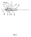
図1~図26は、本開示に係る医療器具の第1の実施形態を示す。この医療器具は、胃腸管に沿った血管を止血するためのクランプを設けるために用いられ、クランプは、内視鏡により標的部位に送達される。 Figures 1-26 show a first embodiment of a medical device according to the present disclosure. The medical device is used to provide a clamp for hemostasis in a blood vessel along the gastrointestinal tract, and the clamp is delivered to a target site by an endoscope.
この医療器具は、ハンドル1と、ハンドル1に取付けられたシース装置2と、シース装置2の遠位端に設けられたクランプ装置3と、を含む。制御線4は、シース装置2を貫通して延在し、その近位端ではアクチュエータ5に接続され、アクチュエータ5は、ハンドル1にスライド可能に保持され、アクチュエータを作動させることで制御線4を遠位側方向及び近位側方向に可逆的に移動させることができる。アクチュエータ5及びハンドル1は、制御線4がシース装置2に対してその長手方向の軸線を中心に回転することができるように設計される。
This medical instrument includes a
クランプ装置3は、クランプケース6を含み、このクランプケース6は、スリーブとして形成されたクランプベース7と、それぞれ制御線4の遠位端に接続された2つのクランプアーム8a、8bと、を有する。具体的には、2つのクランプアーム8a、8bは、管状の枢動ピン(pivot pin)9によって制御線4に接続される別個の素子/部材である。このために、枢動ピン9は、クランプアーム8a、8bの近位端部(proximal end section)に設けられた対応する貫通孔10を貫通して延在し、制御線4の遠位端に形成されたカップリングヘッド11によって着脱可能に保持される。
The
2つのクランプアーム8a、8bは、制御線4の遠位端に接続され、枢動ピン9によって形成された共通の枢動軸線を中心に回動して開閉することができる。各クランプアーム8a、8bには、ガイド溝12が設けられており、クランプアーム8a、8bのガイド溝12は、互いに部分的に重なっている。各ガイド溝12は、近位側の湾曲部(proximal curved section)12a及び遠位側の直線部(distal straight section)12bを含む。クランプ装置3は、クランプケース6に取付けられ、ガイド溝12の重なり部を貫通するガイドピン13をさらに含み、ガイドピン13とガイド溝12との係合により、制御線4の近位側方向への移動は、クランプアーム8a、8bの閉動作に変換され、制御線4の遠位側方向への移動は、クランプアーム8a、8bの枢動軸線を中心とする開動作に変換される。本実施形態では、ガイドピン13は、クランプベース7から遠位側方向に延在して二股構造を形成するクランプケース6の2つの支持アーム14a、14bの間に保持され、クランプアーム8a、8bは、これらの支持アーム14a、14bの間に配置される。クランプケース6は、クランプベース7に形成された中心通路開口15と支持アーム14a、14bとの間の空間によって限定される内部空間を有する。
The two
クランプケース6の内面には、クランプケース6の長手方向に延在し、枢動ピン9の端部が係合するように互いに対向して配置された2つのスライド溝16が設けられている。スライド溝16は、矩形の断面を有する。
The inner surface of the
図12~図15に示すように、クランプアーム8a、8bを閉状態でロックするために、クランプケース6には、2つのロック突部17が設けられている。ロック突部17は、それぞれのスライド溝16の底部からスライド溝16内に突出し、且つそれぞれのスライド溝16の全幅に亘って延在している。ロック突部17は、クランプアーム8a、8bを閉状態でロックするために、枢動ピン9の近位側方向への通過は許容されるが、枢動ピン9の遠位側方向への通過は阻止されるように設計される。このために、各ロック突部17は、その遠位側にクランプベース7の長手方向Xに対して45°の傾斜角度を有する傾斜面18を有し、その近位側に長手方向Xに対して垂直に延在する垂直面19を有する。
As shown in Figs. 12 to 15, the
この医療器具は、クランプアーム8a、8bが閉状態でロックされ、制御線4がさらに近位側方向へ引っ張られるときにクランプアーム8a、8bと制御線4との係合の解除を許容する解除装置をさらに含む。
The medical device further includes a release device that allows the
このために、カップリングヘッド11は、クランプアーム8a、8bの横方向の対向両側に配置される2対の保持アーム20a、20bを含む二股状の保持構造を有する。保持アーム20a、20bは、例えば図4~図11に示す固定位置と、例えば図12~図15に示す解除位置との間で移動可能である。固定位置では、保持アーム20a、20bが枢動ピン9を囲んで枢動ピン9をフォームフィット方式で保持する。具体的には、保持アーム20a、20bの互いに対向する面には、半円状の断面を有する凹部21が形成されている。枢動ピン9は、保持アーム20a、20bの固定位置においてこれらの凹部21内に保持される。解除位置では、保持アーム20a、20bが互いに離れて枢動ピン9を開放させる。保持アーム20a、20bは、解除位置に向かって付勢されている。特に図2及び図3に示すように、カップリングヘッド11は、2対の保持アームを形成するシート部材11aと、押出管11bとにより形成され、シート部材11aの近位部は、当該押出管11bを介して制御線4に接続される。
For this purpose, the
クランプケース6の内側輪郭と保持アーム20a、20bとの協働により、保持アーム20a、20bがクランプケース6の遠位部に移動するに従って、保持アーム20a、20bが互いに向かって固定位置に押圧される。クランプケース6の内部輪郭は、各対の保持アーム20a、20bに割り当てられる保持溝22を含み、この保持溝22は、クランプケース6の遠位端に向かって開口する。したがって、合計2つの矩形の断面を有する保持溝22は、クランプケース6の内部空間の対向両側に位置する。保持溝22は、保持アーム20a、20bが保持溝22内に移動するに従って、保持アーム20bが側壁に当接されてその復元力を抗して固定位置へ押圧されるように、その側壁の間に保持アーム20a、20bが受容される。
The cooperation of the inner contour of the
保持溝22は、保持溝22と比較して拡大された開口寸法を有するクランプケース6の近位側拡大部23まで延在する。実質的に矩形の断面を有する近位側拡大部23と保持溝22との間の過度は、段差部24として形成される。近位側拡大部23は、中心通路開口15及び支持アーム14a、14bの近位部まで延在する。従って、保持アーム20a、20bは、制御線4が近位側方向に引っ張られて保持アーム20a、20bが近位側拡大部23に到達したときに、それらの復元力によって自動的に解除位置に戻る。
The retaining
段差部24は、カップリングヘッド11の保持アーム20a、20bが近位側拡大部23に到達して解除位置に戻る前に、枢動ピン9がロック突部17を通過するように、ロック突部17に対して配置される。具体的には、段差部24は、ロック突部17の遠位側に配置されている。従って、ガイドピン13がガイド溝12の直線部12bの遠位端に到達する前に、保持アーム20a、20bは、それらの解除位置に戻る。
The
シース装置2は、ハンドル1に接続されたコイル状シース25と、シース25の遠位端に固定的に接続された接続管26と、を含み、シース25と接続管26とは、溶接により分離不可能なユニットを形成する。
The
クランプケース6は、クランプケース6が接続管26に対して長手方向の軸線を中心に回転可能であるように、接続管26に直接且つ着脱可能に接続される。具体的には、この接続は、押し込み式接続により実現され、それにより接続管26とクランプケース6との重なり部27が形成される。図1~図26に示す実施形態では、クランプケース6は、クランプケース6が内部素子を形成し、接続管26が外部素子を形成するように接続管26内に押し込まれる。クランプケース6の重なり部27には、2つの貫通孔28が形成され、接続管26の重なり部27には、内側を向く対応する環状溝29が形成される。
The clamping
クランプケース6をシース装置2に接続し、クランプケース6をシース装置2の接続管26に対して回動させることができるようにするために、貫通孔28を貫通して環状溝29に係合する1つの接続素子30が設けられている。具体的には、接続素子30は、中心開口部32を有する円板状の近位側の主部31を含む。制御線4は、この中心開口部32を貫通する。周方向に互いに対向して配置された2つの接続アーム33は、主部31から遠位側へ延在し、接続アーム33の遠位端には、係合部34が形成されており、この係合部34は、径方向に外側に延在して貫通孔28を貫通して環状溝29内に係合する。さらに、接続素子30は、主部31から遠位側へ延在する2つのガイドアーム35を含む。ガイドアーム35は、周方向上で接続アーム33の間に配置されている。
In order to connect the
接続素子30と協働する解放装置が設けられており、クランプアーム8a、8bが閉となりかつ制御線4がクランプ装置3から接続が解除されたとき、この解放装置は、接続素子30の接続管26の環状溝29との係合が解除されるように、制御線4を近位側方向に移動させることにより作動されることができる。具体的には、解放装置は、制御線4を囲んで接続素子30と制御線4のカップリングヘッド11との間に配置される中心管36を含む。
A release device is provided which cooperates with the
中心管36は、接続素子30の主部31に押し付けるように設計される。従って、中心管36は、制御線4が近位側方向に移動してクランプアーム8a、8bが閉となったときに、接続素子30を近位側方向に押すことができる。このようにして、係合部34は、接続管26に形成された環状溝29との係合を解除することができ、それにより、図13に例示したように、クランプケース6が接続管26から解放される。
The
使用時には、内視鏡によってクランプ装置3を標的部位に送達して、標的部位の所定の位置でクランプ装置3を血管に固定する。このために、制御線4をシース装置2に対して回転させることにより、クランプ装置3をシース装置2に対して回転させることができる。血管をクランプするために、アクチュエータ5で制御線4を遠位側方向及び近位側方向に移動させることにより、クランプアーム8a、8bを繰り返し開閉することができる。
In use, the
クランプアーム8a、8bの間に位置する組織の把持を改善し、患者の体内の組織に固定されたときにクランプ装置3の緩むリスクを最小限にするために、各クランプアーム8a、8bは、クランプアーム8a、8bの横方向に対向両側の把持部38に配置された2つのバーブ37a、37b、37c、37dを含む。バーブ37a、37b、37c、37dは、各バーブが他方のクランプアーム8a、8bの対応する反対側のバーブを向くように形成される。例えば、図24から、クランプアーム8bが、他方のクランプアーム8aを向く2つのバーブ37c、37dを含むことが分かる。バーブ37cは、V字形突起39の形状を呈するクランプ輪郭を含み、バーブ37dは、V字形の突起39と相補的なV字形凹部40の形状を呈するクランプ輪郭を含む。クランプアーム8aのバーブ37aは、V字形凹部40を有し、バーブ37bは、V字形の突起39を有し、それぞれが他方のクランプアーム8bに対応するバーブ37c、37dと相補的である。クランプアーム8a、8bの間に挟まれた血管の意図しない損傷を回避するために、V字形突起39の角とV字形凹部40の角とは、丸みを帯びている。また、バーブ37a、37b、37c、37dの近傍には、丸み付き凹口41が設けられている。
To improve the gripping of the tissue located between the clamping
各クランプアーム8a、8bの把持部38の遠位端は、他方のクランプアーム8a、8bに向かって内側に曲げられている。各クランプアーム8a、8bの遠位端には、係合輪郭42(本例では、ジグザグ状の輪郭)が形成されている。クランプアーム8a、8bの係合輪郭42は、クランプアーム8a、8bが閉となったときに互いに噛合されるように、互いに相補的である。
The distal end of the gripping
クランプ装置3がセットされると、クランプアーム8a、8bが閉状態でロックされる。このために、制御線4が近位側方向に引っ張られて、スライド溝16に係合されている枢動ピン9がロック突部17を通過して弾性変形される。枢動ピン9がロック突部17を通過するとき、長手方向Xに垂直に延在する面19により、この枢動ピン9は、遠位側方向には再び通過することができなくなる。このようにして、クランプアーム8a、8bが意図せずに再び開となるのを防止することができる。
When the
次のステップとして、クランプアーム8a、8bの制御線4との接続を解除する。このために、保持アーム20a、20bがクランプケース6の近位側拡大部23に到達するように、制御線4をさらに近位側方向に引っ張る。弾性復元力により保持アーム20a、20bが展開して、枢動ピン9を保持アーム20a、20bに形成された凹部21から解放させる。
The next step is to disconnect the
クランプケース6をシース装置2から分離/解放するには、制御線4をさらに近位側方向に引き戻す。これにより、中心管36が制御線4のカップリングヘッド11と接続素子30との間で押圧されるため、接続素子30が近位側方向に押圧される。このようにして、接続アーム33に形成された係合部34が接続管26の環状溝29及びクランプケース6の貫通孔28から係合が解除され、それによりクランプケース6がシース装置2の接続管26から解放される。
To separate/release the
図27及び28は、本開示に係る医療器具の第2の実施形態を示す。 Figures 27 and 28 show a second embodiment of a medical device according to the present disclosure.
この医療器具は、図1~図26に開示された医療器具と非常に類似しており、この実施形態と異なるのは、クランプケース6がシース25の遠位端に固定接続された接続管26に押し込まれず、逆に、外側素子を形成するクランプケース6が接続管26に押し込まれて内側素子を形成する点のみである。従って、接続管26には、互いに対向して配置された2つの貫通孔28が形成され、クランプケース6には、内側を向く環状溝29が形成される。
This medical device is very similar to the medical device disclosed in Figures 1 to 26, and differs from this embodiment only in that the
その結果、図1~図26に示す実施形態における接続素子と実質的に同一に形成された接続素子30は、その接続アーム33の係合部34が接続管26の貫通孔28を貫通してクランプケース6の環状溝29に係合される。このようにして、クランプケース6は、制御線4を回転させることによって、シース装置に対して回転することができる。
As a result, the
図29及び図30は、本開示に係る医療器具の第3の実施形態を示す。この医療器具は、図1~図26に開示された医療器具と非常に類似しているが、接続素子30は、図1~図26の医療器具における接続素子とは異なる。接続素子30は、中心開口部32と半径方向外側に突出する2つの接続アーム33とを有する平面円板として形成される。図29に示すように、接続アーム33は、円板と同一平面上に配置され、クランプケース6に形成された貫通孔28を貫通して接続管26に形成された環状溝29に係合される。
29 and 30 show a third embodiment of the medical device according to the present disclosure. This medical device is very similar to the medical device disclosed in FIGS. 1 to 26, but the
クランプケース6を接続管26から解放するために、接続素子30は、制御線4のカップリングヘッド11により近位側方向に押圧され、それにより接続素子30が変形して、接続アーム33の環状溝29との係合が解除される。
To release the
図31及び32は、本開示に係る医療器具のもう1つの実施形態を示す。 Figures 31 and 32 show another embodiment of a medical device according to the present disclosure.
この医療器具は、以上で説明したものとほぼ同じである。しかしながら、シース装置2は、クランプケース6の対向両側に位置決めされた弾性接続アームの形態の2つの接続素子30によりクランプケース6に接続される。具体的には、接続素子30の遠位端は、クランプケース6に固定的に取付けられ、接続素子30の自由端としの近位端は、クランプケース6をシース装置2に接続させるために接続管26の内周面に設けられた対応する係合手段と係合する係合部34を形成する。ここで、クランプケース6は、クランプケース6の近位端が接続管26の遠位端に挿入されて延長する押込み式の接続によってシース装置2に接続される。接続管26の重なり部において、互いに対向して配置されている貫通孔28は、クランプケース6に形成されており、対応する環状溝29は、接続管26に形成されている。接続素子30の係合部34がクランプケース6の貫通孔28を貫通して接続管26の環状溝29に挿入されることにより、クランプケース6がシース装置2に接続される。
This medical device is substantially the same as that described above. However, the
接続素子30は、内側に膨出された内向き膨出部を有する。また、接続素子30の遠位端は、クランプケース6に設けられた対応する保持孔43内に径方向外側に延在し、溶接によって、好ましくはスポット溶接によって、保持孔43内に固定される。接続素子30は、接続素子30の遠位端に続く直線部44をさらに有し、この直線部44は、クランプケースの中心長手方向の軸線に対して内側に5°の傾斜角度で傾斜する。直線部44と接続素子30の係合部34との間において、接続素子30の近位端に内向き膨出部45が設けられている。
The
クランプケース6と接続管26との接続を解除する解除装置が設けられる。この解除装置は、制御線4の遠位端に設けられたカップリングヘッド11により形成された突起46を含む。突起46は、内向き膨出部45の間に位置し、接続素子30の内向き膨出部45との協働により内向き膨出部45が外側に弾性変形されるように接続素子30の自由端を押圧する。制御線4が近位側に引っ張られて突起46と接続素子30との協働が解除されると、内向き膨出部45は、弾性復元力により内側に弾性変形して元の形状に復元され、係合部34は、接続管26に形成された環状溝29から係合が解除される。
A release device is provided to release the connection between the
1 ハンドル
2 シース装置
3 クランプ装置
4 制御線
5 アクチュエータ
6 クランプケース
7 クランプベース
8a、8b クランプアーム
9 枢動ピン
10 貫通孔
11 カップリングヘッド
11a シート状部材
11b 押圧管
12 ガイド溝
12a 湾曲部
12b 直線部
13 ガイドピン
14a、14b 支持アーム
15 中心通路開口
16 スライド溝
17 ロック突部
18 傾斜面
19 面
20a、20b 保持アーム
21 凹部
22 保持溝
23 近位側拡大部
24 段差部
25 シース
26 接続管
27 重なり部分
28 貫通孔
29 環状溝
30 接続部材
31 主部
32 中心開口部
33 接続アーム
34 係合部
35 ガイドアーム
36 中心管
37a~d バーブ
38 把持部
39 V字状突起
40 V字状凹部
41 丸み付き凹口
42 係合輪郭
43 保持孔
44 直線部
45 内向き膨出部
46 突起
X 長手方向
LIST OF
クランプケース6と接続管26との接続を解除する解除装置が設けられる。この解除装置は、制御線4の遠位端に設けられたカップリングヘッド11により形成された突起を含む。突起は、内向き膨出部45の間に位置し、接続素子30の内向き膨出部45との協働により内向き膨出部45が外側に弾性変形されるように接続素子30の自由端を押圧する。制御線4が近位側に引っ張られて突起と接続素子30との協働が解除されると、内向き膨出部45は、弾性復元力により内側に弾性変形して元の形状に復元され、係合部34は、接続管26に形成された環状溝29から係合が解除される。
A release device is provided for releasing the connection between the
1 ハンドル
2 シース装置
3 クランプ装置
4 制御線
5 アクチュエータ
6 クランプケース
7 クランプベース
8a、8b クランプアーム
9 枢動ピン
10 貫通孔
11 カップリングヘッド
11a シート状部材
11b 押圧管
12 ガイド溝
12a 湾曲部
12b 直線部
13 ガイドピン
14a、14b 支持アーム
15 中心通路開口
16 スライド溝
17 ロック突部
18 傾斜面
19 面
20a、20b 保持アーム
21 凹部
22 保持溝
23 近位側拡大部
24 段差部
25 シース
26 接続管
27 重なり部分
28 貫通孔
29 環状溝
30 接続部材
31 主部
32 中心開口部
33 接続アーム
34 係合部
35 ガイドアーム
36 中心管
37a~d バーブ
38 把持部
39 V字状突起
40 V字状凹部
41 丸み付き凹口
42 係合輪郭
43 保持孔
44 直線部
45 内向き膨出部
X 長手方向
LIST OF
X Longitudinal direction
Claims (11)
前記ハンドル(1)に取付けられたシース装置(2)と、
前記シース装置(2)の遠位端に設けられたクランプケース(6)と、少なくとも2つの、具体的に2つのクランプアーム(8a、8b)と、を含むクランプ装置(3)と、
前記シース装置(2)を貫通して延在し、遠位側方向及び近位側方向に可逆的に移動可能な制御線(4)と、
前記制御線(4)の近位端に接続され、前記制御線(4)が前記遠位側方向及び近位側方向に可逆的に移動するように動作可能なアクチュエータ(5)と、を含み、
前記クランプアーム(8a、8b)は、それぞれ前記制御線(4)の遠位端に接続され、前記クランプ装置(3)は、前記制御線(4)の移動により前記クランプアーム(8a、8b)が開閉するように動作可能であり、前記制御線(4)の近位側方向への移動は、前記クランプアーム(8a、8b)の閉動作に変換され、前記制御線(4)の遠位側方向への移動は、前記クランプアーム(8a、8b)の開動作に変換され、
前記シース装置(2)は、好ましくは伸縮可能なコイル状シース(25)であるシース(25)と、長手方向の軸線を限定し、前記シース(25)の遠位端に固定的に接続された接続管(26)と、を含み、
前記クランプケース(6)は、前記接続管(26)に対して前記長手方向の軸線を中心に回転できるように、前記接続管(26)に直接且つ解放可能に接続される、ことを特徴とする血管止血用の医療器具。 A handle (1);
a sheath device (2) attached to the handle (1);
a clamping device (3) including a clamp case (6) provided at the distal end of the sheath device (2) and at least two, specifically two, clamping arms (8a, 8b);
a control line (4) extending through the sheath device (2) and reversibly movable in a distal direction and a proximal direction;
an actuator (5) connected to a proximal end of the control line (4) and operable to reversibly move the control line (4) in the distal and proximal directions;
the clamping arms (8a, 8b) are each connected to a distal end of the control line (4), and the clamping device (3) is operable such that movement of the control line (4) causes the clamping arms (8a, 8b) to open and close, such that movement of the control line (4) in a proximal direction is translated into a closing movement of the clamping arms (8a, 8b) and movement of the control line (4) in a distal direction is translated into an opening movement of the clamping arms (8a, 8b);
The sheath device (2) includes a sheath (25), preferably an expandable coiled sheath (25), and a connecting tube (26) defining a longitudinal axis and fixedly connected to a distal end of the sheath (25);
A medical device for vascular hemostasis, characterized in that the clamp case (6) is directly and releasably connected to the connecting tube (26) so as to be rotatable about the longitudinal axis relative to the connecting tube (26).
内部素子としての前記クランプケース(6)が外部素子としての前記接続管(26)内に押し込まれるか、又は、内部素子としての前記接続管(26)が外部素子としての前記クランプケース(6)内に押し込まれ、
前記内部素子の前記重なり部(27)には、周方向に角度オフセットして設けられた少なくとも2つの貫通孔(28)が形成されており、前記外部素子の前記重なり部(27)には、内向きの環状溝(29)が形成されており、
前記クランプケース(6)を前記シース装置(2)に、前記接続管(26)に対して回転可能に接続するために、前記内部素子の少なくとも1つの貫通孔(28)を貫通して前記外部素子の前記環状溝(29)に係合する少なくとも1つの接続素子(30)が設けられている、ことを特徴とする請求項1に記載の医療器具。 The clamp case (6) and the connecting pipe (26) are connected to each other by a push-in connection, and an overlapping portion (27) between the connecting pipe (26) and the clamp case (6) is formed;
The clamp case (6) as an internal element is pushed into the connecting tube (26) as an external element, or the connecting tube (26) as an internal element is pushed into the clamp case (6) as an external element;
The overlapping portion (27) of the inner element has at least two through holes (28) that are angularly offset in the circumferential direction, and the overlapping portion (27) of the outer element has an inwardly directed annular groove (29);
2. The medical device according to claim 1, characterized in that at least one connecting element (30) is provided which passes through at least one through hole (28) of the inner element and engages with the annular groove (29) of the outer element to rotatably connect the clamp case (6) to the sheath device (2) relative to the connecting tube (26).
前記クランプアーム(8a、8b)が閉となって特に前記制御線(4)の前記クランプ装置(3)との係合が解除されたときに、前記解放装置は、前記制御線(4)を前記近位側方向に移動させることにより動作可能であり、それにより前記接続素子(30)の前記外部素子の前記環状溝(29)との係合が解除されて前記クランプケース(6)が前記シース装置(2)から解放される、ことを特徴とする請求項2に記載の医療器具。 A release device is provided which cooperates with each connection element (30);
3. The medical instrument according to claim 2, characterized in that, when the clamp arms (8a, 8b) are closed and in particular the control line (4) is disengaged from the clamp device (3), the release device is operable by moving the control line (4) in the proximal direction, whereby the connection element (30) is disengaged from the annular groove (29) of the outer element and the clamp case (6) is released from the sheath device (2).
前記制御線(4)が前記近位側方向に移動して前記クランプアーム(8a、8b)が閉となったときに、前記中間管(36)は、前記接続素子(30)の、前記外部素子に形成された前記環状溝(29)との係合が解除されるように、前記接続素子(30)を前記近位側方向に押して、前記クランプケース(6)を前記接続管(26)から解放する、ことを特徴とする請求項5又は6に記載の医療器具。 the release device includes an intermediate tube (36) surrounding the control line (4) and disposed between the connection element (30) and a connection head (11) formed at the distal end of the control line (4);
7. The medical device according to claim 5 or 6, characterized in that, when the control line (4) is moved in the proximal direction to close the clamp arms (8a, 8b), the intermediate tube (36) pushes the connection element (30) in the proximal direction so as to disengage the connection element (30) from the annular groove (29) formed in the outer element, thereby releasing the clamp case (6) from the connection tube (26).
前記接続素子(30)の遠位端は、前記クランプケース(6)に固定的に取付けられ、
前記接続素子(30)の自由端としての近位端は、係合部(34)を形成し、各係合部は、前記内部素子に形成された対応する貫通孔(28)を貫通して前記外部素子に形成された前記環状溝(29)に係合される、ことを特徴とする請求項3に記載の医療器具。 At least two, in particular two, connecting elements (30) are provided in the form of elastically deformable connecting arms (33),
A distal end of the connecting element (30) is fixedly attached to the clamp case (6);
The medical device according to claim 3, characterized in that the proximal end as a free end of the connecting element (30) forms an engagement portion (34), each of which is engaged with the annular groove (29) formed in the outer element through a corresponding through hole (28) formed in the inner element.
前記突起(46)は、前記制御線(4)に接続され、特に前記制御線(4)に固定的に設けられ、
前記クランプアーム(8a、8b)が閉となった後に前記制御線(4)が近位側方向にさらに移動すると、前記突起(46)が前記制御線(4)と共に移動して前記接続素子(30)との係合が解除され、これにより、前記接続素子(30)がその弾性復元力により径方向内側に変形されて、前記接続素子(30)の前記係合部(34)の、前記外部素子の対応する環状溝(29)との係合が解除されて前記クランプケース(6)が前記シース装置(2)から解放される、ことを特徴とする請求項8に記載の医療器具。 the release device is disposed within the connection element (30) and includes a protrusion (46) cooperating with the connection element (30), and the protrusion presses against the connection element (30) to elastically deform it radially outward, whereby the engagement portion (34) of the connection element (30) is pushed radially outward to engage with the corresponding through hole (28) and the annular groove (29);
The protrusion (46) is connected to the control line (4), in particular fixedly attached to the control line (4);
9. The medical device according to claim 8, characterized in that when the control wire (4) is further moved in the proximal direction after the clamp arms (8a, 8b) are closed, the protrusion (46) moves together with the control wire (4) and disengages from the connection element (30), whereby the connection element (30) is deformed radially inward due to its elastic restoring force, and the engagement portion (34) of the connection element (30) is disengaged from the corresponding annular groove (29) of the outer element, thereby releasing the clamp case (6) from the sheath device (2).
Applications Claiming Priority (1)
| Application Number | Priority Date | Filing Date | Title |
|---|---|---|---|
| PCT/CN2022/078089 WO2023159520A1 (en) | 2022-02-25 | 2022-02-25 | Medical device for causing hemostasis of blood vessel |
Publications (1)
| Publication Number | Publication Date |
|---|---|
| JP3249585U true JP3249585U (en) | 2024-12-25 |
Family
ID=87764315
Family Applications (1)
| Application Number | Title | Priority Date | Filing Date |
|---|---|---|---|
| JP2024600134U Active JP3249585U (en) | 2022-02-25 | 2022-02-25 | Medical devices for vascular hemostasis |
Country Status (6)
| Country | Link |
|---|---|
| US (1) | US20250025182A1 (en) |
| JP (1) | JP3249585U (en) |
| CN (1) | CN223095581U (en) |
| DE (1) | DE212022000341U1 (en) |
| ES (1) | ES1319136Y (en) |
| WO (1) | WO2023159520A1 (en) |
Family Cites Families (10)
| Publication number | Priority date | Publication date | Assignee | Title |
|---|---|---|---|---|
| US7094245B2 (en) | 2001-10-05 | 2006-08-22 | Scimed Life Systems, Inc. | Device and method for through the scope endoscopic hemostatic clipping |
| US11116531B2 (en) * | 2016-11-16 | 2021-09-14 | Cilag Gmbh International | Surgical instrument with removable clamp arm assembly |
| CN110638489B (en) * | 2018-06-26 | 2021-06-11 | 杭州唯强医疗科技有限公司 | Quick release implant pusher and implant delivery system |
| CN109805977B (en) * | 2019-03-21 | 2024-03-05 | 南微医学科技股份有限公司 | Medical hemostatic clamp |
| EP3725244A1 (en) * | 2019-04-17 | 2020-10-21 | Micro-Tech (Nanjing) Co., Ltd. | Medical device for causing the hemostasis of a blood vessel |
| US12167857B2 (en) * | 2019-04-17 | 2024-12-17 | Micro-Tech (Nanjing) Co., Ltd. | Clamp device for hemostasis or closure of tissue and medical instrument for hemostasis or closure of tissue |
| EP3725242B1 (en) * | 2019-04-17 | 2023-11-29 | Micro-Tech (Nanjing) Co., Ltd. | Medical device for causing the hemostasis of a blood vessel |
| EP3763298B1 (en) * | 2019-07-10 | 2023-11-29 | Micro-Tech (Nanjing) Co., Ltd. | Medical device for causing the hemostasis of a blood vessel |
| KR102688422B1 (en) * | 2019-07-29 | 2024-07-29 | 보스톤 싸이엔티픽 싸이메드 인코포레이티드 | tissue clipping device |
| WO2021087461A2 (en) * | 2019-11-01 | 2021-05-06 | Michael Barenboym | Devices and methods for applying a hemostatic clip assembly |
-
2022
- 2022-02-25 JP JP2024600134U patent/JP3249585U/en active Active
- 2022-02-25 CN CN202290000808.8U patent/CN223095581U/en active Active
- 2022-02-25 DE DE212022000341.1U patent/DE212022000341U1/en active Active
- 2022-02-25 WO PCT/CN2022/078089 patent/WO2023159520A1/en not_active Ceased
- 2022-02-25 ES ES202450003U patent/ES1319136Y/en active Active
- 2022-02-25 US US18/714,380 patent/US20250025182A1/en active Pending
Also Published As
| Publication number | Publication date |
|---|---|
| CN223095581U (en) | 2025-07-15 |
| US20250025182A1 (en) | 2025-01-23 |
| ES1319136U (en) | 2025-06-04 |
| WO2023159520A1 (en) | 2023-08-31 |
| DE212022000341U1 (en) | 2024-08-07 |
| ES1319136Y (en) | 2025-08-27 |
Similar Documents
| Publication | Publication Date | Title |
|---|---|---|
| JP7268190B2 (en) | Medical devices for tissue hemostasis or tissue closure | |
| CN113784670B (en) | Medical devices used to stop bleeding or seal tissue | |
| CA2654004C (en) | Release mechanisms for a clip device | |
| US8152822B2 (en) | Combination therapy hemostatic clip | |
| CN217853157U (en) | Clamping devices and medical devices for hemostasis or closure of tissue | |
| JP3249585U (en) | Medical devices for vascular hemostasis | |
| JP3250413U (en) | Medical devices for vascular hemostasis | |
| CN216876472U (en) | Medical device for tissue hemostasis or closure | |
| WO2023159521A1 (en) | Medical device for causing hemostasis of blood vessel |
Legal Events
| Date | Code | Title | Description |
|---|---|---|---|
| A521 | Request for written amendment filed |
Free format text: JAPANESE INTERMEDIATE CODE: A523 Effective date: 20240731 |
|
| R150 | Certificate of patent or registration of utility model |
Ref document number: 3249585 Country of ref document: JP Free format text: JAPANESE INTERMEDIATE CODE: R150 |