JP3236998U - Folding container - Google Patents
Folding container Download PDFInfo
- Publication number
- JP3236998U JP3236998U JP2022000342U JP2022000342U JP3236998U JP 3236998 U JP3236998 U JP 3236998U JP 2022000342 U JP2022000342 U JP 2022000342U JP 2022000342 U JP2022000342 U JP 2022000342U JP 3236998 U JP3236998 U JP 3236998U
- Authority
- JP
- Japan
- Prior art keywords
- side wall
- container
- folding container
- lower frame
- main body
- Prior art date
- Legal status (The legal status is an assumption and is not a legal conclusion. Google has not performed a legal analysis and makes no representation as to the accuracy of the status listed.)
- Active
Links
- 238000010586 diagram Methods 0.000 abstract 1
- 210000000078 claw Anatomy 0.000 description 6
- 230000002093 peripheral effect Effects 0.000 description 6
- 238000000034 method Methods 0.000 description 2
- 239000004033 plastic Substances 0.000 description 2
- 239000000919 ceramic Substances 0.000 description 1
- 239000000463 material Substances 0.000 description 1
- 239000002184 metal Substances 0.000 description 1
- 239000011347 resin Substances 0.000 description 1
- 229920005989 resin Polymers 0.000 description 1
- 239000002023 wood Substances 0.000 description 1
Images


Landscapes
- Rigid Containers With Two Or More Constituent Elements (AREA)
Abstract
【課題】側壁が容易に外側に倒れることのない折り畳みコンテナを提供する。【解決手段】四角形状の下枠10の四辺に、一対の第1の側壁11と一対の第2の側壁12をヒンジ13で折り畳み自在に結合したコンテナ本体2と、四角形状の底板25の四辺に支持側壁26を取り付けた、下枠10が挿入される外枠本体3を備え、第1の側壁11と第2の側壁12を底板25の上に重ねて折畳んだ状態では、第1の側壁11と第2の側壁12が外枠本体3の内部に収納され、第1の側壁11と第2の側壁12を立ち上げた状態では、第1の側壁11と第2の側壁12の外面の下方部分が、支持側壁26の内面に密着されることを特徴とする、折り畳みコンテナ1である。【選択図】図1PROBLEM TO BE SOLVED: To provide a folding container in which a side wall does not easily fall outward. SOLUTION: A container main body 2 in which a pair of first side walls 11 and a pair of second side walls 12 are foldably connected by hinges 13 to four sides of a square lower frame 10, and four sides of a square bottom plate 25. The outer frame main body 3 into which the lower frame 10 is inserted is provided, and the first side wall 11 and the second side wall 12 are overlapped on the bottom plate 25 and folded. When the side wall 11 and the second side wall 12 are housed inside the outer frame main body 3 and the first side wall 11 and the second side wall 12 are raised, the outer surfaces of the first side wall 11 and the second side wall 12 are raised. The folding container 1 is characterized in that the lower portion of the support side wall 26 is in close contact with the inner surface of the support side wall 26. [Selection diagram] Fig. 1
Description
本考案は、物品の保管や運搬などに使用される折り畳みコンテナに関する。 The present invention relates to a folding container used for storing and transporting goods.
従来、折り畳みコンテナに関し、種々のものが提案されており、例えば特許文1には、方形状の底壁の四辺に一対の第1側壁と、一対の第2側壁をヒンジで折り畳み自在に結合した折畳み自在コンテナが開示されている。この折畳み自在コンテナは、折畳み状態では、底壁の上面に転倒された一対の第1側壁が重ねられ、その上に転倒された一対の第2側壁が重ねられるようになっている。また、組立て状態では、起立させた第2側壁の側縁部に対して、起立させた第1側壁の側縁部が接合されると共に、ロック手段により連結固定されるようになっている。
Conventionally, various folding containers have been proposed. For example, in
しかしながら、従来の折り畳みコンテナでは、ヒンジ結合された側壁が外側に倒れやすいという欠点があった。 However, the conventional folding container has a drawback that the hinged side wall tends to fall outward.
したがって、本考案の目的は、側壁が容易に外側に倒れることのない折り畳みコンテナを提供することになる。 Therefore, an object of the present invention is to provide a folding container in which the side wall does not easily fall outward.
上記課題を解決するために、本考案によれば、四角形状の下枠の四辺に、一対の第1の側壁と一対の第2の側壁をヒンジで折り畳み自在に結合したコンテナ本体と、四角形状の底板の四辺に支持側壁を取り付けた、下枠が挿入される外枠本体を備え、第1の側壁と第2の側壁を底板の上に重ねて折畳んだ状態では、第1の側壁と第2の側壁が外枠本体の内部に収納され、第1の側壁と第2の側壁を立ち上げた状態では、第1の側壁と第2の側壁の外面の下方部分が、支持側壁の内面に密着されることを特徴とする、折り畳みコンテナが提供される。 In order to solve the above problems, according to the present invention, a container body in which a pair of first side walls and a pair of second side walls are foldably connected by hinges to four sides of a square lower frame and a square shape. It has an outer frame body into which a lower frame is inserted, with support side walls attached to the four sides of the bottom plate, and when the first side wall and the second side wall are overlapped on the bottom plate and folded, the first side wall When the second side wall is housed inside the outer frame body and the first side wall and the second side wall are raised, the lower portion of the outer surface of the first side wall and the second side wall is the inner surface of the support side wall. Folding containers are provided, characterized by being in close contact with.
この折り畳みコンテナにおいて、第1の側壁と第2の側壁を立ち上げた状態で、第1の側壁と第2の側壁の側縁同士を係合させる係合機構を有していても良い。 In this folding container, an engaging mechanism may be provided in which the side edges of the first side wall and the second side wall are engaged with each other in a state where the first side wall and the second side wall are raised.
本考案によれば、側壁が外側に倒れることのない折り畳みコンテナを提供することができる。 According to the present invention, it is possible to provide a folding container in which the side wall does not fall outward.
以下、図面に基づいて本考案の実施の形態の一例を説明する。なお、本明細書において、実質的に同様の構成要素については、同じ符号を付すことにより、重複する説明を省略する。 Hereinafter, an example of an embodiment of the present invention will be described with reference to the drawings. In the present specification, substantially the same components are designated by the same reference numerals, and duplicate description will be omitted.
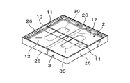
図1、2に示すように、本考案の実施の形態の折り畳みコンテナ1は、コンテナ本体2と外枠本体3を備えている。
As shown in FIGS. 1 and 2, the
コンテナ本体2は、四角形状(図示の形態では長方形状)を有する下枠10の四辺において、長方形の長辺にそれぞれ結合された一対の第1の側壁11と、長方形の短辺にそれぞれ結合された一対の第2の側壁12を備えている。これら第1の側壁11と第2の側壁12は、いずれも下枠10の上端に対して、ヒンジ13を介して折り畳み自在に結合されており、第1の側壁11と第2の側壁12は、下枠10の上方において、ヒンジ13を中心に回動させることが可能である。ヒンジ13は、下枠10に対して第1の側壁11と第2の側壁12を折り畳み自在に結合する可動部であり、図9、10に示すように、例えば薄いプラスチックの繋がり部分である。
The
下枠10の内面には、折り畳んだ一対の第1の側壁11を支えるためのストッパー15が、下枠10の内面から内側に突出して設けられている。図1、2に示すように、第1の側壁11を内側に折り畳んでストッパー15の上で支持することにより、下枠10の内方において第1の側壁11を水平の姿勢に保持することができる。第2の側壁12を下枠10に結合しているヒンジ13の位置は、第1の側壁11を下枠10に結合しているヒンジ13の位置よりも僅かに(第1の側壁11の厚さの分だけ)高くなっている。このため、図3に示すように、第2の側壁12を内側に折り畳んで、予め折り畳まれた第1の側壁11の上に乗せることにより、下枠10の内方において第1の側壁11の上に第2の側壁12を重ねて水平の姿勢に保持することができる。
On the inner surface of the
第1の側壁11の側縁と第2の側壁12の側縁には、第1の側壁11と第2の側壁12を垂直に立ち上げた状態で、第1の側壁11と第2の側壁の側縁同士を係合させる係合機構を有している。図示の形態では、係合機構は、第1の側壁11の側縁に設けられた突起20(図4、5、6、7に符号20を示す)と、第2の側壁12の側縁に設けられた受け孔21(図1、2、4、5、6、7に符号21を示す)および係合爪22(図2、4、5、6、8に符号22を示す)で構成されている。そして、図6に示すように、第1の側壁11と第2の側壁12を垂直に立ち上げた状態で、第1の側壁11の側縁に設けられた突起20を第2の側壁12の側縁に設けられた受け孔21に差し込み(図7に、突起20を第2の側壁12の側縁に設けられた受け孔21に差し込んだ状態を拡大して示す。)、さらに、第2の側壁12の側縁の内側を係合爪22で押さえることにより(図8に、第2の側壁12の側縁の内側を係合爪22で押さえだ状態を拡大して示す。)、第1の側壁11と第2の側壁12を垂直に立ち上げた状態で、第1の側壁11と第2の側壁の側縁同士を係合させることができる。
On the side edge of the
図1、2に示すように、外枠本体3は、四角形状(図示の形態では長方形状)を有する底板25の四辺に所定の高さの支持側壁26をそれぞれ取り付けた構成を有している。支持側壁26は、下枠10の外周面を囲む位置に配置されており、後述するように、外枠本体3の内部にコンテナ本体2を挿入すると、下枠10の外周面に支持側壁26の内周面がそれぞれ密着するようになっている。また、支持側壁26は、いずれも下枠10よりも高い高さを有している。
As shown in FIGS. 1 and 2, the outer frame
以上のように構成される本考案の実施の形態の折り畳みコンテナ1は、外枠本体3の内部に上からコンテナ本体2を挿入して使用される。先ず図3に示すように、外枠本体3の内部に上からコンテナ本体2を挿入し、コンテナ本体2の下枠10の下面が外枠本体3の底板25の上面に当接する位置まで、外枠本体3の内部にコンテナ本体2を押し込んで、外れないように一体化させる。
The
図3に示す折り畳んだ状態では、第1の側壁11はストッパー15の上で支持され、水平の姿勢で保持される。また、第2の側壁12は予め折り畳まれた第1の側壁11の上に乗った状態で、水平の姿勢に保持される。外枠本体3の支持側壁26は、コンテナ本体2の下枠10よりも高い高さを有しているので、折り畳まれた第1の側壁11と第2の側壁12は、いずれも外枠本体3の内部(支持側壁26で囲まれた内部)に収納されている。また、このように折り畳んだ状態において、受け孔21となる部分を格納するための隙間が形成されている。
In the folded state shown in FIG. 3, the
そして、コンテナを組み立てる場合は、先ず図4に示すように、一対の第2の側壁12を垂直に立ち上げる。この場合、第2の側壁12の外面の下方部分が外枠本体3の支持側壁26の内周面に密着するまで第2の側壁12を立ち上げることにより、第2の側壁12を垂直の姿勢にすることができる。
Then, when assembling the container, first, as shown in FIG. 4, the pair of
次に図5に示すように、第1の側壁11を徐々に立ち上げ、更に図6に示すように、第1の側壁11を垂直になるまで立ち上げる。この場合も、第1の側壁11の外面の下方部分が外枠本体3の支持側壁26の内周面に密着するまで第1の側壁11を立ち上げることにより、第1の側壁11を垂直の姿勢にすることができる。
Next, as shown in FIG. 5, the
そして、以上のように第1の側壁11と第2の側壁12を垂直に立ち上げた状態で、第1の側壁11と第2の側壁の側縁同士を係合機構により係合させる。すなわち、第1の側壁11と第2の側壁12を垂直に立ち上げた状態で、図7に示すように、第1の側壁11の側縁に設けられた突起20を第2の側壁12の側縁に設けられた受け孔21に差し込み、さらに、図8に示すように、第1の側壁11の側縁の内側を係合爪22で押さえることにより、第1の側壁11と第2の側壁の側縁同士を係合させる。
Then, with the
こうして、コンテナ(ボックス)状に組み立てられた本考案の実施の形態の折り畳みコンテナ1は、図9に示すように、第1の側壁11の外面の下方部分と第2の側壁12の外面の下方部分が外枠本体3の支持側壁26の内周面に密着した状態で垂直の姿勢に保持されるので、第1の側壁11と第2の側壁12が外側に倒れることを防止できる。
As shown in FIG. 9, the
なお、図示の実施の形態の折り畳みコンテナ1では、第1の側壁11に取っ手孔30が設けられている。この取っ手孔30を手で持つことにより、コンテナ状に組み立てられた折り畳みコンテナ1を容易に運搬することができる。
In the
また、折り畳みコンテナ1を折り畳む場合は、第1の側壁11の側縁の内側を係合爪22から取り外して、突起20を受け孔21から抜き去ることで、第1の側壁11と第2の側壁の側縁同士の係合を解除する。そして、第1の側壁11、第2の側壁12の順に内側に折り畳むことにより、図3に示すように、第1の側壁11と第2の側壁12を外枠本体3の内部に収納することができる。
Further, when folding the
以上、本考案の実施の形態の一例について説明したが、本発明はかかる例に限定されない。当業者であれば、実用新案登録請求の範囲に記載された技術的思想の範疇内において、各種の変更例または修正例に想到しうることは明らかであり、それらについても当然に本考案の技術的範囲に属するものと了解される。 Although an example of the embodiment of the present invention has been described above, the present invention is not limited to such an example. It is clear that a person skilled in the art can come up with various examples of changes or amendments within the scope of the technical idea described in the claims for utility model registration, and of course, the technique of the present invention is also used for these. It is understood that it belongs to the target range.
例えば、本考案の折り畳みコンテナは、例えば プラスチック、樹脂、木材、金属、セラミックス等種々の材料で構成することができる。また、ヒンジ13の構造は、図9に示すように下枠10と第1の側壁11、第2の側壁12の板厚中心位置にあっても良いし、図10(a)に示すように下枠10と第1の側壁11、第2の側壁12の内面側、あるいは、図10(b)に示すように下枠10と第1の側壁11、第2の側壁12の外面側にあっても良い。また、第1の側壁11に取っ手孔30を設けた例を示したが、第2の側壁12に取っ手孔30を設けても良いし、取っ手孔30を省略しても良い。また、図示の形態では、平面視で長方形状の折り畳みコンテナを示したが、平面視で正方形の折り畳みコンテナとしても良い。
For example, the folding container of the present invention can be made of various materials such as plastic, resin, wood, metal, and ceramics. Further, the structure of the
1 折り畳みコンテナ
2 コンテナ本体
3 外枠本体
10 下枠
11 第1の側壁
12 第2の側壁
13 ヒンジ
15 ストッパー
20 突起
21 孔
22 係合爪
25 底板
26 支持側壁
30 取っ手孔
1 Folding
Claims (2)
四角形状の底板の四辺に支持側壁を取り付けた、下枠が挿入される外枠本体を備え、
第1の側壁と第2の側壁を底板の上に重ねて折畳んだ状態では、第1の側壁と第2の側壁が外枠本体の内部に収納され、
第1の側壁と第2の側壁を立ち上げた状態では、第1の側壁と第2の側壁の外面の下方部分が、支持側壁の内面に密着されることを特徴とする、折り畳みコンテナ。 A container body in which a pair of first side walls and a pair of second side walls are foldably connected by hinges on the four sides of a square lower frame.
Equipped with an outer frame body into which the lower frame is inserted, with support side walls attached to the four sides of the square bottom plate.
In a state where the first side wall and the second side wall are overlapped on the bottom plate and folded, the first side wall and the second side wall are housed inside the outer frame main body.
A folding container characterized in that, in a state where the first side wall and the second side wall are raised, the lower portion of the outer surface of the first side wall and the second side wall is brought into close contact with the inner surface of the support side wall.
The first aspect of the invention, wherein the first side wall and the second side wall are raised, and the side edges of the first side wall and the second side wall are engaged with each other. Folding container.
Priority Applications (1)
| Application Number | Priority Date | Filing Date | Title |
|---|---|---|---|
| JP2022000342U JP3236998U (en) | 2022-02-07 | 2022-02-07 | Folding container |
Applications Claiming Priority (1)
| Application Number | Priority Date | Filing Date | Title |
|---|---|---|---|
| JP2022000342U JP3236998U (en) | 2022-02-07 | 2022-02-07 | Folding container |
Publications (1)
| Publication Number | Publication Date |
|---|---|
| JP3236998U true JP3236998U (en) | 2022-04-04 |
Family
ID=80948428
Family Applications (1)
| Application Number | Title | Priority Date | Filing Date |
|---|---|---|---|
| JP2022000342U Active JP3236998U (en) | 2022-02-07 | 2022-02-07 | Folding container |
Country Status (1)
| Country | Link |
|---|---|
| JP (1) | JP3236998U (en) |
-
2022
- 2022-02-07 JP JP2022000342U patent/JP3236998U/en active Active
Similar Documents
| Publication | Publication Date | Title |
|---|---|---|
| US3874546A (en) | Convertible container-pallet | |
| JPH05507257A (en) | container | |
| JP2001287738A (en) | Folding container | |
| JP3236998U (en) | Folding container | |
| JP2000255563A (en) | Folding type carrying container | |
| JP2594525B2 (en) | Foldable box | |
| JP5681927B2 (en) | Transport container | |
| JP3677440B2 (en) | Folding container | |
| JPH11147526A (en) | Collapsible container | |
| JP3008772U (en) | Foldable container | |
| JPS6318583Y2 (en) | ||
| JP4480347B2 (en) | Folding container | |
| JP4121517B2 (en) | Container stack structure | |
| JPH08318939A (en) | Foldable container | |
| JPH072413Y2 (en) | Stackable container | |
| JPH0516105Y2 (en) | ||
| JP4658240B2 (en) | Cardboard partition material | |
| JP2002059925A (en) | Foldable container | |
| JP2001287737A (en) | Folding container | |
| JP5410153B2 (en) | Folding container | |
| JP2003291964A (en) | Foldable container | |
| JP4317684B2 (en) | Folding container | |
| JP4261116B2 (en) | Folding container | |
| JPS594913Y2 (en) | collapsible container | |
| JPH0144429Y2 (en) |
Legal Events
| Date | Code | Title | Description |
|---|---|---|---|
| R150 | Certificate of patent or registration of utility model |
Ref document number: 3236998 Country of ref document: JP Free format text: JAPANESE INTERMEDIATE CODE: R150 |
|
| R250 | Receipt of annual fees |
Free format text: JAPANESE INTERMEDIATE CODE: R250 |