JP3205012U - Gasket for heat exchanger - Google Patents
Gasket for heat exchanger Download PDFInfo
- Publication number
- JP3205012U JP3205012U JP2016001764U JP2016001764U JP3205012U JP 3205012 U JP3205012 U JP 3205012U JP 2016001764 U JP2016001764 U JP 2016001764U JP 2016001764 U JP2016001764 U JP 2016001764U JP 3205012 U JP3205012 U JP 3205012U
- Authority
- JP
- Japan
- Prior art keywords
- gasket
- heat exchanger
- flange
- metal clip
- branch
- Prior art date
- Legal status (The legal status is an assumption and is not a legal conclusion. Google has not performed a legal analysis and makes no representation as to the accuracy of the status listed.)
- Expired - Fee Related
Links
- 239000002184 metal Substances 0.000 claims abstract description 44
- 229910052751 metal Inorganic materials 0.000 claims abstract description 44
- 238000006073 displacement reaction Methods 0.000 description 6
- 238000000034 method Methods 0.000 description 5
- 239000000463 material Substances 0.000 description 3
- 229910000838 Al alloy Inorganic materials 0.000 description 2
- 229910001369 Brass Inorganic materials 0.000 description 2
- RYGMFSIKBFXOCR-UHFFFAOYSA-N Copper Chemical compound [Cu] RYGMFSIKBFXOCR-UHFFFAOYSA-N 0.000 description 2
- ATJFFYVFTNAWJD-UHFFFAOYSA-N Tin Chemical compound [Sn] ATJFFYVFTNAWJD-UHFFFAOYSA-N 0.000 description 2
- 239000010951 brass Substances 0.000 description 2
- 229910052802 copper Inorganic materials 0.000 description 2
- 239000010949 copper Substances 0.000 description 2
- 238000007789 sealing Methods 0.000 description 2
- 239000010935 stainless steel Substances 0.000 description 2
- 229910001220 stainless steel Inorganic materials 0.000 description 2
- 239000011135 tin Substances 0.000 description 2
- 239000005028 tinplate Substances 0.000 description 2
- 239000000853 adhesive Substances 0.000 description 1
- 230000001070 adhesive effect Effects 0.000 description 1
- 238000010276 construction Methods 0.000 description 1
- 239000012530 fluid Substances 0.000 description 1
- 239000003779 heat-resistant material Substances 0.000 description 1
- 230000001771 impaired effect Effects 0.000 description 1
- 238000004519 manufacturing process Methods 0.000 description 1
- 238000005192 partition Methods 0.000 description 1
- 238000003466 welding Methods 0.000 description 1
Images


Landscapes
- Flanged Joints, Insulating Joints, And Other Joints (AREA)
Abstract
【課題】ガイド溝を形成させるための煩雑な加工を必要とせず、フランジとガスケットとの位置ずれを防止してガスケットをフランジに容易に固定することができる熱交換器用ガスケットを提供する。【解決手段】フランジに取り付けるための枝部2が配設されているガスケット本体1および金属クリップ3を有する熱交換器用ガスケットであって、枝部2が前記金属クリップ3内に挿入されており、金属クリップ3の端部が枝部2の端面から突出し、フランジを固定するための固定部が形成されていることを特徴とする。【選択図】図1There is provided a gasket for a heat exchanger that does not require complicated processing for forming a guide groove, and that can prevent the positional deviation between the flange and the gasket and can easily fix the gasket to the flange. A heat exchanger gasket having a gasket body (1) and a metal clip (3) in which a branch (2) for mounting on a flange is disposed, the branch (2) being inserted into the metal clip (3), An end portion of the metal clip 3 protrudes from an end surface of the branch portion 2, and a fixing portion for fixing the flange is formed. [Selection] Figure 1
Description
本考案は、熱交換器用ガスケットに関する。さらに詳しくは、本考案は、熱交換器のシェルフランジなどに好適に使用することができる熱交換器用ガスケットに関する。 The present invention relates to a heat exchanger gasket. More specifically, the present invention relates to a heat exchanger gasket that can be suitably used for a shell flange of a heat exchanger or the like.
熱交換器のシェルフランジには、一般に枝付ガスケットが使用されている。当該シェルフランジに枝付きガスケットの枝部を施工の際に正確に装着させなければ内容物の漏出が生じることから、熱交換器のシェルフランジの締付け時には慎重な位置合わせが必要である。しかし、熱交換器のシェルフランジは、その直径が数百〜数千mmであり、スケールが大きいとともに重量が高いため、重機を用いて当該枝付きフランジを吊り下げて締付け作業を行なう必要があることから、当該締付け作業時の位置合わせに多大な労力を要する。 A branch gasket is generally used for the shell flange of the heat exchanger. Careful alignment is required when tightening the shell flange of the heat exchanger because the contents leak if the branch of the branch gasket is not correctly attached to the shell flange during construction. However, the shell flange of the heat exchanger has a diameter of several hundred to several thousand mm, and has a large scale and a high weight. Therefore, it is necessary to suspend the branch flange using a heavy machine and perform a tightening operation. For this reason, a great deal of labor is required for alignment during the tightening operation.
枝付きガスケットの枝部を容器の仕切り板に確実にシールさせることにより、流体のショートパスを起こさせないガスケットとして、ガスケットの枝部にガイドが設けられたガイド付きガスケットを用い、当該ガイド付きガスケットのガイドを当該ガイド付きガスケットの枝部の接触面に設けられたガイド溝に嵌入することが提案されている(例えば、特許文献1参照)。しかし、前記ガイド付きガスケットには、当該ガイド付きガスケットが使用される枝部の接触面にガイドを嵌入させるためのガイド溝を形成させるという煩雑な加工を施す必要があるのみならず、当該ガイド溝を形成させる位置に高精度が要求され、位置ずれが生じた場合には、前記接触面でのシール性が損なわれるという欠点がある。 A gasket with a guide provided with a guide on the branch of the gasket is used as a gasket that does not cause a short path of fluid by securely sealing the branch of the branch with the partition plate of the container. It has been proposed to insert the guide into a guide groove provided on the contact surface of the branch portion of the gasket with guide (see, for example, Patent Document 1). However, the guide-equipped gasket not only needs to be subjected to complicated processing of forming a guide groove for fitting the guide into a contact surface of a branch portion where the guide-equipped gasket is used. In the case where high accuracy is required for the position where the film is to be formed and positional displacement occurs, there is a disadvantage that the sealing performance at the contact surface is impaired.
したがって、近年、ガイド溝を形成させるための煩雑な加工を必要とせず、フランジとガスケットとの位置ずれを防止してガスケットをフランジに容易に固定することができる熱交換器用ガスケットの開発が望まれている。 Therefore, in recent years, it has been desired to develop a gasket for a heat exchanger that does not require a complicated process for forming a guide groove and that can prevent the positional displacement between the flange and the gasket and can easily fix the gasket to the flange. ing.
本考案は、前記従来技術に鑑みてなされたものであり、ガイド溝を形成させるための煩雑な加工を必要とせず、フランジとガスケットとの位置ずれを防止してガスケットをフランジに容易に固定することができる熱交換器用ガスケットを提供することを課題とする。 The present invention has been made in view of the above prior art, and does not require a complicated process for forming a guide groove, and can easily fix the gasket to the flange by preventing displacement between the flange and the gasket. It is an object to provide a gasket for a heat exchanger that can be used.
本考案は、フランジに取り付けるための枝部が配設されているガスケット本体および金属クリップを有する熱交換器用ガスケットであって、前記枝部が前記金属クリップ内に挿入されており、前記金属クリップの端部が前記枝部の端面から突出し、フランジを固定するための固定部が形成されていることを特徴とする熱交換器用ガスケットに関する。 The present invention is a gasket for a heat exchanger having a gasket body and a metal clip on which a branch part to be attached to a flange is disposed, wherein the branch part is inserted into the metal clip, The present invention relates to a gasket for a heat exchanger, characterized in that an end portion projects from an end face of the branch portion, and a fixing portion for fixing a flange is formed.
本考案によれば、ガイド溝を形成させるための煩雑な加工を必要とせず、フランジとガスケットとの位置ずれを防止してガスケットをフランジに容易に固定することができる熱交換器用ガスケットが提供される。 According to the present invention, there is provided a gasket for a heat exchanger that does not require complicated processing for forming a guide groove, and that can prevent the positional displacement between the flange and the gasket and can easily fix the gasket to the flange. The
本考案の熱交換器用ガスケットは、前記したように、フランジに取り付けるための枝部が配設されているガスケット本体および金属クリップを有し、前記枝部が前記金属クリップ内に挿入されており、前記金属クリップの端部が前記枝部の端面から突出し、フランジを固定するための固定部が形成されていることを特徴とする。 As described above, the heat exchanger gasket of the present invention has a gasket body and a metal clip in which a branch part to be attached to the flange is disposed, and the branch part is inserted into the metal clip. An end portion of the metal clip protrudes from an end surface of the branch portion, and a fixing portion for fixing the flange is formed.
以下に、本考案の熱交換器用ガスケットを図面に基づいて説明するが、本考案は、かかる実施態様のみに限定されるものではない。 Although the gasket for heat exchangers of this invention is demonstrated based on drawing below, this invention is not limited only to this embodiment.
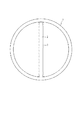
図1は、本考案の熱交換器用ガスケットの一実施態様を示す概略平面図、図2は、図1のA−A部における本考案の熱交換器用ガスケットの概略断面図である。 FIG. 1 is a schematic plan view showing an embodiment of a heat exchanger gasket according to the present invention, and FIG. 2 is a schematic cross-sectional view of the heat exchanger gasket according to the present invention taken along a line AA in FIG.
本考案の熱交換器用ガスケットは、熱交換器のフランジ(図示せず)に取り付けるための枝部2が配設されているガスケット本体1および金属クリップ3を有する。
The gasket for a heat exchanger according to the present invention has a gasket body 1 and a
ガスケット本体1としては、例えば、うず巻形ガスケット、メタルジャケットガスケットなどが挙げられるが、本考案は、かかる例示のみに限定されるものではない。また、ガスケット本体1の大きさについても特に限定がなく、一般に熱交換器に使用されているガスケットと同様の大きさを有するものであればよい。ガスケットの口径の一例を挙げれば、例えば、50A〜100Aなどが挙げられる。 Examples of the gasket body 1 include a spiral wound gasket and a metal jacket gasket. However, the present invention is not limited to such examples. Moreover, there is no limitation in particular also about the magnitude | size of the gasket main body 1, What is necessary is just to have a magnitude | size similar to the gasket generally used for the heat exchanger. If an example of the diameter of a gasket is given, 50A-100A etc. will be mentioned, for example.
ガスケット本体1には、枝部2が配設されている。枝部2は、本考案の熱交換器用ガスケットを熱交換器用フランジに固定するために設けられている。枝部2は、耐熱性を有する材料で構成され、当該材料としては、例えば、ステンレス鋼、真鍮、銅、アルミニウム合金、ブリキ、トタンなどが挙げられるが、本考案は、かかる例示のみに限定されるものではない。
A
図1に示される枝部2は、ガスケット本体1の中心部を通り、その直径方向に延伸しており、ガスケット本体1の円周と交叉する部分で固定されている。枝部2の形状は、本考案の熱交換器用ガスケットが使用される熱交換器用フランジの種類に応じて適宜選択することが好ましい。枝部2の形状は、例えば、図1に示されるように直線状のものであってもよく、例えば、日本バルカー工業(株)製、No.7590シリーズ、No.8590シリーズなどの熱交用枝付のうず巻形ガスケットのようにY字形を有するものであってもよい。これらの形状のなかでは、本考案の熱交換器用ガスケットとガスケットとの位置ずれを防止して本考案の熱交換器用ガスケットをフランジに容易に固定することができることから、図1に示される直線状のものが好ましい。また、枝部2の幅および厚さに関しても、本考案の熱交換器用ガスケットが使用される熱交換器用フランジの種類に応じて適宜選択することが好ましい。枝部2の幅は、通常、6〜12mm程度であり、枝部2の厚さは、通常、3〜10mm程度である。
The
枝部2は、金属クリップ3内に挿入されており、金属クリップ3の端部は、枝部2の端面2aから突出し、フランジを固定するための固定部3a,3bが形成されている。
The
金属クリップ3を構成する材料としては、例えば、ステンレス鋼、真鍮、銅、アルミニウム合金、ブリキ、トタンなどが挙げられるが、本考案は、かかる例示のみに限定されるものではない。また、金属クリップ3の大きさも任意であり、本考案の熱交換器用ガスケットが使用される熱交換器用フランジの種類に応じて適宜選択することが好ましい。通常、金属クリップ3の厚さは0.2〜0.8mm程度であり、幅は5〜30mm程度であり、深さは20〜30mm程度である。また、金属クリップ3の表面には、メタルジャケットが1〜3枚程度被覆されていてもよい。
Examples of the material constituting the
金属クリップ3は、例えば、図1のA−A部における断面形状を示す図2に示されているように、その断面形状がコの字形を有するものなどが挙げられる。図2に示されるように、枝部2は、金属クリップ3内に挿入されている。枝部2の底面と金属クリップ3の内底面との間に間隙が存在していてもよく、枝部2の底面と金属クリップ3の内底面とが接触していてもよい。枝部2の底面と金属クリップ3の内底面とは、必要により、溶接によって一体化されていてもよく、接着剤で接着されていてもよい。
Examples of the
金属クリップ3の端部は、枝部2の端面2aから突出し、フランジを固定するための固定部3a,3bが形成されている。本考案においては、金属クリップ3の端部が枝部2の端面2aから突出しており、フランジを固定するための固定部3a,3bが形成されている点に、1つの大きな特徴がある。本考案においては、このように金属クリップ3の固定部3a,3bは、熱交換器用ガスケットをフランジに装着する際の位置決めとなる。また、一対の固定部3a,3b間に熱交換器用フランジの固定部(図示せず)を挿入するだけで、本考案の熱交換器用ガスケットを熱交換器用フランジに容易に装着することができる。したがって、本考案の熱交換器用ガスケットを用いることにより、従来のようにガイド溝を形成させるための煩雑な加工を必要とせず、フランジと当該熱交換器用ガスケットとの位置ずれを防止して当該熱交換器用ガスケットをフランジに容易に固定することができる。
The end portion of the
図1に示される熱交換器用ガスケットでは、金属クリップ3は、ガスケット本体1の中心部にのみ設けられているが、例えば、図3に示されるように、枝部2のほぼ全体が金属クリップ3内に収容されるように設けられていてもよい。
In the heat exchanger gasket shown in FIG. 1, the
なお、図3は、本考案の熱交換器用ガスケットに用いられる金属クリップ3の一実施態様を示す概略断面図である。
FIG. 3 is a schematic cross-sectional view showing an embodiment of the
図2に示される金属クリップ3の断面形状は、前記したように、コの字状を有するが、枝部2が金属クリップ3から離脱することを防止するために、例えば、図4に示されるように、金属クリップ3の開口部に形成されている一対の固定部3a,3bの間隔が枝部2の幅よりも小さくなるように設定してもよい。この場合、金属クリップ3の内底面と枝部2の底面とを接着する必要がないという利点がある。固定部3a,3bの間隔が枝部2の幅よりも小さくなるようにする方法としては、例えば、枝部2を金属クリップ3内に挿入した後、固定部3a,3bの間隔を狭める方法、金属クリップ3として可撓性のある材料を用い、枝部2を金属クリップ3内に挿入する際に固定部3a,3bの間隔を広げて枝部2を金属クリップ3内に挿入する方法などが挙げられるが、本考案は、かかる方法によって限定されるものではない。
The cross-sectional shape of the
ガスケット本体1の端面2aから突出している固定部3a,3bの長さHは、当該固定部3a,3bにフランジの固定部を容易に挿入することができるようにする観点から、2〜10mm程度であることが好ましく、3〜8mm程度であることがより好ましい。
The length H of the fixing
以上説明したように、本考案の熱交換器用ガスケットは、フランジに取り付けるための枝部2が配設されているガスケット本体1および金属クリップ3を有し、枝部2が金属クリップ3内に挿入されており、金属クリップ3の端部が枝部2の端面2aから突出し、フランジを固定するための固定部3a,3bが形成されているので、従来のようにガイド溝を形成させるための煩雑な加工を必要とせず、フランジとガスケットとの位置ずれを防止してガスケットをフランジに容易に固定することができる。
As described above, the gasket for a heat exchanger according to the present invention has the gasket body 1 and the
したがって、本考案の熱交換器用ガスケットは、熱交換器のシェルフランジなどに好適に使用することができる。 Therefore, the heat exchanger gasket of the present invention can be suitably used for a shell flange of a heat exchanger or the like.
1 ガスケット本体
2 枝部
2a 枝部の端面
3 金属クリップ
3a 固定部
3b 固定部
DESCRIPTION OF SYMBOLS 1
Claims (1)
Priority Applications (1)
| Application Number | Priority Date | Filing Date | Title |
|---|---|---|---|
| JP2016001764U JP3205012U (en) | 2016-04-16 | 2016-04-16 | Gasket for heat exchanger |
Applications Claiming Priority (1)
| Application Number | Priority Date | Filing Date | Title |
|---|---|---|---|
| JP2016001764U JP3205012U (en) | 2016-04-16 | 2016-04-16 | Gasket for heat exchanger |
Publications (1)
| Publication Number | Publication Date |
|---|---|
| JP3205012U true JP3205012U (en) | 2016-06-30 |
Family
ID=56236246
Family Applications (1)
| Application Number | Title | Priority Date | Filing Date |
|---|---|---|---|
| JP2016001764U Expired - Fee Related JP3205012U (en) | 2016-04-16 | 2016-04-16 | Gasket for heat exchanger |
Country Status (1)
| Country | Link |
|---|---|
| JP (1) | JP3205012U (en) |
-
2016
- 2016-04-16 JP JP2016001764U patent/JP3205012U/en not_active Expired - Fee Related
Similar Documents
| Publication | Publication Date | Title |
|---|---|---|
| CN103460003B (en) | For the corrosion-resistant barrier assembly of process apparatus | |
| JPH11337288A (en) | Heat exchanger | |
| JP2009086075A (en) | Lens with lens barrel | |
| JP2007135594A (en) | Method for producing freezer, and freezer produced by the same | |
| US9573219B2 (en) | Welding method for shell and tube | |
| KR101359778B1 (en) | Welding method for shell and tube | |
| JP3205012U (en) | Gasket for heat exchanger | |
| US10612865B2 (en) | Header tank of heat exchanger and heat exchanger having the same | |
| WO2015022783A1 (en) | Electromagnetic flowmeter | |
| JP2006037223A (en) | Cooling plate | |
| JP6744089B2 (en) | Gasoline direct injection rail | |
| JP2017207114A (en) | Fixing device of pipe | |
| JP2018515737A (en) | Collector plate especially for heat exchangers for motor vehicles | |
| US20150330819A1 (en) | Measuring device, especially flow measuring device, and method for manufacturing a measuring tube for a measuring device | |
| KR20120033741A (en) | Connecting structure of tube by welding | |
| US10286440B2 (en) | Method and kit for joining a tubular member and a pipeline for conveying corrosive products | |
| WO2017025009A1 (en) | Housing assembly of valve and valve | |
| JP2016036831A (en) | Brazing structure | |
| US818731A (en) | Sheet-metal can. | |
| JP7377789B2 (en) | Metal member joining structure and metal member joining method | |
| JP6009479B2 (en) | Fluid distributor and manufacturing method thereof | |
| JP7319139B2 (en) | Piping structure and heat exchanger | |
| JP2010012515A (en) | Metallic pipe and manufacturing method thereof | |
| JP2007301625A (en) | Method of mutually welding end faces of tubes | |
| JP2010117040A (en) | Cooling member and manufacturing method therefor |
Legal Events
| Date | Code | Title | Description |
|---|---|---|---|
| R150 | Certificate of patent or registration of utility model |
Ref document number: 3205012 Country of ref document: JP Free format text: JAPANESE INTERMEDIATE CODE: R150 |
|
| S533 | Written request for registration of change of name |
Free format text: JAPANESE INTERMEDIATE CODE: R323533 |
|
| R350 | Written notification of registration of transfer |
Free format text: JAPANESE INTERMEDIATE CODE: R350 |
|
| R250 | Receipt of annual fees |
Free format text: JAPANESE INTERMEDIATE CODE: R250 |
|
| R250 | Receipt of annual fees |
Free format text: JAPANESE INTERMEDIATE CODE: R250 |
|
| R250 | Receipt of annual fees |
Free format text: JAPANESE INTERMEDIATE CODE: R250 |
|
| R250 | Receipt of annual fees |
Free format text: JAPANESE INTERMEDIATE CODE: R250 |
|
| LAPS | Cancellation because of no payment of annual fees |