JP3161105U - Piping connection structure - Google Patents
Piping connection structure Download PDFInfo
- Publication number
- JP3161105U JP3161105U JP2010002963U JP2010002963U JP3161105U JP 3161105 U JP3161105 U JP 3161105U JP 2010002963 U JP2010002963 U JP 2010002963U JP 2010002963 U JP2010002963 U JP 2010002963U JP 3161105 U JP3161105 U JP 3161105U
- Authority
- JP
- Japan
- Prior art keywords
- pipe
- retaining ring
- ring
- insertion hole
- connection structure
- Prior art date
- Legal status (The legal status is an assumption and is not a legal conclusion. Google has not performed a legal analysis and makes no representation as to the accuracy of the status listed.)
- Expired - Fee Related
Links
Images


Landscapes
- Flanged Joints, Insulating Joints, And Other Joints (AREA)
Abstract
【課題】簡単な構成で、取り付け工数を節約でき、さらに設置に大きなスペースを必要としない配管接続構造を提供する。【解決手段】配管挿通孔3を有する筐体1に、該筐体1の配管挿通孔3に挿通させてなる配管2を取り付ける配管接続構造において、配管2の外周と配管挿通孔3の内周との間に位置し流体のシールを行うリング状のシール部材たるOリング4と、内周側を配管2の外周に設けたリング装着溝2aに係り合わせてなるとともに外周側を筐体1の外側面に設けた抜け止めリング装着部たるリング装着凹部3bに係り合わせてなる抜け止めリング5と、リング装着凹部3bに係り合わせた状態の抜け止めリング5の外方に固定され、抜け止めリング5の軸方向への移動を規制する固定部材6とを利用する。【選択図】図3Provided is a pipe connection structure that can save installation man-hours with a simple configuration and that does not require a large space for installation. In a pipe connection structure in which a pipe 2 formed by being inserted into a pipe insertion hole 3 of the casing 1 is attached to a casing 1 having a pipe insertion hole 3, the outer periphery of the pipe 2 and the inner circumference of the pipe insertion hole 3 The ring-shaped sealing member O-ring 4 that seals the fluid and the inner peripheral side is engaged with the ring mounting groove 2a provided on the outer periphery of the pipe 2, and the outer peripheral side of the casing 1 is A retaining ring 5 that is engaged with a ring mounting recess 3b that is a retaining ring mounting portion provided on the outer surface, and a retaining ring 5 that is fixed to the outside of the retaining ring 5 that is engaged with the ring mounting recess 3b. 5 and a fixing member 6 that restricts movement in the axial direction. [Selection] Figure 3
Description
本考案は、筐体に配管を接続する箇所に設けられる配管接続構造に関する。 The present invention relates to a pipe connection structure provided at a location where a pipe is connected to a housing.
従来、筐体に配管を接続する箇所においては、図4及び図5に示すように、筐体aに雌ネジ穴a1を形成し、この雌ネジ穴a1にフィッティング継手b又はエルボcの一端部に形成した雄ネジ部b1、c1を螺着してフィッティング継手b又はエルボcを筐体aに取り付けるとともに、フィッティング継手b又はエルボcの他端部には、予めフレア加工を施した配管dの端部d1を面接触させ、フィッティングナットeをフィッティング継手b又はエルボcの前記他端部に形成した雄ネジ部b2、c2に螺着することによりフレア加工を施した配管dの端部d1をスリーブfを介してフィッティング継手b又はエルボcに圧着することにより、配管dと筐体aとを接続する構成が広く採用されている(例えば、特許文献1を参照)。このような構成に用いられるフィッティング継手又はエルボはいずれも公共規格に規定があり、調達性の観点からは好ましいものである。 Conventionally, as shown in FIGS. 4 and 5, a female screw hole a <b> 1 is formed in the housing a at a location where the pipe is connected to the housing, and one end portion of the fitting joint b or elbow c is formed in the female screw hole a <b> 1. The male threaded parts b1 and c1 formed in the above are screwed together to attach the fitting joint b or elbow c to the housing a, and the other end of the fitting joint b or elbow c has a flare-processed pipe d in advance. The end d1 of the pipe d which has been subjected to flare processing by bringing the end d1 into surface contact and screwing the fitting nut e into the male screw parts b2 and c2 formed at the other end of the fitting joint b or the elbow c. The structure which connects the piping d and the housing | casing a by crimping | bonding to the fitting joint b or the elbow c via the sleeve f is employ | adopted widely (for example, refer patent document 1). Any fitting joint or elbow used in such a configuration is prescribed in public standards and is preferable from the viewpoint of procurement.
しかし、公共規格に規定されているフィッティング継手又はエルボは、いずれも非常に高圧な油圧系統でも使用可能なものである。このようなフィッティング継手又はエルボを空気系統等、比較的低圧の流体のみを使用する場合には、強度が過剰であり、以下に述べるような問題が起こり得る。 However, any of the fitting joints or elbows specified in the public standards can be used in a very high pressure hydraulic system. When such a fitting joint or elbow uses only a relatively low-pressure fluid such as an air system, the strength is excessive and the following problems may occur.
具体的には、従来の構成では、少なくともフィッティング継手及びナットを用意する必要があり部品点数が多くなることに加え、配管にフレア加工を施す必要があるので接続のための工数も多くなるという問題が起こり得る。 Specifically, in the conventional configuration, it is necessary to prepare at least fitting joints and nuts, and in addition to the increase in the number of parts, it is necessary to perform flare processing on the piping, so that the man-hour for connection also increases. Can happen.
また、フィッティング継手の寸法及び質量が大きく、フィッティング継手が筐体の取付面から突出し、さらに配管にフレア加工を施すためにはある程度の長さを必要とすることから、筐体の接続部位の強度を確保する必要があるとともに、フィッティング継手の設置のためのスペースを確保する必要もあるという問題も起こり得る。 In addition, the size and mass of the fitting joint is large, the fitting joint protrudes from the mounting surface of the housing, and a certain length is required to flare the piping. There is also a possibility that it is necessary to secure a space for installing the fitting joint.
さらに、配管とフィッティング継手とが面接触する構造であることから、取付面間の長さ及び配管の長さの累積公差により空気配管を取り付けることができなくなることを防止するために、配管には累積公差を吸収する曲げ形状等を設ける必要があり、この点でも設置にスペースが大きく必要となるという問題も起こり得る。 In addition, since the piping and fitting fitting are in surface contact, the piping must be installed in order to prevent the air piping from being attached due to the accumulated tolerance of the length between the mounting surfaces and the length of the piping. It is necessary to provide a bent shape or the like that absorbs the accumulated tolerance, and in this respect as well, there may be a problem that a large space is required for installation.
本考案は、以上を踏まえ、簡単な構成で、取り付け工数を節約でき、さらに設置に大きなスペースを必要としない配管接続構造を実現することを所期の目的とする。 Based on the above, the present invention is intended to realize a pipe connection structure with a simple configuration that can save installation man-hours and does not require a large space for installation.
すなわち本考案に係る配管接続構造の一つは、配管挿通孔を有する筐体と、前記筐体の配管挿通孔に挿通させてなる配管と、この配管の外周と前記配管挿通孔の内周との間に位置し流体のシールを行うリング状のシール部材と、内周側を配管の外周に設けたリング装着溝に係り合わせてなるとともに外周側を筐体に設けた抜け止めリング装着部に係り合わせてなる抜け止めリングと、前記リング装着部に係り合わせた状態の抜け止めリングの外方に固定されこの抜け止めリングの軸方向への移動を規制する固定部材とを利用することを特徴とする配管接続構造。 That is, one of the pipe connection structures according to the present invention includes a casing having a pipe insertion hole, a pipe inserted through the pipe insertion hole of the casing, an outer periphery of the pipe, and an inner periphery of the pipe insertion hole. The ring-shaped seal member that seals the fluid located between the ring and the ring mounting groove provided on the outer periphery of the pipe on the inner peripheral side and the retaining ring mounting portion provided on the casing on the outer peripheral side It uses a retaining ring that is engaged, and a fixing member that is fixed to the outside of the retaining ring that is engaged with the ring mounting portion and restricts the axial movement of the retaining ring. Piping connection structure.
また、本考案に係る配管接続構造の他の一つは、配管挿通孔を有する筐体と、前記筐体の配管挿通孔に挿通させてなる配管と、この配管の外周と前記配管挿通孔の内周との間に位置し流体のシールを行うリング状のシール部材と、内周側を配管の外周に設けたリング装着部に係り合わせてなるとともに外周側を筐体に設けた抜け止めリング装着部に圧入させてなる抜け止めリングを利用することを特徴とする。 Further, another one of the pipe connection structures according to the present invention includes a casing having a pipe insertion hole, a pipe inserted through the pipe insertion hole of the casing, an outer periphery of the pipe, and the pipe insertion hole. A ring-shaped seal member that is located between the inner periphery and seals the fluid, and a retaining ring that is engaged with a ring mounting portion provided on the outer periphery of the pipe on the inner periphery and provided on the casing on the outer periphery. A retaining ring that is press-fitted into the mounting portion is used.
これらのような構成によれば、配管の外周のリング装着溝に抜け止めリングを装着し、この抜け止めリングを筐体に設けた抜け止めリング装着部に装着して固定部材を取り付ける、又は抜け止めリングを筐体の抜け止めリング装着部に圧入することにより抜け止めリングの軸方向への移動が規制される。その上で、この抜け止めリングが配管の外周のリング装着溝に装着されているので配管と抜け止めリングとの相対移動も規制される。従って、フィッティング継手、スリーブ及びナットといった特別な部材を用意する必要がなく、少ない部品点数や工数で、大きな設置スペースを必要とすることなく、配管が筐体に対して相対移動して筐体から抜けることを防止できる。 According to such a configuration, the retaining ring is mounted in the ring mounting groove on the outer periphery of the pipe, and the retaining member is mounted on the retaining ring mounting portion provided in the housing, and the fixing member is attached or detached. The axial movement of the retaining ring is restricted by press-fitting the retaining ring into the retaining ring mounting portion of the housing. In addition, since the retaining ring is mounted in the ring mounting groove on the outer periphery of the pipe, the relative movement between the pipe and the retaining ring is also restricted. Therefore, there is no need to prepare special members such as fitting joints, sleeves, and nuts, and the piping moves relative to the housing with a small number of parts and man-hours and without requiring a large installation space. It can be prevented from coming off.
前記抜け止めリングの好適な構成の一例として、前記抜け止めリングが、それぞれ半円弧状をなす1対のリング要素を組み合わせてなるものが挙げられる。このようなものであれば、抜け止めリングの配管への取り付け作業を容易に行うことができる。 As an example of a preferable configuration of the retaining ring, there is a structure in which the retaining ring is combined with a pair of ring elements each having a semicircular arc shape. If it is such, attachment work to piping of a retaining ring can be performed easily.
前記抜け止めリングの好適な構成の他の一例として、前記抜け止めリングが、環状をなすものが挙げられる。このようなものであれば、部品点数をさらに削減することができる。 As another example of a preferable configuration of the retaining ring, one in which the retaining ring has an annular shape can be cited. With such a configuration, the number of parts can be further reduced.
そして、このような配管接続構造の好適な使用態様として前記配管が、気体を流通させる配管であるものが挙げられる。 And as a suitable usage aspect of such a pipe connection structure, what the said pipe is a pipe | tube which distribute | circulates gas is mentioned.
本考案の構成によれば、簡単な構成で、取り付け工数を節約でき、さらに設置に大きなスペースを必要としない配管接続構造を実現できる。 According to the configuration of the present invention, it is possible to save the installation man-hours with a simple configuration and to realize a pipe connection structure that does not require a large space for installation.
以下、本考案の一実施形態を、図1,図2及び図3を参照して説明する。 Hereinafter, an embodiment of the present invention will be described with reference to FIGS.
本実施形態に係る配管接続構造は、例えば、空圧式バルブの筐体1に空気を導入するための配管2を取り付ける部位に使用される。
The pipe connection structure according to the present embodiment is used, for example, at a site where a
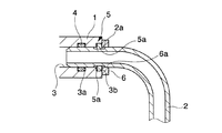
具体的には、図2及び図3に示すように、筐体1には、配管2の先端部を挿し通すための配管挿通孔3が設けられている。この配管挿通孔3内には、シール部材たるOリング4を嵌め込むためのOリング溝3aが設けられている。さらに、配管挿通孔3の開口端縁には、抜け止めリング5と係り合うことが可能な抜け止めリング装着部たる抜け止めリング装着凹部3bが設けられている。ここで、前記図3において、筐体1はその一部を破断して示している。
Specifically, as shown in FIGS. 2 and 3, the
一方、配管2には、図2及び図3に示すように、その先端近傍の部位に、抜け止めリング装着溝2aが設けられている。この抜け止めリング装着溝2aには、外側から抜け止めリング5を装着することができる。この抜け止めリング装着溝2aの溝幅は、抜け止めリング5の厚さ寸法よりも大きく設定している。また、配管2の外周と前記配管挿通孔3の内周との間、より具体的には抜け止めリング装着溝2aより先端側の外周と前記配管挿通孔3内のOリング溝3aとの間に、流体のシールを行うべくOリング4が配される。
On the other hand, as shown in FIGS. 2 and 3, the
抜け止めリング5は、図3に示すように、それぞれ半円弧状をなす1対のリング要素5aを組み合わせてなる。この抜け止めリング5は、内周側を配管2の外周に設けた抜け止めリング装着溝2aに係り合わせるとともに外周側を筐体1の外側面に設けた抜け止めリング装着凹部3bに係り合わせることにより、配管2を筐体1に対して位置決めする。
As shown in FIG. 3, the
抜け止めリング装着凹部3bに係り合わせた状態の抜け止めリング5の外方には、図1及び図3に示すように、配管2を通過させるための配管通過孔6aと、雄ネジ部材7を通過させるためのネジ挿通孔6bとを有する板状の固定部材6が取り付けられる。前記ネジ挿通孔6bを通過させた雄ネジ部材7を筐体1に設けた雌ネジ穴8に螺着して固定部材6を筐体1に固定した状態で、この固定部材6は、前記抜け止めリング5の軸方向への移動を規制する。前記図3において、固定部材6はその一部を破断して示している。
As shown in FIGS. 1 and 3, a
ここで、配管2に筐体1から抜脱する方向への作用が加わった際には、この配管2の抜け止めリング装着溝2aの先端側の端縁が抜け止めリング5に衝き当たり、抜け止めリング5を筐体1から抜脱する方向に押圧する一方、この抜け止めリング5は固定部材6により抜脱する方向への移動が規制されるので、結果として配管2の筐体1からの抜脱も規制される。
Here, when the
以上に述べたように、本実施形態の配管接続構造によれば、配管2の外周に設けた抜け止めリング装着溝2aに抜け止めリング5を係り合わせ、この抜け止めリング5を筐体1の配管挿通孔3の開口端縁に設けた抜け止めリング装着凹部3bに係り合わせ、その状態で固定部材6を取り付けるようにしているので、筐体1と抜け止めリング5との相対移動が規制されるとともに、配管2と抜け止めリング5との相対移動も規制される。従って、フィッティング継手、スリーブ及びナットといった特別な部材を用意する必要がなく、少ない部品点数や工数で、大きな設置スペースを必要とすることなく、配管2が筐体1に対して相対移動して筐体1から抜けることを防止できる。その上で、前記抜け止めリング5よりも下流側において筐体1の配管挿通孔3の内周と配管2の外周との間にOリング4を設けることにより空気漏れが防止されるので、流体のシールを行う機能と配管2の抜け止めを行う機能とをそれぞれ別個の部位により担わせているので、この点でも構造の簡単化を図ることができる。
As described above, according to the pipe connection structure of the present embodiment, the
さらに、前記抜け止めリング5が、それぞれ半円弧状をなす1対のリング要素5aを組み合わせてなるものであるので、抜け止めリング5の配管2への取り付け作業を容易に行うことができる。
Furthermore, since the retaining
なお、本考案は以上に述べた実施形態に限られない。 The present invention is not limited to the embodiment described above.
例えば、抜け止めリングの外径を抜け止めリング装着溝の直径よりも小さくし、抜け止めリングを抜け止めリング装着溝に圧入させてなるものとすることにより、固定部材を省略してもよい。このようなものであれば、特に配管の着脱が頻繁でない使用態様において、部品点数及び組み立て工数の削減を好適に図ることができる。 For example, the fixing member may be omitted by making the outer diameter of the retaining ring smaller than the diameter of the retaining ring mounting groove and pressing the retaining ring into the retaining ring mounting groove. With such a configuration, it is possible to suitably reduce the number of parts and the number of assembling steps particularly in a usage mode in which the piping is not frequently attached and detached.
さらに、抜け止めリングは、半円弧状をなす1対のリング要素を組み合わせてなるものに限らず、それぞれ円弧状を3つ以上に分割した形状を有する3個以上のリング要素を組み合わせてなるものであってもよい。 Furthermore, the retaining ring is not limited to a combination of a pair of ring elements having a semicircular arc shape, but is a combination of three or more ring elements each having a shape obtained by dividing the arc shape into three or more. It may be.
また、抜け止めリングは、弾性変形可能な材料により形成した1個の環状の部材を利用したものや、Cリングや、Eリング等であってもよい。この場合、抜け止めリングは1つの部材のみにより構成されるので、部品点数の削減を図ることができる。 Further, the retaining ring may be one using a single annular member formed of an elastically deformable material, a C ring, an E ring, or the like. In this case, since the retaining ring is composed of only one member, the number of parts can be reduced.
そして、空気を通過させてなる配管に限らず、その他の気体を通過させてなる配管や、低圧の液体を通過させてなる配管の筐体への取り付けに本考案の配管接続構造を採用してもよい。 And the pipe connection structure of the present invention is adopted not only for pipes that allow air to pass through but also to pipes that allow other gases to pass through and pipes that allow low-pressure liquid to pass through. Also good.
その他、本考案の趣旨を損ねない範囲で種々に変更してよい。 In addition, various modifications may be made without departing from the spirit of the present invention.
1…筐体
2…配管
3…配管挿通孔
3b…抜け止めリング装着部
4…Oリング(シール部材)
5…抜け止めリング
5a…リング要素
6…固定部材
DESCRIPTION OF
5 ... Retaining
Claims (5)
Priority Applications (1)
| Application Number | Priority Date | Filing Date | Title |
|---|---|---|---|
| JP2010002963U JP3161105U (en) | 2010-05-07 | 2010-05-07 | Piping connection structure |
Applications Claiming Priority (1)
| Application Number | Priority Date | Filing Date | Title |
|---|---|---|---|
| JP2010002963U JP3161105U (en) | 2010-05-07 | 2010-05-07 | Piping connection structure |
Publications (1)
| Publication Number | Publication Date |
|---|---|
| JP3161105U true JP3161105U (en) | 2010-07-22 |
Family
ID=54864056
Family Applications (1)
| Application Number | Title | Priority Date | Filing Date |
|---|---|---|---|
| JP2010002963U Expired - Fee Related JP3161105U (en) | 2010-05-07 | 2010-05-07 | Piping connection structure |
Country Status (1)
| Country | Link |
|---|---|
| JP (1) | JP3161105U (en) |
Cited By (1)
| Publication number | Priority date | Publication date | Assignee | Title |
|---|---|---|---|---|
| CN111006088A (en) * | 2019-12-27 | 2020-04-14 | 汉腾汽车有限公司 | Quick insertion structure for pipeline connection |
-
2010
- 2010-05-07 JP JP2010002963U patent/JP3161105U/en not_active Expired - Fee Related
Cited By (1)
| Publication number | Priority date | Publication date | Assignee | Title |
|---|---|---|---|---|
| CN111006088A (en) * | 2019-12-27 | 2020-04-14 | 汉腾汽车有限公司 | Quick insertion structure for pipeline connection |
Similar Documents
| Publication | Publication Date | Title |
|---|---|---|
| JP4374561B2 (en) | Clip coupler for hose | |
| CN103363207A (en) | Housing type pipe joint | |
| JP4939826B2 (en) | How to assemble pipe fittings | |
| JP2008286395A (en) | Non-serviceable fluid coupling | |
| US20070194567A1 (en) | Brake Tube Connector | |
| US20080048440A1 (en) | Direct port connection for tubes | |
| JP5915918B2 (en) | High pressure pipe joints and joint structures | |
| US8056939B2 (en) | Plug connector for piping | |
| JP5269178B2 (en) | How to assemble pipe fittings | |
| JP2007231985A (en) | Piping flange joint | |
| JP2007192270A (en) | Pipe joint structure | |
| JP2008038924A (en) | Pipe joint | |
| JP2018017293A (en) | Pressure-resistant fittings and pressure-resistant fitting structures | |
| JP3161105U (en) | Piping connection structure | |
| WO2008077013A3 (en) | Connection of tubes for air conditioning and seal adapted thereto | |
| JP2009052571A (en) | Pipe-connecting structure | |
| JP2015078749A (en) | Pipe joint | |
| JP2002106766A (en) | Pipe joint | |
| JP7555097B2 (en) | Pipe Fittings | |
| JP2013002515A (en) | Hose fastening structure | |
| JP2007255684A (en) | Pipe joint | |
| JP2007078158A (en) | Hose-end connection joint | |
| JP6300067B2 (en) | Pipe fitting | |
| JP4324565B2 (en) | Double pipe fitting | |
| US8944472B2 (en) | Conduit joint and seal ring |
Legal Events
| Date | Code | Title | Description |
|---|---|---|---|
| R150 | Certificate of patent or registration of utility model |
Free format text: JAPANESE INTERMEDIATE CODE: R150 |
|
| FPAY | Renewal fee payment (event date is renewal date of database) |
Free format text: PAYMENT UNTIL: 20130630 Year of fee payment: 3 |
|
| FPAY | Renewal fee payment (event date is renewal date of database) |
Free format text: PAYMENT UNTIL: 20130630 Year of fee payment: 3 |
|
| LAPS | Cancellation because of no payment of annual fees |