JP3132555U - Joining structure of golf club head face plate - Google Patents
Joining structure of golf club head face plate Download PDFInfo
- Publication number
- JP3132555U JP3132555U JP2007002149U JP2007002149U JP3132555U JP 3132555 U JP3132555 U JP 3132555U JP 2007002149 U JP2007002149 U JP 2007002149U JP 2007002149 U JP2007002149 U JP 2007002149U JP 3132555 U JP3132555 U JP 3132555U
- Authority
- JP
- Japan
- Prior art keywords
- face plate
- coupling
- golf club
- club head
- head body
- Prior art date
- Legal status (The legal status is an assumption and is not a legal conclusion. Google has not performed a legal analysis and makes no representation as to the accuracy of the status listed.)
- Expired - Lifetime
Links
Images


Landscapes
- Golf Clubs (AREA)
Abstract
【課題】フェース板とヘッド本体の結合部には突出部と凹溝が対応するように形成されることによって接触の面積が増え、拡大された粘着剤層の塗布面積の拡大によってフェース板とヘッド本体との間の貼接の結合強度を高める。
【解決手段】ヘッド本体10、フェース板20および粘着剤層により構成され、ヘッド本体の正面にはフェース板を収容する溝座11が形成され、溝座は溝口の内周縁111および結合部によってフェース板の外周縁21および結合部と結合すると同時に、ヘッド本体とフェース板の結合部には少なくとも一個の凹溝113と突出部23が対応するように形成され、凹溝と突出部によって粘着剤層はその塗布の面積を拡大することができることにより、ヘッド本体とフェース板との間の結合強度を高めるように構成されている。
【選択図】図1An area of contact is increased by forming a protrusion and a groove corresponding to a joint portion of a face plate and a head body, and a face plate and a head are increased by increasing an application area of an expanded adhesive layer. Increase the bonding strength of the adhesive between the main body.
A head body, a face plate, and a pressure-sensitive adhesive layer are formed, and a groove seat that accommodates the face plate is formed on the front surface of the head body. The groove seat is a face formed by an inner peripheral edge of the groove opening and a coupling portion. Simultaneously with the outer peripheral edge 21 and the connecting portion of the plate, at the same time, at least one concave groove 113 and the protruding portion 23 are formed in the connecting portion of the head body and the face plate, and the adhesive layer is formed by the concave groove and the protruding portion. Is configured to increase the bonding strength between the head body and the face plate by increasing the area of the coating.
[Selection] Figure 1
Description
本考案は、ゴルフクラブヘッドのフェース板の結合構造に関するもので、特にフェース板とヘッド本体の結合部には突出部と凹溝が対応するように形成されることによって粘着剤層の塗布の面積が拡大されるため、フェース板とヘッド本体の間の結合強度を高めることができるゴルフクラブヘッドのフェース板の結合構造に係るものである。 The present invention relates to a structure for connecting a face plate of a golf club head, and in particular, an area for applying an adhesive layer by forming a protrusion and a groove corresponding to a connecting portion of the face plate and the head body. Therefore, the present invention relates to a coupling structure of a face plate of a golf club head that can increase the coupling strength between the face plate and the head body.
従来この種のものにあっては、下記のようなものになっている。 Conventionally, this type is as follows.
従来のゴルフクラブアイアンヘッドの構造としては、嵌設配合、タングステンイナートガスアーク熔接、硬ろう付けまたは高エネルギ熔接等の方式によってフェース板を結合するもので、しかし上記の結合方式だと沢山の問題点を抱えており、例えば嵌設配合によってはフェース板が変形し易いという問題点を有し、また、異種類の材質を熔接したヘッド本体とフェース板は熔接の互換性が不足するという問題点を有し、さらに、硬ろう付けまたは高エネルギ熔接(レザー熔接、プラズマアーク熔接)によっては大量な時間をつやして真空処理または惰性気体処理を行うことによって金属の表面酸化の変色を防止しなければならないという問題点があった。 The structure of the conventional golf club iron head is that the face plates are joined by a method such as fitting blending, tungsten inert gas arc welding, hard brazing, or high energy welding. For example, the face plate is likely to be deformed depending on the fitting composition, and the head body and the face plate welded with different types of materials are not compatible with each other. In addition, it is necessary to prevent discoloration of metal surface oxidation by performing a vacuum treatment or an inert gas treatment for a long time depending on hard brazing or high energy welding (leather welding, plasma arc welding). There was a problem.
上記ゴルフクラブヘッドのフェース板の結合構造の問題点を克服するべく、業界においては常温における高強度樹脂の粘着剤の結合技術が段々と開発されている。図11に示すように、アイアン型のヘッドは主にヘッド本体10およびフェース板20により構成され、ヘッド本体10の正面にはフェース板20を収容するための溝座11が凹設される。貼接の作業においては、フェース板20の外周縁21と結合部22を溝座11の内周縁111と結合部112に貼接して結合させるだけで、室温において組立の作業を迅速に完成することができるように構成されている。
In order to overcome the problems of the bonding structure of the face plate of the golf club head, in the industry, bonding techniques for adhesives of high-strength resin at room temperature have been developed gradually. As shown in FIG. 11, the iron-type head is mainly composed of a head
また、従来のゴルフクラブのアイアンヘッドの構造としては、フェース部の内部には中空部が形成され、ヘッドの背面部の中央部には上記中空部を外部へ開放した開口部が形成されると同時に、上記フェース部の肉厚を3mm以下に設定すると共に、フェース部は120Kgf/mm2図以上の湾曲力を有する高強度の材料により構成されるようにしたものがある(例えば、特許文献1を参照)。
従来のゴルフクラブヘッドのフェース板の結合構造においては、高強度の粘着剤の結合強度の上限に制限されており、貼接して結合されたフェース板20が受けられる打球の剪断応力の範囲は僅か4000から4600psiで、しかしテストで得た数値では、フェース板20が正常な状態で受けられる最大な剪断応力は4100psiに達しているため、上記貼接の結合構造は製造工程を速めることができるが、ヘッド本体10とフェース板20との間の結合強度を確保することができないという問題点があった。
In the conventional golf club head face plate bonding structure, the upper limit of the bonding strength of the high-strength adhesive is limited, and the shear stress range of the hit ball that can receive the
また、従来のゴルフクラブのアイアンヘッドの構造においては、そのフェース部とヘッドの接触の面積が少ないため、フェース部とヘッドとの間の結合強度を確保することができないという問題点があった。そのために、上記従来のゴルフクラブのアイアンヘッドの構造をさらに改良しなければならない。 Further, in the structure of the conventional iron head of a golf club, there is a problem that since the area of contact between the face portion and the head is small, the bonding strength between the face portion and the head cannot be ensured. Therefore, the structure of the iron head of the conventional golf club has to be further improved.
本考案は、このような問題点に鑑みて考案したものであって、その目的とするところは、フェース板とヘッド本体の結合部には突出部と凹溝が対応するように形成されることによって接触の面積が増やされ、拡大された粘着剤層の塗布の面積によってフェース板とヘッド本体との間の貼接の結合強度を高めることができるため、ヘッドの組立の製造工程を速めることができると共に、使用寿命をさらに延ばすことができるゴルフクラブヘッドのフェース板の結合構造を提供することにある。 The present invention has been devised in view of such problems, and the object of the present invention is to form a protrusion and a concave groove at the joint between the face plate and the head body. The contact area is increased by the above, and the bonding strength of the adhesive between the face plate and the head body can be increased by the application area of the expanded adhesive layer, which speeds up the manufacturing process of the head assembly. Another object of the present invention is to provide a golf club head face plate coupling structure capable of further extending the service life.
本考案の第一の目的は、フェース板の結合部には突出部が形成されるのに対し、ヘッド本体の結合部には対応するように凹溝が形成されることにより、拡大された粘着剤層の塗布の面積によって結合強度を高めることができるため、ヘッドの結合強度を増やすことができると共に、使用寿命を延ばすことができるゴルフクラブヘッドのフェース板の結合構造を提供することである。 The first object of the present invention is to expand the pressure-sensitive adhesive by forming a concave groove corresponding to the coupling portion of the head body, while the projection portion is formed in the coupling portion of the face plate. An object of the present invention is to provide a bonding structure for a face plate of a golf club head that can increase the bonding strength of the head and extend the service life since the bonding strength can be increased by the application area of the agent layer.
本考案の第二の目的は、フェース板の外周縁、結合部と突出部を高強度の粘着剤によってヘッド本体の内周縁、結合部と凹溝に対応するように貼接して結合させることにより、ヘッドの組立作業を速めることができるゴルフクラブヘッドのフェース板の結合構造を提供することである。 The second object of the present invention is to bond the outer peripheral edge of the face plate, the connecting part and the protruding part with a high-strength adhesive so as to correspond to the inner peripheral edge of the head body, the connecting part and the concave groove. Another object of the present invention is to provide a golf club head face plate coupling structure capable of speeding up the head assembly operation.
上記目的を達成するために、本考案によるゴルフクラブヘッドのフェース板の結合構造は、下記のようになるものである。すなわち、
ゴルフクラブヘッドのフェース板の結合構造は、ヘッド本体、フェース板、粘着剤層および溝座により構成される。ヘッド本体の正面の周縁には結合部が設けられる。フェース板の背面の周縁には結合部が設けられ、フェース板の背面の周縁の結合部はヘッド本体の結合部に結合されることができると同時に、ヘッド本体の正面の周縁の結合部とフェース板の背面の周縁の結合部には少なくとも一個の凹溝と少なくとも一個の突出部が対応するように形成される。粘着剤層はヘッド本体の正面の周縁とフェース板の背面の周縁の結合部の間に貼接して結合され、凹溝と突出部との対応する嵌設の結合によって粘着剤層はその塗布の面積を拡大することができることにより、ヘッド本体とフェース板との間の結合強度を高めることができる。溝座はヘッド本体の正面の結合部に囲まれて形成され、溝座にはヘッド本体の正面側から背面側に連通する開口空間が形成され、その開口空間はフェース板が前後方向へ弾性変形するのを許す。
In order to achieve the above object, a golf club head face plate coupling structure according to the present invention is as follows. That is,
The coupling structure of the face plate of the golf club head includes a head body, a face plate, an adhesive layer and a groove seat. A coupling portion is provided on the front peripheral edge of the head body. A coupling portion is provided at the periphery of the back surface of the face plate, and the coupling portion at the periphery of the back surface of the face plate can be coupled to the coupling portion of the head body. At least one concave groove and at least one projecting portion are formed so as to correspond to the connecting portion on the peripheral edge of the back surface of the plate. The pressure-sensitive adhesive layer is bonded and bonded between the front peripheral edge of the head body and the rear peripheral edge of the face plate, and the pressure-sensitive adhesive layer is applied by bonding the corresponding groove and the protrusion. Since the area can be enlarged, the bonding strength between the head body and the face plate can be increased. The groove seat is formed by being surrounded by the front joint of the head body. The groove seat has an opening space that communicates from the front side to the back side of the head body, and the face plate is elastically deformed in the front-rear direction. Allow to do.
また、本考案のゴルフクラブヘッドのフェース板の結合構造は、下記のように構成することもできる。
1.ヘッド本体の正面には溝座が形成され、溝座の溝口には内周縁と結合部が形成され、フェース板は溝座に収容されることができると共に、フェース板は外周縁および結合部によって溝座の内周縁および結合部と対応するように結合される。
2.溝座の結合部は凹溝に形成され、フェース板の背面の結合部は突出部に形成される。
3.溝座の結合部は突出部に形成され、フェース板の背面の結合部は凹溝に形成される。
4.ヘッド本体の正面の周縁には結合部が形成され、さらにフェース板にはヘッド本体の結合部に対応した環状壁が折り曲げて形成されると共に、環状壁の端面には結合部が形成される。
5.ヘッド本体の結合部は凹溝に形成され、フェース板の環状壁の結合部は突出部に形成される。
6.ヘッド本体の結合部は突出部に形成され、フェース板の環状壁の結合部は凹溝に形成される。
7.突出部と凹溝は矩形の断面、梯形の断面、倒立円錐形の断面、長矩形の断面、三角形の断面に形成された対応の補い合う構造である。
8.突出部と凹溝は内突出縁と外突出縁に置き換えることができる対応の補い合う構造である。
9.突出部と凹溝は一対の鋸歯状突出縁に置き換えることができる対応の補い合う構造である。
10.凹溝と突出部は連続的な環状または不連続的な方式によってヘッド本体とフェース板の結合部に設置される。
11.接着剤層の厚さは0.2mm以上を維持する。
Further, the coupling structure of the face plates of the golf club head of the present invention can be configured as follows.
1. A groove seat is formed on the front surface of the head body, and an inner peripheral edge and a coupling portion are formed in a groove opening of the groove seat. The face plate can be accommodated in the groove seat, and the face plate is formed by the outer peripheral edge and the coupling portion. It couple | bonds so that it may correspond with the inner periphery of a groove seat, and a connection part.
2. The coupling portion of the groove seat is formed as a concave groove, and the coupling portion on the back surface of the face plate is formed as a protruding portion.
3. The coupling portion of the groove seat is formed in the protruding portion, and the coupling portion on the back surface of the face plate is formed in the concave groove.
4). A coupling portion is formed at the peripheral edge of the front surface of the head body, and an annular wall corresponding to the coupling portion of the head body is formed on the face plate by bending, and a coupling portion is formed at the end surface of the annular wall.
5). The coupling part of the head body is formed in a concave groove, and the coupling part of the annular wall of the face plate is formed in the protruding part.
6). The coupling portion of the head body is formed as a protruding portion, and the coupling portion of the annular wall of the face plate is formed as a concave groove.
7). The protrusion and the concave groove have a complementary structure formed in a rectangular cross section, a trapezoidal cross section, an inverted conical cross section, a long rectangular cross section, and a triangular cross section.
8). The protruding portion and the recessed groove have a corresponding complementary structure that can be replaced with an inner protruding edge and an outer protruding edge.
9. The projecting portion and the recessed groove have a corresponding complementary structure that can be replaced by a pair of serrated projecting edges.
10. The concave groove and the protruding portion are installed at the joint between the head main body and the face plate in a continuous annular or discontinuous manner.
11. The thickness of the adhesive layer is maintained at 0.2 mm or more.
本考案のゴルフクラブヘッドのフェース板の結合構造によれば、フェース板の結合部には突出部が形成されるのに対し、ヘッド本体の結合部には対応するように凹溝が形成されることにより、拡大された粘着剤層の塗布の面積によって結合強度を高めることができるため、ヘッドの結合強度を増やすことができると共に、使用寿命を延ばすことができるという利点がある。 According to the coupling structure of the face plate of the golf club head of the present invention, the protruding portion is formed at the coupling portion of the face plate, while the concave groove is formed at the coupling portion of the head body. Thus, the bonding strength can be increased by the area of application of the expanded pressure-sensitive adhesive layer, so that there is an advantage that the bonding strength of the head can be increased and the service life can be extended.
本考案のゴルフクラブヘッドのフェース板の結合構造によれば、フェース板の外周縁、結合部と突出部を高強度の粘着剤によってヘッド本体の内周縁、結合部と凹溝に対応するように貼接して結合させることにより、ヘッドの組立の作業を速めることができるという利点がある。 According to the coupling structure of the face plate of the golf club head of the present invention, the outer peripheral edge of the face plate, the connecting portion and the protruding portion are made to correspond to the inner peripheral edge of the head body, the connecting portion and the concave groove by a high strength adhesive. By bonding by bonding, there is an advantage that the head assembling work can be speeded up.
本考案の実施の形態について、以下、図面を参照して説明する。 Embodiments of the present invention will be described below with reference to the drawings.
図1は本考案の実施形態1によるゴルフクラブヘッドのフェース板の結合構造の組立状態の断面図で、図2は図1の2の局部の拡大図で、図3は本考案の実施形態2によるゴルフクラブヘッドのフェース板の結合構造の組立状態の局部の断面図で、図4は本考案の実施形態3によるゴルフクラブヘッドのフェース板の結合構造の組立状態の局部の断面図で、図5は本考案の実施形態4によるゴルフクラブヘッドのフェース板の結合構造の組立状態の局部の断面図で、図6は本考案の実施形態5によるゴルフクラブヘッドのフェース板の結合構造の組立状態の局部の断面図で、図7は図6の7の局部の断面図で、図8は本考案の実施形態6によるゴルフクラブヘッドのフェース板の結合構造の組立状態の局部の断面図で、図9は本考案の実施形態7によるゴルフクラブヘッドのフェース板の結合構造の組立状態の局部の断面図で、図10は本考案の実施形態8によるゴルフクラブヘッドのフェース板の結合構造の組立状態の局部の断面図である。
1 is a cross-sectional view of an assembled state of a face plate coupling structure of a golf club head according to Embodiment 1 of the present invention, FIG. 2 is an enlarged view of a
本考案のゴルフクラブヘッドのフェース板の結合構造の一部分の部材は従来の技術におけるゴルフクラブヘッドのフェース板の結合構造と同じため、両者の同じ部分の部材は同じ符号を用いて標示し、その構造と功能については再び詳細に説明しない。 Since some members of the connecting structure of the face plate of the golf club head of the present invention are the same as the connecting structure of the face plate of the golf club head in the prior art, the same parts of both members are indicated by the same reference numerals, The structure and function will not be explained again in detail.
〔実施形態1〕
図1、2を参照すると、本考案の実施形態1によるゴルフクラブヘッドのフェース板の結合構造はヘッド本体10、フェース板20および粘着剤層30により構成される。ヘッド本体10の正面にはフェース板20を収容するための溝座11が形成され、溝座11は溝口の内周縁111および結合部112によってフェース板20の外周縁21および結合部22と結合し、溝座11とフェース板20の結合部112、22には少なくとも一個の凹溝111と少なくとも一個の突出部が対応するように形成される。凹溝113と突出部23の設置によって粘着剤層30は塗布の面積を拡大することができるため、ヘッド本体10とフェース板20との間の結合強度を高めることができ、さらにヘッドの組立の製造工程を速めることができると共に、使用寿命を高めることができる。
Embodiment 1
Referring to FIGS. 1 and 2, the golf club head face plate coupling structure according to the first embodiment of the present invention includes a
再び図1、2を参照すると、本考案の実施形態1におけるヘッド本体10、フェース板20および粘着剤層30の細部な構造が示される。ヘッド本体10はアイアン型、ウッド型またはパターのヘッドで、ヘッド本体10の正面には溝座11が形成され、溝座11の溝口の位置には内周縁111と結合部112が形成され、結合部112には少なくとも一個の凹溝113が形成される。フェース板20は鋳造、鍛造または機械加工等の方式によって製造された金属板体で、フェース板20の外周壁には外周縁21が形成されると共に、フェース板20の背面のリップ縁には結合部112が形成され、そしてフェース板20は外周縁21と結合部22によってヘッド本体10の溝座11の内周縁111と結合部112に結合され、さらに結合部22には凹溝113に対応して少なくとも一個の突出部23が形成される。粘着剤層30は高強度の粘着剤によって固化して形成されるもので、特に4000psiの打球の剪断応力を受けられる粘着剤からなり、例えばエキポシ樹脂または二液剤混合型の粘着剤等からなることができる。
Referring again to FIGS. 1 and 2, detailed structures of the
本考案の実施形態1において、凹溝113と突出部23は矩形の断面または梯形の断面の対応の補い合う構造を利用することにより、ヘッド本体10とヘッド本体20の接触面積を拡大することができる。図11に示す従来の結合構造と比較して見ると、本考案は凹溝113と突出部23によって粘着剤層23の塗布の面積を50%以上拡大させることができると共に、フェース板20は比較的よい打球の作用力を受けることができるため、本考案においてヘッドの結合強度を確実に増やすことができると共に、使用寿命を延ばすことができる。
In the first embodiment of the present invention, the contact area between the head
さらに、本考案の実施形態1の凹溝113と突出部23は連続的な環状方式でそれぞれヘッド本体10とフェース板20の結合部112、22に形成される方が好適で、しかし、例えば不連続的な方式で設置することもできる。また、凹溝113と突出部23の数も適当に変えることができる。その他に、本考案の粘着剤層30はエキポシ樹脂によって製造された時、その厚さは0.2mm以上を維持する方が好適で、また本考案の粘着剤層30は二液剤混合型の粘着剤によって製造された時、例えば60から120℃の温度処理によって固化の工程を速めることができる。
Further, it is preferable that the
〔実施形態2〜4〕
図3、4、5を参照すると、本考案の実施形態2、3、4のヘッド本体10およびフェース板20の細部な構造が示される。実施形態1と比較して見ると、実施形態2、3、4は設計上の需要性または結合強度の要求によってヘッド本体10の凹溝113の形状およびフェース板20の突出部23の形状を変えることができる。図3に示すように、凹溝113と突出部23は倒立円錐形の断面の対応の補い合う構造に形成される。図4に示すように、凹溝113と突出部23は長矩形の断面の対応の補い合う構造に形成される。図5に示すように、凹溝113と突出部23は三角形の断面の対応の補い合う構造に形成される。さらに、凹溝113と突出部23も同様に例えば連続的な環状または不連続的な方式によってそれぞれヘッド本体10とフェース板20の結合部112、22に設置されることができる。
[
3, 4, and 5, detailed structures of the head
〔実施形態5〕
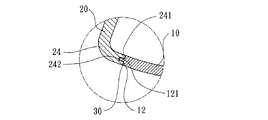
図6を参照すると、本考案の実施形態5のアイアン型のヘッドにはヘッド本体10およびフェース板20が設けられ、ヘッド本体10の正面の周縁には結合部12が直接形成され、そしてフェース板20にはヘッド本体10の正面の周縁に対応した環状壁24が折り曲げて形成されるため、有効な打球の面積を最大に拡大することができると共に、フェース板20に最大な弾性変形量を即時に完成させることにより、比較的高い弾性回復係数(coefficient of restitution, COR)を獲得することができると共に、アイアン型のヘッドに遠距離の打球を適用させることができる。
[Embodiment 5]
Referring to FIG. 6, the iron-type head according to the fifth embodiment of the present invention is provided with a
図6、7を参照すると、ヘッド本体10とフェース板20の結合の接触面積をさらに拡大させるべく、本考案の実施形態5において、例えばヘッド本体10の結合部12には突出部121が突設され、さらにフェース板20の環状壁24の端面には結合部241が設けられ、結合部241には補い合うための凹溝242が対応するように凹設されることにより、同じく粘着剤層30の塗布の面積を拡大することができるため、ヘッド本体10とフェース板20との間の結合強度をさらに高めることができる。また、突出部121と凹溝242は同様に例えば連続的な環状または不連続的な方式によってそれぞれヘッド本体10とフェース板20の結合部12、241に設けられることができる。
6 and 7, in order to further increase the contact area of the coupling between the
〔実施形態6〜8〕
図8、9、10を参照すると、本考案の実施形態6、7、8のヘッド本体10およびフェース板20の細部な構造が示される。実施形態5と比較して見ると、実施形態6、7、8は例えばヘッド本体10とフェース板の結合部12、241の結合の方式を変えることができる。図8に示すように、ヘッド本体10の結合部12には凹溝122が凹設され、そしてフェース板20の結合部241には補い合うための突出部243が対応するように突設される。図9に示すように、ヘッド本体10の結合部12の内周縁には内突出縁123が突設され、そしてフェース板20の結合部241の外周縁には補い合うための外突出縁244が対応するように突設される。図10に示すように、ヘッド本体10の結合部12の外周縁と結合部241の内周縁には鋸歯状突出縁124、245が対応するように突設され、鋸歯状突出縁124、245によって粘着剤層30の塗布の面積を拡大することができるだけではなく、さらに係止の構造を提供してヘッド本体10とフェース板20との間の結合強度を強化することができる。また、上記の結合の構造も同様に例えば連続的な環状または不連続的な方式によってそれぞれヘッド本体10とフェース板20の結合部112、22に設置されることができる。
[Embodiments 6 to 8]
Referring to FIGS. 8, 9, and 10, detailed structures of the
図1、11を参照すると、本考案のゴルフクラブヘッドのフェース板の結合構造はヘッド本体10とフェース板20の結合部112、22に突出部23と凹溝113を対応して形成させることにより、接触の面積を拡大するもので、上記拡大された粘着剤層30の塗布の面積によってフェース板20とヘッド本体10との間の結合強度を高めることができる。従来のゴルフクラブアイアンヘッドの構造において嵌設配合、タングステンイナートガスアーク熔接、硬ろう付けまたは高エネルギ熔接等の方式によって製造された構造と比較してみると、製造工程を速めて結合強度を高めることができないという問題点があった。本考案のゴルフクラブヘッドのフェース板の結合構造は結合強度を確実に高めることができると共に、組立の製造工程を速め、さらに使用寿命を延ばすことができるという利点がある。
Referring to FIGS. 1 and 11, the golf club head face plate coupling structure of the present invention is formed by forming
本考案は、その精神及び必須の特徴事項から逸脱することなく他のやり方で実施することができる。従って、本明細書に記載した好ましい実施例は例示的なものであり、限定的なものではない。 The present invention may be implemented in other ways without departing from the spirit and essential characteristics thereof. Accordingly, the preferred embodiments described herein are illustrative and not limiting.
10 ヘッド本体 11 溝座
111 内周縁 112 結合部
113 凹溝 12 結合部
121 突出部 122 凹溝
123 内突出縁 124 鋸歯状突出縁
20 フェース板 21 外周縁
22 結合部 23 突出部
24 環状壁 241 結合部
242 凹溝 243 突出部
244 外突出縁 245 鋸歯状突出縁
30 接着剤層
DESCRIPTION OF
Claims (12)
Priority Applications (1)
| Application Number | Priority Date | Filing Date | Title |
|---|---|---|---|
| JP2007002149U JP3132555U (en) | 2007-03-29 | 2007-03-29 | Joining structure of golf club head face plate |
Applications Claiming Priority (1)
| Application Number | Priority Date | Filing Date | Title |
|---|---|---|---|
| JP2007002149U JP3132555U (en) | 2007-03-29 | 2007-03-29 | Joining structure of golf club head face plate |
Related Parent Applications (1)
| Application Number | Title | Priority Date | Filing Date |
|---|---|---|---|
| JP2003037262A Continuation JP2004242952A (en) | 2003-02-14 | 2003-02-14 | Bonding structure of face plate of golf club head |
Publications (1)
| Publication Number | Publication Date |
|---|---|
| JP3132555U true JP3132555U (en) | 2007-06-14 |
Family
ID=43283281
Family Applications (1)
| Application Number | Title | Priority Date | Filing Date |
|---|---|---|---|
| JP2007002149U Expired - Lifetime JP3132555U (en) | 2007-03-29 | 2007-03-29 | Joining structure of golf club head face plate |
Country Status (1)
| Country | Link |
|---|---|
| JP (1) | JP3132555U (en) |
-
2007
- 2007-03-29 JP JP2007002149U patent/JP3132555U/en not_active Expired - Lifetime
Similar Documents
| Publication | Publication Date | Title |
|---|---|---|
| US20040185960A1 (en) | Connection structure for a striking plate of a golf club head | |
| JP2002017908A (en) | Golf club and manufacturing method thereof | |
| JP6287083B2 (en) | Dissimilar metal joining method between steel plate and aluminum alloy plate | |
| GB2428077A (en) | Self piercing rivet | |
| JP2691496B2 (en) | Golf club head and method of manufacturing the same | |
| JP3459173B2 (en) | Golf club head face member fixing method | |
| JP2004242952A (en) | Bonding structure of face plate of golf club head | |
| JP2005288525A (en) | Spot welding method of different kind of metallic member | |
| JP3132555U (en) | Joining structure of golf club head face plate | |
| JP2001321967A (en) | Spot welding joint and spot welding method | |
| JP3124540U (en) | Golf club head | |
| JP2020163467A (en) | Spot welding method for aluminum material | |
| JP2002224857A (en) | Joining structure and joining method between hollow members made of respectively different kinds of metal | |
| US20080125245A1 (en) | Golf club head | |
| JP3113023U (en) | Golf club head structure having a thin cover plate | |
| JPH07255884A (en) | Manufacture of iron head for golf club | |
| JPH1076031A (en) | Golf club head and its manufacture | |
| JP3124726U (en) | Golf club head | |
| JP3120522U (en) | Composite face plate golf club head | |
| JP3127220U (en) | Golf club head having a composite face plate | |
| JPH09154987A (en) | Golf club with clad material on head face | |
| JP3120341U (en) | Golf club head having composite plate | |
| JP3120340U (en) | Golf club head having a composite face plate | |
| JP3132561U (en) | Golf club head | |
| CN114351096B (en) | Sputtering target, target assembly and method for manufacturing target assembly |
Legal Events
| Date | Code | Title | Description |
|---|---|---|---|
| R150 | Certificate of patent or registration of utility model |
Free format text: JAPANESE INTERMEDIATE CODE: R150 |
|
| EXPY | Cancellation because of completion of term | ||
| FPAY | Renewal fee payment (event date is renewal date of database) |
Free format text: PAYMENT UNTIL: 20090523 Year of fee payment: 2 |