JP3131650U - strike - Google Patents
strike Download PDFInfo
- Publication number
- JP3131650U JP3131650U JP2007001221U JP2007001221U JP3131650U JP 3131650 U JP3131650 U JP 3131650U JP 2007001221 U JP2007001221 U JP 2007001221U JP 2007001221 U JP2007001221 U JP 2007001221U JP 3131650 U JP3131650 U JP 3131650U
- Authority
- JP
- Japan
- Prior art keywords
- strike
- dead bolt
- lock
- attached
- electronic lock
- Prior art date
- Legal status (The legal status is an assumption and is not a legal conclusion. Google has not performed a legal analysis and makes no representation as to the accuracy of the status listed.)
- Expired - Fee Related
Links
Images


Landscapes
- Casings For Electric Apparatus (AREA)
Abstract
【課題】錠の取付面と異なる面にも取り付けられて錠と協働することができるストライクを提供すること。
【解決手段】横断面が矩形をしたデッドボルト210が嵌入して施錠するストライクにおいて、立方体の一面に設けられた第1のデッドボルト用開口111aと、前記立方体の他の面に前記第1のデッドボルトと直角方向をなす向きに設けられた第2のデッドボルト用開口112aと、をそなえたことを特徴とするストライク。
【選択図】図1To provide a strike which can be attached to a surface different from the attachment surface of the lock and can cooperate with the lock.
In a strike in which a dead bolt 210 having a rectangular cross section is inserted and locked, a first dead bolt opening 111a provided on one surface of a cube and the first surface on the other surface of the cube. A strike having a second dead bolt opening 112a provided in a direction perpendicular to the dead bolt.
[Selection] Figure 1
Description
本考案は、錠のデッドボルトが係合するストライクに係わり、とくに取付対象物の取付個所の構造に対応し得るストライクに関する。 The present invention relates to a strike to which a dead bolt of a lock is engaged, and more particularly to a strike that can correspond to the structure of an attachment portion of an attachment object.
近年、セキュリティ対策を強化する傾向にあり、建物のドアであれば2重、3重の施錠が一般化している。これに対応して、オフィス等の各種収納庫(書庫、金庫、キャビネット、ロッカー、下駄箱、机の抽斗等)もより強力な施錠が求められている。このような観点から、既設の主錠の外に補助錠として電子ロックを後付けすることが普及している。 In recent years, there has been a tendency to strengthen security measures, and double and triple locking have become common for building doors. Correspondingly, various storages such as offices (library, safe, cabinet, locker, clog box, desk drawer, etc.) are required to have stronger locking. From such a viewpoint, it is widespread that an electronic lock is retrofitted as an auxiliary lock in addition to the existing main lock.
ここで、一般的な電子錠は、デッドボルトを出入りさせて施解錠する構造であるから、このデッドボルトが係合するストライクとともに取り付ける必要がある。このため、収納庫の固定部と可動部の一方に錠を、他方にストライクを取り付けることになる。そして、ストライクは錠によって異なるため、各種の錠に対応し得るストライクが提供されている(特許文献1参照)。
しかしながら、収納庫が既設であると、錠とストライクとを予定通りに同一平面上に取り付けられるとは限らず、特許文献1記載のストライクでも対応できない場合がある。 However, if the storage is already installed, the lock and the strike are not necessarily mounted on the same plane as planned, and the strike described in Patent Document 1 may not be supported.
本考案は上述の点を考慮してなされたもので、錠の取付面と異なる面にも取り付けられて錠と協働することができるストライクを提供することを目的とする。 The present invention has been made in consideration of the above-described points, and an object thereof is to provide a strike that can be attached to a surface different from the attachment surface of the lock and can cooperate with the lock.
上記目的達成のため、本発明では、
横断面が矩形をしたデッドボルトが嵌入して施錠するストライクにおいて、
立方体の一面に設けられた第1のデッドボルト用開口と、
前記立方体の他の面に前記第1のデッドボルトと直角方向をなす向きに設けられた第2のデッドボルト用開口と、
をそなえたことを特徴とするストライク、
を提供するものである。
In order to achieve the above object, in the present invention,
In the strike where the dead bolt with a rectangular cross section is inserted and locked,
A first dead bolt opening provided on one side of the cube;
A second dead bolt opening provided on the other surface of the cube in a direction perpendicular to the first dead bolt;
Strike, characterized by having
Is to provide.
本考案は上述のように、向きの異なる少なくとも2つのデッドボルト用開口を有するため、設置場所の制限が大幅に緩和され、錠の取付対象を拡大することができる。 Since the present invention has at least two dead bolt openings with different orientations as described above, the restriction on the installation location is greatly relaxed, and the object to which the lock is attached can be expanded.
以下、添付図面を参照して本考案の実施の形態を説明する。 Embodiments of the present invention will be described below with reference to the accompanying drawings.
図1(a),(b)は本考案に係るストライク100を示し、図2(a),(b)はこのストライク100と組み合わせて使用される電子錠200を示している。そして、ストライク100は、電子錠200と組み合わされるものであり、電子錠200と並べて設置されるのが普通である。そこで、まず図2を参照して電子錠200を説明し、次いでストライク100を説明することとする。
1 (a) and 1 (b) show a
図2(a),(b)は、電子錠として構成された錠200の施錠状態および解錠状態の外観をそれぞれ示す斜視図である。この錠200は、図示のように正面から見て左側面に横断面が矩形のデッドボルト210を有しており、このデッドボルト210を電子錠本体220のケース221から出没させる。
2 (a) and 2 (b) are perspective views showing the external appearance of the
出没操作は、図示しない電子キーを、電子錠本体220の正面に設けられた操作部222aに当接すると、そのやや上部にある発光表示窓222bが発光して応動したことが表示され、かつデッドボルト210がケース221から突出したり、引っ込んだりする。
When the electronic key (not shown) is brought into contact with the
デッドボルト210は、その本体210aの一側面に色付き表示210bを有する。この表示210bは、デッドボルト210が突出したことを目視確認するために設けられており、例えば緑色に着色されている。
The
本体220の正面左側は、電池蓋223であり、指掛け223aに指を掛け蓋をスライドさせて電池蓋223を開け、電池交換を行う。
The left side of the front face of the
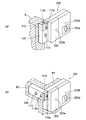
この電子錠200と組み合わされるストライク100は、図1(a),(b)に示す構成である。図1(a),(b)は本考案の一実施例の外観形状を示すもので、ストライク100を左、右の斜め上から見た斜視図である。この図1において、100は外付け用ストライクであり、電子錠200(図1)と並べて設置される。
The
例えば抽斗の前板に錠を取り付けるのが通例であるが、ストライク100は抽斗の枠に錠と並べて取り付けることになる。抽斗の枠は、通常、幅が狭く縦方向に延びているから、ストライク100は枠の前面に縦向きに取り付けることになる。開口111aは、そのときに用いる。
For example, a lock is usually attached to the front plate of the drawer, but the
一方、枠の幅が更に狭いときは、机の抽斗の脇の壁面にストライク100を取り付けざるを得ない。そのときは、ストライク100を横長姿勢として開口112aにデッドボルト210が嵌入するように配する。
On the other hand, when the width of the frame is narrower, the
したがって、ストライク100は、2つの開口111a,112aの何れかを用いる2通りの取付け方がある。そして、本体110のこれら2つの開口111a,112aに対応する壁面に、これら開口111a,112aに連通する覗き窓111b,112bが設けられており、デッドボルト210が嵌入したときに目視観察できるようになっている。
Therefore, there are two ways of attaching the
ストライク100は、とくに材料を選ばないが、樹脂製とすれば製造、取り扱いの両面で好都合である。
The
図3(a),(b)は、ストライク100の2通りの取付け方を示している。図3(a)は、電子錠200を机の抽斗に取り付ける場合であり、ストライク100の固着対象物が机の抽斗周りの縦枠Aである。この場合、ストライク100は縦長姿勢で取り付けることになり、縦枠Aに対してストライク100の裏面、つまり図示しない開口112bが設けられている面を両面テープ(図示せず)で固着する。
3A and 3B show two ways of attaching the
この図3(a)に示す姿勢で取り付けられると、デッドボルト210がストライク100に嵌入したときは、覗き窓111bからデッドボルト210の色付き表示210bが見えることになる。したがって、電子錠200の正面からロック状態が確認できる。
3A, when the
次に、図3(b)は、電子錠200を小型金庫の蓋B1に取り付ける場合であり、ストライク100の固着対象物が小型金庫の側壁B2である。この場合、ストライク100は横長姿勢で取り付けることになるが、小型金庫の側壁B2に対してストライク100の裏面、つまり開口112bが設けられている面を両面テープ(図示せず)で固着する点は同様である。
Next, FIG.3 (b) is a case where the
この図3(b)に示す姿勢で取り付けられると、デッドボルト210の嵌入状態は覗き窓112bから見える。このときも、電子錠200の正面からロック状態が確認できる。
When attached in the posture shown in FIG. 3 (b), the inserted state of the
上記実施例1では、電子錠のデッドボルトが断面形状矩形のものを示したが、
丸棒型等の他の形状であっても、開口111a,112aおよび必要に応じて覗き窓111b,112bの形状をデッドボルト形状に合わせて変形することで、同様に本考案を適用することができる。
In Example 1 above, the dead bolt of the electronic lock showed a rectangular cross-sectional shape,
Even in other shapes such as a round bar shape, the present invention can be similarly applied by deforming the shapes of the
また、実施例1は、電子錠と組み合わされるストライクとして説明したが、機械錠にも本考案を適用することができる。 Moreover, although Example 1 demonstrated as a strike combined with an electronic lock, this invention is applicable also to a mechanical lock.
100 ストライク、110 ストライク本体、 111 開口、
111a 開口、111b 覗き窓、112a 、112b 覗き窓、
113 取付穴、200 電子錠、210 デッドボルト、
210a デッドボルト本体、210b 色付き表示、220 電子錠本体、
221 ケース、222a 操作部、222b 発光表示窓、223 電池蓋、223a 指掛け、A 抽斗縦枠、B1 金庫の蓋、B2 金庫の側壁。
100 strike, 110 strike body, 111 opening,
111a opening, 111b viewing window, 112a, 112b viewing window,
113 mounting holes, 200 electronic locks, 210 dead bolts,
210a dead bolt body, 210b colored display, 220 electronic lock body,
221 case, 222a operation unit, 222b light emitting display window, 223 battery cover, 223a finger hook, A drawer vertical frame, B1 safe cover, B2 safe side wall.
Claims (3)
立方体の一面に設けられた第1のデッドボルト用開口と、
前記立方体の他の面に前記第1のデッドボルトと直角方向をなす向きに設けられた第2のデッドボルト用開口と、
をそなえたことを特徴とするストライク。 In the strike where the dead bolt with a rectangular cross section is inserted and locked,
A first dead bolt opening provided on one side of the cube;
A second dead bolt opening provided on the other surface of the cube in a direction perpendicular to the first dead bolt;
Strike characterized by having.
前記デッドボルト用開口に対応する前記立方体の表面に、前記デッドボルト用開口に達する覗き窓が設けられたことを特徴とするストライク。 The strike of claim 1,
A strike, wherein a viewing window reaching the deadbolt opening is provided on a surface of the cube corresponding to the deadbolt opening.
前記立方体は、両面テープで取付対象物に固着するための平面を有することを特徴とするストライク。 The strike of claim 1,
The cube has a flat surface for fixing to a mounting object with a double-sided tape.
Priority Applications (1)
| Application Number | Priority Date | Filing Date | Title |
|---|---|---|---|
| JP2007001221U JP3131650U (en) | 2007-02-27 | 2007-02-27 | strike |
Applications Claiming Priority (1)
| Application Number | Priority Date | Filing Date | Title |
|---|---|---|---|
| JP2007001221U JP3131650U (en) | 2007-02-27 | 2007-02-27 | strike |
Publications (1)
| Publication Number | Publication Date |
|---|---|
| JP3131650U true JP3131650U (en) | 2007-05-17 |
Family
ID=43282419
Family Applications (1)
| Application Number | Title | Priority Date | Filing Date |
|---|---|---|---|
| JP2007001221U Expired - Fee Related JP3131650U (en) | 2007-02-27 | 2007-02-27 | strike |
Country Status (1)
| Country | Link |
|---|---|
| JP (1) | JP3131650U (en) |
Cited By (2)
| Publication number | Priority date | Publication date | Assignee | Title |
|---|---|---|---|---|
| KR101966600B1 (en) * | 2018-11-02 | 2019-04-05 | 김길수 | Digital door lock |
| WO2020091169A1 (en) * | 2018-11-02 | 2020-05-07 | 김길수 | Digital door lock, door lock control server, and door lock system |
-
2007
- 2007-02-27 JP JP2007001221U patent/JP3131650U/en not_active Expired - Fee Related
Cited By (2)
| Publication number | Priority date | Publication date | Assignee | Title |
|---|---|---|---|---|
| KR101966600B1 (en) * | 2018-11-02 | 2019-04-05 | 김길수 | Digital door lock |
| WO2020091169A1 (en) * | 2018-11-02 | 2020-05-07 | 김길수 | Digital door lock, door lock control server, and door lock system |
Similar Documents
| Publication | Publication Date | Title |
|---|---|---|
| US6666054B1 (en) | Remote-controlled door lock | |
| JP3178832U (en) | Locks used in electronic devices | |
| US6658905B1 (en) | Remote-controlled door lock | |
| US20140311390A1 (en) | Safe and Lock Mechanism | |
| JP3131650U (en) | strike | |
| CA2877780C (en) | Security assembly for use with a security console | |
| JP4948192B2 (en) | Indoor door locks | |
| US20040148982A1 (en) | Latching device for a lock | |
| TWI472672B (en) | Handle assembly for lock | |
| WO2017154704A1 (en) | Latch locking device and door comprising same | |
| JP2008190226A5 (en) | ||
| WO2011014116A1 (en) | Safe comprising a door which is linearly displaceable between closed and open position. | |
| JP5082151B2 (en) | Locking method | |
| US20050223760A1 (en) | Safety lock for glass doors | |
| KR20170120951A (en) | Assembly for deadbolt | |
| JP3230168U (en) | Auxiliary lock | |
| KR200345893Y1 (en) | Spare door lock | |
| JP2008150883A (en) | Lock tool for sliding door | |
| CN210127738U (en) | Lockset and tool box | |
| JP6014345B2 (en) | Lock bracket | |
| US1177091A (en) | Lock. | |
| JP2012001988A (en) | Reforming method of door frame structure and door device for reforming door device | |
| JP5159690B2 (en) | Attachment structure of entrance restriction device to door frame | |
| US20160340092A1 (en) | Lockbox | |
| KR101315963B1 (en) | Dead lock |
Legal Events
| Date | Code | Title | Description |
|---|---|---|---|
| R150 | Certificate of patent or registration of utility model |
Free format text: JAPANESE INTERMEDIATE CODE: R150 |
|
| FPAY | Renewal fee payment (event date is renewal date of database) |
Free format text: PAYMENT UNTIL: 20100418 Year of fee payment: 3 |
|
| FPAY | Renewal fee payment (event date is renewal date of database) |
Free format text: PAYMENT UNTIL: 20110418 Year of fee payment: 4 |
|
| FPAY | Renewal fee payment (event date is renewal date of database) |
Free format text: PAYMENT UNTIL: 20120418 Year of fee payment: 5 |
|
| FPAY | Renewal fee payment (event date is renewal date of database) |
Free format text: PAYMENT UNTIL: 20120418 Year of fee payment: 5 |
|
| FPAY | Renewal fee payment (event date is renewal date of database) |
Free format text: PAYMENT UNTIL: 20130418 Year of fee payment: 6 |
|
| FPAY | Renewal fee payment (event date is renewal date of database) |
Free format text: PAYMENT UNTIL: 20130418 Year of fee payment: 6 |
|
| FPAY | Renewal fee payment (event date is renewal date of database) |
Free format text: PAYMENT UNTIL: 20140418 Year of fee payment: 7 |
|
| LAPS | Cancellation because of no payment of annual fees |