JP3107948U - Shiatsu health and exercise equipment - Google Patents
Shiatsu health and exercise equipment Download PDFInfo
- Publication number
- JP3107948U JP3107948U JP2004005402U JP2004005402U JP3107948U JP 3107948 U JP3107948 U JP 3107948U JP 2004005402 U JP2004005402 U JP 2004005402U JP 2004005402 U JP2004005402 U JP 2004005402U JP 3107948 U JP3107948 U JP 3107948U
- Authority
- JP
- Japan
- Prior art keywords
- acupressure
- pedestal
- guide rail
- main body
- health
- Prior art date
- Legal status (The legal status is an assumption and is not a legal conclusion. Google has not performed a legal analysis and makes no representation as to the accuracy of the status listed.)
- Expired - Fee Related
Links
Images


Landscapes
- Finger-Pressure Massage (AREA)
Abstract
【課題】腕及び背筋及び腹筋の筋肉運動と脊柱起立筋の指圧マッサージ、という筋肉運動と指圧マッサージ機能を採り入れ、何等の駆動源を用いないで簡単な構成で低廉な指圧健康器具兼運動器具を提供する。
【解決手段】左右のフレーム2b、2aは、J型をなしており、梃子の力を与えるために手で掴まれるグリップ3aと、ボール部6とを有しており、台座本体17は、ガイドレール9に取付けられた複数の指圧突起8aと、クッションセット15とを、少なくとも装備し、前記複数の指圧突起8aは、内部に磁石8bを内蔵しており、クッションセット15よりも突出し、さらに高さ調節可能しえるのがよく、前記複数の指圧突起8aは、前記ガイドレール9の取付けによりスライドし可変自在とし、さらに前記ガイドレール9は、複数の指圧突起軸固定孔22を設けており、幅調節固定し得るように構成されている。
【選択図】図1An object of the present invention is to provide an inexpensive acupressure health equipment and exercise apparatus that adopts a muscle movement and acupressure massage function of arm and back muscles and abdominal muscles and acupressure massage of the standing muscle of the spine, without using any driving source. provide.
The left and right frames (2b, 2a) are J-shaped, have a grip (3a) that can be gripped by a hand to give a lever force, and a ball part (6). A plurality of acupressure protrusions 8a attached to the rail 9 and a cushion set 15 are provided at least, and the acupressure protrusions 8a have magnets 8b built in, project beyond the cushion set 15, and have a higher height. The plurality of acupressure protrusions 8a are slidable and adjustable by attaching the guide rail 9, and the guide rail 9 is provided with a plurality of acupressure protrusion shaft fixing holes 22. The width adjustment can be fixed.
[Selection] Figure 1
Description
本考案は、上半身の筋肉運動を行ないながら腰部を指圧状にマッサージすることができる指圧健康器具兼運動器具に関するものである。 [Technical Field] The present invention relates to an acupressure health and exercise device capable of massaging the lower back with acupressure while performing upper body muscle exercise.
従来よりある腰痛解消用健康器具としては、突起物を有する器具を床に置き、突起物上に仰臥して腰部をのせて使用者の体重により腰部を押圧するものが開発されている。代表的なものとして、特開平10−216195号公報がある。また、突起物にローラーを有したものが挙げられる。代表的なものとして、実用新案登録番号3093269号公報がある。しかしながら、指圧と運動が同時に出来るという運動性に優れた器具は少なかった。そこで、マッサージとストレッチ運動を兼用できる器具として仰臥した使用者の腰部を吊り上げて、背部をそらしながら腰を左右に揺らすための健康器具が開発された。代表的なものとして、実用新案登録番号3085373号公報や実用新案登録番号3093204号公報がある。また、筋力増強やリハビリテーションのために家庭的に使用される各種の健康器具もある。 2. Description of the Related Art Conventional health devices for relieving back pain have been developed in which a device having a protrusion is placed on the floor, and the waist is placed on the protrusion and the waist is pressed, and the waist is pressed by the weight of the user. A typical example is JP-A-10-216195. Moreover, what has a roller in the protrusion is mentioned. As a typical example, there is a utility model registration number 3093269. However, there were few instruments excellent in mobility that can perform acupressure and exercise at the same time. Therefore, a health device has been developed for lifting the waist of a user who is supine as a device that can be used for both massage and stretching exercises, and swinging the waist to the left and right while deflecting the back. Representative examples include utility model registration number 3085373 and utility model registration number 3093204. There are also various health appliances used at home for muscle strength and rehabilitation.
従来の吊り上げ型の押圧健康器にあっては、指圧板部に仰向けに寝そべるだけで一定の箇所を固定的にマッサージするものであるから、前記押圧板部の高低を調整したとしても、各人により、或はそのときの状態等により最も指圧したい箇所等が異なるから、これに適合したマッサージをすることができない、またベルトの調節に時間が掛かるという欠点がある。しかも、左右に揺らし運動、ねじり運動をして腰部と下肢の筋肉運動では、腰部と下肢をほぐす事はできるが、背骨を支えている脊柱起立筋の強化には適していなかった。 In a conventional lifting type press health device, a certain part is fixedly massaged by lying on the back of the acupressure plate part, so even if the height of the press plate part is adjusted, each person Because of this, or because the location where the most desired acupressure differs depending on the condition at that time, there is a disadvantage that it is not possible to perform massage suitable for this, and it takes time to adjust the belt. Moreover, the lumbar and lower limb muscles can be loosened by swinging left and right and twisting, but it is not suitable for strengthening the spinal column standing muscle that supports the spine.
一方、従来の運動器具にあっては、人体各所の運動に適するようにするためには装置全体が大掛かりになって高価になると共にこれまた使用しない場合には邪魔物となる欠点がある。 On the other hand, the conventional exercise apparatus has a drawback that the entire apparatus becomes large and expensive in order to be suitable for movements of various parts of the human body and becomes an obstacle when not used again.
脊椎の衰えは筋肉から来る、といわれ、就中、背筋及び腹筋の筋肉運動はきわめて大切である。また、脊椎は人体の中枢であるからこれを支えている脊柱起立筋を指圧マッサージすることは健康維持にきわめて重要であると共に、この脊柱起立筋を強化することは腰痛解消の根本と何人も認めるところである。 It is said that the decline of the spine comes from the muscles, and the muscles of the back and abdominals are particularly important. Also, since the spine is the center of the human body, it is extremely important to acupressure massage the erection of the spine that supports it. Strengthening the erection of the vertebrae is recognized as the basis for eliminating low back pain. By the way.
このことから、本考案は、腕及び背筋及び腹筋の筋肉運動と脊柱起立筋の指圧マッサージ、という筋肉運動と指圧マッサージ機能を採り入れ、何等の駆動源を用いないで簡単な構成で低廉な指圧健康器具兼運動器具を提供することにある。 Therefore, the present invention adopts the muscle movement and acupressure massage functions of arm and back muscles and abdominal muscles and acupressure massage of the erection spine muscles, and a simple structure and inexpensive acupressure health without using any driving source. The object is to provide an instrument and exercise apparatus.
上記の課題を解決するために本考案の指圧健康器具兼運動器具は、台座上部と台座下部と本体軸からなる台座本体と、前記台座本体の本体軸により左右のフレームに連結してなる指圧健康器具兼運動器具において、前記左右のフレームは、J型をなしており、梃子の力を与えるために手で掴まれるグリップと、ボール部とを有しており、前記台座本体は、ガイドレールに取付けられた複数の指圧突起と、クッションセットとを、少なくとも装備したことを特徴とするものである。 In order to solve the above-mentioned problems, the acupressure health equipment / exercise apparatus of the present invention comprises a pedestal body comprising a pedestal upper part, a pedestal lower part and a body axis, and a shiatsu health connected to the left and right frames by the body axis of the pedestal body. In the instrument / exercise apparatus, the left and right frames are J-shaped, and have a grip that can be grasped by a hand to give a lever force, and a ball part. A plurality of attached acupressure protrusions and a cushion set are provided at least.
ここで好ましい態様として、前記複数の指圧突起は、内部に磁石を内蔵しており、クッションセットよりも突出し、さらに高さ調節可能しえるのがよく、前記複数の指圧突起は、前記ガイドレールの取付けによりスライドし可変自在とし、さらに前記ガイドレールは、複数の指圧突起軸固定孔を設けており、幅調節固定し得るように構成されている。 Here, as a preferred aspect, the plurality of acupressure protrusions have magnets incorporated therein, protrude from the cushion set, and can be height-adjustable. The guide rail is slidable by attachment, and the guide rail is provided with a plurality of finger pressure projection shaft fixing holes so that the width can be adjusted and fixed.
前記クッションセットは、中央に横一文字型のクッションガイドレールを有しいることを特徴とする。 The cushion set has a horizontal single letter type cushion guide rail in the center.
運搬時又は不使用時には、ノブと一体となったフレーム固定ボルトを取り外すと共に、左右のフレームを内側に折り畳んでコンパクトな形態とすることができる。 When carrying or not in use, the frame fixing bolt integrated with the knob can be removed, and the left and right frames can be folded inward to form a compact form.
以上、詳細に説明したように、本考案によれば、指圧健康器具兼運動器具のクッションセットにあるクッションガイドレールよりも突出している複数の指圧突起を、体格差により中央付近に幅調整固定し、仰向けに寝て左右のフレームと一体となったグリップを、梃子の力によって押し上げると、指圧突起が背骨を挟んで脊柱起立筋の当接するから、グリップの押し上げ加減により、好みに合った指圧マッサージと胸と腕の筋肉を鍛えることができる。 As described above in detail, according to the present invention, a plurality of acupressure protrusions protruding from the cushion guide rail in the acupressure set of the acupressure health equipment / exercise equipment are adjusted and fixed in the vicinity of the center due to the physique difference. When the grip united with the left and right frames is pushed up by the force of the lever, the shiatsu protrusion comes in contact with the spinal column standing muscle across the spine, so that the shiatsu massage suits your taste by pushing up and down the grip. And you can train your chest and arm muscles.
又、請求項2のように、複数の指圧突起は、内部に磁石を内蔵しており、クッションセットにあるクッションガイドレールよりも突出し、さらに高さ調節可能となっており、磁気による血行促進と高さ調節による指圧の強さ調節が可能となっている。 Further, as in
又、請求項3のように、複数の指圧突起はガイドレールの取付けによりスライドし可変自在とし、さらに前記ガイドレールは、複数の指圧突起軸固定孔を設けており、幅調節固定し得るように構成されているので、体格差により、或いは指圧すべき箇所により、指圧突起を幅調整して、指圧の幅を可変できると共に、運動用具として使用するときは指圧突起をクッションセットの両側に固定して、身体に当接しないように対応することができ、筋肉運動を無理なく行えるように使用できる。 According to a third aspect of the present invention, the plurality of acupressure protrusions are made slidable and variable by attaching a guide rail, and the guide rail is provided with a plurality of acupressure protrusion shaft fixing holes so that the width can be adjusted and fixed. Because it is configured, the width of the acupressure protrusion can be varied by adjusting the width of the acupressure protrusion depending on the difference in physique or depending on the location where acupressure should be applied, and when used as an exercise tool, the acupressure protrusion is fixed to both sides of the cushion set. Therefore, it can be used so as not to come into contact with the body, and can be used so that muscle exercise can be performed without difficulty.
又、請求項4のように、クッションセットは、中央に横一文字型のクッションガイドレールを有しいて、指圧突起の取り付けと取り外しを容易に行うことができる。 In addition, the cushion set has a horizontal single letter type cushion guide rail in the center, and the attachment and removal of the acupressure protrusion can be easily performed.
又、請求項5のように、運搬時又は不使用時にはノブ型フレーム固定ボルトを取り外すと共に左右のフレームを内側に折り畳んでコンパクトな形態とし、しかも、フレームの固定もできる。 Further, as in
又、クッションセットにあるクッションガイドレールよりも突出している複数の指圧突起を、身体に当接しないように両側に固定し、台座本体に座し、グリップを握持し引き寄せると腕と背筋の筋肉運動が行われ、台座本体に座し、ボール部を下方に押し下げると腕と胸の筋肉運動が行われる。 In addition, a plurality of acupressure protrusions protruding from the cushion guide rail in the cushion set are fixed to both sides so that they do not contact the body, sit on the pedestal body, grip and pull the grip muscles of the arms and back muscles When exercise is performed, sitting on the pedestal body and pushing down the ball part downward, the arm and chest muscles are exercised.
従って、何等の動力源を使用することなく自分自身の運動と自分にあった指圧マッサージをすることができる。 Therefore, you can perform your own exercise and acupressure massage that suits you without using any power source.
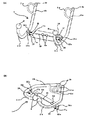
以下、本発明を添付図面に示す実施形態例に基づき、更に詳細に説明する。図1(A)は指圧突起を中央に固定した斜視図、図1(B)は左右のフレームを本体台座側に折り畳み指圧突起を両側に固定した斜視図、図2(A)は台座上部と下部と台座軸を装着前の斜視図、(B)はフレームと台座上部と下部と台座軸を装着した斜視図、図3(A)は指圧用突起とガイドレールの幅調整機構を示す拡大図、図3(B)は指圧突起部とガイドレール部の拡大断面図、図4(A)は台座上部にガイドレールと指圧部を装着した斜視図、図4(B)は台座本体の斜視図、図5(A)は左右のフレームの斜視図、図5(B)はノブ部の平面図、図5(C)はグリップ部の斜視図、図5(D)は本体軸止ボルト部の平面図、図5(E)はグリップ固定螺子の平面図、図6は押し上げ状態で使用するときの側面図、図7は押し上げ状態で両足を揃えて上下させて使用する時の側面図、図8は台座本体に座し引き寄せ状態で使用する時の側面図、図9は台座本体に座し押し下げ状態で使用するときの側面図である。 Hereinafter, the present invention will be described in more detail based on an embodiment shown in the accompanying drawings. 1A is a perspective view in which the acupressure protrusion is fixed at the center, FIG. 1B is a perspective view in which the left and right frames are folded to the main body pedestal side, and the acupressure protrusion is fixed on both sides, and FIG. FIG. 3B is a perspective view of the frame, the upper portion of the pedestal, the lower portion, and the pedestal shaft, and FIG. 3A is an enlarged view showing a shiatsu protrusion and a guide rail width adjustment mechanism. 3B is an enlarged cross-sectional view of the acupressure protrusion and guide rail, FIG. 4A is a perspective view of the guide rail and the acupressure part mounted on the pedestal, and FIG. 4B is a perspective view of the pedestal body. 5 (A) is a perspective view of the left and right frames, FIG. 5 (B) is a plan view of the knob portion, FIG. 5 (C) is a perspective view of the grip portion, and FIG. FIG. 5 (E) is a plan view of the grip fixing screw, FIG. 6 is a side view when used in a pushed-up state, and FIG. 7 is a pushed-up view. FIG. 8 is a side view when used with the pedestal body sitting and pulled, and FIG. 9 is a side view when the pedestal body is used while being pushed down. FIG.
前記左右のフレームと、前記グリップと、前記ボール部とを、梃子の力によって押し上げられて身体の部分を押圧する前記台座本体は、ガイドレールに取付けられた左右2つの指圧突起と、クッションセットとを、少なくとも装備したことを特徴とする指圧健康器具兼運動器具。 The pedestal body that pushes up the left and right frames, the grip, and the ball portion by a lever force to press the body part includes two left and right acupressure protrusions attached to a guide rail, and a cushion set. A shiatsu health equipment / exercise equipment characterized by comprising at least.
この指圧健康器具兼運動器具1は、台座本体17と、指圧突起8aと、右フレーム2a、左フレーム2bと、グリップ3aと、ボール部6と、ノブ14aと一体となったフレーム固定ボルト14bを主に備えいる。 This acupressure health /
この指圧健康器具兼運動器具1は、台座上部4と、クッションセット15と、台座下部5と、本体軸7aからなる台座本体17と、前記台座本体17と一体化した本体軸7aにより左右のフレームに連結されると共に本体軸止ボルト19と、ワッシャー20とナット21によって取り付けられ、梃子の力を与えるために手で掴まれるグリップ3aと、ボール部6とを、右フレーム2a、左フレーム2bに取付けられている。 This acupressure health appliance /
本考案案の指圧健康器具兼運動器具1は、台座上部4、4と台座下部5、5と本体軸7a、7aからなる台座本体17、17と、前記台座本体17の本体軸7により右フレーム2a、2aと左フレーム2b、2bに本体軸止ボルト19、19によって連結してなり、前記右フレーム2a、2aと前記左フレーム2b、2bは、J型をなしており、梃子の力を与えるために手で掴まれるグリップ3a、3aと、ボール部6、6とを有しており、前記台座本体17、17は、ガイドレール9、9に取付けられた指圧突起8a、8aと、クッションセット15,15とを、少なくとも装着した事を特徴としている。 The acupressure health equipment /
梃子の力によって押し上げられて腰の部分を押圧する指圧突起8a、8aは、内部に磁石8b、8bを内蔵しており、台座本体17、17に設けたクッションセット15、15にあるクッションガイドレール16,16よりも突出し、さらに、高さ調節可能であることを特徴とする。 The
指圧突起8a、8aはガイドレール9、9に取付けにより、スライド可変自在とし、ガイドレール9、9は、複数の指圧突起固定孔22、22を設けており、幅調節固定し得るように構成されていることを特徴としている。 The
運搬時又は不使用時にはノブ14a、14aに取り付けられたフレーム固定螺子14b、14bをフレーム固定螺子穴18、18から取り外し本体軸止ステー12a、12aから抜き取ると共に、右フレーム2aと左フレーム2bをそれぞれ内側に折り畳み、ノブ14a、14aに取り付けられたフレーム固定螺子14b、14bを再度フレーム固定螺子穴18、18に取り付けることによりコンパクトな形態とすることができ、折り畳んだ右フレーム2aと左フレーム2bの固定をすることができるように構成されている。 When carrying or not in use, the frame fixing screws 14b and 14b attached to the
右フレーム2a、2aと左フレーム2b、2bは、指圧健康器具兼運動器具1、1のフレームをなす部分であり、円筒形状の中空の丸パイプを曲げ加工によりJ型に構成されていて、本体軸7a、7aと連結するための本体軸止ステー12a、12aを側面に溶接して接着されており、しかも、グリップ3a、3aを取り付け固定するために挿入するためにグリップ固定穴13a、13aとグリップ固定螺子穴13b、13bが丸穴加工されていて、グリップ3a、3a側の先端にはキャップ2c、2cが装着されており、又、反対側になる先端にはボール部6、6が装着しており、床に接する部分にラバー2d、2dを装着している。 The right frames 2a and 2a and the
梃子の力を与えるために手で掴まれるグリップ3a、3aは、U型で円筒形状の中空の丸パイプを曲げ加工により構成されていて円筒形状のウレタン3b、3bが差し込まれており、右フレーム2a、2aと左フレーム2b、2b上部に設けれたグリップ固定穴13a、13aに垂直に挿入して、裏側にあるグリップ固定螺子穴13b、13bよりワッシャー20を挿入して一体となったグリップ固定螺子13c、13cを挿入してナット部3c、3cに螺合して取り付けられる。このナット部3c、3cはグリップ固定螺子13c、13cを取り付けるための螺子穴が形成されている。 The
本体軸7a、7aは、円筒形のストレートの丸パイプによりなり、本体軸止ボルト19、19を挿入して貫通するために丸穴に形成された本体軸止孔12b、12bを4箇所設けられ、右フレーム2a、2aと左フレーム2b、2bを組み立て、又は、折り畳み固定するためにノブ14a、14aと一体になったフレーム固定螺子14b、14bを挿入して螺合するフレーム固定螺子穴18、18を形成している。このことにより、右フレーム2a、2aと左フレーム2b、2bの組み立てと、固定と、折り畳み固定を容易にすることができるように構成されている。 The main body shafts 7a and 7a are made of cylindrical straight round pipes, and are provided with four main body shaft stop holes 12b and 12b formed in round holes for inserting and penetrating the main body shaft stop
台座本体17は、本体軸7a、7aに台座上部4、4と台座下部5、5とをはめ込むように装着し、螺子等で固定しており、ガイドレール9、9に指圧突起軸台座11、11を2個挿入してから台座上部4、4に接着し、その上からクッションセット15、15をずれないように接着剤等により固定し、クッションガイドレール16、16から指圧突起8aと一体化した指圧突起軸10aの先端である指圧突起軸螺子10cを挿入して指圧突起台座11、11に螺合して挿入されている。 The pedestal
台座本体17、17と一体化した本体軸7aは、台座上部4と台座下部5一体となった台座部とは固定されていないので台座部は本体軸7aを支点にシーソーのように90度前後の角度に回転する事ができる。さらに、台座上部4、4と台座下部5、5が本体軸7a、7aに装着後、左右に移動しないようにストッパー金具7b、7bが本体軸7a、7aに溶接固定されている。 Since the main body shaft 7a integrated with the pedestal
このことにより、梃子の力により右フレーム2a、2aと左フレーム2b、2bを傾けて台座本体17を上部に押し上げてもクッションセット15と一体となった台座上部4,4は、身体に対し、常に水平に押圧しするように構成されていて、臀部や腰部分に緩やかに当たるようするためである。 As a result, even if the
クッションセット15、15は使用者の臀部か腰部分に当接して押し上げるもので、内部は硬度のスポンジで形成され、表側全体が合成皮革等の表皮で覆われており、中央部分に横一文字にクッションガイドレール16が設けられ、台座上部に接着されており、指圧突起8a、8aはクッションセット15、15中央にあるクッションガイドレール16、16よりも突出するように構成されていて腰の部分に緩やかに当たるようにするためである。 The cushion sets 15 and 15 are pushed up against the user's buttocks or waist, and the inside is formed with a sponge of hardness, and the entire front side is covered with a skin such as synthetic leather, with a single horizontal letter at the center. A
指圧突起8a、8aは適度な高度のゴム又はプラスチックラバー8c、8cにより形成され、内部に磁石8b、8bを埋め込むように装着していて、指圧突起軸10a、10aの頭部に固定された指圧突起固定金具8d、8dに接着されて形成される。
指圧突起台座11、11は四角形状の金具になっており、中央に上記指圧突起軸10a、10aの先端をなしている指圧突起軸螺子10b、10bを挿入して支持するための螺子穴形成されており、指圧突起軸螺子10b、10bを螺合して挿入されている。これにより指圧突起軸10a、10aと一体になった指圧突起8a、8aを所定の高低に調整して固定できるようになっている。 The shiatsu protrusion pedestals 11 and 11 are rectangular metal fittings, and a screw hole is formed in the center for inserting and supporting the shiatsu protrusion shaft screws 10b and 10b forming the tips of the
前記指圧突起8a、8aは、前記ガイドレール9,9の取付けによりスライドし可変自在にでき、さらに前記ガイドレールは、複数の指圧突起軸固定孔22、22を設けており、幅調節固定し得るようになっている。指圧突起8a、8aを左右にスライドさせるには、まず指圧突起8a、8aと指圧突起軸10a、10aと指圧突起台座11、11と一体になった指圧突起8a、8aを掴み上部に上げて、すでに指圧突起軸螺子10b、10bを挿入し固定している指圧突起軸固定孔22、22から抜き取り、右又は、左にスライドさせて所定の指圧突起軸固定孔22、22に挿入し、固定して使用する。これにより、指圧器具として腰部を指圧して使用するときは、体格に合わせて指圧突起8a、8aの幅調整し当接する場所を調節し、又、運動器具として上半身の筋肉運動をするときは、クッションガイドレール16、16の両側に固定して身体に当接しないように使用することができる。 The
次に、上記考案の実施するための最良の形態に基づく指圧健康器具兼運動器具の使用方法について以下説明する。 Next, a method for using the acupressure health and exercise equipment based on the best mode for carrying out the above-described device will be described below.
腕を押し上げて指圧健康器具兼運動器具1の台座本体17を押し上げるには、図5に示すようにして使用する。 In order to push up the arm and push up the
先ず、台座上部4、4に設けたクッションセット15、15の中央に形成されているクッションガイドレール16、16よりも突出している指圧突起8a、8aと指圧突起軸10a、10aと指圧突起台座11、11と一体になった指圧突起8a、8aを掴み上部に上げて、すでに指圧突起軸螺子10b、10bを挿入し固定している指圧突起軸固定孔22、22から抜き取り、右又は、左にスライドさせて体格に合った脊柱起立筋の幅に調節して、所定の指圧突起軸固定孔22、22に挿入し、固定する。次に、指圧突起8a、8aを好みの高低に調節するには、指圧突起軸10a、10aと一体になった指圧突起8a、8aを掴んで回転させて所定の高低に調整してする。このとき、指圧突起8a、8aを低く調節設定するには、右に指圧突起軸8a、8aを回転させるとそれに伴い指圧突起台座11、11螺合している指圧突起軸螺子10b、10bが下へ挿入されると共に、指圧突起8a、8aも低く調整される。又、指圧突起8a、8aを高く調節設定するには、左に指圧突起軸8a、8aを回転させるとそれに伴い指圧突起台座11、11螺合している指圧突起軸螺子10b、10bが上へ緩まると共に、指圧突起8a、8aも高く調整される。 First, the
以上のような調整が済んだ後に、身体を指圧健康器具兼運動器具1に載せる。即ち、指圧健康器具兼運動器具を側面から見て、グリップ3a側に身体の頭部側が向き、ボール部5側に脚部側が向くように身体を仰向けの状態で腰の部分を台座本体17の上に載せる。 After the above adjustment is completed, the body is placed on the acupressure health equipment /
そして、両腕を曲げて胸の位置におき、両手でグリップ3a又は右フレーム2a、左フレーム2bの上部などを掴み、肘を伸ばしながら両腕を押し上げると、梃子の力を利用しながら台座本体17と指圧突起8a、8bを上方側に押し上げる。 Then, bend your arms and place them in the chest position, grasp the
この上方側に押し上げる指圧突起8a、8bは身体の腰部分、特に脊柱起立筋を指圧することになり、これにより、身体は背中側が弓なりにそって背筋を伸ばすと同時に、腰の指圧が行われ、磁石による磁気の効果で血行が促進され、脊柱起立筋がほぐされることになる。 These
又、腕を押し上げて指圧健康器具兼運動器具1の台座本体17を押し上げて両足を揃えて上下させるには、図6に示すようにして使用する。 Moreover, in order to push up the arm and push up the pedestal
先ず、運動器具として使用する場合は、台座上部4に設けたクッションセット15の中央に形成されているクッションガイドレール16、16よりも突出している指圧突起8a、8aと指圧突起軸10a、10aと指圧突起台座11、11と一体になった指圧突起8a、8aを掴み上部に上げて、すでに指圧突起軸螺子10b、10bを挿入し固定している指圧突起軸固定孔22、22から抜き取り、クッションガイドレール16の両側にスライドさせて、ガイドレール9、9の両側にある指圧突起軸固定孔22、22に挿入し固定する。 First, when used as an exercise device, the
以上のような調整が済んだ後に、身体を指圧健康器具兼運動器具1に載せる。即ち、指圧健康器具兼運動器具を側面から見て、グリップ3a側に身体の頭部側が向き、ボール部6側に脚部側が向くように身体を仰向けの状態で腰の部分を台座本体17の上に載せる。 After the above adjustment is completed, the body is placed on the acupressure health equipment /
そして、両腕を曲げて胸の位置におき、両手でグリップ3a又は右フレーム2a、左フレーム2bの上部などを掴み、肘を伸ばしながら両腕を押し上げ梃子の力を利用しながら台座本体17を押し上げる。 Then, both arms are bent and placed at the chest position, and the upper part of the
次に両足を揃えて上下させるが、このとき指圧突起8a、8aはクッションガイドレール16、16の両側に固定されているので腰部分に接することなく、腹筋運動が行われることになり、身体は背中側が弓なりにそって背筋を伸ばすと同時に、台座本体17、17押し上げながら、肢の上げ下げ腹筋を行うことができるので、腰を痛めることなく腹筋運動を行われることになる。 Next, the feet are aligned and moved up and down. At this time, the
又、腕を引き寄せて指圧健康器具兼運動器具1の台座本体17を押し上げて腕と背筋の筋肉運動をさせるには、図7に示すようにして使用する。 Further, in order to pull up the arm and push up the pedestal
先ず、運動器具として使用する場合は、台座上部4に設けたクッションセット15の中央に形成されているクッションガイドレール16、16よりも突出している指圧突起8a、8aと指圧突起軸10a、10aと指圧突起台座11、11と一体になった指圧突起8a、8aを掴み上部に上げて、すでに指圧突起軸螺子10b、10bを挿入し固定している指圧突起軸固定孔22、22から抜き取り、クッションガイドレール16の両側にスライドさせて、ガイドレール9、9の両側にある指圧突起軸固定孔22、22に挿入し固定する。 First, when used as an exercise device, the
以上のような調整が済んだ後に、身体を指圧健康器具兼運動器具1に載せる。即ち、指圧健康器具兼運動器具を側面から見て、ボール部6側に身体の頭部側が向き、グリップ3側に脚部側が向くように座して臀部を本体台座17に載せる。 After the above adjustment is completed, the body is placed on the acupressure health equipment /
そして、両腕を伸ばして、両手でグリップ3aを掴み、肘を曲げながら両腕を引き上げ梃子の力を利用しながら台座本体17を引き上げる。次に肘を伸ばしながら台座本体17を押し下げる。このとき指圧突起8a、8bはクッションガイドレール16の両側に固定されているので臀部に接することなく、腕と背筋と腹筋の筋肉運動が行われることになり、身体の体重によって腕と背筋の筋肉にかかる負荷率が変わり、理想的な筋肉運動を行われることになる。 Then, both arms are extended, the
又、腕を押し下げて指圧健康器具兼運動器具1の台座本体17を押し上げて腕と胸と背筋の筋肉運動をさせるには、図8に示すようにして使用する。 Moreover, in order to push down the arm and push up the
先ず、運動器具として使用する場合は、台座上部4に設けたクッションセット15の中央に形成されているクッションガイドレール16、16よりも突出している指圧突起8a、8aと指圧突起軸10a、10aと指圧突起台座11、11と一体になった指圧突起8a、8aを掴み上部に上げて、すでに指圧突起軸螺子10b、10bを挿入し固定している指圧突起軸固定孔22、22から抜き取り、クッションガイドレール16の両側にスライドさせて、ガイドレール9、9の両側にある指圧突起軸固定孔22、22に挿入し固定する。 First, when used as an exercise device, the
以上のような調整が済んだ後に、身体を指圧健康器具兼運動器具1に載せる。即ち、指圧健康器具兼運動器具を側面から見て、ボール部6側に身体の頭部側が向き、グリップ3側に脚部側が向くように座し、臀部を本体台座17に載せる。そして、両腕を後ろに回し、両手でボール部6を掴み、肘を伸ばしながら両腕を下方へ押し下げ梃子の力を利用しながら台座本体17を引き上げる。次に肘を曲げながら台座本体17を下げる。このとき指圧突起8a、8aはクッションガイドレールの両側に固定されているので臀部に接することなく、腕と胸と背筋の筋肉運動が行われることになり、身体の体重によって腕と胸と背筋の筋肉にかかる負荷率が変わり、理想的な筋肉運動を行われることになる。 After the above adjustment is completed, the body is placed on the acupressure health equipment /
なお、本考案は以上述べた実施例に限定されるものではない。 The present invention is not limited to the embodiments described above.
1 指圧健康器具兼運動器具
2a 右フレーム
2b 左フレーム
2c キャップ
2d ラバー
3a グリップ
3b ウレタン
3c ナット部
4 台座上部
5 台座下部
6 ボール部
7a 本体軸
7b ストッパー金具
8a 指圧突起
8b 磁石
8c ゴムまたはプラスチックラバー
8d 指圧突起軸固定金具
9 ガイドレール
10a 指圧突起軸
10b 指圧突起軸螺子
11 指圧突起台座
12a 本体軸止ステー
12b 本体軸止ボルト孔
12c フレーム固定ボルト孔
12d 本体軸止ステー孔
13a グリップ固定孔
13b グリップ固定螺子穴
13c グリップ固定螺子
14a ノブ
14b フレーム固定螺子
15 クッションセット
16 クッションガイドレール
17 台座本体
18 フレーム固定螺子孔
19 本体軸止ボルト
20 ワッシャー
21 ナット
22 指圧突起軸固定孔1 acupressure health and
Claims (5)
前記左右のフレームは、J型をなしており、梃子の力を与えるために手で掴まれるグリップと、ボール部とを有しており、
前記台座本体は、ガイドレールに取付けられた複数の指圧突起と、クッションセットとを、少なくとも装備したことを特徴とする指圧健康器具兼運動器具。In a pedestal main body composed of a pedestal upper part, a pedestal lower part and a main body axis, and a shiatsu health instrument and exercise apparatus connected to the left and right frames by the main body axis of the pedestal main body,
The left and right frames have a J shape, and have a grip that can be grasped by a hand to give a lever force, and a ball portion.
The pedestal main body is equipped with at least a plurality of acupressure protrusions attached to a guide rail and a cushion set.
Priority Applications (1)
| Application Number | Priority Date | Filing Date | Title |
|---|---|---|---|
| JP2004005402U JP3107948U (en) | 2004-08-12 | 2004-08-12 | Shiatsu health and exercise equipment |
Applications Claiming Priority (1)
| Application Number | Priority Date | Filing Date | Title |
|---|---|---|---|
| JP2004005402U JP3107948U (en) | 2004-08-12 | 2004-08-12 | Shiatsu health and exercise equipment |
Publications (1)
| Publication Number | Publication Date |
|---|---|
| JP3107948U true JP3107948U (en) | 2005-04-07 |
Family
ID=43270642
Family Applications (1)
| Application Number | Title | Priority Date | Filing Date |
|---|---|---|---|
| JP2004005402U Expired - Fee Related JP3107948U (en) | 2004-08-12 | 2004-08-12 | Shiatsu health and exercise equipment |
Country Status (1)
| Country | Link |
|---|---|
| JP (1) | JP3107948U (en) |
Cited By (1)
| Publication number | Priority date | Publication date | Assignee | Title |
|---|---|---|---|---|
| JP2892245B2 (en) | 1993-01-11 | 1999-05-17 | 三菱電機株式会社 | Radiotherapy equipment |
-
2004
- 2004-08-12 JP JP2004005402U patent/JP3107948U/en not_active Expired - Fee Related
Cited By (1)
| Publication number | Priority date | Publication date | Assignee | Title |
|---|---|---|---|---|
| JP2892245B2 (en) | 1993-01-11 | 1999-05-17 | 三菱電機株式会社 | Radiotherapy equipment |
Similar Documents
| Publication | Publication Date | Title |
|---|---|---|
| KR100436899B1 (en) | Stretch Therapy Apparatus | |
| KR101287134B1 (en) | Chiropractic and paraspinal muscle strengthening exercise apparatus | |
| KR20190015122A (en) | Weight training device for disabled people with spinal cord injury | |
| US7976446B2 (en) | Exercise apparatus | |
| KR101441290B1 (en) | Muscular exercise and massage chair | |
| Norris | Functional load abdominal training: part 2 | |
| KR20100122299A (en) | Stretching apparatus | |
| EP2768462B1 (en) | Upper body attachment apparatus for whole body vibration equipment | |
| KR100869178B1 (en) | Pelvic Muscle Strengthening Equipment | |
| CN106267717A (en) | Body-building training apparatus | |
| JP3107948U (en) | Shiatsu health and exercise equipment | |
| KR20190015123A (en) | Weight training device for disabled people with spinal cord injury | |
| CN109529262A (en) | A kind of sports medical science or rehabilitation science hemiplegia fitness equipment | |
| KR100873064B1 (en) | Chiropractor including lower body reinforcement combined use | |
| CN209437611U (en) | A massage and stretching device suitable for posterior superficial muscle group | |
| JP2002052092A (en) | Health promotion equipment | |
| US20100311554A1 (en) | Upper torso exercise apparatus | |
| JP2002035161A (en) | Instrument for training muscular power | |
| KR200487636Y1 (en) | Push-up exercise equipment for plank exercise combined use | |
| KR102703159B1 (en) | Exercise Equipment for Orthodontic and Rehabilitation Treatment | |
| CN201175425Y (en) | Leg rump health-care bending and extending device | |
| CN114343945B (en) | A correction device based on spinal deformity | |
| KR200348213Y1 (en) | Frozen shoulder machine | |
| KR200436590Y1 (en) | Leg stretching apparatus | |
| JP2014161551A (en) | Stretch device |
Legal Events
| Date | Code | Title | Description |
|---|---|---|---|
| R150 | Certificate of patent or registration of utility model |
Free format text: JAPANESE INTERMEDIATE CODE: R150 |
|
| LAPS | Cancellation because of no payment of annual fees |