JP3102695U - Waterproof keyboard - Google Patents
Waterproof keyboard Download PDFInfo
- Publication number
- JP3102695U JP3102695U JP2004000049U JP2004000049U JP3102695U JP 3102695 U JP3102695 U JP 3102695U JP 2004000049 U JP2004000049 U JP 2004000049U JP 2004000049 U JP2004000049 U JP 2004000049U JP 3102695 U JP3102695 U JP 3102695U
- Authority
- JP
- Japan
- Prior art keywords
- support plate
- circuit board
- waterproof keyboard
- opening
- bottom plate
- Prior art date
- Legal status (The legal status is an assumption and is not a legal conclusion. Google has not performed a legal analysis and makes no representation as to the accuracy of the status listed.)
- Expired - Lifetime
Links
Images


Landscapes
- Push-Button Switches (AREA)
- Input From Keyboards Or The Like (AREA)
Abstract
【課題】誤って液体を溢しても内部のマザーボードにダメージを与えることのない防水型キーボードを提供する。
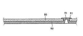
【解決手段】サポートプレート80の下にボトムプレート90を配置し、サポートプレート80(および被膜回路板70)のスルーホール71(および開口81)にボトムプレート90のノード91を貫通させ、組立後にスルーホール又は開口をノード91でリベット加工することにより開口をなくして防水型キーボード100を得る。
【選択図】図1An object of the present invention is to provide a waterproof keyboard that does not damage an internal motherboard even if a liquid overflows accidentally.
A bottom plate (90) is disposed under a support plate (80), and a node (91) of the bottom plate (90) passes through a through hole (71) of the support plate (80). The waterproof keyboard 100 is obtained by riveting the hole or opening at the node 91 to eliminate the opening.
[Selection diagram] Fig. 1
Description
本考案はキーボードに関し、特にパーソナルコンピュータ(PC)等においてデータや指令等の入力に使用される防水型のキーボードに関する。 The present invention relates to a keyboard, and more particularly to a waterproof keyboard used for inputting data, instructions, and the like in a personal computer (PC) or the like.
一般的なノートブック型コンピュータ10は、図5に示す如き構成であり、パネル(表示装置)20、キーボード30およびベース(基部)40により構成される。ここで、パネル20およびベース40は、ヒンジにより一体的に連結されている。キーボード30は、ベース40上に取り付けられ、表面にCPU(中央演算処理装置)等の電子デバイスが実装されたマザーボード(図示せず)がベース40の内部に収容されている。マザーボードは、キーボード30の下方に配置されている。
A
図6乃至図10にそれぞれ全体斜視図、全体上面図、全体底面図、全体側断面図およびその拡大図で示す如く、キーボード30は、複数のキー31、これら複数のキー31を支持および固定するために複数のキー31の下方に配置されたエラスチック(又は弾性)層33、このエラスチック層33の下に取り付けられた回路板層34およびこの回路板層34の下に配置されたボトムプレート(底板)35により構成される。このボトムプレート35は、キー31、エラスチック層33および回路板層34を固定し、4辺にフランジ37を有する。
As shown in FIGS. 6 to 10 as a whole perspective view, a whole top view, a whole bottom view, a whole side sectional view, and an enlarged view thereof, the
図8に最もよく示す如く、ボトムプレート35には、スタンピング(打ち抜き)により形成された複数の開口36が分布されている。このプロセスでラグ又は突起状部(図示せず)が形成され、キー31、エラスチック層33および回路板層34が固定される。エラスチック層33および回路板層34には、それぞれボトムプレート35の開口36に対応する孔が形成され、キー31、エラスチック層33および回路板層34が、ボトムプレート35に取り付けられたラグにより係合および固定され一体化される。更に、ボトムプレート35には、多数のねじ(図示せず)が配置され、キーボード30をベース40の上にロックし、キーボード30およびベース40内のマザーボード間に所定の間隔を維持する。
As shown best in FIG. 8, the
キーボードの構成は周知技術であるので、ここでこれ以上の説明は必要ないと思料する。コンピュータのユーザは、キー31を押下して操作するので、キー31、エラスチック層33および回路板層34を支持するボトムプレート35は、金属等の硬質且つ堅牢な材料で製造する必要がある。これにより、ユーザが押下する力に耐え且つキーボード30の曲がりおよび変形を防止する。
Since the configuration of the keyboard is a well-known technique, it is not considered necessary to describe it further here. Since the user of the computer operates the
上述の如き従来技術において、ボトムプレート35の開口36は、従来のスタンピングにより形成され、ラグが貫通し、キー31、エラスチック(弾性)層33および回路板層34を係合固定する必要がある。このボトムプレート35には複数の開口36が分布するので、ユーザが誤って液体をキーボード30の上に溢すと、液体はキーボード30の開口に沿ってキーボード30の下方のマザーボードに向けて下方へ流れる。従って、マザーボード30にダメージを生じさせてキーボード30を動作不能にする虞があった。
In the prior art as described above, the
本考案は、従来のキーボードの上述の如き課題に鑑みなされたものであり、ボトムプレートのスタンピングされたノードは、サポートプレートの開口でリベット加工し、キーボードのボトムプレートの下方のマザーボードが、キーボード内に誤って液体が侵入することによりダメージを受けるのを阻止することを1つの目的とする。 The present invention has been made in view of the above-described problems of the conventional keyboard, and the stamped node of the bottom plate is riveted at the opening of the support plate, and the motherboard below the bottom plate of the keyboard is mounted inside the keyboard. It is an object of the present invention to prevent a liquid from being inadvertently invaded by a liquid.
本考案の他の目的は、ボトムプレートをサポートプレートによりリベットして、被膜回路板をサポートプレートの上に配置し、被膜回路板が全体の組立を容易且つ安定にする防水型キーボードを提供することである。 Another object of the present invention is to provide a waterproof keyboard in which the bottom plate is riveted by the support plate and the coated circuit board is placed on the support plate, and the coated circuit board makes the whole assembly easy and stable. It is.
本考案の更に他の目的は、ボトムプレートのスタンピングされたノードが、被膜回路板およびサポートプレートの開口によりリベットされ、キーボードから誤って侵入する液体によりマザーボードがダメージを受けるのを阻止する防水型キーボードを提供することである。 Still another object of the present invention is to provide a waterproof keyboard in which a stamped node of a bottom plate is riveted by an opening in a cover circuit board and a support plate to prevent a motherboard from being damaged by a liquid that accidentally enters from the keyboard. It is to provide.
上述した課題を解消又は軽減して上述した目的を達成するために、本考案の防水型キーボードは、底面の両端に設けられた複数のキーと、これら各キーに設けられる上ピボット部および下ピボット部を有するハサミフレームと、コンタクト押圧部を有する弾性コンタクトボディと、第1スルーホールを有する被膜回路板と、第1開口および下固定部を有するサポートプレートと、複数のスタンピングされたノードを有するボトムプレートとを備え、このボトムプレートはサポートプレートの下側に配置され、ボトムプレートのスタンピングされたノードはサポートプレートの対応する第1開口を貫通し、ボトムプレートおよびサポートプレートはリベット加工され、被膜回路基板はサポートプレートの上に配置されることを特徴とする。本考案の好適実施例によると、光遮蔽プレートが更に設けられている。被膜回路板は、上層、中層および下層よりなる。被膜回路板の上に黒又は暗い印刷面が印刷されている。サポートプレートの第1開口は略円形である。サポートプレートの第1開口には複数のノッチが形成されている。 In order to solve or alleviate the above-described problems and achieve the above-described object, the waterproof keyboard of the present invention includes a plurality of keys provided at both ends of a bottom surface, an upper pivot portion and a lower pivot provided for each of these keys. Frame having a portion, an elastic contact body having a contact pressing portion, a coated circuit board having a first through hole, a support plate having a first opening and a lower fixing portion, and a bottom having a plurality of stamped nodes A bottom plate disposed below the support plate, wherein the stamped nodes of the bottom plate pass through corresponding first openings in the support plate, the bottom plate and the support plate are riveted, and The substrate is disposed on the support plate. According to a preferred embodiment of the present invention, a light shielding plate is further provided. The coated circuit board comprises an upper layer, a middle layer and a lower layer. A black or dark printed surface is printed on the coated circuit board. The first opening of the support plate is substantially circular. A plurality of notches are formed in the first opening of the support plate.
また、本考案の防水型キーボードは、複数のキーと、これらのキー毎に設けられる複数のハサミフレームおよび弾性コンタクトボディと、第1開口を有するサポートプレートと、第2スルーホールを有する被膜回路板と、複数のスタンピングされたノードを有するボトムプレートとを備え、被膜回路板はボトムプレートおよびサポートプレート間に配置され、スタンピングされたノードは被膜回路板の第2スルーホールおよびサポートプレートの対応する第1開口を貫通し、ボトムプレート、被膜回路板およびサポートプレートはリベット加工されることを特徴とする。本考案の好適実施例によると、キーの底面の両側に固定部が設けられている。ハサミフレームには、それぞれ上ピボット部および下ピボット部が設けられている。弾性コンタクトボディには、コンタクト押圧部が設けられている。光遮蔽プレートが更に設けられている。サポートプレートには、第2開口および下固定部が設けられている。被膜回路板は、上層、中層および下層により構成されている。被膜回路板の上面には、黒又は暗い印刷面が印刷されている。 Further, the waterproof keyboard of the present invention includes a plurality of keys, a plurality of scissors frames and elastic contact bodies provided for each of the keys, a support plate having a first opening, and a coated circuit board having a second through hole. And a bottom plate having a plurality of stamped nodes, wherein the coated circuit board is disposed between the bottom plate and the support plate, and wherein the stamped nodes correspond to the second through-holes of the coated circuit board and a corresponding first one of the support plates. Through one opening, the bottom plate, the coated circuit board and the support plate are riveted. According to a preferred embodiment of the present invention, fixing portions are provided on both sides of the bottom surface of the key. The scissors frame is provided with an upper pivot portion and a lower pivot portion, respectively. The elastic contact body is provided with a contact pressing portion. A light shielding plate is further provided. The support plate is provided with a second opening and a lower fixing portion. The coated circuit board includes an upper layer, a middle layer, and a lower layer. A black or dark printed surface is printed on the upper surface of the coated circuit board.
本考案の防水型キーボードによると、次の如き実用上の顕著な効果が得られる。即ち、サポートプレートの下にノードが形成されたボトムプレートを配置し、ボトムプレートのノードをサポートプレートおよび被膜回路板の開口に挿入して、組立後にリベット加工するので、開口が完全に塞がれるので、誤ってキーボード上に溢した液体が内部のマザーボードに流れてダメージを与えることを効果的に阻止して、信頼性を改善する。また、サポートプレートおよびボトムプレートが一体化されるので、堅牢度を改善することが可能である。 According to the waterproof keyboard of the present invention, the following remarkable practical effects can be obtained. That is, a bottom plate having a node formed under the support plate is arranged, and the node of the bottom plate is inserted into the opening of the support plate and the covering circuit board, and riveted after assembly, so that the opening is completely closed. As a result, liquids that accidentally overflow on the keyboard are prevented from flowing to and damaging the internal motherboard, thereby improving reliability. Further, since the support plate and the bottom plate are integrated, the robustness can be improved.
以下、本考案による防水型キーボードの好適実施例の構成および動作を、添付図面を参照して詳細に説明する。しかし、斯かる実施例は、本考案の単なる例示に過ぎず、何ら本考案を限定するものではないことに留意されたい。 Hereinafter, the configuration and operation of the preferred embodiment of the waterproof keyboard according to the present invention will be described in detail with reference to the accompanying drawings. However, it should be noted that such embodiments are merely examples of the present invention and do not limit the present invention in any way.
先ず、図1は、本考案による防水型キーボードの好適(又は第1)実施例の主要部の断面図である。本考案による防水型キーボード100は、複数のキー50を備える(但し、図1中には1個のキーのみを示す)。各キー50の下には、両側の上固定部51、上ピボット部61および下ピボット部62を有するハサミ(又はシザー)フレーム60およびコンタクト押圧部64を有する弾性(エラスチック)コンタクトボディ63を備える。被膜回路板70は、上、中間および下回路板を備え、第1スルーホール71が形成されている。この被膜回路板70の上面には、黒又は暗い印刷面73が印刷されている。サポートプレート(支持板)80には、第1開口81および下固定部83を有する。そしてボトムプレート90には、複数のスタンピングされたノード91が配置されている。
FIG. 1 is a sectional view of a main part of a preferred (or first) embodiment of a waterproof keyboard according to the present invention. The
更に、図1を参照すると、ハサミフレーム60の上ピボット部61は、キー50の上固定部51にピボット状に連結されている。弾性(エラスチック)コンタクトボディ63は、キー50および被膜状の回路板(被膜回路板)70間に配置されている、ここで、印刷面73は、被膜回路板70に光遮蔽効果を与える。サポートプレート80の下固定部83は、被膜回路板70の第1スルーホール71を介してハサミフレーム60の下ピボット部62と係合する。サポートプレート80は、第1開口81を介してボトムプレート90のスタンプされたノード91と連結され、本考案の防水型キーボード100を完成する。
Further, referring to FIG. 1, the
次に、図2を参照して説明する。図2は、本考案による防水型キーボード100のボトムプレート90およびサポートプレート80の部分断面図である。ここで、キー50、ハサミフレーム60、弾性コンタクトボディ63および被膜回路板70は省略している。ボトムプレート90には、スタンピングされた複数のノード91が形成されている。そして、サポートプレート80には、スタンピングされたノード91に対応する位置に第1開口81を含んでいる。
Next, a description will be given with reference to FIG. FIG. 2 is a partial cross-sectional view of the
図2(A)は本考案による防水型キーボード100における組立前の側断面図である。サポートプレート80は、ボトムプレート90の上に配置され、ボトムプレート90のスタンピングされたノード91は、サポートプレート80の第1開口81から突出する。その後、ボトムプレート90のスタンピングされたノード91サポートプレート80の第1開口81の両側でリベット加工され、その組立状態の断面図を図2(B)に示す。
FIG. 2A is a side sectional view of the
次に、図3を参照して説明する。図3(A)は、本考案による防水型キーボード100のリベットされたボトムプレート90およびサポートプレート80の上図面を示す。サポートプレート80の第1開口81は、リベット加工された後に円形に形成され、スタンピングされたノード91は完全に覆われ且つ第1開口81に固着され、従ってボトムプレート90およびサポートプレート80は相互に連結される。
Next, a description will be given with reference to FIG. FIG. 3A is a top view of the riveted
次に、図3(B)は、本考案による防水型キーボード100のリベットされたボトムプレート90およびサポートプレート80の好適実施例の上面図である。複数のノッチ84がサポートプレート80の第1開口81に取り付けられ、サポートプレート80がボトムプレート90にリベット加工されると、ボトムプレート90は第1開口81および第1開口81のノッチ84間の領域でサポートプレート80に固着される。その結果、サポートプレート80およびボトムプレート90間のリベット加工は、容易に緩むことなく確実に固定される。
Next, FIG. 3B is a top view of the preferred embodiment of the riveted
本考案の構成によると、ボトムプレート90のスタンピングされたノードおよびサポートプレート80間のリベット加工によると、ボトムプレート90に開口又は間隙が形成されないので、キーボード30に誤って液体を溢しても、キーボード30の下側に配置されているマザーボードには何らダメージを生じさせない。更に、ボトムプレート90およびサポートプレート80間のリベット加工により、被膜回路板をサポートプレート80の上に配置でき、全体の組立を容易にすると共に全体の安定度を一層改善する。
According to the configuration of the present invention, according to the rivet processing between the stamped node of the
次に、図4を参照して、本考案による防水型キーボードの第2実施例を説明する。図4は、本考案による防水型キーボード100´の第2実施例の主要部の側断面図である。尚、上述の第1実施例の防水型キーボード100に対応する構成要素には、同様の参照番号を付している。この防水型キーボード100´は、複数のキー50を備え(図4中には、1個のキーのみを示す)、各キー50の下両側に上固定部51および上ピボット部61および下ピボット部62を有するハサミフレーム60が設けられている。更に、コンタクト押圧部64を有するエラスチックコンタクトボディ63が配置されている。また、サポートプレート80は、第1開口81、第2開口82および下固定部83を有する。被膜回路板70は、第2貫通孔72を有し、その上面には黒又は暗い印刷面73が印刷されている。ボトムプレート90は、複数のスタンピングされたノード91を有する。
Next, a second embodiment of the waterproof keyboard according to the present invention will be described with reference to FIG. FIG. 4 is a side sectional view of a main part of a second embodiment of the waterproof keyboard 100 'according to the present invention. Note that components corresponding to the
更に、図4を参照すると、ハサミフレーム60の上ピボット部61は、キー50の上固定部51にピボット連結されている。一方、ハサミフレーム60の下ピボット部62は、サポートプレート80の下固定部83と係合している。弾性コンタクトボディ63は、キー50およびサポートプレート80間に配置されている。一方、被膜回路板70は、サポートプレート80およびボトムプレート90間に配置され、印刷面73が被膜回路板70の上面を覆い、被膜回路板70に遮光機能を付与する。キー50を押下すると、ハサミフレーム60の移動により、弾性コンタクトボディ63が押下され、弾性コンタクトボディ63のコンタクト押圧部64がサポートプレート80の第2開口82を介して被膜回路板70と接触し押圧する。そして、図2を参照して上述した好適又は第1実施例に設けられていると同様のリベット手段を採用する。ボトムプレート90のスタンピングされたノード91が被膜回路板70の第2スルーホール72およびサポートプレート80の第2開口81を通過した後、ボトムプレート90のスタンピングされたノード91がサポートプレート80上にリベット加工される。これにより、本考案による第2実施例の防水型キーボード100´が完成される。
4, the
以上、本考案による防水型キーボードの好適実施例の構成および動作を詳述した。しかし、斯かる実施例は、本考案の単なる例示に過ぎず、何ら本考案を限定するものではない。本考案の要旨を逸脱することなく、特定用途に応じて種々の変形変更が可能であること、当業者には容易に理解できよう。例えば、本考案の防水型キーボード100又は100´の上に遮光板を配置してもよい。
The configuration and operation of the preferred embodiment of the waterproof keyboard according to the present invention have been described above. However, such embodiments are merely examples of the present invention and do not limit the present invention in any way. It will be readily apparent to those skilled in the art that various modifications can be made in accordance with the particular application without departing from the spirit of the invention. For example, a light blocking plate may be disposed on the
50 キー
51 上固定部
60 ハサミフレーム
63 弾性(エラスチック)コンタクトボディ
64 コンタクト押圧部
70 被膜回路板
71 第1スルーホール
80 サポートプレート
81 第1開口
90 ボトムプレート
91 ノード
100、100´ 防水型キーボード
Claims (14)
該ボトムプレートは前記サポートプレートの下側に配置され、前記ボトムプレートのスタンピングされたノードは前記サポートプレートの対応する第1開口を貫通し、前記ボトムプレートおよびサポートプレートはリベット加工され、前記被膜回路板は前記サポートプレートの上に配置されることを特徴とする防水型キーボード。 A plurality of keys having upper fixing portions provided on both sides of the bottom surface, a scissor frame having an upper pivot portion and a lower pivot portion provided for each key, an elastic contact body having a contact pressing portion, and a first through hole. A coated circuit board, a support plate having a first opening and a lower fixing portion, and a bottom plate having a plurality of stamped nodes.
The bottom plate is disposed below the support plate, a stamped node of the bottom plate passes through a corresponding first opening of the support plate, the bottom plate and the support plate are riveted, and A waterproof keyboard, wherein a board is disposed on the support plate.
前記被膜回路板は前記ボトムプレートおよび前記サポートプレート間に配置され、前記スタンピングされたノードは前記被膜回路板の前記第2スルーホールおよび前記サポートプレートの対応する第1開口を貫通し、前記ボトムプレート、前記被膜回路板および前記サポートプレートはリベット加工されることを特徴とする防水型キーボード。 A plurality of keys, a plurality of scissors frames and resilient contact bodies provided for each key, a support plate having a first opening, a coated circuit board having a second through-hole, and a bottom having a plurality of stamped nodes; With a plate,
The coated circuit board is disposed between the bottom plate and the support plate, and the stamped node extends through the second through hole of the coated circuit board and a corresponding first opening of the support plate; The waterproof keyboard, wherein the coated circuit board and the support plate are riveted.
Priority Applications (1)
| Application Number | Priority Date | Filing Date | Title |
|---|---|---|---|
| JP2004000049U JP3102695U (en) | 2004-01-08 | 2004-01-08 | Waterproof keyboard |
Applications Claiming Priority (1)
| Application Number | Priority Date | Filing Date | Title |
|---|---|---|---|
| JP2004000049U JP3102695U (en) | 2004-01-08 | 2004-01-08 | Waterproof keyboard |
Publications (1)
| Publication Number | Publication Date |
|---|---|
| JP3102695U true JP3102695U (en) | 2004-07-15 |
Family
ID=43256217
Family Applications (1)
| Application Number | Title | Priority Date | Filing Date |
|---|---|---|---|
| JP2004000049U Expired - Lifetime JP3102695U (en) | 2004-01-08 | 2004-01-08 | Waterproof keyboard |
Country Status (1)
| Country | Link |
|---|---|
| JP (1) | JP3102695U (en) |
Cited By (2)
| Publication number | Priority date | Publication date | Assignee | Title |
|---|---|---|---|---|
| JP2009129870A (en) * | 2007-11-28 | 2009-06-11 | Oki Electric Ind Co Ltd | Key switch structure |
| US9842710B2 (en) | 2014-09-26 | 2017-12-12 | Fujitsu Component Limited | Key switch device and keyboard |
-
2004
- 2004-01-08 JP JP2004000049U patent/JP3102695U/en not_active Expired - Lifetime
Cited By (2)
| Publication number | Priority date | Publication date | Assignee | Title |
|---|---|---|---|---|
| JP2009129870A (en) * | 2007-11-28 | 2009-06-11 | Oki Electric Ind Co Ltd | Key switch structure |
| US9842710B2 (en) | 2014-09-26 | 2017-12-12 | Fujitsu Component Limited | Key switch device and keyboard |
Similar Documents
| Publication | Publication Date | Title |
|---|---|---|
| US6971807B2 (en) | Waterproof keyboard | |
| US8492669B2 (en) | Key device | |
| KR100265713B1 (en) | Device for installing the touch pad in the electronic system | |
| CN201210457Y (en) | Key and keyboard | |
| KR200240552Y1 (en) | Portable computer with speakers | |
| US7504596B2 (en) | Keyboard | |
| US6693800B1 (en) | Expansion card mounting apparatus | |
| US9418798B2 (en) | Keyboard | |
| CN114141565A (en) | keyboard | |
| JP3102695U (en) | Waterproof keyboard | |
| US10032575B2 (en) | Keyboard device | |
| CN111009437B (en) | Keyboard with a keyboard body | |
| US7402765B2 (en) | Flat key and the frame supporting thereof | |
| US7697271B2 (en) | Portable computer enclosure | |
| KR910008540A (en) | Portable device having a structure for fixing a printed wiring board to a base unit | |
| JP4309732B2 (en) | Information equipment | |
| CN101303611A (en) | Electronic device with keyboard module | |
| CN111292989B (en) | Key device and keyboard device | |
| US20030215277A1 (en) | Keyboard deflection control | |
| JP5445010B2 (en) | Electronics | |
| US7505257B2 (en) | Body structure for notebook type computer | |
| KR102728820B1 (en) | Switch holder for keyboard and keyboard including same | |
| CN100485579C (en) | Anti-electromagnetic interference device | |
| JP3593720B2 (en) | Key switch device | |
| JP2024102653A (en) | Electronic apparatus |
Legal Events
| Date | Code | Title | Description |
|---|---|---|---|
| R150 | Certificate of patent or registration of utility model |
Free format text: JAPANESE INTERMEDIATE CODE: R150 |
|
| R250 | Receipt of annual fees |
Free format text: JAPANESE INTERMEDIATE CODE: R250 |
|
| EXPY | Cancellation because of completion of term | ||
| FPAY | Renewal fee payment (event date is renewal date of database) |
Free format text: PAYMENT UNTIL: 20100414 Year of fee payment: 6 |