JP2025520970A - IMPLANTABLE MEDICAL DEVICE WITH VISUAL ORIENTATION INDICATOR - Patent application - Google Patents
IMPLANTABLE MEDICAL DEVICE WITH VISUAL ORIENTATION INDICATOR - Patent application Download PDFInfo
- Publication number
- JP2025520970A JP2025520970A JP2025500246A JP2025500246A JP2025520970A JP 2025520970 A JP2025520970 A JP 2025520970A JP 2025500246 A JP2025500246 A JP 2025500246A JP 2025500246 A JP2025500246 A JP 2025500246A JP 2025520970 A JP2025520970 A JP 2025520970A
- Authority
- JP
- Japan
- Prior art keywords
- valve
- replacement
- implantable medical
- medical device
- layer
- Prior art date
- Legal status (The legal status is an assumption and is not a legal conclusion. Google has not performed a legal analysis and makes no representation as to the accuracy of the status listed.)
- Pending
Links
Images


Classifications
-
- A—HUMAN NECESSITIES
- A61—MEDICAL OR VETERINARY SCIENCE; HYGIENE
- A61F—FILTERS IMPLANTABLE INTO BLOOD VESSELS; PROSTHESES; DEVICES PROVIDING PATENCY TO, OR PREVENTING COLLAPSING OF, TUBULAR STRUCTURES OF THE BODY, e.g. STENTS; ORTHOPAEDIC, NURSING OR CONTRACEPTIVE DEVICES; FOMENTATION; TREATMENT OR PROTECTION OF EYES OR EARS; BANDAGES, DRESSINGS OR ABSORBENT PADS; FIRST-AID KITS
- A61F2/00—Filters implantable into blood vessels; Prostheses, i.e. artificial substitutes or replacements for parts of the body; Appliances for connecting them with the body; Devices providing patency to, or preventing collapsing of, tubular structures of the body, e.g. stents
- A61F2/02—Prostheses implantable into the body
- A61F2/24—Heart valves ; Vascular valves, e.g. venous valves; Heart implants, e.g. passive devices for improving the function of the native valve or the heart muscle; Transmyocardial revascularisation [TMR] devices; Valves implantable in the body
- A61F2/2412—Heart valves ; Vascular valves, e.g. venous valves; Heart implants, e.g. passive devices for improving the function of the native valve or the heart muscle; Transmyocardial revascularisation [TMR] devices; Valves implantable in the body with soft flexible valve members, e.g. tissue valves shaped like natural valves
- A61F2/2418—Scaffolds therefor, e.g. support stents
-
- A—HUMAN NECESSITIES
- A61—MEDICAL OR VETERINARY SCIENCE; HYGIENE
- A61F—FILTERS IMPLANTABLE INTO BLOOD VESSELS; PROSTHESES; DEVICES PROVIDING PATENCY TO, OR PREVENTING COLLAPSING OF, TUBULAR STRUCTURES OF THE BODY, e.g. STENTS; ORTHOPAEDIC, NURSING OR CONTRACEPTIVE DEVICES; FOMENTATION; TREATMENT OR PROTECTION OF EYES OR EARS; BANDAGES, DRESSINGS OR ABSORBENT PADS; FIRST-AID KITS
- A61F2/00—Filters implantable into blood vessels; Prostheses, i.e. artificial substitutes or replacements for parts of the body; Appliances for connecting them with the body; Devices providing patency to, or preventing collapsing of, tubular structures of the body, e.g. stents
- A61F2/02—Prostheses implantable into the body
- A61F2/24—Heart valves ; Vascular valves, e.g. venous valves; Heart implants, e.g. passive devices for improving the function of the native valve or the heart muscle; Transmyocardial revascularisation [TMR] devices; Valves implantable in the body
- A61F2/2442—Annuloplasty rings or inserts for correcting the valve shape; Implants for improving the function of a native heart valve
-
- A—HUMAN NECESSITIES
- A61—MEDICAL OR VETERINARY SCIENCE; HYGIENE
- A61F—FILTERS IMPLANTABLE INTO BLOOD VESSELS; PROSTHESES; DEVICES PROVIDING PATENCY TO, OR PREVENTING COLLAPSING OF, TUBULAR STRUCTURES OF THE BODY, e.g. STENTS; ORTHOPAEDIC, NURSING OR CONTRACEPTIVE DEVICES; FOMENTATION; TREATMENT OR PROTECTION OF EYES OR EARS; BANDAGES, DRESSINGS OR ABSORBENT PADS; FIRST-AID KITS
- A61F2/00—Filters implantable into blood vessels; Prostheses, i.e. artificial substitutes or replacements for parts of the body; Appliances for connecting them with the body; Devices providing patency to, or preventing collapsing of, tubular structures of the body, e.g. stents
- A61F2/02—Prostheses implantable into the body
- A61F2/24—Heart valves ; Vascular valves, e.g. venous valves; Heart implants, e.g. passive devices for improving the function of the native valve or the heart muscle; Transmyocardial revascularisation [TMR] devices; Valves implantable in the body
- A61F2/2427—Devices for manipulating or deploying heart valves during implantation
- A61F2/243—Deployment by mechanical expansion
-
- A—HUMAN NECESSITIES
- A61—MEDICAL OR VETERINARY SCIENCE; HYGIENE
- A61F—FILTERS IMPLANTABLE INTO BLOOD VESSELS; PROSTHESES; DEVICES PROVIDING PATENCY TO, OR PREVENTING COLLAPSING OF, TUBULAR STRUCTURES OF THE BODY, e.g. STENTS; ORTHOPAEDIC, NURSING OR CONTRACEPTIVE DEVICES; FOMENTATION; TREATMENT OR PROTECTION OF EYES OR EARS; BANDAGES, DRESSINGS OR ABSORBENT PADS; FIRST-AID KITS
- A61F2220/00—Fixations or connections for prostheses classified in groups A61F2/00 - A61F2/26 or A61F2/82 or A61F9/00 or A61F11/00 or subgroups thereof
- A61F2220/0025—Connections or couplings between prosthetic parts, e.g. between modular parts; Connecting elements
- A61F2220/0075—Connections or couplings between prosthetic parts, e.g. between modular parts; Connecting elements sutured, ligatured or stitched, retained or tied with a rope, string, thread, wire or cable
-
- A—HUMAN NECESSITIES
- A61—MEDICAL OR VETERINARY SCIENCE; HYGIENE
- A61F—FILTERS IMPLANTABLE INTO BLOOD VESSELS; PROSTHESES; DEVICES PROVIDING PATENCY TO, OR PREVENTING COLLAPSING OF, TUBULAR STRUCTURES OF THE BODY, e.g. STENTS; ORTHOPAEDIC, NURSING OR CONTRACEPTIVE DEVICES; FOMENTATION; TREATMENT OR PROTECTION OF EYES OR EARS; BANDAGES, DRESSINGS OR ABSORBENT PADS; FIRST-AID KITS
- A61F2230/00—Geometry of prostheses classified in groups A61F2/00 - A61F2/26 or A61F2/82 or A61F9/00 or A61F11/00 or subgroups thereof
- A61F2230/0002—Two-dimensional shapes, e.g. cross-sections
- A61F2230/0028—Shapes in the form of latin or greek characters
- A61F2230/0043—L-shaped
-
- A—HUMAN NECESSITIES
- A61—MEDICAL OR VETERINARY SCIENCE; HYGIENE
- A61F—FILTERS IMPLANTABLE INTO BLOOD VESSELS; PROSTHESES; DEVICES PROVIDING PATENCY TO, OR PREVENTING COLLAPSING OF, TUBULAR STRUCTURES OF THE BODY, e.g. STENTS; ORTHOPAEDIC, NURSING OR CONTRACEPTIVE DEVICES; FOMENTATION; TREATMENT OR PROTECTION OF EYES OR EARS; BANDAGES, DRESSINGS OR ABSORBENT PADS; FIRST-AID KITS
- A61F2250/00—Special features of prostheses classified in groups A61F2/00 - A61F2/26 or A61F2/82 or A61F9/00 or A61F11/00 or subgroups thereof
- A61F2250/0058—Additional features; Implant or prostheses properties not otherwise provided for
- A61F2250/0096—Markers and sensors for detecting a position or changes of a position of an implant, e.g. RF sensors, ultrasound markers
- A61F2250/0097—Visible markings, e.g. indicia
-
- A—HUMAN NECESSITIES
- A61—MEDICAL OR VETERINARY SCIENCE; HYGIENE
- A61F—FILTERS IMPLANTABLE INTO BLOOD VESSELS; PROSTHESES; DEVICES PROVIDING PATENCY TO, OR PREVENTING COLLAPSING OF, TUBULAR STRUCTURES OF THE BODY, e.g. STENTS; ORTHOPAEDIC, NURSING OR CONTRACEPTIVE DEVICES; FOMENTATION; TREATMENT OR PROTECTION OF EYES OR EARS; BANDAGES, DRESSINGS OR ABSORBENT PADS; FIRST-AID KITS
- A61F2250/00—Special features of prostheses classified in groups A61F2/00 - A61F2/26 or A61F2/82 or A61F9/00 or A61F11/00 or subgroups thereof
- A61F2250/0058—Additional features; Implant or prostheses properties not otherwise provided for
- A61F2250/0096—Markers and sensors for detecting a position or changes of a position of an implant, e.g. RF sensors, ultrasound markers
- A61F2250/0098—Markers and sensors for detecting a position or changes of a position of an implant, e.g. RF sensors, ultrasound markers radio-opaque, e.g. radio-opaque markers
Landscapes
- Health & Medical Sciences (AREA)
- Cardiology (AREA)
- Engineering & Computer Science (AREA)
- Biomedical Technology (AREA)
- Heart & Thoracic Surgery (AREA)
- Transplantation (AREA)
- Oral & Maxillofacial Surgery (AREA)
- Vascular Medicine (AREA)
- Life Sciences & Earth Sciences (AREA)
- Animal Behavior & Ethology (AREA)
- General Health & Medical Sciences (AREA)
- Public Health (AREA)
- Veterinary Medicine (AREA)
- Mechanical Engineering (AREA)
- Prostheses (AREA)
Abstract
埋込部位に埋込むよう適合された埋込型医療装置は、当該埋込部位において複数の回転配向で埋込まれ得る。埋込型医療装置は、送達のために潰れた形態から展開のための拡張した形態へ拡張するよう適合された拡張可能な本体と、拡張可能な本体に対して配置された不透視性指標とを備える。不透視性指標は、第1の回転配向で視認された場合に第1の外観を呈するように適合され、第1の回転配向とは異なる第2の回転配向で視認された場合に、第1の外観とは異なる第2の外観を呈するよう適合される。一例として、埋込型医療装置は、カテーテル送達型の置換大動脈弁であり得る。
An implantable medical device adapted for implantation at an implantation site may be implanted at the implantation site in multiple rotational orientations. The implantable medical device includes an expandable body adapted to expand from a collapsed configuration for delivery to an expanded configuration for deployment, and an opaque indicia disposed relative to the expandable body. The opaque indicia is adapted to exhibit a first appearance when viewed in a first rotational orientation and is adapted to exhibit a second appearance different from the first appearance when viewed in a second rotational orientation different from the first rotational orientation. As an example, the implantable medical device may be a catheter-delivered replacement aortic valve.
Description
本開示は、医療装置、並びに医療装置を製造し使用するための方法に関する。より具体的には、本開示は、埋込手術の際及び術後に適切な方向を示す視覚的配向指標を備えた埋込型医療装置に関する。 The present disclosure relates to medical devices and methods for making and using medical devices. More specifically, the present disclosure relates to implantable medical devices with visual orientation indicators that indicate proper orientation during and after implantation surgery.
例えば、体腔へアクセスして体腔内の流体及び構造と相互作用する際に使用するため等、さまざまな医療装置が医療用に開発されてきた。これらの装置のいくつかには、ガイドワイヤ、カテーテル、ポンプ、モータ、コントローラ、フィルタ、グラインダ、針、バルブ、並びに、そのような装置を送達するために使用される送達装置及び/又はシステムが含まれ得る。これらの装置は、多種多様な異なる製造方法のいずれか1つによって製造され、さまざまな方法のいずれか1つにしたがって使用され得る。既知の医療装置及び方法には、それぞれに所定の利点と欠点がある。 A variety of medical devices have been developed for medical use, such as for use in accessing and interacting with fluids and structures within body cavities. Some of these devices may include guidewires, catheters, pumps, motors, controllers, filters, grinders, needles, valves, as well as delivery devices and/or systems used to deliver such devices. These devices may be manufactured by any one of a variety of different manufacturing methods and used according to any one of a variety of methods. Each of the known medical devices and methods has certain advantages and disadvantages.
本開示は、代替的な医療装置のためのデザイン、材料、製造方法、及び用途を提供する。その一例として、埋込型医療装置は、埋込部位への埋込みに適合しており、かつ、複数の回転配向から埋込み可能である。埋込型医療装置は、送達のために潰れた形態から展開のための拡張した形態へ拡張するよう適合された拡張可能な本体と、拡張可能な本体に対して配置された不透視性指標とを備え、不透視性指標は、第1の回転配向で視認された場合に第1の外観を呈し、第1の回転配向とは異なる第2の回転配向で視認された場合に、第1の外観とは異なる第2の外観を呈するよう適合される。 The present disclosure provides designs, materials, manufacturing methods, and uses for alternative medical devices. In one example, an implantable medical device is adapted for implantation at an implantation site and is implantable from multiple rotational orientations. The implantable medical device includes an expandable body adapted to expand from a collapsed configuration for delivery to an expanded configuration for deployment, and an opaque indicia disposed relative to the expandable body, the opaque indicia adapted to exhibit a first appearance when viewed in a first rotational orientation and to exhibit a second appearance different from the first appearance when viewed in a second rotational orientation different from the first rotational orientation.
代替的に又は追加的に、不透視性指標は蛍光透視下で視認可能であり、これにより、埋込型医療装置を送達するために使用されている送達装置内に埋込型医療装置が留まっている間も、当該埋込型医療装置の配向を示すことが可能である。 Alternatively or additionally, the opaque indicator is visible under fluoroscopy, thereby allowing the implantable medical device to indicate the orientation of the implantable medical device while it remains within the delivery device being used to deliver the implantable medical device.
代替的に又は追加的に、不透視性指標は蛍光透視下で視認可能であり、これにより、埋込型医療装置が送達装置から少なくとも部分的に展開された後も、当該埋込型医療装置の配向を示すことが可能である。 Alternatively or additionally, the opaque indicator is visible under fluoroscopy and can thereby indicate the orientation of the implantable medical device after the implantable medical device has been at least partially deployed from the delivery device.
代替的に又は追加的に、不透視性指標は英数字を模した形状を含み得る。
代替的に又は追加的に、不透視性指標は、正面から視認された場合には英数字を模した形状を含み得るとともに、背面から視認された場合には当該英数字の非対称な鏡像として見え得る。
Alternatively or additionally, the opaque indicia may include shapes resembling alphanumeric characters.
Alternatively or additionally, the opaque indicia may include a shape that resembles an alphanumeric character when viewed from the front and may appear as an asymmetric mirror image of the alphanumeric character when viewed from the back.
代替的に又は追加的に、不透視性指標は、直線的な断面形状を含み得る。
代替的に又は追加的に、不透視性指標は、タンタルを含み得る。
代替的に又は追加的に、埋込型医療装置は、置換心臓弁を含み得る。
Alternatively or additionally, the opaque indicia may include a rectilinear cross-sectional shape.
Alternatively or additionally, the opaque indicia may include tantalum.
Alternatively, or additionally, the implantable medical device may include a replacement heart valve.
代替的に又は追加的に、置換心臓弁は、弁尖材(valve flap)の第1の層及び弁尖材の第2の層を含み、不透視性指標は、弁尖材の第1の層若しくは弁尖材の第2の層、又は弁尖材の第1の層及び弁尖材の第2の層に固定され得る。 Alternatively or additionally, the replacement heart valve may include a first layer of valve flap material and a second layer of valve flap material, and the opaque indicator may be secured to the first layer of valve flap material or the second layer of valve flap material, or to the first layer of valve flap material and the second layer of valve flap material.
代替的に又は追加的に、不透視性指標は、弁尖材の第1の層若しくは弁尖材の第2の層、又は弁尖材の第1の層及び弁尖材の第2の層に縫合され得る。
代替的に又は追加的に、不透視性指標は、弁尖材の第1の層と弁尖材の第2の層との間に配置され得る。
Alternatively or additionally, the opaque indicator may be sutured to the first layer of leaflet material or the second layer of leaflet material, or to the first layer of leaflet material and the second layer of leaflet material.
Alternatively or additionally, the opaque indicia may be disposed between the first layer of leaflet material and the second layer of leaflet material.
別の例として、自然心臓弁輪内に埋込むよう適合され、複数の回転配向での埋込み可能な置換心臓弁が挙げられる。置換心臓弁は、送達のために潰れた形態から展開のための拡張した形態へ拡張するよう適合された拡張可能な本体を備え、該拡張可能な本体は、複数の置換弁交連ポストを含む。弁材が複数の置換弁交連ポストに対して固定されており、当該弁材は、複数の置換弁交連ポストの間に弁尖(valve cusp)を形成する。不透視性指標が、複数の置換弁交連ポストのうちの1つに対して配置されており、当該不透視性指標は、自然心臓弁輪に対する置換心臓弁の回転配向の表示を提供するよう適合される。 Another example includes an implantable replacement heart valve adapted for implantation within a native heart valve annulus and in multiple rotational orientations. The replacement heart valve includes an expandable body adapted to expand from a collapsed configuration for delivery to an expanded configuration for deployment, the expandable body including multiple replacement valve commissure posts. A valve material is secured to the multiple replacement valve commissure posts, the valve material forming valve cusps between the multiple replacement valve commissure posts. An opaque indicia is disposed relative to one of the multiple replacement valve commissure posts, the opaque indicia adapted to provide an indication of the rotational orientation of the replacement heart valve relative to the native heart valve annulus.
代替的に又は追加的に、自然心臓弁は大動脈弁を含み得る。置換心臓弁は置換大動脈弁を含み得る。不透視性指標は、自然大動脈弁輪に近接する冠動脈に対する複数の交連ポストのそれぞれの相対位置の表示を提供するよう適合され得る。 Alternatively or additionally, the native heart valve may include an aortic valve. The replacement heart valve may include a replacement aortic valve. The opaque indicator may be adapted to provide an indication of a relative position of each of the plurality of commissure posts with respect to a coronary artery proximate to the native aortic valve annulus.
代替的に又は追加的に、不透視性指標は、弁材に対して固定され得る。
代替的に又は追加的に、不透視性指標は、弁材若しくは置換弁交連ポストの1つ、又は弁材及び置換弁交連ポストの1つに縫合され得る。
Alternatively or additionally, the opaque indicia may be fixed to the valve material.
Alternatively or additionally, the opaque indicator may be sutured to the valve material or one of the replacement valve commissure posts, or to the valve material and one of the replacement valve commissure posts.
代替的に又は追加的に、不透視性指標は、当該不透視性指標が置換心臓弁の展開前及び展開中に蛍光透視下で視認可能となるように配置され得る。
代替的に又は追加的に、不透視性指標は、正面になる位置から視認された場合に英数字を模した形状を含み、背面になる位置から視認された場合に、当該英数字の非対称な鏡像として見え得る。
Alternatively or additionally, the opaque indicators may be positioned such that they are visible under fluoroscopy before and during deployment of the replacement heart valve.
Alternatively or additionally, the opaque indicia may include a shape that resembles an alphanumeric character when viewed from a frontal position, and appear as an asymmetric mirror image of the alphanumeric character when viewed from a rearward position.
代替的に又は追加的に、当該形状は、「C」形状、「E」形状、「F」形状、「J」形状、「K」形状、「L」形状、「P」形状、「R」形状、又は「Z」形状のいずれかを含み得る。 Alternatively or additionally, the shape may include any of a "C" shape, an "E" shape, an "F" shape, a "J" shape, a "K" shape, an "L" shape, a "P" shape, an "R" shape, or a "Z" shape.
別の例として、自然大動脈弁内に埋込むよう適合され、複数の自然交連を有し、複数の回転配向で埋込まれ得る置換大動脈弁が挙げられる。置換心臓弁は、送達のために潰れた形態から展開のための拡張した形態へ拡張するよう適合された拡張可能な本体を含み、該拡張可能な本体は、複数の置換弁交連ポストを含む。ウシ由来材料の第1の層が、複数の置換弁交連ポストの第1の側に配置される。ウシ由来材料の第2の層が、複数の置換弁交連ポストの第2の側に配置される。不透視性指標が、ウシ由来材料の第1の層とウシ由来材料の第2の層との間に配置され、当該不透視性指標は、自然大動脈弁に対する置換大動脈弁の回転配向の表示を提供するよう適合される。 Another example includes a replacement aortic valve adapted for implantation within a native aortic valve, having multiple native commissures, and capable of being implanted in multiple rotational orientations. The replacement heart valve includes an expandable body adapted to expand from a collapsed configuration for delivery to an expanded configuration for deployment, the expandable body including multiple replacement valve commissure posts. A first layer of bovine-derived material is disposed on a first side of the multiple replacement valve commissure posts. A second layer of bovine-derived material is disposed on a second side of the multiple replacement valve commissure posts. An opaque indicia is disposed between the first layer of bovine-derived material and the second layer of bovine-derived material, the opaque indicia adapted to provide an indication of a rotational orientation of the replacement aortic valve relative to the native aortic valve.
代替的に又は追加的に、不透視性指標は、タンタルから形成された「L」字形を含み得る。
いくつかの実施態様に係る既述の要約は、本発明の開示された各実施形態又は全ての具現化を説明することを意図していない。以下の図面及び詳細な説明は、これらの実施形態をより具体的に例示する。
Alternatively or additionally, the opaque indicia may include an "L" shape formed from tantalum.
The foregoing summary of some embodiments is not intended to describe each disclosed embodiment or every implementation of the present invention. The figures and detailed description that follow more particularly exemplify these embodiments.
本発明は、添付の図面に関連して本発明のさまざまな実施形態を示す以下の詳細な説明を考慮することにより、より完全に理解され得る。 The present invention may be more fully understood by considering the following detailed description, which illustrates various embodiments of the invention in conjunction with the accompanying drawings.
本開示は、さまざまな変更や代替形態に適用可能であるが、その具体的な内容は、図面に例示され、詳細に説明される。ただし、本開示を記載の特定の実施形態に限定する意図はないことを理解すべきである。むしろ、本開示の趣旨及び範囲に含まれるすべての変更、同等物、及び代替案を網羅することを意図している。 While the present disclosure is susceptible to various modifications and alternative forms, specifics thereof are illustrated in the drawings and described in detail. It should be understood, however, that the intention is not to limit the present disclosure to the particular embodiments described. Rather, the intention is to cover all modifications, equivalents, and alternatives falling within the spirit and scope of the present disclosure.
以下に定義する用語については、請求項又は本明細書の他の箇所で異なる定義が与えられない限り、これらの定義が適用される。
本明細書では、すべての数値は、明示的に示されているかどうかにかかわらず、「約」という用語で修飾されていると想定される。「約」という用語は、一般に、当業者が列挙された値と同等であると考える(つまり、同じ機能又は結果を有する)数値の範囲を指す。多くの場合、「約」という用語には、最も近い有効数字に四捨五入された数値が含まれ得る。
For the following defined terms, these definitions shall be applied, unless a different definition is given in the claims or elsewhere in this specification.
All numerical values herein are assumed to be modified by the term "about," whether or not expressly stated. The term "about" generally refers to a range of numerical values that one of ordinary skill in the art would consider equivalent to the recited value (i.e., having the same function or result). In many instances, the term "about" may include numerical values that are rounded to the nearest significant figure.
端点による数値範囲の列挙には、その範囲内の全ての数値が含まれる(例えば、1~5には、1,1.5,2,2.75,3,3.80,4,5が含まれる)。
本明細書及び添付の特許請求の範囲で使用されるように、単数形「a」、「an」、及び「the」は、内容が明らかに他に指示しない限り、複数の指示対象を含む。本明細書及び添付の特許請求の範囲で使用されるように、用語「又は」は、内容が明確に他のことを指示しない限り、「及び/又は」を含むその意味で一般に使用される。
The recitation of numerical ranges by endpoints includes all numbers within that range (eg 1 to 5 includes 1, 1.5, 2, 2.75, 3, 3.80, 4 and 5).
As used in this specification and the appended claims, the singular forms "a,""an," and "the" include plural referents unless the content clearly dictates otherwise. As used in this specification and the appended claims, the term "or" is used generally in its sense including "and/or" unless the content clearly dictates otherwise.
以下の詳細な説明は、異なる図面を通して同様の要素に同一の参照番号を付している図面を参照して読まれるべきである。図面は、必ずしも縮尺通りではなく、例示的な実施形態を示し、本発明の範囲を限定することを意図するものではない。 The following detailed description should be read with reference to the drawings, in which like elements are designated by the same reference numerals throughout the different drawings. The drawings, which are not necessarily to scale, depict illustrative embodiments and are not intended to limit the scope of the invention.
多くの埋込型医療装置が、患者のさまざまな埋込部位に埋込まれる。場合によっては、特定の埋込部位において、一部の埋込型医療装置は、複数の許容される方向で埋込むことが可能である。例えば、一部の埋込型医療装置は、その構造や全体的な形状の特性により、複数の異なる回転配向で埋込むことが可能である。埋込型医療装置は、当該埋込型医療装置上の特定の基準点が、例えば360度の円周上に定義されたいずれかの特定の回転位置に向くように、埋込まれ得る。基準点は、45度の方向を向く場合もあれば、310度の方向を向く場合もあり、あるいはさまざまな異なる方向を向く場合もある。一部の埋込型医療装置では、回転配向が問題とならない場合がある。一部の埋込型医療装置では、回転配向が重要な場合がある。 Many implantable medical devices are implanted in a patient at a variety of implantation sites. In some cases, at a particular implantation site, some implantable medical devices may be implanted in multiple permissible orientations. For example, some implantable medical devices may be implanted in multiple different rotational orientations due to the nature of their structure or overall shape. An implantable medical device may be implanted such that a particular reference point on the implantable medical device is oriented at any particular rotational position defined, for example, on a 360 degree circumference. The reference point may be oriented at 45 degrees, 310 degrees, or a variety of different orientations. For some implantable medical devices, rotational orientation may not be an issue. For some implantable medical devices, rotational orientation may be important.
説明を容易にするため、本開示では、埋込型医療装置として、例えば経カテーテル的に送達可能な置換心臓弁(例えば置換大動脈弁)を対象とする。しかしながら、本開示はこれに限定されるものではなく、本明細書に記載の置換大動脈弁はあくまで例示にすぎない。 For ease of explanation, the present disclosure is directed to an implantable medical device, for example, a replacement heart valve (e.g., a replacement aortic valve) that can be delivered via a catheter. However, the present disclosure is not so limited, and the replacement aortic valves described herein are by way of example only.
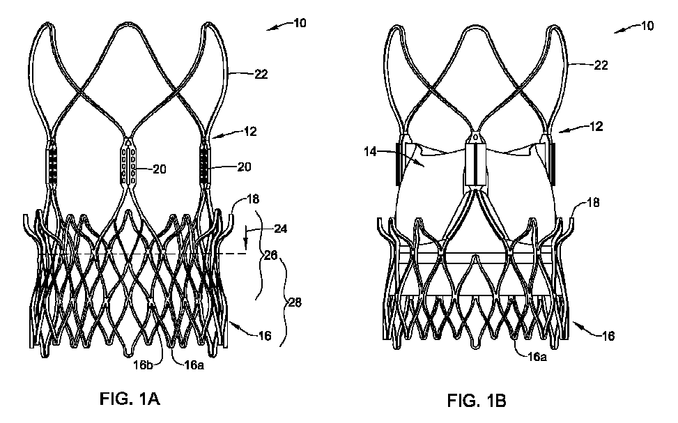
図1A及び図1Bは、例示的な置換心臓弁10の側面図である。置換心臓弁10は、例えば、置換大動脈弁、置換用僧帽弁、置換用肺動脈弁、又は置換用三尖弁であり得る。場合によっては、置換心臓弁10には、ブタ若しくはウシの心膜等の生体組織、及び/又はブタの心臓弁の天然弁尖等の天然の心臓弁尖が含まれる場合がある。場合によっては、天然の心臓弁尖が、自然心臓壁組織の一部にくっついている場合がある。その生体材料は、例えばグルタルアルデヒドを用いて固定され得る。
1A and 1B are side views of an exemplary
置換心臓弁10は、拡張フレーム12を含み、このフレームは、送達カテーテルを用いた送達のために、半径方向に圧縮された形態、すなわち潰れた形態に圧縮可能であり、埋込時には(図示のように)拡張された形態に拡張可能である。その置換心臓弁10は、拡張フレーム12を含み、このフレームは、送達カテーテルを用いた送達のために、半径方向に圧縮された形態、又は潰れた形態に圧縮可能であり、埋込時には(図1Bに示されるように)拡張された形態に拡張可能である。弁14を形成する弁尖は、例えば図2A及び図2Bに示され(弁尖42a、42b、並びに42cを含む)、視認可能である。
The
場合によっては、拡張フレームは、下部管状部すなわちクラウン部16、上部クラウン部18、複数の直立する交連ポスト20、及び複数の安定化アーチ22を含む場合がある。使用時において、拡張フレーム12の下部16は、拡張フレーム12の他の領域の後に展開されるよう適合され得る。例えば、アーチ22、支持部20、及び上部クラウン18は、下部16よりも少なくとも一部先に展開され得る(この順序、逆順、又は異なる順序で)。最低限、上部クラウン18が少なくとも一部展開された時点で、拡張フレーム12は矢印24の方向に押圧され、及び/又は変位され、埋込部位において自然弁尖に対し上部クラウン18を着座させ得る。下部16を最終段階で展開することで、拡張フレーム12が最終的な位置に固定される。
In some cases, the expansion frame may include a lower tubular or
下部16、及び選択的に上部クラウン18の一部は、ステントのラティス構造によって形成され得る。ラティス構造はセル又は開口、例えば、概ね菱形の開口を画定し得る。場合によっては、自然弁尖が拡張フレーム12の一部26と概ね重なることがある。自然弁輪が拡張フレームの一部28と重なることがある。
The
拡張フレーム12は、選択的に自己拡張型であり得る。かかる自己拡張型は、埋込部位への送達のために送達カテーテルへ装填する際、圧縮形態へ圧縮可能である。使用時において、拡張フレーム12を圧縮形態に保持するシースの拘束効果を除去することで、拡張フレーム12は作動形態に、又は作動形態に向けて自己拡張する。自己拡張型ステントは、例えば、形状記憶材料により、例えば形状記憶合金により、例えばニチノールにより、構成され得る。代替的に、拡張フレーム12は、送達カテーテルからの短縮力の付与、及び/又は、例えば拡張バルーンを使用することによる、送達カテーテルからの拡張力の付与によって、拡張されるよう構成され得る。これらは単なる例である。
Optionally, the
場合によっては、置換心臓弁10の相対的な回転配向が重要となる場合があり、特に、置換心臓弁10が自然大動脈弁輪内に埋込まれることを意図した置換大動脈弁である場合に重要となる。場合によっては、そのような置換心臓弁10の一部が、後続する冠動脈へのアクセスを潜在的に妨げる可能性がある。一部の患者、特に若年の患者においては、初回の埋込みから数年後に、新たな置換大動脈弁を埋込むという後続的な必要が生じる場合がある。患者によっては、例えば血管形成術や回転アテレクトミーを行うために、複数の冠動脈にアクセスする必要が、即時的であれ、将来的であれ、生じる場合がある。複数のステントを埋込むために、複数の冠動脈にアクセスする必要が生じる場合がある。初回に埋込まれた置換大動脈弁が冠動脈へのアクセスを妨げる場合、これは問題となり得る。
In some cases, the relative rotational orientation of the
図2Aは、自然大動脈弁輪36内に埋込まれた置換大動脈弁34の模式図を示す。置換大動脈弁34は、図1A及び図1Bに示され、説明された置換心臓弁10の一例と見なされ得る。置換大動脈弁34は拡張フレーム38を含み、この拡張フレームは拡張フレーム12と同等であり得る。拡張フレーム38は、複数の交連ポスト40を含む。場合によっては、(個別には42a、42b、及び42cと示される)弁尖42が、交連ポスト40に対して固定される。図示のように、冠動脈44及び冠動脈46は、それぞれ自然大動脈弁輪36に接続されている。
2A shows a schematic diagram of a replacement
図2Aは、置換大動脈弁34の不適切な回転配向を示す。交連ポスト40の一つが冠動脈44を少なくとも部分的に閉塞し、別の交連ポスト40が冠動脈46を少なくとも部分的に閉塞していることが分かる。冠動脈44及び46の両方が部分的に閉塞されている様子が示されているが、場合によっては、一部の患者における冠動脈44及び46の特定の位置が置換大動脈弁34の不適切な回転配向となることを意味し、その結果、冠動脈44及び46のうちの一方のみが少なくとも部分的に閉塞される可能性がある。
2A illustrates an improper rotational orientation of the replacement
図2Bは、置換大動脈弁34の好適な回転配向を示しており、交連ポスト40のいずれも冠動脈44を閉塞しておらず、また、交連ポスト40のいずれも冠動脈46を閉塞していないことが分かる。この回転配向の結果、将来的に2つ目の置換大動脈弁を埋込む必要が生じた場合でも、置換大動脈弁34は問題を引き起こさないか、少なくとも問題を軽減することとなる。これはまた、冠動脈44及び46内で行われる血管形成術、回転アテレクトミー、ステント埋込み等(ただし、これらに限定されない)といった後続の処置において、冠動脈44及び46へのアクセスが容易であることを意味する。
2B illustrates the preferred rotational orientation of the replacement
図3は、例示的な置換心臓弁48の部分模式図を示す。例示的な置換心臓弁48は、図1A及び図1Bに示され、説明された置換心臓弁10の一例として、及び/又は、図2A及び図2Bに示され、説明された置換大動脈弁34の一例としてみなされ得る。置換心臓弁48は、複数の交連ポスト52(うち1つのみ図示)を含む拡張フレーム50を備える。場合によっては、置換心臓弁48は、第1の組織層54及び第2の組織層56を含み、これらが交連ポスト52のそれぞれの側に配置されることにより、交連ポスト52を第1の組織層54と第2の組織層56との間に挟み込む。場合によっては、第1の組織層54及び/又は第2の組織層56は、弁14を形成する組織の一部と見なされ得る。
3 shows a partial schematic diagram of an exemplary
不透視性指標58は、第1の組織層54と第2の組織層56との間に配置され得る。場合によっては、不透視性指標58は、図示のように、第1の組織層54と交連ポスト52との間に配置され得る。場合によっては、不透視性指標58は、代わりに、交連ポスト52と第2の組織層56との間に配置される場合もある。場合によっては、不透視性指標58は、交連ポスト52に固定され得る。場合によっては、不透視性指標58は、第1の組織層54と第2の組織層56の一方又は両方に固定され得る。不透視性指標58は、接着によって所定の位置に固定され得る。不透視性指標58は、縫合によって所定の位置に固定され得る。場合によっては、不透視性指標58は、置換心臓弁48が送達のために圧縮形態にある間も、当該不透視性指標58が蛍光透視下で視認可能となるべく、交連ポスト52に対して所定の位置に固定され得る。場合によっては、不透視性指標58は、置換心臓弁48の展開後であっても、又は置換心臓弁48の展開中であっても、当該不透視性指標58が蛍光透視下で視認可能となるべく、交連ポスト52に対して所定の位置に固定され得る。
The
不透視性指標58は、例えば、蛍光透視下で十分に視認可能な任意の適切な不透視性材料で形成され得る。場合によっては、不透視性指標58はタンタルで形成され得る。場合によっては、不透視性指標58は、白金-イリジウム混合物又は合金、金、タングステン、ビスマス、又はバリウムで形成され得る。不透視性指標58は、適切な材料のワイヤを所定の長さに切断し、成形することによって形成され得る。例示的ではあるが限定されない例として、不透視性指標58は、直径0.020インチ(約0.508ミリメートル)の所定の長さのタンタルワイヤから形成され得る。場合によっては、不透視性指標58は、不透視性(ひいては蛍光透視下での視認性の最大化)を最大限にするために、正方形あるいはその他の直線的な断面形状を有するワイヤで形成され得る。
The
場合によっては、不透視性指標58は、第1の回転配向で視認されたときに第1の外観を有し得るともに、第1の回転配向とは異なる第2の回転配向で視認されたときに、第1の外観とは異なる第2の外観を有し得る。例として、不透視性指標58は形状を有し得る。当該形状は、その正面になる位置から見た場合に英数字を模しているとともに、背面から見た場合には当該英数字の非対称な鏡像として見える。場合によっては、不透視性指標58は、「C」形状、「E」形状、「F」形状、「J」形状、「K」形状、「L」形状、「P」形状、「R」形状、又は「Z」形状のいずれかの形状を有し得る。これらはあくまで例であり、他の形状も考えられる。
In some cases, the
図4から図6は、送達カテーテル62を介して治療部位へ送達される例示的な置換大動脈弁60を示す透視画像である。これらの画像において、治療部位は人工的に作成された大動脈弁埋込部位64であり、透視下で半透明となるようにポリマー製の管で構築されている。人工的に作成された大動脈弁埋込部位64は要素66を含む。当該要素66は、3つのマーカー66a、66b、及び66cを担持し、大動脈弁輪、並びにLCC(左冠動脈尖)、RCC(右冠動脈尖)、NCC(無冠動脈尖)の相対的な位置を模している。LCCは左冠動脈に近接する弁尖に対応し、RCCは右冠動脈に近接する弁尖に対応する。図2A及び図2Bに示される冠動脈44、46の一方は左冠動脈に対応し、他方は右冠動脈に対応する。
4-6 are fluoroscopic images showing an exemplary replacement
図4に示されるように、置換大動脈弁60は所定の位置に誘導されており、交連ポスト68が、その中央寄りの後方位置で不透視性指標70を担持している。この例では、不透視性指標70は「L」字形を有している。「L」が「L」として正しく見えていることから、これは、大動脈弁60が現在適切な回転配向にあることを意味する。図5に移ると、置換大動脈弁60はポスト解放第1段階の位置に移動しており、交連ポスト68が後方位置で不透視性指標70を担持している。「L」が「L」として正しく見えていることから、これは、大動脈弁60が引き続き、適切な回転配向にあることを意味する。図6に移ると、置換大動脈弁60はポスト解放第2段階の位置に移動しており、交連ポスト68が後方位置で不透視性指標70を担持している。「L」が「L」として正しく見えていることから、これは、大動脈弁60が引き続き、適切な回転配向にあることを意味する。
As shown in FIG. 4, the replacement
図7は、置換大動脈弁60が不適切な回転配向にある例を示している。図7において、置換大動脈弁60は、図5に示されるものと同様の送達段階にある。しかし、図7では、不透視性指標70は「L」字形としてではなく、その鏡像として見えている。これは、置換大動脈弁60が図5に示される位置に対して回転していることを意味する。例えば、図7に示される置換大動脈弁60は、図5に示される位置から約180度回転している可能性がある。
Figure 7 illustrates an example of a replacement
本明細書に記載の装置は、その各種構成要素と同様に、成形、鋳造、機械加工等、あるいはその他の適切な技術を含む、基本的にあらゆる適切な製造技術によって製造され得る。さらに、各種構造は、金属、金属合金、ポリマー、金属-ポリマー複合材、セラミック、それらの組み合わせ等、医療装置に一般的に用いられる材料、あるいはその他の適切な材料を含み得る。これらの材料は、処置中の視認性を向上させるために、透明又は半透明の材料を含み得る。適切な金属及び金属合金のいくつかの例としては、304V、304L、316LVステンレス鋼などのステンレス鋼、軟鋼、線形弾性ニチノール又は超弾性ニチノールなどのニッケル-チタン合金、ニッケル-クロム-モリブデン合金(例:UNS:N06625(INCONEL(登録商標)625)、UNS:N06022(HASTELLOY(登録商標)C-22)、UNS:N10276(HASTELLOY(登録商標)C276)、その他のHASTELLOY(登録商標)合金等)、ニッケル-銅合金(例:UNS:N04400(MONEL(登録商標)400、NICKELVAC(登録商標)400、NICORROS(登録商標)400等))、ニッケル-コバルト-クロム-モリブデン合金(例:UNS:R30035(MP35-N(登録商標)等))、ニッケル-モリブデン合金(例:UNS:N10665(HASTELLOY(登録商標)ALLOYB2))、その他のニッケル-クロム合金、その他のニッケル-モリブデン合金、その他のニッケル-コバルト合金、その他のニッケル-鉄合金、その他のニッケル-銅合金、その他のニッケル-タングステン合金、又はタングステン合金等のニッケル合金、コバルト-クロム合金、コバルト-クロム-モリブデン合金(例:UNS:R30003(ELGILOY(登録商標)、PHYNOX(登録商標)等))、白金強化ステンレス鋼、それらの組み合わせ等、又はその他の適切な材料が挙げられる。 The devices described herein, as well as the various components thereof, may be manufactured by essentially any suitable manufacturing technique, including molding, casting, machining, the like, or other suitable techniques. Additionally, the various structures may include materials commonly used in medical devices, such as metals, metal alloys, polymers, metal-polymer composites, ceramics, combinations thereof, or other suitable materials. These materials may include transparent or translucent materials to enhance visibility during procedures. Some examples of suitable metals and metal alloys include stainless steels such as 304V, 304L, 316LV stainless steel, mild steel, nickel-titanium alloys such as linear elastic Nitinol or superelastic Nitinol, nickel-chromium-molybdenum alloys (e.g., UNS: N06625 (INCONEL® 625), UNS: N06022 (HASTELLOY® C-22), UNS: N10276 (HASTELLOY® C276), other HASTELLOY® alloys, etc.), nickel-copper alloys (e.g., UNS: N04400 (MONEL® 400, NICKELVAC® 400, NICORROS® 400, etc.)), nickel-cobalt- Nickel alloys such as chrome-molybdenum alloys (e.g., UNS: R30035 (MP35-N®, etc.)), nickel-molybdenum alloys (e.g., UNS: N10665 (HASTELLOY® ALLOYB2)), other nickel-chrome alloys, other nickel-molybdenum alloys, other nickel-cobalt alloys, other nickel-iron alloys, other nickel-copper alloys, other nickel-tungsten alloys, or tungsten alloys, cobalt-chrome alloys, cobalt-chrome-molybdenum alloys (e.g., UNS: R30003 (ELGILOY®, PHYNOX®, etc.)), platinum-strengthened stainless steels, combinations thereof, and the like, or other suitable materials.
適切なポリマーのいくつかの例としては、ポリテトラフルオロエチレン(PTFE)、エチレン-テトラフルオロエチレン(ETFE)、フッ素化エチレンプロピレン(FEP)、ポリオキシメチレン(POM、例えば、DuPont社のDELRIN(登録商標))、ポリエーテルブロックエステル、ポリウレタン、ポリプロピレン(PP)、ポリ塩化ビニル(PVC)、ポリエーテル-エステル(例えば、DSMエンジニアリングプラスチックス社のARNITEL(登録商標))、エーテル又はエステル系共重合体(例えば、ブチレン/ポリ(アルキレンエーテル)フタレート及び/又はその他のポリエステルエラストマー(DuPont社のHYTREL(登録商標)))、ポリアミド(例えば、Bayer社のDURETHAN(登録商標)又はElf Atochem社のCRISTAMID(登録商標))、エラストマー性ポリアミド、ブロックポリアミド/エーテル、ポリエーテルブロックアミド(PEBA、例えばPEBAX(登録商標)として入手可能)、エチレン-酢酸ビニル共重合体(EVA)、シリコーン、ポリエチレン(PE)、Marlex高密度ポリエチレン、Marlex低密度ポリエチレン、直鎖状低密度ポリエチレン(例えばREXELL(登録商標))、ポリエステル、ポリブチレンテレフタレート(PBT)、ポリエチレンテレフタレート(PET)、ポリトリメチレンテレフタレート、ポリエチレンナフタレート(PEN)、ポリエーテルエーテルケトン(PEEK)、ポリイミド(PI)、ポリエーテルイミド(PEI)、ポリフェニレンサルファイド(PPS)、ポリフェニレンオキシド(PPO)、ポリパラフェニレンテレフタルアミド(例えばKEVLAR(登録商標))、ポリスルホン、ナイロン、ナイロン-12(例えば、EMS American Grilon社のGRILAMID(登録商標))、パーフルオロ(プロピルビニルエーテル)(PFA)、エチレン-ビニルアルコール、ポリオレフィン、ポリスチレン、エポキシ、ポリ塩化ビニリデン(PVdC)、ポリカーボネート、アイオノマー、生体適合性ポリマー、その他の適切な材料、又はそれらの混合物、組み合わせ、共重合体、ポリマー/金属複合材料等が挙げられる。 Some examples of suitable polymers include polytetrafluoroethylene (PTFE), ethylene-tetrafluoroethylene (ETFE), fluorinated ethylene propylene (FEP), polyoxymethylene (POM, e.g., DELRIN® from DuPont), polyether block esters, polyurethanes, polypropylene (PP), polyvinyl chloride (PVC), polyether-esters (e.g., ARNITEL® from DSM Engineering Plastics), ether or ester-based copolymers (e.g., butylene/poly(alkylene ether) phthalates and/or other polyester elastomers (HYTREL® from DuPont)), polyamides (e.g., DURETHAN® or Elf® from Bayer), Atochem's CRISTAMID®), elastomeric polyamides, block polyamide/ethers, polyether block amides (PEBA, available as, for example, PEBAX®), ethylene-vinyl acetate copolymers (EVA), silicones, polyethylene (PE), Marlex high density polyethylene, Marlex low density polyethylene, linear low density polyethylene (for example, REXEL®), polyester, polybutylene terephthalate (PBT), polyethylene terephthalate (PET), polytrimethylene terephthalate, polyethylene naphthalate (PEN), polyether ether ketone (PEEK), polyimide (PI), polyetherimide (PEI), polyphenylene sulfide (PPS), polyphenylene oxide (PPO), polyparaphenylene terephthalamide (for example, KEVLAR®), polysulfone, nylon, nylon-12 (for example, EMS American Examples include Grilon's GRILAMID (registered trademark), perfluoro(propyl vinyl ether) (PFA), ethylene-vinyl alcohol, polyolefins, polystyrene, epoxies, polyvinylidene chloride (PVdC), polycarbonates, ionomers, biocompatible polymers, and other suitable materials, or mixtures, combinations, copolymers, polymer/metal composites, and the like.
この開示は、多くの点で、単なる例示であることを理解されたい。本発明の範囲を超えることなく、詳細、特に形状、サイズ、及びステップの配置に関して変更を加え得る。これは、適切な範囲で、他の実施形態で使用される1つの例示的な実施形態の特徴のいずれかの使用を含み得る。本発明の範囲は、もちろん、添付の特許請求の範囲が表現される言語で定義される。 It will be understood that this disclosure is, in many respects, merely illustrative. Changes may be made in details, particularly in matters of shape, size and arrangement of steps, without exceeding the scope of the invention. This may include, to the extent appropriate, the use of any of the features of one illustrative embodiment used in other embodiments. The scope of the invention is, of course, defined in the language in which the appended claims are expressed.
Claims (15)
送達のために潰れた形態から展開のための拡張した形態へ拡張するよう適合された拡張可能な本体を備え、
前記拡張可能な本体に配置された不透視性指標を備え、前記不透視性指標は、第1の回転配向で視認された場合に第1の外観を有するように適合されるとともに、前記第1の回転配向とは異なる第2の回転配向で視認された場合に第1の外観とは異なる第2の外観を有するよう適合される、埋込型医療装置。 1. An implantable medical device adapted for implantation at an implantation site and capable of being implanted in a plurality of rotational orientations, the implantable medical device comprising:
an expandable body adapted to expand from a collapsed configuration for delivery to an expanded configuration for deployment;
An implantable medical device comprising an opaque indicator disposed on the expandable body, the opaque indicator adapted to have a first appearance when viewed in a first rotational orientation and adapted to have a second appearance different from the first appearance when viewed in a second rotational orientation different from the first rotational orientation.
送達のために潰れた形態から展開のための拡張した形態へ拡張するよう適合された拡張可能な本体を備え、前記拡張可能な本体は、複数の置換弁交連ポストを含み、
前記複数の置換弁交連ポストに固定された弁材を備え、前記弁材は、前記複数の置換弁交連ポストの間に弁尖を形成し、
前記複数の置換弁交連ポストのうちの一つに対して配置された不透視性指標を備え、前記不透視性指標は、自然心臓弁輪に対する前記置換心臓弁の回転配向の表示を提供するよう適合される、置換心臓弁。 1. A replacement heart valve adapted for implantation within a native heart valve annulus and capable of being implanted in a plurality of rotational orientations, said replacement heart valve comprising:
an expandable body adapted to expand from a collapsed configuration for delivery to an expanded configuration for deployment, the expandable body including a plurality of replacement valve commissure posts;
a valve material secured to the plurality of replacement valve commissure posts, the valve material forming leaflets between the plurality of replacement valve commissure posts;
a replacement heart valve comprising an opaque indicator disposed relative to one of the plurality of replacement valve commissure posts, the opaque indicator adapted to provide an indication of a rotational orientation of the replacement heart valve relative to a native heart valve annulus.
前記置換心臓弁が置換大動脈弁であり、
前記不透視性指標が、自然大動脈弁輪に近接する冠動脈に対する前記複数の交連ポストのそれぞれの相対位置の表示を提供するよう適合される、
請求項9に記載の置換心臓弁。 the native heart valve is an aortic valve;
the replacement heart valve is a replacement aortic valve;
the opaque indicator is adapted to provide an indication of a relative position of each of the plurality of commissure posts with respect to a coronary artery proximate a native aortic valve annulus.
10. The replacement heart valve of claim 9.
拡張可能な本体を備え、前記拡張可能な本体は、送達のために潰れた形態から展開のための拡張した形態へ拡張するよう適合され、前記拡張可能な本体は複数の置換弁交連ポストを含み、
第1の層のウシ由来材料を備え、該第1の層のウシ由来材料は、前記複数の置換弁交連ポストの第1の側に配置されており、
第2の層のウシ由来材料を備え、該第2の層のウシ由来材料は、前記複数の置換弁交連ポストの第2の側に配置されており、
前記第1の層のウシ由来材料と前記第2の層のウシ由来材料との間に配置された不透視性指標を備え、前記不透視性指標は、前記自然大動脈弁に対する前記置換大動脈弁の回転配向の表示を提供するよう適合される、置換大動脈弁。 1. A replacement aortic valve adapted for implantation within a native aortic valve having a plurality of native commissures and capable of being implanted in a plurality of rotational orientations, the replacement aortic valve comprising:
an expandable body adapted to expand from a collapsed configuration for delivery to an expanded configuration for deployment, the expandable body including a plurality of replacement valve commissure posts;
a first layer of bovine derived material disposed on a first side of the plurality of replacement valve commissure posts;
a second layer of bovine derived material disposed on a second side of the plurality of replacement valve commissure posts;
1. A replacement aortic valve comprising: an opaque indicia disposed between the first layer of bovine-derived material and the second layer of bovine-derived material, the opaque indicia adapted to provide an indication of a rotational orientation of the replacement aortic valve relative to the native aortic valve.
Applications Claiming Priority (3)
| Application Number | Priority Date | Filing Date | Title |
|---|---|---|---|
| US202263359595P | 2022-07-08 | 2022-07-08 | |
| US63/359,595 | 2022-07-08 | ||
| PCT/US2023/027095 WO2024010908A1 (en) | 2022-07-08 | 2023-07-07 | Implantable medical device with visual orientation indicator |
Publications (1)
| Publication Number | Publication Date |
|---|---|
| JP2025520970A true JP2025520970A (en) | 2025-07-03 |
Family
ID=87556342
Family Applications (1)
| Application Number | Title | Priority Date | Filing Date |
|---|---|---|---|
| JP2025500246A Pending JP2025520970A (en) | 2022-07-08 | 2023-07-07 | IMPLANTABLE MEDICAL DEVICE WITH VISUAL ORIENTATION INDICATOR - Patent application |
Country Status (5)
| Country | Link |
|---|---|
| US (1) | US20240008981A1 (en) |
| EP (1) | EP4551158A1 (en) |
| JP (1) | JP2025520970A (en) |
| CN (1) | CN119768129A (en) |
| WO (1) | WO2024010908A1 (en) |
Families Citing this family (1)
| Publication number | Priority date | Publication date | Assignee | Title |
|---|---|---|---|---|
| US12011349B2 (en) * | 2020-03-04 | 2024-06-18 | Medtronic, Inc. | Balloon expandable stent with lengthened commissure posts for transcatheter implantation of a cardiac valve prosthesis |
Family Cites Families (4)
| Publication number | Priority date | Publication date | Assignee | Title |
|---|---|---|---|---|
| DE102018126828A1 (en) * | 2018-10-26 | 2020-04-30 | Nvt Ag | Heart valve prosthesis |
| US12011349B2 (en) * | 2020-03-04 | 2024-06-18 | Medtronic, Inc. | Balloon expandable stent with lengthened commissure posts for transcatheter implantation of a cardiac valve prosthesis |
| BR112023002487A2 (en) * | 2020-08-24 | 2023-05-02 | Edwards Lifesciences Corp | BALLOON COVER FOR A DISTRIBUTION APPLIANCE FOR AN EXPANDABLE PROSTHETIC HEART VALVE |
| US11969343B2 (en) * | 2020-12-07 | 2024-04-30 | Medtronic, Inc. | Transcatheter heart valve prosthesis systems and methods for rotational alignment |
-
2023
- 2023-07-07 EP EP23751141.5A patent/EP4551158A1/en active Pending
- 2023-07-07 WO PCT/US2023/027095 patent/WO2024010908A1/en not_active Ceased
- 2023-07-07 JP JP2025500246A patent/JP2025520970A/en active Pending
- 2023-07-07 US US18/219,302 patent/US20240008981A1/en active Pending
- 2023-07-07 CN CN202380062092.3A patent/CN119768129A/en active Pending
Also Published As
| Publication number | Publication date |
|---|---|
| CN119768129A (en) | 2025-04-04 |
| US20240008981A1 (en) | 2024-01-11 |
| WO2024010908A1 (en) | 2024-01-11 |
| EP4551158A1 (en) | 2025-05-14 |
Similar Documents
| Publication | Publication Date | Title |
|---|---|---|
| US20240268954A1 (en) | Information markers for heart prostheses and methods of using same | |
| EP2004095B1 (en) | Prosthetic cardiac valve formed from pericardium material and methods of making same | |
| EP2254512B1 (en) | Markers for prosthetic heart valves | |
| JP2010517622A (en) | System and method for delivering a valve | |
| JP2025520970A (en) | IMPLANTABLE MEDICAL DEVICE WITH VISUAL ORIENTATION INDICATOR - Patent application | |
| US20240091006A1 (en) | Implantable medical device with visual orientation indicator | |
| US20230255634A1 (en) | Implantable medical device with opposing barbs for bi-directional stability | |
| US20260026856A1 (en) | Medical device with axial stability for lacerating cardiac valve leaflets | |
| EP3525725B1 (en) | Replacement heart valve with diaphragm |
Legal Events
| Date | Code | Title | Description |
|---|---|---|---|
| A521 | Request for written amendment filed |
Free format text: JAPANESE INTERMEDIATE CODE: A523 Effective date: 20250221 |
|
| A621 | Written request for application examination |
Free format text: JAPANESE INTERMEDIATE CODE: A621 Effective date: 20250221 |
|
| A977 | Report on retrieval |
Free format text: JAPANESE INTERMEDIATE CODE: A971007 Effective date: 20251222 |
|
| A131 | Notification of reasons for refusal |
Free format text: JAPANESE INTERMEDIATE CODE: A131 Effective date: 20260127 |