JP2025520701A - Respiratory Support Devices - Google Patents
Respiratory Support Devices Download PDFInfo
- Publication number
- JP2025520701A JP2025520701A JP2024575515A JP2024575515A JP2025520701A JP 2025520701 A JP2025520701 A JP 2025520701A JP 2024575515 A JP2024575515 A JP 2024575515A JP 2024575515 A JP2024575515 A JP 2024575515A JP 2025520701 A JP2025520701 A JP 2025520701A
- Authority
- JP
- Japan
- Prior art keywords
- gas
- patient
- flow path
- flow
- gas flow
- Prior art date
- Legal status (The legal status is an assumption and is not a legal conclusion. Google has not performed a legal analysis and makes no representation as to the accuracy of the status listed.)
- Pending
Links
Images


Classifications
-
- A—HUMAN NECESSITIES
- A61—MEDICAL OR VETERINARY SCIENCE; HYGIENE
- A61M—DEVICES FOR INTRODUCING MEDIA INTO, OR ONTO, THE BODY; DEVICES FOR TRANSDUCING BODY MEDIA OR FOR TAKING MEDIA FROM THE BODY; DEVICES FOR PRODUCING OR ENDING SLEEP OR STUPOR
- A61M16/00—Devices for influencing the respiratory system of patients by gas treatment, e.g. ventilators; Tracheal tubes
- A61M16/08—Bellows; Connecting tubes ; Water traps; Patient circuits
- A61M16/0883—Circuit type
- A61M16/0891—Closed circuit, e.g. for anaesthesia
-
- A—HUMAN NECESSITIES
- A61—MEDICAL OR VETERINARY SCIENCE; HYGIENE
- A61M—DEVICES FOR INTRODUCING MEDIA INTO, OR ONTO, THE BODY; DEVICES FOR TRANSDUCING BODY MEDIA OR FOR TAKING MEDIA FROM THE BODY; DEVICES FOR PRODUCING OR ENDING SLEEP OR STUPOR
- A61M16/00—Devices for influencing the respiratory system of patients by gas treatment, e.g. ventilators; Tracheal tubes
- A61M16/10—Preparation of respiratory gases or vapours
- A61M16/14—Preparation of respiratory gases or vapours by mixing different fluids, one of them being in a liquid phase
- A61M16/18—Vaporising devices for anaesthetic preparations
-
- A—HUMAN NECESSITIES
- A61—MEDICAL OR VETERINARY SCIENCE; HYGIENE
- A61M—DEVICES FOR INTRODUCING MEDIA INTO, OR ONTO, THE BODY; DEVICES FOR TRANSDUCING BODY MEDIA OR FOR TAKING MEDIA FROM THE BODY; DEVICES FOR PRODUCING OR ENDING SLEEP OR STUPOR
- A61M16/00—Devices for influencing the respiratory system of patients by gas treatment, e.g. ventilators; Tracheal tubes
- A61M16/0045—Means for re-breathing exhaled gases, e.g. for hyperventilation treatment
-
- A—HUMAN NECESSITIES
- A61—MEDICAL OR VETERINARY SCIENCE; HYGIENE
- A61M—DEVICES FOR INTRODUCING MEDIA INTO, OR ONTO, THE BODY; DEVICES FOR TRANSDUCING BODY MEDIA OR FOR TAKING MEDIA FROM THE BODY; DEVICES FOR PRODUCING OR ENDING SLEEP OR STUPOR
- A61M16/00—Devices for influencing the respiratory system of patients by gas treatment, e.g. ventilators; Tracheal tubes
- A61M16/021—Devices for influencing the respiratory system of patients by gas treatment, e.g. ventilators; Tracheal tubes operated by electrical means
- A61M16/022—Control means therefor
- A61M16/024—Control means therefor including calculation means, e.g. using a processor
-
- A—HUMAN NECESSITIES
- A61—MEDICAL OR VETERINARY SCIENCE; HYGIENE
- A61M—DEVICES FOR INTRODUCING MEDIA INTO, OR ONTO, THE BODY; DEVICES FOR TRANSDUCING BODY MEDIA OR FOR TAKING MEDIA FROM THE BODY; DEVICES FOR PRODUCING OR ENDING SLEEP OR STUPOR
- A61M16/00—Devices for influencing the respiratory system of patients by gas treatment, e.g. ventilators; Tracheal tubes
- A61M16/06—Respiratory or anaesthetic masks
- A61M16/0605—Means for improving the adaptation of the mask to the patient
-
- A—HUMAN NECESSITIES
- A61—MEDICAL OR VETERINARY SCIENCE; HYGIENE
- A61M—DEVICES FOR INTRODUCING MEDIA INTO, OR ONTO, THE BODY; DEVICES FOR TRANSDUCING BODY MEDIA OR FOR TAKING MEDIA FROM THE BODY; DEVICES FOR PRODUCING OR ENDING SLEEP OR STUPOR
- A61M16/00—Devices for influencing the respiratory system of patients by gas treatment, e.g. ventilators; Tracheal tubes
- A61M16/10—Preparation of respiratory gases or vapours
- A61M16/1075—Preparation of respiratory gases or vapours by influencing the temperature
- A61M16/109—Preparation of respiratory gases or vapours by influencing the temperature the humidifying liquid or the beneficial agent
-
- A—HUMAN NECESSITIES
- A61—MEDICAL OR VETERINARY SCIENCE; HYGIENE
- A61M—DEVICES FOR INTRODUCING MEDIA INTO, OR ONTO, THE BODY; DEVICES FOR TRANSDUCING BODY MEDIA OR FOR TAKING MEDIA FROM THE BODY; DEVICES FOR PRODUCING OR ENDING SLEEP OR STUPOR
- A61M16/00—Devices for influencing the respiratory system of patients by gas treatment, e.g. ventilators; Tracheal tubes
- A61M16/10—Preparation of respiratory gases or vapours
- A61M16/12—Preparation of respiratory gases or vapours by mixing different gases
- A61M16/122—Preparation of respiratory gases or vapours by mixing different gases with dilution
- A61M16/125—Diluting primary gas with ambient air
-
- A—HUMAN NECESSITIES
- A61—MEDICAL OR VETERINARY SCIENCE; HYGIENE
- A61M—DEVICES FOR INTRODUCING MEDIA INTO, OR ONTO, THE BODY; DEVICES FOR TRANSDUCING BODY MEDIA OR FOR TAKING MEDIA FROM THE BODY; DEVICES FOR PRODUCING OR ENDING SLEEP OR STUPOR
- A61M16/00—Devices for influencing the respiratory system of patients by gas treatment, e.g. ventilators; Tracheal tubes
- A61M16/20—Valves specially adapted to medical respiratory devices
- A61M16/208—Non-controlled one-way valves, e.g. exhalation, check, pop-off non-rebreathing valves
- A61M16/209—Relief valves
-
- A—HUMAN NECESSITIES
- A61—MEDICAL OR VETERINARY SCIENCE; HYGIENE
- A61M—DEVICES FOR INTRODUCING MEDIA INTO, OR ONTO, THE BODY; DEVICES FOR TRANSDUCING BODY MEDIA OR FOR TAKING MEDIA FROM THE BODY; DEVICES FOR PRODUCING OR ENDING SLEEP OR STUPOR
- A61M16/00—Devices for influencing the respiratory system of patients by gas treatment, e.g. ventilators; Tracheal tubes
- A61M16/22—Carbon dioxide-absorbing devices ; Other means for removing carbon dioxide
-
- A—HUMAN NECESSITIES
- A61—MEDICAL OR VETERINARY SCIENCE; HYGIENE
- A61M—DEVICES FOR INTRODUCING MEDIA INTO, OR ONTO, THE BODY; DEVICES FOR TRANSDUCING BODY MEDIA OR FOR TAKING MEDIA FROM THE BODY; DEVICES FOR PRODUCING OR ENDING SLEEP OR STUPOR
- A61M16/00—Devices for influencing the respiratory system of patients by gas treatment, e.g. ventilators; Tracheal tubes
- A61M16/0057—Pumps therefor
- A61M16/0066—Blowers or centrifugal pumps
-
- A—HUMAN NECESSITIES
- A61—MEDICAL OR VETERINARY SCIENCE; HYGIENE
- A61M—DEVICES FOR INTRODUCING MEDIA INTO, OR ONTO, THE BODY; DEVICES FOR TRANSDUCING BODY MEDIA OR FOR TAKING MEDIA FROM THE BODY; DEVICES FOR PRODUCING OR ENDING SLEEP OR STUPOR
- A61M16/00—Devices for influencing the respiratory system of patients by gas treatment, e.g. ventilators; Tracheal tubes
- A61M16/0057—Pumps therefor
- A61M16/0075—Bellows-type
-
- A—HUMAN NECESSITIES
- A61—MEDICAL OR VETERINARY SCIENCE; HYGIENE
- A61M—DEVICES FOR INTRODUCING MEDIA INTO, OR ONTO, THE BODY; DEVICES FOR TRANSDUCING BODY MEDIA OR FOR TAKING MEDIA FROM THE BODY; DEVICES FOR PRODUCING OR ENDING SLEEP OR STUPOR
- A61M16/00—Devices for influencing the respiratory system of patients by gas treatment, e.g. ventilators; Tracheal tubes
- A61M16/0057—Pumps therefor
- A61M16/0078—Breathing bags
-
- A—HUMAN NECESSITIES
- A61—MEDICAL OR VETERINARY SCIENCE; HYGIENE
- A61M—DEVICES FOR INTRODUCING MEDIA INTO, OR ONTO, THE BODY; DEVICES FOR TRANSDUCING BODY MEDIA OR FOR TAKING MEDIA FROM THE BODY; DEVICES FOR PRODUCING OR ENDING SLEEP OR STUPOR
- A61M16/00—Devices for influencing the respiratory system of patients by gas treatment, e.g. ventilators; Tracheal tubes
- A61M16/04—Tracheal tubes
- A61M16/0402—Special features for tracheal tubes not otherwise provided for
- A61M16/0409—Special features for tracheal tubes not otherwise provided for with mean for closing the oesophagus
-
- A—HUMAN NECESSITIES
- A61—MEDICAL OR VETERINARY SCIENCE; HYGIENE
- A61M—DEVICES FOR INTRODUCING MEDIA INTO, OR ONTO, THE BODY; DEVICES FOR TRANSDUCING BODY MEDIA OR FOR TAKING MEDIA FROM THE BODY; DEVICES FOR PRODUCING OR ENDING SLEEP OR STUPOR
- A61M16/00—Devices for influencing the respiratory system of patients by gas treatment, e.g. ventilators; Tracheal tubes
- A61M16/04—Tracheal tubes
- A61M16/0465—Tracheostomy tubes; Devices for performing a tracheostomy; Accessories therefor, e.g. masks, filters
-
- A—HUMAN NECESSITIES
- A61—MEDICAL OR VETERINARY SCIENCE; HYGIENE
- A61M—DEVICES FOR INTRODUCING MEDIA INTO, OR ONTO, THE BODY; DEVICES FOR TRANSDUCING BODY MEDIA OR FOR TAKING MEDIA FROM THE BODY; DEVICES FOR PRODUCING OR ENDING SLEEP OR STUPOR
- A61M16/00—Devices for influencing the respiratory system of patients by gas treatment, e.g. ventilators; Tracheal tubes
- A61M16/06—Respiratory or anaesthetic masks
- A61M16/0666—Nasal cannulas or tubing
- A61M16/0672—Nasal cannula assemblies for oxygen therapy
-
- A—HUMAN NECESSITIES
- A61—MEDICAL OR VETERINARY SCIENCE; HYGIENE
- A61M—DEVICES FOR INTRODUCING MEDIA INTO, OR ONTO, THE BODY; DEVICES FOR TRANSDUCING BODY MEDIA OR FOR TAKING MEDIA FROM THE BODY; DEVICES FOR PRODUCING OR ENDING SLEEP OR STUPOR
- A61M16/00—Devices for influencing the respiratory system of patients by gas treatment, e.g. ventilators; Tracheal tubes
- A61M16/06—Respiratory or anaesthetic masks
- A61M16/0683—Holding devices therefor
-
- A—HUMAN NECESSITIES
- A61—MEDICAL OR VETERINARY SCIENCE; HYGIENE
- A61M—DEVICES FOR INTRODUCING MEDIA INTO, OR ONTO, THE BODY; DEVICES FOR TRANSDUCING BODY MEDIA OR FOR TAKING MEDIA FROM THE BODY; DEVICES FOR PRODUCING OR ENDING SLEEP OR STUPOR
- A61M16/00—Devices for influencing the respiratory system of patients by gas treatment, e.g. ventilators; Tracheal tubes
- A61M16/08—Bellows; Connecting tubes ; Water traps; Patient circuits
- A61M16/0816—Joints or connectors
- A61M16/0833—T- or Y-type connectors, e.g. Y-piece
-
- A—HUMAN NECESSITIES
- A61—MEDICAL OR VETERINARY SCIENCE; HYGIENE
- A61M—DEVICES FOR INTRODUCING MEDIA INTO, OR ONTO, THE BODY; DEVICES FOR TRANSDUCING BODY MEDIA OR FOR TAKING MEDIA FROM THE BODY; DEVICES FOR PRODUCING OR ENDING SLEEP OR STUPOR
- A61M16/00—Devices for influencing the respiratory system of patients by gas treatment, e.g. ventilators; Tracheal tubes
- A61M16/10—Preparation of respiratory gases or vapours
- A61M16/105—Filters
-
- A—HUMAN NECESSITIES
- A61—MEDICAL OR VETERINARY SCIENCE; HYGIENE
- A61M—DEVICES FOR INTRODUCING MEDIA INTO, OR ONTO, THE BODY; DEVICES FOR TRANSDUCING BODY MEDIA OR FOR TAKING MEDIA FROM THE BODY; DEVICES FOR PRODUCING OR ENDING SLEEP OR STUPOR
- A61M16/00—Devices for influencing the respiratory system of patients by gas treatment, e.g. ventilators; Tracheal tubes
- A61M16/10—Preparation of respiratory gases or vapours
- A61M16/14—Preparation of respiratory gases or vapours by mixing different fluids, one of them being in a liquid phase
- A61M16/16—Devices to humidify the respiration air
- A61M16/161—Devices to humidify the respiration air with means for measuring the humidity
-
- A—HUMAN NECESSITIES
- A61—MEDICAL OR VETERINARY SCIENCE; HYGIENE
- A61M—DEVICES FOR INTRODUCING MEDIA INTO, OR ONTO, THE BODY; DEVICES FOR TRANSDUCING BODY MEDIA OR FOR TAKING MEDIA FROM THE BODY; DEVICES FOR PRODUCING OR ENDING SLEEP OR STUPOR
- A61M16/00—Devices for influencing the respiratory system of patients by gas treatment, e.g. ventilators; Tracheal tubes
- A61M16/20—Valves specially adapted to medical respiratory devices
- A61M16/201—Controlled valves
- A61M16/202—Controlled valves electrically actuated
-
- A—HUMAN NECESSITIES
- A61—MEDICAL OR VETERINARY SCIENCE; HYGIENE
- A61M—DEVICES FOR INTRODUCING MEDIA INTO, OR ONTO, THE BODY; DEVICES FOR TRANSDUCING BODY MEDIA OR FOR TAKING MEDIA FROM THE BODY; DEVICES FOR PRODUCING OR ENDING SLEEP OR STUPOR
- A61M16/00—Devices for influencing the respiratory system of patients by gas treatment, e.g. ventilators; Tracheal tubes
- A61M16/20—Valves specially adapted to medical respiratory devices
- A61M16/208—Non-controlled one-way valves, e.g. exhalation, check, pop-off non-rebreathing valves
-
- A—HUMAN NECESSITIES
- A61—MEDICAL OR VETERINARY SCIENCE; HYGIENE
- A61M—DEVICES FOR INTRODUCING MEDIA INTO, OR ONTO, THE BODY; DEVICES FOR TRANSDUCING BODY MEDIA OR FOR TAKING MEDIA FROM THE BODY; DEVICES FOR PRODUCING OR ENDING SLEEP OR STUPOR
- A61M16/00—Devices for influencing the respiratory system of patients by gas treatment, e.g. ventilators; Tracheal tubes
- A61M16/0003—Accessories therefor, e.g. sensors, vibrators, negative pressure
- A61M2016/0027—Accessories therefor, e.g. sensors, vibrators, negative pressure pressure meter
-
- A—HUMAN NECESSITIES
- A61—MEDICAL OR VETERINARY SCIENCE; HYGIENE
- A61M—DEVICES FOR INTRODUCING MEDIA INTO, OR ONTO, THE BODY; DEVICES FOR TRANSDUCING BODY MEDIA OR FOR TAKING MEDIA FROM THE BODY; DEVICES FOR PRODUCING OR ENDING SLEEP OR STUPOR
- A61M16/00—Devices for influencing the respiratory system of patients by gas treatment, e.g. ventilators; Tracheal tubes
- A61M16/0003—Accessories therefor, e.g. sensors, vibrators, negative pressure
- A61M2016/003—Accessories therefor, e.g. sensors, vibrators, negative pressure with a flowmeter
- A61M2016/0033—Accessories therefor, e.g. sensors, vibrators, negative pressure with a flowmeter electrical
- A61M2016/0036—Accessories therefor, e.g. sensors, vibrators, negative pressure with a flowmeter electrical in the breathing tube and used in both inspiratory and expiratory phase
-
- A—HUMAN NECESSITIES
- A61—MEDICAL OR VETERINARY SCIENCE; HYGIENE
- A61M—DEVICES FOR INTRODUCING MEDIA INTO, OR ONTO, THE BODY; DEVICES FOR TRANSDUCING BODY MEDIA OR FOR TAKING MEDIA FROM THE BODY; DEVICES FOR PRODUCING OR ENDING SLEEP OR STUPOR
- A61M16/00—Devices for influencing the respiratory system of patients by gas treatment, e.g. ventilators; Tracheal tubes
- A61M16/0003—Accessories therefor, e.g. sensors, vibrators, negative pressure
- A61M2016/003—Accessories therefor, e.g. sensors, vibrators, negative pressure with a flowmeter
- A61M2016/0033—Accessories therefor, e.g. sensors, vibrators, negative pressure with a flowmeter electrical
- A61M2016/0039—Accessories therefor, e.g. sensors, vibrators, negative pressure with a flowmeter electrical in the inspiratory circuit
-
- A—HUMAN NECESSITIES
- A61—MEDICAL OR VETERINARY SCIENCE; HYGIENE
- A61M—DEVICES FOR INTRODUCING MEDIA INTO, OR ONTO, THE BODY; DEVICES FOR TRANSDUCING BODY MEDIA OR FOR TAKING MEDIA FROM THE BODY; DEVICES FOR PRODUCING OR ENDING SLEEP OR STUPOR
- A61M16/00—Devices for influencing the respiratory system of patients by gas treatment, e.g. ventilators; Tracheal tubes
- A61M16/0003—Accessories therefor, e.g. sensors, vibrators, negative pressure
- A61M2016/003—Accessories therefor, e.g. sensors, vibrators, negative pressure with a flowmeter
- A61M2016/0033—Accessories therefor, e.g. sensors, vibrators, negative pressure with a flowmeter electrical
- A61M2016/0042—Accessories therefor, e.g. sensors, vibrators, negative pressure with a flowmeter electrical in the expiratory circuit
-
- A—HUMAN NECESSITIES
- A61—MEDICAL OR VETERINARY SCIENCE; HYGIENE
- A61M—DEVICES FOR INTRODUCING MEDIA INTO, OR ONTO, THE BODY; DEVICES FOR TRANSDUCING BODY MEDIA OR FOR TAKING MEDIA FROM THE BODY; DEVICES FOR PRODUCING OR ENDING SLEEP OR STUPOR
- A61M16/00—Devices for influencing the respiratory system of patients by gas treatment, e.g. ventilators; Tracheal tubes
- A61M16/10—Preparation of respiratory gases or vapours
- A61M16/1005—Preparation of respiratory gases or vapours with O2 features or with parameter measurement
- A61M2016/102—Measuring a parameter of the content of the delivered gas
- A61M2016/1025—Measuring a parameter of the content of the delivered gas the O2 concentration
-
- A—HUMAN NECESSITIES
- A61—MEDICAL OR VETERINARY SCIENCE; HYGIENE
- A61M—DEVICES FOR INTRODUCING MEDIA INTO, OR ONTO, THE BODY; DEVICES FOR TRANSDUCING BODY MEDIA OR FOR TAKING MEDIA FROM THE BODY; DEVICES FOR PRODUCING OR ENDING SLEEP OR STUPOR
- A61M16/00—Devices for influencing the respiratory system of patients by gas treatment, e.g. ventilators; Tracheal tubes
- A61M16/10—Preparation of respiratory gases or vapours
- A61M16/1005—Preparation of respiratory gases or vapours with O2 features or with parameter measurement
- A61M2016/102—Measuring a parameter of the content of the delivered gas
- A61M2016/103—Measuring a parameter of the content of the delivered gas the CO2 concentration
-
- A—HUMAN NECESSITIES
- A61—MEDICAL OR VETERINARY SCIENCE; HYGIENE
- A61M—DEVICES FOR INTRODUCING MEDIA INTO, OR ONTO, THE BODY; DEVICES FOR TRANSDUCING BODY MEDIA OR FOR TAKING MEDIA FROM THE BODY; DEVICES FOR PRODUCING OR ENDING SLEEP OR STUPOR
- A61M2202/00—Special media to be introduced, removed or treated
- A61M2202/02—Gases
- A61M2202/0208—Oxygen
-
- A—HUMAN NECESSITIES
- A61—MEDICAL OR VETERINARY SCIENCE; HYGIENE
- A61M—DEVICES FOR INTRODUCING MEDIA INTO, OR ONTO, THE BODY; DEVICES FOR TRANSDUCING BODY MEDIA OR FOR TAKING MEDIA FROM THE BODY; DEVICES FOR PRODUCING OR ENDING SLEEP OR STUPOR
- A61M2202/00—Special media to be introduced, removed or treated
- A61M2202/02—Gases
- A61M2202/0225—Carbon oxides, e.g. Carbon dioxide
-
- A—HUMAN NECESSITIES
- A61—MEDICAL OR VETERINARY SCIENCE; HYGIENE
- A61M—DEVICES FOR INTRODUCING MEDIA INTO, OR ONTO, THE BODY; DEVICES FOR TRANSDUCING BODY MEDIA OR FOR TAKING MEDIA FROM THE BODY; DEVICES FOR PRODUCING OR ENDING SLEEP OR STUPOR
- A61M2202/00—Special media to be introduced, removed or treated
- A61M2202/02—Gases
- A61M2202/0241—Anaesthetics; Analgesics
-
- A—HUMAN NECESSITIES
- A61—MEDICAL OR VETERINARY SCIENCE; HYGIENE
- A61M—DEVICES FOR INTRODUCING MEDIA INTO, OR ONTO, THE BODY; DEVICES FOR TRANSDUCING BODY MEDIA OR FOR TAKING MEDIA FROM THE BODY; DEVICES FOR PRODUCING OR ENDING SLEEP OR STUPOR
- A61M2202/00—Special media to be introduced, removed or treated
- A61M2202/02—Gases
- A61M2202/0266—Nitrogen (N)
- A61M2202/0283—Nitrous oxide (N2O)
-
- A—HUMAN NECESSITIES
- A61—MEDICAL OR VETERINARY SCIENCE; HYGIENE
- A61M—DEVICES FOR INTRODUCING MEDIA INTO, OR ONTO, THE BODY; DEVICES FOR TRANSDUCING BODY MEDIA OR FOR TAKING MEDIA FROM THE BODY; DEVICES FOR PRODUCING OR ENDING SLEEP OR STUPOR
- A61M2205/00—General characteristics of the apparatus
- A61M2205/33—Controlling, regulating or measuring
- A61M2205/3306—Optical measuring means
-
- A—HUMAN NECESSITIES
- A61—MEDICAL OR VETERINARY SCIENCE; HYGIENE
- A61M—DEVICES FOR INTRODUCING MEDIA INTO, OR ONTO, THE BODY; DEVICES FOR TRANSDUCING BODY MEDIA OR FOR TAKING MEDIA FROM THE BODY; DEVICES FOR PRODUCING OR ENDING SLEEP OR STUPOR
- A61M2205/00—General characteristics of the apparatus
- A61M2205/33—Controlling, regulating or measuring
- A61M2205/3331—Pressure; Flow
- A61M2205/3334—Measuring or controlling the flow rate
-
- A—HUMAN NECESSITIES
- A61—MEDICAL OR VETERINARY SCIENCE; HYGIENE
- A61M—DEVICES FOR INTRODUCING MEDIA INTO, OR ONTO, THE BODY; DEVICES FOR TRANSDUCING BODY MEDIA OR FOR TAKING MEDIA FROM THE BODY; DEVICES FOR PRODUCING OR ENDING SLEEP OR STUPOR
- A61M2205/00—General characteristics of the apparatus
- A61M2205/33—Controlling, regulating or measuring
- A61M2205/3368—Temperature
-
- A—HUMAN NECESSITIES
- A61—MEDICAL OR VETERINARY SCIENCE; HYGIENE
- A61M—DEVICES FOR INTRODUCING MEDIA INTO, OR ONTO, THE BODY; DEVICES FOR TRANSDUCING BODY MEDIA OR FOR TAKING MEDIA FROM THE BODY; DEVICES FOR PRODUCING OR ENDING SLEEP OR STUPOR
- A61M2205/00—General characteristics of the apparatus
- A61M2205/35—Communication
- A61M2205/3546—Range
- A61M2205/3553—Range remote, e.g. between patient's home and doctor's office
-
- A—HUMAN NECESSITIES
- A61—MEDICAL OR VETERINARY SCIENCE; HYGIENE
- A61M—DEVICES FOR INTRODUCING MEDIA INTO, OR ONTO, THE BODY; DEVICES FOR TRANSDUCING BODY MEDIA OR FOR TAKING MEDIA FROM THE BODY; DEVICES FOR PRODUCING OR ENDING SLEEP OR STUPOR
- A61M2205/00—General characteristics of the apparatus
- A61M2205/50—General characteristics of the apparatus with microprocessors or computers
- A61M2205/502—User interfaces, e.g. screens or keyboards
- A61M2205/505—Touch-screens; Virtual keyboard or keypads; Virtual buttons; Soft keys; Mouse touches
-
- A—HUMAN NECESSITIES
- A61—MEDICAL OR VETERINARY SCIENCE; HYGIENE
- A61M—DEVICES FOR INTRODUCING MEDIA INTO, OR ONTO, THE BODY; DEVICES FOR TRANSDUCING BODY MEDIA OR FOR TAKING MEDIA FROM THE BODY; DEVICES FOR PRODUCING OR ENDING SLEEP OR STUPOR
- A61M2205/00—General characteristics of the apparatus
- A61M2205/75—General characteristics of the apparatus with filters
Landscapes
- Health & Medical Sciences (AREA)
- Anesthesiology (AREA)
- Pulmonology (AREA)
- Heart & Thoracic Surgery (AREA)
- Engineering & Computer Science (AREA)
- Biomedical Technology (AREA)
- Emergency Medicine (AREA)
- Hematology (AREA)
- Life Sciences & Earth Sciences (AREA)
- Animal Behavior & Ethology (AREA)
- General Health & Medical Sciences (AREA)
- Public Health (AREA)
- Veterinary Medicine (AREA)
- Measurement Of The Respiration, Hearing Ability, Form, And Blood Characteristics Of Living Organisms (AREA)
Abstract
患者に呼吸補助を提供するデバイスは、第1ガス流路と、第2ガス流路と、第1ガス流路と第2ガス流路の何れかからガスを受け取るように構成された第1ガスポートと、を含む。デバイスは、第1ガスポートの流れを第1ガス流路と第2ガス流路との間で切り替えるように動作可能な切替機構を含む。第1ガスポートからのガスは呼吸補助のために患者に提供される。
A device for providing respiratory assistance to a patient includes a first gas flow path, a second gas flow path, and a first gas port configured to receive gas from either the first gas flow path or the second gas flow path. The device includes a switching mechanism operable to switch flow of the first gas port between the first gas flow path and the second gas flow path. Gas from the first gas port is provided to the patient for respiratory assistance.
Description
本開示は患者への呼吸補助の提供と、患者に提供される呼吸補助のモード間の切替を提供するデバイス及びシステムに関する。これは特に、ただし排他的にではなく、臨床現場での使いやすさを提供する呼吸補助のモード間の切替を行う装置に関する。 The present disclosure relates to devices and systems for providing respiratory assistance to a patient and for switching between modes of respiratory assistance provided to the patient. It particularly, but not exclusively, relates to an apparatus for switching between modes of respiratory assistance that provides ease of use in a clinical setting.
患者は、麻酔中若しくは鎮静中、又はより一般的にはいくつかの医療処置中に、呼吸機能を失う場合がある。医療処置の前に、患者は、医療専門家により、酸素飽和のリザーバを提供するために前酸素化が行われる場合がある。前酸素化及びCO2のフラッシング/洗い流しは、鼻カニューレ又は他の患者インタフェースを介するハイフロー呼吸補助とともに実施される場合がある。 Patients may lose respiratory function during anesthesia or sedation, or more generally during some medical procedures. Prior to a medical procedure, the patient may be pre-oxygenated by a medical professional to provide a reservoir of oxygen saturation. Pre-oxygenation and CO2 flushing/washout may be performed in conjunction with high-flow respiratory support via a nasal cannula or other patient interface.
手術室には、麻酔若しくは鎮静処置、又は他の医療処置中に使用するためにハイフローシステムが存在する場合がある。ハイフロー呼吸補助は、患者の正常な吸気要求を満たすか又はそれを上回ることで、患者の酸素化を促進し、呼吸の仕事を低減させ、経鼻加湿急速送気換気交換(THRIVE)を行うのに有効であることが分かっている。麻酔又は鎮静剤を投与する前に、ハイフローシステムを使用して前酸素化を行うことにより、酸素リザーバが提供され、安全な無呼吸時間が延長される。さらに、上気道の解剖学的死腔が入ってくる高流量のガス流によってフラッシングされるように、鼻咽頭にフラッシング効果を発生させることができる。これにより、二酸化炭素、窒素等の再呼吸を最小限にしながら、毎回の呼吸に利用可能な新鮮ガスのリザーバがもたらされる。THRIVEは、患者が無呼吸のときに高流量の呼吸ガスを患者に提供することであり、麻酔薬が効いたとき、且つ患者にうまく挿管され機械式に換気がなされる前に行われる。ハイフロー呼吸補助とは、患者が自発呼吸しているときに、一般に患者の吸気要求を満たすか又はそれを上回るように意図された高い流量で、非密閉患者インタフェース(鼻カニューレ等)を介して患者に加熱及び加湿された呼吸ガスを送達することを指す。 In operating rooms, high-flow systems may be present for use during anesthesia or sedation procedures or other medical procedures. High-flow respiratory support has been found to be effective in meeting or exceeding the patient's normal inspiratory demands, enhancing patient oxygenation, reducing the work of breathing, and providing transnasal humidified rapid-flow ventilation exchange (THRIVE). Pre-oxygenation using a high-flow system prior to administration of anesthesia or sedation provides an oxygen reservoir and extends safe apneic time. Additionally, a flushing effect can be created in the nasopharynx such that the anatomical dead space in the upper airway is flushed by the incoming high-flow gas stream. This provides a reservoir of fresh gas available for every breath while minimizing rebreathing of carbon dioxide, nitrogen, etc. THRIVE is the provision of a high flow of respiratory gas to the patient when the patient is apneic, occurring when the anesthetic has taken effect and before the patient has been successfully intubated and mechanically ventilated. High-flow respiratory support refers to the delivery of heated and humidified respiratory gases to a patient through a non-sealing patient interface (such as a nasal cannula) at high flow rates generally intended to meet or exceed the patient's inspiratory demands when the patient is spontaneously breathing.
前酸素化が行われると、挿管前に患者を鎮静させるために麻酔薬が患者に送達される。挿管後もまた、医療処置中に患者の麻酔状態を維持するために麻酔薬が送達される。この麻酔薬の送達は、静脈内又はエアロゾル/蒸気の吸入によって行うことができ、後者は麻酔器を使用することにより達成することができる。麻酔処置用に構成されたシステムは、通常、麻酔器を含み、麻酔器は、患者からの呼気ガスが麻酔器に戻される再呼吸システムを含む。麻酔器は、患者の上に配置された密閉マスクを介して、患者を鎮静させ且つ/又は鎮静状態で維持するための麻酔薬を提供する。鎮静状態となると、患者は、挿管され、自発呼吸を補助するか又は自発呼吸に取って代わる麻酔器により、機械式に換気がなされる(麻酔換気)。 Once preoxygenation has been performed, an anesthetic agent is delivered to the patient to sedate him/her prior to intubation. After intubation, an anesthetic agent is also delivered to keep the patient anesthetized during the medical procedure. This delivery can be intravenous or by aerosol/vapor inhalation, the latter of which can be achieved by using an anesthesia machine. Systems configured for anesthesia procedures typically include an anesthesia machine that includes a rebreathing system in which exhaled gases from the patient are returned to the anesthesia machine. The anesthesia machine delivers an anesthetic agent to sedate and/or keep the patient sedated via a sealed mask placed over the patient. Once sedated, the patient is intubated and mechanically ventilated (anesthesia ventilation) by the anesthesia machine to assist or replace spontaneous breathing.
各種の呼吸補助モードの提供は、単純な連続方式ではほとんど行われない。臨床現場では多くの場合、例えば麻酔導入及び挿管中に適切な酸素化を確保するために補助モードを切り替える必要がある。呼吸補助のモードの違いによって異なる患者インタフェース、例えば非密閉、密閉フェイスマスク、気管内チューブ等が必要となるかもしれず、これには複数のガス源や又は呼吸補助システムからガス流を提供する複数の吸気ガス流導管が必要であり得る。チューブ及び/又は接続部(及び/又は接続/切断動作)の数を減らし、それと同時に臨床医が依然として、患者にとって望ましい臨床転帰を実現するのに適当であり得る呼吸補助の各種モード間の切替を行えるようにすることにより、臨床現場を単純化することが望ましいかもしれない。 The provision of various respiratory support modes is rarely done in a simple sequential manner. Clinical practice often requires switching between support modes to ensure adequate oxygenation, for example during anesthesia induction and intubation. Different modes of respiratory support may require different patient interfaces, e.g., non-occlusive, occlusive face masks, endotracheal tubes, etc., which may require multiple gas sources and/or multiple inspiratory gas flow conduits providing gas flow from the respiratory support system. It may be desirable to simplify the clinical practice by reducing the number of tubes and/or connections (and/or connect/disconnect operations) while still allowing the clinician to switch between various modes of respiratory support that may be appropriate to achieve a desired clinical outcome for the patient.
本明細書において、特許文献、又は先行技術として特定された他のいかなる事項への参照も、その文献若しくは他の事項が既知であったこと、又はその文献若しくは他の事項に含まれる情報が共通の一般知識の一部であったことと認めるものとして解釈されるべきではない。 Reference in this specification to a patent document, or any other matter identified as prior art, should not be construed as an admission that the document or other matter was known or that the information contained in the document or other matter was part of the common general knowledge.
1つの態様から見ると、本開示は患者に呼吸補助を提供するためのデバイスを提供し、このデバイスは、(a)第1ガス流路と、(b)第2ガス流路と、(c)第1ガス流路及び第2ガス流路の何れかからガスを受けるように構成された第1ガスポートと、(d)第1ガスポートへの流れを第1ガス流路と第2ガス流路との間で切り替えるように動作可能な切替機構と、を含み、第1ガスポートからのガスは呼吸補助のために患者に提供される。 Viewed from one aspect, the present disclosure provides a device for providing respiratory assistance to a patient, the device including: (a) a first gas flow path; (b) a second gas flow path; (c) a first gas port configured to receive gas from either the first gas flow path or the second gas flow path; and (d) a switching mechanism operable to switch flow to the first gas port between the first gas flow path and the second gas flow path, wherein gas from the first gas port is provided to the patient for respiratory assistance.
いくつかの実施形態では、ガス流路の一方から第1ガスポートへの流れを可能にするように切替機構が動作すると、ガス流路の他方から第1ガスポートへの流れは阻止される。 In some embodiments, when the switching mechanism operates to allow flow from one of the gas flow paths to the first gas port, flow from the other gas flow path to the first gas port is prevented.
いくつかの実施形態では、第1ガスポートは第2患者インタフェースを通じてガスを患者に提供する第1導管と連結可能である。 In some embodiments, the first gas port is connectable to a first conduit that provides gas to the patient through the second patient interface.
いくつかの実施形態では、デバイスは第2ガスポートを含み、これは患者からの呼気ガスを受けるように構成された第2導管に連結可能である。デバイスは、例えば患者からの呼気ガスを受け取って、第2導管を通じてデバイスに戻すように構成されたフェイスマスク等の第1患者インタフェースを含み得る。 In some embodiments, the device includes a second gas port that is connectable to a second conduit configured to receive exhaled gases from the patient. The device may include a first patient interface, such as a face mask, configured to receive exhaled gases from the patient and return them to the device through the second conduit.
いくつかの実施形態では、第1患者インタフェースの患者への適用により、切替機構は第1流路から第1ガスポートへの流れを可能にする。いくつかの実施形態では、第1患者インタフェースの患者への適用は、第2患者インタフェースとデバイスとの間の呼気ガス流路内のガスの1つ又は複数のパラメータの上昇を検出することによって特定され得て、パラメータはガス圧力、CO2、O2、流量、温度、湿度を含む群から選択される。いくつかの実施形態では、第1患者インタフェースは、カフ内の圧力を特定するためのセンサを有するシーリングカフを含むフェイスマスクであり、フェイスマスクの患者への適用は、カフ圧の上昇により特定される。 In some embodiments, application of the first patient interface to the patient causes the switching mechanism to allow flow from the first flow path to the first gas port. In some embodiments, application of the first patient interface to the patient may be determined by detecting an increase in one or more parameters of the gas in the expiratory gas flow path between the second patient interface and the device, the parameters being selected from the group including gas pressure, CO2, O2, flow rate, temperature, and humidity. In some embodiments, the first patient interface is a face mask including a sealing cuff having a sensor for determining pressure in the cuff, and application of the face mask to the patient is determined by an increase in cuff pressure.
いくつかの実施形態では、第1患者インタフェースは、第2患者インタフェースが患者に適用されたことを特定するように構成される1つ又は複数のセンサを含む。いくつかの実施形態では、第1患者インタフェースの1つ又は複数のセンサは、光センサ、近接センサ、及び温度センサのうちの1つ又は複数を含む。 In some embodiments, the first patient interface includes one or more sensors configured to determine when the second patient interface has been applied to the patient. In some embodiments, the one or more sensors of the first patient interface include one or more of an optical sensor, a proximity sensor, and a temperature sensor.
いくつかの実施形態では、デバイスはYピースコネクタを介して第1及び第2導管に連結可能であり、第1患者インタフェースと第2患者インタフェースの両方として機能する気管内チューブ(ETT:endotracheal tube)又はラリンジアルマスク(LMA:laryngeal mask airway)を含む。いくつかの実施形態では、デバイスは人工呼吸器として使用するように構成可能であり得る。 In some embodiments, the device includes an endotracheal tube (ETT) or laryngeal mask airway (LMA) that is connectable to the first and second conduits via a Y-piece connector and serves as both the first and second patient interfaces. In some embodiments, the device may be configurable for use as a ventilator.
いくつかの実施形態では、第1患者インタフェースを患者から取り外すと、切替機構は第2ガス流路から第1ガスポートへの流れを可能にする。 In some embodiments, when the first patient interface is removed from the patient, the switching mechanism allows flow from the second gas flow path to the first gas port.
いくつかの実施形態では、ガスが第2ガス流路から第1ガスポートに流れるとき、デバイスは、例えば鼻カニューレ等の非密閉患者インタフェースである第2患者インタフェースを通じてガスを患者に提供するように動作可能である。 In some embodiments, when gas flows from the second gas flow path to the first gas port, the device is operable to provide gas to the patient through a second patient interface, which may be a non-sealing patient interface, such as a nasal cannula.
いくつかの実施形態では、切替機構は切替要素を含み、これは、切替機構がガス流路の一方から第1ガスポートへの流れを可能にするように動作しているとき、流れ源から他方のガス流路への流れを阻止するように構成される。 In some embodiments, the switching mechanism includes a switching element that is configured to block flow from the flow source to one of the gas flow paths when the switching mechanism is operated to allow flow from the other gas flow path to the first gas port.
いくつかの実施形態では、切替機構は、第1ガス流路と第2ガス流路との間の合流点の上流に1つ又は複数の弁を含み、これらは、切替機構がガス流路の一方から第1ガスポートへの流れを可能にするように動作しているとき、他方のガス流路内の逆流を防止するように構成される。 In some embodiments, the switching mechanism includes one or more valves upstream of the junction between the first and second gas flow paths that are configured to prevent backflow in one of the gas flow paths when the switching mechanism is operating to allow flow from the other gas flow path to the first gas port.
いくつかの実施形態では、切替機構は、切替機構の動作に応じて第1ガスポートへのガス流を提供しないガス流路へのガス流を停止させるように構成された1つ又は複数の流量計に作動的に連結され得る。 In some embodiments, the switching mechanism may be operatively coupled to one or more flow meters configured to stop gas flow to gas flow paths that do not provide gas flow to the first gas port in response to operation of the switching mechanism.
いくつかの実施形態では、切替機構は、切替機構の動作に応じて第1ガスポートへのガス流を提供するガス流路へのガス流を制御するように動作可能な1つ又は複数の流量計に作動的に連結される。 In some embodiments, the switching mechanism is operatively coupled to one or more flow meters operable to control gas flow to a gas passage that provides gas flow to the first gas port in response to operation of the switching mechanism.
いくつかの実施形態では、切替機構は、切替機構の動作に応じて第1ガスポートへのガス流を提供するガス流路へのガス流を制御するように動作可能な1つ又は複数の流量計に作動的に連結され、1つ又は複数の固定流量計は1つ又は複数の事前設定ガス流量にガス流を制御する。 In some embodiments, the switching mechanism is operatively coupled to one or more flow meters operable to control gas flow to a gas flow passage that provides gas flow to the first gas port in response to operation of the switching mechanism, and the one or more fixed flow meters control the gas flow to one or more preset gas flow rates.
いくつかの実施形態では、デバイスはコントローラを含み、これは切替機構と作動的に通信し、デバイスに対して動作可能で患者に呼吸補助を送達する。いくつかの実施形態では、コントローラは1つ又は複数のセンサからの入力を受信し、第1患者インタフェースが患者に適用されたか否かを特定し得る。 In some embodiments, the device includes a controller that is in operative communication with the switching mechanism and operable with the device to deliver respiratory assistance to the patient. In some embodiments, the controller may receive input from one or more sensors and determine whether the first patient interface is applied to the patient.
いくつかの実施形態では、第1患者インタフェースが患者に適用されたことが特定されると、コントローラは自動的に、第1モードで呼吸補助を提供するようにデバイスを制御し、第1患者インタフェースが患者から取り外されたことが特定されると、コントローラは自動的に、第2モードで呼吸補助を提供するようにデバイスを制御する。 In some embodiments, when it is determined that the first patient interface has been applied to the patient, the controller automatically controls the device to provide respiratory assistance in a first mode, and when it is determined that the first patient interface has been removed from the patient, the controller automatically controls the device to provide respiratory assistance in a second mode.
いくつかの実施形態では、コントローラは、患者にガスを提供する呼吸流路内、デバイス内の、第1ガスポートと、デバイス内の戻されたガスが新鮮なガス供給と出会う合流点との間、患者からデバイスにガスを戻す呼気流路内、デバイス内の、患者から戻されたガスを受け取る第2ガスポートと合流点との間、及びデバイスの流れ発生器又は流れ混合器の下流のガス流内を含む群から選択される1つ又は複数の場所の1つ又は複数のセンサからの入力を受信し得る。1つ又は複数のセンサは、圧力センサ、流量センサ、O2センサを含むがこれらに限定されない群から選択されるセンサタイプであり得る。 In some embodiments, the controller may receive inputs from one or more sensors in one or more locations selected from the group including: in a respiratory flow path providing gas to the patient; in the device between a first gas port and a junction in the device where returned gas meets a fresh gas supply; in an expiratory flow path returning gas from the patient to the device; in the device between a second gas port receiving returned gas from the patient and a junction; and in a gas stream downstream of a flow generator or flow mixer of the device. The one or more sensors may be a sensor type selected from the group including, but not limited to, a pressure sensor, a flow sensor, and an O2 sensor.
いくつかの実施形態では、コントローラは、患者からデバイスにガスを戻す呼気流路、再呼吸回路及びCO2吸収器を有するデバイス内、デバイス内の、患者から戻されたガスを受け取る第2ガスポートとCO2吸収器との間を含む群から選択される1つ又は複数の場所の1つ又は複数のCO2センサからの入力を受信し得る。いくつかの実施形態では、コントローラは、CO2濃度が周囲空気より高い1つ又は複数の場所が患者に適用された患者インタフェースに関連付けられることを特定する。 In some embodiments, the controller may receive input from one or more CO2 sensors at one or more locations selected from the group including an exhalation flow path that returns gas from the patient to the device, a device having a rebreathing circuit and a CO2 absorber, and between a second gas port that receives gas returned from the patient and the CO2 absorber in the device. In some embodiments, the controller identifies one or more locations where the CO2 concentration is higher than ambient air is associated with a patient interface applied to the patient.
いくつかの実施形態では、コントローラは、複数のセンサからの入力を受信して、第1患者インタフェースが患者に適用されたか否かを特定することにより、第1モードと第2モードとの誤った切替を低減させ得る。 In some embodiments, the controller may receive inputs from multiple sensors to determine whether the first patient interface is applied to the patient, thereby reducing erroneous switching between the first and second modes.
いくつかの実施形態では、コントローラは、呼吸補助にシグネチャ流れ要素を提供するようにデバイスを制御し得て、コントローラは、戻されたガス中のシグネチャ流れ要素を探し、第1患者インタフェースが患者に適用されていることを特定する。シグネチャ流れ要素は例えば、患者に提供されるガスの圧力、流量、O2濃度のうちの1つ又は複数の周波数、振幅、及びプロファイルのうちの1つ又は複数における変動を含み得る。 In some embodiments, the controller may control the device to provide a signature flow element to the respiratory support, and the controller looks for the signature flow element in the returned gas to identify that the first patient interface is being applied to the patient. The signature flow element may include, for example, a variation in one or more of the frequency, amplitude, and profile of one or more of the pressure, flow rate, and O2 concentration of the gas provided to the patient.
いくつかの実施形態では、コントローラは、吸気流路及び/又は呼気流路内の1つ又は複数の圧力及び/又は流量及び/又はガス濃度センサを含む1つ又は複数のセンサからセンサ信号を受信して、第2モードから第1モードへの切替を制御し得て、任意に、同じ又は異なる1つ又は複数のセンサ信号がコントローラによって受信されて、第1モードから第2モードへの切替が制御されてもよい。コントローラは、第1モードから第2モードへと切り替える、又はその逆のために、より多くのセンサ条件が満たさなければならないように構成され得る。これは、ユーザの選好に応じて設定可能であり得る。 In some embodiments, the controller may receive sensor signals from one or more sensors, including one or more pressure and/or flow and/or gas concentration sensors in the inhalation and/or exhalation flow paths, to control switching from the second mode to the first mode, and optionally the same or different sensor signals may be received by the controller to control switching from the first mode to the second mode. The controller may be configured such that more sensor conditions must be satisfied to switch from the first mode to the second mode or vice versa. This may be configurable according to user preferences.
いくつかの実施形態では、コントローラは、ガスの連続的又は規則的モニタリングのために、第1ガス流路と第2ガス流路のうちの一方又は両方での残留ガス流を提供するようにデバイスを制御し得る。いくつかの実施形態では、残留ガス流は、約0.5L/min~約5L/minであり得る。 In some embodiments, the controller may control the device to provide a residual gas flow in one or both of the first and second gas flow paths for continuous or regular monitoring of the gas. In some embodiments, the residual gas flow may be from about 0.5 L/min to about 5 L/min.
いくつかの実施形態では、デバイスは圧力、流量、ガス種濃度を含む群から選択されるガスの1つ又は複数の特徴を検知する1つ又は複数のセンサを含み得る。 In some embodiments, the device may include one or more sensors that sense one or more characteristics of the gas selected from the group including pressure, flow rate, and gas species concentration.
いくつかの実施形態では、コントローラはタイミング制御を適用し得て、モード切替をトリガすべき状態が検出されると、コントローラは、モード切替を行うように切替要素を制御する前に遅延を適用する。いくつかの実施形態では、コントローラは、コントローラがデバイスの制御を第1モードと第2モードとの間で切り替える時の聴覚的及び視覚的カウントダウンインディケータのうちの1つ又は複数を提供するようにユーザインタフェースを制御し得る。いくつかの実施形態では、コントローラは、遅延中、キャンセルのユーザ入力を受信すると、モード間の自動切替を中止するように構成され得る。 In some embodiments, the controller may apply timing control such that when a condition to trigger a mode switch is detected, the controller applies a delay before controlling the switching element to effect a mode switch. In some embodiments, the controller may control the user interface to provide one or more of an audible and visual countdown indicator as the controller switches control of the device between the first and second modes. In some embodiments, the controller may be configured to abort automatic switching between modes upon receiving a cancel user input during the delay.
いくつかの実施形態では、コントローラは、デバイスの現在の動作モードを表す聴覚的及び視覚的モード表示の一方又は両方を提供するユーザインタフェースを制御し得る。いくつかの実施形態では、コントローラは、ユーザインタフェースは、ガス導管又は患者インタフェース上に、その位置に、又はその付近に位置付けられ、モード表示を提供する1つ又は複数の聴覚的及び/又は視覚的出力要素を含み得る。 In some embodiments, the controller may control a user interface that provides one or both of an audio and visual mode indication representative of the current operating mode of the device. In some embodiments, the controller may control a user interface that includes one or more audio and/or visual output elements positioned on, at, or near the gas conduit or patient interface that provide the mode indication.
いくつかの実施形態では、デバイスはユーザインタフェースを含み、これはコントローラと作動的に通信し、患者に提供されるべき呼吸補助の1つ又は複数のパラメータに対応するユーザからの入力を受信するように構成される。パラメータは、呼吸補助の再呼吸モード及び/又は呼吸補助のハイフローモードのための1つ又は複数のパラメータを含み得る。パラメータは、患者に提供されるガスの流量、組成、圧力、温度、及び湿度のうちの1つ又は複数を含み得る。 In some embodiments, the device includes a user interface that is in operative communication with the controller and is configured to receive input from a user corresponding to one or more parameters of the respiratory assistance to be provided to the patient. The parameters may include one or more parameters for a rebreathing mode of the respiratory assistance and/or a high-flow mode of the respiratory assistance. The parameters may include one or more of a flow rate, composition, pressure, temperature, and humidity of the gas provided to the patient.
いくつかの実施形態では、コントローラは、切替機構に第1ガスポートへの流れを第1ガス流路と第2ガス流路との間で切り替えさせるユーザ入力を受信するように構成され得る。ユーザ入力は、(a)タッチスクリーンディスプレイ、(b)有線又は無線接続されたリモートユニット、(c)足で操作するペダル又はスイッチ、(d)デバイス上に設けられた物理的スイッチのうちの1つ又は複数から受信され得る。 In some embodiments, the controller may be configured to receive a user input that causes the switching mechanism to switch flow to the first gas port between the first and second gas flow paths. The user input may be received from one or more of: (a) a touch screen display; (b) a wired or wirelessly connected remote unit; (c) a foot operated pedal or switch; or (d) a physical switch provided on the device.
いくつかの実施形態では、第1ガス流路は、患者から戻された呼気ガスを受け取って加工する再呼吸ガス流路を含む。患者から戻された呼気ガスを加工することは、第1ガス流路内の呼気ガスを再循環させることを含み得る。いくつかの実施形態では、デバイスは、再循環ガス流路を介して麻酔及び換気呼吸補助の一方又は両方を提供するように動作可能であり得る。 In some embodiments, the first gas flow path includes a rebreathing gas flow path that receives and processes exhaled gas returned from the patient. Processing the exhaled gas returned from the patient may include recirculating the exhaled gas in the first gas flow path. In some embodiments, the device may be operable to provide one or both of anesthesia and ventilatory respiratory support via the recirculating gas flow path.
いくつかの実施形態では、第2ガス流路はハイフローガス流路を含む。いくつかの実施形態では、デバイスは第2ガス流路内のガスの流れを発生させるように構成された流れ源を含む。 In some embodiments, the second gas flow path includes a high flow gas flow path. In some embodiments, the device includes a flow source configured to generate a flow of gas in the second gas flow path.
いくつかの実施形態では、第1ガスポートは、第1ガス流路又は第2ガス流路の何れかからガスを患者に送達するための第1導管に連結可能な共通のガス出口ポートである。 In some embodiments, the first gas port is a common gas outlet port that can be connected to a first conduit for delivering gas to the patient from either the first gas flow path or the second gas flow path.
いくつかの実施形態では、第1ガス流路及び第2ガス流路がその中に提供されるハウジングであって、そこに第1導管を連結可能な、第1ガスポートを画定する第1ガスカップリングを提供するハウジング。 In some embodiments, a housing having a first gas flow passage and a second gas flow passage provided therein, the housing providing a first gas coupling defining a first gas port to which a first conduit can be coupled.
いくつかの実施形態では、デバイスは、ガスを、第1及び第2ガス流路の一方又は両方を通じて患者に送達する前に、予め決められた温度及び/又は湿度に調整するように構成された加湿器を含む。 In some embodiments, the device includes a humidifier configured to condition the gas to a predetermined temperature and/or humidity prior to delivery to the patient through one or both of the first and second gas flow paths.
いくつかの実施形態では、デバイスはガス流を第2ガス流路内で、約20L/min~約100L/minの利用可能な範囲から選択可能な流量で提供するように動作可能であり得る。別法として、デバイスはガス流を第2流路内で、少なくとも0L/min、40L/min、及び70L/minを含む複数の利用可能な固定流量から選択可能な流量で提供するように動作可能であり得る。 In some embodiments, the device may be operable to provide a gas flow in the second gas flow path at a flow rate selectable from an available range of about 20 L/min to about 100 L/min. Alternatively, the device may be operable to provide a gas flow in the second flow path at a flow rate selectable from a plurality of available fixed flow rates including at least 0 L/min, 40 L/min, and 70 L/min.
患者からの呼気を受け取るように構成された第2ガスポートを有するいくつかの実施形態では、デバイスは、第1ガス流路内で患者から戻された呼気ガスを処理するように構成されたCO2吸収器を含み得る。これは、第1ガス流路内でガスを患者へと再循環させる前に提供され得る。 In some embodiments having a second gas port configured to receive exhaled gas from the patient, the device may include a CO2 absorber configured to process exhaled gas returned from the patient in the first gas flow path. This may be provided prior to recirculating the gas in the first gas flow path to the patient.
いくつか実施形態では、デバイスは第1ガス流路内に以下の機能の1つ又は複数を含む:(a)第1ガス流路内で実質的に安定な圧力を保持するように構成された圧力制限弁、(b)第1ガス流路内のガスの置換のための可変容量部、(c)第1ガス流路内で患者に送達される麻酔ガスを補充するための補充ガス流、(d)ガス混合器、(e)第1ガス流路内で揮発性麻酔薬をガス中に気化させるための気化器、及び(f)第1ガス流路内の流量を約15L/minに制限するように構成された流量制限器。 In some embodiments, the device includes one or more of the following features in the first gas flow path: (a) a pressure limiting valve configured to maintain a substantially stable pressure in the first gas flow path; (b) a variable volume section for replacement of gas in the first gas flow path; (c) a make-up gas flow for replenishing the anesthetic gas delivered to the patient in the first gas flow path; (d) a gas mixer; (e) a vaporizer for vaporizing a volatile anesthetic into a gas in the first gas flow path; and (f) a flow restrictor configured to limit the flow rate in the first gas flow path to about 15 L/min.
いくつかの実施形態では、デバイスは、(a)第1又は第2ガス流路により患者に送達される呼吸ガス、及び(b)第1ガス流路により患者に送達される麻酔ガスのうちの一方又は両方の供給を受けるように構成された1つ又は複数のガス供給ポートを含み得る。 In some embodiments, the device may include one or more gas supply ports configured to receive a supply of one or both of (a) respiratory gas delivered to the patient by the first or second gas flow path, and (b) anesthetic gas delivered to the patient by the first gas flow path.
いくつかの実施形態では、デバイスは、汎用電源コンセント又はバッテリを含む電源に結合するように構成され得る。 In some embodiments, the device may be configured to couple to a power source, including a universal power outlet or a battery.
患者からの呼気ガスを受け取るように構成された第2ガスポートを有するいくつかの実施形態では、デバイスは、(a)ガスが第1ガス流路から第1ガスポートへと流れ、患者に提供され、吐き出された患者ガスが第2ガスポートを介してデバイスに戻される再呼吸モードと、(b)ガスが第2ガス流路から第1ガスポートへと流れ、吐き出された患者ガスがデバイスに戻されることなく患者に提供されるハイフローモードで動作するように構成され得る。いくつかの実施形態では、再呼吸モードは、麻酔を患者に提供するための麻酔再呼吸モードを含み得る。別法として又はさらに、デバイスは、換気再呼吸モードで使用するように構成され得て、この場合、ガスは第1ガス流路から第1ガスポートへと流れ、患者にETT又はLMAを通じて提供され、そこから吐き出された患者ガスが第2ガスポートを介してデバイスに戻される。デバイスは、例えばデバイスのベローズの使用による自動再呼吸、又は手動バッグ式人工呼吸器の使用による手動再呼吸を提供するように動作可能であり得る。 In some embodiments having a second gas port configured to receive exhaled gas from the patient, the device may be configured to operate in (a) a rebreathing mode in which gas flows from the first gas flow path to the first gas port and is provided to the patient, with exhaled patient gas being returned to the device via the second gas port, and (b) a high-flow mode in which gas flows from the second gas flow path to the first gas port and exhaled patient gas is provided to the patient without being returned to the device. In some embodiments, the rebreathing mode may include an anesthesia rebreathing mode for providing anesthesia to the patient. Alternatively or additionally, the device may be configured for use in a ventilation rebreathing mode in which gas flows from the first gas flow path to the first gas port and is provided to the patient through an ETT or LMA, from which exhaled patient gas is returned to the device via the second gas port. The device may be operable to provide automatic rebreathing, for example by use of a bellows in the device, or manual rebreathing, for example by use of a manual bag-type ventilator.
他の態様から見ると、本開示は患者に呼吸補助を提供するデバイスを提供し、このデバイスは、第1ガス流路と、第2ガス流路と、第1ガス流路と第2ガス流路の何れかからガスを受け取るように構成された第1ガスポートと、第1ガスポートへの流れを第1ガス流路と第2ガス流路との間で切り替えるように動作可能な切替機構と、を含み、第1ガスポートからのガスは、呼吸補助のために患者に提供され、デバイスは、第1ガスポートへの流れの第1ガス流路と第2ガス流路との間の切替をトリガする状態が存在するか否かを特定するために、1つ又は複数のセンサからの入力を受信するように構成されたコントローラを含み、1つ又は複数のセンサは、ガスを患者に提供する吸気流路内、デバイス内の、第1ガスポートと、デバイス内で戻されたガスが新鮮なガス供給と出会う合流点との間、患者からガスをデバイスに戻す呼気流路内、デバイス内の、患者から戻されたガスを受け取る第2ガスポートと合流点との間、及びデバイスの流れ発生器又は流れ混合器の下流のガス流中を含む群から選択される1つ又は複数の場所に提供される。 Viewed from another aspect, the present disclosure provides a device for providing respiratory assistance to a patient, the device including a first gas flow path, a second gas flow path, a first gas port configured to receive gas from either the first gas flow path or the second gas flow path, and a switching mechanism operable to switch flow to the first gas port between the first gas flow path and the second gas flow path, the gas from the first gas port being provided to the patient for respiratory assistance, the device including a controller configured to receive input from one or more sensors to identify whether a condition exists that triggers switching of flow to the first gas port between the first gas flow path and the second gas flow path, the one or more sensors being provided at one or more locations selected from the group including in an inhalation flow path providing gas to the patient, between the first gas port and a junction in the device where returned gas meets a fresh gas supply in the device, in an exhalation flow path returning gas from the patient to the device, between the second gas port receiving returned gas from the patient and a junction in the device, and in a gas flow downstream of a flow generator or flow mixer of the device.
いくつかの実施形態では、デバイスは、患者から戻されたガスを受け取るように構成される第2ガスポートを含み、状態は、コントローラが、第2ガスポートと流体連通する密閉患者インタフェースが患者に適用されているか又は否かを特定することを含む。 In some embodiments, the device includes a second gas port configured to receive gas returned from the patient, and the state includes the controller determining whether a sealed patient interface in fluid communication with the second gas port is applied to the patient or not.
他の態様から見ると、本開示は患者に呼吸補助を提供するデバイスを提供し、このデバイスは、第1ガス流路と、第2ガス流路と、第1ガス流路と第2ガス流路の何れかからガスを受け取るように構成された第1ガスポートと、第1ガスポートへの流れを第1ガス流路と第2ガス流路との間で切り替えるように構成された切替機構と、を含み、第1ガスポートからのガスは呼吸補助のために患者に提供され、デバイスは、呼吸補助にシグネチャ流れ要素を提供すべくデバイスを制御するように構成されるコントローラを含み、コントローラは、患者からデバイスに戻されるガス中のシグネチャ流れ要素を探し、患者インタフェースが患者に適用されたか否かを特定する。 Viewed from another aspect, the present disclosure provides a device for providing respiratory assistance to a patient, the device including a first gas flow path, a second gas flow path, a first gas port configured to receive gas from either the first gas flow path or the second gas flow path, and a switching mechanism configured to switch flow to the first gas port between the first gas flow path and the second gas flow path, where gas from the first gas port is provided to the patient for respiratory assistance, the device including a controller configured to control the device to provide a signature flow element for the respiratory assistance, the controller searching for the signature flow element in gas returning from the patient to the device and identifying whether a patient interface has been applied to the patient.
いくつかの実施形態では、シグネチャ流れ要素は、患者に提供されるガスの圧力、流量、及びO2濃度のうちの1つ又は複数の周波数、振幅、プロファイルのうちの1つ又は複数における変動を含み得る。 In some embodiments, the signature flow elements may include variations in one or more of the frequency, amplitude, and profile of one or more of the pressure, flow rate, and O2 concentration of the gas provided to the patient.
本明細書に記載の各種の態様の各々は1つ又は複数の他の態様に関して記載されている1つ又は複数の特徴、改変点、代替案を組み込み得て、後述の実施形態の何れかの1つ又は複数の特徴、改変点、及び代替案を適切に含み得ると理解されたい。効率化のために、これらの特徴、改変点、及び代替案は個々の態様について繰り返し開示されてはいないが、当業者であれば、いくつかの態様及び実施形態について開示された特徴、改変点、及び代替案のこのような組合せは他の態様にも同様に当てはまり、本開示の範囲に含まれ、その主旨の一部を形成することがわかるであろう。 It should be understood that each of the various aspects described herein may incorporate one or more features, modifications, or alternatives described with respect to one or more other aspects, and may include one or more features, modifications, and alternatives of any of the embodiments described below, as appropriate. For purposes of efficiency, these features, modifications, and alternatives are not repeatedly disclosed for each individual aspect, but one of ordinary skill in the art will recognize that such combinations of features, modifications, and alternatives disclosed for some aspects and embodiments apply to other aspects as well, and are within the scope of, and form part of, the spirit of, the present disclosure.
ここで、本発明について、同様の特徴が同様の数字で表されている添付図面を参照してより詳細に説明する。図示する実施形態は単に例であり、本明細書に添付の暫定の特許請求の範囲に定義されている本発明の範囲を限定するように解釈されるべきではないことが理解されるべきである。 The present invention will now be described in more detail with reference to the accompanying drawings, in which like features are designated with like numerals. It should be understood that the illustrated embodiments are merely examples and should not be construed as limiting the scope of the invention as defined in the provisional claims appended hereto.
本明細書では、本発明の実施形態について、図面を参照して考察するが、図面は正確な縮尺で描かれておらず、単に本発明の説明を補助するように意図されている。 Embodiments of the invention are discussed herein with reference to drawings, which are not drawn to scale and are intended merely to aid in the explanation of the invention.
麻酔器の構成部品
図1は、麻酔器10の構成要素を示す概略図であり、麻酔器10は、当技術分野で既知の配管接続を介して、患者300に呼吸補助を送達するガス供給部1060を受けるように構成可能である。ガス供給部1060は、麻酔ガス(例えば、亜酸化窒素(NO))、酸素(O2)及び供給空気のうちの1つ又は複数を含むことができる。供給空気は周囲空気であり得る。流量計をガス供給部1060に組み込むか、又は麻酔器10の上流に配置するか、又は麻酔器10に組み込んで、麻酔器を通るガスの流れを制御することができる。流量計は手動で制御されるか、及び/又は麻酔器のコントローラによって精密制御される場合もある。
Components of the Anesthesia Machine FIG. 1 is a schematic diagram showing components of an anesthesia machine 10 that can be configured to receive a gas supply 1060 that delivers respiratory assistance to a
呼吸回路が、患者300にガスを送り、呼気ガスを再呼吸構成要素140に戻す。呼吸回路は、患者の気道にガスを向け、呼気ガスを除去する波形管、弁、及び1つ又は複数の患者インタフェースを含み得る。図1の概略図では、呼吸回路は簡略化され、(限定されないが)患者300の気道310にガスを向ける吸気導管110及び第1患者インタフェース120、並びに呼気ガスを回収する呼気導管130を含むものとして示されている。したがって、第1患者インタフェース120は、密閉マスク又は気管内チューブ等の密閉インタフェースであってもよく、患者300からの呼気ガスを、呼気ガスを麻酔器10の再呼吸構成要素140に戻す呼気流路130に向けるように構成してもよい。吸気導管及び呼気導管は、Yピースコネクタによって患者インタフェースに接続され得る。
The breathing circuit delivers gas to the
1つ又は複数の気化器150が、イソフルラン及びセボフルラン等の揮発性麻酔薬を液体から蒸気に変換し、ユーザ、麻酔臨床医などの要求に応じて、正確に制御された濃度及び用量で呼吸回路へのこれらの薬剤の導入を制御する。気化器150は、手動で制御され得るか、及び/又は呼吸装置のコントローラによって精密に制御される場合もある。いくつかの実施形態では、気化器150は再呼吸構成要素140に薬剤を供給する。 One or more vaporizers 150 convert volatile anesthetic agents, such as isoflurane and sevoflurane, from liquid to vapor and control the introduction of these agents into the breathing circuit at precisely controlled concentrations and doses as required by a user, anesthesia clinician, or the like. The vaporizers 150 may be manually controlled and/or precisely controlled by a controller in the breathing device. In some embodiments, the vaporizers 150 deliver the agents to the rebreathing component 140.
麻酔器10には、誘導中及び麻酔薬の投与後に患者300を換気して継続的な麻酔を達成する換気システムが統合されている。例えば揮発性物質が送達されている導入中(再呼吸構成要素140内の一点鎖線)及び患者に挿管される前に、手動換気バッグ142が臨床医に使用され得る。換気バッグ142のコンプライアンスにより、患者は、フェイスマスクの形態の密閉第1患者インタフェース120を通して、一定量のガスを吸い込み且つ吐き出すことができる。挿管されると、換気モードが手動から機械式に変わり、手動換気バッグ142及び関連する圧力逃がし弁143が再呼吸構成要素140から効果的に隔離され、機械システム(再呼吸構成要素140内の破線)を介して換気が生じる。これは、気管内チューブ又は密閉フェイスマスクの形態の密閉型の第1患者インタフェース120を通じて患者に送達される呼吸の一回換気量及びタイミングを制御する折り畳み可能なベローズ145及び/又は電気差動弁(麻酔器10のコントローラにより制御される)を含み得る。患者に提供されるガスは、機械的システムによって、圧力及び/若しくは体積が制御され、並びに/又は流量が制御され得る。圧力逃がし弁143、146は、周囲空気が呼吸回路に入るのを阻止しながら、再呼吸構成要素140からの(気化器150からの新鮮ガス流及び戻された呼気患者ガスから生じる)過剰ガスの放出を提供する。挿管後、希望に応じて換気バッグ142を介した手動換気も使用され得る。
The anesthesia machine 10 is integrated with a ventilation system that ventilates the
再呼吸構成要素140は、患者からの呼気ガスが回路を流れる際に処理され、その後再吸息される、ガス再循環システムを提供する。これにより、患者からの呼気ガス流中に存在する酸素及び揮発性物質を再利用して、大気中の麻酔薬の存在が低減するとともにコストが削減されるという利点が得られる。再呼吸構成要素140内の呼気ガスは、ソーダ石灰(又は別のCO2吸収物質)を収容するキャニスタを含むことができるCO2吸収器141に通される。ソーダ石灰(NaOHとCa(OH)2との混合物)は、再呼吸構成要素140内のガスが吸気導管110に再び入る前にCO2を除去するCO2スクラバとして作用する。さらに、圧力逃がし弁143、146からのガスは、排気(図示せず)を介して、ガス流から麻酔ガスを濾過して回収する外部スカベンジャシステム144に向けられる。 The rebreathing component 140 provides a gas recirculation system in which the exhaled gas from the patient is treated as it flows through the circuit and then re-inhaled. This provides the advantage of recycling oxygen and volatiles present in the exhaled gas stream from the patient, reducing the presence of anesthetics in the atmosphere and reducing costs. The exhaled gas in the rebreathing component 140 is passed through a CO2 absorber 141, which may include a canister containing soda lime (or another CO2 absorbing material). The soda lime (a mixture of NaOH and Ca(OH) 2 ) acts as a CO2 scrubber that removes CO2 before the gas in the rebreathing component 140 re-enters the inhalation conduit 110. Additionally, gas from the pressure relief valves 143, 146 is directed via exhaust (not shown) to an external scavenger system 144 that filters and collects anesthetic gases from the gas stream.
麻酔器10の一部として、当技術分野で既知であるような、例えば、患者モニタリング、吸引、圧力計、レギュレータ、並びに患者及び機械の構成要素を高圧ガスから保護するための「ポップオフ」弁等、さらなる機能を設けることができることが理解されるべきである。簡単のために、これらは図示の例には含まれていない。 It should be understood that additional features may be provided as part of the anesthesia machine 10, such as patient monitoring, suction, pressure gauges, regulators, and "pop-off" valves to protect the patient and machine components from high pressure gases, as known in the art. For simplicity, these are not included in the illustrated example.
図2は、集中治療室(ICU)で使用することができる人工呼吸器20の概略図である。人工呼吸器20は、ガス供給部1060からのガスで、多くの場合、患者の気道310に送達されるガスを加熱及び加湿するように構成された加湿器420による能動的な加湿を伴って、患者を換気する。加湿器420は図2では人工呼吸器20の一部として示されているが、そうである必要はない。人工呼吸器20からのガスは、人工呼吸器とは別に提供され、人工呼吸器からのガスをそれらが第1第2患者インタフェース120に到達する前に加湿する加湿器により加湿され得る。人工呼吸器20は、「正常な」吸息及び呼息の呼吸相を再現するように制御された呼吸ガスを患者に送達することによって、患者自身の呼吸を補助するか、又は呼吸に取って代わることができる。機械式人工呼吸器184は、流量調節器及び/又はブロワを含むことができ、密閉第1患者インタフェース120によって患者に送達される、吸気導管110を通して送達される呼吸ガスの圧力、量及び呼吸数を制御する。密閉第1患者インタフェースは、侵襲的(例えば、気管内チューブ又はラリンジアルマスク(LMA:laryngeal mask airway))であっても、非侵襲的(例えば、密閉フェイスマスク)であってもよい。呼気ガスは、第1患者インタフェース及び呼気導管130を介して患者から離れ、そこで、例えばフィルタ182によって処理されて大気に放出される。いくつかの非侵襲的換気システムでは、呼気ガスは、患者インタフェース120又は呼気導管の通気孔又は排気ポートから出て、これにより、呼気ガスは人工呼吸装置20に戻ることなく大気中に出ることができる。
2 is a schematic diagram of a ventilator 20 that can be used in an intensive care unit (ICU). The ventilator 20 ventilates a patient with gas from a gas supply 1060, often with active humidification by a humidifier 420 configured to heat and humidify the gas delivered to the patient's airway 310. Although the humidifier 420 is shown in FIG. 2 as part of the ventilator 20, this need not be the case. Gas from the ventilator 20 can be humidified by a humidifier provided separately from the ventilator, which humidifies the gas from the ventilator before they reach the first second patient interface 120. The ventilator 20 can assist or replace the patient's own breathing by delivering breathing gas to the patient that is controlled to replicate the "normal" inhalation and exhalation breathing phases. The mechanical ventilator 184 may include a flow regulator and/or blower to control the pressure, volume and rate of breathing gas delivered through the inhalation conduit 110 to the patient by the sealed first patient interface 120. The sealed first patient interface may be invasive (e.g., an endotracheal tube or laryngeal mask airway (LMA)) or non-invasive (e.g., a sealed face mask). Exhaled gas leaves the patient via the first patient interface and the
ハイフローシステムの構成要素
図3は、患者300にハイフロー呼吸補助を送達するためにガス供給部1060からガスを受け取るように構成可能なハイフローシステム30の構成要素の概略図である。ガス供給部1060は、麻酔ガス(例えば亜酸化窒素(NO))、酸素(O2)又は供給空気のうちの1つ又は複数、好ましくはO2及び/又は供給空気であり得る。供給空気は周囲空気であり得る。ハイフローシステム30は、ガス流を発生させるように構成された流量調節器250を有し、ガス流は、流量調節器250によって発生したガス流を加熱及び加湿するように構成された加湿器420に通される。いくつかの実施形態では、流量調節器250は、後述のようなガス供給部1060又はファン若しくはブロワ等の流れ源を含み得る。加湿された高流量のガス流は第2吸気導管210と非密閉第2患者インタフェース220によって患者300に送達される。これは鼻カニューレを含み得て、それが高流量の呼吸ガスを一方又は両方の鼻孔を通じて患者の気道310内へと向ける。任意のフィルタ230が吸気導管210と第2患者インタフェース220との間に提供され得て、それにより、フィルタの上流の呼吸回路の構成要素を再使用でき、その際、第2患者インタフェース220によって意図せず捕捉された呼気ガスによる汚染のリスクは生じない。それに関連して、フィルタ230は流路内の他の箇所、例えば加湿器420と吸気導管210との間等にも提供され得る。いくつかの例では、フィルタは、非密閉第2患者インタフェース220のカニューレに関連付けられ得て、及び/又は呼気流路130内にあり得る。
Components of a High-Flow System FIG. 3 is a schematic diagram of components of a high-flow system 30 that can be configured to receive gas from a gas supply 1060 to deliver high-flow respiratory assistance to a
いくつかの構成では、流量調節器250は、ハイフローシステム30を通して患者にガスを送達するように構成されている。いくつかの実施形態では、流量調節器は、ハイフローシステム30の外部の環境からガスを受け取り、ハイフローシステム30を通してガスを推進するように適合されたガス発生手段、例えばブロワを備える。いくつかの構成では、流量調節器250は、病院のガス出口又は壁面供給部から利用可能な供給源(例えば、酸素又は空気)、又は、圧縮空気及び/又は別のガスの1つ又は複数の容器、並びにガスが1つ又は複数の容器から出る速度を制御するように適合された1つ又は複数の弁配置を備えることができる。いくつかの構成では、流量調節器250は酸素濃縮器を備えることができる。 In some configurations, the flow regulator 250 is configured to deliver gas to the patient through the high flow system 30. In some embodiments, the flow regulator comprises a gas generating means, e.g., a blower, adapted to receive gas from an environment external to the high flow system 30 and propel the gas through the high flow system 30. In some configurations, the flow regulator 250 can comprise a source (e.g., oxygen or air) available from a hospital gas outlet or wall supply, or one or more containers of compressed air and/or another gas, and one or more valve arrangements adapted to control the rate at which gas exits the one or more containers. In some configurations, the flow regulator 250 can comprise an oxygen concentrator.
本明細書において、「ハイフロー(高流量)」とは、限定なしに、健康な患者の正常な吸気流量よりも高い等、通常/正常よりも高いか、又は状況に関連する他の何らかの閾値流量よりも高い、流量を有する任意のガス流を意味する。これは、例えば患者の気道の入口で起こる、実質的な漏れを伴う非密閉呼吸システムによって提供することができる。これは、患者の快適性、コンプライアンス及び安全性を向上させるために加湿を伴って提供することもできる。「ハイフロー」は、状況に関連する他の何らかの閾値流量よりも高い流量の任意のガス流量を意味することができ、例えば、吸気要求を満たす流量でガス流を患者に提供する場合、その流量は、他の方法で提供された可能性のある公称流量よりも高いため、「ハイフロー」とみなされる場合がある。したがって、「ハイフロー」は状況によって決まり、「ハイフロー」を構成するものは、患者の健康状態、提供されている処置/療法/補助のタイプ、患者の性質(大きい、小さい、成人、子供)等の多くの要因によって決まる。当業者であれば、特定の状況において、「ハイフロー」を構成するものを理解するであろう。しかしながら、限定なしに、ハイフローのいくつかの指示値は以下のようにすることができる。 As used herein, "high flow" means, without limitation, any gas flow having a flow rate that is higher than usual/normal, such as higher than the normal inspiratory flow rate of a healthy patient, or higher than some other threshold flow rate relevant to the situation. This may be provided by a non-sealed breathing system with substantial leakage, for example, occurring at the entrance to the patient's airway. This may also be provided with humidification to improve patient comfort, compliance and safety. "High flow" may mean any gas flow rate that is higher than some other threshold flow rate relevant to the situation, for example, if a gas flow is provided to a patient at a rate that meets the inspiratory demand, that flow rate may be considered "high flow" because it is higher than the nominal flow rate that may have been provided otherwise. Thus, "high flow" is situational and what constitutes "high flow" depends on many factors, such as the patient's health, the type of treatment/therapy/assistance being provided, the nature of the patient (large, small, adult, child), etc. One of ordinary skill in the art will understand what constitutes "high flow" in a particular situation. However, without limitation, some indications of high flow may be as follows:
いくつかの構成では、治療流量での患者へのガスのハイフロー送達は、約5又は10リットル毎分(5又は10LPM又はL/min)より高いか、それと等しい流量であり得る。治療流量は時間変化する(例えば、変動する)ものとすることができる。すなわち、治療流量は、時間変化する(例えば、変動する)流量成分を有することができる。この時間変化流量は、改善された酸素化及び/又はCO2クリアランスを提供することによって呼吸補助を支援し、及び/又は無気肺のリスクを低減させることができ、それによって肺全体を通じて患者の圧力をより均一に分散させることになり得る。 In some configurations, high flow delivery of gas to a patient at a therapeutic flow rate may be a flow rate greater than or equal to about 5 or 10 liters per minute (5 or 10 LPM or L/min). The therapeutic flow rate may be time-varying (e.g., fluctuating). That is, the therapeutic flow rate may have a time-varying (e.g., fluctuating) flow component. This time-varying flow rate may assist respiratory support by providing improved oxygenation and/or CO2 clearance and/or reduce the risk of atelectasis, which may result in a more even distribution of patient pressure throughout the lungs.
いくつかの構成では、患者へのガスの高流量送達は、約5又は約10LPM~約150LPM、又は約10LPM~約120LPM、又は約15LPM~約95LPM、又は約20LPM~約90LPM、又は約20LPM~約70LPM、又は約25LPM~約85LPM、又は約30LPM~約80LPM、又は約35LPM~約75LPM、又は約40LPM~約70LPM、又は約45LPM~約65LPM、又は約50LPM~約60LPMの流量である。例えば、本明細書に記載するそれらのさまざまな実施形態及び構成によれば、開示するシステムの実施形態によって供給されるガスの流量は、限定されないが、少なくとも約5、10、15、20、30、40、50、60、70、80、90、100、110、120、130、140、150LPM、又はそれ以上の流量を含むことができ、有用な範囲は、これらの値のうちの任意のもの(例えば、約20LPM~約90LPM、約15LPM~約70LPM、約20LPM~約70LPM、約40LPM~約70LPM、約40LPM~約80LPM、約50LPM~約80LPM、約60LPM~約80LPM、約70LPM~約100LPM、約70LPM~約80LPM)であるように選択することができる。したがって、「ハイフロー」又は「ハイフロー呼吸補助」は、約5又は約10LPM~約100LPM、又は約15LPM~約95LPM、又は約20LPM~約90LPM、又は約25LPM~約85LPM、又は約30LPM~約80LPM、又は約35LPM~約75LPM、又は約40LPM~約70LPM、又は約45LPM~約65LPM、又は約50LPM~約60LPMの流量で患者にガスを送達することを指す場合がある。 In some configurations, the high flow rate delivery of gas to the patient is at a flow rate of about 5 or about 10 LPM to about 150 LPM, or about 10 LPM to about 120 LPM, or about 15 LPM to about 95 LPM, or about 20 LPM to about 90 LPM, or about 20 LPM to about 70 LPM, or about 25 LPM to about 85 LPM, or about 30 LPM to about 80 LPM, or about 35 LPM to about 75 LPM, or about 40 LPM to about 70 LPM, or about 45 LPM to about 65 LPM, or about 50 LPM to about 60 LPM. For example, according to various embodiments and configurations thereof described herein, flow rates of gas provided by embodiments of the disclosed systems can include, but are not limited to, flow rates of at least about 5, 10, 15, 20, 30, 40, 50, 60, 70, 80, 90, 100, 110, 120, 130, 140, 150 LPM, or more, and useful ranges can be selected to be any of these values (e.g., about 20 LPM to about 90 LPM, about 15 LPM to about 70 LPM, about 20 LPM to about 70 LPM, about 40 LPM to about 70 LPM, about 40 LPM to about 80 LPM, about 50 LPM to about 80 LPM, about 60 LPM to about 80 LPM, about 70 LPM to about 100 LPM, about 70 LPM to about 80 LPM). Thus, "high flow" or "high flow respiratory support" may refer to the delivery of gas to a patient at a flow rate of about 5 or about 10 LPM to about 100 LPM, or about 15 LPM to about 95 LPM, or about 20 LPM to about 90 LPM, or about 25 LPM to about 85 LPM, or about 30 LPM to about 80 LPM, or about 35 LPM to about 75 LPM, or about 40 LPM to about 70 LPM, or about 45 LPM to about 65 LPM, or about 50 LPM to about 60 LPM.
「ハイフロー」では、送達されるガスは、例えば療法又は補助の意図される使用に応じて選択される。送達されるガスは、ある割合の酸素を含むことができる。いくつかの構成では、送達されるガス中の酸素の割合は、約15%~約100%、20%~約100%、又は約30%~約100%、又は約40%~約100%、又は約50%~約100%、又は約60%~約100%、又は約70%~約100%、又は約80%~約100%、又は約90%~約100%、又は約100%、又は100%であり得る。 In "high flow", the gas delivered is selected depending on the intended use, e.g., therapy or support. The delivered gas may include a percentage of oxygen. In some configurations, the percentage of oxygen in the delivered gas may be about 15% to about 100%, 20% to about 100%, or about 30% to about 100%, or about 40% to about 100%, or about 50% to about 100%, or about 60% to about 100%, or about 70% to about 100%, or about 80% to about 100%, or about 90% to about 100%, or about 100%, or 100%.
(体重が約1~約30kgの範囲にある)早産児/乳児/小児のための「ハイフロー」の流量は、異なり得る。流量は、最小約0.5LPM、最大約70LPMで、約0.4LPM/kg~約8LPM/kgに設定することができる。2kg未満の患者の場合、最大流量を8LPMに設定することができる。変動する流量は、0.05~2L/min/kgに設定され得て、好ましい範囲は0.1~1L/min/kgであり、他の好ましい範囲は0.2~0.8L/min/kgである。 The "high flow" flow rate for premature infants/infants/children (whose weight ranges from about 1 to about 30 kg) can vary. The flow rate can be set from about 0.4 LPM/kg to about 8 LPM/kg, with a minimum of about 0.5 LPM and a maximum of about 70 LPM. For patients under 2 kg, the maximum flow rate can be set at 8 LPM. The variable flow rate can be set from 0.05 to 2 L/min/kg, with a preferred range of 0.1 to 1 L/min/kg, and another preferred range of 0.2 to 0.8 L/min/kg.
ハイフローは、酸素及び/又は他のガスの送達を通して、且つ患者の気道からのCO2の除去を通して、ガス交換及び/又は呼吸補助を促進する手段として使用することができる。ハイフローは、医療処置前、処置中、又は処置後に特に有用であり得る。高流量のガス流のさらなる利点としては、高流量のガスにより患者の気道内の圧力が上昇し、それにより、気道、気管、肺/肺胞及び気管支を開く開存補助が提供されることを挙げることができる。これらの構造の開放は、酸素化を促進し、ある程度までCO2の除去に役立つ。 High flow can be used as a means of enhancing gas exchange and/or respiratory support through the delivery of oxygen and/or other gases and through the removal of CO2 from the patient's airways. High flow can be particularly useful before, during, or after a medical procedure. An additional benefit of high gas flow is that it increases pressure within the patient's airways, thereby providing patency support to open the airways, trachea, lungs/alveoli, and bronchi. The opening of these structures enhances oxygenation and, to some extent, aids in the removal of CO2 .
圧力が上昇すると、挿管中に喉頭等の構造が声帯を見えなくするのを防ぐこともできる。加湿されると、高流量のガス流は、気道が乾燥するのを防ぎ、粘膜の損傷を緩和し、喉頭痙攣のリスク、並びに鼻出血、(鼻出血の結果としての)誤嚥、及び気道の閉塞、腫脹及び出血等、気道乾燥に関連するリスクを軽減することもできる。 Increased pressure can also prevent structures such as the larynx from obscuring the vocal cords during intubation. When humidified, high gas flow can also prevent the airway from drying out, mitigate mucosal damage, and reduce the risk of laryngospasm and the risks associated with a dry airway, such as nosebleeds, aspiration (as a result of nosebleeds), and airway obstruction, swelling, and bleeding.
本明細書では、対象者及び患者という用語は同義で使用する。対象者又は患者とは、ヒト又は動物の対象者又は患者を指す場合がある。 As used herein, the terms subject and patient are used interchangeably. Subject or patient may refer to a human or animal subject or patient.
本明細書において、本明細書に開示する数の範囲(例えば、1~10)に対する言及は、その範囲内のすべての有理数(例えば、1、1.1、2、3、3.9、4、5、6、6.5、7、8、9及び10)、及びその範囲内の有理数の任意の範囲(例えば、2~8、1.5~5.5及び3.1~4.7)に対する言及をも組み込むことが意図され、したがって、本明細書に明示的に開示するすべての範囲のすべての部分範囲は、これにより明示的に開示されている。これらは具体的に意図されているものの単なる例であり、列挙された最低値と最高値との間の数値のすべてのあり得る組合せは、本出願において同様に明示的に言及されているものとみなされるべきである。 Any reference herein to a range of numbers disclosed herein (e.g., 1-10) is intended to incorporate reference to all rational numbers within that range (e.g., 1, 1.1, 2, 3, 3.9, 4, 5, 6, 6.5, 7, 8, 9, and 10), and any range of rational numbers within that range (e.g., 2-8, 1.5-5.5, and 3.1-4.7), and thus all subranges of any range expressly disclosed herein are hereby expressly disclosed. These are merely examples of what is specifically intended, and all possible combinations of numerical values between the lowest and highest values recited should be considered as being expressly recited in this application as well.
概要
本開示の実施形態は、1つの装置により提供される呼吸補助の異なる形態又はモード間の切替を提供する、患者に呼吸補助を提供するデバイスに関する。このようなデバイスは、患者に送達される呼吸補助の異なる形態間を切り替えたいと望み得る臨床医にとって望ましく、及び/又は有益であり得る。
Embodiments of the present disclosure relate to devices for providing respiratory assistance to a patient that provide for switching between different forms or modes of respiratory assistance provided by a single apparatus. Such devices may be desirable and/or beneficial to clinicians who may wish to switch between different forms of respiratory assistance delivered to a patient.
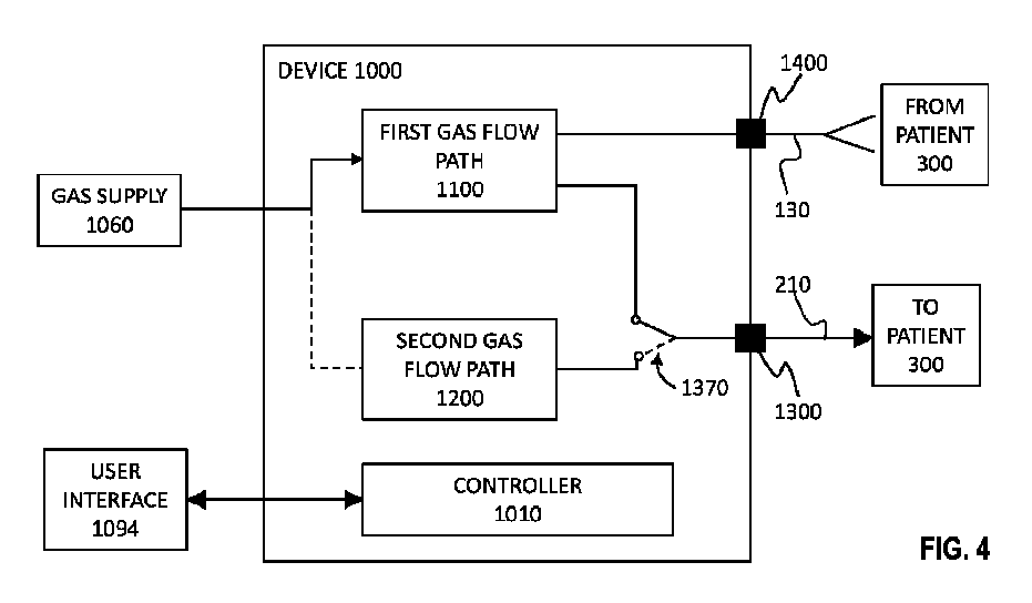
図4は、患者に呼吸補助を提供するデバイス1000の構成要素を示す概略図である。デバイスは、第1ガス流路1100と、第2ガス流路1200と、第1ガス流路と第2ガス流路の何れかからガスを受け取るように構成される第1ガスポート1300と、を含む。デバイスは、第1ガスポートへの流れを第1ガス流路1100と第2ガス流路1200との間で切り替えるように動作可能な切替機構1370をさらに含む。第1ガスポート1300がそこから吸気ガスが患者に提供されるポートである用途では、第1ガスポートは吸気ガスを患者に送達するための共通のガスポートとしてみなされ得る。 Figure 4 is a schematic diagram showing components of a device 1000 for providing respiratory assistance to a patient. The device includes a first gas flow path 1100, a second gas flow path 1200, and a first gas port 1300 configured to receive gas from either the first or second gas flow path. The device further includes a switching mechanism 1370 operable to switch flow to the first gas port between the first gas flow path 1100 and the second gas flow path 1200. In applications where the first gas port 1300 is the port through which inhalation gas is provided to the patient, the first gas port may be considered as a common gas port for delivering inhalation gas to the patient.
いくつかの実施形態では、デバイス1000はコントローラ1010を含み、切替機構1370の動作は、後述のように、コントローラがデバイスの1つ又は複数の動作条件を検出したことによって、及び/又はコントローラがユーザ入力を受信したことによってトリガされ得る。それゆえ、いくつかの実施形態では、デバイス1000はユーザインタフェース1094を含み、これは例えば、コントローラ1010と作動的に通信するキーボード及び/又はその他の入力アクチュエータ(ボタン、つまみ、ダイヤル等)を備えるタッチスクリーン及び/又は表示デバイス及び/又はモニタリングを含み得る。 In some embodiments, the device 1000 includes a controller 1010, and operation of the switching mechanism 1370 may be triggered by the controller detecting one or more operating conditions of the device and/or by the controller receiving user input, as described below. Thus, in some embodiments, the device 1000 includes a user interface 1094, which may include, for example, a touch screen and/or a display device and/or monitoring with a keyboard and/or other input actuators (buttons, knobs, dials, etc.) in operative communication with the controller 1010.
ガス流路のうちの一方から第1ガスポート1300への流れを可能にする切替機構1370の動作を、本明細書中、その流路を「イネーブルする」と言う場合があり、これは、切替により、イネーブルされた流路と第1ガスポート1300との間に流れが生じることが可能になる、という意味である。いくつかの実施形態では、ガス流路のうちの一方から第1ガスポート1300への流れを可能にする切替機構1370の動作はまた、他方のガス流路から第1ガスポートへの流れを阻止する。そこからの第1ガスポート1300への流れが阻止されるガス流路を、本明細書において、「ディスエーブルされる」と言う場合があり、これは、切替により、ディスエーブルされた流路と第1ガスポート1300との間に流れが生じることができない、又は生じないという意味である。 Operation of the switching mechanism 1370 to allow flow from one of the gas flow paths to the first gas port 1300 may be referred to herein as "enabling" that path, meaning that switching allows flow to occur between the enabled path and the first gas port 1300. In some embodiments, operation of the switching mechanism 1370 to allow flow from one of the gas flow paths to the first gas port 1300 also blocks flow from the other gas flow path to the first gas port. A gas flow path from which flow is blocked to the first gas port 1300 may be referred to herein as "disabled," meaning that switching does not allow or does not allow flow to occur between the disabled path and the first gas port 1300.
図4はまた、ガスを第1ガス流路1100及び/又は第2ガス流路1200に供給する1つのガス供給部1060も示しているが、多くの実施形態では複数のガス供給部が提供され得ると理解されたい。図4に示されるガス供給部1060は、例示的にすぎず、少なくとも1つのガスが患者300に呼吸補助を提供するためにデバイスに提供されることを示すことに関してのみ提供されている。
4 also shows one gas supply 1060 supplying gas to the first gas flow path 1100 and/or the second gas flow path 1200, although it should be understood that in many embodiments multiple gas supplies may be provided. The gas supply 1060 shown in FIG. 4 is provided for illustrative purposes only and solely with respect to illustrating that at least one gas is provided to the device to provide respiratory assistance to the
いくつかの実施形態では、第1ガスポート1300はガス出口ポートとみなされ得て、そこに、後述のように、第2患者インタフェースを介してガスを患者に提供するために第1導管、例えば吸気導管が連結され得る。図4はまた、第2ガスポート1400も示しており、これは第1患者インタフェースを介して患者300からの呼気ガスを受け取るように構成された第2導管、例えば呼気導管と連結可能であるように構成される。第2ガスポート1400で受け取られた呼気ガスは、後述のように、第1ガス流路1100に戻される。
In some embodiments, the first gas port 1300 may be considered a gas outlet port to which a first conduit, e.g., an inhalation conduit, may be coupled to provide gas to the patient via the second patient interface, as described below. FIG. 4 also shows a second gas port 1400, which is configured to be connectable to a second conduit, e.g., an exhalation conduit, configured to receive exhaled gas from the
しかしながら、用途によっては、切替が行われたときに第1ガスポート1300を通じた流れの方向が変化し得る。例えば、ハイフロー呼吸補助を提供するために、第2ガス流路1200が当初イネーブルされ、ガス流は非密閉第2患者インタフェース(例えば、カニューレ)を介して患者に提供される。第1ガスポート1300への流路が第1ガス流路1100をイネーブルするように切り替えられると、非密閉第2患者インタフェースは患者からの呼気ガスを受け取る可能性があり、吸気流は第2ガスポート1400から提供されて、密閉第1患者インタフェース(例えば、フェイスマスク)を通じて送達される。この配置では、デバイス1000の外部の流れの方向は逆転し、非密閉第2患者インタフェース及び導管210が呼気流路を提供し、密閉第1患者インタフェース及び導管130が吸気流路を提供する。
However, in some applications, the direction of flow through the first gas port 1300 may change when the switch is made. For example, to provide high-flow respiratory assistance, the second gas flow path 1200 may be initially enabled and gas flow may be provided to the patient via a non-sealing second patient interface (e.g., a cannula). When the flow path to the first gas port 1300 is switched to enable the first gas flow path 1100, the non-sealing second patient interface may receive exhaled gas from the patient, and inhalation flow may be provided from the second gas port 1400 and delivered through the sealing first patient interface (e.g., a face mask). In this arrangement, the direction of flow outside the device 1000 is reversed, with the non-sealing second patient interface and
切替機構1370は、デバイスの、第1ガスポート1300にガス流を提供する流路間の切替を行う1つ又は複数の構成要素又は構成要素の組合せにより提供され得る。図4に示される実施形態では、切替機構1370は切替要素を含み、これは第1ガス流路1100と第1ガスポート1300との間の流れを提供するように動作している。破線は、切替要素が第2流路1200と第1ガスポート1300との間の流れを提供する代替的な「切替後の」動作を示す。切替機構1370は、切替要素、例えば機械的又は空気圧アクチュエータ、分流器、弁、その他を含み得て、デバイス1000のユーザが切替機構を直接トリガすることによって操作され得る。 The switching mechanism 1370 may be provided by one or more components or combination of components that switch between the flow paths of the device that provide gas flow to the first gas port 1300. In the embodiment shown in FIG. 4, the switching mechanism 1370 includes a switching element that operates to provide flow between the first gas flow path 1100 and the first gas port 1300. The dashed lines indicate an alternative "post-switch" operation in which the switching element provides flow between the second flow path 1200 and the first gas port 1300. The switching mechanism 1370 may include a switching element, such as a mechanical or pneumatic actuator, a flow diverter, a valve, etc., and may be operated by a user of the device 1000 by directly triggering the switching mechanism.
図4では切替機構1370と1つのスイッチとして示されているが、切替機構は図5の概略図で示されている1つ又は複数の切替要素1370A及び1370Bを含み得ると理解されたい。ここで、第1切替要素1370Aは第1流路1100のために提供され、第2切替要素1370Bは第2流路1200のために提供される。切替要素は、センサ駆動自動コントローラであり得る電子コントローラ等のコントローラ1010の制御により動作可能な遮断弁又はその他の弁を含み得る。いくつかの実施形態では、切替要素1370A、Bは、切替機構1370のためのアクチュエータに関して本明細書に記載のユーザが操作可能なアクチュエータを含み得る。 4 as a single switch, it is understood that the switching mechanism may include one or more switching elements 1370A and 1370B as shown in the schematic diagram of FIG. 5, where a first switching element 1370A is provided for the first flow path 1100 and a second switching element 1370B is provided for the second flow path 1200. The switching elements may include shutoff valves or other valves operable under the control of a controller 1010, such as an electronic controller, which may be a sensor-driven automated controller. In some embodiments, the switching elements 1370A,B may include user-operable actuators as described herein with respect to actuators for the switching mechanism 1370.
図4及び5の切替機構1370の位置は代表的なものにすぎず、本明細書で提供される他の例を参照すれば明らかとなるように、切替機構は、第1ガスポート1300に供給する第1及び第2流路1100、1200間の合流点の上流の何れかの箇所、例えば第1及び第2ガス流路1100、1200の構成要素の上流、並びに/又は第1及び第2ガス流路1100、1200の要素の下流に提供された1つ又は複数の切替要素を含み得る。 The location of the switching mechanism 1370 in Figures 4 and 5 is merely representative, and as will become apparent with reference to other examples provided herein, the switching mechanism may include one or more switching elements provided anywhere upstream of the junction between the first and second flow paths 1100, 1200 feeding the first gas port 1300, such as upstream of components of the first and second gas flow paths 1100, 1200 and/or downstream of components of the first and second gas flow paths 1100, 1200.
切替機構(及びそれに関連する切替要素)は、ユーザによって直接、又は例えば電子コントローラ等のコントローラ1010を介して間接的に操作され得る。それゆえ、切替機構1370は、ユーザが動作モードを手動で選択でき、その結果、切替機構の動作によって第1ガスポート1300へのガス流路をイネーブル又はディスエーブルさせる、ユーザが操作可能なアクチュエータ、及び/又は、後述のように、切替機構1370(及びデバイスのその他のコンポーネント)を作動させるセンサ駆動自動コントローラを含み得る。各種の切替要素が、実質的に同時に、又は他の切替要素若しくはアクチュエータに応答して、又はコントローラ1010の制御により動作するように作動的に連結され得て、これは本明細書で提供される非限定的な例を参照すれば明らかになるであろう。 The switching mechanism (and its associated switching elements) may be operated directly by a user or indirectly via a controller 1010, such as an electronic controller. Thus, the switching mechanism 1370 may include a user-operable actuator that allows a user to manually select an operating mode, thereby enabling or disabling the gas flow path to the first gas port 1300 by operation of the switching mechanism, and/or a sensor-driven automatic controller that operates the switching mechanism 1370 (and other components of the device), as described below. The various switching elements may be operatively linked to operate substantially simultaneously, or in response to other switching elements or actuators, or under the control of the controller 1010, as will become apparent with reference to the non-limiting examples provided herein.
いくつかの実施形態では、第1ガス流路1100は1種又は複数種の麻酔薬を含む呼吸ガスを患者に送達するように構成可能であり得、第2ガス流路1200は、呼吸ガスを所望の流量で患者に送達するように構成可能であり得る。それゆえ、第1ガス流路1100は麻酔デバイス10(図1)及び/又は換気システム20(図2)の1つ又は複数の構成要素を内蔵し得て、第2ガス流路1200は、ハイフローシステム30(図3)の1つ又は複数の構成要素を内蔵し得る。簡略化するために、本開示を通じてこのような構成要素を指すために同様の番号が使用される。 In some embodiments, the first gas flow path 1100 may be configurable to deliver a breathing gas containing one or more anesthetic agents to a patient, and the second gas flow path 1200 may be configurable to deliver a breathing gas to a patient at a desired flow rate. Thus, the first gas flow path 1100 may house one or more components of the anesthesia device 10 (FIG. 1) and/or the ventilation system 20 (FIG. 2), and the second gas flow path 1200 may house one or more components of the high-flow system 30 (FIG. 3). For simplicity, similar numbers are used to refer to such components throughout this disclosure.
いくつかの実施形態では、切替機構1370の動作は、異なる形態の呼吸補助を患者に提供するために、異なる動作モードでデバイス1000を構成するように行われる。例えば、切替機構1370が第1ガス流路1100をイネーブルするように操作されると、デバイス1000は、患者からの呼気ガスが第1ガス流路へと戻される再呼吸モードを含む第1動作モードで動作するように構成され得て、切替機構1370が第2ガス流路1200をイネーブルするように操作されると、デバイスは、再呼吸を行わない流れ制御モードであり得る第2動作モードで動作するように構成され得る。第2動作モードはハイフローモードを含み得る。いくつかの実施形態では、切替機構1370が第1ガス流路1100をイネーブルするように操作されると、デバイス1000は、図1に関して前述したように、麻酔再呼吸モードである第1モードで、又は換気再呼吸モードである第3モードで動作するように構成され得る。それゆえ、第1モードでの動作への言及は、同じく再呼吸モードである第3モードも指すと解釈されるものとする。この動作モードで患者に提供されるガスは、圧力及び/又は体積が制御され得て、且つ/又は流量が制御され得る。換気は、患者の動作によりトリガされるか、換気デバイス(例えば、麻酔器)により設定された呼吸速度でトリガされ得る。 In some embodiments, the switching mechanism 1370 is operated to configure the device 1000 in different operating modes to provide different forms of respiratory assistance to the patient. For example, when the switching mechanism 1370 is operated to enable the first gas flow path 1100, the device 1000 may be configured to operate in a first operating mode including a rebreathing mode in which exhaled gas from the patient is returned to the first gas flow path, and when the switching mechanism 1370 is operated to enable the second gas flow path 1200, the device may be configured to operate in a second operating mode, which may be a flow control mode without rebreathing. The second operating mode may include a high-flow mode. In some embodiments, when the switching mechanism 1370 is operated to enable the first gas flow path 1100, the device 1000 may be configured to operate in a first mode, which is an anesthesia rebreathing mode, or in a third mode, which is a ventilation rebreathing mode, as described above with respect to FIG. 1. Thus, references to operation in the first mode shall be interpreted as also referring to the third mode, which is also a rebreathing mode. In this mode of operation, the gas provided to the patient may be pressure and/or volume controlled and/or flow controlled. Ventilation may be triggered by patient movement or at a breathing rate set by the ventilation device (e.g., anesthesia machine).
本明細書では、第2流路がイネーブルされた時に患者への麻酔薬の送達を防止する各種の実施形態が開示されているが、提供される例の代替例として、又はそれに加えて、また別の方式が採用され得ると理解されたい。例えば、第2ガス流路がイネーブルされている時に麻酔薬が放出されることによる被害を回避するために、デバイス1000は、気化器を停止させるか、又はその機能を無効なレベルまで低下させることにより、患者への麻酔薬の放出を無効にし得る。別法として又はさらに、デバイス1000は、麻酔薬の送達を無効化し得る。例えば、デバイスは、第1ガス流路1100内で、気化器を停止させるか、その機能を無効なレベルまで低下させ得る。別法として又はさらに、デバイスは、デバイスがガス流路1200がイネーブルされた状態で操作されたときに起動する第1ガス流路内の中和器を使って第1ガス流路1100から送達されるガス流内の麻酔薬を不活性化し得て、システムを通って流れている可能性のあるいかなる麻酔薬も無効にすることができる。無駄は多いが、これは重要な安全対策であり得る。 Although various embodiments are disclosed herein for preventing delivery of anesthetic to the patient when the second flow path is enabled, it should be understood that other approaches may be employed as an alternative or in addition to the examples provided. For example, to avoid harm from the release of anesthetic when the second gas flow path is enabled, the device 1000 may disable the release of anesthetic to the patient by shutting down or reducing the function of the vaporizer to an ineffective level. Alternatively or additionally, the device 1000 may disable the delivery of anesthetic. For example, the device may shut down or reduce the function of the vaporizer to an ineffective level in the first gas flow path 1100. Alternatively or additionally, the device may inactivate the anesthetic in the gas stream delivered from the first gas flow path 1100 using a neutralizer in the first gas flow path that is activated when the device is operated with the gas flow path 1200 enabled, thus neutralizing any anesthetic that may be flowing through the system. Although wasteful, this may be an important safety measure.
第1ガス流路1100がイネーブルされると、デバイス1000は第1モードでのデバイスの動作のために、第1ガス流路から第1ガスポート1300へのガスの流れを可能にする。ここから、第1導管210は、第1ガスポート1300から第2患者インタフェース220(吸気患者インタフェースである)へとガスを提供し、それがガスを患者300の気道内に向ける。この配置構成では、患者にガスを提供する第2患者インタフェース220は、鼻カニューレ等の非密閉インタフェースであり得る。フェイスマスク等の密閉インタフェースである第1患者インタフェースは、患者からの呼気ガスを第2導管130へと向けるように構成され、それが呼気ガスを第1ガス流路1100へと第2ガスポート1400を介して戻す。戻された呼気ガスは図1に関して述べたように、第1ガス流路1100内の再呼吸構成要素140によって処理され得る。第1ガス流路1100がイネーブルされると、デバイス1000はまた、第2ガス流路1200から第1ガスポーと1300への流れを阻止し、それによって第2ガス流路を「ディスエーブル」する。
When the first gas flow path 1100 is enabled, the device 1000 allows gas to flow from the first gas flow path to the first gas port 1300 for operation of the device in a first mode. From there, the
第2ガス流路1200がイネーブルされると、デバイス1000は第2ガス流路から第1ガスポーと1300へとガスが流れるようにする。追加的に、デバイス1000は、第1ガス流路1100から第1ガスポート1300へのガスの流れを阻止する。それゆえ、第1ガス流路1100は「ディスエーブル」されて、NO及び気化した麻酔薬を含み得る麻酔ガスの患者300への送達を阻止する。第1導管210は、第1ガスポート1300から第2患者インタフェース220(吸気患者インタフェースである)へとガスを供給し、それがガスを患者300の気道内へと向ける。この配置構成では、第2患者インタフェース120は、患者の一方又は両方の鼻孔へとガスを向ける1つ又は複数の鼻プロングを有する鼻カニューレ等の非密閉インタフェースである。第2ガス流路がイネーブルされ、デバイスが第2モードで動作するように構成されている場合、第1患者インタフェース又は第2導管が呼気ガスをデバイスに戻す必要はない。
When the second gas flow path 1200 is enabled, the device 1000 allows gas to flow from the second gas flow path to the first gas port 1300. Additionally, the device 1000 blocks the flow of gas from the first gas flow path 1100 to the first gas port 1300. Thus, the first gas flow path 1100 is "disabled" to block the delivery of anesthetic gas, which may include NO and vaporized anesthetic, to the
デバイス1000は、ガス供給部1060からのNO、O2、及び/又は空気を含むガスの供給を受けるように構成され得る。デバイス1000内のガスの流量を制御して所望の呼吸補助を実現するために、1つ又は複数の流量計が提供され得る。1つ又は複数のガス混合要素もまた、ガスを合体させるために提供され得る。流量計の制御は、ユーザによって行われる直接制御(例えば、流量計の中の流れを直接変更するロータリ又はリニアスイッチ等のアクチュエータを作動させる)によって、又はデバイス1000内の例えば電子制御式流量計に対する正確な制御を提供するように構成されたコントローラ1010にユーザが入力を提供することによって実現され得る。 The device 1000 may be configured to receive a supply of gases including NO, O2 , and/or air from a gas supply 1060. One or more flow meters may be provided to control the flow of gases within the device 1000 to achieve the desired respiratory assistance. One or more gas mixing elements may also be provided to combine the gases. Control of the flow meters may be achieved by direct control exercised by a user (e.g., activating an actuator such as a rotary or linear switch that directly alters the flow through the flow meters) or by a user providing input to a controller 1010 configured to provide precise control over, for example, electronically controlled flow meters within the device 1000.
流量計は、ガス供給部1060に組み込まれるか、ガス供給部の下流に設置されて、第1ガス流路1100及び第2ガス流路1200に入るガスの比率を制御し得る。別法として、流量計はデバイス1000内に提供され得る(図6及び7参照)。このような流量計は、例えばロータリアクチュエータを有する比例弁によって手動で制御すること、又はデバイス1000のコントローラ1010によって制御することができる。ガスの流量と比率を安全限度内に制限するため、例えば確実に第1ガス流路1100から出るガスの流量がいくつかの実施形態で15L/minを越えず、及び/又はFiO2が0.21を下回らないようにするために、安全上の機能が構築され得る。 A flow meter may be integrated into the gas supply 1060 or placed downstream of the gas supply to control the ratio of gases entering the first gas flow path 1100 and the second gas flow path 1200. Alternatively, a flow meter may be provided within the device 1000 (see Figures 6 and 7). Such a flow meter may be manually controlled, for example by a proportional valve with a rotary actuator, or may be controlled by the controller 1010 of the device 1000. Safety features may be built in to limit the gas flow rates and ratios within safe limits, for example to ensure that the flow rate of gas exiting the first gas flow path 1100 does not exceed 15 L/min in some embodiments and/or the FiO2 does not fall below 0.21.
いくつかの実施形態では、デバイス1000は、ガスを患者に送達される前に予め決められた温度及び/又は湿度に調整するように構成された加湿器420(図4A~7)を含み得る。好ましくは、このような調整済みガスは第2ガス流路1200内で提供されるが、加湿器420は、ガスを、換気再呼吸モードで使用される場合、第1ガス流路1100を介して患者に送達される前に、予め決められた温度及び/又は湿度に調整するように構成され得ることも想定される。加湿器420をデバイス1000内に提供することにより、加湿器のセットアップを、それを患者に呼吸補助を提供するためにデバイス1000をセットアップする日常のルーティンに組み込むことによって、合理化できるという利点が得られる。しかしながら、加湿器420はデバイス1000内に提供される必要はない。いくつかの実施形態では、デバイス1000は、図7及び8に示されるように別の構成要素又は装置である加湿器420と協働するように構成され得る。デバイスの外部に加湿器420を提供するために、同様の変更を図5~7の実施形態に加え得るが、簡潔にするために、これらは図で別々に例示されていない。 In some embodiments, the device 1000 may include a humidifier 420 (FIGS. 4A-7) configured to condition the gas to a predetermined temperature and/or humidity before delivery to the patient. Preferably, such conditioned gas is provided in the second gas flow path 1200, but it is also envisioned that the humidifier 420 may be configured to condition the gas to a predetermined temperature and/or humidity before delivery to the patient via the first gas flow path 1100 when used in ventilation-rebreathing mode. Providing the humidifier 420 in the device 1000 provides the advantage that the set-up of the humidifier can be streamlined by incorporating it into the daily routine of setting up the device 1000 to provide respiratory assistance to the patient. However, the humidifier 420 need not be provided in the device 1000. In some embodiments, the device 1000 may be configured to cooperate with the humidifier 420, which is a separate component or device, as shown in FIGS. 7 and 8. Similar modifications may be made to the embodiments of Figures 5-7 to provide a humidifier 420 external to the device, but for simplicity, these are not separately illustrated in the figures.
図7及び8で、デバイス1000は実線1050で示されるハウジングを含み、そこには図6に示されるような第1ガス流路1100及び第2ガス流路1200の要素が格納されるが、加湿器420はデバイスハウジングの外に示されて、別の構成要素又は装置を表している。第3ガスポート1210は、流れ源250の下流に提供され、第2ガス流路の第1区間1200Aと加湿器420にガスを供給する第3導管240との間の流体結合を可能にするように構成される。 7 and 8, the device 1000 includes a housing, shown by solid lines 1050, in which elements of the first gas flow path 1100 and the second gas flow path 1200 as shown in FIG. 6 are housed, but the humidifier 420 is shown outside the device housing and represents a separate component or apparatus. A third gas port 1210 is provided downstream of the flow source 250 and configured to allow fluid coupling between the first section 1200A of the second gas flow path and a third conduit 240 that supplies gas to the humidifier 420.
図7の配置構成では、加湿されたガスは、加湿器420からの加湿されたガスを収容する第4導管260と第2ガス流路の第2区間1200Bとの間の流体結合を可能にするように構成された第4ガスポート1220を介してデバイス1000に戻される。図8の配置構成では、第4導管260はデバイス1000内部のガスポートに連結されない。その代わりに、第4導管260内の加湿されたガスは、Tピースコネクタ等の合流点又はコネクタ600を介して第1導管210内に流れる。コネクタ600は、第1ガスポート1300の一部を形成し、又はその中に組み込まれ得るか、図8に示されるように第1ガスポートの下流に提供され得る。図8の配置構成では、逆止弁149Aはデバイスハウジング1050内の加湿器420の上流に位置付けられ得ることに留意されたい。逆止弁149Aを加湿器420に関して上流に設置することは、図7及び、加湿器がデバイスハウジング1050内に提供される実施形態でも可能である。逆止弁149A、149Bは、後述のようにディスエーブルされた流路内の逆流を防止するために提供され得る。
In the arrangement of FIG. 7, the humidified gas is returned to the device 1000 via a fourth gas port 1220 configured to allow fluid coupling between the fourth conduit 260 containing the humidified gas from the humidifier 420 and the second section 1200B of the second gas flow path. In the arrangement of FIG. 8, the fourth conduit 260 is not connected to a gas port inside the device 1000. Instead, the humidified gas in the fourth conduit 260 flows into the
加湿器420は、ユーザが、デバイス1000とは別に提供されている場合の加湿器と共に、又はその上に提供される制御インタフェースに手作業での入力を提供することによって直接制御され得る。別法として/さらに、外部加湿器は、デバイスのコントローラ1010に作動的に連結され得て、それにより、デバイス1000の動作は、デバイスの一部として提供された場合、又はデバイスの外部の別の構成要素として提供された場合の加湿器420のパフォーマンスを制御する。それゆえ、切替機構が第2ガス流路をイネーブルするように操作されると、コントローラ1010は、加湿器420に第2ガス流路1200内を流れるガスの温度及び湿度を事前設定された目標値まで上昇させるようにし得る。目標温度及び湿度は、コントローラ内にプログラムされるか、又はユーザによりユーザインタフェース1094を通じて選択され得る。この意味で、コントローラ1010は、患者に提供される呼吸補助の全ての要素を制御するように動作するマスタコントローラとみなされ得る。 The humidifier 420 may be directly controlled by the user by providing manual input to a control interface provided in conjunction with or on the humidifier when provided separately from the device 1000. Alternatively/additionally, the external humidifier may be operatively coupled to the device's controller 1010, whereby the operation of the device 1000 controls the performance of the humidifier 420 when provided as part of the device or when provided as a separate component external to the device. Thus, when the switching mechanism is operated to enable the second gas flow path, the controller 1010 may cause the humidifier 420 to increase the temperature and humidity of the gas flowing in the second gas flow path 1200 to a preset target value. The target temperature and humidity may be programmed into the controller or selected by the user through the user interface 1094. In this sense, the controller 1010 may be considered a master controller that operates to control all elements of the respiratory assistance provided to the patient.
切替機構が第1ガスポート1300への流れを第2ガス流路1200から第1ガス流路1100へと切り替えるように操作されると、コントローラは、加湿器420をスタンバイモードに入らせ得て、その間に温度は目標温度未満に下げられるが、加湿器は完全に停止されない。これは、制御が第2ガス流路をイネーブルするように再び切り換えられた時に、加湿されたガスが目標温度及び湿度により速く到達できるようにすることによりパフォーマンスを改善し得る。しかしながら、作動停止することも、第1ガス流路がイネーブルされ、(第2ガス流路がディスエーブルされ)たときに、デバイスの動作中に実行可能な制御として考えられる。 When the switching mechanism is operated to switch flow to the first gas port 1300 from the second gas flow path 1200 to the first gas flow path 1100, the controller may cause the humidifier 420 to enter a standby mode during which the temperature is reduced below the target temperature, but the humidifier is not shut down completely. This may improve performance by allowing the humidified gas to reach the target temperature and humidity more quickly when control is switched back to enable the second gas flow path. However, shutting down is also contemplated as a possible control during operation of the device when the first gas flow path is enabled (and the second gas flow path is disabled).
図6~8は、切替機構がガス源1060と第1及び第2ガス流路1100、1200との間に位置付けられているデバイス1000の概略図である。切替機構はO2の流れを、第1モードでのデバイスの動作のために第1ガス流路1100(これは、空気とNOの供給も受ける)に、及び第2モードでのデバイスの動作のために第2ガス流路1200に向けるように動作可能な第1切替要素710を含む。図6~8は、第1モードでデバイス1000を動作させるために第1ガス流路1100をイネーブルするためのこのような切替機構の動作を示す概略図を提供する。特に、動作の第1モードでは、第2切替要素も、好ましい実施形態では、第1ガス流路1100が手動(147)又は自動的/機械的(148)換気/再呼吸モードの何れかで動作できるように動作可能であり得る。図6~8に示される実施形態では、手動の第1モードが選択されている。いくつかの実施形態では、切替機構はまた、第1ガス流路1100への空気及び/又はNOの流れを制御するように動作可能な1つ又は複数の切替要素(図示せず)も含み得る。 6-8 are schematic diagrams of the device 1000 in which a switching mechanism is positioned between the gas source 1060 and the first and second gas flow paths 1100, 1200. The switching mechanism includes a first switching element 710 operable to direct the flow of O2 to the first gas flow path 1100 (which also receives a supply of air and NO) for operation of the device in a first mode, and to the second gas flow path 1200 for operation of the device in a second mode. FIGS. 6-8 provide schematic diagrams illustrating the operation of such a switching mechanism to enable the first gas flow path 1100 to operate the device 1000 in the first mode. In particular, in the first mode of operation, the second switching element may also be operable in preferred embodiments to enable the first gas flow path 1100 to operate in either a manual (147) or automatic/mechanical (148) ventilation/rebreathing mode. In the embodiment shown in FIGS. 6-8, the manual first mode is selected. In some embodiments, the switching mechanism may also include one or more switching elements (not shown) operable to control the flow of air and/or NO into the first gas flow path 1100.
第2切替要素720は、第1切替要素710に応答し得る。したがって、第1切替要素710が、第2モードでのデバイスの動作のために第2ガス流路1200をイネーブルするように切り替えられると、O2は第2ガス流路1200に(流量調節器250及び加湿器420により表される)向けられ、第2切替要素720は最も下の位置722に移動して、手動及び自動換気/再呼吸の両方をオフにし、患者から第2ガスポート1400へと戻される呼気ガスが第1ガス流路1100の再呼吸構成要素140に入り、その後、第1ガスポート1300へと流れるのを阻止する。第1切替要素710が第2ガス流路をイネーブルするように切り替えられると、O2は第2ガス流路1200へと向けられる。図8の例では、第2流路1200からのガスは、第1ガスポート1300の下流の吸気導管210に入る。したがって、第1切替要素710の第2ガス流路1200をイネーブルする動作は、O2が第1ガス流路1100のガス混合要素1042に入るのを阻止し、それと同時に、第1ガス出口1300を通じた患者300への新鮮ガス流も阻止する。
The second switching element 720 may be responsive to the first switching element 710. Thus, when the first switching element 710 is switched to enable the second gas flow path 1200 for operation of the device in the second mode, O2 is directed to the second gas flow path 1200 (represented by the flow regulator 250 and humidifier 420) and the second switching element 720 moves to the lowest position 722 to turn off both manual and automatic ventilation/rebreathing and to prevent exhaled gases returning from the patient to the second gas port 1400 from entering the rebreathing component 140 of the first gas flow path 1100 and then flowing to the first gas port 1300. When the first switching element 710 is switched to enable the second gas flow path, O2 is directed to the second gas flow path 1200. In the example of FIG. 8, gas from the second flow path 1200 enters the
例えば図6~9の切替要素710/730を含み得る切替機構に加えて、デバイス1000は1つ又は複数の逆止弁又はその他の一方向弁を含み得て、例えば「ディスエーブルされた」ガス流路から第1ガスポート1300への、システム内の逆流を阻止又は制御する。図6~9に示される例では、切替機構が第1ガスポート1400へのガスを第1ガス流路1100から第2ガス流路1200へと切り替えるように操作されると、逆止弁149Bは第1ガスポートから第1ガス流路への逆流を阻止する。逆に、切替機構が第1ガスポート1300への流れを第2ガス流路1200から第1ガス流路1100へと切り替えるように操作されると、逆止弁149Aは第1ガスポート1400から第2ガス流路1200への逆流を阻止する。追加的な逆止弁は、ガス流システムの場合、特に再呼吸回路の場合に一般的であるように、デバイス1000の流路の何れかの場所に実装され得る。 In addition to the switching mechanism, which may include, for example, switching element 710/730 of FIGS. 6-9, device 1000 may include one or more check valves or other one-way valves to prevent or control backflow in the system, for example, from a "disabled" gas flow path to first gas port 1300. In the example shown in FIGS. 6-9, when the switching mechanism is operated to switch gas to first gas port 1400 from first gas flow path 1100 to second gas flow path 1200, check valve 149B prevents backflow from the first gas port to the first gas flow path. Conversely, when the switching mechanism is operated to switch flow to first gas port 1300 from second gas flow path 1200 to first gas flow path 1100, check valve 149A prevents backflow from first gas port 1400 to second gas flow path 1200. Additional check valves may be implemented anywhere in the flow path of device 1000, as is common in gas flow systems, particularly rebreathing circuits.
前述の例に関するものを含むいくつかの実施形態では、第2ガス流路1200から第1ガスポート1300へと送達されるガスの所望の流量は、ユーザがコントローラ1010のユーザインタフェース1094を通じて選択することによって、又は切替機構の構成要素若しくはデバイスのフローコントローラを手作業で操作することによって、約20LPM~約100LPMの範囲から選択可能であり得る。しかしながら、小児又は新生児患者等、場合によっては、より低い範囲が望ましいかもしれない。いくつかの実施形態では、所望の流量は、ユーザによって、例えば0LPM、40LPM、70LPM等の複数の利用可能な流量から選択可能であり得るが、追加的及び/又は異なる流量が本明細書において開示される高流量範囲内で選択可能であり得ると理解されたい。 In some embodiments, including those relating to the examples above, the desired flow rate of gas delivered from the second gas flow path 1200 to the first gas port 1300 may be selectable by a user through the user interface 1094 of the controller 1010 or by manually manipulating a component of the switching mechanism or a flow controller of the device from a range of about 20 LPM to about 100 LPM. However, in some cases, such as with pediatric or neonatal patients, a lower range may be desirable. In some embodiments, the desired flow rate may be selectable by the user from a number of available flow rates, such as 0 LPM, 40 LPM, 70 LPM, etc., although it should be understood that additional and/or different flow rates may be selectable within the high flow rate range disclosed herein.
所望の流量の選択は、いくつかの実施形態では例えばつまみ、スライドスイッチ、タッチスクリーン、又は複数の利用可能流量若しくはその範囲から所望の流量をユーザが選択できるようにするその他のアクチュエータの形態の流量セレクタを含む。 Selection of the desired flow rate includes, in some embodiments, a flow rate selector in the form of, for example, a knob, slide switch, touch screen, or other actuator that allows the user to select a desired flow rate from multiple available flow rates or a range thereof.
いくつかの実施形態では、流量セレクタは、図9に概略的に示されるように流量切替要素730を含み得る。幾つかの例では、流量切替要素730は第1切替要素710と置き換わることができるが、いくつかの実施形態では、第2ガス流路1200がイネーブルされた時のガス流量の上昇の遅延の問題を回避するために、第1切替要素710に加えて流量切替要素730を提供することが望ましい場合がある。好ましくは、流量切替要素730は第2切替要素720に作動的に連結され、それによって第2ガス流路1200内での第1ガスポート1300への流れ(図のように加湿器420を通じたものを含む)を可能にする流量セレクタ730の動作は、患者から第2ガスポート1400へと戻される呼気ガスが第1ガス流路1100の再呼吸構成要素140に入り、その後、第1ガスポート1300へと流れるのも阻止する。 In some embodiments, the flow rate selector may include a flow rate switching element 730 as shown diagrammatically in FIG. 9. In some instances, the flow rate switching element 730 may replace the first switching element 710, but in some embodiments, it may be desirable to provide the flow rate switching element 730 in addition to the first switching element 710 to avoid issues with delayed gas flow rate ramp-up when the second gas flow path 1200 is enabled. Preferably, the flow rate switching element 730 is operatively coupled to the second switching element 720, such that operation of the flow rate selector 730 to allow flow in the second gas flow path 1200 to the first gas port 1300 (including through the humidifier 420 as shown) also prevents exhaled gases returning from the patient to the second gas port 1400 from entering the rebreathing component 140 of the first gas flow path 1100 and then flowing to the first gas port 1300.
図9の配置構成では、切替要素730は第1及び第2ガス流路1100、1200へのO2の流れを制御する。それゆえ、流量切替要素730が流量コントローラ250A(例えば、40LPMに対応する)又は流量コントローラ250B(例えば、70LPMに対応する)に関連付けられる2つの所定の流量のうちの1つを選択するように操作されると、第2ガス流路1200内にO2が流れ、デバイス1000は第2モードで動作するように構成され、また、流量切替要素730が図に示される一番上の位置を選択するように操作されると、O2供給部からの流れは第1ガス流路1100へと向けられ、デバイスは第1モードで動作するように構成される。流量切替要素730と第2切替要素720は作動的に連結され得て、それによって第2ガス流路1200をイネーブルする流量セレクタ730の動作は、切替要素720の一番下の位置722への切替を作動させて、患者から第2ガスポート1400へと戻される呼気ガスが第1ガス流路1100の再呼吸構成要素140に入り、その後、第1ガスポート1300へと流れるのを阻止することができる。第2ガス流路1200をイネーブルする流量切替要素730の動作はO2が第1ガス流路1100のガス混合要素1042に入るのを阻止するため、第1ガスポート1300を通じた第1ガス流路1100から患者への新鮮ガスの流れもない。いくつかの実施形態では、切替要素730の動作はまた、第2ガス流路1200へのNO/空気供給も停止させ得る。これは、例えばNO及び/又は空気ガス流路中に提供された1つ又は複数の作動的に連結された遮断弁によって実現され得る。いくつかの実施形態では、切替機構は、第1及び/又は第2ガス流路1100、1200への空気及び/又はNOの流れを制御するように動作可能な1つ又は複数の切替要素(図示せず)も含み得る。 9, the switching element 730 controls the flow of O2 to the first and second gas flow paths 1100, 1200. Thus, when the flow switching element 730 is manipulated to select one of two predetermined flow rates associated with flow controller 250A (e.g., corresponding to 40 LPM) or flow controller 250B (e.g., corresponding to 70 LPM), O2 flows into the second gas flow path 1200 and the device 1000 is configured to operate in the second mode, and when the flow switching element 730 is manipulated to select the top position shown in the figure, flow from the O2 supply is directed to the first gas flow path 1100 and the device is configured to operate in the first mode. The flow rate switching element 730 and the second switching element 720 may be operatively coupled such that operation of the flow rate selector 730 to enable the second gas flow path 1200 may actuate the switching element 720 to switch to the lowest position 722 to prevent exhaled gas returning from the patient to the second gas port 1400 from entering the rebreathing component 140 of the first gas flow path 1100 and thereafter flowing to the first gas port 1300. Operation of the flow rate switching element 730 to enable the second gas flow path 1200 prevents O2 from entering the gas mixing element 1042 of the first gas flow path 1100, so there is no flow of fresh gas from the first gas flow path 1100 to the patient through the first gas port 1300. In some embodiments, operation of the switching element 730 may also stop the NO/air supply to the second gas flow path 1200. This may be accomplished, for example, by one or more operatively coupled shut-off valves provided in the NO and/or air gas flow paths. In some embodiments, the switching mechanism may also include one or more switching elements (not shown) operable to control the flow of air and/or NO to the first and/or second gas flow paths 1100, 1200.
いくつかの実施形態では、切替機構は、図10の概略図に示されているように、1つ又は複数の流量セレクタ/流量計190A、190B、190Cを含み得る。この例では、流量計190A、190B、190Cの1つの集合が、O2、空気、及びNOの各々の共通のガス混合要素1042への流れを制御するように提供され、そこから第1ガス流路1100と第2ガス流路1200の両方がガスを受け取る。この配置構成では、破線により示されるように、流量計190A、190B、190Cと切替要素710を含む切替機構との間に作動的連結がある。前述のように、切替要素710は、第1ガス出口1300へのガスの流れを第1ガス流路1100と第2ガス流路1200との間で切り替えるように動作可能である。図10の配置構成では、切替要素710が(図の構成のように)第1ガス流路1100をイネーブルするように操作されると、切替要素710と流量計190A、190B、190Cとの間の作動的連結により、流量計はガスを第1動作モードでの呼吸補助を実現するのに適した流量でガスを送達するように動作する。逆に、切替要素710が第2ガス流路1200をイネーブルするように操作されると、切替要素710と流量計190A、190B、190Cとの間の作動的連結によって、流量計は第2動作モードでの呼吸補助を実現するのに適した流量でガスを送達するように動作する。各流量計190A、190B、190Cの各々に必要な流量は、特定の動作モードでの動作のために事前設定され得る。例えば、第1ガス流路1100がイネーブルされると、流量計190A、190B、190Cは第1動作モードでの呼吸補助の提供に適した混合ガスのための流量(例えば、第1ガス出口1300において15L/min)を送達するように構成され得る。第2ガス流路1200がイネーブルされると、流量計190A、190B、190Cは、第2動作モードでの呼吸補助の提供に適した混合ガスのための流量(例えば、第1ガス出口1300で40L/min又は70L/min)を送達するように構成され得る。流量計190A、190B、190Cにより提供される流量は、所望のO2及び/又はNO濃度に応じて特定できる。 例えば、流量15L/minで100%のO2濃度を実現するために、流量計190Aは15L/minに設定でき、流量計190B、190Cを通る流れはゼロである。別法として又はさらに、NO源は、NOの流れをゼロにする必要がある場合、例えば第2動作モードでの呼吸補助を提供する場合、追加の安全機構としてディスエーブルできる。15L/minでの混合ガス中のO2:空気の比50:50を実現するために、流量計190A及び190Bの各々を、7.5L/minを提供するように設定できる。流量計190Cからの流れは、臨床医の決定に従って患者への混合ガス流中に必要なNOの割合に応じて調整でき、流量計190A、Bの一方又は両方からの流れは臨床的必要性に応じて相応に調整される。別法として又はさらに、流量計190A、190B、190Cは、手作業での動作を通じて、又は流量計がコントローラ1010と作動的に通信する配置構成ではユーザインタフェース1094を介して調整可能であり得る。 In some embodiments, the switching mechanism may include one or more flow selectors/flow meters 190A, 190B, 190C, as shown in the schematic diagram of FIG. 10. In this example, one set of flow meters 190A, 190B, 190C is provided to control the flow of each of O2, air, and NO to a common gas mixing element 1042 from which both the first gas flow path 1100 and the second gas flow path 1200 receive gas. In this arrangement, there is an operative connection between the flow meters 190A, 190B, 190C and the switching mechanism including the switching element 710, as shown by the dashed lines. As previously described, the switching element 710 is operable to switch the flow of gas to the first gas outlet 1300 between the first gas flow path 1100 and the second gas flow path 1200. In the arrangement of Figure 10, when the switching element 710 is operated to enable the first gas flow path 1100 (as configured in the figure), the operative connection between the switching element 710 and the flow meters 190A, 190B, 190C causes the flow meters to operate to deliver gas at a flow rate suitable for providing respiratory assistance in a first mode of operation. Conversely, when the switching element 710 is operated to enable the second gas flow path 1200, the operative connection between the switching element 710 and the flow meters 190A, 190B, 190C causes the flow meters to operate to deliver gas at a flow rate suitable for providing respiratory assistance in a second mode of operation. The flow rate required for each of the flow meters 190A, 190B, 190C may be preset for operation in a particular mode of operation. For example, when the first gas flow path 1100 is enabled, the flow meters 190A, 190B, 190C may be configured to deliver a flow rate for the mixed gas suitable for providing respiratory assistance in the first mode of operation (e.g., 15 L/min at the first gas outlet 1300). When the second gas flow path 1200 is enabled, the flow meters 190A, 190B, 190C may be configured to deliver a flow rate for the mixed gas suitable for providing respiratory assistance in the second mode of operation (e.g., 40 L/min or 70 L/min at the first gas outlet 1300). The flow rates provided by the flow meters 190A, 190B, 190C may be specified as a function of the desired O2 and/or NO concentrations. For example, to achieve 100% O2 concentration at a flow rate of 15 L/min, the flow meter 190A may be set to 15 L/min and the flow through the flow meters 190B, 190C is zero. Alternatively or additionally, the NO source can be disabled as an additional safety mechanism when the flow of NO needs to be zero, for example when providing respiratory assistance in the second mode of operation. To achieve a 50:50 ratio of O2:air in the mixed gas at 15 L/min, flow meters 190A and 190B can each be set to provide 7.5 L/min. The flow from flow meter 190C can be adjusted according to the percentage of NO required in the mixed gas flow to the patient as determined by the clinician, with the flow from one or both flow meters 190A, B being adjusted accordingly according to clinical need. Alternatively or additionally, flow meters 190A, 190B, 190C can be adjustable through manual operation or via user interface 1094 in an arrangement in which the flow meters are in operative communication with controller 1010.
図11は図10の実施形態の変形型を提供しており、これは流量計190A、190B、190Cと190D、190E、190Fの別々の集合と別々のガス混合要素1042A、1042Bを提供する。第1集合の流量計190A、190B、190Cは、そこから第1ガス流路1100がガスを受け取る第1ガス混合要素1042AへのO2、空気、及びNOの各々の流れを制御する。第2集合の流量計190D、190E、190Fは、そこから第2ガス流路1200がガスを受け取る第2ガス混合要素1042BへのO2、空気、及びNOの各々の流れを制御する。図11は、別々のガス源1060A及び1060Bを示しているが、これは図中の流れの表現を容易にするためである。図の実施形態では、別々のガス源1060A及び1060Bが第1及び第2ガス流路1100及び1200の各々に供給する必要はないと理解されたい。第1及び第2ガス流路1100及び1200の各々は、患者に提供される1種又は複数のガスの各々の1つの供給源からそれぞれの集合の流量計の中にガスを受け取ることができると考えられ、その点を明記する。第1及び第2ガス流路1100及び1200が単独の供給源からガスを受け取る場合、幾つかの実施形態において、NOは第2ガス流路1200に供給されなくてもよいと理解されたい。さらに、気化器150がガス混合要素1042Aの下流に示されているが、第1及び第2ガス流路1100及び1200が単独の供給源からガスを受け取る構成を含め、これらの要素の位置は逆転され得ると理解されたい。 11 provides a variation of the embodiment of FIG. 10, which provides separate sets of flow meters 190A, 190B, 190C and 190D, 190E, 190F and separate gas mixing elements 1042A, 1042B. The first set of flow meters 190A, 190B, 190C controls the flow of O2, air, and NO, respectively, to the first gas mixing element 1042A from which the first gas flow path 1100 receives gas. The second set of flow meters 190D, 190E, 190F controls the flow of O2, air, and NO, respectively, to the second gas mixing element 1042B from which the second gas flow path 1200 receives gas. FIG. 11 shows separate gas sources 1060A and 1060B for ease of depiction of the flows in the figure. It should be understood that in the illustrated embodiment, separate gas sources 1060A and 1060B are not required to supply each of the first and second gas flow paths 1100 and 1200. It is contemplated and noted that each of the first and second gas flow paths 1100 and 1200 may receive gas into a respective collection of flow meters from a single source of each of the one or more gases provided to the patient. It should be understood that in some embodiments, NO may not be supplied to the second gas flow path 1200 if the first and second gas flow paths 1100 and 1200 receive gas from a single source. Additionally, while the vaporizer 150 is shown downstream of the gas mixing element 1042A, it should be understood that the positions of these elements may be reversed, including configurations in which the first and second gas flow paths 1100 and 1200 receive gas from a single source.
図11では、第1集合の流量計190A、190B、190Cと第2集合の流量計190D、190E、190Fの各々と、切替要素710を含む切替機構との間には、破線で示されるように作動的連結がある。前述のように、切替要素710は第1ガス出口1300へのガス流を第1ガス流路1100と第2ガス流路1200との間で切り替えるように動作可能である。図11の配置構成では、切替要素710が(図の構成のように)第1ガス流路1100をイネーブルするように操作されると、切替要素710と流量計との間の作動的連結によって、第1集合の流量計190A、190B、190Cは第1動作モードでの呼吸補助を実現するのに適した流量でガスを送達するように動作し、第2集合の流量計190D、190E、190Fからの流れを遮断する。逆に、切替要素710が第2ガス流路1200をイネーブルするように操作されると、切替要素710と流量計との間の作動的連結によって、第2集合の流量計190D、190E、190Fは第2動作モードでの呼吸補助を実現するのに適した流量でガスを送達するように動作し、第1集合の流量計190A、190B、190Cからの流れを遮断する。各流量計に必要な流量は、図10の説明と同様に、指定されたガス流路に供給する動作のために事前設定され得る。例えば、第1ガス流路1100がイネーブルされると、流量計190A、190B、190Cは第1動作モードでの呼吸補助の提供に適した混合ガスのための流量(例えば、第1ガス出口1300において15L/min)を送達するように構成され得る。第2ガス流路1200がイネーブルされると、流量計190D、190E、190Fは、第2動作モードでの呼吸補助の提供に適した混合ガスのための流量(例えば、第1ガス出口1300において40L/min又は70L/min)を送達するように構成され得る。いくつかの実施形態では、第2ガス流路1200がイネーブルされると、ガス流量計は、O2ガス流量計190Dだけがガス混合要素1042Bにガス流を提供するように構成され得て、空気及びNO流量計190E、190Fはディスエーブルされるか、流れを提供しない。他の場合では、ガス流量計190DE、190Eの一方又は両方がガス混合要素1042Bに流れを提供することが望ましいかもしれない。別法として/さらに、流量計190A、190B、190C、190D、190E、190Fは手動での動作を通じて、又は流量計がコントローラ1010と作動的に通信する配置構成ではユーザインタフェース1094を介して調整可能であり得る。 In FIG. 11, there is an operational connection between each of the first set of flow meters 190A, 190B, 190C and the second set of flow meters 190D, 190E, 190F and a switching mechanism including a switching element 710, as shown by dashed lines. As previously described, the switching element 710 is operable to switch the flow of gas to the first gas outlet 1300 between the first gas flow path 1100 and the second gas flow path 1200. In the arrangement of FIG. 11, when the switching element 710 is operated to enable the first gas flow path 1100 (as in the illustrated configuration), the operational connection between the switching element 710 and the flow meters causes the first set of flow meters 190A, 190B, 190C to operate to deliver gas at a flow rate suitable to provide respiratory assistance in the first mode of operation and to block flow from the second set of flow meters 190D, 190E, 190F. Conversely, when the switching element 710 is operated to enable the second gas flow path 1200, the operative connection between the switching element 710 and the flow meters causes the second set of flow meters 190D, 190E, 190F to operate to deliver gas at a flow rate suitable for providing respiratory assistance in the second mode of operation and blocks flow from the first set of flow meters 190A, 190B, 190C. The required flow rate for each flow meter may be pre-set for operation to supply a designated gas flow path, similar to the description of FIG. 10. For example, when the first gas flow path 1100 is enabled, the flow meters 190A, 190B, 190C may be configured to deliver a flow rate for the mixed gas suitable for providing respiratory assistance in the first mode of operation (e.g., 15 L/min at the first gas outlet 1300). When the second gas flow path 1200 is enabled, the flow meters 190D, 190E, 190F may be configured to deliver a flow rate for the mixed gas suitable for providing respiratory assistance in the second mode of operation (e.g., 40 L/min or 70 L/min at the first gas outlet 1300). In some embodiments, when the second gas flow path 1200 is enabled, the gas flow meters may be configured such that only the O2 gas flow meter 190D provides gas flow to the gas mixing element 1042B, and the air and NO flow meters 190E, 190F are disabled or provide no flow. In other cases, it may be desirable for one or both of the gas flow meters 190DE, 190E to provide flow to the gas mixing element 1042B. Alternatively/additionally, the flow meters 190A, 190B, 190C, 190D, 190E, and 190F may be adjustable through manual operation or via a user interface 1094 in an arrangement in which the flow meters are in operative communication with the controller 1010.
図6及び7の例は、切替要素710をデバイス1000の切替機構の一部として提供している。切替要素710は、動作モードを選択するためにユーザが操作できるアクチュエータ、つまみスイッチ、又は入力インタフェース1094を含み得る。別法として/さらに、切替機構は、コントローラに入力を提供するセンサが判断する動作状態の変化(例えば、患者への密閉患者インタフェースの適用又は患者からのその取り外し)に応答して動作モードを切り替えるデバイス1000のコントローラ1010の動作を含み得る。 6 and 7 provide a switching element 710 as part of a switching mechanism of the device 1000. The switching element 710 may include an actuator, a knob switch, or an input interface 1094 that a user can manipulate to select an operating mode. Alternatively/additionally, the switching mechanism may include operation of the controller 1010 of the device 1000 to switch operating modes in response to a change in operating condition (e.g., application of a sealing patient interface to or removal from the patient) determined by a sensor providing input to the controller.
有利な点として、図4~7の実施形態では追加の酸素供給源をセットアップする必要がなくなり、これは、第1動作モードでのデバイスの動作を可能にする第1ガス流路1100と第2動作モードでのデバイスの動作を可能にする第2ガス流路1200の両方が共通のガス供給源1060から酸素を受け取ることができるからである。さらに、この配置構成では、第1ガス流路1100と第2ガス流路1200の両方を同時に切り替えることが容易であり、それによって第2モードが選択されると、第1ガス流路1100は患者300へのガスの送達を停止する。これによって、第1ガスポートへのガス流の中で、NOと、第1ガス流路1100で気化した揮発性麻酔を含む麻酔薬が送達されるのが阻止されて安全性が高められる。さらに、麻酔剤が環境中に入ることはあり得ず、患者に付き添う介護者によるこれらの麻酔薬の吸入が回避され、それと同時に無駄も軽減される。
Advantageously, the embodiment of Figs. 4-7 eliminates the need to set up an additional oxygen source, since both the first gas flow path 1100, which allows the device to operate in the first mode of operation, and the second gas flow path 1200, which allows the device to operate in the second mode of operation, can receive oxygen from a common gas source 1060. Moreover, this arrangement makes it easy to switch both the first gas flow path 1100 and the second gas flow path 1200 simultaneously, so that when the second mode is selected, the first gas flow path 1100 stops delivering gas to the
コントローラ1010及びユーザインタフェース1094を含むいくつかの実施形態では、デバイスは、第2ガス流路1200をイネーブルするように切り替える時期についてユーザを促す聴覚的、視覚的、又は触覚的等のプロンプトを提供し得て、ユーザに、第2ガスポート1400でデバイスに戻される呼気ガス中の麻酔薬の量が極めて少量となり、又は全くなくなるまで患者に第1患者インタフェース120を使用し続けるように促す。このような警告は、麻酔薬が医療環境中に漏出するリスクを軽減又は排除するための安全上の機能を提供する。別法として/さらに、コントローラ1010は、ユーザに、第1患者インタフェースを患者から安全に取り外せることを知らせるプロンプト(例えば、第2プロンプト)を提供するように構成され得る。コントローラ1010は、タイマを有し、切替後、十分な時間が経過すると、患者に戻される呼気ガス中の麻酔薬の量が極めて少量となり、又は全くなくなったとの第2のプロンプトが与えられるように構成され得る。いくつかの例では、ユーザインタフェース1094は、ユーザに対して経過時間が終了する時期についてのガイドを提供する視覚的及び/又は聴覚的カウントダウンタイマを提供して、呼気ガス中の麻酔薬の量が極めて少量になり、又は全くなくなり、第1患者インタフェース120を外してもよいことを示し得る。別法として又はさらに、デバイス1000は、呼気ガス流路内に、麻酔ガスの存在を検出するための1つ又は複数のセンサを含み得て、コントローラ1010は、センサが麻酔ガスが検出されなくなったこと、又は検出された麻酔ガスの量が所定の安全閾値未満になったことを示したときにのみ、第2プロンプトを提供するように構成され得る。 In some embodiments including the controller 1010 and the user interface 1094, the device may provide an audio, visual, tactile, etc. prompt to the user when to switch to enable the second gas flow path 1200, encouraging the user to continue using the first patient interface 120 with the patient until there is very little or no anesthetic in the exhaled gas being returned to the device at the second gas port 1400. Such a warning provides a safety feature to reduce or eliminate the risk of anesthetic leaking into the medical environment. Alternatively/additionally, the controller 1010 may be configured to provide a prompt (e.g., a second prompt) to inform the user that it is safe to remove the first patient interface from the patient. The controller 1010 may have a timer and may be configured to provide a second prompt after a sufficient amount of time has elapsed after the switch that there is very little or no anesthetic in the exhaled gas being returned to the patient. In some examples, the user interface 1094 may provide a visual and/or audio countdown timer to guide the user as to when the elapsed time has expired, indicating that the amount of anesthetic agent in the exhaled gas is very low or nonexistent and the first patient interface 120 may be removed. Alternatively or additionally, the device 1000 may include one or more sensors in the exhaled gas flow path to detect the presence of anesthetic gas, and the controller 1010 may be configured to provide the second prompt only when the sensor indicates that anesthetic gas is no longer detected or that the amount of anesthetic gas detected is below a predetermined safety threshold.
電子的に使用可能な切替要素710を、第1又は第2患者インタフェース120、220の一方又は両方に物理的に取付可能にして、患者インタフェースが交換されるとき、例えば、挿管前から挿管に移るとき、又は鎮静から患者を離脱させるときに、異なるモードでのデバイス1000の動作のためのガス流路間の迅速な切替を可能にすることができる。例えば、切替要素710は、患者インタフェース上に位置付けられたボタン又は電子スイッチを含み得て、それが起動され得て、デバイス1000にそのインタフェースを通じて患者にガスを安全に送達する動作モードに切り替えさせる。別法として、フットペダル若しくは足で操作するスイッチ又は音声制御を利用してもよい。これらの各々は、ユーザがデバイス自体の上にある制御部から離れている間のガス流路/モード選択の実行可能性を改善する可能性を有する。 An electronically enabled switching element 710 may be physically attachable to one or both of the first or second patient interfaces 120, 220 to allow rapid switching between gas flow paths for operation of the device 1000 in different modes when the patient interfaces are swapped, e.g., when transitioning from pre-intubation to intubation, or when weaning a patient from sedation. For example, the switching element 710 may include a button or electronic switch located on the patient interface that may be activated to cause the device 1000 to switch to an operating mode that safely delivers gas to the patient through that interface. Alternatively, a foot pedal or foot operated switch or voice control may be utilized. Each of these has the potential to improve the feasibility of gas flow path/mode selection while the user is away from the controls on the device itself.
本開示のいくつかの実施形態では、切替要素へのユーザによる手作業での入力に基づいて、又はユーザインタフェースを通じて、デバイス1000のイネーブルされたガス流路(及び動作モード)の切替を行うが、いくつかの実施形態では、デバイス1000は、デバイスの動作状態、例えば第1患者インタフェース120が患者に適用されて、呼気ガスを受け取る場合か否かを検出するように構成された1つ又は複数のセンサからの入力を受け取るコントローラ1010を含み、それは、これが第1ガス流路1100がイネーブルされた時にのみ使用される方式であるからである。それゆえ、第1患者インタフェース120が患者に適用されると、コントローラ1010は第1ガス流路1100がイネーブルされ、デバイスがまとめて、又は個々に「再呼吸」モードとみなされ得る第1モード(麻酔再呼吸)又は第1モードの具体例と考えられ得る第3モード(換気再呼吸)で動作を行うように構成されることを確実にする。逆に、センサが第1患者インタフェース120は患者に適用されていないことを検出すると、コントローラ1010は第2ガス流路1200がイネーブルされ、デバイスがネーザルハイフロー(NHF)呼吸補助を送達する第2モードで動作するように構成されることを確実にする。 In some embodiments of the present disclosure, the switching of the enabled gas flow paths (and operational modes) of the device 1000 is performed based on manual input by a user to a switching element or through a user interface, but in some embodiments, the device 1000 includes a controller 1010 that receives input from one or more sensors configured to detect the operational state of the device, for example, whether the first patient interface 120 is applied to the patient and receives exhaled gas, since this is the mode that is used only when the first gas flow path 1100 is enabled. Thus, when the first patient interface 120 is applied to the patient, the controller 1010 ensures that the first gas flow path 1100 is enabled and that the device is configured to operate in a first mode (anesthesia rebreathing), which may be considered collectively or individually as a "rebreathing" mode, or a third mode (ventilation rebreathing), which may be considered as an example of the first mode. Conversely, when the sensor detects that the first patient interface 120 is not being applied to the patient, the controller 1010 ensures that the second gas flow path 1200 is enabled and the device is configured to operate in a second mode to deliver nasal high flow (NHF) respiratory assistance.
検知のための様々な異なる方式又は方式の組合せが、患者にガスを送達するデバイス1000におけるガス流路及び/又はモード切替を提供する手段として使用され得る。一例では、マスクキャビティ内の圧力が圧力センサによりモニタされ、マスクが患者に適用されていることを検出するために使用され得る。患者に適用されたマスクの検出は、マスク圧力がハイフロー呼吸補助の送達中(マスクがカニューレ上に取り付けられていることと一致する)に予想される圧力から上昇したことを検出することによって達成され得て、それによって切替機構は第2ガス流路1200をディスエーブルし、第1流路1100をイネーブルして、デバイスの構成が第2動作(ハイフロー)モードから第1(再呼吸)モードに切り替えられる。さらに、又は別法として、光センサがマスク内に提供され得て、これは患者の皮膚が存在すると生じる発光/検出光の変化をモニタするように構成され得て、患者へのマスクの設置を検出するために使用され得る。いくつかの実施形態では、これは圧力センサ(例えば、マスクのカフ内又はマスクキャビティ内の圧力上昇を検知する)と共に使用され得て、圧力センサは、マスクが患者に適用されたときの圧力上昇を検出し、それによって切替機構は第2流路をディスエーブルし、第1流路をイネーブルして、動作の第2モードから第1モードへの切替が行われる。いくつかの実施形態では、マスクのカフ内の圧力センサは光センサとは独立して使用され得る。同様に、これらの測定値の反対の変化が検出された場合、これはマスクが患者から取り外されたことと一致し得て、それにより、切替機構は第1流路をディスエーブルし、第2流路をイネーブルして、動作の第1モードから第2モードへの切替が行われる。さらに又は別法として、1つ又は複数の圧力センサが鼻カニューレの外面に提供され得る。例えば、ある圧力センサは、カニューレのうち、第1モードでのデバイスの動作のためにその一部にマスクカフが取り付けられる領域及び/又はカニューレのうち、患者に取り付けられた時に密閉フェイスマスクの内部に位置付けられる領域に提供され得る。カニューレ圧力の上昇は、マスクがカニューレ上に取り付けられたことを示し、それによって切替機構は第1(再呼吸)モードでの動作のために第2流路1200をディスエーブルし、第1流路1100をイネーブルする。 A variety of different methods or combinations of methods for sensing may be used as a means for providing gas flow paths and/or mode switching in the device 1000 for delivering gas to a patient. In one example, the pressure in the mask cavity may be monitored by a pressure sensor and used to detect when the mask is applied to the patient. Detection of the mask being applied to the patient may be accomplished by detecting that the mask pressure has risen from the pressure expected during delivery of high-flow respiratory assistance (consistent with the mask being mounted on the cannula), whereby the switching mechanism disables the second gas flow path 1200 and enables the first flow path 1100, switching the configuration of the device from the second (high-flow) mode of operation to the first (rebreathing) mode. Additionally or alternatively, an optical sensor may be provided in the mask, which may be configured to monitor changes in emitted/detected light that occur in the presence of the patient's skin and may be used to detect placement of the mask on the patient. In some embodiments, this may be used in conjunction with a pressure sensor (e.g. sensing a pressure rise in the mask cuff or mask cavity) that detects a pressure rise when the mask is applied to the patient, causing the switching mechanism to disable the second flow path and enable the first flow path to switch from the second to the first mode of operation. In some embodiments, the pressure sensor in the mask cuff may be used independently of the optical sensor. Similarly, if an opposite change in these measurements is detected, this may coincide with the mask being removed from the patient, causing the switching mechanism to disable the first flow path and enable the second flow path to switch from the first to the second mode of operation. Additionally or alternatively, one or more pressure sensors may be provided on the exterior surface of the nasal cannula. For example, a pressure sensor may be provided in an area of the cannula to which the mask cuff is attached for operation of the device in the first mode and/or in an area of the cannula that is positioned inside the sealing face mask when attached to the patient. An increase in cannula pressure indicates that the mask is placed on the cannula, causing the switching mechanism to disable the second flow path 1200 and enable the first flow path 1100 for operation in the first (rebreathing) mode.
別法として又はさらに、センサは、第1ガス流路1100と第2ガス流路1200の一方又は両方の圧力を測定するように配置された圧力センサを含み得る。デバイス1000は、第1ガス流路1100及び/又は第2ガス流路1200を通じたガスの断続的又は間欠的な流れを提供して、デバイス内の圧力の測定を可能にし得る。いくつかの実施形態では、この断続的又は間欠的ガス流は、第1及び/又は第2モードで患者に提供されるガス流より小さい流量、圧力、及び/又は体積を含む。流れに対する抵抗値の違いは、それぞれ第1及び第2モードで使用される、患者300に連結されたときの第1(密閉)患者インタフェース120と第2(非密閉)患者インタフェース220に関連付けられる。測定された圧力が、患者に対して実質的に密閉状態の密閉患者インタフェースによって呼気が患者から戻されたことを示すと、コントローラ1010は、切替機構に第2ガス流路1100をイネーブルさせ、デバイスを、麻酔薬を含み得るガスが患者300に送達される第1モードで動作させ、呼気ガスは第1ガス流路1100の再呼吸構成要素140に戻される。別法として、測定された圧力が、呼吸ガスが非密閉患者インタフェースによって患者に送達される(すなわち、呼気ガスを戻すマスクがない)ことを示した場合、コントローラ1010は切替機構に第2ガス流路をイネーブルさせ、デバイス1000を、麻酔薬を含まないガスが所望の(ハイフロー)流量で患者に送達される第2モードで動作させる。いくつかの実施形態では、圧力センサはデバイス1000の流量調節器250の下流に、又はガス流路内の患者の気道と流量調節器250との間の何れかの好都合な場所に位置付けられ得る。
Alternatively or additionally, the sensor may include a pressure sensor positioned to measure the pressure in one or both of the first gas flow path 1100 and the second gas flow path 1200. The device 1000 may provide an intermittent or intermittent flow of gas through the first gas flow path 1100 and/or the second gas flow path 1200 to allow for measurement of pressure within the device. In some embodiments, the intermittent or intermittent gas flow includes a lower flow rate, pressure, and/or volume than the gas flow provided to the patient in the first and/or second modes. A difference in resistance to flow is associated with the first (sealing) patient interface 120 and the second (non-sealing) patient interface 220 when coupled to the
別法として又はさらに、1つ又は複数のセンサは、(例えば第1ガスポート1300、第1導管210、第1患者インタフェース120、及び/又は第2患者インタフェース220のうちの、インタフェース構成に応じた1つ又は複数の中の)吸気ガス流路及び/又は(例えば第2ガスポート1400、第2導管130、及び第1患者インタフェース120のうちの1つ又は複数の中の)呼気ガス流路に関連付けられるCO2センサを含み得る。このような実施形態では、コントローラ1010は、周囲空気より高い濃度のCO2を収容するガス流路が、患者の気道に連結された患者インタフェースに関連付けられることを特定する。両方の流路内のCO2濃度が周囲空気より高い場合、コントローラはCO2濃度がより高い流路は呼気ガスを受け取る患者インタフェースに関連付けられ、そのため、患者の気道に連結されることを特定して、デバイス1000に第1ガス流路1100をイネーブルさせ、それによってデバイスは第1(又は第3)モードで動作し、第2ガス流路1200はディスエーブルされる。
Alternatively or additionally, the one or more sensors may include a CO2 sensor associated with the inhaled gas flow path (e.g., in one or more of the first gas port 1300, the
別法として又はさらに、1つ又は複数のセンサは、呼気流路中のO2の特徴(例えば、ガス濃度)を測定するO2センサを含み得る。呼吸補助中に患者に供給されるO2の特徴がわかると、コントローラ1010は検知されたO2の特徴を供給されたO2の特徴と比較して、それが供給された値と等しいかそれに近く、又はその範囲内にあるときに、第1患者インタフェース120が患者に取り付けられていることを特定できる。別法として、検知されたO2の特徴(例えば、濃度)が大気中のO2濃度より高い(例えば、22%より高いか、25%より高い)場合、コントローラ1010は、第1患者インタフェースが患者に取り付けられていることを特定できる。別法として又はさらに、トレースガス(例えば、亜酸化窒素又はその他の不活性ガス)又はトレースガスの流れパターン(例えば、既知の周波数又は挙動の流量又は圧力変動を含む)が、第1導管210で呼吸補助に加えて提供され得る。コントローラがトレースガス又はトレースガスの流れパターンが呼気ガス中に存在すると特定した場合、第1患者インタフェースが患者に適用されていると特定できる。
Alternatively or additionally, the one or more sensors may include an O2 sensor that measures a characteristic (e.g., gas concentration) of O2 in the expiratory flow path. Once the characteristic of O2 delivered to the patient during respiratory assistance is known, the controller 1010 can compare the detected O2 characteristic to the delivered O2 characteristic and determine that the first patient interface 120 is attached to the patient when it is equal to, close to, or within the delivered value. Alternatively, the controller 1010 can determine that the first patient interface is attached to the patient if the detected O2 characteristic (e.g., concentration) is higher than the O2 concentration in air (e.g., higher than 22% or higher than 25%). Alternatively or additionally, a trace gas (e.g., nitrous oxide or other inert gas) or a trace gas flow pattern (e.g., including flow or pressure fluctuations of known frequency or behavior) can be provided in the
別法として又はさらに、呼気流路内の検知は、第1患者インタフェース120(例えば、密閉マスク)が患者に適用されたことを特定して、第1(再呼吸)モードへの切替をトリガするために利用され得る。流量、圧力、温度、又は湿度等の呼気流路中の1つ又は複数のパラメータは、適当なセンサを使って特定され得る。これらのパラメータのうちの1つ又は複数の上昇は(例えば、センサが呼気流路内の温度が上昇した、又は気温より高いことを特定すると)、マスクが患者に適用されたことを示し、第1ガス流路をイネーブルするための切替をトリガし、デバイス1000を第1(又は第3)モードで動作するように構成する。 Alternatively or additionally, sensing in the expiratory flow path may be utilized to identify that a first patient interface 120 (e.g., an occlusive mask) has been applied to the patient and trigger a switch to the first (rebreathing) mode. One or more parameters in the expiratory flow path, such as flow rate, pressure, temperature, or humidity, may be identified using appropriate sensors. An increase in one or more of these parameters (e.g., when a sensor identifies that the temperature in the expiratory flow path has increased or is higher than ambient temperature) indicates that a mask has been applied to the patient and triggers a switch to enable the first gas flow path and configures the device 1000 to operate in the first (or third) mode.
図12は、それぞれ吸気流路210と呼気流路130内のガスの特徴を検出するセンサのための2つの例示的な位置S1及びS2を示す概略図である。センサは、例えば第1患者インタフェース120が患者に適用されているか(否か)を特定するために、1つ又は両方の位置S1、S2に提供され得る。S1及び/又はS2におけるセンサは、ガスの特徴、例えば、ただしこれに限定されないが、圧力、流量、及びガス種濃度(例えば、O2、CO2濃度)を検知し得る。これらのセンサは、メインストリームセンサ(検知構成要素が吸気又は呼気ガス流路内に配置される)又は、吸気若しくは呼気ガス流路から取り出されるサンプルガスを受け取るサイドストリームセンサであり得る。各位置S1、S2は、センサを含まないか、1つ又は複数のセンサを含み得て、センサの種類は検知対象のガスの1つ又は複数の特徴に応じて選択され得る。吸気流路210内及び/又はデバイス1000内の再呼吸構成要素140を接続する流路の合流点145とガス出口ポート1300との間の位置S1は、S1における1つのセンサを第1ガス流路1100と第2ガス流路1200の両方の流れを測定するために使用できるため、イネーブルされた流路のセンサ駆動特定にとって有利であり得る。S1におけるガス圧力センサは、第1患者インタフェースが患者に適用されているか否かを特定するために使用され得て、これは、S1で測定される圧力を提供されている呼吸補助のモードに対応する予想圧力値と比較できるからである。一例では、第1モードは第1(密閉)患者インタフェースが患者に適用された場合の再呼吸モードであり得、第2モードは第1患者インタフェースが患者に適用されない場合のハイフローモードであり得る。
12 is a schematic diagram showing two exemplary locations S1 and S2 for sensors to detect characteristics of gas in the
別法として又はさらに、センサがS2に提供されて、呼気導管130内の呼気ガスの特徴を特定し得る。S2に提供されるセンサは、第1(密閉)患者インタフェース120が患者に適用されたか否かを特定するために使用され得る。一例では、デバイスが第2モードで動作しているとき、S2でのガス流の検出は、第1(再呼吸)動作モードへの切替をトリガするために使用され得る。逆に、装置が第1モードで動作しているとき、S2でのガス流がないとの検出は、第2動作モードへの切替をトリガするために使用され得る。複数のセンサを、任意に両方のセンサ位置S1及びS2において使用することにより、デバイスの動作モード間のセンサ駆動自動切替における冗長性を提供する。それによって、例えば室内換気やその他の発生源からの偶発的な流れに起因し得るモード切替の誤ったトリガを低減させ得る。追加的に、複数のセンサがコントローラ1010にモード切替を行うべき時期を特定するための入力を提供する場合、1つのみのセンサの不正確なパフォーマンスや故障によってデバイスの安全な動作が損なわれることがない。
Alternatively or additionally, a sensor may be provided at S2 to identify characteristics of the exhaled gas in the
図12のセンサ位置S1及びS2は例示的にすぎないと理解されたい。第2ガス流路1200内の流れを検知する流量センサは、流量調節器250又は流量計190の下流の何れかの箇所に位置付けられ得る。第1動作モードでの流れを検知するために、流量センサはガス混合器1042の下流の何れかの箇所に位置付けられ得る。何れかの動作モードでの流れを検知するために、流量センサは逆止弁149A、Bの下流の何れかの箇所及び/又は第1ガスポート1300の下流の何れかの箇所に位置付けられ得る。別法として又はさらに、呼気流路130内の流れを検知する流量センサは、患者300と合流点145との間の流路内の何れかの箇所に位置付けられ得る。これには、患者300と第2ガスポート1400との間の位置並びに/又はデバイス1000内部の、第2ガスポート1400と合流点145との間及び/若しくは第2ガスポート1400と逆止弁149Cとの間の位置が含まれ得る。圧力センサは、流量センサに加えて、又はその代わりに、流量センサと同じ位置に位置決めされ得る。
It should be understood that the sensor positions S1 and S2 in FIG. 12 are exemplary only. The flow sensor sensing flow in the second gas flow path 1200 may be positioned anywhere downstream of the flow regulator 250 or the flow meter 190. To sense flow in the first mode of operation, the flow sensor may be positioned anywhere downstream of the gas mixer 1042. To sense flow in either mode of operation, the flow sensor may be positioned anywhere downstream of the check valves 149A,B and/or anywhere downstream of the first gas port 1300. Alternatively or additionally, the flow sensor sensing flow in the
吸気流路210内のO2濃度を検知するO2センサは、何れの動作モードの流れ源1060の下流の何れの箇所にも位置付けられ得て、これには逆止弁149A、Bの下流及び/又は第1ガスポート1300の下流が含まれる。別法として又はさらに、呼気流路130内のO2濃度を検知するO2センサは、流路内の患者300と合流点145との間の何れの箇所にも位置付けられ得る。これには、患者300と第2ガスポート1400との間の位置並びに/又はデバイス1000内部の第2ガスポート1400と合流点145との間及び/若しくは第2ガスポート1400と逆止弁149Cとの間の位置が含まれ得る。呼気流路130内の流れを検知するCO2センサは、流路内の、患者300と、提供されている場合はCO2吸収器141との間の何れかの箇所に提供され得る。これには、患者300と第2ガスポート1400との間の位置並びに/又はデバイス1000内の第2ガスポート1400と逆止弁149Cとの間及び/若しくは逆止弁149CとCO2吸収器141との間の位置が含まれ得る。
The O2 sensor detecting O2 concentration in the
いくつかの例では、センサを第1及び/又は第2ガスポート1300、1400のデバイス側に位置付けて、センサがシステムの消耗/使い捨て構成要素の中に組み込まれるのを回避し、それによってコストを削減することが有利であるかもしれない。しかしながら、いくつかの例では、患者により近い、例えば患者インタフェース内又は患者インタフェースに連結された導管内のガスの特徴を検知して、精度を高め、導管の偶発的なつぶれやセンサの測定に影響を与え得るその他の動きから生じる誤読み取り(及びモード切替の可能性)を低減させることが有利かもしれない。 In some instances, it may be advantageous to position the sensor on the device side of the first and/or second gas ports 1300, 1400 to avoid incorporating the sensor into consumable/disposable components of the system, thereby reducing cost. However, in some instances, it may be advantageous to sense gas characteristics closer to the patient, for example, in the patient interface or in a conduit connected to the patient interface, to improve accuracy and reduce false readings (and potential mode switches) resulting from accidental collapse of the conduit or other movement that may affect the sensor measurements.
異なるモードでのデバイス1000の動作のためのガス流路間のセンサ駆動自動切替は、コントローラ1010がセンサ入力を受け取ることによって、これらの入力に基づいて、特定の事前に規定された条件が満たされたときにデバイスの切替要素の動作を制御することによって実現され得る。一例では、呼気流路130内の圧力、流量、及びガス濃度のうちの1つ又は複数を検知し得る1つ又は複数のセンサがコントローラ1010に入力を提供する。流量又は圧力又はガス濃度が所定の条件を満たした場合、例えば所定の閾値より高い、例えば流量が0より大きいか、約0.5~約2L/minである場合、及び/又は圧力が周囲空気より高い場合、及び/又はCO2濃度が周囲空気より高い場合(患者が呼吸しているとき)、及び/又はO2濃度が周囲空気より高い場合(患者に提供されるO2が21%を超えるとき)、コントローラは密閉マスクが患者に適用され、システムが第1(再呼吸)モードで動作可能であることを特定する。
Sensor-driven automatic switching between gas flow paths for operation of the device 1000 in different modes can be achieved by the controller 1010 receiving sensor inputs and, based on these inputs, controlling the operation of the switching elements of the device when certain predefined conditions are met. In one example, one or more sensors that can sense one or more of the pressure, flow rate, and gas concentration in the
逆に、検知されたパラメータが所定の条件を満たした場合、例えば所定の閾値より低い場合、コントローラは、密閉マスクが患者に適用されておらず、システムは第2(ハイフロー)モードで動作可能であることを特定する。ガス濃度パラメータを検知するいくつかの例では、所定の条件は、閾値が周囲空気に対応するガス濃度値に対応する場合、検知されたガス濃度が所定の閾値であるかそれに近いことを含み得る。デバイス100がまだ適切なモードで動作していない場合、コントローラは、適切なモードで呼吸補助を提供するように切替要素を動作させる。それゆえ、デバイスが第1モードでの呼吸補助を提供していて、コントローラが、センサ入力が閾値より低いと特定した場合、制御は第2モードでの呼吸補助の提供に切り替えられる。逆に、デバイスが第2モードでの呼吸補助を提供していて、コントローラが、センサ入力が閾値より高いと特定した場合、制御は第1モードでの呼吸補助を提供するように切り替えられる。CO2及びO2濃度の閾値を周辺値よりわずかに高く設定して、例えば室内換気又はその他の発生源からの環境流れによる誤った閾値検出を低減させることが望ましいかもしれない。コントローラ1010がセンサ駆動自動切替において使用する閾値は、例えばユーザ又はサービス技師によって調整可能であり得る。いくつかの例では、第1モードから第2モードへの切替をトリガする閾値は、第2モードから第1モードへの切替をトリガする閾値と同じであってもよい。別法として、これらの切替条件は、切替の許容差と確実性が得られ、及び/又は、例えば1つの閾値が使用される場合のモード間の望ましくない変動を軽減させることができるように、異なる閾値によりトリガされ得る。 Conversely, if the sensed parameter meets a predetermined condition, e.g., is below a predetermined threshold, the controller determines that a confining mask is not being applied to the patient and that the system can operate in the second (high flow) mode. In some examples of sensing a gas concentration parameter, the predetermined condition may include the sensed gas concentration being at or near a predetermined threshold, where the threshold corresponds to a gas concentration value corresponding to ambient air. If the device 100 is not already operating in the appropriate mode, the controller operates the switching element to provide respiratory assistance in the appropriate mode. Thus, if the device is providing respiratory assistance in the first mode and the controller determines that the sensor input is below the threshold, control is switched to providing respiratory assistance in the second mode. Conversely, if the device is providing respiratory assistance in the second mode and the controller determines that the sensor input is above the threshold, control is switched to providing respiratory assistance in the first mode. It may be desirable to set the CO2 and O2 concentration thresholds slightly above ambient to reduce false threshold detections due to environmental flows, e.g., from room ventilation or other sources. The thresholds used by the controller 1010 in sensor-driven automatic switching may be adjustable, for example, by a user or a service technician. In some examples, the threshold that triggers switching from the first mode to the second mode may be the same as the threshold that triggers switching from the second mode to the first mode. Alternatively, these switching conditions may be triggered by different thresholds to allow for tolerance and robustness of switching and/or to mitigate undesirable fluctuations between modes, for example, when one threshold is used.
他の例では、1つ又は複数のセンサが吸気流路210内の圧力を検知し得る。デバイスが第2モードで動作している間に、コントローラ1010は圧力センサからの連続的又は定期的入力を受信して、これらを第2(ハイフロー)モードでの呼吸補助の提供と一致することがわかっているハイフロー圧力値の閾値又は範囲と比較し得る。コントローラが、ハイフロー圧力値の閾値又は範囲を超える圧力上昇を検出すると、コントローラは、密閉マスクが患者に適用されていると特定し、第1モードでの呼吸補助を提供するようにデバイスの切替要素を制御する。同様に、デバイスが第1モードで動作している間に、コントローラ1010は圧力センサからの継続的又は定期的入力を受信して、これらを第1モードでの呼吸補助の提供と一致することがわかっている再呼吸圧力値の閾値又は範囲と比較し得る。コントローラが再呼吸圧力値の閾値又は範囲を下回る圧力低下を検出すると、コントローラは、密閉マスクが患者に適用されていないと特定し、第2モードでの呼吸補助を提供するようにデバイス切替要素を制御する。
In another example, one or more sensors may sense pressure in the
他の例では、1つ又は複数のセンサは呼気経路130内の圧力及び/又は流量及び/又はガス濃度を検知して、コントローラ1010に入力を提供し得る。コントローラ1010が、呼気流路130内のガスの時間平均流量又はO2濃度が呼吸補助の一部として提供される流量又はO2濃度とほぼ等しいか、それに近いか、そのあるパーセンテージ以内(例えば、90+%以内)であると特定した場合、コントローラは、マスクが患者に適用されていると特定し、呼吸補助が第2モードである場合、呼吸補助を第1モードに切り替えるようにデバイスの切替要素を制御する。逆に、コントローラ1010が呼気流路130内のガスの時間平均流量又はO2濃度が呼吸補助の一部として提供される流量又はO2濃度と等しくないか、それに近くないか、そのあるパーセンテージ内(例えば、90%以内)にないと特定すると、コントローラは、マスクが患者に適用されていないと特定し、呼吸保持夜が第1モードである場合、呼吸補助を第2モードに切り替えるようにデバイスの切替要素を制御する。いくつかの例では、1つ又は複数のセンサは、吸気経路210内の圧力及び/又は流量及び/又はガス濃度も検知して、患者に提供される呼吸補助の特徴を特定し得る。呼吸補助の一部として提供される流量、O2濃度、及びガス流圧力等の特徴は、提供される呼吸補助のモードに応じて異なることに留意することが適切である。圧力及び/又は流量及び/又はガス濃度の値を少なくとも1呼吸サイクルにわたり(患者が自発呼吸している場合)時間平均して、測定の遅延を可能にすることが好ましいかもしれない。
In another example, one or more sensors may sense pressure and/or flow rate and/or gas concentration in the
別法として又はさらに、患者に提供される呼吸補助は、ガス流中に、マスクが患者に適用されているか否かを確認するためにコントローラが使用できる「シグネチャ」を提供する制御された構成要素を含み得る。シグネチャは、例えば患者に提供されるガスの圧力及び/又は流量及び/又はO2濃度の周波数、振幅、又はプロファイル等の特徴における変動を含み得る。変動は、例えば流路内の比例弁等の弁によって実現され得る。呼吸補助の提供中、コントローラが、呼気流路130内で受け取られたガス中にシグネチャが存在することを特定すると、コントローラは、マスクが患者に適用されていると特定し、呼吸補助が第2モードである場合、呼吸補助を第1モードに切り替えるようにデバイスの切替要素を制御する。逆に、コントローラが、呼気流路130内で受け取られたガス中にシグネチャが存在しないと特定すると、コントローラは、マスクが患者に適用されていないと特定し、呼吸補助が第1モードであれば、呼吸補助を第2モードに切り替えるようにデバイスの切替要素を制御する。いくつかの実施形態では、シグネチャは1つのモードのみに提供されても、異なるシグネチャが呼吸補助の異なるモードのために提供されてよい。
Alternatively or additionally, the respiratory assistance provided to the patient may include a controlled component that provides a "signature" in the gas flow that the controller can use to determine whether a mask is being applied to the patient. The signature may include, for example, a variation in a feature such as the frequency, amplitude, or profile of the pressure and/or flow rate and/or O2 concentration of the gas provided to the patient. The variation may be achieved, for example, by a valve, such as a proportional valve, in the flow path. During the provision of respiratory assistance, if the controller determines that the signature is present in the gas received in the
コントローラ1010が検知された流量を参照値又は閾値と比較する例では、コントローラは絶対値としての差及び/又は閾値若しくは提供された呼吸補助のパーセンテージを計算し得る。コントローラ1010はさらに、計算された差をユーザインタフェース1094上に表示するように構成され得る。コントローラが提供された値と検知された値との差を特定する場合、差の表示はシステム内の漏出の存在を示すことができる有益なデータを提供し得る。密閉マスクが第1モードで使用されている場合、この表示は、患者の顔面でのマスクの密閉状態が不十分であることを示す可能性がある。 In examples where the controller 1010 compares the sensed flow rate to a reference value or threshold, the controller may calculate the difference as an absolute value and/or a percentage of the threshold or respiratory assistance provided. The controller 1010 may be further configured to display the calculated difference on the user interface 1094. If the controller identifies a difference between the provided value and the sensed value, the display of the difference may provide useful data that may indicate the presence of a leak in the system. If a sealing mask is being used in the first mode, this display may indicate a poor seal of the mask on the patient's face.
コントローラ1010は、上述の検知の例のうちの何れの1つ又は複数でも利用し、及び/又は組み合わせることにより、切替のための条件が満たされたことの確実性を高め、それによって誤った切替の原因となる誤検出の可能性を低減させ得ると理解されたい。あくまでも例として、このような組合せの1つは、呼気流路130内の流量とCO2検出、又は吸気流路210内の流量検出と呼気流路130内のガス濃度検知を含み得る。他の組合せは、吸気流路210内の圧力検知と呼気流路130内の圧力検知を含み得て、これにさらに呼気流路130内のCO2検知が、任意に追加される。
It should be appreciated that the controller 1010 may utilize and/or combine any one or more of the above-mentioned sensing examples to increase certainty that the conditions for switching have been met, thereby reducing the likelihood of a false positive causing an erroneous switch. By way of example only, one such combination may include flow rate and CO2 sensing in the
例えば呼気流路130内の圧力、流量、又はガス濃度検知、吸気流路210内の圧力検知、及び呼気又は呼気流路210、130内の圧力、流量、及び/又はガス濃度検知のうちの何れの1つ又は複数も、コントローラにより、第2モードから第1モードへの切替を制御するために使用され得て、同じ又は異なる1つ又は複数のセンサ入力がコントローラによって、第1モードから第2モードへの切替を制御する他に使用され得る。行く場合により、コントローラが揮発性物質の放出によって第2モードから第1モードに切り替えるときに、より高い冗長性又は確実性を有する(それゆえ、切替の前により多くの条件を満たさなければならないようにする)ことが望ましいかもしれない。しかしながら、場合によっては、第1モードから第2モードに切り替えるときにより高い確実性を有して、吸気ガス流路内の換気又は揮発性物質の提供を停止する前にそれが確実に安全及び/又は適切であるようにすることが望ましいかもしれない。
For example, any one or more of the pressure, flow, or gas concentration sensing in the
図13に概略的に示される他の例では、第1及び/又は第2流路1100、1200に、それが不活性である(イネーブルされていない)場合であっても少量の残留流れが提供されて、1つ又は複数のセンサが逆止弁149の上流の位置S3及び/又はS4に提供され得る。残留流れは、位置S3及び/又はS4のセンサが第1ガスポート1300と確実に流体連通するために、例えば約0.5L/min~約5L/minのオーダであり得る(例えば、流路内に逆止弁149A、149Bがある場合、残留流れはこれらの弁を開状態に保つ)。残留流れは、O2の消費及び/又は無駄を削減するために、O2の代わりに空気を含み得る。 In another example, as shown diagrammatically in FIG. 13, a small amount of residual flow may be provided in the first and/or second flow paths 1100, 1200 even when they are inactive (not enabled) to provide one or more sensors at locations S3 and/or S4 upstream of the check valve 149. The residual flow may be, for example, on the order of about 0.5 L/min to about 5 L/min to ensure that the sensors at locations S3 and/or S4 are in fluid communication with the first gas port 1300 (e.g., if there are check valves 149A, 149B in the flow paths, the residual flow keeps these valves open). The residual flow may include air instead of O2 to reduce consumption and/or waste of O2.
一例では、デバイスが第2モードでの呼吸補助を提供している場合、残留流れは、流路を開いたままにするために、再呼吸構成要素140を通じてS3を越えるように保持され得る。S3での圧力が定期的/継続的に検知され得て、コントローラ1010は圧力センサからの入力を受信して、これらを、特定の流量による第2モードでの呼吸補助の提供と一致することがわかっている閾値又は値の範囲と比較する。圧力上昇がS3で検出されると、コントローラは、マスクが患者に適用されたと特定し、第1モードでの呼吸補助を提供するように装置の切替要素を制御する。 In one example, when the device is providing respiratory assistance in the second mode, residual flow may be held above S3 through the rebreathing component 140 to keep the flow path open. The pressure at S3 may be sensed periodically/continuously and the controller 1010 receives inputs from the pressure sensor and compares these to thresholds or ranges of values known to be consistent with providing respiratory assistance in the second mode at a particular flow rate. When a pressure rise is detected at S3, the controller identifies that a mask is applied to the patient and controls a switching element of the device to provide respiratory assistance in the first mode.
第1モードでの動作中、第2ガス流路1200内で保持される残留流れは流路を開状態に保つ。S4での圧力が定期的/継続的に検知されて、コントローラ1010は圧力センサからの入力を受信して、これらを第1モードでの呼吸補助の提供と一致することが知られている閾値又は値の範囲と比較する。圧力低下がS4で検出されると、コントローラはマスクが患者に適用されていないと特定し、残留流量より高い流量による第2モードでの呼吸補助を提供するようにデバイスの切替要素を制御する。コントローラは、S3及び/又はS4での圧力上昇又は低下を、絶対値(例えば、1cmH2)又は特定の動作モードに関する予想圧力のパーセンテージ(例えば、予想からの変化が20+%)であり得る閾値又は値の範囲を参照することによって特定し得る。 During operation in the first mode, residual flow held in the second gas flow path 1200 keeps the flow path open. The pressure at S4 is sensed periodically/continuously and the controller 1010 receives inputs from the pressure sensor and compares these to thresholds or ranges of values known to be consistent with providing respiratory assistance in the first mode. If a pressure drop is detected at S4, the controller identifies that the mask is not being applied to the patient and controls the switching elements of the device to provide respiratory assistance in the second mode with a flow rate higher than the residual flow rate. The controller may identify pressure increases or decreases at S3 and/or S4 by reference to thresholds or ranges of values that may be absolute values (e.g., 1 cmH2) or percentages of expected pressure for the particular operating mode (e.g., 20+% change from expected).
図中、逆止弁149A、Bは第1ガス流路1100及び第2ガス流路1200からの吸気流れ間の合流点の上流に別々の弁として示されている。しかしながら、これらの弁の機能性は、第1ガス流路1100及び第2ガス流路1200からの吸気流れ間の合流点の下流に提供される1つの逆止弁にまとめられ得る。別法として、逆流を防止する弁を追加的に合流点の下流のこの位置に設置できる。このような配置構成では、第1(再呼吸)モードで環境中に出る逆流を阻止するために、例えば加湿器420の下流若しくは上流及び/又は切替要素710における逆流防止弁が望ましいかもしれない。 In the figures, the check valves 149A, B are shown as separate valves upstream of the junction between the inhalation flows from the first gas flow path 1100 and the second gas flow path 1200. However, the functionality of these valves may be combined into one check valve provided downstream of the junction between the inhalation flows from the first gas flow path 1100 and the second gas flow path 1200. Alternatively, an additional valve preventing backflow may be installed at this location downstream of the junction. In such an arrangement, a backflow prevention valve, e.g., downstream or upstream of the humidifier 420 and/or in the switching element 710, may be desirable to prevent backflow into the environment in the first (rebreathing) mode.
別法として又はさらに、センサは、呼吸回路のいずれが第1又は第2患者インタフェースによって患者の気道と連結されているかを決定するために、例えば(可聴及び/又は超音波を含む)音響、(赤外線を含む)光学、高周波、(吸気/呼気導管及び/又はマスクカフ内の)圧力、流量、電気伝導度、抵抗、温度又は他のセンサ等の1つ又は複数の近接センサを含むことができる。こうした近接センサは、国際公開第2016157105号においてさらに詳細に説明されており、その内容は参照により本明細書に援用される。 Alternatively or additionally, the sensor may include one or more proximity sensors, such as acoustic (including audible and/or ultrasonic), optical (including infrared), radio frequency, pressure (in the inspiratory/expiratory conduits and/or mask cuff), flow, electrical conductivity, resistance, temperature or other sensors, to determine which of the breathing circuits is coupled to the patient's airway by the first or second patient interface. Such proximity sensors are described in further detail in WO2016157105, the contents of which are incorporated herein by reference.
呼吸補助モード間の自動(センサ駆動)切替のいくつかの例では、コントローラ1010は切替制御にタイミング制御を適用し得て、モード切替をトリガすべき状態が検出されると、コントローラはモード切替を行うように切替要素を制御する前に遅延を適用する。これによって、例えば導管の偶発的なつぶれや、数秒後に解消されるその他の動きによる検知エラー又は過渡的状態から生じる誤った切替を回避し得る。ユーザインタフェース1094は、ユーザにモード間の切替が行われる時期の表示を提供する視覚的及び/他は聴覚的カウントダウンタイマを提供し得る。ユーザインタフェース1094がユーザに対して、例えばユーザが誤った切替条件が満たされたことに気付いた場合、コントローラにより提供されるモード切替を所定の時間内にキャンセルする選択肢を提供することも望ましいかもしれない。例えば、第1モードから第2モードに切り替える際、コントローラは、ガス源1060、1600A、1060B及び流量計190C、190Fのうちの1つ又は複数の動作を制御して、第1ガス流路1100内で提供されている揮発性物質の供給を停止し、及び/又はその流量を減少させ得るが、それ以外は第1ガス流路を通じた治療は所定の時間が経過するまで継続され得る。提案された切替が所定の時間中にユーザによりキャンセルされた場合、コントローラは揮発性物質の提供を再開し、第1ガス流路1100から患者への流れは停止されない。 In some examples of automatic (sensor-driven) switching between respiratory assistance modes, the controller 1010 may apply timing control to the switching control, such that when a condition that should trigger a mode switch is detected, the controller applies a delay before controlling the switching element to perform the mode switch. This may avoid erroneous switching resulting from a detection error or a transient condition due to, for example, accidental collapse of the conduit or other movement that resolves after a few seconds. The user interface 1094 may provide a visual and/or audible countdown timer that provides the user with an indication of when a switch between modes will occur. It may also be desirable for the user interface 1094 to provide the user with the option to cancel the mode switch provided by the controller within a predetermined time, for example if the user realizes that an erroneous switching condition has been met. For example, when switching from the first mode to the second mode, the controller may control the operation of one or more of the gas sources 1060, 1600A, 1060B and flow meters 190C, 190F to stop and/or reduce the flow rate of the volatile material being provided in the first gas flow path 1100, but may otherwise continue treatment through the first gas flow path until a predetermined time has elapsed. If the proposed switch is canceled by the user during the predetermined time, the controller resumes providing the volatile material and flow from the first gas flow path 1100 to the patient is not stopped.
切替機構1370は、ユーザにより操作可能な1つ又は複数のアクチュエータを含み得て、これは例えばボタン、スイッチ、つまみ、足で操作するスイッチ、又はペダルであるが、これらに限定されない。別法として又はさらに、切替機構1370は、デバイス1000の電子コントローラ1010と共に動作可能であるような電子入力デバイス、タッチスクリーン、音声起動センサ、その他のうちの1つ又は複数を含むか、それと作動的に通信し得る。切替機構1370の1つ又は複数のアクチュエータは、それを通じて呼気ガスが除去され、又は呼吸ガスが患者に送達される第1又は第2患者インタフェース120、220に、又はその付近に位置付けられ得る。アクチュエータの1つ又は複数を、患者の気道にガスを送達する呼吸導管の患者端に、又はその付近に位置付けることにより、デバイス1000の動作モード及び送達される呼吸補助の形態を切り替えることがしばしば必要となるような麻酔フェーズ全体を通じて、患者に治療を行う臨床医に対して利便性が提供される。モード選択を可能にするアクチュエータを患者側単に位置付けることは、臨床医及びその付近にいる他の人物にとって、より好都合であり、時間の節約につながり得る。他の配置構成では、デバイス1000は、デバイスに戻すために患者からの呼気ガスを受け取るように構成された呼気患者インタフェースである第1患者インタフェースが患者に取り付けられたことを検出し、動作モードと流路選択をそれに応じて変更するように構成され得る。 The switching mechanism 1370 may include one or more actuators operable by a user, such as, but not limited to, a button, switch, knob, foot-operated switch, or pedal. Alternatively or additionally, the switching mechanism 1370 may include or be in operative communication with one or more of an electronic input device, a touch screen, a voice-activated sensor, etc., operable with the electronic controller 1010 of the device 1000. The actuator or actuators of the switching mechanism 1370 may be located at or near the first or second patient interface 120, 220 through which exhaled gas is removed or through which respiratory gas is delivered to the patient. Locating the actuator or actuators at or near the patient end of the respiratory conduit that delivers gas to the patient's airway provides convenience to the clinician providing care to the patient throughout the anesthesia phase, where it is often necessary to switch between the operating modes of the device 1000 and the form of respiratory support delivered. Simply locating the actuator enabling mode selection on the patient side may be more convenient and time-saving for the clinician and others in the vicinity. In other arrangements, the device 1000 may be configured to detect when a first patient interface, an exhalation patient interface configured to receive exhaled gases from the patient for return to the device, is attached to the patient and change the operating mode and flow path selection accordingly.
いくつかの実施形態では、ユーザインタフェース1094は、ユーザに対して、デバイス1000が動作中の動作モードを示す聴覚的及び/又は視覚的出力(例えば、表示スクリーン上の表示及び/又は聴覚的な音声若しくはメッセージ)を提供し得る。別法として又はさらに、例えば呼吸回路のガス導管又は患者インタフェース等の呼吸補助システムの他の構成要素は、ユーザに対してデバイス1000が動作中の動作モードを知らせる出力を提供するために、コントローラ1010により操作可能な聴覚的又は視覚的出力要素(例えば、スピーカ及び/又はLED若しくはその他の照明素子)を含み得る。一例では、出力要素上の所定の色及び/又は音声及び/又は記号は、第1モードでのデバイス1000の動作に関連付けられ得て、異なる所定の色及び/又は音声及び/又は記号は第2モードの動作に関連付けられ得る。1つ又は複数の所定の色及び/又は音声及び/又は記号は、ユーザにより選択可能及び/又はユーザにより規定可能であり得る。患者の気道にガスを送達する呼吸回路の患者端に、又はその付近に出力要素の1つ又は複数を位置付けることにより、患者に治療を行う臨床医が麻酔フェーズ中全体を通じて常にデバイスが動作中のモードを知る上での利便性が提供される。 In some embodiments, the user interface 1094 may provide the user with an audio and/or visual output (e.g., a display on a display screen and/or an audio voice or message) indicating the mode of operation in which the device 1000 is operating. Alternatively or additionally, other components of the respiratory assistance system, such as the gas conduit of the breathing circuit or the patient interface, may include audio or visual output elements (e.g., speakers and/or LEDs or other lighting elements) operable by the controller 1010 to provide an output informing the user of the mode of operation in which the device 1000 is operating. In one example, a predetermined color and/or sound and/or symbol on the output element may be associated with operation of the device 1000 in a first mode, and a different predetermined color and/or sound and/or symbol may be associated with operation in a second mode. One or more predetermined colors and/or sounds and/or symbols may be user selectable and/or user definable. Locating one or more of the output elements at or near the patient end of the breathing circuit that delivers gas to the patient's airway provides the clinician treating the patient with the convenience of knowing the mode in which the device is operating at all times throughout the anesthesia phase.
切替機構1370は、本明細書に記載の機能性を実現するために機械的、電子的、電気機械的、電磁的、空気圧、又は他の何れかの適当な切替機構を含み得ると理解されたい。さらに、1つ又は複数の切替要素は、当業者にとっては容易に理解され、確認可能な技術を用いた有線及び/又は無線結合を介して切替機構1370と連結可能であり得る。切替要素は、デバイス1000のユーザが必要な動作モード(及びイネーブルすべき流路)を選択するために操作機能なアクチュエータを含み得て、記載された切替要素の何れを含み、又はそれからなっていてもよい。いくつかの実施形態では、切替要素はデバイス1000のコントローラ1010と無線通信し、患者300及び/又はデバイス1000及び/又は患者インタフェース120/220に関して別の位置へと移動可能に位置付け可能な電子入力デバイスを含み得る。
It should be understood that the switching mechanism 1370 may include mechanical, electronic, electromechanical, electromagnetic, pneumatic, or any other suitable switching mechanism to achieve the functionality described herein. Additionally, one or more switching elements may be coupled to the switching mechanism 1370 via wired and/or wireless coupling using techniques readily understood and identifiable by those skilled in the art. The switching elements may include actuators operable by a user of the device 1000 to select the desired operating mode (and flow paths to enable), and may include or consist of any of the switching elements described. In some embodiments, the switching elements may include electronic input devices that communicate wirelessly with the controller 1010 of the device 1000 and are movably positionable to different locations with respect to the
幾つかの実施形態では、切替機構1370の1つ又は複数の切替要素は、対象者に送達されるガスの1つ又は複数の特徴、例えば、ただしこれらに限定されないが、揮発性物質の存在、流量、ガス組成、ガス濃度、温度、及び/又は湿度を制御するように動作可能であり得る。 In some embodiments, one or more switching elements of the switching mechanism 1370 may be operable to control one or more characteristics of the gas delivered to the subject, such as, but not limited to, the presence of volatiles, flow rate, gas composition, gas concentration, temperature, and/or humidity.
簡潔にするために、第1ガス流路1100の特定の機能は図中に常に示されているとはかぎらない。しかしながら、好ましい実施形態では、第1ガス流路1100は麻酔器10及び/又は人工呼吸器20の機能を実行し、第1モードで戻された呼気ガスを患者に再循環させる前に処理するように構成されたCO2吸収器141、第1モードのデバイス中で実質的に安定な圧力を保持するように構成された圧力制限弁146、第1モードのガスの置換のための可変容量部145(例えば、ベローズ又はバッグ人工呼吸器を使用)、第1モードで患者に送達される麻酔ガスを補充する補充ガス流、及び第1モードで患者に送達されるガス中へと揮発性麻酔薬を気化させるための気化器150を含むと理解されたい。 For the sake of brevity, the specific functions of the first gas flow path 1100 are not always shown in the figures. However, it should be understood that in a preferred embodiment, the first gas flow path 1100 performs the functions of the anesthesia machine 10 and/or the ventilator 20 and includes a CO2 absorber 141 configured to treat the returned exhaled gas in the first mode before recirculation to the patient, a pressure limiting valve 146 configured to maintain a substantially stable pressure in the device in the first mode, a variable volume section 145 (e.g., using a bellows or bag ventilator) for replacement of gas in the first mode, a supplemental gas flow to supplement the anesthesia gas delivered to the patient in the first mode, and a vaporizer 150 for vaporizing a volatile anaesthetic agent into the gas delivered to the patient in the first mode.
同様に、簡潔にするために、第2ガス流路1200の特定の機能は常に図中に示されているとはかぎらない。しかしながら、好ましい実施形態では、第2ガス流路1200は本明細書に記載されているようにハイフロー呼吸補助を提供し、第2モードで第2ガス流路1200を通じたガス流を発生させるように構成された流れ源250又は調節器のうちの1つ又は複数を含むと理解されたい。ガスを、第1ガスポート1300に送達する前に所定の温度及び/又は湿度に調整するように構成された加湿器420もまた提供され得るが、場合によってこれは省かれ得る。 Similarly, for the sake of brevity, the specific features of the second gas flow path 1200 are not always shown in the figures. However, it should be understood that in a preferred embodiment, the second gas flow path 1200 provides high-flow respiratory assistance as described herein and includes one or more of a flow source 250 or regulator configured to generate a flow of gas through the second gas flow path 1200 in the second mode. A humidifier 420 configured to condition the gas to a predetermined temperature and/or humidity before delivery to the first gas port 1300 may also be provided, although in some cases this may be omitted.
いくつかの実施形態では、切替機構は、第1及び第2患者インタフェース120、220を同時に使用することによって提供され得る。それゆえ、第1(呼気)及び第2(吸気)患者インタフェースが患者に同時に適用されると、第1ガス流路1100がイネーブルされて、第1モードで動作するようにデバイス1000を構成し、第2(吸気)患者インタフェースだけが患者に適用されると、第2ガス流路1200がイネーブルされて、第2モードで動作するようにデバイス1000を構成する。1つの配置構成では、第1患者インタフェース120は、鼻カニューレである第2患者インタフェース220の上で、カニューレを通る流れを妨げずに密閉することのできるマスクである。吸気流はカニューレを介して送達され、呼気ガスはフェイスマスクを介して戻される。この配置構成は、麻酔薬を患者に送達するためのカニューレと呼気ガスを戻すためのマスクを利用する閉鎖系で麻酔を送達するために展開できる。圧力センサは、マスクが患者に適用され、カニューレ上で密閉されたことを特定するために使用され得て、目標圧力がマスクで(例えば、マスク内部又はマスクカフ内で、又はカニューレ本体上の圧力センサで)検出されると、切替機構1370がトリガされ、それによって、鼻カニューレを通じて麻酔薬を提供するように第1ガス流路1100をイネーブルする。本願の出願人が所有する国際公開第2015145390号は、こうした状況に適したマスクを開示しており、この参照により本願に援用される。 In some embodiments, the switching mechanism may be provided by using the first and second patient interfaces 120, 220 simultaneously. Thus, when the first (expiratory) and second (inhalation) patient interfaces are applied to the patient simultaneously, the first gas flow path 1100 is enabled, configuring the device 1000 to operate in a first mode, and when only the second (inhalation) patient interface is applied to the patient, the second gas flow path 1200 is enabled, configuring the device 1000 to operate in a second mode. In one arrangement, the first patient interface 120 is a mask that can be sealed over the second patient interface 220, which is a nasal cannula, without impeding flow through the cannula. Inhalation flow is delivered through the cannula and exhalation gases are returned through a face mask. This arrangement can be deployed to deliver anesthesia in a closed system utilizing a cannula to deliver anesthetic to the patient and a mask to return exhalation gases. A pressure sensor may be used to determine when the mask is applied to the patient and sealed over the cannula, and when a target pressure is detected at the mask (e.g., within the mask or mask cuff, or by a pressure sensor on the cannula body), a switching mechanism 1370 is triggered, thereby enabling the first gas flow path 1100 to provide anesthetic through the nasal cannula. Commonly owned PCT Publication WO2015145390 discloses a mask suitable for such situations and is incorporated herein by reference.
図14~16は、第1及び第2患者インタフェース120、220を同時に、又は別個に使用することによって、呼吸補助の異なるモードで使用されるデバイスを構成するために、本願で開示されるデバイス1000内の流路間をいかに切り替えるかの一例を示す。デバイス1000は、第1(吸気)導管210と連結されるように構成される第1ガスポート1300を提供する。第2ガスポート1400は、第2(呼気)導管130と連結されて、第1患者インタフェース120を介して患者から呼気ガスを戻すために提供される。デバイス1000の何れかの流路がイネーブルされると、ガスは導管210及び第2患者インタフェース220を介して患者の気道に提供される。第1流路1100がイネーブルされると、デバイス1000は、第1モードで動作して、第1流れパラメータを使って患者にガスを提供し、呼気ガスを患者から第2ガスポート1400へと第1患者インタフェース120及び第2導管130を介して戻すことができる。第2ガス流路1200がイネーブルされると、デバイス1000は第2モードで動作して、第2流れパラメータを使ってガスを患者に提供できる。第1及び第2流れパラメータは、それぞれ第1及び第2流量を含むか、それに対応する。いくつかの実施形態では、第1流量が15L/min未満であり、第2流量は15L/minより高い。いくつかの実施形態では、第2流量は約20L/min~約90L/min、任意に約40L/min~約70L/minの範囲内である。しかしながら、第1流れバラメータは、別法として又はさらに、圧力及び/又は容量パラメータを含み得ると理解されたい。
14-16 show an example of how to switch between flow paths in the device 1000 disclosed herein to configure the device for use in different modes of respiratory assistance by using the first and second patient interfaces 120, 220 simultaneously or separately. The device 1000 provides a first gas port 1300 configured to be coupled to the first (inhalation)
図14に示されるように、第2患者インタフェース220は、第1導管210と流体連通する鼻カニューレ224として示される非密閉患者インタフェースであり、第1患者インタフェースはマスク124として示される密閉患者インタフェースである。図15では、鼻カニューレ224及びマスク124が患者に同時に適用され、それによってデバイス1000は第1モードで動作可能で、麻酔換気を提供し、マスク124は鼻カニューレ224の上及び患者300と密閉するように構成される。この配置構成では、ガスは第1導管210を介して患者に送達され、患者からの呼気ガスはマスク124及び第2導管130を介して患者からデバイス1000に戻される。図14では、非密閉患者インタフェース、例えば鼻カニューレ224のみが患者に適用されて、患者の気道にハイフロー呼吸補助を提供する第2モードでガスを提供する。いくつかの実施形態では、第2導管130は不要であるか、第2モードでは動作しない。
14, the second patient interface 220 is a non-sealing patient interface shown as a
代替的実施形態では、ガスは第2導管130及びマスク124を介して患者に送達され得て、患者からの呼気は鼻カニューレ224及び第1導管210を介して患者からデバイス1000に戻される。このような実施形態では、第2導管130は吸気導管であり、第1導管210は呼気導管である。
In an alternative embodiment, gas may be delivered to the patient via the
有利には、図14において例示されているように密閉マスク124を非密閉カニューレ224に物理的に適用する場合、患者自身の気道を利用してカニューレとマスクとの間のガス流路が提供される。これによって、呼吸ガスが吸気導管を介して提供され、呼気ガスが呼気導管を介して除去されることが可能となり、吸気及び呼気肢部を連結するために再呼吸患者回路内で通常使用されるようなYピースコネクタは使用されない。さらに、マスク124を取り外したときに、カニューレ224はその場に残り、第2動作モードでの呼吸補助を提供でき、また別の患者インタフェースを患者に適用する必要がない。Yピースコネクタを不要にすることによる構成要素の削減と、構成要素及び患者介入ステップの簡素化により、コストと時間が節減され、麻酔手順の態様が簡素化される。
Advantageously, when the sealing
図16は、第3モードでのデバイス1000の動作のための配置構成を提供する。第3モードでは、換気再呼吸が気管内チューブ126によって送達される。ここで、第1導管210は鼻カニューレ224から切り離されて、カップリング620の入口に連結されている。同様に、第2導管130はマスク124から切り離されて、カップリング620の出口に連結されている。カップリング620の患者端は気管内チューブ126に接続されていて、第3モードで第1及び第2患者インタフェースの両方の機能を提供する。いくつかの実施形態では、気管内チューブ126は他の種類の患者インタフェース、例えばラリンジアルマスク又は気管切開インタフェース又はマスク等であり得る。第3モードでは、流量、圧力、又は体積パラメータのうちの1つ又は複数を含み得る第3流れパラメータを含むガスが患者に送達され得る。図示されていないが、気管内チューブ、ラリンジアルマスク、又は気管切開インタフェースを用いた第3モードでのデバイスの動作中、鼻カニューレ224を含む第2患者インタフェース220は患者の上のその場にとどまり得るが、第1導管210からは切断される。これは、それによってユーザが呼吸補助の第3及び第1モード及び/又は第3及び第2モードを容易に切り替えることができるという点で有利であり得る。
16 provides an arrangement for operation of the device 1000 in a third mode. In the third mode, ventilation rebreathing is delivered by the endotracheal tube 126. Here, the
図14~図16に関連して説明した例によるモード切替の利点は、単一の吸気導管及び単一の呼気導管を使用して、患者に複数のモードの呼吸補助を提供することができるということである。これにより、患者の治療に利用される呼吸回路のコストが削減され複雑さが低減する。 An advantage of mode switching according to the examples described in connection with Figures 14-16 is that a single inspiratory conduit and a single expiratory conduit can be used to provide multiple modes of respiratory assistance to a patient. This reduces the cost and complexity of the breathing circuit utilized to treat the patient.
図17は、図14~図16の実施形態に関連して説明したように、第1モード及び第2モードで呼吸補助を送達するための構成要素の交換を容易にするために使用することができる、新規のコネクタ1700の概略図である。コネクタ1700は、標準的なYピースコネクタ1750と連結するように構成されている。通常の使用では、Yピースコネクタ1750は、ポート1755で、図14及び図15に示すタイプのマスク124に呼吸ガスの流れを提供する導管と連結するように構成されている。Yピースコネクタ1750は、第1導管210からのガスの流れを受け取り、第2導管130を介した患者からの呼気ガスのための流出経路を提供する。図15のように使用された場合、マスク124は患者の気道との密閉インタフェースを形成し、鼻カニューレ224を介して麻酔薬を含み得るガスを送達し、他方でマスク124及び第2導管130を介して呼気ガスをデバイス1000に戻す。
17 is a schematic diagram of a
異なる患者インタフェース間の相互運用性を容易にするために、Yピースコネクタ1750内に突出するように構成された壁1720を提供する新規のコネクタ1700を使用することができる。接続されると、壁1720は、流れを別個の肢部1710及び1730に分離する。使用時、コネクタ1700は、第1肢部1710を鼻カニューレ224に取り付けられた導管と連結するように構成され、第2肢部1730をフェイスマスク124に取り付けられた導管と連結するように構成される。分離壁1720により、カニューレ224(図14、図15参照)への吸気流は、(図15の構成で使用される場合)マスク124から受け取られる呼気流から分離されたままである。第3モードで補助を送達するために必要な患者のインタフェースに迅速に切り替えるために、コネクタ1700は、Yピースコネクタ1750から取り外すことができ、Yピースコネクタ1750は、代わりに気管内チューブ126と連結される。有利には、コネクタ1700を使用して、Yピースコネクタ1750を鼻カニューレ224及びマスク124に同時に、気管内チューブ126の迅速な接続のために部品の分離/再接続の数が少なく、且つ間違いの余地が少なく、連結し切り離すことができる。(図15のように)マスク124が鼻カニューレ224の上で密閉するように構成された状態で第1支持モードに戻るように切り換えるとき、気管内チューブ126は、Yピースコネクタ1750から切り離され、コネクタ1700は再接続されて、第1導管210及び第2導管130をカニューレ224及びマスク124に同時に再接続する。
To facilitate interoperability between different patient interfaces, a
図18は、図15に示される配置構成で使用するために提供される、標準的なYピースコネクタ1750の代わりとなる他のコネクタ1800の概略図である。コネクタ1800を使用することで、マスク124は第2導管130を介して呼気ガスを除去するために使用され得る。第1モードで動作するために(図15)、コネクタ1800はその場でマスク124及び第2導管130との間に接続されたままであるが、その代わりに鼻カニューレ224と連結される第1導管210からは切り離される。一方向弁1810は、第1導管210内の呼気流をマスク124へと付勢し、マスクからの呼気ガスが大気中に出るのを阻止するように動作するが、これは、この動作モードではコネクタ1800に吸気導管が取り付けられていないからである。第3モードで動作するために(図16)、第1導管210をコネクタ1800に再接続でき、マスク124を切り離して、気管内チューブ126の接続と置き換えることができる。この配置構成の利点は、コネクタ1800が図9及び10に示される両方のモードの呼吸補助を送達する中で使用され得て、その一方で、標準的なYピースコネクタの場合のように、切断して、ガスを除去するのに必要な第2導管130に再接続する必要がなくなることである。
18 is a schematic diagram of an
図19は、鼻カニューレ224が異なるモードの呼吸補助を送達するために使用される実施形態において使用されるように構成された別の新規のコネクタ1900の概略図である。コネクタ1900は、ネーザルハイフロー呼吸補助の送達のためのガスの流れを提供するように構成された第1吸気ガス流路210Aと、麻酔換気の送達のためのガスの流れを提供するように構成された第2吸気ガス流路210Bと、患者から呼気ガスを出すための呼気ガス流路130との各々と流体連通を提供する3つの導管と連結可能である。異なる補助のモードが選択されたときにコネクタ1900の内部流路を変更するためのスイッチ1910(切替弁、ソレノイド等)が設けられている。鼻カニューレ224が麻酔再呼吸の送達に使用される場合、スイッチ1910は実線で示す位置にあり、第2吸気ガス流路210Bからの(麻酔薬を含む)呼吸ガスの送達を可能にし、呼気ガス130の経路を提供する。手動の再呼吸中、バッグマスクを鼻カニューレ124の上に適用し、カニューレが吸気流路及び呼気流路の両方を提供することができるのに十分な圧力を(例えば、付き添いによって)加えることができる。ハイフロー呼吸補助では、スイッチ1910は破線で示される位置(斜めの位置)にある。スイッチ1910は、デバイス1000の中の、異なる補助モードで動作するようにデバイスを構成するためにユーザ(又はユーザインタフェース1094を用いるデバイスコントローラ1010)によって操作可能な他の切替要素と作動的に連結され得る。
19 is a schematic diagram of another
図20及び21は、図19のコネクタの変形型であるコネクタ1950A、1950Bの概略図であり、鼻カニューレ224とマスク124の両方との接続がなされている。このコネクタ1950A、1950Bは、スイッチ1910が破線の(斜めの)位置にあるときにネーザルハイフローを送達する。スイッチ1910が実線の(縦の)位置にあるとき、麻酔再呼吸がカニューレ224によって提供され得て、呼気ガスはフェイスマスク124の適用によって除去され、装置は図15に示されるように配置される。図20は、全ての流路が単独のコネクタピースの中にあるコネクタ1950Aを示す。図21は、鼻カニューレ124のための接続部を有する吸気流路と、マスク124に取り付けられた第2(呼気)導管130を提供するために使用される別の導管とを含むコネクタ1950Bを示す。
20 and 21 are schematic diagrams of
図14~16に示される患者インタフェースを使用し得るデバイス1000は、流れ源/調節器250と通信するコントローラ1010と、コントローラと通信し、コントローラに対し、流れ源/調節器を制御して第1又は第2モードでガス流を提供するための入力を提供する1つ又は複数のセンサ及び/又はユーザインタフェースを含み得る。センサ及び/又はユーザインタフェースはまた、コントローラに対して、流れ源/調節器を制御して第3モードでガス流を提供するための入力を提供するように構成され得る。 A device 1000 that may use the patient interface shown in Figures 14-16 may include a controller 1010 in communication with the flow source/regulator 250, and one or more sensors and/or user interfaces in communication with the controller and providing input to the controller for controlling the flow source/regulator to provide gas flow in the first or second mode. The sensors and/or user interfaces may also be configured to provide input to the controller for controlling the flow source/regulator to provide gas flow in a third mode.
「第1」、「第2」、「第3」という用語は、本開示の機能を指定するための符号にすぎず、これらは説明的とはみなされないものとする。したがって、「第2」機能に言及しても、「第1」のこのような機能の提供が必要になることはなく「第3」機能に言及しても、「第1」及び「第2」のそのような機能の提供が必要になることはない。例えば、本開示における第2患者インタフェース(これは、ハイフロー患者インタフェースであり得る)の提供は、第1患者インタフェース(これは、再呼吸患者インタフェースであり得る)の提供を必要としない。 The terms "first," "second," and "third" are merely designations for designating features of the present disclosure and are not to be considered descriptive. Thus, reference to a "second" feature does not require the provision of the "first" such feature, and reference to a "third" feature does not require the provision of the "first" and "second" such features. For example, the provision of a second patient interface in the present disclosure (which may be a high-flow patient interface) does not require the provision of a first patient interface (which may be a rebreathing patient interface).
利点
本開示の実施形態は、ハイフロー呼吸補助と、麻酔の送達及び/又は換気のための再呼吸呼吸補助を送達でき、これらの呼吸補助モード間を容易に切り替えることのできるデバイスを提供する。すなわち、本開示の実施形態により、臨床医はハイフロー呼吸補助と、患者の導入/換気のための再呼吸呼吸補助の展開を容易に切り替えることができる。これによって、構成要素の総数が減り、作業環境を簡素化し、麻酔医が、麻酔の投与に加えて、ハイフロー療法又は呼吸補助を含む処置中に必要なタスクを実行することが容易になる。これは、例えば患者への挿管の準備を行うとき、又は患者を鎮静から離脱させるときに有利であり得る。この配置構成では、ハイフロー呼吸補助を送達するためのユーザ制御のための機能を、鎮静又はより深い麻酔を送達するためのユーザ制御のための機能と共に好都合に配置できる。本明細書で開示される実施形態はまた、臨床現場で貴重なスペースを占有する設備及び導管を簡素化し、その数を減らすこともできる。
Advantages The embodiments of the present disclosure provide a device capable of delivering high-flow respiratory support and rebreathing respiratory support for anesthesia delivery and/or ventilation, and easily switching between these respiratory support modes. That is, the embodiments of the present disclosure allow clinicians to easily switch between high-flow respiratory support and deployment of rebreathing respiratory support for induction/ventilation of a patient. This reduces the total number of components, simplifies the work environment, and makes it easier for anesthesiologists to perform the tasks required during a procedure involving high-flow therapy or respiratory support in addition to administering anesthesia. This can be advantageous, for example, when preparing a patient for intubation or weaning a patient from sedation. In this arrangement, functionality for user control for delivering high-flow respiratory support can be conveniently located with functionality for user control for delivering sedation or deeper anesthesia. The embodiments disclosed herein can also simplify and reduce the number of equipment and conduits that take up valuable space in a clinical setting.
再呼吸モードからハイフローモードに切り替えるとき、安全上の理由から、その移行によって麻酔ガス送達が停止することが望ましい。(例えば、マスクが患者から取り外されたとき)第1ガス流路の外部にO2が制御されずに送達されると、火災の危険性が引き起こされる可能性があり、麻酔ガスの浪費がある可能性があるとともに、麻酔ガスが手術環境に意図せずに放出され、ハイフロー呼吸補助ガスを汚染するだけでなく、手術環境にいる人の能力に影響を与える可能性がある。本発明の実施形態は、これらの問題のうちの1つ又は複数に対処し得る。 When switching from rebreathing mode to high-flow mode, it is desirable for the transition to stop anesthetic gas delivery for safety reasons. Uncontrolled delivery of O2 outside the first gas flow path (e.g., when the mask is removed from the patient) can cause a fire hazard, there can be waste of anesthetic gas, and anesthetic gas can be unintentionally released into the surgical environment, contaminating the high-flow respiratory support gas as well as affecting the ability of personnel in the surgical environment. Embodiments of the present invention may address one or more of these issues.
本明細書では、呼吸補助のモードの切替を達成するさまざまな実施形態、装置、コネクタ、アセンブリ、付属品、デバイス等についても説明している。これらのうちのいくつかは、ユーザが「機械」に位置していないときにモード選択を制御する及び/又は動作モードを表示する利便性を提供する。いくつかの実施形態は、呼気ガス中のガス圧、O2及びCO2濃度等、ガスの特性をモニタリングすることにより、動作モードの自動選択を提供する。これらの特徴は、これらの呼吸補助モードを提供するデバイスの利便性及び操作性を向上させるだけでなく、患者の安全性を向上させる能力も有する。 Also described herein are various embodiments, apparatus, connectors, assemblies, accessories, devices, etc., that accomplish switching between modes of respiratory assistance. Some of these provide the convenience of controlling mode selection and/or displaying the operating mode when the user is not at the "machine." Some embodiments provide automatic selection of the operating mode by monitoring gas characteristics, such as gas pressure, O2 and CO2 concentrations in the exhaled gas. These features not only improve the convenience and ease of use of devices that provide these modes of respiratory assistance, but also have the potential to improve patient safety.
本明細書に添付する暫定の特許請求の範囲に定義するような本発明の範囲から逸脱することなく、上述した部材に対してさまざまな変更、追加及び/又は代替を行うことができることが理解されるべきである。 It should be understood that various modifications, additions and/or substitutions may be made to the elements described above without departing from the scope of the invention as defined in the provisional claims appended hereto.
本発明はまた、本出願の明細書中において個々に又はまとめて言及又は示した部分、要素及び特徴に、前記部分、要素又は特徴のうちの2つ以上の任意の又はすべての組合せで存するように、広範に述べることができる。上述した説明において、既知の均等物を有する完全体又は構成要素に言及している場合、それらの完全体は、個々に示されているかのように本明細書に組み込まれる。 The invention may also be broadly described as consisting in any or all combinations of two or more of the parts, elements and features referred to or shown individually or collectively in the specification of this application. Where the above description refers to wholes or components having known equivalents, those wholes are incorporated herein as if individually set forth.
本明細書(暫定の特許請求の範囲を含む)において、「備える、含む(comprise)」、「備える、含む(comprises)」、「備えられた、含まれた(comprised)」又は「備えている、含んでいる(comprising)」という用語の任意もの又はすべてが使用される場合、それらは、述べられている特徴、完全体、ステップ又は構成要素の存在を特定するものとして解釈されるべきであるが、1つ又は複数の他の特徴、完全体、ステップ若しくは構成要素、又はそれらの群の存在を排除するものとして解釈されるべきではない。 When any or all of the terms "comprise", "comprises", "comprised" or "comprising" are used in this specification (including the provisional claims), they should be interpreted as specifying the presence of stated features, wholes, steps or components, but not as excluding the presence of one or more other features, wholes, steps or components, or groups thereof.
本願に基づき、又はその優先権を主張して将来特許出願が行われるかもしれない。以下の特許請求項は例として提供されているにすぎず、将来の出願において特許請求され得るものの範囲を制限しようとしていないと理解されたい。後日、本発明をさらに定義し、又は定義しなおすように、仮の特許請求項から特徴が追加又は削除されるかもしれない。 Future patent applications may be filed based on or claiming priority to this application. It is understood that the following claims are provided by way of example only and are not intended to limit the scope of what may be claimed in future applications. Features may be added or deleted from the provisional claims at a later date to further define or redefine the invention.
Claims (61)
(a)第1ガス流路と、
(b)第2ガス流路と、
(c)前記第1ガス流路及び前記第2ガス流路の何れかからのガスを受けるように構成された第1ガスポートと、
(d)前記第1ガスポートへの流れを前記第1ガス流路と前記第2ガス流路との間で切り替えるように動作可能な切替機構と、
を含み、前記第1ガスポートからのガスは呼吸補助のために前記患者に提供されるデバイス。 1. A device for providing respiratory assistance to a patient, comprising:
(a) a first gas flow path;
(b) a second gas flow path;
(c) a first gas port configured to receive gas from either the first gas flow path or the second gas flow path;
(d) a switching mechanism operable to switch flow to the first gas port between the first gas passage and the second gas passage;
wherein gas from the first gas port is provided to the patient for respiratory assistance.
患者にガスを提供する呼吸流路内、
前記デバイス内の、前記第1ガスポートと、前記デバイス内の戻されたガスが新鮮なガス供給と出会う合流点との間、
前記患者から前記デバイスにガスを戻す呼気流路内、
前記デバイス内の、前記患者から戻されたガスを受け取る第2ガスポートと前記合流点との間、及び
前記デバイスの流れ発生器又は流れ混合器の下流のガス流内
を含む群から選択される1つ又は複数の場所の1つ又は複数のセンサからの入力を受信する、請求項23又は請求項24に記載のデバイス。 The controller:
in a breathing passageway providing gas to a patient;
between the first gas port in the device and a junction in the device where the returned gas meets a fresh gas supply;
in an exhalation flow path that returns gas from the patient to the device;
25. The device of claim 23 or claim 24, receiving input from one or more sensors at one or more locations selected from the group including: within the device between a second gas port that receives gas returned from the patient and the junction, and within the gas flow downstream of a flow generator or flow mixer of the device.
前記患者から前記デバイスにガスを戻す呼気流路、及び
再呼吸回路及びCO2吸収器を有するデバイス内、前記デバイス内の、前記患者から戻されたガスを受け取る第2ガスポートとCO2吸収器との間
を含む群から選択される1つ又は複数の場所の1つ又は複数のCO2センサからの入力を受信する、請求項23~26の何れか1項に記載のデバイス。 The controller:
A device as described in any one of claims 23 to 26, receiving input from one or more CO2 sensors at one or more locations selected from the group including: an expiratory flow path that returns gas from the patient to the device, and a device having a rebreathing circuit and a CO2 absorber, within the device between a second gas port that receives gas returned from the patient and the CO2 absorber.
(a)タッチスクリーンディスプレイ、
(b)有線又は無線接続されたリモートユニット、
(c)足で操作するペダル又はスイッチ、
(d)デバイス上に設けられた物理的スイッチ
のうちの1つ又は複数から受信される、請求項41に記載のデバイス。 The user input may include:
(a) a touch screen display;
(b) a wired or wirelessly connected remote unit;
(c) a foot-operated pedal or switch;
42. The device of claim 41, wherein (d) the signal is received from one or more of the physical switches provided on the device.
(a)前記第1ガス流路内で実質的に安定な圧力を保持するように構成された圧力制限弁、
(b)前記第1ガス流路内のガスの置換のための可変容量部、
(c)前記第1ガス流路内で前記患者に送達される麻酔ガスを補充するための補充ガス流、
(d)ガス混合器、
(e)前記第1ガス流路内で揮発性麻酔薬をガス中に気化させるための気化器、及び
(f)前記第1ガス流路内の流量を約15L/minに制限するように構成された流量制限器
のうちの1つ又は複数を含む、請求項1~52の何れか1項に記載のデバイス。 The first gas flow path has the following functions:
(a) a pressure limiting valve configured to maintain a substantially stable pressure in the first gas flow path;
(b) a variable volume portion for replacing gas in the first gas flow passage;
(c) a makeup gas flow for supplementing the anesthetic gas delivered to the patient in the first gas flow path;
(d) a gas mixer;
A device as described in any one of claims 1 to 52, comprising one or more of: (e) a vaporizer for vaporizing a volatile anesthetic into a gas in the first gas flow path; and (f) a flow restrictor configured to limit the flow rate in the first gas flow path to approximately 15 L/min.
(b)前記第1ガス流路により前記患者に送達される麻酔ガス
のうちの一方又は両方の供給を受けるように構成された1つ又は複数のガス供給ポートを含む、請求項1~53の何れか1項に記載のデバイス。 54. A device as claimed in any one of claims 1 to 53, comprising one or more gas supply ports configured to receive a supply of one or both of: (a) breathing gas delivered to the patient by the first or second gas flow path; and (b) anaesthetic gas delivered to the patient by the first gas flow path.
(b)ガスが前記第2ガス流路から前記第1ガスポートへと流れ、吐き出された患者ガスが前記デバイスに戻されることなく前記患者に提供されるハイフローモードで
動作するように構成される、請求項4に従属する請求項5~54の何れか1項に記載のデバイス。 (a) a rebreathing mode in which gas flows from the first gas flow path to the first gas port and is provided to the patient, and exhaled patient gas is returned to the device via the second gas port;
55. A device as claimed in any one of claims 5 to 54 dependent on claim 4, configured to operate in a high-flow mode in which (b) gas flows from the second gas flow path to the first gas port and exhaled patient gas is provided to the patient without being returned to the device.
- 第1ガス流路と、
- 第2ガス流路と、
- 前記第1ガス流路と前記第2ガス流路の何れかからガスを受け取るように構成された第1ガスポートと、
- 前記第1ガスポートへの流れを前記第1ガス流路と前記第2ガス流路との間で切り替えるように動作可能な切替機構と、
を含み、
前記第1ガスポートからのガスは、呼吸補助のために前記患者に提供され、
前記第1ガスポートへの前記流れの前記第1ガス流路と前記第2ガス流路との間の切替をトリガする状態が存在するか否かを特定するために、1つ又は複数のセンサからの入力を受信するように構成されたコントローラを含み、前記1つ又は複数のセンサは、
- ガスを患者に提供する吸気流路内、
- 前記デバイス内の、前記第1ガスポートと、前記デバイス内で戻されたガスが新鮮なガス供給と出会う合流点との間、
- 前記患者からガスを前記デバイスに戻す呼気流路内、
- 前記デバイス内の、前記患者から戻されたガスを受け取る第2ガスポートと前記合流点との間、及び
- 前記デバイスの流れ発生器又は流れ混合器の下流のガス流中
を含む群から選択される1つ又は複数の場所に提供されるデバイス。 1. A device for providing respiratory assistance to a patient, comprising:
a first gas flow path,
a second gas flow path;
a first gas port configured to receive gas from either the first gas flow path or the second gas flow path;
a switching mechanism operable to switch flow to the first gas port between the first gas flow path and the second gas flow path;
Including,
gas from the first gas port is provided to the patient for respiratory assistance;
a controller configured to receive input from one or more sensors to determine whether a condition exists that triggers a switch between the first and second gas flow paths of the flow to the first gas port, the one or more sensors comprising:
in the inspiratory flow path which provides gas to the patient;
- between the first gas port and a junction in the device where the returned gas meets a fresh gas supply;
in an expiratory flow path that returns gas from the patient to the device;
- within the device, between a second gas port receiving gas returned from the patient and the junction; and - in the gas stream downstream of a flow generator or flow mixer of the device.
- 第1ガス流路と、
- 第2ガス流路と、
- 前記第1ガス流路と前記第2ガス流路の何れかからガスを受け取るように構成された第1ガスポートと、
- 前記第1ガスポートへの流れを前記第1ガス流路と前記第2ガス流路との間で切り替えるように構成された切替機構と、
を含み、
前記第1ガスポートからのガスは呼吸補助のために前記患者に提供され、
前記デバイスを、呼吸補助にシグネチャ流れ要素を提供すべく制御するように構成されたコントローラを含み、前記コントローラは、前記患者から前記デバイスに戻されるガス中の前記シグネチャ流れ要素を探し、患者インタフェースが前記患者に適用されたか否かを特定するデバイス。 1. A device for providing respiratory assistance to a patient, comprising:
a first gas flow path,
a second gas flow path;
a first gas port configured to receive gas from either the first gas flow path or the second gas flow path;
a switching mechanism configured to switch flow to the first gas port between the first gas flow path and the second gas flow path;
Including,
gas from the first gas port is provided to the patient for respiratory assistance;
A device comprising: a controller configured to control the device to provide a signature flow element to respiratory assistance, the controller searching for the signature flow element in gas returned from the patient to the device and identifying whether a patient interface has been applied to the patient.
Applications Claiming Priority (3)
| Application Number | Priority Date | Filing Date | Title |
|---|---|---|---|
| US202263354647P | 2022-06-22 | 2022-06-22 | |
| US63/354,647 | 2022-06-22 | ||
| PCT/IB2023/056441 WO2023248167A1 (en) | 2022-06-22 | 2023-06-22 | Respiratory support device |
Publications (1)
| Publication Number | Publication Date |
|---|---|
| JP2025520701A true JP2025520701A (en) | 2025-07-03 |
Family
ID=89379251
Family Applications (1)
| Application Number | Title | Priority Date | Filing Date |
|---|---|---|---|
| JP2024575515A Pending JP2025520701A (en) | 2022-06-22 | 2023-06-22 | Respiratory Support Devices |
Country Status (6)
| Country | Link |
|---|---|
| US (1) | US20250352755A1 (en) |
| EP (1) | EP4543521A1 (en) |
| JP (1) | JP2025520701A (en) |
| CN (1) | CN119585007A (en) |
| AU (1) | AU2023288162A1 (en) |
| WO (1) | WO2023248167A1 (en) |
Families Citing this family (1)
| Publication number | Priority date | Publication date | Assignee | Title |
|---|---|---|---|---|
| CN120586224B (en) * | 2025-06-05 | 2026-01-30 | 中国人民解放军总医院第八医学中心 | Atomization and humidification integrated oxygen supply device |
Family Cites Families (6)
| Publication number | Priority date | Publication date | Assignee | Title |
|---|---|---|---|---|
| US7617824B2 (en) * | 2005-12-08 | 2009-11-17 | Ric Investments, Llc | Ventilator adaptable for use with either a dual-limb circuit or a single-limb circuit |
| US10449323B2 (en) * | 2012-03-30 | 2019-10-22 | Fisher & Paykel Healthcare Limited | Humidification system |
| CN105828862B (en) * | 2013-12-17 | 2019-07-09 | 皇家飞利浦有限公司 | Reversible component for more Breathing Suppotion modes |
| GB2552617B (en) * | 2015-03-31 | 2021-03-17 | Fisher & Paykel Healthcare Ltd | A user interface and system for supplying gases to an airway |
| AU2017260744B2 (en) * | 2016-05-04 | 2022-04-21 | Fisher & Paykel Healthcare Limited | Respiratory support system and blower for respiratory support system |
| EP4132620A4 (en) * | 2020-04-08 | 2024-05-22 | Resmed Asia Pte. Ltd. | METHOD AND DEVICE FOR PROVIDING CONCENTRATED THERAPEUTIC GAS FOR A RESPIRATORY DISEASE |
-
2023
- 2023-06-22 AU AU2023288162A patent/AU2023288162A1/en active Pending
- 2023-06-22 WO PCT/IB2023/056441 patent/WO2023248167A1/en not_active Ceased
- 2023-06-22 JP JP2024575515A patent/JP2025520701A/en active Pending
- 2023-06-22 EP EP23826652.2A patent/EP4543521A1/en active Pending
- 2023-06-22 CN CN202380055617.0A patent/CN119585007A/en active Pending
- 2023-06-22 US US18/872,196 patent/US20250352755A1/en active Pending
Also Published As
| Publication number | Publication date |
|---|---|
| WO2023248167A1 (en) | 2023-12-28 |
| CN119585007A (en) | 2025-03-07 |
| US20250352755A1 (en) | 2025-11-20 |
| AU2023288162A1 (en) | 2025-01-02 |
| EP4543521A1 (en) | 2025-04-30 |
Similar Documents
| Publication | Publication Date | Title |
|---|---|---|
| CN109069782B (en) | Anesthesia machine and system | |
| Mosley | Anesthesia equipment | |
| US10046129B2 (en) | System and method for ventilating lungs | |
| US4644947A (en) | Respirator | |
| US6131571A (en) | Ventilation apparatus and anesthesia delivery system | |
| JP6371387B2 (en) | Gas flow diversion element with bypass | |
| EP0832662B1 (en) | Anaesthesia systems | |
| US20240261523A1 (en) | Integration and mode switching for respiratory apparatus | |
| CN102355921A (en) | A device, an aggregate and a method for providing a gasified anesthetic agent | |
| CN113260401B (en) | Improved continuous positive airway pressure device for neonates | |
| CN119630444A (en) | Anesthesia machine and ventilation control method | |
| JP2025520701A (en) | Respiratory Support Devices | |
| JP2002272848A (en) | Anesthesia equipment | |
| US20240350759A1 (en) | Method and system of monitoring oxygen | |
| CN118593850A (en) | Anesthesia machine, respiratory support equipment and ventilation control method | |
| CN116761650A (en) | For integration and mode switching of respiratory equipment | |
| CN113082441A (en) | Anesthesia machine gas circuit system and anesthesia machine | |
| ES3039557T3 (en) | Detecting medical ventilator patient circuit disconnect from compliance | |
| CN113842528B (en) | A pressure differential controlled high flow ventilation method and system | |
| WO2025215592A1 (en) | System for providing respiratory support | |
| CN118593849A (en) | Anesthesia system and ventilation control method | |
| CN102695538A (en) | A device for patient breathing |