JP2025514816A - Reference Picture Resampling for Video Encoding and Decoding - Google Patents
Reference Picture Resampling for Video Encoding and Decoding Download PDFInfo
- Publication number
- JP2025514816A JP2025514816A JP2024562190A JP2024562190A JP2025514816A JP 2025514816 A JP2025514816 A JP 2025514816A JP 2024562190 A JP2024562190 A JP 2024562190A JP 2024562190 A JP2024562190 A JP 2024562190A JP 2025514816 A JP2025514816 A JP 2025514816A
- Authority
- JP
- Japan
- Prior art keywords
- interpolation filters
- upsampling
- filter
- video
- frames
- Prior art date
- Legal status (The legal status is an assumption and is not a legal conclusion. Google has not performed a legal analysis and makes no representation as to the accuracy of the status listed.)
- Pending
Links
Images


Classifications
-
- G—PHYSICS
- G10—MUSICAL INSTRUMENTS; ACOUSTICS
- G10L—SPEECH ANALYSIS TECHNIQUES OR SPEECH SYNTHESIS; SPEECH RECOGNITION; SPEECH OR VOICE PROCESSING TECHNIQUES; SPEECH OR AUDIO CODING OR DECODING
- G10L15/00—Speech recognition
- G10L15/08—Speech classification or search
- G10L15/18—Speech classification or search using natural language modelling
- G10L15/183—Speech classification or search using natural language modelling using context dependencies, e.g. language models
- G10L15/19—Grammatical context, e.g. disambiguation of the recognition hypotheses based on word sequence rules
- G10L15/197—Probabilistic grammars, e.g. word n-grams
-
- G—PHYSICS
- G10—MUSICAL INSTRUMENTS; ACOUSTICS
- G10L—SPEECH ANALYSIS TECHNIQUES OR SPEECH SYNTHESIS; SPEECH RECOGNITION; SPEECH OR VOICE PROCESSING TECHNIQUES; SPEECH OR AUDIO CODING OR DECODING
- G10L15/00—Speech recognition
- G10L15/08—Speech classification or search
- G10L15/16—Speech classification or search using artificial neural networks
-
- G—PHYSICS
- G06—COMPUTING OR CALCULATING; COUNTING
- G06N—COMPUTING ARRANGEMENTS BASED ON SPECIFIC COMPUTATIONAL MODELS
- G06N3/00—Computing arrangements based on biological models
- G06N3/02—Neural networks
- G06N3/04—Architecture, e.g. interconnection topology
- G06N3/045—Combinations of networks
- G06N3/0455—Auto-encoder networks; Encoder-decoder networks
-
- G—PHYSICS
- G06—COMPUTING OR CALCULATING; COUNTING
- G06N—COMPUTING ARRANGEMENTS BASED ON SPECIFIC COMPUTATIONAL MODELS
- G06N3/00—Computing arrangements based on biological models
- G06N3/02—Neural networks
- G06N3/08—Learning methods
- G06N3/09—Supervised learning
-
- G—PHYSICS
- G10—MUSICAL INSTRUMENTS; ACOUSTICS
- G10L—SPEECH ANALYSIS TECHNIQUES OR SPEECH SYNTHESIS; SPEECH RECOGNITION; SPEECH OR VOICE PROCESSING TECHNIQUES; SPEECH OR AUDIO CODING OR DECODING
- G10L15/00—Speech recognition
- G10L15/02—Feature extraction for speech recognition; Selection of recognition unit
-
- G—PHYSICS
- G10—MUSICAL INSTRUMENTS; ACOUSTICS
- G10L—SPEECH ANALYSIS TECHNIQUES OR SPEECH SYNTHESIS; SPEECH RECOGNITION; SPEECH OR VOICE PROCESSING TECHNIQUES; SPEECH OR AUDIO CODING OR DECODING
- G10L15/00—Speech recognition
- G10L15/04—Segmentation; Word boundary detection
-
- G—PHYSICS
- G10—MUSICAL INSTRUMENTS; ACOUSTICS
- G10L—SPEECH ANALYSIS TECHNIQUES OR SPEECH SYNTHESIS; SPEECH RECOGNITION; SPEECH OR VOICE PROCESSING TECHNIQUES; SPEECH OR AUDIO CODING OR DECODING
- G10L15/00—Speech recognition
- G10L15/06—Creation of reference templates; Training of speech recognition systems, e.g. adaptation to the characteristics of the speaker's voice
- G10L15/063—Training
-
- G—PHYSICS
- G10—MUSICAL INSTRUMENTS; ACOUSTICS
- G10L—SPEECH ANALYSIS TECHNIQUES OR SPEECH SYNTHESIS; SPEECH RECOGNITION; SPEECH OR VOICE PROCESSING TECHNIQUES; SPEECH OR AUDIO CODING OR DECODING
- G10L15/00—Speech recognition
- G10L15/22—Procedures used during a speech recognition process, e.g. man-machine dialogue
-
- G—PHYSICS
- G10—MUSICAL INSTRUMENTS; ACOUSTICS
- G10L—SPEECH ANALYSIS TECHNIQUES OR SPEECH SYNTHESIS; SPEECH RECOGNITION; SPEECH OR VOICE PROCESSING TECHNIQUES; SPEECH OR AUDIO CODING OR DECODING
- G10L25/00—Speech or voice analysis techniques not restricted to a single one of groups G10L15/00 - G10L21/00
- G10L25/93—Discriminating between voiced and unvoiced parts of speech signals
-
- H—ELECTRICITY
- H04—ELECTRIC COMMUNICATION TECHNIQUE
- H04N—PICTORIAL COMMUNICATION, e.g. TELEVISION
- H04N19/00—Methods or arrangements for coding, decoding, compressing or decompressing digital video signals
- H04N19/10—Methods or arrangements for coding, decoding, compressing or decompressing digital video signals using adaptive coding
- H04N19/102—Methods or arrangements for coding, decoding, compressing or decompressing digital video signals using adaptive coding characterised by the element, parameter or selection affected or controlled by the adaptive coding
- H04N19/117—Filters, e.g. for pre-processing or post-processing
-
- H—ELECTRICITY
- H04—ELECTRIC COMMUNICATION TECHNIQUE
- H04N—PICTORIAL COMMUNICATION, e.g. TELEVISION
- H04N19/00—Methods or arrangements for coding, decoding, compressing or decompressing digital video signals
- H04N19/10—Methods or arrangements for coding, decoding, compressing or decompressing digital video signals using adaptive coding
- H04N19/134—Methods or arrangements for coding, decoding, compressing or decompressing digital video signals using adaptive coding characterised by the element, parameter or criterion affecting or controlling the adaptive coding
- H04N19/157—Assigned coding mode, i.e. the coding mode being predefined or preselected to be further used for selection of another element or parameter
- H04N19/159—Prediction type, e.g. intra-frame, inter-frame or bidirectional frame prediction
-
- H—ELECTRICITY
- H04—ELECTRIC COMMUNICATION TECHNIQUE
- H04N—PICTORIAL COMMUNICATION, e.g. TELEVISION
- H04N19/00—Methods or arrangements for coding, decoding, compressing or decompressing digital video signals
- H04N19/10—Methods or arrangements for coding, decoding, compressing or decompressing digital video signals using adaptive coding
- H04N19/169—Methods or arrangements for coding, decoding, compressing or decompressing digital video signals using adaptive coding characterised by the coding unit, i.e. the structural portion or semantic portion of the video signal being the object or the subject of the adaptive coding
- H04N19/17—Methods or arrangements for coding, decoding, compressing or decompressing digital video signals using adaptive coding characterised by the coding unit, i.e. the structural portion or semantic portion of the video signal being the object or the subject of the adaptive coding the unit being an image region, e.g. an object
- H04N19/172—Methods or arrangements for coding, decoding, compressing or decompressing digital video signals using adaptive coding characterised by the coding unit, i.e. the structural portion or semantic portion of the video signal being the object or the subject of the adaptive coding the unit being an image region, e.g. an object the region being a picture, frame or field
-
- H—ELECTRICITY
- H04—ELECTRIC COMMUNICATION TECHNIQUE
- H04N—PICTORIAL COMMUNICATION, e.g. TELEVISION
- H04N19/00—Methods or arrangements for coding, decoding, compressing or decompressing digital video signals
- H04N19/80—Details of filtering operations specially adapted for video compression, e.g. for pixel interpolation
-
- G—PHYSICS
- G10—MUSICAL INSTRUMENTS; ACOUSTICS
- G10L—SPEECH ANALYSIS TECHNIQUES OR SPEECH SYNTHESIS; SPEECH RECOGNITION; SPEECH OR VOICE PROCESSING TECHNIQUES; SPEECH OR AUDIO CODING OR DECODING
- G10L15/00—Speech recognition
- G10L15/02—Feature extraction for speech recognition; Selection of recognition unit
- G10L2015/025—Phonemes, fenemes or fenones being the recognition units
-
- G—PHYSICS
- G10—MUSICAL INSTRUMENTS; ACOUSTICS
- G10L—SPEECH ANALYSIS TECHNIQUES OR SPEECH SYNTHESIS; SPEECH RECOGNITION; SPEECH OR VOICE PROCESSING TECHNIQUES; SPEECH OR AUDIO CODING OR DECODING
- G10L25/00—Speech or voice analysis techniques not restricted to a single one of groups G10L15/00 - G10L21/00
- G10L25/93—Discriminating between voiced and unvoiced parts of speech signals
- G10L2025/932—Decision in previous or following frames
Landscapes
- Engineering & Computer Science (AREA)
- Physics & Mathematics (AREA)
- Multimedia (AREA)
- Computational Linguistics (AREA)
- Health & Medical Sciences (AREA)
- Audiology, Speech & Language Pathology (AREA)
- Human Computer Interaction (AREA)
- Acoustics & Sound (AREA)
- Signal Processing (AREA)
- Artificial Intelligence (AREA)
- Theoretical Computer Science (AREA)
- Evolutionary Computation (AREA)
- Molecular Biology (AREA)
- Mathematical Physics (AREA)
- Biomedical Technology (AREA)
- Biophysics (AREA)
- Data Mining & Analysis (AREA)
- General Health & Medical Sciences (AREA)
- Life Sciences & Earth Sciences (AREA)
- General Engineering & Computer Science (AREA)
- Software Systems (AREA)
- General Physics & Mathematics (AREA)
- Computing Systems (AREA)
- Computer Vision & Pattern Recognition (AREA)
- Probability & Statistics with Applications (AREA)
- Compression Or Coding Systems Of Tv Signals (AREA)
- Color Television Systems (AREA)
Abstract
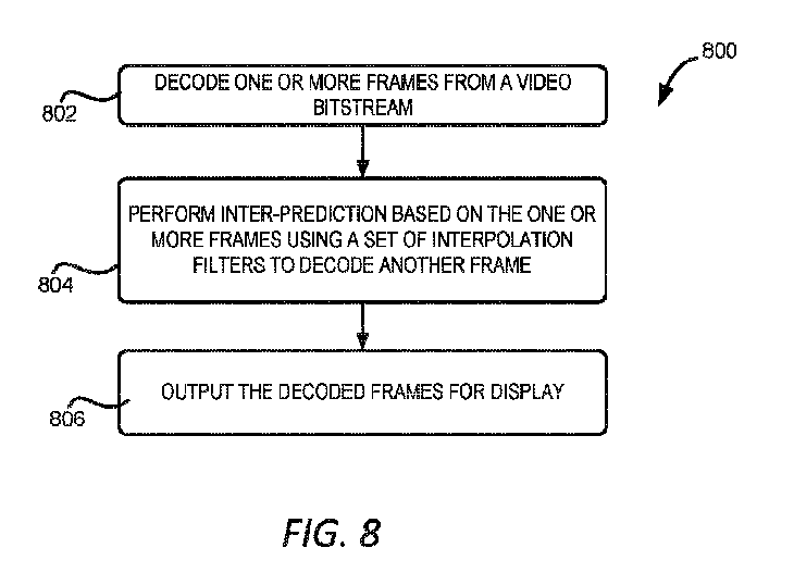
いくつかの実施例では、ビデオデコーダは、ビデオビットストリームをビデオフレームに復号化する。デコーダは、ビデオビットストリームからビデオフレームを復号化する。デコーダは、さらにインター予測を実行して、復号化されたフレームを参照フレームとしてビデオの現在フレームを復号化する。インター予測を実行するステップは、32個の6タップ補間フィルタの集合の中から選択した1つ又は複数のフィルタを使用して、現在フレームの参照フレームに対してアップサンプリングを行うことにより、参照ピクチャのリサンプリングを実行する。この補間フィルタの集合は、動き補償のための色度成分を補間するためにも使用される。復号化されたフレームと復号化された現在フレームは、表示用に出力される。
【選択図】図8
In some embodiments, a video decoder decodes a video bitstream into video frames. The decoder decodes the video frames from the video bitstream. The decoder further performs inter prediction to decode a current frame of the video using the decoded frames as reference frames. The step of performing inter prediction performs resampling of the reference picture by upsampling the current frame's reference frames using one or more filters selected from a set of 32 6-tap interpolation filters. This set of interpolation filters is also used to interpolate chrominance components for motion compensation. The decoded frames and the decoded current frame are output for display.
[Selected figure] Figure 8
Description
(関連出願への相互参照)
本願は、2022年04月21日に提出された、発明の名称が「Use of Chroma Interpolation Filter for Reference Picture Resampling」であり、出願番号が63/363,386号である米国仮出願の優先権を主張し、その内容の全てが引用により本願に組み込まれる。
CROSS-REFERENCE TO RELATED APPLICATIONS
This application claims priority to U.S. Provisional Application No. 63/363,386, filed on April 21, 2022, entitled "Use of Chroma Interpolation Filter for Reference Picture Resampling," the entire contents of which are incorporated herein by reference.
本願は、一般にビデオ処理に関し、具体的には、ビデオの符号化と復号化における参照ピクチャのリサンプリングに色度補間フィルタを適用することに関するものである。 This application relates generally to video processing, and more specifically to applying chromaticity interpolation filters to reference picture resampling in video encoding and decoding.
よく見られるカメラ機能を備えたデバイス(スマートフォン、タブレット、パソコンなど)により、ビデオや画像の収集がかつてないほど簡単になった。しかしながら、ショートビデオでもそのデータ量はかなり大きい可能性がある。ビデオの符号化と復号化技術(ビデオ符号化と復号化を含む)により、ビデオデータをより小さなサイズに圧縮することができ、それにより、様々なビデオの記憶と伝送が可能になる。ビデオの符号化と復号化は、デジタルTV放送、インターネット及びモバイルネットワークを介したビデオ伝送、リアルタイムアプリケーション(ビデオチャット、ビデオ会議など)、DVD及びブルーレイディスクなど、幅広い用途で使用されている。ビデオを記憶するための記憶空間及び/又はビデオを伝送するためのネットワーク帯域幅の消費を削減するには、ビデオの符号化と復号化方式の効率を向上させる必要がある。 With the widespread availability of camera-enabled devices (e.g., smartphones, tablets, and personal computers), collecting videos and images has never been easier. However, the amount of data even for short videos can be quite large. Video encoding and decoding techniques (including video encoding and decoding) allow video data to be compressed into smaller sizes, which allows for the storage and transmission of various videos. Video encoding and decoding is used in a wide range of applications, including digital TV broadcasting, video transmission over the Internet and mobile networks, real-time applications (e.g., video chat, video conferencing), DVDs and Blu-ray discs, etc. To reduce the consumption of storage space for storing videos and/or network bandwidth for transmitting videos, the efficiency of video encoding and decoding methods needs to be improved.
いくつかの実施例は、ビデオの符号化と復号化における参照ピクチャのリサンプリングに色度補間フィルタを使用することに関する。一例では、ビデオビットストリームからビデオを復号化する方法は、前記ビデオビットストリームから前記ビデオの1つ又は複数のフレームを復号化するステップと、復号化された1つ又は複数のフレームを参照フレームとして使用してインター予測を実行することにより、ビデオの現在フレームを復号化するステップと、を含む。インター予測を実行するステップは、32個の6タップ補間フィルタの集合の中から選択した少なくとも1つのフィルタを使用して、現在フレームの参照フレームに対してアップサンプリングを行うことにより、参照ピクチャのリサンプリングを実行するステップを含む。前記復号化方法は、復号化された1つ又は複数のフレーム及び復号化された現在フレームを表示するステップをさらに含む。 Some embodiments relate to using chromaticity interpolation filters for reference picture resampling in video encoding and decoding. In one example, a method for decoding video from a video bitstream includes decoding one or more frames of the video from the video bitstream and decoding a current frame of the video by performing inter prediction using the decoded one or more frames as reference frames. Performing inter prediction includes performing reference picture resampling by upsampling a reference frame of the current frame using at least one filter selected from a set of 32 6-tap interpolation filters. The decoding method further includes displaying the decoded one or more frames and the decoded current frame.
別の例では、非一時的コンピュータ可読媒体にはプログラムコードが記憶され、前記プログラムコードは、1つ又は複数の処理機器によって実行可能であり、以下の動作を実行する。前記動作は、ビデオビットストリームからビデオの1つ又は複数のフレームを復号化するステップと、復号化された1つ又は複数のフレームを参照フレームとして使用してインター予測を実行することにより、ビデオの現在フレームを復号化するステップと、を含む。インター予測を実行するステップは、32個の6タップ補間フィルタの集合の中から選択した少なくとも1つのフィルタを使用して、現在フレームの参照フレームに対してアップサンプリングを行うことにより、参照ピクチャのリサンプリングを実行するステップを含む。前記動作は、復号化された1つ又は複数のフレーム及び復号化された現在フレームを表示するステップをさらに含む。 In another example, the non-transitory computer-readable medium has stored thereon program code executable by one or more processing devices to perform the following operations: the operations include decoding one or more frames of video from a video bitstream; and decoding a current frame of the video by performing inter prediction using the decoded one or more frames as reference frames. The performing inter prediction includes performing reference picture resampling by upsampling the reference frame of the current frame using at least one filter selected from a set of 32 6-tap interpolation filters. The operations further include displaying the decoded one or more frames and the decoded current frame.
さらに別の例では、システムは、処理機器と、前記処理機器に通信可能に結合された非一時的コンピュータ可読媒体と、を備える。処理機器は、前記非一時的コンピュータ可読媒体に記憶されたプログラムコードを実行することにより、以下の動作を実行するように構成される。前記動作は、ビデオビットストリームからビデオの1つ又は複数のフレームを復号化するステップと、復号化された1つ又は複数のフレームを参照フレームとして使用してインター予測を実行することにより、ビデオの現在フレームを復号化するステップと、を含む。インター予測を実行するステップは、32個の6タップ補間フィルタの集合の中から選択した少なくとも1つのフィルタを使用して、現在フレームの参照フレームに対してアップサンプリングを行うことにより、参照ピクチャのリサンプリングを実行するステップを含む。前記動作は、復号化された1つ又は複数のフレーム及び復号化された現在フレームを表示するステップをさらに含む。 In yet another example, a system includes a processing device and a non-transitory computer-readable medium communicatively coupled to the processing device. The processing device is configured to perform the following operations by executing program code stored on the non-transitory computer-readable medium: decoding one or more frames of video from a video bitstream; and decoding a current frame of the video by performing inter prediction using the decoded one or more frames as reference frames. Performing inter prediction includes performing reference picture resampling by upsampling the reference frame of the current frame using at least one filter selected from a set of 32 6-tap interpolation filters. The operations further include displaying the decoded one or more frames and the decoded current frame.
別の例では、ビデオを符号化する方法は、ビデオの複数のフレームにアクセスするステップと、前記複数のフレームに対してインター予測を実行して、前記複数のフレームの予測残差を生成するステップと、を含む。インター予測を実行するステップは、32個の6タップ補間フィルタの集合の中から選択した少なくとも1つのフィルタを使用して、前記複数のフレーム内の現在フレームの参照フレームに対してアップサンプリングを行うことにより、参照ピクチャのリサンプリングを実行するステップを含む。前記符号化方法は、前記複数のフレームの予測残差を、ビデオを表すビットストリームに符号化するステップをさらに含む。 In another example, a method for encoding a video includes accessing a plurality of frames of a video and performing inter prediction on the plurality of frames to generate prediction residuals for the plurality of frames. Performing inter prediction includes performing reference picture resampling by upsampling a reference frame of a current frame in the plurality of frames using at least one filter selected from a set of 32 6-tap interpolation filters. The encoding method further includes encoding the prediction residuals for the plurality of frames into a bitstream representing the video.
別の例では、非一時的コンピュータ可読媒体には、プログラムコードが記憶され、前記プログラムコードは、1つ又は複数の処理機器によって実行可能であり、以下の動作を実行する。前記動作は、ビデオの複数のフレームにアクセスするステップと、前記複数のフレームに対してインター予測を実行して、前記複数のフレームの予測残差を生成するステップと、を含む。インター予測を実行するステップは、32個の6タップ補間フィルタの集合の中から選択した少なくとも1つのフィルタを使用して、前記複数のフレーム内の現在フレームの参照フレームに対してアップサンプリングを行うことにより、参照ピクチャのリサンプリングを実行するステップを含む。前記動作は、前記複数のフレームの予測残差を、ビデオを表すビットストリームに符号化するステップをさらに含む。 In another example, a non-transitory computer-readable medium has stored thereon program code executable by one or more processing devices to perform the following operations: The operations include accessing a plurality of frames of a video and performing inter prediction on the plurality of frames to generate prediction residuals for the plurality of frames. Performing inter prediction includes performing reference picture resampling by upsampling a reference frame of a current frame in the plurality of frames using at least one filter selected from a set of 32 6-tap interpolation filters. The operations further include encoding the prediction residuals for the plurality of frames into a bitstream representing a video.
さらに別の例では、システムは、処理機器と、前記処理機器に通信可能に結合された非一時的コンピュータ可読媒体と、を備える。処理機器は、前記非一時的コンピュータ可読媒体に記憶されたプログラムコードを実行することにより、以下の動作を実行するように構成される。前記動作は、ビデオの複数のフレームにアクセスするステップと、前記複数のフレームに対してインター予測を実行して、前記複数のフレームの予測残差を生成するステップと、を含む。インター予測を実行するステップは、32個の6タップ補間フィルタの集合の中から選択した少なくとも1つのフィルタを使用して、前記複数のフレーム内の現在フレームの参照フレームに対してアップサンプリングを行うことにより、参照ピクチャのリサンプリングを実行するステップを含む。前記動作は、前記複数のフレームの予測残差を、ビデオを表すビットストリームに符号化するステップをさらに含む。 In yet another example, a system includes a processing device and a non-transitory computer-readable medium communicatively coupled to the processing device. The processing device is configured to perform the following operations by executing program code stored on the non-transitory computer-readable medium: accessing a plurality of frames of a video; and performing inter prediction on the plurality of frames to generate prediction residuals for the plurality of frames. Performing inter prediction includes performing reference picture resampling by upsampling a reference frame of a current frame in the plurality of frames using at least one filter selected from a set of 32 6-tap interpolation filters. The operations further include encoding the prediction residuals for the plurality of frames into a bitstream representing a video.
これらの例示的な実施例は、本開示を限定することを意図したものではなく、理解を容易にする例を提供することを意図したものである。具体的な実施形態では、追加の実施例が説明され、さらなる説明が提供される。 These illustrative examples are not intended to limit the disclosure, but are intended to provide examples to facilitate understanding. Additional examples are described and further explanations are provided in specific embodiments.
本開示の特徴、実施例、及び利点は、図面を参照して下記の具体的な実施形態を読むことにより、よりよく理解することができる。 The features, embodiments, and advantages of the present disclosure can be better understood by reading the specific embodiments below with reference to the drawings.
様々な実施例は、ビデオの符号化と復号化における参照ピクチャのリサンプリングに色度補間フィルタを使用するためのメカニズムを提供する。上述したように、より多くのビデオデータが生成され、記憶され、伝送されている。これは、ビデオの符号化と復号化技術の効率を向上させるのに有益である。ビデオの符号化と復号化技術の効率を向上させるための1つの方法はインター予測であり、既に再構築された他のフレーム(「参照フレーム」又は「参照ピクチャ」と呼ばれる)の画素又はサンプルを使用して、復号化待ちの現在フレーム内のビデオ画素又はサンプルを予測する。インター予測を実行するために、通常、例えば動き補償中に補間フィルタを使用し、整数画素位置におけるサンプルの値を使用することにより、参照フレーム内の小数画素位置における予測サンプルを決定する。場合によっては、参照フレームは、現在フレームとは異なる解像度を有し得る。このような場合、参照フレームは、現在フレームと同じ解像度にリサンプリングされ、例えば、低解像度の参照フレームに対してアップサンプリングを行い、現在フレームの解像度に合致させる。アップサンプリングでは、整数画素位置におけるサンプルの値を使用して、小数画素位置におけるサンプルに対して補間を行う。参照ピクチャをリサンプリングするための既存の補間フィルタは、参照ピクチャの色度成分をアップサンプリングするための4タップフィルタを使用するが、これは、不正確な補間結果をもたらす可能性があり、低い符号化効率につながる。 Various embodiments provide a mechanism for using chromaticity interpolation filters for resampling reference pictures in video encoding and decoding. As mentioned above, more video data is being generated, stored, and transmitted. This is beneficial for improving the efficiency of video encoding and decoding techniques. One method for improving the efficiency of video encoding and decoding techniques is inter-prediction, which uses pixels or samples of other frames (called "reference frames" or "reference pictures") that have already been reconstructed to predict video pixels or samples in a current frame waiting to be decoded. To perform inter-prediction, an interpolation filter is typically used, for example during motion compensation, to determine predicted samples at sub-pel positions in the reference frame by using values of samples at integer pel positions. In some cases, the reference frame may have a different resolution than the current frame. In such cases, the reference frame is resampled to the same resolution as the current frame, for example by upsampling a lower resolution reference frame to match the resolution of the current frame. In upsampling, values of samples at integer pel positions are used to interpolate samples at sub-pel positions. Existing interpolation filters for resampling reference pictures use a 4-tap filter to upsample the chrominance components of the reference picture, which can result in inaccurate interpolation results and lead to low coding efficiency.
本明細書に記載される様々な実施例は、参照ピクチャのリサンプリングに6タップ補間フィルタを使用することによって、これらの問題を解決し、これにより、より良好でより正確な補間結果を提供することができる。いくつかの実施例では、ビデオエンコーダ又はデコーダは、動き補償のための32個の6タップ色度補間フィルタの集合を再利用して、ビデオの参照ピクチャアップサンプリングを実行する。この32個の6タップ色度補間フィルタの集合からフィルタを選択するために、ビデオコーデックは、現在フレームの解像度、参照フレームの解像度、及びアップサンプリング位置に基づいて、アップサンプリング比を決定することができる。32個の補間フィルタに対応する32個の位置の中で、アップサンプリング位置の小数部分に最も近い位置を決定し、32個の補間フィルタの集合から、決定された位置に対応する補間フィルタを選択することにより、この32個の6タップ色度補間フィルタの集合から補間フィルタを選択することができる。 Various embodiments described herein address these issues by using 6-tap interpolation filters for reference picture resampling, which can provide better and more accurate interpolation results. In some embodiments, a video encoder or decoder reuses a set of 32 6-tap chroma interpolation filters for motion compensation to perform reference picture upsampling of a video. To select a filter from the set of 32 6-tap chroma interpolation filters, the video codec can determine an upsampling ratio based on the resolution of the current frame, the resolution of the reference frame, and the upsampling position. An interpolation filter can be selected from the set of 32 6-tap chroma interpolation filters by determining a position among the 32 positions corresponding to the 32 interpolation filters that is closest to a fractional part of the upsampling position, and selecting an interpolation filter from the set of 32 interpolation filters that corresponds to the determined position.
本明細書に記載されるように、いくつかの実施例は、6タップ補間フィルタを使用して参照ピクチャのリサンプリングを行い、構成された動き補償のための32個の6タップ色度補間フィルタの集合を再利用することにより、ビデオの符号化と復号化効率を改善する。既存の4タップフィルタの代わりに6タップ補間フィルタを使用することにより、アップサンプリングにおいてより正確な補間を実現することができ、これは、補間サンプルを生成する際に、より多くの隣接サンプルが考慮されるためである。したがって、インター予測残差の値が小さくなり、ビデオの符号化と復号化効率が向上する。また、動き補償補間フィルタを参照ピクチャのリサンプリングに再利用することで、ビデオエンコーダとデコーダの保存利用率が低減する。これらの技術は、将来のビデオの符号化と復号化標準における効果的なコーデックツールになることができる。 As described herein, some embodiments improve video encoding and decoding efficiency by using a 6-tap interpolation filter for reference picture resampling and reusing a set of 32 6-tap chrominance interpolation filters for configured motion compensation. By using a 6-tap interpolation filter instead of the existing 4-tap filter, more accurate interpolation can be achieved in upsampling because more neighboring samples are considered in generating the interpolated sample. Thus, the value of the inter prediction residual is smaller, and video encoding and decoding efficiency is improved. Also, reusing the motion compensation interpolation filter for reference picture resampling reduces storage utilization of the video encoder and decoder. These techniques can become effective codec tools in future video encoding and decoding standards.
ここで図面を参照すると、図1は、本明細書で提案される実施例を実現するように構成されたビデオエンコーダ100の一例を示すブロック図である。図1に示す例では、ビデオエンコーダ100は、分割モジュール112、変換モジュール114、量子化モジュール115、逆量子化モジュール118、逆変換モジュール119、ループ内フィルタモジュール120、イントラ予測モジュール126、インター予測モジュール124、動き推定モジュール122、復号化済みピクチャバッファ130、及びエントロピー符号化モジュール116を備える。
Now referring to the drawings, FIG. 1 is a block diagram illustrating an example of a video encoder 100 configured to realize embodiments proposed herein. In the example illustrated in FIG. 1, the video encoder 100 comprises a
ビデオエンコーダ100の入力は、ピクチャ(フレーム又は画像とも呼ばれる)のシーケンスを含む入力ビデオ102である。ブロックベースのビデオエンコーダでは、各ピクチャについて、ビデオエンコーダ100は、分割モジュール112を採用してピクチャをブロック104に分割し、各ブロックは複数の画素を含む。前記ブロックは、マクロブロック、符号化ツリーユニット、符号化ユニット、予測ユニット及び/又は予測ブロックであってもよい。1つのピクチャは、異なるサイズのブロックを含み得、ビデオの異なるピクチャのブロック分割も異なることができる。異なる予測(イントラ予測又はインター予測又はイントラ予測とインター予測との混合予測など)を使用して各ブロックを符号化することができる。
The input of the video encoder 100 is an
通常、ビデオ信号の最初のピクチャは、イントラ符号化のピクチャであり、イントラ予測のみを使用して符号化する。イントラ予測モードでは、同一ピクチャから符号化されたデータのみを使用してピクチャのブロックを予測する。イントラ符号化されたピクチャは、他のピクチャからの情報なしに復号化することができる。イントラ予測を実行するために、図1に示すビデオエンコーダ100は、イントラ予測モジュール126を採用することができる。イントラ予測モジュール126は、同一ピクチャの隣接ブロックの再構築ブロック136内の再構築サンプルを使用して、イントラ予測ブロック(予測ブロック134)を生成するように構成される。ブロックに対して選択されたイントラ予測モードに従ってイントラ予測を行う。次に、ビデオエンコーダ100は、ブロック104とイントラ予測ブロック134との差を計算する。この差は、残差ブロック106と呼ばれる。
Typically, the first picture of a video signal is an intra-coded picture, which is coded using only intra prediction. In intra prediction modes, blocks of the picture are predicted using only coded data from the same picture. An intra-coded picture can be decoded without information from other pictures. To perform intra prediction, the video encoder 100 shown in FIG. 1 may employ an
ブロックから冗長性をさらに除去するために、変換モジュール114は、ブロック内のサンプルに変換を適用することにより、残差ブロック106を変換ドメインに変換する。変換の例としては、離散コサイン変換(DCT:discrete cosine transform)又は離散サイン変換(DST:discrete sine transform)を含み得るが、これらに限定されない。変換された値は、変換ドメイン内の残差ブロックを表す変換係数と呼ばれ得る。いくつかの例では、残差ブロックは、変換モジュール114によって変換されることなく、直接量子化されてもよい。これは、変換スキップモードと呼ばれる。
To further remove redundancy from the block, the
ビデオエンコーダ100は、量子化モジュール115をさらに使用して変換係数を量子化して、量子化された係数を取得することができる。量子化は、サンプルを量子化ステップ長で除算してから四捨五入することを含み、一方、逆量子化は、量子化された値に量子化ステップ長を乗算することを含む。このような量子化プロセスは、スカラー量子化と呼ばれる。量子化は、(変換された又は変換されていない)ビデオサンプルのダイナミックレンジを減少させるために使用され、より少ないバイナリビットでビデオサンプルを表現することができる。
The video encoder 100 may further use the
ブロック内の係数/サンプルの量子化は独立して行うことができ、このような量子化方法は、例えば、H.264又はAVC(advance video codec)及びH.265又はHEVC(high efficiency video coding)のような、いくつかの既存のビデオ圧縮標準で採用されている。1つのN×Mブロックの場合、いくつかのスキャン順序によって、ブロックの2次元係数を1次元配列に変換して、係数量子化及び符号化と復号化を行うことができる。ブロック内の係数の量子化は、スキャン順序情報を利用することができる。例えば、ブロック内の所与の係数の量子化は、スキャン順序において前に量子化された値の状態に依存してもよい。コーデック効率をさらに向上させるために、複数の量子化器を使用してもよい。現在の係数を量子化するためにどの量子化器を使用するかは、符号化/復号化スキャン順序における現在係数の前の情報に依存する。このような量子化方法は、依存量子化と呼ばれる。 Quantization of coefficients/samples within a block can be done independently, and such a quantization method is adopted in some existing video compression standards, such as H.264 or AVC (advance video codec) and H.265 or HEVC (high efficiency video coding). For one NxM block, some scan orders can convert the two-dimensional coefficients of the block into a one-dimensional array for coefficient quantization and encoding and decoding. Quantization of coefficients within a block can utilize scan order information. For example, quantization of a given coefficient within a block may depend on the state of the previous quantized value in the scan order. To further improve codec efficiency, multiple quantizers may be used. Which quantizer is used to quantize the current coefficient depends on the previous information of the current coefficient in the encoding/decoding scan order. Such a quantization method is called dependent quantization.
量子化の度合いは、量子化ステップ長によって調整され得る。例えば、スカラー量子化の場合、異なる量子化ステップ長を適用してより細かい量子化又はより粗い量子化を実現することができる。小さい量子化ステップ長は、細かい量子化に対応し、大きい量子化ステップ長は、粗い量子化に対応する。量子化ステップ長は、量子化パラメータ(QP:quantization parameter)によって指示され得る。量子化パラメータは、ビデオの符号化ビットストリームで提供され、それによってビデオデコーダは、量子化パラメータにアクセスし、適用して復号化することができる。 The degree of quantization can be adjusted by the quantization step length. For example, in the case of scalar quantization, different quantization step lengths can be applied to achieve finer or coarser quantization. A small quantization step length corresponds to finer quantization, and a large quantization step length corresponds to coarser quantization. The quantization step length can be indicated by a quantization parameter (QP). The quantization parameter is provided in the encoded bitstream of the video, so that a video decoder can access and apply the quantization parameter for decoding.
次に、エントロピー符号化モジュール116は、量子化されたサンプルを符号化して、ビデオ信号のサイズをさらに小さくする。エントロピー符号化モジュール116は、エントロピー符号化アルゴリズムを量子化されたサンプルに適用するように構成される。いくつかの例では、量子化されたサンプルは、バイナリ項(bin)に2値化されて、符号化アルゴリズムはさらに、前記バイナリ項をバイナリビットに圧縮する。2値化方法の例としては、TR(truncated Rice)、EGk(Exp-Golomb)を組み合わせた2値化、及びk次のExp-Golomb2値化を含むが、これらに限定されない。エントロピー符号化アルゴリズムの例としては、可変長符号化(VLC:variable length coding)方式、コンテキスト適応型VLC方式(CAVLC:context adaptive VLC)、算術符号化方式、2値化、コンテキスト適応型2値算術符号化(CABAC:context adaptive binary arithmetic coding)、構文ベースのコンテキスト適応型2値算術符号化(SBAC:syntax-based context-adaptive binary arithmetic coding)、確率区間分割エントロピー(PIPE:probability interval partitioning entropy)符号化、又は他のエントロピー符号化技術を含むが、これらに限定されない。エントロピー符号化されたデータは、出力の符号化済みビデオ132のビットストリームに追加される。 The entropy coding module 116 then encodes the quantized samples to further reduce the size of the video signal. The entropy coding module 116 is configured to apply an entropy coding algorithm to the quantized samples. In some examples, the quantized samples are binarized into binary terms (bins), and the coding algorithm further compresses the binary terms into binary bits. Examples of binarization methods include, but are not limited to, truncated Rice (TR), combined Exp-Golomb (EGk) binarization, and k-th order Exp-Golomb binarization. Examples of entropy coding algorithms include, but are not limited to, variable length coding (VLC) schemes, context adaptive VLC schemes (CAVLC), arithmetic coding schemes, binarization, context adaptive binary arithmetic coding (CABAC), syntax-based context-adaptive binary arithmetic coding (SBAC), probability interval partitioning entropy (PIPE) coding, or other entropy coding techniques. The entropy coded data is added to the output coded video 132 bitstream.
上記に記載されたように、隣接ブロックからの再構築ブロック136は、ピクチャのブロックのイントラ予測に使用される。ブロックの再構築ブロック136を生成することは、このブロックの再構築残差を計算することを含む。再構築残差は、ブロックの量子化残差に逆量子化及び逆変換を適用することによって決定することができる。逆量子化モジュール118は、量子化されたサンプルに逆量子化を適用して、量子化解除の係数を取得するように構成される。逆量子化モジュール118は、量子化モジュール115と同じ量子化ステップ長を利用することによって、量子化モジュール115に適用された量子化方式と逆の方式を適用する。逆変換モジュール119は、変換モジュール114に適用される変換の逆変換を、逆DCTや逆DSTのような量子化解除のサンプルに適用するように構成される。逆変換モジュール119の出力は、画素ドメイン内のブロックの再構築残差である。再構築残差をブロックの予測ブロック134に追加して、画素ドメイン内の再構築ブロック136を取得してもよい。逆変換モジュール119は変換がスキップされるブロックに適用されない。量子化解除のサンプルは、ブロックの再構築残差である。
As described above, the reconstructed block 136 from the neighboring blocks is used for intra prediction of the block of the picture. Generating the reconstructed block 136 of a block includes calculating a reconstructed residual of this block. The reconstructed residual can be determined by applying an inverse quantization and an inverse transform to the quantized residual of the block. The inverse quantization module 118 is configured to apply an inverse quantization to the quantized samples to obtain dequantized coefficients. The inverse quantization module 118 applies a quantization scheme that is inverse to the quantization scheme applied to the
インター予測又はイントラ予測を使用して、最初のイントラ予測のピクチャの後ろの後続ピクチャ内のブロックを符号化することができる。インター予測では、ピクチャ内のブロックは、1つ又は複数の以前に符号化されたビデオピクチャに基づいて予測される。インター予測を行うために、ビデオエンコーダ100は、インター予測モジュール124を使用する。インター予測モジュール124は、動き推定モジュール122によって提供される動き推定に基づいて、ブロックに対して動き補償を行うように構成される。
Inter prediction or intra prediction may be used to encode blocks in subsequent pictures after an initial intra prediction picture. In inter prediction, blocks in a picture are predicted based on one or more previously encoded video pictures. To perform inter prediction, video encoder 100 uses
動き推定モジュール122は、現在ピクチャの現在ブロック104と復号化済み参照ピクチャ108とを比較することにより、動き推定を行う。復号化済み参照ピクチャ108は、復号化済みピクチャバッファ130に記憶される。動き推定モジュール122は、復号化済み参照ピクチャ108から現在ブロックと最も合致する参照ブロックを選択する。動き推定モジュール122は、参照ブロックの位置(x座標、y座標など)と現在ブロック位置との間のオフセットをさらに識別する。このオフセットは、動きベクトル(MV:motion vector)と呼ばれ、選択された参照ブロックとともにインター予測モジュール124に提供される。場合によっては、複数の復号化済み参照ピクチャ108内の現在ブロックに対して複数の参照ブロックが識別される。したがって、複数の動きベクトルが生成され、対応する参照ブロックとともにインター予測モジュール124に提供される。
The
インター予測モジュール124は、(1つ又は複数の)動きベクトル及び他のインター予測パラメータを使用して動き補償を実行して、現在ブロック(即ち、インター予測ブロック134)の予測を生成する。例えば、(1つ又は複数の)動きベクトルに基づいて、インター予測モジュール124は、対応する参照ピクチャ内で、(1つ又は複数の)動きベクトルに指される(1つ又は複数の)予測ブロックを特定することができる。1つ以上の予測ブロックが存在する場合、これらの予測ブロックをいくつかの重みと結合して、現在ブロックの予測ブロック134を生成する。
The
インター予測ブロックについて、ビデオエンコーダ100は、ブロック104からインター予測ブロック134を減算して、残差ブロック106を生成してもよい。残差ブロック106は、上述したイントラ予測ブロックの残差と同様な方式によって、変換、量子化、及びエントロピー符号化されてもよい。同様に、インター予測ブロックの再構築ブロック136は、残差に対して逆量子化、逆変換を行ってから、対応する予測ブロック134と結合することによって取得することができる。
For an inter-predicted block, the video encoder 100 may subtract the inter-predicted block 134 from the
動き推定のための復号化済みピクチャ108を取得するために、再構築ブロック136は、ループ内フィルタモジュール120によって処理される。ループ内フィルタモジュール120は、画素遷移を滑らかにするように構成され、それによって、ビデオ品質を改善する。ループ内フィルタモジュール120は、アンロックフィルタ、サンプリング適応オフセット(SAO:sample-adaptive offset)フィルタ、適応ループフィルタ(ALF:adaptive loop filter)などの1つ又は複数のループフィルタを実現するように構成され得る。 To obtain the decoded picture 108 for motion estimation, the reconstruction block 136 is processed by the in-loop filter module 120. The in-loop filter module 120 is configured to smooth pixel transitions, thereby improving video quality. The in-loop filter module 120 may be configured to implement one or more loop filters, such as an unlocked filter, a sample-adaptive offset (SAO) filter, an adaptive loop filter (ALF), etc.
図2は、本明細書で提案される実施例を実現するように構成されたビデオデコーダ200の一例を示すブロック図である。ビデオデコーダ200は、ビットストリーム内の符号化済みビデオ202を処理し、復号化済みピクチャ208を生成する。図2に示す例では、ビデオデコーダ200は、エントロピー復号化モジュール216、逆量子化モジュール218、逆変換モジュール219、ループ内フィルタモジュール220、イントラ予測モジュール226、インター予測モジュール224、及び復号化済みピクチャバッファ230を備える。
2 is a block diagram illustrating an example of a video decoder 200 configured to implement embodiments proposed herein. The video decoder 200 processes encoded video 202 in a bitstream to generate decoded pictures 208. In the example illustrated in FIG. 2, the video decoder 200 includes an entropy decoding module 216, an inverse quantization module 218, an inverse transform module 219, an in-loop filter module 220, an
エントロピー復号化モジュール216は、符号化済みビデオ202に対してエントロピー復号化を行うように構成される。エントロピー復号化モジュール216は、量子化の係数、イントラ予測パラメータ及びインター予測パラメータを含む符号化パラメータ、及び他の情報を復号化する。いくつかの例では、エントロピー復号化モジュール216は、符号化済みビデオ202のビットストリームを2進数表現に復号化し、さらに2進数表現を係数の量子化レベルに変換する。次に、エントロピー復号化済みレベルは、逆量子化モジュール218によって逆量子化され、その後、逆変換モジュール219によって画素ドメインに逆変換される。逆量子化モジュール218及び逆変換モジュール219の機能は、それぞれ図1について上記で説明した逆量子化モジュール118及び逆変換モジュール119と同様である。逆変換された残差ブロックを、対応する予測ブロック234に追加して、再構築ブロック236を生成してもよい。逆変換モジュール219は変換がスキップされたブロックに適用されない。逆量子化モジュール118によって生成された量子化解除のサンプルは、再構築ブロック236を生成するために使用される。
The entropy decoding module 216 is configured to perform entropy decoding on the encoded video 202. The entropy decoding module 216 decodes the coding parameters, including quantization coefficients, intra-prediction parameters and inter-prediction parameters, and other information. In some examples, the entropy decoding module 216 decodes the bitstream of the encoded video 202 into a binary representation and further converts the binary representation into quantization levels of the coefficients. The entropy decoded levels are then inverse quantized by the inverse quantization module 218 and then inverse transformed to the pixel domain by the inverse transform module 219. The functions of the inverse quantization module 218 and the inverse transform module 219 are similar to the inverse quantization module 118 and the inverse transform module 119, respectively, described above with respect to FIG. 1. The inverse transformed residual blocks may be added to the corresponding prediction blocks 234 to generate the reconstruction blocks 236. The inverse transform module 219 is not applied to blocks whose transformations have been skipped. The dequantized samples generated by the inverse quantization module 118 are used to generate the
前記ブロックの予測モードに基づいて、特定のブロックの予測ブロック234が生成される。ブロックの符号化パラメータが、このブロックがイントラ予測されたことを示す場合、同一ピクチャ内の参照ブロックの再構築ブロック236をイントラ予測モジュール226に入力して、このブロックの予測ブロック234を生成してもよい。ブロックの符号化パラメータが、このブロックがインター予測されたことを示す場合、インター予測モジュール224によって予測ブロック234が生成される。イントラ予測モジュール226及びインター予測モジュール224機能は、それぞれ図1のイントラ予測モジュール126及びインター予測モジュール124と同様である。
Based on the prediction mode of the block, a prediction block 234 for the particular block is generated. If the coding parameters of the block indicate that the block is intra predicted, a
図1について上記で説明したように、インター予測は1つ又は複数の参照ピクチャに関わる。ビデオデコーダ200は、ループ内フィルタモジュール220を参照ピクチャの再構築ブロックに適用することによって、参照ピクチャの復号化済みピクチャ208を生成する。復号化済みピクチャ208は、インター予測モジュール224が使用及び出力するように、復号化済みピクチャバッファ230に記憶される。
As described above with respect to FIG. 1, inter prediction involves one or more reference pictures. The video decoder 200 generates a decoded picture 208 of the reference picture by applying an in-loop filter module 220 to a reconstructed block of the reference picture. The decoded picture 208 is stored in a decoded picture buffer 230 for use and output by the
図3を参照すると、図3は、本開示のいくつかの実施例によるビデオ内のピクチャの符号化ツリーユニット分割の一例を示す図である。図1及び図2について上記で説明したように、ビデオのピクチャを符号化するために、ピクチャは、図3に示すVVC(versatile video coding)の符号化ツリーユニット(CTU)302のようなブロックに分割される。例えば、CTU302は、128x128画素のブロックであってもよい。順序(例えば、図3に示す順序)に従ってCTUを処理する。いくつかの例では、図4に示すように、ピクチャ内の各CTU302は、1つ又は複数の符号化ユニット(CU:Coding Unit)402に分割されてもよく、CU402はさらに、予測及び変換のために、予測ユニット又は変換ユニット(TU:transform unit)に分割されてもよい。コーデック方式に応じて、CTU302は、異なる方式でCU402に分割されてもよい。例えば、VVCでは、CU402は、長方形又は正方形であってもよく、予測ユニット又は変換ユニットにさらに分割されることなく符号化されてもよい。各CU402は、ルートCTU302と同じ大きさであってもよく、4x4ブロックのようなルートCTU302の小さい細分であってもよい。図4に示すように、VVCにおけるCTU302からCU402への分割は、4分木分割、2分木分割又は3分木分割であってもよい。図4では、実線は、4分木分割を示し、破線は、2分木又は3分木分割を示す。
Referring to FIG. 3, FIG. 3 is a diagram illustrating an example of coding tree unit division of a picture in a video according to some embodiments of the present disclosure. As described above with respect to FIG. 1 and FIG. 2, to code a picture of a video, the picture is divided into blocks such as coding tree units (CTUs) 302 of versatile video coding (VVC) shown in FIG. 3. For example, the
動き補償について
混合ビデオ符号化システム(VVC及びHEVCなど)で採用されるツールは、既に再構築された他のフレームからの画素又はサンプルを使用して、復号化待ちの現在フレームのビデオ画素又はサンプルを予測する。このアーキテクチャに従うコーデックツールは、通常、「インター予測」ツールと呼ばれ、再構築されたフレームは、「参照フレーム」と呼ばれ得る。静止のビデオシーンでは、現在フレーム内の画素又はサンプルのインター予測は、参照フレームからの参照画素又はサンプルを復号化して使用することによって実現することができる。しかしながら、動きを含むビデオシーンでは、動き補償を有するインター予測ツールを使用する必要がある。例えば、参照フレームのサンプルからの「予測ブロック」に基づいて、現在フレーム内のサンプルの現在ブロックを予測することができ、この「予測ブロック」は、まず、現在フレーム内の現在ブロックの位置に対する、信号で送信される参照フレーム内の予測ブロックの位置の「動きベクトル」を復号化することによって決定される。より複雑なインター予測ツールは、複雑な動き(遮蔽やアフィン動きなど)を有するビデオシーンを利用するために使用される。
About Motion Compensation: Tools employed in mixed video coding systems (such as VVC and HEVC) predict video pixels or samples of a current frame waiting to be decoded using pixels or samples from other frames that have already been reconstructed. Codec tools following this architecture are usually called "inter prediction" tools, and the reconstructed frames can be called "reference frames". In still video scenes, inter prediction of pixels or samples in a current frame can be achieved by decoding and using reference pixels or samples from a reference frame. However, in video scenes involving motion, it is necessary to use inter prediction tools with motion compensation. For example, a current block of samples in a current frame can be predicted based on a "prediction block" from samples of a reference frame, which is determined by first decoding a "motion vector" of the position of the prediction block in a reference frame signaled relative to the position of the current block in the current frame. More complex inter prediction tools are used to exploit video scenes with complex motion (such as occlusion and affine motion).
補間について
現在ブロックの位置に対する予測ブロックの位置が整数個のサンプルで表される場合、参照フレーム内の対応するサンプル位置に基づいて予測ブロックのサンプルを直接取得することができる。しかしながら、通常、シーンにおける実際の動きは、非整数個のサンプルに相当する可能性が高い。この場合、小数画素(fractional-pel)の動き補償を使用して予測ブロックを決定してもよい。予測ブロックのサンプルを決定するために、所望の小数画素位置におけるサンプルの値は、整数画素位置における利用可能なサンプルによって補間して得られる。補間方法は、複雑さ、動きベクトルの精度、補間誤差、ノイズに対するロバスト性などの設計要件のバランスをとることによって選択される。このようなトレードオフがあるにもかかわらず、整数画素による動き補償を有する予測ブロックに比べて、小数画素による動き補償を利用して、補間予測ブロックに基づいて予測することが有利であることが判明している。
Regarding Interpolation: If the position of a prediction block relative to the position of a current block is represented by an integer number of samples, the samples of the prediction block can be obtained directly based on the corresponding sample positions in a reference frame. However, in general, the actual motion in a scene is likely to correspond to a non-integer number of samples. In this case, the prediction block may be determined using fractional-pel motion compensation. To determine the samples of the prediction block, the values of the samples at the desired fractional-pel positions are obtained by interpolating with the available samples at the integer-pel positions. The interpolation method is selected by balancing design requirements such as complexity, accuracy of the motion vector, interpolation error, and robustness against noise. Despite such trade-offs, it has been found that predicting based on an interpolated prediction block using fractional-pel motion compensation is advantageous compared to a prediction block with integer-pel motion compensation.
計算を容易にするため、ほとんどの補間方法は、利用可能な参照フレームサンプルを、線形の、シフト不変な係数セットと畳み込むことによって実現することができる。このような操作はフィルタリングとしても知られている。ビデオ符号化標準は、通常、垂直方向及び水平方向において1次元フィルタリングを分離可能に適用することによって、2次元予測ブロックの補間を実現する。動きベクトル情報のシグナリングを送信可能にするために、動きベクトルは、通常、小数画素の精度の倍数に制限される。例えば、輝度予測に使用される動きベクトルは、1/16画素精度の倍数に制限され得る。 For ease of computation, most interpolation methods can be realized by convolving the available reference frame samples with a linear, shift-invariant set of coefficients. Such an operation is also known as filtering. Video coding standards usually achieve the interpolation of two-dimensional prediction blocks by applying one-dimensional filtering separably in the vertical and horizontal directions. To be able to transmit the signaling of motion vector information, motion vectors are usually restricted to multiples of fractional pixel precision. For example, motion vectors used for luma prediction may be restricted to multiples of 1/16 pixel precision.
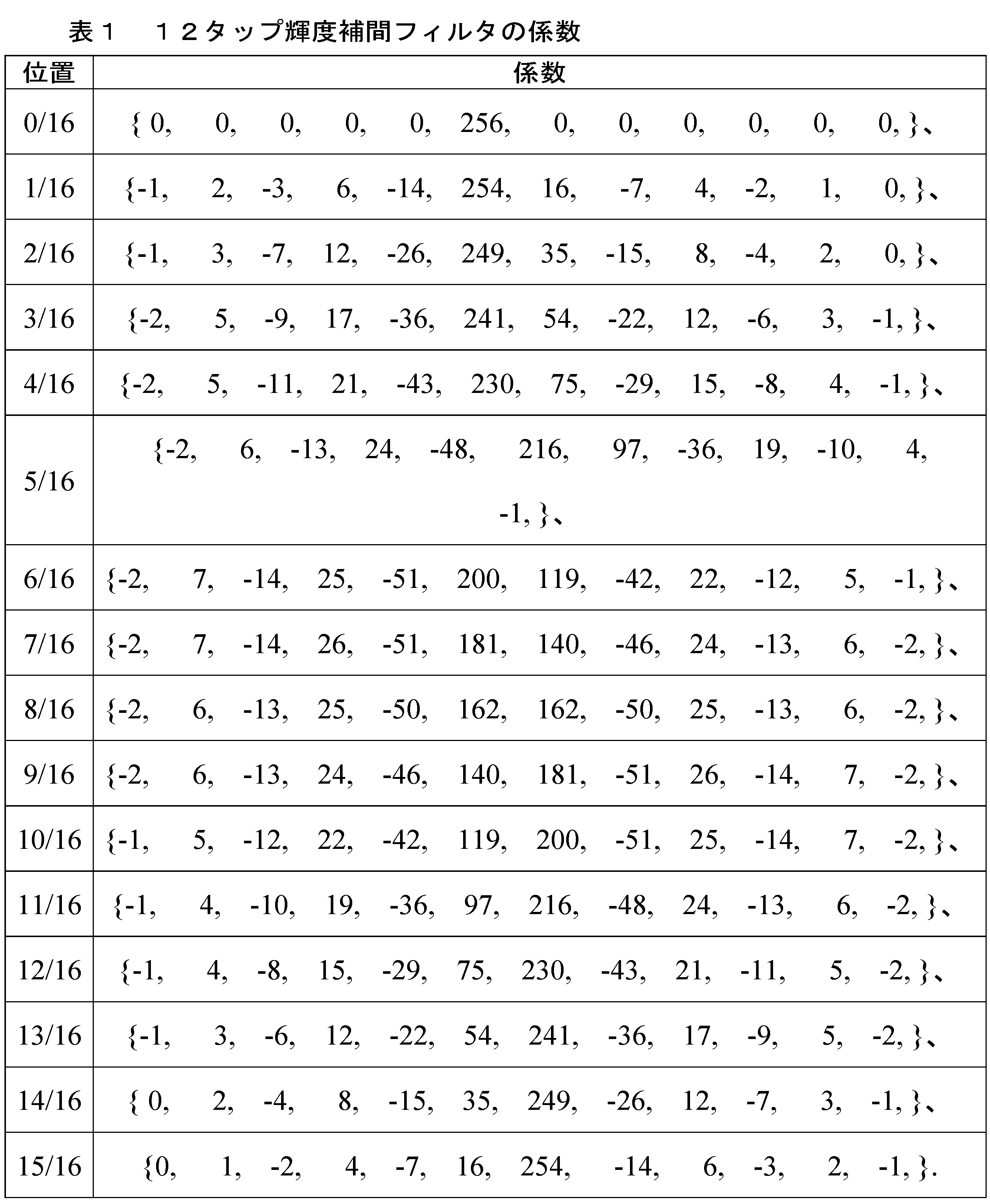
上記の補間の例では、予測ブロックのサンプルの決定は、補間フィルタの有限集合によって支配される。例えば、1/16画素精度について、輝度補間に必要なフィルタの総数は16である。フィルタ集合内の各フィルタは、それらの位相によって表すことができ、1/P画素精度で設計されたフィルタ集合では、位相は0からP-1までの番号を付けることができる。フィルタ集合H内の各フィルタは、h0、h1、…hP-1と付番することができる。実現形態の規則性から、各フィルタは、通常、同じ長さのNを有する。フィルタの長さは、フィルタのサポートとも呼ばれ得る。各フィルタ係数(タップとも呼ばれ得る)と、位相番号がkである特定のフィルタとの関係は、式1の通りである。
In the above interpolation example, the determination of the samples of the prediction block is governed by a finite set of interpolation filters. For example, for 1/16 pixel accuracy, the total number of filters required for luma interpolation is 16. Each filter in the filter set can be represented by their phase, and in a filter set designed with 1/P pixel accuracy, the phases can be numbered from 0 to P-1. Each filter in the filter set H can be numbered h 0 , h 1 , ... h P-1 . Due to the regularity of implementation, each filter usually has the same length N. The length of the filter can also be called the support of the filter. The relationship between each filter coefficient (which can also be called tap) and a particular filter with phase number k is as shown in
[式1]
hk={hk[0],hk[1],…hk[N-1]}
予測ブロックの補間プロセスは、補間プロセスの定義は、P個の補間フィルタの固定集合の設計に簡略化され得、各フィルタはN個の係数を有する。また、これらのフィルタの多くは冗長である。hP-1フィルタで補間を行うことが、仮想的なh-1フィルタ(即ち、位相が-1であるフィルタ)で補間を行うことと等価であるが、サポート領域が1画素前方にシフトされていることを考慮し、また、h-1フィルタは、h1フィルタの鏡像により実現することができ、したがって、フィルタ設計は、位相が0~P/2であるフィルタの集合を設計するようにさらに簡略化すると求められている。残りのフィルタは、最初のP/2位相に基づいて定義することができる。
[Formula 1]
h k ={h k [0],h k [1],…h k [N-1]}
The definition of the interpolation process for the prediction block can be simplified to the design of a fixed set of P interpolation filters, each filter having N coefficients. Also, many of these filters are redundant. Considering that performing the interpolation with an h P-1 filter is equivalent to performing the interpolation with a virtual h -1 filter (i.e., a filter with a phase of -1), but with the support region shifted forward by one pixel, and the h -1 filter can be realized by the mirror image of the h 1 filter, it is therefore sought to further simplify the filter design to design a set of filters with phases from 0 to P/2. The remaining filters can be defined based on the initial P/2 phase.

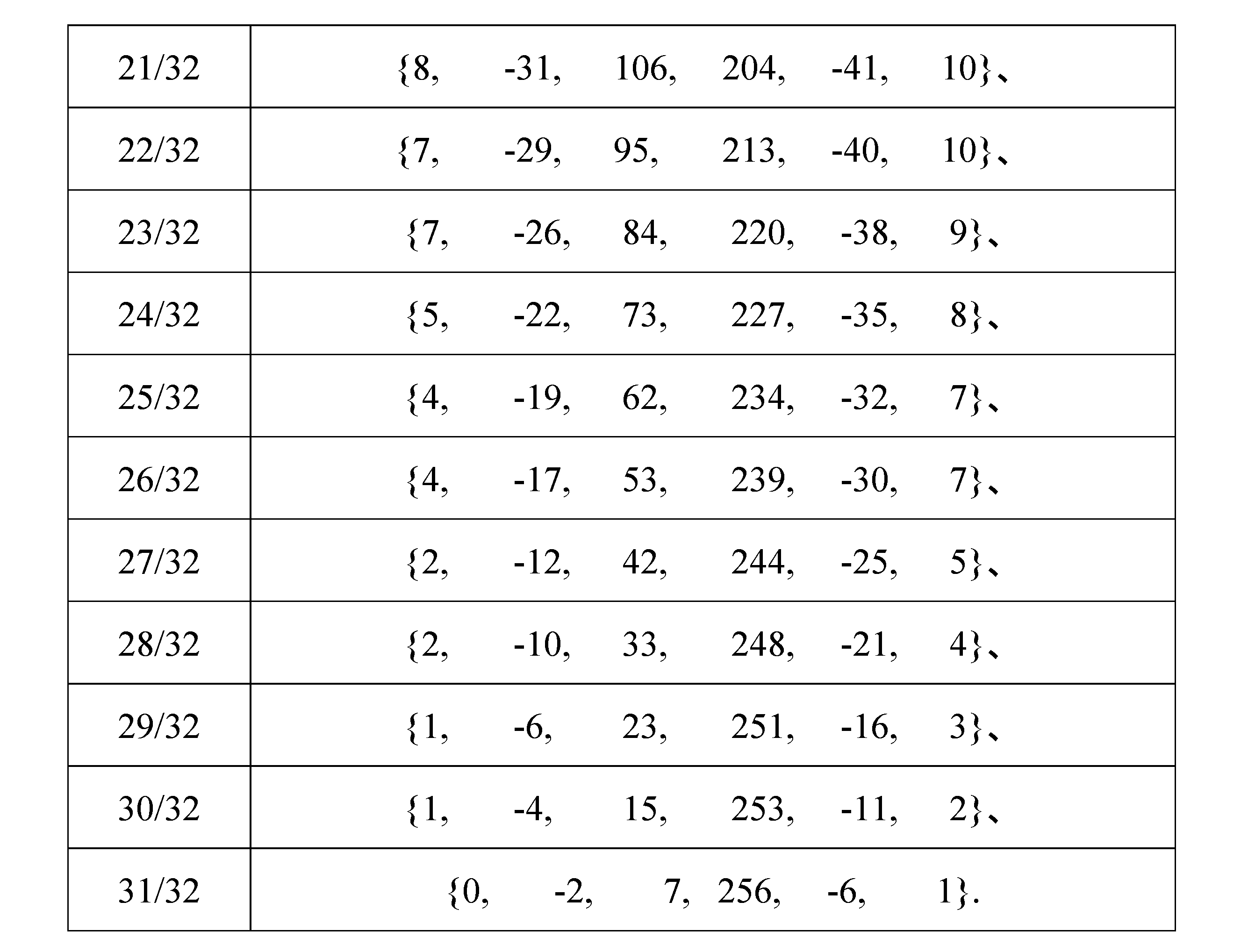
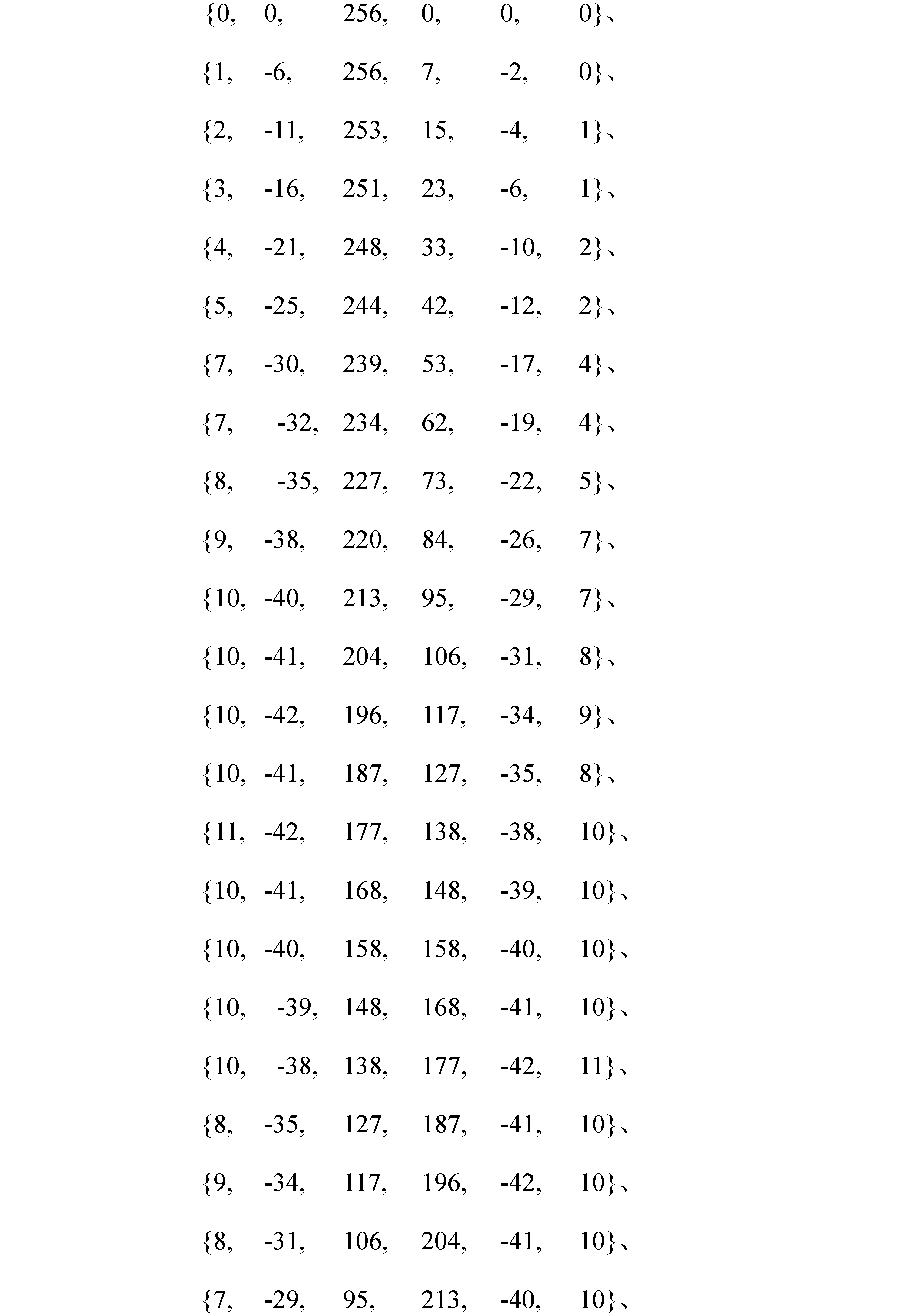
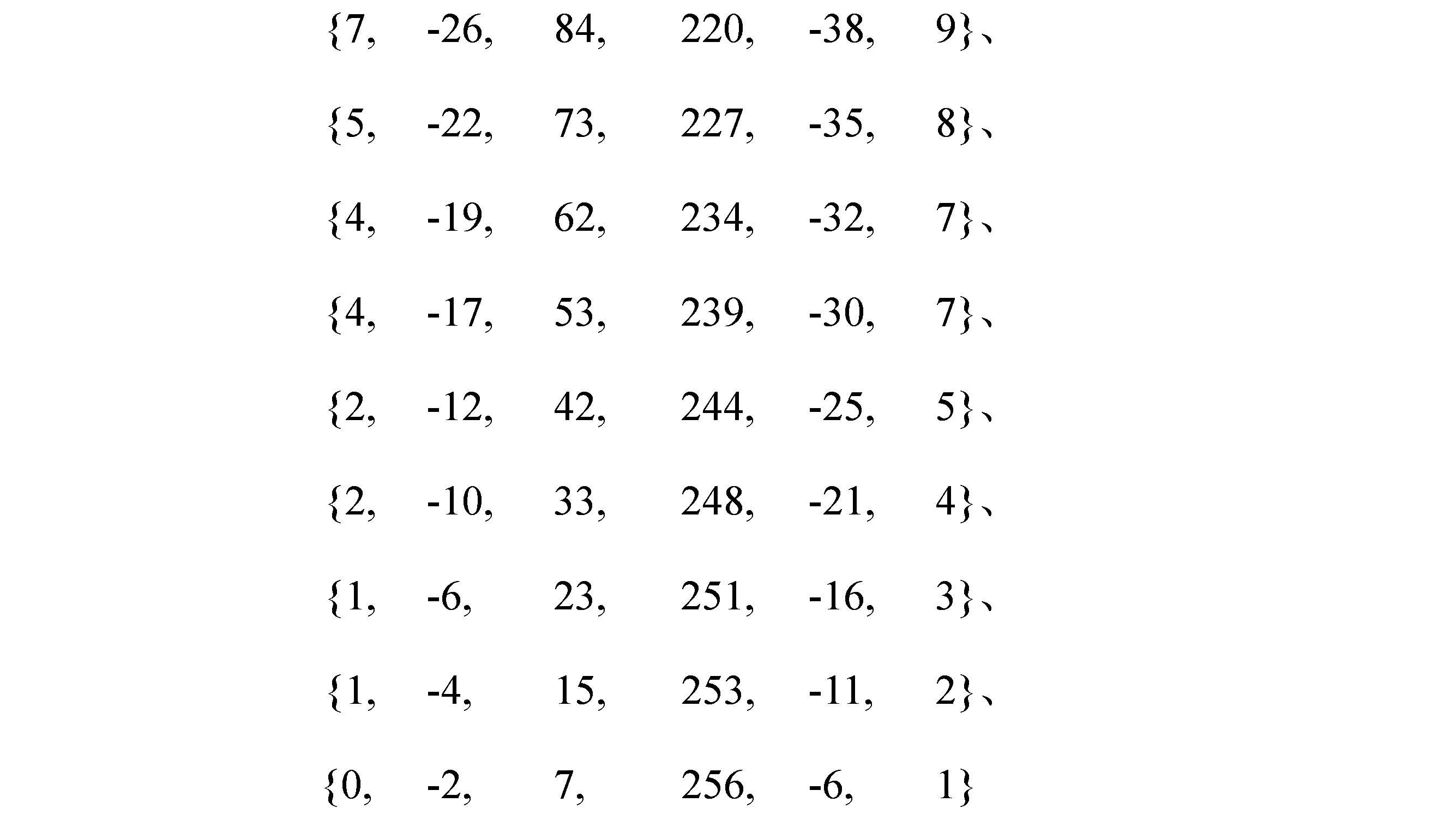
色度成分について、表2に示すように32個のフィルタが存在し、前記フィルタは、1/32サンプルシフトの増分で補間を実現する。表2では、各行は、対応する位置における6タップフィルタの係数を表す。例えば、表2のk番目の行(k=0,…,31)は、位置k/32における6タップフィルタの係数を表す。 For the chrominance components, there are 32 filters as shown in Table 2, which realize the interpolation with an increment of 1/32 sample shift. In Table 2, each row represents the coefficients of a 6-tap filter at the corresponding position. For example, the kth row (k=0,...,31) of Table 2 represents the coefficients of a 6-tap filter at position k/32.

参照ピクチャのリサンプリングについて
リアルタイム通信のユースケースでは、不安定なネットワーク接続でも通信が継続できるように、レート制御メカニズムが実行される。これを実現する1つのメカニズムは、動的な解像度調整である。つまり、ネットワーク容量が減少した場合、リアルタイム通信システムは、ビットレートを節約する目的を実現するために、低解像度のビデオを送信するように変わることができる。AVCやHEVCのような古いビデオ規格では、この特徴は、いわゆる「IDR」又は「IRAP」フレームの伝送で、解像度変更を開始することによってのみ実現することができ、「IDR」又は「IRAP」フレームは、以前に復号化されたフレームに依存せずに符号化される。このような独立フレームは、動き補償を含む効率的なインター予測ツールを利用できないため、送信するビットレートが著しく大きくなる。
On Reference Picture Resampling In real-time communication use cases, rate control mechanisms are implemented to ensure that communication can continue even with unstable network connections. One mechanism to achieve this is dynamic resolution adjustment. That is, if network capacity is reduced, real-time communication systems can switch to transmitting lower resolution video to achieve the goal of saving bitrate. In older video standards such as AVC and HEVC, this feature can only be achieved by initiating the resolution change with the transmission of so-called "IDR" or "IRAP" frames, which are coded without any dependency on previously decoded frames. Such independent frames cannot take advantage of efficient inter-prediction tools, including motion compensation, and therefore require significantly higher bitrates to transmit.
VVCでは、参照ピクチャのリサンプリング(RPR:Reference Picture Resampling)ツールを採用することにより、この制限を解消する。RPRでは、参照ピクチャは、現在フレームの解像度に合致するようにリサンプリングされることができ、これは、インター予測ツールは、異なる解像度を有する参照ピクチャを利用できることを意味する。これにより、IDR又はIRAPフレームを伝送することなく、解像度の切り替えをシームレスに行うことができる。 VVC overcomes this limitation by employing Reference Picture Resampling (RPR) tools. With RPR, reference pictures can be resampled to match the resolution of the current frame, which means that inter-prediction tools can use reference pictures with different resolutions. This allows for seamless resolution switching without the need to transmit IDR or IRAP frames.
RPRを実施するには、リサンプリングプロセスを規範的に定義する必要がある。参照ピクチャが現在ピクチャより解像度が低い場合、参照ピクチャに対してアップンプリングを行う。参照ピクチャが現在ピクチャより解像度が高い場合、参照ピクチャに対してダウンサンプリングを行う。既存のRPR実現形態は、4タップフィルタを使用して、参照ピクチャの色度成分をアップサンプリングする。これらの4タップフィルタは、正確なアップサンプリング結果を提供できない可能性がある。 To implement RPR, the resampling process needs to be normatively defined. If the reference picture has a lower resolution than the current picture, upsampling is performed on the reference picture. If the reference picture has a higher resolution than the current picture, downsampling is performed on the reference picture. Existing RPR implementations use 4-tap filters to upsample the chrominance components of the reference picture. These 4-tap filters may not provide accurate upsampling results.
より正確な参照ピクチャのアップサンプリングを実現するために、色度補間フィルタは、参照ピクチャのリサンプリングに再利用され得る。i,jが整数値である場合、参照ピクチャの色度成分のサンプル値をx[i,j]とする。平行移動動き補償の例では、非整数の位置で色度成分を補間する必要がある。しかしながら、サンプル間隔は依然として単位距離である。例えば、ブロックの下記の位置で色度成分xをサンプリングすることができる。 To achieve more accurate reference picture upsampling, the chrominance interpolation filter can be reused for reference picture resampling. Let x[i,j] be the sample value of the chrominance component of the reference picture, where i,j are integer values. In the case of translation motion compensation, we need to interpolate the chrominance components at non-integer positions. However, the sample interval is still unit distance. For example, we can sample the chrominance component x at the following positions of the block:
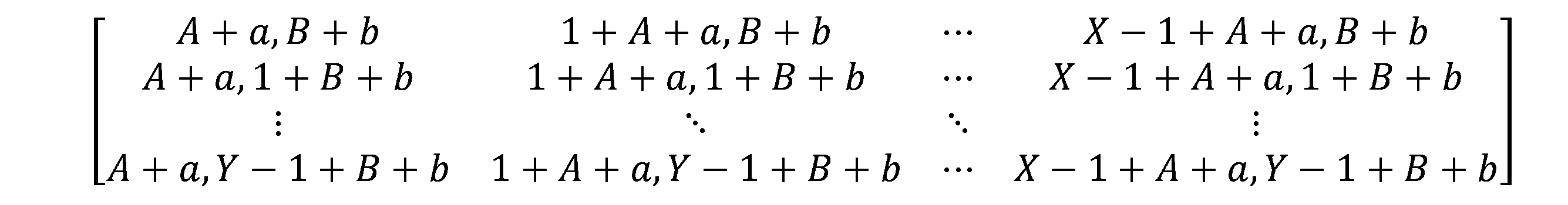
ここで、A、Bは、最初のサンプルの位置の整数成分であり、a、bは、最初のサンプルの位置の非整数成分であり、X、Yは、ブロックのサイズである。 where A, B are the integer components of the first sample position, a, b are the non-integer components of the first sample position, and X, Y are the block size.
参照ピクチャが現在ピクチャより解像度が低い場合、色度成分をアップサンプリングする要件は、より密なサンプル間隔(即ち、サンプル間の間隔が単位距離より小さい)で信号xをサンプリングすることとして再定義することができ、その中のいくつかのサンプルは必然的に非整数のサンプル位置に位置しなければならない。動き補償に対して色度補間フィルタが定義されているため、これらのフィルタを再利用することは、ビデオの符号化と復号化の実現形態のストレージコストを削減することに有利である。1/32サンプル精度で、非整数位置でxをサンプリングする限り、RPRアップサンプリングの実行に適した、関連する色度補間フィルタが存在する。 If the reference picture is of lower resolution than the current picture, the requirement to upsample the chrominance components can be redefined as sampling the signal x at a tighter sample interval (i.e., the spacing between samples is less than unit distance), some of which must necessarily be located at non-integer sample positions. Since chrominance interpolation filters have been defined for motion compensation, reusing these filters is advantageous in reducing the storage cost of video encoding and decoding implementations. As long as we sample x at non-integer positions with 1/32 sample precision, there are relevant chrominance interpolation filters suitable for performing RPR upsampling.
一実施例では、既知の比率rで参照ピクチャ全体をアップサンプリングし、得られたアップサンプリングされた参照ピクチャをバッファに記憶する。rの値は、現在ピクチャの解像度と参照ピクチャの解像度との比率によってを計算される。次に、アップサンプリングされた参照ピクチャサンプルは、現在ピクチャを予測するためのインター予測ツールの入力に使用される。 In one embodiment, we upsample the entire reference picture by a known ratio r and store the resulting upsampled reference picture in a buffer. The value of r is calculated by the ratio of the resolution of the current picture to the resolution of the reference picture. The upsampled reference picture samples are then used as input to an inter prediction tool to predict the current picture.
補間される正確なアップサンプリング位置は、サンプリング慣例に依存されてもよい。例えば、r=2である場合、一例では、オリジナルサンプルは、i∈[0,W-1]に位置する参照ピクチャについて、i次元(水平次元)に沿ったアップサンプリング位置は、以下の通りである。 The exact upsampling position to be interpolated may depend on the sampling convention. For example, if r=2, in one example, for a reference picture whose original samples are located at i∈[0,W−1], the upsampling positions along the i dimension (horizontal dimension) are:
i=0,0.5,1,1.5,2,2.5…,W-1,W-0.5
このアップサンプリング位置の例を図5Aに示す。図5Aでは、丸はオリジナルサンプルを表し、十字はアップサンプリング位置を表す。この配置の利点は、サンプルの半分がオリジナルサンプルの位置(例えば、i=0、1、…、W-1)に位置することである。このようにして、残りのサンプルの半分(例えば、i=0.5、1.5、…、W-0.5)のみを補間する必要がある。半画素の補間サンプルを補間するために、表2に示す16/32位置に向ける6タップ色度フィルタ、即ち、以下の係数を有するフィルタを使用することができる。
i=0,0.5,1,1.5,2,2.5…,W-1,W-0.5
An example of this upsampling location is shown in Figure 5A. In Figure 5A, the circles represent the original samples and the crosses represent the upsampling locations. The advantage of this arrangement is that half of the samples are located at the original sample locations (e.g., i = 0, 1, ..., W-1). In this way, only half of the remaining samples (e.g., i = 0.5, 1.5, ..., W-0.5) need to be interpolated. To interpolate the half-pixel interpolated samples, a 6-tap chromaticity filter oriented to the 16/32 location shown in Table 2 can be used, i.e., a filter with the following coefficients:
{10,-40,158,158,-40,10}
r=2である別の例では、i次元に沿ったアップサンプリング位置は、以下の位置に位置することができる。
{10, -40, 158, 158, -40, 10}
In another example where r=2, the upsampling positions along the i dimension may be located at the following positions:
i=-0.25,0.25,0.75,1.25,…W-1.25,W-0.75
このアップサンプリング位置の例を図5Bに示す。図5Aと同様に、図5Bでは、丸はオリジナルサンプルを表し、十字はアップサンプリング位置を表す。この配置の利点は、アップサンプリング位置がオリジナル参照ピクチャサンプルに対して対称的に配置されていることである。1/4画素の補間サンプルを補間するために、8/32位置に向ける6タップ色度フィルタ及び24/32位置の6タップ色度フィルタ、即ち、以下のフィルタを使用する。
i=-0.25,0.25,0.75,1.25,…W-1.25,W-0.75
An example of this upsampling location is shown in Figure 5B. As in Figure 5A, in Figure 5B, the circles represent the original samples and the crosses represent the upsampling locations. The advantage of this arrangement is that the upsampling locations are symmetrically arranged with respect to the original reference picture samples. To interpolate the quarter-pixel interpolated samples, we use a 6-tap chrominance filter oriented at the 8/32 position and a 6-tap chrominance filter at the 24/32 position, i.e., the following filters:
{8,-35,227,73,-22,5}
{5,-22,73,227,-35,8}
特に、8/32位置に向ける色度フィルタは、0.25、1.25、…、-0.75の位置で補間サンプルを生成するために使用され得、24/32位置に向ける色度フィルタは、-0.25、0.75、…、-1.25の位置で補間サンプルを生成するために使用され得る。
{8,-35,227,73,-22,5}
{5,-22,73,227,-35,8}
In particular, a chromaticity filter oriented at the 8/32 position may be used to generate interpolated samples at positions 0.25, 1.25, ..., -0.75, and a chromaticity filter oriented at the 24/32 position may be used to generate interpolated samples at positions -0.25, 0.75, ..., -1.25.
rの値及びサンプリング慣例に基づいて他の補間フィルタを選択することができる。例えば、r=4であり、アップサンプリング位置が0、0.25、0.5、0.75、1、1.25、1.5、1.75……に位置する場合、8/32の位置の色度フィルタ、16/32の位置の色度フィルタ、24/32の位置の色度フィルタは、アップサンプリング値を生成するために使用され得る。例えば、8/32の位置の色度フィルタは、0.25、1.25、……でのアップサンプリング値を生成するために使用され得、16/32の位置の色度フィルタは、0.5、1.5、……でのアップサンプリング値を生成するために使用され得、24/32の位置の色度フィルタは、0.75、1.75、……でのアップサンプリング値を生成するために使用され得る。 Other interpolation filters can be selected based on the value of r and the sampling convention. For example, if r=4 and the upsampling positions are located at 0, 0.25, 0.5, 0.75, 1, 1.25, 1.5, 1.75..., then a chroma filter at 8/32, a chroma filter at 16/32, and a chroma filter at 24/32 can be used to generate upsampling values. For example, a chroma filter at 8/32 can be used to generate upsampling values at 0.25, 1.25,..., a chroma filter at 16/32 can be used to generate upsampling values at 0.5, 1.5,..., and a chroma filter at 24/32 can be used to generate upsampling values at 0.75, 1.75,....
r=1.5である別の例では、アップサンプリング位置は、0、2/3、4/3、2、8/3、10/3、4、……に配置され得る。この例では、対応するアップサンプリング位置の小数部分に最も近い位置における色度フィルタを識別することにより、異なるアップサンプリング位置に使用される補間フィルタを決定することができる。例えば、2/3、8/3、……でのアップサンプリング位置の場合、21/32の位置が他の色度フィルタ位置より2/3に近いため、21/32の位置の色度フィルタ(即ち、係数が{8,-31,106,204,-41,10}であるフィルタ)を使用することができる。同様に、4/3、10/3、……でのアップサンプリング位置の場合、11/32の位置が他の色度フィルタ位置より1/3に近いため、11/32の位置の色度フィルタ(即ち、係数が{10,-41,204,106,-31,8}であるフィルタ)を使用することができる。 In another example where r=1.5, the upsampling positions may be located at 0, 2/3, 4/3, 2, 8/3, 10/3, 4, etc. In this example, the interpolation filters to be used for the different upsampling positions can be determined by identifying the chromaticity filter at the position closest to the fractional part of the corresponding upsampling position. For example, for upsampling positions at 2/3, 8/3, etc., the chromaticity filter at the 21/32 position (i.e., a filter with coefficients of {8, -31, 106, 204, -41, 10}) can be used since the 21/32 position is closer to 2/3 than the other chromaticity filter positions. Similarly, for upsampling positions at 4/3, 10/3, etc., the chromaticity filter at the 11/32 position (i.e., a filter with coefficients of {10, -41, 204, 106, -31, 8}) can be used since the 11/32 position is closer to 1/3 than the other chromaticity filter positions.
別の実施例では、インター予測ツールの適用に参照ピクチャの一部が必要な場合、この参照ピクチャの一部のみに対してリアルタイムリサンプリングを行うことができる。この実施例の利点は、リサンプリングの複雑さ及びバッファストレージを削減することである。 In another embodiment, if a portion of a reference picture is required for the application of inter prediction tools, real-time resampling can be performed on only this portion of the reference picture. The advantage of this embodiment is that it reduces resampling complexity and buffer storage.
図6は、本開示のいくつかの実施例による、参照ピクチャのリサンプリングのための補間フィルタを決定するためのプロセス600を示す図である。1つ又は複数のコンピューティング機器(例えば、ビデオエンコーダ100を実現するコンピューティング機器、ビデオデコーダ100を実現するコンピューティング機器又は他のコンピューティング機器)は、適切なプログラムコードを実行することによって、図6に示す動作を実現する。
Figure 6 illustrates a
ステップ602において、プロセス600は、色度補間フィルタの集合にアクセスすることを含む。いくつかの例では、色度補間フィルタの集合は、現在フレームの動き補償に使用される。例えば、色度補間フィルタの集合は、表2に示すフィルタであり得、これらのフィルタは、1/32サンプルシフトの増分で補間を実現する。ステップ604において、プロセス600は、現在フレームのアップサンプリング比r及びアップサンプリング位置を決定することを含む。上記に記載されたように、現在フレーム及び参照フレームの解像度に基づいてアップサンプリング比rを決定することができる。例えば、現在フレームの解像度が2W×2Hであり、参照フレームの解像度がW×Hである場合、アップサンプリング比r=2である。サンプリング慣例及びアップサンプリング比に基づいてアップサンプリング位置を決定することができる。例えば、アップサンプリング位置は、補間されるサンプルの数を減らすために、オリジナル参照ピクチャサンプルを含むように決定されてもよい。代替的に、又は追加的に、アップサンプリング位置は、オリジナル参照ピクチャサンプルに対して対称的に位置するように決定されてもよい。
At
ステップ606において、プロセス600は、色度補間フィルタの集合から、参照ピクチャのリサンプリングのための1つ又は複数の補間フィルタを識別することを含む。ステップ604で決定されたアップサンプリング比及びアップサンプリング位置に基づいて識別を実行することができる。例えば、対応するアップサンプリング位置に最も近い位置にある色度フィルタを識別することによって補間フィルタを決定することができる。例えば、s/t、1s/t、2s/t……位置におけるアップサンプリング位置の場合、s/tはアップサンプリング位置の小数部分であり、s/tに最も近い関連位置を有する色度フィルタは、これらの位置でアップサンプリング値を生成するために使用されるように識別されることができる。上記の例に示すように、アップサンプリング位置に従って、小数画素位置におけるアップサンプリング値を生成するために、1つ又は複数の補間フィルタが必要になる可能性がある。整数位置(例えば、0、1、2、……)におけるアップサンプリング位置の場合、補間フィルタは必要なく、アップサンプリング参照フレームで参照ピクチャのオリジナルサンプル値を使用する。ステップ608において、識別された(1つ又は複数の)補間フィルタを出力して、参照ピクチャのリサンプリングに使用することができる。
In
図7は、本開示のいくつかの実施例による、参照ピクチャのリサンプリングのための色度補間フィルタを使用してビデオを符号化するプロセス700の例を示す図である。1つ又は複数のコンピューティング機器(例えば、ビデオエンコーダ100を実現するコンピューティング機器)は、例えば、インター予測モジュール124及び他のモジュールを実現するプログラムコードなどの適切なプログラムコードを実行することによって、図7に示す動作を実現する。説明のために、図示された幾つかの例を参照してプロセス700を説明する。しかしながら、他の実現形態も可能である。
FIG. 7 illustrates an
ステップ702において、プロセス700は、ビデオ信号のフレーム又はピクチャの集合にアクセスすることを含む。図1について上記で詳細に説明したように、ビデオのフレームの集合は、ブロックに分割される。ブロックは、例えば、図4で説明された符号化ユニット402であってもよく、インター予測の実行時に、ビデオエンコーダとして処理される任意の種類のブロックであってもよい。ステップ704において、プロセス700は、補間フィルタの集合を使用してフレームの集合に対してインター予測を実行して、複数のフレームの予測残差を生成することを含む。いくつかの例では、補間フィルタの集合は、表2に示すような色度補間フィルタを含み、これらの色度補間フィルタは、色度サンプルの動き補償に使用される。上記で詳細に説明したように、この色度補間フィルタの集合は、参照フレームのリサンプリングに再利用され得る。図6について上記で説明したプロセス600に従って、色度補間フィルタの集合から参照ピクチャのリサンプリングのための(1つ又は複数の)補間フィルタを選択することを実行することができる。ビデオエンコーダは、選択された(1つ又は複数の)補間フィルタを使用して、参照フレームの色度成分をアップサンプリングして、ブロックのインター予測値を計算し、ブロックのサンプルからインター予測を減算することによって残差を計算することができる。
At
ステップ706において、プロセス700は、フレームの集合の予測残差を、ビデオを表すビットストリームに符号化することを含む。図1について上記で詳細に説明したように、符号化は、予測残差の変換、量子化、エントロピー符号化などの動作を含み得る。予測残差の符号化済みのバイナリビットは、他のデータとともにビデオのビットストリームに含めることができる。
At
図8は、本開示のいくつかの実施例による、ビデオを復号化するプロセス800を示す図である。1つ又は複数のコンピューティング機器は、適切なプログラムコードを実行することにより、図8に示す動作を実現する。例えば、ビデオデコーダ200を実現するコンピューティング機器は、インター予測モジュール224のプログラムコードを実行することによって、図8に示す動作を実現する。説明のために、図示された幾つかの例を参照してプロセス800を説明する。しかしながら、他の実現形態も可能である。
FIG. 8 illustrates a
ステップ802において、プロセス800は、ビデオビットストリーム(符号化済みビデオ202など)から1つ又は複数のフレームを復号化することを含む。図2について上記で詳細に説明したように、復号化は、エントロピー復号化、量子化解除、逆変換、及びインター予測ブロック又はイントラ予測ブロックに基づいてフレームのブロックを再構築することを含む。ステップ804において、プロセス800は、1つ又は複数の復号化されたフレームに基づいて、インター予測を行ってビデオの現在フレームを復号化することを含む。例えば、上記で詳細に説明したように、1つ又は複数の復号化されたフレームは参照フレームとして使用され得、ビデオビットストリームから復号化された動きベクトル及び補間フィルタの集合に基づいて、現在フレームのインター予測を実行することができる。
At
いくつかの例では、動き補償に使用される補間フィルタの集合は、表2に示すような色度補間フィルタを含む。上記で詳細に説明したように、この色度補間フィルタの集合は、現在フレームより低い解像度の参照フレームに対してアップサンプリングを行うために、参照ピクチャのリサンプリングに再利用され得る。図6について上記で説明したプロセス600に従って、色度補間フィルタの集合から参照ピクチャのリサンプリングのための(1つ又は複数の)補間フィルタを選択することができる。ビデオデコーダは、動き補償を実行する前に、選択された(1つ又は複数の)補間フィルタを使用して、現在フレームより低い解像度の参照フレームに対してアップサンプリングを行うことができる。ステップ806において、プロセス800は、ビデオ内の残りのフレームを画像に復号化することを含む。いくつかの例では、図2について上記で説明したプロセスに従って復号化を実行する。復号化後のビデオを出力して表示することができる。
In some examples, the set of interpolation filters used for motion compensation includes chrominance interpolation filters as shown in Table 2. As described in detail above, this set of chrominance interpolation filters may be reused for resampling the reference picture to upsample to a reference frame of lower resolution than the current frame. From the set of chrominance interpolation filters, an interpolation filter(s) for resampling the reference picture may be selected according to the
コンピューティングシステムの例について
本明細書で説明される動作を実行するために、任意の適切なコンピューティングシステムを使用することができる。例えば、図9は、図1のビデオエンコーダ100又は図2のビデオデコーダ200を実現可能なコンピューティング機器900の一例を示す図である。いくつかの実施例では、コンピューティング機器900は、プロセッサ912を含み得、プロセッサ912は、メモリ914に通信可能に結合され、コンピュータ実行可能なプログラムコードを実行し、及び/又はメモリ914に記憶された情報にアクセスする。プロセッサ912は、マイクロプロセッサ、特定用途向け集積回路(「ASIC」:application-specific integrated circuit)、ステートマシン、又は他の処理機器を含み得る。プロセッサ912は、複数の処理機器のいずれかを含んでもよく、1つの処理機器のみを含んでもよい。このようなプロセッサは、命令を記憶するコンピュータ可読媒体を含んでもよく、命令を記憶するコンピュータ可読媒体と通信可能であってもよく、これらの命令は、プロセッサ912によって実行されるときに、プロセッサに本明細書で説明される動作を実行させる。
Illustrative Computing Systems Any suitable computing system may be used to perform the operations described herein. For example, FIG. 9 illustrates an example of a computing device 900 capable of implementing the video encoder 100 of FIG. 1 or the video decoder 200 of FIG. 2. In some examples, the computing device 900 may include a processor 912 communicatively coupled to a memory 914 to execute computer-executable program code and/or access information stored in the memory 914. The processor 912 may include a microprocessor, an application-specific integrated circuit ("ASIC"), a state machine, or other processing device. The processor 912 may include any of a number of processing devices or may include only one processing device. Such a processor may include, or be in communication with, a computer-readable medium that stores instructions that, when executed by the processor 912, cause the processor to perform the operations described herein.
メモリ914は、任意の適切な非一時的コンピュータ可読媒体を含んでもよい。コンピュータ可読媒体は、プロセッサにコンピュータ可読命令又は他のプログラムコードを提供できる任意の電子、光学、磁気、又は他の記憶装置を含み得る。コンピュータ可読媒体の非限定的な例としては、ディスク、メモリチップ、ROM、RAM、ASIC、構成されたプロセッサ、光メモリ、磁気テープ又は他の磁気記憶装置、又はコンピュータプロセッサが命令を読み取り可能なその他の媒体が含まれる。命令は、コンパイラ及び/又はインタプリタによって、任意の適切なコンピュータプログラミング言語で記述されたコードから生成されたプロセッサ固有の命令を含んでもよい。前記コンピュータプログラミング言語は、C、C++、C#、Visual Basic、Java、Python、Perl、JavaScript、及びActionScriptなどを含む。 Memory 914 may include any suitable non-transitory computer-readable medium. Computer-readable media may include any electronic, optical, magnetic, or other storage device capable of providing computer-readable instructions or other program code to a processor. Non-limiting examples of computer-readable media include disks, memory chips, ROM, RAM, ASICs, configured processors, optical memory, magnetic tape or other magnetic storage devices, or other media from which a computer processor can read instructions. Instructions may include processor-specific instructions generated by a compiler and/or interpreter from code written in any suitable computer programming language. Such computer programming languages include C, C++, C#, Visual Basic, Java, Python, Perl, JavaScript, ActionScript, and the like.
コンピューティング機器900は、バス916をさらに含んでもよい。バス916は、コンピューティング機器900の1つ又は複数の構成要素に通信可能に結合することができる。コンピューティング機器900は、入力機器又は出力機器などの複数の外部機器又は内部機器をさらに含んでもよい。例えば、コンピューティング機器900は、入力/出力(「I/O」)インタフェース918を有するものとして示され、I/Oインタフェース918は、1つ又は複数の入力機器920から入力を受信し、又は1つ又は複数の出力機器922に出力を提供することができる。1つ又は複数の入力機器920と1つ又は複数の出力機器922は、I/Oインタフェース918に通信可能に結合することができる。通信可能な結合は、任意の適切な方式(例えば、プリント回路基板による接続、ケーブルによる接続、無線伝送による通信など)で実現することができる。入力機器920の非限定的な例としては、タッチスクリーン(例えば、タッチ領域を撮像するための1つ又は複数のカメラ、又はタッチによる圧力変化を検出するための圧力センサ)、マウス、キーボード、又はコンピューティング機器のユーザの物理的な操作に応答して入力イベントを生成するために使用可能な任意の他の機器が含まれる。出力機器922の非限定的な例としては、LCDスクリーン、外部ディスプレイ、スピーカ、又はコンピューティング機器によって生成された出力を表示又はその他の方法で表示するために使用可能な任意の他の機器が含まれる。
The computing device 900 may further include a bus 916. The bus 916 may be communicatively coupled to one or more components of the computing device 900. The computing device 900 may further include a number of external or internal devices, such as input devices or output devices. For example, the computing device 900 is shown as having an input/output ("I/O")
コンピューティング機器900は、以下のプログラムコードを実行することができ、このプログラムコードは、図1~8について上記で説明した1つ又は複数の動作を実行するようにプロセッサ912を構成する。プログラムコードは、ビデオエンコーダ100又はビデオデコーダ200を含んでもよい。プログラムコードは、メモリ914又は任意の適切なコンピュータ可読媒体に存在してもよく、プロセッサ912又は任意の他の適切なプロセッサによって実行されてもよい。 The computing device 900 may execute the following program code, which configures the processor 912 to perform one or more operations described above with respect to FIGS. 1-8. The program code may include the video encoder 100 or the video decoder 200. The program code may reside in the memory 914 or any suitable computer-readable medium and may be executed by the processor 912 or any other suitable processor.
コンピューティング機器900は、少なくとも1つのネットワークインタフェース機器924をさらに含んでもよい。ネットワークインタフェース機器924は、1つ又は複数のデータネットワーク928への有線又は無線データ接続を確立するのに適した任意の機器又は機器群を含んでもよい。ネットワークインタフェース機器924の非限定的な例としては、イーサネットネットワークアダプタ、モデム、及び/又はこれらに類似する機器が含まれる。コンピューティング機器900は、ネットワークインタフェース機器924によって電子信号又は光信号の形でメッセージを伝送することができる。
The computing device 900 may further include at least one
一般的な考慮事項について
本明細書では、保護請求される主題の完全な理解を提供するために、多くの詳細が説明されている。しかしながら、当業者は、保護請求される主題がこれらの詳細なしに実施され得ることを理解することができる。他の例では、当業者に公知の方法、装置、又はシステムは、保護請求される主題を不明瞭にしないように詳細に説明されていない。
General Considerations Numerous details have been described herein to provide a thorough understanding of the claimed subject matter. However, one of ordinary skill in the art will understand that the claimed subject matter may be practiced without these details. In other instances, methods, apparatus, or systems known to those skilled in the art have not been described in detail so as not to obscure the claimed subject matter.
特に明記されていない限り、理解可能なこととして、本明細書において、「処理」、「コンピューティング(computing)」、「計算(calculating)」、「決定」、「識別」又は類似の用語を使用した議論は、コンピューティング機器(例えば、1台又は複数のコンピュータ、又は同様の電子コンピューティング機器)の動作又はプロセスを意味し、前記コンピューティング機器は、コンピューティングプラットフォームのメモリ、レジスタ、又は情報記憶装置、伝送装置、又は表示機器において、物理的な電子量又は磁気量として表されるデータを操作又は変換する。 Unless otherwise specified, it is understood that in this specification, discussions of "processing," "computing," "calculating," "determining," "identifying," or similar terms refer to operations or processes of a computing device (e.g., one or more computers or similar electronic computing devices) that manipulate or transform data represented as physical electronic or magnetic quantities in the memory, registers, or information storage, transmission, or display devices of the computing platform.
本明細書で議論されるシステムは、特定のハードウェアアーキテクチャや構成に限定されるものではない。コンピューティング機器は、1つ又は複数の入力に関して結果を提供するように条件付けされたコンポーネントの任意の適切な配置を含んでもよい。適切なコンピューティング機器には、記憶されたソフトウェアにアクセスできる、マイクロプロセッサベースの多目的コンピュータシステムが含まれ、記憶されたソフトウェアは、コンピューティングシステムを汎用コンピューティング装置から、本主題の1つ以上の実施例を実現する専用コンピューティング装置へとプログラム又は構成する。コンピューティング機器をプログラム又は構成するために使用されるソフトウェアにおいて、任意の適切なプログラミング言語、スクリプト言語、又は他の種類の言語又は言語の組み合わせは、本明細書に含まれる教示を実施するために使用され得る。 The systems discussed herein are not limited to any particular hardware architecture or configuration. A computing device may include any suitable arrangement of components conditioned to provide a result with respect to one or more inputs. Suitable computing devices include microprocessor-based general-purpose computer systems that can access stored software that programs or configures the computing system from a general-purpose computing device to a special-purpose computing device that implements one or more embodiments of the present subject matter. In the software used to program or configure a computing device, any suitable programming language, scripting language, or other type of language or combination of languages may be used to implement the teachings contained herein.
本開示の方法の実施例は、そのようなコンピューティング機器の動作において実行されてもよい。上記の例で提示されたステップの順序は変更可能であり、例えば、ステップは、順序変更、組み合わせ、及び/又は、サブステップに分解することができる。いくつかのステップ又はプロセスは、並行して実行されてもよい。 Embodiments of the methods disclosed herein may be performed in operation of such a computing device. The order of steps presented in the above examples may be changed, e.g., steps may be reordered, combined, and/or decomposed into substeps. Some steps or processes may be performed in parallel.
本明細書で使用される「~に適合した」又は「~に構成された」は、開放的かつ包括的な言語であり、追加のタスク又はステップを実行するために適合した又は構成された機器を排除するものではない。さらに、「~に基づく」という用語の使用は、1つ又は複数の記述された条件又は値「に基づく」プロセス、ステップ、計算又は他の動作が、実際には記述されたもの以外の他の条件又は値に基づいている可能性があるため、開放的かつ包括的である。本明細書に含まれるタイトル、リスト、番号は説明の便宜上だけのものであり、限定を意味するものではない。 As used herein, "adapted for" or "configured for" is open and inclusive language and does not exclude equipment adapted or configured to perform additional tasks or steps. Furthermore, use of the term "based on" is open and inclusive because a process, step, calculation, or other operation that is "based on" one or more described conditions or values may in fact be based on other conditions or values other than those described. Titles, lists, and numbers included herein are for convenience of description only and are not meant to be limiting.
本主題は、その具体的な実施例に関して詳細に説明されているが、理解可能なこととして、当業者は、上記の内容を理解した上で、これらの実施例の変更、変形、及び等価を容易に行うことができる。したがって、理解すべきこととして、本開示は、限定ではなく例示の目的で提案されたものであり、当業者にとって明らかになるような本主題の変更、変形及び/又は追加を含むことを排除するものではない。 Although the subject matter has been described in detail with respect to specific embodiments thereof, it is to be understood that those skilled in the art, upon understanding the above, may readily make modifications, variations, and equivalents to these embodiments. It is therefore to be understood that the present disclosure is presented for purposes of illustration and not limitation, and is not intended to exclude the inclusion of modifications, variations, and/or additions to the subject matter as would become apparent to those skilled in the art.
Claims (40)
前記ビデオビットストリームから前記ビデオの1つ又は複数のフレームを復号化するステップと、
復号化された1つ又は複数のフレームを参照フレームとして使用してインター予測を実行することにより、前記ビデオの現在フレームを復号化するステップと、
前記復号化された1つ又は複数のフレーム及び復号化された現在フレームを表示するステップと、を含み、
前記インター予測を実行するステップは、


decoding one or more frames of the video from the video bitstream;
decoding a current frame of the video by performing inter prediction using the decoded frame or frames as reference frames;
displaying the decoded frame or frames and the current decoded frame;
The step of performing inter prediction includes:
請求項1に記載の方法。 and performing inter prediction further comprising performing motion compensation for the current frame using the set of 32 interpolation filters.
The method of claim 1.
請求項2に記載の方法。 the set of 32 interpolation filters are interpolation filters for the chrominance components of the video;
The method of claim 2.
前記参照フレームのアップサンプリング比及びアップサンプリング位置を決定するステップと、
前記アップサンプリング比及び前記アップサンプリング位置に基づいて、前記32個の補間フィルタの集合から前記フィルタを識別するステップと、を含む、
請求項1に記載の方法。 The step of selecting the filter from the set of 32 interpolation filters comprises:
determining an upsampling ratio and an upsampling position of the reference frame;
and identifying the filter from the set of 32 interpolation filters based on the upsampling ratio and the upsampling position.
The method of claim 1.
前記32個の補間フィルタに対応する32個の位置の中で、前記アップサンプリング位置の小数部分に最も近い位置を決定するステップと、
前記32個の補間フィルタの集合から、決定された位置に対応する補間フィルタを選択するステップと、を含む、
請求項4に記載の方法。 Identifying the filter from the set of 32 interpolation filters based on the upsampling ratio and the upsampling position comprises:
determining which of the 32 positions corresponding to the 32 interpolation filters is closest to a fractional part of the upsampling position;
selecting an interpolation filter from the set of 32 interpolation filters that corresponds to the determined position;
The method according to claim 4.
請求項4に記載の方法。 the upsampling ratio is 2 and the selected filter is one of the interpolation filters with coefficients {10, -40, 158, 158, -40, 10}, {8, -35, 227, 73, -22, 5}, or {5, -22, 73, 227, -35, 8};
The method according to claim 4.
請求項1に記載の方法。 The upsampled reference frame is stored in a buffer.
The method of claim 1.
ビデオビットストリームからビデオの1つ又は複数のフレームを復号化するステップと、
復号化された1つ又は複数のフレームを参照フレームとして使用してインター予測を実行することにより、前記ビデオの現在フレームを復号化するステップと、
前記復号化された1つ又は複数のフレーム及び復号化された現在フレームを表示するステップと、を含む動作を実行させ、
前記インター予測を実行するステップは、


decoding a current frame of the video by performing inter prediction using the decoded frame or frames as reference frames;
displaying the decoded frame or frames and the current decoded frame;
The step of performing inter prediction includes:
請求項8に記載の非一時的コンピュータ可読媒体。 and performing inter prediction further comprising performing motion compensation for the current frame using the set of 32 interpolation filters.
The non-transitory computer-readable medium of claim 8.
請求項9に記載の非一時的コンピュータ可読媒体。 the set of 32 interpolation filters are interpolation filters for the chrominance components of the video;
10. The non-transitory computer readable medium of claim 9.
前記参照フレームのアップサンプリング比及びアップサンプリング位置を決定するステップと、
前記アップサンプリング比及び前記アップサンプリング位置に基づいて、前記32個の補間フィルタの集合から前記フィルタを識別するステップと、を含む、
請求項8に記載の非一時的コンピュータ可読媒体。 The step of selecting the filter from the set of 32 interpolation filters comprises:
determining an upsampling ratio and an upsampling position of the reference frame;
and identifying the filter from the set of 32 interpolation filters based on the upsampling ratio and the upsampling position.
The non-transitory computer-readable medium of claim 8.
前記32個の補間フィルタに対応する32個の位置の中で、前記アップサンプリング位置の小数部分に最も近い位置を決定するステップと、
前記32個の補間フィルタの集合から、決定された位置に対応する補間フィルタを選択するステップと、を含む、
請求項11に記載の非一時的コンピュータ可読媒体。 Identifying the filter from the set of 32 interpolation filters based on the upsampling ratio and the upsampling position comprises:
determining which of the 32 positions corresponding to the 32 interpolation filters is closest to a fractional part of the upsampling position;
selecting an interpolation filter from the set of 32 interpolation filters that corresponds to the determined position;
The non-transitory computer-readable medium of claim 11.
請求項11に記載の非一時的コンピュータ可読媒体。 the upsampling ratio is 2 and the selected filter is one of the interpolation filters with coefficients {10, -40, 158, 158, -40, 10}, {8, -35, 227, 73, -22, 5}, or {5, -22, 73, 227, -35, 8};
The non-transitory computer-readable medium of claim 11.
請求項8に記載の非一時的コンピュータ可読媒体。 The upsampled reference frame is stored in a buffer.
The non-transitory computer-readable medium of claim 8.
処理機器と、
前記処理機器に通信可能に結合された非一時的コンピュータ可読媒体とを備え、前記処理機器は、前記非一時的コンピュータ可読媒体に記憶されたプログラムコードを実行し、それによって、
ビデオビットストリームからビデオの1つ又は複数のフレームを復号化するステップと、
復号化された1つ又は複数のフレームを参照フレームとして使用してインター予測を実行することにより、前記ビデオの現在フレームを復号化するステップと、
前記復号化された1つ又は複数のフレーム及び復号化された現在フレームを表示するステップと、を含む動作を実行するように構成され、
前記インター予測を実行するステップは、
A processing device;
and a non-transitory computer-readable medium communicatively coupled to the processing device, the processing device executing program code stored on the non-transitory computer-readable medium, thereby:
decoding one or more frames of video from a video bitstream;
decoding a current frame of the video by performing inter prediction using the decoded frame or frames as reference frames;
displaying the decoded one or more frames and the current decoded frame;
The step of performing inter prediction includes:
請求項15に記載のシステム。 and performing inter prediction further comprising performing motion compensation for the current frame using the set of 32 interpolation filters.
The system of claim 15.
請求項16に記載のシステム。 the set of 32 interpolation filters are interpolation filters for the chrominance components of the video;
17. The system of claim 16.
前記参照フレームのアップサンプリング比及びアップサンプリング位置を決定するステップと、
前記アップサンプリング比及び前記アップサンプリング位置に基づいて、前記32個の補間フィルタの集合から前記フィルタを識別するステップと、を含む、
請求項15に記載のシステム。 The step of selecting the filter from the set of 32 interpolation filters comprises:
determining an upsampling ratio and an upsampling position of the reference frame;
and identifying the filter from the set of 32 interpolation filters based on the upsampling ratio and the upsampling position.
The system of claim 15.
前記32個の補間フィルタに対応する32個の位置の中で、前記アップサンプリング位置の小数部分に最も近い位置を決定するステップと、
前記32個の補間フィルタの集合から、決定された位置に対応する補間フィルタを選択するステップと、を含む、
請求項18に記載のシステム。 Identifying the filter from the set of 32 interpolation filters based on the upsampling ratio and the upsampling position comprises:
determining which of the 32 positions corresponding to the 32 interpolation filters is closest to a fractional part of the upsampling position;
selecting an interpolation filter from the set of 32 interpolation filters that corresponds to the determined position;
20. The system of claim 18.
請求項18に記載のシステム。 the upsampling ratio is 2 and the selected filter is one of the interpolation filters with coefficients {10, -40, 158, 158, -40, 10}, {8, -35, 227, 73, -22, 5}, or {5, -22, 73, 227, -35, 8};
20. The system of claim 18.
前記ビデオの複数のフレームにアクセスするステップと、
前記複数のフレームに対してインター予測を実行して、前記複数のフレームの予測残差を生成するステップと、
前記複数のフレームの前記予測残差を、前記ビデオを表すビットストリームに符号化するステップと、を含み、
前記インター予測を実行するステップは、


accessing a plurality of frames of the video;
performing inter prediction on the plurality of frames to generate prediction residuals for the plurality of frames;
encoding the prediction residuals for the plurality of frames into a bitstream representing the video;
The step of performing inter prediction includes:
請求項21に記載の方法。 and performing inter prediction further comprising performing motion compensation for the current frame using the set of 32 interpolation filters.
22. The method of claim 21.
請求項22に記載の方法。 the set of 32 interpolation filters are interpolation filters for the chrominance components of the video;
23. The method of claim 22.
前記参照フレームのアップサンプリング比及びアップサンプリング位置を決定するステップと、
前記アップサンプリング比及び前記アップサンプリング位置に基づいて、前記32個の補間フィルタの集合から前記フィルタを識別するステップと、を含む、
請求項21に記載の方法。 The step of selecting the filter from the set of 32 interpolation filters comprises:
determining an upsampling ratio and an upsampling position of the reference frame;
and identifying the filter from the set of 32 interpolation filters based on the upsampling ratio and the upsampling position.
22. The method of claim 21.
前記32個の補間フィルタに対応する32個の位置の中で、前記アップサンプリング位置の小数部分に最も近い位置を決定するステップと、
前記32個の補間フィルタの集合から、決定された位置に対応する補間フィルタを選択するステップと、を含む、
請求項24に記載の方法。 Identifying the filter from the set of 32 interpolation filters based on the upsampling ratio and the upsampling position comprises:
determining which of the 32 positions corresponding to the 32 interpolation filters is closest to a fractional part of the upsampling position;
selecting an interpolation filter from the set of 32 interpolation filters that corresponds to the determined position;
25. The method of claim 24.
請求項24に記載の方法。 the upsampling ratio is 2 and the selected filter is one of the interpolation filters with coefficients {10, -40, 158, 158, -40, 10}, {8, -35, 227, 73, -22, 5}, or {5, -22, 73, 227, -35, 8};
25. The method of claim 24.
請求項21に記載の方法。 The upsampled reference frame is stored in a buffer.
22. The method of claim 21.
ビデオの複数のフレームにアクセスするステップと、
前記複数のフレームに対してインター予測を実行して、前記複数のフレームの予測残差を生成するステップと、
前記複数のフレームの前記予測残差を、前記ビデオを表すビットストリームに符号化するステップと、を含む動作を実行させ、
前記インター予測を実行するステップは、


accessing a number of frames of a video;
performing inter prediction on the plurality of frames to generate prediction residuals for the plurality of frames;
encoding the prediction residuals for the plurality of frames into a bitstream representing the video;
The step of performing inter prediction includes:
請求項28に記載の非一時的コンピュータ可読媒体。 and performing inter prediction further comprising performing motion compensation for the current frame using the set of 32 interpolation filters.
30. The non-transitory computer readable medium of claim 28.
請求項29に記載の非一時的コンピュータ可読媒体。 the set of 32 interpolation filters are interpolation filters for the chrominance components of the video;
30. The non-transitory computer readable medium of claim 29.
前記参照フレームのアップサンプリング比及びアップサンプリング位置を決定するステップと、
前記アップサンプリング比及び前記アップサンプリング位置に基づいて、前記32個の補間フィルタの集合から前記フィルタを識別するステップと、を含む、
請求項28に記載の非一時的コンピュータ可読媒体。 The step of selecting the filter from the set of 32 interpolation filters comprises:
determining an upsampling ratio and an upsampling position of the reference frame;
and identifying the filter from the set of 32 interpolation filters based on the upsampling ratio and the upsampling position.
30. The non-transitory computer readable medium of claim 28.
前記32個の補間フィルタに対応する32個の位置の中で、前記アップサンプリング位置の小数部分に最も近い位置を決定するステップと、
前記32個の補間フィルタの集合から、決定された位置に対応する補間フィルタを選択するステップと、を含む、
請求項31に記載の非一時的コンピュータ可読媒体。 Identifying the filter from the set of 32 interpolation filters based on the upsampling ratio and the upsampling position comprises:
determining which of the 32 positions corresponding to the 32 interpolation filters is closest to a fractional part of the upsampling position;
selecting an interpolation filter from the set of 32 interpolation filters that corresponds to the determined position;
32. The non-transitory computer readable medium of claim 31.
請求項31に記載の非一時的コンピュータ可読媒体。 the upsampling ratio is 2 and the selected filter is one of the interpolation filters with coefficients {10, -40, 158, 158, -40, 10}, {8, -35, 227, 73, -22, 5}, or {5, -22, 73, 227, -35, 8};
32. The non-transitory computer readable medium of claim 31.
請求項28に記載の非一時的コンピュータ可読媒体。 The upsampled reference frame is stored in a buffer.
30. The non-transitory computer readable medium of claim 28.
処理機器と、
前記処理機器に通信可能に結合された非一時的コンピュータ可読媒体とを備え、前記処理機器は、前記非一時的コンピュータ可読媒体に記憶されたプログラムコードを実行するように構成され、
ビデオの複数のフレームにアクセスするステップと、
前記複数のフレームに対してインター予測を実行して、前記複数のフレームの予測残差を生成するステップと、
前記複数のフレームの前記予測残差を、前記ビデオを表すビットストリームに符号化するステップと、を含む動作を実行し、
前記インター予測を実行するステップは、


A processing device;
a non-transitory computer-readable medium communicatively coupled to the processing device, the processing device configured to execute program code stored on the non-transitory computer-readable medium;
accessing a number of frames of a video;
performing inter prediction on the plurality of frames to generate prediction residuals for the plurality of frames;
encoding the prediction residuals for the plurality of frames into a bitstream representing the video;
The step of performing inter prediction includes:
請求項35に記載のシステム。 and performing inter prediction further comprising performing motion compensation for the current frame using the set of 32 interpolation filters.
36. The system of claim 35.
請求項36に記載のシステム。 the set of 32 interpolation filters are interpolation filters for the chrominance components of the video;
37. The system of claim 36.
前記参照フレームのアップサンプリング比及びアップサンプリング位置を決定するステップと、
前記アップサンプリング比及び前記アップサンプリング位置に基づいて、前記32個の補間フィルタの集合から前記フィルタを識別するステップと、を含む、
請求項35に記載のシステム。 The step of selecting the filter from the set of 32 interpolation filters comprises:
determining an upsampling ratio and an upsampling position of the reference frame;
and identifying the filter from the set of 32 interpolation filters based on the upsampling ratio and the upsampling position.
36. The system of claim 35.
前記32個の補間フィルタに対応する32個の位置の中で、前記アップサンプリング位置の小数部分に最も近い位置を決定するステップと、
前記32個の補間フィルタの集合から、決定された位置に対応する補間フィルタを選択するステップと、を含む、
請求項38に記載のシステム。 Identifying the filter from the set of 32 interpolation filters based on the upsampling ratio and the upsampling position comprises:
determining which of the 32 positions corresponding to the 32 interpolation filters is closest to a fractional part of the upsampling position;
selecting an interpolation filter from the set of 32 interpolation filters that corresponds to the determined position;
39. The system of claim 38.
請求項38に記載のシステム。 the upsampling ratio is 2 and the selected filter is one of the interpolation filters with coefficients {10, -40, 158, 158, -40, 10}, {8, -35, 227, 73, -22, 5}, or {5, -22, 73, 227, -35, 8};
39. The system of claim 38.
Applications Claiming Priority (3)
| Application Number | Priority Date | Filing Date | Title |
|---|---|---|---|
| US202263363386P | 2022-04-21 | 2022-04-21 | |
| US63/363,386 | 2022-04-21 | ||
| PCT/US2023/019386 WO2023205409A1 (en) | 2022-04-21 | 2023-04-21 | Reference picture resampling for video coding |
Publications (1)
| Publication Number | Publication Date |
|---|---|
| JP2025514816A true JP2025514816A (en) | 2025-05-09 |
Family
ID=88415706
Family Applications (1)
| Application Number | Title | Priority Date | Filing Date |
|---|---|---|---|
| JP2024562190A Pending JP2025514816A (en) | 2022-04-21 | 2023-04-21 | Reference Picture Resampling for Video Encoding and Decoding |
Country Status (6)
| Country | Link |
|---|---|
| US (1) | US20250240413A1 (en) |
| EP (1) | EP4512075A1 (en) |
| JP (1) | JP2025514816A (en) |
| CN (1) | CN119054276A (en) |
| MX (1) | MX2024012933A (en) |
| WO (1) | WO2023205409A1 (en) |
Family Cites Families (29)
| Publication number | Priority date | Publication date | Assignee | Title |
|---|---|---|---|---|
| US6898245B2 (en) * | 2001-03-26 | 2005-05-24 | Telefonaktiebolaget Lm Ericsson (Publ) | Low complexity video decoding |
| US7991236B2 (en) * | 2006-10-16 | 2011-08-02 | Nokia Corporation | Discardable lower layer adaptations in scalable video coding |
| US8199812B2 (en) * | 2007-01-09 | 2012-06-12 | Qualcomm Incorporated | Adaptive upsampling for scalable video coding |
| US8107571B2 (en) * | 2007-03-20 | 2012-01-31 | Microsoft Corporation | Parameterized filters and signaling techniques |
| US8676308B2 (en) * | 2009-11-03 | 2014-03-18 | Boston Scientific Neuromodulation Corporation | System and method for mapping arbitrary electric fields to pre-existing lead electrodes |
| US20120075436A1 (en) * | 2010-09-24 | 2012-03-29 | Qualcomm Incorporated | Coding stereo video data |
| US9591303B2 (en) * | 2012-06-28 | 2017-03-07 | Qualcomm Incorporated | Random access and signaling of long-term reference pictures in video coding |
| US9584808B2 (en) * | 2013-02-22 | 2017-02-28 | Qualcomm Incorporated | Device and method for scalable coding of video information |
| US10284842B2 (en) * | 2013-03-05 | 2019-05-07 | Qualcomm Incorporated | Inter-layer reference picture construction for spatial scalability with different aspect ratios |
| US10291827B2 (en) * | 2013-11-22 | 2019-05-14 | Futurewei Technologies, Inc. | Advanced screen content coding solution |
| WO2015104451A1 (en) * | 2014-01-07 | 2015-07-16 | Nokia Technologies Oy | Method and apparatus for video coding and decoding |
| US10368097B2 (en) * | 2014-01-07 | 2019-07-30 | Nokia Technologies Oy | Apparatus, a method and a computer program product for coding and decoding chroma components of texture pictures for sample prediction of depth pictures |
| US10091512B2 (en) * | 2014-05-23 | 2018-10-02 | Futurewei Technologies, Inc. | Advanced screen content coding with improved palette table and index map coding methods |
| FI20165547A1 (en) * | 2016-06-30 | 2018-12-31 | Nokia Technologies Oy | Apparatus, method and computer program for video encoding and video decoding |
| US10382781B2 (en) * | 2016-09-28 | 2019-08-13 | Qualcomm Incorporated | Interpolation filters for intra prediction in video coding |
| US10341659B2 (en) * | 2016-10-05 | 2019-07-02 | Qualcomm Incorporated | Systems and methods of switching interpolation filters |
| JP2019036821A (en) * | 2017-08-14 | 2019-03-07 | キヤノン株式会社 | Image processing apparatus, image processing method, and program |
| CN108833918B (en) * | 2018-06-20 | 2021-09-17 | 腾讯科技(深圳)有限公司 | Video encoding method, decoding method, device, computer device and storage medium |
| US11277644B2 (en) * | 2018-07-02 | 2022-03-15 | Qualcomm Incorporated | Combining mode dependent intra smoothing (MDIS) with intra interpolation filter switching |
| US11190764B2 (en) * | 2018-07-06 | 2021-11-30 | Qualcomm Incorporated | Merged mode dependent intra smoothing (MDIS) and intra interpolation filter switching with position dependent intra prediction combination (PDPC) |
| CN113287317B (en) * | 2018-10-23 | 2023-04-28 | 北京字节跳动网络技术有限公司 | Juxtaposed local illumination compensation and modified inter-frame codec tool |
| WO2020084502A1 (en) * | 2018-10-23 | 2020-04-30 | Beijing Bytedance Network Technology Co., Ltd. | Video processing using local illumination compensation |
| EP3700210A1 (en) * | 2019-02-21 | 2020-08-26 | Ateme | Method and apparatus for image encoding |
| CN113826386B (en) * | 2019-05-11 | 2023-10-24 | 北京字节跳动网络技术有限公司 | Selective use of codec tools in video processing |
| US12143631B2 (en) * | 2019-06-23 | 2024-11-12 | Sharp Kabushiki Kaisha | Systems and methods for performing an adaptive resolution change in video coding |
| FR3098072B1 (en) * | 2019-06-26 | 2021-08-06 | Ateme | Process for processing a set of images from a video sequence |
| US11356707B2 (en) * | 2019-09-23 | 2022-06-07 | Qualcomm Incorporated | Signaling filters for video processing |
| CN112616057B (en) * | 2019-10-04 | 2024-08-23 | Oppo广东移动通信有限公司 | Image prediction method, encoder, decoder and storage medium |
| EP3945721B1 (en) * | 2020-07-30 | 2024-08-07 | Ateme | Method for image processing and apparatus for implementing the same |
-
2023
- 2023-04-21 WO PCT/US2023/019386 patent/WO2023205409A1/en not_active Ceased
- 2023-04-21 CN CN202380034176.6A patent/CN119054276A/en active Pending
- 2023-04-21 US US18/857,157 patent/US20250240413A1/en active Pending
- 2023-04-21 JP JP2024562190A patent/JP2025514816A/en active Pending
- 2023-04-21 EP EP23792575.5A patent/EP4512075A1/en active Pending
-
2024
- 2024-10-18 MX MX2024012933A patent/MX2024012933A/en unknown
Also Published As
| Publication number | Publication date |
|---|---|
| CN119054276A (en) | 2024-11-29 |
| WO2023205409A1 (en) | 2023-10-26 |
| MX2024012933A (en) | 2024-12-06 |
| US20250240413A1 (en) | 2025-07-24 |
| EP4512075A1 (en) | 2025-02-26 |
Similar Documents
| Publication | Publication Date | Title |
|---|---|---|
| CN113950836B (en) | Context determination for matrix-based intra prediction | |
| JP5965054B2 (en) | Data encoding and decoding | |
| CN113875233B (en) | Matrix-based intra prediction using upsampling | |
| KR102707051B1 (en) | Early termination for optical flow refinement | |
| WO2021115235A1 (en) | Cross-component prediction using multiple components | |
| CN113678459A (en) | Adaptation of matrix-based intra prediction | |
| KR20220013939A (en) | Limited upsampling process in matrix-based intra prediction | |
| JP7712988B2 (en) | Method for constructing an MPM list, method for obtaining an intra-prediction mode of a chroma block, and apparatus therefor - Patents.com | |
| CN113748676A (en) | Matrix derivation in intra coding and decoding mode | |
| KR102359415B1 (en) | Interpolation filter for inter prediction apparatus and method for video coding | |
| CN113728629A (en) | Motion vector derivation in video coding | |
| US20250133232A1 (en) | Method for decoding, system, and method for intra predicting | |
| CN119835416A (en) | Video image component prediction method and device and computer storage medium | |
| JP2025111512A (en) | Device and method for intra-prediction | |
| JP2024157004A (en) | A method, a computing device, a non-transitory computer-readable storage medium, and a computer program for encoding a video signal. | |
| JP2024537716A (en) | Video coding with selectable neural network-based coding tools | |
| JP2025508549A (en) | Model adjustment for local illumination compensation in video coding | |
| KR20220097997A (en) | Video coding apparatus and method for controlling loop filtering | |
| US12519937B2 (en) | Integerization for interpolation filter design in video coding | |
| US20250240413A1 (en) | Reference picture resampling for video coding | |
| CN118829981A (en) | Integerization of interpolation filter design in video coding | |
| KR20210154103A (en) | Video Encoding and Decoding Using Luma Mapping Chroma Scaling |