JP2025509154A - Fluid transfer station in a robotic pharmaceutical preparation system - Google Patents
Fluid transfer station in a robotic pharmaceutical preparation system Download PDFInfo
- Publication number
- JP2025509154A JP2025509154A JP2024552051A JP2024552051A JP2025509154A JP 2025509154 A JP2025509154 A JP 2025509154A JP 2024552051 A JP2024552051 A JP 2024552051A JP 2024552051 A JP2024552051 A JP 2024552051A JP 2025509154 A JP2025509154 A JP 2025509154A
- Authority
- JP
- Japan
- Prior art keywords
- fluid transfer
- septum
- container
- robotic system
- connector
- Prior art date
- Legal status (The legal status is an assumption and is not a legal conclusion. Google has not performed a legal analysis and makes no representation as to the accuracy of the status listed.)
- Pending
Links
Images


Classifications
-
- A—HUMAN NECESSITIES
- A61—MEDICAL OR VETERINARY SCIENCE; HYGIENE
- A61J—CONTAINERS SPECIALLY ADAPTED FOR MEDICAL OR PHARMACEUTICAL PURPOSES; DEVICES OR METHODS SPECIALLY ADAPTED FOR BRINGING PHARMACEUTICAL PRODUCTS INTO PARTICULAR PHYSICAL OR ADMINISTERING FORMS; DEVICES FOR ADMINISTERING FOOD OR MEDICINES ORALLY; BABY COMFORTERS; DEVICES FOR RECEIVING SPITTLE
- A61J1/00—Containers specially adapted for medical or pharmaceutical purposes
- A61J1/14—Details; Accessories therefor
- A61J1/20—Arrangements for transferring or mixing fluids, e.g. from vial to syringe
- A61J1/2003—Accessories used in combination with means for transfer or mixing of fluids, e.g. for activating fluid flow, separating fluids, filtering fluid or venting
- A61J1/2048—Connecting means
- A61J1/2055—Connecting means having gripping means
-
- A—HUMAN NECESSITIES
- A61—MEDICAL OR VETERINARY SCIENCE; HYGIENE
- A61J—CONTAINERS SPECIALLY ADAPTED FOR MEDICAL OR PHARMACEUTICAL PURPOSES; DEVICES OR METHODS SPECIALLY ADAPTED FOR BRINGING PHARMACEUTICAL PRODUCTS INTO PARTICULAR PHYSICAL OR ADMINISTERING FORMS; DEVICES FOR ADMINISTERING FOOD OR MEDICINES ORALLY; BABY COMFORTERS; DEVICES FOR RECEIVING SPITTLE
- A61J1/00—Containers specially adapted for medical or pharmaceutical purposes
- A61J1/05—Containers specially adapted for medical or pharmaceutical purposes for collecting, storing or administering blood, plasma or medical fluids ; Infusion or perfusion containers
- A61J1/06—Ampoules or carpules
- A61J1/065—Rigid ampoules, e.g. glass ampoules
-
- A—HUMAN NECESSITIES
- A61—MEDICAL OR VETERINARY SCIENCE; HYGIENE
- A61J—CONTAINERS SPECIALLY ADAPTED FOR MEDICAL OR PHARMACEUTICAL PURPOSES; DEVICES OR METHODS SPECIALLY ADAPTED FOR BRINGING PHARMACEUTICAL PRODUCTS INTO PARTICULAR PHYSICAL OR ADMINISTERING FORMS; DEVICES FOR ADMINISTERING FOOD OR MEDICINES ORALLY; BABY COMFORTERS; DEVICES FOR RECEIVING SPITTLE
- A61J1/00—Containers specially adapted for medical or pharmaceutical purposes
- A61J1/05—Containers specially adapted for medical or pharmaceutical purposes for collecting, storing or administering blood, plasma or medical fluids ; Infusion or perfusion containers
- A61J1/10—Bag-type containers
-
- A—HUMAN NECESSITIES
- A61—MEDICAL OR VETERINARY SCIENCE; HYGIENE
- A61J—CONTAINERS SPECIALLY ADAPTED FOR MEDICAL OR PHARMACEUTICAL PURPOSES; DEVICES OR METHODS SPECIALLY ADAPTED FOR BRINGING PHARMACEUTICAL PRODUCTS INTO PARTICULAR PHYSICAL OR ADMINISTERING FORMS; DEVICES FOR ADMINISTERING FOOD OR MEDICINES ORALLY; BABY COMFORTERS; DEVICES FOR RECEIVING SPITTLE
- A61J1/00—Containers specially adapted for medical or pharmaceutical purposes
- A61J1/14—Details; Accessories therefor
- A61J1/1406—Septums, pierceable membranes
-
- A—HUMAN NECESSITIES
- A61—MEDICAL OR VETERINARY SCIENCE; HYGIENE
- A61J—CONTAINERS SPECIALLY ADAPTED FOR MEDICAL OR PHARMACEUTICAL PURPOSES; DEVICES OR METHODS SPECIALLY ADAPTED FOR BRINGING PHARMACEUTICAL PRODUCTS INTO PARTICULAR PHYSICAL OR ADMINISTERING FORMS; DEVICES FOR ADMINISTERING FOOD OR MEDICINES ORALLY; BABY COMFORTERS; DEVICES FOR RECEIVING SPITTLE
- A61J1/00—Containers specially adapted for medical or pharmaceutical purposes
- A61J1/14—Details; Accessories therefor
- A61J1/20—Arrangements for transferring or mixing fluids, e.g. from vial to syringe
- A61J1/2003—Accessories used in combination with means for transfer or mixing of fluids, e.g. for activating fluid flow, separating fluids, filtering fluid or venting
- A61J1/2006—Piercing means
- A61J1/201—Piercing means having one piercing end
-
- A—HUMAN NECESSITIES
- A61—MEDICAL OR VETERINARY SCIENCE; HYGIENE
- A61J—CONTAINERS SPECIALLY ADAPTED FOR MEDICAL OR PHARMACEUTICAL PURPOSES; DEVICES OR METHODS SPECIALLY ADAPTED FOR BRINGING PHARMACEUTICAL PRODUCTS INTO PARTICULAR PHYSICAL OR ADMINISTERING FORMS; DEVICES FOR ADMINISTERING FOOD OR MEDICINES ORALLY; BABY COMFORTERS; DEVICES FOR RECEIVING SPITTLE
- A61J1/00—Containers specially adapted for medical or pharmaceutical purposes
- A61J1/14—Details; Accessories therefor
- A61J1/20—Arrangements for transferring or mixing fluids, e.g. from vial to syringe
- A61J1/2089—Containers or vials which are to be joined to each other in order to mix their contents
-
- A—HUMAN NECESSITIES
- A61—MEDICAL OR VETERINARY SCIENCE; HYGIENE
- A61J—CONTAINERS SPECIALLY ADAPTED FOR MEDICAL OR PHARMACEUTICAL PURPOSES; DEVICES OR METHODS SPECIALLY ADAPTED FOR BRINGING PHARMACEUTICAL PRODUCTS INTO PARTICULAR PHYSICAL OR ADMINISTERING FORMS; DEVICES FOR ADMINISTERING FOOD OR MEDICINES ORALLY; BABY COMFORTERS; DEVICES FOR RECEIVING SPITTLE
- A61J1/00—Containers specially adapted for medical or pharmaceutical purposes
- A61J1/14—Details; Accessories therefor
- A61J1/20—Arrangements for transferring or mixing fluids, e.g. from vial to syringe
- A61J1/2096—Combination of a vial and a syringe for transferring or mixing their contents
-
- A—HUMAN NECESSITIES
- A61—MEDICAL OR VETERINARY SCIENCE; HYGIENE
- A61J—CONTAINERS SPECIALLY ADAPTED FOR MEDICAL OR PHARMACEUTICAL PURPOSES; DEVICES OR METHODS SPECIALLY ADAPTED FOR BRINGING PHARMACEUTICAL PRODUCTS INTO PARTICULAR PHYSICAL OR ADMINISTERING FORMS; DEVICES FOR ADMINISTERING FOOD OR MEDICINES ORALLY; BABY COMFORTERS; DEVICES FOR RECEIVING SPITTLE
- A61J3/00—Devices or methods specially adapted for bringing pharmaceutical products into particular physical or administering forms
- A61J3/002—Compounding apparatus specially for enteral or parenteral nutritive solutions
-
- B—PERFORMING OPERATIONS; TRANSPORTING
- B25—HAND TOOLS; PORTABLE POWER-DRIVEN TOOLS; MANIPULATORS
- B25J—MANIPULATORS; CHAMBERS PROVIDED WITH MANIPULATION DEVICES
- B25J13/00—Controls for manipulators
- B25J13/08—Controls for manipulators by means of sensing devices, e.g. viewing or touching devices
-
- B—PERFORMING OPERATIONS; TRANSPORTING
- B65—CONVEYING; PACKING; STORING; HANDLING THIN OR FILAMENTARY MATERIAL
- B65B—MACHINES, APPARATUS OR DEVICES FOR, OR METHODS OF, PACKAGING ARTICLES OR MATERIALS; UNPACKING
- B65B3/00—Packaging plastic material, semiliquids, liquids or mixed solids and liquids, in individual containers or receptacles, e.g. bags, sacks, boxes, cartons, cans, or jars
- B65B3/003—Filling medical containers such as ampoules, vials, syringes or the like
-
- A—HUMAN NECESSITIES
- A61—MEDICAL OR VETERINARY SCIENCE; HYGIENE
- A61J—CONTAINERS SPECIALLY ADAPTED FOR MEDICAL OR PHARMACEUTICAL PURPOSES; DEVICES OR METHODS SPECIALLY ADAPTED FOR BRINGING PHARMACEUTICAL PRODUCTS INTO PARTICULAR PHYSICAL OR ADMINISTERING FORMS; DEVICES FOR ADMINISTERING FOOD OR MEDICINES ORALLY; BABY COMFORTERS; DEVICES FOR RECEIVING SPITTLE
- A61J2200/00—General characteristics or adaptations
- A61J2200/70—Device provided with specific sensor or indicating means
Landscapes
- Health & Medical Sciences (AREA)
- Pharmacology & Pharmacy (AREA)
- Life Sciences & Earth Sciences (AREA)
- Animal Behavior & Ethology (AREA)
- General Health & Medical Sciences (AREA)
- Public Health (AREA)
- Veterinary Medicine (AREA)
- Engineering & Computer Science (AREA)
- Mechanical Engineering (AREA)
- Physics & Mathematics (AREA)
- Fluid Mechanics (AREA)
- Robotics (AREA)
- Human Computer Interaction (AREA)
- Hematology (AREA)
- Nutrition Science (AREA)
- Chemical & Material Sciences (AREA)
- Medicinal Chemistry (AREA)
- Manipulator (AREA)
- Infusion, Injection, And Reservoir Apparatuses (AREA)
- Medical Preparation Storing Or Oral Administration Devices (AREA)
Abstract
容器隔壁を介してアクセス可能な容器と、流体移送コネクタ隔壁を介してアクセス可能な流体移送アセンブリとの間で流体を移送するためのロボットシステム及び方法が提供される。ロボットシステムは、コントローラと、容器及び流体移送アセンブリのうちの少なくとも1つを操作するためにコントローラによって制御可能なマニピュレータと、を含む。コントローラは、流体の移送の少なくとも一部の間に容器隔壁と流体移送コネクタ隔壁との間の接触を固定するようにマニピュレータを動作させるように構成される。
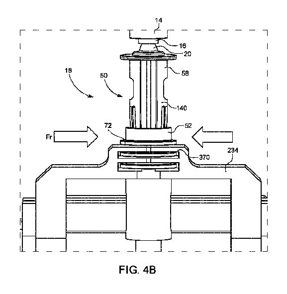
【選択図】図4B
A robotic system and method for transferring fluid between a container accessible through a container septum and a fluid transfer assembly accessible through a fluid transfer connector septum is provided. The robotic system includes a controller and a manipulator controllable by the controller to manipulate at least one of the container and the fluid transfer assembly. The controller is configured to operate the manipulator to secure contact between the container septum and the fluid transfer connector septum during at least a portion of the transfer of the fluid.
[Selected Figure] Figure 4B
Description
関連出願の相互参照
本出願は、2022年3月8日に出願された米国仮特許出願第63/269,004号、2022年11月2日に出願された同第63/382,014号、及び2022年12月1日に出願された同第63/429,340号の利益及び優先権を主張し、これらの各々は、その全体が本明細書中に参考として援用される。
CROSS-REFERENCE TO RELATED APPLICATIONS This application claims the benefit of and priority to U.S. Provisional Patent Application No. 63/269,004, filed March 8, 2022, No. 63/382,014, filed November 2, 2022, and No. 63/429,340, filed December 1, 2022, each of which is incorporated by reference in its entirety herein.
本出願は、概して、ロボット医薬品調製システムに関し、より詳細には、ロボット医薬品調製システム内の流体移送ステーションに関する。 This application relates generally to robotic drug preparation systems, and more particularly to fluid transfer stations within robotic drug preparation systems.
患者への投与用に指定された薬剤を調製するための自動又は半自動の調製システムが知られている。これらのシステムは、シリンジとバイアルとの間、又はシリンジと静脈内(IV)バッグとの間で流体を移送するための流体移送ステーションを含む。危険な薬剤の調製のために展開される閉鎖流体移送システムでは、シリンジ、バイアル又はIVバッグからの危険な薬剤の漏出を防止するための対策がとられる。したがって、シリンジ、バイアル、及びIVバッグは各々、隔壁を備えるコネクタ(「アダプタ」又は「スパイクアダプタ」とも呼ばれる)に取り付けられ、したがって、流体の移送は、シリンジ隔壁及びバイアル隔壁を介して、又はシリンジ隔壁及びIVバッグ隔壁を介して実行される。従来技術では、これらのコネクタは、シリンジ隔壁とバイアル隔壁との位置合わせ、又はシリンジ隔壁とIVバッグ隔壁との位置合わせを確実にするためのリング又はケーシングを備える。これらのケーシングは、隔壁の側部に沿って延在するねじ又はスナップ又は延長部などによって、隔壁を互いに固定的に結合するための固定(すなわち固定)手段を更に備える。 Automatic or semi-automatic preparation systems are known for preparing designated drugs for administration to a patient. These systems include a fluid transfer station for transferring fluids between a syringe and a vial or between a syringe and an intravenous (IV) bag. In closed fluid transfer systems deployed for the preparation of dangerous drugs, measures are taken to prevent leakage of the dangerous drug from the syringe, vial or IV bag. Thus, the syringe, vial and IV bag are each attached to a connector (also called an "adapter" or "spike adapter") that comprises a septum, and thus the transfer of fluids is carried out through the syringe septum and the vial septum or through the syringe septum and the IV bag septum. In the prior art, these connectors comprise a ring or a casing to ensure the alignment of the syringe septum with the vial septum or the alignment of the syringe septum with the IV bag septum. These casings further include fastening (i.e., locking) means for fixedly connecting the bulkheads to one another, such as by screws or snaps or extensions extending along the sides of the bulkheads.
開示される主題は、概して、ロボット医薬品調製システムに関し、より具体的には、ロボット医薬品調製システム内の流体移送ステーションに関する。ロボット医薬品調製システム及び流体移送ステーションは、容器、流体移送アセンブリ、コネクタ、導管、ポンプ、シリンジ、バイアル、静脈内バッグ、アダプタ、針などを含む異なる流体移送装置間での薬剤の移送に関連する動作を実行するように構成される。開示された主題によるロボット医薬品調製システム(又はロボットシステム)は、ロボットステーション、ロボットアーム、モータ、制御ユニット(コントローラ)、流体の移送を制御する機構などを含む。本明細書では、本明細書に記載の例(図面及び他のものを参照)は、本明細書の簡潔さ及び明確さの目的で本主題の範囲に包含される流体移送装置の構成要素のうちの少数の構成要素のみを参照して説明されていることを理解されたい。流体移送装置及びロボットステーションの構成要素の異なる組み合わせを含む、流体移送装置の異なる構成要素及び異なるロボットステーションを有する、本明細書に記載されるものに類似する様々な例は、本明細書の範囲内であると見なされるべきである。 The disclosed subject matter generally relates to a robotic drug preparation system, and more specifically to a fluid transfer station in a robotic drug preparation system. The robotic drug preparation system and fluid transfer station are configured to perform operations related to the transfer of medication between different fluid transfer devices, including containers, fluid transfer assemblies, connectors, conduits, pumps, syringes, vials, intravenous bags, adapters, needles, and the like. A robotic drug preparation system (or robotic system) according to the disclosed subject matter includes a robotic station, a robotic arm, a motor, a control unit (controller), a mechanism for controlling the transfer of fluids, and the like. It should be understood that the examples described herein (see drawings and elsewhere) are described with reference to only a few of the components of the fluid transfer device that are included within the scope of the present subject matter for the purposes of brevity and clarity of the present specification. Various examples similar to those described herein having different components of the fluid transfer device and different robotic stations, including different combinations of components of the fluid transfer device and robotic station, should be considered within the scope of the present specification.
例えば、容器は、バイアル及び/又は静脈内バッグを参照して本明細書で説明され、容器は、容器と他の流体移送構成要素との流体連通を確立するためのアダプタ又はコネクタを伴う又は伴わない、流体移送装置の構成要素である任意の他の容器であり得ることを理解されたい。例えば、容器は、流体移送装置の他の構成要素との容器の流体連通を確立するための容器コネクタ(又はアダプタ)とともに容器を有する容器アセンブリを構成することができる。例えば、容器は、バイアルアダプタを伴うバイアル、又はスパイクアダプタを伴う静脈内バッグであってもよい。容器は、容器隔壁を介してアクセス可能であってもよく、容器隔壁は、容器蓋の隔壁であってもよく、コネクタの一部であってもよい。いくつかの例において、容器は、シリンジ、流体移送パイプ、導管などであり得る。 For example, the container is described herein with reference to a vial and/or an intravenous bag, it should be understood that the container may be any other container that is a component of a fluid transfer device, with or without an adapter or connector for establishing fluid communication between the container and other fluid transfer components. For example, the container may comprise a container assembly having the container along with a container connector (or adapter) for establishing fluid communication between the container and other components of the fluid transfer device. For example, the container may be a vial with a vial adapter, or an intravenous bag with a spike adapter. The container may be accessible through a container septum, which may be a septum in a container lid or may be part of a connector. In some examples, the container may be a syringe, a fluid transfer pipe, a conduit, or the like.
同様に、流体移送アセンブリは、シリンジ及びシリンジコネクタを含むシリンジアセンブリを参照して本明細書で説明されており、流体移送アセンブリは、薬剤を移送するための類似の構成要素を含むことができることを理解されたい。いくつかの例では、流体移送アセンブリは、ポンプ機構と、薬剤の移送のために容器に接続されるように構成された流体移送パイプと、を含むことができる。いくつかの例では、流体移送アセンブリは、流体移送ユニット(流体移送パイプ、導管、ポンプ、シリンジなど)と容器との間の流体連通を確立するための流体移送コネクタ(又はアダプタ)を含むことができる。いくつかの例では、流体移送アセンブリは流体移送コネクタを含まなくてもよく、流体移送コネクタは、流体移送アセンブリを動作させるロボットシステムの一部を構成することができる。いくつかの例では、流体移送アセンブリは、他の容器との流体の移送のためのバイアル又は静脈内バッグを含むことができる。 Similarly, while the fluid transfer assembly is described herein with reference to a syringe assembly including a syringe and a syringe connector, it should be understood that the fluid transfer assembly can include similar components for transferring medication. In some examples, the fluid transfer assembly can include a pump mechanism and a fluid transfer pipe configured to be connected to a container for transfer of medication. In some examples, the fluid transfer assembly can include a fluid transfer connector (or adapter) for establishing fluid communication between a fluid transfer unit (fluid transfer pipe, conduit, pump, syringe, etc.) and the container. In some examples, the fluid transfer assembly may not include a fluid transfer connector, and the fluid transfer connector can form part of a robotic system that operates the fluid transfer assembly. In some examples, the fluid transfer assembly can include a vial or an intravenous bag for transfer of fluid to and from other containers.
更に、本明細書に記載のすべての例において、流体の移送は、容器隔壁を貫通して容器に入る針によって実行されるものとして記載されている。いくつかの例では、流体の移送は、針が容器隔壁を貫通することなく、又は任意選択で、(流体移送アセンブリに関連付けられた)流体移送コネクタの隔壁であっても貫通することなく実行することができることを、本明細書で理解されたい。いくつかの例では、流体移送は、針がなくても、流体の制御された圧力によって流体移送導管を介して実行することができる。例えば、流体移送導管は、針を含んでも含まなくてもよく、流体移送導管が針を含む場合、針は、両方の隔壁を完全に貫通してもよく、又は一方の隔壁を完全に貫通して他方の隔壁を部分的に貫通してもよく、又は一方の隔壁を部分的に貫通して他方の隔壁を全く貫通しなくてもよく、又はいずれの隔壁も全く貫通しなくてもよい。 Furthermore, in all examples described herein, the transfer of fluid is described as being performed by a needle penetrating the container septum and entering the container. It is understood herein that in some examples, the transfer of fluid can be performed without the needle penetrating the container septum, or optionally even the septum of a fluid transfer connector (associated with a fluid transfer assembly). In some examples, the transfer of fluid can be performed through a fluid transfer conduit by controlled pressure of the fluid, even without a needle. For example, the fluid transfer conduit may or may not include a needle, and if the fluid transfer conduit includes a needle, the needle may completely penetrate both septums, completely penetrate one septum and partially penetrate the other septum, partially penetrate one septum and not penetrate the other septum at all, or not penetrate any septum at all.
本開示の主題によるロボットシステムは、流体の移送を実行するために、上述のようなその異なる例のすべてによる容器及び流体移送アセンブリを取り扱い、動作させるように構成される。例えば、本明細書に記載のすべての実施例において、ロボットシステムは、流体移送アセンブリ(より具体的にはシリンジアセンブリ)を操作するように構成されたマニピュレータを有するものとして記載されているが、本明細書において、ロボットシステム(及びマニピュレータ)は、上述のすべての実施例に係る容器及び流体移送アセンブリのいずれか又は両方を取り扱い操作するように構成されていることを理解されたい。また、本明細書に記載のすべての例において、マニピュレータはロボットアームとして記載されているが、マニピュレータは、流体移送装置の構成要素を保持し、それらを互いに対して移動させ、流体の移送を実行するためのホルダを有するプラットフォーム、ロボットステーションなどであってもよいことを理解されたい。 The robotic system according to the subject matter of the present disclosure is configured to handle and manipulate the container and fluid transfer assembly according to all of its different examples as described above to perform the fluid transfer. For example, in all of the examples described herein, the robotic system is described as having a manipulator configured to manipulate the fluid transfer assembly (more specifically, the syringe assembly), but it should be understood that the robotic system (and manipulator) is configured to handle and manipulate either or both of the container and the fluid transfer assembly according to all of the examples described above. Also, in all of the examples described herein, the manipulator is described as a robotic arm, but it should be understood that the manipulator may be a platform, robotic station, etc. having holders for holding components of the fluid transfer device and moving them relative to each other to perform the fluid transfer.
本出願全体を通して使用される以下の用語及びそれらの派生語は、以下の説明を考慮するとより良く理解され得る。 The following terms and their derivatives used throughout this application may be better understood in light of the following explanation:
ロボットシステムは、コントローラユニット(コントローラ又は制御ユニットとも称される)によって少なくとも部分的に制御されるマニピュレータを備える自動又は部分自動システムを備えてもよい。 The robotic system may comprise an automated or partially automated system comprising a manipulator that is at least partially controlled by a controller unit (also referred to as a controller or control unit).
マニピュレータは、容器及び/又は流体移送アセンブリを操作するように構成されたロボットアーム、プラットフォーム、ロボットステーション、又はそれらの組み合わせを備えてもよい。 The manipulator may comprise a robotic arm, a platform, a robotic station, or a combination thereof configured to manipulate the container and/or the fluid transfer assembly.
コントローラ又はコントローラユニットは、中央処理装置(CPU)、1つ以上のプロセッサ、プロセッサユニット、マイクロプロセッサなどによって実行され得る、コントローラによって読み取り可能なメモリ上に記憶された命令セットに従って動作を実行するように構成されたコンピュータコントローラを備え得る。別の実施形態では、コントローラ又はコントローラユニットは、1つ以上の制御回路を含む。いくつかの例では、制御ユニットは、1つ以上の機構コントローラを含むことができる。コントローラユニットは、ロボット医薬品調製システム内の要素を制御するための任意の手段を備えてもよく、コントローラ、同期ユニット、及びプロセッサのうちの少なくともいずれか1つを備えてもよい。 The controller or controller unit may comprise a computer controller configured to perform operations according to an instruction set stored on a memory readable by the controller, which may be executed by a central processing unit (CPU), one or more processors, processor units, microprocessors, etc. In another embodiment, the controller or controller unit includes one or more control circuits. In some examples, the control unit may include one or more mechanism controllers. The controller unit may include any means for controlling elements in the robotic drug preparation system and may include at least one of a controller, a synchronization unit, and a processor.
ロボット医薬品調製システムは、患者への投与のために指定された薬剤の調製に関連する任意の活動を実行するように動作可能なロボットシステムを備える。本明細書で使用される「ロボットシステム」という用語は、ロボット医薬品調製システムを含み得ることに留意されたい。 A robotic medicine preparation system comprises a robotic system operable to perform any activity associated with preparing a designated medication for administration to a patient. It is noted that the term "robotic system" as used herein may include a robotic medicine preparation system.
医薬品調製システムは、任意の1つ以上の希釈ステーション、すなわち、任意のタイプの希釈剤が固体及び/若しくは液体形態である薬剤に添加される再構成ステーション、並びに/又は任意の1つ以上の充填ステーション、すなわち、少なくとも部分的若しくは完全に調製された薬剤が容器内に移送される配合ステーションを備えてもよい。 The pharmaceutical preparation system may optionally include one or more dilution stations, i.e., a reconstitution station where any type of diluent is added to the drug in solid and/or liquid form, and/or one or more filling stations, i.e., a compounding station where the at least partially or completely prepared drug is transferred into a container.
「医薬品」及び「薬剤」という用語は互換的に使用される。 The terms "drug" and "medicine" are used interchangeably.
針は、容器を貫通し、それを通して流体を移送するように構成されるカニューレ又は任意の他のデバイスを備えてもよい。針は、その遠位先端にベベル、又は側面に開口部、又は任意の他の構成を含んでもよい。 The needle may comprise a cannula or any other device configured to penetrate a container and transfer fluid therethrough. The needle may include a bevel at its distal tip, or an opening in a side, or any other configuration.
隔壁は、概して、それが属するデバイスの一部へのアクセスを閉鎖するように構成される、膜を指し得る。一般に、容器又は容器コネクタ上の隔壁(容器隔壁とも呼ばれる)は、容器を密封し得る。流体移送アセンブリ上の隔壁(流体移送コネクタ隔壁とも称される)は、流体移送導管(例えば、図面を参照して本明細書に説明される実施例による針)へのアクセスを防止又は抵抗し得る。典型的には、隔壁は、弾性の穿孔可能な材料で作られる。そのような材料は、ゴムのような弾性特性を有するポリマーであってもよい。 A septum may generally refer to a membrane configured to close access to a portion of the device to which it belongs. In general, a septum on a container or container connector (also referred to as a container septum) may seal the container. A septum on a fluid transfer assembly (also referred to as a fluid transfer connector septum) may prevent or resist access to a fluid transfer conduit (e.g., a needle according to the embodiments described herein with reference to the drawings). Typically, a septum is made of an elastic, pierceable material. Such a material may be a polymer with elastic properties, such as rubber.
長手方向軸Lx1は、流体移送アセンブリ(図3B)の長さに沿って中心に延在し、注入軸を画定する。 The longitudinal axis Lx1 extends centrally along the length of the fluid transfer assembly (FIG. 3B) and defines the injection axis.
中心長手方向軸Lx2は、容器保持モジュール(本明細書では容器ホルダと互換的に使用される)208に配置された容器(バイアル)の中心の長さに沿って中心に延在する。流体移送中、軸Lx2は、図3Bに示すように、軸Lx1と位置合わせしてもよい。 The central longitudinal axis Lx2 extends centrally along the central length of a container (vial) placed in the container holding module (used interchangeably herein with container holder) 208. During fluid transfer, axis Lx2 may be aligned with axis Lx1, as shown in FIG. 3B.
中心長手方向軸Lx3は、容器アセンブリ保持モジュール214に配置された容器(静脈内バッグ又はIVバッグ)の中心の長さに沿って中心に延在する。図15Aに示されるような流体移送の間、軸Lx3は軸Lx1と位置合わせし得る。
The central longitudinal axis Lx3 extends centrally along the central length of the container (intravenous bag or IV bag) placed in the container
垂直軸x1は、長手方向軸Lx1に略平行である。軸方向移動及び軸方向変位は、概して、垂直軸x1(図3A)に平行に実行される。 The vertical axis x1 is approximately parallel to the longitudinal axis Lx1. Axial movement and axial displacement are generally performed parallel to the vertical axis x1 (FIG. 3A).
水平軸x2は、垂直軸x1に直交し、概して、流体移送ステーションのテーブル(例えば、図3Aのテーブル220)の長さに平行に延在する。 The horizontal axis x2 is perpendicular to the vertical axis x1 and generally extends parallel to the length of the fluid transfer station table (e.g., table 220 in FIG. 3A).
横軸x3は、垂直軸x1及び水平軸x2に直交する軸である(図3A)。 The horizontal axis x3 is an axis perpendicular to the vertical axis x1 and the horizontal axis x2 (Figure 3A).
回転軸r1は垂直軸x1に平行であり、その周りの回転は図3Aにおいて矢印r2によって示される。 The axis of rotation r1 is parallel to the vertical axis x1, and rotation about it is indicated by the arrow r2 in FIG. 3A.
正面図は、概して、図3Aに示される図などの垂直軸x1及び水平軸x2に沿って広がる正面平面から取られた図を指す。側面図は、概して、図4Bに示される図などの垂直軸x1及び横軸x3に沿って広がる側面から取られた図を指す。本明細書に示される断面図は、主に長手方向断面図である。 A front view generally refers to a view taken from a front plane extending along a vertical axis x1 and a horizontal axis x2, such as the view shown in FIG. 3A. A side view generally refers to a view taken from a side extending along a vertical axis x1 and a horizontal axis x3, such as the view shown in FIG. 4B. Cross-sectional views shown herein are primarily longitudinal cross-sections.
本開示の主題の第1の態様によれば、例えば、容器隔壁を介してアクセス可能な容器と流体移送コネクタ隔壁を介してアクセス可能な流体移送アセンブリとの間で流体を移送するように動作可能なロボットシステムが提供され、ロボットシステムは、コントローラと、容器及び流体移送シリンジアセンブリのうちの少なくとも1つを操作するようにコントローラによって制御可能なマニピュレータと、を含み、コントローラは、流体の移送の少なくとも一部の間に容器隔壁と流体移送コネクタ隔壁との間の接触を固定するようにマニピュレータを動作させるように構成される。 According to a first aspect of the subject matter of the present disclosure, for example, a robotic system operable to transfer fluid between a container accessible through a container septum and a fluid transfer assembly accessible through a fluid transfer connector septum is provided, the robotic system including a controller and a manipulator controllable by the controller to manipulate at least one of the container and the fluid transfer syringe assembly, the controller configured to operate the manipulator to secure contact between the container septum and the fluid transfer connector septum during at least a portion of the transfer of the fluid.
いくつかの例では、容器は、容器及び容器コネクタを含む容器アセンブリを構成することができるが、そのような例では、容器隔壁は、容器コネクタの一部を構成することができる。いくつかの例では、容器コネクタは、ロボットシステムの一部を構成することができる。いくつかの例において、容器隔壁は容器の一部を構成し、容器コネクタは存在しない。 In some examples, the container may form a container assembly including the container and the container connector, but in such examples, the container septum may form part of the container connector. In some examples, the container connector may form part of a robotic system. In some examples, the container septum forms part of the container and the container connector is not present.
いくつかの例では、流体移送アセンブリは、流体移送コネクタを含むことができる。いくつかの例では、流体移送コネクタは、ロボットシステムの一部を構成することができる。いくつかの例では、流体移送アセンブリは、流体移送ユニットを含むことができる。流体移送ユニットは、管、パイプ、容器などであってもよい。流体移送ユニットの内外に流体をポンプするように動作可能なポンプ機構に接続されている、流体移送ユニット。いくつかの例における流体移送ユニットは、シリンジプランジャ又はポンプ機構によって動作可能なシリンジであってもよい。本明細書では、図面に示され、それに関して説明される実施例は、シリンジアセンブリである、すなわち、プランジャによって動作可能なシリンジを含む流体移送アセンブリと、シリンジコネクタである流体移送コネクタとを参照して説明されている。本明細書を簡潔にするために、流体移送アセンブリ(管セット、管、パイプ、ポンプ機構など)の他のすべての例、及びそれを用いたロボットシステムの動作は詳細に説明されておらず、本明細書の範囲によって包含されるものと見なされるべきである。 In some examples, the fluid transfer assembly may include a fluid transfer connector. In some examples, the fluid transfer connector may form part of a robotic system. In some examples, the fluid transfer assembly may include a fluid transfer unit. The fluid transfer unit may be a tube, pipe, container, etc. The fluid transfer unit is connected to a pump mechanism operable to pump fluid into and out of the fluid transfer unit. The fluid transfer unit in some examples may be a syringe plunger or a syringe operable by a pump mechanism. In this specification, the examples shown in the drawings and described with reference thereto are described with reference to a fluid transfer assembly that is a syringe assembly, i.e., includes a syringe operable by a plunger, and a fluid transfer connector that is a syringe connector. For the sake of brevity of this specification, all other examples of fluid transfer assemblies (tubing sets, tubes, pipes, pump mechanisms, etc.) and the operation of the robotic system therewith have not been described in detail and should be considered as encompassed by the scope of this specification.
本明細書では、容器隔壁とシリンジ隔壁(流体移送コネクタ隔壁)との間の接触を固定することは、(i)容器隔壁及びシリンジ隔壁のうちの少なくとも1つが弾性変形させられる程度まで、容器隔壁及びシリンジ隔壁を押圧することと、(ii)少なくとも所定の圧縮閾値力によって容器隔壁及びシリンジ隔壁を押圧し、次いで、流体の移送中にその力を維持又は増加させることと、のうちの少なくとも1つ以上を含み得ることを理解されたい。隔壁のうちの少なくとも1つの変形は、隔壁間の接触を固定する際に、隔壁の非接触面間の総距離が隔壁の高さの合計よりも小さいことを意味することが意図される。例えば、容器隔壁は、シリンジ隔壁に面する第1の表面と、反対側の第2の表面と、それらの間に延在し、第1の表面と第2の表面との間の容器隔壁の高さを画定する側面と、を含む。同様に、シリンジ隔壁は、容器隔壁に面する第1の表面と、反対側の第2の表面と、それらの間に延在し、第1の表面と第2の表面との間のシリンジ隔壁の高さを画定する側面と、を含む。容器隔壁の第1の表面とシリンジ隔壁の第1の表面とが互いに接触させられ、その接触がマニピュレータによって固定されるとき、容器隔壁の第2の表面とシリンジ隔壁の第2の表面との間の距離は、2つの隔壁の高さの合計よりも小さい。換言すれば、少なくとも1つの隔壁の側面は、半径方向外向きに膨らむ。 It is understood that, in this specification, securing the contact between the container septum and the syringe septum (fluid transfer connector septum) may include at least one or more of: (i) compressing the container septum and the syringe septum to an extent that at least one of the container septum and the syringe septum is elastically deformed; and (ii) compressing the container septum and the syringe septum with at least a predetermined compression threshold force and then maintaining or increasing that force during the transfer of fluid. Deformation of at least one of the septums is intended to mean that when securing the contact between the septums, the total distance between the non-contacting surfaces of the septum is less than the sum of the heights of the septums. For example, the container septum includes a first surface facing the syringe septum, an opposing second surface, and a side extending therebetween that defines the height of the container septum between the first and second surfaces. Similarly, the syringe septum includes a first surface facing the container septum, an opposing second surface, and a side extending therebetween that defines the height of the syringe septum between the first and second surfaces. When the first surface of the container septum and the first surface of the syringe septum are brought into contact with each other and the contact is secured by the manipulator, the distance between the second surface of the container septum and the second surface of the syringe septum is less than the sum of the heights of the two septums. In other words, at least one of the septum sides bulges radially outward.
2つの隔壁間の接触を固定するために2つの隔壁間を押圧する力は、少なくとも、接触点を半径方向に取り囲む要素がなくても、隔壁間の接触点を通る液体の漏出を防止するのに十分である。換言すれば、接触を固定することは、コネクタ、容器、又はロボットシステムのいずれかに、接触を半径方向に取り囲むことによって漏れ防止として隔壁間の接触を維持するための要素(ロック、スナップ、接続要素など)がない場合であっても、隔壁が、少なくともそれらの間の接触を安全かつ漏出防止に維持するための力で互いに押圧されることを意味することが意図されている。隔壁が互いから分離することを防止するか、又は接点を通して流体の漏出を可能にするために最小限必要とされる、すなわち少なくとも十分な力の大きさは、流体の移送中にマニピュレータによって維持される。いくつかの非限定的な例では、接触を固定するのに必要な最小力は、少なくとも5~100ニュートンの範囲、その部分範囲及び変数であり得、及び/又はいくつかの非限定的な例では、少なくとも25~100ニュートンの範囲、その部分範囲及び変数であり得、いくつかの非限定的な例では、力は、10~50ニュートンの範囲、その部分範囲及び変数であり得、いくつかの非限定的な例では、力は、25~75ニュートンの範囲、その部分範囲及び変数の範囲内であり得、いくつかの非限定的な例では、力は、30~50ニュートンの範囲、その部分範囲及び変数の範囲内であり得、いくつかの非限定的な例では、力は30~40ニュートンの範囲、その部分範囲及び変数の範囲内であり得る。 The force of pressing the two partitions together to fix the contact between them is at least sufficient to prevent leakage of liquid through the contact points between the partitions even in the absence of elements that radially surround the contact points. In other words, fixing the contact is intended to mean that the partitions are pressed together with a force to at least maintain the contact between them secure and leak-proof, even in the absence of elements (locks, snaps, connecting elements, etc.) in either the connector, the container, or the robotic system to maintain the contact between the partitions as leak-proof by radially surrounding the contact. The magnitude of force that is minimally required, i.e. at least sufficient, to prevent the partitions from separating from each other or to allow leakage of fluid through the contact points is maintained by the manipulator during the transfer of the fluid. In some non-limiting examples, the minimum force required to secure the contact may be in the range of at least 5-100 Newtons, sub-ranges and variables thereof, and/or in some non-limiting examples, at least 25-100 Newtons, sub-ranges and variables thereof, in some non-limiting examples, the force may be in the range of 10-50 Newtons, sub-ranges and variables thereof, in some non-limiting examples, the force may be in the range of 25-75 Newtons, sub-ranges and variables thereof, in some non-limiting examples, the force may be in the range of 30-50 Newtons, sub-ranges and variables thereof, and in some non-limiting examples, the force may be in the range of 30-40 Newtons, sub-ranges and variables thereof.
本明細書では、隔壁間の接触を固定することは、単に隔壁を互いに接触させること、及び/又はスナップ、ロック、接続要素などの外部要素の助けを借りて隔壁を接触状態に保持することよりも著しく大きいことを意味することが意図されていることを理解されたい。 It should be understood that, as used herein, securing the contact between the partitions is intended to mean significantly more than simply contacting the partitions with one another and/or holding the partitions in contact with the aid of external elements such as snaps, locks, connecting elements, etc.
いくつかの例では、コントローラは、マニピュレータを制御して、容器隔壁と流体移送コネクタ隔壁とを接触させ、流体の移送の少なくとも一部の間に、容器隔壁及び流体移送コネクタ隔壁のうちの少なくとも一方を容器隔壁及び流体移送コネクタ隔壁の他方に押圧することによって、容器隔壁と流体移送コネクタ隔壁との間の接触の固定を実行するように更に構成されている。 In some examples, the controller is further configured to control the manipulator to contact the container septum and the fluid transfer connector septum and perform fixation of the contact between the container septum and the fluid transfer connector septum by pressing at least one of the container septum and the fluid transfer connector septum against the other of the container septum and the fluid transfer connector septum during at least a portion of the transfer of fluid.
いくつかの例では、マニピュレータは、流体の移送の開始前に容器隔壁と流体移送コネクタ隔壁との間の所定の圧縮閾値に到達することを確実にするように構成された押圧機構を含み、所定の圧縮閾値に到達することは、接触を固定することと関連付けられる。 In some examples, the manipulator includes a pressing mechanism configured to ensure that a predetermined compression threshold is reached between the container septum and the fluid transfer connector septum before initiation of fluid transfer, where reaching the predetermined compression threshold is associated with securing the contact.
いくつかの例では、押圧機構は、容器隔壁と流体移送コネクタ隔壁との間の所定の圧縮閾値が流体の移送の少なくとも一部の間に維持されることを確実にするように更に構成される。 In some examples, the biasing mechanism is further configured to ensure that a predetermined compression threshold between the container septum and the fluid transfer connector septum is maintained during at least a portion of the transfer of fluid.
いくつかの例では、コントローラは、マニピュレータを動作させて、流体移送アセンブリの流体移送コネクタ隔壁と容器の容器隔壁とを位置合わせし、流体移送コネクタ隔壁と容器隔壁とを互いに接触させ、流体移送コネクタ隔壁及び容器隔壁のうちの少なくとも一方を流体移送コネクタ隔壁及び容器隔壁の他方に対して押圧して、それらの間の接触の固定を実行し、及び/又は流体の移送を可能にするために流体移送アセンブリの流体移送コネクタに関連付けられた流体移送導管によって流体移送コネクタ隔壁及び容器隔壁のうちの少なくとも一方の少なくとも部分的な貫通を実行するように構成され、押圧機構は、少なくとも部分的な貫通の前に容器隔壁と流体移送コネクタ隔壁との間の所定の圧縮閾値に到達することを確実にするように構成される。いくつかの例では、流体移送導管は、針を備えることができる。 In some examples, the controller is configured to operate the manipulator to align a fluid transfer connector septum of the fluid transfer assembly with a vessel septum of the vessel, bring the fluid transfer connector septum and the vessel septum into contact with one another, press at least one of the fluid transfer connector septum and the vessel septum against the other of the fluid transfer connector septum and the vessel septum to effect a securement of contact therebetween, and/or effect at least partial penetration of at least one of the fluid transfer connector septum and the vessel septum by a fluid transfer conduit associated with the fluid transfer connector of the fluid transfer assembly to enable transfer of fluid, the pressing mechanism being configured to ensure that a predetermined compression threshold between the vessel septum and the fluid transfer connector septum is reached prior to the at least partial penetration. In some examples, the fluid transfer conduit may comprise a needle.
いくつかの例では、マニピュレータは、流体移送アセンブリ及び容器のうちの少なくとも1つの把持部分を把持するように構成された把持アームを備える。いくつかの例では、把持アームは、流体移送アセンブリ及び容器のうちの少なくとも1つを少なくとも部分的に垂直軸に沿って保持するように構成される。いくつかの例では、把持アームは、1つ以上の流体移送アセンブリを保管するように構成された流体移送アセンブリ再循環コンベヤから流体移送アセンブリを把持することを可能にするように、及び/又は1つ以上の容器を保管するように構成された容器再循環コンベヤから容器を把持することを可能にするように、制御可能に移動可能であるように構成される。いくつかの例では、把持アームは、容器を保持するように構成された容器ホルダに対して制御可能に移動可能であるように構成され、把持アームは、把持アームが流体移送アセンブリを保持するとき、流体移送コネクタ隔壁と容器隔壁とを位置合わせし、流体移送コネクタ隔壁を容器隔壁と接触させるように構成される。 In some examples, the manipulator comprises a gripping arm configured to grip a gripping portion of at least one of the fluid transfer assembly and the container. In some examples, the gripping arm is configured to hold at least one of the fluid transfer assembly and the container at least partially along a vertical axis. In some examples, the gripping arm is configured to be controllably movable to allow gripping of the fluid transfer assembly from a fluid transfer assembly recirculating conveyor configured to store one or more fluid transfer assemblies and/or to allow gripping of the container from a container recirculating conveyor configured to store one or more containers. In some examples, the gripping arm is configured to be controllably movable relative to a container holder configured to hold the container, and the gripping arm is configured to align the fluid transfer connector septum with the container septum and contact the fluid transfer connector septum when the gripping arm holds the fluid transfer assembly.
いくつかの例では、マニピュレータは、把持アームが流体移送アセンブリを把持するときに、係合部分において流体移送アセンブリに係合するように構成された係合アームを含み、係合アームは、把持アームに対して軸方向に移動可能であるように構成される。いくつかの例では、係合アーム及び把持アームは、係合アーム及び把持アームが一緒に軸方向に又は互いに対して軸方向に制御可能に変位するように動作可能であるように結合される。 In some examples, the manipulator includes an engagement arm configured to engage the fluid transfer assembly at the engagement portion when the gripping arm grips the fluid transfer assembly, the engagement arm configured to be axially movable relative to the gripping arm. In some examples, the engagement arm and the gripping arm are coupled such that the engagement arm and the gripping arm are operable to be controllably displaced axially together or axially relative to each other.
いくつかの例では、係合アームは、流体移送アセンブリの流体移送コネクタのスリーブに係合するように構成され、スリーブは、流体移送コネクタ隔壁に対して固定的に結合され、把持アームは、流体移送コネクタの流体移送導管に対して固定的に結合された流体移送コネクタの本体部材を把持するように構成され、コントローラは、容器隔壁と流体移送コネクタ隔壁との間の所定の圧縮閾値に到達すると、把持アームと係合アームとの間の相対移動を引き起こして、流体移送導管及び流体移送コネクタ隔壁を少なくとも部分的に互いに向かって移動させるように構成される。 In some examples, the engagement arm is configured to engage a sleeve of a fluid transfer connector of the fluid transfer assembly, the sleeve being fixedly coupled to the fluid transfer connector septum, the gripping arm is configured to grip a body member of the fluid transfer connector fixedly coupled to a fluid transfer conduit of the fluid transfer connector, and the controller is configured to cause relative movement between the gripping arm and the engagement arm to move the fluid transfer conduit and the fluid transfer connector septum at least partially toward one another upon reaching a predetermined compression threshold between the container septum and the fluid transfer connector septum.
いくつかの例では、マニピュレータは、所定の押圧閾値未満の軸方向の力が印加されて相対移動を引き起こすときに、把持アームと係合アームとの間の相対移動に抵抗するように構成され、所定の押圧閾値は、所定の圧縮閾値と関連付けられる。 In some examples, the manipulator is configured to resist relative movement between the gripping arm and the engagement arm when an axial force below a predetermined compression threshold is applied to cause the relative movement, the predetermined compression threshold being associated with a predetermined compression threshold.
いくつかの例では、係合アーム及び把持アームは、把持アーム及び係合アームの互いに向かう相対移動に対抗する抵抗部材を介して結合される。いくつかの例では、抵抗部材は、係合アーム及び把持アームの互いに向かう移動によって選択的に圧縮されるように構成されたばねを含むことができる。いくつかの例では、抵抗部材は、係合アーム及び把持アームが互いに向かって移動することによって選択的に引き伸ばされるように構成された伸縮性部材を含むことができる。いくつかの例では、抵抗部材は、係合アーム及び把持アームの互いに向かう移動によって選択的に変形されるように構成された変形可能部材を含むことができる。いくつかの例では、抵抗部材は、ばね、バンド、伸縮構成、線形駆動構成などを含むことができる。 In some examples, the engagement arm and the gripping arm are coupled via a resistance member that resists relative movement of the gripping arm and the engagement arm toward one another. In some examples, the resistance member can include a spring configured to be selectively compressed by movement of the engagement arm and the gripping arm toward one another. In some examples, the resistance member can include an elastic member configured to be selectively stretched by movement of the engagement arm and the gripping arm toward one another. In some examples, the resistance member can include a deformable member configured to be selectively deformed by movement of the engagement arm and the gripping arm toward one another. In some examples, the resistance member can include a spring, a band, an elastic arrangement, a linear drive arrangement, etc.
いくつかの例では、抵抗部材は、流体の移送が完了した後に、係合アーム及び把持アームを互いから離れるように移動させるように構成される。いくつかの例では、係合アームは、流体移送コネクタ隔壁が容器隔壁に接触するときに係合部分の半径方向止め具に当接するように構成され、マニピュレータは、所定の押圧閾値力が印加された後にのみ把持アームと係合アームとの間の相対移動を引き起こすように構成され、それによって、流体移送導管及び流体移送コネクタ隔壁が少なくとも部分的に互いに向かって移動する前に、流体移送コネクタ隔壁を容器隔壁に押圧して、それらの間の接触が所定の圧縮閾値に到達するようにする。 In some examples, the resistance member is configured to move the engagement arm and the gripping arm away from each other after fluid transfer is completed. In some examples, the engagement arm is configured to abut a radial stop of the engagement portion when the fluid transfer connector septum contacts the vessel septum, and the manipulator is configured to cause relative movement between the gripping arm and the engagement arm only after a predetermined compression threshold force is applied, thereby pressing the fluid transfer connector septum against the vessel septum such that contact therebetween reaches a predetermined compression threshold before the fluid transfer conduit and the fluid transfer connector septum move at least partially toward each other.
いくつかの例では、ロボットシステムは、容器長手方向軸に沿って容器を保持するように構成された容器保持モジュール又は容器ホルダを更に含む。 In some examples, the robotic system further includes a container holding module or container holder configured to hold the container along the container longitudinal axis.
いくつかの例では、容器ホルダは、少なくとも1つのバイアルを支持するように構成されたバイアルホルダ、及び/又は少なくとも1つの静脈内バッグを支持するように構成された静脈内バッグホルダを含む。 In some examples, the container holder includes a vial holder configured to support at least one vial and/or an intravenous bag holder configured to support at least one intravenous bag.
いくつかの例では、マニピュレータは、容器ホルダに向かって移動するように構成される。いくつかの例では、容器ホルダは、マニピュレータに向かって移動するように構成される。 In some examples, the manipulator is configured to move towards the vessel holder. In some examples, the vessel holder is configured to move towards the manipulator.
いくつかの例では、コントローラは、把持アーム及び係合アームを一緒に回転軸の周りで回転させるように更に構成される。いくつかの例では、コントローラは、把持アームが、流体移送コネクタの流体移送導管に対して固定的に結合されている流体移送コネクタの本体部材を把持し、流体移送アセンブリを容器と位置合わせし、流体移送コネクタ隔壁を容器隔壁と接触させるように、係合アーム及び把持アームを制御するように構成される。係合アームは、流体移送アセンブリの流体移送コネクタのスリーブに係合し、スリーブは、流体移送コネクタ隔壁に対して固定的に結合され、容器隔壁に対して流体移送コネクタ隔壁を押圧して、それらの間の接触の固定を実行し、及び/又は、把持アームは、本体部材及びスリーブの互いに向かう折り畳み可能な移動を引き起こし、これは、流体移送導管及び流体移送コネクタ隔壁の互いに向かう少なくとも部分的な移動を実行して、流体の移送を容易にする。 In some examples, the controller is further configured to rotate the gripping arm and the engagement arm together about the axis of rotation. In some examples, the controller is configured to control the engagement arm and the gripping arm such that the gripping arm grips a body member of the fluid transfer connector fixedly coupled to a fluid transfer conduit of the fluid transfer connector, aligns the fluid transfer assembly with the container, and brings the fluid transfer connector septum into contact with the container septum. The engagement arm engages a sleeve of the fluid transfer connector of the fluid transfer assembly, the sleeve being fixedly coupled to the fluid transfer connector septum, and presses the fluid transfer connector septum against the container septum to effectuate a fixation of contact therebetween, and/or the gripping arm causes a collapsible movement of the body member and the sleeve toward one another, which effectuates at least a partial movement of the fluid transfer conduit and the fluid transfer connector septum toward one another to facilitate the transfer of fluid.
いくつかの例では、把持アームは、流体移送アセンブリの外壁に半径方向の力を印加するように更に構成され、コントローラは、流体移送アセンブリの流体移送コネクタアクチュエータを押圧するように、半径方向の力を選択的に印加するように把持アームを制御するように構成される。 In some examples, the gripping arms are further configured to apply a radial force to an outer wall of the fluid transfer assembly, and the controller is configured to control the gripping arms to selectively apply the radial force to press against a fluid transfer connector actuator of the fluid transfer assembly.
いくつかの例では、流体移送アセンブリはシリンジを備え、ロボットシステムは、シリンジのプランジャを動作させるように構成されたプランジャアームを更に備え、コントローラは、プランジャアームを制御してプランジャのプランジャフランジ部分を把持し、シリンジと容器との間で流体を移送するためにプランジャフランジを軸方向に変位させるように構成される。 In some examples, the fluid transfer assembly includes a syringe, and the robotic system further includes a plunger arm configured to operate a plunger of the syringe, and the controller is configured to control the plunger arm to grasp a plunger flange portion of the plunger and axially displace the plunger flange to transfer fluid between the syringe and the container.
いくつかの例では、コントローラは、係合アーム及び把持アームを制御するように構成され、それにより、流体の移送に続いて、把持アームが本体部材をスリーブから離れるように移動させ、係合アーム及び把持アームが、隔壁を分離するために容器から離間される。 In some examples, the controller is configured to control the engagement arm and the gripping arm such that, following fluid transfer, the gripping arm moves the body member away from the sleeve and the engagement arm and the gripping arm are moved away from the container to separate the septum.
いくつかの例では、コントローラは、流体移送後に把持アームを動作させて、本体部材をスリーブから離れるように移動させるように構成される。 In some examples, the controller is configured to operate the gripping arms to move the body member away from the sleeve after fluid transfer.
いくつかの例では、コントローラは、本体部材がスリーブから離れるように移動された後に把持アームを動作させて、半径方向の力の印加を停止するように構成される。いくつかの例では、コントローラは、把持アームを動作させて、本体部材を把持し、流体移送アセンブリを容器と位置合わせし、流体移送コネクタ隔壁を容器隔壁と接触させ、流体移送アセンブリの流体移送コネクタアクチュエータを押圧するように半径方向の力を選択的に印加する動作を同時に又は連続的に実行するように構成される。 In some examples, the controller is configured to operate the gripping arms to cease application of the radial force after the body member is moved away from the sleeve. In some examples, the controller is configured to simultaneously or sequentially operate the gripping arms to grip the body member, align the fluid transfer assembly with the container, contact the fluid transfer connector septum with the container septum, and selectively apply a radial force to press against a fluid transfer connector actuator of the fluid transfer assembly.
いくつかの例では、コントローラは、係合アーム及び把持アームのいずれか一方が流体移送アセンブリを把持し、流体移送アセンブリを容器と位置合わせし、流体移送コネクタ隔壁を容器隔壁と接触させ、係合アーム及び把持アームのいずれか一方が流体移送コネクタ隔壁を容器隔壁に押圧してそれらの間の接触を確実にするように、係合アーム及び把持アームを制御するように構成される。 In some examples, the controller is configured to control the engagement arm and the gripping arm such that one of the engagement arm and the gripping arm grips the fluid transfer assembly, aligns the fluid transfer assembly with the container, contacts the fluid transfer connector septum with the container septum, and presses the fluid transfer connector septum against the container septum to ensure contact therebetween.
いくつかの例では、係合アーム及び把持アームは、流体移送コネクタにおいて流体移送アセンブリに接触するように配置される。いくつかの例では、係合アームには、容器隔壁と流体移送コネクタ隔壁との間の接触を固定するために、流体移送アセンブリの半径方向止め具に押圧されるように構成された押圧面が形成されている。いくつかの例では、係合アームの押圧面は、流体移送アセンブリを取り囲み、流体移送アセンブリの外壁との間に半径方向の間隙を形成するように寸法決めされた弓形部分を含む。 In some examples, the engagement arm and the gripping arm are positioned to contact the fluid transfer assembly at the fluid transfer connector. In some examples, the engagement arm is formed with a pressing surface configured to press against a radial stop of the fluid transfer assembly to secure contact between the container septum and the fluid transfer connector septum. In some examples, the pressing surface of the engagement arm includes an arcuate portion dimensioned to surround the fluid transfer assembly and form a radial gap with an outer wall of the fluid transfer assembly.
いくつかの例では、係合アームの押圧面は、流体移送アセンブリの外壁と押圧面との間に半径方向の間隙が存在しないように、流体移送アセンブリの外面と嵌合するように構成されている。 In some examples, the pressing surface of the engagement arm is configured to mate with the outer surface of the fluid transfer assembly such that no radial gap exists between the outer wall of the fluid transfer assembly and the pressing surface.
いくつかの例では、把持アームは、流体移送アセンブリがロボットシステムによって操作されるときに流体移送アセンブリの外壁に半径方向の力を印加するように構成された少なくとも1つの突出要素を含む。 In some examples, the gripping arm includes at least one protruding element configured to apply a radial force to an outer wall of the fluid transfer assembly when the fluid transfer assembly is manipulated by the robotic system.
いくつかの例では、把持アームの突出要素は、弓形溝が形成されたプレートを含む。 In some examples, the protruding element of the gripping arm includes a plate having an arcuate groove formed therein.
いくつかの例では、把持アームは、流体移送アセンブリの外壁上の第1の対及び第2の対の開口部にアクセスするように構成された第1の対及び第2の対の突出要素を含む2つの対向するプレートを含む。 In some examples, the gripping arm includes two opposing plates including a first pair and a second pair of protruding elements configured to access a first pair and a second pair of openings on the outer wall of the fluid transfer assembly.
いくつかの例では、2つの対向するプレートは、それらの間に間隙を形成するために互いから離間されるように構成される。いくつかの例では、押圧機構は、流体の移送が完了した後、少なくとも流体移送導管が流体移送コネクタ隔壁から離れるように移動されるまで、容器隔壁と流体移送コネクタ隔壁との間の所定の圧縮閾値が維持されることを確実にするように更に構成される。いくつかの例では、ロボットシステムは、本明細書に記載されるその例のいずれかによる流体移送コネクタを備える。 In some examples, the two opposing plates are configured to be spaced apart from one another to form a gap therebetween. In some examples, the pressing mechanism is further configured to ensure that a predetermined compression threshold between the container septum and the fluid transfer connector septum is maintained after the fluid transfer is completed, at least until the fluid transfer conduit is moved away from the fluid transfer connector septum. In some examples, the robotic system includes a fluid transfer connector according to any of the examples thereof described herein.
一例によれば、第1の態様のロボットシステムによって実行される方法が提供される。本方法は、容器隔壁を介してアクセス可能な容器と、流体移送コネクタ隔壁を介してアクセス可能な流体移送アセンブリとの間で流体を移送するためのプロセスを含み、本方法は、ロボットシステムの動作によって、容器の容器隔壁を流体移送アセンブリの流体移送コネクタ隔壁と接触させることと、容器隔壁及び流体移送コネクタ隔壁のうちの少なくとも一方を、容器隔壁及び流体移送コネクタ隔壁のうちの他方の上に押圧して、それらの間の接触を固定することと、容器隔壁及び流体移送コネクタ隔壁を通して流体を移送することと、流体の移送の少なくとも一部の間、容器隔壁と流体移送コネクタ隔壁との間の固定された接触を維持することと、を含む。 According to one example, a method is provided that is performed by the robotic system of the first aspect. The method includes a process for transferring fluid between a container accessible through a container septum and a fluid transfer assembly accessible through a fluid transfer connector septum, the method including: contacting a container septum of the container with a fluid transfer connector septum of the fluid transfer assembly by operation of the robotic system; pressing at least one of the container septum and the fluid transfer connector septum onto the other of the container septum and the fluid transfer connector septum to secure contact therebetween; transferring fluid through the container septum and the fluid transfer connector septum; and maintaining the secured contact between the container septum and the fluid transfer connector septum during at least a portion of the transfer of fluid.
本開示の主題の第2の態様によれば、容器隔壁を介してアクセス可能な容器と流体移送アセンブリとの間で流体を移送するように動作可能なロボットシステムが提供され、流体移送アセンブリは、本体部材と、流体移送コネクタ隔壁を含むスリーブとを有する流体移送コネクタを介してアクセス可能であり、スリーブ及び本体部材は、ロック機構の作動時に互いに対して移動するように構成され、ロボットシステムは、コントローラと、コントローラによって制御可能であり、流体移送アセンブリを操作するように構成されたマニピュレータであって、流体移送アセンブリを把持するとともにロック機構を作動させるように構成され、コントローラは、ロック機構の作動時にマニピュレータを動作させてスリーブ及び本体部材を互いに対して移動させ、流体移送アセンブリと容器との間で流体を移送するように構成されたマニピュレータと、を備える。 According to a second aspect of the subject matter of the present disclosure, a robotic system operable to transfer fluid between a container accessible through a container septum and a fluid transfer assembly is provided, the fluid transfer assembly being accessible through a fluid transfer connector having a body member and a sleeve including a fluid transfer connector septum, the sleeve and the body member being configured to move relative to one another upon actuation of a locking mechanism, the robotic system comprising: a controller; and a manipulator controllable by the controller and configured to manipulate the fluid transfer assembly, the manipulator being configured to grasp the fluid transfer assembly and actuate the locking mechanism, the controller being configured to operate the manipulator to move the sleeve and the body member relative to one another upon actuation of the locking mechanism to transfer fluid between the fluid transfer assembly and the container.
いくつかの例では、第2の態様によるロボットシステムは、第1の態様によるロボットシステムについて上述したように、流体移送コネクタ隔壁と容器隔壁との間の接触を固定することに関連する動作の一部又は全部を実行するように構成することができ、それに関連する構成要素の一部又は全部を含むことができる。いくつかの例では、第2の態様によるロボットシステムは、第1の態様によるロボットシステムについて上述したように、ロック機構並びに係合アーム及び把持アーム(又はスリーブ及び本体部材)の相対移動に関連する動作の一部又は全部を実行するように構成することができ、それに関連する構成要素の一部又は全部を含むことができる。 In some examples, the robotic system according to the second aspect can be configured to perform some or all of the operations associated with securing contact between the fluid transfer connector septum and the container septum, as described above for the robotic system according to the first aspect, and can include some or all of the components associated therewith. In some examples, the robotic system according to the second aspect can be configured to perform some or all of the operations associated with the locking mechanism and the relative movement of the engagement arm and the gripping arm (or the sleeve and the body member), as described above for the robotic system according to the first aspect, and can include some or all of the components associated therewith.
更に、第2の態様によるロボットシステムは、第1の態様によるロボットシステムについて説明したように、マニピュレータ、把持アーム、係合アーム、及び抵抗部材に関連する特徴の一部又は全部を含むことができる。 Furthermore, the robotic system according to the second aspect may include some or all of the features associated with the manipulator, gripping arm, engagement arm, and resistance member as described for the robotic system according to the first aspect.
いくつかの例では、ロボットシステムは、本明細書に記載されるその例のいずれかによる流体移送コネクタを備える。 In some examples, the robotic system includes a fluid transfer connector according to any of the examples described herein.
一例によれば、第2の態様のロボットシステムによって実行される方法が提供される。本方法は、容器隔壁を介してアクセス可能な容器と、流体移送コネクタを介してアクセス可能な流体移送アセンブリとの間で流体を移送するためのプロセスを含み、本方法は、ロボットシステムの動作によって、ロボットシステムのマニピュレータを制御して、流体移送アセンブリを把持し、流体移送アセンブリと容器との間の流体連通の確立に関連付けられたロック機構を作動させることと、流体連通を確立するためにロック機構を作動させると、マニピュレータを動作させて、流体移送コネクタのスリーブ及び本体部材を互いに対して移動させることと、流体移送アセンブリと容器との間で流体を移送することと、を含む。 According to one example, a method is provided that is performed by the robotic system of the second aspect. The method includes a process for transferring fluid between a container accessible through a container septum and a fluid transfer assembly accessible through a fluid transfer connector, the method including controlling, by operation of the robotic system, a manipulator of the robotic system to grasp the fluid transfer assembly and actuate a locking mechanism associated with establishing fluid communication between the fluid transfer assembly and the container, and, upon actuating the locking mechanism to establish fluid communication, operating the manipulator to move a sleeve and a body member of the fluid transfer connector relative to each other, and transferring fluid between the fluid transfer assembly and the container.
本開示の主題の第3の態様によれば、容器隔壁を介してアクセス可能な容器と、本体部材及び流体移送コネクタ隔壁を含むスリーブを有する流体移送コネクタを介してアクセス可能な流体移送アセンブリとの間で流体を移送するように動作可能なロボットシステムが提供され、スリーブ及び本体部材は、互いに対して移動するように構成され、システムは、容器を支持し、流体移送アセンブリと少なくとも部分的に同軸に位置決めされるように構成された容器ホルダと、本体部材及びスリーブのうちの一方を係合するように構成された係合アームと、本体部材及びスリーブのうちの他方を把持するように構成された把持アームであって、把持アーム及び係合アームが互いに対して移動可能である、把持アームと、を備える。 According to a third aspect of the subject matter of the present disclosure, there is provided a robotic system operable to transfer fluid between a container accessible through a container septum and a fluid transfer assembly accessible through a fluid transfer connector having a sleeve including a body member and a fluid transfer connector septum, the sleeve and the body member configured to move relative to one another, the system comprising a container holder configured to support the container and be positioned at least partially coaxially with the fluid transfer assembly, an engagement arm configured to engage one of the body member and the sleeve, and a gripping arm configured to grip the other of the body member and the sleeve, the gripping arm and the engagement arm being movable relative to one another.
いくつかの例では、係合アーム及び把持アームは、把持アーム及び係合アームのうちの少なくとも1つを流体移送アセンブリの外面に押圧しながら、係合アーム及び把持アームを一緒に同時に移動させるように構成された一次駆動アセンブリに機械的に結合される。 In some examples, the engagement arm and the gripping arm are mechanically coupled to a primary drive assembly configured to simultaneously move the engagement arm and the gripping arm together while pressing at least one of the gripping arm and the engagement arm against an outer surface of the fluid transfer assembly.
いくつかの例では、係合アームは、把持アームと係合アームとの間の相対移動を引き起こすように構成された二次駆動アセンブリを介して把持アームに接続される。 In some examples, the engagement arm is connected to the gripping arm via a secondary drive assembly configured to cause relative movement between the gripping arm and the engagement arm.
いくつかの例では、第3の態様によるロボットシステムは、第1及び第2の態様によるロボットシステムについて上述したように、流体移送コネクタ隔壁と容器隔壁との間の接触を固定することに関連する動作の一部又は全部を実行するように構成することができ、それに関連する構成要素の一部又は全部を含むことができる。いくつかの例では、第3の態様によるロボットシステムは、第1及び第2の態様によるロボットシステムについて上述したように、ロック機構並びに係合アーム及び把持アーム(又はスリーブ及び本体部材)の相対移動に関連する動作の一部又は全部を実行するように構成することができ、それに関連する構成要素の一部又は全部を含むことができる。 In some examples, the robotic system according to the third aspect can be configured to perform some or all of the operations associated with securing contact between the fluid transfer connector septum and the container septum, as described above for the robotic systems according to the first and second aspects, and can include some or all of the components associated therewith. In some examples, the robotic system according to the third aspect can be configured to perform some or all of the operations associated with the locking mechanism and the relative movement of the engagement arm and the gripping arm (or the sleeve and the body member), as described above for the robotic systems according to the first and second aspects, and can include some or all of the components associated therewith.
更に、第3の態様によるロボットシステムは、第1及び第2の態様によるロボットシステムについて説明したように、マニピュレータ、把持アーム、係合アーム、及び抵抗部材に関連する特徴の一部又は全部を含むことができる。 Furthermore, the robot system according to the third aspect may include some or all of the features associated with the manipulator, gripping arm, engagement arm, and resistance member as described for the robot systems according to the first and second aspects.
いくつかの例では、ロボットシステムは、本明細書に記載されるその例のいずれかによる流体移送コネクタを備える。 In some examples, the robotic system includes a fluid transfer connector according to any of the examples described herein.
一例によれば、第3の態様のロボットシステムによって実行される方法が提供される。方法は、容器隔壁を介してアクセス可能な容器と流体移送コネクタを介してアクセス可能な流体移送アセンブリとの間で流体を移送するためのプロセスを含み、方法は、ロボットシステムの動作によって、流体移送コネクタのスリーブを係合するためにロボットシステムの係合アームを動作させることと、流体移送コネクタの本体部材を把持するためにロボットシステムの把持アームを動作させることと、流体移送アセンブリと容器との間の流体連通を確立するために、係合アーム及び把持アームのうちの少なくとも一方を他方に向かって移動させることと、流体移送アセンブリと容器との間で流体の移送を実行することと、を含む。 According to one example, a method is provided that is performed by the robotic system of the third aspect. The method includes a process for transferring fluid between a container accessible through a container septum and a fluid transfer assembly accessible through a fluid transfer connector, the method including, by operation of the robotic system, operating an engagement arm of the robotic system to engage a sleeve of the fluid transfer connector, operating a gripping arm of the robotic system to grip a body member of the fluid transfer connector, moving at least one of the engagement arm and the gripping arm toward the other to establish fluid communication between the fluid transfer assembly and the container, and performing a transfer of fluid between the fluid transfer assembly and the container.
本開示の主題の第4の態様によれば、容器隔壁を介してアクセス可能な容器と流体移送コネクタを介してアクセス可能な流体移送アセンブリとの間で注入軸に少なくとも部分的に沿って流体を移送するように動作可能なロボットシステムが提供され、ロボットシステムは、コントローラと、コントローラによって制御可能なマニピュレータと、を備え、マニピュレータは、流体移送アセンブリの把持部分を把持するように構成された把持アームと、係合部分において流体移送アセンブリに係合するように構成された係合アームと、を備え、少なくとも1つの係合アーム及び把持アームは、係合アーム及び把持アームの他方に対して注入軸に沿って変位可能であり、係合アーム及び把持アームは、マニピュレータの移動の少なくとも一部の間に一緒に変位するように構成される。 According to a fourth aspect of the subject matter of the present disclosure, there is provided a robotic system operable to transfer fluid at least partially along an injection axis between a container accessible through a container septum and a fluid transfer assembly accessible through a fluid transfer connector, the robotic system comprising a controller and a manipulator controllable by the controller, the manipulator comprising a gripping arm configured to grip a gripping portion of the fluid transfer assembly and an engagement arm configured to engage the fluid transfer assembly at an engagement portion, at least one of the engagement arm and the gripping arm being displaceable along the injection axis relative to the other of the engagement arm and the gripping arm, the engagement arm and the gripping arm being configured to displace together during at least a portion of a movement of the manipulator.
いくつかの例では、第4の態様によるロボットシステムは、第1、第2、及び第3の態様によるロボットシステムについて上述したように、流体移送コネクタ隔壁と容器隔壁との間の接触を固定することに関連する動作の一部又は全部を実行するように構成することができ、それに関連する構成要素の一部又は全部を含むことができる。いくつかの例では、第4の態様によるロボットシステムは、第1、第2、及び第3の態様によるロボットシステムについて上述したように、ロック機構並びに係合アーム及び把持アーム(又はスリーブ及び本体部材)の相対移動に関連する動作の一部又は全部を実行するように構成することができ、それに関連する構成要素の一部又は全部を含むことができる。 In some examples, the robotic system according to the fourth aspect can be configured to perform some or all of the operations associated with securing contact between the fluid transfer connector septum and the container septum, as described above for the robotic systems according to the first, second, and third aspects, and can include some or all of the components associated therewith. In some examples, the robotic system according to the fourth aspect can be configured to perform some or all of the operations associated with the locking mechanism and the relative movement of the engagement arm and the gripping arm (or the sleeve and the body member), as described above for the robotic systems according to the first, second, and third aspects, and can include some or all of the components associated therewith.
更に、第4の態様によるロボットシステムは、第1、第2、及び第3の態様によるロボットシステムについて説明したように、マニピュレータ、把持アーム、係合アーム、及び抵抗部材に関連する特徴の一部又は全部を含むことができる。 Furthermore, the robot system according to the fourth aspect may include some or all of the features associated with the manipulator, gripping arm, engagement arm, and resistance member as described for the robot systems according to the first, second, and third aspects.
いくつかの例では、ロボットシステムは、本明細書に記載されるその例のいずれかによる流体移送コネクタを備える。 In some examples, the robotic system includes a fluid transfer connector according to any of the examples described herein.
一例によれば、第4の態様のロボットシステムによって実行される方法が提供される。方法は、容器隔壁を介してアクセス可能な容器と流体移送コネクタを介してアクセス可能な流体移送アセンブリとの間で注入軸に少なくとも部分的に沿って流体を移送するためのプロセスを含み、方法は、ロボットシステムの動作によって、流体移送アセンブリの係合部分に係合するためにロボットシステムのマニピュレータの係合アームを動作させることと、流体移送アセンブリの把持部分を把持するためにマニピュレータの把持アームを動作させることと、係合アーム及び把持アームを一緒に容器とともに流体移送アセンブリに沿って移動させることと、流体移送アセンブリと容器との間の流体連通を確立するために、係合アーム及び把持アームのうちの少なくとも一方を注入軸に沿って係合アーム及び把持アームのうちの他方に向かって移動させることと、流体移送アセンブリと容器との間で流体の移送を実行することと、を含む。 According to one example, a method is provided that is performed by the robotic system of the fourth aspect. The method includes a process for transferring fluid at least partially along an injection axis between a container accessible through a container septum and a fluid transfer assembly accessible through a fluid transfer connector, the method including, by operation of the robotic system, operating an engagement arm of a manipulator of the robotic system to engage an engagement portion of the fluid transfer assembly, operating a gripping arm of the manipulator to grip a gripping portion of the fluid transfer assembly, moving the engagement arm and gripping arm together along the fluid transfer assembly with the container, moving at least one of the engagement arm and gripping arm along the injection axis toward the other of the engagement arm and gripping arm to establish fluid communication between the fluid transfer assembly and the container, and performing a transfer of fluid between the fluid transfer assembly and the container.
本開示の主題の第5の態様によれば、容器隔壁を介してアクセス可能な容器と、流体の移送のために容器と流体移送アセンブリとの間に流体連通を確立するように構成された流体移送コネクタを介してアクセス可能な流体移送アセンブリとの間で流体を移送するように動作可能なロボットシステムであって、流体移送コネクタは、通常位置である伸長位置と、流体移送コネクタが流体連通を確立する折り畳み位置との間で互いに対して変位可能な本体部材及びスリーブを備え、流体移送コネクタは、スリーブに配置された流体移送コネクタ隔壁を備え、ロボットシステムは、コントローラと、容器及び流体移送アセンブリのうちの少なくとも1つを操作して、流体移送コネクタ隔壁と容器隔壁とを互いに接触させ、流体移送コネクタを伸長位置からその折り畳み位置に選択的に変位させるように、コントローラによって制御可能なマニピュレータと、容器隔壁と流体移送コネクタ隔壁との間の所定の圧縮閾値に到達するまで、マニピュレータが流体移送コネクタを伸長位置からその折り畳み位置に変位させることを防止するように構成された接触固定機構と、を備える、ロボットシステムが提供される。 According to a fifth aspect of the subject matter of the present disclosure, there is provided a robotic system operable to transfer fluid between a container accessible through a container septum and a fluid transfer assembly accessible through a fluid transfer connector configured to establish fluid communication between the container and the fluid transfer assembly for transfer of the fluid, the fluid transfer connector comprising a body member and a sleeve displaceable relative to one another between an extended position, which is a normal position, and a folded position in which the fluid transfer connector establishes fluid communication, the fluid transfer connector comprising a fluid transfer connector septum disposed on the sleeve, the robotic system comprising a controller, a manipulator controllable by the controller to manipulate at least one of the container and the fluid transfer assembly to bring the fluid transfer connector septum and the container septum into contact with one another and selectively displace the fluid transfer connector from the extended position to its folded position, and a contact fixation mechanism configured to prevent the manipulator from displacing the fluid transfer connector from the extended position to its folded position until a predetermined compression threshold between the container septum and the fluid transfer connector septum is reached.
いくつかの例では、マニピュレータは、可変の大きさを有する圧縮力によって、流体移送コネクタ隔壁及び容器隔壁のうちの少なくとも一方を、流体移送コネクタ隔壁及び容器隔壁のうちの他方に対して押圧するように構成される。 In some examples, the manipulator is configured to press at least one of the fluid transfer connector septum and the container septum against the other of the fluid transfer connector septum and the container septum with a compressive force having a variable magnitude.
いくつかの例では、接触固定機構は、少なくとも圧縮力が所定の圧縮閾値未満になるまで、マニピュレータが流体移送コネクタを伸長位置からその折り畳み位置に変位させることを防止するように構成される。 In some examples, the contact fixation mechanism is configured to prevent the manipulator from displacing the fluid transfer connector from the extended position to its collapsed position at least until the compressive force is below a predetermined compression threshold.
いくつかの例では、接触固定機構は、少なくとも圧縮力が所定の圧縮閾値以上であるときに、マニピュレータが流体移送コネクタを伸長位置からその折り畳み位置に変位させることを可能にするように構成される。 In some examples, the contact fixation mechanism is configured to enable the manipulator to displace the fluid transfer connector from the extended position to its collapsed position at least when the compressive force is equal to or greater than a predetermined compression threshold.
いくつかの例では、接触固定機構は、圧縮力が所定の圧縮閾値以上であることを示す事象の検出に続いて、マニピュレータが流体移送コネクタをその折り畳み位置に変位させることを可能にするように構成される。 In some examples, the contact fixation mechanism is configured to enable the manipulator to displace the fluid transfer connector to its collapsed position following detection of an event indicating that the compressive force is equal to or greater than a predetermined compression threshold.
いくつかの例では、接触固定機構は機械的要素を備える。 In some examples, the contact fixation mechanism comprises a mechanical element.
いくつかの例では、接触固定機構は、マニピュレータが流体移送コネクタをその折り畳み位置に変位させることに抵抗するように構成された抵抗部材を備える。 In some examples, the contact fixation mechanism includes a resistance member configured to resist the manipulator from displacing the fluid transfer connector to its folded position.
いくつかの例では、マニピュレータは、スリーブに係合するように構成された係合アームと、本体部材を把持するように構成された把持アームと、を備え、係合アーム及び把持アームは、互いに対して移動して流体移送コネクタを伸長位置と折り畳み位置との間で変位させるように構成され、係合アーム及び把持アームは、抵抗部材を介して互いに結合される。 In some examples, the manipulator includes an engagement arm configured to engage the sleeve and a gripping arm configured to grip the body member, the engagement arm and the gripping arm configured to move relative to one another to displace the fluid transfer connector between the extended position and the collapsed position, and the engagement arm and the gripping arm are coupled to one another via a resistance member.
いくつかの例では、係合アーム及び把持アームは、抵抗部材の変形の開始時に、互いに向かって移動して、流体移送コネクタを折り畳み位置に変位させるように構成される。いくつかの実施例では、抵抗部材は、最小閾値力がその上に印加されるまで、変形を防止するように構成される。いくつかの例では、事象は、変形の開始を含む。 In some examples, the engagement arm and the gripping arm are configured to move toward one another upon initiation of deformation of the resistance member to displace the fluid transfer connector to the collapsed position. In some examples, the resistance member is configured to prevent deformation until a minimum threshold force is applied thereon. In some examples, the event includes initiation of deformation.
いくつかの例では、ロボットシステムは、変形の開始を検出し、それを示す信号を生成するように構成されたセンサを更に備える。いくつかの例では、抵抗部材は、流体の移送の完了後に、マニピュレータに流体移送コネクタをその伸長位置に変位させるように構成される。 In some examples, the robotic system further comprises a sensor configured to detect the initiation of the deformation and generate a signal indicative thereof. In some examples, the resistance member is configured to cause the manipulator to displace the fluid transfer connector to its extended position after completion of the fluid transfer.
いくつかの例では、第5の態様によるロボットシステムは、第1、第2、第3、及び第4の態様によるロボットシステムについて上述したように、流体移送コネクタ隔壁と容器隔壁との間の接触を固定することに関連する動作の一部又は全部を実行するように構成することができ、それに関連する構成要素の一部又は全部を含むことができる。いくつかの例では、第5の態様によるロボットシステムは、第1、第2、第3、及び第4の態様によるロボットシステムについて上述したように、ロック機構並びに係合アーム及び把持アーム(又はスリーブ及び本体部材)の相対移動に関連する動作の一部又は全部を実行するように構成することができ、それに関連する構成要素の一部又は全部を含むことができる。 In some examples, the robotic system according to the fifth aspect can be configured to perform some or all of the operations associated with securing contact between the fluid transfer connector septum and the container septum, as described above for the robotic systems according to the first, second, third, and fourth aspects, and can include some or all of the components associated therewith. In some examples, the robotic system according to the fifth aspect can be configured to perform some or all of the operations associated with the locking mechanism and the relative movement of the engagement arm and the gripping arm (or the sleeve and the body member), as described above for the robotic systems according to the first, second, third, and fourth aspects, and can include some or all of the components associated therewith.
更に、第5の態様によるロボットシステムは、第1、第2、第3、及び第4の態様によるロボットシステムについて説明したように、マニピュレータ、把持アーム、係合アーム、センサ、及び抵抗部材に関する特徴の一部又は全部を含むことができる。 Furthermore, the robot system according to the fifth aspect may include some or all of the features relating to the manipulator, gripping arm, engagement arm, sensor, and resistance member as described for the robot systems according to the first, second, third, and fourth aspects.
いくつかの例では、ロボットシステムは、本明細書に記載されるその例のいずれかによる流体移送コネクタを備える。 In some examples, the robotic system includes a fluid transfer connector according to any of the examples described herein.
いくつかの例では、上述の態様によるロボットシステムは、第5の態様によるロボットシステムについて説明したような接触固定機構に関連する特徴の一部又は全部を含むことができる。 In some examples, the robot system according to the above aspect may include some or all of the features associated with the contact fixation mechanism as described for the robot system according to the fifth aspect.
一例によれば、第5の態様のロボットシステムによって実行される方法が提供される。方法は、容器隔壁を介してアクセス可能な容器と、流体移送コネクタ隔壁を備える流体移送コネクタを介してアクセス可能な流体移送アセンブリとの間で流体を移送するためのプロセスを含み、方法は、ロボットシステムの動作によって、容器及び流体移送アセンブリのうちの少なくとも1つを操作するためのロボットシステムのマニピュレータを動作させて、流体移送コネクタ隔壁及び容器隔壁を互いに接触させることと、少なくとも容器隔壁と流体移送コネクタ隔壁との間の所定の圧縮閾値に到達するまで、流体移送アセンブリを操作して流体移送コネクタ隔壁を容器隔壁に押圧するためにマニピュレータを動作させることと、マニピュレータを動作させて、所定の圧縮閾値に到達した後に、流体移送コネクタを、容器と流体移送アセンブリとの間の流体連通が確立されるその折り畳み位置に、通常位置であるその伸長位置から変位させることと、流体移送アセンブリと容器との間で流体の移送を実行することと、を含む。 According to one example, a method is provided that is performed by the robotic system of the fifth aspect. The method includes a process for transferring fluid between a container accessible through a container septum and a fluid transfer assembly accessible through a fluid transfer connector having a fluid transfer connector septum, the method including: operating a manipulator of the robotic system for manipulating at least one of the container and the fluid transfer assembly by operation of the robotic system to bring the fluid transfer connector septum and the container septum into contact with each other; operating the manipulator to manipulate the fluid transfer assembly to press the fluid transfer connector septum against the container septum at least until a predetermined compression threshold between the container septum and the fluid transfer connector septum is reached; operating the manipulator to displace the fluid transfer connector from its extended position, which is a normal position, to its folded position in which fluid communication between the container and the fluid transfer assembly is established after the predetermined compression threshold is reached; and performing a transfer of fluid between the fluid transfer assembly and the container.
本開示の主題の第6の態様によれば、容器隔壁を介してアクセス可能な容器と、流体移送コネクタを介してアクセス可能な流体移送アセンブリとの間で流体を移送するように動作可能なロボットシステムであって、コントローラと、容器と流体移送アセンブリとの間の流体連通を確立するために、容器及び流体移送アセンブリのうちの少なくとも1つを操作するようにコントローラによって動作可能なマニピュレータと、マニピュレータの動作を監視し、監視を示す信号を送信するように構成されたセンサと、を備える、ロボットシステムが提供される。 According to a sixth aspect of the subject matter of the present disclosure, there is provided a robotic system operable to transfer fluid between a container accessible through a container septum and a fluid transfer assembly accessible through a fluid transfer connector, the robotic system comprising: a controller; a manipulator operable by the controller to manipulate at least one of the container and the fluid transfer assembly to establish fluid communication between the container and the fluid transfer assembly; and a sensor configured to monitor operation of the manipulator and transmit a signal indicative of the monitoring.
いくつかの例では、マニピュレータは、流体移送コネクタの把持部分を把持するように構成された把持アームと、流体移送コネクタの係合部分に係合するように構成された係合アームと、を備え、係合アーム及び把持アームは、流体連通を選択的に確立するために互いに対して移動するように構成され、センサは、係合アーム及び把持アームの相対移動を監視するように構成される。いくつかの例では、センサは、係合アーム及び把持アームのうちの少なくとも一方の相対位置を、係合アーム及び把持アームのうちの少なくとも一方の他方に対して監視するように構成される。 In some examples, the manipulator comprises a gripping arm configured to grip a gripping portion of the fluid transfer connector and an engagement arm configured to engage an engagement portion of the fluid transfer connector, the engagement arm and the gripping arm configured to move relative to one another to selectively establish fluid communication, and the sensor configured to monitor the relative movement of the engagement arm and the gripping arm. In some examples, the sensor is configured to monitor the relative position of at least one of the engagement arm and the gripping arm relative to the other of the engagement arm and at least one of the gripping arm.
いくつかの例では、係合アームは、係合アームと把持アームとの間の互いに向かう相対移動に抵抗するように構成された抵抗部材を介して把持アームに結合される。いくつかの例では、センサは、抵抗部材を監視するように構成される。いくつかの例では、抵抗部材は、係合アームと把持アームとの間の相対移動時に変形するように構成される。いくつかの例では、センサは、抵抗部材の変形を監視するように構成される。いくつかの例では、抵抗部材は、少なくとも所定の閾値以上の力がその上に印加されるまで、変形の開始を防止するように構成される。いくつかの例では、センサは、力を監視するように構成される。 In some examples, the engagement arm is coupled to the gripping arm via a resistance member configured to resist relative movement between the engagement arm and the gripping arm towards one another. In some examples, the sensor is configured to monitor the resistance member. In some examples, the resistance member is configured to deform upon relative movement between the engagement arm and the gripping arm. In some examples, the sensor is configured to monitor deformation of the resistance member. In some examples, the resistance member is configured to prevent initiation of deformation until a force equal to or greater than a predetermined threshold is applied thereon. In some examples, the sensor is configured to monitor the force.
いくつかの例では、ロボットシステムは、マニピュレータの動作を実行するためにマニピュレータを移動させるように構成されたモータを更に備え、モータは、マニピュレータを移動させるために可変電力を消費するように構成され、センサは、電力消費を監視するように構成される。 In some examples, the robotic system further includes a motor configured to move the manipulator to perform the manipulator movements, the motor configured to consume variable power to move the manipulator, and the sensor configured to monitor the power consumption.
いくつかの例では、第6の態様によるロボットシステムは、上述の態様によるロボットシステムについて上述したように、流体移送コネクタ隔壁と容器隔壁との間の接触を固定することに関連する動作の一部又は全部を実行するように構成することができ、それに関連する構成要素の一部又は全部を含むことができる。いくつかの例では、第6の態様によるロボットシステムは、上述した態様によるロボットシステムについて上述したように、ロック機構並びに係合アーム及び把持アーム(又はスリーブ及び本体部材)の相対移動に関連する動作の一部又は全部を実行するように構成することができ、それに関連する構成要素の一部又は全部を含むことができる。 In some examples, the robotic system according to the sixth aspect can be configured to perform some or all of the operations associated with securing contact between the fluid transfer connector septum and the container septum, as described above for the robotic system according to the previous aspect, and can include some or all of the components associated therewith. In some examples, the robotic system according to the sixth aspect can be configured to perform some or all of the operations associated with the locking mechanism and the relative movement of the engagement arm and the gripping arm (or the sleeve and the body member), as described above for the robotic system according to the previous aspect, and can include some or all of the components associated therewith.
更に、第6の態様によるロボットシステムは、上述の態様によるロボットシステムについて説明したように、マニピュレータ、把持アーム、係合アーム、センサ、接触固定機構、及び抵抗部材に関連する特徴の一部又は全部を含むことができる。 Furthermore, the robot system according to the sixth aspect may include some or all of the features related to the manipulator, gripping arm, engagement arm, sensor, contact fixation mechanism, and resistance member as described for the robot system according to the above aspects.
いくつかの例では、ロボットシステムは、本明細書に記載されるその例のいずれかによる流体移送コネクタを備える。 In some examples, the robotic system includes a fluid transfer connector according to any of the examples described herein.
いくつかの例では、上述の態様によるロボットシステムは、第6の態様によるロボットシステムについて説明したようなセンサに関連する特徴の一部又は全部を含むことができる。 In some examples, the robotic system according to the above aspect may include some or all of the sensor-related features as described for the robotic system according to the sixth aspect.
一例によれば、第6の態様のロボットシステムによって実行される方法が提供される。方法は、容器隔壁を介してアクセス可能な容器と、流体移送コネクタを介してアクセス可能な流体移送アセンブリとの間で流体を移送するためのプロセスを含み、方法は、ロボットシステムの動作によって、ロボットシステムのマニピュレータを制御して、容器及び流体移送アセンブリのうちの少なくとも1つを操作して、それらの間に流体連通を確立することと、ロボットシステムのセンサによって、マニピュレータの動作を監視することと、センサによって、監視を示す信号を送信することと、を含む。 According to one example, a method is provided that is performed by the robotic system of the sixth aspect. The method includes a process for transferring fluid between a container accessible through a container septum and a fluid transfer assembly accessible through a fluid transfer connector, the method including controlling, by operation of the robotic system, a manipulator of the robotic system to manipulate at least one of the container and the fluid transfer assembly to establish fluid communication therebetween, monitoring, by a sensor of the robotic system, the operation of the manipulator, and transmitting, by the sensor, a signal indicative of the monitoring.
本開示の主題の第7の態様によれば、容器隔壁を介してアクセス可能な容器と流体移送コネクタを介してアクセス可能な流体移送アセンブリとの間で流体を移送するように動作可能なロボットシステムであって、容器と流体移送アセンブリとの間の流体連通を確立するために容器及び流体移送アセンブリのうちの少なくとも1つを操作するように構成されたマニピュレータと、流体連通を確立するためにマニピュレータを移動させるように構成されたモータであって、マニピュレータを移動させるための可変電力を消費するように構成されたモータと、電力消費を監視し、少なくともそれに基づいてモータを制御するように構成されたコントローラと、を備える、ロボットシステムが提供される。 According to a seventh aspect of the subject matter of the present disclosure, there is provided a robotic system operable to transfer fluid between a container accessible through a container septum and a fluid transfer assembly accessible through a fluid transfer connector, the robotic system comprising: a manipulator configured to manipulate at least one of the container and the fluid transfer assembly to establish fluid communication between the container and the fluid transfer assembly; a motor configured to move the manipulator to establish fluid communication, the motor configured to consume variable power to move the manipulator; and a controller configured to monitor power consumption and control the motor based at least thereon.
いくつかの例では、モータは、マニピュレータの移動を引き起こすように動作可能なモータシャフトと、モータシャフトの位置を検出するように動作可能なエンコーダと、を備え、コントローラは、電力消費とモータシャフトの位置との組み合わせに基づいてモータを制御するように構成される。 In some examples, the motor comprises a motor shaft operable to cause movement of the manipulator and an encoder operable to detect a position of the motor shaft, and the controller is configured to control the motor based on a combination of power consumption and the position of the motor shaft.
いくつかの例では、コントローラは、電力消費の上限及び下限のうちの少なくとも一方を予め決定し、電力消費が予め決定された範囲から逸脱したことを検出すると警告を生成するように構成される。いくつかの例では、電力消費は、モータに印加される電流の大きさによって測定可能である。 In some examples, the controller is configured to predetermine at least one of an upper and lower limit of power consumption and generate an alert upon detecting that the power consumption falls outside the predetermine range. In some examples, the power consumption is measurable by the magnitude of the current applied to the motor.
いくつかの例では、第7の態様によるロボットシステムは、上述の態様によるロボットシステムについて上述したように、流体移送コネクタ隔壁と容器隔壁との間の接触を固定することに関連する動作の一部又は全部を実行するように構成することができ、それに関連する構成要素の一部又は全部を含むことができる。いくつかの例では、第7の態様によるロボットシステムは、上述した態様によるロボットシステムについて上述したように、ロック機構並びに係合アーム及び把持アーム(又はスリーブ及び本体部材)の相対移動に関連する動作の一部又は全部を実行するように構成することができ、それに関連する構成要素の一部又は全部を含むことができる。 In some examples, the robotic system according to the seventh aspect can be configured to perform some or all of the operations associated with securing contact between the fluid transfer connector septum and the container septum, as described above for the robotic system according to the previous aspect, and can include some or all of the components associated therewith. In some examples, the robotic system according to the seventh aspect can be configured to perform some or all of the operations associated with the locking mechanism and the relative movement of the engagement arm and the gripping arm (or the sleeve and the body member), as described above for the robotic system according to the previous aspect, and can include some or all of the components associated therewith.
更に、第7の態様によるロボットシステムは、上述の態様によるロボットシステムについて説明したように、マニピュレータ、把持アーム、係合アーム、センサ、接触固定機構、及び抵抗部材に関連する特徴の一部又は全部を含むことができる。 Furthermore, the robot system according to the seventh aspect may include some or all of the features related to the manipulator, gripping arm, engagement arm, sensor, contact fixation mechanism, and resistance member as described for the robot system according to the above aspects.
いくつかの例では、ロボットシステムは、本明細書に記載されるその例のいずれかによる流体移送コネクタを備える。 In some examples, the robotic system includes a fluid transfer connector according to any of the examples described herein.
いくつかの例では、上述した態様によるロボットシステムは、第7の態様によるロボットシステムについて説明したように、モータによる電力消費に基づいてマニピュレータを移動させるモータを制御することに関するいくつか又はすべての特徴を含むことができる。 In some examples, the robotic system according to the above aspect may include some or all of the features related to controlling the motors that move the manipulator based on power consumption by the motors, as described for the robotic system according to the seventh aspect.
一例によれば、第7の態様のロボットシステムによって実行される方法が提供される。方法は、容器隔壁を介してアクセス可能な容器と、流体移送コネクタを介してアクセス可能な流体移送アセンブリとの間で流体を移送するためのプロセスを含み、方法は、ロボットシステムの動作によって、ロボットシステムのマニピュレータを制御して、容器及び流体移送アセンブリのうちの少なくとも1つを操作して、それらの間に流体連通を確立することと、流体連通を確立するためにマニピュレータを移動させるようにロボットシステムのモータを動作させることであって、モータを動作させることが可変電力を消費することを含む、動作させることと、ロボットシステムのコントローラによって電力消費を監視することと、少なくとも監視に基づいてモータを制御することと、を含む。 According to one example, a method is provided that is performed by the robotic system of the seventh aspect. The method includes a process for transferring fluid between a container accessible through a container septum and a fluid transfer assembly accessible through a fluid transfer connector, the method including: controlling, by operation of the robotic system, a manipulator of the robotic system to manipulate at least one of the container and the fluid transfer assembly to establish fluid communication therebetween; operating a motor of the robotic system to move the manipulator to establish fluid communication, where operating the motor includes consuming variable power; monitoring the power consumption by a controller of the robotic system; and controlling the motor based at least on the monitoring.
本開示の主題の第8の態様によれば、容器隔壁を介してアクセス可能な容器と、流体移送のために容器と流体移送アセンブリとの間に流体連通を確立するように構成された流体移送コネクタを介してアクセス可能な流体移送アセンブリとの間で流体を移送するように動作可能なロボットシステムが提供され、流体移送コネクタは、通常位置である伸長位置と、流体移送コネクタが流体連通を確立する折り畳み位置との間で互いに対して変位可能な本体部材及びスリーブを備え、流体移送コネクタは、スリーブの遠位端に配置された流体移送コネクタ隔壁と、本体部材の近位端から流体移送コネクタ隔壁に向かって延在する流体移送導管と、を備え、ロボットシステムは、コントローラと、コントローラによって制御可能なマニピュレータであって、位置決め段階を通して流体移送アセンブリを操作するために可変位置決め力を印加し、位置決め段階中に流体移送アセンブリ及び/又は容器を位置決めして流体移送コネクタ隔壁と容器隔壁とを互いに接触させ、貫通段階を通して流体移送アセンブリ及び/又は容器を操作するために可変貫通力を印加し、貫通段階中に流体移送導管の少なくとも先端が容器隔壁及び流体移送コネクタ隔壁のうちの少なくとも一方を少なくとも部分的に貫通し、可変貫通力の最小値が可変位置決め力の最大値よりも大きい、マニピュレータと、を備える。 According to an eighth aspect of the subject matter of the present disclosure, there is provided a robotic system operable to transfer fluid between a container accessible through a container septum and a fluid transfer assembly accessible through a fluid transfer connector configured to establish fluid communication between the container and the fluid transfer assembly for fluid transfer, the fluid transfer connector comprising a body member and a sleeve displaceable relative to one another between an extended position, which is a normal position, and a folded position, in which the fluid transfer connector establishes fluid communication, the fluid transfer connector comprising a fluid transfer connector septum disposed at a distal end of the sleeve, and a fluid transfer conduit extending from a proximal end of the body member toward the fluid transfer connector septum. The robotic system includes a controller and a manipulator controllable by the controller, the manipulator applying a variable positioning force to manipulate the fluid transfer assembly through a positioning step, positioning the fluid transfer assembly and/or the container to bring the fluid transfer connector septum and the container septum into contact with each other during the positioning step, applying a variable penetration force to manipulate the fluid transfer assembly and/or the container through a penetration step, during which at least a tip of the fluid transfer conduit at least partially penetrates at least one of the container septum and the fluid transfer connector septum, and a minimum value of the variable penetration force is greater than a maximum value of the variable positioning force.
いくつかの例では、マニピュレータは、コントローラによって、可変折り畳み力を印加して、折り畳み段階を通して流体移送アセンブリを操作するように更に制御可能であり、折り畳み段階中に、スリーブ及び本体部材は、互いに対して変位されて、流体移送コネクタ隔壁と本体部材との間の距離を減少させ、マニピュレータは、コントローラによって、少なくとも折り畳み段階の一部の間、可変折り畳み力を連続的に増加させるように更に制御可能である。 In some examples, the manipulator is further controllable by the controller to apply a variable folding force to manipulate the fluid transfer assembly through a folding stage, during which the sleeve and body member are displaced relative to one another to reduce the distance between the fluid transfer connector bulkhead and the body member, and the manipulator is further controllable by the controller to continuously increase the variable folding force during at least a portion of the folding stage.
いくつかの例では、マニピュレータは、貫通段階の開始に先立って、少なくとも折り畳み段階の一部の間、可変折り畳み力を連続的に増加させるように、コントローラによって更に制御可能である。 In some examples, the manipulator can be further controlled by the controller to continuously increase the variable folding force during at least a portion of the folding phase prior to initiation of the penetration phase.
いくつかの例では、マニピュレータは、接触固定段階を通して流体移送アセンブリ及び容器のうちの少なくとも1つを操作するために可変固定力を印加するようにコントローラによって更に制御可能であり、接触固定段階の間、マニピュレータは、流体移送コネクタ隔壁と容器隔壁との間の接触を固定する。 In some examples, the manipulator is further controllable by the controller to apply a variable clamping force to manipulate at least one of the fluid transfer assembly and the container through a contact clamping phase, during which the manipulator fixes contact between the fluid transfer connector septum and the container septum.
本開示の主題の第9の態様によれば、容器隔壁を介してアクセス可能な容器と、流体の移送のために容器と流体移送アセンブリとの間に流体連通を確立するように構成された流体移送コネクタを介してアクセス可能な流体移送アセンブリとの間で流体を移送するように動作可能なロボットシステムが提供される、流体移送コネクタは、通常位置である伸長位置と、流体移送コネクタが流体連通を確立する折り畳み位置との間で互いに対して変位可能な本体部材及びスリーブを備え、流体移送コネクタは、スリーブの遠位端に位置する流体移送コネクタ隔壁と、本体部材の近位端から流体移送コネクタ隔壁に向かって延在する流体移送導管と、を備え、ロボットシステムは、コントローラと、折り畳み段階を通して流体移送アセンブリを操作するために可変折り畳み力を印加するようにコントローラによって制御可能なマニピュレータであって、折り畳み段階中にスリーブ及び本体部材が互いに対して変位して流体移送コネクタ隔壁と本体部材との間の距離を減少させ、少なくとも折り畳み段階の一部の間に可変折り畳み力を連続的に増加させるようにコントローラによって更に制御可能なマニピュレータと、を備える。 According to a ninth aspect of the subject matter of the present disclosure, a robotic system operable to transfer fluid between a container accessible through a container septum and a fluid transfer assembly accessible through a fluid transfer connector configured to establish fluid communication between the container and the fluid transfer assembly for transfer of the fluid is provided, the fluid transfer connector comprises a body member and a sleeve displaceable relative to each other between an extended position, which is a normal position, and a folded position in which the fluid transfer connector establishes fluid communication, the fluid transfer connector comprises a fluid transfer connector septum located at a distal end of the sleeve and a fluid transfer conduit extending from a proximal end of the body member toward the fluid transfer connector septum, the robotic system comprises a controller and a manipulator controllable by the controller to apply a variable folding force to manipulate the fluid transfer assembly through a folding stage, the manipulator further controllable by the controller to displace the sleeve and the body member relative to each other during the folding stage to reduce the distance between the fluid transfer connector septum and the body member, and to continuously increase the variable folding force during at least a portion of the folding stage.
いくつかの例では、マニピュレータは、貫通段階を通して流体移送アセンブリ及び/又は容器を操作するために可変貫通力を印加するようにコントローラによって更に制御可能であり、貫通段階中に、流体移送導管の少なくとも先端は、容器隔壁及び流体移送コネクタ隔壁のうちの少なくとも1つを通して少なくとも部分的に貫通する。 In some examples, the manipulator is further controllable by the controller to apply a variable penetration force to manipulate the fluid transfer assembly and/or the container through a penetration step, during which at least the tip of the fluid transfer conduit penetrates at least partially through at least one of the container septum and the fluid transfer connector septum.
いくつかの例では、マニピュレータは、位置決め段階を通して流体移送アセンブリを操作するために可変位置決め力を印加するようにコントローラによって更に制御可能であり、位置決め段階中に、マニピュレータは、流体移送コネクタ隔壁と容器隔壁とを互いに接触させるように流体移送アセンブリ及び/又は容器を位置決めする。 In some examples, the manipulator can be further controlled by the controller to apply a variable positioning force to manipulate the fluid transfer assembly through a positioning phase, during which the manipulator positions the fluid transfer assembly and/or the container such that the fluid transfer connector septum and the container septum contact each other.
いくつかの例では、マニピュレータは、接触固定段階を通して流体移送アセンブリ及び容器のうちの少なくとも1つを操作するために可変固定力を印加するようにコントローラによって更に制御可能であり、接触固定段階の間、マニピュレータは、流体移送コネクタ隔壁と容器隔壁との間の接触を固定する。 In some examples, the manipulator is further controllable by the controller to apply a variable clamping force to manipulate at least one of the fluid transfer assembly and the container through a contact clamping phase, during which the manipulator fixes contact between the fluid transfer connector septum and the container septum.
本開示の主題の第10の態様によれば、容器隔壁を介してアクセス可能な容器と、容器と流体移送のための流体移送アセンブリとの間に流体連通を確立するように構成された流体移送コネクタを介してアクセス可能な流体移送アセンブリとの間で流体を移送するように動作可能なロボットシステムが提供され、流体移送コネクタは、本体部材と、通常位置である伸長位置と流体移送コネクタが流体連通を確立する折り畳み位置との間で互いに対して変位可能なスリーブとを備え、流体移送コネクタは、スリーブの遠位端に配置された流体移送コネクタ隔壁と、本体部材の近位端から流体移送コネクタ隔壁に向かって延在する流体移送導管とを備え、ロボットシステムは、コントローラと、コントローラによって制御可能なマニピュレータであって、接触固定段階を通して流体移送アセンブリ及び容器のうちの少なくとも1つを操作するために可変固定力を印加し、接触固定段階の間にマニピュレータが流体移送コネクタ隔壁と容器隔壁との間の接触を固定し、スリーブ及び本体部材が互いに対して変位して流体移送コネクタ隔壁と本体部材との間の距離を減少させる折り畳み段階を介して流体移送アセンブリを操作するために可変折り畳み力を印加し、可変折り畳み力の初期値は可変固定力の初期値よりも大きい、マニピュレータと、を備える。 According to a tenth aspect of the subject matter of the present disclosure, there is provided a robotic system operable to transfer fluid between a container accessible through a container septum and a fluid transfer assembly accessible through a fluid transfer connector configured to establish fluid communication between the container and the fluid transfer assembly for fluid transfer, the fluid transfer connector comprising a body member and a sleeve displaceable relative to one another between an extended position, which is a normal position, and a folded position in which the fluid transfer connector establishes fluid communication, the fluid transfer connector comprising a fluid transfer connector septum disposed at a distal end of the sleeve and a sleeve extending from a proximal end of the body member toward the fluid transfer connector septum. and a fluid transfer conduit, the robotic system comprising: a controller; and a manipulator controllable by the controller, the manipulator applying a variable clamping force to manipulate at least one of the fluid transfer assembly and the container through a contact clamping stage, during which the manipulator clamps contact between the fluid transfer connector septum and the container septum, and applying a variable folding force to manipulate the fluid transfer assembly through a folding stage in which the sleeve and the body member are displaced relative to one another to reduce the distance between the fluid transfer connector septum and the body member, the initial value of the variable folding force being greater than the initial value of the variable clamping force.
いくつかの例では、マニピュレータは、貫通段階を通して流体移送アセンブリ及び/又は容器を操作するために可変貫通力を印加するようにコントローラによって更に制御可能であり、貫通段階中に、流体移送導管の少なくとも先端は、容器隔壁及び流体移送コネクタ隔壁のうちの少なくとも1つを少なくとも部分的に貫通する。 In some examples, the manipulator is further controllable by the controller to apply a variable penetration force to manipulate the fluid transfer assembly and/or the container through a penetration step, during which at least the tip of the fluid transfer conduit at least partially penetrates at least one of the container septum and the fluid transfer connector septum.
いくつかの例では、マニピュレータは、位置決め段階を通して流体移送アセンブリを操作するために可変位置決め力を印加するようにコントローラによって更に制御可能であり、位置決め段階中に、マニピュレータは、流体移送コネクタ隔壁と容器隔壁とを互いに接触させるように流体移送アセンブリ及び/又は容器を位置決めする。 In some examples, the manipulator can be further controlled by the controller to apply a variable positioning force to manipulate the fluid transfer assembly through a positioning phase, during which the manipulator positions the fluid transfer assembly and/or the container such that the fluid transfer connector septum and the container septum contact each other.
本開示の主題の第11の態様によれば、容器隔壁を介してアクセス可能な容器と、流体移送のために容器と流体移送アセンブリとの間に流体連通を確立するように構成された流体移送コネクタを介してアクセス可能な流体移送アセンブリとの間で流体を移送するように動作可能なロボットシステムが提供され、流体移送コネクタは、本体部材と、通常位置である伸長位置と、流体移送コネクタが流体連通を確立する折り畳み位置との間で互いに対して変位可能なスリーブと、を備え、流体移送コネクタは、スリーブの遠位端に位置決めされた流体移送コネクタ隔壁と、本体部材の近位端から流体移送コネクタ隔壁に向かって延在する流体移送導管と、を備え、ロボットシステムは、コントローラと、コントローラによって制御可能なマニピュレータであって、位置決め段階を通して流体移送アセンブリを操作するために可変位置決め力を印加し、位置決め段階中に流体移送アセンブリ及び/又は容器を位置決めして流体移送コネクタ隔壁と容器隔壁とを互いに接触させ、折り畳み段階を通して流体移送アセンブリを操作するために可変折り畳み力を印加し、折り畳み段階中にスリーブと本体部材とを互いに対して変位させて流体移送コネクタ隔壁と本体部材との間の距離を減少させ、可変折り畳み力の初期値は、可変位置決め力の最大値よりも大きい、マニピュレータと、を備える。 According to an eleventh aspect of the subject matter of the present disclosure, there is provided a robotic system operable to transfer fluid between a container accessible through a container septum and a fluid transfer assembly accessible through a fluid transfer connector configured to establish fluid communication between the container and the fluid transfer assembly for fluid transfer, the fluid transfer connector comprising a body member and a sleeve displaceable relative to one another between an extended position, which is a normal position, and a folded position, in which the fluid transfer connector establishes fluid communication, the fluid transfer connector comprising a fluid transfer connector septum positioned at a distal end of the sleeve and a fluid transfer connector septum extending from a proximal end of the body member toward the fluid transfer connector septum. The robotic system includes a controller and a manipulator controllable by the controller, the manipulator applying a variable positioning force to manipulate the fluid transfer assembly through a positioning stage, positioning the fluid transfer assembly and/or the container to bring the fluid transfer connector septum and the container septum into contact with each other during the positioning stage, applying a variable folding force to manipulate the fluid transfer assembly through a folding stage, displacing the sleeve and the body member relative to each other during the folding stage to reduce the distance between the fluid transfer connector septum and the body member, and an initial value of the variable folding force being greater than a maximum value of the variable positioning force.
いくつかの例では、マニピュレータは、貫通段階を通して流体移送アセンブリ及び/又は容器を操作するために可変貫通力を印加するようにコントローラによって更に制御可能であり、貫通段階中に、流体移送導管の少なくとも先端は、容器隔壁及び流体移送コネクタ隔壁のうちの少なくとも1つを少なくとも部分的に貫通する。 In some examples, the manipulator is further controllable by the controller to apply a variable penetration force to manipulate the fluid transfer assembly and/or the container through a penetration step, during which at least the tip of the fluid transfer conduit at least partially penetrates at least one of the container septum and the fluid transfer connector septum.
いくつかの例では、マニピュレータは、接触固定段階を通して流体移送アセンブリ及び容器のうちの少なくとも1つを操作するために可変固定力を印加するようにコントローラによって更に制御可能であり、接触固定段階の間、マニピュレータは、流体移送コネクタ隔壁と容器隔壁との間の接触を固定する。 In some examples, the manipulator is further controllable by the controller to apply a variable clamping force to manipulate at least one of the fluid transfer assembly and the container through a contact clamping phase, during which the manipulator fixes contact between the fluid transfer connector septum and the container septum.
第8、第9、第10、及び第11の態様によるロボットシステムのすべては、以下の特徴のうちの少なくともいくつかを含む。
-位置決め段階は、マニピュレータが流体移送アセンブリ及び/又は容器を移動させることの開始で開始し、マニピュレータが流体移送コネクタ隔壁と容器隔壁とを互いに接触させることで終了する。
-接触固定段階は、マニピュレータが流体移送コネクタ隔壁と容器隔壁とを互いに接触させることで開始し、流体の移送の完了で終了する。
-折り畳み段階は、スリーブと本体部材との互いに向かう相対移動の開始とともに開始し、流体移送コネクタがその折り畳み位置に変位することで終了する。
-貫通段階は、容器隔壁及び流体移送コネクタ隔壁のうちの少なくとも1つを少なくとも部分的に通る流体移送導管の先端の貫通の開始で開始し、流体移送コネクタがその折り畳み位置に変位することで終了する。
-接触固定段階は、折り畳み段階と少なくとも部分的に重複する。
-接触固定段階は、貫通段階と少なくとも部分的に重複する。
-折り畳み段階は、貫通段階と少なくとも部分的に重複する。
-可変貫通力の最小値は、可変位置決め力の最大値よりも大きく。
-可変折り畳み力は、少なくとも折り畳み段階の一部の間、連続的に増加する。
-可変折り畳み力は、少なくとも貫通段階の開始前の折り畳み段階の一部の間、連続的に増加する。
-可変折り畳み力の初期値は、可変位置決め力の最大値よりも大きい。
-可変固定力は、少なくとも折り畳み段階の開始前に増加する。
-可変折り畳み力の初期値は、可変固定力の初期値よりも大きい。
-可変折り畳み力は、少なくとも折り畳み段階の大部分の間、連続的に増加する。
-可変貫通力の初期値は、可変折り畳み力の初期値よりも大きい。
-可変折り畳み力の最小値は、可変位置決め力の最大値よりも大きい。
The robotic systems according to the eighth, ninth, tenth and eleventh aspects all include at least some of the following features.
The positioning step begins with the manipulator starting to move the fluid transfer assembly and/or the container, and ends with the manipulator bringing the fluid transfer connector septum and the container septum into contact with each other.
The contact and fixation phase begins with the manipulator bringing the fluid transfer connector septum and the container septum into contact with each other and ends with the completion of the fluid transfer.
The folding step begins with the initiation of relative movement of the sleeve and body member towards each other and ends with the displacement of the fluid transfer connector into its folded position.
The piercing step begins with the initiation of penetration of the tip of the fluid transfer conduit at least partially through at least one of the container septum and the fluid transfer connector septum, and ends with the displacement of the fluid transfer connector to its collapsed position.
The contact fixing step at least partially overlaps with the folding step.
The contact fixing step at least partially overlaps with the penetration step.
The folding step at least partially overlaps with the penetration step.
- The minimum value of the variable penetration force is greater than the maximum value of the variable positioning force.
The variable folding force increases continuously during at least part of the folding phase.
The variable folding force increases continuously during at least a portion of the folding phase before the start of the penetration phase.
The initial value of the variable folding force is greater than the maximum value of the variable positioning force.
The variable clamping force is increased at least before the start of the folding phase.
The initial value of the variable folding force is greater than the initial value of the variable fixing force.
- The variable folding force increases continuously, at least during most of the folding phase.
The initial value of the variable penetration force is greater than the initial value of the variable folding force.
The minimum value of the variable folding force is greater than the maximum value of the variable positioning force.
様々な例によれば、第8、第9、第10、及び第11の態様のロボットシステムによって実行される方法が提供される。 According to various examples, methods are provided that are performed by the robotic systems of the eighth, ninth, tenth, and eleventh aspects.
いくつかの例では、第8、第9、第10、及び第11の態様によるロボットシステムは、上述の態様によるロボットシステムについて上述したように、流体移送コネクタ隔壁と容器隔壁との間の接触を固定することに関連する動作の一部又は全部を実行するように構成することができ、それに関連する構成要素の一部又は全部を含むことができる。いくつかの例では、第8、第9、第10、及び第11の態様によるロボットシステムは、上述の態様によるロボットシステムについて上述したように、ロック機構並びに係合アーム及び把持アーム(又はスリーブ及び本体部材)の相対移動に関連する動作の一部又は全部を実行するように構成することができ、それに関連する構成要素の一部又は全部を含むことができる。 In some examples, the robotic systems according to the eighth, ninth, tenth, and eleventh aspects can be configured to perform some or all of the operations associated with securing contact between the fluid transfer connector septum and the container septum, as described above for the robotic systems according to the above aspects, and can include some or all of the components associated therewith. In some examples, the robotic systems according to the eighth, ninth, tenth, and eleventh aspects can be configured to perform some or all of the operations associated with the locking mechanism and the relative movement of the engagement arm and the gripping arm (or the sleeve and the body member), as described above for the robotic systems according to the above aspects, and can include some or all of the components associated therewith.
更に、第8、第9、第10、及び第11の態様によるロボットシステムは、上述の態様によるロボットシステムについて説明したように、マニピュレータ、把持アーム、係合アーム、センサ、接触固定機構、及び抵抗部材に関連する特徴の一部又は全部を含むことができる。 Furthermore, the robotic systems according to the eighth, ninth, tenth, and eleventh aspects may include some or all of the features associated with the manipulator, gripping arm, engagement arm, sensor, contact fixation mechanism, and resistance member as described for the robotic systems according to the above aspects.
いくつかの実施例では、第8、第9、第10、及び第11の態様によるロボットシステムは、本明細書に説明されるその実施例のいずれかによる流体移送コネクタを備える。 In some embodiments, the robotic system according to the eighth, ninth, tenth, and eleventh aspects includes a fluid transfer connector according to any of the embodiments described herein.
いくつかの例では、上述の第1~第7の態様によるロボットシステムは、第8、第9、第10、及び第11の態様によるロボットシステムの特徴の一部又は全部を含むことができる。 In some examples, the robotic systems according to the first to seventh aspects described above may include some or all of the features of the robotic systems according to the eighth, ninth, tenth, and eleventh aspects.
本開示の主題の第12の態様によれば、容器と流体移送アセンブリとの間で流体を移送するように動作可能なロボットシステムが提供され、ロボットシステムは、コントローラと、コントローラによって制御可能なマニピュレータと、を備え、マニピュレータは、流体移送アセンブリの把持部分を把持するように構成された把持アームと、少なくとも把持アームが把持部分を把持する前に、流体移送アセンブリの支持部分を支持するように構成された支持アームと、を備える。 According to a twelfth aspect of the subject matter of the present disclosure, there is provided a robotic system operable to transfer a fluid between a container and a fluid transfer assembly, the robotic system comprising a controller and a manipulator controllable by the controller, the manipulator comprising a gripping arm configured to grip a gripping portion of the fluid transfer assembly and a support arm configured to support a support portion of the fluid transfer assembly at least before the gripping arm grips the gripping portion.
いくつかの例では、ロボットシステムは、注入軸に少なくとも部分的に沿って流体を移送するように動作可能であり、支持アームは、注入軸に対して静止するように構成される。 In some examples, the robotic system is operable to transfer the fluid at least partially along the injection axis, and the support arm is configured to be stationary relative to the injection axis.
いくつかの例では、把持アームは、支持アームに対して変位可能であるように構成され、支持アームは、把持アームに対して静止するように構成される。 In some examples, the gripping arm is configured to be displaceable relative to the support arm, and the support arm is configured to be stationary relative to the gripping arm.
いくつかの例では、マニピュレータは、流体移送アセンブリの流体移送ユニットのプランジャフランジ部分に係合するように構成されたプランジャアームを更に備える。 In some examples, the manipulator further comprises a plunger arm configured to engage a plunger flange portion of the fluid transfer unit of the fluid transfer assembly.
いくつかの例では、マニピュレータは、流体移送アセンブリの係合部分に係合するように構成された係合アームを更に備える。 In some examples, the manipulator further comprises an engagement arm configured to engage an engagement portion of the fluid transfer assembly.
いくつかの例では、係合アームは、支持アームに対して変位可能であるように構成され、支持アームは、係合アームに対して静止しているように構成される。 In some examples, the engagement arm is configured to be displaceable relative to the support arm, and the support arm is configured to be stationary relative to the engagement arm.
いくつかの例では、マニピュレータは本体を備え、支持アームは本体から突出する突出部を備える。 In some examples, the manipulator comprises a body and the support arm comprises a protrusion that protrudes from the body.
いくつかの例では、上述の第1~第11の態様によるロボットシステムは、第12の態様によるロボットシステムの特徴の一部又は全部を含むことができる。 In some examples, the robot system according to the first to eleventh aspects described above may include some or all of the features of the robot system according to the twelfth aspect.
いくつかの例では、第12の態様によるロボットシステムは、上述の第1~第11の態様によるロボットシステムの特徴の一部又は全部を含むことができる。 In some examples, the robot system according to the twelfth aspect may include some or all of the features of the robot systems according to the first to eleventh aspects described above.
本開示の主題の第13の態様によれば、容器と、プランジャフランジ部分を備える流体移送アセンブリとの間で流体を移送するように動作可能なロボットシステムが提供され、ロボットシステムは、コントローラと、コントローラによって制御可能なマニピュレータと、を備え、マニピュレータは、少なくとも第1のプランジャ保持要素及び第2のプランジャ保持要素を含むプランジャ支持体を備え、第1のプランジャ保持要素は、第1のフランジ寸法でサイズ決めされる第1のプランジャフランジ部分を収容するように構成され、第2のプランジャ保持要素は、第1のフランジ寸法とは異なる第2の寸法でサイズ決めされる第2のプランジャフランジ部分を収容するように構成される。 According to a thirteenth aspect of the subject matter of the present disclosure, a robotic system operable to transfer a fluid between a container and a fluid transfer assembly having a plunger flange portion is provided, the robotic system comprising a controller and a manipulator controllable by the controller, the manipulator comprising a plunger support including at least a first plunger retaining element and a second plunger retaining element, the first plunger retaining element configured to receive a first plunger flange portion sized with a first flange dimension, and the second plunger retaining element configured to receive a second plunger flange portion sized with a second dimension different from the first flange dimension.
いくつかの例では、第1のプランジャ保持要素は、第1のプランジャフランジ部分をその中に受容するように構成された第1の凹部を備え、第1の凹部は、第1のフランジ寸法に対応する第1の凹部寸法を有する第1の受容空間とともに形成され、第2のプランジャ保持要素は、第2のプランジャフランジ部分をその中に受容するように構成された第2の凹部を備え、第2の凹部は、第2のフランジ寸法に対応し、第1の凹部寸法とは異なる第2の凹部寸法を有する第2の受容空間とともに形成される。 In some examples, the first plunger retaining element includes a first recess configured to receive the first plunger flange portion therein, the first recess being formed with a first receiving space having a first recess dimension corresponding to the first flange dimension, and the second plunger retaining element includes a second recess configured to receive the second plunger flange portion therein, the second recess being formed with a second receiving space having a second recess dimension corresponding to the second flange dimension and different from the first recess dimension.
いくつかの例では、プランジャ支持体は、第1及び第2のフランジ寸法とは異なる第3のフランジ寸法でサイズ決めされた第3のプランジャフランジ部分を収容するように構成された第3のプランジャ保持要素を更に含み、第3のプランジャ保持要素は、第3のプランジャフランジ部分をその中に受容するように構成された第3の凹部を備え、第3の凹部は、第3のフランジ寸法に対応し、第1及び第2の凹部寸法とは異なる第3の凹部寸法を有する第3の受容空間とともに形成される。 In some examples, the plunger support further includes a third plunger retaining element configured to accommodate a third plunger flange portion sized with a third flange dimension different from the first and second flange dimensions, the third plunger retaining element including a third recess configured to receive the third plunger flange portion therein, the third recess being formed with a third receiving space having a third recess dimension corresponding to the third flange dimension and different from the first and second recess dimensions.
いくつかの例では、上述の第1~第12の態様によるロボットシステムは、第13の態様によるロボットシステムの特徴の一部又は全部を含むことができる。 In some examples, the robot system according to the first to twelfth aspects described above may include some or all of the features of the robot system according to the thirteenth aspect.
いくつかの例では、第13の態様によるロボットシステムは、上述の第1~第12の態様によるロボットシステムの特徴の一部又は全部を含むことができる。 In some examples, the robot system according to the thirteenth aspect may include some or all of the features of the robot systems according to the first to twelfth aspects described above.
本開示の主題の第14の態様によれば、流体移送コネクタが提供され、流体移送コネクタは、ユニット結合部分において流体移送ユニットに結合可能な本体部材であって、本体管腔を画定するように成形された本体部材と、ユニット結合部分から本体管腔の中へ軸方向に延在する流体移送導管であって、流体移送ユニットがユニット結合部分に結合されると、流体移送ユニットとの流体連通を確立するように構成される、流体移送導管と、本体部材に対して同軸に配置されたスリーブと、スリーブの遠位端に取り付けられた流体移送コネクタ隔壁であって、スリーブ及び本体部材が、伸長位置と折り畳み位置との間で互いに対して移動するように構成されている、流体移送コネクタ隔壁と、スリーブと本体部材との相対移動を選択的に可能にし、かつ防止するためにロック状態とロック解除状態との間で切り替えるように構成されたロック機構であって、流体移送コネクタの外壁を通してアクセス可能なアクチュエータの作動時に、スリーブと本体部材との間の伸長位置から折り畳み位置への相対移動を可能にするように構成されたロック機構と、を備え、ロック機構は、流体移送コネクタの外壁を介してアクセス可能なアクチュエータの起動時に、スリーブと本体部材との間の伸長位置から折り畳み位置への相対移動を可能にするように構成される。 According to a fourteenth aspect of the subject matter of the present disclosure, there is provided a fluid transfer connector comprising: a body member coupleable to a fluid transfer unit at a unit coupling portion, the body member shaped to define a body lumen; a fluid transfer conduit extending axially from the unit coupling portion into the body lumen, the fluid transfer conduit configured to establish fluid communication with the fluid transfer unit when the fluid transfer unit is coupled to the unit coupling portion; a sleeve coaxially disposed relative to the body member; and a fluid transfer connector septum attached to a distal end of the sleeve, the sleeve and the body member being adapted to be rotatable relative to one another between an extended position and a folded position. The fluid transfer connector includes a fluid transfer connector septum configured to move relative to the sleeve and the body member, and a locking mechanism configured to switch between a locked state and an unlocked state to selectively enable and prevent relative movement between the sleeve and the body member, the locking mechanism being configured to allow relative movement between the sleeve and the body member from an extended position to a collapsed position upon activation of an actuator accessible through the outer wall of the fluid transfer connector, the locking mechanism being configured to allow relative movement between the sleeve and the body member from an extended position to a collapsed position upon activation of an actuator accessible through the outer wall of the fluid transfer connector.
いくつかの例では、アクチュエータは、その上に半径方向の力を印加することによって作動可能である。 In some examples, the actuator is actuable by applying a radial force thereon.
いくつかの例では、アクチュエータは、スリーブ及び本体部材のうちの一方の中に少なくとも部分的に配置された内部部分と、スリーブ及び本体部材のうちの他方に形成された開口部を介してアクセス可能な作動部分と、を備え、作動部分への半径方向の力の印加は、少なくとも伸長位置から折り畳み位置へのスリーブに対する本体部材の移動を容易にするために、少なくともロック状態からロック解除状態へのロック機構の作動を引き起こす。 In some examples, the actuator includes an internal portion disposed at least partially within one of the sleeve and the body member and an actuating portion accessible through an opening formed in the other of the sleeve and the body member, and application of a radial force to the actuating portion causes actuation of the locking mechanism from at least a locked state to an unlocked state to facilitate movement of the body member relative to the sleeve from at least an extended position to a collapsed position.
いくつかの例では、シリンジコネクタの外壁は、アクチュエータへの手動アクセスを防止するように構成された保護表面を備える。 In some examples, the outer wall of the syringe connector includes a protective surface configured to prevent manual access to the actuator.
いくつかの例では、保護表面は、開口部を取り囲む1つ以上の保護要素を備える。 In some examples, the protective surface comprises one or more protective elements surrounding the opening.
いくつかの実施例では、流体移送コネクタ内面は、伸長位置と折り畳み位置との間の移動を容易にするために、それに沿ったアクチュエータの軸方向の摺動可能な移動のために構成される。 In some embodiments, the fluid transfer connector inner surface is configured for axially slidable movement of the actuator therealong to facilitate movement between the extended and collapsed positions.
いくつかの例では、アクチュエータは、半径方向の力によって押圧可能であり、それによって、伸長位置においてロック状態からロック解除状態に切り替わり、伸長位置から折り畳み位置に移行するための内面に沿ったその後の摺動可能な軸方向移動のために構成される。 In some examples, the actuator is depressible with a radial force to switch from a locked state to an unlocked state in the extended position and is configured for subsequent slidable axial movement along the inner surface to transition from the extended position to the collapsed position.
いくつかの例では、流体移送コネクタ隔壁は、隔壁近位面から隔壁遠位面まで延在し、流体移送導管を受容するように寸法決めされた貫通ボアを備える。 In some examples, the fluid transfer connector septum includes a through bore extending from the septum proximal face to the septum distal face and dimensioned to receive a fluid transfer conduit.
いくつかの例では、流体移送コネクタ隔壁はモノリスとして形成される。 In some examples, the fluid transfer connector bulkhead is formed as a monolith.
いくつかの例では、流体移送コネクタの外壁は、スリーブの周壁を含み、周壁の遠位縁で終端し、周壁遠位縁は、スリーブの取付け部分から軸方向に離間されてそれらの間に間隙を形成し、スリーブ取付け部分は、その上に流体移送コネクタ隔壁を取り付けるように構成される。 In some examples, the outer wall of the fluid transfer connector includes a peripheral wall of a sleeve and terminates at a distal edge of the peripheral wall, the peripheral wall distal edge being axially spaced from a mounting portion of the sleeve to form a gap therebetween, and the sleeve mounting portion is configured to mount the fluid transfer connector bulkhead thereon.
いくつかの例では、周壁は、1つ以上の梁を介して取付け部分に接続される。 In some examples, the peripheral wall is connected to the mounting portion via one or more beams.
いくつかの例では、流体移送コネクタは長手方向軸を有し、1つ以上の梁は、2つの対向する梁を備え、隔壁取付け部分は、2つの対向する梁の間で長手方向軸に垂直な平面に沿って延在する。 In some examples, the fluid transfer connector has a longitudinal axis, the one or more beams include two opposing beams, and the bulkhead mounting portion extends along a plane perpendicular to the longitudinal axis between the two opposing beams.
本開示の主題の第15の態様によれば、流体移送コネクタが提供され、流体移送コネクタは、ユニット結合部分において流体移送ユニットに結合可能な本体部材であって、本体管腔を画定するように成形された本体部材と、ユニット結合部分から本体管腔の中へ軸方向に延在する流体移送導管であって、流体移送ユニットは、流体移送ユニットがユニット結合部分に結合されるときに流体移送ユニットとの流体連通を確立するように構成される、流体移送導管と、本体部材に対して同軸に配置されたスリーブと、スリーブの遠位端に取り付けられた流体移送コネクタ隔壁であって、スリーブ及び本体部材が、伸長位置と折り畳み位置との間で互いに対して移動するように構成されている、流体移送コネクタ隔壁と、スリーブと本体部材との相対移動を選択的に可能にし、防止するためにロック状態とロック解除状態との間で切り替えるように構成されたロック機構であって、アクチュエータの作動時にスリーブと本体部材との間の伸長位置から折り畳み位置への相対移動を可能にするように構成され、アクチュエータは、流体移送コネクタ隔壁に印加される軸方向の力に関係なく作動可能である、ロック機構と、を備え、ロック機構は、アクチュエータの作動時にスリーブと本体部材との間の伸長位置から折り畳み位置への相対移動を可能にするように構成され、アクチュエータは、流体移送コネクタ隔壁に印加される軸方向の力に関係なく作動可能である。 According to a fifteenth aspect of the subject matter of the present disclosure, there is provided a fluid transfer connector comprising: a body member coupleable to a fluid transfer unit at a unit coupling portion, the body member shaped to define a body lumen; a fluid transfer conduit extending axially from the unit coupling portion into the body lumen, the fluid transfer unit configured to establish fluid communication with the fluid transfer unit when the fluid transfer unit is coupled to the unit coupling portion; a sleeve coaxially disposed relative to the body member; and a fluid transfer connector septum attached to a distal end of the sleeve, the sleeve and the body member configured to move relative to one another between an extended position and a collapsed position. The fluid transfer connector septum includes a locking mechanism configured to switch between a locked state and an unlocked state to selectively allow and prevent relative movement between the sleeve and the body member, the locking mechanism being configured to allow relative movement between the sleeve and the body member from an extended position to a collapsed position upon actuation of the actuator, the actuator being operable regardless of an axial force applied to the fluid transfer connector septum, the locking mechanism being configured to allow relative movement between the sleeve and the body member from an extended position to a collapsed position upon actuation of the actuator, the actuator being operable regardless of an axial force applied to the fluid transfer connector septum.
いくつかの例では、アクチュエータは、容器隔壁によって流体移送コネクタ隔壁に印加される軸方向の力に関係なく作動可能である。 In some examples, the actuator is operable regardless of the axial force applied by the container septum to the fluid transfer connector septum.
いくつかの例では、第15の態様による流体移送コネクタは、第14の態様による流体移送コネクタの特徴の一部又は全部を含むことができる。 In some examples, the fluid transfer connector according to the fifteenth aspect may include some or all of the features of the fluid transfer connector according to the fourteenth aspect.
いくつかの例では、第14の態様による流体移送コネクタは、第15の態様による流体移送コネクタの特徴の一部又は全部を含むことができる。 In some examples, the fluid transfer connector according to the fourteenth aspect may include some or all of the features of the fluid transfer connector according to the fifteenth aspect.
本開示の主題の第16の態様によれば、流体移送コネクタが提供され、流体移送コネクタは、ユニット結合部分において流体移送ユニットに結合可能な本体部材であって、流体移送コネクタの長手方向軸を含む本体管腔を画定するように成形された本体部材と、ユニット結合部分から本体管腔の中へ軸方向に延在する流体移送導管であって、流体移送ユニットは、流体移送ユニットがユニット結合部分に結合されるときに流体移送ユニットとの流体連通を確立するように構成される、流体移送導管と、本体部材に対して同軸に配置されたスリーブであって、スリーブの遠位端に取り付けられた流体移送コネクタ隔壁を備え、スリーブ及び本体部材が、伸長位置と折り畳み位置との間で互いに対して移動するように構成される、スリーブと、スリーブ及び本体部材の相対移動を選択的に可能にし、防止するためにロック状態とロック解除状態との間で切り替えるように構成されたロック機構であって、ロック状態において、長手方向軸に平行な方向で本体部材及びスリーブのうちの少なくとも一方に印加される軸方向の力によって、スリーブと本体部材との間の伸長位置から折り畳み位置への相対移動を防止するように構成される、ロック機構と、を備え、そのロック状態にあるロック機構は、長手方向軸に平行な方向に本体部材及びスリーブのうちの少なくとも一方に印加される軸方向の力によって、スリーブと本体部材との間の伸長位置から折り畳み位置への相対移動を防止するように構成される。 According to a sixteenth aspect of the subject matter of the present disclosure, there is provided a fluid transfer connector comprising: a body member coupleable to a fluid transfer unit at a unit coupling portion, the body member shaped to define a body lumen including a longitudinal axis of the fluid transfer connector; a fluid transfer conduit extending axially from the unit coupling portion into the body lumen, the fluid transfer unit being configured to establish fluid communication with the fluid transfer unit when the fluid transfer unit is coupled to the unit coupling portion; and a sleeve coaxially disposed relative to the body member, the fluid transfer connector comprising a fluid transfer connector septum attached to a distal end of the sleeve, the sleeve and the body member being movable relative to one another between an extended position and a collapsed position. and a locking mechanism configured to switch between a locked state and an unlocked state to selectively allow and prevent relative movement of the sleeve and the body member, the locking mechanism being configured to prevent relative movement between the sleeve and the body member from the extended position to the folded position by an axial force applied to at least one of the body member and the sleeve in a direction parallel to the longitudinal axis in the locked state, the locking mechanism being configured to prevent relative movement between the sleeve and the body member from the extended position to the folded position by an axial force applied to at least one of the body member and the sleeve in a direction parallel to the longitudinal axis in the locked state.
いくつかの例では、ロック機構は、長手方向軸に対して垂直な方向にロック機構に印加される半径方向の力が印加されると、ロック状態からロック解除状態に切り替わり、ロック解除状態においてスリーブと本体部材との相対移動を可能にするように構成される。 In some examples, the locking mechanism is configured to switch from a locked state to an unlocked state upon application of a radial force applied to the locking mechanism in a direction perpendicular to the longitudinal axis, and to allow relative movement between the sleeve and the body member in the unlocked state.
いくつかの例では、ロック機構は、軸方向の力に応じてロック機構がロック状態からロック解除状態に切り替わることを防止するように構成されたアクチュエータを備える。 In some examples, the locking mechanism includes an actuator configured to prevent the locking mechanism from switching from a locked state to an unlocked state in response to an axial force.
いくつかの例では、アクチュエータは、半径方向の力が印加されたことに応じて、ロック機構をロック状態からロック解除状態に切り替えるように構成される。 In some examples, the actuator is configured to switch the locking mechanism from a locked state to an unlocked state in response to application of a radial force.
いくつかの例では、アクチュエータはロック可能部材を備え、スリーブ及び本体部材のうちの1つは、ロック機構のロック状態においてロック可能部材に選択的に係合するように構成されたロック部材を備え、ロック可能部材は、軸方向の力によるロック部材からのその解放を防止するように構成される。 In some examples, the actuator includes a lockable member, and one of the sleeve and the body member includes a locking member configured to selectively engage the lockable member in a locked state of the locking mechanism, and the lockable member is configured to prevent its release from the locking member due to an axial force.
いくつかの例では、ロック可能部材は、半径方向の力に応じてロック部材から解放するように構成される。 In some examples, the lockable member is configured to release from the locking member in response to a radial force.
いくつかの例では、第16の態様による流体移送コネクタは、第14及び第15の態様による流体移送コネクタの特徴の一部又は全部を含むことができる。 In some examples, the fluid transfer connector according to the sixteenth aspect may include some or all of the features of the fluid transfer connectors according to the fourteenth and fifteenth aspects.
いくつかの例では、第14及び第15の態様による流体移送コネクタは、第16の態様による流体移送コネクタの特徴の一部又は全部を含むことができる。 In some examples, the fluid transfer connectors according to the fourteenth and fifteenth aspects may include some or all of the features of the fluid transfer connector according to the sixteenth aspect.
本開示の主題の第17の態様によれば、流体移送コネクタが提供され、流体移送コネクタは、ユニット結合部分において流体移送ユニットに結合可能な本体部材であって、本体管腔を画定するように成形された本体部材と、ユニット結合部分から本体管腔の中へ軸方向に延在する流体移送導管であって、流体移送ユニットがユニット結合部分に結合されると、流体移送ユニットとの流体連通を確立するように構成される、流体移送導管と、本体部材に対して同軸に配置されたスリーブと、スリーブの遠位端に取り付けられた流体移送コネクタ隔壁であって、スリーブ及び本体部材が、流体移送コネクタ隔壁がユニット結合部分から伸長距離にある伸長位置と、流体移送コネクタ隔壁がユニット結合部分から伸長距離よりも小さく、ユニット結合部分から第2の距離よりも小さい中間距離にある中間位置との間で互いに対して移動するように構成される、流体移送コネクタ隔壁と、ロック状態とロック解除状態との間で切り替えて、スリーブ及び本体部材の伸長位置及び中間位置での相対移動を選択的に可能にし、防止するように構成されたロック機構と、を備える。 According to a seventeenth aspect of the subject matter of the present disclosure, a fluid transfer connector is provided, the fluid transfer connector comprising: a body member coupleable to a fluid transfer unit at a unit coupling portion, the body member shaped to define a body lumen; a fluid transfer conduit extending axially from the unit coupling portion into the body lumen, the fluid transfer conduit configured to establish fluid communication with the fluid transfer unit when the fluid transfer unit is coupled to the unit coupling portion; a sleeve coaxially disposed relative to the body member; a fluid transfer connector septum attached to a distal end of the sleeve, the sleeve and the body member configured to move relative to one another between an extended position in which the fluid transfer connector septum is at an extended distance from the unit coupling portion and an intermediate position in which the fluid transfer connector septum is at an intermediate distance from the unit coupling portion less than the extended distance and less than a second distance from the unit coupling portion; and a locking mechanism configured to switch between a locked state and an unlocked state to selectively allow and prevent relative movement of the sleeve and the body member in the extended position and the intermediate position.
いくつかの実施例では、スリーブ及び本体部材は、伸長位置及び中間位置のうちの少なくとも1つと、流体移送コネクタ隔壁がユニット結合部分から中間距離よりも小さい折り畳み距離にある折り畳み位置との間で、互いに対して移動するように構成される。 In some embodiments, the sleeve and body member are configured to move relative to one another between at least one of an extended position and an intermediate position and a folded position in which the fluid transfer connector septum is at a folded distance from the unit coupling portion that is less than the intermediate distance.
いくつかの実施例では、スリーブ及び本体部材は、互いに対して軸方向に移動して、伸長位置及び中間位置のうちの少なくとも1つから折り畳み位置に移行するように構成される。 In some embodiments, the sleeve and body member are configured to move axially relative to one another to transition from at least one of the extended position and the intermediate position to the collapsed position.
いくつかの例では、ロック機構は、流体移送コネクタの外壁を通してアクセス可能なアクチュエータの作動時に、伸長位置及び中間位置のうちの少なくとも1つからの本体部材に対するスリーブの移動を選択的に可能にするように構成される。 In some examples, the locking mechanism is configured to selectively permit movement of the sleeve relative to the body member from at least one of the extended position and the intermediate position upon actuation of an actuator accessible through an outer wall of the fluid transfer connector.
いくつかの例では、アクチュエータは、その上に半径方向の力を印加することによって作動可能である。 In some examples, the actuator is actuable by applying a radial force thereon.
いくつかの例では、アクチュエータは、スリーブ及び本体部材のうちの一方の中に少なくとも部分的に配置された内部部分と、スリーブ及び本体部材のうちの他方に形成された開口部を介してアクセス可能な作動部分と、を備え、作動部分への半径方向の力の印加は、伸長位置及び中間位置のうちの少なくとも一方からのスリーブに対する本体部材の移動を容易にするために、少なくともロック状態からロック解除状態へのロック機構の作動を引き起こす。 In some examples, the actuator includes an internal portion disposed at least partially within one of the sleeve and the body member and an actuating portion accessible through an opening formed in the other of the sleeve and the body member, and application of a radial force to the actuating portion causes actuation of the locking mechanism from at least a locked state to an unlocked state to facilitate movement of the body member relative to the sleeve from at least one of an extended position and an intermediate position.
いくつかの例では、シリンジコネクタの外壁は、アクチュエータへの手動アクセスを防止するように構成された保護表面を備える。 In some examples, the outer wall of the syringe connector includes a protective surface configured to prevent manual access to the actuator.
いくつかの例では、保護表面は、開口部を取り囲む1つ以上の保護要素を備える。 In some examples, the protective surface comprises one or more protective elements surrounding the opening.
いくつかの実施例では、流体移送コネクタ内面は、伸長位置と折り畳み位置との間の移動を容易にするために、それに沿ったアクチュエータの軸方向の摺動可能な移動のために構成される。 In some embodiments, the fluid transfer connector inner surface is configured for axially slidable movement of the actuator therealong to facilitate movement between the extended and collapsed positions.
いくつかの例では、アクチュエータは、半径方向の力によって押圧可能であり、それによって、伸長位置及び中間位置のうちの少なくとも1つにおいてロック状態からロック解除状態に切り替わり、伸長位置と中間位置との間で移行するための内面に沿ったその後の摺動可能な軸方向移動のために構成される。 In some examples, the actuator is depressible with a radial force to switch from a locked state to an unlocked state in at least one of the extended position and the intermediate position, and is configured for subsequent slidable axial movement along the inner surface to transition between the extended position and the intermediate position.
いくつかの例では、流体移送コネクタ隔壁は、隔壁近位面から隔壁遠位面まで延在し、流体移送導管を受容するように寸法決めされた貫通ボアを備える。 In some examples, the fluid transfer connector septum includes a through bore extending from the septum proximal face to the septum distal face and dimensioned to receive a fluid transfer conduit.
いくつかの例では、流体移送コネクタ隔壁はモノリスとして形成される。 In some examples, the fluid transfer connector bulkhead is formed as a monolith.
いくつかの例では、流体移送コネクタの外壁は、スリーブの周壁を含み、周壁の遠位縁で終端し、周壁遠位縁は、スリーブの取付け部分から軸方向に離間されてそれらの間に間隙を形成し、スリーブ取付け部分は、その上に流体移送コネクタ隔壁を取り付けるように構成される。 In some examples, the outer wall of the fluid transfer connector includes a peripheral wall of a sleeve and terminates at a distal edge of the peripheral wall, the peripheral wall distal edge being axially spaced from a mounting portion of the sleeve to form a gap therebetween, and the sleeve mounting portion is configured to mount the fluid transfer connector bulkhead thereon.
いくつかの例では、周壁は、1つ以上の梁を介して取付け部分に接続される。 In some examples, the peripheral wall is connected to the mounting portion via one or more beams.
いくつかの例では、流体移送コネクタは長手方向軸を有し、1つ以上の梁は、2つの対向する梁を備え、隔壁取付け部分は、2つの対向する梁の間で長手方向軸に垂直な平面に沿って延在する。 In some examples, the fluid transfer connector has a longitudinal axis, the one or more beams include two opposing beams, and the bulkhead mounting portion extends along a plane perpendicular to the longitudinal axis between the two opposing beams.
いくつかの例では、ロック機構は、アクチュエータへの手動アクセスを防止するように構成される。 In some examples, the locking mechanism is configured to prevent manual access to the actuator.
いくつかの例では、第17の態様による流体移送コネクタは、第14~第16の態様による流体移送コネクタの特徴の一部又は全部を含むことができる。 In some examples, the fluid transfer connector according to the seventeenth aspect may include some or all of the features of the fluid transfer connectors according to the fourteenth to sixteenth aspects.
いくつかの例では、第14~第16の態様による流体移送コネクタは、第17の態様による流体移送コネクタの特徴の一部又は全部を含むことができる。
In some examples, the fluid transfer connectors according to
本開示の主題の第18の態様によれば、流体移送コネクタが提供され、流体移送コネクタは、ユニット結合部分において流体移送ユニットに結合可能な本体部材であって、本体管腔を画定するように成形された本体部材と、ユニット結合部分から本体管腔の中へ軸方向に延在する流体移送導管であって、流体移送ユニットがユニット結合部分に接続されると、流体移送ユニットとの流体連通を確立するように構成される、流体移送導管と、本体部材に対して同軸に配置されたスリーブと、スリーブの遠位端に取り付けられた流体移送コネクタ隔壁と、を備え、スリーブ及び本体部材が、流体移送コネクタ隔壁がユニット結合部分から中間距離にある中間位置と、流体移送コネクタ隔壁がユニット結合部分から中間距離よりも小さい折り畳み距離にある折り畳み位置との間で互いに対して移動するように構成され、ロック状態とロック解除状態との間で切り替えて、中間状態でのスリーブと本体部材との相対移動を選択的に可能及び防止するように構成されたロック機構であって、少なくとも中間位置から折り畳み位置へ移行するために、アクチュエータの作動時にスリーブと本体部材との相対移動を選択的に可能にするように構成されたロック機構、を備える。 According to an eighteenth aspect of the subject matter of the present disclosure, a fluid transfer connector is provided, the fluid transfer connector comprising: a body member connectable to a fluid transfer unit at a unit coupling portion, the body member shaped to define a body lumen; a fluid transfer conduit extending axially from the unit coupling portion into the body lumen, the fluid transfer conduit configured to establish fluid communication with the fluid transfer unit when the fluid transfer unit is connected to the unit coupling portion; a sleeve arranged coaxially with the body member; and a fluid transfer connector septum attached to a distal end of the sleeve, the sleeve and the body member configured to move relative to one another between an intermediate position in which the fluid transfer connector septum is at an intermediate distance from the unit coupling portion and a folded position in which the fluid transfer connector septum is at a folded distance from the unit coupling portion less than the intermediate distance; and a locking mechanism configured to switch between a locked state and an unlocked state to selectively enable and prevent relative movement between the sleeve and the body member in the intermediate state, the locking mechanism configured to selectively enable relative movement between the sleeve and the body member upon actuation of an actuator to transition from at least the intermediate position to the folded position.
いくつかの実施例では、スリーブ及び本体部材は、中間位置及び折り畳み位置のうちの少なくとも1つと、流体移送コネクタ隔壁がユニット結合部分から中間距離を上回る伸長距離にある伸長位置との間で、互いに対して移動するように構成される。 In some embodiments, the sleeve and body member are configured to move relative to one another between at least one of an intermediate position and a folded position and an extended position in which the fluid transfer connector septum is at an extended distance greater than the intermediate distance from the unit coupling portion.
いくつかの例では、第18の態様による流体移送コネクタは、第14~第17の態様による流体移送コネクタの特徴の一部又は全部を含むことができる。 In some examples, the fluid transfer connector according to the 18th aspect may include some or all of the features of the fluid transfer connectors according to the 14th to 17th aspects.
いくつかの例では、第14~第17の態様による流体移送コネクタは、第18の態様による流体移送コネクタの特徴の一部又は全部を含むことができる。
In some examples, the fluid transfer connectors according to
ここに開示される主題の第19の態様によれば、スリーブ遠位端を有するスリーブと、スリーブ遠位端に取り付けられ、スリーブから軸方向に突出する隔壁突出部分を有する流体移送コネクタ隔壁と、を備え、隔壁突出部分が段丘状に形成されている、流体移送コネクタが提供される。 According to a nineteenth aspect of the subject matter disclosed herein, there is provided a fluid transfer connector comprising a sleeve having a sleeve distal end, and a fluid transfer connector septum attached to the sleeve distal end and having a septum protruding portion protruding axially from the sleeve, the septum protruding portion being formed in a terraced shape.
いくつかの例では、隔壁突出部分は、第1の円周を備える第1の周壁を有する隔壁近位部分と、第2の円周を備える第2の周壁を有する隔壁遠位部分と、を備え、第2の円周は、第1の円周よりも小さい。 In some examples, the septum protruding portion comprises a septum proximal portion having a first circumferential wall with a first circumference and a septum distal portion having a second circumferential wall with a second circumference, the second circumference being smaller than the first circumference.
いくつかの例では、第2の周壁は、第2の円周が隔壁遠位面に向かって後退するように傾斜している。 In some examples, the second peripheral wall is tapered such that the second circumference slopes back toward the distal surface of the septum.
いくつかの実施例では、スリーブは、スリーブ管腔を画定するように成形され、流体移送コネクタ隔壁は、スリーブ管腔の内側に収容される隔壁表面下部分を備える。 In some embodiments, the sleeve is shaped to define a sleeve lumen, and the fluid transfer connector septum includes a septum subsurface portion that is received inside the sleeve lumen.
いくつかの例では、コネクタは長手方向軸を有し、隔壁表面下部分は、スリーブから長手方向軸に向かって内側に延在する突出部を受容するように形成された凹部を備える。 In some examples, the connector has a longitudinal axis and the bulkhead subsurface portion includes a recess configured to receive a protrusion extending inwardly from the sleeve toward the longitudinal axis.
いくつかの実施例では、隔壁突出部分は、スリーブの遠位端から隔壁遠位面まで軸方向に延在する長さを有し、長さは、少なくとも20ミリメートルである。 In some embodiments, the septum protruding portion has a length extending axially from the distal end of the sleeve to the septum distal surface, the length being at least 20 millimeters.
いくつかの実施例では、隔壁突出部分は、スリーブの遠位端から隔壁遠位面まで軸方向に延在する長さを有し、長さは、少なくとも30ミリメートルである。 In some embodiments, the septum protruding portion has a length extending axially from the distal end of the sleeve to the septum distal surface, the length being at least 30 millimeters.
いくつかの実施例では、隔壁突出部分は、スリーブの遠位端から隔壁遠位面まで軸方向に延在する長さを有し、長さは、少なくとも15~30ミリメートルの範囲である。 In some embodiments, the septum projection portion has a length extending axially from the distal end of the sleeve to the septum distal surface, the length being in the range of at least 15-30 millimeters.
いくつかの例では、第19の態様による流体移送コネクタは、第14~第18の態様による流体移送コネクタの特徴の一部又は全部を含むことができる。 In some examples, the fluid transfer connector according to the 19th aspect may include some or all of the features of the fluid transfer connectors according to the 14th to 18th aspects.
いくつかの例では、第14~第18の態様による流体移送コネクタは、第19の態様による流体移送コネクタの特徴の一部又は全部を含むことができる。
In some examples, the fluid transfer connectors according to
本開示の主題の第20の態様によれば、コネクタ近位端とコネクタ遠位端との間に延在し、コネクタ近位端において流体移送ユニットに接続されるように構成された流体移送コネクタであって、コネクタ近位端から延在するコネクタ本体と、コネクタ本体から延在し、コネクタ本体からコネクタ遠位端に向かって突出する隔壁突出部分を有する隔壁と、を備え、隔壁突出部分は、段丘状に形成されている、流体移送コネクタが提供される。 According to a twentieth aspect of the subject matter of the present disclosure, there is provided a fluid transfer connector extending between a connector proximal end and a connector distal end and configured to be connected to a fluid transfer unit at the connector proximal end, the fluid transfer connector comprising a connector body extending from the connector proximal end and a septum extending from the connector body and having a septum protruding portion protruding from the connector body toward the connector distal end, the septum protruding portion being formed in a terrace shape.
いくつかの実施例では、隔壁突出部分は、第1の円周を伴う第1の周壁を有する隔壁近位部分と、第2の円周を伴う第2の周壁を有する隔壁遠位部分と、を備え、第2の円周は、第1の円周よりも小さい。 In some embodiments, the septum protruding portion comprises a septum proximal portion having a first circumferential wall with a first circumference and a septum distal portion having a second circumferential wall with a second circumference, the second circumference being smaller than the first circumference.
いくつかの例では、第2の周壁は、第2の円周がコネクタ遠位端に向かって後退するように傾斜している。 In some examples, the second peripheral wall is tapered such that the second circumference tapers off toward the connector distal end.
いくつかの例では、隔壁は、コネクタ本体内に収容された隔壁表面下部分を備える。 In some examples, the septum includes a subsurface portion of the septum that is housed within the connector body.
いくつかの例では、第20の態様による流体移送コネクタは、第14~第19の態様による流体移送コネクタの特徴の一部又は全部を含むことができる。 In some examples, the fluid transfer connector according to the twentieth aspect may include some or all of the features of the fluid transfer connectors according to the fourteenth to nineteenth aspects.
いくつかの例では、第14~第19の態様による流体移送コネクタは、第20の態様による流体移送コネクタの特徴の一部又は全部を含むことができる。 In some examples, the fluid transfer connectors according to the fourteenth to nineteenth aspects may include some or all of the features of the fluid transfer connector according to the twentieth aspect.
本開示の主題の第21の態様によれば、容器と、流体移送ユニット及び流体移送コネクタを介してアクセス可能な流体移送アセンブリとの間で流体を移送するように動作可能なロボットシステムが提供され、流体移送コネクタは、流体移送のために流体移送アセンブリと容器との接続を容易にするように構成され、ロボットシステムは、コントローラと、流体移送アセンブリを保持及び操作するようにコントローラによって制御可能なマニピュレータと、を備え、マニピュレータは、流体移送アセンブリを流体移送コネクタで保持するように構成される。 According to a twenty-first aspect of the subject matter of the present disclosure, there is provided a robotic system operable to transfer fluid between a container and a fluid transfer assembly accessible via a fluid transfer unit and a fluid transfer connector, the fluid transfer connector configured to facilitate connection of the fluid transfer assembly with the container for fluid transfer, the robotic system comprising a controller and a manipulator controllable by the controller to hold and manipulate the fluid transfer assembly, the manipulator configured to hold the fluid transfer assembly with the fluid transfer connector.
いくつかの例では、マニピュレータは、流体移送コネクタの把持部分を把持するように構成された少なくとも1つの把持要素を有する把持アームを備える。 In some examples, the manipulator includes a gripping arm having at least one gripping element configured to grip a gripping portion of the fluid transfer connector.
いくつかの例では、マニピュレータは、流体移送コネクタの係合部分に係合するように構成された係合アームを備える。 In some examples, the manipulator includes an engagement arm configured to engage an engagement portion of the fluid transfer connector.
いくつかの例では、マニピュレータは、流体移送アセンブリを操作する一方で、流体移送ユニットをマニピュレータによって保持されないように維持するように構成される。 In some examples, the manipulator is configured to manipulate the fluid transfer assembly while maintaining the fluid transfer unit free from being held by the manipulator.
いくつかの例では、マニピュレータは、流体移送ユニットから離れた部分で流体移送アセンブリを保持しながら、流体移送アセンブリを操作するように構成される。 In some examples, the manipulator is configured to manipulate the fluid transfer assembly while holding the fluid transfer assembly at a distance from the fluid transfer unit.
いくつかの例では、マニピュレータは、流体移送アセンブリを流体移送コネクタに保持しながら、流体移送アセンブリを操作して、流体移送コネクタの流体移送コネクタ隔壁と容器の容器隔壁との間の接触を固定するように構成される。 In some examples, the manipulator is configured to manipulate the fluid transfer assembly while holding the fluid transfer assembly in the fluid transfer connector to secure contact between a fluid transfer connector septum of the fluid transfer connector and a container septum of the container.
いくつかの例では、ロボットシステムは、第14~第20の態様のいずれか1つによる流体移送コネクタを更に備える。
In some examples, the robotic system further comprises a fluid transfer connector according to any one of
いくつかの例では、第21の態様によるロボットシステムは、第1~第13の態様によるロボットシステムの特徴の一部又は全部を含むことができる。 In some examples, the robot system according to the twenty-first aspect may include some or all of the features of the robot systems according to the first to thirteenth aspects.
いくつかの例では、第1~第13の態様によるロボットシステムは、第21の態様によるロボットシステムの特徴の一部又は全部を含むことができる。
In some examples, the robotic system according to
一例によれば、第21の態様のロボットシステムによって実行される方法が提供される。本方法は、容器隔壁を介してアクセス可能な容器と流体移送コネクタを介してアクセス可能な流体移送アセンブリとの間で流体を移送するためのプロセスを含み、本方法は、ロボットシステムのマニピュレータを制御するためにロボットシステムを動作させて、ロボットシステムのマニピュレータを制御して、流体移送コネクタを保持し、流体移送アセンブリを操作して流体の移送を実行することを含む。 According to one example, a method is provided that is performed by the robotic system of the twenty-first aspect. The method includes a process for transferring fluid between a container accessible through a container septum and a fluid transfer assembly accessible through a fluid transfer connector, the method including operating the robotic system to control a manipulator of the robotic system to hold the fluid transfer connector and manipulate the fluid transfer assembly to perform the transfer of fluid.
本開示の主題の第22の態様によれば、流体移送アセンブリと第1の容器との間、及び流体移送アセンブリと第2の容器との間で流体を移送するように動作可能なロボットシステムが提供され、ロボットシステムは、第1の容器を保持するように構成された第1の容器ホルダと、第2の容器を保持するように構成された第2の容器ホルダと、を備え、第1の容器ホルダは、第2の容器ホルダから弓形経路によって離間されており、コントローラと、その回転軸を中心に回転可能であり、流体移送アセンブリを把持するように構成された把持アームを備える回転可能なマニピュレータと、を更に備え、コントローラは、流体移送アセンブリを把持しながら、弓形経路に沿って第1の位置と第2の位置との間で把持アームを移動させるために回転可能なマニピュレータを回転させるように構成され、第1の位置は第1の容器ホルダと位置合わせされ、第2の位置は第2の容器ホルダと位置合わせされる。 According to a twenty-second aspect of the subject matter of the present disclosure, a robotic system operable to transfer fluid between a fluid transfer assembly and a first container and between a fluid transfer assembly and a second container is provided, the robotic system comprising a first container holder configured to hold a first container and a second container holder configured to hold a second container, the first container holder being spaced apart from the second container holder by an arcuate path, and further comprising a controller and a rotatable manipulator rotatable about its axis of rotation and comprising a gripping arm configured to grip the fluid transfer assembly, the controller being configured to rotate the rotatable manipulator to move the gripping arm between a first position and a second position along the arcuate path while gripping the fluid transfer assembly, the first position being aligned with the first container holder and the second position being aligned with the second container holder.
いくつかの例では、把持アームは、弓形経路に沿ってのみ第1の位置から第2の位置に移動される。 In some examples, the gripping arm is moved from the first position to the second position only along an arcuate path.
いくつかの例では、把持アームは、第1の位置から第2の位置まで弓形経路に沿って単一の連続動作で移動される。 In some examples, the gripping arm is moved in a single continuous motion along an arcuate path from the first position to the second position.
いくつかの例では、第1の容器ホルダは、回転軸に垂直な第1の方向に回転軸から第1の距離で第1の容器を保持するように構成され、第2の容器ホルダは、回転軸に垂直な第2の方向に回転軸から第2の距離で第2の容器を保持するように構成され、第1の距離は第2の距離に等しい。 In some examples, the first container holder is configured to hold a first container at a first distance from the axis of rotation in a first direction perpendicular to the axis of rotation, and the second container holder is configured to hold a second container at a second distance from the axis of rotation in a second direction perpendicular to the axis of rotation, the first distance being equal to the second distance.
いくつかの例では、第1及び第2の方向は、それらの間に弓形経路角度を画定し、それは、第1の位置と第2の位置との間の弓形経路の弧長に対応する。 In some examples, the first and second directions define an arcuate path angle therebetween, which corresponds to the arc length of the arcuate path between the first position and the second position.
いくつかの例では、マニピュレータは、流体移送アセンブリが第1及び第2の位置のうちの少なくとも1つにあるときに、回転軸に平行な方向に沿って流体移送アセンブリの少なくとも一部を移動させるように構成される。 In some examples, the manipulator is configured to move at least a portion of the fluid transfer assembly along a direction parallel to the axis of rotation when the fluid transfer assembly is in at least one of the first and second positions.
いくつかの例では、マニピュレータは、第1の容器が第1の容器ホルダによって保持されるとき、流体移送アセンブリと第1の容器との間に第1の流体連通を確立し、第2の容器が第2の容器ホルダによって保持されるとき、流体移送アセンブリと第2の容器との間に第2の流体連通を確立するように構成される。 In some examples, the manipulator is configured to establish a first fluid communication between the fluid transfer assembly and a first container when the first container is held by the first container holder, and to establish a second fluid communication between the fluid transfer assembly and a second container when the second container is held by the second container holder.
いくつかの例では、第1及び第2の容器の各々は、それぞれの容器隔壁を介してアクセス可能であり、流体移送アセンブリは、把持部分と、容器隔壁を通して流体を移送するように構成された流体移送導管と、を備える。 In some examples, each of the first and second containers is accessible through a respective container septum, and the fluid transfer assembly includes a gripping portion and a fluid transfer conduit configured to transfer fluid through the container septum.
いくつかの例では、第1及び第2の容器は、バイアル及びIVバッグのいずれか1つを含む。 In some examples, the first and second containers include one of a vial and an IV bag.
いくつかの例では、回転軸はマニピュレータの長手方向軸である。 In some instances, the axis of rotation is the longitudinal axis of the manipulator.
いくつかの例では、ロボットシステムは、第14~第20の態様のいずれか1つによる流体移送コネクタを更に備える。
In some examples, the robotic system further comprises a fluid transfer connector according to any one of
いくつかの例では、第22の態様によるロボットシステムは、第1~第13及び第21の態様によるロボットシステムの特徴の一部又は全部を含むことができる。 In some examples, the robot system according to the twenty-second aspect may include some or all of the features of the robot systems according to the first to thirteenth and twenty-first aspects.
いくつかの例では、第1~第13及び第21の態様によるロボットシステムは、第22の態様によるロボットシステムの特徴の一部又は全部を含むことができる。
In some examples, the robotic systems according to
一例によれば、第22の態様のロボットシステムによって実行される方法が提供される。 According to one example, a method is provided that is performed by the robot system of the twenty-second aspect.
本開示の主題の第23の態様によれば、容器と流体移送アセンブリとの間で流体を移送するように動作可能なロボットシステムが提供され、このロボットシステムは、プランジャフランジと、注入軸に少なくとも部分的に沿って延在し、プランジャフランジの変位時に流体を移送する流体移送導管とを有するシリンジを備え、ロボットシステムは、コントローラと、コントローラによって制御可能なマニピュレータと、を備え、マニピュレータは、プランジャフランジに係合するように構成されたプランジャアームと、流体移送アセンブリの把持部分を把持するように構成された把持アームであって、プランジャアームは、注入軸に沿って把持アームに対して変位可能であり、マニピュレータの移動の少なくとも一部の間に把持アームとともに変位されるように構成されている、把持アームと、を備える。 According to a twenty-third aspect of the subject matter of the present disclosure, there is provided a robotic system operable to transfer fluid between a container and a fluid transfer assembly, the robotic system comprising a syringe having a plunger flange and a fluid transfer conduit extending at least partially along an injection axis and transferring fluid upon displacement of the plunger flange, the robotic system comprising a controller and a manipulator controllable by the controller, the manipulator comprising a plunger arm configured to engage the plunger flange and a gripping arm configured to grip a gripping portion of the fluid transfer assembly, the plunger arm being displaceable relative to the gripping arm along the injection axis and configured to be displaced together with the gripping arm during at least a portion of a movement of the manipulator.
いくつかの例では、コントローラは、流体移送アセンブリを容器と位置合わせするために把持アームを移動させ、容器とシリンジとの間で流体を移送するためにプランジャフランジを変位させるために注入軸に沿ってプランジャアームを移動させるようにマニピュレータを動作させるように構成される。 In some examples, the controller is configured to operate the manipulator to move the gripper arm to align the fluid transfer assembly with the container and to move the plunger arm along the injection axis to displace the plunger flange to transfer fluid between the container and the syringe.
いくつかの例では、マニピュレータは、プランジャアームを把持アームと機械的に結合するように構成される。 In some examples, the manipulator is configured to mechanically couple the plunger arm to the gripper arm.
いくつかの例では、プランジャアーム及び把持アームを含むマニピュレータは、モノリシック構造として形成される。 In some examples, the manipulator, including the plunger arm and the gripper arm, is formed as a monolithic structure.
いくつかの例では、コントローラは、プランジャアームがプランジャフランジを把持し、プランジャアームが、シリンジと容器との間で流体を移送するためにプランジャフランジを軸方向に変位させるように、プランジャアームを制御するように構成される。 In some examples, the controller is configured to control the plunger arm such that the plunger arm grips the plunger flange and the plunger arm axially displaces the plunger flange to transfer fluid between the syringe and the container.
いくつかの例では、マニピュレータは中心長手方向軸を有し、注入軸は中心長手方向軸から離れて配置される。 In some examples, the manipulator has a central longitudinal axis and the injection axis is positioned away from the central longitudinal axis.
いくつかの例では、ロボットシステムは、第14~第20の態様のいずれか1つによる流体移送コネクタを更に備える。
In some examples, the robotic system further comprises a fluid transfer connector according to any one of
いくつかの例では、第23の態様によるロボットシステムは、第1~第13、第21及び第22の態様によるロボットシステムの特徴の一部又は全部を含むことができる。 In some examples, the robot system according to the twenty-third aspect may include some or all of the features of the robot systems according to the first to thirteenth, twenty-first and twenty-second aspects.
いくつかの例では、第1~第13、第21及び第22の態様によるロボットシステムは、第23の態様によるロボットシステムの特徴の一部又は全部を含むことができる。
In some examples, the robotic systems according to
一例によれば、第23の態様のロボットシステムによって実行される方法が提供される。 According to one example, a method is provided that is performed by the robot system of the twenty-third aspect.
実施形態
詳細な説明において、より具体的な説明が提供されるが、以下は、本開示の主題の異なる実施形態の非限定的な例である。
EMBODIMENTS Although more specific descriptions are provided in the detailed description, below are non-limiting examples of different embodiments of the subject matter of the present disclosure.
1.容器隔壁を介してアクセス可能な容器と、流体移送コネクタ隔壁を介してアクセス可能な流体移送アセンブリとの間で流体を移送するように動作可能なロボットシステムであって、
コントローラと、
コントローラによって制御可能であり、容器及び流体移送アセンブリのうちの少なくとも1つを操作するように構成されたマニピュレータと、を備え、
コントローラは、流体の移送の少なくとも一部の間に容器隔壁と流体移送コネクタ隔壁との間の接触を固定するようにマニピュレータを動作させるように構成されている、ロボットシステム。
1. A robotic system operable to transfer fluid between a container accessible through a container septum and a fluid transfer assembly accessible through a fluid transfer connector septum, comprising:
A controller;
a manipulator controllable by the controller and configured to manipulate at least one of the container and the fluid transfer assembly;
The controller is configured to operate the manipulator to secure contact between the container septum and the fluid transfer connector septum during at least a portion of the transfer of the fluid.
2.コントローラは、マニピュレータを制御して、
容器隔壁と流体移送コネクタ隔壁とを接触させ、
流体の移送の少なくとも一部の間に、容器隔壁及び流体移送コネクタ隔壁のうちの少なくとも一方を容器隔壁及び流体移送コネクタ隔壁のうちの他方に押圧することによって、容器隔壁と流体移送コネクタ隔壁との間の接触の固定を実行するように更に構成されている、実施形態1に記載のロボットシステム。
2. The controller controls the manipulator to
contacting the container septum with the fluid transfer connector septum;
The robot system of
3.マニピュレータは、流体の移送の開始前に容器隔壁と流体移送コネクタ隔壁との間の所定の圧縮閾値に到達することを確実にするように構成された押圧機構を備え、所定の圧縮閾値の到達は、接触を固定することに関連付けられる、実施形態1又は2に記載のロボットシステム。
3. The robotic system of
4.押圧機構は、容器隔壁と流体移送コネクタ隔壁との間の所定の圧縮閾値が、流体の移送の少なくとも一部の間に維持されることを確実にするように更に構成されている、実施形態3に記載のロボットシステム。
4. The robotic system of
5.コントローラは、マニピュレータを動作させて、
流体移送アセンブリの流体移送コネクタ隔壁と容器の容器隔壁とを位置合わせし、
流体移送コネクタ隔壁と容器隔壁とを互いに接触させ、
流体移送コネクタ隔壁及び容器隔壁のうちの少なくとも一方を流体移送コネクタ隔壁及び容器隔壁のうちの他方に押圧して、それらの間の接触の固定を実行すること、及び/又は、
流体移送アセンブリの流体移送コネクタに関連付けられた流体移送導管によって、流体移送コネクタ隔壁及び容器隔壁のうちの少なくとも一方の少なくとも部分的な貫通を実行して、流体の移送を可能にし、押圧機構は、少なくとも部分的な貫通の前に、容器隔壁と流体移送コネクタ隔壁との間の所定の圧縮閾値に到達することを確実にするように構成されている、実施形態3又は4に記載のロボットシステム。
5. The controller operates the manipulator to
Aligning a fluid transfer connector septum of the fluid transfer assembly with a vessel septum of the vessel;
contacting the fluid transfer connector septum and the container septum with each other;
Pressing at least one of the fluid transfer connector septum and the vessel septum against the other of the fluid transfer connector septum and the vessel septum to effect a fixed contact therebetween; and/or
A robotic system as described in
6.マニピュレータは、流体移送アセンブリ及び容器のうちの少なくとも1つの把持部分を把持するように構成された把持アームを備える、実施形態1から5のいずれか1つに記載のロボットシステム。
6. The robotic system of any one of
7.把持アームは、流体移送アセンブリ及び容器のうちの少なくとも1つを少なくとも部分的に垂直軸に沿って保持するように構成されている、実施形態6に記載のロボットシステム。
7. The robotic system of
8.把持アームは、1つ以上の流体移送アセンブリを保管するように構成された流体移送アセンブリ再循環コンベヤからの流体移送アセンブリの把持を可能にするように、及び/又は1つ以上の容器を保管するように構成された容器再循環コンベヤからの容器の把持を可能にするように、制御可能に移動可能であるように構成されている、実施形態6又は7に記載のロボットシステム。
8. The robotic system of
9.把持アームは、容器を保持するように構成された容器ホルダに対して制御可能に移動可能であるように構成され、把持アームは、把持アームが流体移送アセンブリを保持するとき、流体移送コネクタ隔壁と容器隔壁とを位置合わせし、流体移送コネクタ隔壁を容器隔壁と接触させるように構成されている、実施形態6から8のいずれか1つに記載のロボットシステム。
9. The robotic system of any one of
10.マニピュレータは、把持アームが流体移送アセンブリを把持するときに係合部分において流体移送アセンブリに係合するように構成された係合アームを備え、係合アームは、把持アームに対して軸方向に移動可能であるように構成されている、実施形態6から9のいずれか1つに記載のロボットシステム。
10. The robot system according to any one of
11.係合アーム及び把持アームは、係合アーム及び把持アームが一緒に軸方向に又は互いに対して軸方向に制御可能に変位されるように動作可能であるように結合される、実施形態10に記載のロボットシステム。
11. The robotic system of
12.実施形態3又は4に従属する場合、係合アームは、流体移送アセンブリの流体移送コネクタのスリーブに係合するように構成され、スリーブは、流体移送コネクタ隔壁に対して固定的に結合され、把持アームは、流体移送コネクタの流体移送導管に対して固定的に結合された流体移送コネクタの本体部材を把持するように構成され、コントローラは、容器隔壁と流体移送コネクタ隔壁との間の所定の圧縮閾値に到達すると、把持アームと係合アームとの間の相対移動を引き起こして、流体移送導管及び流体移送コネクタ隔壁を少なくとも部分的に互いに向かって移動させるように構成されている、実施形態10及び11のいずれか1つに記載のロボットシステム。
12. The robotic system according to any one of
13.マニピュレータは、把持アームと係合アームとの間の相対移動を引き起こすために所定の押圧閾値未満の軸方向の力が印加されたときに、相対移動に抵抗するように構成され、所定の押圧閾値は、所定の圧縮閾値と関連付けられている、実施形態12に記載のロボットシステム。
13. The robotic system of
14.係合アーム及び把持アームは、把持アーム及び係合アームの互いに向かう相対移動に対抗する抵抗部材を介して結合される、実施形態13に記載のロボットシステム。 14. The robot system of embodiment 13, wherein the engagement arm and the gripping arm are coupled via a resistance member that resists relative movement of the gripping arm and the engagement arm toward each other.
15.抵抗部材は、流体の移送が完了した後に、係合アーム及び把持アームを互いから離れるように移動させるように構成されている、実施形態14に記載のロボットシステム。
15. The robotic system of
16.係合アームは、流体移送コネクタ隔壁が容器隔壁に接触するときに、係合部分の半径方向止め具に当接するように構成され、マニピュレータは、所定の押圧閾値力が印加された後にのみ、把持アームと係合アームとの間の相対移動を引き起こすように構成され、それによって、流体移送導管及び流体移送コネクタ隔壁が少なくとも部分的に互いに向かって移動する前に、流体移送コネクタ隔壁を容器隔壁に押圧して、それらの間の接触が所定の圧縮閾値に到達するようにする、実施形態12から15のいずれか1つに記載のロボットシステム。
16. The robotic system of any one of
17.容器長手方向軸に沿って容器を保持するように構成された容器ホルダを更に備える、実施形態1から16のいずれか1つに記載のロボットシステム。
17. The robot system of any one of
18.容器ホルダは、少なくとも1つのバイアルを支持するように構成されるバイアルホルダ及び/又は少なくとも1つの静脈内バッグを支持するように構成される静脈内バッグホルダを備える、実施形態17に記載のロボットシステム。 18. The robotic system of embodiment 17, wherein the container holder comprises a vial holder configured to support at least one vial and/or an intravenous bag holder configured to support at least one intravenous bag.
19.マニピュレータは、容器ホルダに向かって移動するように構成されている、実施形態17又は18に記載のロボットシステム。
19. The robot system of
20.容器ホルダは、マニピュレータに向かって移動するように構成されている、実施形態17から19のいずれか1つに記載のロボットシステム。 20. A robotic system according to any one of embodiments 17 to 19, wherein the container holder is configured to move towards the manipulator.
21.コントローラが、把持アーム及び係合アームを一緒に回転軸の周りで回転させるように更に構成されている、実施形態10から20のいずれか1つに記載のロボットシステム。
21. The robot system of any one of
22.コントローラは、係合アーム及び把持アームを制御して、
把持アームは、流体移送コネクタの流体移送導管に対して固定的に結合されている流体移送コネクタの本体部材を把持し、流体移送アセンブリを容器と位置合わせし、流体移送コネクタ隔壁を容器隔壁と接触させ、
係合アームは、流体移送アセンブリの流体移送コネクタのスリーブに係合し、スリーブは、流体移送コネクタ隔壁に対して固定的に結合され、流体移送コネクタ隔壁を容器隔壁に対して押圧して、それらの間の接触の固定を実行し、及び/又は、
把持アームは、本体部材とスリーブとを互いに向かって折り畳み可能に移動させ、流体移送導管と流体移送コネクタ隔壁とを互いに向かって少なくとも部分的な移動を実行して、流体の移送を容易にするように構成されている、実施形態10から21のいずれか1つに記載のロボットシステム。
22. The controller controls the engagement arm and the gripping arm to:
The gripping arms grip a body member of the fluid transfer connector fixedly coupled to a fluid transfer conduit of the fluid transfer connector to align the fluid transfer assembly with the container and bring a fluid transfer connector septum into contact with a container septum;
the engagement arm engages a sleeve of a fluid transfer connector of the fluid transfer assembly, the sleeve being fixedly coupled to the fluid transfer connector septum and pressing the fluid transfer connector septum against the container septum to effect fixed contact therebetween; and/or
A robot system as described in any one of
23.把持アームは、流体移送アセンブリの外壁に半径方向の力を印加するように更に構成され、コントローラは、流体移送アセンブリの流体移送コネクタアクチュエータを押圧するために半径方向の力を選択的に印加するように把持アームを制御するように構成されている、実施形態22に記載のロボットシステム。
23. The robotic system of
24.流体移送アセンブリは、シリンジを備え、ロボットシステムは、シリンジのプランジャを動作させるように構成されたプランジャアームを更に備え、コントローラはプランジャアームを制御して、
プランジャのプランジャフランジ部分を把持し、
シリンジと容器との間で流体を移送するために、プランジャフランジを軸方向に変位させるように構成されている、実施形態1から23のいずれか1つに記載のロボットシステム。
24. The fluid transfer assembly includes a syringe, and the robotic system further includes a plunger arm configured to operate a plunger of the syringe, and the controller controls the plunger arm to:
Grip the plunger flange portion of the plunger,
24. The robotic system of any one of
25.コントローラは、係合アーム及び把持アームを制御して、
流体の移送に続いて、把持アームは、本体部材をスリーブから離れるように移動させ、
係合アーム及び把持アームは、流体移送コネクタ隔壁を容器隔壁から分離するために、容器から離間されるように構成されている、実施形態22に記載のロボットシステム。
25. The controller controls the engagement arm and the gripping arm to:
Following the transfer of fluid, the gripping arms move the body member away from the sleeve;
23. The robotic system of
26.コントローラは、流体移送後に把持アームを動作させて、本体部材をスリーブから離れるように移動させるように構成されている、実施形態25に記載のロボットシステム。 26. The robot system of embodiment 25, wherein the controller is configured to operate the gripping arm to move the body member away from the sleeve after fluid transfer.
27.実施形態23に従属する場合、コントローラは、本体部材がスリーブから離れるように移動された後に把持アームを動作させて、半径方向の力の印加を停止するように構成されている、実施形態26に記載のロボットシステム。 27. The robot system of embodiment 26, when dependent on embodiment 23, wherein the controller is configured to operate the gripping arms to stop applying the radial force after the body member is moved away from the sleeve.
28.コントローラは、把持アームを動作させて、
本体部材を把持し、流体移送アセンブリを容器と位置合わせし、流体移送コネクタ隔壁を容器隔壁と接触させ、
流体移送アセンブリの流体移送コネクタアクチュエータを押圧するように、半径方向の力を選択的に印加する、動作を同時に又は連続的に実行するように構成されている、実施形態27に記載のロボットシステム。
28. The controller operates the gripping arm to
Grasping the body member and aligning the fluid transfer assembly with the container and contacting the fluid transfer connector septum with the container septum;
28. The robotic system of embodiment 27, configured to simultaneously or sequentially perform operations that selectively apply radial forces to press against a fluid transfer connector actuator of a fluid transfer assembly.
29.コントローラは、係合アーム及び把持アームを制御して、
係合アーム及び把持アームのうちのいずれか1つは、流体移送アセンブリを把持し、流体移送アセンブリを容器と位置合わせし、流体移送コネクタ隔壁を容器隔壁と接触させ、
係合アーム及び把持アームのうちのいずれか1つは、流体移送コネクタ隔壁を容器隔壁に押圧して、それらの間の接触を固定するように構成されている、実施形態10から28のいずれか1つに記載のロボットシステム。
29. The controller controls the engagement arm and the gripping arm to:
Any one of the engagement arm and the gripping arm grips the fluid transfer assembly, aligns the fluid transfer assembly with the container, and contacts the fluid transfer connector septum with the container septum;
A robot system as described in any one of
30.係合アーム及び把持アームは、流体移送コネクタにおいて流体移送アセンブリに接触するように配置される、実施形態10から29のいずれか1つに記載のロボットシステム。
30. The robotic system of any one of
31.係合アームは、容器隔壁と流体移送コネクタ隔壁との間の接触の固定を実行するために、流体移送アセンブリの半径方向止め具に押圧されるように構成された押圧面を有して形成されている、実施形態10から30のいずれか1つに記載のロボットシステム。
31. The robotic system of any one of
32.係合アームの押圧面は、流体移送アセンブリを取り囲み、流体移送アセンブリの外壁と半径方向の間隙を形成するように寸法決めされた弓形部分を備える、実施形態31に記載のロボットシステム。 32. The robotic system of embodiment 31, wherein the pressing surface of the engagement arm includes an arcuate portion dimensioned to surround the fluid transfer assembly and form a radial gap with the outer wall of the fluid transfer assembly.
33.係合アームの押圧面は、流体移送アセンブリの外壁と押圧面との間に半径方向の間隙が存在しないように、流体移送アセンブリの外面と嵌合するように構成されている、実施形態31に記載のロボットシステム。 33. The robotic system of embodiment 31, wherein the pressing surface of the engagement arm is configured to mate with the outer surface of the fluid transfer assembly such that there is no radial gap between the outer wall of the fluid transfer assembly and the pressing surface.
34.把持アームは、流体移送アセンブリがロボットシステムによって操作されるときに流体移送アセンブリの外壁に半径方向の力を印加するように構成された少なくとも1つの突出要素を備える、実施形態10から33のいずれか1つに記載のロボットシステム。
34. The robotic system of any one of
35.把持アームの突出要素は、弓形溝が形成されたプレートを備える、実施形態34に記載のロボットシステム。 35. The robot system of embodiment 34, wherein the protruding element of the gripping arm comprises a plate having an arcuate groove formed therein.
36.把持アームが、流体移送アセンブリの外壁上の第1の対及び第2の対の開口部にアクセスするように構成された第1の対及び第2の対の突出要素を備える2つの対向するプレートを備える、実施形態34又は35に記載のロボットシステム。 36. The robotic system of embodiment 34 or 35, wherein the gripping arm comprises two opposing plates having first and second pairs of protruding elements configured to access first and second pairs of openings on the outer wall of the fluid transfer assembly.
37.2つの対向するプレートは、それらの間に間隙を形成するために互いから離間されるように構成されている、実施形態36に記載のロボットシステム。 37. The robot system of embodiment 36, wherein the two opposing plates are configured to be spaced apart from one another to form a gap therebetween.
38.実施形態12に従属する場合、押圧機構は、流体の移送が完了した後、少なくとも流体移送導管が流体移送コネクタ隔壁から離れるように移動されるまで、容器隔壁と流体移送コネクタ隔壁との間の所定の圧縮閾値が維持されることを確実にするように更に構成されている、実施形態12及び実施形態13から37に記載のロボットシステム。
38. The robotic system according to any one of
39.流体移送アセンブリの流体移送ユニットに接続されるように構成されたコネクタ近位端と、流体移送コネクタ隔壁を備えるコネクタ遠位端との間に延在する流体移送コネクタを更に備え、流体移送コネクタは、流体の移送のために流体移送ユニットと容器との間の流体連通を確立するように構成されている、実施形態1から38のいずれか1つに記載のロボットシステム。
39. The robotic system of any one of
40.流体移送コネクタは、
コネクタ近位端から本体遠位端に向かって延在するコネクタ本体、を備え、
流体移送コネクタ隔壁は本体遠位端からコネクタ遠位端に向かって延在する隔壁突出部分を備える、実施形態39に記載のロボットシステム。
40. The fluid transfer connector comprises:
a connector body extending from a connector proximal end toward a body distal end;
40. The robotic system of embodiment 39, wherein the fluid transfer connector septum comprises a septum protrusion portion extending from the body distal end toward the connector distal end.
41.流体移送コネクタ隔壁は、コネクタ本体に向かって配置された隔壁近位端と、コネクタ遠位端を構成する隔壁遠位端と、を備える、実施形態40に記載のロボットシステム。 41. The robotic system of embodiment 40, wherein the fluid transfer connector septum comprises a septum proximal end disposed toward the connector body and a septum distal end that constitutes the connector distal end.
42.流体移送コネクタは、通常位置である伸長位置と、流体移送コネクタが流体連通を確立する折り畳み位置との間で互いに対して変位可能な本体部材及びスリーブを備える、実施形態39から41のいずれか1つに記載のロボットシステム。 42. The robotic system of any one of embodiments 39 to 41, wherein the fluid transfer connector comprises a body member and a sleeve that are displaceable relative to each other between an extended position, which is a normal position, and a folded position, in which the fluid transfer connector establishes fluid communication.
43.マニピュレータは、流体移送コネクタ隔壁と容器隔壁との間の接触を固定した後に、流体移送コネクタを折り畳み位置に変位させるように構成されている、実施形態42に記載のロボットシステム。 43. The robotic system of embodiment 42, wherein the manipulator is configured to displace the fluid transfer connector to a folded position after securing contact between the fluid transfer connector septum and the container septum.
44.実施形態3に従属する場合、マニピュレータは、所定の圧縮閾値に到達した後に、流体移送コネクタを折り畳み位置に変位させ、それによって、流体移送コネクタ隔壁と容器隔壁との間の接触を固定するように構成されている、実施形態42又は43に記載のロボットシステム。
44. The robotic system of embodiment 42 or 43, when dependent on
45.流体移送コネクタは、ロック機構が流体移送コネクタのその折り畳み位置への変位を防止するロック状態と、ロック機構が流体移送コネクタのその折り畳み位置への変位を可能にするロック解除状態との間で変位されるように構成されたロック機構を備える、実施形態42から44のいずれか1つに記載のロボットシステム。 45. The robotic system of any one of embodiments 42 to 44, wherein the fluid transfer connector includes a locking mechanism configured to be displaced between a locked state in which the locking mechanism prevents displacement of the fluid transfer connector to its collapsed position and an unlocked state in which the locking mechanism allows displacement of the fluid transfer connector to its collapsed position.
46.マニピュレータは、流体移送コネクタ隔壁と容器隔壁との間の接触を固定した後に、ロック機構をそのロック解除状態に変位させるように構成されている、実施形態45に記載のロボットシステム。 46. The robotic system of embodiment 45, wherein the manipulator is configured to displace the locking mechanism to its unlocked state after securing contact between the fluid transfer connector septum and the container septum.
47.容器隔壁を介してアクセス可能な容器と、流体移送コネクタ隔壁を介してアクセス可能な流体移送アセンブリとの間で流体を移送するための方法であって、ロボットシステムの動作によって、
容器の容器隔壁を流体移送アセンブリの流体移送コネクタ隔壁と接触させることと、
容器隔壁及び流体移送コネクタ隔壁のうちの少なくとも一方を、容器隔壁及び流体移送コネクタ隔壁のうちの他方に押圧し、それらの間の接触を固定することと、
容器隔壁及び流体移送コネクタ隔壁を通して流体を移送することと、
流体の移送の少なくとも一部の間に、容器隔壁と流体移送コネクタ隔壁との間の固定された接触を維持することと、を含む、方法。
47. A method for transferring fluid between a container accessible through a container septum and a fluid transfer assembly accessible through a fluid transfer connector septum, the method comprising the steps of:
contacting a vessel septum of the vessel with a fluid transfer connector septum of the fluid transfer assembly;
Pressing at least one of the container septum and the fluid transfer connector septum against the other of the container septum and the fluid transfer connector septum to secure contact therebetween;
transferring a fluid through the container septum and the fluid transfer connector septum;
and maintaining fixed contact between the container septum and the fluid transfer connector septum during at least a portion of the fluid transfer.
48.容器隔壁と流体移送コネクタ隔壁との間の接触を固定することが、少なくとも容器隔壁と流体移送コネクタシリンジ隔壁との間の所定の圧縮閾値に到達するまで、容器隔壁及び流体移送コネクタ隔壁のうちの少なくとも一方を容器隔壁及び流体移送コネクタ隔壁の他方に押圧することを含む、実施形態47に記載の方法。 48. The method of embodiment 47, wherein securing the contact between the container septum and the fluid transfer connector septum includes pressing at least one of the container septum and the fluid transfer connector septum against the other of the container septum and the fluid transfer connector septum until a predetermined compression threshold between the container septum and the fluid transfer connector syringe septum is reached.
49.コントローラによって、ロボットシステムのマニピュレータを、
マニピュレータを容器及びシリンジアセンブリのうちの少なくとも1つの一部と係合させ、
容器隔壁と流体移送コネクタ隔壁とを同軸に位置決めするために、動作させることを更に含む、実施形態47又は48に記載の方法。
49. The controller controls the manipulator of the robot system.
Engaging a manipulator with a portion of at least one of the container and the syringe assembly;
49. The method of embodiment 47 or 48, further comprising operating to coaxially position the container septum and the fluid transfer connector septum.
50.容器隔壁及び流体移送コネクタ隔壁のうちの少なくとも一方を容器隔壁及び流体移送コネクタ隔壁のうちの他方に押圧することは、流体移送アセンブリ及び流体移送コネクタ隔壁に関連付けられた流体移送導管を少なくとも部分的に互いに向かって移動させることを含む、実施形態49に記載の方法。 50. The method of embodiment 49, wherein pressing at least one of the container septum and the fluid transfer connector septum against the other of the container septum and the fluid transfer connector septum includes moving fluid transfer conduits associated with the fluid transfer assembly and the fluid transfer connector septum at least partially toward each other.
51.容器隔壁及び流体移送コネクタ隔壁のうちの少なくとも一方を容器隔壁及び流体移送コネクタ隔壁のうちの他方に押圧することが、マニピュレータを容器に向かって前進させることを含む、実施形態47から50のいずれか1つに記載の方法。 51. The method of any one of embodiments 47 to 50, wherein pressing at least one of the container septum and the fluid transfer connector septum against the other of the container septum and the fluid transfer connector septum comprises advancing a manipulator toward the container.
52.容器隔壁及び流体移送コネクタ隔壁のうちの少なくとも一方を容器隔壁及び流体移送コネクタ隔壁のうちの他方に押圧することが、容器をマニピュレータに向かって前進させることを含む、実施形態47から51のいずれか1つに記載の方法。 52. The method of any one of embodiments 47 to 51, wherein pressing at least one of the container septum and the fluid transfer connector septum against the other of the container septum and the fluid transfer connector septum comprises advancing the container toward the manipulator.
53.容器隔壁と流体移送コネクタ隔壁との間の接触を固定することが、接触を緊密に密封された接触にすることを含む、実施形態47から52のいずれか1つに記載の方法。 53. The method of any one of embodiments 47 to 52, wherein securing the contact between the container septum and the fluid transfer connector septum includes making the contact a tightly sealed contact.
54.流体移送コネクタ隔壁から離れた流体移送アセンブリの一部においてマニピュレータの係合アームを係合するために、コントローラによってロボットシステムのマニピュレータを動作させることを更に含む、実施形態47から53のいずれか1つに記載の方法。 54. The method of any one of embodiments 47 to 53, further comprising operating a manipulator of the robotic system by the controller to engage an engagement arm of the manipulator at a portion of the fluid transfer assembly remote from the fluid transfer connector bulkhead.
55.本体部材と、
本体部材と同軸に配置されたスリーブであって、スリーブ及び本体部材が互いに対して移動可能であり、流体移送コネクタ隔壁がスリーブの遠位端に取り付けられている、スリーブと、を含む、流体移送コネクタを提供することと、
流体移送アセンブリの少なくとも一部を把持するように構成された把持アームを提供することと、
流体移送アセンブリを把持しながら、容器から所定の軸方向距離に把持アームを同軸に位置決めするために、把持アームを制御することと、
本体部材とスリーブとの互いに向かう折り畳み可能な相対移動を引き起こすために、把持アームを容器に向かって前進させることと、を更に含む、実施形態47から54のいずれか1つに記載の方法。
55. A body member;
providing a fluid transfer connector including: a sleeve coaxially disposed on a body member, the sleeve and the body member being movable relative to one another, the fluid transfer connector septum being attached to a distal end of the sleeve;
providing a gripping arm configured to grip at least a portion of the fluid transfer assembly;
controlling the gripping arm to coaxially position the gripping arm a predetermined axial distance from the container while gripping the fluid transfer assembly;
55. The method of any one of embodiments 47 to 54, further comprising advancing the gripper arms toward the container to cause foldable relative movement of the body member and the sleeve toward one another.
56.容器隔壁を介してアクセス可能な容器と流体移送アセンブリとの間で流体を移送するように動作可能なロボットシステムであって、流体移送アセンブリは、本体部材と、流体移送コネクタ隔壁を含むスリーブとを有する流体移送コネクタを介してアクセス可能であり、スリーブ及び本体部材は、ロック機構の作動時に互いに対して移動するように構成され、ロボットシステムは、
コントローラと、
コントローラによって制御可能であり、流体移送アセンブリを操作するように構成されたマニピュレータであって、流体移送アセンブリを把持するとともにロック機構を作動させるように構成されたマニピュレータと、を備え、
コントローラは、ロック機構を作動させると、マニピュレータを動作させてスリーブと本体部材とを互いに対して移動させ、流体移送アセンブリと容器との間で流体を移送するように構成されている、ロボットシステム。
56. A robotic system operable to transfer fluid between a container accessible through a container septum and a fluid transfer assembly, the fluid transfer assembly being accessible through a fluid transfer connector having a body member and a sleeve including a fluid transfer connector septum, the sleeve and the body member being configured to move relative to one another upon actuation of a locking mechanism, the robotic system comprising:
A controller;
a manipulator controllable by the controller and configured to manipulate the fluid transfer assembly, the manipulator configured to grip the fluid transfer assembly and actuate the locking mechanism;
The controller is configured, upon actuation of the locking mechanism, to operate the manipulator to move the sleeve and the body member relative to one another to transfer fluid between the fluid transfer assembly and the container.
57.コントローラは、マニピュレータを動作させて、流体移送コネクタ隔壁及び容器隔壁を互いに接触させるように構成されている、実施形態56に記載のロボットシステム。
57. The robotic system of
58.コントローラは、流体の移送の少なくとも一部の間、容器隔壁と流体移送コネクタ隔壁との間の接触を固定するようにマニピュレータを動作させるように構成されている、実施形態57に記載のロボットシステム。 58. The robotic system of embodiment 57, wherein the controller is configured to operate the manipulator to fix contact between the container septum and the fluid transfer connector septum during at least a portion of the fluid transfer.
59.マニピュレータは、流体移送コネクタの外壁を通してアクセス可能なアクチュエータを作動させることによって、ロック機構を作動させるように構成されている、実施形態56から58のいずれか1つに記載のロボットシステム。
59. The robotic system of any one of
60.マニピュレータが、流体移送アセンブリの把持部分を把持するように構成された把持アームを備える、実施形態56から59のいずれか1つに記載のロボットシステム。
60. The robotic system of any one of
61.把持アームは、少なくとも部分的に垂直軸に沿って流体移送アセンブリを保持するように構成されている、実施形態60に記載のロボットシステム。
61. The robotic system of
62.マニピュレータは、1つ以上の流体移送アセンブリを保管するように構成された流体移送アセンブリ再循環コンベヤからの流体移送アセンブリの把持を可能にするために制御可能に移動可能であるように構成されている、実施形態56から61のいずれか1つに記載のロボットシステム。
62. The robotic system of any one of
63.マニピュレータアームが、容器を保持するように構成された容器ホルダに対して制御可能に移動可能であるように構成され、それにより、マニピュレータが、流体移送コネクタ隔壁と容器隔壁とを位置合わせし、流体移送コネクタ隔壁を容器隔壁と接触させるように構成されている、実施形態56から62のいずれか1つに記載のロボットシステム。
63. The robotic system of any one of
64.実施形態60に従属する場合、マニピュレータは、係合部分において流体移送アセンブリに係合するように構成された係合アームを備え、係合アームは、把持アームに対して軸方向に移動可能であるように構成されている、実施形態60又は実施形態61から63のいずれか1つに記載のロボットシステム。
64. A robotic system according to any one of
65.係合アーム及び把持アームは、係合アーム及び把持アームが一緒に軸方向に又は互いに対して軸方向に制御可能に変位されるように動作可能であるように結合される、実施形態64に記載のロボットシステム。 65. The robotic system of embodiment 64, wherein the engagement arm and the gripping arm are operatively coupled such that the engagement arm and the gripping arm are controllably displaced axially together or axially relative to each other.
66.コントローラユニットは、容器隔壁と流体移送コネクタ隔壁との間の所定の圧縮閾値に到達したときに、本体部材に関連付けられた流体移送導管を少なくとも部分的に流体移送コネクタ隔壁に向かって移動させるために、本体部材を把持する把持アームとスリーブに係合する係合アームとの間の相対移動を引き起こすように構成されている、実施形態64又は65に記載のロボットシステム。 66. The robotic system of embodiment 64 or 65, wherein the controller unit is configured to cause relative movement between a gripping arm that grips the body member and an engagement arm that engages the sleeve to move a fluid transfer conduit associated with the body member at least partially toward the fluid transfer connector septum when a predetermined compression threshold between the container septum and the fluid transfer connector septum is reached.
67.マニピュレータは、所定の押圧閾値未満の軸方向の力が把持アームと係合アームとの間の相対移動を引き起こすために印加されたときに、相対移動に抵抗するように構成されている、実施形態64から66のいずれか1つに記載のロボットシステム。 67. The robotic system of any one of embodiments 64 to 66, wherein the manipulator is configured to resist relative movement between the gripping arm and the engagement arm when an axial force below a predetermined compression threshold is applied to induce relative movement between the gripping arm and the engagement arm.
68.係合アーム及び把持アームは、把持アームと係合アームとの間の互いに向かう相対移動に対抗する抵抗部材を介して結合される、実施形態64から67のいずれか1つに記載のロボットシステム。 68. The robot system of any one of embodiments 64 to 67, wherein the engagement arm and the gripping arm are coupled via a resistance member that resists relative movement between the gripping arm and the engagement arm toward one another.
69.抵抗部材は、流体の移送が完了した後に、係合アーム及び把持アームを互いから離れるように移動させるように構成されている、実施形態68に記載のロボットシステム。 69. The robotic system of embodiment 68, wherein the resistance member is configured to move the engagement arm and the gripping arm away from each other after the transfer of the fluid is completed.
70.係合アームは、流体移送コネクタ隔壁が容器隔壁に接触するときにスリーブの半径方向止め具に当接するように構成され、マニピュレータは、所定の押圧閾値力が印加された後にのみ、把持アームと係合アームとの間の相対移動を引き起こすように構成され、それによって、本体部材に関連付けられた流体移送導管及び流体移送コネクタ隔壁が少なくとも部分的に互いに向かって移動する前に、流体移送コネクタ隔壁を容器隔壁に押圧して、それらの間の接触が所定の圧縮閾値に到達するようにする、実施形態64から69のいずれか1つに記載のロボットシステム。 70. The robotic system of any one of embodiments 64 to 69, wherein the engagement arm is configured to abut against a radial stop on the sleeve when the fluid transfer connector septum contacts the vessel septum, and the manipulator is configured to cause relative movement between the gripper arm and the engagement arm only after a predetermined compression threshold force is applied, thereby pressing the fluid transfer connector septum against the vessel septum such that contact therebetween reaches a predetermined compression threshold before the fluid transfer conduit associated with the body member and the fluid transfer connector septum move at least partially toward one another.
71.容器長手方向軸に沿って容器を保持するように構成される容器ホルダを更に備える、実施形態64から70のいずれか1つに記載のロボットシステム。 71. The robotic system of any one of embodiments 64 to 70, further comprising a container holder configured to hold the container along the container longitudinal axis.
72.容器ホルダは、少なくとも1つのバイアルを支持するように構成されるバイアルホルダ、及び/又は少なくとも1つの静脈内バッグを支持するように構成される静脈内バッグホルダを備える、実施形態71に記載のロボットシステム。 72. The robotic system of embodiment 71, wherein the container holder comprises a vial holder configured to support at least one vial and/or an intravenous bag holder configured to support at least one intravenous bag.
73.マニピュレータは、容器ホルダに向かって移動するように構成されている、実施形態70及び72のいずれか1つに記載のロボットシステム。
73. The robot system of any one of
74.容器ホルダは、マニピュレータに向かって移動するように構成されている、実施形態70から73のいずれか1つに記載のロボットシステム。
74. A robotic system according to any one of
75.コントローラは、把持アーム及び係合アームを一緒に回転軸の周りで回転させるように更に構成されている、実施形態64から74のいずれか1つに記載のロボットシステム。 75. The robot system of any one of embodiments 64 to 74, wherein the controller is further configured to rotate the gripping arm and the engagement arm together about a rotation axis.
76.コントローラは、係合アーム及び把持アームを制御して、
把持アームは、本体部材を把持し、流体移送アセンブリを容器と位置合わせし、流体移送コネクタ隔壁を容器隔壁と接触させ、
係合アームは、スリーブに係合し、流体移送コネクタ隔壁を容器隔壁に対して押圧して、それらの間の接触を固定する、及び/又は、
把持アームは、本体部材及びスリーブの互いに向かう折り畳み可能な移動を引き起こし、流体の移送を容易にするために、本体部材及び流体移送コネクタ隔壁に関連付けられた流体移送導管の互いに向かう少なくとも部分的な移動を実行するように構成されている、実施形態64から75のいずれか1つに記載のロボットシステム。
76. The controller controls the engagement arm and the gripping arm to:
The gripping arms grip the body member and align the fluid transfer assembly with the container and bring the fluid transfer connector septum into contact with the container septum;
the engagement arm engages the sleeve and presses the fluid transfer connector septum against the container septum to secure contact therebetween; and/or
A robot system as described in any one of embodiments 64 to 75, wherein the gripping arm is configured to cause foldable movement of the body member and the sleeve toward each other and to perform at least partial movement of the body member and a fluid transfer conduit associated with the fluid transfer connector bulkhead toward each other to facilitate fluid transfer.
77.把持アームは、流体移送アセンブリの外壁に半径方向の力を印加するように更に構成され、コントローラは、流体移送アセンブリの流体移送コネクタアクチュエータを押圧するように半径方向の力を選択的に印加するように把持アームを制御するように構成されている、実施形態76に記載のロボットシステム。 77. The robotic system of embodiment 76, wherein the gripping arm is further configured to apply a radial force to an outer wall of the fluid transfer assembly, and the controller is configured to control the gripping arm to selectively apply the radial force to press against a fluid transfer connector actuator of the fluid transfer assembly.
78.流体移送アセンブリがシリンジを備え、
ロボットシステムは、シリンジのプランジャを動作させるように構成されたプランジャアームを更に備え、
コントローラは、プランジャアームを制御して、
プランジャのプランジャフランジ部分を把持し、
シリンジと容器との間で流体を移送するために、プランジャフランジを軸方向に変位させるように構成されている、実施形態64から77のいずれか1つに記載のロボットシステム。
78. The fluid transfer assembly comprises a syringe;
The robotic system further comprises a plunger arm configured to actuate a plunger of the syringe;
The controller controls the plunger arm to
Grip the plunger flange portion of the plunger,
78. The robotic system of any one of embodiments 64 to 77, configured to axially displace a plunger flange to transfer fluid between the syringe and the container.
79.コントローラは、係合アーム及び把持アームを制御して、
把持アームは、流体の移送に続いて本体部材をスリーブから離れるように移動させ、
係合アーム及び把持アームは、流体移送コネクタ隔壁を容器隔壁から分離するために、容器から離間されるように構成されている、実施形態64から78のいずれか1つに記載のロボットシステム。
79. The controller controls the engagement arm and the gripping arm to:
the gripping arms move the body member away from the sleeve following the transfer of fluid;
79. The robot system of any one of embodiments 64 to 78, wherein the engagement arm and the gripping arm are configured to be moved away from the container to separate the fluid transfer connector septum from the container septum.
80.コントローラは、流体移送後に把持アームを動作させて、本体部材をスリーブから離れるように移動させるように構成されている、実施形態79に記載のロボットシステム。 80. The robot system of embodiment 79, wherein the controller is configured to operate the gripping arm to move the body member away from the sleeve after fluid transfer.
81.実施形態77に従属する場合、コントローラは、本体部材がスリーブから離れるように移動された後に把持アームを動作させて半径方向の力の印加を停止するように構成されている、実施形態80に記載のロボットシステム。 81. The robot system of embodiment 80, when dependent on embodiment 77, wherein the controller is configured to operate the gripping arms to stop applying the radial force after the body member is moved away from the sleeve.
82.コントローラは、把持アームを動作させて、
本体部材を把持し、流体移送アセンブリを容器と位置合わせし、流体移送コネクタ隔壁を容器隔壁と接触させ、
流体移送アセンブリの流体移送コネクタアクチュエータを押圧するように、半径方向の力を選択的に印加する、動作を同時に又は連続的に実行するように構成されている、実施形態81に記載のロボットシステム。
82. The controller operates the gripping arm to
Grasping the body member and aligning the fluid transfer assembly with the container and contacting the fluid transfer connector septum with the container septum;
82. The robotic system of embodiment 81, configured to simultaneously or sequentially perform operations that selectively apply radial forces to press against a fluid transfer connector actuator of a fluid transfer assembly.
83.コントローラは、係合アーム及び把持アームを制御して、
係合アーム及び把持アームのうちのいずれか1つは、本体部材を把持し、流体移送アセンブリを容器と位置合わせし、流体移送コネクタ隔壁を容器隔壁と接触させ、
係合アーム及び把持アームのうちのいずれか1つは、流体移送コネクタ隔壁を容器隔壁に押圧して、それらの間の接触を固定する、及び/又は、
係合アーム及び把持アームのいずれか一方が、本体部材とスリーブとの間の相対移動を引き起こすように構成されている、実施形態64から82のいずれか1つに記載のロボットシステム。
83. The controller controls the engagement arm and the gripping arm to:
Any one of the engagement arm and the gripping arm grips the body member to align the fluid transfer assembly with the container and bring the fluid transfer connector septum into contact with the container septum;
Any one of the engagement arm and the gripping arm presses the fluid transfer connector septum against the container septum to secure contact therebetween; and/or
A robot system described in any one of embodiments 64 to 82, wherein one of the engagement arm and the gripping arm is configured to cause relative movement between the body member and the sleeve.
84.係合アーム及び把持アームは、流体移送コネクタにおいて流体移送アセンブリに接触するように配置される、実施形態64から83のいずれか1つに記載のロボットシステム。 84. The robotic system of any one of embodiments 64 to 83, wherein the engagement arm and the gripping arm are positioned to contact the fluid transfer assembly at the fluid transfer connector.
85.係合アームは、容器隔壁と流体移送コネクタ隔壁との間の接触を固定することを実行するために、流体移送アセンブリの半径方向止め具に押圧されるように構成された押圧面を有して形成されている、実施形態64から84のいずれか1つに記載のロボットシステム。 85. The robotic system of any one of embodiments 64 to 84, wherein the engagement arm is formed with a pressing surface configured to press against a radial stop of the fluid transfer assembly to effectuate securing contact between the container septum and the fluid transfer connector septum.
86.係合アームの押圧面は、流体移送アセンブリを取り囲み、流体移送アセンブリの外壁との間に半径方向の間隙を形成するように寸法決めされた弓形部分を含む、実施形態85に記載のロボットシステム。 86. The robotic system of embodiment 85, wherein the pressing surface of the engagement arm includes an arcuate portion dimensioned to surround the fluid transfer assembly and form a radial gap with the outer wall of the fluid transfer assembly.
87.係合アームの押圧面は、流体移送アセンブリの外壁と押圧面との間に半径方向の間隙が存在しないように、流体移送アセンブリの外面と嵌合するように構成されている、実施形態86に記載のロボットシステム。 87. The robotic system of embodiment 86, wherein the pressing surface of the engagement arm is configured to mate with the outer surface of the fluid transfer assembly such that there is no radial gap between the outer wall of the fluid transfer assembly and the pressing surface.
88.把持アームは、流体移送アセンブリがロボットシステムによって操作されるときに流体移送アセンブリの外壁に半径方向の力を印加するように構成された少なくとも1つの突出要素を備える、実施形態64から87のいずれか1つに記載のロボットシステム。 88. The robotic system of any one of embodiments 64 to 87, wherein the gripping arm includes at least one protruding element configured to apply a radial force to an outer wall of the fluid transfer assembly when the fluid transfer assembly is manipulated by the robotic system.
89.把持アームの突出要素は、弓形溝が形成されたプレートを含む、実施形態88に記載のロボットシステム。 89. The robot system of embodiment 88, wherein the protruding element of the gripping arm includes a plate having an arcuate groove formed therein.
90.把持アームは、流体移送アセンブリの外壁上の第1の対及び第2の対の開口部にアクセスするように構成された突出要素の第1の対及び第2の対を備える2つの対向するプレートを備える、実施形態89に記載のロボットシステム。 90. The robotic system of embodiment 89, wherein the gripping arm comprises two opposing plates having first and second pairs of protruding elements configured to access first and second pairs of openings on the outer wall of the fluid transfer assembly.
91.2つの対向するプレートは、それらの間に間隙を形成するために互いに離間されるように構成されている、実施形態90に記載のロボットシステム。 91. The robot system of embodiment 90, wherein the two opposing plates are configured to be spaced apart from one another to form a gap therebetween.
92.流体移送コネクタを更に備え、流体移送コネクタは、
ユニット結合部分において流体移送アセンブリの流体移送ユニットに結合可能な本体部材と、
本体部材に対して同軸に配置されたスリーブと、
スリーブの遠位端に取り付けられた流体移送コネクタ隔壁であって、スリーブ及び本体部材は、通常位置である伸長位置と、流体移送コネクタが流体移送のために流体移送ユニットと容器との間の流体連通を確立するように構成されている折り畳み位置との間で互いに対して移動するように構成されている、流体移送コネクタ隔壁と、
ロック状態とロック解除状態との間で切り替えて、スリーブと本体部材との相対移動を選択的に可能にし、かつ防止するように構成されたロック機構であって、流体移送コネクタの外壁を通してアクセス可能なアクチュエータの作動時に、スリーブと本体部材との間の伸長位置から折り畳み位置への相対移動を可能にするように構成されたロック機構と、を備える、実施形態56から91のいずれか1つに記載のロボットシステム。
92. A fluid transfer connector is further provided, the fluid transfer connector comprising:
a body member connectable to a fluid transfer unit of a fluid transfer assembly at a unit connection portion;
a sleeve disposed coaxially relative to the body member;
a fluid transfer connector septum attached to a distal end of the sleeve, the sleeve and the body member being configured to move relative to one another between an extended position, which is a normal position, and a collapsed position, in which the fluid transfer connector is configured to establish fluid communication between the fluid transfer unit and the container for fluid transfer;
A robot system as described in any one of
93.マニピュレータは、流体移送アセンブリを把持し、ロック機構をロック状態からロック解除状態に切り替えるように構成されている、実施形態92に記載のロボットシステム。 93. The robotic system of embodiment 92, wherein the manipulator is configured to grasp the fluid transfer assembly and switch the locking mechanism from a locked state to an unlocked state.
94.マニピュレータは、容器隔壁と流体移送コネクタ隔壁との間の接触を固定するように構成され、マニピュレータは、更に、ロック機構をロック解除状態に切り替え、流体移送コネクタ隔壁と容器隔壁との間の接触を固定した後に、流体移送コネクタを折り畳み位置に変位させるように構成されている、実施形態93に記載のロボットシステム。 94. The robotic system of embodiment 93, wherein the manipulator is configured to secure contact between the container septum and the fluid transfer connector septum, and the manipulator is further configured to switch the locking mechanism to an unlocked state and displace the fluid transfer connector to a folded position after securing contact between the fluid transfer connector septum and the container septum.
95.容器隔壁を介してアクセス可能な容器と、流体移送コネクタを介してアクセス可能な流体移送アセンブリとの間で流体を移送するための方法であって、ロボットシステムの動作によって、
ロボットシステムのマニピュレータを制御して、流体移送アセンブリを把持し、流体移送アセンブリと容器との間の流体連通の確立に関連付けられたロック機構を作動させることと、
流体連通を確立するためにロック機構を作動させると、流体移送コネクタのスリーブ及び本体部材を互いに対して移動させるようにマニピュレータを動作させることと、
流体移送アセンブリと容器との間で流体を移送することと、を含む、方法。
95. A method for transferring fluid between a container accessible through a container septum and a fluid transfer assembly accessible through a fluid transfer connector, comprising:
controlling a manipulator of a robotic system to grasp the fluid transfer assembly and actuate a locking mechanism associated with establishing fluid communication between the fluid transfer assembly and the container;
operating the manipulator to move a sleeve and a body member of the fluid transfer connector relative to one another upon actuating the locking mechanism to establish fluid communication;
transferring fluid between the fluid transfer assembly and the container.
96.ロック機構を作動させるようにマニピュレータを制御することは、ロック機構のアクチュエータを作動させることを含む、実施形態95に記載の方法。 96. The method of embodiment 95, wherein controlling the manipulator to actuate the locking mechanism includes actuating an actuator of the locking mechanism.
97.容器隔壁と流体移送コネクタの流体移送コネクタ隔壁との間の接触を固定するためにマニピュレータを制御するようにロボットシステムを動作させることを更に含む、実施形態95又は96に記載の方法。 97. The method of embodiment 95 or 96, further comprising operating a robotic system to control the manipulator to secure contact between the container septum and the fluid transfer connector septum of the fluid transfer connector.
98.ロック機構を作動させるようにマニピュレータを制御することが、容器隔壁と流体移送コネクタ隔壁との間の接触を固定した後にロック機構を作動させることを含む、実施形態97に記載の方法。 98. The method of embodiment 97, wherein controlling the manipulator to actuate the locking mechanism includes actuating the locking mechanism after securing contact between the container septum and the fluid transfer connector septum.
99.容器隔壁を介してアクセス可能な容器と、本体部材及び流体移送コネクタ隔壁を含むスリーブを有する流体移送コネクタを介してアクセス可能な流体移送アセンブリとの間で流体を移送するように動作可能なロボットシステムであって、スリーブ及び本体部材は、互いに対して移動するように構成され、システムは、
容器を支持し、流体移送アセンブリと少なくとも部分的に同軸に配置されるように構成された容器ホルダと、
本体部材及びスリーブの一方に係合するように構成された係合アームと、
本体部材及びスリーブの他方を把持するように構成された把持アームであって、把持アーム及び係合アームは互いに対して移動可能である、把持アームと、を備える、ロボットシステム。
99. A robotic system operable to transfer fluid between a container accessible through a container septum and a fluid transfer assembly accessible through a fluid transfer connector having a sleeve including a body member and a fluid transfer connector septum, the sleeve and the body member configured to move relative to one another, the system comprising:
a vessel holder configured to support a vessel and be disposed at least partially coaxially with the fluid transfer assembly;
an engagement arm configured to engage one of the body member and the sleeve;
a gripping arm configured to grip the other of the body member and the sleeve, the gripping arm and the engagement arm being movable relative to one another.
100.係合アーム及び把持アームは、把持アーム及び係合アームのうちの少なくとも1つを流体移送アセンブリの外面に押圧しながら、係合アーム及び把持アームを一緒に同時に移動させるように構成された一次駆動アセンブリに機械的に結合される、実施形態99に記載のロボットシステム。
100. The robotic system of
101.係合アームは、把持アームと係合アームとの間の相対移動を引き起こすように構成された二次駆動アセンブリを介して把持アームに接続されている、実施形態99又は100に記載のロボットシステム。
101. The robotic system of
102.把持アーム及び係合アームのうちの少なくとも1つは、流体移送アセンブリの外面上に形成された半径方向止め具を軸方向に押圧して、流体移送コネクタ隔壁の容器隔壁との接触を固定するように構成された押圧面を備える、実施形態99から101のいずれか1つに記載のロボットシステム。
102. The robotic system of any one of
103.押圧面は、流体移送アセンブリの外壁から間隙に配置される、実施形態102に記載のロボットシステム。 103. The robot system of embodiment 102, wherein the pressing surface is disposed in a gap from the outer wall of the fluid transfer assembly.
104.把持アームには、流体移送アセンブリの外面を把持するように構成された弓形部分が形成され、流体移送アセンブリ内に配置されたアクチュエータにアクセスするように構成され、本体部材とスリーブとの間の相対移動を選択的に防止及び容易にするように動作可能な少なくとも1つの突出部が形成されている、実施形態99から103のいずれか1つに記載のロボットシステム。
104. The robotic system of any one of
105.係合アームは、係合アームに流体移送アセンブリの外面を押圧させるために係合アームに軸方向の力を印加するように構成された抵抗部材を介して把持アームに結合されている、実施形態99から104のいずれか1つに記載のロボットシステム。
105. The robotic system of any one of
106.抵抗部材は、係合アーム及び把持アームの互いの方への相対移動に抵抗するように構成されている、実施形態105に記載のロボットシステム。 106. The robot system of embodiment 105, wherein the resistance member is configured to resist relative movement of the engagement arm and the gripping arm toward one another.
107.抵抗部材は、流体の移送の完了時に、把持アーム及び係合アームを互いから離れるように変位させるように構成されている、実施形態106に記載のロボットシステム。 107. The robotic system of embodiment 106, wherein the resistance member is configured to displace the gripping arm and the engagement arm away from each other upon completion of the transfer of the fluid.
108.把持アーム及び係合アームは、マニピュレータの一部を構成する、実施形態99から107のいずれか1つに記載のロボットシステム。
108. A robot system according to any one of
109.本体部材と、流体移送コネクタ隔壁を含むスリーブとを有する流体移送コネクタを更に備え、スリーブ及び本体部材は、互いに対して移動するように構成され、係合アームは、スリーブに係合するように構成され、把持アームは、本体部材を把持するように構成されている、実施形態99から108のいずれか1つに記載のロボットシステム。
109. The robotic system of any one of
110.スリーブは、スリーブから半径方向に突出する半径方向止め具を備え、半径方向止め具は、本体部材に面する止め具の第1の表面と、反対側の止め具の第2の表面と、を備え、係合アームは、止め具の第1の表面に係合するように構成されている、実施形態109に記載のロボットシステム。 110. The robotic system of embodiment 109, wherein the sleeve includes a radial stop protruding radially from the sleeve, the radial stop including a first stop surface facing the body member and an opposing second stop surface, and the engagement arm is configured to engage the first stop surface.
111.容器隔壁を介してアクセス可能な容器と、流体移送コネクタを介してアクセス可能な流体移送アセンブリとの間で流体を移送するための方法であって、ロボットシステムの動作によって、
流体移送コネクタのスリーブを係合するようにロボットシステムの係合アームを動作させることと、
流体移送コネクタの本体部材を把持するために、ロボットシステムの把持アームを動作させることと、
流体移送アセンブリと容器との間の流体連通を確立するために、係合アーム及び把持アームのうちの少なくとも一方を係合アーム及び把持アームのうちの他方に向かって移動させることと、
流体移送アセンブリと容器との間で流体の移送を実行することと、を含む、方法。
111. A method for transferring fluid between a container accessible through a container septum and a fluid transfer assembly accessible through a fluid transfer connector, comprising the steps of:
activating an engagement arm of the robotic system to engage a sleeve of the fluid transfer connector;
activating a gripping arm of a robotic system to grip a body member of a fluid transfer connector;
moving at least one of the engagement arm and the gripping arm toward the other of the engagement arm and the gripping arm to establish fluid communication between the fluid transfer assembly and the container;
and performing a transfer of fluid between the fluid transfer assembly and the container.
112.流体の移送の完了後に、係合アーム及び把持アームのうちの少なくとも一方を、係合アーム及び把持アームのうちの他方から離れるように移動させることを更に含む、実施形態111に記載の方法。 112. The method of embodiment 111, further comprising moving at least one of the engagement arm and the gripping arm away from the other of the engagement arm and the gripping arm after completion of the transfer of the fluid.
113.容器隔壁を介してアクセス可能な容器と、流体移送コネクタを介してアクセス可能な流体移送アセンブリとの間で注入軸に少なくとも部分的に沿って流体を移送するように動作可能なロボットシステムであって、
コントローラと、
コントローラによって制御可能なマニピュレータと、を備え、マニピュレータは、
流体移送アセンブリの把持部分を把持するように構成された把持アームと、
係合部分において流体移送アセンブリに係合するように構成された係合アームであって、係合アーム及び把持アームのうちの少なくとも一方が、注入軸に沿って係合アーム及び把持アームのうちの他方に対して変位可能であり、係合アーム及び把持アームが、マニピュレータの移動の少なくとも一部の間に一緒に変位されるように構成されている、係合アームと、を備える、ロボットシステム。
113. A robotic system operable to transfer fluid at least partially along an injection axis between a container accessible through a container septum and a fluid transfer assembly accessible through a fluid transfer connector, comprising:
A controller;
and a manipulator controllable by the controller, the manipulator comprising:
a gripping arm configured to grip a gripping portion of the fluid transfer assembly;
and an engagement arm configured to engage the fluid transfer assembly at an engagement portion, wherein at least one of the engagement arm and the gripping arm is displaceable relative to the other of the engagement arm and the gripping arm along an injection axis, and the engagement arm and the gripping arm are configured to be displaced together during at least a portion of a movement of the manipulator.
114.コントローラが、流体移送コネクタの流体移送コネクタ隔壁を容器隔壁と接触させるように把持アームを動作させ、流体の移送の少なくとも一部の間に容器隔壁と流体移送コネクタ隔壁との間の接触を固定するために係合アームを動作させるように構成されている、実施形態113に記載のロボットシステム。 114. The robotic system of embodiment 113, wherein the controller is configured to operate the gripper arm to bring a fluid transfer connector septum of the fluid transfer connector into contact with the container septum and to operate the engagement arm to secure contact between the container septum and the fluid transfer connector septum during at least a portion of the transfer of fluid.
115.マニピュレータは、係合アームを把持アームに機械的に結合するように構成されている、実施形態113及び114のいずれか1つに記載のロボットシステム。 115. A robot system according to any one of embodiments 113 and 114, wherein the manipulator is configured to mechanically couple the engagement arm to the gripping arm.
116.係合アーム及び把持アームを含むマニピュレータは、モノリシック構造として形成されている、実施形態113から115のいずれか1つに記載のロボットシステム。 116. A robot system according to any one of embodiments 113 to 115, wherein the manipulator including the engagement arm and the gripping arm is formed as a monolithic structure.
117.マニピュレータは、中心長手方向軸を有し、注入軸は、中心長手方向軸から離れて配置される、実施形態113から116のいずれか1つに記載のロボットシステム。 117. The robotic system of any one of embodiments 113 to 116, wherein the manipulator has a central longitudinal axis and the injection axis is positioned away from the central longitudinal axis.
118.係合アームは、係合アームと把持アームとの互いに向かう相対移動に抵抗するように構成された抵抗部材を介して把持アームに結合されている、実施形態113から117のいずれか1つに記載のロボットシステム。 118. The robot system of any one of embodiments 113 to 117, wherein the engagement arm is coupled to the gripping arm via a resistance member configured to resist relative movement of the engagement arm and the gripping arm toward one another.
119.抵抗部材は、流体の移送の完了時に、把持アーム及び係合アームを互いから離れるように変位させるように構成されている、実施形態118に記載のロボットシステム。 119. The robotic system of embodiment 118, wherein the resistance member is configured to displace the gripping arm and the engagement arm away from each other upon completion of the transfer of the fluid.
120.本体部材と、流体移送コネクタ隔壁を含むスリーブとを有する流体移送コネクタを更に備え、スリーブ及び本体部材は、互いに対して移動するように構成され、係合アームは、スリーブに係合するように構成され、把持アームは、本体部材を把持するように構成されている、実施形態113から119のいずれか1つに記載のロボットシステム。 120. The robotic system of any one of embodiments 113 to 119, further comprising a fluid transfer connector having a body member and a sleeve including a fluid transfer connector septum, the sleeve and the body member configured to move relative to one another, the engagement arm configured to engage the sleeve, and the gripping arm configured to grip the body member.
121.スリーブは、スリーブから半径方向に突出する半径方向止め具を備え、半径方向止め具は、本体部材に面する止め具の第1の表面と、反対側の止め具の第2の表面と、を備え、係合アームは、止め具の第1の表面に係合するように構成されている、実施形態120に記載のロボットシステム。
121. The robotic system of
122.ロボットシステムの動作によって、容器隔壁を介してアクセス可能な容器と流体移送コネクタを介してアクセス可能な流体移送アセンブリとの間で注入軸に少なくとも部分的に沿って流体を移送するための方法であって、ロボットシステムの動作によって、
流体移送アセンブリの係合部分に係合するために、ロボットシステムのマニピュレータの係合アームを動作させることと、
マニピュレータの把持アームを動作させて、流体移送アセンブリの把持部分を把持することと、
係合アーム及び把持アームを容器とともに流体移送アセンブリに沿って移動させることと、
流体移送アセンブリと容器との間の流体連通を確立するために、係合アーム及び把持アームのうちの少なくとも一方を注入軸に沿って係合アーム及び把持アームのうちの他方に向かって移動させることと、
流体移送アセンブリと容器との間で流体の移送を実行することと、を含む、方法。
122. A method for transferring fluid at least partially along an injection axis between a container accessible through a container septum and a fluid transfer assembly accessible through a fluid transfer connector by operation of a robotic system, the method comprising:
operating an engagement arm of a manipulator of a robotic system to engage an engagement portion of a fluid transfer assembly;
activating a gripping arm of a manipulator to grip a gripping portion of a fluid transfer assembly;
moving the engagement arm and the gripping arm along the fluid transfer assembly with the container;
moving at least one of the engagement arm and the gripping arm along the injection axis toward the other of the engagement arm and the gripping arm to establish fluid communication between the fluid transfer assembly and the container;
and performing a transfer of fluid between the fluid transfer assembly and the container.
123.流体の移送の完了後に、係合アーム及び把持アームのうちの少なくとも一方を、係合アーム及び把持アームのうちの他方から離れるように移動させることを更に含む、実施形態122に記載の方法。
123. The method of
124.容器隔壁を介してアクセス可能な容器と、流体の移送のために容器と流体移送アセンブリとの間に流体連通を確立するように構成された流体移送コネクタを介してアクセス可能な流体移送アセンブリとの間で流体を移送するように動作可能なロボットシステムであって、流体移送コネクタは、通常位置である伸長位置と、流体移送コネクタが流体連通を確立する折り畳み位置との間で互いに対して変位可能な本体部材及びスリーブを備え、流体移送コネクタは、スリーブに配置された流体移送コネクタ隔壁を備え、ロボットシステムは、
コントローラと、
コントローラによって制御可能であり、容器及び流体移送アセンブリのうちの少なくとも1つを操作して、流体移送コネクタ隔壁及び容器隔壁を互いに接触させ、流体移送コネクタを伸長位置からその折り畳み位置に選択的に変位させるように構成されたマニピュレータと、
容器隔壁と流体移送コネクタ隔壁との間の所定の圧縮閾値に到達するまで、マニピュレータが流体移送コネクタを伸長位置からその折り畳み位置に変位させることを防止するように構成された接触固定機構と、を備える、ロボットシステム。
124. A robotic system operable to transfer fluid between a container accessible through a container septum and a fluid transfer assembly accessible through a fluid transfer connector configured to establish fluid communication between the container and the fluid transfer assembly for transfer of the fluid, the fluid transfer connector comprising a body member and a sleeve displaceable relative to one another between an extended position, which is a normal position, and a collapsed position in which the fluid transfer connector establishes fluid communication, the fluid transfer connector comprising a fluid transfer connector septum disposed on the sleeve, the robotic system comprising:
A controller;
a manipulator controllable by the controller and configured to manipulate at least one of the container and the fluid transfer assembly to bring the fluid transfer connector septum and the container septum into contact with one another and to selectively displace the fluid transfer connector from an extended position to its collapsed position;
a contact fixation mechanism configured to prevent the manipulator from displacing the fluid transfer connector from the extended position to its collapsed position until a predetermined compression threshold between the container septum and the fluid transfer connector septum is reached.
125.マニピュレータは、可変の大きさを有する圧縮力によって、流体移送コネクタ隔壁及び容器隔壁のうちの少なくとも一方を、流体移送コネクタ隔壁及び容器隔壁のうちの他方に対して押圧するように構成されている、実施形態124に記載のロボットシステム。
125. The robotic system of
126.接触固定機構は、少なくとも圧縮力が所定の圧縮閾値未満になるまで、マニピュレータが流体移送コネクタを伸長位置からその折り畳み位置に変位させることを防止するように構成されている、実施形態125に記載のロボットシステム。 126. The robotic system of embodiment 125, wherein the contact fixation mechanism is configured to prevent the manipulator from displacing the fluid transfer connector from the extended position to its folded position at least until the compressive force is less than a predetermined compression threshold.
127.接触固定機構は、少なくとも圧縮力が所定の圧縮閾値以上であるときに、マニピュレータが流体移送コネクタを伸長位置からその折り畳み位置に変位させることを可能にするように構成されている、実施形態125又は126に記載のロボットシステム。
127. The robotic system of
128.接触固定機構は、圧縮力が所定の圧縮閾値以上であることを示す事象の検出に続いて、マニピュレータが流体移送コネクタをその折り畳み位置に変位させることを可能にするように構成されている、実施形態125から127のいずれか1つに記載のロボットシステム。 128. The robotic system of any one of embodiments 125 to 127, wherein the contact fixation mechanism is configured to enable the manipulator to displace the fluid transfer connector to its folded position following detection of an event indicating that the compressive force is equal to or greater than a predetermined compressive threshold.
129.接触固定機構は、機械的要素を備える、実施形態124から128のいずれか1つに記載のロボットシステム。
129. A robot system according to any one of
130.接触固定機構は、マニピュレータが流体移送コネクタをその折り畳み位置に変位させることに抵抗するように構成された抵抗部材を備える、実施形態124から129のいずれか1つに記載のロボットシステム。
130. The robot system of any one of
131.マニピュレータは、スリーブに係合するように構成された係合アームと、本体部材を把持するように構成された把持アームと、を備え、係合アーム及び把持アームは、互いに対して移動して、流体移送コネクタを伸長位置と折り畳み位置との間で変位させるように構成され、係合アーム及び把持アームは、抵抗部材を介して互いに結合される、実施形態130に記載のロボットシステム。 131. The robotic system of embodiment 130, wherein the manipulator comprises an engagement arm configured to engage the sleeve and a gripping arm configured to grip the body member, the engagement arm and the gripping arm configured to move relative to each other to displace the fluid transfer connector between the extended position and the folded position, and the engagement arm and the gripping arm are coupled to each other via a resistance member.
132.係合アーム及び把持アームは、抵抗部材の変形の開始に応じて、互いに向かって移動し、流体移送コネクタを折り畳み位置に変位させるように構成されている、実施形態131に記載のロボットシステム。 132. The robotic system of embodiment 131, wherein the engagement arm and the gripping arm are configured to move toward each other in response to initiation of deformation of the resistance member to displace the fluid transfer connector to the folded position.
133.抵抗部材は、最小閾値力がその上に印加されるまで、変形を防止するように構成されている、実施形態132に記載のロボットシステム。 133. The robotic system of embodiment 132, wherein the resistance member is configured to prevent deformation until a minimum threshold force is applied thereon.
134.実施形態128に従属する場合、事象は、変形の開始を含む、実施形態132及び133のいずれか1つに記載のロボットシステム。 134. A robot system according to any one of embodiments 132 and 133, wherein the event includes the initiation of a transformation, when dependent on embodiment 128.
135.変形の開始を検出し、それを示す信号を生成するように構成されたセンサを更に備える、実施形態132から134のいずれか1つに記載のロボットシステム。 135. The robot system of any one of embodiments 132 to 134, further comprising a sensor configured to detect the onset of deformation and generate a signal indicative thereof.
136.抵抗部材は、流体の移送の完了後に、マニピュレータに流体移送コネクタをその伸長位置に変位させるように構成されている、実施形態130から135のいずれか1つに記載のロボットシステム。 136. The robotic system of any one of embodiments 130 to 135, wherein the resistance member is configured to cause the manipulator to displace the fluid transfer connector to its extended position after completion of the fluid transfer.
137.容器と流体移送アセンブリとの間の流体連通を確立するように構成された流体移送コネクタを更に備え、流体移送コネクタは、本体部材と、流体移送コネクタ隔壁を含むスリーブとを有し、スリーブ及び本体部材は、通常位置である伸長位置と、流体移送コネクタが流体連通を確立する折り畳み位置との間で互いに対して変位可能である、実施形態124から136のいずれか1つに記載のロボットシステム。
137. The robotic system of any one of
138.容器隔壁を介してアクセス可能な容器と、流体移送コネクタ隔壁を備える流体移送コネクタを介してアクセス可能な流体移送アセンブリとの間で流体を移送するための方法であって、ロボットシステムの動作によって、
容器及び流体移送アセンブリのうちの少なくとも1つを操作して、流体移送コネクタ隔壁及び容器隔壁を互いに接触させるために、ロボットシステムのマニピュレータを動作させることと、
少なくとも容器隔壁と流体移送コネクタ隔壁との間の所定の圧縮閾値に到達するまで、流体移送アセンブリを操作して流体移送コネクタ隔壁を容器隔壁に押圧するためにマニピュレータを動作させることと、
マニピュレータを動作させて、所定の圧縮閾値に到達した後に、流体移送コネクタを、容器と流体移送アセンブリとの間の流体連通が確立されるその折り畳み位置に、通常位置であるその伸長位置から変位させることと、
流体移送アセンブリと容器との間で流体の移送を実行することと、を含む、方法。
138. A method for transferring fluid between a container accessible through a container septum and a fluid transfer assembly accessible through a fluid transfer connector including a fluid transfer connector septum, the method comprising the steps of:
operating a manipulator of the robotic system to manipulate at least one of the container and the fluid transfer assembly to bring the fluid transfer connector septum and the container septum into contact with one another;
operating the manipulator to manipulate the fluid transfer assembly to press the fluid transfer connector septum against the container septum at least until a predetermined compression threshold between the container septum and the fluid transfer connector septum is reached;
operating the manipulator to displace the fluid transfer connector from its extended position, which is a normal position, to its collapsed position in which fluid communication between the container and the fluid transfer assembly is established after a predetermined compression threshold is reached;
and performing a transfer of fluid between the fluid transfer assembly and the container.
139.少なくとも所定の圧縮閾値に到達するまで、接触固定機構を動作させて、マニピュレータが流体移送コネクタを伸長位置からその折り畳み位置に変位させることを防止することを更に含む、実施形態138に記載の方法。
139. The method of
140.容器隔壁を介してアクセス可能な容器と、流体移送コネクタを介してアクセス可能な流体移送アセンブリとの間で流体を移送するように動作可能なロボットシステムであって、
コントローラと、
コントローラによって動作可能であり、容器と流体移送アセンブリとの間の流体連通を確立するために容器及び流体移送アセンブリのうちの少なくとも1つを操作するように構成されたマニピュレータと、
マニピュレータの動作を監視し、監視を示す信号を送信するように構成されたセンサと、を備える、ロボットシステム。
140. A robotic system operable to transfer fluid between a container accessible through a container septum and a fluid transfer assembly accessible through a fluid transfer connector, comprising:
A controller;
a manipulator operable by the controller and configured to manipulate at least one of the container and the fluid transfer assembly to establish fluid communication between the container and the fluid transfer assembly;
a sensor configured to monitor movement of the manipulator and to transmit a signal indicative of the monitoring.
141.マニピュレータは、
流体移送コネクタの把持部分を把持するように構成された把持アームと、
流体移送コネクタの係合部分に係合するように構成された係合アームであって、係合アーム及び把持アームは、流体連通を選択的に確立するために互いに対して移動するように構成されており、センサは、係合アーム及び把持アームの相対移動を監視するように構成されている、係合アームと、を備える、実施形態140に記載のロボットシステム。
141. The manipulator is
a gripping arm configured to grip a gripping portion of the fluid transfer connector;
The robot system of
142.センサは、係合アーム及び把持アームのうちの少なくとも一方の相対位置を、係合アーム及び把持アームのうちの少なくとも一方の他方に対して監視するように構成されている、実施形態140に記載のロボットシステム。
142. The robotic system of
143.係合アームは、係合アームと把持アームとの間の互いに向かう相対移動に抵抗するように構成された抵抗部材を介して把持アームに結合される、実施形態141又は142に記載のロボットシステム。 143. The robot system of embodiment 141 or 142, wherein the engagement arm is coupled to the gripping arm via a resistance member configured to resist relative movement between the engagement arm and the gripping arm toward one another.
144.センサは、抵抗部材を監視するように構成されている、実施形態143に記載のロボットシステム。 144. The robot system of embodiment 143, wherein the sensor is configured to monitor the resistance member.
145.抵抗部材は、係合アームと把持アームとの間の相対移動時に変形するように構成されている、実施形態143又は144に記載のロボットシステム。
145. The robot system of
146.センサは、抵抗部材の変形を監視するように構成されている、実施形態145に記載のロボットシステム。 146. The robot system of embodiment 145, wherein the sensor is configured to monitor deformation of the resistance member.
147.抵抗部材は、少なくとも所定の閾値以上の力が印加されるまで変形の開始を防止するように構成されている、実施形態145又は146に記載のロボットシステム。 147. The robot system of embodiment 145 or 146, wherein the resistance member is configured to prevent initiation of deformation until a force equal to or greater than a predetermined threshold is applied.
148.センサは、力を監視するように構成されている、実施形態147に記載のロボットシステム。 148. The robot system of embodiment 147, wherein the sensor is configured to monitor force.
149.マニピュレータの動作を実行するためにマニピュレータを移動させるように構成されたモータを更に備え、モータは、マニピュレータを移動させるために可変電力を消費するように構成され、センサは、電力消費を監視するように構成されている、実施形態140から148のいずれか1つに記載のロボットシステム。
149. The robotic system of any one of
150.容器と流体移送アセンブリとの間に流体連通を確立するように構成された流体移送コネクタを更に備え、流体移送コネクタは、通常位置である伸長位置と、流体移送コネクタが流体連通を確立する折り畳み位置との間で互いに対して変位可能な本体部材及びスリーブを備え、マニピュレータは、流体移送コネクタをその伸長位置と折り畳み位置との間で変位させるように構成されている、実施形態140から149のいずれか1つに記載のロボットシステム。
150. The robotic system of any one of
151.流体移送コネクタは、本体部材と関連付けられる流体移送導管と、スリーブと関連付けられる流体移送コネクタ隔壁と、を備え、流体移送コネクタは、流体移送導管の流体連通部分が基準位置に配置されると、容器と流体移送アセンブリとの間の流体連通を確立するように構成され、コントローラは、監視を示す信号を受信し、少なくともそれに基づいて、流体連通部分が基準位置に配置されるか否かを決定するように構成されている、実施形態150に記載のロボットシステム。
151. The robotic system of
152.実施形態142に従属する場合、本体部材は把持部分を備え、スリーブは係合部分を備え、コントローラは、係合アーム及び把持アームのうちの少なくとも一方の相対位置に基づいて、係合アーム及び把持アームのうちの少なくとも一方の他方に対する決定を行うように構成されている、実施形態151に記載のロボットシステム。 152. The robotic system of embodiment 151, when dependent on embodiment 142, wherein the body member comprises a gripping portion, the sleeve comprises an engagement portion, and the controller is configured to make a determination of at least one of the engagement arm and the gripping arm relative to the other based on a relative position of at least one of the engagement arm and the gripping arm.
153.実施形態146に従属する場合、本体部材は把持部分を備え、スリーブは係合部分を備え、コントローラは、抵抗部材の変形に基づいて決定を行うように構成されている、実施形態151に記載のロボットシステム。 153. When dependent on embodiment 146, the robot system of embodiment 151, wherein the body member comprises a gripping portion, the sleeve comprises an engagement portion, and the controller is configured to make a decision based on the deformation of the resistance member.
154.実施形態148に従属する場合、本体部材は把持部分を備え、スリーブは係合部分を備え、コントローラは、力の監視に基づいて決定を行うように構成されている、実施形態151に記載のロボットシステム。
154. When dependent on
155.実施形態149に従属する場合、本体部材は把持部分を備え、スリーブは係合部分を備え、コントローラは、電力消費の監視に基づいて決定を行うように構成されている、実施形態151に記載のロボットシステム。 155. When dependent on embodiment 149, the robot system of embodiment 151, wherein the body member comprises a gripping portion, the sleeve comprises an engagement portion, and the controller is configured to make a decision based on monitoring the power consumption.
156.容器隔壁を介してアクセス可能な容器と、流体移送コネクタを介してアクセス可能な流体移送アセンブリとの間で流体を移送するための方法であって、ロボットシステムの動作によって、
ロボットシステムのマニピュレータを制御して、容器と流体移送アセンブリとの間の流体連通を確立するために容器及び流体移送アセンブリのうちの少なくとも1つを操作することと、
ロボットシステムのセンサによって、マニピュレータの動作を監視することと、
センサによって、監視を示す信号を送信することと、を含む、方法。
156. A method for transferring fluid between a container accessible through a container septum and a fluid transfer assembly accessible through a fluid transfer connector, comprising the steps of:
controlling a manipulator of the robotic system to manipulate at least one of the container and the fluid transfer assembly to establish fluid communication between the container and the fluid transfer assembly;
monitoring the motion of the manipulator by sensors of the robot system;
transmitting, by the sensor, a signal indicative of the monitoring.
157.マニピュレータの把持アームによって、流体移送アセンブリの把持部分を把持することと、
マニピュレータの係合アームによって、流体移送アセンブリの係合部分に係合することと、
流体連通を選択的に確立するために、係合アーム及び把持アームを互いに対して移動させることと、
センサによって、係合アームと把持アームとの相対移動を監視することと、を更に含む、実施形態156に記載の方法。
157. Grasping a gripping portion of a fluid transfer assembly with a gripping arm of a manipulator;
engaging an engagement portion of a fluid transfer assembly with an engagement arm of a manipulator;
moving the engagement arm and the gripping arm relative to one another to selectively establish fluid communication;
157. The method of embodiment 156, further comprising monitoring the relative movement between the engagement arm and the gripping arm with a sensor.
158.係合アーム及び把持アームの相対移動を監視することが、係合アーム及び把持アームのうちの少なくとも一方の、係合アーム及び把持アームのうちの他方に対する相対位置を監視することを含む、実施形態157に記載の方法。 158. The method of embodiment 157, wherein monitoring the relative movement of the engagement arm and the gripping arm includes monitoring a relative position of at least one of the engagement arm and the gripping arm with respect to the other of the engagement arm and the gripping arm.
159.係合アーム及び把持アームの相対移動を監視することは、係合アームと把持アームとの間の互いに向かう相対移動に抵抗するように構成されたロボットシステムの抵抗部材を監視することを含む、実施形態157又は158に記載の方法。 159. The method of embodiment 157 or 158, wherein monitoring the relative movement of the engagement arm and the gripping arm includes monitoring a resistance member of the robotic system configured to resist relative movement between the engagement arm and the gripping arm toward one another.
160.抵抗部材を監視することが、抵抗部材の変形を監視することを含む、実施形態159に記載の方法。 160. The method of embodiment 159, wherein monitoring the resistance member includes monitoring deformation of the resistance member.
161.抵抗部材を監視することが、抵抗部材に印加されている力を監視することを含む、実施形態159又は160に記載の方法。
161. The method of
162.マニピュレータの動作を監視することは、動作を実行するためにマニピュレータを移動させるように構成されたモータによる電力消費を監視することを含む、実施形態156から161のいずれか1つに記載の方法。 162. The method of any one of embodiments 156 to 161, wherein monitoring the operation of the manipulator includes monitoring power consumption by a motor configured to move the manipulator to perform the operation.
163.マニピュレータの動作を監視することが、ロボットシステムの流体移送コネクタのスリーブと本体部材との間の相対移動を監視することと、少なくとも監視に基づいて、流体移送コネクタに関連付けられた流体移送導管の流体連通部分が、流体連通の確立に関連付けられた基準位置に配置されているかどうかを決定することと、を含む、実施形態156から162のいずれか1つに記載の方法。 163. The method of any one of embodiments 156 to 162, wherein monitoring the operation of the manipulator includes monitoring relative movement between a sleeve and a body member of a fluid transfer connector of the robotic system, and determining, based on at least the monitoring, whether a fluid communication portion of a fluid transfer conduit associated with the fluid transfer connector is disposed at a reference position associated with establishing fluid communication.
164.容器隔壁を介してアクセス可能な容器と、流体移送コネクタを介してアクセス可能な流体移送アセンブリとの間で流体を移送するように動作可能なロボットシステムであって、
容器と流体移送アセンブリとの間の流体連通を確立するために、容器及び流体移送アセンブリのうちの少なくとも1つを操作するように構成されたマニピュレータと、
流体連通を確立するためにマニピュレータを移動させるように構成されたモータであって、マニピュレータを移動させるための可変電力を消費するように構成されたモータと、電力消費を監視し、少なくともそれに基づいてモータを制御するように構成されたコントローラと、を備える、ロボットシステム。
164. A robotic system operable to transfer fluid between a container accessible through a container septum and a fluid transfer assembly accessible through a fluid transfer connector, comprising:
a manipulator configured to manipulate at least one of the container and the fluid transfer assembly to establish fluid communication between the container and the fluid transfer assembly;
A robotic system comprising: a motor configured to move a manipulator to establish fluid communication, the motor configured to consume variable power to move the manipulator; and a controller configured to monitor power consumption and control the motor based at least thereon.
165.モータは、マニピュレータの移動を引き起こすように動作可能なモータシャフトと、モータシャフトの位置を検出するように動作可能なエンコーダと、を備え、コントローラは、電力消費とモータシャフトの位置との組み合わせに基づいてモータを制御するように構成されている、実施形態164に記載のロボットシステム。
165. The robotic system of
166.コントローラは、電力消費の上限及び下限のうちの少なくとも一方を予め決定し、予め決定された範囲からの電力消費の逸脱の検出時に警告を生成するように構成されている、実施形態164又は165に記載のロボットシステム。
166. The robotic system of
167.電力消費は、モータに印加される電流の大きさによって測定可能である、実施形態164から166のいずれか1つに記載のロボットシステム。
167. A robot system according to any one of
168.容器と流体移送アセンブリとの間に流体連通を確立するように構成された流体移送コネクタを更に備え、流体移送コネクタは、通常位置である伸長位置と、流体移送コネクタが流体連通を確立する折り畳み位置との間で互いに対して変位可能な本体部材及びスリーブを備え、マニピュレータは、流体移送コネクタをその伸長位置と折り畳み位置との間で変位させるように構成されている、実施形態164から167のいずれか1つに記載のロボットシステム。
168. The robotic system of any one of
169.流体移送コネクタは、本体部材と関連付けられた流体移送導管と、スリーブと関連付けられた流体移送コネクタ隔壁と、を備え、流体移送コネクタは、流体移送導管の流体連通部分が基準位置に配置されると、容器と流体移送アセンブリとの間の流体連通を確立するように構成され、コントローラは、流体連通部分の位置を監視し、少なくともそれに基づいてモータを制御するように構成されている、実施形態168に記載のロボットシステム。 169. The robotic system of embodiment 168, wherein the fluid transfer connector comprises a fluid transfer conduit associated with the body member and a fluid transfer connector septum associated with the sleeve, the fluid transfer connector is configured to establish fluid communication between the container and the fluid transfer assembly when the fluid communication portion of the fluid transfer conduit is positioned at a reference position, and the controller is configured to monitor the position of the fluid communication portion and control the motor based at least thereon.
170.容器隔壁を介してアクセス可能な容器と、流体移送コネクタを介してアクセス可能な流体移送アセンブリとの間で流体を移送するための方法であって、ロボットシステムの動作によって、
ロボットシステムのマニピュレータを制御して、容器と流体移送アセンブリとの間の流体連通を確立するために容器及び流体移送アセンブリのうちの少なくとも1つを操作することと、
流体連通を確立するためにマニピュレータを移動させるようにロボットシステムのモータを動作させることであって、モータを動作させることが可変電力を消費することを含む、動作させることと、
ロボットシステムのコントローラによって、電力消費を監視することと、
少なくとも監視に基づいてモータを制御することと、を含む、方法。
170. A method for transferring fluid between a container accessible through a container septum and a fluid transfer assembly accessible through a fluid transfer connector, comprising:
controlling a manipulator of the robotic system to manipulate at least one of the container and the fluid transfer assembly to establish fluid communication between the container and the fluid transfer assembly;
operating a motor of the robotic system to move a manipulator to establish fluid communication, where operating the motor includes consuming variable power;
monitoring power consumption by a controller of the robotic system;
and controlling the motor based at least on the monitoring.
171.マニピュレータの移動を引き起こすために、モータのモータシャフトを動作させることと、
モータのエンコーダによってモータシャフトの位置を検出することと、を更に含み、
監視することに少なくとも基づいてモータを制御することは、電力消費とモータシャフトの位置との組み合わせに基づいてモータを制御することを含む、実施形態170に記載の方法。
171. Operate a motor shaft of a motor to cause movement of a manipulator;
and detecting a position of the motor shaft by an encoder of the motor;
171. The method of
172.電力消費を監視することは、電力消費の上限及び下限のうちの少なくとも1つを予め決定することを含み、方法は、予め決定された範囲からの電力消費の逸脱の検出時に警告を生成することを更に含む、実施形態170又は171に記載のロボットシステム。
172. The robotic system of
173.容器隔壁を介してアクセス可能な容器と、流体の移送のために容器と流体移送アセンブリとの間に流体連通を確立するように構成された流体移送コネクタを介してアクセス可能な流体移送アセンブリとの間で流体を移送するように動作可能なロボットシステムであって、流体移送コネクタは、通常位置である伸長位置と、流体移送コネクタが流体連通を確立する折り畳み位置との間で互いに対して変位可能な本体部材及びスリーブを備え、流体移送コネクタは、スリーブの遠位端に位置決めされた流体移送コネクタ隔壁と、本体部材の近位端から流体移送コネクタ隔壁に向かって延在する流体移送導管と、を備え、ロボットシステムは、
コントローラと、
コントローラによって制御可能なマニピュレータと、を備え、マニピュレータは、
可変位置決め力を印加して、位置決め段階を通して流体移送アセンブリを操作し、位置決め段階中に、マニピュレータは、流体移送コネクタ隔壁と容器隔壁とを互いに接触させるように流体移送アセンブリ及び/又は容器を位置決めし、
貫通段階を通して流体移送アセンブリ及び/又は容器を操作するために可変貫通力を印加することであって、貫通段階中に、流体移送導管の少なくとも先端が、容器隔壁及び流体移送コネクタ隔壁のうちの少なくとも1つを少なくとも部分的に貫通し、可変貫通力の最小値が、可変位置決め力の最大値よりも大きい、印加するように構成されている、ロボットシステム。
173. A robotic system operable to transfer fluid between a container accessible through a container septum and a fluid transfer assembly accessible through a fluid transfer connector configured to establish fluid communication between the container and the fluid transfer assembly for transfer of the fluid, the fluid transfer connector comprising a body member and a sleeve displaceable relative to one another between an extended position, which is a normal position, and a collapsed position, in which the fluid transfer connector establishes fluid communication, the fluid transfer connector comprising a fluid transfer connector septum positioned at a distal end of the sleeve and a fluid transfer conduit extending from a proximal end of the body member toward the fluid transfer connector septum, the robotic system comprising:
A controller;
and a manipulator controllable by the controller, the manipulator comprising:
applying a variable positioning force to manipulate the fluid transfer assembly through a positioning step, during which the manipulator positions the fluid transfer assembly and/or the container such that the fluid transfer connector septum and the container septum are in contact with each other;
A robotic system configured to apply a variable penetration force to manipulate the fluid transfer assembly and/or the container through a penetration step, wherein during the penetration step, at least a tip of the fluid transfer conduit at least partially penetrates at least one of the container septum and the fluid transfer connector septum, and a minimum value of the variable penetration force is greater than a maximum value of the variable positioning force.
174.位置決め段階は、流体移送アセンブリ及び/又は容器を移動させるマニピュレータの開始で開始し、流体移送コネクタ隔壁と容器隔壁とを互いに接触させるマニピュレータで終了し、貫通段階は、容器隔壁及び流体移送コネクタ隔壁のうちの少なくとも1つを少なくとも部分的に通る流体移送導管の先端の貫通の開始で開始し、流体移送コネクタがその折り畳み位置に変位することで終了する、実施形態173に記載のロボットシステム。 174. The robotic system of embodiment 173, wherein the positioning step begins with the initiation of the manipulator moving the fluid transfer assembly and/or the container and ends with the manipulator bringing the fluid transfer connector septum and the container septum into contact with each other, and the penetration step begins with the initiation of penetration of the tip of the fluid transfer conduit at least partially through at least one of the container septum and the fluid transfer connector septum and ends with the fluid transfer connector being displaced to its folded position.
175.マニピュレータは、可変折り畳み力を印加して、折り畳み段階を通して流体移送アセンブリを操作するようにコントローラによって更に制御可能であり、折り畳み段階中に、スリーブ及び本体部材は、互いに対して変位されて、流体移送コネクタ隔壁と本体部材との間の距離を減少させ、マニピュレータは、折り畳み段階の少なくとも一部の間、可変折り畳み力を連続的に増加させるようにコントローラによって更に制御可能である、実施形態173又は174に記載のロボットシステム。
175. The robotic system of
176.折り畳み段階は、スリーブ及び本体部材の互いに向かう相対移動の開始で開始し、流体移送コネクタがその折り畳み位置に変位することで終了する、実施形態175に記載のロボットシステム。 176. The robotic system of embodiment 175, wherein the folding stage begins with the initiation of relative movement of the sleeve and body member toward one another and ends with the fluid transfer connector being displaced to its folded position.
177.実施形態174に従属する場合、折り畳み段階は、貫通段階と少なくとも部分的に重複する、実施形態176に記載のロボットシステム。
177. When dependent on
178.マニピュレータは、貫通段階の開始前の折り畳み段階の少なくとも一部の間、可変折り畳み力を連続的に増加させるようにコントローラによって更に制御可能である、実施形態177に記載のロボットシステム。 178. The robotic system of embodiment 177, wherein the manipulator is further controllable by the controller to continuously increase the variable folding force during at least a portion of the folding phase prior to the start of the penetration phase.
179.可変折り畳み力の初期値は、可変位置決め力の最大値よりも大きい、実施形態175から178のいずれか1つに記載のロボットシステム。 179. A robot system according to any one of embodiments 175 to 178, wherein the initial value of the variable folding force is greater than the maximum value of the variable positioning force.
180.マニピュレータは、接触固定段階を通して流体移送アセンブリ及び容器のうちの少なくとも1つを操作するために可変固定力を印加するようにコントローラによって更に制御可能であり、接触固定段階中に、マニピュレータは、流体移送コネクタ隔壁と容器隔壁との間の接触を固定する、実施形態173から179のいずれか1つに記載のロボットシステム。 180. The robotic system of any one of embodiments 173 to 179, wherein the manipulator is further controllable by the controller to apply a variable clamping force to manipulate at least one of the fluid transfer assembly and the container through a contact clamping phase, during which the manipulator clamps contact between the fluid transfer connector septum and the container septum.
181.接触固定段階は、マニピュレータが流体移送コネクタ隔壁と容器隔壁とを互いに接触させることで開始し、流体の移送の完了で終了する、実施形態180に記載のロボットシステム。
181. The robotic system of
182.実施形態174に従属する場合、接触固定段階は、貫通段階と少なくとも部分的に重複する、実施形態181に記載のロボットシステム。
182. When dependent on
183.実施形態176に従属する場合、接触固定段階は、折り畳み段階と少なくとも部分的に重複する、実施形態181又は182に記載のロボットシステム。
183. When dependent on embodiment 176, the robot system described in
184.マニピュレータは、少なくとも折り畳み段階の開始前に可変固定力を増加させるようにコントローラによって更に制御可能である、実施形態183に記載のロボットシステム。 184. The robot system of embodiment 183, wherein the manipulator is further controllable by the controller to increase the variable fixation force at least prior to the start of the folding phase.
185.可変折り畳み力の初期値は、可変固定力の初期値よりも大きい、実施形態183又は184に記載のロボットシステム。
185. The robot system of
186.流体移送コネクタを更に備える、実施形態173から185のいずれか1つに記載のロボットシステム。 186. The robot system of any one of embodiments 173 to 185, further comprising a fluid transfer connector.
187.容器隔壁を介してアクセス可能な容器と、流体の移送のために容器と流体移送アセンブリとの間に流体連通を確立するように構成された流体移送コネクタを介してアクセス可能な流体移送アセンブリとの間で流体を移送する方法であって、流体移送コネクタは、通常位置である伸長位置と、流体移送コネクタが流体連通を確立する折り畳み位置との間で互いに対して変位可能な本体部材及びスリーブを備え、流体移送コネクタは、スリーブの遠位端に位置決めされた流体移送コネクタ隔壁と、本体部材の近位端から流体移送コネクタ隔壁に向かって延在する流体移送導管と、を備え、ロボットシステムの動作によって、
ロボットシステムのマニピュレータを制御するようにロボットシステムを動作させることであって、
可変位置決め力を印加して、位置決め段階を通して流体移送アセンブリを操作することであって、位置決め段階の間に、マニピュレータが、流体移送コネクタ隔壁と容器隔壁とを互いに接触させるように流体移送アセンブリ及び/又は容器を位置決めする、操作することと、
貫通段階を通して流体移送アセンブリ及び/又は容器を操作するために可変貫通力を印加することであって、貫通段階中に、流体移送導管の少なくとも先端が、容器隔壁及び流体移送コネクタ隔壁のうちの少なくとも1つを少なくとも部分的に貫通し、可変貫通力の最小値が、可変位置決め力の最大値よりも大きい、印加することと、を含む、ロボットシステムを動作させることを含む、方法。
187. A method of transferring fluid between a container accessible through a container septum and a fluid transfer assembly accessible through a fluid transfer connector configured to establish fluid communication between the container and the fluid transfer assembly for transfer of the fluid, the fluid transfer connector comprising a body member and a sleeve displaceable relative to one another between an extended position, which is a normal position, and a collapsed position, in which the fluid transfer connector establishes fluid communication, the fluid transfer connector comprising a fluid transfer connector septum positioned at a distal end of the sleeve and a fluid transfer conduit extending from a proximal end of the body member toward the fluid transfer connector septum, the method comprising the steps of:
operating a robotic system to control a manipulator of the robotic system,
applying a variable positioning force to manipulate the fluid transfer assembly through a positioning step, during which the manipulator positions and manipulates the fluid transfer assembly and/or the container such that a fluid transfer connector septum and a container septum are in contact with one another;
A method comprising operating a robotic system, the method comprising: applying a variable penetration force to manipulate the fluid transfer assembly and/or the container through a penetration step, wherein during the penetration step, at least a tip of the fluid transfer conduit at least partially penetrates at least one of a container septum and a fluid transfer connector septum, and a minimum value of the variable penetration force is greater than a maximum value of the variable positioning force.
188.位置決め段階が、流体移送アセンブリ及び/又は容器を移動させるマニピュレータの開始で開始し、流体移送コネクタ隔壁と容器隔壁とを互いに接触させるマニピュレータで終了し、貫通段階が、容器隔壁及び流体移送コネクタ隔壁のうちの少なくとも1つを少なくとも部分的に通る流体移送導管の先端の貫通の開始で開始し、流体移送コネクタがその折り畳み位置に変位することで終了する、実施形態187に記載の方法。 188. The method of embodiment 187, wherein the positioning step begins with the initiation of the manipulator moving the fluid transfer assembly and/or the container and ends with the manipulator bringing the fluid transfer connector septum and the container septum into contact with each other, and the piercing step begins with the initiation of the penetration of the tip of the fluid transfer conduit at least partially through at least one of the container septum and the fluid transfer connector septum and ends with the fluid transfer connector being displaced to its folded position.
189.可変折り畳み力を印加し、折り畳み段階を通して流体移送アセンブリを操作するために、マニピュレータを制御することを更に含み、折り畳み段階中に、スリーブ及び本体部材は、互いに対して変位され、流体移送コネクタ隔壁と本体部材との間の距離を減少させ、方法は、少なくとも折り畳み段階の一部の間、可変折り畳み力を連続的に増加させることを更に含む、実施形態187及び189のいずれか1つに記載の方法。
189. The method of any one of
190.折り畳み段階は、スリーブ及び本体部材の互いに向かう相対移動の開始とともに開始し、流体移送コネクタがその折り畳み位置に変位すると終了する、実施形態189に記載の方法。
190. The method of
191.実施形態188に従属する場合、折り畳み段階は、貫通段階と少なくとも部分的に重複する、実施形態190に記載の方法。
191. The method of
192.貫通段階の開始前の折り畳み段階の少なくとも一部の間、可変折り畳み力を連続的に増加させることを更に含む、実施形態191に記載の方法。 192. The method of embodiment 191, further comprising continuously increasing the variable folding force during at least a portion of the folding step prior to initiation of the penetration step.
193.可変折り畳み力の初期値は、可変位置決め力の最大値よりも大きい、実施形態189から192のいずれか1つに記載の方法。
193. The method of any one of
194.接触固定段階を通して流体移送アセンブリ及び容器のうちの少なくとも1つを操作するために可変固定力を印加するためにマニピュレータを制御することを更に含み、接触固定段階中に、マニピュレータが流体移送コネクタ隔壁と容器隔壁との間の接触を固定する、実施形態187から193のいずれか1つに記載の方法。 194. The method of any one of embodiments 187 to 193, further comprising controlling a manipulator to apply a variable clamping force to manipulate at least one of the fluid transfer assembly and the container through a contact clamping phase, wherein during the contact clamping phase, the manipulator clamps contact between the fluid transfer connector septum and the container septum.
195.接触固定段階は、マニピュレータが流体移送コネクタ隔壁と容器隔壁とを互いに接触させることで開始し、流体の移送の完了で終了する、実施形態194に記載の方法。
195. The method of
196.実施形態188に従属する場合、接触固定段階は、貫通段階と少なくとも部分的に重複する、実施形態195に記載の方法。
196. The method of embodiment 195, when dependent on
197.実施形態190に従属する場合、接触固定段階は、折り畳み段階と少なくとも部分的に重複する、実施形態195又は196に記載の方法。
197. The method of embodiment 195 or 196, when dependent on
198.少なくとも折り畳み段階の開始前に可変固定力を増加させることを更に含む、実施形態197に記載の方法。 198. The method of embodiment 197, further comprising increasing the variable fixation force at least prior to initiation of the folding step.
199.可変折り畳み力の初期値は、可変固定力の初期値よりも大きい、実施形態197又は198に記載の方法。 199. The method of embodiment 197 or 198, wherein the initial value of the variable folding force is greater than the initial value of the variable fixing force.
200.容器隔壁を介してアクセス可能な容器と、流体の移送のために容器と流体移送アセンブリとの間に流体連通を確立するように構成された流体移送コネクタを介してアクセス可能な流体移送アセンブリとの間で流体を移送するように動作可能なロボットシステムであって、流体移送コネクタは、通常位置である伸長位置と、流体移送コネクタが流体連通を確立する折り畳み位置との間で互いに対して変位可能な本体部材及びスリーブを備え、流体移送コネクタは、スリーブの遠位端に配置された流体移送コネクタ隔壁を備え、ロボットシステムは、
コントローラと、
コントローラによって制御可能なマニピュレータであって、可変折り畳み力を印加して、折り畳み段階を通して流体移送アセンブリを操作するように構成され、折り畳み段階中に、スリーブ及び本体部材が互いに対して変位されて、流体移送コネクタ隔壁と本体部材との間の距離を減少させる、マニピュレータと、を備え、
マニピュレータは、コントローラによって更に制御可能であり、折り畳み段階の少なくとも一部の間、可変折り畳み力を連続的に増加させるように構成されている、ロボットシステム。
200. A robotic system operable to transfer fluid between a container accessible through a container septum and a fluid transfer assembly accessible through a fluid transfer connector configured to establish fluid communication between the container and the fluid transfer assembly for transfer of the fluid, the fluid transfer connector comprising a body member and a sleeve displaceable relative to one another between an extended position, which is a normal position, and a collapsed position, in which the fluid transfer connector establishes fluid communication, the fluid transfer connector comprising a fluid transfer connector septum disposed at a distal end of the sleeve, the robotic system comprising:
A controller;
a manipulator controllable by the controller configured to apply a variable folding force to manipulate the fluid transfer assembly through a folding stage, during which the sleeve and the body member are displaced relative to one another to reduce a distance between the fluid transfer connector septum and the body member;
The manipulator is further controllable by a controller and configured to continuously increase the variable folding force during at least a portion of the folding phase.
201.マニピュレータは、コントローラによって更に制御可能であり、折り畳み段階の少なくとも大部分の間、可変折り畳み力を連続的に増加させるように構成されている、実施形態200に記載のロボットシステム。 201. The robotic system of embodiment 200, wherein the manipulator is further controllable by the controller and configured to continuously increase the variable folding force during at least a majority of the folding phase.
202.折り畳み段階は、スリーブと本体部材との互いに向かう相対移動の開始で開始し、流体移送コネクタがその折り畳み位置に変位することで終了する、実施形態200又は201に記載のロボットシステム。
202. The robotic system of
203.マニピュレータは、コントローラによって更に制御可能であり、貫通段階を通して流体移送アセンブリ及び/又は容器を操作するために可変貫通力を印加するように構成され、貫通段階の間に、流体移送導管の少なくとも先端が、容器隔壁及び流体移送コネクタ隔壁のうちの少なくとも1つを少なくとも部分的に貫通する、実施形態200から202のいずれか1つに記載のロボットシステム。 203. The robotic system of any one of embodiments 200 to 202, wherein the manipulator is further controllable by the controller and configured to apply a variable penetration force to manipulate the fluid transfer assembly and/or the vessel through a penetration step, during which at least a tip of the fluid transfer conduit at least partially penetrates at least one of the vessel septum and the fluid transfer connector septum.
204.貫通段階は、容器隔壁及び流体移送コネクタ隔壁のうちの少なくとも1つを少なくとも部分的に通る流体移送導管の先端の貫通の開始で開始し、流体移送コネクタがその折り畳み位置に変位することで終了する、実施形態203に記載のロボットシステム。 204. The robotic system of embodiment 203, wherein the penetration step begins with the initiation of penetration of the tip of the fluid transfer conduit at least partially through at least one of the container septum and the fluid transfer connector septum and ends with the fluid transfer connector being displaced to its folded position.
205.折り畳み段階は、貫通段階と少なくとも部分的に重複する、実施形態204に記載のロボットシステム。 205. The robot system of embodiment 204, wherein the folding step at least partially overlaps with the penetration step.
206.マニピュレータは、コントローラによって更に制御可能であり、少なくとも貫通段階の開始前に可変折り畳み力を増加させるように構成されている、実施形態205に記載のロボットシステム。 206. The robot system of embodiment 205, wherein the manipulator is further controllable by the controller and configured to increase the variable folding force at least prior to the start of the penetration phase.
207.可変貫通力の初期値は、可変折り畳み力の初期値よりも大きい、実施形態203から206のいずれか1つに記載のロボットシステム。 207. The robot system of any one of embodiments 203 to 206, wherein the initial value of the variable penetration force is greater than the initial value of the variable folding force.
208.マニピュレータは、コントローラによって更に制御可能であり、位置決め段階を通して流体移送アセンブリを操作するために可変位置決め力を印加するように構成され、位置決め段階中に、マニピュレータは、流体移送コネクタ隔壁と容器隔壁とを互いに接触させるように流体移送アセンブリ及び/又は容器を位置決めする、実施形態200から207のいずれか1つに記載のロボットシステム。 208. The robotic system of any one of embodiments 200 to 207, wherein the manipulator is further controllable by the controller and configured to apply a variable positioning force to manipulate the fluid transfer assembly through a positioning step, during which the manipulator positions the fluid transfer assembly and/or the container so that the fluid transfer connector septum and the container septum are in contact with each other.
209.位置決め段階は、流体移送アセンブリ及び/又は容器を移動させるマニピュレータの開始で開始し、流体移送コネクタ隔壁及び容器隔壁を互いに接触させるマニピュレータで終了する、実施形態208に記載のロボットシステム。
209. The robotic system of
210.可変折り畳み力の最小値は、可変位置決め力の最大値よりも大きい、実施形態208又は209に記載のロボットシステム。
210. The robot system of
211.実施形態203に従属する場合、可変貫通力の最小値は、可変位置決め力の最大値よりも大きい、実施形態208から210のいずれか1つに記載のロボットシステム。
211. A robot system according to any one of
212.マニピュレータは、コントローラによって更に制御可能であり、接触固定段階を通して流体移送アセンブリ及び容器のうちの少なくとも1つを操作するために可変固定力を印加するように構成され、接触固定段階の間、マニピュレータは、流体移送コネクタ隔壁と容器隔壁との間の接触を固定する、実施形態200から211のいずれか1つに記載のロボットシステム。 212. The robotic system of any one of embodiments 200 to 211, wherein the manipulator is further controllable by the controller and configured to apply a variable clamping force to manipulate at least one of the fluid transfer assembly and the container through a contact clamping phase, during which the manipulator clamps contact between the fluid transfer connector septum and the container septum.
213.接触固定段階は、マニピュレータが流体移送コネクタ隔壁と容器隔壁とを互いに接触させることで開始し、流体の移送の完了で終了する、実施形態212に記載のロボットシステム。 213. The robotic system of embodiment 212, wherein the contact fixation step begins with the manipulator bringing the fluid transfer connector septum and the container septum into contact with each other and ends with completion of the fluid transfer.
214.接触固定段階は、折り畳み段階と少なくとも部分的に重複する、実施形態212又は213に記載のロボットシステム。 214. The robot system of embodiment 212 or 213, wherein the contact fixation step at least partially overlaps with the folding step.
215.マニピュレータは、コントローラによって更に制御可能であり、少なくとも折り畳み段階の開始前に可変固定力を増加させるように構成されている、実施形態214に記載のロボットシステム。
215. The robot system of
216.可変折り畳み力の初期値は、可変固定力の初期値よりも大きい、実施形態214又は215に記載のロボットシステム。
216. The robot system of
217.流体移送コネクタを更に備える、実施形態200から216のいずれか1つに記載のロボットシステム。 217. The robotic system of any one of embodiments 200 to 216, further comprising a fluid transfer connector.
218.容器隔壁を介してアクセス可能な容器と、流体の移送のために容器と流体移送アセンブリとの間に流体連通を確立するように構成された流体移送コネクタを介してアクセス可能な流体移送アセンブリとの間で流体を移送する方法であって、流体移送コネクタは、通常位置である伸長位置と、流体移送コネクタが流体連通を確立する折り畳み位置との間で互いに対して変位可能な本体部材及びスリーブを備え、流体移送コネクタは、スリーブの遠位端に位置決めされた流体移送コネクタ隔壁と、本体部材の近位端から流体移送コネクタ隔壁に向かって延在する流体移送導管と、を備え、ロボットシステムの動作によって、
ロボットシステムのマニピュレータを制御するようにロボットシステムを動作させることであって、
可変折り畳み力を印加して、折り畳み段階を通して流体移送アセンブリを操作することであって、折り畳み段階中に、スリーブ及び本体部材が、互いに対して変位させられ、流体移送コネクタ隔壁と本体部材との間の距離を低減させる、操作することと、
折り畳み段階の少なくとも一部の間、可変折り畳み力を連続的に増加させることと、を含む、ロボットシステムを動作させることを含む、方法。
218. A method of transferring fluid between a container accessible through a container septum and a fluid transfer assembly accessible through a fluid transfer connector configured to establish fluid communication between the container and the fluid transfer assembly for transfer of the fluid, the fluid transfer connector comprising a body member and a sleeve displaceable relative to one another between an extended position, which is a normal position, and a collapsed position, in which the fluid transfer connector establishes fluid communication, the fluid transfer connector comprising a fluid transfer connector septum positioned at a distal end of the sleeve and a fluid transfer conduit extending from a proximal end of the body member toward the fluid transfer connector septum, the method comprising the steps of:
operating a robotic system to control a manipulator of the robotic system,
applying a variable folding force to manipulate the fluid transfer assembly through a folding stage, during which the sleeve and the body member are displaced relative to one another to reduce a distance between the fluid transfer connector septum and the body member;
and continuously increasing a variable folding force during at least a portion of the folding phase.
219.折り畳み段階の少なくとも大部分の間、可変折り畳み力を連続的に増加させることを含む、実施形態218に記載の方法。 219. The method of embodiment 218, comprising continuously increasing the variable folding force during at least a majority of the folding phase.
220.折り畳み段階は、スリーブ及び本体部材の互いに向かう相対移動の開始で開始し、流体移送コネクタがその折り畳み位置に変位することで終了する、実施形態218又は219に記載の方法。 220. The method of embodiment 218 or 219, wherein the folding step begins with the initiation of relative movement of the sleeve and body member toward one another and ends with the fluid transfer connector being displaced to its folded position.
221.貫通段階を通して流体移送アセンブリ及び/又は容器を操作するために可変貫通力を印加することを更に含み、貫通段階中に、流体移送導管の少なくとも先端が、容器隔壁及び流体移送コネクタ隔壁のうちの少なくとも1つを少なくとも部分的に貫通する、実施形態218から220のいずれか1つに記載の方法。 221. The method of any one of embodiments 218 to 220, further comprising applying a variable penetration force to manipulate the fluid transfer assembly and/or the vessel through the penetration step, wherein during the penetration step, at least the tip of the fluid transfer conduit at least partially penetrates at least one of the vessel septum and the fluid transfer connector septum.
222.貫通段階は、容器隔壁及び流体移送コネクタ隔壁のうちの少なくとも1つを少なくとも部分的に通る流体移送導管の先端の貫通の開始で開始し、流体移送コネクタがその折り畳み位置に変位することで終了する、実施形態221に記載の方法。 222. The method of embodiment 221, wherein the piercing step begins with the initiation of piercing of the tip of the fluid transfer conduit at least partially through at least one of the container septum and the fluid transfer connector septum and ends with the fluid transfer connector being displaced to its collapsed position.
223.折り畳み段階が貫通段階と少なくとも部分的に重複する、実施形態222に記載の方法。
223. The method of
224.少なくとも貫通段階の開始前に可変折り畳み力を増加させることを更に含む、実施形態223に記載の方法。 224. The method of embodiment 223, further comprising increasing the variable folding force at least prior to initiation of the penetration step.
225.可変貫通力の初期値は、可変折り畳み力の初期値よりも大きい、実施形態221から224のいずれか1つに記載の方法。 225. The method of any one of embodiments 221 to 224, wherein the initial value of the variable penetration force is greater than the initial value of the variable folding force.
226.位置決め段階を通して流体移送アセンブリを操作するために可変位置決め力を印加することを更に含み、位置決め段階の間に、マニピュレータが、流体移送コネクタ隔壁と容器隔壁とを互いに接触させるように流体移送アセンブリ及び/又は容器を位置決めする、実施形態218から225のいずれか1つに記載の方法。 226. The method of any one of embodiments 218 to 225, further comprising applying a variable positioning force to manipulate the fluid transfer assembly through a positioning step, during which the manipulator positions the fluid transfer assembly and/or the container such that the fluid transfer connector septum and the container septum are in contact with each other.
227.位置決め段階は、流体移送アセンブリ及び/又は容器を移動させるマニピュレータの開始で開始し、流体移送コネクタ隔壁及び容器隔壁を互いに接触させるマニピュレータで終了する、実施形態226に記載の方法。 227. The method of embodiment 226, wherein the positioning step begins with the manipulator moving the fluid transfer assembly and/or the container and ends with the manipulator bringing the fluid transfer connector septum and the container septum into contact with each other.
228.可変折り畳み力の最小値は、可変位置決め力の最大値よりも大きい、実施形態226又は227に記載の方法。 228. The method of embodiment 226 or 227, wherein the minimum value of the variable folding force is greater than the maximum value of the variable positioning force.
229.実施形態221に従属する場合、可変貫通力の最小値は、可変位置決め力の最大値よりも大きい、実施形態226から228のいずれか1つに記載の方法。 229. The method of any one of embodiments 226 to 228, when dependent on embodiment 221, wherein the minimum value of the variable penetration force is greater than the maximum value of the variable positioning force.
230.接触固定段階を通して流体移送アセンブリ及び容器のうちの少なくとも1つを操作するために可変固定力を印加することを更に含み、接触固定段階中に、マニピュレータが流体移送コネクタ隔壁と容器隔壁との間の接触を固定する、実施形態218から229のいずれか1つに記載の方法。 230. The method of any one of embodiments 218 to 229, further comprising applying a variable clamping force to manipulate at least one of the fluid transfer assembly and the container through a contact clamping step, wherein during the contact clamping step, the manipulator clamps contact between the fluid transfer connector septum and the container septum.
231.接触固定段階は、マニピュレータが流体移送コネクタ隔壁と容器隔壁とを互いに接触させることで開始し、流体の移送の完了で終了する、実施形態230に記載の方法。 231. The method of embodiment 230, wherein the contact fixation step begins with the manipulator bringing the fluid transfer connector septum and the container septum into contact with each other and ends with the completion of the transfer of fluid.
232.接触固定段階は、折り畳み段階と少なくとも部分的に重複する、実施形態230又は231に記載の方法。 232. The method of embodiment 230 or 231, wherein the contact fixation step at least partially overlaps with the folding step.
233.少なくとも折り畳み段階の開始前に可変固定力を増加させることを含む、実施形態232に記載の方法。 233. The method of embodiment 232, comprising increasing the variable fixation force at least prior to initiation of the folding step.
234.可変折り畳み力の初期値は、可変固定力の初期値よりも大きい、実施形態232又は233に記載の方法。 234. The method of embodiment 232 or 233, wherein the initial value of the variable folding force is greater than the initial value of the variable fixing force.
235.容器隔壁を介してアクセス可能な容器と、流体の移送のために容器と流体移送アセンブリとの間に流体連通を確立するように構成された流体移送コネクタを介してアクセス可能な流体移送アセンブリとの間で流体を移送するように動作可能なロボットシステムであって、流体移送コネクタは、通常位置である伸長位置と、流体移送コネクタが流体連通を確立する折り畳み位置との間で互いに対して変位可能な本体部材及びスリーブを備え、流体移送コネクタは、スリーブの遠位端に配置された流体移送コネクタ隔壁を備え、ロボットシステムは、
コントローラと、
コントローラによって制御可能なマニピュレータと、を備え、マニピュレータは、
接触固定段階を通して流体移送アセンブリ及び容器のうちの少なくとも1つを操作するために可変固定力を印加することであって、接触固定段階中に、マニピュレータが流体移送コネクタ隔壁と容器隔壁との間の接触を固定する、印加することと、
流体移送コネクタ隔壁と本体部材との間の距離を減少させるためにスリーブ及び本体部材が互いに対して変位される折り畳み段階を通して流体移送アセンブリを操作するために可変折り畳み力を印加するように構成され、可変折り畳み力の初期値は、可変固定力の初期値よりも大きい、ロボットシステム。
235. A robotic system operable to transfer fluid between a container accessible through a container septum and a fluid transfer assembly accessible through a fluid transfer connector configured to establish fluid communication between the container and the fluid transfer assembly for transfer of the fluid, the fluid transfer connector comprising a body member and a sleeve displaceable relative to one another between an extended position, which is a normal position, and a collapsed position, in which the fluid transfer connector establishes fluid communication, the fluid transfer connector comprising a fluid transfer connector septum disposed at a distal end of the sleeve, the robotic system comprising:
A controller;
and a manipulator controllable by the controller, the manipulator comprising:
applying a variable clamping force to manipulate at least one of the fluid transfer assembly and the container through a contact clamping stage, during which the manipulator clamps contact between the fluid transfer connector septum and the container septum;
A robotic system configured to apply a variable folding force to manipulate the fluid transfer assembly through a folding stage in which the sleeve and the body member are displaced relative to one another to reduce a distance between the fluid transfer connector bulkhead and the body member, wherein an initial value of the variable folding force is greater than an initial value of the variable fixing force.
236.接触固定段階は、マニピュレータが流体移送コネクタ隔壁と容器隔壁とを互いに接触させることで開始し、流体の移送の完了で終了し、折り畳み段階は、スリーブと本体部材との互いに向かう相対移動の開始で開始し、流体移送コネクタがその折り畳み位置に変位することで終了する、実施形態235に記載のロボットシステム。 236. The robotic system of embodiment 235, wherein the contact fixation step begins with the manipulator bringing the fluid transfer connector septum and the container septum into contact with each other and ends with the completion of the fluid transfer, and the folding step begins with the initiation of relative movement of the sleeve and the body member toward each other and ends with the fluid transfer connector being displaced to its folded position.
237.接触固定段階は、折り畳み段階と少なくとも部分的に重複する、実施形態236に記載のロボットシステム。
237. The robot system of
238.マニピュレータは、コントローラによって更に制御可能であり、少なくとも折り畳み段階の開始前に可変固定力を増加させるように構成されている、実施形態237に記載のロボットシステム。 238. The robot system of embodiment 237, wherein the manipulator is further controllable by the controller and configured to increase the variable fixation force at least prior to the start of the folding phase.
239.マニピュレータは、コントローラによって更に制御可能であり、位置決め段階を通して流体移送アセンブリを操作するために可変位置決め力を印加するように構成され、位置決め段階中に、マニピュレータは、流体移送コネクタ隔壁と容器隔壁とを互いに接触させるように流体移送アセンブリ及び/又は容器を位置決めする、実施形態235から238のいずれか1つに記載のロボットシステム。 239. The robotic system of any one of embodiments 235 to 238, wherein the manipulator is further controllable by the controller and configured to apply a variable positioning force to manipulate the fluid transfer assembly through a positioning step, during which the manipulator positions the fluid transfer assembly and/or the container so that the fluid transfer connector septum and the container septum are in contact with each other.
240.位置決め段階は、流体移送アセンブリ及び/又は容器を移動させるマニピュレータの開始で開始し、流体移送コネクタ隔壁及び容器隔壁を互いに接触させるマニピュレータで終了する、実施形態239に記載のロボットシステム。
240. The robotic system of
241.可変折り畳み力の最小値は、可変位置決め力の最大値よりも大きい、実施形態239又は240に記載のロボットシステム。
241. The robot system of
242.マニピュレータは、コントローラによって更に制御可能であり、貫通段階を通して流体移送アセンブリ及び/又は容器を操作するために可変貫通力を印加するように構成され、貫通段階の間に、流体移送導管の少なくとも先端が、容器隔壁及び流体移送コネクタ隔壁のうちの少なくとも1つを少なくとも部分的に貫通する、実施形態235から241のいずれか1つに記載のロボットシステム。 242. The robotic system of any one of embodiments 235 to 241, wherein the manipulator is further controllable by the controller and configured to apply a variable penetration force to manipulate the fluid transfer assembly and/or the container through a penetration step, during which at least a tip of the fluid transfer conduit at least partially penetrates at least one of the container septum and the fluid transfer connector septum.
243.貫通段階は、容器隔壁及び流体移送コネクタ隔壁のうちの少なくとも1つを少なくとも部分的に通る流体移送導管の先端の貫通の開始で開始し、流体移送コネクタがその折り畳み位置に変位することで終了する、実施形態242に記載のロボットシステム。 243. The robotic system of embodiment 242, wherein the penetration step begins with the initiation of penetration of the tip of the fluid transfer conduit at least partially through at least one of the container septum and the fluid transfer connector septum and ends with the fluid transfer connector being displaced to its folded position.
244.折り畳み段階は、貫通段階と少なくとも部分的に重複する、実施形態243に記載のロボットシステム。 244. The robot system of embodiment 243, wherein the folding step at least partially overlaps with the penetration step.
245.接触固定段階は、貫通段階と少なくとも部分的に重複する、実施形態243又は244に記載のロボットシステム。
245. The robot system of
246.マニピュレータは、コントローラによって更に制御可能であり、少なくとも貫通段階の開始前に可変折り畳み力を増加させるように構成されている、実施形態245に記載のロボットシステム。 246. The robot system of embodiment 245, wherein the manipulator is further controllable by the controller and configured to increase the variable folding force at least prior to the start of the penetration phase.
247.可変貫通力の初期値は、可変折り畳み力の初期値よりも大きい、実施形態242から246のいずれか1つに記載のロボットシステム。 247. A robot system according to any one of embodiments 242 to 246, wherein the initial value of the variable penetration force is greater than the initial value of the variable folding force.
248.流体移送コネクタを更に備える、実施形態235から247のいずれか1つに記載のロボットシステム。 248. The robot system of any one of embodiments 235 to 247, further comprising a fluid transfer connector.
249.容器隔壁を介してアクセス可能な容器と、流体の移送のために容器と流体移送アセンブリとの間に流体連通を確立するように構成された流体移送コネクタを介してアクセス可能な流体移送アセンブリとの間で流体を移送する方法であって、流体移送コネクタは、通常位置である伸長位置と、流体移送コネクタが流体連通を確立する折り畳み位置との間で互いに対して変位可能な本体部材及びスリーブを備え、流体移送コネクタは、スリーブの遠位端に位置決めされた流体移送コネクタ隔壁と、本体部材の近位端から流体移送コネクタ隔壁に向かって延在する流体移送導管と、を備え、ロボットシステムの動作によって、
ロボットシステムのマニピュレータを制御するようにロボットシステムを動作させることであって、
接触固定段階を通して流体移送アセンブリ及び容器のうちの少なくとも1つを操作するために可変固定力を印加することであって、接触固定段階中に、マニピュレータが流体移送コネクタ隔壁と容器隔壁との間の接触を固定する、印加することと、
可変折り畳み力を印加して、折り畳み段階を通して流体移送アセンブリを操作することであって、折り畳み段階中に、スリーブ及び本体部材は、互いに対して変位されて、流体移送コネクタ隔壁と本体部材との間の距離を減少させ、可変折り畳み力の初期値が、可変固定力の初期値よりも大きい、操作することと、を含む、ロボットシステムを動作させることを含む、方法。
249. A method of transferring fluid between a container accessible through a container septum and a fluid transfer assembly accessible through a fluid transfer connector configured to establish fluid communication between the container and the fluid transfer assembly for transfer of the fluid, the fluid transfer connector comprising a body member and a sleeve displaceable relative to one another between an extended position, which is a normal position, and a collapsed position, in which the fluid transfer connector establishes fluid communication, the fluid transfer connector comprising a fluid transfer connector septum positioned at a distal end of the sleeve and a fluid transfer conduit extending from a proximal end of the body member toward the fluid transfer connector septum, the method comprising the steps of:
operating a robotic system to control a manipulator of the robotic system,
applying a variable clamping force to manipulate at least one of the fluid transfer assembly and the container through a contact clamping stage, during which the manipulator clamps contact between the fluid transfer connector septum and the container septum;
A method comprising operating a robotic system comprising: applying a variable folding force to operate the fluid transfer assembly through a folding stage, wherein during the folding stage, the sleeve and the body member are displaced relative to one another to reduce a distance between the fluid transfer connector bulkhead and the body member, and an initial value of the variable folding force is greater than an initial value of the variable fixing force.
250.接触固定段階は、マニピュレータが流体移送コネクタ隔壁と容器隔壁とを互いに接触させることで開始し、流体の移送の完了で終了し、折り畳み段階は、スリーブと本体部材との互いに向かう相対移動の開始で開始し、流体移送コネクタがその折り畳み位置に変位することで終了する、実施形態249に記載の方法。 250. The method of embodiment 249, wherein the contact and fixation step begins with the manipulator bringing the fluid transfer connector septum and the container septum into contact with each other and ends with the completion of the fluid transfer, and the folding step begins with the initiation of relative movement of the sleeve and the body member toward each other and ends with the fluid transfer connector being displaced to its folded position.
251.接触固定段階は、折り畳み段階と少なくとも部分的に重複する、実施形態250に記載の方法。
251. The method of
252.方法は、少なくとも折り畳み段階の開始前に可変固定力を増加させることを更に含む、実施形態251に記載のロボットシステム。 252. The robot system of embodiment 251, wherein the method further comprises increasing the variable fixation force at least prior to initiation of the folding phase.
253.位置決め段階を通して流体移送アセンブリを操作するために可変位置決め力を印加することを更に含み、位置決め段階の間に、マニピュレータが、流体移送コネクタ隔壁と容器隔壁とを互いに接触させるように流体移送アセンブリ及び/又は容器を位置決めする、実施形態249から252のいずれか1つに記載の方法。 253. The method of any one of embodiments 249 to 252, further comprising applying a variable positioning force to manipulate the fluid transfer assembly through a positioning step, during which the manipulator positions the fluid transfer assembly and/or the container such that the fluid transfer connector septum and the container septum are in contact with each other.
254.位置決め段階は、流体移送アセンブリ及び/又は容器を移動させるマニピュレータの開始で開始し、流体移送コネクタ隔壁及び容器隔壁を互いに接触させるマニピュレータで終了する、実施形態253に記載の方法。 254. The method of embodiment 253, wherein the positioning step begins with the manipulator moving the fluid transfer assembly and/or the container and ends with the manipulator bringing the fluid transfer connector septum and the container septum into contact with each other.
255.可変折り畳み力の最小値は、可変位置決め力の最大値よりも大きい、実施形態253又は254に記載の方法。 255. The method of embodiment 253 or 254, wherein the minimum value of the variable folding force is greater than the maximum value of the variable positioning force.
256.貫通段階を通して流体移送アセンブリ及び/又は容器を操作するために可変貫通力を印加することを更に含み、貫通段階中に、流体移送導管の少なくとも先端が、容器隔壁及び流体移送コネクタ隔壁のうちの少なくとも1つを少なくとも部分的に貫通する、実施形態249から255のいずれか1つに記載の方法。 256. The method of any one of embodiments 249 to 255, further comprising applying a variable penetration force to manipulate the fluid transfer assembly and/or the vessel through the penetration step, wherein during the penetration step, at least the tip of the fluid transfer conduit at least partially penetrates at least one of the vessel septum and the fluid transfer connector septum.
257.貫通段階は、容器隔壁及び流体移送コネクタ隔壁のうちの少なくとも1つを少なくとも部分的に通る流体移送導管の先端の貫通の開始で開始し、流体移送コネクタがその折り畳み位置に変位することで終了する、実施形態256に記載の方法。 257. The method of embodiment 256, wherein the piercing step begins with the initiation of piercing of the tip of the fluid transfer conduit at least partially through at least one of the container septum and the fluid transfer connector septum and ends with the fluid transfer connector being displaced to its collapsed position.
258.折り畳み段階が貫通段階と少なくとも部分的に重複する、実施形態257に記載の方法。 258. The method of embodiment 257, wherein the folding step at least partially overlaps with the penetration step.
259.接触固定段階は、貫通段階と少なくとも部分的に重複する、実施形態257又は258に記載の方法。 259. The method of embodiment 257 or 258, wherein the contact fixation step at least partially overlaps with the penetration step.
260.少なくとも貫通段階の開始前に可変折り畳み力を増加させることを更に含む、実施形態259に記載の方法。 260. The method of embodiment 259, further comprising increasing the variable folding force at least prior to initiation of the penetration step.
261.可変貫通力の初期値は、可変折り畳み力の初期値よりも大きい、実施形態256から260のいずれか1つに記載の方法。 261. The method of any one of embodiments 256 to 260, wherein the initial value of the variable penetration force is greater than the initial value of the variable folding force.
262.容器隔壁を介してアクセス可能な容器と、流体の移送のために容器と流体移送アセンブリとの間に流体連通を確立するように構成された流体移送コネクタを介してアクセス可能な流体移送アセンブリとの間で流体を移送するように動作可能なロボットシステムであって、流体移送コネクタは、通常位置である伸長位置と、流体移送コネクタが流体連通を確立する折り畳み位置との間で互いに対して変位可能な本体部材及びスリーブを備え、流体移送コネクタは、スリーブの遠位端に配置された流体移送コネクタ隔壁を備え、ロボットシステムは、
コントローラと、
コントローラによって制御可能なマニピュレータと、を備え、マニピュレータは、
可変位置決め力を印加して、位置決め段階を通して流体移送アセンブリを操作し、位置決め段階中に、マニピュレータは、流体移送コネクタ隔壁と容器隔壁とを互いに接触させるように流体移送アセンブリ及び/又は容器を位置決めし、
流体移送コネクタ隔壁と本体部材との間の距離を減少させるためにスリーブ及び本体部材が互いに対して変位される折り畳み段階を通して流体移送アセンブリを操作するために可変折り畳み力を印加するように構成され、可変折り畳み力の初期値は、可変位置決め力の最大値よりも大きい、ロボットシステム。
262. A robotic system operable to transfer fluid between a container accessible through a container septum and a fluid transfer assembly accessible through a fluid transfer connector configured to establish fluid communication between the container and the fluid transfer assembly for transfer of the fluid, the fluid transfer connector comprising a body member and a sleeve displaceable relative to one another between an extended position, which is a normal position, and a collapsed position, in which the fluid transfer connector establishes fluid communication, the fluid transfer connector comprising a fluid transfer connector septum disposed at a distal end of the sleeve, the robotic system comprising:
A controller;
and a manipulator controllable by the controller, the manipulator comprising:
applying a variable positioning force to manipulate the fluid transfer assembly through a positioning step, during which the manipulator positions the fluid transfer assembly and/or the container such that the fluid transfer connector septum and the container septum are in contact with each other;
A robotic system configured to apply a variable folding force to manipulate the fluid transfer assembly through a folding stage in which the sleeve and the body member are displaced relative to one another to reduce a distance between the fluid transfer connector bulkhead and the body member, wherein an initial value of the variable folding force is greater than a maximum value of the variable positioning force.
263.位置決め段階は、流体移送アセンブリ及び/又は容器を移動させるマニピュレータの開始で開始し、マニピュレータが流体移送コネクタ隔壁と容器隔壁とを互いに接触させることで終了し、折り畳み段階は、スリーブと本体部材との互いに向かう相対移動の開始で開始し、流体移送コネクタがその折り畳み位置に変位することで終了する、実施形態262に記載のロボットシステム。
263. The robotic system of
264.可変折り畳み力の最小値は、可変位置決め力の最大値よりも大きい、実施形態263に記載のロボットシステム。 264. The robot system of embodiment 263, wherein the minimum value of the variable folding force is greater than the maximum value of the variable positioning force.
265.マニピュレータは、コントローラによって更に制御可能であり、接触固定段階を通して流体移送アセンブリ及び容器のうちの少なくとも1つを操作するために可変固定力を印加するように構成され、接触固定段階の間、マニピュレータは、流体移送コネクタ隔壁と容器隔壁との間の接触を固定する、実施形態262から264のいずれか1つに記載のロボットシステム。
265. The robotic system of any one of
266.接触固定段階は、マニピュレータが流体移送コネクタ隔壁と容器隔壁とを互いに接触させることで開始し、流体の移送の完了で終了する、実施形態265に記載のロボットシステム。 266. The robotic system of embodiment 265, wherein the contact fixation step begins with the manipulator bringing the fluid transfer connector septum and the container septum into contact with each other and ends with completion of the fluid transfer.
267.接触固定段階は、折り畳み段階と少なくとも部分的に重複する、実施形態265又は266に記載のロボットシステム。 267. The robot system of embodiment 265 or 266, wherein the contact fixation step at least partially overlaps with the folding step.
268.マニピュレータは、コントローラによって更に制御可能であり、少なくとも折り畳み段階の開始前に可変固定力を増加させるように構成されている、実施形態267に記載のロボットシステム。 268. The robot system of embodiment 267, wherein the manipulator is further controllable by the controller and configured to increase the variable fixation force at least prior to the start of the folding phase.
269.可変折り畳み力の初期値は、可変固定力の初期値よりも大きい、実施形態267又は268に記載のロボットシステム。
269. The robot system of
270.マニピュレータは、コントローラによって更に制御可能であり、貫通段階を通して流体移送アセンブリ及び/又は容器を操作するために可変貫通力を印加するように構成され、貫通段階の間に、流体移送導管の少なくとも先端が、容器隔壁及び流体移送コネクタ隔壁のうちの少なくとも1つを少なくとも部分的に貫通する、実施形態262から269のいずれか1つに記載のロボットシステム。
270. The robotic system of any one of
271.貫通段階は、容器隔壁及び流体移送コネクタ隔壁のうちの少なくとも1つを少なくとも部分的に通る流体移送導管の先端の貫通の開始で開始し、流体移送コネクタがその折り畳み位置に変位することで終了する、実施形態270に記載のロボットシステム。
271. The robotic system of
272.折り畳み段階は、貫通段階と少なくとも部分的に重複する、実施形態271に記載のロボットシステム。 272. The robot system of embodiment 271, wherein the folding step at least partially overlaps with the penetration step.
273.マニピュレータは、コントローラによって更に制御可能であり、少なくとも貫通段階の開始前に可変折り畳み力を増加させるように構成されている、実施形態272に記載のロボットシステム。
273. The robot system of
274.可変貫通力の初期値は、可変折り畳み力の初期値よりも大きい、実施形態270から273のいずれか1つに記載のロボットシステム。
274. The robot system of any one of
275.可変貫通力の最小値は、可変位置決め力の最大値よりも大きい、実施形態270から274のいずれか1つに記載のロボットシステム。
275. A robot system according to any one of
276.流体移送コネクタを更に備える、実施形態262から275のいずれか1つに記載のロボットシステム。
276. The robot system of any one of
277.容器隔壁を介してアクセス可能な容器と、流体の移送のために容器と流体移送アセンブリとの間に流体連通を確立するように構成された流体移送コネクタを介してアクセス可能な流体移送アセンブリとの間で流体を移送する方法であって、流体移送コネクタは、通常位置である伸長位置と、流体移送コネクタが流体連通を確立する折り畳み位置との間で互いに対して変位可能な本体部材及びスリーブを備え、流体移送コネクタは、スリーブの遠位端に位置決めされた流体移送コネクタ隔壁と、本体部材の近位端から流体移送コネクタ隔壁に向かって延在する流体移送導管と、を備え、ロボットシステムの動作によって、
ロボットシステムのマニピュレータを制御するようにロボットシステムを動作させることであって、
可変位置決め力を印加して、位置決め段階を通して流体移送アセンブリを操作することであって、位置決め段階の間に、マニピュレータが、流体移送コネクタ隔壁と容器隔壁とを互いに接触させるように流体移送アセンブリ及び/又は容器を位置決めする、操作することと、
可変折り畳み力を印加して、折り畳み段階を通して流体移送アセンブリを操作することであって、折り畳み段階中に、スリーブ及び本体部材が、互いに対して変位されて、流体移送コネクタ隔壁と本体部材との間の距離を減少させる、ことであって、可変折り畳み力の初期値が、可変位置決め力の最大値よりも大きい、操作することと、を含む、ロボットシステムを動作させることを含む、方法。
277. A method of transferring fluid between a container accessible through a container septum and a fluid transfer assembly accessible through a fluid transfer connector configured to establish fluid communication between the container and the fluid transfer assembly for transfer of the fluid, the fluid transfer connector comprising a body member and a sleeve displaceable relative to one another between an extended position, which is a normal position, and a collapsed position, in which the fluid transfer connector establishes fluid communication, the fluid transfer connector comprising a fluid transfer connector septum positioned at a distal end of the sleeve and a fluid transfer conduit extending from a proximal end of the body member toward the fluid transfer connector septum, the method comprising the steps of:
operating a robotic system to control a manipulator of the robotic system,
applying a variable positioning force to manipulate the fluid transfer assembly through a positioning step, during which the manipulator positions and manipulates the fluid transfer assembly and/or the container such that a fluid transfer connector septum and a container septum are in contact with one another;
A method comprising operating a robotic system, the method comprising: applying a variable folding force to manipulate a fluid transfer assembly through a folding stage, during which a sleeve and a body member are displaced relative to one another to reduce a distance between a fluid transfer connector bulkhead and the body member, wherein an initial value of the variable folding force is greater than a maximum value of the variable positioning force.
278.位置決め段階は、流体移送アセンブリ及び/又は容器を移動させるマニピュレータの開始で開始し、マニピュレータが流体移送コネクタ隔壁と容器隔壁とを互いに接触させることで終了し、折り畳み段階は、スリーブと本体部材との互いに向かう相対移動の開始で開始し、流体移送コネクタがその折り畳み位置に変位することで終了する、実施形態277に記載のロボットシステム。 278. The robotic system of embodiment 277, wherein the positioning step begins with the initiation of the manipulator moving the fluid transfer assembly and/or the container and ends with the manipulator bringing the fluid transfer connector septum and the container septum into contact with each other, and the folding step begins with the initiation of relative movement of the sleeve and the body member toward each other and ends with the fluid transfer connector being displaced to its folded position.
279.可変折り畳み力の最小値は、可変位置決め力の最大値よりも大きい、実施形態278に記載のロボットシステム。
279. The robot system of
280.方法が、接触固定段階を通して流体移送アセンブリ及び容器のうちの少なくとも1つを操作するために可変固定力を印加することを更に含み、接触固定段階中に、マニピュレータが流体移送コネクタ隔壁と容器隔壁との間の接触を固定する、実施形態277から279のいずれか1つに記載のロボットシステム。 280. The robotic system of any one of embodiments 277 to 279, wherein the method further comprises applying a variable clamping force to manipulate at least one of the fluid transfer assembly and the container through a contact clamping phase, and during the contact clamping phase, the manipulator clamps contact between the fluid transfer connector septum and the container septum.
281.接触固定段階は、マニピュレータが流体移送コネクタ隔壁と容器隔壁とを互いに接触させることで開始し、流体の移送の完了で終了する、実施形態280に記載のロボットシステム。
281. The robotic system of
282.接触固定段階は、折り畳み段階と少なくとも部分的に重複する、実施形態280又は281に記載のロボットシステム。
282. The robot system of
283.方法は、少なくとも折り畳み段階の開始前に可変固定力を増加させることを更に含む、実施形態282に記載のロボットシステム。 283. The robot system of embodiment 282, wherein the method further comprises increasing the variable fixation force at least prior to initiation of the folding phase.
284.可変折り畳み力の初期値は、可変固定力の初期値よりも大きい、実施形態282又は283に記載のロボットシステム。 284. The robot system of embodiment 282 or 283, wherein the initial value of the variable folding force is greater than the initial value of the variable fixing force.
285.方法が、貫通段階を通して流体移送アセンブリ及び/又は容器を操作するために可変貫通力を印加することを更に含み、貫通段階中に、流体移送導管の少なくとも先端が、容器隔壁及び流体移送コネクタ隔壁のうちの少なくとも1つを少なくとも部分的に貫通する、実施形態282から284のいずれか1つに記載のロボットシステム。 285. The robotic system of any one of embodiments 282 to 284, wherein the method further comprises applying a variable penetration force to manipulate the fluid transfer assembly and/or the container through the penetration step, and during the penetration step, at least the tip of the fluid transfer conduit at least partially penetrates at least one of the container septum and the fluid transfer connector septum.
286.貫通段階は、容器隔壁及び流体移送コネクタ隔壁のうちの少なくとも1つを少なくとも部分的に通る流体移送導管の先端の貫通の開始で開始し、流体移送コネクタがその折り畳み位置に変位することで終了する、実施形態285に記載のロボットシステム。 286. The robotic system of embodiment 285, wherein the penetration step begins with the initiation of penetration of the tip of the fluid transfer conduit at least partially through at least one of the container septum and the fluid transfer connector septum and ends with the fluid transfer connector being displaced to its folded position.
287.折り畳み段階は、貫通段階と少なくとも部分的に重複する、実施形態286に記載のロボットシステム。 287. The robot system of embodiment 286, wherein the folding step at least partially overlaps with the penetration step.
288.方法は、少なくとも貫通段階の開始前に、可変折り畳み力を増加させることを更に含む、実施形態287に記載のロボットシステム。 288. The robot system of embodiment 287, wherein the method further comprises increasing the variable folding force at least prior to initiation of the penetration phase.
289.可変貫通力の初期値は、可変折り畳み力の初期値よりも大きい、実施形態285から288のいずれか1つに記載のロボットシステム。 289. The robot system of any one of embodiments 285 to 288, wherein the initial value of the variable penetration force is greater than the initial value of the variable folding force.
290.可変貫通力の最小値は、可変位置決め力の最大値よりも大きい、実施形態285から289のいずれか1つに記載のロボットシステム。 290. The robot system of any one of embodiments 285 to 289, wherein the minimum value of the variable penetration force is greater than the maximum value of the variable positioning force.
291.容器と流体移送アセンブリとの間で流体を移送するように動作可能なロボットシステムであって、
コントローラと、
コントローラによって制御可能なマニピュレータと、を備え、マニピュレータは、
流体移送アセンブリの把持部分を把持するように構成された把持アームと、
少なくとも把持アームが把持部分を把持する前に、流体移送アセンブリの支持部分を支持するように構成された支持アームと、を備える、ロボットシステム。
291. A robotic system operable to transfer a fluid between a container and a fluid transfer assembly, comprising:
A controller;
and a manipulator controllable by the controller, the manipulator comprising:
a gripping arm configured to grip a gripping portion of the fluid transfer assembly;
a support arm configured to support a support portion of the fluid transfer assembly at least prior to the gripping arm gripping the gripping portion.
292.ロボットシステムは、注入軸に少なくとも部分的に沿って流体を移送するように動作可能であり、支持アームは、注入軸に対して静止しているように構成されている、実施形態291に記載のロボットシステム。 292. The robotic system of embodiment 291, wherein the robotic system is operable to transfer fluid at least partially along the injection axis and the support arm is configured to be stationary relative to the injection axis.
293.把持アームは、支持アームに対して変位可能であるように構成され、支持アームは、把持アームに対して静止しているように構成されている、実施形態291又は292に記載のロボットシステム。
293. The robot system of
294.マニピュレータは、流体移送アセンブリの流体移送ユニットのプランジャフランジ部分に係合するように構成されたプランジャアームを更に備える、実施形態291から293のいずれか1つに記載のロボットシステム。 294. The robotic system of any one of embodiments 291 to 293, wherein the manipulator further comprises a plunger arm configured to engage a plunger flange portion of the fluid transfer unit of the fluid transfer assembly.
295.マニピュレータが、流体移送アセンブリの係合部分に係合するように構成された係合アームを更に備える、実施形態291から294のいずれか1つに記載のロボットシステム。 295. The robotic system of any one of embodiments 291 to 294, wherein the manipulator further comprises an engagement arm configured to engage an engagement portion of the fluid transfer assembly.
296.係合アームは、支持アームに対して変位可能であるように構成され、支持アームは、係合アームに対して静止しているように構成されている、実施形態295に記載のロボットシステム。 296. The robot system of embodiment 295, wherein the engagement arm is configured to be displaceable relative to the support arm, and the support arm is configured to be stationary relative to the engagement arm.
297.マニピュレータは本体を備え、支持アームは本体から突出する突出部を備える、実施形態291から296のいずれか1つに記載のロボットシステム。 297. A robot system according to any one of embodiments 291 to 296, wherein the manipulator comprises a body and the support arm comprises a protrusion protruding from the body.
298.容器と、プランジャフランジ部分を備える流体移送アセンブリとの間で流体を移送するように動作可能なロボットシステムであって、
コントローラと、
コントローラによって制御可能なマニピュレータであって、マニピュレータは、少なくとも第1のプランジャ保持要素及び第2のプランジャ保持要素を含むプランジャ支持体を備え、第1のプランジャ保持要素は、第1のフランジ寸法でサイズ決めされた第1のプランジャフランジ部分を収容するように構成され、第2のプランジャ保持要素は、第1のフランジ寸法とは異なる第2のフランジ寸法でサイズ決めされた第2のプランジャフランジ部分を収容するように構成される、マニピュレータと、を備える、ロボットシステム。
298. A robotic system operable to transfer a fluid between a container and a fluid transfer assembly comprising a plunger flange portion, comprising:
A controller;
and a manipulator controllable by a controller, the manipulator comprising a plunger support including at least a first plunger retaining element and a second plunger retaining element, the first plunger retaining element configured to accommodate a first plunger flange portion sized with a first flange dimension, and the second plunger retaining element configured to accommodate a second plunger flange portion sized with a second flange dimension different from the first flange dimension.
299.第1のプランジャ保持要素は、第1のプランジャフランジ部分をその中に受容するように構成された第1の凹部を備え、第1の凹部は、第1のフランジ寸法に対応する第1の凹部寸法を有する第1の受容空間とともに形成され、第2のプランジャ保持要素は、第2のプランジャフランジ部分をその中に受容するように構成された第2の凹部を備え、第2の凹部は、第2のフランジ寸法に対応し、第1の凹部寸法とは異なる第2の凹部寸法を有する第2の受容空間とともに形成されている、実施形態298に記載のロボットシステム。
299. The robotic system of
300.プランジャ支持体は更に、第1及び第2のフランジ寸法と異なる第3のフランジ寸法でサイズ決めされる第3のプランジャフランジ部分を収容するように構成される、第3のプランジャ保持要素を含み、第3のプランジャ保持要素は、第3のプランジャフランジ部分をその中に受容するように構成される、第3の凹部を備え、第3の凹部は、第3のフランジ寸法に対応し、第1及び第2の凹部寸法と異なる第3の凹部寸法を有する、第3の受容空間とともに形成されている、実施形態298又は299に記載のロボットシステム。
300. The robotic system of
301.流体移送コネクタであって、
ユニット結合部分において流体移送ユニットに結合可能な本体部材であって、本体管腔を画定するように成形されている本体部材と、
ユニット結合部分から本体管腔の中へ軸方向に延在する流体移送導管であって、流体移送ユニットがユニット結合部分に結合されると、流体移送ユニットとの流体連通を確立するように構成される、流体移送導管と、
本体部材に対して同軸に配置されたスリーブと、
スリーブの遠位端に取り付けられた流体移送コネクタ隔壁と、を備え、
スリーブ及び本体部材は、伸長位置と折り畳み位置との間で互いに対して移動するように構成され、
スリーブと本体部材との相対移動を選択的に可能にし、かつ防止するために、ロック状態とロック解除状態との間で切り替わるように構成されたロック機構であって、流体移送コネクタの外壁を通してアクセス可能なアクチュエータの作動時に、スリーブと本体部材との間の伸長位置から折り畳み位置への相対移動を可能にするように構成されたロック機構、を備える、流体移送コネクタ。
301. A fluid transfer connector, comprising:
a body member connectable to the fluid transfer unit at a unit connection portion, the body member being shaped to define a body lumen;
a fluid transfer conduit extending axially from the unit coupling portion into the body lumen, the fluid transfer conduit being configured to establish fluid communication with the fluid transfer unit when the fluid transfer unit is coupled to the unit coupling portion;
a sleeve disposed coaxially relative to the body member;
a fluid transfer connector septum attached to a distal end of the sleeve;
the sleeve and the body member are configured to move relative to one another between an extended position and a collapsed position;
A fluid transfer connector comprising a locking mechanism configured to switch between a locked state and an unlocked state to selectively enable and prevent relative movement between the sleeve and the body member, the locking mechanism configured to allow relative movement between the sleeve and the body member from an extended position to a collapsed position upon actuation of an actuator accessible through an outer wall of the fluid transfer connector.
302.アクチュエータは、そこに半径方向の力を印加することによって作動可能である、実施形態301に記載の流体移送コネクタ。 302. The fluid transfer connector of embodiment 301, wherein the actuator is actuable by applying a radial force thereto.
303.アクチュエータは、スリーブ及び本体部材のうちの一方の内部に少なくとも部分的に配置された内部部分と、スリーブ及び本体部材のうちの他方に形成された開口部を介してアクセス可能な作動部分と、を備え、
作動部分への半径方向の力の印加は、少なくとも伸長位置から折り畳み位置へのスリーブに対する本体部材の移動を容易にするために、少なくともロック状態からロック解除状態へのロック機構の作動を引き起こす、実施形態301又は302に記載の流体移送コネクタ。
303. The actuator comprises an interior portion disposed at least partially within one of the sleeve and the body member, and an actuation portion accessible through an opening formed in the other of the sleeve and the body member;
A fluid transfer connector as described in
304.シリンジコネクタの外壁は、アクチュエータへの手動アクセスを防止するように構成された保護表面を備える、実施形態301から303のいずれか1つに記載の流体移送コネクタ。 304. The fluid transfer connector of any one of embodiments 301 to 303, wherein the outer wall of the syringe connector comprises a protective surface configured to prevent manual access to the actuator.
305.実施形態303に従属する場合、保護表面は、開口部を取り囲む1つ以上の保護要素を備える、実施形態304に記載の流体移送コネクタ。
305. When dependent on embodiment 303, the fluid transfer connector of
306.流体移送コネクタ内面は、伸長位置と折り畳み位置との間の移動を容易にするために、それに沿ってアクチュエータが軸方向に摺動可能に移動するように構成されている、実施形態301から305のいずれか1つに記載の流体移送コネクタ。 306. The fluid transfer connector of any one of embodiments 301 to 305, wherein the fluid transfer connector inner surface is configured for axially slidable movement of the actuator along the fluid transfer connector inner surface to facilitate movement between the extended position and the collapsed position.
307.アクチュエータは、
伸長位置において、半径方向の力によって押圧可能であり、ロック状態からロック解除状態に切り替えられ、
伸長位置から折り畳み位置への移行のために、内面に沿ったその後の摺動可能な軸方向移動のために構成されている、実施形態306に記載の流体移送コネクタ。
307. The actuator is
In the extended position, the locking member is depressible by a radial force and can be switched from a locked state to an unlocked state;
307. A fluid transfer connector as described in embodiment 306, configured for subsequent slidable axial movement along the inner surface for transitioning from an extended position to a collapsed position.
308.流体移送コネクタ隔壁は、隔壁近位面から隔壁遠位面まで延在し、流体移送導管を受容するように寸法決めされた貫通ボアを備える、実施形態301から307のいずれか1つに記載の流体移送コネクタ。 308. The fluid transfer connector of any one of embodiments 301 to 307, wherein the fluid transfer connector septum includes a through bore extending from the septum proximal surface to the septum distal surface and dimensioned to receive a fluid transfer conduit.
309.流体移送コネクタ隔壁は、モノリスとして形成されている、実施形態301から308のいずれか1つに記載の流体移送コネクタ。 309. A fluid transfer connector according to any one of embodiments 301 to 308, wherein the fluid transfer connector bulkhead is formed as a monolith.
310.流体移送コネクタの外壁は、スリーブの周壁を備え、周壁の遠位縁で終端し、周壁遠位縁は、スリーブの取付け部分から軸方向に離間されてそれらの間に間隙を形成し、スリーブ取付け部分は、その上に流体移送コネクタ隔壁を取り付けるように構成されている、実施形態301から309のいずれか1つに記載の流体移送コネクタ。 310. The fluid transfer connector of any one of embodiments 301 to 309, wherein the outer wall of the fluid transfer connector comprises a peripheral wall of a sleeve and terminates at a distal edge of the peripheral wall, the peripheral wall distal edge being axially spaced from the mounting portion of the sleeve to form a gap therebetween, and the sleeve mounting portion is configured to mount the fluid transfer connector bulkhead thereon.
311.周壁は、1つ以上の梁を介して取付け部分に接続される、実施形態310に記載の流体移送コネクタ。
311. The fluid transfer connector of
312.流体移送コネクタは長手方向軸を有し、1つ以上の梁は、2つの対向する梁を備え、隔壁取付け部分は、2つの対向する梁の間で長手方向軸に垂直な平面に沿って延在する、実施形態311に記載の流体移送コネクタ。 312. The fluid transfer connector of embodiment 311, wherein the fluid transfer connector has a longitudinal axis, the one or more beams include two opposing beams, and the bulkhead mounting portion extends along a plane perpendicular to the longitudinal axis between the two opposing beams.
313.流体移送コネクタであって、
ユニット結合部分において流体移送ユニットに結合可能な本体部材であって、本体管腔を画定するように成形されている本体部材と、
ユニット結合部分から本体管腔の中へ軸方向に延在する流体移送導管であって、流体移送ユニットは、流体移送ユニットがユニット結合部分に結合されるときに流体移送ユニットとの流体連通を確立するように構成される、流体移送導管と、
本体部材に対して同軸に配置されたスリーブと、
スリーブの遠位端に取り付けられた流体移送コネクタ隔壁と、を備え、
スリーブ及び本体部材は、伸長位置と折り畳み位置との間で互いに対して移動するように構成され、
スリーブと本体部材との相対移動を選択的に可能にし、かつ防止するために、ロック状態とロック解除状態との間で切り替わるように構成されたロック機構であって、アクチュエータの作動時に、スリーブと本体部材との間の伸長位置から折り畳み位置への相対移動を可能にするように構成され、アクチュエータが、流体移送コネクタ隔壁に印加される軸方向の力に関係なく作動可能である、ロック機構、を備える、流体移送コネクタ。
313. A fluid transfer connector, comprising:
a body member connectable to the fluid transfer unit at a unit connection portion, the body member being shaped to define a body lumen;
a fluid transfer conduit extending axially from the unit coupling portion into the body lumen, the fluid transfer unit being configured to establish fluid communication with the fluid transfer unit when the fluid transfer unit is coupled to the unit coupling portion;
a sleeve disposed coaxially relative to the body member;
a fluid transfer connector septum attached to a distal end of the sleeve;
the sleeve and the body member are configured to move relative to one another between an extended position and a collapsed position;
A fluid transfer connector comprising: a locking mechanism configured to switch between a locked state and an unlocked state to selectively enable and prevent relative movement between the sleeve and the body member, the locking mechanism being configured to enable relative movement between the sleeve and the body member from an extended position to a collapsed position upon actuation of an actuator, the actuator being actuable regardless of an axial force applied to the fluid transfer connector bulkhead.
314.アクチュエータは、容器隔壁によって流体移送コネクタ隔壁に印加される軸方向の力に関係なく作動可能である、実施形態313に記載の流体移送コネクタ。 314. The fluid transfer connector of embodiment 313, wherein the actuator is operable regardless of the axial force applied to the fluid transfer connector septum by the container septum.
315.アクチュエータは、シリンジコネクタの外壁を通してアクセス可能である、実施形態313又は314に記載の流体移送コネクタ。 315. A fluid transfer connector as described in embodiment 313 or 314, wherein the actuator is accessible through an outer wall of the syringe connector.
316.アクチュエータは、そこに半径方向の力を印加することによって作動可能である、実施形態315に記載の流体移送コネクタ。 316. The fluid transfer connector of embodiment 315, wherein the actuator is actuable by applying a radial force thereto.
317.アクチュエータが、スリーブ及び本体部材の一方の内部に少なくとも部分的に配置された内部部分と、スリーブ及び本体部材の他方に形成された開口部を介してアクセス可能な作動部分と、を備え、作動部分への半径方向の力の印加が、少なくとも伸長位置から折り畳み位置へのスリーブに対する本体部材の移動を容易にするために、少なくともロック状態からロック解除状態へのロック機構の作動を引き起こす、実施形態315又は316に記載の流体移送コネクタ。 317. The fluid transfer connector of embodiment 315 or 316, wherein the actuator comprises an interior portion disposed at least partially within one of the sleeve and the body member and an actuation portion accessible through an opening formed in the other of the sleeve and the body member, and application of a radial force to the actuation portion causes actuation of the locking mechanism from at least a locked state to an unlocked state to facilitate movement of the body member relative to the sleeve from at least an extended position to a collapsed position.
318.シリンジコネクタの外壁は、アクチュエータへの手動アクセスを防止するように構成された保護表面を備える、実施形態313から317のいずれか1つに記載の流体移送コネクタ。 318. A fluid transfer connector according to any one of embodiments 313 to 317, wherein the outer wall of the syringe connector comprises a protective surface configured to prevent manual access to the actuator.
319.保護表面が、開口部を取り囲む1つ以上の保護要素を備える、実施形態318に記載の流体移送コネクタ。 319. The fluid transfer connector of embodiment 318, wherein the protective surface comprises one or more protective elements surrounding the opening.
320.流体移送コネクタ内面は、伸長位置と折り畳み位置との間の移動を容易にするために、それに沿ったアクチュエータの軸方向の摺動可能な移動のために構成されている、実施形態319に記載の流体移送コネクタ。 320. The fluid transfer connector of embodiment 319, wherein the fluid transfer connector inner surface is configured for axially slidable movement of the actuator therealong to facilitate movement between the extended and collapsed positions.
321.アクチュエータは、
伸長位置において、半径方向の力によって押圧可能であり、ロック状態からロック解除状態に切り替えられ、
伸長位置から折り畳み位置への移行のために、内面に沿ったその後の摺動可能な軸方向移動のために構成されている、実施形態320に記載の流体移送コネクタ。
321. The actuator is
In the extended position, the locking member is depressible by a radial force and can be switched from a locked state to an unlocked state;
321. A fluid transfer connector as described in
322.流体移送コネクタ隔壁は、隔壁近位面から隔壁遠位面まで延在し、流体移送導管を受容するように寸法決めされた貫通ボアを備える、実施形態313から321のいずれか1つに記載の流体移送コネクタ。 322. The fluid transfer connector of any one of embodiments 313 to 321, wherein the fluid transfer connector septum includes a through bore extending from the septum proximal surface to the septum distal surface and dimensioned to receive a fluid transfer conduit.
323.流体移送コネクタ隔壁は、モノリスとして形成されている、実施形態313から322のいずれか1つに記載の流体移送コネクタ。 323. A fluid transfer connector according to any one of embodiments 313 to 322, wherein the fluid transfer connector bulkhead is formed as a monolith.
324.流体移送コネクタの外壁は、スリーブの周壁を備え、周壁の遠位縁で終端し、周壁遠位縁は、スリーブの取付け部分から軸方向に離間されてそれらの間に間隙を形成し、スリーブ取付け部分は、その上に流体移送コネクタ隔壁を取り付けるように構成されている、実施形態313から323のいずれか1つに記載の流体移送コネクタ。 324. The fluid transfer connector of any one of embodiments 313 to 323, wherein the outer wall of the fluid transfer connector comprises a peripheral wall of a sleeve and terminates at a distal edge of the peripheral wall, the peripheral wall distal edge being axially spaced from the mounting portion of the sleeve to form a gap therebetween, and the sleeve mounting portion is configured to mount the fluid transfer connector bulkhead thereon.
325.周壁は、1つ以上の梁を介して取付け部分に接続される、実施形態324に記載の流体移送コネクタ。
325. The fluid transfer connector of
326.流体移送コネクタは長手方向軸を有し、1つ以上の梁は、2つの対向する梁を備え、隔壁取付け部分は、2つの対向する梁の間で長手方向軸に垂直な平面に沿って延在する、実施形態325に記載の流体移送コネクタ。 326. The fluid transfer connector of embodiment 325, wherein the fluid transfer connector has a longitudinal axis, the one or more beams include two opposing beams, and the bulkhead mounting portion extends along a plane perpendicular to the longitudinal axis between the two opposing beams.
327.ロック機構は、アクチュエータへの手動アクセスを防止するように構成されている、実施形態315から326のいずれか1つに記載の流体移送コネクタ。 327. The fluid transfer connector of any one of embodiments 315 to 326, wherein the locking mechanism is configured to prevent manual access to the actuator.
328.流体移送コネクタであって、
ユニット結合部分において流体移送ユニットに結合可能な本体部材であって、流体移送コネクタの長手方向軸を含む本体管腔を画定するように成形された本体部材と、
ユニット結合部分から本体管腔の中へ軸方向に延在する流体移送導管であって、流体移送ユニットは、流体移送ユニットがユニット結合部分に結合されるときに流体移送ユニットとの流体連通を確立するように構成される、流体移送導管と、
本体部材に対して同軸に配置されたスリーブであって、スリーブの遠位端に取り付けられた流体移送コネクタ隔壁を備え、スリーブ及び本体部材が、伸長位置と折り畳み位置との間で互いに対して移動するように構成されている、スリーブと、
スリーブと本体部材との相対移動を選択的に可能にし、防止するために、ロック状態とロック解除状態との間で切り替わるように構成されたロック機構であって、ロック状態にあるロック機構は、長手方向軸に平行な方向に本体部材及びスリーブのうちの少なくとも1つに印加される軸方向の力によって、伸長位置から折り畳み位置へのスリーブと本体部材との間の相対移動を防止するように構成されている、ロック機構と、を備える、流体移送コネクタ。
328. A fluid transfer connector, comprising:
a body member connectable to the fluid transfer unit at a unit connection portion, the body member being shaped to define a body lumen that includes a longitudinal axis of the fluid transfer connector;
a fluid transfer conduit extending axially from the unit coupling portion into the body lumen, the fluid transfer unit being configured to establish fluid communication with the fluid transfer unit when the fluid transfer unit is coupled to the unit coupling portion;
a sleeve coaxially disposed relative to the body member, the sleeve including a fluid transfer connector septum attached to a distal end of the sleeve, the sleeve and the body member configured to move relative to one another between an extended position and a collapsed position;
A fluid transfer connector comprising: a locking mechanism configured to switch between a locked state and an unlocked state to selectively allow and prevent relative movement between the sleeve and the body member, wherein the locking mechanism in the locked state is configured to prevent relative movement between the sleeve and the body member from an extended position to a collapsed position by an axial force applied to at least one of the body member and the sleeve in a direction parallel to the longitudinal axis.
329.ロック機構は、長手方向軸に垂直な方向に半径方向の力が印加されると、ロック状態からロック解除状態に切り替わり、ロック解除状態において、スリーブと本体部材との相対移動を可能にするように構成されている、実施形態328に記載の流体移送コネクタ。 329. The fluid transfer connector of embodiment 328, wherein the locking mechanism is configured to switch from a locked state to an unlocked state upon application of a radial force in a direction perpendicular to the longitudinal axis, and to allow relative movement between the sleeve and the body member in the unlocked state.
330.ロック機構は、ロック機構が軸方向の力に応じてロック状態からそのロック解除状態に切り替わることを防止するように構成される、アクチュエータを備える、実施形態328又は329に記載の流体移送コネクタ。 330. The fluid transfer connector of embodiment 328 or 329, wherein the locking mechanism includes an actuator configured to prevent the locking mechanism from switching from a locked state to its unlocked state in response to an axial force.
331.実施形態329に従属する場合、アクチュエータは、半径方向の力がそこに印加されたことに応じて、ロック機構をロック状態からロック解除状態に切り替えるように構成されている、実施形態330に記載の流体移送コネクタ。
331. The fluid transfer connector of
332.アクチュエータがロック可能部材を備え、スリーブ及び本体部材のうちの一方が、ロック機構のロック状態においてロック可能部材に選択的に係合するように構成されたロック部材を備え、ロック可能部材が、軸方向の力によってロック部材から解放されることを防止するように構成されている、実施形態330又は331に記載の流体移送コネクタ。
332. The fluid transfer connector of
333.実施形態329に従属する場合、ロック可能部材は、半径方向の力に応じてロック部材から解放されるように構成されている、実施形態332に記載の流体移送コネクタ。 333. The fluid transfer connector of embodiment 332, when dependent on embodiment 329, wherein the lockable member is configured to be released from the locking member in response to a radial force.
334.流体移送コネクタであって、
ユニット結合部分において流体移送ユニットに結合可能な本体部材であって、本体管腔を画定するように成形されている本体部材と、
ユニット結合部分から本体管腔の中へ軸方向に延在する流体移送導管であって、流体移送ユニットがユニット結合部分に結合されると、流体移送ユニットとの流体連通を確立するように構成される、流体移送導管と、
本体部材に対して同軸に配置されたスリーブと、
スリーブの遠位端に取り付けられた流体移送コネクタ隔壁であって、スリーブ及び本体部材は、流体移送コネクタ隔壁がユニット結合部分から伸長距離にある伸長位置と、流体移送コネクタ隔壁がユニット結合部分から伸長距離よりも小さく、ユニット結合部分から第2の距離よりも小さい中間距離にある中間位置との間で互いに対して移動するように構成されている、流体移送コネクタ隔壁と、
ロック状態とロック解除状態との間で切り替えて、伸長位置及び中間位置におけるスリーブと本体部材との相対移動を選択的に可能にし、かつ防止するように構成されたロック機構と、を備える、流体移送コネクタ。
334. A fluid transfer connector, comprising:
a body member connectable to the fluid transfer unit at a unit connection portion, the body member being shaped to define a body lumen;
a fluid transfer conduit extending axially from the unit coupling portion into the body lumen, the fluid transfer conduit being configured to establish fluid communication with the fluid transfer unit when the fluid transfer unit is coupled to the unit coupling portion;
a sleeve disposed coaxially relative to the body member;
a fluid transfer connector septum attached to a distal end of the sleeve, the sleeve and the body member being configured to move relative to one another between an extended position in which the fluid transfer connector septum is at an extended distance from the unit coupling portion and an intermediate position in which the fluid transfer connector septum is at an intermediate distance from the unit coupling portion less than the extended distance and less than a second distance from the unit coupling portion;
a locking mechanism configured to be switched between a locked state and an unlocked state to selectively allow and prevent relative movement between the sleeve and the body member in the extended position and the intermediate position.
335.スリーブ及び本体部材は、伸長位置及び中間位置のうちの少なくとも1つと、流体移送コネクタ隔壁がユニット結合部分から中間距離よりも小さい折り畳み距離にある折り畳み位置との間で、互いに対して移動するように構成されている、実施形態334に記載の流体移送コネクタ。
335. The fluid transfer connector of
336.スリーブ及び本体部材は、互いに対して軸方向に移動して、伸長位置及び中間位置のうちの少なくとも1つから折り畳み位置に移行するように構成されている、実施形態335に記載の流体移送コネクタ。 336. The fluid transfer connector of embodiment 335, wherein the sleeve and the body member are configured to move axially relative to one another to transition from at least one of the extended position and the intermediate position to the collapsed position.
337.ロック機構は、流体移送コネクタの外壁を通してアクセス可能なアクチュエータの作動時に、伸長位置及び中間位置のうちの少なくとも1つからの本体部材に対するスリーブの移動を選択的に可能にするように構成されている、実施形態334から336のいずれか1つに記載の流体移送コネクタ。
337. The fluid transfer connector of any one of
338.アクチュエータは、そこに半径方向の力を印加することによって作動可能である、実施形態337に記載の流体移送コネクタ。 338. The fluid transfer connector of embodiment 337, wherein the actuator is actuable by applying a radial force thereto.
339.アクチュエータが、スリーブ及び本体部材のうちの一方の中に少なくとも部分的に配置された内部部分と、スリーブ及び本体部材のうちの他方に形成された開口部を介してアクセス可能な作動部分と、を備え、作動部分への半径方向の力の印加が、少なくともロック状態からロック解除状態へのロック機構の作動を引き起こして、伸長位置及び中間位置のうちの少なくとも一方からのスリーブに対する本体部材の移動を容易にする、実施形態337又は338に記載の流体移送コネクタ。 339. The fluid transfer connector of embodiment 337 or 338, wherein the actuator comprises an internal portion at least partially disposed within one of the sleeve and the body member and an actuation portion accessible through an opening formed in the other of the sleeve and the body member, and application of a radial force to the actuation portion causes actuation of the locking mechanism from at least a locked state to an unlocked state to facilitate movement of the body member relative to the sleeve from at least one of the extended position and the intermediate position.
340.シリンジコネクタの外壁が、アクチュエータへの手動アクセスを防止するように構成された保護表面を備える、実施形態339に記載の流体移送コネクタ。 340. The fluid transfer connector of embodiment 339, wherein the outer wall of the syringe connector comprises a protective surface configured to prevent manual access to the actuator.
341.保護表面が、開口部を取り囲む1つ以上の保護要素を備える、実施形態340に記載の流体移送コネクタ。
341. The fluid transfer connector of
342.流体移送コネクタ内面は、伸長位置と折り畳み位置との間の移動を容易にするために、それに沿ったアクチュエータの軸方向の摺動可能な移動のために構成されている、実施形態341に記載の流体移送コネクタ。 342. The fluid transfer connector of embodiment 341, wherein the fluid transfer connector inner surface is configured for axially slidable movement of the actuator therealong to facilitate movement between the extended and collapsed positions.
343.アクチュエータは、
伸長位置及び中間位置のうちの少なくとも一方において、半径方向の力によって押圧可能であり、ロック状態からロック解除状態に切り替えられ、
伸長位置と中間位置との間で移行するために、内面に沿ったその後の摺動可能な軸方向移動のために構成されている、実施形態342に記載の流体移送コネクタ。
343. The actuator is
In at least one of the extended position and the intermediate position, the locking member is depressible by a radial force and is switched from a locked state to an unlocked state;
A fluid transfer connector as described in embodiment 342, configured for subsequent slidable axial movement along the inner surface to transition between an extended position and an intermediate position.
344.流体移送コネクタ隔壁は、隔壁近位面から隔壁遠位面まで延在し、流体移送導管を受容するように寸法決めされた貫通ボアを備える、実施形態337から343のいずれか1つに記載の流体移送コネクタ。 344. The fluid transfer connector of any one of embodiments 337 to 343, wherein the fluid transfer connector septum includes a through bore extending from the septum proximal surface to the septum distal surface and dimensioned to receive a fluid transfer conduit.
345.流体移送コネクタ隔壁は、モノリスとして形成されている、実施形態337から344のいずれか1つに記載の流体移送コネクタ。 345. A fluid transfer connector according to any one of embodiments 337 to 344, wherein the fluid transfer connector bulkhead is formed as a monolith.
346.流体移送コネクタの外壁は、スリーブの周壁を備え、周壁の遠位縁で終端し、周壁遠位縁は、スリーブの取付け部分から軸方向に離間されてそれらの間に間隙を形成し、スリーブ取付け部分は、その上に流体移送コネクタ隔壁を取り付けるように構成されている、実施形態337から345のいずれか1つに記載の流体移送コネクタ。 346. The fluid transfer connector of any one of embodiments 337 to 345, wherein the outer wall of the fluid transfer connector comprises a peripheral wall of a sleeve and terminates at a distal edge of the peripheral wall, the peripheral wall distal edge being axially spaced from the mounting portion of the sleeve to form a gap therebetween, and the sleeve mounting portion is configured to mount the fluid transfer connector bulkhead thereon.
347.周壁は、1つ以上の梁を介して取付け部分に接続される、実施形態346に記載の流体移送コネクタ。
347. The fluid transfer connector of
348.流体移送コネクタは長手方向軸を有し、1つ以上の梁は、2つの対向する梁を備え、隔壁取付け部分は、2つの対向する梁の間で長手方向軸に垂直な平面に沿って延在する、実施形態347に記載の流体移送コネクタ。 348. The fluid transfer connector of embodiment 347, wherein the fluid transfer connector has a longitudinal axis, the one or more beams include two opposing beams, and the bulkhead mounting portion extends along a plane perpendicular to the longitudinal axis between the two opposing beams.
349.ロック機構は、アクチュエータへの手動アクセスを防止するように構成されている、実施形態337から348のいずれか1つに記載の流体移送コネクタ。 349. The fluid transfer connector of any one of embodiments 337 to 348, wherein the locking mechanism is configured to prevent manual access to the actuator.
350.ユニット結合部分において流体移送ユニットに結合可能な本体部材であって、本体管腔を画定するように成形されている本体部材と、
ユニット結合部分から本体管腔の中へ軸方向に延在する流体移送導管であって、流体移送ユニットがユニット結合部分に接続されると、流体移送ユニットとの流体連通を確立するように構成される、流体移送導管と、
本体部材に対して同軸に配置されたスリーブと、
スリーブの遠位端に取り付けられた流体移送コネクタ隔壁と、を備え、
スリーブ及び本体部材は、流体移送コネクタ隔壁がユニット結合部分から中間距離にある中間位置と、流体移送コネクタ隔壁がユニット結合部分から中間距離よりも小さい折り畳み距離にある折り畳み位置との間で互いに対して移動するように構成され、
ロック状態とロック解除状態との間で切り替えて、中間状態におけるスリーブと本体部材との相対移動を選択的に可能にし、かつ防止するように構成されたロック機構であって、少なくとも中間位置から折り畳み位置へ移行するために、アクチュエータの作動時にスリーブと本体部材との相対移動を選択的に可能にするように構成されたロック機構を備える、流体移送コネクタ。
350. A body member connectable to a fluid transfer unit at a unit connection portion, the body member being shaped to define a body lumen;
a fluid transfer conduit extending axially from the unit coupling portion into the body lumen, the fluid transfer conduit being configured to establish fluid communication with the fluid transfer unit when the fluid transfer unit is connected to the unit coupling portion;
a sleeve disposed coaxially relative to the body member;
a fluid transfer connector septum attached to a distal end of the sleeve;
the sleeve and body member are configured to move relative to one another between an intermediate position in which the fluid transfer connector septum is at an intermediate distance from the unit coupling portion and a folded position in which the fluid transfer connector septum is at a folded distance from the unit coupling portion that is less than the intermediate distance;
A fluid transfer connector comprising a locking mechanism configured to switch between a locked state and an unlocked state to selectively allow and prevent relative movement between the sleeve and the body member in an intermediate state, the locking mechanism being configured to selectively allow relative movement between the sleeve and the body member upon actuation of an actuator to transition from at least the intermediate position to a folded position.
351.スリーブ及び本体部材は、中間位置及び折り畳み位置のうちの少なくとも1つと、流体移送コネクタ隔壁がユニット結合部分から中間距離よりも大きい伸長距離にある伸長位置との間で互いに対して移動するように構成されている、実施形態350に記載の流体移送コネクタ。
351. The fluid transfer connector of
352.ロック機構は、アクチュエータを備え、アクチュエータは、流体移送コネクタの外壁を通してアクセス可能な作動部分を含む、実施形態350又は351に記載の流体移送コネクタ。
352. The fluid transfer connector of
353.アクチュエータは、そこに半径方向の力を印加することによって作動可能である、実施形態352に記載の流体移送コネクタ。 353. The fluid transfer connector of embodiment 352, wherein the actuator is actuable by applying a radial force thereto.
354.アクチュエータが、スリーブ及び本体部材の一方の内部に少なくとも部分的に配置された内部部分と、スリーブ及び本体部材の他方に形成された開口部を介してアクセス可能な作動部分と、を備え、作動部分への半径方向の力の印加が、少なくとも中間位置から折り畳み位置へのスリーブに対する本体部材の移動を容易にするために、少なくともロック状態からロック解除状態へのロック機構の作動を引き起こす、実施形態350から353のいずれか1つに記載の流体移送コネクタ。
354. The fluid transfer connector of any one of
355.シリンジコネクタの外壁が、アクチュエータへの手動アクセスを防止するように構成された保護表面を備える、実施形態354に記載の流体移送コネクタ。 355. The fluid transfer connector of embodiment 354, wherein the outer wall of the syringe connector comprises a protective surface configured to prevent manual access to the actuator.
356.保護表面が、開口部を取り囲む1つ以上の保護要素を備える、実施形態355に記載の流体移送コネクタ。 356. The fluid transfer connector of embodiment 355, wherein the protective surface comprises one or more protective elements surrounding the opening.
357.流体移送コネクタ内面は、伸長位置と折り畳み位置との間の移動を容易にするために、それに沿ったアクチュエータの軸方向の摺動可能な移動のために構成されている、実施形態356に記載の流体移送コネクタ。 357. The fluid transfer connector of embodiment 356, wherein the fluid transfer connector inner surface is configured for axially slidable movement of the actuator therealong to facilitate movement between the extended and collapsed positions.
358.突出部分は、
中間位置において、半径方向の力によって押圧可能であり、ロック状態からロック解除状態に切り替えられ、
中間位置と折り畳み位置との間で移行するために、内面に沿ったその後の摺動可能な軸方向移動のために構成されている、実施形態357に記載の流体移送コネクタ。
358. The protruding part is
In the intermediate position, the locking member can be pressed by a radial force and switched from a locked state to an unlocked state;
A fluid transfer connector as described in embodiment 357, configured for subsequent slidable axial movement along the inner surface to transition between the intermediate position and the folded position.
359.流体移送コネクタ隔壁は、隔壁近位面から隔壁遠位面まで延在し、流体移送導管を受容するように寸法決めされた貫通ボアを備える、実施形態350から358のいずれか1つに記載の流体移送コネクタ。
359. The fluid transfer connector of any one of
360.流体移送コネクタ隔壁は、モノリスとして形成されている、実施形態350から359のいずれか1つに記載の流体移送コネクタ。
360. A fluid transfer connector according to any one of
361.流体移送コネクタの外壁は、スリーブの周壁を備え、周壁の遠位縁で終端し、周壁遠位縁は、スリーブの取付け部分から軸方向に離間されてそれらの間に間隙を形成し、スリーブ取付け部分は、その上に流体移送コネクタ隔壁を取り付けるように構成されている、実施形態350から360のいずれか1つに記載の流体移送コネクタ。
361. The fluid transfer connector of any one of
362.周壁は、1つ以上の梁を介して取付け部分に接続される、実施形態361に記載の流体移送コネクタ。 362. The fluid transfer connector of embodiment 361, wherein the peripheral wall is connected to the mounting portion via one or more beams.
363.流体移送コネクタは長手方向軸を有し、1つ以上の梁は、2つの対向する梁を備え、隔壁取付け部分は、2つの対向する梁の間で長手方向軸に垂直な平面に沿って延在する、実施形態362に記載の流体移送コネクタ。 363. The fluid transfer connector of embodiment 362, wherein the fluid transfer connector has a longitudinal axis, the one or more beams include two opposing beams, and the bulkhead mounting portion extends along a plane perpendicular to the longitudinal axis between the two opposing beams.
364.ロック機構は、アクチュエータへの手動アクセスを防止するように構成されている、実施形態350から363のいずれか1つに記載の流体移送コネクタ。
364. The fluid transfer connector of any one of
365.実施形態351に従属する場合、ロック機構は、アクチュエータの作動時に本体部材に対するスリーブの移動を選択的に可能にして、
中間位置への伸長位置、
中間位置から折り畳み位置への移動、及び、
中間位置又は伸長位置に戻る折り畳み位置、のうちの1つ以上から移行するように構成されている、実施形態351又は実施形態352から364のいずれか1つに記載の流体移送コネクタ。
365. According to any embodiment according to the present invention, the locking mechanism selectively allows movement of the sleeve relative to the body member upon actuation of the actuator,
Extended position to intermediate position,
Movement from the intermediate position to the folded position; and
The fluid transfer connector of any one of embodiments 351 or 352 to 364, configured to transition from one or more of an intermediate position or a folded position back to an extended position.
366.スリーブ遠位端を有するスリーブと、
スリーブ遠位端に取り付けられ、スリーブから軸方向に突出する隔壁突出部分を有する流体移送コネクタ隔壁であって、隔壁突出部分が段丘状に形成されている、流体移送コネクタ隔壁と、を備える、流体移送コネクタ。
366. A sleeve having a sleeve distal end;
A fluid transfer connector comprising: a fluid transfer connector septum attached to a distal end of a sleeve and having a septum projection portion projecting axially from the sleeve, the septum projection portion being formed in a terraced shape.
367.隔壁突出部分は、第1の円周を備える第1の周壁を有する隔壁近位部分と、第2の円周を備える第2の周壁を有する隔壁遠位部分と、を備え、第2の円周は、第1の円周よりも小さい、実施形態366に記載の流体移送コネクタ。 367. The fluid transfer connector of embodiment 366, wherein the septum protruding portion comprises a septum proximal portion having a first peripheral wall with a first circumference and a septum distal portion having a second peripheral wall with a second circumference, the second circumference being smaller than the first circumference.
368.第2の周壁は、第2の円周が隔壁遠位面に向かって後退するように傾斜している、実施形態367に記載の流体移送コネクタ。 368. A fluid transfer connector as described in embodiment 367, wherein the second peripheral wall is inclined such that the second circumference is recessed toward the distal surface of the septum.
369.スリーブは、スリーブ管腔を画定するように成形され、流体移送コネクタ隔壁は、スリーブ管腔の内側に収容される隔壁表面下部分を備える、実施形態366から368のいずれか1つに記載の流体移送コネクタ。 369. The fluid transfer connector of any one of embodiments 366 to 368, wherein the sleeve is shaped to define a sleeve lumen and the fluid transfer connector septum includes a septum subsurface portion that is received inside the sleeve lumen.
370.流体移送コネクタが長手方向軸を有し、隔壁表面下部分が、スリーブから長手方向軸に向かって内側に延在する突出部を受容するように形成された凹部を備える、実施形態369に記載の流体移送コネクタ。 370. The fluid transfer connector of embodiment 369, wherein the fluid transfer connector has a longitudinal axis and the septum subsurface portion includes a recess formed to receive a protrusion extending inwardly from the sleeve toward the longitudinal axis.
371.隔壁突出部分は、スリーブの遠位端から隔壁遠位面まで軸方向に延在する長さを有し、長さは、少なくとも20ミリメートルである、実施形態366から370のいずれか1つに記載の流体移送コネクタ。 371. A fluid transfer connector according to any one of embodiments 366 to 370, wherein the septum protruding portion has a length extending axially from the distal end of the sleeve to the septum distal surface, the length being at least 20 millimeters.
372.隔壁突出部分は、スリーブの遠位端から隔壁遠位面まで軸方向に延在する長さを有し、長さは、少なくとも30ミリメートルである、実施形態366から371のいずれか1つに記載の流体移送コネクタ。 372. A fluid transfer connector according to any one of embodiments 366 to 371, wherein the septum protruding portion has a length extending axially from the distal end of the sleeve to the septum distal surface, the length being at least 30 millimeters.
373.隔壁突出部分は、スリーブの遠位端から隔壁遠位面まで軸方向に延在する長さを有し、長さは、少なくとも15から30ミリメートルの範囲である、実施形態366から372のいずれか1つに記載の流体移送コネクタ。 373. A fluid transfer connector according to any one of embodiments 366 to 372, wherein the septum protruding portion has a length extending axially from the distal end of the sleeve to the septum distal surface, the length being in the range of at least 15 to 30 millimeters.
374.コネクタ近位端とコネクタ遠位端との間に延在し、コネクタ近位端において流体移送ユニットに接続されるように構成された流体移送コネクタであって、
コネクタ近位端から延在するコネクタ本体と、
コネクタ本体から延在し、コネクタ本体からコネクタ遠位端に向かって突出する隔壁突出部分を有する隔壁であって、隔壁突出部分は、段丘状に形成されている、隔壁と、を備える、流体移送コネクタ。
374. A fluid transfer connector extending between a connector proximal end and a connector distal end and configured to be connected to a fluid transfer unit at the connector proximal end, comprising:
a connector body extending from the connector proximal end;
A fluid transfer connector comprising: a septum extending from a connector body and having a septum protruding portion protruding from the connector body toward a distal end of the connector, the septum protruding portion being formed in a terrace shape.
375.隔壁突出部分は、第1の円周を伴う第1の周壁を有する隔壁近位部分と、第2の円周を伴う第2の周壁を有する隔壁遠位部分と、を備え、第2の円周は、第1の円周よりも小さい、実施形態374に記載の流体移送コネクタ。
375. The fluid transfer connector of
376.第2の周壁は、第2の円周がコネクタ遠位端に向かって後退するように傾斜している、実施形態375に記載の流体移送コネクタ。 376. The fluid transfer connector of embodiment 375, wherein the second peripheral wall is inclined such that the second circumference recedes toward the distal end of the connector.
377.隔壁は、コネクタ本体の内側に収容された隔壁表面下部分を備える、実施形態374から376のいずれか1つに記載の流体移送コネクタ。
377. A fluid transfer connector according to any one of
378.流体移送ユニット及び流体移送コネクタを介してアクセス可能な容器と流体移送アセンブリとの間で流体を移送するように動作可能なロボットシステムであって、流体移送コネクタは、流体の移送のために流体移送アセンブリと容器との接続を容易にするように構成され、ロボットシステムは、
コントローラと、
コントローラによって制御可能であり、流体移送アセンブリを保持及び操作するように構成されたマニピュレータであって、流体移送コネクタにおいて流体移送アセンブリを保持するように構成されたマニピュレータと、を備える、ロボットシステム。
378. A robotic system operable to transfer fluid between a container accessible via a fluid transfer unit and a fluid transfer assembly, the fluid transfer connector configured to facilitate connection of the fluid transfer assembly to the container for transfer of fluid, the robotic system comprising:
A controller;
A robotic system comprising: a manipulator controllable by a controller and configured to hold and manipulate a fluid transfer assembly, the manipulator configured to hold the fluid transfer assembly in a fluid transfer connector.
379.マニピュレータは、流体移送コネクタの把持部分を把持するように構成された少なくとも1つの把持要素を有する把持アームを備える、実施形態378に記載のロボットシステム。
379. The robotic system of
380.マニピュレータが、流体移送コネクタの係合部分に係合するように構成された係合アームを備える、実施形態378又は379に記載のロボットシステム。
380. The robotic system of
381.マニピュレータは、流体移送ユニットをマニピュレータによって保持されない状態に維持しながら、流体移送アセンブリを操作するように構成されている、実施形態378から380のいずれか1つに記載のロボットシステム。
381. The robotic system of any one of
382.マニピュレータは、流体移送ユニットから離れた部分で流体移送アセンブリを保持しながら流体移送アセンブリを操作するように構成されている、実施形態378から381のいずれか1つに記載のロボットシステム。
382. The robotic system of any one of
383.マニピュレータは、流体移送アセンブリを流体移送コネクタに保持しながら、流体移送コネクタの流体移送コネクタ隔壁と容器の容器隔壁との間の接触を固定するように流体移送アセンブリを操作するように構成されている、実施形態378から382のいずれか1つに記載のロボットシステム。
383. The robotic system of any one of
384.流体移送アセンブリの流体移送ユニットに接続し、流体の移送のために流体移送ユニットと容器との接続を容易にするように構成された流体移送コネクタを更に備える、実施形態378から383のいずれか1つに記載のロボットシステム。
384. The robotic system of any one of
385.実施形態379に従属する場合、流体移送コネクタは、マニピュレータの把持アームによって把持されるように構成された把持部分を備える、実施形態384に記載のロボットシステム。
385. When dependent on embodiment 379, the robot system of
386.把持部分は、把持アームの把持要素によって把持されるように構成された少なくとも1つの把持可能要素を備える、実施形態385に記載のロボットシステム。 386. The robot system of embodiment 385, wherein the gripping portion comprises at least one graspable element configured to be grasped by a gripping element of the gripping arm.
387.少なくとも1つの把持可能要素は突出部を備え、把持要素は、少なくとも部分的に突出部をその中に受容するように構成される、対応する凹部を備える、実施形態386に記載のロボットシステム。 387. The robotic system of embodiment 386, wherein at least one graspable element includes a protrusion and the grasping element includes a corresponding recess configured to at least partially receive the protrusion therein.
388.把持要素は、突出部を備え、把持可能要素は、少なくとも部分的に突出部をその中に受容するように構成される、対応する凹部を備える、実施形態386に記載のロボットシステム。 388. The robotic system of embodiment 386, wherein the gripping element includes a protrusion and the graspable element includes a corresponding recess configured to at least partially receive the protrusion therein.
389.流体移送コネクタは流体移送コネクタ隔壁を備え、マニピュレータは、流体移送コネクタ隔壁と容器の容器隔壁との間の接触を固定するように構成されている、実施形態384から388のいずれか1つに記載のロボットシステム。
389. The robotic system of any one of
390.容器隔壁を介してアクセス可能な容器と、流体移送コネクタを介してアクセス可能な流体移送アセンブリとの間で流体を移送するための方法であって、ロボットシステムの動作によって、ロボットシステムのマニピュレータを制御することによってロボットシステムを動作させて、流体移送コネクタを保持し、流体移送アセンブリを操作して流体の移送を実行することを含む、方法。 390. A method for transferring fluid between a container accessible through a container septum and a fluid transfer assembly accessible through a fluid transfer connector, the method comprising operating a robotic system to control a manipulator of the robotic system to hold the fluid transfer connector and manipulate the fluid transfer assembly to perform the transfer of fluid.
391.流体移送アセンブリと第1の容器との間、及び流体移送アセンブリと第2の容器との間で流体を移送するように動作可能なロボットシステムであって、
第1の容器を保持するように構成された第1の容器ホルダ、及び第2の容器を保持するように構成された第2の容器ホルダであって、第1の容器ホルダは、第2の容器ホルダから弓形経路によって離間されている、第1の容器ホルダと、
コントローラと、
その回転軸を中心に回転可能であり、流体移送アセンブリを把持するように構成された把持アームを備える回転可能なマニピュレータと、を備え、コントローラは、流体移送アセンブリを把持しながら、弓形経路に沿って第1の位置と第2の位置との間で把持アームを移動させるために回転可能なマニピュレータを回転させるように構成され、第1の位置は第1の容器ホルダと位置合わせされ、第2の位置は第2の容器ホルダと位置合わせされる、ロボットシステム。
391. A robotic system operable to transfer fluid between a fluid transfer assembly and a first container, and between a fluid transfer assembly and a second container, comprising:
a first container holder configured to hold a first container and a second container holder configured to hold a second container, the first container holder being spaced from the second container holder by an arcuate path;
A controller;
a rotatable manipulator having a gripping arm rotatable about its axis of rotation and configured to grip a fluid transfer assembly, wherein the controller is configured to rotate the rotatable manipulator to move the gripping arm along an arcuate path between a first position and a second position while gripping the fluid transfer assembly, the first position being aligned with a first container holder and the second position being aligned with a second container holder.
392.把持アームは、弓形経路に沿ってのみ第1の位置から第2の位置へ移動される、実施形態391に記載のロボットシステム。 392. The robot system of embodiment 391, wherein the gripping arm is moved from the first position to the second position only along an arcuate path.
393.把持アームは、第1の位置から第2の位置まで弓形経路に沿って単一の連続動作で移動される、実施形態391又は392に記載のロボットシステム。 393. The robot system of embodiment 391 or 392, wherein the gripping arm is moved in a single continuous motion along an arcuate path from the first position to the second position.
394.第1の容器ホルダは、回転軸からそれに垂直な第1の方向に取られた第1の距離で第1の容器を保持するように構成され、第2の容器ホルダは、回転軸からそれに垂直な第2の方向に取られた第2の距離で第2の容器を保持するように構成され、第1の距離は第2の距離に等しい、実施形態391から393のいずれか1つに記載のロボットシステム。 394. The robotic system of any one of embodiments 391 to 393, wherein the first container holder is configured to hold a first container at a first distance taken from the axis of rotation in a first direction perpendicular thereto, and the second container holder is configured to hold a second container at a second distance taken from the axis of rotation in a second direction perpendicular thereto, the first distance being equal to the second distance.
395.第1及び第2の方向は、それらの間に、第1の位置と第2の位置との間の弓形経路の弧長に対応する弓形経路角度を画定する、実施形態394に記載のロボットシステム。 395. The robot system of embodiment 394, wherein the first and second directions define an arcuate path angle therebetween that corresponds to an arc length of the arcuate path between the first position and the second position.
396.マニピュレータは、流体移送アセンブリが第1及び第2の位置のうちの少なくとも1つにあるときに、回転軸に平行な方向に沿って流体移送アセンブリの少なくとも一部を移動させるように構成されている、実施形態391から395のいずれか1つに記載のロボットシステム。 396. The robotic system of any one of embodiments 391 to 395, wherein the manipulator is configured to move at least a portion of the fluid transfer assembly along a direction parallel to the axis of rotation when the fluid transfer assembly is in at least one of the first and second positions.
397.マニピュレータは、第1の容器が第1の容器ホルダによって保持されているときに、流体移送アセンブリと第1の容器との間に第1の流体連通を確立し、第2の容器が第2の容器ホルダによって保持されているときに、流体移送アセンブリと第2の容器との間に第2の流体連通を確立するように構成されている、実施形態391から396のいずれか1つに記載のロボットシステム。 397. The robotic system of any one of embodiments 391 to 396, wherein the manipulator is configured to establish a first fluid communication between the fluid transfer assembly and the first container when the first container is held by the first container holder, and to establish a second fluid communication between the fluid transfer assembly and the second container when the second container is held by the second container holder.
398.第1及び第2の容器の各々は、それぞれの容器隔壁を介してアクセス可能であり、流体移送アセンブリは、把持部分と、容器隔壁を通して流体を移送するように構成された流体移送導管と、を備える、実施形態391から397のいずれか1つに記載のロボットシステム。 398. The robotic system of any one of embodiments 391 to 397, wherein each of the first and second containers is accessible through a respective container septum, and the fluid transfer assembly comprises a gripping portion and a fluid transfer conduit configured to transfer fluid through the container septum.
399.第1及び第2の容器が、バイアル及びIVバッグのいずれか1つを含む、実施形態391から398のいずれか1つに記載のロボットシステム。 399. The robotic system of any one of embodiments 391 to 398, wherein the first and second containers include one of a vial and an IV bag.
400.回転軸は、マニピュレータの長手方向軸である、実施形態391から399のいずれか1つに記載のロボットシステム。 400. A robot system according to any one of embodiments 391 to 399, wherein the axis of rotation is a longitudinal axis of the manipulator.
401.容器と流体移送アセンブリとの間で流体を移送するように動作可能なロボットシステムであって、プランジャフランジと、プランジャフランジの変位時に流体を移送するために注入軸に少なくとも部分的に沿って延在する流体移送導管とを有するシリンジを備え、ロボットシステムは、
コントローラと、
コントローラによって制御可能なマニピュレータと、を備え、マニピュレータは、
プランジャフランジに係合するように構成されたプランジャアームと、
流体移送アセンブリの把持部分を把持するように構成された把持アームであって、プランジャアームは、注入軸に沿って把持アームに対して変位可能であり、マニピュレータの移動の少なくとも一部の間に把持アームとともに変位されるように構成されている、把持アームと、を備える、ロボットシステム。
401. A robotic system operable to transfer a fluid between a container and a fluid transfer assembly, the robotic system comprising: a syringe having a plunger flange and a fluid transfer conduit extending at least partially along an injection axis for transferring the fluid upon displacement of the plunger flange, the robotic system comprising:
A controller;
and a manipulator controllable by the controller, the manipulator comprising:
a plunger arm configured to engage the plunger flange;
A robotic system comprising: a gripping arm configured to grip a gripping portion of a fluid transfer assembly, wherein a plunger arm is displaceable relative to the gripping arm along an injection axis and configured to be displaced together with the gripping arm during at least a portion of a movement of the manipulator.
402.コントローラは、マニピュレータを動作させて、
把持アームを移動させて、流体移送アセンブリを容器と位置合わせし、
容器とシリンジとの間で流体を移送するためにプランジャフランジを変位させるように、注入軸に沿ってプランジャアームを移動させるように構成されている、実施形態401に記載のロボットシステム。
402. The controller operates the manipulator to
Moving the gripper arm to align the fluid transfer assembly with the container;
402. The robotic system of embodiment 401, configured to move a plunger arm along an injection axis to displace a plunger flange to transfer fluid between a container and a syringe.
403.マニピュレータは、プランジャアームを把持アームと機械的に結合するように構成されている、実施形態401又は402に記載のロボットシステム。
403. The robot system of
404.プランジャアーム及び把持アームを含むマニピュレータは、モノリシック構造として形成されている、実施形態401から403のいずれか1つに記載のロボットシステム。 404. A robot system according to any one of embodiments 401 to 403, wherein the manipulator including the plunger arm and the gripping arm is formed as a monolithic structure.
405.コントローラは、プランジャアームを制御して、
プランジャアームは、プランジャフランジを把持し、
プランジャアームは、シリンジと容器との間で流体を移送するためにプランジャフランジを軸方向に変位させるように構成されている、実施形態401から404のいずれか1つに記載のロボットシステム。
405. The controller controls the plunger arm to
The plunger arm grasps the plunger flange,
A robotic system described in any one of embodiments 401 to 404, wherein the plunger arm is configured to axially displace the plunger flange to transfer fluid between the syringe and the container.
406.マニピュレータは、中心長手方向軸を有し、注入軸は、中心長手方向軸から離れて配置される、実施形態401から405のいずれか1つに記載のロボットシステム。 406. The robotic system of any one of embodiments 401 to 405, wherein the manipulator has a central longitudinal axis and the injection axis is positioned away from the central longitudinal axis.
本明細書に開示されている主題をより良く理解し、実際にそれがどのように実行され得るかを例証するために、添付図面を参照して、非限定的な実施例としてのみ、実施形態をここで説明する。
図面を参照して本明細書で以下に記載されるロボット医薬品調製システム及び流体移送ステーションは、容器、流体移送アセンブリ、コネクタ、導管、ポンプ、シリンジ、バイアル、静脈内バッグ、アダプタ、針などを含む異なる流体移送装置間での薬剤の移送に関連する動作を実行するように構成される。本明細書では、本明細書に記載される例(図面などを参照して)は、本明細書の簡潔さ及び明確さの目的のために本主題の範囲に包含される流体移送装置の構成要素のごく一部のみを参照して説明されていることを理解されたい。流体移送装置及びロボットステーションの構成要素の異なる組み合わせを含む、流体移送装置の異なる構成要素及び異なるロボットステーションを有する、本明細書に記載されるものに類似する様々な例は、本明細書の範囲内であると見なされるべきである。 The robotic pharmaceutical preparation system and fluid transfer station described herein below with reference to the drawings are configured to perform operations related to the transfer of medication between different fluid transfer devices, including containers, fluid transfer assemblies, connectors, conduits, pumps, syringes, vials, intravenous bags, adapters, needles, etc. It should be understood that the examples described herein (with reference to the drawings, etc.) are described with reference to only a small portion of the components of the fluid transfer devices that are included within the scope of the present subject matter for purposes of brevity and clarity of the present specification. Various examples similar to those described herein having different components of the fluid transfer devices and different robotic stations, including different combinations of components of the fluid transfer devices and robotic stations, should be considered within the scope of the present specification.
例えば、容器は、バイアル及び/又は静脈内バッグを参照して本明細書で説明され、容器は、容器と他の流体移送構成要素との流体連通を確立するためのアダプタ又はコネクタを伴う又は伴わない、流体移送装置の構成要素である任意の他の容器であり得ることを理解されたい。例えば、容器は、流体移送装置の他の構成要素との容器の流体連通を確立するための容器コネクタ(又はアダプタ)とともに容器を有する容器アセンブリを構成することができる。例えば、容器は、バイアルアダプタを伴うバイアル、又はスパイクアダプタを伴う静脈内バッグであってもよい。容器は、容器隔壁を介してアクセス可能であってもよく、容器隔壁は、容器蓋の隔壁であってもよく、コネクタの一部であってもよい。いくつかの例において、容器は、シリンジ、流体移送パイプ、導管などであり得る。 For example, the container is described herein with reference to a vial and/or an intravenous bag, it should be understood that the container may be any other container that is a component of a fluid transfer device, with or without an adapter or connector for establishing fluid communication between the container and other fluid transfer components. For example, the container may comprise a container assembly having the container along with a container connector (or adapter) for establishing fluid communication between the container and other components of the fluid transfer device. For example, the container may be a vial with a vial adapter, or an intravenous bag with a spike adapter. The container may be accessible through a container septum, which may be a septum in a container lid or may be part of a connector. In some examples, the container may be a syringe, a fluid transfer pipe, a conduit, or the like.
同様に、流体移送アセンブリは、シリンジ及びシリンジコネクタを含むシリンジアセンブリを参照して本明細書で説明されており、流体移送アセンブリは、薬剤を移送するための類似の構成要素を含むことができることを理解されたい。いくつかの例では、流体移送アセンブリは、ポンプ機構と、薬剤の移送のために容器に接続されるように構成された流体移送パイプと、を含むことができる。いくつかの例では、流体移送アセンブリは、流体移送ユニット(例えば、流体移送パイプ、導管、ポンプ、シリンジなど)と容器との間の流体連通を確立するための流体移送コネクタ(又はアダプタ)を含むことができる。いくつかの例では、流体移送アセンブリは流体移送コネクタを含まなくてもよく、流体移送コネクタは、流体移送アセンブリを動作させるロボットシステムの一部を構成することができる。いくつかの例では、流体移送アセンブリは、別の容器との流体の移送のためのバイアル又は静脈内バッグを含むことができる。 Similarly, while the fluid transfer assembly is described herein with reference to a syringe assembly including a syringe and a syringe connector, it should be understood that the fluid transfer assembly can include similar components for transferring a medication. In some examples, the fluid transfer assembly can include a pump mechanism and a fluid transfer pipe configured to be connected to a container for transfer of a medication. In some examples, the fluid transfer assembly can include a fluid transfer connector (or adapter) for establishing fluid communication between a fluid transfer unit (e.g., a fluid transfer pipe, a conduit, a pump, a syringe, etc.) and the container. In some examples, the fluid transfer assembly may not include a fluid transfer connector, and the fluid transfer connector can form part of a robotic system that operates the fluid transfer assembly. In some examples, the fluid transfer assembly can include a vial or an intravenous bag for transfer of fluid to or from another container.
更に、本明細書に記載のすべての例において、流体の移送は、容器隔壁を貫通して容器に入る針によって実行されるものとして記載されている。本明細書において、いくつかの例では、流体の移送は、針が容器隔壁を貫通することなく、すなわち無針流体移送によって、又は任意選択で、流体移送コネクタ(流体移送アセンブリに関連付けられている)の隔壁を貫通しなくても、実行され得ることを理解されたい。いくつかの例では、流体移送は、針がなくても、流体の制御された圧力によって流体移送導管を介して実行することができる。例えば、流体移送導管は、針を含んでも含まなくてもよく、流体移送導管が針を含む場合、針は、両方の隔壁を完全に貫通してもよく、又は一方の隔壁を完全に貫通して他方の隔壁を部分的に貫通してもよく、又は一方の隔壁を部分的に貫通して他方の隔壁を全く貫通しなくてもよく、又はいずれの隔壁も全く貫通しなくてもよい。 Furthermore, in all examples described herein, the transfer of fluid is described as being performed by a needle penetrating the container septum and entering the container. It should be understood herein that in some examples, the transfer of fluid can be performed without a needle penetrating the container septum, i.e., by needleless fluid transfer, or, optionally, without penetrating the septum of the fluid transfer connector (associated with the fluid transfer assembly). In some examples, the fluid transfer can be performed through a fluid transfer conduit by controlled pressure of the fluid, without a needle. For example, the fluid transfer conduit may or may not include a needle, and if the fluid transfer conduit includes a needle, the needle may completely penetrate both septums, completely penetrate one septum and partially penetrate the other septum, partially penetrate one septum and not penetrate the other septum at all, or may not penetrate any septum at all.
本開示の主題によるロボットシステムは、流体の移送を実行するために、上述のようなその異なる例のすべてによる容器及び流体移送アセンブリを取り扱い、動作させるように構成される。例えば、本明細書に記載のすべての実施例において、ロボットシステムは、流体移送アセンブリ(より具体的にはシリンジアセンブリ)を操作するように構成されたマニピュレータを有するものとして記載されているが、本明細書において、ロボットシステム(及びマニピュレータ)は、上述のすべての実施例に係る容器及び流体移送アセンブリのいずれか又は両方を取り扱い操作するように構成されていることを理解されたい。また、本明細書に記載のすべての例において、マニピュレータはロボットアームとして記載されているが、マニピュレータは、流体移送装置の構成要素を保持し、それらを互いに対して移動させ、流体の移送を実行するためのホルダを有するプラットフォーム、ロボットステーションなどであってもよいことを理解されたい。 The robotic system according to the subject matter of the present disclosure is configured to handle and manipulate the container and fluid transfer assembly according to all of its different examples as described above to perform the fluid transfer. For example, in all of the examples described herein, the robotic system is described as having a manipulator configured to manipulate the fluid transfer assembly (more specifically, the syringe assembly), but it should be understood that the robotic system (and manipulator) is configured to handle and manipulate either or both of the container and the fluid transfer assembly according to all of the examples described above. Also, in all of the examples described herein, the manipulator is described as a robotic arm, but it should be understood that the manipulator may be a platform, robotic station, etc. having holders for holding components of the fluid transfer device and moving them relative to each other to perform the fluid transfer.
ここで図面を参照して、ロボットシステム及びその構成要素の特定の例を詳細に説明する。以下の特定の実施例の詳細な説明は、例示の目的のためであり、流体移送装置の構成要素のすべての実施例は、十分に本明細書の範囲内にあると見なされるべきである。 Specific examples of robotic systems and components thereof will now be described in detail with reference to the drawings. The detailed description of specific embodiments below is for illustrative purposes, and all embodiments of the components of the fluid transfer device should be considered well within the scope of this specification.
図1Aは、ロボット医薬品調製システム12内の流体移送ステーション10のブロック図である。ロボットシステムは、コントローラユニットによって少なくとも部分的に制御されるマニピュレータを備える自動又は部分自動システムを備えてもよく、更に説明されるように、マニピュレータの移動を容易にするための1つ以上の駆動アセンブリを更に備えてもよい。医薬品調製システム12は、患者への投与のために指定された薬剤の調製に関連する任意の活動を実行するように動作可能なロボットシステムを備える。
FIG. 1A is a block diagram of a
流体移送ステーション10は、容器14とシリンジアセンブリ18との間で流体を移送するように動作可能である。図示の例では、流体移送アセンブリはシリンジアセンブリ18である。いくつかの例では、流体移送アセンブリは、ポンプに関連付けられたパイプ又は管セットであり得る。
The
容器14は、容器隔壁16を介してアクセス可能であるように構成される。シリンジアセンブリ18は、針22に対して変位可能なシリンジ隔壁20を備える。針22は、シリンジ隔壁20及び容器隔壁16を介して容器14内に延在して、容器14とシリンジアセンブリ18との間で針22を通して流体を移送するように動作可能である。いくつかの例では、シリンジ隔壁は、ロボットシステムの一部を構成し、流体移送アセンブリを構成しない流体移送コネクタの一部を構成することができる。いくつかの例では、流体の移送は、針なしで、隔壁に形成されたスリットを通る流体圧力によって行うことができる。いくつかの実施例では、針は、隔壁のいずれか又は両方を完全ではなく部分的に延在させるように構成されることができる。
The
容器14は、流体を内部に収容するように構成された任意の容器、例えば、以下に記載のバイアル及び静脈内(IV)バッグ、又は非限定的な例では、ポンプ、例えば、分配ポンプ、エラストマーポンプ、注入ポンプ、注入容器、ボトル、IV容器、IVボトル及び/又は閉鎖系若しくは開放系IVボトルなどの他のタイプの容器を含むことができる。
流体は、典型的には、薬剤、希釈剤、生理食塩水若しくは水、又は薬剤配合若しくは再構成のために使用される任意の他の流体を含む。薬剤は、粉末又は液相で提供され得る。 The fluid typically includes the drug, a diluent, saline or water, or any other fluid used for drug formulation or reconstitution. The drug may be provided in a powder or liquid phase.
ロボット医薬品調製システム12は、マニピュレータ32を制御するように動作可能なコントローラユニット30を備える。マニピュレータ32は、シリンジ隔壁20を容器隔壁16に押圧することなどによって、少なくとも容器隔壁16とシリンジ隔壁20との間の接触を固定するために、シリンジアセンブリ18を操作するように動作する。この接触は、針22が容器隔壁16及びシリンジ隔壁20を通って容器14内に延在している間(針の伸長状態が破線で示されている)、少なくとも針22を介した流体の移送中に固定される。いくつかの例では、マニピュレータは、シリンジアセンブリの代わりに、又はそれに加えて、容器を操作するように構成され得る。
The robotic
容器隔壁16及びシリンジ隔壁20は、弾性変形し、その変形後に元の形状に実質的に戻ることができる材料として定義され得る弾性材料から形成されてもよい。弾性容器隔壁16及びシリンジ隔壁20は、シリンジアセンブリ18及び容器14への微生物の侵入を防止し、かつ/又はそれらの相互汚染を防止するために、針22によって可逆的に穿孔可能であり、針22によって繰り返し穿孔された後にもそれらの元の形態に再構成するように構成される。更に、容器隔壁16とシリンジ隔壁20との間の接触は、シリンジアセンブリ18及び容器14への微生物の侵入を防止するように、及び/又はそれらの相互汚染を防止するように、密封された接触である。また、ロボットシステムを介したシリンジ隔壁及び容器隔壁の固定は、シリンジ隔壁及び容器隔壁の界面における液滴の形成を減少させ得る。容器隔壁16及びシリンジ隔壁20は、それらの間に緊密に密封された接触すると、一時的に変形し、半径方向に拡張するように構成されてもよいことに留意されたい。
The
容器隔壁16及びシリンジ隔壁20は、同じ又は異なる材料から形成されてもよい。
The
言い換えれば、本主題のいくつかの例によれば、ロボットシステム12は、容器隔壁16を介してアクセス可能な容器14と、シリンジ隔壁20を備えるシリンジアセンブリ18との間で流体を移送するように動作可能である。シリンジ隔壁20は、針22がシリンジ隔壁20及び容器隔壁16を通って延在することを可能にするように、針22に対して変位可能である。ロボットシステム12は、容器隔壁16をシリンジ隔壁20と接触させ、針22が容器隔壁16及びシリンジ隔壁20を通って延在する間に針22を介して流体を移送するために、針22を容器隔壁16及びシリンジ隔壁20を通って延在させるように動作可能である。ロボットシステム12は、少なくとも針22が容器隔壁16及びシリンジ隔壁20を通って延在する間に針22を介して流体を移送する間、容器隔壁16とシリンジ隔壁20との間の接触を固定するように動作可能であり、容器隔壁16とシリンジ隔壁20との間の接触を固定することは、ロボットシステム12が容器隔壁16及びシリンジ隔壁20を圧縮閾値に到達する最小力で互いに押圧することによって実行される。
In other words, according to some examples of the present subject matter, the
いくつかの例では、容器隔壁16とシリンジ隔壁20との間の接触を固定することは、ロボットシステム12が、容器隔壁16及びシリンジ隔壁20を通る針の伸長中及びそこからの針の引き抜き中に、更に容器隔壁16及びシリンジ隔壁20を互いに押圧することによって実行される。
In some examples, securing the contact between the
容器隔壁16及びシリンジ隔壁20を通して針22を延在させることは、シリンジアセンブリ18と容器14との間の所定の軸方向距離を減少させることに続いてもよく、それは、容器14に向かって針22を前進させ、その後、針22の前述の伸長を引き起こす。所定の軸方向距離を減少させることは、シリンジアセンブリ18を容器14に向かって前進させることによって実行され得る。代替として、所定の軸方向距離を減少させることは、容器14をシリンジアセンブリ18に向かって前進させることによって実行されてもよい。加えて、いくつかの実施例では、所定の軸方向距離を減少させることは、容器14及びシリンジアセンブリ18の両方を互いに向かって前進させることによって実行され得る。
Extending the
ロボットシステム12は、容器14とシリンジアセンブリ18との間で流体を移送するように動作可能であってもよい。いくつかの例では、ロボットシステムは、コントローラユニット30によって制御されるマニピュレータ32を備える。容器隔壁16をシリンジ隔壁20と接触させることは、マニピュレータ32をシリンジアセンブリ18の一部と係合させること(例えば、シリンジアセンブリを把持することによって)と、シリンジアセンブリ18を容器隔壁16とともに容器14から上述の所定の軸方向距離に同軸に位置決めすることと、を含む。
The
ロボット医薬品調製システム12は、閉鎖系内で調製される危険な薬剤並びに危険でない薬剤を含む、任意のタイプの薬剤の調製のために展開されてもよい。
The robotic
いくつかの例では、容器隔壁16は、従来の容器に追加された補助隔壁を備えてもよい。補助隔壁は、一般に、容器コネクタなどのハウジングを介して容器に取り付けることができる。例えば、バイアルは、補助アダプタ隔壁を備えるバイアルアダプタを備えてもよい。
In some examples, the
いくつかの例では、容器隔壁16は、バイアルの既存のゴム栓又はIVバッグの既存の薬剤ポートなどの市販の容器の従来の隔壁を含むことができる。既存の容器隔壁16、特に既存のIVバッグ薬剤ポート(図12Aの500)は、様々な直径及び長さで利用可能である。上述したように、従来のロボット又は非ロボット医薬品調製システムでは、容器隔壁は、所定の寸法(例えば、直径及び/又は長さ)のポートに嵌合するように設計された指定された製造容器コネクタ(「アダプタ」とも呼ばれる)内に収容される。したがって、異なる寸法のポートを備えて形成されるか、又は異なるアダプタ(例えば、異なる製造業者からの)に接続される、様々なIVバッグ又はバイアルの使用は、そのような医薬品調製システムでは不可能である。更に、IVバッグの既存の薬剤ポートは、IVバッグ上の様々な位置から、例えば、その縁部から、又はその中心から突出するように製造され得る(例えば、「ベリーボタン」IVバッグ)。したがって、既存のIVバッグ薬剤ポートに容器コネクタを取り付けることは困難である。
In some examples, the
本出願によれば、シリンジ隔壁20と容器隔壁16との間の接触は、マニピュレータ32によって確立され固定され、マニピュレータ32は、シリンジ隔壁20及び容器隔壁16の両方から離れて配置されながら、確実な接触を位置合わせして維持するように構成される。マニピュレータ32は、薬剤の移送を所定の特定のポート寸法に制限する補助固定(すなわち固定)手段を必要とすることなく、確実な接触を維持するのに十分な大きさの力を印加するように動作可能である。したがって、本出願のロボット医薬品調製システムは、所定の容器寸法又はポート寸法に限定されることなく、多種多様な寸法の容器を利用しながら、薬剤を移送することを容易にする。
According to the present application, contact between the
加えて、IVバッグコネクタ(及び/又はバイアルコネクタ)を排除することは、誤動作し、それによって、適切な流体移送を妨げる可能性がある補助部品への依存を低減する。 In addition, eliminating the IV bag connector (and/or vial connector) reduces reliance on auxiliary components that may malfunction, thereby preventing proper fluid transfer.
いくつかの例では、シリンジ隔壁20と容器隔壁16との間の接触は、少なくとも主に、マニピュレータ32によってシリンジアセンブリ18及び/又は容器に軸方向の力が印加されることによって固定される。マニピュレータ32は、好ましくはシリンジ隔壁20及び容器隔壁16を除く、シリンジアセンブリ18又は容器14の任意の係合部分に係合するように構成されてもよい。マニピュレータ32は、シリンジ隔壁20及び容器隔壁16から(例えば、軸方向に)離間している係合部分に軸方向の力を印加することなどによって、シリンジ隔壁20に軸方向の力を間接的に印加することによって、シリンジ隔壁20を容器隔壁16に押圧するように構成されてもよい。
In some examples, contact between the
いくつかの例では、シリンジアセンブリ18はシリンジコネクタを備えてもよい。シリンジ隔壁20は、シリンジコネクタに取り付けられてもよい。シリンジコネクタは、任意の好適な構成を備えてもよい。例示的なシリンジコネクタは、図1Bを参照して説明される。
In some examples, the
図1Bは、シリンジアセンブリ18又はロボットシステムの一部を構成し得る、シリンジコネクタ50のいくつかの要素のブロック図である。シリンジコネクタ50は、本体管腔を画定するように成形された本体部材52を備える。本体部材52は、シリンジ結合部分56においてシリンジ54(図示の例では、流体移送ユニットである)に結合可能である。スリーブ58は、本体部材52に対して同軸に配置され、シリンジ隔壁20は、スリーブ58の遠位端60に取り付けられる。針22は、シリンジ結合部分56から本体管腔内に軸方向に延在し、シリンジ54がシリンジ結合部分56に結合されると、シリンジ54との流体連通を確立するように構成される。
1B is a block diagram of some elements of a
スリーブ58及び本体部材52は、(i)針先端が隔壁近位面62の近位にある伸長位置(実線で示される)、(ii)針先端がシリンジ隔壁20の内側に封入される中間位置(破線で示される)、及び(iii)針先端が隔壁遠位面66を越えて突出する折り畳み位置(点線で示される)、の位置のうちの少なくとも1つの間で互いに対して移動するように構成される。
The
いくつかの例では、伸長位置及び中間位置のいずれか1つから折り畳み位置への移行、及び折り畳み位置から中間位置への移行は、本体部材52に対して軸方向にのみ移動するように構成されたスリーブ58によって実行されてもよい。いくつかの例では、伸長位置及び中間位置のうちのいずれか1つから折り畳み位置への移行、及び折り畳み位置から中間位置への移行は、長手方向軸Lx1(3B)を中心に回転し、かつ/又は本体部材52に対して軸方向に移動するように構成されたスリーブ58によって実行されてもよい。
In some examples, the transition from any one of the extended position and the intermediate position to the folded position, and from the folded position to the intermediate position, may be performed by a
いくつかの例では、シリンジコネクタは、針を含有しなくてもよく、又は針は、隔壁のいずれも全く貫通しなくてもよく、流体移送は、隔壁内に形成されるスリットを通して、流体圧力によって実行されることができる。そのような例においても、シリンジアセンブリと容器との間の流体連通は、シリンジコネクタがその折り畳み位置に変位し、伸長位置がシリンジコネクタの通常位置であるときに確立される。いくつかの実施例では、伸長位置は、製造及び/又は試験中の滅菌の目的のためであり、滅菌後、シリンジコネクタは、その中間位置にもたらされることができる。そのような実施例では、シリンジコネクタは、ロボットシステムにおいて、その中間位置から開始して使用され(伸長位置は不要である)、次いで、それは、通常位置である。伸長状態では、シリンジ隔壁は、シリンジが結合されるシリンジコネクタの近位部分から伸長距離にある。中間状態では、シリンジ隔壁は、シリンジが結合されるシリンジコネクタの近位部分から、伸長距離よりも小さい中間距離にある。折り畳まれた状態では、シリンジ隔壁は、シリンジが結合されているシリンジコネクタの近位部分から中間距離よりも小さい折り畳み距離にある。 In some examples, the syringe connector may not contain a needle, or the needle may not penetrate any of the septa at all, and fluid transfer may be performed by fluid pressure through a slit formed in the septa. Even in such examples, fluid communication between the syringe assembly and the container is established when the syringe connector is displaced to its collapsed position, and the extended position is the normal position of the syringe connector. In some examples, the extended position is for sterilization purposes during manufacturing and/or testing, and after sterilization, the syringe connector can be brought to its intermediate position. In such examples, the syringe connector is used in a robotic system starting from its intermediate position (the extended position is not necessary), which is then the normal position. In the extended state, the syringe septum is at an extended distance from the proximal portion of the syringe connector to which the syringe is coupled. In the intermediate state, the syringe septum is at an intermediate distance, less than the extended distance, from the proximal portion of the syringe connector to which the syringe is coupled. In the folded state, the syringe septum is at a folded distance that is less than the intermediate distance from the proximal portion of the syringe connector to which the syringe is coupled.
シリンジコネクタ50は、伸長位置及び中間位置(又は折り畳み位置若しくは任意の他の位置)のうちの1つ以上において、スリーブ58を本体部材52の中にロックするように構成される、ロック機構70を備えてもよい。ロック機構は、アクチュエータ72の作動時に、伸長位置からの本体部材52に対するスリーブ58の移動を選択的に可能にし、防止するように構成される。いくつかの例では、アクチュエータ72は、シリンジコネクタ50が任意の補助隔壁に接続されているかどうかに関係なく、作動可能である。補助隔壁は、容器隔壁16、又は独立型隔壁などの容器14と係合していない隔壁、又はアダプタ若しくはコネクタと係合した隔壁などの別の構成要素と係合した隔壁を備えてもよい。
The
したがって、上述した伸長位置、中間位置又は折り畳み位置のうちの少なくとも1つに配置されるように動作可能なシリンジコネクタ50が提供される。シリンジコネクタ50は、シリンジコネクタ50を伸長位置又は中間位置にロックし、別の位置への移行を容易にするために、アクチュエータ72によって作動されるロック機構70を備える。
Therefore, a
知られているシリンジコネクタでは、シリンジ隔壁に対する針22の位置を制御することは、シリンジコネクタの不正確な公差によるなど、様々な理由些細なことではないことに留意されたい。対照的に、本明細書に記載されるロック機構70は、伸長位置における隔壁近位面60の近位の位置、中間位置ではシリンジ隔壁20の内側に封入され、折り畳み位置では隔壁遠位面66を越えて突出する位置のいずれか1つに位置決めされるように、シリンジ隔壁20に対する針先端の位置の実質的に正確な制御を容易にする。
It should be noted that in known syringe connectors, controlling the position of the
シリンジコネクタ50は、従来のロボットシステム及び/又は本出願のロボット医薬品調製システム12に展開されてもよい。
The
本出願のロボット医薬品調製システム12は、本明細書に説明されるシリンジコネクタ50又は任意の他のタイプのシリンジコネクタを利用してもよいことに留意されたい。
It should be noted that the robotic
いくつかの例では、シリンジコネクタは、スリーブ58及び本体部材52などの相互に折り畳み可能な部分を備えてもよいが、ロック機構70を含まなくてもよい。ロボット医薬品調製システム12は、ロック機構70を欠く、そのようなシリンジコネクタを利用して、流体移送のために動作可能であり得る。
In some examples, the syringe connector may include mutually collapsible portions, such as the
別の例では、シリンジコネクタは、流体移送動作の任意の段階で作動されるように構成されたロック機構70を備えてもよい。図6A~図15Cを参照して説明した動作ステップにおいて、ロック機構70の作動は、図6A~図6Cを参照して説明した最初の第1の動作ステップにおいて実行されるように説明されている。ロボット医薬品調製システム12は、例えば、針22が容器14内に延在する前の任意の時点など、任意の段階でロック機構70を作動させるように構成され得ることが理解される。
In another example, the syringe connector may include a
シリンジコネクタ50は、任意の好適な様式で構成されてもよい。1つの例示的な構成を、図2A~図2Hを参照して説明する。
The
図2A~図2Hに見られるように、シリンジコネクタ50は、本体部材52に対して同軸に配置されたスリーブ58を備え、スリーブ58の遠位端60に取り付けられたシリンジ隔壁20を備える。本体部材52は、本体管腔を画定するように成形され、シリンジ結合部分56においてシリンジ54(IB)に結合可能である。針22は、シリンジ結合部分56から本体管腔内へと軸方向に延在する。
As seen in Figures 2A-2H, the
スリーブ58及び本体部材52は、針先端が隔壁近位面62の近位にある、図2Cに示されるような伸長位置と、図2Hに示されるように、針先端が隔壁遠位面66を越えて突出する、折り畳み位置との間で互いに対して移動するように構成される。スリーブ58は、本体部材52の内面122に形成されたレール120(2A)に沿って本体部材52内に挿入可能であってもよい。レール120は、スリーブ58の外面126に形成された対応する溝124に沿って摺動するように構成されている。
The
本体部材52及びスリーブ58は、互いに対して折り畳み可能である任意の適切な手段を備え得ることが理解される。
It is understood that the
本体部材52は、図17A及び17Bに示されるように、スリーブ58内に挿入可能であり得ることが更に理解される。
It is further understood that the
シリンジコネクタ50は、アクチュエータ72の作動時に、伸長位置からの本体部材52に対するスリーブ58の移動を選択的に可能にし、防止するように構成されたロック機構70を備える。アクチュエータ72は、任意の好適な様式で形成されてもよく、シリンジコネクタ50の外壁140上でアクセス可能な突出部分138を含んでもよく、それは、突出部分138上への半径方向又は横方向の力Fr(2F)(並びにいくつかの例及び/又は軸方向の力)などの力の印加によって作動可能である。半径方向の力又は横方向力Frは、把持力、横方向力、線形双方向(圧搾)力、双線形力、双方向力、及び/又は平衡力を含んでもよい。アクチュエータ72は、スリーブ58内に配置された内部部分144(2D)を備える。突出部分138は、本体部材52に形成された少なくとも1つの開口部148(2B)を介して横方向に突出する。半径方向(及び/又は軸方向の力)Frを突出部分138上に印加することにより、ロック状態からロック解除状態へのロック機構70の作動(すなわち、起動)を引き起こし、伸長位置から中間位置及び/又は折り畳み位置への移行のためのスリーブ58に対する本体部材52の摺動可能な軸方向移動を容易にする。
The
代替例では、図17Bに示すように、内部部分144は本体部材52内に配置され、突出部分138は、スリーブ58上に形成された少なくとも1つの開口部148を介して横方向に突出する。
In an alternative embodiment, as shown in FIG. 17B, the
いくつかの例では、ロック機構は、シリンジコネクタの長手方向軸Lx1(3B)に平行な方向にシリンジ隔壁に印加される軸方向の力に関係なく、スリーブと本体部材との相対移動を可能にするように構成され得る。例えば、ロック機構は、シリンジコネクタの長手方向軸に平行な方向にシリンジ隔壁に印加される力がない場合であっても、スリーブと本体部材との間の相対移動を可能にすることができる。 In some examples, the locking mechanism can be configured to allow relative movement between the sleeve and the body member regardless of an axial force applied to the syringe septum in a direction parallel to the longitudinal axis Lx1 (3B) of the syringe connector. For example, the locking mechanism can allow relative movement between the sleeve and the body member even in the absence of a force applied to the syringe septum in a direction parallel to the longitudinal axis of the syringe connector.
いくつかの例では、ロック状態にあるロック機構は、本体部材及びスリーブのうちの少なくとも1つに、又は長手方向軸に平行な方向にシリンジ隔壁に印加される軸方向の力に起因して、スリーブと本体部材との間の伸長位置から折り畳み位置への相対移動、及び/又は中間位置、すなわち通常位置から折り畳み位置への相対移動を防止するように構成される。例えば、突出部分138の底部の平坦面138A(2G)は、少なくともロック機構がそのロック解除状態に変位されるまで、本体部材及びスリーブのうちの少なくとも1つに、又は長手方向軸に平行な方向のシリンジ隔壁に印加される軸方向の力に関係なく、スリーブと本体部材との間の相対移動を防止する。そのような例では、突出部分138はロック可能部材を構成し、開口部148はロック可能部材をロックするロック部材を構成し、ロック機構は、軸方向の力に応じてロック解除状態に変位することができない。
In some examples, the locking mechanism in the locked state is configured to prevent relative movement between the sleeve and the body member from the extended position to the folded position and/or from the intermediate position, i.e., normal position, to the folded position due to an axial force applied to at least one of the body member and the sleeve or to the syringe septum in a direction parallel to the longitudinal axis. For example, the
図2A~図2Hに戻ると、アクチュエータ72は、スリーブ58の両側に形成された可撓性延長部として構成された一対の内部部分144を備える。可撓性延長部144の各々は、一対の対応する開口部148とスナップ接続を形成するためのタブとして構成された突出部分138を備える。一対の対応する開口部148は、本体部材52の両側に形成され、ロック状態においてタブ138が対応する開口部148から横方向に突出することができるように、タブと位置合わせされるように配置される。
2A-2H, the
第2の対の開口部150(2F)は、シリンジコネクタ50に沿って提供されてもよく、第1の対の開口部148に対して軸方向に同一直線上などの任意の好適な位置に配置されてもよい。
The second pair of openings 150 (2F) may be provided along the
タブ138への力Frの印加がなく、対応する第1の対の開口部148又は対応する第2の対の開口部150のいずれかと位置合わせされたとき、可撓性延長部144は、そこから半径方向に延在するように構成され、それによって、タブ138を対応する対の開口部148又は150から横方向に突出させ、シリンジコネクタ50をロック状態に位置付ける。
When the
図2A~図2Fは、伸長位置に配置されたスリーブ58及び本体部材52を示す。タブ138は、ロック状態で第1の対の開口部148から突出する。この伸長位置は、隔壁近位面62の近位に配置される針先端を含む針の滅菌を可能にするために展開されてもよい。それによって、シリンジコネクタ50を貫通する滅菌ガスは、針先端とともに針22を滅菌することが可能になる。滅菌は、典型的には、図6A~図6Cに示される第1の動作段階を参照して更に説明するように、シリンジコネクタ50を流体移送ステーション10に位置決めする前に実行される。
2A-2F show the
タブ138に力Fr(2F)を印加することによって、タブ138は、第1の開口部148を通って長手方向軸Lx1(3B)に向かって内側に押され、ロック状態からロック解除状態に移行するように本体部材52の内面122内に位置決めされる。ロック解除状態では、本体部材52は、伸長位置から図2Gに示される中間位置及び/又は図2Hに示される折り畳み位置に移行するために、スリーブ58に対して軸方向に摺動可能に移動してもよい。
By applying a force Fr (2F) to the
図2Gは、中間位置に位置決めされたスリーブ58及び本体部材52を示す。タブ138は、ロック状態で第2の対の開口部150から突出するように配置される。針先端又は開口部は、針先端がシリンジ隔壁20を越えて突出することを防止するために、シリンジ隔壁20内に封入されるように配置される。この中間位置は、針先端の汚染及び針先端を通ってシリンジ54内への微生物の侵入を防止し、シリンジアセンブリ18を容器14から取り外す際にオペレータを不注意に傷つけることを防止するために展開され得る。加えて、針先端又は開口部をシリンジ隔壁20内に封入することは、針先端又は開口部を液滴から密封する。
2G shows the
シリンジコネクタ50の外壁140は、いくつかの実施例では、アクチュエータ138、すなわち、タブ138への手動アクセスを防止するように構成される、保護表面170を備えてもよい。これは、シリンジアセンブリ18が人間のオペレータによって輸送されるときなどに、シリンジ隔壁20を越えて針先端の望ましくない突出を引き起こす可能性があるタブの不注意な押圧を防止するためである。保護表面170は、開口部を取り囲む一対の周辺突出部分174を備えてもよい。図2A~図2Hに見られるように、3つの周辺突出部分174が、第1の対の開口部148及び第2の対の開口部150を取り囲むように配置されるが、1つの周辺突出部分174が設けられてもよく、又は多くの周辺突出部分174が設けられてもよい。
The
図2Hに見られるように、折り畳み位置において、スリーブ58は、本体部材52内に挿入され、本体部材52のベース表面160によってその近位端において本体部材52内に閉じ込められる。スリーブ58の遠位端60には、半径方向止め具164が形成されている。半径方向止め具164は、スリーブ58の外面126(2A)から半径方向に突出するリムなどの任意の適切な構成を備えることができる。折り畳み位置では、本体部材52の遠位端は、半径方向止め具164と当接し、針先端は、隔壁遠位面66を越えて突出する。この折り畳み位置は、図9A~図9Cに示される動作段階を参照して更に説明されるように、流体の移送を可能にするために容器14内への針貫通を実行するために展開され得る。
2H, in the collapsed position, the
シリンジコネクタ50は、伸長位置から不可逆的に移動可能であるように構成されてもよく、それにより、流体の移送の開始に続いて、シリンジコネクタ50は、図2Hに示される折り畳み位置から、図2Gに示されるように針開口部がシリンジ隔壁20の内側に封入される中間位置に戻るように構成される。いくつかの実施例では、シリンジコネクタは、その伸長位置に戻らず、むしろ、別の容器ホルダにシフトされるか、又は流体移送ステーション10から取り外されるために、容器ホルダ又は容器ホルダと見なされ得るものから取り外されると、中間位置内に留まる。シリンジコネクタ50は、例えば、針先端の汚染及び針先端を通したシリンジ54内への微生物侵入を防止し、容器14からシリンジアセンブリ18を取り外す際にオペレータを不注意に傷つけることを防止するために、中間位置に配置される。
The
図2A~図2Hに見られるように、シリンジ隔壁20は、管腔を有するように成形されたスリーブ58の遠位端60に取り付けられる。シリンジ隔壁20は、その遠位端60からスリーブ58から軸方向に突出する隔壁突出部分180(図2Cの挿入図に示される)を備える。シリンジ隔壁突出部分180は、段丘状の形状などの任意の適切な形態で成形され得る。隔壁突出部分180は、第1の円周を備える第1の周壁184を有するスリーブ近位部分182を備える。隔壁突出部分180は、第2の円周を備える第2の周壁188を有するスリーブ遠位部分186を備える。第2の円周は、第1の円周よりも小さい。いくつかの例では、第2の周壁188は、第2の円周が隔壁遠位面66に向かって後退するように傾斜している。
2A-2H, the
いくつかの実施形態では、シリンジコネクタ50は、コネクタ近位端189と、スリーブ遠位端60(図2C)も構成するコネクタ遠位端との間に延在し、コネクタ近位端189においてシリンジ54に接続されるように構成される。シリンジコネクタ50は、コネクタ構造を備え、これは、いくつかの実施形態では、コネクタ近位端189及びスリーブ58から延在するコネクタ本体部材52を備える。シリンジ隔壁20は、コネクタ構造から(例えば、スリーブ58から)延在し、コネクタ遠位端60に向かってそこから突出するシリンジ隔壁突出部分180を有する。シリンジ隔壁突出部分180は、段丘状に形成されている。
In some embodiments, the
いくつかの代替例では、隔壁突出部分180は、第1及び第2の円周が同一であり得る円筒形状を備えてもよいことに留意されたい。いくつかの例では、隔壁突出部分180は、第1の円周が第2の円周よりも小さくなるように成形され得ることに更に留意されたい。
It is noted that in some alternative examples, the
シリンジ隔壁突出部分180は、スリーブ58の遠位端60から隔壁遠位面66まで軸方向に延在する長さLを有する。いくつかの例では、長さLは少なくとも20ミリメートル以上である。いくつかの例では、長さLは少なくとも30ミリメートル以上である。いくつかの例では、長さLは、少なくとも15~30ミリメートルの範囲、部分範囲、及びその変形である。長さLは、アクセスが困難なIVバッグの既存の薬剤ポートなどの容器隔壁16との接触を容易にするために、比較的長く、少なくとも従来のシリンジ隔壁よりも長くなるように寸法決めされ得る。
The syringe
シリンジ隔壁20は、スリーブ58の遠位端60からシリンジ54に向かって延在するシリンジ隔壁表面下部分190を備えてもよい。図2A~図2Hの例では、シリンジ隔壁20は、スリーブ管腔内に収容されているように示されている。
The
シリンジコネクタ50及びシリンジ隔壁20の更なる例は、図17A~図19Cを参照して更に説明される。
Further examples of
いくつかの実施形態によれば、本明細書において理解されるべきであり、図面に見られるように、容器(又は容器コネクタ)又はシリンジコネクタ又はロボットシステムのうち、2つの隔壁の接触点を半径方向に又は任意の方法で取り囲んでそれらの間の接触を固定する部分はない。したがって、ロボットシステムによる押圧動作によって実行される(2つの隔壁の接触点における)接触の固定は、それを考慮すると更に重要になる。 According to some embodiments, as should be understood herein and as seen in the drawings, no part of the container (or container connector) or syringe connector or robotic system radially or in any way surrounds the contact point of the two septa to secure the contact therebetween. Thus, the securing of the contact (at the contact point of the two septa) performed by the pressing action of the robotic system becomes even more important in that regard.
図3A~図15Cは、流体移送ステーション10の一例を示す。図3A~図5Bは、流体移送ステーション10及びその構成要素を示す。図6A~図15Cは、流体移送ステーション10においてシリンジアセンブリ18と容器14との間で流体を移送する動作段階を示す。本明細書に記載される構成要素は一例であり、流体移送ステーション10は代替構成要素を備えてもよいことが理解される。更に、流体移送ステーション10は、図2A~図2Hのシリンジコネクタ50とともに展開されるように示されているが、流体移送ステーション10は、当該技術分野で知られている又は本明細書に記載されている任意の他のタイプのシリンジコネクタとともに展開されてもよいことが理解される。更に、シリンジアセンブリ18は、例として提供され、任意の流体移送アセンブリが展開され得ることが理解される。
3A-15C show an example of a
図3A~図3Eは、シリンジアセンブリ18から容器14に流体を移送するように動作可能なロボット医薬品調製システム12の流体移送ステーション10の一例を示す。
Figures 3A-3E show an example of a
図3Aに見られるように、流体移送ステーション10は、少なくとも1つのバイアルアセンブリ210(3B)を支持するように構成されたバイアルアセンブリ保持モジュール208などの容器保持モジュール(又は容器ホルダ)と、少なくとも1つの静脈内(IV)バッグ216をその上に支持するように構成された離間したIVバッグ保持モジュール214と、を備える。バイアルアセンブリ保持モジュール208及びIVバッグ保持モジュール214は、シリンジマニピュレータモジュール224との流体連通を容易にするように構成された凹部テーブル220上に取り付けられる。シリンジマニピュレータモジュール224は、マニピュレータ32を備えてもよく、マニピュレータ32を備えてもよく、又はマニピュレータ32を構成してもよい。非限定的な例では、流体移送は、バイアルアセンブリ210からシリンジアセンブリ18(3B)へ、及びシリンジアセンブリ18からIVバッグ216へであってもよい。流体は、医薬品、生理食塩水、水、又は任意の他の好適な流体を含んでもよい。
3A, the
バイアルアセンブリ210は、バイアル又はバイアルアダプタに結合されたバイアルを含んでもよいことに留意されたい。バイアルアセンブリ210の容器隔壁16(1A)は、バイアルの隔壁又はバイアルアダプタ内に配置された隔壁を含むことができる。
It should be noted that the
シリンジマニピュレータモジュール224は、選択されたシリンジアセンブリ18と容器14との間で流体の移送を実行するために、シリンジマニピュレータモジュール224によって選択されるシリンジ(図示せず)の列を搬送するように構成されたカルーセルコンベヤ228に近接して配置される。
The
シリンジマニピュレータモジュール224は、シリンジアセンブリ18の一部に接触し、垂直軸x1、水平軸x2、横軸x3のうちの任意の1つ以上に沿って、及び/又は回転軸r1を中心にシリンジアセンブリ18を移動させるように動作可能な少なくとも1つのアームを有するように構成されたマニピュレータ32を備える。
The
アームのいずれか1つは、駆動アクチュエータを含む駆動アセンブリによって変位される。駆動アクチュエータは、アームの移動を作動させるように構成され、非限定的な例では、モータ、サーボモータ、油圧モータ、空気圧モータ、電気モータ、磁気モータ、ばね、ピストンなどの機械アクチュエータ、及びそれらの組み合わせのうちのいずれか1つを備えることができる。 Any one of the arms is displaced by a drive assembly that includes a drive actuator. The drive actuator is configured to actuate movement of the arm and, in non-limiting examples, can include any one of a motor, a servo motor, a hydraulic motor, a pneumatic motor, an electric motor, a magnetic motor, a mechanical actuator such as a spring, a piston, and combinations thereof.
駆動アクチュエータは、シャフト、ガイドレール、ベルト、プーリ、ギア、及びそれらの組み合わせなどの少なくとも1つの運動伝達部材、又は任意の他の適切な運動伝達部材によって、1つ以上のアームの変位を実現する。 The drive actuator achieves the displacement of one or more arms by at least one motion transmission member such as a shaft, guide rail, belt, pulley, gear, combinations thereof, or any other suitable motion transmission member.
マニピュレータ32は、シリンジアセンブリ18を移動させ、シリンジ隔壁20と容器隔壁16との間の接触を固定するための1つ以上のアームを備えるマニピュレータアセンブリとして形成されてもよい。図3A~図19Cを参照して説明した例示的なマニピュレータ32では、マニピュレータは、把持アーム234と、係合アーム238と、プランジャアーム244と、を備える。マニピュレータは、単一のアーム以上、2つのアーム以上、及び3つのアーム以上を備えてもよいことが理解される。
The
いくつかの例では、係合アーム234、把持アーム238、及びプランジャアーム244のうちの任意の1つ以上を含むマニピュレータ32は、モノリシック構造として形成される。プランジャアーム244は、把持アーム238に対して注入軸Lx1(図3B)に沿って変位可能であってもよく、マニピュレータ32の移動中に把持アーム238とともに変位するように構成される。係合アーム234は、把持アーム238に対して注入軸Lx1に沿って変位可能であり得、マニピュレータ32の移動時に把持アーム238とともに変位するように構成されている。
In some examples, the
加えて、又は代替として、マニピュレータ32は、係合アーム234のうちの任意の1つ以上を把持アーム238及び/又はプランジャアーム244と機械的に結合するように構成される。更に、係合アーム234、把持アーム238、及びプランジャアーム244のうちのいずれか1つ以上は、マニピュレータ32から延在してもよい。
Additionally or alternatively, the
図3Bは、図3Aの拡大図を示す。テーブル220、カルーセルコンベヤ228、及びバイアルアセンブリ保持モジュール208の部品などのいくつかの構成要素は、明確にするために省略されている。
Figure 3B shows an expanded view of Figure 3A. Some components, such as the table 220, the
図3B~図5Bを参照すると、マニピュレータ32は、シリンジアセンブリ18の把持部分236(3C)を把持し、シリンジアセンブリ18を垂直軸x1(すなわち、図3Bに示す長手方向軸Lx1)に沿って移動させて保持するように構成された把持アーム234を備えることが分かる。更に、把持アーム234は、容器14を保持するように構成された容器保持モジュールに対して制御可能に移動可能であるように構成され、把持アーム234がシリンジアセンブリ18を保持するとき(図3Cの挿入図に示すように)、把持アーム234は、シリンジ隔壁20と容器隔壁16とを位置合わせし、シリンジ隔壁20を容器隔壁16と接触させることができる。
3B-5B, it can be seen that the
把持アーム234は、(i)図2A~図2Hを参照して上述したように、シリンジアセンブリ18のシリンジコネクタアクチュエータ72を押圧するために半径方向又は横方向の力Fr(4B)を選択的に印加し、それによって、シリンジコネクタ50を伸長位置、中間位置、及び折り畳み位置のうちのいずれか1つに位置決めするように、ロック状態からロック解除状態に移行する、(ii)コネクタ50、(例えば、本体部材52又はスリーブ58において)を把持するために、シリンジアセンブリ18を容器14と位置合わせし、シリンジ隔壁20を容器隔壁16と接触させる、動作のうちの1つ以上を実行するように構成される。把持アーム234は、これらの動作を同時に又は連続的に実行するように構成される。
The
マニピュレータ32は、係合部分240(3C)においてシリンジアセンブリ18に係合するように構成された係合アーム238を更に備え、把持アーム234に対する軸方向移動のために構成される。
The
いくつかの例では、係合アーム238及び把持アーム234は、係合アーム238及び把持アーム234が、一緒に軸方向に(例えば、図7A~図7Cを参照して説明される動作段階において)又は互いに対して軸方向に(例えば、係合アーム238が静止しており、把持アーム234が係合アーム238に向かって軸方向に前進するときの図9A~図9Cを参照して説明される動作段階において)制御可能に変位されるように動作可能であるように結合される。いくつかの例では、係合アーム238及び把持アーム234は、長手方向軸Lx1、水平軸x2、横軸x3、回転軸r1、及び/又はそれらの組み合わせのいずれか1つに沿って、軸方向、半径方向、横方向、回転可能などの任意の方向に、一緒に又は互いに対して制御可能に変位するように動作可能であることが理解される。
In some examples, the
図3A~図15Cの例では、係合アーム238は、把持アーム234の軸方向上方に配置されるように示されているが、係合アーム238及び把持アーム234は、例えば図16A~図16Cに示すような任意の適切な構成で互いに対して配置されてもよいことが理解される。
In the example of Figures 3A-15C, the
把持アーム234は、シリンジアセンブリ18のシリンジ隔壁20と容器14の容器隔壁16とを位置合わせし、シリンジ隔壁20を容器隔壁16に接触させ、シリンジ隔壁20を容器隔壁16に押圧してそれらの間の接触を固定し、容器隔壁16とシリンジ隔壁20との間の接触が係合アーム238によって固定されたままである間に、流体の移送を可能にするために針22によるシリンジ隔壁20及び容器隔壁14の貫通を実行するように動作可能である。
The
一例では、係合アーム238及び把持アーム234は、シリンジアセンブリ18のシリンジ隔壁20と容器14の容器隔壁16とを位置合わせし、シリンジ隔壁20を容器隔壁16に接触させ、シリンジ隔壁20を容器隔壁16に押圧してそれらの間の接触を固定し、容器隔壁16とシリンジ隔壁20との間の接触が係合アーム238及び把持アーム234のいずれか1つによって固定されたままである間に、流体の移送を可能にするために針22によるシリンジ隔壁20及び容器隔壁14の貫通を実行するように、別個に又は一緒に動作可能であることに留意されたい。
It should be noted that in one example, the
マニピュレータ32は、シリンジアセンブリ18のプランジャ248を動作させ、プランジャ248のプランジャフランジ部分250を把持するように構成されたプランジャアーム244(3E)を更に備える。シリンジアセンブリ18と容器14(例えば、バイアルアセンブリ210又はIVバッグ216)との間の流体の移送は、プランジャアーム244によるプランジャフランジ部分250の軸方向変位によって容易になる。容器14から離れる下方への軸方向変位は、そこからの流体の引き抜きを容易にし、容器14に向かう上方への軸方向変位は、その中への流体の注入を容易にする。プランジャアーム244の軸方向変位は、注入軸Lx1(3B)に沿って実行されてもよく、マニピュレータ32の中心長手方向軸(図3Aにおいて軸x1として示される)から離れて配置される。
The
代替例では、プランジャアーム244は、把持アーム234及び係合アーム238のうちのいずれか1つを置換してもよく、針22がシリンジ隔壁20及び容器隔壁16を通って容器14内に延在する間に、少なくとも針22を介した流体の移送中に、シリンジ隔壁20を容器隔壁16に位置合わせすること、及び/又は容器隔壁16とシリンジ隔壁20との間の接触を固定することのうちの1つ以上を実行するように容易にされてもよいことに留意されたい。
Note that in the alternative, the
図3A~図5Bの例では、駆動アセンブリは、垂直軸x1の向きにおける可動シャフト264に沿ったシリンジマニピュレータモジュール224の軸方向変位を作動させるようにそのサーボモータ262によって動作可能な一次駆動アセンブリ260(3B)を備える。軸方向変位は、図7A~9Cを参照して説明される動作段階を参照して更に説明されるように、流体を移送するために容器14に向かって、及びそこから離れるように、係合アーム238、把持アーム234、及びプランジャアーム244の同時移動を容易にする。
3A-5B, the drive assembly comprises a primary drive assembly 260 (3B) operable by its
換言すれば、一次駆動アセンブリ260は、係合アーム238をシリンジアセンブリ18の外面126(2A)に向けて押圧しながら、係合アーム234及び把持アーム234を容器14に向けて同時に前進させるように構成されている。図3A~図15Cの例では、係合アーム238は、スリーブ58の半径方向止め具164に配置された係合部分240(図3C)を軸方向に押圧して、シリンジ隔壁20と容器隔壁16との間に接触し、固定された接触を維持する。
In other words, the
バイアルアセンブリ210からの流体の移送に続いて、一次駆動アセンブリ260は、シリンジマニピュレータモジュール224の回転変位のために更に動作可能である。回転変位は、図11A~Cを参照して説明される動作段階を参照して更に説明されるように、バイアルアセンブリ保持モジュール208からIVバッグ保持モジュール214へ、及びその逆に、矢印r2の向きでシャフト264を回転させることによって、回転軸r1を中心としたシャフト264の回転によって実行される。バイアルアセンブリ保持モジュール208からIVバッグ保持モジュール214への、及びその逆のマニピュレータモジュール224の変位は、線形(すなわち、回転ではない)又は任意の他の軸方向及び/又は横方向の変位であり得ることが理解される。
Following transfer of fluid from the
一次駆動アセンブリ260は、一次駆動アセンブリ260を二次駆動アセンブリ270に機械的に結合するフレーム268上に取り付けられる。
The
二次駆動アセンブリ270は、水平軸x2の向きにマニピュレータ32の変位を作動させるように、そのサーボモータ272によって動作可能である。マニピュレータ32は、キャリッジ274に結合されており、キャリッジ274は、その上に取り付けられたガイドレール276を有して構成され、スライダ278に沿って水平に摺動するように動作可能である。キャリッジ274は更に、ベルトドライブ284を介してサーボモータ272によって回転するように作動される回転可能な軸280に固定される。軸280の回転は、ガイドレール276をスライダ278に沿って摺動させ、それによって、キャリッジ274をマニピュレータ32とともにカルーセルコンベヤ228(3A)に向かって水平に前進させる。バイアルアセンブリ保持モジュール208から離れてカルーセルコンベヤ228に向かうマニピュレータ32の水平前進は、一般に、把持アーム234がカルーセルコンベヤ228から選択されたシリンジアセンブリ18を把持することを可能にするための動作の初期段階において実行される。把持アーム234は、バイアルアセンブリ保持モジュール208に向かって水平に後退して、図6A~図6Cに示す動作段階を参照して更に説明するように、シリンジアセンブリ18とバイアルアセンブリ210との位置合わせを容易にするように、又はいくつかの例では、シリンジアセンブリ18とIVバッグ216との位置合わせを容易にする。
The
第3の駆動アセンブリ290は、そのサーボモータ292によって動作可能であり、垂直軸x1の向きに回転可能なシャフト298に沿って摺動するための貫通ボアが形成されたブロック296に取り付けられたプランジャアーム244の軸方向変位を作動させる。ブロック296は、ガイドレール302に沿って軸方向に摺動するように構成されたスライダ300に固定される。回転可能なシャフト298は、ベルトドライブ304を介してサーボモータ292によって回転するように作動され、スライダ300をガイドレール302に沿って摺動させ、それによって、プランジャアーム244に取り付けられたプランジャ248を容器14(例えば、バイアルアセンブリ210又はIVバッグ216)に対して軸方向に変位させる。容器14から離れる下方への軸方向変位は、図10A~図10Cに示される動作段階を参照して更に説明されるように、容器14からシリンジアセンブリ18内への流体の引き抜きを容易にする。容器14に向かって上方への軸方向変位は、図14に示される動作段階を参照して更に説明されるように、容器14への流体の注入を容易にする。
The
いくつかの例では、ロボット医薬品調製システム12は、例えば、光学センサ、例えば、カメラ及び/若しくはエンコーダ(サーボモータのうちのいずれか1つのエンコーダなど)、又は任意の他のタイプの磁気センサ、振動センサ、加速度計、音声センサ、電気センサ、又は、容器隔壁16をシリンジ隔壁20と接触させること、容器隔壁16及びシリンジ隔壁20を通して針22を延在させること、針22が容器隔壁16及びシリンジ隔壁20を通って延在する間に針22を介して流体を移送し、少なくとも針22がシリンジ隔壁20及び容器隔壁16を通って延在する間に針22を介して流体を移送する間に容器隔壁16とシリンジ隔壁20との間の接触を固定すること、のうちのいずれか1つ以上を実行するようにマニピュレータ32の移動を実行するための駆動アセンブリを誘導するように構成された任意のセンサなどのセンサ308を更に備えてもよい。
In some examples, the robotic
いくつかの例では、マニピュレータ32は、異なる長さ及び直径、例えば、その本体、すなわち、シリンジバレル310、ハブ312(3C)、及び/又はプランジャフランジ部分250(3E)の直径で寸法決めされた様々なシリンジ54を収容するように構成及び配置される。図3Eに見られるように、プランジャアーム244は、プランジャフランジ部分250を支持するための少なくとも1つの凹部324が形成されたプランジャプレート320を備える。複数の凹部324が形成され、各凹部324は、異なる直径で形成されたプランジャフランジ部分250を収容するように異なる直径で寸法決めされる。プランジャプレート320は、第1のプランジャ保持要素324Aと、第2のプランジャ保持要素324Bと、第3のプランジャ支持要素324Cと、を含むプランジャ支持体を構成し、各々が、それに応じて寸法決めされたプランジャフランジを受容するための対応する凹部寸法を有するそれぞれの受容空間とともに形成されたそれぞれの凹部を備える。いくつかの実施形態では、プランジャプレート320は、単一のプランジャ保持要素324、2つのプランジャ保持要素、3つのプランジャ保持要素、又はそれ以上を備えてもよい。
In some examples, the
図3A~Dに見られるように、把持アーム234は、シリンジコネクタ50においてシリンジアセンブリ18を把持しながら、シリンジ54から離れて(又は少なくともシリンジバレルから離れて)把持部分236を把持するように配置され、係合アーム238は、シリンジコネクタ50においてシリンジアセンブリ18を把持しながら、シリンジ54から離れて又は遠位に(又は少なくともシリンジバレルから離れて)係合部分240に係合するように配置される。シリンジコネクタ50においてシリンジアセンブリ18を把持することなどによって、把持部分において把持アーム234によってシリンジアセンブリを把持すること、及び/又はシリンジ54から離れて若しくは遠位に(又は少なくともシリンジバレルから離れて)係合アーム238によってシリンジアセンブリを係合することは、シリンジ寸法に関係なく、任意のシリンジを収容することを容易にする。したがって、ロボット医薬品調製システム12は、異なる長さ及び直径で寸法決めされた異なるタイプのシリンジ54に典型的に含まれる多種多様な医薬品を調製することを容易にする。
3A-D, the
加えて、シリンジコネクタ50においてシリンジアセンブリ18を把持することによって、少なくともシリンジバレルから離れるなど、シリンジ54から離れて又は遠位に、把持部分においてシリンジアセンブリを把持することは、画像、印(例えば、スケールマーク、数字、若しくはテキスト)、又はシリンジ内の液体の体積レベルなど、シリンジ上(例えば、シリンジの本体310、すなわち、バレル、ハブ312、及び/又はプランジャフランジ部分250上)に表示される任意の画像情報を妨害することを防止する。これにより、シリンジ画像情報を明確に視認することができ、画像情報に基づく画像処理を実行することができる。
In addition, gripping the
更に、バレルではなくシリンジコネクタで保持することにより、接触の固定がより効果的かつ安全になる。例えば、接触点のより近くを保持することは、隔壁を位置合わせし、それらの間の接触を固定することをより容易にする。いくつかの例では、シリンジバレル及び/又はシリンジコネクタ50以外のシリンジアセンブリ18の任意の部分は、薬剤の移送中にマニピュレータによって接触しないように維持される。
Furthermore, holding at the syringe connector rather than the barrel makes securing the contact more effective and safer. For example, holding closer to the point of contact makes it easier to align the septums and secure the contact therebetween. In some instances, any portion of the
いくつかの例では、マニピュレータは単一のアームで構成されることに留意されたい。例えば、把持アーム、係合アーム及びプランジャアームとして機能する単一のアームを備えるマニピュレータ、又は例えば把持アーム及びプランジャアームを含む2つのアームを備えるマニピュレータなどである。そのような単一又は2つのアームマニピュレータでは、マニピュレータアームは、少なくともシリンジバレルから離れるように、シリンジコネクタにおいてシリンジアセンブリ18を把持することなどによって、シリンジアセンブリをシリンジ54から離れるように、又は遠位に把持するように構成される。そのような単一又は2つのアームマニピュレータでは、シリンジコネクタは、バイアルアダプタ又はIVバッグスパイクアダプタなどの容器アダプタ/コネクタに取り付けられるように構成されてもよい。
It should be noted that in some examples, the manipulator is configured with a single arm, such as a manipulator with a single arm that functions as a gripping arm, an engagement arm, and a plunger arm, or a manipulator with two arms, such as a gripping arm and a plunger arm. In such single or two arm manipulators, the manipulator arm is configured to grip the syringe assembly away from or distal to the
いくつかの例では、マニピュレータ32はシリンジ54に接触するように配置され、異なる長さ及び直径で寸法決めされた様々なシリンジ54を収容するために他の適合が行われても行われなくてもよいことに留意されたい。
Note that in some examples, the
図3Cに見られるように、係合アーム238及び把持アーム234は、支持ベース340上に取り付けられ、摺動アセンブリ344を介して互いに摺動可能に結合される。摺動アセンブリ344は、ガイドレール348が形成された取付け壁346を備える。ガイドレール348は、把持アーム234を係合アーム238に向かって軸方向に移動させるように、係合アーム238に固定されたスライダ350(例えば、軸受)に沿って軸方向に摺動するように動作する。支持ベース340が係合アーム238に向かって前進すると、係合アーム238は、スリーブ58の半径方向止め具164に当接するように位置決めされたときに、半径方向止め具164に軸方向圧縮力を印加する。次に、半径方向止め具164は、シリンジ隔壁20を容器隔壁16に向かって押圧する。
3C, the
上述したように、係合アーム238は、スリーブ58において係合部分240に係合するように配置され、把持アーム234は、本体部材52において把持部分236を把持するように配置される。把持部分236を係合部分240に向かって変位させると、針22がシリンジ隔壁20を通って延在する。
As described above, the
いくつかの例では、マニピュレータ32は、針22がシリンジ隔壁20及び容器隔壁16を通って延在する前に、シリンジ隔壁20と容器隔壁16との間の所定の圧縮閾値に到達することを確実にするように構成された押圧機構330を備えてもよく、又は押圧機構であってもよい。針がない例、又は針が隔壁を貫通する必要がない例では、押圧機構は、スリーブとシリンジコネクタの本体部材との相対移動、又は把持アームと係合アームとの間の相対移動が始まる前に、シリンジ隔壁20と容器隔壁16との間の所定の圧縮閾値に確実に到達するように構成される。更に、押圧機構330は、シリンジ隔壁20と容器隔壁16との間の所定の圧縮閾値が、針22を介した流体移送中に維持され、いくつかの例では、その後、針22を容器隔壁16から引き抜く間に維持されることを確実にするように構成される。
In some examples, the
いくつかの実施形態では、ロボットシステム12によって動作されるシリンジアセンブリ18は、スリーブ58がシリンジ隔壁20に対して固定的に結合され、本体部材52が針22に対して固定的に結合されるようなものであってもよい。ロボットシステム12は、係合部分240がスリーブ58上にあり、把持部分236が本体部材52上にあるように構成され、把持部分236が係合部分240に向かって変位することにより、針22がシリンジ隔壁20を通って延在する。コントローラユニット30(1A)は、容器隔壁16とシリンジ隔壁20との間の所定の圧縮閾値に到達したときに、把持アーム234を係合アーム238に向かって相対移動させて、シリンジ隔壁20及び容器隔壁16を通して針22を延在させるように構成される。
In some embodiments, the
係合アーム238は、把持アーム234に結合され、所定の押圧閾値未満の軸方向の力が把持アーム234に印加されたときに、把持アーム238が係合アーム234に向かう軸方向移動に抵抗する一方で、係合アーム238は軸方向に静止して維持される。
The
押圧機構330は、所定の押圧閾値(Ft)の大きさの軸方向圧縮力がばね334に印加されたときのみ圧縮可能であるように配置される、図示された例では圧縮要素又はばね334である抵抗部材334を備えてもよい。抵抗部材334は、ばね自体に限定されず、抵抗力、復元力、又は圧縮可能な抵抗力を提供する任意のデバイス又は機構であってもよい。いくつかの例では、移動支持ベース340は、ばね334にFtの大きさの軸方向圧縮力を印加することができる。いくつかの例において、抵抗部材は、任意の他の圧縮要素であってもよい。いくつかの例では、抵抗部材は、力が印加されると弾性変形し、スリーブとシリンジコネクタの本体部材との間の相対移動、又は把持アームと係合アームとの間の相対移動に抵抗するように構成された任意の要素であってもよく、又は任意の構造を有してもよい。
The
この構成(すなわち、Ftの大きさの軸方向圧縮力の印加時に圧縮可能であるばね334の構成)は、任意の好適な様式で達成されてもよい。
This configuration (i.e., the configuration of
いくつかの例では、ばね334は、所定の押圧閾値の大きさで予荷重を印加されてもよい。予荷重ばね334は、係合アーム238に固定的に結合され、把持アームが取り付けられた可動支持ベース340に取り付けられる。支持ベース340が把持アーム234を係合アーム238に向かって前進させることを可能にするために、ばね334は圧縮されなければならない。ばね334を更に圧縮するためには、予荷重力に抵抗してこれに打ち勝つように、閾値力よりも大きい力を印加する必要がある。したがって、移動支持ベース340がばね334に所定の押圧閾値(Ft)の大きさの軸方向圧縮力を印加するときのみ(係合アームが軸方向に静止して維持されている間(例えば、シリンジ隔壁20と容器隔壁14とが接触しているときにスリーブ58の半径方向止め具164に当接することによって))、ばね334が更に圧縮されるように予荷重状態に打ち勝つことができる。
In some examples, the
図3Dに見られるように、軸方向の力が押圧閾値に到達すると、予荷重ばね334は更に圧縮し、支持ベース340が把持アーム234を係合アーム238に向かって前進させることを可能にし得る。ベース340に印加された力Ftは、ばね334に結合された係合アーム238に伝達され、係合アーム238は、力Ftを半径方向止め具164に印加する。次に、半径方向止め具164は、力Ftでシリンジ隔壁20を容器隔壁16に向かって押圧する。
As seen in FIG. 3D, when the axial force reaches the push threshold, the
軸方向の力が押圧閾値に到達すると、予荷重ばねの更なる圧縮により、ベース支持体340が把持アーム234を係合アーム238に向かって前進させることが可能になり、シリンジ隔壁20が力Ft及び/又はFtよりも大きい力で容器隔壁16を押圧しながら、針22をシリンジ隔壁20内に延在させる。
When the axial force reaches the compression threshold, further compression of the preload spring allows the
いくつかの例では、ばね334は、例えば、Ftの大きさの軸方向圧縮力の印加時にばねが圧縮することを可能にするように設計されたばね定数(k)の構造で形成されてもよい。ばね定数は、ばね材料の剛性の尺度、ばねが巻かれるワイヤの厚さ、コイルの巻きのばねコイル(コイルばねの場合)の直径、ばねのピッチ、及びばねの全長のうちのいずれか1つ以上に基づいて決定されてもよい。
In some examples, the
圧縮要素334は、所定の押圧閾値(Ft)の大きさの軸方向圧縮力が機械的要素に印加されたときにのみ圧縮可能であるように配置される、力に抵抗する任意の機械的要素を備えてもよい。非限定的な例では、機械的要素は、ばね334を含むことができる。
The
したがって、押圧機構330により、シリンジ隔壁20と容器隔壁16との間の所定の圧縮閾値に到達して維持されたときにのみ、針がシリンジ隔壁20を通って延在することが可能になることが認識される。
Thus, it is recognized that the
圧縮要素334は、マニピュレータ32を押圧するように構成された任意の要素、例えば、ピストン、空気圧アクチュエータ、油圧アクチュエータなどを備えてもよい。
The
押圧機構330は、例として、所定の圧縮閾値に到達したことが圧力センサによって検出されたときにのみ、シリンジ隔壁20内への針22の伸長を可能にするように構成された機械的又は電気的止め具など、上述したような所定の圧縮閾値を確実にするための任意の構成を備え得ることが理解される。
It is understood that the pushing
更に、圧縮要素334は、図11A~図11Cに示される動作段階を参照して更に説明されるように、容器隔壁16から針22を引き抜く間、シリンジ隔壁20と容器隔壁16との間の所定の圧縮閾値を維持するように構成される。
Further, the
容器隔壁16から針22を引き抜いた後、ベース支持体340を容器隔壁16から離れるように移動させて、係合アーム238への力の印加を停止することができる。動作のこの段階で、ばね334又は任意の他の圧縮要素は、係合アーム238を半径方向止め具164に対して押圧し、それによって係合アーム238を半径方向止め具164に固定するように構成される。
After the
いくつかの例では、押圧機構330は、少なくとも容器隔壁16とシリンジ隔壁20との間の所定の圧縮閾値に到達するまで針22の伸長を防止するように構成された接触固定機構を構成することができる。マニピュレータは、所定の圧縮閾値よりも小さいか、等しいか、又は大きい大きさの圧縮力を印加するように構成される。
In some examples, the pushing
したがって、接触固定機構は、マニピュレータ32が所定の圧縮閾値未満の大きさの圧縮力を印加するとすぐに、針22の伸長を防止するように構成される。更に、接触固定機構は、マニピュレータ32が所定の圧縮閾値以上の大きさの圧縮力を印加するとすぐに、針22の伸長を可能にするように構成される。
The contact fixation mechanism is therefore configured to prevent extension of the
いくつかの例では、針22の伸長は、事象の検出に続いて許容される。事象は、圧縮力の大きさが所定の圧縮閾値以上であることを示し得る。いくつかの例では、事象は、圧縮要素の圧縮の開始を含む。いくつかの例では、事象は、ばねの圧縮の開始を含む。ばね(例えば、図3Cのばね334)は、圧縮力の大きさが所定の圧縮閾値未満であるとき、圧縮に抵抗するように構成される。
In some examples, extension of
いくつかの例では、事象は、圧縮力の大きさが所定の圧縮閾値以上であることを検出し、それを示す信号を生成するように構成されたセンサ(例えば、図3Fに示すセンサ358)によって検出される。いくつかの例では、センサは、ばねの圧縮によって引き起こされる光の変化に基づいてばねの圧縮の開始を検出するように構成された光センサを備える。いくつかの例では、センサは、係合アームと把持アームとの相対移動を監視するように構成され得る。いくつかの例では、センサは、係合アーム238及び把持アームのうちの少なくとも一方の他方に対する相対位置を監視するように構成することができる。いくつかの例では、センサは、ばねの変形(図示された例では圧縮)及び/又はばねに作用する力を監視するように構成することができる。いくつかの例では、センサは、マニピュレータをその動作のために移動させているモータによる電力消費を監視するように構成することができる。コントローラユニットは、センサによる上述の監視に基づいて、隔壁に対する流体移送導管(図示の例では針)の正確な位置を決定するように構成される。例えば、コントローラユニットは、針の先端(又は流体の移送のために構成された針のポート)が流体の移送に最も適した基準位置(所定の位置)にあるかどうかを決定するために、針の長さ、シリンジコネクタ、ばね、係合アーム及び把持アームの様々な寸法、モータの電力消費の知識の少なくとも一部を使用するように構成される。
In some examples, the event is detected by a sensor (e.g.,
いくつかの例では、流体の移送に続いて、把持アーム234は、本体部材52をスリーブ58から離れるように移動させることができ、それによって針22が容器隔壁16から取り外される。係合アーム238及び把持アーム234は、シリンジ隔壁20を容器隔壁16から分離するために容器14から離間される。コントローラユニット30は、把持アーム234を動作させて本体部材52をスリーブ58から離間するように構成され、それにより、針22がシリンジ隔壁20内に移動し、針22の遠位先端がシリンジ隔壁20内に封入される。
In some examples, following fluid transfer, the
いくつかの例では、センサ358が設けられ、容器隔壁16とシリンジ隔壁20との間の所定の圧縮閾値に到達したことを検出し、それを示す信号を生成するように構成される。信号を受信すると、コントローラユニット30は、針22をシリンジ隔壁20を通して延在させ、その後、容器隔壁16を通して容器に延在させる。
In some examples, a
センサ358は、任意の好適な位置に配置されてもよく、所定の圧縮閾値への到達を検出するために容易にされる任意の好適な構成を備えてもよい。
The
図3Fに示されるようないくつかの例では、センサ358は、ばね334の近位に配置されてもよく、ばね334の収縮を検出するように構成されてもよい。センサ358がばね334の収縮の開始を検出すると、センサ358は、それを示す信号を送信し、それにより、コントローラユニット30は、支持ベース340が把持アーム234を係合アーム238に向かって前進させることができる。図3Dを参照して本明細書で上述したように、ベース340に印加された力Ftは、ばね334に結合された係合アーム238に伝達され、係合アーム238は、半径方向止め具164に力Ftを印加する。次に、半径方向止め具164は、力Ftでシリンジ隔壁20を容器隔壁16に向かって押圧する。軸方向の力が押圧閾値に到達すると、予荷重ばねの更なる圧縮により、ベース支持体340が把持アーム234を係合アーム238に向かって前進させることが可能になり、シリンジ隔壁20が力Ft及び/又はFtよりも大きい力で容器隔壁16を押圧しながら、針22をシリンジ隔壁20内に延在させる。
In some examples, such as shown in FIG. 3F, the
いくつかの例では、コントローラユニット30は、概して針22の長さに関連して、針22を所定の程度まで容器14内に延在させるように構成されてもよい。
In some examples, the
センサ358又は追加のセンサは、把持アーム234又は係合アーム238の移動を検出するように構成され得ることに留意されたい。
Note that
いくつかの例では、センサ358は、電磁誘導によって物体を検出又は測定するように動作する誘導センサを備えることができる。いくつかの例では、センサ358は、光を感知することによって、又は任意の他の好適な機構によって物体を検出するように構成された光センサを備え得る。図4A及び図4Bは、動作前(図4A)及び動作中(図4B)に示される把持アーム234の描画図である。図4A及び図4Bに見られるように、把持アーム234は、シリンジコネクタ50(4B)の外壁140に半径方向又は横方向の力Frを印加するように構成された少なくとも1つの突出要素370を備える。コントローラユニット30は、シリンジアセンブリ18のシリンジコネクタアクチュエータ72を押圧するように、半径方向又は横方向の力Frを選択的に印加するように把持アーム234を制御するように構成される。
In some examples, the
突出要素370は、弓形溝376が形成されたプレート374など、任意の適切な方法で形成することができる。いくつかの例では、把持部材234は、第1及び第2の対の開口部148及び150(2G)にそれぞれアクセスするように構成された第1及び第2の対(又はそれ以上)の突出要素370を備える少なくとも2つ(又はそれ以上)の対向するプレート374を備える。2つの対向するプレートは、弓形溝376がそれらの間に間隙を形成するように、互いから離間されるように構成される。間隙は、その中にシリンジアセンブリ18を配置するように寸法決めされる。
The protruding
把持アーム234は、その把持を把持部分236に固定するための追加の一対の突出要素378を備えてもよい。
The
把持アーム234は、突出要素370を開口部148及び150の対から離して位置付けるために、横軸x3又は任意の他の軸の向きにおいて互いから分離するように動作可能であり、かつ突出要素370を開口部148及び150(2A)の対の近位に位置付けるために再接続するように動作可能である、2つの相互に移動可能なスライダ380を備えてもよい。スライダ380は、溝付き支持バー384を横軸x3の向きに互いに向かって及び互いから離れるように移動させるように構成された空気圧アクチュエータなどの駆動アクチュエータを備える取付け壁346(3C)に取り付けられた溝付き支持バー384に沿って横方向に摺動するように構成されてもよい。
The
把持アーム234は、突出要素370をスライダ380に機械的に接続するように構成された2つの対向するフレーム388を備えることができる。
The
図5A及び図5Bは、係合アーム238の動作前(図5A)及び動作中(図5B)を示す描画図である。係合アーム238には、シリンジアセンブリ18の係合部分240を任意の向き(例えば、軸方向、半径方向、角度方向)に押圧するように構成された押圧面400が形成されており、係合部分240は、シリンジアセンブリ18の任意の位置に配置することができる。図5A及び図5Bに見られるように、押圧面400は、シリンジアセンブリ18の半径方向止め具164を軸方向に押圧して、図5Bに示されるように、容器隔壁16とシリンジ隔壁20との間の接触を固定するように構成される。
5A and 5B are pictorial views of the
いくつかの例では、押圧面400は、シリンジアセンブリ18を取り囲み、シリンジアセンブリ18の外壁140との間に半径方向の間隙406を形成するように寸法決めされた弓形部分402を備える。間隙は、シリンジコネクタ50が折り畳み位置(2H)に配置されると、本体部材52の遠位端が半径方向止め具164と当接することを可能にするように寸法決めされてもよい。
In some examples, the
代替例では、押圧面400は、外壁140と押圧面400との間に半径方向の間隙が存在しないように、シリンジアセンブリ18の外壁140と嵌合するように構成される。
In an alternative example, the
係合アーム238の押圧面400は、長手方向軸Lx1に略垂直に延在し、逆L字型バー412から突出する軸方向突出部分410から突出する。
The
図3A~図5Bを参照して、係合アーム238がスリーブ58に係合し、把持アーム238が本体部材52を把持することが説明されているが、位置は交換されてもよく、係合アーム238及び把持アーム234のいずれか1つが本体部材52を把持し、シリンジアセンブリ18を容器14と位置合わせし、シリンジ隔壁20を容器隔壁16と接触させることが理解される。係合アーム238及び把持アーム234のいずれか1つは、シリンジ隔壁20を容器隔壁16に押圧して、それらの間の接触を固定する。係合アーム238及び把持アーム234のいずれか1つは、スリーブ58に向かう本体部材52の折り畳み可能な移動を引き起こし、それは、流体の移送を容易にするために、針22による容器隔壁16の貫通を実行する。
3A-5B, it is described that the
流体移送ステーション10又は10Aは、いくつかの例では、回転軸r1を中心としたシャフト264の回転による第1の容器保持モジュールから第2の容器保持モジュールへのマニピュレータ32のシフトに起因して、比較的小さい設置面積(すなわち、比較的小さい面積又は床面積を含む)で構成され得ることに留意されたい。例えば、マニピュレータ32は、バイアルアセンブリ保持モジュール208からIVバッグ保持モジュール214まで回転し、マニピュレータ32を直線的に変位させるよりも少ない空間を占める。更に、マニピュレータ32は、アーム(例えば、把持アーム、係合アーム、及びプランジャアーム)を備える統合マニホールドとして形成されてもよく、マニピュレータ32が、非統合マニピュレータ内の個別アームに必要とされたであろうものよりも比較的少ない駆動アクチュエータ及びより少ない構成要素によって制御されることを可能にする。
It should be noted that the
図3Aの一部の上面図を示す図5Cに見られるように、マニピュレータ32は、その回転軸r1(3A)を中心として回転可能なマニピュレータであるように構成される。回転軸r1は、図3Aに垂直軸x1として示されるマニピュレータ32の長手方向軸であってもよい。
As can be seen in FIG. 5C, which shows a top view of a portion of FIG. 3A, the
マニピュレータ32は、把持アーム238(図3A)を移動させるために回転されるようにコントローラユニット30(図1A)によって制御可能であり、一方で、シリンジアセンブリ18を、第1の容器ホルダと位置合わせされた第1の位置と、第2の容器ホルダと位置合わせされた第2の位置との間で、弓形経路p1に沿って把持する。第1及び第2の容器ホルダは、バイアルアセンブリ保持モジュール208及びIVバッグ保持モジュール214のうちのいずれか1つを備えてもよく、第1及び第2の容器ホルダは、弓形経路p1によって互いに離間される。
The
いくつかの例では、第1及び第2の位置は、任意の好適な位置に位置してもよい。そのような位置は、非限定的な例では、軸Lx2に沿って位置決めされたときのバイアルの中心、及び軸Lx3に沿って位置決めされたときのIVバッグの中心のうちの1つを含むことができる。別の非限定的な例では、位置は、バイアルアセンブリ保持モジュール208及びIVバッグアセンブリ保持モジュール214の任意の位置を含むことができる。
In some examples, the first and second positions may be located at any suitable positions. Such positions may include, in a non-limiting example, one of the center of the vial when positioned along axis Lx2 and the center of the IV bag when positioned along axis Lx3. In another non-limiting example, the positions may include any position of the vial
いくつかの例では、把持アーム238は、第1の位置から第2の位置まで弓形経路p1に沿って単一の連続動作で移動される。いくつかの例では、把持アーム238は、第1の位置から第2の位置へ、弓形経路p1のみに沿って単一の連続動作で移動される。
In some examples, the
弓形経路p1は、回転軸r1の周りに配置されてもよく、それにより、第1の容器ホルダは、回転軸に垂直な第1の方向に回転軸から第1の距離Y1で第1の容器を(例えばバイアルアセンブリ保持モジュール208で)保持するように構成され、第2の容器ホルダは、回転軸に垂直な第2の方向に回転軸から第2の距離Y2で第2の容器を(例えばIVバッグアセンブリ保持モジュール214で)保持するように構成される。いくつかの例では、第1の距離Y1は第2の距離Y2に等しい。第1及び第2の方向は、第1及び第2の方向の弓形経路角度A1を画定することができ、これは弓形経路p1の弧長に対応する。 The arcuate path p1 may be disposed about the axis of rotation r1 such that the first container holder is configured to hold a first container (e.g., at the vial assembly holding module 208) at a first distance Y1 from the axis of rotation in a first direction perpendicular to the axis of rotation, and the second container holder is configured to hold a second container (e.g., at the IV bag assembly holding module 214) at a second distance Y2 from the axis of rotation in a second direction perpendicular to the axis of rotation. In some examples, the first distance Y1 is equal to the second distance Y2. The first and second directions can define an arcuate path angle A1 between the first and second directions, which corresponds to an arc length of the arcuate path p1.
マニピュレータ32は、シリンジアセンブリ18が第1及び第2の位置のうちの少なくとも1つにあるとき、シリンジアセンブリ18の少なくとも一部を回転軸r1に平行な方向に沿って移動させるように構成される。更に、マニピュレータ32は、第1の容器が第1の容器ホルダ(例えば、バイアルアセンブリ保持モジュール208)によって保持されるときに、シリンジアセンブリ18と第1の容器(例えば、バイアルアセンブリ210)との間に第1の流体連通を確立し、第2の容器が第2の容器ホルダ(例えば、IVバッグアセンブリ保持モジュール214)によって保持されるときに、シリンジアセンブリ18と第2の容器(例えば、IVバッグ216)との間に第2の流体連通を確立するように構成される。バイアルアセンブリ保持モジュール208からIVバッグ保持モジュール214への、及びその逆のマニピュレータ32の変位は、線形(すなわち、回転ではない)又は任意の他の軸方向及び/又は横方向変位であってもよいことが理解される。
The
図6A~図15Cは、流体移送ステーション10内で流体移送のための方法を実行するための10個の後続の動作段階を示す。これらの段階は例として説明されており、より多くの又はより少ない動作段階が実行されてもよいことが理解される。加えて、段階の順序は交換可能であり得ることが理解される。更に、流体移送は、例えば図16A~図16Eの流体移送ステーション10Aなどの流体移送ステーションの他の例において実行されてもよい。
FIGS. 6A-15C show ten subsequent operational steps for performing a method for fluid transfer within the
一般に、容器隔壁16を介してアクセス可能な容器14とシリンジアセンブリ18との間で流体を移送するためにロボットシステム12を使用する方法が提供され、シリンジアセンブリ18は、針22がそれを通って延在することを可能にするために針22に対して変位可能である。いくつかの例では、本方法は、容器隔壁16をシリンジ隔壁20と接触させるステップと、容器隔壁16及びシリンジ隔壁20を通してシリンジアセンブリ18の針を延在させるステップと、針22が容器隔壁16及びシリンジ隔壁20を通って延在している間に、針22を介して流体を移送し、針22が容器隔壁16及びシリンジ隔壁20を通って延在している間に、少なくとも針22を介して流体を移送する間に、容器隔壁16とシリンジ隔壁20との間の接触を固定するステップと、の動作ステップのうちの1つ以上を含んでもよい。容器隔壁16とシリンジ隔壁20との間の接触の固定は、ロボットシステム12が容器隔壁16とシリンジ隔壁20とを互いに押圧することによって実行される。本明細書では、針がない、又は針が隔壁を貫通しない実施例では、針を貫通するステップは、流体移送アセンブリと容器との間の流体連通を確立するステップによって置き換えられることを理解されたい。
In general, a method is provided for using a
いくつかの例では、容器隔壁16とシリンジ隔壁20との間の接触を固定することは、ロボットシステム12が、容器隔壁16及びシリンジ隔壁20を通る針の伸長中、更に針22がそこから引き抜かれている間に、容器隔壁16及びシリンジ隔壁20を互いに押圧することによって実行される。
In some examples, securing the contact between the
いくつかの例では、容器隔壁16とシリンジ隔壁20との間の接触を固定することは、容器14及びシリンジアセンブリ20が、それらの間の接触を固定するための固定手段から自由であるときに実行される。
In some examples, securing the contact between the
いくつかの例では、容器隔壁16とシリンジ隔壁20との間の接触を固定することは、係合アーム238がシリンジ隔壁20及び容器隔壁16から離れてシリンジアセンブリ部分(例えば、係合部分238)に係合するように配置されるときに実行される。
In some examples, securing the contact between the
いくつかの例では、容器隔壁16をシリンジ隔壁20と接触させることは、マニピュレータ32をシリンジアセンブリ18の一部と係合させることと、マニピュレータ32を容器14から所定の軸方向距離で容器隔壁16と同軸に位置決めすることと、を含む。
In some examples, contacting the
いくつかの実施例では、針22を容器隔壁16及びシリンジ隔壁20を通して延在させることは、シリンジアセンブリ18と容器14との間の所定の軸方向距離を減少させ、それによって針22を容器14に向かって前進させることを含む。
In some embodiments, extending the
いくつかの例では、所定の軸方向距離を減少させることは、マニピュレータ32を容器14に向かって前進させることを含む。いくつかの例では、所定の軸方向距離を減少させることは、容器14をマニピュレータ32に向かって前進させることを含む。
In some examples, decreasing the predetermined axial distance includes advancing the
容器隔壁16とシリンジ隔壁20との間の接触は、緊密に密封された接触であってもよい。
The contact between the
いくつかの例では、方法は、シリンジ接続部分においてシリンジアセンブリ20のシリンジ54に接続可能な本体部材52を含むシリンジコネクタ50を提供することを更に含む。本体部材52は、本体管腔を画定するように成形される。本方法は、本体部材52に対して同軸に移動可能に配置されたスリーブ58を提供することを更に含む。シリンジ隔壁20は、スリーブ58の遠位端60に取り付けられる。マニピュレータ32は、係合アーム238と、シリンジアセンブリ18の別の部分を把持するためにコントローラユニット30によって制御可能な把持アーム234と、を備える。この方法は、本体部材52を把持しながら(又は他の例では、スリーブ234及び/又はシリンジ54を把持しながら)、把持アーム234を容器14から所定の軸方向距離に同軸に位置決めすることと、貫通を実行するために本体部材52をスリーブ58に向かって折り畳み可能に移動させる(又はいくつかの例では、スリーブ58を本体部材52に向かって折り畳み可能に移動させる)ために把持アーム234を容器14に向かって前進させることとを更に含む。
In some examples, the method further includes providing a
図6A~図11Cにそれぞれ示される以下の第1~第6の動作段階は、バイアルアセンブリ210とシリンジアセンブリ18との間のバイアルアセンブリ保持モジュール208における流体の移送、特にバイアルアセンブリ210からシリンジ54への流体の引き抜きを示す。
The following first through sixth operational steps, shown respectively in Figures 6A through 11C, illustrate the transfer of fluid in the vial
図6A~Cは、第1の動作段階における流体移送ステーションの描画図である。図6A~Cに見られるように、動作の第1の初期段階において、把持アーム234は、カルーセルコンベヤ228から選択されたシリンジアセンブリ18を把持する。カルーセルコンベヤ228に到達するために、把持アーム234は、カルーセルコンベヤ228に向かって水平に前進させられる。把持アーム234は、水平軸x2(3A)に沿ってバイアルアセンブリ210に向かって後退する。
FIGS. 6A-C are pictorial diagrams of the fluid transfer station in a first phase of operation. As seen in FIG. 6A-C, in a first initial phase of operation, the
把持アーム234によって把持される前に、シリンジコネクタ50は、針先端が隔壁近位面62の近位にある伸長位置でロックされる。この伸長位置は、隔壁近位面62の近位に配置されるとき、その針先端を含む針の滅菌を可能にするために展開されてもよい。それによって、シリンジコネクタ50を貫通する滅菌ガスは、針先端とともに針22を滅菌することが可能になる。いくつかの実施形態では、伸長位置が除去されてもよく、シリンジコネクタ50は、針がシリンジ隔壁内に配置される中間位置に事前に設定されたシリンジアセンブリ18内に配置されることに留意されたい。
Prior to being gripped by the gripping
その後、把持アーム234がシリンジアセンブリ18を把持すると、把持アーム234の突出要素370(6C)は、シリンジコネクタ50の突出部分138に半径方向又は横方向の力Frを印加する。これは、シリンジコネクタ50をロック状態からロック解除状態に移行させるためのロック機構70(1B)の作動を引き起こす。
Thereafter, as the
係合アーム238は、係合部分240(すなわち、半径方向止め具164)から離れて配置される。押圧機構330のばね334は、その予荷重状態にある。
The
図7A~Cは、第2の動作段階における流体移送ステーションの描画図である。図7A~図7Cに見られるように、動作の第2の段階において、把持アーム234及び係合アーム238は、シリンジ隔壁20を容器隔壁16と接触させるために、長手方向軸Lx1に沿ってバイアルアセンブリ210に向かって前進し始める。
7A-C are pictorial diagrams of the fluid transfer station in a second phase of operation. As seen in FIGS. 7A-C, in the second phase of operation, the
係合アーム238は、係合部分240(例えば、半径方向止め具164)から離れて配置されたままである。押圧機構330のばね334は、その予荷重状態のままである。
The
シリンジコネクタ50は、ロック解除状態にあるが、依然として伸長位置にあり、針先端は、隔壁近位面62の近位にある。いくつかの実施形態では、シリンジコネクタ50は、中間(すなわち、通常)位置に事前配置される。
The
いくつかの実施形態では、伸長位置を中間位置と呼ぶことができ、伸長位置及び/又は中間位置を各々通常位置と呼ぶことができることに留意されたい。 Note that in some embodiments, the extended position may be referred to as an intermediate position, and the extended position and/or the intermediate position may each be referred to as a normal position.
図8A~図8Cは、第3の動作段階における流体移送ステーションの描画図である。図8A~図8Cに見られるように、動作の第3段階において、係合アーム238は、把持アーム234とともにバイアルアセンブリ210に向かって前進している。係合アーム238は、半径方向止め具164を押圧することによって係合部分240に当接し、それによって、バイアルアセンブリ210の容器隔壁16を押圧するシリンジ隔壁20に軸方向の力を印加する。軸方向の力は、所定の圧縮閾値未満の大きさで印加されるように示されており、したがって、ばね334は、その予荷重状態のままである。
8A-8C are pictorial views of the fluid transfer station in a third stage of operation. As seen in FIGS. 8A-8C, in the third stage of operation, the
シリンジコネクタ50は、針先端がシリンジ隔壁20内に封入される中間位置において、ロック解除状態にある。
The
図9A~Cは、第4の動作段階における流体移送ステーションの描画図である。図9A~図9Cに見られるように、動作の第4段階では、係合アーム238は、半径方向止め具164を押圧することによって係合部分240に当接し続け、それによってシリンジ隔壁20に軸方向の力を印加する。軸方向の力は、所定の圧縮閾値以上の大きさで印加されるように示されている。したがって、ばね334は、予荷重状態から解放されて、圧縮することができる。針22がシリンジ隔壁20及び容器隔壁16を通って延在することができる前に、押圧機構330がシリンジ隔壁20と容器隔壁16との間の所定の圧縮閾値に到達することを確実にしたので、把持アーム234は、ここで、係合アーム238に向かって前進することが可能になる。
9A-C are pictorial views of the fluid transfer station in a fourth stage of operation. As seen in FIGS. 9A-C, in the fourth stage of operation, the
シリンジコネクタ50は、針22が伸長され、針先端が隔壁遠位面66を越えてバイアルアセンブリ210内に突出する折り畳み位置において、ロック解除状態にある。
The
いくつかの例では、この第4の動作段階は、図3Fを参照して説明したセンサ358によるなど、任意の適切な方法でばね334の収縮を検出することを更に含むことができる。
In some examples, this fourth operational stage may further include detecting the contraction of the
図10A~Cは、第5の動作段階における流体移送ステーションの描画図である。図10A~図10Cに見られるように、動作の第5段階では、プランジャ248は、バイアルアセンブリ210から離れるように下方に変位されて、そこからの流体の引き抜きを容易にする。係合アーム238は、半径方向止め具164を押圧することによって係合部分240に当接し続け、それによってシリンジ隔壁20に軸方向の力を印加する。したがって、容器隔壁16とシリンジ隔壁20との間の接触が固定され、バイアルアセンブリ210からシリンジ54への流体の移送の間ずっと維持される。
10A-C are pictorial views of the fluid transfer station in a fifth stage of operation. As seen in FIGS. 10A-C, in the fifth stage of operation, the
シリンジコネクタ50は、流体の移送を容易にするために、針先端が隔壁遠位面66を越えてバイアルアセンブリ210内に突出する折り畳み位置にある。
The
図11A~Cは、第6の動作段階における流体移送ステーションの描画図である。図11A~図11Cに見られるように、動作の第6段階において、プランジャ248は、シリンジ54内に流体を収容するために下方に変位したままである。把持アーム234は、軸方向に離間され、例えば、係合アーム238から離れるように移動され、それによって、シリンジコネクタ50は、針先端がバイアルアセンブリ210から引き抜かれ、シリンジ隔壁20内に封入される中間位置に戻る。
11A-C are pictorial views of the fluid transfer station in a sixth stage of operation. As seen in FIGS. 11A-C, in the sixth stage of operation, the
ばね334の圧縮は減少するが、ばね334は半径方向止め具164に向かって係合アーム238に軸方向の力を印加し続ける。したがって、係合アーム238は、半径方向止め具164を押圧することによって係合部分240に当接し続け、シリンジ隔壁20に軸方向の力を印加する。したがって、容器隔壁16とシリンジ隔壁20との間の接触は固定され、容器隔壁16から針22を引き抜く間も維持される。
Although the compression of the
次に、シリンジアセンブリ18をバイアルアセンブリ210から取り外すことができる。いくつかの例では、シリンジアセンブリ18は、流体移送ステーション10から取り外されてもよい。シリンジコネクタ50は、針先端の汚染及び針先端を通ってシリンジ54内への微生物の侵入を防止し、容器14からシリンジアセンブリ18を取り外す際にオペレータを不注意に傷つけることを防止するために、中間位置に配置される。
The
いくつかの例では、バイアルアセンブリ210からの流体の移送に続いて、シリンジマニピュレータモジュール224は、バイアルアセンブリ保持モジュール208からIVバッグ保持モジュール214への矢印r2(3A及び3B)の向きに一次駆動アセンブリ260のシャフト264を回転させることによって、回転軸r1を中心に回転する。いくつかの実施形態では、バイアルアセンブリ保持モジュール208は、線形変位又は任意の他の変位によってIVバッグ保持モジュール214に移動する。
In some examples, following transfer of fluid from the
シリンジマニピュレータモジュール224がバイアルアセンブリ210から取り外されると、ばね334は、その非圧縮状態に戻ることができる。ばね334は、流体の移送の完了後に、マニピュレータに針22をその伸長位置又は中間位置又は通常位置に変位させるように構成される。
When the
ばね334は、半径方向止め具164に向かって係合アーム238に軸方向の力を印加し続ける。したがって、係合アーム238は、半径方向止め具164を押圧することによって係合部分240に当接し続け、シリンジ隔壁20に軸方向の力を印加する。
The
プランジャ248は、シリンジ54内に流体を収容するために下方に変位したままである。
The
図12A~図15Cにそれぞれ示される以下の第7~第10の動作段階は、IVバッグ216とシリンジアセンブリ18との間のIVバッグ保持モジュール214における流体の移送、特にシリンジ54からIVバッグ216への流体の注入を示す。
The following seventh through tenth operational steps, shown in Figures 12A through 15C, respectively, illustrate the transfer of fluid in the IV
図12A~Cは、第7の動作段階における流体移送ステーションの描画図である。図12A~Cに見られるように、動作の第7段階では、シリンジ隔壁20とIVバッグ隔壁16との間の接触は、まだ確立されていない。IVバッグ隔壁16は、IVバッグの既存の薬剤ポート500を含むことが分かる。IVバッグ保持モジュール214は、IVバッグポート500を支持し、その位置ずれを防止するためのトング510などの支持体を備えることができる。
12A-C are pictorial diagrams of the fluid transfer station in the seventh stage of operation. As seen in FIG. 12A-C, in the seventh stage of operation, contact between the
把持アーム234は、シリンジアセンブリ18の把持部分236でその把持を維持する。把持アーム234の突出要素370(4A)は、シリンジコネクタ50の突出部分138に半径方向又は横方向の力Frを印加し続ける。シリンジコネクタ50は、針先端がシリンジ隔壁20内に封入される中間位置に留まる。
The
ばね334は、半径方向止め具164に向かって係合アーム238に軸方向の力を印加し続ける。したがって、係合アーム238は、半径方向止め具164を押圧することによって係合部分240に当接し続け、シリンジ隔壁20に軸方向の力を印加する。
The
プランジャ248は、シリンジ54内に流体を収容するために下方に変位したままである。
The
図13A~Cは、第8の動作段階における流体移送ステーションの描画図である。図13A~Cに見られるように、動作の第8段階では、把持アーム234及び係合アーム238は、シリンジ隔壁20を容器隔壁16、例えば、IVバッグポート500と接触させるために、長手方向軸Lx1(3B)に沿ってIVバッグ216に向かって前進し始める。
13A-C are pictorial diagrams of the fluid transfer station in an eighth stage of operation. As seen in FIG. 13A-C, in the eighth stage of operation, the
係合アーム238は、半径方向止め具164を押圧することによって係合部分240に当接し続け、それによってシリンジ隔壁20に軸方向の力を印加する。把持アーム234が係合アーム238に向かって更に前進すると、ばね334が圧縮される。
The
シリンジコネクタ50は、針22が伸長され、針先端が隔壁遠位面を越えてIVバッグ216内に突出する折り畳み位置において、ロック解除状態にある。
The
プランジャ248は、シリンジ54内に流体を収容するために下方に変位したままである。
The
図14は、第9の動作段階における流体移送ステーションの描画図である。図14に見られるように、第9の動作段階は、係合アーム238及び把持アーム234の位置に対して第8の動作段階(13A~C)と同様であり、ばね334は圧縮されたままであり、シリンジコネクタ50(把持アーム234によって隠されている)は、針22が伸長され、針先端が隔壁遠位面66を越えてIVバッグ216内に突出する折り畳み位置に留まる。
14 is a pictorial diagram of the fluid transfer station in the ninth stage of operation. As seen in FIG. 14, the ninth stage of operation is similar to the eighth stage of operation (13A-C) with respect to the position of the
図14において、プランジャ248は、シリンジ54の流体をIVバッグ216に注入するために、IVバッグ216に向かって上方に変位される。
In FIG. 14, the
図15A~Cは、第10の動作段階における流体移送ステーションの描画図である。図15A~図15Cに見られるように、動作の第10段階では、シリンジ隔壁20とIVバッグ隔壁16(IVバッグポート500)との間の接触が維持される。
15A-C are pictorial diagrams of the fluid transfer station in a tenth stage of operation. As seen in FIGS. 15A-C, in the tenth stage of operation, contact is maintained between the
把持アーム234は、シリンジアセンブリ18の把持部分236における把持を解放する。把持アーム234の突出要素370は、シリンジコネクタ50の突出部分138に半径方向又は横方向の力Frを印加することを停止し、シリンジコネクタ50は、開口部150から突出する。シリンジコネクタ50は、針先端がシリンジ隔壁20内に封入されているがロック状態にある中間位置に配置される。
The
シリンジアセンブリ18からIVバッグ216への流体の移送に続いて、流体移送の動作が開始される。
Following the transfer of fluid from the
図16A~図16Eは、シリンジアセンブリ18から容器14に流体を移送するように動作可能なロボット医薬品調製システム12の流体移送ステーション10Aの別の例を示す。非限定的な例では、流体移送は、バイアルアセンブリ210からシリンジアセンブリ18Aへ、及びシリンジアセンブリ18AからIVバッグ216へであってもよい。
16A-16E show another example of a
シリンジアセンブリ18Aは、図2A~図2Hのシリンジアセンブリ18と同様の構成を備えるが、図17A及び図17Bを参照して更に説明されるいくつかの適合を有することが理解される。シリンジアセンブリ18及びシリンジアセンブリ18Aなどの本明細書に説明されるシリンジアセンブリのうちのいずれか1つは、本明細書に説明される流体移送ステーションのうちのいずれか1つにおいて展開されることができることに留意されたい。
シリンジマニピュレータモジュール224Aは、図3Aのシリンジマニピュレータモジュール224を参照して説明されるように、カルーセルコンベヤ228に近接して配置される。
The
シリンジマニピュレータモジュール224Aは、シリンジアセンブリ18Aの一部に接触し、垂直軸x1、水平軸x2、横軸x3のうちのいずれか1つに沿って、及び/又は回転軸r1(3A)を中心にシリンジアセンブリ18Aを移動させるように動作可能な少なくとも1つのアームを有するように構成されたマニピュレータ32Aを備える。
The
アームのいずれか1つは、駆動アクチュエータを含む駆動アセンブリによって変位される。駆動アクチュエータは、アームの移動を作動させるように構成され、非限定的な例では、モータ、サーボモータ、油圧モータ、空気圧モータ、電気モータ、磁気モータ、ばね、ピストンなどの機械アクチュエータ、及びそれらの組み合わせのうちのいずれか1つを備えることができる。 Any one of the arms is displaced by a drive assembly that includes a drive actuator. The drive actuator is configured to actuate movement of the arm and, in non-limiting examples, can include any one of a motor, a servo motor, a hydraulic motor, a pneumatic motor, an electric motor, a magnetic motor, a mechanical actuator such as a spring, a piston, and combinations thereof.
駆動アクチュエータは、シャフト、ガイドレール、ベルト、プーリ、ギア、及びそれらの組み合わせなどの少なくとも1つの運動伝達部材、又は任意の他の適切な運動伝達部材によってアームの変位を実現する。 The drive actuator achieves the displacement of the arm through at least one motion transmission member such as a shaft, guide rail, belt, pulley, gear, combinations thereof, or any other suitable motion transmission member.
図16A~図16Eに見られるように、マニピュレータ32Aは把持アーム234Aを備える。把持アーム234Aは、シリンジアセンブリ18Aの把持部分236A(16C)を把持し、シリンジアセンブリ18Aを垂直軸x1(3A)に沿って移動及び保持するように構成されている。更に、把持アーム234Aは、容器14を保持するように構成された容器保持モジュール208に対して制御可能に移動可能であるように構成され、把持アーム234Aがシリンジアセンブリ18Aを保持するときに、把持アーム234Aがシリンジ隔壁20と容器隔壁16とを位置合わせし、シリンジ隔壁20を容器隔壁16に接触させることができるようにする。
As seen in Figures 16A-16E, the
図16A~図16Eの例では、把持アーム234Aは、スリーブ58Aに配置された把持部分236A(16C)に配置されている。
In the example of Figures 16A to 16E, the
把持アーム234Aは、(i)半径方向又は横方向の力Frを選択的に印加して、シリンジアセンブリ18Aのシリンジコネクタアクチュエータ72(17B)を押圧して、ロック状態からロック解除状態に移行させて、シリンジコネクタ50Aを伸長位置、中間位置、及び折り畳み位置のいずれか1つに位置決めし、(ii)スリーブ58Aを把持し、シリンジアセンブリ18Aを容器14と位置合わせし、シリンジ隔壁20を容器隔壁14と接触させる、動作を実行するように構成されている。把持アーム234Aは、これらの動作を同時に又は連続的に実行するように構成されている。
The
マニピュレータ32Aは、係合部分240Aにおいてシリンジアセンブリ18Aに係合するように構成された係合アーム238Aを更に備え、把持アーム234Aに対する軸方向移動のために構成される。
The
いくつかの例では、係合アーム238A及び把持アーム234Aは、係合アーム238A及び把持アーム234Aが一緒に軸方向に又は互いに対して軸方向に制御可能に変位されるように動作可能であるように機械的に結合される。
In some examples, the
図16A~図16Eの例では、把持アーム234Aは、係合アーム238Aの軸方向上方に配置されるように示されている。
In the example of Figures 16A-16E, the
係合アーム238A及び把持アーム234Aは、シリンジアセンブリ18Aのシリンジ隔壁20と容器14の容器隔壁16とを位置合わせし、シリンジ隔壁20を容器隔壁16に接触させ、シリンジ隔壁20を容器隔壁16に押圧してそれらの間の接触を固定し、容器隔壁16とシリンジ隔壁20との間の接触が係合アーム238A及び把持アーム234Aのいずれか1つによって固定されたままである間に、流体の移送を可能にするために針22によるシリンジ隔壁20及び容器隔壁14の貫通を実行するように、別個に又は一緒に動作可能である。
The
マニピュレータ32Aは、プランジャアーム244(16A)を更に備える。
The
図16A~図16Eの例では、駆動アセンブリは、垂直軸x1(3A)の向きにおける可動シャフト264に沿ったシリンジマニピュレータモジュール224Aの軸方向変位を作動させるようにそのサーボモータ262によって動作可能な一次駆動アセンブリ260を備える。軸方向変位は、図7A~Cを参照して説明された動作段階の説明と同様に、流体を移送するために、係合アーム238A、把持アーム234A、及びプランジャアーム244の容器14に向かう、及びそこから離れる同時移動を容易にする。換言すれば、一次駆動アセンブリ260は、係合アーム238A及び把持アーム234Aを容器14に向かって同時に前進させると同時に、係合アーム234Aをシリンジアセンブリ18Aに押圧しながらシリンジアセンブリ18Aに移動させるように構成される。
16A-16E, the drive assembly includes a
図16A~図16Eの例では、係合アーム234Aは、本体部材52Aの近位縁600(16C)に配置された係合部分240Aを軸方向に押圧して、シリンジ隔壁20と容器隔壁16との間に接触して固定された接触を維持する。
In the example of Figures 16A-16E, the
図3A~図3Eを参照して上述したように、バイアルアセンブリ210からの流体の移送に続いて、一次駆動アセンブリ260は、図11A~図11Cを参照した説明と同様に、バイアルアセンブリ保持モジュール208からIVバッグ保持モジュール214への、及びその逆の、シリンジマニピュレータモジュール224の回転及び/又は軸方向又は直線又は横方向の変位のために更に動作可能である。
As described above with reference to Figures 3A-3E, following transfer of fluid from the
図3A~図3Eを参照して上述したように、二次駆動アセンブリ270は、把持アーム234Aがカルーセルコンベヤ228から選択されたシリンジアセンブリ18Aを把持することを可能にするために、水平軸x2(3A)の向きにおけるマニピュレータ32Aの変位を作動させるように、そのサーボモータ272によって動作可能である。把持アーム234Aは、図6A~図6Cを参照して説明した動作段階の説明と同様に、シリンジアセンブリ18Aとバイアルアセンブリ210との位置合わせを容易にするように、バイアルアセンブリ保持モジュール208に向かって水平に後退する。
As described above with reference to Figures 3A-3E, the
図3A~図3Eを参照して上述したように、第3の駆動アセンブリ290は、そのサーボモータ292によって動作可能であり、プランジャアーム244の軸方向変位を作動させる。容器14から離れる下方への軸方向変位は、図10A~Cに示される動作段階を参照して説明されるように、容器14からシリンジアセンブリ18Aの中への流体の引き抜きを容易にし、容器14に向かって上方への軸方向変位は、図14に示される動作段階を参照した説明と同様に、容器14の中への流体の注入を容易にする。
3A-3E, the
図16B及び16Cに見られるように、係合アーム238Aは、モータ622又は任意の他の好適な手段によって作動される空気圧アクチュエータ620などの任意の好適な様式で形成される変位アクチュエータによって、水平軸x2(3A)に沿って水平に変位させられる。変位アクチュエータは、係合アーム238Aをシリンジアセンブリ18A上の係合部分240Aに向かって水平に前進させるように構成される。係合部分240Aは、ここでは、図16Eを参照して更に説明されるように、係合アーム238Aによって軸方向に押圧される本体部材52Aの近位縁600(17B)に配置されるように示される。係合アーム238Aは、シリンジアセンブリ18Aと確実に係合するために、シリンジ54のハブ312と嵌合するように構成されてもよい。
16B and 16C, the
把持アーム234Aがシリンジアセンブリ18Aを容器14と位置合わせし、シリンジ隔壁20を容器隔壁14と接触させた後、把持アーム234Aは概して静止したままである。係合アーム238Aは、係合部分240Aを軸方向に押圧しながら、把持アーム234Aに向かって軸方向に前進して、針22をシリンジ隔壁20を通って延在させるように構成される。これは、流体移送中にシリンジ隔壁20と容器隔壁16との間の確実な接触を維持するためである。
After the
係合アーム238Aの軸方向変位は、スリーブ58Aに対するシリンジ54及び本体部材52Aの移動を引き起こす第3の駆動アセンブリ290の軸方向変位など、任意の適切な方法で実行され得る。空気圧アクチュエータ620は、フランジ628及びシャフト630を介して第3の駆動アセンブリ290に結合される。したがって、係合アーム238Aは、本体部材52Aと係合している間、第3の駆動アセンブリ290の軸方向変位とともに軸方向に変位する。
The axial displacement of the
図16A~図16Eの例では、マニピュレータ32Aは、押圧機構330を備えても備えなくてもよい。いくつかの例では、針22がシリンジ隔壁20及び容器隔壁16を通って延在する前に、シリンジ隔壁20と容器隔壁16との間の所定の圧縮閾値に到達することを確実にすることは、係合部材238Aが少なくとも所定の圧縮閾値の圧縮の大きさで係合部分240Aを軸方向に押圧するように動作可能なコントローラユニット30(1A)によって実行され得る。
16A-16E, the
加えて、又は代替として、圧力センサ又は任意の他の好適な手段が、所定の圧縮閾値に到達したときを検出するために提供されてもよい。 Additionally or alternatively, a pressure sensor or any other suitable means may be provided to detect when a predetermined compression threshold has been reached.
いくつかの例では、マニピュレータ32Aは、針がシリンジ隔壁20及び容器隔壁16を通って延在する前に、シリンジ隔壁20と容器隔壁16との間の所定の圧縮閾値に到達することを確実にすることなく動作することができる。
In some examples, the
図16Dは、把持アーム234Aの図である。把持アーム234Aは、図4A及び図4Bの把持アーム234と同様であり、シリンジコネクタ50Aの外壁140に半径方向又は横方向の力Fr(例えば、横軸x3の向き)を印加するように構成された突出要素370と、把持部分236Aにその把持を固定するための追加の対の突出要素378と、を備える。更に、把持アーム234Aの追加の突出要素378は、シリンジ54に対して遠位に配置されるように配置され、把持アーム234(図4A及び図4B)の追加の突出要素378は、シリンジ54に対して近位に配置されるように配置される。
16D is a diagram of the
図16Eは、押圧面400Aとともに形成され、シリンジアセンブリ18Aの係合部分240Aを軸方向に押圧するように構成された係合アーム238Aの図である。係合部分240Aは、本体部材52A(16C~17B)の近位縁600を備えるように示されている。押圧面400Aは、逆L字型バー412Aから突出する軸方向突出部分410Aの上面に形成されていてもよい。突出部分410Aは、シリンジ54のハブ312と嵌合するサイズの半円筒形構成で形成されてもよく、軸方向突出部分410Aは、シリンジアセンブリ18Aと係合するための任意の好適な形状で形成されてもよいことを理解されたい。
16E is a view of the
図17A及び図17Bは、ロボット医薬品調製システム12内で流体を移送するために使用されるシリンジ54とともに展開されるように構成されたシリンジコネクタ50Aの描画図である。シリンジコネクタ50Aは、図2A~図15Cに示すシリンジコネクタ50の別の例である。シリンジコネクタ50Aは、シリンジコネクタ50と同一であってもよいが、図16A~図16Eの流体移送ステーション10A又は任意の他の流体移送ステーションにおけるシリンジコネクタ50Aの展開のためのいくつかの適合を備えてもよい。図2A~図15Cに示されるシリンジコネクタ50では、スリーブ58は、折り畳み位置で本体部材52に挿入されるように構成され、図16A~図16Eに示されるシリンジコネクタ50Aでは、本体部材52Aは、スリーブ58Aに挿入されるように構成される。加えて、シリンジコネクタ50Aは、スリーブ58の外面126から半径方向に突出するリムを備えず、むしろ、係合部分240A(例えば、半径方向止め具)は、本体部材52Bの近位縁600を備える。
17A and 17B are pictorial views of a
図18は、図2A~図15Cに示されるシリンジコネクタ50及び図16A~図16Eに示されるシリンジコネクタ50Aの別の例であるシリンジコネクタ50Bの側面断面図である。シリンジコネクタ50Bは、シリンジコネクタ50と同一であってもよいが、シリンジ隔壁20B及び/又は針22Bの他の例を備えてもよい。図2A~図15Cに示されるシリンジコネクタ50では、シリンジ隔壁20は、凹部又はボアのないモノリスとして形成され、弾性材料又は任意の他の手段によって形成されることなどによって、針22又は針22Bによって繰り返し穿孔可能であるように構成される。図18に見られるように、シリンジ隔壁20Bは、隔壁近位面62から隔壁遠位面66まで延在し、隔壁遠位面66を越えて延在することを可能にするように、針22又は針22Bを受容するように寸法決めされる、軸方向に延在する(部分的又は完全に)貫通ボア700を伴って形成されてもよい。ボア700が形成されたシリンジ隔壁20Bは、図2A~図15Cに示すシリンジコネクタ50に実装されてもよいことに留意されたい。
18 is a side cross-sectional view of a
針は、それを通して流体を移送するために、それらの遠位端に開口部を伴って形成される。図2C~図2Dに示されている針22は、開口部704が形成されているその先端が面取りされている。いくつかの例では、開口部は、水平軸x2及び横軸x3(3A)に平行に延在する平面において先端に形成されてもよい。いくつかの実施例では、図18に見られるように、針22Bは、平坦、三角形、又は任意の他の形状であり得る、その先端で封入される。針22Bの側部には開口部708が形成されている。針22Bがボア700に挿入されると、側部の開口部708はボア700に面するように配置され、それによって、シリンジ隔壁20Bによって針22Bを更に封入し、場合によっては隔離する。針22Bは、図2Cのシリンジ隔壁20とともに使用され得ることに留意されたい。
Needles are formed with openings at their distal ends for transferring fluids therethrough. The
いくつかの実施形態では、シリンジ隔壁20Bは、シリンジ隔壁20Bの本体内に部分的又は完全な円周凹部710を伴って形成されてもよい。凹部710は、コネクタ50Cから内側に突出する横方向突出部714によって支持されるように寸法決め及び構成される。
In some embodiments, the
図19A~図19Cは、図2A~図15Cに示すシリンジコネクタ50の別の例であるシリンジコネクタ50Cの図である。シリンジコネクタ50Cは、シリンジコネクタ50と同一であってもよいが、スリーブの別の例を備えてもよい。図2A~図15Cに示されるシリンジコネクタ50では、スリーブ58は、半径方向止め具164又はスリーブ58の遠位端60まで延在する周壁(すなわち、シリンジコネクタ50の外壁140)を有し、それによって、スリーブ58の管腔内にシリンジ隔壁表面下部分190(2C)を封入する。図19A~Cに見られるように、スリーブ58Cの周壁720は、本体部材52から延在し、周壁720の遠位縁722で終端する。周壁遠位縁722は、隔壁表面下部分190から軸方向に離間され、隔壁表面下部分190がシリンジコネクタ20によって封入されないように、間隙728がその間に形成される。
19A-19C are views of a
半径方向止め具164は、任意の適切な手段によって、例えば、周壁720を、スリーブ58C上に形成され、その上に隔壁表面下部分190を取り付けるように構成された取付け部分734に接続する1つ又は1つ以上の梁730を介して、支持され得る。梁730は、取付け部分734が2つの対向する梁730の間で長手方向軸Lx1に垂直な平面に沿って延在するように、2つの対向する梁730を備えてもよい。取付け部分734は、針22又は22Cがそこを通って延在することを可能にするための凹部を備えて形成されてもよい。
The
図20A及び20Bは各々、シリンジアセンブリと容器との間で流体を移送するためのいくつかの動作段階中の、本開示の主題の一例に従って構成され動作する第1のロボット医薬品調製システム内の第1のマニピュレータ(20A)、及び第2の従来のロボット医薬品調製システム内の第2のマニピュレータ(20B)の速度及び電流を示すグラフである。 20A and 20B are graphs illustrating the speed and current of a first manipulator (20A) in a first robotic drug preparation system constructed and operative in accordance with an example of the subject matter of the present disclosure, and a second manipulator (20B) in a second conventional robotic drug preparation system, respectively, during several stages of operation for transferring fluid between a syringe assembly and a container.
図20A及び20Bに見られるように、上のグラフ800A及び800Bは、それぞれの第1及び第2のマニピュレータの速度Vs.時間を示す。下のグラフ802A及び802Bは、それぞれの第1及び第2のマニピュレータの電流Vs時間を示す。
As seen in Figures 20A and 20B, the
本明細書では、マニピュレータは、マニピュレータを動作させるための電力を消費するモータによって動作されることが理解されるべきである。グラフ中の電流は、モータの電力消費を意味し、これは、マニピュレータによって流体移送アセンブリに印加された力を意味する。グラフ中の速度は、マニピュレータ及び/又は流体移送アセンブリの実効速度を意味する。例えば、マニピュレータは、一緒に移動するだけでなく、互いに対して独立して移動する把持アーム及び係合アームを含む。マニピュレータの速度は、可動部分の速度を意味することが意図される。換言すれば、特定の時間における速度は、その特定の時間に移動している流体移送アセンブリの構成要素、又はその特定の時間に移動しているマニピュレータの一部の速度を意味する。したがって、速度は、マニピュレータのどの部分も効果的に移動していないときのみ0であることを理解されたい。同様に、マニピュレータによって流体移送アセンブリに印加される力は、マニピュレータによって印加される有効力を意味する。例えば、マニピュレータは、把持アームと、流体移送アセンブリに力を印加する係合アームと、を含む。力は、マニピュレータによって印加される正味の力を意味する。 It should be understood that in this specification, the manipulator is operated by a motor that consumes power to operate the manipulator. The current in the graph refers to the power consumption of the motor, which means the force applied by the manipulator to the fluid transfer assembly. The speed in the graph refers to the effective speed of the manipulator and/or the fluid transfer assembly. For example, the manipulator includes a gripping arm and an engagement arm that move together as well as independently relative to each other. The speed of the manipulator is intended to mean the speed of the moving parts. In other words, the speed at a particular time refers to the speed of the component of the fluid transfer assembly that is moving at that particular time, or the part of the manipulator that is moving at that particular time. It should therefore be understood that the speed is zero only when no part of the manipulator is effectively moving. Similarly, the force applied by the manipulator to the fluid transfer assembly refers to the effective force applied by the manipulator. For example, the manipulator includes a gripping arm and an engagement arm that applies a force to the fluid transfer assembly. The force refers to the net force applied by the manipulator.
図20Aは、図1A~図19Cを参照して本明細書で説明したマニピュレータ、又は本明細書で提供されるマニピュレータの様々な例の一般的な説明を考慮して本主題の範囲内に入るマニピュレータなど、任意のタイプのマニピュレータを含み得る第1のマニピュレータに関連する速度及び電流を示す。 FIG. 20A shows the velocities and currents associated with a first manipulator, which may include any type of manipulator, such as those described herein with reference to FIGS. 1A-19C, or that fall within the scope of the present subject matter in light of the general description of the various examples of manipulators provided herein.
図1A~図19Cを参照して上述したように、第1のマニピュレータは、把持アーム及び係合アームなどの2つ以上のアームを備えてもよい。流体の移送中、把持アーム及び係合アームの両方が移動する動作段階が存在する。そのような動作段階では、グラフ800Aに描写される速度は、両方のアームの速度を示す(例えば、本明細書では位置決め段階と称される、係合アーム及び把持アームの両方が一緒に移動する、点AからBまで)。
As discussed above with reference to Figures 1A-19C, the first manipulator may include two or more arms, such as a gripping arm and an engagement arm. During fluid transfer, there are phases of motion in which both the gripping arm and the engagement arm move. In such phases of motion, the velocities depicted in
一方のアームのみが移動しており、他方のアームが静止しているとき、他の動作段階がある。そのような動作段階では、グラフ800Aに描写される速度は、移動アームの速度を示す(例えば、点Cの後、係合部が再び移動され、シリンジアセンブリを容器から離れるように移動させるまで)。したがって、グラフ800Aにおける速度の説明は、概して、第1のマニピュレータの速度に言及するが、アームのうちの1つのみが、実際の移動にあってもよいことを理解されたい。
There are other phases of motion when only one arm is moving and the other arm is stationary. In such phases of motion, the velocity depicted in
非限定的な例では、第1のマニピュレータによって針を容器に導入することは、容器がバイアルを備える図6A~図10C、及び容器がIVバッグを備える図12A~図14を参照して説明される動作段階のうちのいくつかを含んでもよい。 In a non-limiting example, introducing the needle into the container by the first manipulator may include some of the operational steps described with reference to FIGS. 6A-10C, where the container comprises a vial, and FIGS. 12A-14, where the container comprises an IV bag.
図20Aの点Aにおいて、グラフ800A及び802Aは、(例えば、動作の第1の初期段階として説明され、例えば、図6A~Cに示されるように)第1のマニピュレータが第1のシリンジアセンブリを把持するときの速度及び電流をそれぞれ示す。点Aと点Bとの間で、第1のマニピュレータは、第1のシリンジアセンブリを把持しながら、シリンジ隔壁を容器隔壁と接触させるために容器に向かって前進し始め(例えば、動作の第2の段階として説明され、図7A~図7Cに示されるように)、それによって、位置決め段階を通してシリンジアセンブリを操作することによってシリンジアセンブリを位置決めする。
At point A in FIG. 20A,
点Aから点Bまで、速度及び電流は最初に振動するが、第1のマニピュレータが定常状態に到達するときに点Bに近づくと、速度及び電流はほぼ一定の速度及び電流をとる。 From point A to point B, the velocity and current will initially oscillate, but as the first manipulator approaches point B as it reaches a steady state, the velocity and current will be approximately constant.
点Aから点Bの中間で第1のシリンジアセンブリに印加される力は、可変位置決め力(可変位置決め力とも称される)と称されてもよく、その測定値は、電流のグラフ802Aによって描写される。
The force applied to the first syringe assembly halfway between points A and B may be referred to as the variable positioning force (also referred to as the variable positioning force), the measurement of which is depicted by the
非限定的な例では、A点での電流の大きさは0であり、B点では約4アンペアまで上昇する。点Aでの速度の大きさは0であり、点Bでは毎秒約10ミリメートルに上昇する。電流の大きさの実際の数値は、例として示されており、異なる流体移送システムにおいて変化し得るが、グラフ802Aの傾向は、第1のマニピュレータを備える異なるタイプの流体移送システムにおいて実質的に同じであることが理解される。
In a non-limiting example, the current magnitude at point A is 0 and rises to approximately 4 amps at point B. The velocity magnitude at point A is 0 and rises to approximately 10 millimeters per second at point B. The actual values of the current magnitude are shown as examples and may vary in different fluid transfer systems, but it is understood that the trends in
点Bにおいて、グラフ800A及び802Aは、それぞれ、シリンジ隔壁と容器隔壁との最初の接触における速度及び電流を示し、第1のマニピュレータにその移動を停止させ、点Bの直後に速度を0に低下させる。いくつかの例では、本明細書に記載されるように、第1のマニピュレータは、シリンジ隔壁及び容器隔壁を通って針が伸長する前に、容器隔壁とシリンジ隔壁との間の所定の圧縮閾値に確実に到達するように構成された押圧機構を備える。なお、押圧機構は、上述した押圧機構330を含んでいてもよく、接触固定機構を含んでいてもよい。
At point B,
したがって、第1のマニピュレータは、点BとCとの間のグラフ800Aに見られるように、実質的に静止したままであり、速度は、最初に0値に降下し、次いで、概して、0値に維持されるように示される。
Thus, the first manipulator remains substantially stationary, as seen in
点Bと点Cとの間では、速度は最初に低下し、その後、電流が増加しても0のままである。この部分は、隔壁間の接触が、隔壁を点Bで接触させた後にマニピュレータによって固定されることを意味する。したがって、点Bの後のグラフの部分は、マニピュレータが隔壁間の接触を固定する接触固定段階を示す。このグラフから、流体の移送が完了するまでの接触固定段階のほぼ全体にわたって力が連続的に増加していることが分かる。 Between points B and C, the velocity first decreases and then remains zero as the current increases. This section means that the contact between the partitions is fixed by the manipulator after bringing the partitions into contact at point B. Thus, the portion of the graph after point B shows the contact fixation stage where the manipulator fixes the contact between the partitions. From the graph, it can be seen that the force increases continuously throughout almost the entire contact fixation stage until the transfer of the fluid is completed.
点Cにおいて、抵抗部材を変形させる(例えば、ばね334を圧縮する)ために必要とされる所定の閾値力に到達し、したがって、把持アームは、係合アームに向かって移動し始め、それによって、速度を増加させる。点Dは、可変点であり、一例によれば、隔壁間の接触が固定されている、換言すれば、圧縮閾値が満たされている。点Dは、意図された圧縮閾値に基づいて、異なる例において変化し得る。したがって、点Bと点Dとの間の段階は接触固定段階と呼ばれ、そこを通して印加される力は可変固定力と呼ばれる。圧縮閾値は点Dで満たされるが、力は増加し続け、流体移送プロセス全体を通して接触を更に固定し続ける。いくつかの例では、力は点Dの後で一定にすることができる。 At point C, a predetermined threshold force required to deform the resistance member (e.g., compress the spring 334) is reached, and thus the gripping arm begins to move toward the engagement arm, thereby increasing its speed. Point D is a variable point, and according to one example, the contact between the bulkheads is fixed, in other words, the compression threshold is met. Point D can vary in different examples based on the intended compression threshold. Thus, the stage between points B and D is referred to as the contact fixation stage, and the force applied therethrough is referred to as the variable fixation force. Although the compression threshold is met at point D, the force continues to increase, further fixing the contact throughout the entire fluid transfer process. In some examples, the force can be constant after point D.
本明細書では、力(電流によって示される)はBの後も増加し続けるが、それは点Cにおいてのみであり、把持アームは係合アームに向かって移動し始め、それによってシリンジコネクタの折り畳みを引き起こすことに留意されたい。したがって、点Cから始まり、コネクタが完全に折り畳まれるまでのグラフの部分は、折り畳み段階と称され、それを通して印加される力は、可変折り畳み力と称される。接触固定段階と折り畳み段階とは、少なくともC点とD点との間で互いに重複している。 Note herein that the force (represented by the current) continues to increase after B, but only at point C, where the gripping arm begins to move towards the engagement arm, thereby causing the syringe connector to collapse. Thus, the portion of the graph starting from point C until the connector is fully folded is referred to as the folding phase, and the force applied throughout is referred to as the variable folding force. The contact fixation phase and the folding phase overlap each other at least between points C and D.
非限定的な例では、点C付近の電流の大きさは、5アンペア付近、例えば4.5~6.5アンペアの範囲で振動する。点Cにおける速度の大きさは、毎秒約10ミリメートル、例えば、毎秒9.5~11ミリメートルの範囲で振動する。 In a non-limiting example, the magnitude of the current near point C oscillates around 5 amps, e.g., in the range of 4.5 to 6.5 amps. The magnitude of the velocity at point C oscillates around 10 millimeters per second, e.g., in the range of 9.5 to 11 millimeters per second.
点Cに続いて、圧縮力の大きさは、所定の圧縮閾値に等しくてもよく、又は更に増加してもよい。電流は、点Dを通過して増加するように示され、圧縮力が増加されることを示す。 Following point C, the magnitude of the compressive force may equal or further increase to a predetermined compression threshold. The current is shown increasing through point D, indicating that the compressive force is increased.
非限定的な例では、点D付近の電流の大きさは約6アンペアである。点Dにおける速度の大きさは、毎秒約10ミリメートルである。 In a non-limiting example, the magnitude of the current near point D is approximately 6 amps. The magnitude of the velocity at point D is approximately 10 millimeters per second.
点Dから点Eまで、電流、したがって力は更に増加し、ばねを圧縮し続け、第1のマニピュレータにコネクタの折り畳みを続けさせる。針なし又は針が貫通していない実施例では、折り畳みが完了するまで、圧縮力は均一に増加し続ける。図示された例(針が容器に貫通している)では、点Eにおいて、針の先端が隔壁の接触点に到達する。先端を容器隔壁内に貫通させるために、マニピュレータは、点Eの後、先端が容器隔壁を通って容器内に貫通する点804まで、力を急速に増加させる。点Eと点804との間のグラフの部分は、貫通段階と呼ばれ、そこを通って印加される力は、可変貫通力と呼ばれる。
From point D to point E, the current, and therefore the force, increases further, continuing to compress the spring and causing the first manipulator to continue collapsing the connector. In needleless or non-penetrating embodiments, the compression force continues to increase uniformly until the collapse is complete. In the illustrated example (needle penetrating the container), at point E, the tip of the needle reaches the contact point of the septum. To penetrate the tip into the container septum, the manipulator rapidly increases the force after point E until
いくつかの例では、図3Fを参照して説明したように、センサ(例えば、センサ358)が、所定の圧縮閾値の到達を検出するために提供されてもよい。センサは、それを示す信号を生成するように構成される。センサからの信号は、ばねがその圧縮を開始した時点Cで検出され送信されてもよい。 In some examples, as described with reference to FIG. 3F, a sensor (e.g., sensor 358) may be provided to detect the reaching of a predetermined compression threshold. The sensor is configured to generate a signal indicative thereof. The signal from the sensor may be detected and transmitted at the point C when the spring begins its compression.
再び点B~Eを参照すると、圧縮力が印加されるとき、電流、したがって圧縮力は、概して連続的に増加するが、速度は、概して一定レベルのままである。いくつかの実施例では、図20Aに示されるように、圧縮力又は少なくともその一部は、概して、徐々に増加し、実質的に線形上方傾斜を伴うグラフを形成する。 Referring again to points B-E, as the compressive force is applied, the current, and therefore the compressive force, generally increases continuously, while the rate remains at a generally constant level. In some embodiments, as shown in FIG. 20A, the compressive force, or at least a portion thereof, generally increases gradually, forming a graph with a substantially linear upward slope.
非限定的な例では、点E付近の電流の大きさは約7アンペアである。点Eにおける速度の大きさは、毎秒約10ミリメートルである。 In a non-limiting example, the magnitude of the current near point E is approximately 7 amps. The magnitude of the velocity at point E is approximately 10 millimeters per second.
針が容器隔壁を貫通すると、点Eに続いて、第1のマニピュレータは、容器隔壁からのその移動に対する摂動を経験し、速度を一定速度レベルの周囲で振動させ得る。速度をその一定レベルに戻すために、電流、したがって動作力が増加される。最終的に、点Fに向かって、速度はその一定レベルに戻る。 As the needle penetrates the vessel septum, following point E, the first manipulator experiences a perturbation to its movement from the vessel septum, which may cause the velocity to oscillate around a constant velocity level. To return the velocity to that constant level, the current, and therefore the operating force, is increased. Finally, towards point F, the velocity returns to its constant level.
点Fと点Gとの間で、針は、流体移送を実行するために、容器隔壁から容器内に突出するように更に伸長される。 Between points F and G, the needle is further extended to protrude from the vessel septum into the vessel to perform the fluid transfer.
非限定的な例では、点F付近の電流の大きさは、8アンペアよりわずかに小さい。点Fにおける速度の大きさは、毎秒約10ミリメートルである。 In a non-limiting example, the magnitude of the current near point F is slightly less than 8 amps. The magnitude of the velocity at point F is approximately 10 millimeters per second.
点Gにおいて、第1のマニピュレータは、その前進を終了するように構成され、したがって、針は、容器の中へ更に延在しない。貫通段階の間、力は増加し続け、それによって、接触の固定を継続するとともに、コネクタの折り畳みを引き起こすことが分かる。したがって、貫通段階は、接触固定段階及び折り畳み段階と重複する。 At point G, the first manipulator is configured to terminate its advancement, so that the needle does not extend further into the container. It can be seen that during the penetration phase, the force continues to increase, thereby continuing to secure the contact and causing the connector to collapse. Thus, the penetration phase overlaps with the contact securing phase and the folding phase.
センサが提供される場合などのいくつかの例では、コントローラユニットは、針が所定の長さまで延在すると、第1のマニピュレータの前進を終了させるように動作し得る。所定の長さの測定は、センサ(例えば、点C)によって提供される信号がコントローラユニットによって受信されたときに開始してもよい。 In some examples, such as when a sensor is provided, the controller unit may be operative to terminate advancement of the first manipulator when the needle extends to a predetermined length. Measuring the predetermined length may begin when a signal provided by the sensor (e.g., point C) is received by the controller unit.
非限定的な例では、点G付近の電流の大きさは、8アンペアよりも少し大きい。点Gにおける速度の大きさは、毎秒約10ミリメートルである。 In a non-limiting example, the magnitude of the current near point G is slightly greater than 8 amps. The magnitude of the velocity at point G is approximately 10 millimeters per second.
点Gと点Hとの間では、速度レベル及び電流レベルは、点Hで見られるように0に低下する。 Between points G and H, the speed and current levels drop to 0 as seen at point H.
点Aから点Gまでの電流グラフによって示される力の大きさを比較することによって、以下のことが分かる。
可変貫通力(804)の最小値は、可変位置決め力(806)の最大値よりも大きく
可変折り畳み力は、少なくとも折り畳み段階の一部の間、連続的に増加し
可変折り畳み力は、少なくとも貫通段階の開始前の折り畳み段階の一部の間、連続的に増加し
可変折り畳み力の初期値(点C)は、可変位置決め力(806)の最大値よりも大きく
可変固定力は、少なくとも折り畳み段階の開始前に増加し
可変折り畳み力の初期値(点C)は、可変固定力の初期値(点B)よりも大きく
可変折り畳み力は、少なくとも折り畳み段階の大部分の間、連続的に増加し
可変貫通力の初期値(点E)は、可変折り畳み力の初期値(点C)よりも大きく
可変折り畳み力の最小値は、可変位置決め力の最大値よりも大きく
例えば位置814に示される貫通力の最大の大きさは、例えば位置816に示される位置決め力の最小の大きさよりも大きい。
By comparing the magnitude of the forces shown by the current graphs from point A to point G, we can see that:
the minimum value of the variable penetration force (804) is greater than the maximum value of the variable positioning force (806); the variable folding force increases continuously during at least a portion of the folding phase; the variable folding force increases continuously during at least a portion of the folding phase before the start of the penetration phase; the initial value of the variable folding force (point C) is greater than the maximum value of the variable positioning force (806); the variable fixing force increases at least before the start of the folding phase; the initial value of the variable folding force (point C) is greater than the initial value of the variable fixing force (point B); the variable folding force increases continuously during at least a majority of the folding phase; the initial value of the variable penetration force (point E) is greater than the initial value of the variable folding force (point C); the minimum value of the variable folding force is greater than the maximum value of the variable positioning force; and the maximum magnitude of the penetration force, e.g. as shown at
ここで図20Bを参照すると、第2のマニピュレータに関連する速度及び電流が示されている。第2のマニピュレータは、典型的には、シリンジ隔壁を伴わないシリンジを備え得る、第2のシリンジアセンブリを延在させるように動作する、従来のマニピュレータを備えてもよい。第2のシリンジアセンブリの針は、容器隔壁を通って容器内に延在する。容器はバイアルを含むことができ、容器隔壁は、バイアルの既存のゴム栓などの市販の容器の従来の隔壁を含むことができる。比較のために、図20Aの点A~Hで生じる動作段階が、必要な変更を加えて図20Bに示されていることに留意されたい。 Referring now to FIG. 20B, the speeds and currents associated with the second manipulator are shown. The second manipulator may comprise a conventional manipulator that operates to extend a second syringe assembly, which may typically comprise a syringe without a syringe septum. The needle of the second syringe assembly extends through the container septum into the container. The container may comprise a vial, and the container septum may comprise a conventional septum of a commercially available container, such as an existing rubber stopper of a vial. For comparison, it is noted that the operational steps occurring at points A-H of FIG. 20A are shown mutatis mutandis in FIG. 20B.
図20Bの点Aにおいて、グラフ800B及び802Bは、それぞれ、第2のマニピュレータが第2のシリンジアセンブリを把持するときの速度及び電流を示す。点Aと点Eとの間で、第2のマニピュレータは、第2のシリンジアセンブリを把持しながら、針を容器隔壁と接触させるために容器に向かって前進し始める。点A~Eの中間で第2のシリンジアセンブリに印加される力は、従来の初期力と称され得る。
At point A in FIG. 20B,
点Aから点Eまで、速度及び電流は最初に振動するが、第2のマニピュレータが定常状態に到達すると点Eに近づき、速度及び電流はほぼ一定の速度及び電流をとる。 From point A to point E, the velocity and current initially oscillate, but as the second manipulator reaches a steady state, approaching point E, the velocity and current become nearly constant.
非限定的な例では、点Aにおける電流の大きさは、0であり、4アンペアの概ね一定の電流まで上昇し、点Eに到達するまでそのままである。点Aにおける速度の大きさは、0であり、毎秒10ミリメートルの概ね一定の速度まで上昇し、点Eに到達するまでそのままである。 In a non-limiting example, the magnitude of the current at point A is 0, rises to a generally constant current of 4 amps, and remains there until point E is reached. The magnitude of the velocity at point A is 0, rises to a generally constant velocity of 10 millimeters per second, and remains there until point E is reached.
従来のロボット医薬品調製システムは、所定の圧縮閾値力が印加された後にのみ、針がシリンジ隔壁を通って容器隔壁まで延在することを可能にするために、コントローラユニットによって制御されない。したがって、図20Aのグラフ800A及び802Aにおける点B、C、及びDは、図20Bのグラフ800B及び802Bには現れず、第2のマニピュレータは、第2のシリンジアセンブリに圧縮力を印加するように構成されていない。
Conventional robotic pharmaceutical preparation systems are not controlled by a controller unit to allow the needle to extend through the syringe septum to the container septum only after a predetermined compression threshold force is applied. Thus, points B, C, and D in
点Eと点Gとの間で、従来の動作力が第2のシリンジアセンブリに印加されて、針を伸長させる、すなわち、針を押して容器隔壁を貫通させ、そこから容器内に伸長させる。 Between points E and G, a conventional operating force is applied to the second syringe assembly to extend the needle, i.e., to push the needle through the container septum and therefrom into the container.
針が容器隔壁を貫通すると、点Eに続いて、第2のマニピュレータは、容器隔壁からのその移動に対する摂動を経験し、速度を一定速度レベルの周囲で振動させ得る。速度をその一定レベルに戻すために、電流、したがって従来の動作力が増加される。最終的に、点Fに向かって、速度はその一定レベルに戻る。図20Bに見られるように、電流、したがって従来の動作力も同様にその一定レベルに戻る。 As the needle penetrates the vessel septum, following point E, the second manipulator experiences a perturbation to its movement from the vessel septum, which may cause the velocity to oscillate around a constant velocity level. To return the velocity to its constant level, the current, and therefore the conventional actuation force, is increased. Finally, towards point F, the velocity returns to its constant level. As can be seen in FIG. 20B, the current, and therefore the conventional actuation force, likewise returns to its constant level.
点Fと点Gとの間で、針は、流体移送を実行するために、容器隔壁から容器内に突出するように更に伸長される。 Between points F and G, the needle is further extended to protrude from the vessel septum into the vessel to perform the fluid transfer.
非限定的な例では、点F付近の電流の大きさは約4アンペアである。点Fにおける速度の大きさは、毎秒約10ミリメートルである。 In a non-limiting example, the magnitude of the current near point F is about 4 amps. The magnitude of the velocity at point F is about 10 millimeters per second.
点Gにおいて、第2のマニピュレータは、その前進を終了するように構成され、したがって、針は、容器の中へ更に延在しない。 At point G, the second manipulator is configured to terminate its advancement so that the needle does not extend further into the vessel.
非限定的な例では、点G付近の電流の大きさは約4アンペアである。点Gにおける速度の大きさは、毎秒約10ミリメートルである。 In a non-limiting example, the magnitude of the current near point G is approximately 4 amps. The magnitude of the velocity at point G is approximately 10 millimeters per second.
点Gと点Hとの間では、速度レベル及び電流レベルは、点Hで見られるように0に低下する。 Between points G and H, the speed and current levels drop to 0 as seen at point H.
点Aから点Eまでの電流グラフによって示される従来の初期力の大きさを、点Eから点Gまでの電流グラフによって示される従来の動作力の大きさと比較することによって、従来の動作力の少なくとも一部が従来の初期力の少なくとも一部と同じであることが分かる。 By comparing the magnitude of the conventional initial force shown by the current graph from point A to point E with the magnitude of the conventional operating force shown by the current graph from point E to point G, it can be seen that at least a portion of the conventional operating force is the same as at least a portion of the conventional initial force.
更に、電流グラフ802Aの傾向を電流グラフ802Bと比較することによって、電流グラフ802Aの傾向が徐々に直線的に増加し得、グラフ802Bの傾向がほぼ一定であることが明らかである。したがって、第1のマニピュレータによって第1のシリンジアセンブリに印加される動作力は、初期力及び圧縮力よりも大きいことが明らかである。第2のマニピュレータによって第2のシリンジアセンブリに印加される従来の動作力は、概して同じであり、概して一定レベルのままである。更に、図20A及び20Bを参照すると、電流は、それぞれの第1及び第2のモータによってそれぞれの第1及び第2のマニピュレータに印加されることに留意されたい。
Further, by comparing the trend of
第2の従来のロボット医薬品調製システムにおいて、また第1のロボット医薬品調製システムにおけるいくつかの例においても、第1及び第2のモータは各々、それぞれの第1及び第2のマニピュレータの移動を引き起こすように動作可能なモータシャフトを備える。第1及び第2のモータは各々、モータシャフトの位置を検出し、それを示す信号を送信するように動作可能なエンコーダを備える。第1及び第2のロボット医薬品調製システムの各々のコントローラユニットは、エンコーダから位置信号を受信し、位置信号に基づいてそれぞれの第1及び第2のモータを制御するように構成される。針先端の空間位置は、モータシャフトの位置を示すエンコーダからの位置信号に基づいて導出することができる。 In the second conventional robotic drug preparation system, and also in some examples of the first robotic drug preparation system, the first and second motors each include a motor shaft operable to cause movement of the respective first and second manipulators. The first and second motors each include an encoder operable to detect a position of the motor shaft and transmit a signal indicative thereof. The controller unit of each of the first and second robotic drug preparation systems is configured to receive a position signal from the encoder and control the respective first and second motor based on the position signal. A spatial position of the needle tip can be derived based on the position signal from the encoder indicative of the position of the motor shaft.
第1及び第2のマニピュレータの移動は、それぞれの第1及び第2のマニピュレータを動作させるための電力を可変的に消費するように構成されたそれぞれの第1及び第2のモータによって容易にされる。電力消費は、例えば、第1のマニピュレータ上の第1のモータによって印加される電流を描写する、図20A内のグラフ802Aに示されるように、マニピュレータ上のモータによって印加される電流によって測定されてもよい。
Movement of the first and second manipulators is facilitated by respective first and second motors configured to variably consume power to operate the respective first and second manipulators. Power consumption may be measured by the current applied by the motors on the manipulators, for example, as shown in
いくつかの例では、第1のロボット医薬品調製システムのコントローラユニットは、第1のモータの電力消費を監視することによって第1のマニピュレータの動作を制御するように構成され、それは次に第1のマニピュレータの移動を容易にする。任意選択的に、コントローラユニットは、第1のモータの電力消費に基づく制御と組み合わされたエンコーダ位置信号に基づいて第1のマニピュレータを制御するように構成される。 In some examples, the controller unit of the first robotic pharmaceutical preparation system is configured to control the operation of the first manipulator by monitoring the power consumption of the first motor, which in turn facilitates the movement of the first manipulator. Optionally, the controller unit is configured to control the first manipulator based on an encoder position signal combined with control based on the power consumption of the first motor.
いくつかの例では、第1のモータの電力消費を監視することは、図20Aのそれぞれの上線820及び下線822によって示されるように、電力消費の上限及び下限のうちの少なくとも1つを予め決定することを含む。動作中、コントローラユニットは、実際の(すなわちリアルタイムで測定された)電力消費が予め決定された範囲820及び/又は822から逸脱したかどうかを検出するように構成される。コントローラユニットは、実際の電力消費が予め決定された範囲から逸脱したことを示す警告を生成するように構成され得る。警告に対する応答は、コントローラユニットが第1のモータの動作を停止するように構成されるなど、又はコントローラユニットが実際の電力消費を予め決定された範囲に戻すように電力消費を調整するように構成され得るなど、所定の電力消費からの逸脱を是正するための任意の適切な応答を含んでもよい。
In some examples, monitoring the power consumption of the first motor includes predetermining at least one of an upper limit and a lower limit of the power consumption, as shown by the respective upper and
エンコーダ位置信号に基づいて第1のマニピュレータを監視及び/又は制御することは、従来の方法である。しかし、時には、第1のマニピュレータのモータシャフト又は他の部品が不安定である可能性があり、したがって位置信号を不正確にする可能性があるので、不正確さを被る可能性がある。電力消費に基づいて第1のマニピュレータを監視及び/又は制御することは、代替的に又はエンコーダ位置信号に基づいて監視及び/又は制御することと組み合わせて、コントローラユニットに提供される信号の精度を高める。これにより、コントローラユニットは、第1のマニピュレータをより高精度に動作させることを可能にする。 Monitoring and/or controlling the first manipulator based on the encoder position signal is a conventional method. However, sometimes it may suffer from inaccuracies since the motor shaft or other parts of the first manipulator may be unstable, thus causing the position signal to be inaccurate. Monitoring and/or controlling the first manipulator based on power consumption, alternatively or in combination with monitoring and/or controlling based on the encoder position signal, increases the accuracy of the signals provided to the controller unit. This allows the controller unit to operate the first manipulator with greater accuracy.
したがって、第1のマニピュレータ及びそのアーム(例えば、把持アーム234、係合アーム238及び/又はプランジャアーム244)のうちの任意の1つ以上、並びにシリンジアセンブリ18の動作は、エンコーダ位置信号(すなわち、モータシャフトの位置)及び電力消費の組み合わせに基づいて監視及び検証されてもよく、それによって、第1のマニピュレータ上の制御ループを高精度に閉じるための方法を提供する。
Accordingly, the operation of the first manipulator and any one or more of its arms (e.g., gripper
いくつかの例では、コントローラユニット30は、針22を(その先端で)容器14内に所定の程度まで延在させるように構成されてもよい。所定の範囲は、任意の適切な方法で決定することができる。
In some examples, the
非限定的な例では、所定の針範囲は、図3C~図3Fを参照して上述した事象などの事象の検出によって決定されてもよい。事象が検出されると、コントローラユニット30は、針22を所定の範囲まで前進させるように動作し、その範囲は、コントローラユニットに関連付けられたメモリに記憶されてもよく、針の長さに依存してもよい。
In a non-limiting example, the predetermined needle range may be determined by detection of an event, such as the events described above with reference to Figures 3C-3F. Upon detection of the event, the
針22が所定の長さまで延在したことの監視及び確認は、任意の適切な方法で実行されてもよい。いくつかの実施例では、針範囲(すなわち、針先端の空間位置)は、モータシャフトの位置を示すように動作可能である、エンコーダによって検証されてもよい。モータシャフトの位置は、針22の位置の指標である(モータシャフトによって移動されるマニピュレータのアームが、針22を備えるシリンジアセンブリを把持するため)。
Monitoring and verifying that the
別の例では、針範囲は、検出された実際の電力消費を、コントローラユニット30に関連付けられた、典型的にはメモリに記憶された電力消費の予め決定された範囲又は値と比較することによって実行される、電力消費に基づいて監視及び検証されてもよい。
In another example, the needle range may be monitored and verified based on power consumption, which is performed by comparing the actual power consumption detected with a predetermined range or value of power consumption associated with the
別の例では、針範囲は、エンコーダ位置信号(すなわち、モータシャフトの位置)と電力消費との組み合わせに基づいて監視及び検証されてもよく、それによって、針範囲に対する制御ループを高精度に閉じるための方法を提供する。 In another example, the needle range may be monitored and verified based on a combination of the encoder position signal (i.e., motor shaft position) and power consumption, thereby providing a method for closing the control loop over the needle range with high accuracy.
ここで図21A及び21Bを参照すると、本開示の主題の一例に従って構成され、動作するロボット医薬品調製システム12’の流体移送ステーション10’が示されている。ロボットシステム12’は、ロボットシステム12について上述したのと同様に、容器と流体移送アセンブリとの間で流体を動作可能に移送するように構成され、コントローラユニット(図示せず)と、ロボットシステム12のものに対応するコントローラユニットによって制御可能なマニピュレータと、を含む。また、ロボットシステム12’は、ロボットシステム12の把持アーム及び係合アームに対応する把持アーム及び係合アームを含む。マニピュレータは一般に32’で指定され、把持アームは234’で示され、係合アームは238’で示されている。加えて、マニピュレータ32’は、少なくとも把持アームが流体移送アセンブリの把持部分を把持する前に、流体移送アセンブリの支持部分を支持するための支持アーム239’を含む。
21A and 21B, there is shown a fluid transfer station 10' of a robotic pharmaceutical preparation system 12' constructed and operative in accordance with one example of the subject matter of the present disclosure. The robotic system 12' is configured to operatively transfer fluids between a container and a fluid transfer assembly in a manner similar to that described above for the
図示された例では、流体移送アセンブリは、シリンジアセンブリ18’であるように示されており、流体移送アセンブリは、本明細書で説明されるその任意の例に従うことができることが本明細書で理解されるべきである。 In the illustrated example, the fluid transfer assembly is shown to be a syringe assembly 18', and it should be understood herein that the fluid transfer assembly may conform to any of the examples thereof described herein.
把持アーム234’及び係合アーム238’は、上述のロボットシステム12の把持アーム234及び係合アーム238の動作のすべて又は一部を実行するように構成することができる。支持アーム239’は、把持アーム234’及び/又は係合アーム238’がシリンジアセンブリ18’を保持する前に、その上にシリンジアセンブリ18’を吊り下げるように構成される。例えば、マニピュレータの動作の開始前に、シリンジアセンブリ18’を支持アーム239’に吊り下げることができ、そこから把持アーム234’及び/又は係合アーム238’がシリンジアセンブリ18’を把持することができる。マニピュレータ32’は本体33’を備え、支持アーム239’は本体33’から外向きに突出する。支持アーム239’は本体部材33’に対して静止しており、把持アーム234’及び/又は係合アーム238’は支持アーム239’に対して移動可能である。支持アーム239’は、それに沿って流体の移送が行われる注入軸に対して静止している。
The gripping arm 234' and the engagement arm 238' can be configured to perform all or some of the operations of the
様々な本発明の例が本明細書に記載され、図示されているが、当業者は、機能を実行し、結果を得るための、又は本明細書に記載の利点のうちの1つ以上のための様々な他の手段、材料、又は構造を容易に想定し、そのような変形又は修正の各々は、本明細書に記載の本発明の例の範囲内であると見なされる。より一般的には、当業者であれば、本明細書に記載されるすべてのパラメータ、寸法、材料、及び構成は、例示のみを意図したものであり、実際のパラメータ、寸法、材料、及び構成は、本発明の教示が使用される特定の用途に依存することを容易に理解するであろう。当業者は、日常的な実験のみを使用して、本明細書に記載される特定の本発明の実施例に対する多くの等価物を認識又は確認することができるであろう。したがって、前述の例は、例としてのみ提示され、添付の特許請求の範囲、その均等物、及び本開示によって支持される任意の特許請求の範囲内で、発明例は、具体的に説明及び特許請求されるものとは別様に実践されてもよいことを理解されたい。本開示の発明例は、本明細書に記載される個々の特徴、システム、物品、材料、組成物、キット、方法、及びステップの各々に関する。加えて、2つ以上のそのような特徴、システム、物品、材料、組成物、キット、方法、及びステップの任意の組み合わせは、そのような特徴、システム、物品、材料、組成物、キット、方法、及びステップが相互に矛盾しない場合、本開示の発明の範囲内に含まれる。 While various examples of the invention are described and illustrated herein, those skilled in the art will readily envision various other means, materials, or structures for performing the functions and obtaining the results, or for one or more of the advantages described herein, and each such variation or modification is deemed to be within the scope of the examples of the invention described herein. More generally, those skilled in the art will readily appreciate that all parameters, dimensions, materials, and configurations described herein are intended to be exemplary only, and that the actual parameters, dimensions, materials, and configurations will depend on the particular application in which the teachings of the invention are used. Those skilled in the art will recognize or be able to ascertain, using no more than routine experimentation, many equivalents to the specific inventive embodiments described herein. Thus, the foregoing examples are presented by way of example only, and it should be understood that within the scope of the appended claims, their equivalents, and any claims supported by this disclosure, the examples may be practiced otherwise than as specifically described and claimed. The inventive examples of the present disclosure relate to each of the individual features, systems, articles, materials, compositions, kits, methods, and steps described herein. In addition, any combination of two or more such features, systems, articles, materials, compositions, kits, methods, and steps is within the inventive scope of the present disclosure, if such features, systems, articles, materials, compositions, kits, methods, and steps are not mutually inconsistent.
本明細書に開示される実施例はまた、1つ以上の特徴、機能性、又は材料、並びに完全なシステム、デバイス、又は方法と組み合わせられて、更に他の実施例及び発明をもたらし得る。更に、いくつかの例は、特定の先行技術文献に開示されている1つ及び/又は別の特徴を具体的に欠いていることによって、先行技術と区別することができる。すなわち、いくつかの実施例に対する特許請求の範囲は、1つ以上の否定的な制限を含むことによって、従来技術と区別することができる。 The embodiments disclosed herein may also be combined with one or more features, functionality, or materials, as well as complete systems, devices, or methods, to produce yet other embodiments and inventions. Moreover, some examples may be distinguished from the prior art by specifically lacking one and/or another feature disclosed in a particular prior art document. That is, claims to some embodiments may be distinguished from the prior art by including one or more negative limitations.
また、上述したように、様々な発明概念は、1つ以上の方法として具現化されてもよく、その例が提供されている。方法の一部として実行される動作は、任意の適切な方法で順序付けられてもよい。したがって、例示とは異なる順序で行為が実行される例が構成されてもよく、これは、例示的な例では連続的な動作として示されているが、いくつかの動作を同時に実行することを含んでもよい。 Also, as noted above, various inventive concepts may be embodied as one or more methods, examples of which are provided. The acts performed as part of a method may be ordered in any suitable manner. Thus, examples may be constructed in which acts are performed in an order different from that illustrated, which may include performing some acts simultaneously although shown as sequential acts in the illustrative examples.
本出願のどこかに提示される特許、特許出願、記事、ウェブページ、書籍などを含むがこれらに限定されない刊行物又は他の文書へのありとあらゆる参照は、その全体が本明細書中に参考として援用される。更に、本明細書で定義され、使用されるすべての定義は、辞書の定義、参考として援用される文献中の定義、及び/又は定義された用語の通常の意味を支配すると理解される。 Any and all references to publications or other documents, including but not limited to patents, patent applications, articles, web pages, books, and the like, presented anywhere in this application are incorporated herein by reference in their entirety. Furthermore, all definitions defined and used herein are understood to control over dictionary definitions, definitions in documents incorporated by reference, and/or ordinary meanings of the defined terms.
本明細書及び特許請求の範囲において使用される不定冠詞「a」及び「an」は、そうでないことが明確に示されない限り、「少なくとも1つ」を意味すると理解されるべきである。 The indefinite articles "a" and "an" as used in this specification and claims should be understood to mean "at least one," unless expressly indicated otherwise.
本明細書及び特許請求の範囲において使用される「及び/又は」という句は、そのように結合された要素、すなわち、ある場合には接続的に存在し、他の場合には離接的に存在する要素の「いずれか又は両方」を意味すると理解されるべきである。「及び/又は」で列挙された複数の要素は、同じように、すなわち、そのように結合された要素の「1つ以上」と解釈されるべきである。「及び/又は」節によって具体的に特定された要素以外の他の要素が、具体的に特定されたそれらの要素に関連するか関連しないかにかかわらず、任意選択的に存在し得る。したがって、非限定的な例として、「A及び/又はB」への言及は、「含む(comprising)」などのオープンエンド言語と併せて使用される場合、一例では、Aのみ(任意選択的にB以外の要素を含む)、別の例では、Bのみ(任意選択的にA以外の要素を含む)、更に別の例では、A及びBの両方(任意選択的に他の要素を含む)などを指すことができる。など。 The phrase "and/or" as used herein and in the claims should be understood to mean "either or both" of the elements so conjoined, i.e., elements that are conjunctive in some cases and disjunctive in other cases. Multiple elements listed with "and/or" should be construed in the same manner, i.e., "one or more" of the elements so conjoined. Other elements other than the elements specifically identified by the "and/or" clause may optionally be present, whether related or unrelated to those elements specifically identified. Thus, as a non-limiting example, a reference to "A and/or B," when used in conjunction with open-ended language such as "comprising," may refer in one example to A only (optionally including elements other than B), in another example to B only (optionally including elements other than A), in yet another example to both A and B (optionally including other elements), etc. etc.
本明細書及び特許請求の範囲において使用される場合、「又は」は、上で定義された「及び/又は」と同じ意味を有すると理解されるべきである。例えば、リスト内の項目を分離するとき、「又は」又は「及び/又は」は、包括的である、すなわち、複数の要素又は要素のリストのうちの少なくとも1つを含むが、2つ以上も含み、任意選択的に、追加の列挙されていない項目を含むと解釈されるものとする。「~のうちの1つのみ」若しくは「~のうちの正確に1つ」、又は特許請求の範囲において使用される場合、「~からなる」などの、それとは反対に明確に示される用語のみが、複数の要素又は要素のリストのうちの正確に1つの要素を含むことを指す。概して、本明細書で使用される「又は」という用語は、「いずれか」、「のうちの1つ」、「のうちの1つのみ」、又は「のうちの正確に1つ」は、排他性の用語が先行する場合、排他的な選択肢(すなわち、「一方又は他方であるが、両方ではない」)を示すものとしてのみ解釈される。「から本質的になる」は、特許請求の範囲で使用される場合、特許法の分野で使用されるその通常の意味を有するものとする。 As used herein and in the claims, "or" should be understood to have the same meaning as "and/or" defined above. For example, when separating items in a list, "or" or "and/or" shall be interpreted as being inclusive, i.e., including at least one of a plurality of elements or a list of elements, but also including more than one, and optionally including additional unlisted items. Only terms clearly indicated to the contrary, such as "only one of" or "exactly one of," or, when used in the claims, "consisting of," refer to the inclusion of exactly one element of a plurality of elements or a list of elements. In general, the term "or" as used herein, "either," "one of," "only one of," or "exactly one of," shall only be interpreted as indicating exclusive alternatives (i.e., "one or the other, but not both") when preceded by a term of exclusivity. "Consisting essentially of," when used in the claims, shall have its ordinary meaning as used in the field of patent law.
本明細書及び特許請求の範囲で使用される場合、1つ以上の要素のリストに関して「少なくとも1つ」という句は、要素のリスト内の要素の任意の1つ以上から選択される少なくとも1つの要素を意味するが、必ずしも要素のリスト内に具体的に列挙されたありとあらゆる要素のうちの少なくとも1つを含むとは限らず、要素のリスト内の要素の任意の組み合わせを除外するとは限らないことを理解されたい。この定義はまた、「少なくとも1つの」という句が言及する要素のリスト内で具体的に特定された要素以外の要素が、具体的に特定されたそれらの要素に関連するか関連しないかにかかわらず、任意選択的に存在し得ることを可能にする。したがって、非限定的例として、「A及びBのうちの少なくとも1つ」(又は同等に、「A又はBのうちの少なくとも1つ」、又は同等に、「A及び/又はBのうちの少なくとも1つ」)は、一例では、少なくとも1つ、任意選択的に、2つ以上のAを含み、Bが存在しない(任意選択的に、B以外の要素を含む)場合、別の例では、少なくとも1つの、任意選択的に2つ以上のBを含み、Aは存在しない(任意選択的にA以外の要素を含む)場合、更に別の例では、少なくとも1つの、任意選択的に2つ以上を含むA、及び少なくとも1つの、任意選択的に2つ以上を含むB(及び任意選択的に他の要素を含む)場合などを指すことができる。など。 As used herein and in the claims, the phrase "at least one" in reference to a list of one or more elements means at least one element selected from any one or more of the elements in the list of elements, but does not necessarily include at least one of each and every element specifically listed in the list of elements, and does not necessarily exclude any combination of elements in the list of elements. This definition also allows for elements other than those specifically identified in the list of elements to which the phrase "at least one" refers, whether related or unrelated to those specifically identified elements, may optionally be present. Thus, as a non-limiting example, "at least one of A and B" (or, equivalently, "at least one of A or B" or, equivalently, "at least one of A and/or B") can refer in one example to at least one, optionally including more than one, A, and no B (optionally including elements other than B); in another example to at least one, optionally including more than one, B, and no A (optionally including elements other than A); in yet another example to at least one, optionally including more than one, A, and at least one, optionally including more than one, B (and optionally including other elements); etc.
本明細書及び以下の実施例及び特許請求の範囲を通して、「含む(comprising)」、「含む(including)」、「有する(carrying)」、「有する(having)」、「含有する(containing)」、「含む(involving)」、「保持する(holding)」、「構成される(composed of)」などのすべての移行句は、オープンエンドであり、すなわち、含むがこれらに限定されないことを意味すると理解されるべきである。移行句「からなる」及び「から本質的になる」という移行句のみが、それぞれクローズド又はセミクローズドの移行句であるものとする。 Throughout this specification and the examples and claims that follow, all transitional phrases such as "comprising," "including," "carrying," "having," "containing," "involving," "holding," "composed of," and the like, are to be understood to be open-ended, i.e., to mean including but not limited to. Only the transitional phrases "consisting of" and "consisting essentially of" shall be closed or semi-closed transitional phrases, respectively.
様々な例示的な実施形態が本明細書で詳細に説明されてきたが、本開示を考慮すると、本開示の概念から実質的に逸脱することなく、例示的な実施形態において多くの修正が可能である。したがって、任意のそのような修正は、本開示の範囲内に含まれることが意図される。同様に、本明細書の開示は多くの特定の組み合わせを含むが、これらの特定の組み合わせは、本開示又は添付の特許請求の範囲のいずれかの範囲を限定するものとして解釈されるべきではなく、本開示及び添付の特許請求の範囲内に含まれ得る1つ以上の特定の実施形態に関する説明として提供される。開示される様々な実施形態からの任意の説明される特徴は、他の開示される実施形態と組み合わせて採用されてもよい。加えて、本開示の範囲及び添付の特許請求の範囲内にある本開示の他の実施形態も考案され得る。 Although various exemplary embodiments have been described in detail herein, in light of the present disclosure, many modifications are possible in the exemplary embodiments without substantially departing from the concept of the present disclosure. Any such modifications are therefore intended to be included within the scope of the present disclosure. Similarly, while the disclosure herein includes many specific combinations, these specific combinations should not be construed as limiting the scope of either the present disclosure or the appended claims, but are provided as descriptions of one or more specific embodiments that may be included within the scope of the present disclosure and the appended claims. Any described features from the various disclosed embodiments may be employed in combination with other disclosed embodiments. In addition, other embodiments of the present disclosure may be devised that are within the scope of the present disclosure and the appended claims.
本開示は、様々な例、実施形態、及び特徴を提供し、これらは、明示的に述べられていない限り、又は相互排他的でない限り、本明細書に記載されている他の例、実施形態、又は特徴と組み合わせ可能であると理解されるべきである。
The present disclosure provides various examples, embodiments, and features, which should be understood as being combinable with other examples, embodiments, or features described herein, unless expressly stated otherwise or are mutually exclusive.
Claims (406)
コントローラと、
前記コントローラによって制御可能であり、前記容器及び前記流体移送アセンブリのうちの少なくとも1つを操作するように構成されたマニピュレータと、を備え、
前記コントローラは、前記流体の移送の少なくとも一部の間に前記容器隔壁と前記流体移送コネクタ隔壁との間の接触を固定するように前記マニピュレータを動作させるように構成されている、ロボットシステム。 1. A robotic system operable to transfer fluid between a container accessible through a container septum and a fluid transfer assembly accessible through a fluid transfer connector septum, comprising:
A controller;
a manipulator controllable by the controller and configured to manipulate at least one of the container and the fluid transfer assembly;
The controller is configured to operate the manipulator to secure contact between the container septum and the fluid transfer connector septum during at least a portion of the fluid transfer.
前記容器隔壁と前記流体移送コネクタ隔壁とを接触させ、
前記流体の移送の少なくとも一部の間に、前記容器隔壁及び前記流体移送コネクタ隔壁のうちの少なくとも一方を前記容器隔壁及び前記流体移送コネクタ隔壁のうちの他方に押圧することによって、前記容器隔壁と前記流体移送コネクタ隔壁との間の前記接触の前記固定を実行するように更に構成されている、請求項1に記載のロボットシステム。 The controller controls the manipulator to
contacting the container septum with the fluid transfer connector septum;
2. The robotic system of claim 1, further configured to perform the securing of the contact between the container septum and the fluid transfer connector septum by pressing at least one of the container septum and the fluid transfer connector septum against the other of the container septum and the fluid transfer connector septum during at least a portion of the fluid transfer.
前記流体移送アセンブリの前記流体移送コネクタ隔壁と前記容器の前記容器隔壁とを位置合わせし、
前記流体移送コネクタ隔壁と前記容器隔壁とを互いに接触させ、
前記流体移送コネクタ隔壁及び前記容器隔壁のうちの少なくとも一方を前記流体移送コネクタ隔壁及び前記容器隔壁のうちの他方に押圧して、それらの間の前記接触の前記固定を実行すること、及び/又は、
前記流体移送アセンブリの流体移送コネクタに関連付けられた流体移送導管によって、前記流体移送コネクタ隔壁及び前記容器隔壁のうちの少なくとも一方の少なくとも部分的な貫通を実行して、前記流体の移送を可能にし、前記押圧機構は、前記少なくとも部分的な貫通の前に、前記容器隔壁と前記流体移送コネクタ隔壁との間の前記所定の圧縮閾値に到達することを確実にするように構成されている、請求項3又は4に記載のロボットシステム。 The controller operates the manipulator to
aligning the fluid transfer connector septum of the fluid transfer assembly with the vessel septum of the vessel;
contacting the fluid transfer connector septum and the container septum with each other;
Pressing at least one of the fluid transfer connector septum and the vessel septum against the other of the fluid transfer connector septum and the vessel septum to effect said securing of said contact therebetween; and/or
5. The robotic system of claim 3, wherein a fluid transfer conduit associated with a fluid transfer connector of the fluid transfer assembly performs at least partial penetration of at least one of the fluid transfer connector septum and the container septum to enable the transfer of the fluid, and the pressing mechanism is configured to ensure that the predetermined compression threshold between the container septum and the fluid transfer connector septum is reached prior to the at least partial penetration.
前記把持アームは、流体移送コネクタの流体移送導管に対して固定的に結合されている前記流体移送コネクタの本体部材を把持し、前記流体移送アセンブリを前記容器と位置合わせし、前記流体移送コネクタ隔壁を前記容器隔壁と接触させ、
前記係合アームは、前記流体移送アセンブリの前記流体移送コネクタのスリーブに係合し、前記スリーブは、前記流体移送コネクタ隔壁に対して固定的に結合され、前記流体移送コネクタ隔壁を前記容器隔壁に対して押圧して、それらの間の接触の前記固定を実行し、及び/又は、
前記把持アームは、前記本体部材と前記スリーブとを互いに向かって折り畳み可能に移動させ、これにより、前記流体移送導管と前記流体移送コネクタ隔壁とを互いに向かって少なくとも部分的な移動を実行して、前記流体の移送を容易にするように構成されている、請求項10から21のいずれか一項に記載のロボットシステム。 The controller controls the engagement arm and the gripping arm to
the gripping arms grip a body member of the fluid transfer connector fixedly coupled to a fluid transfer conduit of the fluid transfer connector to align the fluid transfer assembly with the container and bring the fluid transfer connector septum into contact with the container septum;
the engagement arm engages a sleeve of the fluid transfer connector of the fluid transfer assembly, the sleeve being fixedly coupled to the fluid transfer connector septum and pressing the fluid transfer connector septum against the container septum to effect the fixing of contact therebetween; and/or
22. The robotic system of claim 10, wherein the gripping arm is configured to foldably move the body member and the sleeve toward one another, thereby effecting at least partial movement of the fluid transfer conduit and the fluid transfer connector bulkhead toward one another to facilitate transfer of the fluid.
前記プランジャのプランジャフランジ部分を把持し、
前記シリンジと前記容器との間で前記流体を移送するために、前記プランジャフランジを軸方向に変位させるように構成されている、請求項1から23のいずれか一項に記載のロボットシステム。 The fluid transfer assembly includes a syringe, the robotic system further includes a plunger arm configured to operate a plunger of the syringe, and the controller controls the plunger arm to:
Grip a plunger flange portion of the plunger;
24. The robotic system of claim 1, configured to axially displace the plunger flange to transfer the fluid between the syringe and the container.
前記流体の移送に続いて、前記把持アームは、前記本体部材を前記スリーブから離れるように移動させ、
前記係合アーム及び前記把持アームは、前記流体移送コネクタ隔壁を前記容器隔壁から分離するために、前記容器から離間されるように構成されている、請求項22に記載のロボットシステム。 The controller controls the engagement arm and the gripping arm to
Following the transfer of the fluid, the gripping arms move the body member away from the sleeve;
23. The robotic system of claim 22, wherein the engagement arm and the gripping arm are configured to be moved away from the vessel to separate the fluid transfer connector septum from the vessel septum.
前記本体部材を把持し、前記流体移送アセンブリを前記容器と位置合わせし、前記流体移送コネクタ隔壁を前記容器隔壁と接触させ、
前記流体移送アセンブリの前記流体移送コネクタアクチュエータを押圧するように、前記半径方向の力を選択的に印加する、動作を同時に又は連続的に実行するように構成されている、請求項27に記載のロボットシステム。 The controller operates the gripping arm to
grasping the body member and aligning the fluid transfer assembly with the container and contacting the fluid transfer connector septum with the container septum;
28. The robotic system of claim 27, configured to simultaneously or sequentially perform operations that selectively apply the radial force to press against the fluid transfer connector actuator of the fluid transfer assembly.
前記係合アーム及び前記把持アームのうちのいずれか1つは、前記流体移送アセンブリを把持し、前記流体移送アセンブリを前記容器と位置合わせし、前記流体移送コネクタ隔壁を前記容器隔壁と接触させ、
前記係合アーム及び前記把持アームのうちのいずれか1つは、前記流体移送コネクタ隔壁を前記容器隔壁に押圧して、それらの間の接触を固定するように構成されている、請求項10から28のいずれか一項に記載のロボットシステム。 The controller controls the engagement arm and the gripping arm to
one of the engagement arm and the gripping arm grips the fluid transfer assembly, aligns the fluid transfer assembly with the container, and contacts the fluid transfer connector septum with the container septum;
29. The robotic system of claim 10, wherein any one of the engagement arm and the gripping arm is configured to press the fluid transfer connector septum against the container septum to secure contact therebetween.
前記コネクタ近位端から本体遠位端に向かって延在するコネクタ本体を備え、
前記流体移送コネクタ隔壁は、前記本体遠位端から前記コネクタ遠位端に向かって延在する隔壁突出部分を備える、請求項39に記載のロボットシステム。 The fluid transfer connector comprises:
a connector body extending from the connector proximal end toward a body distal end;
40. The robotic system of claim 39, wherein the fluid transfer connector septum comprises a septum projection portion extending from the body distal end toward the connector distal end.
前記容器の前記容器隔壁を前記流体移送アセンブリの前記流体移送コネクタ隔壁と接触させることと、
前記容器隔壁及び流体移送コネクタ隔壁のうちの少なくとも一方を、前記容器隔壁及び流体移送コネクタ隔壁のうちの他方に押圧し、それらの間の接触を固定することと、
前記容器隔壁及び前記流体移送コネクタ隔壁を通して流体を移送することと、
前記流体の前記移送の少なくとも一部の間に、前記容器隔壁と前記流体移送コネクタ隔壁との間の前記固定された接触を維持することと、を含む、方法。 1. A method for transferring fluid between a container accessible through a container septum and a fluid transfer assembly accessible through a fluid transfer connector septum, the method comprising the steps of:
contacting the vessel septum of the vessel with the fluid transfer connector septum of the fluid transfer assembly;
pressing at least one of the container septum and the fluid transfer connector septum against the other of the container septum and the fluid transfer connector septum to secure contact therebetween;
transferring a fluid through the container septum and the fluid transfer connector septum;
and maintaining said fixed contact between said container septum and said fluid transfer connector septum during at least a portion of said transfer of said fluid.
前記マニピュレータを前記容器及び前記シリンジアセンブリのうちの少なくとも1つの一部と係合させ、
前記容器隔壁と前記流体移送コネクタ隔壁とを同軸に位置決めするために、動作させることを更に含む、請求項47又は48に記載の方法。 A controller controls a manipulator of the robot system to
engaging the manipulator with a portion of at least one of the container and the syringe assembly;
49. The method of claim 47 or 48, further comprising operating to coaxially position the reservoir septum and the fluid transfer connector septum.
前記本体部材と同軸に配置されたスリーブであって、前記スリーブ及び前記本体部材が互いに対して移動可能であり、前記流体移送コネクタ隔壁が前記スリーブの遠位端に取り付けられている、スリーブと、を含む、流体移送コネクタを提供することと、
前記流体移送アセンブリの少なくとも一部を把持するように構成された把持アームを提供することと、
流体移送アセンブリを把持しながら、前記容器から所定の軸方向距離に前記把持アームを同軸に位置決めするために、前記把持アームを制御することと、
前記把持アームを前記容器に向かって前進させて、前記本体部材と前記スリーブとの互いに向かう折り畳み可能な相対移動を引き起こすことと、を更に含む、請求項47から54のいずれか一項に記載の方法。 A body member;
a sleeve coaxially disposed on the body member, the sleeve and the body member being movable relative to one another, the fluid transfer connector septum being attached to a distal end of the sleeve;
providing a gripping arm configured to grip at least a portion of the fluid transfer assembly;
controlling the gripping arm to coaxially position the gripping arm at a predetermined axial distance from the container while gripping a fluid transfer assembly;
55. The method of any one of claims 47 to 54, further comprising advancing the gripper arms towards the container to cause collapsible relative movement of the body member and sleeve towards one another.
コントローラと、
前記コントローラによって制御可能であり、前記流体移送アセンブリを操作するように構成されたマニピュレータであって、前記流体移送アセンブリを把持するとともに前記ロック機構を作動させるように構成されたマニピュレータと、を備え、
前記コントローラは、前記ロック機構を作動させると、前記マニピュレータを動作させて前記スリーブと前記本体部材とを互いに対して移動させ、前記流体移送アセンブリと前記容器との間で流体を移送するように構成されている、ロボットシステム。 1. A robotic system operable to transfer fluid between a container accessible through a container septum and a fluid transfer assembly, the fluid transfer assembly being accessible through a fluid transfer connector having a body member and a sleeve including a fluid transfer connector septum, the sleeve and the body member being configured to move relative to one another upon actuation of a locking mechanism, the robotic system comprising:
A controller;
a manipulator controllable by the controller and configured to manipulate the fluid transfer assembly, the manipulator configured to grasp the fluid transfer assembly and actuate the locking mechanism;
The controller is configured to, when the locking mechanism is activated, operate the manipulator to move the sleeve and the body member relative to each other to transfer fluid between the fluid transfer assembly and the container.
前記把持アームは、前記本体部材を把持し、前記流体移送アセンブリを前記容器と位置合わせし、前記流体移送コネクタ隔壁を前記容器隔壁と接触させ、
前記係合アームは、前記スリーブに係合し、前記流体移送コネクタ隔壁を前記容器隔壁に対して押圧して、それらの間の接触を固定する、及び/又は、
前記把持アームは、前記本体部材及び前記スリーブの互いに向かう折り畳み可能な移動を引き起こし、前記流体の移送を容易にするために、前記本体部材及び前記流体移送コネクタ隔壁に関連付けられた流体移送導管の互いに向かう少なくとも部分的な移動を実行するように構成されている、請求項64から75のいずれか一項に記載のロボットシステム。 The controller controls the engagement arm and the gripping arm to
the gripping arms grip the body member to align the fluid transfer assembly with the container and bring the fluid transfer connector septum into contact with the container septum;
the engagement arm engages the sleeve and presses the fluid transfer connector septum against the vessel septum to secure contact therebetween; and/or
76. The robotic system of any one of claims 64 to 75, wherein the gripping arm is configured to cause foldable movement of the body member and the sleeve toward one another and effect at least partial movement of the body member and a fluid transfer conduit associated with the fluid transfer connector bulkhead toward one another to facilitate transfer of the fluid.
前記ロボットシステムは、前記シリンジのプランジャを動作させるように構成されたプランジャアームを更に備え、
前記コントローラは、前記プランジャアームを制御して、
前記プランジャのプランジャフランジ部分を把持し、
前記シリンジと前記容器との間で前記流体を移送するために、前記プランジャフランジを軸方向に変位させるように構成されている、請求項64から77のいずれか一項に記載のロボットシステム。 the fluid transfer assembly comprising a syringe;
the robotic system further comprising a plunger arm configured to actuate a plunger of the syringe;
The controller controls the plunger arm to
Grip a plunger flange portion of the plunger;
78. The robotic system of any one of claims 64 to 77, configured to axially displace the plunger flange to transfer the fluid between the syringe and the container.
前記把持アームは、前記流体の移送に続いて前記本体部材を前記スリーブから離れるように移動させ、
前記係合アーム及び前記把持アームは、前記流体移送コネクタ隔壁を前記容器隔壁から分離するために、前記容器から離間されるように構成されている、請求項64から78のいずれか一項に記載のロボットシステム。 The controller controls the engagement arm and the gripping arm to
the gripping arms move the body member away from the sleeve following the transfer of the fluid;
79. The robotic system of any one of claims 64 to 78, wherein the engagement arm and the gripping arm are configured to be moved away from the vessel to separate the fluid transfer connector septum from the vessel septum.
前記本体部材を把持し、前記流体移送アセンブリを前記容器と位置合わせし、前記流体移送コネクタ隔壁を前記容器隔壁と接触させ、
前記流体移送アセンブリの前記流体移送コネクタアクチュエータを押圧するように、前記半径方向の力を選択的に印加する、動作を同時に又は連続的に実行するように構成されている、請求項81に記載のロボットシステム。 The controller operates the gripping arm to
grasping the body member and aligning the fluid transfer assembly with the container and contacting the fluid transfer connector septum with the container septum;
82. The robotic system of claim 81, configured to simultaneously or sequentially perform operations that selectively apply the radial force to press against the fluid transfer connector actuator of the fluid transfer assembly.
前記係合アーム及び前記把持アームのうちのいずれか1つは、前記本体部材を把持し、前記流体移送アセンブリを前記容器と位置合わせし、前記流体移送コネクタ隔壁を前記容器隔壁と接触させ、
前記係合アーム及び前記把持アームのうちのいずれか1つは、前記流体移送コネクタ隔壁を前記容器隔壁に押圧して、それらの間の接触を固定する、及び/又は、
前記係合アーム及び前記把持アームのいずれか一方が、前記本体部材と前記スリーブとの間の前記相対移動を引き起こすように構成されている、請求項64から82のいずれか一項に記載のロボットシステム。 The controller controls the engagement arm and the gripping arm to
one of the engagement arm and the gripping arm grips the body member to align the fluid transfer assembly with the container and bring the fluid transfer connector septum into contact with the container septum;
Any one of the engagement arm and the gripping arm presses the fluid transfer connector septum against the container septum to secure contact therebetween; and/or
83. The robotic system of any one of claims 64 to 82, wherein one of the engagement arm and the gripping arm is configured to cause the relative movement between the body member and the sleeve.
ユニット結合部分において前記流体移送アセンブリの流体移送ユニットに結合可能な本体部材と、
前記本体部材に対して同軸に配置されたスリーブと、
前記スリーブの遠位端に取り付けられた流体移送コネクタ隔壁であって、前記スリーブ及び前記本体部材は、通常位置である伸長位置と、前記流体移送コネクタが前記流体移送のために前記流体移送ユニットと前記容器との間の流体連通を確立するように構成されている折り畳み位置との間で互いに対して移動するように構成されている、流体移送コネクタ隔壁と、
ロック状態とロック解除状態との間で切り替えて、前記スリーブと前記本体部材との相対移動を選択的に可能にし、かつ防止するように構成されたロック機構であって、前記流体移送コネクタの外壁を通してアクセス可能なアクチュエータの作動時に、前記スリーブと前記本体部材との間の前記伸長位置から前記折り畳み位置への相対移動を可能にするように構成されたロック機構と、を備える、請求項56から91のいずれか一項に記載のロボットシステム。 The fluid transfer connector further comprises:
a body member connectable to a fluid transfer unit of the fluid transfer assembly at a unit connection portion;
a sleeve disposed coaxially relative to the body member;
a fluid transfer connector septum attached to a distal end of the sleeve, the sleeve and the body member configured to move relative to one another between an extended position, which is a normal position, and a collapsed position, in which the fluid transfer connector is configured to establish fluid communication between the fluid transfer unit and the container for the fluid transfer;
92. The robotic system of any one of claims 56 to 91, comprising: a locking mechanism configured to switch between a locked state and an unlocked state to selectively allow and prevent relative movement between the sleeve and the body member, the locking mechanism configured to allow relative movement between the sleeve and the body member from the extended position to the folded position upon actuation of an actuator accessible through an outer wall of the fluid transfer connector.
前記ロボットシステムのマニピュレータを制御して、前記流体移送アセンブリを把持し、前記流体移送アセンブリと前記容器との間の流体連通の確立に関連付けられたロック機構を作動させることと、
前記流体連通を確立するために前記ロック機構を作動させると、前記流体移送コネクタのスリーブ及び本体部材を互いに対して移動させるように前記マニピュレータを動作させることと、
前記流体移送アセンブリと前記容器との間で流体を移送することと、を含む、方法。 1. A method for transferring fluid between a container accessible through a container septum and a fluid transfer assembly accessible through a fluid transfer connector, the method comprising the steps of:
controlling a manipulator of the robotic system to grasp the fluid transfer assembly and actuate a locking mechanism associated with establishing fluid communication between the fluid transfer assembly and the container;
operating the manipulator to move a sleeve and a body member of the fluid transfer connector relative to one another upon actuating the locking mechanism to establish the fluid communication;
transferring fluid between the fluid transfer assembly and the container.
前記容器を支持し、前記流体移送アセンブリと少なくとも部分的に同軸に配置されるように構成された容器ホルダと、
前記本体部材及び前記スリーブの一方に係合するように構成された係合アームと、
前記本体部材及び前記スリーブの他方を把持するように構成された把持アームであって、前記把持アーム及び前記係合アームは互いに対して移動可能である、把持アームと、を備える、ロボットシステム。 1. A robotic system operable to transfer fluid between a container accessible through a container septum and a fluid transfer assembly accessible through a fluid transfer connector having a sleeve including a body member and a fluid transfer connector septum, the sleeve and the body member configured to move relative to one another, the system comprising:
a vessel holder configured to support the vessel and be disposed at least partially coaxially with the fluid transfer assembly;
an engagement arm configured to engage one of the body member and the sleeve;
a gripping arm configured to grip the other of the body member and the sleeve, the gripping arm and the engagement arm being movable relative to one another.
前記流体移送コネクタのスリーブを係合するように前記ロボットシステムの係合アームを動作させることと、
前記流体移送コネクタの本体部材を把持するために、前記ロボットシステムの把持アームを動作させることと、
前記流体移送アセンブリと前記容器との間の流体連通を確立するために、前記係合アーム及び前記把持アームのうちの少なくとも一方を前記係合アーム及び前記把持アームのうちの他方に向かって移動させることと、
前記流体移送アセンブリと前記容器との間で前記流体の移送を実行することと、を含む、方法。 1. A method for transferring fluid between a container accessible through a container septum and a fluid transfer assembly accessible through a fluid transfer connector, the method comprising the steps of:
operating an engagement arm of the robotic system to engage a sleeve of the fluid transfer connector;
operating a gripping arm of the robotic system to grip a body member of the fluid transfer connector;
moving at least one of the engagement arm and the gripping arm toward the other of the engagement arm and the gripping arm to establish fluid communication between the fluid transfer assembly and the container;
and performing transfer of the fluid between the fluid transfer assembly and the container.
コントローラと、
前記コントローラによって制御可能なマニピュレータと、を備え、前記マニピュレータは、
前記流体移送アセンブリの把持部分を把持するように構成された把持アームと、
係合部分において前記流体移送アセンブリに係合するように構成された係合アームであって、前記係合アーム及び前記把持アームのうちの少なくとも一方が、前記注入軸に沿って前記係合アーム及び前記把持アームのうちの他方に対して変位可能であり、前記係合アーム及び前記把持アームが、前記マニピュレータの移動の少なくとも一部の間に一緒に変位されるように構成されている、係合アームと、を備える、ロボットシステム。 1. A robotic system operable to transfer fluid at least partially along an injection axis between a container accessible through a container septum and a fluid transfer assembly accessible through a fluid transfer connector, the robotic system comprising:
A controller;
a manipulator controllable by the controller, the manipulator comprising:
a gripping arm configured to grip a gripping portion of the fluid transfer assembly;
an engagement arm configured to engage the fluid transfer assembly at an engagement portion, wherein at least one of the engagement arm and the gripping arm is displaceable relative to the other of the engagement arm and the gripping arm along the injection axis, and the engagement arm and the gripping arm are configured to be displaced together during at least a portion of a movement of the manipulator.
前記流体移送アセンブリの係合部分に係合するために、前記ロボットシステムのマニピュレータの係合アームを動作させることと、
前記マニピュレータの把持アームを動作させて、前記流体移送アセンブリの把持部分を把持することと、
前記係合アーム及び前記把持アームを前記容器とともに前記流体移送アセンブリに沿って移動させることと、
前記流体移送アセンブリと前記容器との間の流体連通を確立するために、前記係合アーム及び前記把持アームのうちの少なくとも一方を前記注入軸に沿って前記係合アーム及び前記把持アームのうちの他方に向かって移動させることと、
前記流体移送アセンブリと前記容器との間で前記流体の移送を実行することと、を含む、方法。 1. A method for transferring fluid at least partially along an injection axis between a container accessible through a container septum and a fluid transfer assembly accessible through a fluid transfer connector by operation of a robotic system, the method comprising:
operating an engagement arm of a manipulator of the robotic system to engage an engagement portion of the fluid transfer assembly;
activating a gripping arm of the manipulator to grip a gripping portion of the fluid transfer assembly;
moving the engagement arm and the gripping arm along the fluid transfer assembly with the container;
moving at least one of the engagement arm and the gripping arm along the injection axis toward the other of the engagement arm and the gripping arm to establish fluid communication between the fluid transfer assembly and the container;
and performing transfer of the fluid between the fluid transfer assembly and the container.
コントローラと、
前記コントローラによって制御可能であり、前記容器及び前記流体移送アセンブリのうちの少なくとも1つを操作して、前記流体移送コネクタ隔壁及び前記容器隔壁を互いに接触させ、前記流体移送コネクタを前記伸長位置からその折り畳み位置に選択的に変位させるように構成されたマニピュレータと、
前記容器隔壁と前記流体移送コネクタ隔壁との間の所定の圧縮閾値に到達するまで、前記マニピュレータが前記流体移送コネクタを前記伸長位置からその折り畳み位置に変位させることを防止するように構成された接触固定機構と、を備える、ロボットシステム。 1. A robotic system operable to transfer fluid between a container accessible through a container septum and a fluid transfer assembly accessible through a fluid transfer connector configured to establish fluid communication between the container and the fluid transfer assembly for transfer of fluid, the fluid transfer connector comprising a body member and a sleeve displaceable relative to one another between an extended position, which is a normal position, and a collapsed position, in which the fluid transfer connector establishes the fluid communication, the fluid transfer connector comprising a fluid transfer connector septum disposed on the sleeve, the robotic system comprising:
A controller;
a manipulator controllable by the controller and configured to manipulate at least one of the container and the fluid transfer assembly to bring the fluid transfer connector septum and the container septum into contact with one another and to selectively displace the fluid transfer connector from the extended position to its collapsed position;
a contact fixation mechanism configured to prevent the manipulator from displacing the fluid transfer connector from the extended position to its collapsed position until a predetermined compression threshold between the container septum and the fluid transfer connector septum is reached.
前記容器及び前記流体移送アセンブリのうちの少なくとも1つを操作して、前記流体移送コネクタ隔壁及び前記容器隔壁を互いに接触させるために、前記ロボットシステムのマニピュレータを動作させることと、
少なくとも前記容器隔壁と前記流体移送コネクタ隔壁との間の所定の圧縮閾値に到達するまで、前記流体移送アセンブリを操作して前記流体移送コネクタ隔壁を前記容器隔壁に押圧するために前記マニピュレータを動作させることと、
前記マニピュレータを動作させて、前記所定の圧縮閾値に到達した後に、前記流体移送コネクタを、前記容器と前記流体移送アセンブリとの間の流体連通が確立されるその折り畳み位置に、通常位置であるその伸長位置から変位させることと、
前記流体移送アセンブリと前記容器との間で前記流体の移送を実行することと、を含む、方法。 1. A method for transferring fluid between a container accessible through a container septum and a fluid transfer assembly accessible through a fluid transfer connector including a fluid transfer connector septum, the method comprising the steps of:
operating a manipulator of the robotic system to manipulate at least one of the container and the fluid transfer assembly to bring the fluid transfer connector septum and the container septum into contact with one another;
operating the manipulator to manipulate the fluid transfer assembly to press the fluid transfer connector septum against the vessel septum at least until a predetermined compression threshold between the vessel septum and the fluid transfer connector septum is reached;
operating the manipulator to displace the fluid transfer connector from its extended position, which is a normal position, to its collapsed position in which fluid communication between the container and the fluid transfer assembly is established after the predetermined compression threshold is reached;
and performing transfer of the fluid between the fluid transfer assembly and the container.
コントローラと、
前記コントローラによって動作可能であり、前記容器と前記流体移送アセンブリとの間の流体連通を確立するために前記容器及び前記流体移送アセンブリのうちの少なくとも1つを操作するように構成されたマニピュレータと、
前記マニピュレータの動作を監視し、前記監視を示す信号を送信するように構成されたセンサと、を備える、ロボットシステム。 1. A robotic system operable to transfer fluid between a container accessible through a container septum and a fluid transfer assembly accessible through a fluid transfer connector, comprising:
A controller;
a manipulator operable by the controller and configured to manipulate at least one of the container and the fluid transfer assembly to establish fluid communication between the container and the fluid transfer assembly;
a sensor configured to monitor movement of the manipulator and to transmit a signal indicative of said monitoring.
前記流体移送コネクタの把持部分を把持するように構成された把持アームと、
前記流体移送コネクタの係合部分に係合するように構成された係合アームであって、前記係合アーム及び前記把持アームは、前記流体連通を選択的に確立するために互いに対して移動するように構成されており、前記センサは、前記係合アーム及び前記把持アームの前記相対移動を監視するように構成されている、係合アームと、を備える、請求項140に記載のロボットシステム。 The manipulator comprises:
a gripping arm configured to grip a gripping portion of the fluid transfer connector;
141. The robotic system of claim 140, comprising: an engagement arm configured to engage an engagement portion of the fluid transfer connector, the engagement arm and the gripping arm configured to move relative to one another to selectively establish the fluid communication, and the sensor configured to monitor the relative movement of the engagement arm and the gripping arm.
前記ロボットシステムのマニピュレータを制御して、前記容器と前記流体移送アセンブリとの間の流体連通を確立するために前記容器及び前記流体移送アセンブリのうちの少なくとも1つを操作することと、
前記ロボットシステムのセンサによって、前記マニピュレータの動作を監視することと、
前記センサによって、前記監視を示す信号を送信することと、を含む、方法。 1. A method for transferring fluid between a container accessible through a container septum and a fluid transfer assembly accessible through a fluid transfer connector, the method comprising the steps of:
controlling a manipulator of the robotic system to manipulate at least one of the container and the fluid transfer assembly to establish fluid communication between the container and the fluid transfer assembly;
monitoring the movement of the manipulator by a sensor of the robotic system;
transmitting, by the sensor, a signal indicative of the monitoring.
前記マニピュレータの係合アームによって、前記流体移送アセンブリの係合部分に係合することと、
前記流体連通を選択的に確立するために、前記係合アーム及び前記把持アームを互いに対して移動させることと、
前記センサによって、前記係合アームと前記把持アームとの前記相対移動を監視することと、を更に含む、請求項156に記載の方法。 gripping a gripping portion of the fluid transfer assembly with a gripping arm of the manipulator;
engaging an engagement portion of the fluid transfer assembly with an engagement arm of the manipulator;
moving the engagement arm and the gripping arm relative to one another to selectively establish the fluid communication;
157. The method of claim 156, further comprising monitoring the relative movement between the engagement arm and the gripping arm with the sensor.
前記容器と前記流体移送アセンブリとの間の流体連通を確立するために、前記容器及び前記流体移送アセンブリのうちの少なくとも1つを操作するように構成されたマニピュレータと、
前記流体連通を確立するために前記マニピュレータを移動させるように構成されたモータであって、前記マニピュレータを移動させるために可変電力を消費するように構成されたモータと、
前記電力消費を監視し、少なくともそれに基づいて前記モータを制御するように構成されたコントローラと、を備える、ロボットシステム。 1. A robotic system operable to transfer fluid between a container accessible through a container septum and a fluid transfer assembly accessible through a fluid transfer connector, comprising:
a manipulator configured to manipulate at least one of the container and the fluid transfer assembly to establish fluid communication between the container and the fluid transfer assembly;
a motor configured to move the manipulator to establish the fluid communication, the motor configured to consume variable power to move the manipulator;
a controller configured to monitor the power consumption and to control the motor based at least thereon.
前記ロボットシステムのマニピュレータを制御して、前記容器と前記流体移送アセンブリとの間の流体連通を確立するために前記容器及び前記流体移送アセンブリのうちの少なくとも1つを操作することと、
前記流体連通を確立するために前記マニピュレータを移動させるように前記ロボットシステムのモータを動作させることであって、前記モータを動作させることが可変電力を消費することを含む、動作させることと、
前記ロボットシステムのコントローラによって前記電力消費を監視することと、少なくとも前記監視に基づいて前記モータを制御することと、を含む、方法。 1. A method for transferring fluid between a container accessible through a container septum and a fluid transfer assembly accessible through a fluid transfer connector, the method comprising the steps of:
controlling a manipulator of the robotic system to manipulate at least one of the container and the fluid transfer assembly to establish fluid communication between the container and the fluid transfer assembly;
operating a motor of the robotic system to move the manipulator to establish the fluid communication, wherein operating the motor comprises consuming variable power;
monitoring the power consumption by a controller of the robotic system; and controlling the motors based at least on the monitoring.
前記モータのエンコーダによって前記モータシャフトの位置を検出することと、を更に含み、
前記監視することに少なくとも基づいて前記モータを制御することは、前記電力消費と前記モータシャフトの前記位置との組み合わせに基づいて前記モータを制御することを含む、請求項170に記載の方法。 operating a motor shaft of the motor to cause the movement of the manipulator;
detecting a position of the motor shaft by an encoder of the motor;
171. The method of claim 170, wherein controlling the motor based at least on the monitoring comprises controlling the motor based on a combination of the power consumption and the position of the motor shaft.
コントローラと、
前記コントローラによって制御可能なマニピュレータと、を備え、前記マニピュレータは、
可変位置決め力を印加して、位置決め段階を通して前記流体移送アセンブリを操作し、位置決め段階中に、前記マニピュレータは、前記流体移送コネクタ隔壁と前記容器隔壁とを互いに接触させるように前記流体移送アセンブリ及び/又は前記容器を位置決めし、
貫通段階を通して前記流体移送アセンブリ及び/又は前記容器を操作するために可変貫通力を印加することであって、前記貫通段階中に、前記流体移送導管の少なくとも先端が、前記容器隔壁及び前記流体移送コネクタ隔壁のうちの少なくとも1つを少なくとも部分的に貫通し、前記可変貫通力の最小値が、前記可変位置決め力の最大値よりも大きい、印加するように構成されている、ロボットシステム。 1. A robotic system operable to transfer fluid between a container accessible through a container septum and a fluid transfer assembly accessible through a fluid transfer connector configured to establish fluid communication between the container and the fluid transfer assembly for transfer of the fluid, the fluid transfer connector comprising a body member and a sleeve displaceable relative to one another between an extended position, which is a normal position, and a collapsed position, in which the fluid transfer connector establishes the fluid communication, the fluid transfer connector comprising a fluid transfer connector septum positioned at a distal end of the sleeve, and a fluid transfer conduit extending from a proximal end of the body member towards the fluid transfer connector septum, the robotic system comprising:
A controller;
a manipulator controllable by the controller, the manipulator comprising:
applying a variable positioning force to manipulate the fluid transfer assembly through a positioning step, during which the manipulator positions the fluid transfer assembly and/or the container such that the fluid transfer connector septum and the container septum are in contact with one another;
A robotic system configured to apply a variable penetration force to manipulate the fluid transfer assembly and/or the container through a penetration step, wherein during the penetration step, at least a tip of the fluid transfer conduit at least partially penetrates at least one of the container septum and the fluid transfer connector septum, and a minimum value of the variable penetration force is greater than a maximum value of the variable positioning force.
前記ロボットシステムのマニピュレータを制御するように前記ロボットシステムを動作させることであって、
可変位置決め力を印加して、位置決め段階を通して前記流体移送アセンブリを操作することであって、位置決め段階の間に、前記マニピュレータが、前記流体移送コネクタ隔壁と前記容器隔壁とを互いに接触させるように前記流体移送アセンブリ及び/又は前記容器を位置決めする、操作することと、
貫通段階を通して前記流体移送アセンブリ及び/又は前記容器を操作するために可変貫通力を印加することであって、前記貫通段階中に、前記流体移送導管の少なくとも先端が、前記容器隔壁及び前記流体移送コネクタ隔壁のうちの少なくとも1つを少なくとも部分的に貫通し、前記可変貫通力の最小値が、前記可変位置決め力の最大値よりも大きい、印加することと、を含む、前記ロボットシステムを動作させることを含む、方法。 1. A method of transferring fluid between a container accessible through a container septum and a fluid transfer assembly accessible through a fluid transfer connector configured to establish fluid communication between the container and the fluid transfer assembly for transfer of the fluid, the fluid transfer connector comprising a body member and a sleeve displaceable relative to one another between an extended position, which is a normal position, and a collapsed position, in which the fluid transfer connector establishes the fluid communication, the fluid transfer connector comprising a fluid transfer connector septum positioned at a distal end of the sleeve, and a fluid transfer conduit extending from a proximal end of the body member toward the fluid transfer connector septum, the method comprising the steps of:
operating the robotic system to control a manipulator of the robotic system,
applying a variable positioning force to manipulate the fluid transfer assembly through a positioning step, during which the manipulator positions and manipulates the fluid transfer assembly and/or the container such that the fluid transfer connector septum and the container septum are in contact with one another;
A method comprising: operating the robotic system, the method comprising: applying a variable penetration force to manipulate the fluid transfer assembly and/or the container through a penetration step, wherein during the penetration step, at least a tip of the fluid transfer conduit at least partially penetrates at least one of the container septum and the fluid transfer connector septum, and a minimum value of the variable penetration force is greater than a maximum value of the variable positioning force.
コントローラと、
前記コントローラによって制御可能なマニピュレータであって、可変折り畳み力を印加して、折り畳み段階を通して前記流体移送アセンブリを操作するように構成され、前記折り畳み段階中に、前記スリーブ及び前記本体部材が互いに対して変位されて、前記流体移送コネクタ隔壁と前記本体部材との間の距離を減少させる、マニピュレータと、を備え、
前記マニピュレータは、前記コントローラによって更に制御可能であり、前記折り畳み段階の少なくとも一部の間、前記可変折り畳み力を連続的に増加させるように構成されている、ロボットシステム。 1. A robotic system operable to transfer fluid between a container accessible through a container septum and a fluid transfer assembly accessible through a fluid transfer connector configured to establish fluid communication between the container and the fluid transfer assembly for transfer of fluid, the fluid transfer connector comprising a body member and a sleeve displaceable relative to one another between an extended position, which is a normal position, and a collapsed position, in which the fluid transfer connector establishes the fluid communication, the fluid transfer connector comprising a fluid transfer connector septum disposed at a distal end of the sleeve, the robotic system comprising:
A controller;
a manipulator controllable by the controller configured to apply a variable folding force to manipulate the fluid transfer assembly through a folding stage, during which the sleeve and the body member are displaced relative to one another to reduce a distance between the fluid transfer connector septum and the body member;
The manipulator is further controllable by the controller and configured to continuously increase the variable folding force during at least a portion of the folding stage.
前記ロボットシステムのマニピュレータを制御するように前記ロボットシステムを動作させることであって、
可変折り畳み力を印加して、折り畳み段階を通して前記流体移送アセンブリを操作することであって、前記折り畳み段階中に、前記スリーブ及び前記本体部材が、互いに対して変位させられ、前記流体移送コネクタ隔壁と前記本体部材との間の距離を低減させる、操作することと、
前記折り畳み段階の少なくとも一部の間、前記可変折り畳み力を連続的に増加させることと、を含む、前記ロボットシステムを動作させることを含む、方法。 1. A method of transferring fluid between a container accessible through a container septum and a fluid transfer assembly accessible through a fluid transfer connector configured to establish fluid communication between the container and the fluid transfer assembly for transfer of the fluid, the fluid transfer connector comprising a body member and a sleeve displaceable relative to one another between an extended position, which is a normal position, and a collapsed position, in which the fluid transfer connector establishes the fluid communication, the fluid transfer connector comprising a fluid transfer connector septum positioned at a distal end of the sleeve, and a fluid transfer conduit extending from a proximal end of the body member toward the fluid transfer connector septum, the method comprising the steps of:
operating the robotic system to control a manipulator of the robotic system,
applying a variable folding force to manipulate the fluid transfer assembly through a folding stage, during which the sleeve and the body member are displaced relative to one another to reduce a distance between the fluid transfer connector septum and the body member;
and continuously increasing the variable folding force during at least a portion of the folding stage.
コントローラと、
前記コントローラによって制御可能なマニピュレータと、を備え、前記マニピュレータは、
接触固定段階を通して前記流体移送アセンブリ及び前記容器のうちの少なくとも1つを操作するために可変固定力を印加することであって、前記接触固定段階中に、前記マニピュレータが前記流体移送コネクタ隔壁と前記容器隔壁との間の接触を固定する、印加することと、
前記流体移送コネクタ隔壁と前記本体部材との間の距離を減少させるために前記スリーブ及び前記本体部材が互いに対して変位される折り畳み段階を通して前記流体移送アセンブリを操作するために可変折り畳み力を印加するように構成され、前記可変折り畳み力の初期値は、前記可変固定力の初期値よりも大きい、ロボットシステム。 1. A robotic system operable to transfer fluid between a container accessible through a container septum and a fluid transfer assembly accessible through a fluid transfer connector configured to establish fluid communication between the container and the fluid transfer assembly for transfer of fluid, the fluid transfer connector comprising a body member and a sleeve displaceable relative to one another between an extended position, which is a normal position, and a collapsed position, in which the fluid transfer connector establishes the fluid communication, the fluid transfer connector comprising a fluid transfer connector septum disposed at a distal end of the sleeve, the robotic system comprising:
A controller;
a manipulator controllable by the controller, the manipulator comprising:
applying a variable clamping force to manipulate at least one of the fluid transfer assembly and the vessel through a contact clamping phase, during which the manipulator clamps contact between the fluid transfer connector septum and the vessel septum;
A robotic system configured to apply a variable folding force to manipulate the fluid transfer assembly through a folding stage in which the sleeve and the body member are displaced relative to one another to reduce a distance between the fluid transfer connector bulkhead and the body member, an initial value of the variable folding force being greater than an initial value of the variable fixing force.
ロボットシステムのマニピュレータを制御するように前記ロボットシステムを動作させることであって、
接触固定段階を通して前記流体移送アセンブリ及び前記容器のうちの少なくとも1つを操作するために可変固定力を印加することであって、接触固定段階中に、前記マニピュレータが前記流体移送コネクタ隔壁と前記容器隔壁との間の接触を固定する、印加することと、
可変折り畳み力を印加して、折り畳み段階を通して前記流体移送アセンブリを操作することであって、前記折り畳み段階中に、前記スリーブ及び前記本体部材は、互いに対して変位されて、前記流体移送コネクタ隔壁と前記本体部材との間の距離を減少させ、前記可変折り畳み力の初期値が、前記可変固定力の初期値よりも大きい、操作することと、を含む、前記ロボットシステムを動作させることを含む、方法。 1. A method of transferring fluid between a container accessible through a container septum and a fluid transfer assembly accessible through a fluid transfer connector configured to establish fluid communication between the container and the fluid transfer assembly for transfer of the fluid, the fluid transfer connector comprising a body member and a sleeve displaceable relative to one another between an extended position, which is a normal position, and a collapsed position, in which the fluid transfer connector establishes the fluid communication, the fluid transfer connector comprising a fluid transfer connector septum positioned at a distal end of the sleeve, and a fluid transfer conduit extending from a proximal end of the body member toward the fluid transfer connector septum, the method comprising the steps of:
operating a robotic system to control a manipulator of the robotic system,
applying a variable clamping force to manipulate at least one of the fluid transfer assembly and the vessel through a contact clamping phase, during which the manipulator clamps contact between the fluid transfer connector septum and the vessel septum;
and operating the robotic system, the method comprising: applying a variable folding force to manipulate the fluid transfer assembly through a folding stage, wherein during the folding stage, the sleeve and the body member are displaced relative to one another to reduce a distance between the fluid transfer connector bulkhead and the body member, and an initial value of the variable folding force is greater than an initial value of the variable fixing force.
コントローラと、
前記コントローラによって制御可能なマニピュレータと、を備え、前記マニピュレータは、
可変位置決め力を印加して、位置決め段階を通して前記流体移送アセンブリを操作し、前記位置決め段階中に、前記マニピュレータは、前記流体移送コネクタ隔壁と前記容器隔壁とを互いに接触させるように前記流体移送アセンブリ及び/又は前記容器を位置決めし、
前記流体移送コネクタ隔壁と前記本体部材との間の距離を減少させるために前記スリーブ及び前記本体部材が互いに対して変位される折り畳み段階を通して前記流体移送アセンブリを操作するために可変折り畳み力を印加するように構成され、前記可変折り畳み力の初期値は、前記可変位置決め力の最大値よりも大きい、ロボットシステム。 1. A robotic system operable to transfer fluid between a container accessible through a container septum and a fluid transfer assembly accessible through a fluid transfer connector configured to establish fluid communication between the container and the fluid transfer assembly for transfer of fluid, the fluid transfer connector comprising a body member and a sleeve displaceable relative to one another between an extended position, which is a normal position, and a collapsed position, in which the fluid transfer connector establishes the fluid communication, the fluid transfer connector comprising a fluid transfer connector septum disposed at a distal end of the sleeve, the robotic system comprising:
A controller;
a manipulator controllable by the controller, the manipulator comprising:
applying a variable positioning force to manipulate the fluid transfer assembly through a positioning step, during which the manipulator positions the fluid transfer assembly and/or the container such that the fluid transfer connector septum and the container septum are in contact with one another;
A robotic system configured to apply a variable folding force to manipulate the fluid transfer assembly through a folding stage in which the sleeve and the body member are displaced relative to one another to reduce a distance between the fluid transfer connector bulkhead and the body member, an initial value of the variable folding force being greater than a maximum value of the variable positioning force.
ロボットシステムのマニピュレータを制御するように前記ロボットシステムを動作させることであって、
可変位置決め力を印加して、位置決め段階を通して前記流体移送アセンブリを操作することであって、位置決め段階の間に、前記マニピュレータが、前記流体移送コネクタ隔壁と前記容器隔壁とを互いに接触させるように前記流体移送アセンブリ及び/又は前記容器を位置決めする、操作することと、
可変折り畳み力を印加して、折り畳み段階を通して前記流体移送アセンブリを操作することであって、前記折り畳み段階中に、前記スリーブ及び前記本体部材が、互いに対して変位されて、前記流体移送コネクタ隔壁と前記本体部材との間の距離を減少させる、ことであって、前記可変折り畳み力の初期値が、前記可変位置決め力の最大値よりも大きい、操作することと、を含む、前記ロボットシステムを動作させることを含む、方法。 1. A method of transferring fluid between a container accessible through a container septum and a fluid transfer assembly accessible through a fluid transfer connector configured to establish fluid communication between the container and the fluid transfer assembly for transfer of the fluid, the fluid transfer connector comprising a body member and a sleeve displaceable relative to one another between an extended position, which is a normal position, and a collapsed position, in which the fluid transfer connector establishes the fluid communication, the fluid transfer connector comprising a fluid transfer connector septum positioned at a distal end of the sleeve, and a fluid transfer conduit extending from a proximal end of the body member toward the fluid transfer connector septum, the method comprising the steps of:
operating a robotic system to control a manipulator of the robotic system,
applying a variable positioning force to manipulate the fluid transfer assembly through a positioning step, during which the manipulator positions and manipulates the fluid transfer assembly and/or the container such that the fluid transfer connector septum and the container septum are in contact with one another;
A method comprising: operating the robotic system, the method comprising: applying a variable folding force to manipulate the fluid transfer assembly through a folding stage, during which the sleeve and the body member are displaced relative to one another to reduce a distance between the fluid transfer connector septum and the body member, an initial value of the variable folding force being greater than a maximum value of the variable positioning force.
コントローラと、
前記コントローラによって制御可能なマニピュレータと、を備え、前記マニピュレータは、
前記流体移送アセンブリの把持部分を把持するように構成された把持アームと、
少なくとも前記把持アームが前記把持部分を把持する前に、前記流体移送アセンブリの支持部分を支持するように構成された支持アームと、を備える、ロボットシステム。 1. A robotic system operable to transfer a fluid between a container and a fluid transfer assembly, comprising:
A controller;
a manipulator controllable by the controller, the manipulator comprising:
a gripping arm configured to grip a gripping portion of the fluid transfer assembly;
a support arm configured to support a support portion of the fluid transfer assembly at least prior to the gripping arm gripping the gripping portion.
コントローラと、
前記コントローラによって制御可能なマニピュレータであって、前記マニピュレータは、少なくとも第1のプランジャ保持要素及び第2のプランジャ保持要素を含むプランジャ支持体を備え、前記第1のプランジャ保持要素は、第1のフランジ寸法でサイズ決めされた第1のプランジャフランジ部分を収容するように構成され、前記第2のプランジャ保持要素は、前記第1のフランジ寸法とは異なる第2のフランジ寸法でサイズ決めされた第2のプランジャフランジ部分を収容するように構成されている、マニピュレータと、を備える、ロボットシステム。 1. A robotic system operable to transfer a fluid between a container and a fluid transfer assembly comprising a plunger flange portion, the robotic system comprising:
A controller;
a manipulator controllable by the controller, the manipulator comprising a plunger support including at least a first plunger retaining element and a second plunger retaining element, the first plunger retaining element configured to accommodate a first plunger flange portion sized with a first flange dimension, and the second plunger retaining element configured to accommodate a second plunger flange portion sized with a second flange dimension different from the first flange dimension.
ユニット結合部分において流体移送ユニットに結合可能な本体部材であって、本体管腔を画定するように成形されている本体部材と、
前記ユニット結合部分から前記本体管腔の中へ軸方向に延在する流体移送導管であって、前記流体移送ユニットが前記ユニット結合部分に結合されると、前記流体移送ユニットとの流体連通を確立するように構成されている、流体移送導管と、
前記本体部材に対して同軸に配置されたスリーブと、
前記スリーブの遠位端に取り付けられた流体移送コネクタ隔壁と、を備え、
前記スリーブ及び前記本体部材は、伸長位置と折り畳み位置との間で互いに対して移動するように構成され、
前記スリーブと前記本体部材との前記相対移動を選択的に可能にし、かつ防止するために、ロック状態とロック解除状態との間で切り替わるように構成されたロック機構であって、前記流体移送コネクタの外壁を通してアクセス可能なアクチュエータの作動時に、前記スリーブと前記本体部材との間の前記伸長位置から前記折り畳み位置への前記相対移動を可能にするように構成されたロック機構、を備える、流体移送コネクタ。 1. A fluid transfer connector, comprising:
a body member connectable to the fluid transfer unit at a unit connection portion, the body member being shaped to define a body lumen;
a fluid transfer conduit extending axially from the unit coupling portion into the body lumen, the fluid transfer conduit being configured to establish fluid communication with the fluid transfer unit when the fluid transfer unit is coupled to the unit coupling portion;
a sleeve disposed coaxially relative to the body member;
a fluid transfer connector septum attached to a distal end of the sleeve;
the sleeve and the body member are configured to move relative to one another between an extended position and a collapsed position;
A fluid transfer connector comprising: a locking mechanism configured to switch between a locked state and an unlocked state to selectively enable and prevent the relative movement between the sleeve and the body member, the locking mechanism configured to allow the relative movement between the sleeve and the body member from the extended position to the collapsed position upon activation of an actuator accessible through an outer wall of the fluid transfer connector.
前記作動部分への半径方向の力の印加は、少なくとも前記伸長位置から前記折り畳み位置への前記スリーブに対する前記本体部材の移動を容易にするために、少なくとも前記ロック状態から前記ロック解除状態への前記ロック機構の作動を引き起こす、請求項301又は302に記載の流体移送コネクタ。 the actuator comprises an interior portion at least partially disposed within one of the sleeve and the body member and an actuation portion accessible through an opening formed in the other of the sleeve and the body member;
A fluid transfer connector as described in claim 301 or 302, wherein application of a radial force to the actuation portion causes actuation of the locking mechanism from at least the locked state to the unlocked state to facilitate movement of the body member relative to the sleeve from at least the extended position to the collapsed position.
前記伸長位置において、半径方向の力によって押圧可能であり、前記ロック状態から前記ロック解除状態に切り替えられ、
前記伸長位置から前記折り畳み位置への移行のために、前記内面に沿ったその後の摺動可能な軸方向移動のために構成されている、請求項306に記載の流体移送コネクタ。 The actuator comprises:
In the extended position, the locking member is depressible by a radial force and is switched from the locked state to the unlocked state;
307. The fluid transfer connector of claim 306, configured for subsequent slidable axial movement along the inner surface for transitioning from the extended position to the collapsed position.
ユニット結合部分において流体移送ユニットに結合可能な本体部材であって、本体管腔を画定するように成形されている本体部材と、
前記ユニット結合部分から前記本体管腔の中へ軸方向に延在する流体移送導管であって、前記流体移送ユニットは、前記流体移送ユニットが前記ユニット結合部分に結合されるときに前記流体移送ユニットとの流体連通を確立するように構成されている、流体移送導管と、
前記本体部材に対して同軸に配置されたスリーブと、
前記スリーブの遠位端に取り付けられた流体移送コネクタ隔壁と、を備え、
前記スリーブ及び前記本体部材は、伸長位置と折り畳み位置との間で互いに対して移動するように構成され、
前記スリーブと前記本体部材との相対移動を選択的に可能にし、かつ防止するために、ロック状態とロック解除状態との間で切り替わるように構成されたロック機構であって、アクチュエータの作動時に、前記スリーブと前記本体部材との間の前記伸長位置から前記折り畳み位置への相対移動を可能にするように構成され、前記アクチュエータが、前記流体移送コネクタ隔壁に印加される軸方向の力に関係なく作動可能である、ロック機構、を備える、流体移送コネクタ。 1. A fluid transfer connector, comprising:
a body member connectable to the fluid transfer unit at a unit connection portion, the body member being shaped to define a body lumen;
a fluid transfer conduit extending axially from the unit interface into the body lumen, the fluid transfer unit being configured to establish fluid communication with the fluid transfer unit when the fluid transfer unit is coupled to the unit interface;
a sleeve disposed coaxially relative to the body member;
a fluid transfer connector septum attached to a distal end of the sleeve;
the sleeve and the body member are configured to move relative to one another between an extended position and a collapsed position;
A fluid transfer connector comprising: a locking mechanism configured to switch between a locked state and an unlocked state to selectively enable and prevent relative movement between the sleeve and the body member, the locking mechanism being configured to enable relative movement between the sleeve and the body member from the extended position to the collapsed position upon actuation of an actuator, the actuator being actuable regardless of an axial force applied to the fluid transfer connector bulkhead.
前記伸長位置において、半径方向の力によって押圧可能であり、前記ロック状態から前記ロック解除状態に切り替えられ、
前記伸長位置から前記折り畳み位置への移行のために、前記内面に沿ったその後の摺動可能な軸方向移動のために構成されている、請求項320に記載の流体移送コネクタ。 The actuator comprises:
In the extended position, the locking member is depressible by a radial force and is switched from the locked state to the unlocked state;
321. The fluid transfer connector of claim 320, configured for subsequent slidable axial movement along the inner surface for transitioning from the extended position to the collapsed position.
ユニット結合部分において流体移送ユニットに結合可能な本体部材であって、前記流体移送コネクタの長手方向軸を含む本体管腔を画定するように成形された本体部材と、
前記ユニット結合部分から前記本体管腔の中へ軸方向に延在する流体移送導管であって、前記流体移送ユニットは、前記流体移送ユニットが前記ユニット結合部分に結合されるときに前記流体移送ユニットとの流体連通を確立するように構成されている、流体移送導管と、
前記本体部材に対して同軸に配置されたスリーブであって、前記スリーブの遠位端に取り付けられた流体移送コネクタ隔壁を備え、前記スリーブ及び前記本体部材が、伸長位置と折り畳み位置との間で互いに対して移動するように構成されている、スリーブと、
前記スリーブと前記本体部材との相対移動を選択的に可能にし、防止するために、ロック状態とロック解除状態との間で切り替わるように構成されたロック機構であって、ロック状態にある前記ロック機構は、前記長手方向軸に平行な方向に前記本体部材及び前記スリーブのうちの少なくとも1つに印加される軸方向の力によって、前記伸長位置から前記折り畳み位置への前記スリーブと前記本体部材との間の相対移動を防止するように構成されている、ロック機構と、を備える、流体移送コネクタ。 1. A fluid transfer connector, comprising:
a body member connectable to a fluid transfer unit at a unit connection portion, the body member being shaped to define a body lumen that includes a longitudinal axis of the fluid transfer connector;
a fluid transfer conduit extending axially from the unit interface into the body lumen, the fluid transfer unit being configured to establish fluid communication with the fluid transfer unit when the fluid transfer unit is coupled to the unit interface;
a sleeve coaxially disposed relative to the body member, the sleeve including a fluid transfer connector septum attached to a distal end of the sleeve, the sleeve and the body member configured to move relative to one another between an extended position and a collapsed position;
a locking mechanism configured to switch between a locked state and an unlocked state to selectively allow and prevent relative movement between the sleeve and the body member, wherein the locking mechanism in the locked state is configured to prevent relative movement between the sleeve and the body member from the extended position to the collapsed position by an axial force applied to at least one of the body member and the sleeve in a direction parallel to the longitudinal axis.
ユニット結合部分において流体移送ユニットに結合可能な本体部材であって、本体管腔を画定するように成形されている本体部材と、
前記ユニット結合部分から前記本体管腔の中へ軸方向に延在する流体移送導管であって、前記流体移送ユニットが前記ユニット結合部分に結合されると、前記流体移送ユニットとの流体連通を確立するように構成されている、流体移送導管と、
前記本体部材に対して同軸に配置されたスリーブと、
前記スリーブの遠位端に取り付けられた流体移送コネクタ隔壁であって、前記スリーブ及び前記本体部材は、前記流体移送コネクタ隔壁が前記ユニット結合部分から伸長距離にある伸長位置と、前記流体移送コネクタ隔壁が前記ユニット結合部分から前記伸長距離よりも小さく、前記ユニット結合部分から前記第2の距離よりも小さい中間距離にある中間位置との間で互いに対して移動するように構成されている、流体移送コネクタ隔壁と、
ロック状態とロック解除状態との間で切り替えて、前記伸長位置及び前記中間位置における前記スリーブと前記本体部材との相対移動を選択的に可能にし、かつ防止するように構成されたロック機構と、を備える、流体移送コネクタ。 1. A fluid transfer connector, comprising:
a body member connectable to the fluid transfer unit at a unit connection portion, the body member being shaped to define a body lumen;
a fluid transfer conduit extending axially from the unit coupling portion into the body lumen, the fluid transfer conduit being configured to establish fluid communication with the fluid transfer unit when the fluid transfer unit is coupled to the unit coupling portion;
a sleeve disposed coaxially relative to the body member;
a fluid transfer connector septum attached to a distal end of the sleeve, the sleeve and the body member being configured to move relative to one another between an extended position in which the fluid transfer connector septum is at an extended distance from the unit coupling portion and an intermediate position in which the fluid transfer connector septum is at an intermediate distance from the unit coupling portion less than the extended distance and less than the second distance from the unit coupling portion;
a locking mechanism configured to be switched between a locked state and an unlocked state to selectively enable and prevent relative movement between the sleeve and the body member in the extended position and the intermediate position.
前記伸長位置及び前記中間位置のうちの少なくとも一方において、半径方向の力によって押圧可能であり、前記ロック状態から前記ロック解除状態に切り替えられ、
前記伸長位置と前記中間位置との間で移行するために、前記内面に沿ったその後の摺動可能な軸方向移動のために構成されている、請求項342に記載の流体移送コネクタ。 The actuator comprises:
In at least one of the extended position and the intermediate position, the locking member is pressable by a radial force and is switched from the locked state to the unlocked state;
343. The fluid transfer connector of claim 342, configured for subsequent slidable axial movement along the inner surface to transition between the extended position and the intermediate position.
前記ユニット結合部分から前記本体管腔の中へ軸方向に延在する流体移送導管であって、前記流体移送ユニットが前記ユニット結合部分に接続されると、前記流体移送ユニットとの流体連通を確立するように構成されている、流体移送導管と、
前記本体部材に対して同軸に配置されたスリーブと、
前記スリーブの遠位端に取り付けられた流体移送コネクタ隔壁と、を備え、
前記スリーブ及び前記本体部材は、前記流体移送コネクタ隔壁が前記ユニット結合部分から中間距離にある中間位置と、前記流体移送コネクタ隔壁が前記ユニット結合部分から前記中間距離よりも小さい折り畳み距離にある折り畳み位置との間で互いに対して移動するように構成され、
ロック状態とロック解除状態との間で切り替えて、前記中間状態における前記スリーブと前記本体部材との相対移動を選択的に可能にし、かつ防止するように構成されたロック機構であって、少なくとも前記中間位置から前記折り畳み位置へ移行するために、アクチュエータの作動時に前記スリーブと前記本体部材との前記相対移動を選択的に可能にするように構成されたロック機構を備える、流体移送コネクタ。 a body member connectable to the fluid transfer unit at a unit connection portion, the body member being shaped to define a body lumen;
a fluid transfer conduit extending axially from the unit interface into the body lumen, the fluid transfer conduit configured to establish fluid communication with the fluid transfer unit when the fluid transfer unit is connected to the unit interface;
a sleeve disposed coaxially relative to the body member;
a fluid transfer connector septum attached to a distal end of the sleeve;
the sleeve and the body member are configured to move relative to one another between an intermediate position in which the fluid transfer connector septum is at an intermediate distance from the unit coupling portion and a folded position in which the fluid transfer connector septum is at a folded distance from the unit coupling portion that is less than the intermediate distance;
A fluid transfer connector comprising a locking mechanism configured to switch between a locked state and an unlocked state to selectively enable and prevent relative movement between the sleeve and the body member in the intermediate state, the locking mechanism being configured to selectively enable the relative movement between the sleeve and the body member upon actuation of an actuator to transition from at least the intermediate position to the folded position.
前記中間位置において、半径方向の力によって押圧可能であり、前記ロック状態から前記ロック解除状態に切り替えられ、
前記中間位置と前記折り畳み位置との間で移行するために、前記内面に沿ったその後の摺動可能な軸方向移動のために構成されている、請求項357に記載の流体移送コネクタ。 The protruding portion is
At the intermediate position, the locking member can be pressed by a radial force and switched from the locked state to the unlocked state;
358. The fluid transfer connector of claim 357, configured for subsequent slidable axial movement along the inner surface to transition between the intermediate position and the folded position.
前記中間位置への前記伸長位置、
前記中間位置から前記折り畳み位置への移動、及び、
前記中間位置又は前記伸長位置に戻る前記折り畳み位置、のうちの1つ以上から移行するように構成されている、請求項351又は請求項352から364のいずれか一項に記載の流体移送コネクタ。 When dependent on claim 351, the locking mechanism selectively permits movement of the sleeve relative to the body member upon actuation of the actuator;
the extended position to the intermediate position;
moving from the intermediate position to the folded position; and
365. The fluid transfer connector of any one of claims 351 or 352-364, configured to transition from one or more of the intermediate position or the collapsed position back to the extended position.
前記スリーブ遠位端に取り付けられ、前記スリーブから軸方向に突出する隔壁突出部分を有する流体移送コネクタ隔壁であって、前記隔壁突出部分が段丘状に形成されている、流体移送コネクタ隔壁と、を備える、流体移送コネクタ。 a sleeve having a sleeve distal end;
A fluid transfer connector comprising: a fluid transfer connector septum attached to a distal end of the sleeve and having a septum projection portion projecting axially from the sleeve, the septum projection portion being formed in a terraced shape.
前記コネクタ近位端から延在するコネクタ本体と、
前記コネクタ本体から延在し、前記コネクタ本体から前記コネクタ遠位端に向かって突出する隔壁突出部分を有する隔壁であって、前記隔壁突出部分は、段丘状に形成されている、隔壁と、を備える、流体移送コネクタ。 1. A fluid transfer connector extending between a connector proximal end and a connector distal end and configured to be connected to a fluid transfer unit at the connector proximal end,
a connector body extending from the connector proximal end;
A fluid transfer connector comprising: a septum extending from the connector body and having a septum protrusion portion protruding from the connector body toward the connector distal end, the septum protrusion portion being formed in a terrace shape.
コントローラと、
前記コントローラによって制御可能であり、前記流体移送アセンブリを保持及び操作するように構成されたマニピュレータであって、前記流体移送コネクタにおいて前記流体移送アセンブリを保持するように構成されたマニピュレータと、を備える、ロボットシステム。 1. A robotic system operable to transfer fluid between a container and a fluid transfer assembly accessible via a fluid transfer unit and a fluid transfer connector, the fluid transfer connector configured to facilitate connection of the fluid transfer assembly to the container for the fluid transfer, the robotic system comprising:
A controller;
a manipulator controllable by the controller and configured to hold and manipulate the fluid transfer assembly, the manipulator configured to hold the fluid transfer assembly in the fluid transfer connector.
前記第1の容器を保持するように構成された第1の容器ホルダ、及び前記第2の容器を保持するように構成された第2の容器ホルダであって、前記第1の容器ホルダは、前記第2の容器ホルダから弓形経路によって離間されている、第1の容器ホルダと、
コントローラと、
その回転軸を中心に回転可能であり、前記流体移送アセンブリを把持するように構成された把持アームを備える回転可能なマニピュレータと、を備え、前記コントローラは、前記流体移送アセンブリを把持しながら、前記弓形経路に沿って第1の位置と第2の位置との間で前記把持アームを移動させるために前記回転可能なマニピュレータを回転させるように構成され、前記第1の位置は前記第1の容器ホルダと位置合わせされ、前記第2の位置は前記第2の容器ホルダと位置合わせされる、ロボットシステム。 1. A robotic system operable to transfer fluid between a fluid transfer assembly and a first container, and between the fluid transfer assembly and a second container, comprising:
a first container holder configured to hold the first container and a second container holder configured to hold the second container, the first container holder being spaced from the second container holder by an arcuate path;
A controller;
a rotatable manipulator rotatable about its axis of rotation and having a gripping arm configured to grip the fluid transfer assembly, wherein the controller is configured to rotate the rotatable manipulator to move the gripping arm along the arcuate path between a first position and a second position while gripping the fluid transfer assembly, wherein the first position is aligned with the first container holder and the second position is aligned with the second container holder.
コントローラと、
前記コントローラによって制御可能なマニピュレータと、を備え、前記マニピュレータは、
前記プランジャフランジに係合するように構成されたプランジャアームと、
前記流体移送アセンブリの把持部分を把持するように構成された把持アームであって、前記プランジャアームは、前記注入軸に沿って前記把持アームに対して変位可能であり、前記マニピュレータの移動の少なくとも一部の間に前記把持アームとともに変位されるように構成されている、把持アームと、を備える、ロボットシステム。 1. A robotic system operable to transfer a fluid between a container and a fluid transfer assembly, the robotic system comprising: a syringe having a plunger flange and a fluid transfer conduit extending at least partially along an injection axis for transferring the fluid upon displacement of the plunger flange, the robotic system comprising:
A controller;
a manipulator controllable by the controller, the manipulator comprising:
a plunger arm configured to engage the plunger flange;
a gripping arm configured to grip a gripping portion of the fluid transfer assembly, the plunger arm being displaceable relative to the gripping arm along the injection axis and configured to be displaced with the gripping arm during at least a portion of the manipulator movement.
前記把持アームを移動させて、前記流体移送アセンブリを前記容器と位置合わせし、
前記容器と前記シリンジとの間で前記流体を移送するために前記プランジャフランジを変位させるように、前記注入軸に沿って前記プランジャアームを移動させるように構成されている、請求項401に記載のロボットシステム。 The controller operates the manipulator to
moving the gripper arm to align the fluid transfer assembly with the container;
402. The robotic system of claim 401, configured to move the plunger arm along the injection axis to displace the plunger flange to transfer the fluid between the container and the syringe.
前記プランジャアームは、前記プランジャフランジを把持し、
前記プランジャアームは、前記シリンジと前記容器との間で前記流体を移送するために前記プランジャフランジを軸方向に変位させるように構成されている、請求項401から404のいずれか一項に記載のロボットシステム。 The controller controls the plunger arm to
The plunger arm grasps the plunger flange,
405. The robotic system of any one of claims 401 to 404, wherein the plunger arm is configured to axially displace the plunger flange to transfer the fluid between the syringe and the container.
406. The robotic system of any one of claims 401 to 405, wherein the manipulator has a central longitudinal axis and the injection axis is positioned away from the central longitudinal axis.
Applications Claiming Priority (7)
| Application Number | Priority Date | Filing Date | Title |
|---|---|---|---|
| US202263269004P | 2022-03-08 | 2022-03-08 | |
| US63/269,004 | 2022-03-08 | ||
| US202263382014P | 2022-11-02 | 2022-11-02 | |
| US63/382,014 | 2022-11-02 | ||
| US202263429340P | 2022-12-01 | 2022-12-01 | |
| US63/429,340 | 2022-12-01 | ||
| PCT/IL2023/050233 WO2023170680A1 (en) | 2022-03-08 | 2023-03-06 | Fluid transfer station in a robotic pharmaceutical preparation system |
Publications (1)
| Publication Number | Publication Date |
|---|---|
| JP2025509154A true JP2025509154A (en) | 2025-04-11 |
Family
ID=87932844
Family Applications (1)
| Application Number | Title | Priority Date | Filing Date |
|---|---|---|---|
| JP2024552051A Pending JP2025509154A (en) | 2022-03-08 | 2023-03-06 | Fluid transfer station in a robotic pharmaceutical preparation system |
Country Status (8)
| Country | Link |
|---|---|
| US (10) | US11931313B2 (en) |
| EP (1) | EP4490042A1 (en) |
| JP (1) | JP2025509154A (en) |
| CN (1) | CN119173446A (en) |
| AU (1) | AU2023232562A1 (en) |
| CA (1) | CA3244889A1 (en) |
| IL (1) | IL315475A (en) |
| WO (1) | WO2023170680A1 (en) |
Families Citing this family (4)
| Publication number | Priority date | Publication date | Assignee | Title |
|---|---|---|---|---|
| IL268368B2 (en) * | 2019-07-30 | 2023-11-01 | Equashield Medical Ltd | Components of open liquid drug transfer systems and a robotic system employing them |
| DE102020134782A1 (en) * | 2020-12-23 | 2022-06-23 | Bausch + Ströbel Maschinenfabrik Ilshofen GmbH + Co. KG | Device for processing pharmaceutical containers and fastening device for such a device |
| WO2025120639A1 (en) * | 2023-12-03 | 2025-06-12 | Equashield Medical Ltd | Imaging-based verification of sequence of robotic pharmaceutical preparation |
| WO2025173007A1 (en) * | 2024-02-14 | 2025-08-21 | Equashield Medical Ltd | Conveyor for a pharmaceutical preparation system |
Family Cites Families (352)
| Publication number | Priority date | Publication date | Assignee | Title |
|---|---|---|---|---|
| US4187890A (en) * | 1978-12-04 | 1980-02-12 | Mono-Med, Inc. | Filling apparatus for pharmaceuticals |
| AU575814B2 (en) | 1983-03-03 | 1988-08-11 | Bengt Gustavsson | A device for transferring a substance |
| IT1173370B (en) | 1984-02-24 | 1987-06-24 | Erba Farmitalia | SAFETY DEVICE TO CONNECT A SYRINGE TO THE MOUTH OF A BOTTLE CONTAINING A DRUG OR A TUBE FOR DISPENSING THE SYRINGE DRUG |
| US5341854A (en) * | 1989-09-28 | 1994-08-30 | Alberta Research Council | Robotic drug dispensing system |
| DE4104649A1 (en) | 1991-02-15 | 1992-09-03 | Deutsche Forsch Luft Raumfahrt | DEVICE FOR INJECTING A FLUID IN A RECEIVER |
| US5431201A (en) * | 1993-12-03 | 1995-07-11 | Technology 2000 Incororated | Robotic admixture system |
| US5934885A (en) | 1994-10-07 | 1999-08-10 | Bayer Corporation | Reagent pump assembly |
| US5713856A (en) | 1995-03-13 | 1998-02-03 | Alaris Medical Systems, Inc. | Modular patient care system |
| CA2227973C (en) | 1995-08-25 | 2007-01-16 | Debiotech S.A. | Continuously operating infusion device and method |
| JP3116821B2 (en) | 1996-04-30 | 2000-12-11 | 株式会社島津製作所 | Auto injector |
| US5884457A (en) | 1997-02-05 | 1999-03-23 | Smithkline Beecham Corporation | Method and apparatus for automatically producing a plurality of sterile liquid filled delivery devices |
| US5911252A (en) | 1997-04-29 | 1999-06-15 | Cassel; Douglas | Automated syringe filling system for radiographic contrast agents and other injectable substances |
| US6176392B1 (en) | 1997-12-05 | 2001-01-23 | Mckesson Automated Prescription Systems, Inc. | Pill dispensing system |
| US5971041A (en) * | 1998-06-22 | 1999-10-26 | Kalish Canada Inc. | Container filling apparatus with walking nozzles bank |
| US6975924B2 (en) | 1999-12-03 | 2005-12-13 | Baxter International Inc. | Method and apparatus for controlling the strategy of compounding pharmaceutical admixtures |
| IT1319785B1 (en) | 2000-01-12 | 2003-11-03 | Gambro Dasco Spa | EMPTYING METHOD OF A BLOOD CIRCUIT IN A DIDIALYSIS AND BLOOD CIRCUIT FOR IMPLEMENTING THE METHOD. |
| US8852937B2 (en) | 2000-03-30 | 2014-10-07 | Curis, Inc. | Small organic molecule regulators of cell proliferation |
| TW523409B (en) | 2000-09-15 | 2003-03-11 | Baxter Int | Container for inhalation anesthetic |
| US6360794B1 (en) | 2000-12-19 | 2002-03-26 | Bechtel Bwxt Idaho, Llc | Apparatus and method for delivering a fluid to a container |
| US9700866B2 (en) | 2000-12-22 | 2017-07-11 | Baxter International Inc. | Surfactant systems for delivery of organic compounds |
| US7108184B2 (en) | 2001-03-30 | 2006-09-19 | Baxter International, Inc. | Coding symbology and a method for printing same |
| WO2002091145A1 (en) | 2001-05-08 | 2002-11-14 | Ip.Com, Inc. | Method and apparatus for collecting electronic signatures |
| JP2002342483A (en) | 2001-05-22 | 2002-11-29 | Fuji Electric Co Ltd | Drug prescription information management device, drug prescription information management system, drug prescription information management method, and program for causing computer to execute the method |
| US6711460B1 (en) | 2001-06-18 | 2004-03-23 | Diebold Incorporated | Pharmaceutical system in which pharmaceutical care is provided by a remote professional serving multiple pharmacies |
| US7096212B2 (en) | 2001-11-21 | 2006-08-22 | Forhealth Technologies, Inc. | Serial data capture and processing |
| US6616771B2 (en) | 2001-11-30 | 2003-09-09 | Forhealth Technologies, Inc. | Method and system for cleaning and reusing a cannula |
| US6604903B2 (en) | 2001-11-30 | 2003-08-12 | Forhealth Technologies, Inc. | Automated drug vial safety cap removal |
| US8775196B2 (en) | 2002-01-29 | 2014-07-08 | Baxter International Inc. | System and method for notification and escalation of medical data |
| US7698156B2 (en) | 2002-01-29 | 2010-04-13 | Baxter International Inc. | System and method for identifying data streams associated with medical equipment |
| US10173008B2 (en) | 2002-01-29 | 2019-01-08 | Baxter International Inc. | System and method for communicating with a dialysis machine through a network |
| GB0204548D0 (en) | 2002-02-27 | 2002-04-10 | Qinetiq Ltd | Blind signal separation |
| US7640529B2 (en) | 2002-07-30 | 2009-12-29 | Photronics, Inc. | User-friendly rule-based system and method for automatically generating photomask orders |
| US7022098B2 (en) | 2002-04-10 | 2006-04-04 | Baxter International Inc. | Access disconnection systems and methods |
| US10155082B2 (en) | 2002-04-10 | 2018-12-18 | Baxter International Inc. | Enhanced signal detection for access disconnection systems |
| US20040254513A1 (en) | 2002-04-10 | 2004-12-16 | Sherwin Shang | Conductive polymer materials and applications thereof including monitoring and providing effective therapy |
| US20030208165A1 (en) | 2002-05-01 | 2003-11-06 | Christensen Kelly David | Needless luer access connector |
| ES2427174T3 (en) | 2002-07-19 | 2013-10-29 | Baxter International Inc. | Systems to develop peritoneal dialysis |
| AU2003249296A1 (en) | 2002-07-19 | 2004-02-09 | Baxter Healthcare S.A. | Systems and methods for performing peritoneal dialysis |
| US7100792B2 (en) | 2002-08-30 | 2006-09-05 | Omnicell, Inc. | Automatic apparatus for storing and dispensing packaged medication and other small elements |
| GB0228163D0 (en) | 2002-12-03 | 2003-01-08 | Qinetiq Ltd | Decorrelation of signals |
| US10688021B2 (en) * | 2002-12-03 | 2020-06-23 | Baxter Corporation Englewood | Automated drug preparation apparatus including automated drug reconstitution |
| US7753085B2 (en) | 2002-12-03 | 2010-07-13 | Forhealth Technologies, Inc. | Automated drug preparation apparatus including automated drug reconstitution |
| GB0304386D0 (en) | 2003-02-25 | 2003-04-02 | Glaxosmithkline Biolog Sa | Novel process |
| DK1596888T3 (en) | 2003-02-27 | 2012-03-26 | Baxter Int | Method for the validable inactivation of pathogens in a biological fluid by irradiation |
| US6975922B2 (en) | 2003-05-08 | 2005-12-13 | Omnicell, Inc. | Secured dispensing cabinet and methods |
| CN100571613C (en) | 2003-05-12 | 2009-12-23 | 奇塔医疗有限公司 | Systems, methods and devices for measuring blood flow and blood volume |
| US6948522B2 (en) | 2003-06-06 | 2005-09-27 | Baxter International Inc. | Reconstitution device and method of use |
| AU2004275764B2 (en) | 2003-09-22 | 2010-01-14 | Baxter Healthcare S.A. | High-pressure sterilization to terminally sterilize pharmaceutical preparations and medical products |
| EP1680155B2 (en) | 2003-10-28 | 2015-11-04 | Baxter International Inc. | Dialysis machine with improved integrity test |
| US8122923B2 (en) | 2003-10-30 | 2012-02-28 | Teva Medical Ltd. | Safety drug handling device |
| US7310143B2 (en) | 2003-11-09 | 2007-12-18 | Gerald Walter Budd | NIST traceable automated visual inspection system for an inspection of particles in solution |
| US7228308B2 (en) | 2003-11-12 | 2007-06-05 | International Business Machines Corporation | Method and system for direct linkage of a relational database table for data preparation |
| JP2005211537A (en) * | 2004-01-30 | 2005-08-11 | Yuyama Manufacturing Co Ltd | Tablet storing and dispensing apparatus |
| DE102004005342B4 (en) | 2004-02-04 | 2006-01-26 | Khs Maschinen- Und Anlagenbau Ag | Plant for the aseptic filling of a liquid filling material |
| DE102004005435B3 (en) | 2004-02-04 | 2005-09-15 | Haindl, Hans, Dr. | Medical transfer device |
| US7118857B2 (en) | 2004-02-27 | 2006-10-10 | Baxter International Inc. | Methods and compositions for detection of microbial contaminants in peritoneal dialysis solutions |
| US7096896B2 (en) * | 2004-03-05 | 2006-08-29 | Medical Instill Technologies, Inc. | Apparatus and method for needle filling and laser resealing |
| US7343943B2 (en) | 2004-05-13 | 2008-03-18 | Forhealth Technologies, Inc. | Medication dose underfill detection system and application in an automated syringe preparing system |
| US7128105B2 (en) | 2004-04-07 | 2006-10-31 | Forhealth Technologies, Inc. | Device for reconstituting a drug vial and transferring the contents to a syringe in an automated matter |
| KR20070015178A (en) | 2004-04-27 | 2007-02-01 | 백스터 인터내셔널 인코포레이티드 | Stirring-Tank Reactor System |
| US7927313B2 (en) | 2004-05-27 | 2011-04-19 | Baxter International Inc. | Medical device configuration based on recognition of identification information |
| NL1026375C1 (en) | 2004-06-10 | 2005-12-14 | Medical Dispensing Systems V O | Method and device for preparing preparations. |
| US7017623B2 (en) | 2004-06-21 | 2006-03-28 | Forhealth Technologies, Inc. | Automated use of a vision system to unroll a label to capture and process drug identifying indicia present on the label |
| US7544301B2 (en) | 2004-08-19 | 2009-06-09 | Hhd Llc | Citrate-based dialysate chemical formulations |
| US7124011B2 (en) | 2004-08-20 | 2006-10-17 | Dresser, Inc. | Engine control module and method for use in engine system manufacture |
| US7398802B2 (en) * | 2004-09-02 | 2008-07-15 | Baker James W | System for dispensing biological fluids |
| US7783383B2 (en) * | 2004-12-22 | 2010-08-24 | Intelligent Hospital Systems Ltd. | Automated pharmacy admixture system (APAS) |
| CA2592109C (en) * | 2004-12-22 | 2014-09-23 | Intelligent Hospital Systems Ltd. | Automated pharmacy admixture system (apas) |
| US8575101B2 (en) | 2005-01-06 | 2013-11-05 | Kuros Biosurgery Ag | Supplemented matrices for the repair of bone fractures |
| US7499581B2 (en) | 2005-02-10 | 2009-03-03 | Forhealth Technologies, Inc. | Vision system to calculate a fluid volume in a container |
| CA2597264C (en) | 2005-02-15 | 2017-07-25 | Cheetah Medical Ltd. | System, method and apparatus for measuring blood flow and blood volume |
| US7481978B2 (en) | 2005-03-23 | 2009-01-27 | Beckman Coulter, Inc. | Apparatus for aspirating liquids from sealed containers |
| NL1028756C1 (en) * | 2005-04-13 | 2006-10-16 | Medical Dispensing Systems V O | Method and device for preparing liquid-filled product containers. |
| US20060258985A1 (en) | 2005-05-11 | 2006-11-16 | Russell Claudia J | Graphical display of medication limits and delivery program |
| CA2617230A1 (en) | 2005-08-02 | 2007-02-08 | Baxter International Inc. | Medical products and parenteral formulations |
| US8372025B2 (en) | 2005-09-22 | 2013-02-12 | Baxter International Inc. | Automation and optimization of CRRT treatment using regional citrate anticoagulation |
| EP2557040B1 (en) | 2005-12-02 | 2015-02-18 | Baxter Corporation Englewood | Improved automated medical liquid filling method |
| DE102005060291A1 (en) | 2005-12-15 | 2007-06-28 | Gerstel Systemtechnik Gmbh & Co.Kg | Method of preparing samples for an analyzer and sampling station therefor |
| US7931859B2 (en) | 2005-12-22 | 2011-04-26 | Intelligent Hospital Systems Ltd. | Ultraviolet sanitization in pharmacy environments |
| US8267129B2 (en) | 2006-11-09 | 2012-09-18 | Intelligent Hospital Systems Ltd. | Control of fluid transfer operations |
| CN103499466B (en) * | 2006-01-18 | 2017-04-12 | 阿戈斯治疗公司 | Systems and methods for processing samples in a closed container, and related devices |
| US7645860B2 (en) | 2006-03-31 | 2010-01-12 | Baxter Healthcare S.A. | Factor VIII polymer conjugates |
| US7547300B2 (en) | 2006-04-12 | 2009-06-16 | Icu Medical, Inc. | Vial adaptor for regulating pressure |
| GB0611587D0 (en) | 2006-06-12 | 2006-07-19 | Glaxo Group Ltd | Novel compounds |
| WO2008005564A2 (en) | 2006-07-07 | 2008-01-10 | Hrp Manufacturing, Llc | Liquid food dispenser system and method |
| CA2658803C (en) | 2006-07-26 | 2014-07-08 | Health Robotics S.R.L. | Machine for the preparation of pharmaceutical products |
| TWI436793B (en) | 2006-08-02 | 2014-05-11 | 巴克斯特國際公司 | Quick acting dry sealant and use and manufacturing method thereof |
| US8151835B2 (en) | 2006-08-23 | 2012-04-10 | Fht, Inc. | Automated drug delivery bag filling system |
| US7670326B2 (en) | 2006-09-25 | 2010-03-02 | Teva Medical Ltd.. | Syringe adapter element in drug mixing system |
| EP2092470A2 (en) | 2006-10-16 | 2009-08-26 | Hospira, Inc. | System and method for comparing and utilizing activity information and configuration information from mulitple device management systems |
| US7814731B2 (en) | 2006-10-20 | 2010-10-19 | Forhealth Technologies, Inc. | Automated drug preparation apparatus including a bluetooth communications network |
| US20080169044A1 (en) | 2006-10-20 | 2008-07-17 | Forhealth Technologies, Inc. | Automated drug preparation apparatus including syringe loading, preparation and filling |
| US7900658B2 (en) * | 2006-10-20 | 2011-03-08 | Fht, Inc. | Automated drug preparation apparatus including drug vial handling, venting, cannula positioning functionality |
| US7913720B2 (en) * | 2006-10-31 | 2011-03-29 | Fht, Inc. | Automated drug preparation apparatus including serial dilution functionality |
| WO2008055194A2 (en) | 2006-10-31 | 2008-05-08 | Forhealth Technologies, Inc. | Automated drug preparation apparatus including drug reconstitution and serial dilution functionality |
| KR100806052B1 (en) | 2006-11-13 | 2008-02-21 | (주)제이브이엠 | Formulation Control Method of Automatic Pharmaceutical Packaging Machine |
| AU2007323131A1 (en) | 2006-11-22 | 2008-05-29 | Health Robotics S.R.L. | Method and machine for manipulating toxic substances |
| US8140351B2 (en) | 2007-02-08 | 2012-03-20 | Fht, Inc. | Centralized sterile drug products distribution and automated management of sterile compounding stations |
| US8361023B2 (en) | 2007-02-15 | 2013-01-29 | Baxter International Inc. | Dialysis system with efficient battery back-up |
| ES2476250T3 (en) | 2007-02-23 | 2014-07-14 | Baxter International Inc. | Methods of purification procedure of fucoidane from seaweed extracts |
| US8798284B2 (en) | 2007-04-02 | 2014-08-05 | Baxter International Inc. | User selectable masking sounds for medical instruments |
| CA2684745C (en) | 2007-04-23 | 2016-06-28 | Plastmed Ltd. | Method and apparatus for contamination-free transfer of a hazardous drug |
| US8280550B2 (en) | 2008-06-17 | 2012-10-02 | Omnicell, Inc. | Cabinet with remote integration |
| US8287724B2 (en) | 2007-07-05 | 2012-10-16 | Baxter International Inc. | Dialysis fluid measurement systems using conductive contacts |
| EP2522753B1 (en) | 2007-08-13 | 2014-04-02 | Baxter International Inc. | IVIG modulation of chemokines for treatment of Multiple Sclerosis, Alzheimer's disease, and Parkinson's disease |
| US8287513B2 (en) | 2007-09-11 | 2012-10-16 | Carmel Pharma Ab | Piercing member protection device |
| US8271138B2 (en) * | 2007-09-12 | 2012-09-18 | Intelligent Hospital Systems Ltd. | Gripper device |
| GB2453922B (en) | 2007-09-14 | 2012-03-07 | Electro Mec Reading Ltd | Product feeding apparatus |
| US8114276B2 (en) | 2007-10-24 | 2012-02-14 | Baxter International Inc. | Personal hemodialysis system |
| US8660860B2 (en) | 2007-11-09 | 2014-02-25 | Hospira, Inc. | System and method for synchronizing medication configuration information among systems containing medication configuration information |
| US8225824B2 (en) | 2007-11-16 | 2012-07-24 | Intelligent Hospital Systems, Ltd. | Method and apparatus for automated fluid transfer operations |
| US9393362B2 (en) | 2007-12-18 | 2016-07-19 | Hospira, Inc. | Infusion pump with configurable screen settings |
| CN105816858B (en) | 2007-12-28 | 2024-10-18 | 武田药品工业株式会社 | Recombinant VWF formulation |
| US11197916B2 (en) | 2007-12-28 | 2021-12-14 | Takeda Pharmaceutical Company Limited | Lyophilized recombinant VWF formulations |
| EP2235188A2 (en) | 2007-12-31 | 2010-10-06 | Baxter International Inc. | Transgenic non-human animals expressing human blood clotting factors |
| HRP20110881T1 (en) | 2008-01-17 | 2011-12-31 | Teva Medical Ltd. | Syringe adapter element in drug mixing system |
| US8763651B2 (en) | 2008-02-01 | 2014-07-01 | Rescue Dose Ltd. | Dosage dispensing device |
| US7762989B2 (en) | 2008-02-08 | 2010-07-27 | Baxter International Inc. | Method and apparatus for preventing the use of unauthorized disposable sets in infusion pumps |
| US10973968B2 (en) | 2008-02-14 | 2021-04-13 | Baxter International Inc. | Control of a water device via a dialysis machine user interface |
| US7719420B2 (en) | 2008-02-14 | 2010-05-18 | Mckesson Automation Inc. | Lock status notification and next case medication method, apparatus and corresponding medication storage device |
| DK2254542T3 (en) | 2008-02-18 | 2012-10-15 | Icu Medical Inc | bottle Adapter |
| TWI532498B (en) | 2008-03-17 | 2016-05-11 | 巴克斯特保健公司 | Combination and method for subcutaneous administration of immunoglobulin and hyaluronic acid |
| AU2009232000B2 (en) | 2008-04-03 | 2014-12-11 | Baxter International Inc. | Hemostatic microspheres |
| CN102015014B (en) | 2008-05-02 | 2013-03-27 | 泰尔茂株式会社 | Connector assembly |
| US8523797B2 (en) | 2008-05-08 | 2013-09-03 | Hospira, Inc. | Automated point-of-care fluid testing device and method of using the same |
| US8414554B2 (en) | 2008-05-14 | 2013-04-09 | J & J Solutions, Inc. | Systems and methods for safe medicament transport |
| US8449495B2 (en) | 2008-05-28 | 2013-05-28 | Baxter Healthcare Inc. | Dialysis system having automated effluent sampling and peritoneal equilibration test |
| US8242730B2 (en) * | 2008-06-10 | 2012-08-14 | Nichols Michael J | Automated robot teach tool and method of use |
| US8057679B2 (en) | 2008-07-09 | 2011-11-15 | Baxter International Inc. | Dialysis system having trending and alert generation |
| US9147045B2 (en) | 2008-07-09 | 2015-09-29 | Baxter International Inc. | Peritoneal equilibration test and dialysis system using same |
| US8168063B2 (en) | 2008-07-09 | 2012-05-01 | Baxter International Inc. | Dialysis system having filtering method for determining therapy prescriptions |
| US10089443B2 (en) | 2012-05-15 | 2018-10-02 | Baxter International Inc. | Home medical device systems and methods for therapy prescription and tracking, servicing and inventory |
| US7981281B2 (en) | 2008-07-09 | 2011-07-19 | Baxter International, Inc. | Dialysis system having regimen generation methodology |
| US9514283B2 (en) | 2008-07-09 | 2016-12-06 | Baxter International Inc. | Dialysis system having inventory management including online dextrose mixing |
| US8062513B2 (en) | 2008-07-09 | 2011-11-22 | Baxter International Inc. | Dialysis system and machine having therapy prescription recall |
| US10265454B2 (en) | 2008-07-25 | 2019-04-23 | Baxter International Inc. | Dialysis system with flow regulation device |
| US7781744B2 (en) | 2008-08-21 | 2010-08-24 | Comecer S.P.A. | Procedure for the preparation of radioisotopes |
| WO2010020423A2 (en) | 2008-08-22 | 2010-02-25 | Baxter Healthcare S.A. | Methods for treating bleeding disorders |
| US8554579B2 (en) | 2008-10-13 | 2013-10-08 | Fht, Inc. | Management, reporting and benchmarking of medication preparation |
| SI2349314T1 (en) | 2008-10-21 | 2013-05-31 | Baxter International Inc. | Lyophilized recombinant vwf formulations |
| US8024913B2 (en) | 2008-10-30 | 2011-09-27 | Fht, Inc. | Prepared medication bagging system and method |
| BRPI0921429B1 (en) | 2008-11-07 | 2022-07-12 | Takeda Pharmaceutical Company Limited | STABLE LYOPHILIZED PHARMACEUTICAL FORMULATION, AND METHOD FOR PREPARING A STABLE LYOPHILIZED FACTOR |
| CN101403705B (en) | 2008-11-17 | 2011-03-23 | 湖南大学 | Foreign body machine vision recognition method and device for assembly line special-shaped bottling liquid |
| US9931105B2 (en) | 2008-12-16 | 2018-04-03 | Nico Corporation | System and method of taking and collecting tissue cores for treatment |
| US9216031B2 (en) | 2008-12-16 | 2015-12-22 | Nico Corporation | Tissue removal device with adjustable fluid supply sleeve for neurosurgical and spinal surgery applications |
| US8777895B2 (en) | 2009-01-06 | 2014-07-15 | Hospira, Inc. | System and method for authorized medication delivery |
| US8103379B2 (en) | 2009-01-09 | 2012-01-24 | Automed Technologies, Inc. | Medication cabinetry |
| US8512309B2 (en) | 2009-01-15 | 2013-08-20 | Teva Medical Ltd. | Vial adapter element |
| US8386070B2 (en) | 2009-03-18 | 2013-02-26 | Intelligent Hospital Systems, Ltd | Automated pharmacy admixture system |
| US20100249997A1 (en) | 2009-03-25 | 2010-09-30 | Greyshock Shawn T | System, method and corresponding apparatus for detecting perforations on a unit dose blister card |
| US8315885B2 (en) | 2009-04-14 | 2012-11-20 | Baxter International Inc. | Therapy management development platform |
| US8271106B2 (en) | 2009-04-17 | 2012-09-18 | Hospira, Inc. | System and method for configuring a rule set for medical event management and responses |
| US10952965B2 (en) | 2009-05-15 | 2021-03-23 | Baxter International Inc. | Compositions and methods for drug delivery |
| AU2010276522B2 (en) | 2009-07-29 | 2016-03-10 | Icu Medical, Inc. | Fluid transfer devices and methods of use |
| US8598327B2 (en) | 2009-08-18 | 2013-12-03 | Baxter International Inc. | Aptamers to tissue factor pathway inhibitor and their use as bleeding disorder therapeutics |
| EP2467399B2 (en) | 2009-08-20 | 2023-02-01 | Baxalta Incorporated | Purification of vWF for increased removal of non-lipid enveloped viruses |
| US8317698B2 (en) | 2009-08-31 | 2012-11-27 | Hospira, Inc. | Method of monitoring an automated point-of-care fluid testing system |
| PL2477603T3 (en) | 2009-09-17 | 2016-10-31 | Stable co-formulation of hyaluronidase and immunoglobulin, and methods of use thereof | |
| CN102573792B (en) | 2009-09-21 | 2014-10-15 | 巴克斯特国际公司 | Stabilized liquid and lyophilized ADAMTS13 formulations |
| CN102740904B (en) | 2009-11-27 | 2017-05-03 | 拜耳知识产权有限责任公司 | Fluid management system |
| EP2335755A1 (en) | 2009-12-17 | 2011-06-22 | Sanofi-Aventis Deutschland GmbH | Device and method for delivery of two or more drug agents |
| US8869667B2 (en) | 2009-12-04 | 2014-10-28 | Aesynt Incorporated | System, method and corresponding apparatus for singulating a unit dose blister card |
| KR20110074047A (en) | 2009-12-24 | 2011-06-30 | (주)제이브이엠 | Pharmacy management system and pharmacy management method using the same |
| EP2347750A1 (en) | 2010-01-26 | 2011-07-27 | Fresenius Kabi Deutschland GmbH | Connector for containers containing medical agents |
| EP2360609B1 (en) | 2010-01-29 | 2019-10-23 | Omnicell, Inc. | Digital assistant appliance for assisting an operator in the manual preparation of a liquid pharmaceutical composition |
| US9103358B2 (en) | 2010-03-16 | 2015-08-11 | Eaton Corporation | Corrosion-resistant position measurement system and method of forming same |
| DK2547355T3 (en) | 2010-03-19 | 2017-03-20 | Baxalta GmbH | TFPI INHIBITORS AND METHODS OF USE |
| US8453548B2 (en) | 2010-03-23 | 2013-06-04 | Mckesson Automation Inc. | Apparatuses for cutting a unit dose blister card |
| US8640586B2 (en) | 2010-03-23 | 2014-02-04 | Mckesson Automation Inc. | Method and apparatus for facilitating cutting of a unit dose blister card |
| US8527090B2 (en) | 2010-03-30 | 2013-09-03 | Mckesson Automation Inc. | Method, computer program product and apparatus for facilitating storage and/or retrieval of unit dose medications |
| JP6227407B2 (en) | 2010-05-14 | 2017-11-08 | バクスアルタ インコーポレイテッド | OSPA chimeras and their use in vaccines |
| AU2010202125B1 (en) | 2010-05-26 | 2010-09-02 | Takeda Pharmaceutical Company Limited | A method to produce an immunoglobulin preparation with improved yield |
| MX348044B (en) | 2010-05-27 | 2017-05-25 | J&J Solutions Inc | Closed fluid transfer system. |
| MX352875B (en) | 2010-06-01 | 2017-12-13 | Baxter Healthcare Sa | Process for making dry and stable hemostatic compositions. |
| US8940335B2 (en) | 2010-06-01 | 2015-01-27 | Baxter International Inc. | Process for making dry and stable hemostatic compositions |
| AU2011260258B2 (en) | 2010-06-01 | 2015-07-09 | Baxter Healthcare S.A. | Process for making dry and stable hemostatic compositions |
| PT2923688T (en) | 2010-08-25 | 2017-06-06 | Baxalta Inc | Assembly to facilitate user reconstitution |
| US8794276B2 (en) | 2010-08-30 | 2014-08-05 | Health Robotics S.R.L. | Method and machine for the preparation of pharmaceutical products |
| US8632738B2 (en) | 2010-08-30 | 2014-01-21 | Health Robotics S.r.l | Syringe actuating method and assembly |
| US8499919B2 (en) | 2010-08-30 | 2013-08-06 | Health Robotics, S.r.l. | Machine for the production of pharmaceutical products |
| US8865070B2 (en) | 2010-08-30 | 2014-10-21 | Paolo Giribona | Machine for the production of pharmaceutical products |
| US8539989B2 (en) | 2010-08-30 | 2013-09-24 | Health Robotics, S.r.l. | Method for the production of pharmaceutical products |
| US10336477B2 (en) * | 2010-09-17 | 2019-07-02 | Nicholas J. Perazzo | Syringe packaging system for hospital pharmacies |
| US9466088B2 (en) | 2010-09-17 | 2016-10-11 | National Instrument, Llc | Automated oral syringe packaging system for hospital pharmacies |
| US8893949B2 (en) | 2010-09-30 | 2014-11-25 | Ethicon Endo-Surgery, Inc. | Surgical stapler with floating anvil |
| IT1402717B1 (en) | 2010-11-18 | 2013-09-18 | Comecer Spa | METHOD AND PLANT FOR FILLING A BOTTLE WITH A MIXTURE BASED ON RADIOACTIVE FLUID |
| ES2762175T3 (en) | 2010-12-06 | 2020-05-22 | Omnicell Inc | Medicine distribution cart |
| EP3395825B1 (en) | 2010-12-16 | 2021-11-10 | Takeda Pharmaceutical Company Limited | Real time monitoring and control of protein production processes using impedance spectroscopy |
| WO2012103305A1 (en) | 2011-01-27 | 2012-08-02 | Baxter International Inc. | Use of (s) - esmolol for controlling venous irritation associated with the treatment of a cardiac disorder |
| US9907908B2 (en) | 2011-03-08 | 2018-03-06 | Baxter International Inc. | Non-invasive radio frequency medical fluid level and volume detection system and method |
| US9355220B2 (en) | 2011-05-02 | 2016-05-31 | Omnicell, Inc. | Medication dispensing cabinet systems and methods |
| AU2012255066B2 (en) | 2011-05-18 | 2016-06-02 | Takeda Pharmaceutical Company Limited | Modification-dependent activity assays |
| ITBO20110289A1 (en) | 2011-05-20 | 2012-11-21 | Health Robotics Srl | CONTAINMENT BOX OF A BAG FOR PHARMACEUTICALS |
| DK2535034T3 (en) | 2011-06-17 | 2014-07-28 | Kiro Robotics Sl | MACHINE AND METHOD OF AUTOMATICALLY PREPARING INTRAVENOUS MEDICATION |
| WO2012172418A2 (en) | 2011-06-17 | 2012-12-20 | Kiro Robotics, S.L. | Machine and method for the automatic preparation of intravenous medication |
| ITBO20110360A1 (en) | 2011-06-22 | 2012-12-23 | Health Robotics Srl | EQUIPMENT FOR REMOVING SYRINGE NEEDLES |
| ITBO20110359A1 (en) | 2011-06-22 | 2012-12-23 | Health Robotics Srl | SCREWDRIVER GROUP FOR THE CLAMPING OF CLOSING CAPS ON SYRINGES |
| CN103782299A (en) | 2011-07-01 | 2014-05-07 | 百特恩格伍德公司 | Systems and methods for intelligent patient interface device |
| KR101889124B1 (en) * | 2011-08-08 | 2018-08-16 | 가부시키가이샤 유야마 세이사쿠쇼 | Infusion mixing device |
| EP2744469B2 (en) | 2011-08-18 | 2025-07-23 | ICU Medical, Inc. | Pressure-regulating vial adaptors |
| WO2013060770A1 (en) | 2011-10-27 | 2013-05-02 | Baxter International Inc. | Hemostatic compositions |
| US9804586B2 (en) | 2011-12-02 | 2017-10-31 | Aesynt Topco B.V. | Method for powdered drug reconstitution |
| CA2857602C (en) | 2011-12-05 | 2020-08-25 | Aesynt Topco B.V. | Machine for the preparation of pharmaceutical products |
| ES2661510T3 (en) | 2011-12-15 | 2018-04-02 | Novartis Ag | Use of inhibitors of PI3K activity or function |
| PT2794600T (en) | 2011-12-22 | 2018-03-13 | Novartis Ag | 2,3-dihydro-benzo[1,4]oxazine derivatives and related compounds as phosphoinositide-3 kinase (pi3k) inhibitors for the treatment of e.g. rheumatoid arthritis |
| EP4218857A3 (en) | 2011-12-22 | 2023-10-25 | ICU Medical, Inc. | Fluid transfer devices and methods of use |
| FR2987896B1 (en) * | 2012-03-08 | 2014-04-25 | Noviloire | MEDICAL ANALYSIS AUTOMATE AND CORRESPONDING METHOD |
| NZ724133A (en) | 2012-03-21 | 2020-07-31 | Baxalta Inc | Tfpi inhibitors and methods of use |
| MX350846B (en) | 2012-03-28 | 2017-09-22 | Ethicon Endo Surgery Inc | Tissue thickness compensator comprising capsules defining a low pressure environment. |
| US9399002B2 (en) | 2012-05-18 | 2016-07-26 | Health Robotics S.R.L. | Gripping member of a bag for pharmaceutical products |
| JP2014018318A (en) | 2012-07-13 | 2014-02-03 | Toshiba Tec Corp | Drug mixing preparation management apparatus, control method, and control program |
| JP2014018381A (en) | 2012-07-17 | 2014-02-03 | Toshiba Tec Corp | Drug mixture preparation management device, drug mixture preparation management system and control program |
| EP2877139B1 (en) | 2012-07-24 | 2017-03-01 | ARxIUM Inc. | Closed system transfer device and automation system |
| EP3682897A1 (en) | 2012-07-27 | 2020-07-22 | Baxalta GmbH | Compositions comprising chimeric ospa molecules and methods of use thereof |
| IN2015DN00950A (en) | 2012-08-13 | 2015-06-12 | Novartis Ag | |
| CA2881841A1 (en) | 2012-08-23 | 2014-02-27 | The Regents Of The University Of California | Spectrally encoded microbeads and methods and devices for making and using same |
| WO2014047657A2 (en) * | 2012-09-24 | 2014-03-27 | Minipumps, Llc | Drug pump devices and needle-insertion mechanisms |
| JP2015530200A (en) | 2012-10-04 | 2015-10-15 | フレゼニウス カービ ドイチュラント ゲーエムベーハー | Delivery device containing medicinal fluid |
| US9138520B2 (en) | 2012-10-22 | 2015-09-22 | Baxter International Inc. | Total chlorine water detection system and method for medical fluid treatments |
| US9162021B2 (en) | 2012-10-22 | 2015-10-20 | Baxter International Inc. | Integrated water testing system and method for ultra-low total chlorine detection |
| KR101974258B1 (en) | 2012-10-26 | 2019-04-30 | 백스터 코포레이션 잉글우드 | Improved image acquisition for medical dose preparation system |
| SG11201503191UA (en) | 2012-10-26 | 2015-05-28 | Baxter Corp Englewood | Improved work station for medical dose preparation system |
| RU2676903C2 (en) | 2012-11-13 | 2019-01-11 | Бакстер Интернэшнл Инк. | Infusion line management system |
| ES2804534T3 (en) | 2012-12-07 | 2021-02-08 | Baxter Int | Hemostatic foam |
| ES2399255B1 (en) | 2012-12-14 | 2014-01-28 | Kiro Robotics, S.L. | Laminar air flow cabinet |
| ES2397476B9 (en) | 2012-12-14 | 2014-06-05 | Kiro Robotics, S.L. | Handling tools for vials and system for the preparation of medicines comprising it |
| CN105308646B (en) | 2013-02-05 | 2019-08-13 | 艾韦尼克斯股份有限公司 | Systems and methods for management with associated medical devices |
| US11285262B2 (en) | 2013-02-05 | 2022-03-29 | Ivenix, Inc. | Fluid flow measurement and control |
| SG11201505828RA (en) | 2013-02-07 | 2015-08-28 | Equashield Medical Ltd | Improvements to a closed drug transfer system |
| SG11201506092RA (en) | 2013-02-08 | 2015-09-29 | Baxter Corp Englewood | Code for patient care device configuration |
| US9440017B2 (en) | 2013-03-14 | 2016-09-13 | Baxter International Inc. | System and method for performing alternative and sequential blood and peritoneal dialysis modalities |
| US11338074B2 (en) | 2013-03-14 | 2022-05-24 | Baxter International Inc. | System and method for electronic identification of remote peritoneal dialysis exchanges |
| AU2014239690B2 (en) | 2013-03-15 | 2017-04-06 | Baxter Corporation Englewood | System and method for compounding a preparation using a premix solution |
| US9359885B2 (en) | 2013-03-15 | 2016-06-07 | Baxter International Inc. | Acoustic line tracing system and method for fluid transfer system |
| US9211498B2 (en) | 2013-03-15 | 2015-12-15 | Makefield Llc | Functional desiccants |
| US9626817B2 (en) | 2013-03-29 | 2017-04-18 | Aesynt Incorporated | Apparatuses, systems, and methods for storing and dispensing medication proximate a patient |
| IL225734A0 (en) | 2013-04-14 | 2013-09-30 | Medimop Medical Projects Ltd | Ready-to-use drug vial assemblages including drug vial and drug vial closure having fluid transfer member, and drug vial closure therefor |
| US9867612B2 (en) | 2013-04-16 | 2018-01-16 | Ethicon Llc | Powered surgical stapler |
| IL226281A (en) | 2013-05-09 | 2017-01-31 | Kriheli Marino | Needle valve and connectors for use in liquid transfer apparatuses |
| ES2529375B1 (en) | 2013-07-15 | 2015-06-02 | Kiro Robotics, S.L. | Method of controlling the actuation of a robotic arm and robotic arm using said method |
| EP3027162B1 (en) | 2013-08-02 | 2018-07-18 | J&J Solutions, Inc. D.B.A Corvida Medical | Compounding systems and methods for safe medicament transport |
| US10265351B2 (en) | 2013-08-09 | 2019-04-23 | Ab-Biotics, S.A. | Probiotic for infantile colic |
| CN103436908B (en) | 2013-08-13 | 2015-12-02 | 李欣 | A kind of ozone gas of electrolysis ozone generator is the device of ice-making machine disinfection |
| EP3039619B1 (en) * | 2013-08-26 | 2021-09-22 | Equashield Medical Ltd. | Method and apparatus for monitoring, documenting and assisting with the manual compounding of medications |
| CN103622820B (en) | 2013-09-20 | 2018-04-27 | 张玉武 | Closed venous transfusion automatic preparation system |
| CA2925081C (en) | 2013-09-26 | 2021-04-06 | Ivenix, Inc. | Medical device management using safety supervisor |
| US9414991B2 (en) | 2013-11-06 | 2016-08-16 | Becton Dickinson and Company Limited | Medical connector having locking engagement |
| JP6092765B2 (en) | 2013-12-20 | 2017-03-08 | 東芝テック株式会社 | Drug mixing preparation management device and control program |
| CN203730273U (en) | 2013-12-27 | 2014-07-23 | 闪熠科技(上海)有限公司 | Magnetic drive pump motor intelligent remote monitoring system based on ARM |
| US10878551B2 (en) | 2014-01-27 | 2020-12-29 | Baxter International Inc. | Visual inspection system for automated detection of particulate matter in flexible medical containers |
| US9365315B2 (en) | 2014-01-28 | 2016-06-14 | Omnicell, Inc. | Versatile lighting system for dispensing cabinets |
| GB201401878D0 (en) | 2014-02-04 | 2014-03-19 | Lightship Medical Ltd | Calibration method |
| KR20160125389A (en) | 2014-02-20 | 2016-10-31 | 프레제니우스 헤모케어 네덜란드 비.브이. | Medical containers and system components with non-dehp plasticizers for storing red blood cell products, plasma and platelets |
| JP5958486B2 (en) * | 2014-03-05 | 2016-08-02 | 株式会社安川電機 | Fluid transfer system, drug manufacturing method, fluid transfer device, and fluid transfer control method |
| US10927267B2 (en) | 2014-03-31 | 2021-02-23 | Ppg Industries Ohio, Inc. | Infrared fluorescent coatings |
| US9750663B2 (en) | 2014-03-31 | 2017-09-05 | Aesynt | Systems, methods, apparatuses, and computer program products for providing interim volume verification of a fluid |
| US20150286799A1 (en) | 2014-04-04 | 2015-10-08 | Baxter Corporation Englewood | Management of medication dose orders |
| CA2945647C (en) | 2014-04-30 | 2023-08-08 | Hospira, Inc. | Patient care system with conditional alarm forwarding |
| ES2551810B1 (en) | 2014-05-21 | 2016-05-17 | Kiro Robotics Sl | ROBOTIZED SYRINGE ACTUATOR |
| ES2551809B1 (en) | 2014-05-21 | 2016-05-17 | Kiro Robotics Sl | Intravenous substance preparation machine |
| AU2015289952A1 (en) | 2014-07-14 | 2017-01-12 | Icu Medical, Inc. | Fluid transfer devices and methods of use |
| US10025909B2 (en) | 2014-08-04 | 2018-07-17 | Ivenix, Inc. | Medical devices and configuration update management |
| US10002235B2 (en) | 2014-08-13 | 2018-06-19 | Ivenix, Inc. | Medical device management and theft inhibitor techniques |
| US9539383B2 (en) | 2014-09-15 | 2017-01-10 | Hospira, Inc. | System and method that matches delayed infusion auto-programs with manually entered infusion programs and analyzes differences therein |
| IL234746A0 (en) | 2014-09-18 | 2014-11-30 | Equashield Medical Ltd | Improved needle valve and connectors for use in liquid transfer apparatuses |
| GB201417094D0 (en) | 2014-09-26 | 2014-11-12 | Glaxosmithkline Ip Dev Ltd | Novel compounds |
| US11107574B2 (en) | 2014-09-30 | 2021-08-31 | Baxter Corporation Englewood | Management of medication preparation with formulary management |
| US11357702B2 (en) | 2014-10-02 | 2022-06-14 | Equashield Medical Ltd. | Liquid transfer system |
| ES2549462B1 (en) | 2014-10-24 | 2016-02-10 | Kiro Robotics, S.L. | Method for automatic filling of containers for intravenous administration medication in a machine for automatic preparation of intravenous medication |
| CA2966888C (en) | 2014-11-10 | 2024-01-02 | Baxter Corporation Englewood | Management of medication preparation with dynamic processing |
| CN107106870B (en) | 2014-12-11 | 2020-06-05 | 皇家飞利浦有限公司 | Ultrasonic Thrombolysis Ultrasonic Output Power Settings |
| US9516760B2 (en) | 2015-01-22 | 2016-12-06 | Eastman Kodak Company | Methods for providing electrically-conductive articles |
| US9557841B2 (en) | 2015-01-22 | 2017-01-31 | Eastman Kodak Company | Devices with protected electrically-conductive metal grids |
| US9545025B2 (en) | 2015-01-22 | 2017-01-10 | Eastman Kodak Company | Electrically-conductive articles with protective polymeric coatings |
| US9650716B2 (en) | 2015-01-22 | 2017-05-16 | Eastman Kodak Company | Patterning continuous webs with protected electrically-conductive grids |
| US10279124B2 (en) | 2015-01-22 | 2019-05-07 | Aesynt Incorporated | Expanding needle device and method of expansion for the transfer of fluids |
| US9818251B2 (en) | 2015-02-27 | 2017-11-14 | Omnicell, Inc. | Unit dose dispensing systems and methods |
| US9931118B2 (en) | 2015-02-27 | 2018-04-03 | Ethicon Endo-Surgery, Llc | Reinforced battery for a surgical instrument |
| US11154301B2 (en) | 2015-02-27 | 2021-10-26 | Cilag Gmbh International | Modular stapling assembly |
| IL237788B (en) | 2015-03-16 | 2019-10-31 | Kriheli Marino | Septum holders for use in syringe connectors |
| US11357966B2 (en) | 2015-04-23 | 2022-06-14 | B. Braun Medical Inc. | Compounding device, system, kit, software, and method |
| IL239366B (en) | 2015-06-11 | 2018-07-31 | Kriheli Marino | Components of a fluid transfer device |
| US9708440B2 (en) | 2015-06-18 | 2017-07-18 | Novoset, Llc | High temperature three dimensional printing compositions |
| ES2596708B1 (en) | 2015-07-08 | 2017-04-12 | Kiro Grifols S.L | Machine and procedure for automatic preparation of intravenous substances |
| ITUB20152531A1 (en) | 2015-07-28 | 2017-01-28 | Health Robotics Srl | CONTAINER FOR CLOSING CAPS OF SYRINGES |
| CN108349237B (en) | 2015-08-14 | 2020-06-19 | M&R印刷设备有限公司 | Hybrid printer and method for screen printing and direct garment printing |
| US10525059B2 (en) | 2015-08-21 | 2020-01-07 | Fresenius Kabi Oncology, Ltd. | Pharmaceutical compositions comprising Afatinib |
| EP3342551B1 (en) | 2015-08-25 | 2024-12-25 | Kawasaki Jukogyo Kabushiki Kaisha | Robot system |
| JP6895142B2 (en) | 2015-09-17 | 2021-06-30 | ジェイ アンド ジェイ ソリューションズ,インコーポレイテッド | Drug vial assembly |
| WO2017059284A1 (en) | 2015-09-30 | 2017-04-06 | Muffin Incorporated | Systems and methods for filling and sealing vials |
| JP2018530396A (en) | 2015-10-13 | 2018-10-18 | ジェイ アンド ジェイ ソリューションズ,インコーポレイテッド | Automatic compounding equipment for closed fluid transfer systems. |
| US10515722B2 (en) | 2015-10-15 | 2019-12-24 | Omnicell, Inc. | Medical equipment with diversion mechanism |
| AU2016365335B2 (en) | 2015-12-04 | 2021-10-21 | Icu Medical, Inc. | Systems methods and components for transferring medical fluids |
| IL243108B (en) | 2015-12-22 | 2018-08-30 | Kriheli Marino | Connector section |
| JP6195037B1 (en) | 2015-12-28 | 2017-09-13 | 株式会社湯山製作所 | Mixed injection device |
| CN108601894B (en) | 2015-12-30 | 2021-01-05 | 百特恩格伍德公司 | Syringe positioning apparatus and method |
| US9845168B2 (en) | 2015-12-30 | 2017-12-19 | Baxter Corporation Englewood | Source fluid inlet assembly for automated filling device |
| EP3397313B1 (en) | 2015-12-30 | 2020-10-21 | Baxter Corporation Englewood | Measurement of syringe graduation marks using a vision system |
| US10124308B2 (en) | 2015-12-31 | 2018-11-13 | Baxter Corporation Englewood | Apparatus and system for improved set-up of multi-ingredient compounder |
| CN108473218B (en) | 2016-01-22 | 2019-07-19 | 巴克斯特国际公司 | Method and machine for producing sterile solution product bags |
| WO2017127625A1 (en) | 2016-01-22 | 2017-07-27 | Baxter International Inc. | Sterile solutions product bag |
| WO2017132588A1 (en) | 2016-01-29 | 2017-08-03 | Icu Medical, Inc. | Pressure-regulating vial adaptors |
| US10186100B2 (en) | 2016-02-09 | 2019-01-22 | Omnicell, Inc. | Relay box |
| JP6999564B2 (en) | 2016-02-19 | 2022-02-10 | フレゼニウス カービ ドイチュラント ゲーエムベーハー | Valve unit of the system for manufacturing pharmaceutical products |
| US11211776B2 (en) | 2016-03-09 | 2021-12-28 | B.S.A.F.E. Manufacturing Incorporated | Risk reduction of electrical hazards |
| ES2992953T3 (en) | 2016-03-15 | 2024-12-20 | Fresenius Kabi Deutschland Gmbh | System for producing a medical preparation |
| ES2945413T3 (en) | 2016-03-15 | 2023-07-03 | Fresenius Kabi Deutschland Gmbh | Process for producing a medicinal preparation |
| US11013666B2 (en) | 2016-03-15 | 2021-05-25 | Fresenius Kabi Deutschland Gmbh | Scales and installation for producing a medical preparation |
| WO2017158011A1 (en) | 2016-03-15 | 2017-09-21 | Fresenius Kabi Deutschland Gmbh | Method for the synthesis of a medical preparation using a peristaltic pump |
| CN109804432B (en) | 2016-04-15 | 2023-07-14 | 武田药品工业株式会社 | Methods and devices for providing pharmacokinetic drug dosing regimens |
| IL245289B (en) | 2016-04-21 | 2019-03-31 | Kriheli Marino | A septum holder with moveable septum |
| EP4218848A1 (en) | 2016-05-06 | 2023-08-02 | Gambro Lundia AB | System for peritoneal dialysis having point of use dialysis fluid preparation including testing thereof |
| ES2643119B1 (en) | 2016-05-18 | 2018-03-27 | Kiro Grifols S.L | DEVICE FOR THE LOAD OF MEDICAL CONTAINERS IN DOSAGE MACHINES, ADAPTER FOR CONTAINERS, SUPPORT FOR ADAPTERS AND USES OF THE SAME |
| IL246073A0 (en) | 2016-06-06 | 2016-08-31 | West Pharma Services Il Ltd | Fluid transfer devices for use with drug pump cartridge having slidable driving plunger |
| CA3031529A1 (en) | 2016-07-25 | 2018-02-01 | Icu Medical, Inc. | Systems, methods, and components for trapping air bubbles in medical fluid transfer modules and systems |
| US10850873B2 (en) | 2016-08-04 | 2020-12-01 | Vanrx Pharmasystems Inc. | Apparatus and method for asepticaly filling pharmaceutical containers with a pharmaceutical fluid using rotary stage |
| US11083827B2 (en) | 2016-10-03 | 2021-08-10 | Baxter International Inc. | Medical fluid therapy machine including servicing regime therefore |
| ES2663214B8 (en) | 2016-10-10 | 2018-11-07 | Kiro Grifols S.L | DEVICE FOR PLACEMENT OF PLUGS WITH THREAD IN CONTAINERS |
| US10399726B2 (en) | 2016-11-23 | 2019-09-03 | Baxter Corporation Englewood | Label applicator for syringe labeling |
| US10964417B2 (en) | 2016-12-21 | 2021-03-30 | Baxter International Inc. | Medical fluid delivery system including a mobile platform for patient engagement and treatment compliance |
| EP3570810B1 (en) | 2017-01-17 | 2025-09-24 | Becton Dickinson and Company Limited | Syringe adapter with cap |
| NL2018556B1 (en) | 2017-03-21 | 2018-10-03 | Contec B V | Device for automatically filling product containers with liquids held in one or more source containers |
| USD833032S1 (en) | 2017-03-27 | 2018-11-06 | Kiro Grifols, S.L. | Automatic intravenous preparation machine |
| IL251458A0 (en) | 2017-03-29 | 2017-06-29 | Medimop Medical Projects Ltd | User actuated liquid drug transfer devices for use in ready-to-use (rtu) liquid drug transfer assemblages |
| JP7150703B2 (en) | 2017-04-03 | 2022-10-11 | 大和製罐株式会社 | Connecting devices and device connecting devices |
| EP3639274B1 (en) | 2017-06-15 | 2023-11-01 | Baxter International Inc. | A dialysis machine, external medical equipment and methods for establishing secure communication between a dialysis machine and external medical equipment |
| AU2018315324A1 (en) | 2017-08-10 | 2020-02-27 | Simplivia Healthcare Ltd. | Syringe adaptor and complementary fluid-port adaptor |
| US10517799B2 (en) | 2017-08-31 | 2019-12-31 | Omnicell, Inc. | Unit dose dispensing mechanisms |
| US10586418B2 (en) | 2017-09-29 | 2020-03-10 | Omnicell, Inc. | Apparatuses, systems, and methods for the automated dispensing of articles |
| US10722635B2 (en) | 2017-10-03 | 2020-07-28 | Baxter International Inc. | Modular medical fluid management assemblies and associated machines and methods |
| US10729839B2 (en) | 2017-10-03 | 2020-08-04 | Baxter International Inc. | Modular medical fluid management assemblies, machines and methods |
| EP3466822B1 (en) | 2017-10-04 | 2021-03-10 | Kiro Grifols, S.L. | Labelling device for syringes for pharmaceutical products |
| EP3703774B1 (en) | 2017-11-01 | 2024-06-19 | Baxter International Inc | Mixing for online medical fluid generation |
| US10596319B2 (en) | 2017-11-23 | 2020-03-24 | Aesynt Incorporated | Compounding device system |
| US10991264B2 (en) | 2017-11-23 | 2021-04-27 | Omnicell, Inc. | Multi-camera imaging for IV compounding |
| US11335444B2 (en) | 2017-11-30 | 2022-05-17 | Omnicell, Inc. | IV compounding systems and methods |
| US11304699B2 (en) | 2017-12-28 | 2022-04-19 | Cilag Gmbh International | Method for adaptive control schemes for surgical network control and interaction |
| US11304763B2 (en) | 2017-12-28 | 2022-04-19 | Cilag Gmbh International | Image capturing of the areas outside the abdomen to improve placement and control of a surgical device in use |
| IL257778B (en) | 2018-02-27 | 2022-07-01 | Equashield Medical Ltd | An apparatus for securing device couplings |
| JP6984034B2 (en) | 2018-03-20 | 2021-12-17 | ベクトン ディキンソン アンド カンパニー リミテッド | Connection arrangement for closed system transfer of fluids |
| US10814057B2 (en) | 2018-04-05 | 2020-10-27 | Baxter International Inc. | Disposable set for a gravity fed dialysis system |
| MX2020012268A (en) | 2018-05-15 | 2021-01-29 | Baxter Int | Infusion pump with tube loading guidance and confirmation. |
| IL261024B2 (en) | 2018-08-07 | 2023-07-01 | Equashield Medical Ltd | A septum holder with moveable septum |
| US11045192B2 (en) | 2018-08-20 | 2021-06-29 | Cilag Gmbh International | Fabricating techniques for surgical stapler anvils |
| US11014695B2 (en) | 2018-11-06 | 2021-05-25 | Arxium, Inc. | High-speed container filling with reduced cross-contamination |
| US11305072B2 (en) | 2018-11-28 | 2022-04-19 | Fresenius Kabi Usa, Llc | Tamper evident assembly for syringes |
| US12383468B2 (en) | 2019-04-04 | 2025-08-12 | Rescue Dose Ltd | Pharmaceutical compounding system and method |
| US11214391B2 (en) | 2019-06-28 | 2022-01-04 | Omnicell, Inc. | Apparatuses, systems, and methods for the automated dispensing of and packaging of articles |
| IL268368B2 (en) | 2019-07-30 | 2023-11-01 | Equashield Medical Ltd | Components of open liquid drug transfer systems and a robotic system employing them |
| JP7306937B2 (en) | 2019-09-25 | 2023-07-11 | ファナック株式会社 | A control device for a robot device that adjusts the position of a member supported by a robot |
| US11334035B2 (en) | 2019-12-04 | 2022-05-17 | Budderfly, Inc. | Machine learning application to predictive energy management |
| DE102021132217A1 (en) | 2021-12-07 | 2023-06-07 | Schwäbische Hüttenwerke Automotive GmbH | Fluid delivery system with load-dependent speed reversal of a rotary pump |
-
2023
- 2023-03-06 JP JP2024552051A patent/JP2025509154A/en active Pending
- 2023-03-06 AU AU2023232562A patent/AU2023232562A1/en active Pending
- 2023-03-06 CA CA3244889A patent/CA3244889A1/en active Pending
- 2023-03-06 IL IL315475A patent/IL315475A/en unknown
- 2023-03-06 CN CN202380032401.2A patent/CN119173446A/en active Pending
- 2023-03-06 WO PCT/IL2023/050233 patent/WO2023170680A1/en not_active Ceased
- 2023-03-06 EP EP23766261.4A patent/EP4490042A1/en active Pending
- 2023-03-08 US US18/118,999 patent/US11931313B2/en active Active
- 2023-04-07 US US18/132,028 patent/US11865074B2/en active Active
- 2023-04-07 US US18/132,031 patent/US11992462B2/en active Active
- 2023-04-07 US US18/132,045 patent/US11925600B2/en active Active
- 2023-04-07 US US18/132,053 patent/US12414899B2/en active Active
- 2023-04-07 US US18/132,037 patent/US11938091B2/en active Active
- 2023-04-07 US US18/132,050 patent/US11865075B2/en active Active
- 2023-04-07 US US18/132,018 patent/US11857497B2/en active Active
-
2024
- 2024-01-26 US US18/424,187 patent/US12370125B2/en active Active
-
2025
- 2025-04-22 US US19/186,422 patent/US20250248899A1/en active Pending
Also Published As
| Publication number | Publication date |
|---|---|
| US20240164988A1 (en) | 2024-05-23 |
| CA3244889A1 (en) | 2023-09-14 |
| WO2023170680A1 (en) | 2023-09-14 |
| US11992462B2 (en) | 2024-05-28 |
| US20230310274A1 (en) | 2023-10-05 |
| CN119173446A (en) | 2024-12-20 |
| US11865075B2 (en) | 2024-01-09 |
| US20230285242A1 (en) | 2023-09-14 |
| US11865074B2 (en) | 2024-01-09 |
| US20230285240A1 (en) | 2023-09-14 |
| US11938091B2 (en) | 2024-03-26 |
| US20230310273A1 (en) | 2023-10-05 |
| US11857497B2 (en) | 2024-01-02 |
| US20230285238A1 (en) | 2023-09-14 |
| US20230285241A1 (en) | 2023-09-14 |
| US20250248899A1 (en) | 2025-08-07 |
| US20230285237A1 (en) | 2023-09-14 |
| US12414899B2 (en) | 2025-09-16 |
| EP4490042A1 (en) | 2025-01-15 |
| US11931313B2 (en) | 2024-03-19 |
| US11925600B2 (en) | 2024-03-12 |
| US20230285239A1 (en) | 2023-09-14 |
| IL315475A (en) | 2024-11-01 |
| AU2023232562A1 (en) | 2024-09-05 |
| US12370125B2 (en) | 2025-07-29 |
Similar Documents
| Publication | Publication Date | Title |
|---|---|---|
| JP2025509154A (en) | Fluid transfer station in a robotic pharmaceutical preparation system | |
| US9877895B2 (en) | Compounding systems and methods for safe medicament transport | |
| US10894317B2 (en) | Automated compounding equipment for closed fluid transfer system | |
| US9795535B2 (en) | Robotized syringe actuator | |
| US20250251744A1 (en) | Robotic pharmaceutical preparation system having a movable platform | |
| US12496258B2 (en) | Vial manipulator for use in a robotic pharmaceutical preparation system | |
| CN223112014U (en) | Injector delivery device for a fluid dispensing system |