JP2025507630A - Modular Vehicle Power Storage - Google Patents
Modular Vehicle Power Storage Download PDFInfo
- Publication number
- JP2025507630A JP2025507630A JP2024549518A JP2024549518A JP2025507630A JP 2025507630 A JP2025507630 A JP 2025507630A JP 2024549518 A JP2024549518 A JP 2024549518A JP 2024549518 A JP2024549518 A JP 2024549518A JP 2025507630 A JP2025507630 A JP 2025507630A
- Authority
- JP
- Japan
- Prior art keywords
- power source
- vehicle
- floor
- trailer
- cargo bed
- Prior art date
- Legal status (The legal status is an assumption and is not a legal conclusion. Google has not performed a legal analysis and makes no representation as to the accuracy of the status listed.)
- Pending
Links
Classifications
-
- B—PERFORMING OPERATIONS; TRANSPORTING
- B60—VEHICLES IN GENERAL
- B60K—ARRANGEMENT OR MOUNTING OF PROPULSION UNITS OR OF TRANSMISSIONS IN VEHICLES; ARRANGEMENT OR MOUNTING OF PLURAL DIVERSE PRIME-MOVERS IN VEHICLES; AUXILIARY DRIVES FOR VEHICLES; INSTRUMENTATION OR DASHBOARDS FOR VEHICLES; ARRANGEMENTS IN CONNECTION WITH COOLING, AIR INTAKE, GAS EXHAUST OR FUEL SUPPLY OF PROPULSION UNITS IN VEHICLES
- B60K1/00—Arrangement or mounting of electrical propulsion units
- B60K1/04—Arrangement or mounting of electrical propulsion units of the electric storage means for propulsion
-
- B—PERFORMING OPERATIONS; TRANSPORTING
- B60—VEHICLES IN GENERAL
- B60L—PROPULSION OF ELECTRICALLY-PROPELLED VEHICLES; SUPPLYING ELECTRIC POWER FOR AUXILIARY EQUIPMENT OF ELECTRICALLY-PROPELLED VEHICLES; ELECTRODYNAMIC BRAKE SYSTEMS FOR VEHICLES IN GENERAL; MAGNETIC SUSPENSION OR LEVITATION FOR VEHICLES; MONITORING OPERATING VARIABLES OF ELECTRICALLY-PROPELLED VEHICLES; ELECTRIC SAFETY DEVICES FOR ELECTRICALLY-PROPELLED VEHICLES
- B60L1/00—Supplying electric power to auxiliary equipment of vehicles
- B60L1/006—Supplying electric power to auxiliary equipment of vehicles to power outlets
-
- B—PERFORMING OPERATIONS; TRANSPORTING
- B60—VEHICLES IN GENERAL
- B60L—PROPULSION OF ELECTRICALLY-PROPELLED VEHICLES; SUPPLYING ELECTRIC POWER FOR AUXILIARY EQUIPMENT OF ELECTRICALLY-PROPELLED VEHICLES; ELECTRODYNAMIC BRAKE SYSTEMS FOR VEHICLES IN GENERAL; MAGNETIC SUSPENSION OR LEVITATION FOR VEHICLES; MONITORING OPERATING VARIABLES OF ELECTRICALLY-PROPELLED VEHICLES; ELECTRIC SAFETY DEVICES FOR ELECTRICALLY-PROPELLED VEHICLES
- B60L50/00—Electric propulsion with power supplied within the vehicle
- B60L50/50—Electric propulsion with power supplied within the vehicle using propulsion power supplied by batteries or fuel cells
- B60L50/60—Electric propulsion with power supplied within the vehicle using propulsion power supplied by batteries or fuel cells using power supplied by batteries
- B60L50/66—Arrangements of batteries
-
- B—PERFORMING OPERATIONS; TRANSPORTING
- B60—VEHICLES IN GENERAL
- B60L—PROPULSION OF ELECTRICALLY-PROPELLED VEHICLES; SUPPLYING ELECTRIC POWER FOR AUXILIARY EQUIPMENT OF ELECTRICALLY-PROPELLED VEHICLES; ELECTRODYNAMIC BRAKE SYSTEMS FOR VEHICLES IN GENERAL; MAGNETIC SUSPENSION OR LEVITATION FOR VEHICLES; MONITORING OPERATING VARIABLES OF ELECTRICALLY-PROPELLED VEHICLES; ELECTRIC SAFETY DEVICES FOR ELECTRICALLY-PROPELLED VEHICLES
- B60L55/00—Arrangements for supplying energy stored within a vehicle to a power network, i.e. vehicle-to-grid [V2G] arrangements
-
- B—PERFORMING OPERATIONS; TRANSPORTING
- B62—LAND VEHICLES FOR TRAVELLING OTHERWISE THAN ON RAILS
- B62D—MOTOR VEHICLES; TRAILERS
- B62D33/00—Superstructures for load-carrying vehicles
- B62D33/02—Platforms; Open load compartments
-
- B—PERFORMING OPERATIONS; TRANSPORTING
- B62—LAND VEHICLES FOR TRAVELLING OTHERWISE THAN ON RAILS
- B62D—MOTOR VEHICLES; TRAILERS
- B62D63/00—Motor vehicles or trailers not otherwise provided for
- B62D63/02—Motor vehicles
- B62D63/025—Modular vehicles
-
- B—PERFORMING OPERATIONS; TRANSPORTING
- B62—LAND VEHICLES FOR TRAVELLING OTHERWISE THAN ON RAILS
- B62D—MOTOR VEHICLES; TRAILERS
- B62D63/00—Motor vehicles or trailers not otherwise provided for
- B62D63/06—Trailers
- B62D63/062—Trailers with one axle or two wheels
- B62D63/064—Trailers with one axle or two wheels light luggage or equipment trailers, e.g. for batteries, gas generators, gas bottles, stretchers
-
- B—PERFORMING OPERATIONS; TRANSPORTING
- B62—LAND VEHICLES FOR TRAVELLING OTHERWISE THAN ON RAILS
- B62D—MOTOR VEHICLES; TRAILERS
- B62D63/00—Motor vehicles or trailers not otherwise provided for
- B62D63/06—Trailers
- B62D63/08—Component parts or accessories
-
- B—PERFORMING OPERATIONS; TRANSPORTING
- B60—VEHICLES IN GENERAL
- B60K—ARRANGEMENT OR MOUNTING OF PROPULSION UNITS OR OF TRANSMISSIONS IN VEHICLES; ARRANGEMENT OR MOUNTING OF PLURAL DIVERSE PRIME-MOVERS IN VEHICLES; AUXILIARY DRIVES FOR VEHICLES; INSTRUMENTATION OR DASHBOARDS FOR VEHICLES; ARRANGEMENTS IN CONNECTION WITH COOLING, AIR INTAKE, GAS EXHAUST OR FUEL SUPPLY OF PROPULSION UNITS IN VEHICLES
- B60K1/00—Arrangement or mounting of electrical propulsion units
- B60K1/04—Arrangement or mounting of electrical propulsion units of the electric storage means for propulsion
- B60K2001/0405—Arrangement or mounting of electrical propulsion units of the electric storage means for propulsion characterised by their position
- B60K2001/0416—Arrangement in the rear part of the vehicle
-
- B—PERFORMING OPERATIONS; TRANSPORTING
- B60—VEHICLES IN GENERAL
- B60K—ARRANGEMENT OR MOUNTING OF PROPULSION UNITS OR OF TRANSMISSIONS IN VEHICLES; ARRANGEMENT OR MOUNTING OF PLURAL DIVERSE PRIME-MOVERS IN VEHICLES; AUXILIARY DRIVES FOR VEHICLES; INSTRUMENTATION OR DASHBOARDS FOR VEHICLES; ARRANGEMENTS IN CONNECTION WITH COOLING, AIR INTAKE, GAS EXHAUST OR FUEL SUPPLY OF PROPULSION UNITS IN VEHICLES
- B60K1/00—Arrangement or mounting of electrical propulsion units
- B60K1/04—Arrangement or mounting of electrical propulsion units of the electric storage means for propulsion
- B60K2001/0405—Arrangement or mounting of electrical propulsion units of the electric storage means for propulsion characterised by their position
- B60K2001/0438—Arrangement under the floor
-
- B—PERFORMING OPERATIONS; TRANSPORTING
- B60—VEHICLES IN GENERAL
- B60K—ARRANGEMENT OR MOUNTING OF PROPULSION UNITS OR OF TRANSMISSIONS IN VEHICLES; ARRANGEMENT OR MOUNTING OF PLURAL DIVERSE PRIME-MOVERS IN VEHICLES; AUXILIARY DRIVES FOR VEHICLES; INSTRUMENTATION OR DASHBOARDS FOR VEHICLES; ARRANGEMENTS IN CONNECTION WITH COOLING, AIR INTAKE, GAS EXHAUST OR FUEL SUPPLY OF PROPULSION UNITS IN VEHICLES
- B60K1/00—Arrangement or mounting of electrical propulsion units
- B60K1/04—Arrangement or mounting of electrical propulsion units of the electric storage means for propulsion
- B60K2001/0405—Arrangement or mounting of electrical propulsion units of the electric storage means for propulsion characterised by their position
- B60K2001/0444—Arrangement on a trailer
-
- B—PERFORMING OPERATIONS; TRANSPORTING
- B60—VEHICLES IN GENERAL
- B60K—ARRANGEMENT OR MOUNTING OF PROPULSION UNITS OR OF TRANSMISSIONS IN VEHICLES; ARRANGEMENT OR MOUNTING OF PLURAL DIVERSE PRIME-MOVERS IN VEHICLES; AUXILIARY DRIVES FOR VEHICLES; INSTRUMENTATION OR DASHBOARDS FOR VEHICLES; ARRANGEMENTS IN CONNECTION WITH COOLING, AIR INTAKE, GAS EXHAUST OR FUEL SUPPLY OF PROPULSION UNITS IN VEHICLES
- B60K1/00—Arrangement or mounting of electrical propulsion units
- B60K1/04—Arrangement or mounting of electrical propulsion units of the electric storage means for propulsion
- B60K2001/0455—Removal or replacement of the energy storages
- B60K2001/0477—Removal or replacement of the energy storages from the back
-
- B—PERFORMING OPERATIONS; TRANSPORTING
- B60—VEHICLES IN GENERAL
- B60K—ARRANGEMENT OR MOUNTING OF PROPULSION UNITS OR OF TRANSMISSIONS IN VEHICLES; ARRANGEMENT OR MOUNTING OF PLURAL DIVERSE PRIME-MOVERS IN VEHICLES; AUXILIARY DRIVES FOR VEHICLES; INSTRUMENTATION OR DASHBOARDS FOR VEHICLES; ARRANGEMENTS IN CONNECTION WITH COOLING, AIR INTAKE, GAS EXHAUST OR FUEL SUPPLY OF PROPULSION UNITS IN VEHICLES
- B60K1/00—Arrangement or mounting of electrical propulsion units
- B60K1/04—Arrangement or mounting of electrical propulsion units of the electric storage means for propulsion
- B60K2001/0455—Removal or replacement of the energy storages
- B60K2001/0494—Removal or replacement of the energy storages with arrangements for sliding
-
- B—PERFORMING OPERATIONS; TRANSPORTING
- B60—VEHICLES IN GENERAL
- B60L—PROPULSION OF ELECTRICALLY-PROPELLED VEHICLES; SUPPLYING ELECTRIC POWER FOR AUXILIARY EQUIPMENT OF ELECTRICALLY-PROPELLED VEHICLES; ELECTRODYNAMIC BRAKE SYSTEMS FOR VEHICLES IN GENERAL; MAGNETIC SUSPENSION OR LEVITATION FOR VEHICLES; MONITORING OPERATING VARIABLES OF ELECTRICALLY-PROPELLED VEHICLES; ELECTRIC SAFETY DEVICES FOR ELECTRICALLY-PROPELLED VEHICLES
- B60L2200/00—Type of vehicles
- B60L2200/28—Trailers
-
- B—PERFORMING OPERATIONS; TRANSPORTING
- B60—VEHICLES IN GENERAL
- B60L—PROPULSION OF ELECTRICALLY-PROPELLED VEHICLES; SUPPLYING ELECTRIC POWER FOR AUXILIARY EQUIPMENT OF ELECTRICALLY-PROPELLED VEHICLES; ELECTRODYNAMIC BRAKE SYSTEMS FOR VEHICLES IN GENERAL; MAGNETIC SUSPENSION OR LEVITATION FOR VEHICLES; MONITORING OPERATING VARIABLES OF ELECTRICALLY-PROPELLED VEHICLES; ELECTRIC SAFETY DEVICES FOR ELECTRICALLY-PROPELLED VEHICLES
- B60L2200/00—Type of vehicles
- B60L2200/36—Vehicles designed to transport cargo, e.g. trucks
-
- B—PERFORMING OPERATIONS; TRANSPORTING
- B60—VEHICLES IN GENERAL
- B60Y—INDEXING SCHEME RELATING TO ASPECTS CROSS-CUTTING VEHICLE TECHNOLOGY
- B60Y2200/00—Type of vehicle
- B60Y2200/10—Road Vehicles
- B60Y2200/14—Trucks; Load vehicles, Busses
- B60Y2200/141—Light trucks
-
- B—PERFORMING OPERATIONS; TRANSPORTING
- B62—LAND VEHICLES FOR TRAVELLING OTHERWISE THAN ON RAILS
- B62D—MOTOR VEHICLES; TRAILERS
- B62D33/00—Superstructures for load-carrying vehicles
- B62D33/06—Drivers' cabs
Landscapes
- Engineering & Computer Science (AREA)
- Transportation (AREA)
- Mechanical Engineering (AREA)
- Power Engineering (AREA)
- Chemical & Material Sciences (AREA)
- Combustion & Propulsion (AREA)
- Life Sciences & Earth Sciences (AREA)
- Sustainable Development (AREA)
- Sustainable Energy (AREA)
- Arrangement Or Mounting Of Propulsion Units For Vehicles (AREA)
- Battery Mounting, Suspending (AREA)
Abstract
モジュール電源を収容するための車両及びシステム。車両は、車両から取り外し可能な電源を含んでいてよい。電源は、車両及びリモートデバイスに電力を供給してよい。車両は、電源を保管する荷台を更に含んでいてよい。荷台又は荷台の一部は、電源とともに車両の残りの部分から取り外されてよい。
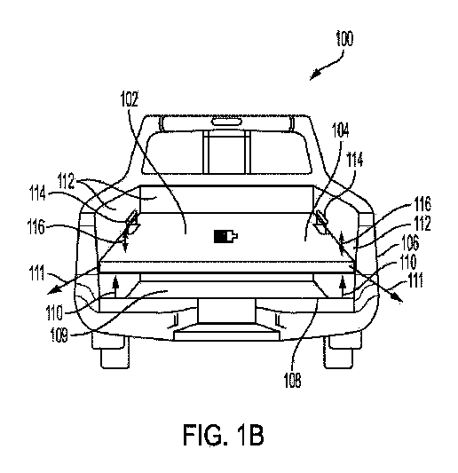
【選択図】図1B
Vehicles and systems for housing a modular power supply. The vehicle may include a power supply that is removable from the vehicle. The power supply may provide power to the vehicle and to a remote device. The vehicle may further include a cargo bed for storing the power supply. The cargo bed or a portion of the cargo bed may be detached from the remainder of the vehicle along with the power supply.
[Selected Figure] Figure 1B
Description
この開示は、車両電源のストレージに関し、特に、車両から取り外し可能な電源のためのモジュール電源及びモジュール保管領域に関する。 This disclosure relates to storage of vehicle power sources, and more particularly to modular power sources and modular storage areas for power sources that are removable from a vehicle.
低燃費車両(例えば、ハイブリッド、プラグインハイブリッド、電気、燃料電池)は、長年にわたって人気を獲得し続けている。車両を推進するために、それらのモータ(例えば、電気モータ、内燃機関)に電力を供給する低燃費車両のバッテリはまた、車両のネイティブコンポーネント(例えば、エアコン、シートヒータ、インフォテインメント手段)及びリモートデバイス(例えば、冷蔵庫、換気装置、ミュージックプレイヤー、スピーカー、外灯、電気コンロ、映写機、スマートフォン等)に電力を供給することもできる。一部のバッテリは、家庭やレクリエーショナルビークル(RV)にも電力を供給することがある。例えばキャンプ、緊急サービスの提供等の、レクリエーションの屋外活動に参加している間、又は、例えば建設現場での作業の間、特に、ピックアップトラック及びトレーラを牽引する車両は、車両バッテリを使用して、送電網から離れたリモートデバイスに電力を供給することができる。車両が1回の完全なバッテリ充電で走行できる範囲を維持又は増大させるために、補足バッテリ又はバックアップバッテリが望ましい場合がある。車載バッテリの使用の汎用性のために、車載バッテリの輸送性及び収納性の改善が望ましい。 Fuel-efficient vehicles (e.g., hybrid, plug-in hybrid, electric, fuel cell) have been gaining popularity for many years. The batteries of fuel-efficient vehicles that power their motors (e.g., electric motors, internal combustion engines) to propel the vehicle can also power the vehicle's native components (e.g., air conditioners, heated seats, infotainment means) and remote devices (e.g., refrigerators, ventilators, music players, speakers, outdoor lights, electric stoves, projectors, smartphones, etc.). Some batteries may also power homes and recreational vehicles (RVs). Pickup trucks and vehicles towing trailers, in particular, can use the vehicle battery to power remote devices off the grid while participating in recreational outdoor activities, such as camping, providing emergency services, or while working, for example, on construction sites. A supplemental or backup battery may be desirable to maintain or increase the range that the vehicle can travel on one full battery charge. Due to the versatility of use of on-board batteries, improvements in the transportability and storage of on-board batteries are desirable.
このように、トラックの荷台又はトレーラに保管可能な電源、並びに、電源を保管するトラックの荷台及びトレーラが必要とされている。 Thus, there is a need for a power source that can be stored in a truck bed or trailer, as well as truck beds and trailers for storing power sources.
本明細書に記載する例は、モジュール電源ストレージのための車両及びシステムに関する。車両は、車両から取り外し可能な電源を含んでよい。電源は、車両及びリモートデバイスに電力を供給してもよい。車両は、電源を保管する荷台をさらに含んでよい。電源は、荷台の一部又は複数の部分と一体化されてよい。荷台又は荷台の少なくとも一部は、電源と共に車両の残りの部分から取り外し可能であってもよい。代わりに又は加えて、電源は、荷台から取り外し可能であってもよい。 Examples described herein relate to vehicles and systems for modular power storage. The vehicle may include a power source removable from the vehicle. The power source may provide power to the vehicle and to a remote device. The vehicle may further include a cargo bed for storing the power source. The power source may be integrated with a portion or portions of the cargo bed. The cargo bed or at least a portion of the cargo bed may be removable from the remainder of the vehicle along with the power source. Alternatively or in addition, the power source may be removable from the cargo bed.
一態様では、本開示は、車両において具現化される。車両は、電源を含む。電源は、車両から取り外し可能であり、車両及びリモートデバイスに電力を供給する。車両はさらに、荷台を含む。荷台は電源を保管する。 In one aspect, the disclosure is embodied in a vehicle. The vehicle includes a power source. The power source is removable from the vehicle and provides power to the vehicle and the remote device. The vehicle further includes a cargo bed. The cargo bed stores the power source.
これら及び他の実施形態は、任意に、以下の特徴のうち一以上を含んでもよい。荷台は床部を含んでよい。床部は車両から取り外し可能である。電源は床部と一体化されていてよい。代替的に、床部は、下方から電源を支持してよく、荷台は、さらに、電源を上方から覆う仮床部を含んでよい。電源は、上方に、又は、互いに隣接するように積まれた複数のモジュールバッテリであってよい。 These and other embodiments may optionally include one or more of the following features: The cargo bed may include a floor. The floor is removable from the vehicle. The power source may be integrated with the floor. Alternatively, the floor may support the power source from below, and the cargo bed may further include a temporary floor covering the power source from above. The power source may be multiple modular batteries stacked above or adjacent to each other.
車両は、キャビンをさらに含んでもよい。キャビンは人を収容してよい。荷台は、キャビンに取り外し可能に取り付けられてよい。荷台は、荷台がキャビンから取り外された場合に、荷台を所望の場所に牽引するために、地表を回転する一以上の車輪に結合されてよい。 The vehicle may further include a cabin. The cabin may accommodate a person. The cargo bed may be removably attached to the cabin. The cargo bed may be coupled to one or more wheels that rotate on a surface to tow the cargo bed to a desired location when the cargo bed is detached from the cabin.
荷台は、荷台の全部又は一部を覆い、取り外し可能な筐体を含んでよい。電源は、筐体と一体化されていてよい。荷台は、後尾扉を含んでよい。あるいは、電源は、後尾扉と一体化されていてよい。 The carrier may include a removable housing that covers all or a portion of the carrier. The power source may be integral with the housing. The carrier may include a tailgate. Alternatively, the power source may be integral with the tailgate.
別の態様では、本開示は、システムにおいて具現化される。このシステムは、車両を含む。システムは、電源をさらに含む。電源は車両とリモートデバイスに電力を供給する。システムは、トレーラをさらに含む。トレーラは、車両に取り外し可能に結合され、電源を保管する。 In another aspect, the disclosure is embodied in a system. The system includes a vehicle. The system further includes a power source. The power source provides power to the vehicle and the remote device. The system further includes a trailer. The trailer is removably coupled to the vehicle and stores the power source.
これら及び他の実施形態は、任意に、以下の特徴のうち一以上を含んでもよい。トレーラは床部を含んでよい。床部は、トレーラの残りの部分から取り外し可能であってよい。電源は床部と一体化されていてよい。代替的に、床部は、電源を下方から支持してもよい。トレーラは、さらに、電源を上から覆う仮床部を含んでよい。電源は、上方に、又は、互いに隣接するように積まれた複数のモジュールバッテリであってよい。 These and other embodiments may optionally include one or more of the following features: The trailer may include a floor. The floor may be removable from the remainder of the trailer. The power source may be integrated with the floor. Alternatively, the floor may support the power source from below. The trailer may further include a false floor that covers the power source from above. The power source may be multiple modular batteries stacked above or adjacent to each other.
トレーラは、トレーラが車両から取り外された場合に、トレーラを所望の場所まで牽引するために、地表を回転する一以上の車輪に結合されてよい。トレーラは、トレーラを覆う取り外し可能な筐体を含んでよい。電源は、筐体と一体化されていてよい。トレーラは、後尾扉を含んでいてよい。あるいは、電源は、後尾扉と一体化されていてよい。 The trailer may be coupled to one or more wheels that rotate over a surface to tow the trailer to a desired location when the trailer is detached from the vehicle. The trailer may include a removable housing that encases the trailer. A power source may be integrated with the housing. The trailer may include a tailgate. Alternatively, the power source may be integrated with the tailgate.
さらに別の態様では、本開示は、車両において具現化される。車両はフレームを含む。車両はさらにキャビンを含む。キャビンはフレームに結合され、人を収容する。車両はさらに、荷台を含む。荷台は、フレームに取り外し可能に取り付けられる少なくとも一部を有する。車両は、電源をさらに含む。電源は、荷台の少なくとも一部に結合され、車両とリモートデバイスに電力を供給する。 In yet another aspect, the disclosure is embodied in a vehicle. The vehicle includes a frame. The vehicle further includes a cabin. The cabin is coupled to the frame and accommodates a person. The vehicle further includes a cargo bed. The cargo bed has at least a portion removably attached to the frame. The vehicle further includes a power source. The power source is coupled to at least a portion of the cargo bed and provides power to the vehicle and the remote device.
これら及び他の実施形態は、任意に、以下の特徴のうち一以上を含んでもよい。上記少なくとも一部は、荷台の床部であってよい。電源は床部と一体化されていてよい。代替的に、床部は、電源を下方から支持してもよい。荷台は、さらに、電源を上方から覆う仮床部を含んでよい。電源は、上方に、又は、互いに隣接するように積まれた複数のモジュールバッテリであってよい。荷台の少なくとも一部は、該少なくとも一部がフレームから取り外された場合に、電源を所望の場所に牽引するために、地表を回転する一以上の車輪に結合されてよい。 These and other embodiments may optionally include one or more of the following features: The at least a portion may be a floor of the platform. The power source may be integrated with the floor. Alternatively, the floor may support the power source from below. The platform may further include a temporary floor covering the power source from above. The power source may be a number of modular batteries stacked above or adjacent to each other. At least a portion of the platform may be coupled to one or more wheels that rotate on a surface to tow the power source to a desired location when the at least a portion of the platform is detached from the frame.
本発明の他のシステム、方法、特徴及び利点は、以下の図及び詳細な説明を検討すれば、当業者には明らかであろう。図面に示される構成部品は、必ずしも原寸に比例しておらず、本発明の重要な特徴をより良く説明するために誇張されている場合がある。 Other systems, methods, features, and advantages of the present invention will be apparent to one of ordinary skill in the art upon examination of the following figures and detailed description. Components illustrated in the drawings are not necessarily to scale and may be exaggerated to better illustrate the important features of the present invention.
本明細書に記載する車両及びシステムは、モジュール電源保管を可能にする。車両は、当該車両から取り外し可能な電源を含んでよい。電源は、バッテリ又は燃料電池であってよい。電源は、車両(例えば、電気モータ、インフォテインメントシステム、空調等)及びリモートデバイス(例えば、電子デバイス、キャンピング機器、家庭等)に電力を供給してよい。車両は、さらに、電源を保管する荷台含んでよい、及び/又は、電源を保管するトレーラを牽引してよい。電源は、荷台及び/又はトレーラの一部又は複数の部分(例えば、床部、筐体、後尾扉等)と一体化されてよい。荷台及び/若しくはトレーラ、又は、荷台及び/若しくはトレーラの少なくとも一部は、電源と共に車両から都合よく取り外されてよい。これに代えて、又はこれに加えて、電源は、荷台及び/又はトレーラから都合よく取り外されてよい。電源は、その後、仮に電源が車両に固定されていれば到達することが困難なリモートデバイスに給電するために、所望の又は都合のよい場所に運搬されてよい。「運転者」又は「利用者」という用語は、自律型又は半自律型の車両を指す場合、「乗客」と相互交換することができる。本明細書で論じられる結合、分離、取り付け、取り外し、及び/又は、同様のものは、手作業で、及び/又は、自動的(例えば、ばね、モータ等)に実施されてよい。ここで論ずる結合又は取り付けの操作の逆の順序に従って、分離又は取り外しが説明されてよく、その逆も同様である。 The vehicles and systems described herein enable modular power storage. The vehicle may include a power source that is removable from the vehicle. The power source may be a battery or a fuel cell. The power source may power the vehicle (e.g., electric motor, infotainment system, air conditioning, etc.) and remote devices (e.g., electronic devices, camping equipment, home, etc.). The vehicle may further include a bed in which the power source is stored and/or may tow a trailer in which the power source is stored. The power source may be integrated with a portion or portions of the bed and/or trailer (e.g., floor, enclosure, tailgate, etc.). The bed and/or trailer, or at least a portion of the bed and/or trailer, may be conveniently removed from the vehicle along with the power source. Alternatively or additionally, the power source may be conveniently removed from the bed and/or trailer. The power source may then be transported to a desired or convenient location to power remote devices that would be difficult to reach if the power source were fixed to the vehicle. The terms "driver" or "user" may be used interchangeably with "passenger" when referring to an autonomous or semi-autonomous vehicle. Coupling, decoupling, attachment, decoupling, and/or the like discussed herein may be performed manually and/or automatically (e.g., springs, motors, etc.). Decoupling or decoupling may be described by following the reverse order of the coupling or attachment operations discussed herein, and vice versa.
図1Aは、荷台106の取り外し可能な床部104と一体化された電源102を有する車両100の背面図を示している。車両100は、一以上の人を運搬するように構成された容器であってよい。車両100は、トラックであってよく、より具体的には、ピックアップトラックであってよい。車両100は、電源102が単一のバッテリ(又は複数のバッテリ)である電気車両であってよい。車両100は、完全に電気式であってもよく、車両100を前方に推進するために電気モータだけに依存してよい。別の例では、車両100は、内燃機関と電気モータとを組み合わせて車両100を前方に推進させる、ハイブリッド車両又はプラグインハイブリッド車両のような部分的電気自動車であってよい。このような実施例では、電源102は部分的にバッテリであってもよい。さらに別の例では、車両100は、電気モータが電気を取り出すための電源102としての、独立型の燃料電池を有する、又は、燃料電池及びバッテリを有する水素燃料電池車両であってよい。 1A shows a rear view of a vehicle 100 having a power source 102 integrated with a removable floor 104 of a cargo bed 106. The vehicle 100 may be a container configured to transport one or more people. The vehicle 100 may be a truck, and more specifically, a pickup truck. The vehicle 100 may be an electric vehicle in which the power source 102 is a single battery (or multiple batteries). The vehicle 100 may be fully electric and rely solely on an electric motor to propel the vehicle 100 forward. In another example, the vehicle 100 may be a partially electric vehicle, such as a hybrid vehicle or a plug-in hybrid vehicle, that combines an internal combustion engine and an electric motor to propel the vehicle 100 forward. In such an example, the power source 102 may be partially a battery. In yet another example, the vehicle 100 may be a hydrogen fuel cell vehicle with a stand-alone fuel cell or with a fuel cell and a battery as the power source 102 for the electric motor to derive electricity.
図1Aにおいて、電源102は、一例としてバッテリである。バッテリは、互いに接続されるとともに電気モータに接続された、電気モータに電力を供給するための一以上のバッテリであってよい。また、バッテリは、車両100に関連付けられる、又は、車両100から離れた、他の電装部品に電力を供給してよい。例えば、電装部品は、エアコンディショナ、シートヒータ、インフォティメントユニット、電話機、冷蔵庫、換気装置、充電中の電子機器、ライト、サウンドシステム、ウィンチ、テレビジョンディスプレイ、ゲームコンソール、等であってよい。 In FIG. 1A, the power source 102 is, by way of example, a battery. The battery may be one or more batteries connected together and to an electric motor to power the electric motor. The battery may also power other electrical components associated with the vehicle 100 or remote from the vehicle 100. For example, the electrical components may be an air conditioner, seat heaters, an infotainment unit, a telephone, a refrigerator, a ventilator, electronic devices being charged, lights, a sound system, a winch, a television display, a game console, etc.
バッテリは、任意の種類のバッテリ、例えば、リチウムイオンバッテリであってよい。ガソリンスタンドで車両に給油するのと同様に、バッテリは、バッテリ充電消費量に基づいて、必要に応じて、充電ステーションでの充電を要求してよい。充電ステーションは、ガソリンスタンドに似た所望の充電ステーションであってよく、又は、自宅のガレージ、公共若しくは私有の駐車ガレージ、駐車場等に配置されてもよい。 The battery may be any type of battery, for example a lithium ion battery. Similar to refueling a vehicle at a gas station, the battery may request charging at a charging station as needed based on battery charge consumption. The charging station may be a desired charging station similar to a gas station, or may be located in a home garage, a public or private parking garage, a parking lot, etc.
電源102又はバッテリは、荷台106の床部104と一体化されていてよい。電源102は、床部104によって完全に又は部分的に囲まれ又は包まれてよく、或いは、床部104の一部又は全体を形成してもよい。重量のある建設工具が荷台106内に投げかけられるときのように、電源102を、その上方から及ぶ物理的衝撃から保護する単一の物質又は複数の物質から床部104は作られていてよい例えば、床部104は、アルミニウム単独であってもよく、又は、付加的な保護及びグリップを提供するライナ材料(例えば、ビニルポリマ)によって被覆されてもよい。 The power source 102 or battery may be integrated into the floor 104 of the loading platform 106. The power source 102 may be completely or partially surrounded or encased by the floor 104, or may form part or all of the floor 104. The floor 104 may be made of a material or materials that protect the power source 102 from physical shocks from above, such as when a heavy construction tool is thrown into the loading platform 106. For example, the floor 104 may be aluminum alone, or may be covered with a liner material (e.g., vinyl polymer) that provides additional protection and grip.
床部104は、荷台106の下に延在する凹部又は空洞108内に挿入して載置されてよい。凹部108は、図1Aに破線によって示される。凹部108は、床部104を下方から支持するベース109を有してよい。いくつかの実施形態では、凹部108は、床部104を下方から支持する荷台106の2つ以上の側壁112に取り付けられたマウント部品を有してよい。凹部108内ではあるが、電源102は、車両100の電気モータ及びネイティブ電気装置と同様に、車両100の電気回路に電気的に結合された補助装置に電気的に結合されてよい。電気接続は、床部104が凹部108内に挿入されるとき、凹部108内に隠すことができる。このように、電源102を完全に隠すことができ、床部104はトラックの荷台の従来の床部の外観を有してよい。床部104は、従来の締結具(例えば、クリップ、フック、アンカー、ネジ等)で荷台106に締結され、床部104が動き回り、特に車両100が走行中の場合、電源102が電気モータ及び車両100の電気回路から切り離されるのを防止することができる。荷台106の後尾扉は、明確さのために、図1A乃至1Bでは省略されている。 The floor 104 may be inserted and placed in a recess or cavity 108 extending under the bed 106. The recess 108 is shown by a dashed line in FIG. 1A. The recess 108 may have a base 109 that supports the floor 104 from below. In some embodiments, the recess 108 may have mounting parts attached to two or more side walls 112 of the bed 106 that support the floor 104 from below. While in the recess 108, the power source 102 may be electrically coupled to auxiliary devices that are electrically coupled to the electrical circuit of the vehicle 100, as well as the electric motor and native electrical devices of the vehicle 100. The electrical connections may be hidden in the recess 108 when the floor 104 is inserted into the recess 108. In this way, the power source 102 may be completely hidden and the floor 104 may have the appearance of a conventional floor of a truck bed. The floor 104 is fastened to the cargo bed 106 with conventional fasteners (e.g., clips, hooks, anchors, screws, etc.) to prevent the floor 104 from moving around and disconnecting the power source 102 from the electric motor and the electrical circuitry of the vehicle 100, especially when the vehicle 100 is moving. The tailgate of the cargo bed 106 is omitted from FIGS. 1A-1B for clarity.
図1Bは、荷台106の、取り外される床部104と一体化された電源102を伴う車両100の背面図を示している。電源102は、床部104と一緒に、矢印110の方向に凹部108から持ち上げられ、取り外されてよい。次に、電源102は、矢印111の方向に荷台106から取り外されてよい。床部104は、取付け及び取外しの間、床部104をつかむための一以上のグリップ114を有してもよい。グリップ114は、伸縮式又は格納式であってよく、矢印116の方向に移動してもよい。そのように、グリップ114は、使用しないときに隠されてよい。いくつかの実施形態では、グリップ114は、床部104上の、一以上の指又は取り外し工具を挿入可能な一以上の空洞であってよい。グリップ114は、滑りを低減又は防止するために、従来の把持物質(例えば、合成皮革、シリコーン系、ニトリル等)で被覆されてもよい。グリップ114は、互いの反対側に位置していてもよい。グリップ114は、一個人が電源102を車両100から取り外すことを可能にするために、おおよそ成人の平均的な翼幅以下の長さだけ互いに離れていてもよい。 FIG. 1B shows a rear view of the vehicle 100 with the power source 102 integrated with the floor 104 of the loading platform 106 to be removed. The power source 102, together with the floor 104, may be lifted from the recess 108 in the direction of arrow 110 and removed. The power source 102 may then be removed from the loading platform 106 in the direction of arrow 111. The floor 104 may have one or more grips 114 for gripping the floor 104 during installation and removal. The grips 114 may be extendable or retractable and may move in the direction of arrow 116. As such, the grips 114 may be hidden when not in use. In some embodiments, the grips 114 may be one or more cavities on the floor 104 into which one or more fingers or a removal tool can be inserted. The grips 114 may be coated with a conventional gripping material (e.g., synthetic leather, silicone, nitrile, etc.) to reduce or prevent slippage. The grips 114 may be located opposite each other. The grips 114 may be spaced apart by a distance equal to or less than the average wingspan of an adult human to allow an individual to remove the power source 102 from the vehicle 100.
車両100から取り外されると、電源102は、車両100から離れた場所に運搬されてよく、リモートデバイス118a~c(図2参照)に必要に応じて電力を供給するように配置されてよい。電源102は、輸送中にグリップ114から保持されてもよい。いくつかの実施形態において、電源102は、巻き取りバックパック又はクーラのように、電源102を地表上で転がすための、一以上の車輪、及び、伸縮式であってよいハンドルを有してよい。 Once removed from the vehicle 100, the power source 102 may be transported away from the vehicle 100 and positioned to provide power as needed to the remote devices 118a-c (see FIG. 2). The power source 102 may be held from the grip 114 during transport. In some embodiments, the power source 102 may have one or more wheels and a handle, which may be extendable, for rolling the power source 102 over a surface, such as a roll-up backpack or cooler.
図2は、リモートデバイス118a~cに結合される電源102の概略図を示す。リモートデバイス118aは電動キャンピングギアであり(図2には、例示的なランタンが示されている)、リモートデバイス118bは家庭の回路システムであり、リモートデバイス118cは例としてスマートフォンである。リモートデバイス118a~cは、車両100がアクセスできない場所に配置されてよく、若しくは、配置される必要があり、又は、電源102とリモートデバイス118a~cとの間の電気的接続を可能にするために近接した場所に配置される。電源102が車両100から取り外された場合、電源102は、電源102とリモートデバイス118a~cのうちの一以上との間の電気的接続が確立され得るように、ある場所まで運搬され、配置されてもよい。次に、電源102は、リモートデバイス118a~cのうちの1つ、いくつか、又は、全てに電力を供給してよい。 Figure 2 shows a schematic diagram of the power source 102 coupled to the remote devices 118a-c. The remote device 118a is an electric camping gear (an exemplary lantern is shown in Figure 2), the remote device 118b is a home circuit system, and the remote device 118c is, for example, a smartphone. The remote devices 118a-c may be or must be located in a location inaccessible to the vehicle 100, or in close proximity to allow electrical connection between the power source 102 and the remote devices 118a-c. When the power source 102 is removed from the vehicle 100, the power source 102 may be transported to a location and placed such that an electrical connection between the power source 102 and one or more of the remote devices 118a-c can be established. The power source 102 may then provide power to one, some, or all of the remote devices 118a-c.
図3Aは、荷台206の仮床部204の下に取り外し可能な電源202を有する車両200の背面図を示している。車両200は、荷台206の仮床部の下に格納されている電源202を除いて、車両100(図1A~1B参照)の仕様の一部又は全部を有していてもよい。電源202は、電源102の物理的構造を除いて、電源102の仕様の一部又は全部を有していてもよい。 FIG. 3A shows a rear view of a vehicle 200 with a removable power source 202 located under the false floor 204 of the loading platform 206. The vehicle 200 may have some or all of the specifications of the vehicle 100 (see FIGS. 1A-1B), except for the power source 202 being stored under the false floor of the loading platform 206. The power source 202 may have some or all of the specifications of the power source 102, except for the physical structure of the power source 102.
電源202は、荷台206の床部208によって下方から支持されてよい。床部208は、車両200の後部バンパ212の上縁部210と水平で、これより上又はこれより下であってよい。後部バンパ212の上縁部210に対して低い床部208は、電源202が隠蔽されるのに利用可能なスペースを増やすことができる。その結果、荷台206によって提供される貨物スペースは、増加してよい。 The power source 202 may be supported from below by a floor 208 of the loading platform 206. The floor 208 may be level with, above or below the upper edge 210 of the rear bumper 212 of the vehicle 200. A floor 208 that is lower relative to the upper edge 210 of the rear bumper 212 may increase the space available for the power source 202 to be concealed. As a result, the cargo space provided by the loading platform 206 may be increased.
電源202は、仮床部204によって上方から全体的又は部分的に覆われてもよい。仮床部204は、従来のトラックの荷台の床の外観を有してもよい。仮床部204は、上方から加わる物理的衝撃から電源202を保護する単一の物質又は複数の物質から作られてよい。例えば、仮床部204は、アルミニウム単独であってもよく、又は、付加的な保護及びグリップを提供するライナ材料(例えば、ビニールポリマ)によって被覆されてもよい。 The power source 202 may be fully or partially covered from above by a temporary floor 204. The temporary floor 204 may have the appearance of a conventional truck bed floor. The temporary floor 204 may be made of a single material or multiple materials that protect the power source 202 from physical impacts from above. For example, the temporary floor 204 may be aluminum alone or may be covered with a liner material (e.g., vinyl polymer) that provides additional protection and grip.
仮床部204と床部208との間に挟まれている間、電源202は、車両200の電気モータ及びネイティブ電気装置と同様に、車両200の電気回路に電気的に結合された補助装置に電気的に結合されてよい。電気的接続は、電源202と荷台206との間に隠されてよい。 While sandwiched between the false floor 204 and the floor 208, the power source 202 may be electrically coupled to the electric motors and native electrical equipment of the vehicle 200 as well as auxiliary equipment electrically coupled to the electrical circuitry of the vehicle 200. The electrical connections may be concealed between the power source 202 and the cargo bed 206.
特に車両200が動いている場合に、電源202が、電気モータ及び車両200の電気回路の周りを動いたり、切り離されたりすることを防ぐために、仮床部204は、従来の留め具(例えば、軌道、クリップ、フック、アンカー、ネジ等)で荷台206に留められてよい。後尾扉が下位置にある場合、又は、利用されていない場合、電源202が荷台206から滑り出るのを防止するために、車両200はカバーを含んでよい。カバーは、仮床部204及び/又は床部208に取り付けられてよく、仮床部204と床部208との間の空間を覆ってよい。いくつかの実施形態では、仮床部204及び/又は床部208は、電源202を所定の位置に保持するように電源202の近位側面213の上に延在する部位を有してもよい。いくつかの実施形態では、仮床部204及び/又は床部208は、電源202を所定の位置に保持するために、電源202上の雌部品に連結されてよい雄部品を有してもよく、又はその逆でもよい。 The temporary floor 204 may be fastened to the loading platform 206 with conventional fasteners (e.g., tracks, clips, hooks, anchors, screws, etc.) to prevent the power source 202 from moving around or becoming disconnected from the electric motor and the electrical circuitry of the vehicle 200, especially when the vehicle 200 is moving. The vehicle 200 may include a cover to prevent the power source 202 from sliding out of the loading platform 206 when the tailgate is in the down position or is not in use. The cover may be attached to the temporary floor 204 and/or the floor 208 and may cover the space between the temporary floor 204 and the floor 208. In some embodiments, the temporary floor 204 and/or the floor 208 may have a portion that extends over the proximal side 213 of the power source 202 to hold the power source 202 in place. In some embodiments, the false floor 204 and/or floor 208 may have male components that may be coupled to female components on the power source 202 to hold the power source 202 in place, or vice versa.
電源202は、電源202を車両200から取り外すための一以上のグリップ214を有してよい。一以上のグリップ214は、図1A~1Bに示されるグリップ114と構造及び機能が同様であってよい。電源202を取り外す前に仮床部204を取り外す実施形態では、仮床部204も、取り外し中に仮床部204を保持するための一以上のグリップを有してよい。 The power source 202 may have one or more grips 214 for removing the power source 202 from the vehicle 200. The one or more grips 214 may be similar in structure and function to the grips 114 shown in FIGS. 1A-1B. In embodiments in which the temporary floor 204 is removed prior to removing the power source 202, the temporary floor 204 may also have one or more grips for holding the temporary floor 204 during removal.
図3Bは、電源202が取り外された状態の車両200の背面図を示す。電源202は、荷台206から矢印211の方向に取り外されてよい。床部208(図3A参照)が後部バンパ212(図3A参照)の上縁210(図3A参照)に対して下側にある実施形態では、電源202は、矢印211の方向に取り外される前に、後部バンパ212の上縁210から離れるように持ち上げられてよい。いくつかの実施形態において、仮床部204は、矢印211の方向に荷台206から取り外すか、又は、電源202を持ち上げる前に持ち上げられてよい。 3B shows a rear view of the vehicle 200 with the power source 202 removed. The power source 202 may be removed from the cargo bed 206 in the direction of arrow 211. In embodiments where the floor 208 (see FIG. 3A) is below the upper edge 210 (see FIG. 3A) of the rear bumper 212 (see FIG. 3A), the power source 202 may be lifted away from the upper edge 210 of the rear bumper 212 before being removed in the direction of arrow 211. In some embodiments, the temporary floor 204 may be lifted before removing the power source 202 from the cargo bed 206 in the direction of arrow 211 or lifting the power source 202.
車両200から取り外されると、電源202は、車両200から離れた場所に運ばれてよく、リモートデバイス118a~c(図2参照)に電力を供給するように希望に応じて配置されてよい。電源202は、輸送中にグリップ214から保持されてもよい。いくつかの実施形態において、電源202は、巻き取りバックパック又はクーラのように、電源202を地表上で転がすための、一以上の車輪、及び、伸縮式であってよいハンドルを有してよい。 Once removed from the vehicle 200, the power source 202 may be transported away from the vehicle 200 and deployed as desired to provide power to remote devices 118a-c (see FIG. 2). The power source 202 may be held from the grip 214 during transport. In some embodiments, the power source 202 may have one or more wheels and a handle, which may be extendable, for rolling the power source 202 over a surface, such as a roll-up backpack or cooler.
図4Aは、荷台206の仮床部204の下に、互いに隣接するように積まれた複数の電源202を有する車両200の背面図を示す。2つの電源202は単なる例として図4Aに示されており、他の実施形態では2つよりも多い電源202が存在していてよい。複数の電源202を有することは、電源202のうちの1つが消耗されたり、誤動作したり、損傷したり、すでに使用されている場合に、バックアップ電源を提供することができる。さらに、複数の電源202を有することにより、単一の電源202(図3A~3B参照)に対してバッテリ容量を増加させることができる。加えて、複数の電源202は、重量及び/又はサイズが低減されることによって、複数の電源202の組合せ寸法と同等の寸法を有する単一の電源202よりも取り外し及び運搬が容易になってよい。各電源202は、取り付け及び取り外し手順の間保持される一以上のハンドル214を有してよい。 4A shows a rear view of a vehicle 200 with multiple power sources 202 stacked adjacent to each other under a false floor 204 of a loading platform 206. Two power sources 202 are shown in FIG. 4A by way of example only, and there may be more than two power sources 202 in other embodiments. Having multiple power sources 202 may provide backup power in case one of the power sources 202 is depleted, malfunctions, is damaged, or has already been used. Furthermore, having multiple power sources 202 may increase battery capacity relative to a single power source 202 (see FIGS. 3A-3B). Additionally, multiple power sources 202 may be easier to remove and transport than a single power source 202 having dimensions comparable to the combined dimensions of the multiple power sources 202 due to reduced weight and/or size. Each power source 202 may have one or more handles 214 to be held during installation and removal procedures.
複数の電源202は、仮床部204と床部208との間に挿入された場合に、それらが互いに隣り合って面一になるように成形されてもよい。複数の電源202は、追加のセキュリティのために、さらに車両200が動いているときに動かないようにするために、互いに連結されてよい。例えば、1つの電源202は雄部を有してよく、隣接する電源202は雌部を有してよく、2つの電源202を互いに結合するために雄部は雌部を保持する。 The multiple power sources 202 may be molded so that they are flush next to each other when inserted between the false floor 204 and the floor 208. The multiple power sources 202 may be coupled together for added security and to prevent movement when the vehicle 200 is in motion. For example, one power source 202 may have a male portion and an adjacent power source 202 may have a female portion, with the male portion holding the female portion to couple the two power sources 202 together.
図4Bは、荷台206の仮床部204の下に、互いの上に積み重ねられた複数の電源202を有する車両200の背面図を示す。2つの電源202は単なる例として図4Bに示されており、他の実施形態では、2つよりも多い電源202が存在してよい。いくつかの実施形態では、複数の電源202は、互いの上に積み重ねられ、互いに隣接して積まれてもよい。各電源202は、取り付け及び取り外し手順の間保持される一以上のハンドル214を有してよい。 FIG. 4B shows a rear view of the vehicle 200 with multiple power sources 202 stacked on top of each other under the false floor 204 of the loading platform 206. Two power sources 202 are shown in FIG. 4B by way of example only, and in other embodiments, there may be more than two power sources 202. In some embodiments, multiple power sources 202 may be stacked on top of each other and stacked adjacent to each other. Each power source 202 may have one or more handles 214 that are held during installation and removal procedures.
複数の電源202は、仮床部204と床部208との間に積み重ねられ、且つ、挿入された場合に、それらが互いに面一になるように成形されてもよい。電源202は、追加のセキュリティのために、さらに車両200が動いているときに動かないようにするために、互いに連結されてよい。例えば、1つの電源202は雄部を有してよく、隣接する電源202は雌部を有してよく、2つの電源202を互いに結合するために雄部は雌部を保持する。 Multiple power sources 202 may be stacked between the false floor 204 and the floor 208 and molded so that they are flush with each other when inserted. The power sources 202 may be coupled together for added security and to prevent movement when the vehicle 200 is in motion. For example, one power source 202 may have a male portion and an adjacent power source 202 may have a female portion, with the male portion holding the female portion to couple the two power sources 202 together.
図5は、荷台306の取り外し可能な筐体304と一体化された電源302を有する車両300の背面図を示している。車両300は、荷台306の仮床部の下に格納されている電源302を除いて、車両100(図1A~1B参照)の仕様の一部又は全部を有していてもよい。電源302は、電源102の物理的構造を除いて、電源102の仕様の一部又は全部を有していてもよい。 FIG. 5 shows a rear view of a vehicle 300 with a power source 302 integrated into a removable housing 304 of a loading platform 306. The vehicle 300 may have some or all of the specifications of the vehicle 100 (see FIGS. 1A-1B), except for the power source 302, which is stored under the false floor of the loading platform 306. The power source 302 may have some or all of the specifications of the power source 102, except for the physical structure of the power source 102.
電源302又はバッテリは、荷台306の筐体304と一体化されていてよい。電源302は、筐体304によって完全に又は部分的に囲まれてよい、又は、筐体304の一部又は全体を形成してよい。筐体304は、電源302を物理的衝撃から保護する物質又は複数の物質から作られてよい。例えば、筐体304は、アルミニウム単独であってもよく、又は、付加的な保護及びグリップを提供するライナ材料(例えば、ビニルポリマ)で被覆されてもよい。 The power source 302 or battery may be integrated into the housing 304 of the loading platform 306. The power source 302 may be completely or partially enclosed by the housing 304, or may form part or all of the housing 304. The housing 304 may be made from a material or materials that protect the power source 302 from physical impact. For example, the housing 304 may be aluminum alone, or may be coated with a liner material (e.g., vinyl polymer) that provides additional protection and grip.
筐体304は、従来の荷台筐体のように機能してよい。筐体304は、一以上の側面から荷台306及び/又は後尾扉308に連結されてよい。筐体304の下にアクセスするために、筐体304は、結合点から上下にヒンジで開閉してよい。いくつかの実施態様では、筐体304は、夫々、荷台306に取り付けられ、荷台306から取り外される、荷台306上の複数の軌道に滑り込み、滑り出てよい。いくつかの実施形態では、筐体304の付加的なセキュリティ、及び、筐体304の移動を最小限又はなくすために、後尾扉308は、筐体304の上に延在し、及び/又は、筐体304に結合されてよい。このような実施形態では、荷台306から筐体304が取り外される前に、後尾扉308を開ける必要があるかもしれない。筐体304が荷台306に連結されている間、電源302は、車両300の電気モータ及びネイティブ電気装置と同様に、車両300の電気回路に電気的に結合された補助装置に電気的に結合されてよい。電気接続は、筐体304の下に隠されてよい。このように、電源302を完全に隠されてよく、筐体304はトラックの従来の荷台筐体の外観を有してよい。 The housing 304 may function like a conventional cargo bed housing. The housing 304 may be connected to the cargo bed 306 and/or the tailgate 308 from one or more sides. To access underneath the housing 304, the housing 304 may hinge up and down from a connection point. In some implementations, the housing 304 may slide in and out of a number of tracks on the cargo bed 306, which are attached to and removed from the cargo bed 306, respectively. In some embodiments, the tailgate 308 may extend above and/or be connected to the housing 304 for added security of the housing 304 and to minimize or eliminate movement of the housing 304. In such an embodiment, it may be necessary to open the tailgate 308 before the housing 304 is removed from the cargo bed 306. While the housing 304 is coupled to the bed 306, the power source 302 may be electrically coupled to the electric motors and native electrical equipment of the vehicle 300, as well as auxiliary equipment electrically coupled to the electrical circuitry of the vehicle 300. The electrical connections may be hidden under the housing 304. In this manner, the power source 302 may be completely hidden and the housing 304 may have the appearance of a conventional bed housing for a truck.
筐体304は、車両300から筐体、即ち、電源302を取り外すために、一以上のグリップ314を有してよい。一以上のグリップ314は、図1A~1Bに示されるグリップ114と構造及び機能において同様であってよい。 The housing 304 may have one or more grips 314 for removing the housing, and therefore the power source 302, from the vehicle 300. The one or more grips 314 may be similar in structure and function to the grip 114 shown in FIGS. 1A-1B.
図6は、後尾扉404と一体化された、取り外し可能な電源402を有する車両400の背面図を例示している。車両400は、荷台406の仮床部の下に格納されている電源402を除いて、車両100(図1A~1B参照)の仕様の一部又は全部を有してよい。電源402は、電源102の物理的構造を除いて、電源102(図1A~1B参照)の仕様の一部又は全部を有してよい。 FIG. 6 illustrates a rear view of a vehicle 400 having a removable power source 402 integrated into a tailgate 404. The vehicle 400 may have some or all of the specifications of the vehicle 100 (see FIGS. 1A-1B), except for the power source 402 being stored under a false floor in the loading platform 406. The power source 402 may have some or all of the specifications of the power source 102 (see FIGS. 1A-1B), except for the physical structure of the power source 102.
電源402又はバッテリは、後尾扉404と一体化されていてよい。電源402は、後尾扉404によって完全に若しくは部分的に覆われていてよく、又は、後尾扉404の一部若しくは全体を形成してよい。後尾扉404は、電源402を物理的衝撃から保護する物質又は複数の物質から作られてよい。例えば、後尾扉404は、アルミニウム単独であってもよく、又は、付加的な保護及びグリップを提供するライナ材料(例えば、ビニールポリマ)で被覆されてもよい。 The power source 402 or battery may be integrated with the tailgate 404. The power source 402 may be completely or partially covered by the tailgate 404, or may form part or all of the tailgate 404. The tailgate 404 may be made from a material or materials that protect the power source 402 from physical impact. For example, the tailgate 404 may be solely aluminum or may be coated with a liner material (e.g., vinyl polymer) that provides additional protection and grip.
後尾扉404は、トラック又はSUVの通常の後尾扉のように機能してよい。後尾扉404は、一以上の側面から荷台406に連結されてよい。後尾扉404の背後にアクセスするために、後尾扉404は、結合点から上下又は左右にヒンジで開閉してよい。いくつかの実施態様では、後尾扉404は、夫々、荷台406から取り外され、荷台406に取り付けられる、荷台406上の複数の軌道の内側を上下にスライドされてよい。いくつかの実施形態では、後尾扉404の付加的なセキュリティ、及び、後尾扉404の移動を最小限又はなくすために、荷台406を囲む筐体は、後尾扉404上に延在し、及び/又は、後尾扉404に結合されてよい。このような実施形態では、荷台406から後尾扉404が取り外される前に、筐体を取り外す必要があるかもしれない。後尾扉404が荷台406に連結されている間、電源402は、車両400の電気モータ及びネイティブ電気装置と同様に、車両400の電気回路に電気的に結合された補助装置に電気的に結合されてよい。電気的接続は、後尾扉404の下、又は、後尾扉404と荷台406との間に隠されてよい。このように、電源402は完全に隠されてよく、後尾扉404は従来の後尾扉の外観を有してよい。 The tailgate 404 may function like a normal tailgate on a truck or SUV. The tailgate 404 may be connected to the bed 406 from one or more sides. To access the rear of the tailgate 404, the tailgate 404 may hinge up and down or left and right from a connection point. In some implementations, the tailgate 404 may be slid up and down inside a number of tracks on the bed 406, which are respectively removed from the bed 406 and attached to the bed 406. In some embodiments, for added security of the tailgate 404 and to minimize or eliminate movement of the tailgate 404, a housing surrounding the bed 406 may extend over and/or be connected to the tailgate 404. In such an embodiment, it may be necessary to remove the housing before the tailgate 404 can be removed from the bed 406. While the tailgate 404 is coupled to the cargo bed 406, the power source 402 may be electrically coupled to auxiliary devices electrically coupled to the electrical circuitry of the vehicle 400, as well as the electric motors and native electrical devices of the vehicle 400. The electrical connections may be concealed under the tailgate 404 or between the tailgate 404 and the cargo bed 406. In this manner, the power source 402 may be completely concealed and the tailgate 404 may have the appearance of a conventional tailgate.
後尾扉404は、車両400から後尾扉404、即ち、電源402を取り外すために、一以上のグリップ414を有してよい。一以上のグリップ414は、図1A~1Bに示されるグリップ114と構造及び機能において同様であってよい。一以上のグリップ414は、後尾扉404のいずれかの側部又は両方の側部に位置してよい。図6に例として示される後尾扉404の外側408は、グリップ414を有している。いくつかの実施形態では、後尾扉404が荷台406に取り付けられている場合に、後尾扉404の開閉に用いられる、後尾扉404のハンドル410は、後尾扉404を取り外して運搬する際に後尾扉404の保持に用いられてよい。 The tailgate 404 may have one or more grips 414 for removing the tailgate 404, i.e., the power source 402, from the vehicle 400. The one or more grips 414 may be similar in structure and function to the grip 114 shown in FIGS. 1A-1B. The one or more grips 414 may be located on either or both sides of the tailgate 404. The outer side 408 of the tailgate 404 shown as an example in FIG. 6 has the grip 414. In some embodiments, the handle 410 of the tailgate 404, which is used to open and close the tailgate 404 when the tailgate 404 is attached to the cargo bed 406, may be used to hold the tailgate 404 when removing it and transporting it.
図7は、電源502を格納する取り外し可能な荷台506を有する車両500の側面図を示す。車両500は、車両100(図1A~1B参照)の仕様の一部又は全部を有してよい。電源502は、電源102の物理的構造を除いて、電源102(図1A~1B参照)の仕様の一部又は全部を有してよい。電源502は、荷台506の中又は上に格納されてよい。電源502は、全体的又は部分的に、荷台506によって囲まれてよく、又は、封入されてもよい。電源502は、荷台506と完全に又は部分的に一体化されてよい。荷台506及び/又は電源502の上に配置された筐体は、電源502を物理的衝撃から保護する物質又は複数の物質から作られてよい。特に車両500が動いている場合に、電源502が、電気モータ及び車両500の電気回路の周りを動いたり、切り離されたりすることを防ぐために、電源502は、従来の留め具(例えば、軌道、クリップ、フック、アンカー、ネジ等)を介して荷台506に留められてよい。 FIG. 7 shows a side view of a vehicle 500 having a removable cargo bed 506 that stores a power source 502. The vehicle 500 may have some or all of the specifications of the vehicle 100 (see FIGS. 1A-1B). The power source 502 may have some or all of the specifications of the power source 102 (see FIGS. 1A-1B), except for the physical structure of the power source 102. The power source 502 may be stored in or on the cargo bed 506. The power source 502 may be fully or partially surrounded or encapsulated by the cargo bed 506. The power source 502 may be fully or partially integrated with the cargo bed 506. The cargo bed 506 and/or the housing disposed on the power source 502 may be made of a material or materials that protect the power source 502 from physical impact. To prevent the power source 502 from moving around or becoming disconnected from the electric motor and electrical circuitry of the vehicle 500, especially when the vehicle 500 is in motion, the power source 502 may be fastened to the cargo bed 506 via conventional fasteners (e.g., tracks, clips, hooks, anchors, screws, etc.).
車両500は、キャビン503を有してよい。キャビン503は、運転者及び/又は同乗者である少なくとも一の人物を保持してよい。キャビン503及び荷台506は、個々に又は集合的に車両500のフレーム501に連結されてよい。荷台506は、キャビン503に直接連結されてもよい。荷台506は、従来の留め具(例えば、軌道、クリップ、フック、アンカー、ネジ等)を介してフレーム501及びキャビン503に留められてもよい。荷台506、即ち、電源502は、フレーム501から取り外されてよく、又は、フレーム501及びキャビン503から取り外されてよい。取り外された状態の荷台506を破線504で示す。荷台506は、例えば、フレーム501から矢印505の方向に荷台506を持ち上げることによって取り外されてよい。いくつかの実施形態において、荷台506は、矢印505と交わるキャビン503から離れる方向に荷台を引くことによって取り外されてよい。 The vehicle 500 may have a cabin 503. The cabin 503 may hold at least one person, the driver and/or passenger. The cabin 503 and the cargo bed 506 may be individually or collectively connected to the frame 501 of the vehicle 500. The cargo bed 506 may be directly connected to the cabin 503. The cargo bed 506 may be fastened to the frame 501 and the cabin 503 via conventional fasteners (e.g., tracks, clips, hooks, anchors, screws, etc.). The cargo bed 506, i.e., the power source 502, may be removed from the frame 501 or may be removed from the frame 501 and the cabin 503. The cargo bed 506 in a removed state is shown by dashed lines 504. The cargo bed 506 may be removed, for example, by lifting the cargo bed 506 from the frame 501 in the direction of the arrow 505. In some embodiments, the cargo bed 506 may be removed by pulling the cargo bed in a direction intersecting with arrow 505 and away from the cabin 503.
荷台506がキャビン503に連結されている間、電源502は、車両500の電気モータ及びネイティブ電気装置と同様に、車両500の電気回路に電気的に結合された補助装置に電気的に結合されてよい。電気的接続は、例えば、キャビン503と荷台506との間、又は、車両500の下に隠されてよい。このように、電源502が完全に隠されてよく、荷台503は従来の荷台の外観を有してよい。 While the cargo bed 506 is coupled to the cabin 503, the power source 502 may be electrically coupled to auxiliary devices electrically coupled to the electrical circuitry of the vehicle 500, as well as the electric motors and native electrical devices of the vehicle 500. The electrical connections may be concealed, for example, between the cabin 503 and the cargo bed 506 or underneath the vehicle 500. In this manner, the power source 502 may be completely concealed and the cargo bed 503 may have the appearance of a conventional cargo bed.
車両500から取り外されると、電源荷台506、即ち、電源502は、車両500から離れた場所に運ばれてよく、リモートデバイス118a~c(図2参照)に電力を供給するために希望に応じて配置されてよい。荷台506は、荷台506を損傷することなく、地表上に静止させるために、下から保護層でパッド付け、又はコーティングされてよい。いくつかの実施形態では、荷台506は、荷台506が地表に立つように下方から伸長可能な一以上の脚部を有してよい。輸送中、荷台506は、図1A~1Bに示すグリップ114と構造及び機能において同様の、荷台506上に位置する一以上のグリップから保持されてよい。いくつかの実施形態では、荷台506は、巻き取りバックパック又はクーラのように、荷台506を地表上で転がすための、一以上の車輪、及び、伸縮式であってよいハンドルを有してよい。 Once removed from the vehicle 500, the power supply platform 506, i.e., the power source 502, may be transported away from the vehicle 500 and positioned as desired to provide power to the remote devices 118a-c (see FIG. 2). The platform 506 may be padded or coated with a protective layer from underneath to allow the platform 506 to rest on the ground surface without damage. In some embodiments, the platform 506 may have one or more legs extendable from underneath so that the platform 506 stands on the ground surface. During transportation, the platform 506 may be held from one or more grips located on the platform 506, similar in structure and function to the grips 114 shown in FIGS. 1A-1B. In some embodiments, the platform 506 may have one or more wheels and a handle, which may be extendable, for rolling the platform 506 on the ground surface, like a roll-up backpack or cooler.
図8は、電源602を格納する取り外し可能な荷台606を有する車両600の側面図を示す。車両600は、車両100(図1A~1B参照)の仕様の一部又は全部を有してよい。電源602は、電源102の物理的構造を除いて、電源102(図1A~1B参照)の仕様の一部又は全部を有してよい。電源602は、荷台606の中又は上に格納されてよい。電源602は、全体的又は部分的に、荷台606によって囲まれてよく、又は、封入されてもよい。電源602は、荷台606と完全に又は部分的に一体化されてよい。荷台606及び/又は電源602の上に配置された筐体は、電源602を物理的衝撃から保護する物質又は複数の物質から作られてよい。特に、車両600が動いている場合に、電源602が、電気モータ及び車両600の電気回路の周りを動いたり、切り離されたりすることを防ぐために、電源602は、従来の留め具(例えば、軌道、クリップ、フック、アンカー、ネジ等)を介して荷台606に留められてよい。 FIG. 8 shows a side view of a vehicle 600 having a removable cargo bed 606 that stores a power source 602. The vehicle 600 may have some or all of the specifications of the vehicle 100 (see FIGS. 1A-1B). The power source 602 may have some or all of the specifications of the power source 102 (see FIGS. 1A-1B), except for the physical structure of the power source 102. The power source 602 may be stored in or on the cargo bed 606. The power source 602 may be fully or partially surrounded or encapsulated by the cargo bed 606. The power source 602 may be fully or partially integrated with the cargo bed 606. The cargo bed 606 and/or a housing disposed on the power source 602 may be made of a material or materials that protect the power source 602 from physical impact. In particular, the power source 602 may be secured to the cargo bed 606 via conventional fasteners (e.g., tracks, clips, hooks, anchors, screws, etc.) to prevent the power source 602 from moving around or becoming disconnected from the electric motor and electrical circuitry of the vehicle 600 when the vehicle 600 is in motion.
車両600は、キャビン603を有してよい。キャビン603は、運転者及び/又は同乗者であってよい少なくとも一の人物を保持してよい。キャビン603及び荷台606は、個々に又は集合的に車両600のフレーム601に結合されてよい。荷台606は、キャビン603に直接結合されてもよい。荷台606は、従来の留め具(例えば、軌道、クリップ、フック、アンカー、ネジ等)を介してフレーム601及びキャビン603に留められてもよい。荷台606、即ち、電源602は、フレーム601の分割によってキャビン603から切り離されてよい。キャビン603がフレーム601の第1部分601aにそのまま残り、且つ、荷台606がフレーム601の第2部分602bにそのまま残るように、フレーム601が分割されてよい。車両600の一つの後輪又は複数の後輪608は、第2部分601b、即ち、荷台606にそのまま残ってよい。第1部分601aは、従来の留め具(例えば、軌道、クリップ、フック、アンカー、ネジ等)を介して第2部分601bに留められてよい。切り離された状態の荷台606を破線604で示す。キャビン603が地面に触れることを防ぐために、取り外し前に、脚又はスタンド610が第1部分601aの下に配置されてよい。スタンド610は、車両600に取り付けられてもよく、車両600から離れていてもよい。車両600に取り付けられている場合、スタンド610は、第1部分601aの下から伸縮又は回転降下して、地面に接してよい。荷台606は、矢印612の方向に荷台606が引かれることによって取り外されてよい。取り外し中に荷台606は後輪608上で転がされてよい。 The vehicle 600 may have a cabin 603. The cabin 603 may hold at least one person, which may be a driver and/or a passenger. The cabin 603 and the cargo bed 606 may be coupled individually or collectively to the frame 601 of the vehicle 600. The cargo bed 606 may be coupled directly to the cabin 603. The cargo bed 606 may be fastened to the frame 601 and the cabin 603 via conventional fasteners (e.g., tracks, clips, hooks, anchors, screws, etc.). The cargo bed 606, i.e., the power source 602, may be separated from the cabin 603 by splitting the frame 601. The frame 601 may be split so that the cabin 603 remains intact on the first portion 601a of the frame 601 and the cargo bed 606 remains intact on the second portion 602b of the frame 601. The rear wheel or wheels 608 of the vehicle 600 may remain on the second portion 601b, i.e., the loading platform 606. The first portion 601a may be fastened to the second portion 601b via conventional fasteners (e.g., tracks, clips, hooks, anchors, screws, etc.). The loading platform 606 in a detached state is shown by dashed lines 604. To prevent the cabin 603 from touching the ground, a leg or stand 610 may be placed under the first portion 601a prior to removal. The stand 610 may be attached to the vehicle 600 or may be separate from the vehicle 600. When attached to the vehicle 600, the stand 610 may telescope or rotate down from under the first portion 601a to contact the ground. The loading platform 606 may be removed by pulling the loading platform 606 in the direction of the arrow 612. During removal, the loading platform 606 may be rolled over the rear wheels 608.
荷台606がキャビン603に結合されている間、電源602は、車両600の電気モータ及びネイティブ電気装置と同様に、車両600の電気回路に電気的に結合された補助装置に電気的に結合されてよい。電気的接続は、例えば、キャビン603と荷台606との間、又は車両600の下に隠されてよい。このように、電源602が完全に隠されてよく、荷台606は従来の荷台の外観を有してよい。 While the cargo bed 606 is coupled to the cabin 603, the power source 602 may be electrically coupled to auxiliary devices electrically coupled to the electrical circuitry of the vehicle 600, as well as the electric motors and native electrical devices of the vehicle 600. The electrical connections may be concealed, for example, between the cabin 603 and the cargo bed 606 or underneath the vehicle 600. In this manner, the power source 602 may be completely concealed and the cargo bed 606 may have the appearance of a conventional cargo bed.
車両600から取り外されると、荷台606、即ち、電源602は、車両600から離れた場所に運ばれてよく、リモートデバイス118a~c(図2参照)に電力を供給するために希望に応じて配置されてよい。いくつかの実施形態において、地表上で荷台606のバランスを保ち、後輪608が回転しないように、荷台606は、荷台606の下方から伸長可能な一以上の脚部を有してよい。輸送中、荷台606は、図1A~1Bに示すグリップ114と構造及び機能において同様であってよい、荷台606上に位置する一以上のグリップから保持されてよい。いくつかの実施形態では、荷台606は、巻き取りバックパック又はクーラのように、荷台606を地表上で転がすための、一以上の車輪、及び、伸縮式であってよいハンドルを有してよい。 Once removed from the vehicle 600, the carrier 606, i.e., the power source 602, may be transported away from the vehicle 600 and deployed as desired to provide power to the remote devices 118a-c (see FIG. 2). In some embodiments, the carrier 606 may have one or more legs extendable from below the carrier 606 to balance the carrier 606 on the ground surface and to prevent the rear wheels 608 from rotating. During transportation, the carrier 606 may be held from one or more grips located on the carrier 606, which may be similar in structure and function to the grips 114 shown in FIGS. 1A-1B. In some embodiments, the carrier 606 may have one or more wheels and a handle, which may be extendable, for rolling the carrier 606 over the ground surface, like a roll-up backpack or cooler.
図9は、電源702を格納しているトレーラ706を牽引する車両700の側面図を示している。車両700は、車両100(図1A~1B参照)の仕様の一部又は全部を有してよい。例えば、車両700は、任意の他のタイプの自動車(例えば、セダン、ハッチバック、クロスオーバー、ステーションワゴン等)、オートバイ、又は、トライクであってもよい。車両700は、電源702に加えてネイティブ電源を有してよい。電源702は、電源102の物理的構造を除いて、電源102(図1A~1B参照)の仕様の一部又は全部を有してよい。電源702は、トレーラ706の中又は上に格納されてよい。トレーラ706は、車両700の荷台704と同じ又は類似の形状及びサイズを有していてもよい。電源702は、トレーラ706によって、全体的に又は部分的に囲まれてもよく、又は、封入されてもよい。電源702は、トレーラ706と完全に又は部分的に一体化されてよい。トレーラ706及び/又は電源702の上に配置された筐体は、電源702を物理的衝撃から保護する物質又は複数の物質から作られてよい。特に、車両700が動いている場合に、電源702が、電気モータ及び車両700の電気回路電源の周りを動いたり、切り離されたりすることを防ぐために、電源702は、従来の留め具(例えば、軌道、クリップ、フック、アンカー、ネジ等)を介してトレーラ706に留められてよい。 FIG. 9 shows a side view of a vehicle 700 towing a trailer 706 that houses a power source 702. The vehicle 700 may have some or all of the specifications of the vehicle 100 (see FIGS. 1A-1B). For example, the vehicle 700 may be any other type of automobile (e.g., a sedan, hatchback, crossover, station wagon, etc.), a motorcycle, or a trike. The vehicle 700 may have a native power source in addition to the power source 702. The power source 702 may have some or all of the specifications of the power source 102 (see FIGS. 1A-1B), except for the physical structure of the power source 102. The power source 702 may be stored in or on the trailer 706. The trailer 706 may have the same or similar shape and size as the cargo bed 704 of the vehicle 700. The power source 702 may be fully or partially surrounded or enclosed by the trailer 706. The power source 702 may be fully or partially integrated with the trailer 706. The enclosure disposed on the trailer 706 and/or the power source 702 may be made of a material or materials that protect the power source 702 from physical shock. The power source 702 may be fastened to the trailer 706 via conventional fasteners (e.g., tracks, clips, hooks, anchors, screws, etc.) to prevent the power source 702 from moving around or becoming disconnected from the electric motor and electrical circuitry power sources of the vehicle 700, particularly when the vehicle 700 is in motion.
トレーラ706は、従来のトレーラが車両に連結されるように、車両700に連結されてよい。例えば、トレーラ706は、車両700の後部バンパ708及び/又は荷台704に連結されてよい。トレーラ706は、従来の留め具(例えば、軌道、クリップ、フック、アンカー、ネジ等)を介して後部バンパ708及び/又は荷台704に連結されてよい。トレーラ706、即ち、電源702は、留め具を外すことによって車両700から取り外されてよい。車両700の一つの車輪又は複数の車輪710は、切り離された後もトレーラ706にそのまま残ってよい。 The trailer 706 may be coupled to the vehicle 700 in the same manner that a conventional trailer is coupled to a vehicle. For example, the trailer 706 may be coupled to the rear bumper 708 and/or cargo bed 704 of the vehicle 700. The trailer 706 may be coupled to the rear bumper 708 and/or cargo bed 704 via conventional fasteners (e.g., tracks, clips, hooks, anchors, screws, etc.). The trailer 706, and thus the power source 702, may be removed from the vehicle 700 by removing the fasteners. A wheel or wheels 710 of the vehicle 700 may remain on the trailer 706 after being detached.
トレーラ706が車両700に連結されている間、電源702は、車両700の電気モータ及びネイティブ電気装置と同様に、車両700の電気回路に電気的に結合されている補助装置に電気的に結合されてよい。電気接続は、例えばトレーラ706を車両700に固定するコネクタ712の内側に隠されてよい。そのように、電源702が完全に隠されてよく、トレーラ706は従来のトレーラの外観を有してよい。 While the trailer 706 is coupled to the vehicle 700, the power source 702 may be electrically coupled to the electric motor and native electric equipment of the vehicle 700 as well as auxiliary equipment that is electrically coupled to the electrical circuitry of the vehicle 700. The electrical connections may be hidden, for example, inside a connector 712 that secures the trailer 706 to the vehicle 700. That way, the power source 702 may be completely hidden and the trailer 706 may have the appearance of a conventional trailer.
車両700から取り外されると、トレーラ706、即ち、電源702は、車両700から離れた場所に運ばれてよく、リモートデバイス118a~c(図2参照)に電力を供給するために希望に応じて配置されてよい。輸送中、トレーラ706は、図1A~1Bに示されたグリップ114と構造及び機能において同様であってよい、トレーラ706上に位置する一以上のグリップから保持されてよい。いくつかの実施形態において、トレーラ706は、巻き取りバックパック又はクーラのように、車輪710を用いてトレーラ706を地表上で転がすための、伸縮式であってよいハンドルを有してよい。 Once removed from the vehicle 700, the trailer 706, and thus the power source 702, may be transported to a location remote from the vehicle 700 and deployed as desired to provide power to the remote devices 118a-c (see FIG. 2). During transport, the trailer 706 may be held from one or more grips located on the trailer 706, which may be similar in structure and function to the grips 114 shown in FIGS. 1A-1B. In some embodiments, the trailer 706 may have a handle, which may be extendable, for rolling the trailer 706 over a surface using wheels 710, like a roll-up backpack or cooler.
図10は、トレーラ806の取り外し可能な床部804と一体化された電源802を有するトレーラ806の背面図を例示している。トレーラ806は、車両700(図9参照)の仕様の一部又は全部を有してよい車両によって牽引されてよい。トレーラ806は、荷台106(図1A~1B参照)と同様であってよい。電源802は、電源102の物理的構造を除いて、電源102(図1A~1B参照)の仕様の一部又は全部を有してよい。 FIG. 10 illustrates a rear view of a trailer 806 having a power source 802 integrated with a removable floor 804 of the trailer 806. The trailer 806 may be towed by a vehicle that may have some or all of the specifications of the vehicle 700 (see FIG. 9). The trailer 806 may be similar to the cargo bed 106 (see FIGS. 1A-1B). The power source 802 may have some or all of the specifications of the power source 102 (see FIGS. 1A-1B), except for the physical structure of the power source 102.
図11は、トレーラ906の仮床部904の下に、取り外し可能な電源902を有するトレーラ906の背面図を例示している。トレーラ906は、車両700(図9参照)の仕様の一部又は全部を有してよい車両によって牽引されてよい。トレーラ906は、荷台206(図3A~3B参照)と同様であってよい。電源902は、電源102の物理的構造を除いて、電源102(図1A~1B参照)の仕様の一部又は全部を有してよい。 FIG. 11 illustrates a rear view of a trailer 906 with a removable power source 902 beneath the false floor 904 of the trailer 906. The trailer 906 may be towed by a vehicle that may have some or all of the specifications of the vehicle 700 (see FIG. 9). The trailer 906 may be similar to the loading platform 206 (see FIGS. 3A-3B). The power source 902 may have some or all of the specifications of the power source 102 (see FIGS. 1A-1B), except for the physical structure of the power source 102.
図12Aは、トレーラ906の仮床部904の下に、互いに隣接するように積まれた複数の電源902を有するトレーラ906の背面図を例示している。図12Aに示す実施形態において、トレーラ906は、荷台206(図4A参照)と同様であってよい。 12A illustrates a rear view of a trailer 906 having multiple power sources 902 stacked adjacent to one another under a false floor 904 of the trailer 906. In the embodiment shown in FIG. 12A, the trailer 906 may be similar to the loading platform 206 (see FIG. 4A).
図12Bは、トレーラ906の仮床部904の下に、互いに積み重ねられた複数の電源902を有するトレーラ906の背面図を示している。図12Bに示す実施形態において、トレーラ906は、荷台206(図4B参照)と同様であってよい。いくつかの実施形態では、複数の電源902は、互いの上に積み重ねられ、互いに隣接して積まれてもよい。 12B illustrates a rear view of a trailer 906 with multiple power sources 902 stacked on top of each other under a false floor 904 of the trailer 906. In the embodiment illustrated in FIG. 12B, the trailer 906 may be similar to the loading platform 206 (see FIG. 4B). In some embodiments, the multiple power sources 902 may be stacked on top of each other and loaded adjacent to each other.
図13は、トレーラ1006の取り外し可能な筐体1004と一体化された電源1002を有するトレーラ1006の背面図を示している。トレーラ1006は、車両700(図9参照)の仕様の一部又は全部を有してよい車両によって牽引されてよい。トレーラ1006は、荷台306(図5参照)と同様であってよい。電源1002は、電源102の物理的構造を除いて、電源102(図1A~1B参照)の仕様の一部又は全部を有してよい。 FIG. 13 shows a rear view of a trailer 1006 having a power source 1002 integrated with a removable housing 1004 of the trailer 1006. The trailer 1006 may be towed by a vehicle that may have some or all of the specifications of the vehicle 700 (see FIG. 9). The trailer 1006 may be similar to the cargo bed 306 (see FIG. 5). The power source 1002 may have some or all of the specifications of the power source 102 (see FIGS. 1A-1B), except for the physical structure of the power source 102.
図14は、後尾扉1104と一体化された、取り外し可能な電源1102を有するトレーラ1106の背面図を示す。トレーラ1106は、車両700(図9参照)の仕様の一部又は全部を有してよい車両によって牽引されてよい。トレーラ1106は、荷台406(図6参照)と同様であってよい。電源1102は、電源102の物理的構造を除いて、電源102(図1A~1B参照)の仕様の一部又は全部を有してよい。 FIG. 14 shows a rear view of a trailer 1106 having a removable power source 1102 integrated with a tailgate 1104. The trailer 1106 may be towed by a vehicle that may have some or all of the specifications of the vehicle 700 (see FIG. 9). The trailer 1106 may be similar to the loading platform 406 (see FIG. 6). The power source 1102 may have some or all of the specifications of the power source 102 (see FIGS. 1A-1B), except for the physical structure of the power source 102.
方法/システムの例示的な実施形態は、図解形式で開示されている。このため、全体を通して採用されている用語は、非限定的な方法で読み取るべきである。本明細書における教示に対する軽微な修正は、当該技術に精通した者に思い浮かぶであろうが、添付の請求の範囲及びその同等物の観点を除いて、ここに保証される特許の範囲内に限定されることが意図されているものは、ここに提供された技術の進歩の範囲内に合理的に含まれる全ての実施形態であり、その範囲が制限されてはならないことを理解されたい。 Exemplary embodiments of the method/system are disclosed in an illustrative format. For this reason, the terms employed throughout should be read in a non-limiting manner. Minor modifications to the teachings herein will occur to those skilled in the art, but it should be understood that what is intended to be limited within the scope of the patent secured herein are all embodiments that are reasonably within the scope of the advances in technology provided herein, and should not be limited in scope, except in light of the appended claims and their equivalents.
Claims (20)
前記車両から取り外し可能であり、且つ、前記車両及びリモートデバイスに電力を供給するように構成された電源と、
前記電源を収容する荷台と、
を備える車両。 A vehicle,
a power source removable from the vehicle and configured to provide power to the vehicle and a remote device;
a carrier that houses the power source;
A vehicle equipped with.
前記電源は、前記床部と一体化されている
請求項1に記載の車両。 The bed has a floor portion that is removable from the vehicle,
The vehicle of claim 1 , wherein the power source is integrated into the floor.
請求項1に記載の車両。 The vehicle according to claim 1 , wherein the loading platform has a floor configured to support the power source from below, and a temporary floor configured to cover the power source from above.
請求項3に記載の車両。 4. The vehicle of claim 3, wherein the power source is a plurality of modular batteries stacked above or adjacent to one another.
前記荷台は、前記キャビンに取り外し可能に取り付けられる
請求項1に記載の車両。 [0023] Further comprising a cabin configured to accommodate a person;
The vehicle of claim 1 , wherein the cargo bed is removably attached to the cabin.
請求項5に記載の車両。 6. The vehicle of claim 5, wherein the cargo bed is coupled to one or more wheels configured to roll on a surface to tow the cargo bed to a desired location when the cargo bed is detached from the cabin.
前記電源は、前記筐体と一体化されている
請求項1に記載の車両。 the loading platform has a removable housing configured to cover at least a portion of the loading platform;
The vehicle of claim 1 , wherein the power source is integral with the housing.
前記電源は、前記後尾扉と一体化されている
請求項1に記載の車両。 The loading platform has a rear door,
The vehicle of claim 1 , wherein the power source is integral with the rear door.
前記車両及びリモートデバイスに電力を供給するように構成された電源と、
前記車両に取り外し可能に結合され、且つ、前記電源を保管するように構成されたトレーラと、
を備えるシステム。 Vehicles and
a power source configured to provide power to the vehicle and a remote device;
a trailer removably coupled to the vehicle and configured to store the power source;
A system comprising:
前記電源は、前記床部と一体化されている
請求項9に記載のシステム。 the trailer having a floor that is removable from the remainder of the trailer;
The system of claim 9 , wherein the power source is integral with the floor.
請求項9に記載のシステム。 The system of claim 9 , wherein the trailer has a floor configured to support the power source from below and a false floor configured to cover the power source from above.
請求項11に記載のシステム。 The system of claim 11 , wherein the power source is a plurality of modular batteries stacked above or adjacent to one another.
請求項9に記載のシステム。 10. The system of claim 9, wherein the trailer is coupled to one or more wheels configured to rotate over a surface to tow the trailer to a desired location when the trailer is detached from the vehicle.
前記電源は、前記筐体と一体化されている
請求項9に記載のシステム。 the trailer having a removable housing configured to cover at least a portion of the trailer;
The system of claim 9 , wherein the power source is integral with the housing.
前記電源は、前記後尾扉と一体化されている
請求項9に記載のシステム。 The trailer has a rear door,
The system of claim 9 , wherein the power source is integrated with the tailgate.
フレームと、
前記フレームに結合され、且つ、人を収容するように構成されたキャビンと、
前記フレームに取り外し可能に取り付けられるように構成された少なくとも一部を有する荷台と、
前記荷台の前記少なくとも一部に結合され、且つ、前記車両及びリモートデバイスに電力を供給するように構成された電源と、
を備える車両。 A vehicle,
A frame,
a cabin coupled to the frame and configured to accommodate a person;
a carrier having at least a portion configured to be removably attached to the frame;
a power source coupled to at least a portion of the cargo bed and configured to provide power to the vehicle and a remote device;
A vehicle equipped with.
前記電源は、前記床部と一体化されている
請求項16に記載の車両。 the at least one portion being a floor portion of the loading platform,
17. The vehicle of claim 16, wherein the power source is integrated into the floor.
請求項16に記載の車両。 The vehicle according to claim 16 , wherein the loading platform has a floor configured to support the power source from below, and a temporary floor configured to cover the power source from above.
請求項18に記載の車両。 20. The vehicle of claim 18, wherein the power source is a plurality of modular batteries stacked above or adjacent to one another.
請求項16に記載の車両。 17. The vehicle of claim 16, wherein the at least a portion of the carrier is coupled to one or more wheels configured to rotate over a surface to tow the power source to a desired location when the at least a portion of the carrier is detached from the frame.
Applications Claiming Priority (3)
| Application Number | Priority Date | Filing Date | Title |
|---|---|---|---|
| US17/678,762 US12227242B2 (en) | 2022-02-23 | 2022-02-23 | Modular vehicle power source storage |
| US17/678,762 | 2022-02-23 | ||
| PCT/US2023/012844 WO2023163862A1 (en) | 2022-02-23 | 2023-02-10 | Modular vehicle power source storage |
Publications (1)
| Publication Number | Publication Date |
|---|---|
| JP2025507630A true JP2025507630A (en) | 2025-03-21 |
Family
ID=87573633
Family Applications (1)
| Application Number | Title | Priority Date | Filing Date |
|---|---|---|---|
| JP2024549518A Pending JP2025507630A (en) | 2022-02-23 | 2023-02-10 | Modular Vehicle Power Storage |
Country Status (5)
| Country | Link |
|---|---|
| US (1) | US12227242B2 (en) |
| EP (1) | EP4482701A1 (en) |
| JP (1) | JP2025507630A (en) |
| CN (1) | CN118946475A (en) |
| WO (1) | WO2023163862A1 (en) |
Families Citing this family (5)
| Publication number | Priority date | Publication date | Assignee | Title |
|---|---|---|---|---|
| US12337718B2 (en) * | 2019-05-03 | 2025-06-24 | Oshkosh Corporation | Battery storage system for electric refuse vehicle |
| US20230312009A1 (en) * | 2022-04-01 | 2023-10-05 | Toyota Motor Engineering & Manufacturing North America, Inc. | Detachable backup high voltage battery located in front trunk |
| US20250108702A1 (en) * | 2023-09-29 | 2025-04-03 | Canoo Technologies Inc. | Auxiliary power unit (apu) for electric vehicles (evs) |
| DE102024105117A1 (en) * | 2024-02-23 | 2025-08-28 | Liebherr-Hydraulikbagger Gmbh | Mobile power supply unit for a mobile work machine |
| CN118636706B (en) * | 2024-08-08 | 2024-12-10 | 比亚迪股份有限公司 | Vehicle-mounted power supply, battery assembly, device, method, equipment, medium and vehicle |
Family Cites Families (35)
| Publication number | Priority date | Publication date | Assignee | Title |
|---|---|---|---|---|
| US2498146A (en) * | 1947-08-14 | 1950-02-21 | Albert L Trotter | Removable floor unit for transporting equipment |
| US4489977A (en) | 1982-06-21 | 1984-12-25 | Earing Jr James F | Pickup truck with interchangeable bed components |
| US4842326A (en) | 1987-05-08 | 1989-06-27 | John A. DiVito | Motor vehicles with interchangeable functional body modules |
| US5301997A (en) | 1992-01-10 | 1994-04-12 | Charles Cudden | Modular passenger compartment for motor vehicle |
| US5573300A (en) | 1994-12-19 | 1996-11-12 | Simmons; Michael C. | Utility vehicles with interchangeable emergency response modules |
| US6105231A (en) | 1995-07-26 | 2000-08-22 | Clare; Scott | Hidden storage/utility system modular fabrication method |
| US6571949B2 (en) * | 2000-06-05 | 2003-06-03 | Motorola, Inc. | Power toolbox |
| US6596941B2 (en) * | 2001-06-13 | 2003-07-22 | Salvatore M. Tripoli | A.C. electrical power delivery system for a pickup truck bed utility box |
| US8013567B2 (en) * | 2007-06-04 | 2011-09-06 | Windsor Michael E | Portable power and utility system |
| US8281967B2 (en) * | 2007-09-14 | 2012-10-09 | Shape Corp. | Storage unit for truck beds |
| US7942464B2 (en) | 2007-09-25 | 2011-05-17 | Kenneth H. Schmidt | Tonneau style pop-up camper for pickup trucks |
| US8240748B2 (en) | 2008-10-28 | 2012-08-14 | Draco Trust | Modular vehicle and triangular truss support system therefor |
| US20110291444A1 (en) | 2008-11-17 | 2011-12-01 | Ische Timothy B | Quick changing rear module body vehicle |
| CA2692931A1 (en) * | 2009-02-16 | 2010-08-16 | Vehicules Nemo Inc. | Vehicle monocoque body assembly |
| US9162558B2 (en) * | 2009-06-15 | 2015-10-20 | Polaris Industries Inc. | Electric vehicle |
| US20110226539A1 (en) | 2010-03-16 | 2011-09-22 | Huss Michael A | Vehicle with removable auxiliary power system |
| US10479184B2 (en) * | 2010-09-30 | 2019-11-19 | Evaos, Inc. | Auxiliary electric drive system and vehicle using same |
| US8627908B2 (en) * | 2011-01-29 | 2014-01-14 | GM Global Technology Operations LLC | Semi-autonomous vehicle providing an auxiliary power supply |
| WO2012154990A2 (en) * | 2011-05-10 | 2012-11-15 | Johnsen Stephen G | Mobile variable power system and method |
| US20130240274A1 (en) | 2012-03-16 | 2013-09-19 | GM Global Technology Operations LLC | Expandable vehicle systems |
| US9290100B2 (en) * | 2013-02-01 | 2016-03-22 | GM Global Technology Operations LLC | Shared swappable energy module |
| US10160410B2 (en) | 2013-07-12 | 2018-12-25 | Ford Global Technologies, Llc | System and method for supplying auxiliary power to an electrified vehicle |
| US9227675B1 (en) | 2014-03-21 | 2016-01-05 | Jason Elquest | Convertible pickup truck cargo box system |
| US10029603B2 (en) | 2015-07-27 | 2018-07-24 | NR-LOK, Corp. | Interchangeable truck bed |
| TWI608952B (en) | 2016-01-20 | 2017-12-21 | 國立臺灣師範大學 | Assembling electric vehicles |
| US10309871B2 (en) * | 2016-09-22 | 2019-06-04 | Ford Global Technologie, Llc | Trailer for measuring operating characteristics of a vehicle |
| EP3652014A4 (en) | 2017-07-12 | 2021-04-28 | Rivian IP Holdings, LLC | ELECTRIC VEHICLE WITH MODULAR REMOVABLE AUXILIARY BATTERY WITH INTEGRATED COOLING |
| US10910614B2 (en) | 2018-03-23 | 2021-02-02 | Ford Global Technologies, Llc | Electrified vehicles equipped with secondary battery packs |
| US10562403B2 (en) | 2018-03-23 | 2020-02-18 | Ford Global Technologies, Llc | Electrified vehicles equipped with range extending secondary battery packs |
| CA3058587A1 (en) | 2018-10-18 | 2020-04-18 | Werner Co. | Truck storage box with integrated lighting and power |
| US11396256B2 (en) | 2019-02-28 | 2022-07-26 | Jeffrey L York | Chassis assembly for installation in a bed of a pickup truck |
| US10933749B2 (en) * | 2019-03-18 | 2021-03-02 | Toyota Motor Engineering & Manufacturing North America, Inc. | Systems and methods for directly delivering high voltage to appliances in a vehicle |
| US11310105B2 (en) * | 2019-10-11 | 2022-04-19 | Cisco Technology, Inc. | Creating a user private network based on 802.11ay Wi-Fi technology |
| US20210178930A1 (en) * | 2019-12-17 | 2021-06-17 | Miniasec Mobility-Fabricacão de veiculos Automóveis de Mobilidade Urbana, S.A. | Combined Removable and Fixed Batteries in Powered Urban Mobility |
| US11400982B2 (en) * | 2020-01-06 | 2022-08-02 | Workhorse Group Inc. | Methods of making monocoques of land vehicles using modular mold systems |
-
2022
- 2022-02-23 US US17/678,762 patent/US12227242B2/en active Active
-
2023
- 2023-02-10 CN CN202380030591.4A patent/CN118946475A/en active Pending
- 2023-02-10 WO PCT/US2023/012844 patent/WO2023163862A1/en not_active Ceased
- 2023-02-10 JP JP2024549518A patent/JP2025507630A/en active Pending
- 2023-02-10 EP EP23760530.8A patent/EP4482701A1/en active Pending
Also Published As
| Publication number | Publication date |
|---|---|
| CN118946475A (en) | 2024-11-12 |
| US20230264766A1 (en) | 2023-08-24 |
| EP4482701A1 (en) | 2025-01-01 |
| WO2023163862A1 (en) | 2023-08-31 |
| US12227242B2 (en) | 2025-02-18 |
Similar Documents
| Publication | Publication Date | Title |
|---|---|---|
| JP2025507630A (en) | Modular Vehicle Power Storage | |
| US11951854B2 (en) | Portable power systems for vehicles | |
| CN102848948B (en) | Put thing supporting plate, there is the cargo management system and vehicle of putting thing supporting plate | |
| US8215692B2 (en) | Adjustable length delivery vehicle | |
| US20090101422A1 (en) | Interchangeable Power Plant for Automobiles | |
| US3477538A (en) | Electric propulsion motor vehicle | |
| US20200369161A1 (en) | Electrical vehicular system for powering a semi-trailer truck with solar energy | |
| US11377015B2 (en) | Detachable motorized vehicle | |
| CN108995597A (en) | Motor vehicles | |
| CN107878342A (en) | Mobile unit, motor vehicles, shelf, dilly | |
| US20250360879A1 (en) | Vehicle with compartment and drawer accessible from exterior of vehicle | |
| KR20210043238A (en) | Movable Charging Apparatus for Electric Vehicle | |
| US12017615B2 (en) | Front trunk including closure section configurable into two deployed positions | |
| US20230312009A1 (en) | Detachable backup high voltage battery located in front trunk | |
| US20230015701A1 (en) | Trailers with ev charging capacity | |
| US8215422B2 (en) | Emergency utility vehicle | |
| JP7006140B2 (en) | vehicle | |
| US11772565B2 (en) | Golf car under seat removable and portable storage tote bag | |
| CN119099508A (en) | Accessory base plate with power connection wiring | |
| JP3138703U (en) | Power supply device | |
| JP2001524908A (en) | Method for transporting cargo and combination of lorry and transport device, and transport device used in the method and the combination | |
| JP2025515693A (en) | Vehicles and methods of use for ridesharing and package delivery services | |
| CN205168765U (en) | Portable electric bicycle | |
| CN204441358U (en) | For the battery conveying arrangement of micro-electric automobile | |
| JP2010208406A (en) | Carriage for unloading on-vehicle body, system for unloading on-vehicle body, and structure for mounting on-vehicle body |
Legal Events
| Date | Code | Title | Description |
|---|---|---|---|
| A621 | Written request for application examination |
Free format text: JAPANESE INTERMEDIATE CODE: A621 Effective date: 20251111 |