JP2025505767A - Skin incision device for catheter placement system - Google Patents
Skin incision device for catheter placement system Download PDFInfo
- Publication number
- JP2025505767A JP2025505767A JP2024547914A JP2024547914A JP2025505767A JP 2025505767 A JP2025505767 A JP 2025505767A JP 2024547914 A JP2024547914 A JP 2024547914A JP 2024547914 A JP2024547914 A JP 2024547914A JP 2025505767 A JP2025505767 A JP 2025505767A
- Authority
- JP
- Japan
- Prior art keywords
- shield
- needle
- blade
- skin
- frame
- Prior art date
- Legal status (The legal status is an assumption and is not a legal conclusion. Google has not performed a legal analysis and makes no representation as to the accuracy of the status listed.)
- Pending
Links
Images


Classifications
-
- A—HUMAN NECESSITIES
- A61—MEDICAL OR VETERINARY SCIENCE; HYGIENE
- A61B—DIAGNOSIS; SURGERY; IDENTIFICATION
- A61B17/00—Surgical instruments, devices or methods
- A61B17/32—Surgical cutting instruments
- A61B17/3209—Incision instruments
- A61B17/32093—Incision instruments for skin incisions
-
- A—HUMAN NECESSITIES
- A61—MEDICAL OR VETERINARY SCIENCE; HYGIENE
- A61M—DEVICES FOR INTRODUCING MEDIA INTO, OR ONTO, THE BODY; DEVICES FOR TRANSDUCING BODY MEDIA OR FOR TAKING MEDIA FROM THE BODY; DEVICES FOR PRODUCING OR ENDING SLEEP OR STUPOR
- A61M25/00—Catheters; Hollow probes
- A61M25/01—Introducing, guiding, advancing, emplacing or holding catheters
-
- A—HUMAN NECESSITIES
- A61—MEDICAL OR VETERINARY SCIENCE; HYGIENE
- A61B—DIAGNOSIS; SURGERY; IDENTIFICATION
- A61B17/00—Surgical instruments, devices or methods
- A61B17/34—Trocars; Puncturing needles
- A61B17/3415—Trocars; Puncturing needles for introducing tubes or catheters, e.g. gastrostomy tubes, drain catheters
-
- A—HUMAN NECESSITIES
- A61—MEDICAL OR VETERINARY SCIENCE; HYGIENE
- A61B—DIAGNOSIS; SURGERY; IDENTIFICATION
- A61B17/00—Surgical instruments, devices or methods
- A61B17/34—Trocars; Puncturing needles
- A61B17/3494—Trocars; Puncturing needles with safety means for protection against accidental cutting or pricking, e.g. limiting insertion depth, pressure sensors
- A61B17/3496—Protecting sleeves or inner probes; Retractable tips
-
- A—HUMAN NECESSITIES
- A61—MEDICAL OR VETERINARY SCIENCE; HYGIENE
- A61M—DEVICES FOR INTRODUCING MEDIA INTO, OR ONTO, THE BODY; DEVICES FOR TRANSDUCING BODY MEDIA OR FOR TAKING MEDIA FROM THE BODY; DEVICES FOR PRODUCING OR ENDING SLEEP OR STUPOR
- A61M25/00—Catheters; Hollow probes
- A61M25/0043—Catheters; Hollow probes characterised by structural features
-
- A—HUMAN NECESSITIES
- A61—MEDICAL OR VETERINARY SCIENCE; HYGIENE
- A61M—DEVICES FOR INTRODUCING MEDIA INTO, OR ONTO, THE BODY; DEVICES FOR TRANSDUCING BODY MEDIA OR FOR TAKING MEDIA FROM THE BODY; DEVICES FOR PRODUCING OR ENDING SLEEP OR STUPOR
- A61M25/00—Catheters; Hollow probes
- A61M25/0067—Catheters; Hollow probes characterised by the distal end, e.g. tips
- A61M25/0082—Catheter tip comprising a tool
- A61M25/0084—Catheter tip comprising a tool being one or more injection needles
-
- A—HUMAN NECESSITIES
- A61—MEDICAL OR VETERINARY SCIENCE; HYGIENE
- A61M—DEVICES FOR INTRODUCING MEDIA INTO, OR ONTO, THE BODY; DEVICES FOR TRANSDUCING BODY MEDIA OR FOR TAKING MEDIA FROM THE BODY; DEVICES FOR PRODUCING OR ENDING SLEEP OR STUPOR
- A61M25/00—Catheters; Hollow probes
- A61M25/01—Introducing, guiding, advancing, emplacing or holding catheters
- A61M25/0102—Insertion or introduction using an inner stiffening member, e.g. stylet or push-rod
-
- A—HUMAN NECESSITIES
- A61—MEDICAL OR VETERINARY SCIENCE; HYGIENE
- A61M—DEVICES FOR INTRODUCING MEDIA INTO, OR ONTO, THE BODY; DEVICES FOR TRANSDUCING BODY MEDIA OR FOR TAKING MEDIA FROM THE BODY; DEVICES FOR PRODUCING OR ENDING SLEEP OR STUPOR
- A61M25/00—Catheters; Hollow probes
- A61M25/01—Introducing, guiding, advancing, emplacing or holding catheters
- A61M25/06—Body-piercing guide needles or the like
- A61M25/0606—"Over-the-needle" catheter assemblies, e.g. I.V. catheters
-
- A—HUMAN NECESSITIES
- A61—MEDICAL OR VETERINARY SCIENCE; HYGIENE
- A61M—DEVICES FOR INTRODUCING MEDIA INTO, OR ONTO, THE BODY; DEVICES FOR TRANSDUCING BODY MEDIA OR FOR TAKING MEDIA FROM THE BODY; DEVICES FOR PRODUCING OR ENDING SLEEP OR STUPOR
- A61M25/00—Catheters; Hollow probes
- A61M25/01—Introducing, guiding, advancing, emplacing or holding catheters
- A61M25/06—Body-piercing guide needles or the like
- A61M25/065—Guide needles
-
- A—HUMAN NECESSITIES
- A61—MEDICAL OR VETERINARY SCIENCE; HYGIENE
- A61M—DEVICES FOR INTRODUCING MEDIA INTO, OR ONTO, THE BODY; DEVICES FOR TRANSDUCING BODY MEDIA OR FOR TAKING MEDIA FROM THE BODY; DEVICES FOR PRODUCING OR ENDING SLEEP OR STUPOR
- A61M25/00—Catheters; Hollow probes
- A61M25/01—Introducing, guiding, advancing, emplacing or holding catheters
- A61M25/06—Body-piercing guide needles or the like
- A61M25/0662—Guide tubes
-
- A—HUMAN NECESSITIES
- A61—MEDICAL OR VETERINARY SCIENCE; HYGIENE
- A61M—DEVICES FOR INTRODUCING MEDIA INTO, OR ONTO, THE BODY; DEVICES FOR TRANSDUCING BODY MEDIA OR FOR TAKING MEDIA FROM THE BODY; DEVICES FOR PRODUCING OR ENDING SLEEP OR STUPOR
- A61M25/00—Catheters; Hollow probes
- A61M25/01—Introducing, guiding, advancing, emplacing or holding catheters
- A61M25/09—Guide wires
- A61M25/09041—Mechanisms for insertion of guide wires
-
- A—HUMAN NECESSITIES
- A61—MEDICAL OR VETERINARY SCIENCE; HYGIENE
- A61M—DEVICES FOR INTRODUCING MEDIA INTO, OR ONTO, THE BODY; DEVICES FOR TRANSDUCING BODY MEDIA OR FOR TAKING MEDIA FROM THE BODY; DEVICES FOR PRODUCING OR ENDING SLEEP OR STUPOR
- A61M25/00—Catheters; Hollow probes
- A61M25/0043—Catheters; Hollow probes characterised by structural features
- A61M2025/0063—Catheters; Hollow probes characterised by structural features having means, e.g. stylets, mandrils, rods or wires to reinforce or adjust temporarily the stiffness, column strength or pushability of catheters which are already inserted into the human body
-
- A—HUMAN NECESSITIES
- A61—MEDICAL OR VETERINARY SCIENCE; HYGIENE
- A61M—DEVICES FOR INTRODUCING MEDIA INTO, OR ONTO, THE BODY; DEVICES FOR TRANSDUCING BODY MEDIA OR FOR TAKING MEDIA FROM THE BODY; DEVICES FOR PRODUCING OR ENDING SLEEP OR STUPOR
- A61M25/00—Catheters; Hollow probes
- A61M25/0067—Catheters; Hollow probes characterised by the distal end, e.g. tips
- A61M25/0082—Catheter tip comprising a tool
- A61M25/0084—Catheter tip comprising a tool being one or more injection needles
- A61M2025/0089—Single injection needle protruding axially, i.e. along the longitudinal axis of the catheter, from the distal tip
-
- A—HUMAN NECESSITIES
- A61—MEDICAL OR VETERINARY SCIENCE; HYGIENE
- A61M—DEVICES FOR INTRODUCING MEDIA INTO, OR ONTO, THE BODY; DEVICES FOR TRANSDUCING BODY MEDIA OR FOR TAKING MEDIA FROM THE BODY; DEVICES FOR PRODUCING OR ENDING SLEEP OR STUPOR
- A61M25/00—Catheters; Hollow probes
- A61M25/01—Introducing, guiding, advancing, emplacing or holding catheters
- A61M2025/0177—Introducing, guiding, advancing, emplacing or holding catheters having external means for receiving guide wires, wires or stiffening members, e.g. loops, clamps or lateral tubes
-
- A—HUMAN NECESSITIES
- A61—MEDICAL OR VETERINARY SCIENCE; HYGIENE
- A61M—DEVICES FOR INTRODUCING MEDIA INTO, OR ONTO, THE BODY; DEVICES FOR TRANSDUCING BODY MEDIA OR FOR TAKING MEDIA FROM THE BODY; DEVICES FOR PRODUCING OR ENDING SLEEP OR STUPOR
- A61M25/00—Catheters; Hollow probes
- A61M25/01—Introducing, guiding, advancing, emplacing or holding catheters
- A61M25/06—Body-piercing guide needles or the like
- A61M25/0662—Guide tubes
- A61M2025/0681—Systems with catheter and outer tubing, e.g. sheath, sleeve or guide tube
-
- A—HUMAN NECESSITIES
- A61—MEDICAL OR VETERINARY SCIENCE; HYGIENE
- A61M—DEVICES FOR INTRODUCING MEDIA INTO, OR ONTO, THE BODY; DEVICES FOR TRANSDUCING BODY MEDIA OR FOR TAKING MEDIA FROM THE BODY; DEVICES FOR PRODUCING OR ENDING SLEEP OR STUPOR
- A61M25/00—Catheters; Hollow probes
- A61M25/01—Introducing, guiding, advancing, emplacing or holding catheters
- A61M25/06—Body-piercing guide needles or the like
- A61M25/0662—Guide tubes
- A61M2025/0687—Guide tubes having means for atraumatic insertion in the body or protection of the tip of the sheath during insertion, e.g. special designs of dilators, needles or sheaths
Landscapes
- Health & Medical Sciences (AREA)
- Life Sciences & Earth Sciences (AREA)
- Animal Behavior & Ethology (AREA)
- Veterinary Medicine (AREA)
- Public Health (AREA)
- Engineering & Computer Science (AREA)
- Biomedical Technology (AREA)
- Heart & Thoracic Surgery (AREA)
- General Health & Medical Sciences (AREA)
- Anesthesiology (AREA)
- Pulmonology (AREA)
- Biophysics (AREA)
- Hematology (AREA)
- Surgery (AREA)
- Molecular Biology (AREA)
- Nuclear Medicine, Radiotherapy & Molecular Imaging (AREA)
- Medical Informatics (AREA)
- Pathology (AREA)
- Gastroenterology & Hepatology (AREA)
- Dermatology (AREA)
- Surgical Instruments (AREA)
- Media Introduction/Drainage Providing Device (AREA)
- Infusion, Injection, And Reservoir Apparatuses (AREA)
Abstract
カテーテル留置の挿入部位を拡張するための皮膚切開デバイス(210)は、針(120)と摺動可能に結合されており、フレーム(214)に取り付けられた1つまたは複数の刃(230)を有している。皮膚切開デバイスを針に沿って遠位に変位させることによって、刃が皮膚を切開して挿入部位を拡張する。皮膚切開デバイスのシールド(214)は、刃を格納する安全構成と刃を露出させる使用構成との間を移行し、シールドは安全構成に向かって付勢される。ラッチ(217)はシールドを安全構成に固定し、アクチュエータ(218)はラッチを解放する。皮膚切開デバイスのシース(216)は、シースの管腔内に摺動可能に配置された針と、シースの壁内に埋め込まれた刃の鋭利な先端とを含む。
A skin lancing device (210) for enlarging an insertion site for catheter placement is slidably coupled to a needle (120) and has one or more blades (230) mounted to a frame (214). Displacing the skin lancing device distally along the needle causes the blades to incise the skin and enlarge the insertion site. A shield (214) of the skin lancing device transitions between a safety configuration that stores the blade and a use configuration that exposes the blade, with the shield biased toward the safety configuration. A latch (217) secures the shield in the safety configuration and an actuator (218) releases the latch. A sheath (216) of the skin lancing device includes a needle slidably disposed within a lumen of the sheath and a sharp tip of the blade embedded within the wall of the sheath.
Description
本発明は、カテーテル留置システムのための皮膚切開デバイスに関する。 The present invention relates to a skin incision device for a catheter placement system.
中心静脈カテーテル(central venous catheter、「CVC」)は一般に、患者に導入されて、セルジンガー法によって血管系に沿って前進させられる。セルジンガー法では、多くの手順(step)および医療器具(例えば、針、メス、ガイドワイヤ、導入器シース、拡張器、CVC等)を使用する。セルジンガー法は有効ではあるものの、手順の数が多く時間がかかる、医療器具の数が多く取り扱いが厄介である、そして前述の両方が患者の外傷や感染リスクを高める可能性がある。セルジンガー法では、交換する医療器具の数が多いため、接触による汚染の可能性が比較的高い。したがって、CVCのようなカテーテルを患者に留置する際の手順や医療器具の数を減らすために、高度なカテーテル留置システム(catheter placement system)が開発されてきた。 Central venous catheters ("CVCs") are typically introduced into a patient and advanced along the vascular system by the Seldinger technique. The Seldinger technique involves many steps and medical instruments (e.g., needles, scalpels, guidewires, introducer sheaths, dilators, CVCs, etc.). Although the Seldinger technique is effective, it is time-consuming due to the large number of steps and cumbersome handling of medical instruments, both of which may increase the patient's risk of trauma and infection. Due to the large number of medical instruments exchanged during the Seldinger technique, the potential for contact contamination is relatively high. Therefore, advanced catheter placement systems have been developed to reduce the number of steps and medical instruments required to place a catheter such as a CVC in a patient.
これらの高度なカテーテル留置システムの中には、針を用いて血管系にアクセスし、ガイドワイヤでアクセス部位を安定させものもある。ガイドワイヤを配置すると、カテーテルの挿入を容易にするために、挿入部位の皮膚や筋膜をメスで切開するか切り目を入れることがある。皮膚の切り目が適切に作成されない場合、皮膚ブリッジが形成され、皮膚から血管へのカテーテルの挿入が妨げられることがある。皮膚切開デバイス(skin nicking device)を使用することで、再現性のある切開深度を作り出して、挿入部位の周囲に皮膚ブリッジを残す可能性を減らすことができる。本明細書に開示されるのは、血管系へのカテーテルの挿入を妨げる皮膚ブリッジを排除するために、挿入部位において皮膚を切開するための高度なカテーテル留置システムおよび関連方法である。 Some of these advanced catheter placement systems use a needle to access the vasculature and a guidewire to stabilize the access site. Once the guidewire is in place, the skin and fascia at the insertion site may be incised or scored with a scalpel to facilitate catheter insertion. If the skin incision is not properly made, a skin nicking device may form that may prevent the catheter from being inserted through the skin and into the vessel. The use of a skin nicking device may create a reproducible incision depth and reduce the likelihood of leaving a skin bridge around the insertion site. Disclosed herein are advanced catheter placement systems and associated methods for incising the skin at the insertion site to eliminate skin nicking that would prevent the catheter from being inserted into the vasculature.
本明細書に開示されるのは、いくつかの実施形態によれば、血管カテーテルのための挿入部位を確立するように構成された針を含むカテーテル留置デバイスであり、針は、遠位端と近位端の針ハブとの間に延在する針管腔を画定する。カテーテル留置デバイスは、針と摺動可能に結合された皮膚切開デバイスをさらに含み、皮膚切開デバイスは、挿入部位を拡張するために挿入部位に隣接する皮膚を切開するように構成された刃と、シールドと、を含み、シールドは、(i)刃がシールドによって格納される安全構成と、(ii)刃が皮膚を切開するために露出される使用構成との間を移行可能である。 Disclosed herein, according to some embodiments, is a catheter placement device including a needle configured to establish an insertion site for a vascular catheter, the needle defining a needle lumen extending between a distal end and a needle hub at a proximal end. The catheter placement device further includes a skin incision device slidably coupled to the needle, the skin incision device including a blade configured to incise skin adjacent the insertion site to enlarge the insertion site, and a shield, the shield being transitionable between (i) a safety configuration in which the blade is retracted by the shield, and (ii) a use configuration in which the blade is exposed to incise the skin.
いくつかの実施形態では、皮膚切開デバイスは、刃およびシールドと結合されたフレームを含む。いくつかの実施形態では、フレームは、臨床医によって皮膚切開デバイスに加えられる分離力がない場合に、フレームが針ハブによって位置を保持されるように、針ハブと結合される。 In some embodiments, the skin lancing device includes a frame coupled to the blade and the shield. In some embodiments, the frame is coupled to the needle hub such that in the absence of a separation force applied to the skin lancing device by the clinician, the frame is held in position by the needle hub.
いくつかの実施形態では、シールドは、シールドが安全構成と使用構成との間で回転可能であるように、フレームと回転可能に結合される。いくつかの実施形態では、シールドは、シールドが安全構成と使用構成との間で変位可能であるように、フレームと摺動可能に結合される。いくつかの実施形態では、シールドは、安全構成に対応する遠位位置と使用構成に対応する近位位置との間で長手方向に変位可能である。いくつかの実施形態では、シールドは、安全構成に向かって付勢される。 In some embodiments, the shield is rotatably coupled to the frame such that the shield is rotatable between the safety configuration and the use configuration. In some embodiments, the shield is slidably coupled to the frame such that the shield is displaceable between the safety configuration and the use configuration. In some embodiments, the shield is longitudinally displaceable between a distal position corresponding to the safety configuration and a proximal position corresponding to the use configuration. In some embodiments, the shield is biased toward the safety configuration.
いくつかの実施形態では、皮膚切開デバイスは、シールドとフレームとの間に動作可能に結合されたラッチをさらに含み、ラッチは、臨床医による意図的な動作がない場合に、シールドが安全構成から使用構成に移行するのを防止するように構成されている。いくつかの実施形態では、ラッチは、意図的な動作の結果としてラッチを解放するように構成されたアクチュエータを含み、それによって、シールドが安全構成から使用構成に移行することができる。 In some embodiments, the skin lancing device further includes a latch operably coupled between the shield and the frame, the latch configured to prevent the shield from transitioning from the safety configuration to the use configuration in the absence of intentional action by the clinician. In some embodiments, the latch includes an actuator configured to release the latch as a result of the intentional action, thereby allowing the shield to transition from the safety configuration to the use configuration.
いくつかの実施形態では、刃は、刃がフレームから遠位に延在するように、フレームに固定して取り付けられている。いくつかの実施形態では、刃は、鋭いエッジ(sharp edge)および鈍いエッジ(dull edge)を含み、鋭いエッジは鈍いエッジから離れる方向を向き、さらに、鋭いエッジは鈍いエッジに対して斜めに配置される。いくつかの実施形態では、鋭いエッジおよび鈍いエッジは、刃の遠位端において鋭利な先端を画定するように収束する。 In some embodiments, the blade is fixedly attached to the frame such that the blade extends distally from the frame. In some embodiments, the blade includes a sharp edge and a dull edge, the sharp edge facing away from the dull edge and the sharp edge disposed at an angle relative to the dull edge. In some embodiments, the sharp edge and the dull edge converge to define a sharp tip at the distal end of the blade.
いくつかの実施形態では、刃は、(i)鈍いエッジが針の方を向き、(ii)鋭いエッジが針から半径方向に離れる方向を向き、(iii)鋭利な先端が針のすぐ隣に配置されるように、フレームに固定して取り付けられている。 In some embodiments, the blade is fixedly mounted to the frame such that (i) the blunt edge faces toward the needle, (ii) the sharp edge faces radially away from the needle, and (iii) the sharp tip is positioned immediately adjacent to the needle.
いくつかの実施形態では、皮膚切開デバイスは管状シースを含み、管状シースは針に沿ってフレームから遠位に離れるようにフレームと結合されており、針は管状シースの管腔内に配置される。いくつかの実施形態では、鋭利な先端は、管状シースの外径面の半径方向内側に配置される。いくつかの実施形態では、鋭利な先端は、管状シースの壁に埋め込まれている。 In some embodiments, the skin incision device includes a tubular sheath coupled to the frame distally away from the frame along with a needle, the needle being disposed within the lumen of the tubular sheath. In some embodiments, the sharp tip is disposed radially inward of the outer diameter surface of the tubular sheath. In some embodiments, the sharp tip is embedded in the wall of the tubular sheath.
いくつかの実施形態では、皮膚切開デバイスは第2の刃を含み、第2の刃は、第2の刃が前述の刃の反対側に配置されるようにフレームに固定して結合される。いくつかの実施形態では、シールドは、安全構成において第2の刃を格納し、使用構成において第2の刃を露出させるように構成される。 In some embodiments, the skin incision device includes a second blade, the second blade fixedly coupled to the frame such that the second blade is disposed opposite the aforementioned blade. In some embodiments, the shield is configured to retract the second blade in a safety configuration and expose the second blade in a use configuration.
また、本明細書に開示されるのは、患者の血管系にカテーテルを留置する方法であって、いくつかの実施形態によれば、(i)カテーテルの挿入部位を画定するために針を用いて血管にアクセスすることと、(ii)針と結合された皮膚切開デバイスのシールドを安全構成から使用構成に移行させて、皮膚切開デバイスの刃を露出させることと、(iii)皮膚切開デバイスを針に沿って挿入部位に向かって遠位に摺動させることと、(iv)刃で皮膚を切開して挿入部位を拡張することと、(v)カテーテルを血管系に留置することと、を含む方法である。 Also disclosed herein is a method of placing a catheter in a patient's vasculature, according to some embodiments, that includes: (i) accessing a blood vessel with a needle to define an insertion site for the catheter; (ii) transitioning a shield of a skin-cutting device coupled to the needle from a safety configuration to a use configuration to expose a blade of the skin-cutting device; (iii) sliding the skin-cutting device distally along the needle toward the insertion site; (iv) incising the skin with the blade to enlarge the insertion site; and (v) placing the catheter in the vasculature.
本方法のいくつかの実施形態では、皮膚を切開することは、刃が挿入部位に延びるように、針に沿って皮膚切開デバイスを遠位に摺動させることを含む。
いくつかの実施形態では、本方法はさらに、皮膚切開デバイスのフレームを針の針ハブから切り離すことを含む。
In some embodiments of the method, lancing the skin includes sliding a skin lancing device distally along the needle such that a blade extends to the insertion site.
In some embodiments, the method further includes decoupling the frame of the skin incision device from the needle hub of the needle.
いくつかの実施形態では、本方法は、シールドが安全構成から使用構成に移行できるように、シールドとフレームとの間で動作可能に結合されたラッチを解放することをさらに含む。 In some embodiments, the method further includes releasing a latch operably coupled between the shield and the frame to allow the shield to transition from the safe configuration to the use configuration.
いくつかの実施形態では、本方法はさらに、刃を格納するために、シールドを使用構成から安全構成に移行させることを含む。
本方法のいくつかの実施形態では、シールドを移行させることは、シールドを回転させることを含む。
In some embodiments, the method further includes transitioning the shield from the use configuration to a safety configuration to retract the blade.
In some embodiments of the method, transitioning the shield includes rotating the shield.
本方法のいくつかの実施形態では、シールドを安全構成から使用構成に移行させることは、シールドを遠位位置から近位位置に摺動可能に変位させることを含む。
本方法のいくつかの実施形態では、シールドを安全構成から使用構成に移行させることは、皮膚をシールドと接触させることと、シールドを遠位位置から近位位置に向かって変位させるために、皮膚がシールドに近位方向の力を加えるように、皮膚切開デバイスを針に沿ってさらに遠位に変位させることとを含む。
In some embodiments of the method, transitioning the shield from the safety configuration to the use configuration includes slidably displacing the shield from a distal position to a proximal position.
In some embodiments of the method, transitioning the shield from the safety configuration to the use configuration includes contacting the skin with the shield and displacing the skin incision device further distally along the needle such that the skin exerts a proximal force on the shield to displace the shield from the distal position toward the proximal position.
本明細書で提供される概念のこれらおよび他の特徴は、そのような概念の特定の実施形態をより詳細に開示する添付の図面および以下の説明を考慮して、当業者にとってより明白になるであろう。 These and other features of the concepts provided herein will become more apparent to those skilled in the art in view of the accompanying drawings and the following description, which disclose in more detail certain embodiments of such concepts.
本開示のより具体的な説明は、添付の図面に示されているその特定の実施形態を参照することによって提供される。これらの図面は、本発明の典型的な実施形態のみを示しており、したがって、その範囲を限定すると見なされるべきではない。本発明の例示的な実施形態は、添付の図面を使用することにより、追加の特異性および詳細とともに記載および説明される。 A more particular description of the present disclosure will be provided by reference to specific embodiments thereof that are illustrated in the accompanying drawings. These drawings depict only typical embodiments of the invention and therefore should not be considered as limiting its scope. Exemplary embodiments of the invention will be described and explained with additional specificity and detail through the use of the accompanying drawings.
いくつかの特定の実施形態をより詳細に開示する前に、本明細書に開示される特定の実施形態は、本明細書に提供される概念の範囲を限定しないことを理解されたい。本明細書に開示される特定の実施形態は、特定の実施形態から容易に分離でき、任意選択で、本明細書に開示される他の複数の実施形態のいずれかの特徴と組み合わせるか、または置換することができる特徴を有し得ることも理解されたい。 Before disclosing some specific embodiments in more detail, it should be understood that the specific embodiments disclosed herein do not limit the scope of the concepts provided herein. It should also be understood that the specific embodiments disclosed herein may have features that can be readily separated from the specific embodiment and, optionally, combined with or substituted for features of any of the other embodiments disclosed herein.
本明細書で使用される用語に関して、これらの用語は、いくつかの特定の実施形態を説明することを目的とするものであり、これらの用語は、本明細書で提供される概念の範囲を限定しないことも理解されたい。序数(例えば、第1、第2、第3など)は、一般に、特徴またはステップのグループ内の異なる特徴またはステップを区別または識別するために使用され、シリアルまたは数値の制限を提供しない。例えば、「第1」、「第2」、および「第3」の特徴またはステップは、必ずしもその順序で現れる必要はなく、そのような特徴またはステップを含む特定の実施形態は、必ずしも3つの特徴またはステップに限定される必要はない。「左」、「右」、「上」、「下」、「前」、「後」などの表示は便宜上のものであり、例えば特定の固定された位置、方向、向きなどを意味するものではない。代わりに、そのような表示は、例えば、相対的な位置、向き、または方向を反映するために使用される。「1つの(a)」、「1つの(an)」、および「その(the)」の単数形には、文脈で明確に指示されていない限り、複数形の対象が含まれる。 With regard to the terms used herein, it should also be understood that these terms are intended to describe certain particular embodiments, and that these terms do not limit the scope of the concepts provided herein. Ordinal numbers (e.g., first, second, third, etc.) are generally used to distinguish or identify different features or steps within a group of features or steps, and do not provide serial or numerical limitations. For example, the "first," "second," and "third" features or steps do not necessarily have to appear in that order, and a particular embodiment that includes such features or steps is not necessarily limited to three features or steps. Designations such as "left," "right," "up," "down," "front," "rear," etc. are for convenience and do not imply, for example, a particular fixed position, direction, orientation, etc. Instead, such designations are used to reflect, for example, a relative position, orientation, or direction. The singular forms "a," "an," and "the" include plural referents unless the context clearly dictates otherwise.
例えば、本明細書に開示されるカテーテルの「近位」、「近位部分」または「近位端部分」に関して、カテーテルが患者に使用されるときに臨床医の近くにあることを意図したカテーテルの部分を含む。同様に、例えば、カテーテルの「近位の長さ」は、カテーテルが患者に使用されるときに臨床医の近くにあることを意図したカテーテルの長さを含む。例えば、カテーテルの「近位端」は、カテーテルが患者に使用されるときに臨床医の近くにあることを意図したカテーテルの端部を含む。カテーテルの近位部分、近位端部分、または近位長さは、カテーテルの近位端を含むことができる。しかしながら、カテーテルの近位部分、近位端部分、または近位長さは、カテーテルの近位端を含む必要はない。すなわち、文脈が別のことを示唆しない限り、カテーテルの近位部分、近位端部分、または近位長さは、カテーテルの末端部分または末端長さではない。 For example, with respect to the "proximal," "proximal portion," or "proximal end portion" of a catheter disclosed herein, includes the portion of the catheter that is intended to be near the clinician when the catheter is used with a patient. Similarly, for example, the "proximal length" of a catheter includes the length of the catheter that is intended to be near the clinician when the catheter is used with a patient. For example, the "proximal end" of a catheter includes the end of the catheter that is intended to be near the clinician when the catheter is used with a patient. The proximal portion, proximal end portion, or proximal length of a catheter can include the proximal end of the catheter. However, the proximal portion, proximal end portion, or proximal length of a catheter need not include the proximal end of the catheter. That is, unless the context suggests otherwise, the proximal portion, proximal end portion, or proximal length of a catheter is not the terminal portion or terminal length of the catheter.
例えば、本明細書に開示されるカテーテルの「遠位」、「遠位部分」または「遠位端部分」に関して、カテーテルが患者に使用されるときに患者の近くまたは患者の体内にあることを意図したカテーテルの部分を含む。同様に、例えば、カテーテルの「遠位の長さ」は、カテーテルが患者に使用されるときに患者の近くまたは患者の体内にあることを意図したカテーテルの長さを含む。例えば、カテーテルの「遠位端」は、カテーテルが患者に使用されるときに、患者の近くまたは患者の体内にあることを意図したカテーテルの端部を含む。カテーテルの遠位部分、遠位端部分、または遠位長さは、カテーテルの遠位端を含むことができる。しかしながら、カテーテルの遠位部分、遠位端部分、または遠位長さは、カテーテルの遠位端を含む必要はない。すなわち、文脈が別のことを示唆しない限り、カテーテルの遠位部分、遠位端部分、または遠位長さは、カテーテルの末端部分または末端長さではない。 For example, with respect to the "distal," "distal portion," or "distal end portion" of a catheter disclosed herein, includes the portion of the catheter that is intended to be near or within the patient when the catheter is used with the patient. Similarly, for example, the "distal length" of a catheter includes the length of the catheter that is intended to be near or within the patient when the catheter is used with the patient. For example, the "distal end" of a catheter includes the end of the catheter that is intended to be near or within the patient when the catheter is used with the patient. The distal portion, distal end portion, or distal length of a catheter can include the distal end of the catheter. However, the distal portion, distal end portion, or distal length of a catheter need not include the distal end of the catheter. That is, unless the context suggests otherwise, the distal portion, distal end portion, or distal length of a catheter is not the terminal portion or terminal length of the catheter.
本明細書で開示される任意の方法は、説明された方法を実行するための1つまたは複数のステップまたは動作(action)を含む。方法ステップおよび/または動作は、互いに入れ替えてもよい。言い換えれば、ステップまたは動作の特定の順序が実施形態の適切な動作のために必要とされない限り、特定のステップおよび/または動作の順序および/または使用は変更されてもよい。さらに、本明細書で説明されるサブルーチンまたは方法の一部のみが、本開示の範囲内の別個の方法であってもよい。別の言い方をすれば、いくつかの方法は、より詳細な方法において説明されているステップの一部のみを含むことができる。加えて、本明細書に開示される全ての実施形態は、別様に記載されない限り、組み合わせ可能および/または交換可能であるか、あるいはそのような組み合わせまたは交換は、いずれかの実施形態の記載される実施可能性に反するであろう。 Any method disclosed herein includes one or more steps or actions for carrying out the described method. Method steps and/or actions may be interchanged with one another. In other words, unless a specific order of steps or actions is required for proper operation of an embodiment, the order and/or use of specific steps and/or actions may be changed. Furthermore, only some of the subroutines or methods described herein may be separate methods within the scope of the present disclosure. In other words, some methods may include only some of the steps described in a more detailed method. In addition, all embodiments disclosed herein are combinable and/or interchangeable unless otherwise stated, or such combinations or interchanges would be contrary to the described enablement of any embodiment.
「~に接続される」、「~に/と結合される」、および「~と連通する」という語句は、機械的、電気的、磁気的、電磁気的、流体、および熱的相互作用を含むが、それらに限定されない、2つ以上の実体間の任意の形態の相互作用を指す。2つの構成要素は、それらが互いに直接接触していなくても、互いに結合され得る。例えば、2つの構成要素が中間構成要素を介して互いに結合されてもよい。 The phrases "connected to," "coupled to," and "in communication with" refer to any form of interaction between two or more entities, including, but not limited to, mechanical, electrical, magnetic, electromagnetic, fluid, and thermal interactions. Two components may be coupled to one another even if they are not in direct contact with one another. For example, two components may be coupled to one another through an intermediate component.
別段の定義がない限り、本明細書で使用されるすべての技術用語および科学用語は、当業者によって一般的に理解されているのと同じ意味を有する。
図1A~1Cは、例示的な高度カテーテル留置システム(「システム」)100を示し、一般に、針120、ガイドワイヤ130、シリンジシステム140、カテーテル150、および針ハウジング(「ハウジング」)170を含む。図1Aは、説明を容易にするために、展開構成のシステム100を示す。図1Bは、使用の準備ができた折畳み構成のシステム100の平面図を示す。図1Cは、折畳み構成のシステム100の斜視図を示す。一実施形態では、カテーテル留置システム100は、迅速挿入型中心静脈カテーテル(Rapidly Insertable Central Catheter(RICC))150を留置するように構成されたRICC留置システム100であってもよい。しかしながら、他の種類のカテーテルを留置するように構成された別のカテーテル留置システムも考えられる。例示的なカテーテル150はまた、末梢静脈(peripheral intravenous(PIV))カテーテル、末梢挿入中心静脈カテーテル(peripherally inserted central catheter(PICC))、中心静脈カテーテル(CVC)、正中線カテーテル、透析カテーテル、単管腔カテーテル、複管腔カテーテルなどを含むことができる。
Unless otherwise defined, all technical and scientific terms used herein have the same meaning as commonly understood by one of ordinary skill in the art.
1A-1C illustrate an exemplary advanced catheter placement system ("system") 100, which generally includes a
一実施形態では、カテーテル150は、一般に、カテーテルハブ(「ハブ」)160によって近位端で支持されたカテーテル本体152を含むことができる。ハブ160は、ハブ160から近位に延在する1つまたは複数の延長脚部162を含むことができる。1つまたは複数の延長脚部162の各延長脚部は、カテーテル本体152の管腔と連通することができる。カテーテル本体152は、遠位に配置された第1の部分154と、近位に配置された第2の部分156と、それらの間に配置された移行部分158とを含むことができる。第1の部分154は、単一の管腔を画定するとともに、第1の外径を有することができ、第2の部分156は、2つ以上の管腔を画定することができ、第1の直径よりも大きい第2の直径を有することができる。第1の部分154と第2の部分156との間に配置された移行部分158は、第1の部分の第1の直径から第2の部分の第2の直径まで延在するテーパ形状を画定することができる。ガイドワイヤ130は、カテーテル150の管腔を通って延長脚部162の近位端から第1の部分154の遠位先端まで延在することができる。
In one embodiment, the
図2は、システム100の例示的なカテーテル150のさらなる詳細を示す。本明細書で述べるように、カテーテル150の異なる部分は異なる機能を果たすことが必要とされ、したがって、異なる機械的特性を示すことが必要とされる。例えば、第1の部分154および移行部分158は、第2の部分156と比較して、より剛性の機械的特性またはデュロメータでより硬質な材料を含むことができる。そのため、第1の部分154および移行部分158は、これらの部分が遠位方向に付勢されて挿入部位を形成および拡張するので、ねじれたり潰れたりすることなく、より大きな軸方向の力に耐えることができる。第2の部分156は、蛇行した血管経路を第2の部分156が容易に通過できるように、デュロメータでより軟質な、またはより柔軟な材料で形成することができる。
2 shows further details of an
図3A~3Cは、第1の部分154、第2の部分156および移行部分158を含む、カテーテル150の遠位部分のさらなる詳細を示す。一実施形態では、第2の部分156は、近位管腔開口116Aで終端する近位管腔114Aと、中間管腔開口116Bで終端する中間管腔114Bとを含むことができる。近位管腔開口116Aおよび中間管腔開口116Bのそれぞれは、第2の部分156の側壁を通って延びることができる。近位管腔開口116Aおよび中間管腔開口116Bのそれぞれは、移行部分158の近位に配置することができる。近位管腔開口116Aは、中間管腔開口116Bの近位に配置することができる。
3A-3C show further details of the distal portion of the
図3Bは、図3Aの位置「A」におけるカテーテル本152の断面図を示す。図示のように、第1の部分154は、単一の管腔および比較的小さい外径を画定することができる。一実施形態では、第1の部分154の近位部分は、移行部分158の遠位部分内に収容することができる。カテーテル150の遠位管腔114Cは、カテーテル150の遠位先端118まで延在することができ、遠位管腔開口116Cと連通することができる。図3Cは、図3Aの位置「B」における第2の部分156の断面図であり、近位管腔114A、中間管腔114Bおよび遠位管腔114Cを示している。
Figure 3B shows a cross-sectional view of the
図4は、本明細書でより詳細に述べるように、針120と、ガイドワイヤ130と、シリンジシステム140の遠位部分と、針スプリッタシステム180を含む針ハウジング(「ハウジング」)170とを含む、カテーテル留置システム100の遠位部分の縦断面図を示す。一実施形態では、針120の近位端は、シリンジシステム140の遠位端に結合されるとともに支持される針ハブによって支持されてもよい。シリンジシステム140は、針管腔122と連通することができる。シリンジシステム140は、その中に真空を形成し、針管腔122を通って近位に流体の流れを引き込むように構成することができる。一実施形態では、針120は、針120の壁に配置されるとともに、針管腔122と連通するガイドワイヤ開口124を含むことができる。ガイドワイヤ130の遠位部分は、ガイドワイヤ開口124を通って針管腔122内に延びることができる。一実施形態では、ガイドワイヤ130の遠位先端138は、針120の遠位先端128に近接して配置することができる。したがって、針120が血管系に到達すると、ガイドワイヤ130の遠位先端138を血管系内に配置することができ、カテーテル150の留置を迅速に行うことができる。
FIG. 4 illustrates a longitudinal cross-sectional view of a distal portion of the
一実施形態では、カテーテル留置システム100はハウジング170を含むことができる。ハウジング170は、ハウジング170の近位端176と遠位端178との間に延在するハウジング管腔172を含むことができる。ハウジング170は、ハウジング管腔172と連通し、かつ、ハウジング管腔172から斜めに延びるガイドワイヤ管腔174をさらに含むことができる。針120の一部は、ハウジング管腔172に摺動可能に係合することができる。さらに、ハウジングの近位端176は、針ハブおよびシリンジシステム140の遠位部分の一方または両方に解放可能に係合することができる。ハウジング170がシリンジシステム140と係合すると、針120のガイドワイヤ開口124は、ハウジング170のガイドワイヤ管腔174と整列することができる。したがって、ガイドワイヤ130は、ハウジング170のガイドワイヤ管腔174を通って、針120のガイドワイヤ開口124を通り、針管腔122内に延びることができる。
In one embodiment, the
図5A~5Eは、カテーテル留置システム100を使用してカテーテル150を留置する例示的な方法を示す。図5Aに示すように、針120は、患者の表面組織90を貫通し、血管系80にアクセスして、挿入部位を形成することができる。図5Bに示すように、シリンジシステム140または同様のデバイスは、真空を形成し、針管腔122を通って近位に流体の流れを引き込むことができる。ユーザは、色または拍動流を観察して、正確な血管アクセスを確認することができる。不正確な血管アクセスが確認された場合、針120を引き抜いて、挿入部位を閉じることができる。図5Cに示すように、正しい血管アクセスが確認されると、次にガイドワイヤ130は、針管腔122を通って血管系80内に進み、挿入部位の開存性を維持することができる。
5A-5E show an exemplary method of placing a
図5Dに示すように、針120およびシリンジシステム140のアセンブリは、ガイドワイヤ130の遠位部分を血管系80内の所定位置に残したまま、ガイドワイヤ130から針120を係合解除させるために、近位に引き抜くことができる。本明細書でより詳細に説明するように、ハウジング170は、針120を近位に引き抜くときに、針120を長手方向に分割するように構成されたスプリッタシステム180を含むことができる。ガイドワイヤ130の一部は、針120がガイドワイヤ130を係合解除することができるように、針120の2つの半体の間を通過することができる。
As shown in FIG. 5D, the
図5Eに示すように、針120およびシリンジシステム140のアセンブリがガイドワイヤ130から係合解除された状態で、カテーテル150は、次いで、ガイドワイヤ130の上を進んで血管系に入ることができる。カテーテル150の第1の部分154は、単一の管腔のみを有しているとともに、比較的小さい外径を画定しており、ガイドワイヤ130に沿って血管系に入り、挿入部位を固定することができる。次いで、移行部分158を遠位方向に付勢し、挿入部位を拡張させることで、2つ以上の管腔を画定する比較的大きい直径の第2の部分156が血管系80に入ることが可能になる。カテーテル150を留置すると、ガイドワイヤ130を近位に引き抜くことができる。
With the
そのようなカテーテル配置システム100のさらなる詳細および実施形態は、例えば、米国特許出願第10,376,675号、米国特許出願公開第2019/0255294号、米国特許出願公開第2021/0069471号、米国特許出願公開第2021/0085927号、米国特許出願公開第2021/0113809号、米国特許出願公開第2021/0113810号、米国特許出願公開第2021/0121661号、米国特許出願公開第2021/0121667号、米国特許出願公開第2021/0228843号、米国特許出願公開第2021/0322729号、米国特許出願公開第2021/0330941号、米国特許出願公開第2021/0330942号、米国特許出願公開第2021/0361915号、米国特許出願公開第2021/0402153号、米国特許出願公開第2021/0402149号、米国特許出願公開第2022/0001138号、2021年7月30日に出願された米国特許出願第17/390,682号、および2021年8月5日に出願された米国仮特許出願第63/229,862号に見出すことができ、これらの文献は、参照によりその全体が本出願に援用される。
Further details and embodiments of such a
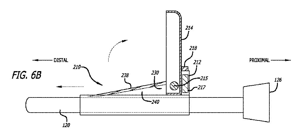
図6Aは、いくつかの実施形態による、安全構成で配置されたシールド214を有する皮膚切開デバイス210の側面図を示す。いくつかの実施形態では、皮膚切開デバイス210は、カテーテル留置システム100と併用することもできる。いくつかの実施形態では、皮膚切開デバイス210は、カテーテル150が血管系80内に留置されるときに皮膚を切開するために、カテーテル留置システム100に組み込まれてもよい。
6A shows a side view of a skin incision device 210 with a shield 214 positioned in a safety configuration, according to some embodiments. In some embodiments, the skin incision device 210 can also be used in conjunction with a
皮膚切開デバイス210は、針120とともに展開されてもよく、またはカテーテル留置デバイスを画定するために針に組み込まれてもよい。皮膚切開デバイス210は、針120に沿って摺動し、いくつかの実施形態では、針ハブ126と着脱可能に結合するように構成される。皮膚切開デバイス210は、針120に沿って近位および/または遠位に摺動するように構成されてもよい。皮膚切開デバイス210は、カテーテルの挿入部位を拡張するためにカテーテルの挿入部位に隣接する皮膚に切り目を入れる/皮膚を切開するように概して構成された刃230を含む。いくつかの実施形態では、皮膚切開デバイス210は、2つ以上の刃230を含むこともできる。皮膚切開デバイス210(またはより具体的には、シールド214)は、安全構成(図6A)と使用構成(図6B)との間で移行するように構成される。安全構成では、刃230は、シールド214に格納されている(または他の方法でアクセス不能になっている)。使用構成では、刃230は、皮膚に切り目を入れるために使用できるように露出している。
The skin incision device 210 may be deployed with the
いくつかの実施形態では、皮膚切開デバイス210はフレーム212を含んでもよく、フレーム212にはシールド214が結合されている。いくつかの実施形態では、シールド214は、ヒンジ215によってフレーム212にヒンジ式に/回転可能に結合されてもよい。いくつかの実施形態では、皮膚切開デバイス210は、フレーム212から遠位に延在する刃230を含むこともできる。いくつかの実施形態では、シールド214は、安全構成において誤って刃230を突き刺さないように刃230を覆うように構成されてもよい。シールド214は、本明細書でより詳細に説明されるように、安全構成と使用構成との間で移行するように構成されてもよい。いくつかの実施形態では、刃230は、刃の長さ232と、鈍いエッジ240と、鋭いエッジ238とを有することができる。いくつかの実施形態では、鈍いエッジ240は、鈍いエッジ240と針120との間に実質的に間隙がないように、針120に隣接して配置されてもよく、それによって、刃230が皮膚を切開するときに皮膚ブリッジを形成する可能性を排除する。いくつかの実施形態では、皮膚切開デバイス210は、針120とは別個に提供され、使用時に針120に組み付けられてもよい。他の実施形態では、皮膚切開デバイス210および針120は、事前に組み立てられてもよい(すなわち、結合される)。一実施形態では、フレーム212は、臨床医によって皮膚切開デバイス210に加えられる分離力がない場合に、フレーム212が針ハブ126によって位置的に保持されるように、針ハブ126と取り外し可能に結合されてもよい。フレーム212は、スナップ嵌め、圧入、締まり嵌め、磁気嵌めなどで針ハブ126に結合されてもよい。
In some embodiments, the skin incision device 210 may include a frame 212 to which a shield 214 is coupled. In some embodiments, the shield 214 may be hingedly/rotatably coupled to the frame 212 by a hinge 215. In some embodiments, the skin incision device 210 may also include a blade 230 extending distally from the frame 212. In some embodiments, the shield 214 may be configured to cover the blade 230 to prevent accidental pricking of the blade 230 in a safety configuration. The shield 214 may be configured to transition between a safety configuration and a use configuration, as described in more detail herein. In some embodiments, the blade 230 may have a blade length 232, a blunt edge 240, and a sharp edge 238. In some embodiments, the blunt edge 240 may be positioned adjacent to the
刃230は、刃230がフレーム212から遠位に延在するように、フレーム212に固定して取り付けられる。刃は、鋭いエッジ238と鈍いエッジ240とを含み、鋭いエッジ238は鈍いエッジ240から離れる方向を向いている。鋭いエッジ238は、鈍いエッジ240に対して斜めに配置され、鋭いエッジ238および鈍いエッジ240は収束して刃230の遠位端に鋭利な先端239を画定する。 The blade 230 is fixedly mounted to the frame 212 such that the blade 230 extends distally from the frame 212. The blade includes a sharp edge 238 and a blunt edge 240, with the sharp edge 238 facing away from the blunt edge 240. The sharp edge 238 is disposed at an angle relative to the blunt edge 240, and the sharp edge 238 and the blunt edge 240 converge to define a sharp tip 239 at the distal end of the blade 230.
いくつかの実施形態では、皮膚切開デバイス210は、フレーム212と結合された管状シース216を含み、管状シース216は針120に沿ってフレーム212から離れて遠位に延在する。そのような実施形態では、針120は、針120が管状シース216の管腔216A内で摺動可能であるように、管腔216A内に配置される。いくつかの実施形態では、鋭利な先端239は、管状シース216の外径面216Bの半径方向内側に配置される。いくつかの実施形態では、鋭利な先端239は、管状シース216の壁216C内に埋め込まれる。いくつかの実施形態では、シース216は省略されてもよい。
In some embodiments, the skin incision device 210 includes a tubular sheath 216 coupled to the frame 212, the tubular sheath 216 extending distally away from the frame 212 along with the
図6Bは、皮膚切開デバイス210の側面図を示しており、シールド214が使用構成で配置されている。シールド214は針120に対して垂直な方向に回転され、それによって刃230を露出させ、すなわち刃130が皮膚を切開できるようになる。いくつかの実施形態では、シールド214は、針120に対して0~180°の範囲の任意の角度で動かすことができる。シールド214が使用構成に配置された状態で、刃230を含むフレーム212を針120に沿って遠位に摺動させて、刃230を挿入部位に挿入して皮膚を切開できるようにする。使用中、刃230を含むフレーム212は、皮膚が切開された後で、挿入部位から離れる方向に針120に沿って近位に変位させてもよい。いくつかの実施形態では、フレーム212は、針ハブ126と再結合し、針ハブ126によって保持されるように構成される。シールド214は、図6Bの使用構成から図6Aの安全構成に戻ることができる。
6B shows a side view of the skin incision device 210 with the shield 214 positioned in a use configuration. The shield 214 is rotated in a direction perpendicular to the
図6Aおよび6Bを参照すると、いくつかの実施形態では、皮膚切開デバイス210は、シールド214とフレーム212との間に動作可能に結合されたラッチ217を含むことができる。ラッチ217は、臨床医による意図的な動作がない場合に、シールド214が安全構成から使用構成に移行することを防止するように、シールド214を安全構成にロックするように構成されてもよい。いくつかの実施形態では、ラッチ217は、意図的な動作の結果としてラッチ217を解放するように構成されたアクチュエータ218を含み、それによって、シールド214が安全構成から使用構成に移行することができる。 6A and 6B, in some embodiments, the skin incision device 210 can include a latch 217 operably coupled between the shield 214 and the frame 212. The latch 217 can be configured to lock the shield 214 in a safety configuration to prevent the shield 214 from transitioning from the safety configuration to the use configuration in the absence of an intentional action by the clinician. In some embodiments, the latch 217 includes an actuator 218 configured to release the latch 217 as a result of an intentional action, thereby allowing the shield 214 to transition from the safety configuration to the use configuration.
図7Aおよび7Bは、特定の点において、図6Aおよび6Bに関連して説明した皮膚切開デバイス210の構成要素に類似する、皮膚切開デバイス310の別の実施形態を示す。図示されたすべての実施形態が類似の特徴を有することができる。そのため、同様の特徴には同様の参照数字が付され、先頭の数字が「3」に増加している。例えば、シールドは、図6Aおよび6Bにおいて「214」で示しており、類似のシールドは、図7Aおよび7Bにおいて「314」で示す。したがって、同様に特定された特徴に関する上述の関連する開示は、以後繰り返さないことがある。さらに、図6Aおよび6Bに示す皮膚切開デバイス310および関連する構成要素の特定の特徴は、図面において参照数字によって示されていないか、または識別されていないか、もしくは以下に記載される説明において具体的に説明されていない場合がある。しかしながら、そのような特徴は、他の実施形態で述べられている、および/またはそのような実施形態に関して説明されている特徴と明らかに同一であるか、または実質的に同一である可能性がある。したがって、そのような特徴の関連する説明は、図7Aおよび7Bの皮膚切開デバイス310の特徴にも同様に適用される。図6Aおよび6Bに示す皮膚切込デバイス210および構成要素に関して説明される特徴の任意の好適な組み合わせおよびその変形例は、図7Aおよび7Bの皮膚切込デバイス310および構成要素にも採用することができ、その逆も同様である。 7A and 7B show another embodiment of a skin lancing device 310, which is similar in certain respects to the components of the skin lancing device 210 described in connection with FIGS. 6A and 6B. All of the illustrated embodiments may have similar features. As such, similar features are given similar reference numerals, with the leading numerals increasing to "3". For example, a shield is shown in FIGS. 6A and 6B as "214", and a similar shield is shown in FIGS. 7A and 7B as "314". Thus, the above related disclosure regarding similarly identified features may not be repeated hereafter. Furthermore, certain features of the skin lancing device 310 and related components shown in FIGS. 6A and 6B may not be indicated or identified by reference numerals in the drawings or specifically described in the description set forth below. However, such features may be clearly identical or substantially identical to features described in and/or with respect to other embodiments. Thus, the relevant descriptions of such features apply equally to the features of the skin incision device 310 of Figures 7A and 7B. Any suitable combinations and variations of the features described with respect to the skin incision device 210 and components shown in Figures 6A and 6B may also be employed with the skin incision device 310 and components of Figures 7A and 7B, and vice versa.
図7Aおよび7Bは、安全構成(図7A)と使用構成(図7B)との間で移行する皮膚切開デバイス310の断面図を示す。皮膚切開デバイス310は、針120に対して互いに対向して配置された2つの刃330を含む。皮膚切開デバイス310は、安全構成と使用構成との間で変位可能(例えば、長手方向に摺動可能)であるシールド314をさらに含む。シールド314は、安全構成において刃330を格納する(または他の方法で刃330をアクセス不能にする)ように構成される。いくつかの実施形態では、刃330は、シールド314内に収まるように、またはシールド314に覆われるように構成されてもよい。シールド314は、(i)刃330がシールド314内に格納される安全構成に対応する遠位位置と、(ii)刃330がシールド314から遠位に延在する(すなわち、露出される)使用構成に対応する近位位置との間で長手方向に変位するように構成される。いくつかの実施形態では、シールド314は、安全構成に向かって付勢されてもよく、例えば、安全構成に向かってばねで付勢されてもよい。
7A and 7B show cross-sectional views of a skin incision device 310 transitioning between a safety configuration (FIG. 7A) and a use configuration (FIG. 7B). The skin incision device 310 includes two blades 330 disposed opposite each other relative to the
皮膚切開デバイス310は、シールド314とフレーム312との間に動作可能に結合されたラッチ317を含むことができる。ラッチ317は、臨床医による意図的な動作がない場合に、シールド314が安全構成から使用構成に移行することを防止するために、シールド314を安全構成にロックするように構成されてもよい。いくつかの実施形態では、ラッチ317は、意図的な動作の結果としてラッチ317を解放するように構成されたアクチュエータ318を含み、それによって、シールド314が安全構成から使用構成に移行することができる。いくつかの実施形態では、シールド314は、シールド直径または幅316を画定することができる。いくつかの実施形態では、非押下状態にあるラッチ317のアクチュエータ318は、シールド直径316を越えて延在してもよく、ラッチ317は、シールド314の近位側への変位を妨げ、シールド314が安全構成に留まることを保証する。押下状態では、アクチュエータ318は、シールド直径316内に配置されてもよく、それによって、使用構成に向かうシールド314の近位変位を可能にする。 The skin incision device 310 may include a latch 317 operably coupled between the shield 314 and the frame 312. The latch 317 may be configured to lock the shield 314 in a safety configuration to prevent the shield 314 from transitioning from the safety configuration to the use configuration in the absence of an intentional action by the clinician. In some embodiments, the latch 317 includes an actuator 318 configured to release the latch 317 as a result of an intentional action, thereby allowing the shield 314 to transition from the safety configuration to the use configuration. In some embodiments, the shield 314 may define a shield diameter or width 316. In some embodiments, the actuator 318 of the latch 317 in a non-depressed state may extend beyond the shield diameter 316, and the latch 317 prevents proximal displacement of the shield 314, ensuring that the shield 314 remains in the safety configuration. In a depressed state, the actuator 318 may be disposed within the shield diameter 316, thereby allowing proximal displacement of the shield 314 toward the use configuration.
図8Aおよび8Bを参照すると、いくつかの実施形態では、刃330は、各刃330の近位端334が針120に対して横方向に移動可能であるように、フレーム312と移動可能に結合されてもよい。例えば、図8Aに示すように、各刃330は、針120から横方向に第1の距離380だけ離れて延びることができる。より大きいサイズのカテーテルに対応するために、刃330の近位端334は、針120から第2の距離382までさらに横方向に延びるように移動可能であってもよい。第2の長さ382によって、針120の挿入中に刃330が皮膚により大きな切り目を入れることが可能になる。いくつかの実施形態では、刃330は、針120から手動で延ばしてもよいし、針120から延びるように作動させてもよい。有利には、刃330の近位端334を延ばして、針120の挿入中に皮膚により大きな切り目を入れるように構成されてもよく、皮膚切開デバイス310が全てのサイズのカテーテルに適応できるようになる。
8A and 8B, in some embodiments, the blades 330 may be movably coupled to the frame 312 such that the proximal end 334 of each blade 330 is laterally movable relative to the
図9は、患者の血管系内にカテーテルを留置する例示的な方法400のフローチャートを示しており、以下の手順(ステップ)、動作、またはプロセスのすべてまたは任意のサブセットを含むことができる。方法400は、カテーテルの挿入部位を画定するために針を使用して血管にアクセスすることを含むことができる(ブロック410)。 9 illustrates a flow chart of an exemplary method 400 for placing a catheter within a patient's vasculature, which may include all or any subset of the following steps, actions, or processes. The method 400 may include accessing a blood vessel using a needle to define an insertion site for the catheter (Block 410).
方法400は、皮膚切開デバイスの刃を露出させるために、針と結合された皮膚切開デバイスのシールドを安全構成から使用構成に移行させることをさらに含むことができる(ブロック420)。本方法のいくつかの実施形態では、シールドを移行させることは、シールドを回転させることを含む。本方法のいくつかの実施形態では、シールドを安全構成から使用構成に移行させることは、シールドを遠位位置から近位位置に摺動可能に変位させることを含む。方法400のいくつかの実施形態では、シールドを安全構成から使用構成に移行させることは、皮膚をシールドと接触させることを含む。 The method 400 may further include transitioning a shield of the skin-cutting device coupled to the needle from a safety configuration to a use configuration to expose a blade of the skin-cutting device (block 420). In some embodiments of the method, transitioning the shield includes rotating the shield. In some embodiments of the method, transitioning the shield from the safety configuration to the use configuration includes slidably displacing the shield from a distal position to a proximal position. In some embodiments of the method 400, transitioning the shield from the safety configuration to the use configuration includes contacting the skin with the shield.
方法400は、シールドが安全構成から使用構成に移行できるように、シールドとフレームとの間に動作可能に結合されたラッチを解放すること(ブロック430)をさらに含むことができる。 The method 400 may further include releasing a latch operably coupled between the shield and the frame (block 430) to allow the shield to transition from the safe configuration to the use configuration.
方法400は、挿入部位に向かって皮膚切開デバイスを針に沿って遠位に摺動させること(ブロック440)をさらに含んでもよい。方法400のいくつかの実施形態では、皮膚切開デバイスを遠位に摺動させる前に、皮膚切開デバイスのフレームを針の針ハブから切り離してもよい。方法400のいくつかの実施形態では、皮膚切開デバイスを遠位に摺動させることは、皮膚がシールドに近位方向の力を加えてシールドを遠位位置から近位位置に向かって変位させるように、皮膚切開デバイスを遠位に変位させることを含んでもよい。 The method 400 may further include sliding the skin incision device distally along the needle toward the insertion site (block 440). In some embodiments of the method 400, the frame of the skin incision device may be decoupled from the needle hub of the needle before sliding the skin incision device distally. In some embodiments of the method 400, sliding the skin incision device distally may include displacing the skin incision device distally such that the skin exerts a proximal force on the shield to displace the shield from a distal position toward a proximal position.
方法400は、挿入部位を拡張するために刃で皮膚を切開すること(ブロック450)をさらに含んでもよい。方法400のいくつかの実施形態では、皮膚を切開することは、刃が挿入部位内に延びるように、針に沿って皮膚切開デバイスを遠位に摺動させることを含む。 Method 400 may further include cutting the skin with a blade to enlarge the insertion site (block 450). In some embodiments of method 400, cutting the skin includes sliding a skin cutting device distally along the needle such that the blade extends into the insertion site.
方法400は、カテーテルを血管系内に留置すること(ブロック460)をさらに含むことができる。方法400は、刃を格納するためにシールドを使用構成から安全構成に移行させること(ブロック470)をさらに含むことができる。 The method 400 may further include placing the catheter within the vasculature (Block 460). The method 400 may further include transitioning the shield from the use configuration to the safety configuration to retract the blade (Block 470).
いくつかの特定の実施形態が本明細書に開示されており、特定の実施形態がある程度詳細に開示されているが、特定の実施形態が本明細書で提供される概念の範囲を制限することは意図されていない。追加の適合および/または修正は、当業者には明らかであり得、より広い態様では、これらの適合および/または修正もまた包含される。したがって、本明細書で提供される概念の範囲から逸脱することなく、本明細書で開示される特定の実施形態から逸脱することができる。 Although some specific embodiments are disclosed herein, and the specific embodiments are disclosed in some detail, the specific embodiments are not intended to limit the scope of the concepts provided herein. Additional adaptations and/or modifications may be apparent to those skilled in the art, and the broader aspects also encompass these adaptations and/or modifications. Thus, one may depart from the specific embodiments disclosed herein without departing from the scope of the concepts provided herein.
Claims (18)
血管カテーテルのための挿入部位を確立するように構成された針であって、遠位端と近位端の針ハブとの間に延在する針管腔を画定する針と、
前記針と摺動可能に結合された皮膚切開デバイスであって、
前記挿入部位を拡張するために、該挿入部位に隣接する皮膚を切開するように構成された刃と、
シールドであって、
前記刃が前記シールドによって格納される安全構成と、
前記刃が皮膚を切開するために露出している、使用構成と、の間を移行可能である、シールドと、
を含む皮膚切開デバイスと、
を備えている、カテーテル留置デバイス。 1. A catheter placement device comprising:
a needle configured to establish an insertion site for a vascular catheter, the needle defining a needle lumen extending between a distal end and a needle hub at a proximal end;
a skin lancing device slidably coupled to the needle,
a blade configured to incise the skin adjacent the insertion site to enlarge the insertion site;
A shield,
a safety arrangement in which the blade is retracted by the shield;
a shield that is transitionable between a use configuration in which the blade is exposed for cutting the skin; and
A skin incision device comprising:
A catheter placement device comprising:
前記安全構成に対応する遠位位置と、
前記使用構成に対応する近位位置と、の間で長手方向に変位可能である、請求項5に記載のデバイス。 The shield is
a distal position corresponding to the safety configuration; and
A device as described in claim 5, wherein the device is longitudinally displaceable between a proximal position corresponding to the use configuration and a distal position corresponding to the use configuration.
前記ラッチが、臨床医による意図的な動作がない場合に、前記シールドが前記安全構成から前記使用構成に移行するのを防止するように構成されている、請求項1~7のいずれか一項に記載のデバイス。 the skin lancing device includes a latch operably coupled between the shield and the frame;
The device of any one of claims 1 to 7, wherein the latch is configured to prevent the shield from transitioning from the safety configuration to the use configuration in the absence of intentional action by a clinician.
前記鋭いエッジが、前記鈍いエッジから離れる方向を向いており、
前記鋭いエッジが、前記鈍いエッジに対して斜めに配置されている、請求項1~10のいずれか一項に記載のデバイス。 the blade having a sharp edge and a blunt edge;
the sharp edge faces away from the blunt edge;
A device according to any preceding claim, wherein the sharp edge is disposed at an angle to the blunt edge.
前記鈍いエッジが針の方を向くように、
前記鋭いエッジが前記針から半径方向に離れる方向を向くように、および
前記鋭利な先端が前記針のすぐ隣に配置されるように、前記フレームに固定して取り付けられている、請求項12に記載のデバイス。 The blade is
With the blunt edge facing the needle,
13. The device of claim 12, fixedly attached to the frame such that the sharp edge faces radially away from the needle and such that the sharp tip is positioned immediately adjacent to the needle.
前記針が、前記管状シースの管腔内に配置されている、請求項2~13のいずれか一項に記載のデバイス。 the skin incision device includes a tubular sheath coupled to the frame so as to extend distally away from the frame along the needle;
The device of any one of claims 2 to 13, wherein the needle is disposed within the lumen of the tubular sheath.
前記第2の刃を前記安全構成で格納し、
前記使用構成において前記第2の刃を露出させる、請求項17に記載のデバイス。
The shield is
storing the second blade in the safety configuration;
The device of claim 17 , wherein the second blade is exposed in the use configuration.
Applications Claiming Priority (3)
| Application Number | Priority Date | Filing Date | Title |
|---|---|---|---|
| US202263310531P | 2022-02-15 | 2022-02-15 | |
| US63/310,531 | 2022-02-15 | ||
| PCT/US2023/013056 WO2023158643A1 (en) | 2022-02-15 | 2023-02-14 | Skin nicking device for catheter placement system |
Publications (2)
| Publication Number | Publication Date |
|---|---|
| JP2025505767A true JP2025505767A (en) | 2025-02-28 |
| JPWO2023158643A5 JPWO2023158643A5 (en) | 2026-01-22 |
Family
ID=85569953
Family Applications (1)
| Application Number | Title | Priority Date | Filing Date |
|---|---|---|---|
| JP2024547914A Pending JP2025505767A (en) | 2022-02-15 | 2023-02-14 | Skin incision device for catheter placement system |
Country Status (5)
| Country | Link |
|---|---|
| US (1) | US20230255660A1 (en) |
| EP (1) | EP4472533A1 (en) |
| JP (1) | JP2025505767A (en) |
| CN (2) | CN116603153A (en) |
| WO (1) | WO2023158643A1 (en) |
Families Citing this family (2)
| Publication number | Priority date | Publication date | Assignee | Title |
|---|---|---|---|---|
| US12440657B2 (en) | 2020-11-13 | 2025-10-14 | Bard Access Systems, Inc. | Mechanical dilator |
| CA3202879A1 (en) | 2020-12-04 | 2022-06-09 | Bard Access Systems, Inc. | Catheter insertion systems with passive skin dilation |
Family Cites Families (20)
| Publication number | Priority date | Publication date | Assignee | Title |
|---|---|---|---|---|
| US6716228B2 (en) * | 2000-09-30 | 2004-04-06 | Yale University | Surgical access device |
| DE10100332A1 (en) * | 2001-01-03 | 2002-07-25 | Gip Medizintechnik Gmbh | Surgical knife for arterial incisions comprises distally sharp knife pair slidably pushed along hollow needle-shaped body but sheathed in rear non-advanced position. |
| US9480497B2 (en) * | 2012-02-01 | 2016-11-01 | Angiodynamics, Inc. | Skin nicking device, method and assembly |
| WO2016123278A1 (en) | 2015-01-29 | 2016-08-04 | Redsmith, Inc. | Rapid insertion integrated catheter and method of using an integrated catheter |
| US9480498B1 (en) * | 2015-07-06 | 2016-11-01 | Yoel Kessler | Tissue cutter |
| US20200246597A1 (en) * | 2019-02-05 | 2020-08-06 | D & J Solutions, Llc | Vascular access dilator apparatus and method of use |
| WO2021050302A1 (en) | 2019-09-10 | 2021-03-18 | Bard Access Systems, Inc. | Rapidly inserted central catheter and methods thereof |
| AU2020353080B2 (en) | 2019-09-24 | 2025-10-09 | Bard Access Systems, Inc. | An integrated acute central venous catheter and peripherally inserted venous catheter |
| EP4041340A4 (en) | 2019-10-18 | 2023-12-13 | Bard Access Systems, Inc. | RAPIDLY INSERTED CENTRAL CATHETER AND METHOD THEREOF |
| WO2021081205A1 (en) | 2019-10-22 | 2021-04-29 | Bard Access Systems, Inc. | Rapidly insertable central catheters and methods thereof |
| AU2020370502B2 (en) | 2019-10-25 | 2025-06-05 | Bard Access Systems, Inc. | Guidewire-management devices and methods thereof |
| US20210121661A1 (en) | 2019-10-27 | 2021-04-29 | Bard Access Systems, Inc. | Rapidly Insertable Central Catheter and Methods Thereof |
| US11826526B2 (en) | 2020-01-23 | 2023-11-28 | Bard Access Systems, Inc. | Splitable catheter docking station system and method |
| CN113521490A (en) | 2020-04-20 | 2021-10-22 | 巴德阿克塞斯系统股份有限公司 | Rapidly insertable central catheter including catheter assembly and method therefor |
| WO2021216902A1 (en) | 2020-04-23 | 2021-10-28 | Bard Access Systems, Inc. | Rapidly insertable central catheters including catheter assemblies |
| AU2021264447B2 (en) | 2020-04-27 | 2025-09-04 | Bard Access Systems, Inc. | Rapidly insertable central catheters including catheter assemblies and methods thereof |
| CA3181532A1 (en) | 2020-05-21 | 2021-11-25 | Bard Access Systems, Inc. | Rapidly insertable central catheters including catheter assemblies |
| WO2022005892A2 (en) | 2020-06-29 | 2022-01-06 | Bard Access Systems, Inc. | Rapidly insertable central catheters including catheter assemblies and methods thereof |
| CA3186461A1 (en) | 2020-06-29 | 2022-01-06 | Bard Access Systems, Inc. | Rapidly insertable central catheters including assemblies |
| WO2022006243A1 (en) | 2020-07-01 | 2022-01-06 | Bard Access Systems, Inc. | Rapidly insertable central catheters and methods of manufacture thereof |
-
2023
- 2023-02-14 JP JP2024547914A patent/JP2025505767A/en active Pending
- 2023-02-14 EP EP23710562.2A patent/EP4472533A1/en active Pending
- 2023-02-14 US US18/109,793 patent/US20230255660A1/en active Pending
- 2023-02-14 CN CN202310120845.3A patent/CN116603153A/en active Pending
- 2023-02-14 WO PCT/US2023/013056 patent/WO2023158643A1/en not_active Ceased
- 2023-02-14 CN CN202320274837.XU patent/CN220002684U/en active Active
Also Published As
| Publication number | Publication date |
|---|---|
| US20230255660A1 (en) | 2023-08-17 |
| CN116603153A (en) | 2023-08-18 |
| EP4472533A1 (en) | 2024-12-11 |
| CN220002684U (en) | 2023-11-14 |
| WO2023158643A1 (en) | 2023-08-24 |
Similar Documents
| Publication | Publication Date | Title |
|---|---|---|
| US11931534B2 (en) | Medical component insertion device including a retractable needle | |
| CN112618914B (en) | Integrated acute central venous catheter and peripherally inserted intravenous catheter | |
| CN215608689U (en) | Rapidly insertable central catheter including catheter assembly | |
| CN217526049U (en) | Catheter placement system and catheter placement device | |
| KR20230007433A (en) | RAPIDLY INSERTABLE CENTRAL CATHETERS INCLUDING CATHETER ASSEMBLIES AND METHODS THEREOF | |
| JP2022526808A (en) | Vascular access device with fluid permeable structure and related devices | |
| JP2025503965A (en) | Clot treatment system with expander locking mechanism and related devices and methods | |
| JP2005501637A (en) | Surgical access device | |
| CN220002685U (en) | Catheter placement system and catheter placement device | |
| CN116492574A (en) | Quick-insertion type central catheter insertion assembly | |
| JP2025505767A (en) | Skin incision device for catheter placement system | |
| CN113613700A (en) | Catheter needle assembly with closeable needle | |
| JP2025504110A (en) | SKIN NICKING DEVICE FOR A CATHETER DEPLOYMENT SYSTEM - Patent application | |
| JP2025504139A (en) | SKIN NICKING DEVICE FOR A CATHETER DEPLOYMENT SYSTEM - Patent application | |
| CN219963705U (en) | catheter placement system |
Legal Events
| Date | Code | Title | Description |
|---|---|---|---|
| A521 | Request for written amendment filed |
Free format text: JAPANESE INTERMEDIATE CODE: A523 Effective date: 20260114 |
|
| A621 | Written request for application examination |
Free format text: JAPANESE INTERMEDIATE CODE: A621 Effective date: 20260114 |