JP2025504065A - WIRELESS DEVICES, SYSTEMS AND METHODS FOR ENDOSCOPIC POSITIONING - Patent application - Google Patents
WIRELESS DEVICES, SYSTEMS AND METHODS FOR ENDOSCOPIC POSITIONING - Patent application Download PDFInfo
- Publication number
- JP2025504065A JP2025504065A JP2024545205A JP2024545205A JP2025504065A JP 2025504065 A JP2025504065 A JP 2025504065A JP 2024545205 A JP2024545205 A JP 2024545205A JP 2024545205 A JP2024545205 A JP 2024545205A JP 2025504065 A JP2025504065 A JP 2025504065A
- Authority
- JP
- Japan
- Prior art keywords
- tissue
- tissue engaging
- engaging member
- target site
- locator system
- Prior art date
- Legal status (The legal status is an assumption and is not a legal conclusion. Google has not performed a legal analysis and makes no representation as to the accuracy of the status listed.)
- Pending
Links
Images


Classifications
-
- A—HUMAN NECESSITIES
- A61—MEDICAL OR VETERINARY SCIENCE; HYGIENE
- A61F—FILTERS IMPLANTABLE INTO BLOOD VESSELS; PROSTHESES; DEVICES PROVIDING PATENCY TO, OR PREVENTING COLLAPSING OF, TUBULAR STRUCTURES OF THE BODY, e.g. STENTS; ORTHOPAEDIC, NURSING OR CONTRACEPTIVE DEVICES; FOMENTATION; TREATMENT OR PROTECTION OF EYES OR EARS; BANDAGES, DRESSINGS OR ABSORBENT PADS; FIRST-AID KITS
- A61F2/00—Filters implantable into blood vessels; Prostheses, i.e. artificial substitutes or replacements for parts of the body; Appliances for connecting them with the body; Devices providing patency to, or preventing collapsing of, tubular structures of the body, e.g. stents
- A61F2/95—Instruments specially adapted for placement or removal of stents or stent-grafts
- A61F2/958—Inflatable balloons for placing stents or stent-grafts
-
- A—HUMAN NECESSITIES
- A61—MEDICAL OR VETERINARY SCIENCE; HYGIENE
- A61B—DIAGNOSIS; SURGERY; IDENTIFICATION
- A61B17/00—Surgical instruments, devices or methods
- A61B17/11—Surgical instruments, devices or methods for performing anastomosis; Buttons for anastomosis
-
- A—HUMAN NECESSITIES
- A61—MEDICAL OR VETERINARY SCIENCE; HYGIENE
- A61B—DIAGNOSIS; SURGERY; IDENTIFICATION
- A61B17/00—Surgical instruments, devices or methods
- A61B17/11—Surgical instruments, devices or methods for performing anastomosis; Buttons for anastomosis
- A61B17/1114—Surgical instruments, devices or methods for performing anastomosis; Buttons for anastomosis of the digestive tract, e.g. bowels or oesophagus
-
- A—HUMAN NECESSITIES
- A61—MEDICAL OR VETERINARY SCIENCE; HYGIENE
- A61B—DIAGNOSIS; SURGERY; IDENTIFICATION
- A61B17/00—Surgical instruments, devices or methods
- A61B17/28—Surgical forceps
- A61B17/29—Forceps for use in minimally invasive surgery
-
- A—HUMAN NECESSITIES
- A61—MEDICAL OR VETERINARY SCIENCE; HYGIENE
- A61B—DIAGNOSIS; SURGERY; IDENTIFICATION
- A61B90/00—Instruments, implements or accessories specially adapted for surgery or diagnosis and not covered by any of the groups A61B1/00 - A61B50/00, e.g. for luxation treatment or for protecting wound edges
- A61B90/39—Markers, e.g. radio-opaque or breast lesions markers
-
- A—HUMAN NECESSITIES
- A61—MEDICAL OR VETERINARY SCIENCE; HYGIENE
- A61B—DIAGNOSIS; SURGERY; IDENTIFICATION
- A61B17/00—Surgical instruments, devices or methods
- A61B17/00234—Surgical instruments, devices or methods for minimally invasive surgery
- A61B2017/00238—Type of minimally invasive operation
- A61B2017/00278—Transorgan operations, e.g. transgastric
-
- A—HUMAN NECESSITIES
- A61—MEDICAL OR VETERINARY SCIENCE; HYGIENE
- A61B—DIAGNOSIS; SURGERY; IDENTIFICATION
- A61B17/00—Surgical instruments, devices or methods
- A61B2017/00535—Surgical instruments, devices or methods pneumatically or hydraulically operated
- A61B2017/00557—Surgical instruments, devices or methods pneumatically or hydraulically operated inflatable
-
- A—HUMAN NECESSITIES
- A61—MEDICAL OR VETERINARY SCIENCE; HYGIENE
- A61B—DIAGNOSIS; SURGERY; IDENTIFICATION
- A61B17/00—Surgical instruments, devices or methods
- A61B2017/00743—Type of operation; Specification of treatment sites
- A61B2017/00818—Treatment of the gastro-intestinal system
-
- A—HUMAN NECESSITIES
- A61—MEDICAL OR VETERINARY SCIENCE; HYGIENE
- A61B—DIAGNOSIS; SURGERY; IDENTIFICATION
- A61B17/00—Surgical instruments, devices or methods
- A61B17/11—Surgical instruments, devices or methods for performing anastomosis; Buttons for anastomosis
- A61B2017/1103—Approximator
-
- A—HUMAN NECESSITIES
- A61—MEDICAL OR VETERINARY SCIENCE; HYGIENE
- A61B—DIAGNOSIS; SURGERY; IDENTIFICATION
- A61B17/00—Surgical instruments, devices or methods
- A61B17/11—Surgical instruments, devices or methods for performing anastomosis; Buttons for anastomosis
- A61B2017/1125—Forceps, specially adapted for performing or assisting anastomosis
-
- A—HUMAN NECESSITIES
- A61—MEDICAL OR VETERINARY SCIENCE; HYGIENE
- A61B—DIAGNOSIS; SURGERY; IDENTIFICATION
- A61B17/00—Surgical instruments, devices or methods
- A61B17/11—Surgical instruments, devices or methods for performing anastomosis; Buttons for anastomosis
- A61B2017/1139—Side-to-side connections, e.g. shunt or X-connections
-
- A—HUMAN NECESSITIES
- A61—MEDICAL OR VETERINARY SCIENCE; HYGIENE
- A61B—DIAGNOSIS; SURGERY; IDENTIFICATION
- A61B17/00—Surgical instruments, devices or methods
- A61B17/28—Surgical forceps
- A61B17/29—Forceps for use in minimally invasive surgery
- A61B2017/2926—Details of heads or jaws
- A61B2017/2932—Transmission of forces to jaw members
- A61B2017/2939—Details of linkages or pivot points
-
- A—HUMAN NECESSITIES
- A61—MEDICAL OR VETERINARY SCIENCE; HYGIENE
- A61B—DIAGNOSIS; SURGERY; IDENTIFICATION
- A61B90/00—Instruments, implements or accessories specially adapted for surgery or diagnosis and not covered by any of the groups A61B1/00 - A61B50/00, e.g. for luxation treatment or for protecting wound edges
- A61B90/39—Markers, e.g. radio-opaque or breast lesions markers
- A61B2090/3904—Markers, e.g. radio-opaque or breast lesions markers specially adapted for marking specified tissue
- A61B2090/3908—Soft tissue, e.g. breast tissue
-
- A—HUMAN NECESSITIES
- A61—MEDICAL OR VETERINARY SCIENCE; HYGIENE
- A61B—DIAGNOSIS; SURGERY; IDENTIFICATION
- A61B90/00—Instruments, implements or accessories specially adapted for surgery or diagnosis and not covered by any of the groups A61B1/00 - A61B50/00, e.g. for luxation treatment or for protecting wound edges
- A61B90/39—Markers, e.g. radio-opaque or breast lesions markers
- A61B2090/3937—Visible markers
- A61B2090/3945—Active visible markers, e.g. light emitting diodes
Landscapes
- Health & Medical Sciences (AREA)
- Life Sciences & Earth Sciences (AREA)
- Surgery (AREA)
- Engineering & Computer Science (AREA)
- Biomedical Technology (AREA)
- Animal Behavior & Ethology (AREA)
- Heart & Thoracic Surgery (AREA)
- General Health & Medical Sciences (AREA)
- Public Health (AREA)
- Veterinary Medicine (AREA)
- Medical Informatics (AREA)
- Molecular Biology (AREA)
- Nuclear Medicine, Radiotherapy & Molecular Imaging (AREA)
- Oral & Maxillofacial Surgery (AREA)
- Physiology (AREA)
- Pathology (AREA)
- Cardiology (AREA)
- Transplantation (AREA)
- Vascular Medicine (AREA)
- Ophthalmology & Optometry (AREA)
- Surgical Instruments (AREA)
- Media Introduction/Drainage Providing Device (AREA)
Abstract
第1の解剖学的構造内の標的部位に展開可能であり、かつ第2の解剖学的構造内から識別可能なロケータシステム。ロケータシステムは、信号発生器及び組織係合部材を含む。組織係合部材は標的部位の組織に係合し、これにより送達システムは、標的部位の組織に組織係合部材が係合した状態で、ロケータシステムの位置を乱すことなくロケータシステムを送達し、また、引き抜かれることができる。ロケータシステムは、患者の腸内の標的部位に展開され、患者の胃内から識別され、胃と標的部位との間に吻合部を作成することができる。
A locator system deployable at a target site within a first anatomical structure and identifiable from within a second anatomical structure, the locator system including a signal generator and a tissue engaging member, the tissue engaging member engaging tissue at the target site such that a delivery system can deliver the locator system and be withdrawn with the tissue engaging member engaged to tissue at the target site without disturbing the position of the locator system, the locator system being deployable at a target site within a patient's intestine and identifiable from within the patient's stomach and capable of creating an anastomosis between the stomach and the target site.
Description
本開示は、概して、体内で使用する医療デバイスの分野に関する。特に、本開示は、内視鏡処置で使用するための医療デバイス、システム、及び方法に関する。さらに具体的には、本開示は、体内の標的部位の位置の識別を容易にするなど、体内でのデバイスの位置決めを容易にする医療デバイス、システム、及び方法に関する。 The present disclosure relates generally to the field of medical devices for use within the body. In particular, the present disclosure relates to medical devices, systems, and methods for use in endoscopic procedures. More specifically, the present disclosure relates to medical devices, systems, and methods that facilitate positioning of a device within the body, including facilitating identification of the location of a target site within the body.
体内から解剖学的構造、デバイス、及び/又は1つ以上のデバイスを含む解剖学的構造を視認、配置、及び操作することは困難な場合がある。体内の処置中、例えば体管腔内での内視鏡処置(身体を切開するものではない)中に、医療専門家は身体の特定の解剖学的構造や身体内でのその位置を外部から特定する必要がある場合がある。照明の欠如又は照明量の少なさ、及び/又は介在する解剖学的構造、及び/又は身体の様々な部分の形状及び/又は構造のために、身体の所望の解剖学的構造及び/又は身体内でのその位置を特定することが困難な場合がある。例えば、腸などの体管腔内での処置では、体外から区別することが難しい長い解剖学的領域が現れることがある。身体内に、様々な位置特定デバイスが設けられる場合がある。しかしながら、そのような位置特定デバイスに関して体内でデバイスを操作すると(例えば、デバイスを操作しながら処置を行う、及び/又は位置特定デバイスの送達デバイスを引き抜くなど)、そのような位置特定デバイスがずれてしまうことにより、そのような位置特定デバイスの目的及び機能が妨げられる可能性がある。 It may be difficult to view, locate, and manipulate anatomical structures, devices, and/or anatomical structures that include one or more devices from within the body. During an internal procedure, such as an endoscopic procedure (not cutting the body) within a body lumen, a medical professional may need to identify a particular anatomical structure of the body and its location within the body from the outside. It may be difficult to identify a desired anatomical structure of the body and/or its location within the body due to lack of or low amount of illumination, and/or intervening anatomical structures, and/or the shape and/or structure of various parts of the body. For example, a procedure within a body lumen, such as the intestine, may present long anatomical regions that are difficult to distinguish from the outside of the body. Various localization devices may be provided within the body. However, manipulating the device within the body with respect to such localization devices (e.g., performing a procedure while manipulating the device and/or withdrawing a delivery device of the localization device) may cause such localization devices to become dislodged, thereby hindering the purpose and function of such localization devices.
これら及びその他の考慮事項に関して、本願の改良は有用であり得る。 With respect to these and other considerations, the improvements of the present application may be useful.
本開示のこの概要は理解を助けるために提供されており、当業者であれば、本開示の様々な態様及び特徴のそれぞれが、場合によっては別々に有利に使用され、又は他の場合には本開示の他の態様及び特徴と組み合わせて使用され得ることを理解するであろう。この概要に要素、コンポーネントなどを含めるか含めないかによらず、請求された主題の範囲が制限されることは意図されていない。 This summary of the disclosure is provided to aid in understanding, and those skilled in the art will appreciate that each of the various aspects and features of the disclosure may be advantageously used separately in some cases or in combination with other aspects and features of the disclosure in other cases. The inclusion or exclusion of elements, components, etc. in this summary is not intended to limit the scope of the claimed subject matter.
本開示の様々な原理によれば、ロケータシステムは、可撓性の長尺部材、前記可撓性の長尺部材に取り付けられたビーコン、及び標的部位の組織に係合することで前記ロケータシステムを標的部位に対して固定するように構成された組織係合部材を含む。 In accordance with various principles of the present disclosure, a locator system includes a flexible elongate member, a beacon attached to the flexible elongate member, and a tissue engagement member configured to engage tissue at the target site to secure the locator system relative to the target site.
いくつかの実施形態では、前記組織係合部材は、標的部位の組織に係合することで前記ロケータシステムを標的部位に対して固定するために拡張可能である。いくつかの実施形態では、前記組織係合部材は膨張可能なバルーンである。いくつかの実施形態では、前記組織係合部材は拡張可能なステントである。いくつかの実施形態では、前記組織係合部材は、前記可撓性の長尺部材上に取り付けられる。 In some embodiments, the tissue engaging member is expandable to engage tissue at the target site to secure the locator system relative to the target site. In some embodiments, the tissue engaging member is an inflatable balloon. In some embodiments, the tissue engaging member is an expandable stent. In some embodiments, the tissue engaging member is mounted on the flexible elongate member.
いくつかの実施形態では、前記組織係合部材は、一対の把持アームであって、それらの間にある標的部位の組織を把持するように構成された前記一対の把持アームを有する。
いくつかの実施形態では、前記ロケータシステムは、前記可撓性の長尺部材に沿って延び、前記組織係合部材を送達構成と組織係合構成との間でシフトさせるように作動可能なコントローラをさらに含む。いくつかの実施形態では、前記組織係合部材は膨張可能であり、前記コントローラは前記可撓性の長尺部材を通る膨張ルーメンである。いくつかの実施形態では、前記組織係合部材は膨張可能であり、前記コントローラは前記可撓性の長尺部材に沿って延びる膨張ライン内の膨張ルーメンである。いくつかの実施形態では、前記コントローラは前記可撓性の長尺部材の周囲に延びるシースであり、前記組織係合部材は、前記送達構成では前記コントローラ内に配置され、前記コントローラの外側にあるときは組織係合構成に拡張可能な、拡張可能なステントである。いくつかの実施形態では、前記組織係合部材は、一対の把持アームであって、それらの間にある標的部位の組織を把持するように構成された前記一対の把持アームを有する。
In some embodiments, the tissue engaging member comprises a pair of gripping arms configured to grasp tissue at a target site therebetween.
In some embodiments, the locator system further includes a controller extending along the flexible elongate member and operable to shift the tissue engaging member between a delivery configuration and a tissue engaging configuration. In some embodiments, the tissue engaging member is expandable and the controller is an inflation lumen through the flexible elongate member. In some embodiments, the tissue engaging member is expandable and the controller is an inflation lumen in an inflation line extending along the flexible elongate member. In some embodiments, the controller is a sheath extending around the flexible elongate member and the tissue engaging member is an expandable stent disposed within the controller in the delivery configuration and expandable to a tissue engaging configuration when outside of the controller. In some embodiments, the tissue engaging member has a pair of gripping arms configured to grip tissue at a target site between them.
本開示の様々な原理によれば、ロケータシステムは、ビーコン、組織係合部材、及び、前記組織係合部材がコンパクトであり、経管腔的に標的部位に送達可能である送達構成と、前記組織係合部材が標的部位の組織に係合することで前記ビーコンを標的部位に対して固定する組織係合構成との間で前記組織係合部材をシフトさせるように作動可能なコントローラを含む。 In accordance with various principles of the present disclosure, a locator system includes a beacon, a tissue engaging member, and a controller operable to shift the tissue engaging member between a delivery configuration in which the tissue engaging member is compact and transluminally deliverable to a target site and a tissue engaging configuration in which the tissue engaging member engages tissue at the target site to secure the beacon relative to the target site.
いくつかの実施形態では、前記ロケータシステムは、前記ビーコン及び前記組織係合部材が取り付けられる可撓性の長尺部材を含む。
いくつかの実施形態では、前記組織係合部材は膨張可能なバルーンであり、前記コントローラは前記バルーンと連通する膨張ルーメンである。
In some embodiments, the locator system includes a flexible elongate member to which the beacon and the tissue engaging member are attached.
In some embodiments, the tissue engaging member is an inflatable balloon and the controller is an inflation lumen in communication with the balloon.
いくつかの実施形態では、前記コントローラはシースであり、前記組織係合部材は、前記シース内にあるときの送達構成と前記シース外にあるときの拡張された組織係合構成との間でシフト可能な拡張可能なステントである。 In some embodiments, the controller is a sheath and the tissue engaging member is an expandable stent that is shiftable between a delivery configuration when within the sheath and an expanded tissue engaging configuration when outside the sheath.
いくつかの実施形態では、前記組織係合部材は一対のジョーを含み、前記一対のジョーは、ジョーが送達構成にあるか又はジョーの間に組織を把持している閉じた構成と、ジョーがジョーの間の組織と係合することができる開いた構成との間で前記コントローラによって移動可能である。 In some embodiments, the tissue engaging member includes a pair of jaws that are movable by the controller between a closed configuration in which the jaws are in a delivery configuration or grip tissue between the jaws, and an open configuration in which the jaws can engage tissue between the jaws.
本開示の様々な原理によれば、第2の解剖学的構造内から第1の解剖学的構造内の標的部位の位置を特定する方法は、送達システムを使用して標的部位にロケータシステムを送達すること、前記ロケータシステムの組織係合部材を標的部位の組織と係合させることによって標的部位に対して前記ロケータシステムを固定すること、標的部位に対して前記ロケータシステムが所定の場所に固定されたままの状態であるように前記送達システムを前記ロケータシステムから引き抜くこと、及び少なくとも第2の解剖学的構造の壁を通して第2の解剖学的構造からロケータシステムの位置を特定し及び識別することを含む。 In accordance with various principles of the present disclosure, a method for locating a target site in a first anatomical structure from within a second anatomical structure includes delivering a locator system to the target site using a delivery system, securing the locator system relative to the target site by engaging a tissue engaging member of the locator system with tissue at the target site, withdrawing the delivery system from the locator system such that the locator system remains fixed in place relative to the target site, and locating and identifying the location of the locator system from the second anatomical structure through at least a wall of the second anatomical structure.
いくつかの実施形態では、前記方法は、標的部位に沿って第1の解剖学的構造と第2の解剖学的構造との間に吻合部を形成することを含む。
いくつかの実施形態では、前記方法は、前記組織係合部材をコンパクトな送達構成から拡張構成に拡張することで、標的部位の組織に係合させることにより、前記ロケータシステムを標的部位に対して固定することを含む。
In some embodiments, the method includes forming an anastomosis between a first anatomical structure and a second anatomical structure along the target site.
In some embodiments, the method includes securing the locator system relative to the target site by expanding the tissue engaging member from a compact delivery configuration to an expanded configuration to engage tissue at the target site.
いくつかの実施形態では、前記方法は、前記組織係合部材の把持アームの間で標的部位の組織を把持することによって、前記ロケータシステムを標的部位に固定することを含む。 In some embodiments, the method includes securing the locator system to the target site by grasping tissue at the target site between grasping arms of the tissue engaging member.
本開示のこれらの特徴及び利点、ならびにその他の特徴及び利点は、以下の詳細な説明から容易に明らかになるであろう。本発明の範囲は、添付の特許請求の範囲に記載されている。以下の開示は、態様又は実施形態の観点から提示されているが、個々の態様は、別々に、又はその実施形態又は他の実施形態の態様及び特徴と組み合わせて請求できることが理解されるべきである。 These and other features and advantages of the present disclosure will become readily apparent from the following detailed description. The scope of the present invention is set forth in the appended claims. While the following disclosure is presented in terms of aspects or embodiments, it should be understood that each aspect may be claimed separately or in combination with aspects and features of that embodiment or other embodiments.
本開示の非限定的な実施形態は、添付の図面を参照して例として説明されるが、添付の図面は概略的なものであり、一定の縮尺で描かれることを意図したものではない。添付の図面は説明のみを目的として提供されており、図面内の数字に反映されている寸法、位置、順序、及び相対的な大きさは変わる場合がある。例えば、デバイスは、詳細が識別できるように拡大され得るが、例えば、送達カテーテル又は内視鏡の作業チャネル内に収まるように縮小されることが意図されている。図面では、同一又はほぼ同一又は同等の要素は通常同じ参照番号で表され、類似の要素は通常100ずつ異なる類似の参照番号で指定され、重複する説明は省略される。明瞭性と簡潔性を目的として、すべての図においてすべての要素に符号が付けされているわけではなく、また、当業者が本開示を理解するために図示が必要ない場合には、各実施形態のすべての要素が示されているわけでもない。 Non-limiting embodiments of the present disclosure are described by way of example with reference to the accompanying drawings, which are schematic and not intended to be drawn to scale. The accompanying drawings are provided for illustrative purposes only, and the dimensions, positions, order, and relative sizes reflected in the figures in the drawings may vary. For example, a device may be enlarged so that details can be discerned, but is intended to be reduced in size to fit, for example, within a working channel of a delivery catheter or endoscope. In the drawings, identical or nearly identical or equivalent elements are typically designated by the same reference numerals, and similar elements are typically designated by similar reference numerals differing by 100, and duplicate descriptions are omitted. For purposes of clarity and conciseness, not every element is labeled in every figure, nor every element of each embodiment is shown unless illustration is necessary for a person skilled in the art to understand the disclosure.
詳細な説明は、添付の図面と併せるとよりよく理解できる。図面では、同様の参照文字は、次のように同様の要素を表す。
詳細な説明
以下の詳細な説明は、例示的な実施形態を示す図面を参照して読む必要がある。本開示は、記載された特定の実施形態に限定されるものではなく、変化する可能性があることを理解されたい。ここで述べるすべての装置、システム、及び方法は、本開示の1つ以上の原則に従って実装される装置及び/又はシステム及び/又は方法の例である。実施形態の各例は説明のために提供されており、これらの原理を実装する唯一の方法ではなく、単なる例である。したがって、図面内の要素、構造、又は特徴への言及は、本開示の実施形態の例への言及として理解されなければならず、本開示を図示された特定の要素、構造、又は特徴に限定するものと理解されるべきではない。開示された原理を実施する方法の他の例は、本開示を読めば当業者には思い浮かぶであろう。実際、本発明の主題の範囲又は趣旨から逸脱することなく、本開示において様々な修正及び変更を加えることができることは、当業者には明らかであろう。例えば、ある実施形態の一部として図示又は説明された特徴を別の実施形態と組み合わせて使用することで、さらに別の実施形態が得られる。したがって、本発明の主題は、添付の請求項及びそれらの均等物の範囲内に含まれるそのような修正及び変更を包含することを意図している。
DETAILED DESCRIPTION The following detailed description should be read with reference to the drawings illustrating exemplary embodiments. It should be understood that the disclosure is not limited to the specific embodiments described, as such may vary. All devices, systems, and methods described herein are examples of devices and/or systems and/or methods implemented according to one or more principles of the disclosure. Each example of an embodiment is provided for illustrative purposes, and is merely an example, not the only way to implement these principles. Thus, references to elements, structures, or features in the drawings should be understood as references to example embodiments of the disclosure, and should not be understood as limiting the disclosure to the specific elements, structures, or features illustrated. Other examples of ways to implement the disclosed principles will occur to those of skill in the art upon reading this disclosure. Indeed, it will be apparent to those of skill in the art that various modifications and changes can be made in the present disclosure without departing from the scope or spirit of the inventive subject matter. For example, features illustrated or described as part of one embodiment can be used in combination with another embodiment to yield yet another embodiment. It is therefore intended that the inventive subject matter encompass such modifications and variations as fall within the scope of the appended claims and their equivalents.
本開示は、本願において様々なレベルの詳しさで説明されていることが理解されるであろう。場合によっては、当業者が本開示を理解するために必要ではない詳細、又は他の詳細を認識するのを困難にする詳細は、省略されることがある。本明細書で使用される用語は、特定の実施形態を説明するためだけのものであり、添付の請求項の範囲を超えて限定することを意図するものではない。別途定義されていない限り、本明細書で使用される技術用語は、本開示が属する技術分野の当業者によって一般的に理解されているように理解されるものとする。本明細書に開示され、請求されているすべてのデバイス及び/又は方法は、本開示に照らして過度の実験を行うことなく作成及び実施することができる。 It will be understood that the present disclosure is described in this application with various levels of detail. In some cases, details that are not necessary for a person skilled in the art to understand the present disclosure or that would make it difficult for one of ordinary skill in the art to appreciate other details may be omitted. The terms used herein are for the purpose of describing particular embodiments only and are not intended to be limiting beyond the scope of the appended claims. Unless otherwise defined, technical terms used herein shall be understood as commonly understood by one of ordinary skill in the art to which the present disclosure pertains. All of the devices and/or methods disclosed and claimed herein can be made and executed without undue experimentation in light of the present disclosure.
本明細書で使用される「近位」とは、デバイスの使用時(例えば、デバイスを患者に導入する場合、又は埋め込み、配置、又は送達する最中)にユーザ(医療専門家、臨床医、技術者、オペレータ、医師など、本明細書ではこれらの用語は限定する意図なく互換的に使用され、自動制御システムなどを含む)などに最も近い、及び/又は送達デバイスに最も近い方向又は位置を指し、「遠位」とは、デバイスの使用時(例えば、デバイスを患者に導入する場合、又は埋め込み、配置、又は送達する最中)にユーザから最も遠い、及び/又は送達デバイスに最も近い方向又は位置を指す。「長手方向」とは、要素の長い方又は大きい方の寸法に沿って延びることを意味する。「中心」とは、少なくともほぼ二等分する中心点、及び/又は周囲又は境界からほぼ等距離にあることを意味し、「中心軸」とは、開口部に関して、開口部が例えば管状要素、支柱、チャネル、空洞、又は穴を含む場合に、開口部の長さに沿って長手方向に延び、開口部の中心点を少なくともほぼ二等分する線を意味する。 As used herein, "proximal" refers to a direction or location closest to a user (e.g., a medical professional, clinician, technician, operator, physician, etc., including an automated control system, etc., as used herein interchangeably and without limitation, and including an automated control system, etc.) and/or closest to a delivery device when the device is in use (e.g., when the device is introduced into a patient or during implantation, placement, or delivery), and "distal" refers to a direction or location furthest from a user and/or closest to a delivery device when the device is in use (e.g., when the device is introduced into a patient or during implantation, placement, or delivery). "Longitudinal" means extending along the longer or larger dimension of an element. "Center" means at least approximately bisecting a center point and/or approximately equidistant from a perimeter or boundary, and "central axis" means, with respect to an opening, a line extending longitudinally along the length of the opening and at least approximately bisecting a center point of the opening when the opening includes, for example, a tubular element, strut, channel, cavity, or hole.
多くの医療処置では、器官や組織壁などの解剖学的構造の位置を特定し、次にその位置に医療器具を送達して、特定された位置(例えば、「標的部位」又は「標的組織」又は「標的組織部位」など)で処置を行うことが必要である。本開示は、そのような位置のいずれにも適用可能であり、そのような指定のいずれかへの参照は、特に明記しない限り、制限する意図なく、他の指定にも適用可能である。解剖学的位置の識別後に処置を行う場合など、識別された位置を後から(例えば、ロケータシステムの送達システムが除去された後)、及び/又は体内の別の位置から特定できることが望ましい場合がある。行われ得る処置の非限定的な例としては、組織壁(例えば、体管腔壁又は器官の壁)を、例えば別の組織壁(例えば、体管腔壁又は器官の壁)に対して、所望の位置に移動させることを伴う様々な医療処置が挙げられる。例えば、第1の器官又は構造(食道、胃、十二指腸、小腸、大腸、又は腹腔など)を通して胃腸管(GI管)に進入させ、隣接する器官又は管腔又は組織構造(GI管の隣接部分、胆管、膵管、胆嚢、膵臓、嚢胞、仮性嚢胞、膿瘍など)にアンカー又はステントを送達することにより、様々な処置を行うことができる。通常、アクセスを確立するためのアクセス組織壁(例えば、器官の壁又は第1の体管腔)と、処置の標的に沿った、又はその標的に隣接する、又はその標的のところにある第2の組織壁(例えば、器官の壁又は第2の体管腔)の両方を貫通する必要がある。ステント又はその他の組織アンカーは、処置の指示に従って、組織壁を並置状態に維持するため、及び/又は吻合部を作成するためなど、隣接する体管腔、器官、又はその他の構造の間に展開され得る。組織アンカーは、ステントに加えて、ステントが展開される前などに隣接する組織又は器官を固定するために使用することができ、ステントが展開された後も所定の位置に残されることがある。 Many medical procedures require locating an anatomical structure, such as an organ or tissue wall, and then delivering a medical instrument to that location to perform the procedure at the identified location (e.g., "target site" or "target tissue" or "target tissue site"). The present disclosure is applicable to any such location, and reference to any such designation is applicable to other designations without limitation, unless otherwise specified. It may be desirable to be able to locate the identified location later (e.g., after the delivery system of the locator system is removed) and/or from another location within the body, such as when performing a procedure after identifying the anatomical location. Non-limiting examples of procedures that may be performed include various medical procedures that involve moving a tissue wall (e.g., a body lumen wall or an organ wall) to a desired location, for example, relative to another tissue wall (e.g., a body lumen wall or an organ wall). For example, various procedures can be performed by entering the gastrointestinal tract (GI tract) through a first organ or structure (such as the esophagus, stomach, duodenum, small intestine, large intestine, or abdominal cavity) and delivering an anchor or stent to an adjacent organ or lumen or tissue structure (such as an adjacent portion of the GI tract, bile duct, pancreatic duct, gallbladder, pancreas, cyst, pseudocyst, abscess, etc.). Typically, it is necessary to penetrate both an access tissue wall (e.g., a wall of an organ or a first body lumen) to establish access and a second tissue wall (e.g., a wall of an organ or a second body lumen) along or adjacent to or at the target of the procedure. Stents or other tissue anchors may be deployed between adjacent body lumens, organs, or other structures, such as to maintain tissue walls in apposition and/or to create an anastomosis, as indicated by the procedure. Tissue anchors, in addition to stents, may be used to secure adjacent tissue or organs, such as before the stent is deployed, and may be left in place after the stent is deployed.
内視鏡処置は、胃腸吻合術を通じて胃と腸の特定の部分との間に吻合部などの接続を作成するために使用されてきた。例えば、胃と小腸(十二指腸の遠位部又は空腸を伴う)との間に、例えば幽門から約150cm以上の吻合部を形成するなどして十二指腸の一部をバイパスすることで、疾患の症状が改善される場合がある。胃出口閉塞の場合、胃空腸吻合術は、閉塞/機能不全を起こした十二指腸の下/遠位の空腸に胃の内容物を排出する目的で行われる。胃空腸吻合術は、胃と空腸の間に吻合部を形成して十二指腸を迂回し、望ましい代謝効果をもたらすことで、代謝性疾患の患者にとって、侵襲性が最小限で、おそらくは可逆的な治療選択肢となり得る。この方法では、十二指腸部分での胃の内容物(例えば、食物や他の栄養素)の吸収が回避され、そのような内容物が胃から小腸を通って移動する際に、そのような内容物からの栄養素が吸収されないか、又は摂取又は吸収が遅れる可能性があり、患者の体重減少が促進され、2型糖尿病の制御又は解消が期待できる。 Endoscopic procedures have been used to create connections, such as anastomoses, between the stomach and certain parts of the intestine through gastrointestinal anastomosis. For example, bypassing a portion of the duodenum, such as by creating an anastomosis between the stomach and small intestine (with the distal duodenum or jejunum) about 150 cm or more from the pylorus, may improve disease symptoms. In cases of gastric outlet obstruction, a gastrojejunostomy is performed with the goal of draining the stomach contents into the jejunum below/distal to the obstructed/failed duodenum. Gastrojejunostomy may be a minimally invasive and potentially reversible treatment option for patients with metabolic disease by creating an anastomosis between the stomach and jejunum to bypass the duodenum and provide the desired metabolic effect. In this manner, absorption of stomach contents (e.g., food and other nutrients) in the duodenum is avoided and nutrients from such contents may not be absorbed or may be taken in or absorbed slowly as such contents pass from the stomach through the small intestine, which may promote weight loss in the patient and control or elimination of type 2 diabetes.
胃腸吻合や体内の他の処置は、内視鏡(胃鏡又は腹腔鏡)又は開腹手術のいずれかの外科手術によって行われ得る。胃腸吻合などの内視鏡処置には、胃腔を介して腸内などの所望の位置(本明細書では「標的部位」又は「標的組織部位」と呼ぶ場合がある)を内視鏡的に特定する必要があることなど、様々な課題がある。超音波及び/又は透視検査は、解剖学的壁(例えば、胃壁及び腸壁)を透過した画像を提供する。しかし、超音波は組織の画像化には役立つが、組織の識別に使用される無機材料は超音波では容易に画像化できない可能性がある。透視法は、医療器具の材料となるような高密度の材料を観察するのに適しているが、透視法で使用する造影剤は標的組織の位置を特定する間に消散することがあり、そのため再注入が必要になる場合がある。本明細書では、器具、ツール、デバイスなどの用語は、限定する意図なく互換的に使用され得ることが理解されるであろう。 Gastrointestinal anastomoses and other procedures within the body may be performed by either endoscopic (gastroscopic or laparoscopic) or open surgical procedures. Endoscopic procedures such as gastrointestinal anastomoses present various challenges, including the need to endoscopically identify a desired location, such as within the intestine (sometimes referred to herein as a "target site" or "target tissue site") through the gastric cavity. Ultrasound and/or fluoroscopy provide images through anatomical walls (e.g., the stomach and intestinal walls). However, while ultrasound is useful for imaging tissues, inorganic materials used to identify tissues may not be easily imaged by ultrasound. Fluoroscopy is well suited to viewing dense materials such as those from which medical instruments are made, but the contrast agents used in fluoroscopy may dissipate during the location of the target tissue and may therefore require reinjection. It will be understood that the terms instruments, tools, devices, and the like may be used interchangeably herein without any limitation.
別の解決策としては、次のように動作する複数のデバイスが挙げられる。まず、可撓性の長尺部材(ガイドワイヤや管状要素など)の遠位端にライトを備えたビーコンシステムを、内視鏡などを使用して、処置の所望の位置(例えば、腸と胃の接続を作成しようとする場所)に挿入する。内視鏡を引き抜き、ライトをそのまま残す。次に、内視鏡を体内に再挿入し(例えば、遠位端にライトが付いた可撓性の長尺部材と平行に)、胃壁や腹膜を切開するなどの処置を行うための1つ以上の器具を挿入する。ライトを視覚化し、又は他の方法で位置を特定して、処置の標的部位を識別することで、処置を所望の標的部位で行うことができる。例えば、腹膜内に入ったら、医師は腸壁の外側から見える小腸内のライトの助けを借りて、小腸の目的の部分の位置を特定する。小腸の外側を掴んで胃と合体させる。次にステントを展開して小腸と胃をつなぐことで、吻合部を形成する。 Another solution includes multiple devices that operate as follows: A beacon system with a light on the distal end of a flexible elongated member (such as a guidewire or tubular element) is inserted, for example with an endoscope, into the desired location of the procedure (e.g., where a connection between the intestine and the stomach is to be created). The endoscope is then withdrawn, leaving the light in place. The endoscope is then reinserted into the body (e.g., parallel to the flexible elongated member with the light on its distal end) to insert one or more instruments to perform the procedure, such as incising the stomach wall or peritoneum. The light can be visualized or otherwise located to identify the target site of the procedure, so that the procedure can be performed at the desired target site. For example, once inside the peritoneum, the physician locates the desired portion of the small intestine with the help of a light in the small intestine that is visible from the outside of the intestinal wall. The outside of the small intestine is grasped and merged with the stomach. A stent is then deployed to connect the small intestine to the stomach, forming an anastomosis.
ライトを使用して処置の標的部位を特定する上記の解決策にも、いくつかの課題がある。例えば、処置の初期段階では、ガイドワイヤを所望の位置に配置した後、体内のライトの位置を所望の位置に保ちながら内視鏡を体から引き抜く必要がある。ライトを元の所望の位置に維持するために、内視鏡の引き抜きは、ライトが配置されている可撓性の長尺部材の前進と調整する必要がある。そのような処置は、正確に実施することが困難な場合があり、ライトの最終的な位置、ひいては処置を行うための1つ以上の器具を進める位置(例えば、胃との吻合部が形成される小腸の部分)に影響を与える傾向があり、これは処置の成功にとって重要な要素である。 The above-mentioned solutions using a light to identify the target site for the procedure also present several challenges. For example, during the initial phase of the procedure, after the guidewire has been placed at the desired location, the endoscope must be withdrawn from the body while maintaining the position of the light in the body at the desired location. In order to maintain the light in its original desired location, withdrawal of the endoscope must be coordinated with advancement of the flexible elongate member in which the light is located. Such procedures can be difficult to perform precisely and tend to affect the final location of the light, and therefore the location of one or more instruments to perform the procedure (e.g., the portion of the small intestine where the anastomosis with the stomach is to be formed), which is a critical factor in the success of the procedure.
本開示は、最初にロケータシステムでの処置の標的部位を特定し、標的部位にロケータシステムを展開し、次にロケータシステムの位置を特定して、ロケータシステムによって特定された目的の標的部位で処置を行うことによる、体内で内視鏡、腹腔鏡、及び/又は開腹手術などの処置を行うのに有用なデバイス、システム、及び方法に関する。いくつかの態様では、デバイス、システム、及び方法は、胃空腸吻合などの吻合部を作成するために使用され得る。例えば、本明細書に記載のデバイス及びシステムは、患者の胃腸系内の所望の位置を確実かつ繰り返して特定することにより、例えば、トライツ靭帯の近位又は遠位又は隣接部などの空腸内の位置を識別することにより、胃空腸吻合の配置を支援することができる。さらに、本明細書に記載のデバイス及びシステムにより、医療専門家は、胃空腸吻合手術中に胃及び小腸の一部の位置を特定し、掴み、保持し、及び/又は切断することが可能になる。任意選択で、開口部が作成された胃と空腸の壁を橋渡しするバイパスにステント又はその他の導管を配置することもできる。ステント又は導管は、吻合部を確立し、又は吻合部が安定するまで開いたまま維持するのに役立ち得る。ステントはその後除去されてもされなくてもよい。 The present disclosure relates to devices, systems, and methods useful for performing procedures, such as endoscopic, laparoscopic, and/or open surgery, within the body by first identifying a target site for the procedure with a locator system, deploying the locator system at the target site, and then locating the locator system and performing the procedure at the intended target site identified by the locator system. In some aspects, the devices, systems, and methods may be used to create an anastomosis, such as a gastrojejunostomy. For example, the devices and systems described herein may assist in the placement of a gastrojejunostomy by reliably and repeatedly identifying a desired location within a patient's gastrointestinal system, for example, by identifying a location within the jejunum, such as proximal or distal or adjacent to the ligament of Treitz. Additionally, the devices and systems described herein may enable a medical professional to locate, grasp, hold, and/or cut a portion of the stomach and small intestine during a gastrojejunostomy procedure. Optionally, a stent or other conduit may be placed in the bypass bridging the stomach and jejunum walls where an opening has been created. The stent or conduit may help establish the anastomosis or keep it open until the anastomosis is stable. The stent may or may not be removed afterwards.
本開示の様々な原理は、本明細書に開示されるロケータシステム及びロケータシステムの送達及び展開システムを使用して患者の体内で他の処置を行うためのデバイス、システム、及び方法に適用できることが理解されるであろう。したがって、本明細書に記載のシステム、デバイス、及び方法は、胃腸系に関して説明されているが、本開示によるデバイス、システム、及び方法は、組織(例えば、体管腔及び/又はその他の敏感な組織構造)の把持、操作、又は切断を伴うものなどであるがこれらに限定されない他のあらゆる処置で使用するのに有利であり得ることが理解され得る。さらに、本明細書に記載のシステム、デバイス、及び方法は、組織の選択的な位置が他の組織壁を通過する、及び/又は見えないなどの、解剖学的構造の他の領域でも使用できることが理解されるべきである。 It will be appreciated that the various principles of the present disclosure may be applied to devices, systems, and methods for performing other procedures within a patient's body using the locator systems and locator system delivery and deployment systems disclosed herein. Thus, while the systems, devices, and methods described herein are described with respect to the gastrointestinal system, it may be appreciated that the devices, systems, and methods according to the present disclosure may be advantageous for use in any other procedures, such as, but not limited to, those involving grasping, manipulating, or cutting of tissue (e.g., body lumens and/or other sensitive tissue structures). Additionally, it should be appreciated that the systems, devices, and methods described herein may be used in other areas of the anatomy, such as where the selective location of tissue passes through other tissue barriers and/or is not visible.
本開示の様々な原理によれば、ロケータシステムは、送達システムによって標的部位に送達され、標的部位の標的組織に固定される(例えば、身体の別の領域から位置を特定されるように)。ロケータシステムを組織にそのように係合させることにより、ロケータシステムが標的部位に対して固定されるので、送達システムの除去と、ロケータデバイスを標的部位の所望の位置に維持することとの調整が不要になる。結合する、係合する、掴む、保持する、留める、挟む、固定する、付ける、維持する、係留するなどの用語(及びそれらの他の文法形式)は、限定する意図なく本明細書では互換的に使用され得ることが理解されるであろう。さらに、本明細書では、ロケータ、ビーコン、ガイド、信号、エミッタ、ライトなどについて、限定する意図なく互換的に言及され得ることが理解されるであろう。 According to various principles of the present disclosure, a locator system is delivered to a target site by a delivery system and secured to a target tissue at the target site (e.g., to be located from another area of the body). Such engagement of the locator system with tissue fixes the locator system relative to the target site, eliminating the need to coordinate removal of the delivery system with maintaining the locator device in a desired position at the target site. It will be understood that terms such as bind, engage, grab, hold, fasten, clamp, secure, attach, maintain, anchor, and the like (and other grammatical forms thereof) may be used interchangeably herein without any limitation. Additionally, it will be understood that terms such as locator, beacon, guide, signal, emitter, light, and the like may be referred to interchangeably herein without any limitation.
いくつかの実施形態では、ロケータシステムは、ロケータシステムを標的部位の組織に固定するように構成された組織係合部材を含む。組織係合部材は、本明細書では、組織留め具又はクリップ、あるいは他の機械的固定デバイス(例えば、止血クリップ、クランプ、グラスパー、バスケット、グリッパー、磁石、接着剤など)として参照されることもあるが、これらに限定されないことは理解されるであろう。組織係合部材は、送達構成(例えば、ロケータシステムを標的部位へ送達しやすくするコンパクトな構成)と組織係合構成(例えば、係合組織に対してロケータシステムを固定するために組織に係合する)との間でシフト可能であり得る。組織係合部材を送達構成と組織係合構成との間でシフトさせるためのアクチュエータが設けられてもよい。さらに、標的部位で組織係合部材によって係合される組織は、行われる処置及び使用される技術及び医療専門家の指定に応じて、吻合などの処置が行われる位置か、又はそのような処置の遠位側又は近位側にあり得ることが理解されるであろう。 In some embodiments, the locator system includes a tissue engaging member configured to secure the locator system to tissue at the target site. It will be understood that the tissue engaging member may also be referred to herein as, but is not limited to, a tissue fastener or clip, or other mechanical fixation device (e.g., hemostatic clip, clamp, grasper, basket, gripper, magnet, adhesive, etc.). The tissue engaging member may be shiftable between a delivery configuration (e.g., a compact configuration that facilitates delivery of the locator system to the target site) and a tissue engaging configuration (e.g., engaging tissue to secure the locator system relative to the engaged tissue). An actuator may be provided for shifting the tissue engaging member between the delivery configuration and the tissue engaging configuration. Additionally, it will be understood that the tissue engaged by the tissue engaging member at the target site may be at a location where a procedure such as an anastomosis is to be performed, or distal or proximal to such a procedure, depending on the procedure to be performed and the technique used and the medical professional's specifications.
体内で位置を特定するためのデバイス、システム、及び方法の様々な実施形態を、添付の図面に示す例を参照して以下に説明する。本明細書における「1つの実施形態」、「一実施形態」、「いくつかの実施形態」、「他の実施形態」などの言及は、本開示の原理に従った1つ以上の特定の特徴、構造、概念、及び/又は特性がその実施形態に関連して含まれる可能性があることを示す。ただし、そのような言及は、必ずしもすべての実施形態がその特定の特徴、構造、概念、及び/又は特性を含むこと、又は実施形態がすべての特徴、構造、概念、及び/又は特性を含むことを意味するものではない。いくつかの実施形態は、そのような特徴、構造、概念、及び/又は特性の1つ以上を様々な組み合わせで含み得る。1つの実施形態を参照して説明した特徴、構造、概念、及び/又は特性の1つ以上は、本明細書で提供される他の実施形態のいずれかの特徴、構造、概念、及び/又は特性の1つ以上と組み合わせることができることを理解されたい。つまり、本明細書に記載された特徴、構造、概念、及び/又は特性のいずれかを組み合わせてハイブリッド実施形態を作成することができ、そのようなハイブリッド実施形態は本開示の範囲内である。さらに、本明細書の様々な箇所での「1つの実施形態」、「一実施形態」、「いくつかの実施形態」、「他の実施形態」などの言及は、必ずしもすべて同じ実施形態を参照しているわけではなく、また、別個の又は代替の実施形態が必ずしも他の実施形態と相互に排他的であるわけでもない。さらに、開示された実施形態の様々な特徴、構造、概念、及び/又は特性は、互いに独立して分離されており、代替実施形態を作成するために、個別に又は互いに様々な組み合わせで使用又は提示される可能性があり、それも本開示の一部とみなされることも理解されるべきである。したがって、特徴、構造、概念、及び/又は特性の多数の可能な組み合わせ及びサブコンビネーションのすべてを説明するのは煩雑すぎるため、本開示は、本明細書に具体的に記載された実施形態のみに限定されず、本明細書に開示された実施形態の例は、本開示のより広範な態様を制限することを意図したものではない。以下の説明は実施形態の例示的な例に過ぎず、本開示のより広範な態様を制限することを意図するものではない。 Various embodiments of devices, systems, and methods for identifying positions within the body are described below with reference to examples shown in the accompanying drawings. References herein to "one embodiment," "one embodiment," "some embodiments," "other embodiments," and the like indicate that one or more particular features, structures, concepts, and/or characteristics in accordance with the principles of the present disclosure may be included in association with that embodiment. However, such references do not necessarily mean that all embodiments include that particular feature, structure, concept, and/or characteristic, or that the embodiments include all features, structures, concepts, and/or characteristics. Some embodiments may include one or more of such features, structures, concepts, and/or characteristics in various combinations. It should be understood that one or more of the features, structures, concepts, and/or characteristics described with reference to one embodiment may be combined with one or more of the features, structures, concepts, and/or characteristics of any of the other embodiments provided herein. That is, any of the features, structures, concepts, and/or characteristics described herein may be combined to create hybrid embodiments, and such hybrid embodiments are within the scope of the present disclosure. Furthermore, references in various places herein to "one embodiment," "one embodiment," "some embodiments," "other embodiments," and the like are not necessarily all referring to the same embodiment, nor are separate or alternative embodiments necessarily mutually exclusive of other embodiments. Furthermore, it should be understood that various features, structures, concepts, and/or properties of the disclosed embodiments are independent and separate from one another and may be used or presented individually or in various combinations with one another to create alternative embodiments, which are also considered to be part of this disclosure. Thus, since it would be too cumbersome to describe all of the many possible combinations and subcombinations of features, structures, concepts, and/or properties, the disclosure is not limited to only the embodiments specifically described herein, and the example embodiments disclosed herein are not intended to limit the broader aspects of the disclosure. The following description is merely an illustrative example of an embodiment, and is not intended to limit the broader aspects of the disclosure.
図面では、共通の特徴は共通の参照要素によって識別され、簡潔さと利便性のため、また限定する意図なしに、共通の特徴の説明は通常は繰り返されないことが理解されるであろう。明確にするために、同じ参照番号を有するすべての構成要素に番号が付けられているわけではない。さらに、類似の要素のグループは数字と文字で示される場合があり、数字のみ(各類似の要素に関連付けられた文字を含めない)によって、1つの要素又はそのような要素、あるいはグループとしてのそのような要素を全体的に参照する場合がある。以下の説明では、参照番号が1000未満の様々な図示された実施形態間で類似する要素又はコンポーネントは、通常、同じ参照番号に1000の倍数を加えて指定され、簡潔にするために重複する説明は通常省略されることが理解されるであろう。さらに、ある実施形態の特定の特徴は、異なる実施形態にわたって使用される場合があり、異なる実施形態に現れるときに必ずしも個別にラベル付けされるわけではない。 In the drawings, it will be understood that common features are identified by common reference elements, and for brevity and convenience, and without intent of limitation, descriptions of common features will not typically be repeated. For clarity, not all components having the same reference number are numbered. Furthermore, groups of similar elements may be indicated by numbers and letters, and may generally refer to one element or such elements, or such elements as a group, by the numbers alone (without including the letters associated with each similar element). In the following description, it will be understood that similar elements or components among various illustrated embodiments having reference numbers less than 1000 will typically be designated by the same reference number plus a multiple of 1000, and duplicate descriptions will typically be omitted for brevity. Furthermore, certain features of an embodiment may be used across different embodiments and will not necessarily be individually labeled when appearing in different embodiments.
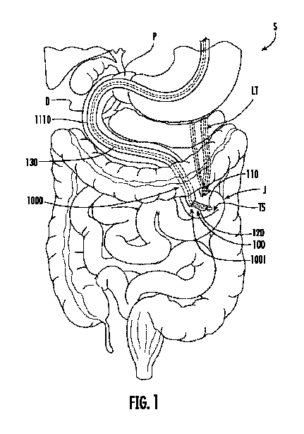
次に図面を参照すると、ロケータシステム100及びロケータシステム100を標的部位TSに送達するように構成された送達システム1000の実施形態の一例が、図1の胃腸系の概略図において示されている。本開示の原理は、他の解剖学的部位及び構造にも適用できることが理解されるであろうが、便宜上、そして限定する意図なしに、胃腸の位置及び構造を参照する。さらに、標的部位で組織係合部材によって係合される組織は、行われる処置及び使用される技術及び医療専門家の指定に応じて、吻合などの処置が行われる位置か、又はそのような処置の遠位側又は近位側にあり得ることが理解されるであろう。さらに、「~に」という表現は、特に明記しない限り、~の付近(例えば、~に沿って、~に隣接してなど)を含むことを意図していることが理解されるであろう。図示の環境例では、ロケータ送達システム1000は、自然開口部経管腔的視鏡手術(NOTES)処置(例えば、鼻又は口から食道へ)を介して胃Sに挿入され、幽門Pを通過し、十二指腸Dに挿入される。図1に示す実施形態の例では、ロケータ送達システム1000は、身体を通して標的部位TSに送達することができる可撓性の長尺送達部材1110を含む。可撓性の長尺送達部材1110は、(開腹手術技術による場合とは対照的に)体内を介したデバイスの経管腔送達のために当業者に知られている可撓性の長尺管状部材(例えば、シャフト、カテーテル、内視鏡など)内の管腔を通して送達され得る。いくつかの実施形態では、可撓性の長尺送達部材1110は、標的部位TSの位置を容易に特定するための視覚化及び/又は画像化機能を備えた内視鏡(図示せず、ただし、当業者に知られている様々な内視鏡のいずれであってもよい)を介して送達される。
Turning now to the drawings, an example embodiment of a
ロケータシステム100は、ロケータ送達システム1000によって、ロケータシステム100の所望の標的部位TSまで進められる。ロケータ送達システム1000及びロケータシステム100は、ロケータ送達システム1000の近位端にある制御ハンドルを使用して前進させることができる(図示されていないが、これは当業者に知られている任意の適切な制御ハンドルであってよく、その詳細は本開示を限定するものではなく、重要でもない)。GI系を通る蠕動運動も、ロケータ送達システム1000及びロケータシステム100の前進に役立ち得る。図1に示す環境の例では、標的部位TSは空腸Jにあり、例えばトライツ靭帯LTに隣接しているか、近位、又は遠位にある。空腸Jの一部が、空腸Jと胃Sとの間の吻合部が形成される幽門Pから距離をおいた「標的部位TS」として選択され得る(例えば、医療専門家によって決定される)。ロケータ送達システム1000は、当業者に知られている光学/視覚化要素(例えば、カメラ、スコープ、光ファイバー、蛍光透視法などであり、これらの詳細は、本開示を限定するものではなく、重要でもない)の使用などにより、標的部位TSの識別及び選択を支援することができる。ロケータシステム100は、ロケータ送達システム1000によって標的部位TSまで進められる。ロケータシステム100上のビーコン110は、標的部位TSを識別するために使用され、これにより、以下でさらに詳しく説明するように、胃S内などの別の解剖学的位置にある器具によって標的部位TSの位置を特定することができる。ビーコン110は、解剖学的組織を通して位置を特定できる信号を発する様々なデバイスのいずれかである。いくつかの実施形態では、ビーコン110は1つ以上の発光ダイオード(LED)を含む。
The
本開示の様々な原理によれば、ロケータシステム100が標的部位TSに到達すると、ロケータシステム100の組織係合部材120(以下でさらに詳しく説明する)を標的部位TSの組織に係合させることによって、ロケータシステム100が展開される。このように、ロケータシステム100を標的部位TSに対して固定し、ロケータ送達システム1000を、ロケータシステム100の位置に影響を与えることなく、ロケータシステム100から引き抜くことができる。次に、標的部位TSと胃Sの一部(好ましくは空腸J内の標的部位TSの近く)との間に吻合部を形成するための器具を体内に挿入して、標的部位TSと胃Sとの間に吻合部を形成する。
According to various principles of the present disclosure, once the
空腸Jと胃Sとの間に吻合部を形成するために、図2に示すような送達システム2000を、NOTES処置などを通じてGI系に挿入し、さらに胃Sに挿入することができる。吻合部を形成するために使用される送達システム2000は、ロケータ送達システム1000にあるものと同様の共通の送達コンポーネントを含み得ることが理解されよう。例えば、内視鏡は、ロケータ送達システム1000と同様に送達システム2000でも使用できる。送達システム2000は、ロケータシステム100のビーコン110を視覚化して標的部位TSの位置を特定できる視覚化システムを含む。例えば、送達システム2000は、カメラ付きの内視鏡や、当業者に既知の又はこれまでに知られているその他の視覚化システムなどを含み得るが、その詳細は本開示の原理を限定するものではなく、重要でもない。標的部位TSの位置が特定されると、送達システム2000によって様々な器具、ツール、デバイスなど(これらの用語は、限定する意図なく、本明細書では互換的に使用される)が送達され、標的部位TSと胃Sに沿った適切な位置との間に吻合部が形成される。
To form an anastomosis between the jejunum J and the stomach S, a
例えば、図2に示すように、送達システム2000によって切断ツール2010が送達され、標的部位TSの領域内の胃Sの壁を貫通する開口部が(ビーコン110によって誘導されて)作成される。本明細書において、「切断」という用語は、開口部を作成するという広い意味で理解されるべきであり、「切断ツール」は、刃、焼灼ツール(例えば、焼灼刃付き)、針、はさみ、アブレーションデバイス、その他のエネルギ送達デバイスなどの、組織に開口部を作成できる当業者に知られている任意のツールとして理解されるべきであり、本開示は、切断を、その用語の狭義の意味に特に限定されるものではないことが理解されるであろう。把持ツール2020(エンドエフェクタ、クリップ、スネアなど、組織を把持できることが当業者に知られている任意のグラスパー)は、送達システム2000によって送達され(例えば、切断ツール2010が送達された作業チャネルを介して、及び切断ツール2010を引き抜いた後、又は送達システム2000の別の作業チャネルを介して、又は切断ツール2010の一部として、あるいはその他の方法で)、図3に示すように、切断ツール2010によって切り込まれた胃Sの穴を通して延長される。把持ツール2020は、空腸Jに向かって伸展され、空腸Jの標的部位TS(ロケータシステム100によって識別される)を含む部分を把持し、空腸Jのその部分を胃Sに引き寄せる。空腸Jは、胃Sに対して所定の位置に保持され、当業者に既知又はこれまでに知られている任意の所望の方法で、それらの間に吻合部が形成され得る。
For example, as shown in FIG. 2, a
例えば、いくつかの実施形態では、吻合システム2030を空腸Jと胃Sの近接部分に送達して、それらの間に吻合部を形成することができる。図4に示すように、いくつかの実施形態では、吻合システム2030は、空腸J及び胃Sの近接部分を一緒に保持し(例えば、空腸J内の保持部材2034、及び胃S内の保持部材2036を使用)、それらの間に(例えば、ステント2032を通る内腔2035を介して)吻合部を形成するように構成されたステント2032を送達することができる。図5に示すようないくつかの実施形態では、空腸J及び胃Sは、組織アプロキシメーター2040によって密着した状態で保持され、そのような組織壁を通してステント2032を展開して吻合部を形成する(図4に示す実施形態の例に関して上記で説明したように)。いくつかの実施形態では、組織アプロキシメーター2040は、近接する組織壁を貫通して延び、空腸J内の拡張された組織固定端2044及び胃S内の拡張された組織固定端2046などによって、組織壁を並置して保持するように構成される。(図4に示す実施形態の例に関して上記で説明したような)ステント2032を組織アプロキシメーター2040に隣接して展開することで、図5に示す実施形態の例のように吻合部を形成することができる。図4に示す組織アプロキシメーター2040の実施形態の例は、送達システム2000及び/又は吻合システム2030(これらは、いくつかの特徴及び/又は構造を共有することができる)によって送達することができる。いくつかの実施形態では、組織アプロキシメーター2040は、切断ツール2010によって形成された開口部を通して展開される。このような場合、吻合システム2030は、組織アプロキシメーター2040に隣接する空腸J及び胃Sの近接する壁に開口部を作成するための切断ツールと、そこを通してステント2032を展開するための展開デバイスとを含み得る。空腸Jと胃Sとの間の吻合部が形成されると、ロケータシステム100は除去されてもよく、したがって、図4及び図5に示すように、任意選択で存在しないことが理解されるであろう。
For example, in some embodiments, an
本開示の様々な原理に従って形成され、上記のように使用されるロケータシステム200、300の実施形態の例が、図6、図7、図8、図9、及び図10にさらに詳細に示されている。
Example embodiments of
図6に示すロケータシステム200の実施形態の例では、ビーコン210は、組織係合部材220の遠位にあるロケータシステム200の遠位端201に隣接している。ビーコン210及び組織係合部材220は、可撓性の長尺部材230に、例えばその遠位端231に沿って取り付けられるように図示されている。組織係合部材220は(可撓性の長尺部材230の遠位端231に隣接して取り付けられた)ビーコン210の近位にあるが、逆の構成も本開示の範囲及び趣旨に含まれる。可撓性の長尺部材230は、ガイドワイヤ、又は体内(例えば、GI系)を通って標的部位TSまで経管腔的に移動可能なもの、例えば、ビーコン210を(例えば、送達システム1000内の作業チャネル又は内腔を介して)標的部位TSに送達するものとして当業者に知られている他の要素であり得る。組織係合部材220は、拡張可能な要素の形態である。例えば、図6に示す実施形態の例では、組織係合部材220は拡張可能なバルーンである。しかし、標的部位TSに対してロケータシステム200を固定するために、標的部位TSに隣接する組織壁に接触するように拡張可能な(例えば、標的部位TSに隣接する空腸Jの一部の内部に接触するように拡張可能な)他の形態の拡張可能部材も、本開示の範囲及び趣旨に含まれる。組織係合部材220が拡張して標的部位TSの組織壁(例えば、空腸Jの内部)に接触すると、組織係合部材220がビーコン210を固定している位置を乱すことなく、送達システム1000を標的部位TSから引き抜くことができ、これにより、さらなる処置を行うためにビーコン210の位置を識別することができる。
In the example embodiment of the
図6に示すように、拡張可能なバルーンの形態の組織係合部材220は、限定するものではないが、ポリエチレンテレフタラート(PET)、ポリアミド(ナイロン、ポリアミドホモポリマー、ポリアミドコポリマー、ポリ(エーテル-co-アミド)コポリマーなど)、シリコーン、ポリウレタン、ポリアリーレンスルフィド、ポリウレタンブロックコポリマー、ブロックコポリマー熱可塑性エラストマー、ポリエーテル-ブロック-アミドコポリマー、ポリエステル-ブロック-エーテルコポリマー、及びそれらの組み合わせ及び/又はコポリマーといったポリマー材料などの、形状適合性の又は非形状適合性の生体適合性材料から形成され得る。組織係合部材220は、経管腔送達を容易にするコンパクトな構成の送達構成と、拡張された組織係合構成との間でシフトされてもよい。ロケータシステム200は、組織係合部材220の送達構成と組織係合構成との間のシフトを制御する膨張ルーメンを含む。いくつかの実施形態では、可撓性の長尺部材230は、その中を延びる膨張ルーメンを有し、この膨張ルーメンを通して膨張媒体(例えば、空気や生理食塩水などの流体)を送ることで、膨張可能なバルーンの形態の組織係合部材220を膨張させることができる。あるいは、可撓性の長尺部材220の横などに、膨張ルーメンが貫通して画定された別の膨張ライン240を設けることもできる。組織係合部材220に膨張媒体を供給するための空気ポンプ250と、膨張媒体を放出して組織係合部材220を収縮させるための(例えば、標的部位TSに関して形成された処置の完了時に、組織係合部材220を標的部位TSから除去するための)収縮弁260とを、図6に概略的に示すように、膨張ライン240を介して、又は可撓性の長尺部材230内の膨張ルーメンを介して、組織係合部材220と、流体が流れることができるように結合させてもよい。
As shown in FIG. 6, the
図6に示す実施形態の例のような膨張可能な拡張可能部材の代わりに、本開示の様々な原理に従って形成されたロケータシステム300は、図7及び図8に示すように、ステントの形態の拡張可能部材を有し得る。図6に示す実施形態の例と同様に、図7及び図8に示すロケータシステム300の実施形態の図示された例は、可撓性の長尺部材330上に取り付けられたビーコン310及び拡張可能な組織係合部材320を有する。ビーコン310は組織係合部材320よりも遠位にあるが、逆の構成も本開示の範囲及び趣旨に含まれる。さらに、例えば組織係合部材320を保護し、及び/又は拡張可能な組織係合部材320が送達システム1000を通じて標的部位TSに送達される際にコンパクトな送達構成を維持するように、ロケータシステム300は、図7に示すように、送達構成において少なくとも組織係合部材320上に延びるシース340を含む。いくつかの実施形態では、ビーコン310はシース340の遠位側に送達され得る。図8に示すように、ビーコン310が標的部位TSに送達されると、シース340を近位方向に引き込み、拡張可能な組織係合部材320が拡張して標的部位TSの組織壁(例えば、空腸Jの内部)と接触できるようにする。このように、送達システム1000は、本開示の様々な原理に従って、組織係合部材320がビーコン310を固定する位置を乱すことなく、標的部位TSから引き抜かれ、さらなる処置を行うためにその位置を特定することができる。シース340は、組織係合部材320上を遠位方向に前進させて組織係合部材320をコンパクトな構成に戻し、標的部位TSに対して行われた処置の完了時などに標的部位TSから引き抜いて除去できるようにするために、所定の位置に残しておくことができる。
Instead of an expandable member as in the example embodiment shown in FIG. 6, a
組織係合部材320は、当業者に既知又はこれまでに知られているステントなどの自己拡張型デバイスであってもよい。例えば、支柱部材は、形状記憶又は熱成形可能な材料(例えば、ニチノール又はエルジロイ(商標))で形成され、組織係合部材320が、シース340を引き抜いた際に、組織係合部材320をコンパクトな送達構成に維持する収縮構成から、予め形成された拡張構成に戻るようにしてもよい。より具体的には、拡張可能な組織係合部材320は、剛性及び/又は半剛性のステント構造を形成するために組み合わされた1つ以上の支柱部材からなど、様々な方法で形成され得る。支柱部材は、1つ以上のワイヤ又はフィラメントを、編む、巻き付ける、絡み合わせる、織り合わせる、織る、編む、ループ状にする(例えば、ボビネットスタイル)、結び目を付けるなどして、拡張可能かつ収縮可能な足場構成を形成することにより形成され得る。ワイヤ又はフィラメントは、様々な非限定的な、好ましくは生体適合性の材料、例えば、限定するものではないが、ポリプロピレン、ポリエステル、ポリスルホン、ナイロン、ポリウレタン、ポリスチレン、ポリエチレン(PE)(高密度PE及び低密度PEを含む)、ポリエチレンテレフタラート(PET)、ポリブチレンテレフタラート(PBT)、ポリトリメチレンテレフタラート、ポリエーテルエーテルケトン(PEEK)、ポリ(メチルメタクリラート)(PMMA)、ポリエチレンテレフタラート(PET)、ポリテトラフルオロエチレン(PTFE)、エチレンテトラフルオロエチレン(ETFE)、フッ素化エチレンプロピレン(FEP)、ポリオキシメチレン(POM)、ポリエーテルブロックエステル、ポリ塩化ビニル(PVC)、ポリ塩化ビニリデン(PVDC)、ポリエーテルエステル、エーテル系又はエステル系コポリマー(例えば、ブチレン/ポリ(アルキレンエーテル)フタラート及び/又は他のポリエステルエラストマー、ポリアミド、エチレンビニルアセタートコポリマー(EVA)、シリコーン、ポリエチレンナフタラート(PEN)、ポリイミド(PI)、ポリエーテルイミド(PEI)、ポリフェニレンスルフィド(PPS)、ポリフェニレンオキシド(PPO)、ポリパラフェニレンテレフタルアミド、ペルフルオロ(プロピルビニルエーテル)(PFA)、エチレンビニルアルコール、ポリオレフィン、エポキシ、ポリ(スチレン-b-イソブチレン-b-スチレン)、ポリカルボナート、アイオノマー等、それらの混合物、組み合わせ、及びコポリマー;金属、例えば、ステンレス鋼、ニチノールなどのニッケル-チタン合金、又はエルジロイ(商標)などのコバルト-クロム-ニッケルベースの合金など;生体吸収性又は生分解性材料、例えば、ポリグリコール酸、乳酸、ポリ(乳酸-co-グリコール酸)、カプロラクトン、ポリマー、ポリジオキサノン、ネコ又はウシの腸など;天然繊維、例えば、絹又は綿など;又は上記のものの任意の混合物、複合材料、組み合わせ、コポリマー、又は共構造などから形成され得る。あるいは、支柱部材は、管状構造(例えば、任意選択でモノリシックな円筒状の管状部材)を拡張可能な構成に切断(例えば、レーザ切断)することによって形成され、その切断によって支柱部材が形成される。そのような管状部材は、当業者であれば理解できるように、上記に列挙した材料のうち任意の適切な材料から形成することができる。
The
拡張可能な部材の代わりに、本開示の様々な原理に従って形成されたロケータシステムの組織係合部材は、標的部位の組織を掴むことによって組織に係合することができる。例えば、図9及び図10に示すロケータシステム400の実施形態の例では、ビーコン410は組織係合部材420の近位に送達され、組織係合部材420の把持アーム422はロケータシステム400の遠位端401まで遠位に延びて標的部位TSの組織に係合する。図9及び図10に示すように、ビーコン410は可撓性の長尺部材430(例えば、編組中空シャフト)に取り付けられており、この長尺部材430もビーコン410を標的部位TSに送達することができる(例えば、送達システム1000内の作業チャネル又はルーメンを介して)。コントローラ440は、把持アーム422と作動的に係合して、把持アーム422を、送達用の閉じた構成(図9に示す)と、把持アーム422がその遠位端421に沿ってそれらの間にある標的部位TSの組織に係合する開いた構成(図10に示す)との間でシフトさせることができる。いくつかの実施形態では、把持アームは、鋸歯状の又はギザギザした(crenulated)外形429、又は遠位端421に沿った、及び/又はその縁に沿った歯などの1つ以上の追加の把持機能を有する。標的部位TSの組織が把持アーム422の間に位置すると、コントローラ440が作動することで把持アーム422を閉じた構成にシフトし、この構成では把持アーム422が一緒にそれらの間の組織を把持する。その後、本開示の様々な原理に従って、送達システム1000は、組織係合部材420がビーコン410を固定している位置を乱すことなく、標的部位TSから引き抜かれ、さらなる処置を行うためにその位置を識別することができる。コントローラ440は、例えば、標的部位TSに対して行われた処置が完了したときなどに、組織係合部材420を標的部位TSから引き抜くために把持アーム422を送達構成に戻すように作動され得る。
Instead of an expandable member, a tissue engaging member of a locator system formed according to various principles of the present disclosure can engage tissue by gripping the tissue at the target site. For example, in the example embodiment of the
図9及び図10に示す組織係合部材420の実施形態の例では、把持アーム422はピボット425aの上に回転可能に結合される。いくつかの実施形態では、把持アーム422の近位端423は、アクチュエータアーム424の遠位端427に、ピボット425bを中心に回転可能に結合される。アクチュエータアーム424の近位端429同士は、可撓性の長尺部材430の遠位端431内で、さらなるピボット425cを中心に結合されてもよいし、統一された湾曲に沿って互いに結合されてもよい。組織係合部材420を図9に示す閉じた構成に保持するために、ピボット425a(それを中心に把持アーム422が結合されている)と組織係合部材420の近位端403との間にばね442が配置されてもよい。アクチュエータ440を近位方向に引き込むと、ピボット425a(それを中心に把持アーム422が結合されている)が組織係合部材420の近位端403に近づき、アクチュエータアーム424が回転する結果、把持アーム422が図10に示す開いた構成にシフトする。そのような実施形態では、ばね442は、アクチュエータ440にかかる近位方向の力が解放されると組織係合部材420が閉じた構成に戻るように、組織係合部材420を閉じた構成に付勢するように構成され得る。これに代えて又はこれに加えて、アクチュエータアーム424の近位端429同士は、シース430の遠位端431内から遠位方向に延ばされたときにアクチュエータアーム424を互いに離すように付勢するばねを形成する統一された湾曲に沿って一緒に結合されてもよい。図9に示すように、シース430の遠位端431はアクチュエータアーム424を閉じた構成に保持し、アクチュエータアーム424の閉じた構成は把持アーム422を閉じた構成に保持する。アクチュエータ440を遠位方向に前進させると、アクチュエータアーム424の近位端429がシース430の遠位端431から前進し、把持アーム422が図10に示す開いた構成に移動できるようになる。そのような実施形態では、ばね442は把持アーム422を開いた構成に付勢してもよいし、ばね442は存在しなくてもよく、把持アーム422はシース430内に引き戻されて閉じられる。把持アーム422及びコントローラ440の他の構成も本開示の範囲及び趣旨の範囲内にあり、本開示は図9及び図10に示す実施形態の例の構成に限定されないことは理解されるであろう。
In the example embodiment of the
上記を考慮して、本開示の様々な原理によれば、上述のように、ロケータシステムは、ロケータシステムを妨害することなく、すなわち、ロケータシステムが標的部位に展開された位置に影響を与えることなく、送達システムを引き抜けるような方法で標的部位に送達され、展開される。その後、ロケータシステムのビーコンの位置を特定することで標的部位を識別できる視覚化デバイスの助けを借りて、体内の別の解剖学的位置にあるツールを使用して、標的部位に対して処置を行うことができる。 In view of the above, and in accordance with various principles of the present disclosure, the locator system is delivered and deployed at the target site in a manner that allows the delivery system to be withdrawn without disturbing the locator system, i.e., without affecting the position at which the locator system is deployed at the target site, as described above. The target site can then be treated using a tool at another anatomical location within the body with the aid of a visualization device that can identify the target site by locating the beacon of the locator system.
本開示の実施形態は、GI系で使用される医療デバイス及びシステム(例えば、内視鏡デバイス、付属ツール、及び/又はガイドワイヤ)に特に言及して説明される場合があるが、本明細書に記載のロケータデバイス及びシステムは、例えば、IVR処置、バルーン血管形成術/血管造影処置、血栓溶解処置、泌尿器科又は婦人科処置などを含む、管、管腔、血管、又は体管腔の解剖学的構造で行われる様々な医療処置とともに使用できることを理解されたい。ここでの医療デバイスには、例えば、カテーテル、尿管鏡、気管支鏡、大腸鏡、関節鏡、膀胱鏡、子宮鏡など、体管腔内を進行するための様々な医療デバイスが含まれる。また、開示された医療デバイス及びシステムは、経皮的、内視鏡的、腹腔鏡的、又はそれらの組み合わせなど、様々なアクセスポイント及びアプローチを介して挿入され得る。 Although embodiments of the present disclosure may be described with particular reference to medical devices and systems (e.g., endoscopic devices, accessory tools, and/or guidewires) used in the GI system, it should be understood that the locator devices and systems described herein may be used with a variety of medical procedures performed in the anatomical structures of ducts, lumens, vessels, or body cavities, including, for example, IVR procedures, balloon angioplasty/angiography procedures, thrombolysis procedures, urological or gynecological procedures, and the like. Medical devices herein include various medical devices for navigation within body lumens, such as, for example, catheters, ureteroscopes, bronchoscopes, colonoscopes, arthroscopes, cystoscopes, hysteroscopes, and the like. Additionally, the disclosed medical devices and systems may be inserted via various access points and approaches, such as percutaneous, endoscopic, laparoscopic, or combinations thereof.
前述の説明は広範囲に適用可能であり、例示及び説明の目的で提示されており、本明細書に開示された形式に本開示を制限することを意図したものではないことが理解されるであろう。本開示の概念、趣旨、及び範囲から逸脱することなく、本明細書に開示された実施形態に様々な追加、変更、及び置換を行うことができることが理解されるであろう。特に、本開示の原理は、その概念、趣旨、範囲、又は特性から逸脱することなく、他の形態、構造、配置、比率で、及び他の要素、材料、及びコンポーネントとともに具体化できることは、当業者には明らかであろう。例えば、本開示の様々な特徴は、本開示を合理化する目的で、1つ以上の態様、実施形態、又は構成にグループ化される。ただし、本開示の特定の態様、実施形態、又は構成の様々な特徴は、代替の態様、実施形態、又は構成で組み合わせられ得ることを理解すべきである。本開示は実施形態の観点から提示されているが、本発明の主題又はその様々な個別の特徴の所望の特性及び/又は利点の少なくとも一部を達成するために、そのような個別の特徴のすべてが存在する必要はないことを理解されたい。当業者は、本開示が、本開示の実施に使用される、本開示の原理、趣旨、又は範囲から逸脱することなく、特定の環境及び動作要件に特に適合された構造、配置、比率、材料、コンポーネント、及びその他の多くの変更又は修正を伴って使用され得ることを理解するであろう。例えば、一体的に形成されていることが示されている要素は複数の部分から構成されてもよく、複数の部分として示されている要素は一体的に形成されてもよく、要素の動作は逆順に、又は他の様式で変更されてもよく、要素のサイズ又は寸法は変更されてもよい。同様に、操作、動作、又は手順が特定の順序で説明されている場合でも、望ましい結果を得るためには、そのような特定の順序が必要であるとも、すべての操作、動作、又は手順を実行する必要があるとも理解されるべきではない。さらに、他の実装も以下の請求項の範囲内にある。場合によっては、請求項に記載されている動作を異なる順序で実行しても、望ましい結果が得られることがある。したがって、本願に開示されている実施形態は、あらゆる点で例示的なものであり、限定的なものではないとみなされるべきであり、請求された主題の範囲は、添付の請求項によって示され、前述の説明又は本明細書で説明又は図示されている特定の実施形態又は構成に限定されない。上記を踏まえて、任意の実施形態の個々の特徴は、別々に、又はその実施形態又は他の実施形態の特徴と組み合わせて使用及び請求することができ、発明の主題の範囲は添付の請求項によって示され、前述の説明に限定されない。 It will be understood that the foregoing description is broadly applicable and is presented for purposes of illustration and explanation, and is not intended to limit the disclosure to the form disclosed herein. It will be understood that various additions, modifications, and substitutions can be made to the embodiments disclosed herein without departing from the concept, spirit, and scope of the disclosure. In particular, it will be apparent to those skilled in the art that the principles of the disclosure can be embodied in other forms, structures, arrangements, ratios, and with other elements, materials, and components without departing from the concept, spirit, scope, or characteristics thereof. For example, various features of the disclosure are grouped into one or more aspects, embodiments, or configurations for the purpose of streamlining the disclosure. However, it should be understood that various features of a particular aspect, embodiment, or configuration of the disclosure may be combined in alternative aspects, embodiments, or configurations. Although the disclosure is presented in terms of embodiments, it should be understood that not all such individual features need be present to achieve at least some of the desired properties and/or advantages of the subject matter of the invention or its various individual features. Those skilled in the art will appreciate that the present disclosure may be used with many changes or modifications in structure, arrangement, proportions, materials, components, and other features specifically adapted to particular environments and operating requirements without departing from the principles, spirit, or scope of the present disclosure used to practice the disclosure. For example, elements shown to be integrally formed may be composed of multiple parts, elements shown as multiple parts may be integrally formed, operations of elements may be reversed or otherwise changed, and sizes or dimensions of elements may be changed. Similarly, even if operations, actions, or steps are described in a particular order, it should not be understood that such a particular order is required or that all operations, actions, or steps need to be performed in order to achieve desirable results. Moreover, other implementations are within the scope of the following claims. In some cases, desirable results may be achieved by performing the actions recited in the claims in a different order. The embodiments disclosed herein are therefore to be considered in all respects as illustrative and not restrictive, and the scope of the claimed subject matter is indicated by the appended claims and is not limited to the specific embodiments or configurations described or illustrated in the foregoing description or herein. In light of the above, the individual features of any embodiment may be used and claimed separately or in combination with features of that embodiment or other embodiments, and the scope of the inventive subject matter is indicated by the appended claims and is not limited to the foregoing description.
前述の説明及び以下の請求項から、以下のことが理解されるであろう。本願で使用されている「少なくとも1つ」、「1つ以上」、及び「及び/又は」という語句は、接続詞と分離詞の両方の機能を有するオープンエンドの表現である。「1つ」、「その」、「前記」、「第1の」、「第2の」などの用語は複数形を排除するものではない。例えば、本願で使用されている「1つ」という用語は、その実体の1つ以上を指す。したがって、本願では、「1つ」、「1つ以上」、及び「少なくとも1つ」という用語は互換的に使用できる。すべての方向の参照(例えば、近位、遠位、上部、下部、上方、下方、左、右、横方向、長手方向、前、後、頂部、底部、上、下、垂直、水平、放射状、軸方向、時計回り、反時計回り、及び/又は同様のもの)は、本開示の読み手の理解を助けるための識別目的のみに使用され、及び/又は関連する要素の領域を互いに区別する役割を果たし、特に本開示の位置、方向、又は使用に関して、関連する要素を制限するものではない。接続の参照(例えば、取り付けられている、結合されている、接続されている、係合されている、接合されている)は広く解釈されるべきであり、特に明記されていない限り、要素の集合間の中間部材や要素間の相対的な動きを含み得る。したがって、接続の参照は、必ずしも2つの要素が直接接続され、互いに固定された関係にあることを意味するわけではない。識別の参照(例えば、一次、二次、第1、第2、第3、第4など)は、重要性や優先順位を意味するものではなく、ある特徴を別の特徴と区別するために使用される。 From the foregoing description and the following claims, it will be understood that: The terms "at least one," "one or more," and "and/or," as used herein, are open-ended expressions that function as both conjunctions and disjunctions. Terms such as "one," "the," "said," "first," "second," and the like, do not exclude plurals. For example, the term "one" as used herein refers to one or more of its entities. Thus, the terms "one," "one or more," and "at least one" can be used interchangeably herein. All directional references (e.g., proximal, distal, upper, lower, upward, downward, left, right, lateral, longitudinal, front, rear, top, bottom, top, bottom, vertical, horizontal, radial, axial, clockwise, counterclockwise, and/or the like) are used solely for identification purposes to aid the reader's understanding of this disclosure and/or serve to distinguish regions of related elements from one another, and do not limit the related elements, particularly with respect to the location, orientation, or use of this disclosure. Connection references (e.g., attached, coupled, connected, engaged, joined) should be interpreted broadly and may include intermediate members between collections of elements and relative movement between the elements, unless otherwise specified. Thus, connection references do not necessarily imply that two elements are directly connected and in a fixed relationship to one another. Distinguishing references (e.g., primary, secondary, first, second, third, fourth, etc.) do not imply importance or priority, but are used to distinguish one feature from another.
以下の請求項は、この参照によりこの詳細な説明に組み込まれ、各請求項は、本開示の個別の実施形態として独立して存在する。請求項において、「含む」という用語は、他の要素、コンポーネント、特徴、領域、整数、ステップ、操作などの存在を排除するものではない。さらに、個々の特徴が異なる請求項に含まれる場合があるが、これらは有利に組み合わせられる可能性があり、異なる請求項に含まれることは、特徴の組み合わせが実行可能ではない、及び/又は有利ではないことを意味するものではない。さらに、単数形の参照は複数形を排除するものではない。請求項中の参照符号は、単に説明のための例として提供されており、請求項の範囲を限定するものと解釈されるものではない。 The following claims are incorporated by reference into this detailed description, with each claim standing on its own as a separate embodiment of the present disclosure. In the claims, the term "comprising" does not exclude the presence of other elements, components, features, regions, integers, steps, operations, etc. Furthermore, although individual features may be included in different claims, they may be advantageously combined, and their inclusion in different claims does not imply that a combination of features is not feasible and/or advantageous. Furthermore, a reference in the singular does not exclude a plural. Reference signs in the claims are provided merely as an illustrative example and shall not be construed as limiting the scope of the claims.
Claims (15)
前記可撓性の長尺部材に取り付けられたビーコン、及び
組織係合部材
を含むロケータシステムであって、前記組織係合部材は、標的部位の組織に係合することで前記ロケータシステムを標的部位に対して固定するように構成されている、ロケータシステム。 A flexible elongated member;
A locator system comprising: a beacon attached to the flexible elongate member; and a tissue engaging member configured to engage tissue at the target site to secure the locator system relative to the target site.
前記組織係合部材は、前記送達構成では前記コントローラ内に配置され、前記コントローラの外側にあるときは組織係合構成に拡張可能な、拡張可能なステントである、請求項6に記載のロケータシステム。 the controller being a sheath extending around the flexible elongate member;
The locator system of claim 6 , wherein the tissue engaging member is an expandable stent disposed within the controller in the delivery configuration and expandable to a tissue engaging configuration when external to the controller.
ビーコンと、
組織係合部材と、
前記組織係合部材がコンパクトであり、経管腔的に標的部位に送達可能である送達構成と、前記組織係合部材が標的部位の組織に係合することで前記ビーコンを標的部位に対して固定する組織係合構成との間で前記組織係合部材をシフトさせるように作動可能なコントローラと
を含む、ロケータシステム及びその送達システム。 A locator system and its delivery system,
Beacon,
A tissue engaging member; and
A locator system and its delivery system, comprising: a delivery configuration in which the tissue engaging member is compact and deliverable transluminally to a target site; and a controller operable to shift the tissue engaging member between a tissue engaging configuration in which the tissue engaging member engages tissue at the target site, thereby fixing the beacon relative to the target site.
前記組織係合部材は、前記シース内にあるときの送達構成と前記シース外にあるときの拡張された組織係合構成との間でシフト可能な拡張可能なステントである、請求項11に記載のロケータシステム及びその送達システム。 the controller is a sheath;
The locator system and delivery system thereof of claim 11 , wherein the tissue engaging member is an expandable stent shiftable between a delivery configuration when within the sheath and an expanded, tissue engaging configuration when outside the sheath.
Applications Claiming Priority (3)
| Application Number | Priority Date | Filing Date | Title |
|---|---|---|---|
| US202263309236P | 2022-02-11 | 2022-02-11 | |
| US63/309,236 | 2022-02-11 | ||
| PCT/US2023/012787 WO2023154447A1 (en) | 2022-02-11 | 2023-02-10 | Devices, systems, and methods for endoscopic positioning |
Publications (1)
| Publication Number | Publication Date |
|---|---|
| JP2025504065A true JP2025504065A (en) | 2025-02-06 |
Family
ID=85640936
Family Applications (1)
| Application Number | Title | Priority Date | Filing Date |
|---|---|---|---|
| JP2024545205A Pending JP2025504065A (en) | 2022-02-11 | 2023-02-10 | WIRELESS DEVICES, SYSTEMS AND METHODS FOR ENDOSCOPIC POSITIONING - Patent application |
Country Status (6)
| Country | Link |
|---|---|
| US (1) | US20230255809A1 (en) |
| EP (1) | EP4465901A1 (en) |
| JP (1) | JP2025504065A (en) |
| KR (1) | KR20240145026A (en) |
| CN (1) | CN118660673A (en) |
| WO (1) | WO2023154447A1 (en) |
Families Citing this family (1)
| Publication number | Priority date | Publication date | Assignee | Title |
|---|---|---|---|---|
| EP4653979A1 (en) | 2024-05-24 | 2025-11-26 | LG Electronics Inc. | Knob assembly for cooking apparatus |
Citations (5)
| Publication number | Priority date | Publication date | Assignee | Title |
|---|---|---|---|---|
| US5259837A (en) * | 1990-12-27 | 1993-11-09 | Wormer Mark E Van | Acoustically enhanced catheter |
| JP2002523170A (en) * | 1998-09-01 | 2002-07-30 | セノークス・インコーポレイテッド | Securing surgical instruments at target tissue locations |
| JP2005218680A (en) * | 2004-02-06 | 2005-08-18 | Olympus Corp | Surgical lesion identification system |
| US20090216115A1 (en) * | 2004-07-23 | 2009-08-27 | Calypso Medical Technologies, Inc. | Anchoring wirless markers within a human body |
| US20210196106A1 (en) * | 2019-12-30 | 2021-07-01 | Boston Scientific Scimed Inc. | Devices, systems, and methods for locating a body lumen |
Family Cites Families (3)
| Publication number | Priority date | Publication date | Assignee | Title |
|---|---|---|---|---|
| US9757535B2 (en) * | 2014-07-16 | 2017-09-12 | Fractyl Laboratories, Inc. | Systems, devices and methods for performing medical procedures in the intestine |
| JP2023511071A (en) * | 2020-01-16 | 2023-03-16 | エヌエックスティー バイオメディカル,エルエルシー | Lymph Node Access, Drainage, and Shunting |
| US12256933B2 (en) * | 2020-02-20 | 2025-03-25 | Boston Scientific Scimed, Inc. | Devices, systems, and methods for forming an opening between body lumens |
-
2023
- 2023-02-10 JP JP2024545205A patent/JP2025504065A/en active Pending
- 2023-02-10 US US18/108,169 patent/US20230255809A1/en active Pending
- 2023-02-10 EP EP23711215.6A patent/EP4465901A1/en active Pending
- 2023-02-10 CN CN202380020562.XA patent/CN118660673A/en active Pending
- 2023-02-10 KR KR1020247030440A patent/KR20240145026A/en active Pending
- 2023-02-10 WO PCT/US2023/012787 patent/WO2023154447A1/en not_active Ceased
Patent Citations (5)
| Publication number | Priority date | Publication date | Assignee | Title |
|---|---|---|---|---|
| US5259837A (en) * | 1990-12-27 | 1993-11-09 | Wormer Mark E Van | Acoustically enhanced catheter |
| JP2002523170A (en) * | 1998-09-01 | 2002-07-30 | セノークス・インコーポレイテッド | Securing surgical instruments at target tissue locations |
| JP2005218680A (en) * | 2004-02-06 | 2005-08-18 | Olympus Corp | Surgical lesion identification system |
| US20090216115A1 (en) * | 2004-07-23 | 2009-08-27 | Calypso Medical Technologies, Inc. | Anchoring wirless markers within a human body |
| US20210196106A1 (en) * | 2019-12-30 | 2021-07-01 | Boston Scientific Scimed Inc. | Devices, systems, and methods for locating a body lumen |
Also Published As
| Publication number | Publication date |
|---|---|
| CN118660673A (en) | 2024-09-17 |
| KR20240145026A (en) | 2024-10-04 |
| US20230255809A1 (en) | 2023-08-17 |
| WO2023154447A1 (en) | 2023-08-17 |
| EP4465901A1 (en) | 2024-11-27 |
Similar Documents
| Publication | Publication Date | Title |
|---|---|---|
| JP5173930B2 (en) | Surgical device | |
| JP5224298B2 (en) | Lumen wall puncture overtube | |
| JP2021069952A (en) | Multi-lumen-catheter retractor system for minimally-invasive, operative gastrointestinal treatment | |
| JP5824458B2 (en) | Device, instrument and method for accessing a body opening | |
| US20090012541A1 (en) | Expandable fastener system with flower petal-shaped retention elements | |
| US20130172828A1 (en) | Endoscopic guide wire track | |
| US20130324795A1 (en) | Three-dimensional retractor | |
| JP7751122B2 (en) | System for positioning an endoscope | |
| JP2007532240A (en) | Method and apparatus for obtaining intraluminal access | |
| KR20230058127A (en) | Stabilization and leverage devices, systems and methods | |
| JP2012080902A (en) | Retractor for flexible endoscope | |
| JP2025504065A (en) | WIRELESS DEVICES, SYSTEMS AND METHODS FOR ENDOSCOPIC POSITIONING - Patent application | |
| US20240172922A1 (en) | Distendable beacon devices, systems, and methods | |
| US20240189128A1 (en) | Devices, systems, and methods for implanting a medical device | |
| US20240285279A1 (en) | Devices, systems, and methods for delivering a device between anatomical structures | |
| ES2947435B2 (en) | Endoscopic thread suture device | |
| US20250318718A1 (en) | Systems, devices, and methods for delivery of medical devices | |
| US11241245B2 (en) | Tissue deflecting devices and related methods of use | |
| EP4577093A1 (en) | Beacon devices, systems, and methods for medical procedures | |
| CN121443333A (en) | Medical systems, devices, and related methods for wound treatment | |
| CN118302097A (en) | External sleeve providing additional working channel |
Legal Events
| Date | Code | Title | Description |
|---|---|---|---|
| A521 | Request for written amendment filed |
Free format text: JAPANESE INTERMEDIATE CODE: A523 Effective date: 20240730 |
|
| A621 | Written request for application examination |
Free format text: JAPANESE INTERMEDIATE CODE: A621 Effective date: 20240730 |
|
| A977 | Report on retrieval |
Free format text: JAPANESE INTERMEDIATE CODE: A971007 Effective date: 20250424 |
|
| A131 | Notification of reasons for refusal |
Free format text: JAPANESE INTERMEDIATE CODE: A131 Effective date: 20250603 |
|
| A521 | Request for written amendment filed |
Free format text: JAPANESE INTERMEDIATE CODE: A523 Effective date: 20250819 |
|
| A02 | Decision of refusal |
Free format text: JAPANESE INTERMEDIATE CODE: A02 Effective date: 20251111 |