JP2025503657A - Wet cleaning equipment - Google Patents
Wet cleaning equipment Download PDFInfo
- Publication number
- JP2025503657A JP2025503657A JP2024541610A JP2024541610A JP2025503657A JP 2025503657 A JP2025503657 A JP 2025503657A JP 2024541610 A JP2024541610 A JP 2024541610A JP 2024541610 A JP2024541610 A JP 2024541610A JP 2025503657 A JP2025503657 A JP 2025503657A
- Authority
- JP
- Japan
- Prior art keywords
- porous material
- negative pressure
- cleaning fluid
- liquid
- cleaner head
- Prior art date
- Legal status (The legal status is an assumption and is not a legal conclusion. Google has not performed a legal analysis and makes no representation as to the accuracy of the status listed.)
- Pending
Links
Images


Classifications
-
- A—HUMAN NECESSITIES
- A47—FURNITURE; DOMESTIC ARTICLES OR APPLIANCES; COFFEE MILLS; SPICE MILLS; SUCTION CLEANERS IN GENERAL
- A47L—DOMESTIC WASHING OR CLEANING; SUCTION CLEANERS IN GENERAL
- A47L11/00—Machines for cleaning floors, carpets, furniture, walls, or wall coverings
- A47L11/29—Floor-scrubbing machines characterised by means for taking-up dirty liquid
- A47L11/30—Floor-scrubbing machines characterised by means for taking-up dirty liquid by suction
-
- A—HUMAN NECESSITIES
- A47—FURNITURE; DOMESTIC ARTICLES OR APPLIANCES; COFFEE MILLS; SPICE MILLS; SUCTION CLEANERS IN GENERAL
- A47L—DOMESTIC WASHING OR CLEANING; SUCTION CLEANERS IN GENERAL
- A47L11/00—Machines for cleaning floors, carpets, furniture, walls, or wall coverings
- A47L11/40—Parts or details of machines not provided for in groups A47L11/02 - A47L11/38, or not restricted to one of these groups, e.g. handles, arrangements of switches, skirts, buffers, levers
- A47L11/4002—Installations of electric equipment
- A47L11/4005—Arrangements of batteries or cells; Electric power supply arrangements
-
- A—HUMAN NECESSITIES
- A47—FURNITURE; DOMESTIC ARTICLES OR APPLIANCES; COFFEE MILLS; SPICE MILLS; SUCTION CLEANERS IN GENERAL
- A47L—DOMESTIC WASHING OR CLEANING; SUCTION CLEANERS IN GENERAL
- A47L11/00—Machines for cleaning floors, carpets, furniture, walls, or wall coverings
- A47L11/40—Parts or details of machines not provided for in groups A47L11/02 - A47L11/38, or not restricted to one of these groups, e.g. handles, arrangements of switches, skirts, buffers, levers
- A47L11/4013—Contaminants collecting devices, i.e. hoppers, tanks or the like
- A47L11/4016—Contaminants collecting devices, i.e. hoppers, tanks or the like specially adapted for collecting fluids
-
- A—HUMAN NECESSITIES
- A47—FURNITURE; DOMESTIC ARTICLES OR APPLIANCES; COFFEE MILLS; SPICE MILLS; SUCTION CLEANERS IN GENERAL
- A47L—DOMESTIC WASHING OR CLEANING; SUCTION CLEANERS IN GENERAL
- A47L11/00—Machines for cleaning floors, carpets, furniture, walls, or wall coverings
- A47L11/40—Parts or details of machines not provided for in groups A47L11/02 - A47L11/38, or not restricted to one of these groups, e.g. handles, arrangements of switches, skirts, buffers, levers
- A47L11/4036—Parts or details of the surface treating tools
- A47L11/4044—Vacuuming or pick-up tools; Squeegees
-
- A—HUMAN NECESSITIES
- A47—FURNITURE; DOMESTIC ARTICLES OR APPLIANCES; COFFEE MILLS; SPICE MILLS; SUCTION CLEANERS IN GENERAL
- A47L—DOMESTIC WASHING OR CLEANING; SUCTION CLEANERS IN GENERAL
- A47L11/00—Machines for cleaning floors, carpets, furniture, walls, or wall coverings
- A47L11/40—Parts or details of machines not provided for in groups A47L11/02 - A47L11/38, or not restricted to one of these groups, e.g. handles, arrangements of switches, skirts, buffers, levers
- A47L11/408—Means for supplying cleaning or surface treating agents
- A47L11/4083—Liquid supply reservoirs; Preparation of the agents, e.g. mixing devices
-
- A—HUMAN NECESSITIES
- A47—FURNITURE; DOMESTIC ARTICLES OR APPLIANCES; COFFEE MILLS; SPICE MILLS; SUCTION CLEANERS IN GENERAL
- A47L—DOMESTIC WASHING OR CLEANING; SUCTION CLEANERS IN GENERAL
- A47L11/00—Machines for cleaning floors, carpets, furniture, walls, or wall coverings
- A47L11/40—Parts or details of machines not provided for in groups A47L11/02 - A47L11/38, or not restricted to one of these groups, e.g. handles, arrangements of switches, skirts, buffers, levers
- A47L11/408—Means for supplying cleaning or surface treating agents
- A47L11/4088—Supply pumps; Spraying devices; Supply conduits
-
- A—HUMAN NECESSITIES
- A47—FURNITURE; DOMESTIC ARTICLES OR APPLIANCES; COFFEE MILLS; SPICE MILLS; SUCTION CLEANERS IN GENERAL
- A47L—DOMESTIC WASHING OR CLEANING; SUCTION CLEANERS IN GENERAL
- A47L13/00—Implements for cleaning floors, carpets, furniture, walls, or wall coverings
- A47L13/10—Scrubbing; Scouring; Cleaning; Polishing
- A47L13/20—Mops
- A47L13/22—Mops with liquid-feeding devices
Landscapes
- Cleaning Implements For Floors, Carpets, Furniture, Walls, And The Like (AREA)
- Cleaning By Liquid Or Steam (AREA)
Abstract

クリーナーヘッド(100)を含む湿式掃除装置が提供される。クリーナーヘッドは、少なくとも1つの汚れ入口(142A)と、少なくとも1つの汚れ入口を覆う多孔質材料(114、156)とを有する。湿式掃除装置は、湿式掃除装置の内部と大気圧との間に、多孔質材料を通して流体を少なくとも1つの汚れ入口に引き込むための圧力差を提供するように構成された負圧発生器(178)をさらに含み、圧力差は2000Pa~13500Paの範囲である。
A wet cleaning apparatus is provided that includes a cleaner head (100) having at least one dirt inlet (142A) and a porous material (114, 156) covering the at least one dirt inlet. The wet cleaning apparatus further includes a negative pressure generator (178) configured to provide a pressure differential between an interior of the wet cleaning apparatus and atmospheric pressure to draw fluid through the porous material into the at least one dirt inlet, the pressure differential being in the range of 2000 Pa to 13500 Pa.
Description
本発明は、クリーナーヘッドを含む湿式掃除装置、例えば、湿式モップ掛け装置に関する。湿式掃除装置は、例えば、床、室内表面、又は窓を掃除するために使用することができる。 The present invention relates to a wet cleaning device, e.g., a wet mopping device, that includes a cleaner head. The wet cleaning device can be used, for example, to clean floors, indoor surfaces, or windows.
掃除すべき表面から水を除去する湿式掃除装置、例えば湿式モップ掛け装置が知られている。このような湿式掃除装置は、掃除すべき表面に洗浄液、例えば水を塗布し、その後、例えば適切な布でその液体を除去することもできる。 Wet cleaning devices, e.g. wet mopping devices, are known which remove water from the surface to be cleaned. Such wet cleaning devices can also apply a cleaning liquid, e.g. water, to the surface to be cleaned and then remove the liquid, e.g. with a suitable cloth.
一部の湿式掃除装置には、掃除すべき表面から水を除去するための動力付きピックアップ機能を有する。例えば、湿式真空掃除機は、十分な対気速度(例えば、少なくとも10m/s)及び/又はブラシパワーを発生させて、液滴に十分な剪断力を加えて液滴を装置に流入させることによって、液体を吸い上げることができる。このような真空掃除機の典型的な電力消費値は比較的高く、例えば数百ワットほどである。 Some wet cleaning devices have a powered pick-up function to remove water from the surface to be cleaned. For example, a wet vacuum cleaner can pick up liquid by generating sufficient air speed (e.g., at least 10 m/s) and/or brush power to apply sufficient shear force to the droplets to cause them to flow into the device. Typical power consumption of such vacuum cleaners is relatively high, e.g., on the order of several hundred watts.
湿式掃除装置が吸引を使用して液体を吸い上げるだけでなく、洗浄液を送達するように構成されている場合、さらなる課題が生じる可能性がある。両方の機能を提供すると、少なくとも一部の設計では、洗浄液が非効率的に使用されるリスクがある。 Additional challenges can arise when a wet cleaning device is configured to deliver cleaning fluid rather than just using suction to pick up liquid. Providing both functions runs the risk of inefficient use of cleaning fluid, at least in some designs.
また、使用中又はさらに使用後、洗浄液の送達が適切に制御されていないと、環境が洗浄液で浸されてしまうリスクもあり得る。掃除すべき表面のこのような浸漬は、少なくともいくつかの状況において、特に比較的低電力のピックアップシステムが使用される場合には、装置のピックアップ機能によって容易に対処できない可能性がある。 There may also be a risk that the environment will become saturated with cleaning liquid if the delivery of the cleaning liquid is not properly controlled during or even after use. Such submersion of the surface to be cleaned may not be easily handled by the pick-up functionality of the device, at least in some circumstances, especially if a relatively low-power pick-up system is used.
一部の設計では、ピックアップ機能は、このような湿式掃除装置のクリーナーヘッドが掃除すべき濡れた表面上を移動するのを妨げるリスクもあり得る。 In some designs, there is also a risk that the pick-up function may interfere with the cleaner head of such a wet cleaning device moving over the wet surface to be cleaned.
韓国登録実用新案第940001037号(Y1)は湿式ダスターを含む真空掃除機を開示している。 Korean Registered Utility Model No. 940001037 (Y1) discloses a vacuum cleaner that includes a wet duster.
国際公開第2016/008773号(A1)は、多孔質材料上に配置された布と、布によって吸収された液体を収集するためのリザーバと、液体を布からリザーバに移送するためにリザーバ内に負圧を加える装置とを含む表面掃除装置を開示している。多孔質材料の細孔サイズは1μm~50μmである。 WO 2016/008773 A1 discloses a surface cleaning device that includes a fabric disposed on a porous material, a reservoir for collecting liquid absorbed by the fabric, and a device for applying negative pressure in the reservoir to transfer the liquid from the fabric to the reservoir. The pore size of the porous material is between 1 μm and 50 μm.
独国特許出願公開第3143355号(A1)は、ほぼ水平な表面から液体を吸い取るための吸引ノズルを開示している。吸引ノズルは、吸引ノズルが設けられたノズル本体を有し、自吸ポンプ又は吸引ファンに接続することができる。 DE 31 43 355 A1 discloses a suction nozzle for sucking liquid from a substantially horizontal surface. The suction nozzle has a nozzle body provided with a suction nozzle and can be connected to a self-priming pump or a suction fan.
欧州特許出願公開第3366182号(A1)は、表面相互作用層と、ある表面と接触している表面相互作用層を通してその表面に洗浄流体を供給するための、表面相互作用層に洗浄流体チャネルが設けられた洗浄流体供給部とを含む掃除装置を開示している。この掃除装置はさらに、その表面と接触している表面相互作用層を通してその表面から汚れた水を負圧によって排出するための、表面相互作用層に汚れた流体チャネルを有する汚れた流体ドレンを含む。 EP 3366182 A1 discloses a cleaning device including a surface interaction layer and a cleaning fluid supply with cleaning fluid channels in the surface interaction layer for supplying cleaning fluid to a surface through the surface interaction layer in contact with the surface. The cleaning device further includes a dirty fluid drain with dirty fluid channels in the surface interaction layer for draining dirty water from the surface by negative pressure through the surface interaction layer in contact with the surface.
独国特許出願公開第102013223864号(A1)は、ファンモータを有するファンを含む真空掃除機を動作させる方法を開示しており、ファンは、真空掃除機の吸引ノズルを通して空気流を発生させる。真空掃除機の制御装置は、処理すべき床材の種類に応じてファンを制御する。 DE 10 2013 223 864 A1 discloses a method for operating a vacuum cleaner including a fan with a fan motor, which generates an air flow through a suction nozzle of the vacuum cleaner. A control device of the vacuum cleaner controls the fan depending on the type of floor material to be treated.
本発明は特許請求の範囲によって定義される。 The invention is defined by the claims.
本発明の一態様による例によれば、湿式掃除装置が提供され、この湿式掃除装置は、少なくとも1つの汚れ入口及び少なくとも1つの汚れ入口を覆う多孔質材料を有するクリーナーヘッドと、湿式掃除装置の内部と大気圧との間に、多孔質材料を通して流体を少なくとも1つの汚れ入口に引き込むための圧力差を提供するように構成された負圧発生器とを含み、圧力差は2000Pa~13500Paの範囲である。 According to an example according to one aspect of the present invention, a wet cleaning apparatus is provided, the wet cleaning apparatus including a cleaner head having at least one dirt inlet and a porous material covering the at least one dirt inlet, and a negative pressure generator configured to provide a pressure differential between an interior of the wet cleaning apparatus and atmospheric pressure to draw fluid through the porous material into the at least one dirt inlet, the pressure differential being in the range of 2000 Pa to 13500 Pa.
一部の従来の湿式掃除装置、特に湿式真空掃除機は、比較的高い対気速度/空気流量(例えば>15l/s)を発生させて、液滴に対する空気の剪断力を介して水を装置内に移動させることによって、掃除すべき表面から液体、例えば汚れた液体を除去する比較的高出力のファンを使用する。このようなファンは比較的大きくて重い場合があり、ファンが必要とする電力のために、装置に比較的大きなバッテリーを含める必要がある場合がある。したがって、このような液体ピックアップ原理は、特にフラットモップ型の湿式モップ掛け装置などの湿式モップ掛け装置には適していない。 Some conventional wet cleaning devices, particularly wet vacuum cleaners, use relatively high power fans that generate relatively high air speeds/air flows (e.g. >15 l/s) to remove liquids, e.g. dirty liquids, from the surface to be cleaned by moving the water through the shear forces of the air on the droplets within the device. Such fans may be relatively large and heavy, and the power required by the fans may require the inclusion of relatively large batteries in the device. Thus, such liquid pick-up principles are not suitable for wet mopping devices, particularly flat mop type wet mopping devices.
本発明は、汚れ入口(複数可)を覆う多孔質材料が、湿式掃除装置の内部と大気圧との間の圧力差(本明細書ではこの圧力差を「負圧」と呼ぶ)を維持するのに役立つことができるという洞察に(少なくとも部分的に)基づいている。 The present invention is based (at least in part) on the insight that a porous material covering the dirt inlet(s) can help maintain a pressure differential between the interior of the wet cleaning device and atmospheric pressure (herein referred to as "negative pressure").
多孔質材料の細孔内に保持される液体の表面張力は、負圧を維持するのに役立つことができる。言い換えれば、細孔は閉じることができ、細孔が「破壊」して空気がそこを通って輸送される前に、かなりの負圧に耐えることができることが見出されている。 The surface tension of the liquid held within the pores of the porous material can help maintain the negative pressure. In other words, it has been found that the pores can close and withstand significant negative pressure before they "collapse" and air is transported through them.
液体のピックアップに関しては、この表面張力を克服することができ、これは、掃除すべき表面上の液体と接触する多孔質材料の外側の1つの点(又は複数の点)で気液表面が除去され、液体が多孔質材料を通って汚れ入口(複数可)の方向に輸送されることを意味する。 For liquid pick-up, this surface tension can be overcome, which means that the gas-liquid surface is removed at a point (or points) on the outside of the porous material that comes into contact with the liquid on the surface to be cleaned, and the liquid is transported through the porous material in the direction of the dirt inlet(s).
圧力差の2000Pa~13500Paの範囲の両方の端点は意図的に選択される。 Both endpoints of the pressure differential range of 2000 Pa to 13500 Pa are intentionally selected.
2000Paの下限は、クリーナーヘッドが通常、床などの掃除すべき表面上を移動することを反映し、床上でのクリーナーヘッドの速度が増加すると、それに伴う静圧の低下は、液体が床に向かって引っ張られることを意味する。このような挙動は、以下でより詳細に説明するように、ベルヌーイ方程式によって近似することができる。 The lower limit of 2000 Pa reflects that the cleaner head typically moves over the surface to be cleaned, such as a floor, and as the speed of the cleaner head increases over the floor, the associated drop in static pressure means that the liquid is pulled towards the floor. Such behavior can be approximated by the Bernoulli equation, as explained in more detail below.
2000Pa未満では、クリーナーヘッドが典型的な掃除/モップ掛け速度で掃除すべき表面上を移動すると、過剰な量の液体が掃除すべき表面に残る可能性があることが分かっている。 It has been found that below 2000 Pa, excessive amounts of liquid may remain on the surface to be cleaned when the cleaner head is moved over the surface at typical cleaning/mopping speeds.
2000Paの最小負圧は、ユーザが掃除すべき表面上でクリーナーヘッドを移動させる典型的な最小速度に応じて設定され、これにより、液体を吸い上げるために、ユーザが掃除すべき表面上でクリーナーヘッドの移動を大幅に遅くしたり停止したりする必要なく、負圧が液体を湿式掃除装置の内部に引き込むのに十分であることを確保する。 The minimum negative pressure of 2000 Pa is set according to the typical minimum speed at which a user would move the cleaner head over the surface to be cleaned, ensuring that the negative pressure is sufficient to draw the liquid into the interior of the wet cleaning device without the user having to significantly slow or stop moving the cleaner head over the surface to be cleaned in order to pick up the liquid.
13500Paの上限は、多孔質材料を通る液体輸送が十分に迅速であることを確保する目的で定義される。 The upper limit of 13,500 Pa is defined to ensure that liquid transport through the porous material is sufficiently rapid.
維持できる負圧の大きさと多孔質材料を通る流れ抵抗との間にはトレードオフがあり、多孔質材料を通る流れ抵抗は、液体が多孔質材料を通過できる速度を決定する。このトレードオフは、範囲の上限である13500Paの選択に反映されている。 There is a trade-off between the amount of negative pressure that can be maintained and the flow resistance through the porous material, which determines the rate at which liquid can pass through it. This trade-off is reflected in the selection of the upper end of the range, 13,500 Pa.
いくつかの実施形態では、圧力差は5000Pa~9000Paであり、最も好ましくは7000Pa~9000Paである。これらの範囲は、クリーナーヘッドの移動中に観察される特に強化された液体ピックアップと、多孔質材料を通る比較的低い流れ抵抗との組み合わせを反映している可能性がある。 In some embodiments, the pressure differential is between 5000 Pa and 9000 Pa, and most preferably between 7000 Pa and 9000 Pa. These ranges may reflect the combination of the particularly enhanced liquid pick-up observed during movement of the cleaner head, and the relatively low flow resistance through the porous material.
より一般的には、前述したように、多孔質材料は、掃除すべき表面上の液体と接触するように配置されてもよい。したがって、多孔質材料は、掃除すべき表面上の液体に露出可能な多孔質材料の外面から、少なくとも1つの汚れ入口に露出された多孔質材料の内面まで画定され得る。 More generally, as previously discussed, the porous material may be positioned to contact liquid on the surface to be cleaned. The porous material may thus be defined from an outer surface of the porous material that is exposed to liquid on the surface to be cleaned, to an inner surface of the porous material that is exposed to at least one soil inlet.
いくつかの実施形態では、例えば1つ以上のメッシュ層の形態の液体輸送支持構造を多孔質材料の内面上に配置することができることに留意されたい。内面と汚れ入口(複数可)との間の1つ以上の流路は、そのようなメッシュ層(複数可)を構成する要素間の空間によって提供することができる。誤解を避けるために、このような実施形態では、多孔質材料の内面は依然として汚れ入口(複数可)に露出している。 It should be noted that in some embodiments, a liquid transport support structure, for example in the form of one or more mesh layers, may be disposed on the inner surface of the porous material. One or more flow paths between the inner surface and the dirt inlet(s) may be provided by spaces between the elements making up such mesh layer(s). For the avoidance of doubt, in such embodiments, the inner surface of the porous material is still exposed to the dirt inlet(s).
いくつかの実施形態では、ASTM F316-03(2019)の試験Aを用いて測定した多孔質材料の限界細孔径は15μm以上である。(以下でさらに説明するように)15μm以上の限界細孔径は、細孔が効率的に液体を輸送するのに十分に大きいことを確保しながら、比較的大きな負圧を維持するのに役立つ可能性があることが経験的に見出されている。後者に関しては、この観察は理論によって裏付けられていることに留意されたい。ポアズイユ方程式を使用して近似すると、細孔が小さくなると流れ抵抗が4累乗に増加する可能性があることに留意されたい。 In some embodiments, the porous material has a critical pore size of 15 μm or greater, as measured using Test A of ASTM F316-03(2019). It has been empirically found (as further explained below) that a critical pore size of 15 μm or greater can be useful for maintaining a relatively large negative pressure while ensuring that the pores are large enough to efficiently transport liquids. With regard to the latter, it is noted that this observation is supported by theory. It is noted that, when approximated using the Poiseuille equation, flow resistance can increase to a power of four as the pores get smaller.
同様に、ASTM F316-03(2019)の試験Aを用いて測定した多孔質材料の泡立ち点圧力は13500Pa以下であり得る。 Similarly, the bubble point pressure of the porous material, measured using Test A of ASTM F316-03(2019), may be 13,500 Pa or less.
いくつかの実施形態では、ASTM F316-03(2019)の試験Aを用いて測定した多孔質材料の限界細孔径は105μm以下である。限界細孔径のこの上限は、多孔質材料によって十分な負圧が維持可能であることを確保するのに役立つ。 In some embodiments, the porous material has a critical pore size of 105 μm or less, as measured using Test A of ASTM F316-03(2019). This upper limit on the critical pore size helps ensure that sufficient negative pressure can be maintained by the porous material.
同様に、ASTM F316-03(2019)の試験Aを用いて測定した多孔質材料の泡立ち点圧力は2000Pa以上であり得る。 Similarly, the bubble point pressure of the porous material, measured using Test A of ASTM F316-03(2019), may be 2000 Pa or greater.
流量を上限に制限することは、細孔が負圧に耐えられなくなり、したがって「破壊」し、その結果、大量の空気が湿式掃除装置の内部に入り、より多くの電力を消費するより大きなポンプが必要になる可能性があるリスクを最小限に抑えるのに役立つことができる。 Limiting the flow rate to an upper limit can help minimize the risk that the pores will not be able to withstand the negative pressure and therefore "collapse", potentially resulting in large amounts of air entering the interior of the wet cleaning device and requiring a larger pump that consumes more power.
いくつかの実施形態では、負圧発生器は、多孔質材料を通る流量が2000cm3/分以下となるように構成される。 In some embodiments, the negative pressure generator is configured to provide a flow rate through the porous material of up to 2000 cm 3 /min.
このような流量は、上述の従来の湿式真空掃除機の場合よりも大幅に低い可能性がある。電力は流量と圧力差の積に等しいため、この最大流量2000cm3/分(0.03l/s)と前述の最大圧力差13500Paを最大電力消費シナリオとして組み合わせることにより、湿式掃除装置の電力消費を最小限に抑えることができる。これにより、例えばより小さなバッテリーを使用して、湿式掃除装置を比較的コンパクトにすることができ、及び/又は湿式掃除装置の稼動時間を比較的長くすることができる。 Such a flow rate may be significantly lower than that of the conventional wet vacuum cleaners described above. Since power is equal to the product of flow rate and pressure differential, this maximum flow rate of 2000 cm3 /min (0.03 l/s) combined with the aforementioned maximum pressure differential of 13500 Pa as a maximum power consumption scenario may minimize the power consumption of the wet cleaning device. This may allow the wet cleaning device to be relatively compact, for example by using a smaller battery, and/or may allow the wet cleaning device to have a relatively long operating time.
代替的に又は追加的に、負圧発生器は、多孔質材料を通る流量が15cm3/分以上となるように構成されてもよい。これは、掃除すべき表面からの液体のピックアップが十分に迅速になることに寄与する可能性がある。15cm3/分の下限は、いくつかの実施形態では、同じくクリーナーヘッドに含まれる洗浄液出口(複数可)からの洗浄液の流量と同じか又はそれを超えるように設定することができる。 Alternatively or additionally, the negative pressure generator may be configured to provide a flow rate through the porous material of 15 cm3 /min or more, which may contribute to a sufficiently rapid pick-up of liquid from the surface to be cleaned. The lower limit of 15 cm3 /min may in some embodiments be set to be equal to or greater than the flow rate of cleaning liquid from the cleaning liquid outlet(s) also included in the cleaner head.
いくつかの実施形態では、負圧発生器は、多孔質材料を通る流量が40cm3/分以上となるように構成される。効率的な液体のピックアップに寄与するだけでなく、この40cm3/分は、いくつかの実施形態では、同じくクリーナーヘッドに含まれる洗浄液出口(複数可)からの洗浄液の流量と同じか又はそれを超えるように設定することができ、洗浄液の最小流量は、掃除すべき表面への洗浄液の十分な供給を確保するように設定される。 In some embodiments the negative pressure generator is configured to provide a flow rate through the porous material of 40 cm3 / min or more, which not only contributes to efficient liquid pick-up but in some embodiments can be set to be the same as or greater than the flow rate of cleaning liquid from the cleaning liquid outlet(s) also included in the cleaner head, with the minimum flow rate of cleaning liquid being set to ensure an adequate supply of cleaning liquid to the surface to be cleaned.
負圧発生器は、多孔質材料を通る流量が80~750cm3/分、より好ましくは100~300cm3/分、最も好ましくは150~300cm3/分の範囲となるように構成されてもよい。このような流量は、多孔質材料の負圧維持能力を利用することができ、また、エネルギー消費を制限しながら十分な液体のピックアップを確保することができる。 The negative pressure generator may be configured to provide a flow rate through the porous material in the range of 80-750 cm3 /min, more preferably 100-300 cm3 /min, and most preferably 150-300 cm3 /min. Such a flow rate can take advantage of the porous material's ability to maintain negative pressure and ensure sufficient liquid pick-up while limiting energy consumption.
少なくともいくつかの実施形態では、多孔質材料は、少なくとも1つの汚れ入口に密封して取り付けられた多孔質材料層を含む。これは、湿式掃除装置に含まれる負圧発生器によって流れが加えられるか否かに関係なく、汚れ入口(複数可)内の負圧を維持するのに役立つ可能性がある。 In at least some embodiments, the porous material includes a layer of porous material sealingly attached to at least one dirt inlet. This can help maintain negative pressure in the dirt inlet(s) regardless of whether flow is applied by a negative pressure generator included in the wet cleaning device.
多孔質材料層の液体ピックアップ領域は、例えば、多孔質材料層を、例えば少なくとも1つの汚れ入口のそれぞれの周りに密封して取り付けることによって画定することができる。 The liquid pick-up area of the porous material layer may be defined, for example, by sealingly attaching the porous material layer, for example, around each of the at least one dirt inlet.
密封取り付けは、少なくとも1つの汚れ入口のそれぞれの周りに多孔質材料層を接着又は溶接すること、例えば、1つ以上のチューブ(その開口部(複数可)が汚れ入口(複数可)を画定する)の周りに多孔質材料層を接着及び/又は溶接することなど、任意の適切な方法で実施することができる。いくつかの非限定的な例では、ポリマーフィルムなどの不浸透性部分は、汚れ入口(複数可)に露出している多孔質材料層の表面上及び汚れ入口(複数可)の周りに密封される。 The sealed attachment can be performed in any suitable manner, such as by gluing or welding the porous material layer around each of the at least one dirt inlet, for example, by gluing and/or welding the porous material layer around one or more tubes whose opening(s) define the dirt inlet(s). In some non-limiting examples, an impermeable portion, such as a polymeric film, is sealed onto the surface of the porous material layer exposed to the dirt inlet(s) and around the dirt inlet(s).
いくつかの実施形態では、多孔質材料は、1つ以上のさらなる多孔質材料層を含む。汚れ入口(複数可)に密封して取り付けられた多孔質材料層に加えて、1つ以上のさらなる多孔質材料層を含めることは、汚れ入口(複数可)内に維持できる負圧を増加させるのに役立つ可能性がある。これは、上述の負圧発生器がより効率的に動作するのを助けることができる。 In some embodiments, the porous material includes one or more additional layers of porous material. In addition to the porous material layer sealingly attached to the dirt inlet(s), the inclusion of one or more additional layers of porous material can help increase the negative pressure that can be maintained within the dirt inlet(s). This can help the negative pressure generator described above operate more efficiently.
このようなさらなる多孔質材料層(複数可)は、例えば、多孔質材料の厚さ方向において少なくとも1つの汚れ入口から最も遠いさらなる多孔質材料層の外面が、掃除すべき表面と接触するように、多孔質材料層の外面上に配置することができる。 Such further porous material layer(s) can be arranged, for example, on the outer surface of the porous material layer such that the outer surface of the further porous material layer furthest from the at least one dirt inlet in the thickness direction of the porous material is in contact with the surface to be cleaned.
いくつかの実施形態では、多孔質材料は、10mm以下、より好ましくは5mm以下、最も好ましくは3mm以下の厚さを有する。このような最大厚さは、多孔質材料を通る流れ抵抗の最小化に寄与し得る。 In some embodiments, the porous material has a thickness of 10 mm or less, more preferably 5 mm or less, and most preferably 3 mm or less. Such a maximum thickness may contribute to minimizing flow resistance through the porous material.
いくつかの実施形態では、多孔質材料を通る200cm3/分の流量での流体輸送圧力は、ASTM F316-03(2019)の試験Aで測定した泡立ち点圧力に0.25を掛けた値未満である。 In some embodiments, the fluid delivery pressure at a flow rate of 200 cm 3 /min through the porous material is less than 0.25 times the bubble point pressure as measured by Test A of ASTM F316-03(2019).
これは、多孔質材料を通る流れ抵抗が比較的低いレベルに維持されることを意味する可能性がある。 This may mean that flow resistance through the porous material is maintained at a relatively low level.
いくつかの実施形態では、多孔質材料は、多孔質布地、多孔質プラスチック、及び発泡体のうちの1つ以上を含む。 In some embodiments, the porous material includes one or more of a porous fabric, a porous plastic, and a foam.
このような多孔質プラスチックは、例えば、プラスチック顆粒の焼結メッシュの形態をとることができる。 Such porous plastics can take the form, for example, of a sintered mesh of plastic granules.
多孔質材料がそのような多孔質プラスチックを含む実施形態では、例えば多孔質織布などの多孔質布地を含む1つ以上のさらなる多孔質材料層は、多孔質プラスチックの外面上に配置されてもよい。このようなさらなる多孔質材料層(複数可)は、多孔質プラスチックよりも水に濡れやすく、したがって、水に濡れたときに掃除すべき表面と接触するのにより適している可能性がある。 In embodiments in which the porous material comprises such a porous plastic, one or more additional layers of porous material, including, for example, a porous fabric such as a porous woven fabric, may be disposed on the outer surface of the porous plastic. Such additional porous material layer(s) may be more water-wettable than the porous plastic and therefore more suitable for contacting the surface to be cleaned when wet.
特に、多孔質織布、最も好ましくはマイクロファイバー織布を含む多孔質材料について言及する。このようなマイクロファイバー織布は、湿式掃除装置内で必要な負圧を達成するのを容易にすることができる。 In particular, reference is made to porous materials including porous woven fabrics, most preferably microfiber woven fabrics. Such microfiber woven fabrics can facilitate achieving the necessary negative pressure within the wet cleaning device.
このような多孔質織布、特にこのようなマイクロファイバー織布は、特にその織りの緻密さを介して、限界細孔径の上記範囲を満たすように構成することができる。 Such porous woven fabrics, and in particular such microfiber woven fabrics, can be configured to meet the above range of critical pore size, particularly through the tightness of the weave.
いくつかの実施形態では、負圧発生器は容積式ポンプ又は圧力制限式ポンプを含む。 In some embodiments, the negative pressure generator includes a positive displacement pump or a pressure limited pump.
ポンプ設計が本質的にポンプ出口からの逆流を制限するため、負圧発生器が停止された後、例えばスイッチがオフになった後に容積式ポンプが汚れ入口(複数可)内の負圧を維持する能力があるため、特に容積式ポンプについて言及する。これは、例えば掃除すべき表面の掃除後及び/又は使用後に湿式掃除装置を保管領域に収納している間に、多孔質材料から問題となる液体が放出されるのを軽減することができる。 Particular mention is made of positive displacement pumps due to their ability to maintain negative pressure in the dirt inlet(s) after the negative pressure generator is stopped, e.g., switched off, since the pump design inherently limits backflow from the pump outlet. This can mitigate problematic release of liquid from porous materials, e.g., after cleaning the surface to be cleaned and/or while storing the wet cleaning device in a storage area after use.
代替的に又は追加的に、クリーナーヘッドは、(負圧発生器が存在するか否かに関係なく)多孔質材料を通して流体を少なくとも1つの汚れ入口に引き込むための流れを可能にし、多孔質材料層に向かう逆流を制限するように構成された弁アセンブリを含んでもよい。 Alternatively or additionally, the cleaner head may include a valve assembly configured to allow flow to draw fluid through the porous material to at least one dirt inlet (whether or not a negative pressure generator is present) and to restrict backflow toward the porous material layer.
弁アセンブリが多孔質材料層に向かう逆流を制限することによって、弁アセンブリは、覆われた汚れ入口(複数可)内の負圧を維持するのに役立つことができ、それによって、例えば負圧発生器の停止時に、多孔質材料を通した上記の問題となる液体の放出を軽減する。 By restricting backflow towards the porous material layer, the valve assembly can help maintain negative pressure within the covered dirt inlet(s), thereby mitigating the problematic release of liquid through the porous material discussed above, for example, upon shutdown of the negative pressure generator.
いくつかの実施形態では、湿式掃除装置は、液体を収集するための汚れた液体収集タンクを含み、負圧発生器は、液体が少なくとも1つの汚れ入口から汚れた液体収集タンクに引き込まれるように構成される。 In some embodiments, the wet cleaning apparatus includes a dirty liquid collection tank for collecting liquid, and the negative pressure generator is configured to draw liquid from the at least one dirty inlet into the dirty liquid collection tank.
負圧発生器は、例えば、汚れ入口(複数可)と汚れた液体収集タンクとの間に配置された液体ポンプ、例えば液体を圧送するための容積式ポンプを含んでもよい。 The negative pressure generator may include, for example, a liquid pump, e.g., a positive displacement pump for pumping liquid, disposed between the dirt inlet(s) and the dirty liquid collection tank.
代替的に又は追加的に、負圧発生器は、汚れた液体収集タンクの下流に配置された空気ポンプを含んでもよい。 Alternatively or additionally, the negative pressure generator may include an air pump positioned downstream of the dirty liquid collection tank.
いくつかの実施形態では、クリーナーヘッドは、洗浄液を送達することができる少なくとも1つの洗浄液出口を含む。 In some embodiments, the cleaner head includes at least one cleaning fluid outlet through which cleaning fluid can be delivered.
湿式掃除装置は、洗浄液を収容するための洗浄液リザーバを含む洗浄液供給部を含んでもよく、洗浄液リザーバは、少なくとも1つの洗浄液出口と流体連通可能であるか、又は流体連通している。 The wet cleaning device may include a cleaning fluid supply including a cleaning fluid reservoir for containing cleaning fluid, the cleaning fluid reservoir being capable of or in fluid communication with at least one cleaning fluid outlet.
このような洗浄液供給部は、例えば、洗浄液リザーバと、洗浄液を少なくとも1つの洗浄液出口に輸送し、かつ少なくとも1つの洗浄液出口を通して輸送するための送達装置、例えばポンプを含む送達装置とを含んでもよい。 Such a cleaning fluid supply may include, for example, a cleaning fluid reservoir and a delivery device, e.g., a delivery device including a pump, for transporting cleaning fluid to and through at least one cleaning fluid outlet.
洗浄液供給部及び少なくとも1つの洗浄液出口は、例えば、掃除すべき表面に向かって洗浄液を連続的に送達するように構成することができる。このような連続的な送達は、例えば、負圧発生器が多孔質材料を通して流体を少なくとも1つの汚れ入口に引き込むための流れを提供するのと同時に提供されてもよい。 The cleaning fluid supply and at least one cleaning fluid outlet can be configured, for example, to continuously deliver cleaning fluid toward the surface to be cleaned. Such continuous delivery may be provided, for example, simultaneously with a negative pressure generator providing a flow to draw fluid through the porous material and into the at least one dirt inlet.
いくつかの実施形態では、洗浄液供給部は、洗浄液を洗浄液リザーバから少なくとも1つの洗浄液出口に、かつ少なくとも1つの洗浄液出口を通して圧送するように構成されたポンプを含む。 In some embodiments, the cleaning fluid supply includes a pump configured to pump cleaning fluid from the cleaning fluid reservoir to and through the at least one cleaning fluid outlet.
いくつかの実施形態では、負圧発生器は、少なくとも1つの洗浄液出口を通して洗浄液供給部によって提供される洗浄液の流量と同じか又はそれよりも高い、多孔質材料を通る流量を提供するように構成される。 In some embodiments, the negative pressure generator is configured to provide a flow rate through the porous material that is the same as or higher than the flow rate of the cleaning fluid provided by the cleaning fluid supply through the at least one cleaning fluid outlet.
これは、掃除すべき表面が洗浄液で過度に濡れないようにするのに役立つ可能性がある。例えば、洗浄液の流量は20~60cm3/分の範囲であってもよく、負圧発生器によって提供される流量は、40~2000cm3/分、より好ましくは80~750cm3/分、さらに好ましくは100~300cm3/分、最も好ましくは150~300cm3/分の範囲であり得る。 This may help to prevent the surface to be cleaned from becoming overly wet with the cleaning liquid. For example, the flow rate of the cleaning liquid may be in the range of 20-60 cm3 /min and the flow rate provided by the negative pressure generator may be in the range of 40-2000 cm3 /min, more preferably 80-750 cm3 /min, even more preferably 100-300 cm3 /min and most preferably 150-300 cm3 /min.
少なくともいくつかの実施形態では、湿式掃除装置は湿式モップ掛け装置である。 In at least some embodiments, the wet cleaning device is a wet mopping device.
他の例では、湿式掃除装置は、例えば、窓掃除機、スイーパー、又はキャニスター型、スティック型、若しくは直立型の湿式真空掃除機などの湿式真空掃除機であってもよく、又はそれらを含んでもよい。 In other examples, the wet cleaning device may be or include, for example, a window cleaner, a sweeper, or a wet vacuum cleaner, such as a canister, stick, or upright wet vacuum cleaner.
湿式掃除装置は、いくつかの例では、床の表面などの掃除すべき表面上でクリーナーヘッドを例えば1つの掃除方向に自律的に移動させるように構成されたロボット湿式真空掃除機又はロボット湿式モップ掛け装置であるか、又はそれらを含んでもよい。 The wet cleaning device may, in some examples, be or include a robotic wet vacuum cleaner or a robotic wet mopping device configured to autonomously move a cleaner head, e.g., in one cleaning direction, over a surface to be cleaned, such as a floor surface.
湿式掃除装置は、負圧発生器に電気的に接続されたバッテリーによって負圧発生器に電力を供給できるバッテリー駆動の湿式掃除装置であってもよい。 The wet cleaning device may be a battery-powered wet cleaning device in which the negative pressure generator can be powered by a battery electrically connected to the negative pressure generator.
汚れ入口(複数可)(汚れ入口に負圧発生器の吸引力が提供される)を覆う多孔質材料によって提供することができる上述の電力消費低減効果により、湿式掃除装置はバッテリー駆動の動作に特に適したものとなり得る。 The above-mentioned power consumption reduction effect that can be provided by the porous material covering the dirt inlet(s) (through which the suction force of the negative pressure generator is provided) may make the wet cleaning device particularly suitable for battery-powered operation.
クリーナーヘッドに関して本明細書に記載される実施形態は、湿式掃除装置に適用可能であり、湿式掃除装置に関して本明細書に記載される実施形態は、クリーナーヘッドに適用可能である。 The embodiments described herein with respect to the cleaner head are applicable to the wet cleaning device and the embodiments described herein with respect to the wet cleaning device are applicable to the cleaner head.
次に、添付図面を参照して本発明の実施例を詳細に説明する
図面を参照して本発明について説明する。 The present invention will be described with reference to the drawings.
詳細な説明及び具体的な実施例は、装置、システム、及び方法の例示的な実施形態を示しているが、例示のみを目的としており、本発明の範囲を限定するものではないことを理解されたい。本発明の装置、システム及び方法のこれら及び他の特徴、態様、及び利点は、以下の説明、添付の特許請求の範囲、及び添付の図面からよりよく理解されるであろう。図面は単に概略的なものであり、縮尺通りに描かれていないことを理解されたい。また、図全体にわたって、同じ参照番号が同じ又は類似の部分を示すために使用されていることも理解されたい。 It should be understood that the detailed description and specific examples, while illustrating exemplary embodiments of the devices, systems, and methods, are for purposes of illustration only and are not intended to limit the scope of the invention. These and other features, aspects, and advantages of the devices, systems, and methods of the present invention will be better understood from the following description, the appended claims, and the accompanying drawings. It should be understood that the drawings are merely schematic and are not drawn to scale. It should also be understood that the same reference numerals are used throughout the figures to denote the same or similar parts.
クリーナーヘッドを含む湿式掃除装置が提供される。クリーナーヘッドは、少なくとも1つの汚れ入口と、少なくとも1つの汚れ入口を覆う多孔質材料とを有する。湿式掃除装置は、湿式掃除装置の内部と大気圧との間に、多孔質材料を通して流体を少なくとも1つの汚れ入口に引き込むための圧力差を提供するように構成された負圧発生器をさらに含み、圧力差は2000Pa~13500Paの範囲である。 A wet cleaning apparatus is provided that includes a cleaner head. The cleaner head has at least one dirt inlet and a porous material covering the at least one dirt inlet. The wet cleaning apparatus further includes a negative pressure generator configured to provide a pressure differential between an interior of the wet cleaning apparatus and atmospheric pressure to draw fluid through the porous material into the at least one dirt inlet, the pressure differential being in the range of 2000 Pa to 13500 Pa.
図1は、非限定的な例によるクリーナーヘッド100を示す。特に、クリーナーヘッド100の下面102が図1に示されている。下面102は、クリーナーヘッド100を使用して掃除すべき表面(図1では見えない)に面する。
Figure 1 illustrates a
図1に示す図から明らかなように、クリーナーヘッド100に少なくとも1つの洗浄液出口104が含まれている。洗浄液は、例えば少なくとも1つの洗浄液出口104のそれぞれを通して送達可能である。少なくとも1つの洗浄液出口は、クリーナーヘッド100の下面102に設ける必要はなく、洗浄液が洗浄液出口(複数可)を介して送達されて掃除すべき表面に到達できるのであれば、代替的にクリーナーヘッド100の他の場所に設けられてもよいことに留意されたい。
As can be seen from the diagram shown in FIG. 1, the
洗浄液は、水を含むか、又は水からなることができる。したがって、洗浄液は水性洗浄液であってもよい。以下にさらに詳細に説明するいくつかの非限定的な例では、洗浄液は水性洗剤溶液である。 The cleaning solution can include or consist of water. Thus, the cleaning solution can be an aqueous cleaning solution. In some non-limiting examples, described in more detail below, the cleaning solution is an aqueous detergent solution.
図1に示す非限定的な例では、洗浄液出口104は、クリーナーヘッド100の長さ106に沿って一列に配置される。これは、クリーナーヘッド100が、クリーナーヘッド100の長さ106に沿って掃除すべき表面を洗浄液で濡らすのを助けることができる。それにもかかわらず、クリーナーヘッド100の他の部分を収容できる限り、洗浄液出口104の任意の適切な構成又はパターンが考えられ得ることに留意されたい。
1, the cleaning
図1に示す特定の例では、16個の洗浄液出口104がクリーナーヘッド100に含まれているが、より多くの洗浄液出口104が、掃除すべき表面の濡れの均一性を高めるのに役立つ可能性があることに留意されたい。しかしながら、クリーナーヘッド100には、例えば、1、2、3、4、5、6、7、8、9、10、11、12、13、14、15、16、17、18、19、20又はそれ以上の任意の適切な数の洗浄液出口104を設けることができる。
1, sixteen cleaning
図1に示すようないくつかの実施形態では、クリーナーヘッド100は、洗浄液分配ストリップ108を含む。図示のように、洗浄液出口104の少なくとも一部、又はこの例ではすべてが洗浄液分配ストリップ108に含まれてもよい。
In some embodiments, such as shown in FIG. 1, the
図2は、図1に示す例示的なクリーナーヘッド100に含まれる洗浄液分配ストリップ108の概略断面図を提供する。この非限定的な例では、洗浄液分配ストリップ108は、チャネル110を含み、このチャネル110には、例えば適切な洗浄液リザーバ(図2では見えない)から入口112を介して洗浄液を供給することができる。
2 provides a schematic cross-sectional view of a cleaning
図2に示す例では、入口112は洗浄液分配ストリップ108の端部又はその近くに設けられているが、入口112が洗浄液分配ストリップ108の長さに沿った中央位置に設けられることも考えられる。代替的に又は追加的に、洗浄液分配ストリップ108は、複数の入口112、例えば、洗浄液分配ストリップ108の両端に配置された一対の入口112を含む。
In the example shown in FIG. 2, the
洗浄液は、洗浄液出口104を画定する洗浄液分配ストリップ108の開口部を介して洗浄液分配ストリップ108から出ることができる。このような開口部は、チャネル110が満たされている間、洗浄液の表面張力により、開口部を通る洗浄液、例えば水性洗浄液の通過が制限されるが、チャネル110が満たされると、洗浄液分配ストリップ108のすべての開口部を同時に通る洗浄液の通過が許可されるような寸法にすることができる。これにより、クリーナーヘッド100の長さ106にわたって掃除すべき表面を比較的均一に濡らすことが可能になり得る。
The cleaning fluid may exit the cleaning
この目的のために、各洗浄液出口104は、例えば1mm未満の直径、例えば0.1~1mm、好ましくは0.1~0.8mm、最も好ましくは0.1~0.5mmの範囲、例えば約0.3mmの直径を有してもよい。
For this purpose, each cleaning
洗浄液分配ストリップ108は、金属、ステンレス鋼などの金属合金、及び/又はポリマーなどの任意の適切な材料で形成することができる。ポリマーから洗浄液分配ストリップ108を形成することにより、洗浄液分配ストリップ108をより軽量にし、及び/又はより安価に製造することができる。
The cleaning
図1に戻ると、クリーナーヘッド100はまた、多孔質材料層114を含むか、又はいくつかの例では多孔質材料層114からなる多孔質材料を含む。図1では見えないが、クリーナーヘッド100は少なくとも1つの汚れ入口を有する。汚れ入口(複数可)のそれぞれは、多孔質材料層114によって覆われている。
Returning to FIG. 1, the
多孔質材料層114は、掃除すべき表面上の汚れた液体が最初に多孔質材料層114の細孔内に輸送され、次に、多孔質材料層114から汚れ入口(複数可)に入るように、汚れ入口(複数可)と掃除すべき表面との間に配置されてもよい。
The
図1に示す図は、多孔質材料層114の外面116を示しており、外面116は掃除すべき表面に面している。
The diagram in FIG. 1 shows the
多孔質材料層114は、クリーナーヘッド100の下面102に、又はその近くに配置される。より一般的には、多孔質材料は、必ずしも具体的には多孔質材料に含まれる多孔質材料層114ではないが、掃除すべき表面及び/又は掃除すべき表面上の液体と接触することができる。
The
多孔質材料が、多孔質材料層114の外面116上に配置された1つ以上のさらなる多孔質材料層(図1では見えない)を含む非限定的な例では、多孔質材料の厚さ方向において少なくとも1つの汚れ入口から最も遠いさらなる多孔質材料層の外面は、掃除すべき表面と接触することができる。
In a non-limiting example where the porous material includes one or more additional porous material layers (not visible in FIG. 1) disposed on the
少なくとも1つの汚れ入口のそれぞれを覆う多孔質材料層114は、例えば、汚れ入口(複数可)に流体的に接続された負圧発生器、例えばポンプによって一定の流れが加えられるか否かにかかわらず、汚れ入口(複数可)内の負圧を維持するのに役立つ可能性がある。
The
多孔質材料層114は、例えば、多孔質布地及び/又は多孔質発泡体を含むか、あるいはそれらからなることができる。多孔質布地は、例えば、マイクロファイバー布地であってもよい。
The
同様に、上述の1つ以上のさらなる多孔質材料層のそれぞれは、マイクロファイバー布地などの多孔質布地及び/又は多孔質発泡体を含むか、あるいはそれらからなることができる。 Similarly, each of the one or more additional porous material layers described above can include or consist of a porous fabric, such as a microfiber fabric, and/or a porous foam.
本明細書で使用される「マイクロファイバー布地」という用語は、合成繊維で形成された布地を指す場合があり、この布地は、繊度が1デシテックス未満の糸で形成される。 As used herein, the term "microfiber fabric" may refer to a fabric formed from synthetic fibers, the fabric being formed from yarns having a fineness of less than 1 decitex.
このようなマイクロファイバー布地は、例えば、ポリエステル繊維、ポリアミド繊維、及びポリエステル繊維とポリアミド繊維の組み合わせを含むことができる。 Such microfiber fabrics can include, for example, polyester fibers, polyamide fibers, and combinations of polyester and polyamide fibers.
マイクロファイバー布地は、例えば、マイクロファイバーセーム革であってもよい。 The microfiber fabric may be, for example, a microfiber chamois.
他の例では、多孔質布地は、例えばシャモア、鹿、ヤギ、又は羊の皮から作られる天然セーム革であり。 In another example, the porous fabric is a natural chamois made, for example, from chamois, deer, goat, or sheepskin.
多孔質材料層114の細孔内に保持される液体の表面張力は、負圧を維持するのに役立つことができる。この表面張力は、液体と接触する多孔質材料層114の外面116上の1つの点(又は複数の点)で克服することができ、それによって液体が多孔質材料層114を通って汚れ入口(複数可)の方向に輸送される。
The surface tension of the liquid held within the pores of the
例えばマイクロファイバー布地を含む多孔質材料は、特に磨耗しやすい可能性があり、そのような磨耗は、多孔質材料の負圧維持/液体ピックアップ性能を損なう危険性がある。したがって、多孔質材料は、複数の異なる色の層を含むことができ、これらの層は、クリーナーヘッド100の使用により徐々に磨耗し、その結果、多孔質材料の色が摩耗インジケータとして機能する。
Porous materials, including, for example, microfiber fabrics, may be particularly susceptible to wear, which may compromise the vacuum maintenance/liquid pickup performance of the porous material. Thus, the porous material may include multiple different colored layers that gradually wear away with use of the
図1に示すようないくつかの実施形態では、多孔質材料及び/又は多孔質材料に含まれる多孔質材料層114は、クリーナーヘッド100の長さ106と平行に延びる最大寸法を有するように細長い。
In some embodiments, such as that shown in FIG. 1, the porous material and/or the
図1に示す非限定的な例では、多孔質材料層114は、洗浄液出口104に対してクリーナーヘッド100の幅118に沿った異なる位置に配置される。
In the non-limiting example shown in FIG. 1, the
図1に示すようないくつかの実施形態では、クリーナーヘッド100は、掃除すべき表面に面する部分120を含む。1つ以上の洗浄液出口104は、洗浄液をクリーナーヘッド100の部分120に送達するように構成されてもよい。
In some embodiments, such as shown in FIG. 1, the
図1に示す図では見えないが、部分120に隣接して突出要素を取り付けることができ、突出要素はクリーナーヘッド100から掃除すべき表面の方向に突出する。突出要素は、部分120に関してクリーナーヘッド100内に別個に取り付けられる要素とみなすことができる。
Although not visible in the view shown in FIG. 1, a protruding element may be attached adjacent to
突出要素の突出特性により、突出要素は掃除すべき表面との接触が制限される可能性がある。突出要素は、例えば、部分120よりも掃除すべき表面との接触面積が小さくてもよい。
The protruding characteristics of the protruding element may limit the contact of the protruding element with the surface to be cleaned. The protruding element may, for example, have a smaller contact area with the surface to be cleaned than
少なくともいくつかの実施形態では、突出要素は多孔質材料を含む。したがって、多孔質材料と掃除すべき表面との間の接触面積が限られているため、掃除すべき表面を横切るクリーナーヘッド100の移動に対する抵抗が軽減される可能性がある。これについては、図31を参照して以下でさらに詳しく説明する。
In at least some embodiments, the protruding elements comprise a porous material. Thus, the limited contact area between the porous material and the surface to be cleaned may reduce resistance to movement of the
いくつかの実施形態では、クリーナーヘッド100は突出要素上で第1の方向に揺動して部分120を掃除すべき表面に接触させることができ、また、突出要素上で第1の方向とは反対の第2の方向に揺動して部分120を掃除すべき表面から分離させることができる。
In some embodiments, the
このような実施形態では、突出要素は、クリーナーヘッド100が部分120上で揺動できるようにするロッカーとみなすことができる。この揺動機能を実現するために、突出要素は掃除すべき表面との接触が制限される。
In such an embodiment, the protruding elements can be considered as rockers that allow the
図3に示す非限定的な例などのいくつかの実施形態では、クリーナーヘッド100は、部分120と、掃除すべき表面に面するさらなる部分122とを含む。このような実施形態では、多孔質材料層114は、部分120とさらなる部分122との間に配置されてもよい。
In some embodiments, such as the non-limiting example shown in FIG. 3, the
図3に示す図では見えないが、クリーナーヘッド100が上述の突出要素を含む場合、突出要素は部分120とさらなる部分122との間に取り付けられてもよい。したがって、突出要素は、部分120とさらなる部分122の両方に対して別々に取り付けられた要素であってもよい。このようにして、クリーナーヘッド100は突出要素上で前方に揺動して部分120を掃除すべき表面に接触させ、また後方に揺動してさらなる部分122を掃除すべき表面に接触させることができる。
Although not visible in the view shown in FIG. 3, if the
クリーナーヘッド100が突出要素を含むか否かに関係なく、洗浄液出口104(複数可)は、クリーナーヘッド100の部分120及びさらなる部分122に洗浄液を送達するように構成されてもよい。
Regardless of whether the
図3に示す非限定的な例では、クリーナーヘッド100は、図1及び図2に関連して上述したように、洗浄液分配ストリップ108(その開口部が洗浄液を部分120に送達する洗浄液出口104を画定する)と、さらなる洗浄液分配ストリップ124(そのさらなる開口部が、洗浄液をさらなる部分122に送達する洗浄液出口104を画定する)とを含む。
In the non-limiting example shown in FIG. 3, the
洗浄液分配ストリップ108とさらなる洗浄液分配ストリップ124の両方は、図3に示すように、クリーナーヘッド100の長さ106と平行に延びてもよい。
Both the cleaning
図4に示すようないくつかの実施形態では、クリーナーヘッド100は、少なくとも1つの洗浄液出口104のそれぞれに隣接する洗浄液アプリケータ材料126、128を含み、洗浄液アプリケータ材料126、128は、掃除すべき表面に洗浄液を塗布するように構成される。言い換えれば、洗浄液アプリケータ材料126、128は、洗浄液出口104(複数可)から送達される洗浄液を受け取り、その洗浄液を掃除すべき表面に移送することができる。
In some embodiments, such as shown in FIG. 4, the
洗浄液アプリケータ材料126、128は、例えば、ポリアミド及び/又はポリエステル繊維を含むことができる。
The cleaning
代替的に又は追加的に、洗浄液アプリケータ材料126、128は、細い繊維と太い繊維の組み合わせを含む。
Alternatively or additionally, the cleaning
細い繊維は、例えば、1デシテックス以下であってもよく、太い繊維は、0.01mmを超える厚さを有してもよく、例えば、太い繊維の厚さは、約0.05mmであり得る。 Fine fibers may be, for example, 1 decitex or less, and thick fibers may have a thickness greater than 0.01 mm, for example, the thickness of thick fibers may be about 0.05 mm.
ポリアミド又はポリエステルから作ることができる太い繊維は、洗浄液アプリケータ材料126、128と掃除すべき表面との間の摩擦を低減するのに役立つ可能性がある一方、例えばポリアミド又はポリエステルから作られた細い繊維は、汚れの保持を強化するのに役立つ可能性がある。
Thick fibers, which may be made from polyamide or polyester, may help reduce friction between the cleaning
太い繊維はまた、洗浄液アプリケータ材料126、128に弾性を与えることができ、それによって洗浄液アプリケータ材料126、128の圧縮を最小限に抑えることができる。
The thick fibers can also provide elasticity to the cleaning
太い繊維の圧縮低減能力は、洗浄液アプリケータ材料126、128が突出要素ロッカーに隣接する部分120及び/又はさらなる部分122に含まれる実施形態において特に有用であり得る。これは、圧縮を最小限に抑えることが、クリーナーヘッド100の継続使用にわたって、突出要素上の一貫した程度の揺動により洗浄液アプリケータ材料126、128が掃除すべき表面に接触することを確保するのに役立つ可能性があるためである。
The compression reducing ability of thicker fibers may be particularly useful in embodiments in which the cleaning
クリーナーヘッド100の使用中に洗浄液アプリケータ材料126、128の圧縮を最小限に抑えるなどのために、洗浄液アプリケータ材料126、128の厚さは、代替的に又は追加的に、例えば部分120及び/又はさらなる部分122に対する突出要素の突出の程度を考慮して選択又は制限されてもよい。
The thickness of the cleaning
洗浄液アプリケータ材料126、128が細い繊維と太い繊維の組み合わせを含む実施形態では、これらの繊維は任意の適切な方法で互いに対して配置することができる。例えば、洗浄液アプリケータ材料126、128は、細い繊維のストリップに隣接する厚い繊維のストリップを含んでもよい。このようなストリップは、繊維の厚さが幅118方向に交互になるように、クリーナーヘッド100の長さ106に沿ってそれぞれ延びることができる。このような構成は、クリーナーヘッド100が幅118方向に平行な方向に移動するときの摩擦を低減するのに役立つ可能性がある。
In embodiments in which the cleaning
洗浄液アプリケータ材料126、128がポリアミド繊維とポリエステル繊維の両方を含む実施形態では、これらの繊維は、任意の適切な方法で互いに対して配置することができる。例えば、洗浄液アプリケータ材料126、128は、ポリエステル繊維のストリップに隣接するポリアミド繊維のストリップを含んでもよい。このようなストリップは、繊維のタイプが幅118方向に交互になるように、クリーナーヘッド100の長さ106に沿ってそれぞれ延びることができる。
In embodiments in which the cleaning
洗浄液アプリケータ材料126、128は、例えば、掃除すべき表面と接触する材料、例えばポリアミド及び/又はポリエステル繊維含有材料を支持する裏地層を含むことができる。裏地層は、ポリエステルなどの任意の適切な裏地布材料から形成することができる。
The cleaning
このような裏地層には、例えばポリアミド及び/又はポリエステル繊維から形成されたタフトを設けることができる。このようなタフトは、洗浄液アプリケータ材料126、128が掃除すべき表面の輪郭に従うのを助けることができ、及び/又は洗浄液アプリケータ材料126、128が汚れ粒子を保持するのを助けると同時に、掃除すべき表面を傷つける危険性も最小限に抑えることができる。
Such a backing layer may be provided with tufts formed, for example, from polyamide and/or polyester fibers. Such tufts may help the cleaning
いくつかの実施形態では、洗浄液アプリケータ材料126、128は、(少なくとも)洗浄液アプリケータ材料126、128には含まれるが、多孔質材料には含まれない裏地層、例えばタフトを支持する上述の裏地層によって、多孔質材料と区別することができる。
In some embodiments, the cleaning
いくつかの非限定的な例では、洗浄液アプリケータ材料126、128を構成する繊維は、多孔質材料を構成する繊維と同一である。
In some non-limiting examples, the fibers that make up the cleaning
代替例では、洗浄液アプリケータ材料126、128を多孔質材料から区別できる方法の1つは、それぞれの材料の糸及び/又は繊維、例えばそれぞれの材料の掃除すべき表面と接触する糸及び/又は繊維の細かさ、例えば繊度である。例えば、多孔質材料を構成する多孔質材料層(複数可)の繊維は、洗浄液アプリケータ材料126、128の繊維よりも細くてもよい。代替的に又は追加的に、多孔質材料を構成する多孔質材料層(複数可)の糸は、洗浄液アプリケータ材料126、128の糸よりも細くてもよい。
In the alternative, one way in which the cleaning
多孔質材料は一般に、例えばマイクロファイバー布地の織りがより緻密であるため、洗浄液アプリケータ材料126、128よりも密度が高くてもよい。
The porous material may generally be denser than the cleaning
いくつかの実施形態では、洗浄液アプリケータ材料126、128は、複数の異なる色の層を含み、これらの層は、クリーナーヘッド100の使用により徐々に磨耗し、その結果、洗浄液アプリケータ材料126、128の色が摩耗インジケータとして機能する。
In some embodiments, the cleaning
いくつかの実施形態では、洗浄液アプリケータ材料126、128は、少なくとも1つの洗浄液出口104のそれぞれから取り外し可能である。これにより、例えば洗浄液アプリケータ材料126、128が過度に磨耗した場合に洗浄液アプリケータ材料126、128の交換が可能となり、及び/又は洗浄液アプリケータ材料126、128を使用の合間に洗浄することが可能になる可能性がある。磨耗は、例えば、上述の着色層を含む洗浄液アプリケータ材料126、128を介して示すことができる。
In some embodiments, the cleaning
洗浄液アプリケータ材料126、128は、任意の適切な方法で、クリーナーヘッド100、特に図1~図4に示す非限定的な例におけるクリーナーヘッド100の下面102に取り付けることができる。
The cleaning
図3に戻ると、図示のクリーナーヘッド100は、本例ではVelcroストリップの形態の少なくとも1つの締結部材130A、130B、132A、132Bを含み、これらは、洗浄液アプリケータ材料126、128上のさらなる締結部材(複数可)(図示せず)と係合する。さらなる締結部材(複数可)を、例えば、洗浄液アプリケータ材料126、128の上述の裏地層に含めるか、又はそこに取り付けることができる。
Returning to FIG. 3, the illustrated
洗浄液アプリケータ材料126、128をクリーナーヘッド100、特に少なくとも1つの洗浄液出口104に取り付ける(例えば取り外し可能に結合する)代替方法として、例えば、ポッパー、ボタン(複数可)-ボタン穴(複数可)配置、ジッパーなどを使用することが考えられる。
Alternative methods of attaching (e.g., removably coupling) the cleaning
図4に示すようないくつかの実施形態では、洗浄液アプリケータ材料126、128は、第1のアプリケータ部分126及び第2のアプリケータ部分128を含み、多孔質材料層114は、第1のアプリケータ部分126と第2のアプリケータ部分128との間に配置される。
In some embodiments, such as that shown in FIG. 4, the cleaning
第1のアプリケータ部分126がクリーナーヘッド100に含まれる場合、第1のアプリケータ部分126は、クリーナーヘッド100の上述の部分120に含まれてもよい。
When the
洗浄液アプリケータ材料、例えば第1のアプリケータ部分126が部分120に含まれる実施形態では、この部分は、掃除すべき表面と接触することと、例えば掃除すべき表面への洗浄液の塗布を補助することによって掃除すべき表面の掃除を補助することの両方に適している可能性がある。
In embodiments in which a cleaning fluid applicator material, e.g.,
しかしながら、例えば、クリーナーヘッド100がそのような洗浄液アプリケータ材料が設けられていない場合、部分120に洗浄液アプリケータ材料が含まれていないことも考えられる。このようなシナリオでは、部分120は、洗浄液アプリケータ材料、例えば第1のアプリケータ部分126が部分120に含まれるシナリオよりも洗浄能力が低くなる可能性があるにもかかわらず、(部分120に洗浄液アプリケータ材料を含める必要がなく、部分120を掃除すべき表面と接触させることが可能であるという意味で)掃除すべき表面と接触するのに適している可能性がある。
However, it is also conceivable that
第1のアプリケータ部分126を部分120に組み込むために、第1のアプリケータ部分126は、クリーナーヘッド100上に設けられた締結部材130A、130B(複数可)と係合する上述のさらなる締結部材(複数可)を含むことができる。
To incorporate the
同様に、第2のアプリケータ部分128がクリーナーヘッド100に含まれる場合、第2のアプリケータ部分128は、クリーナーヘッド100の上述のさらなる部分122に含まれてもよい。
Similarly, if the
このような実施形態では、第2のアプリケータ部分128をさらなる部分122に組み込むために、第2のアプリケータ部分128は、クリーナーヘッド100上に設けられた締結部材132A、132B(複数可)と係合する上述のさらなる締結部材(複数可)を含むことができる。
In such an embodiment, the
いくつかの実施形態では、少なくとも1つの洗浄液出口104は、少なくとも1対の洗浄液出口104を含み、多孔質材料層114は各対の洗浄液出口104の間に配置される。
In some embodiments, the at least one cleaning
洗浄液アプリケータ材料126、128が第1のアプリケータ部分126及び第2のアプリケータ部分128を含む実施形態では、第1のアプリケータ部分126は、上記1対の洗浄液出口104の一方に隣接してもよく、第2のアプリケータ部分128は、上記1対の洗浄液出口104の他方に隣接してもよい。その一例を図3及び図4に示す。
In an embodiment in which the cleaning
少なくともいくつかの実施形態では、多孔質材料は、必ずしも具体的には多孔質材料に含まれる多孔質材料層114ではないが、洗浄液アプリケータ布地126、128と接触する。
In at least some embodiments, the porous material is in contact with the cleaning
多孔質材料が洗浄液アプリケータ材料126、128と接触することにより、洗浄液の一部が洗浄液アプリケータ材料126、128から多孔質材料に、そして汚れ入口(複数可)に移送することができる。この構成は、洗浄液アプリケータ材料126、128に過剰な洗浄液が蓄積するのを防止するのに役立つ可能性があり、したがって、例えば洗浄液アプリケータ材料から洗浄液を掃除すべき表面上に滴下することによって掃除すべき表面が過度に濡れるのを最小限に抑えるのに役立つ可能性がある。代替的に又は追加的に、多孔質材料が洗浄液アプリケータ材料126、128と接触することにより、洗浄液アプリケータ材料126、128中の洗浄液を使用して、汚れ入口(複数可)を覆う多孔質材料を効率的にすすぐことができる。
Contact of the porous material with the cleaning
非限定的な例では、多孔質材料層114は、洗浄液アプリケータ材料126、128と接触する。多孔質材料が、多孔質材料層114の外面116上に配置された1つ以上のさらなる多孔質材料層(図3及び図4では見えない)を含む例では、多孔質材料層114及び/又はさらなる多孔質材料層(複数可)は、洗浄液アプリケータ材料126、128と接触してもよい。
In a non-limiting example, the
多孔質材料が洗浄液アプリケータ材料126、128と接触しているにもかかわらず、これらの材料の両方が掃除すべき表面と接触するように配置されてもよい。これは、任意の適切な方法で達成することができる。図3及び図4に示すようないくつかの実施形態では、多孔質材料のエッジ部分134は、洗浄液アプリケータ材料126、128の対向するエッジ部分136に当接する。したがって、洗浄液は、最初に洗浄液アプリケータ材料126、128内に輸送され、その後にのみ、それぞれの材料の当接するエッジ部分134、136を介して洗浄液アプリケータ材料126、128から多孔質材料内に輸送され得る。これにより、洗浄液アプリケータ材料126、128の濡れ具合に対する制御を強化することができる。
Although the porous material is in contact with the cleaning
代替的に又は追加的に、洗浄液アプリケータ材料126、128は、洗浄液アプリケータ材料126、128の少なくとも一部を多孔質材料と接触させるように変形可能であってもよい。
Alternatively or additionally, the cleaning
洗浄液アプリケータ材料126、128が、洗浄液アプリケータ材料126、128の少なくとも一部を多孔質材料と接触させるように変形可能であることにより、洗浄液の一部は、特に制御された方法で洗浄液アプリケータ材料126、128から多孔質材料に移送することができる。このようにして、例えば洗浄液アプリケータ材料126、128から洗浄液が掃除すべき表面上に滴下することによる、掃除すべき表面の過度の濡れを最小限に抑えることができる。代替的に又は追加的に、洗浄液アプリケータ材料126、128が変形して洗浄液アプリケータ材料126、128の少なくとも一部が多孔質材料と接触することにより、多孔質材料内の洗浄液を使用して多孔質材料を効率的にすすぐことができる。
By the cleaning
少なくともいくつかの実施形態では、洗浄液アプリケータ材料126、128は、掃除すべき表面と接触すると、及び/又は液体、例えば水で濡れると変形するように構成される。
In at least some embodiments, the cleaning
このような濡れは、洗浄液出口(複数可)から洗浄液アプリケータ材料126、128に洗浄液が送達される結果として、及び/又は掃除すべき表面上に液体が存在することに起因して起こり得る。
Such wetting may occur as a result of cleaning fluid being delivered from the cleaning fluid outlet(s) to the cleaning
非限定的な例では、洗浄液アプリケータ材料126、128は、繊維から形成されたタフトと、タフトを支持する裏地層とを含む。このようなタフトは、例えば掃除すべき表面と接触すると、及び/又は液体、例えば水で濡れると、多孔質材料と接触するように変形可能であり得る。
In a non-limiting example, the cleaning
タフトが多孔質材料との接触を維持している間、洗浄液はタフトを介して洗浄液アプリケータ材料126、128から多孔質材料に移送することができる。
While the tufts maintain contact with the porous material, cleaning fluid can be transferred from the cleaning
いくつかの実施形態では、洗浄液アプリケータ材料は、洗浄液アプリケータ材料126、128のエッジ部分136を多孔質材料、例えば、多孔質材料のエッジ部分134と接触させるように変形可能である。
In some embodiments, the cleaning fluid applicator material is deformable to bring the
洗浄液アプリケータ材料126、128のエッジ部分136は、例えば、洗浄液アプリケータ材料126、128が変形して洗浄液アプリケータ材料126、128のエッジ部分136を多孔質材料と接触させると、多孔質材料の(対向する)エッジ部分134に当接することができる。
The
いくつかの実施形態では、洗浄液アプリケータ材料126、128のエッジ部分136は、少なくとも洗浄液アプリケータ材料126、128が変形して洗浄液アプリケータ材料126、128のエッジ部分136を多孔質材料と接触させるときに掃除すべき表面と接触するように構成される。したがって、洗浄液アプリケータ材料126、128が掃除すべき表面と接触する位置で洗浄液アプリケータ材料126、128の濡れ具合を制御することができ、それによって掃除すべき表面が過度に濡れるリスクを最小限に抑える。
In some embodiments, the
非限定的な例では、洗浄液アプリケータ材料126、128は、洗浄液アプリケータ材料126、128の少なくとも一部を多孔質材料の多孔質材料層114と接触させるように変形可能である。多孔質材料が1つ以上のさらなる多孔質材料層を含む例では、洗浄液アプリケータ材料126、128の変形により、洗浄液アプリケータ材料126、128の少なくとも一部、例えばエッジ部分136が多孔質材料層114及び/又はさらなる多孔質材料層(複数可)と接触する。
In a non-limiting example, the cleaning
クリーナーヘッド100が上述の突出要素を含む実施形態では、多孔質材料及び洗浄液アプリケータ材料126、128の当接する対向するエッジ部分134、136は、好ましくは、突出要素と部分120との間に配置される。このようにして、例えば、突出要素を介してクリーナーヘッド100を揺動させることによって突出要素と洗浄液アプリケータ材料126、128との間で洗浄液アプリケータ材料126、128から絞り出される過剰な洗浄液は、多孔質材料を介して汚れ入口(複数可)に効率的に輸送され得る。
In embodiments in which the
多孔質材料と洗浄液アプリケータ材料126、128との間の接触は、材料の掃除べき表面と接触する側で行われてもよいことに留意されたい。これは、洗浄液が洗浄液アプリケータ材料126、128を適切に濡らしたり、多孔質材料をすすいだりすることなく、多孔質材料に直接入ることを回避するのに役立つ可能性がある。
Note that contact between the porous material and the cleaning
いくつかの実施形態では、洗浄液アプリケータ材料126、128は、洗浄液アプリケータ材料126、128の少なくとも一部を突出要素と部分120との間の多孔質材料と接触させるように変形可能である。
In some embodiments, the cleaning
したがって、例えば、突出要素上でクリーナーヘッド100を揺動させることによって突出要素と洗浄液アプリケータ材料との間で洗浄液アプリケータ材料126、128から絞り出される過剰な洗浄液は、多孔質材料を介して汚れ入口(複数可)に効率的に輸送され得る。
Thus, for example, excess cleaning fluid squeezed out of the cleaning
洗浄液アプリケータ材料126、128が上述の第1のアプリケータ部分126及び第2のアプリケータ部分128を含む実施形態では、図4に示すように、洗浄液アプリケータ材料126、128の対向するエッジ部分136は、第1のアプリケータ部分126に含まれてもよい。さらに、多孔質材料のさらなるエッジ部分138は、第2のアプリケータ部分128のさらなる対向するエッジ部分140に当接することができる。その一例を図3及び図4に示す。
In an embodiment in which the cleaning
上述の突出要素が部分120とさらなる部分122との間に配置される場合、多孔質材料及び第1のアプリケータ部分126の当接する対向するエッジ部分134、136は、好ましくは、突出要素と部分120との間に配置され、そして、多孔質材料と第2のアプリケータ部分128の当接する対向するさらなるエッジ部分138、140は、好ましくは、突出要素とさらなる部分122との間に配置される。
When the above-mentioned protruding element is disposed between the
このようにして、例えば、クリーナーヘッド100をそれぞれ前方及び後方に揺動させることによって突出要素と第1及び第2の洗浄液アプリケータ材料126、128との間で洗浄液アプリケータ材料126、128から絞り出される過剰な洗浄液は、多孔質材料を介して汚れ入口(複数可)に効率的に輸送され得る。
In this manner, for example, excess cleaning fluid squeezed from the cleaning
洗浄液アプリケータ材料126、128の対向するエッジ部分136及び/又はさらなる対向するエッジ部分140(存在する場合)は、例えば、掃除すべき表面と接触するように配置されてもよい。したがって、洗浄液アプリケータ材料126、128が掃除すべき表面と接触する位置で洗浄液アプリケータ材料126、128の濡れ具合を制御することができ、それによって掃除すべき表面が過度に濡れるリスクを最小限に抑える。
The opposing
いくつかの実施形態では、第1のアプリケータ部分126は、第1のアプリケータ部分126の少なくとも一部を部分120と突出要素との間の多孔質材料と接触させるように変形可能であり、及び/又は、第2のアプリケータ部分128は、第2のアプリケータ部分128の少なくとも一部をさらなる部分122と突出要素との間の多孔質材料と接触させるように変形可能であってもよい。
In some embodiments, the
図5Aは、例示的なクリーナーヘッド100の多孔質材料層114及び少なくとも1つの汚れ入口142A、142Bを示す平面図を提供する。図5Bは、図5Aに示す多孔質材料層114及び少なくとも1つの汚れ入口142A、142Bの概略断面図を提供する。
Figure 5A provides a plan view of the
図5A及び図5Bに示すようないくつかの実施形態では、少なくとも1つの汚れ入口142A、142Bのそれぞれは、負圧発生器(図5A及び図5Bでは見えない)に流体的に接続されるか又は流体的に接続可能な1つ又は複数のチューブ144A、144Bの開口部によって画定される。
In some embodiments, such as those shown in FIGS. 5A and 5B, each of the at least one
図5A及び図5Bに示す非限定的な例では、クリーナーヘッド100は、1対の汚れ入口142A、142Bを含むが、1、2、3、4、5、6、又はそれ以上など、任意の適切な数の汚れ入口142A、142Bが考えられ得る。
In the non-limiting example shown in Figures 5A and 5B, the
複数の汚れ入口142A、142Bがクリーナーヘッド100に含まれる場合、これらは、例えば、互いに同じ寸法を有してもよい。
If
代替的に又は追加的に、複数の、例えば1対の汚れ入口142A、142Bが使用される場合、汚れ入口142A、142Bは、クリーナーヘッド100の長さ106に沿って比較的均一な吸引力を提供するように、クリーナーヘッド100の長さ106方向に沿って間隔を置いて配置されてもよい。例えば、クリーナーヘッド100の中心位置と汚れ入口142Aの中心との間の長さ106に沿った距離は、中心位置と汚れ入口142Bの中心との間の長さ106に沿った距離と同じであってもよく、又は実質的に同じであってもよい。
Alternatively or additionally, if multiple, e.g., a pair of
単一の汚れ入口が使用される場合、これは、クリーナーヘッド100の長さ106に沿って比較的対称的な吸引プロファイルを提供するために、クリーナーヘッド100の中心位置に設けることができる。
If a single dirt inlet is used, it may be located in a central position on the
より一般的には、多孔質材料層114の液体ピックアップ領域PRは、例えば、多孔質材料層114を、例えば少なくとも1つの汚れ入口142A、142Bのそれぞれの周りに密封して取り付けることによって画定される。
More generally, the liquid pick-up area PR of the
このような密封取り付けは、汚れ入口142A、142B(複数可)と多孔質材料層114との間の漏れによる負圧の損失が最小限に抑えられるか又は防止されるため、覆われた汚れ入口142A、142B(複数可)内の負圧を維持するのに役立つことができる。
Such a sealed attachment can help maintain negative pressure within the covered dirt inlet(s) 142A, 142B because loss of negative pressure due to leakage between the dirt inlet(s) 142A, 142B and the
密封取り付けは、少なくとも1つの汚れ入口142A、142Bのそれぞれの周りに多孔質材料層114を接着又は溶接すること、例えば、多孔質材料層114を、汚れ入口142A、142B(複数可)を画定する開口部(複数可)の周りで上述のチューブ144A、144B(複数可)に接着及び/又は溶接することなど、任意の適切な方法で実施することができる。
The sealing attachment can be performed in any suitable manner, such as by gluing or welding the
特に、ヒートシール、例えば超音波溶接によって多孔質材料層114を汚れ入口142A、142B(複数可)に密封して取り付けることについて言及する。これは、汚れ入口142A、142B(複数可)内の負圧を維持するのに役立つ簡単な方法で特に気密なシールを提供することがわかっている。
In particular, reference is made to sealingly attaching the
図5B、図6A及び図6Bを参照すると、多孔質材料層114を汚れ入口142A、142Bに密封して取り付ける非限定的な例は、多孔質材料層114上、例えば多孔質材料層114の内面148上、及び汚れ入口142A、142Bの周りに密封された不浸透性部分146を含むクリーナーヘッド100によって実装され、これにより、汚れ入口142A、142Bは、多孔質材料層114と不浸透性部分146との間の密閉キャビティ150に露出される。
5B, 6A and 6B, a non-limiting example of sealingly attaching the
不浸透性部分146は、例えば、熱可塑性フィルムなどのポリマーフィルムを含むか、又はそれからなり得る。様々な代替の密封構成を以下に説明するが、そのいくつかはそのようなポリマーフィルムを含まない。
The
図6A及び図6Bに示す非限定的な例では、不浸透性部分146、例えばポリマーフィルムの接着及び/又は溶接によって形成されたシール152は、多孔質材料層114の周囲及び汚れ入口142A、142Bの周囲に延びる。
In the non-limiting example shown in Figures 6A and 6B, the
図7A及び図7Bに示すような少なくともいくつかの実施形態では、液体ピックアップ領域PRは、例えば、洗浄液が液体ピックアップ領域PRを迂回して、例えばその周囲を通過して、掃除すべき表面に到達するか、又は少なくとも掃除すべき表面に向けられることを可能にするように、少なくとも1つの洗浄液出口104に対して配置される。
In at least some embodiments, such as those shown in Figures 7A and 7B, the liquid pickup area PR is positioned relative to at least one cleaning
これにより、洗浄液をより効率的に使用できる可能性がある。これは、洗浄液が、例えば上述の洗浄液アプリケータ材料126、128(クリーナーヘッド100に含まれる場合)を介して、掃除すべき表面に到達する可能性がより高いためである。
This may result in more efficient use of cleaning fluid since the cleaning fluid is more likely to reach the surface to be cleaned, for example via the cleaning
他の例では、多孔質材料は、少なくとも部分的に負圧発生器によって提供される流れによって吸引されることによって、例えばクリーナーヘッド100又はクリーナーヘッド100の構成要素に対して、汚れ入口142A、142B(複数可)の周囲に取り付けることができる。
In other examples, the porous material may be attached around the
いくつかの実施形態では、クリーナーヘッド100は、キャビティ150内に液体輸送支持構造154を含み、液体輸送支持構造154は、多孔質材料層114、特に多孔質材料層114の細孔と少なくとも1つの汚れ入口142A、142Bとの間の液体ピックアップ領域PR内に1つ以上の流路を提供するように構成される。
In some embodiments, the
多孔質材料層114、例えばマイクロファイバー布地、及び/又は不浸透性部分146、例えばポリマーフィルムは、負圧により多孔質材料層114及び不浸透性部分146が互いに引き寄せられるように柔軟であってもよい。これにより、多孔質材料層114から少なくとも1つの汚れ入口142A、142Bへの液体の通過が制限されるリスクがある。液体輸送支持構造154は、多孔質材料層114と不浸透性部分146が互いに向かって引き寄せられるにもかかわらず、液体が依然として多孔質材料層114、特に多孔質材料層114の細孔から少なくとも1つの汚れ入口142A、142Bに輸送され得ることを確保するのに役立つ可能性がある。
The
液体輸送支持構造154は、任意の適切な方法で実装することができる。図7A及び図7Bに示す非限定的な例では、液体輸送支持構造154は、1つ以上のメッシュ層を含むか、又はそれによって定義される。このような例では、上述の1つ以上の流路は、メッシュ層(複数可)を構成する要素間の空間によって提供することができる。液体輸送支持構造154の代替例については、以下に説明する。
The liquid
上述したように、多孔質材料は、いくつかの実施形態では、多孔質材料層114に加えて、1つ以上のさらなる多孔質材料層156、158を含むことができる。その例を図8及び図9に示す。
As mentioned above, in some embodiments, the porous material can include one or more additional
ここで、多孔質材料が乾燥しているとき、多孔質材料は、空気が多孔質材料の乾燥細孔のそれぞれを通して輸送される「空気輸送状態」にあるとみなすことができることに留意されたい。「液体輸送状態」は、液体、例えば水が多孔質材料の(濡れた)細孔を通して輸送される状態に対応する。細孔(複数可)への液体の供給がなくなると、「流体遮断状態」を使用してもよい。「流体遮断状態」は、多孔質材料の濡れた細孔(複数可)内に保持された(残留)液体の表面張力により、細孔(複数可)を通る流体輸送が妨げられる状態に対応する。後者の状態では、空気と液体、例えば水との境界に表面又は障壁が形成される。この障壁は、汚れ入口142A、142B(複数可)内の上述の負圧を維持するのに役立つことができる。この障壁を「破る」ために必要な圧力を「破壊圧力」と呼ぶことができる。 It should be noted here that when the porous material is dry, it can be considered to be in an "air transport state" where air is transported through each of the dry pores of the porous material. The "liquid transport state" corresponds to a state where a liquid, e.g. water, is transported through the (wet) pores of the porous material. When the supply of liquid to the pore(s) is eliminated, a "fluid blocking state" may be used. The "fluid blocking state" corresponds to a state where the surface tension of the (residual) liquid held in the wet pore(s) of the porous material prevents fluid transport through the pore(s). In the latter state, a surface or barrier is formed at the interface between the air and the liquid, e.g. water. This barrier can help to maintain the aforementioned negative pressure in the dirt inlet(s) 142A, 142B. The pressure required to "break" this barrier can be called the "breaking pressure".
織りが細かい多孔質織布は、より小さな細孔、例えば微細孔を有し、より高い破壊圧力を生み出す可能性があることに留意されたい。ただし、製織技術で細孔をどれだけ小さくできるかには限界がある可能性がある。同時に、特定の繊維、例えば、好ましい洗浄及び/又は摩耗性能のために選択された繊維は、汚れ入口142A、142B(複数可)内で十分な負圧を維持するのには適していない、より開放的な構造を提供するようにしか織ることができない可能性がある。
It should be noted that tightly woven, porous woven fabrics may have smaller pores, e.g., micropores, and produce higher burst pressures. However, there may be limitations to how small the pores can be made with a weaving technique. At the same time, certain fibers, e.g., fibers selected for preferred cleaning and/or abrasion performance, may only be able to be woven to provide a more open structure that is not suitable for maintaining sufficient negative pressure within the
それにもかかわらず、「破壊圧力」は様々な方法で調整することができる。図8に示す非限定的な例では、多孔質材料は、多孔質材料層114及び第1のさらなる多孔質材料層156を含むか、又はそれらによって定義される。
Nonetheless, the "break pressure" can be adjusted in a variety of ways. In the non-limiting example shown in FIG. 8, the porous material includes or is defined by a
例えば、多孔質材料層114はマイクロファイバー布地であり、第1のさらなる多孔質材料層156はマイクロファイバー布地である。
For example, the
このように多孔質材料が多孔質材料層114、156の積層体を含むことによって、例えば多孔質材料が多孔質材料層114のみからなるシナリオと比較して、破壊圧力が増加する可能性がある。
In this manner, the porous material may include a laminate of
いかなる特定の理論にも束縛されることを望まないが、この効果は、細孔サイズ及び形状の変動、例えば統計的変動から生じるものと考えられる。例えば、マイクロファイバー布地は、多くの繊維と糸から作ることができ、これらの繊維と糸が織り合わされて1枚の布地になる。したがって、繊維と糸の間に微細孔などの細孔が形成される可能性があるため、布地に存在する細孔サイズは厳密に1つのサイズと形状に固定されず、統計的に変化する。 Without wishing to be bound by any particular theory, it is believed that this effect results from variations, e.g., statistical variations, in pore size and shape. For example, a microfiber fabric may be made from many fibers and threads that are woven together into a piece of fabric. Thus, the pore sizes present in the fabric are not fixed to a precise size and shape, but rather vary statistically, as pores, such as micropores, may form between the fibers and threads.
単一の多孔質材料層114は、残留液体の表面張力がより小さい少数の比較的大きな細孔を含んでもよく、その結果、これらの比較的大きな細孔は、単一の多孔質材料層114の破壊圧力を低下させるのに寄与する。さらなる多孔質材料層156を多孔質材料層114上に積層することによって、多孔質材料層114の上述の少数の比較的大きな細孔が、さらなる多孔質材料層156に含まれる比較的大きな細孔と整列/連通する確率は、比較的小さい可能性がある。したがって、多孔質材料層114、156の積層は、多孔質材料の破壊圧力を増加させるのに役立つ可能性がある。
The single
図8に示す非限定的な例では、多孔質材料は多孔質材料層114及び第1のさらなる多孔質材料層156から形成されるが、例えば破壊圧力をさらに増加させるために、多孔質材料に2つ以上のさらなる多孔質材料層156を含めることができる。図9に示す非限定的な例では、多孔質材料は、多孔質材料層114、第1のさらなる多孔質材料層156、及び第2のさらなる多孔質材料層158を含むか、又はそれらによって定義される。
In the non-limiting example shown in FIG. 8, the porous material is formed from the
例えば、多孔質材料層114はマイクロファイバー布地であり、第1のさらなる多孔質材料層156はマイクロファイバー布地であり、第2のさらなる多孔質材料層158はマイクロファイバー布地である。
For example, the
多孔質材料の多孔質材料層114、156、158は、互いに接着していてもよく、接着していなくてもよい。多孔質材料層114、156、158が、例えば多孔質材料層間に塗布される適切な接着剤を介して互いに接着される非限定的な例では、これは、多孔質材料の破壊圧力をさらに増加させるのに役立つ可能性がある。
The
いかなる特定の理論にも束縛されることを望まないが、これは、接着剤が、接着された多孔質材料層間の水平方向の流体輸送を妨げるためであると考えられる。図10を参照すると、多孔質材料層114の細孔160A、160Bを通る流体輸送は、左上のペインに概略的に示されており、一方、接着されていない多孔質材料層114と第1のさらなる多孔質材料層156の細孔162Aとの間の水平方向の流体輸送は、左下のペインに概略的に示されている。後者を図10の右側のペインと比較すると、多孔質材料層114と第1のさらなる多孔質材料層156との間の接着剤164が、多孔質材料層の細孔160Aと第1のさらなる多孔質材料層156の細孔162A、162Bとの間の水平方向の流体輸送を制限又は防止することが明らかである。
Without wishing to be bound by any particular theory, it is believed that this is because the adhesive prevents horizontal fluid transport between the bonded porous material layers. With reference to FIG. 10, fluid transport through the
多孔質材料層114、156、158を互いに接着するために、熱活性化布地接着剤などの任意の適切な接着剤164を使用することができる。熱活性化布地接着剤の市販品の例は、Vliesofix(登録商標)である。
Any
多孔質材料の多孔質材料層114、156、158が互いに接着されていないことの利点は、例えば、接着剤164が多孔質材料層114、156、158の間に存在するシナリオと比較して多孔質材料層114、156、158間の液体の水平方向の輸送が許可されるか、又は少なくとも制限が少ないため、多孔質材料を通る液体輸送に対する抵抗が軽減され得ることであり得る。
An advantage of the
多孔質材料層114に加えて1つ以上のさらなる多孔質材料層156、158を含む多孔質材料の代替として、又はそれに加えて、多孔質材料層114、例えばマイクロファイバー布地は、例えば超音波溶接によって緻密化処理を受けることができる。これは、多孔質材料層114の破壊圧力を増加させるのに役立つ可能性がある。
As an alternative or in addition to a porous material including one or more further
例示的な緻密化プロセスでは、多孔質材料層114、例えばマイクロファイバー布地などの多孔質布地が、例えば2つの要素(例えば、ローラー)の間に配置され、例えば、圧縮され、比較的高い周波数(例えば、約40kHz)の振動を多孔質材料層114に発する。
In an exemplary densification process, the
この振動により、多孔質布地、例えばマイクロファイバー布地の繊維が動いて互いに擦れ合い、熱が発生し、その結果、個々の繊維が互いに溶接される可能性がある。このような溶接は、例えば圧縮された固体ブロックではなく、より密度の高い多孔質構造が得られるように制御することができる。このプロセスは、多孔質布地が圧縮された状態にある間に行われる可能性があるため、布地の密度が増加し、それによって破壊圧力が増加する可能性がある。 This vibration causes the fibers of a porous fabric, e.g., a microfiber fabric, to move and rub against each other, generating heat that may result in individual fibers welding together. Such welding may be controlled to result in a denser porous structure rather than, for example, a compressed solid block. This process may take place while the porous fabric is in a compressed state, thus increasing the density of the fabric and thereby the burst pressure.
このような緻密化プロセスは、代替的に又は追加的に、1つ以上のさらなる多孔質材料層156、158(複数可)が多孔質材料に含まれている場合に、そのようなさらなる多孔質材料層156、158(複数可)を緻密化するために使用されてもよい。
Such a densification process may alternatively or additionally be used to densify one or more further
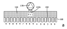
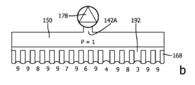
図11は、多孔質材料168の破壊圧力特性を試験するための例示的な試験装置166を概略的に示す。多孔質材料168は、締め付け部材170とベースプレート172の間に締め付けられている。締め付け部材170は、ボルト174用の穴を画定し、ボルト174はベースプレート172のねじ穴に受け入れられる。ボルト174を適切な方向に回すと、多孔質材料168を締め付ける/解放することができる。
FIG. 11 illustrates a schematic of an
この特定の例では、締め付け部材170は厚さ10mmのアルミニウムリングであり、ベースプレート172は厚さ10mmのポリメタクリル酸メチルで作られる。多孔質材料のサンプルは直径140mmの円形ディスクである。サンプルは8本のボルト174を使用して固定される。
In this particular example, the clamping
本試験装置166の汚れ入口142Aは、ベースプレート172に設けられた輸送ダクト176の開口部によって画定される。多孔質材料168と汚れ入口142Aとの間のキャビティには、上述の液体輸送支持構造154が、この場合は直径80mmのメッシュの形態で設けられる。
The
試験装置166は、汚れ入口142A内に負圧を発生させる負圧発生器178と、汚れ入口142A内の圧力を測定するように構成された圧力センサ180、例えば圧力計とを含む。
The
この特定の例における圧力センサ180は、時間に応じて圧力を監視できるように、圧力計とデータ収集ユニット(LabQuest(登録商標)2)の組み合わせを含む。
The
この特定の例における負圧発生器178は、蠕動ポンプ又はシリンジポンプ(例えば250mLシリンジポンプ)の形態である。蠕動ポンプは、パルス水流を提供することができる。シリンジポンプは、蠕動ポンプよりも正確な測定を可能にすることが見出された。
The
試験装置166はまた、チャンバの形態の圧力ラインフィルタ182を含み、これは、圧力ラインフィルタ182を圧力センサ180に接続する圧力センサライン184に液体が入るのを防止するように構成される。圧力ラインフィルタ182とポンプ178の下流には、多孔質材料168を通して圧送された液体を収集するための収集リザーバ186がある。
The
試験手順は、多孔質材料168のサンプルを締め付け部材170とベースプレート172の間に締め付け、次に100cm3/分の流量を送達するようにポンプ178を設定することを含む。圧力ラインフィルタ182が空であることを確認するためにチェックし、各測定の前に圧力センサ180の圧力計をゼロにして再接続する。次に、多孔質材料168のサンプルに25cm3の水を注ぎ、多孔質材料上に約4mの深さを有する水の層を残す。次に、ポンプ178を起動してフラッシングを実施し、多孔質材料168のサンプルに水が通るようにする。フラッシング実施に続いて、ポンプ178を停止し、25cm3の水を多孔質材料168のサンプル上に注ぎ、データ収集ユニットをトリガしてデータ収集を開始させ、ポンプ178を起動することによって測定を実施する。
The test procedure involves clamping a sample of
データ収集から得られた負圧対時間の典型的なグラフを、多孔質材料168の概略図とともに図12に示す。最初に、上述の「液体輸送状態」188を採用し、この状態では、液体190(この例では水)が(事前に濡れた)細孔192を通って輸送される。この場合に記録される「輸送圧力」は、多孔質材料168及びメッシュ液体輸送支持構造154を通して液体190を輸送するために必要な圧力差に対応する。
A typical graph of negative pressure versus time obtained from data collection is shown in FIG. 12 along with a schematic diagram of the
「液体輸送状態」188を記述する支配方程式は、次のポアズイユ方程式である可能性があり、

例えば、細孔径が20μmで、細孔が厚さ0.8mmの多孔質材料168を横切って延び、細孔192あたりの推定体積流量が約4.96*10-14m3/s(通常の流量100cm3/分から)で、η水が1*10-3Pa・sであると仮定すると、ΔP=10.1Paとなる。
For example, assuming a pore size of 20 μm, pores extending across a 0.8 mm thick
「液体輸送状態」188に続いて、中間状態194を採用し、この状態では、液体190のほとんどすべてが多孔質材料168のサンプルの表面から除去され、その結果、ほとんどの細孔は前述の「流体遮断状態」にあり、多孔質材料168の濡れた細孔(複数可)内に保持された(残留)液体190の表面張力により、空気196が細孔192を通って輸送されるのが防止される。中間状態194では、「液体輸送状態」にある可能性のある細孔192の数はますます減少する。「流体遮断状態」では、かなり高い負圧が許容されるため、中間状態194では、負圧が図に示すように比較的急速に増加する。
Following the "liquid transport state" 188, an
「流体遮断状態」を記述する支配方程式は、以下の液滴dP方程式であってもよく、

例えば、典型的な直径20μmの細孔192に対してRが10μmで、T水が0.073N/mであると仮定すると、Pi-PO=ΔP=14600Paとなる。
For example, assuming R is 10 μm for a typical 20
上記の近似では、液滴の壁が多孔質材料168の表面に対して90度の角度に達することができると仮定していることに留意されたい。ただし、以下に説明するASTM F316-03(2019)の試験Aでは、限界細孔径dはd=Cγ/pで与えられ、式中、γはmM/m単位の表面張力であり(20°Cの蒸留水の場合は72.75)、pがPa単位の場合、Cは2860である。同様の単位を使用した場合の上記の液滴dP方程式の場合と同様に、Cが4000ではなく2860である理由は、C=4000*cosθであるためであり、ここで、θは、液体と材料間の接触角であり、標準法によって規定される限界細孔径を決定するために、θは、44.3°であると仮定される(参考までに、ASTM E3278-21にさらなる説明がある)。前述の直径20μmの細孔の例に同じ44.3°の接触角を使用すると、ΔP=10449Pa(上記の14600Pa値を参照)となる。
Note that the above approximation assumes that the walls of the droplet can reach an angle of 90 degrees with respect to the surface of the
上記の液滴dP方程式からの14600PaのΔPは、洗剤を水に加えると18000Paに増加する可能性がある。洗剤を加えると水の表面張力は低下するが(T石鹸水は0.045N/m)、細孔192の上の気泡内には、気泡の内側と外側の2つの表面が形成される。したがって、水に洗剤を加えた場合の破壊圧力は、単層表面の場合の約2倍になる可能性がある。

中間状態194に続いて、最終状態198を採用し、この状態で、多孔質材料168の表面からすべての自由水が除去され、すべての細孔192が最初は「流体遮断状態」にある。ポンプ178は多孔質材料168を通して水を吸い上げ続けるため、負圧が増大し、これにより流体ブロックの一部が破壊され、空気196が「空気輸送状態」でそれぞれの細孔192を通って輸送される可能性がある。関連する空気の侵入は、加えられた流れによって負圧が生じ、流体ブロックがそれ以上破壊されなくなる最終状態198で平衡に達する可能性がある。後者は、研究対象の多孔質材料168の「破壊圧力」に対応する。
Following the
「空気輸送状態」を記述する支配方程式は、「液体輸送状態」について上記で示したポアズイユ方程式であり得る。例えば、細孔径が20μmで、細孔が厚さ0.8mmの多孔質材料168を横切って延び、細孔192あたりの推定体積流量が約4.96*10-14m3/s(通常の流量100cm3/分から)で、η空気が18.1*10-6Pa・sであると仮定すると、ΔP=0.18Paとなる。
The governing equation describing the "air transport conditions" may be the Poiseuille equation as shown above for the "liquid transport conditions". For example, assuming a pore size of 20 μm, pores extending across a 0.8 mm thick
全体的に、空気輸送圧力(例えば0.18Pa)及び水輸送圧力(例えば10.1Pa)は、表面張力由来の圧力差(例えば14600Pa)と比較して、両方とも有意に小さく、例えば無視できるほどである可能性がある。 Overall, the air transport pressure (e.g., 0.18 Pa) and the water transport pressure (e.g., 10.1 Pa) are both significantly smaller, e.g., potentially negligible, compared to the pressure difference due to surface tension (e.g., 14,600 Pa).
図13は、上記の試験装置166及び試験手順を使用して試験した多孔質材料168のいくつかの圧力対時間のグラフを提供する。プロット200は、多孔質材料層114のみを有する多孔質材料168に関するものであり、プロット202は、多孔質材料層114と、第1のさらなる多孔質材料層156とを有する多孔質材料168に関するものであり、プロット204は、多孔質材料層114、第1のさらなる多孔質材料層156、及び第2のさらなる多孔質材料層158を有する多孔質材料168に関するものであり、プロット206は、多孔質材料層114及び3つのさらなる多孔質材料層を有する多孔質材料168に関するものである。これらのデータは、前述したように、より多くの積層された多孔質材料層を多孔質材料168に含めると、破壊圧力が増加することを示す。
13 provides pressure versus time graphs of several of the
さらに、プロット202、204、及び206の各セット内には、多孔質材料層が互いに接着されている多孔質材料168及び多孔質材料層が互いに接着されていない多孔質材料168についてのプロットがある。上述のように、接着剤を使用して多孔質材料層を互いに接着すると、破壊圧力がさらに増加することが観察された。
Furthermore, within each set of
図14は、a)の、液体がすべての細孔192を通って引き込まれている上述の「液体輸送状態」188、b)の「液体輸送状態」188の終了、c)の中間状態194、及びd)の終了状態198を概略的に示す。図14には、負圧発生器178、例えばポンプに接続された汚れ入口142A、142B(複数可)を覆う多孔質材料168が示されている。
Figure 14 shows a) the above-mentioned "liquid transport state" 188 in which liquid is being drawn through all
多孔質材料168は、それぞれ異なる破壊圧力を有する細孔192、例えば微細孔を有する。破壊圧力は、図14では各細孔192の下の数字によって表される。簡単にするために、各数字は1桁に丸められている。
The
負圧発生器178、例えばポンプの起動時に、すべての液体、例えば水が床から吸引され、必要な圧力は、この例では「1」に設定された水輸送圧力である。汚れ入口142A内、及びこの例では多孔質材料168の後ろのキャビティ150内の負圧は、それに応じて「1」である。したがって、図14のa)は「液体輸送状態」188を概略的に表し、b)は「液体輸送状態」188の終了を示す。b)では、負圧が上昇し始めるポイントに達する。
Upon starting the
すべての液体、例えば水が床から除去されると、すべての細孔192は、その中の残留液体の表面張力によって塞がれる可能性がある。図示の非限定的な例では、負圧発生器178は固定流量ポンプであり、したがってポンプの継続的な動作によって負圧が増加する可能性がある。ある時点で、多孔質材料168の後ろの汚れ入口142A内の負圧は、最も弱い細孔192の破壊圧力のレベル(例えば、「4」)まで上昇する可能性があり、細孔の破壊圧力を超え、空気がそこを通って輸送され始める可能性がある。これらの第1の細孔192が「破壊」したとき、多孔質材料168の後ろの汚れ入口142A内の圧力がすでにかなり大きい可能性があるため、この時点でこれらの細孔192によって輸送される空気はかなり大きい可能性がある。したがって、図14のステップc)は、中間状態194を概略的に表すものとみなすことができる。
When all the liquid, e.g., water, is removed from the bed, all the
中間状態194では、細孔192が塞がれつつある一方で、他の細孔192は依然として(汚れ入口142A(複数可)からさらに離れた)さらなる領域から液体を輸送している可能性があるため、汚れ入口142A(複数可)の近くにより大きな負圧が発生する。これにより、すべての自由液体がなくなるまで、負圧は比較的ゆっくりと上昇することができる。これはすべて、ポンプ速度、及び少なくともいくつかの例では、液体輸送支持構造154の特性、並びに負圧が加えられたときに変形するすべての要素の柔軟性によって影響を受ける可能性がある。
In the
簡単に説明すると、流量を100cm3/分に設定し、多孔質材料とポンプとの間の流れ抵抗を無視し、すべての要素が無限に剛性であると仮定すると、中間状態194は図12の垂直線であってもよく、「液体輸送状態」188から終了状態198にデジタル的に移動する。
Briefly, if the flow rate is set to 100 cm3 /min, the flow resistance between the porous material and the pump is neglected, and all elements are assumed to be infinitely rigid, the
このプロセスは、この例では、輸送される空気がポンプ速度と等しくなり、多孔質材料168の後ろの汚れ入口142A内の負圧が、最も低い破壊圧力を有する残りの「破壊されていない」細孔192の破壊圧力よりも低くなるまで継続することができる。したがって、図14のステップd)は、上述の終了状態198を概略的に表すものとみなすことができる。
This process can continue, in this example, until the air being pumped is equal to the pump speed and the negative pressure in the
試験装置166において測定した圧力は、多孔質材料168の破壊圧力を定義する可能性があることに留意してください。150cm3/分などの異なる流量を試験したが、同じ破壊圧力が示されている。増加した流量を補うためにより多くの細孔192が「破壊」される可能性があることに留意されたい。
Note that the pressure measured in the
多孔質材料168の細孔192の細孔サイズ、言い換えれば細孔径は、比較的高い負圧と、多孔質材料168を通る液体の輸送に対する比較的低い抵抗/多孔質材料168の液体輸送圧力とのバランスをとるように選択することができる。
The pore size, or pore diameter, of the
より小さな細孔192は、例えば比較的低電力の負圧発生器178、例えばポンプを使用して、汚れ入口142A内に発生させることができる負圧を増加させることができる。より小さな細孔192を有するより密度の高い多孔質材料168は、より高い破壊圧力を生じさせることができる。また、細孔サイズの下限を調べる目的で、上述の試験装置166及び試験手順を使用して、多孔質材料168として、保持できる粒子のサイズに応じて指定されたビールフィルタを用いて研究を行った。0.25μm、3μm、10μm及び25μmのフィルタを試験した。
Smaller pores 192 can increase the negative pressure that can be generated in the
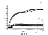
図15を参照すると、プロット208は0.25μmフィルタについてのものであり、プロット210は3μmフィルタについてのものであり、プロット212は10μmフィルタについてのものであり、プロット214は25μmフィルタについてのものであり、プロット216は参照用マイクロファイバー布地についてのものである。
Referring to FIG. 15,
図15から、多孔質材料168の多孔質サイズ/直径が性能に大きな影響を与えることがわかる。
Figure 15 shows that the pore size/diameter of the
図15から、0.25μmフィルタでは、3μmフィルタの場合よりも水輸送圧力が大幅に高くなる可能性があることが明らかである。0.25μmフィルタの場合、水輸送中に負圧が約23000Paまで上昇する可能性がある。また、0.25μmフィルタの場合、乾燥状態に達するまでの時間が大幅に長くなる可能性があり、これは、掃除すべき表面から液体/水を輸送するのに大幅により多くの時間がかかる可能性があることを意味する。 From Figure 15, it is clear that the water transport pressure can be significantly higher with the 0.25 μm filter than with the 3 μm filter. With the 0.25 μm filter, the negative pressure can rise to about 23000 Pa during water transport. Also, with the 0.25 μm filter, the time to reach dryness can be significantly longer, which means that it can take significantly more time to transport the liquid/water from the surface to be cleaned.
非限定的な例では、多孔質材料168の平均細孔サイズ/細孔径が約3μmの場合、特性の好ましいバランスが得られる可能性がある。
In a non-limiting example, a favorable balance of properties may be achieved when the
図15は、液体/水輸送圧力と多孔質材料168の破壊圧力との間に有限の差があることを示しているように見える。比較的小さな細孔192は、破壊圧力の上昇(例えば、0.25μmフィルタの場合、39000Paまで)につながる可能性があるが、水/液体輸送圧力も上昇する可能性がある(例えば、0.25μmフィルタの場合、33000Pa)。水輸送圧力と破壊圧力との間のこの差は、参照用マイクロファイバー布地(水輸送圧力1000Pa、破壊圧力7000Pa)の差と類似していることに留意されたい。
Figure 15 appears to show that there is a finite difference between the liquid/water transport pressure and the burst pressure of the
細菌は、比較的小さいサイズを特徴とする傾向がある。例えば、「平均的な」サイズの細菌とみなすことができる大腸菌細胞は、長さが約2μm、直径が0.5μmである。 Bacteria tend to be characterised by a relatively small size. For example, an E. coli cell, which can be considered an "average" sized bacterium, is around 2 μm in length and 0.5 μm in diameter.
したがって、細孔サイズが2μmより大きい多孔質材料168は、そのような細菌が通過することを可能にする可能性がある。このようにして、細菌を掃除すべき表面から除去することができる。
Thus, a
選択された多孔質材料168に応じて、最大99.9%の細菌を多孔質材料168を通して掃除すべき表面から引き離すことができる。
Depending on the
いくつかの実施形態では、多孔質材料168は、0.25μm~40μmの範囲の細孔サイズ/細孔径を有するマイクロファイバー布地の1つ以上の層によって定義される。
In some embodiments, the
例えば、このような多孔質材料168(マイクロファイバー布地の1つ以上の層によって定義される)は、前述の0.25μm~40μmの範囲の細孔サイズ/細孔径の分布、及び20μm~40μm(例えば約35μm)の平均細孔サイズを有することができる。細孔の寸法は細菌のサイズよりもかなり大きいため、細菌は多孔質材料168を通過することができ、したがって掃除すべき表面から除去される。
For example, such a porous material 168 (defined by one or more layers of microfiber fabric) may have the aforementioned pore size/pore diameter distribution in the range of 0.25 μm to 40 μm, and an average pore size of 20 μm to 40 μm (e.g., about 35 μm). Because the pore dimensions are significantly larger than the size of bacteria, bacteria can pass through the
上記の説明は多孔質材料168自体の動作原理に焦点を当てているが、多孔質材料168は掃除すべき表面と接触し、掃除すべき表面を一定の速度で移動することができることに留意されたい。これは図16に概略的に示されており、図16は、清掃除すべき表面218上の多孔質材料168で覆われた汚れ入口142Aを含む例示的なクリーナーヘッド100を示す。この非限定的な例では、掃除すべき表面218は床220の表面であり、掃除すべき表面218と多孔質材料168との間には液体(例えば水)の層222が存在する。負圧発生器178、例えばポンプは、多孔質材料168の細孔192を通して矢印224の方向に流体を引き込むことを目的としている。矢印226は、液体を汚れ入口142Aに向かって引っ張る内部負圧を表す。矢印228はクリーナーヘッド100の速度を表す。
While the above description focuses on the working principle of the
図16は、流体層222内の速度分布234を概略的に示す。矢印230は、流体層222内の速度分布234によって生成される、多孔質材料168にかかる流体剪断力を表す。矢印232は、水を床220に向かって引っ張る剪断力を表す。
Figure 16 shows a schematic of the
この挙動は、次のベルヌーイ方程式を使用して近似することができ、

上記のベルヌーイ方程式は、多孔質材料168の下の圧力について書き直すことができる。

速度が1.5m/sの場合、ΔP=1125Paであり、速度が3.16m/sの場合、ΔP=5000Paである。 When the speed is 1.5 m/s, ΔP = 1125 Pa, and when the speed is 3.16 m/s, ΔP = 5000 Pa.
これは、より高い速度では床220が液体をより強く引っ張ることになるため、より高い速度では、より多くの液体が床220上に残ることを示し、これは、本開示によるクリーナーヘッド100で観察された。
This indicates that at higher speeds, more liquid remains on the
例えば約1.5m/sでのクリーナーヘッド100の移動により、液体の層222に剪断流が発生し、多孔質材料168内に存在する液体に剪断力232が作用して、液体を掃除すべき表面218に向かって引っ張る可能性がある。水はまた、負圧226によって汚れ入口142Aの方向にも押し込まれる。負圧は、液体222を汚れ入口142A(複数可)に向かって移動させる力が剪断力232を超えるように選択することができる。
Movement of the
多孔質材料168と、掃除すべき表面218に液体(例えば水)を塗布するための洗浄液アプリケータ材料126、128とを含む例示的なクリーナーヘッド100の液体ピックアップ性能を、異なる汚れ入口負圧で1.5m/sで掃除すべき表面218上を移動して評価した。結果を表1に示す。
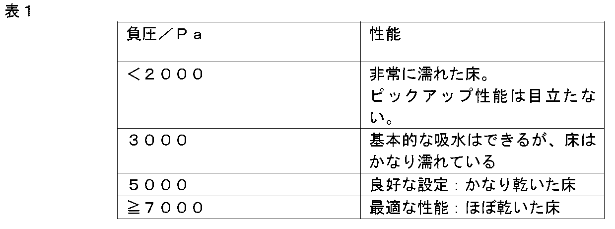
本明細書に記載される液体ピックアップ原理のさらなる利点は、特に負圧発生器178に電力が供給される例において、電力消費がより低いことであり得る。
A further advantage of the liquid pickup principle described herein may be lower power consumption, particularly in instances where the
水を吸い上げることができる従来の真空掃除機は、水滴に十分な剪断力を発生させて水滴を真空掃除機に入らせるために、かなりの対気速度及び/又はブラシパワーを発生させる必要がある。このような真空掃除機の典型的な電力消費は数百ワットである。 Conventional vacuum cleaners capable of sucking up water must generate significant airspeed and/or brush power to generate sufficient shear on the water droplets to cause them to enter the vacuum cleaner. Typical power consumption for such vacuum cleaners is several hundred watts.
以下の計算は、本開示による液体、例えば水のピックアップに必要な機械的動力が比較的低いことを示し、

例えば、負圧が5000Pa、流体流量が100cm3/分の場合、電力は8.3*10-3ワットである。 For example, for a negative pressure of 5000 Pa and a fluid flow rate of 100 cm 3 /min, the power is 8.3*10 −3 Watts.
例えば、機械的電力消費が約50ワットの湿式掃除装置において28分間の稼働時間を提供する従来のバッテリーを使用して、負圧発生器178に電力を供給する場合、この場合の稼働時間は168,000分、言い換えれば100日以上となる。
For example, if a conventional battery providing 28 minutes of run time in a wet cleaning device with a mechanical power consumption of approximately 50 watts is used to power the
したがって、本開示によるクリーナーヘッド100を有する電動湿式掃除装置は、そのバッテリーの再充電をほとんど必要としない可能性があり(湿式掃除装置に電力を供給するためにこのようなバッテリーが含まれている例では)、及び/又は例えば1時間の稼働に必要なバッテリー容量が最小限であるため、より軽量にすることができる。後者に関しては、従来の手持ち式湿式掃除装置用のバッテリーの重量は約0.5kgである可能性があり、したがって湿式掃除装置全体の重量に大きく影響する可能性があることに留意されたい。
Thus, a powered wet cleaning device having a
表2は、従来の真空掃除機と、本開示による湿式掃除装置に関して上述した様々な状態との間の機械的動力の比較を提供する。

より一般的には、本開示は、クリーナーヘッド100を含む湿式掃除装置を提供する。クリーナーヘッド100は、少なくとも1つの汚れ入口142A、142Bと、少なくとも1つの汚れ入口142A、142Bを覆う多孔質材料168とを有する。湿式掃除装置は、湿式掃除装置の内部と大気圧との間に、多孔質材料168を通して流体を少なくとも1つの汚れ入口142A、142Bに引き込むための圧力差を提供するように構成された負圧発生器178をさらに含み、圧力差は2000Pa~13500Paの範囲である。
More generally, the present disclosure provides a wet cleaning apparatus including a
圧力差の2000Pa~13500Paの範囲の両方の端点は意図的に選択される。 Both endpoints of the pressure differential range of 2000 Pa to 13500 Pa are intentionally selected.
2000Paの下限は、クリーナーヘッド100が通常、床などの掃除すべき表面上を移動することを反映し、床上でのクリーナーヘッド100の速度が増加すると、それに伴う静圧の低下は、液体が床に向かって引っ張られることを意味する。このような挙動は、上述のようにベルヌーイ方程式で近似することができる。
The lower limit of 2000 Pa reflects that the
上記の表1を参照すると、2000Pa未満では、クリーナーヘッド100が典型的な速度で掃除すべき表面上を移動すると、過剰な量の液体が掃除すべき表面に残る可能性があることが分かっている。
Referring to Table 1 above, it has been found that below 2000 Pa, excessive amounts of liquid may remain on the surface being cleaned when the
2000Paの最小負圧は、ユーザが掃除すべき表面上でクリーナーヘッド100を移動させる典型的な最小速度に応じて設定され、これにより、液体を吸い上げるために、ユーザが掃除すべき表面上でクリーナーヘッド100の移動を大幅に遅くしたり停止したりする必要なく、負圧が液体を湿式掃除装置の内部に引き込むのに十分であることを確保する。
The minimum negative pressure of 2000 Pa is set according to the typical minimum speed at which a user moves the
13500Paの上限は、多孔質材料168を通る液体輸送が十分に迅速であることを確保する目的で定義される。
The upper limit of 13,500 Pa is defined to ensure that liquid transport through the
維持できる負圧の大きさと多孔質材料168を通る流れ抵抗との間にはトレードオフがあり、多孔質材料を通る流れ抵抗は、液体が多孔質材料168を通過できる速度を決定する。このトレードオフは、範囲の上限である13500Paの選択に反映されている。
There is a trade-off between the amount of negative pressure that can be maintained and the flow resistance through the
いくつかの実施形態では、圧力差は5000Pa~9000Paであり、最も好ましくは7000Pa~9000Paである。これらの範囲は、クリーナーヘッド100の移動中に観察される特に強化された液体ピックアップと、多孔質材料168を通る比較的低い流れ抵抗との組み合わせを反映している可能性がある。
In some embodiments, the pressure differential is between 5000 Pa and 9000 Pa, and most preferably between 7000 Pa and 9000 Pa. These ranges may reflect a combination of the particularly enhanced liquid pickup observed during movement of the
圧力差は、例えば、汚れ入口142A、142B(複数可)と流体的に接続された湿式掃除装置のチューブに穴を開け、その穴を使用して、端部を膜で覆ったチューブを有する空気圧センサ自体に結合することによって、所与の湿式掃除装置において直接かつ確実に検証することができ、したがって、センサは気密接続を使用して接続される。センサは流れを乱さないように配置することができ、したがって当業者は、例えばバイパス流が発生しないようにセンサを配置する。センサに向かう流れもセンサから出る流れもなく、圧力のみが伝達される。このようにして、機器の流れは決して損なわれることがない(したがって、センサの設置にもかかわらず、設定レベルに留まる可能性がある)。 The pressure difference can be verified directly and reliably in a given wet cleaning device, for example, by drilling a hole in the tube of the wet cleaning device that is fluidly connected to the dirt inlet(s) 142A, 142B and using the hole to couple to the air pressure sensor itself, which has a tube covered with a membrane at the end, so that the sensor is connected using an airtight connection. The sensor can be positioned so as not to disturb the flow, and therefore the skilled person will position the sensor so that there is no bypass flow, for example. There is no flow to or from the sensor, only pressure is transmitted. In this way, the flow of the equipment is never impaired (and therefore may remain at a set level despite the installation of the sensor).
圧力センサは、多孔質材料168と負圧発生器178との間に、多孔質材料168に可能な限り近接して接続され、流れ抵抗などの他の要因が感知された圧力差に与える影響を最小限に抑える。
The pressure sensor is connected between the
圧力センサ/圧力計の感知要素/膜は、感知要素を直接(チューブを接続する必要なく)チューブ内に、又は多孔質材料168の後ろのキャビティ150内に配置できるように、圧力センサ内に理想的に配置/位置決めされる。
The sensing element/membrane of the pressure sensor/manometer is ideally positioned/located within the pressure sensor so that the sensing element can be placed directly within the tube (without the need to connect the tube) or within the
当業者には理解されるように、圧力センサの膜、言い換えれば膜圧力計を、膜がチューブの壁に位置し、言い換えればチューブの壁と一直線になるように(又はキャビティ150に露出されるように)配置することによって、測定誤差を最小限に抑えることができる。 As will be appreciated by those skilled in the art, measurement errors can be minimized by positioning the pressure sensor membrane, i.e., membrane pressure gauge, so that the membrane is located on the wall of the tube, i.e., aligned with the wall of the tube (or exposed to cavity 150).
細いチューブ内の気泡は抵抗(毛細管/表面張力効果)を発生させる可能性があり、したがって測定に影響を与える可能性があることに留意されたい。したがって、当業者は、気泡(水-空気表面)が圧力差の測定に過度に影響を与えないように注意することも必要であることをさらに理解するであろう。 Note that air bubbles in thin tubes can create resistance (capillary/surface tension effects) and therefore affect the measurement. Thus, one skilled in the art will further appreciate that care must also be taken to ensure that air bubbles (water-air surface) do not unduly affect the measurement of pressure difference.
さらに、圧力センサと多孔質材料168との間に存在する水柱は、水柱によって生成される静圧を補償するために、測定結果から差し引く必要があることに留意されたい(測定中にそのような水柱が存在する場合)。
Furthermore, it should be noted that the water column present between the pressure sensor and the
圧力センサが上記のように配置されると、負圧の維持は多孔質材料168によるものであり、弁などのいくつかの他の要素によるものではないことを確認することができる。多孔質材料168に与えられる負圧に影響を与えるいかなるそのような要素も、測定を行うために動作不能にする必要がある。
With the pressure sensor positioned as described above, it can be confirmed that the maintenance of the negative pressure is due to the
(湿式掃除装置が洗浄液を送達するように構成されている場合)洗浄液を分配する構成要素(複数可)は、圧力差測定を行う際に切り離される。 (If the wet cleaning device is configured to deliver cleaning fluid) The component(s) that dispenses the cleaning fluid are disconnected when taking the pressure differential measurement.
湿式掃除装置を(所望の設定で)オンにして、負圧発生器178を含むピックアップシステムを作動させる。圧力センサからのデータの記録を開始する。
Turn on the wet vacuum (at the desired setting) and activate the pick-up system, including the
クリーナーヘッド100のピックアップ領域は、最大5mmの深さで水層に浮かんでいる。
The pickup area of the
次に、水がもはや多孔質材料168と接触しないように、ピックアップ領域をいかなる方法でも傾けることなく水から持ち上げる(その結果、クリーナーヘッド100は、床を掃除するように配置されているかのように、掃除位置にとどまる)。この時点で、「自由水」が多孔質材料168から除去され、すべての細孔が「遮断状態」になり、破壊圧力が測定可能である。測定結果は図12に示すグラフに類似しており、ここでも、加えられた流れによって負圧が発生し、流体ブロックがそれ以上破壊されなくなる最終状態198で平衡が確立されることに留意されたい。
The pick-up area is then lifted out of the water without tilting in any way so that the water is no longer in contact with the porous material 168 (so that the
終了状態198を参照すると、この測定結果から得られる破壊圧力は、「多孔質材料168を通して流体を少なくとも1つの汚れ入口142A、142Bに引き込むための、湿式掃除装置の内部と大気圧との間の圧力差」である。測定結果から、2000Pa~13500Paの範囲が満たされているか否かを検証する。
Referring to end
多孔質材料168は、前述したように、掃除すべき表面上の液体と接触するように配置することができることに留意されたい。したがって、多孔質材料168は、掃除すべき表面上の液体に露出可能な多孔質材料168の外面から、少なくとも1つの汚れ入口に露出された多孔質材料168の内面まで画定することができる。
It should be noted that the
ASTM F316-03(2019)の試験Aは、泡立ち点圧力測定を提供する。この標準的な方法は非繊維性膜フィルタ用に開発されたが、この手順は、本開示による多孔質材料168に対して再現できる。
Test A of ASTM F316-03(2019) provides a bubble point pressure measurement. Although this standard method was developed for non-fibrous membrane filters, the procedure can be reproduced for the
限界細孔径、言い換えれば最大細孔サイズを決定するための泡立ち点試験は、要約すると、多孔質材料168のサンプルを事前に湿らせ、多孔質材料168の上流のガス圧力を所定の速度で増加させ、下流のガス泡を監視して多孔質材料168の最大直径の細孔を通るガスの通過を示すことによって行われる。
The bubble point test for determining the limiting pore diameter, or maximum pore size, is briefly performed by pre-wetting a sample of the
ASTM F316-03(2019)の試験Aに記載されている膜フィルタと同様に、多孔質材料168は、毛細管と同様に、多孔質材料168の一方の側から他方の側まで延びる個別の細孔を(少なくとも近似的に)有することができる。泡立ち点試験は、湿潤液体が毛細管引力及び表面張力によってこれらの毛細管細孔内に保持され、これらの細孔から液体を押し出すために必要な最小圧力が細孔径の関数であるという原理に基づいている。この試験で安定した気泡の流れが発生する圧力は、「泡立ち点圧力」と呼ばれる。
Similar to the membrane filters described in Test A of ASTM F316-03(2019), the
ASTM F316-03(2019)の試験Aは、細孔を円形断面を有する毛細管細孔として近似することに基づいており、したがって、限界細孔径は、この前提に基づく最大細孔径の単なる経験的推定値とみなされるべきであることに留意されたい。 Please note that Test A of ASTM F316-03(2019) is based on approximating the pores as capillary pores with circular cross-sections, and therefore the limiting pore size should be considered merely an empirical estimate of the maximum pore size based on this assumption.
ASTM F316-03(2019)の試験Aに規定された試験装置を、試験手順と同様に再現した。 The test apparatus specified in Test A of ASTM F316-03 (2019) was reproduced in the same manner as the test procedure.
1.多孔質材料のサンプル(直径2インチ(50.8mm)、例えば直径47mmの開放/有効領域を有するように円形ホルダに保持される)を液体のプールに浮かべて完全に濡らす(必要に応じて、サンプルを濡らすのを助けるために真空チャンバを使用してもよいことに留意されたい)。水で濡らすことができるサンプルの場合、サンプルを水に入れて完全に浸す。 1. Float a sample of porous material (2 inch (50.8 mm) diameter, held in a circular holder to have an open/active area of, say, 47 mm diameter) in a pool of liquid until it is completely wet (note that a vacuum chamber may be used to help wet the sample, if necessary). For samples that can be wetted by water, place the sample in the water until it is completely submerged.
2.多孔質材料の濡れたサンプルを、試験装置のフィルタホルダに入れた。 2. The wet sample of the porous material was placed in the filter holder of the test fixture.
3.細かい(100×100)メッシュを多孔質材料のサンプル上に置き、この細かいメッシュは、規格で規定された2層構造の第1の部分である。 3. A fine (100x100) mesh is placed over the sample of porous material; this fine mesh is the first part of the two-layer structure defined in the standard.
4.2層構造の第2の部分(剛性を高めるために穴あき金属部品の形態である)を細かいメッシュ上に置く。 4. The second part of the two-layer structure (in the form of a perforated metal part to increase rigidity) is placed on top of the fine mesh.
5.支持リングを積層体上に配置し、ボルトを使用して所定の位置に固定する。この時点で、わずかなガス圧を加えて、起こり得る液体の逆流を排除することができる。 5. Place the support ring onto the stack and secure it in place using bolts. At this point, a slight gas pressure can be applied to eliminate any possible liquid backflow.
6.穴あき金属部品を2~3mmの試験液(サンプルが水で濡れることができる場合は、規格で規定されたタイプIVの水)で覆う。 6. Cover the perforated metal part with 2-3 mm of test liquid (Type IV water as specified in the standard if the sample is water wettable).
7.次にガス圧を上げて、リザーバの中央領域から安定した気泡の流れが上昇する最低圧力を記録する(ASTM F316-03(2019)の試験Aの図5を参照。リザーバの端で観察される気泡は、泡立ち点の決定では無視されることに留意されたい)。 7. The gas pressure is then increased and the lowest pressure recorded at which a steady stream of bubbles rises from the central region of the reservoir (see Figure 5 of Test A in ASTM F316-03(2019). Note that bubbles observed at the edges of the reservoir are ignored in determining the bubble point).
最初に圧力を比較的迅速に、例えば約200Pa/秒で上げて、泡立ち点を大まかに判断するのが適切であることが見出された。次に、サンプルから圧力を解放して、水がサンプルに戻るようにした。次に、圧力を予想圧力値のおよそ80%まで上げ、80%レベルで約15秒間維持し(すべての「自由」水がサンプルから押し出されるようにするため)、その後、気泡の一定の流れが観察されるまで、≦50Pa/秒のより低い速度で再度圧力を上げた。 It has been found appropriate to first increase the pressure relatively quickly, for example at about 200 Pa/s, to roughly determine the bubble point. The pressure is then released from the sample, allowing the water to return to the sample. The pressure is then increased to approximately 80% of the expected pressure value and maintained at the 80% level for approximately 15 seconds (to ensure that all the "free" water is forced out of the sample), after which the pressure is increased again at a slower rate of ≦50 Pa/s until a steady flow of bubbles is observed.
次に、ASTM F316-03(2019)の試験Aの式1:d=Cγ/p(式中、γはmM/m単位の表面張力(20℃の蒸留水の場合は72.75)であり、pがPa単位の場合、Cは2860である)を使用して、記録した泡立ち点圧力pから限界細孔径dを決定する。
Then, determine the critical pore diameter d from the recorded bubble point pressure
0.25μmビールフィルタの場合を除いて、多孔質材料168のサンプルについて、ASTM F316-03(2019)の試験Aからの泡立ち点圧力は、上記の破壊圧力と同等であることが判明した。これは、破壊圧力試験では強制流が存在するが、泡立ち点試験では強制流が存在しないことで簡単に説明することができる。様々な多孔質材料168サンプルについての結果を表Aに示す。

いくつかの実施形態では、ASTM F316-03(2019)の試験Aを用いて測定した多孔質材料168の限界細孔径は15μm以上である。
In some embodiments, the limiting pore size of the
このような15μm以上の限界細孔径は、細孔が効率的に液体を輸送するのに十分に大きいことを確保しながら、比較的大きな負圧を維持するのに役立つ可能性がある。後者に関しては、この観察は理論によって裏付けられていることに留意されたい。上記のポアズイユ方程式を使用して近似すると、細孔が小さくなると流れ抵抗が4累乗に増加する可能性があることに留意されたい。 Such a limiting pore size of 15 μm or more may be useful for maintaining a relatively large negative pressure while ensuring that the pores are large enough to efficiently transport liquid. With regard to the latter, note that this observation is supported by theory. Note that, when approximated using the Poiseuille equation above, flow resistance can increase to a power of four as the pores get smaller.
いくつかの実施形態では、ASTM F316-03(2019)の試験Aを用いて測定した多孔質材料168の限界細孔径は105μm以下である。限界細孔径のこの上限は、多孔質材料168によって十分な負圧が維持可能であることを確保するのに役立つ。
In some embodiments, the
上記のように、ASTM F316-03(2019)の試験Aでは、円筒形の細孔を想定している。純粋に説明/例示の目的で(したがって、ASTM F316-03(2019)の試験Aからの限界細孔径についてここで提供される限界値とみなすべきではない)、細孔の非真円度を補償するために、限界細孔径は、ソリッドワイヤフィルタ用に導出された経験的係数であるTortuoise係数(TF)で調整することができることに留意されたい。ASTM E3278-21で提案されているTFの1.3~1.65の広がり(同規格のセクション4.2.1を参照)により、約27%の細孔サイズの広がりが生じる可能性がある。例示のみを目的として、表Bは、TFを使用して調整した場合の上記の限界細孔径端点を示す。ASTM F316-03(2019)の試験Aからの限界細孔径は、粒子が通過する最大の細孔サイズの尺度を提供することに留意されたい。したがって、TFは、「三角形」の細孔が三角形の表面よりも大幅に小さい球形粒子のみを通過させることができるという事実を償うことができる。

いくつかの実施形態では、負圧発生器は、多孔質材料168を通る流量が2000cm3/分以下となるように構成される。
In some embodiments, the negative pressure generator is configured to provide a flow rate through the
このような流量は、上述の従来の湿式真空掃除機の場合よりも大幅に低い可能性がある。電力は流量と圧力差の積に等しいため、この最大流量2000cm3/分と前述の最大圧力差13500Paを最大電力消費シナリオとして組み合わせることにより、湿式掃除装置の電力消費を最小限に抑えることができる。上記の表2を参照すると、これにより、例えばより小さなバッテリーを使用して、湿式掃除装置を比較的コンパクトにすることができ、及び/又は湿式掃除装置の稼動時間を比較的長くすることができる。 Such a flow rate may be significantly lower than that of the conventional wet vacuum cleaner described above. Since power is equal to the product of flow rate and pressure difference, this maximum flow rate of 2000 cm3 /min combined with the aforementioned maximum pressure difference of 13500 Pa as a maximum power consumption scenario may minimize the power consumption of the wet cleaning device. Referring to Table 2 above, this may allow the wet cleaning device to be relatively compact, for example by using a smaller battery, and/or may allow the wet cleaning device to have a relatively long operating time.
代替的に又は追加的に、負圧発生器は、多孔質材料168を通る流量が15cm3/分以上となるように構成されてもよい。これは、掃除すべき表面からの液体のピックアップが十分に迅速になることに寄与する可能性がある。15cm3/分の下限は、いくつかの実施形態では、同じくクリーナーヘッド100に含まれる洗浄液出口104(複数可)からの洗浄液の流量と同じか又はそれを超えるように設定することができる。
Alternatively or additionally, the negative pressure generator may be configured to provide a flow rate of 15 cm3 /min or more through the
いくつかの実施形態では、負圧発生器は、多孔質材料168を通る流量が40cm3/分以上となるように構成される。効率的な液体のピックアップに寄与するだけでなく、この40cm3/分は、いくつかの実施形態では、同じくクリーナーヘッドに含まれる洗浄液出口(複数可)からの洗浄液の流量と同じか又はそれを超えるように設定することができ、洗浄液の最小流量は、掃除すべき表面への洗浄液の十分な供給を確保するように設定される。
In some embodiments the negative pressure generator is configured to provide a flow rate of 40 cm3 /min or greater through the
負圧発生器は、多孔質材料を通る流量が80~750cm3/分、より好ましくは100~300cm3/分、最も好ましくは150~300cm3/分の範囲となるように構成されてもよい。このような流量は、多孔質材料168の負圧維持能力を利用することができ、また、エネルギー消費を制限しながら十分な液体のピックアップを確保することができる。
The negative pressure generator may be configured to provide a flow rate through the porous material in the range of 80-750 cm3 /min, more preferably 100-300 cm3 /min, and most preferably 150-300 cm3 /min. Such a flow rate can take advantage of the negative pressure maintaining ability of the
いくつかの実施形態では、多孔質材料168は、10mm以下、より好ましくは5mm以下、最も好ましくは3mm以下の厚さを有する。このような最大厚さは、多孔質材料168を通る流れ抵抗の最小化に寄与し得る。
In some embodiments, the
多孔質材料168の厚さは、0.01mmの精密計器と、多孔質材料168を挟む2枚の研削金属板(常圧を加える上板は70mm×30mmであり、多孔質材料のサンプルを支持する下板は、位置合わせを容易にするために上板の70mm×30mmの表面よりも大きな面積を有する)を使用して測定することができる。この配置は、多孔質材料のサンプル(70mm×30mm)に垂直に864.2N/m2の圧力を加えるように構成される。関連する測定パラメータを表Cに示す。

この方法を使用していくつかのサンプルの厚さを測定し、データを表Dに示す。
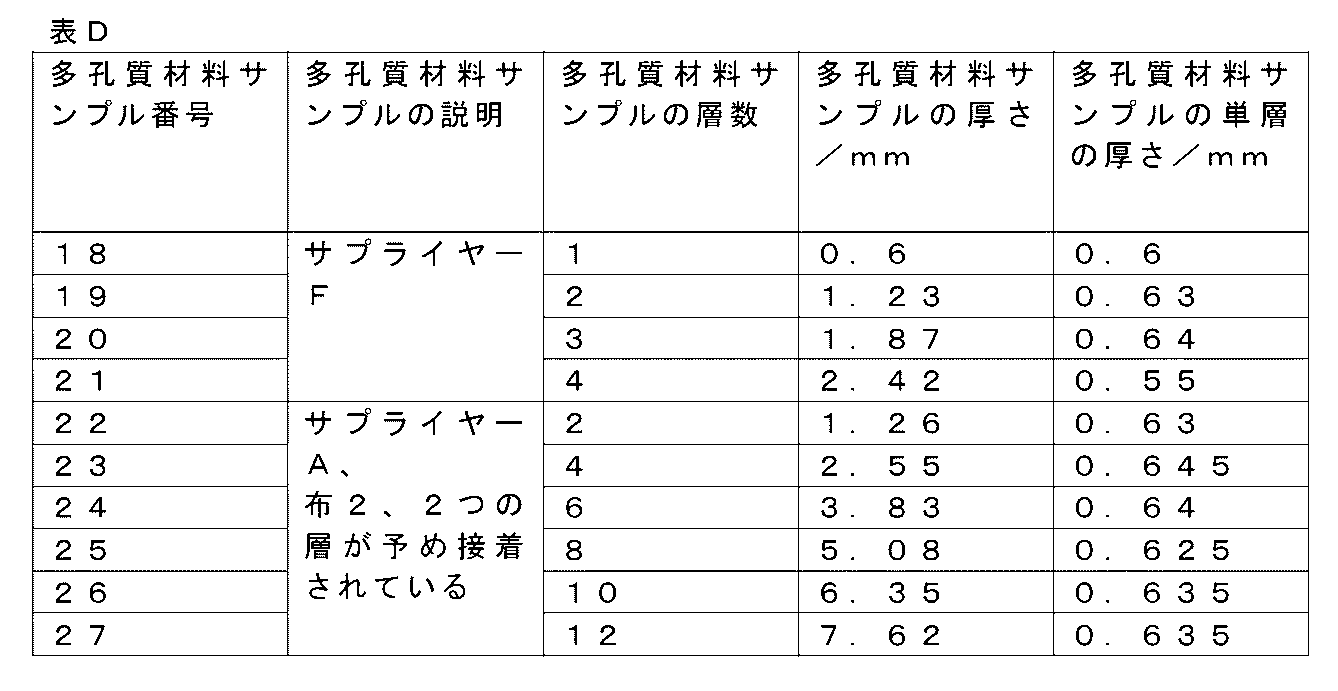
いくつかの実施形態では、多孔質材料168を通る200cm3/分の流量での流体輸送圧力は、ASTM F316-03(2019)の試験Aで測定した泡立ち点圧力に0.25を掛けた値未満である。
In some embodiments, the fluid delivery pressure at a flow rate of 200 cm 3 /min through the
これは、多孔質材料168を通る流れ抵抗が比較的低いレベルに維持されることを意味する可能性がある。
This may mean that flow resistance through the
表Aのサンプル番号18、表Dのサンプル番号22~25、及び厚さ0.8mmのサプライヤーFの布地に対応する多孔質材料を使用して、さらに一連の破壊圧力試験を実施した(上記の実験と同様)。各サンプルの流動圧力降下と破壊圧力を記録し、その結果(少なくとも2回の測定の平均値)を表Eに示す。これらの実験では、89cm3/分の流量を使用し、サンプルの下の円形メッシュの直径(サンプルの「有効領域」全体に広がる)は80mmであった。

前述のように、より多くの層が互いに積み重ねられると、破壊圧力が上昇することが分かる。ただし、より多くの層が追加されるにつれて、輸送流圧力は破壊圧力よりも急速に増加する可能性があり、サンプル番号22~27の場合、多孔質材料が4つの積み重ねられた二重層を有する場合には(サンプル番号25)、輸送流圧力は破壊圧力を上回る。 As mentioned above, it can be seen that as more layers are stacked on top of each other, the burst pressure increases. However, as more layers are added, the transport flow pressure can increase more rapidly than the burst pressure, and in the case of samples 22-27, and in the case where the porous material has four stacked bilayers (sample 25), the transport flow pressure exceeds the burst pressure.
より多くの層では、輸送流圧力は、サンプル22~27から明らかであるよりも速く上昇する可能性があるが、システム内の空気は、特にサンプル番号25~27ではデータが圧縮性を示し始めることを意味する可能性がある。 With more layers, the transport flow pressure may be rising faster than is evident from samples 22-27, but air in the system may mean that the data begins to show compressibility, especially in samples 25-27.
より一般的には、これらのデータは、(所望の流量での)輸送流圧力が破壊圧力よりも低い場合に湿式掃除装置が作動し得ることを示す可能性がある。 More generally, these data may indicate that the wet cleaning device may operate when the transport flow pressure (at the desired flow rate) is less than the burst pressure.
表Eに結果を示す試験では、流量は89cm3/分であり、布地の有効面積は5030mm2であった。クリーナーヘッド100の場合、有効面積は約1750mm2であり得る。したがって、クリーナーヘッド100の多孔質材料168に輸送流圧力が加えられると、多孔質材料168を通る実際の流量は、これらの試験で使用された流量の0.35倍(1750/5030)であり得る。
In the tests whose results are shown in Table E, the flow rate was 89 cm3 /min and the effective fabric area was 5030 mm2 . For the
これは、輸送流圧力が破壊圧力に等しい点(例えば、サンプル番号24)において、多孔質材料168が耐えることができる最大流量が約(0.35*98)31cm3/分であることを意味する可能性がある。多孔質材料168により多くの層を追加しても、破壊圧力はほぼ同じままである可能性がある一方、輸送流圧力が増加するため、この値はさらに低下する。
This may mean that at the point where the transport flow pressure equals the burst pressure (e.g., sample number 24), the maximum flow rate that the
上記の破壊圧力試験では、試験サンプルの表面全体が水で覆われているため、多孔質材料168の領域全体が水を輸送することに留意されたい。しかし、実際には、床に接触するクリーナーヘッド100の領域(例えば、幅5mm、長さ350mm)は水を輸送するが、その領域に隣接する多孔質材料168の領域は空気も輸送することができる。これは、例えば4つの二重層が使用され(サンプル番号25の場合)、多孔質材料の破壊圧力が水輸送圧力よりも低い場合、多孔質材料168の周囲が破壊し始めて空気を取り込み、したがって破壊圧力で沈降する可能性があることを意味する可能性がある。有効/ピックアップ領域は比較的低い圧力のままにされる可能性があり、したがって液体を比較的ゆっくりとピックアップする可能性があり、その結果、掃除すべき表面に液体が残る可能性がある。逆に、多孔質材料168の輸送流圧力が比較的低く、破壊圧力がかなり大きいシナリオでは(例えば、破壊圧力が輸送流圧力の50倍である厚さ0.8mmのサプライヤーF布地の場合)、ピックアップ流は非常に高くなる可能性がある。
It should be noted that in the above burst pressure test, the entire surface of the test sample is covered with water, so the entire area of the
全体として、湿式掃除装置は、破壊圧力が輸送流圧力よりも高い状態で動作することができるが、より高速でのピックアップを可能にするために、破壊圧力は輸送流圧力の少なくとも2倍であってもよい。 Overall, the wet sweeper can operate with the burst pressure higher than the transport flow pressure, but the burst pressure may be at least twice the transport flow pressure to allow for faster pick-up.
いくつかの非限定的な例では、クリーナーヘッド100は、40cm3/分の流量で洗浄液を送達することができる。多孔質材料168を通る流量が、掃除すべき滑らかな表面上のこの洗浄液流量の85%の場合、すなわち、ピックアップ速度が34cm3/分の場合、ピックアップ速度は、サンプル番号24について上記で推定した31cm3/分に匹敵する。
In some non-limiting examples, the
いくつかの非限定的な例では、例えば20cm3/分の洗浄液の流量を考慮して、ある程度の許容差を導入することができ、したがって、多孔質材料168の厚さの上限は約5mmになる(サンプル番号25を参照)。
In some non-limiting examples, some tolerance can be introduced, for example taking into account a flow rate of the cleaning liquid of 20 cm3 /min, and therefore the upper limit of the thickness of the
前述のように、多孔質材料168は、多孔質布地、多孔質プラスチック、及び発泡体のうちの1つ以上を含むことができる。
As previously mentioned, the
このような多孔質プラスチックは、例えば、プラスチック顆粒の焼結メッシュの形態をとることができる。 Such porous plastics can take the form of, for example, a sintered mesh of plastic granules.
多孔質材料168がそのような多孔質プラスチックを含む実施形態では、例えば多孔質織布などの多孔質布地を含む1つ以上のさらなる多孔質材料層は、多孔質プラスチックの外面上に配置されてもよい。このようなさらなる多孔質材料層(複数可)は、多孔質プラスチックよりも水に濡れやすく、したがって、水に濡れたときに掃除すべき表面と接触するのにより適している可能性がある。
In embodiments in which the
特に、多孔質織布、最も好ましくはマイクロファイバー織布を含む多孔質材料について言及する。このようなマイクロファイバー織布は、湿式掃除装置内で必要な負圧を達成するのを容易にすることができる。 In particular, reference is made to porous materials including porous woven fabrics, most preferably microfiber woven fabrics. Such microfiber woven fabrics can facilitate achieving the necessary negative pressure within the wet cleaning device.
このような多孔質織布、特にこのようなマイクロファイバー織布は、特にその織りの緻密さを介して、限界細孔径の上記範囲を満たすように構成することができる。 Such porous woven fabrics, and in particular such microfiber woven fabrics, can be configured to meet the above range of critical pore size, particularly through the tightness of the weave.
特に適切な織布の仕様を、例示的かつ非限定的な例として表Fに示す。
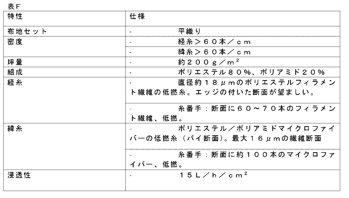
図17~図23は、多孔質材料168をどのようにクリーナーヘッド100に取り付けることができるかの例を概略的に示す。
Figures 17-23 show schematic examples of how the
多孔質材料168は、任意の適切な方法で取り付けることができる。図17に示すようないくつかの実施形態では、クリーナーヘッド100は、多孔質材料168を支持するための支持部材236、例えば剛性支持部材236を含む。支持部材236は、エンジニアリング熱可塑性プラスチックなどの任意の適切な材料で形成することができる。
The
いくつかの実施形態では、クリーナーヘッド100は、エラストマー材料238を含み、その上に多孔質材料168が配置される。このようなエラストマー材料238の弾性変形により、例えば、掃除すべき表面218上に比較的硬い突起物が存在し、それが多孔質材料168と接触した場合に、多孔質材料168が損傷するリスクが低減される可能性がある。代替的に又は追加的に、エラストマー材料238は、多孔質材料168が掃除すべき表面218の任意の輪郭に従うのを助けることができる。
In some embodiments, the
エラストマー材料238は、例えば、シリコーンゴムであるか、又はシリコーンゴムを含むことができる。ポリジエン(例えばポリブタジエン)、熱可塑性エラストマーなどの他のエラストマー材料も、エラストマー材料238に含めたり、エラストマー材料238を定義したりするために考慮することができる。
The
代替的に又は追加的に、エラストマー材料は、ショアA硬度が50未満、好ましくはショアA硬度が20未満、最も好ましくはショアA硬度が10未満であってもよい。 Alternatively or additionally, the elastomeric material may have a Shore A hardness of less than 50, preferably a Shore A hardness of less than 20, and most preferably a Shore A hardness of less than 10.
非限定的な例では、エラストマー材料は、ショアA硬度が4のシリコンゴムである。 In a non-limiting example, the elastomeric material is silicone rubber having a Shore A hardness of 4.
クリーナーヘッド100が支持部材236、例えば剛性支持部材236を含む実施形態では、エラストマー材料238は、支持部材236と多孔質材料168との間に設けることができる。その一例を図17に示す。
In embodiments in which the
クリーナーヘッド100が上述の突出要素を含む実施形態では、突出要素は、以下でより詳細に説明するように、エラストマー材料238を含むことができる。
In embodiments in which the
図17に示す非限定的な例に戻ると、不浸透性部分146はポリマー、例えば熱可塑性フィルムの形態であり、シール152はポリマーフィルムと多孔質材料168に含まれる多孔質材料層114との間に設けられる。さらに、この特定の例に含まれる液体輸送支持構造154は、メッシュ又はメッシュ層の積層の形態である。
Returning to the non-limiting example shown in FIG. 17, the
図18に示す非限定的な例などのいくつかの実施形態では、不浸透性部分146は、エラストマー材料238から多孔質材料168の多孔質材料層114まで延びる不浸透性シール部分(複数可)、例えばポリマーフィルム片によって画定される。この場合、ポリマーフィルムが多孔質材料層114の内面にわたって横方向に延びる必要はない可能性がある。
In some embodiments, such as the non-limiting example shown in FIG. 18, the
いくつかの実施形態では、エラストマー材料238は、多孔質材料168の多孔質材料層114上に密封された不浸透性部分146を含む。したがって、この例では、上述のポリマーフィルム及びポリマーフィルム片は不要であり、省略することができる。このようにして、クリーナーヘッド100内の構成要素の数を減らすことができ、それによって製造が容易になる。
In some embodiments, the
図19に示すようないくつかの実施形態では、液体輸送支持構造154は、多孔質材料168の多孔質材料層114に面するエラストマー材料238の表面上及び/又は表面内の表面パターンによって少なくとも部分的に又は全体的に提供される。メッシュ(複数可)をエラストマー材料238の表面上の表面パターンに置き換えることは、クリーナーヘッド100内の構成要素の数を減らすのに役立つ可能性がある。他の点では、図19に示す例は、図18に示す例に対応する。
19, the liquid
図20に示すようないくつかの実施形態では、支持部材236は、多孔質材料168の多孔質材料層114に対して密封された不浸透性部分146を含む。言い換えれば、支持部材236と多孔質材料168との間に存在するシールは、多孔質材料168に対して密封する支持部材236の突出部分によって提供される。したがって、多孔質材料層114と支持部材236との間の直接接続を使用してシールを形成することができるため、この例では上記のポリマーフィルムは不要である。他の点では、図20に示す例は、図17に示す例に対応する。
In some embodiments, such as shown in FIG. 20, the
図21に示す非限定的な例は、図20に示す例に対応し、ただし、液体輸送支持構造154は、多孔質材料168の多孔質材料層114に面するエラストマー材料238の表面上及び/又は表面内の表面パターンによって、少なくとも部分的に又は全体的に提供される。
The non-limiting example shown in FIG. 21 corresponds to the example shown in FIG. 20, except that the liquid
図22に示す非限定的な例は、図18に示す例に対応し、ただし、エラストマー材料238は、不浸透性部分146としてのポリマーフィルムと多孔質材料168の多孔質材料層114との間に設けられたキャビティ150内に配置される。
The non-limiting example shown in FIG. 22 corresponds to the example shown in FIG. 18, except that the
図23に示す非限定的な例は、図22に示す例に対応し、ただし、液体輸送支持構造154は、多孔質材料168の多孔質材料層114に面するエラストマー材料238の表面上及び/又は表面内の表面パターンによって、少なくとも部分的に又は全体的に提供される。
The non-limiting example shown in FIG. 23 corresponds to the example shown in FIG. 22, except that the liquid
ここで、繰り返しになるが、多孔質材料層114の上述の液体ピックアップ領域PR(多孔質材料層114を、例えば少なくとも1つの汚れ入口142A、142Bのそれぞれの周りに密封して取り付けることによって画定される)は、例えば、洗浄液が液体ピックアップ領域PRを迂回して掃除すべき表面218に到達するか、又は少なくとも掃除すべき表面218に向けられることを可能にするように、少なくとも1つの洗浄液出口104のそれぞれに対して配置されてもよい。洗浄液出口104(複数可)のそれぞれに対する液体ピックアップ領域PRのこのような配置は、任意の適切な方法で達成することができる。
Here again, the above-mentioned liquid pick-up area PR of the porous material layer 114 (defined, for example, by sealingly attaching the
図24に示すようないくつかの実施形態では、洗浄液出口104のそれぞれは、多孔質材料層114から空間的に分離された1つ以上の分配部分に配置される。このような別個の分配部分(又は複数の分配部分)に洗浄液出口104(複数可)を配置することによって、洗浄液は、最初に多孔質材料層114に接触することなく、図24の矢印240の方向に、掃除すべき表面218に向かって送達することができる。
In some embodiments, such as shown in FIG. 24, each of the cleaning
図24に示す非限定的な例では、分配部分は、上述の洗浄液分配ストリップ108、124に対応する。 In the non-limiting example shown in FIG. 24, the dispensing portions correspond to the cleaning fluid dispensing strips 108, 124 described above.
図24では、多孔質材料層114と洗浄液分配ストリップ108、124との間に設けられた隙間242、例えば空隙242によって空間的な分離が明らかである。
In FIG. 24, the spatial separation is evident by the
図25に示すようないくつかの実施形態では、多孔質材料168は、上述の1つ以上のさらなる多孔質材料層156を含み、クリーナーヘッド100は、1つ以上のさらなる多孔質材料層156を含む取り外し可能な要素244を含み、取り外し可能な要素244を取り外すと、1つ以上のさらなる多孔質材料層156が多孔質材料層114から分離される。
In some embodiments, such as that shown in FIG. 25, the
いくつかの実施形態では、取り外し可能な要素244は、上述の洗浄液アプリケータ材料126、128を含む。このようにして、洗浄液アプリケータ材料126、128を交換すると同時に、1つ以上のさらなる多孔質材料層156を簡単に交換することができる。例えば、洗浄液アプリケータ材料126、128は、取り外し可能な要素244内の1つ以上のさらなる多孔質材料層156に取り付ける(例えば接着する)ことができる。
In some embodiments, the
図25に示す非限定的な例のようないくつかの実施形態では、洗浄液アプリケータ材料126、128は、上述の第1及び第2のアプリケータ部分126、128を含み、第1のアタッチメント246Aは1つ以上のさらなる多孔質材料層156を第1のアプリケータ部分126に接続し、第2のアタッチメント246Bは1つ以上のさらなる多孔質材料層156を第2のアプリケータ部分128に接続する。これの別の例については、図33Eを参照して以下で説明する。
In some embodiments, such as the non-limiting example shown in FIG. 25, the cleaning
いくつかの実施形態では、クリーナーヘッド100は、多孔質材料層114を支持するための支持体を含み、クリーナーヘッド100は、多孔質材料層114を含む取り外し可能な(及び/又は取り付け可能な)部材248を含み、取り外し可能な部材248を取り外すと、多孔質材料層114が支持体から分離される。
In some embodiments, the
このような取り外し可能な部材248は、多孔質材料層114に加えて、例えばポリマーフィルムを含むか、又はポリマーフィルムの形態である上述の不浸透性部分146を含むことができ、少なくとも1つの汚れ入口142Aは不浸透性部分146の1つ又は複数の開口部によって画定される。
Such a
図26に示すようないくつかの非限定的な例では、取り外し可能な(及び/又は取り付け可能な)部材248はさらに、上述の液体輸送支持構造154を含む。
In some non-limiting examples, such as that shown in FIG. 26, the removable (and/or attachable)
例えば、液体輸送支持構造154は、多孔質材料層114と不浸透性部分146との間のキャビティ150内に設けられてもよい。
For example, the liquid
クリーナーヘッド100が取り外し可能な要素244と取り外し可能な部材248の両方を含む場合、取り外し可能な要素244は、例えば、取り外し可能な部材248とは独立して取り外し可能であってもよく、取り外し可能な部材248は取り外し可能な要素244とは独立して取り外し可能であってもよい。
When the
図27に示すようないくつかの実施形態では、取り外し可能な部材248は、洗浄液アプリケータ材料126、128をさらに含む。例えば、取り外し可能な部材248が不浸透性部分146を含む場合、洗浄液アプリケータ材料126、128は、不浸透性部分146に取り付ける(例えば、接着する)ことができる。
In some embodiments, such as shown in FIG. 27, the
図27に示す非限定的な例では、洗浄液アプリケータ材料126、128は、上述の第1及び第2のアプリケータ部分126、128を含み、第1の接続部250Aは不浸透性部分146の第1の側を第1のアプリケータ部分126に接続し、第2の接続部250Bは、不浸透性部分146の第2の側を第2のアプリケータ部分128に接続する。
In the non-limiting example shown in FIG. 27, the cleaning
図28は、洗浄液アプリケータ材料126、128を含まない取り外し可能な部材248を含む例示的なクリーナーヘッド100を概略的に示す。しかしながら、それにもかかわらず、洗浄液アプリケータ材料126、128は、取り外し可能であり、この例では、第1及び第2のアプリケータ部分126、128のそれぞれは、互いに独立して、かつ取り外し可能な部材248とは独立して、洗浄液出口104から取り外し可能である。
28 shows an example
より一般的には、本開示は、取り付け可能な(及び/又は取り外し可能な)部材248自体を提供する。取り付け可能な部材248は、負圧発生器178を有する湿式掃除装置に取り付けるのに適している可能性がある。少なくともいくつかの実施形態では、取り付け可能な部材248は、多孔質材料層114と、取り付け可能な部材248が湿式掃除装置に取り付けられたときに負圧発生器178が流体的に接続可能な少なくとも1つの汚れ入口142A、142Bとを含み、多孔質材料層114の液体ピックアップ領域PRは、多孔質材料層114を少なくとも1つの汚れ入口142A、142Bの周りに密封して取り付けることによって画定される。
More generally, the present disclosure provides an attachable (and/or detachable)
このような取り付け可能な部材248は、多孔質材料層114を汚れ入口142A、142B(複数可)に再び密封する必要なく、多孔質材料層114の交換を可能にすることができる。
Such an
いくつかの実施形態では、取り付け可能な部材248は不浸透性部分146を含み、少なくとも1つの汚れ入口142A、142Bは、不浸透性部分146内及び/又は不浸透性部分146と多孔質材料層114との間に設けられた1つ又は複数の開口部によって画定される。このような取り付け可能な部材248は、不浸透性部分146を多孔質材料層114に再び密封する必要なく、多孔質材料層114の交換を可能にすることができる。
In some embodiments, the
いくつかの実施形態では、少なくとも1つの汚れ入口142A、142Bは、多孔質材料層114と不浸透性部分146との間のキャビティ150に露出しており、液体輸送支持構造154はキャビティ150内に配置され、多孔質材料層114と少なくとも1つの汚れ入口142A、142Bとの間の液体ピックアップ領域PRに1つ以上の流路を提供する。
In some embodiments, at least one
湿式掃除装置、例えば湿式掃除装置に含まれるクリーナーヘッド100は、前述のように、洗浄液を送達することができる少なくとも1つの洗浄液出口104を含んでもよい。取り付け可能な部材248の少なくとも1つの汚れ入口が負圧発生器178に流体的に接続されている場合、液体ピックアップ領域PRは、少なくとも1つの洗浄液出口104のそれぞれに対して配置されてもよく、その結果、掃除すべき表面218に向かって送達される洗浄液が液体ピックアップ領域PRを迂回する。
A wet cleaning device, such as a
図29は、取り外し可能な要素244を含む例示的なクリーナーヘッド100を概略的に示しており、取り外し可能な要素244は、この例では、1つ以上のさらなる多孔質材料層156からなる。さらに、この非限定的な例では、この例の第1及び第2のアプリケータ部分126、128のそれぞれは、互いに独立して、かつ取り外し可能な要素244とは独立して、洗浄液出口104から取り外し可能である。
29 shows a schematic of an exemplary
図30は、多孔質材料、この場合は多孔質材料層114が洗浄液アプリケータ布地126、128と接触する例示的なクリーナーヘッド100を示す。前述のように、この構成は、洗浄液アプリケータ材料126、128に過剰な洗浄液が蓄積するのを防止するのに役立つ可能性があり、したがって、例えば洗浄液アプリケータ材料126、128から洗浄液を掃除すべき表面218に滴下することによって掃除すべき表面218が過度に濡れるのを最小限に抑えるのに役立つ可能性がある。
Figure 30 illustrates an exemplary
この特定の例では、多孔質材料層114のエッジ部分134が洗浄液アプリケータ材料126、128の対向するエッジ部分136に当接しているため、洗浄液126、128の濡れ具合に対する制御を強化することができる。
In this particular example, the
より具体的には、この非限定的な例では、洗浄液アプリケータ材料126、128は、第1のアプリケータ部分126及び第2のアプリケータ部分128を含み、その結果、図示のように、洗浄液アプリケータ材料の対向するエッジ部分136が第1のアプリケータ部分126に含まれるようになる。さらに、この例では、多孔質材料層114のさらなるエッジ部分138は、第2のアプリケータ部分128のさらなる対向するエッジ部分140に当接する。
More specifically, in this non-limiting example, the cleaning
それにもかかわらず、多孔質材料層114の液体ピックアップ領域PR(多孔質材料層114を、例えば少なくとも1つの汚れ入口142A、142Bのそれぞれの周りに密封して取り付けることによって画定される)は、図30に示す例では、例えば、洗浄液が液体ピックアップ領域PRを迂回できるように、洗浄液出口104のそれぞれに対して配置される。この点に関して、この例の洗浄液出口104は、多孔質材料層114から空間的に分離された分配部分に配置され、分配部分は、この例では洗浄液分配ストリップ108、124の形態である。空間的な分離は、多孔質材料層114と分配部分108、124との間に設けられた隙間242、例えば空隙242によって反映される。
Nevertheless, the liquid pick-up area PR of the porous material layer 114 (defined, for example, by sealingly attaching the
繰り返しになるが、多孔質材料層114を含む多孔質材料168は、多孔質材料168が、例えばマイクロファイバー布地の織りが密であることにより、洗浄液アプリケータ材料126、128よりも密度が高いという点で、洗浄液アプリケータ材料126、128と区別され得る。
To reiterate, the
図31に示すようないくつかの実施形態では、クリーナーヘッド100は、掃除すべき表面218に面する部分120を含み、突出要素252は、部分120に隣接して取り付けられる。したがって、突出要素252は、部分120に対して別個に取り付けられた要素である。突出要素252は、クリーナーヘッド100から掃除すべき表面218の方向に突出している。このようにして、前述のように、クリーナーヘッド100は突出要素252上で第1の方向に揺動して部分120を掃除すべき表面に接触させることができ、また、突出要素252上で第1の方向とは反対の第2の方向に揺動して部分120を掃除すべき表面218から分離させることができる。
In some embodiments, such as shown in FIG. 31, the
図31に示すようないくつかの実施形態では、クリーナーヘッド100は、支持部材236、例えば剛性支持部材236を含み、突出要素252は支持部材236への取り付けによって取り付けられる。
In some embodiments, such as shown in FIG. 31, the
クリーナーヘッド100の移動を補助するために、クリーナーヘッド100は、適切なハンドル(図示せず)に取り付けることができるか、又は取り付け可能であってもよいことに留意されたい。この目的のために、クリーナーヘッド100は、このようなハンドルが結合され得る、例えば旋回可能に結合され得る結合点254を含んでもよい。
It should be noted that to aid in movement of the
図31を参照すると、力F移動を加えてクリーナーヘッド100を掃除すべき表面218上で移動させると、抵抗がないとは限らない。クリーナーヘッド100の重量F重力、及び/又はユーザがクリーナーヘッド100を掃除すべき表面218に向かって押すことにより、掃除すべき表面218に垂直な力Fnが生じる可能性がある。
31, applying a force F displacement to move the
クリーナーヘッド100は濡れていてもよく、したがって粘性摩擦状態と乾燥状態で動作することができ、粘性摩擦状態では、粘性摩擦力Fvが生じ、乾燥状態では、クーロン摩擦Fcが生じ、これは法線力Fnと摩擦係数fによって決まる。結果として生じる抵抗力Frは、次の式で近似され、

上記の式は、より大きな接触面積Aと、厚さyがゼロに近づく液体層の両方が粘性摩擦項を増加させ、それによって結果として生じる抵抗力Frを増加させる可能性があることを示す。 The above equation shows that both a larger contact area A and a liquid layer with thickness y approaching zero can increase the viscous friction term and thereby the resulting drag force Fr.
さらに、掃除すべき平坦でない表面218上で液体を効果的に吸い上げるために必要な比較的大きな接触面積Aは、特に掃除すべき比較的平坦/平滑な表面218上で比較的高い抵抗力Frをもたらす可能性があることに留意されたい。
Furthermore, it should be noted that the relatively large contact area A required to effectively wick liquid onto an
したがって、少なくともいくつかの実施形態では、突出要素252は多孔質材料168を含む。したがって、多孔質材料168と掃除すべき表面218との間の接触面積Aが限られているため、掃除すべき表面を横切るクリーナーヘッド100の移動に対する抵抗が軽減される可能性がある。
Thus, in at least some embodiments, the protruding
多孔質材料168の多孔質材料層114は、突出要素252に含まれてもよい。
The
いくつかの実施形態では、多孔質材料層114の液体ピックアップ領域PRは、突出要素252に含まれ、突出要素252と部分120との間で終了する。このようにして、吸引力が加えられる多孔質材料層114の領域は、突出要素252に限定され、それによって、移動に対する抵抗を軽減するのに役立つ。
In some embodiments, the liquid pick-up region PR of the
代替的に又は追加的に、少なくとも1つの汚れ入口142A、142Bは、突出要素252内に画定されてもよい。したがって、クリーナーヘッド100の一部、言い換えれば、突出要素252に吸引力を加えることができ、突出要素252は、例えばその揺動機能により、掃除すべき表面218との接触が減少する。
Alternatively or additionally, at least one
クリーナーヘッド100が部分120と、掃除すべき表面218に面するさらなる部分122とを含む実施形態では、突出要素252は部分120とさらなる部分122との間に取り付けられてもよい。このようにして、クリーナーヘッド100は、図31に示すように、突出要素252上で前方に揺動して部分120を掃除すべき表面218に接触させ、また後方に揺動してさらなる部分122を掃除すべき表面218に接触させることができる。
In an embodiment in which the
このような実施形態では、多孔質材料層114の液体ピックアップ領域PRは、部分120とさらなる部分122との間に延び、突出要素252と部分120との間、及び突出要素252とさらなる部分122との間で終了してもよい。
In such an embodiment, the liquid pick-up region PR of the
図31に示す非限定的な例では、多孔質材料168及び洗浄液アプリケータ材料126、128の当接する対向するエッジ部分134、136は、突出要素252と部分120との間に配置される。このようにして、例えば、クリーナーヘッド100の揺動によって突出要素252と洗浄液アプリケータ材料126、128との間で洗浄液アプリケータ材料126、128から絞り出される過剰な洗浄液は、多孔質材料168を介して汚れ入口142A、142B(複数可)に効率的に輸送され得る。
In the non-limiting example shown in FIG. 31, the
特に、図31に示す部分120は第1のアプリケータ部分126を含み、さらなる部分122は第2のアプリケータ部分128を含む。さらに、この例では、多孔質材料168及び第1のアプリケータ部分126の当接する対向するエッジ部分134、136は、突出要素252と部分120との間に配置され、そして、多孔質材料168及び第2のアプリケータ部分128の当接する対向するさらなるエッジ部分138、140は、突出要素252とさらなる部分122との間に配置される。したがって、例えば、クリーナーヘッド100をそれぞれ前方及び後方に揺動させることによって突出要素と第1のアプリケータ部分126との間、及び突出要素と第2のアプリケータ部分128との間で洗浄液アプリケータ材料126、128から絞り出される過剰な洗浄液は、多孔質材料168を介して汚れ入口142A、142B(複数可)に効率的に輸送され得る。
In particular, the
図31に示すようないくつかの実施形態では、突出要素252は、掃除すべき表面218と接触するように構成された曲面を有する。
In some embodiments, such as that shown in FIG. 31, the protruding
突出要素252のこのような曲面、例えば丸みを帯びた表面は、突出要素252と掃除すべき表面218との接触面積を最小限に抑えるのにさらに役立つ可能性があり、それによって掃除すべき表面218を横切るクリーナーヘッド100の移動に対する抵抗を最小限に抑えるのに役立つ。
Such curved, e.g., rounded, surfaces of the
突出要素252の曲面は、例えば、図31に示すように、部分120とさらなる部分122との間で湾曲してもよい。
The curved surface of the protruding
いくつかの実施形態では、突出要素252は、エラストマー材料238を含み、その上に多孔質材料168が配置される。エラストマー材料238は、例えば、シリコーンゴムであるか、若しくはシリコーンゴムを含むことができ、及び/又は50未満、好ましくは20未満、最も好ましくは10未満のショアA硬度を有することができる。
In some embodiments, the protruding
図31を参照すると、エラストマー材料238は、支持部材236、例えば剛性支持部材236と多孔質材料168との間に配置されてもよい。
Referring to FIG. 31, an
このようなエラストマー材料238の弾性変形により、例えば、掃除すべき表面218上に比較的硬い突起物が存在し、それが多孔質材料168と接触した場合に、多孔質材料168が損傷するリスクが低減される可能性がある。代替的に又は追加的に、エラストマー材料238は、多孔質材料168が掃除すべき表面218の任意の輪郭に従うのを助けることができる。
Such elastic deformation of the
代替的に又は追加的に、突出要素252は、部分120に隣接して弾性的に取り付けられてもよい。例えば、突出要素252は、支持部材236にばねで取り付けられてもよい。これは、多孔質材料168が掃除すべき表面218の輪郭に従うのを助けることができ、それによって液体のピックアップが容易になる。
Alternatively or additionally, the protruding
エラストマー材料238が突出要素252に含まれる実施形態では、多孔質材料168が、エラストマー材料238の曲面の湾曲、例えば部分120とさらなる部分122との間の円弧に従って、突出要素252の曲面を形成し得る。
In embodiments in which the
図31では見えないが、突出要素252は、多孔質材料層114上及び汚れ入口142A、142Bの周囲に密封されたポリマーフィルムを含むか、又はポリマーフィルムの形態である上述の不浸透性部分146をさらに含んでもよい。このような例では、クリーナーヘッド100の使用中に多孔質材料168の後ろに存在する負圧は、エラストマー材料238には存在しない可能性があり、むしろ多孔質材料層114と不浸透性部分146との間の密閉されたキャビティ150内に閉じ込められる。これは、特にエラストマー材料238自体が多孔質であり、そのため、普通であれば負圧により圧縮されやすい可能性がある例では、エラストマー材料238が負圧によって実質的に影響を受けないことを確保するのに役立つ可能性がある。
31, the protruding
他の非限定的な例では、エラストマー材料238自体は非多孔質であり、したがって、エラストマー材料238は、例えば図18に関連して上述したように、多孔質材料168の多孔質材料層114上に密封された不浸透性部分146に含まれてもよい。
In another non-limiting example, the
図31に示す非限定的な例では、上述の液体輸送支持構造154は、多孔質材料168、特に多孔質材料層114と不浸透性部分146との間にも設けられる。液体輸送支持構造154は、例えば、エラストマー材料238の表面(例えば曲面)上及び/又は表面内の1つ以上のメッシュ層及び/又は表面パターンによって定義されるか、又はそれらを含むことができる。
In a non-limiting example shown in FIG. 31, the liquid
より一般的には、突出要素252は、例えば多孔質材料層114と少なくとも1つの汚れ入口142A、142Bとの間に配置された液体輸送支持構造154を含むことができる。
More generally, the protruding
多孔質材料168は、エラストマー材料238上、例えばエラストマー材料238の曲面上に任意の適切な方法で配置されてもよい。
The
図32A及び図32Bは、液体ピックアップ領域PRを画定するために、汚れ入口142A、142Bの周りに多孔質材料層114を密封して取り付ける例を概略的に示す。図32A及び図32Bでは、不浸透性部分146(この場合はポリマーフィルムの形態)、及び液体輸送支持構造154(この場合はメッシュ又は複数の積み重ねられたメッシュ層の形態)がさらに明らかである。この例の多孔質材料168は、多孔質材料層114及びさらなる多孔質材料層156、158を含むか、又はそれらによって定義される。したがって、積層体は、さらなる多孔質材料層156、158、多孔質材料層114、液体輸送支持構造154、及び不浸透性部分146を含み、汚れ入口142A、142Bを提供するチューブ144A、144Bは、不浸透性部分146と多孔質材料層114との間に部分的に挟まれている。
32A and 32B show a schematic example of a sealing attachment of a
図32A及び図32Bに示す非限定的な例では、不浸透性部分146、多孔質材料層114、及びさらなる多孔質材料層156、158は、チューブ144A、144Bの方向に液体輸送支持層154を越えて延びる。シール152、この場合はヒートシールも、チューブ144A、144Bの方向に液体輸送支持層154を越えて延びる。
In the non-limiting example shown in Figures 32A and 32B, the
シール152、すなわち気密シールは、多孔質材料層114とチューブ144A、144Bが貫通する不浸透性部分146との間の領域に粘土を導入することによって、多孔質材料層114と不浸透性部分146との間に設けられる。この例では、次に、多孔質材料層114、不浸透性部分146、チューブ144A、144B、及び粘土の周りに1枚のテープを巻き付けて粘土を包み込み、粘土が他の物体に付着するのを防ぐ。
A
この積層体は、例えばエラストマー材料238の曲面上に配置できるほど十分に柔軟であってもよい。さらに、積層体には、クリーナーヘッド100内に積層体を固定するための適切な1つ又は複数の留め具256A-D(この場合はVelcro(登録商標)ストリップの形態)が設けられてもよい。
The laminate may be sufficiently flexible, for example so that it can be placed over a curved surface of the
図33A及び図33Bに示す非限定的な例を参照すると、図32A及び図32Bに関連して上記で説明したものと同様の、多孔質材料層114及び第1のさらなる多孔質材料層156を含む積層体が、エラストマー材料238の曲面258上に配置され、留め具256A~D(複数可)、例えばVelcro(登録商標)を介して支持部材236に固定される。したがって、この例の突出要素252は、エラストマー材料238及び多孔質材料層114、156を含む。
33A and 33B, a laminate including a
この例では、多孔質材料層114、156がエラストマー材料238の曲面258の湾曲に従うため、突出要素252自体は、掃除すべき表面218と接触するように構成された曲面を含む。
In this example, the protruding
図33A及び図33Bに示す非限定的な例では、突出要素252は、クリーナーヘッド100の支持部材236に取り付けられたエラストマー材料238によって、部分120に隣接して(特に、この例では部分120とさらなる部分122との間に)取り付けられる。この非限定的な例では、この取り付けは、支持部材236内に画定されたスロット262内に収容され、かつそのスロット262と係合する突起260を含むエラストマー材料238によって少なくとも部分的に達成される。突起260は、例えば、スロット262に押し嵌めすることができる。
In a non-limiting example shown in Figures 33A and 33B, the protruding
図33Aは、洗浄液アプリケータ材料126、128の少なくとも一部を多孔質材料と接触させるための洗浄液アプリケータ材料126、128の変形を示す。このようにして、洗浄液の一部は、特に制御された方法で洗浄液アプリケータ材料126、128から多孔質材料に移送することができる。
Figure 33A shows a modification of the cleaning
図33Aに示す非限定的な例では、洗浄液アプリケータ材料126、128は、繊維から形成されたタフトと、タフトを支持する裏地層(見えない)とを含む。図示のように、このようなタフトは、例えば掃除すべき表面と接触すると、及び/又は液体、例えば水で濡れると、多孔質材料と接触するように変形可能であり得る。
In a non-limiting example shown in FIG. 33A, the cleaning
いくつかの実施形態では、湿式掃除装置は、クリーナーヘッド100と、少なくとも1つの汚れ入口142A、142Bに流体的に接続された負圧発生器178(図33A及び図33Bでは見えない)とを含む。この流体接続は、チューブ144A、144Bを介して行うことができ、チューブ144A、144Bは、この特定の非限定的な例では、分岐点266で負圧発生器に通じる単一のチューブまで延びる。
In some embodiments, the wet vacuum includes a
負圧発生器178は、例えば、容積式ポンプなどのポンプであるか、又は容積式ポンプなどのポンプを含んでもよい(後者の技術的利点については、以下でより詳細に説明する)。ポンプが湿式掃除装置のために選択された動作圧力、例えば約5000Pa(上記の表1を参照)に耐えることができるのであれば、任意の適切なポンプを使用することができる。
The
いくつかの実施形態では、負圧発生器178は、40~2000cm3/分、より好ましくは80~750cm3/分、最も好ましくは100~300cm3/分の範囲の流量を提供することによって吸引力を供給するように構成される。
In some embodiments, the
このような流れ、すなわち流量は、多孔質材料168の負圧維持能力を利用することができ、また、エネルギー消費を制限しながら十分な液体のピックアップを確保することができる。
Such a flow, or rate, can take advantage of the
湿式掃除装置はまた、汚れた液体収集タンク(図33A及び図33Bでは見えない)を含むこともできる。そのような実施形態では、負圧発生器は、少なくとも1つの汚れ入口142A、142Bから液体を汚れた液体収集タンクに引き込むように構成されてもよい。
The wet cleaning apparatus may also include a dirty liquid collection tank (not visible in FIGS. 33A and 33B). In such an embodiment, the negative pressure generator may be configured to draw liquid from at least one
そのような実施形態では、汚れた液体収集タンクは、例えば、負圧発生器178の上流又は下流に対して任意の適切な方法で配置することができる。
In such an embodiment, the dirty liquid collection tank may be positioned in any suitable manner, for example, upstream or downstream of the
いくつかの実施形態では、クリーナーヘッド100を含む湿式掃除装置は、少なくとも1つの洗浄液出口104(複数可)によって洗浄液を掃除すべき表面に向かって送達するためにクリーナーヘッド100に洗浄液を供給するための洗浄液供給部(図33A及び図33Bでは見えない)を含む。このような洗浄液供給部は、例えば、洗浄液リザーバと、洗浄液を少なくとも1つの洗浄液出口104に、かつ、少なくとも1つの洗浄液出口104を通して輸送するための送達装置(例えば、ポンプを含む送達装置)とを含んでもよい。
In some embodiments, a wet cleaning apparatus including the
洗浄液供給部及び少なくとも1つの洗浄液出口104は、掃除すべき表面218に向かって洗浄液を連続的に送達するように構成されてもよい。
The cleaning fluid supply and at least one cleaning
洗浄液供給部及び負圧発生器178は、例えば、少なくとも1つの洗浄液出口104を通って送達される洗浄液の流量が、負圧発生器178によって少なくとも1つの汚れ入口142A、142Bに提供される流量よりも低くなるように構成されてもよい。これは、掃除すべき表面218が洗浄液で過度に濡れないようにするのに役立つ可能性がある。例えば、洗浄液の流量は20~60cm3/分の範囲であってもよく、負圧発生器178によって提供される流量は、40~2000cm3/分、より好ましくは80~750cm3/分、最も好ましくは100~300cm3/分の範囲であり得る。
The cleaning fluid supply and
容積式ポンプを負圧発生器178として使用する場合、流量が1リットル/分又は2リットル/分では、このようなポンプは比較的大きくて騒音が大きくなる可能性があり、したがってより低い流量は、湿式掃除装置を比較的小型、静音、軽量に保つのに役立つ可能性がある。
If a positive displacement pump is used as the
原則として、洗浄液供給部によって供給される洗浄液の流量と等しい負圧発生器178の流量で十分であり得る。
In principle, a flow rate of the
しかし、例えば、(例えば、新しく取り付けられた)多孔質材料168がこぼれた水に遭遇した場合、システムの平衡(必要な負圧)が比較的大きく乱れるリスクがある可能性がある。例えば、洗浄液の流量が40cm3/分で、負圧発生器178によって提供される流量が50cm3/分である湿式掃除装置が50cm3の水たまりに遭遇した場合、すべての水を吸い込むのに約5分かかることを意味する可能性がある(その結果、負圧が5分間低下し、したがって、床が著しくさらに濡れた状態が5分間続く(水たまりが広がり続けるため))。一方、負圧発生器178によって提供される250cm3/分の流量では、この期間が14秒間に短縮される可能性がある。負圧発生器178によって提供される流量が洗浄液供給部によって供給される洗浄液の流量を上回ると、システムは、このような乱れの後、より迅速に平衡状態に戻ることができる。
However, for example, if the (e.g. newly installed)
図33A及び図33Bに示す非限定的な例では、洗浄液は、例えば、上記の洗浄液リザーバからチューブ268を介して送達され、チューブ268は、分岐して、第1のチューブ270Aを介して洗浄液分配ストリップ108の洗浄液出口104に、また第2のチューブ270Bを介してさらなる洗浄液分配ストリップ124の洗浄液出口104に洗浄液を供給する。
In the non-limiting example shown in Figures 33A and 33B, the cleaning fluid is delivered, for example, from a cleaning fluid reservoir as described above via a
湿式掃除装置がクリーナーヘッド100、負圧発生器、及び洗浄液供給部を含む実施形態では、負圧発生器は、洗浄液供給部が洗浄液を少なくとも1つの洗浄液出口104に、かつ少なくとも1つの洗浄液出口104を通して供給すると同時に、言い換えれば同時に、少なくとも1つの汚れ入口142A、142Bに吸引力を提供するように構成されてもよい。
In embodiments in which the wet cleaning apparatus includes a
図33A及び図33Bに示す例示的なクリーナーヘッド100では、洗浄液分配ストリップ108、124は、接合部材272A、272Bによって互いに接合され、支持部材236にも接合される。
In the exemplary
いくつかの実施形態では、湿式掃除装置は、クリーナーヘッド100に結合又は取り付け可能なハンドル(図33A及び図33Bでは見えない)を含む。このようなハンドルは、クリーナーヘッド100の移動を容易にすることができる。
In some embodiments, the wet cleaning device includes a handle (not visible in FIGS. 33A and 33B) that can be coupled or attached to the
図33A及び図33Bに示す非限定的な例では、このようなハンドルが結合され得る結合点254は、結合が行われる高さを調整するための垂直に延びるスロットを含む。この例では、このような結合点254は、一対のマウント274A、274Bのそれぞれに設けられ、マウント274A、274Bの間にハンドル係合部材276が旋回可能に取り付けられる。ハンドル係合部材276は、ハンドルの端部と係合し、例えば、ハンドルの端部を受け入れることができる。
In a non-limiting example shown in FIGS. 33A and 33B, the connection points 254 to which such handles may be connected include vertically extending slots for adjusting the height at which the connection is made. In this example, such connection points 254 are provided on each of a pair of
いくつかの実施形態では、ハンドルは、少なくとも1つの汚れ入口142A、142B及び/又は汚れた液体収集タンクに流体的に接続された負圧発生器178の少なくとも一部を支持するか、又はを含むことができる。代替的に又は追加的に、洗浄液供給部の少なくとも一部、例えば洗浄液リザーバ及び/又は送達装置は、ハンドルによって支持されるか、又はハンドルに含まれてもよい。
In some embodiments, the handle may support or include at least a portion of the
図33C及び図33Dに示すようないくつかの実施形態では、上述の取り付け可能な部材248(多孔質材料層114の液体ピックアップ領域PRが、少なくとも1つの汚れ入口142A、142Bの周りに多孔質材料層114を密封して取り付けすることによって画定される)は、突出要素252を含む(又は定義する)。
In some embodiments, such as those shown in Figures 33C and 33D, the attachable member 248 (wherein the liquid pick-up area PR of the
図33Cに示す非限定的な例では、突出要素252は、エラストマー材料238を含み、その上に多孔質材料層114が配置される。この特定の例では、多孔質材料層114は、シール152、例えばヒートシールを介して支持部材236に密封して取り付けられる。
In a non-limiting example shown in FIG. 33C, the protruding
このようにして、多孔質材料層114は、汚れ入口142A(複数可)に密封して取り付けられ、汚れ入口142A(複数可)は、この例では、支持部材236及びエラストマー材料238内に画定される、すなわちそれらによって境界が定められる。この特定の例では、汚れ入口142A、142Bは、支持部材236及びエラストマー材料238を貫通するチャネルの形態である。
In this manner, the
より一般的には、多孔質材料層114が密封して取り付けられている支持部材236は、取り付け可能な部材248に含まれてもよい。このような例では、支持部材236は、クリーナーヘッド100(の残りの部分)に含まれる支持体に取り付け可能であり得る。
More generally, the
取り付け可能な部材248は、取り付け可能な部材248、例えば支持部材236が、支持体内に画定されたスロットに押し嵌めする鋼性部材を有することによって、又は支持体が、取り付け可能な部材248、例えば支持部材236内に画定されたスロットに押し嵌めするそのような鋼性部材を有することによってなど、任意の適切な方法で支持体に取り付けることができる。
The
図33Cに示す例では、さらなる多孔質材料層156も突出要素252に含まれている。多孔質材料層114を、例えば超音波溶接によってプラスチック支持部材236にヒートシールするプロセスによって、さらなる多孔質材料層156も多孔質材料層114に接着されることに留意されたい。
In the example shown in FIG. 33C, an additional
図33C及び図33Dに示す例は、図33Cに示す液体輸送支持構造154がエラストマー材料238の表面上及び/又は表面内に配置された表面パターンによって定義されるのに対し、図33Dに示す液体輸送支持構造154がメッシュ層の形態であるという点で互いに異なる。
The examples shown in Figures 33C and 33D differ from one another in that the liquid
図33Eは、さらなる多孔質材料層158A、158B及び洗浄液アプリケータ材料126、128を含む例示的な取り外し可能な要素244を示す。この例は、図26に示す取り外し可能な要素244とある程度類似しており、ただし、この場合、洗浄液アプリケータ材料126、128は、さらなる多孔質材料層158A、158B上に取り付けられる。
Figure 33E shows an exemplary
さらなる多孔質材料層158A、158Bは、例えば超音波溶接などのヒートシールを介して互いに接着することができることに留意されたい。
Note that the additional
図33Eではさらに、洗浄液アプリケータ材料126、128に含まれる裏地層BLとタフトTUが明らかである。裏地層BLは、前述のように、タフトTUを支持する。
FIG. 33E further reveals the backing layer BL and tufts TU contained within the cleaning
図33Fは、図33C又は図33Dに示す突出要素252/取り付け可能な部材248と、図33Eに示す取り外し可能な要素244とを含むクリーナーヘッド100の斜視図を示す。したがって、この場合、多孔質材料168は、多孔質材料層114と、突出要素252/取り付け可能な部材248に含まれるさらなる多孔質材料層156と、取り外し可能な要素244に含まれるさらなる多孔質材料層158A、158B(複数可)とを含む。
Figure 33F shows a perspective view of a
取り外し可能な要素244は、任意の適切な方法で、例えば、取り外し可能な要素244が取り外し可能な要素244の一方の長手方向側に沿って配置された1組のシューと、反対側の長手方向側に配置されたVelcro(登録商標)ストリップとを含むことによって、クリーナーヘッド100の残りの部分に取り外し可能に結合することができる。このような例では、1組のシューは、それぞれ、クリーナーヘッド100の残りの部分の一方の長手方向側に設けられたフットを受け入れて係合し、Velcro(登録商標)ストリップは、クリーナーヘッド100の残りの部分の反対側の長手方向側に配置された相補的なVelcro(登録商標)ストリップに接合することができる。この1組のフットと1組のシューの配置は、クリーナーヘッド100の残りの部分に対する取り外し可能な要素244の幅方向及び長さ方向の両方における望ましくない移動を最小限に抑えるのに役立つことができる。
The
図33Fではさらに、取り外し可能な要素244のラベルLAが明らかである。このラベルは、取り付け/取り外し指示、及び/又はクリーナーヘッド100の残りの部分から取り外し可能な要素244を取り外した後に取り外し可能な要素244を洗浄するための洗浄指示を提供することができる。
Also evident in FIG. 33F is the label LA on the
より一般的には、本開示の一態様による湿式掃除装置は、負圧発生器装置と、少なくとも1つの汚れ入口142A、142B、及び少なくとも1つの汚れ入口142A、142Bに密封して取り付けられた多孔質材料層114を含む多孔質材料168を有するクリーナーヘッド100とを含む。
More generally, a wet cleaning device according to one aspect of the present disclosure includes a negative pressure generator device and a
クリーナーヘッド100は、例えば、本明細書に記載の実施形態のいずれかによるものであってもよい。
The
負圧発生器装置は、負圧発生器出口を有する負圧発生器178を含み、負圧発生器178は、少なくとも1つの汚れ入口242A、242Bから負圧発生器出口に、かつ負圧発生器出口を通して流れを提供するように作動可能であり、流れを停止するように作動不能である。
The negative pressure generator apparatus includes a
少なくともいくつかの実施形態では、負圧発生器装置は、少なくとも負圧発生器が停止されたときに、負圧発生器出口から少なくとも1つの汚れ入口242A、242Bに向かう流体の通過を制限するように構成される。 In at least some embodiments, the negative pressure generator device is configured to restrict the passage of fluid from the negative pressure generator outlet toward at least one of the dirt inlets 242A, 242B at least when the negative pressure generator is stopped.
負圧発生器178によって提供される流れは、少なくとも1つの汚れ入口142A、142B内に負圧を発生させることができる。多孔質材料168、特に濡れた多孔質材料168は、負圧を維持するのに役立つ可能性があり、液体は、前述のように、多孔質材料168を通って汚れ入口(複数可)に引き込まれ得る。
The flow provided by the
図34は、多孔質材料168を通して液体190を引き込む前(左側のペイン)、引き込み中(中央のペイン)、及び引き込んだ後(右側のペイン)の例示的な湿式掃除装置278を概略的に示す。図34の左側のペインは、例えば洗浄サイクルの開始時の完全に乾燥したシステムを示すものとみなすことができる。図34の中央のペインは、動作中の湿式掃除装置278を示しており、その間、多孔質材料168と接触している液体190(例えば水)は、多孔質材料168を通って汚れ入口142A(複数可)の方向に輸送される。したがって、掃除すべき表面218は乾燥又は少なくともより乾燥した状態になり得るが、すべての液体190がクリーナーヘッド100から離れて、例えば湿式掃除装置278に含まれる汚れた液体収集タンク(図34では見えない)に輸送され得るわけではない。この非限定的な例では、図示のように、液体190の一部は、液体輸送支持構造154の流路(複数可)内に残る場合がある。動作中、この液体190は、掃除すべき表面218に液体190が存在しない可能性がある場合でも、多孔質材料168を湿潤状態に保つのに役立つため、有益である可能性がある。多孔質材料168の細孔192内の残留液体190は、前述のように、負圧を維持するのに役立つ。負圧が汚れ入口142A(複数可)内に維持されている間、液体190は、図34の中央のペインに示すように、多孔質材料168の汚れ入口(複数可)側に残る。
FIG. 34 shows an exemplary
しかし、負圧発生器178が、例えば湿式掃除装置278の使用後にスイッチを切ることによって停止されると、負圧発生器出口を介した流体、例えば周囲空気の侵入によって負圧の損失がもたらされる可能性がある。これにより、図34の右側のペインに示すように、多孔質材料168から液体190が放出され、例えば滴り落ちる可能性がある。
However, when the
掃除後、例えば掃除すべき表面のモップがけの後、負圧発生器178の停止時に及び/又は湿式掃除装置278を保管場所まで輸送している間に、液体190が多孔質材料168を通って放出され、例えば、掃除すべき(又は掃除された)表面218に戻ることは望ましくない可能性がある。
After cleaning, e.g., after mopping the surface to be cleaned, when the
この理由のために、負圧発生器装置は、少なくとも負圧発生器178が停止されたとき、例えば負圧発生器178がオフになっているとき、負圧発生器出口から汚れ入口(複数可)に向かう流体、例えば周囲空気の通過を制限する、例えば遮断するように構成されてもよい。これは、例えば掃除すべき表面218の掃除後及び/又は使用後に湿式掃除装置を保管領域に収納している間に、多孔質材料168から問題となる液体が放出されるのを軽減することができる。
For this reason, the negative pressure generator device may be configured to restrict, e.g., block, the passage of fluid, e.g., ambient air, from the negative pressure generator outlet toward the dirt inlet(s) at least when the
図35は、このような負圧発生器装置280を含む例示的な湿式掃除装置278を概略的に示す。図35の左側のペインでは、この例ではポンプである負圧発生器178が作動している。これは「ポンプオン」で示される。図35の右側のペインでは、「ポンプオフ」で示されるように、負圧発生器178が停止されている。図34に関連して上記で説明した液体の漏れとは対照的に、図35の十字282で示されるように、負圧発生器出口から汚れ入口142A(複数可)に向かう流体の通過は制限され、例えば遮断される。このようにして、負圧発生器178の停止後に負圧をより良く維持することができ、それによって多孔質材料168からの問題となる液体の放出を軽減する。
35 shows a schematic diagram of an exemplary
少なくとも負圧発生器178が停止されたときに、負圧発生器出口から汚れ入口142A(複数可)に向かう流体の通過を制限するように負圧発生器装置280を構成する任意の適切な方法が考えられ得る。
Any suitable method of configuring the negative
いくつかの実施形態では、負圧発生器178自体は、負圧発生器178が停止されたときに、負圧発生器出口から汚れ入口142A(複数可)の方向への流体、例えば空気の逆流を制限するように構成される。
In some embodiments, the
図36に示すようないくつかの実施形態では、負圧発生器178は、容積型ポンプであるか、又は容積型ポンプを含む。このような容積式ポンプの設計は、負圧発生器出口、言い換えればポンプ出口から汚れ入口142A(複数可)の方向への流体、例えば空気の逆流が本質的に制限されることを意味する。
In some embodiments, such as that shown in FIG. 36, the
このような容積式ポンプの例としては、蠕動ポンプ、膜ポンプ、及びピストンポンプが挙げられる。したがって、負圧発生器178は、蠕動ポンプ、膜ポンプ、及びピストンポンプのうちの1つ以上を含むか、又はそれらからなり得る。
Examples of such positive displacement pumps include peristaltic pumps, membrane pumps, and piston pumps. Thus, the
図36を参照すると、図示の蠕動ポンプは、ポンプ/負圧発生器入口286とポンプ/負圧発生器出口288との間に圧縮可能なホース284を含んでもよく、このホースは、蠕動ポンプが停止されたときに少なくとも1つの位置で圧縮される。したがって、蠕動ポンプが停止されると、ポンプ出口から汚れ入口142A(複数可)に向かう流体、例えば空気の逆流が制限され、例えば遮断され得る。したがって、蠕動ポンプを選択することにより、汚れ入口(複数可)内の負圧損失を最小限に抑えることができ、それによって、多孔質材料168を介してクリーナーヘッド100の外部に問題となる液体が放出されるのを最小限に抑える。
36, the illustrated peristaltic pump may include a
蠕動ポンプは、例えば、少なくとも1つの圧縮シュー292を含む回転可能な圧縮シューアセンブリ290を含んでもよく、圧縮シューアセンブリ290の回転と、少なくとも1つの圧縮シュー292による圧縮可能なホース284の同時圧縮とによって流れが提供される。
The peristaltic pump may, for example, include a rotatable
上述の膜ポンプ及びピストンポンプは、ポンプの休止状態、すなわちポンプが停止されたときに、ポンプ出口288から汚れ入口142A(複数可)の方向への逆流を制限する類似のタイプの構造を使用する。
The membrane and piston pumps described above use similar types of structures that limit backflow from the
いくつかの実施形態では、例えば、負圧発生器178を構成する上述の容積型ポンプの代替として、又はそれに加えて、負圧発生器装置280は、例えば図35の十字282で示される弁アセンブリを含み、これは、負圧発生器出口288から少なくとも1つの汚れ入口142Aに向かう流体の通過を制限するように構成される。
In some embodiments, for example, as an alternative to or in addition to the above-mentioned positive displacement pump that constitutes the
図35に示す非限定的な例では、弁アセンブリは、負圧発生器入口286と少なくとも1つの汚れ入口142Aとの間の上記流体の通過を制限するように構成される。
In a non-limiting example shown in FIG. 35, the valve assembly is configured to restrict passage of the fluid between the negative
代替的に又は追加的に、例えば、負圧発生器178に含まれるか又は負圧発生器178を定義する容積式ポンプに関して上述したように、流体の通過は、負圧発生器出口288と負圧発生器入口186との間で制限されてもよい。
Alternatively or additionally, the passage of fluid may be restricted between the negative
弁アセンブリは、任意の適切な設計を有し得る。いくつかの実施形態では、弁アセンブリは、負圧発生器178が停止されることに応答して、上記空気の通過を制限するように構成される。これは、負圧発生器178が停止されるされることによって(負圧発生器出口288から汚れ入口142A(複数可)への流体の通過を制限することによって)システムを閉じるようにトリガされる「能動」弁とみなすことができる。
The valve assembly may have any suitable design. In some embodiments, the valve assembly is configured to restrict the passage of said air in response to the
いくつかの実施形態では、弁アセンブリは、流体が少なくとも1つの汚れ入口142Aの方向に輸送されるのを防ぐように構成された一方向弁を含む。一方向弁は、「受動」弁とみなすことができる。このような一方向弁は、流体(例えば、空気及び/又は液体)の流れが多孔質材料168から離れることを可能にするが、負圧発生器178の停止時及び停止後に流体(例えば、空気及び/又は液体)が汚れ入口142A(複数可)に向かって戻るのを防ぐように構成されてもよい。ボール逆止め弁など、任意の適切な一方向弁設計が考えられ得る。
In some embodiments, the valve assembly includes a one-way valve configured to prevent fluid from being transported in the direction of at least one
非限定的な例では、例えばマイクロファイバー布地で作られた追加の多孔質材料部分が、多孔質材料層114と負圧発生器出口288との間に配置される。追加の多孔質材料部分は、流体(例えば空気及び/又は液体)の流れが多孔質材料層114から離れることを可能にするが、(少なくとも)負圧発生器178が停止されたときに、流体(例えば空気及び/又は液体)が多孔質材料層114に向かって戻ることを制限することができる。
In a non-limiting example, an additional porous material portion, e.g., made of microfiber fabric, is disposed between the
より一般的には、負圧発生器178は、流れが(作動された)負圧発生器178によって提供されているとき、流量が40~2000cm3/分、より好ましくは80~750cm3/分、さらにより好ましくは100~300cm3/分、最も好ましくは150~300cm3/分の範囲にあるように構成されてもよい。
More generally, the
このような流れ、すなわち流量は、多孔質材料168の負圧維持能力を利用することができ、また、エネルギー消費を制限しながら十分な液体のピックアップを確保することができる。
Such a flow, or rate, can take advantage of the
繰り返しになるが、湿式掃除装置278は、汚れた液体を収集するための汚れた液体収集タンク(図35及び図36では見えない)を含んでもよく、負圧発生器装置280は、負圧発生器出口288への流れ及び負圧発生器出口288を通る流れが、汚れた液体を少なくとも1つの汚れ入口142Aから汚れた液体収集タンクに引き込むように構成される。このような実施形態では、上述の弁アセンブリは、例えば、汚れた液体収集タンクの上流又は下流に対して、任意の適切な方法で配置することができる。
Again, the wet
いくつかの実施形態では、汚れ入口142A(複数可)と負圧発生器出口288との間に密閉された流路が画定される。
In some embodiments, a sealed flow path is defined between the dirt inlet(s) 142A and the negative
これは、負圧を維持するのに役立つ可能性がある。 This may help maintain negative pressure.
代替的な実施形態では、流体、例えば空気の侵入は、負圧発生器出口288及び多孔質材料168の細孔192ではなく、湿式掃除装置278の1つ以上の領域を介して行われる可能性がある。
In an alternative embodiment, ingress of fluid, e.g., air, may occur through one or more areas of the
しかし、このような代替的な実施形態では、負圧発生器装置280の構成は、それにもかかわらず、負圧発生器出口288から汚れ入口142A(複数可)の方向への流体の通過を(少なくとも)制限することによって、負圧を維持するのに役立つ可能性がある。
However, in such alternative embodiments, the configuration of the negative
いくつかの実施形態では、負圧発生器装置280は、1つ以上の領域と汚れ入口142A(複数可)との間に配置された弁アセンブリ282、例えば上述の弁アセンブリ282を含み、これにより、1つ以上の領域から汚れ入口142A(複数可)に向かう逆流が制限される。このような実施形態では、弁アセンブリ142Aは、例えば、負圧発生器出口288から汚れ入口142A(複数可)の方向への流体の通過を制限することに加えて、1つ以上の領域からの逆流を制限することができる。
In some embodiments, the negative
より一般的には、本開示の別の態様による湿式掃除装置は、負圧発生器装置280と、少なくとも1つの汚れ入口142A、142B及び少なくとも1つの汚れ入口142A、142Bを覆う多孔質材料168を有するクリーナーヘッド100とを含む。いくつかの実施形態では、多孔質材料168は、少なくとも1つの汚れ入口142A、142Bに密封して取り付けられた多孔質材料層114を含む。クリーナーヘッド100は、例えば、本明細書に記載の実施形態のいずれかによるものであってもよい。この態様では、負圧発生器装置280は、多孔質材料168を通して流体を少なくとも1つの汚れ入口(複数可)に引き込むために、湿式掃除装置の内部に流れを提供するように構成された負圧発生器178を含み、負圧発生器装置280は、多孔質材料168と負圧発生器178との間の湿式掃除装置の内部、例えば、少なくとも1つの覆われた汚れ入口142A、142B内の圧力に基づいて流れを制御するように構成される。
More generally, a wet cleaning apparatus according to another aspect of the disclosure includes a negative
負圧発生器装置280が、多孔質材料168と負圧発生器178との間の湿式掃除装置の内部の圧力に基づいて流れを制御することによって、多孔質材料168を通る流体輸送を有利に制御することができる。いくつかの非限定的な例では、このような制御により、多孔質材料168内及びその下流での泡の蓄積を最小限に抑えることができる。
The negative
いくつかの実施形態では、負圧発生器装置280は、圧力が所定の圧力閾値以上に維持されるように流れを制御するように構成される。
In some embodiments, the negative
例えば、圧力を所定の閾値以上(言い換えれば、負圧閾値以下)に維持するように流れを制御することにより、湿式掃除装置278の安定かつ効率的な動作を促進することができる。特に、圧力を所定の閾値以上に維持することは、例えば間欠的に停止/スイッチオフすることにより、負圧発生器178をより効率的に動作させることができることを意味する可能性があり、したがって多孔質材料168の上述の能力を利用して、覆われた汚れ入口142A、142B(複数可)内の負圧を維持するのに役立つ。
For example, controlling the flow to maintain the pressure above a predetermined threshold (in other words, below a negative pressure threshold) can promote stable and efficient operation of the
流れの制御は、前述のように、掃除すべき表面の濡れ具合を制御するのにも役立つことができる。 Flow control can also help control the wetting of the surface being cleaned, as mentioned above.
図37Aは、多孔質材料層168の細孔192、例えば微細孔192が液体190、例えば水で満たされている様子を概略的に示す。このように保持された液体190は、前述のように、負圧発生器178によって流れが加えられても加えられなくても、汚れ入口142A(複数可)内の負圧を維持するのに役立つことができる。
Figure 37A shows diagrammatically how the
前にも説明したように、多孔質材料168の各細孔192は、特定の破壊圧力を有し、その特定の破壊圧力では、細孔192内に存在する(残留)液体190の表面張力がもはや内部の負圧に耐えることができなくなり、崩れる。これが起こると、細孔192は、その中に含まれる液体によってもはや効果的に閉じられなくなり、代わりに空気を汚れ入口142A(複数可)に輸送し始める可能性がある。
As previously explained, each
負圧発生器178として使用される典型的なポンプは、例えば、流体駆動ポンプ又はピストンポンプなどの容積式ポンプであってもよく、多孔質材料168が詰まったときに、最大動作圧力、例えば20000Paに移行することができる。最大動作圧力は、多孔質材料168の平均破壊圧力、例えば約5000Paよりも高くてもよく、その結果、多孔質材料168は、ある時点で空気を通過させ始めることができる。
A typical pump used as the
例えば、液体190として純水を使用した動作の場合、たとえあったとしても、問題はほとんど生じない可能性がある。ただし、洗浄液190に発泡性洗剤が含まれている場合、問題が発生する可能性がある。図37Bを参照すると、破壊された細孔294は、負圧発生器178(例えばポンプ)の速度で空気を輸送し始める可能性があり、これにより比較的大量の泡296が発生するリスクがある可能性があり、泡296は、例えば、比較的急速に汚れた液体収集タンク(図37Bでは見えない)にあふれる可能性がある。
For example, operation with pure water as the liquid 190 may pose few, if any, problems. However, problems may arise if the cleaning liquid 190 contains a foaming detergent. Referring to FIG. 37B, the destroyed
特定の非限定的な例では、上述の洗浄液供給部のポンプ(図37Bでは見えない)は、40cm3/分の洗浄液の流れを送達する。これにより、ピックアップ可能な洗浄液(例えば、水)は40cm3のみになる可能性がある。この例では、負圧発生器178、例えばポンプは、約150cm3/分の流量を送達する。この組み合わせにより、少なくとも(150cm3/分-40cm3/分=)110cm3/分の泡が生成される可能性がある。例えば、湿式掃除装置278に400cm3の容量の汚れた液体収集タンクが含まれている場合、泡は、約4分(又は、40cm3/分のピックアップ速度では10分)で容量に達することができる。
In a specific, non-limiting example, the pump (not visible in FIG. 37B) of the cleaning fluid supply described above delivers a flow of cleaning fluid of 40 cm3 /min. This may result in only 40 cm3 of cleaning fluid (e.g., water) being available for pick-up. In this example, the
これは、改善策を講じない場合、特に洗浄液に水性洗剤が含まれている場合、泡が急速に蓄積して湿式掃除装置278の使用が中断される可能性があることを示す。このような中断には、汚れた液体収集タンクを空にするために掃除が頻繁に中断されることが含まれ得る。
This indicates that if no remedial measures are taken, foam may build up quickly and cause interruptions in the use of the
したがって、上記の所定の圧力閾値は、例えば、多孔質材料168の少なくとも一部の細孔192、例えば大部分の細孔又はすべての細孔の破壊圧力に達するのを回避するように設定することができる。これは、洗剤が使用されているときの泡に関連する動作上の問題を回避するのに役立つ可能性がある。
The above-mentioned predetermined pressure threshold can therefore be set, for example, to avoid reaching the burst pressure of at least some of the
圧力閾値は、多孔質材料168の破壊圧力(上記の試験装置166及び試験手順を使用して測定)に応じて設定/事前決定することができる。したがって、所定の圧力閾値は、負圧、言い換えれば、多孔質材料と負圧発生器との間の湿式掃除装置の内部とクリーナーヘッド100の外部(例えば大気圧)との間の圧力差を、(例えば最大で)2000Pa~13500Pa、より好ましくは5000Pa~9000Pa、最も好ましくは7000Pa~9000Paの範囲の値に制限するように設定することができる。
The pressure threshold can be set/predetermined depending on the burst pressure of the porous material 168 (measured using the
研究により、前述のように(上記の表1を参照)、負圧が高ければ高いほど、掃除すべき表面が乾燥する可能性があることが示されている。このことから、湿式掃除装置278は多孔質材料168の破壊圧力で動作することが望ましいという結論に至る。
Research has shown, as previously mentioned (see Table 1 above), that the higher the negative pressure, the more likely the surface being cleaned will dry out. This leads to the conclusion that it is desirable for the
上述の研究により、5000Paの負圧で動作すると、好ましい表面乾燥結果が得られる可能性があることが示されている。したがって、発泡を防止できる作業ウィンドウを定義することができる。表3は、例示的な湿式掃除装置278の動作パラメータの特定の非限定的な例を示す。
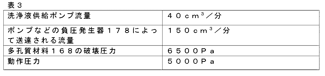
上記のパラメータは、多孔質材料168が5000Paで好ましい表面乾燥能力を示すことができ、6500Paで初めて「破壊」し始める可能性があることを反映することができる。
The above parameters may reflect that the
したがって、多孔質材料168の後ろの負圧が多孔質材料168の破壊圧力に達しないように、圧力を調節することによって、言い換えれば、上記の圧力閾値を選択することによって、発泡を最小限に抑えるか、又は防止することができる。
Therefore, foaming can be minimized or prevented by adjusting the pressure, in other words, by selecting the above pressure threshold, so that the negative pressure behind the
図37Cは、特に湿式掃除装置の起動時の、湿式掃除装置の動作ウィンドウをグラフで示す。図37Cは、大気圧に対する圧力VS時間を示す。 Figure 37C graphically illustrates the operating window of the wet vacuum cleaner, particularly upon start-up of the wet vacuum cleaner. Figure 37C illustrates pressure vs. time relative to atmospheric pressure.
多孔質材料168の破壊圧力BPは、(大気圧を基準として)負であるとみなすことができる。したがって、多孔質材料168と負圧発生器178との間の湿式掃除装置内部の圧力は、この負圧BPより高く維持することができる。他方、多孔質材料の破壊圧力が絶対圧力(真空0Paを基準として)である場合、多孔質材料168と負圧発生器178との間の湿式掃除装置内部の圧力は、特に、圧力を所定の閾値PT以上に維持するように流量を制御することによって、依然としてそのような絶対圧力より高く維持することができる。
The burst pressure BP of the
図37Cはまた、所定の閾値PT以上の「安全ゾーン」SZを示しており、このゾーンでは、多孔質材料168の破壊圧力BPに近づくことなく湿式装置装置を動作させることができる。さらに、図37Cは、多孔質材料168の破壊圧力BPに達するのを回避するという要件と、掃除すべき表面からの十分な液体のピックアップを達成することとが組み合わされた最適動作ゾーンOZを示す。
Figure 37C also shows a "safety zone" SZ above a given threshold PT, in which the wetter device can be operated without approaching the burst pressure BP of the
より一般的には、少なくとも1つの覆われた汚れ入口142A内の圧力に基づいて流れを制御することは、任意の適切な方法で達成することができる。図38に示すようないくつかの実施形態では、負圧発生器装置280は、多孔質材料168と負圧発生器178との間の湿式掃除装置内部の圧力の測定値を感知するように構成されたセンサ180と、感知された圧力の測定値に基づいて流れを供給するように負圧発生器178を制御するよう構成されたコントローラ298とを含む。
More generally, controlling flow based on pressure within at least one covered
コントローラ298、例えばマイクロコントローラは、図38に矢印300で示されるように、センサ180からセンサ信号を受信し、そして、そのセンサ信号に基づいて、制御信号302を負圧発生器178に送信することができる。
The
制御信号302は、例えば、負圧発生器178をトリガーして、流れを提供するように作動させ、又は流れを停止するように停止させることができる。代替的に又は追加的に、制御信号302は、センサ信号300に応じて、流れを増加又は減少させることができる。このようにして、負圧発生器178によって提供される流れを停止又は減少させることは、湿式掃除装置278の電力消費を削減するのに役立つことができる。これは、湿式掃除装置がバッテリー駆動式/バッテリー駆動可能である例においてバッテリー電力の節約に役立つことができ、それによって稼働時間を延長する。
The
流れの制御は、前述のように、掃除すべき表面の濡れ具合を制御するのにも役立つことができる。 Flow control can also help control the wetting of the surface being cleaned, as mentioned above.
いくつかの実施形態では、コントローラ298は、多孔質材料168と負圧発生器178との間の湿式掃除装置の内部の圧力が、前述の所定の圧力閾値以上に維持されるように、負圧発生器178によって提供される流れを制御するように構成される。非限定的な例では、感知された圧力の測定値が、圧力が所定の圧力閾値未満であることを示す場合、負圧発生器178は、負圧発生器178を制御して、流れを停止又は減少させるように停止させることができる。
In some embodiments, the
非限定的な例では、例えば比例積分コントローラを含むか、又は比例積分コントローラの形態のコントローラ298は、感知された圧力の測定値を所望の動作圧力(例えば、前述のように多孔質材料168の破壊圧力を基準として設定される)と比較し、比較に基づいて負圧発生器178を制御するように構成される。
In a non-limiting example, the
いくつかの実施形態では、センサ180は、多孔質材料168と少なくとも1つの汚れ入口142Aとの間のキャビティ150、及び少なくとも1つの汚れ入口142Aを負圧発生器178に接続するチューブ144A(又はチューブ144A、144B)のうちの少なくとも1つにおける圧力の測定値を感知するように構成される。
In some embodiments, the
キャビティ150内の圧力の測定値を感知することは、使用中に多孔質材料168の特性に合わせて流れをより直接調整できるため、特に有利である。
Sensing a measurement of the pressure within the
圧力の測定値がチューブ144A、144B(複数可)内で感知されるようにセンサ180を配置することは、センサ180を湿式掃除装置に組み込む比較的簡単な方法を提供することができる。
Positioning the
負圧発生器178が汚れた液体収集タンクの下流に配置される実施形態では、センサ180を汚れた液体収集タンク内に配置することもできる。そのようなシナリオでは、例えばハンドル上又はハンドル内に配置された汚れた液体収集タンクの高さによってノイズが発生する可能性がある(dP=H*cos(α)*ρ*g、Hは垂直位置における汚れた液体収集タンクの高さであり、αは垂直に対するハンドルの角度である)。ただし、このノイズは、センサ180に角度センサ、例えば加速度計を含めることで補償することができる。
In embodiments where the
より一般的には、センサ180は、多孔質材料168と負圧発生器178との間の湿式掃除装置内部の圧力の測定値を感知できる限り、任意の適切なタイプのセンサであり得る。例えば、センサは、圧力センサ、例えば微小電気機械システム(microelectromechanical system、MEMS)圧力センサを含む。
More generally, the
図39に示すようないくつかの実施形態では、負圧発生器装置280は、多孔質材料168と負圧発生器178との間の湿式掃除装置内部の圧力に基づいて流れを制御するように構成された機械式レギュレータ304を含む。
In some embodiments, such as that shown in FIG. 39, the negative
機械式レギュレータ304は、例えば、少なくとも1つの覆われた汚れ入口142A内の圧力に従って、負圧発生器178と少なくとも1つの汚れ入口142Aとの間の流体連通を制御するように構成された弁306、308を含むことができる。
The
図39に示す非限定的な例では、弁306、308は、弁座306と、弁部材308とを含み、弁部材308は、弁部材308が弁座306から分離されて、負圧発生器178と少なくとも1つの汚れ入口142Aとの間の流体連通を可能にする初期位置と、弁部材308が弁座306に当接して、負圧発生器178と少なくとも1つの汚れ入口142Aとの間の流体連通を制限する閉位置とをとるように構成される。
In a non-limiting example shown in FIG. 39, the
いくつかの実施形態では、弁306、308は、圧力が前述の所定の圧力閾値を下回る場合、少なくとも1つの覆われた汚れ入口142A内の圧力によって弁部材308が弁座306に向かって移動するように構成される。
In some embodiments, the
弁部材308は、例えば、初期位置で平坦なプロファイルをとる可撓性ゴム膜の形態であってもよく、したがって、覆われた汚れ入口142A(複数可)内に負圧がない場合、弁座306から空間的に離れている。負圧発生器178、例えばポンプが作動された後、覆われた汚れ入口142A(複数可)及び機械式レギュレータ304内に負圧が発生する可能性がある。負圧は機械式レギュレータ304内のゴム膜の露出面に作用する可能性があり、したがって、機械式レギュレータ304は、弁座306の方向に内側に偏向し始める可能性がある。
The
この非限定的な例では、閾値圧力は、可撓性ゴム膜と弁座306との間の距離によって設定/事前決定することができる。距離が長いほど、ゴム膜を変形させて弁座306に接触させるために必要な、覆われた汚れ入口142A(複数可)内の負圧が高くなる(又は、同等に圧力が低くなる)。
In this non-limiting example, the threshold pressure can be set/predetermined by the distance between the flexible rubber membrane and the
負圧がゴム膜を弁座に接触させるレベルに達すると、負圧発生器178と多孔質材料168との間の流体連通が解除される可能性があり、それによって負圧が機械式レギュレータ304によって設定されたレベルよりも高いレベルに達するのを防ぐ。負圧発生器178は、その最大動作負圧に向けて同じ速度で動作し続けることができる。覆われた汚れ入口142A(複数可)内の負圧が低下すると、可撓性膜は上記の平坦な状態に向かって戻ることができ、それによって弁306、308が開き、負圧発生器178が所望の負圧レベルを回復することが可能になる。
When the negative pressure reaches a level that causes the rubber membrane to contact the valve seat, fluid communication between the
別の非限定的な例では、機械式レギュレータ304は、スイッチ(その作動が負圧発生器178を制御する)と、圧力に応じてスイッチを作動させるように構成された偏向可能な部材、例えば膜とを含む。
In another non-limiting example, the
このような機械式レギュレータ、この場合は電気機械式レギュレータは、例えば圧力が所定の圧力閾値以上である場合に、例えば負圧発生器178を停止するために膜によるスイッチの作動が行われるように構成することができる。
Such a mechanical regulator, in this case an electromechanical regulator, may be configured such that, for example, a membrane switch is activated to shut off the
このスイッチ-膜構成は、追加のコントローラ、例えばマイクロコントローラを必要とせずに、圧力に基づいて流れを制御する簡単で安価な方法を提供することができる。 This switch-membrane configuration can provide a simple and inexpensive way to control flow based on pressure without the need for an additional controller, e.g., a microcontroller.
図40及び図41に示すようないくつかの実施形態では、負圧発生器178自体は、少なくとも1つの覆われた汚れ入口142A内の圧力に応じて流れを制御するように構成されたポンプを含む。
In some embodiments, such as those shown in FIGS. 40 and 41, the
このようなポンプは、圧力制限式ポンプとみなすことができる。圧力制限式ポンプは、それが接続されているチューブにわたって特定の圧力差を発生させることができる。原則として、このポンプ圧力を、汚れ入口142A(複数可)を覆う多孔質材料168に必要な圧力に調整することができる。
Such a pump can be considered a pressure-limited pump. A pressure-limited pump can generate a certain pressure difference across the tubing to which it is connected. In principle, this pump pressure can be adjusted to the pressure required for the
圧力制限式ポンプは、例えば遠心ポンプを含むか、又は遠心ポンプであり得る。ポンプ、例えば遠心ポンプは、液体ポンプであるか、又は液体ポンプを含んでもよい。このような液体ポンプは、例えば、汚れ入口142A(複数可)と汚れた液体収集タンク310との間に配置されてもよい。
The pressure-limited pump may include or be, for example, a centrifugal pump. The pump, e.g., a centrifugal pump, may be or include a liquid pump. Such a liquid pump may be disposed, for example, between the dirt inlet(s) 142A and the dirty
図40に示す非限定的な例では、負圧発生器178、例えば遠心ポンプ及び/又は液体ポンプがクリーナーヘッド100内に配置される。
In a non-limiting example shown in FIG. 40, a
あるいは、ポンプ、例えば遠心ポンプは、空気ポンプであるか、又は空気ポンプを含んでもよい。このような空気ポンプは、例えば、汚れた液体収集タンク310の下流に配置されてもよい。
Alternatively, the pump, e.g., a centrifugal pump, may be or include an air pump. Such an air pump may be located, for example, downstream of the dirty
汚れた液体収集タンク310は、ハンドル上の特定の高さ312、例えば0.5mの位置に配置されてもよいことに留意されたい。したがって、追加の水頭が必要になる可能性がある。
![]()
![]()
ハンドルが掃除すべき水平面218、例えば床の表面上に平らに置かれる位置(水頭がゼロになる)を含めてハンドルの位置を考慮すると、多孔質材料168の圧力変動はその動作圧力に等しくなる可能性がある。後者は、ハンドルの位置に関係なく、床に対して一定の高さにチューブ144Aを取り付けることによって、例えば、汚れた液体収集タンク310(の一部)を多孔質材料168に直接取り付けることによって対処することができる。
Considering the position of the handle, including the position where it is lying flat on the surface of the
図41は、圧力が負圧発生器178の圧力制限式空気ポンプ、例えば、遠心空気ポンプを使用して調整される湿式掃除装置278を概略的に示す。これにより、図40に示す例に比べて起動時の利点が得られる可能性がある。なぜなら、ポンプが常に空気を使用して動作することができ、それによってポンプが起動時に(多孔質材料168が完全に乾燥している状態で)必要な負圧を発生させることができることが保証されるからである。
Figure 41 shows a schematic of a
いくつかの実施形態では、負圧発生器178は、その設計にかかわらず、流れが提供されているとき、流量が40~2000cm3/分、より好ましくは80~750cm3/分、さらにより好ましくは100~300cm3/分、最も好ましくは150~300cm3/分の範囲にあるように構成される。
In some embodiments, regardless of its design, the
このような流れ、すなわち流量は、多孔質材料168の負圧維持能力を利用することができ、また、前述のようにエネルギー消費を制限しながら十分な液体のピックアップを確保することができる。
Such a flow, or rate, can take advantage of the
より一般的には、湿式掃除装置278は、例えば、湿式モップ掛け装置、窓掃除機、スイーパー、又はキャニスター型、スティック型、若しくは直立型の湿式真空掃除機などの湿式真空掃除機であってもよく、又はそれらを含んでもよい。
More generally, the
特定の非限定的な例では、湿式掃除装置278は、バッテリー駆動(又はバッテリー駆動可能)湿式モップ掛け装置などのバッテリー駆動(又はバッテリー駆動可能)湿式掃除装置であり、この装置では、負圧発生器178、例えばポンプは、それに電気的に接続された(又は接続可能な)バッテリーによって駆動される(又は駆動可能である)。汚れ入口142A、142B(複数可)(汚れ入口142A、142Bに負圧発生器178の吸引力が提供される)を覆う多孔質材料168が上述の電力消費低減効果を提供することができるため、この例について特に言及する。
In a specific, non-limiting example, the
図42は、湿式真空掃除機の形態の例示的な湿式掃除装置278を概略的に示す。この非限定的な例では、湿式掃除装置278は、前述の汚れた液体収集タンク310と、洗浄液リザーバ313とを含む。湿式真空掃除機に含まれるクリーナーヘッド100は、この例では、湿式真空掃除機に含まれる車輪314の補助を受けて、掃除すべき表面218上を移動することができる。
Figure 42 shows a schematic diagram of an exemplary
湿式掃除装置278は、いくつかの例では、床の表面などの掃除すべき表面上でクリーナーヘッド100を自律的に移動させるように構成されたロボット湿式真空掃除機又はロボット湿式モップ掛け装置であるか、又はそれらを含んでもよい。
The
図43は、ロボット湿式真空掃除機の形態の例示的な湿式掃除装置278を概略的に示す。ロボット湿式真空掃除機は、例えば車輪314に対する自動制御を介して、掃除すべき表面218上を自律的に移動することができる。
Figure 43 illustrates a schematic of an exemplary
ロボット湿式真空掃除機の自律移動中、洗浄液リザーバ313に貯蔵された洗浄液を掃除すべき表面に送達することができ、液体をクリーナーヘッド100の覆われた汚れ入口142A(複数可)を介して吸い上げ、汚れた液体収集タンク310内に収集することができる。負圧発生器278/負圧発生器装置280及び/又は洗浄液供給部も自動制御されてもよい。
During the autonomous movement of the robotic wet vacuum cleaner, cleaning fluid stored in the cleaning
開示された実施形態に対する他の変形は、図面、本開示、及び添付の特許請求の範囲を研究することにより、特許請求された発明を実施する際に当業者によって理解され、実施され得る。特許請求の範囲において、「含む(comprising)」という語は他の要素又はステップを排除するものではなく、不定冠詞「a」又は「an」は複数を排除するものではない。相互に異なる従属請求項に特定の手段が記載されているという事実だけでは、これらの手段の組み合わせが有利に使用できないことを示すものではない。特許請求の範囲におけるいかなる参照符号も、範囲を限定するものとして解釈されるべきではない。 Other variations to the disclosed embodiments can be understood and effected by those skilled in the art in practicing the claimed invention, from a study of the drawings, the disclosure, and the appended claims. In the claims, the word "comprising" does not exclude other elements or steps, and the indefinite articles "a" or "an" do not exclude a plurality. The mere fact that certain measures are recited in mutually different dependent claims does not indicate that a combination of these measures cannot be used to advantage. Any reference signs in the claims should not be interpreted as limiting the scope.
Claims (15)
少なくとも1つの汚れ入口(142A、142B)と、前記少なくとも1つの汚れ入口を覆う多孔質材料(168)とを有するクリーナーヘッド(100)と、
前記湿式掃除装置の内部と大気圧との間に、前記多孔質材料を通して流体を前記少なくとも1つの汚れ入口に引き込むための圧力差を提供するように構成された負圧発生器(178)であって、前記圧力差が2000Pa~13500Paの範囲である、負圧発生器(178)とを備える、湿式掃除装置(278)。 A wet cleaning device (278), comprising:
a cleaner head (100) having at least one dirt inlet (142A, 142B) and a porous material (168) covering said at least one dirt inlet;
a negative pressure generator (178) configured to provide a pressure differential between an interior of the wet cleaning device and atmospheric pressure to draw fluid through the porous material into the at least one dirt inlet, the pressure differential being in the range of 2000 Pa to 13500 Pa.
Applications Claiming Priority (17)
| Application Number | Priority Date | Filing Date | Title |
|---|---|---|---|
| EP22150879.9 | 2022-01-11 | ||
| EP22150883.1A EP4209160A1 (en) | 2022-01-11 | 2022-01-11 | Wet cleaning apparatus |
| EP22150883.1 | 2022-01-11 | ||
| EP22150906.0 | 2022-01-11 | ||
| EP22150888.0A EP4209159A1 (en) | 2022-01-11 | 2022-01-11 | Wet cleaning apparatus and cleaner head |
| EP22150906.0A EP4209167A1 (en) | 2022-01-11 | 2022-01-11 | Cleaner head and wet cleaning apparatus comprising the same |
| EP22150898.9 | 2022-01-11 | ||
| EP22150898.9A EP4209162A1 (en) | 2022-01-11 | 2022-01-11 | Wet cleaning apparatus |
| EP22150879.9A EP4209158A1 (en) | 2022-01-11 | 2022-01-11 | Cleaning element, cleaner head and wet cleaning apparatus |
| EP22150862.5A EP4209165A1 (en) | 2022-01-11 | 2022-01-11 | Attachable member, cleaner head and wet cleaning apparatus |
| EP22150912.8A EP4209163A1 (en) | 2022-01-11 | 2022-01-11 | Cleaner head and wet cleaning apparatus comprising the same |
| EP22150862.5 | 2022-01-11 | ||
| EP22150912.8 | 2022-01-11 | ||
| EP22150888.0 | 2022-01-11 | ||
| EP22150901.1 | 2022-01-11 | ||
| EP22150901.1A EP4209166A1 (en) | 2022-01-11 | 2022-01-11 | Cleaner head and wet cleaning apparatus comprising the same |
| PCT/EP2023/050354 WO2023135090A1 (en) | 2022-01-11 | 2023-01-09 | Wet cleaning apparatus |
Publications (2)
| Publication Number | Publication Date |
|---|---|
| JP2025503657A true JP2025503657A (en) | 2025-02-04 |
| JPWO2023135090A5 JPWO2023135090A5 (en) | 2026-01-21 |
Family
ID=84981970
Family Applications (5)
| Application Number | Title | Priority Date | Filing Date |
|---|---|---|---|
| JP2024541610A Pending JP2025503657A (en) | 2022-01-11 | 2023-01-09 | Wet cleaning equipment |
| JP2023563231A Active JP7764497B2 (en) | 2022-01-11 | 2023-01-09 | Wet cleaning device and cleaner head |
| JP2023563229A Active JP7764496B2 (en) | 2022-01-11 | 2023-01-09 | Wet Cleaning Equipment |
| JP2023562997A Active JP7764495B2 (en) | 2022-01-11 | 2023-01-09 | Cleaner head and wet cleaning device equipped with cleaner head |
| JP2023563230A Active JP7725609B2 (en) | 2022-01-11 | 2023-01-09 | Cleaner head and wet cleaning device equipped with cleaner head |
Family Applications After (4)
| Application Number | Title | Priority Date | Filing Date |
|---|---|---|---|
| JP2023563231A Active JP7764497B2 (en) | 2022-01-11 | 2023-01-09 | Wet cleaning device and cleaner head |
| JP2023563229A Active JP7764496B2 (en) | 2022-01-11 | 2023-01-09 | Wet Cleaning Equipment |
| JP2023562997A Active JP7764495B2 (en) | 2022-01-11 | 2023-01-09 | Cleaner head and wet cleaning device equipped with cleaner head |
| JP2023563230A Active JP7725609B2 (en) | 2022-01-11 | 2023-01-09 | Cleaner head and wet cleaning device equipped with cleaner head |
Country Status (8)
| Country | Link |
|---|---|
| US (6) | US20250120559A1 (en) |
| EP (8) | EP4463043B1 (en) |
| JP (5) | JP2025503657A (en) |
| KR (6) | KR102699948B1 (en) |
| CN (3) | CN116897003B (en) |
| AU (4) | AU2023207772B2 (en) |
| PL (7) | PL4274459T3 (en) |
| WO (8) | WO2023135091A1 (en) |
Families Citing this family (1)
| Publication number | Priority date | Publication date | Assignee | Title |
|---|---|---|---|---|
| WO2023135091A1 (en) * | 2022-01-11 | 2023-07-20 | Philips Domestic Appliances Holding B.V. | Attachable member, cleaner head and wet cleaning apparatus |
Family Cites Families (65)
| Publication number | Priority date | Publication date | Assignee | Title |
|---|---|---|---|---|
| US1066201A (en) * | 1911-08-25 | 1913-07-01 | John W Fulper | Vacuum-mop. |
| US2506077A (en) | 1945-03-01 | 1950-05-02 | Vernon H Goldsmith | Surface cleaning device employing liquid cleaning agent |
| US2893044A (en) * | 1956-02-16 | 1959-07-07 | Kurose Keamon | Squeegee type fountain cleaning device |
| US3195166A (en) | 1963-07-24 | 1965-07-20 | John A Wisner | Wall washing apparatus |
| US3958298A (en) | 1974-08-01 | 1976-05-25 | Servicemaster Industries Inc. | Cleaning nozzle |
| FR2299001A1 (en) * | 1975-01-30 | 1976-08-27 | Novacel Sa | Combined brush and sponge for floors and walls - with cleaning liquid sprayed in front of brush picked up by suction pad fitted behind |
| DE2505137A1 (en) * | 1975-02-07 | 1976-08-19 | Hoechst Ag | CLEAN AIR UNIT |
| US4103519A (en) * | 1977-03-18 | 1978-08-01 | Byron W. Boyd | Apparatus for ultrasonic cleaning of carpet, upholstery, and similar materials |
| DE8017072U1 (en) * | 1980-06-27 | 1982-09-02 | Alfred Kärcher GmbH & Co, 7057 Winnenden | CLEANING HEAD FOR CLEANING PLANE SURFACES |
| DE3143355A1 (en) | 1981-10-31 | 1983-05-11 | May + Lipfert, 3300 Braunschweig | Suction nozzle for taking up liquids |
| US4490882A (en) * | 1983-07-18 | 1985-01-01 | Wells R Leon | Upright vacuum center |
| JPS62258626A (en) * | 1986-04-07 | 1987-11-11 | ラグ ドクタ− インコ−ポレ−テツド | Built-in type vacuum cleaner |
| US5084938A (en) * | 1989-06-13 | 1992-02-04 | Leopold Knestele | Apparatus for cleaning floor coverings |
| FR2653002B1 (en) * | 1989-10-13 | 1991-12-13 | Alazet Jean | SUCTION DEVICE WITH SQUEEGEE FOR REMOVAL OF SALT WATER WHEN CLEANING CERTAIN SURFACES. |
| US5074008A (en) | 1991-05-21 | 1991-12-24 | Palomino Jr Guillermo | Dust mop attachment for vacuum cleaners |
| FR2683443B1 (en) * | 1991-11-12 | 1994-11-04 | Moulinex Sa | CLEANING HEAD FOR FLAT SURFACES. |
| KR940001037Y1 (en) * | 1992-01-07 | 1994-02-25 | 강진구 | Vacuum cleaner with wet duster |
| WO1994001035A1 (en) * | 1992-07-02 | 1994-01-20 | Steven Chayer | Methods of and apparatus for containing and evacuating fluids |
| JPH07255320A (en) * | 1994-03-17 | 1995-10-09 | Suiken:Kk | Water tank cleaning implement |
| GB9503185D0 (en) * | 1995-02-18 | 1995-04-05 | Vax Ltd | Cleaning head |
| US5655258A (en) | 1996-03-12 | 1997-08-12 | Heintz; J. Aaron | Device for aspirating fluids from hospital operating room floor |
| US5907879A (en) * | 1996-12-05 | 1999-06-01 | Downey; Mike | High flow steam carpet cleaner |
| US7350257B2 (en) | 1998-06-12 | 2008-04-01 | Rapid Brands Corporation | Cleaning tool with removable cleaning sheets |
| JP2000070204A (en) * | 1998-09-03 | 2000-03-07 | Atox Co Ltd | Nozzle for floor surface cleaning device |
| US6260232B1 (en) | 1998-09-22 | 2001-07-17 | Marc O. Nelson | Surface cleaning apparatus |
| US6446302B1 (en) * | 1999-06-14 | 2002-09-10 | Bissell Homecare, Inc. | Extraction cleaning machine with cleaning control |
| US20040134016A1 (en) * | 2003-01-10 | 2004-07-15 | Royal Appliance Manufacturing Company | Suction wet jet mop |
| US7137169B2 (en) | 2003-01-10 | 2006-11-21 | Royal Appliance Mfg. Co. | Vacuum cleaner with cleaning pad |
| JP3484188B1 (en) * | 2003-03-31 | 2004-01-06 | 貴幸 関島 | Steam injection cleaning device |
| US7141118B2 (en) | 2003-06-20 | 2006-11-28 | Patent Tech, Llc | Apparatus and method for treating and impregnating porous structures |
| KR20070010775A (en) * | 2005-07-20 | 2007-01-24 | 서경미 | Mop combined vacuum cleaner |
| US7409745B2 (en) | 2005-08-09 | 2008-08-12 | The Scott Fetzer Company | Cleaning pad for vacuum cleaner |
| WO2007111957A2 (en) * | 2006-03-22 | 2007-10-04 | S. C. Johnson & Son, Inc. | Cleaning implement |
| JP3926378B1 (en) * | 2006-08-09 | 2007-06-06 | 貴幸 関島 | Suction type cleaning device |
| US20080047093A1 (en) * | 2006-08-28 | 2008-02-28 | Gordon Evan A | Battery powered extractor |
| US20090110890A1 (en) * | 2007-10-30 | 2009-04-30 | 3M Innovative Properties Company | Color changing wear indicator |
| DE102007059930B3 (en) * | 2007-12-04 | 2009-02-19 | Kurz, Gerhard | Motor performance controlling or regulating device for cylinder vacuum cleaner, has regulating device formed such that motor is switched off for preset time period when rise rate of low pressure exceeds preset value |
| DE102008010068B4 (en) | 2008-02-20 | 2013-02-28 | BSH Bosch und Siemens Hausgeräte GmbH | Device for automatic suction power control of a vacuum cleaner |
| DE202008010345U1 (en) * | 2008-08-04 | 2008-10-02 | Pauly, Udo, Dr.-Ing. | Device for underwater cleaning of surfaces |
| US8528161B2 (en) | 2009-08-07 | 2013-09-10 | Euro-Pro Operating Llc | Cleaning appliance having multiple functions |
| DE102011078388A1 (en) * | 2011-06-30 | 2013-01-03 | BSH Bosch und Siemens Hausgeräte GmbH | Auxiliary air valve for vacuum cleaner, has housing, inlet opening and outlet opening for bypass airflow, and pressure-dependent opening closure unit for blocking flow connection between inlet opening and outlet |
| DE102011052020A1 (en) | 2011-07-21 | 2013-01-24 | Miele & Cie. Kg | Vacuum cleaner and method for operating a vacuum cleaner |
| GB2504675B (en) * | 2012-08-03 | 2014-11-26 | Dyson Technology Ltd | A floor tool for a vacuum cleaning appliance |
| EP2800504B1 (en) * | 2012-08-07 | 2018-06-20 | Kärcher North America, Inc. | Floor cleaning tool having a mechanically operated pump |
| JP2014148844A (en) | 2013-02-01 | 2014-08-21 | Kawada Industries Inc | Washing device for bridge |
| WO2014191024A1 (en) * | 2013-05-28 | 2014-12-04 | Alfred Kärcher Gmbh & Co. Kg | Method for adjusting a position of a suction lip of a floor-cleaning machine, and floor-cleaning machine |
| DE102013223864A1 (en) * | 2013-11-21 | 2015-05-21 | BSH Hausgeräte GmbH | Method of operating a vacuum cleaner and vacuum cleaner |
| TR201810071T4 (en) * | 2014-07-14 | 2018-08-27 | Koninklijke Philips Nv | Surface cleaning device. |
| WO2016123190A1 (en) * | 2015-01-28 | 2016-08-04 | Techtronic Industries Co. Ltd | Surface cleaning head with a valve assembly |
| DE102016118248A1 (en) * | 2015-10-30 | 2017-05-04 | Vorwerk & Co. Interholding Gmbh | Cleaning device, in particular household vacuum cleaner |
| DE102016124425A1 (en) * | 2016-12-14 | 2018-06-14 | Hako Gmbh | Floor cleaning machine with level measurement for waste water tank |
| EP3366182A1 (en) * | 2017-02-27 | 2018-08-29 | Koninklijke Philips N.V. | Cleaning device |
| GB2560366A (en) * | 2017-03-09 | 2018-09-12 | Kaercher Gmbh & Co Kg Alfred | Improvements relating to robotic cleaning systems and robots therefor |
| US10561292B2 (en) * | 2017-09-15 | 2020-02-18 | Omachron Intellectual Property Inc. | Surface cleaning apparatus |
| CN208031150U (en) * | 2017-12-13 | 2018-11-02 | 兰州工业学院 | A kind of plain type cleaning stair mop |
| CN208659211U (en) * | 2018-04-27 | 2019-03-29 | 杨子暄 | A kind of mop and its draining cleaning barrel |
| WO2020132032A1 (en) | 2018-12-18 | 2020-06-25 | Sharkninja Operating Llc | Cleaning device |
| EP3840623B1 (en) | 2019-03-28 | 2022-07-20 | Techtronic Cordless GP | Floor cleaner and tray |
| WO2020207557A1 (en) * | 2019-04-08 | 2020-10-15 | Alfred Kärcher SE & Co. KG | Surface cleaning machine with tank arrangement for dirty fluid |
| WO2021092429A1 (en) | 2019-11-06 | 2021-05-14 | Sharkninja Operating Llc | Cleaning device |
| WO2021108496A1 (en) | 2019-11-25 | 2021-06-03 | Sharkninja Operating Llc | Cleaning device |
| CN111543904B (en) * | 2020-05-25 | 2021-11-05 | 胡佳威 | Floor cleaning machine capable of cleaning side wall of step and climbing step |
| CN113876245B (en) * | 2020-07-02 | 2025-04-04 | 武汉学院 | A cleaning device based on water-dust circulation |
| CN215128158U (en) * | 2021-06-11 | 2021-12-14 | 深圳市优代尔科技有限公司 | Cleaning tool |
| WO2023135091A1 (en) * | 2022-01-11 | 2023-07-20 | Philips Domestic Appliances Holding B.V. | Attachable member, cleaner head and wet cleaning apparatus |
-
2023
- 2023-01-09 WO PCT/EP2023/050355 patent/WO2023135091A1/en not_active Ceased
- 2023-01-09 PL PL23700503.8T patent/PL4274459T3/en unknown
- 2023-01-09 KR KR1020237029299A patent/KR102699948B1/en active Active
- 2023-01-09 CN CN202380010209.3A patent/CN116897003B/en active Active
- 2023-01-09 CN CN202380010211.0A patent/CN116867411B/en active Active
- 2023-01-09 WO PCT/EP2023/050360 patent/WO2023135096A1/en not_active Ceased
- 2023-01-09 PL PL23700502.0T patent/PL4274458T3/en unknown
- 2023-01-09 EP EP23700630.9A patent/EP4463043B1/en active Active
- 2023-01-09 US US18/728,415 patent/US20250120559A1/en active Pending
- 2023-01-09 WO PCT/EP2023/050358 patent/WO2023135094A1/en not_active Ceased
- 2023-01-09 EP EP23700502.0A patent/EP4274458B1/en active Active
- 2023-01-09 JP JP2024541610A patent/JP2025503657A/en active Pending
- 2023-01-09 WO PCT/EP2023/050357 patent/WO2023135093A1/en not_active Ceased
- 2023-01-09 WO PCT/EP2023/050356 patent/WO2023135092A1/en not_active Ceased
- 2023-01-09 US US18/728,406 patent/US20240415355A1/en active Pending
- 2023-01-09 KR KR1020237034178A patent/KR102774502B1/en active Active
- 2023-01-09 WO PCT/EP2023/050353 patent/WO2023135089A1/en not_active Ceased
- 2023-01-09 JP JP2023563231A patent/JP7764497B2/en active Active
- 2023-01-09 PL PL23700634.1T patent/PL4274461T3/en unknown
- 2023-01-09 PL PL23700631.7T patent/PL4463044T3/en unknown
- 2023-01-09 US US18/728,408 patent/US20250000323A1/en active Pending
- 2023-01-09 JP JP2023563229A patent/JP7764496B2/en active Active
- 2023-01-09 EP EP23700632.5A patent/EP4463045A1/en active Pending
- 2023-01-09 AU AU2023207772A patent/AU2023207772B2/en active Active
- 2023-01-09 CN CN202380010208.9A patent/CN116897002B/en active Active
- 2023-01-09 PL PL23700630.9T patent/PL4463043T3/en unknown
- 2023-01-09 AU AU2023207248A patent/AU2023207248B2/en active Active
- 2023-01-09 KR KR1020247026872A patent/KR20240134187A/en active Pending
- 2023-01-09 JP JP2023562997A patent/JP7764495B2/en active Active
- 2023-01-09 PL PL23700635.8T patent/PL4274457T3/en unknown
- 2023-01-09 EP EP23700633.3A patent/EP4274460B1/en active Active
- 2023-01-09 EP EP23700631.7A patent/EP4463044B1/en active Active
- 2023-01-09 PL PL23700633.3T patent/PL4274460T3/en unknown
- 2023-01-09 JP JP2023563230A patent/JP7725609B2/en active Active
- 2023-01-09 AU AU2023207420A patent/AU2023207420B2/en active Active
- 2023-01-09 KR KR1020237032254A patent/KR102699947B1/en active Active
- 2023-01-09 EP EP23700634.1A patent/EP4274461B1/en active Active
- 2023-01-09 WO PCT/EP2023/050354 patent/WO2023135090A1/en not_active Ceased
- 2023-01-09 WO PCT/EP2023/050359 patent/WO2023135095A1/en not_active Ceased
- 2023-01-09 US US18/728,409 patent/US12495942B2/en active Active
- 2023-01-09 US US18/728,418 patent/US20250057378A1/en active Pending
- 2023-01-09 US US18/728,413 patent/US20250000324A1/en active Pending
- 2023-01-09 EP EP23700635.8A patent/EP4274457B1/en active Active
- 2023-01-09 KR KR1020237030926A patent/KR102699946B1/en active Active
- 2023-01-09 KR KR1020247026532A patent/KR20240134170A/en active Pending
- 2023-01-09 AU AU2023206582A patent/AU2023206582A1/en active Pending
- 2023-01-09 EP EP23700503.8A patent/EP4274459B1/en active Active
Also Published As
Similar Documents
| Publication | Publication Date | Title |
|---|---|---|
| JP7764496B2 (en) | Wet Cleaning Equipment | |
| CN116897004B (en) | Cleaning head and wet cleaning device comprising same | |
| RU2826284C2 (en) | Wet cleaning device and cleaning head | |
| RU2826257C2 (en) | Cleaning head and device for wet cleaning, containing it | |
| RU2833960C2 (en) | Wet cleaning device | |
| RU2836296C2 (en) | Cleaning head and device for wet cleaning containing thereof | |
| CN121487673A (en) | Cleaner head member, surface cleaning assembly and wet cleaning apparatus |
Legal Events
| Date | Code | Title | Description |
|---|---|---|---|
| A521 | Request for written amendment filed |
Free format text: JAPANESE INTERMEDIATE CODE: A523 Effective date: 20240925 Free format text: JAPANESE INTERMEDIATE CODE: A821 Effective date: 20240925 |
|
| A521 | Request for written amendment filed |
Free format text: JAPANESE INTERMEDIATE CODE: A523 Effective date: 20260108 |
|
| A621 | Written request for application examination |
Free format text: JAPANESE INTERMEDIATE CODE: A621 Effective date: 20260108 |