JP2025104329A - Flow Diverter for Catheters - Google Patents
Flow Diverter for Catheters Download PDFInfo
- Publication number
- JP2025104329A JP2025104329A JP2024230082A JP2024230082A JP2025104329A JP 2025104329 A JP2025104329 A JP 2025104329A JP 2024230082 A JP2024230082 A JP 2024230082A JP 2024230082 A JP2024230082 A JP 2024230082A JP 2025104329 A JP2025104329 A JP 2025104329A
- Authority
- JP
- Japan
- Prior art keywords
- annular ridge
- distal
- proximal
- flow diverter
- annular
- Prior art date
- Legal status (The legal status is an assumption and is not a legal conclusion. Google has not performed a legal analysis and makes no representation as to the accuracy of the status listed.)
- Pending
Links
Images


Classifications
-
- A—HUMAN NECESSITIES
- A61—MEDICAL OR VETERINARY SCIENCE; HYGIENE
- A61B—DIAGNOSIS; SURGERY; IDENTIFICATION
- A61B18/00—Surgical instruments, devices or methods for transferring non-mechanical forms of energy to or from the body
- A61B18/04—Surgical instruments, devices or methods for transferring non-mechanical forms of energy to or from the body by heating
- A61B18/12—Surgical instruments, devices or methods for transferring non-mechanical forms of energy to or from the body by heating by passing a current through the tissue to be heated, e.g. high-frequency current
- A61B18/14—Probes or electrodes therefor
- A61B18/1492—Probes or electrodes therefor having a flexible, catheter-like structure, e.g. for heart ablation
-
- A—HUMAN NECESSITIES
- A61—MEDICAL OR VETERINARY SCIENCE; HYGIENE
- A61M—DEVICES FOR INTRODUCING MEDIA INTO, OR ONTO, THE BODY; DEVICES FOR TRANSDUCING BODY MEDIA OR FOR TAKING MEDIA FROM THE BODY; DEVICES FOR PRODUCING OR ENDING SLEEP OR STUPOR
- A61M25/00—Catheters; Hollow probes
- A61M25/0067—Catheters; Hollow probes characterised by the distal end, e.g. tips
- A61M25/0068—Static characteristics of the catheter tip, e.g. shape, atraumatic tip, curved tip or tip structure
-
- A—HUMAN NECESSITIES
- A61—MEDICAL OR VETERINARY SCIENCE; HYGIENE
- A61M—DEVICES FOR INTRODUCING MEDIA INTO, OR ONTO, THE BODY; DEVICES FOR TRANSDUCING BODY MEDIA OR FOR TAKING MEDIA FROM THE BODY; DEVICES FOR PRODUCING OR ENDING SLEEP OR STUPOR
- A61M25/00—Catheters; Hollow probes
- A61M25/0021—Catheters; Hollow probes characterised by the form of the tubing
- A61M25/0023—Catheters; Hollow probes characterised by the form of the tubing by the form of the lumen, e.g. cross-section, variable diameter
- A61M25/0026—Multi-lumen catheters with stationary elements
- A61M25/0032—Multi-lumen catheters with stationary elements characterized by at least one unconventionally shaped lumen, e.g. polygons, ellipsoids, wedges or shapes comprising concave and convex parts
-
- A—HUMAN NECESSITIES
- A61—MEDICAL OR VETERINARY SCIENCE; HYGIENE
- A61M—DEVICES FOR INTRODUCING MEDIA INTO, OR ONTO, THE BODY; DEVICES FOR TRANSDUCING BODY MEDIA OR FOR TAKING MEDIA FROM THE BODY; DEVICES FOR PRODUCING OR ENDING SLEEP OR STUPOR
- A61M25/00—Catheters; Hollow probes
- A61M25/01—Introducing, guiding, advancing, emplacing or holding catheters
- A61M25/09—Guide wires
-
- A—HUMAN NECESSITIES
- A61—MEDICAL OR VETERINARY SCIENCE; HYGIENE
- A61B—DIAGNOSIS; SURGERY; IDENTIFICATION
- A61B2218/00—Details of surgical instruments, devices or methods for transferring non-mechanical forms of energy to or from the body
- A61B2218/001—Details of surgical instruments, devices or methods for transferring non-mechanical forms of energy to or from the body having means for irrigation and/or aspiration of substances to and/or from the surgical site
- A61B2218/002—Irrigation
-
- A—HUMAN NECESSITIES
- A61—MEDICAL OR VETERINARY SCIENCE; HYGIENE
- A61M—DEVICES FOR INTRODUCING MEDIA INTO, OR ONTO, THE BODY; DEVICES FOR TRANSDUCING BODY MEDIA OR FOR TAKING MEDIA FROM THE BODY; DEVICES FOR PRODUCING OR ENDING SLEEP OR STUPOR
- A61M25/00—Catheters; Hollow probes
- A61M25/0067—Catheters; Hollow probes characterised by the distal end, e.g. tips
- A61M25/0068—Static characteristics of the catheter tip, e.g. shape, atraumatic tip, curved tip or tip structure
- A61M2025/0073—Tip designed for influencing the flow or the flow velocity of the fluid, e.g. inserts for twisted or vortex flow
-
- A—HUMAN NECESSITIES
- A61—MEDICAL OR VETERINARY SCIENCE; HYGIENE
- A61M—DEVICES FOR INTRODUCING MEDIA INTO, OR ONTO, THE BODY; DEVICES FOR TRANSDUCING BODY MEDIA OR FOR TAKING MEDIA FROM THE BODY; DEVICES FOR PRODUCING OR ENDING SLEEP OR STUPOR
- A61M25/00—Catheters; Hollow probes
- A61M25/01—Introducing, guiding, advancing, emplacing or holding catheters
- A61M25/09—Guide wires
- A61M2025/09058—Basic structures of guide wires
-
- A—HUMAN NECESSITIES
- A61—MEDICAL OR VETERINARY SCIENCE; HYGIENE
- A61M—DEVICES FOR INTRODUCING MEDIA INTO, OR ONTO, THE BODY; DEVICES FOR TRANSDUCING BODY MEDIA OR FOR TAKING MEDIA FROM THE BODY; DEVICES FOR PRODUCING OR ENDING SLEEP OR STUPOR
- A61M2205/00—General characteristics of the apparatus
- A61M2205/02—General characteristics of the apparatus characterised by a particular materials
-
- A—HUMAN NECESSITIES
- A61—MEDICAL OR VETERINARY SCIENCE; HYGIENE
- A61M—DEVICES FOR INTRODUCING MEDIA INTO, OR ONTO, THE BODY; DEVICES FOR TRANSDUCING BODY MEDIA OR FOR TAKING MEDIA FROM THE BODY; DEVICES FOR PRODUCING OR ENDING SLEEP OR STUPOR
- A61M2205/00—General characteristics of the apparatus
- A61M2205/33—Controlling, regulating or measuring
- A61M2205/3331—Pressure; Flow
- A61M2205/3334—Measuring or controlling the flow rate
Landscapes
- Health & Medical Sciences (AREA)
- Life Sciences & Earth Sciences (AREA)
- Engineering & Computer Science (AREA)
- General Health & Medical Sciences (AREA)
- Veterinary Medicine (AREA)
- Public Health (AREA)
- Animal Behavior & Ethology (AREA)
- Heart & Thoracic Surgery (AREA)
- Biomedical Technology (AREA)
- Anesthesiology (AREA)
- Hematology (AREA)
- Pulmonology (AREA)
- Biophysics (AREA)
- Surgery (AREA)
- Physics & Mathematics (AREA)
- Cardiology (AREA)
- Plasma & Fusion (AREA)
- Nuclear Medicine, Radiotherapy & Molecular Imaging (AREA)
- Otolaryngology (AREA)
- Geometry (AREA)
- Medical Informatics (AREA)
- Molecular Biology (AREA)
- Surgical Instruments (AREA)
- Media Introduction/Drainage Providing Device (AREA)
Abstract
【課題】カテーテルのための分流器を提供すること。
【解決手段】開示された技術は、分流器の近位端から遠位端まで長手方向軸に沿って延在する管腔を備える分流器を含む。分流器は、複数のマニホールドを備えることができ、各マニホールドは、複数の流体通路を備え、各流体通路は、管腔から分流器の外部まで延在する。分流器は、分流器の近位端と遠位端との間で管腔の周りに配置された複数の環状隆起部を更に備えることができる。複数のマニホールドの各マニホールドは、複数の環状隆起部の隣接する環状隆起部の間に配置され得る。
【選択図】図3A
A flow diverter for a catheter is provided.
The disclosed technology includes a flow diverter comprising a lumen extending along a longitudinal axis from a proximal end to a distal end of the flow diverter. The flow diverter may comprise a plurality of manifolds, each manifold comprising a plurality of fluid passageways, each fluid passageway extending from the lumen to an exterior of the flow diverter. The flow diverter may further comprise a plurality of annular ridges disposed about the lumen between the proximal and distal ends of the flow diverter. Each manifold of the plurality of manifolds may be disposed between adjacent annular ridges of the plurality of annular ridges.
[Selected Figure] Figure 3A
Description
本発明は、概して、医療デバイスに関し、特に、灌注を伴う医療用プローブに関し、更に、電極に灌注を提供するように構成された医療用プローブに関するが、これに限定されない。 The present invention relates generally to medical devices, and more particularly, but not exclusively, to medical probes with irrigation, and further to medical probes configured to provide irrigation to electrodes.
心房細動(atrial fibrillation、AF)などの心臓不整脈は、心臓組織の領域が隣接組織に電気信号を異常に伝達するときに発生する。これは、正常な心周期を混乱させ、非同期的な律動を引き起こす。不整脈を治療するために存在するある特定の処置としては、不整脈の原因となる信号の発生源を外科的に破壊すること、及びそのような信号の伝導経路を破壊することが挙げられる。カテーテルを介してエネルギーを印加して心臓組織を選択的にアブレーションすることによって、心臓の一部分から別の部分への望ましくない電気信号の伝播を停止又は変更することが時に可能である。 Cardiac arrhythmias, such as atrial fibrillation (AF), occur when an area of cardiac tissue abnormally transmits electrical signals to adjacent tissue. This disrupts the normal cardiac cycle and causes an asynchronous rhythm. Certain procedures that exist to treat arrhythmias include surgically destroying the source of the signals that cause the arrhythmia and destroying the conduction pathways of such signals. By selectively ablating cardiac tissue with the application of energy through a catheter, it is sometimes possible to stop or alter the propagation of unwanted electrical signals from one part of the heart to another.
当該技術分野における多くの現在のアブレーションアプローチは、高周波(RF)電気エネルギーを利用して組織を加熱する。RFアブレーションは、組織の炭化、燃焼、スチームポップ、横隔神経麻痺、肺静脈狭窄、及び食道瘻につながり得る、熱加熱に関連する特定のリスクを有することができる。 Many current ablation approaches in the art utilize radio frequency (RF) electrical energy to heat tissue. RF ablation can have certain risks associated with thermal heating that can lead to tissue charring, burning, steam popping, phrenic nerve paralysis, pulmonary vein stenosis, and esophageal fistulas.
組織をアブレーションする前に、肺静脈又は他の解剖学的特徴をマッピングすることが望ましい場合がある。マッピング中に、血栓を誘発する機会が増加する可能性がある。更に、組織のアブレーションは、電極近くの局所的な温度上昇を引き起こし得る。少なくともこれらの理由から、治療又はマッピングされる解剖学的領域に灌注流体を提供することが望ましい。残念ながら、多くの既存の灌注要素は、灌注要素によって提供される冷却の有効性を低下させ得る急カーブ又は他の非効率的な設計で設計されている。したがって、当技術分野では、灌注要素によって提供される冷却の有効性を高める灌注要素が必要とされている。 Prior to ablating tissue, it may be desirable to map pulmonary veins or other anatomical features. During mapping, the chance of inducing a thrombus may be increased. Furthermore, ablation of tissue may cause a localized temperature increase near the electrode. For at least these reasons, it is desirable to provide irrigation fluid to the anatomical region being treated or mapped. Unfortunately, many existing irrigation elements are designed with sharp turns or other inefficient designs that may reduce the effectiveness of the cooling provided by the irrigation element. Thus, there is a need in the art for an irrigation element that increases the effectiveness of the cooling provided by the irrigation element.
本開示の技術の実施例によれば、近位端及び遠位端と、長手方向軸に沿って分流器の近位端から遠位端まで延在する管腔と、近位端と遠位端との間で管腔の周りに配置された複数の環状隆起部と、複数のマニホールドであって、各マニホールドは、複数の環状隆起部のうちの隣接する環状隆起部の間に配置され、複数の流体通路を備えることができ、各流体通路は、管腔から分流器の外部まで延在することができる、複数のマニホールドと、を備える、分流器が提供される。 According to an embodiment of the disclosed technique, a flow diverter is provided that includes a proximal end and a distal end, a lumen extending from the proximal end to the distal end of the flow diverter along a longitudinal axis, a plurality of annular ridges disposed about the lumen between the proximal end and the distal end, and a plurality of manifolds, each manifold disposed between adjacent ones of the plurality of annular ridges and capable of including a plurality of fluid passages, each fluid passage extending from the lumen to an exterior of the flow diverter.
分流器の遠位端は遠位開口を備えることができ、遠位開口は、管腔を通して配置されたエンドエフェクタの外周の周りにシールを形成するように構成することができる。複数の環状隆起部は、近位環状隆起部、第2の環状隆起部、第3の環状隆起部、及び遠位環状隆起部を備えることができる。複数のマニホールドは、近位環状隆起部と第2の環状隆起部との間に配置された第1のマニホールドと、第2の環状隆起部と第3の環状隆起部との間に配置された第2のマニホールドと、第3の環状隆起部と遠位環状隆起部との間に配置された第3のマニホールドとを備えることができる。近位環状隆起部、第2の環状隆起部、及び第3の環状隆起部のそれぞれは、遠位表面及び近位表面を含むことができ、近位表面のそれぞれは、実質的に凸状であることができ、遠位表面のそれぞれは、実質的に凹状であることができる。遠位環状隆起部は、遠位表面及び近位表面を備えることができ、遠位環状隆起部の遠位表面及び近位表面の両方は、実質的に凸状であり得る。近位環状隆起部の直径は、第2の環状隆起部の直径より大きくてもよく、第2の環状隆起部の直径は、第3の環状隆起部の直径より大きくてもよく、第3の環状隆起部の直径は、遠位環状隆起部の直径より大きくてもよい。分流器は、エラストマー材料を含むことができる。分流器はシリコーンを含むことができる。 The distal end of the diverter can include a distal opening, and the distal opening can be configured to form a seal around an outer periphery of an end effector disposed through the lumen. The plurality of annular ridges can include a proximal annular ridge, a second annular ridge, a third annular ridge, and a distal annular ridge. The plurality of manifolds can include a first manifold disposed between the proximal annular ridge and the second annular ridge, a second manifold disposed between the second annular ridge and the third annular ridge, and a third manifold disposed between the third annular ridge and the distal annular ridge. Each of the proximal annular ridge, the second annular ridge, and the third annular ridge can include a distal surface and a proximal surface, and each of the proximal surfaces can be substantially convex and each of the distal surfaces can be substantially concave. The distal annular ridge can include a distal surface and a proximal surface, and both the distal and proximal surfaces of the distal annular ridge can be substantially convex. The diameter of the proximal annular ridge can be greater than the diameter of the second annular ridge, and the diameter of the second annular ridge can be greater than the diameter of the third annular ridge, and the diameter of the third annular ridge can be greater than the diameter of the distal annular ridge. The flow diverter can include an elastomeric material. The flow diverter can include silicone.
開示された技術は、カテーテルであって、長手方向軸に沿って延在する挿入シャフトを備えるカテーテルと、挿入シャフトの遠位端に配置されたエンドエフェクタと、挿入シャフトの周りに配置されたシースと、シースの遠位端に配置された分流器であって、近位端及び遠位端と、分流器の近位端から遠位端まで長手方向軸に沿って延在する管腔と、近位端と遠位端との間で管腔の周りに配置された複数の環状隆起部と、複数のマニホールドであって、各マニホールドは、複数の環状隆起部のうちの隣接する環状隆起部の間に配置され、複数の流体通路を備えることができ、各流体通路は、管腔から分流器の外部まで延在することができる、複数のマニホールドと、を備える、分流器と、を含む、カテーテルを含むことができる。 The disclosed technology may include a catheter including a catheter having an insertion shaft extending along a longitudinal axis, an end effector disposed at a distal end of the insertion shaft, a sheath disposed around the insertion shaft, a flow diverter disposed at the distal end of the sheath, the flow diverter having a proximal end and a distal end, a lumen extending along the longitudinal axis from the proximal end to the distal end of the flow diverter, a plurality of annular ridges disposed around the lumen between the proximal end and the distal end, and a plurality of manifolds, each manifold being disposed between adjacent ones of the plurality of annular ridges and capable of having a plurality of fluid passages, each fluid passage extending from the lumen to an exterior of the flow diverter.
複数のマニホールドは、灌注流体を管腔から分流器の外部に迂回させて、エンドエフェクタの周囲に半径方向に灌注流体を分配することができる。エンドエフェクタは、組織アブレーションのために構成された1つ以上の電極を備えることができ、灌注流体は、アブレーション中に電極を冷却することができる。エンドエフェクタは、ガイドワイヤであり得る。 The multiple manifolds can divert irrigation fluid from the lumen to the exterior of the diverter to distribute the irrigation fluid radially around the end effector. The end effector can include one or more electrodes configured for tissue ablation, and the irrigation fluid can cool the electrodes during ablation. The end effector can be a guidewire.
複数の環状隆起部のうちの各環状隆起部の直径は、分流器の近位端から遠位に向かって互いに対して減少してもよい。複数の環状隆起部は、近位環状隆起部、第2の環状隆起部、第3の環状隆起部、及び遠位環状隆起部を備えることができる。複数のマニホールドは、近位環状隆起部と第2の環状隆起部との間に配置された第1のマニホールドと、第2の環状隆起部と第3の環状隆起部との間に配置された第2のマニホールドと、第3の環状隆起部と遠位環状隆起部との間に配置された第3のマニホールドとを備えることができる。 The diameters of each of the plurality of annular ridges may decrease relative to one another from the proximal end of the flow splitter toward the distal end. The plurality of annular ridges may include a proximal annular ridge, a second annular ridge, a third annular ridge, and a distal annular ridge. The plurality of manifolds may include a first manifold disposed between the proximal annular ridge and the second annular ridge, a second manifold disposed between the second annular ridge and the third annular ridge, and a third manifold disposed between the third annular ridge and the distal annular ridge.
近位環状隆起部、第2の環状隆起部、及び第3の環状隆起部の各々は、遠位表面及び近位表面を備えることができ、近位表面の各々は、実質的に凸状であり得、遠位表面の各々は、実質的に凹状であり得る。分流器の遠位端は遠位開口を備えることができ、遠位開口は、管腔を通して配置されたエンドエフェクタの外周の周囲にシールを形成することができる。シールは、エラストマー材料を含むことができる。シールはシリコーンを含むことができる。 Each of the proximal annular ridge, the second annular ridge, and the third annular ridge can include a distal surface and a proximal surface, each of the proximal surfaces can be substantially convex and each of the distal surfaces can be substantially concave. The distal end of the diverter can include a distal opening, which can form a seal around a circumference of an end effector disposed through the lumen. The seal can include an elastomeric material. The seal can include silicone.
本開示の技術の追加の特徴、機能、及び用途は、本明細書でより詳細に論じられる。 Additional features, functionality, and applications of the techniques disclosed herein are discussed in more detail herein.
以下の詳細な説明は、図面を参照しながら読まれるべきものであり、異なる図面における同様の要素には、同一の番号が付けられている。図面は、必ずしも縮尺どおりとは限らず、選択された実施例を示しており、また本発明の範囲を限定することを意図していない。詳細な説明は、限定ではなく、例として、本発明の原理を例解する。この説明は、当業者が本発明を作製及び使用することを明らかに可能にし、また本発明を実施するための最良の態様であると現在考えられているものを含めて、本発明のいくつかの実施形態、適応例、変形例、代替例、及び使用を説明する。 The following detailed description should be read with reference to the drawings, in which like elements in different drawings are numbered the same. The drawings, which are not necessarily to scale, depict selected examples, and are not intended to limit the scope of the invention. The detailed description illustrates, by way of example, but not by way of limitation, the principles of the invention. The description clearly enables one skilled in the art to make and use the invention, and describes several embodiments, adaptations, variations, alternatives, and uses of the invention, including what is currently contemplated to be the best mode for carrying out the invention.
本明細書で使用される場合、任意の数値又は範囲に対する「約」又は「ほぼ(略)」という用語は、構成要素の一部又は集合が本明細書に説明される意図された目的のために機能することを可能にする好適な寸法公差を示す。より具体的には、「約」又は「ほぼ(略)」は、列挙された値の±20%の値の範囲を指し得る。例えば、「約90%」は、71%~110%の値の範囲を指し得る。加えて、本明細書で使用される場合、「患者」、「宿主」、「ユーザ」、及び「対象」という用語は、任意のヒト又は動物対象を指し、ヒト患者における本発明の使用が好ましい実施形態を表すが、システム又は方法をヒトの使用に限定することを意図するものではない。同様に、「近位」という用語は、オペレータ又は医師により近い方の位置を示す一方、「遠位」は、オペレータ又は医師からより遠い位置を示す。 As used herein, the term "about" or "approximately" with respect to any numerical value or range indicates a suitable dimensional tolerance that allows a portion or collection of components to function for the intended purpose described herein. More specifically, "about" or "approximately" may refer to a range of values of ±20% of the recited value. For example, "about 90%" may refer to a range of values of 71% to 110%. Additionally, as used herein, the terms "patient," "host," "user," and "subject" refer to any human or animal subject, and while use of the invention in a human patient represents a preferred embodiment, it is not intended to limit the system or method to human use. Similarly, the term "proximal" refers to a location closer to the operator or physician, while "distal" refers to a location farther from the operator or physician.
本明細書で考察されるように、「患者」、「宿主」、「ユーザ」、及び「対象」の血管系は、ヒト又は任意の動物の血管系であり得る。動物は、哺乳類、獣医学的動物、家畜動物、又はペット類の動物などを含むが、これらに限定されない、様々な任意の適用可能なタイプのものであり得ることを理解するべきである。一例として、動物は、ヒトに類似したある特定の性質を有するように特に選択された実験動物(例えば、ラット、イヌ、ブタ、サルなど)であり得る。対象は、例えば、任意の適用可能なヒト患者であり得ることを理解するべきである。 As discussed herein, the vascular system of a "patient," "host," "user," and "subject" may be that of a human or any animal. It should be understood that the animal may be of any of a variety of applicable types, including, but not limited to, mammals, veterinary animals, livestock animals, or pet animals. By way of example, the animal may be a laboratory animal (e.g., rats, dogs, pigs, monkeys, etc.) that is specifically selected to have certain characteristics similar to humans. It should be understood that the subject may be, for example, any applicable human patient.
本明細書で考察されるように、「医師」は、医師、外科医、技術者、科学者、オペレータ、又は対象への薬物難治性心房細動の治療のための多電極カテーテルの送達に関連する任意の他の個人若しくは送達器具類を含むことができる。 As discussed herein, a "physician" may include a physician, surgeon, technician, scientist, operator, or any other individual or delivery instrumentation involved in the delivery of a multi-electrode catheter for the treatment of drug refractory atrial fibrillation to a subject.
本明細書で論じられるように、用語「アブレーションする」又は「アブレーション」は、本開示のデバイス及び対応するシステムに関する場合、本開示全体を通して、パルス電界(PEF)及びパルス場アブレーション(PFA)と互換的に称される、可逆エレクトロポレーション又は不可逆エレクトロポレーション(IRE)などの非熱エネルギー、又は高周波(RF)アブレーション若しくは冷凍アブレーションなどの熱エネルギーを利用することによって、細胞内の不規則な心臓信号の生成を低減又は防止するように構成された、構成要素及び構造的特徴を指す。本開示のデバイス及び対応するシステムに関する場合、アブレーションすること又はアブレーションは、不整脈、心房粗動アブレーション、肺静脈隔離、上室頻脈アブレーション、及び心室頻脈アブレーションを含むがこれらに限定されない特定の状態の心臓組織の熱アブレーション又は非熱アブレーションを参照して、本開示全体を通して使用される。「アブレーションする」又は「アブレーション」という用語はまた、当業者によって理解されるように、様々な形態の身体組織アブレーションを達成するための既知の方法、装置、及びシステムを含む。 As discussed herein, the term "ablate" or "ablation", in the context of the devices and corresponding systems of the present disclosure, refers to components and structural features configured to reduce or prevent the generation of irregular cardiac signals within cells by utilizing non-thermal energy, such as reversible or irreversible electroporation (IRE), interchangeably referred to as pulsed electric field (PEF) and pulsed field ablation (PFA), or thermal energy, such as radio frequency (RF) ablation or cryoablation. In the context of the devices and corresponding systems of the present disclosure, ablation or ablation is used throughout the present disclosure in reference to thermal or non-thermal ablation of cardiac tissue for specific conditions, including, but not limited to, arrhythmias, atrial flutter ablation, pulmonary vein isolation, supraventricular tachycardia ablation, and ventricular tachycardia ablation. The term "ablate" or "ablation" also includes known methods, devices, and systems for achieving various forms of body tissue ablation, as will be understood by those skilled in the art.
本明細書で考察されるように、「管状」及び「管」という用語は、広義に解釈されるものとし、直円柱構造、若しくは断面が厳密に円形である構造、又はその長さ全体にわたって均一な断面である構造に限定されるものではない。例えば、管状構造は、概して、実質的な直円柱構造として例解される。しかしながら、管状構造は、本開示の範囲から逸脱することなく、先細状又は湾曲した外部表面を有し得る。 As discussed herein, the terms "tubular" and "tube" are intended to be broadly construed and are not limited to right cylindrical structures, or structures that are strictly circular in cross section, or structures that are uniform in cross section throughout their length. For example, a tubular structure is generally illustrated as a substantially right cylindrical structure. However, a tubular structure may have a tapered or curved exterior surface without departing from the scope of the present disclosure.
図1は、例示的なカテーテルベースの電気生理学マッピング及びアブレーションシステム10を示す。システム10は、患者23の血管系を通って、心臓12の腔又は血管構造内に医師24によって経皮的に挿入される複数のカテーテルを含む。典型的には、送達シースカテーテルが、心臓12の所望の位置の近くの左心房又は右心房内へと挿入される。その後、複数のカテーテルを送達シースカテーテルに挿入して、所望の位置に到達させることができる。複数のカテーテルは、心内電位図(Intracardiac Electrogram、IEGM)信号の感知専用のカテーテル、アブレーション専用のカテーテル、並びに/又は感知及びアブレーションの両方に専用のカテーテルを含んでもよい。IEGM信号を感知する例では、医師24は、カテーテル14の遠位先端(すなわち、この場合、エンドエフェクタ200)を心臓12内の標的部位に運ぶ。アブレーションのために、医師24は、同様に、アブレーションカテーテルの遠位端をアブレーションのための標的部位に運ぶ。
1 illustrates an exemplary catheter-based electrophysiology mapping and ablation system 10. The system 10 includes multiple catheters that are percutaneously inserted by a
カテーテル14は、シース300の遠位端に配置された分流器100を含むシース300を含む例示的なカテーテルである。カテーテル14は、シース300及び分流器を通過するエンドエフェクタ200を更に含むことができる。エンドエフェクタ200は、電気生理学的信号を検出し、かつ/又はアブレーションエネルギーを組織に送達するように構成された1つ以上の電極を含んでもよい。カテーテル14は、エンドエフェクタ200の位置及び配向を追跡するために、エンドエフェクタ200内又はその近くに埋め込まれた磁気ベースの位置センサを追加的に含み得る。エンドエフェクタ200は、エンドエフェクタ200の位置及び配向を追跡するためにエンドエフェクタ200内又はその近くに配置された1つ以上のインピーダンスベースの電極を更に含むことができる。いくつかの例では、エンドエフェクタ200はガイドワイヤである。
The
磁気ベースの位置センサは、所定の作業体積内に磁場を発生させるように構成された複数の磁気コイル32を含む位置パッド25と共に動作し得る。カテーテル14のエンドエフェクタ200のリアルタイム位置は、位置パッド25によって発生し、磁気ベースの位置センサ29によって感知される磁場に基づいて追跡され得る。磁気ベースの位置センサは、特定の構成に応じて、単軸センサ、二軸センサ、又は三軸センサとすることができる。磁気ベースの位置感知技術の詳細は、米国特許第5,391,199号、同第5,443,489号、同第5,558,091号、同第6,172,499号、同第6,239,724号、同第6,332,089号、同第6,484,118号、同第6,618,612号、同第6,690,963号、同第6,788,967号、及び同第6,892,091号に記載され、それらの各々が参照によってあたかも本明細書に完全に記載されているかのように本明細書に組み込まれる。
The magnetic-based position sensor may operate in conjunction with a
システム10は、位置パッド25の位置基準及び電極26のインピーダンスベースの追跡を確立するために、患者23上の皮膚接触のために配置された1つ以上の電極パッチ38を含む。インピーダンスベースの追跡のために、電流が電極26に方向付けられ、電極皮膚パッチ38において感知され、それにより、各電極の位置を、電極パッチ38を介して三角測量することができる。インピーダンスベースの位置追跡技術の詳細は、米国特許第7,536,218号、同第7,756,576号、同第7,848,787号、同第7,869,865号及び同第8,456,182号に記載され、これらの各々は参照により本明細書に組み込まれる。
The system 10 includes one or
レコーダ11は、体表面ECG電極18で捕捉された電位図21と、カテーテル14の電極26で捕捉された心内電位図(IEGM)と、を表示する。レコーダ11は、心臓の律動をペーシングするためのペーシング能力を含んでよく、かつ/又は独立型ペーサに電気的に接続されてもよい。
The
システム10は、アブレーションするように構成されたカテーテルの遠位先端部にある電極のうちの1つ以上にアブレーションエネルギーを伝達するように適合された、アブレーションエネルギー発生器50を含んでもよい。アブレーションエネルギー発生器50によって生成されるエネルギーは、不可逆電気穿孔法(irreversible electroporation、IRE)をもたらすために使用され得るような、単極性若しくは双極性の高電圧DCパルスを含む、高周波(radiofrequency、RF)エネルギー若しくはパルスフィールドアブレーション(Pulsed-Field Ablation、PFA)エネルギー、又はこれらの組み合わせを含んでもよいが、これらに限定されるものではない。
The system 10 may include an
患者インターフェースユニット(patient interface unit、PIU)30は、カテーテルと、電気生理学的機器と、電源と、システム10の動作を制御するワークステーション55との間の電気通信を確立するように構成されたインターフェースである。システム10の電気生理学的機器は、例えば、複数のカテーテル、位置パッド25、体表面ECG電極18、電極パッチ38、アブレーションエネルギー発生器50、及びレコーダ11を含んでもよい。任意選択的に、かつ好ましくは、PIU30は、カテーテルの位置のリアルタイム計算を実装し、ECG計算を実行するための処理能力を追加的に含む。
The patient interface unit (PIU) 30 is an interface configured to establish electrical communication between the catheters, the electrophysiological equipment, a power source, and a
ワークステーション55は、メモリと、適切なオペレーティングソフトウェアがロードされたメモリ又は記憶装置を有するプロセッサユニットと、ユーザインターフェース機能と、を含む。ワークステーション55は、任意選択的に、(1)心内膜解剖学的構造を三次元(3D)でモデリングし、モデル又は解剖学的マップ20をディスプレイデバイス27上に表示するためにレンダリングすることと、(2)記録された電位図21からコンパイルされた活性化シーケンス(又は他のデータ)を、レンダリングされた解剖学的マップ20上に重ね合わされた代表的な視覚的表示又は画像でディスプレイデバイス27上に表示することと、(3)心腔内の複数のカテーテルのリアルタイムの位置及び配向を表示することと、(5)アブレーションエネルギーが印加されている箇所などの関心部位をディスプレイデバイス27上に表示することと、を含む、複数の機能を提供し得る。システム10の要素を具現化する1つの市販製品は、Biosense Webster,Inc.,31 Technology Drive,Suite 200,Irvine,CA 92618,USAから市販されている、CARTO(商標)3システムとして入手可能である。
The
図2に示すように、カテーテル14はシース300を含むことができる。分流器100は、シース300の遠位端に配置されてもよい。エンドエフェクタ200は、挿入シャフト350の遠位端に配置されてもよい。分流器100は、灌注流体をエンドエフェクタ200の周囲に半径方向に標的解剖学的領域に送達するように構成されてもよい。エンドエフェクタ200は、分流器100を貫通して設けられてもよく、分流器100の遠位端は、エンドエフェクタ200の外周の周りにシールを形成するように構成されてもよい。いくつかの例では、分流器100は、かご形カテーテルの内部に設けられて、動作中に当該カテーテルの電極に灌注を提供することができる。
As shown in FIG. 2, the
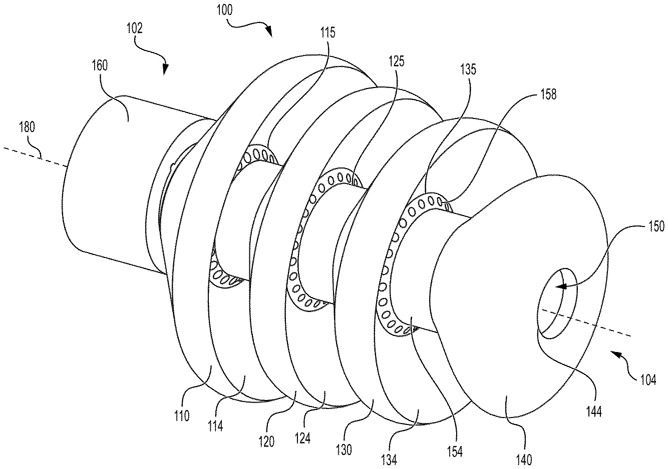
図3A~図3Dは、本開示の技術による分流器100を示す。前述したように、また本明細書でより詳細に説明するように、分流器100は、流体をエンドエフェクタの周囲に半径方向に、かつ/又は標的解剖学的領域に送達するように構成することができる。分流器100は、図3Dに示すように、分流器100の長手方向軸180に沿って設けられた実質的に管状の管腔150を含むことができる。
3A-3D show a
分流器100は、複数のマニホールド115、125、135を備えることができる。各マニホールド115、125、135は、管腔150から分流器100の外部まで延在する複数の流体通路157(図3Dに示されるような)を備えてもよい。いくつかの例では、分流器100の各流体通路157は、管腔150の内周152に設けられた内部開口156から、管腔150の外周154の周囲に設けられた外部開口158まで延在する。図3A~図3Dに示される例では、各マニホールドは24個の流体通路157を備えるが、流体通路の数は変更されてもよい。例えば、各マニホールドは、6個、12個、18個、若しくは32個、又はそれらの間の任意の数の流体通路を備えてもよい。いくつかの例では、分流器のマニホールドは、異なる数の流体通路を備えてもよい。例えば、流体通路の数は、第2のマニホールド125が第1のマニホールド115よりも多くの流体通路を備え、第3のマニホールド135が第2のマニホールド125よりも多くの流体通路を備えるように、又はその逆になるように、分流器の近位端から遠位端に向かって増加してもよい。
The
動作中、エンドエフェクタは、分流器100の管腔150を通して提供され得る。分流器100の遠位端104に設けられた遠位開口144は、エンドエフェクタの外周の周りにシールを形成することができる。灌注流体が(例えば、ポンプによって)分流器100の近位端102に設けられた近位開口108内に供給されると、灌注流体は、複数のマニホールド115、125、135の流体通路157を強制的に通される。いくつかの例では、灌注流体はまた、分流器100の遠位開口144から出る。いくつかの実施例では、エンドエフェクタの外周と相互作用する遠位開口144によって生成されるシールは、複数のマニホールド115、125、135の流体通路157のみを通して灌注流体を押し出す。いくつかの例では、遠位開口144の内径は、約0.010インチ~約0.050インチである。いくつかの例では、遠位開口144の内径は約0.045インチである。いくつかの例では、遠位開口144の内径は、約0.255ミリメートル(mm)~約1.5mmである。いくつかの例では、遠位開口144の内径は約1.17mmである。
In operation, an end effector may be provided through the
いくつかの例では、分流器100は、複数の環状隆起部110、120、130、140を備える。いくつかの例では、環状隆起部は、灌注流体をカテーテルのエンドエフェクタに向けて方向付けるために設けられ得る。いくつかの例では、各環状隆起部のサイズ(すなわち、円周、半径、及び直径)は、環状隆起部が分流器の近位端102から遠位端104に向かって先細りになるように、近位環状隆起部110から遠位環状隆起部140に向かって減少する。環状隆起部は、分流器が設けられる解剖学的領域又は解剖学的管腔の形状に適合するように可撓性であり得る。いくつかの例では、分流器は、シリコーンから形成されるか、又はそうでなければシリコーンを含む。図3A~図3Dに示すように、分流器100は、分流器100の長手方向軸180に沿って近位端102から遠位端104まで配置された近位環状隆起部110、第2の環状隆起部120、第3の環状隆起部130、及び遠位環状隆起部140を備えることができる。
In some examples, the
いくつかの実施例では、各環状隆起部は、近位表面及び遠位表面を備える。例えば、近位環状隆起部110は近位表面112及び遠位表面114を備え、第2の環状隆起部120は近位表面122及び遠位表面124を備え、第3の環状隆起部130は近位表面132及び遠位表面134を備え、遠位環状隆起部140は近位表面及び遠位表面を備える。いくつかの例では、各環状隆起部は実質的に円錐形である。いくつかの例では、環状隆起部の近位表面の各々は、実質的に凸状であり得、遠位表面の各々は、実質的に凹状である。いくつかの例では、近位環状隆起部110、第2の環状隆起部120、及び第3の環状隆起部130の遠位表面114、124、134は、実質的に凹状であり得、遠位環状隆起部140の遠位表面は、実質的に平坦であり得る。いくつかの例では、遠位環状隆起部140の遠位表面は、実質的に凸状であり得る。
In some examples, each annular ridge comprises a proximal surface and a distal surface. For example, the proximal
いくつかの例では、環状隆起部の各々の近位表面(例えば、112、122、132)は、近位表面が分流器100の長手方向軸180に対してある角度をなすように、分流器100の近位端102に向かって先細りになっている。角度付き近位表面は、標的解剖学的領域からシース300を通した分流器100の除去を容易にすることができる。
In some examples, the proximal surface of each of the annular ridges (e.g., 112, 122, 132) tapers toward the
いくつかの例では、各環状隆起部の遠位表面(例えば、114、124、134)は、分流器の近位端102に向かって先細りになっており、分流器100の長手方向軸180に対してある角度で遠位表面を提供する。近位表面及び遠位表面の角度は、ほぼ等しくてもよい。いくつかの例では、隣接する環状隆起部には、いくらかの重なりが設けられる。例えば、第2の環状隆起部120と第3の環状隆起部130との間の間隔は、(図3Cに示されるように)長手方向軸180を横切る角度から見たときに、第2の環状隆起部120の遠位表面124の一部が第3の環状隆起部130の近位表面132の一部に重なるように設けられてもよい。
In some examples, the distal surface of each annular ridge (e.g., 114, 124, 134) tapers toward the
いくつかの例では、複数のマニホールド115、125、135の各々は、隣接する環状隆起部の間に設けることができる。例えば、第1のマニホールド115の流体通路157の外部開口158は、近位環状隆起部110と第2の環状隆起部120との間に設けられ、第2のマニホールド135の流体通路157の外部開口158は、第2の環状隆起部120と第3の環状隆起部130との間に設けられ、第3のマニホールド125の流体通路157の外部開口158は、第3の環状隆起部130と遠位環状隆起部140との間に設けられる。いくつかの例では、各マニホールドの流体通路157の外部開口158は、環状隆起部の遠位表面に設けられる。例えば、第1のマニホールド115の流体通路157の外部開口158は、近位環状隆起部110の遠位表面114上に設けられ、第2のマニホールド135の流体通路157の外部開口158は、第2の環状隆起部120の遠位表面124上に設けられ、第3のマニホールド125の流体通路157の外部開口158は、第3の環状隆起部130の遠位表面134上に設けられる。
In some examples, each of the
いくつかの例では、流体通路157は、長手方向軸から離れて角度Φで管腔から外向きに延在する。角度Φは、(図3Eに示されるように)流体が長手方向軸180を中心として略半径方向付けられるように、マニホールドの流体通路から放出された灌注流体を複数の外部開口から外に方向付けるのに十分な所定の角度であり得る。非限定的な例として、角度θは、ほぼ15°、20°、25°、30°、35°、40°、45°、60°、75°、85°、又は特定の用途に好適な任意の他の角度とすることができる。
In some examples, the
分流器100は、4つの環状隆起部を有する図に例示されているが、分流器100の他の例は、より多くの又はより少ない環状隆起部を含むことができる。例えば、分流器は、3つ、4つ、5つ、又は6つの環状隆起部を含むことができる。いくつかの例では、マニホールドの数は、環状隆起部の数よりも1少ない(すなわち、環状隆起部の数がnに等しい場合、マニホールドの数はn-1に等しい)。いくつかの例では、分流器100は射出成形によって形成される。
Although the
いくつかの例では、環状隆起部は、長手方向軸から離れて角度θで管腔から外向きに延在する。角度θは、マニホールドの流体通路から放出された灌注流体を方向転換させ、流体が長手方向軸180(図3Eに示すよう、)をほぼ横断して方向付けられるように複数の外部開口から外に方向付けるのに十分な所定の角度とすることができる。いくつかの例では、角度θは、エンドエフェクタに設けられた電極に流体を方向付けることができる。非限定的な例として、角度θは、ほぼ15°、20°、25°、30°、35°、40°、45°、60°、75°、85°、又は特定の用途に好適な任意の他の角度とすることができる。 In some examples, the annular ridge extends outward from the lumen at an angle θ away from the longitudinal axis. The angle θ can be a predetermined angle sufficient to redirect irrigation fluid discharged from the fluid passages of the manifold and direct the fluid out of the plurality of external openings such that the fluid is directed generally transverse to the longitudinal axis 180 (as shown in FIG. 3E). In some examples, the angle θ can direct the fluid to an electrode disposed on the end effector. As non-limiting examples, the angle θ can be approximately 15°, 20°, 25°, 30°, 35°, 40°, 45°, 60°, 75°, 85°, or any other angle suitable for a particular application.
図3Dに示されるように、管腔150の遠位端は、レッジ103を備え得る。レッジ103は、カテーテルの挿入シャフト(例えば、図2に示されるような挿入シャフト350)が近位開口108によって受容され、分流器100の管腔150の遠位端内に提供されるときに、挿入シャフトの遠位端に当接するように提供され得る。
As shown in FIG. 3D, the distal end of the
いくつかの例では、分流器100の近位端102は、波形管105を備える。波形部106は、分流器100をシース(例えば、図2に示すシース300)の遠位端に取り付けるために設けられてもよい。分流器100のシースの遠位端への取付けは、シースの遠位端を波形管105の上に配置し、次いで電極165をシースの外周の上に配置し、カラー160を電極165及びシースの遠位端の両方の上に結合することによってシースを分流器に固定することを含むことができる。電極165は、非接触心内電位図信号感知のために構成されることができる。図4Aに示すように、分流器の近位端102に設けられた波形管105は、1つ以上の波形を貫通して設けられたチャネル107を備えてもよい。チャネル107は、カラー内に提供されるスロット(例えば、図4Bに描写されるスロット164)と整列し、リード線が非接触電極(例えば、図3Cに描写される電極165)に接続するための空間を提供してもよい。
In some examples, the
図4Bは、分流器100のカラー160構成要素を示す。いくつかの実施例では、カラーは、リード線が非接触電極(例えば、図3Cに示される電極165)に接続するための空間を提供するために、分流器の近位端の波形部を通して提供されるチャネル(例えば、図4Aに示されるチャネル107)と整列するスロット164を備える。カラー160は、リード線を収容するための穴162を更に備えることができる。リード線は、例えば、電極165の近く又は下に設けられた治療コイル又は電極(図示せず)に接続されてもよい。治療コイル又は電極は、例えば、位置感知、切除エネルギーの送達、又は電気生理学的信号の検出のために構成されることができる。
FIG. 4B shows the
本明細書に説明される本開示の技術は、以下の条項に従って更に理解することができる。 The technology of the present disclosure described herein can be further understood in accordance with the following provisions:
条項1:近位端及び遠位端を備えるデッキと、長手方向軸に沿って分流器の近位端から遠位端まで延在する管腔と、近位端と遠位端との間で管腔の周りに配置された複数の環状隆起部と、複数のマニホールドであって、各マニホールドは、複数の環状隆起部のうちの隣接する環状隆起部の間に配置され、複数の流体通路を備え、各流体通路は、管腔から分流器の外部まで延在する、複数のマニホールドと、を備える、分流器。 Clause 1: A flow splitter comprising: a deck having a proximal end and a distal end; a lumen extending from the proximal end to the distal end of the flow splitter along a longitudinal axis; a plurality of annular ridges disposed about the lumen between the proximal end and the distal end; and a plurality of manifolds, each manifold disposed between adjacent ones of the plurality of annular ridges and each manifold having a plurality of fluid passages, each fluid passage extending from the lumen to an exterior of the flow splitter.
条項2:遠位端は遠位開口を備え、遠位開口は、管腔を通して配置されたエンドエフェクタの外周の周りにシールを形成するように構成されている、条項1に記載の分流器。
Clause 2: The flow diverter of
条項3:複数の環状隆起部は、近位環状隆起部、第2の環状隆起部、第3の環状隆起部、及び遠位環状隆起部を備える、条項1又は2に記載の分流器。
Clause 3: A flow diverter as described in
条項4:複数のマニホールドが、近位環状隆起部と第2の環状隆起部との間に配置された第1のマニホールドと、第2の環状隆起部と第3の環状隆起部との間に配置された第2のマニホールドと、第3の環状隆起部と遠位環状隆起部との間に配置された第3のマニホールドとを備える、条項3に記載の分流器。 Clause 4: The flow splitter of clause 3, wherein the manifolds include a first manifold disposed between the proximal annular ridge and the second annular ridge, a second manifold disposed between the second annular ridge and the third annular ridge, and a third manifold disposed between the third annular ridge and the distal annular ridge.
条項5:近位環状隆起部、第2の環状隆起部、及び第3の環状隆起部のそれぞれは、遠位表面及び近位表面を備え、近位表面のそれぞれは、実質的に凸状であり、遠位表面のそれぞれは、実質的に凹状である、条項4に記載の分流器。 Clause 5: The flow diverter of clause 4, wherein each of the proximal annular ridge, the second annular ridge, and the third annular ridge has a distal surface and a proximal surface, each of the proximal surfaces being substantially convex and each of the distal surfaces being substantially concave.
条項6:遠位環状隆起部は、遠位表面及び近位表面を備え、遠位環状隆起部の遠位表面及び近位表面の両方は、実質的に凸状である、条項5に記載の分流器。 Clause 6: The flow diverter of clause 5, wherein the distal annular ridge has a distal surface and a proximal surface, and both the distal surface and the proximal surface of the distal annular ridge are substantially convex.
条項7:近位環状隆起部の直径が第2の環状隆起部の直径よりも大きく、第2の環状隆起部の直径が第3の環状隆起部の直径よりも大きく、第3の環状隆起部の直径が遠位環状隆起部の直径よりも大きい、条項3に記載の分流器。 Clause 7: A flow diverter as described in clause 3, wherein the diameter of the proximal annular ridge is greater than the diameter of the second annular ridge, the diameter of the second annular ridge is greater than the diameter of the third annular ridge, and the diameter of the third annular ridge is greater than the diameter of the distal annular ridge.
条項8:分流器がエラストマー材料を含む、条項1~7のいずれか一項に記載の分流器。
Clause 8: A flow diverter according to any one of
条項9:分流器がシリコーンを含む、条項8に記載の分流器。 Clause 9: A flow diverter as described in clause 8, wherein the flow diverter comprises silicone.
条項10:カテーテルであって、長手方向軸に沿って延在する挿入シャフトと、挿入シャフトの遠位端に配置されたエンドエフェクタと、挿入シャフトの周りに配置されたシースと、シースの遠位端に配置された分流器であって、近位端及び遠位端と、分流器の近位端から遠位端まで長手方向軸に沿って延在する管腔と、近位端と遠位端との間で管腔の周りに配置された複数の環状隆起部と、複数のマニホールドであって、各マニホールドは、複数の環状隆起部のうちの隣接する環状隆起部の間に配置され、複数の流体通路を備え、各流体通路は、管腔から分流器の外部まで延在する、複数のマニホールドと、を備える、分流器と、を含む、カテーテル。 Clause 10: A catheter including an insertion shaft extending along a longitudinal axis, an end effector disposed at a distal end of the insertion shaft, a sheath disposed around the insertion shaft, a flow diverter disposed at the distal end of the sheath, the flow diverter having proximal and distal ends, a lumen extending along the longitudinal axis from the proximal end to the distal end of the flow diverter, a plurality of annular ridges disposed around the lumen between the proximal and distal ends, and a plurality of manifolds, each manifold disposed between adjacent ones of the plurality of annular ridges and including a plurality of fluid passages, each fluid passage extending from the lumen to an exterior of the flow diverter. A catheter including a flow diverter.
条項11:複数のマニホールドが、管腔から分流器の外部に灌注流体を迂回させて、エンドエフェクタの周囲に半径方向に灌注流体を分配する、条項10に記載のカテーテル。 Clause 11: A catheter as described in clause 10, in which a plurality of manifolds divert irrigation fluid from the lumen to an exterior of the flow diverter to distribute the irrigation fluid radially around the end effector.
条項12:エンドエフェクタは、組織アブレーションのために構成された1つ以上の電極を備え、灌注流体は、アブレーション中に電極を冷却する、条項11に記載のカテーテル。
Clause 12: The catheter of
条項13:エンドエフェクタは、ガイドワイヤである、条項11に記載のカテーテル。
Clause 13: The catheter of
条項14:複数の環状隆起部のうちの各環状隆起部の直径は、分流器の近位端から遠位端に向かって互いに対して減少する、条項10~13のいずれか1つに記載のカテーテル。 Clause 14: A catheter according to any one of clauses 10 to 13, wherein the diameters of the annular ridges of the plurality of annular ridges decrease relative to each other from the proximal end to the distal end of the flow diverter.
条項15:複数の環状隆起部が、近位環状隆起部、第2の環状隆起部、第3の環状隆起部、及び遠位環状隆起部を含む、条項10~14のいずれか一項に記載のカテーテル。 Clause 15: A catheter described in any one of clauses 10 to 14, wherein the plurality of annular ridges includes a proximal annular ridge, a second annular ridge, a third annular ridge, and a distal annular ridge.
条項16:複数のマニホールドが、近位環状隆起部と第2の環状隆起部との間に配置された第1のマニホールドと、第2の環状隆起部と第3の環状隆起部との間に配置された第2のマニホールドと、第3の環状隆起部と遠位環状隆起部との間に配置された第3のマニホールドとを備える、条項15に記載のカテーテル。 Clause 16: The catheter of clause 15, wherein the manifolds include a first manifold disposed between the proximal annular ridge and the second annular ridge, a second manifold disposed between the second annular ridge and the third annular ridge, and a third manifold disposed between the third annular ridge and the distal annular ridge.
条項17:近位環状隆起部、第2の環状隆起部、及び第3の環状隆起部のそれぞれは、遠位表面及び近位表面を備え、近位表面のそれぞれは、実質的に凸状であり、遠位表面のそれぞれは、実質的に凹状である、条項15又は16に記載のカテーテル。 Clause 17: The catheter of clause 15 or 16, wherein each of the proximal annular ridge, the second annular ridge, and the third annular ridge has a distal surface and a proximal surface, each of the proximal surfaces being substantially convex and each of the distal surfaces being substantially concave.
条項18:分流器の遠位端は遠位開口を備え、遠位開口は、管腔を通して配置されたエンドエフェクタの外周の周囲にシールを形成する、条項10~17のいずれか一項に記載のカテーテル。 Clause 18: The catheter of any one of clauses 10 to 17, wherein the distal end of the flow diverter has a distal opening, the distal opening forming a seal around the outer periphery of an end effector disposed through the lumen.
条項19.シールは、エラストマー材料を含む、条項18に記載のカテーテル。
Clause 19. The catheter of
条項20.シールがシリコーンを含む、条項19に記載のカテーテル。
上記の実施形態は、例として引用したものであり、本発明は、以上で本明細書に具体的に図示及び説明されたものに限定されるものではない。むしろ、本発明の範囲は、本明細書でこれまでに記載される様々な特徴の組み合わせ及びその部分的組み合わせの両方、並びに上述の説明を読むことで当業者に想到されるであろう、先行技術において開示されていないそれらの変形例及び修正例を含むものである。 The above embodiments are cited by way of example, and the present invention is not limited to what has been specifically shown and described hereinabove. Rather, the scope of the present invention includes both combinations and subcombinations of the various features previously described herein, as well as variations and modifications thereof not disclosed in the prior art that would occur to one skilled in the art upon reading the above description.
〔実施の態様〕
(1) 分流器であって、
近位端及び遠位端と、
長手方向軸に沿って前記分流器の前記近位端から前記遠位端まで延在する管腔と、
前記近位端と前記遠位端との間で前記管腔の周りに配置された複数の環状隆起部と、
複数のマニホールドであって、各マニホールドは、前記複数の環状隆起部のうちの隣接する環状隆起部の間に配置され、複数の流体通路を備え、各流体通路は、前記管腔から前記分流器の外部まで延在する、複数のマニホールドと、を含む、分流器。
(2) 前記遠位端は、遠位開口を備え、前記遠位開口は、前記管腔を通して配置されるエンドエフェクタの外周の周りにシールを形成するように構成されている、実施態様1に記載の分流器。
(3) 前記複数の環状隆起部は、近位環状隆起部と、第2の環状隆起部と、第3の環状隆起部と、遠位環状隆起部とを含む、実施態様1に記載の分流器。
(4) 前記複数のマニホールドが、前記近位環状隆起部と前記第2の環状隆起部との間に配置された第1のマニホールドと、前記第2の環状隆起部と前記第3の環状隆起部との間に配置された第2のマニホールドと、前記第3の環状隆起部と前記遠位環状隆起部との間に配置された第3のマニホールドとを含む、実施態様3に記載の分流器。
(5) 前記近位環状隆起部、前記第2の環状隆起部、及び前記第3の環状隆起部の各々は、遠位表面及び近位表面を備え、前記近位表面の各々は、実質的に凸状であり、前記遠位表面の各々は、実質的に凹状である、実施態様4に記載の分流器。
[Embodiment]
(1) A shunt, comprising:
a proximal end and a distal end;
a lumen extending along a longitudinal axis from the proximal end to the distal end of the flow diverter;
a plurality of annular ridges disposed about the lumen between the proximal end and the distal end;
a plurality of manifolds, each manifold disposed between adjacent ones of the plurality of annular ridges and including a plurality of fluid passages, each fluid passage extending from the lumen to an exterior of the flow distributor.
2. The flow diverter of
3. The flow diverter of
4. The flow distributor of claim 3, wherein the plurality of manifolds includes a first manifold disposed between the proximal annular ridge and the second annular ridge, a second manifold disposed between the second annular ridge and the third annular ridge, and a third manifold disposed between the third annular ridge and the distal annular ridge.
5. The flow diverter of claim 4, wherein each of the proximal annular ridge, the second annular ridge, and the third annular ridge comprises a distal surface and a proximal surface, each of the proximal surfaces being substantially convex and each of the distal surfaces being substantially concave.
(6) 前記遠位環状隆起部は、遠位表面及び近位表面を備え、前記遠位環状隆起部の前記遠位表面及び前記近位表面の両方は、実質的に凸状である、実施態様5に記載の分流器。
(7) 前記近位環状隆起部の直径が前記第2の環状隆起部の直径よりも大きく、前記第2の環状隆起部の前記直径が前記第3の環状隆起部の直径よりも大きく、前記第3の環状隆起部の前記直径が前記遠位環状隆起部の直径よりも大きい、実施態様3に記載の分流器。
(8) 前記分流器が、エラストマー材料を含む、実施態様1に記載の分流器。
(9) 前記分流器がシリコーンを含む、実施態様8に記載の分流器。
(10) カテーテルであって、
長手方向軸に沿って延在する挿入シャフトと、
前記挿入シャフトの遠位端に配置されたエンドエフェクタと、
前記挿入シャフトの周りに配置されたシースと、
前記シースの遠位端に配置された分流器であって、
近位端及び遠位端と、
前記分流器の前記近位端から前記遠位端まで前記長手方向軸に沿って延在する管腔と、
前記近位端と前記遠位端との間で前記管腔の周りに配置された複数の環状隆起部と、
複数のマニホールドであって、各マニホールドは、前記複数の環状隆起部のうちの隣接する環状隆起部の間に配置され、複数の流体通路を備え、各流体通路は、前記管腔から前記分流器の外部まで延在する、複数のマニホールドと、を備える、分流器と、を含む、カテーテル。
6. The flow diverter of claim 5, wherein the distal annular ridge comprises a distal surface and a proximal surface, both of the distal and proximal surfaces of the distal annular ridge being substantially convex.
7. The flow diverter of claim 3, wherein a diameter of the proximal annular ridge is greater than a diameter of the second annular ridge, the diameter of the second annular ridge is greater than a diameter of the third annular ridge, and the diameter of the third annular ridge is greater than a diameter of the distal annular ridge.
8. The flow diverter of
9. The flow distributor of claim 8, wherein the flow distributor comprises silicone.
(10) A catheter comprising:
an insertion shaft extending along a longitudinal axis;
an end effector disposed at a distal end of the insertion shaft;
a sheath disposed about the insertion shaft;
a flow diverter disposed at a distal end of the sheath,
a proximal end and a distal end;
a lumen extending along the longitudinal axis from the proximal end to the distal end of the flow diverter;
a plurality of annular ridges disposed about the lumen between the proximal end and the distal end;
a flow diverter comprising: a plurality of manifolds, each manifold disposed between adjacent ones of the plurality of annular ridges and comprising a plurality of fluid passageways, each fluid passageway extending from the lumen to an exterior of the flow diverter.
(11) 前記複数のマニホールドが、前記管腔から前記分流器の外部に灌注流体を迂回させて、前記エンドエフェクタの周囲に半径方向に前記灌注流体を分配する、実施態様10に記載のカテーテル。
(12) 前記エンドエフェクタは、組織アブレーションのために構成された1つ以上の電極を備え、前記灌注流体は、アブレーション中に前記電極を冷却する、実施態様11に記載のカテーテル。
(13) 前記エンドエフェクタがガイドワイヤである、実施態様11に記載のカテーテル。
(14) 前記複数の環状隆起部のうちの各環状隆起部の直径が、前記分流器の前記近位端から前記遠位端まで互いに対して減少する、実施態様10に記載のカテーテル。
(15) 前記複数の環状隆起部が、近位環状隆起部、第2の環状隆起部、第3の環状隆起部、及び遠位環状隆起部を含む、実施態様10に記載のカテーテル。
11. The catheter of claim 10, wherein the plurality of manifolds divert irrigation fluid from the lumen to an exterior of the flow diverter to distribute the irrigation fluid radially around the end effector.
12. The catheter of
13. The catheter of
14. The catheter of claim 10, wherein a diameter of each of the plurality of annular ridges decreases relative to one another from the proximal end to the distal end of the flow diverter.
15. The catheter of claim 10, wherein the plurality of annular ridges includes a proximal annular ridge, a second annular ridge, a third annular ridge, and a distal annular ridge.
(16) 前記複数のマニホールドが、前記近位環状隆起部と前記第2の環状隆起部との間に配置された第1のマニホールドと、前記第2の環状隆起部と前記第3の環状隆起部との間に配置された第2のマニホールドと、前記第3の環状隆起部と前記遠位環状隆起部との間に配置された第3のマニホールドとを含む、実施態様15に記載のカテーテル。
(17) 前記近位環状隆起部、前記第2の環状隆起部、及び前記第3の環状隆起部の各々は、遠位表面及び近位表面を備え、前記近位表面の各々は、実質的に凸状であり、前記遠位表面の各々は、実質的に凹状である、実施態様15に記載のカテーテル。
(18) 前記分流器の前記遠位端は、遠位開口を備え、前記遠位開口は、前記管腔を通して配置される前記エンドエフェクタの外周の周囲にシールを形成する、実施態様10に記載のカテーテル。
(19) 前記シールがエラストマー材料を含む、実施態様18に記載のカテーテル。
(20) 前記シールがシリコーンを含む、実施態様19に記載のカテーテル。
16. The catheter of claim 15, wherein the plurality of manifolds includes a first manifold disposed between the proximal annular ridge and the second annular ridge, a second manifold disposed between the second annular ridge and the third annular ridge, and a third manifold disposed between the third annular ridge and the distal annular ridge.
17. The catheter of claim 15, wherein each of the proximal annular ridge, the second annular ridge, and the third annular ridge comprises a distal surface and a proximal surface, each of the proximal surfaces being substantially convex and each of the distal surfaces being substantially concave.
18. The catheter of claim 10, wherein the distal end of the flow diverter comprises a distal opening, the distal opening forming a seal around a circumference of the end effector disposed through the lumen.
19. The catheter of
20. The catheter of claim 19, wherein the seal comprises silicone.
Claims (20)
近位端及び遠位端と、
長手方向軸に沿って前記分流器の前記近位端から前記遠位端まで延在する管腔と、
前記近位端と前記遠位端との間で前記管腔の周りに配置された複数の環状隆起部と、
複数のマニホールドであって、各マニホールドは、前記複数の環状隆起部のうちの隣接する環状隆起部の間に配置され、複数の流体通路を備え、各流体通路は、前記管腔から前記分流器の外部まで延在する、複数のマニホールドと、を含む、分流器。 1. A current shunt, comprising:
a proximal end and a distal end;
a lumen extending along a longitudinal axis from the proximal end to the distal end of the flow diverter;
a plurality of annular ridges disposed about the lumen between the proximal end and the distal end;
a plurality of manifolds, each manifold disposed between adjacent ones of the plurality of annular ridges and including a plurality of fluid passages, each fluid passage extending from the lumen to an exterior of the flow distributor.
長手方向軸に沿って延在する挿入シャフトと、
前記挿入シャフトの遠位端に配置されたエンドエフェクタと、
前記挿入シャフトの周りに配置されたシースと、
前記シースの遠位端に配置された分流器であって、
近位端及び遠位端と、
前記分流器の前記近位端から前記遠位端まで前記長手方向軸に沿って延在する管腔と、
前記近位端と前記遠位端との間で前記管腔の周りに配置された複数の環状隆起部と、
複数のマニホールドであって、各マニホールドは、前記複数の環状隆起部のうちの隣接する環状隆起部の間に配置され、複数の流体通路を備え、各流体通路は、前記管腔から前記分流器の外部まで延在する、複数のマニホールドと、を備える、分流器と、を含む、カテーテル。 A catheter comprising:
an insertion shaft extending along a longitudinal axis;
an end effector disposed at a distal end of the insertion shaft;
a sheath disposed about the insertion shaft;
a flow diverter disposed at a distal end of the sheath,
a proximal end and a distal end;
a lumen extending along the longitudinal axis from the proximal end to the distal end of the flow diverter;
a plurality of annular ridges disposed about the lumen between the proximal end and the distal end;
a flow diverter comprising: a plurality of manifolds, each manifold disposed between adjacent ones of the plurality of annular ridges and comprising a plurality of fluid passageways, each fluid passageway extending from the lumen to an exterior of the flow diverter.
Applications Claiming Priority (2)
| Application Number | Priority Date | Filing Date | Title |
|---|---|---|---|
| US18/397,853 | 2023-12-27 | ||
| US18/397,853 US20250213817A1 (en) | 2023-12-27 | 2023-12-27 | Flow diverter for a catheter |
Publications (1)
| Publication Number | Publication Date |
|---|---|
| JP2025104329A true JP2025104329A (en) | 2025-07-09 |
Family
ID=94083103
Family Applications (1)
| Application Number | Title | Priority Date | Filing Date |
|---|---|---|---|
| JP2024230082A Pending JP2025104329A (en) | 2023-12-27 | 2024-12-26 | Flow Diverter for Catheters |
Country Status (5)
| Country | Link |
|---|---|
| US (1) | US20250213817A1 (en) |
| EP (1) | EP4578415A1 (en) |
| JP (1) | JP2025104329A (en) |
| CN (1) | CN120204575A (en) |
| IL (1) | IL318024A (en) |
Family Cites Families (17)
| Publication number | Priority date | Publication date | Assignee | Title |
|---|---|---|---|---|
| DE4338758C2 (en) * | 1992-11-13 | 2001-08-09 | Scimed Life Systems Inc | Catheter assembly |
| US5391199A (en) | 1993-07-20 | 1995-02-21 | Biosense, Inc. | Apparatus and method for treating cardiac arrhythmias |
| US5558091A (en) | 1993-10-06 | 1996-09-24 | Biosense, Inc. | Magnetic determination of position and orientation |
| US6690963B2 (en) | 1995-01-24 | 2004-02-10 | Biosense, Inc. | System for determining the location and orientation of an invasive medical instrument |
| IL125761A (en) | 1996-02-15 | 2005-05-17 | Biosense Inc | Independently positionable transducers for location system |
| JP4166277B2 (en) | 1996-02-15 | 2008-10-15 | バイオセンス・ウェブスター・インコーポレイテッド | Medical method and apparatus using in-vivo probe |
| US6239724B1 (en) | 1997-12-30 | 2001-05-29 | Remon Medical Technologies, Ltd. | System and method for telemetrically providing intrabody spatial position |
| US6172499B1 (en) | 1999-10-29 | 2001-01-09 | Ascension Technology Corporation | Eddy current error-reduced AC magnetic position measurement system |
| US6892091B1 (en) | 2000-02-18 | 2005-05-10 | Biosense, Inc. | Catheter, method and apparatus for generating an electrical map of a chamber of the heart |
| US6484118B1 (en) | 2000-07-20 | 2002-11-19 | Biosense, Inc. | Electromagnetic position single axis system |
| US7869865B2 (en) | 2005-01-07 | 2011-01-11 | Biosense Webster, Inc. | Current-based position sensing |
| US7848787B2 (en) | 2005-07-08 | 2010-12-07 | Biosense Webster, Inc. | Relative impedance measurement |
| US7536218B2 (en) | 2005-07-15 | 2009-05-19 | Biosense Webster, Inc. | Hybrid magnetic-based and impedance-based position sensing |
| US7756576B2 (en) | 2005-08-26 | 2010-07-13 | Biosense Webster, Inc. | Position sensing and detection of skin impedance |
| US8456182B2 (en) | 2008-09-30 | 2013-06-04 | Biosense Webster, Inc. | Current localization tracker |
| US11648053B2 (en) * | 2018-12-20 | 2023-05-16 | Biosense Webster (Israel) Ltd. | Catheter with flex circuit distal assembly |
| US20230346465A1 (en) * | 2022-04-28 | 2023-11-02 | Biosense Webster (Israel) Ltd. | Irrigation hub for an ablation catheter |
-
2023
- 2023-12-27 US US18/397,853 patent/US20250213817A1/en active Pending
-
2024
- 2024-12-23 EP EP24222715.5A patent/EP4578415A1/en active Pending
- 2024-12-24 CN CN202411911044.XA patent/CN120204575A/en active Pending
- 2024-12-25 IL IL318024A patent/IL318024A/en unknown
- 2024-12-26 JP JP2024230082A patent/JP2025104329A/en active Pending
Also Published As
| Publication number | Publication date |
|---|---|
| US20250213817A1 (en) | 2025-07-03 |
| CN120204575A (en) | 2025-06-27 |
| EP4578415A1 (en) | 2025-07-02 |
| IL318024A (en) | 2025-07-01 |
Similar Documents
| Publication | Publication Date | Title |
|---|---|---|
| US20230346465A1 (en) | Irrigation hub for an ablation catheter | |
| JP2025039556A (en) | Expandable electrode assembly with an extended distal end for a medical catheter - Patents.com | |
| EP4578415A1 (en) | Flow diverter for a catheter | |
| CN220655661U (en) | Irrigation hubs and medical probes for medical probes | |
| EP4541303A1 (en) | Flexible circuit electrodes for lasso catheter | |
| EP4527333A1 (en) | Medical device with an irrigation manifold | |
| EP4606334A1 (en) | Modular ring electrodes | |
| US20250099168A1 (en) | Medical device with a monolithic spine framework | |
| EP4574074A1 (en) | Mapping and ablation catheter | |
| US20240374304A1 (en) | Electrical connector for a catheter device | |
| US20250099160A1 (en) | Medical device with an end effector including connecting hubs and an electrode array | |
| JP2024174846A (en) | Expandable basket assembly and expandable basket assembly having electrode wire strain relief - Patents.com | |
| JP2025015493A (en) | Flexible irrigation tube for medical catheter | |
| JP2025097312A (en) | Simplified basket catheter with multiple spines | |
| IL309727A (en) | Irrigation center for ablation catheter | |
| JP2024166148A (en) | Electrodes and electrode configurations for basket catheters | |
| JP2025017349A (en) | CATHETER END EFFECTOR HAVING NON-PLANAR SUBSTRATE - Patent application | |
| JP2024174848A (en) | Medical probe end effector having hinge - Patents.com | |
| CN118000896A (en) | Catheter, system and method for combining ablation modalities |