JP2025073660A - Blood purification device, control method thereof, and program - Google Patents
Blood purification device, control method thereof, and program Download PDFInfo
- Publication number
- JP2025073660A JP2025073660A JP2023184623A JP2023184623A JP2025073660A JP 2025073660 A JP2025073660 A JP 2025073660A JP 2023184623 A JP2023184623 A JP 2023184623A JP 2023184623 A JP2023184623 A JP 2023184623A JP 2025073660 A JP2025073660 A JP 2025073660A
- Authority
- JP
- Japan
- Prior art keywords
- blood
- circuit
- venous
- arterial
- sensor
- Prior art date
- Legal status (The legal status is an assumption and is not a legal conclusion. Google has not performed a legal analysis and makes no representation as to the accuracy of the status listed.)
- Pending
Links
Images


Landscapes
- External Artificial Organs (AREA)
Abstract
Description
この開示は、血液浄化装置、その制御方法、およびプログラムに関する。 This disclosure relates to a blood purification device, its control method, and program.
たとえば、特開2016-047473号公報(特許文献1)には、返血の終盤に応じた動作および作業を行わせることができる血液浄化装置が開示されている。特許文献1に開示される血液浄化装置においては、動脈側血液回路または静脈側血液回路を流れる血液の有無を検出し得る血液判別手段と、返血時に血液判別手段で検出された血液の有無に基づいて置換液による置換の終了が近い状態である返血の終盤を認識し得る認識手段とを備えたものである。
For example, JP 2016-047473 A (Patent Document 1) discloses a blood purification device that can perform operations and tasks according to the end of blood return. The blood purification device disclosed in
上述の特許文献1に開示される血液浄化装置においては、認識手段が返血時に血液判別手段で検出された血液の有無に基づいて置換液による置換が終了に近い状態であることを認識することができる。しかしながら、返血時(血液回収時)に動脈側血液回収量および静脈側血液回収量はユーザの設定に依存しており、ユーザが設定を誤ると返血不足になってしまったり、置換液が患者の体内に入ってしまったりする虞があった。
In the blood purification device disclosed in the above-mentioned
そこで、本開示では、上記の課題を解決することであり、返血時に動脈側血液回収量および静脈側血液回収量をユーザが設定することなく、適切な量を返血することが可能な血液浄化装置、その制御方法、およびプログラムを提供することである。 The present disclosure aims to solve the above problem by providing a blood purification device, a control method thereof, and a program that can return an appropriate amount of blood without the user having to set the amount of arterial blood collected and the amount of venous blood collected during blood return.
[1]血液浄化器と、上記血液浄化器に接続される動脈側血液回路と、上記血液浄化器に接続される静脈側血液回路と、上記静脈側血液回路に設けられ、血液を検知可能な静脈側血液センサと、上記動脈側血液回路に設けられ、血液を送り出す血液ポンプと、上記静脈側血液センサからの入力に応じて、上記血液ポンプを少なくとも制御する制御部と、上記静脈側血液回路における前記静脈側血液センサより患者側の静脈側回路容量を少なくとも記憶する記憶部と、を備え、上記制御部は、返血時に上記静脈側血液センサが血液未検知状態になるまで上記血液ポンプを駆動し、上記静脈側血液センサが血液未検知状態となったとき、上記記憶部に記憶する上記静脈側回路容量だけ上記血液ポンプを駆動して置換液を上記静脈側血液回路に供給する。 [1] A blood purifier, an arterial blood circuit connected to the blood purifier, a venous blood circuit connected to the blood purifier, a venous blood sensor provided in the venous blood circuit and capable of detecting blood, a blood pump provided in the arterial blood circuit and pumping blood, a control unit that controls at least the blood pump in response to an input from the venous blood sensor, and a memory unit that stores at least the venous circuit capacity on the patient side of the venous blood sensor in the venous blood circuit, and the control unit drives the blood pump until the venous blood sensor detects no blood during blood return, and when the venous blood sensor detects no blood, drives the blood pump by the venous circuit capacity stored in the memory unit to supply replacement fluid to the venous blood circuit.
このように構成された血液浄化装置によれば、制御部が、返血時に静脈側血液センサが血液未検知状態になるまで血液ポンプを駆動し、静脈側血液センサが血液未検知状態となったとき、記憶部に記憶する静脈側回路容量だけ血液ポンプを駆動して置換液を静脈側血液回路に供給するので適切な量を返血することができる。また、この場合に、上記血液浄化装置は、ユーザの設定ミスによる溢水および血液の回収不足を防ぐことができるとともに、ユーザ設定自体を不要にしてユーザの負担を軽減することができる。 With the blood purification device configured in this way, the control unit drives the blood pump when blood is returned until the venous blood sensor detects no blood, and when the venous blood sensor detects no blood, the control unit drives the blood pump only for the venous circuit capacity stored in the memory unit to supply replacement fluid to the venous blood circuit, allowing an appropriate amount of blood to be returned. In this case, the blood purification device can prevent overflow and insufficient blood recovery due to user setting errors, and can reduce the burden on the user by eliminating the need for user setting itself.
[2]上記動脈側血液回路に設けられ、血液を検知可能な動脈側血液センサをさらに備え、上記記憶部は、上記動脈側血液回路における前記動脈側血液センサより患者側の動脈側回路容量を記憶し、上記制御部は、返血時に上記動脈側血液センサが血液未検知状態になるまで上記血液ポンプを駆動し、上記動脈側血液センサが血液未検知状態となったとき、上記記憶部に記憶する上記動脈側回路容量だけ上記血液ポンプを駆動して置換液を上記動脈側血液回路に供給する、[1]に記載の血液浄化装置。 [2] The blood purification device according to [1] further comprises an arterial blood sensor provided in the arterial blood circuit and capable of detecting blood, the memory unit stores an arterial circuit capacity on the patient side of the arterial blood sensor in the arterial blood circuit, and the control unit drives the blood pump until the arterial blood sensor detects no blood during blood return, and when the arterial blood sensor detects no blood, drives the blood pump by the arterial circuit capacity stored in the memory unit to supply replacement fluid to the arterial blood circuit.
このように構成された血液浄化装置によれば、動脈側血液回路についても適切な量を返血することができる。 With a blood purification device configured in this way, an appropriate amount of blood can be returned to the arterial blood circuit as well.
[3]上記記憶部は、上記静脈側血液回路の種類に応じて上記静脈側回路容量を記憶することが可能である、[1]または[2]に記載の血液浄化装置。 [3] The blood purification device according to [1] or [2], wherein the memory unit is capable of storing the venous circuit capacity according to the type of the venous blood circuit.
このように構成された血液浄化装置によれば、静脈側血液回路の種類に応じて適切な量を返血することができる。 The blood purification device configured in this way can return an appropriate amount of blood depending on the type of venous blood circuit.
[4]上記記憶部は、上記動脈側血液回路の種類に応じて上記動脈側回路容量を記憶することが可能である、[2]に記載の血液浄化装置。 [4] The blood purification device described in [2], wherein the memory unit is capable of storing the arterial circuit capacity according to the type of the arterial blood circuit.
このように構成された血液浄化装置によれば、動脈側血液回路の種類に応じて適切な量を返血することができる。 The blood purification device configured in this way can return an appropriate amount of blood depending on the type of arterial blood circuit.
[5]上記静脈側血液回路の種類の情報を少なくとも入力することが可能な入力部をさらに備え、上記制御部は、上記入力部に入力された上記静脈側血液回路の種類の情報に基づき、使用されている上記静脈側血液回路の種類を特定し、特定した種類の上記静脈側回路容量を上記記憶部から読み出す、[1]から[4]のいずれかに記載の血液浄化装置。 [5] The blood purification device according to any one of [1] to [4], further comprising an input unit capable of inputting at least information on the type of the venous blood circuit, and the control unit identifies the type of the venous blood circuit being used based on the information on the type of the venous blood circuit inputted to the input unit, and reads out the venous circuit capacity of the identified type from the memory unit.
このように構成された血液浄化装置によれば、静脈側血液回路の種類の情報をユーザが入力するだけで、自動的に静脈側血液回路の種類に応じて適切な量を返血することができる。 With a blood purification device configured in this way, the user only needs to input information about the type of venous blood circuit, and the appropriate amount of blood can be automatically returned according to the type of venous blood circuit.
[6]上記動脈側血液回路の種類の情報を少なくとも入力することが可能な入力部をさらに備え、上記制御部は、上記入力部に入力された上記動脈側血液回路の種類の情報に基づき、使用されている上前動脈側血液回路の種類を特定し、特定した種類の上記動脈側回路容量を上記記憶部から読み出す、[4]に記載の血液浄化装置。 [6] The blood purification device described in [4] further includes an input unit capable of inputting at least information on the type of the arterial blood circuit, and the control unit identifies the type of the superior arterial blood circuit being used based on the information on the type of the arterial blood circuit input to the input unit, and reads out the arterial circuit capacity of the identified type from the memory unit.
このように構成された血液浄化装置によれば、動脈側血液回路の種類の情報をユーザが入力するだけで、自動的に動脈側血液回路の種類に応じて適切な量を返血することができる。 With a blood purification device configured in this way, the user only needs to input information about the type of arterial blood circuit, and the appropriate amount of blood can be automatically returned according to the type of arterial blood circuit.
[7]血液浄化器と、上記血液浄化器に接続される動脈側血液回路と、上記血液浄化器に接続される静脈側血液回路と、上記静脈側血液回路に設けられ、血液を検知可能な静脈側血液センサと、上記動脈側血液回路に設けられ、血液を送り出す血液ポンプと、上記静脈側血液センサからの入力に応じて、上記血液ポンプを少なくとも制御する制御部と、上記静脈側血液回路における前記静脈側血液センサより患者側の静脈側回路容量を少なくとも記憶する記憶部と、を備える血液浄化装置の制御方法であって、上記静脈側回路容量を上記記憶部から読み出すステップと、返血時に上記静脈側血液センサが血液未検知状態になるまで上記血液ポンプを駆動するステップと、上記静脈側血液センサが血液未検知状態となったとき、上記記憶部に記憶する上記静脈側回路容量だけ上記血液ポンプを駆動して置換液を上記静脈側血液回路に供給するステップを含む。 [7] A method for controlling a blood purification device comprising a blood purifier, an arterial blood circuit connected to the blood purifier, a venous blood circuit connected to the blood purifier, a venous blood sensor provided in the venous blood circuit capable of detecting blood, a blood pump provided in the arterial blood circuit to pump blood, a control unit that controls at least the blood pump in response to an input from the venous blood sensor, and a memory unit that stores at least the venous circuit capacity on the patient side of the venous blood sensor in the venous blood circuit, the method including the steps of reading out the venous circuit capacity from the memory unit, driving the blood pump until the venous blood sensor detects no blood during blood return, and driving the blood pump by the venous circuit capacity stored in the memory unit to supply replacement fluid to the venous blood circuit when the venous blood sensor detects no blood.
このような血液浄化装置の制御方法によれば、返血時に静脈側血液センサが血液未検知状態になるまで血液ポンプを駆動し、静脈側血液センサが血液未検知状態となったとき、記憶部に記憶する静脈側回路容量だけ血液ポンプを駆動して置換液を静脈側血液回路に供給するので適切な量を返血することができる。 According to this control method for a blood purification device, the blood pump is driven during blood return until the venous blood sensor detects no blood, and when the venous blood sensor detects no blood, the blood pump is driven to supply replacement fluid to the venous blood circuit by the amount of the venous circuit capacity stored in the memory unit, thereby allowing an appropriate amount of blood to be returned.
[8]血液浄化器と、上記血液浄化器に接続される動脈側血液回路と、上記血液浄化器に接続される静脈側血液回路と、上記静脈側血液回路に設けられ、血液を検知可能な静脈側血液センサと、上記動脈側血液回路に設けられ、血液を送り出す血液ポンプと、上記静脈側血液センサからの入力に応じて、上記血液ポンプを少なくとも制御する制御部と、上記静脈側血液回路における前記静脈側血液センサより患者側の静脈側回路容量を少なくとも記憶する記憶部と、を備える血液浄化装置の上記制御部で実行されるプログラムであって、上記プログラムは、上記静脈側回路容量を上記記憶部から読み出すステップと、返血時に上記静脈側血液センサが血液未検知状態になるまで上記血液ポンプを駆動するステップと、上記静脈側血液センサが血液未検知状態となったとき、上記記憶部に記憶する上記静脈側回路容量だけ上記血液ポンプを駆動して置換液を上記静脈側血液回路に供給するステップを含む。 [8] A program executed by the control unit of a blood purification device including a blood purifier, an arterial blood circuit connected to the blood purifier, a venous blood circuit connected to the blood purifier, a venous blood sensor provided in the venous blood circuit capable of detecting blood, a blood pump provided in the arterial blood circuit to pump blood, a control unit that controls at least the blood pump in response to an input from the venous blood sensor, and a memory unit that stores at least the venous circuit capacity on the patient side of the venous blood sensor in the venous blood circuit, the program including the steps of reading out the venous circuit capacity from the memory unit, driving the blood pump until the venous blood sensor detects no blood during blood return, and driving the blood pump by the venous circuit capacity stored in the memory unit when the venous blood sensor detects no blood to supply replacement fluid to the venous blood circuit.
このようなプログラムによれば、返血時に静脈側血液センサが血液未検知状態になるまで血液ポンプを駆動し、静脈側血液センサが血液未検知状態となったとき、記憶部に記憶する静脈側回路容量だけ血液ポンプを駆動して置換液を静脈側血液回路に供給するので適切な量を返血することができる。 According to this program, the blood pump is driven during blood return until the venous blood sensor detects no blood, and when the venous blood sensor detects no blood, the blood pump is driven to supply replacement fluid to the venous blood circuit by the amount of the venous circuit capacity stored in the memory unit, allowing an appropriate amount of blood to be returned.
以上に説明したように、本開示に従えば、返血時に動脈側血液回収量および静脈側血液回収量をユーザが設定することなく、適切な量を返血することができる。 As described above, according to the present disclosure, an appropriate amount of blood can be returned without the user having to set the amount of arterial blood recovered and the amount of venous blood recovered during blood return.
本開示の実施の形態について、図面を参照して説明する。なお、以下で参照する図面では、同一またはそれに相当する部材には、同じ番号が付されている。 Embodiments of the present disclosure will be described with reference to the drawings. Note that in the drawings referred to below, the same or equivalent components are given the same numbers.
以下の実施形態の説明においては、血液浄化装置として、持続緩徐式腎機能代替療法(Continuous Renal Replacement Therapy:CRRT)に用いられる血液浄化装置について説明する。ただし、血液浄化装置は、血漿交換(Plasma Exchange:PE)、持続的血液浄化療法(Continuous blood purification therapy:CBP)、持続的血液濾過透析法(continuous hemodiafiltration:CHDF)、持続的血液ろ過法(continuous hemofiltration:CHF)、持続的血液透析法(continuous hemodialysis:CHD)、および、持続緩徐式限外濾過(Slow Continuous UltraFiltration:SCUF)のいずれかに用いられる血液浄化装置であってもよく、一般的な腎機能代替療法に用いられる血液浄化装置であってもよい。 In the following description of the embodiment, a blood purification device used in Continuous Renal Replacement Therapy (CRRT) will be described as a blood purification device. However, the blood purification device may be a blood purification device used in any of Plasma Exchange (PE), Continuous Blood Purification Therapy (CBP), Continuous Hemodiafiltration (CHDF), Continuous Hemofiltration (CHF), Continuous Hemodialysis (CHD), and Slow Continuous UltraFiltration (SCUF), or may be a blood purification device used in general renal replacement therapy.
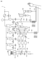
図1は、血液浄化装置を示す回路図である。図1を参照して、まず、血液浄化装置1の全体構成を説明する。
Figure 1 is a circuit diagram showing a blood purification device. First, the overall configuration of the
血液浄化装置1は、血液浄化器100と、透析液管路110と、給液ポンプ111と、排液管路120と、排液ポンプ121と、動脈側血液回路130と、静脈側血液回路140と、補液管路150と、補液ポンプ151と、第1接続管路160と、第1計量バッグ165と、第2接続管路170と、第2計量バッグ175と、秤180と、シリンジポンプ190とを有する。なお、血液ポンプ131の種類は特に限定されないが、典型的にはロータリーポンプである。また、給液ポンプ111、排液ポンプ121および補液ポンプ151は特に限定されないが、典型的にはペリスタルティック式ポンプである。
The
動脈側血液回路130および静脈側血液回路140は、血液浄化器100と連通し、血液が流れる血液流路である。透析液管路110および排液管路120は、血液浄化器100と連通し、治療液としての透析液が流れる治療液流路である。
The
血液浄化器100は、たとえば、中空糸膜からなる半透膜(血液浄化膜)を内部に含む。血液浄化器100は、透析液入口101と、排液出口102と、血液入口103と、血液出口104とを有する。
The
透析液管路110は、血液浄化器100の透析液入口101に接続されており、血液浄化器100に透析液を供給する。透析液管路110の上流端は、補液および透析液を供給する供給源(図示せず)と接続されている。透析液管路110には、透析液を送り出す給液ポンプ111(液供給ポンプ)が接続されている。透析液管路110を流れた透析液は、血液浄化器100内に供給される。なお、透析液管路110、および、以下において説明するその他の管路は、たとえばポリ塩化ビニル、または、ポリブタジエンなどで構成される軟質のチューブである。
The
排液管路120は、血液浄化器100の排液出口102に接続されており、血液浄化器100の排液出口102から排出された排液を流す。排液管路120の下流端からは、血液浄化器100から排出された排液が排出される。排液管路120には、排液管路120を流れる排液を送り出す排液ポンプ121が接続されている。排液管路120には、排液ポンプ121より上流側において、排液管路120内の圧力を測定する濾過圧センサ122が設けられている。濾過圧センサ122の下流側には、2次膜圧センサ123が設けられている。さらに、排液管路120は、濾過圧センサ122より上流側に漏血センサ2が設けられている。
The
動脈側血液回路130は、血液浄化器100の血液入口103に接続され、血液浄化器100に血液を流入させるための回路である。動脈側血液回路130には、血液を送り出す血液ポンプ131が設けられている。動脈側血液回路130において、血液ポンプ131と血液浄化器100との間に、動脈側エアートラップチャンバ132が設けられている。動脈側エアートラップチャンバ132には、動脈側エアートラップチャンバ132内の圧力を測定する入口圧センサ133が設けられている。
The
動脈側血液回路130を介して患者の動脈から採取された血液は、動脈側血液回路130を流れて動脈側エアートラップチャンバ132にて圧力を測定された後、血液入口103から血液浄化器100内に流入する。動脈側エアートラップチャンバ132は、動脈側血液回路130内の血液に空気が混入することを防止するために設けられている。
Blood collected from the patient's artery via the
動脈側血液回路130には、動脈側気泡センサ230a、動脈側血液センサ230b、および動脈側クランプ230cが設けられている。動脈側血液回路130から置換液管路136が分岐しており、置換液管路136には置換液側クランプ230dが設けられている。置換液20は、生理食塩液などである。
The
動脈側血液回路130には、さらにエアレスモニタ138が接続されている。具体的には、エアレスモニタ138は、動脈側血液回路130における動脈側気泡センサ230aと血液ポンプ131との間に接続されている。エアレスモニタ138には脱血圧センサ139が接続されており、動脈側血液回路130に流入した患者の脱血圧を測定する。
An
静脈側血液回路140は、血液浄化器100の血液出口104に接続され、血液浄化器100から血液を流出させ、患者へ血液を返却するための回路である。静脈側血液回路140には、静脈側エアートラップチャンバ141が設けられている。静脈側エアートラップチャンバ141には、静脈側エアートラップチャンバ141内の圧力を測定する静脈回路圧センサ142が設けられている。
The
血液浄化器100によって浄化された血液は、静脈側血液回路140を流れて静脈側エアートラップチャンバ141にて圧力を測定された後、患者に返される。静脈側エアートラップチャンバ141は、静脈側血液回路140内の血液に空気が混入することを防止するために設けられている。静脈側血液回路140には、静脈側気泡センサ240a、静脈側血液センサ240b、および静脈側クランプ240cが設けられている。
The blood purified by the
補液管路150は、動脈側血液回路130または静脈側血液回路140に接続され、置換液を供給する。本実施形態において、補液管路150は、静脈側血液回路140に接続されており、静脈側血液回路140に置換液を供給する。すなわち、本実施形態において血液浄化装置1は、いわゆる後希釈法を採用している。具体的には、補液管路150は、静脈側エアートラップチャンバ141に接続されている。補液管路150を流れた置換液は、静脈側エアートラップチャンバ141内に供給される。なお、血液浄化装置1は、いわゆる前希釈法でも適用可能である。前希釈法を採用する場合、補液管路150は、動脈側血液回路130に接続される。
The
補液管路150には、置換液を送り出す補液ポンプ151が接続されている。第1接続管路160は、排液管路120に接続されている。具体的には、第1接続管路160は、排液管路120において排液ポンプ121より下流側に接続されている。第1計量バッグ165は、第1接続管路160の排液管路120側とは反対側の端部に接続され、排液を一時的に貯液し、貯液した排液を送出可能である。第1計量バッグ165は、空気抜き用の孔が形成されていない軟質の袋である。
A
第2接続管路170は、補液管路150に接続されている。具体的には、第2接続管路170は、補液管路150において補液ポンプ151より上流側に接続されている。第2計量バッグ175は、第2接続管路170の補液管路150側とは反対側の端部に接続され、置換液を一時的に貯液し、貯液した置換液を送出可能である。第2計量バッグ175は、空気抜き用の孔が形成されていない軟質の袋である。
The
秤180には、重量測定部が接続されている。重量測定部は、秤180に取り付けられた第1計量バッグ165および第2計量バッグ175の全体の重量変化を測定する。本実施の形態においては、秤180は、ロードセルである。ただし、秤180は、ロードセルに限られず、ばねばかりなどであってもよい。
A weight measuring unit is connected to the
シリンジポンプ190は、シリンジポンプ管路191を介して動脈側血液回路130に接続されている。シリンジポンプ190は、薬液30を動脈側血液回路130内に供給する。薬液30は、たとえば、ヘパリンまたはナファモスタットなどの抗凝固薬である。
The
続いて、透析(血液浄化)が終了して、血液浄化装置1内に残っている血液を患者に返却する返血時(血液回収時)の制御について説明する。図2は、返血時の制御に関わる血液浄化装置1の構成を示すブロック図である。図2に示すように、血液浄化装置1は、制御部90をさらに備える。制御部90は、動脈側血液センサ230b、静脈側血液センサ240b、および入力部70からの入力を受け付け、血液ポンプ131、動脈側クランプ230c、静脈側クランプ240c、および置換液側クランプ230dの動作を制御する。制御部90は、さらに給液ポンプ111、排液ポンプ121、補液ポンプ151、および報知部80の動作を制御することができる。
Next, the control during blood return (blood recovery) when the blood remaining in the
制御部90は、具体的には制御回路であり、プロセッサ91とメモリ92とを有する。具体的には、プロセッサ91は、メモリ92に記憶された各種のプログラムを実行することにより、血液浄化装置1の動作を制御する。
The
プロセッサ91は、CPUやGPUなどで構成され、メモリ92に記憶されたプログラム(一例として、OSおよび制御プログラム)を読出して、実行することができる。プロセッサ91では、メモリ92から読み出した様々なプログラムを実行する。具体的に、制御プログラムは、返血時に血液浄化装置1内に残っている血液を患者に返却する制御を行う。
The
メモリ92は、例えば、ROMやフラッシュメモリなどの不揮発性記憶装置などで構成される。メモリ92には、基本的な機能を実現するためのOSに加えて、制御プログラムが記憶される。
The
入力部70は、キーボードやマウス、マイク、タッチデバイスなどで構成され、ユーザにより入力された情報を受け付けることができる。
The
報知部80は、ディスプレイ、各種インジケータ、警報ランプなどで構成され、制御部90により制御されている血液浄化装置1の状況、制御が異常であるとの警報などを知らせることができる。
The
制御部90で実行される制御プログラムなどは、コンピュータ読取可能な記録媒体を介してインストールされてもよいが、ネットワーク上のサーバ装置などからダウンロードする形でインストールするようにしてもよい。また、制御部90が提供する機能は、OSが提供するモジュールの一部を利用する形で実現される場合もある。
The control programs executed by the
図2には、プロセッサ91がプログラムを実行することで、血液浄化装置1として必要な機能が提供される構成例を示したが、これらの提供される機能の一部または全部を、専用のハードウェア回路(例えば、ASICまたはFPGAなど)を用いて実装してもよい。また、図2に示した血液浄化装置1の構成は例示であって、この構成に限定されない。
Figure 2 shows an example of a configuration in which the functions required for the
従来の血液浄化装置では、返血時に、動脈側および動脈側から返却される血液の量(動脈側血液回収量)と、静脈側および静脈側から返却される血液の量(静脈側血液回収量)とをユーザが設定する必要があった。しかし、動脈側血液回路には血液浄化器100、動脈側エアートラップチャンバ132などが設けられており、動脈側血液回収量をユーザが精度良く設定することは困難であった。同様に、静脈側血液回路には血液浄化器100、静脈側エアートラップチャンバ141などが設けられており、静脈側血液回収量をユーザが精度良く設定することは困難であった。ユーザが設定した回収量が、本来の返血量より多い場合、置換液が患者に流入してしまい溢水になる。逆に、ユーザが設定した回収量が、本来の返血量より少ない場合、返血不足になり血液浄化装置に血液が残った状態となる。
In conventional blood purification devices, the user had to set the amount of blood returned from the arterial side and the arterial side (arterial blood recovery amount) and the amount of blood returned from the venous side and the venous side (venous blood recovery amount) during blood return. However, the arterial blood circuit is provided with a
そこで、本実施の形態に係る血液浄化装置1では、動脈側血液回収量および静脈側血液回収量をユーザが設定することなく、適切な量を返血することができる制御を行っている。図3は、返血時の制御の流れを示すフローチャートである。なお、透析(血液浄化)が終了時、血液浄化装置1内には、図1に示すように動脈側血液回路130、および静脈側血液回路140に血液が残っている(ハッチングで示した経路)。
The
まず、制御部90は、静脈側血液回路140の静脈側回路容量をメモリ92から読み出す(ステップS101)。メモリ92には、静脈側血液回路140の静脈側回路容量があらかじめ記憶してある。ここで、静脈側回路容量は、静脈側血液回路における静脈側血液センサ240bより患者側の回路容量で、たとえば100mlと設定されている。使用される静脈側血液回路140の種類が1種類であれば、固定値として静脈側血液回路140の静脈側回路容量をメモリ92に記憶すればよいが、使用される静脈側血液回路140の種類が複数種類あれば、静脈側血液回路140の種類に応じて複数の静脈側回路容量をメモリ92に記憶する。
First, the
制御部90は、入力部70からユーザが入力した静脈側血液回路140の種類の情報に基づき、静脈側血液回路140の種類を特定し、特定した種類の静脈側血液回路140の静脈側回路容量をメモリ92から読み出す。入力部70に静脈側血液回路140の種類の情報を入力する方法は、ユーザが静脈側血液回路140の型番を直接キーボードから入力する以外に、静脈側血液回路140に付された識別情報(2次元コード、ICチップなど)を読取装置に読み取らせてもよい。なお、ユーザが、静脈側血液回路140の静脈側回路容量をキーボードなどから直接入力してもよい。
The
次に、制御部90は、動脈側血液回路130の動脈側回路容量をメモリ92から読み出す(ステップS102)。メモリ92には、動脈側血液回路130の動脈側回路容量があらかじめ記憶してある。ここで、動脈側回路容量は、動脈側血液回路における動脈側血液センサ230bより患者側の回路容量で、たとえば100mlと設定されている。使用される動脈側血液回路130の種類が1種類であれば、固定値として動脈側血液回路130の動脈側回路容量をメモリ92に記憶すればよいが、使用される動脈側血液回路130の種類が複数種類あれば、動脈側血液回路130の種類に応じて複数の動脈側回路容量をメモリ92に記憶する。
Next, the
制御部90は、入力部70からユーザが入力した動脈側血液回路130の種類の情報に基づき、動脈側血液回路130の種類を特定し、特定した種類の動脈側血液回路130の動脈側回路容量をメモリ92から読み出す。入力部70に動脈側血液回路130の種類の情報を入力する方法は、ユーザが動脈側血液回路130の型番を直接キーボードから入力する以外に、動脈側血液回路130に付された識別情報(2次元コード、ICチップなど)を読取装置に読み取らせてもよい。なお、ユーザが、動脈側血液回路130の動脈側回路容量をキーボードなどから直接入力してもよい。
The
次に、制御部90は、血液ポンプ131を正回転駆動して置換液20を動脈側血液回路130から静脈側血液回路140に供給する(ステップS103)。制御部90は、動脈側血液回路130から静脈側血液回路140に置換液20を供給する際、静脈側クランプ240cおよび置換液側クランプ230dを開状態に制御する。置換液20が、動脈側血液回路130から静脈側血液回路140に供給されることで、図4に示すように血液浄化装置1内に残っている血液が静脈側血液回路140から患者に返却される。図4は、静脈側血液回路140の返血時の制御の一例を示す図である。なお、図4では、ハッチングで示した経路に血液が残っている。
Next, the
図3に戻って、制御部90は、静脈側血液センサ240bが血液未検知状態を検知したか否かを判断する(ステップS104)。静脈側血液センサ240bが血液未検知状態を検知していない場合(ステップS104でNO)、制御部90は、処理をステップS103に戻し、置換液20を動脈側血液回路130から静脈側血液回路140に供給し続ける。つまり、静脈側血液センサ240bの位置まで置換液20が到達しておらず、静脈側血液回路140内にまだ血液が残った状態である。
Returning to FIG. 3, the
一方、静脈側血液センサ240bが血液未検知状態を検知した場合(ステップS104でYES)、制御部90は、メモリ92から読み出した静脈側血液回路140の静脈側回路容量だけ、置換液20を静脈側血液回路140に供給する(ステップS105)。静脈側血液センサ240bが血液未検知状態を検知した場合、図4のように静脈側血液回路140内から血液が返却されたが静脈側血液回路140にはまだ血液が残っている状態である。そのため、制御部90は、静脈側回路容量だけ、置換液20を静脈側血液回路140に供給すれば、図5のように過不足なしに患者に静脈側血液回路140内の血液を返却できる。図5は、静脈側血液回路140から血液を返却する制御の一例を示す図である。なお、図5では、ハッチングで示した経路に血液が残っている。具体的に、静脈側回路容量が100mlの場合、制御部90は、100mlの置換液20が静脈側血液回路140に供給されるように、血液ポンプ131を正回転駆動する。また、制御部90は、静脈側血液センサ240bが血液未検知状態を検知した場合、報知部80に対して残り100mlで静脈側血液回路140の返血が終了する旨を報知するように制御してもよい。
On the other hand, when the
次に、動脈側血液回路130内の血液を患者に返却する。図3に戻って、制御部90は、血液ポンプ131を逆回転駆動して置換液20を動脈側血液回路130に供給する(ステップS106)。制御部90は、動脈側血液回路130に置換液20を供給する際、静脈側クランプ240cを閉状態にし、動脈側クランプ230cおよび置換液側クランプ230dを開状態に制御する。静脈側血液回路140内の血液を患者に返却した時点で、図5のように置換液管路136と分岐した動脈側血液回路130の位置から静脈側血液回路140側には血液が残っていない。そのため、血液ポンプ131を逆回転駆動して、置換液管路136と分岐した動脈側血液回路130の位置から動脈側血液回路130側の血液を患者に返却する。
Next, the blood in the
次に、制御部90は、動脈側血液センサ230bが血液未検知状態を検知したか否かを判断する(ステップS107)。動脈側血液センサ230bが血液未検知状態を検知していない場合(ステップS107でNO)、制御部90は、処理をステップS106に戻し、置換液20を動脈側血液回路130に供給し続ける。つまり、動脈側血液センサ230bの位置まで置換液20が到達しておらず、動脈側血液回路130内にまだ血液が残った状態である。
Next, the
一方、動脈側血液センサ230bが血液未検知状態を検知した場合(ステップS107でYES)、制御部90は、メモリ92から読み出した動脈側回路容量だけ、置換液20を動脈側血液回路130に供給する(ステップS108)。動脈側血液センサ230bが血液未検知状態を検知した場合、図6のように動脈側血液回路130内にはまだ血液が残っている状態である。図6は、動脈側血液回路130の返血時の制御の一例を示す図である。なお、図6では、ハッチングで示した経路に血液が残っている。
On the other hand, if the
そのため、制御部90は、動脈側回路容量だけ、置換液20を動脈側血液回路130に供給すれば、図7のように過不足なしに患者に動脈側血液回路130内の血液を返却できる。図7は、動脈側血液回路130から血液を返却する制御の一例を示す図である。具体的に、動脈側回路容量が100mlの場合、制御部90は、100mlの置換液20が動脈側血液回路130に供給されるように、血液ポンプ131を逆回転駆動する。また、制御部90は、動脈側血液センサ230bが血液未検知状態を検知した場合、報知部80に対して残り100mlで動脈側血液回路130の返血が終了する旨を報知するように制御してもよい。
Therefore, if the
なお、血液ポンプ131を逆回転駆動して置換液20を動脈側血液回路130における置換液管路136の分岐部分より患者側に供給するには、たとえば、血液ポンプ131を一旦正回転駆動して置換液20を動脈側エアートラップチャンバ132に貯めた上で血液ポンプ131を逆回転駆動する。なお、動脈側血液回路130および静脈側血液回路140への置換液20の供給は、血液浄化装置1の装置構成に依存するため、上記の制御に限定されない。いずれの制御であって、血液浄化装置1は、静脈側血液センサ240bが血液未検知状態を検知したとき、動脈側回路容量だけ置換液20を静脈側血液回路140に供給し、動脈側血液センサ230bが血液未検知状態を検知したとき、動脈側回路容量だけ置換液20を動脈側血液回路130に供給すればよい。
To supply the
このように構成された血液浄化装置1によれば、制御部90が、静脈側血液センサ240bが血液未検知状態となったとき、メモリ92に記憶する動脈側回路容量だけ血液ポンプ131を駆動して置換液20を静脈側血液回路140に供給するので静脈側血液回路140について適切な量を返血することができる。さらに、血液浄化装置1は、動脈側血液センサ230bが血液未検知状態となったとき、メモリ92に記憶する動脈側回路容量だけ血液ポンプ131を駆動して置換液20を動脈側血液回路130に供給するので適切な量を返血することができる。また、この場合に、血液浄化装置1は、ユーザの設定ミスによる溢水および血液の回収不足を防ぐことができるとともに、ユーザ設定自体を不要にしてユーザの負担を軽減することができる。
According to the
(変形例)
図1に示す血液浄化装置1では、動脈側血液センサ230bおよび静脈側血液センサ240bを有し、動脈側血液回路130および静脈側血液回路140に供給する置換液20の量を制御する構成を説明した。しかし、動脈側血液回路130内に残った血液の返却については、ユーザが目視で供給する置換液の量を制御したり、別の方法で置換液の量を制御したりするのであれば、血液浄化装置は動脈側血液センサを設ける必要がない。図8は、血液浄化装置1aの変形例を示す回路図である。図8に示す血液浄化装置1aにおいて、図1に示す血液浄化装置1に示す構成と同じ構成については、同じ符号を付して詳細な説明を繰り返さない。
(Modification)
In the
血液浄化装置1aは、血液浄化器100と、透析液管路110と、給液ポンプ111と、排液管路120と、排液ポンプ121と、動脈側血液回路130と、静脈側血液回路140と、補液管路150と、補液ポンプ151と、第1接続管路160と、第1計量バッグ165と、第2接続管路170と、第2計量バッグ175と、秤180と、シリンジポンプ190とを有する。
The blood purification device 1a has a
動脈側血液回路130には、動脈側気泡センサ230aおよび動脈側クランプ230cが設けられている。動脈側血液回路130から置換液管路136が分岐しており、置換液管路136には、置換液側クランプ230dが設けられている。動脈側血液回路130には、動脈側血液回路130内に血液が残っているか否かを判断するための動脈側血液センサが設けられていない。
The
そのため、血液浄化装置1aは、静脈側血液センサ240bが血液未検知状態を検知した場合、静脈側回路容量だけ置換液20を静脈側血液回路140に供給し、静脈側血液回路140について適切な量を返血することができる。一方、血液浄化装置1aは、動脈側血液回路130内に残った血液の返却について、ユーザが目視で供給する置換液20の量を制御したり、別の方法で置換液20の量を制御したりする。血液浄化装置1aは、動脈側血液センサを設ける必要がないため、装置構成を簡略化でき、製造コストの低減を図ることができる。
Therefore, when the
今回開示された実施の形態はすべての点で例示であって制限的なものではないと考えられるべきである。本発明の範囲は上記した説明ではなくて特許請求の範囲によって示され、特許請求の範囲と均等の意味および範囲内でのすべての変更が含まれることが意図される。 The embodiments disclosed herein should be considered to be illustrative and not restrictive in all respects. The scope of the present invention is indicated by the claims, not by the above description, and is intended to include all modifications within the meaning and scope of the claims.
1,1a 血液浄化装置、2 漏血センサ、20 置換液、30 薬液、70 入力部、80 報知部、90 制御部、91 プロセッサ、92 メモリ、100 血液浄化器、101 透析液入口、102 排液出口、103 血液入口、104 血液出口、110 透析液管路、111 給液ポンプ、120 排液管路、121 排液ポンプ、122 濾過圧センサ、130 動脈側血液回路、131 血液ポンプ、132 動脈側エアートラップチャンバ、133 入口圧センサ、136 置換液管路、138 エアレスモニタ、139 脱血圧センサ、140 静脈側血液回路、141 静脈側エアートラップチャンバ、142 静脈回路圧センサ、150 補液管路、151 補液ポンプ、160 第1接続管路、165 第1計量バッグ、170 第2接続管路、175 第2計量バッグ、180 秤、190 シリンジポンプ、191 シリンジポンプ管路。 1, 1a blood purification device, 2 blood leakage sensor, 20 substitution fluid, 30 drug solution, 70 input unit, 80 notification unit, 90 control unit, 91 processor, 92 memory, 100 blood purifier, 101 dialysis fluid inlet, 102 drainage outlet, 103 blood inlet, 104 blood outlet, 110 dialysis fluid line, 111 supply pump, 120 drainage line, 121 drainage pump, 122 filtration pressure sensor, 130 arterial blood circuit, 131 blood pump, 132 arterial air trap chamber, 133 inlet pressure sensor, 136 substitution fluid line, 138 airless monitor, 139 venting pressure sensor, 140 venous blood circuit, 141 venous air trap chamber, 142 venous circuit pressure sensor, 150 replacement fluid line, 151 replacement fluid pump, 160 First connecting line, 165 first weighing bag, 170 second connecting line, 175 second weighing bag, 180 scale, 190 syringe pump, 191 syringe pump line.
Claims (8)
前記血液浄化器に接続される動脈側血液回路と、
前記血液浄化器に接続される静脈側血液回路と、
前記静脈側血液回路に設けられ、血液を検知可能な静脈側血液センサと、
前記動脈側血液回路に設けられ、血液を送り出す血液ポンプと、
前記静脈側血液センサからの入力に応じて、前記血液ポンプを少なくとも制御する制御部と、
前記静脈側血液回路における前記静脈側血液センサより患者側の静脈側回路容量を少なくとも記憶する記憶部と、を備え、
前記制御部は、
返血時に前記静脈側血液センサが血液未検知状態になるまで前記血液ポンプを駆動し、前記静脈側血液センサが血液未検知状態となったとき、前記記憶部に記憶する前記静脈側回路容量だけ前記血液ポンプを駆動して置換液を前記静脈側血液回路に供給する、血液浄化装置。 Blood purifier,
an arterial blood circuit connected to the blood purifier;
a venous blood circuit connected to the blood purifier;
a venous blood sensor provided in the venous blood circuit and capable of detecting blood;
a blood pump provided in the arterial blood circuit for pumping blood;
a control unit that controls at least the blood pump in response to an input from the venous blood sensor;
a memory unit that stores at least a venous circuit capacitance on a patient side of the venous blood sensor in the venous blood circuit,
The control unit is
A blood purification device that drives the blood pump until the venous blood sensor detects no blood during blood return, and when the venous blood sensor detects no blood, drives the blood pump by an amount corresponding to the venous circuit capacity stored in the memory unit to supply replacement fluid to the venous blood circuit.
前記記憶部は、前記動脈側血液回路における前記動脈側血液センサより患者側の動脈側回路容量を記憶し、
前記制御部は、
返血時に前記動脈側血液センサが血液未検知状態になるまで前記血液ポンプを駆動し、前記動脈側血液センサが血液未検知状態となったとき、前記記憶部に記憶する前記動脈側回路容量だけ前記血液ポンプを駆動して置換液を前記動脈側血液回路に供給する、請求項1に記載の血液浄化装置。 An arterial blood sensor is provided in the arterial blood circuit and is capable of detecting blood.
the storage unit stores an arterial circuit capacitance on a patient side of the arterial blood circuit relative to the arterial blood sensor;
The control unit is
2. The blood purification device according to claim 1, wherein the blood pump is driven until the arterial blood sensor detects no blood during blood return, and when the arterial blood sensor detects no blood, the blood pump is driven by an amount corresponding to the arterial circuit capacity stored in the memory unit to supply substitution fluid to the arterial blood circuit.
前記制御部は、
前記入力部に入力された前記静脈側血液回路の種類の情報に基づき、使用されている前記静脈側血液回路の種類を特定し、特定した種類の前記静脈側回路容量を前記記憶部から読み出す、請求項3に記載の血液浄化装置。 an input unit capable of inputting at least information on the type of the venous blood circuit;
The control unit is
4. The blood purification apparatus according to claim 3, wherein the type of the venous blood circuit being used is identified based on information on the type of the venous blood circuit inputted to the input unit, and the venous circuit capacity of the identified type is read out from the storage unit.
前記制御部は、
前記入力部に入力された前記動脈側血液回路の種類の情報に基づき、使用されている前記動脈側血液回路の種類を特定し、特定した種類の前記動脈側回路容量を前記記憶部から読み出す、請求項4に記載の血液浄化装置。 An input unit capable of inputting at least information on the type of the arterial blood circuit,
The control unit is
5. The blood purification apparatus according to claim 4, wherein the type of the arterial blood circuit being used is identified based on information on the type of the arterial blood circuit inputted to the input unit, and the arterial blood circuit capacity of the identified type is read out from the storage unit.
前記静脈側回路容量を前記記憶部から読み出すステップと、
返血時に前記静脈側血液センサが血液未検知状態になるまで前記血液ポンプを駆動するステップと、
前記静脈側血液センサが血液未検知状態となったとき、前記記憶部に記憶する前記静脈側回路容量だけ前記血液ポンプを駆動して置換液を前記静脈側血液回路に供給するステップを含む、血液浄化装置の制御方法。 A control method for a blood purification device comprising: a blood purifier; an arterial blood circuit connected to the blood purifier; a venous blood circuit connected to the blood purifier; a venous blood sensor provided in the venous blood circuit and capable of detecting blood; a blood pump provided in the arterial blood circuit and pumping blood; a control unit that controls at least the blood pump in response to an input from the venous blood sensor; and a memory unit that stores at least a venous circuit capacity on a patient's side of the venous blood sensor in the venous blood circuit,
reading out the venous circuit capacitance from the storage unit;
driving the blood pump until the venous blood sensor detects no blood during blood return;
A method for controlling a blood purification apparatus comprising the step of driving the blood pump by an amount corresponding to the venous circuit capacity stored in the memory unit when the venous blood sensor is in a state where blood is not being detected, to supply replacement fluid to the venous blood circuit.
前記プログラムは、
前記静脈側回路容量を前記記憶部から読み出すステップと、
返血時に前記静脈側血液センサが血液未検知状態になるまで前記血液ポンプを駆動するステップと、
前記静脈側血液センサが血液未検知状態となったとき、前記記憶部に記憶する前記静脈側回路容量だけ前記血液ポンプを駆動して置換液を前記静脈側血液回路に供給するステップを含む、プログラム。
A program executed by a control unit of a blood purification device comprising: a blood purifier; an arterial blood circuit connected to the blood purifier; a venous blood circuit connected to the blood purifier; a venous blood sensor provided in the venous blood circuit and capable of detecting blood; a blood pump provided in the arterial blood circuit and pumping blood; a control unit that controls at least the blood pump in response to an input from the venous blood sensor; and a memory unit that stores at least a venous circuit capacity on a patient's side of the venous blood sensor in the venous blood circuit,
The program is
reading out the venous circuit capacitance from the storage unit;
driving the blood pump until the venous blood sensor detects no blood during blood return;
When the venous blood sensor is in a state of not detecting blood, the program includes a step of driving the blood pump by an amount corresponding to the venous circuit capacity stored in the memory unit to supply replacement fluid to the venous blood circuit.
Priority Applications (1)
| Application Number | Priority Date | Filing Date | Title |
|---|---|---|---|
| JP2023184623A JP2025073660A (en) | 2023-10-27 | 2023-10-27 | Blood purification device, control method thereof, and program |
Applications Claiming Priority (1)
| Application Number | Priority Date | Filing Date | Title |
|---|---|---|---|
| JP2023184623A JP2025073660A (en) | 2023-10-27 | 2023-10-27 | Blood purification device, control method thereof, and program |
Publications (1)
| Publication Number | Publication Date |
|---|---|
| JP2025073660A true JP2025073660A (en) | 2025-05-13 |
Family
ID=95697007
Family Applications (1)
| Application Number | Title | Priority Date | Filing Date |
|---|---|---|---|
| JP2023184623A Pending JP2025073660A (en) | 2023-10-27 | 2023-10-27 | Blood purification device, control method thereof, and program |
Country Status (1)
| Country | Link |
|---|---|
| JP (1) | JP2025073660A (en) |
-
2023
- 2023-10-27 JP JP2023184623A patent/JP2025073660A/en active Pending
Similar Documents
| Publication | Publication Date | Title |
|---|---|---|
| US9162020B2 (en) | Method and apparatus for controlling an extra-corporeal blood treatment in a medical device | |
| KR102220982B1 (en) | Device and method for detecting the recirculation during an extracorporeal blood treatment | |
| JP5588447B2 (en) | Method and apparatus for monitoring the introduction of replacement fluid upstream or downstream of a dialyzer or filter | |
| KR20100103800A (en) | Method and device for determining the transmembrane pressure in an extracorporeal blood treatment | |
| JP7451426B2 (en) | Calculation of patient fluid removal rate to compensate for the amount of fluid not removed due to equipment downtime | |
| US20240269365A1 (en) | Extracorporeal blood treatment apparatus and method for monitoring pressures in an extracorporeal blood treatment apparatus | |
| CN117202948A (en) | Methods and devices for controlling blood therapy devices | |
| US11524101B2 (en) | Blood treatment device with improved bag weight monitoring | |
| JP2025073660A (en) | Blood purification device, control method thereof, and program | |
| CN115252936B (en) | A blood purification device and storage medium | |
| US20240399036A1 (en) | Device for monitoring blood purification using an extracorporeal blood purification device | |
| JP7725878B2 (en) | Blood purification device | |
| US20210093772A1 (en) | Blood treatment device with automatic substitution volume compensation | |
| JP2024507968A (en) | Methods and devices for analyzing measured pressure values | |
| Clark et al. | Advances in machine technology | |
| US11806458B2 (en) | Blood treatment device with automatic reduction of a substitution-solution flow rate | |
| US20240102880A1 (en) | Leakage detection method and system, in particular for use in a blood treatment device | |
| JP2025115609A (en) | Blood purification device, its control method, and program | |
| JP7790230B2 (en) | Blood purification device | |
| JP7775736B2 (en) | Blood purification device | |
| JP2025081941A (en) | Blood purification device, control method therefor, and program | |
| WO2024150754A1 (en) | Blood purification device | |
| KR20240030011A (en) | Hemodialysis method for controlling amount of heparin using pressure sensor | |
| WO2023219084A1 (en) | Blood purification device |