JP2025032284A - Golf club head with open back cavity - Google Patents
Golf club head with open back cavity Download PDFInfo
- Publication number
- JP2025032284A JP2025032284A JP2024216474A JP2024216474A JP2025032284A JP 2025032284 A JP2025032284 A JP 2025032284A JP 2024216474 A JP2024216474 A JP 2024216474A JP 2024216474 A JP2024216474 A JP 2024216474A JP 2025032284 A JP2025032284 A JP 2025032284A
- Authority
- JP
- Japan
- Prior art keywords
- inches
- degrees
- club head
- golf club
- strike face
- Prior art date
- Legal status (The legal status is an assumption and is not a legal conclusion. Google has not performed a legal analysis and makes no representation as to the accuracy of the status listed.)
- Pending
Links
Classifications
-
- A—HUMAN NECESSITIES
- A63—SPORTS; GAMES; AMUSEMENTS
- A63B—APPARATUS FOR PHYSICAL TRAINING, GYMNASTICS, SWIMMING, CLIMBING, OR FENCING; BALL GAMES; TRAINING EQUIPMENT
- A63B53/00—Golf clubs
- A63B53/04—Heads
- A63B53/0408—Heads characterised by specific dimensions, e.g. thickness
-
- A—HUMAN NECESSITIES
- A63—SPORTS; GAMES; AMUSEMENTS
- A63B—APPARATUS FOR PHYSICAL TRAINING, GYMNASTICS, SWIMMING, CLIMBING, OR FENCING; BALL GAMES; TRAINING EQUIPMENT
- A63B53/00—Golf clubs
- A63B53/04—Heads
- A63B53/0458—Heads with non-uniform thickness of the impact face plate
-
- A—HUMAN NECESSITIES
- A63—SPORTS; GAMES; AMUSEMENTS
- A63B—APPARATUS FOR PHYSICAL TRAINING, GYMNASTICS, SWIMMING, CLIMBING, OR FENCING; BALL GAMES; TRAINING EQUIPMENT
- A63B53/00—Golf clubs
- A63B53/04—Heads
- A63B53/047—Heads iron-type
-
- A—HUMAN NECESSITIES
- A63—SPORTS; GAMES; AMUSEMENTS
- A63B—APPARATUS FOR PHYSICAL TRAINING, GYMNASTICS, SWIMMING, CLIMBING, OR FENCING; BALL GAMES; TRAINING EQUIPMENT
- A63B53/00—Golf clubs
- A63B53/04—Heads
- A63B53/047—Heads iron-type
- A63B53/0475—Heads iron-type with one or more enclosed cavities
-
- A—HUMAN NECESSITIES
- A63—SPORTS; GAMES; AMUSEMENTS
- A63B—APPARATUS FOR PHYSICAL TRAINING, GYMNASTICS, SWIMMING, CLIMBING, OR FENCING; BALL GAMES; TRAINING EQUIPMENT
- A63B53/00—Golf clubs
- A63B53/08—Golf clubs with special arrangements for obtaining a variable impact
-
- A—HUMAN NECESSITIES
- A63—SPORTS; GAMES; AMUSEMENTS
- A63B—APPARATUS FOR PHYSICAL TRAINING, GYMNASTICS, SWIMMING, CLIMBING, OR FENCING; BALL GAMES; TRAINING EQUIPMENT
- A63B60/00—Details or accessories of golf clubs, bats, rackets or the like
- A63B60/02—Ballast means for adjusting the centre of mass
-
- A—HUMAN NECESSITIES
- A63—SPORTS; GAMES; AMUSEMENTS
- A63B—APPARATUS FOR PHYSICAL TRAINING, GYMNASTICS, SWIMMING, CLIMBING, OR FENCING; BALL GAMES; TRAINING EQUIPMENT
- A63B60/00—Details or accessories of golf clubs, bats, rackets or the like
- A63B60/50—Details or accessories of golf clubs, bats, rackets or the like with through-holes
-
- A—HUMAN NECESSITIES
- A63—SPORTS; GAMES; AMUSEMENTS
- A63B—APPARATUS FOR PHYSICAL TRAINING, GYMNASTICS, SWIMMING, CLIMBING, OR FENCING; BALL GAMES; TRAINING EQUIPMENT
- A63B60/00—Details or accessories of golf clubs, bats, rackets or the like
- A63B60/54—Details or accessories of golf clubs, bats, rackets or the like with means for damping vibrations
-
- A—HUMAN NECESSITIES
- A63—SPORTS; GAMES; AMUSEMENTS
- A63B—APPARATUS FOR PHYSICAL TRAINING, GYMNASTICS, SWIMMING, CLIMBING, OR FENCING; BALL GAMES; TRAINING EQUIPMENT
- A63B53/00—Golf clubs
- A63B53/04—Heads
- A63B2053/0491—Heads with added weights, e.g. changeable, replaceable
-
- A—HUMAN NECESSITIES
- A63—SPORTS; GAMES; AMUSEMENTS
- A63B—APPARATUS FOR PHYSICAL TRAINING, GYMNASTICS, SWIMMING, CLIMBING, OR FENCING; BALL GAMES; TRAINING EQUIPMENT
- A63B2209/00—Characteristics of used materials
-
- A—HUMAN NECESSITIES
- A63—SPORTS; GAMES; AMUSEMENTS
- A63B—APPARATUS FOR PHYSICAL TRAINING, GYMNASTICS, SWIMMING, CLIMBING, OR FENCING; BALL GAMES; TRAINING EQUIPMENT
- A63B53/00—Golf clubs
- A63B53/04—Heads
Landscapes
- Health & Medical Sciences (AREA)
- General Health & Medical Sciences (AREA)
- Physical Education & Sports Medicine (AREA)
- Golf Clubs (AREA)
Abstract
Description
本開示は、概してゴルフクラブに関し、より詳細には、エネルギー貯蔵特性を有するゴルフクラブヘッドに関する。 The present disclosure relates generally to golf clubs and, more particularly, to golf club heads having energy storage properties.
(関連出願)
本願は、2019年2月6日出願の米国仮特許出願第62/802,125号の優先権を主張する。
(Related Applications)
This application claims priority to U.S. Provisional Patent Application No. 62/802,125, filed February 6, 2019.
本願は、2015年10月22日出願の米国特許出願第14/920,480号の一部継続出願である2015年10月22日出願の米国特許出願第14/920,484号の一部継続出願である2017年6月20日出願の米国特許出願第15/628,639号の一部継続出願である2018年12月21日出願の米国特許出願第16/231,053号の一部継続出願である。 This application is a continuation-in-part of U.S. patent application Ser. No. 16/231,053, filed Dec. 21, 2018, which is a continuation-in-part of U.S. patent application Ser. No. 14/920,484, filed Oct. 22, 2015, which is a continuation-in-part of U.S. patent application Ser. No. 15/628,639, filed Jun. 20, 2017, which is a continuation-in-part of U.S. patent application Ser. No. 14/920,480, filed Oct. 22, 2015.
2018年12月21日出願の米国特許出願第16/231,053号もまた、2015年10月22日出願の第14/920,484号の一部継続出願である2017年2月16日出願の米国特許出願第15号/435,054号の一部継続出願である。さらに、2015年10月22日出願の米国特許出願第14/920,484号は、2015年8月17日出願の米国仮特許出願62/206,152号、2015年3月11日出願の米国仮特許出願第62/131,739号、2015年1月20日出願の米国仮特許出願第62/105,460号、2015年1月20日出願の第62/105,464号、および、2014年10月24日出願の米国仮特許出願第62/068,232号に対する優先権を主張する。
2015年10月22日出願の米国特許出願第14/920,480号はまた、2015年8月17日出願の米国仮特許出願62/206,152号、2015年3月11日出願の米国仮特許出願第62/131,739号、2015年1月20日出願の米国仮特許出願第62/105,460号、2015年1月20日出願の第62/105,464号、および、2014年10月24日出願の米国仮特許出願第62/068,232号に対する優先権を主張する。
U.S. Patent Application No. 16/231,053, filed December 21, 2018, is also a continuation-in-part of U.S. Patent Application No. 15/435,054, filed February 16, 2017, which is a continuation-in-part of U.S. Patent Application No. 14/920,484, filed October 22, 2015. Additionally, U.S. Patent Application No. 14/920,484, filed October 22, 2015, claims priority to U.S. Provisional Patent Application No. 62/206,152, filed August 17, 2015, U.S. Provisional Patent Application No. 62/131,739, filed March 11, 2015, U.S. Provisional Patent Application No. 62/105,460, filed January 20, 2015, U.S. Provisional Patent Application No. 62/105,464, filed January 20, 2015, and U.S. Provisional Patent Application No. 62/068,232, filed October 24, 2014.
U.S. Patent Application No. 14/920,480, filed October 22, 2015, also claims priority to U.S. Provisional Patent Application No. 62/206,152, filed August 17, 2015, U.S. Provisional Patent Application No. 62/131,739, filed March 11, 2015, U.S. Provisional Patent Application No. 62/105,460, filed January 20, 2015, U.S. Provisional Patent Application No. 62/105,464, filed January 20, 2015, and U.S. Provisional Patent Application No. 62/068,232, filed October 24, 2014.
2017年2月16日出願の米国特許出願第15/435,054号もまた、2016年3月25日出願の米国仮特許出願第62/313,215号および2016年2月16日出願の米国仮特許出願第62/295,565号の優先権を主張する。 U.S. Patent Application No. 15/435,054, filed February 16, 2017, also claims priority to U.S. Provisional Patent Application No. 62/313,215, filed March 25, 2016, and U.S. Provisional Patent Application No. 62/295,565, filed February 16, 2016.
2018年12月21日出願の米国特許出願第16/231,053号は、2017年12月22日出願の米国特許出願第62/610,053号の優先権を主張し、また、2015年10月22日出願の米国特許出願第14/920,484号の一部継続出願である2018年2月28日出願の米国特許出願第15/908,427号の一部継続出願である。さらに、2017年6月20日出願の米国特許出願第15/628,639号は、2017年4月12日出願の米国仮特許出願第62/484,529号、2017年2月22日出願の米国仮特許出願第62/462,250号、2016年12月19日出願の米国仮特許出願第62/436,019号、および、2016年6月20日出願の米国仮特許出願第62/352,495号に対する優先権をさらに主張する。 U.S. patent application Ser. No. 16/231,053, filed December 21, 2018, claims priority to U.S. patent application Ser. No. 62/610,053, filed December 22, 2017, and is a continuation-in-part of U.S. patent application Ser. No. 15/908,427, filed February 28, 2018, which is a continuation-in-part of U.S. patent application Ser. No. 14/920,484, filed October 22, 2015. Additionally, U.S. Patent Application No. 15/628,639, filed June 20, 2017, further claims priority to U.S. Provisional Patent Application No. 62/484,529, filed April 12, 2017, U.S. Provisional Patent Application No. 62/462,250, filed February 22, 2017, U.S. Provisional Patent Application No. 62/436,019, filed December 19, 2016, and U.S. Provisional Patent Application No. 62/352,495, filed June 20, 2016.
上記の開示の全ての内容は、その全体が参照により本明細書に完全に組み込まれる。 The entire contents of the above disclosure are hereby fully incorporated by reference.
ゴルフクラブ製造業者は、ゴルフクラブヘッドのストライクフェースにおける応力を軽減するようにゴルフクラブヘッドを設計してきた。多くの場合、ゴルフクラブヘッドがクラウンからソール方向に撓まないように設計されている。さらに、これらの設計は、ゴルフクラブヘッドの曲げのピークとなる位置を変化させず、ゴルフボールとのインパクトによるゴルフクラブヘッド内のばねエネルギーのさらなる蓄積を可能にしない。追加のばねエネルギーは、ストライクフェースの全体でボール速度を増加させることができる。 Golf club manufacturers have designed golf club heads to reduce stress on the strike face of the golf club head. In many cases, the golf club head is designed to not flex in the crown-to-sole direction. Furthermore, these designs do not change the location of peak bending of the golf club head and do not allow for additional storage of spring energy within the golf club head upon impact with the golf ball. The additional spring energy can increase ball speed across the strike face.
実施形態のさらなる説明を容易にするために、以下の図面が提供される。 The following drawings are provided to facilitate further explanation of the embodiments:
図の簡潔さおよび明確さのために、図面は、一般的な構造様式を示し、周知の特徴および技術の説明および詳細は、ゴルフクラブおよびそれらの製造方法を不必要に曖昧にすることを避けるために省略され得る。さらに、図面中の要素は、必ずしも一定の縮尺で描かれていない。例えば、図中のいくつかの要素の寸法は、ゴルフクラブの実施例およびそれらの製造方法の理解を向上させるのを助けるために、他の要素に対して誇張されている場合がある。異なる図面における同じ参照番号は、同じ要素を示す。 For brevity and clarity of illustration, the drawings show general structural patterns, and descriptions and details of well-known features and techniques may be omitted to avoid unnecessarily obscuring golf clubs and their manufacturing methods. Additionally, elements in the drawings are not necessarily drawn to scale. For example, dimensions of some elements in the figures may be exaggerated relative to other elements to help improve understanding of embodiments of golf clubs and their manufacturing methods. The same reference numbers in different drawings refer to the same elements.
本明細書および請求項における「第1の」、「第2の」、「第3の」、「第4の」などの用語は、類似の要素を区別するために使用され、必ずしも特定の逐次的または時系列的順番を説明するために使用されるものではない。本明細書に記載されるゴルフクラブおよび製造方法の実施形態が、例えば、本明細書に図示されるまたは他の方法以外の順番で操作可能であるように、適切な状況下で交換可能であるように、使用される用語は、理解されるべきである。さらに、「含む」、「備える」及び「有する」という用語及びその変化は、非排他的な包含を含むことを意図しており、要素のリストを含むプロセス、方法、物品または装置は、必ずしもこれらの要素に制限されるものではなく、このようなプロセス、方法、物品または装置に明示的に表示されずまたは本来の他の要素を包含してもよい。 Terms such as "first," "second," "third," "fourth," and the like in this specification and claims are used to distinguish between similar elements and are not necessarily used to describe a particular sequential or chronological order. The terms used should be understood to be interchangeable under appropriate circumstances, such that the golf club and manufacturing method embodiments described herein are operable, for example, in sequences other than those illustrated herein or in other ways. Furthermore, the terms "including," "comprising," and "having" and variations thereof are intended to include non-exclusive inclusions, and a process, method, article, or apparatus that includes a list of elements is not necessarily limited to those elements and may include other elements not expressly listed or inherent in such process, method, article, or apparatus.
本明細書および特許請求の範囲における用語「左」、「右」、「前」、「後」、「トップ」、「ボトム」、「サイド」、「下方」、「上方」などは、もしあれば、説明の目的で使用され、永久的な相対位置を説明するためには必ずしも使用されない。そのように使用される用語は、本明細書に記載されるゴルフクラブおよび製造方法の実施形態が、例えば、本明細書に図示されるかまたは他の方法で記載されるもの以外の他の向きで動作することができるような適切な状況下で交換可能であることを理解されたい。用語「連結された」は、本明細書で使用される場合、物理的、機械的、または他の方法で直接的または間接的に接続されるものとして定義される。 The terms "left," "right," "front," "rear," "top," "bottom," "side," "lower," "upper," and the like, if any, in this specification and claims are used for descriptive purposes and not necessarily to describe permanent relative positions. It is to be understood that such terms are interchangeable under appropriate circumstances, such that the embodiments of the golf clubs and methods of manufacture described herein may, for example, operate in other orientations other than those illustrated or otherwise described herein. The term "coupled," as used herein, is defined as directly or indirectly connected, whether physically, mechanically, or otherwise.
エネルギー貯蔵特性を有するゴルフクラブヘッドの様々な実施形態は、中空ボディを含むゴルフクラブヘッドを含む。中空ボディは、ストライクフェース、ヒール領域、ヒール領域に対向するトウ領域、ソール、及びクラウンを含む。多くの実施形態では、クラウンは、トップレールを含む上部領域と、下部領域と、を含む。いくつかの実施形態では、キャビティは、トップレールの下方に位置し、クラウンの下部領域の上方に位置し、クラウンの上部領域および下部領域によって少なくとも部分的に画定される。多くの実施形態では、キャビティは、トップ壁、バック壁、ボトム傾斜部、キャビティのトップ壁とバック壁との間で測定されるバックキャビティ角度、および少なくとも1つのチャネルを備える。 Various embodiments of golf club heads with energy storage properties include a golf club head including a hollow body. The hollow body includes a strike face, a heel region, a toe region opposite the heel region, a sole, and a crown. In many embodiments, the crown includes an upper region including a top rail, and a lower region. In some embodiments, a cavity is located below the top rail and above the lower region of the crown and is at least partially defined by the upper and lower regions of the crown. In many embodiments, the cavity includes a top wall, a back wall, a bottom slope, a back cavity angle measured between the top wall and the back wall of the cavity, and at least one channel.
いくつかの実施形態は、中空ボディゴルフクラブと、中空ボディゴルフクラブヘッドに連結されたシャフトと、を含むゴルフクラブを備える。中空ボディゴルフクラブヘッドは、ストライクフェース、ヒール領域、ヒール領域に対向するトウ領域、ソール、およびクラウンを含む。多くの実施形態では、クラウンは、トップレールを含む上部領域と、下部領域と、を含む。いくつかの実施形態では、キャビティは、トップレールの下方に位置し、クラウンの下部領域の上方に位置し、クラウンの上部領域および下部領域によって少なくとも部分的に画定される。多くの実施形態では、キャビティは、トップ壁、バック壁、ボトム傾斜部、キャビティのトップ壁とバック壁との間で測定されるバックキャビティ角度、および少なくとも1つのチャネルを備える。 Some embodiments include a golf club including a hollow body golf club and a shaft coupled to the hollow body golf club head. The hollow body golf club head includes a strike face, a heel region, a toe region opposite the heel region, a sole, and a crown. In many embodiments, the crown includes an upper region including a top rail, and a lower region. In some embodiments, a cavity is located below the top rail and above the lower region of the crown and is at least partially defined by the upper and lower regions of the crown. In many embodiments, the cavity includes a top wall, a back wall, a bottom slope, a back cavity angle measured between the top wall and the back wall of the cavity, and at least one channel.
他の実施形態は、ゴルフクラブヘッドを製造するための方法を含む。多くの実施形態では、方法は、ボディを提供することを含む。ボディは、ストライクフェース、ヒール領域、ヒール領域に対向するトウ領域、ソール、およびクラウンを有する。クラウンは、トップレールを含む上部領域と、下部領域と、を含む。いくつかの実施形態では、キャビティは、トップレールの下方に位置し、クラウンの下部領域の上方に位置し、クラウンの上部領域と下部領域によって少なくとも部分的に画定される。多くの実施形態では、キャビティは、トップ壁、トップ壁に隣接するバック壁、バック壁に隣接するボトム傾斜部、キャビティのトップ壁とバック壁との間で測定されるバックキャビティ角度、および少なくとも1つのチャネルを備える。 Other embodiments include a method for manufacturing a golf club head. In many embodiments, the method includes providing a body. The body has a strike face, a heel region, a toe region opposite the heel region, a sole, and a crown. The crown includes an upper region including a top rail, and a lower region. In some embodiments, a cavity is located below the top rail and above the lower region of the crown and is at least partially defined by the upper and lower regions of the crown. In many embodiments, the cavity includes a top wall, a back wall adjacent the top wall, a bottom slope adjacent the back wall, a back cavity angle measured between the top wall and the back wall of the cavity, and at least one channel.
様々な実施形態は、中空ボディを含むゴルフクラブヘッドを含む。中空ボディは、ストライクフェース、ヒール領域、ヒール領域に対向するトウ領域、ソール、及びクラウンを含む。多くの実施形態では、クラウンは、トップレールを含む上部領域と、下部外壁を含む下部領域と、を含む。いくつかの実施形態では、キャビティは、トップレールの下方に位置し、クラウンの下部領域の上方に位置し、クラウンの上部領域と下部領域によって少なくとも部分的に画定される。多くの実施形態では、キャビティは、トップ壁と、バック壁と、トップ壁とバック壁に隣接する第1の屈曲点と、ボトム傾斜部と、バック壁とボトム傾斜部に隣接する第2の屈曲点と、ボトム傾斜部と下部外壁に隣接する第3の屈曲点と、ボトム傾斜部と下部外壁の間で測定される下部角度と、下部角度は、180度未満であり、キャビティのトップ壁とバック壁の間で測定されるバックキャビティ角度と、少なくとも1つのチャネルと、を備える。 Various embodiments include a golf club head including a hollow body. The hollow body includes a strike face, a heel region, a toe region opposite the heel region, a sole, and a crown. In many embodiments, the crown includes an upper region including a top rail and a lower region including a lower outer wall. In some embodiments, a cavity is located below the top rail and above the lower region of the crown and is at least partially defined by the upper and lower regions of the crown. In many embodiments, the cavity includes a top wall, a back wall, a first inflection point adjacent the top wall and the back wall, a bottom slope, a second inflection point adjacent the back wall and the bottom slope, a third inflection point adjacent the bottom slope and the lower outer wall, a bottom angle measured between the bottom slope and the lower outer wall, the bottom angle being less than 180 degrees, a back cavity angle measured between the top wall and the back wall of the cavity, and at least one channel.
いくつかの実施形態は、中空ボディゴルフクラブと、中空ボディゴルフクラブヘッドに連結されたシャフトと、を含むゴルフクラブを備える。中空ボディゴルフクラブヘッドは、ストライクフェース、ヒール領域、ヒール領域に対向するトウ領域、ソール、およびクラウンを含む。多くの実施形態では、クラウンは、トップレールを含む上部領域と、下部外壁を含む下部領域と、を含む。いくつかの実施形態では、キャビティは、トップレールの下方に位置し、クラウンの下部領域の上方に位置し、クラウンの上部領域と下部領域によって少なくとも部分的に画定される。多くの実施形態では、キャビティは、トップ壁と、バック壁と、トップ壁とバック壁に隣接する第1の屈曲点と、ボトム傾斜部と、バック壁とボトム傾斜部に隣接する第2の屈曲点と、ボトム傾斜部と下部外壁に隣接する第3の屈曲点と、ボトム傾斜部と下部外壁の間で測定される下部角度と、下部角度は、180度未満であり、キャビティのトップ壁とバック壁の間で測定されるバックキャビティ角度と、少なくとも1つのチャネルと、を備える。 Some embodiments include a golf club including a hollow body golf club and a shaft coupled to the hollow body golf club head. The hollow body golf club head includes a strike face, a heel region, a toe region opposite the heel region, a sole, and a crown. In many embodiments, the crown includes an upper region including a top rail and a lower region including a lower outer wall. In some embodiments, the cavity is located below the top rail and above the lower region of the crown and is at least partially defined by the upper and lower regions of the crown. In many embodiments, the cavity includes a top wall, a back wall, a first bending point adjacent the top wall and the back wall, a bottom slope, a second bending point adjacent the back wall and the bottom slope, a third bending point adjacent the bottom slope and the lower outer wall, a lower angle measured between the bottom slope and the lower outer wall, the lower angle being less than 180 degrees, a back cavity angle measured between the top wall and the back wall of the cavity, and at least one channel.
他の実施形態は、ゴルフクラブヘッドを製造するための方法を含む。多くの実施形態では、方法は、ボディを提供することを含む。ボディは、ストライクフェース、ヒール領域、ヒール領域に対向するトウ領域、ソール、およびクラウンを有する。クラウンは、トップレールを含む上部領域と、下部外壁を含む下部領域と、を含む。いくつかの実施形態では、キャビティは、トップレールの下方に位置し、クラウンの下部領域の上方に位置し、クラウンの上部領域と下部領域によって少なくとも部分的に画定される。多くの実施形態では、キャビティは、トップ壁と、バック壁と、トップ壁とバック壁に隣接する第1の屈曲点と、ボトム傾斜部と、バック壁とボトム傾斜部に隣接する第2の屈曲点と、ボトム傾斜部と下部外壁に隣接する第3の屈曲点と、ボトム傾斜部と下部外壁の間で測定される下部角度と、下部角度は、180度未満であり、キャビティのトップ壁とバック壁の間で測定されるバックキャビティ角度と、少なくとも1つのチャネルと、を備える。 Other embodiments include a method for manufacturing a golf club head. In many embodiments, the method includes providing a body. The body has a strike face, a heel region, a toe region opposite the heel region, a sole, and a crown. The crown includes an upper region including a top rail and a lower region including a lower outer wall. In some embodiments, the cavity is located below the top rail and above the lower region of the crown and is at least partially defined by the upper and lower regions of the crown. In many embodiments, the cavity includes a top wall, a back wall, a first inflection point adjacent the top wall and the back wall, a bottom slope, a second inflection point adjacent the back wall and the bottom slope, a third inflection point adjacent the bottom slope and the lower outer wall, a bottom angle measured between the bottom slope and the lower outer wall, the bottom angle being less than 180 degrees, a back cavity angle measured between the top wall and the back wall of the cavity, and at least one channel.
いくつかの実施形態は、ボディの内部に配置された部分的バックキャビティを備えるボディを含むゴルフクラブヘッドを備える。クラブヘッドは、前方端においてボディに結合され、打撃する面またはストライクフェースを画定するフェースプレートと、前方端と反対側にある後方端においてボディに結合されたカバーまたはバッジと、を含む。いくつかの実施形態では、以下に記載されるように、バッジは、部分的バッジであってもよく、または、バッジは、クラブヘッドから完全に省略されてもよい。前方端および後方端に加えて、ボディは、ヒール領域と、ヒール領域に対向するトウ領域と、ソールと、ソールに対向するトップレールと、を含む。部分的バックキャビティは、ゴルフボールを打つときに、ボディの動的撓みまたはバネ効果に寄与する。 Some embodiments include a golf club head including a body with a partial back cavity disposed within the body. The club head includes a face plate coupled to the body at a forward end and defining a striking or strike face, and a cover or badge coupled to the body at a rearward end opposite the forward end. In some embodiments, as described below, the badge may be a partial badge or the badge may be omitted entirely from the club head. In addition to the forward and rearward ends, the body includes a heel region, a toe region opposite the heel region, a sole, and a top rail opposite the sole. The partial back cavity contributes to the dynamic deflection or spring effect of the body when striking a golf ball.
他の例および実施形態が、本明細書でさらに開示される。そのような例および実施形態は、図面、特許請求の範囲、および/または本明細書に見出すことができる。 Other examples and embodiments are further disclosed herein. Such examples and embodiments may be found in the drawings, claims, and/or this specification.
I.バックキャビティを有するゴルフクラブヘッド
一実施形態では、ゴルフクラブヘッドは、ゴルフクラブの上部クラウン領域に位置するバックキャビティを有する。多くの実施形態では、バックキャビティは、ゴルフボールを打つときにボックススプリング効果を提供することができる。バックキャビティは、クラブヘッドのソールの内径の厚さの変化(カスケードソール)と組み合わせて、ばね状効果を提供することができる。
I. Golf Club Head with Back Cavity In one embodiment, the golf club head has a back cavity located in the upper crown area of the golf club. In many embodiments, the back cavity can provide a box spring effect when striking a golf ball. The back cavity can provide a spring-like effect in combination with a change in thickness of the inner diameter of the sole of the club head (cascading sole).
いくつかの実施形態は、より「アイアン状」の外観および感触を提供する中空構造のクラブヘッドを特徴とするクラブヘッド(中空設計を有するハイブリッドまたはフェアウェイウッドまたはアイアン)を対象とする。いくつかの実施形態では、ゴルフクラブヘッドは、平坦なストライクフェースおよびアイアン状の外形を特徴とすることができ、これにより、アイアンと同様に、改善された操作性および正確性を提供することができる。クラブヘッドの上部クラウンに沿ってトップレールの下に位置するバックキャビティは、中空構造を有するハイブリッド、フェアウェイウッドおよびアイアン用に設計されている。バックキャビティは、トップレールのすぐ下、およびクラブヘッドの上部クラウンまたはバック部に沿って、ヒールからトウまでのフルチャネルであってもよい。トップレールおよびキャビティは、どのような設計であってもよい。いくつかの実施形態では、キャビティは、約90度の角度をなしており、ゴルフクラブヘッドのクラウン領域に目標とするヒンジ点を提供する。このヒンジまたは座屈領域は、トップレールが、より広い体積領域にわたって、より多くのインパクト力を吸収することを可能にし、キャビティおよびトップレールが、当初の向きに戻るにつれて、より反動力をストライクフェースに戻すことによって、スプリングボードとして働くことを可能にし、それによって、より多くの力をボールに与える。キャビティ設計によるこのより大きなクラブフェースの撓みは、標準的なゴルフクラブヘッドよりも、より少ないスピン、インパクト時のゴルフボールのより高いロフト角、および同じクラブ速度でのより大きなボール速度をもたらすことができる。 Some embodiments are directed to club heads (hybrids or fairway woods or irons with hollow design) that feature a club head with a hollow construction that provides a more "iron-like" look and feel. In some embodiments, the golf club head can feature a flat strike face and an iron-like profile, which can provide improved playability and accuracy, similar to an iron. A back cavity located below the top rail along the upper crown of the club head is designed for hybrids, fairway woods and irons with hollow construction. The back cavity may be a full heel-to-toe channel just below the top rail and along the upper crown or back of the club head. The top rail and cavity may be of any design. In some embodiments, the cavity is angled at approximately 90 degrees to provide a targeted hinge point in the crown area of the golf club head. This hinge or buckling area allows the top rail to absorb more of the impact force over a larger volume area and allows the cavity and top rail to act as a springboard by transferring more reaction force back to the strike face as it returns to its original orientation, thereby imparting more power to the ball. This greater club face flexure with the cavity design can result in less spin, higher loft of the golf ball at impact, and greater ball speed for the same club speed than a standard golf club head.
標準的なハイブリッドクラブヘッドでは、トップレール及び上部クラウン領域は、この設計のキャビティを有さない。本開示と比較して、このような標準的なハイブリッドクラブヘッドでは、クラブストライクフェースの曲げまたは撓みが少ない。標準的なハイブリッドは、キャビティがないためにクラブのトップレールに伝達されるエネルギーが少ないため、それほど大きなスプリングバック効果を有することができない。バックキャビティを有する開示されたゴルフクラブヘッドは、ゴルフボールのインパクト力のより多くを吸収し、次いでストライクフェースに戻すことを可能にする。多くの実施形態では、キャビティの角度は、ストライクフェースが標準的なゴルフクラブ上でより撓むための座屈点、または塑性ヒンジ、またはターゲットヒンジを提供することができる。 In a standard hybrid club head, the top rail and upper crown area do not have a cavity in this design. There is less bending or deflection of the club strike face in such a standard hybrid club head compared to the present disclosure. A standard hybrid cannot have as much spring back effect because there is less energy transferred to the top rail of the club due to the lack of a cavity. The disclosed golf club head with a back cavity allows more of the impact force of the golf ball to be absorbed and then returned to the strike face. In many embodiments, the angle of the cavity can provide a buckling point, or plastic hinge, or target hinge for the strike face to deflect more on a standard golf club.
ストライクフェース上のキャビティの反動効果は、(1)ストライクフェースに対するヒンジ領域からボールに伝達されるばね効果にある程度起因する、上部クラウンキャビティ(または、バックキャビティ)を有するクラブヘッドと無いものとの同じクラブヘッドスピードに対するより高速のゴルフボール速度、(2)キャビティの上部のヒンジポイントがクラブで吸収されるより大きな力に反作用し、代りに、より大きな力をボールに伝達し、これにより、ボールがストライクフェースから後方にスピンするのを阻止されることにある程度起因する、クラブとのインパクトの後のゴルフボールの少ないスピン、(3)ヒンジ及びストライクフェースがボールに対してダイビングボードまたはカタパルトとして作用することに起因する、インパクト時にゴルフボールに対するより大きなロフト角、を提供する。いくつかの実施形態では、キャビティは、約1.0から1.2%のボール速度の増加、および約0.4から0.7度の打ち出し角度の増加を提供し得る。 The recoil effect of the cavity on the strike face provides (1) a higher golf ball velocity for the same club head speed with and without a top crown cavity (or back cavity), due in part to the spring effect transferred from the hinge area to the strike face to the ball, (2) less spin of the golf ball after impact with the club, due in part to the hinge point at the top of the cavity reacting to the greater force absorbed by the club and instead transferring the greater force to the ball, thereby preventing the ball from spinning backwards from the strike face, and (3) a greater loft angle for the golf ball at impact, due to the hinge and strike face acting as a diving board or catapult for the ball. In some embodiments, the cavity can provide an increase in ball velocity of about 1.0 to 1.2%, and an increase in launch angle of about 0.4 to 0.7 degrees.
図面に戻ると、図1は、ゴルフクラブヘッド1000の実施形態の背面トウ側斜視図を示し、図2は、図1の実施形態におけるゴルフクラブヘッド1000の背面ヒール側斜視図を示す。ゴルフクラブヘッド1000は、ハイブリッドタイプのゴルフクラブヘッドとすることができる。他の実施形態では、ゴルフクラブヘッド1000は、アイアンタイプのゴルフクラブヘッドまたはフェアウェイウッドタイプのゴルフクラブヘッドとすることができる。多くの実施形態では、ゴルフクラブヘッド1000は、バッジまたはカスタムチューニングポートを含まない。 Returning to the drawings, FIG. 1 shows a rear toe-side perspective view of an embodiment of a golf club head 1000, and FIG. 2 shows a rear heel-side perspective view of the golf club head 1000 in the embodiment of FIG. 1. The golf club head 1000 can be a hybrid-type golf club head. In other embodiments, the golf club head 1000 can be an iron-type golf club head or a fairway wood-type golf club head. In many embodiments, the golf club head 1000 does not include a badge or a custom tuning port.
ゴルフクラブヘッド1000は、ボディ1001を備える。多くの実施形態では、ボディは中空である。いくつかの実施形態では、ボディは、少なくとも部分的に中空である。ボディ1001は、ストライクフェース1012と、ヒール領域1002と、ヒール領域1002に対向するトウ領域1004と、ソール1006と、クラウン1008と、を含む。クラウン1008は、上部領域1011および下部領域1013を含む。上部領域1011は、トップレール1015を備える。トップレール1015は、トウ領域1004で始まり、ストライクフェース1012のトップエッジに隣接し、ゴルフクラブヘッド1000のトップに沿ってヒール領域1002に向かって延びる。図3のような断面側面図から、トップレール1015は、ストライクフェース1012とゴルフクラブヘッド1000のトップとの間の移行部で始まり、ゴルフクラブヘッド1000のクラウン1008のトップとリア壁1023のような異なる向きを有するクラウンの断面との間の移行部で終わる。いくつかの実施形態では、トップレール1015は、当業者に知られているアイアンよりも平坦で背の高いトップレールとすることができる。より平坦でより背の高いトップレールは、ストライクフェース1012上のミスヒットを補償して、ティーからのプレイアビリティを増大させることができる。 The golf club head 1000 includes a body 1001. In many embodiments, the body is hollow. In some embodiments, the body is at least partially hollow. The body 1001 includes a strike face 1012, a heel region 1002, a toe region 1004 opposite the heel region 1002, a sole 1006, and a crown 1008. The crown 1008 includes an upper region 1011 and a lower region 1013. The upper region 1011 includes a top rail 1015. The top rail 1015 begins at the toe region 1004, adjacent the top edge of the strike face 1012, and extends along the top of the golf club head 1000 toward the heel region 1002. From a cross-sectional side view such as FIG. 3, the top rail 1015 begins at the transition between the strike face 1012 and the top of the golf club head 1000 and ends at the transition between the top of the crown 1008 of the golf club head 1000 and a section of the crown with a different orientation such as the rear wall 1023. In some embodiments, the top rail 1015 can be flatter and taller than irons known to those skilled in the art. A flatter and taller top rail can compensate for mis-hits on the strike face 1012 and increase playability off the tee.
いくつかの実施形態では、ボディ1001は、ステンレス鋼、チタン、アルミニウム、鋼合金(例えば、455鋼、475鋼、431鋼、17-4ステンレス鋼、マルエージング鋼)、チタン合金(例えば、Ti 7-4、Ti 6-4、T-9S)、アルミニウム合金、または複合材料を含むことができる。いくつかの実施形態では、ストライクフェース1012は、ステンレス鋼、チタン、アルミニウム、鋼合金(例えば、455鋼、475鋼、431鋼、17-4ステンレス鋼、マルエージング鋼)、チタン合金(例えば、Ti 7-4、Ti 6-4、T-9S)、アルミニウム合金、または複合材料を含むことができる。いくつかの実施形態では、ボディ1001は、ストライクフェース1012と同じ材料を含むことができる。いくつかの実施形態では、ボディ1001は、ストライクフェース1012とは異なる材料を含むことができる。 In some embodiments, the body 1001 can include stainless steel, titanium, aluminum, a steel alloy (e.g., 455 steel, 475 steel, 431 steel, 17-4 stainless steel, maraging steel), a titanium alloy (e.g., Ti 7-4, Ti 6-4, T-9S), an aluminum alloy, or a composite material. In some embodiments, the strike face 1012 can include stainless steel, titanium, aluminum, a steel alloy (e.g., 455 steel, 475 steel, 431 steel, 17-4 stainless steel, maraging steel), a titanium alloy (e.g., Ti 7-4, Ti 6-4, T-9S), an aluminum alloy, or a composite material. In some embodiments, the body 1001 can include the same material as the strike face 1012. In some embodiments, the body 1001 can include a different material than the strike face 1012.
多くの実施形態では、キャビティ1030は、トップレール1015の下に位置する。多くの実施形態では、キャビティ1030は、トップレールボックススプリング設計を備える。多くの実施形態では、トップレール1015およびキャビティ1030は、ストライクフェース1012の全体的な曲げの増加を提供する。いくつかの実施形態では、ストライクフェース1012の曲げは、エネルギーの約2%から約5%の増加を可能にすることができる。キャビティ1030は、ストライクフェース1012がより薄くなることを可能にし、追加の全体的な曲げを可能にする。いくつかのフェアウェイウッドタイプのゴルフクラブヘッドの実施形態では、キャビティ1030は、クラウン1008のリバーススクープまたは窪みであり得、ボディ1001は、ソール1006に向かってより大きな厚さまたは幅を備える。 In many embodiments, the cavity 1030 is located below the top rail 1015. In many embodiments, the cavity 1030 comprises a top rail box spring design. In many embodiments, the top rail 1015 and cavity 1030 provide an increase in the overall bending of the strike face 1012. In some embodiments, the bending of the strike face 1012 can allow for an increase in energy of about 2% to about 5%. The cavity 1030 allows the strike face 1012 to be thinner, allowing for additional overall bending. In some fairway wood type golf club head embodiments, the cavity 1030 can be a reverse scoop or recess in the crown 1008, with the body 1001 having a greater thickness or width toward the sole 1006.
図1を参照すると、いくつかの実施形態では、ゴルフクラブヘッド1000は、トウ領域1004に向かうクラウン1008の下部領域1013にインサート1062をさらに備えることができる。いくつかの実施形態は、ソール1006に内部ウェイトを備える。多くの実施形態では、インサート1062は、タングステンまたは他の何らかの高密度材料で構成することができる。多くの実施形態では、インサートは、重心(CG)をストライクフェース1012から約0.04インチ(1mm)から0.10インチ(2.5mm)だけ戻し、打ち上げ角度の3.5%から5.5%の増加をもたらし、これは、ティーからのプレイアビリティの増加および高または低いミスヒットをもたらし得る。 Referring to FIG. 1, in some embodiments, the golf club head 1000 may further include an insert 1062 in the lower region 1013 of the crown 1008 toward the toe region 1004. Some embodiments include an internal weight in the sole 1006. In many embodiments, the insert 1062 may be constructed of tungsten or some other high density material. In many embodiments, the insert moves the center of gravity (CG) back about 0.04 inches (1 mm) to 0.10 inches (2.5 mm) from the strike face 1012, resulting in a 3.5% to 5.5% increase in launch angle, which may result in increased playability off the tee and higher or lower mis-hits.
多くの実施形態では、CGは、トウ領域1004とソール1006との交点に近い、クラウン1008の下部領域1013にある。いくつかの実施形態では、ゴルフクラブヘッド1000のCGは、CGy平面に沿って0.597インチであり、CGz平面に沿って0.541インチである。慣性モーメントIxxについては、ゴルフクラブヘッド1000によって、G30アイアンに対して20.5%の増加があり、Rapture DIに対して28%の増加があった。Iyyについては、G30アイアンに対して1.7%の増加があり、Rapture DIに対して22%の増加があった。 In many embodiments, the CG is in the lower region 1013 of the crown 1008 near the intersection of the toe region 1004 and the sole 1006. In some embodiments, the CG of the golf club head 1000 is 0.597 inches along the CGy plane and 0.541 inches along the CGz plane. For moment of inertia Ixx, the golf club head 1000 had a 20.5% increase over the G30 irons and a 28% increase over the Rapture DI. For Iyy, there was a 1.7% increase over the G30 irons and a 22% increase over the Rapture DI.
いくつかの実施形態では、約3グラム(g)から約4gがトップレール1015に加えられる。ほとんどの実施形態では、ゴルフクラブヘッド1000の全体質量は同じままである。いくつかの実施形態では、トップレール1015への質量の追加を相殺するために、質量をソール1006またはトウ領域1004から除去することができる。いくつかの実施形態では、約3gから約4gの質量をトップレール1015に加えることは、ゴルフクラブヘッドが回転に抵抗するのを助けることができる。いくつかの実施形態では、ゴルフクラブヘッドのCGは、わずかに上昇する。 In some embodiments, about 3 grams (g) to about 4 g is added to the top rail 1015. In most embodiments, the overall mass of the golf club head 1000 remains the same. In some embodiments, mass can be removed from the sole 1006 or toe area 1004 to offset the addition of mass to the top rail 1015. In some embodiments, adding about 3 g to about 4 g of mass to the top rail 1015 can help the golf club head resist rotation. In some embodiments, the CG of the golf club head is slightly increased.
図3は、一実施形態における、図1の断面線XII-XIIに沿ったゴルフクラブヘッド1000の断面を示す。図3に見られるように、ストライクフェース1012は、高領域1076、中間領域1074、および低領域1072を含む。多くの実施形態では、クラウン1008の上部領域1011は、リア壁1023と、リア壁1023の下方で隣接するキャビティ1030のトップ壁1017と、トップ壁1017の下方で隣接するキャビティ1030のバック壁1019とを含む。 Figure 3 shows a cross-section of the golf club head 1000 along section line XII-XII of Figure 1 in one embodiment. As seen in Figure 3, the strike face 1012 includes a high region 1076, a mid region 1074, and a low region 1072. In many embodiments, the upper region 1011 of the crown 1008 includes a rear wall 1023, a top wall 1017 of the cavity 1030 adjacent below the rear wall 1023, and a back wall 1019 of the cavity 1030 adjacent below the top wall 1017.
いくつかの実施形態では、クラウン1008の上部領域1011のリア壁1023の高さ1280は、約0.125インチ(0.318cm)から約0.75インチ(1.91cm)、または約0.150インチ(0.381cm)から約0.400インチ(1.02cm)とすることができる。例えば、いくつかの実施形態では、クラウン1008の上部領域1011のリア壁1023の高さ1280は、約0.175インチ(0.445cm)、0.275インチ(0.699cm)、0.375インチ(0.953cm)、0.475インチ(1.21cm)、0.575インチ(1.46cm)、または0.675インチ(1.71cm)とすることができる。いくつかの実施形態では、クラウン1008の上部領域1011のリア壁1023の高さ1280は、ゴルフクラブヘッド1000の高さの約5%~約25%であり得る。いくつかの実施形態では、ヒール領域1002からトウ領域1004まで測定されるトップレール1015の長さは、ゴルフクラブヘッド1000の長さの約70%から約95%であり得る。 In some embodiments, the height 1280 of the rear wall 1023 of the upper region 1011 of the crown 1008 can be about 0.125 inches (0.318 cm) to about 0.75 inches (1.91 cm), or about 0.150 inches (0.381 cm) to about 0.400 inches (1.02 cm). For example, in some embodiments, the height 1280 of the rear wall 1023 of the upper region 1011 of the crown 1008 can be about 0.175 inches (0.445 cm), 0.275 inches (0.699 cm), 0.375 inches (0.953 cm), 0.475 inches (1.21 cm), 0.575 inches (1.46 cm), or 0.675 inches (1.71 cm). In some embodiments, the height 1280 of the rear wall 1023 of the upper region 1011 of the crown 1008 can be from about 5% to about 25% of the height of the golf club head 1000. In some embodiments, the length of the top rail 1015 measured from the heel region 1002 to the toe region 1004 can be from about 70% to about 95% of the length of the golf club head 1000.
クラウン1008の上部領域1011のリア壁1023の高さ1280は、本明細書に記載されるように、ゴルフボールとのインパクト中に、キャビティ1030がストライクフェース1012上の応力の少なくとも一部を吸収することを可能にする。本明細書に記載するリア壁高さ1280よりも大きいリア壁高さを有するゴルフクラブヘッドは、キャビティに到達する前にトップレールに沿ったインパクト応力の分散が増大するため、本明細書に記載するゴルフクラブヘッド1000よりもインパクトに対するより少ない応力を吸収するであろう(およびより少ないストライクフェースの撓みを許容するであろう)。 The height 1280 of the rear wall 1023 of the upper region 1011 of the crown 1008 allows the cavity 1030 to absorb at least a portion of the stress on the strike face 1012 during impact with a golf ball, as described herein. A golf club head having a rear wall height greater than the rear wall height 1280 described herein would absorb less stress on impact (and allow less strike face deflection) than the golf club head 1000 described herein, due to increased distribution of impact stress along the top rail before reaching the cavity.
いくつかの実施形態では、キャビティ1030は、クラウン1008の下部領域1013の上方に位置し、クラウン1008の上部領域1011および下部領域1013によって少なくとも部分的に画定される。キャビティ1030は、トップ壁1017と、バック壁1019と、ボトム傾斜部1021とを備える。第1の屈曲点1082は、キャビティ1030のトップ壁1017とキャビティのバック壁1019との間に位置する。第2の屈曲点1086は、キャビティ1030のバック壁1019とボトム傾斜部1021との間に位置する。 In some embodiments, the cavity 1030 is located above the lower region 1013 of the crown 1008 and is at least partially defined by the upper region 1011 and the lower region 1013 of the crown 1008. The cavity 1030 comprises a top wall 1017, a back wall 1019, and a bottom sloped portion 1021. A first bending point 1082 is located between the top wall 1017 of the cavity 1030 and the back wall 1019 of the cavity. A second bending point 1086 is located between the back wall 1019 of the cavity 1030 and the bottom sloped portion 1021.
外部キャビティ1030のトップ壁1017およびバック壁1019は、第1の屈曲点1082を中心にヒンジする。第1の屈曲点1082におけるこのヒンジ状の移動は、より大きなストライクフェース1012の撓みを可能にする。 The top wall 1017 and back wall 1019 of the exterior cavity 1030 hinge about a first flex point 1082. This hinge-like movement at the first flex point 1082 allows for greater deflection of the strike face 1012.
いくつかの実施態様において、第1の屈曲点1082から第2の屈曲点1086まで測定された、バック壁1019の高さは、約0.010インチ(0.25mm)から約0.138インチ(3.5mm)、又は約0.010インチ(0.25mm)から約0.059インチ(1.5mm)であり得る。例えば、バック背壁1019の高さは、ほぼ0.01インチ(0.25mm)、0.02インチ(0.5mm)、0.03インチ(0.75mm)、0.04インチ(1.0mm)、0.05インチ(1.25mm)、0.06インチ(1.5mm)、0.07インチ(1.75mm)、0.08インチ(2.0mm)、0.09インチ(2.25mm)、0.10インチ(2.5mm)、0.11インチ(2.75mm)、0.012インチ(3.0mm)、0.13インチ(3.25mm)、または0.14インチ(3.5mm)であり得る。多くの実施形態では、トップ壁1017の頂点は、トップレール1015の頂点の下に約0.125インチ(0.318cm)から約1.25インチ(3.18cm)、または約0.25インチ(0.635cm)から約1.25インチ(3.18cm)とすることができる。例えば、トップ壁1017の頂点は、トップレール1015の頂点の下に約0.125インチ(0.318cm)、0.25インチ(0.635cm)、0.375インチ(0.953cm)、0.5インチ(1.27cm)、0.625インチ(1.59cm)、0.75インチ(1.91cm)、0.825インチ(2.10cm)、1.0インチ(2.54cm)、1.125インチ(2.88cm)、または1.25インチ(3.18cm)であり得る。 In some embodiments, the height of the back wall 1019, measured from the first inflection point 1082 to the second inflection point 1086, can be from about 0.010 inches (0.25 mm) to about 0.138 inches (3.5 mm), or from about 0.010 inches (0.25 mm) to about 0.059 inches (1.5 mm). For example, the height of the back wall 1019 can be approximately 0.01 inch (0.25 mm), 0.02 inch (0.5 mm), 0.03 inch (0.75 mm), 0.04 inch (1.0 mm), 0.05 inch (1.25 mm), 0.06 inch (1.5 mm), 0.07 inch (1.75 mm), 0.08 inch (2.0 mm), 0.09 inch (2.25 mm), 0.10 inch (2.5 mm), 0.11 inch (2.75 mm), 0.012 inch (3.0 mm), 0.13 inch (3.25 mm), or 0.14 inch (3.5 mm). In many embodiments, the apex of the top wall 1017 can be about 0.125 inches (0.318 cm) to about 1.25 inches (3.18 cm), or about 0.25 inches (0.635 cm) to about 1.25 inches (3.18 cm) below the apex of the top rail 1015. For example, the apex of the top wall 1017 can be about 0.125 inches (0.318 cm), 0.25 inches (0.635 cm), 0.375 inches (0.953 cm), 0.5 inches (1.27 cm), 0.625 inches (1.59 cm), 0.75 inches (1.91 cm), 0.825 inches (2.10 cm), 1.0 inches (2.54 cm), 1.125 inches (2.88 cm), or 1.25 inches (3.18 cm) below the apex of the top rail 1015.
多くの実施形態では、キャビティ1030のバック壁1019は、ストライクフェース1012に実質的に平行とすることができる。他の実施形態では、バック壁1019は、ストライクフェース1012に実質的に平行ではない。多くの実施形態では、キャビティのトップ壁1017は、第1の屈曲点1082に向かって移動するときに、ストライクフェース1012に向かって角度が付けられる。トップ壁1017のこの配向は、座屈点またはヒンジ点または塑性ヒンジを生成し、インパクトの応力をキャビティ1030の方へ向け、インパクト中にストライクフェース1012の増大した撓みを可能にする。 In many embodiments, the back wall 1019 of the cavity 1030 can be substantially parallel to the strike face 1012. In other embodiments, the back wall 1019 is not substantially parallel to the strike face 1012. In many embodiments, the top wall 1017 of the cavity is angled toward the strike face 1012 as it moves toward the first bending point 1082. This orientation of the top wall 1017 creates a buckling or hinge point or plastic hinge, directing the impact stresses toward the cavity 1030 and allowing increased deflection of the strike face 1012 during impact.
クラウン1008の下部領域1013は、キャビティ1030のボトム傾斜部1021を含む。多くの実施形態では、ボトム傾斜部1021に隣接する第2の屈曲点1086は、トップレール1015の頂点の下に少なくとも約0.25インチ(0.635cm)から約2.0インチ(5.08cm)、または約0.5インチ(1.27cm)から約1.5インチ(3.81cm)とすることができる。例えば、第2の屈曲点1086は、トップレール1015の頂点よりも下に少なくとも約0.25インチ(0.635cm)、0.5インチ(1.27cm)、0.75インチ(1.91cm)、1.0インチ(2.53cm)、1.25インチ(3.18cm)、1.5インチ(3.81cm)、1.75インチ(4.45cm)、または2.0インチ(5.08cm)であり得る。いくつかの実施形態では、クラブヘッド1000のソール1006から第2の屈曲点1086まで測定されたボトム傾斜部の最大高さは、ソール1006の最低点より上に少なくとも約0.25インチ(0.635cm)から約3インチ(7.62cm)、または約0.50インチ(1.27cm)から約2インチ(5.08cm)であり得る。例えば、第2の屈曲点1086は、ソール1006の最低点より上に少なくとも約0.25インチ(0.635cm)、0.375インチ(1.27cm)、0.625インチ(1.59cm)、0.825インチ(2.10cm)、1.125インチ(2.88cm)、1.25インチ(3.18cm)、1.375インチ(3.49cm)、1.5インチ(3.81cm)、1.625インチ(4.12cm)、1.75インチ(4.45cm)であり得る。1.875インチ(4.76cm)、2.0インチ(5.08cm)、2.125インチ(5.40cm)、2.25インチ(5.71cm)、2.375インチ(6.03cm)、2.5インチ(6.35cm)、2.625インチ(6.67cm)、2.75インチ(7.00cm)、2.875インチ(7.30cm)、3.0インチ(7.62cm)であり得る。 The lower region 1013 of the crown 1008 includes the bottom sloped portion 1021 of the cavity 1030. In many embodiments, the second bending point 1086 adjacent the bottom sloped portion 1021 can be at least about 0.25 inches (0.635 cm) to about 2.0 inches (5.08 cm), or about 0.5 inches (1.27 cm) to about 1.5 inches (3.81 cm) below the apex of the top rail 1015. For example, the second bending point 1086 can be at least about 0.25 inches (0.635 cm), 0.5 inches (1.27 cm), 0.75 inches (1.91 cm), 1.0 inches (2.53 cm), 1.25 inches (3.18 cm), 1.5 inches (3.81 cm), 1.75 inches (4.45 cm), or 2.0 inches (5.08 cm) below the apex of the top rail 1015. In some embodiments, the maximum height of the bottom slope portion measured from the sole 1006 of the club head 1000 to the second inflection point 1086 may be at least about 0.25 inches (0.635 cm) to about 3 inches (7.62 cm), or about 0.50 inches (1.27 cm) to about 2 inches (5.08 cm) above the lowest point of the sole 1006. For example, the second inflection point 1086 can be at least approximately 0.25 inches (0.635 cm), 0.375 inches (1.27 cm), 0.625 inches (1.59 cm), 0.825 inches (2.10 cm), 1.125 inches (2.88 cm), 1.25 inches (3.18 cm), 1.375 inches (3.49 cm), 1.5 inches (3.81 cm), 1.625 inches (4.12 cm), or 1.75 inches (4.45 cm) above the lowest point of the sole 1006. It can be 1.875 inches (4.76 cm), 2.0 inches (5.08 cm), 2.125 inches (5.40 cm), 2.25 inches (5.71 cm), 2.375 inches (6.03 cm), 2.5 inches (6.35 cm), 2.625 inches (6.67 cm), 2.75 inches (7.00 cm), 2.875 inches (7.30 cm), or 3.0 inches (7.62 cm).
キャビティ1030は、少なくとも1つのチャネル1039(図1)をさらに備える。多くの実施形態では、チャネル1039は、ヒール領域1002からトウ領域1004まで延在する。チャネル幅1032(図3)は、チャネル1039全体にわたって実質的に一定とすることができる。いくつかの実施形態では、チャネル幅1032(図3)は、約0.008インチ(0.2mm)から約1インチ(25mm)、または約0.008インチ(0.2mm)から約0.31インチ(8mm)とすることができる。例えば、チャネル幅1032は、約0.008インチ(0.2mm)、0.016インチ(0.4mm)、0.024インチ(0.6mm)、0.031インチ(0.8mm)、0.039インチ(1.0mm)、0.079インチ(2mm)、0.12インチ(3mm)、0.16インチ(4mm)、0.20インチ(5mm)、0.24インチ(6mm)、0.28インチ(7mm)、0.31インチ(8mm)、0.39インチ(10mm)、0.59インチ(15mm)、0.79インチ(20mm)、または0.98インチ(25mm)であり得る。他の実施形態では、チャネル1039のチャネルトウ領域幅は、チャネルのチャネルヒール領域幅よりも小さい。他の実施形態では、チャネルヒール領域幅は、チャネルトウ領域幅よりも小さい。他の実施形態では、チャネル1039のチャネル中央領域幅は、チャネルヒール領域幅またはチャネルトウ領域幅のうちの少なくとも1つよりも小さくすることができる。他の実施形態では、チャネル中間領域幅は、チャネルヒール領域幅またはチャネルトウ領域幅のうちの少なくとも1つよりも大きくすることができる。いくつかの実施形態では、チャネル1039は対称である。他の実施形態では、チャネル1039は非対称である。他の実施形態では、チャネル1039は、少なくとも2つの部分チャネルをさらに含むことができる。いくつかの実施形態では、チャネル1039は、1つまたは複数のブリッジによって中断された一連の部分チャネルを備えることができる。いくつかの実施形態では、1つまたは複数のブリッジは、クラウン1008の上部領域1011の厚さとほぼ同じ厚さとすることができる。 The cavity 1030 further comprises at least one channel 1039 (FIG. 1). In many embodiments, the channel 1039 extends from the heel region 1002 to the toe region 1004. The channel width 1032 (FIG. 3) can be substantially constant throughout the channel 1039. In some embodiments, the channel width 1032 (FIG. 3) can be from about 0.008 inches (0.2 mm) to about 1 inch (25 mm), or from about 0.008 inches (0.2 mm) to about 0.31 inches (8 mm). For example, the channel width 1032 can be about 0.008 inches (0.2 mm), 0.016 inches (0.4 mm), 0.024 inches (0.6 mm), 0.031 inches (0.8 mm), 0.039 inches (1.0 mm), 0.079 inches (2 mm), 0.12 inches (3 mm), 0.16 inches (4 mm), 0.20 inches (5 mm), 0.24 inches (6 mm), 0.28 inches (7 mm), 0.31 inches (8 mm), 0.39 inches (10 mm), 0.59 inches (15 mm), 0.79 inches (20 mm), or 0.98 inches (25 mm). In other embodiments, the channel toe region width of the channel 1039 is less than the channel heel region width of the channel. In other embodiments, the channel heel region width is less than the channel toe region width. In other embodiments, the channel center region width of the channel 1039 can be less than at least one of the channel heel region width or the channel toe region width. In other embodiments, the channel middle region width can be greater than at least one of the channel heel region width or the channel toe region width. In some embodiments, the channel 1039 is symmetrical. In other embodiments, the channel 1039 is asymmetrical. In other embodiments, the channel 1039 can further include at least two partial channels. In some embodiments, the channel 1039 can comprise a series of partial channels interrupted by one or more bridges. In some embodiments, the one or more bridges can be approximately the same thickness as the thickness of the top region 1011 of the crown 1008.
チャネル幅1032は、本明細書に記載されるように、インパクト時にストライクフェース1012からの応力の吸収を可能にする。本明細書に記載されるチャネル幅未満のチャネル幅を有するゴルフクラブヘッド(例えば、より目立たないキャビティを有するゴルフクラブヘッド)は、(クラウン1008の上部領域1011上のより少ない材料に起因して)インパクト時にストライクフェースからの応力吸収をより少なくすることができ、したがって、本明細書に記載されるゴルフクラブヘッド1000よりもストライクフェースの撓みをより少なくすることができる。 The channel width 1032 allows for absorption of stress from the strike face 1012 upon impact as described herein. Golf club heads having channel widths less than those described herein (e.g., golf club heads having less pronounced cavities) may absorb less stress from the strike face upon impact (due to less material on the upper region 1011 of the crown 1008) and therefore may experience less deflection of the strike face than the golf club head 1000 described herein.
多くの実施形態では、キャビティ1030は、バックキャビティ角度1035をさらに含む。バックキャビティ角度は、トップ壁1017とキャビティ1030のバック壁1019との間で測定される。多くの実施形態では、バックキャビティ角度1035は、約70度から約110度とすることができる。いくつかの実施形態では、バックキャビティ角度1035は、約80度から約100度とすることができる。いくつかの実施形態では、バックキャビティ角度1035は、約70、75、80、85、90、95、100、または110度である。多くの実施形態では、バックキャビティ角度1035は、ゴルフボールにインパクトするゴルフクラブヘッド1000上で、トップレールヒンジ点1070における座屈点または塑性ヒンジまたはターゲットヒンジを提供する。いくつかの実施態様において、トップレールヒンジ点1070における肉厚は、キャビティ1030のトップ壁1017における肉厚よりも薄い。 In many embodiments, the cavity 1030 further includes a back cavity angle 1035. The back cavity angle is measured between the top wall 1017 and the back wall 1019 of the cavity 1030. In many embodiments, the back cavity angle 1035 can be about 70 degrees to about 110 degrees. In some embodiments, the back cavity angle 1035 can be about 80 degrees to about 100 degrees. In some embodiments, the back cavity angle 1035 is about 70, 75, 80, 85, 90, 95, 100, or 110 degrees. In many embodiments, the back cavity angle 1035 provides a buckling point or plastic hinge or target hinge at the top rail hinge point 1070 on the golf club head 1000 impacting a golf ball. In some embodiments, the wall thickness at the top rail hinge point 1070 is less than the wall thickness at the top wall 1017 of the cavity 1030.
図4は、図3のゴルフクラブヘッド1000の断面のクラウン1008の図を、図1の同様の断面線XII-XIIに沿ったキャビティのないゴルフクラブヘッド1200の同様の断面と並べて示す。ゴルフクラブヘッド1200は、ストライクフェース1212、クラウン1208、トップレール1215、トップレールヒンジポイント1270、およびリア壁1223を備える。多くの実施形態では、ゴルフクラブヘッド1000は、リア角度1040、トップレール角度1045、およびストライクフェース角度1050を備える。上部領域角度1040は、トップ壁1017から上部領域1011のリア壁1023まで測定される。多くの実施形態では、リア角度1040は、約70度から約110度とすることができる。いくつかの実施形態では、リア角度1040は約90度である。トップレール角度1045は、上部領域1011のリア壁1023からトップレール1015まで測定される。多くの実施形態では、トップレール角度1045は、約35度から約120度、または70度から約110度とすることができる。いくつかの実施形態では、トップレール角度1045は、約35、40、45、50、55、60、65、70、75、80、85、90、95、100、105、110、115、または120度とすることができる。ストライクフェース角度1050がストライクフェース1012からトップレール1015まで測定される。多くの実施形態では、ストライクフェース角度1050は、約70度から約160度、または70度から約110度とすることができる。いくつかの実施形態では、ストライクフェース角度1050は、約70、75、80、85、90、95、100、105、110、115、120、125、130、135、140、145、150、155、または160度である。 4 shows a view of the crown 1008 of the cross section of the golf club head 1000 of FIG. 3 alongside a similar cross section of a cavity-free golf club head 1200 along similar cross section line XII-XII of FIG. 1. The golf club head 1200 comprises a strike face 1212, a crown 1208, a top rail 1215, a top rail hinge point 1270, and a rear wall 1223. In many embodiments, the golf club head 1000 comprises a rear angle 1040, a top rail angle 1045, and a strike face angle 1050. The top region angle 1040 is measured from the top wall 1017 to the rear wall 1023 of the top region 1011. In many embodiments, the rear angle 1040 can be from about 70 degrees to about 110 degrees. In some embodiments, the rear angle 1040 is about 90 degrees. The top rail angle 1045 is measured from the rear wall 1023 of the upper region 1011 to the top rail 1015. In many embodiments, the top rail angle 1045 can be from about 35 degrees to about 120 degrees, or from 70 degrees to about 110 degrees. In some embodiments, the top rail angle 1045 can be about 35, 40, 45, 50, 55, 60, 65, 70, 75, 80, 85, 90, 95, 100, 105, 110, 115, or 120 degrees. The strike face angle 1050 is measured from the strike face 1012 to the top rail 1015. In many embodiments, the strike face angle 1050 can be from about 70 degrees to about 160 degrees, or from 70 degrees to about 110 degrees. In some embodiments, the strike face angle 1050 is approximately 70, 75, 80, 85, 90, 95, 100, 105, 110, 115, 120, 125, 130, 135, 140, 145, 150, 155, or 160 degrees.
図4を参照すると、いくつかの実施形態では、ストライクフェース1012とバック壁1019との間の最小ギャップ1090は、約0.079インチ(2mm)から約0.39インチ(10mm)である。例えば、ストライクフェース1012とバック壁1019との間の最小ギャップ1090は、約0.079インチ(2mm)、0.16インチ(4mm)、0.24インチ(6mm)、0.31インチ(8mm)、または0.39インチ(10mm)であり得る。いくつかの実施形態では、ストライクフェース1012とバック壁1019との間の最小ギャップ1090は、約0.55インチ(14mm)未満、約0.47インチ(12mm)未満、約0.39インチ(10mm)未満、約0.31インチ(8mm)未満、約0.24インチ(6mm)未満、または約0.16インチ(4mm)未満である。さらに、いくつかの実施形態では、ストライクフェース1012とゴルフクラブヘッド1000の上部領域1011のリア壁1023との間の最大ギャップは、最小ギャップ1090よりも大きい。さらに、いくつかの実施形態では、ストライクフェース1012とゴルフクラブヘッド1000の下部領域1013のボトム傾斜部1021との間の最大ギャップは、最小ギャップ1090及び上部領域1011における最大ギャップよりも大きい。 4, in some embodiments, the minimum gap 1090 between the strike face 1012 and the back wall 1019 is about 0.079 inches (2 mm) to about 0.39 inches (10 mm). For example, the minimum gap 1090 between the strike face 1012 and the back wall 1019 can be about 0.079 inches (2 mm), 0.16 inches (4 mm), 0.24 inches (6 mm), 0.31 inches (8 mm), or 0.39 inches (10 mm). In some embodiments, the minimum gap 1090 between the strike face 1012 and the back wall 1019 is less than about 0.55 inches (14 mm), less than about 0.47 inches (12 mm), less than about 0.39 inches (10 mm), less than about 0.31 inches (8 mm), less than about 0.24 inches (6 mm), or less than about 0.16 inches (4 mm). Additionally, in some embodiments, the maximum gap between the strike face 1012 and the rear wall 1023 of the upper region 1011 of the golf club head 1000 is greater than the minimum gap 1090. Additionally, in some embodiments, the maximum gap between the strike face 1012 and the bottom slope 1021 of the lower region 1013 of the golf club head 1000 is greater than the minimum gap 1090 and the maximum gap in the upper region 1011.
多くの実施形態では、キャビティ1030は、ゴルフクラブヘッド1200または他の標準的なゴルフクラブヘッドを超えるゴルフボール速度の増加を提供することができ、標準的なハイブリッドクラブヘッドのスピン速度を減少させることができ、標準的なハイブリッドクラブヘッドおよびアイアンクラブヘッドの両方を超える打ち上げ角度を増加させることができる。多くの実施形態では、キャビティ1035の形状は、ゴルフクラブヘッド1000のバネのレベルおよび応答のタイミングを決定する。キャビティ1030を有するクラブヘッド1000のストライクフェース1012にゴルフボールがインパクトすると、ストライクフェース1012はドラムのようにスプリングバックし、クラウン1008は制御されたバックル方式で曲がる。多くの実施形態では、トップレール1015は、キャビティ1030のないゴルフクラブヘッドのトップレールよりも、より大きな体積空間にわたってより多くの応力を吸収することができる。キャビティ1030の長さ、深さ、および幅は、変化し得る。これらのパラメータは、クラブヘッド1000の全体設計にどれだけのスプリングバックが存在するかに関する制御を提供する。 In many embodiments, the cavity 1030 can provide increased golf ball velocity over the golf club head 1200 or other standard golf club heads, can reduce the spin rate of a standard hybrid club head, and can increase the launch angle over both standard hybrid club heads and iron club heads. In many embodiments, the shape of the cavity 1035 determines the spring level and timing of response of the golf club head 1000. When a golf ball impacts the strike face 1012 of a club head 1000 with a cavity 1030, the strike face 1012 springs back like a drum and the crown 1008 bends in a controlled buckling manner. In many embodiments, the top rail 1015 can absorb more stress over a larger volumetric space than the top rail of a golf club head without the cavity 1030. The length, depth, and width of the cavity 1030 can vary. These parameters provide control over how much springback is present in the overall design of the club head 1000.
ゴルフボールとインパクトすると、ストライクフェース1012は、キャビティ1030のないゴルフクラブよりも大きな距離で内側に曲がることができる。いくつかの実施形態では、ストライクフェース1012は、キャビティ1030のないゴルフクラブヘッドのストライクフェースよりも約10%から約50%大きな撓みを有する。いくつかの実施形態では、ストライクフェース1012は、キャビティ1035のないゴルフクラブヘッドのストライクフェースよりも約5%から約40%、または約10%から約20%大きな撓みを有する。例えば、ストライクフェース1012は、キャビティ1035のないゴルフクラブヘッドのストライクフェースよりも約5%、10%、15%、20%、25%、30%、35%、または40%大きな撓みを有することができる。多くの実施形態では、キャビティとともにクラブのバック部を有しない標準的なストライクフェースを越えるキャビティ1030のヒンジおよび曲げによって、ストライクフェース1012によるより大きな引込み距離の両方が存在する。 Upon impact with a golf ball, the strike face 1012 can bend inward a greater distance than a golf club head without the cavity 1030. In some embodiments, the strike face 1012 has a deflection of about 10% to about 50% greater than a strike face of a golf club head without the cavity 1030. In some embodiments, the strike face 1012 has a deflection of about 5% to about 40%, or about 10% to about 20% greater than a strike face of a golf club head without the cavity 1035. For example, the strike face 1012 can have a deflection of about 5%, 10%, 15%, 20%, 25%, 30%, 35%, or 40% greater than a strike face of a golf club head without the cavity 1035. In many embodiments, there is both a greater pull-in distance by the strike face 1012 due to the hinge and bending of the cavity 1030 over a standard strike face that does not have a back of the club with a cavity.
多くの実施形態では、フェースの撓みは、ゴルフボールとのインパクトによりトップレールヒンジ点1070に沿ってより大きな座屈が生じるので、キャビティ1030を有するクラブヘッド1000でより大きくなる。しかしながら、キャビティ1030は、トップレールのトップレールヒンジ点1070領域に沿って応力のより大きな分散を提供し、スプリングバック力は、キャビティ1030およびトップレール1015からストライクフェース1012に伝達される。キャビティのない標準的なトップレールは、このヒンジ/座屈効果を有さず、また、トップレールの大きな体積領域にわたって高いレベルの応力を吸収しない。したがって、標準的なストライクフェースは、ストライクフェース1012ほど収縮せず、その後、反動しない。さらに、ストライクフェース1012のより大きな領域とトップレール1015との両方が、標準的なトップレールを有し、キャビティのない標準的なゴルフクラブヘッドの同じクラウン領域よりも大きな応力を吸収する。多くの実施形態では、キャビティを有さない標準的なクラブにおける同じ領域よりも、キャビティ1030の上方のより大きな領域に沿ってより大きな応力が存在するが、キャビティを有するクラブヘッドと有さないクラブヘッドの耐久性は同じである。クラブのバック端により多くのばねを加えることにより(ストライクフェース1012に向かうトップ壁1017の内向きの傾斜により)、より多くの力が構造体の容積全体にわたって変位される。応力は、ゴルフクラブヘッド1000のストライクフェース1012のより広い領域およびトップレール1015にわたって観察される。ピーク応力は、標準的なトップレールクラブヘッドに見ることができる。しかしながら、より多くのピーク応力がゴルフクラブヘッド1000に見られるが、材料の大きな体積にわたって分布している。ゴルフクラブヘッド1000のヒンジ領域および曲げ領域(すなわち、キャビティ1030およびキャビティ1030自体の上の領域)は、応力が臨界座屈閾値を満たさない限り、変形しないであろう。キャビティ1030およびその配置は、座屈閾値の臨界K値の下になるように設計され得る。 In many embodiments, the deflection of the face is greater in the club head 1000 with the cavity 1030 because impact with a golf ball causes greater buckling along the top rail hinge point 1070. However, the cavity 1030 provides greater distribution of stress along the top rail hinge point 1070 area of the top rail, and springback forces are transferred from the cavity 1030 and the top rail 1015 to the strike face 1012. A standard top rail without a cavity does not have this hinge/buckling effect and does not absorb high levels of stress over a large volumetric area of the top rail. Thus, the standard strike face does not contract and subsequently recoil as much as the strike face 1012. Furthermore, both the larger area of the strike face 1012 and the top rail 1015 absorb more stress than the same crown area of a standard golf club head with a standard top rail and no cavity. In many embodiments, there is more stress along a larger area above the cavity 1030 than the same area in a standard club without a cavity, but the durability of the club head with and without the cavity is the same. By adding more spring to the back end of the club (due to the inward slope of the top wall 1017 toward the strike face 1012), more force is displaced throughout the volume of the structure. Stresses are observed over a larger area of the strike face 1012 and the top rail 1015 of the golf club head 1000. Peak stresses can be seen in the standard top rail club head. However, more peak stresses are seen in the golf club head 1000, but distributed over a larger volume of material. The hinge and bending regions of the golf club head 1000 (i.e., the cavity 1030 and the area above the cavity 1030 itself) will not deform unless the stress meets a critical buckling threshold. The cavity 1030 and its placement can be designed to be below the critical K value of the buckling threshold.
図面を先に見ると、図8は、ゴルフクラブヘッド2200の実施形態の背面斜視図を示し、図9は、図8の実施形態におけるゴルフクラブヘッド2200の背面ヒール側斜視図を示す。いくつかの実施形態では、ゴルフクラブヘッド2200は、ゴルフクラブヘッド1000(図1)と同様であり得る。ゴルフクラブヘッド2200は、ハイブリッドタイプのゴルフクラブヘッドであり得る。他の実施形態では、ゴルフクラブヘッド2200は、アイアンタイプのゴルフクラブヘッドまたはフェアウェイウッドタイプのゴルフクラブヘッドであり得る。多くの実施形態では、ゴルフクラブヘッド2200は、バッジまたはカスタムチューニングポートを含まない。 Looking forward to the drawings, FIG. 8 shows a rear perspective view of an embodiment of a golf club head 2200, and FIG. 9 shows a rear heel-side perspective view of the golf club head 2200 in the embodiment of FIG. 8. In some embodiments, the golf club head 2200 can be similar to the golf club head 1000 (FIG. 1). The golf club head 2200 can be a hybrid type golf club head. In other embodiments, the golf club head 2200 can be an iron type golf club head or a fairway wood type golf club head. In many embodiments, the golf club head 2200 does not include a badge or a custom tuning port.
ゴルフクラブヘッド2200は、ボディ2201を備える。いくつかの実施形態では、ボディ2201は、ボディ1001(図1)と同様とすることができる。多くの実施形態では、ボディは中空である。いくつかの実施形態では、ボディは、少なくとも部分的に中空である。ボディ2201は、ストライクフェース2212と、ヒール領域2202と、ヒール領域2202に対向するトウ領域2204と、ソール2206と、リア部2210と、を備える。リア部2210は、上部領域2211および下部領域2213を含む。上部領域2211は、トップレール2215を備える。トップレール2215は、ゴルフクラブヘッド1000のトップレール1015と同様とすることができる。いくつかの実施形態では、トップレール2215は、当業者に知られているアイアンの場合よりも平坦で高さの高いトップレールとすることができる。より平坦で高さの高いトップレールは、ストライクフェース2212上のミスヒットを補償して、ティーからのプレイアビリティを増大させることができる。 The golf club head 2200 includes a body 2201. In some embodiments, the body 2201 can be similar to the body 1001 (FIG. 1). In many embodiments, the body is hollow. In some embodiments, the body is at least partially hollow. The body 2201 includes a strike face 2212, a heel region 2202, a toe region 2204 opposite the heel region 2202, a sole 2206, and a rear portion 2210. The rear portion 2210 includes an upper region 2211 and a lower region 2213. The upper region 2211 includes a top rail 2215. The top rail 2215 can be similar to the top rail 1015 of the golf club head 1000. In some embodiments, the top rail 2215 can be a flatter, taller top rail than that of an iron known to those skilled in the art. A flatter, taller top rail can compensate for mis-hits on the strike face 2212 and increase playability off the tee.
図8~12のボディ2201は、ブレード長さをさらに備える。ボディ2201のためのブレード長さは、図29に示され、説明されるように、ブレード長さ3725と同様に測定され得る(すなわち、ストライクフェース3712の平坦面に平行であって、ストライクフェース3712のトウ端3726から、ストライクフェース3712がホーゼル内に一体的に湾曲する前のストライクフェース端3727までの測定)。ボディ2201のブレード長さは、2.80インチ(7.11cm)から3.00インチ(7.62cm)の範囲とすることができる。例えば、いくつかの実施形態では、ボディ2201は、2.80インチ(7.11cm)、2.82インチ(7.16cm)、2.84インチ(7.21cm)、2.86インチ(7.26cm)、2.88インチ(7.32cm)、2.90インチ(7.37cm)、2.93インチ(7.44cm)、2.94インチ(7.47cm)、2.96インチ(7.52cm)、2.98インチ(7.57cm)、または3.00インチ(7.62cm)である。 8-12 further comprises a blade length. The blade length for the body 2201 may be measured similarly to the blade length 3725 as shown and described in FIG. 29 (i.e., measured parallel to the flat surface of the strike face 3712 from the toe end 3726 of the strike face 3712 to the strike face end 3727 before the strike face 3712 is integrally curved into the hosel). The blade length of the body 2201 may range from 2.80 inches (7.11 cm) to 3.00 inches (7.62 cm). For example, in some embodiments, the body 2201 is 2.80 inches (7.11 cm), 2.82 inches (7.16 cm), 2.84 inches (7.21 cm), 2.86 inches (7.26 cm), 2.88 inches (7.32 cm), 2.90 inches (7.37 cm), 2.93 inches (7.44 cm), 2.94 inches (7.47 cm), 2.96 inches (7.52 cm), 2.98 inches (7.57 cm), or 3.00 inches (7.62 cm).
ボディ2201は、ストライクフェース2212の底部からソール2206に、ソールのカスケードソール部分に向かって移行する、均一に薄くされた領域をさらに備える(以下でより詳細に説明されるように)。図示の実施形態では、均一に薄くされた領域は、均一に薄くされた領域で外面2225から内面に垂直に測定されたソール厚さを含み、これは、ストライクフェース2212の底部からソールのカスケードソール部分に隣接するまで一定のままとすることができる。いくつかの実施形態では、均一に薄くされた領域のソールの厚さは、従来のソールより薄くすることができる。例えば、いくつかの実施形態では、均一に薄くされた領域のソール厚さは、約0.040インチから0.080インチの範囲であってもよい。他の実施形態では、均一に薄くされた領域のソール厚さは、0.040インチから0.050インチ、0.050インチから0.060インチ、0.060インチから0.070インチ、0.070インチから0.080インチ、0.040インチから0.055インチ、0.045インチから0.060インチ、0.050インチから0.065インチ、0.055インチから0.070インチ、0.060インチから0.075インチ、または0.065インチから0.080インチの範囲内であってもよい。例えば、均一に薄くされた領域のソールの厚さは、0.040インチ、0.045インチ、0.050インチ、0.060インチ、0.065インチ、0.070インチ、0.075インチ、または0.080インチとすることができる。 The body 2201 further comprises a uniformly thinned region that transitions from the bottom of the strike face 2212 to the sole 2206 toward the cascade sole portion of the sole (as described in more detail below). In the illustrated embodiment, the uniformly thinned region includes a sole thickness measured perpendicularly from the outer surface 2225 to the inner surface at the uniformly thinned region, which may remain constant from the bottom of the strike face 2212 to adjacent the cascade sole portion of the sole. In some embodiments, the sole thickness in the uniformly thinned region may be thinner than a conventional sole. For example, in some embodiments, the sole thickness in the uniformly thinned region may range from about 0.040 inches to 0.080 inches. In other embodiments, the sole thickness of the uniformly thinned region may be within the range of 0.040 inches to 0.050 inches, 0.050 inches to 0.060 inches, 0.060 inches to 0.070 inches, 0.070 inches to 0.080 inches, 0.040 inches to 0.055 inches, 0.045 inches to 0.060 inches, 0.050 inches to 0.065 inches, 0.055 inches to 0.070 inches, 0.060 inches to 0.075 inches, or 0.065 inches to 0.080 inches. For example, the sole thickness of the uniformly thinned region may be 0.040 inches, 0.045 inches, 0.050 inches, 0.060 inches, 0.065 inches, 0.070 inches, 0.075 inches, or 0.080 inches.
いくつかの実施形態において、ボディ2201は、ステンレス鋼、チタン、アルミニウム、鋼合金(例えば、455鋼、475鋼、431鋼、17-4ステンレス鋼、マルエージング鋼)、チタン合金(例えば、Ti 7-4、Ti 6-4、T-9S、Ti SSAT2041、Ti SP700、Ti 15-0-3、Ti 15-5-3、Ti 3-8-6-4-4、Ti 10-2-3、Ti 15-3-3-3、Ti-6-6-2、Ti-185、またはそれらの任意の組み合わせ)、アルミニウム合金、または複合材料を含むことができる。他の実施形態において、ボディ2201は、カーペンター等級455鋼、カーペンター等級475鋼、C300鋼、C350鋼、Ni-Co-Cr鋼合金、焼入れ焼戻し鋼合金、または565鋼を含むことができる。いくつかの実施態様において、ストライクフェース2212は、ステンレス鋼、チタン、アルミニウム、鋼合金(例えば、455鋼、475鋼、431鋼、17-4ステンレス鋼、マルエージング鋼)、チタン合金(例えば、Ti 7-4、Ti 6-4、T-9S、Ti SSAT2041、Ti SP700、Ti 15-0-3、Ti 15-5-3、Ti 3-8-6-4-4、Ti 10-2-3、Ti 15-3-3-3、Ti-6-6-2、Ti-185、又はこれらの任意の組み合わせ)、アルミニウム合金、又は複合材料を含むことができる。他の実施形態では、ストライクフェース2212は、カーペンター等級455鋼、カーペンター等級475鋼、C300鋼、C350鋼、Ni-Co-Cr鋼合金、焼入れ焼戻し鋼合金、または565鋼を含むことができる。いくつかの実施形態では、ボディ2201は、ストライクフェース2212と同じ材料を含むことができる。いくつかの実施形態では、ボディ2201は、ストライクフェース2212とは異なる材料を含むことができる。 In some embodiments, the body 2201 can include stainless steel, titanium, aluminum, a steel alloy (e.g., 455 steel, 475 steel, 431 steel, 17-4 stainless steel, maraging steel), a titanium alloy (e.g., Ti 7-4, Ti 6-4, T-9S, Ti SSAT2041, Ti SP700, Ti 15-0-3, Ti 15-5-3, Ti 3-8-6-4-4, Ti 10-2-3, Ti 15-3-3-3, Ti-6-6-2, Ti-185, or any combination thereof), an aluminum alloy, or a composite material. In other embodiments, the body 2201 can include Carpenter grade 455 steel, Carpenter grade 475 steel, C300 steel, C350 steel, Ni-Co-Cr steel alloy, hardened and tempered steel alloy, or 565 steel. In some implementations, the strike face 2212 can include stainless steel, titanium, aluminum, a steel alloy (e.g., 455 steel, 475 steel, 431 steel, 17-4 stainless steel, maraging steel), a titanium alloy (e.g., Ti 7-4, Ti 6-4, T-9S, Ti SSAT2041, Ti SP700, Ti 15-0-3, Ti 15-5-3, Ti 3-8-6-4-4, Ti 10-2-3, Ti 15-3-3-3, Ti-6-6-2, Ti-185, or any combination thereof), an aluminum alloy, or a composite material. In other embodiments, the strike face 2212 can include Carpenter grade 455 steel, Carpenter grade 475 steel, C300 steel, C350 steel, Ni-Co-Cr steel alloy, hardened and tempered steel alloy, or 565 steel. In some embodiments, the body 2201 can include the same material as the strike face 2212. In some embodiments, the body 2201 can include a different material than the strike face 2212.
多くの実施形態では、キャビティ2230は、トップレール2215の下に配置される。いくつかの実施形態では、ヒール領域2202からトウ領域2204まで測定されるトップレール2215の長さは、ゴルフクラブヘッド2200の長さの約70%から約95%であり得る。多くの実施形態では、キャビティ2230は、トップレールボックススプリング設計を含む。多くの実施形態では、トップレール2215およびキャビティ2230は、ストライクフェース2212の全体的な曲げの増加を提供する。いくつかの実施形態では、ストライクフェース2212の曲げは、エネルギーの約2%から約5%の増加を可能にすることができる。キャビティ2230は、ストライクフェース2212をより薄くすることを可能にし、追加の全体的な曲げを可能にする。いくつかのフェアウェイウッドタイプのゴルフクラブヘッドの実施形態では、キャビティ2230は、リア部2210のリバーススクープまたは窪みであり得、ボディ2201は、より大きな厚さまたは幅のソール2206を備える。 In many embodiments, the cavity 2230 is located under the top rail 2215. In some embodiments, the length of the top rail 2215 measured from the heel region 2202 to the toe region 2204 can be about 70% to about 95% of the length of the golf club head 2200. In many embodiments, the cavity 2230 includes a top rail box spring design. In many embodiments, the top rail 2215 and the cavity 2230 provide an increase in the overall bending of the strike face 2212. In some embodiments, the bending of the strike face 2212 can allow for an increase in energy of about 2% to about 5%. The cavity 2230 allows the strike face 2212 to be thinner, allowing for additional overall bending. In some fairway wood type golf club head embodiments, the cavity 2230 can be a reverse scoop or recess in the rear portion 2210, and the body 2201 includes a sole 2206 of greater thickness or width.
図10は、一実施形態における、図8の断面線XXIV-XXIVに沿ったゴルフクラブヘッド2200の断面を示す。図10に見られるように、ストライクフェース2212は、高領域2476と、中間領域2474と、低領域2472と、を含む。多くの実施形態では、リア部2210の上部領域2211は、リア壁2423と、リア壁2423の下方で隣接するキャビティ2230のトップ壁2417と、トップ壁2417の下方で隣接するキャビティ2230のバック壁2219と、を含む。いくつかの実施形態では、トップ壁2417のトップ壁長さ2491は、約0.090インチ(0.229cm)から約0.130インチ(0.330cm)とすることができる。いくつかの実施形態では、トップ壁2417のトップ壁長さ2491は、約0.090インチ(0.229cm)、0.100インチ(0.254cm)、0.110インチ(0.279cm)、0.120インチ(0.305cm)、または0.130インチ(0.330cm)とすることができる。 10 illustrates a cross-section of the golf club head 2200 along section line XXIV-XXIV of FIG. 8 in one embodiment. As seen in FIG. 10, the strike face 2212 includes a high region 2476, a middle region 2474, and a low region 2472. In many embodiments, the upper region 2211 of the rear portion 2210 includes a rear wall 2423, a top wall 2417 of the cavity 2230 adjacent below the rear wall 2423, and a back wall 2219 of the cavity 2230 adjacent below the top wall 2417. In some embodiments, the top wall length 2491 of the top wall 2417 can be from about 0.090 inches (0.229 cm) to about 0.130 inches (0.330 cm). In some embodiments, the top wall length 2491 of the top wall 2417 can be approximately 0.090 inches (0.229 cm), 0.100 inches (0.254 cm), 0.110 inches (0.279 cm), 0.120 inches (0.305 cm), or 0.130 inches (0.330 cm).
いくつかの実施形態では、リア部2210の上部領域2211のリア壁2423の高さ2480は、約0.125インチ(0.318cm)から約0.75インチ(1.91cm)、または約0.150インチ(0.381cm)から約0.400インチ(1.02cm)とすることができる。例えば、いくつかの実施形態では、リア部2210の上部領域2211のリア壁2423の高さ2480は、約0.175インチ(0.445cm)、0.275インチ(0.699cm)、0.375インチ(0.953cm)、0.475インチ(1.21cm)、0.575インチ(1.46cm)、または0.675インチ(1.71cm)とすることができる。いくつかの実施形態では、リア部2210の上部領域2211のリア壁2423の高さ2480は、約0.180インチ(0.4572cm)から約0.200インチ(0.508cm)とすることができる。いくつかの実施形態では、リア部2210の上部領域2211のリア壁2423の高さ2480は、約0.190インチ(0.4826cm)とすることができる。いくつかの実施形態では、リア部2210の上部領域2211のリア壁2423の高さ2480は、ゴルフクラブヘッド2200の高さの約5%から約25%であり得る。 In some embodiments, the height 2480 of the rear wall 2423 of the upper region 2211 of the rear portion 2210 can be about 0.125 inches (0.318 cm) to about 0.75 inches (1.91 cm), or about 0.150 inches (0.381 cm) to about 0.400 inches (1.02 cm). For example, in some embodiments, the height 2480 of the rear wall 2423 of the upper region 2211 of the rear portion 2210 can be about 0.175 inches (0.445 cm), 0.275 inches (0.699 cm), 0.375 inches (0.953 cm), 0.475 inches (1.21 cm), 0.575 inches (1.46 cm), or 0.675 inches (1.71 cm). In some embodiments, the height 2480 of the rear wall 2423 of the upper region 2211 of the rear portion 2210 can be about 0.180 inches (0.4572 cm) to about 0.200 inches (0.508 cm). In some embodiments, the height 2480 of the rear wall 2423 of the upper region 2211 of the rear portion 2210 can be about 0.190 inches (0.4826 cm). In some embodiments, the height 2480 of the rear wall 2423 of the upper region 2211 of the rear portion 2210 can be about 5% to about 25% of the height of the golf club head 2200.
本明細書に記載されるように、リア部2210の上部領域2211のリア壁2423の高さ2480は、キャビティ2230が、ゴルフボールとのインパクト中にストライクフェース2212上の応力の少なくとも一部を吸収することを可能にする。本明細書に記載するリア壁高さ2480よりも大きいリア壁高さを有するゴルフクラブヘッドは、キャビティに到達する前にトップレールに沿ったインパクト力の分散が増大するため、本明細書に記載するゴルフクラブヘッド2200よりもインパクトに対するより少ない応力を吸収するであろう(およびより少ないストライクフェースの撓みを許容するであろう)。 As described herein, the height 2480 of the rear wall 2423 of the upper region 2211 of the rear portion 2210 allows the cavity 2230 to absorb at least a portion of the stress on the strike face 2212 during impact with a golf ball. A golf club head having a rear wall height greater than the rear wall height 2480 described herein would absorb less stress on impact (and allow less strike face deflection) than the golf club head 2200 described herein due to increased distribution of the impact force along the top rail before it reaches the cavity.
いくつかの実施形態では、キャビティ2230は、リア部2210の下部領域2213の上方に位置し、リア部2210の上部領域2211および下部領域2213によって少なくとも部分的に画定される。キャビティ2230は、トップ壁2417、バック壁2219、およびボトム傾斜部2421を備える。第1の屈曲点2482は、キャビティ2230のトップ壁2417とキャビティのリア壁2219との間に位置する。第2の屈曲点2486は、キャビティ2230のリア壁2219とボトム傾斜部2421との間に位置する。 In some embodiments, the cavity 2230 is located above the lower region 2213 of the rear portion 2210 and is at least partially defined by the upper region 2211 and the lower region 2213 of the rear portion 2210. The cavity 2230 comprises a top wall 2417, a back wall 2219, and a bottom sloped portion 2421. A first bending point 2482 is located between the top wall 2417 of the cavity 2230 and the rear wall 2219 of the cavity. A second bending point 2486 is located between the rear wall 2219 of the cavity 2230 and the bottom sloped portion 2421.
いくつかの実施形態では、第1の屈曲点2482から第2の屈曲点2486まで測定されたバック壁2219の高さ2488は、約0.100インチ(0.254cm)から約0.600インチ(1.524cm)とすることができる。例えば、バック壁2219の高さ2488は、約0.100インチ(0.254cm)、0.150インチ(0.381cm)、0.200インチ(0.508cm)、0.250インチ(0.635cm)、0.300インチ(0.762cm)、0.350インチ(0.889cm)、0.400インチ(1.016cm)、0.450インチ(1.143cm)、0.500インチ(1.27cm)、0.550インチ(1.397cm)、または0.600インチ(1.524cm)とすることができる。多くの実施形態では、バック壁2219の高さ2488は、約0.420インチ(1.067cm)から約0.520インチ(1.321cm)とすることができる。いくつかの実施態様において、バック壁2219の高さ2488は、約0.420インチ(1.067cm)、0.430インチ(01.092cm)、0.440インチ(1.118cm)、0.450インチ(1.143cm)、0.460インチ(1.168cm)、0.470インチ(1.194cm)、0.480インチ(1.219cm)、0.490インチ(1.245cm)、0.500インチ(1.27cm)、0.510インチ(1.295cm)、又は0.520インチ(1.321cm)とすることができる。 In some embodiments, the height 2488 of the back wall 2219 measured from the first bend point 2482 to the second bend point 2486 can be from about 0.100 inches (0.254 cm) to about 0.600 inches (1.524 cm). For example, the height 2488 of the back wall 2219 can be about 0.100 inches (0.254 cm), 0.150 inches (0.381 cm), 0.200 inches (0.508 cm), 0.250 inches (0.635 cm), 0.300 inches (0.762 cm), 0.350 inches (0.889 cm), 0.400 inches (1.016 cm), 0.450 inches (1.143 cm), 0.500 inches (1.27 cm), 0.550 inches (1.397 cm), or 0.600 inches (1.524 cm). In many embodiments, the height 2488 of the back wall 2219 can be about 0.420 inches (1.067 cm) to about 0.520 inches (1.321 cm). In some embodiments, the height 2488 of the back wall 2219 can be approximately 0.420 inches (1.067 cm), 0.430 inches (01.092 cm), 0.440 inches (1.118 cm), 0.450 inches (1.143 cm), 0.460 inches (1.168 cm), 0.470 inches (1.194 cm), 0.480 inches (1.219 cm), 0.490 inches (1.245 cm), 0.500 inches (1.27 cm), 0.510 inches (1.295 cm), or 0.520 inches (1.321 cm).
多くの実施形態では、トップ壁2417の頂点は、トップレール2215の頂点の下に約0.125インチ(0.318cm)から約1.25インチ(3.18cm)、または約0.25インチ(0.635cm)から約1.25インチ(3.18cm)とすることができる。例えば、トップ壁2417の頂点は、トップレール2215の頂点の下に約0.125インチ(0.318cm)、0.25インチ(0.635cm)、0.375インチ(0.953cm)、0.5インチ(1.27cm)、0.625インチ(1.59cm)、0.75インチ(1.91cm)、0.825インチ(2.10cm)、1.0インチ(2.54cm)、1.125インチ(2.88cm)、または1.25インチ(3.18cm)とすることができる。 In many embodiments, the apex of the top wall 2417 can be about 0.125 inches (0.318 cm) to about 1.25 inches (3.18 cm), or about 0.25 inches (0.635 cm) to about 1.25 inches (3.18 cm) below the apex of the top rail 2215. For example, the apex of the top wall 2417 can be about 0.125 inches (0.318 cm), 0.25 inches (0.635 cm), 0.375 inches (0.953 cm), 0.5 inches (1.27 cm), 0.625 inches (1.59 cm), 0.75 inches (1.91 cm), 0.825 inches (2.10 cm), 1.0 inches (2.54 cm), 1.125 inches (2.88 cm), or 1.25 inches (3.18 cm) below the apex of the top rail 2215.
多くの実施形態では、キャビティ2230のバック壁2219は、ストライクフェース2212に実質的に平行とすることができる。他の実施形態では、バック壁2219は、ストライクフェース2212に実質的に平行ではない。いくつかの実施形態では、キャビティ2230のバック壁2219は、リア部2210の上部領域2211のリア壁2423に実質的に平行である。多くの実施形態では、キャビティ2230のバック壁2219は、第1の屈曲点2482から第2の屈曲点2486に移動するときに、ストライクフェース2212から離れるように角度が付けられる。バック壁2219のこの配向は、座屈点またはヒンジ点または塑性ヒンジを生成し、インパクトの応力をキャビティ2230の方へ向け、インパクト中にストライクフェース2212の増大した撓みを可能にする。 In many embodiments, the back wall 2219 of the cavity 2230 can be substantially parallel to the strike face 2212. In other embodiments, the back wall 2219 is not substantially parallel to the strike face 2212. In some embodiments, the back wall 2219 of the cavity 2230 is substantially parallel to the rear wall 2423 of the upper region 2211 of the rear portion 2210. In many embodiments, the back wall 2219 of the cavity 2230 is angled away from the strike face 2212 as it moves from the first bending point 2482 to the second bending point 2486. This orientation of the back wall 2219 creates a buckling or hinge point or plastic hinge that directs the impact stresses toward the cavity 2230 and allows for increased deflection of the strike face 2212 during impact.
リア部2210の下部領域2213は、キャビティ2230のボトム傾斜部2421と、下部外壁2427と、を備える。いくつかの実施態様において、キャビティ2230のボトム傾斜部2421は、第2の屈曲点2486から、ボトム傾斜部2421と下部外壁2427との間に配置される第3の屈曲点2492まで測定されるボトム傾斜部長さ2484を有し得る。いくつかの実施形態では、ボトム傾斜部長さ2484は、約0.150インチ(0.381cm)から約0.210インチ(0.533cm)とすることができる。多くの実施形態では、ボトム傾斜部長さ2484は、約0.150インチ(0.381cm)、0.160インチ(0.406cm)、0.170インチ(0.432cm)、0.180インチ(0.457cm)、0.190インチ(0.483cm)、0.200インチ(0.508cm)、または0.210インチ(0.533cm)とすることができる。 The lower region 2213 of the rear portion 2210 includes a bottom sloped portion 2421 of the cavity 2230 and a lower outer wall 2427. In some implementations, the bottom sloped portion 2421 of the cavity 2230 can have a bottom sloped portion length 2484 measured from a second inflection point 2486 to a third inflection point 2492 disposed between the bottom sloped portion 2421 and the lower outer wall 2427. In some embodiments, the bottom sloped portion length 2484 can be from about 0.150 inches (0.381 cm) to about 0.210 inches (0.533 cm). In many embodiments, the bottom ramp length 2484 can be approximately 0.150 inches (0.381 cm), 0.160 inches (0.406 cm), 0.170 inches (0.432 cm), 0.180 inches (0.457 cm), 0.190 inches (0.483 cm), 0.200 inches (0.508 cm), or 0.210 inches (0.533 cm).
いくつかの実施態様において、ボトム傾斜部2421と下部外壁2427との間から、下部角度2451を測定することができる。いくつかの実施形態では、下部角度2451は、180度未満であってもよい。いくつかの実施形態では、下部角度2451は、約30度から180度未満とすることができる。様々な実施形態では、下部角度2451は、約70度から約130度とすることができる。いくつかの実施形態では、より低い角度2451は、約70、75、80、85、90、95、100、105、110、115、120、125、または130度であり得る。 In some implementations, the lower angle 2451 can be measured between the bottom sloped portion 2421 and the lower outer wall 2427. In some embodiments, the lower angle 2451 can be less than 180 degrees. In some embodiments, the lower angle 2451 can be from about 30 degrees to less than 180 degrees. In various embodiments, the lower angle 2451 can be from about 70 degrees to about 130 degrees. In some embodiments, the lower angle 2451 can be about 70, 75, 80, 85, 90, 95, 100, 105, 110, 115, 120, 125, or 130 degrees.
いくつかの実施形態では、バック壁2219からボトム傾斜部2421まで測定される屈曲角度2496は、約70度から約150度とすることができる。いくつかの実施形態では、屈曲角度2496は、約90度から約130度とすることができる。いくつかの実施形態では、屈曲角度2496は、約70、75、80、85、90、95、100、110、115、120、125、130、135、140、145、または150度である。 In some embodiments, the bend angle 2496 measured from the back wall 2219 to the bottom slope 2421 can be about 70 degrees to about 150 degrees. In some embodiments, the bend angle 2496 can be about 90 degrees to about 130 degrees. In some embodiments, the bend angle 2496 is about 70, 75, 80, 85, 90, 95, 100, 110, 115, 120, 125, 130, 135, 140, 145, or 150 degrees.
多くの実施形態では、ボトム傾斜部2421に隣接する第2の屈曲点2486は、トップレール2215の頂点の下に少なくとも約0.25インチ(0.635cm)から約2.0インチ(5.08cm)、または約0.5インチ(1.27cm)から約1.5インチ(3.81cm)とすることができる。例えば、第2の屈曲点2486は、トップレール2215の頂点よりも下に少なくとも約0.25インチ(0.635cm)、0.5インチ(1.27cm)、0.75インチ(1.91cm)、1.0インチ(2.53cm)、1.25インチ(3.18cm)、1.5インチ(3.81cm)、1.75インチ(4.45cm)、または2.0インチ(5.08cm)であり得る。いくつかの実施形態では、クラブヘッド2200のソール2206から第2の屈曲点2486まで測定されたボトム傾斜部の最大高さは、ソール2206の最低点より上に少なくとも約0.25インチ(0.635cm)から約3インチ(7.62cm)、または約0.50インチ(1.27cm)から約2インチ(5.08cm)であり得る。例えば、第2の屈曲点2486は、ソールの最低点より上に少なくとも約0.25インチ(0.635cm)、0.375インチ(1.27cm)、0.5インチ(1.27cm)、0.625インチ(1.59cm)、0.75インチ(1.91cm)、0.825インチ(2.10cm)、1.0インチ(2.54cm)、1.125インチ(2.88cm)、1.25インチ(3.18cm)、1.375インチ(3.49cm)、1.5インチ(3.81cm)、1.625インチ(4.12cm)、1.75インチ(4.45cm)、1.875インチ(4.76cm)、2.0インチ(5.08cm)、2.125インチ(5.40cm)、2.25インチ(5.71cm)、2.375インチ(6.03cm)、2.5インチ(6.35cm)、2.625インチ(6.67cm)、2.75インチ(7.00cm)、2.875インチ(7.30cm)、3.0インチ(7.62cm)であり得る。 In many embodiments, the second flex point 2486 adjacent the bottom sloped portion 2421 can be at least about 0.25 inches (0.635 cm) to about 2.0 inches (5.08 cm), or about 0.5 inches (1.27 cm) to about 1.5 inches (3.81 cm) below the apex of the top rail 2215. For example, the second flex point 2486 can be at least about 0.25 inches (0.635 cm), 0.5 inches (1.27 cm), 0.75 inches (1.91 cm), 1.0 inches (2.53 cm), 1.25 inches (3.18 cm), 1.5 inches (3.81 cm), 1.75 inches (4.45 cm), or 2.0 inches (5.08 cm) below the apex of the top rail 2215. In some embodiments, the maximum height of the bottom slope portion measured from the sole 2206 of the club head 2200 to the second inflection point 2486 may be at least about 0.25 inches (0.635 cm) to about 3 inches (7.62 cm), or about 0.50 inches (1.27 cm) to about 2 inches (5.08 cm) above the lowest point of the sole 2206. For example, the second inflection point 2486 may be at least about 0.25 inches (0.635 cm), 0.375 inches (1.27 cm), 0.5 inches (1.27 cm), 0.625 inches (1.59 cm), 0.75 inches (1.91 cm), 0.825 inches (2.10 cm), 1.0 inches (2.54 cm), 1.125 inches (2.88 cm), 1.25 inches (3.18 cm), 1.375 inches (3.49 cm), 1.5 inches (3. 81 cm), 1.625 inches (4.12 cm), 1.75 inches (4.45 cm), 1.875 inches (4.76 cm), 2.0 inches (5.08 cm), 2.125 inches (5.40 cm), 2.25 inches (5.71 cm), 2.375 inches (6.03 cm), 2.5 inches (6.35 cm), 2.625 inches (6.67 cm), 2.75 inches (7.00 cm), 2.875 inches (7.30 cm), 3.0 inches (7.62 cm).
キャビティ2230は、少なくとも1つのチャネル2239(図8)をさらに備える。多くの実施形態では、チャネル2239は、ヒール領域2202からトウ領域2204まで延在する。バック壁2219(図10)からリア壁2423(図10)に測定され、ゴルフクラブヘッド2200がアドレスにあるとき、接地面に実質的に垂直なチャネル幅2432(図10)は、チャネル2239全体を通して実質的に一定であり得る。いくつかの実施形態では、チャネル幅2432(図10)は、約0.008インチ(0.2mm)から約1インチ(25mm)、または約0.008インチ(0.2mm)から約0.31インチ(8mm)とすることができる。例えば、チャネル幅2432は、約0.008インチ(0.2mm)、0.016インチ(0.4mm)、0.024インチ(0.6mm)、0.031インチ(0.8mm)、0.039インチ(1.0mm)、0.079インチ(2mm)、0.12インチ(3mm)、0.16インチ(4mm)、0.20インチ(5mm)、0.24インチ(6mm)、0.28インチ(7mm)、0.31インチ(8mm)、0.39インチ(10mm)、0.59インチ(15mm)、0.79インチ(20mm)、または0.98インチ(25mm)であり得る。他の実施形態では、チャネル2239のチャネルトウ領域幅は、チャネルのチャネルヒール領域幅よりも小さい。他の実施形態では、チャネルヒール領域幅は、チャネルトウ領域幅よりも小さい。他の実施形態では、チャネル2239のチャネル中央領域幅は、チャネルヒール領域幅またはチャネルトウ領域幅のうちの少なくとも1つよりも小さくすることができる。他の実施形態では、チャネル中間領域幅は、チャネルヒール領域幅またはチャネルトウ領域幅のうちの少なくとも1つよりも大きくすることができる。いくつかの実施形態では、チャネル2239は、ヒール領域2202からトウ領域2204まで対称である。他の実施形態では、チャネル2239は非対称である。他の実施形態では、チャネル2239は、少なくとも2つの部分チャネルをさらに含むことができる。いくつかの実施形態では、チャネル2239は、1つまたは複数のブリッジによって中断された一連の部分チャネルを備えることができる。いくつかの実施形態では、1つまたは複数のブリッジは、リア部2210の上部領域2211の厚さとほぼ同じ厚さとすることができる。 The cavity 2230 further comprises at least one channel 2239 (FIG. 8). In many embodiments, the channel 2239 extends from the heel region 2202 to the toe region 2204. A channel width 2432 (FIG. 10), measured from the back wall 2219 (FIG. 10) to the rear wall 2423 (FIG. 10) and substantially perpendicular to the ground plane when the golf club head 2200 is at address, may be substantially constant throughout the channel 2239. In some embodiments, the channel width 2432 (FIG. 10) may be from about 0.008 inches (0.2 mm) to about 1 inch (25 mm), or from about 0.008 inches (0.2 mm) to about 0.31 inches (8 mm). For example, the channel width 2432 can be about 0.008 inches (0.2 mm), 0.016 inches (0.4 mm), 0.024 inches (0.6 mm), 0.031 inches (0.8 mm), 0.039 inches (1.0 mm), 0.079 inches (2 mm), 0.12 inches (3 mm), 0.16 inches (4 mm), 0.20 inches (5 mm), 0.24 inches (6 mm), 0.28 inches (7 mm), 0.31 inches (8 mm), 0.39 inches (10 mm), 0.59 inches (15 mm), 0.79 inches (20 mm), or 0.98 inches (25 mm). In other embodiments, the channel toe region width of the channel 2239 is less than the channel heel region width of the channel. In other embodiments, the channel heel region width is less than the channel toe region width. In other embodiments, the channel center region width of the channel 2239 can be less than at least one of the channel heel region width or the channel toe region width. In other embodiments, the channel middle region width can be greater than at least one of the channel heel region width or the channel toe region width. In some embodiments, the channel 2239 is symmetrical from the heel region 2202 to the toe region 2204. In other embodiments, the channel 2239 is asymmetrical. In other embodiments, the channel 2239 can further include at least two partial channels. In some embodiments, the channel 2239 can comprise a series of partial channels interrupted by one or more bridges. In some embodiments, the one or more bridges can be approximately the same thickness as the thickness of the top region 2211 of the rear portion 2210.
チャネル幅2432は、本明細書に記載されるように、インパクト時にストライクフェース2212からの応力の吸収を可能にする。本明細書に記載されるチャネル幅未満のチャネル幅を有するゴルフクラブヘッド(例えば、より目立たないキャビティを有するゴルフクラブヘッド)は、インパクト時にストライクフェースからの応力吸収をより少なくすることができ(リア部2210の上部領域2211上の材料がより少ないため)、したがって、本明細書に記載されるゴルフクラブヘッド2200よりもストライクフェースの撓みをより少なくすることができる。 The channel width 2432 allows for absorption of stress from the strike face 2212 upon impact as described herein. Golf club heads having channel widths less than those described herein (e.g., golf club heads having less pronounced cavities) may absorb less stress from the strike face upon impact (due to less material on the upper region 2211 of the rear portion 2210) and therefore may experience less deflection of the strike face than the golf club head 2200 described herein.
多くの実施形態では、キャビティ2230は、バックキャビティ角度2435をさらに含む。バックキャビティ角度は、キャビティ2230のトップ壁2417とバック壁2219との間で測定される。多くの実施形態では、バックキャビティ角度2435は、約70度から約110度とすることができる。いくつかの実施形態では、バックキャビティ角度2435は、約80度から約100度とすることができる。いくつかの実施形態では、バックキャビティ角度2435は、約70、75、80、85、90、95、100、または110度である。多くの実施形態では、バックキャビティ角度2435は、ゴルフボールをストライクフェース2212でインパクトさせるゴルフクラブヘッド2200上で、トップレールヒンジ点2470における座屈点または塑性ヒンジまたはターゲットヒンジを提供する。いくつかの実施態様において、トップレールヒンジ点2470における肉厚は、キャビティ2230のトップ壁2417における肉厚よりも薄い。 In many embodiments, the cavity 2230 further includes a back cavity angle 2435. The back cavity angle is measured between the top wall 2417 and the back wall 2219 of the cavity 2230. In many embodiments, the back cavity angle 2435 can be about 70 degrees to about 110 degrees. In some embodiments, the back cavity angle 2435 can be about 80 degrees to about 100 degrees. In some embodiments, the back cavity angle 2435 is about 70, 75, 80, 85, 90, 95, 100, or 110 degrees. In many embodiments, the back cavity angle 2435 provides a buckling point or plastic hinge or target hinge at the top rail hinge point 2470 on the golf club head 2200 that impacts the golf ball with the strike face 2212. In some embodiments, the wall thickness at the top rail hinge point 2470 is less than the wall thickness at the top wall 2417 of the cavity 2230.
図11は、図4に示すように、ゴルフクラブヘッド1200の断面とは異なる、図8のゴルフクラブヘッド2200の断面のトップレール2215およびリア部2210の一部を示す。多くの実施形態では、ゴルフクラブヘッド2200は、リア角度2540、トップレール角度2545、およびストライクフェース角度2550を備える。リア角度2540は、トップ壁2417から上部領域2211のリア壁2423まで測定される。多くの実施形態では、リア角度2540は、約70度から約110度とすることができる。いくつかの実施形態では、リア角度2540は、約70、75、80、85、90、95、100、105、または110度である。トップレール角度2545は、上部領域2211のリア壁2423からトップレール2215まで測定される。多くの実施形態では、トップレール角度2545は、約35度から約120度または70度から約110度とすることができる。いくつかの実施形態では、トップレール角度2545は、約35、40、45、50、55、60、65、70、75、80、85、90、95、100、105、110、115、または120度とすることができる。ストライクフェース角度2550がストライクフェース2212からトップレール2215まで測定される。多くの実施形態では、ストライクフェース角度2550は、約70度から約160度、または70度から約110度とすることができる。いくつかの実施形態では、ストライクフェース角度2550は、約70、75、80、85、90、95、100、105、110、115、120、125、130、135、140、145、150、155、または160度である。 FIG. 11 illustrates a portion of the top rail 2215 and rear section 2210 of the golf club head 2200 of FIG. 8 in a cross section different from the cross section of the golf club head 1200 as shown in FIG. 4. In many embodiments, the golf club head 2200 includes a rear angle 2540, a top rail angle 2545, and a strike face angle 2550. The rear angle 2540 is measured from the top wall 2417 to the rear wall 2423 of the upper region 2211. In many embodiments, the rear angle 2540 can be from about 70 degrees to about 110 degrees. In some embodiments, the rear angle 2540 is about 70, 75, 80, 85, 90, 95, 100, 105, or 110 degrees. The top rail angle 2545 is measured from the rear wall 2423 of the upper region 2211 to the top rail 2215. In many embodiments, the top rail angle 2545 can be about 35 degrees to about 120 degrees or 70 degrees to about 110 degrees. In some embodiments, the top rail angle 2545 can be about 35, 40, 45, 50, 55, 60, 65, 70, 75, 80, 85, 90, 95, 100, 105, 110, 115, or 120 degrees. The strike face angle 2550 is measured from the strike face 2212 to the top rail 2215. In many embodiments, the strike face angle 2550 can be about 70 degrees to about 160 degrees, or 70 degrees to about 110 degrees. In some embodiments, the strike face angle 2550 is approximately 70, 75, 80, 85, 90, 95, 100, 105, 110, 115, 120, 125, 130, 135, 140, 145, 150, 155, or 160 degrees.
いくつかの実施形態において、ストライクフェース2212に対して垂直にバック壁2219まで測定された最小ギャップ2590は、約0.079インチ(2mm)から約0.39インチ(10mm)である。例えば、ストライクフェース2212とバック壁2219との間の最小ギャップ2590は、約0.079インチ(2mm)、0.16インチ(4mm)、0.24インチ(6mm)、0.31インチ(8mm)、または0.39インチ(10mm)であり得る。いくつかの実施形態では、ストライクフェース2212とバック壁2219との間の最小ギャップ2590は、約0.55インチ(14mm)未満、約0.47インチ(12mm)未満、約0.39インチ(10mm)未満、約0.31インチ(8mm)未満、約0.24インチ(6mm)未満、または約0.16インチ(4mm)未満である。さらに、いくつかの実施形態では、ストライクフェース2212とゴルフクラブヘッド2200の上部領域2211のリア壁2423との間の最大ギャップは、最小ギャップ2590よりも大きい。さらに、いくつかの実施形態では、ストライクフェース2212とゴルフクラブヘッド2200の下部領域2213(図10)のボトム傾斜部2421(図10)との間の最大ギャップは、最小ギャップ2590および上部領域2211における最大ギャップよりも大きい。 In some embodiments, the minimum gap 2590 measured perpendicular to the strike face 2212 to the back wall 2219 is about 0.079 inches (2 mm) to about 0.39 inches (10 mm). For example, the minimum gap 2590 between the strike face 2212 and the back wall 2219 can be about 0.079 inches (2 mm), 0.16 inches (4 mm), 0.24 inches (6 mm), 0.31 inches (8 mm), or 0.39 inches (10 mm). In some embodiments, the minimum gap 2590 between the strike face 2212 and the back wall 2219 is less than about 0.55 inches (14 mm), less than about 0.47 inches (12 mm), less than about 0.39 inches (10 mm), less than about 0.31 inches (8 mm), less than about 0.24 inches (6 mm), or less than about 0.16 inches (4 mm). Additionally, in some embodiments, the maximum gap between the strike face 2212 and the rear wall 2423 of the upper region 2211 of the golf club head 2200 is greater than the minimum gap 2590. Additionally, in some embodiments, the maximum gap between the strike face 2212 and the bottom slope 2421 (FIG. 10) of the lower region 2213 (FIG. 10) of the golf club head 2200 is greater than the minimum gap 2590 and the maximum gap in the upper region 2211.
図12は、図10に示すゴルフクラブヘッド2200の詳細な断面と同様の、ゴルフクラブヘッド2200の簡略化した断面図を示す。ゴルフクラブヘッド2200は、キャビティ2230と、外面2225と、上部領域2211と、下部領域2213と、を含む。上部領域2211はリア壁2423を有し、キャビティ2230はキャビティ外壁2225、トップ壁2417、およびバック壁221を有し、下部領域2213はボトム傾斜部2421および下部外壁2427を有する。多くの実施形態では、ストライクフェース2212の外面2225から上部領域2211のリア壁2423の外面2225までの垂直距離として測定される最大上部距離2692は、約0.20から0.59インチ(5から15mm)であり得る。例えば、最大上部距離2692は、約0.20インチ(5mm)、0.24インチ(6mm)、0.28インチ(7mm)、0.31インチ(8mm)、0.35インチ(8.89mm)、0.39インチ(10mm)、0.43インチ(11mm)、0.47インチ(12mm)、0.51インチ(13mm)、0.55インチ(14mm)、または0.59インチ(15mm)であり得る。いくつかの実施形態では、最大上部距離2692は、約0.355インチ(9.02mm)とすることができる。 12 shows a simplified cross-sectional view of a golf club head 2200 similar to the detailed cross-section of the golf club head 2200 shown in FIG. 10. The golf club head 2200 includes a cavity 2230, an outer surface 2225, an upper region 2211, and a lower region 2213. The upper region 2211 has a rear wall 2423, the cavity 2230 has a cavity outer wall 2225, a top wall 2417, and a back wall 221, and the lower region 2213 has a bottom slope 2421 and a lower outer wall 2427. In many embodiments, the maximum top distance 2692, measured as the perpendicular distance from the outer surface 2225 of the strike face 2212 to the outer surface 2225 of the rear wall 2423 of the upper region 2211, may be about 0.20 to 0.59 inches (5 to 15 mm). For example, the maximum top distance 2692 can be approximately 0.20 inches (5 mm), 0.24 inches (6 mm), 0.28 inches (7 mm), 0.31 inches (8 mm), 0.35 inches (8.89 mm), 0.39 inches (10 mm), 0.43 inches (11 mm), 0.47 inches (12 mm), 0.51 inches (13 mm), 0.55 inches (14 mm), or 0.59 inches (15 mm). In some embodiments, the maximum top distance 2692 can be approximately 0.355 inches (9.02 mm).
さらに、ストライクフェース2212の外面2225からバック壁2219の外面2225までの垂直距離として測定される最小上部距離2694は、約0.16から0.47インチ(4から12mm)であり得る。例えば、最小上部距離2694は、約0.16インチ(4mm)、0.20インチ(5mm)、0.24インチ(6mm)、0.28インチ(7mm)、0.31インチ(8mm)、0.35インチ(9mm)、0.39インチ(10mm)、0.43インチ(11mm)、または0.47インチ(12mm)とすることができる。いくつかの実施形態では、最小上部距離2694は、約0.284インチ(7.21mm)とすることができる。 Additionally, the minimum top distance 2694, measured as the vertical distance from the outer surface 2225 of the strike face 2212 to the outer surface 2225 of the back wall 2219, can be about 0.16 to 0.47 inches (4 to 12 mm). For example, the minimum top distance 2694 can be about 0.16 inches (4 mm), 0.20 inches (5 mm), 0.24 inches (6 mm), 0.28 inches (7 mm), 0.31 inches (8 mm), 0.35 inches (9 mm), 0.39 inches (10 mm), 0.43 inches (11 mm), or 0.47 inches (12 mm). In some embodiments, the minimum top distance 2694 can be about 0.284 inches (7.21 mm).
さらに、ストライクフェース2212の外面2225から下部外壁2427の外面2225までの垂直距離として測定される最大下部距離2696は、約0.98から1.57インチ(25~40mm)であり得る。例えば、最大下部距離2696は、約0.98インチ(25mm)、1.02インチ(26mm)、1.06インチ(27mm)、1.10インチ(28mm)、1.14インチ(29mm)、1.18インチ(30mm)、1.22インチ(31mm)、1.26インチ(32mm)、1.30インチ(33mm)、1.34インチ(34mm)、1.38インチ(35mm)、1.42インチ(36mm)、1.46インチ(37mm)、1.50インチ(38mm)、1.54インチ(39mm)、1.57インチまたは(40mm)であり得る。いくつかの実施形態では、最大下部距離2696は、約1.043インチ(26.5mm)とすることができる。多くの実施形態では、最大下部距離2696は、最大上部距離2692よりも大きく、最大上部距離2692は、最小上部距離2694よりも大きい。 Additionally, the maximum lower distance 2696, measured as the vertical distance from the outer surface 2225 of the strike face 2212 to the outer surface 2225 of the lower outer wall 2427, can be about 0.98 to 1.57 inches (25-40 mm). For example, the maximum lower distance 2696 can be about 0.98 inches (25 mm), 1.02 inches (26 mm), 1.06 inches (27 mm), 1.10 inches (28 mm), 1.14 inches (29 mm), 1.18 inches (30 mm), 1.22 inches (31 mm), 1.26 inches (32 mm), 1.30 inches (33 mm), 1.34 inches (34 mm), 1.38 inches (35 mm), 1.42 inches (36 mm), 1.46 inches (37 mm), 1.50 inches (38 mm), 1.54 inches (39 mm), 1.57 inches, or (40 mm). In some embodiments, the maximum bottom distance 2696 can be approximately 1.043 inches (26.5 mm). In many embodiments, the maximum bottom distance 2696 is greater than the maximum top distance 2692, which is greater than the minimum top distance 2694.
多くの実施形態では、キャビティ2230は、ゴルフクラブヘッド1200(図11)または他の標準的なゴルフクラブヘッドを超えるゴルフボール速度の増加を提供することができ、標準的なハイブリッドクラブヘッドのスピン速度を減少させることができ、標準的なハイブリッドクラブヘッドおよびアイアンクラブヘッドの両方を超える打ち上げ角度を増加させることができる。多くの実施形態では、キャビティ2230の形状は、ゴルフクラブヘッド2200のバネのレベルおよび応答のタイミングを決定する。キャビティ2230を有するクラブヘッド2200のストライクフェース2212にゴルフボールがインパクトすると、ストライクフェース2212はドラムのようにスプリングバックし、リア部2210は制御されたバックル方式で曲がる。多くの実施形態では、トップレール2215は、キャビティ2230のないゴルフクラブヘッドのトップレールよりも、より大きな体積空間にわたってより多くの応力を吸収することができる。キャビティ2230の長さ、深さ、および幅は、変化し得る。これらのパラメータは、クラブヘッド2200の全体設計にどれだけのスプリングバックが存在するかに関する制御を提供する。 In many embodiments, the cavity 2230 can provide increased golf ball velocity over the golf club head 1200 (FIG. 11) or other standard golf club heads, can reduce the spin rate of a standard hybrid club head, and can increase the launch angle over both standard hybrid club heads and iron club heads. In many embodiments, the shape of the cavity 2230 determines the spring level and timing of response of the golf club head 2200. When a golf ball impacts the strike face 2212 of a club head 2200 with a cavity 2230, the strike face 2212 springs back like a drum and the rear section 2210 bends in a controlled buckling manner. In many embodiments, the top rail 2215 can absorb more stress over a larger volumetric space than a top rail of a golf club head without a cavity 2230. The length, depth, and width of the cavity 2230 can vary. These parameters provide control over how much springback is present in the overall design of the club head 2200.
ゴルフボールとインパクトすると、ストライクフェース2212は、キャビティ2230のないゴルフクラブよりも大きな距離で内側に曲がることができる。いくつかの実施形態では、ストライクフェース2212は、キャビティ2230のないゴルフクラブヘッドのストライクフェースよりも約10%から約50%大きな撓みを有する。いくつかの実施形態では、ストライクフェース2212は、キャビティ2230のないゴルフクラブヘッドのストライクフェースよりも約5%から約40%、または約10%から約20%大きな撓みを有する。例えば、ストライクフェース2212は、キャビティ2230のないゴルフクラブヘッドのストライクフェースよりも約5%、10%、15%、20%、25%、30%、35%、または40%大きな撓みを有することができる。多くの実施形態では、キャビティとともにクラブのバック部を有しない標準的なストライクフェースを越えるキャビティ2230のヒンジおよび曲げによって、ストライクフェース2212によるより大きな引込み距離が両方とも存在する。 Upon impact with a golf ball, the strike face 2212 can bend inward a greater distance than a golf club head without the cavity 2230. In some embodiments, the strike face 2212 has about 10% to about 50% more deflection than a strike face of a golf club head without the cavity 2230. In some embodiments, the strike face 2212 has about 5% to about 40%, or about 10% to about 20% more deflection than a strike face of a golf club head without the cavity 2230. For example, the strike face 2212 can have about 5%, 10%, 15%, 20%, 25%, 30%, 35%, or 40% more deflection than a strike face of a golf club head without the cavity 2230. In many embodiments, there is both a greater pull-in distance by the strike face 2212 due to the hinge and bending of the cavity 2230 over a standard strike face that does not have a cavity as well as the back of the club.
多くの実施形態では、フェースの撓みは、ゴルフボールとのインパクトによりトップレールヒンジ点2470に沿ってより大きな座屈が生じるので、キャビティ2230を有するクラブヘッド2200でより大きくなる。しかしながら、キャビティ2230は、トップレールのトップレールヒンジ点2470領域に沿った応力のより大きな分散を提供し、スプリングバック力は、キャビティ2230およびトップレール2215からストライクフェース2212に伝達される。キャビティのない標準トップレールは、このヒンジ/座屈効果を有さず、また、トップレールの大きな体積領域にわたって高いレベルの応力を吸収しない。したがって、標準的なストライクフェースは、ストライクフェース2212ほど収縮せず、その後、反動しない。さらに、ストライクフェース2212のより大きな領域とトップレール2215との両方が、標準的なトップレールを有し、キャビティのない標準的なゴルフクラブヘッドの同じクラウン領域よりも大きな応力を吸収する。多くの実施形態では、キャビティを有さない標準的なクラブにおける同じ領域よりも、キャビティ2230の上方のより大きな領域に沿ってより大きな応力が存在するが、キャビティを有するクラブヘッドと有さないクラブヘッドの耐久性は同じである。クラブのバック端により多くのばねを加えることにより(ストライクフェース2212に向かうトップ壁2417の内向きの傾斜により)、より多くの力が構造体の体積全体にわたって変位される。応力は、ゴルフクラブヘッド2200のストライクフェース2212のより広い領域およびトップレール2215にわたって観察される。ピーク応力は、標準的なトップレールクラブヘッドに見ることができる。しかしながら、より多くのピーク応力がゴルフクラブヘッド2200に見られるが、材料の大体積にわたって分布している。ゴルフクラブヘッド2200のヒンジおよび曲げ領域(すなわち、キャビティ2230およびキャビティ2230自体の上の領域)は、応力が臨界座屈閾値を満たさない限り、変形しないであろう。キャビティ2230およびその配置は、座屈閾値の臨界K値の下になるように設計され得る。 In many embodiments, the deflection of the face is greater in the club head 2200 with the cavity 2230 because impact with a golf ball causes greater buckling along the top rail hinge point 2470. However, the cavity 2230 provides greater distribution of stress along the top rail hinge point 2470 area of the top rail, and springback forces are transferred from the cavity 2230 and the top rail 2215 to the strike face 2212. A standard top rail without a cavity does not have this hinge/buckling effect and does not absorb high levels of stress over a large volumetric area of the top rail. Thus, the standard strike face does not contract and subsequently recoil as much as the strike face 2212. Furthermore, both the larger area of the strike face 2212 and the top rail 2215 absorb greater stress than the same crown area of a standard golf club head with a standard top rail and no cavity. In many embodiments, there is more stress along a larger area above the cavity 2230 than the same area in a standard club without a cavity, but the durability of the club head with and without the cavity is the same. By adding more spring to the back end of the club (due to the inward slope of the top wall 2417 toward the strike face 2212), more force is displaced throughout the volume of the structure. Stresses are observed over a larger area of the strike face 2212 and the top rail 2215 of the golf club head 2200. Peak stresses can be seen in the standard top rail club head. However, more peak stresses are seen in the golf club head 2200, but distributed over a larger volume of material. The hinge and bending regions of the golf club head 2200 (i.e., the areas above the cavity 2230 and the cavity 2230 itself) will not deform unless the stress meets a critical buckling threshold. The cavity 2230 and its placement can be designed to be below the critical K value of the buckling threshold.
図5を参照すると、図5は、ゴルフクラブヘッド1500と、ゴルフクラブヘッド1500に結合されたシャフト1590と、を含むゴルフクラブ1500を示す。いくつかの実施形態では、ゴルフクラブ15000のゴルフクラブヘッド1500は、ハイブリッド型ゴルフクラブヘッドを含む。他の実施形態では、ゴルフクラブヘッド1500は、アイアンタイプのゴルフクラブヘッドまたはフェアウェイウッドタイプのゴルフクラブヘッドとすることができる。多くの実施形態では、ゴルフクラブヘッド1500は、ゴルフクラブヘッド100またはゴルフクラブヘッド1000(図1)と同様であり得る。ゴルフクラブヘッド1500は、中空ボディであり得、そしてストライクフェース1512、ヒール領域1502、ヒール領域1502に対向するトウ領域1504、ソール1506、およびクラウン1508を備える。クラウン1508は、上部領域1511および下部領域1513を含む。上部領域1511は、トップレール1515を備える。ゴルフクラブヘッド1500は、トップレール1515の下方、およびクラウン1508の下部領域1513の上方に位置するキャビティ1530をさらに備える。 5, FIG. 5 shows a golf club 1500 including a golf club head 1500 and a shaft 1590 coupled to the golf club head 1500. In some embodiments, the golf club head 1500 of the golf club 15000 includes a hybrid type golf club head. In other embodiments, the golf club head 1500 can be an iron type golf club head or a fairway wood type golf club head. In many embodiments, the golf club head 1500 can be similar to the golf club head 100 or the golf club head 1000 (FIG. 1). The golf club head 1500 can be a hollow body and includes a strike face 1512, a heel region 1502, a toe region 1504 opposite the heel region 1502, a sole 1506, and a crown 1508. The crown 1508 includes an upper region 1511 and a lower region 1513. The upper region 1511 includes a top rail 1515. The golf club head 1500 further includes a cavity 1530 located below the top rail 1515 and above the lower region 1513 of the crown 1508.
図6は、一実施形態における、図5の断面線XVI-XVIに沿ったゴルフクラブヘッド1500の断面を示す。いくつかの実施形態では、キャビティ1530は、上部領域1511および下部領域1513によって少なくとも部分的に画定することができる。多くの実施形態では、キャビティ1530は、トップ壁1517、バック壁1519、ボトム傾斜部1521、トップ壁1517とバック壁1519との間で測定されるバックキャビティ角度1535、および少なくとも1つのチャネル1539を含む。いくつかの実施形態では、トップ壁1517の頂点は、トップレール1515の頂点の下に約0.25インチから約1.25インチである。いくつかの実施形態では、トップ壁1517の頂点は、トップレール1515の頂点から約0.375インチ下方にある。いくつかの実施形態では、ボトム傾斜部1521は、トップレール1515の頂点よりも下に少なくとも約0.50インチから約2インチにあることができる。多くの実施形態では、バックキャビティ角度1535は、約70度から約110度とすることができる。いくつかの実施形態では、バックキャビティ角度1535は、約90度とすることができる。 6 illustrates a cross-section of the golf club head 1500 along section line XVI-XVI of FIG. 5 in one embodiment. In some embodiments, the cavity 1530 can be at least partially defined by an upper region 1511 and a lower region 1513. In many embodiments, the cavity 1530 includes a top wall 1517, a back wall 1519, a bottom sloped portion 1521, a back cavity angle 1535 measured between the top wall 1517 and the back wall 1519, and at least one channel 1539. In some embodiments, the apex of the top wall 1517 is about 0.25 inches to about 1.25 inches below the apex of the top rail 1515. In some embodiments, the apex of the top wall 1517 is about 0.375 inches below the apex of the top rail 1515. In some embodiments, the bottom sloped portion 1521 can be at least about 0.50 inches to about 2 inches below the apex of the top rail 1515. In many embodiments, the back cavity angle 1535 can be about 70 degrees to about 110 degrees. In some embodiments, the back cavity angle 1535 can be about 90 degrees.
多くの実施形態では、上部領域1511は、キャビティのトップ壁およびバック壁を含み、クラウンの下部領域は、キャビティのボトム傾斜部を含む。いくつかの実施態様において、上部領域1511は、キャビティ1530のトップ壁1517に隣接するリア壁1523と、キャビティ1530のトップ壁1517と上部領域1511のリア壁1523との間で測定されるリア角度1540とをさらに含む。多くの実施形態では、リア角度1540は、約70度から約110度である。 In many embodiments, the upper region 1511 includes the top and back walls of the cavity, and the lower region of the crown includes the bottom slope of the cavity. In some implementations, the upper region 1511 further includes a rear wall 1523 adjacent the top wall 1517 of the cavity 1530, and a rear angle 1540 measured between the top wall 1517 of the cavity 1530 and the rear wall 1523 of the upper region 1511. In many embodiments, the rear angle 1540 is from about 70 degrees to about 110 degrees.
別の実施形態では、ゴルフクラブヘッドはホーゼルを含むことができる。ホーゼルは、ホーゼルノッチを含むことができる。ホーゼルノッチは、アイアンのような範囲のロフトおよびライ角度調整を可能にすることができる。 In another embodiment, the golf club head can include a hosel. The hosel can include a hosel notch. The hosel notch can allow for an iron-like range of loft and lie angle adjustments.
図12に示すように、ゴルフクラブヘッド2200のさらなる撓み特徴は、ソール2206に位置し、ボディ2201のリア部2210とストライクフェース2212との間で、(より詳細に後述するように)ソールのカスケーディングソール部分に向かって延伸する均一に薄くされた領域2660であり得る。均一に薄くされた領域2660は、複数の利点を提供することができる。第1に、均一に薄くされた領域2660は、ゴルフボールとのインパクト中に生じるストライクフェース2212上の応力を低減することができる。第2に、均一に薄くされた領域2660は、ストライクフェース2212がより大きな撓みを経験することを可能にするように曲げられ得る。第3に、均一に薄くされた領域2660は、ソール領域から重量を除去し、重量がゴルフクラブヘッド2200のリア部に向かってより再分配されることを可能にする。インパクト時に、ゴルフボールによってストライクフェース2212に付与されたエネルギーは、均一に薄くされた領域2660を外側に曲げさせ、次にストライクフェース2212の撓みを増加させる。曲げられた後、均一に薄くされた領域2660は、その元の位置に戻り、インパクトからのエネルギーの大部分をゴルフボールに戻す。その結果、ゴルフクラブヘッド2200は、インパクト後にゴルフボールに増大したボール速度およびより大きな飛行距離を与える。 As shown in FIG. 12, a further flexure feature of the golf club head 2200 may be a uniformly thinned region 2660 located in the sole 2206 and extending between the rear portion 2210 of the body 2201 and the strike face 2212 toward the cascading sole portion of the sole (as described in more detail below). The uniformly thinned region 2660 may provide multiple benefits. First, the uniformly thinned region 2660 may reduce stress on the strike face 2212 that occurs during impact with a golf ball. Second, the uniformly thinned region 2660 may be curved to allow the strike face 2212 to experience greater flexure. Third, the uniformly thinned region 2660 may remove weight from the sole region, allowing weight to be more redistributed toward the rear portion of the golf club head 2200. Upon impact, the energy imparted to the strike face 2212 by the golf ball causes the uniformly thinned region 2660 to bend outward, which in turn increases the deflection of the strike face 2212. After bending, the uniformly thinned region 2660 returns to its original position, transferring most of the energy from the impact back to the golf ball. As a result, the golf club head 2200 imparts increased ball velocity and greater flight distance to the golf ball after impact.
図面を先に見ると、図13は、ゴルフクラブヘッド2700の実施形態の背面斜視図を示し、図14は、図13の実施形態によるゴルフクラブヘッド2700の背面ヒール側斜視図を示す。いくつかの実施形態では、ゴルフクラブヘッド2700は、ゴルフクラブヘッド1000(図1)および/またはゴルフクラブヘッド2200(図8)と同様であり得る。ゴルフクラブヘッド2700は、ハイブリッド型ゴルフクラブヘッドとすることができる。他の実施形態では、ゴルフクラブヘッド2700は、アイアンタイプのゴルフクラブヘッドまたはフェアウェイウッドタイプのゴルフクラブヘッドとすることができる。多くの実施形態では、ゴルフクラブヘッド2700は、バッジまたはカスタムチューニングポートを含まない。 Looking forward to the drawings, FIG. 13 shows a rear perspective view of an embodiment of a golf club head 2700, and FIG. 14 shows a rear heel-side perspective view of the golf club head 2700 according to the embodiment of FIG. 13. In some embodiments, the golf club head 2700 can be similar to the golf club head 1000 (FIG. 1) and/or the golf club head 2200 (FIG. 8). The golf club head 2700 can be a hybrid type golf club head. In other embodiments, the golf club head 2700 can be an iron type golf club head or a fairway wood type golf club head. In many embodiments, the golf club head 2700 does not include a badge or a custom tuning port.
ゴルフクラブヘッド2700は、ボディ2701を含む。いくつかの実施形態では、ボディ2701は、ボディ1001(図1)および/またはボディ2201(図8)と同様であり得る。多くの実施形態では、ボディは中空である。いくつかの実施形態では、ボディは、少なくとも部分的に中空である。ボディ2701は、外面2703と、ストライクフェース2712と、ヒール領域2702と、ヒール領域2702の反対側のトウ領域2704と、ソール2706と、リア部2710と、を含む。 The golf club head 2700 includes a body 2701. In some embodiments, the body 2701 can be similar to the body 1001 (FIG. 1) and/or the body 2201 (FIG. 8). In many embodiments, the body is hollow. In some embodiments, the body is at least partially hollow. The body 2701 includes an outer surface 2703, a strike face 2712, a heel region 2702, a toe region 2704 opposite the heel region 2702, a sole 2706, and a rear portion 2710.
図13~17のボディ2701は、ブレード長さをさらに備える。ボディ2701のブレード長は、図43に示され説明されるように、ブレード長3725と同様に測定され得る(すなわち、ストライクフェース3712の平坦面に平行であって、ストライクフェース3712のトウ端3726から、ストライクフェース3712がホーゼル内に一体的に湾曲するの前のストライクフェース端3727までの測定)。ボディ2701のブレード長さは、2.80インチ(7.11cm)から3.00インチ(7.62cm)の範囲とすることができる。例えば、いくつかの実施形態では、ボディ2701は、2.80インチ(7.11cm)、2.82インチ(7.16cm)、2.84インチ(7.21cm)、2.86インチ(7.26cm)、2.88インチ(7.32cm)、2.90インチ(7.37cm)、2.93インチ(7.44cm)、2.94インチ(7.47cm)、2.96インチ(7.52cm)、2.98インチ(7.57cm)、または3.00インチ(7.62cm)である。 13-17 further comprises a blade length. The blade length of the body 2701 may be measured similarly to the blade length 3725 as shown and described in FIG. 43 (i.e., measured parallel to the flat surface of the strike face 3712 from the toe end 3726 of the strike face 3712 to the strike face end 3727 before the strike face 3712 is integrally curved into the hosel). The blade length of the body 2701 may range from 2.80 inches (7.11 cm) to 3.00 inches (7.62 cm). For example, in some embodiments, the body 2701 is 2.80 inches (7.11 cm), 2.82 inches (7.16 cm), 2.84 inches (7.21 cm), 2.86 inches (7.26 cm), 2.88 inches (7.32 cm), 2.90 inches (7.37 cm), 2.93 inches (7.44 cm), 2.94 inches (7.47 cm), 2.96 inches (7.52 cm), 2.98 inches (7.57 cm), or 3.00 inches (7.62 cm).
ボディ2701は、ストライクフェース2712の底部からソール2706に、ソールのカスケードソール部分に向かって移行する、均一に薄くされた領域をさらに備える(以下でより詳細に説明されるように)。図示の実施形態では、均一に薄くされた領域は、均一に薄くされた領域で外面2703から内面に垂直に測定されたソール厚さを含み、これは、ストライクフェース2712の底部からソールのカスケードソール部分に隣接するまで一定のままとすることができる。いくつかの実施形態では、均一に薄くされた領域のソールの厚さは、従来のソールより薄くすることができる。例えば、いくつかの実施形態では、均一に薄くされた領域のソール厚さは、約0.040インチから0.080インチの範囲であってもよい。他の実施形態では、均一に薄くされた領域のソール厚さは、0.040インチから0.050インチ、0.050インチから0.060インチ、0.060インチから0.070インチ、0.070インチから0.080インチ、0.040インチから0.055インチ、0.045インチから0.060インチ、0.050インチから0.065インチ、0.055インチから0.070インチ、0.060インチから0.075インチ、または0.065インチから0.080インチの範囲内であってもよい。例えば、均一に薄くされた領域のソールの厚さは、0.040インチ、0.045インチ、0.050インチ、0.060インチ、0.065インチ、0.070インチ、0.075インチ、または0.080インチとすることができる。 The body 2701 further comprises a uniformly thinned region that transitions from the bottom of the strike face 2712 to the sole 2706 toward the cascade sole portion of the sole (as described in more detail below). In the illustrated embodiment, the uniformly thinned region includes a sole thickness measured perpendicularly from the outer surface 2703 to the inner surface at the uniformly thinned region, which may remain constant from the bottom of the strike face 2712 to adjacent the cascade sole portion of the sole. In some embodiments, the sole thickness in the uniformly thinned region may be thinner than a conventional sole. For example, in some embodiments, the sole thickness in the uniformly thinned region may range from about 0.040 inches to 0.080 inches. In other embodiments, the sole thickness of the uniformly thinned region may be within the range of 0.040 inches to 0.050 inches, 0.050 inches to 0.060 inches, 0.060 inches to 0.070 inches, 0.070 inches to 0.080 inches, 0.040 inches to 0.055 inches, 0.045 inches to 0.060 inches, 0.050 inches to 0.065 inches, 0.055 inches to 0.070 inches, 0.060 inches to 0.075 inches, or 0.065 inches to 0.080 inches. For example, the sole thickness of the uniformly thinned region may be 0.040 inches, 0.045 inches, 0.050 inches, 0.060 inches, 0.065 inches, 0.070 inches, 0.075 inches, or 0.080 inches.
図15は、一実施形態における、図13の断面線XXIX-XXIXに沿ったゴルフクラブヘッド2700の断面を示す。図15に見られるように、ストライクフェース2712は、高領域2976と、中間領域2974と、低領域2972と、を含む。リア部2710は、上部領域2711および下部領域2713を含む(図15)。上部領域2711は、トップレール2715、リア壁2923、およびトップ壁2719を備える。トップレール2715は、ゴルフクラブヘッド1000のトップレール1015と同様とすることができる。多くの実施形態では、リア部2710のリア壁2923は、トップレール2715の下方で隣接して位置し、リア部2710のトップ壁2719は、リア壁2923の下方で隣接して位置する。下部領域2713は、バック壁2921と、下部外壁2927とを備え、バック壁2921は、トップ壁2719の下方で隣接して位置し、下部外壁2927は、バック壁2921の下方で隣接する。キャビティ2730は、リア部2710の下部領域2713の上方で、トッレール2715およびリア壁2923の下の、外面2703上に位置し、上部領域2711および下部領域2713によって少なくとも部分的に画定される。 15 shows a cross-section of the golf club head 2700 along section line XXIX-XXIX of FIG. 13 in one embodiment. As seen in FIG. 15, the strike face 2712 includes a high region 2976, a middle region 2974, and a low region 2972. The rear portion 2710 includes an upper region 2711 and a lower region 2713 (FIG. 15). The upper region 2711 includes a top rail 2715, a rear wall 2923, and a top wall 2719. The top rail 2715 can be similar to the top rail 1015 of the golf club head 1000. In many embodiments, the rear wall 2923 of the rear portion 2710 is located below and adjacent to the top rail 2715, and the top wall 2719 of the rear portion 2710 is located below and adjacent to the rear wall 2923. The lower region 2713 includes a back wall 2921 and a lower outer wall 2927, the back wall 2921 being adjacent and below the top wall 2719, and the lower outer wall 2927 being adjacent and below the back wall 2921. A cavity 2730 is located on the outer surface 2703 above the lower region 2713 of the rear portion 2710, below the torrail 2715 and the rear wall 2923, and is at least partially defined by the upper region 2711 and the lower region 2713.
いくつかの実施形態では、リア部2710の上部領域2711のトップレール2715は、当業者に知られているアイアンの場合よりも平坦で背の高いトップレールまたはスカートとすることができる。より平坦で高さの高いトップレールは、ストライクフェース2712上のミスヒットを補償して、ティーからのプレイアビリティを増大させることができる。いくつかの実施形態では、ヒール領域2702からトウ領域2704まで測定されるトップレール2715の長さは、ゴルフクラブヘッド2700の長さの70%から95%であり得る。多くの実施形態では、キャビティ2730は、トップレールボックススプリング設計を含む。多くの実施形態では、トップレール2715およびキャビティ2730は、ストライクフェース2712の全体的な曲げの増加を提供する。いくつかの実施形態では、ストライクフェース2712の曲げは、エネルギーの2%から5%の増加を可能にすることができる。キャビティ2730は、ストライクフェース2712をより薄くし、追加の全体的な曲げを可能にすることを可能にする。いくつかのフェアウェイウッドタイプのゴルフクラブヘッドの実施形態では、キャビティ2730は、リア部2710のリバーススクープまたは窪みとすることができ、ボディ2701は、ソール2706に向かってより大きな厚さまたは幅を含む。 In some embodiments, the top rail 2715 of the upper region 2711 of the rear portion 2710 can be a flatter and taller top rail or skirt than that of irons known to those skilled in the art. A flatter and taller top rail can compensate for mishits on the strike face 2712 to increase playability off the tee. In some embodiments, the length of the top rail 2715 measured from the heel region 2702 to the toe region 2704 can be 70% to 95% of the length of the golf club head 2700. In many embodiments, the cavity 2730 includes a top rail box spring design. In many embodiments, the top rail 2715 and cavity 2730 provide an increase in the overall bending of the strike face 2712. In some embodiments, the bending of the strike face 2712 can allow for a 2% to 5% increase in energy. The cavity 2730 allows the strike face 2712 to be thinner and allow for additional overall bending. In some fairway wood type golf club head embodiments, the cavity 2730 can be a reverse scoop or recess in the rear portion 2710, and the body 2701 includes a greater thickness or width toward the sole 2706.
いくつかの実施形態では、リア部2710の上部領域2711のリア壁2923の高さ2980は、0.125インチ(0.318cm)から0.75インチ(1.91cm)、または0.150インチ(0.381cm)から0.400インチ(1.02cm)の範囲とすることができる。例えば、いくつかの実施形態では、リア部2710の上部領域2711のリア壁2923の高さ2980は、0.175インチ(0.445cm)、0.275インチ(0.699cm)、0.375インチ(0.953cm)、0.475インチ(1.21cm)、0.575インチ(1.46cm)、または0.675インチ(1.71cm)とすることができる。いくつかの実施形態では、リア部2710の上部領域2711のリア壁2923の高さ2980は、0.150インチ(0.381cm)から0.200インチ(0.508cm)の範囲とすることができる。いくつかの実施態様において、リア部2710の上部領域2711のリア壁2923の高さ2980は、0.432cm(0.170インチ)であり得る。いくつかの実施態様において、リア部2710の上部領域2711のリア壁2923の高さ2980は、ゴルフクラブヘッド2700の高さの5%から25%であり得る。 In some embodiments, the height 2980 of the rear wall 2923 of the upper region 2711 of the rear portion 2710 can range from 0.125 inches (0.318 cm) to 0.75 inches (1.91 cm), or from 0.150 inches (0.381 cm) to 0.400 inches (1.02 cm). For example, in some embodiments, the height 2980 of the rear wall 2923 of the upper region 2711 of the rear portion 2710 can be 0.175 inches (0.445 cm), 0.275 inches (0.699 cm), 0.375 inches (0.953 cm), 0.475 inches (1.21 cm), 0.575 inches (1.46 cm), or 0.675 inches (1.71 cm). In some embodiments, the height 2980 of the rear wall 2923 of the upper region 2711 of the rear portion 2710 can range from 0.150 inches (0.381 cm) to 0.200 inches (0.508 cm). In some implementations, the height 2980 of the rear wall 2923 of the upper region 2711 of the rear portion 2710 can be 0.170 inches (0.432 cm). In some implementations, the height 2980 of the rear wall 2923 of the upper region 2711 of the rear portion 2710 can be 5% to 25% of the height of the golf club head 2700.
本明細書に記載されるように、リア部2710の上部領域2711のリア壁2923の高さ2980は、ゴルフボールとのインパクト中に、キャビティ2730がストライクフェース2712上の応力の少なくとも一部を吸収することを可能にする。本明細書に記載されるリア壁高さ2980よりも大きいリア壁高さを有するゴルフクラブヘッドは、キャビティに到達する前に、トップレールに沿った衝撃応力の分散が増大するため、本明細書に記載されるゴルフクラブヘッド2700よりも衝撃に対するより少ない応力を吸収するであろう(およびより少ないストライクフェースの撓みを許容するであろう)。 As described herein, the height 2980 of the rear wall 2923 of the upper region 2711 of the rear portion 2710 allows the cavity 2730 to absorb at least a portion of the stress on the strike face 2712 during impact with a golf ball. A golf club head having a rear wall height greater than the rear wall height 2980 described herein would absorb less stress on impact (and allow less strike face deflection) than the golf club head 2700 described herein due to increased distribution of impact stress along the top rail before it reaches the cavity.
いくつかの実施態様において、キャビティ2730は、リア部2710の下部領域2713の上に位置し、リア部2710の上部領域2711および下部領域2713によって少なくとも部分的に画定される。キャビティ2730は、トップ壁2719と、バック壁2921と、を備える。第1の基準点2922は、トップレール2715とリア壁2923との間に位置する。第2の基準点2982は、リア壁2923とトップ壁2719との間に位置する。第1の屈曲点2986は、キャビティ2730のトップ壁2719とバック壁2921との間に位置する。第3の基準点2924は、ストライクフェース2712に最も近いトップ壁2719上に位置する点である。第1の基準点2922および第2の基準点2982は、第1の基準線2929を生成する。第2の基準点2982および第3の基準点2924は、第2の基準線2925を生成する。第3の基準点2924および第1の屈曲点2986は、第3の基準線2926を生成する。 In some embodiments, the cavity 2730 is located above the lower region 2713 of the rear portion 2710 and is at least partially defined by the upper region 2711 and the lower region 2713 of the rear portion 2710. The cavity 2730 includes a top wall 2719 and a back wall 2921. A first reference point 2922 is located between the top rail 2715 and the rear wall 2923. A second reference point 2982 is located between the rear wall 2923 and the top wall 2719. A first bending point 2986 is located between the top wall 2719 and the back wall 2921 of the cavity 2730. A third reference point 2924 is a point located on the top wall 2719 closest to the strike face 2712. The first reference point 2922 and the second reference point 2982 generate a first reference line 2929. The second reference point 2982 and the third reference point 2924 generate a second reference line 2925. The third reference point 2924 and the first inflection point 2986 generate a third reference line 2926.
ゴルフクラブヘッド2700は、ストライクフェース2712と平行に、かつ、第2の基準点2982から第1の屈曲点2986までで測定される、トップ壁2719の高さ2988をさらに含む。多くの実施形態では、高さ2988は、0.100インチ(0.254cm)から0.600インチ(1.524cm)の範囲とすることができる。例えば、高さ2988は、0.100インチ(0.254cm)、0.150インチ(0.381cm)、0.200インチ(0.508cm)、0.250インチ(0.635cm)、0.300インチ(0.762cm)、0.350インチ(0.889cm)、0.400インチ(1.016cm)、0.450インチ(1.143cm)、0.500インチ(1.27cm)、0.550インチ(1.397cm)、または0.600インチ(1.524cm)であり得る。多くの実施形態では、高さ2988は、0.500インチ(1.27cm)から0.600インチ(1.524cm)の範囲とすることができる。いくつかの実施形態では、トップ壁2719の高さ2488は、0.500インチ(1.27cm)、0.510インチ(1.295cm)、0.520インチ(1.321cm)、0.530インチ(1.346cm)、0.540インチ(1.372cm)、0.550インチ(1.397cm)、0.560インチ(1.422cm)、0.570インチ(1.448cm)、0.580インチ(1.473cm)、0.590インチ(1.499cm)、0.600インチ(1.524cm)とすることができる。 The golf club head 2700 further includes a height 2988 of the top wall 2719, measured parallel to the strike face 2712 and from the second reference point 2982 to the first inflection point 2986. In many embodiments, the height 2988 can range from 0.100 inches (0.254 cm) to 0.600 inches (1.524 cm). For example, the height 2988 can be 0.100 inches (0.254 cm), 0.150 inches (0.381 cm), 0.200 inches (0.508 cm), 0.250 inches (0.635 cm), 0.300 inches (0.762 cm), 0.350 inches (0.889 cm), 0.400 inches (1.016 cm), 0.450 inches (1.143 cm), 0.500 inches (1.27 cm), 0.550 inches (1.397 cm), or 0.600 inches (1.524 cm). In many embodiments, the height 2988 can range from 0.500 inches (1.27 cm) to 0.600 inches (1.524 cm). In some embodiments, the height 2488 of the top wall 2719 can be 0.500 inches (1.27 cm), 0.510 inches (1.295 cm), 0.520 inches (1.321 cm), 0.530 inches (1.346 cm), 0.540 inches (1.372 cm), 0.550 inches (1.397 cm), 0.560 inches (1.422 cm), 0.570 inches (1.448 cm), 0.580 inches (1.473 cm), 0.590 inches (1.499 cm), or 0.600 inches (1.524 cm).
多くの実施形態では、第2の基準点2982は、トップレール2715の頂点2928に対して0.125インチ(0.318cm)から1.25インチ(3.18cm)または0.25インチ(0.635cm)から1.25インチ(3.18cm)とすることができる。例えば、第2の基準点2982は、トップレール2715の頂点2928の下に0.125インチ(0.318cm)、0.25インチ(0.635cm)、0.375インチ(0.953cm)、0.5インチ(1.27cm)、0.625インチ(1.59cm)、0.75インチ(1.91cm)、0.825インチ(2.10cm)、1.0インチ(2.54cm)、1.125インチ(2.88cm)、または1.25インチ(3.18cm)とすることができる。 In many embodiments, the second reference point 2982 can be 0.125 inches (0.318 cm) to 1.25 inches (3.18 cm) or 0.25 inches (0.635 cm) to 1.25 inches (3.18 cm) relative to the apex 2928 of the top rail 2715. For example, the second reference point 2982 can be 0.125 inches (0.318 cm), 0.25 inches (0.635 cm), 0.375 inches (0.953 cm), 0.5 inches (1.27 cm), 0.625 inches (1.59 cm), 0.75 inches (1.91 cm), 0.825 inches (2.10 cm), 1.0 inches (2.54 cm), 1.125 inches (2.88 cm), or 1.25 inches (3.18 cm) below the apex 2928 of the top rail 2715.
多くの実施形態では、キャビティ2730のトップ壁2719は、ストライクフェース2712に実質的に平行であり得る。他の実施形態では、トップ壁2719は、ストライクフェース2712に実質的に平行ではない。いくつかの実施態様において、キャビティ2730のトップ壁2719は、リア部2710の上部領域2711のリア壁2923と実質的に平行である。いくつかの実施形態では、トップ壁2719の一部は、第2の基準点2982から第3の基準点2924まで、リア壁2923からストライクフェース2712に向かって延びる。いくつかの実施態様において、第2の基準点2982から第3の基準点2924に向かってリア壁2923から離れてストライクフェース2712に向かって延在するトップ壁2719の一部は、直線状、上方に湾曲し、または下方に湾曲し得る。多くの実施形態では、キャビティ2730のトップ壁2719の一部は、第3の基準点2924から第1の屈曲点2986まで、ストライクフェース2712から離れるように角度が付けられている。いくつかの実施態様において、第3の基準点2924から第1の屈曲点2986までのストライクフェース2712から離れるように角度を付けられたトップ壁2719の一部は、直線であっても、上方に湾曲しても、または下方に湾曲してもよい。トップ壁2719のこの配向は、座屈点、ヒンジ点、または塑性ヒンジを生成し、インパクトの応力をキャビティ2730に向け、インパクト中にストライクフェース2712の増大した撓みを可能にする。 In many embodiments, the top wall 2719 of the cavity 2730 can be substantially parallel to the strike face 2712. In other embodiments, the top wall 2719 is not substantially parallel to the strike face 2712. In some implementations, the top wall 2719 of the cavity 2730 is substantially parallel to the rear wall 2923 of the upper region 2711 of the rear portion 2710. In some embodiments, a portion of the top wall 2719 extends from the rear wall 2923 toward the strike face 2712 from the second reference point 2982 to the third reference point 2924. In some implementations, the portion of the top wall 2719 that extends away from the rear wall 2923 toward the strike face 2712 from the second reference point 2982 toward the third reference point 2924 can be straight, curved upward, or curved downward. In many embodiments, a portion of the top wall 2719 of the cavity 2730 is angled away from the strike face 2712 from the third reference point 2924 to the first bend point 2986. In some implementations, the portion of the top wall 2719 angled away from the strike face 2712 from the third reference point 2924 to the first bend point 2986 may be straight, curved upward, or curved downward. This orientation of the top wall 2719 creates a buckling point, hinge point, or plastic hinge, directing the stresses of the impact into the cavity 2730 and allowing increased deflection of the strike face 2712 during impact.
リア部2710の下部領域2713は、キャビティ2730のバック壁2921と、下部外壁2927とを備える。いくつかの実施態様において、キャビティ2730のバック壁2921は、第1の屈曲点2986からバック壁2921と下部外壁2927との間に位置する第2の屈曲点2992まで測定されたバック壁長さ2990を有することができる。いくつかの実施形態では、バック壁長さ2990は、0.150インチ(0.381cm)から0.400インチ(1.02cm)の範囲とすることができる。多くの実施形態において、バック壁長さ2990は、0.150インチ(0.381cm)、0.160インチ(0.432cm)、0.170インチ(0.432cm)、0.180インチ(0.457cm)、0.190インチ(0.583cm)、0.200インチ(0.508cm)、0.210インチ(0.533cm)、0.220インチ(0.559cm)、0.230インチ(0.584cm)、0.240インチ(0.61cm)、0.250インチ(0.635cm)、0.260インチ(0.660cm)、0.270インチ(0.686cm)、0.280インチ(0.711cm)、0.290インチ(0.762cm)、0.300インチ(0.762cm)、0.310インチ(0.787cm)、0.320インチ(0.813cm)、0.330インチ(0.838cm)、0.340インチ(0.864cm)、0.350インチ(0.889cm)、0.360インチ(0.914cm)、0.370インチ(0.94cm)、0.380インチ(0.965cm)、0.390インチ(0.991cm)、または0.400インチ(1.02cm)とすることができる。 The lower region 2713 of the rear portion 2710 includes a back wall 2921 of a cavity 2730 and a lower outer wall 2927. In some implementations, the back wall 2921 of the cavity 2730 can have a back wall length 2990 measured from a first inflection point 2986 to a second inflection point 2992 located between the back wall 2921 and the lower outer wall 2927. In some embodiments, the back wall length 2990 can range from 0.150 inches (0.381 cm) to 0.400 inches (1.02 cm). In many embodiments, the back wall length 2990 is 0.150 inches (0.381 cm), 0.160 inches (0.432 cm), 0.170 inches (0.432 cm), 0.180 inches (0.457 cm), 0.190 inches (0.583 cm), 0.200 inches (0.508 cm), 0.210 inches (0.533 cm), 0.220 inches (0.559 cm), 0.230 inches (0.584 cm), 0.240 inches (0.61 cm), 0.250 inches (0.635 cm), 0.260 inches (0.660 cm), 0.270 inches (0. 686 cm), 0.280 inches (0.711 cm), 0.290 inches (0.762 cm), 0.300 inches (0.762 cm), 0.310 inches (0.787 cm), 0.320 inches (0.813 cm), 0.330 inches (0.838 cm), 0.340 inches (0.864 cm), 0.350 inches (0.889 cm), 0.360 inches (0.914 cm), 0.370 inches (0.94 cm), 0.380 inches (0.965 cm), 0.390 inches (0.991 cm), or 0.400 inches (1.02 cm).
いくつかの実施態様において、下部角度2951がバック壁2921と下部外壁2927との間から測定することができる。いくつかの実施形態では、下部角度2951は、180度未満とすることができる。いくつかの実施形態では、下部角度2951は、30度から180度の範囲であり得る。様々な実施形態では、下部角度2951は、70度から130度の範囲とすることができる。いくつかの実施形態では、下部角度2951は、70度、75度、80度、85度、90度、95度、100度、105度、110度、115度、120度、125度、または130度とすることができる。 In some implementations, the lower angle 2951 can be measured between the back wall 2921 and the lower outer wall 2927. In some embodiments, the lower angle 2951 can be less than 180 degrees. In some embodiments, the lower angle 2951 can range from 30 degrees to 180 degrees. In various embodiments, the lower angle 2951 can range from 70 degrees to 130 degrees. In some embodiments, the lower angle 2951 can be 70 degrees, 75 degrees, 80 degrees, 85 degrees, 90 degrees, 95 degrees, 100 degrees, 105 degrees, 110 degrees, 115 degrees, 120 degrees, 125 degrees, or 130 degrees.
いくつかの実施形態では、第3の基準線2926からバック壁2921まで測定される屈曲角度2996は、70度から150度の範囲であり得る。いくつかの実施形態では、屈曲角度2996は、90度から130度の範囲とすることができる。いくつかの実施形態では、屈曲角度2996は、70度、75度、80度、85度、90度、95度、100度、105度、110度、115度、120度、125度、130度、135度、140度、145度、または150度とすることができる。多くの実施形態では、屈曲角度2996は、第1の屈曲点2986が、ゴルフクラブヘッド2700がストライクフェース2712でゴルフボールにインパクトする際の座屈点または塑性ヒンジとして作用することを可能にする。いくつかの実施態様において、第1の屈曲点2986における肉厚は、トップ壁2719およびバック壁2921における肉厚よりも薄くすることができる。 In some embodiments, the flex angle 2996 measured from the third reference line 2926 to the back wall 2921 may range from 70 degrees to 150 degrees. In some embodiments, the flex angle 2996 may range from 90 degrees to 130 degrees. In some embodiments, the flex angle 2996 may be 70 degrees, 75 degrees, 80 degrees, 85 degrees, 90 degrees, 95 degrees, 100 degrees, 105 degrees, 110 degrees, 115 degrees, 120 degrees, 125 degrees, 130 degrees, 135 degrees, 140 degrees, 145 degrees, or 150 degrees. In many embodiments, the flex angle 2996 allows the first flex point 2986 to act as a buckling point or plastic hinge when the golf club head 2700 impacts a golf ball with the strike face 2712. In some embodiments, the wall thickness at the first inflection point 2986 can be less than the wall thickness at the top wall 2719 and the back wall 2921.
多くの実施形態では、バック壁2921に隣接する第1の屈曲点2986は、トップレール2715の頂点2928の下に0.25インチ(0.635cm)から2.0インチ(5.08cm)、または0.5インチ(1.27cm)から1.5インチ(3.81cm)の範囲とすることができる。例えば、第1の屈曲点2986は、トップレール2715の頂点2928の下に0.25インチ(0.635cm)、0.5インチ(1.27cm)、0.75インチ(1.91cm)、1.0インチ(2.53cm)、1.25インチ(3.18cm)、1.5インチ(3.81cm)、1.75インチ(4.45cm)又は2.0インチ(5.08cm)とすることができる。いくつかの実施形態では、ゴルフクラブヘッド2700がアドレスにあるときに接地面2903に垂直に測定される、ソール2706の最下点から第1の屈曲点2986までのバック壁2921の最大高さは、0.25インチ(0.635cm)から3インチ(7.62cm)、または0.50インチ(1.27cm)から2インチ(5.08cm)の範囲であり得る。例えば、第1の屈曲点2986は、ゴルフクラブヘッド2700がアドレスにあるときに接地面2903に垂直なソール2706の最下点の上方に、0.25インチ(0.635cm)、0.375インチ(1.27cm)、0.5インチ(1.27cm)、0.625インチ(1.59cm)、0.75インチ(1.91cm)、0.825インチ(2.10cm)、1.0インチ(2.54cm)、1.125インチ(2.88cm)、1.25インチ(3.18cm)、1.375インチ(3.49cm)、1.5インチ(3.81cm)、1.625インチ(4.12cm)、1.75インチ(4.45cm)、1.875インチ(4.76cm)、2.0インチ(5.08cm)、2.125インチ(5.40cm)、2.25インチ(5.71cm)、2.375インチ(6.03cm)、2.5インチ(6.35cm)、2.625インチ(6.67cm)、2.75インチ(7.00cm)、2.875インチ(7.30cm)、または3.0インチ(7.62cm)とすることができる。 In many embodiments, the first inflection point 2986 adjacent the back wall 2921 can range from 0.25 inches (0.635 cm) to 2.0 inches (5.08 cm), or 0.5 inches (1.27 cm) to 1.5 inches (3.81 cm) below the apex 2928 of the top rail 2715. For example, the first inflection point 2986 can be 0.25 inches (0.635 cm), 0.5 inches (1.27 cm), 0.75 inches (1.91 cm), 1.0 inches (2.53 cm), 1.25 inches (3.18 cm), 1.5 inches (3.81 cm), 1.75 inches (4.45 cm), or 2.0 inches (5.08 cm) below the apex 2928 of the top rail 2715. In some embodiments, the maximum height of the back wall 2921 from the lowest point of the sole 2706 to the first flex point 2986, measured perpendicular to the ground plane 2903 when the golf club head 2700 is at address, may range from 0.25 inches (0.635 cm) to 3 inches (7.62 cm), or from 0.50 inches (1.27 cm) to 2 inches (5.08 cm). For example, the first inflection point 2986 may be located 0.25 inches (0.635 cm), 0.375 inches (1.27 cm), 0.5 inches (1.27 cm), 0.625 inches (1.59 cm), 0.75 inches (1.91 cm), 0.825 inches (2.10 cm), 1.0 inches (2.54 cm), 1.125 inches (2.88 cm), 1.25 inches (3.18 cm), 1.375 inches (3.4 9 cm), 1.5 inches (3.81 cm), 1.625 inches (4.12 cm), 1.75 inches (4.45 cm), 1.875 inches (4.76 cm), 2.0 inches (5.08 cm), 2.125 inches (5.40 cm), 2.25 inches (5.71 cm), 2.375 inches (6.03 cm), 2.5 inches (6.35 cm), 2.625 inches (6.67 cm), 2.75 inches (7.00 cm), 2.875 inches (7.30 cm), or 3.0 inches (7.62 cm).
いくつかの実施形態では、バック壁2921から接地面2903まで測定されるバック壁角度2905は、15度から45度の範囲であり得る。いくつかの実施形態では、バック壁角度2905は、15度、16度、17度、18度、19度、20度、21度、22度、23度、24度、25度、26度、27度、28度、29度、30度、31度、32度、33度、34度、35度、36度、37度、38度、39度、40度、41度、42度、43度、44度、または45度とすることができる。 In some embodiments, the back wall angle 2905, measured from the back wall 2921 to the ground plane 2903, can range from 15 degrees to 45 degrees. In some embodiments, the back wall angle 2905 can be 15 degrees, 16 degrees, 17 degrees, 18 degrees, 19 degrees, 20 degrees, 21 degrees, 22 degrees, 23 degrees, 24 degrees, 25 degrees, 26 degrees, 27 degrees, 28 degrees, 29 degrees, 30 degrees, 31 degrees, 32 degrees, 33 degrees, 34 degrees, 35 degrees, 36 degrees, 37 degrees, 38 degrees, 39 degrees, 40 degrees, 41 degrees, 42 degrees, 43 degrees, 44 degrees, or 45 degrees.
いくつかの実施形態では、キャビティ2730は、少なくとも1つのチャネル2739(図13)をさらに備えることができる。多くの実施形態では、チャネル2739は、ヒール領域2702(図13)からトウ領域2704(図13)まで延在する。チャネル2739は、接地面2903に実質的に平行に第2の基準点2982からトップ壁2719まで測定されるチャネル幅を含み、チャネル幅は、トップレール2715からソール2706までの方向に変化し得る。いくつかの実施形態では、接地面2903に実質的に平行に第1の屈曲点2986から第2の基準点2982まで測定される最大チャネル幅2932は、ヒール領域2702からトウ領域2704までチャネル2739全体にわたって実質的に一定とすることができる。いくつかの実施態様において、最大チャネル幅2932(図15)は、0.008インチ(0.2mm)から1インチ(25mm)、または0.008インチ(0.2mm)から0.31インチ(8mm)の範囲であり得る。例えば、最大チャネル幅2932は、0.008インチ(0.2mm)、0.016インチ(0.4mm)、0.024インチ(0.6mm)、0.031インチ(0.8mm)、0.039インチ(1.0mm)、0.079インチ(2mm)、0.12インチ(3mm)、0.16インチ(4mm)、0.20インチ(5mm)、0.24インチ(6mm)、0.28インチ(7mm)、0.31インチ(8mm)、0.39インチ(10mm)、0.59インチ(15mm)、0.79インチ(20mm)、または0.98インチ(25mm)であり得る。他の実施形態では、チャネル2739のチャネルトウ領域幅は、チャネル2739のチャネルヒール領域幅未満である。他の実施形態では、チャネルヒール領域幅は、チャネルトウ領域幅よりも小さい。他の実施形態では、チャネル2739のチャネル中央領域幅は、チャネルヒール領域幅またはチャネルトウ領域幅のうちの少なくとも1つより小さくてもよい。他の実施形態では、チャネル中間領域幅は、チャネルヒール領域幅またはチャネルトウ領域幅のうちの少なくとも1つよりも大きくすることができる。いくつかの実施形態では、チャネル2739は、ヒールからトウまで対称である。他の実施形態では、チャネル2739は非対称である。他の実施形態では、チャネル2739は、少なくとも2つの部分チャネルをさらに含むことができる。いくつかの実施形態では、チャネル2739は、1つまたは複数のブリッジによって中断された一連の部分チャネルを備えることができる。いくつかの実施形態では、1つまたは複数のブリッジは、トップレール2715の厚さとほぼ同じ厚さとすることができる。 In some embodiments, the cavity 2730 can further include at least one channel 2739 (FIG. 13). In many embodiments, the channel 2739 extends from the heel region 2702 (FIG. 13) to the toe region 2704 (FIG. 13). The channel 2739 includes a channel width measured substantially parallel to the ground contact surface 2903 from the second reference point 2982 to the top wall 2719, and the channel width can vary in a direction from the top rail 2715 to the sole 2706. In some embodiments, the maximum channel width 2932 measured substantially parallel to the ground contact surface 2903 from the first inflection point 2986 to the second reference point 2982 can be substantially constant throughout the channel 2739 from the heel region 2702 to the toe region 2704. In some embodiments, the maximum channel width 2932 (FIG. 15) can range from 0.008 inches (0.2 mm) to 1 inch (25 mm), or from 0.008 inches (0.2 mm) to 0.31 inches (8 mm). For example, the maximum channel width 2932 can be 0.008 inches (0.2 mm), 0.016 inches (0.4 mm), 0.024 inches (0.6 mm), 0.031 inches (0.8 mm), 0.039 inches (1.0 mm), 0.079 inches (2 mm), 0.12 inches (3 mm), 0.16 inches (4 mm), 0.20 inches (5 mm), 0.24 inches (6 mm), 0.28 inches (7 mm), 0.31 inches (8 mm), 0.39 inches (10 mm), 0.59 inches (15 mm), 0.79 inches (20 mm), or 0.98 inches (25 mm). In other embodiments, the channel toe region width of the channel 2739 is less than the channel heel region width of the channel 2739. In other embodiments, the channel heel region width is less than the channel toe region width. In other embodiments, the channel mid region width of the channel 2739 may be less than at least one of the channel heel region width or the channel toe region width. In other embodiments, the channel mid region width can be greater than at least one of the channel heel region width or the channel toe region width. In some embodiments, the channel 2739 is symmetrical from heel to toe. In other embodiments, the channel 2739 is asymmetrical. In other embodiments, the channel 2739 can further include at least two partial channels. In some embodiments, the channel 2739 can comprise a series of partial channels interrupted by one or more bridges. In some embodiments, the one or more bridges can be approximately the same thickness as the thickness of the top rail 2715.
本明細書に記載されるように、最大チャネル幅2932は、インパクト時のストライクフェース2712からの応力の吸収を可能にする。本明細書に記載される最大チャネル幅未満のチャネル幅を有するゴルフクラブヘッド(例えば、より目立たないキャビティを有するゴルフクラブヘッド)は、インパクト時にストライクフェースからの応力吸収をより少なくすることができ(リア部2710の上部領域2711上の材料がより少ないため)、したがって、本明細書に記載されるゴルフクラブヘッド2700よりもストライクフェースの撓みをより少なくすることができる。 As described herein, the maximum channel width 2932 allows for absorption of stress from the strike face 2712 upon impact. Golf club heads having a channel width less than the maximum channel width described herein (e.g., golf club heads having less pronounced cavities) may absorb less stress from the strike face upon impact (due to less material on the upper region 2711 of the rear portion 2710) and therefore may experience less deflection of the strike face than the golf club head 2700 described herein.
多くの実施形態では、キャビティ2730は、バックキャビティ角度2935をさらに含む。バックキャビティ角度2935は、第1の基準線2929から第2の基準線2925まで測定される。多くの実施形態では、バックキャビティ角度2935は、15°から80°の範囲とすることができる。いくつかの実施形態では、バックキャビティ角度2935は、15度、20度、25度、30度、35度、40度、45度、50度、55度、60度、65度、70度、75度、または80度である。 In many embodiments, the cavity 2730 further includes a back cavity angle 2935. The back cavity angle 2935 is measured from the first reference line 2929 to the second reference line 2925. In many embodiments, the back cavity angle 2935 can range from 15 degrees to 80 degrees. In some embodiments, the back cavity angle 2935 is 15 degrees, 20 degrees, 25 degrees, 30 degrees, 35 degrees, 40 degrees, 45 degrees, 50 degrees, 55 degrees, 60 degrees, 65 degrees, 70 degrees, 75 degrees, or 80 degrees.
図16は、図4に示すように、ゴルフクラブヘッド1200の断面とは異なる、図13のゴルフクラブヘッド2700の断面のトップレール2715およびリア部2710の一部を示す。多くの実施形態では、ゴルフクラブヘッド2700は、リア角度3040、トップレール角度3045、およびストライクフェース角度3050を備える。リア角度3040は、第2の基準線2925から上部領域2711のリア壁2923まで測定される。多くの実施形態において、リア角度3040は、70度から140度の範囲とすることができる。いくつかの実施形態では、リア角度3040は、70度、75度、80度、85度、90度、95度、100度、105度、110度、115度、120度、125度、130度、135度、または140度とすることができる。トップレール角度3045は、上部領域2711のリア壁2923からトップレール2715まで測定される。多くの実施形態では、トップレール角度3045は、35度から120度、または70度から110度の範囲であり得る。いくつかの実施形態では、トップレール角度3045は、35度、40度、45度、50度、55度、60度、65度、70度、75度、80度、85度、90度、95度、100度、105度、110度、115度、または120度とすることができる。ストライクフェース2712からトップレール2715までのストライクフェース角度3050が測定される。多くの実施形態では、ストライクフェース角度3050は、70°から160°または70°から110°の範囲とすることができる。いくつかの実施形態では、ストライクフェース角度3050は、70度、75度、80度、85度、90度、95度、100度、105度、110度、115度、120度、125度、130度、135度、140度、145度、150度、155度、または160度とすることができる。 FIG. 16 illustrates a portion of the top rail 2715 and rear section 2710 of the golf club head 2700 of FIG. 13 in a cross section that differs from the cross section of the golf club head 1200 as shown in FIG. 4. In many embodiments, the golf club head 2700 includes a rear angle 3040, a top rail angle 3045, and a strike face angle 3050. The rear angle 3040 is measured from the second reference line 2925 to the rear wall 2923 of the upper region 2711. In many embodiments, the rear angle 3040 can range from 70 degrees to 140 degrees. In some embodiments, the rear angle 3040 can be 70 degrees, 75 degrees, 80 degrees, 85 degrees, 90 degrees, 95 degrees, 100 degrees, 105 degrees, 110 degrees, 115 degrees, 120 degrees, 125 degrees, 130 degrees, 135 degrees, or 140 degrees. The top rail angle 3045 is measured from the rear wall 2923 of the upper region 2711 to the top rail 2715. In many embodiments, the top rail angle 3045 can range from 35 degrees to 120 degrees, or 70 degrees to 110 degrees. In some embodiments, the top rail angle 3045 can be 35 degrees, 40 degrees, 45 degrees, 50 degrees, 55 degrees, 60 degrees, 65 degrees, 70 degrees, 75 degrees, 80 degrees, 85 degrees, 90 degrees, 95 degrees, 100 degrees, 105 degrees, 110 degrees, 115 degrees, or 120 degrees. The strike face angle 3050 is measured from the strike face 2712 to the top rail 2715. In many embodiments, the strike face angle 3050 can range from 70 degrees to 160 degrees, or 70 degrees to 110 degrees. In some embodiments, the strike face angle 3050 can be 70 degrees, 75 degrees, 80 degrees, 85 degrees, 90 degrees, 95 degrees, 100 degrees, 105 degrees, 110 degrees, 115 degrees, 120 degrees, 125 degrees, 130 degrees, 135 degrees, 140 degrees, 145 degrees, 150 degrees, 155 degrees, or 160 degrees.
上部領域2711は、ストライクフェース2712に垂直に、トップ壁2719の内側2919の第3の基準点2924からストライクフェース2712の内側2919まで測定される最小ギャップ3090をさらに含む。いくつかの実施態様において、最小ギャップ3090は、0.079インチ(2mm)から0.39インチ(10mm)の範囲であり得る。例えば、最小ギャップ3090は、0.079インチ(2mm)、0.16インチ(4mm)、0.24インチ(6mm)、0.31インチ(8mm)、または0.39インチ(10mm)であり得る。他の実施形態では、最小ギャップ3090は、0.16インチ(4mm)から0.55インチ(14mm)の範囲であり得る。いくつかの実施態様において、最小ギャップ3090は、0.55インチ(14mm)、0.47インチ(12mm)、0.39インチ(10mm)、0.31インチ(8mm)、0.24インチ(6mm)又は0.16インチ(4mm)であり得る。 The upper region 2711 further includes a minimum gap 3090 measured perpendicular to the strike face 2712 from a third reference point 2924 on the interior 2919 of the top wall 2719 to the interior 2919 of the strike face 2712. In some implementations, the minimum gap 3090 can be in the range of 0.079 inches (2 mm) to 0.39 inches (10 mm). For example, the minimum gap 3090 can be 0.079 inches (2 mm), 0.16 inches (4 mm), 0.24 inches (6 mm), 0.31 inches (8 mm), or 0.39 inches (10 mm). In other embodiments, the minimum gap 3090 can be in the range of 0.16 inches (4 mm) to 0.55 inches (14 mm). In some embodiments, the minimum gap 3090 can be 0.55 inches (14 mm), 0.47 inches (12 mm), 0.39 inches (10 mm), 0.31 inches (8 mm), 0.24 inches (6 mm), or 0.16 inches (4 mm).
図17は、図15に示されるゴルフクラブヘッド2700の詳細な断面と同様の、ゴルフクラブヘッド2700の簡略化された断面図を示す。ゴルフクラブヘッド2700は、キャビティ2730と、上部領域2711と、下部領域2713と、外面2703と、を含む。多くの実施形態では、ストライクフェース2712の外面2703から上部領域2711の第2の基準点2982の外面2703までの垂直距離として測定される最大上部距離3192は、0.20インチから0.59インチ(5mmから15mm)の範囲であり得る。例えば、最大上部距離3192は、0.20インチ(5mm)、0.24インチ(6mm)、0.28インチ(7mm)、0.31インチ(8mm)、0.35インチ(8.89mm)、0.39インチ(10mm)、0.43インチ(11mm)、0.47インチ(12mm)、0.51インチ(13mm)、0.55インチ(14mm)、または0.59インチ(15mm)とすることができる。いくつかの実施形態において、最大上部距離3192は、0.358インチ(9.09mm)であり得る。さらに、ストライクフェース2712の外面2703から第3の屈曲点2924の外面2703までの垂直距離として測定される最小上部距離3194は、0.09インチから0.47インチ(2.28mmから12mm)の範囲であり得る。例えば、最小上部距離3194は、0.16インチ(4mm)、0.20インチ(5mm)、0.24インチ(6mm)、0.28インチ(7mm)、0.31インチ(8mm)、0.35インチ(9mm)、0.39インチ(10mm)、0.43インチ(11mm)、または0.47インチ(12mm)とすることができる。いくつかの実施形態では、最小上部の距離3194は、0.309インチ(7.85mm)とすることができる。さらに、ストライクフェース2712の外面2703から、下部外壁2927とソール2706との間に位置する第4の基準点2920の外面2703までの垂直距離として測定される最大下部距離3196は、0.98インチから1.57インチ(25mmから40mm)の範囲であり得る。例えば、最大下部距離3196は、0.98インチ(25mm)、1.02インチ(26mm)、1.06インチ(27mm)、1.10インチ(28mm)、1.14インチ(29mm)、1.18インチ(30mm)、1.22インチ(31mm)、1.26インチ(32mm)、1.30インチ(33mm)、1.34インチ(34mm)、1.38インチ(35mm)、1.42インチ(36mm)、1.46インチ(37mm)、1.50インチ(38mm)、1.54インチ(39mm)、1.57インチまたは(40mm)であり得る。いくつかの実施形態では、最大下部距離3196は、1.302インチ(33.1mm)とすることができる。多くの実施形態では、最大下部距離3196は、最大上部距離3192よりも大きく、最大上部距離3192は、最小上部距離3194よりも大きい。 17 shows a simplified cross-sectional view of a golf club head 2700 similar to the detailed cross-section of the golf club head 2700 shown in FIG. 15. The golf club head 2700 includes a cavity 2730, an upper region 2711, a lower region 2713, and an outer surface 2703. In many embodiments, a maximum upper distance 3192 measured as the perpendicular distance from the outer surface 2703 of the strike face 2712 to the outer surface 2703 of the second reference point 2982 of the upper region 2711 can range from 0.20 inches to 0.59 inches (5 mm to 15 mm). For example, the maximum top distance 3192 can be 0.20 inches (5 mm), 0.24 inches (6 mm), 0.28 inches (7 mm), 0.31 inches (8 mm), 0.35 inches (8.89 mm), 0.39 inches (10 mm), 0.43 inches (11 mm), 0.47 inches (12 mm), 0.51 inches (13 mm), 0.55 inches (14 mm), or 0.59 inches (15 mm). In some embodiments, the maximum top distance 3192 can be 0.358 inches (9.09 mm). Additionally, the minimum top distance 3194, measured as the perpendicular distance from the outer surface 2703 of the strike face 2712 to the outer surface 2703 of the third bending point 2924, can be in the range of 0.09 inches to 0.47 inches (2.28 mm to 12 mm). For example, the minimum top distance 3194 can be 0.16 inches (4 mm), 0.20 inches (5 mm), 0.24 inches (6 mm), 0.28 inches (7 mm), 0.31 inches (8 mm), 0.35 inches (9 mm), 0.39 inches (10 mm), 0.43 inches (11 mm), or 0.47 inches (12 mm). In some embodiments, the minimum top distance 3194 can be 0.309 inches (7.85 mm). Additionally, the maximum bottom distance 3196, measured as the perpendicular distance from the outer surface 2703 of the strike face 2712 to the outer surface 2703 of a fourth reference point 2920 located between the lower outer wall 2927 and the sole 2706, can be in the range of 0.98 inches to 1.57 inches (25 mm to 40 mm). For example, the maximum bottom distance 3196 can be 0.98 inches (25 mm), 1.02 inches (26 mm), 1.06 inches (27 mm), 1.10 inches (28 mm), 1.14 inches (29 mm), 1.18 inches (30 mm), 1.22 inches (31 mm), 1.26 inches (32 mm), 1.30 inches (33 mm), 1.34 inches (34 mm), 1.38 inches (35 mm), 1.42 inches (36 mm), 1.46 inches (37 mm), 1.50 inches (38 mm), 1.54 inches (39 mm), 1.57 inches, or (40 mm). In some embodiments, the maximum bottom distance 3196 can be 1.302 inches (33.1 mm). In many embodiments, the maximum bottom distance 3196 is greater than the maximum top distance 3192, which is greater than the minimum top distance 3194.
多くの実施形態では、キャビティ2730は、ゴルフクラブヘッド1200(図16)または他の標準的なゴルフクラブヘッドよりも、ゴルフボール速度の増加を提供でき、標準的なハイブリッドクラブヘッドのスピン速度を低減でき、標準的なハイブリッドおよびアイアンクラブヘッドの両方よりも、打ち上げ角度を増加できる。多くの実施形態では、キャビティ2730の形状は、ばねのレベルおよびゴルフクラブヘッド2700の応答のタイミングを決定する。キャビティ2730を有するクラブヘッド2700のストライクフェース2712にゴルフボールがインパクトすると、ストライクフェース2712はドラムのようにスプリングバックし、リア部2710は制御されたバックル方式で曲がる。多くの実施形態では、トップレール2715は、キャビティ2730のないゴルフクラブヘッドのトップレールよりも、より大きな体積空間にわたってより多くの応力を吸収することができる。キャビティ2730の長さ、深さ、および幅は、変化し得る。これらのパラメータは、クラブヘッド2700の全体設計にどれだけのスプリングバックが存在するかに関する制御を提供する。 In many embodiments, the cavity 2730 can provide increased golf ball velocity over the golf club head 1200 (FIG. 16) or other standard golf club heads, can reduce the spin rate of a standard hybrid club head, and can increase launch angle over both standard hybrid and iron club heads. In many embodiments, the shape of the cavity 2730 determines the spring level and timing of the response of the golf club head 2700. When a golf ball impacts the strike face 2712 of a club head 2700 with a cavity 2730, the strike face 2712 springs back like a drum and the rear section 2710 bends in a controlled buckling manner. In many embodiments, the top rail 2715 can absorb more stress over a larger volumetric space than a top rail of a golf club head without a cavity 2730. The length, depth, and width of the cavity 2730 can vary. These parameters provide control over how much springback is present in the overall design of the club head 2700.
ゴルフボールとインパクトすると、ストライクフェース2712は、キャビティ2730のないゴルフクラブ上よりも大きな距離で内側に曲がることができる。いくつかの実施形態では、ストライクフェース2712は、キャビティ2730のないゴルフクラブヘッドのストライクフェースよりも10%から50%大きい撓みを有する。いくつかの実施形態では、ストライクフェース2712は、キャビティ2730のないゴルフクラブヘッドのストライクフェースよりも5%から40%または10%から20%大きい撓みを有する。例えば、ストライクフェース2712は、キャビティ2730のないゴルフクラブヘッドのストライクフェースよりも5%、10%、15%、20%、25%、30%、35%または40%大きい撓みを有することができる。多くの実施形態では、キャビティとともにクラブのバック部を有しない標準的なストライクフェースを超えるキャビティ2730のヒンジおよび曲げによって、ストライクフェース2712によるより大きな引込み距離の両方が存在する。 Upon impact with a golf ball, the strike face 2712 can bend inward a greater distance than on a golf club head without the cavity 2730. In some embodiments, the strike face 2712 has a 10% to 50% greater deflection than a strike face of a golf club head without the cavity 2730. In some embodiments, the strike face 2712 has a 5% to 40% or 10% to 20% greater deflection than a strike face of a golf club head without the cavity 2730. For example, the strike face 2712 can have a 5%, 10%, 15%, 20%, 25%, 30%, 35% or 40% greater deflection than a strike face of a golf club head without the cavity 2730. In many embodiments, there is both a greater pull-in distance by the strike face 2712 due to the hinge and bending of the cavity 2730 over a standard strike face that does not have a back of the club with a cavity.
多くの実施形態では、フェースの撓みは、ゴルフボールとのインパクトに際してトップ壁2719の第1の変曲角2986でより大きな座屈が生じるので、キャビティ2730を有するクラブヘッド2700でより大きくなる。しかしながら、キャビティ2730は、トップレール2715、リア壁2923、およびトップ壁2719に沿った応力のより大きな分散を提供し、スプリングバック力は、キャビティ2730およびトップ壁2719の第1の屈曲点2986からストライクフェース2712に伝達される。キャビティのない標準的なトップレール、リア壁およびトップ壁は、このヒンジ/座屈効果を有さず、また、トップレール、リア壁およびトップ壁の大きな容積領域にわたって高いレベルの応力を吸収しない。したがって、標準的なストライクフェースは、ストライクフェース2712ほど収縮せず、その後、反動しない。さらに、ストライクフェース2712のより大きな領域、トップレール2715、リア壁2923、およびトップ壁2719の両方は、標準的なトップレール、トップ壁、およびキャビティのない標準的なゴルフクラブヘッドの同じクラウン領域よりも大きな応力を吸収する。多くの実施形態では、キャビティを有さない標準的なクラブにおいて、キャビティ2730の上方のより大きな領域に沿って同じ領域よりも大きな応力が存在するが、キャビティを有するクラブヘッドと有さないクラブヘッドの耐久性は同じである。クラブのバック端により多くのばねを加えることにより(ストライクフェース2712に向かうトップ壁2719の一部の内側傾斜により)、より多くの力が構造体の体積全体にわたって変位される。応力は、ゴルフクラブヘッド2700のストライクフェース2712、トップレール2715、リア壁2923、およびトップ壁2719のより大きな領域にわたって観察される。ピーク応力は、標準的なトップレールクラブヘッドに見ることができる。しかしながら、より多くのピーク応力がゴルフクラブヘッド2700に見られるが、材料の大体積にわたって分布している。ゴルフクラブヘッド2700のヒンジおよび曲げ領域(すなわち、キャビティ2730およびキャビティ2730自体の上の領域)は、応力が臨界座屈閾値を満たさない限り、変形しない。キャビティ2730およびその配置は、座屈閾値の臨界K値の下になるように設計され得る。 In many embodiments, the deflection of the face is greater in the club head 2700 with the cavity 2730 because greater buckling occurs at the first inflection angle 2986 of the top wall 2719 upon impact with a golf ball. However, the cavity 2730 provides greater distribution of stress along the top rail 2715, rear wall 2923, and top wall 2719, and the springback force is transferred from the first inflection point 2986 of the cavity 2730 and top wall 2719 to the strike face 2712. A standard top rail, rear wall, and top wall without a cavity does not have this hinge/buckling effect and does not absorb high levels of stress over a large volumetric area of the top rail, rear wall, and top wall. Thus, the standard strike face does not contract and subsequently recoil as much as the strike face 2712. Additionally, the larger area of the strike face 2712, both the top rail 2715, rear wall 2923, and top wall 2719 absorb more stress than the same crown area of a standard golf club head without a standard top rail, top wall, and cavity. In many embodiments, there is more stress along the larger area above the cavity 2730 in a standard club without a cavity than the same area, but the durability of the club head with and without the cavity is the same. By adding more spring to the back end of the club (due to the inward slope of a portion of the top wall 2719 toward the strike face 2712), more force is displaced throughout the volume of the structure. Stresses are observed over the larger areas of the strike face 2712, top rail 2715, rear wall 2923, and top wall 2719 of the golf club head 2700. Peak stresses can be seen in the standard top rail club head. However, more peak stresses are seen in the golf club head 2700, but distributed over a larger volume of material. The hinge and bending regions of the golf club head 2700 (i.e., the cavity 2730 and the region above the cavity 2730 itself) will not deform unless the stress meets the critical buckling threshold. The cavity 2730 and its placement can be designed to be below the critical K value of the buckling threshold.
図17に示されるように、ゴルフクラブヘッド2700のさらなる撓み特徴は、ソール2706に位置し、ボディ2701のリア部2710とストライクフェース2712との間で、(より詳細に後述するように)ソールのカスケーディングソール部分に向かって伸張する均一に薄くされた領域3160とすることができる。均一に薄くされた領域3160は、複数の利点を提供することができる。第1に、均一に薄くされた領域3160は、ゴルフボールとのインパクト中に生じるストライクフェース2712上の応力を低減することができる。第2に、均一に薄くされた領域3160は、ストライクフェース2712がより大きな撓みを経験できるように曲げ得る。第3に、均一に薄くされた領域3160は、ソール領域から重量を除去し、重量がゴルフクラブヘッド2700のリア部に向かってより再分配されることを可能にする。インパクト時に、ゴルフボールによってストライクフェース2712に付与されたエネルギーは、均一に薄くされた領域3160を外側に曲げ、その結果、ストライクフェース2712の撓みを増加させることができる。曲げられた後、均一に薄くされた領域3160は、その元の位置に戻り、インパクトからのエネルギーの大部分をゴルフボールに戻す。その結果、ゴルフクラブヘッド2700は、インパクト後にゴルフボールに増大したボール速度およびより大きな飛行距離を与える。 As shown in FIG. 17, a further flexure feature of the golf club head 2700 may be a uniformly thinned region 3160 located in the sole 2706 between the rear 2710 of the body 2701 and the strike face 2712, extending toward the cascading sole portion of the sole (as described in more detail below). The uniformly thinned region 3160 may provide several advantages. First, the uniformly thinned region 3160 may reduce stress on the strike face 2712 that occurs during impact with a golf ball. Second, the uniformly thinned region 3160 may flex so that the strike face 2712 can experience greater flexure. Third, the uniformly thinned region 3160 may remove weight from the sole region, allowing weight to be more redistributed toward the rear of the golf club head 2700. Upon impact, the energy imparted to the strike face 2712 by the golf ball can cause the uniformly thinned region 3160 to bend outward, resulting in increased deflection of the strike face 2712. After bending, the uniformly thinned region 3160 returns to its original position, transferring most of the energy from the impact back to the golf ball. As a result, the golf club head 2700 imparts increased ball velocity and greater flight distance to the golf ball after impact.
いくつかの実施形態において、ボディ2701は、ステンレス鋼、チタン、アルミニウム、鋼合金(例えば、455鋼、475鋼、431鋼、17-4ステンレス鋼、マルエージング鋼)、チタン合金(例えば、Ti 7-4、Ti 6-4、T-9S、Ti SSAT2041、Ti SP700、Ti 15-0-3、Ti 15-5-3、Ti 3-8-6-4-4、Ti 10-2-3、Ti 15-3-3-3、Ti-6-6-2、Ti-185、またはそれらの任意の組み合わせ)、アルミニウム合金、または複合材料を含むことができる。他の実施形態において、ボディ2701は、カーペンター等級455鋼、カーペンター等級475鋼、C300鋼、C350鋼、Ni-Co-Cr鋼合金、焼入れ焼戻し鋼合金、または565鋼を含むことができる。いくつかの実施形態において、ストライクフェース2712は、ステンレス鋼、チタン、アルミニウム、鋼合金(例えば、455鋼、475鋼、431鋼、17-4ステンレス鋼、マルエージング鋼)、チタン合金(例えば、Ti 7-4、Ti 6-4、T-9S、Ti SSAT2041、Ti SP700、Ti 15-0-3、Ti 15-5-3、Ti 3-8-6-4-4、Ti 10-2-3、Ti 15-3-3-3、Ti-6-6-2、Ti-185、又はこれらの任意の組み合わせ)、アルミニウム合金、又は複合材料を含むことができる。他の実施形態では、ストライクフェース2712は、カーペンター等級455鋼、カーペンター等級475鋼、C300鋼、C350鋼、Ni-Co-Cr鋼合金、焼入れ焼戻し鋼合金、または565鋼を含むことができる。いくつかの実施形態では、ボディ2701は、ストライクフェース2712と同じ材料を含むことができる。いくつかの実施形態では、ボディ2701は、ストライクフェース2712とは異なる材料を含むことができる。 In some embodiments, the body 2701 can include stainless steel, titanium, aluminum, a steel alloy (e.g., 455 steel, 475 steel, 431 steel, 17-4 stainless steel, maraging steel), a titanium alloy (e.g., Ti 7-4, Ti 6-4, T-9S, Ti SSAT2041, Ti SP700, Ti 15-0-3, Ti 15-5-3, Ti 3-8-6-4-4, Ti 10-2-3, Ti 15-3-3-3, Ti-6-6-2, Ti-185, or any combination thereof), an aluminum alloy, or a composite material. In other embodiments, the body 2701 can include Carpenter grade 455 steel, Carpenter grade 475 steel, C300 steel, C350 steel, Ni-Co-Cr steel alloy, hardened and tempered steel alloy, or 565 steel. In some embodiments, the strike face 2712 can include stainless steel, titanium, aluminum, a steel alloy (e.g., 455 steel, 475 steel, 431 steel, 17-4 stainless steel, maraging steel), a titanium alloy (e.g., Ti 7-4, Ti 6-4, T-9S, Ti SSAT2041, Ti SP700, Ti 15-0-3, Ti 15-5-3, Ti 3-8-6-4-4, Ti 10-2-3, Ti 15-3-3-3, Ti-6-6-2, Ti-185, or any combination thereof), an aluminum alloy, or a composite material. In other embodiments, the strike face 2712 can include Carpenter grade 455 steel, Carpenter grade 475 steel, C300 steel, C350 steel, Ni-Co-Cr steel alloy, hardened and tempered steel alloy, or 565 steel. In some embodiments, the body 2701 can include the same material as the strike face 2712. In some embodiments, the body 2701 can include a different material than the strike face 2712.
図18は、ゴルフクラブヘッド3200の一実施形態の背面斜視図を示し、図19は、図18の実施形態によるゴルフクラブヘッド3200の背面ヒール側斜視図を示す。いくつかの実施形態では、ゴルフクラブヘッド3200は、ゴルフクラブヘッド1000(図1)、ゴルフクラブヘッド2200(図8)、および/またはゴルフクラブヘッド2700(図13)と同様であり得る。ゴルフクラブヘッド3200は、アイアンタイプのゴルフクラブヘッドとすることができる。他の実施形態では、ゴルフクラブヘッド3200は、ハイブリッド型またはフェアウェイウッド型ゴルフクラブヘッドであり得る。いくつかの実施形態では、ゴルフクラブヘッド3200は、バッジまたはカスタムチューニングポートを含まない。 18 shows a rear perspective view of one embodiment of a golf club head 3200, and FIG. 19 shows a rear heel-side perspective view of the golf club head 3200 according to the embodiment of FIG. 18. In some embodiments, the golf club head 3200 can be similar to the golf club head 1000 (FIG. 1), the golf club head 2200 (FIG. 8), and/or the golf club head 2700 (FIG. 13). The golf club head 3200 can be an iron-type golf club head. In other embodiments, the golf club head 3200 can be a hybrid-type or fairway wood-type golf club head. In some embodiments, the golf club head 3200 does not include a badge or a custom tuning port.
ゴルフクラブヘッド3200は、ボディ3201を含む。いくつかの実施形態では、ボディ3201は、ボディ1001(図1)、ボディ2201(図8)、および/またはボディ2701(図13)と同様であり得る。いくつかの実施形態では、ボディ3201は中空である。他の実施形態では、ボディは、少なくとも部分的に中空である。ボディ3201は、外面3203と、ストライクフェース3212と、ヒール領域3202と、ヒール領域3202の反対側のトウ領域3204と、ソール3206と、トップレール3215と、リア部3210とを含む。 The golf club head 3200 includes a body 3201. In some embodiments, the body 3201 can be similar to the body 1001 (FIG. 1), the body 2201 (FIG. 8), and/or the body 2701 (FIG. 13). In some embodiments, the body 3201 is hollow. In other embodiments, the body is at least partially hollow. The body 3201 includes an outer surface 3203, a strike face 3212, a heel region 3202, a toe region 3204 opposite the heel region 3202, a sole 3206, a top rail 3215, and a rear portion 3210.
図18~22のボディ3201は、ブレード長さをさらに備える。ボディ3201のブレード長さは、図29に示され、説明されるように、ブレード長さ3725と同様に測定され得る(すなわち、ストライクフェース3712の平坦面に平行であって、ストライクフェース3712のトウ端3726から、ストライクフェース3712がホーゼル内に一体的に湾曲するの前のストライクフェース端3727までの測定)。ボディ3201のブレード長さは、2.70インチ(6.86cm)から3.00インチ(7.62cm)の範囲とすることができる。例えば、いくつかの実施形態では、ボディ3201は、2.74インチ(6.96cm)、2.78インチ(7.06cm)、2.82インチ(7.16cm)、2.86インチ(7.26cm)、2.90インチ(7.37cm)、2.94インチ(7.47cm)、2.98インチ(7.57cm)、または3.00インチ(7.62cm)のブレード長さを含むことができる。 18-22 further comprises a blade length. The blade length of the body 3201 may be measured similarly to the blade length 3725 as shown and described in FIG. 29 (i.e., measured parallel to the flat surface of the strike face 3712 from the toe end 3726 of the strike face 3712 to the strike face end 3727 before the strike face 3712 is integrally curved into the hosel). The blade length of the body 3201 may range from 2.70 inches (6.86 cm) to 3.00 inches (7.62 cm). For example, in some embodiments, the body 3201 can include a blade length of 2.74 inches (6.96 cm), 2.78 inches (7.06 cm), 2.82 inches (7.16 cm), 2.86 inches (7.26 cm), 2.90 inches (7.37 cm), 2.94 inches (7.47 cm), 2.98 inches (7.57 cm), or 3.00 inches (7.62 cm).
ボディ3201は、ストライクフェース3212の底部からソール3206に、ソールのカスケードソール部分に向かって移行する、均一に薄くされた領域をさらに備える(以下でより詳細に説明されるように)。図示の実施形態では、均一に薄くされた領域は、均一に薄くされた領域で外面3203から内面に垂直に測定されたソール厚さを含み、これは、ストライクフェース3212の底部からソールのカスケードソール部分に隣接するまで一定のままとすることができる。いくつかの実施形態では、均一に薄くされた領域のソールの厚さは、従来のソールより薄くすることができる。例えば、いくつかの実施形態では、均一に薄くされた領域のソール厚さは、約0.040インチから0.080インチの範囲であってもよい。他の実施形態では、均一に薄くされた領域のソール厚さは、0.040インチから0.050インチ、0.050インチから0.060インチ、0.060インチから0.070インチ、0.070インチから0.080インチ、0.040インチから0.055インチ、0.045インチから0.060インチ、0.050インチから0.065インチ、0.055インチから0.070インチ、0.060インチから0.075インチ、または0.065インチから0.080インチの範囲内であってもよい。例えば、均一に薄くされた領域のソールの厚さは、0.040インチ、0.045インチ、0.050インチ、0.060インチ、0.065インチ、0.070インチ、0.075インチ、または0.080インチとすることができる。 The body 3201 further comprises a uniformly thinned region that transitions from the bottom of the strike face 3212 to the sole 3206 toward the cascade sole portion of the sole (as described in more detail below). In the illustrated embodiment, the uniformly thinned region includes a sole thickness measured perpendicularly from the outer surface 3203 to the inner surface in the uniformly thinned region, which may remain constant from the bottom of the strike face 3212 to adjacent the cascade sole portion of the sole. In some embodiments, the sole thickness in the uniformly thinned region may be thinner than a conventional sole. For example, in some embodiments, the sole thickness in the uniformly thinned region may range from about 0.040 inches to 0.080 inches. In other embodiments, the sole thickness of the uniformly thinned region may be within the range of 0.040 inches to 0.050 inches, 0.050 inches to 0.060 inches, 0.060 inches to 0.070 inches, 0.070 inches to 0.080 inches, 0.040 inches to 0.055 inches, 0.045 inches to 0.060 inches, 0.050 inches to 0.065 inches, 0.055 inches to 0.070 inches, 0.060 inches to 0.075 inches, or 0.065 inches to 0.080 inches. For example, the sole thickness of the uniformly thinned region may be 0.040 inches, 0.045 inches, 0.050 inches, 0.060 inches, 0.065 inches, 0.070 inches, 0.075 inches, or 0.080 inches.
図20は、一実施形態における、図18の断面線XXXIV-XXXIVに沿ったゴルフクラブヘッド3200の断面を示す。図18に見られるように、ストライクフェース3212は、高領域3476と、中間領域3474と、低領域3472と、を含む。リア部3210は、上部領域3211と、下部領域3213と、キャビティ3230と、を含むことができる。上部領域3211は、トップレール3215と、リア壁3423と、トップ壁3219と、を備える。多くの実施形態では、リア部3210のリア壁3423は、トップレール3215の下方および隣接して位置し、リア部3210のトップ壁3219は、リア壁3423の下方および隣接して位置する。下部領域3213は、バック壁3421と、下部外壁3427と、を備える。キャビティ3230は、トップレール3215およびリア壁3423の下の、リア部3210の下部外壁3427の上の、外面3203上に位置し、上部領域3211および下部領域3213によって少なくとも部分的に画定される。 20 shows a cross section of the golf club head 3200 along the section line XXXIV-XXXIV of FIG. 18 in one embodiment. As seen in FIG. 18, the strike face 3212 includes a high region 3476, a middle region 3474, and a low region 3472. The rear portion 3210 can include an upper region 3211, a lower region 3213, and a cavity 3230. The upper region 3211 includes a top rail 3215, a rear wall 3423, and a top wall 3219. In many embodiments, the rear wall 3423 of the rear portion 3210 is located below and adjacent to the top rail 3215, and the top wall 3219 of the rear portion 3210 is located below and adjacent to the rear wall 3423. The lower region 3213 includes a back wall 3421 and a lower outer wall 3427. The cavity 3230 is located on the outer surface 3203, below the top rail 3215 and the rear wall 3423, above the lower outer wall 3427 of the rear portion 3210, and is at least partially defined by an upper region 3211 and a lower region 3213.
いくつかの実施形態では、上部領域3211のトップレール3215は、当業者に知られているアイアンよりも平坦で背の高いトップレールまたはスカートとすることができる。より平坦でより高いレール3215は、ストライクフェース3212上のミスヒットを補償して、ティーからのプレイアビリティを増大させることができる。いくつかの実施形態では、ヒール領域3202からトウ領域3204まで測定されるトップレール3215の長さは、ゴルフクラブヘッド3200の長さの70%から95%であり得る。多くの実施形態では、キャビティ3230は、トップレールボックススプリング設計を含む。多くの実施形態では、トップレール3215およびキャビティ3230は、ストライクフェース3212の全体的な曲げの増加を提供する。いくつかの実施形態では、ストライクフェース3212の曲げは、エネルギーの2%から5%の増加を可能にすることができる。キャビティ3230は、ストライクフェース3212をより薄くし、追加の全体的な曲げを可能にすることを可能にする。いくつかのフェアウェイアイアン型ゴルフクラブヘッドの実施形態では、キャビティ3230は、リア部3210のリバーススクープまたは窪みであってもよく、ボディ3201は、ソール3206に向かってより厚い厚さを含む。 In some embodiments, the top rail 3215 of the upper region 3211 can be a flatter and taller top rail or skirt than irons known to those skilled in the art. The flatter and taller rail 3215 can compensate for mis-hits on the strike face 3212 to increase playability off the tee. In some embodiments, the length of the top rail 3215 measured from the heel region 3202 to the toe region 3204 can be 70% to 95% of the length of the golf club head 3200. In many embodiments, the cavity 3230 includes a top rail box spring design. In many embodiments, the top rail 3215 and cavity 3230 provide an increase in the overall bending of the strike face 3212. In some embodiments, the bending of the strike face 3212 can allow for a 2% to 5% increase in energy. The cavity 3230 allows the strike face 3212 to be thinner and allow for additional overall bending. In some fairway iron-type golf club head embodiments, the cavity 3230 may be a reverse scoop or recess in the rear portion 3210, and the body 3201 includes a greater thickness toward the sole 3206.
いくつかの実施形態では、リア部3210の上部領域3211のリア壁3423の高さ3480は、0.115インチ(0.292cm)から0.25インチ(0.635cm)、または0.130インチ(0.330cm)から0.20インチ(0.508cm)の範囲とすることができる。例えば、いくつかの実施形態では、リア部3210の上部領域3211のリア壁3423の高さ3480は、0.115インチ(0.292cm)、0.125インチ(0.318cm)、0.135インチ(0.343cm)、0.145インチ(0.368cm)、0.155インチ(0.394cm)、0.165インチ(0.419cm)、0.175インチ(0.445cm)、0.185インチ(0.470cm)、0.195インチ(0.495cm)、または0.250インチ(0.635cm)であり得る。いくつかの実施形態では、リア部3210の上部領域3211のリア壁3423の高さ3480は、0.150インチ(0.381cm)から0.210インチ(0.533cm)の範囲とすることができる。いくつかの実施形態では、リア部3210の上部領域3211のリア壁3423の高さ3480は、0.166インチ(0.422cm)とすることができる。いくつかの実施形態では、リア部3210の上部領域3211のリア壁3423の高さ3480は、ゴルフクラブヘッド3200の高さの3%から15%の範囲であり得る。 In some embodiments, the height 3480 of the rear wall 3423 in the upper region 3211 of the rear portion 3210 can range from 0.115 inches (0.292 cm) to 0.25 inches (0.635 cm), or from 0.130 inches (0.330 cm) to 0.20 inches (0.508 cm). For example, in some embodiments, the height 3480 of the rear wall 3423 of the upper region 3211 of the rear portion 3210 can be 0.115 inches (0.292 cm), 0.125 inches (0.318 cm), 0.135 inches (0.343 cm), 0.145 inches (0.368 cm), 0.155 inches (0.394 cm), 0.165 inches (0.419 cm), 0.175 inches (0.445 cm), 0.185 inches (0.470 cm), 0.195 inches (0.495 cm), or 0.250 inches (0.635 cm). In some embodiments, the height 3480 of the rear wall 3423 of the upper region 3211 of the rear portion 3210 can range from 0.150 inches (0.381 cm) to 0.210 inches (0.533 cm). In some embodiments, the height 3480 of the rear wall 3423 of the upper region 3211 of the rear portion 3210 can be 0.166 inches (0.422 cm). In some embodiments, the height 3480 of the rear wall 3423 of the upper region 3211 of the rear portion 3210 can be in the range of 3% to 15% of the height of the golf club head 3200.
本明細書に記載されるように、リア部3210の上部領域3211のリア壁3423の高さ3480は、ゴルフボールとのインパクト中に、キャビティ3230がストライクフェース3212上の応力の少なくとも一部を吸収することを可能にする。本明細書に記載されるリア壁高さ3480よりも大きいリア壁高さを有するゴルフクラブヘッドは、キャビティに到達する前にトップレールに沿ったインパクト応力の分散が増大するため、本明細書に記載されるゴルフクラブヘッド3200よりもインパクトにおける応力をより少なく吸収するであろう(およびより少ないストライクフェースの撓みを可能にするであろう)。 As described herein, the height 3480 of the rear wall 3423 of the upper region 3211 of the rear portion 3210 allows the cavity 3230 to absorb at least a portion of the stress on the strike face 3212 during impact with a golf ball. A golf club head having a rear wall height greater than the rear wall height 3480 described herein would absorb less stress at impact (and allow less strike face deflection) than the golf club head 3200 described herein due to increased distribution of impact stress along the top rail before reaching the cavity.
いくつかの実施形態では、キャビティ3230は、リア部3210の下部領域3213の上方に位置し、リア部3210の上部領域3211および下部領域3213によって少なくとも部分的に画定される。キャビティ3230は、トップ壁3219と、バック壁3421と、を備える。第1の基準点3422は、トップレール3215とリア壁3423との間に位置する。第2の基準点3482は、リア壁3423とトップ壁3219との間に位置する。第1の屈曲点3486は、キャビティ3230のトップ壁3219とバック壁3421との間に配置される。第3の基準点3424は、ストライクフェース3212に最も近いトップ壁3219上に位置する点である。第1の基準点3422および第2の基準点3482は、第1の基準線3429を生成する。第2の基準点3482および第3の基準点3424は、第2の基準線3425を生成する。第3の基準点3424および第1の屈曲点3486は、第3の基準線3426を生成する。 In some embodiments, the cavity 3230 is located above the lower region 3213 of the rear portion 3210 and is at least partially defined by the upper region 3211 and the lower region 3213 of the rear portion 3210. The cavity 3230 comprises a top wall 3219 and a back wall 3421. The first reference point 3422 is located between the top rail 3215 and the rear wall 3423. The second reference point 3482 is located between the rear wall 3423 and the top wall 3219. The first bending point 3486 is disposed between the top wall 3219 and the back wall 3421 of the cavity 3230. The third reference point 3424 is a point located on the top wall 3219 closest to the strike face 3212. The first reference point 3422 and the second reference point 3482 generate a first reference line 3429. The second reference point 3482 and the third reference point 3424 generate a second reference line 3425. The third reference point 3424 and the first inflection point 3486 generate a third reference line 3426.
ゴルフクラブヘッド3200は、ストライクフェース3212に平行に、第2の基準点3482から第1の屈曲点3486まで測定される、トップ壁3219の高さ3488をさらに含む。多くの実施形態では、高さ3488は、0.100インチ(0.254cm)から0.700インチ(1.778cm)の範囲とすることができる。例えば、高さ3488は、0.100インチ(0.254cm)、0.150インチ(0.381cm)、0.200インチ(0.508cm)、0.250インチ(0.635cm)、0.300インチ(0.762cm)、0.350インチ(0.899cm)、0.400インチ(1.016cm)、0.450インチ(1.143cm)、0.500インチ(1.270cm)、0.550インチ(1.397cm)、0.600インチ(1.524cm)、0.650インチ、又は0.700インチ(1.778cm)とすることができる。多くの実施形態では、高さ3488は、0.300インチ(0.762cm)から0.550インチ(1.397cm)の範囲とすることができる。いくつかの実施態様において、トップ壁3219の高さ3488は、0.300インチ(0.762cm)、0.330インチ(0.838cm)、0.360インチ(0.914cm)、0.390インチ(0.991cm)、0.420インチ(1.067cm)、0.450インチ(1.143cm)、0.480インチ(1.219cm)、0.510インチ(1.295cm)、又は0.540インチ(1.312cm)であり得る。 The golf club head 3200 further includes a height 3488 of the top wall 3219, measured parallel to the strike face 3212 from the second reference point 3482 to the first inflection point 3486. In many embodiments, the height 3488 can range from 0.100 inches (0.254 cm) to 0.700 inches (1.778 cm). For example, the height 3488 can be 0.100 inches (0.254 cm), 0.150 inches (0.381 cm), 0.200 inches (0.508 cm), 0.250 inches (0.635 cm), 0.300 inches (0.762 cm), 0.350 inches (0.899 cm), 0.400 inches (1.016 cm), 0.450 inches (1.143 cm), 0.500 inches (1.270 cm), 0.550 inches (1.397 cm), 0.600 inches (1.524 cm), 0.650 inches, or 0.700 inches (1.778 cm). In many embodiments, the height 3488 can range from 0.300 inches (0.762 cm) to 0.550 inches (1.397 cm). In some embodiments, the height 3488 of the top wall 3219 can be 0.300 inches (0.762 cm), 0.330 inches (0.838 cm), 0.360 inches (0.914 cm), 0.390 inches (0.991 cm), 0.420 inches (1.067 cm), 0.450 inches (1.143 cm), 0.480 inches (1.219 cm), 0.510 inches (1.295 cm), or 0.540 inches (1.312 cm).
多くの実施形態では、第2の基準点3482は、トップレール3215の頂点3428に対して0.075インチ(0.191cm)から1.00インチ(2.54cm)または0.150インチ(0.381cm)から0.180インチ(0.457cm)の範囲とすることができる。例えば、第2の基準点3482は、トップレール3215の頂点3428の下に0.075インチ(0.191cm)、0.095インチ(0.241cm)、0.115インチ(0.292cm)、0.135インチ(0.343cm)、0.155インチ(0.394cm)、0.175インチ(0.445cm)、0.190インチ(0.483cm)、または1.000インチ(2.54cm)とすることができる。 In many embodiments, the second reference point 3482 can be in the range of 0.075 inches (0.191 cm) to 1.00 inches (2.54 cm) or 0.150 inches (0.381 cm) to 0.180 inches (0.457 cm) relative to the apex 3428 of the top rail 3215. For example, the second reference point 3482 can be 0.075 inches (0.191 cm), 0.095 inches (0.241 cm), 0.115 inches (0.292 cm), 0.135 inches (0.343 cm), 0.155 inches (0.394 cm), 0.175 inches (0.445 cm), 0.190 inches (0.483 cm), or 1.000 inches (2.54 cm) below the apex 3428 of the top rail 3215.
多くの実施形態では、キャビティ3230のトップ壁3219は、ストライクフェース3212に実質的に平行とすることができる。他の実施形態では、トップ壁3219は、ストライクフェース3212に実質的に平行ではない。いくつかの実施態様において、キャビティ3230のトップ壁3219は、リア部3210の上部領域3211のリア壁3423と実質的に平行である。いくつかの実施態様において、トップ壁3219の一部は、第2の基準点3482から第3の基準点3424に向かって、トップレール3215から離れてストライクフェース3212に向かって延在する。いくつかの実施態様において、第2の基準点3482から第3の基準点3424に向かってトップレール3215から離れてストライクフェース3212に向かって延在するトップ壁3219の一部は、直線状、上方に湾曲し、または下方に湾曲し得る。多くの実施形態では、キャビティ3230のトップ壁3219の一部は、第3の基準点3424から第1の屈曲点3486まで、ストライクフェース3212から離れるように角度が付けられる。いくつかの実施態様において、第3の基準点3424から第1の屈曲点3486までのストライクフェース3212から離れるように角度を付けられたトップ壁3219の一部は、直線であっても、上方に湾曲しても、または下方に湾曲してもよい。トップ壁3219のこの配向は、座屈点、ヒンジ点、または塑性ヒンジを生成し、インパクトの応力をキャビティ3230の方へ向け、インパクト中にストライクフェース3212の増大した撓みを可能にする。 In many embodiments, the top wall 3219 of the cavity 3230 can be substantially parallel to the strike face 3212. In other embodiments, the top wall 3219 is not substantially parallel to the strike face 3212. In some implementations, the top wall 3219 of the cavity 3230 is substantially parallel to the rear wall 3423 of the upper region 3211 of the rear portion 3210. In some implementations, a portion of the top wall 3219 extends from the second reference point 3482 toward the third reference point 3424 away from the top rail 3215 toward the strike face 3212. In some implementations, the portion of the top wall 3219 extending from the second reference point 3482 toward the third reference point 3424 away from the top rail 3215 toward the strike face 3212 can be straight, curved upward, or curved downward. In many embodiments, a portion of the top wall 3219 of the cavity 3230 is angled away from the strike face 3212 from the third reference point 3424 to the first bend point 3486. In some implementations, the portion of the top wall 3219 angled away from the strike face 3212 from the third reference point 3424 to the first bend point 3486 may be straight, curved upward, or curved downward. This orientation of the top wall 3219 creates a buckling point, hinge point, or plastic hinge that directs the impact stresses toward the cavity 3230 and allows for increased deflection of the strike face 3212 during impact.
リア部3210の下部領域3213は、キャビティ3230のバック壁3421と、下部外壁3427と、を含む。いくつかの実施態様において、キャビティ3230のバック壁3421は、第1の屈曲点3486からバック壁3421と下部外壁3427との間に位置する第2の屈曲点3492まで測定されたバック壁長さ3490を有することができる。いくつかの実施形態では、バック壁長ささ3490は、0.100インチ(0.254cm)から0.350インチ(0.889cm)の範囲とすることができる。多くの実施形態では、バック壁長さ3490は、0.100インチ(0.254cm)、0.125インチ(0.318cm)、0.150インチ(0.381cm)、0.175インチ(0.445cm)、0.200インチ(0.508cm)、225インチ(0.572cm)、250インチ(0.635cm)、275インチ(0.699cm)、300インチ(0.762cm)、0,325インチ(0.826cm)、または0,350インチ(0.889cm)であり得る。 The lower region 3213 of the rear portion 3210 includes a back wall 3421 of the cavity 3230 and a lower outer wall 3427. In some implementations, the back wall 3421 of the cavity 3230 can have a back wall length 3490 measured from a first inflection point 3486 to a second inflection point 3492 located between the back wall 3421 and the lower outer wall 3427. In some embodiments, the back wall length 3490 can range from 0.100 inches (0.254 cm) to 0.350 inches (0.889 cm). In many embodiments, the back wall length 3490 can be 0.100 inches (0.254 cm), 0.125 inches (0.318 cm), 0.150 inches (0.381 cm), 0.175 inches (0.445 cm), 0.200 inches (0.508 cm), 225 inches (0.572 cm), 250 inches (0.635 cm), 275 inches (0.699 cm), 300 inches (0.762 cm), 0.325 inches (0.826 cm), or 0.350 inches (0.889 cm).
いくつかの実施態様において、バック壁3421と下部外壁3427との間から、下部角度3451を測定することができる。いくつかの実施形態では、下部角度3451は、180度未満とすることができる。いくつかの実施形態では、下部角度3451は、30度から180度の範囲であり得る。様々な実施形態では、下部角度3451は、70度から130度の範囲とすることができる。いくつかの実施形態では、下部角度3451は、70度、75度、80度、85度、90度、95度、100度、105度、110度、115度、120度、125度、または130度とすることができる。 In some implementations, the lower angle 3451 can be measured between the back wall 3421 and the lower outer wall 3427. In some embodiments, the lower angle 3451 can be less than 180 degrees. In some embodiments, the lower angle 3451 can range from 30 degrees to 180 degrees. In various embodiments, the lower angle 3451 can range from 70 degrees to 130 degrees. In some embodiments, the lower angle 3451 can be 70 degrees, 75 degrees, 80 degrees, 85 degrees, 90 degrees, 95 degrees, 100 degrees, 105 degrees, 110 degrees, 115 degrees, 120 degrees, 125 degrees, or 130 degrees.
いくつかの実施形態では、第3の基準線3426からバック壁3421まで測定される屈曲角度3496は、70度から150度の範囲であり得る。いくつかの実施形態では、屈曲角度3496は、90度から130度の範囲とすることができる。いくつかの実施形態では、屈曲角度3496は、70度、75度、80度、85度、90度、95度、100度、105度、110度、115度、120度、125度、130度、135度、140度、145度、または150度とすることができる。多くの実施形態では、屈曲角度3496は、第1の屈曲点3486が、ゴルフクラブヘッド3200がストライクフェース3212でゴルフボールにインパクトする際の座屈点または塑性ヒンジとして作用することを可能にする。いくつかの実施態様において、第1の屈曲点3486における肉厚は、トップ壁3219およびバック壁3421における肉厚よりも薄くなり得る。 In some embodiments, the flex angle 3496 measured from the third reference line 3426 to the back wall 3421 may range from 70 degrees to 150 degrees. In some embodiments, the flex angle 3496 may range from 90 degrees to 130 degrees. In some embodiments, the flex angle 3496 may be 70 degrees, 75 degrees, 80 degrees, 85 degrees, 90 degrees, 95 degrees, 100 degrees, 105 degrees, 110 degrees, 115 degrees, 120 degrees, 125 degrees, 130 degrees, 135 degrees, 140 degrees, 145 degrees, or 150 degrees. In many embodiments, the flex angle 3496 allows the first flex point 3486 to act as a buckling point or plastic hinge when the golf club head 3200 impacts a golf ball with the strike face 3212. In some embodiments, the wall thickness at the first inflection point 3486 can be less than the wall thickness at the top wall 3219 and the back wall 3421.
多くの実施形態では、バック壁3421に隣接する第1の屈曲点3486は、トップレール3215の頂点3428の下に0.20インチ(0.508cm)から1.0インチ(2.54cm)、または0.5インチ(1.27cm)から0.7インチ(1.778cm)の範囲とすることができる。例えば、第1の屈曲点3486は、トップレール3215の頂点3428の下に0.20インチ(0.508cm)、0.25インチ(0.635cm)、0.30インチ(0.762cm)、0.35インチ(0.889cm)、0.40インチ(1.016cm)、0.45インチ(1.143cm)、0.50インチ(1.27cm)、0.55インチ(1.397cm)、0.60インチ(1.524cm)、0.65インチ(1.651cm)、0.70インチ(1.778cm)、0.75インチ(1.905cm)、0.80インチ(2.032cm)、0.85インチ(2.159cm)、0.90インチ(2.286cm)、0.95インチ(2.413cm)、又は1.0インチ(2.54cm)とすることができる。いくつかの実施形態では、ゴルフクラブヘッド3200がアドレスにあるときに地面3403に垂直に測定される、ソール3206の最下点から第1の屈曲点3486までのバックウォール3421の最大高さは、0.25インチ(0.635cm)から3インチ(7.62cm)、または0.50インチ(1.27cm)から2インチ(5.08cm)の範囲であり得る。例えば、第1の屈曲点3486は、ゴルフクラブヘッド3200がアドレスにあるとき、ソール3206の最下点から0.25インチ(0.635cm)、0.375インチ(0.953cm)、0.5インチ(1.27cm)、0.625インチ(1.59cm)、0.725インチ(1.91cm)、0.825インチ(2.10cm)、1.0インチ(2.54cm)、1.125インチ(2.88cm)、1.25インチ(3.18cm)、1.375インチ(3.49cm)、1.5インチ(3.81cm)、1,625インチ(4.12cm)、1.75インチ(4.45cm)、1.875インチ(4.76cm)、2.0インチ(5.08cm)、2.125インチ(5.40cm)、2.25インチ(5.71cm)、2.375インチ(6.03cm)、2.5インチ(6.35cm)、2.625インチ(6.67cm)、2.75インチ(7.00cm)、2.875インチ(7.30cm)または3.0インチ(7.62cm)とすることができる。 In many embodiments, the first flex point 3486 adjacent the back wall 3421 can be in the range of 0.20 inches (0.508 cm) to 1.0 inches (2.54 cm), or 0.5 inches (1.27 cm) to 0.7 inches (1.778 cm) below the apex 3428 of the top rail 3215. For example, the first flex point 3486 can be in the range of 0.20 inches (0.508 cm), 0.25 inches (0.635 cm), 0.30 inches (0.762 cm), 0.35 inches (0.889 cm), 0.40 inches (1.016 cm), 0.45 inches (1.143 cm), 0.50 inches (1.27 cm), 0.55 inches (1.39 cm), or 0.5 inches (1.47 cm) below the apex 3428 of the top rail 3215. 7 cm), 0.60 inches (1.524 cm), 0.65 inches (1.651 cm), 0.70 inches (1.778 cm), 0.75 inches (1.905 cm), 0.80 inches (2.032 cm), 0.85 inches (2.159 cm), 0.90 inches (2.286 cm), 0.95 inches (2.413 cm), or 1.0 inches (2.54 cm). In some embodiments, the maximum height of the backwall 3421 from the lowest point of the sole 3206 to the first flex point 3486, measured perpendicular to the ground 3403 when the golf club head 3200 is at address, may range from 0.25 inches (0.635 cm) to 3 inches (7.62 cm), or from 0.50 inches (1.27 cm) to 2 inches (5.08 cm). For example, the first bending point 3486 may be located 0.25 inches (0.635 cm), 0.375 inches (0.953 cm), 0.5 inches (1.27 cm), 0.625 inches (1.59 cm), 0.725 inches (1.91 cm), 0.825 inches (2.10 cm), 1.0 inches (2.54 cm), 1.125 inches (2.88 cm), 1.25 inches (3.18 cm), 1.375 inches (3.49 cm), 1.0 inches (2.54 ... It can be 5 inches (3.81 cm), 1,625 inches (4.12 cm), 1.75 inches (4.45 cm), 1.875 inches (4.76 cm), 2.0 inches (5.08 cm), 2.125 inches (5.40 cm), 2.25 inches (5.71 cm), 2.375 inches (6.03 cm), 2.5 inches (6.35 cm), 2.625 inches (6.67 cm), 2.75 inches (7.00 cm), 2.875 inches (7.30 cm) or 3.0 inches (7.62 cm).
いくつかの実施態様において、バック壁3421から接地面3403まで測定されるバック壁角度3405は、15度から45度の範囲であり得る。いくつかの実施形態では、バック壁角度3405は、15度、16度、17度、18度、19度、20度、21度、22度、23度、24度、25度、26度、27度、28度、29度、30度、31度、32度、33度、34度、35度、36度、37度、38度、39度、40度、41度、42度、43度、44度、または45度とすることができる。 In some implementations, the back wall angle 3405, measured from the back wall 3421 to the ground plane 3403, can range from 15 degrees to 45 degrees. In some embodiments, the back wall angle 3405 can be 15 degrees, 16 degrees, 17 degrees, 18 degrees, 19 degrees, 20 degrees, 21 degrees, 22 degrees, 23 degrees, 24 degrees, 25 degrees, 26 degrees, 27 degrees, 28 degrees, 29 degrees, 30 degrees, 31 degrees, 32 degrees, 33 degrees, 34 degrees, 35 degrees, 36 degrees, 37 degrees, 38 degrees, 39 degrees, 40 degrees, 41 degrees, 42 degrees, 43 degrees, 44 degrees, or 45 degrees.
図18に示すいくつかの実施形態では、キャビティ3230は、少なくとも1つのチャネル3239をさらに備えることができる。多くの実施形態では、チャネル3239は、ヒール領域3202からトウ領域3204まで延在する。チャネル3239は、接地面3403に実質的に平行に第2の基準点3482からトップ壁3219まで測定されるチャネル幅を含み、チャネル幅は、トップレール3215からソール3206までの方向に変化し得る。いくつかの実施形態では、接地面3403に実質的に平行に第1の屈曲点3486から第2の基準点3482まで測定される最大チャネル幅3432は、ヒール領域3202からトウ領域3204までチャネル3230全体にわたって実質的に一定であり得る。図20に図示されるようないくつかの実施態様において、最大チャネル幅3432は、0.039インチ(1mm)から0.590インチ(15mm)、または0.150インチ(3,81mm)から0.400インチ(10.16mm)の範囲であり得る。例えば、最大チャネル幅3432は、0.039インチ(1.0mm)、0.079インチ(2mm)、0.12インチ(3mm)、0.16インチ(4mm)、0.20インチ(5mm)、0.24インチ(6mm)、0.28インチ(7mm)、0.31インチ(8mm)、0.39インチ(10mm)、または0.59インチ(15mm)であり得る。他の実施形態では、チャネル3239のチャネルトウ領域幅は、チャネル3239のチャネルヒール領域幅よりも小さい。他の実施形態では、チャネルヒール領域幅は、チャネルトウ領域幅よりも小さい。他の実施形態では、チャネル3239のチャネル中央領域幅は、チャネルヒール領域幅またはチャネルトウ領域幅のうちの少なくとも1つより小さくてもよい。他の実施形態では、チャネル中間領域幅は、チャネルヒール領域幅またはチャネルトウ領域幅のうちの少なくとも1つよりも大きくすることができる。いくつかの実施形態では、チャネル3239は、ヒールからトウまで対称である。他の実施形態では、チャネル3239は非対称である。他の実施形態では、チャネル3239は、少なくとも2つの部分チャネルをさらに含むことができる。いくつかの実施形態では、チャネル3239は、1つまたは複数のブリッジによって中断された一連の部分チャネルを備えることができる。いくつかの実施態様において、1つ以上のブリッジは、トップレール3215の上部領域3211の厚さとほぼ同じ厚さであり得る。 In some embodiments, shown in FIG. 18, the cavity 3230 can further include at least one channel 3239. In many embodiments, the channel 3239 extends from the heel region 3202 to the toe region 3204. The channel 3239 includes a channel width measured substantially parallel to the ground contact surface 3403 from the second reference point 3482 to the top wall 3219, and the channel width can vary in a direction from the top rail 3215 to the sole 3206. In some embodiments, the maximum channel width 3432 measured substantially parallel to the ground contact surface 3403 from the first inflection point 3486 to the second reference point 3482 can be substantially constant throughout the channel 3230 from the heel region 3202 to the toe region 3204. In some embodiments, such as illustrated in FIG. 20, the maximum channel width 3432 can range from 0.039 inches (1 mm) to 0.590 inches (15 mm), or from 0.150 inches (3.81 mm) to 0.400 inches (10.16 mm). For example, the maximum channel width 3432 can be 0.039 inches (1.0 mm), 0.079 inches (2 mm), 0.12 inches (3 mm), 0.16 inches (4 mm), 0.20 inches (5 mm), 0.24 inches (6 mm), 0.28 inches (7 mm), 0.31 inches (8 mm), 0.39 inches (10 mm), or 0.59 inches (15 mm). In other embodiments, the channel toe region width of the channel 3239 is less than the channel heel region width of the channel 3239. In other embodiments, the channel heel region width is less than the channel toe region width. In other embodiments, the channel mid-region width of the channel 3239 may be less than at least one of the channel heel region width or the channel toe region width. In other embodiments, the channel mid-region width may be greater than at least one of the channel heel region width or the channel toe region width. In some embodiments, the channel 3239 is symmetrical from heel to toe. In other embodiments, the channel 3239 is asymmetrical. In other embodiments, the channel 3239 may further include at least two partial channels. In some embodiments, the channel 3239 may comprise a series of partial channels interrupted by one or more bridges. In some implementations, the one or more bridges may be approximately the same thickness as the thickness of the top region 3211 of the top rail 3215.
本明細書に記載されるように、最大チャネル幅3432は、インパクト時のストライクフェース3212からの応力の吸収を可能にする。本明細書に記載される最大チャネル幅3432未満のチャネル幅を有するゴルフクラブヘッド(例えば、より目立たないキャビティを有するゴルフクラブヘッド)は、インパクト時にストライクフェースからの応力吸収をより少なくすることができ(リア部3210の上部領域3211上の材料がより少ないため)、したがって、本明細書に記載されるゴルフクラブヘッド3200よりもストライクフェースの撓みをより少なくすることができる。 As described herein, the maximum channel width 3432 allows for absorption of stress from the strike face 3212 upon impact. Golf club heads having a channel width less than the maximum channel width 3432 described herein (e.g., golf club heads having less pronounced cavities) may absorb less stress from the strike face upon impact (due to less material on the upper region 3211 of the rear portion 3210) and therefore may experience less deflection of the strike face than the golf club head 3200 described herein.
多くの実施形態では、バックキャビティ3230は、キャビティ角度3435をさらに含む。バックキャビティ角度3435は、第1の基準線3429から第2の基準線3425まで測定される。多くの実施形態では、バックキャビティ角度3435は、15度から80度の範囲とすることができる。いくつかの実施形態では、バックキャビティ角度3435は、15度、20度、25度、30度、35度、40度、45度、50度、55度、60度、65度、70度、75度、または80度とすることができる。 In many embodiments, the back cavity 3230 further includes a cavity angle 3435. The back cavity angle 3435 is measured from the first reference line 3429 to the second reference line 3425. In many embodiments, the back cavity angle 3435 can range from 15 degrees to 80 degrees. In some embodiments, the back cavity angle 3435 can be 15 degrees, 20 degrees, 25 degrees, 30 degrees, 35 degrees, 40 degrees, 45 degrees, 50 degrees, 55 degrees, 60 degrees, 65 degrees, 70 degrees, 75 degrees, or 80 degrees.
図21は、図4に示されるように、ゴルフクラブヘッド1200の断面とは異なる、図18のゴルフクラブヘッド3200の断面のトップレール3215およびリア部3210の一部を図示する。多くの実施形態では、ゴルフクラブヘッド3200は、リア角度3540と、トップレール角度3545と、ストライクフェース角度3550と、を備える。リア角度3540は、第2の基準線3425から上部領域3211のリア壁3423まで測定される。多くの実施形態では、リア角度3540は、70度から140度の範囲とすることができる。いくつかの実施形態では、リア角度3540は、70度、75度、80度、85度、90度、100度、105度、110度、115度、120度、125度、130度、135度、または140度とすることができる。トップレール角度3545は、上部領域3211のリア壁3423からトップレール3215まで測定される。多くの実施形態では、トップレール3545は、35度から120度、または70度から110度までの範囲であり得る。いくつかの実施形態では、トップレール角度3545は、35度、40度、45度、50度、55度、60度、65度、70度、75度、80度、85度、90度、95度、100度、105度、110度、115度、または120度とすることができる。ストライクフェース角度3550が、ストライクフェース3212からトップレール3215まで測定される。多くの実施形態では、ストライクフェース角度3550は、70度から160度または70度から110度の範囲とすることができる。いくつかの実施形態では、縞面角度3550は、70度、75度、80度、90度、95度、100度、105度、110度、115度、120度、125度、130度、135度、140度、145度、150度、155度、または160度とすることができる。 FIG. 21 illustrates a portion of the top rail 3215 and rear section 3210 of the cross section of the golf club head 3200 of FIG. 18, which differs from the cross section of the golf club head 1200 as shown in FIG. 4. In many embodiments, the golf club head 3200 includes a rear angle 3540, a top rail angle 3545, and a strike face angle 3550. The rear angle 3540 is measured from the second reference line 3425 to the rear wall 3423 of the upper region 3211. In many embodiments, the rear angle 3540 can range from 70 degrees to 140 degrees. In some embodiments, the rear angle 3540 can be 70 degrees, 75 degrees, 80 degrees, 85 degrees, 90 degrees, 100 degrees, 105 degrees, 110 degrees, 115 degrees, 120 degrees, 125 degrees, 130 degrees, 135 degrees, or 140 degrees. The top rail angle 3545 is measured from the rear wall 3423 of the upper region 3211 to the top rail 3215. In many embodiments, the top rail 3545 can range from 35 degrees to 120 degrees, or from 70 degrees to 110 degrees. In some embodiments, the top rail angle 3545 can be 35 degrees, 40 degrees, 45 degrees, 50 degrees, 55 degrees, 60 degrees, 65 degrees, 70 degrees, 75 degrees, 80 degrees, 85 degrees, 90 degrees, 95 degrees, 100 degrees, 105 degrees, 110 degrees, 115 degrees, or 120 degrees. The strike face angle 3550 is measured from the strike face 3212 to the top rail 3215. In many embodiments, the strike face angle 3550 can range from 70 degrees to 160 degrees, or from 70 degrees to 110 degrees. In some embodiments, the fringe surface angle 3550 can be 70 degrees, 75 degrees, 80 degrees, 90 degrees, 95 degrees, 100 degrees, 105 degrees, 110 degrees, 115 degrees, 120 degrees, 125 degrees, 130 degrees, 135 degrees, 140 degrees, 145 degrees, 150 degrees, 155 degrees, or 160 degrees.
上部領域3211は、さらに、ストライクフェース3212に垂直に、トップ壁3219の内側表面3419の第3基準点3424から、ストライクフェース3212の内側表面3419まで測定される最小ギャップ3590を含む。いくつかの実施形態では、最小ギャップ3590は、0.079インチ(2mm)から0.24インチ(6mm)の範囲とすることができる。例えば、最小ギャップ3590は、0.079インチ(2mm)、0.118インチ(3mm)、0.16インチ(4mm)、0.197インチ(5mm)又は0.24インチ(6mm)とすることができる。他の実施形態では、最小ギャップ3590は、0.118インチ(3mm)から0.16インチ(4mm)の範囲とすることができる。いくつかの実施形態では、最小ギャップ3590は、0.135インチ(3.429mm)とすることができる。 The upper region 3211 further includes a minimum gap 3590 measured perpendicular to the strike face 3212 from a third reference point 3424 on the inner surface 3419 of the top wall 3219 to the inner surface 3419 of the strike face 3212. In some embodiments, the minimum gap 3590 can range from 0.079 inches (2 mm) to 0.24 inches (6 mm). For example, the minimum gap 3590 can be 0.079 inches (2 mm), 0.118 inches (3 mm), 0.16 inches (4 mm), 0.197 inches (5 mm), or 0.24 inches (6 mm). In other embodiments, the minimum gap 3590 can range from 0.118 inches (3 mm) to 0.16 inches (4 mm). In some embodiments, the minimum gap 3590 can be 0.135 inches (3.429 mm).
図22は、図20に示されるゴルフクラブヘッド3200の詳細な断面と同様の、ゴルフクラブヘッド3200の簡略化された断面図を示す。ゴルフクラブヘッド3200は、キャビティ3230、上部領域3211、下部領域3213、および外面3203を含む。多くの実施形態では、ストライクフェース3212の外面3203から上部領域3211の第2の基準点3482の外面3203までの垂直距離として測定される最大上部距離3692は、0.20インチから0.59インチ(5mmから15mm)の範囲であり得る。例えば、最大上部距離3692は、0.20インチ(5mm)、0.24インチ(6mm)、0.28インチ(7mm)、0.31インチ(8mm)、0.35インチ(8.89mm)、0.39インチ(10mm)、0.43インチ(11mm)、0.47インチ(12mm)、0.51インチ(13mm)、0.55インチ(14mm)、または0.59インチ(15mm)とすることができる。いくつかの実施態様において、最大上部距離3692は、0.348インチ(9.09mm)であり得る。さらに、ストライクフェース3212の外面3203から第3の基準点3424の外面3203までの垂直距離として測定される最小上部距離3694は、0.10インチから0.47インチ(.54mmから12mm)の範囲であり得る。例えば、最小上部距離3694は、0.10インチ(2.54mm)、0.16インチ(4mm)、0.20インチ(5mm)、0.24インチ(6mm)、0.28インチ(7mm)、0.31インチ(8mm)、0.35インチ(9mm)、0.39インチ(10mm)、0.43インチ(11mm)、または0.47インチ(12mm)であり得る。いくつかの実施形態では、最小上部距離3694は、0.309インチ(7.85mm)とすることができる。さらに、ストライクフェース3212の外面3203から、下部外壁3427とソール3206との間に位置する第4の基準点3420の外面3203までの垂直距離として測定される最大下部距離3696は、0.670インチから0.98インチ(17mmから25mm)の範囲であり得る。例えば、最大下部距離3696は、0.670インチ(17mm)、0.709インチ(18mm)、0.748インチ(19mm)、0.787インチ(20mm)、827インチ(21mm)、0.866インチ(22mm)、0.906インチ(23mm)、0.945インチ(24mm)、または0.98インチ(25mm)であり得る。いくつかの実施形態では、最大下部距離3696は、0.863インチ(21.9mm)とすることができる。多くの実施形態では、最大下部距離3696は、最大上部距離3692よりも大きく、最大上部距離3692は、最小上方距離3694よりも大きい。 22 shows a simplified cross-sectional view of a golf club head 3200 similar to the detailed cross-section of the golf club head 3200 shown in FIG. 20. The golf club head 3200 includes a cavity 3230, an upper region 3211, a lower region 3213, and an outer surface 3203. In many embodiments, a maximum upper distance 3692, measured as the perpendicular distance from the outer surface 3203 of the strike face 3212 to the outer surface 3203 of the second reference point 3482 of the upper region 3211, may range from 0.20 inches to 0.59 inches (5 mm to 15 mm). For example, the maximum top distance 3692 can be 0.20 inches (5 mm), 0.24 inches (6 mm), 0.28 inches (7 mm), 0.31 inches (8 mm), 0.35 inches (8.89 mm), 0.39 inches (10 mm), 0.43 inches (11 mm), 0.47 inches (12 mm), 0.51 inches (13 mm), 0.55 inches (14 mm), or 0.59 inches (15 mm). In some implementations, the maximum top distance 3692 can be 0.348 inches (9.09 mm). Additionally, the minimum top distance 3694, measured as the perpendicular distance from the outer surface 3203 of the strike face 3212 to the outer surface 3203 of the third reference point 3424, can be in the range of 0.10 inches to 0.47 inches (.54 mm to 12 mm). For example, the minimum top distance 3694 can be 0.10 inches (2.54 mm), 0.16 inches (4 mm), 0.20 inches (5 mm), 0.24 inches (6 mm), 0.28 inches (7 mm), 0.31 inches (8 mm), 0.35 inches (9 mm), 0.39 inches (10 mm), 0.43 inches (11 mm), or 0.47 inches (12 mm). In some embodiments, the minimum top distance 3694 can be 0.309 inches (7.85 mm). Additionally, the maximum bottom distance 3696, measured as the vertical distance from the outer surface 3203 of the strike face 3212 to the outer surface 3203 of the fourth reference point 3420 located between the lower outer wall 3427 and the sole 3206, can be in the range of 0.670 inches to 0.98 inches (17 mm to 25 mm). For example, the maximum lower distance 3696 can be 0.670 inches (17 mm), 0.709 inches (18 mm), 0.748 inches (19 mm), 0.787 inches (20 mm), 827 inches (21 mm), 0.866 inches (22 mm), 0.906 inches (23 mm), 0.945 inches (24 mm), or 0.98 inches (25 mm). In some embodiments, the maximum lower distance 3696 can be 0.863 inches (21.9 mm). In many embodiments, the maximum lower distance 3696 is greater than the maximum upper distance 3692, which is greater than the minimum upper distance 3694.
多くの実施形態では、キャビティ3230は、ゴルフクラブヘッド1200または他の標準的なゴルフクラブヘッドよりもゴルフボール速度を増大させることができ、標準的なハイブリッドクラブヘッドのスピン速度を低減することができ、標準的なハイブリッドクラブヘッドおよびアイアンクラブヘッドの両方よりも打ち上げ角度を増大させることができる。多くの実施形態では、キャビティ3230の形状は、ゴルフクラブヘッド3200のバネのレベルおよび応答のタイミングを決定する。キャビティ3230を有するクラブヘッド3200のストライクフェース3212にゴルフクラブボールがインパクトすると、ストライクフェース3212はドラムのように跳ね返り、リア部3210は制御されたバックル様式で曲がる。多くの実施例では、トップレール3215は、キャビティ3230のないゴルフクラブヘッドのトップレールよりも大きな体積空間にわたって、より多くの応力を吸収することができる。キャビティ3230の長さ、深さ、および幅は、変化し得る。これらのパラメータは、クラブヘッド3200の全体設計にどれだけのスプリングバックが存在するかに関する制御を提供する。 In many embodiments, the cavity 3230 can increase golf ball speed over the golf club head 1200 or other standard golf club heads, can reduce the spin rate of a standard hybrid club head, and can increase launch angle over both standard hybrid club heads and iron club heads. In many embodiments, the shape of the cavity 3230 determines the spring level and timing of response of the golf club head 3200. When a golf club ball impacts the strike face 3212 of a club head 3200 with a cavity 3230, the strike face 3212 bounces like a drum and the rear section 3210 bends in a controlled buckling manner. In many examples, the top rail 3215 can absorb more stress over a larger volumetric space than a top rail of a golf club head without a cavity 3230. The length, depth, and width of the cavity 3230 can vary. These parameters provide control over how much springback is present in the overall design of the club head 3200.
ゴルフボールとインパクトすると、ストライクフェース3212は、キャビティ3230のないゴルフクラブ上よりも大きな距離で内側に曲がることができる。いくつかの実施形態では、ストライクフェース3212は、キャビティ3230のないゴルフクラブヘッドのストライクフェースよりも10%から50%大きい撓みを有する。いくつかの実施形態では、ストライクフェース3212は、キャビティ3230のないゴルフクラブヘッドのストライクフェースよりも5%から40%または10%から20%大きい撓みを有する。例えば、ストライクフェース3212は、キャビティ3230のないゴルフクラブヘッドのストライクフェースよりも5%、10%、15%、20%、25%、30%、35%、または40%大きな撓みを有することができる。多くの実施形態では、キャビティとともにクラブのバック部を有しない標準的なストライクフェースを超えるキャビティ3230のヒンジおよび曲げによって、ストライクフェース3212のより大きな引き込み距離の両方が存在する。 Upon impact with a golf ball, the strike face 3212 can bend inward a greater distance than on a golf club head without the cavity 3230. In some embodiments, the strike face 3212 has a 10% to 50% greater deflection than a strike face of a golf club head without the cavity 3230. In some embodiments, the strike face 3212 has a 5% to 40% or 10% to 20% greater deflection than a strike face of a golf club head without the cavity 3230. For example, the strike face 3212 can have a 5%, 10%, 15%, 20%, 25%, 30%, 35%, or 40% greater deflection than a strike face of a golf club head without the cavity 3230. In many embodiments, there is both a greater pull-in distance of the strike face 3212 due to the hinge and bending of the cavity 3230 over a standard strike face that does not have a back of the club with a cavity.
多くの実施形態では、フェースの撓みは、ゴルフボールとのインパクトに際してトップ壁3219の第1の変曲角3486でより大きな座屈が生じるので、キャビティ3230を有するクラブヘッド3200でより大きくなる。しかしながら、キャビティ3230は、トップレール3215、リア壁3423、およびトップ壁3219に沿った応力のより大きな分散を提供し、スプリングバック力は、キャビティ3230およびトップ壁3219の第1の屈曲点3486からストライクフェース3212に伝達される。キャビティのない標準的なトップレール、リア壁およびトップ壁は、このヒンジ/座屈効果を有さず、また、トップレール、リア壁およびトップ壁の大きな容積領域にわたって高いレベルの応力を吸収しない。したがって、標準的なストライクフェースは、ストライクフェース3212ほど収縮せず、その後、反動しない。さらに、ストライクフェース3212のより大きな領域、トップレール3215、リア壁3423、およびトップ壁3219の両方は、標準的なトップレール、トップ壁、およびキャビティのない標準的なゴルフクラブヘッドの同じクラウン領域よりも大きな応力を吸収する。多くの実施形態では、キャビティ3230の上方のより大きな領域に沿って、キャビティを有さない標準的なクラブの同じ領域よりも大きな応力があるが、キャビティを有さないクラブヘッドの耐久性は同じである。クラブのバック端により多くのばねを加えることによって(ストライクフェース3212に向かうトップ壁3219の一部分の内側への傾斜によって)、より多くの力が構造体の容積全体にわたって変位される。応力は、ゴルフクラブヘッド3200のストライクフェース3212のより広い領域、トップレール3215、リア壁3423、およびトップ壁3219にわたって観察される。ピーク応力は、標準的なトップレールクラブヘッドに見ることができる。しかしながら、より多くのピーク応力がゴルフクラブヘッド3200に見られるが、材料の大体積にわたって分布している。ゴルフクラブヘッド3200のヒンジおよび曲げ領域(すなわち、キャビティ3230およびキャビティ3230自体の上の領域)は、応力が臨界座屈閾値を満たさない限り、変形しない。キャビティ3230およびその配置は、座屈閾値の臨界K値の下になるように設計され得る。 In many embodiments, the deflection of the face is greater in the club head 3200 with the cavity 3230 because greater buckling occurs at the first inflection angle 3486 of the top wall 3219 upon impact with a golf ball. However, the cavity 3230 provides greater distribution of stress along the top rail 3215, rear wall 3423, and top wall 3219, and the springback force is transferred from the first inflection point 3486 of the cavity 3230 and top wall 3219 to the strike face 3212. A standard top rail, rear wall, and top wall without a cavity does not have this hinge/buckling effect and does not absorb high levels of stress over a large volumetric area of the top rail, rear wall, and top wall. Thus, the standard strike face does not contract and subsequently recoil as much as the strike face 3212. Additionally, the larger area of the strike face 3212, both the top rail 3215, rear wall 3423, and top wall 3219 absorb more stress than the same crown area of a standard golf club head without a standard top rail, top wall, and cavity. In many embodiments, there is more stress along the larger area above the cavity 3230 than the same area of a standard club without a cavity, but the durability of the club head without a cavity is the same. By adding more spring to the back end of the club (by the inward slope of a portion of the top wall 3219 toward the strike face 3212), more force is displaced throughout the volume of the structure. Stresses are observed over the larger area of the strike face 3212, the top rail 3215, rear wall 3423, and top wall 3219 of the golf club head 3200. Peak stresses can be seen in the standard top rail club head. However, more peak stresses are seen in the golf club head 3200, but distributed over a larger volume of material. The hinge and bending regions of the golf club head 3200 (i.e., the cavity 3230 and the region above the cavity 3230 itself) will not deform unless the stress meets the critical buckling threshold. The cavity 3230 and its placement can be designed to be below the critical K value of the buckling threshold.
図22に示されるように、ゴルフクラブヘッド3200のさらなる撓み特徴は、ソール3206に位置し、ボディ3201のリア部3210とストライクフェース3212との間でソールのカスケードソール部分に向かって伸びる、均一に薄くされた領域3660であり得る(以下により詳細に記載されるように)。均一に薄くされた領域3660は、複数の利点を提供することができる。第1に、均一に薄くされた領域3660は、ゴルフボールとのインパクト中に生じるストライクフェース3212上の応力を低減することができる。第2に、均一に薄くされた領域3660は、ストライクフェース3212が、より大きな撓みを経験することを可能にするように曲げられ得る。第3に、均一に薄くされた領域3660は、ソール領域から重量を除去し、重量がゴルフクラブヘッド3200のリア部に向かってより再分配されることを可能にする。インパクト時に、ゴルフボールによってストライクフェース3212に付与されたエネルギーは、均一な薄くされた領域3660を外側に曲げ、その結果、ストライクフェース3212の撓みを増加させることができる。曲げられた後、均一に薄くされた領域3660は、その元の位置に戻り、インパクトからのエネルギーの大部分をゴルフボールに戻す。その結果、ゴルフクラブヘッド3200は、インパクト後のゴルフボールに、増加したボール速度およびより大きな飛行距離を与える。 As shown in FIG. 22, a further flexure feature of the golf club head 3200 may be a uniformly thinned region 3660 located in the sole 3206 and extending between the rear 3210 of the body 3201 and the strike face 3212 toward the cascade sole portion of the sole (as described in more detail below). The uniformly thinned region 3660 may provide multiple benefits. First, the uniformly thinned region 3660 may reduce stress on the strike face 3212 that occurs during impact with a golf ball. Second, the uniformly thinned region 3660 may bend to allow the strike face 3212 to experience greater flexure. Third, the uniformly thinned region 3660 may remove weight from the sole region, allowing weight to be more redistributed toward the rear of the golf club head 3200. Upon impact, the energy imparted to the strike face 3212 by the golf ball can cause the uniformly thinned region 3660 to bend outward, resulting in increased deflection of the strike face 3212. After bending, the uniformly thinned region 3660 returns to its original position, transferring most of the energy from the impact back to the golf ball. As a result, the golf club head 3200 imparts increased ball speed and greater flight distance to the golf ball after impact.
いくつかの実施形態において、ボディ3201は、ステンレス鋼、チタン、アルミニウム、鋼合金(例えば、455鋼、475鋼、431鋼、17-4ステンレス鋼、マルエージング鋼)、チタン合金(例えば、Ti 7-4、Ti 6-4、T-9S、Ti SSAT2041、Ti SP700、Ti 15-0-3、Ti 15-5-3、Ti 3-8-6-4-4、Ti 10-2-3、Ti 15-3-3-3、Ti-6-6-2、Ti-185、またはそれらの任意の組み合わせ)、アルミニウム合金、または複合材料を含むことができる。他の実施形態において、ボディ3201は、カーペンター等級455鋼、カーペンター等級475鋼、C300鋼、C350鋼、Ni-Co-Cr鋼合金、焼入れ焼戻し鋼合金、または565鋼を含んでもよい。いくつかの実施態様において、ストライクフェース212は、ステンレス鋼、チタン、アルミニウム、鋼合金(例えば、455鋼、475鋼、431鋼、17-4ステンレス鋼、マルエージング鋼)、チタン合金(例えば、Ti 7-4、Ti 6-4、T-9S、Ti SSAT2041、Ti SP700、Ti 15-0-3、Ti 15-5-3、Ti 3-8-6-4-4、Ti 10-2-3、Ti 15-3-3-3、Ti-6-6-2、Ti-185、又はこれらの任意の組み合わせ)、アルミニウム合金、又は複合材料を含むことができる。他の実施形態では、ストライクフェース3212は、カーペンター等級455鋼、カーペンター等級475鋼、C300鋼、C350鋼、Ni-Co-Cr鋼合金、急冷および焼戻し鋼合金、または565鋼を含むことができる。いくつかの実施形態では、ボディ2701は、ストライクフェース3212と同じ材料を含むことができる。いくつかの実施形態では、ボディ2701は、ストライクフェース3212とは異なる材料を含むことができる。 In some embodiments, the body 3201 can include stainless steel, titanium, aluminum, a steel alloy (e.g., 455 steel, 475 steel, 431 steel, 17-4 stainless steel, maraging steel), a titanium alloy (e.g., Ti 7-4, Ti 6-4, T-9S, Ti SSAT2041, Ti SP700, Ti 15-0-3, Ti 15-5-3, Ti 3-8-6-4-4, Ti 10-2-3, Ti 15-3-3-3, Ti-6-6-2, Ti-185, or any combination thereof), an aluminum alloy, or a composite material. In other embodiments, the body 3201 can include Carpenter grade 455 steel, Carpenter grade 475 steel, C300 steel, C350 steel, Ni-Co-Cr steel alloy, hardened and tempered steel alloy, or 565 steel. In some implementations, the strike face 212 can include stainless steel, titanium, aluminum, a steel alloy (e.g., 455 steel, 475 steel, 431 steel, 17-4 stainless steel, maraging steel), a titanium alloy (e.g., Ti 7-4, Ti 6-4, T-9S, Ti SSAT2041, Ti SP700, Ti 15-0-3, Ti 15-5-3, Ti 3-8-6-4-4, Ti 10-2-3, Ti 15-3-3-3, Ti-6-6-2, Ti-185, or any combination thereof), an aluminum alloy, or a composite material. In other embodiments, the strike face 3212 can include Carpenter grade 455 steel, Carpenter grade 475 steel, C300 steel, C350 steel, Ni-Co-Cr steel alloy, quenched and tempered steel alloy, or 565 steel. In some embodiments, the body 2701 can include the same material as the strike face 3212. In some embodiments, the body 2701 can include a different material than the strike face 3212.
図23は、ゴルフクラブヘッド3700の実施形態の背面斜視図を示し、図24は、図23の実施形態によるゴルフクラブヘッド3700の背面ヒール側斜視図を示す。いくつかの実施形態では、ゴルフクラブヘッド3700は、ゴルフクラブヘッド1000(図1)、ゴルフクラブヘッド2200(図8)、ゴルフクラブヘッド2700(図13)、および/またはゴルフクラブヘッド3200(図18)と同様であり得る。ゴルフクラブヘッド3700は、アイアンタイプのゴルフクラブヘッドとすることができる。他の実施形態では、ゴルフクラブヘッド3700は、ハイブリッド型またはフェアウェイウッド型ゴルフクラブヘッドであり得る。いくつかの実施形態では、ゴルフクラブヘッド3700は、バッジまたはカスタムチューニングポートを含まない。 23 shows a rear perspective view of an embodiment of a golf club head 3700, and FIG. 24 shows a rear heel-side perspective view of the golf club head 3700 according to the embodiment of FIG. 23. In some embodiments, the golf club head 3700 can be similar to the golf club head 1000 (FIG. 1), the golf club head 2200 (FIG. 8), the golf club head 2700 (FIG. 13), and/or the golf club head 3200 (FIG. 18). The golf club head 3700 can be an iron-type golf club head. In other embodiments, the golf club head 3700 can be a hybrid-type or fairway wood-type golf club head. In some embodiments, the golf club head 3700 does not include a badge or a custom tuning port.
ゴルフクラブヘッド3700は、ボディ3701を含む。いくつかの実施形態では、ボディ3701は、ボディ1001(図1)、ボディ2201(図8)、ボディ2701(図13)、および/またはボディ3201(図18)と同様であり得る。いくつかの実施形態では、ボディ3701は、内部キャビティ3716を有する中空である。他の実施形態では、ボディは、少なくとも部分的に中空である。ボディ3701が中空または部分的に中空である実施例では、ボディ3701は、1.71インチ3(28cc)から2.3インチ3(37.69cc)の範囲の内部キャビディ3716の容積空隙を含むことができる。いくつかの中空および部分的に中空の実施形態では、ボディ3701は、1.70インチ3(27.86cc)、1.80インチ3(29.50cc)、1.90インチ3(31.14cc)、2.00インチ3(32.77c)、2.10インチ3(34.41cc)、2.20インチ3(36.05cc)、または2.30インチ3(37.69cc)の容積を含むことができる。ボディ3701は、外面3703と、ストライクフェース3712と、ヒール領域3702と、ヒール領域3702に対向するトウ領域3704と、ソール3706と、トップレール3715と、リア部3710とをさらに備える。 Golf club head 3700 includes a body 3701. In some embodiments, body 3701 can be similar to body 1001 (FIG. 1), body 2201 (FIG. 8), body 2701 (FIG. 13), and/or body 3201 (FIG. 18). In some embodiments, body 3701 is hollow having an interior cavity 3716. In other embodiments, the body is at least partially hollow. In examples where body 3701 is hollow or partially hollow, body 3701 can include a volumetric void of interior cavity 3716 ranging from 1.71 in3 (28 cc) to 2.3 in3 (37.69 cc). In some hollow and partially hollow embodiments, the body 3701 can include a volume of 1.70 inches (27.86 cc), 1.80 inches (29.50 cc), 1.90 inches (31.14 cc), 2.00 inches (32.77 cc), 2.10 inches (34.41 cc), 2.20 inches (36.05 cc), or 2.30 inches (37.69 cc). The body 3701 further comprises an outer surface 3703, a strike face 3712, a heel region 3702, a toe region 3704 opposite the heel region 3702, a sole 3706, a top rail 3715, and a rear portion 3710.
図23~図29のボディ3701は、ブレード長さ3725、トウ端3726、およびストライクフェース端3727をさらに備える。トウ端3726は、トウ領域3704におけるストライクフェース3712の最も遠い端部であり、ストライクフェース端3727は、ストライクフェース3712がホーゼル内に一体的に湾曲する直前の、ヒール領域3702におけるストライクフェース3712の端部である。図29に図示されるように、ブレード長さ3725は、トウ端3726からストライクフェース端3727まで測定される距離である。ブレード長さ3725は、ストライクフェース3712の平坦面に平行に、トウ端3726とストライクフェース3712がホーゼルと一体的に湾曲する前のヒール端3702におけるストライクフェース端3727との間で測定される。ボディ3701のブレード長さは、2.70インチ(6.86cm)から3.00インチ(7.62cm)の範囲とすることができる。例えば、いくつかの実施形態では、ボディ3701は、2.74インチ(6.96cm)、2.78インチ(7.06cm)、2.82インチ(7.16cm)、2.86インチ(7.26cm)、2.90インチ(7.37cm)、2.94インチ(7.47cm)、2.98インチ(7.57cm)、または3.00インチ(7.62cm)のブレード長さを含むことができる。 23-29 further comprises a blade length 3725, a toe end 3726, and a strike face end 3727. The toe end 3726 is the furthest end of the strike face 3712 in the toe region 3704, and the strike face end 3727 is the end of the strike face 3712 in the heel region 3702 just before the strike face 3712 is integrally curved into the hosel. As shown in FIG. 29, the blade length 3725 is the distance measured from the toe end 3726 to the strike face end 3727. The blade length 3725 is measured parallel to the flat surface of the strike face 3712 between the toe end 3726 and the strike face end 3727 at the heel end 3702 just before the strike face 3712 is integrally curved into the hosel. The blade length of the body 3701 can range from 2.70 inches (6.86 cm) to 3.00 inches (7.62 cm). For example, in some embodiments, the body 3701 can include a blade length of 2.74 inches (6.96 cm), 2.78 inches (7.06 cm), 2.82 inches (7.16 cm), 2.86 inches (7.26 cm), 2.90 inches (7.37 cm), 2.94 inches (7.47 cm), 2.98 inches (7.57 cm), or 3.00 inches (7.62 cm).
ボディ3701は、ストライクフェース3712の底部からソール3706に、ソールのカスケードソール部分に向かって移行する、均一に薄くされた領域をさらに備える(以下でより詳細に説明されるように)。図示の実施形態では、均一に薄くされた領域は、均一に薄くされた領域において外面3703から内面3919に垂直に測定されたソール厚さを含み、これは、ストライクフェース3712の底部からソールのカスケードソール部分に隣接するまで一定のままとすることができる。いくつかの実施形態では、均一に薄くされた領域のソールの厚さは、従来のソールより薄くすることができる。例えば、いくつかの実施形態では、均一に薄くされた領域のソール厚さは、約0.040インチから~0.080インチの範囲であってもよい。他の実施形態では、均一に薄くされた領域のソール厚さは、0.040インチから0.050インチ、0.050インチから0.060インチ、0.060インチから0.070インチ、0.070インチから0.080インチ、0.040インチから0.055インチ、0.045インチから0.060インチ、0.050インチから0.065インチ、0.055インチから0.070インチ、0.060インチから0.075インチ、または0.065インチから0.080インチの範囲内であってもよい。例えば、均一に薄くされた領域のソールの厚さは、0.040インチ、0.045インチ、0.050インチ、0.060インチ、0.065インチ、0.070インチ、0.075インチ、または0.080インチとすることができる。 The body 3701 further comprises a uniformly thinned region that transitions from the bottom of the strike face 3712 to the sole 3706 toward the cascade sole portion of the sole (as described in more detail below). In the illustrated embodiment, the uniformly thinned region includes a sole thickness measured perpendicularly from the outer surface 3703 to the inner surface 3919 in the uniformly thinned region, which may remain constant from the bottom of the strike face 3712 to adjacent the cascade sole portion of the sole. In some embodiments, the sole thickness in the uniformly thinned region may be thinner than a conventional sole. For example, in some embodiments, the sole thickness in the uniformly thinned region may range from about 0.040 inches to about 0.080 inches. In other embodiments, the sole thickness of the uniformly thinned region may be within the range of 0.040 inches to 0.050 inches, 0.050 inches to 0.060 inches, 0.060 inches to 0.070 inches, 0.070 inches to 0.080 inches, 0.040 inches to 0.055 inches, 0.045 inches to 0.060 inches, 0.050 inches to 0.065 inches, 0.055 inches to 0.070 inches, 0.060 inches to 0.075 inches, or 0.065 inches to 0.080 inches. For example, the sole thickness of the uniformly thinned region may be 0.040 inches, 0.045 inches, 0.050 inches, 0.060 inches, 0.065 inches, 0.070 inches, 0.075 inches, or 0.080 inches.
図25は、一実施形態における、図23の断面線XXXIX-XXXIXに沿ったゴルフクラブヘッド3700の断面を示す。図25に見られるように、ストライクフェース3712は、高領域3976と、中間領域3974と、低領域3972と、を含む。リア部3710は、上部領域3711と、下部領域3713と、キャビティ3730と、を含むことができる。 25 illustrates a cross-section of a golf club head 3700 along section line XXXIX-XXXIX of FIG. 23 in one embodiment. As seen in FIG. 25, the strike face 3712 includes a high region 3976, a mid region 3974, and a low region 3972. The rear portion 3710 can include an upper region 3711, a lower region 3713, and a cavity 3730.
リア部3710の上部領域3711は、トップレール3715と、リア壁3923と、トップ壁3719と、バック壁3921と、を含む。多くの実施形態では、リア部3710のリア壁3923は、トップレール3715の下方および隣接して位置し、リア部3710のトップ壁3719は、リア壁3923の下方で隣接して位置し、バック壁3721は、トップ壁3719の下方で隣接して位置する。上部領域は、トップレール3715とリア壁3923との間に位置する第1の基準点3922と、リア壁3923とトップ壁3719との間に位置する第2の基準点3982と、トップ壁3719とバック壁3921との間に位置する第1の屈曲点3986と、バック壁3921と下部領域3713のボトム傾斜部3925との間に位置する第2屈曲点3992と、をさらに含む。第1の基準点3922および第2の基準点3982は、図26に示すように、基準線3939を生成する。 The upper region 3711 of the rear portion 3710 includes a top rail 3715, a rear wall 3923, a top wall 3719, and a back wall 3921. In many embodiments, the rear wall 3923 of the rear portion 3710 is located below and adjacent to the top rail 3715, the top wall 3719 of the rear portion 3710 is located below and adjacent to the rear wall 3923, and the back wall 3721 is located below and adjacent to the top wall 3719. The upper region further includes a first reference point 3922 located between the top rail 3715 and the rear wall 3923, a second reference point 3982 located between the rear wall 3923 and the top wall 3719, a first bending point 3986 located between the top wall 3719 and the back wall 3921, and a second bending point 3992 located between the back wall 3921 and the bottom sloped portion 3925 of the lower region 3713. The first reference point 3922 and the second reference point 3982 generate a reference line 3939 as shown in FIG.
トップ壁3719は、第1の屈曲点3986に向かう方向に、ストライクフェースに向かって、かつトップレール3715から離れるように傾斜している。トップ壁3719の開示される構成は、開示されるトップ壁構成を欠くクラブヘッドと比較して、ゴルフボールとのインパクトに対するクラブヘッド3700のトップレール3715の増大した曲げを可能にする。 The top wall 3719 slopes toward the strike face and away from the top rail 3715 in a direction toward the first bending point 3986. The disclosed configuration of the top wall 3719 allows for increased bending of the top rail 3715 of the club head 3700 upon impact with a golf ball as compared to a club head lacking the disclosed top wall configuration.
キャビティ3730は、リア部3710の下部領域3713の上方で、トップレール3715およびリア壁3923の下の、外面3703上に位置し、上部領域3711と下部領域3713によって少なくとも部分的に画定される。 The cavity 3730 is located on the outer surface 3703 above the lower region 3713 of the rear portion 3710 and below the top rail 3715 and rear wall 3923, and is at least partially defined by the upper region 3711 and the lower region 3713.
いくつかの実施形態では、上部領域3711のトップレール3715は、当業者に知られているアイアンよりも平坦で背の高い上部レールまたはスカートとすることができる。より平坦で高さの高いレールは、ストライクフェース3712のミスヒットを補償して、ティーからのプレイアビリティを増大させることができる。いくつかの実施形態では、ヒール領域3702からトウ領域3704まで測定されるトップレール3715の長さは、ゴルフクラブヘッド3700の長さの70%から95%であり得る。多くの実施形態では、キャビティ3730は、トップレールボックススプリング設計を含む。いくつかのフェアウェイアイアン型ゴルフクラブヘッドの実施形態では、キャビティ3730は、リア部3710のリバーススクープまたは窪みであり得、ボディ3701は、ソール3706に向かってより厚い厚さを含む。多くの実施形態では、トップレール3715およびキャビティ3730は、ストライクフェース3712の全体的な曲げの増加を提供する。いくつかの実施形態では、ストライクフェース3712の曲げは、エネルギーの2%から5%の増加を可能にすることができる。キャビティ3730は、ストライクフェース3712をより薄くし、追加の全体的な曲げを可能にすることを可能にする。 In some embodiments, the top rail 3715 of the upper region 3711 can be a flatter, taller top rail or skirt than irons known to those skilled in the art. The flatter, taller rail can compensate for mishits of the strike face 3712 to increase playability off the tee. In some embodiments, the length of the top rail 3715 measured from the heel region 3702 to the toe region 3704 can be 70% to 95% of the length of the golf club head 3700. In many embodiments, the cavity 3730 includes a top rail box spring design. In some fairway iron type golf club head embodiments, the cavity 3730 can be a reverse scoop or recess in the rear portion 3710, and the body 3701 includes a greater thickness toward the sole 3706. In many embodiments, the top rail 3715 and cavity 3730 provide increased overall flex of the strike face 3712. In some embodiments, the bending of the strike face 3712 can allow for a 2% to 5% increase in energy. The cavity 3730 allows the strike face 3712 to be thinner and allow for additional overall bending.
ボディ3701のストライクフェース3712は、ストライクフェース3712に対して垂直に外面3703から内面3919まで測定される厚さ3954を含む。ストライクフェース3712の厚さ3954は、0.060インチから0.110インチの範囲であり得る。例えば、ストライクフェース3712の厚さ3954は、0.060インチ、0.065インチ、0.070インチ、0.075インチ、0.080インチ、0.085インチ、0.090インチ、0.095インチ、0.100インチ、0.105インチ、または0.110インチであり得る。いくつかの実施形態では、ストライクフェース3712の厚さ3954は、ヒール領域3702からトウ領域3704まで、および/またはトップレール3715からソール3706まで一定のままであり得る。他の実施形態では、ストライクフェース3712の厚さ3954は、ヒール領域3702からトウ領域3704まで、および/またはトップレール3715からソール3706まで変化することができる。例えば、ストライクフェース3712の厚さ3954は、中央領域3974の近くのストライクフェース3712の中央部分で最大となり得、高領域3976および低領域3972の近くのストライクフェース3712の周辺に沿ってテーパ状となり得る。多くの実施形態では、中間領域3974付近のストライクフェース3712の中心は、0.100インチの厚さ3954を有することができ、ストライクフェース3712の周辺は、0.080インチの厚さ3954を有することができる。他の例では、厚さ3954は、ストライクフェース3712の中間領域3974の近傍の中央領域から始まり、高領域3976および低領域3972の近傍の周辺に向かって延びる、増加または減少、またはそれらの任意の変形を行うことができる。 The strike face 3712 of the body 3701 includes a thickness 3954 measured from the outer surface 3703 to the inner surface 3919 perpendicular to the strike face 3712. The thickness 3954 of the strike face 3712 can range from 0.060 inches to 0.110 inches. For example, the thickness 3954 of the strike face 3712 can be 0.060 inches, 0.065 inches, 0.070 inches, 0.075 inches, 0.080 inches, 0.085 inches, 0.090 inches, 0.095 inches, 0.100 inches, 0.105 inches, or 0.110 inches. In some embodiments, the thickness 3954 of the strike face 3712 can remain constant from the heel region 3702 to the toe region 3704 and/or from the top rail 3715 to the sole 3706. In other embodiments, the thickness 3954 of the strike face 3712 can vary from the heel region 3702 to the toe region 3704 and/or from the top rail 3715 to the sole 3706. For example, the thickness 3954 of the strike face 3712 can be greatest at a central portion of the strike face 3712 near the mid region 3974 and taper along the perimeter of the strike face 3712 near the high region 3976 and low region 3972. In many embodiments, the center of the strike face 3712 near the mid region 3974 can have a thickness 3954 of 0.100 inches and the perimeter of the strike face 3712 near the mid region 3974 can have a thickness 3954 of 0.080 inches. In other examples, the thickness 3954 can begin in a central region near the mid region 3974 of the strike face 3712 and extend toward the periphery near the high region 3976 and the low region 3972, increase or decrease, or any variation thereof.
ゴルフクラブヘッド3700は、第1の基準点3922から第2の基準点3982まで測定された、リア部3710の上部領域3711のリア壁3923の高さ3980をさらに備える。いくつかの実施形態では、リア部3710の上部領域3711のリア壁3923の高さ3980は、0.115インチ(0.292cm)から0.250インチ(0.635cm)、0.130インチ(0.330cm)から0.200インチ(0.508cm)、または0.150インチ(0.381cm)から0.180インチ(0.457cm)の範囲とすることができる。例えば、いくつかの実施形態では、リア部3710の上部領域3711のリア壁3923の高さ3980は、0.115インチ(0.292cm)、0.125インチ(0.318cm)、0.135インチ(0.343cm)、0.145インチ(0.368cm)、0.155インチ(0.394cm)、0.165インチ(0.419cm)、0.175インチ(0.445cm)、0.185インチ(0.470cm)、0.195インチ(0.495cm)、または0.250インチ(0.635cm)であり得る。いくつかの実施形態では、リア部3710の上部領域3711のリア壁3923の高さ3980は、0.150インチ(0.381cm)から0.210インチ(0.533cm)の範囲とすることができる。いくつかの実施形態では、リア部3710の上部領域3711のリア壁3923の高さ3980は、0.166インチ(0.422cm)とすることができる。いくつかの実施形態では、リア部3710の上部領域3711のリア壁3923の高さ3980は、ゴルフクラブヘッド3700の高さの3%から15%の範囲であり得る。 The golf club head 3700 further comprises a height 3980 of the rear wall 3923 of the upper region 3711 of the rear portion 3710, measured from the first reference point 3922 to the second reference point 3982. In some embodiments, the height 3980 of the rear wall 3923 of the upper region 3711 of the rear portion 3710 can range from 0.115 inches (0.292 cm) to 0.250 inches (0.635 cm), 0.130 inches (0.330 cm) to 0.200 inches (0.508 cm), or 0.150 inches (0.381 cm) to 0.180 inches (0.457 cm). For example, in some embodiments, the height 3980 of the rear wall 3923 of the upper region 3711 of the rear portion 3710 can be 0.115 inches (0.292 cm), 0.125 inches (0.318 cm), 0.135 inches (0.343 cm), 0.145 inches (0.368 cm), 0.155 inches (0.394 cm), 0.165 inches (0.419 cm), 0.175 inches (0.445 cm), 0.185 inches (0.470 cm), 0.195 inches (0.495 cm), or 0.250 inches (0.635 cm). In some embodiments, the height 3980 of the rear wall 3923 of the upper region 3711 of the rear portion 3710 can range from 0.150 inches (0.381 cm) to 0.210 inches (0.533 cm). In some embodiments, the height 3980 of the rear wall 3923 of the upper region 3711 of the rear portion 3710 can be 0.166 inches (0.422 cm). In some embodiments, the height 3980 of the rear wall 3923 of the upper region 3711 of the rear portion 3710 can be in the range of 3% to 15% of the height of the golf club head 3700.
本明細書に記載されるように、リア部3210の上部領域3211のリア壁3923の高さ3980は、ゴルフボールとのインパクト中に、キャビティ3730がストライクフェース3712上の応力の少なくとも一部を吸収することを可能にする。本明細書に記載されるリア壁高さ3980よりも大きいリア壁高さを有するゴルフクラブヘッドは、キャビティに到達する前に、トップレールに沿った衝撃応力の分散が増大するため、本明細書に記載されるゴルフクラブヘッド3700よりもインパクトにおける応力をより少なく吸収するであろう(およびより少ないストライクフェースの撓みを可能にするであろう)。 As described herein, the height 3980 of the rear wall 3923 of the upper region 3211 of the rear portion 3210 allows the cavity 3730 to absorb at least a portion of the stress on the strike face 3712 during impact with a golf ball. A golf club head having a rear wall height greater than the rear wall height 3980 described herein would absorb less stress on impact (and allow less strike face deflection) than the golf club head 3700 described herein due to increased distribution of impact stress along the top rail before reaching the cavity.
リア壁3923は、さらに、外面3703からリア壁3923の内面3919に垂直に測定される厚さを備える。リア壁3923の厚さは、0.037インチから0.058インチ、0.037インチから0.048インチ、または0.042インチから0.058インチの範囲であり得る。例えば、リア壁3923の厚さは、0.037インチ、0.040インチ、0.043インチ、0.046インチ、0.049インチ、0.052インチ、0.055インチ、または0.058インチであり得る。リア壁3923の厚さは、応力分布を助けるとともに、ストライクフェース3712の曲げを増大させることができる。 The rear wall 3923 further comprises a thickness measured perpendicularly from the outer surface 3703 to the inner surface 3919 of the rear wall 3923. The thickness of the rear wall 3923 may range from 0.037 inches to 0.058 inches, 0.037 inches to 0.048 inches, or 0.042 inches to 0.058 inches. For example, the thickness of the rear wall 3923 may be 0.037 inches, 0.040 inches, 0.043 inches, 0.046 inches, 0.049 inches, 0.052 inches, 0.055 inches, or 0.058 inches. The thickness of the rear wall 3923 may aid in stress distribution and increase bending of the strike face 3712.
多くの実施形態では、リア部3710の上部領域3711の第2の基準点3982は、トップレール3715の頂点3928から0.150インチ(0.381cm)から1.00インチ(2.54cm)、0.150インチ(0.381cm)から0.350インチ(0.457cm)、0.300インチ(0.457cm)から0.500インチ(1.27cm)、0.450インチ(1.14cm)から0.650インチ(1.65cm)、0.600インチ(1.52cm)から0.800インチ(2.03cm)、または0.750インチ(1.91cm)から1.00インチ(2.54cm)の範囲の距離を有することができる。例えば、上部領域3711の第2の基準点3982は、トップレール3215の頂点3428の下に0.150インチ(0.381cm)、0.450インチ(1.14cm)、0.600インチ(1.52cm)、0.750インチ(1.91cm)、0.900インチ(2.29cm)、または1.000インチ(2.54cm)とすることができる。 In many embodiments, the second reference point 3982 of the upper region 3711 of the rear portion 3710 can have a distance in the range of 0.150 inches (0.381 cm) to 1.00 inches (2.54 cm), 0.150 inches (0.381 cm) to 0.350 inches (0.457 cm), 0.300 inches (0.457 cm) to 0.500 inches (1.27 cm), 0.450 inches (1.14 cm) to 0.650 inches (1.65 cm), 0.600 inches (1.52 cm) to 0.800 inches (2.03 cm), or 0.750 inches (1.91 cm) to 1.00 inches (2.54 cm) from the apex 3928 of the top rail 3715. For example, the second reference point 3982 of the upper region 3711 can be 0.150 inches (0.381 cm), 0.450 inches (1.14 cm), 0.600 inches (1.52 cm), 0.750 inches (1.91 cm), 0.900 inches (2.29 cm), or 1.000 inches (2.54 cm) below the apex 3428 of the top rail 3215.
ゴルフクラブヘッド3700は、第2の基準点3982から第1屈曲点3986まで測定される、上部領域3711のトップ壁3719の長さ3988をさらに含む。多くの実施形態では、トップ壁長さ3988は、0.030インチ(0.076cm)から0.100インチ(0.254cm)の範囲とすることができる。多くの実施形態では、トップ壁長さ3988は、0.030インチ(0.076cm)から0.050インチ(0.127cm)、0.040インチ(0.102cm)から0.060インチ(0.152cm)、0.050インチ(0.127cm)から0.080インチ(0.203cm)、または0.070インチ(0.178cm)から0.100インチ(0.254cm)の範囲とすることができる。例えば、トップ壁長さ3988は、0.030インチ(0.076cm)、0.035インチ(0.089cm)、0.040インチ(0.102cm)、0.045インチ(0.114cm)、0.050インチ(0.127cm)、0.055インチ(0.140cm)、0.060インチ(0.152cm)、0.065インチ(0.165cm)、0.070インチ(0.178cm)、0.075インチ(0.191cm)、0.080インチ(0.203cm)、0.085インチ(0.216cm)、0.090インチ(0.229cm)、0.095インチ(0.241cm)、または0.100 インチ(0.254cm)とすることができる。 The golf club head 3700 further includes a length 3988 of the top wall 3719 of the upper region 3711, measured from the second reference point 3982 to the first inflection point 3986. In many embodiments, the top wall length 3988 can range from 0.030 inches (0.076 cm) to 0.100 inches (0.254 cm). In many embodiments, the top wall length 3988 can range from 0.030 inches (0.076 cm) to 0.050 inches (0.127 cm), 0.040 inches (0.102 cm) to 0.060 inches (0.152 cm), 0.050 inches (0.127 cm) to 0.080 inches (0.203 cm), or 0.070 inches (0.178 cm) to 0.100 inches (0.254 cm). For example, the top wall length 3988 can be 0.030 inches (0.076 cm), 0.035 inches (0.089 cm), 0.040 inches (0.102 cm), 0.045 inches (0.114 cm), 0.050 inches (0.127 cm), 0.055 inches (0.140 cm), 0.060 inches (0.152 cm), 0.065 inches (0.165 cm), 0.070 inches (0.178 cm), 0.075 inches (0.191 cm), 0.080 inches (0.203 cm), 0.085 inches (0.216 cm), 0.090 inches (0.229 cm), 0.095 inches (0.241 cm), or 0.100 inches (0.254 cm).
いくつかの実施形態において、上部領域3711のトップ壁3719の一部は、第2の基準点3982でリア壁3923から離れて、第1の屈曲点3986でストライクフェース3712に向かって延在する。いくつかの実施態様において、ストライクフェース3712に向かってリア壁3923から離れるように延在するトップ壁3719の一部は、直線状、上方に湾曲し、または下方に湾曲し得る。トップ壁3719のこの配向は、座屈点、ヒンジ点、または塑性ヒンジを生成し、インパクトの応力をキャビティ3730に向かって導き、インパクト中にストライクフェース3712の増大した撓みを可能にする。 In some embodiments, a portion of the top wall 3719 of the upper region 3711 extends away from the rear wall 3923 at a second reference point 3982 toward the strike face 3712 at a first bending point 3986. In some implementations, the portion of the top wall 3719 that extends away from the rear wall 3923 toward the strike face 3712 can be straight, curved upward, or curved downward. This orientation of the top wall 3719 creates a buckling point, hinge point, or plastic hinge that directs the impact stress toward the cavity 3730 and allows for increased deflection of the strike face 3712 during impact.
上部領域3711の第1の屈曲点3986は、0.20インチ(0.508cm)から1.0インチ(2.54cm)、または0.5インチ(1.27cm)から0.7インチ(1.778cm)の範囲の第1の基準点3922からの距離を有することができる。例えば、第1の屈曲点3986は、第1の基準点3922の下に0.20インチ(0.508cm)、0.25インチ(0.635cm)、0.30インチ(0.762cm)、0.35インチ(0.889cm)、0.40インチ(1.016cm)、0.45インチ(1.143cm)、0.50インチ(1.27cm)、0.55インチ(1.397cm)、0.60インチ(1.524cm)、0.65インチ(1.651cm)、0.70インチ(1.778cm)、0.75インチ(1.905cm)、0.80インチ(2.032cm)、0.85インチ(2.159cm)、0.90インチ(2.286cm)、0.95インチ(2.413cm)、または1.0インチ(2.54cm)とすることができる。 The first inflection point 3986 of the upper region 3711 can have a distance from the first reference point 3922 in the range of 0.20 inches (0.508 cm) to 1.0 inches (2.54 cm), or 0.5 inches (1.27 cm) to 0.7 inches (1.778 cm). For example, the first inflection point 3986 can be 0.20 inches (0.508 cm), 0.25 inches (0.635 cm), 0.30 inches (0.762 cm), 0.35 inches (0.889 cm), 0.40 inches (1.016 cm), 0.45 inches (1.143 cm), 0.50 inches (1.27 cm), 0.55 inches (1.397 cm), 0.60 inches (1.524 cm), 0.65 inches (1.651 cm), 0.70 inches (1.778 cm), 0.75 inches (1.905 cm), 0.80 inches (2.032 cm), 0.85 inches (2.159 cm), 0.90 inches (2.286 cm), 0.95 inches (2.413 cm), or 1.0 inch (2.54 cm) below the first reference point 3922.
いくつかの実施形態では、上部領域3711は、トップ壁3719からリア壁3921まで測定される屈曲角度3996をさらに含み、屈曲角度3996は、70度から150度の範囲であり得る。いくつかの実施形態では、上部領域の屈曲角度3996は、90度から130度の範囲であり得る。いくつかの実施形態では、上部領域の屈曲角度3996は、70度、75度、80度、85度、90度、95度、100度、105度、110度、115度、120度、125度、130度、135度、140度、145度、または150度とすることができる。多くの実施形態では、上部領域の屈曲角度3996は、第1の屈曲点3986が、ゴルフクラブヘッド3700がゴルフボールをストライクフェース3712にインパクトするときの座屈点または塑性ヒンジとして作用することを可能にする。いくつかの実施態様において、第1の屈曲点3986における肉厚は、トップ壁3719およびバック壁3921における肉厚よりも薄くすることができる。 In some embodiments, the upper region 3711 further includes a flex angle 3996 measured from the top wall 3719 to the rear wall 3921, and the flex angle 3996 may range from 70 degrees to 150 degrees. In some embodiments, the flex angle 3996 of the upper region may range from 90 degrees to 130 degrees. In some embodiments, the flex angle 3996 of the upper region may be 70 degrees, 75 degrees, 80 degrees, 85 degrees, 90 degrees, 95 degrees, 100 degrees, 105 degrees, 110 degrees, 115 degrees, 120 degrees, 125 degrees, 130 degrees, 135 degrees, 140 degrees, 145 degrees, or 150 degrees. In many embodiments, the flex angle 3996 of the upper region allows the first flex point 3986 to act as a buckling point or plastic hinge when the golf club head 3700 impacts a golf ball with the strike face 3712. In some embodiments, the wall thickness at the first inflection point 3986 can be less than the wall thickness at the top wall 3719 and the back wall 3921.
いくつかの実施形態では、上部領域3711のキャビティ3730のバック壁3921は、第1の屈曲点3986から第2の屈曲点3992まで測定されたバック壁長さ3990を有することができる。いくつかの実施形態では、バック壁長さ3990は、0.100インチ(0.254cm)から0.350インチ(0.889cm)の範囲とすることができる。多くの実施形態では、バック壁長さ3990は、0.100インチ(0.254cm)、0.125インチ(0.318cm)、0.150インチ(0.381cm)、0.175インチ(0.445cm)、0.200インチ(0.508cm)、225インチ(0.572cm)、250インチ(0.635cm)、275インチ(0.699cm)、300インチ(0.762cm)、0,325インチ(0.826cm)、または0,350インチ(0.889cm)であり得る。 In some embodiments, the back wall 3921 of the cavity 3730 in the upper region 3711 can have a back wall length 3990 measured from a first inflection point 3986 to a second inflection point 3992. In some embodiments, the back wall length 3990 can range from 0.100 inches (0.254 cm) to 0.350 inches (0.889 cm). In many embodiments, the back wall length 3990 can be 0.100 inches (0.254 cm), 0.125 inches (0.318 cm), 0.150 inches (0.381 cm), 0.175 inches (0.445 cm), 0.200 inches (0.508 cm), 225 inches (0.572 cm), 250 inches (0.635 cm), 275 inches (0.699 cm), 300 inches (0.762 cm), 0.325 inches (0.826 cm), or 0.350 inches (0.889 cm).
キャビティ3730のバック壁3921は、バック壁3921の内面3919から外面3703まで垂直に測定された厚さをさらに含むことができる。バック壁3921の厚さは、0.028インチから0.039インチ、0.028インチから0.032インチ、または0.032インチから0.039インチの範囲であり得る。例えば、バック壁3921の厚さは、0.028インチ、0.030インチ、0.032インチ、0.034インチ、0.035インチ、0.037インチ、または0.039インチであり得る。バック壁3921の厚さは、応力の分散を助け、ストライクフェース3712の曲げを増加させることができる。 The back wall 3921 of the cavity 3730 can further include a thickness measured perpendicularly from the inner surface 3919 to the outer surface 3703 of the back wall 3921. The thickness of the back wall 3921 can range from 0.028 inches to 0.039 inches, 0.028 inches to 0.032 inches, or 0.032 inches to 0.039 inches. For example, the thickness of the back wall 3921 can be 0.028 inches, 0.030 inches, 0.032 inches, 0.034 inches, 0.035 inches, 0.037 inches, or 0.039 inches. The thickness of the back wall 3921 can help distribute stress and increase bending of the strike face 3712.
いくつかの実施形態において、ゴルフクラブヘッド3700がアドレスにあるときに接地面3903に対して垂直に測定された、上部領域3711のバック壁3921の最大高さは、第1の屈曲点3986まで、0.25インチ(0.635cm)から3インチ(7.62cm)、または0.50インチ(1.27cm)から2インチ(5.08cm)の範囲であり得る。例えば、第1の屈曲点3986は、ゴルフクラブヘッド3700がアドレスにあるとき、接地面3903に対するソール3706の最下点の上方に、0.25インチ(0.635cm)、0.375インチ(0.953cm)、0.5インチ(1.27cm)、0.625インチ(1.59cm)、0.75インチ(1.91cm)、0.825インチ(2.10cm)、1.0インチ(2.54cm)、1.125インチ(2.88cm)、1.25インチ(3.18cm)、1.375インチ(3.49cm)、1.5インチ(3.81cm)、1,625インチ(4.12cm)、1.75インチ(4.45cm)、1.875インチ(4.76cm)、2.0インチ(5.08cm)、2.125インチ(5.40cm)、2.25インチ(5.71cm)、2.375インチ(6.03cm)、2.5インチ(6.35cm)、2.625インチインチ(6.67cm)、2.75インチ(7.00cm)、2.875インチ(7.30cm)または3.0インチ(7.62cm)とすることができる。 In some embodiments, the maximum height of the back wall 3921 of the upper region 3711, measured perpendicular to the ground plane 3903 when the golf club head 3700 is at address, to the first flex point 3986 may range from 0.25 inches (0.635 cm) to 3 inches (7.62 cm), or from 0.50 inches (1.27 cm) to 2 inches (5.08 cm). For example, the first inflection point 3986 may be located 0.25 inches (0.635 cm), 0.375 inches (0.953 cm), 0.5 inches (1.27 cm), 0.625 inches (1.59 cm), 0.75 inches (1.91 cm), 0.825 inches (2.10 cm), 1.0 inches (2.54 cm), 1.125 inches (2.88 cm), 1.25 inches (3.18 cm), 1.375 inches (3.49 cm), 1.5 inches (1.59 cm), 1.6 inches (1.59 cm), 1.7 inches (1.59 cm), 1.8 inches (1.59 cm), 1.9 inches (2.54 cm), 1.5 ... cm), 1.5 inches (3.81 cm), 1,625 inches (4.12 cm), 1.75 inches (4.45 cm), 1.875 inches (4.76 cm), 2.0 inches (5.08 cm), 2.125 inches (5.40 cm), 2.25 inches (5.71 cm), 2.375 inches (6.03 cm), 2.5 inches (6.35 cm), 2.625 inches (6.67 cm), 2.75 inches (7.00 cm), 2.875 inches (7.30 cm) or 3.0 inches (7.62 cm).
多くの実施形態では、下部領域3713のボトム傾斜部3925に隣接する、上部領域3711のキャビティ3730の第2の屈曲点3992は、トップレール3715の頂点3928から、少なくとも0.25インチ(0.635cm)から2.0インチ(5.08cm)、または0.5インチ(1.27cm)から1.5インチ(3.81cm)の範囲の距離を有することができる。例えば、第2の屈曲点3992は、トップレール3715の頂点3928の下に少なくとも0.25インチ(0.635cm)、0.5インチ(1.27cm)、0.75インチ(1.91cm)、1.0インチ(2.53cm)、1.25インチ(3.18cm)、1.75インチ(4.45cm)、または2.0インチ(5.08cm)とすることができる。 In many embodiments, the second inflection point 3992 of the cavity 3730 of the upper region 3711 adjacent the bottom slope 3925 of the lower region 3713 can have a distance in the range of at least 0.25 inches (0.635 cm) to 2.0 inches (5.08 cm), or 0.5 inches (1.27 cm) to 1.5 inches (3.81 cm) from the apex 3928 of the top rail 3715. For example, the second inflection point 3992 can be at least 0.25 inches (0.635 cm), 0.5 inches (1.27 cm), 0.75 inches (1.91 cm), 1.0 inches (2.53 cm), 1.25 inches (3.18 cm), 1.75 inches (4.45 cm), or 2.0 inches (5.08 cm) below the apex 3928 of the top rail 3715.
図23に示すように、いくつかの実施形態では、上部領域3711のキャビティ3730は、少なくとも1つのチャネル3739を含むことができる。多くの実施形態では、チャネル3739は、ヒール領域3702からトウ領域3704まで延在する。チャネル3739は、接地面3903に実質的に平行に、バック壁3921から第2の基準点3982まで測定されるチャネル幅3932を含み、チャネル幅は、トップレール3215からソール3206までの方向に変化し得る。図23に図示されるようないくつかの実施態様において、チャネル幅3932は、0.039インチ(1mm)から0.590インチ(15mm)、または0.150インチ(3,81mm)から0.400インチ(10.16mm)の範囲であり得る。例えば、チャネル幅3932は、0.039インチ(1.0mm)、0.079インチ(2mm)、0.12インチ(3mm)、0.16インチ(4mm)、0.20インチ(5mm)、0.24インチ(6mm)、0.28インチ(7mm)、0.31インチ(8mm)、0.39インチ(10mm)、または0.59インチ(15mm)であり得る。他の実施形態では、チャネル3739のチャネルトウ領域幅は、チャネル3739のチャネルヒール領域よりも小さい。他の実施形態では、チャネルヒール領域幅は、チャネルトウ領域幅よりも小さい。他の実施形態では、チャネル3739のチャネル中央領域幅は、チャネルヒール領域幅またはチャネルトウ領域幅のうちの少なくとも1つより小さくてもよい。他の実施形態では、チャネル中間領域幅は、チャネルヒール領域幅またはチャネルトウ領域幅のうちの少なくとも1つよりも大きくすることができる。いくつかの実施形態では、チャネル3739は、ヒールからトウまで対称である。他の実施形態では、チャネル3739は非対称である。他の実施形態では、チャネル3739は、少なくともトウ部分チャネルをさらに含むことができる。いくつかの実施形態では、チャネル3739は、1つまたは複数のブリッジによって中断された一連の部分チャネルを備えることができる。いくつかの実施形態では、1つまたは複数のブリッジは、トップレール3715の厚さとほぼ同じ厚さとすることができる。 As shown in FIG. 23, in some embodiments, the cavity 3730 in the upper region 3711 can include at least one channel 3739. In many embodiments, the channel 3739 extends from the heel region 3702 to the toe region 3704. The channel 3739 includes a channel width 3932 measured from the back wall 3921 to the second reference point 3982 substantially parallel to the ground contact surface 3903, and the channel width can vary in a direction from the top rail 3215 to the sole 3206. In some implementations as illustrated in FIG. 23, the channel width 3932 can range from 0.039 inches (1 mm) to 0.590 inches (15 mm), or from 0.150 inches (3,81 mm) to 0.400 inches (10.16 mm). For example, the channel width 3932 can be 0.039 inches (1.0 mm), 0.079 inches (2 mm), 0.12 inches (3 mm), 0.16 inches (4 mm), 0.20 inches (5 mm), 0.24 inches (6 mm), 0.28 inches (7 mm), 0.31 inches (8 mm), 0.39 inches (10 mm), or 0.59 inches (15 mm). In other embodiments, the channel toe region width of the channel 3739 is smaller than the channel heel region width of the channel 3739. In other embodiments, the channel heel region width is smaller than the channel toe region width. In other embodiments, the channel mid region width of the channel 3739 can be smaller than at least one of the channel heel region width or the channel toe region width. In other embodiments, the channel mid region width can be larger than at least one of the channel heel region width or the channel toe region width. In some embodiments, the channel 3739 is symmetrical from heel to toe. In other embodiments, the channel 3739 is asymmetrical. In other embodiments, the channel 3739 can further include at least a toe partial channel. In some embodiments, the channel 3739 can comprise a series of partial channels interrupted by one or more bridges. In some embodiments, the one or more bridges can be approximately the same thickness as the thickness of the top rail 3715.
チャネル幅3932は、本明細書に記載されるように、インパクト時にストライクフェース3712からの応力の吸収を可能にする。本明細書に記載されるチャネル幅3932未満のチャネル幅を有するゴルフクラブヘッド(例えば、より目立たないキャビティを有するゴルフクラブヘッド)は、インパクト時にストライクフェースからの応力吸収をより少なくすることができ(リア部3710の上部領域3711上の材料がより少ないため)、したがって、本明細書に記載されるゴルフクラブヘッド3700よりもストライクフェースの撓みをより少なくすることができる。 The channel width 3932 allows for absorption of stress from the strike face 3712 upon impact as described herein. Golf club heads having a channel width less than the channel width 3932 described herein (e.g., golf club heads having less pronounced cavities) may absorb less stress from the strike face upon impact (due to less material on the upper region 3711 of the rear portion 3710) and therefore may experience less deflection of the strike face than the golf club head 3700 described herein.
多くの実施形態では、バックキャビティ3730は、バックキャビティ角度3935をさらに含む。バックキャビティ角度3935は、基準線3939からトップ壁3719まで測定される。多くの実施形態では、バックキャビティ角度3935は、5度から80度の範囲とすることができる。いくつかの実施形態では、バックキャビティ角度3935は、5度、10度、15度、20度、25度、30度、35度、40度、45度、50度、55度、60度、65度、70度、75度、または80度とすることができる。 In many embodiments, the back cavity 3730 further includes a back cavity angle 3935. The back cavity angle 3935 is measured from the reference line 3939 to the top wall 3719. In many embodiments, the back cavity angle 3935 can range from 5 degrees to 80 degrees. In some embodiments, the back cavity angle 3935 can be 5 degrees, 10 degrees, 15 degrees, 20 degrees, 25 degrees, 30 degrees, 35 degrees, 40 degrees, 45 degrees, 50 degrees, 55 degrees, 60 degrees, 65 degrees, 70 degrees, 75 degrees, or 80 degrees.
いくつかの実施形態では、上部領域3711のキャビティ3730のバック壁3921は、平坦な表面をさらに備えることができる。他の実施形態では、バック壁3921の少なくとも一部は、ストライクフェース3712から離れて外向きに延びる突起3940を含むことができる。突起3940を含むバック壁3921の少なくとも一部は、15%から100%の範囲とすることができる。例えば、バック壁3921の少なくとも15%、20%、25%、30%、35%、40%、45%、50%、55%、60%、65%、70%、75%、80%、85%、90%、95%、または100%は、突起3940を含むことができる。突起3940は、トウ領域3704に近い方に、ヒール領域3702に近い方に、下部外壁3927に近い方に、トップ壁3719に近い方に、またはバック壁3921の中心に、バック壁3921の少なくとも一部に配置することができる。突起3940は、ヒール領域3702からトウ領域3704まで測定された長さ3942と、トップレール3715からソール3706まで測定された幅3944とを含む。 In some embodiments, the back wall 3921 of the cavity 3730 in the upper region 3711 can further comprise a flat surface. In other embodiments, at least a portion of the back wall 3921 can include a protrusion 3940 extending outwardly away from the strike face 3712. At least a portion of the back wall 3921 that includes the protrusion 3940 can range from 15% to 100%. For example, at least 15%, 20%, 25%, 30%, 35%, 40%, 45%, 50%, 55%, 60%, 65%, 70%, 75%, 80%, 85%, 90%, 95%, or 100% of the back wall 3921 can include the protrusion 3940. The projection 3940 can be located on at least a portion of the back wall 3921 near the toe region 3704, near the heel region 3702, near the lower outer wall 3927, near the top wall 3719, or at the center of the back wall 3921. The projection 3940 includes a length 3942 measured from the heel region 3702 to the toe region 3704 and a width 3944 measured from the top rail 3715 to the sole 3706.
突起3940は、突起3940の内面3919から外面3703まで垂直に測定された厚さを含むことができる。突出部3940の厚さは、0.028インチから0.045インチ、0.028インチから0.032インチ、0.032インチから0.039インチ、または0.039インチから0.045インチの範囲であり得る。例えば、バック壁3921の厚さは、0.028インチ、0.030インチ、0.032インチ、0.034インチ、0.035インチ、0.037インチ、0.039インチ、0.041インチ、0.043インチ、または0.045インチであり得る。突出部3940の厚さは、応力の分散を助け、ストライクフェース3712の曲げを増加させ得る。 The protrusion 3940 may include a thickness measured perpendicularly from the inner surface 3919 to the outer surface 3703 of the protrusion 3940. The thickness of the protrusion 3940 may range from 0.028 inches to 0.045 inches, 0.028 inches to 0.032 inches, 0.032 inches to 0.039 inches, or 0.039 inches to 0.045 inches. For example, the thickness of the back wall 3921 may be 0.028 inches, 0.030 inches, 0.032 inches, 0.034 inches, 0.035 inches, 0.037 inches, 0.039 inches, 0.041 inches, 0.043 inches, or 0.045 inches. The thickness of the protrusion 3940 may help distribute stress and increase bending of the strike face 3712.
図26は、図25の断面に同様の、図23の断面線XXXIX-XXXIXに沿った、図23のゴルフクラブヘッド3700の断面のトップレール3715およびリア部3710の一部を示す。多くの実施形態では、ゴルフクラブヘッド3700は、リア角度4040と、トップレール角度4045と、ストライクフェース角度4050と、を備える。リア角度4040は、トップ壁3719から上部領域3711のリア壁3923まで測定される。多くの実施形態において、リア角度4040は、70度から140度の範囲とすることができる。いくつかの実施形態では、リア角度4040は、70度、75度、80度、85度、90度、100度、105度、110度、115度、120度、125度、130度、135度、または140度とすることができる。トップレール角度4045は、上部領域3711のリア壁3923からトップレール3715まで測定される。多くの実施形態では、トップレール角度4045は、35度から120度、または70度から110度の範囲であり得る。いくつかの実施形態では、トップレール角度4045は、35度、40度、45度、50度、55度、60度、65度、70度、75度、80度、85度、90度、95度、100度、105度、110度、115度、または120度とすることができる。ストライクフェース3712からトップレール3715までのストライクフェース角度4050が測定される。多くの実施形態では、ストライクフェース角度4050は、70度から160度または70度から110度の範囲とすることができる。いくつかの実施形態では、ストライクフェース角度4050は、70度、75度、80度、90度、95度、100度、105度、110度、115度、120度、125度、130度、135度、140度、145度、150度、155度、または160度とすることができる。 FIG. 26 shows a portion of the top rail 3715 and rear portion 3710 of the golf club head 3700 of FIG. 23 in a cross section taken along section line XXXIX-XXXIX of FIG. 23, similar to the cross section of FIG. 25. In many embodiments, the golf club head 3700 comprises a rear angle 4040, a top rail angle 4045, and a strike face angle 4050. The rear angle 4040 is measured from the top wall 3719 to the rear wall 3923 of the upper region 3711. In many embodiments, the rear angle 4040 can range from 70 degrees to 140 degrees. In some embodiments, the rear angle 4040 can be 70 degrees, 75 degrees, 80 degrees, 85 degrees, 90 degrees, 100 degrees, 105 degrees, 110 degrees, 115 degrees, 120 degrees, 125 degrees, 130 degrees, 135 degrees, or 140 degrees. The top rail angle 4045 is measured from the rear wall 3923 of the upper region 3711 to the top rail 3715. In many embodiments, the top rail angle 4045 can range from 35 degrees to 120 degrees, or from 70 degrees to 110 degrees. In some embodiments, the top rail angle 4045 can be 35 degrees, 40 degrees, 45 degrees, 50 degrees, 55 degrees, 60 degrees, 65 degrees, 70 degrees, 75 degrees, 80 degrees, 85 degrees, 90 degrees, 95 degrees, 100 degrees, 105 degrees, 110 degrees, 115 degrees, or 120 degrees. The strike face angle 4050 is measured from the strike face 3712 to the top rail 3715. In many embodiments, the strike face angle 4050 can range from 70 degrees to 160 degrees, or from 70 degrees to 110 degrees. In some embodiments, the strike face angle 4050 can be 70 degrees, 75 degrees, 80 degrees, 90 degrees, 95 degrees, 100 degrees, 105 degrees, 110 degrees, 115 degrees, 120 degrees, 125 degrees, 130 degrees, 135 degrees, 140 degrees, 145 degrees, 150 degrees, 155 degrees, or 160 degrees.
上部領域3711は、第1の屈曲点3986におけるキャビティの内面からストライクフェース3712の内面3919までの垂直距離として測定される最小ギャップ4090をさらに含む。いくつかの実施形態では、最小ギャップ4090は、0.079インチ(2mm)から0.24インチ(6mm)の範囲とすることができる。例えば、最小ギャップ4090は、0.079インチ(2mm)、0.118インチ(3mm)、0.16インチ(4mm)、0.197インチ(5mm)又は0.24インチ(6mm)であり得る。他の実施形態では、最小ギャップ4090は、0.118インチ(3mm)から0.16インチ(4mm)の範囲であり得る。いくつかの実施形態では、最小ギャップ4090は、0.135インチ(3.429mm)とすることができる。 The upper region 3711 further includes a minimum gap 4090 measured as the vertical distance from the inner surface of the cavity at the first inflection point 3986 to the inner surface 3919 of the strike face 3712. In some embodiments, the minimum gap 4090 can range from 0.079 inches (2 mm) to 0.24 inches (6 mm). For example, the minimum gap 4090 can be 0.079 inches (2 mm), 0.118 inches (3 mm), 0.16 inches (4 mm), 0.197 inches (5 mm), or 0.24 inches (6 mm). In other embodiments, the minimum gap 4090 can range from 0.118 inches (3 mm) to 0.16 inches (4 mm). In some embodiments, the minimum gap 4090 can be 0.135 inches (3.429 mm).
ボディ3701のリア部3710の下部領域3713は、ボトム傾斜部3925と、下部外壁3927と、を含む。下部外壁3927は、ボトム傾斜部3925の下方および隣接して位置する。第3の屈曲点3994は、ボトム傾斜部3925と下部外壁3927との間に位置する。第3の基準点3920は、下側外壁3927とソール3706との間に位置する。 The lower region 3713 of the rear portion 3710 of the body 3701 includes a bottom sloped portion 3925 and a lower outer wall 3927. The lower outer wall 3927 is located below and adjacent to the bottom sloped portion 3925. A third inflection point 3994 is located between the bottom sloped portion 3925 and the lower outer wall 3927. A third reference point 3920 is located between the lower outer wall 3927 and the sole 3706.
下部領域3713の下部外壁3927の頂部は、厚さを含むことができる。下部外壁3927の頂部の厚さは、内面3919から下部外壁3927の頂部の外面3703に垂直に測定され得る。下部外壁3827の頂部の厚さは、0.037インチから0.058インチ、0.037インチから0.048インチ、または0.042インチから0.058インチの範囲であり得る。例えば、下部外壁3827の頂部の厚さは、0.037インチ、0.040インチ、0.043インチ、0.046インチ、0.049インチ、0.052インチ、0.055インチ、または0.058インチであり得る。下部外壁3827の頂部の厚さは、ストライクフェース3712の曲げを増加させるとともに、応力分布を助けることができる。 The top of the lower outer wall 3927 of the lower region 3713 can include a thickness. The thickness of the top of the lower outer wall 3927 can be measured perpendicular to the inner surface 3919 to the outer surface 3703 of the top of the lower outer wall 3927. The thickness of the top of the lower outer wall 3827 can range from 0.037 inches to 0.058 inches, 0.037 inches to 0.048 inches, or 0.042 inches to 0.058 inches. For example, the thickness of the top of the lower outer wall 3827 can be 0.037 inches, 0.040 inches, 0.043 inches, 0.046 inches, 0.049 inches, 0.052 inches, 0.055 inches, or 0.058 inches. The thickness of the top of the lower outer wall 3827 can increase bending of the strike face 3712 and aid in stress distribution.
いくつかの実施形態では、下部領域3713のボトム傾斜部3925は、ボトム傾斜部長さ3929を含む。ボトム傾斜部長さ3929は、第2の屈曲点3992から第3の屈曲点3994まで測定される。いくつかの実施形態では、ボトム傾斜部長さ3994は、0.010インチ(0.025cm)から0.210インチ(0.533cm)、0.010インチ(0.025cm)から0.050インチ(0.127cm)、0.050インチ(0.127cm)から0.100インチ(0.254cm)、0.100インチ(0.254cm)から0.150インチ(0.381cm)、または0.150インチ(0.381cm)から0.210インチ(0.533cm)の範囲であり得る。多くの実施形態では、ボトム傾斜部長さ3929は、0.010インチ(0.025cm)、0.030インチ(0.076cm)、0.050インチ(0.127cm)、0.070インチ(0.178cm)、0.090インチ(0.229cm)、0.110インチ(0.279cm)、0.130インチ(0.330cm)、0.150インチ(0.381cm)、0.160インチ(0.406cm)、0.170インチ(0.432cm)、0.180インチ(0.457cm)、0.190インチ(0.483cm)、0.200インチ(0.508cm)、または0.210インチ(0.533cm)とすることができる。いくつかの実施形態では、ボトム傾斜部長さ3929は、ヒール領域3702からトウ領域3704まで変化することができる。他の実施形態では、ボトム傾斜部長さ3929は、ヒール領域3702からトウ領域3704まで一定のままであることができる。 In some embodiments, the bottom slope 3925 of the lower region 3713 includes a bottom slope length 3929. The bottom slope length 3929 is measured from the second inflection point 3992 to the third inflection point 3994. In some embodiments, the bottom slope length 3994 can range from 0.010 inches (0.025 cm) to 0.210 inches (0.533 cm), 0.010 inches (0.025 cm) to 0.050 inches (0.127 cm), 0.050 inches (0.127 cm) to 0.100 inches (0.254 cm), 0.100 inches (0.254 cm) to 0.150 inches (0.381 cm), or 0.150 inches (0.381 cm) to 0.210 inches (0.533 cm). In many embodiments, the bottom ramp length 3929 can be 0.010 inches (0.025 cm), 0.030 inches (0.076 cm), 0.050 inches (0.127 cm), 0.070 inches (0.178 cm), 0.090 inches (0.229 cm), 0.110 inches (0.279 cm), 0.130 inches (0.330 cm), 0.150 inches (0.381 cm), 0.160 inches (0.406 cm), 0.170 inches (0.432 cm), 0.180 inches (0.457 cm), 0.190 inches (0.483 cm), 0.200 inches (0.508 cm), or 0.210 inches (0.533 cm). In some embodiments, the bottom ramp length 3929 can vary from the heel region 3702 to the toe region 3704. In other embodiments, the bottom slope length 3929 can remain constant from the heel region 3702 to the toe region 3704.
いくつかの実施形態では、ボディ3701がアドレスにあるときに接地面3903から第2の屈曲点3992まで垂直に測定されるボトム傾斜部3925の最大高さは、地面3903の上方0.25インチ(0.635cm)から3インチ(7.62cm)、0.05インチ(1.27cm)から2インチ(5.08cm)とすることができる。例えば、第2の屈曲点3992は、地面3903の上方に0.25インチ(0.635cm)、0.375インチ(0.953cm)、0.5インチ(1.27cm)、0.625インチ(1.59cm)、0.75インチ(1.91cm)、0.825インチ(2.10cm)、1.0インチ(2.54cm)、1.125インチ(2.88cm)、1.25インチ(3.18cm)、1.375インチ(3.49cm)、1.5インチ(3.81cm)、1.625インチ(4.12cm)、1.75インチ(4.45cm)、1.875インチ(4.76cm)、2.0インチ(5.08cm)、2.125インチ(5.40cm)、2.25インチ(5.71cm)、2.375インチ(6.03cm)、2.5インチ(6.35cm)、2.625インチ(6.67cm)、2.75インチ(7.00cm)、2.875インチ(7.30cm)、または3.0インチ(7.62cm)とすることができる。 In some embodiments, the maximum height of the bottom slope 3925 measured vertically from the ground surface 3903 to the second flex point 3992 when the body 3701 is at address can be 0.25 inches (0.635 cm) to 3 inches (7.62 cm), or 0.05 inches (1.27 cm) to 2 inches (5.08 cm) above the ground 3903. For example, the second inflection point 3992 may be located 0.25 inches (0.635 cm), 0.375 inches (0.953 cm), 0.5 inches (1.27 cm), 0.625 inches (1.59 cm), 0.75 inches (1.91 cm), 0.825 inches (2.10 cm), 1.0 inches (2.54 cm), 1.125 inches (2.88 cm), 1.25 inches (3.18 cm), 1.375 inches (3.49 cm), 1.5 inches (3.81 cm), It can be 1.625 inches (4.12 cm), 1.75 inches (4.45 cm), 1.875 inches (4.76 cm), 2.0 inches (5.08 cm), 2.125 inches (5.40 cm), 2.25 inches (5.71 cm), 2.375 inches (6.03 cm), 2.5 inches (6.35 cm), 2.625 inches (6.67 cm), 2.75 inches (7.00 cm), 2.875 inches (7.30 cm), or 3.0 inches (7.62 cm).
いくつかの実施形態では、下部領域3713は、図27に示すように、下側領域3713のボトム傾斜部3925と下側領域3710の下側外壁3927との間で測定した下部角度3951をさらに含む。いくつかの実施形態では、下部角度3951は、180度未満とすることができる。いくつかの実施形態では、下部角度3951は、30度から160度、または70度から130度とすることができる。例えば、下部角度3951は、30度、40度、50度、60度、70度、80度、90度、100度、110度、120度、130度、140度、150度、または160度とすることができる。 In some embodiments, the lower region 3713 further includes a lower angle 3951 measured between the bottom slope 3925 of the lower region 3713 and the lower outer wall 3927 of the lower region 3710, as shown in FIG. 27. In some embodiments, the lower angle 3951 can be less than 180 degrees. In some embodiments, the lower angle 3951 can be between 30 degrees and 160 degrees, or between 70 degrees and 130 degrees. For example, the lower angle 3951 can be 30 degrees, 40 degrees, 50 degrees, 60 degrees, 70 degrees, 80 degrees, 90 degrees, 100 degrees, 110 degrees, 120 degrees, 130 degrees, 140 degrees, 150 degrees, or 160 degrees.
いくつかの実施形態では、下部領域3713は、ボトム傾斜部3925から地面3903まで測定されたボトム傾斜部角度3905をさらに含む。ボトム傾斜部角度3905は、15度から45度の範囲であり得る。いくつかの実施形態では、ボトム傾斜部角度3905は、15度、16度、17度、18度、19度、20度、21度、22度、23度、24度、25度、26度、27度、28度、29度、30度、31度、32度、33度、34度、35度、36度、37度、38度、39度、40度、41度、42度、43度、44度、または45度とすることができる。 In some embodiments, the lower region 3713 further includes a bottom slope angle 3905 measured from the bottom slope 3925 to the ground 3903. The bottom slope angle 3905 can range from 15 degrees to 45 degrees. In some embodiments, the bottom slope angle 3905 can be 15 degrees, 16 degrees, 17 degrees, 18 degrees, 19 degrees, 20 degrees, 21 degrees, 22 degrees, 23 degrees, 24 degrees, 25 degrees, 26 degrees, 27 degrees, 28 degrees, 29 degrees, 30 degrees, 31 degrees, 32 degrees, 33 degrees, 34 degrees, 35 degrees, 36 degrees, 37 degrees, 38 degrees, 39 degrees, 40 degrees, 41 degrees, 42 degrees, 43 degrees, 44 degrees, or 45 degrees.
図27は、図25に示されるゴルフクラブヘッド3700の詳細な断面と同様の、ゴルフクラブヘッド3700の簡略化された断面図を示す。ゴルフクラブヘッド3700は、キャビティ3730、上部領域3711、下部領域3713、および外面3703を含む。多くの実施形態では、ストライクフェース3712の外面3703から上部領域3711の第2の基準点3982の外面3703までの垂直距離として測定される最大上部距離4192は、0.20インチから0.59インチ(5mmから15mm)の範囲であり得る。例えば、最大上部距離4192は、0.20インチ(5mm)、0.24インチ(6mm)、0.28インチ(7mm)、0.31インチ(8mm)、0.35インチ(8.89mm)、0.39インチ(10mm)、0.43インチ(11mm)、0.47インチ(12mm)、0.51インチ(13mm)、0.55インチ(14mm)、または0.59インチ(15mm)とすることができる。いくつかの実施態様において、最大上部距離4192は、0.348インチ(9.09mm)であり得る。さらに、第1の屈曲点3986における、ストライクフェース3712の外面3703からバック壁3921の外面3703までの垂直距離として測定される最小上部距離4194は、0.16インチから0.47インチ(4mmから12mm)の範囲であり得る。例えば、最小上部距離4194は、0.16インチ(4mm)、0.20インチ(5mm)、0.24インチ(6mm)、0.28インチ(7mm)、0.31インチ(8mm)、0.35インチ(9mm)、0.39インチ(10mm)、0.43インチ(11mm)、または0.47インチ(12mm)とすることができる。いくつかの実施形態では、最小上部距離4194は、0.309インチ(7.85mm)とすることができる。さらに、ストライクフェース3712の外面3703から下部領域3713の第3の基準点3920の外面3703までの垂直距離として測定される最大下部距離4196は、0.670インチから0.98インチ(17mmから25mm)の範囲であり得る。例えば、最大下部距離4196は、0.670インチ(17mm)、0.709インチ(18mm)、0.748インチ(19mm)、0.787インチ(20mm)、827インチ(21mm)、0.866インチ(22mm)、0.906インチ(23mm)、0.945インチ(24mm)、または0.98インチ(25mm)であり得る。いくつかの実施形態では、最大下部距離4196は、0.863インチ(21.9mm)とすることができる。多くの実施形態では、最大下部距離4196は、最大上部距離4192よりも大きく、最大上部距離4192は、最小上部距離4194よりも大きい。 27 shows a simplified cross-sectional view of a golf club head 3700 similar to the detailed cross-section of the golf club head 3700 shown in FIG. 25. The golf club head 3700 includes a cavity 3730, an upper region 3711, a lower region 3713, and an outer surface 3703. In many embodiments, a maximum upper distance 4192 measured as the perpendicular distance from the outer surface 3703 of the strike face 3712 to the outer surface 3703 of the second reference point 3982 of the upper region 3711 can range from 0.20 inches to 0.59 inches (5 mm to 15 mm). For example, the maximum top distance 4192 can be 0.20 inches (5 mm), 0.24 inches (6 mm), 0.28 inches (7 mm), 0.31 inches (8 mm), 0.35 inches (8.89 mm), 0.39 inches (10 mm), 0.43 inches (11 mm), 0.47 inches (12 mm), 0.51 inches (13 mm), 0.55 inches (14 mm), or 0.59 inches (15 mm). In some implementations, the maximum top distance 4192 can be 0.348 inches (9.09 mm). Additionally, the minimum top distance 4194, measured as the perpendicular distance from the outer surface 3703 of the strike face 3712 to the outer surface 3703 of the back wall 3921 at the first bending point 3986, can be in the range of 0.16 inches to 0.47 inches (4 mm to 12 mm). For example, the minimum top distance 4194 can be 0.16 inches (4 mm), 0.20 inches (5 mm), 0.24 inches (6 mm), 0.28 inches (7 mm), 0.31 inches (8 mm), 0.35 inches (9 mm), 0.39 inches (10 mm), 0.43 inches (11 mm), or 0.47 inches (12 mm). In some embodiments, the minimum top distance 4194 can be 0.309 inches (7.85 mm). Additionally, the maximum bottom distance 4196, measured as the perpendicular distance from the outer surface 3703 of the strike face 3712 to the outer surface 3703 of the third reference point 3920 of the lower region 3713, can be in the range of 0.670 inches to 0.98 inches (17 mm to 25 mm). For example, the maximum bottom distance 4196 can be 0.670 inches (17 mm), 0.709 inches (18 mm), 0.748 inches (19 mm), 0.787 inches (20 mm), 827 inches (21 mm), 0.866 inches (22 mm), 0.906 inches (23 mm), 0.945 inches (24 mm), or 0.98 inches (25 mm). In some embodiments, the maximum bottom distance 4196 can be 0.863 inches (21.9 mm). In many embodiments, the maximum bottom distance 4196 is greater than the maximum top distance 4192, which is greater than the minimum top distance 4194.
図25~図27に示すように、ボディ3701は、内部キャビティ3716をさらに備える中空ボディクラブヘッドである。ボディ3701の内部キャビティ3716は、容積を含む。内部キャビティ3716の容積は、0.70インチ3(11.47cc)から1.70インチ3(27.86cc)までの範囲であり得る。ある実施形態では、内部キャビティ3716は、0.70インチ3(11.47cc)、0.80インチ3(13.11cc)、0.90インチ3(14.75cc)、1.00インチ3(16.39cc)、1.10インチ3(18.03cc)、1.20インチ3(19.66cc)、1.30インチ3(21.30cc)、1.40インチ3(22.94cc)、1.50インチ3(24.58cc)、1.60インチ3(26.22cc)、または1.70インチ3(27.86cc)の容積を含むことができる。 25-27, the body 3701 is a hollow body club head further comprising an interior cavity 3716. The interior cavity 3716 of the body 3701 includes a volume. The volume of the interior cavity 3716 can range from 0.70 in3 (11.47 cc) to 1.70 in3 (27.86 cc). In certain embodiments, the interior cavity 3716 can include a volume of 0.70 inch3 (11.47 cc), 0.80 inch3 (13.11 cc), 0.90 inch3 (14.75 cc), 1.00 inch3 (16.39 cc), 1.10 inch3 (18.03 cc), 1.20 inch3 (19.66 cc), 1.30 inch3 (21.30 cc), 1.40 inch3 (22.94 cc), 1.50 inch3 (24.58 cc), 1.60 inch3 (26.22 cc), or 1.70 inch3 (27.86 cc).
ボディ3701の内部キャビティ3716は、内面3919をさらに備える。いくつかの実施形態では、リア部3710の内面3919は、平坦で滑らかな表面である。図28に示す他の実施形態では、リア部3710の内部キャビティ3716の内面3919は、複数のリブ3952を含む。複数のリブ3952は、トップレール3715からソール3706に向かう方向に延在する。複数のリブ3952は、リア部3710の内面3919上のどこにでも配置することができる。いくつかの例では、複数のリブ3952は、下部外壁3927の内面3919の一部の上に配置することができる。他の例では、複数のリブ3952は、リア壁3923の内面3919の一部の上に配置され得る。いくつかの実施形態では、複数のリブ3952は、リア部3710の内面3919の一部の上に配置することができ、リア部3710の別の一部に延在することができる。例えば、複数のリブ3952は、リア壁3923の内面3919の一部の上に配置され、さらに、トップ壁3719の内面3919の少なくとも一部、バック壁3921の少なくとも一部、または下部外壁3927の少なくとも一部分まで延びることができる。複数のリブ3952は、1~8個のリブを含むことができる。例えば、複数のリブ3952は、1つのリブ3952、2つのリブ3952、3つのリブ3952、4つのリブ3952、5つのリブ3952、6つのリブ3952、7つのリブ3952、または8つのリブ3952を含むことができる。1つ以上の複数のリブ3952を有する実施形態では、複数のリブ3952は、互いに等距離に、またはヒール領域3702、トウ領域3704、トップレール3715、またはソール3706の近くで、より集中して離間され得る。複数のリブ3952および複数のリブ3952の位置は、音応答の周波数および振幅の最適化を助けることができる。 The interior cavity 3716 of the body 3701 further comprises an inner surface 3919. In some embodiments, the inner surface 3919 of the rear portion 3710 is a flat, smooth surface. In another embodiment shown in FIG. 28, the inner surface 3919 of the interior cavity 3716 of the rear portion 3710 includes a plurality of ribs 3952. The plurality of ribs 3952 extends in a direction from the top rail 3715 toward the sole 3706. The plurality of ribs 3952 can be disposed anywhere on the inner surface 3919 of the rear portion 3710. In some examples, the plurality of ribs 3952 can be disposed on a portion of the inner surface 3919 of the lower outer wall 3927. In other examples, the plurality of ribs 3952 can be disposed on a portion of the inner surface 3919 of the rear wall 3923. In some embodiments, the plurality of ribs 3952 can be disposed on a portion of the inner surface 3919 of the rear portion 3710 and can extend to another portion of the rear portion 3710. For example, the plurality of ribs 3952 can be disposed on a portion of the inner surface 3919 of the rear wall 3923 and can further extend to at least a portion of the inner surface 3919 of the top wall 3719, at least a portion of the back wall 3921, or at least a portion of the lower outer wall 3927. The plurality of ribs 3952 can include 1 to 8 ribs. For example, the plurality of ribs 3952 can include one rib 3952, two ribs 3952, three ribs 3952, four ribs 3952, five ribs 3952, six ribs 3952, seven ribs 3952, or eight ribs 3952. In embodiments having one or more of the plurality of ribs 3952, the plurality of ribs 3952 can be spaced equidistant from one another or more concentrically near the heel region 3702, the toe region 3704, the top rail 3715, or the sole 3706. The plurality of ribs 3952 and the positioning of the plurality of ribs 3952 can help optimize the frequency and amplitude of the sound response.
多くの実施形態では、ボディ3701の内部キャビティ3716は、任意の物質を含まなくてもよい。他の実施形態では、ボディ3701の内部キャビティ3716は、ポリマーをさらに含むことができ、ポリマーは、内部キャビティ3716を少なくとも部分的に満たすことができる。ポリマーは、ポリエチレンテレフタレート、高密度ポリエチレン、ポリ塩化ビニル、ポリカーボネート、ポリプロピレン、他の熱可塑性プラスチック、複合ポリマーまたはそれらの任意の組み合わせであり得る。ポリマーは、ボディ3701の内部キャビティ3716の10%から80%、10%から25%、15%から30%、30%から45%、45%から60%、60%から75%、75%から80%、10%から40%、30%から60%、または40%から80%を充填することができる。例えば、ポリマーは、ボディ3701の内部キャビティ3716の10%、15%、20%、25%、30%、35%、40%、45%、50%、55%、60%、65%、70%、75%、80%、または85%を満たすことができる。いくつかの実施形態では、ポリマーは、ボディ3701の内部キャビティ3716の80%を満たす。 In many embodiments, the internal cavity 3716 of the body 3701 may be free of any material. In other embodiments, the internal cavity 3716 of the body 3701 may further include a polymer, which may at least partially fill the internal cavity 3716. The polymer may be polyethylene terephthalate, high density polyethylene, polyvinyl chloride, polycarbonate, polypropylene, other thermoplastics, composite polymers, or any combination thereof. The polymer may fill 10% to 80%, 10% to 25%, 15% to 30%, 30% to 45%, 45% to 60%, 60% to 75%, 75% to 80%, 10% to 40%, 30% to 60%, or 40% to 80% of the internal cavity 3716 of the body 3701. For example, the polymer can fill 10%, 15%, 20%, 25%, 30%, 35%, 40%, 45%, 50%, 55%, 60%, 65%, 70%, 75%, 80%, or 85% of the interior cavity 3716 of the body 3701. In some embodiments, the polymer fills 80% of the interior cavity 3716 of the body 3701.
ポリマーは、0.5から4の範囲の比重を含む。例えば、ポリマーの比重は、0.5、1、1.5、2、2.5、3、3.5、または4であり得る。いくつかの実施形態では、ポリマーの比重は、ポリマーの質量に比例し、ポリマーの1比重は1グラムに等しく、ポリマーの2比重は2グラムに等しく、等々である。同様に、いくつかの実施形態では、ポリマーの体積は、ポリマー比重に比例する。例えば、ポリマー体積に対するポリマー質量の比は、1g/1cc、2g/2cc、3g/3cc、または4g/4ccであり得る。しかしながら、他の実施形態では、ポリマーの比重はポリマー質量に比例するが、体積は比重と相関しない。例えば、ポリマー体積に対するポリマー質量の比は、1g/1cc、2g/0cc、3g/1cc、4g/2cc、4g/3cc、3g/2cc、3g/4cc、または任意の他の適切な比であり得る。 The polymers include specific gravities ranging from 0.5 to 4. For example, the specific gravity of the polymer can be 0.5, 1, 1.5, 2, 2.5, 3, 3.5, or 4. In some embodiments, the specific gravity of the polymer is proportional to the mass of the polymer, with a specific gravity of 1 of the polymer equal to 1 gram, a specific gravity of 2 of the polymer equal to 2 grams, and so on. Similarly, in some embodiments, the volume of the polymer is proportional to the polymer specific gravity. For example, the ratio of polymer mass to polymer volume can be 1 g/1 cc, 2 g/2 cc, 3 g/3 cc, or 4 g/4 cc. However, in other embodiments, the specific gravity of the polymer is proportional to the polymer mass, but the volume does not correlate to the specific gravity. For example, the ratio of polymer mass to polymer volume can be 1 g/1 cc, 2 g/0 cc, 3 g/1 cc, 4 g/2 cc, 4 g/3 cc, 3 g/2 cc, 3 g/4 cc, or any other suitable ratio.
ポリマーの質量は、ゴルフクラブヘッド3700のスイングウェイトが、各プレイヤーに対してカスタマイズ可能であることを可能にする。ポリマーの体積、したがって質量を増加させると、スイングウェイトが増加し、ポリマーの体積を減少させると、スイングウェイトが減少する。個々のプレイヤーごとに適切なスイングウェイトを持つと、スイング中のフィーリングが改善され、スイング速度、スイング経路およびこのボール速度、およびボール軌道のような性能を改善することができる。ポリマーは、リア部3710およびソール3706に向かってゴルフクラブヘッド3700の全体重量をさらに増加させることができる。重量をリア部3710およびソール3706に向かってより多く増加させることは、重心を低くかつ後方に保つことができ、慣性モーメントを改善する。ポリマーは、さらに、音を改善し、インパクト中の衝撃を吸収するための緩衝剤として作用することができる。 The mass of the polymer allows the swing weight of the golf club head 3700 to be customizable for each player. Increasing the volume, and therefore the mass, of the polymer increases the swing weight, while decreasing the volume of the polymer decreases the swing weight. Having the proper swing weight for each individual player can improve the feel during the swing and improve performance such as swing speed, swing path and ball speed, and ball trajectory. The polymer can further increase the overall weight of the golf club head 3700 toward the rear section 3710 and the sole 3706. Increasing the weight more toward the rear section 3710 and the sole 3706 can keep the center of gravity low and rearward, improving the moment of inertia. The polymer can also improve sound and act as a cushion to absorb shock during impact.
内部キャビネット3716内に充填されるポリマー体積は、0インチ3(0cc)から1.53インチ3(25cc)、0.244インチ3(4cc)から1.22インチ3(20cc)、0.305インチ3(5cc)から0.915インチ3(15cc)、0.122インチ3(2cc)から0.488インチ3(12cc)、または0.854インチ3(14cc)から1.34インチ(22cc)の範囲であり得る。いくつかの実施態様において、内部キャビティ3716内のポリマー体積は、0インチ3(0cc)、0.244インチ3(4cc)、0.244インチ3(8cc)、0.488インチ3(12cc)、0.976インチ3(16cc)、1.22インチ3(20cc)、又は1.53インチ3(25cc)であり得る。内部キャビティ3716内に充填されたポリマーは、0%から100%、15%から85%、30%から70%、45%から60%、20%から40%、または60%から80%の範囲のストライクフェース3712の内面3919の割合を覆うことができる。いくつかの実施形態では、ポリマーは、ストライクフェース3712の内面3919の0%、15%、30%、45%、60%、75%、90%または100%を覆う。ストライクフェース3712の内面3919上のポリマーの被覆率を増加させることは、ストライクフェース3712の支持を増加させ、それによって、より薄いストライクフェース3712を可能にする。ストライクフェース3712を薄くすると、速度およびスピンの増加をボールに付与し得る、ボールとのインパクトのときのストライクフェース3712の撓みを増加させることができる。また、ストライクフェース3716を薄くすることは、重心および慣性モーメントを最適化するために、ボディ3701上の別の場所で重量を再配分することを可能にする。 The polymer volume filled within the inner cabinet 3716 can range from 0 in3 (0 cc) to 1.53 in3 (25 cc), 0.244 in3 (4 cc) to 1.22 in3 (20 cc), 0.305 in3 (5 cc) to 0.915 in3 (15 cc), 0.122 in3 (2 cc) to 0.488 in3 (12 cc), or 0.854 in3 (14 cc) to 1.34 in3 (22 cc). In some embodiments, the volume of polymer in the interior cavity 3716 can be 0 inch3 (0 cc), 0.244 inch3 (4 cc), 0.244 inch3 (8 cc), 0.488 inch3 (12 cc), 0.976 inch3 (16 cc), 1.22 inch3 (20 cc), or 1.53 inch3 (25 cc). The polymer filled in the interior cavity 3716 can cover a percentage of the inner surface 3919 of the strike face 3712 in the range of 0% to 100%, 15% to 85%, 30% to 70%, 45% to 60%, 20% to 40%, or 60% to 80%. In some embodiments, the polymer covers 0%, 15%, 30%, 45%, 60%, 75%, 90% or 100% of the inner surface 3919 of the strike face 3712. Increasing the coverage of the polymer on the inner surface 3919 of the strike face 3712 increases the support of the strike face 3712, thereby allowing for a thinner strike face 3712. Thinning the strike face 3712 can increase the deflection of the strike face 3712 upon impact with a ball, which can impart increased velocity and spin to the ball. Thinning the strike face 3716 also allows weight to be redistributed elsewhere on the body 3701 to optimize the center of gravity and moment of inertia.
図29に示すいくつかの実施形態では、ゴルフクラブヘッド3700は、トウ領域3704上に位置する第1のアパーチャ3934と、ゴルフクラブヘッド3700のホーゼル内に位置する第2のアパーチャ3936と、をさらに備えることができる。第1のアパーチャ3924は、トウウェイト(図示せず)を受容するように構成され、トウウェイトは、2グラムから7グラムの範囲であり得る。いくつかの実施形態では、トウウェイトは、2グラム、3グラム、4グラム、5グラム、6グラム、または7グラムであり得る。第2のアパーチャ3936は、チップウェイト(図示せず)を受け入れるように構成され、チップウェイトは、2グラムから7グラムの範囲とすることができる。いくつかの実施形態では、チップウェイトは、2グラム、3グラム、4グラム、5グラム、6グラム、または7グラムであり得る。多くの実施形態では、第1のアパーチャ3934および第2のアパーチャ3936は、ポリマーを受容するようにさらに構成することができる。第1のアパーチャ3934は、1グラムから9グラムのポリマー(例えば、1グラム、2グラム、3グラム、4グラム、5グラム、6グラム、7グラム、8グラム、または9グラム)を受け入れることができる。同様に、第2のアパーチャ3936は、1グラムから9グラムのポリマー(例えば、1グラム、2グラム、3グラム、4グラム、5グラム、6グラム、7グラム、8グラム、または9グラム)を受け入れることができる。トウおよびチップウェイト、ならびに第1のアパーチャ3934および第2のアパーチャ3936内に収容されたポリマーは、CGおよびMOIを最適化するためにスイングウェイトに影響を及ぼすことができる。 In some embodiments, as shown in FIG. 29, the golf club head 3700 may further include a first aperture 3934 located on the toe region 3704 and a second aperture 3936 located in the hosel of the golf club head 3700. The first aperture 3924 is configured to receive a toe weight (not shown), which may range from 2 grams to 7 grams. In some embodiments, the toe weight may be 2 grams, 3 grams, 4 grams, 5 grams, 6 grams, or 7 grams. The second aperture 3936 is configured to receive a tip weight (not shown), which may range from 2 grams to 7 grams. In some embodiments, the tip weight may be 2 grams, 3 grams, 4 grams, 5 grams, 6 grams, or 7 grams. In many embodiments, the first aperture 3934 and the second aperture 3936 may further be configured to receive a polymer. The first aperture 3934 can accommodate 1 to 9 grams of polymer (e.g., 1, 2, 3, 4, 5, 6, 7, 8, or 9 grams). Similarly, the second aperture 3936 can accommodate 1 to 9 grams of polymer (e.g., 1, 2, 3, 4, 5, 6, 7, 8, or 9 grams). The toe and tip weights, as well as the polymers accommodated within the first aperture 3934 and second aperture 3936 can affect the swing weight to optimize the CG and MOI.
多くの実施形態では、キャビティ3730は、ゴルフクラブヘッド1200または他の標準的なゴルフクラブヘッドよりもゴルフボール速度を増大させることができ、標準的なハイブリッドクラブヘッドのスピン速度を低減することができ、標準的なハイブリッドクラブヘッドおよびアイアンクラブヘッドの両方よりも打ち上げ角度を増大させることができる。多くの実施形態では、キャビティ3730の形状は、ゴルフクラブヘッド3200のバネのレベルおよび応答のタイミングを決定する。キャビティ3730を有するクラブヘッド3700のストライクフェース3712にゴルフクラブボールがインパクトすると、ストライクフェース3712はドラムのようにスプリングバックし、リア部3710は制御されたバックル方式で曲がる。多くの実施形態では、トップレール3715は、キャビティ3730のないゴルフクラブヘッド内のトップレールよりも、より大きな体積空間にわたってより多くの応力を吸収することができる。キャビティ3730の長さ、深さ、および幅は、変化し得る。これらのパラメータは、クラブヘッド3700の全体設計にどれだけのスプリングバックが存在するかに関する制御を提供する。 In many embodiments, the cavity 3730 can increase golf ball speed over the golf club head 1200 or other standard golf club heads, can reduce the spin rate of a standard hybrid club head, and can increase launch angle over both standard hybrid club heads and iron club heads. In many embodiments, the shape of the cavity 3730 determines the spring level and timing of response of the golf club head 3200. When a golf club ball impacts the strike face 3712 of a club head 3700 with a cavity 3730, the strike face 3712 springs back like a drum and the rear section 3710 bends in a controlled buckling manner. In many embodiments, the top rail 3715 can absorb more stress over a larger volumetric space than a top rail in a golf club head without a cavity 3730. The length, depth, and width of the cavity 3730 can vary. These parameters provide control over how much springback is present in the overall design of the club head 3700.
ゴルフボールとインパクトすると、ストライクフェース3712は、キャビティ3730のないゴルフクラブ上よりも大きな距離で内側に曲がることができる。いくつかの実施形態では、ストライクフェース3712は、キャビティ3730のないゴルフクラブヘッド上のストライクフェースよりも10%から50%大きい撓みを有する。いくつかの実施形態では、ストライクフェース3712は、キャビティ3730のないゴルフクラブヘッド上のストライクフェースよりも5%から40%または10%から20%大きい撓みを有する。例えば、ストライクフェース3712は、キャビティ3730のないゴルフクラブヘッド上のストライクフェースよりも5%、10%、15%、20%、25%、30%、35%、または40%大きな撓みを有することができる。多くの実施形態では、キャビティとともにクラブのリア部を有しない標準的なストライクフェースを超えるキャビティ3730のヒンジおよび曲げによって、ストライクフェース3712によるより大きな引込み距離の両方が存在する。 Upon impact with a golf ball, the strike face 3712 can bend inward a greater distance than on a golf club head without the cavity 3730. In some embodiments, the strike face 3712 has a 10% to 50% greater deflection than a strike face on a golf club head without the cavity 3730. In some embodiments, the strike face 3712 has a 5% to 40% or 10% to 20% greater deflection than a strike face on a golf club head without the cavity 3730. For example, the strike face 3712 can have a 5%, 10%, 15%, 20%, 25%, 30%, 35%, or 40% greater deflection than a strike face on a golf club head without the cavity 3730. In many embodiments, there is both a greater pull-in distance by the strike face 3712 due to the hinge and bending of the cavity 3730 over a standard strike face that does not have a cavity in the rear of the club.
多くの実施形態では、フェースの撓みは、ゴルフボールとのインパクトに際してトップ壁3219の第1の屈曲角度3986でより大きな座屈が生じるので、キャビティ3730を有するクラブヘッド3700でより大きくなる。しかしながら、キャビティ3730は、トップレール3715、リア壁3923、およびトップ壁3719に沿った応力のより大きな分散を提供し、スプリングバック力は、キャビティ3730およびトップ壁3719の第1の屈曲点3986からストライクフェース3712に伝達される。キャビティのない標準のトップレール、リア壁およびトップ壁は、このヒンジ/座屈効果を有さず、また、トップレール、リア壁およびトップ壁の大きな体積領域にわたって高いレベルの応力を吸収しない。したがって、標準的なストライクフェースは、ストライクフェース3712ほど収縮せず、その後、反動しない。さらに、ストライクフェース3712、トップレール3715、リア壁3923、およびトップ壁3719の両方のより大きな領域は、標準的なトップレール、トップ壁、およびキャビティのない標準的なゴルフクラブヘッドの同じクラウン領域よりも大きな応力を吸収する。多くの実施形態では、キャビティ3730の上方のより大きな領域に沿って、キャビティを有さない標準的なクラブの同じ領域よりも大きな応力が存在するが、キャビティを有するおよび有さないクラブヘッドの耐久性は同じである。クラブのバック端により多くのばねを加えることによって(ストライクフェース3712に向かうトップ壁3719の一部の内側への傾斜によって)、より多くの力が構造体の体積全体にわたって変位される。応力は、ゴルフクラブヘッド3700のストライクフェース3712、トップレール3715、リア壁3923、およびトップ壁3719のより大きな領域にわたって観察される。ピーク応力は、標準的なトップレールクラブヘッドに見ることができる。しかしながら、より多くのピーク応力がゴルフクラブヘッド3700に見られるが、材料の大体積にわたって分布している。ゴルフクラブヘッド3700のヒンジおよび曲げ領域(すなわち、キャビティ3730およびキャビティ3730自体の上の領域)は、応力が臨界座屈閾値を満たさない限り、変形しないであろう。キャビティ3730およびその配置は、座屈閾値の臨界K値の下になるように設計され得る。 In many embodiments, the deflection of the face is greater in the club head 3700 with the cavity 3730 because greater buckling occurs at the first flex angle 3986 of the top wall 3219 upon impact with a golf ball. However, the cavity 3730 provides greater distribution of stress along the top rail 3715, rear wall 3923, and top wall 3719, and the springback force is transferred from the first flex point 3986 of the cavity 3730 and top wall 3719 to the strike face 3712. A standard top rail, rear wall, and top wall without a cavity does not have this hinge/buckling effect and does not absorb high levels of stress over a large volumetric area of the top rail, rear wall, and top wall. Thus, the standard strike face does not contract and subsequently recoil as much as the strike face 3712. Additionally, the larger areas of both the strike face 3712, top rail 3715, rear wall 3923, and top wall 3719 absorb more stress than the same crown area of a standard golf club head without a standard top rail, top wall, and cavity. In many embodiments, there is more stress along the larger area above the cavity 3730 than the same area of a standard club without a cavity, but the durability of the club head with and without the cavity is the same. By adding more spring to the back end of the club (by the inward slope of the portion of the top wall 3719 toward the strike face 3712), more force is displaced throughout the volume of the structure. Stresses are observed over the larger areas of the strike face 3712, top rail 3715, rear wall 3923, and top wall 3719 of the golf club head 3700. Peak stresses can be seen in the standard top rail club head. However, more peak stresses are seen in the golf club head 3700, but distributed over a larger volume of material. The hinge and bending regions of the golf club head 3700 (i.e., the cavity 3730 and the region above the cavity 3730 itself) will not deform unless the stress meets the critical buckling threshold. The cavity 3730 and its placement can be designed to be below the critical K value of the buckling threshold.
図28に示されるように、ゴルフクラブヘッド3700のさらなる撓み特徴は、ソール3706に位置し、ボディ3701のリア部3710とストライクフェース3712との間でソールのカスケードソール部分に向かって伸びる(以下により詳細に記載されるように)、均一に薄くされた領域4160であり得る。均一に薄くされた領域4160は、複数の利点を提供することができる。第1に、均一に薄くされた領域4160は、ゴルフボールとのインパクト中に生じるストライクフェース3712上の応力を低減することができる。第2に、均一に薄くされた領域4160は、ストライクフェース3712が、より大きな撓みを経験できるように曲げ得る。第3に、均一に薄くされた領域4160は、ソール領域から重量を除去し、重量がゴルフクラブヘッド3700のリア部に向かってより再分配されることを可能にする。インパクト時に、ゴルフボールによってストライクフェース3712に付与されたエネルギーは、均一に薄くされた領域を外側に曲げ、その結果、ストライクフェース3712の撓みを増加させることができる。曲げられた後、均一に薄くされた領域4160は、その元の位置に戻り、インパクトからのエネルギーの大部分をゴルフボールに戻す。その結果、ゴルフクラブヘッド3700は、インパクト後にゴルフボールに増大したボール速度およびより大きな飛行距離を与える。 As shown in FIG. 28, a further flexure feature of the golf club head 3700 may be a uniformly thinned region 4160 located in the sole 3706 and extending toward the cascade sole portion of the sole between the rear portion 3710 of the body 3701 and the strike face 3712 (as described in more detail below). The uniformly thinned region 4160 may provide multiple benefits. First, the uniformly thinned region 4160 may reduce stress on the strike face 3712 that occurs during impact with a golf ball. Second, the uniformly thinned region 4160 may flex so that the strike face 3712 can experience greater flexure. Third, the uniformly thinned region 4160 removes weight from the sole region, allowing weight to be more redistributed toward the rear portion of the golf club head 3700. Upon impact, the energy imparted to the strike face 3712 by the golf ball can cause the uniformly thinned region to bend outward, resulting in increased deflection of the strike face 3712. After bending, the uniformly thinned region 4160 returns to its original position, transferring most of the energy from the impact back to the golf ball. As a result, the golf club head 3700 imparts increased ball velocity and greater flight distance to the golf ball after impact.
いくつかの実施形態において、ボディ3701は、ステンレス鋼、チタン、アルミニウム、鋼合金(例えば、455鋼、475鋼、431鋼、17-4ステンレス鋼、マルエージング鋼)、チタン合金(例えば、Ti 7-4、Ti 6-4、T-9S、Ti SSAT2041、Ti SP700、Ti 15-0-3、Ti 15-5-3、Ti 3-8-6-4-4、Ti 10-2-3、Ti 15-3-3-3、Ti-6-6-2、Ti-185、またはそれらの任意の組み合わせ)、アルミニウム合金、または複合材料を含むことができる。他の実施形態において、ボディ3701は、カーペンター等級455鋼、カーペンター等級475鋼、C300鋼、C350鋼、Ni-Co-Cr鋼合金、焼入れ焼戻し鋼合金、または565鋼を含むことができる。いくつかの実施態様において、ストライクフェース3712は、ステンレス鋼、チタン、アルミニウム、鋼合金(例えば、455鋼、475鋼、431鋼、17-4ステンレス鋼、マルエージング鋼)、チタン合金(例えば、Ti 7-4、Ti 6-4、T-9S、Ti SSAT2041、Ti SP700、Ti 15-0-3、Ti 15-5-3、Ti 3-8-6-4-4、Ti 10-2-3、Ti 15-3-3-3、Ti-6-6-2、Ti-185、又はこれらの任意の組み合わせ)、アルミニウム合金、又は複合材料を含むことができる。他の実施形態では、ストライクフェース3712は、カーペンター等級455鋼、カーペンター等級475鋼、C300鋼、C350鋼、Ni-Co-Cr鋼合金、焼入れ焼戻し鋼合金、または565鋼を含むことができる。いくつかの実施形態では、ボディ3701は、ストライクフェース3712と同じ材料を含むことができる。いくつかの実施形態では、ボディ3701は、ストライクフェース3712とは異なる材料を含むことができる。 In some embodiments, the body 3701 can include stainless steel, titanium, aluminum, a steel alloy (e.g., 455 steel, 475 steel, 431 steel, 17-4 stainless steel, maraging steel), a titanium alloy (e.g., Ti 7-4, Ti 6-4, T-9S, Ti SSAT2041, Ti SP700, Ti 15-0-3, Ti 15-5-3, Ti 3-8-6-4-4, Ti 10-2-3, Ti 15-3-3-3, Ti-6-6-2, Ti-185, or any combination thereof), an aluminum alloy, or a composite material. In other embodiments, the body 3701 can include Carpenter grade 455 steel, Carpenter grade 475 steel, C300 steel, C350 steel, Ni-Co-Cr steel alloy, hardened and tempered steel alloy, or 565 steel. In some implementations, the strike face 3712 can include stainless steel, titanium, aluminum, a steel alloy (e.g., 455 steel, 475 steel, 431 steel, 17-4 stainless steel, maraging steel), a titanium alloy (e.g., Ti 7-4, Ti 6-4, T-9S, Ti SSAT2041, Ti SP700, Ti 15-0-3, Ti 15-5-3, Ti 3-8-6-4-4, Ti 10-2-3, Ti 15-3-3-3, Ti-6-6-2, Ti-185, or any combination thereof), an aluminum alloy, or a composite material. In other embodiments, the strike face 3712 can include Carpenter grade 455 steel, Carpenter grade 475 steel, C300 steel, C350 steel, Ni-Co-Cr steel alloy, hardened and tempered steel alloy, or 565 steel. In some embodiments, the body 3701 can include the same material as the strike face 3712. In some embodiments, the body 3701 can include a different material than the strike face 3712.
図30は、ゴルフクラブヘッド4400の実施形態の背面斜視図を示し、図31は、図30の実施形態によるゴルフクラブヘッド4400の背面ヒール側斜視図を示す。いくつかの実施形態では、ゴルフクラブヘッド4400は、ゴルフクラブヘッド1000(図1)、ゴルフクラブヘッド2200(図8)、ゴルフクラブヘッド2700(図13)、ゴルフクラブヘッド3200(図18)、および/またはゴルフクラブヘッド3700(図23)と同様であり得る。ゴルフクラブヘッド4400は、アイアンタイプのゴルフクラブヘッドとすることができる。他の実施形態では、ゴルフクラブヘッド4400は、ハイブリッド型またはフェアウェイウッド型ゴルフクラブヘッドであり得る。いくつかの実施形態では、ゴルフクラブヘッド4400は、バッジまたはカスタムチューニングポートを含まない。 30 shows a rear perspective view of an embodiment of a golf club head 4400, and FIG. 31 shows a rear heel-side perspective view of the golf club head 4400 according to the embodiment of FIG. 30. In some embodiments, the golf club head 4400 can be similar to the golf club head 1000 (FIG. 1), the golf club head 2200 (FIG. 8), the golf club head 2700 (FIG. 13), the golf club head 3200 (FIG. 18), and/or the golf club head 3700 (FIG. 23). The golf club head 4400 can be an iron-type golf club head. In other embodiments, the golf club head 4400 can be a hybrid-type or fairway wood-type golf club head. In some embodiments, the golf club head 4400 does not include a badge or a custom tuning port.
ゴルフクラブヘッド4400は、ボディ4401を含む。いくつかの実施形態では、ボディ4401は、ボディ1001(図1)、ボディ2201(図8)、ボディ2701(図13)、ボディ3201(図18)、および/またはボディ3701(図23)と同様であり得る。ボディ4401は、外面4403と、ストライクフェース4412と、ヒール領域4402と、ヒール領域4402に対向するトウ領域4404と、ソール4406と、トップレール4415と、リア部4410と、をさらに備える。 The golf club head 4400 includes a body 4401. In some embodiments, the body 4401 can be similar to the body 1001 (FIG. 1), the body 2201 (FIG. 8), the body 2701 (FIG. 13), the body 3201 (FIG. 18), and/or the body 3701 (FIG. 23). The body 4401 further includes an outer surface 4403, a strike face 4412, a heel region 4402, a toe region 4404 opposite the heel region 4402, a sole 4406, a top rail 4415, and a rear portion 4410.
図44~48のボディ4401は、ブレード長さをさらに備える。ボディ4401のブレード長さは、図29に示され、説明されるように、ブレード長さ3725と同様に測定され得る(すなわち、ストライクフェース3712の平坦面に平行であって、ストライクフェース3712のトウ端3726から、ストライクフェース3712がホーゼル内に一体的に湾曲する前のストライクフェース端3727までの測定)。ボディ4401のブレード長さは、2.50インチ(6.35cm)から2.90インチ(7.37cm)の範囲とすることができる。例えば、いくつかの実施形態では、ボディ3701は、2.50インチ(6.35cm)、2.54インチ(6.45cm)、2.58インチ(6.55cm)、2.62インチ(6.65cm)、2.66インチ(6.76cm)、2.70インチ(6.86cm)、2.74インチ(6.96cm)、2.78インチ(7.06cm)、2.82インチ(7.16cm)、2.86インチ(7.264cm)、または2.90インチ(7.37cm)とすることができる。 44-48 further comprises a blade length. The blade length of the body 4401 may be measured similarly to the blade length 3725 as shown and described in FIG. 29 (i.e., measured parallel to the flat surface of the strike face 3712 from the toe end 3726 of the strike face 3712 to the strike face end 3727 before the strike face 3712 is integrally curved into the hosel). The blade length of the body 4401 may range from 2.50 inches (6.35 cm) to 2.90 inches (7.37 cm). For example, in some embodiments, the body 3701 can be 2.50 inches (6.35 cm), 2.54 inches (6.45 cm), 2.58 inches (6.55 cm), 2.62 inches (6.65 cm), 2.66 inches (6.76 cm), 2.70 inches (6.86 cm), 2.74 inches (6.96 cm), 2.78 inches (7.06 cm), 2.82 inches (7.16 cm), 2.86 inches (7.264 cm), or 2.90 inches (7.37 cm).
図34に示されるように、ゴルフクラブヘッド4400のさらなる撓み特徴は、ソール4406に位置し、ボディ01のリア部4410とストライクフェース4412との間でソールのカスケードソール部分に向かって伸びる(以下により詳細に記載されるように)、均一に薄くされた領域4860であり得る。図示の実施形態では、均一に薄くされた領域4860は、均一に薄くされた領域4860において外面4403から内面4619に垂直に測定されたソール厚さを含み、これは、ストライクフェース4412の底部からソールのカスケードソール部分に隣接するまで一定のままとすることができる。いくつかの実施形態では、均一に薄くされた領域4860のソールの厚さは、従来のソールより薄くすることができる。例えば、いくつかの実施形態では、均一に薄くされた領域4860のソール厚さは、約0.040インチから0.080インチの範囲とすることができる。他の実施形態では、均一に薄くされた領域4860のソール厚さは、0.040インチから0.050インチ、0.050インチから0.060インチ、0.060インチから0.070インチ、0.070インチから0.080インチ、0.040インチから0.055インチ、0.045インチから0.060インチ、0.050インチから0.065インチ、0.055インチから0.070インチ、0.060インチから0.075インチ、または0.065インチから0.080インチの範囲内であってもよい。例えば、均一に薄くされた領域4860のソール厚さは、0.040インチ、0.045インチ、0.050インチ、0.060インチ、0.065インチ、0.070インチ、0.075インチ、または0.080インチであり得る。 As shown in FIG. 34, a further flexure feature of the golf club head 4400 may be a uniformly thinned region 4860 located in the sole 4406 and extending between the rear portion 4410 of the body 01 and the strike face 4412 toward the cascade sole portion of the sole (as described in more detail below). In the illustrated embodiment, the uniformly thinned region 4860 includes a sole thickness measured perpendicularly from the outer surface 4403 to the inner surface 4619 in the uniformly thinned region 4860, which may remain constant from the bottom of the strike face 4412 to adjacent the cascade sole portion of the sole. In some embodiments, the sole thickness in the uniformly thinned region 4860 may be thinner than a conventional sole. For example, in some embodiments, the sole thickness in the uniformly thinned region 4860 may range from about 0.040 inches to 0.080 inches. In other embodiments, the sole thickness of the uniformly thinned region 4860 may be within the range of 0.040 inches to 0.050 inches, 0.050 inches to 0.060 inches, 0.060 inches to 0.070 inches, 0.070 inches to 0.080 inches, 0.040 inches to 0.055 inches, 0.045 inches to 0.060 inches, 0.050 inches to 0.065 inches, 0.055 inches to 0.070 inches, 0.060 inches to 0.075 inches, or 0.065 inches to 0.080 inches. For example, the sole thickness of the uniformly thinned region 4860 may be 0.040 inches, 0.045 inches, 0.050 inches, 0.060 inches, 0.065 inches, 0.070 inches, 0.075 inches, or 0.080 inches.
図32は、一実施形態における、図30の断面線XLVI-XLVIに沿ったゴルフクラブヘッド4400の断面を示す。図32に見られるように、ストライクフェース4412は、高領域4676と、中間領域4674と、低領域4672と、を含む。 FIG. 32 illustrates a cross-section of a golf club head 4400 taken along section line XLVI-XLVI of FIG. 30 in one embodiment. As seen in FIG. 32, the strike face 4412 includes a high region 4676, a mid region 4674, and a low region 4672.
ボディ4401のストライクフェース4412は、外面4403から内面4619までストライクフェース4412に対して垂直に測定された厚さ4654をさらに含む。ストライクフェース4412の厚さ4654は、0.040インチから0.100インチの範囲であり得る。例えば、ストライクフェース4412の厚さ4654は、0.040インチ、0.045インチ、0.050インチ、0.055インチ、0.060インチ、0.065インチ、0.070インチ、0.075インチ、0.080インチ、0.085インチ、0.090インチ、0.095インチ、または0.100インチであり得る。いくつかの実施形態では、ストライクフェース4412の厚さ4654は、ヒール領域4402からトウ領域4404まで、および/またはトップレール4415からソール4406まで変化することができる。例えば、ストライクフェース4412の厚さ4654は、ストライクフェース4412の中央領域4674の近くの中央部分で最大となり得、ストライクフェース4412の高領域4676および低領域4672の近くの周辺に沿ってテーパ状となり得る。多くの実施形態では、ストライクフェース4412の中心は、0.090インチの厚さ4654を有することができ、ストライクフェース4412の周囲は、0.070インチの厚さ4654を有することができる。他の例では、厚さ4654は、ストライクフェース4412の中間領域4674付近の中央領域から始まり、高領域4676および低領域4672付近の周辺に向かって延びる、その増減または任意の変動が可能である。 The strike face 4412 of the body 4401 further includes a thickness 4654 measured perpendicular to the strike face 4412 from the outer surface 4403 to the inner surface 4619. The thickness 4654 of the strike face 4412 can range from 0.040 inches to 0.100 inches. For example, the thickness 4654 of the strike face 4412 can be 0.040 inches, 0.045 inches, 0.050 inches, 0.055 inches, 0.060 inches, 0.065 inches, 0.070 inches, 0.075 inches, 0.080 inches, 0.085 inches, 0.090 inches, 0.095 inches, or 0.100 inches. In some embodiments, the thickness 4654 of the strike face 4412 can vary from the heel region 4402 to the toe region 4404 and/or from the top rail 4415 to the sole 4406. For example, the thickness 4654 of the strike face 4412 can be greatest at a central portion near a central region 4674 of the strike face 4412 and taper along the periphery near the high region 4676 and low region 4672 of the strike face 4412. In many embodiments, the center of the strike face 4412 can have a thickness 4654 of 0.090 inches and the periphery of the strike face 4412 can have a thickness 4654 of 0.070 inches. In other examples, the thickness 4654 can be increased, decreased, or any other variation beginning in a central region near the mid region 4674 of the strike face 4412 and extending toward the periphery near the high region 4676 and the low region 4672.
図32のゴルフクラブヘッド4400の断面は、リア部4410をさらに示す。リア部4410は、上部領域4411と、下部領域4413と、上部領域4411と下部領域4413との間に配置された屈曲点4686と、を含むことができる。屈曲点4686は、リア壁4623とボトム傾斜部4625との間の接合部にさらに位置する。屈曲点4686は、トップレール4415よりもクラブヘッドのソールの近くに位置する。 The cross-section of the golf club head 4400 in FIG. 32 further illustrates the rear portion 4410. The rear portion 4410 can include an upper region 4411, a lower region 4413, and a flex point 4686 disposed between the upper region 4411 and the lower region 4413. The flex point 4686 is further located at the junction between the rear wall 4623 and the bottom sloped portion 4625. The flex point 4686 is located closer to the sole of the club head than the top rail 4415.
リア部4410の上部領域4411は、トップレール4415と、トップレールの頂部4628と、ストライクフェース4412に平行に向けられるリア壁4623と、トップレール4415とリア壁4623との間に配置される第1の基準点4622と、を備える。第1の基準点4622は、トップレール4415とストライクフェース4412に平行なリア壁2623との間の接合部に位置する。多くの実施態様において、上部領域4411のリア壁4623は、トップレール4415の下方で隣接して位置する。 The upper region 4411 of the rear portion 4410 includes a top rail 4415, a top 4628 of the top rail, a rear wall 4623 oriented parallel to the strike face 4412, and a first reference point 4622 disposed between the top rail 4415 and the rear wall 4623. The first reference point 4622 is located at the junction between the top rail 4415 and the rear wall 4623 parallel to the strike face 4412. In many embodiments, the rear wall 4623 of the upper region 4411 is located adjacent to and below the top rail 4415.
いくつかの実施形態では、上部領域4411のトップレール4415は、当業者に知られているアイアンよりも平坦で背の高いトップレールまたはスカートとすることができる。より平坦でより背の高いレールは、ミスヒットまたはストライクフェース4412を補償して、ティーからのプレイアビリティを増大させることができる。いくつかの実施形態において。ヒール領域4402からトウ領域4404まで測定されるトップレール4415の長さは、ゴルフクラブヘッド4400の長さの70%から95%であり得る。 In some embodiments, the top rail 4415 in the upper region 4411 can be a flatter, taller top rail or skirt than irons known to those skilled in the art. The flatter, taller rail can compensate for mis-hits or strike faces 4412 to increase playability off the tee. In some embodiments, the length of the top rail 4415 measured from the heel region 4402 to the toe region 4404 can be 70% to 95% of the length of the golf club head 4400.
上部領域4411のトップレール4415は、厚さ4652を備える。トップレール4415の厚さ4652は、0.040インチから0.080インチの範囲であり得る。例えば、トップレール4415の厚さ4652は、0.040インチ、0.043インチ、0.046インチ、0.049インチ、0.051インチ、0.054インチ、0.057インチ、0.060インチ、0.063インチ、0.066インチ、0.069インチ、0.071インチ、0.074インチ、0.077インチ、または0.080インチであり得る。多くの実施形態では、トップレール4415の厚さ4652は、全体を通して一定である。他の実施形態では、トップレール4415の厚さ4652は、変化することができる。例示的な実施形態では、トップレール4415の厚さ4652は、ストライクフェース4412からリア壁4623に向かって減少する。トップレールの厚さ4652による多くの実施形態では、トップレール4415は、ストライクフェース4412の全体的な曲げの増加を提供し得る。いくつかの実施形態では、ストライクフェース4412の曲げは、エネルギーの2%から5%の増加を可能にすることができる。 The top rail 4415 of the upper region 4411 comprises a thickness 4652. The thickness 4652 of the top rail 4415 can range from 0.040 inches to 0.080 inches. For example, the thickness 4652 of the top rail 4415 can be 0.040 inches, 0.043 inches, 0.046 inches, 0.049 inches, 0.051 inches, 0.054 inches, 0.057 inches, 0.060 inches, 0.063 inches, 0.066 inches, 0.069 inches, 0.071 inches, 0.074 inches, 0.077 inches, or 0.080 inches. In many embodiments, the thickness 4652 of the top rail 4415 is constant throughout. In other embodiments, the thickness 4652 of the top rail 4415 can vary. In an exemplary embodiment, the thickness 4652 of the top rail 4415 decreases from the strike face 4412 toward the rear wall 4623. In many embodiments, the thickness 4652 of the top rail 4415 can provide an increase in the overall bending of the strike face 4412. In some embodiments, the bending of the strike face 4412 can allow for a 2% to 5% increase in energy.
図33は、図4に示すように、ゴルフクラブヘッド1200の断面とは異なる、図32のゴルフクラブヘッド4400の断面のトップレール4415およびリア部4410の一部を図示する。ストライクフェース4412は、ストライクフェース角度4750をさらに含む。ストライクフェース角度4750は、ストライクフェース4412からトップレール4415まで測定され、ここで、ストライクフェース角度4750は、70度から160度または70度から110度までの範囲であり得る。いくつかの実施形態では、ストライクフェース角度4050は、70度、75度、80度、90度、95度、100度、105度、110度、115度、120度、125度、130度、135度、140度、145度、150度、155度、または160度とすることができる。 33 illustrates a portion of the top rail 4415 and rear portion 4410 of a cross section of the golf club head 4400 of FIG. 32, which differs from the cross section of the golf club head 1200 as shown in FIG. 4. The strike face 4412 further includes a strike face angle 4750. The strike face angle 4750 is measured from the strike face 4412 to the top rail 4415, where the strike face angle 4750 can range from 70 degrees to 160 degrees or from 70 degrees to 110 degrees. In some embodiments, the strike face angle 4050 can be 70 degrees, 75 degrees, 80 degrees, 90 degrees, 95 degrees, 100 degrees, 105 degrees, 110 degrees, 115 degrees, 120 degrees, 125 degrees, 130 degrees, 135 degrees, 140 degrees, 145 degrees, 150 degrees, 155 degrees, or 160 degrees.
図33は、トップレール角度4745を備えるトップレール4415をさらに図示する。トップレール角度4745は、リア壁4623からトップレール4415まで測定される。多くの実施形態では、トップレール角度4745は、35度から120度、または70度から110度の範囲であり得る。いくつかの実施形態では、トップレール角度4745は、35度、40度、45度、50度、55度、60度、65度、70度、75度、80度、85度、90度、95度、100度、105度、110度、115度、または120度とすることができる。 33 further illustrates the top rail 4415 with a top rail angle 4745. The top rail angle 4745 is measured from the rear wall 4623 to the top rail 4415. In many embodiments, the top rail angle 4745 can range from 35 degrees to 120 degrees, or 70 degrees to 110 degrees. In some embodiments, the top rail angle 4745 can be 35 degrees, 40 degrees, 45 degrees, 50 degrees, 55 degrees, 60 degrees, 65 degrees, 70 degrees, 75 degrees, 80 degrees, 85 degrees, 90 degrees, 95 degrees, 100 degrees, 105 degrees, 110 degrees, 115 degrees, or 120 degrees.
上部領域4411のリア壁4623は、高さ4680を含む。リア壁4623の高さ4680は、第1の基準点4622から屈曲点4686まで測定され、第1の基準点4622は、トップレール4415とストライクフェース4412と平行なリア壁4623との間の接合点に位置される。リア壁4623の高さ4680は、0.055インチから0.060インチ、0.060インチから0.070インチ、0.070インチから0.080インチ、0.080インチから0.085インチ、または0.55インチから0.85インチの範囲であり得る。例えば、リア壁4623の高さ4680は、0.55インチ、0.58インチ、0.61インチ、0.64インチ、0.67インチ、0.70インチ、0.73インチ、0.76インチ、0.79インチ、0.82インチ、または0.85インチであり得る。いくつかの実施形態では、リア壁4623の高さ4680は、ゴルフクラブヘッド4400の全高の35%から60%、35%から45%、45%から68%、40%から55%、30%から40%、35%から45%、40%から50%、45%から55%、または50%から60%の範囲である。例えば、リア壁4623の高さ4680は、ゴルフクラブヘッド4400の全高の35%、38%、41%、44%、47%、50%、53%、56%、または60%とすることができる。 The rear wall 4623 of the upper region 4411 includes a height 4680. The height 4680 of the rear wall 4623 is measured from a first reference point 4622 to a bending point 4686, the first reference point 4622 being located at the junction between the top rail 4415 and the rear wall 4623 parallel to the strike face 4412. The height 4680 of the rear wall 4623 may range from 0.055 inches to 0.060 inches, 0.060 inches to 0.070 inches, 0.070 inches to 0.080 inches, 0.080 inches to 0.085 inches, or 0.55 inches to 0.85 inches. For example, the height 4680 of the rear wall 4623 can be 0.55 inches, 0.58 inches, 0.61 inches, 0.64 inches, 0.67 inches, 0.70 inches, 0.73 inches, 0.76 inches, 0.79 inches, 0.82 inches, or 0.85 inches. In some embodiments, the height 4680 of the rear wall 4623 ranges from 35% to 60%, 35% to 45%, 45% to 68%, 40% to 55%, 30% to 40%, 35% to 45%, 40% to 50%, 45% to 55%, or 50% to 60% of the overall height of the golf club head 4400. For example, the height 4680 of the rear wall 4623 can be 35%, 38%, 41%, 44%, 47%, 50%, 53%, 56%, or 60% of the overall height of the golf club head 4400.
上部領域4411のリア壁4623はまた、高さ4680Aを含むことができる。高さ4680Aは、トップレール4415の頂部4628から屈曲点4686まで測定される。高さ4680Aの範囲は、0.60インチから1.0インチである。たとえば、高さ4680Aは、0.60インチ、0.61インチ、0.64インチ、0.67インチ、0.70インチ、0.73インチ、0.76インチ、0.79インチ、0.82インチ、0.85インチ、0.90インチ、0.95インチ、または1.0インチであり得る。いくつかの実施形態では、高さ4680Aは、ゴルフクラブヘッド4400の全高の40%から75%の範囲であり得る。例えば、高さ4680Aは、ゴルフクラブヘッド4400の全高の40%、44%、47%、50%、53%、56%、60%、65%、70%、または75%であり得る。 The rear wall 4623 of the upper region 4411 may also include a height 4680A. The height 4680A is measured from the apex 4628 of the top rail 4415 to the inflection point 4686. The range of the height 4680A is 0.60 inches to 1.0 inches. For example, the height 4680A may be 0.60 inches, 0.61 inches, 0.64 inches, 0.67 inches, 0.70 inches, 0.73 inches, 0.76 inches, 0.79 inches, 0.82 inches, 0.85 inches, 0.90 inches, 0.95 inches, or 1.0 inches. In some embodiments, the height 4680A may range from 40% to 75% of the overall height of the golf club head 4400. For example, the height 4680A can be 40%, 44%, 47%, 50%, 53%, 56%, 60%, 65%, 70%, or 75% of the overall height of the golf club head 4400.
上部領域4411のリア壁4623は、厚さ4656をさらに備える。厚さ4656は、外面4403から内面4619までのリア壁4623の垂直距離である。リア壁4623の厚さ4656は、0.040インチから0.080インチの範囲であり得る。例えば、リア壁4623の厚さ4656は、0.040インチ、0.043インチ、0.046インチ、0.049インチ、0.051インチ、0.054インチ、0.057インチ、0.060インチ、0.063インチ、0.066インチ、0.069インチ、0.071インチ、0.074インチ、0.077インチ、または0.080インチであり得る。多くの実施形態では、リア壁4623の厚さ4656は、全体を通して一定である。他の実施形態では、リア壁4623の厚さ4656は変えることができる。例示的な実施形態では、リア壁4623の厚さ4656は、一定の0.05インチである。リア壁4623の厚さ4656は、インパクトから屈曲点4686へのエネルギー伝達を可能にし、座屈効果を誘導するのを助ける。 The rear wall 4623 of the upper region 4411 further comprises a thickness 4656. The thickness 4656 is the vertical distance of the rear wall 4623 from the outer surface 4403 to the inner surface 4619. The thickness 4656 of the rear wall 4623 can range from 0.040 inches to 0.080 inches. For example, the thickness 4656 of the rear wall 4623 can be 0.040 inches, 0.043 inches, 0.046 inches, 0.049 inches, 0.051 inches, 0.054 inches, 0.057 inches, 0.060 inches, 0.063 inches, 0.066 inches, 0.069 inches, 0.071 inches, 0.074 inches, 0.077 inches, or 0.080 inches. In many embodiments, the thickness 4656 of the rear wall 4623 is constant throughout. In other embodiments, the thickness 4656 of the rear wall 4623 can vary. In an exemplary embodiment, the thickness 4656 of the rear wall 4623 is a constant 0.05 inches. The thickness 4656 of the rear wall 4623 allows for energy transfer from the impact to the bending point 4686 and helps induce the buckling effect.
ボディ4401の下部領域4413は、ボトム傾斜部4625と、下部外壁4627と、第2の基準点4682と、第3の基準点4620と、を含む。ボトム傾斜部4625は、屈曲点4686の下に隣接している。下部外壁4627は、ボトム傾斜部4625の下で隣接している。第2の基準点4682は、ボトム傾斜部4625と下部外壁4627との間の接合部に配置または位置付けられる。第3の基準点4620は、下部外壁4727とソール4406との間に配置される。ボトム傾斜部4625は、トップレール4415から離れて、第2の基準点4682に向かう方向に、ストライクフェース4412から離れるように角度付けられる。 The lower region 4413 of the body 4401 includes a bottom ramp 4625, a lower outer wall 4627, a second reference point 4682, and a third reference point 4620. The bottom ramp 4625 is adjacent below the inflection point 4686. The lower outer wall 4627 is adjacent below the bottom ramp 4625. The second reference point 4682 is located or positioned at the junction between the bottom ramp 4625 and the lower outer wall 4627. The third reference point 4620 is located between the lower outer wall 4727 and the sole 4406. The bottom ramp 4625 is angled away from the strike face 4412 in a direction away from the top rail 4415 and toward the second reference point 4682.
いくつかの実施形態では、下部領域4413のボトム傾斜部4625は、ボトム傾斜部長さ4629を含む。ボトム傾斜部長さ4629は、屈曲点4686から第2の基準点4682まで測定される。ボトム傾斜部長さ4629は、0インチから0.45インチの範囲であり得る。例えば、ボトム傾斜部長さ4629は、0インチ、0.05インチ、0.10インチ、0.15インチ、0.20インチ、0.20インチ、0.25インチ、0.30インチ、0.35インチ、0.40インチ、または0.45インチであり得る。いくつかの実施形態では、ボトム傾斜部長さ4629は、ヒール領域4402からトウ領域4404まで一定のままであり得る。他の実施形態では、ボトム傾斜部長さ4629は、ヒール領域4402からトウ領域4404まで変化することができる。例えば、ボトム傾斜部長さ4629は、図44に示すように、ヒール領域4402からトウ領域4404まで増加することができる。他の実施形態では、ボトム傾斜部長さ4629は、ヒール領域4402からトウ領域4404まで減少することができる。 In some embodiments, the bottom slope 4625 of the lower region 4413 includes a bottom slope length 4629. The bottom slope length 4629 is measured from the inflection point 4686 to the second reference point 4682. The bottom slope length 4629 can range from 0 inches to 0.45 inches. For example, the bottom slope length 4629 can be 0 inches, 0.05 inches, 0.10 inches, 0.15 inches, 0.20 inches, 0.20 inches, 0.25 inches, 0.30 inches, 0.35 inches, 0.40 inches, or 0.45 inches. In some embodiments, the bottom slope length 4629 can remain constant from the heel region 4402 to the toe region 4404. In other embodiments, the bottom slope length 4629 can vary from the heel region 4402 to the toe region 4404. For example, the bottom slope length 4629 can increase from the heel region 4402 to the toe region 4404, as shown in FIG. 44. In other embodiments, the bottom slope length 4629 can decrease from the heel region 4402 to the toe region 4404.
いくつかの実施形態では、下部領域4413は、ボトム傾斜部4625から下部外壁4627までの間で測定される下部角度4651をさらに備える。いくつかの実施形態では、下部角度4651は、180度未満とすることができる。いくつかの実施形態では、下部角度4651は、130度から175度とすることができる。例えば、下部領域4413の下部角度4651は、130度、135度、140度、145度、150度、155度、160度、165度、170度、または175度とすることができる。 In some embodiments, the lower region 4413 further comprises a lower angle 4651 measured from the bottom sloped portion 4625 to the lower outer wall 4627. In some embodiments, the lower angle 4651 can be less than 180 degrees. In some embodiments, the lower angle 4651 can be between 130 degrees and 175 degrees. For example, the lower angle 4651 of the lower region 4413 can be 130 degrees, 135 degrees, 140 degrees, 145 degrees, 150 degrees, 155 degrees, 160 degrees, 165 degrees, 170 degrees, or 175 degrees.
リア部4410の上部領域4411および下部領域4413は、屈曲点4686によって分離されている。リア壁4623の高さ4680により、屈曲点4686は、ボディ4401に低く位置決めされる。多くの実施形態では、屈曲点4686は、頂点4628の下の少なくとも40%下方のボディ4401に配置される。例えば、屈曲点4686は、頂点4628の下に40%、42%、44%、46%、48%、50%、52%、54%、56%、58%、または60%下方のボディ4401に配置することができる。低く位置決めされた屈曲点4686は、より高い屈曲点位置を有する同様のゴルフクラブヘッドと比較して、ボールとのインパクト中に、上部領域4411上のより大きなてこ作用が増大した曲げを経験することを可能にする。 The upper region 4411 and the lower region 4413 of the rear portion 4410 are separated by a flex point 4686. The height 4680 of the rear wall 4623 causes the flex point 4686 to be positioned low on the body 4401. In many embodiments, the flex point 4686 is located on the body 4401 at least 40% below the apex 4628. For example, the flex point 4686 can be located on the body 4401 40%, 42%, 44%, 46%, 48%, 50%, 52%, 54%, 56%, 58%, or 60% below the apex 4628. The low positioned flex point 4686 allows for greater leverage on the upper region 4411 to experience increased bending during impact with the ball compared to a similar golf club head having a higher flex point location.
屈曲点4686は、上部領域4411のリア壁4623から下部領域4413のボトム傾斜部4625まで測定された屈曲角度4696を含む。いくつかの実施形態では、屈曲角度4696は、ボトム傾斜部4625がない場合(すなわち、ボトム傾斜部長さ4629が0インチである場合)に、リア壁4623から下部外壁4627まで測定することができる。屈曲点4686の屈曲角度4696は、少なくとも95度から150度の範囲とすることができる。いくつかの実施形態では、屈曲角度4696は、少なくとも95度、100度、105度、110度、115度、120度、125度、130度、135度、140度、145度、または150度であり得る。いくつかの実施形態では、屈曲角度4696は、ヒール領域4402からトウ領域4404まで一定であってもよい。他の実施形態では、屈曲角度4696は、ヒール領域4402からトウ領域4404まで変化することができる。多くの実施形態では、屈曲角度4696は、ゴルフクラブヘッド4400がストライクフェース4412でゴルフボールにインパクトする際に、屈曲点4686が座屈点または塑性ヒンジとして作用することを可能にする。屈曲角度が95度未満である(すなわち、90度未満である、またはボトム傾斜部がストライクフェースにほぼ垂直に向けられている)屈曲角度を有する同様のゴルフクラブヘッドの他の例では、屈曲角度は、エネルギー伝達を妨げ、屈曲点での曲げを防止する。 The inflection point 4686 includes a bend angle 4696 measured from the rear wall 4623 of the upper region 4411 to the bottom ramp 4625 of the lower region 4413. In some embodiments, the bend angle 4696 can be measured from the rear wall 4623 to the lower outer wall 4627 in the absence of the bottom ramp 4625 (i.e., when the bottom ramp length 4629 is 0 inches). The bend angle 4696 of the inflection point 4686 can range from at least 95 degrees to 150 degrees. In some embodiments, the bend angle 4696 can be at least 95 degrees, 100 degrees, 105 degrees, 110 degrees, 115 degrees, 120 degrees, 125 degrees, 130 degrees, 135 degrees, 140 degrees, 145 degrees, or 150 degrees. In some embodiments, the bend angle 4696 can be constant from the heel region 4402 to the toe region 4404. In other embodiments, the flex angle 4696 can vary from the heel region 4402 to the toe region 4404. In many embodiments, the flex angle 4696 allows the flex point 4686 to act as a buckling point or plastic hinge when the golf club head 4400 impacts a golf ball with the strike face 4412. In other examples of similar golf club heads with flex angles less than 95 degrees (i.e., less than 90 degrees or with the bottom ramp oriented approximately perpendicular to the strike face), the flex angle impedes energy transfer and prevents bending at the flex point.
屈曲点4686は、厚さ4660をさらに含む。屈曲点4686の厚さ4660は、外面4403から内面4619まで屈曲点4686に対して垂直に測定される。屈曲点4686の厚さ4660は、0.040インチから0.080インチの範囲とすることができる。例えば、厚さ4660は、0.040インチ、0.045インチ、0.050インチ、0.055インチ、0.060インチ、0.65インチ、0.065インチ、0.070インチ、0.075インチ、または0.080インチであり得る。多くの実施形態では、屈曲点4686における厚さ4660は、リア壁4623の厚さ4656及びボトム傾斜部4625の厚さ4658と一定である。他の実施形態では、屈曲点4686における厚さ4660は、リア壁4623の厚さ4656及びボトム傾斜部4656の厚さ4658よりも小さくすることができる。屈曲点4686における厚さ4660は、リア壁4623およびボトム傾斜部4656の厚さ4656、4658と一致するか、またはそれ未満であり、より均一なエネルギー伝達および屈曲を可能にする。 The inflection point 4686 further includes a thickness 4660. The thickness 4660 of the inflection point 4686 is measured perpendicular to the inflection point 4686 from the outer surface 4403 to the inner surface 4619. The thickness 4660 of the inflection point 4686 can range from 0.040 inches to 0.080 inches. For example, the thickness 4660 can be 0.040 inches, 0.045 inches, 0.050 inches, 0.055 inches, 0.060 inches, 0.65 inches, 0.065 inches, 0.070 inches, 0.075 inches, or 0.080 inches. In many embodiments, the thickness 4660 at the inflection point 4686 is constant with the thickness 4656 of the rear wall 4623 and the thickness 4658 of the bottom sloped portion 4625. In other embodiments, the thickness 4660 at the bending point 4686 can be less than the thickness 4656 of the rear wall 4623 and the thickness 4658 of the bottom sloped portion 4656. The thickness 4660 at the bending point 4686 can match or be less than the thicknesses 4656, 4658 of the rear wall 4623 and the bottom sloped portion 4656, allowing for more uniform energy transfer and bending.
図34は、図30に示すゴルフクラブヘッド4400の詳細な断面と同様の、ゴルフクラブヘッド4400の別の断面図を示す。ゴルフクラブヘッド4400のボディ4401は、最小距離4616および最大距離4618をさらに備える。本文4401の最小距離は、上部領域4411内のストライクフェース4412の外面4403からリア壁4623の外面4403までの垂直距離として測定される。最小距離4616は、0.20インチから0.40インチの範囲にある。例えば、最小距離4616は、0.20インチ、0.22インチ、0.24インチ、0.26インチ、0.28インチ、0.30インチ、0.32インチ、0.34インチ、0.36インチ、0.038インチ、または0.40インチであり得る。いくつかの実施形態では、ボディ4401の最小距離4616は、ボトム傾斜部長さ4629よりも短くすることができる。ボディ4401の最大距離4618は、下部領域4413内のストライクフェース4412の外面4403から、第3の基準点4620の外面4403までの垂直距離として測定される。最大距離4618は、0.60インチから0.90インチの範囲にある。例えば、最大距離4618は、0.60インチ、0.64インチ、0.68インチ、0.72インチ、0.76インチ、0.80インチ、0.84インチ、0.88インチ、または0.90インチであり得る。 34 illustrates another cross-sectional view of the golf club head 4400 similar to the detailed cross-section of the golf club head 4400 illustrated in FIG. 30. The body 4401 of the golf club head 4400 further comprises a minimum distance 4616 and a maximum distance 4618. The minimum distance of the body 4401 is measured as the vertical distance from the outer surface 4403 of the strike face 4412 in the upper region 4411 to the outer surface 4403 of the rear wall 4623. The minimum distance 4616 is in the range of 0.20 inches to 0.40 inches. For example, the minimum distance 4616 can be 0.20 inches, 0.22 inches, 0.24 inches, 0.26 inches, 0.28 inches, 0.30 inches, 0.32 inches, 0.34 inches, 0.36 inches, 0.038 inches, or 0.40 inches. In some embodiments, the minimum distance 4616 of the body 4401 can be less than the bottom slope length 4629. The maximum distance 4618 of the body 4401 is measured as the vertical distance from the outer surface 4403 of the strike face 4412 in the lower region 4413 to the outer surface 4403 of the third reference point 4620. The maximum distance 4618 is in the range of 0.60 inches to 0.90 inches. For example, the maximum distance 4618 can be 0.60 inches, 0.64 inches, 0.68 inches, 0.72 inches, 0.76 inches, 0.80 inches, 0.84 inches, 0.88 inches, or 0.90 inches.
図32~34に示されるように、ゴルフクラブヘッド4400は、内部キャビティ4416を含む中空または少なくとも部分的に中空のボディであり得る。ボディ4401の内部キャビティ4416は、容積を含む。内部キャビティ4416の容積は、0.65インチから3(10.65cm3)から1.05インチ3(17.21cm3)までの範囲であり得る。いくつかの実施形態において、内部キャビティ4416は、0.65インチ3(10.65cm3)、0.70インチ3(11.47cm3)、0.75インチ3(12.29cm3)、0.80インチ3(13.11cm3)、0.85インチ3(13.93cm3)、0.90インチ3(14.75cm3)、0.95インチ3(15.57cm3)、1.00インチ3(16.39cm3)、または1.05インチ3(17.21cm3)の容積を含むことができる。同様に、キャビティ4416の空隙であるボディ4401の中実部分は、材料体積をさらに含む。ボディ4401の材料体積は、2.50インチ3(40.97cm3)から3.50インチ3(57.35cm3)までの範囲であり得る。例えば、ボディ4401の材料体積は、2.50インチ3(40.97cm3)、2.60インチ3(42.61cm3)、2.70インチ3(44.25cm3)、2.80インチ3(45.88cm3)、2.90インチ3(47.52cm3)、3.00インチ3(49.16cm3)、3.10インチ3(50.80cm3)、3.20インチ3(52.44cm3)、3.30インチ3(54.08cm3)、3.40インチ(55.72cm3)、または3.50インチ3(57.35cm3)とすることができる。 32-34, the golf club head 4400 can be a hollow or at least partially hollow body that includes an interior cavity 4416. The interior cavity 4416 of the body 4401 includes a volume. The volume of the interior cavity 4416 can range from 0.65 in.3 (10.65 cm.sup.3 ) to 1.05 in.3 (17.21 cm.sup.3 ). In some embodiments, the interior cavity 4416 can include a volume of 0.65 inches (10.65 cm ), 0.70 inches (11.47 cm ), 0.75 inches (12.29 cm ), 0.80 inches (13.11 cm ), 0.85 inches (13.93 cm ), 0.90 inches (14.75 cm ), 0.95 inches (15.57 cm ), 1.00 inches (16.39 cm ), or 1.05 inches (17.21 cm ). Similarly, the solid portion of the body 4401 that is the void of the cavity 4416 further includes a volume of material. The material volume of the body 4401 can range from 2.50 in3 (40.97 cm3 ) to 3.50 in3 (57.35 cm3 ). For example, the material volume of the body 4401 can be 2.50 inches3 (40.97 cm3 ), 2.60 inches3 (42.61 cm3 ), 2.70 inches3 (44.25 cm3 ), 2.80 inches3 (45.88 cm3 ), 2.90 inches3 (47.52 cm3 ), 3.00 inches3 (49.16 cm3 ), 3.10 inches3 (50.80 cm3 ), 3.20 inches3 (52.44 cm3 ), 3.30 inches3 (54.08 cm3 ), 3.40 inches (55.72 cm3 ), or 3.50 inches3 (57.35 cm3 ).
多くの実施形態では、ボディ4401の内部キャビティ4416は、任意の物質の空隙とすることができる。他の実施形態では、ボディ4401の内部キャビティ4416は、ポリマー(図示せず)を含むことができ、ポリマーは、内部キャビティ4416を少なくとも部分的に充填することができる。ポリマーは、ポリエチレンテレフタレート、高密度ポリエチレン、ポリ塩化ビニル、ポリカーボネート、ポリプロピレン、他の熱可塑性プラスチック、複合ポリマーまたはそれらの任意の組み合わせであり得る。ポリマーは、ボディ4401の内部キャビティ4416の10%から80%、10%から25%、15%から30%、30%から45%、45%から60%、60%から75%、75%から80%、10%から40%、30%から60%、または40%から80%を充填することができる。例えば、ポリマーは、本文4401の内部キャビティ4416の10%、15%、20%、25%、30%、35%、40%、45%、50%、55%、60%、65%、70%、75%、80%、または85%を満たすことができる。いくつかの実施形態では、ポリマーは、ボディ4401の内部キャビティ4416の80%を満たす。 In many embodiments, the internal cavity 4416 of the body 4401 can be a void of any material. In other embodiments, the internal cavity 4416 of the body 4401 can include a polymer (not shown), which can at least partially fill the internal cavity 4416. The polymer can be polyethylene terephthalate, high density polyethylene, polyvinyl chloride, polycarbonate, polypropylene, other thermoplastics, composite polymers, or any combination thereof. The polymer can fill 10% to 80%, 10% to 25%, 15% to 30%, 30% to 45%, 45% to 60%, 60% to 75%, 75% to 80%, 10% to 40%, 30% to 60%, or 40% to 80% of the internal cavity 4416 of the body 4401. For example, the polymer can fill 10%, 15%, 20%, 25%, 30%, 35%, 40%, 45%, 50%, 55%, 60%, 65%, 70%, 75%, 80%, or 85% of the interior cavity 4416 of the body 4401. In some embodiments, the polymer fills 80% of the interior cavity 4416 of the body 4401.
ボディ4401の内部キャビティ4416を少なくとも部分的に充填するためのポリマーは、0.05から4の範囲の比重を含む。例えば、ポリマーの比重は、0.5、1.0、1.5、2.0、2.5、3.0、3.5、または4であり得る。いくつかの実施形態では、ポリマーの比重は、ポリマーの質量に比例し、ポリマーの1比重は、1グラムに等しい。同様に、これらの例示的な実施形態では、体積はポリマー比重に比例し、ポリマーの1比重は1ccに等しい。他の実施形態では、体積は、ポリマーの比重に比例しない。例えば、ポリマー体積に対するポリマー比重の比は、2:1cc、2:3cc、2:4cc、3:1cc、3:2cc、3:4cc、4:1cc、4:2cc、または4:3ccであり得る。 The polymer for at least partially filling the internal cavity 4416 of the body 4401 includes a specific gravity ranging from 0.05 to 4. For example, the specific gravity of the polymer can be 0.5, 1.0, 1.5, 2.0, 2.5, 3.0, 3.5, or 4. In some embodiments, the specific gravity of the polymer is proportional to the mass of the polymer, with 1 specific gravity of the polymer equal to 1 gram. Similarly, in these exemplary embodiments, the volume is proportional to the polymer specific gravity, with 1 specific gravity of the polymer equal to 1 cc. In other embodiments, the volume is not proportional to the specific gravity of the polymer. For example, the ratio of polymer specific gravity to polymer volume can be 2:1 cc, 2:3 cc, 2:4 cc, 3:1 cc, 3:2 cc, 3:4 cc, 4:1 cc, 4:2 cc, or 4:3 cc.
ポリマーの質量は、ゴルフクラブヘッド4400のスイングウェイトが、各プレイヤーに対してカスタマイズ可能であることを可能にする。ポリマーの体積、したがって重量を増加させると、スイングウェイトが増加する。同様に、ポリマーの体積を減少させると、スイングウェイトが減少する。個々のプレイヤーに適切なスイングウェイトを持たせることで、スイング中のフィーリングが向上し、スイングスピード、スイングパス、ボールスピード、ボール軌道などのパフォーマンスを向上させることができる。ポリマーは、ソール4406に向かってゴルフクラブヘッド4400の全体重量をさらに増加させることができる。重量をソールに向かって増加させると、CGが低く後方にシフトし、それによって慣性モーメントが改善される。 The mass of the polymer allows the swing weight of the golf club head 4400 to be customizable for each player. Increasing the volume, and therefore weight, of the polymer increases the swing weight. Similarly, decreasing the volume of the polymer decreases the swing weight. Proper swing weight for an individual player can improve feel during the swing and improve performance such as swing speed, swing path, ball speed, and ball trajectory. The polymer can further increase the overall weight of the golf club head 4400 toward the sole 4406. Increasing the weight toward the sole shifts the CG lower and rearward, thereby improving the moment of inertia.
いくつかの実施形態では、ゴルフクラブヘッド4400は、トウ領域4404上に位置するアパーチャ(図示せず)をさらに備えることができる。アパーチャは、雌ねじを備え、ねじ山付きスクリューウェイト(図示せず)を受け入れるように構成される。ねじ山付きスクリューウェイトは、重量を含み、ねじ付きスクリューウェイトの重量は、2グラムから12グラムの範囲とすることができる。他の実施形態では、ねじ山付きスクリューウェイトの重量は、4グラムから10グラムの範囲とすることができる。いくつかの実施形態では、スクリューウェイトは、2グラム、3グラム、4グラム、5グラム、6グラム、7グラム、8グラム、9グラム、10グラム、11グラム、または12グラムであり得る。スクリューウェイトの重量は、スクリューウェイトの長さと相関し、スクリューウェイトが長いほど、重量が大きいことに等しい。ねじ付きスクリューウェイトは、ゴルフクラブヘッド4400の質量および全体のスイングウェイトにさらに影響を及ぼす。したがって、ねじ付きスクリューウェイトは、性能特性(例えば、スイング速度、ボール速度、およびボール飛行)と同様に、ゴルフクラブヘッド4400のフィーリングを改善することができる。 In some embodiments, the golf club head 4400 can further include an aperture (not shown) located on the toe region 4404. The aperture includes an internal thread and is configured to receive a threaded screw weight (not shown). The threaded screw weight includes a weight, and the weight of the threaded screw weight can range from 2 grams to 12 grams. In other embodiments, the weight of the threaded screw weight can range from 4 grams to 10 grams. In some embodiments, the screw weight can be 2 grams, 3 grams, 4 grams, 5 grams, 6 grams, 7 grams, 8 grams, 9 grams, 10 grams, 11 grams, or 12 grams. The weight of the screw weight correlates with the length of the screw weight, with a longer screw weight equating to a larger weight. The threaded screw weight further affects the mass and overall swing weight of the golf club head 4400. Thus, the threaded screw weight can improve the feel of the golf club head 4400 as well as the performance characteristics (e.g., swing speed, ball speed, and ball flight).
多くの実施形態では、屈曲点4686の低位置は、ゴルフクラブヘッド1200(または他の標準的なゴルフクラブヘッド)を超えるゴルフボール速度の増加を提供することができ、標準的なハイブリッドクラブヘッド(または他の標準的なゴルフクラブヘッド)のスピン速度を減少させることができ、標準的なハイブリッドおよびアイアンクラブヘッドの両方を超える打ち上げ角度を増加させることができる。頂点から下方40%未満のボディに位置決めされた屈曲点は、高い位置決めによって上部領域が屈曲するためのてこが減少するので、容易に座屈できない。したがって、ゴルフボールが、頂点4628から少なくとも40%下方のボディ4401に配置された屈曲点4686を有するクラブヘッド4400のストライクフェース4412にインパクトすると、ストライクフェース4412は、ドラムのようにスプリングバックし、リア部4410は、頂点から下方40%未満のボディに配置された屈曲点を有するゴルフクラブヘッドよりも制御されたバックル方式で屈曲する。 In many embodiments, the lower location of the flex point 4686 can provide increased golf ball speed over the golf club head 1200 (or other standard golf club head), can reduce the spin rate of a standard hybrid club head (or other standard golf club head), and can increase the launch angle over both standard hybrid and iron club heads. A flex point positioned less than 40% of the body below the apex cannot buckle as easily because the higher positioning reduces the leverage for the upper region to flex. Thus, when a golf ball impacts the strike face 4412 of a club head 4400 having a flex point 4686 positioned at least 40% of the body below the apex 4628, the strike face 4412 springs back like a drum and the rear portion 4410 flexes in a more controlled buckling manner than a golf club head having a flex point positioned less than 40% of the body below the apex.
標準的なトップレール、および低位置決めされた屈曲点のないリア壁は、このヒンジ/座屈効果を有さず、また、トップレールおよびリア壁の大きな体積領域にわたって高いレベルの応力を吸収しない。したがって、標準的なストライクフェースは、ストライクフェース4412ほど収縮せず、その後、反動しない。(トップレール4415およびリア壁4623の薄さ、および屈曲点4686の低位置のために)クラブの後端に、より多くのスプリングを追加することによって、より多くの力が、構造の体積全体にわたって変位される。ストレスは、ゴルフクラブヘッド4400のストライクフェース4412、トップレール4415、およびリア壁4623のより大きな領域にわたって観察される。ピーク応力は、標準的なクラブヘッドのトップレールに沿って見ることができる。しかしながら、より多くのピーク応力がゴルフクラブヘッド4400に見られるが、材料の大体積にわたって分布している。ゴルフクラブヘッド4400のヒンジ領域および曲げ領域(すなわち、屈曲点4686)は、応力が臨界座屈閾値を満たさない限り、変形しない。屈曲点4686およびその配置は、座屈閾値の臨界K値未満になるように設計され得る。 A standard top rail and rear wall without a low positioned flex point do not have this hinge/buckling effect and do not absorb high levels of stress over a large volumetric area of the top rail and rear wall. Thus, the standard strike face does not contract and then recoil as much as the strike face 4412. By adding more springs to the rear end of the club (due to the thinness of the top rail 4415 and rear wall 4623 and the low location of the flex point 4686), more force is displaced over the entire volume of the structure. Stresses are observed over a larger area of the strike face 4412, top rail 4415, and rear wall 4623 of the golf club head 4400. Peak stresses can be seen along the top rail of the standard club head. However, more peak stresses are seen in the golf club head 4400, but distributed over a large volume of material. The hinge and bending regions (i.e., flex points 4686) of the golf club head 4400 will not deform unless the stress meets a critical buckling threshold. The flex points 4686 and their placement can be designed to be below the critical K value of the buckling threshold.
さらに、ゴルフボールとのインパクトにより、ストライクフェース4412は、薄いトップレール4415、薄いリア壁4623、および頂部4628から少なくとも40%下方のボディに配置された屈曲点4686を伴わないゴルフクラブよりも遠い距離で、内側に曲がることができる。いくつかの実施形態では、ストライクフェース4412は、薄いトップレール、薄いリア壁、および低位置決め屈曲点のないゴルフクラブヘッドのストライクフェースよりも10%から50%大きい撓みを有する。例えば、ストライクフェース4412は、薄いトップレール4415、薄いリア壁4623、および低位置決め屈曲点4686のないゴルフクラブヘッドのストライクフェースよりも、10%、15%、20%、30%、35%、40%、45%、または50%大きい撓みを有することができる。 Furthermore, upon impact with a golf ball, the strike face 4412 can bend inward a greater distance than a golf club without the thin top rail 4415, the thin rear wall 4623, and the flex point 4686 located at least 40% below the apex 4628. In some embodiments, the strike face 4412 has 10% to 50% more deflection than a strike face of a golf club head without the thin top rail, the thin rear wall, and the low-positioned flex point. For example, the strike face 4412 can have 10%, 15%, 20%, 30%, 35%, 40%, 45%, or 50% more deflection than a strike face of a golf club head without the thin top rail 4415, the thin rear wall 4623, and the low-positioned flex point 4686.
図34に示されるように、ゴルフクラブヘッド4400のさらなる撓み特徴は、ソール4406に位置し、ボディ4401のリア部4410とストライクフェース4412との間でソールのカスケードソール部分に向かって伸びる(以下により詳細に記載されるように)、均一に薄くされた領域4860であり得る。均一に薄くされた領域4860は、複数の利点を提供することができる。第1に、均一に薄くされた領域4860は、ゴルフボールとのインパクト中に生じるストライクフェース4412上の応力を低減することができる。第2に、均一に薄くされた領域4860は、ストライクフェース4412が、より大きな撓みを経験することを可能にするように曲げられ得る。第3に、均一に薄くされた領域4860は、ソール領域から重量を除去し、重量がゴルフクラブヘッド4400の後方に向かってより再分配されることを可能にする。インパクト時に、ゴルフボールによってストライクフェース4412に付与されるエネルギーは、均一に薄くされた領域4860を外側に曲げ、その結果、ストライクフェース4412の撓みを増大させ得る。曲げられた後、均一に薄くされた領域4860は、その元の位置に戻り、インパクトからのエネルギーの大部分をゴルフボールに戻す。その結果、ゴルフクラブヘッド4400は、インパクト後のゴルフボールに、増加したボール速度およびより大きな飛行距離を与える。 As shown in FIG. 34, a further flexure feature of the golf club head 4400 may be a uniformly thinned region 4860 located in the sole 4406 and extending toward the cascade sole portion of the sole between the rear portion 4410 of the body 4401 and the strike face 4412 (as described in more detail below). The uniformly thinned region 4860 may provide multiple benefits. First, the uniformly thinned region 4860 may reduce stress on the strike face 4412 that occurs during impact with a golf ball. Second, the uniformly thinned region 4860 may bend to allow the strike face 4412 to experience greater flexure. Third, the uniformly thinned region 4860 may remove weight from the sole region, allowing weight to be redistributed more toward the rear of the golf club head 4400. Upon impact, the energy imparted to the strike face 4412 by the golf ball may cause the uniformly thinned region 4860 to bend outward, resulting in increased deflection of the strike face 4412. After bending, the uniformly thinned region 4860 returns to its original position, transferring most of the energy from the impact back to the golf ball. As a result, the golf club head 4400 imparts increased ball speed and greater flight distance to the golf ball after impact.
いくつかの実施形態において、ボディ4401は、ステンレス鋼、チタン、アルミニウム、鋼合金(例えば、455鋼、475鋼、431鋼、17-4ステンレス鋼、マルエージング鋼)、チタン合金(例えば、Ti 7-4、Ti 6-4、T-9S、Ti SSAT2041、Ti SP700、Ti 15-0-3、Ti 15-5-3、Ti 3-8-6-4-4、Ti 10-2-3、Ti 15-3-3-3、Ti-6-6-2、Ti-185、またはそれらの任意の組み合わせ)、アルミニウム合金、または複合材料を含むことができる。他の実施形態では、ボディ4401は、カーペンター等級455鋼、カーペンター等級475鋼、C300鋼、C350鋼、Ni-Co-Cr鋼合金、焼入れ焼戻し鋼合金、または565鋼を含むことができる。いくつかの実施態様において、ストライクフェース4412は、ステンレス鋼、チタン、アルミニウム、鋼合金(例えば、455鋼、475鋼、431鋼、17-4ステンレス鋼、マルエージング鋼)、チタン合金(例えば、Ti 7-4、Ti 6-4、T-9S、Ti SSAT2041、Ti SP700、Ti 15-0-3、Ti 15-5-3、Ti 3-8-6-4-4、Ti 10-2-3、Ti 15-3-3-3、Ti-6-6-2、Ti-185、又はこれらの任意の組み合わせ)、アルミニウム合金、又は複合材料を含むことができる。他の実施形態では、ストライクフェース4412は、カーペンター等級455鋼、カーペンター等級475鋼、C300鋼、C350鋼、Ni-Co-Cr鋼合金、急冷および焼戻し鋼合金、または565鋼を含んでもよい。いくつかの実施形態では、ボディ4401は、ストライクフェース4412と同じ材料を含むことができる。いくつかの実施形態では、ボディ4401は、ストライクフェース4412とは異なる材料を含むことができる。 In some embodiments, the body 4401 can include stainless steel, titanium, aluminum, a steel alloy (e.g., 455 steel, 475 steel, 431 steel, 17-4 stainless steel, maraging steel), a titanium alloy (e.g., Ti 7-4, Ti 6-4, T-9S, Ti SSAT2041, Ti SP700, Ti 15-0-3, Ti 15-5-3, Ti 3-8-6-4-4, Ti 10-2-3, Ti 15-3-3-3, Ti-6-6-2, Ti-185, or any combination thereof), an aluminum alloy, or a composite material. In other embodiments, the body 4401 can include Carpenter grade 455 steel, Carpenter grade 475 steel, C300 steel, C350 steel, Ni-Co-Cr steel alloy, hardened and tempered steel alloy, or 565 steel. In some implementations, the strike face 4412 can include stainless steel, titanium, aluminum, a steel alloy (e.g., 455 steel, 475 steel, 431 steel, 17-4 stainless steel, maraging steel), a titanium alloy (e.g., Ti 7-4, Ti 6-4, T-9S, Ti SSAT2041, Ti SP700, Ti 15-0-3, Ti 15-5-3, Ti 3-8-6-4-4, Ti 10-2-3, Ti 15-3-3-3, Ti-6-6-2, Ti-185, or any combination thereof), an aluminum alloy, or a composite material. In other embodiments, the strike face 4412 may comprise Carpenter grade 455 steel, Carpenter grade 475 steel, C300 steel, C350 steel, Ni-Co-Cr steel alloy, quenched and tempered steel alloy, or 565 steel. In some embodiments, the body 4401 may comprise the same material as the strike face 4412. In some embodiments, the body 4401 may comprise a different material than the strike face 4412.
図35は、ゴルフクラブヘッド4900の実施形態の背面斜視図を示し、図36は、図35の実施形態によるゴルフクラブヘッド4900の背面ヒール側斜視図を示す。いくつかの実施形態では、ゴルフクラブヘッド4900は、ゴルフクラブヘッド1000(図1)、ゴルフクラブヘッド2200(図8)、ゴルフクラブヘッド2700(図13)、ゴルフクラブヘッド3200(図18)、ゴルフクラブヘッド3700(図23)、および/またはゴルフクラブヘッド4400(図30)に同様であり得る。ゴルフクラブヘッド4900は、アイアンタイプのゴルフクラブヘッドとすることができる。いくつかの実施形態では、ゴルフクラブヘッド4900は、バッジまたはカスタムチューニングポートを含まない。 35 shows a rear perspective view of an embodiment of the golf club head 4900, and FIG. 36 shows a rear heel-side perspective view of the golf club head 4900 according to the embodiment of FIG. 35. In some embodiments, the golf club head 4900 can be similar to the golf club head 1000 (FIG. 1), the golf club head 2200 (FIG. 8), the golf club head 2700 (FIG. 13), the golf club head 3200 (FIG. 18), the golf club head 3700 (FIG. 23), and/or the golf club head 4400 (FIG. 30). The golf club head 4900 can be an iron-type golf club head. In some embodiments, the golf club head 4900 does not include a badge or a custom tuning port.
ゴルフクラブヘッド4900は、ボディ4901を含む。いくつかの実施形態では、ボディ4901は、ボディ1001(図1)、ボディ2201(図8)、ボディ2701(図13)、ボディ3201(図18)、ボディ3701(図23)、および/またはボディ4401(図30)と同様であり得る。ボディ4901は、外面4903、ストライクフェース4912、ヒール領域4902、ヒール領域の反対側のトウ領域4904、ソール4906、トップレール4915、およびリア部4910をさらに備える。 The golf club head 4900 includes a body 4901. In some embodiments, the body 4901 can be similar to the body 1001 (FIG. 1), the body 2201 (FIG. 8), the body 2701 (FIG. 13), the body 3201 (FIG. 18), the body 3701 (FIG. 23), and/or the body 4401 (FIG. 30). The body 4901 further includes an outer surface 4903, a strike face 4912, a heel region 4902, a toe region 4904 opposite the heel region, a sole 4906, a top rail 4915, and a rear portion 4910.
図49~52のボディ4901は、ブレード長さをさらに備える。ボディ4901のブレード長さは、図43のゴルフクラブヘッド3700について図示および説明されるように、ブレード長さ3725と同様に測定され得る(すなわち、ストライクフェースの平坦面に平行であって、ストライクフェースのトウ端から、ストライクフェースがホーゼル内に一体的に湾曲する前のストライクフェース端までの測定)。ボディ4901のブレード長さは、2.50インチ(6.35cm)から2.90インチ(7.37cm)の範囲とすることができる。いくつかの実施形態では、ブレード長さは、2.50インチ(6.35cm)から2.60インチ(6.60cm)、2.60インチ(6.60cm)から2.70インチ(6.86インチ)、2.70インチ(6.86cm)から2.80インチ(7.11cm)、または2.80インチ(7.11cm)から2.90インチ(7.37cm)の範囲とすることができる。例えば、いくつかの実施形態では、ボディ4901は、2.50インチ(6.35cm)、2.54インチ(6.45cm)、2.58インチ(6.55cm)、2.62インチ(6.65cm)、2.66インチ(6.76cm)、2.70インチ(6.86cm)、2.74インチ(6.96cm)、2.78インチ(7.06cm)、2.82インチ(7.16cm)、2.86インチ(7.264cm)、または2.90インチ(7.37cm)のブレード長を含むことができる。 49-52 further comprises a blade length. The blade length of the body 4901 may be measured similarly to the blade length 3725 as shown and described for the golf club head 3700 of FIG. 43 (i.e., measured parallel to the flat surface of the strike face from the toe end of the strike face to the end of the strike face before the strike face is integrally curved into the hosel). The blade length of the body 4901 may range from 2.50 inches (6.35 cm) to 2.90 inches (7.37 cm). In some embodiments, the blade length may range from 2.50 inches (6.35 cm) to 2.60 inches (6.60 cm), 2.60 inches (6.60 cm) to 2.70 inches (6.86 inches), 2.70 inches (6.86 cm) to 2.80 inches (7.11 cm), or 2.80 inches (7.11 cm) to 2.90 inches (7.37 cm). For example, in some embodiments, the body 4901 can include a blade length of 2.50 inches (6.35 cm), 2.54 inches (6.45 cm), 2.58 inches (6.55 cm), 2.62 inches (6.65 cm), 2.66 inches (6.76 cm), 2.70 inches (6.86 cm), 2.74 inches (6.96 cm), 2.78 inches (7.06 cm), 2.82 inches (7.16 cm), 2.86 inches (7.264 cm), or 2.90 inches (7.37 cm).
図39に示されるように、ゴルフクラブヘッド4900のさらなる撓み特徴は、ソール4906に位置し、ボディ4901のリア部4910とストライクフェース4912との間でソールのカスケードソール部分に向かって伸びる(以下により詳細に記載されるように)、均一に薄くされた領域5360であり得る。図示される実施形態では、均一に薄くされた領域5360は、均一に薄くされた領域5360における外面4903から内面5119に垂直に測定されるソール厚さ5361を含み、これは、ストライクフェース4912の底部からソール4906のカスケードソール部分に隣接するまで一定のままであり得る。いくつかの実施形態では、均一に薄くされた領域5360のソール厚さ5361は、従来のソールより薄くすることができる。例えば、いくつかの実施形態では、均一に薄くされた領域5360のソール厚さ5361は、約0.040インチから0.080インチの範囲とすることができる。他の実施形態では、均一に薄くされた領域5360のソール厚さ5361は、0.040インチから0.050インチ、0.050インチから0.060インチ、0.060インチから0.070インチ、0.070インチから0.080インチ、0.040インチから0.055インチ、0.045インチから0.060インチ、0.050インチから0.065インチ、0.055インチから0.070インチ、0.060インチから0.075インチ、または0.065インチから0.080インチの範囲内であってもよい。例えば、均一に薄くされた領域5360のソール厚さは、0.040インチ、0.045インチ、0.050インチ、0.060インチ、0.065インチ、0.070インチ、0.075インチ、または0.080インチであり得る。 As shown in FIG. 39, a further flexure feature of the golf club head 4900 may be a uniformly thinned region 5360 located in the sole 4906 and extending between the rear 4910 of the body 4901 and the strike face 4912 toward the cascade sole portion of the sole (as described in more detail below). In the illustrated embodiment, the uniformly thinned region 5360 includes a sole thickness 5361 measured perpendicularly from the outer surface 4903 to the inner surface 5119 at the uniformly thinned region 5360, which may remain constant from the bottom of the strike face 4912 to adjacent the cascade sole portion of the sole 4906. In some embodiments, the sole thickness 5361 of the uniformly thinned region 5360 may be thinner than a conventional sole. For example, in some embodiments, the sole thickness 5361 of the uniformly thinned region 5360 may range from about 0.040 inches to 0.080 inches. In other embodiments, the sole thickness 5361 of the uniformly thinned region 5360 may be in the range of 0.040 inches to 0.050 inches, 0.050 inches to 0.060 inches, 0.060 inches to 0.070 inches, 0.070 inches to 0.080 inches, 0.040 inches to 0.055 inches, 0.045 inches to 0.060 inches, 0.050 inches to 0.065 inches, 0.055 inches to 0.070 inches, 0.060 inches to 0.075 inches, or 0.065 inches to 0.080 inches. For example, the sole thickness of the uniformly thinned region 5360 may be 0.040 inches, 0.045 inches, 0.050 inches, 0.060 inches, 0.065 inches, 0.070 inches, 0.075 inches, or 0.080 inches.
図37は、一実施形態におけるゴルフクラブヘッド4900の断面を示す。図37に見られるように、ストライクフェース4912は、高領域5176と、中間領域5174と、低領域5172とを含む。 FIG. 37 shows a cross section of a golf club head 4900 in one embodiment. As seen in FIG. 37, the strike face 4912 includes a high region 5176, a mid region 5174, and a low region 5172.
ボディ4901のストライクフェース4912は、外面4903から内面5119までストライクフェース4912に垂直に測定された厚さ5154をさらに含む。ストライクフェース4912の厚さ5154は、0.040インチから0.200インチの範囲であり得る。いくつかの実施態様において、ストライクフェース4912の厚さ5154は、0.040インチから0.080インチ、0.080インチから0.120インチ、0.120インチから0.160インチ、または0.160インチから0.20インチの範囲であり得る。例えば、ストライクフェース4912の厚さ5154は、0.040インチ、0.045インチ、0.050インチ、0.055インチ、0.060インチ、0.065インチ、0.070インチ、0.075インチ、0.080インチ、0.085インチ、0.090インチ、0.095インチ、0.100インチ、0.150インチ、または0.200インチであり得る。いくつかの実施形態では、ストライクフェース4912の厚さ5154は、ヒール領域4902からトウ領域4904まで、および/またはトップレール4915からソール4906まで変化することができる。例えば、ストライクフェース4912の厚さ5154は、ストライクフェース4912の中央領域5174の近くの中央部分で最大であり、ストライクフェース4912の高領域5176および低領域5172の近くの周辺に沿ってテーパ状であり得る。多くの実施形態では、ストライクフェース4912の中心は、0.10インチから0.14インチの厚さ5154の範囲を有することができ、ストライクフェース4912の周囲は、0.06インチから0.10インチの厚さ5154の範囲を有することができる。いくつかの実施形態において、ストライクフェース4912の中心は、0.10インチ~0.12インチ、または0.12インチ~0.14インチの厚さ5154の範囲を有することができる。他の実施形態では、ストライクフェース4912の周辺は、0.06インチから0.08インチ、または0.08インチから0.10インチの厚さ5154範囲を有することができる。他の例では、厚さ5154は、ストライクフェースの中間領域近傍の中央領域から始まり、高領域5176および低領域5172近傍の周辺に向かって延びる、その増減または任意の変動が可能である。 The strike face 4912 of the body 4901 further includes a thickness 5154 measured perpendicular to the strike face 4912 from the outer surface 4903 to the inner surface 5119. The thickness 5154 of the strike face 4912 can range from 0.040 inches to 0.200 inches. In some embodiments, the thickness 5154 of the strike face 4912 can range from 0.040 inches to 0.080 inches, 0.080 inches to 0.120 inches, 0.120 inches to 0.160 inches, or 0.160 inches to 0.20 inches. For example, the thickness 5154 of the strike face 4912 can be 0.040 inches, 0.045 inches, 0.050 inches, 0.055 inches, 0.060 inches, 0.065 inches, 0.070 inches, 0.075 inches, 0.080 inches, 0.085 inches, 0.090 inches, 0.095 inches, 0.100 inches, 0.150 inches, or 0.200 inches. In some embodiments, the thickness 5154 of the strike face 4912 can vary from the heel region 4902 to the toe region 4904 and/or from the top rail 4915 to the sole 4906. For example, the thickness 5154 of the strike face 4912 may be greatest at a central portion near the central region 5174 of the strike face 4912 and taper along the periphery near the high region 5176 and low region 5172 of the strike face 4912. In many embodiments, the center of the strike face 4912 may have a thickness 5154 range of 0.10 inches to 0.14 inches and the periphery of the strike face 4912 may have a thickness 5154 range of 0.06 inches to 0.10 inches. In some embodiments, the center of the strike face 4912 may have a thickness 5154 range of 0.10 inches to 0.12 inches, or 0.12 inches to 0.14 inches. In other embodiments, the periphery of the strike face 4912 may have a thickness 5154 range of 0.06 inches to 0.08 inches, or 0.08 inches to 0.10 inches. In other examples, the thickness 5154 can be increased, decreased, or any other variation beginning in a central region near the mid-region of the strike face and extending toward the periphery near the high region 5176 and low region 5172.
図37のゴルフクラブヘッドの断面は、リア部4910をさらに示す。リア部4910は、上部領域4911、下部領域4913、および上部領域4911と下部領域4913との間に配置される屈曲点5186を含むことができる。屈曲点5186は、リア壁5123とボトム傾斜部5125との間の接合部にさらに位置する。屈曲点5186は、トップレール4915よりもクラブヘッド4900のソール4906の近くに位置する。 The cross section of the golf club head in FIG. 37 further illustrates the rear portion 4910. The rear portion 4910 can include an upper region 4911, a lower region 4913, and a flex point 5186 disposed between the upper region 4911 and the lower region 4913. The flex point 5186 is further located at the junction between the rear wall 5123 and the bottom sloped portion 5125. The flex point 5186 is located closer to the sole 4906 of the club head 4900 than the top rail 4915.
リア部4910の上部領域4911は、トップレール4915と、トップレール5128の頂部と、ストライクフェース4912に平行に向けられるリア壁5123と、トップレール4915とリア壁5123との間に配置される第1の基準点5122と、を含む。第1の基準点5122は、トップレール4915とストライクフェースに平行なリア壁5123との間の接合部に位置する。多くの実施形態では、上部領域4911のリア壁5123は、トップレール4915の下方に位置し、隣接する。 The upper region 4911 of the rear portion 4910 includes a top rail 4915, a top of the top rail 5128, a rear wall 5123 oriented parallel to the strike face 4912, and a first reference point 5122 disposed between the top rail 4915 and the rear wall 5123. The first reference point 5122 is located at the junction between the top rail 4915 and the rear wall 5123 parallel to the strike face. In many embodiments, the rear wall 5123 of the upper region 4911 is located below and adjacent to the top rail 4915.
いくつかの実施形態では、上部領域4911のトップレール4915は、当業者に知られているアイアンよりも平坦で背の高いトップレールまたはスカートとすることができる。より平坦でより背の高いレールは、ストライクフェース4912のミスヒットを補償し、ティーからのプレイアビリティを増加させることができる。いくつかの実施形態において、ヒール領域4902からトウ領域4904まで測定されるトップレール4915の長さは、ゴルフクラブヘッド4900の長さの60%から95%であり得る。 In some embodiments, the top rail 4915 in the upper region 4911 can be a flatter, taller top rail or skirt than irons known to those skilled in the art. The flatter, taller rail can compensate for mishits of the strike face 4912 and increase playability off the tee. In some embodiments, the length of the top rail 4915 measured from the heel region 4902 to the toe region 4904 can be 60% to 95% of the length of the golf club head 4900.
上部領域4911のトップレール4915は、厚さ5152を備える。トップレール4915の厚さ5152は、0.040インチから0.080インチの範囲であり得る。いくつかの実施形態において、トップレール4915の厚さ5152は、0.040インチから0.060インチ、または0.060インチから0.080インチの範囲であり得る。例えば、トップレール4915の厚さ5152は、0.040インチ、0.043インチ、0.046インチ、0.049インチ、0.051インチ、0.054インチ、0.057インチ、0.060インチ、0.063インチ、0.066インチ、0.069インチ、0.071インチ、0.074インチ、0.077インチ、または0.080インチであり得る。多くの実施形態では、トップレール4915の厚さ5152は、全体を通して一定である。他の実施形態では、トップレール4915の厚さ5152は、変化することができる。例示的な実施形態では、トップレール4915の厚さ5152は、ストライクフェース4912からリア壁5123に向かって減少する。多くの実施形態では、トップレールの厚さによって、トップレールは、ストライクフェースの全体的な曲げの増大をもたらすことができる。いくつかの実施形態では、ストライクフェースの曲げは、エネルギーの2%から5%の増加を可能にすることができる。 The top rail 4915 of the upper region 4911 comprises a thickness 5152. The thickness 5152 of the top rail 4915 can range from 0.040 inches to 0.080 inches. In some embodiments, the thickness 5152 of the top rail 4915 can range from 0.040 inches to 0.060 inches, or from 0.060 inches to 0.080 inches. For example, the thickness 5152 of the top rail 4915 can be 0.040 inches, 0.043 inches, 0.046 inches, 0.049 inches, 0.051 inches, 0.054 inches, 0.057 inches, 0.060 inches, 0.063 inches, 0.066 inches, 0.069 inches, 0.071 inches, 0.074 inches, 0.077 inches, or 0.080 inches. In many embodiments, the thickness 5152 of the top rail 4915 is constant throughout. In other embodiments, the thickness 5152 of the top rail 4915 can vary. In an exemplary embodiment, the thickness 5152 of the top rail 4915 decreases from the strike face 4912 toward the rear wall 5123. In many embodiments, the thickness of the top rail can cause the top rail to provide an increase in the overall bending of the strike face. In some embodiments, the bending of the strike face can allow for a 2% to 5% increase in energy.
図38は、図4に示すように、ゴルフクラブヘッド1200の断面とは異なる、図35のゴルフクラブヘッドの断面のトップレール4915およびリア部4910の一部を示す。ストライクフェース4912は、ストライクフェース角度5250をさらに含む。ストライクフェース角度5250は、ストライクフェース4912からトップレール4915まで測定され、ここで、ストライクフェース角度5250は、70度から160度、または70度から110度の範囲であり得る。いくつかの実施形態では、ストライクフェース角度は、70度、75度、80度、90度、95度、100度、105度、110度、115度、120度、125度、130度、135度、140度、145度、150度、155度、または160度とすることができる。 38 illustrates a portion of the top rail 4915 and rear portion 4910 of the cross section of the golf club head of FIG. 35, which differs from the cross section of the golf club head 1200 as shown in FIG. 4. The strike face 4912 further includes a strike face angle 5250. The strike face angle 5250 is measured from the strike face 4912 to the top rail 4915, where the strike face angle 5250 can range from 70 degrees to 160 degrees, or 70 degrees to 110 degrees. In some embodiments, the strike face angle can be 70 degrees, 75 degrees, 80 degrees, 90 degrees, 95 degrees, 100 degrees, 105 degrees, 110 degrees, 115 degrees, 120 degrees, 125 degrees, 130 degrees, 135 degrees, 140 degrees, 145 degrees, 150 degrees, 155 degrees, or 160 degrees.
図38は、トップレール角度5245を備えるトップレール4915をさらに図示する。トップレール角度5245は、リア壁5123からトップレール4915まで測定される。多くの実施形態では、トップレール角度5245は、35度から150度または70度から145度の範囲とすることができる。いくつかの実施形態では、トップレール角度5245は、35度、40度、45度、50度、55度、60度、65度、70度、75度、80度、85度、90度、95度、100度、105度、110度、115度、120度、125度、130度、135度、140度、145度、または150度とすることができる。 38 further illustrates the top rail 4915 with a top rail angle 5245. The top rail angle 5245 is measured from the rear wall 5123 to the top rail 4915. In many embodiments, the top rail angle 5245 can range from 35 degrees to 150 degrees or 70 degrees to 145 degrees. In some embodiments, the top rail angle 5245 can be 35 degrees, 40 degrees, 45 degrees, 50 degrees, 55 degrees, 60 degrees, 65 degrees, 70 degrees, 75 degrees, 80 degrees, 85 degrees, 90 degrees, 95 degrees, 100 degrees, 105 degrees, 110 degrees, 115 degrees, 120 degrees, 125 degrees, 130 degrees, 135 degrees, 140 degrees, 145 degrees, or 150 degrees.
上部領域4911のリア壁5123は、高さ5180を備える。リア壁5123の高さ5180は、第1の基準点5122から屈曲点5186まで測定され、第1の基準点5122は、トップレール4915とストライクフェース4912に平行なリア壁5123との間の接合点に位置される。リア壁5123の高さ5180は、0.55インチから0.60インチ、0.60インチから0.70インチ、0.70インチから0.80インチ、0.80インチから0.85インチ、0.85インチから0.90インチ、0.90インチから0.95インチ、0.95インチから1インチまたは0.55インチから1インチの範囲であり得る。例えば、リア壁5123の高さ5180は、0.55インチ、0.58インチ、0.61インチ、0.64インチ、0.67インチ、0.70インチ、0.73インチ、0.76インチ、0.79インチ、0.82インチ、0.85インチ、0.88インチ、0.91インチ、0.94インチ、0.97インチ、または1インチであり得る。いくつかの実施形態では、リア壁5123の高さ5180は、ゴルフクラブヘッド4900の全高の35%から60%、35%から45%、45%から68%、40%から55%、30%から40%、35%から45%、40%から50%、45%から55%、または50%から60%の範囲である。例えば、リア壁5123の高さ5180は、ゴルフクラブヘッド4900の全高の35%、38%、41%、44%、47%、50%、53%、56%、または60%であり得る。 The rear wall 5123 of the upper region 4911 has a height 5180. The height 5180 of the rear wall 5123 is measured from a first reference point 5122 to a bending point 5186, the first reference point 5122 being located at a junction between the top rail 4915 and the rear wall 5123 parallel to the strike face 4912. The height 5180 of the rear wall 5123 can be in the range of 0.55 inches to 0.60 inches, 0.60 inches to 0.70 inches, 0.70 inches to 0.80 inches, 0.80 inches to 0.85 inches, 0.85 inches to 0.90 inches, 0.90 inches to 0.95 inches, 0.95 inches to 1 inch, or 0.55 inches to 1 inch. For example, the height 5180 of the rear wall 5123 can be 0.55 inches, 0.58 inches, 0.61 inches, 0.64 inches, 0.67 inches, 0.70 inches, 0.73 inches, 0.76 inches, 0.79 inches, 0.82 inches, 0.85 inches, 0.88 inches, 0.91 inches, 0.94 inches, 0.97 inches, or 1 inch. In some embodiments, the height 5180 of the rear wall 5123 is in the range of 35% to 60%, 35% to 45%, 45% to 68%, 40% to 55%, 30% to 40%, 35% to 45%, 40% to 50%, 45% to 55%, or 50% to 60% of the overall height of the golf club head 4900. For example, the height 5180 of the rear wall 5123 can be 35%, 38%, 41%, 44%, 47%, 50%, 53%, 56%, or 60% of the overall height of the golf club head 4900.
また、上部領域4911のリア壁5123は、第2の高さ5180Aを含んでもよい。第2の高さ5180Aは、トップレール4915の頂部5128から屈曲点5186まで測定される。第2の高さ5180Aは、0.60インチから1.2インチの範囲とすることができる。いくつかの実施形態では、第2の高さ5180Aは、0.60インチから0.80インチ、0.80インチから1.0インチ、または1.0インチから1.20インチの範囲であり得る。例えば、第2の高さ5180Aは、0.60インチ、0.61インチ、0.64インチ、0.67インチ、0.70インチ、0.73インチ、0.76インチ、0.79インチ、0.82インチ、0.85インチ、0.90インチ、0.95インチ、1.0インチ、または1.2インチとすることができる。いくつかの実施形態では、第2の高さ5180Aは、ゴルフクラブヘッド4900の全高の40%から75%の範囲であり得る。例えば、第2の高さ5180Aは、ゴルフクラブヘッド4900の全高の40%、41%、42%、43%、44%、45%、46%、47%、48%、49%、50%、51%、52%、53%、54%、55%、56%、60%、65%、70%、または75%であり得る。 The rear wall 5123 of the upper region 4911 may also include a second height 5180A. The second height 5180A is measured from the apex 5128 of the top rail 4915 to the inflection point 5186. The second height 5180A may range from 0.60 inches to 1.2 inches. In some embodiments, the second height 5180A may range from 0.60 inches to 0.80 inches, 0.80 inches to 1.0 inches, or 1.0 inches to 1.20 inches. For example, the second height 5180A may be 0.60 inches, 0.61 inches, 0.64 inches, 0.67 inches, 0.70 inches, 0.73 inches, 0.76 inches, 0.79 inches, 0.82 inches, 0.85 inches, 0.90 inches, 0.95 inches, 1.0 inches, or 1.2 inches. In some embodiments, the second height 5180A can range from 40% to 75% of the total height of the golf club head 4900. For example, the second height 5180A can be 40%, 41%, 42%, 43%, 44%, 45%, 46%, 47%, 48%, 49%, 50%, 51%, 52%, 53%, 54%, 55%, 56%, 60%, 65%, 70%, or 75% of the total height of the golf club head 4900.
上部領域4911のリア壁5123は、厚さ5156をさらに備える。厚さ5156は、外面4903から内面5119までのリア壁5123の垂直距離である。リア壁5123の厚さ5156は、0.040インチから0.080インチの範囲であり得る。いくつかの実施形態において、リア壁5123の厚さ5156は、0.040インチから0.060インチ、または0.060インチから0.080インチの範囲であり得る。例えば、リア壁5123の厚さ5156は、0.040インチ、0.043インチ、0.046インチ、0.049インチ、0.051インチ、0.054インチ、0.057インチ、0.060インチ、0.063インチ、0.066インチ、0.069インチ、0.071インチ、0.074インチ、0.077インチ、または0.080インチであり得る。多くの実施形態では、リア壁5123の厚さ5156は、全体を通して一定である。他の実施形態では、リア壁5123の厚さ5156は、変化することができる。例示的な実施形態では、リア壁5123の厚さ5156は、一定の0.045インチである。リア壁の厚さは、インパクトから屈曲点へのエネルギー伝達を可能にし、座屈効果を誘起するのを助ける。 The rear wall 5123 of the upper region 4911 further comprises a thickness 5156. The thickness 5156 is the vertical distance of the rear wall 5123 from the outer surface 4903 to the inner surface 5119. The thickness 5156 of the rear wall 5123 can range from 0.040 inches to 0.080 inches. In some embodiments, the thickness 5156 of the rear wall 5123 can range from 0.040 inches to 0.060 inches, or from 0.060 inches to 0.080 inches. For example, the thickness 5156 of the rear wall 5123 can be 0.040 inches, 0.043 inches, 0.046 inches, 0.049 inches, 0.051 inches, 0.054 inches, 0.057 inches, 0.060 inches, 0.063 inches, 0.066 inches, 0.069 inches, 0.071 inches, 0.074 inches, 0.077 inches, or 0.080 inches. In many embodiments, the thickness 5156 of the rear wall 5123 is constant throughout. In other embodiments, the thickness 5156 of the rear wall 5123 can vary. In an exemplary embodiment, the thickness 5156 of the rear wall 5123 is a constant 0.045 inches. The thickness of the rear wall allows for energy transfer from the impact to the bending point and helps induce the buckling effect.
ボディ4901の下部領域4913は、ボトム傾斜部5125と、下部外壁5127と、第2の基準点5182と、第3の基準点5120と、を含む。ボトム傾斜部5125は、屈曲点5186の下方で屈曲点5186に隣接する。下部外壁5127は、ボトム傾斜部5125の下方でボトム傾斜部5125に隣接する。第2の基準点5182は、ボトム傾斜部5125と下部外壁5127との間の接合点の間に配置されるか、またはその接合点に配置される。第3の基準点5120は、下部外壁5127とソール4906との間に配置される。ボトム傾斜部5125は、トップレール4915から離れて、第2の基準点5182に向かう方向に、ストライクフェース4912から離れるように角度付けられる。 The lower region 4913 of the body 4901 includes a bottom ramp 5125, a lower outer wall 5127, a second reference point 5182, and a third reference point 5120. The bottom ramp 5125 is adjacent to and below the inflection point 5186. The lower outer wall 5127 is adjacent to and below the bottom ramp 5125. The second reference point 5182 is located between or at the junction between the bottom ramp 5125 and the lower outer wall 5127. The third reference point 5120 is located between the lower outer wall 5127 and the sole 4906. The bottom ramp 5125 is angled away from the strike face 4912 in a direction away from the top rail 4915 and toward the second reference point 5182.
いくつかの実施形態では、下部領域4913のボトム傾斜部5125は、ボトム傾斜部長さ5129を含む。ボトム傾斜部長さ5129は、屈曲点5186から第2の基準点5182まで測定される。ボトム傾斜部長さ5129は、0インチから0.55インチの範囲であり得る。いくつかの実施形態では、ボトム傾斜部長さ5129は、0インチから0.35インチ、または0.35インチから0.55インチの範囲であり得る。例えば、ボトム傾斜部長さ5129は、0インチ、0.05インチ、0.10インチ、0.15インチ、0.20インチ、0.20インチ、0.25インチ、0.30インチ、0.35インチ、0.40インチ、0.45インチ、0.50インチ、または0.55インチであり得る。いくつかの実施形態では、ボトム傾斜部長さ5129は、ヒール領域4902からトウ領域4904まで一定のままであることができる。他の実施形態では、ボトム傾斜部長さ5129は、図35に示すように、ヒール領域4902からトウ領域4904まで変化することができる。例えば、ボトム傾斜部長さ5129は、ヒール領域4902からトウ領域4904まで増加することができる。他の実施形態では、ボトム傾斜部長さ5129は、ヒール領域4902からトウ領域4904まで減少することができる。 In some embodiments, the bottom slope 5125 of the lower region 4913 includes a bottom slope length 5129. The bottom slope length 5129 is measured from the inflection point 5186 to the second reference point 5182. The bottom slope length 5129 can range from 0 inches to 0.55 inches. In some embodiments, the bottom slope length 5129 can range from 0 inches to 0.35 inches, or from 0.35 inches to 0.55 inches. For example, the bottom slope length 5129 can be 0 inches, 0.05 inches, 0.10 inches, 0.15 inches, 0.20 inches, 0.20 inches, 0.25 inches, 0.30 inches, 0.35 inches, 0.40 inches, 0.45 inches, 0.50 inches, or 0.55 inches. In some embodiments, the bottom slope length 5129 can remain constant from the heel region 4902 to the toe region 4904. In other embodiments, the bottom slope length 5129 can vary from the heel region 4902 to the toe region 4904, as shown in FIG. 35. For example, the bottom slope length 5129 can increase from the heel region 4902 to the toe region 4904. In other embodiments, the bottom slope length 5129 can decrease from the heel region 4902 to the toe region 4904.
いくつかの実施形態では、下部領域4913は、ボトム傾斜部5125から下部外壁5127までの間で測定される下部角度5151をさらに備える。いくつかの実施形態では、下部角度5151は、180度未満とすることができる。いくつかの実施形態では、下部角度5151は、130度から175度とすることができる。例えば、下部領域4913の下部角度5151は、130度、135度、140度、145度、150度、155度、160度、165度、170度、または175度とすることができる。 In some embodiments, the lower region 4913 further comprises a lower angle 5151 measured from the bottom slope 5125 to the lower outer wall 5127. In some embodiments, the lower angle 5151 can be less than 180 degrees. In some embodiments, the lower angle 5151 can be between 130 degrees and 175 degrees. For example, the lower angle 5151 of the lower region 4913 can be 130 degrees, 135 degrees, 140 degrees, 145 degrees, 150 degrees, 155 degrees, 160 degrees, 165 degrees, 170 degrees, or 175 degrees.
リア部4910の上部領域4911および下部領域4913は、屈曲点5186によって分離されている。リア壁の高さによって、屈曲点5186は、ボディ4901上で低く配置される。多くの実施形態では、屈曲点5186は、頂点5128の下に少なくとも40%下方のボディ4901に配置される。例えば、屈曲点5186は、頂点5128の下に40%、42%、44%、46%、48%、50%、52%、54%、56%、58%、または60%下方のボディ4901に配置することができる。低く位置決めされた屈曲点5186は、より高い屈曲点位置を有する同様のゴルフクラブヘッドと比較して、ボールとのインパクト中に、上部領域4911上のより大きなてこ作用が増大した曲げを経験することを可能にする。 The upper region 4911 and the lower region 4913 of the rear portion 4910 are separated by a flex point 5186. Due to the height of the rear wall, the flex point 5186 is located low on the body 4901. In many embodiments, the flex point 5186 is located on the body 4901 at least 40% below the apex 5128. For example, the flex point 5186 can be located on the body 4901 40%, 42%, 44%, 46%, 48%, 50%, 52%, 54%, 56%, 58%, or 60% below the apex 5128. The low positioned flex point 5186 allows for greater leverage on the upper region 4911 to experience increased bending during impact with the ball compared to a similar golf club head having a higher flex point location.
屈曲点5186は、上部領域4911のリア壁5123から、下部領域4913のボトム傾斜部5125まで測定される屈曲角度5196を含む。いくつかの実施形態において、屈曲角度5196は、ボトム傾斜部5125がない場合(すなわち、ボトム傾斜部長さが0インチ)に、リア壁5123から下部外壁5127まで測定され得る。屈曲点5186の屈曲角度5196は、少なくとも95度から150度の範囲とすることができる。いくつかの実施形態では、屈曲角度5196は、少なくとも95度、100度、105度、110度、115度、120度、125度、130度、135度、140度、145度、または150度であり得る。いくつかの実施形態では、屈曲角度5196は、ヒール領域4902からトウ領域4904まで一定であってもよい。他の実施形態では、屈曲角度5196は、ヒール領域4902からトウ領域4904まで変化することができる。多くの実施形態では、屈曲角度5196は、ゴルフクラブヘッド4900がストライクフェース4912でゴルフボールにインパクトする際に、屈曲点5186が座屈点または塑性ヒンジとして作用することを可能にする。屈曲角度が95度未満(すなわち、90度、またはストライクフェースにほぼ垂直に配向されたボトム傾斜部)である、屈曲角度を有する同様のゴルフクラブヘッドの他の例では、屈曲角度は、エネルギー伝達を妨げ、屈曲点での屈曲を防止する。 The inflection point 5186 includes a bend angle 5196 measured from the rear wall 5123 of the upper region 4911 to the bottom slope 5125 of the lower region 4913. In some embodiments, the bend angle 5196 may be measured from the rear wall 5123 to the lower outer wall 5127 in the absence of the bottom slope 5125 (i.e., a bottom slope length of 0 inches). The bend angle 5196 of the inflection point 5186 may range from at least 95 degrees to 150 degrees. In some embodiments, the bend angle 5196 may be at least 95 degrees, 100 degrees, 105 degrees, 110 degrees, 115 degrees, 120 degrees, 125 degrees, 130 degrees, 135 degrees, 140 degrees, 145 degrees, or 150 degrees. In some embodiments, the bend angle 5196 may be constant from the heel region 4902 to the toe region 4904. In other embodiments, the flex angle 5196 can vary from the heel region 4902 to the toe region 4904. In many embodiments, the flex angle 5196 allows the flex point 5186 to act as a buckling point or plastic hinge when the golf club head 4900 impacts a golf ball with the strike face 4912. In other examples of similar golf club heads with flex angles less than 95 degrees (i.e., 90 degrees, or a bottom ramp oriented nearly perpendicular to the strike face), the flex angle impedes energy transfer and prevents bending at the flex point.
屈曲点5186におけるリア壁は、厚さ5160をさらに含む。屈曲点5186における厚さ5160は、外面4903から内面5119までの屈曲点5186の垂直方向に測定される。屈曲点5186の厚さ5160は、0.040インチから0.080インチの範囲であり得る。いくつかの実施形態では、屈曲点5186の厚さ5160は、0.040インチから0.060インチ、または0.060インチから0.080インチの範囲であり得る。例えば、厚さ5160は、0.040インチ、0.045インチ、0.050インチ、0.055インチ、0.060インチ、0.65インチ、0.065インチ、0.070インチ、0.075インチ、または0.080インチであり得る。多くの実施形態では、屈曲点5186の厚さ5160は、リア壁5123の厚さ5156とボトム傾斜部5125の厚さ5158と一定である。他の実施形態では、屈曲点5186の厚さ5160は、リア壁5123の厚さ5156およびボトム傾斜部5125の厚さ5158よりも小さくなり得る。屈曲点5186の厚さ5160は、リア壁5123およびボトム傾斜部5125の厚さ5156、5158と一致するか、またはそれ未満であり、より均一なエネルギー伝達および曲げを可能にする。 The rear wall at the inflection point 5186 further includes a thickness 5160. The thickness 5160 at the inflection point 5186 is measured perpendicular to the inflection point 5186 from the outer surface 4903 to the inner surface 5119. The thickness 5160 at the inflection point 5186 can range from 0.040 inches to 0.080 inches. In some embodiments, the thickness 5160 at the inflection point 5186 can range from 0.040 inches to 0.060 inches, or from 0.060 inches to 0.080 inches. For example, the thickness 5160 can be 0.040 inches, 0.045 inches, 0.050 inches, 0.055 inches, 0.060 inches, 0.65 inches, 0.065 inches, 0.070 inches, 0.075 inches, or 0.080 inches. In many embodiments, the thickness 5160 of the inflection point 5186 is constant with the thickness 5156 of the rear wall 5123 and the thickness 5158 of the bottom ramp 5125. In other embodiments, the thickness 5160 of the inflection point 5186 can be less than the thickness 5156 of the rear wall 5123 and the thickness 5158 of the bottom ramp 5125. The thickness 5160 of the inflection point 5186 matches or is less than the thicknesses 5156, 5158 of the rear wall 5123 and the bottom ramp 5125, allowing for more uniform energy transfer and bending.
ゴルフクラブヘッド4900のボディ4901は、最小距離5116、および最大距離5118をさらに含む。ボディ4901の最小距離5116は、上部領域4911内のストライクフェース4912の外面4903から、リア壁5123の外面4903までの垂直距離として測定される。最小距離5116は、0.20インチから0.44インチの範囲にある。いくつかの実施形態では、最小距離5116は、例えば、0.20インチから0.30インチ、または0.30インチから0.44インチの範囲であり得、最小距離5116は、0.20インチ、0.22インチ、0.24インチ、0.26インチ、0.28インチ、0.30インチ、0.32インチ、0.34インチ、0.36インチ、0.38インチ、0.40インチ、0.42インチ、または0.44インチであり得る。ボディ4901の最大距離5118は、下部領域4913内のストライクフェース4912の外面4903から、第3の基準点5120の外面4903までの垂直距離として測定される。最大距離5118は、0.60インチから1.0インチの範囲にある。いくつかの実施形態では、最大距離5118は、0.60インチから0.80インチ、または0.80インチから1.0インチの範囲であり得る。例えば、最大距離5118は、0.60インチ、0.64インチ、0.68インチ、0.72インチ、0.76インチ、0.80インチ、0.84インチ、0.88インチ、0.90インチ、0.92インチ、0.94インチ、0.96インチ、または1.0インチであり得る。 The body 4901 of the golf club head 4900 further includes a minimum distance 5116 and a maximum distance 5118. The minimum distance 5116 of the body 4901 is measured as the vertical distance from the outer surface 4903 of the strike face 4912 in the upper region 4911 to the outer surface 4903 of the rear wall 5123. The minimum distance 5116 is in the range of 0.20 inches to 0.44 inches. In some embodiments, the minimum distance 5116 can be in the range of, for example, 0.20 inches to 0.30 inches, or 0.30 inches to 0.44 inches, and the minimum distance 5116 can be 0.20 inches, 0.22 inches, 0.24 inches, 0.26 inches, 0.28 inches, 0.30 inches, 0.32 inches, 0.34 inches, 0.36 inches, 0.38 inches, 0.40 inches, 0.42 inches, or 0.44 inches. The maximum distance 5118 of the body 4901 is measured as the vertical distance from the outer surface 4903 of the strike face 4912 in the lower region 4913 to the outer surface 4903 of the third reference point 5120. The maximum distance 5118 is in the range of 0.60 inches to 1.0 inches. In some embodiments, the maximum distance 5118 can be in the range of 0.60 inches to 0.80 inches, or 0.80 inches to 1.0 inches. For example, the maximum distance 5118 can be 0.60 inches, 0.64 inches, 0.68 inches, 0.72 inches, 0.76 inches, 0.80 inches, 0.84 inches, 0.88 inches, 0.90 inches, 0.92 inches, 0.94 inches, 0.96 inches, or 1.0 inches.
ゴルフクラブヘッド4900のボディ4901は、図39に示すように、内部キャビティ距離5114をさらに含む。内部キャビティ距離5114は、下部領域4913内のストライクフェース4912の外面4903から、リア壁5123の内面5119までの垂直距離として測定される。内部キャビティ距離5114は、0.40インチから0.80インチの範囲であり得る。いくつかの実施態様では、内部キャビティ距離5114は、0.40インチから0.60インチ、または0.60インチから0.80インチの範囲であり得る。例えば、内部キャビティ距離5114は、0.40インチ、0.44インチ、0.48インチ、0.52インチ、0.56インチ、0.60インチ、0.64インチ、0.68インチ、0.72インチ、0.76インチ、または0.80インチであり得る。 The body 4901 of the golf club head 4900 further includes an internal cavity distance 5114, as shown in FIG. 39. The internal cavity distance 5114 is measured as the vertical distance from the outer surface 4903 of the strike face 4912 in the lower region 4913 to the inner surface 5119 of the rear wall 5123. The internal cavity distance 5114 may range from 0.40 inches to 0.80 inches. In some implementations, the internal cavity distance 5114 may range from 0.40 inches to 0.60 inches, or from 0.60 inches to 0.80 inches. For example, the internal cavity distance 5114 may be 0.40 inches, 0.44 inches, 0.48 inches, 0.52 inches, 0.56 inches, 0.60 inches, 0.64 inches, 0.68 inches, 0.72 inches, 0.76 inches, or 0.80 inches.
図35~38に示されるように、ゴルフクラブヘッド4900は、内部キャビティ4916を含む中空または少なくとも部分的に中空ボディであり得る。ボディ4901の内部キャビティ4916は、容積を含む。内部キャビティ4916の容積は、1.20インチ3(19.66cm3)から2.0インチ3(32.77cm3)までの範囲であり得る。ある実施形態では、内部キャビティ4916は、1.20インチ3(19.66cm3)から1.6インチ3(26.22cm3)、または1.6インチ3(26.22cm3)から2.0インチ3(32.77cm3)の範囲であり得る。例えば、内部キャビティ4916は、1.20インチ3(19.66cm3)、1.30インチ3(21.30cm3)、1.40インチ3(22.94cm3)、1.50インチ3(24.58cm3)、1.60インチ3(26.22cm3)、1.70インチ3(27.86cm3)、1.80インチ3(29.50cm3)、1.90インチ3(31.14cm3)、または2.0インチ3(32.77cm3)の体積を含むことができる。同様に、キャビティ4916の空隙であるボディ4900の中実部分は、材料体積をさらに含む。体積は3.0インチ3(49.16cm3)から4.0インチ3(65.55cm3)である。いくつかの実施態様において、ボディの材料体積は、3.0インチ3(49.16cm3)から3.5インチ3(57.35cm3)、又は3.5インチ3(57.35cm3)から4.0インチ3(65.55cm3)であり得る。例えば、ボディの体積は、3.0インチ3(40.97cm3)、3.10インチ3(50.80cm3)、3.20インチ3(52.44cm3)、3.30インチ3(54.08cm3)、3.40インチ3(55.72cm3)、3.50インチ3(57.35cm3)、3.60インチ3(58.99cm3)、3.70インチ3(60.63cm3)、3.80インチ3(62.27cm3)、3.90インチ3(63.91cm3)、4.0インチ3(65.55cm3)のいずれかである。 35-38, the golf club head 4900 can be a hollow or at least partially hollow body that includes an interior cavity 4916. The interior cavity 4916 of the body 4901 includes a volume. The volume of the interior cavity 4916 can range from 1.20 inches3 (19.66 cm3 ) to 2.0 inches3 (32.77 cm3 ). In some embodiments, the interior cavity 4916 can range from 1.20 inches3 (19.66 cm3 ) to 1.6 inches3 (26.22 cm3 ), or from 1.6 inches3 (26.22 cm3 ) to 2.0 inches3 (32.77 cm3 ). For example, the interior cavity 4916 may include a volume of 1.20 inches (19.66 cm ), 1.30 inches (21.30 cm ), 1.40 inches (22.94 cm ), 1.50 inches (24.58 cm ), 1.60 inches (26.22 cm ), 1.70 inches (27.86 cm ), 1.80 inches (29.50 cm ), 1.90 inches (31.14 cm ), or 2.0 inches (32.77 cm ). Similarly, the solid portion of the body 4900 that is the void of the cavity 4916 further includes a material volume. The volume may be 3.0 inches (49.16 cm ) to 4.0 inches (65.55 cm ). In some embodiments, the material volume of the body can be from 3.0 in3 (49.16 cm3 ) to 3.5 in3 (57.35 cm3 ), or from 3.5 in3 (57.35 cm3 ) to 4.0 in3 (65.55 cm3 ). For example, the volume of the body may be any of 3.0 inches3 (40.97 cm3 ), 3.10 inches3 (50.80 cm3 ), 3.20 inches3 (52.44 cm3 ), 3.30 inches3 (54.08 cm3 ), 3.40 inches3 (55.72 cm3 ), 3.50 inches3 (57.35 cm3 ), 3.60 inches3 (58.99 cm3 ), 3.70 inches3 (60.63 cm3 ), 3.80 inches3 (62.27 cm3 ), 3.90 inches3 (63.91 cm3 ), or 4.0 inches3 (65.55 cm3 ).
多くの実施形態では、ボディ4900の内部キャビティ4916は、任意の物質を含まないものとすることができる。他の実施形態では、ボディ4900の内部キャビティ4916は、ポリマー(図示せず)を含むことができ、ポリマーは、内部キャビティ4916を少なくとも部分的に満たすことができる。ポリマーは、ポリエチレンテレフタレート、高密度ポリエチレン、ポリ塩化ビニル、ポリカーボネート、ポリプロピレン、他の熱可塑性プラスチック、複合ポリマーまたはそれらの任意の組み合わせであり得る。ポリマーは、体の内部キャビティの10%から80%、10%から25%、15%から30%、30%から45%、45%から60%、60%から75%、75%から80%、10%から40%、30%から60%、または40%から80%を充填することができる。例えば、ポリマーは、ボディの内部キャビティの10%、15%、20%、25%、30%、35%、40%、45%、50%、55%、60%、65%、70%、75%、80%、または85%を満たすことができる。いくつかの実施形態では、ポリマーは、ボディ4901の内部キャビティ4916の80%を満たす。 In many embodiments, the internal cavity 4916 of the body 4900 can be free of any material. In other embodiments, the internal cavity 4916 of the body 4900 can include a polymer (not shown), which can at least partially fill the internal cavity 4916. The polymer can be polyethylene terephthalate, high density polyethylene, polyvinyl chloride, polycarbonate, polypropylene, other thermoplastics, composite polymers, or any combination thereof. The polymer can fill 10% to 80%, 10% to 25%, 15% to 30%, 30% to 45%, 45% to 60%, 60% to 75%, 75% to 80%, 10% to 40%, 30% to 60%, or 40% to 80% of the internal cavity of the body. For example, the polymer can fill 10%, 15%, 20%, 25%, 30%, 35%, 40%, 45%, 50%, 55%, 60%, 65%, 70%, 75%, 80%, or 85% of the interior cavity of the body. In some embodiments, the polymer fills 80% of the interior cavity 4916 of the body 4901.
ボディ4901の内部キャビティ4916を少なくとも部分的に充填するためのポリマーは、0.05から4の範囲の比重を含む。いくつかの実施形態では、比重は、0.05から0.10、0.10から0.50、0.50から1.0、1.0から2.0、または2.0から4.0の範囲である。例えば、ポリマーの比重は、0.50、1.0、1.5、2.0、2.5、3.0、3.5、または4.0であり得る。いくつかの実施形態では、ポリマーの比重は、ポリマーの質量に比例し、ポリマーの1比重は、1グラムに等しい。同様に、これらの例示的な実施形態では、体積はポリマー比重に比例し、ポリマーの1比重は1ccに等しい。他の実施形態では、体積は、ポリマーの比重に比例しない。例えば、ポリマー体積に対するポリマー比重の比は、2:1cc、2:3cc、2:4cc、3:1cc、3:2cc、3:4cc、4:1cc、4:2cc、または4:3ccであり得る。 The polymer for at least partially filling the internal cavity 4916 of the body 4901 includes a specific gravity in the range of 0.05 to 4. In some embodiments, the specific gravity ranges from 0.05 to 0.10, 0.10 to 0.50, 0.50 to 1.0, 1.0 to 2.0, or 2.0 to 4.0. For example, the specific gravity of the polymer can be 0.50, 1.0, 1.5, 2.0, 2.5, 3.0, 3.5, or 4.0. In some embodiments, the specific gravity of the polymer is proportional to the mass of the polymer, with 1 specific gravity of the polymer equal to 1 gram. Similarly, in these exemplary embodiments, the volume is proportional to the polymer specific gravity, with 1 specific gravity of the polymer equal to 1 cc. In other embodiments, the volume is not proportional to the specific gravity of the polymer. For example, the ratio of polymer specific gravity to polymer volume can be 2:1 cc, 2:3 cc, 2:4 cc, 3:1 cc, 3:2 cc, 3:4 cc, 4:1 cc, 4:2 cc, or 4:3 cc.
いくつかの実施形態では、図40に示すように、ゴルフクラブヘッド4900は、トウ領域4904上に位置する第1のアパーチャ5134と、ゴルフクラブヘッド4900のホーゼル内に位置する第2のアパーチャ5136と、をさらに備えることができる。第1のアパーチャ5134は、トウウェイト(図示せず)を受け入れるように構成され、トウウェイトは、2グラムから7グラムの範囲とすることができる。いくつかの実施形態では、トウウェイトは、2グラムから5グラム、または5グラムから7グラムの範囲であり得る。例えば、トウウェイトは、2グラム、3グラム、4グラム、5グラム、6グラム、または7グラムであり得る。第2のアパーチャ5136は、チップウェイト(図示せず)を受け入れるように構成され、チップウェイトは、2グラムから7グラムの範囲とすることができる。いくつかの実施形態では、チップウェイトは、2グラムから5グラム、または5グラムから7グラムの範囲であり得る。例えば、チップウェイトは、2グラム、3グラム、4グラム、5グラム、6グラム、または7グラムであり得る。多くの実施形態では、第1のアパーチャ5134および第2のアパーチャ5136は、ポリマーを受容するようにさらに構成することができる。第1のアパーチャ5134は、1グラムから9グラムのポリマー(例えば、1グラム、2グラム、3グラム、4グラム、5グラム、6グラム、7グラム、8グラム、または9グラム)を受け入れることができる。同様に、第2のアパーチャ5136は、1グラムから9グラムのポリマー(例えば、1グラム、2グラム、3グラム、4グラム、5グラム、6グラム、7グラム、8グラム、または9グラム)を受け取ることができる。トウおよびチップウェイト、ならびに第1のアパーチャ5134および第2のアパーチャ5136内に収容されたポリマーは、CGおよびMOIを最適化するためにスイングウェイトに影響を及ぼすことができる。 In some embodiments, as shown in FIG. 40, the golf club head 4900 may further include a first aperture 5134 located on the toe region 4904 and a second aperture 5136 located in the hosel of the golf club head 4900. The first aperture 5134 is configured to receive a toe weight (not shown), and the toe weight may range from 2 grams to 7 grams. In some embodiments, the toe weight may range from 2 grams to 5 grams, or from 5 grams to 7 grams. For example, the toe weight may be 2 grams, 3 grams, 4 grams, 5 grams, 6 grams, or 7 grams. The second aperture 5136 is configured to receive a tip weight (not shown), and the tip weight may range from 2 grams to 7 grams. In some embodiments, the tip weight may range from 2 grams to 5 grams, or from 5 grams to 7 grams. For example, the tip weight may be 2 grams, 3 grams, 4 grams, 5 grams, 6 grams, or 7 grams. In many embodiments, the first aperture 5134 and the second aperture 5136 can be further configured to receive a polymer. The first aperture 5134 can receive 1 to 9 grams of polymer (e.g., 1, 2, 3, 4, 5, 6, 7, 8, or 9 grams). Similarly, the second aperture 5136 can receive 1 to 9 grams of polymer (e.g., 1, 2, 3, 4, 5, 6, 7, 8, or 9 grams). The toe and tip weights, as well as the polymer contained within the first aperture 5134 and the second aperture 5136 can affect the swing weight to optimize the CG and MOI.
ボディ4901の内部キャビティ4916は、内面5119をさらに備える。いくつかの実施形態では、リア部4910の内面5119は、平坦で滑らかな表面である。図38に示す他の実施形態では、リア部4910の内部キャビティ4916の内面5119は、複数のリブ4952を含む。複数のリブ4952は、トップレール4915からソール4906に向かう方向に延在する。複数のリブ4952は、リア部4910の内部表面5119上の任意の場所に位置されてもよい。いくつかの例では、複数のリブ4952は、下部外壁5127の内面5119の一部上に配置され得る。他の実施例では、複数のリブ4952は、リア壁5123の内面5119の一部に配置され得る。いくつかの実施形態では、複数のリブ4952は、リア部4910の内面5119の一部に配置することができ、リア部4910の別の部分内に延在することができる。例えば、複数のリブ4952は、リア壁5123の内面5119の一部に位置付けられ、ボトム傾斜部5125の少なくとも一部、または下部外壁5127の少なくとも一部まで延在可能である。複数のリブ4952は、1つから8つの間のリブを含むことができる。例えば、複数のリブ4952は、1つのリブ、2つのリブ、3つのリブ、4つのリブ、5つのリブ、6つのリブ、7つのリブ、または8つのリブを含むことができる。1つ以上の複数のリブ4952を有する実施形態では、複数のリブ4952は、互いに等距離に、またはヒール領域4902、トウ領域4904、トップレール4915、またはソール4906の近くでより集中して離間され得る。複数のリブ4952および複数のリブ4952の位置は、音応答の周波数および振幅の最適化を助けることができる。 The interior cavity 4916 of the body 4901 further comprises an inner surface 5119. In some embodiments, the inner surface 5119 of the rear portion 4910 is a flat, smooth surface. In another embodiment shown in FIG. 38, the inner surface 5119 of the interior cavity 4916 of the rear portion 4910 includes a plurality of ribs 4952. The plurality of ribs 4952 extend in a direction from the top rail 4915 toward the sole 4906. The plurality of ribs 4952 may be located anywhere on the inner surface 5119 of the rear portion 4910. In some examples, the plurality of ribs 4952 may be disposed on a portion of the inner surface 5119 of the lower outer wall 5127. In other examples, the plurality of ribs 4952 may be disposed on a portion of the inner surface 5119 of the rear wall 5123. In some embodiments, the plurality of ribs 4952 may be disposed on a portion of the inner surface 5119 of the rear portion 4910 and may extend into another portion of the rear portion 4910. For example, the ribs 4952 can be positioned on a portion of the inner surface 5119 of the rear wall 5123 and extend to at least a portion of the bottom ramp 5125 or at least a portion of the lower outer wall 5127. The ribs 4952 can include between one and eight ribs. For example, the ribs 4952 can include one rib, two ribs, three ribs, four ribs, five ribs, six ribs, seven ribs, or eight ribs. In an embodiment having one or more ribs 4952, the ribs 4952 can be spaced equidistant from each other or more concentrated near the heel region 4902, the toe region 4904, the top rail 4915, or the sole 4906. The ribs 4952 and the location of the ribs 4952 can help optimize the frequency and amplitude of the sound response.
いくつかの実施形態において、ボディ4901は、ステンレス鋼、チタン、アルミニウム、鋼合金(例えば、455鋼、475鋼、431鋼、17-4ステンレス鋼、マルエージング鋼)、チタン合金(例えば、Ti 7-4、Ti 6-4、T-9S、Ti SSAT2041、Ti SP700、Ti 15-0-3、Ti 15-5-3、Ti 3-8-6-4-4、Ti 10-2-3、Ti 15-3-3-3、Ti-6-6-2、Ti-185、またはそれらの任意の組み合わせ)、アルミニウム合金、または複合材料を含むことができる。他の実施形態では、ボディ4901は、カーペンター等級455鋼、カーペンター等級475鋼、C300鋼、C350鋼、Ni-Co-Cr鋼合金、焼入れ焼戻し鋼合金、または565鋼を含むことができる。いくつかの実施態様において、ストライクフェース4912は、ステンレス鋼、チタン、アルミニウム、鋼合金(例えば、455鋼、475鋼、431鋼、17-4ステンレス鋼、マルエージング鋼)、チタン合金(例えば、Ti 7-4、Ti 6-4、T-9S、Ti SSAT2041、Ti SP700、Ti 15-0-3、Ti 15-5-3、Ti 3-8-6-4-4、Ti 10-2-3、Ti 15-3-3-3、Ti-6-6-2、Ti-185、又はこれらの任意の組み合わせ)、アルミニウム合金、又は複合材料を含むことができる。他の実施形態では、ストライクフェース4912は、カーペンター等級455鋼、カーペンター等級475鋼、C300鋼、C350鋼、Ni-Co-Cr鋼合金、急冷および焼戻し鋼合金、または565鋼を含んでもよい。いくつかの実施形態では、ボディ4901は、ストライクフェース4912と同じ材料を含むことができる。いくつかの実施形態では、ボディ4901は、ストライクフェース4912とは異なる材料を含むことができる。 In some embodiments, the body 4901 can include stainless steel, titanium, aluminum, a steel alloy (e.g., 455 steel, 475 steel, 431 steel, 17-4 stainless steel, maraging steel), a titanium alloy (e.g., Ti 7-4, Ti 6-4, T-9S, Ti SSAT2041, Ti SP700, Ti 15-0-3, Ti 15-5-3, Ti 3-8-6-4-4, Ti 10-2-3, Ti 15-3-3-3, Ti-6-6-2, Ti-185, or any combination thereof), an aluminum alloy, or a composite material. In other embodiments, the body 4901 can include Carpenter grade 455 steel, Carpenter grade 475 steel, C300 steel, C350 steel, Ni-Co-Cr steel alloy, hardened and tempered steel alloy, or 565 steel. In some implementations, the strike face 4912 can include stainless steel, titanium, aluminum, a steel alloy (e.g., 455 steel, 475 steel, 431 steel, 17-4 stainless steel, maraging steel), a titanium alloy (e.g., Ti 7-4, Ti 6-4, T-9S, Ti SSAT2041, Ti SP700, Ti 15-0-3, Ti 15-5-3, Ti 3-8-6-4-4, Ti 10-2-3, Ti 15-3-3-3, Ti-6-6-2, Ti-185, or any combination thereof), an aluminum alloy, or a composite material. In other embodiments, the strike face 4912 may comprise Carpenter grade 455 steel, Carpenter grade 475 steel, C300 steel, C350 steel, Ni-Co-Cr steel alloy, quenched and tempered steel alloy, or 565 steel. In some embodiments, the body 4901 may comprise the same material as the strike face 4912. In some embodiments, the body 4901 may comprise a different material than the strike face 4912.
図42は、ゴルフクラブヘッド5600の実施形態の背面斜視図を示し、図43は、図42の実施形態によるゴルフクラブヘッド5600の背面ヒール側斜視図を示す。いくつかの実施形態では、ゴルフクラブヘッド5600は、ゴルフクラブヘッド1000(図1)、ゴルフクラブヘッド2200(図8)、ゴルフクラブヘッド2700(図13)、ゴルフクラブヘッド3200(図18)、ゴルフクラブヘッド3700(図23)、および/またはゴルフクラブヘッド4400(図30)に同様であり得る。ゴルフクラブヘッド5600は、アイアンタイプのゴルフクラブヘッドとすることができる。 42 shows a rear perspective view of an embodiment of a golf club head 5600, and FIG. 43 shows a rear heel-side perspective view of the golf club head 5600 according to the embodiment of FIG. 42. In some embodiments, the golf club head 5600 can be similar to the golf club head 1000 (FIG. 1), the golf club head 2200 (FIG. 8), the golf club head 2700 (FIG. 13), the golf club head 3200 (FIG. 18), the golf club head 3700 (FIG. 23), and/or the golf club head 4400 (FIG. 30). The golf club head 5600 can be an iron-type golf club head.
ゴルフクラブヘッド5600は、ボディ5601を含む。いくつかの実施形態では、ボディ5601は、ボディ1001(図1)、ボディ2201(図8)、ボディ2701(図13)、ボディ3201(図18)、ボディ3701(図23)、および/またはボディ4401(図30)と同様であり得る。ボディ5601は、外面5603と、ストライクフェース5612と、ヒール領域5602と、ヒール領域5602の反対側のトウ領域5604と、ソール5606と、トップレール5615と、リア部5610と、を含む。ボディ5601のストライクフェース5612、ソール5606、トップレール5615、およびリア部5610は、一緒になって、内部キャビティ5616を形成する。さらに、ゴルフクラブヘッド5600は、上部領域5611と下部領域5613とに分けることができる(図44参照)。 The golf club head 5600 includes a body 5601. In some embodiments, the body 5601 can be similar to the body 1001 (FIG. 1), the body 2201 (FIG. 8), the body 2701 (FIG. 13), the body 3201 (FIG. 18), the body 3701 (FIG. 23), and/or the body 4401 (FIG. 30). The body 5601 includes an outer surface 5603, a strike face 5612, a heel region 5602, a toe region 5604 opposite the heel region 5602, a sole 5606, a top rail 5615, and a rear portion 5610. The strike face 5612, the sole 5606, the top rail 5615, and the rear portion 5610 of the body 5601 together form an interior cavity 5616. Furthermore, the golf club head 5600 can be divided into an upper region 5611 and a lower region 5613 (see FIG. 44).
ゴルフクラブヘッド5600のリア部5610は、クラブヘッドの撓みおよび/または重量配分を変更する窪み5630を備えることができる。ゴルフクラブヘッドのリア部5610は、窪み5630の下にレッジ5825またはステップ壁をさらに備えることができる。リア部5610は、さらに、上部周辺部5609を備え、トップレール5615に沿って延在し、トウ領域5604およびヒール領域5602の側面を包む。トウスリット5666およびヒールスリット5662は、それぞれ、上部周辺部5609の一部とクラブヘッド5600の下部領域5613の下部外壁5727との間に配置され、クラブヘッド5600の上側半分と下側半分との間の構造的曲げを可能にする。トウスリット5666およびヒールスリット5662によって許容されるこの曲げは、結果として、これらのスリットを伴わないクラブヘッドを超えるストライクフェース5612のより大きな撓みをもたらす。クラブヘッド5600は、ストライクフェース5612の内面5819上に振動減衰層5878をさらに含むことができる。いくつかの実施形態では、内部キャビティ5616は、ポリマー材料で充填されるか、または部分的に充填され得る。 The rear portion 5610 of the golf club head 5600 may include a recess 5630 that alters the flexure and/or weight distribution of the club head. The rear portion 5610 of the golf club head may further include a ledge 5825 or step wall below the recess 5630. The rear portion 5610 further includes an upper perimeter 5609 that extends along the top rail 5615 and wraps around the sides of the toe region 5604 and heel region 5602. The toe slit 5666 and heel slit 5662 are disposed between a portion of the upper perimeter 5609 and the lower outer wall 5727 of the lower region 5613 of the club head 5600, respectively, to allow structural bending between the upper and lower halves of the club head 5600. This bending permitted by the toe slit 5666 and heel slit 5662 results in greater flexure of the strike face 5612 than a club head without these slits. The club head 5600 may further include a vibration-damping layer 5878 on the inner surface 5819 of the strike face 5612. In some embodiments, the interior cavity 5616 may be filled or partially filled with a polymeric material.
図42~48のボディ5601は、ブレード長さを備える。ボディ5601のブレード長さは、図29に示され、説明されるように、ブレード長さ3725と同様に測定され得る(すなわち、ストライクフェース3712の平坦面に平行であって、ストライクフェース3712のトウ端から、ストライクフェース3712がホーゼル内に一体的に湾曲する前のストライクフェース端3727までの測定)。ボディ5601のブレード長さは、2.50インチ(6.35cm)から2.90インチ(7.37cm)の範囲とすることができる。例えば、いくつかの実施形態では、ボディ3701は、2.50インチ(6.35cm)、2.54インチ(6.45cm)、2.58インチ(6.55cm)、2.62インチ(6.65cm)、2.66インチ(6.76cm)、2.70インチ(6.86cm)、2.74インチ(6.96cm)、2.78インチ(7.06cm)、2.82インチ(7.16cm)、2.86インチ(7.264cm)、または2.90インチ(7.37cm)とすることができる。 42-48 includes a blade length. The blade length of the body 5601 may be measured similarly to the blade length 3725 shown and described in FIG. 29 (i.e., measured parallel to the flat surface of the strike face 3712 from the toe end of the strike face 3712 to the strike face end 3727 before the strike face 3712 is integrally curved into the hosel). The blade length of the body 5601 may range from 2.50 inches (6.35 cm) to 2.90 inches (7.37 cm). For example, in some embodiments, the body 3701 can be 2.50 inches (6.35 cm), 2.54 inches (6.45 cm), 2.58 inches (6.55 cm), 2.62 inches (6.65 cm), 2.66 inches (6.76 cm), 2.70 inches (6.86 cm), 2.74 inches (6.96 cm), 2.78 inches (7.06 cm), 2.82 inches (7.16 cm), 2.86 inches (7.264 cm), or 2.90 inches (7.37 cm).
ソールは、以下でより詳細に説明するように、ソールのカスケードソール部分を含むことができる。図46に示されるように、ゴルフクラブヘッド5600の撓み特徴は、ソール5606に位置し、ボディ5601のリア部5610とストライクフェース5612との間で、ソールのカスケーディングソール部分に向かって伸張する、均一に薄くされた領域6060であり得る。図示の実施形態では、均一に薄くされた領域6060は、均一に薄くされた領域6060において外面5603から内面5819に垂直に測定されたソール厚さを含み、これは、ストライクフェース5612の底部からソールのカスケードソール部分に隣接するまで一定のままとすることができる。いくつかの実施形態では、均一に薄くされた領域6060のソールの厚さは、従来のソールより薄くすることができる。例えば、いくつかの実施形態では、均一に薄くされた領域6060のソール厚さは、約0.040インチから0.080インチの範囲とすることができる。他の実施形態では、均一に薄くされた領域6060のソール厚さは、0.040インチから0.050インチ、0.050インチから0.060インチ、0.060インチから0.070インチ、0.070インチから0.080インチ、0.040インチから0.055インチ、0.045インチから0.060インチ、0.050インチから0.065インチ、0.055インチから0.070インチ、0.060インチから0.075インチ、または0.065インチから0.080インチの範囲内であってもよい。例えば、均一に薄くされた領域4860のソール厚は、0.040インチ、0.045インチ、0.050インチ、0.060インチ、0.065インチ、0.070インチ、0.075インチ、または0.080インチであり得る。 The sole may include a cascading sole portion of the sole, as described in more detail below. As shown in FIG. 46, the flexure feature of the golf club head 5600 may be a uniformly thinned region 6060 located in the sole 5606 and extending between the rear portion 5610 of the body 5601 and the strike face 5612 toward the cascading sole portion of the sole. In the illustrated embodiment, the uniformly thinned region 6060 includes a sole thickness measured perpendicularly from the outer surface 5603 to the inner surface 5819 in the uniformly thinned region 6060, which may remain constant from the bottom of the strike face 5612 to adjacent the cascading sole portion of the sole. In some embodiments, the sole thickness of the uniformly thinned region 6060 may be thinner than a conventional sole. For example, in some embodiments, the sole thickness of the uniformly thinned region 6060 may range from about 0.040 inches to 0.080 inches. In other embodiments, the sole thickness of the uniformly thinned region 6060 may be within the range of 0.040 inches to 0.050 inches, 0.050 inches to 0.060 inches, 0.060 inches to 0.070 inches, 0.070 inches to 0.080 inches, 0.040 inches to 0.055 inches, 0.045 inches to 0.060 inches, 0.050 inches to 0.065 inches, 0.055 inches to 0.070 inches, 0.060 inches to 0.075 inches, or 0.065 inches to 0.080 inches. For example, the sole thickness of the uniformly thinned region 4860 may be 0.040 inches, 0.045 inches, 0.050 inches, 0.060 inches, 0.065 inches, 0.070 inches, 0.075 inches, or 0.080 inches.
図44は、一実施形態における、図42の断面線LVIII-LVIIIに沿ったゴルフクラブヘッド5600の断面を示す。図44に見られるように、ストライクフェース5612は、高領域5876と、中間領域5874と、低領域5872と、を含む。 FIG. 44 illustrates a cross-section of the golf club head 5600 taken along section line LVIII-LVIII of FIG. 42 in one embodiment. As seen in FIG. 44, the strike face 5612 includes a high region 5876, a mid region 5874, and a low region 5872.
ボディ5601のストライクフェース5612は、外面5603から内面5819までストライクフェース5612に対して垂直に測定された厚さ5854をさらに含む。ストライクフェース5612の厚さ5854は、0.040インチから0.100インチの範囲であり得る。例えば、ストライクフェース4412の厚さ5854は、0.040インチ、0.045インチ、0.050インチ、0.055インチ、0.060インチ、0.065インチ、0.070インチ、0.075インチ、0.080インチ、0.085インチ、0.090インチ、0.095インチ、または0.100インチであり得る。いくつかの実施形態では、ストライクフェース5612の厚さ5854は、ヒール領域5602からトウ領域5604まで、および/またはトップレール5615からソール5606まで変化することができる。例えば、ストライクフェース5612の厚さ5854は、ストライクフェース5612の中央領域5874の近くの中央部分で最大であり、ストライクフェース5612の高領域5876および低領域5872の近くの周辺に沿ってテーパすることができる。多くの実施形態では、ストライクフェース5612の中心は、0.090インチの厚さ5854を有することができ、ストライクフェース5612の周辺は、0.070インチの厚さ5854を有することができる。他の例では、厚さ5854は、ストライクフェース5612の中間領域5874近傍の中央領域から始まり、高領域5876および低領域5872近傍の周辺に向かって延びる、その増減または任意の変動が可能である。 The strike face 5612 of the body 5601 further includes a thickness 5854 measured perpendicular to the strike face 5612 from the outer surface 5603 to the inner surface 5819. The thickness 5854 of the strike face 5612 can range from 0.040 inches to 0.100 inches. For example, the thickness 5854 of the strike face 4412 can be 0.040 inches, 0.045 inches, 0.050 inches, 0.055 inches, 0.060 inches, 0.065 inches, 0.070 inches, 0.075 inches, 0.080 inches, 0.085 inches, 0.090 inches, 0.095 inches, or 0.100 inches. In some embodiments, the thickness 5854 of the strike face 5612 can vary from the heel region 5602 to the toe region 5604 and/or from the top rail 5615 to the sole 5606. For example, the thickness 5854 of the strike face 5612 can be greatest at a central portion near a mid region 5874 of the strike face 5612 and taper along the perimeter near the high region 5876 and low region 5872 of the strike face 5612. In many embodiments, the center of the strike face 5612 can have a thickness 5854 of 0.090 inches and the perimeter of the strike face 5612 can have a thickness 5854 of 0.070 inches. In other examples, the thickness 5854 can be increased, decreased, or any variation beginning in the central region near the mid region 5874 of the strike face 5612 and extending toward the perimeter near the high region 5876 and low region 5872.
リア部5610の上部領域5611は、上部周辺部5609と、窪み5630と、レッジ5825と、を含む。上部周辺部は、クラブヘッドのトップレールを含み、クラブヘッドのトウおよびヒール領域の長さの周りに巻き付く。上部周辺部5609は、ゴルフクラブヘッド5600の上縁に沿ってヒール領域5602からトウ領域5604まで延びる。トウ領域5604では、上部周辺部5609は、トウ領域5604の周辺に沿って下方に延在する。いくつかの実施形態において、上部周辺部5609は、トウ領域5604の周辺に沿って、ほぼ半分下に延在する。上部周囲部は、窪みに当接する。リア部5610の上部周辺部5609は、クラブヘッド5600の周辺重量配分を提供し得る。さらに、上部周辺部5609は、トップレール5615内の応力を、クラブヘッド5600のリア部5610内に消散させることを可能にする。 The upper region 5611 of the rear portion 5610 includes an upper perimeter 5609, a recess 5630, and a ledge 5825. The upper perimeter includes the top rail of the club head and wraps around the length of the toe and heel regions of the club head. The upper perimeter 5609 extends along the top edge of the golf club head 5600 from the heel region 5602 to the toe region 5604. In the toe region 5604, the upper perimeter 5609 extends downward along the perimeter of the toe region 5604. In some embodiments, the upper perimeter 5609 extends approximately halfway down along the perimeter of the toe region 5604. The upper perimeter abuts the recess. The upper perimeter 5609 of the rear portion 5610 can provide a perimeter weight distribution for the club head 5600. Additionally, the upper perimeter 5609 allows stresses in the top rail 5615 to be dissipated into the rear portion 5610 of the club head 5600.
窪み5630は、クラブヘッド5600の上部周辺部の下、および下部領域5613の上であって、外面5603上に位置する。リア部5610の窪み5630は、ゴルフクラブヘッド5600のストライクフェースに向かって内側に延びる。窪み5630は、クラブヘッド5600の上部分5611に位置する。いくつかの実施形態では、窪み5630は、主にゴルフクラブヘッド5600の上半分に位置する。窪み5630は、その上部、トウ側、およびヒール側上で、上部周辺部5609によって境界される。窪み5630は、その底面がレッジ5825によって境界付けられている。 The recess 5630 is located on the outer surface 5603 below the top perimeter and above the lower region 5613 of the club head 5600. The recess 5630 in the rear portion 5610 extends inward toward the strike face of the golf club head 5600. The recess 5630 is located in the top portion 5611 of the club head 5600. In some embodiments, the recess 5630 is located primarily in the top half of the golf club head 5600. The recess 5630 is bounded on its top, toe, and heel sides by the top perimeter 5609. The recess 5630 is bounded on its bottom by a ledge 5825.
レッジ5825は、概してヒール領域5602からトウ領域5604に向かう方向に延在する。レッジ5825は、窪み5630の下側境界を形成するのに役立つ。レッジ5825は、クラブヘッド5600がアドレス位置にあるときに、接地面10の上方の様々な高さに配置することができる。レッジ5825は、複数のセグメントを備えることができ、各セグメントは、図42の背面図に示されるように、接地面10より上の異なる高さに位置する。例えば、レッジ5825は、少なくとも部分的に、ヒール領域5602内に位置するセグメントよりも、接地面10から高いトウ領域5604内に位置するセグメントを含んでもよい。 The ledge 5825 generally extends in a direction from the heel region 5602 toward the toe region 5604. The ledge 5825 helps to form a lower boundary of the recess 5630. The ledge 5825 can be located at various heights above the ground surface 10 when the club head 5600 is in the address position. The ledge 5825 can include multiple segments, each segment located at a different height above the ground surface 10, as shown in the rear view of FIG. 42. For example, the ledge 5825 can include a segment located at least partially in the toe region 5604 that is higher from the ground surface 10 than a segment located in the heel region 5602.
クラブヘッド5600のリア部5610のレッジ5825は、ストライクフェース5612の面にほぼ垂直な平面内に位置決めされ得る。レッジ5825は、ヒール領域5602からトウ領域5604までクラブヘッド5600の長さにわたる。レッジ5825は、レッジまたは溝と考えることもできる。ヒール端部では、レッジ5825はヒールスリット5662に融合することができる。トウ端部では、レッジ5825はトウスリット5666に融合することができる。 The ledge 5825 on the rear portion 5610 of the club head 5600 may be positioned in a plane that is approximately perpendicular to the plane of the strike face 5612. The ledge 5825 runs the length of the club head 5600 from the heel region 5602 to the toe region 5604. The ledge 5825 may also be considered a ledge or a groove. At the heel end, the ledge 5825 may blend into the heel slit 5662. At the toe end, the ledge 5825 may blend into the toe slit 5666.
レッジ5825は、レッジ角度(図示せず)で、接地面10に対して角度付けられ得る。いくつかの実施形態では、レッジ5825から接地面10まで測定されるレッジ角度は、15度から45度の範囲であり得る。いくつかの実施形態では、レッジ角度は、15度、16度、17度、18度、19度、20度、21度、22度、23度、24度、25度、26度、27度、28度、29度、30度、31度、32度、33度、34度、35度、36度、37度、38度、39度、40度、41度、42度、43度、44度、または45度とすることができる。 The ledge 5825 may be angled relative to the ground contact surface 10 at a ledge angle (not shown). In some embodiments, the ledge angle measured from the ledge 5825 to the ground contact surface 10 may range from 15 degrees to 45 degrees. In some embodiments, the ledge angle may be 15 degrees, 16 degrees, 17 degrees, 18 degrees, 19 degrees, 20 degrees, 21 degrees, 22 degrees, 23 degrees, 24 degrees, 25 degrees, 26 degrees, 27 degrees, 28 degrees, 29 degrees, 30 degrees, 31 degrees, 32 degrees, 33 degrees, 34 degrees, 35 degrees, 36 degrees, 37 degrees, 38 degrees, 39 degrees, 40 degrees, 41 degrees, 42 degrees, 43 degrees, 44 degrees, or 45 degrees.
トウおよびヒールスリット5666、5662は、クラブヘッド5600のリア部5610上に、接地面10からトップレール5615に向かってほぼ半分上方に位置決めされる。トウスリット5666およびヒールスリット5662は、それぞれ、クラブヘッド5600のトウ領域5604およびヒール領域5604を横切る短い長さにわたる。トウスリット5666及びヒールスリット5662は、レッジ5825の両端から延びている。トウスリット5666は、クラブヘッド5600の上部周辺部5609と下部領域5613との間のトウ領域5604に配置される。ヒールスリット5662は、ヒール領域5602において、ホーゼルの隣で隣接する上部周辺部5609の間に位置決めされる。 The toe and heel slits 5666, 5662 are positioned on the rear 5610 of the club head 5600 approximately halfway up from the ground 10 toward the top rail 5615. The toe slit 5666 and heel slit 5662 span a short length across the toe and heel regions 5604, respectively, of the club head 5600. The toe slit 5666 and heel slit 5662 extend from either end of the ledge 5825. The toe slit 5666 is located in the toe region 5604 between the upper perimeter 5609 and the lower region 5613 of the club head 5600. The heel slit 5662 is positioned in the heel region 5602 between the adjacent upper perimeters 5609 next to the hosel.
トウスリット5666及びヒールスリット5662は、トウ-ヒール方向に配向される。トウスリット5666は、ストライクフェース5612に平行に測定される、接地面10からトップレール5615に向かって上方へのほぼ半分とほぼ2/3との間に位置決めされ得る。また、ヒールスリット5662は、接地面10から上レール5615に向かって上方へのほぼ半分とほぼ約2/3との間に位置決めされてもよい。いくつかの実施形態では、ヒールスリット5662は、トウスリット5666よりも接地面10に対して低い位置に配置される。これらの実施例では、上部周辺部5609は、トウ領域5604よりもヒール領域5602において下方に延在する。 The toe slit 5666 and the heel slit 5662 are oriented in a toe-heel direction. The toe slit 5666 may be positioned between approximately halfway and approximately 2/3 of the way up from the ground surface 10 toward the top rail 5615, measured parallel to the strike face 5612. The heel slit 5662 may also be positioned between approximately halfway and approximately 2/3 of the way up from the ground surface 10 toward the top rail 5615. In some embodiments, the heel slit 5662 is positioned lower relative to the ground surface 10 than the toe slit 5666. In these examples, the upper perimeter 5609 extends downward in the heel region 5602 than in the toe region 5604.
トウスリット5666は、スリット5666の最も深い表面が窪み5630に融合するような深さ6267を有する。トウスリット深さ6267は、上部周辺部の外面からトウスリットの内側の最低点までで測定され得る。トウスリットの深さ6267は、0.05インチから0.20インチの範囲とすることができる。例えば、トウスリット深さ6267は、0.05インチから0.15インチ、または0.15インチから0.20インチの範囲であり得る。トウスリット高さ5668は、上部周辺部5609とトウスリット5666の交差から、レッジ5825とトウスリット5666の交差まで、接地面に略直交する方向で測定され得る。トウスリット高さ5668は、0.10インチから0.30インチの範囲であり得る。例えば、トウスリット高さ5668は、0.15インチから0.17インチ、0.10インチから0.15インチ、0.15インチから0.20インチ、または0.20インチから0.30インチの範囲であり得る。トウスリット5666は、図42に示すように、トウ領域5604の外縁とトウスリット5666が終端する窪み5630との間の長さ5669を含むことができる。トウスリット長さ5669は、0.318インチから0.418インチの範囲であり得る。例えば、トウスリット長さ5669は、0.318インチ、0.320インチ、0.330インチ、0.340インチ、0.350インチ、0.360インチ、0.368インチ、0.370インチ、0.380インチ、0.390インチ、0.400インチ、0.410インチ、0.418インチであり得る。トウスリット5666の寸法は、以下に記載されるように、ストライクフェース5612の撓みに影響し得る。 The toe slit 5666 has a depth 6267 such that the deepest surface of the slit 5666 blends into the recess 5630. The toe slit depth 6267 may be measured from the outer surface of the upper perimeter to the lowest point on the inside of the toe slit. The toe slit depth 6267 may range from 0.05 inches to 0.20 inches. For example, the toe slit depth 6267 may range from 0.05 inches to 0.15 inches, or from 0.15 inches to 0.20 inches. The toe slit height 5668 may be measured in a direction generally perpendicular to the ground plane from the intersection of the toe slit 5666 with the upper perimeter 5609 to the intersection of the toe slit 5666 with the ledge 5825. The toe slit height 5668 may range from 0.10 inches to 0.30 inches. For example, the toe slit height 5668 can range from 0.15 inches to 0.17 inches, 0.10 inches to 0.15 inches, 0.15 inches to 0.20 inches, or 0.20 inches to 0.30 inches. The toe slit 5666 can include a length 5669 between an outer edge of the toe region 5604 and the recess 5630 where the toe slit 5666 terminates, as shown in FIG. 42. The toe slit length 5669 can range from 0.318 inches to 0.418 inches. For example, the toe slit length 5669 can be 0.318 inches, 0.320 inches, 0.330 inches, 0.340 inches, 0.350 inches, 0.360 inches, 0.368 inches, 0.370 inches, 0.380 inches, 0.390 inches, 0.400 inches, 0.410 inches, 0.418 inches. The dimensions of the toe slit 5666 can affect the deflection of the strike face 5612, as described below.
ヒールスリット5662は、トウスリット5666と深さおよび配向が類似している。しかし、一部の実施形態では、接地面に対するヒールスリット5662の角度配向は、トウスリット5666の角度配向とわずかに異なる。いくつかの実施形態では、ヒールスリット5662は、クラブヘッド5600のヒール最端点まで延在しない。ヒールスリット高さ5664は、上部周辺部5609とヒールスリット5662の交差から、レッジ5825とヒールスリット5662の交差まで、接地面に略直交する方向で測定され得る。ヒールスリット高さ5664は、0.10インチから0.30インチの範囲であり得る。例えば、ヒールスリット高さ5664は、0.13インチから0.16インチ、0.10インチから0.15インチ、0.15インチから0.20インチ、または0.20インチから0.30インチの範囲であり得る。ヒールスリットは、図42に示すように、周辺部分の縁部に隣接してヒール領域に向かって測定された長さ5665を含むことができる。ヒールスリット長さ5665は、トウスリット長さ5669よりも長くすることができる。他の実施形態では、ヒールスリットとトウスリットは同じ長さである。ヒールスリット長さ5665は、0.325インチから0.425インチの範囲とすることができる。例えば、ヒールスリット長さ5665は、0.325インチ、0.330インチ、0.335インチ、0.340インチ、0.345インチ、0.350インチ、0.355インチ、0.360インチ、0.365インチ、0.370インチ、0.375インチ、0.380インチ、0.385インチ、0.390インチ、0.395インチ、0.400インチ、0.405インチ、0.410インチ、0.415インチ、0.420インチ、または0.425インチとすることができる。ヒールスリット5662の寸法は、以下に記載されるように、ストライクフェース5612の撓みに影響し得る。 The heel slit 5662 is similar in depth and orientation to the toe slit 5666. However, in some embodiments, the angular orientation of the heel slit 5662 with respect to the ground plane is slightly different than the angular orientation of the toe slit 5666. In some embodiments, the heel slit 5662 does not extend to the heel-extent of the club head 5600. The heel slit height 5664 may be measured in a direction generally perpendicular to the ground plane from the intersection of the upper periphery 5609 and the heel slit 5662 to the intersection of the ledge 5825 and the heel slit 5662. The heel slit height 5664 may range from 0.10 inches to 0.30 inches. For example, the heel slit height 5664 may range from 0.13 inches to 0.16 inches, 0.10 inches to 0.15 inches, 0.15 inches to 0.20 inches, or 0.20 inches to 0.30 inches. The heel slit can include a length 5665 measured adjacent the edge of the peripheral portion toward the heel region, as shown in FIG. 42. The heel slit length 5665 can be longer than the toe slit length 5669. In other embodiments, the heel slit and toe slit are the same length. The heel slit length 5665 can range from 0.325 inches to 0.425 inches. For example, the heel slit length 5665 can be 0.325 inches, 0.330 inches, 0.335 inches, 0.340 inches, 0.345 inches, 0.350 inches, 0.355 inches, 0.360 inches, 0.365 inches, 0.370 inches, 0.375 inches, 0.380 inches, 0.385 inches, 0.390 inches, 0.395 inches, 0.400 inches, 0.405 inches, 0.410 inches, 0.415 inches, 0.420 inches, or 0.425 inches. The dimensions of the heel slit 5662 can affect the deflection of the strike face 5612, as described below.
クラブヘッド5600の下部領域5613において、ボディ5601は、上部周辺部5609または窪み5630よりも、ストライクフェース5612からより大きな垂直距離を延在する。下部領域5613は、クラブヘッド5600のソール5606およびリア部5610に隣接する中実領域を部分的に含む。中実領域は、クラブヘッド5600に周辺重量配分を提供する。中実領域は、ソール5606および下部外壁5727によって境界付けられる。中実領域の前縁は、内部キャビティ5616の内壁の一部を画定する。 In the lower region 5613 of the club head 5600, the body 5601 extends a greater vertical distance from the strike face 5612 than in the upper perimeter 5609 or the recess 5630. The lower region 5613 includes a solid region adjacent the sole 5606 and rear portion 5610 of the club head 5600. The solid region provides the club head 5600 with a perimeter weight distribution. The solid region is bounded by the sole 5606 and the lower outer wall 5727. The leading edge of the solid region defines a portion of the inner wall of the interior cavity 5616.
図44のゴルフクラブヘッド5600の断面は、リア部5610をさらに示す。リア部5610は、クラブヘッド5600の上部領域5611および下部領域5613に対して分割され、理解され得る。リア部の上部領域6511は、上部周辺部5609と、レッジ5825を含む窪み5630と、を含む。図44に図示されるように、上部周辺部5609は、トップレール5615と、リア壁5723と、トップ壁5719と、を備える。窪み5630は、上部周辺部のトップ壁5719と窪み壁5821とレッジ5825とによって形成される。 The cross section of the golf club head 5600 in FIG. 44 further illustrates the rear portion 5610. The rear portion 5610 can be understood as being divided into an upper region 5611 and a lower region 5613 of the club head 5600. The upper region 6511 of the rear portion includes an upper perimeter 5609 and a recess 5630 that includes a ledge 5825. As illustrated in FIG. 44, the upper perimeter 5609 includes a top rail 5615, a rear wall 5723, and a top wall 5719. The recess 5630 is formed by the top wall 5719 of the upper perimeter, the recess wall 5821, and the ledge 5825.
図44から分かるように、断面図から、リア部5610の上部領域5611は、トップレール5615、リア壁5723、トップ壁5719、窪み壁5821、およびレッジ5825を含む。リア部5610のリア壁5723は、トップレール5615の下方に位置し、トップレール5615に隣接する。リア部5610のトップ壁5719は、リア壁5723の下方に位置し、リア壁5723に隣接する。窪み壁5821は、トップ壁5719の下方に位置し、トップ壁5719に隣接する。レッジ5825は、窪み壁5821の下に位置し、窪み壁5821に隣接する。要するに、トップ壁5719およびレッジ5825は、ストライクフェースに向かって角度を付けられ、窪み壁5821に接続して窪み5630を形成する。上部領域5611は、トップレール5615とリア壁5723との間に位置する第1の基準点5722と、リア壁5723とトップ壁5719との間に位置する第2の基準点5782と、トップ壁5719と窪み壁5821との間に位置する第1の屈曲点5786と、窪み壁5821とレッジ5825との間に位置する第2の屈曲点5792と、レッジ5825と下部領域5613との間に位置する第3の屈曲点5794と、をさらに含む。 44, from a cross-sectional view, the upper region 5611 of the rear portion 5610 includes a top rail 5615, a rear wall 5723, a top wall 5719, a recess wall 5821, and a ledge 5825. The rear wall 5723 of the rear portion 5610 is below and adjacent to the top rail 5615. The top wall 5719 of the rear portion 5610 is below and adjacent to the rear wall 5723. The recess wall 5821 is below and adjacent to the top wall 5719. The ledge 5825 is below and adjacent to the recess wall 5821. In short, the top wall 5719 and the ledge 5825 are angled toward the strike face and connect to the recess wall 5821 to form the recess 5630. The upper region 5611 further includes a first reference point 5722 located between the top rail 5615 and the rear wall 5723, a second reference point 5782 located between the rear wall 5723 and the top wall 5719, a first flex point 5786 located between the top wall 5719 and the recessed wall 5821, a second flex point 5792 located between the recessed wall 5821 and the ledge 5825, and a third flex point 5794 located between the ledge 5825 and the lower region 5613.
いくつかの実施形態では、上部周辺部のトップレール5615は、当業者に知られているアイアンよりも平坦で背の高いトップレールまたはスカートとすることができる。より平坦で高さの高いレールは、ストライクフェース5612のミスヒットを補償して、ティーからのプレイアビリティを増大させることができる。いくつかの実施形態では、ヒール領域5602からトウ領域5604まで測定されるトップレール5615の長さは、ゴルフクラブヘッド5600の長さの70%から95%であり得る。多くの実施形態では、窪み5630は、トップレールボックススプリング設計を含む。いくつかのフェアウェイアイアン型ゴルフクラブヘッドの実施形態では、窪み5630は、リア部5610のリバーススクープまたは窪みであり得、ボディ5601は、ソール5606に向かってより厚い厚さを含む。多くの実施形態では、上部周辺部のトップレールおよび窪み5630は、ストライクフェース5612の全体的な曲げにおける増加を提供する。いくつかの実施形態では、ストライクフェース5612の曲げは、エネルギーの2%から5%の増加を可能にすることができる。窪み5630は、ストライクフェース5612をより薄くし、追加の全体的な曲げを可能にすることを可能にする。 In some embodiments, the top rail 5615 of the upper perimeter can be a flatter and taller top rail or skirt than that of irons known to those skilled in the art. The flatter and taller rail can compensate for miss-hits of the strike face 5612 to increase playability off the tee. In some embodiments, the length of the top rail 5615 measured from the heel region 5602 to the toe region 5604 can be 70% to 95% of the length of the golf club head 5600. In many embodiments, the recess 5630 includes a top rail box spring design. In some fairway iron type golf club head embodiments, the recess 5630 can be a reverse scoop or recess in the rear portion 5610, and the body 5601 includes a greater thickness toward the sole 5606. In many embodiments, the top rail and recess 5630 of the upper perimeter provide an increase in the overall bending of the strike face 5612. In some embodiments, the bending of the strike face 5612 can allow for a 2% to 5% increase in energy. The recess 5630 allows the strike face 5612 to be thinner, allowing for additional overall bending.
上部周辺部のトップレール5615は、厚さ6052を備える。トップレール5615の厚さ6052は、0.040インチから0.080インチの範囲であり得る。例えば、トップレール5615の厚さ6052は、0.040インチ、0.043インチ、0.046インチ、0.049インチ、0.051インチ、0.054インチ、0.057インチ、0.060インチ、0.063インチ、0.066インチ、0.069インチ、0.071インチ、0.074インチ、0.077インチ、または0.080インチであり得る。多くの実施形態では、トップレール5615の厚さ6052は、全体を通して一定である。他の実施形態では、トップレール5615の厚さ6052は、変化することができる。例示的な実施形態では、トップレール5615の厚さ6052は、ストライクフェース5612からリア壁5823に向かって減少する。多くの実施形態では、トップレールの厚さ6052によって、トップレール5615は、ストライクフェース5612の全体的な曲げの増加を提供し得る。 The top rail 5615 at the upper periphery has a thickness 6052. The thickness 6052 of the top rail 5615 can range from 0.040 inches to 0.080 inches. For example, the thickness 6052 of the top rail 5615 can be 0.040 inches, 0.043 inches, 0.046 inches, 0.049 inches, 0.051 inches, 0.054 inches, 0.057 inches, 0.060 inches, 0.063 inches, 0.066 inches, 0.069 inches, 0.071 inches, 0.074 inches, 0.077 inches, or 0.080 inches. In many embodiments, the thickness 6052 of the top rail 5615 is constant throughout. In other embodiments, the thickness 6052 of the top rail 5615 can vary. In an exemplary embodiment, the thickness 6052 of the top rail 5615 decreases from the strike face 5612 toward the rear wall 5823. In many embodiments, the thickness 6052 of the top rail may allow the top rail 5615 to provide an increase in overall bending of the strike face 5612.
図45は、図44の断面と同様の、図42の断面線LVIII-LVIIIに沿った、図42のゴルフクラブヘッド5600の断面のトップレール5615およびリア部5610の一部を図示する。多くの実施形態では、ゴルフクラブヘッド5600は、リア角度5940、トップレール角度5945、およびストライクフェース角度5950を含む。リア角度5940は、トップ壁5819から上部領域5611のリア壁5823まで測定される。多くの実施形態では、リア角度5940は、70度から140度の範囲とすることができる。いくつかの実施形態では、リア角度5940は、70度、75度、80度、85度、90度、100度、105度、110度、115度、120度、125度、130度、135度、または140度とすることができる。いくつかの実施形態では、リア角度5940は、約122度である。 FIG. 45 illustrates a portion of the top rail 5615 and rear section 5610 of the golf club head 5600 of FIG. 42 in a cross section taken along section line LVIII-LVIII of FIG. 42, similar to the cross section of FIG. 44. In many embodiments, the golf club head 5600 includes a rear angle 5940, a top rail angle 5945, and a strike face angle 5950. The rear angle 5940 is measured from the top wall 5819 to the rear wall 5823 of the upper region 5611. In many embodiments, the rear angle 5940 can range from 70 degrees to 140 degrees. In some embodiments, the rear angle 5940 can be 70 degrees, 75 degrees, 80 degrees, 85 degrees, 90 degrees, 100 degrees, 105 degrees, 110 degrees, 115 degrees, 120 degrees, 125 degrees, 130 degrees, 135 degrees, or 140 degrees. In some embodiments, the rear angle 5940 is approximately 122 degrees.
ストライクフェース5612は、ストライクフェース角度5950をさらに含む。ストライクフェース角度5950は、ストライクフェース5612からトップレール5615まで測定され、ここで、ストライクフェース角度5950は、70度から160度または70度から110度までの範囲であり得る。いくつかの実施形態では、ストライクフェース角度5950は、70度、75度、80度、90度、95度、100度、105度、110度、115度、120度、125度、130度、135度、140度、145度、150度、155度、または160度とすることができる。いくつかの実施形態では、ストライクフェース角5950は、約90度である。 The strike face 5612 further includes a strike face angle 5950. The strike face angle 5950 is measured from the strike face 5612 to the top rail 5615, where the strike face angle 5950 can range from 70 degrees to 160 degrees or from 70 degrees to 110 degrees. In some embodiments, the strike face angle 5950 can be 70 degrees, 75 degrees, 80 degrees, 90 degrees, 95 degrees, 100 degrees, 105 degrees, 110 degrees, 115 degrees, 120 degrees, 125 degrees, 130 degrees, 135 degrees, 140 degrees, 145 degrees, 150 degrees, 155 degrees, or 160 degrees. In some embodiments, the strike face angle 5950 is approximately 90 degrees.
図45は、トップレール角度5945を備えるトップレール5615をさらに図示する。トップレール角度5945は、リア壁5823からトップレール5615まで測定される。多くの実施形態では、トップレール角度5945は、70度から160度または90度から110度の範囲とすることができる。いくつかの実施形態では、トップレール角度5945は、70度、75度、80度、85度、90度、95度、100度、105度、110度、115度、120度、125度、130度、135度、140度、145度、150度、155度、または160度とすることができる。いくつかの実施形態では、トップレール角度5945は、約131度である。 45 further illustrates the top rail 5615 with a top rail angle 5945. The top rail angle 5945 is measured from the rear wall 5823 to the top rail 5615. In many embodiments, the top rail angle 5945 can range from 70 degrees to 160 degrees or 90 degrees to 110 degrees. In some embodiments, the top rail angle 5945 can be 70 degrees, 75 degrees, 80 degrees, 85 degrees, 90 degrees, 95 degrees, 100 degrees, 105 degrees, 110 degrees, 115 degrees, 120 degrees, 125 degrees, 130 degrees, 135 degrees, 140 degrees, 145 degrees, 150 degrees, 155 degrees, or 160 degrees. In some embodiments, the top rail angle 5945 is approximately 131 degrees.
リア壁5723は、第1の基準点5722から第2の基準点まで、ストライクフェースにほぼ平行な配向で延在する。リア壁5723は、トップレールとトップ壁5719とを接続する。上部領域5611のリア壁5823は、高さ5880を有する。リア壁5823の高さ5880は、第1の基準点5722から第2の基準点5782まで測定される。リア壁5823の高さ5880は、0.055インチから0.060インチ、0.060インチから0.070インチ、0.070インチから0.080インチ、0.080インチから0.085インチ、または0.55インチから0.85インチの範囲であり得る。例えば、リア壁4623の高さ4680は、0.55インチ、0.58インチ、0.61インチ、0.64インチ、0.67インチ、0.70インチ、0.73インチ、0.76インチ、0.79インチ、0.82インチ、または0.85インチであり得る。いくつかの実施形態では、リア壁4623の高さ5880は、ゴルフクラブヘッド5600の全高の35%から60%、35%から45%、45%から68%、40%から55%、30%から40%、35%から45%、40%から50%、45%から55%、または50%から60%の範囲である。例えば、リア壁5823の高さ5880は、ゴルフクラブヘッド5600の全高の35%、38%、41%、44%、47%、50%、53%、56%、または60%であり得る。 The rear wall 5723 extends from a first reference point 5722 to a second reference point in a generally parallel orientation to the strike face. The rear wall 5723 connects the top rail to the top wall 5719. The rear wall 5823 of the upper region 5611 has a height 5880. The height 5880 of the rear wall 5823 is measured from the first reference point 5722 to the second reference point 5782. The height 5880 of the rear wall 5823 can range from 0.055 inches to 0.060 inches, 0.060 inches to 0.070 inches, 0.070 inches to 0.080 inches, 0.080 inches to 0.085 inches, or 0.55 inches to 0.85 inches. For example, the height 4680 of the rear wall 4623 can be 0.55 inches, 0.58 inches, 0.61 inches, 0.64 inches, 0.67 inches, 0.70 inches, 0.73 inches, 0.76 inches, 0.79 inches, 0.82 inches, or 0.85 inches. In some embodiments, the height 5880 of the rear wall 4623 ranges from 35% to 60%, 35% to 45%, 45% to 68%, 40% to 55%, 30% to 40%, 35% to 45%, 40% to 50%, 45% to 55%, or 50% to 60% of the overall height of the golf club head 5600. For example, the height 5880 of the rear wall 5823 can be 35%, 38%, 41%, 44%, 47%, 50%, 53%, 56%, or 60% of the overall height of the golf club head 5600.
上部領域5611のリア壁5823はまた、高さ5680Aを含むことができる。高さ5680Aは、トップレール5615の頂部5828から第2の基準点5782まで測定される。高さ5880Aの範囲は、0.60インチから1.0インチである。例えば、高さ5880Aは、0.60インチ、0.61インチ、0.64インチ、0.67インチ、0.70インチ、0.73インチ、0.76インチ、0.79インチ、0.82インチ、0.85インチ、0.90インチ、0.95インチ、または1.0インチであり得る。いくつかの実施形態では、高さ5880Aは、ゴルフクラブヘッド5600の全高の40%から75%の範囲であり得る。例えば、高さ5880Aは、ゴルフクラブヘッド5600の全高の40%、44%、47%、50%、53%、56%、60%、65%、70%、または75%であり得る。 The rear wall 5823 of the upper region 5611 may also include a height 5680A. The height 5680A is measured from the top 5828 of the top rail 5615 to the second reference point 5782. The height 5880A may range from 0.60 inches to 1.0 inches. For example, the height 5880A may be 0.60 inches, 0.61 inches, 0.64 inches, 0.67 inches, 0.70 inches, 0.73 inches, 0.76 inches, 0.79 inches, 0.82 inches, 0.85 inches, 0.90 inches, 0.95 inches, or 1.0 inches. In some embodiments, the height 5880A may range from 40% to 75% of the overall height of the golf club head 5600. For example, the height 5880A can be 40%, 44%, 47%, 50%, 53%, 56%, 60%, 65%, 70%, or 75% of the overall height of the golf club head 5600.
上部領域5611のリア壁5823は、リア壁厚さ5856をさらに備える。リア壁厚さ5856は、外面5603から内部キャビティ5630の内面5619までの、リア壁5823の垂直距離である。リア壁厚さ5856は、0.040インチから0.080インチの範囲であり得る。例えば、リア壁厚さ5856は、0.040インチ、0.043インチ、0.046インチ、0.049インチ、0.051インチ、0.054インチ、0.057インチ、0.060インチ、0.063インチ、0.066インチ、0.069インチ、0.071インチ、0.074インチ、0.077インチ、または0.080インチであり得る。多くの実施形態では、リア壁厚さ5856は、全体を通して一定である。他の実施形態では、リア壁厚さ5856は、変化することができる。例示的な実施形態では、リア壁厚さ5856は、一定の0.05インチである。リア壁厚さ5856は、インパクトから屈曲点5886へのエネルギー伝達を可能にし、座屈効果を誘導するのを助ける。 The rear wall 5823 of the upper region 5611 further comprises a rear wall thickness 5856. The rear wall thickness 5856 is the vertical distance of the rear wall 5823 from the exterior surface 5603 to the interior surface 5619 of the internal cavity 5630. The rear wall thickness 5856 can range from 0.040 inches to 0.080 inches. For example, the rear wall thickness 5856 can be 0.040 inches, 0.043 inches, 0.046 inches, 0.049 inches, 0.051 inches, 0.054 inches, 0.057 inches, 0.060 inches, 0.063 inches, 0.066 inches, 0.069 inches, 0.071 inches, 0.074 inches, 0.077 inches, or 0.080 inches. In many embodiments, the rear wall thickness 5856 is constant throughout. In other embodiments, the rear wall thickness 5856 can vary. In an exemplary embodiment, the rear wall thickness 5856 is a constant 0.05 inches. The rear wall thickness 5856 allows for energy transfer from the impact to the bending point 5886 and helps induce the buckling effect.
トップ壁5719は、第1の屈曲点5786に向かう方向に、ストライクフェースに向かって、かつトップレール5615から離れるように傾斜している。トップ壁5719は、第2の基準点5782から第1の屈曲点5786まで延びる。リア壁5723およびトップ壁5719の記載された構成は、記載されたリア壁およびトップ壁の構成を欠くクラブヘッドと比較して、ゴルフボールとのインパクトに対するクラブヘッド5600のトップレール5615の増大した曲げを可能にする。トップ壁5719は、第1の屈曲点5786で窪み壁5821に接続する。 The top wall 5719 slopes toward the strike face and away from the top rail 5615 in a direction toward the first flex point 5786. The top wall 5719 extends from the second reference point 5782 to the first flex point 5786. The described configuration of the rear wall 5723 and the top wall 5719 allows for increased bending of the top rail 5615 of the club head 5600 upon impact with a golf ball, as compared to a club head lacking the described rear wall and top wall configuration. The top wall 5719 connects to the recess wall 5821 at the first flex point 5786.
窪み5630は、トップ壁5719、窪み壁5821、およびレッジ5825によって形成される。いくつかの実施形態では、窪み壁5821は、ほぼ平坦であってもよい。いくつかの実施形態では、窪み壁5821は、図44に示すように、断面図から見たときに、少なくとも部分的に湾曲した輪郭を含むことができる。窪み壁厚さ5858は、第1の屈曲点5786と第2の屈曲点5792との間の窪み壁5821に沿った点で、外面5603から内面5819まで垂直に測定される。窪み壁厚さ5858は、0.040インチから0.080インチの範囲であり得る。例えば、窪み壁厚さ5858は、0.040インチ、0.045インチ、0.050インチ、0.055インチ、0.060インチ、0.65インチ、0.065インチ、0.070インチ、0.075インチ、または0.080インチであり得る。多くの実施形態では、窪み壁厚さ5858は、リア壁厚さ5856およびレッジ厚さ5860と一定である。他の実施形態では、窪み壁厚さ5858は、リア壁厚さ5856およびレッジ厚さ5860よりも小さくなり得る。窪み壁厚さ5858は、リア壁5723およびレッジ5825の厚さ5823,5860と一致するか、またはそれ未満であり、より均一なエネルギー伝達および屈曲を可能にする。 The recess 5630 is formed by a top wall 5719, a recess wall 5821, and a ledge 5825. In some embodiments, the recess wall 5821 may be substantially flat. In some embodiments, the recess wall 5821 may include an at least partially curved profile when viewed in cross section, as shown in FIG. 44. The recess wall thickness 5858 is measured perpendicularly from the outer surface 5603 to the inner surface 5819 at a point along the recess wall 5821 between the first inflection point 5786 and the second inflection point 5792. The recess wall thickness 5858 may range from 0.040 inches to 0.080 inches. For example, the recess wall thickness 5858 can be 0.040 inches, 0.045 inches, 0.050 inches, 0.055 inches, 0.060 inches, 0.65 inches, 0.065 inches, 0.070 inches, 0.075 inches, or 0.080 inches. In many embodiments, the recess wall thickness 5858 is constant with the rear wall thickness 5856 and the ledge thickness 5860. In other embodiments, the recess wall thickness 5858 can be less than the rear wall thickness 5856 and the ledge thickness 5860. The recess wall thickness 5858 matches or is less than the thicknesses 5823, 5860 of the rear wall 5723 and ledge 5825, allowing for more uniform energy transfer and bending.
図42などの背面図から最もよく理解されるように、窪み壁5821は、背面5610の表面積の10%から40%の間の表面積をカバーし得る。例えば、窪み壁5821は、リア部5610の表面積の10%から20%、20%から30%、または30%から40%の間の表面積をカバーし得る。いくつかの実施形態では、窪み壁5821は、リア部5610の表面積の約29%の表面積を覆うことができる。 As best seen from a rear view, such as FIG. 42, the recessed walls 5821 may cover a surface area of between 10% and 40% of the surface area of the rear portion 5610. For example, the recessed walls 5821 may cover a surface area of between 10% and 20%, 20% and 30%, or 30% and 40% of the surface area of the rear portion 5610. In some embodiments, the recessed walls 5821 may cover a surface area of approximately 29% of the surface area of the rear portion 5610.
窪み5630の高さ5888は、第2の基準点5782から第3の屈曲点5794まで接地面10に対して垂直に測定される。窪み5630の高さ5888は、0.15インチから1.1インチの範囲とすることができる。例えば、窪み5630の高さ5888は、0.15インチから0.30インチ、0.30インチから0.45インチ、0.45インチから0.60インチ、0.60インチから0.75インチ、0.75インチから0.90インチ、または0.90インチから1.0インチの範囲であり得る。例えば、窪み5630の高さ5888は、ヒール領域5602では約0.21インチ、ヒール領域5602とトウ領域5604との間のクラブヘッドの中心では約0.63インチ、トウ領域5604では約0.98インチとすることができる。いくつかの実施形態では、窪みの最大高さ5888は、0.80インチと1.1インチとの間である。 The height 5888 of the recess 5630 is measured perpendicular to the ground surface 10 from the second reference point 5782 to the third inflection point 5794. The height 5888 of the recess 5630 can range from 0.15 inches to 1.1 inches. For example, the height 5888 of the recess 5630 can range from 0.15 inches to 0.30 inches, 0.30 inches to 0.45 inches, 0.45 inches to 0.60 inches, 0.60 inches to 0.75 inches, 0.75 inches to 0.90 inches, or 0.90 inches to 1.0 inches. For example, the height 5888 of the recess 5630 can be approximately 0.21 inches in the heel region 5602, approximately 0.63 inches at the center of the club head between the heel region 5602 and the toe region 5604, and approximately 0.98 inches in the toe region 5604. In some embodiments, the maximum height of the recess 5888 is between 0.80 inches and 1.1 inches.
第2の屈曲点5792は、窪み壁5721からレッジ部5825まで測定された第2の屈曲角度を含む。第2の屈曲点5792の第2の屈曲角度は、少なくとも95度から150度の範囲とすることができる。いくつかの実施形態では、第2の屈曲角度5796は、少なくとも95度、100度、105度、110度、115度、120度、125度、130度、135度、140度、145度、または150度とすることができる。いくつかの実施形態では、第2の屈曲角度は、ヒール領域5602からトウ領域5604まで一定であってもよい。他の実施形態では、第2の屈曲角度5796は、ヒール領域5602からトウ領域5604まで変化することができる。多くの実施形態では、第2の屈曲角度5796は、第2の屈曲点5686が、ゴルフクラブヘッド5600がストライクフェース5712でゴルフボールにインパクトする際の座屈点または塑性ヒンジとして作用することを可能にする。 The second bend point 5792 includes a second bend angle measured from the recess wall 5721 to the ledge portion 5825. The second bend angle of the second bend point 5792 can range from at least 95 degrees to 150 degrees. In some embodiments, the second bend angle 5796 can be at least 95 degrees, 100 degrees, 105 degrees, 110 degrees, 115 degrees, 120 degrees, 125 degrees, 130 degrees, 135 degrees, 140 degrees, 145 degrees, or 150 degrees. In some embodiments, the second bend angle can be constant from the heel region 5602 to the toe region 5604. In other embodiments, the second bend angle 5796 can vary from the heel region 5602 to the toe region 5604. In many embodiments, the second bend angle 5796 allows the second bend point 5686 to act as a buckling point or plastic hinge when the golf club head 5600 impacts a golf ball with the strike face 5712.
図44に示すように、いくつかの実施形態では、レッジはレッジ幅5829を含む。レッジ幅5829は、レッジ5825に沿って第2の屈曲点5792から第3の屈曲点5794まで測定される。レッジ幅5829は、0.088インチから0.128インチの範囲とすることができる。例えば、レッジ幅5829は、0.090、0.094インチ、0.098インチ、0.100インチ、0.104インチ、0.108インチ、0.110インチ、0.112インチ、0.114インチ、0.118インチ、0.120インチ、0.124インチ、または0.128インチであり得る。いくつかの実施形態では、レッジ幅5829は、ヒール領域5602からトウ領域5604まで一定のままであり得る。他の実施形態では、レッジ幅5829は、ヒール領域5602からトウ領域5604まで変化することができる。例えば、レッジ幅5829は、ヒール領域5602からトウ領域5604まで増加することができる。他の実施形態では、レッジ幅5829は、ヒール領域5602からトウ領域5602まで減少することができる。 44, in some embodiments, the ledge includes a ledge width 5829. The ledge width 5829 is measured along the ledge 5825 from the second inflection point 5792 to the third inflection point 5794. The ledge width 5829 can range from 0.088 inches to 0.128 inches. For example, the ledge width 5829 can be 0.090, 0.094 inches, 0.098 inches, 0.100 inches, 0.104 inches, 0.108 inches, 0.110 inches, 0.112 inches, 0.114 inches, 0.118 inches, 0.120 inches, 0.124 inches, or 0.128 inches. In some embodiments, the ledge width 5829 can remain constant from the heel region 5602 to the toe region 5604. In other embodiments, the ledge width 5829 can vary from the heel region 5602 to the toe region 5604. For example, the ledge width 5829 can increase from the heel region 5602 to the toe region 5604. In other embodiments, the ledge width 5829 can decrease from the heel region 5602 to the toe region 5602.
レッジ5825は、第2の屈曲点5792と第3の屈曲点5794との間のレッジ5825に沿った点において、外面5603から内面5819まで垂直に測定されたレッジ厚さを含む。レッジ厚さは、窪み壁厚さと同様とすることができる。 The ledge 5825 includes a ledge thickness measured vertically from the outer surface 5603 to the inner surface 5819 at a point along the ledge 5825 between the second inflection point 5792 and the third inflection point 5794. The ledge thickness can be similar to the recess wall thickness.
リア部5610の上部領域5611および下部領域5613は、第3の屈曲点5794によって分離される。多くの実施形態では、第3の屈曲点5794は、頂点5828の下のボディ5601の少なくとも40%下方に配置される。例えば、第3の屈曲点5694は、頂点5828の下のボディ5601の40%、42%、44%、46%、48%、50%、52%、54%、56%、58%、60%、62%、64%、66%、68%、または70%下方に配置することができる。低く位置決めされた第3の屈曲点5794は、より高い屈曲点位置を有する同様のゴルフクラブヘッドと比較して、ボールとのインパクト中に、上部領域5611上のより大きなてこ作用によって増大した曲げを経験することを可能にする。 The upper region 5611 and the lower region 5613 of the rear portion 5610 are separated by a third flex point 5794. In many embodiments, the third flex point 5794 is located at least 40% below the body 5601 below the apex 5828. For example, the third flex point 5694 can be located 40%, 42%, 44%, 46%, 48%, 50%, 52%, 54%, 56%, 58%, 60%, 62%, 64%, 66%, 68%, or 70% below the body 5601 below the apex 5828. The lower positioned third flex point 5794 allows the upper region 5611 to experience increased bending during impact with the ball due to greater leverage on the upper region 5611 compared to a similar golf club head having a higher flex point location.
ボディ5601の下部領域5613は、第3の屈曲点5794で始まり、下部外壁5827を含む。下部外壁5827は、第1の屈曲点5794からソール5606まで延びる。下部外壁5827は、ストライクフェースに対して角度を付けることができる。下部領域5613は、接地面5703からレッジ5825の最下端に隣接する第3の屈曲点5794まで測定された高さを含む。下部領域5613の高さは、0.40インチから1.20インチの範囲であり得る。例えば、下部領域5613の高さは、0.40インチから0.70インチ、0.60インチから0.80インチ、0.70インチから0.90インチ、0.80インチおよび1.00インチ、0.90インチおよび1.10インチ、または1.00インチおよび1.20インチの範囲であり得る。 The lower region 5613 of the body 5601 begins at the third inflection point 5794 and includes a lower outer wall 5827. The lower outer wall 5827 extends from the first inflection point 5794 to the sole 5606. The lower outer wall 5827 may be angled relative to the strike face. The lower region 5613 includes a height measured from the ground surface 5703 to the third inflection point 5794 adjacent the bottom end of the ledge 5825. The height of the lower region 5613 may range from 0.40 inches to 1.20 inches. For example, the height of the lower region 5613 may range from 0.40 inches to 0.70 inches, 0.60 inches to 0.80 inches, 0.70 inches to 0.90 inches, 0.80 inches and 1.00 inches, 0.90 inches and 1.10 inches, or 1.00 inches and 1.20 inches.
第3の屈曲点5794において、レッジ5825と下部外壁5727との間で第3の屈曲角度5851が測定される。いくつかの実施形態では、第3の屈曲角度5851は、160度未満であってもよい。いくつかの実施形態では、第3の屈曲角度5851は、90度から175度とすることができる。例えば、第3の屈曲角度5851は、90度、95度、100度、105度、110度、115度、120度、125度、130度、135度、140度、145度、150度、155度、160度、165度、170度、または175度とすることができる。 At the third bend point 5794, a third bend angle 5851 is measured between the ledge 5825 and the lower outer wall 5727. In some embodiments, the third bend angle 5851 may be less than 160 degrees. In some embodiments, the third bend angle 5851 can be between 90 degrees and 175 degrees. For example, the third bend angle 5851 can be 90 degrees, 95 degrees, 100 degrees, 105 degrees, 110 degrees, 115 degrees, 120 degrees, 125 degrees, 130 degrees, 135 degrees, 140 degrees, 145 degrees, 150 degrees, 155 degrees, 160 degrees, 165 degrees, 170 degrees, or 175 degrees.
下部外壁5727は、クラブヘッド5600の下部領域5613に位置する。下部外壁5727は、レッジ5825の縁部の第3の屈曲点5794からクラブヘッド5600のソールまで下方に延びる。下部外壁5727の一部は、下部領域5613の中実領域の外側リア縁を形成する。下部外壁5727は、レッジ5825の下方のクラブヘッド5600のリア部を境界する。 The lower outer wall 5727 is located in the lower region 5613 of the club head 5600. The lower outer wall 5727 extends downwardly from a third bend point 5794 at the edge of the ledge 5825 to the sole of the club head 5600. A portion of the lower outer wall 5727 forms an outer rear edge of the solid region of the lower region 5613. The lower outer wall 5727 bounds the rear of the club head 5600 below the ledge 5825.
図46は、図42に示すゴルフクラブヘッド5600の詳細な断面と同様の、ゴルフクラブヘッド5600の別の断面図を示す。内部キャビティ5616は、上部キャビティ幅5993と、最小キャビティ幅(最小ギャップ)5990と、最大キャビティ幅6095と、下部領域キャビティ幅6097とを含み、すべて、ストライクフェース5612の内面5819から内部キャビティ5616の後端へのストライクフェース5612から垂直な方向に測定される。上部キャビティ幅5993は、最小上部キャビティ幅5990の上方に位置する。より大きい上部キャビティ幅5993を有する内部キャビティ5616の領域は、上部周辺部5609に対応する。最小上部キャビティ幅5990に隣接する内部キャビティ5616の部分は、窪み5630に対応する。上部キャビティ幅5993は、下部領域キャビティ幅6097より上にある最大キャビティ幅6095より上にある最小キャビティ幅5990より上にある。いくつかの実施形態では、最大キャビティ幅5990は、クラブヘッド5600の下部領域5613に位置する。多くの実施形態では、ボディ5601の下部領域5613は、リア部5610に隣接する中実領域を含む。中実領域は、クラブヘッド5600のリア部5610に重量を提供する。この中実領域は、下部領域キャビティ幅6097を、窪み5630に隣接し且つその下方のキャビティの幅よりも小さくする。最小キャビティ幅5990は、図46の断面に示されるように、クラブヘッド5600の中央部分における下部領域キャビティ幅6097の20%から55%の間であり得る。例えば、最小キャビティ幅5990は、下部領域キャビティ幅6097の20%、25%、30%、35%、40%、45%、または50%とすることができる。 46 shows another cross-sectional view of the golf club head 5600 similar to the detailed cross-section of the golf club head 5600 shown in FIG. 42. The internal cavity 5616 includes an upper cavity width 5993, a minimum cavity width (minimum gap) 5990, a maximum cavity width 6095, and a lower region cavity width 6097, all measured in a direction perpendicular to the strike face 5612 from the inner surface 5819 of the strike face 5612 to the rear end of the internal cavity 5616. The upper cavity width 5993 is located above the minimum upper cavity width 5990. The region of the internal cavity 5616 having the larger upper cavity width 5993 corresponds to the upper perimeter 5609. The portion of the internal cavity 5616 adjacent the minimum upper cavity width 5990 corresponds to the recess 5630. The upper cavity width 5993 is above a minimum cavity width 5990 which is above a maximum cavity width 6095 which is above a lower region cavity width 6097. In some embodiments, the maximum cavity width 5990 is located in the lower region 5613 of the club head 5600. In many embodiments, the lower region 5613 of the body 5601 includes a solid region adjacent the rear portion 5610. The solid region provides weight to the rear portion 5610 of the club head 5600. This solid region makes the lower region cavity width 6097 smaller than the width of the cavity adjacent and below the recess 5630. The minimum cavity width 5990 can be between 20% and 55% of the lower region cavity width 6097 at the central portion of the club head 5600, as shown in cross section in FIG. For example, the minimum cavity width 5990 can be 20%, 25%, 30%, 35%, 40%, 45%, or 50% of the lower region cavity width 6097.
上部キャビティ幅5993は、リア壁5723とストライクフェース5612の裏面との間で測定される。いくつかの実施形態では、上部キャビティ幅5993は、0.079インチ(2mm)から0.24インチ(6mm)の範囲とすることができる。例えば、上部キャビティの幅は、0.079インチ(2mm)、0.118インチ(3mm)、0.16インチ(4mm)、0.197インチ(5mm)、または0.24インチ(6mm)にできる。他の実施形態では、上部キャビティ幅は、0.118インチ(3mm)から0.16インチ(4mm)の範囲とすることができる。いくつかの実施形態では、上部キャビティ幅は、0.135インチ(3.429mm)とすることができる。 The upper cavity width 5993 is measured between the rear wall 5723 and the back surface of the strike face 5612. In some embodiments, the upper cavity width 5993 can range from 0.079 inches (2 mm) to 0.24 inches (6 mm). For example, the upper cavity width can be 0.079 inches (2 mm), 0.118 inches (3 mm), 0.16 inches (4 mm), 0.197 inches (5 mm), or 0.24 inches (6 mm). In other embodiments, the upper cavity width can range from 0.118 inches (3 mm) to 0.16 inches (4 mm). In some embodiments, the upper cavity width can be 0.135 inches (3.429 mm).
いくつかの実施形態では、最小キャビティ幅5990は、第1の屈曲点5786とストライクフェース5612の裏面との間に位置する。いくつかの実施態様において、最小キャビティ幅5990は、窪み壁5821とストライクフェース5612の裏面との間に位置する。いくつかの実施形態では、最小キャビティ幅5990は、0.079インチ(2mm)から0.24インチ(6mm)の範囲とすることができる。例えば、最小キャビティ幅5990は、0.079インチ(2mm)、0.118インチ(3mm)、0.16インチ(4mm)、0.197インチ(5mm)又は0.24インチ(6mm)であり得る。他の実施形態では、最小キャビティ幅5990は、0.118インチ(3mm)から0.16インチ(4mm)の範囲であり得る。いくつかの実施形態では、最小キャビティ幅5990は、0.135インチ(3.429mm)とすることができる。 In some embodiments, the minimum cavity width 5990 is located between the first inflection point 5786 and the back surface of the strike face 5612. In some implementations, the minimum cavity width 5990 is located between the recess wall 5821 and the back surface of the strike face 5612. In some embodiments, the minimum cavity width 5990 can be in the range of 0.079 inches (2 mm) to 0.24 inches (6 mm). For example, the minimum cavity width 5990 can be 0.079 inches (2 mm), 0.118 inches (3 mm), 0.16 inches (4 mm), 0.197 inches (5 mm), or 0.24 inches (6 mm). In other embodiments, the minimum cavity width 5990 can be in the range of 0.118 inches (3 mm) to 0.16 inches (4 mm). In some embodiments, the minimum cavity width 5990 can be 0.135 inches (3.429 mm).
最大キャビティ幅6095は、窪み5630の下に位置する。いくつかの実施態様において、最大キャビティ幅6095は、0.40インチから0.70インチの範囲であり得る。例えば、最大キャビティ幅は、0.40インチ、0.45インチ、0.50インチ、0.55インチ、0.60インチ、0.65インチ、又は0.70インチとすることができる。他の実施形態では、最大キャビティ幅6095は、0.55インチから0.60インチの範囲とすることができる。いくつかの実施形態では、最大キャビティ幅6095は、0.59インチとすることができる。 The maximum cavity width 6095 is located below the recess 5630. In some embodiments, the maximum cavity width 6095 can be in the range of 0.40 inches to 0.70 inches. For example, the maximum cavity width can be 0.40 inches, 0.45 inches, 0.50 inches, 0.55 inches, 0.60 inches, 0.65 inches, or 0.70 inches. In other embodiments, the maximum cavity width 6095 can be in the range of 0.55 inches to 0.60 inches. In some embodiments, the maximum cavity width 6095 can be 0.59 inches.
下部領域キャビティ幅6097は、中実領域とストライクフェース5612の内面5819との間で測定される。いくつかの実施態様において、下部領域キャビティ幅6097は、0.15インチから0.40インチの範囲であり得る。例えば、下領域キャビティ幅6097は、0.15インチ、0.20インチ、0.25インチ、0.30インチ、0.35インチ、または0.40インチであり得る。他の実施形態では、下部領域キャビティ幅6097は、0.27インチから0.31インチの範囲であり得る。いくつかの実施形態では、上部キャビティ幅は、0.29インチとすることができる。 The lower region cavity width 6097 is measured between the solid region and the inner surface 5819 of the strike face 5612. In some implementations, the lower region cavity width 6097 can range from 0.15 inches to 0.40 inches. For example, the lower region cavity width 6097 can be 0.15 inches, 0.20 inches, 0.25 inches, 0.30 inches, 0.35 inches, or 0.40 inches. In other embodiments, the lower region cavity width 6097 can range from 0.27 inches to 0.31 inches. In some embodiments, the upper cavity width can be 0.29 inches.
再び図46を参照すると、ゴルフクラブヘッド5600のボディ5601は、上部周辺部距離6092、最小距離6094、および最大距離6096をさらに含む。トップレール5615に隣接するクラブヘッド5600の上部周辺部距離6092は、ストライクフェース5612の外面5603からリア壁5623の外面5603までの垂直距離として測定される。クラブヘッドの上部周辺部距離6092は、0.305インチから0.325インチの間である。いくつかの実施形態では、クラブヘッドの上部周辺部距離6092は、0.305インチから0.310インチ、0.310インチから0.315インチ、0.315インチから0.320インチ、または0.320インチから0.325の間である。いくつかの実施形態では、クラブヘッド5600の上部周辺部距離6092は、レッジ幅5829よりも大きい。 46, the body 5601 of the golf club head 5600 further includes a top perimeter distance 6092, a minimum distance 6094, and a maximum distance 6096. The top perimeter distance 6092 of the club head 5600 adjacent the top rail 5615 is measured as the vertical distance from the outer surface 5603 of the strike face 5612 to the outer surface 5603 of the rear wall 5623. The top perimeter distance 6092 of the club head is between 0.305 inches and 0.325 inches. In some embodiments, the top perimeter distance 6092 of the club head is between 0.305 inches and 0.310 inches, 0.310 inches and 0.315 inches, 0.315 inches and 0.320 inches, or 0.320 inches and 0.325 inches. In some embodiments, the top perimeter distance 6092 of the club head 5600 is greater than the ledge width 5829.
ボディ5601の最小距離6094は、上部領域5611内のストライクフェース5612の外面5603から、リア壁5623の外面5603までの垂直距離として測定される。最小距離6094は、0.20インチから0.40インチの範囲である。例えば、最小距離6094は、0.20インチ、0.22インチ、0.24インチ、0.26インチ、0.28インチ、0.30インチ、0.32インチ、0.34インチ、0.36インチ、0.038インチ、または0.40インチであり得る。いくつかの実施形態では、ボディ5601の最小距離6094は、レッジ幅5829よりも大きくすることができる。ボディ5601の最大距離6096は、ストライクフェース5612の外面5603から、リア部5610の外面5603までの垂直距離として測定される。最大距離6096は、0.60インチから0.90インチの範囲にある。例えば、最大距離6096は、0.60インチ、0.64インチ、0.68インチ、0.72インチ、0.76インチ、0.80インチ、0.84インチ、0.88インチ、または0.90インチであり得る。 The minimum distance 6094 of the body 5601 is measured as the vertical distance from the outer surface 5603 of the strike face 5612 in the upper region 5611 to the outer surface 5603 of the rear wall 5623. The minimum distance 6094 ranges from 0.20 inches to 0.40 inches. For example, the minimum distance 6094 can be 0.20 inches, 0.22 inches, 0.24 inches, 0.26 inches, 0.28 inches, 0.30 inches, 0.32 inches, 0.34 inches, 0.36 inches, 0.038 inches, or 0.40 inches. In some embodiments, the minimum distance 6094 of the body 5601 can be greater than the ledge width 5829. The maximum distance 6096 of the body 5601 is measured as the vertical distance from the outer surface 5603 of the strike face 5612 to the outer surface 5603 of the rear section 5610. The maximum distance 6096 is in the range of 0.60 inches to 0.90 inches. For example, the maximum distance 6096 can be 0.60 inches, 0.64 inches, 0.68 inches, 0.72 inches, 0.76 inches, 0.80 inches, 0.84 inches, 0.88 inches, or 0.90 inches.
図44~48に示されるように、ゴルフクラブヘッド5600は、内部キャビティ5616を含む中空または少なくとも部分的に中空ボディであり得る。ボディ5601の内部キャビティ5616は、容積を含む。内部キャビティ5616の容積は、0.65インチ3(10.65cm3)から1.05インチ3(17.21cm3)までの範囲であり得る。いくつかの実施形態では、内部キャビティ5616は、0.65インチ3(10.65cm3)、0.70インチ3(11.47cm3)、0.75インチ3(12.29cm3)、0.80インチ3(13.11cm3)、0.85インチ3(13.93cm3)、0.90インチ3(14.75cm3)、0.95インチ3(15.57cm3)、1.00インチ3(16.39cm3)、または1.05インチ3(17.21cm3)の容積を含むことができる。同様に、キャビティ5616の空隙であるボディ5601の材料部分は、材料体積をさらに含む。ボディ5601の材料体積は、2.50インチ3(40.97cm3)から3.50インチ3(57.35cm3)までの範囲であり得る。例えば、ボディ5601の材料容積は、2.50インチ3(40.97cm3)、2.60インチ3(42.61cm3)、2.70インチ3(44.25cm3)、2.80インチ3(45.88cm3)、2.90インチ3(47.52cm3)、3.00インチ3(49.16cm3)、3.10インチ3(50.80cm3)、3.20インチ3(52.44cm3)、3.30インチ3(54.08cm3)、3.40インチ3(55.72cm3)、または3.50インチ3(57.35cm3)とすることができる。 44-48, the golf club head 5600 can be a hollow or at least partially hollow body that includes an interior cavity 5616. The interior cavity 5616 of the body 5601 includes a volume. The volume of the interior cavity 5616 can range from 0.65 in3 (10.65 cm3 ) to 1.05 in3 (17.21 cm3 ). In some embodiments, the interior cavity 5616 can include a volume of 0.65 inches (10.65 cm ), 0.70 inches (11.47 cm ), 0.75 inches (12.29 cm ), 0.80 inches (13.11 cm ), 0.85 inches (13.93 cm ), 0.90 inches (14.75 cm ), 0.95 inches (15.57 cm ), 1.00 inches (16.39 cm ), or 1.05 inches (17.21 cm ). Similarly, the material portion of the body 5601 that is the void of the cavity 5616 further includes a material volume. The material volume of the body 5601 can range from 2.50 in3 (40.97 cm3 ) to 3.50 in3 (57.35 cm3 ). For example, the material volume of the body 5601 can be 2.50 inches3 (40.97 cm3 ), 2.60 inches3 (42.61 cm3 ), 2.70 inches3 (44.25 cm3 ), 2.80 inches3 (45.88 cm3 ), 2.90 inches3 (47.52 cm3 ), 3.00 inches3 (49.16 cm3 ), 3.10 inches3 (50.80 cm3 ), 3.20 inches3 (52.44 cm3 ), 3.30 inches3 (54.08 cm3 ), 3.40 inches3 (55.72 cm3 ), or 3.50 inches3 (57.35 cm3 ).
多くの実施形態では、ボディ5601の内部キャビティ5616は、任意の物質の空隙とすることができる。他の実施形態では、ボディ5601の内部キャビティ5616は、ポリマー(図示せず)を含むことができ、ポリマーは、内部キャビティ5616を少なくとも部分的に充填することができる。ポリマーは、ポリエチレンテレフタレート、高密度ポリエチレン、ポリ塩化ビニル、ポリカーボネート、ポリプロピレン、他の熱可塑性プラスチック、複合ポリマーまたはそれらの任意の組み合わせであり得る。ポリマーは、ボディ5601の内部キャビティ5616の10%から80%、10%から25%、15%から30%、30%から45%、45%から60%、60%から75%、75%から80%、10%から40%、30%から60%、または40%から80%を充填することができる。例えば、ポリマーは、ボディ5601の内部キャビティ5616の10%、15%、20%、25%、30%、35%、40%、45%、50%、55%、60%、65%、70%、75%、80%、または85%を満たすことができる。いくつかの実施形態では、ポリマーは、ボディ5601の内部キャビティ5616の80%を満たす。 In many embodiments, the internal cavity 5616 of the body 5601 can be a void of any material. In other embodiments, the internal cavity 5616 of the body 5601 can include a polymer (not shown), which can at least partially fill the internal cavity 5616. The polymer can be polyethylene terephthalate, high density polyethylene, polyvinyl chloride, polycarbonate, polypropylene, other thermoplastics, composite polymers, or any combination thereof. The polymer can fill 10% to 80%, 10% to 25%, 15% to 30%, 30% to 45%, 45% to 60%, 60% to 75%, 75% to 80%, 10% to 40%, 30% to 60%, or 40% to 80% of the internal cavity 5616 of the body 5601. For example, the polymer can fill 10%, 15%, 20%, 25%, 30%, 35%, 40%, 45%, 50%, 55%, 60%, 65%, 70%, 75%, 80%, or 85% of the interior cavity 5616 of the body 5601. In some embodiments, the polymer fills 80% of the interior cavity 5616 of the body 5601.
ボディ5601の内部キャビティ5616を少なくとも部分的に充填するポリマーは、0.05から4の範囲の比重を含むことができる。例えば、ポリマーの比重は、0.5、1.0、1.5、2.0、2.5、3.0、3.5、または4であり得る。いくつかの実施形態では、ポリマーの比重は、ポリマーの質量に比例し、ポリマーの1比重は、1グラムに等しい。同様に、これらの例示的な実施形態では、体積はポリマー比重に比例し、ポリマーの1比重は1ccに等しい。他の実施形態では、体積は、ポリマーの比重に比例しない。例えば、ポリマー体積に対するポリマー比重の比は、2:1cc、2:3cc、2:4cc、3:1cc、3:2cc、3:4cc、4:1cc、4:2cc、または4:3ccであり得る。 The polymer at least partially filling the internal cavity 5616 of the body 5601 can include a specific gravity ranging from 0.05 to 4. For example, the specific gravity of the polymer can be 0.5, 1.0, 1.5, 2.0, 2.5, 3.0, 3.5, or 4. In some embodiments, the specific gravity of the polymer is proportional to the mass of the polymer, with 1 specific gravity of the polymer equal to 1 gram. Similarly, in these exemplary embodiments, the volume is proportional to the polymer specific gravity, with 1 specific gravity of the polymer equal to 1 cc. In other embodiments, the volume is not proportional to the specific gravity of the polymer. For example, the ratio of polymer specific gravity to polymer volume can be 2:1 cc, 2:3 cc, 2:4 cc, 3:1 cc, 3:2 cc, 3:4 cc, 4:1 cc, 4:2 cc, or 4:3 cc.
ポリマーの重量は、ゴルフクラブヘッド4400のスイングウェイトが、各プレイヤーに対してカスタマイズ可能であることを可能にする。ポリマーの体積、したがって重量を増加させると、スイングウェイトが増加する。同様に、ポリマーの体積を減少させると、スイングウェイトが減少する。個々のプレイヤーに適切なスイングウェイトを持たせることで、スイング中のフィーリングが向上し、スイングスピード、スイングパス、ボールスピード、ボール軌道などのパフォーマンスを向上させることができる。ポリマーは、ソール5606に向かってゴルフクラブヘッド5600の全体重量をさらに増加させることができる。重量をソールに向かって増加させると、CGが低く後方にシフトし、それによって慣性モーメントが改善される。 The weight of the polymer allows the swing weight of the golf club head 4400 to be customizable for each player. Increasing the volume, and therefore weight, of the polymer increases the swing weight. Similarly, decreasing the volume of the polymer decreases the swing weight. Providing the proper swing weight for an individual player can improve feel during the swing and improve performance such as swing speed, swing path, ball speed, and ball trajectory. The polymer can further increase the overall weight of the golf club head 5600 toward the sole 5606. Increasing the weight toward the sole shifts the CG lower and rearward, thereby improving the moment of inertia.
ストライクフェース5612は、耐久性のある仕上げでコーティングすることができる。例えば、ストライクフェース5612は、Hydropearl 2.0クロムプレート仕上げまたは高研磨クロムでコーティングすることができる。いくつかの実施形態では、ストライクフェース5612は、ブラッシングまたはブラストでさらに仕上げられる。ゴルフクラブヘッド5600は、ストライクフェース5612の内面5819上に振動減衰層5878をさらに含むことができる。振動減衰層5878は、エラストマー材料または任意の他の適切な材料から形成することができる。例えば、振動減衰層5878は、ウレタンおよびグラフェンコーティング、ウレタンコーティング、またはシリコーンゲルから形成することができる。振動減衰層5878は、1から7グラムの重量を有し得る。例えば、振動減衰材料は、1グラム、3グラム、5グラム、または7グラムの重量を有することができる。振動減衰層5878は、クラブヘッド5600の内部キャビティの容積の10%から30%の間を充填することができる。振動減衰層5878は、ストライクフェース5612の内面5819を部分的または完全に覆うことができる。ストライクフェース5612に対して垂直に測定される振動減衰層5878の厚さは、ストライクフェース5612の内面5819を横切って変化するか、一定であり得る。 The strike face 5612 can be coated with a durable finish. For example, the strike face 5612 can be coated with Hydropearl 2.0 chrome plate finish or highly polished chrome. In some embodiments, the strike face 5612 is further finished with brushing or blasting. The golf club head 5600 can further include a vibration damping layer 5878 on the inner surface 5819 of the strike face 5612. The vibration damping layer 5878 can be formed from an elastomeric material or any other suitable material. For example, the vibration damping layer 5878 can be formed from a urethane and graphene coating, a urethane coating, or a silicone gel. The vibration damping layer 5878 can have a weight of 1 to 7 grams. For example, the vibration damping material can have a weight of 1 gram, 3 grams, 5 grams, or 7 grams. The vibration damping layer 5878 can fill between 10% and 30% of the volume of the interior cavity of the club head 5600. The vibration-damping layer 5878 can partially or completely cover the inner surface 5819 of the strike face 5612. The thickness of the vibration-damping layer 5878, measured perpendicular to the strike face 5612, can vary or be constant across the inner surface 5819 of the strike face 5612.
いくつかの実施形態では、ゴルフクラブヘッド5600は、トウ領域5604上に位置するアパーチャ5634をさらに備えることができる。アパーチャ5634は、雌ねじを含み、図42に見られるように、ねじ山付きスクリューウェイト5637を受け入れるように構成される。図42は、アパーチャ5634から除去されているが、アパーチャ5634への挿入のために配置される、ねじ付きスクリューウェイト5637を図示する。ねじ山付きスクリューウェイト5637は、重量を含み、ねじ山付きスクリューウェイト5637の重量は、2グラムから12グラムの範囲とすることができる。他の実施形態では、ねじ山付きスクリューウェイト5637の重量は、4グラムから10グラムの範囲とすることができる。いくつかの実施形態では、スクリューウェイト5637は、2グラム、3グラム、4グラム、5グラム、6グラム、7グラム、8グラム、9グラム、10グラム、11グラム、12グラム、13グラム、または14グラムの重量とすることができる。スクリューウェイト5637の重量は、スクリューウェイト5637の長さと相関し、より長いねじ山付きスクリューウェイト5637は、より大きな重量に等しい。ねじ山付きスクリューウェイト5637は、ゴルフクラブヘッド5600の質量および全体のスイングウェイトにさらに影響を及ぼす。したがって、ねじ山付きスクリューウェイト5637は、性能特性(例えば、スイング速度、ボール速度、およびボール飛行)と同様に、ゴルフクラブヘッド5600のフィーリングを改善し得る。 In some embodiments, the golf club head 5600 can further include an aperture 5634 located on the toe region 5604. The aperture 5634 includes internal threads and is configured to receive a threaded screw weight 5637, as seen in FIG. 42. FIG. 42 illustrates the threaded screw weight 5637 removed from the aperture 5634, but positioned for insertion into the aperture 5634. The threaded screw weight 5637 includes a weight, and the weight of the threaded screw weight 5637 can range from 2 grams to 12 grams. In other embodiments, the weight of the threaded screw weight 5637 can range from 4 grams to 10 grams. In some embodiments, the screw weight 5637 can weigh 2 grams, 3 grams, 4 grams, 5 grams, 6 grams, 7 grams, 8 grams, 9 grams, 10 grams, 11 grams, 12 grams, 13 grams, or 14 grams. The weight of the screw weight 5637 correlates with the length of the screw weight 5637, with a longer threaded screw weight 5637 equating to a larger weight. The threaded screw weight 5637 further affects the mass and overall swing weight of the golf club head 5600. Thus, the threaded screw weight 5637 can improve the feel of the golf club head 5600, as well as performance characteristics (e.g., swing speed, ball speed, and ball flight).
クラブヘッド5600のホーゼルは、チップウェイト5638を収容することができる。図42は、ホーゼルから取り外されているが、ホーゼル内に挿入するための位置にあるチップウェイト5638を示す。チップウェイト5638は、0.1から10グラムの範囲の重量を有することができる。例えば、チップウェイト5638は、0.2、0.4、0.6、0.8、1、2、3、4、5、6、7、8、9、または10グラムの重量を有することができる。 The hosel of the club head 5600 can accommodate a tip weight 5638. FIG. 42 shows the tip weight 5638 removed from the hosel but in position for insertion into the hosel. The tip weight 5638 can have a weight ranging from 0.1 to 10 grams. For example, the tip weight 5638 can have a weight of 0.2, 0.4, 0.6, 0.8, 1, 2, 3, 4, 5, 6, 7, 8, 9, or 10 grams.
トウスリット5666およびヒールスリット5662の両方が、クラブヘッド5600の撓みに影響するが、トウスリット5666は、撓みにより大きな影響を有する。スリット5666、5662は、下部領域5613と上部周辺部5609との間のトウおよびヒール接合部における集中応力を低減し、クラブボディ5601のより大きな体積にわたってインパクト応力を広げる。トウスリット5666およびヒールスリット5662は、クラブヘッド5600の上部領域5611と下部領域5613との間の構造的な曲げを可能にし、その結果、トウスリットおよび/またはヒールスリットがない同様のゴルフクラブヘッドに存在するであろうよりも、ストライクフェース5612の撓みが大きくなる。スリット5666、5662は、第2の屈曲点5792の周囲の下部領域5613と上部領域5611との間の曲げを増加させ得る。ストライクフェース5612のより大きな撓みは、ゴルフクラブ5600により高い動的ロフト角を提供する。ロフト角は、ストライクフェース5612から接地基準面10まで測定される鋭角である。クラブヘッド5600の撓みを動的に増加させることによって、従来のロフト角度を、軌跡を犠牲にすることなく下げることができる。例えば、第2のクラブヘッドよりも低いロフト角を有する第1のクラブヘッドは、第1のクラブヘッドがクラブヘッドの撓みを増大させるスリットを備える場合、第2のクラブヘッドの軌道に等しい軌道を有することができる。いくつかの実施形態では、従来のロフト角は、0.6度まで、0.5度まで、または0.4度まで低減することができる。第1のクラブヘッドのロフトが小さいと、第1のクラブのロフト角が小さいため、クラブヘッドによってインパクトされたゴルフボールのボール速度が速くなる。セット内のクラブ間のギャップは、本明細書に開示されるスリットを含むクラブヘッドセット内でより均一にすることができる。 While both the toe slit 5666 and the heel slit 5662 affect the flexure of the club head 5600, the toe slit 5666 has a greater effect on the flexure. The slits 5666, 5662 reduce concentrated stresses at the toe and heel junction between the lower region 5613 and the upper periphery 5609 and spread the impact stress over a larger volume of the club body 5601. The toe slit 5666 and the heel slit 5662 allow structural bending between the upper region 5611 and the lower region 5613 of the club head 5600, resulting in a greater flexure of the strike face 5612 than would be present in a similar golf club head without the toe slit and/or heel slit. The slits 5666, 5662 may increase the flexure between the lower region 5613 and the upper region 5611 around the second flex point 5792. The greater deflection of the strike face 5612 provides the golf club 5600 with a higher dynamic loft angle. The loft angle is the acute angle measured from the strike face 5612 to the ground reference plane 10. By dynamically increasing the deflection of the club head 5600, the conventional loft angle can be lowered without sacrificing trajectory. For example, a first club head having a lower loft angle than a second club head can have a trajectory equal to that of the second club head if the first club head includes a slit that increases the deflection of the club head. In some embodiments, the conventional loft angle can be reduced to 0.6 degrees, 0.5 degrees, or 0.4 degrees. The lower loft of the first club head results in a higher ball velocity for the golf ball impacted by the club head due to the lower loft angle of the first club. The gap between the clubs in a set can be more uniform in a club head set including the slits disclosed herein.
さらに、多くの実施形態では、窪み5630は、標準的なゴルフクラブヘッドのボール速度よりもゴルフボール速度の増加をもたらすことができ、標準的なハイブリッドおよびアイアンクラブヘッドの両方よりも打ち上げ角度を増加させることができる。窪み5630を欠くゴルフクラブヘッドは、インパクト後のドラムのようなインパクトまたはスプリングバックの間、クラブヘッド5600と同様に、制御された様式で座屈することができない。第1、第2、および第3の屈曲点5786、5792、および5794は、ゴルフボールがストライクフェースにインパクトしたときに、これらの屈曲点を欠くゴルフクラブヘッドでは不可能な方法で、ボディ5601が後方に曲がることを可能にする。 Furthermore, in many embodiments, the dimples 5630 can provide increased golf ball velocity over that of a standard golf club head and can increase launch angles over both standard hybrid and iron club heads. Golf club heads lacking the dimples 5630 cannot buckle in a controlled manner as the club head 5600 does during impact or spring back like a drum after impact. The first, second, and third flex points 5786, 5792, and 5794 allow the body 5601 to flex backwards when the golf ball impacts the strike face in a manner that is not possible with a golf club head lacking these flex points.
上部周囲部は、クラブの後端にスプリングを提供し、低いピーク応力集中を示すことができる。ストライクフェース5612、トップレール5615、リア壁5723、およびトップ壁5719の相互作用は、ストライクフェース角度5950、トップレール角度5945、およびリア角度5940の影響を受ける。ストライクフェース5612、トップレール5615、リア壁5723、およびトップ壁5719は、上述のゴルフクラブヘッド3700のそれぞれの構成要素に類似の方法で、クラブヘッドの屈曲と相互作用し、利益をもたらす。 The upper perimeter provides a spring at the rear end of the club and can exhibit a low peak stress concentration. The interaction of the strike face 5612, top rail 5615, rear wall 5723, and top wall 5719 is affected by the strike face angle 5950, the top rail angle 5945, and the rear angle 5940. The strike face 5612, top rail 5615, rear wall 5723, and top wall 5719 interact with and benefit the flexing of the club head in a manner similar to the respective components of the golf club head 3700 described above.
上述のソール5606の均一に薄くされた領域6060は、ゴルフクラブヘッド2200、2700、3200、3700、4400、および4900の均一に薄くされた領域について上述したものと同様の複数の利点を提供することができる。 The uniformly thinned region 6060 of the sole 5606 described above can provide multiple benefits similar to those described above for the uniformly thinned regions of the golf club heads 2200, 2700, 3200, 3700, 4400, and 4900.
いくつかの実施形態において、ボディ5601は、ステンレス鋼、チタン、アルミニウム、鋼合金(例えば、455鋼、475鋼、431鋼、17-4ステンレス鋼、マルエージング鋼)、チタン合金(例えば、Ti 7-4、Ti 6-4、T-9S、Ti SSAT2041、Ti SP700、Ti 15-0-3、Ti 15-5-3、Ti 3-8-6-4-4、Ti 10-2-3、Ti 15-3-3-3、Ti-6-6-2、Ti-185、またはそれらの任意の組み合わせ)、アルミニウム合金、または複合材料を含むことができる。他の実施形態において、ボディ5601は、カーペンター等級455鋼、カーペンター等級475鋼、C300鋼、C350鋼、Ni-Co-Cr鋼合金、急冷および焼戻し鋼合金、または565鋼を含んでもよい。いくつかの実施態様において、ストライクフェース4412は、ステンレス鋼、チタン、アルミニウム、鋼合金(例えば、455鋼、475鋼、431鋼、17-4ステンレス鋼、マルエージング鋼)、チタン合金(例えば、Ti 7-4、Ti 6-4、T-9S、Ti SSAT2041、Ti SP700、Ti 15-0-3、Ti 15-5-3、Ti 3-8-6-4-4、Ti 10-2-3、Ti 15-3-3-3、Ti-6-6-2、Ti-185、又はこれらの任意の組み合わせ)、アルミニウム合金、又は複合材料を含むことができる。他の実施形態では、ストライクフェース4412は、カーペンター等級455鋼、カーペンター等級級475鋼、C300鋼、C350鋼、Ni-Co-Cr鋼合金、急冷および焼戻し鋼合金、または565鋼を含んでもよい。いくつかの実施形態では、ボディ5601は、ストライクフェース5612と同じ材料を含むことができる。いくつかの実施形態では、ボディ5601は、ストライクフェース5612とは異なる材料を含むことができる。 In some embodiments, the body 5601 can include stainless steel, titanium, aluminum, a steel alloy (e.g., 455 steel, 475 steel, 431 steel, 17-4 stainless steel, maraging steel), a titanium alloy (e.g., Ti 7-4, Ti 6-4, T-9S, Ti SSAT2041, Ti SP700, Ti 15-0-3, Ti 15-5-3, Ti 3-8-6-4-4, Ti 10-2-3, Ti 15-3-3-3, Ti-6-6-2, Ti-185, or any combination thereof), an aluminum alloy, or a composite material. In other embodiments, the body 5601 can include Carpenter grade 455 steel, Carpenter grade 475 steel, C300 steel, C350 steel, Ni-Co-Cr steel alloy, quenched and tempered steel alloy, or 565 steel. In some implementations, the strike face 4412 can include stainless steel, titanium, aluminum, a steel alloy (e.g., 455 steel, 475 steel, 431 steel, 17-4 stainless steel, maraging steel), a titanium alloy (e.g., Ti 7-4, Ti 6-4, T-9S, Ti SSAT2041, Ti SP700, Ti 15-0-3, Ti 15-5-3, Ti 3-8-6-4-4, Ti 10-2-3, Ti 15-3-3-3, Ti-6-6-2, Ti-185, or any combination thereof), an aluminum alloy, or a composite material. In other embodiments, the strike face 4412 may comprise Carpenter grade 455 steel, Carpenter grade 475 steel, C300 steel, C350 steel, Ni-Co-Cr steel alloy, quenched and tempered steel alloy, or 565 steel. In some embodiments, the body 5601 may comprise the same material as the strike face 5612. In some embodiments, the body 5601 may comprise a different material than the strike face 5612.
II.部分的バックキャビティを有するゴルフクラブヘッド
図49~60Dは、本発明の実施形態による、部分的バックキャビティ7102およびリア開口7104を含むゴルフクラブヘッド7100を示す。図示の実施形態では、クラブヘッド7100はアイアンタイプのクラブヘッド7100である。クラブヘッド7100は、ボディ7106と、前方端7110においてボディ7106に結合され、打撃する面またはストライクフェース7112を画定するフェースプレート7108と、前方端7110に対向する後方端7116においてボディ7106に結合されるカバーまたはバッジ7114と、を含む。いくつかの実施形態では、ボディ7106は、ボディ1001(図1)、ボディ2201(図8)、ボディ2701(図13)、ボディ3201(図18)ボディ3701(図23)、および/またはボディ4401(図30)と同様であり得る。以下に説明するように、いくつかの実施形態では、バッジ7114は、部分的バッジ7114(図59A~59C)であってもよく、またはバッジ7114は、クラブヘッド7100(図59D)から完全に省略されてもよい。前方端7110および後方端7116に加えて、ボディ7106は、ヒール領域7118と、ヒール領域7118に対向するトウ領域7120と、ソール7122と、ソール7122に対向するトップレール7124と、を含む。ボディ7106はまた、ゴルフクラブヘッド7100をシャフト(図示せず)に結合してゴルフクラブを形成するための、ヒール領域7118に近接したホーゼル77126を含む。
II. Golf Club Head with Partial Back Cavity FIGS. 49-60D show a golf club head 7100 including a partial back cavity 7102 and a rear opening 7104 in accordance with an embodiment of the present invention. In the illustrated embodiment, the club head 7100 is an iron-type club head 7100. The club head 7100 includes a body 7106, a face plate 7108 coupled to the body 7106 at a forward end 7110 and defining a striking face or strike face 7112, and a cover or badge 7114 coupled to the body 7106 at a rearward end 7116 opposite the forward end 7110. In some embodiments, the body 7106 can be similar to body 1001 (FIG. 1), body 2201 (FIG. 8), body 2701 (FIG. 13), body 3201 (FIG. 18), body 3701 (FIG. 23), and/or body 4401 (FIG. 30). As described below, in some embodiments, the badge 7114 may be a partial badge 7114 (FIGS. 59A-59C) or the badge 7114 may be omitted entirely from the club head 7100 (FIG. 59D). In addition to the forward end 7110 and the rearward end 7116, the body 7106 includes a heel region 7118, a toe region 7120 opposite the heel region 7118, a sole 7122, and a top rail 7124 opposite the sole 7122. The body 7106 also includes a hosel 77126 adjacent the heel region 7118 for coupling the golf club head 7100 to a shaft (not shown) to form a golf club.
図52を参照すると、リア開口7104は、ボディ7106によって画定され、後方端7116に形成される。ボディ7106は、前方端7110に形成され、リア開口7104に対向して位置するフロント開口7128をさらに画定する。フェースプレート7108は、フロント開口7128を覆い、閉鎖する。いくつかの実施形態では、以下で説明するように、バッジ7114は、リア開口7104を部分的にまたは完全に覆い、閉鎖する。フェースプレート7108およびボディ7106は、共に、部分的バックキャビティ7102を画定する。部分的バックキャビティ7102はまた、ボディ7106内に形成され、フェースプレート7108によって部分的に境界が定められた部分的に閉じた内部空間として説明される。部分的バックキャビティ7102は、部分的バックキャビティ7102をクラブヘッド7100の外部と連通させるリア開口7104の存在により、クラブヘッド7100の外部に対して部分的に開口したままであるという意味で、本明細書では「部分的」と呼ばれる。他の実施形態(図示せず)では、ボディ7106は、ボディのみが部分的バックキャビティ7102を画定するように、フェースプレートと一体的に形成することができる。 52, the rear opening 7104 is defined by the body 7106 and formed at the rear end 7116. The body 7106 further defines a front opening 7128 formed at the forward end 7110 and located opposite the rear opening 7104. The faceplate 7108 covers and closes the front opening 7128. In some embodiments, as described below, the badge 7114 partially or completely covers and closes the rear opening 7104. The faceplate 7108 and the body 7106 together define a partial back cavity 7102. The partial back cavity 7102 may also be described as a partially closed interior space formed within the body 7106 and partially bounded by the faceplate 7108. The partial back cavity 7102 is referred to herein as "partial" in the sense that it remains partially open to the exterior of the club head 7100 due to the presence of a rear opening 7104 that communicates the partial back cavity 7102 with the exterior of the club head 7100. In other embodiments (not shown), the body 7106 can be integrally formed with the face plate such that only the body defines the partial back cavity 7102.
図54および図55を参照すると、ボディ7106はまた、後方端116から前方端7110に向かって、かつストライクフェース7112に向かって内側に延在する、開放外部キャビティ7130(以下、窪み7130と呼ぶ)を画定する。リア開口7104は、窪み7130内に形成される。窪み7130は、クラブヘッド7100の撓みおよび/または重量配分を変更する。具体的には、窪み7130は、クラブヘッド7100が、ゴルフボールとのインパクト中に、またはインパクト後にドラムのようにスプリングバックする間に、制御された様式で座屈することを可能にする。したがって、窪み7130は、公知の先行技術のアイアンタイプのゴルフクラブヘッドと比較して、ゴルフボール速度および打ち出し角度を相対的に増加させることができる。 54 and 55, the body 7106 also defines an open exterior cavity 7130 (hereinafter referred to as the recess 7130) that extends inwardly from the rear end 116 toward the forward end 7110 and toward the strike face 7112. The rear opening 7104 is formed within the recess 7130. The recess 7130 alters the flexure and/or weight distribution of the club head 7100. Specifically, the recess 7130 allows the club head 7100 to buckle in a controlled manner during impact with a golf ball or to spring back like a drum after impact. Thus, the recess 7130 can relatively increase golf ball speed and launch angle compared to known prior art iron-type golf club heads.
図55および図58を参照すると、ボディ7106は、後方端7116に形成されたバック壁7132を含む。バック壁7132は、窪み7130を囲み、画定し、概して、トップレール7124とソール7122との間、およびヒール領域7118とトウ領域7120との間に延在する。バック壁7132は、さらに、トップレール7124に隣接して形成される上部バック壁7134と、ソール7122に隣接して形成される下部バック壁7136と、に分割される。上部バック壁7134は、トップレール7124から上部レッジまたはトップキャビティ壁7138まで下方に延在する。図示の実施形態では、上部バック壁7134は、ストライクフェース7112と略平行である。他の実施形態では、上部バック壁7134は概して、上部バック壁7134がトップレール7124からトップキャビティ壁7138に延在するときに、ストライクフェース7112に向かって、またはストライクフェース7112から離れて傾斜することができる。下部バック壁7136は、ソール7122から上方に延在して、ボトムレッジまたはボトムキャビティ壁7140に延在する。図示の実施形態では、下部バック壁7136は、下部バック壁7136がソール7122からボトムキャビティ壁7140に向かって延在するとき、ストライクフェース7112から略傾斜する。他の実施形態では、下部バック壁7136は、ストライクフェース7112に略平行であり得るか、または下部バック壁7136は、ストライクフェース7112に向かって傾斜し得る。 55 and 58, the body 7106 includes a back wall 7132 formed at the rear end 7116. The back wall 7132 surrounds and defines the recess 7130 and generally extends between the top rail 7124 and the sole 7122 and between the heel region 7118 and the toe region 7120. The back wall 7132 is further divided into an upper back wall 7134 formed adjacent the top rail 7124 and a lower back wall 7136 formed adjacent the sole 7122. The upper back wall 7134 extends downwardly from the top rail 7124 to an upper ledge or top cavity wall 7138. In the illustrated embodiment, the upper back wall 7134 is generally parallel to the strike face 7112. In other embodiments, the upper back wall 7134 can generally be angled toward or away from the strike face 7112 as the upper back wall 7134 extends from the top rail 7124 to the top cavity wall 7138. The lower back wall 7136 extends upward from the sole 7122 to a bottom ledge or bottom cavity wall 7140. In the illustrated embodiment, the lower back wall 7136 is generally angled away from the strike face 7112 as the lower back wall 7136 extends from the sole 7122 to the bottom cavity wall 7140. In other embodiments, the lower back wall 7136 can be generally parallel to the strike face 7112, or the lower back wall 7136 can be angled toward the strike face 7112.
引き続き図58を参照すると、トップキャビティ壁7138は、ストライクフェース7112にほぼ向かう方向に、上部バック壁7134から上部窪み壁7142に延在する。トップキャビティ壁7138は、トップキャビティ壁138がヒール領域7118とトウ領域7120との間に延在するとき、概して、トップレール7124の輪郭に従う。ボトムキャビティ壁7140は、ストライクフェース7112にほぼ向かう方向に、下部バック壁7136から下部窪み壁7144まで延在する。ボトムキャビティ壁7140は、ボトムキャビティ壁7140が、トップレール124に向かって上方にステップするトウ領域7120に向かって位置する階段状部分146(図54)を含むことを除いて、ボトムキャビティ壁7140がヒール領域7118とトウ領域7120との間に延在するとき、概して、ソール7122の輪郭に従う。 Continuing to refer to FIG. 58, the top cavity wall 7138 extends from the upper back wall 7134 to an upper recess wall 7142 in a direction generally toward the strike face 7112. The top cavity wall 7138 generally follows the contour of the top rail 7124 as the top cavity wall 138 extends between the heel region 7118 and the toe region 7120. The bottom cavity wall 7140 extends from the lower back wall 7136 to a lower recess wall 7144 in a direction generally toward the strike face 7112. The bottom cavity wall 7140 generally follows the contour of the sole 7122 as it extends between the heel region 7118 and the toe region 7120, except that the bottom cavity wall 7140 includes a stepped portion 146 (FIG. 54) located toward the toe region 7120 that steps upward toward the top rail 124.
リア開口リム7148(図54)は、さらに、リア開口7104を画定し、リア開口7104の周囲に境界線を引く。リア開口リム7148は、トップレール7124により近接して位置する上リム7150と、ソール7122(図57、58)により近接して位置する下リム7152と、に分割される。上リム7150は、概して、トップレール7124およびトップキャビティ壁7138の輪郭に従う。下リム7152は、ボトムキャビティ壁7140の輪郭にほぼ従い、下リム7152がヒール領域7118とトウ領域7120との間に延在するにつれて、ほぼ直線状、弓形、またはセグメント化された範囲(例えば、階段状の範囲)を含むことができる。上部窪み壁7142は、トップキャビティ壁7138から、リア開口7104の上リム7150まで、ほぼソール7122に向かう方向に延在する。上部窪み壁7142は、上部バック壁7134と略平行である。上部窪み壁7142も、ストライクフェース7112とほぼ平行である。他の実施形態では、上部窪み壁7142は、上部窪み壁7142がトップキャビティ壁7138から上リム7150に延在するときに、ストライクフェース7112から概ね離れて傾斜することができる。下部窪み壁7144は、ボトムキャビティ壁7140からリア開口7104の下リム7152まで、ほぼトップレール7124に向かう方向に延在する。下部窪み壁7144は、下部窪み壁7144が、ボトムキャビティ壁7140から下リム7152に延在するにつれて、ストライクフェース7112に向かって概ね傾斜する。一緒に、トップおよびボトムキャビティ壁7138、7140、および上部および下部窪み壁7142、7144は、協働して、窪み7130を画定する。バッジ7114を含む実施形態では、バッジ7114は、窪み7130をさらに画定し、窪み7130を部分的バックキャビティ7102から閉鎖する。さらに、バッジ7114を含むいくつかの実施形態では、バッジ7114は、窪み7130をさらに画定し、リア開口リム7148内に配置されることによって、窪み7130を部分的バックキャビティ7102から閉鎖する。いくつかの実施形態では、バッジ7114は、上リム7150および下リム7152に接着することができる。 A rear opening rim 7148 (FIG. 54) further defines the rear opening 7104 and delineates a perimeter of the rear opening 7104. The rear opening rim 7148 is divided into an upper rim 7150 located closer to the top rail 7124 and a lower rim 7152 located closer to the sole 7122 (FIGS. 57, 58). The upper rim 7150 generally follows the contours of the top rail 7124 and the top cavity wall 7138. The lower rim 7152 generally follows the contours of the bottom cavity wall 7140 and can include a generally linear, arcuate, or segmented extent (e.g., a stepped extent) as the lower rim 7152 extends between the heel region 7118 and the toe region 7120. The upper recess wall 7142 extends from the top cavity wall 7138 to an upper rim 7150 of the rear opening 7104 in a direction generally toward the sole 7122. The upper recess wall 7142 is generally parallel to the upper back wall 7134. The upper recess wall 7142 is also generally parallel to the strike face 7112. In other embodiments, the upper recess wall 7142 can be angled generally away from the strike face 7112 as the upper recess wall 7142 extends from the top cavity wall 7138 to the upper rim 7150. The lower recess wall 7144 extends from the bottom cavity wall 7140 to a lower rim 7152 of the rear opening 7104 in a direction generally toward the top rail 7124. The lower recess wall 7144 generally slopes toward the strike face 7112 as the lower recess wall 7144 extends from the bottom cavity wall 7140 to the lower rim 7152. Together, the top and bottom cavity walls 7138, 7140 and the upper and lower recess walls 7142, 7144 cooperate to define a recess 7130. In embodiments that include a badge 7114, the badge 7114 further defines the recess 7130 and closes off the recess 7130 from the partial back cavity 7102. Additionally, in some embodiments that include a badge 7114, the badge 7114 further defines the recess 7130 and closes off the recess 7130 from the partial back cavity 7102 by being disposed within the rear opening rim 7148. In some embodiments, the badge 7114 can be adhered to the upper rim 7150 and the lower rim 7152.
引き続き図58を参照すると、ボディ7106は、前方端7110に形成されたフロント壁7154をさらに含む。フロント壁7154は、フロント開口7128を囲み、トップレール7124とソール7122との間、およびヒール領域7118とトウ領域7120との間に概して延在する。フロント壁7154は、さらに、トップレール7124に隣接して形成される上部フロント壁7156と、ソール7122に隣接して形成される下部フロント壁7158と、に分割される。フロント開口リム7160は、フロント開口7128を画定し、フロント開口7128の周囲に境界を引く。上部フロント壁7156は、トップレール7124からフロント開口リム7160まで下方に延在する。図示の実施形態では、上部フロント壁7156は、ストライクフェース7112と略平行である。下部フロント壁7158は、ソール7122からフロント開口リム7160まで上方に延在する。図示の実施形態では、下部フロント壁7158も、ストライクフェース7112と略平行である。 Continuing to refer to FIG. 58, the body 7106 further includes a front wall 7154 formed at the forward end 7110. The front wall 7154 surrounds the front opening 7128 and generally extends between the top rail 7124 and the sole 7122, and between the heel region 7118 and the toe region 7120. The front wall 7154 is further divided into an upper front wall 7156 formed adjacent the top rail 7124 and a lower front wall 7158 formed adjacent the sole 7122. A front opening rim 7160 defines the front opening 7128 and borders the perimeter of the front opening 7128. The upper front wall 7156 extends downwardly from the top rail 7124 to the front opening rim 7160. In the illustrated embodiment, the upper front wall 7156 is generally parallel to the strike face 7112. The lower front wall 7158 extends upwardly from the sole 7122 to the front opening rim 7160. In the illustrated embodiment, the lower front wall 7158 is also generally parallel to the strike face 7112.
ボディ7106は、フロント壁7156と上部バック壁7134との間のトップレール7124を横切って延在するトップレール壁7162も含む。トップレール壁7162は、トップレール壁7162が上部フロント壁7156と上部バック壁7134との間に延在するとき、滑らかに湾曲した輪郭を含む。ボディ7106は、下部フロント壁7158と下部バック壁7136との間のソール7122を横切って延在するボトム壁7164をさらに含む。ボトム壁7164は、ボトム壁7164が下部フロント壁7158と下部バック壁7136との間に延在するとき、滑らかに湾曲した輪郭を含む。 The body 7106 also includes a top rail wall 7162 that extends across the top rail 7124 between the front wall 7156 and the upper back wall 7134. The top rail wall 7162 includes a smoothly curved contour as the top rail wall 7162 extends between the upper front wall 7156 and the upper back wall 7134. The body 7106 further includes a bottom wall 7164 that extends across the sole 7122 between the lower front wall 7158 and the lower back wall 7136. The bottom wall 7164 includes a smoothly curved contour as the bottom wall 7164 extends between the lower front wall 7158 and the lower back wall 7136.
下部フロント壁7158に隣接するボトム壁7164の一部は、均一に薄くされた領域7166を画定する。均一に薄くされた領域7166は、ボトム壁7164の外面に垂直に、および外面とその内面との間で測定される、ソール厚さ7168を有する。ソール厚さ7168は、ボトム壁7164の残りの部分の厚さと比較して、比較的薄い。ソール厚さ7168はまた、公知の先行技術のアイアン型クラブの厚さと比較して比較的薄い。いくつかの実施形態では、ソール厚さは、約0.040インチから0.080インチの範囲であってもよい。他の実施形態では、ソール厚7168は、0.040インチから0.050インチ、0.050インチから0.060インチ、0.060インチから0.070インチ、0.070インチから0.080インチ、0.040インチから0.055インチ、0.045インチから0.060インチ、0.050インチから0.065インチ、0.055インチから0.070インチ、0.060インチから0.075インチ、または0.065インチから0.080インチの範囲内であってもよい。例えば、ソール厚さ7168は、0.040インチ、0.045インチ、0.050インチ、0.060インチ、0.065インチ、0.070インチ、0.075インチ、または0.080インチであり得る。 A portion of the bottom wall 7164 adjacent the lower front wall 7158 defines a uniformly thinned region 7166. The uniformly thinned region 7166 has a sole thickness 7168 measured perpendicular to the outer surface of the bottom wall 7164 and between the outer surface and its inner surface. The sole thickness 7168 is relatively thin compared to the thickness of the remainder of the bottom wall 7164. The sole thickness 7168 is also relatively thin compared to the thickness of known prior art iron-type clubs. In some embodiments, the sole thickness may range from about 0.040 inches to 0.080 inches. In other embodiments, the sole thickness 7168 may be within the range of 0.040 inches to 0.050 inches, 0.050 inches to 0.060 inches, 0.060 inches to 0.070 inches, 0.070 inches to 0.080 inches, 0.040 inches to 0.055 inches, 0.045 inches to 0.060 inches, 0.050 inches to 0.065 inches, 0.055 inches to 0.070 inches, 0.060 inches to 0.075 inches, or 0.065 inches to 0.080 inches. For example, the sole thickness 7168 may be 0.040 inches, 0.045 inches, 0.050 inches, 0.060 inches, 0.065 inches, 0.070 inches, 0.075 inches, or 0.080 inches.
図57および図58を参照すると、部分的バックキャビティ7102は、ボディ7106のトップレール7124内に画定され、ヒール領域7118とトウ領域7120との間でクラブヘッド7100を横切ってほぼ長手方向に延在する上部チャネル7170を含む。上部チャネル7170は、トップキャビティ壁7138とトップレール壁7162との間、およびフェースプレート7108と上部バック壁7134との間で境界される。部分的には、上部チャネル7170に起因して、トップレール壁7162および上部バック壁7134は、協働して、ボディ7106の第1の座屈または第1のヒンジ領域7172を画定する。第1のヒンジ領域7172は、ストライクフェース7112がゴルフボールにインパクトしたときに、ボディ7106の他の領域と比較して曲げが増大する。第1のヒンジ領域7172は、トップレール7124が、公知の先行技術のアイアン型クラブヘッドと比較して、より大きな範囲で動的に撓むことを可能にし、トップレール7124が、ボディ7106のより広い体積領域にわたってインパクト力に反応することを可能にする。次に、トップレール7124は、トップレール7124が元の配向に戻るときに、より反動された力をフェースプレート7108に戻すことによって、スプリングボードとして作用し、それによって、より多くのエネルギーをゴルフボールに付与する。 57 and 58, the partial back cavity 7102 is defined within the top rail 7124 of the body 7106 and includes an upper channel 7170 that extends generally longitudinally across the club head 7100 between the heel region 7118 and the toe region 7120. The upper channel 7170 is bounded between the top cavity wall 7138 and the top rail wall 7162, and between the face plate 7108 and the upper back wall 7134. Due in part to the upper channel 7170, the top rail wall 7162 and the upper back wall 7134 cooperate to define a first buckling or first hinge region 7172 of the body 7106. The first hinge region 7172 experiences increased bending relative to other regions of the body 7106 when the strike face 7112 impacts a golf ball. The first hinge region 7172 allows the top rail 7124 to dynamically flex over a greater range compared to known prior art iron-type club heads, allowing the top rail 7124 to react to impact forces over a larger volumetric area of the body 7106. The top rail 7124 then acts as a springboard by transferring more recoil force back to the face plate 7108 as the top rail 7124 returns to its original orientation, thereby imparting more energy to the golf ball.
また、トップレール7124の撓みによって、フェースプレート7108は、ゴルフボールとのインパクトの際に、より大きく撓み、標準的なアイアン型ゴルフクラブヘッドと比較して、所与のクラブ速度に対して、より少ないスピン、より高いロフト角度、およびより大きなボール速度をもたらす。第1のヒンジ領域7172がインパクト中に曲がると、フェースプレート7108は撓み、ロフト角度(ゴルフクラブヘッド7100をアドレス位置にあるときに、ストライクフェース7112と接地面との間に画定される)を、静止時のクラブヘッド7100のそれと比較して増加させる。(ゴルフボールとのインパクト前の)クラブヘッド7100の静止状態ロフト角は、典型的な先行技術のアイアン型クラブヘッドの静止状態ロフト角と比較して低減される。静止状態ロフト角のこの減少は、ヒンジ領域7172におけるトップレール7124の撓み、およびゴルフボールを打つ間に経験される結果としての動的に増大されたロフト角を説明する。いくつかの実施形態では、静止状態ロフト角は、公知の先行技術のアイアン型クラブヘッドと比較して、0.6度まで減少させることができ、それでもなお、インパクト中のゴルフボールの匹敵する打ち上げ角を達成することができる。更に、比較的低減されたロフト角度を含むクラブヘッド7100は、低減されたロフト角度のために、比較的より高いボール速度を達成することができる。 The flexing of the top rail 7124 also causes the face plate 7108 to flex more upon impact with a golf ball, resulting in less spin, higher loft angle, and greater ball speed for a given club speed compared to a standard iron-type golf club head. As the first hinge region 7172 bends during impact, the face plate 7108 flexes, increasing the loft angle (defined between the strike face 7112 and the ground plane when the golf club head 7100 is in the address position) compared to that of the club head 7100 at rest. The rest state loft angle of the club head 7100 (before impact with a golf ball) is reduced compared to the rest state loft angle of a typical prior art iron-type club head. This reduction in the rest state loft angle accounts for the flexing of the top rail 7124 at the hinge region 7172 and the resulting dynamically increased loft angle experienced while striking a golf ball. In some embodiments, the resting state loft angle can be reduced by up to 0.6 degrees compared to known prior art iron-type club heads and still achieve a comparable launch angle of the golf ball during impact. Additionally, the club head 7100 including the relatively reduced loft angle can achieve relatively higher ball speeds due to the reduced loft angle.
引き続き図57および図58を参照すると、部分的バックキャビティ7102はまた、ボディ7106のソール7122内に画定され、ヒール領域7118とトウ領域7120との間でクラブヘッド7100を横切ってほぼ長手方向に延在する下部チャネル7174を含む。下部チャネル7174は、ボトムキャビティ壁7140とボトム壁7164との間、およびフェースプレート7108と下部バック壁7136との間に境界される。部分的には、下部チャネル7174に起因して、均一に薄くされた領域7166は、ボディ7106の第2の座屈またはヒンジ領域7176を画定する。第1のヒンジ領域7172とほぼ同様に、第2のヒンジ領域7176は、ゴルフクラブヘッド7100がゴルフボールにインパクトしたときに、ボディ7106の他の領域と比較して曲げが増大する。第2のヒンジ領域7176は、公知の先行技術のアイアン型クラブヘッドと比較して、より大きな範囲で動的に撓み、ソール7122が、ボディ7106のより広い体積領域にわたってインパクト力に反応することを可能にする。次に、ソール7122は、ソール7122がその元の配向に戻るにつれて、より多くの反動力をフェースプレート7108に戻すことによって、スプリングボードとして作用し、それによって、より多くのエネルギーをゴルフボールに与える。 57 and 58, the partial back cavity 7102 also includes a lower channel 7174 defined within the sole 7122 of the body 7106 and extending generally longitudinally across the club head 7100 between the heel region 7118 and the toe region 7120. The lower channel 7174 is bounded between the bottom cavity wall 7140 and the bottom wall 7164, and between the face plate 7108 and the lower back wall 7136. Due in part to the lower channel 7174, the uniformly thinned region 7166 defines a second buckling or hinge region 7176 of the body 7106. Much like the first hinge region 7172, the second hinge region 7176 experiences increased bending relative to other regions of the body 7106 when the golf club head 7100 impacts a golf ball. The second hinge region 7176 dynamically flexes over a greater range, allowing the sole 7122 to react to impact forces over a larger volumetric area of the body 7106, as compared to known prior art iron-type club heads. The sole 7122 then acts as a springboard by transferring more reaction force back to the face plate 7108 as the sole 7122 returns to its original orientation, thereby imparting more energy to the golf ball.
図53を参照すると、ボディ7106はまた、ボディ7106のトウ領域7120、ソール7122、および後方端7116に向かって位置する中実領域7178を含む。中実領域7178は、ボディ7106の他の領域と比較して、ボディ7106を形成する材料の比較的大きな体積を含む。したがって、中実領域7178は、ボディ7106の他の領域と比較して比較的大きな重量を有し、クラブヘッド7100に周囲重量を提供する。 53, the body 7106 also includes solid regions 7178 located toward the toe region 7120, the sole 7122, and the rearward end 7116 of the body 7106. The solid regions 7178 include a relatively greater volume of material forming the body 7106 compared to other regions of the body 7106. Thus, the solid regions 7178 have a relatively greater weight compared to other regions of the body 7106 and provide perimeter weight to the club head 7100.
図52および図53を参照すると、外側のトウキャビティ7180がボディ7106内に形成されている。トウキャビティ7180は、トウ領域7120およびソール7122に向かって、概して中実領域7178内に配置される。トウキャビティ7180は、円筒状トウウェイト7182を受け入れるための円筒形状である。いくつかの実施形態では、トウキャビティ7180は、ねじ山付きトウウェイト7182を受け入れるためにねじが切られている。他の実施形態では、トウウェイト7182はトウキャビティ7180内に押し込まれる。他の実施形態では、トウキャビティ7180は、非円筒形のトウウェイト7182を受け入れるために台形の形状とすることができる。ボディ7106は、複数のウェイトを受け入れるための複数のトウキャビティを含むことができる。トウキャビティ7180は、中実領域7178を通って延在し、部分的バックキャビティ7102と接続する。他の実施形態では、トウキャビティ7180は、部分的に中実領域7178内に延在するが、部分的バックキャビティ7102までは延在しない。いくつかの実施形態では、トウウェイト7182は、2から14グラムの質量を有することができる。トウウェイト7182は、他の性能特性(例えば、スイング速度、ボール速度、およびボール飛行)と同様に、ゴルフクラブヘッド7100のスイングウェイトおよび全体的なフィーリングを改善する。 52 and 53, an exterior toe cavity 7180 is formed in the body 7106. The toe cavity 7180 is generally disposed within the solid region 7178 toward the toe region 7120 and the sole 7122. The toe cavity 7180 is cylindrically shaped to receive a cylindrical toe weight 7182. In some embodiments, the toe cavity 7180 is threaded to receive a threaded toe weight 7182. In other embodiments, the toe weight 7182 is pressed into the toe cavity 7180. In other embodiments, the toe cavity 7180 can be trapezoidal shaped to receive a non-cylindrical toe weight 7182. The body 7106 can include multiple toe cavities to receive multiple weights. The toe cavity 7180 extends through the solid region 7178 and connects with the partial back cavity 7102. In other embodiments, the toe cavity 7180 extends partially into the solid region 7178 but does not extend to the partial back cavity 7102. In some embodiments, the toe weight 7182 can have a mass of 2 to 14 grams. The toe weight 7182 improves the swing weight and overall feel of the golf club head 7100, as well as other performance characteristics (e.g., swing speed, ball speed, and ball flight).
図55を参照すると、ストライクフェース7112は、略平坦であり、ストライクフェース7112の幾何学的中心に位置する中心点7184を有する。中心点7184と一致する中間平面7188は、ストライクフェース7112に対して垂直に延在して、クラブヘッド7100を上部領域と下部領域とに概ね分割する。リア開口7104は、中間平面7188の上方に位置し、その結果、リア開口7104は、中間平面7188とトップレール7124との間に位置する。他の実施形態では、リア開口7104の領域の少なくとも50%は、中間平面7188とトップレール7124との間に位置する。さらなる実施形態では、リア開口7104の領域の50%から60%、60%から70%、70%から80%、80%から90%、または90%から100%は、中間平面7188とトップレール7124との間に配置され得る。 55, the strike face 7112 is generally flat and has a center point 7184 located at the geometric center of the strike face 7112. A mid-plane 7188 coincident with the center point 7184 extends perpendicular to the strike face 7112 and generally divides the club head 7100 into an upper region and a lower region. The rear opening 7104 is located above the mid-plane 7188 such that the rear opening 7104 is located between the mid-plane 7188 and the top rail 7124. In other embodiments, at least 50% of the area of the rear opening 7104 is located between the mid-plane 7188 and the top rail 7124. In further embodiments, 50% to 60%, 60% to 70%, 70% to 80%, 80% to 90%, or 90% to 100% of the area of the rear opening 7104 may be disposed between the mid-plane 7188 and the top rail 7124.
図58を参照すると、リア開口の領域は、リア開口リム7148によって境界が引かれ、画定される。リア開口7104の投影領域7189は、図58における破線で示されるように、リア開口7104の領域を、中間平面7184に平行な方向に沿って、ストライクフェース7112上に投影することによって画定される。中間平面7184は、ストライクフェース7112を、中間平面7184の上方に位置してトップレール7124により近い上部領域7112Aと、中間平面7184の下方に位置してソール7122により近い下部領域7112Bと、に分割する。リア開口7104の投影領域7189は、上部領域7112A上に位置する。他の実施形態では、投影領域7189の少なくとも50%が上部領域7112A上に位置する。さらなる実施形態では、投影領域7189の50%から60%、60%から70%、70%から80%、80%から90%、または90%から100%を、上部領域7112A上に配置することができる。 58, the area of the rear opening is bounded and defined by the rear opening rim 7148. The projected area 7189 of the rear opening 7104 is defined by projecting the area of the rear opening 7104 onto the strike face 7112 along a direction parallel to the mid-plane 7184, as shown by the dashed line in FIG. 58. The mid-plane 7184 divides the strike face 7112 into an upper region 7112A located above the mid-plane 7184 and closer to the top rail 7124, and a lower region 7112B located below the mid-plane 7184 and closer to the sole 7122. The projected area 7189 of the rear opening 7104 is located on the upper region 7112A. In other embodiments, at least 50% of the projected area 7189 is located on the upper region 7112A. In further embodiments, 50% to 60%, 60% to 70%, 70% to 80%, 80% to 90%, or 90% to 100% of the projection area 7189 can be disposed on the upper region 7112A.
ストライクフェース7112は、耐久性のある仕上げ(例えば、Hydropearl 2.0クロムプレート仕上げまたは高研磨クロム)で被覆される。いくつかの実施形態では、ストライクフェース7112は、ブラッシングまたはブラストでさらに仕上げられる。ゴルフクラブヘッド7100は、フェースプレート7108の内面に適用される振動減衰層7190も含む。振動減衰層7190は、エラストマー材料(例えば、ウレタンおよびグラフェンコーティング、ウレタンコーティング、シリコーンゲルなど)から形成される。振動減衰層7190は、ストライクフェース7112がゴルフボールにインパクトするときに生成される音(例えば、「クランク」または「ピンジング」ノイズ)を変更および/または低減し得る。振動減衰層7190は、1から7グラムの重量を有することができ、クラブヘッド7100の部分的バックキャビティ7102の体積の10%から30%を充填することができる。振動減衰層7190は、フェースプレート7108の内面を部分的または完全に覆うことができる。フェースプレート7108に対して垂直に測定される振動減衰層7190の厚さは、フェースプレート7108の内面を横切って変化するか、または一定であり得る。 The strike face 7112 is coated with a durable finish (e.g., Hydropearl 2.0 chrome plate finish or highly polished chrome). In some embodiments, the strike face 7112 is further finished by brushing or blasting. The golf club head 7100 also includes a vibration dampening layer 7190 applied to the inner surface of the face plate 7108. The vibration dampening layer 7190 is formed from an elastomeric material (e.g., urethane and graphene coating, urethane coating, silicone gel, etc.). The vibration dampening layer 7190 may modify and/or reduce the sound (e.g., "crank" or "pinging" noise) generated when the strike face 7112 impacts a golf ball. The vibration dampening layer 7190 may have a weight of 1 to 7 grams and may fill 10% to 30% of the volume of the partial back cavity 7102 of the club head 7100. The vibration-damping layer 7190 can partially or completely cover the inner surface of the faceplate 7108. The thickness of the vibration-damping layer 7190, measured perpendicular to the faceplate 7108, can vary or be constant across the inner surface of the faceplate 7108.
図60A~60Dを参照すると、クラブヘッド7100の部分的バックキャビティ7102は、振動減衰充填材料7192で充填され得る。いくつかの実施形態では、部分バックキャビティ7102の全容積は、充填材料7192で完全に充填される(図60A)。他の実施形態では、部分バックキャビティ7102の容積の大部分(図60B)、または容積の約半分(例えば、容積の下半分)(図60C)、または部分バックキャビティ7102の容積の約4分の1(例えば、容積の下4分の1)(図60D)が、充填材料7192で充填される。他の実施形態では、充填材料7192は、部分バックキャビティ7102の10%から80%、10%から25%、15%から30%、30%から45%、45%から60%、60%から75%、75%から80%、10%から40%、30%から60%、または40%から80%を充填することができる。例えば、充填材料7192は、部分バックキャビティ7102の10%、15%、20%、25%、30%、35%、40%、45%、50%、55%、60%、65%、70%、75%、80%、または85%を充填することができる。いくつかの実施形態では、充填材料7192は、部分バックキャビティ7102の80%を充填する。さらに他の実施形態では、部分バックキャビティ7102は、充填材料を含まない。 60A-60D, the partial back cavity 7102 of the club head 7100 may be filled with a vibration-damping filler material 7192. In some embodiments, the entire volume of the partial back cavity 7102 is completely filled with the filler material 7192 (FIG. 60A). In other embodiments, a majority of the volume of the partial back cavity 7102 (FIG. 60B), or about half of the volume (e.g., the bottom half of the volume) (FIG. 60C), or about a quarter of the volume of the partial back cavity 7102 (e.g., the bottom quarter of the volume) (FIG. 60D) is filled with the filler material 7192. In other embodiments, the fill material 7192 can fill 10% to 80%, 10% to 25%, 15% to 30%, 30% to 45%, 45% to 60%, 60% to 75%, 75% to 80%, 10% to 40%, 30% to 60%, or 40% to 80% of the partial back cavity 7102. For example, the fill material 7192 can fill 10%, 15%, 20%, 25%, 30%, 35%, 40%, 45%, 50%, 55%, 60%, 65%, 70%, 75%, 80%, or 85% of the partial back cavity 7102. In some embodiments, the fill material 7192 fills 80% of the partial back cavity 7102. In yet other embodiments, the partial back cavity 7102 does not include a fill material.
充填材料7192は、合成ポリマーエラストマー(例えば、ポリエチレンテレフタレート、高密度ポリエチレン、ポリ塩化ビニル、ポリカーボネート、ポリプロピレン、ホットメルト、他の熱可塑性プラスチック、複合材料、ポリマーまたはそれらの任意の組み合わせ)であり得る。他の実施形態では、充填材料7192は、天然ポリマー(例えば、ゴム、羽から誘導された天然ポリマーなど)であってもよく、または充填材料7192は、非ポリマー材料(例えば、石英または他の鉱物)であってもよい。充填材料7192は、0.05から4の範囲の比重を有することができる。例えば、充填材料7192の比重は、0.5、1.0、1.5、2.0、2.5、3.0、3.5、または4とすることができる。いくつかの実施形態では、充填材料7192の比重は、充填材料7192の質量に比例して等しく、充填材料7192の1比重は1グラムに等しい。同様に、これらの例示的な実施形態では、充填材料192によって占められる体積は、充填材料7192の比重に比例して等しく、充填材料7192の1比重は1ccに等しい。他の実施形態では、体積は、充填材料192の比重よりも比例的に大きいかまたは小さい。例えば、充填材料192の体積に対する比重の比率は、2:1cc、2:3cc、2:4cc、3:1cc、3:2cc、3:4cc、4:1cc、4:2cc、4:3ccとすることができる。 The filling material 7192 may be a synthetic polymer elastomer (e.g., polyethylene terephthalate, high density polyethylene, polyvinyl chloride, polycarbonate, polypropylene, hot melt, other thermoplastics, composites, polymers, or any combination thereof). In other embodiments, the filling material 7192 may be a natural polymer (e.g., rubber, natural polymers derived from feathers, etc.) or the filling material 7192 may be a non-polymeric material (e.g., quartz or other minerals). The filling material 7192 may have a specific gravity ranging from 0.05 to 4. For example, the specific gravity of the filling material 7192 may be 0.5, 1.0, 1.5, 2.0, 2.5, 3.0, 3.5, or 4. In some embodiments, the specific gravity of the filling material 7192 is proportionally equal to the mass of the filling material 7192, with 1 specific gravity of the filling material 7192 being equal to 1 gram. Similarly, in these exemplary embodiments, the volume occupied by the fill material 192 is proportionally equal to the specific gravity of the fill material 7192, with 1 specific gravity of the fill material 7192 equal to 1 cc. In other embodiments, the volume is proportionally greater or less than the specific gravity of the fill material 192. For example, the ratio of specific gravity to volume of the fill material 192 can be 2:1 cc, 2:3 cc, 2:4 cc, 3:1 cc, 3:2 cc, 3:4 cc, 4:1 cc, 4:2 cc, 4:3 cc.
充填材料7192の重量は、ゴルフクラブヘッド7100のスイングウェイトが各プレイヤーに対してカスタマイズ可能であることを可能にする。オープンバックキャビティ7102を占める充填材料7192の体積を増加させることは、クラブヘッド7100の全体重量を増加させ、したがって、そのスイングウェイトを増加させる。同様に、オープンバックキャビティ7102を占める充填材料7192の体積を減少させることは、クラブヘッド7100のスイングウェイトを減少させる。個々のプレイヤーごとにクラブヘッド7100の適切なスイングウェイトを達成することは、スイング中のゴルフクラブのフィーリングを改善し、スイング速度、スイング経路、ボール速度、およびボール軌道を最適化することによって性能を改善することができる。充填材料7192は、ゴルフクラブヘッド7100の重量をソール7122に向かってさらに集中させることができる。ソール7122に向かって重量をより集中させることは、クラブヘッド100の重心(CG)をソール7122に向かって、およびバックエンド7116に向かって移動させ、それによって、クラブヘッド7100のホーゼル7126によって規定される軸の周りで測定されるクラブヘッドの慣性モーメント(MOI)を改善する。 The weight of the filler material 7192 allows the swing weight of the golf club head 7100 to be customizable for each player. Increasing the volume of the filler material 7192 occupying the open back cavity 7102 increases the overall weight of the club head 7100 and therefore its swing weight. Similarly, decreasing the volume of the filler material 7192 occupying the open back cavity 7102 decreases the swing weight of the club head 7100. Achieving the proper swing weight of the club head 7100 for each individual player can improve the feel of the golf club during the swing and improve performance by optimizing swing speed, swing path, ball speed, and ball trajectory. The filler material 7192 can further concentrate the weight of the golf club head 7100 toward the sole 7122. Concentrating the weight more toward the sole 7122 moves the center of gravity (CG) of the club head 100 toward the sole 7122 and toward the back end 7116, thereby improving the club head's moment of inertia (MOI) as measured about an axis defined by the hosel 7126 of the club head 7100.
リア開口7104は、振動減衰層7190をフェースプレート7108の裏面に適用するための部分的バックキャビティ7102へのアクセスを提供する。充填材料7192を含むこれらの実施例では、リア開口7104はまた、充填材料7192を部分的バックキャビティ7102内に堆積させるために、部分的バックキャビティ102へのアクセスを提供する。 The rear opening 7104 provides access to the partial back cavity 7102 for applying a vibration-damping layer 7190 to the back surface of the faceplate 7108. In those embodiments that include a fill material 7192, the rear opening 7104 also provides access to the partial back cavity 102 for depositing the fill material 7192 within the partial back cavity 7102.
図57および58を参照すると、バッジ7114は、リア開口7104を覆う。ゴルフクラブヘッド7100の組み立て中、バッジ7114は、振動減衰層7190がフェースプレート7108に適用された後、および充填材料7192が部分的バックキャビティ7102内に堆積された後、ボディ7106に結合される。フェースプレート7108およびバッジ7114の両方がボディ7106に結合されると、部分的バックキャビティ7102は、ゴルフクラブヘッド7100内の完全に囲まれた内部容積になる。バッジ7114は、リア開口7104内に延びる突出部分7194(図58)を含む。バッジ7114は、上方および下方の窪み壁7142、7144よりも幅を大きくすることができ、一方、突出部分7194は、上方および下方の窪み壁7142、7144と幅を等しくすることができる。 57 and 58, the badge 7114 covers the rear opening 7104. During assembly of the golf club head 7100, the badge 7114 is bonded to the body 7106 after the vibration damping layer 7190 is applied to the face plate 7108 and after the filler material 7192 is deposited in the partial back cavity 7102. When both the face plate 7108 and the badge 7114 are bonded to the body 7106, the partial back cavity 7102 becomes a completely enclosed internal volume within the golf club head 7100. The badge 7114 includes a protruding portion 7194 (FIG. 58) that extends into the rear opening 7104. The badge 7114 can be wider than the upper and lower recess walls 7142, 7144, while the protruding portion 7194 can be equal in width to the upper and lower recess walls 7142, 7144.
図59A~59Cに示されるようないくつかの実施形態では、バッジ7114は、リア開口7104の一部分のみを覆う部分的バッジ7114である。例えば、部分的バッジ7114は、上リム7150(図59A)に隣接するリア開口7104の上部を覆うことができ、リア開口7104の下部は覆われないまま残される。他の実施形態では、部分的バッジ7114は、下リム7152(図59B)に隣接するリア開口7104の下部を覆うことができ、リア開口7104の上部は覆われないまま残される。さらなる実施形態では、部分的バッジ7114は、リア開口7104の中央領域が覆われていないままであるように、中央開口部7196(図59C)を含むことができる。いくつかの実施形態では、バッジ7114は、ボディ7106に永久的に固定され、他の実施形態では、バッジ7114は、選択的に取り外し可能である。選択的に取り外し可能なバッジ7114を含む実施形態は、部分的バックキャビティ7102内に堆積される充填材料7192のタイプおよび体積をカスタマイズする際に、ユーザにより多くの柔軟性を提供することができる。クラブヘッド7100の他の実施形態は、バッジを含まず(図59D)、したがって、リア開口7104は、覆われないままである。 In some embodiments, such as those shown in FIGS. 59A-59C, the badge 7114 is a partial badge 7114 that covers only a portion of the rear opening 7104. For example, the partial badge 7114 can cover an upper portion of the rear opening 7104 adjacent the upper rim 7150 (FIG. 59A), with the lower portion of the rear opening 7104 left uncovered. In other embodiments, the partial badge 7114 can cover a lower portion of the rear opening 7104 adjacent the lower rim 7152 (FIG. 59B), with the upper portion of the rear opening 7104 left uncovered. In further embodiments, the partial badge 7114 can include a central opening 7196 (FIG. 59C), such that a central region of the rear opening 7104 remains uncovered. In some embodiments, the badge 7114 is permanently secured to the body 7106, while in other embodiments, the badge 7114 is selectively removable. An embodiment that includes a selectively removable badge 7114 can provide the user with more flexibility in customizing the type and volume of filler material 7192 deposited within the partial back cavity 7102. Other embodiments of the club head 7100 do not include a badge (FIG. 59D), and thus the rear opening 7104 remains uncovered.
いくつかの実施態様において、ボディ7106は、17-4ステンレス鋼から形成される。他の実施形態では、ボディ7106は、チタン、アルミニウム、別の鋼合金(例えば、455鋼、475鋼、431鋼、マルエージング鋼)、チタン合金(例えば、Ti 7-4、Ti 6-4、Ti-9S、Ti SSAT2041、Ti SP700、Ti 15-0-3、Ti 15-5-3、Ti 3-8-6-4-4、Ti 10-2-3、Ti 15-3-3-3、Ti-6-6-2、Ti-185、またはこれらの任意の組合せ)、アルミニウム合金、または複合材料から形成され得る。他の実施形態では、ボディ7106は、カーペンター等級455鋼、カーペンター等級475鋼、C300鋼、C350鋼、Ni-Co-Cr鋼合金、焼入れ焼戻し鋼合金、または565鋼から形成され得る。 In some embodiments, the body 7106 is formed from 17-4 stainless steel. In other embodiments, the body 7106 may be formed from titanium, aluminum, another steel alloy (e.g., 455 steel, 475 steel, 431 steel, maraging steel), a titanium alloy (e.g., Ti 7-4, Ti 6-4, Ti-9S, Ti SSAT2041, Ti SP700, Ti 15-0-3, Ti 15-5-3, Ti 3-8-6-4-4, Ti 10-2-3, Ti 15-3-3-3, Ti-6-6-2, Ti-185, or any combination thereof), an aluminum alloy, or a composite material. In other embodiments, the body 7106 may be formed from Carpenter grade 455 steel, Carpenter grade 475 steel, C300 steel, C350 steel, Ni-Co-Cr steel alloy, hardened and tempered steel alloy, or 565 steel.
フェースプレート7108は、C300鋼から形成される。他の実施形態において、フェースプレート108は、ステンレス鋼、チタン、アルミニウム、別の鋼合金(例えば、455鋼、475鋼、431鋼、17-4ステンレス鋼、マルエージング鋼)、チタン合金(例えば、Ti 7-4、Ti 6-4、T-9S、Ti SSAT2041、Ti SP700、Ti 15-0-3、Ti 15-5-3、Ti 3-8-6-4-4、Ti 10-2-3、Ti 15-3-3-3、Ti-6-6-2、Ti-185、またはそれらの任意の組み合わせ)、アルミニウム合金、または複合材料から形成することができる。他の実施形態では、フェースプレート108は、カーペンター等級455鋼、カーペンター等級475鋼、C300鋼、C350鋼、Ni-Co-Cr鋼合金、焼入れ焼戻し鋼合金、又は565鋼から形成することができる。開示される実施形態では、ボディ7106は、フェースプレート7108とは異なる材料から形成される。他の実施形態では、ボディ7106は、フェースプレート7108と同じ材料から形成することができる。 The faceplate 7108 is formed from C300 steel. In other embodiments, the faceplate 108 can be formed from stainless steel, titanium, aluminum, another steel alloy (e.g., 455 steel, 475 steel, 431 steel, 17-4 stainless steel, maraging steel), a titanium alloy (e.g., Ti 7-4, Ti 6-4, T-9S, Ti SSAT2041, Ti SP700, Ti 15-0-3, Ti 15-5-3, Ti 3-8-6-4-4, Ti 10-2-3, Ti 15-3-3-3, Ti-6-6-2, Ti-185, or any combination thereof), an aluminum alloy, or a composite material. In other embodiments, the faceplate 108 can be formed from Carpenter grade 455 steel, Carpenter grade 475 steel, C300 steel, C350 steel, Ni-Co-Cr steel alloy, hardened and tempered steel alloy, or 565 steel. In the disclosed embodiment, the body 7106 is formed from a different material than the faceplate 7108. In other embodiments, the body 7106 can be formed from the same material as the faceplate 7108.
いくつかの実施形態では、バッジ7114はアルミニウムから形成される。他の実施形態では、バッジ7114は、他の金属(例えば、チタン、金属合金など)、または非金属(例えば、ポリマー、エラストマー、複合材料、木材など)から形成することができる。バッジ7114を形成する材料は、ボディ7106を形成する材料の密度よりも低い密度を有し、その結果、従来技術のアイアン型クラブヘッドのそれと比較して、クラブヘッド7100の周囲重量が比較的大きくなる。バッジ7114を形成する材料は、約0.1から8.0の比重を有することができる。 In some embodiments, the badge 7114 is formed from aluminum. In other embodiments, the badge 7114 can be formed from other metals (e.g., titanium, metal alloys, etc.) or non-metals (e.g., polymers, elastomers, composites, wood, etc.). The material forming the badge 7114 has a lower density than the density of the material forming the body 7106, resulting in a relatively high perimeter weight of the club head 7100 compared to that of prior art iron-type club heads. The material forming the badge 7114 can have a specific gravity of about 0.1 to 8.0.
ボディ7106は、鋳造によって形成される。ボディ7106のフロントおよびリア開口7128、7104は、厳密な輪郭を低減し、アンダーカットおよび類似の幾何学的形状を排除することによって、鋳造プロセスを単純化する。フェースプレート7108は、鋳造、打ち抜き(パンチ)、機械加工、または他の方法で形成され得る。バッジ7114は、鋳造、成形、またはスタンプ加工することができる。クラブヘッド7100の製造中、フェースプレート7108は、ボディ7106にスウェッジまたは溶接される。減衰層7190および充填材料7192は、リア開口7104を介して部分的バックキャビティ7102内に挿入され、注入され、噴霧され、または他の方法で堆積され、その後、バッジ7114は、リア開口7104を覆うようにボディ7106に接着され、溶接され、スナップ嵌めされ、または他の方法で固定される。研磨または塗装などの他の段階も、製造プロセスの一部として実行することができる。 The body 7106 is formed by casting. The front and rear openings 7128, 7104 of the body 7106 simplify the casting process by reducing the hard contours and eliminating undercuts and similar geometric shapes. The face plate 7108 may be cast, punched, machined, or otherwise formed. The badge 7114 may be cast, molded, or stamped. During the manufacture of the club head 7100, the face plate 7108 is swaged or welded to the body 7106. The damping layer 7190 and the filler material 7192 are inserted, poured, sprayed, or otherwise deposited into the partial back cavity 7102 through the rear opening 7104, and then the badge 7114 is glued, welded, snap-fit, or otherwise secured to the body 7106 to cover the rear opening 7104. Other steps, such as polishing or painting, may also be performed as part of the manufacturing process.
本明細書で論じたエネルギー貯蔵特性を有するゴルフクラブヘッドは、様々な実施形態で実施することができ、これらの実施形態の前述の議論は、必ずしも全ての可能な実施形態の完全な説明を示すものではない。むしろ、図面の詳細な説明及び図面自体は、エネルギー貯蔵特性を有するゴルフクラブヘッドの少なくとも1つの好ましい実施形態を開示し、段付内側薄肉部を設けたゴルフクラブヘッドの他の実施形態を開示することができる。 The golf club head having the energy storage characteristics discussed herein may be implemented in a variety of embodiments, and the foregoing discussion of these embodiments does not necessarily represent a complete description of all possible embodiments. Rather, the detailed description of the drawings and the drawings themselves disclose at least one preferred embodiment of a golf club head having energy storage characteristics, and may disclose other embodiments of golf club heads having stepped inner thinned portions.
実施例1:キャビティーバックと中空ボディの対比/屈曲点ゴルフクラブ
以下の表1を参照すると、屈曲点3986を有する中空ボディアイアンクラブヘッドである例示的なクラブヘッド3700を、2つのコントロールクラブヘッド(以下、「コントロール1」および「コントロール2」)と比較した。コントロール1およびコントロール2は、例示的なクラブヘッド3700とサイズおよびロフト角が類似していたが、屈曲点がなかったキャビティバックアイアンクラブヘッドであった。コントロール2は、コントロール1よりも顕著なキャビティおよび幅広のソールを有する。ボール速度(mphで測定)、打ち上げ角度(度で測定)、キャリー距離(ヤードで測定)、およびスピン速度(rpmで測定)が、例示的なクラブヘッド3700、コントロール1、およびコントロール2の間で測定された。

表1に示されるように、中空ボディおよび屈曲点3986を有する例示的なクラブヘッド3700は、127.3mphの平均ボール速度、15.9度の平均打ち上げ角度、193ヤードの平均キャリー距離、および5931rpmの平均スピン速度であった。一方、コントロール1は、127.6mphの平均ボール速度、15.4度の平均打ち上げ角度、190ヤードの平均キャリー距離、および5972rpmの平均スピン速度であった。コントロール2は、126.3mphの平均ボール速度、15.8度の平均打ち上げ角度、185ヤードの平均キャリー距離、および6551rpmの平均スピン速度であった。例示的なクラブヘッド3700は、コントロール1と比較して平均ボール速度が約0.2%減少し、コントロール2と比較して平均ボール速度が約0.8%から1%増加したが、平均打ち上げ角度および平均スピン速度は、例示的なクラブヘッド3700の中空ボディおよび屈曲点3986のために、平均キャリー距離をさらに増加させた。例示的なクラブヘッド3700は、コントロール1と比較して平均打ち上げ角度が3.25%増加し、コントロール2と比較して平均打ち上げ角度がそれぞれ0.6%から1%増加した。さらに、例示的なクラブヘッド3700は、コントロール1と比較して平均スピン速度が約0.7%減少し、コントロール2と比較して平均スピン速度がそれぞれ9.46%減少した。コントロール1および2と比較して、例示的なクラブヘッド3700の平均打ち上げ角度が増加し、平均スピン速度が減少したことにより、インパクト中のボールのキャリー距離が増加した。より具体的には、例示的なクラブヘッド3700は、コントロール1と比較して1.58%、コントロール1およびコントロール2と比較してボールの平均キャリー距離が4.32%増加した。したがって、例示的なクラブヘッド3700の中空ボディおよび屈曲点3986は、屈曲点を伴わない類似のサイズのクラブヘッドと比較して、ストライクフェース3712の曲げを増加させ、最適なボール性能特性を生成する。 As shown in Table 1, the exemplary club head 3700 with a hollow body and flex point 3986 had an average ball speed of 127.3 mph, an average launch angle of 15.9 degrees, an average carry distance of 193 yards, and an average spin rate of 5931 rpm. Meanwhile, control 1 had an average ball speed of 127.6 mph, an average launch angle of 15.4 degrees, an average carry distance of 190 yards, and an average spin rate of 5972 rpm. Control 2 had an average ball speed of 126.3 mph, an average launch angle of 15.8 degrees, an average carry distance of 185 yards, and an average spin rate of 6551 rpm. The exemplary club head 3700 had approximately a 0.2% decrease in average ball speed compared to Control 1 and an approximately 0.8% to 1% increase in average ball speed compared to Control 2, while the average launch angle and average spin rate further increased the average carry distance due to the hollow body and bending point 3986 of the exemplary club head 3700. The exemplary club head 3700 had a 3.25% increase in average launch angle compared to Control 1 and an approximately 0.6% to 1% increase in average launch angle compared to Control 2, respectively. Additionally, the exemplary club head 3700 had approximately a 0.7% decrease in average spin rate compared to Control 1 and an approximately 9.46% decrease in average spin rate compared to Control 2, respectively. The increased average launch angle and decreased average spin rate of the exemplary club head 3700 compared to Controls 1 and 2 increased the carry distance of the ball during impact. More specifically, the exemplary club head 3700 had a 1.58% increase in average carry distance of the ball compared to Control 1 and an approximately 4.32% increase in average carry distance of the ball compared to Controls 1 and 2. Thus, the hollow body and flex points 3986 of the exemplary club head 3700 increase the bending of the strike face 3712 compared to a similarly sized club head without flex points, producing optimal ball performance characteristics.
実施例2:キャビティーバックと中空ボディの対比/屈曲点ゴルフクラブ
以下の表2を参照すると、トップレールの頂点からクラブヘッド4400の屈曲点まで55%である屈曲点4686を有する中空ボディアイアンクラブヘッドである例示的なクラブヘッド4400を、コントロールクラブヘッド(以下、「コントロールクラブヘッド」)と比較した。コントロールクラブヘッドは、例示的なクラブヘッド4400とサイズおよびロフト角が類似しているが、屈曲点および中空ボディがないキャビティバックアイアンクラブヘッドであった。上の表1と同様に、例示的なクラブヘッド4400およびコントロールクラブヘッドを比較するために測定されたパラメータは、ボール速度(mphで測定される)、打ち上げ角度(度で測定される)、キャリー距離(ヤードで測定される)、およびスピン速度(rpmで測定される)であった。
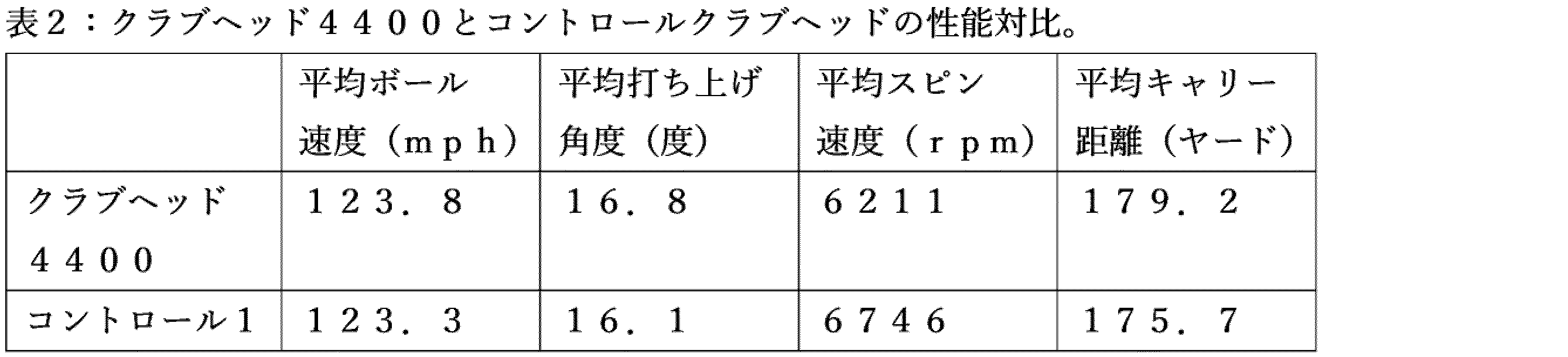
表2に示されるように、中空ボディおよび屈曲点4686を有する例示的なクラブヘッド4400は、123.3mphの平均ボール速度、16.1度の平均打ち上げ角度、175.7ヤードの平均キャリー距離、および6746rpmの平均スピン速度であったコントロールクラブヘッドと比較して、123.8mphの平均ボール速度、16.8度の平均打ち上げ角度、179.2ヤードの平均キャリー距離、および6211rpmの平均スピン速度であった。例示的なクラブヘッド4400は、コントロールクラブヘッドと比較して0.5から1%のボール速度の増加であったが、ストライクフェース4412の曲げを増加させた中空ボディおよび屈曲点4686のために、例示的なクラブヘッド4400は、打ち上げ角度の4.35%の増加およびスピン速度の7.93%の減少を経験した。打ち上げ角度が4.35%増加し、スピン速度が7.93%減少したため、例示的なクラブヘッド4400は、コントロールクラブヘッドよりも遠いキャリー距離の約2%の増加を経験した。したがって、例示的なクラブヘッド4400の中空ボディおよび屈曲4686によるストライクフェース4412の曲げのこの増加は、屈曲点がない、サイズが同様のクラブヘッドと比較して、ボールのより遠いキャリー距離を可能にする。 As shown in Table 2, the exemplary club head 4400 with the hollow body and flex points 4686 had an average ball speed of 123.8 mph, an average launch angle of 16.8 degrees, an average carry distance of 179.2 yards, and an average spin rate of 6211 rpm compared to the control club head, which had an average ball speed of 123.3 mph, an average launch angle of 16.1 degrees, an average carry distance of 175.7 yards, and an average spin rate of 6746 rpm. The exemplary club head 4400 had a 0.5 to 1% increase in ball speed compared to the control club head, but due to the hollow body and flex points 4686, which increased the bending of the strike face 4412, the exemplary club head 4400 experienced a 4.35% increase in launch angle and a 7.93% decrease in spin rate. With a 4.35% increase in launch angle and a 7.93% decrease in spin rate, the example club head 4400 experienced approximately a 2% increase in carry distance over the control club head. Thus, the hollow body of the example club head 4400 and this increase in bending of the strike face 4412 due to the bending 4686 allows for a greater carry distance of the ball compared to a similarly sized club head without a bending point.
実施例3:より小さい体積の中空ボディアイアンと中空ボディクロスオーバーの対比
以下の表3を参照すると、例示的なクラブヘッド3700および例示的なクラブヘッド4400が、例示的なクラブヘッド2700と比較された。3つの例示的なクラブヘッド3700、4400、および2700はすべて、同様のロフト角を有し、中空ボディおよび屈曲点を含んでいた。例示的なクラブヘッド3700および4400は、両方とも、例示的なクラブヘッド2700(体積約1.75インチ3)よりも大きさが著しく小さい(体積は0.65インチ3~ら1.70インチ3の範囲)。上の表1および表2と同様に、例示的なクラブヘッド3700、4400、および2700について測定されるパラメータは、ボール速度(mphで測定される)、打ち上げ角度(度で測定される)、キャリー距離(ヤードで測定される)、およびスピン速度(rpmで測定される)である。
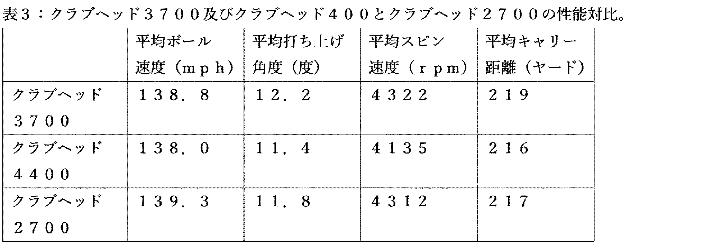
表3に示すように、例示的なクラブヘッド3700は、平均ボール速度138.8mph、平均打ち上げ角度12.2度、平均スピン速度4322rpm、および平均キャリー距離219ヤードであり、例示的なクラブヘッド4400は、平均ボール速度138.0mph、平均打ち上げ角度11.4度、平均スピン速度4135rpm、および平均キャリー距離216ヤードであり、例示的なクラブヘッド2700は、平均ボール速度139.3mph、平均打ち上げ角度11.8度、平均スピン速度4312rpm、および平均キャリー距離217ヤードであった。例示的なクラブヘッド3700は、例示的なクラブ2700を超えるキャリー距離の0.92%の増加を経験し、一方、例示的なクラブヘッド4400は、例示的なクラブ2700と比較して、キャリー距離の0.46%の減少を経験した。例示的なクラブヘッド3700、4400、および2700の間のボールのキャリー距離の小さいパーセント差は、例示的なクラブヘッド3700および例示的なクラブヘッド4400の著しく小さいサイズにかかわらず、中空ボディおよび屈曲点によるストライクフェースの曲がりを示した。より小さいサイズおよびより低い屈曲点のために、例示的なクラブヘッド3700および4400は、プレイヤーに、より小さいアイアンボディクラブヘッドの見た目およびフィーリングの利益を与るとともに、より高い屈曲点を有するより大きい体積サイズの中空ボディクラブヘッド(すなわち、例示的なクラブヘッド2700)のボール性能結果(例えば、打ち出し角度、キャリー距離)をもたらす。 As shown in Table 3, the exemplary club head 3700 had an average ball speed of 138.8 mph, an average launch angle of 12.2 degrees, an average spin rate of 4322 rpm, and an average carry distance of 219 yards, the exemplary club head 4400 had an average ball speed of 138.0 mph, an average launch angle of 11.4 degrees, an average spin rate of 4135 rpm, and an average carry distance of 216 yards, and the exemplary club head 2700 had an average ball speed of 139.3 mph, an average launch angle of 11.8 degrees, an average spin rate of 4312 rpm, and an average carry distance of 217 yards. The exemplary club head 3700 experienced a 0.92% increase in carry distance over the exemplary club 2700, while the exemplary club head 4400 experienced a 0.46% decrease in carry distance compared to the exemplary club 2700. The small percentage difference in ball carry distance between exemplary club heads 3700, 4400, and 2700 indicated the bending of the strike face due to the hollow body and flex point, despite the significantly smaller size of exemplary club head 3700 and exemplary club head 4400. Due to their smaller size and lower flex point, exemplary club heads 3700 and 4400 provide players with the look and feel of a smaller iron body club head while delivering the ball performance results (e.g., launch angle, carry distance) of a larger volumetric size hollow body club head with a higher flex point (i.e., exemplary club head 2700).
実施例4:キャビティーバックと中空ボディの対比/屈曲点ゴルフクラブ
以下の表4を参照すると、例示的なクラブヘッド4900は、トップレールの頂点の約52%下方に位置する屈曲点5186を有する中空ボディアイアンクラブヘッドである。クラブヘッド4900をコントロールクラブヘッド(以下、「コントロールクラブヘッド」)と比較した。コントロールクラブヘッドは、例示的なクラブヘッド4900とサイズが類似しているが、屈曲点および中空ボディがないキャビティバックアイアンクラブヘッドであった。コントロールクラブヘッドは、例示的なクラブヘッド4900よりも約1度小さいロフト角を有していた。上の表1と同様に、例示的なクラブヘッド4900およびコントロールクラブヘッドを比較するために測定されたパラメータは、ボール速度(mphで測定される)、打ち上げ角度(度で測定される)、キャリー距離(ヤードで測定される)、およびスピン速度(rpmで測定される)であった。
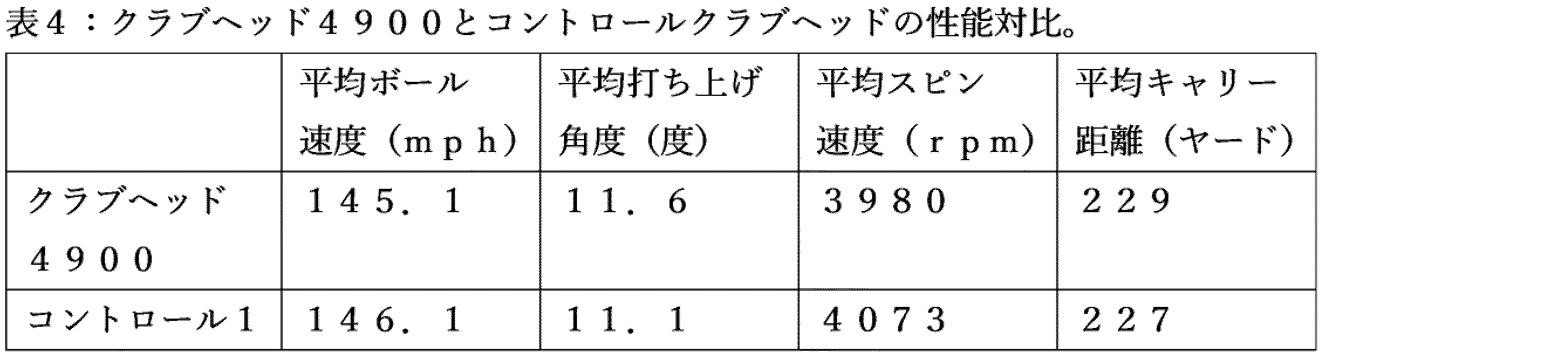
表2に示されるように、中空ボディおよび屈曲点5186を有する例示的なクラブヘッド4900は、平均ボール速度146.1mph、平均打ち上げ角度11.1度、平均キャリー距離227ヤード、および平均スピン速度4073rpmであったコントロールクラブヘッドと比較して、平均ボール速度145.1mph、平均打ち上げ角度11.6度、平均キャリー距離229ヤード、および平均スピン速度3980rpmであった。 As shown in Table 2, the exemplary club head 4900 having a hollow body and flex point 5186 had an average ball speed of 145.1 mph, an average launch angle of 11.6 degrees, an average carry distance of 229 yards, and an average spin rate of 3980 rpm compared to the control club head which had an average ball speed of 146.1 mph, an average launch angle of 11.1 degrees, an average carry distance of 227 yards, and an average spin rate of 4073 rpm.
クラブヘッド4900のより高い打ち上げ角度は、そのより高いロフト角度から生じる。クラブヘッド4900のロフト角がより大きいため、ボール速度がより低くなることも予想され得る。予想外の結果は、クラブヘッド4900のスピン速度とコントロールクラブヘッドのスピン速度の対比である。当業者は、高ロフトクラブヘッド(この例ではクラブヘッド4900)のスピン速度が、低ロフトクラブヘッド(この例ではコントロールクラブヘッド)のスピン速度よりも著しく大きいことを期待するであろう。しかし、測定したスピン速度は、測定データではスピン速度の誤差バーが重なる程度に近い。クラブヘッド4900およびコントロールクラブヘッドのスピン速度は、有意に異ならない。したがって、この試験は、ゴルフクラブヘッド4900が、所与のロフト角に対して、コントロールクラブヘッドよりも低いスピン速度を示すことを示す。この低いスピンレートは、飛行中のゴルフボールのバルーニングを減少させる。インパクト時に高いスピン速度を付与されるゴルフボールは、飛行中に上方にねじれ、すなわちバルーン状になる傾向がある。このようなゴルフボールの飛行軌跡高さの動的な増加は、キャリー距離に悪影響を与え、予測できないショットになる可能性がある。例示的なゴルフクラブ4900の平均キャリー距離は、コントロールクラブヘッドの平均キャリー距離とほぼ同じである。例示的なクラブヘッド4900の屈曲点5186は、中空ボディと共に、フェースプレート4912が、ゴルフボールに与えられるスピンを低減するように曲がることを可能にする。 The higher launch angle of the club head 4900 results from its higher loft angle. It may also be expected that the ball speed will be lower due to the higher loft angle of the club head 4900. An unexpected result is the spin rate of the club head 4900 versus the spin rate of the control club head. One skilled in the art would expect the spin rate of the high loft club head (club head 4900 in this example) to be significantly higher than the spin rate of the low loft club head (control club head in this example). However, the measured spin rates are close enough that the error bars for the spin rates overlap in the measured data. The spin rates of the club head 4900 and the control club head are not significantly different. Thus, this test shows that the golf club head 4900 exhibits a lower spin rate than the control club head for a given loft angle. This lower spin rate reduces the ballooning of the golf ball during flight. A golf ball that is imparted with a high spin rate at impact tends to twist upwards, or balloon, during flight. Such a dynamic increase in the flight path height of the golf ball can adversely affect carry distance and result in unpredictable shots. The average carry distance of the exemplary golf club 4900 is approximately the same as the average carry distance of the control club head. The flex point 5186 of the exemplary club head 4900, along with the hollow body, allows the face plate 4912 to flex in a manner that reduces the spin imparted to the golf ball.
上記表4のデータに加えて、試験は、試験ショットが着地する平均統計プロット面積を明らかにした。例示的なクラブヘッド4900の平均統計プロット面積は、コントロールクラブヘッドの平均統計プロット面積より6.2%小さかった。これは、例示的なクラブヘッド4900が、コントロールクラブヘッドよりも高い精度を示したことを示す。したがって、屈曲点5186のまわりのフェースプレート4912のヒンジは、それらのショットを制御するゴルファーの能力に悪影響を及ぼさない。むしろ、ゴルファーのショット精度が向上する。 In addition to the data in Table 4 above, the testing revealed the average statistical plot area where the test shots landed. The average statistical plot area for the exemplary club head 4900 was 6.2% less than the average statistical plot area for the control club head. This indicates that the exemplary club head 4900 demonstrated greater accuracy than the control club head. Thus, the hinging of the face plate 4912 about the flex point 5186 does not adversely affect the golfer's ability to control their shots. Rather, the golfer's shot accuracy is improved.
1つまたは複数の請求要素の置換は、再構成を構成し、補綴ではない。更に、問題に対する利点、他の有利な点及び解決を、特別な実施形態に関連して説明してきた。しかしながら、問題に対する利点、他の有利な点及び解決、並びに、任意の利点、有利な点または解決を発生させまたは明らかとさせる任意の1つまたは複数の要素は、このような利点、有利な点、解決または要素がこのような請求の範囲に明示的に述べられていない限り、請求の範囲の任意またはすべての要素の重大な、必須の、または、本質的な特徴若しくは要素を構成するものではない。 Substitution of one or more claim elements constitutes a rearrangement, not a prosthesis. Moreover, advantages, other advantages, and solutions to a problem have been described in connection with particular embodiments. However, the advantages, other advantages, and solutions to a problem, and any one or more elements that give rise to or make apparent any advantage, advantage, or solution, do not constitute a critical, essential, or essential feature or element of any or all elements of a claim, unless such advantage, advantage, solution, or element is expressly recited in such claim.
ゴルフに対する規則は、時々変更される(例えば、全米ゴルフ協会(USGA)、英国ゴルフ協会(R&A)等のゴルフ標準組織及び/または管理機関によって、新しい規則が適用されることがあり、または、古いルールが撤廃若しくは変更されることがある)ため、本明細書に記載の装置、方法及び製品に関するゴルフ用品は、任意の特定時におけるゴルフのルールに適合しまたは適合しないことがある。したがって、本明細書に記載の装置、方法及び製品に関するゴルフ用品は、適合または非適合ゴルフ用品として、公表され、売り出され、及び/または、売却されることがある。本明細書に記載の装置、方法及び製品は、この点について制限されない。 Because the rules of golf change from time to time (e.g., new rules may be adopted, or old rules may be repealed or modified, by golf standards organizations and/or governing bodies such as the United States Golf Association (USGA), the Royal and American Golf Association (R&A), etc.), golf equipment related to the devices, methods, and products described herein may or may not conform to the rules of golf at any particular time. Accordingly, golf equipment related to the devices, methods, and products described herein may be advertised, offered for sale, and/or sold as conforming or non-conforming golf equipment. The devices, methods, and products described herein are not limited in this respect.
上記実施例は、ドライバタイプのゴルフクラブとの関連で記載されているが、本明細書に記載の装置、方法及び製品は、フェアウッドタイプのゴルフクラブ、ハイブリッドタイプのゴルフクラブ、アイアンタイプのゴルフクラブ、ウェッジタイプのゴルフクラブ、または、パタータイプのゴルフクラブ等の他のタイプのゴルフクラブに適用してもよい。一方、本明細書に記載の装置、方法及び製品は、ホッケー用スティック、テニスラケット、釣り竿、スキーのストック等の他のタイプのスポーツ用品に適用可能としてもよい。 Although the above embodiments are described in the context of driver-type golf clubs, the apparatus, methods, and products described herein may be applied to other types of golf clubs, such as fairwood-type golf clubs, hybrid-type golf clubs, iron-type golf clubs, wedge-type golf clubs, or putter-type golf clubs. However, the apparatus, methods, and products described herein may be applicable to other types of sporting goods, such as hockey sticks, tennis racquets, fishing rods, ski poles, etc.
更に、本明細書に記載の実施形態及び制限は、実施形態及び/または制限が、(1)請求の範囲に明示的に主張されていない、及び、(2)均等論の下で、請求の範囲における表現要素及び/または制限と等価または潜在的に等価である場合、公開主義の下で公衆に提供するものではない。 Furthermore, the embodiments and limitations described herein are not offered to the public under the doctrine of disclosure if the embodiments and/or limitations (1) are not expressly claimed in the claims and (2) are equivalent or potentially equivalent to the expressive elements and/or limitations in the claims under the doctrine of equivalents.
Claims (20)
ソールと、ソールに対向するトップレールと、を有するボディと、
ストライクフェースを画定するフェースプレートと、
前記ストライクフェースに対向するバック壁と、
前記フェースプレート、前記バック壁、前記ソール、および前記トップレールの間の前記クラブヘッド内に画定される部分的バックキャビティと、
前記バック壁に形成されており、前記ストライクフェースに向かって延びる窪みと、
前記窪み内に画定されたリア開口であって、前記ゴルフクラブヘッドの外部またはその近傍で前記部分的バックキャビティと連通するリア開口と、を備えており、
中間平面は、前記リア開口の少なくとも半分が前記中間平面と前記トップレールとの間に位置するように、前記ストライクフェースの幾何学的中心を通って延びるとともに、前記トップレールと前記ソールとの間で前記ストライクフェースに対して垂直に延びている、ゴルフクラブヘッド。 A golf club head,
a body having a sole and a top rail facing the sole;
a face plate defining a strike face;
a back wall facing the strike face;
a partial back cavity defined within the club head between the face plate, the back wall, the sole, and the top rail;
a recess formed in the back wall and extending toward the strike face;
a rear opening defined within the recess, the rear opening communicating with the partial back cavity at or near an exterior of the golf club head;
a mid-plane extends through a geometric center of the strike face and perpendicular to the strike face between the top rail and the sole such that at least half of the rear opening is located between the mid-plane and the top rail.
前記リア開口の投影領域は、前記リア開口の領域を、前記中間平面に平行な方向に沿って前記ストライクフェース上に投影することによって画定される、請求項1に記載のゴルフクラブヘッド。 the midplane divides the strike face into an upper region and a lower region;
The golf club head of claim 1 , wherein a projected area of the rear opening is defined by projecting an area of the rear opening onto the strike face along a direction parallel to the mid-plane.
前記バック壁は、前記トップレールと前記ソールの間を延びている、請求項1に記載のゴルフクラブヘッド。 the back wall surrounds and defines the recess;
The golf club head of claim 1 , wherein the back wall extends between the top rail and the sole.
前記上部バック壁は、前記トップレールに隣接し、前記トップレールから下方に延びており、
前記下部バック壁は、前記ソールに隣接し、前記ソールから上方に延びている、請求項4に記載のゴルフクラブヘッド。 The back wall is further divided into an upper back wall and a lower back wall,
the upper back wall is adjacent to the top rail and extends downwardly from the top rail;
The golf club head of claim 4 , wherein the lower back wall is adjacent to and extends upwardly from the sole.
前記リア開口リムは、上リムと下リムに分割されており、
前記上リムは、前記トップレールの近くにあり、前記上部バック壁の輪郭に従っており、
前記下リムは、前記ソールの近くにあり、前記下部バック壁の輪郭に従っている、請求項5に記載のゴルフクラブヘッド。 a rear opening rim surrounding the rear opening;
The rear opening rim is divided into an upper rim and a lower rim,
the upper rim is proximate the top rail and follows the contour of the upper back wall;
The golf club head of claim 5 , wherein the lower rim is adjacent the sole and follows the contour of the lower back wall.
前記耐久性のある仕上げは、Hydropearl2.0クロムプレート仕上げまたは高研磨クロム仕上げである、請求項1に記載のゴルフクラブヘッド; the strike face is coated with a durable finish;
2. The golf club head of claim 1, wherein the durable finish is a Hydropearl 2.0 chrome plate finish or a highly polished chrome finish;
前記リア開口の前記上部は、前記上リムに隣接している、請求項7に記載のゴルフクラブヘッド。 The badge covers an upper portion of the rear opening,
The golf club head of claim 7 , wherein the top of the rear opening is adjacent the upper rim.
前記リア開口の前記下部は、前記下リムに隣接している、請求項7に記載のゴルフクラブヘッド。 The badge covers a lower portion of the rear opening,
The golf club head of claim 7 , wherein the lower portion of the rear opening is adjacent the lower rim.
Applications Claiming Priority (4)
| Application Number | Priority Date | Filing Date | Title |
|---|---|---|---|
| US201962802125P | 2019-02-06 | 2019-02-06 | |
| US62/802,125 | 2019-02-06 | ||
| JP2021546320A JP7604382B2 (en) | 2019-02-06 | 2020-02-06 | Golf club head with open back cavity |
| PCT/US2020/017092 WO2020163652A1 (en) | 2019-02-06 | 2020-02-06 | Golf club head with open back cavity |
Related Parent Applications (1)
| Application Number | Title | Priority Date | Filing Date |
|---|---|---|---|
| JP2021546320A Division JP7604382B2 (en) | 2019-02-06 | 2020-02-06 | Golf club head with open back cavity |
Publications (1)
| Publication Number | Publication Date |
|---|---|
| JP2025032284A true JP2025032284A (en) | 2025-03-11 |
Family
ID=71947982
Family Applications (2)
| Application Number | Title | Priority Date | Filing Date |
|---|---|---|---|
| JP2021546320A Active JP7604382B2 (en) | 2019-02-06 | 2020-02-06 | Golf club head with open back cavity |
| JP2024216474A Pending JP2025032284A (en) | 2019-02-06 | 2024-12-11 | Golf club head with open back cavity |
Family Applications Before (1)
| Application Number | Title | Priority Date | Filing Date |
|---|---|---|---|
| JP2021546320A Active JP7604382B2 (en) | 2019-02-06 | 2020-02-06 | Golf club head with open back cavity |
Country Status (5)
| Country | Link |
|---|---|
| EP (1) | EP3921048A4 (en) |
| JP (2) | JP7604382B2 (en) |
| KR (2) | KR102813927B1 (en) |
| GB (4) | GB2617043B (en) |
| WO (1) | WO2020163652A1 (en) |
Citations (8)
| Publication number | Priority date | Publication date | Assignee | Title |
|---|---|---|---|---|
| WO2005056125A1 (en) * | 2003-12-12 | 2005-06-23 | Yonex Kabushiki Kaisha | Golf club head |
| JP2005278757A (en) * | 2004-03-29 | 2005-10-13 | Daiwa Seiko Inc | Golf club head |
| US20060166758A1 (en) * | 2004-07-26 | 2006-07-27 | Roger Cleveland Golf Co., Inc. | Muscle-back, with insert, iron type golf club head |
| US20070123366A1 (en) * | 2005-11-30 | 2007-05-31 | Ray Solari | Flared chipper or wedge for golf |
| US20090069116A1 (en) * | 2007-09-11 | 2009-03-12 | Chen Archer C C | Golf head |
| US9138622B1 (en) * | 2012-09-14 | 2015-09-22 | Callaway Golf Company | Multiple-material iron |
| JP2017189700A (en) * | 2017-08-01 | 2017-10-19 | キャラウェイ・ゴルフ・カンパニ | Weighted golf club head |
| JP3217059U (en) * | 2017-05-08 | 2018-07-12 | アクシュネット カンパニーAcushnet Company | Iron golf club with badge |
Family Cites Families (5)
| Publication number | Priority date | Publication date | Assignee | Title |
|---|---|---|---|---|
| TW200806360A (en) * | 2006-07-26 | 2008-02-01 | Chau Wei Technology Co Ltd | Manufacturing method and the structure of iron club head |
| US8088025B2 (en) * | 2009-07-29 | 2012-01-03 | Taylor Made Golf Company, Inc. | Golf club head |
| US8920261B2 (en) * | 2012-12-17 | 2014-12-30 | Taylor Made Golf Company, Inc. | Badge for golf club head |
| US10427018B2 (en) * | 2015-06-22 | 2019-10-01 | Taylor Made Golf Company, Inc. | Golf club head with sound damping |
| US20180056146A1 (en) * | 2016-08-31 | 2018-03-01 | Acushnet Company | Iron golf club with badge |
-
2020
- 2020-02-06 GB GB2310353.4A patent/GB2617043B/en active Active
- 2020-02-06 JP JP2021546320A patent/JP7604382B2/en active Active
- 2020-02-06 EP EP20752859.7A patent/EP3921048A4/en active Pending
- 2020-02-06 KR KR1020217028408A patent/KR102813927B1/en active Active
- 2020-02-06 GB GB2301694.2A patent/GB2614452B/en active Active
- 2020-02-06 KR KR1020257016978A patent/KR20250076698A/en active Pending
- 2020-02-06 WO PCT/US2020/017092 patent/WO2020163652A1/en not_active Ceased
- 2020-02-06 GB GB2112052.2A patent/GB2595398B/en active Active
- 2020-02-06 GB GB2306639.2A patent/GB2615050B/en active Active
-
2024
- 2024-12-11 JP JP2024216474A patent/JP2025032284A/en active Pending
Patent Citations (8)
| Publication number | Priority date | Publication date | Assignee | Title |
|---|---|---|---|---|
| WO2005056125A1 (en) * | 2003-12-12 | 2005-06-23 | Yonex Kabushiki Kaisha | Golf club head |
| JP2005278757A (en) * | 2004-03-29 | 2005-10-13 | Daiwa Seiko Inc | Golf club head |
| US20060166758A1 (en) * | 2004-07-26 | 2006-07-27 | Roger Cleveland Golf Co., Inc. | Muscle-back, with insert, iron type golf club head |
| US20070123366A1 (en) * | 2005-11-30 | 2007-05-31 | Ray Solari | Flared chipper or wedge for golf |
| US20090069116A1 (en) * | 2007-09-11 | 2009-03-12 | Chen Archer C C | Golf head |
| US9138622B1 (en) * | 2012-09-14 | 2015-09-22 | Callaway Golf Company | Multiple-material iron |
| JP3217059U (en) * | 2017-05-08 | 2018-07-12 | アクシュネット カンパニーAcushnet Company | Iron golf club with badge |
| JP2017189700A (en) * | 2017-08-01 | 2017-10-19 | キャラウェイ・ゴルフ・カンパニ | Weighted golf club head |
Also Published As
| Publication number | Publication date |
|---|---|
| GB2617043B (en) | 2024-01-31 |
| GB202112052D0 (en) | 2021-10-06 |
| EP3921048A1 (en) | 2021-12-15 |
| KR20210121233A (en) | 2021-10-07 |
| GB202306639D0 (en) | 2023-06-21 |
| GB2615050A (en) | 2023-07-26 |
| KR102813927B1 (en) | 2025-05-27 |
| WO2020163652A1 (en) | 2020-08-13 |
| GB2595398B (en) | 2023-03-22 |
| GB2614452B (en) | 2023-11-29 |
| GB2595398A (en) | 2021-11-24 |
| JP7604382B2 (en) | 2024-12-23 |
| GB2615050B (en) | 2024-01-31 |
| JP2022519733A (en) | 2022-03-24 |
| KR20250076698A (en) | 2025-05-29 |
| EP3921048A4 (en) | 2022-10-19 |
| GB2614452A (en) | 2023-07-05 |
| GB2617043A (en) | 2023-09-27 |
Similar Documents
| Publication | Publication Date | Title |
|---|---|---|
| US12172059B2 (en) | Golf club head with open back cavity | |
| US12453907B2 (en) | Golf club and golf club heads | |
| JP7690551B2 (en) | Golf club head with energy storage properties - Patents.com | |
| US12263384B2 (en) | Golf club heads with energy storage characteristics | |
| US20190262675A1 (en) | Club heads having reinforced club head faces and related methods | |
| US11684827B2 (en) | Golf club heads with energy storage characteristics | |
| US11666809B2 (en) | Golf club heads with energy storage characteristics | |
| JP2025134954A (en) | Golf club head with energy storage properties | |
| TWI842607B (en) | Golf club head with vibrational damping system | |
| JP7797517B2 (en) | Golf club head with insert | |
| WO2017223123A1 (en) | Golf club heads with energy storage characteristics | |
| JP7604382B2 (en) | Golf club head with open back cavity | |
| JP2007125399A (en) | Golf club head with top line insert |
Legal Events
| Date | Code | Title | Description |
|---|---|---|---|
| A521 | Request for written amendment filed |
Free format text: JAPANESE INTERMEDIATE CODE: A523 Effective date: 20241217 |
|
| A621 | Written request for application examination |
Free format text: JAPANESE INTERMEDIATE CODE: A621 Effective date: 20241217 |
|
| A131 | Notification of reasons for refusal |
Free format text: JAPANESE INTERMEDIATE CODE: A131 Effective date: 20251014 |
|
| A521 | Request for written amendment filed |
Free format text: JAPANESE INTERMEDIATE CODE: A523 Effective date: 20260114 |
|
| A01 | Written decision to grant a patent or to grant a registration (utility model) |
Free format text: JAPANESE INTERMEDIATE CODE: A01 Effective date: 20260127 |