JP2024544925A - Epitaxial oxide materials, structures, and devices - Google Patents
Epitaxial oxide materials, structures, and devices Download PDFInfo
- Publication number
- JP2024544925A JP2024544925A JP2024527548A JP2024527548A JP2024544925A JP 2024544925 A JP2024544925 A JP 2024544925A JP 2024527548 A JP2024527548 A JP 2024527548A JP 2024527548 A JP2024527548 A JP 2024527548A JP 2024544925 A JP2024544925 A JP 2024544925A
- Authority
- JP
- Japan
- Prior art keywords
- semiconductor structure
- epitaxial oxide
- epitaxial
- layers
- crystal
- Prior art date
- Legal status (The legal status is an assumption and is not a legal conclusion. Google has not performed a legal analysis and makes no representation as to the accuracy of the status listed.)
- Pending
Links
Images


Classifications
-
- H—ELECTRICITY
- H10—SEMICONDUCTOR DEVICES; ELECTRIC SOLID-STATE DEVICES NOT OTHERWISE PROVIDED FOR
- H10H—INORGANIC LIGHT-EMITTING SEMICONDUCTOR DEVICES HAVING POTENTIAL BARRIERS
- H10H20/00—Individual inorganic light-emitting semiconductor devices having potential barriers, e.g. light-emitting diodes [LED]
- H10H20/80—Constructional details
- H10H20/81—Bodies
- H10H20/822—Materials of the light-emitting regions
-
- C—CHEMISTRY; METALLURGY
- C30—CRYSTAL GROWTH
- C30B—SINGLE-CRYSTAL GROWTH; UNIDIRECTIONAL SOLIDIFICATION OF EUTECTIC MATERIAL OR UNIDIRECTIONAL DEMIXING OF EUTECTOID MATERIAL; REFINING BY ZONE-MELTING OF MATERIAL; PRODUCTION OF A HOMOGENEOUS POLYCRYSTALLINE MATERIAL WITH DEFINED STRUCTURE; SINGLE CRYSTALS OR HOMOGENEOUS POLYCRYSTALLINE MATERIAL WITH DEFINED STRUCTURE; AFTER-TREATMENT OF SINGLE CRYSTALS OR A HOMOGENEOUS POLYCRYSTALLINE MATERIAL WITH DEFINED STRUCTURE; APPARATUS THEREFOR
- C30B23/00—Single-crystal growth by condensing evaporated or sublimed materials
- C30B23/02—Epitaxial-layer growth
-
- C—CHEMISTRY; METALLURGY
- C30—CRYSTAL GROWTH
- C30B—SINGLE-CRYSTAL GROWTH; UNIDIRECTIONAL SOLIDIFICATION OF EUTECTIC MATERIAL OR UNIDIRECTIONAL DEMIXING OF EUTECTOID MATERIAL; REFINING BY ZONE-MELTING OF MATERIAL; PRODUCTION OF A HOMOGENEOUS POLYCRYSTALLINE MATERIAL WITH DEFINED STRUCTURE; SINGLE CRYSTALS OR HOMOGENEOUS POLYCRYSTALLINE MATERIAL WITH DEFINED STRUCTURE; AFTER-TREATMENT OF SINGLE CRYSTALS OR A HOMOGENEOUS POLYCRYSTALLINE MATERIAL WITH DEFINED STRUCTURE; APPARATUS THEREFOR
- C30B29/00—Single crystals or homogeneous polycrystalline material with defined structure characterised by the material or by their shape
- C30B29/10—Inorganic compounds or compositions
- C30B29/16—Oxides
- C30B29/22—Complex oxides
- C30B29/26—Complex oxides with formula BMe2O4, wherein B is Mg, Ni, Co, Al, Zn, or Cd and Me is Fe, Ga, Sc, Cr, Co, or Al
-
- C—CHEMISTRY; METALLURGY
- C30—CRYSTAL GROWTH
- C30B—SINGLE-CRYSTAL GROWTH; UNIDIRECTIONAL SOLIDIFICATION OF EUTECTIC MATERIAL OR UNIDIRECTIONAL DEMIXING OF EUTECTOID MATERIAL; REFINING BY ZONE-MELTING OF MATERIAL; PRODUCTION OF A HOMOGENEOUS POLYCRYSTALLINE MATERIAL WITH DEFINED STRUCTURE; SINGLE CRYSTALS OR HOMOGENEOUS POLYCRYSTALLINE MATERIAL WITH DEFINED STRUCTURE; AFTER-TREATMENT OF SINGLE CRYSTALS OR A HOMOGENEOUS POLYCRYSTALLINE MATERIAL WITH DEFINED STRUCTURE; APPARATUS THEREFOR
- C30B29/00—Single crystals or homogeneous polycrystalline material with defined structure characterised by the material or by their shape
- C30B29/60—Single crystals or homogeneous polycrystalline material with defined structure characterised by the material or by their shape characterised by shape
- C30B29/68—Crystals with laminate structure, e.g. "superlattices"
-
- H—ELECTRICITY
- H01—ELECTRIC ELEMENTS
- H01S—DEVICES USING THE PROCESS OF LIGHT AMPLIFICATION BY STIMULATED EMISSION OF RADIATION [LASER] TO AMPLIFY OR GENERATE LIGHT; DEVICES USING STIMULATED EMISSION OF ELECTROMAGNETIC RADIATION IN WAVE RANGES OTHER THAN OPTICAL
- H01S5/00—Semiconductor lasers
- H01S5/30—Structure or shape of the active region; Materials used for the active region
- H01S5/32—Structure or shape of the active region; Materials used for the active region comprising PN junctions, e.g. hetero- or double- heterostructures
- H01S5/3206—Structure or shape of the active region; Materials used for the active region comprising PN junctions, e.g. hetero- or double- heterostructures ordering or disordering the natural superlattice in ternary or quaternary materials
-
- H—ELECTRICITY
- H01—ELECTRIC ELEMENTS
- H01S—DEVICES USING THE PROCESS OF LIGHT AMPLIFICATION BY STIMULATED EMISSION OF RADIATION [LASER] TO AMPLIFY OR GENERATE LIGHT; DEVICES USING STIMULATED EMISSION OF ELECTROMAGNETIC RADIATION IN WAVE RANGES OTHER THAN OPTICAL
- H01S5/00—Semiconductor lasers
- H01S5/30—Structure or shape of the active region; Materials used for the active region
- H01S5/34—Structure or shape of the active region; Materials used for the active region comprising quantum well or superlattice structures, e.g. single quantum well [SQW] lasers, multiple quantum well [MQW] lasers or graded index separate confinement heterostructure [GRINSCH] lasers
-
- H—ELECTRICITY
- H10—SEMICONDUCTOR DEVICES; ELECTRIC SOLID-STATE DEVICES NOT OTHERWISE PROVIDED FOR
- H10D—INORGANIC ELECTRIC SEMICONDUCTOR DEVICES
- H10D30/00—Field-effect transistors [FET]
- H10D30/01—Manufacture or treatment
- H10D30/015—Manufacture or treatment of FETs having heterojunction interface channels or heterojunction gate electrodes, e.g. HEMT
-
- H—ELECTRICITY
- H10—SEMICONDUCTOR DEVICES; ELECTRIC SOLID-STATE DEVICES NOT OTHERWISE PROVIDED FOR
- H10D—INORGANIC ELECTRIC SEMICONDUCTOR DEVICES
- H10D30/00—Field-effect transistors [FET]
- H10D30/40—FETs having zero-dimensional [0D], one-dimensional [1D] or two-dimensional [2D] charge carrier gas channels
- H10D30/47—FETs having zero-dimensional [0D], one-dimensional [1D] or two-dimensional [2D] charge carrier gas channels having 2D charge carrier gas channels, e.g. nanoribbon FETs or high electron mobility transistors [HEMT]
- H10D30/471—High electron mobility transistors [HEMT] or high hole mobility transistors [HHMT]
- H10D30/475—High electron mobility transistors [HEMT] or high hole mobility transistors [HHMT] having wider bandgap layer formed on top of lower bandgap active layer, e.g. undoped barrier HEMTs such as i-AlGaN/GaN HEMTs
-
- H—ELECTRICITY
- H10—SEMICONDUCTOR DEVICES; ELECTRIC SOLID-STATE DEVICES NOT OTHERWISE PROVIDED FOR
- H10D—INORGANIC ELECTRIC SEMICONDUCTOR DEVICES
- H10D30/00—Field-effect transistors [FET]
- H10D30/60—Insulated-gate field-effect transistors [IGFET]
-
- H—ELECTRICITY
- H10—SEMICONDUCTOR DEVICES; ELECTRIC SOLID-STATE DEVICES NOT OTHERWISE PROVIDED FOR
- H10D—INORGANIC ELECTRIC SEMICONDUCTOR DEVICES
- H10D30/00—Field-effect transistors [FET]
- H10D30/60—Insulated-gate field-effect transistors [IGFET]
- H10D30/67—Thin-film transistors [TFT]
- H10D30/674—Thin-film transistors [TFT] characterised by the active materials
- H10D30/6755—Oxide semiconductors, e.g. zinc oxide, copper aluminium oxide or cadmium stannate
-
- H—ELECTRICITY
- H10—SEMICONDUCTOR DEVICES; ELECTRIC SOLID-STATE DEVICES NOT OTHERWISE PROVIDED FOR
- H10D—INORGANIC ELECTRIC SEMICONDUCTOR DEVICES
- H10D62/00—Semiconductor bodies, or regions thereof, of devices having potential barriers
- H10D62/10—Shapes, relative sizes or dispositions of the regions of the semiconductor bodies; Shapes of the semiconductor bodies
- H10D62/13—Semiconductor regions connected to electrodes carrying current to be rectified, amplified or switched, e.g. source or drain regions
- H10D62/149—Source or drain regions of field-effect devices
-
- H—ELECTRICITY
- H10—SEMICONDUCTOR DEVICES; ELECTRIC SOLID-STATE DEVICES NOT OTHERWISE PROVIDED FOR
- H10D—INORGANIC ELECTRIC SEMICONDUCTOR DEVICES
- H10D62/00—Semiconductor bodies, or regions thereof, of devices having potential barriers
- H10D62/10—Shapes, relative sizes or dispositions of the regions of the semiconductor bodies; Shapes of the semiconductor bodies
- H10D62/13—Semiconductor regions connected to electrodes carrying current to be rectified, amplified or switched, e.g. source or drain regions
- H10D62/165—Tunnel injectors
-
- H—ELECTRICITY
- H10—SEMICONDUCTOR DEVICES; ELECTRIC SOLID-STATE DEVICES NOT OTHERWISE PROVIDED FOR
- H10D—INORGANIC ELECTRIC SEMICONDUCTOR DEVICES
- H10D62/00—Semiconductor bodies, or regions thereof, of devices having potential barriers
- H10D62/80—Semiconductor bodies, or regions thereof, of devices having potential barriers characterised by the materials
- H10D62/81—Semiconductor bodies, or regions thereof, of devices having potential barriers characterised by the materials of structures exhibiting quantum-confinement effects, e.g. single quantum wells; of structures having periodic or quasi-periodic potential variation
- H10D62/815—Semiconductor bodies, or regions thereof, of devices having potential barriers characterised by the materials of structures exhibiting quantum-confinement effects, e.g. single quantum wells; of structures having periodic or quasi-periodic potential variation of structures having periodic or quasi-periodic potential variation, e.g. superlattices or multiple quantum wells [MQW]
- H10D62/8161—Semiconductor bodies, or regions thereof, of devices having potential barriers characterised by the materials of structures exhibiting quantum-confinement effects, e.g. single quantum wells; of structures having periodic or quasi-periodic potential variation of structures having periodic or quasi-periodic potential variation, e.g. superlattices or multiple quantum wells [MQW] potential variation due to variations in composition or crystallinity, e.g. heterojunction superlattices
- H10D62/8162—Semiconductor bodies, or regions thereof, of devices having potential barriers characterised by the materials of structures exhibiting quantum-confinement effects, e.g. single quantum wells; of structures having periodic or quasi-periodic potential variation of structures having periodic or quasi-periodic potential variation, e.g. superlattices or multiple quantum wells [MQW] potential variation due to variations in composition or crystallinity, e.g. heterojunction superlattices having quantum effects only in the vertical direction, i.e. layered structures having quantum effects solely resulting from vertical potential variation
- H10D62/8164—Semiconductor bodies, or regions thereof, of devices having potential barriers characterised by the materials of structures exhibiting quantum-confinement effects, e.g. single quantum wells; of structures having periodic or quasi-periodic potential variation of structures having periodic or quasi-periodic potential variation, e.g. superlattices or multiple quantum wells [MQW] potential variation due to variations in composition or crystallinity, e.g. heterojunction superlattices having quantum effects only in the vertical direction, i.e. layered structures having quantum effects solely resulting from vertical potential variation comprising only semiconductor materials
-
- H—ELECTRICITY
- H10—SEMICONDUCTOR DEVICES; ELECTRIC SOLID-STATE DEVICES NOT OTHERWISE PROVIDED FOR
- H10D—INORGANIC ELECTRIC SEMICONDUCTOR DEVICES
- H10D62/00—Semiconductor bodies, or regions thereof, of devices having potential barriers
- H10D62/80—Semiconductor bodies, or regions thereof, of devices having potential barriers characterised by the materials
- H10D62/82—Heterojunctions
-
- H—ELECTRICITY
- H10—SEMICONDUCTOR DEVICES; ELECTRIC SOLID-STATE DEVICES NOT OTHERWISE PROVIDED FOR
- H10D—INORGANIC ELECTRIC SEMICONDUCTOR DEVICES
- H10D62/00—Semiconductor bodies, or regions thereof, of devices having potential barriers
- H10D62/80—Semiconductor bodies, or regions thereof, of devices having potential barriers characterised by the materials
- H10D62/85—Semiconductor bodies, or regions thereof, of devices having potential barriers characterised by the materials being Group III-V materials, e.g. GaAs
- H10D62/8503—Nitride Group III-V materials, e.g. AlN or GaN
-
- H—ELECTRICITY
- H10—SEMICONDUCTOR DEVICES; ELECTRIC SOLID-STATE DEVICES NOT OTHERWISE PROVIDED FOR
- H10D—INORGANIC ELECTRIC SEMICONDUCTOR DEVICES
- H10D64/00—Electrodes of devices having potential barriers
- H10D64/111—Field plates
-
- H—ELECTRICITY
- H10—SEMICONDUCTOR DEVICES; ELECTRIC SOLID-STATE DEVICES NOT OTHERWISE PROVIDED FOR
- H10D—INORGANIC ELECTRIC SEMICONDUCTOR DEVICES
- H10D64/00—Electrodes of devices having potential barriers
- H10D64/20—Electrodes characterised by their shapes, relative sizes or dispositions
- H10D64/23—Electrodes carrying the current to be rectified, amplified, oscillated or switched, e.g. sources, drains, anodes or cathodes
- H10D64/251—Source or drain electrodes for field-effect devices
- H10D64/256—Source or drain electrodes for field-effect devices for lateral devices wherein the source or drain electrodes are recessed in semiconductor bodies
-
- H—ELECTRICITY
- H10—SEMICONDUCTOR DEVICES; ELECTRIC SOLID-STATE DEVICES NOT OTHERWISE PROVIDED FOR
- H10D—INORGANIC ELECTRIC SEMICONDUCTOR DEVICES
- H10D64/00—Electrodes of devices having potential barriers
- H10D64/20—Electrodes characterised by their shapes, relative sizes or dispositions
- H10D64/23—Electrodes carrying the current to be rectified, amplified, oscillated or switched, e.g. sources, drains, anodes or cathodes
- H10D64/251—Source or drain electrodes for field-effect devices
- H10D64/257—Source or drain electrodes for field-effect devices for lateral devices wherein the source or drain electrodes are characterised by top-view geometrical layouts, e.g. interdigitated, semi-circular, annular or L-shaped electrodes
-
- H—ELECTRICITY
- H10—SEMICONDUCTOR DEVICES; ELECTRIC SOLID-STATE DEVICES NOT OTHERWISE PROVIDED FOR
- H10D—INORGANIC ELECTRIC SEMICONDUCTOR DEVICES
- H10D64/00—Electrodes of devices having potential barriers
- H10D64/20—Electrodes characterised by their shapes, relative sizes or dispositions
- H10D64/27—Electrodes not carrying the current to be rectified, amplified, oscillated or switched, e.g. gates
-
- H—ELECTRICITY
- H10—SEMICONDUCTOR DEVICES; ELECTRIC SOLID-STATE DEVICES NOT OTHERWISE PROVIDED FOR
- H10D—INORGANIC ELECTRIC SEMICONDUCTOR DEVICES
- H10D64/00—Electrodes of devices having potential barriers
- H10D64/60—Electrodes characterised by their materials
- H10D64/66—Electrodes having a conductor capacitively coupled to a semiconductor by an insulator, e.g. MIS electrodes
- H10D64/68—Electrodes having a conductor capacitively coupled to a semiconductor by an insulator, e.g. MIS electrodes characterised by the insulator, e.g. by the gate insulator
- H10D64/691—Electrodes having a conductor capacitively coupled to a semiconductor by an insulator, e.g. MIS electrodes characterised by the insulator, e.g. by the gate insulator comprising metallic compounds, e.g. metal oxides or metal silicates
-
- H—ELECTRICITY
- H10—SEMICONDUCTOR DEVICES; ELECTRIC SOLID-STATE DEVICES NOT OTHERWISE PROVIDED FOR
- H10D—INORGANIC ELECTRIC SEMICONDUCTOR DEVICES
- H10D99/00—Subject matter not provided for in other groups of this subclass
-
- H—ELECTRICITY
- H10—SEMICONDUCTOR DEVICES; ELECTRIC SOLID-STATE DEVICES NOT OTHERWISE PROVIDED FOR
- H10H—INORGANIC LIGHT-EMITTING SEMICONDUCTOR DEVICES HAVING POTENTIAL BARRIERS
- H10H20/00—Individual inorganic light-emitting semiconductor devices having potential barriers, e.g. light-emitting diodes [LED]
- H10H20/01—Manufacture or treatment
- H10H20/011—Manufacture or treatment of bodies, e.g. forming semiconductor layers
- H10H20/013—Manufacture or treatment of bodies, e.g. forming semiconductor layers having light-emitting regions comprising only Group III-V materials
- H10H20/0133—Manufacture or treatment of bodies, e.g. forming semiconductor layers having light-emitting regions comprising only Group III-V materials with a substrate not being Group III-V materials
- H10H20/01335—Manufacture or treatment of bodies, e.g. forming semiconductor layers having light-emitting regions comprising only Group III-V materials with a substrate not being Group III-V materials the light-emitting regions comprising nitride materials
-
- H—ELECTRICITY
- H10—SEMICONDUCTOR DEVICES; ELECTRIC SOLID-STATE DEVICES NOT OTHERWISE PROVIDED FOR
- H10H—INORGANIC LIGHT-EMITTING SEMICONDUCTOR DEVICES HAVING POTENTIAL BARRIERS
- H10H20/00—Individual inorganic light-emitting semiconductor devices having potential barriers, e.g. light-emitting diodes [LED]
- H10H20/80—Constructional details
- H10H20/81—Bodies
- H10H20/811—Bodies having quantum effect structures or superlattices, e.g. tunnel junctions
- H10H20/812—Bodies having quantum effect structures or superlattices, e.g. tunnel junctions within the light-emitting regions, e.g. having quantum confinement structures
-
- H—ELECTRICITY
- H10—SEMICONDUCTOR DEVICES; ELECTRIC SOLID-STATE DEVICES NOT OTHERWISE PROVIDED FOR
- H10H—INORGANIC LIGHT-EMITTING SEMICONDUCTOR DEVICES HAVING POTENTIAL BARRIERS
- H10H20/00—Individual inorganic light-emitting semiconductor devices having potential barriers, e.g. light-emitting diodes [LED]
- H10H20/80—Constructional details
- H10H20/81—Bodies
- H10H20/817—Bodies characterised by the crystal structures or orientations, e.g. polycrystalline, amorphous or porous
- H10H20/818—Bodies characterised by the crystal structures or orientations, e.g. polycrystalline, amorphous or porous within the light-emitting regions
-
- H—ELECTRICITY
- H10—SEMICONDUCTOR DEVICES; ELECTRIC SOLID-STATE DEVICES NOT OTHERWISE PROVIDED FOR
- H10H—INORGANIC LIGHT-EMITTING SEMICONDUCTOR DEVICES HAVING POTENTIAL BARRIERS
- H10H20/00—Individual inorganic light-emitting semiconductor devices having potential barriers, e.g. light-emitting diodes [LED]
- H10H20/80—Constructional details
- H10H20/85—Packages
- H10H20/857—Interconnections, e.g. lead-frames, bond wires or solder balls
-
- H—ELECTRICITY
- H10—SEMICONDUCTOR DEVICES; ELECTRIC SOLID-STATE DEVICES NOT OTHERWISE PROVIDED FOR
- H10H—INORGANIC LIGHT-EMITTING SEMICONDUCTOR DEVICES HAVING POTENTIAL BARRIERS
- H10H29/00—Integrated devices, or assemblies of multiple devices, comprising at least one light-emitting semiconductor element covered by group H10H20/00
- H10H29/10—Integrated devices comprising at least one light-emitting semiconductor component covered by group H10H20/00
-
- H10P14/22—
-
- H10P14/2918—
-
- H10P14/2921—
-
- H10P14/2926—
-
- H10P14/3216—
-
- H10P14/3234—
-
- H10P14/3252—
-
- H10P14/3258—
-
- H10P14/3434—
-
- H10P14/3442—
-
- H10P14/3444—
-
- H10P14/3446—
-
- H10P14/6339—
-
- H10P14/6349—
-
- H10P14/6939—
-
- H10P14/69391—
-
- H10P14/69394—
-
- H10P14/69396—
-
- H10P14/69397—
-
- H10W44/20—
-
- H—ELECTRICITY
- H10—SEMICONDUCTOR DEVICES; ELECTRIC SOLID-STATE DEVICES NOT OTHERWISE PROVIDED FOR
- H10D—INORGANIC ELECTRIC SEMICONDUCTOR DEVICES
- H10D30/00—Field-effect transistors [FET]
- H10D30/40—FETs having zero-dimensional [0D], one-dimensional [1D] or two-dimensional [2D] charge carrier gas channels
- H10D30/47—FETs having zero-dimensional [0D], one-dimensional [1D] or two-dimensional [2D] charge carrier gas channels having 2D charge carrier gas channels, e.g. nanoribbon FETs or high electron mobility transistors [HEMT]
-
- H10P14/3226—
-
- H10P14/3426—
-
- H10W44/216—
Landscapes
- Chemical & Material Sciences (AREA)
- Engineering & Computer Science (AREA)
- Physics & Mathematics (AREA)
- Condensed Matter Physics & Semiconductors (AREA)
- General Physics & Mathematics (AREA)
- Organic Chemistry (AREA)
- Crystallography & Structural Chemistry (AREA)
- Materials Engineering (AREA)
- Metallurgy (AREA)
- Microelectronics & Electronic Packaging (AREA)
- Power Engineering (AREA)
- Computer Hardware Design (AREA)
- Manufacturing & Machinery (AREA)
- Electromagnetism (AREA)
- Optics & Photonics (AREA)
- Inorganic Chemistry (AREA)
- Crystals, And After-Treatments Of Crystals (AREA)
- Chemical Kinetics & Catalysis (AREA)
- Semiconductor Lasers (AREA)
- Recrystallisation Techniques (AREA)
- Light Receiving Elements (AREA)
- Led Devices (AREA)
- Junction Field-Effect Transistors (AREA)
Abstract
半導体構造は、組成、結晶対称性、バンドギャップなどの異なる特性を有する2つ以上のエピタキシャル酸化物材料を含み得る。半導体構造は、エピタキシャル酸化物材料の成長に適したテンプレートを提供する面内格子パラメータ及び原子位置を有する互換性のある基板上に形成された1つまたは複数のエピタキシャル酸化物層を含み得る。1つまたは複数のエピタキシャル酸化物材料に歪みが生じる可能性がある。1つまたは複数のエピタキシャル酸化物材料をn型またはp型にドープできる。半導体構造は、エピタキシャル酸化物材料を有する超格子を含み得る。半導体構造は、エピタキシャル酸化物材料を有するチャープ層を含み得る。半導体構造は、オプトエレクトロニクスデバイス、発光ダイオード、レーザダイオード、光検出器、太陽電池、高出力ダイオード、高出力トランジスタ、トランスデューサ、または高電子移動度トランジスタなどの半導体デバイスの一部であり得る。
The semiconductor structure may include two or more epitaxial oxide materials with different properties such as composition, crystal symmetry, band gap, etc. The semiconductor structure may include one or more epitaxial oxide layers formed on a compatible substrate with in-plane lattice parameters and atomic positions that provide a suitable template for the growth of the epitaxial oxide materials. The epitaxial oxide material or materials may be strained. The epitaxial oxide material or materials may be doped n-type or p-type. The semiconductor structure may include a superlattice with the epitaxial oxide material. The semiconductor structure may include a chirped layer with the epitaxial oxide material. The semiconductor structure may be part of a semiconductor device such as an optoelectronic device, a light emitting diode, a laser diode, a photodetector, a solar cell, a high power diode, a high power transistor, a transducer, or a high electron mobility transistor.
Description
関連出願
本出願は、2021年11月10日に出願された「Ultrawide Bandgap Semiconductor Devices Including Magnesium Germanium Oxides」と題する国際出願番号PCT/IB2021/060414、2021年11月10日に出願された「Epitaxial Oxide Materials, Structures and Devices」と題する国際出願番号PCT/IB2021/060413、及び2021年11月10日に出願された「Epitaxial Oxide Materials, Structures, and Devices」と題する国際出願番号PCT/IB2021/060427に対する優先権を主張し、これらはすべて、あらゆる目的のために参照により本明細書に組み込まれる。
RELATED APPLICATIONS This application is related to International Application No. PCT/IB2021/060414, filed on November 10, 2021, entitled "Ultrawide Bandgap Semiconductor Devices Including Magnesium Germanium Oxides," International Application No. PCT/IB2021/060413, filed on November 10, 2021, entitled "Epitaxial Oxide Materials, Structures and Devices," and International Application No. PCT/IB2021/060414, filed on November 10, 2021, entitled "Epitaxial Oxide Materials, Structures, and Devices." This application claims priority to International Application No. PCT/IB2021/060427, entitled "Comparative Experimental Devices," all of which are incorporated herein by reference for all purposes.
本出願は、2020年8月11日に出願され、「Metal Oxide Semiconductor-Based Light Emitting Device」と題する米国非仮特許出願番号16/990,349に関し、これらはすべて、あらゆる目的のために参照により本明細書に組み込まれる。 This application is related to U.S. Nonprovisional Patent Application No. 16/990,349, filed August 11, 2020, and entitled "Metal Oxide Semiconductor-Based Light Emitting Device," all of which are incorporated herein by reference for all purposes.
以下の刊行物は、本出願において参照され、それらの内容は、その全体が参照により本明細書に組み込まれる。
・「OPTICAL TUNING OF LIGHT EMITTING SEMICONDUCTOR JUNCTIONS」と題する米国特許第9,412,911号は、2016年8月9日に発行され、本願の出願人に譲渡された。
・「ADVANCED ELECTRONIC DEVICE STRUCTURES USING SEMICONDUCTOR STRUCTURES AND SUPERLATTICES」と題する米国特許第9,691,938号は、2017年6月27日に発行され、本願の出願人に譲渡された。
・「OPTOELECTRONIC DEVICE」と題する米国特許第10,475,956号は、2019年11月12日に発行され、本出願の出願人に譲渡された。
The following publications are referenced in this application, the contents of which are incorporated herein by reference in their entireties:
- U.S. Patent No. 9,412,911, entitled "OPTICAL TUNING OF LIGHT EMITTING SEMICONDUCTOR JUNCTIONS," issued on August 9, 2016 and is assigned to the present applicant.
No. 9,691,938, entitled “ADVANCED ELECTRONIC DEVICE STRUCTURES USING SEMICONDUCTOR STRUCTURES AND SUPERLATTICES,” issued on June 27, 2017 and is assigned to the present applicant.
- U.S. Patent No. 10,475,956, entitled "OPTOELECTRONIC DEVICE," issued on November 12, 2019 and is assigned to the present applicant.
各々の上記刊行物の内容は、参照によりそれらの全体が明示的に組み込まれる。 The contents of each of the above publications are expressly incorporated by reference in their entirety.
ダイオード、トランジスタ、光検出器、LED、レーザなどの電子及びオプトエレクトロニクスデバイスは、エピタキシャル半導体構造を使用して、自由キャリアの輸送の制御、光の検出、または光の生成を行うことができる。バンドギャップが約4eVを超える半導体材料などの広いバンドギャップ半導体材料は、紫外(UV)波長の光を検出または放出する高出力デバイスやオプトエレクトロニクスデバイスなどのいくつかの用途に役立つ。 Electronic and optoelectronic devices such as diodes, transistors, photodetectors, LEDs, and lasers can use epitaxial semiconductor structures to control the transport of free carriers, detect light, or generate light. Wide bandgap semiconductor materials, such as those with bandgaps greater than about 4 eV, are useful for several applications, such as high-power and optoelectronic devices that detect or emit light at ultraviolet (UV) wavelengths.
例えば、UV発光デバイス(UVLED)は、医療、医療診断、浄水、食品加工、殺菌、無菌包装、ディープサブミクロンのリソグラフィー処理で多くの用途がある。バイオセンシング、通信、製薬プロセス産業、及び材料製造における新たな用途も、UVLEDなどの高い電気変換効率を備えたコンパクトで軽量なパッケージに極短波長の光源を提供することで可能になる。電気エネルギーを個別の光波長に非常に高い効率で電気光学的変換することは、一般に、電子と正孔の電荷キャリアの空間再結合を達成して必要な波長の光を放出するために必要な特性を備えた半導体を使用して達成されてきた。UV光が必要な場合、ウルツ鉱型結晶構造を形成するガリウム-インジウム-アルミニウム-窒化物(GaInAlN)組成をほぼ独占的に使用してUVLEDが開発された。 For example, UV light emitting devices (UVLEDs) have many applications in medicine, medical diagnostics, water purification, food processing, sterilization, aseptic packaging, and deep submicron lithography processing. Emerging applications in biosensing, communications, pharmaceutical processing industries, and materials manufacturing are also enabled by providing extremely short wavelength light sources in a compact, lightweight package with high electrical conversion efficiency such as UVLEDs. Highly efficient electro-optical conversion of electrical energy to discrete optical wavelengths has generally been achieved using semiconductors with the necessary properties to achieve spatial recombination of electron and hole charge carriers to emit light at the required wavelength. When UV light is required, UVLEDs have been developed almost exclusively using gallium-indium-aluminum-nitride (GaInAlN) compositions that form a wurtzite crystal structure.
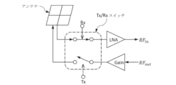
別の例では、高出力RFスイッチは、無線通信システムのトランシーバで送信信号及び受信信号を分離、増幅、フィルタリングするために使用される。このようなRFスイッチを構成するトランジスタデバイスの要件は、損傷することなく高電圧を処理できることである。一般的なRFスイッチは、比較的低い破壊電圧(例えば、約3V未満)の低バンドギャップ半導体(例えば、SiまたはGaAs)を採用したトランジスタデバイスを使用しており、したがって必要な電圧に耐えるために多くのトランジスタデバイスが直列に接続される。直列に接続されたトランジスタデバイスの数を減らし、RFスイッチの最大電圧制限を改善するために、より高い破壊電圧を備えたより広いバンドギャップの半導体(例えば、GaN)が使用されている。RFスイッチにGaNなどのバンドギャップのより広い半導体を使用することのさらなる利点は、マイクロ波回路とのインピーダンス整合を簡素化できることである。 In another example, high power RF switches are used in transceivers of wireless communication systems to separate, amplify, and filter transmit and receive signals. A requirement for the transistor devices that make up such RF switches is that they can handle high voltages without damage. Typical RF switches use transistor devices that employ low bandgap semiconductors (e.g., Si or GaAs) with relatively low breakdown voltages (e.g., less than about 3V), and therefore many transistor devices are connected in series to withstand the required voltages. To reduce the number of transistor devices connected in series and improve the maximum voltage limits of RF switches, wider bandgap semiconductors (e.g., GaN) with higher breakdown voltages are used. An additional advantage of using wider bandgap semiconductors such as GaN in RF switches is that impedance matching with microwave circuits can be simplified.
いくつかの実施形態では、半導体構造はエピタキシャル酸化物材料を含む。いくつかの実施形態では、半導体構造には、組成、結晶対称性、またはバンドギャップなどの異なる特性を有する2つ以上のエピタキシャル酸化物材料が含まれる。半導体構造は、エピタキシャル酸化物材料の成長に適したテンプレートを提供する面内格子パラメータ及び原子位置を有する互換性のある基板上に形成された1つまたは複数のエピタキシャル酸化物層を含み得る。いくつかの実施形態では、エピタキシャル酸化物材料の1つまたは複数が歪んでいる。いくつかの実施形態では、エピタキシャル酸化物材料の1つまたは複数がn型またはp型にドープされる。いくつかの実施形態では、半導体構造はエピタキシャル酸化物材料を有する超格子を含む。いくつかの実施形態では、半導体構造は、エピタキシャル酸化物材料を有するチャープ層を含む。 In some embodiments, the semiconductor structure includes an epitaxial oxide material. In some embodiments, the semiconductor structure includes two or more epitaxial oxide materials having different properties, such as composition, crystal symmetry, or band gap. The semiconductor structure may include one or more epitaxial oxide layers formed on a compatible substrate having in-plane lattice parameters and atomic positions that provide a suitable template for the growth of the epitaxial oxide materials. In some embodiments, one or more of the epitaxial oxide materials are strained. In some embodiments, one or more of the epitaxial oxide materials are doped n-type or p-type. In some embodiments, the semiconductor structure includes a superlattice having epitaxial oxide materials. In some embodiments, the semiconductor structure includes a chirped layer having epitaxial oxide materials.
本明細書に記載の半導体構造は、赤外線から深紫外線までの波長を有するオプトエレクトロニクスデバイス、発光ダイオード、レーザダイオード、光検出器、太陽電池、高出力ダイオード、高出力トランジスタ、トランスデューサ、または高電子移動度トランジスタなどの半導体デバイスの一部であり得る。いくつかの実施形態では、半導体デバイスは、その中のエピタキシャル酸化物材料の特性に起因する高耐圧を有する。いくつかの実施形態では、半導体デバイスは、キャリア増倍のために衝撃イオン化機構を使用する。 The semiconductor structures described herein may be part of a semiconductor device such as an optoelectronic device, a light emitting diode, a laser diode, a photodetector, a solar cell, a high power diode, a high power transistor, a transducer, or a high electron mobility transistor, having wavelengths ranging from infrared to deep ultraviolet. In some embodiments, the semiconductor device has a high breakdown voltage due to the properties of the epitaxial oxide material therein. In some embodiments, the semiconductor device uses an impact ionization mechanism for carrier multiplication.
本開示の実施形態は、添付の図面を参照して詳細に説明される。 Embodiments of the present disclosure will now be described in detail with reference to the accompanying drawings.
本明細書では、エピタキシャル酸化物材料を含む構造及び電子デバイスを有する、エピタキシャル酸化物材料の実施形態が開示される。いくつかの実施形態は、約150nmから約280nmの範囲の波長を有する光を放出するように構成され得るオプトエレクトロニクス半導体発光デバイスを開示する。デバイスは、その上に配置された少なくとも1つのエピタキシャル半導体金属酸化物層を有する金属酸化物基板を含む。基板は、Al2O3、Ga2O3、MgO、LiF、MgAl2O4、MgGa2O4、LiGaO2、LiAlO2、(AlxGa1-x)2O3、MgF2、LaAlO3、TiO2または石英を含んでもよい。特定の実施形態では、少なくとも1つの半導体層のうちの1つまたは複数は、Al2O3及びGa2O3のうちの少なくとも1つを含む。 Disclosed herein are embodiments of epitaxial oxide materials having structures and electronic devices that include the epitaxial oxide materials. Some embodiments disclose optoelectronic semiconductor light emitting devices that can be configured to emit light having a wavelength in the range of about 150 nm to about 280 nm. The device includes a metal oxide substrate having at least one epitaxial semiconductor metal oxide layer disposed thereon. The substrate may include Al 2 O 3 , Ga 2 O 3 , MgO, LiF, MgAl 2 O 4 , MgGa 2 O 4 , LiGaO 2 , LiAlO 2 , (Al x Ga 1-x ) 2 O 3 , MgF 2 , LaAlO 3 , TiO 2 , or quartz. In certain embodiments, one or more of the at least one semiconductor layer includes at least one of Al 2 O 3 and Ga 2 O 3 .
第1の態様では、本開示は、約150nm~約280nmの範囲の波長を有する光を放出するように構成されたオプトエレクトロニクス半導体発光デバイスを提供し、デバイスは、その上に配置された少なくとも1つのエピタキシャル半導体層を有する基板を備え、1つまたは複数のエピタキシャル半導体層の各々は、金属酸化物を含む。 In a first aspect, the present disclosure provides an optoelectronic semiconductor light emitting device configured to emit light having a wavelength in a range of about 150 nm to about 280 nm, the device comprising a substrate having at least one epitaxial semiconductor layer disposed thereon, each of the one or more epitaxial semiconductor layers comprising a metal oxide.
別の形態では、1つまたは複数の半導体層のそれぞれの金属酸化物は、Al2O3、Ga2O3、MgO、NiO、Li2O、ZnO、SiO2、GeO2、Er2O3、Gd2O3、PdO、Bi2O3、IrO2、及び前述の金属酸化物の任意の組み合わせからなる群から選択される。 In another aspect, the metal oxide of each of the one or more semiconductor layers is selected from the group consisting of Al2O3 , Ga2O3 , MgO, NiO, Li2O , ZnO , SiO2 , GeO2 , Er2O3 , Gd2O3 , PdO, Bi2O3 , IrO2 , and any combination of the foregoing metal oxides.
別の形態では、1つまたは複数の半導体層のうちの少なくとも1つは単結晶である。 In another embodiment, at least one of the one or more semiconductor layers is single crystalline.
別の形態では、1つまたは複数の半導体層のうちの少なくとも1つは、菱面体晶、六方晶、または単斜晶の結晶対称性を有する。 In another form, at least one of the one or more semiconductor layers has rhombohedral, hexagonal, or monoclinic crystal symmetry.
別の形態では、1つまたは複数の半導体層のうちの少なくとも1つは2元金属酸化物から構成され、金属酸化物はAl2O3及びGa2O3から選択される。 In another form, at least one of the one or more semiconductor layers is comprised of a binary metal oxide, the metal oxide being selected from Al2O3 and Ga2O3 .
別の形態では、1つまたは複数の半導体層のうちの少なくとも1つは、3元金属酸化物組成物から構成され、3元金属酸化物組成物は、Al2O3及びGa2O3のうちの少なくとも1つ、ならびに、任意選択で、MgO、NiO、LiO2、ZnO、SiO2、GeO2、Er2O3、Gd2O3、PdO、Bi2O3、及びIrO2から選択される金属酸化物を含む。 In another form, at least one of the one or more semiconductor layers is comprised of a ternary metal oxide composition comprising at least one of Al2O3 and Ga2O3 , and optionally a metal oxide selected from MgO, NiO , LiO2, ZnO, SiO2 , GeO2 , Er2O3 , Gd2O3 , PdO, Bi2O3 , and IrO2 .
別の形態では、1つまたは複数の半導体層のうちの少なくとも1つは、(AlxGa1-x)2O3の3元金属酸化物組成物から構成され、式中0<x<1である。 In another form, at least one of the one or more semiconductor layers is comprised of a ternary metal oxide composition of (Al x Ga 1-x ) 2 O 3 , where 0<x<1.
別の形態では、1つまたは複数の半導体層のうちの少なくとも1つは、1軸変形したユニットセルを含む。 In another embodiment, at least one of the one or more semiconductor layers includes a uniaxially deformed unit cell.
別の形態では、1つまたは複数の半導体層のうちの少なくとも1つは、2軸変形したユニットセルを含む。 In another embodiment, at least one of the one or more semiconductor layers includes a biaxially strained unit cell.
別の形態では、1つまたは複数の半導体層のうちの少なくとも1つは、3軸変形したユニットセルを含む。 In another embodiment, at least one of the one or more semiconductor layers includes a triaxially distorted unit cell.
別の形態では、1つまたは複数の半導体層の少なくとも1つは4元金属酸化物組成物から構成され、4元金属酸化物組成物は、(i)Ga2O3及びAl2O3、MgO、NiO、LiO2、ZnO、SiO2、GeO2、Er2O3、Gd2O3、PdO、Bi2O3、IrO2から選択される金属酸化物、または(ii)Al2O3及びGa2O3、MgO、NiO、LiO2、ZnO、SiO2、GeO2、Er2O3、Gd2O3、PdO、Bi2O3及びIrO2から選択される金属酸化物、のいずれかを含む。 In another aspect, at least one of the one or more semiconductor layers is comprised of a quaternary metal oxide composition comprising either (i) Ga2O3 and a metal oxide selected from Al2O3 , MgO, NiO, LiO2 , ZnO, SiO2 , GeO2 , Er2O3, Gd2O3 , PdO, Bi2O3 , IrO2 , or ( ii ) Al2O3 and a metal oxide selected from Ga2O3 , MgO, NiO, LiO2 , ZnO , SiO2 , GeO2 , Er2O3 , Gd2O3 , PdO, Bi2O3 , and IrO2 .
別の形態では、1つまたは複数の半導体層の少なくとも1つは、4元金属酸化物組成物(NixMg1-x)yGa2(1-y)O3-2yから構成され、式中0<x<1及び0<y<1である。 In another form, at least one of the one or more semiconductor layers is comprised of the quaternary metal oxide composition (Ni x Mg 1-x ) y Ga 2(1-y) O 3-2y , where 0<x<1 and 0<y<1.
別の形態では、基板の表面は、少なくとも1つの半導体層の結晶対称性の格子整合を可能にするように構成される。 In another embodiment, the surface of the substrate is configured to allow lattice matching of the crystal symmetry of at least one semiconductor layer.
別の形態では、基板は単結晶基板である。 In another embodiment, the substrate is a single crystal substrate.
別の形態では、基板は、Al2O3、Ga2O3、MgO、LiF、MgAl2O4、MgGa2O4、LiGaO2、LiAlO2、MgF2、LaAlO3、TiO2及び石英から選択される。 In another aspect, the substrate is selected from Al2O3 , Ga2O3 , MgO, LiF , MgAl2O4 , MgGa2O4 , LiGaO2 , LiAlO2 , MgF2 , LaAlO3 , TiO2 , and quartz.
別の形態では、基板の表面は、少なくとも1つの半導体層のホモエピタキシまたはヘテロエピタキシを可能にするために、結晶対称性と面内格子定数の整合を有する。 In another embodiment, the surface of the substrate has crystal symmetry and in-plane lattice parameter matching to enable homoepitaxy or heteroepitaxy of at least one semiconductor layer.
別の形態では、少なくとも1つの半導体層のうちの1つまたは複数は、直接バンドギャップ型である。 In another embodiment, one or more of the at least one semiconductor layer is direct bandgap type.
第2の態様では、本開示は、所定の波長の光を生成するためのオプトエレクトロニクス半導体デバイスを提供し、基板と、所定の波長の光を生成するように構成された発光領域バンド構造を有する発光領域と、を含み、基板によって支持された1つまたは複数のエピタキシャル金属酸化物層を含む。 In a second aspect, the present disclosure provides an optoelectronic semiconductor device for generating light at a predetermined wavelength, comprising a substrate and a light emitting region having a light emitting region band structure configured to generate light at the predetermined wavelength, the light emitting region comprising one or more epitaxial metal oxide layers supported by the substrate.
別の形態では、所定の波長の光を生成するための発光領域バンド構造を構成することは、所定の波長の光を生成することができる発光領域バンドギャップエネルギーを有するように1つまたは複数のエピタキシャル金属酸化物層を選択することを含む。 In another form, configuring a light emitting region band structure to generate light of the predetermined wavelength includes selecting one or more epitaxial metal oxide layers to have a light emitting region band gap energy capable of generating light of the predetermined wavelength.
別の形態では、所定の波長の光を生成することができる発光領域バンドギャップエネルギーを有するように1つまたは複数のエピタキシャル金属酸化物層を選択することは、金属種(A)と酸素(O)が相対比率x及びyで結合したAxOyの形態の2元金属酸化物を含む1つまたは複数のエピタキシャル金属酸化物層を形成することを含む。 In another form, selecting the one or more epitaxial metal oxide layers to have a light emitting region band gap energy capable of producing light of a predetermined wavelength comprises forming the one or more epitaxial metal oxide layers comprising a binary metal oxide of the form A x O y , in which a metal species (A) and oxygen (O) are combined in relative proportions x and y.
別の形態では、2元金属酸化物はAl2O3である。 In another form, the binary metal oxide is Al2O3 .
別の形態では、2元金属酸化物はGa2O3である。 In another form, the binary metal oxide is Ga2O3 .
別の形態では、2元金属酸化物は、MgO、NiO、LiO2、ZnO、SiO2、GeO2、Er2O3、Gd2O3、PdO、Bi2O3及びIrO2からなる群から選択される。 In another aspect, the binary metal oxide is selected from the group consisting of MgO, NiO , LiO2 , ZnO , SiO2 , GeO2 , Er2O3 , Gd2O3 , PdO, Bi2O3 , and IrO2 .
別の形態では、所定の波長の光を生成することができる発光領域バンドギャップエネルギーを有するように1つまたは複数のエピタキシャル金属酸化物層を選択することは、3元金属酸化物の1つまたは複数のエピタキシャル金属酸化物層を形成することを含む。 In another form, selecting one or more epitaxial metal oxide layers to have a light emitting region band gap energy capable of producing light of a predetermined wavelength includes forming one or more epitaxial metal oxide layers of a ternary metal oxide.
別の形態では、3元金属酸化物は、相対比率x、y及びnで酸素(O)と結合した金属種(A)及び(B)を含む、AxByOnの形態の3元金属酸化物バルク合金である。 In another form, the ternary metal oxide is a ternary metal oxide bulk alloy of the form A x B y O n , comprising metal species (A) and (B) combined with oxygen (O) in relative proportions x, y, and n.
別の形態では、金属種Bの金属種Aに対する相対割合は、少数相対割合から多数相対割合までの範囲である。 In another embodiment, the relative proportion of metal species B to metal species A ranges from a minority relative proportion to a majority relative proportion.
別の形態では、3元金属酸化物は、AxB1-xOnの形態であり、式中0<x<1.0である。 In another form, the ternary metal oxide is of the form A x B 1-x O n , where 0<x<1.0.
別の形態では、金属種AはAlであり、金属種Bは、Zn、Mg、Ga、Ni、希土類、Ir、Bi、及びLiからなる群から選択される。 In another embodiment, metal species A is Al and metal species B is selected from the group consisting of Zn, Mg, Ga, Ni, rare earths, Ir, Bi, and Li.
別の形態では、金属種AはGaであり、金属種Bは、Zn、Mg、Ni、Al、希土類、Ir、Bi、及びLiからなる群から選択される。 In another embodiment, metal species A is Ga and metal species B is selected from the group consisting of Zn, Mg, Ni, Al, rare earths, Ir, Bi, and Li.
別の形態では、3元金属酸化物は(AlxGa1-x)2O3の形態であり、式中0<x<1である。他の形態では、xは約0.1であり、または約0.3であり、または約0.5である。 In another form, the ternary metal oxide is of the form (Al x Ga 1-x ) 2 O 3 , where 0<x<1. In other forms, x is about 0.1, or about 0.3, or about 0.5.
別の形態では、3元金属酸化物は、ユニットセル方向に沿って形成されたユニットセルの連続堆積によって形成され、中間O層を有する金属種Aと金属種Bの交互配置層を含んでA-O-B-O-A-O-B-などの形態の金属酸化物規則合金を形成する3元金属酸化物規則合金構造である。 In another form, the ternary metal oxide is a ternary metal oxide ordered alloy structure formed by successive deposition of unit cells formed along the unit cell direction, including alternating layers of metal type A and metal type B with intermediate O layers to form an ordered metal oxide alloy of the form A-O-B-O-A-O-B-, etc.
別の形態では、金属種AはAlであり、金属種BはGaであり、3元金属酸化物規則合金はAl-O-Ga-O-Al-などの形態である。 In another embodiment, metal species A is Al and metal species B is Ga, and the ternary metal oxide ordered alloy is of the form Al-O-Ga-O-Al-, etc.
別の形態では、3元金属酸化物は、結晶改質種を有するホスト2元金属酸化物結晶の形態である。 In another form, the ternary metal oxide is in the form of a host binary metal oxide crystal having crystal modifier species.
別の形態では、ホスト2元金属酸化物結晶は、Ga2O3、Al2O3、MgO、NiO、ZnO、Bi2O3、r-GeO2、Ir2O3、RE2O3及びLi2Oからなる群から選択され、結晶改質種は、Ga、Al、Mg、Ni、Zn、Bi、Ge、Ir、RE及びLiからなる群から選択される。 In another form, the host binary metal oxide crystal is selected from the group consisting of Ga 2 O 3 , Al 2 O 3 , MgO, NiO, ZnO, Bi 2 O 3 , r-GeO 2 , Ir 2 O 3 , RE 2 O 3 and Li 2 O, and the crystal modifier is selected from the group consisting of Ga, Al, Mg, Ni, Zn, Bi, Ge, Ir, RE and Li.
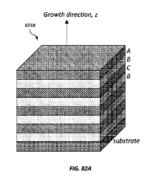
別の形態では、所定の波長の光を生成することができる発光領域バンドギャップエネルギーを有するように1つまたは複数のエピタキシャル金属酸化物層を選択することは、1つまたは複数のエピタキシャル金属酸化物層を、ユニットセルを形成し成長方向に沿って固定ユニットセル周期で繰り返す2つ以上の金属酸化物の層を含む超格子として形成することを含む。 In another form, selecting one or more epitaxial metal oxide layers to have a light emitting region band gap energy capable of producing light of a predetermined wavelength includes forming one or more epitaxial metal oxide layers as a superlattice including two or more layers of metal oxide that form a unit cell and repeat with a fixed unit cell period along the growth direction.
別の形態では、超格子は、2つの異なる金属酸化物を含む繰り返し層を含む二層超格子である。 In another form, the superlattice is a bilayer superlattice that includes repeating layers that include two different metal oxides.
別の形態では、2つの異なる金属酸化物は、第1の2元金属酸化物及び第2の2元金属酸化物を含む。 In another embodiment, the two different metal oxides include a first binary metal oxide and a second binary metal oxide.
別の形態では、第1の2元金属酸化物はAl2O3であり、第2の2元金属酸化物はGa2O3である。 In another form, the first binary metal oxide is Al2O3 and the second binary metal oxide is Ga2O3 .
別の形態では、第1の2元金属酸化物はNiOであり、第2の2元金属酸化物はGa2O3である。 In another form, the first binary metal oxide is NiO and the second binary metal oxide is Ga2O3 .
別の形態では、第1の2元金属酸化物はMgOであり、第2の2元金属酸化物はNiOである。 In another embodiment, the first binary metal oxide is MgO and the second binary metal oxide is NiO.
別の形態では、第1の2元金属酸化物は、Al2O3、Ga2O3、MgO、NiO、LiO2、ZnO、SiO2、GeO2、Er2O3、Gd2O3、PdO、Bi2O3及びIrO2からなる群から選択され、第2の2元金属酸化物は、第1の選択された2元金属酸化物がない、Al2O3、Ga2O3、MgO、NiO、LiO2、ZnO、SiO2、GeO2、Er2O3、Gd2O3、PdO、Bi2O3及びIrO2からなる群から選択される。 In another aspect, the first binary metal oxide is selected from the group consisting of Al2O3, Ga2O3 , MgO , NiO, LiO2 , ZnO, SiO2, GeO2 , Er2O3 , Gd2O3 , PdO, Bi2O3 , and IrO2 , and the second binary metal oxide is selected from the group consisting of Al2O3 , Ga2O3 , MgO, NiO, LiO2 , ZnO, SiO2 , GeO2, Er2O3, Gd2O3, PdO, Bi2O3 , and IrO2 , absent the first selected binary metal oxide .
別の形態では、2つの異なる金属酸化物は、2元金属酸化物及び3元金属酸化物を含む。 In another embodiment, the two different metal oxides include a binary metal oxide and a ternary metal oxide.
別の形態では、2元金属酸化物はGa2O3であり、3元金属酸化物は(AlxGa1-x)2O3であり、式中0<x<1.0である。 In another form, the binary metal oxide is Ga 2 O 3 and the ternary metal oxide is (Al x Ga 1-x ) 2 O 3 , where 0<x<1.0.
別の形態では、2元金属酸化物はGa2O3であり、3元金属酸化物はAlxGa1-xO3であり、式中0<x<1.0である。 In another form, the binary metal oxide is Ga 2 O 3 and the ternary metal oxide is Al x Ga 1-x O 3 , where 0<x<1.0.
別の形態では、2元金属酸化物はGa2O3であり、3元金属酸化物はMgxGa2(1-x)O3-2xであり、式中0<x<1.0である。 In another form, the binary metal oxide is Ga 2 O 3 and the ternary metal oxide is Mg x Ga 2(1-x) O 3-2x , where 0<x<1.0.
別の形態では、2元金属酸化物はAl2O3であり、3元金属酸化物は(AlxGa1-x)2O3であり、式中0<x<1.0である。 In another form, the binary metal oxide is Al 2 O 3 and the ternary metal oxide is (Al x Ga 1-x ) 2 O 3 , where 0<x<1.0.
別の形態では、2元金属酸化物はAl2O3であり、3元金属酸化物はAlxGa1-xO3であり、式中0<x<1.0である。 In another form, the binary metal oxide is Al 2 O 3 and the ternary metal oxide is Al x Ga 1-x O 3 , where 0<x<1.0.
別の形態では、2元金属酸化物はAl2O3であり、3元金属酸化物は(AlxEr1-x)2O3である。 In another form, the binary metal oxide is Al 2 O 3 and the ternary metal oxide is (Al x Er 1-x ) 2 O 3 .
別の形態では、3元金属酸化物は、(Ga2xNi1-x)O2x+1、(Al2xNi1-x)O2x+1、(Al2xMg1-x)O2x+1、(Ga2xMg1-x)O2x+1、(Al2xZn1-x)O2x+1、(Ga2xZn1-x)O2x+1、(GaxBi1-x)2O3、(AlxBi1-x)2O3、(Al2xGe1-x)O2+x、(Ga2xGe1-x)O2+x、(AlxIr1-x)2O3、(GaxIr1-x)2O3、(GaxRE1-x)O3、(AlxRE1-x)O3、(Al2xLi2(1-x))O2x+1及び(Ga2xLi2(1-x))O2x+1からなる群から選択され、式中0<x<1.0である。
In another aspect, the ternary metal oxide is ( Ga2xNi1 -x ) O2x+1 , ( Al2xNi1 -x ) O2x +1 , ( Al2xMg1 - x ) O2x +1 , ( Ga2xMg1-x )O2x + 1 , ( Al2xZn1 -x )
別の形態では、2元金属酸化物は、Al2O3、Ga2O3、MgO、NiO、LiO2、ZnO、SiO2、GeO2、Er2O3、Gd2O3、PdO、Bi2O3及びIrO2からなる群から選択される。 In another embodiment, the binary metal oxide is selected from the group consisting of Al2O3, Ga2O3 , MgO , NiO , LiO2 , ZnO, SiO2 , GeO2 , Er2O3 , Gd2O3 , PdO , Bi2O3 , and IrO2 .
別の形態では、2つの異なる金属酸化物は、第1の3元金属酸化物及び第2の3元金属酸化物を含む。 In another embodiment, the two different metal oxides include a first ternary metal oxide and a second ternary metal oxide.
別の形態では、第1の3元金属酸化物はAlxGa1-xOであり、第2の3元金属酸化物は(AlxGa1-x)2O3またはAlyGa1-yO3であり、式中0<x<1及び0<y<1である。 In another form, the first ternary metal oxide is Al x Ga 1-x O and the second ternary metal oxide is (Al x Ga 1-x ) 2 O 3 or Al y Ga 1-y O 3 , where 0<x<1 and 0<y<1.
別の形態では、第1の3元金属酸化物は(AlxGa1-x)O3であり、第2の3元金属酸化物は(AlyGa1-y)O3であり、式中0<x<1及び0<y<1である。 In another form, the first ternary metal oxide is (Al x Ga 1-x )O 3 and the second ternary metal oxide is (Al y Ga 1-y ) O 3 , where 0<x<1 and 0<y<1.
別の形態では、第1の3元金属酸化物は、(Ga2xNi1-x)O2x+1、(Al2xNi1-x)O2x+1、(Al2xMg1-x)O2x+1、(Ga2xMg1-x)O2x+1、(Al2xZn1-x)O2x+1、(Ga2xZn1-x)O2x+1、(GaxBi1-x)2O3、(AlxBi1-x)2O3、(Al2xGe1-x)O2+x、(Ga2xGe1-x)O2+x、(AlxIr1-x)2O3、(GaxIr1-x)2O3、(GaxRE1-x)O3、(AlxRE1-x)O3、(Al2xLi2(1-x))O2x+1及び(Ga2xLi2(1-x))O2x+1からなる群から選択され、第2の3元金属酸化物は、第1の選択された3元金属酸化物がない、(Ga2xNi1-x)O2x+1、(Al2xNi1-x)O2x+1、(Al2xMg1-x)O2x+1、(Ga2xMg1-x)O2x+1、(Al2xZn1-x)O2x+1、(Ga2xZn1-x)O2x+1、(GaxBi1-x)2O3、(AlxBi1-x)2O3、(Al2xGe1-x)O2+x、(Ga2xGe1-x)O2+x、(AlxIr1-x)2O3、(GaxIr1-x)2O3、(GaxRE1-x)O3、(AlxRE1-x)O3、(Al2xLi2(1-x))O2x+1、及び(Ga2xLi2(1-x))O2x+1からなる群から選択され、式中0<x<1.0である。 In another aspect, the first ternary metal oxide is ( Ga2xNi1 -x ) O2x+1 , ( Al2xNi1 -x )O2x+ 1 , (Al2xMg1- x ) O2x+1 , (Ga2xMg1-x)O2x + 1 , ( Al2xZn1 - x ) O2x +1, ( Ga2xZn1 - x )O2x + 1 , ( GaxBi1 - x ) 2O3 , ( AlxBi1 -x)2O3 , (Al2xGe1- x ) O2+x , ( Ga2xGe1 - x )O2 +x , ( AlxIr1 -x ) 2 O 3 , (Ga x Ir 1-x ) 2 O 3 , (Ga x RE 1-x ) O 3 , (Al x RE 1-x ) O 3 , (Al 2 x Li 2(1-x) ) O 2x+1 and (Ga 2 x Li 2(1-x) ) O 2x+1 , and the second ternary metal oxide is selected from the group consisting of (Ga 2 x Ni 1 -x ) O 2x+1 , (Al 2 x Ni 1-x ) O 2x+1 , (Al 2 x Mg 1-x ) O 2x+1 , (Ga 2 x Mg 1-x ) O 2x+1 , (Al 2 x Zn 1-x )O 2x+1 , (Ga 2x Zn 1-x )O 2x+1 , (Ga x Bi 1-x ) 2 O 3 , (Al x Bi 1-x ) 2 O 3 , (Al 2x Ge 1-x )O 2+x , (Ga 2x Ge 1-x )O 2+x , (Al x Ir 1-x ) 2 O 3 , (Ga x Ir 1-x ) 2 O 3 , (Ga x RE 1-x )O 3 , (Al x RE 1-x )O 3 , (Al 2x Li 2(1-x) )O 2x+1 , and (Ga 2x Li 2(1-x) )O 2x+1 , where 0<x<1.0.
別の形態では、超格子は、3つの異なる金属酸化物の繰り返し層を含む3層超格子である。 In another form, the superlattice is a three-layer superlattice that includes repeating layers of three different metal oxides.
別の形態では、3つの異なる金属酸化物は、第1の2元金属酸化物、第2の2元金属酸化物及び第3の2元金属酸化物を含む。 In another embodiment, the three different metal oxides include a first binary metal oxide, a second binary metal oxide, and a third binary metal oxide.
別の形態では、第1の2元金属酸化物はMgOであり、第2の2元金属酸化物はNiOであり、第3の2元金属酸化物はGa2O3である。 In another form, the first binary metal oxide is MgO, the second binary metal oxide is NiO, and the third binary metal oxide is Ga2O3 .
別の形態では、第1の2元金属酸化物は、Al2O3、Ga2O3、MgO、NiO、LiO2、ZnO、SiO2、GeO2、Er2O3、Gd2O3、PdO、Bi2O3及びIrO2、からなる群から選択され、第2の2元金属酸化物は、第1の選択された2元金属酸化物がない、Al2O3、Ga2O3、MgO、NiO、LiO2、ZnO、SiO2、GeO2、Er2O3、Gd2O3、PdO、Bi2O3及びIrO2からなる群から選択され、第3の2元金属酸化物は、第1及び第2の選択された2元金属酸化物がない、Al2O3、Ga2O3、MgO、NiO、LiO2、ZnO、SiO2、GeO2、Er2O3、Gd2O3、PdO、Bi2O3及びIrO2からなる群から選択される。 In another aspect, the first binary metal oxide is selected from the group consisting of Al2O3, Ga2O3 , MgO , NiO , LiO2 , ZnO, SiO2, GeO2 , Er2O3, Gd2O3 , PdO, Bi2O3 , and IrO2 , the second binary metal oxide is free of the first selected binary metal oxide , Al2O3 , Ga2O3 , MgO, NiO, LiO2 , ZnO, SiO2 , GeO2 , Er2O3 , Gd2O3 , PdO , Bi2O3 , and IrO2 , and the third binary metal oxide is free of the first and second selected binary metal oxides, Al 2O3 , Ga2O3 , MgO, NiO, LiO2 , ZnO , SiO2 , GeO2 , Er2O3 , Gd2O3 , PdO, Bi2O3 and IrO2 .
別の形態では、3つの異なる金属酸化物は、第1の2元金属酸化物、第2の2元金属酸化物及び3元金属酸化物を含む。 In another embodiment, the three different metal oxides include a first binary metal oxide, a second binary metal oxide, and a ternary metal oxide.
別の形態では、第1の2元金属酸化物は、Al2O3、Ga2O3、MgO、NiO、LiO2、ZnO、SiO2、GeO2、Er2O3、Gd2O3、PdO、Bi2O3及びIrO2からなる群から選択され、第2の2元金属酸化物は、第1の選択された2元金属酸化物がない、Al2O3、Ga2O3、MgO、NiO、LiO2、ZnO、SiO2、GeO2、Er2O3、Gd2O3、PdO、Bi2O3及びIrO2からなる群から選択され、3元金属酸化物は、(Ga2xNi1-x)O2x+1、(Al2xNi1-x)O2x+1、(Al2xMg1-x)O2x+1、(Ga2xMg1-x)O2x+1、(Al2xZn1-x)O2x+1、(Ga2xZn1-x)O2x+1、(GaxBi1-x)2O3、(AlxBi1-x)2O3、(Al2xGe1-x)O2+x、(Ga2xGe1-x)O2+x、(AlxIr1-x)2O3、(GaxIr1-x)2O3、(GaxRE1-x)O3、(AlxRE1-x)O3、(Al2xLi2(1-x))O2x+1及び(Ga2xLi2(1-x))O2x+1からなる群から選択され、式中0<x<1である。 In another aspect, the first binary metal oxide is selected from the group consisting of Al2O3, Ga2O3 , MgO , NiO, LiO2 , ZnO, SiO2, GeO2 , Er2O3 , Gd2O3 , PdO , Bi2O3 , and IrO2 , the second binary metal oxide is selected from the group consisting of Al2O3 , Ga2O3 , MgO, NiO, LiO2 , ZnO , SiO2, GeO2 , Er2O3 , Gd2O3 , PdO, Bi2O3 , and IrO2 , the absence of the first selected binary metal oxide, and the ternary metal oxide is ( Ga2xNi1 -x ) O 2x+1 , (Al 2x Ni 1-x )O 2x+1 , (Al 2x Mg 1-x )O 2x+1 , (Ga 2x Mg 1-x )O 2x+1 , (Al 2x Zn 1-x )O 2x+1 , (Ga 2x Zn 1-x )O 2x+1 , (Ga x Bi 1-x ) 2 O 3 , (Al x Bi 1-x ) 2 O 3 , (Al 2x Ge 1-x )O 2+x , (Ga 2x Ge 1-x )O 2+x , (Al x Ir 1-x ) 2 O 3 , (Ga x Ir 1-x ) 2 O 3 , (Ga x RE 1-x )O 3 , (Al x RE 1-x )O 3 , (Al 2 x Li 2(1-x) )O 2x+1 and (Ga 2 x Li 2(1-x) )O 2x+1 , where 0<x<1.
別の形態では、3つの異なる金属酸化物は、2元金属酸化物、第1の3元金属酸化物及び第2の3元金属酸化物を含む。 In another embodiment, the three different metal oxides include a binary metal oxide, a first ternary metal oxide, and a second ternary metal oxide.
別の形態では、2元金属酸化物は、Al2O3、Ga2O3、MgO、NiO、LiO2、ZnO、SiO2、GeO2、Er2O3、Gd2O3、PdO、Bi2O3及びIrO2からなる群から選択され、第1の3元金属酸化物は(Ga2xNi1-x)O2x+1、(Al2xNi1-x)O2x+1、(Al2xMg1-x)O2x+1、(Ga2xMg1-x)O2x+1、(Al2xZn1-x)O2x+1、(Ga2xZn1-x)O2x+1、(GaxBi1-x)2O3、(AlxBi1-x)2O3、(Al2xGe1-x)O2+x、(Ga2xGe1-x)O2+x、(AlxIr1-x)2O3、(GaxIr1-x)2O3、(GaxRE1-x)O3、(AlxRE1-x)O3、(Al2xLi2(1-x))O2x+1及び(Ga2xLi2(1-x))O2x+1からなる群から選択され、第2の3元金属酸化物は、第1の選択された3元金属酸化物がない、(Ga2xNi1-x)O2x+1、(Al2xNi1-x)O2x+1、(Al2xMg1-x)O2x+1、(Ga2xMg1-x)O2x+1、(Al2xZn1-x)O2x+1、(Ga2xZn1-x)O2x+1、(GaxBi1-x)2O3、(AlxBi1-x)2O3、(Al2xGe1-x)O2+x、(Ga2xGe1-x)O2+x、(AlxIr1-x)2O3、(GaxIr1-x)2O3、(GaxRE1-x)O3、(AlxRE1-x)O3、(Al2xLi2(1-x))O2x+1及び(Ga2xLi2(1-x))O2x+1からなる群から選択され、式中0<x<1である。 In another embodiment, the binary metal oxide is selected from the group consisting of Al2O3 , Ga2O3 , MgO, NiO, LiO2 , ZnO, SiO2, GeO2 , Er2O3 , Gd2O3 , PdO , Bi2O3 , and IrO2 , and the first ternary metal oxide is ( Ga2xNi1 -x )O2x + 1 , (Al2xNi1 -x ) O2x+ 1 , ( Al2xMg1 - x)O2x +1, (Ga2xMg1-x)O2x+1, (Al2xZn1-x)O2x + 1 , ( Ga2xZn1 - x ) O2x+1. , (Ga x Bi 1-x ) 2 O 3 , (Al x Bi 1-x ) 2 O 3 , (Al 2 x Ge 1-x ) O 2+x , (Ga 2 x Ge 1-x ) O 2+x , (Al x Ir 1-x ) 2 O 3 , (Ga x Ir 1-x ) 2 O 3 , (Ga x RE 1-x ) O 3 , (Al x RE 1-x ) O 3 , (Al 2 x Li 2(1-x) ) O 2x+1 and (Ga 2 x Li 2(1-x) ) O 2x+1 , wherein the second ternary metal oxide is free of the first selected ternary metal oxide, (Ga 2x Ni 1-x )O 2x+1 , (Al 2x Ni 1-x )O 2x +1 , (Al 2x Mg 1-x )O 2x+1 , (Ga 2x Mg 1-x )O 2x+1 , (Al 2x Zn 1-x )O 2x+1 , (Ga 2x Zn 1-x )O 2x+1 , (Ga x Bi 1-x ) 2 O 3 , (Al x Bi 1-x ) 2 O 3 , (Al 2x Ge 1-x )O 2+x , (Ga 2x Ge 1-x )O 2+x , (Al x Ir 1-x ) 2 O 3 , (Ga x and selected from the group consisting of (Ir1 -x ) 2O3 , ( GaxRE1 -x ) O3 , (AlxRE1- x ) O3 , ( Al2xLi2 ( 1 -x) ) O2x+1 and ( Ga2xLi2 (1-x) ) O2x+1 , where 0<x<1.
別の形態では、3つの異なる金属酸化物は、第1の3元金属酸化物、第2の3元金属酸化物及び第3の3元金属酸化物を含む。 In another embodiment, the three different metal oxides include a first ternary metal oxide, a second ternary metal oxide, and a third ternary metal oxide.
別の形態では、第1の3元金属酸化物は、(Ga2xNi1-x)O2x+1、(Al2xNi1-x)O2x+1、(Al2xMg1-x)O2x+1、(Ga2xMg1-x)O2x+1、(Al2xZn1-x)O2x+1、(Ga2xZn1-x)O2x+1、(GaxBi1-x)2O3、(AlxBi1-x)2O3、(Al2xGe1-x)O2+x、(Ga2xGe1-x)O2+x、(AlxIr1-x)2O3、(GaxIr1-x)2O3、(GaxRE1-x)O3、(AlxRE1-x)O3、(Al2xLi2(1-x))O2x+1及び(Ga2xLi2(1-x))O2x+1からなる群から選択され、第2の3元金属酸化物は、第1の選択された3元金属酸化物がない、(Ga2xNi1-x)O2x+1、(Al2xNi1-x)O2x+1、(Al2xMg1-x)O2x+1、(Ga2xMg1-x)O2x+1、(Al2xZn1-x)O2x+1、(Ga2xZn1-x)O2x+1、(Gax.Bi1-x)2O3、(AlxBi1-x)2O3、(Al2xGe1-x)O2+x、(Ga2xGe1-x)O2+x、(AlxIr1-x)2O3、(GaxIr1-x)2O3、(GaxRE1-x)O3、(AlxRE1-x)O3、(Al2xLi2(1-x))O2x+1及び(Ga2xLi2(1-x))O2x+1からなる群から選択され、第3の3元金属酸化物は、第1及び第2の選択された3元金属酸化物がない、(Ga2xNi1-x)O2x+1、(Al2xNi1-x)O2x+1、(Al2xMg1-x)O2x+1、(Ga2xMg1-x)O2x+1、(Al2xZn1-x)O2x+1、(Ga2xZn1-x)O2x+1、(GaxBi1-x)2O3、(AlxBi1-x)2O3、(Al2xGe1-x)O2+x、(Ga2xGe1-x)O2+x、(AlxIr1-x)2O3、(GaxIr1-x)2O3、(GaxRE1-x)O3、(AlxRE1-x)O3、(Al2xLi2(1-x))O2x+1及び(Ga2xLi2(1-x))O2x+1からなる群から選択され、式中0<x<1である。 In another aspect, the first ternary metal oxide is ( Ga2xNi1 -x ) O2x+1 , ( Al2xNi1 -x )O2x+ 1 , (Al2xMg1- x ) O2x+1 , (Ga2xMg1-x)O2x + 1 , ( Al2xZn1 - x ) O2x +1, ( Ga2xZn1 - x )O2x + 1 , ( GaxBi1 - x) 2O3 , ( AlxBi1 -x )2O3 , (Al2xGe1- x ) O2+x , ( Ga2xGe1 - x )O2 +x , ( AlxIr1 -x ) 2 O 3 , (Ga x Ir 1-x ) 2 O 3 , (Ga x RE 1-x ) O 3 , (Al x RE 1-x ) O 3 , (Al 2 x Li 2(1-x) ) O 2x+1 and (Ga 2 x Li 2(1-x) ) O 2x+1 , and the second ternary metal oxide is selected from the group consisting of (Ga 2 x Ni 1 -x ) O 2x+1 , (Al 2 x Ni 1-x ) O 2x+1 , (Al 2 x Mg 1-x ) O 2x+1 , (Ga 2 x Mg 1-x ) O 2x+1 , (Al 2 x Zn 1-x )O 2x+1 , (Ga 2x Zn 1-x )O 2x+1 , (Ga x .Bi 1-x ) 2 O 3 , (Al x Bi 1-x ) 2 O 3 , (Al 2x Ge 1-x )O 2+x , (Ga 2x Ge 1-x )O 2+x , (Al x Ir 1-x ) 2 O 3 , (Ga x Ir 1-x ) 2 O 3 , (Ga x RE 1-x )O 3 , (Al x RE 1-x )O 3 , (Al 2x Li 2(1-x) )O 2x+1 and (Ga 2x Li 2(1-x) )O 2x+1 , and the third ternary metal oxide is free of the first and second selected ternary metal oxides, ( Ga2xNi1 -x ) O2x+1 , ( Al2xNi1 - x )O2x +1 , (Al2xMg1- x )O2x + 1 , ( Ga2xMg1-x )O2x + 1 , ( Al2xZn1 -x ) O2x +1, ( Ga2xZn1 -x)O2x+ 1, (GaxBi1-x)2O3 , ( AlxBi1 - x ) 2O3, (Al2xGe1- x ) O2+x , ( Ga2xGe1 -x )O2 +x , ( AlxIr1 -x ) 2O3 , ( GaxIr1-x)2O3 , ( GaxRE1 -x ) O3 , (AlxRE1-x) O3 , ( Al2xLi2 (1-x) ) O2x+1 and ( Ga2xLi2 ( 1 -x) ) O2x+1 , where 0<x<1.
別の形態では、超格子は、少なくとも3つの異なる金属酸化物の繰り返し層を含む4層超格子である。 In another embodiment, the superlattice is a four-layer superlattice that includes repeating layers of at least three different metal oxides.
別の形態では、超格子は、3つの異なる金属酸化物の繰り返し層を含む4層超格子であり、3つの異なる金属酸化物の選択された金属酸化物層が4層超格子で繰り返される。 In another form, the superlattice is a four-layer superlattice that includes repeating layers of three different metal oxides, where selected metal oxide layers of the three different metal oxides are repeated in the four-layer superlattice.
別の形態では、3つの異なる金属酸化物は、第1の2元金属酸化物、第2の2元金属酸化物及び第3の2元金属酸化物を含む。 In another embodiment, the three different metal oxides include a first binary metal oxide, a second binary metal oxide, and a third binary metal oxide.
別の形態では、第1の2元金属酸化物はMgOであり、第2の2元金属酸化物はNiOであり、第3の2元金属酸化物は、MgO-Ga2O3-NiO-Ga2O3層を含む4層超格子を形成するGa2O3である。 In another form, the first binary metal oxide is MgO, the second binary metal oxide is NiO, and the third binary metal oxide is Ga 2 O 3 forming a four-layer superlattice including MgO—Ga 2 O 3 —NiO—Ga 2 O 3 layers.
別の形態では、3つの異なる金属酸化物は、Al2O3、Ga2O3、MgO、NiO、LiO2、ZnO、SiO2、GeO2、Er2O3、Gd2O3、PdO、Bi2O3、IrO2、(Ga2xNi1-x)O2x+1、(Al2xNi1-x)O2x+1、(Al2xMg1-x)O2x+1、(Ga2xMg1-x)O2x+1、(Al2xZn1-x)O2x+1、(Ga2xZn1-x)O2x+1、(GaxBi1-x)2O3、(AlxBi1-x)2O3、(Al2xGe1-x)O2+x、(Ga2xGe1-x)O2+x、(AlxIr1-x)2O3、(GaxIr1-x)2O3、(GaxRE1-x)O3、(AlxRE1-x)O3、(Al2xLi2(1-x))O2x+1及び(Ga2xLi2(1-x))O2x+1からなる群から選択され、式中0<x<1.0である。 In another embodiment, the three different metal oxides are Al2O3 , Ga2O3 , MgO, NiO , LiO2 , ZnO, SiO2, GeO2 , Er2O3 , Gd2O3 , PdO, Bi2O3 , IrO2 , ( Ga2xNi1 -x ) O2x+1, (Al2xNi1-x)O2x+1, (Al2xMg1-x)O2x+ 1 , ( Ga2xMg1 -x)O2x + 1 , ( Al2xZn1 - x ) O2x+1 , ( Ga2xZn1 -x ) O2x+1 , ( GaxBi and ( Ga2xLi2 ( 1 - x ) ) O2x + 1 , where 0 < x < 1.0 .
別の形態では、超格子は、4つの異なる金属酸化物の繰り返し層を含む4層超格子である。 In another form, the superlattice is a four-layer superlattice that includes repeating layers of four different metal oxides.
別の形態では、4つの異なる金属酸化物は、Al2O3、Ga2O3、MgO、NiO、LiO2、ZnO、SiO2、GeO2、Er2O3、Gd2O3、PdO、Bi2O3、IrO2、(Ga2xNi1-x)O2x+1、(Al2xNi1-x)O2x+1、(Al2xMg1-x)O2x+1、(Ga2xMg1-x)O2x+1、(Al2xZn1-x)O2x+1、(Ga2xZn1-x)O2x+1、(GaxBi1-x)2O3、(AlxBi1-x)2O3、(Al2xGe1-x)O2+x、(Ga2xGe1-x)O2+x、(AlxIr1-x)2O3、(GaxIr1-x)2O3、(GaxRE1-x)O3、(AlxRE1-x)O3、(Al2xLi2(1-x))O2x+1及び(Ga2xLi2(1-x))O2x+1からなる群から選択され、式中0<x<1.0である。 In another embodiment, the four different metal oxides are Al2O3 , Ga2O3 , MgO, NiO , LiO2 , ZnO, SiO2, GeO2 , Er2O3 , Gd2O3 , PdO, Bi2O3 , IrO2 , ( Ga2xNi1 -x ) O2x+1, (Al2xNi1-x)O2x+1, (Al2xMg1-x)O2x+ 1 , ( Ga2xMg1 -x)O2x + 1 , ( Al2xZn1 - x ) O2x+1 , ( Ga2xZn1 -x ) O2x+1 , ( GaxBi and ( Ga2xLi2 ( 1 - x ) ) O2x + 1 , where 0 < x < 1.0 .
別の形態では、超格子のユニットセルを形成する2つ以上の金属酸化物層のそれぞれの個々の層は、そのそれぞれの個々の層における電子ドブロイ波長未満であるかまたはそれにほぼ等しい厚さを有する。 In another form, each individual layer of the two or more metal oxide layers forming a unit cell of the superlattice has a thickness that is less than or approximately equal to the electron de Broglie wavelength in that each individual layer.
別の形態では、所定の波長の光を生成するための発光領域バンド構造を構成することは、オプトエレクトロニクスデバイスを形成する際に、1つまたは複数のエピタキシャル金属酸化物層の初期発光領域バンド構造を改質することを含む。 In another form, configuring the light emitting region band structure to generate light of a predetermined wavelength includes modifying an initial light emitting region band structure of one or more epitaxial metal oxide layers during formation of the optoelectronic device.
別の形態では、オプトエレクトロニクスデバイスを形成する際に1つまたは複数のエピタキシャル金属酸化物層の初期発光領域バンド構造を改質することは、1つまたは複数のエピタキシャル金属酸化物層のエピタキシャル堆積中に、1つまたは複数のエピタキシャル金属酸化物層に所定の歪みを導入することを含む。 In another form, modifying an initial light-emitting region band structure of one or more epitaxial metal oxide layers in forming an optoelectronic device includes introducing a predetermined strain into the one or more epitaxial metal oxide layers during epitaxial deposition of the one or more epitaxial metal oxide layers.
別の形態では、所定の歪みが導入されて、初期発光領域バンド構造を間接バンドギャップから直接バンドギャップに改質する。 In another embodiment, a predetermined strain is introduced to modify the initial emission region band structure from an indirect band gap to a direct band gap.
別の形態では、所定の歪みが導入されて、初期発光領域バンド構造の初期バンドギャップエネルギーを改質する。 In another embodiment, a predetermined strain is introduced to modify the initial band gap energy of the initial emission region band structure.
別の形態では、所定の歪みが導入されて、初期発光領域バンド構造の初期価電子バンド構造を改質する。 In another embodiment, a predetermined strain is introduced to modify the initial valence band structure of the initial emission region band structure.
別の形態では、初期価電子バンド構造を改質することは、発光領域のフェルミエネルギーレベルに対して選択された価電子バンドを上昇または低下させることを含む。 In another embodiment, modifying the initial valence band structure includes raising or lowering a selected valence band relative to the Fermi energy level of the light emitting region.
別の形態では、初期価電子バンド構造を改質することは、価電子バンド構造の形状を改質して、発光領域に形成される正孔の局在化特性を改質することを含む。 In another embodiment, modifying the initial valence band structure includes modifying the shape of the valence band structure to modify the localization characteristics of holes formed in the light emitting region.
別の形態では、1つまたは複数のエピタキシャル金属酸化物層に所定の歪みを導入することは、下地層組成及び結晶対称型を有する下地層上にエピタキシャルに形成されたときに、被歪み金属酸化物層に所定の歪みを導入する、組成及び結晶対称型を有する被歪み金属酸化物層を選択することを含む。 In another form, introducing the predetermined strain into the one or more epitaxial metal oxide layers includes selecting a strained metal oxide layer having a composition and crystal symmetry type that, when epitaxially formed on an underlayer having the underlayer composition and crystal symmetry type, introduces the predetermined strain into the strained metal oxide layer.
別の形態では、所定の歪みは2軸歪みである。 In another embodiment, the predetermined strain is a biaxial strain.
別の形態では、下地層は、第1の結晶対称型を有する金属酸化物であり、被歪み金属酸化物層も第1の結晶対称型を有するが、被歪み金属酸化物層に2軸歪みを導入するために異なる格子定数を有する。 In another embodiment, the underlayer is a metal oxide having a first crystal symmetry type and the strained metal oxide layer also has the first crystal symmetry type but has a different lattice constant to introduce biaxial strain into the strained metal oxide layer.
別の形態では、金属酸化物の下地層はGa2O3であり、被歪み金属酸化物層はAl2O3であり、2軸圧縮はAl2O3層に導入される。 In another form, the metal oxide underlayer is Ga2O3 , the strained metal oxide layer is Al2O3 , and biaxial compression is induced in the Al2O3 layer .
金属酸化物の下地層はAl2O3であり、被歪み金属酸化物層はGa2O3であり、2軸張力がGa2O3層に導入される。 The metal oxide underlayer is Al2O3 , the strained metal oxide layer is Ga2O3 , and a biaxial tension is introduced into the Ga2O3 layer .
別の形態では、所定の歪みは1軸歪みである。 In another embodiment, the predetermined strain is a uniaxial strain.
別の形態では、下地層は、非対称ユニットセルを有する第1の結晶対称型を有する。 In another embodiment, the underlayer has a first crystal symmetry type having an asymmetric unit cell.
別の形態では、被歪み金属酸化物層は、単斜晶Ga2O3、AlxGa1-xOまたはAl2O3であり、式中x<0<1である。 In another form, the strained metal oxide layer is monoclinic Ga 2 O 3 , Al x Ga 1-x O, or Al 2 O 3 , where x<0<1.
別の形態では、下地層と歪みを受ける層が超格子の層を形成する。 In another embodiment, the underlayer and the strained layer form a superlattice of layers.
別の形態では、オプトエレクトロニクスデバイスを形成する際に1つまたは複数のエピタキシャル金属酸化物層の初期発光領域バンド構造を改質することは、1つまたは複数のエピタキシャル金属酸化物層のエピタキシャル堆積後に、1つまたは複数のエピタキシャル金属酸化物層に所定の歪みを導入することを含む。 In another form, modifying the initial light emitting region band structure of one or more epitaxial metal oxide layers in forming an optoelectronic device includes introducing a predetermined strain into the one or more epitaxial metal oxide layers after epitaxial deposition of the one or more epitaxial metal oxide layers.
別の形態では、オプトエレクトロニクスデバイスは、発光領域と組み合わせて動作して所定の波長の光を生成するように構成された第1の伝導型領域バンド構造を有する1つまたは複数のエピタキシャル金属酸化物層を含む第1の伝導型領域を備える。 In another form, an optoelectronic device comprises a first conductivity type region including one or more epitaxial metal oxide layers having a first conductivity type region band structure configured to operate in combination with a light emitting region to generate light of a predetermined wavelength.
別の形態では、第1の伝導型領域バンド構造を発光領域と組み合わせて動作して所定の波長の光を生成するように構成することは、発光領域エネルギーバンドギャップより大きい第1の伝導型領域エネルギーバンドギャップを選択することを含む。 In another form, configuring the first conduction type region band structure to operate in combination with the light emitting region to generate light of the predetermined wavelength includes selecting the first conduction type region energy band gap greater than the light emitting region energy band gap.
別の形態では、第1の伝導型領域バンド構造を発光領域と組み合わせて動作して所定の波長の光を生成するように構成することは、間接バンドギャップを有するように第1の伝導型領域を選択することを含む。 In another form, configuring the first conductivity type region band structure to operate in combination with the light emitting region to generate light of the predetermined wavelength includes selecting the first conductivity type region to have an indirect band gap.
別の態様では、第1の伝導型領域バンド構造を構成することは、発光領域に関連して本開示で考慮される原理及び技術に沿った適切な金属酸化物材料または複数材料を選択すること、発光領域に関連して本開示において考慮される原理及び技術に沿った超格子を形成すること、及び/または、発光領域に関連して本開示で考慮される原理及び技術に沿った歪みを適用することによって、第1の伝導型領域バンド構造を改質すること、の1つまたは複数を含む。 In another aspect, configuring the band structure of the first conductivity type region includes one or more of: selecting an appropriate metal oxide material or materials consistent with the principles and techniques contemplated in this disclosure in connection with the light emitting region; forming a superlattice consistent with the principles and techniques contemplated in this disclosure in connection with the light emitting region; and/or modifying the band structure of the first conductivity type region by applying strain consistent with the principles and techniques contemplated in this disclosure in connection with the light emitting region.
別の形態では、第1の伝導型領域はn型領域である。 In another embodiment, the first conductivity type region is an n-type region.
別の形態では、オプトエレクトロニクスデバイスは、発光領域と第1の伝導型領域を組み合わせて動作して所定の波長の光を生成するように構成された第2の伝導型領域バンド構造を有する1つまたは複数のエピタキシャル金属酸化物層を含む第2の伝導型領域を備える。 In another form, an optoelectronic device includes a second conductivity type region including one or more epitaxial metal oxide layers having a second conductivity type region band structure configured to operate in combination with the light emitting region and the first conductivity type region to generate light at a predetermined wavelength.
別の形態では、第2の伝導型領域バンド構造を発光領域と組み合わせて動作して所定の波長の光を生成するように構成することは、発光領域エネルギーバンドギャップより大きい第2の伝導型領域エネルギーバンドギャップを選択することを含む。 In another form, configuring the second conduction type region band structure to operate in combination with the light emitting region to generate light of the predetermined wavelength includes selecting the second conduction type region energy band gap greater than the light emitting region energy band gap.
別の形態では、第2の伝導型領域バンド構造を発光領域と組み合わせて動作して所定の波長の光を生成するように構成することは、間接バンドギャップを有するように第2の伝導型領域を選択することを含む。 In another form, configuring the second conductivity type region band structure to operate in combination with the light emitting region to generate light of the predetermined wavelength includes selecting the second conductivity type region to have an indirect band gap.
別の態様では、第2の伝導型領域バンド構造を構成することは、発光領域に関連して本開示で考慮される原理及び技術に沿った適切な金属酸化物材料または複数の材料を選択すること、発光領域に関連して本開示において考慮される原理及び技術に沿った超格子を形成すること、及び/または、発光領域に関連して本開示で考慮される原理及び技術に沿った歪みを適用することによって、第1の伝導型領域バンド構造を改質すること、の1つまたは複数を含む。 In another aspect, configuring the band structure of the second conductivity type region includes one or more of: selecting an appropriate metal oxide material or materials consistent with the principles and techniques contemplated in this disclosure in connection with the light emitting region; forming a superlattice consistent with the principles and techniques contemplated in this disclosure in connection with the light emitting region; and/or modifying the band structure of the first conductivity type region by applying strain consistent with the principles and techniques contemplated in this disclosure in connection with the light emitting region.
別の形態では、第2の伝導型領域はp型領域である。 In another embodiment, the second conductivity type region is a p-type region.
別の形態では、基板は金属酸化物から形成される。 In another embodiment, the substrate is formed from a metal oxide.
別の形態では、金属酸化物は、Al2O3、Ga2O3、MgO、LiF、MgAl2O4、MgGa2O4、LiGaO2、LiAlO2、(AlxGa1-x)2O3、LaAlO3、TiO2及び石英からなる群から選択される。 In another aspect, the metal oxide is selected from the group consisting of Al2O3 , Ga2O3 , MgO, LiF , MgAl2O4 , MgGa2O4 , LiGaO2 , LiAlO2 , ( AlxGa1 - x ) 2O3 , LaAlO3 , TiO2 , and quartz .
別の形態では、基板は金属フッ化物から形成される。 In another embodiment, the substrate is formed from a metal fluoride.
別の形態では、金属フッ化物はMgF2またはLiFである。 In another form, the metal fluoride is MgF2 or LiF.
別の形態では、所定の波長は、150nm~700nmの波長範囲にある。 In another embodiment, the predetermined wavelength is in the wavelength range of 150 nm to 700 nm.
別の形態では、所定の波長は、150nm~280nmの波長範囲にある。 In another embodiment, the predetermined wavelength is in the wavelength range of 150 nm to 280 nm.
第3の態様では、本開示は、約150nm~約280nmの範囲の波長を有する光を放出するように構成されたオプトエレクトロニクス半導体デバイスを形成する方法を提供し、本方法は、エピタキシャル成長表面を有する金属酸化物基板を提供すること、エピタキシャル成長表面を酸化して、活性化されたエピタキシャル成長表面を形成すること、及び活性化されたエピタキシャル成長表面を、各々が高純度金属原子を含む1つまたは複数の原子ビーム及び酸素原子を含む1つまたは複数の原子ビームに、2つ以上のエピタキシャル金属酸化物膜を堆積させる条件下で暴露すること、を含む。 In a third aspect, the present disclosure provides a method for forming an optoelectronic semiconductor device configured to emit light having a wavelength in a range of about 150 nm to about 280 nm, the method including providing a metal oxide substrate having an epitaxial growth surface, oxidizing the epitaxial growth surface to form an activated epitaxial growth surface, and exposing the activated epitaxial growth surface to one or more atomic beams each containing high purity metal atoms and one or more atomic beams containing oxygen atoms under conditions to deposit two or more epitaxial metal oxide films.
別の形態では、金属酸化物基板は、AlまたはGa金属酸化物基板を含む。 In another embodiment, the metal oxide substrate comprises an Al or Ga metal oxide substrate.
別の形態では、高純度金属原子を各々含む1つまたは複数の原子ビームは、Al、Ga、Mg、Ni、Li、Zn、Si、Ge、Er、Y、La、Pr、Gd、Pd、Bi、Ir、及び前述の金属の任意の組み合わせからなる群から選択される任意の1つまたは複数の金属を含む。 In another form, the one or more atomic beams each comprising high purity metal atoms comprise any one or more metals selected from the group consisting of Al, Ga , Mg, Ni, Li, Zn, Si, Ge, Er, Y, La, Pr, Gd, Pd, Bi, Ir , and any combination of the foregoing metals.
別の形態では、高純度金属原子を各々含む1つまたは複数の原子ビームは、Al及びGaからなる群から選択される任意の1つまたは複数の金属を含み、エピタキシャル金属酸化物膜は、(AlxGa1-x)2O3を含み、式中0≦x≦1である。 In another form, the one or more atomic beams each comprising high purity metal atoms comprise any one or more metals selected from the group consisting of Al and Ga, and the epitaxial metal oxide film comprises (Al x Ga 1-x ) 2 O 3 , where 0≦x≦1.
別の形態では、2つ以上のエピタキシャル金属酸化物膜を堆積するための条件は、活性化されたエピタキシャル成長表面を、高純度金属原子を含む原子ビーム及び酸素原子を含む原子ビームに、酸素:全金属フラックス比>1で暴露することを含む。 In another form, the conditions for depositing two or more epitaxial metal oxide films include exposing the activated epitaxial growth surface to an atomic beam containing high purity metal atoms and an atomic beam containing oxygen atoms, with an oxygen:total metal flux ratio >1.
別の形態では、2つ以上のエピタキシャル金属酸化物膜の少なくとも1つは、1つまたは複数のエピタキシャル金属酸化物層を含む第1の伝導型領域を提供し、2つ以上のエピタキシャル金属酸化物膜の少なくとも別の膜は、1つまたは複数のエピタキシャル金属酸化物層を含む第2の伝導型領域を提供する。 In another form, at least one of the two or more epitaxial metal oxide films provides a first conductivity type region including one or more epitaxial metal oxide layers, and at least another of the two or more epitaxial metal oxide films provides a second conductivity type region including one or more epitaxial metal oxide layers.
別の形態では、2つ以上のエピタキシャル(AlxGa1-x)2O3膜の少なくとも1つは、1つまたは複数のエピタキシャル(AlxGa1-x)2O3層を含む第1の伝導型領域を提供し、2つ以上のエピタキシャル(AlxGa1-x)2O3膜の少なくとも他のものは、1つまたは複数のエピタキシャル(AlxGa1-x)2O3層を含む第2の伝導型領域を提供する。 In another form, at least one of the two or more epitaxial (Al x Ga 1-x ) 2 O 3 films provides a first conductivity type region including one or more epitaxial (Al x Ga 1-x ) 2 O 3 layers, and at least another of the two or more epitaxial (Al x Ga 1-x ) 2 O 3 films provides a second conductivity type region including one or more epitaxial (Al x Ga 1-x ) 2 O 3 layers.
別の形態では、基板は、酸化ステップの前に、超高真空チャンバ(5×10⁻¹⁰Torr未満)内で高温(>800℃)脱着によって処理されて、原子的に平坦なエピタキシャル成長面を形成する。 In another form, the substrate is treated by high temperature (>800° C.) desorption in an ultra-high vacuum chamber (<5 × 10 −10 Torr) prior to the oxidation step to form an atomically flat epitaxial growth surface.
別の形態では、方法は、表面をリアルタイムで監視して原子表面の品質を評価することをさらに含む。 In another aspect, the method further includes monitoring the surface in real time to assess atomic surface quality.
別の形態では、表面は反射高エネルギー電子回折(RHEED)によってリアルタイムで監視される。 In another embodiment, the surface is monitored in real time by reflection high-energy electron diffraction (RHEED).
別の形態では、エピタキシャル成長表面を酸化することは、エピタキシャル成長表面を酸化する条件下で、エピタキシャル成長表面を酸素源に暴露することを含む。 In another form, oxidizing the epitaxial growth surface includes exposing the epitaxial growth surface to an oxygen source under conditions that oxidize the epitaxial growth surface.
別の形態では、酸素源は、酸素プラズマ、オゾン、及び亜酸化窒素からなる群のうちの1つまたは複数から選択される。 In another embodiment, the oxygen source is selected from one or more of the group consisting of oxygen plasma, ozone, and nitrous oxide.
別の形態では、酸素源は高周波誘導結合プラズマ(RF-ICP)である。 In another embodiment, the oxygen source is a radio frequency inductively coupled plasma (RF-ICP).
別の形態では、方法は、表面をリアルタイムで監視して表面の酸素密度を評価することをさらに含む。 In another aspect, the method further includes monitoring the surface in real time to assess the oxygen density of the surface.
別の形態では、表面はRHEEDによってリアルタイムで監視される。 In another embodiment, the surface is monitored in real time by RHEED.
別の形態では、高純度Al原子及び/または高純度Ga原子を含む原子ビームは各々、フィラメントによって放出加熱され、るつぼ内の金属溶融温度を監視するフィードバックセンシングによって制御される不活性セラミックるつぼを含む噴出セルによって提供される。 In another form, atomic beams containing high purity Al atoms and/or high purity Ga atoms are each provided by an effusion cell containing an inert ceramic crucible emitted and heated by a filament and controlled by feedback sensing that monitors the metal melt temperature within the crucible.
別の形態では、純度が6N~7N以上の高純度元素金属が使用される。 In another form, high purity elemental metals with a purity of 6N to 7N or higher are used.
別の形態では、方法は、Al及び/またはGaと酸素原子ビームの各ビームフラックスを測定して相対フラックス比を決定した後で、活性化されたエピタキシャル成長表面を決定された相対フラックス比で原子ビームに暴露することをさらに含む。 In another aspect, the method further includes measuring the beam fluxes of the Al and/or Ga and oxygen atomic beams to determine a relative flux ratio, and then exposing the activated epitaxial growth surface to the atomic beams at the determined relative flux ratio.
別の形態では、方法は、活性化されたエピタキシャル成長表面が原子ビームに暴露されるときに基板を回転させて、所与の堆積時間の間、基板表面と交差する均一な量の原子ビームを蓄積することをさらに含む。 In another form, the method further includes rotating the substrate as the activated epitaxial growth surface is exposed to the atomic beam to accumulate a uniform amount of the atomic beam intersecting the substrate surface for a given deposition time.
別の形態では、方法は、活性化されたエピタキシャル成長表面が原子ビームに暴露されるときに基板を加熱することをさらに含む。 In another aspect, the method further includes heating the substrate as the activated epitaxial growth surface is exposed to the atomic beam.
別の形態では、金属酸化物基板のバンドギャップより下の吸収に適合する黒体放射率を使用して、基板が背後から放出加熱される。 In another form, the substrate is heated emissively from behind, using a blackbody emissivity that matches the absorption below the bandgap of the metal oxide substrate.
別の形態では、活性化されたエピタキシャル成長表面は、約1×10⁻⁶Torr~約1×10⁻⁵Torrの真空中で原子ビームに暴露される。 In another form, the activated epitaxial growth surface is exposed to an atomic beam in a vacuum of about 1×10 −6 Torr to about 1×10 −5 Torr.
別の形態では、基板表面でのAl及びGaの原子ビームフラックスは、約1×10⁻⁸Torr~約1×10⁻⁶Torrである。 In another aspect, the atomic beam flux of Al and Ga at the substrate surface is between about 1×10 −8 Torr and about 1×10 −6 Torr.
別の形態では、基板表面での酸素原子ビームフラックスは、約1×10⁻⁷Torrから約1×10⁻⁵Torrである。 In another aspect, the oxygen atomic beam flux at the substrate surface is from about 1×10 −7 Torr to about 1×10 −5 Torr.
別の形態では、AlまたはGa金属酸化物基板はA面サファイアである。 In another embodiment, the Al or Ga metal oxide substrate is A-plane sapphire.
別の形態では、AlまたはGa金属酸化物基板は単斜晶Ga2O3である。 In another form, the Al or Ga metal oxide substrate is monoclinic Ga2O3 .
別の形態では、2つ以上のエピタキシャル(AlxGa1-x)2O3膜は、コランダム型AlGaO3を含む。 In another form, the two or more epitaxial (Al x Ga 1-x ) 2 O 3 films comprise corundum-type AlGaO 3 .
別の形態では、2つ以上のエピタキシャル(AlxGa1-x)2O3膜の各々についてx≦0.5である。 In another form, x≦0.5 for each of the two or more epitaxial (Al x Ga 1-x ) 2 O 3 films.
第4の態様では、本開示は、第1の結晶対称型及び第1の組成を有する第1の層を形成することと、非平衡環境において、第2の結晶対称型及び第2の組成を有する金属酸化物層を第1の層上に堆積させることであって、第2の層を第1の層上に堆積させることは、第2の結晶対称型を第1の結晶対称型に初期整合させることを含む、堆積させることと、を含む多層半導体デバイスを形成する方法を提供する。 In a fourth aspect, the present disclosure provides a method of forming a multilayer semiconductor device, comprising forming a first layer having a first crystal symmetry type and a first composition, and depositing a metal oxide layer having a second crystal symmetry type and a second composition on the first layer in a non-equilibrium environment, where depositing the second layer on the first layer comprises initially matching the second crystal symmetry type to the first crystal symmetry type.
別の形態では、第2の結晶対称型を第1の結晶対称型に初期整合させることは、水平平面成長界面において第1の結晶対称型の第1の格子配置を第2の結晶対称型の第2の格子配置と整合させることを含む。 In another form, initially matching the second crystal symmetry type to the first crystal symmetry type includes matching a first lattice arrangement of the first crystal symmetry type with a second lattice arrangement of the second crystal symmetry type at a horizontal planar growth interface.
別の形態では、第1及び第2の結晶対称型を整合させることは、第1及び第2の格子配置のそれぞれの端面格子定数を実質的に一致させることを含む。 In another embodiment, matching the first and second crystal symmetry types includes substantially matching the end face lattice constants of the first and second lattice configurations, respectively.
別の形態では、第1の層はコランダムAl2O3(サファイア)であり、金属酸化物層はコランダムGa2O3である。 In another form, the first layer is corundum Al2O3 ( sapphire ) and the metal oxide layer is corundum Ga2O3 .
別の形態では、第1の層は単斜晶Al2O3であり、金属酸化物層は単斜晶Ga2O3である。 In another form the first layer is monoclinic Al2O3 and the metal oxide layer is monoclinic Ga2O3 .
別の形態では、第1の層は、Oリッチ成長条件下で調製されたR面コランダムAl2O3(サファイア)であり、金属酸化物層は、低温(<550℃)で選択的に成長したコランダムAlGaO3である。 In another form, the first layer is R-plane corundum Al2O3 (sapphire) prepared under O -rich growth conditions, and the metal oxide layer is corundum AlGaO3 selectively grown at low temperature (<550°C).
別の形態では、第1の層はM面コランダムAl2O3(サファイア)であり、金属酸化物層はコランダムAlGaO3である。 In another form, the first layer is M - plane corundum Al2O3 (sapphire) and the metal oxide layer is corundum AlGaO3 .
別の形態では、第1の層はA面コランダムAl2O3(サファイア)であり、金属酸化物層はコランダムAlGaO3である。 In another form, the first layer is A-plane corundum Al2O3 (sapphire) and the metal oxide layer is corundum AlGaO3 .
別の形態では、第1の層はコランダムGa2O3であり、金属酸化物層はコランダムAl2O3である。 In another form, the first layer is corundum Ga2O3 and the metal oxide layer is corundum Al2O3 .
別の形態では、第1の層は単斜晶Ga2O3であり、金属酸化物層は単斜晶Al2O3(サファイア)である。 In another form the first layer is monoclinic Ga2O3 and the metal oxide layer is monoclinic Al2O3 (sapphire).
別の形態では、第1の層は(-201)配向の単斜晶Ga2O3であり、金属酸化物層は(-201)配向の単斜晶AlGaO3である。 In another form, the first layer is (-201) oriented monoclinic Ga2O3 and the metal oxide layer is ( -201 ) oriented monoclinic AlGaO3 .
別の形態では、第1の層は(010)配向の単斜晶Ga2O3であり、金属酸化物層は(010)配向の単斜晶AlGaO3である。 In another form, the first layer is (010) oriented monoclinic Ga2O3 and the metal oxide layer is ( 010 ) oriented monoclinic AlGaO3 .
別の形態では、第1の層は(001)配向の単斜晶Ga2O3であり、金属酸化物層は(001)配向の単斜晶AlGaO3である。 In another form, the first layer is (001) oriented monoclinic Ga2O3 and the metal oxide layer is ( 001 ) oriented monoclinic AlGaO3 .
別の形態では、第1及び第2の結晶対称型は異なり、第1及び第2の格子配置を整合させることは、金属酸化物層を再配向して、水平平面成長界面で面内原子配列を実質的に整合させることを含む。 In another embodiment, the first and second crystal symmetry types are different and matching the first and second lattice configurations includes reorienting the metal oxide layer to substantially match in-plane atomic arrangements at the horizontal planar growth interface.
別の形態では、第1の層はC面コランダムAl2O3(サファイア)であり、金属酸化物層は単斜晶、三斜晶または六方晶AlGaO3のいずれか1つである。 In another form, the first layer is C-plane corundum Al2O3 (sapphire) and the metal oxide layer is one of monoclinic, triclinic or hexagonal AlGaO3 .
別の形態では、C面コランダムAl2O3(サファイア)は、Oリッチ成長条件下で調製して、より低い成長温度(<650℃)で六方晶AlGaO3を選択的に成長させる。 In another form, C-plane corundum Al2O3 (sapphire) is prepared under O-rich growth conditions to selectively grow hexagonal AlGaO3 at lower growth temperatures (<650°C).
別の形態では、C面コランダムAl2O3(サファイア)を、Oリッチ成長条件下で調製して、より高い成長温度(>650℃)で、Al%を約45~50%に制限して単斜晶AlGaO3を選択的に成長させる。 In another form, C-plane corundum Al 2 O 3 (sapphire) is prepared under O-rich growth conditions to selectively grow monoclinic AlGaO 3 at higher growth temperatures (>650° C.) with Al % limited to about 45-50%.
別の形態では、R面コランダムAl2O3(サファイア)をOリッチ成長条件下で調製して、成長温度(>700℃)で、Al%を<50%にして単斜晶AlGaO3を選択的に成長させる。 In another form, R-plane corundum Al 2 O 3 (sapphire) is prepared under O-rich growth conditions to selectively grow monoclinic AlGaO 3 with Al%<50% at the growth temperature (>700° C.).
別の形態では、第1の層はA面コランダムAl2O3(サファイア)であり、金属酸化物層は(110)配向の単斜晶Ga2O3である。 In another form, the first layer is A-plane corundum Al2O3 (sapphire) and the metal oxide layer is (110) oriented monoclinic Ga2O3 .
別の形態では、第1の層が(110)配向の単斜晶Ga2O3であり、金属酸化物層がコランダムAlGaO3である。 In another form, the first layer is (110) oriented monoclinic Ga2O3 and the metal oxide layer is corundum AlGaO3 .
別の形態では、第1の層は(010)配向の単斜晶Ga2O3であり、金属酸化物層は(111)配向の立方晶MgGa2O4である。 In another form, the first layer is monoclinic Ga2O3 with a (010) orientation and the metal oxide layer is cubic MgGa2O4 with a (111) orientation.
別の形態では、第1の層は(100)配向の立方晶MgOであり、金属酸化物層は(100)配向の単斜晶AlGaO3である。 In another form, the first layer is (100) oriented cubic MgO and the metal oxide layer is (100) oriented monoclinic AlGaO3 .
第1の層は(100)配向の立方晶NiOであり、金属酸化物層は(100)配向の単斜晶AlGaO3である。 The first layer is (100) oriented cubic NiO and the metal oxide layer is (100) oriented monoclinic AlGaO3 .
別の形態では、第2の結晶対称型を第1の結晶対称型に初期整合させることは、非平衡環境で、第1の層と金属酸化物層の間にバッファ層を堆積させることを含み、バッファ層の結晶対称型は第1の結晶対称型と同じであって、第2の結晶対称型を有する金属酸化物層のシードのために原子的に平らな層を提供する。 In another form, initially matching the second crystal symmetry type to the first crystal symmetry type includes depositing a buffer layer between the first layer and the metal oxide layer in a non-equilibrium environment, the buffer layer having a crystal symmetry type the same as the first crystal symmetry type to provide an atomically flat layer for seeding the metal oxide layer having the second crystal symmetry type.
別の形態では、バッファ層は、金属酸化物層をシードするためのO終端テンプレートを含む。 In another embodiment, the buffer layer includes an O-terminated template for seeding the metal oxide layer.
別の形態では、バッファ層は、金属酸化物層をシードするための金属終端テンプレートを含む。 In another embodiment, the buffer layer includes a metal termination template for seeding the metal oxide layer.
別の形態では、第1及び第2の結晶対称型は、立方晶、六方晶、斜方晶、三方晶、菱形及び単斜晶からなる群から選択される。 In another embodiment, the first and second crystal symmetry types are selected from the group consisting of cubic, hexagonal, orthorhombic, trigonal, rhomboidal, and monoclinic.
別の形態では、第1の層の第1の結晶対称型及び第1の組成、ならびに第2の層の第2の結晶対称型及び第2の組成は、第2の層に所定の歪みを導入するように選択される。 In another form, the first crystal symmetry type and first composition of the first layer and the second crystal symmetry type and second composition of the second layer are selected to introduce a predetermined strain in the second layer.
別の形態では、第1の層は金属酸化物層である。 In another embodiment, the first layer is a metal oxide layer.
別の形態では、第1及び第2の層は、固定ユニットセル周期で繰り返されるユニットセルを形成して、超格子を形成する。 In another embodiment, the first and second layers form unit cells that are repeated with a fixed unit cell period to form a superlattice.
別の形態では、第1及び第2の層は、欠陥のない超格子の形成を容易にするために、実質的に等しいが反対の歪みを有するように構成される。 In another form, the first and second layers are configured to have substantially equal but opposite strains to facilitate the formation of a defect-free superlattice.
別の形態では、方法は、非平衡環境で、第3の結晶対称型及び第3の組成を有する追加の金属酸化物層を金属酸化物層上に堆積させることを含む。 In another aspect, the method includes depositing an additional metal oxide layer having a third crystal symmetry type and a third composition on the metal oxide layer in a non-equilibrium environment.
別の形態では、第3の結晶型は、立方晶、六方晶、斜方晶、三方晶、菱形及び単斜晶からなる群から選択される。 In another embodiment, the third crystal form is selected from the group consisting of cubic, hexagonal, orthorhombic, trigonal, rhomboidal, and monoclinic.
別の形態では、多層半導体デバイスは、所定の波長の光を生成するオプトエレクトロニクス半導体デバイスである。 In another form, the multi-layer semiconductor device is an optoelectronic semiconductor device that generates light at a predetermined wavelength.
別の形態では、所定の波長は、150nm~700nmの波長範囲にある。 In another embodiment, the predetermined wavelength is in the wavelength range of 150 nm to 700 nm.
別の形態では、所定の波長は、150nm~280nmの波長範囲にある。 In another embodiment, the predetermined wavelength is in the wavelength range of 150 nm to 280 nm.
第5の態様では、本開示は、所定の波長の光を生成するオプトエレクトロニクス半導体デバイスを形成する方法を提供し、本方法は、基板を導入することと、非平衡環境において、金属酸化物の1つまたは複数のエピタキシャル層を含む第1の伝導型領域を堆積させることと、非平衡環境において、金属酸化物の1つまたは複数のエピタキシャル層を含み、所定の波長の光を生成するように構成された発光領域バンド構造を含む発光領域を堆積させることと、非平衡環境において、金属酸化物の1つまたは複数のエピタキシャル層を含む第2の伝導型領域を堆積させることと、を含む。 In a fifth aspect, the present disclosure provides a method of forming an optoelectronic semiconductor device that generates light of a predetermined wavelength, the method including: introducing a substrate; depositing, in a non-equilibrium environment, a first conductivity type region including one or more epitaxial layers of a metal oxide; depositing, in a non-equilibrium environment, a light emitting region including one or more epitaxial layers of a metal oxide and including a light emitting region band structure configured to generate light of the predetermined wavelength; and depositing, in a non-equilibrium environment, a second conductivity type region including one or more epitaxial layers of a metal oxide.
別の形態では、所定の波長は、約150nm~約700nmの波長範囲にある。別の形態では、所定の波長は、約150nm~約425nmの波長範囲にある。一例では、約425nmまでの波長を生成するために酸化ビスマスを使用することができる。 In another embodiment, the predetermined wavelength is in a wavelength range of about 150 nm to about 700 nm. In another embodiment, the predetermined wavelength is in a wavelength range of about 150 nm to about 425 nm. In one example, bismuth oxide can be used to produce wavelengths up to about 425 nm.
別の形態では、所定の波長は、約150nm~約280nmの波長範囲にある。 In another embodiment, the predetermined wavelength is in a wavelength range of about 150 nm to about 280 nm.
さらに別の形態では、発光効率は、発光領域の結晶対称型の選択によって制御される。電気双極子発光の光学選択則は、伝導バンドと価電子バンドの状態の対称性、及び結晶対称型によって統制される。点群対称を有する結晶構造を有する発光領域は、反転中心対称または非反転対称のいずれかの特性を有することができる。電気双極子または磁気双極子光学遷移を促進するために結晶対称性を有利に選択することは、発光領域への適用のために本明細書で主張される。逆に、電気双極子または磁気双極子光学遷移を抑制するために結晶対称性を有利に選択することは、デバイスの光学的非吸収領域を促進するためにも可能である。 In yet another embodiment, the light emission efficiency is controlled by the selection of the crystal symmetry type of the light emitting region. The optical selection rules for electric dipole emission are governed by the symmetry of the conduction and valence band states, and the crystal symmetry type. Light emitting regions having crystal structures with point group symmetry can have either inversion centrosymmetry or non-inversion symmetry characteristics. Advantageous selection of crystal symmetry to promote electric dipole or magnetic dipole optical transitions is claimed herein for application to the light emitting region. Conversely, advantageous selection of crystal symmetry to suppress electric dipole or magnetic dipole optical transitions is also possible to promote optically non-absorbing regions of the device.
概要として、図1は、例示的な実施形態によるオプトエレクトロニクス半導体オプトエレクトロニクスデバイスを構築するためのプロセスフロー図である。一例では、オプトエレクトロニクス半導体デバイスはUVLEDであり、さらなる例では、UVLEDは、約150nm~約280nmの波長領域で所定の波長を生成するように構成される。この例では、構築プロセスは、最初に、(i)ステップ10で所望の動作波長(例えば、UVC波長またはより低い波長)を選択し、(ii)ステップ60でデバイスの光学構成(例えば、光出力ベクトルまたは方向がエピ層の平面に対して実質的に垂直である垂直発光デバイス70、または光出力ベクトルがエピ層の平面に対して実質的に平行である導波路デバイス75)を選択することを含む。デバイスの発光特性は、半導体材料20と光学材料30の選択によって部分的に実装される。
In overview, FIG. 1 is a process flow diagram for constructing an optoelectronic semiconductor optoelectronic device according to an exemplary embodiment. In one example, the optoelectronic semiconductor device is a UV LED, and in a further example, the UV LED is configured to generate a predetermined wavelength in the wavelength range of about 150 nm to about 280 nm. In this example, the construction process first involves (i) selecting a desired operating wavelength (e.g., a UVC wavelength or lower) in
UVLEDの例を挙げると、図1に示されるプロセスに従って構築されたオプトエレクトロニクス半導体デバイスは、光子が伝導バンドの電子と価電子バンドの正孔の有利な空間再結合によって生成される選択された発光領域材料35に基づく発光領域を含む。一例では、発光領域は、1つまたは複数の金属酸化物層を含む。
Taking the example of a UV LED, an optoelectronic semiconductor device constructed according to the process shown in FIG. 1 includes a light emitting region based on a selected light emitting
発光領域は、直接バンドギャップ型のバンド構造構成であってもよい。これは、選択された材料(複数可)の固有の特性であり得るか、または本開示の技術の1つまたは複数を使用して調整することができる。光再結合または発光領域は、n型及びp型伝導領域を含む電子及び正孔リザーバによってクラッドされてもよい。n型及びp型伝導領域は、発光領域材料35に比べ大きなバンドギャップを有し得るか、または動作波長での光吸収を制限する間接バンドギャップ構造を含むことができる電子及び正孔注入材料45から選択される。一例では、n型及びp型伝導領域は、1つまたは複数の金属酸化物層から形成される。
The light emitting region may have a direct bandgap band structure configuration. This may be an inherent property of the selected material(s) or may be tailored using one or more of the techniques of this disclosure. The light recombination or light emitting region may be clad by electron and hole reservoirs including n-type and p-type conduction regions. The n-type and p-type conduction regions are selected from electron and
Ga2O3及び低Al%のAlGaO3の不純物ドーピングは、n型及びp型材料の両方に対して可能である。n型ドーピングは、Ga2O3及びAlGaO3に特に好ましいが、p型ドーピングはより困難であるが可能である。n型ドーピングに適した不純物は、Si、Ge、Sn、及び希土類(例えば、エルビウム(Er)及びガドリニウム(Gd))である。共堆積ドーピング制御のためのGeフラックスの使用は、特に適している。III族金属を用いたp型共ドーピングでは、Gaサイトは、マグネシウム(Mg2+)、亜鉛(Zn2+)及び原子状窒素(Oサイトに対するN3-置換)を介して、置換され得る。イリジウム(Ir)、ビスマス(Bi)、ニッケル(Ni)、及びパラジウム(Pd)を使用して、さらに改善することもできる。 Impurity doping of Ga2O3 and low Al% AlGaO3 is possible for both n - type and p-type materials. n-type doping is particularly favorable for Ga2O3 and AlGaO3 , while p-type doping is more difficult but possible. Impurities suitable for n-type doping are Si, Ge, Sn, and rare earths (e.g. erbium (Er) and gadolinium (Gd)). The use of Ge flux for codeposition doping control is particularly suitable. For p-type co-doping with group III metals, the Ga site can be substituted via magnesium (Mg2 + ), zinc (Zn2 + ), and atomic nitrogen (N3 - substitution for O-sites). Further improvements can also be achieved using iridium (Ir), bismuth (Bi), nickel (Ni), and palladium (Pd).
NiO、Bi2O3、Ir2O3及びPdOを使用するデジタル合金もいくつかの実施形態で使用して、Ga2O3ベースの材料におけるp型形成を有利に支援することができる。AlGaO3のp型ドーピングは可能であるが、立方晶結晶対称金属酸化物(例えば、LiドープNiOまたはNi空孔NiOx>1)及びウルツ鉱p型Mg:GaNを用いた代替のドーピング戦略も可能である。 Digital alloys using NiO, Bi2O3 , Ir2O3 , and PdO can also be used in some embodiments to advantageously support p-type formation in Ga2O3 - based materials. Although p-type doping of AlGaO3 is possible, alternative doping strategies using cubic crystal symmetric metal oxides (e.g., Li-doped NiO or Ni-vacancy NiO x>1 ) and wurtzite p-type Mg:GaN are also possible.
さらに別の機会は、AlGaO3に直接統合された六方晶対称の高極性形態及びイプシロン相Ga2O3を形成する能力であり、それによって、米国特許第9,691,938号に記載され参照されている原理及び技術に従って分極ーピングを誘導する。屈折率の差分変化としてデバイス内に光を閉じ込めるのに必要な光学材料30も選択が必要である。遠紫外線または真空紫外線の場合、光学的に透明な材料の選択は、MgOから、MgF2、LiFなどの金属フッ化物にまで及ぶ。本開示によれば、単結晶LiF及びMgO基板がUVLEDの実現に有利であることが見出された。
Yet another opportunity is the ability to form highly polar morphologies of hexagonal symmetry and epsilon phase Ga2O3 directly integrated into AlGaO3 , thereby inducing polarization poling according to the principles and techniques described and referenced in U.S. Pat. No. 9,691,938. The
電子及び正孔インジェクタ領域へのコンタクト部を形成する電気材料50は、仕事関数の低い金属と高い金属からそれぞれ選択される。一例では、金属オーミックコンタクトは、最終的な金属酸化物表面上にその場で直接形成され、その結果、半導体酸化物-金属界面で生じるあらゆる中間レベルのトラップ/欠陥が減少する。次いで、ステップ80でデバイスが構築される。
The
図2A及び図2Bは、例示的な実施形態による垂直放出デバイス110及び導波路放出デバイス140を概略的に示す。デバイス110は、基板105及び発光構造135を有する。同様に、デバイス140は、基板155及び発光構造145を有する。デバイス110からの光125及び130、ならびにデバイス140からの光150は、光生成領域120から生成され、領域120からデバイスを通って伝搬し、半導体と空気との界面における屈折率の差によって定義される光エスケープコーンによって閉じ込められる。金属酸化物半導体はバンドギャップエネルギーが非常に大きいため、III-N材料に比べて屈折率が大幅に低くなる。したがって、金属酸化物材料を使用すると、改善された光エスケープコーンが提供され、したがって、従来の発光デバイスと比較して、光出力結合効率が高くなる。シングルモードとマルチモードで動作する導波路デバイスも可能である。
2A and 2B show schematic diagrams of a
広域ストライプ導波路は、元素金属AlまたはMg金属をさらに利用して、半導体-金属界面で紫外線プラズモンガイドを直接形成することもできる。これは、導波路構造を形成するための効率的な方法である。Al、Mg、NiのE-kバンド構造については後述する。所望の材料の選択が利用可能になると、半導体オプトエレクトロニクスデバイスを構築するためのプロセスがステップ80(図1参照)で生じ得る。 The broad stripe waveguide can also utilize elemental Al or Mg metals to form an ultraviolet plasmonic guide directly at the semiconductor-metal interface. This is an efficient method for forming a waveguide structure. The E-k band structures of Al, Mg, and Ni are discussed below. Once the desired material selection is available, the process for constructing a semiconductor optoelectronic device can occur in step 80 (see FIG. 1).
図3Aは、例示的な実施形態による、所定の波長の光を生成するためのオプトエレクトロニクス半導体デバイス160のエピタキシャル構造の機能領域を示す。
Figure 3A shows functional areas of an epitaxial structure of an
基板170は、有利な結晶対称と面内格子定数の整合を表面に備えて提供されて、その後の非吸収スペーサ領域180、発光領域185、任意の第2のスペーサ領域190及び第2の伝導型領域195を有する第1の伝導型領域175のホモエピタキシまたはヘテロエピタキシを可能にする。一例では、面内格子定数と格子形状/配置は、格子欠陥を改質する(すなわち、低減する)ために整合される。電気励起は、第1の伝導型領域175及び第2の伝導型領域195の電子注入領域及び正孔注入領域に接続されたソース200によって提供される。オーミック金属コンタクト及び低バンドギャップまたは半金属のゼロバンドギャップ酸化物半導体が、別の例示的な実施形態では、領域196、197、198として図3Bに示される。
The
第1及び第2の伝導型領域175及び195は、一例では、広いバンドギャップを有する金属酸化物を使用して形成され、本明細書に記載のオーミックコンタクト領域197、198及び196を使用して電気的にコンタクトする。絶縁タイプ基板170の場合、電気的コンタクト構成は、一方の伝導型(すなわち、電子または正孔)に対してオーミックコンタクト領域198及び第1の伝導型領域175を介し、他方はオーミックコンタクト領域196及び第2の伝導型領域195を使用して行われる。オーミックコンタクト領域198は、任意選択で、第1の伝導型領域175の露出部分に作成されてもよい。絶縁基板170はさらに、動作波長に対して透明または不透明であってもよいので、透明基板の場合、下部オーミックコンタクト領域197は、別の実施形態において光共振器の一部として光リフレクタとして利用され得る。
The first and second
垂直伝導デバイスの場合、基板170は伝導性であり、動作波長に対して透明または不透明のいずれかであってもよい。電気的またはオーミックコンタクト領域197及び198は、デバイス内の電気的接続及び光伝搬の両方を有利に可能にするために配置される。
For vertical conduction devices, the
図3Cは、低伝導型領域175及び198を露出させるためのメサエッチング部分を示す、電気的コンタクト領域196及び198のさらなる可能な電気的配置を概略的に示す。オーミックコンタクト領域196は、光抽出のためにデバイスの一部分を露出させるためにさらにパターン化されてもよい。
Figure 3C illustrates a further possible electrical arrangement of
図3Dは、第1の伝導型領域175が露出し、第1の伝導型領域175の部分的に露出した部分に電気的コンタクトが形成されるように、絶縁基板170が使用されるさらに別の電気的構成を示す。伝導性で透明な基板コンタクトの場合、オーミックコンタクト領域198は必要なく、空間的に配置された電気的コンタクト領域197が使用される。
Figure 3D shows yet another electrical configuration in which an insulating
図3Eは、発光領域185から生成された光の光学的結合のために光学的に不透明な基板170に部分的または完全にエッチングされた光学開口199の可能な配置をさらに示す。光学開口は、同様に図3A~図3Dの前の実施形態を用いて利用することができる。
FIG. 3E further illustrates a possible arrangement of
図4は、オプトエレクトロニクス半導体デバイス160の動作を概略的に示しており、例示的な構成は、電気的バイアス200を有する電子注入領域180及び正孔注入領域190を含んで、可動電子230及び正孔225を輸送し、再結合領域220に向ける。結果として生じる電子と正孔の再結合は、空間発光領域185を形成する。
Figure 4 shows a schematic of the operation of an
非常に大きなエネルギーバンドギャップ(EG)の金属酸化物半導体(EG>4eV)は、移動度の低い正孔型キャリアを示す可能性があり、さらには空間的に高度に局在化することさえある結果として、正孔注入の空間的範囲を制限することができる。次いで、正孔注入領域190及び再結合領域220の近傍の領域は、再結合プロセスにとって有利になり得る。さらに、正孔注入領域190自体は、再結合領域220が正孔注入領域190の一部分内に位置するように電子を注入するための好ましい領域であってもよい。
Very large energy band gap (E G ) metal oxide semiconductors (E G >4 eV) may exhibit low mobility hole type carriers and may even be highly spatially localized, thereby limiting the spatial extent of hole injection. The regions in the vicinity of the
ここで図5を参照すると、電子と正孔の選択的空間再結合によってデバイス160内で光または発光が生成されて、後述するように発光領域185を形成する金属酸化物層のバンド構造の構成によって決定される所定の波長の高エネルギー光子240、245、及び250が生成される。電子と正孔は両方とも瞬時に消滅して、選択した金属酸化物のバンド構造の特性である光子を生成する。
Referring now to FIG. 5, light or emission is produced within
発光領域185内で生成された光は、金属酸化物ホスト領域の結晶対称に従ってデバイス内を伝搬することができる。ホスト金属酸化物半導体の結晶対称群は、発光領域185を含む様々な領域のバンド構造を特徴付けるE-k構成として知られる明確なエネルギー及び結晶運動量分散を有する。自明でないE-k分散は、基本的に、ホスト媒体の明確な結晶対称の基礎となる物理的原子配置によって決定される。一般に、可能な偏光、発光エネルギー、及び発光発振器の強度は、ホスト結晶の価電子バンド分散に直接関係している。本開示によれば、実施形態は、一例ではUVLEDなどのオプトエレクトロニクス半導体デバイスに適用するために、選択された金属酸化物半導体の価電子バンド分散を含むバンド構造を有利に構成する。
Light generated in the
垂直に生成された光240及び245は、下にあるバンド構造の光学的選択則を満たす必要がある。同様に、横方向の光250の生成には光学的選択則がある。これらの光学的選択則は、UVLED内の領域の各々について、結晶対称型及び結晶の物理的空間配向の有利な配置によって達成することができる。成長方向の関数としての構成金属酸化物結晶の有利な配向は、本開示のUVLEDの最適動作にとって有益である。さらに、導波路型デバイスを形成する屈折率などの図1に示されるプロセスフロー図における光学特性30の選択は、光閉じ込め及び低損失のために示されている。
Vertically generated light 240 and 245 must satisfy the optical selection rules of the underlying band structure. Similarly, there are optical selection rules for
図6は、完全を期すために、オプトエレクトロニクス半導体デバイス160内に配置された光学開口260を含む別の実施形態をさらに示して、動作波長に対して不透明な材料195の使用を可能にして、発光領域185からの光出力結合を提供する。
For completeness, FIG. 6 further illustrates another embodiment including an
図7は、例示的な実施形態による、1つまたは複数の金属酸化物結晶組成物についての選択基準270を概要として示す。まず、半導体材料275が選択される。半導体材料275は、2元酸化物、3元酸化物、または4元酸化物のうちの1つまたは複数であり得る金属酸化物半導体280を含んでもよい。オプトエレクトロニクス半導体デバイス160の発光領域185を形成する再結合領域220(例えば、図5参照)は、効率的な電子正孔再結合を示すように選択され、一方、伝導型領域は、電子及び正孔の源を提供する能力に対して選択される。金属酸化物半導体は、構成金属種が同じであっても、複数の可能な結晶対称型から選択的に作成することもできる。1つの金属種を含むAxOyの形態の2元金属酸化物が使用されてもよく、金属種(A)は酸素(O)とxとyの相対比率で結合する。xとyの相対比率が同じであっても、大きく異なる結晶対称群を有する複数の結晶構造構成が可能である。
FIG. 7 shows in overview the
以下に説明するように、組成Ga2O3及びAl2O3は、いくつかの有利で明確な結晶対称性(例えば、単斜晶、菱面体晶、三斜晶及び六方晶)を示すが、それらを組み込み、UVLEDを構築する有用性に注意を払う必要がある。MgO及びNiOなどの他の有利な金属酸化物組成物は、実際に達成可能な結晶構造、すなわち立方晶においてあまり変化を示さない。 As will be explained below, the compositions Ga2O3 and Al2O3 exhibit some advantageous well-defined crystal symmetries (e.g., monoclinic, rhombohedral, triclinic and hexagonal), but their usefulness in incorporating and constructing UV LEDs requires caution. Other advantageous metal oxide compositions, such as MgO and NiO, exhibit less variation in the crystal structure that can be practically achieved, i.e., cubic.
有利な第2の異種金属種(B)の添加は、ホストの2元金属酸化物結晶構造を増強して、AxByOnの形態の3元金属酸化物を生成することもできる。3元金属酸化物は、B種の希薄な添加から大部分の相対割合までの範囲である。以下に説明するように、3元金属酸化物は、様々な実施形態において直接バンドギャップ発光構造を有利に形成するために採用することができる。さらに、4元組成AxByCzOnを形成する酸素に結合した3つの異なるカチオン原子種を含むさらなる材料を設計することができる。 The addition of an advantageous second heterometallic species (B) can also enhance the binary metal oxide crystal structure of the host to produce a ternary metal oxide of the form AxByOn . The ternary metal oxides range from dilute additions of the B species to a majority relative proportion. As described below, the ternary metal oxides can be advantageously employed to form direct band gap light emitting structures in various embodiments. Furthermore, additional materials can be designed that contain three different cationic atomic species bonded to oxygen forming the quaternary composition AxByCzOn .
一般に、より多く(>4)の異種金属原子を組み込んで複雑な酸化物材料を形成することは理論的には可能であるが、非常に明確な結晶対称構造を備えた高い結晶品質を生み出すことはめったにない。そのような複合酸化物は、一般に多結晶または非晶質であり、したがって、オプトエレクトロニクスデバイスへの応用には最適な有用性を欠いている。明らかになるように、本開示は、様々な例において、バンド構造を利用してUVLEDエピタキシャル形成デバイスを形成するために、実質的に単結晶で低欠陥密度の構成を求める。いくつかの実施形態は、別の異なる金属種の添加によって望ましいE-k構成を達成することを含む。 In general, while it is theoretically possible to incorporate more (>4) dissimilar metal atoms to form complex oxide materials, it rarely produces high crystalline quality with very well-defined crystal symmetry structures. Such complex oxides are generally polycrystalline or amorphous and therefore lack optimal utility for optoelectronic device applications. As will become apparent, the present disclosure seeks in various examples to utilize band structures to form substantially single crystalline, low defect density configurations for UVLED epitaxial formation devices. Some embodiments include achieving the desired E-k configurations by the addition of another dissimilar metal species.
オプトエレクトロニクス半導体デバイス160のUVLED領域の各々に対する所望のバンドギャップ構造の選択は、異なる結晶対称型の統合も含み得る。例えば、UVLEDの一部分を含む単斜晶結晶対称ホスト領域及び立方晶結晶対称ホスト領域を利用することができる。次いで、エピタキシャル形成関係は、低欠陥層形成の形成に注意を必要とする。次いで、層形成ステップのタイプは、ホモ対称及びヘテロ対称形成として分類される285。エピ層構造を形成する材料を提供するという目標を達成するために、2軸歪み、1軸歪み、及び超格子形成などのデジタル合金などのバンド構造改質剤290を利用することができる。
The selection of the desired band gap structure for each of the UVLED regions of the
次いで、エピタキシプロセス295は、堆積に必要な材料組成のタイプ及び順序によって定義される。本開示は、この目標を達成するための新しいプロセス及び組成物を記載する。 The epitaxy process 295 is then defined by the type and sequence of material compositions required for deposition. This disclosure describes new processes and compositions to achieve this goal.
図8は、エピタキシプロセス300の形成ステップを示している。ステップ310では、発光領域を支持するための膜形成基板が、所望の結晶対称型の特性、ならびに光学的及び電気的特性を有するように選択される。一例では、基板は、動作波長に対して光学的に透明であり、必要なエピタキシャル結晶対称型と適合する結晶対称であるように選択される。基板とエピタキシャル膜(複数可)の両方の同等の結晶対称を使用することができるが、面内格子定数または異種の結晶対称型からのそれぞれの結晶面の面内形状の有利な共入射など、面内の原子配置を整合させるための最適化315もある。
Figure 8 shows the formation steps of the
基板表面は、終端表面原子の明確な2次元結晶配列を有する。真空中、調製された表面では、明確な結晶構造のこの不連続性は、終端原子のダングリングボンドの表面エネルギーの最小化をもたらす。例えば、一実施形態では、金属酸化物表面を酸素終端表面として、または別の実施形態では金属終端表面として調製することができる。金属酸化物半導体は複雑な結晶対称を有する可能性があり、純粋な種の終端には注意が必要な場合がある。例えば、Ga2O3とAl2O3の両方は、真空中の高温アニールとそれに続く高温での原子状または分子状酸素への持続的暴露によってO終端化することができる。 The substrate surface has a well-defined two-dimensional crystal arrangement of terminated surface atoms. In vacuum-prepared surfaces, this discontinuity in well-defined crystal structure results in minimization of the surface energy of the dangling bonds of the terminated atoms. For example, in one embodiment, a metal oxide surface can be prepared as an oxygen-terminated surface, or in another embodiment, as a metal-terminated surface. Metal oxide semiconductors can have complex crystal symmetries, and care may be required to terminate pure species. For example, both Ga2O3 and Al2O3 can be O-terminated by high-temperature annealing in vacuum followed by sustained exposure to atomic or molecular oxygen at high temperatures .
基板の結晶表面配向320は、エピタキシャル金属酸化物の選択的膜形成結晶対称型を達成するように選択することもできる。例えば、A面サファイアを使用して、(110)配向アルファ相形成高品質エピタキシャルGa2O3、AlGaO3及びAl2O3を有利に選択することができ、一方、C面サファイアでは、六方晶及び単斜晶のGa2O3及びAlGaO3膜が生成される。Ga2O3配向表面も、AlGaO3結晶対称の膜形成選択のために選択的に使用される。 The crystal surface orientation 320 of the substrate can also be selected to achieve selective film formation crystal symmetry type of epitaxial metal oxide. For example, A-plane sapphire can be used to advantageously select ( 110 ) oriented alpha phase forming high quality epitaxial Ga2O3 , AlGaO3 and Al2O3 , while C-plane sapphire produces hexagonal and monoclinic Ga2O3 and AlGaO3 films . Ga2O3 oriented surfaces are also selectively used for film formation selection of AlGaO3 crystal symmetry .
次いで、成長条件325は、所望の材料特性を達成するのに必要な元素金属と活性化酸素の相対的割合について最適化される。成長温度も、可能な結晶構造対称型の決定において重要な役割を果たす。適切な結晶表面配向による基板表面エネルギーの賢明な選択は、エピタキシャル構造330が堆積されるエピタキシャルプロセスの温度プロセスウィンドウも決定する。
The growth conditions 325 are then optimized for the relative proportions of elemental metal and activated oxygen required to achieve the desired material properties. The growth temperature also plays an important role in determining the possible crystal structure symmetry types. A judicious selection of the substrate surface energy with the appropriate crystal surface orientation also determines the temperature process window of the epitaxial process in which the
UVLEDベースのオプトエレクトロニクスデバイスへの応用のための材料選択データベース350が図9に開示されている。金属酸化物材料380は、真空に対するそれらの電子親和力エネルギー375の関数としてプロットされている。左から右に並べると、半導体材料は増加する光学バンドギャップを有しているため、短波長動作のUVLEDの有用性が高くなる。このグラフの例としてフッ化リチウム(LiF)を使用すると、LiFは、伝導バンドの最小値360と価電子バンドの最大値365の間の電子ボルトのエネルギー差であるバンドギャップ370(各材料のボックスとして表される)を有する。伝導バンドの最小値360と価電子バンドの最大値365で表される絶対エネルギー位置は、真空エネルギーに対してプロットされている。希土類窒化物(RE-N)、ゲルマニウム(Ge)、酸化パラジウム(PdO)、及びシリコン(Si)などのナローバンドギャップ材料は、発光領域に適切なホスト特性を提供しないが、電気的コンタクトの形成には有利に使用できる。所与の材料の固有の電子親和力の使用は、必要に応じてオーミックコンタクト及び金属-絶縁体-半導体接合を形成するために使用することができる。
A
基板として使用するのに望ましい材料の組み合わせは、酸化ビスマス(Bi2O3)、酸化ニッケル(NiO)、酸化ゲルマニウム(GeOx~2)、酸化ガリウム(Ga2O3)、酸化リチウム(Li2O)、酸化マグネシウム(MgO)、酸化アルミニウム(Al2O3)、単結晶石英SiO2、及び最終的にフッ化リチウム355(LiF)である。具体的には、Al2O3(サファイア)、Ga2O3、MgO、及びLiFは、大型の高品質単結晶基板として入手可能であり、いくつかの実施形態ではUVLED型のオプトエレクトロニクスデバイスの基板として使用することができる。UVLEDアプリケーション用の基板の追加の実施形態は、単結晶立方対称マグネシウムアルミネート(MgAl2O4)及びマグネシウムガレート(MgGa2O4)も含む。いくつかの実施形態では、3元形態のAlGaO3は、チョクラルスキー(CZ)及びエッジフェッド成長(EFG)などの大面積形成法を使用して、単斜晶(高Ga%)及びコランダム(高Al%)結晶対称型のバルク基板として配置することができる。 A combination of materials that are desirable for use as substrates are bismuth oxide (Bi 2 O 3 ), nickel oxide (NiO), germanium oxide (GeO x-2 ), gallium oxide (Ga 2 O 3 ), lithium oxide (Li 2 O), magnesium oxide (MgO), aluminum oxide (Al 2 O 3 ), single crystal quartz SiO 2 , and finally lithium fluoride 355 (LiF). In particular, Al 2 O 3 (sapphire), Ga 2 O 3 , MgO, and LiF are available as large, high quality single crystal substrates and can be used in some embodiments as substrates for UVLED type optoelectronic devices. Additional embodiments of substrates for UVLED applications also include single crystal cubic symmetric magnesium aluminate (MgAl 2 O 4 ) and magnesium gallate (MgGa 2 O 4 ). In some embodiments, the ternary form of AlGaO3 can be arranged as bulk substrates of monoclinic (high Ga%) and corundum (high Al%) crystal symmetry types using large area formation methods such as Czochralski (CZ) and edge-fed growth (EFG).
Ga2O3及びAl2O3のホスト金属酸化物半導体を考慮すると、いくつかの実施形態では、データベース350から選択される元素を介して合金化及び/またはドーピングすることが、膜形成特性にとって有利である。
Considering the host metal oxide semiconductors of Ga2O3 and Al2O3 , in some embodiments alloying and/or doping via elements selected from
したがって、シリコン(Si)、ゲルマニウム(Ge)、Er(エルビウム)、Gd(ガドリニウム)、Pd(パラジウム)、Bi(ビスマス)、Ir(イリジウム)、Zn(亜鉛)、Ni(ニッケル)、Li(リチウム)、マグネシウム(Mg)から選択された元素は、3元結晶構造を形成するため、またはAl2O3、AlGaO3またはGa2O3ホスト結晶(図7の半導体280参照)への希薄添加物を形成するための望ましい結晶改質種である。 Therefore, elements selected from silicon (Si), germanium (Ge), Er (erbium), Gd (gadolinium), Pd (palladium), Bi (bismuth), Ir (iridium), Zn (zinc), Ni (nickel), Li ( lithium ), magnesium (Mg) are desirable crystal modifiers for forming ternary crystal structures or dilute additions to Al2O3 , AlGaO3 or Ga2O3 host crystals (see semiconductor 280 in FIG. 7 ).
さらなる実施形態は、Bi、Ir、Ni、Mg、Liの群から選択される結晶改質剤の群からの選択を含む。 Further embodiments include selection from the group of crystal modifiers selected from the group of Bi, Ir, Ni, Mg, Li.
ホスト結晶Al2O3、AlGaO3またはGa2O3への適用では、Bi及びIrを用いた可能な多価状態が加えられて、p型不純物ドーピングを可能にすることができる。Ni及びMgカチオンを添加すると、GaまたはAl結晶サイトでのp型不純物の置換ドーピングも可能になる。一実施形態では、リチウムは、バンドギャップを増加させ、結晶対称性を可能な限り改質することができる結晶改質剤として使用されてもよく、最終的には斜方晶対称のリチウムガレート(LiGaO2)及び正方晶対称のアルミニウムガレート(LiAlO2)に向けて使用され得る。n型ドーピングのために、Si及びGeを不純物ドーパントとして使用してもよく、Geは膜形成のための改善された成長プロセスを提供する。 For application to the host crystals Al2O3 , AlGaO3 or Ga2O3 , possible multivalent states with Bi and Ir can be added to enable p-type impurity doping. Addition of Ni and Mg cations also allows substitutional doping of p-type impurities at Ga or Al crystal sites. In one embodiment, lithium can be used as a crystal modifier that can increase the band gap and possibly modify the crystal symmetry, ultimately towards lithium gallate ( LiGaO2 ) with orthorhombic symmetry and aluminum gallate ( LiAlO2 ) with tetragonal symmetry. For n-type doping, Si and Ge can be used as impurity dopants, with Ge providing an improved growth process for film formation.
他の材料も可能であるが、データベース350は、UVLEDへの適用に有利な特性を提供する。
Although other materials are possible,
図10は、例示的な実施形態によるオプトエレクトロニクス半導体デバイス160内に画定された材料領域をエピタキシャルに統合するために利用される順次エピタキシャル層形成プロセスフロー400を示す。
Figure 10 illustrates a sequential epitaxial layer
基板405は、複数のエピタキシャル層を含むことができる第1の伝導型結晶構造層(複数可)415を受容するように構成された表面410を用いて調製される。次に、複数のエピタキシャル層を含むことができる第1のスペーサ領域組成物層(複数可)420が、層415上に形成される。次いで、発光領域425が層420上に形成され、領域425は複数のエピタキシャル層を含んでもよい。次いで、複数のエピタキシャル層を含むことができる第2のスペーサ領域430が、領域425上に堆積される。次いで、複数のエピタキシャル層を含むことができる第2の伝導型キャップ領域435が、UVLEDエピタキシャル構造の大部分を完成させる。オプトエレクトロニクス半導体デバイスを完成させるために、オーミック金属層、及び光閉じ込めまたは反射防止などの受動光学層などの、他の層を追加してもよい。
The
図11を参照すると、3元金属酸化物半導体450の可能な選択が、酸化ガリウムベース(GaOxベース)の組成物485の場合について示されている。3元酸化物合金AxB1-xOにおけるxの様々な値に対する光学バンドギャップ480がグラフ化されている。前述のように、金属酸化物は、3元を形成する別の種の追加によってさらに複雑な結晶対称構造のいくつかの安定した形態を示すことができる。しかし、アルミニウム、II族カチオン{Mg、Ni、Zn}、イリジウム、エルビウム、ガドリニウムの原子、ならびにリチウム原子を有利にGa酸化物に選択的に組み込むかまたは合金化することによって、例示的な一般的傾向を見出すことができる。NiとIrは通常、深いdバンドを形成するが、Ga%が高いと有用な光学構造を形成することができる。Irは複数の原子価状態が可能であり、いくつかの実施形態ではIr2O3形態が利用される。
Referring to FIG. 11, a possible selection of ternary
X={Ir、Ni、Zn、Bi}の1つをGaxX1-xOに合金化すると、利用可能な光学バンドギャップが減少する(451、452、453、454とラベル付けされた曲線を参照)。逆に、Y={Al、Mg、Li、RE}の1つを合金化すると、3元GaxY1-xOの利用可能なバンドギャップが増加する(曲線456、457、458、459を参照)。
Alloying one of X={Ir, Ni, Zn, Bi} into Ga x X 1-x O reduces the available optical bandgap (see curves labeled 451, 452, 453, 454). Conversely, alloying one of Y={Al, Mg, Li, RE} increases the available bandgap of the ternary Ga x Y 1-x O (see
したがって、図11は、本開示による発光型領域及び伝導型領域の形成に向けた応用で理解することができる。 Thus, FIG. 11 can be understood in its application to the formation of light-emitting and conductive regions according to the present disclosure.
同様に、図12は、光学バンドギャップ480に関して、酸化アルミニウムベース(AlOxベース)組成物485の場合の3元金属酸化物半導体490の可能な選択を開示する。曲線を精査すると、X={Ir、Ni、Zn、Mg、Bi、Ga、RE、Li}の1つをAlxX1-xOに合金化すると、利用可能な光学バンドギャップが減少することがわかる。Y={Ni、Mg、Zn}のグループはスピネル結晶構造を形成するが、すべて3元AlxY1-xOの利用可能なバンドギャップを減少させる(曲線491、492、493、494、495、496、500、501を参照)。図12は、菱面体結晶晶対称を有するアルファ相酸化アルミニウム(Al2O3)のエネルギーギャップ502も示す。
Similarly, Figure 12 discloses a possible choice of ternary
したがって、図12は、本開示による発光型領域及び伝導型領域の形成に向けた応用で理解することができる。図28に示されるのは、本開示に従って採用され得る(0≦x≦1)の潜在的な3元酸化物の組み合わせのチャート2800である。チャート2800は、左側の列の下に結晶成長改質剤を示し、チャートの上部を横切ってホスト結晶を示す。
12 can thus be seen in its application towards the formation of emissive and conductive regions in accordance with the present disclosure. Shown in FIG. 28 is a
図13A及び13Bは、直接バンドギャップ(図13A)及び間接バンドギャップ(図13B)を示す可能な金属酸化物ベースの半導体の電子エネルギー対結晶運動量の表現であり、本開示によるオプトエレクトロニクスデバイスの形成に関連する概念を例示している。量子力学及び結晶構造設計の分野の研究者によって、対称性が単結晶構造の電子構成またはバンド構造を直接決定することが知られている。 13A and 13B are representations of electron energy versus crystal momentum for possible metal oxide-based semiconductors exhibiting direct (FIG. 13A) and indirect (FIG. 13B) bandgaps, illustrating concepts relevant to the formation of optoelectronic devices according to the present disclosure. It is known by researchers in the fields of quantum mechanics and crystal structure design that symmetry directly determines the electronic configuration or band structure of a single crystal structure.
一般に、発光結晶構造に適用する場合、図13A及び図13Bに示すように、2つのクラスの電子バンド構造が存在する。本開示のオプトエレクトロニクスデバイスで利用される基本的なプロセスは、許容されるエネルギー及び結晶運動量の発現である物理的な(大量の)電子及び正孔粒子様電荷キャリアの再結合である。再結合プロセスは、初期状態から最終状態まで入射キャリアの結晶運動量を保存して発生することができる。 In general, as applied to light-emitting crystal structures, there are two classes of electronic band structures, as shown in Figures 13A and 13B. The fundamental process utilized in the optoelectronic devices of the present disclosure is the recombination of physical (bulk) electron and hole particle-like charge carriers that are a manifestation of allowed energy and crystal momentum. The recombination process can occur with the conservation of the crystal momentum of the incident carriers from the initial state to the final state.
電子と正孔が消滅して質量のない光子を形成する最終状態を達成すること(すなわち、最終状態の質量のない光子の運動量kγがkγ=0)は、図13Aに示される特別なE-kバンド構造を必要とする。純粋な結晶対称性を有する金属酸化物半導体構造は、様々な計算技術を使用して計算することができる。1つのそのような方法は密度関数理論であり、第1の原理を使用して、構造を含む各構成原子に付随する区別されたシュードポテンシャルを含む原子構造を構築することができる。平面波基底を使用したab initio全エネルギー計算の反復計算スキームを使用して、結晶の対称性と空間幾何学に起因するバンド構造を計算することができる。 Achieving the final state where the electron and hole annihilate to form a massless photon (i.e., the momentum k γ of the final state massless photon is k γ =0) requires the special E-k band structure shown in FIG. 13A. Metal-oxide-semiconductor structures with pure crystalline symmetry can be calculated using a variety of computational techniques. One such method is density functional theory, where first principles can be used to construct atomic structures including differentiated pseudopotentials associated with each constituent atom that comprises the structure. An iterative computational scheme of ab initio total energy calculations using a plane wave basis can be used to calculate the band structure resulting from the symmetry and spatial geometry of the crystal.
図13Aは、結晶構造の逆空間エネルギー対結晶運動量またはバンド構造520を表す。結晶の運動量ベクトル

に関してエネルギー分散

を有する最下地の伝導バンド525は、電子の許容される構成空間を示している。エネルギー分散

を有する最も高い下地の価電子バンド535は、正孔(正に帯電した結晶粒子)の許容されるエネルギー状態も示す。
13A depicts the reciprocal space energy of a crystal structure versus crystal momentum or
With respect to energy dispersion
The
The highest
分散525及び535は、電子ボルト単位の電子エネルギー(増加方向530、減少方向585)及び逆空間単位の結晶運動量(ブリルアンゾーン中心からの異なる結晶波動ベクトルを表す正のKBZ545及び負のKBZ540)に関してプロットされている。バンド構造520は、k=0でのバンド構造を表すΓ点としてラベル付けされた結晶の最高対称点に示されている。バンドギャップは、それぞれ525と535の最小値と最大値の間のエネルギー差によって定義される。結晶を通って伝搬する電子は、エネルギーを最小化し、伝導バンドの最小値565に緩和する。同様に、正孔は最低エネルギー状態580に緩和する。
The
565と580が同時にk=0に位置する場合、次いで、電子と正孔は対消滅し、バンドギャップエネルギー560にほぼ等しいエネルギーを有する新しい質量のない光子570を生成する直接再結合プロセスが起こり得る。すなわち、k=0での電子と正孔は、再結合し、結晶モーメントを再結合して保存して、「直接」バンドギャップ材料と呼ばれる質量のない粒子を生成することができる。開示されるように、この状況は実際にはまれであり、すべての結晶対称型半導体の小さなサブセットのみがこの有利な構成を示す。
If 565 and 580 are simultaneously located at k=0, then the electron and hole can annihilate and undergo a direct recombination process that creates a new
ここで、図13Bの結晶構造590を参照すると、バンド構造の1次バンド525及び620が、k=0でそれぞれの最小値565及び最大値610を有しない場合、これは「間接的」構成と呼ばれる。最小バンドギャップエネルギー600は依然として、同じ波動ベクトルで発生する伝導バンドの最小値と価電子バンドの最大値との間のエネルギー差として定義され、間接バンドギャップエネルギー600として知られている。結晶運動量は再結合事象で保存できず、結晶振動量子フォノンなどの結晶運動量を保存するために2次粒子が必要になるため、発光プロセスは明らかに好ましくない。金属酸化物では、縦光学フォノンエネルギーはバンドギャップに比例し、例えばGaAs、Siなどに見られるエネルギーと比較して非常に大きい。
Now, referring to the
したがって、発光領域の目的で間接E-k構成を使用することは困難である。本開示は、特定の結晶対称構造のそうでなければ間接的なバンドギャップを操作し、バンド構造のゾーン中心k=0の特性を発光に適した直接バンドギャップ分散に変換または改質する方法を説明する。これらの方法は、オプトエレクトロニクスデバイスの製造、具体的にはUVLEDの製造への適用のためにここで開示される。 It is therefore difficult to use the indirect E-k configuration for the purpose of light emitting region. This disclosure describes methods to manipulate the otherwise indirect band gap of a particular crystal symmetry structure and convert or modify the zone center k=0 characteristic of the band structure into a direct band gap dispersion suitable for light emission. These methods are disclosed herein for application to the fabrication of optoelectronic devices, specifically UV LEDs.
直接バンドギャップ構成が存在する場合でも、設計の選択は、各エネルギーバンドに割り当てられた対称特性グループによって統制される電気双極子選択則を有する、所与の金属酸化物の特定の結晶対称性に直面する。Ga2O3及びAl2O3の場合、光吸収は最低の伝導バンドと3つの最上部の価電子バンドの間で統制される。 Even when direct bandgap configurations exist, design choices are faced with the specific crystal symmetry of a given metal oxide, with electric dipole selection rules governed by the symmetry property groups assigned to each energy band : in the case of Ga2O3 and Al2O3 , optical absorption is governed between the lowest conduction band and the three topmost valence bands.
図13C~図13Eは、Ga2O3単斜晶対称性に関して、k=0での発光及び吸収遷移を示す。図13C~図13Eは各々、3つの価電子バンドEvi(k)621、622、及び623を示す。図13Cでは、光学的に許容される電気双極子遷移は、電子566及び正孔624が単斜晶ユニットセルのa軸及びc軸内の光学偏向ベクトルに対して許容されることについて示されている。逆空間E-kに関して、これはΓ-Yブランチの波動ベクトル627に対応する。同様に、図13Dにおける電子566と正孔625の間の電気双極子遷移は、結晶ユニットセルのc軸628に沿った偏向に対して許容される。さらに、図13Eの電子566と正孔626との間のより高いエネルギー遷移は、E-k(Γ-X)ブランチに対応するユニットセルのb軸629に沿った光学偏向場に対して許容される。
Figures 13C-13E show emission and absorption transitions at k=0 for Ga2O3 monoclinic symmetry. Each of Figures 13C-13E shows three valence bands Evi (k) 621, 622, and 623. In Figure 13C, optically allowed electric dipole transitions are shown for
明らかに、図13C、13D及び13Eにおけるエネルギー遷移630、631及び632の大きさは、それぞれ、発光に好ましい最低エネルギー遷移のみで増加している。しかしながら、フェルミエネルギーレベル(EF)が、最も低い位置にある価電子バンド621がEFより高く、622がEFより低いように構成される場合、エネルギー631で発光が起こり得る。これらの選択則は、特定のTE、TM、及びTEM動作モードに依存する光学偏光である導波路デバイスを設計するときに特に有用である。
Clearly, the magnitudes of
バンド構造に関連する上記の説明を参照することにより、ここで図14A、図14Bを参照すると、これらの図は、これらの複雑な要素がデバイス構造160にどのように組み込まれ得るかを示している。UVLEDの各機能領域は、劇的に異なる結晶対称型に起因し得る、間接型及び直接型の両方の材料を有する特定のE-k分散を有する。次いで、これにより、発光領域をデバイス内に有利に埋め込むことができる。
With reference to the above discussion relating to band structures, reference is now made to Figures 14A and 14B, which show how these complex elements can be incorporated into the
図14A及び図14Bは、それぞれ、層厚655、660及び665、ならびに基本バンドギャップエネルギー640、645及び650によって定義される単一ブロック633による複合E-k材料の表現を示す。伝導バンド端と価電子バンド端の相対的な位置合わせは、ブロック633に示されている。図14Bは、バンドギャップエネルギー640、645、及び650を有する3つの別個の材料について、電子エネルギー670対空間成長方向635を表す。例えば、間接型結晶を使用して成長方向635に沿って堆積されるが、それ以外の場合は、後続の結晶645の機械的弾性変形を提供できる最終的な表面格子定数ジオメトリを有する第1の領域が可能である。例えば、これは、Ga2O3上に直接AlGaO3を成長させる場合に起こり得る。
14A and 14B show a representation of a composite E-k material with a
エピタキシャル製造方法 Epitaxial manufacturing method
非平衡成長技術は、先行技術において知られており、原子及び分子ビームエピタキシ、化学気相エピタキシ、または物理気相エピタキシと呼ばれる。原子及び分子ビームエピタキシは、図15に示されるように、空間的に離れた成長表面に向けられた成分の原子ビームを利用する。分子ビームも使用されるが、本開示に従って使用できるのは分子ビームと原子ビームの組み合わせである。 Non-equilibrium growth techniques are known in the prior art and are referred to as atomic and molecular beam epitaxy, chemical vapor phase epitaxy, or physical vapor phase epitaxy. Atomic and molecular beam epitaxy utilize atomic beams of spatially separated components directed at the growth surface, as shown in FIG. 15. Molecular beams may also be used, but it is the combination of molecular and atomic beams that may be used in accordance with the present disclosure.
1つの指針は、層ごとに結晶原子層を物理的に構築するために、有利な凝縮と運動学的に好ましい成長条件を通じて成長表面で多重化できる純粋な成分源を使用することである。成長結晶は実質的に自己組織化することができるが、本方法の制御は、原子レベルで介入し、単一種の原子厚さのエピ層を堆積させることもできる。バルク結晶形成の熱力学的化学ポテンシャルに依存する平衡成長技術とは異なり、本技術は、バルク結晶の平衡成長温度から離れた成長パラメータで非常に薄い原子層を堆積させることができる。 One guiding principle is to use pure component sources that can be multiplexed at the growth surface through favorable condensation and kinetically favorable growth conditions to physically build up crystalline atomic layers, layer by layer. While the growing crystals can be substantially self-organized, the control of the method also allows for atomic level intervention and deposition of atomically thick epilayers of a single species. Unlike equilibrium growth techniques that rely on the thermodynamic chemical potential of bulk crystal formation, the technique can deposit very thin atomic layers with growth parameters far removed from the equilibrium growth temperature of the bulk crystal.
一例では、Al2O3膜は、300~800℃の範囲の膜形成温度で形成されるが、Al2O3(サファイア)の従来のバルク平衡成長は、1500℃をはるかに超えて生成され、固体のシード結晶を溶融表面のすぐ近くに配置するように構成できるAl及びO液体を含む溶融リザーバが必要である。シード結晶配向の慎重な位置決めは、溶融物にコンタクトして配置され、溶融物の近傍に再結晶部分を形成する。シード及び部分的に固化した再結晶部分を溶融物から引き離すと、連続結晶ブールが形成される。 In one example, Al 2 O 3 films are formed at film formation temperatures ranging from 300-800° C., whereas conventional bulk equilibrium growth of Al 2 O 3 (sapphire) is produced at well above 1500° C. and requires a melt reservoir containing Al and O liquid that can be configured to place a solid seed crystal in close proximity to the melt surface. Careful positioning of the seed crystal orientation is placed in contact with the melt and forms a recrystallized portion in the vicinity of the melt. When the seed and partially solidified recrystallized portion are pulled away from the melt, a continuous crystal boule is formed.
金属酸化物のそのような平衡成長法により、金属の可能な組み合わせ及び、複雑な構造のヘテロエピタキシャル形成に可能な不連続領域の複雑さが制限される。本開示による非平衡成長技術は、ターゲット金属酸化物の融点から十分に離れた成長パラメータで動作することができ、結晶のユニットセルの単一の原子層に存在する原子種を、予め選択された成長方向に沿って変調することさえできる。そのような非平衡成長法は、平衡状態図に拘束されない。一例では、本方法は、超高純度かつ実質的に電荷が中性になるように成長表面に衝突するビームを含む蒸発源材料を利用する。荷電イオンが生成される場合もあるが、これらは可能な限り最小限に抑える必要がある。 Such equilibrium growth of metal oxides limits the possible combinations of metals and the complexity of discontinuous regions possible for heteroepitaxial formation of complex structures. The non-equilibrium growth techniques of the present disclosure can operate with growth parameters well away from the melting point of the target metal oxide and can even modulate the atomic species present in a single atomic layer of the crystal unit cell along a preselected growth direction. Such non-equilibrium growth methods are not constrained by equilibrium phase diagrams. In one example, the method utilizes an evaporation source material that includes a beam that is ultra-pure and substantially charge neutrally impinges on the growth surface. Charged ions may be produced, but these should be minimized as much as possible.
金属酸化物の成長の場合、成分源ビームは、既知の方法でそれらの相対比率を変更することができる。例えば、酸素リッチ及び金属リッチな成長条件は、成長表面で測定される相対的ビームフラックスを制御することによって達成することができる。ほとんどすべての金属酸化物は、ヒ化ガリウムGaAsのヒ素リッチな成長に類似した酸素リッチ成長条件で最適に成長するが、いくつかの材料は異なる。例えば、GaNとAlNは、成長ウィンドウが非常に狭い金属リッチな成長条件を必要とし、これは大量生産の最も大きな制限理由の1つである。 For metal oxide growth, the component source beams can be modified in their relative proportions in known ways. For example, oxygen-rich and metal-rich growth conditions can be achieved by controlling the relative beam fluxes measured at the growth surface. Almost all metal oxides grow optimally in oxygen-rich growth conditions similar to the arsenic-rich growth of gallium arsenide, GaAs, but some materials are different. For example, GaN and AlN require metal-rich growth conditions with a very narrow growth window, which is one of the biggest limitations for mass production.
金属酸化物は、広い成長ウィンドウで酸素リッチの成長を好むが、介入して意図的な金属欠乏の成長条件を作成する機会がある。例えば、Ga2O3及びNiOの両方は、活性正孔伝導型の生成のためにカチオン空孔を好む。物理的なカチオン空孔は、電子キャリア型の正孔を生成することができ、したがってp型伝導性を好む。 Metal oxides favor oxygen-rich growth over a wide growth window, but there is an opportunity to step in and create deliberate metal-deficient growth conditions. For example, both Ga2O3 and NiO favor cation vacancies for the generation of active hole-type conduction. Physical cation vacancies can generate electron carrier-type holes, thus favoring p-type conductivity.
ここで図41を参照すると、概要として、本開示によるオプトエレクトロニクス半導体デバイスを形成するための方法のプロセスフロー図4100が示されている。一例では、オプトエレクトロニクス半導体デバイスは、約150nm~約280nmの波長で発光するように構成される。 Referring now to FIG. 41, there is shown, in summary, a process flow diagram 4100 of a method for forming an optoelectronic semiconductor device according to the present disclosure. In one example, the optoelectronic semiconductor device is configured to emit light at wavelengths from about 150 nm to about 280 nm.
ステップ4110で、エピタキシャル成長表面を有する金属酸化物基板が提供される。ステップ4120で、エピタキシャル成長表面を酸化して、活性化されたエピタキシャル成長表面を形成する。ステップ4130で、活性化されたエピタキシャル成長表面は、2つ以上のエピタキシャル金属酸化物膜または層を堆積させる条件下で、高純度金属原子を各々含む1つまたは複数の原子ビーム及び酸素原子を含む1つまたは複数の原子ビームに暴露される。
In
再び図15を参照すると、一例では、図41で参照された方法4100による原子各及び分子ビームエピタキシを提供するためのエピタキシャル堆積システム680が示されている。
Referring again to FIG. 15, in one example, an
一例では、基板685は、軸AXを中心にして回転し、金属酸化物基板の吸収と整合するように設計された放射率を有するヒータ684によって放射的に加熱される。高真空チャンバ682は、原子または分子種を純粋な原子成分のビームとして生成することができる複数の元素源688、689、690、691、692を有する。プラズマ源またはガス源693、及びガス源693への接続であるガスフィード694も示されている。
In one example, the
例えば、源689~692は、液体Ga及びAl及びGeまたは前駆体ベースのガスの噴出型の源を含んでもよい。活性酸素源687及び688は、プラズマ励起分子酸素(原子O及びO2*を形成する)、オゾン(O3)、亜酸化窒素(N2O)などを介して提供され得る。いくつかの実施形態では、プラズマ活性化酸素が原子状酸素の制御可能な供給源として使用される。源695、696、697を介して複数のガスを注入して、成長のための異なる種の混合物を提供することができる。例えば、原子窒素と励起分子窒素により、n型、p型、及び半絶縁性の伝導型膜をGa酸化物ベースの材料で精製することが可能になる。真空ポンプ681は真空を維持し、原子ビーム686と交差するメカニカルシャッタは、基板堆積面への見通し線を提供するそれぞれのビームフラックスを変調する。
For example, sources 689-692 may include liquid Ga and Al and Ge or precursor-based gaseous jet-type sources.
この堆積方法は、元素種をGa酸化物ベース及びAl酸化物ベースの材料に組み込む柔軟性を可能にするのに特に有用であることがわかっている。 This deposition method has proven particularly useful in allowing flexibility in incorporating elemental species into Ga-oxide- and Al-oxide-based materials.
図16は、成長方向705の関数としてUVLEDを構築するためのエピタキシャルプロセス700の実施形態を示す。ホモ対称型の層735は、ネイティブ基板710を使用して形成することができる。基板710と結晶構造エピタキシ層735はホモ対称であり、本明細書ではではタイプ1とラベル付けされている。例えば、コランダム型のサファイア基板を使用して、コランダム結晶対称型の層715、720、725、730を堆積させることができる。さらに別の例は、単斜晶型結晶対称層715~730を形成するために単斜晶基板結晶対称性を使用することである。これは、本明細書に開示されるターゲット材料の成長のためのネイティブ基板を使用して容易に可能である(例えば、図43Aの表I参照)。特に興味深いのは、層715~730の複数の組成を有するコランダムAlGaO3などのエピタキシャル層形成の成長である。代替的には、単斜晶Ga2O3基板710を使用して、層715~730の複数の単斜晶AlGaO3組成物を形成することができる。
FIG. 16 illustrates an embodiment of an
ここで図17を参照すると、層745、750、755、760のターゲットエピタキシャル金属酸化物エピ層の結晶型に対して本質的に異質な結晶対称性を有する基板710を使用するさらなるエピタキシャルプロセス740が例示されている。すなわち、基板710は、すべてタイプ2である層745、750、755、760からなる結晶構造エピタキシ765に対してヘテロ対称である結晶対称タイプ1のものである。
17, a
例えば、C面コランダムサファイアを基板として使用して、単斜晶、三斜晶、または六方晶のAlGaO3構造の少なくとも1つを堆積させることができる。別の例は、(110)配向の単斜晶Ga2O3基板を使用して、コランダムAlGaO3構造をエピタキシャル堆積させることである。さらに別の例は、MgO(100)配向の立方対称基板を使用して、(100)配向の単斜晶AlGaO3膜をエピタキシャル堆積することである。 For example, C-plane corundum sapphire can be used as a substrate to deposit at least one of monoclinic, triclinic, or hexagonal AlGaO3 structures. Another example is to use a (110)-oriented monoclinic Ga2O3 substrate to epitaxially deposit a corundum AlGaO3 structure. Yet another example is to use a MgO (100)-oriented cubic symmetric substrate to epitaxially deposit a (100)-oriented monoclinic AlGaO3 film .
プロセス740は、Al2O3基板によって提供される表面構造にGa原子を選択的に拡散させることによって、コランダムGa2O3改質表面742を生成するためにも使用することができる。これは、基板710の成長温度を上昇させ、Al2O3表面を過剰のGaに暴露し、同時にO原子混合物も提供することによって行うことができる。Gaリッチな条件及び高温では、Ga吸着原子がOサイトに選択的に付着し、揮発性亜酸化物Ga2Oを形成し、さらに過剰なGaはGa吸着原子をAl2O3表面に拡散する。適切な条件下で、コランダムGa2O3表面構造が得られ、GaリッチAlGaO3コランダム構造またはより厚い層の格子整合を可能にすることで、単斜晶AlGaO3結晶対称性をもたらすことができる。
The
図18は、バッファ層775が基板710上に堆積されるプロセス770のさらに別の実施形態を説明し、バッファ層775は基板710と同じ結晶対称型(タイプ1)を有し、それによって、原子的に平坦な層が層780、785、790(タイプ2、3…N)の代替結晶対称型をシードすることが可能である。例えば、単斜晶バッファ775は、単斜晶バルクGa2O3基板710上に堆積される。次に、立方晶のMgO及びNiO層780~790が形成される。この図では、ホモ対称バッファ層を有するヘテロ対称結晶構造エピタキシは、構造800としてラベル付けされている。
18 illustrates yet another embodiment of a
図19はさらに、複数の結晶対称型の成長方向705に沿った順次変化を示すプロセス805のさらなる実施形態を示す。例えば、コランダムAl2O3基板710(タイプ1)は、O終端テンプレート810を生成し、これは次いでタイプ2結晶対称のコランダムAlGaO3層815をシードする。次いで、タイプ3結晶対称の六方晶AlGaO3層820を形成し、その後、MgOまたはNiO層830などの立方晶結晶対称型(タイプN)を形成することができる。層815、820、825、及び830は、この図ではヘテロ対称結晶構造エピタキシ835と集合的にラベル付けされている。そのような結晶成長の整合は、面内格子の共入射形状が発生し得る場合、非常に異なる結晶対称型層を使用して可能である。まれではあるが、これは、(100)配向の立方晶MgxNi1-xO(0≦x≦1)及び単斜晶AlGaO3組成物を用いた本開示において可能であることが見出されている。次いで、この手順を成長方向に沿って繰り返すことができる。
FIG. 19 further illustrates a further embodiment of the
さらに別の実施形態が図20Aに示されており、タイプ1の結晶対称の基板710が、第1の結晶対称型815(タイプ2)をシードする調製された表面(テンプレート810)を有し、これは次いで、所与の層厚にわたって別の対称タイプ845(遷移タイプ2-3)に遷移するように設計することができる。次いで、任意選択の層850をさらに別の結晶対称型(タイプN)で成長させることができる。例えば、C面サファイア基板710はコランダムGa2O3層815を形成し、これは次いで六方晶Ga2O3結晶対称型または単斜晶結晶対称型に緩和される。次いで、層850のさらなる成長を使用して、高結晶構造品質の高品質緩和層を形成することができる。層815、845及び850は、この図ではヘテロ対称結晶構造エピタキシ855と集合的にラベル付けされている。
Yet another embodiment is shown in FIG. 20A, where a
ここで図20Bを参照すると、コランダム-サファイア880及び単斜晶ガリア単結晶酸化物材料875の場合の結晶表面配向870の関数としての特定の結晶表面エネルギー865の変化のチャート860が示されている。本開示によれば、技術的に関連するコランダムAl2O3880及び単斜晶基板の結晶表面エネルギーを使用して、AlGaO3結晶対称型を選択的に形成できることが見出された。
20B, there is shown a
例えば、サファイアのC面は、Oリッチの成長条件下で調製して、より低い成長温度(<650℃)で六方晶AlGaO3をより高い温度(>650℃)で単斜晶AlGaO3を、選択的に成長させることができる。単斜晶AlGaO3は、約50%の四面体配位結合(TCB)及び50%の八面体配位結合(OCB)を有する単斜晶結晶対称性のために、約45~50%のAl%に制限される。GaはTCBとOCBの両方に対応できるが、AlはOCBサイトを優先して探す。R面サファイアは、Oリッチ条件下で約550℃未満の低温で成長したAl%が0~100%の範囲のコランダムAlGaO3組成物と、>700℃の高温でAl<50%の単斜晶AlGaO3に対応することができる。 For example, the C-plane of sapphire can be prepared under O-rich growth conditions to selectively grow hexagonal AlGaO3 at lower growth temperatures (<650°C) and monoclinic AlGaO3 at higher temperatures (>650°C). Monoclinic AlGaO3 is limited to about 45-50% Al% due to monoclinic crystal symmetry with about 50% tetrahedrally coordinated bonds (TCB) and 50% octahedrally coordinated bonds (OCB). Ga can accommodate both TCB and OCB, but Al preferentially seeks OCB sites. R-plane sapphire can accommodate corundum AlGaO3 compositions with Al% ranging from 0-100% grown at low temperatures below about 550°C under O-rich conditions, and monoclinic AlGaO3 with Al<50% at high temperatures >700°C.
M面サファイアは、驚くべきことに、Al%=0~100%のコランダムAlGaO3組成のみを成長させることができ、原子的に平坦な表面を提供する、さらに安定した表面を提供する。 M-plane sapphire surprisingly offers a more stable surface, as only corundum AlGaO 3 compositions with Al%=0-100% can be grown and provides an atomically flat surface.
さらに驚くべきことは、非常に低い欠陥密度のコランダムAlGaO3組成と超格子が可能なAlGaO3について提示されたA面サファイア表面の発見である(以下の説明参照)。この結果は、基本的に、コランダムGa2O3とコランダムAl2O3の両方が、OCBによって形成された排他的な結晶対称構造を共有しているという事実に起因している。これは、室温~800℃の範囲の成長温度ウィンドウで非常に安定した成長条件に変換される。これは、UVLEDなどのLEDに適用可能な新しい構造形態を生成できる結晶対称設計への注目を明確に示しす。 Even more surprising is the discovery of a very low defect density corundum AlGaO3 composition and the A-plane sapphire surface presented for AlGaO3 capable of superlattices (see discussion below). This result is essentially due to the fact that both corundum Ga2O3 and corundum Al2O3 share an exclusive crystal symmetry structure formed by OCB. This translates into very stable growth conditions in the growth temperature window ranging from room temperature to 800 °C. This clearly indicates the attention to crystal symmetry design that can generate new structural forms applicable to LEDs such as UVLEDs.
同様に、(-201)配向の表面を有するネイティブな単斜晶Ga2O3基板は、単斜晶AlGaO3組成にのみ対応できる。(-201)配向膜のAl%は、成長する結晶表面によって提示されるTCBのために大幅に低くなる。これは大きなAl割合を好まないが、AlGaO3/Ga2O3の非常に浅いMQWを形成するために使用できる。 Similarly, a native monoclinic Ga2O3 substrate with a (-201) oriented surface can only accommodate monoclinic AlGaO3 composition. The Al% of the (-201) oriented film is significantly lower due to the TCB presented by the growing crystal surface, which does not favor a large Al fraction, but can be used to form very shallow MQWs of AlGaO3 / Ga2O3 .
驚くべきことに、単斜晶Ga2O3の(010)及び(001)配向表面は、非常に高い結晶品質の単斜晶AlGaO3構造に対応することができる。AlGaO3のAl%の主な制限は、2軸歪みの蓄積である。AlGaO3/Ga2O3超格子を使用した本開示による慎重な歪み管理により、Al%<40%の限界値を見出し、(001)配向のGa2O3基板を用いて、より高品質の膜を実現した。さらに、(010)配向の単斜晶Ga2O3基板のさらなる例は、立方晶結晶対称構造を有するMgGa2O4(111)配向膜の非常に高品質の格子整合である。 Surprisingly, the (010) and (001) oriented surfaces of monoclinic Ga2O3 can accommodate monoclinic AlGaO3 structures with very high crystal quality. The main limitation of Al% in AlGaO3 is the accumulation of biaxial strain. Through careful strain management according to the present disclosure using AlGaO3 / Ga2O3 superlattices , we found a limit of Al%<40% and achieved higher quality films using (001) oriented Ga2O3 substrates. Furthermore, a further example of (010) oriented monoclinic Ga2O3 substrates is the very high quality lattice match of MgGa2O4 ( 111) oriented films with cubic crystal symmetry structure.
同様に、MgAl2O4の結晶対称性は、コランダムAlGaO3組成に適合している。(100)配向Ga2O3は、立方晶MgO(100)及びNiO(100)膜に対してほぼ完全な対応格子整合を提供することも、本開示に従って実験的に見出されている。さらに驚くべきことは、コランダムAlGaO3のエピタキシャル成長のための(110)配向の単斜晶Ga2O3基板の有用性である。 Similarly, the crystal symmetry of MgAl2O4 is compatible with the corundum AlGaO3 composition. (100) oriented Ga2O3 has also been found experimentally in accordance with the present disclosure to provide a near perfect lattice match to cubic MgO(100) and NiO(100) films. Even more surprising is the availability of (110) oriented monoclinic Ga2O3 substrates for the epitaxial growth of corundum AlGaO3.
これらの独特の特性により、例として、結晶表面配向の選択的使用により、Al2O3及びGa2O3結晶対称型基板の選択的有用性が提供されて、LED、具体的にはUVLEDの製造に多くの利点が提供される。 These unique properties provide many advantages in the manufacture of LEDs, particularly UV LEDs, by way of example only, the selective use of crystal surface orientations providing the selective utility of Al2O3 and Ga2O3 crystal symmetric substrates.
いくつかの実施形態では、従来のバルク結晶成長技術を採用して、コランダム及び単斜晶結晶対称型を有するコランダムAlGaO3組成バルク基板を形成することができる。これらの3元AlGaO3基板は、UVLEDデバイスへの応用にも価値があることも見込め得る。 In some embodiments, conventional bulk crystal growth techniques can be employed to form corundum- AlGaO3 composition bulk substrates having corundum and monoclinic crystal symmetry types. These ternary AlGaO3 substrates may also be valuable for UV LED device applications.
バンド構造改質剤 Band structure modifier
AlGaO3バンド構造の最適化は、所与の結晶対称型の構造変形に注意を払うことによって実現され得る。固体、具体的には半導体ベースの電気光学的に駆動される紫外発光デバイスへの応用では、価電子バンド構造(VBS)が非常に重要である。通常、電子と正孔の直接再結合による光放出の生成の効力を決定するのは、VBSE-k分散である。したがって、1つの例示的なUVLED動作を達成するための価電子バンド調整オプションに注目が向けられている。 Optimization of the AlGaO3 band structure can be achieved by paying attention to structural modifications of a given crystal symmetry type. For applications in solid-state, specifically semiconductor-based, electro-optically driven ultraviolet light-emitting devices, the valence band structure (VBS) is of great importance. Typically, it is the VBS-k dispersion that determines the efficacy of direct electron-hole recombination to generate light emission. Therefore, attention has been directed to valence band tuning options to achieve one exemplary UVLED operation.
2軸歪みによるバンド構造の構成 Band structure due to biaxial strain
いくつかの実施形態では、AlGaO3結晶構造の選択的エピタキシャル堆積は、組成制御を使用することによって、またはAlGaO3ユニットセルの弾性変形を依然として維持しながらAlGaO3膜をエピタキシャルにレジスターできる表面結晶幾何学的配置を使用することによって、弾性構造変形下で形成することができる。 In some embodiments, selective epitaxial deposition of AlGaO3 crystalline structures can be formed under elastic structural deformation by using compositional control or by using surface crystal geometries that can epitaxially register AlGaO3 films while still maintaining elastic deformation of the AlGaO3 unit cell.
例えば、図21A~図21Cは、ブリルアンゾーン中心(k=0)近傍におけるE-kバンド構造の変化を示し、これは、結晶ユニットセルに適用される2軸歪みの影響下でバンドギャップエネルギー光子を生成するためのe-h再結合に有利に働く。コランダムと単斜晶Al2O3の両方のバンド構造は直接的である。膜の面内格子定数を弾性的に歪ませることができる適切な表面上へのAl2O3、Ga2O3またはAlGaO3薄膜の堆積は、本開示に従って達成され、設計され得る。 For example, Figures 21A-C show the change in the E-k band structure near the Brillouin zone center (k=0), which favors e-h recombination to generate band gap energy photons under the influence of biaxial strain applied to the crystal unit cell. The band structures of both corundum and monoclinic Al2O3 are direct. The deposition of Al2O3 , Ga2O3 or AlGaO3 thin films onto suitable surfaces that can elastically strain the in-plane lattice constant of the film can be achieved and engineered according to the present disclosure.
Al2O3とGa2O3との間の格子定数の不整合は、図43Bの表IIに示されている。3元合金は、同じ結晶対称型の終点2元間で大まかに補間できる。一般に、結晶配向を保存するGa2O3基板上に堆積されたAl2O3膜は、2軸張力でAl2O3膜を生成するが、同じ配向を有するAl2O3基板上に堆積されたGa2O3膜は、結晶配向が圧縮状態になる。 The mismatch of lattice constants between Al2O3 and Ga2O3 is shown in Table II of Figure 43B . Ternary alloys can be roughly interpolated between the end point binaries of the same crystal symmetry type. In general, Al2O3 films deposited on Ga2O3 substrates that preserve the crystal orientation will produce Al2O3 films in biaxial tension, while Ga2O3 films deposited on Al2O3 substrates with the same orientation will produce Al2O3 films in compression.
単斜晶及びコランダム結晶は、従来の立方晶、閃亜鉛鉱、さらにはウルツ鉱結晶と比較して、比較的複雑な歪みテンソルを備えた自明でない幾何学的構造を有する。BZ中心近傍でのE-k分散について観察された一般的な傾向が、図21A、図21Bに示されている。例えば、図21Aの図890は、バンドギャップ893によって分離された伝導バンド891及び価電子バンド892を備えた、歪みのない(σ=0)E-k分散を有するc面コランダム結晶ユニットセル894を記載している。図21Bの図895におけるユニットセル899の2軸圧縮は、例えば、伝導バンド896を参照すると、伝導バンドを静水圧的に持ち上げ、価電子バンド897のE-k曲率を歪めることによって分散を変化させる。圧縮歪み(σ<0)バンドギャップ898は以下のように一般に増加する。

逆に、図21Cの図900に示されるように、ユニットセル904に加えられる2軸張力は、バンドギャップ903

を減少させ、伝導バンド901を下げ、価電子バンドの曲率902を平坦化する効果を有する。価電子バンドの曲率は正孔の有効質量に直接関係するため、曲率が大きいほど正孔の有効質量が減少し、曲率が小さい(すなわち、E-kバンドが平坦になる)と正孔の有効質量が増加する(注:完全に平坦な価電子バンドの分散は、潜在的に不動の正孔を生成する)。したがって、適切な結晶表面対称性及び面内格子構造でのエピタキシによる2軸歪みの賢明な選択により、Ga2O3価電子バンド分散を改善することが可能である。
Conversely, as shown in diagram 900 of FIG. 21C, a biaxial tension applied to
, lowering the
1軸歪みによるバンド構造の構成 Band structure due to uniaxial strain
特に興味深いのは、1軸歪みを使用して、図22A、図22Bに示すように価電子バンド構造を有利に改質する可能性であり、図22Aの参照番号は、図21Aのものに対応する。例えば、ユニットセル909に示されるように、実質的に1つの結晶方向に沿ったユニットセル894の面内1軸変形は、伝導バンド906及びバンドギャップ908も示す図905に示すように、価電子バンド907を非対称に変形させる。
Of particular interest is the possibility of using uniaxial strain to advantageously modify the valence band structure as shown in Figures 22A and 22B, where the reference numbers in Figure 22A correspond to those in Figure 21A. For example, in-plane uniaxial deformation of
単斜晶及びコランダム結晶対称膜の場合、同様の挙動が生じ、Al2O3及びGa2O3基板上に、Al2O3/Ga2O3、AlxGa1-xO3/Ga2O3及びAlxGa1-xO3/Al2O3を含む弾性的に歪んだ超格子構造によって示すことができる。そのような構造は、本開示に関連して成長し、臨界層厚(CLT)は、基板の表面配向に依存し、サファイア上で2元Ga2O3に対して1~2nmから約50nmの範囲にあることが見出された。単斜晶AlxGa1-xO3x、x<10%の場合、CLTは、Ga2O3上で100nmを超えることができる。 Similar behavior occurs for monoclinic and corundum crystalline symmetric films and can be exhibited by elastically strained superlattice structures including Al2O3 / Ga2O3 , AlxGa1 -xO3 / Ga2O3 and AlxGa1 -xO3 / Al2O3 on Al2O3 and Ga2O3 substrates . Such structures have been grown in accordance with the present disclosure and the critical layer thickness (CLT) has been found to be in the range of 1-2 nm to about 50 nm for binary Ga2O3 on sapphire, depending on the surface orientation of the substrate . For monoclinic AlxGa1 -xO3x , x < 10%, the CLT can exceed 100 nm on Ga2O3 .
1軸歪みは、非対称表面ユニットセルを有する表面形状を有する結晶対称表面上での成長によって実現することができる。これは、図20Bに記載されているように、様々な表面配向の下でコランダム結晶と単斜晶結晶の両方で達成されるが、他の表面配向及び結晶、例えば、MgO(100)、MgAl2O4(100)、4H-SiC(0001)、ZnO(111)、Er2O3(222)及びAlN(0002)も可能である。 Uniaxial strain can be achieved by growth on symmetric surfaces of crystals with surface geometries that have asymmetric surface unit cells. This has been achieved for both corundum and monoclinic crystals under various surface orientations, as illustrated in FIG. 20B, but other surface orientations and crystals are also possible, such as MgO(100), MgAl 2 O 4 (100), 4H—SiC(0001), ZnO(111), Er 2 O 3 (222), and AlN(0002).
図22Bは、直接バンドギャップの場合の価電子バンド構造の有利な変形を示す。薄い単層の単斜晶Ga2O3などの間接バンドギャップE-k分散の場合、図23Aまたは23Bから図23Cへの移行で示されるように、価電子バンド分散を間接から直接バンドギャップに調整することができる。伝導バンド916、価電子バンド917、バンドギャップ918及び価電子バンド最大値919を有する図23Bの歪みのないバンド構造915を考慮する。同様に、図23Aの圧縮構造910は、伝導バンド911、価電子バンド912、バンドギャップ913及び価電子バンド最大値914を示す。図23Cの引張構造920は、伝導バンド921、価電子バンド922、バンドギャップ923及び価電子バンド最大値924を示す。詳細な計算と実験的な角度分解光電子分光法(ARPES)は、単斜晶Ga2O3ユニットセルのb軸またはc軸に沿って圧縮歪み(価電子バンド912)及び引張歪み(価電子バンド922)の1軸性歪みを加えた場合について構造910及び920に示すようにGa2O3の薄膜に加える圧縮及び引張歪みが価電子バンドを反らせることができることを示し得る。
FIG. 22B shows an advantageous modification of the valence band structure in the case of a direct band gap. In the case of an indirect band gap E-k dispersion, such as a thin single layer of monoclinic Ga 2 O 3 , the valence band dispersion can be tuned from indirect to direct band gap, as shown in the transition from FIG. 23A or 23B to FIG. 23C. Consider the
これらの図に示されているように、歪みは重要な役割を果たしており、通常、複雑なエピタキシ構造の管理が必要になる。歪みの蓄積を管理しないと、UVLEDの効率を低下させる転位及び結晶学的欠陥が生成されることによって、ユニットセル内の弾性エネルギーが緩和される可能性がある。 As shown in these figures, strain plays a key role and typically requires the management of complex epitaxy structures. Unmanaged strain accumulation can relax the elastic energy within the unit cell by creating dislocations and crystallographic defects that reduce the efficiency of UVLEDs.
成長後応力印加によるバンド構造の構成 Band structure formation by applying stress after growth
上記の技術は、層の形成中に1軸または2軸歪みの形で応力を導入することを伴うが、他の実施形態では、必要に応じてバンド構造を形成するために、金属酸化物の層または複数の層の形成または成長に続いて外部応力を加えることができる。これらの応力を導入するために採用できる例示的な技術は、米国特許第9,412,911号に開示されている。 While the above techniques involve introducing stress in the form of uniaxial or biaxial strain during the formation of the layers, in other embodiments, external stress can be applied following the formation or growth of the metal oxide layer or layers to form band structures as desired. Exemplary techniques that can be employed to introduce these stresses are disclosed in U.S. Pat. No. 9,412,911.
組成合金の選択によるバンド構造の構成 Band structure configuration by selecting alloy composition
本開示で利用され、発光金属酸化物ベースのUVLEDに適用されるさらに別のメカニズムは、望ましい直接バンドギャップを有する3元結晶構造を形成するための組成合金化の使用である。一般に、2つの異なる2元酸化物材料組成が図24A及び図24Bに示されている。バンド構造925は、伝導バンド926、価電子バンド分散927及び直接バンドギャップ931を有する金属原子928及び酸素原子929から構築された結晶構造材料930を有する金属酸化物A-Oを含む。別の2元金属酸化物B-Oは、タイプBの異なる金属カチオン938及び酸素原子939から構築された結晶構造材料940を有し、伝導バンド936、バンドギャップ941及び価電子バンド分散937を有する間接バンド構造935を有する。この例では、共通のアニオンは酸素であり、A-OとB-Oはどちらも基本的な結晶対称型が同じである。
Yet another mechanism utilized in this disclosure and applied to light-emitting metal oxide-based UV LEDs is the use of compositional alloying to form ternary crystal structures with desirable direct bandgaps. In general, two different binary oxide material compositions are shown in Figures 24A and 24B.
他の点では同様の酸素マトリックス内で金属原子A及びBとカチオンサイトを混合して(A-O)x(B-O)1-xを形成することによって3元合金が形成され得る場合、これは同じ基本的な結晶対称性を有するAxB1-xO組成物になる。これに基づいて、次いで、図25Bに示されるように、価電子バンド混合効果を有する3元金属酸化物を形成することが可能である(注:図25A及び図25Cは、図24A及び24Bを再現している)。間接価電子バンド分散937を有するB-O結晶構造材料940と合金化されたA-O結晶構造材料930の直接価電子バンド分散927は、改善された価電子バンド分散947を示し、伝導バンド946及びバンドギャップ949を有する3元材料948を生成することができる。すなわち、材料940のBサイトに組み込まれた材料930の原子種Aは、価電子バンドの分散を増大させることができる。原子論的密度汎関数理論の計算を使用して、構成原子のシュードポテンシャル、歪みエネルギー、及び結晶対称性を完全に説明するこの概念をシミュレートすることができる。
If a ternary alloy can be formed by mixing metal atoms A and B with cationic sites to form (A-O) x (B-O) 1-x in an otherwise similar oxygen matrix, this will result in an A x B 1-x O composition with the same fundamental crystal symmetry. On this basis, it is then possible to form a ternary metal oxide with valence band mixing effects, as shown in Figure 25B (Note: Figures 25A and 25C reproduce Figures 24A and 24B). The direct
したがって、コランダムAl2O3及びGa2O3の合金化は、3元金属酸化物合金のバンド構造の直接バンドギャップをもたらすことができ、単斜晶対称組成物の価電子バンド曲率も改善することができる。 Thus, alloying corundum Al2O3 and Ga2O3 can result in a direct band gap in the band structure of the ternary metal oxide alloy and can also improve the valence band curvature of the monoclinic symmetry composition.
デジタル合金製作の選択によるバンド構造の構成 Band structure configuration by selecting digital alloy fabrication
AlGaO3などの3元合金組成が望ましいが、3元合金を生成するための同等の方法は、少なくとも2つの異なる材料の周期的な繰り返しから構築された超格子(SL)を使用するデジタル合金形成の使用によるものである。SLの繰り返しユニットセルを構成する各層が電子ドブロイ波長(通常は約0.1~数10nm)以下である場合、次いで、超格子の周期性により、図27Aに示されるように結晶バンド構造内に「ミニブリルアンゾーン」が形成される。実際には、新しい周期性が、所定のSL構造の形成によって固有の結晶構造に重ねられる。SL周期性は、通常、エピタキシャル膜形成の成長方向の1次元にある。 While ternary alloy compositions such as AlGaO3 are desirable, an equivalent method for producing ternary alloys is through the use of digital alloying using superlattices (SLs) built from the periodic repeat of at least two different materials. If each layer that makes up the repeating unit cell of the SL is less than or equal to the electron de Broglie wavelength (usually about 0.1 to several tens of nm), then the periodicity of the superlattice creates a "mini-Brillouin zone" within the crystal band structure as shown in FIG. 27A. In effect, a new periodicity is superimposed on the inherent crystal structure by the formation of a given SL structure. The SL periodicity is usually in one dimension, the growth direction of the epitaxial film formation.
図26のグラフ950において、材料955に固有の価電子バンド状態953と、材料956からの価電子バンド状態954を考える。E-k分散は、領域958のエネルギー軸951に沿ったエネルギーギャップ957と、k=0に対する第1のブリルアンゾーン端959を示す。領域958はエネルギーバンド状態953と954の間の禁制エネルギーギャップ(ΔE)であり、材料955と956のバルク状エネルギーバンドである。材料A及びBが図27Bに示されるように超格子968を形成し、SL周期LSLが、A及びBの平均格子定数aABの倍数(例えば、LSL=2aAB)に選択されると、次いで、図27Aに示されるように、新しい状態961、962、963及び964が生成される。したがって、超格子エネルギーポテンシャルは、k=0のSLバンドギャップ967を生成する。これにより、エネルギーバンド953は、第1のバルクブリルアンゾーンエッジ959からk=0に効果的に折り畳まれる。つまり、2つの材料955及び956を使用して超格子を極薄層(それぞれ厚さ970及び971)にすると、周期的な繰り返し単位969が形成され、元のバルク状の価電子バンド状態953及び954は、新しいエネルギーバンド状態961、962、963、及び964に折り畳まれる。別の言い方をすれば、超格子ポテンシャルは、バンド状態961、962、963及び964を含む新しいエネルギー分散構造を生成する。超格子周期が新しい空間ポテンシャルを課すと、ブリルアンゾーンは波動ベクトル975に収縮する。
In
図27BにおけるこのタイプのSL構造は、異なる例であるAlxGa1-xO/Ga2O3、AlxGa1-xO3/Al2O3、Al2O3/Ga2O3及びAlxGa1-xO3/AlyGa1-yO3を含む2層対を使用して、生成することができる。 This type of SL structure in FIG. 27B can be produced using bilayer pairs including Al x Ga 1-x O/Ga 2 O 3 , Al x Ga 1-x O 3 /Al 2 O 3 , Al 2 O 3 /Ga 2 O 3 and Al x Ga 1-x O 3 / Aly Ga 1-y O 3 as different examples.
オプトエレクトロニクスデバイスを構成するためのSLの一般的な使用は、米国特許第10,475,956号に開示されている。 The general use of SLs to construct optoelectronic devices is disclosed in U.S. Patent No. 10,475,956.
図27Cは、Al2O3層983及びGa2O3層984を含むデジタル2元金属酸化物の場合のSL構造を示す。構造は、エピタキシャル成長方向982の関数としての電子エネルギー981に関して示されている。繰り返しユニットセル980を形成するSLの周期は、整数または半整数の繰り返しで繰り返される。例えば、繰り返しの回数は、3周期以上から100周期または1000周期以上まで変化し得る。等価デジタル合金AlxGa1-xOの平均Al%含有量は

として計算され、ここで、

はAl2O3の層厚であり、

層の厚さである。
27C shows the SL structure for a digital binary metal oxide comprising Al 2 O 3 layers 983 and Ga 2 O 3 layers 984. The structure is shown with respect to
It is calculated as, where:
is the layer thickness of Al2O3 ,
is the thickness of the layer.
さらに、可能なSL構造のさらなる例が、図27D~図27Fに示されている。 Further examples of possible SL structures are shown in Figures 27D-27F.
デジタル合金の概念は、他の異なる結晶対称型、例えば、図27Dに示すように立方晶NiO987及び単斜晶Ga2O3986に拡張することができ、デジタル合金985が等価3元(NiO)x(Ga2O3)1-xバルク合金をシミュレートしている。
The digital alloy concept can be extended to other different crystal symmetry types, e.g.,
さらに別の例が、SLを構成する立方晶MgO層991及び立方晶NiO層992を使用する図27Eのデジタル合金990に示されている。この例では、MgOとNiOは、格子不整合が大きいAl2O3とGa2O3とは異なり、非常に近い格子整合を有する。
Yet another example is shown in
4層周期SL996が、図27Fのデジタル合金995に示されており、ここで、(100)に沿って配向成長した立方晶MgO及びNiOは、(100)配向単斜晶Ga2O3に対して格子整合を対応させることができる。そのようなSLは、GaxNiyMgzOnの効果的な4元組成を有する。
A four-layer periodic SL 996 is shown in
Al-Ga系酸化物のバンド構造 Band structure of Al-Ga oxides
UVLED構成領域は、バルク状またはデジタル合金形成による2元または3元AlxGa1-xO3組成を使用して選択することができる。上述のように、2軸または1軸歪みを使用する有利な価電子バンド調整も可能である。UVLEDのバンドギャップ領域を形成するための結晶改質方法のうちの少なくとも1つを選択するための可能な選択基準を記載する例示的なプロセスフロー1000が図29に示されている。
The UVLED component regions can be selected using binary or ternary Al x Ga 1-x O 3 compositions, either in bulk or by digital alloying. As mentioned above, advantageous valence band tuning using biaxial or uniaxial strain is also possible. An
ステップ1005では、バンドギャップが直接的または間接的であれ、バンドギャップエネルギー、Efermi、キャリア移動度、ドーピング及び偏向などのバンド構造特性を含むがこれらに限定されないバンド構造の構成が選択される。ステップ1010で、2元酸化物が適切であるかどうか、さらにステップ1015で、2元酸化物のそのバンド構造が要件を満たすように改質(すなわち、調整)される可能性があるかどうかが決定される。2元酸化物材料が要件を満たす場合、この材料は、ステップ1045でオプトエレクトロニクスデバイスの関連する層に選択される。2元酸化物が適切でない場合、ステップ1025で3元酸化物が適切であるかどうか、さらにステップ1030で要件を満たすように3元酸化物のバンド構造を改質できるかどうかが決定される。3元酸化物が要件を満たす場合、ステップ1045で、この材料が関連する層に選択される。
In
3元酸化物が適切でない場合、ステップ1035でデジタル合金が適切であるかどうか、さらにステップ1040で要件を満たすようにデジタル合金のバンド構造を改質できるかどうかが決定される。デジタル合金が要件を満たす場合、ステップ1045で、この材料が関連する層に選択される。この方法による層の決定に続いて、ステップ1048でオプトエレクトロニクスデバイススタックが製造される。
If a ternary oxide is not suitable, then in
3元合金AlxGa1-xO3に関するAl2O3及びGa2O3のエネルギーバンドラインナップの一実施形態が、図30の図1050に示されており、コランダム及び単斜晶結晶対称性に対して伝導バンドと価電子バンドのオフセットで変化する。図1050では、y軸は電子エネルギー1051であり、x軸は異なる材料タイプ1053(Al2O31054、(Ga1Al1)O31055及びGa2O31056)である。コランダム及び単斜晶ヘテロ接合は両方がタイプIとタイプIIのオフセットを有するように見えるが、図30は、各材料の電子親和力の既存の値を使用して、バンドの位置合わせを単純にプロットしたものである。
One embodiment of the energy band lineup of Al2O3 and Ga2O3 for the ternary alloy AlxGa1 -xO3 is shown in diagram 1050 of Figure 30, varying the offset of the conduction and valence bands for corundum and monoclinic crystal symmetries. In diagram 1050, the y-axis is the
Al2O3及びGa2O3のコランダム及び単斜晶バルク結晶形態の理論的な電子バンド構造は、先行技術において知られている。しかし、薄いエピタキシャル膜への歪みの適用は未開発であり、本開示の主題である。Ga2O31056及びAl2O31054のバルクバンド構造を参照することにより、本開示の実施形態は、UVLEDへの適用のためにどのように歪み工学を有利に適用できるかを利用する。価電子バンドがどのように影響を受けるかを理解するためには、k.pのようなハミルトニアンの単斜晶及び三斜晶の歪みテンソルへの組み込みが必要である。閃亜鉛鉱及びウルツ鉱結晶対称系に適用された先行技術のk.p結晶モデルは、単斜晶及び三方晶系の両方のシミュレーションには成熟度を欠いている。現在の努力は、この中心が点群C2hの対称性を有する材料のブリルアンゾーンの中心で、価電子バンドハミルトニアンの二次近似でこの計算を実行することに向けられている。 The theoretical electronic band structures of the corundum and monoclinic bulk crystal forms of Al2O3 and Ga2O3 are known in the prior art. However, the application of strain to thin epitaxial films is underdeveloped and is the subject of the present disclosure. By referencing the bulk band structures of Ga2O3 1056 and Al2O3 1054 , the present disclosure embodiments exploit how strain engineering can be advantageously applied for UVLED applications. In order to understand how the valence bands are affected, the incorporation of a k.p-like Hamiltonian into the monoclinic and triclinic strain tensors is necessary. The k.p crystal models of the prior art applied to zinc blende and wurtzite crystal symmetry systems lack maturity for the simulation of both monoclinic and trigonal systems. Current efforts are directed to performing this calculation in the second order approximation of the valence band Hamiltonian at the center of the Brillouin Zone of materials with this center having point group C2h symmetry.
単結晶酸化アルミニウム Single crystal aluminum oxide
単斜晶(C2m)及びコランダム(R3c)の結晶対称性を有する2つの主な結晶形が、Al2O3とGa2O3の両方について本明細書で説明されているが、三斜系や六方系など、他の結晶対称型も可能である。他の結晶対称形も、本開示に記載された原理に従って適用することができる。 Two main crystal forms with crystal symmetry, monoclinic (C2m) and corundum (R3c ) , are described herein for both Al2O3 and Ga2O3 , although other crystal symmetry types are possible, such as triclinic and hexagonal . Other crystal symmetry types can also be applied according to the principles described in this disclosure.
(a)コランダム対称Al2O3 (a) Corundum symmetric Al2O3
三方晶Al2O3(コランダム)1060の結晶構造を図31に示す。大きい方の球はAl原子1064を表し、小さい方の球は酸素1063を表す。ユニットセル1062は、結晶軸1061を有する。c軸に沿って、Al原子とO原子の層がある。この結晶構造は、図32A、図32Bに示すように、計算されたバンド構造1065を有する。電子エネルギー1066は、ブリルアンゾーン内の結晶波動ベクトル1067の関数としてプロットされる。ブリルアンゾーン内の高度な対称点は、ゾーンの中心k=0近傍に示されているようにラベル付けされており、これは、材料の発光特性を理解するために適用できる。
The crystal structure of trigonal Al2O3 (corundum) 1060 is shown in Figure 31. The larger spheres represent
直接バンドギャップは、k=0で価電子バンドの最大値1068及び伝導バンドの最小値1069を有する。図32Bの価電子バンドの詳細図は、2つの最上部の価電子バンドの複雑な分散を示す。電子と正孔が実際にAl2O3バンド構造に同時に注入できる場合、最上部の価電子バンドが発光特性を決定する。
The direct band gap has a
(b)単斜晶対称Al2O3 (b) Monoclinic symmetry Al 2 O 3
単斜晶Al2O3の結晶構造1070を図33に示す。大きい方の球はAl原子1064を表し、小さい方の球は酸素1063を表す。ユニットセル1072は、結晶軸1071を有する。この結晶構造は、図34A、図34Bに示すように、計算されたバンド構造1075を有し、図34Bは価電子バンドの詳細図である。図34Aは、伝導バンド1076も示している。ブリルアンゾーン内の高度な対称点は、ゾーンの中心k=0近傍に示されているようにラベル付けされており、これは、材料の発光特性を理解するために適用できる。
The
単斜晶結晶構造1070は、三方晶対称よりも比較的複雑であり、図31に示されるコランダムサファイア1060形態よりも密度が低く、バンドギャップが小さい。
The
単斜晶Al2O3形態は、G-X及びG-N波動ベクトルに沿ったE-k分散に関してより低い曲率を有する明確な分裂した最も高い価電子バンド1077を有する直接バンドギャップも有する。単斜晶バンドギャップはコランダム形態よりも約1.4eV小さい。2番目に高い価電子バンド1078は、最も上の価電子バンドから対称的に分裂している。
The monoclinic Al 2 O 3 form also has a direct band gap with a well-defined split
単結晶酸化ガリウム Single crystal gallium oxide
(a)コランダム対称Ga2O3 (a) Corundum symmetric Ga2O3
三方晶Ga2O3(コランダム)1080の結晶構造を図35に示す。大きい方の球はGa原子1084を表し、小さい方の球は酸素1083を表す。ユニットセル1082は、結晶軸1081を有する。コランダム(三方晶結晶対称型)はアルファ相としても知られる。結晶構造は、図31のサファイア1060と同一である。格子定数は、図43Bの表IIに示されるユニットセル1082を定義している。Ga2O3ユニットセル1082は、Al2O3より大きい。コランダム結晶は、八面体結合したGa原子を有する。
The crystal structure of trigonal Ga2O3 ( corundum ) 1080 is shown in Figure 35. The larger spheres represent
コランダムGa2O3についての計算されたバンド構造1085が、図36A及び図36Bに示されており、これは、価電子バンドの最大値1087とゾーン中心k=0の間のエネルギー差が非常に小さいシュード直接型である。伝導バンド1086も図36Aに示されている。
The
次いで、上記の方法を用いてコランダムGa2O3に適用される2軸及び1軸歪みを使用して、バンド構造及び価電子バンドを直接バンドギャップに改質することができる。実際、b軸及び/またはc軸の結晶に沿って引張歪みを加えて、価電子バンドの最大値をゾーン中心にシフトさせることが可能である。Al2O3/Ga2O3SLを含む薄いGa2O3層内で、約5%の引張歪みに対応できると推定される。 Biaxial and uniaxial strains applied to corundum Ga2O3 using the methods described above can then be used to modify the band structure and valence bands directly into the band gap. Indeed, it is possible to apply tensile strain along the crystallographic b-axis and/or c - axis to shift the valence band maximum to the zone center. It is estimated that about 5% tensile strain can be accommodated within the thin Ga2O3 layers that comprise the Al2O3 / Ga2O3 SL.
(b)単斜晶対称Ga2O3 (b) Monoclinic symmetry Ga 2 O 3
単斜晶Ga2O3(コランダム)1090の結晶構造を図37に示す。大きい方の球はGa原子1084を表し、小さい方の球は酸素1083を表す。ユニットセル1092は、結晶軸1091を有する。この結晶構造は、図38A、図38Bに示すように、計算されたバンド構造1095を有する。ブリルアンゾーン内の高度な対称点は、ゾーンの中心k=0近傍に示されているようにラベル付けされており、これは、材料の発光特性を理解するために適用できる。伝導バンド1096も図38Aに示されている。
The crystal structure of monoclinic Ga2O3 (corundum) 1090 is shown in Figure 37. The larger spheres represent
単斜晶Ga2O3は、比較的平坦なE-k分散を有する最上部の原子価1097を有する。詳細な検査により、価電子バンドの実際の最大位置には数eV(熱エネルギーkBT約25meVより小さい)のばらつきがあることが明らかになる。原子価分散が比較的小さいことから、単斜晶Ga2O3は正孔有効質量が比較的大きく、したがって移動度が低くなる可能性があり、比較的局所化されるという事実に対する洞察を与える。したがって、歪みは、バンド構造、具体的には価電子バンド分散を改善するために有利に使用することができる。 Monoclinic Ga2O3 has a top valence of 1097 with a relatively flat E-k dispersion. Close inspection reveals that the actual position of the valence band maximum varies by several eV (less than the thermal energy kB T about 25 meV). The relatively small valence dispersion gives insight into the fact that monoclinic Ga2O3 has a relatively large hole effective mass and therefore potentially low mobility, which is relatively localized. Strain can therefore be used advantageously to improve the band structure, specifically the valence band dispersion.
3元アルミニウム-ガリウム酸化物 Ternary aluminum-gallium oxide
AlGaO3材料系の独特の特性のさらに別の例は、結晶軸1101及びユニットセル1102を有する、図39に示される結晶構造1100によって実証される。3元合金は、50%のAl組成を含む。
Yet another example of the unique properties of the AlGaO3 material system is demonstrated by the
(AlxGa1-x)2O3は、式中x=0.5であり、菱形構造を有する実質的に異なる結晶対称形に変形することができる。Ga原子1084及びAl原子1064は、酸素原子1083で示されるように結晶内に配置される。特に興味深いのは、AlとGaの原子面の層状構造である。このタイプの構造は原子層技術も使用して構築され、本開示を通じて説明される規則合金を形成することができる。
(Al x Ga 1-x ) 2 O 3 , where x=0.5, can be modified into substantially different crystal symmetries having a rhombic structure.
1105の計算されたバンド構造を図40に示す。伝導バンドの最小値1106と価電子バンドの最大値1107は、直接バンドギャップを示す。 The calculated band structure of 1105 is shown in Figure 40. The conduction band minimum 1106 and the valence band maximum 1107 indicate a direct band gap.
規則化した3元AlGaO3合金 Ordered ternary AlGaO3 alloy
原子層エピタキシ法を使用すると、新しいタイプの結晶対称構造をさらに形成することができる。例えば、いくつかの実施形態は、[Al-O-Ga-O-Al-...]の形態の成長方向に沿った交互配列を含む超薄型エピ層を含む。図42の構造1110は、交互配列1115及び1120を使用して規則3元合金を生成する1つの可能な極端なケースを示す。本開示に関連して、Al及びGaの自己規則化が起こり得る成長条件を作り出すことができることが実証された。この条件は、AlとGaのフラックスが同時に成長表面に共入射された場合でも発生し、自己組織化された規則化合金をもたらすことができる。代替的には、エピ層の表面に到達するAl及びGaフラックスの所定の変調により、規則的な合金構造を生成することもできる。
Using atomic layer epitaxy, new types of crystal symmetry structures can also be formed. For example, some embodiments include ultra-thin epilayers that include alternating sequences along the growth direction in the form of [Al-O-Ga-O-Al-... ].
バルク状金属酸化物、3元組成物、またはさらに依然としてデジタル合金から選択することによって、オプトエレクトロニクスデバイス、具体的にはUVLEDのバンド構造を構成する能力は、すべて本開示の範囲内にあると考えられる。 The ability to configure the band structure of optoelectronic devices, specifically UV LEDs, by selecting from bulk metal oxides, ternary compositions, or even still digital alloys, is all believed to be within the scope of this disclosure.
さらに別の例は、バンド構造を改質するための2軸及び1軸歪みの使用であり、一例は、Al2O3またはGa2O3基板上の歪み層エピタキシを使用する(AlxGa1-x)2O3材料系の使用である。 Yet another example is the use of biaxial and uniaxial strain to modify the band structure, one example being the use of the (Al x Ga 1-x ) 2 O 3 material system using strained layer epitaxy on Al 2 O 3 or Ga 2 O 3 substrates.
AlGaOベースUVLEDの基板選択 Substrate selection for AlGaO-based UV LEDs
ネイティブ金属酸化物基板の選択は、Al2O3またはGa2O3基板上に歪み層エピタキシを使用する(AlxGa1-x)2O3材料系のエピタキシに適用される本開示の1つの利点である。 The choice of native metal oxide substrate is one advantage of the present disclosure, which applies to the epitaxy of the (Al x Ga 1-x ) 2 O 3 material system using strained layer epitaxy on Al 2 O 3 or Ga 2 O 3 substrates.
基板の例を図43Aの表Iに列挙する。いくつかの実施形態では、中間のAlGaO3バルク基板も利用することができ、UVLEDへの適用に有利である。 Examples of substrates are listed in Table I of Figure 43A. In some embodiments, intermediate AlGaO3 bulk substrates can also be utilized and are advantageous for UVLED applications.
単斜晶Ga2O3バルク基板の有益な有用性は、歪み蓄積によって制限される高いGa%(例えば、約30~40%)を有する単斜晶(AlxGa1-x)2O3構造を形成できることである。これにより、伝導性基板を有することができるため、縦型デバイスが可能になる。逆に、コランダムAl2O3基板を使用すると、0≦x≦1のコランダムエピタキシャル膜(AlxGa1-x)2O3が可能になる。 The beneficial utility of monoclinic Ga2O3 bulk substrates is the ability to form monoclinic ( AlxGa1 -x ) 2O3 structures with high Ga % (e.g., about 30-40%) limited by strain accumulation. This allows for vertical devices since it allows for a conductive substrate. Conversely, the use of corundum Al2O3 substrates allows for corundum epitaxial films ( AlxGa1 -x ) 2O3 with 0≦ x ≦ 1.
MgO(100)、MgAl2O4、MgGa2O4などの他の基板も、金属酸化物UVLED構造のエピタキシャル成長に適している。 Other substrates such as MgO ( 100), MgAl2O4 , MgGa2O4 are also suitable for epitaxial growth of metal oxide UVLED structures.
結晶成長改質剤の選択と作用 Selection and action of crystal growth modifiers
金属酸化物構造の例は、オプトエレクトロニクス用途、具体的にはUVLEDの製造についてここで説明される。続いて説明される図44A~図44Zに開示された構造は、可能な結晶構造改質剤は、所与の金属酸化物MO(ここで、M=Al、Ga)、2元Ga2O3、3元(AlxGa1-x)2O3及び2元Al2O3などへの元素カチオン及びアニオン構成のいずれかから選択されてよいので限定されるものではない。 Examples of metal oxide structures are described herein for optoelectronic applications, specifically for the fabrication of UV LEDs. The structures disclosed in Figures 44A-44Z described subsequently are not intended to be limiting as possible crystal structure modifiers may be selected from any of the elemental cation and anion configurations to a given metal oxide, such as MO (where M = Al, Ga), binary Ga2O3 , ternary ( AlxGa1 -x ) 2O3 , and binary Al2O3 .
上記で定義されたM-Oへのカチオン種結晶改質剤は、以下のうちの少なくとも1つから選択され得ることが、本開示に従って理論的にも実験的にも見出される。 It has been found, both theoretically and experimentally, in accordance with the present disclosure, that the cationic seed crystal modifier to M-O defined above may be selected from at least one of the following:
ゲルマニウム(Ge) Germanium (Ge)
Geは、純粋な元素種として有益に供給されて、非平衡結晶形成プロセス中にM-O種の共堆積を介して組み込む。いくつかの実施形態では、原子Ga及びGeの元素純粋弾道ビームは、成長表面に衝突する活性酸素ビームと共に共堆積される。例えば、Geは、+4の原子価を有し、M-Oホスト結晶の金属カチオンMサイトへの置換によって希薄な原子比で導入されて、(Ge+4O2)m(Ga2O3)n=(Ge+4O2)m/(m+n)(Ga2O3)n/(m+n)=(Ge+4O2)x(Ga2O3)1-x=GexGa2(1-x)O3-xの形態の化学量論組成を形成することができ、式中希薄Ge塑性に対してx<0.1である。 Ge is beneficially supplied as a pure elemental species to incorporate via codeposition of M-O species during the non-equilibrium crystal formation process. In some embodiments, an elemental pure ballistic beam of atomic Ga and Ge is co-deposited with an activated oxygen beam impinging on the growth surface. For example, Ge has a valence of +4 and can be introduced in a dilute atomic ratio by substitution into the metal cation M sites of an M-O host crystal to form a stoichiometry of the form (Ge + 4O2 ) m ( Ga2O3 ) n =(Ge + 4O2) m/(m+n) ( Ga2O3 ) n /( m +n) = (Ge + 4O2 ) x (Ga2O3) 1-x =GexGa2 (1-x) O3-x , where x<0.1 for dilute Ge plasmon.
本開示によれば、Geがx<0.1では、Geの希薄な比率は、フェルミエネルギー(EF)を操作するために固有M-Oに十分な電子改質を与え、それによって利用可能な電子自由キャリア濃度を増加させ、エピタキシャル成長中に有利な歪みを付与するために結晶格子構造を変化させることが見出された。希釈組成物の場合、ホストM-O物理ユニットセルは実質的に乱されない。Ge濃度がさらに増加すると、格子膨張によってホストGa2O3結晶構造が変化するか、または新しい材料組成が得られることさえある。 According to the present disclosure, it has been found that for x<0.1 Ge, dilute proportions of Ge provide sufficient electronic modification to the intrinsic M-O to manipulate the Fermi energy (E F ), thereby increasing the available electronic free carrier concentration, and altering the crystal lattice structure to impart favorable strain during epitaxial growth. For dilute compositions, the host M-O physical unit cell is substantially unperturbed. Further increases in Ge concentration may alter the host Ga 2 O 3 crystal structure through lattice expansion, or even result in new material compositions.
例えば、Geがx≦1/3では、ホストGa2O3ユニットセルの単斜晶結晶構造を維持することができる。例えば、x=0.25では、単斜晶Ge0.25Ga1.50O2.75=Ge1Ga6O11を形成することが可能である。有利には、単斜晶GexGa2(1-x)O3-x(x=1/3)結晶は、5eVを超える優れた直接バンドギャップを示す。Geを導入することによる格子変形は、歪みのない単斜晶Ga2O3と比較して、a軸格子定数を保持しながら、b軸及びc軸に沿って優先的に単斜晶ユニットセルを増加させる。 For example, with x≦1/3 Ge, the monoclinic crystal structure of the host Ga 2 O 3 unit cell can be maintained. For example, with x=0.25, it is possible to form monoclinic Ge 0.25 Ga 1.50 O 2.75 =Ge 1 Ga 6 O 11. Advantageously, monoclinic Ge x Ga 2(1-x) O 3-x (x=1/3) crystals exhibit excellent direct bandgaps of over 5 eV. The lattice deformation by introducing Ge increases the monoclinic unit cell preferentially along the b-axis and c-axis while retaining the a-axis lattice parameter compared to unstrained monoclinic Ga 2 O 3 .
単斜晶Ga2O3の格子定数は(a=3.08A、b=5.88A、c=6.41A)であり、単斜晶Ge1Ga6O11の場合(a=3.04A、b=6.38A、c=7.97A)である。したがって、Geを導入すると、b軸とc軸に沿った自立型ユニットセルの2軸膨張が生じる。したがって、GexGa2(1-x)O3-xが、b軸及びc軸に沿って配向されたバルク状の単斜晶Ga2O3表面上にエピタキシャルに堆積される(すなわち、a軸に沿って堆積される)場合、次いで、本明細書で説明されるように、GexGa2(1-x)O3-xの薄膜は弾性的に変形して2軸圧縮を誘発し、したがって価電子バンドE-k分散を有利に反らせることができる。 The lattice constants for monoclinic Ga 2 O 3 are (a=3.08 A, b=5.88 A, c=6.41 A) and for monoclinic Ge 1 Ga 6 O 11 (a=3.04 A, b=6.38 A, c=7.97 A). Thus, the introduction of Ge results in a biaxial expansion of the free-standing unit cell along the b- and c-axes. Thus, if Ge x Ga 2(1-x) O 3-x is epitaxially deposited on a bulk monoclinic Ga 2 O 3 surface oriented along the b- and c-axes (i.e., deposited along the a-axis), then, as described herein, a thin film of Ge x Ga 2(1-x) O 3-x can elastically deform to induce biaxial compression and thus favorably warp the valence band E-k dispersion.
x>1/3を超えると、Ge%が高いほど、結晶構造は、立方晶、例えばGeGa2O5に変化する。 Above x> 1/3 , with higher Ge %, the crystal structure changes to cubic, e.g. GeGa2O5 .
いくつかの実施形態では、Al2O3及び(AlxGa1-x)2O3へのGeの組み込みも可能である。 In some embodiments, incorporation of Ge into Al 2 O 3 and (Al x Ga 1-x ) 2 O 3 is also possible.
例えば、直接バンドギャップGexAl2(1-x)O3-x3元系は、単斜晶対称の薄膜を形成するように、元素Al及びGeと活性酸素の共堆積によってエピタキシャルに形成することもできる。本開示によれば、単斜晶構造はGe%がx約0.6で安定化され、単斜晶Al2O3と比較した場合、a軸及びc軸に沿って大きな相対膨張を有するが、b軸に沿って適度に減少する自立型格子を生成することが見出された。 For example, the direct bandgap Ge x Al 2(1-x) O 3-x ternary system can also be epitaxially formed by co-deposition of the elements Al and Ge with active oxygen to form a thin film of monoclinic symmetry. In accordance with the present disclosure, it has been found that the monoclinic structure is stabilized at a Ge % of x about 0.6, producing a free-standing lattice with large relative expansion along the a- and c-axes, but a modest reduction along the b-axis, when compared to monoclinic Al 2 O 3 .
単斜晶Ge2Al2O7の格子定数は(a=5.34A、b=5.34A、c=9.81A)であり、及び単斜晶Al2O3の場合(a=2.94A、b=5.671A、c=6.14A)である。したがって、b軸に沿って配向した成長方向に沿って堆積され、単斜晶Al2O3表面上にさらに堆積されたGexAl2(1-x)O3は、弾性変形を維持するのに十分薄い膜の場合、2軸張力を受ける。 The lattice constants of monoclinic Ge 2 Al 2 O 7 are (a=5.34 A, b=5.34 A, c=9.81 A) and for monoclinic Al 2 O 3 are (a=2.94 A, b=5.671 A, c=6.14 A). Thus, Ge x Al 2(1-x) O 3 deposited along a growth direction oriented along the b-axis and further deposited on the monoclinic Al 2 O 3 surface is under biaxial tension for a film thin enough to sustain elastic deformation.
シリコン(Si) Silicon (Si)
元素Siは、非平衡結晶形成プロセス中にM-O種の共堆積を介して組み込むために、純粋な元素種としても供給されてもよい。いくつかの実施形態では、原子Ga及びSiの元素純粋弾道ビームは、成長表面に衝突する活性酸素ビームと共に共堆積される。例えば、Siは、+4の原子価を有し、M-Oホスト結晶の金属カチオンMサイトへの置換によって希薄な原子比で導入されて、(Si+4O2)m(Ga2O3)n=(Si+4O2)m/(m+n)(Ga2O3)n/(m+n)=(Si+4O2)x(Ga2O3)1-x=SixGa2(1-x)O3-xの形態の化学量論組成を形成することができ、式中希薄Si組成に対してx<0.1である。 Elemental Si may also be provided as a pure elemental species for incorporation via codeposition of M-O species during the non-equilibrium crystal formation process. In some embodiments, elemental pure ballistic beams of atomic Ga and Si are co-deposited with an activated oxygen beam impinging on the growth surface. For example, Si has a valence of +4 and can be introduced in a dilute atomic ratio by substitution into the metal cation M sites of the M-O host crystal to form a stoichiometry of the form (Si + 4O2 ) m ( Ga2O3 ) n = ( Si + 4O2 ) m/(m+n) ( Ga2O3 ) n /(m+n) = (Si + 4O2) x (Ga2O3) 1-x =Si x Ga2 (1-x) O3 -x , where x<0.1 for dilute Si composition.
本開示によれば、Siが<0.1では、Siの希薄な比率は、フェルミエネルギー(EF)を操作するために固有M-Oに十分な電子改質を与え、それによって利用可能な電子自由キャリア濃度を増加させ、エピタキシャル成長中に有利な歪みを付与するために結晶格子構造を変化させることが見出された。希釈組成物の場合、ホストM-O物理ユニットセルは実質的に乱されない。Si濃度がさらに増加すると、格子膨張によってホストGa2O3結晶構造が変化するか、または新しい材料組成が得られることさえある。 According to the present disclosure, it has been found that at Si<0.1, dilute ratios of Si provide sufficient electronic modification to the intrinsic M-O to manipulate the Fermi energy (E F ), thereby increasing the available electronic free carrier concentration, and altering the crystal lattice structure to impart favorable strain during epitaxial growth. For dilute compositions, the host M-O physical unit cell is substantially unperturbed. Further increases in Si concentration may alter the host Ga2O3 crystal structure through lattice expansion, or even result in new material compositions.
例えば、Siがx≦1/3では、ホストGa2O3ユニットセルの単斜晶結晶構造を維持することができる。例えばSi%x=0.25の場合、単斜晶Si0.25Ga1.50O2.75=Si1Ga6O11の形成が可能である。Siを導入することによる格子変形は、歪みのない単斜晶Ga2O3と比較して、a軸格子定数を保持しながら、b軸及びc軸に沿って優先的に単斜晶ユニットセルを増加させる。単斜晶Si1Ga6O11の格子定数は、単斜晶Ga2O3の(a=3.08A、b=5.88A、c=6.41A)と比較して、(a=6.40A、b=6.40A、c=9.40A)である。 For example, at x ≦1/ 3 Si, the monoclinic crystal structure of the host Ga2O3 unit cell can be maintained. For example, when Si % x=0.25, the formation of monoclinic Si0.25Ga1.50O2.75 = Si1Ga6O11 is possible. The lattice deformation by introducing Si increases the monoclinic unit cell preferentially along the b-axis and c-axis while retaining the a-axis lattice constant compared to unstrained monoclinic Ga2O3 . The lattice constants of monoclinic Si1Ga6O11 are (a=6.40A, b=6.40A, c=9.40A ) compared to ( a =3.08A, b=5.88A, c=6.41A) for monoclinic Ga2O3 .
したがって、Siを導入すると、a軸、b軸及びc軸のすべてに沿った自立型ユニットセルの2軸膨張が生じる。したがって、SixGa2(1-x)O3-xが、b軸及びc軸に沿って配向されたバルク状の単斜晶Ga2O3表面上にエピタキシャルに堆積される(すなわち、a軸に沿って堆積される)場合、次いで、本明細書で説明されるように、SixGa2(1-x)O3-xの薄膜は弾性的に変形して非対称の2軸圧縮を誘発し、したがって価電子バンドE-k分散を有利に反らせることができる。 Thus, the introduction of Si results in a biaxial expansion of the free-standing unit cell along all of the a-, b-, and c-axes. Thus, if Si x Ga 2(1-x) O 3-x is epitaxially deposited on a bulk monoclinic Ga 2 O 3 surface oriented along the b- and c-axes (i.e., deposited along the a-axis), then, as described herein, a thin film of Si x Ga 2(1-x) O 3-x can elastically deform to induce asymmetric biaxial compression and thus favorably warp the valence band E-k dispersion.
x>1/3を超えると、Si%が高いほど、結晶構造は、立方晶、例えばSiGa2O5に変化する。 Above x> 1/3 , with higher Si%, the crystal structure changes to cubic, e.g., SiGa2O5 .
いくつかの実施形態では、SiのAl2O3及び(AlxGa1-x)2O3への組み込みも可能である。例えば、斜方晶(Si+4O2)x(Al2O3)1-x=SixAl2(1-x)O3-xは、元素状Si及びAlを活性酸素フラックスで堆積表面に直接共堆積することにより可能である。堆積表面が利用可能な三方晶α-Al2O3表面(例えば、A面、R面、M面)から選択される場合、次いで斜方晶対称Al2SiO5(すなわち、x=0.5)を形成することが可能であり、これは、ブリルアンゾーン中心で大きな直接バンドギャップを報告する。斜方晶の格子定数は(a=5.61A、b=7.88A、c=7.80A)であり、三方晶(R3c)Al2O3では(a=4.75A、b=4.75A、c=12.982A)である。 In some embodiments, the incorporation of Si into Al 2 O 3 and (Al x Ga 1-x ) 2 O 3 is also possible. For example, orthorhombic (Si +4 O 2 ) x (Al 2 O 3 ) 1-x =Si x Al 2(1-x) O 3-x is possible by co-depositing elemental Si and Al directly onto the deposition surface with active oxygen flux. If the deposition surface is selected from the available trigonal α-Al 2 O 3 surfaces (e.g., A-face, R-face, M-face), then it is possible to form orthorhombic symmetric Al 2 SiO 5 (i.e., x=0.5), which reports a large direct band gap at the Brillouin zone center. The lattice constants for orthorhombic crystals are (a=5.61A, b=7.88A, c = 7.80A) and for trigonal (R3c) Al2O3 they are (a=4.75A, b=4.75A, c=12.982A).
したがって、Al2O3上の配向Al2SiO5膜の堆積は、弾性的に歪んだ膜に対して大きな2軸圧縮をもたらし得る。弾性エネルギー限界を超えると、有害な結晶ミスフィット転位が発生するため、一般的に避けるべきである。特に、Al2O3上の弾性変形膜を達成するために、約10nm未満の厚さの膜が好ましい。 Thus, deposition of oriented Al2SiO5 films on Al2O3 can result in large biaxial compression for elastically strained films. Exceeding the elastic energy limit will result in harmful crystal misfit dislocations and should generally be avoided. In particular, to achieve elastically deformed films on Al2O3 , films with thicknesses less than about 10 nm are preferred.
マグネシウム(Mg) Magnesium (Mg)
いくつかの実施形態は、Mg元素種をGa2O3及びAl2O3ホスト結晶に組み込むことを含み、Mgは好ましいII族金属種として選択される。さらに、Mgの(AlxGa1-x)2O3への組み込みも、4元Mgx(Al、Ga)yOzの形成まで利用することができる。x<0.1であるMgxGa2(1-x)O3-2xの特定の有用な組成は、Ga2O3及び(AlxGa1-x)2O3ホストの電子構造を、Ga3+カチオンサイトをMg2+カチオンで置換することにより、p型伝導型にすることが可能である。(AlyGa1-y)2O3の場合y=0.3バンドギャップは約6.0eVであり、Mgはy約0.05~0.1程度まで組み込むことができ、ホストの伝導型を固有の弱い過剰電子n型から過剰正孔p型に変化させることができる。 Some embodiments include the incorporation of Mg elemental species into Ga2O3 and Al2O3 host crystals, with Mg being selected as the preferred group II metal species. Additionally, the incorporation of Mg into ( AlxGa1 -x ) 2O3 can also be utilized up to the formation of quaternary Mgx (Al , Ga) yOz . Particularly useful compositions of MgxGa2 (1- x ) O3-2x , where x<0.1, can be made to have p-type conductivity in the electronic structure of Ga2O3 and ( AlxGa1 -x ) 2O3 hosts by substituting Mg2 + cations for Ga3 + cation sites. In the case of (Al y Ga 1-y ) 2 O 3 , y=0.3, the band gap is about 6.0 eV, and Mg can be incorporated up to y of about 0.05 to 0.1, changing the host conductivity type from the inherent weak excess electron n-type to excess hole p-type.
MgxGa2(1-x)O3-2x及びMgxAl2(1-x)O3-2x及び(NixMg1-x)Oのタイプの3元化合物も、発光UVLED用の活性領域材料の例示的な実施形態である。 Ternary compounds of the type MgxGa2 (1-x) O3-2x and MgxAl2 (1-x) O3-2x and ( NixMg1-x )O are also exemplary embodiments of active region materials for light emitting UV LEDs.
いくつかの実施形態では、立方晶結晶対称構造を生じるx=0.5のMgxGa2(1-x)O3-2x及びMgxAl2(1-x)O3-2xの両方の化学量論組成は、有利な直接バンドギャップE-k分散を示し、発光領域に適している。 In some embodiments, both stoichiometries Mg x Ga 2(1-x) O 3-2x and Mg x Al 2(1-x) O 3-2x with x=0.5 yielding cubic crystal symmetry structures exhibit favorable direct bandgap Ek dispersion and are suitable for the light emitting region.
さらに、本開示によれば、MgxGa2(1-x)O3-2x及びMgxAl2(1-x)O3-2x組成は、立方晶MgOならびに単斜晶、コランダム、六方晶の結晶対称形態のGa2O3とエピタキシャルに適合することが見出された。 Furthermore, according to the present disclosure, the Mg x Ga 2(1-x) O 3-2x and Mg x Al 2(1-x) O 3-2x compositions have been found to be epitaxially compatible with cubic MgO and Ga 2 O 3 with monoclinic, corundum, and hexagonal crystal symmetry forms.
非平衡成長技術を使用すると、Ga2O3及びAl2O3の両方のホスト内で、MgOからそれぞれのM-O2元まで、Mgの大きな混和範囲が可能になる。これは、揮発性Mg種により相分離が起こるCZなどの平衡成長技術とは対照的である。 The use of non-equilibrium growth techniques allows for a large miscibility range of Mg in both Ga 2 O 3 and Al 2 O 3 hosts, from MgO to the respective M-O binary elements, in contrast to equilibrium growth techniques such as CZ, where phase separation occurs due to volatile Mg species.
例えば、xが約0.5のMgxGa2(1-x)O3-2xの立方晶と単斜晶形態の格子定数は、それぞれ、(a=b=c=8.46A)と(a=10.25A、b=5.98、c=14.50A)である。本開示によれば、立方晶MgxGa2(1-x)O3-2x形態は、単斜晶Ga2O3(100)及びGa2O3(001)基板上の(100)及び(111)配向膜を有する薄膜として配向することができることが見出された。また、MgxGa2(1-x)O3-2xの薄いエピタキシャル膜をMgO基板上に堆積させることができる。さらに、0≦x≦1のMgxGa2(1-x)O3-2x膜は、MgAl2O4(100)スピネル結晶対称基板上に直接堆積することができる。 For example, the lattice constants of the cubic and monoclinic forms of Mg x Ga 2(1-x) O 3-2x , where x is about 0.5, are (a=b=c=8.46 A) and (a=10.25 A, b=5.98, c=14.50 A), respectively. In accordance with the present disclosure, it has been found that the cubic Mg x Ga 2(1-x) O 3-2x form can be oriented as a thin film having (100) and (111) oriented films on monoclinic Ga 2 O 3 (100) and Ga 2 O 3 (001) substrates. Also, thin epitaxial films of Mg x Ga 2(1-x) O 3-2x can be deposited on MgO substrates. Furthermore, Mg x Ga 2 (1-x) O 3-2x films, with 0≦x≦1, can be directly deposited on MgAl 2 O 4 (100) spinel crystal symmetric substrates.
さらなる実施形態では、MgxAl2(1-x)O3-2x及びMgxGa2(1-x)O3-2xの両方の高品質(すなわち、低欠陥密度)エピタキシャル膜を、フッ化リチウム(LiF)基板上に直接堆積させることができる。 In a further embodiment, high quality (i.e., low defect density) epitaxial films of both Mg x Al 2(1-x) O 3-2x and Mg x Ga 2(1-x) O 3-2x can be deposited directly on lithium fluoride (LiF) substrates.
亜鉛(Zn) Zinc (Zn)
いくつかの実施形態は、Zn元素種のGa2O3及びAl2O3ホスト結晶への組み込みを含み、Znは別の好ましいII族金属種である。さらに、Znの(AlxGa1-x)2O3への組み込みも、4元Zngx(Al、Ga)yOzの形成まで利用することができる。 Some embodiments include the incorporation of Zn elemental species into Ga2O3 and Al2O3 host crystals, with Zn being another preferred Group II metal species. Additionally, the incorporation of Zn into ( AlxGa1 -x ) 2O3 can also be utilized up to the formation of quaternary Zngx ( Al , Ga) yOz .
さらに、直接バンドギャップ構造を調整するのに有利なさらなる4元組成は、最も一般的な形の化合物である:
(MgxZn1-x)z(AlyGa1-y)2(1-z)O3-2z、式中0≦x、y、z≦1。
Further quaternary compositions that are advantageous for tailoring the direct band gap structure are compounds of the most common form:
(Mg x Zn 1-x ) z (Al y Ga 1-y ) 2(1-z) O 3-2z , where 0≦x, y, z≦1.
本開示によれば、zが約0.5の立方晶結晶対称組成物は、AlとGaの間の所与の固定y組成に対して有利に使用することができることが見出された。Mg対Znの比率xを変えることで、直接バンドギャップを約4eV≦EG(x)<7eVから調整することができる。これは、有利には、Al、Ga、Mg及びZnの純粋な元素ビームの別々に制御可能なフラックスを配置し、アニオン種に活性化酸素フラックスを提供することによって達成することができる。一般に、衝突する金属フラックス全体に対して原子状酸素が過剰であることが望ましい。次いで、成長表面に到達するAl:Gaフラックス比及びMg:Zn比を制御して、UVLED領域のバンドギャップ調整に望ましい組成を事前に選択することができる。 According to the present disclosure, it has been found that a cubic crystal symmetry composition with z of about 0.5 can be advantageously used for a given fixed y composition between Al and Ga. By varying the ratio x of Mg to Zn, the direct band gap can be tuned from about 4 eV≦E G (x)<7 eV. This can be advantageously achieved by arranging separate controllable fluxes of pure elemental beams of Al, Ga, Mg and Zn, and providing an activated oxygen flux to the anion species. In general, an excess of atomic oxygen relative to the total impinging metal flux is desired. The Al:Ga flux ratio and Mg:Zn ratio reaching the growth surface can then be controlled to preselect the desired composition for band gap tuning in the UVLED region.
驚くべきことに、酸化亜鉛(ZnO)は一般にウルツ鉱六方晶結晶対称構造であるが、(MgxZn1-x)z(AlyGa1-y)2(1-z)O3-2zに導入すると、本明細書に記載の非平衡成長法を使用して、立方晶及びスピネル結晶対称形が容易に可能である。ブリルアンゾーン中心のバンドギャップ特性は、間接特性から直接特性までの範囲の合金組成(x、y、z)によって調整することができる。これは、実質的に非吸収性の電気注入領域及び発光領域にそれぞれ適用するのに有利である。さらに、バンドギャップ変調は、本明細書に記載の超格子及び量子井戸などのバンドギャップ設計構造に対して可能である。 Surprisingly, zinc oxide (ZnO) is generally of wurtzite hexagonal crystal symmetry structure, but when introduced into ( MgxZn1 -x ) z ( AlyGa1 -y ) 2(1-z) O3-2z , cubic and spinel crystal symmetry are readily possible using the non-equilibrium growth methods described herein. The band gap properties of the Brillouin zone center can be tuned by the alloy composition (x,y,z) ranging from indirect to direct properties. This is advantageous for application in substantially non-absorbing electrical injection and emission regions, respectively. Furthermore, band gap modulation is possible for band gap engineered structures such as superlattices and quantum wells as described herein.
ニッケル(Ni) Nickel (Ni)
Ni元素種のGa2O3及びAl2O3ホスト結晶への組み込みは、さらに別の好ましいII族金属種である。さらに、Niの(AlxGa1-x)2O3への組み込みが、4元Nix(Al、Ga)yOzの形成まで利用可能である。 The incorporation of Ni elemental species into Ga2O3 and Al2O3 host crystals is yet another preferred group II metal species. Additionally, the incorporation of Ni into ( AlxGa1 -x ) 2O3 can be exploited up to the formation of quaternary Nix (Al , Ga) yOz .
さらに、直接バンドギャップ構造を調整するのに有利なさらなる4元組成は、最も一般的な形態の化合物である:
(MgxNi1-x)z(AlyGa1-y)2(1-z)O3-2z、式中0≦x、y、z≦1。
Further quaternary compositions that are advantageous for tailoring the direct band gap structure are compounds of the most common form:
(Mg x Ni 1-x ) z (Al y Ga 1-y ) 2(1-z) O 3-2z , where 0≦x, y, z≦1.
本開示によれば、zが約0.5の立方晶結晶対称組成物は、AlとGaの間の所与の固定y組成に対して有利に使用し得ることがわかった。Mg対Niの比xを変えることで、直接バンドギャップを約4.9eV≦EG(x)<7eVから調整することができる。これは、有利には、Al、Ga<Mg及びNiの純粋な元素ビームのフラックスを有利に別々に制御可能に配置し、アニオン種に活性化酸素フラックスを提供することによって達成することができる。次いで、成長表面に到達するAl:Gaフラックス比及びMg:Ni比を制御して、UVLED領域のバンドギャップ調整に望ましい組成を事前に選択することができる。 According to the present disclosure, it has been found that a cubic crystal symmetry composition with z of about 0.5 may be advantageously used for a given fixed y composition between Al and Ga. By varying the Mg to Ni ratio x, the direct band gap can be tuned from about 4.9 eV≦E G (x)<7 eV. This can be advantageously achieved by advantageously separately and controllably arranging the fluxes of pure elemental beams of Al, Ga<Mg and Ni, and providing an activated oxygen flux for the anion species. The Al:Ga flux ratio and Mg:Ni ratio reaching the growth surface can then be controlled to preselect the composition desired for band gap tuning in the UVLED region.
本明細書で非常に有用なのは、立方晶NiOの特定のバンド構造及び固有の伝導型である。ニッケル酸化物(NiO)は、Nid軌道電子により、ネイティブのp型伝導型を示す。一般的な立方晶結晶対称形(MgxNi1-x)z(AlyGa1-y)2(1-z)O3-2zは、本明細書に記載の非平衡成長法を使用して可能である。 Of great use herein is the specific band structure and inherent conductivity type of cubic NiO. Nickel oxide (NiO) exhibits native p-type conductivity due to Nid orbital electrons. The general cubic crystal symmetry ( MgxNi1 -x ) z ( AlyGa1 -y ) 2(1-z) O3-2z is possible using the non-equilibrium growth methods described herein.
NizGa2(1-z)O3-2z及びNizAl2(1-z)O3-2zは両方ともUVLED形成への応用に有利である。z<0.1の希薄組成は、本開示に従って、p型伝導性の生成に有利であることが見出され、zが約0.5の3元立方晶結晶対称化合物も、ブリルアンゾーンの中心で直接バンドギャップを示す。 Both Ni z Ga 2(1-z) O 3-2z and Ni z Al 2(1-z) O 3-2z are advantageous for application in UVLED formation. Dilute compositions with z<0.1 have been found to be advantageous for producing p-type conductivity in accordance with the present disclosure, and ternary cubic crystal symmetry compounds with z about 0.5 also exhibit a direct band gap at the center of the Brillouin zone.
ランタニド Lanthanides
2元Ga2O3、3元(AlxGa1-x)2O3及び2元Al2O3に組み込むことができる利用可能なランタニド金属原子種の大きな選択が存在する。ランタニド族の金属は、ランタン(Z=57)から始まる15の元素からルテチウム(Z=71)までの範囲である。いくつかの実施形態では、ガドリニウムGd(Z=64)とエルビウムEr(Z=68)は、それらの明確な4fシェル構成と、Ga2O3、GaAlO3及びAl2O3との有利な3元化合物を形成する能力のために利用される。再び、(RExGa1-x)2O3、(RExGayAl1-x-y)2O3及び(RExAl1-x)2O3、式中0≦x、y、z≦1、のカチオンサイトに組み込まれたRE={GdまたはEr}から選択された1つの種のみの希薄な不純物の組み込みは、フェルミエネルギーを調整して、コランダム、六方晶、及び単斜晶結晶対称性を示すn型伝導型材料を形成することを可能にする。Gdの内部4fシェル軌道は、電子結合が250nm未満の波長の寄生光学4f-4fエネルギーレベル吸収を回避する電子結合の機会を提供する。 There is a large selection of available lanthanide metal atomic species that can be incorporated into binary Ga 2 O 3 , ternary (Al x Ga 1-x ) 2 O 3 , and binary Al 2 O 3 . The lanthanide family of metals ranges from 15 elements starting with lanthanum (Z=57) through lutetium (Z=71). In some embodiments, gadolinium Gd (Z=64) and erbium Er (Z=68) are utilized due to their well-defined 4f shell configuration and ability to form advantageous ternary compounds with Ga 2 O 3 , GaAlO 3 , and Al 2 O 3 . Again, the incorporation of dilute impurities of only one species selected from RE={Gd or Er} incorporated into the cation sites of (RExGa1-x)2O3, (RExGayAl1-x-y)2O3 and (RExAl1-x)2O3 , where 0 ≦ x , y , z ≦ 1, allows tuning the Fermi energy to form n-type conductivity materials exhibiting corundum, hexagonal and monoclinic crystal symmetries. The inner 4f shell orbitals of Gd provide an opportunity for electronic coupling that avoids parasitic optical 4f-4f energy level absorption for wavelengths less than 250 nm.
驚くべきことに、本開示に従って理論的にも実験的にも、(ErxGa1-x)2O3と(ErxAl1-x)2O3の3元化合物が、xが約0.5の場合に、直接バンドギャップを有する立方晶結晶対称構造を示すことが見出された。2元エルビウム酸化物Er2O3についてはビックスバイト結晶対称性を有し、Si(111)基板上に単結晶膜としてエピタキシャル形成できることが知られている。しかしながら、ビックスバイトEr2O3によって得られる格子定数は、Ga2O3、GaAlO3、及びAl2O3のエピタキシャル膜をシードするためには容易に適用できない。本開示によれば、単斜晶Ga2O3のエピタキシに相応する必要な最終表面を生成するために、0から0.5に増加するErの成長方向に沿った傾斜組成の組み込みが必要であることが見出された。(ErxGa1-x)2O3、0≦x≦0.5の立方晶結晶対称形は、直接バンドギャップを示す組成物などを利用してもよい。
Surprisingly, it has been found, both theoretically and experimentally according to the present disclosure, that the ternary compounds (Er x Ga 1-x ) 2 O 3 and (Er x Al 1-x ) 2 O 3 exhibit a cubic crystal symmetry structure with a direct band gap when x is about 0.5. It is known that binary erbium oxide Er 2 O 3 has bixbyite crystal symmetry and can be epitaxially formed as a single crystal film on a Si(111) substrate. However, the lattice constant provided by bixbyite Er 2 O 3 cannot be easily adapted to seed epitaxial films of Ga 2 O 3 , GaAlO 3 , and Al 2 O 3 . According to the present disclosure, it has been found that the incorporation of a graded composition along the growth direction of Er increasing from 0 to 0.5 is necessary to generate the required final surface corresponding to the epitaxy of monoclinic Ga 2 O 3 . Cubic crystal symmetry such as (Er x Ga 1-x ) 2
特に興味深いのは、格子定数(a=5.18A、b=5.38A、c=7.41)を有し、約6.5~7eVの明確な直接エネルギーバンドギャップEG(k=0)を示す、xが約0.5の(ErxAl1-x)2O3の斜方晶3元組成物である。そのような構造は、単斜晶Ga2O3及びコランダムAl2O3基板またはエピ層上に堆積することができる。前述のように、内側のEr3+4f-4f遷移はE-kバンド構造には存在しないため、UVLEDの用途では非寄生吸収として分類される。
Of particular interest is the orthorhombic ternary composition (Er x Al 1-x ) 2
ビスマス(Bi) Bismuth (Bi)
ビスマスは、薄い窒化ガリウムGaN膜のGaN非平衡エピタキシの界面活性剤として機能する既知の種である。界面活性剤は、エピタキシャル膜形成の表面エネルギーを低下させるが、一般に、成長する膜内には組み込まれない。ガリウム砒素でもBiの組み込みは少ない。ビスマスは、低い成長温度で高い蒸気圧を有する揮発性種であり、成長するエピタキシャル膜への組み込みには不十分な吸着原子であると思われる。しかし驚くべきことに、Ga2O3、(Ga、Al)O3及びAl2O3へのBiの希薄レベルx<0.1での組み込みは、本開示に記載の非平衡成長法を使用して非常に効率的である。例えば、Bi、Ga、及びAlの元素源は、過圧比の活性化酸素(すなわち、原子状酸素、オゾン、及び亜酸化窒素)と共堆積することができる。本開示によれば、単斜晶及びコランダム結晶対称Ga2O3及びx<0.5の(Gax、Al1-x)2O3におけるBiの組み込みは、UVLED機能のp型伝導領域として適切な活性化正孔キャリア濃度を生成する伝導型特性を示すことが見出された。 Bismuth is a known species that acts as a surfactant for GaN non-equilibrium epitaxy of thin gallium nitride GaN films. The surfactant lowers the surface energy for epitaxial film formation, but is generally not incorporated into the growing film. Bi incorporation is low even in gallium arsenide. Bi is a volatile species with high vapor pressure at low growth temperatures and appears to be an insufficient adatom for incorporation into the growing epitaxial film. Surprisingly, however, the incorporation of Bi into Ga 2 O 3 , (Ga,Al)O 3 and Al 2 O 3 at dilute levels x<0.1 is very efficient using the non-equilibrium growth method described in this disclosure. For example, elemental sources of Bi, Ga and Al can be co-deposited with overpressure ratios of activated oxygen (i.e., atomic oxygen, ozone and nitrous oxide). According to the present disclosure, it has been found that the incorporation of Bi in monoclinic and corundum crystal symmetry Ga 2 O 3 and (Ga x ,Al 1-x ) 2 O 3 with x<0.5 exhibits conduction type properties that produce an activated hole carrier concentration suitable for the p-type conduction region for UVLED function.
さらにより高いBi原子組み込みx>0.1は、(BixGa1-x)2O3及び(BixAl1-x)2O33元組成のバンド構造の調整を可能にし、実際、化学量論2元ビスマス酸化物Bi2O3までずっと可能である。単斜晶Bi2O3は、(a=12.55A、b=5.28及びc=5.67A)の格子定数を形成し、これは、単斜晶Ga2O3上に直接歪み層膜をさせることに相応する。 Even higher Bi atom incorporation, x>0.1, allows tuning of the band structure of (Bi x Ga 1-x ) 2 O 3 and (Bi x Al 1-x ) 2 O 3 ternary compositions, indeed all the way up to stoichiometric binary bismuth oxide Bi 2 O 3. Monoclinic Bi 2 O 3 forms lattice constants of (a=12.55 A, b=5.28 and c=5.67 A), which corresponds to depositing a strained layer directly on monoclinic Ga 2 O 3 .
さらに、いくつかの実施形態では、固有のp型伝導性特性及び間接バンドギャップを示す斜方晶及び三方晶の形態を利用することができる。 Furthermore, in some embodiments, orthorhombic and trigonal morphologies can be utilized that exhibit inherent p-type conductivity properties and indirect bandgaps.
特に興味深いのは、x=1/3の場合の(BixAl1-x)2O3の斜方晶結晶対称組成が、直接的でEG=4.78-4.8eVを有するE-k分散を示すことである。 Of particular interest is that the orthorhombic crystal symmetry composition of (Bi x Al 1-x ) 2 O 3 for x=1/3 exhibits a straightforward Ek dispersion with E G =4.78-4.8 eV.
パラジウム(Pd) Palladium (Pd)
Ga2O3、(Ga、Al)O3及びAl2O3へのPdの添加は、いくつかの実施形態において金属挙動を生成するために利用されてもよく、オーミックコンタクトの形成に適用可能である。いくつかの実施形態では、酸化パラジウムPdOは、化合物の本質的に低い仕事関数により、n型広いバンドギャップ金属酸化物のインサイチュー堆積半金属オーミックコンタクトとして使用することができる(図9参照)。 The addition of Pd to Ga2O3 , (Ga,Al) O3 , and Al2O3 may be utilized in some embodiments to produce metallic behavior and is applicable for the formation of ohmic contacts. In some embodiments, palladium oxide PdO can be used as an in situ deposited semimetallic ohmic contact to n-type wide bandgap metal oxides due to the inherently low work function of the compound (see FIG. 9).
イリジウム(Ir) Iridium (Ir)
イリジウムは、Ga2O3、(Ga、Al)O3及びAl2O3に組み込むのに好ましい白金族金属である。本開示によれば、Irは多種多様な原子価状態で結合し得ることが見出された。一般に、IrO2組成のルチル結晶対称形が知られており、半金属特性を示す。驚くべきことに、3重に帯電したIr3+原子価状態は、非平衡成長法を使用して可能であり、Ga2O3、具体的にはコランダム結晶対称性との組み込みへの適用に好ましい状態である。イリジウムは、最も高融点の1つを有し、加熱時に最も低い蒸気圧を有する。本開示は、電子ビーム蒸発を利用して、成長表面に衝突するIr種の元素純粋ビームを形成する。活性酸素が同時に供給され、コランダムGa2O3表面がエピタキシのために提示される場合、Ir2O3組成のコランダム結晶対称形が実現され得る。さらに、IrとGaの純粋な元素ビームを活性酸素と共堆積することにより、0≦x≦1.0の(IrxGa1-x)2O3の化合物が形成され得る。さらに、IrとAlの純粋な元素ビームを活性酸素と共堆積することにより、0≦x≦1.0の(IrxAl1-x)2O3の化合物が形成され得る。Ga2O3、(Ga、Al)O3及びAl2O3のうちの少なくとも1つを含むホスト金属酸化物へのIrの添加は、実効バンドギャップを低減することができる。さらに、Irの分率がx>0.25の場合、バンドギャップは専ら間接的な性質となる。 Iridium is the preferred platinum group metal for incorporation into Ga2O3 , (Ga, Al ) O3 and Al2O3 . In accordance with the present disclosure, it has been discovered that Ir can be bonded in a wide variety of valence states. In general, the rutile crystal symmetry form of IrO2 composition is known and exhibits semimetallic properties. Surprisingly, the triply charged Ir3 + valence state is possible using non-equilibrium growth methods and is the preferred state for application in incorporation into Ga2O3 , specifically with corundum crystal symmetry. Iridium has one of the highest melting points and the lowest vapor pressure upon heating. The present disclosure utilizes electron beam evaporation to form an elementally pure beam of Ir species that impinges on the growth surface. If active oxygen is simultaneously provided and the corundum Ga2O3 surface is presented for epitaxy, the corundum crystal symmetry form of Ir2O3 composition can be realized. Furthermore, by co-depositing pure elemental beams of Ir and Ga with active oxygen, compounds of (Ir x Ga 1-x ) 2 O 3 with 0≦x≦1.0 can be formed. Furthermore, by co-depositing pure elemental beams of Ir and Al with active oxygen, compounds of (Ir x Al 1-x ) 2 O 3 with 0≦x≦1.0 can be formed. The addition of Ir to a host metal oxide comprising at least one of Ga 2 O 3 , (Ga,Al)O 3 and Al 2 O 3 can reduce the effective band gap. Furthermore, when the fraction of Ir is x>0.25, the band gap is exclusively indirect in nature.
リチウム(Li) Lithium (Li)
リチウムは、具体的には酸素と結合したときに独特の原子種である。純粋なリチウム金属は容易に酸化し、酸化リチウム(Li2O)は、明確な表面結晶対称性の成長表面に向けられた純粋な元素Liビームと活性酸素の非平衡成長法を使用して容易に形成される。立方晶結晶対称Li2OはEgが約6.9eVの大きな間接バンドギャップを示し、(a=b=c=4.54A)の格子定数を有する。欠陥のある結晶構造内に存在する場合、リチウムは可動原子であり、リチウムイオン電池技術で利用されるのはこの性質である。対照的に、本開示は、Ga2O3、(Ga、Al)O3及びAl2O3の少なくとも1つを含むホスト結晶マトリックス内にLi原子を強固に組み込むことを求める。再び、希薄なLi濃度は、Ga2O3、(Ga、Al)O3及びAl2O3の置換金属サイトに組み込むことができる。例えば、Li+1の原子価状態の場合、これらの組成物を利用することができる:
(Li2O)x(Ga2O3)1-x=Li2xGa2(1-x)O3-2x、式中0≦x≦1、及び
(Li2O)x(Al2O3)1-x=Li2xAl2(1-x)O3-2x、式中0≦x≦1。
Lithium is a unique atomic species, especially when combined with oxygen. Pure lithium metal oxidizes easily, and lithium oxide (Li 2 O) is readily formed using non-equilibrium growth methods of pure elemental Li beams and active oxygen directed at growth surfaces with well-defined surface crystal symmetry. Cubic crystal symmetry Li 2 O exhibits a large indirect band gap with Eg of about 6.9 eV and has a lattice constant of (a=b=c=4.54 A). When present within a defective crystal structure, lithium is a mobile atom, and it is this property that is exploited in lithium-ion battery technology. In contrast, the present disclosure seeks to robustly incorporate Li atoms within a host crystal matrix that includes at least one of Ga 2 O 3 , (Ga,Al)O 3 and Al 2 O 3. Again, dilute Li concentrations can be incorporated into substitutional metal sites of Ga 2 O 3 , (Ga,Al)O 3 and Al 2 O 3 . For example, for a valence state of Li +1 , these compositions are available:
( Li 2 O ) , where 0≦x≦1.
x=0.5のLi2xGa2(1-x)O3-2xの化学量論形態はLiGaO2を提供し、x=0.5のLi2xAl2(1-x)O3-2xはLiAlO2を提供する。 The stoichiometric form Li2xGa2 (1-x) O3-2x with x=0.5 provides LiGaO2 , and Li2xAl2 (1-x) O3-2x with x=0.5 provides LiAlO2 .
LiGaO2及びLiAlO2はどちらも、EG(LiGaO2)=5.2eV及び約8eVのEG(LiALO2)の、それぞれ直接と間接のバンドギャップエネルギーを有する好ましい斜方晶及び三方晶の形で結晶化する。 Both LiGaO 2 and LiAlO 2 crystallize in preferred orthorhombic and trigonal forms with direct and indirect band gap energies, respectively, of E G (LiGaO 2 )=5.2 eV and E G (LiALO 2 )=about 8 eV.
特に興味深いのは、Ga2O3に比べて正孔有効質量が小さいことを示唆する、両方の比較的小さい価電子バンドの曲率である。 Of particular interest is the relatively small curvature of both valence bands, suggesting a small hole effective mass compared to Ga2O3 .
LiGaO2の格子定数は(a=5.09A、b=5.47、c=6.46A)であり、LiAlO2では(a=b=2.83A、c=14.39A)である。バルクLi(Al、Ga)O2基板を利用できるので、Li(AlxGa1-x)O2などの斜方晶及び三方晶の4元組成も利用でき、それにより発光領域のUVLED動作が可能になる。 The lattice constants for LiGaO2 are (a=5.09A, b=5.47, c=6.46A) and for LiAlO2 are (a=b=2.83A, c=14.39A). Because bulk Li(Al,Ga) O2 substrates are available, orthorhombic and trigonal quaternary compositions such as Li(Al x Ga 1-x ) O2 are also available, enabling UVLED operation in the emission region.
立方晶のNiOさえもLi不純物を組み込むと、p型伝導性が改善され、UVLEDに適用される正孔の可能な電気注入領域として機能し得る。 Even cubic NiO, when incorporated with Li impurities, can improve p-type conductivity and act as a possible electrical injection region for holes for UVLED applications.
さらに、いくつかの実施形態におけるさらなる組成物は、リチウムニッケル酸化物LixNiyOzを含む3元である。理論計算は、可能なより高い原子価状態のNi2+及びLi2+に対する洞察を提供する。Li2 (+4)Ni+2O3 (-6)=Li2NiO3を含む電子組成は、単斜晶結晶対称を形成する非平衡成長技術によって作成するために利用することができる。本開示によれば、Li2NiO3が約5eVのEGの間接バンドギャップを形成することが見出された。さらに別の組成は三方晶結晶対称(R3m)であり、Li+1及びNi+1原子価状態がEG=8eVのs様及びp様状態間の直接バンドギャップを有する組成Li2NiO2を形成するが、Niからの強d様状態は、すべてのブリルアンゾーンにわたって連続する、結晶運動量に依存しない中間バンドギャップエネルギー状態を生成する。 Further compositions in some embodiments are ternary, including lithium nickel oxide Li x Ni y O z . Theoretical calculations provide insight into the possible higher valence states of Ni 2+ and Li 2+ . Electronic compositions including Li 2 (+4) Ni +2 O 3 (-6) = Li 2 NiO 3 can be utilized to create by non-equilibrium growth techniques that form monoclinic crystal symmetry. In accordance with the present disclosure, Li 2 NiO 3 has been found to form an indirect band gap of E G of about 5 eV. Yet another composition is trigonal crystal symmetry (R3m), forming a composition Li 2 NiO 2 in which the Li +1 and Ni +1 valence states have a direct band gap between the s-like and p-like states of E G =8 eV, while the strong d-like states from Ni create intermediate band gap energy states that are continuous across all Brillouin zones and are independent of crystal momentum.
窒素及びフッ素アニオン置換 Nitrogen and fluorine anion substitution
さらに、本開示によれば、開示された金属酸化物組成物に対する選択されたアニオン結晶改質剤は、窒素(N)及びフッ素(F)種の少なくとも1つから選択され得ることが見出された。II族金属種によるIII族金属カチオンサイトの置換的組み込みによる2元Ga2O3及び3元(GaxAl1-x)2O3におけるp型活性化正孔濃度の生成と同様に、活性化された窒素原子(例えば、いくつかの実施形態では中性原子窒素種)によってエピタキシャル成長中に酸素アニオンサイトを置換することがさらに可能である。本開示によれば、驚くべきことに、Ga2O3ホスト内への希釈窒素の組み込みが、エピタキシ中に単斜晶Ga2O3組成を安定化することが見出された。成長中のGa2O3の、元素Gaと同時の酸素及び窒素の中性原子フラックスの組み合わせへの長時間の暴露は、競合するGaN様析出物を形成することが見出された。 Further, according to the present disclosure, it has been found that the selected anionic crystal modifier for the disclosed metal oxide composition can be selected from at least one of nitrogen (N) and fluorine (F) species. Similar to the generation of p-type activated hole concentration in binary Ga 2 O 3 and ternary (GaxAl 1-x ) 2 O 3 by substitutional incorporation of group III metal cation sites by group II metal species, it is further possible to substitute oxygen anion sites during epitaxial growth by activated nitrogen atoms (e.g., neutral atomic nitrogen species in some embodiments). According to the present disclosure, it has been surprisingly found that incorporation of dilute nitrogen into the Ga 2 O 3 host stabilizes the monoclinic Ga 2 O 3 composition during epitaxy. It has been found that prolonged exposure of growing Ga 2 O 3 to a combination of oxygen and nitrogen neutral atomic fluxes simultaneously with elemental Ga forms competing GaN-like precipitates.
本開示によれば、Ga及びOフラックスを周期的に中断し、活性化された原子中性窒素のみで終端表面を優先的に露出することによって、Ga2O3の成長を周期的に変調することにより、表面の一部分にGa2O3成長内の他の利用可能なOサイトにNを組み込むことが可能になることも見出された。成長方向に沿ってGa2O3の5ユニットセル以上の距離だけこれらのN層成長中断の間隔を空けることは、Ga2O3におけるp型伝導特性の達成を助ける高密度不純物の組み込みを可能にする。 In accordance with the present disclosure, it has also been discovered that periodically modulating the Ga2O3 growth by periodically interrupting the Ga and O fluxes and preferentially exposing the terminated surface with only activated atomic neutral nitrogen allows for the incorporation of N into otherwise available O sites within the Ga2O3 growth at a portion of the surface. Spacing these N layer growth interruptions by a distance of 5 or more unit cells of Ga2O3 along the growth direction allows for the incorporation of high density impurities that aid in achieving p-type conductivity characteristics in Ga2O3 .
このプロセスは、Ga2O3のコランダム形態及び三方晶形態の両方に利用することができる。 This process can be utilized for both the corundum and trigonal forms of Ga2O3 .
いくつかの実施形態では、Ga2O3のp型伝導率濃度を制御するために、II族金属カチオンサブステーションと窒素アニオンサブステーションの組み合わせアプローチを利用することができる。 In some embodiments, a combined approach of Group II metal cation substations and nitrogen anion substations can be utilized to control the p-type conductivity concentration of Ga2O3 .
Ga2O3へのフッ素不純物の組み込みも可能であるが、元素フッ素源は困難である。本開示は、クヌーセンセル内でのフッ化リチウムLiFバルク結晶の昇華を独特に利用して、成長表面に供給される活性酸素環境下で元素Ga及びAlビーム中に共堆積されるLi及びFの両方の組成成分を提供する。そのような技術は、エピタキシャル形成されたGa2O3またはLiGaO2ホスト内へのLi原子及びF原子の組み込みを可能にする。 Incorporation of fluorine impurities into Ga2O3 is also possible, but elemental fluorine sources are difficult. The present disclosure uniquely utilizes sublimation of lithium fluoride LiF bulk crystals in a Knudsen cell to provide both Li and F compositional components that are co-deposited into elemental Ga and Al beams in an active oxygen environment supplied to the growth surface. Such a technique allows for the incorporation of Li and F atoms into epitaxially formed Ga2O3 or LiGaO2 hosts.
例示的な組成物を使用して形成された結晶対称構造の例を、ここで説明し、図44A~図44Zで参照する。示された組成物は、結晶改質剤を使用して前のセクションで説明されたように、限定することを意図していない。 Examples of crystal symmetry structures formed using exemplary compositions are described herein and referenced in Figures 44A-44Z. The compositions shown are not intended to be limiting, as described in the previous section using crystal modifiers.
(AlxGa1-x)2O3の3元組成に可能な結晶対称群5000の例が図44Aに示されている。計算された平衡結晶形成確率5005は、所与の結晶対称型に対して構造が形成される確率の尺度である。図44Aで使用される空間群命名法5010は、当業者によって理解されている。
Examples of possible
本明細書に記載の非平衡成長法は、他の方法では平衡成長法(CZなど)を使用してアクセスできない結晶対称型を潜在的に選択することができる。立方晶5015、正方晶、三方晶(菱面体晶/六方晶)5020、単斜晶5025、及び三斜晶5030の一般的結晶分類が、図44Aの挿入図に示されている。 The non-equilibrium growth methods described herein can potentially select for crystal symmetry types that are otherwise inaccessible using balanced growth methods (such as CZ). The general crystal classifications of cubic 5015, tetragonal, trigonal (rhombohedral/hexagonal) 5020, monoclinic 5025, and triclinic 5030 are shown in the inset of Figure 44A.
例えば、単斜晶、三方晶、及び斜方晶の結晶対称型は、エピタキシャル形成される特定の空間群のみに有利な運動学的成長条件を提供することによってエネルギー的に有利にできることが、本開示に従って見出された。例えば、図43Aに示される表Iに示されるように、基板の表面エネルギーは、エピタキシのために提示される表面配向の賢明な事前選択によって選択することができる。 For example, it has been found in accordance with the present disclosure that monoclinic, trigonal, and orthorhombic crystal symmetry types can be energetically favored by providing kinetic growth conditions that favor only certain space groups for epitaxial formation. For example, as shown in Table I shown in FIG. 43A, the surface energy of the substrate can be selected by judicious preselection of the surface orientation presented for epitaxy.
図44Bは、単斜晶Ga2O3(010)配向表面5045上に形成された、高品質、コヒーレント歪み、弾性変形ユニットセル(すなわち、エピ層は、下地基板に関してシュードモルフィックと呼ばれる)歪み3元(AlxGa1-x)2O3エピ層5080の高解像度x線ブラッグ回折(HRXRD)曲線を例示的に示している。グラフは、強度5035をΩ-2θ5040の関数として示している。2つの組成(AlxGa1-x)2O3x=0.15(5050)及びx=0.25(5065)が表示されている。基板は最初に超高真空チャンバ(5×10⁻¹⁰Torr未満)で表面不純物を高温(>800℃)で脱着して調製される。
FIG. 44B exemplarily shows high resolution x -ray Bragg diffraction (HRXRD) curves of a high quality, coherently strained, elastically deformed unit cell (i.e., the epilayer is called pseudomorphic with respect to the underlying substrate) strained ternary (Al x Ga 1 -x ) 2 O 3 epilayer 5080 formed on a monoclinic Ga 2 O 3 (010) oriented
表面は、反射高エネルギー電子回折(RHEED)によってリアルタイムで監視して、原子表面の品質を評価する。不連続な表面原子ダングリングボンドの所定の表面再構成の原子的に平坦な表面を示す明るく筋状のRHEEDパターンが明らかになったら、高周波誘導結合プラズマ(RF-ICP)を含む活性化酸素源を点火して基板の加熱表面に向けて、実質的に中性原子酸素(O*)種と励起分子中性酸素(O2*)の流れを生成させる。 The surface is monitored in real time by reflection high energy electron diffraction (RHEED) to assess atomic surface quality. Once a bright, streaky RHEED pattern is evident, indicative of an atomically flat surface with a predefined surface reconstruction of discontinuous surface atomic dangling bonds, an activated oxygen source comprising a radio frequency inductively coupled plasma (RF-ICP) is ignited to generate a flow of substantially neutral atomic oxygen (O*) species and excited molecular neutral oxygen ( O2 *) toward the heated surface of the substrate.
RHEEDは酸素終端表面を示すように監視される。元素及び純粋なGa及びAl原子の供給源は、フィラメントによって放出加熱される不活性セラミックるつぼを含む噴出セルによって提供され、るつぼ内の金属溶融温度を監視するためにるつぼに対して有利に配置された熱電対のフィードバック感知によって制御される。6N~7N以上の高純度の元素金属が使用される。 RHEED is monitored to indicate an oxygen terminated surface. The source of elemental and pure Ga and Al atoms is provided by an effusion cell containing an inert ceramic crucible heated by a filament and controlled by feedback sensing of a thermocouple strategically placed relative to the crucible to monitor the metal melt temperature within the crucible. High purity elemental metals of 6N-7N or higher are used.
各ソースビームフラックスは、基板表面でビームフラックスをサンプリングするために、基板の中心付近に空間的に配置され得る専用のヌードイオンゲージによって測定される。ビームフラックスは各元素種について測定されるため、相対的なフラックス比を事前に決定することができる。ビームフラックス測定中、基板とビームフラックス測定の間にメカニカルシャッタが配置される。メカニカルシャッタは、エピタキシャル膜を構成するために選択された各元素種を含む各るつぼから放出される原子ビームとも交差する。 Each source beam flux is measured by a dedicated nude ion gauge that can be spatially positioned near the center of the substrate to sample the beam flux at the substrate surface. A beam flux is measured for each elemental species so that the relative flux ratios can be pre-determined. During the beam flux measurement, a mechanical shutter is placed between the substrate and the beam flux measurement. The mechanical shutter also intersects with the atomic beams emitted from each crucible containing each elemental species selected to compose the epitaxial film.
堆積中、基板を回転させて、所与の量の堆積時間の間、基板表面と交差する均一な量の原子ビームを蓄積する。基板は、電気的に加熱されたフィラメントによって背後から放出加熱され、酸化物の成長に優先するのは、シリコンカーバイド(SiC)ヒータの有利な使用である。SiCヒータには、高融点金属フィラメントヒータに対して、近~中赤外域の広い放射率が得られるという独特の利点がある。 During deposition, the substrate is rotated to accumulate a uniform volume of the atomic beam intersecting the substrate surface for a given amount of deposition time. The substrate is back-heated by an electrically heated filament, with the advantageous use of a silicon carbide (SiC) heater to favor oxide growth. SiC heaters offer a unique advantage over refractory metal filament heaters in that they provide broad emissivity in the near-to-mid-infrared range.
エピタキシャル膜成長の分野の研究者にはあまり知られていないが、ほとんどの金属酸化物は、近赤外から遠赤外の波長に対して比較的大きな光吸収の属性を有する。堆積チャンバは、エピタキシャル膜の成長中に1e-6~1e-5Torr付近の真空を達成及び維持するために優先的に能動的かつ連続的にポンピングされる。この真空範囲で動作すると、各噴出るつぼの表面からの蒸発金属粒子は、本質的に非相互作用で弾道的な速度を獲得する。 Although not well known to researchers in the field of epitaxial film growth, most metal oxides have relatively large optical absorption attributes for wavelengths in the near to far infrared. The deposition chamber is preferentially actively and continuously pumped to achieve and maintain a vacuum near 1e-6 to 1e-5 Torr during epitaxial film growth. Operating in this vacuum range, evaporated metal particles from the surface of each spouting crucible acquire essentially non-interacting and ballistic velocities.
るつぼ開口部のクラウシング係数及びUHVの大きな平均自由行程によって形成される噴出セルビームを有利に配置することにより、基板表面への噴出種の衝突のない弾道輸送が確実にされる。噴出タイプの加熱源からの原子ビームフラックスは、るつぼに置かれた特定の元素種のアレニウス挙動によって決定される。いくつかの実施形態では、1×10⁻⁶Torrの範囲のAl及びGaフラックスが基板表面で測定される。酸素プラズマは、プラズマに結合されたRF電力及び原料ガスの流量によって制御される。 The advantageous placement of the effusion cell beam formed by the Claussing coefficient of the crucible opening and the large UHV mean free path ensures collision-free ballistic transport of the effusion species to the substrate surface. The atomic beam flux from the effusion type heating source is determined by the Arrhenius behavior of the specific elemental species placed in the crucible. In some embodiments, Al and Ga fluxes in the range of 1×10 −6 Torr have been measured at the substrate surface. The oxygen plasma is controlled by the RF power coupled to the plasma and the flow rate of the source gas.
RFプラズマ放電は通常、10ミリTorr~1Torrで動作する。これらのRFプラズマ圧力は、本明細書で報告されている原子層堆積プロセスと適合しない。1×10⁻⁷Torr~1×10⁻⁵Torrの範囲の活性化酸素ビームフラックスを達成するために、直径100ミクロン程度のレーザ穿孔開口を備えた密封された溶融石英バルブが、密封円筒形バルブの円形の端面を横切って配置される。当該バルブは、らせん状に巻かれた銅管と、インピーダンス整合ネットワークによって駆動される水冷式RFアンテナ、及び、例えば2MHz~13.6MHzまたは20MHzでさえ動作する高出力100W~1kWのRF発振器に結合される。 RF plasma discharges typically operate at 10 milliTorr to 1 Torr. These RF plasma pressures are not compatible with the atomic layer deposition process reported herein. To achieve activated oxygen beam fluxes in the range of 1×10 −7 Torr to 1×10 −5 Torr, a sealed fused quartz bulb with a laser drilled aperture on the order of 100 microns in diameter is placed across the circular end face of a sealed cylindrical bulb. The bulb is coupled to a spirally wound copper tube, a water-cooled RF antenna driven by an impedance matching network, and a high power 100 W to 1 kW RF generator operating, for example, at 2 MHz to 13.6 MHz or even 20 MHz.
プラズマは、プラズマ放電からの発光を使用して監視され、バルブ内で生成された実際の種の正確なテレメトリを提供する。バルブ端面の開口部のサイズと数は、UHVチャンバへのプラズマのインターフェイスであり、事前に決定して、ソースから基板への距離を超える長い平均自由行程の弾道輸送条件を維持するために、適合するビームフラックスを達成することができる。膜組成と均一性の正確な制御と再現性を可能にする他のインサイチュー診断には、紫外偏光光学反射率測定及びエリプソメトリの使用ならびに基板表面からの種の脱着を監視するための残留ガス分析器が含まれる。 The plasma is monitored using optical emissions from the plasma discharge, providing precise telemetry of the actual species generated within the valve. The size and number of openings in the valve end face, which interfaces the plasma to the UHV chamber, can be predetermined to achieve a suitable beam flux to maintain long mean free path ballistic transport conditions over the source to substrate distance. Other in situ diagnostics that allow precise control and repeatability of film composition and uniformity include the use of ultraviolet polarized optical reflectometry and ellipsometry as well as a residual gas analyzer to monitor species desorption from the substrate surface.
活性酸素の他の形態には、オゾン(O3)及び亜酸化窒素(N2O)などの酸化剤の使用が含まれる。すべての形態、すなわちRFプラズマ、O3及びN2Oが比較的良好に機能するが、RFプラズマは、使用点の活性化の単純性の点に起因して、特定の実施形態で使用されてもよい。しかし、RFプラズマは、材料のバックグラウンドの伝導型に影響を与える非常にエネルギーの高い荷電イオン種を生成する可能性がある。これは、UHVチャンバに結合されたプラズマエンドプレートの中心付近の開口部を直接除去することによって軽減される。円筒状の放電管のソレノイドの中心におけるRF誘起振動磁場は、中心軸に沿って最大になる。したがって、プラズマ内部から成長表面に向かって見通し線を提供する開口を除去すると、エピ層に種弾道的に送達される荷電イオン種が除去される。 Other forms of active oxygen include the use of oxidizers such as ozone ( O3 ) and nitrous oxide ( N2O ). All forms, i.e., RF plasma, O3 and N2O , work relatively well, but RF plasma may be used in certain embodiments due to its simplicity of point-of-use activation. However, RF plasma can generate very energetic charged ionic species that affect the background conductivity type of the material. This is mitigated by directly removing the opening near the center of the plasma end plate coupled to the UHV chamber. The RF-induced oscillating magnetic field at the center of the cylindrical discharge tube solenoid is maximum along the central axis. Therefore, removing the opening that provides a line of sight from the plasma interior toward the growth surface removes the charged ionic species that are ballistically delivered to the epilayer.
再び図44Bを参照して、成長方法を簡単に説明した。単斜晶Ga2O3(010)配向基板5045は、UHV条件での約800℃で30分間などの高温を介してインサイチューで洗浄される。次いで、洗浄された表面は、酸素原子を含む表面再構築を形成する活性酸素吸着原子で終端する。
Referring again to Figure 44B , the growth method was briefly described. A monoclinic Ga2O3 (010) oriented
任意選択のホモエピタキシャルGa2O3バッファ層5075が堆積され、インサイチューRHEEDによって結晶学的表面の改善について監視される。一般に、元素Ga及び活性酸素を使用したGa2O3成長条件では、φ(Ga):φ(O*)<1のフラックス比、すなわち原子酸素リッチ条件が必要である。 An optional homoepitaxial Ga2O3 buffer layer 5075 is deposited and monitored for crystallographic surface improvement by in situ RHEED. In general, Ga2O3 growth conditions using elemental Ga and active oxygen require a flux ratio of φ(Ga):φ(O*)<1, i.e. atomic oxygen rich conditions.
フラックス比Φ(Ga):Φ(O*)>1の場合、成長表面の過剰なGa原子は、潜在的に揮発性のGa2O(g)亜酸化物種を形成する可能性のある表面結合酸素に付着することができ、これは表面から脱着し、表面から材料を除去し、Ga2O3の表面をエッチングすることさえできる。本開示に従って、高Al含有量AlGaO3の場合、このエッチングプロセスは、Al%>50%では排除されないとしても、縮小されることが見出された。エッチングプロセスを使用して、未使用のGa2O3基板を洗浄し、例えば、化学機械研磨(CMP)損傷の除去を支援することができる。
For flux ratios Φ(Ga):Φ(O*)>1, excess Ga atoms at the growth surface can attach to surface-bound oxygen that can potentially form volatile Ga2O (g) suboxide species that can desorb from the surface, remove material from the surface, and even etch the surface of Ga2O3 . In accordance with the present disclosure, for high Al content AlGaO3 , this etching process has been found to be reduced, if not eliminated, for
AlGaO3の成長を開始するために、活性酸素源が最初に表面に任意選択で暴露され、続いてGa及びAlの各々の噴出セルの両方のシャッタが開かれる。Alの付着係数はほぼ単一であるが、成長表面上の付着係数は、成長温度に依存する脱着したGa吸着原子のアレニウス挙動に動力学的に依存することが、本開示に従って実験的に見出された。 To initiate the growth of AlGaO3 , an active oxygen source is first optionally exposed to the surface, followed by opening the shutters of both the Ga and Al effusion cells. It has been found experimentally in accordance with the present disclosure that while the sticking coefficient of Al is approximately unity, the sticking coefficient on the growth surface depends kinetically on the Arrhenius behavior of the desorbed Ga adatoms, which depends on the growth temperature.
エピタキシャル(AlxGa1-x)2O3膜の相対x=Al%は、x=Φ(Al)/[Φ(Ga)+Φ(Al)]に関連する。(AlxGa1-x)2O3の堆積中に、明確な高品質のRHEED表面再構成ストリークが明らかである。厚さはインサイチューで紫外レーザ反射率測定法で監視することができ、シュードモルフィック歪み状態はRHEEDで監視することができる。単斜結晶対称性(AlxGa1-x)2O3の独立した面内格子定数は、下地のGa2O3格子よりも小さいため、(AlxGa1-x)2O3は、弾性変形中の引張歪みの下で成長する。 The relative x=Al% of epitaxial ( AlxGa1 - x ) 2O3 films is related to x=Φ(Al)/[Φ(Ga)+Φ(Al)]. Clear high-quality RHEED surface reconstruction streaks are evident during deposition of ( AlxGa1 - x ) 2O3 . Thickness can be monitored in situ with UV laser reflectometry, and pseudomorphic strain state can be monitored with RHEED. Because the independent in- plane lattice constant of monoclinic crystal symmetry ( AlxGa1 - x ) 2O3 is smaller than the underlying Ga2O3 lattice, ( AlxGa1 -x ) 2O3 grows under tensile strain during elastic deformation .
成長面内にミスフィット転位を含めることによって弾性エネルギーが一致または減少できるエピ層5080の厚さ5085は、臨界層厚(CLT)と呼ばれ、この点を超えると、膜は部分的または完全に緩和して成長したバルク状の膜として成長し始めることができる。曲線5050及び5065は、CLT未満の厚さを有するコヒーレントに歪んだ(AlxGa1-x)2O3膜の場合である。x=0.15の場合、CLTは>400nmであり、x=0.25の場合、CLTは約100nmである。厚さ振動5070は、ペンデロスング干渉縞としても知られており、高度にコヒーレントで原子的に平坦なエピタキシャル膜を示している。
The
本開示に関連して実施された実験では、単斜晶Ga2O3(010)表面上に直接純粋な単斜晶Al2O3エピタキシャル膜を成長させると、CLT<1nmが達成された。さらに実験的にAl%>50%は、約50%の四面体結合サイトと50%の八面体結合サイトとして分割されたカチオンの独特の単斜結合配置により、低い成長率を達成したことがわかった。Al吸着原子は、結晶成長中に八面体結合サイトに組み込まれることを好み、四面体サイトに対して結合親和力を有することがわかった。 In experiments performed in connection with this disclosure, pure monoclinic Al2O3 epitaxial films grown directly on monoclinic Ga2O3 (010) surfaces achieved CLTs < 1 nm. Further experimentally, Al% > 50% was found to achieve low growth rates due to a unique monoclinic bonding arrangement of the cations , which is partitioned as approximately 50% tetrahedral and 50% octahedral bonding sites. Al adatoms were found to have a preference for incorporation into the octahedral bonding sites during crystal growth and to have a binding affinity for the tetrahedral sites.
超格子(SL)が生成され、2つのポテンシャルエネルギーバリアに挟まれたより狭いバンドギャップ材料内で許容されるエネルギーレベルを量子化するための量子サイズ効果調整メカニズムを利用して、UVLED動作に直接適用できる。さらに、SLは、本明細書で論じるようにシュード3元合金を作成するための例示的な媒体であり、層の歪み管理をさらに可能にする。 Superlattices (SLs) are created that can be directly applied to UVLED operation by utilizing the quantum size effect tuning mechanism to quantize the allowed energy levels within a narrower bandgap material sandwiched between two potential energy barriers. Furthermore, SLs are an exemplary medium for creating pseudoternary alloys as discussed herein, further enabling strain management in the layers.
例えば、単斜晶(AlxGa1-x)2O33元合金は、単斜晶Ga2O3上にエピタキシャル堆積されたときに、非対称の面内2軸引張歪みを受ける。この引張歪みは、SLを構成する各層内で3元系の厚さをCLT未満に保つことによって管理することができる。さらに、Ga2O3及び3元層の両方の厚さを調整して、二重層ペアの組み込み歪みエネルギーを管理することにより、歪みのバランスをとることができる。 For example, monoclinic (Al x Ga 1-x ) 2 O 3 ternary alloys experience asymmetric in-plane biaxial tensile strain when epitaxially deposited on monoclinic Ga 2 O 3. This tensile strain can be managed by keeping the ternary thickness below the CLT within each layer that makes up the SL. Furthermore, the thicknesses of both the Ga 2 O 3 and the ternary layer can be adjusted to balance the strain by managing the built-in strain energy of the bilayer pair.
さらに、本開示のさらなる実施形態は、CLTを超え、歪みのない本質的に自立した材料を形成するように、十分に厚く成長させたバルク状またはSLとして3元合金を生成することである。この実質的に歪みのない緩和された3元層は、有効なAl%組成によってパラメータ化される有効な面内格子定数aSLを有する。次いで、第1の緩和された3元層が形成され、続いてさらに別の第2のSLが緩和された層上に直接堆積される場合、次いで第2のSLを形成する2重層対は、2重層を構成する層が第1の面内格子定数に関して、引張及び圧縮歪みの等しくて反対の歪み状態にあるように調整することが可能である。 Yet a further embodiment of the present disclosure is to produce a ternary alloy in bulk or as a SL grown thick enough to go beyond CLT and form an essentially free-standing material without strain. This substantially unstrained relaxed ternary layer has an effective in-plane lattice constant a SL parameterized by the effective Al% composition. If a first relaxed ternary layer is then formed and subsequently yet another second SL is deposited directly on the relaxed layer, then the bilayer pair forming the second SL can be tailored such that the layers making up the bilayer are in equal and opposite strain states of tensile and compressive strain with respect to the first in-plane lattice constant.
図44Cは、Ga2O3(010)配向基板5100上に直接形成された例示的なSL5115を示す。
FIG. 44C shows an
SL5115を構成する2重層対は、単斜晶結晶対称Ga2O3と3元(AlxGa1-x)2O3(x=0.15)の両方であり、SL周期ΔSL=18nmを有する。HRXRD5090は対称ブラッグ回折を示し、GIXR5105はSLの微小角入射反射率を示す。(AlxGa1-x)2O3が<CLTの厚さを有することを示す非常に高い結晶品質を示す10周期が示されている。 The bilayer pairs making up SL5115 are both monoclinic crystalline symmetric Ga2O3 and ternary ( AlxGa1 -x ) 2O3 ( x =0.15) with a SL period ΔSL =18nm. HRXRD5090 shows symmetric Bragg diffraction and GIXR5105 shows grazing incidence reflectivity of the SL. 10 periods are shown showing very high crystalline quality indicating that ( AlxGa1 -x ) 2O3 has a thickness < CLT .
複数の狭いSL回折ピーク5095及び5110は、単斜晶Ga2O3(010)配向のバルク基板5100と整合する面内格子定数でレジスターされたコヒーレントに歪んだ膜を示している。(010)の露出した成長表面を有する単斜晶結晶構造(図37参照)は、Ga原子とO原子の複雑な配列を示す。いくつかの実施形態では、開始基板表面は、前述のようにO終端によって調製される。SLの平均Al%合金含有量は、規則原子平面3元合金と考えることができるシュードバルク状3元合金を表す。
The multiple narrow
[(AlxBGa1-xB)2O3/Ga2O3]の2重層を含むSLは、次のように定義された等価Al%を有する:

式中LBはより広いバンドギャップ(AlxBGa1-xB)2O3層の厚さである。これは、基板ピーク5102に対するSLのゼロ次回折ピークSLn=0の角度分離及び位置を参照することによって直接決定することができる。逆格子マップは、面内格子定数が下地基板とシュードモルフィックであり、UVLEDに優れた応用を提供することを示している。
An SL comprising a bilayer of [(Al xB Ga 1-xB ) 2 O 3 /Ga 2 O 3 ] has an equivalent Al % defined as:
where L B is the thickness of the wider bandgap (Al xB Ga 1-xB ) 2 O 3 layer, which can be determined directly by looking at the angular separation and position of the zeroth order diffraction peak SL n=0 of SL relative to the
図23A~図23Cに示される引張歪みは、発光領域の形成に向けて有利に使用することができる。 The tensile strains shown in Figures 23A-23C can be advantageously used to form light emitting regions.
図44Dはさらに、単斜晶Ga2O3(001)基板5120のさらに別の結晶配向上に、3元単斜晶5130合金(AlxGa1-x)2O3を直接堆積することに対するさらなる柔軟性を示す。
FIG. 44D further illustrates the flexibility of directly depositing the ternary monoclinic 5130 alloy (Al x Ga 1-x ) 2 O 3 on yet another crystal orientation of the monoclinic Ga 2 O 3 (001)
再び、最高の結果は、劈開された基板表面の高品質のCMP表面処理に注意を払うことによって得られる。いくつかの実施形態における成長レシピは、高出力で耐酸素性の放出結合ヒータを介して放出加熱された基板を使用して、高温(例えば、700~800℃)でインサイチュー活性化酸素研磨を利用する。SiCヒータは近遠赤外放射率が高いという独特の性質を有する。SiCヒータの放射率は、固有のGa2O3吸収特性とほぼ一致するため、SiCヒータによって示される放射黒体放射スペクトルとうまく結合する。領域5125は、O終端プロセス及び高品質Ga2O3バッファ層のホモエピタキシャル成長を表す。次いで、SLが堆積され、異なる3元合金組成を有する2つの別個の成長が示される。
Again, best results are obtained by paying attention to high quality CMP surface preparation of the cleaved substrate surface. The growth recipe in some embodiments utilizes in situ activated oxygen polishing at high temperatures (e.g., 700-800°C) using a substrate that is emission heated via a high power, oxygen tolerant emission coupled heater. SiC heaters have the unique property of high near and far infrared emissivity. The emissivity of the SiC heater closely matches the inherent Ga2O3 absorption characteristics, and thus couples well with the radiative blackbody radiation spectrum exhibited by the SiC heater.
図44Dに示されるのは、<CLTの厚さを有し、(002)基板ピーク5122に対して、xが約15%(5135)及びxが約30%(5140)を達成した(AlxGa1-x)2O3のコヒーレントに歪んだエピ層である。再び、高品質の膜は、厚さの干渉縞の存在によって示される。
Shown in Figure 44D is a coherently strained epilayer of ( AlxGa1 - x) 2O3 with a thickness <CLT and achieving x-15% (5135) and x-30% (5140) relative to the ( 002 )
(001)配向の単斜晶Ga2O3基板5155上でもSL構造が可能であることをさらに発見しており、その結果を図44Eに示す。 We further discovered that the SL structure is also possible on a (001)-oriented monoclinic Ga2O3 substrate 5155, the results of which are shown in Figure 44E.
明らかに、HRXRD5145及びGIXR5158は高品質のコヒーレントに堆積されたSLを示している。ピーク5156は基板ピークである。SL回折ピーク5150及び5160により、SL周期の直接測定が可能になり、SLn=0ピークにより、SLの有効なAl%を決定することができる。この場合、周期ΔSL=8.6nmを有する10周期SL[(Al0.18Ga0.92)2O3/Ga2O3]表示されている。
Clearly,
図44Fを参照して、本明細書に開示される金属酸化物膜堆積方法の汎用性の応用例を実証されたい。2つの異なる結晶対称型の構造が、図18によって画定されるように、成長方向に沿ってエピタキシャルに形成される。単斜晶Ga2O3(001)配向表面を含む基板5170(ピーク5172)は、単斜晶Ga2O35175のホモエピタキシのために提示される。次に、立方晶結晶対称のNiOエピ層5180が堆積される。HRXRD5165及びGIXR5190は、厚さ50nmの最上部のNiO膜ピーク5185が優れた原子平坦性及び厚さフリンジ5195を有することを示している。
With reference to Fig. 44F, an example of the versatility of the metal oxide film deposition method disclosed herein is demonstrated. Structures of two different crystal symmetry types are epitaxially formed along the growth direction as defined by Fig. 18. A substrate 5170 (peak 5172) containing a monoclinic Ga2O3 (001) oriented surface is presented for homoepitaxy of monoclinic Ga2O3 5175. Next, a
一例では、結晶対称型の混合及び適合は、UVLED(図1参照)を含む所与の機能にとって有利な所与の材料組成に好ましくなることができ、それによってUVLED設計を最適化するための柔軟性を高めることができる。NixO(0.5<x≦1は金属空孔構造が可能であることを表す)、LixNiyOn、MgxNi1-xO及びLixMgyNizOnは、UVLEDを含むAlGaO3材料との統合に有利に利用され得る組成物である。 In one example, mixing and matching of crystal symmetry types can favor a given material composition that is advantageous for a given function, including UVLEDs (see FIG. 1), thereby allowing greater flexibility for optimizing UVLED designs. Ni x O (0.5<x≦1 indicates that metal vacancy structures are possible), Li x Ni y O n , Mg x Ni 1-x O, and Li x Mg y Ni z O n are compositions that can be advantageously utilized for integration with AlGaO 3 materials including UVLEDs.
NiOとMgOは非常に近い立方晶結晶対称及び格子定数を共有しているため、約3.8~7.8eVのバンドギャップ調整用途に有利である。Niのd状態は、MgNiO合金の光学及び伝導型に影響を与え、UVLED型デバイスへの適用のために調整することできる。同様の挙動は、p型伝導性を生み出すためのイリジウムd状態軌道によるE-k分散内の有利なエネルギー位置を示す、コランダム結晶対称3元合金(IrxGa1-x)2O3へのIrの選択的組み込みで見出される。 NiO and MgO share very close cubic crystal symmetry and lattice parameters, which are advantageous for bandgap tuning applications from about 3.8 to 7.8 eV. The Ni d-states affect the optical and conductivity types of MgNiO alloys and can be tailored for UVLED-type device applications. Similar behavior is found with the selective incorporation of Ir into the corundum crystal symmetry ternary alloy (Ir x Ga 1-x ) 2 O 3 , which shows favorable energy positions within the E-k dispersion with iridium d-state orbitals to produce p-type conductivity.
さらに、金属酸化物構造体のさらなる例が図44Gに示される。基板5205の立方晶結晶対称MgO(100)配向表面(ピーク5206に対応する)が、Ga2O3の直接エピタキシのために提示される。本開示に従って、MgOの表面は、単斜晶Ga2O3(100)5215(ピーク5214及び5217)のその後のエピタキシのための中間遷移層として機能するGa2O3エピ層5210(ガンマGa2O3のピーク5212)の立方晶結晶対称形を作るために選択的に変更できることが見出された。そのような構造は、図20Aに示される成長プロセスによって表される。
Yet another example of a metal oxide structure is shown in FIG. 44G. The cubic crystal symmetry MgO(100) oriented surface of the substrate 5205 (corresponding to peak 5206) is presented for direct epitaxy of Ga2O3 . In accordance with the present disclosure, it has been discovered that the surface of the MgO can be selectively modified to create the cubic crystal symmetry of the Ga2O3 epilayer 5210 (peak 5212 of gamma Ga2O3 ) which serves as an intermediate transition layer for the subsequent epitaxy of monoclinic Ga2O3 (100 ) 5215 (
最初に、調製されたクリーンなMgO(100)表面がMgOホモエピタキシ用に提示される。マグネシウム源は、φ(Mg):φ(O*)<1及び基板表面成長温度500~650℃で供給される活性酸素の存在下で、約1×10⁻¹⁰Torrのビームフラックスで7N純度Mgを含むバルブ付き噴出源である。 First, a prepared clean MgO(100) surface is presented for MgO homoepitaxy. The magnesium source is a valved effusion source containing 7N purity Mg at a beam flux of about 1× 10⁻¹⁰ Torr in the presence of activated oxygen supplied with φ(Mg):φ(O*)<1 and a substrate surface growth temperature of 500-650°C.
RHEEDを監視して、エピタキシャル膜のMgO表面の改善された高品質の表面再構築を示す。約10~50nmのMgOホモエピタキシの後、Mg源を閉じ、基板をO*の保護フラックス下で約700℃の成長温度まで上昇させる。次いで、Ga源が成長表面に露出し、RHEEDにより立方晶結晶対称のGa2O3エピ層5210に向かって瞬時に表面再構成が変化することが観察された。約10~30nmの立方晶Ga2O3(ガンマ相としても知られる)の後、RHEEDの直接観察により、Ga2O3(100)の特徴的な単斜晶面再構成が現れ、最も安定な結晶構造として残ることが観察される。100nmのGa2O3(100)配向膜が堆積され、HRXRD5200及びGIXR5220は、ベータGa2O3(200)のピーク5214及びベータGa2O3(400)のピーク5217を示す。そのような偶然の結晶対称性の一致はまれであるが、UVLEDへの応用には非常に有利である。
RHEED is monitored to show improved, high-quality surface reconstruction of the MgO surface of the epitaxial film. After about 10-50 nm of MgO homoepitaxy, the Mg source is closed and the substrate is ramped up to a growth temperature of about 700° C. under a protective flux of O*. The Ga source is then exposed to the growth surface and an instantaneous change in surface reconstruction towards a Ga 2 O 3 epilayer 5210 with cubic crystal symmetry is observed by RHEED. After about 10-30 nm of cubic Ga 2 O 3 (also known as gamma phase), direct observation of RHEED shows that the characteristic monoclinic plane reconstruction of Ga 2 O 3 (100) appears and remains as the most stable crystal structure. A 100 nm Ga2O3 (100) oriented film was deposited and
UVLEDに適用される複雑な3元金属酸化物構造のさらに別の例が、図44Hに開示されている。HRXRD5225及びGIXR5245は、コランダムAl2O3エピ層と統合された3元ランタニド-アルミニウム-酸化物を含む超格子の実験的実現を示している。 Yet another example of a complex ternary metal oxide structure applied to UVLEDs is disclosed in Figure 44H . HRXRD5225 and GIXR5245 show the experimental realization of a superlattice containing a ternary lanthanide-aluminum-oxide integrated with a corundum Al2O3 epilayer.
SLはコランダム結晶対称(AlxEr1-x)2O33元組成を含み、ランタニドは、コランダムAl2O3とシュードモルフィックに成長したエルビウムから選択される。エルビウムは、噴出セルを使用した昇華性5N純度のエルビウム源を介して非平衡成長に供される。φ(Er):φ(Al)が約0.15のフラックス比が、[φ(Er)+φ(Al)]:φ(O*)]<1の酸素リッチ条件で約500℃の成長温度で使用された。 The SL comprises a corundum crystal symmetry ( AlxEr1 -x ) 2O3 ternary composition, with the lanthanide selected from corundum Al2O3 and pseudomorphically grown erbium. The erbium is subjected to non-equilibrium growth via a sublimable 5N purity erbium source using an effusion cell. A flux ratio of φ(Er):φ(Al) of about 0.15 was used with oxygen-rich conditions of [φ(Er)+φ(Al)]:φ(O*)]<1 at a growth temperature of about 500°C.
特に注目すべきは、Erがエピ層表面で分子状酸素を分解する能力であり、したがって、全酸素過圧は原子状酸素フラックスよりも大きくなる。A面サファイア(11-20)基板5235が調製され、約800℃に加熱され、活性酸素研磨に暴露される。この例では、ベア基板表面の活性化酸素研磨により、その後のエピ層の品質が劇的に向上することがわかった。次に、ホモエピタキシャルコランダムAl2O3層が形成され、RHEEDによって監視され、優れた結晶品質と原子的に平坦な層ごとの堆積が示される。次いで、10周期SLが堆積され、HRXRD5225及びGIXR5245スキャンでサテライトピーク5230及び5240として示される。明らかに明白なのは、優れたコヒーレントな成長を示すペンデロスングフリンジである。
Of particular note is the ability of Er to decompose molecular oxygen at the epilayer surface, such that the total oxygen overpressure is greater than the atomic oxygen flux. An A-plane sapphire (11-20)
SLの(ErxSLAl1-xSL)2O3の有効な合金組成は、(110)基板ピーク5235に対するゼロ次SLピークSLn=0の位置から推定できる。xSlが約0.15であることが可能であり、SL周期を形成する(AlxEr1-x)2O3層はコランダム結晶対称を有することが見出されている。この発見は、UVLEDへの応用にとって特に重要であり、図44Iは、コランダム(AlxEr1-x)2O3のE-Kバンド構造5250が実際にEG≧6eVを有する直接バンドギャップ材料であることを開示している。電子エネルギー1066は、結晶波動ベクトル1067の関数としてプロットされる。伝導バンドの最小値5265と価電子バンド5260は、ブリルアンゾーンの中心5255(k=0)で最大である。
The effective alloy composition of the SL (Er xSL Al 1-xSL ) 2 O 3 can be estimated from the position of the zero-order SL peak SL n=0 relative to the (110)
次に、44Jは、Ga2O3と一体化可能なさらなる3元マグネシウム-ガリウム-酸化物立方晶結晶対称MgxGa2(1-x)O3-2x材料組成をさらに実証している。示されているのは、HRXRD5270及びGIXR5290による、単斜晶Ga2O3(010)配向基板5275(ピーク5277に対応する)上に堆積された10周期SL[MgxGa2(1-x)O3-2x/Ga2O3]を含む超格子の実験的実現である。SL3元合金組成は、厚さ8nm、Ga2O3が8nmでx=0.5から選択される。SL周期は

の平均Mg%でΔSL=16nmである。回折サテライトピーク5280及び5295は、SL界面を横切るMgのわずかな拡散を報告しているが、これは低温で成長させることで軽減され得る。MgxGa2(1-x)O3-2xx=0.5のバンド構造は、UVLEDへの応用に特に有用である。図44Kは、計算されたエネルギーバンド構造5300が、EG約5.5eVのバンドギャップを有する特性(バンド極値5315及び5310及びk=05305を参照)が直接的であることを報告している。
44J then further demonstrates additional ternary magnesium-gallium-oxide cubic crystal symmetric Mg x Ga 2(1-x) O 3-2x material compositions that can be integrated with Ga 2 O 3. Shown is the experimental realization by
ΔSL = 16 nm for an average Mg% of 0.5.
単斜晶Ga2O3結晶対称が立方晶MgAl2O4結晶対称基板と一体化する能力は、図44Lに示されている。MgAl2O4スピネルを含む高品質単結晶基板5320(ピーク5322)は、(100)配向の結晶表面を露出させるために劈開され研磨される。基板は、UHV条件(<1e-9Torr)下で(~700℃)高温で活性酸素を使用して調製され研磨される。基板を700℃の成長温度に保つと、MgGa2O4膜5330は、基板に対して優れたレジストレーションを示すようになる。約10~20nmの後、Mgは遮断され、Ga2O3のみが最上部膜5325として堆積される。GIXR膜の平坦性は優れており、厚さフリンジ5340は>150nm膜を示している。HRXRDは、ピーク5332に対応する遷移材料MgGa2O4及び単斜晶結晶対称を示すピーク5327のGa2O3(100)配向エピ層を示している。いくつかの実施形態では、六方晶Ga2O3もエピタキシャルに堆積させることができる。
The ability of monoclinic Ga2O3 crystal symmetry to integrate with cubic MgAl2O4 crystal symmetry substrates is shown in FIG. 44L . A high quality single crystal substrate 5320 (peak 5322) containing MgAl2O4 spinel is cleaved and polished to expose a (100) oriented crystal surface. The substrate is prepared and polished using activated oxygen at elevated temperature (~700°C) under UHV conditions (<1e-9 Torr). Holding the substrate at the growth temperature of 700°C results in an MgGa2O4 film 5330 that exhibits excellent registration to the substrate. After about 10-20 nm, the Mg is cut off and only Ga2O3 is deposited as the
単斜晶Ga2O3(-201)配向の結晶面は、ウルツ鉱型六方晶対称材料をレジスターするのに許容される面内格子間隔を有する六方晶酸素表面マトリックスの独特の属性を特徴とする。例えば、図44Mの図5345に示すように、ウルツ鉱ZnO5360(ピーク5367)は、基板ZnxGa2(1-x)O3-2x5350(ピーク5352)の酸素終端Ga2O3(-201)配向表面に堆積される。Znは、噴出セル内に含まれる7N純度のZnの昇華によって供給される。成長温度は、ZnOの450~650℃から選択され、非常に明るくシャープな狭いRHEEDストリークを示し、高い結晶品質を示す。ピーク5362は(AlxGa1-x)2O3を表す。ピーク5355は遷移層を表す。
Monoclinic Ga 2 O 3 (-201) oriented crystallographic planes feature the unique attribute of a hexagonal oxygen surface matrix with in-plane lattice spacing that allows for registering wurtzite hexagonal symmetric materials. For example, as shown in diagram 5345 of FIG. 44M, wurtzite ZnO 5360 (peak 5367) is deposited on the oxygen-terminated Ga 2 O 3 (-201) oriented surface of substrate Zn x Ga 2(1-x) O 3-2x 5350 (peak 5352). Zn is provided by sublimation of 7N purity Zn contained in an effusion cell. The growth temperature is selected from 450-650° C. for ZnO, which shows very bright, sharp, narrow RHEED streaks, indicating high crystal quality.
次に、3元亜鉛ガリウム酸化物エピ層ZnxGa2(1-x)O3-2x5365は、GaとZn及び活性酸素を500℃で共堆積することによって堆積される。[φ(Zn)+φ(Ga)]:φ(O*)<1のフラックス比及び金属ビームフラックス比φ(Zn):φ(Ga)が、x約0.5を達成するために選択される。Znは、Gaよりもはるかに低い表面温度で脱着し、Zn吸着原子のアレニウス挙動によって決定される表面温度に依存する吸収制限プロセスによって部分的に制御される。 A ternary zinc gallium oxide epilayer Zn x Ga 2(1-x) O 3-2x 5365 is then deposited by codepositing Ga with Zn and activated oxygen at 500° C. The flux ratio [φ(Zn)+φ(Ga)]:φ(O*)<1 and the metal beam flux ratio φ(Zn):φ(Ga) are selected to achieve x≈0.5. Zn desorbs at much lower surface temperatures than Ga and is controlled in part by a surface temperature dependent absorption limited process determined by the Arrhenius behavior of the Zn adatoms.
Znは群金属であり、ホスト結晶の利用可能なGaサイトを有利に置換する。いくつかの実施形態では、組み込まれたZnのx<0.1の希薄濃度に対してホストの伝導型を変更するためにZnを使用することができる。ZnxGa2(1-x)O3-2xとラベル付けされたピーク5365は、基板上に形成された遷移層を示し、ZnxGa2(1-x)O3-2xの低Ga%形成を示す。これは、0≦x≦1の全範囲の合金の非平衡成長を提供する3元系でのGaとZnの高い混和性を強く示唆している。ZnxGa2(1-x)O3-2xにおいてx=0.5の場合、図44Nの図5370に示されるように、E-kバンド構造から立方晶結晶対称形を提供する。 Zn is a group metal and advantageously substitutes for available Ga sites in the host crystal. In some embodiments, Zn can be used to modify the conductivity type of the host for dilute concentrations of incorporated Zn with x<0.1. Peak 5365 labeled Zn x Ga 2(1-x) O 3-2x indicates a transition layer formed on the substrate, indicating low Ga % formation of Zn x Ga 2 (1-x)O 3-2x . This strongly suggests high miscibility of Ga and Zn in the ternary system providing non-equilibrium growth of alloys in the full range of 0≦x≦1. For x=0.5 in Zn x Ga 2(1-x) O 3-2x , the E-k band structure provides cubic crystal symmetry, as shown in diagram 5370 of FIG. 44N.
バンド極値5375及び5380によって示される間接バンドギャップは、図27に示されるように、SLバンド工学を使用して成形することができる。k≠0で最大値を示す価電子バンド分散5385を使用して、ゾーン中心で最大値を等価エネルギーに有利にマップし直すことができるSL周期を作成し、それによってシュード直接バンドギャップ構造を作成することができる。そのような方法は、本開示で言及されるUVLEDなどのオプトエレクトロニクスデバイスの形成への適用のためにその全体が特許請求される。
The indirect band gap, as shown in FIG. 27, can be shaped using SL band engineering, as shown in FIG. 27. The
本開示で説明したように、UVLEDへの適用に利用できるGa2O3及びAl2O3ホスト結晶に対する結晶改質剤に利用できる大きな設計空間がある。 As described in this disclosure, there is a large design space available for crystal modifiers to Ga2O3 and Al2O3 host crystals that can be utilized for UVLED applications.
さらに、Ga2O3の固有の結晶対称型、すなわち単斜晶(ベータ相)または六方晶(イプシロンまたはカッパ相)を予め選択するように成長条件を調整することができるさらなる別の例をここで開示する。 Additionally, yet another example is disclosed herein in which growth conditions can be adjusted to preselect the specific crystal symmetry type of Ga2O3 , i.e., monoclinic (beta phase) or hexagonal (epsilon or kappa phase).
図44Oは、図19に開示されたより一般的な方法の特定の適用を示す。 Figure 44O shows a specific application of the more general method disclosed in Figure 19.
コランダム結晶対称型のサファイアC面基板5400の調製されたクリーンな表面がエピタキシのために提示される。
A prepared, clean surface of a corundum crystal symmetric sapphire C-
基板表面を>750℃及び約800~850℃などの高温で活性酸素により研磨する。これにより、酸素で終端された表面5405が作成される。高い成長温度を維持しながら、Ga及び活性酸素フラックスは、ベアのAl2O3の表面再構成のエピ面に向けられ、コランダムGa2O3の薄いテンプレート層5396または(AlxGa1-x)2O3x<0.5低Al%コランダムのいずれかに改質され、追加の共堆積Alフラックスによって形成される。約10nmのテンプレート層5396の後、Alフラックスが閉じられ、Ga2O3が堆積される。高い成長温度と低いAl%テンプレート0≦x<0.1の維持は、単斜晶結晶構造エピ層5397の排他的な膜形成に有利である。
The substrate surface is polished with active oxygen at high temperatures such as >750°C and about 800-850°C. This creates an oxygen terminated
初期テンプレート層5396の形成後、成長温度を約650~750℃に下げると、Ga2O3は、六方対称を有する新しい型の結晶対称構造の成長にのみ有利になる。Ga2O3の六方晶相は、x>0.1テンプレート層で有利になる。六方晶結晶対称Ga2O35420組成の独特の性質については、後に説明する。エピタキシャル構造5395を成長させる開示されたプロセスの実験的証拠は、図44Pに提供され、相純粋な単斜晶Ga2O3及び六方晶結晶対称Ga2O3の2つの異なる成長プロセス結果についてのHRXRD5421を示す。HRXRDスキャンは、コランダムAl2O3(0006)5465及びAl2O3(0012)5470のC面Al2O3(0001)配向基板ブラッグ回折ピークを示している。単斜晶Ga2O3最上部エピタキシャル膜の場合、5445、5450、5455、及び5460で示される回折ピークは、シャープな単結晶単斜晶Ga2O3(-201)、Ga2O3(-204)、Ga2O3(-306)及びGa2O3(-408)を表す。
After the formation of the
斜方晶結晶対称性は、非反転対称性を有するという有利な性質をさらに示すことができる。これは、ゾーン中心でバンド構造の伝導バンド端と価電子バンド端の間で電気双極子遷移を可能にするのに特に有利である。例えば、ウルツ鉱ZnO及びGaNはいずれも非反転対称性を有する結晶対称性を示す。同様に、斜方晶(すなわち、空間群33Pna21結晶対称性)は非反転対称性を有し、電気双極子光学遷移を可能にする。 Orthorhombic crystal symmetry can further exhibit the advantageous property of having non-inversion symmetry, which is particularly advantageous for enabling electric dipole transitions between the conduction and valence band edges of the band structure at the zone centers. For example, wurtzite ZnO and GaN both exhibit crystal symmetries with non-inversion symmetry. Similarly, orthorhombic (i.e., space group 33Pna21 crystal symmetry) has non-inversion symmetry, enabling electric dipole optical transitions.
逆に、六方晶Ga2O3ピーク5425、5430、5435、及び5440の成長プロセスでは、シャープな単結晶六方晶結晶対称Ga2O3(002)、Ga2O3(004)、Ga2O3(006)、及びGa2O3(008)を表す。 Conversely, the growth process of hexagonal Ga2O3 peaks 5425, 5430 , 5435, and 5440 represent the sharp single crystal hexagonal crystal symmetries Ga2O3 ( 002 ), Ga2O3 ( 004 ) , Ga2O3 (006), and Ga2O3 (008).
六方晶結晶対称Ga2O3及び六方晶(AlxGa1-x)2O3も、達成することの重要性を図44Qに示す。 The importance of achieving hexagonal crystal symmetry Ga 2 O 3 and also hexagonal (Al x Ga 1-x ) 2 O 3 is shown in FIG. 44Q.
エネルギーバンド構造5475は、伝導バンド5480及び価電子バンド5490の極値が両方ともブリルアンゾーン中心5485に位置し、したがってUVLEDへの適用に有利であることを示している。
The
単結晶サファイアは、最も成熟した結晶性酸化物基板の1つである。サファイアのさらに別の形態は、Ga2O3及びAlGaO3、ならびに本明細書で論じる他の金属酸化物を形成するために有利に使用できるコランダムM面表面である。 Single crystal sapphire is one of the most mature crystalline oxide substrates. Yet another form of sapphire is the corundum M-plane surface that can be advantageously used to form Ga2O3 and AlGaO3 , as well as other metal oxides discussed herein.
例えば、エピタキシに対して提示された特定の結晶面によって示されるサファイアの表面エネルギーを使用して、その上にエピタキシャルに形成されるGa2O3の結晶対称型を事前に選択できることが、本開示によって実験的に見出された。 For example, it has been found experimentally in accordance with the present disclosure that the surface energy of sapphire, as exhibited by the particular crystallographic planes presented for epitaxy, can be used to preselect the crystal symmetry type of Ga2O3 to be epitaxially formed thereon.
ここで、図44Rを考慮すると、M面コランダムAl2O3基板5500の有用性が開示されている。M面は(1-100)配向表面であり、前述のように調製し、活性化酸素フラックスに暴露しながら800℃の高い成長温度でインサイチューで原子的に研磨することができる。次いで、酸素終端表面を500~700℃、一実施形態では500℃などに冷却し、Ga2O3膜をエピタキシャル堆積させる。100~150nmを超えるコランダム結晶対称Ga2O3をM面サファイア上に堆積させることができ、約400~500nmのコランダム(AlxGa1-x)2O3xの約0.3~0.45を堆積させ得ることが見出された。特に興味深いのは、コランダム(Al03Ga0.7)2O3が直接バンドギャップを示し、ウルツ鉱型AlNのエネルギーギャップと等価であることである。 Now, considering FIG. 44R, the utility of M-plane corundum Al 2 O 3 substrates 5500 is disclosed. The M-plane is a (1-100) oriented surface, which can be prepared as described above and atomically polished in situ at high growth temperatures of 800° C. while exposed to an activated oxygen flux. The oxygen terminated surface is then cooled to 500-700° C., such as 500° C. in one embodiment, and a Ga 2 O 3 film is epitaxially deposited. It has been found that greater than 100-150 nm of corundum crystal symmetry Ga 2 O 3 can be deposited on M-plane sapphire, with about 0.3-0.45 of about 400-500 nm of corundum (Al x Ga 1-x ) 2 O 3 x being deposited. Of particular interest is that corundum ( Al03Ga0.7 ) 2O3 exhibits a direct band gap, equivalent in energy to that of wurtzite AlN.
HRXRD5495とGIXR5540の曲線は、M面サファイア5500上の2つの別々の成長を示している。高品質の単結晶コランダムGa2O35510及び(Al03Ga0.7)2O35505が、コランダムAl2O3基板ピーク5502に対して明確に示されている。したがって、M面サファイア上にM面配向AlGaO3膜が可能である。GIXR厚さ振動5535は、原子的に平坦な界面5520及び膜5530を示している。曲線5155は、コランダム相(菱面体晶結晶対称)以外にGa2O3の他の結晶相がないことを示している。
The
完全を期すために、本開示に従って、様々な金属酸化物も使用して、最も技術的に成熟した半導体基板、すなわちシリコンでさえ利用できることも見出された。例えば、バルクGa2O3基板はその結晶学的及び電子的特性のために望ましいが、それらは単結晶基板よりも製造するのに依然として費用がかかり、さらに例えばSiの450mmの直径まで、大きなウェーハ直径の基板にSiほど容易にスケーリングできない。 For completeness, it has also been found that in accordance with the present disclosure, various metal oxides can also be used to utilize even the most technologically mature semiconductor substrate, namely silicon. For example, although bulk Ga2O3 substrates are desirable for their crystallographic and electronic properties, they remain more expensive to manufacture than single crystal substrates, and furthermore cannot be scaled as easily as Si to large wafer diameter substrates, e.g., up to the 450 mm diameter of Si.
したがって、実施形態は、シリコン上に直接機能性電子Ga2O3膜を形成することを含む。この目的のために、この用途専用にプロセスが開発された。 Thus, embodiments include forming functional electronic Ga2O3 films directly on silicon, and for this purpose a process has been developed specifically for this application.
ここで図44Sを参照すると、大面積シリコン基板上に単斜晶Ga2O3膜を堆積させるために実験的に開発されたプロセスの結果が示されている。 Referring now to FIG. 44S, results of an experimentally developed process for depositing monoclinic Ga2O3 films on large area silicon substrates are shown.
単結晶高品質単斜晶Ga2O3エピ層5565は、3元(Ga1-xErx)2O3を含む立方晶遷移層5570上に形成される。遷移層は、突然のまたは連続的であり得る組成グレーディングを使用して堆積される。遷移層は、[(Ga1-xErx)2O3/(Ga1-yEry)2O3]の層のSLを含むデジタル層でもあり、式中x及びyは、0≦x、y≦1から選択される。遷移層は、任意選択で、Si(111)配向基板5555上に堆積された2元ビックスバイト結晶対称Er2O3(111)配向テンプレート層5560上に堆積される。最初に、Si(111)をUHVで900℃以上1300℃未満に加熱して、ネイティブSiO2酸化物を脱着し、不純物を除去する。
A single crystal high quality monoclinic Ga2O3 epilayer 5565 is formed on a
明確な温度依存の表面再構築の変化が観察され、830℃で生じる表面成長温度をインサイチューで較正するために使用でき、表面SiO2のない元のSi表面でのみ観察可能である。次いで、Si基板の温度を500~700℃に下げて(Ga1-yEry)2O3膜(複数可)を堆積させ、次いでわずかに上げて単斜晶Ga2O3(-201)配向活性層膜のエピタキシャル成長を促進する。Er2O3バイナリが使用される場合、活性化酸素は必要なく、純粋な分子状酸素を使用して、純粋なErビームフラックスと共堆積することができる。Gaが導入されるとすぐに、活性酸素フラックスが必要になる。他の遷移層も可能であり、本明細書に記載の多数の3元酸化物から選択することができる。HRXRD5550は、立方晶(Ga1-yEry)2O3ピーク5572を、ビックスバイトEr2O3(111)及び(222)ピーク5562と共に示す。単斜晶Ga2O3(-201)、(-201)、(-402)ピークもピーク5567として観察され、Si(111)基板はピーク5557として観察される。
A clear temperature-dependent change in the surface reconstruction is observed, which can be used to in situ calibrate the surface growth temperature, which occurs at 830°C, and is only observable on pristine Si surfaces without surface SiO2 . The temperature of the Si substrate is then lowered to 500-700°C to deposit the (Ga1 -yEry ) 2O3 film ( s ) and then slightly increased to promote epitaxial growth of the monoclinic Ga2O3 (-201) oriented active layer film. If Er2O3 binary is used, activated oxygen is not required and pure molecular oxygen can be used to co-deposit with a pure Er beam flux. As soon as Ga is introduced, an activated oxygen flux is required. Other transition layers are also possible and can be selected from the numerous ternary oxides described herein. The
本開示の1つの用途は、Ga2O3(001)及び(Al,Ga)2O3(001)配向活性層膜を形成するための、Si(001)配向基板表面間の遷移層の使用のための立方晶対称金属酸化物の使用である。これは、大量生産に対して特に有利である。 One application of the present disclosure is the use of cubic symmetry metal oxides for the use of transition layers between Si(001) oriented substrate surfaces to form Ga2O3 ( 001) and (Al,Ga)2O3 ( 001) oriented active layer films, which is particularly advantageous for mass production.
本明細書における関心は、多種多様な金属酸化物組成及び結晶対称型に対応できる透明基板の開発に向けられている。具体的には、Al2O3、(AlxGa1-x)2O3及びGa2O3材料は非常に興味深いものであり、全体的な混和性に至る(AlxGa1-x)2O3中のAl%x及び(Al1-yGay)2O3中のGa%yの範囲は、コランダム結晶対称型組成によって対処できることが再び繰り返された。 The interest herein is directed to the development of transparent substrates that can accommodate a wide variety of metal oxide compositions and crystal symmetry types. In particular, Al2O3 , ( AlxGa1 -x)2O3 and Ga2O3 materials are of great interest, and it has been reiterated that the range of Al%x in (AlxGa1-x ) 2O3 and Ga % y in ( Al1 -yGay ) 2O3 leading to total miscibility can be accommodated by the corundum crystal symmetry type composition.
ここで、図44T~図44Xの例を参照する。 Here, we refer to the examples in Figures 44T to 44X.
図44Tは、Al2O3(11-20)配向基板(すなわち、A面サファイア)上のコランダムGa2O3(110)配向膜の高品質単結晶エピタキシを開示している。A面Al2O3表面の表面エネルギーを使用して、非常に高品質のコランダムGa2O3及びコランダム(AlxGa1-x)2O3の3元膜を合金範囲全体に成長させることができ、式中0≦x≦1である。Ga2O3は、約45~80nmのCLTまで成長することができ、CLTは、Alの導入により劇的に増加して3元(AlxGa1-x)2O3を形成する。 Figure 44T discloses high quality single crystal epitaxy of corundum Ga2O3 ( 110 ) oriented films on Al2O3 (11-20) oriented substrates (i.e., A-face sapphire). Using the surface energy of the A-face Al2O3 surface, very high quality corundum Ga2O3 and corundum ( AlxGa1 -x ) 2O3 ternary films can be grown over the entire alloy range, where 0 < x < 1. Ga2O3 can be grown to a CLT of about 45-80 nm , which increases dramatically with the introduction of Al to form ternary ( AlxGa1 -x ) 2O3 .
コランダムAl2O3のホモエピタキシャル成長は、驚くほど広い成長ウィンドウ範囲で可能である。コランダムAlGaO3は、室温から約750℃まで成長させることができる。しかし、すべての成長では、活性化酸素(つまり、原子状酸素)フラックスが全金属フラックスを十分に超えること、すなわち、酸素リッチの成長条件が必要である。コランダム結晶対称Ga2O3膜は、A面Al2O3基板上の異なる厚さの膜の2つの別々の成長のHRXRD5575及びGIXR5605スキャンで示されている。基板5590の表面(ピーク5592に対応)は(11-20)面内で配向しており、約800℃の高温でO研磨される。 Homoepitaxial growth of corundum Al2O3 is possible over a surprisingly wide growth window. Corundum AlGaO3 can be grown from room temperature up to about 750°C. However, all growth requires that the activated oxygen (i.e. atomic oxygen ) flux significantly exceeds the total metal flux, i.e. oxygen-rich growth conditions. Corundum crystal symmetric Ga2O3 films are shown in HRXRD5575 and GIXR5605 scans of two separate growths of films of different thicknesses on A-face Al2O3 substrates. The surface of the substrate 5590 (corresponding to peak 5592) is oriented in the (11-20 ) plane and is O-polished at high temperatures of about 800°C.
成長温度が、500℃など、450~600℃の最適範囲に下げられる間、活性化酸素研磨が維持される。次いで、Al2O3バッファ5595を任意選択で10~100nm堆積し、次いで3元(AlxGa1-x)2O3エピ層5600を、適切に配置されたAl及びGaフラックスで共堆積することによって形成して、所望のAl%を達成する。酸素リッチの条件は必須である。曲線5580と5585は、それぞれ20と65nmの例示的x=0のGa2O3膜5600を示している。
The activated oxygen polish is maintained while the growth temperature is reduced to an optimal range of 450-600°C, such as 500°
HRXRDとGIXRの両方のペンデロスング干渉縞は優れたコヒーレントな成長を示し、透過電子顕微鏡(TEM)はオフアクシスXRD測定で107cm-3未満の欠陥密度が可能であることを確認している。 Both HRXRD and GIXR Penderosung fringes indicate excellent coherent growth, and transmission electron microscopy (TEM) confirms that off-axis XRD measurements show defect densities below 10 7 cm -3 are possible.
約65nmを超えるA面Al2O3上のコランダムGa2O3膜は、逆格子マッピング(RSM)で証明されるように緩和を示すが、>CLTの膜に対して優れた結晶品質を維持する。 Corundum Ga2O3 films on A-face Al2O3 greater than about 65 nm show relaxation as evidenced by reciprocal lattice mapping (RSM) but maintain excellent crystalline quality for films with >CLT.
A面Al2O3上の2元Ga2O3膜のCLTをさらに改善するためのさらに他の方法も可能である。例えば、未使用のAl2O3基板表面の高温O研磨ステップ中、基板温度は約750~800℃に維持できる。この成長温度では、Gaフラックスは活性化酸素と共に存在することができ、高温現象が発生する可能性がある。本開示によれば、Gaは、Al2O3基板の最上面に効果的に拡散し、0<x<1の非常に高品質のコランダム(AlxGa1-x)2O3テンプレート層を形成することが見出された。基板温度が約500℃に低下している間、成長を中断または継続することができる。テンプレート層は、Ga2O3により近い面内格子整合層として機能し、したがってエピタキシャル膜のCLTはより厚くなることがわかる。 Still other methods are possible to further improve the CLT of binary Ga2O3 films on A-plane Al2O3 . For example, the substrate temperature can be maintained at about 750-800°C during the high- temperature O polishing step of the virgin Al2O3 substrate surface. At this growth temperature, Ga flux can exist with activated oxygen and high-temperature phenomena can occur. According to the present disclosure, Ga is found to effectively diffuse into the top surface of the Al2O3 substrate and form a very high-quality corundum ( AlxGa1 -x ) 2O3 template layer with 0<x< 1 . Growth can be interrupted or continued while the substrate temperature is reduced to about 500° C . It can be seen that the template layer acts as an in-plane lattice-matched layer closer to Ga2O3 , and therefore the CLT of the epitaxial film is thicker.
A面の独特の特性を確立し、図20Bに開示された表面エネルギーの傾向を参照すると、バンドギャップ変調超格子構造も可能であることが示されている。 Establishing the unique properties of the A-side and referring to the surface energy trends disclosed in Figure 20B, it is shown that band gap modulated superlattice structures are also possible.
図44Uは、A面Al2O3基板5625(ピーク5627に対応する)上にSL構造を形成するために使用される2元Ga2O3及び2元Al2O3エピ層の独特の属性を示す。優れたSLHRXRD5610及びGIXR5630データは、周期ΔSL=9.5nmを有する複数の高品質SLブラッグ回折サテライトピーク5615及び5620を示している。各サテライトピーク5615の半値全幅(FWHM)が非常に小さいだけでなく、ペンデロスングフリンジのピーク間の振動もはっきりと観察される。SLのN=10期間には、HRDRD及びGIXRの両方に示されているように、N-2のペンデロスング振動が存在する。ゼロ次SLピークSLn=0は、SLによって形成されたデジタル合金の平均合金Al%を示しており、

である。このレベルの結晶の完全性は、他の多くの非酸化物の商業的に関連する材料系ではめったに観察されず、基板上に堆積された非常に成熟したGaAs/AlAsIII族砒素材料系に匹敵すると指摘されている。そのような低欠陥密度のSL構造は、高性能UVLED動作に必要である。
FIG. 44U shows the unique attributes of the binary Ga2O3 and binary Al2O3 epilayers used to form the SL structure on the A-plane Al2O3 substrate 5625 (corresponding to peak 5627). The
This level of crystalline perfection has been rarely observed in many other non-oxide commercially relevant material systems and has been noted to be comparable to the very mature GaAs/AlAs III-Arsenide material system deposited on substrates. Such low defect density SL structures are necessary for high performance UV LED operation.
図44Vの画像5660は、A面サファイア5625上に堆積された例示的[Al2O3/Ga2O3]SL5645で観察された結晶品質を示している。SL周期を含むナノメートルスケールの膜5650と5655との間の突然の界面を示すGaとAl種のコントラストが明らかに明瞭である。
画像5660を詳しく検査すると、5635とラベル付けされた領域が示されており、これは、上述の高温Ga相互混合プロセスによるものである。Al2O3バッファ層5640は、SLスタックに小さな歪みを与える。Ga2O3の膜厚をCLTよりも十分に低く維持して、高品質のSLを作成することに細心の注意が払われている。しかしながら、歪みの蓄積が生じる可能性があり、SLを構成する材料の組成端点の中間の緩和されたバッファ組成物上にSL構造を成長させるような他の構造が、いくつかの実施形態において可能である。
Close inspection of
これにより、超格子の周期を形成する層対が等しく反対の面内歪みを有することができるように、歪み対称化を設計することが可能になる。各層はCLTの下に堆積され、2軸弾性歪みを受ける(それにより、界面での転位形成が抑制される)。したがって、いくつかの実施形態は、SLがゼロ歪みを蓄積できるようにする緩和バッファ層上に配置されたSLを設計することを含み、したがって、理論的に無限の厚さで効果的に無歪み成長させることができる。 This allows for the engineering of strain symmetrization so that layer pairs forming a period of the superlattice can have equal and opposite in-plane strain. Each layer is deposited under the CLT and is subjected to biaxial elastic strain (thereby suppressing dislocation formation at the interface). Thus, some embodiments include engineering the SLs to be placed on a relaxed buffer layer that allows the SLs to accumulate zero strain, and thus can be grown effectively unstrained to a theoretically infinite thickness.
さらに、コランダム膜成長のさらなる用途は、さらに別の有利なAl2O3結晶表面、すなわちR面(1-102)で実証され得る。 Moreover, further applications of corundum film growth can be demonstrated on yet another advantageous Al 2 O 3 crystal surface, namely the R-plane (1-102).
図44Wは、R面コランダムAl2O3上に厚い3元コランダム(AlxGa1-x)2O3膜をエピタキシャル堆積する能力を示す。HRXRD5665は、領域5680を形成する成長温度を750から500℃に下げながら、高温O研磨及びAlとGaの共堆積を使用して調製されるR面Al2O3基板5675を示す。領域5680は、酸素終端表面などのサファイア基板表面に対する任意選択の表面層改質である。優れた高品質の3元エピ層5670(XRDピーク5672に対応)は、シャープなペンデロスングフリンジ5680を示し、基板ピーク5677に関して、x=0.64の合金組成を提供する。この場合の膜厚は約115nmである。図44Wにも示されているのは、シュードモルフィックコランダムGa2O3エピ層の対称ブラッグピーク5685の角度分離である。
FIG. 44W shows the ability to epitaxially deposit thick ternary corundum (Al x Ga 1-x ) 2 O 3 films on R-plane corundum Al 2 O 3.
再び、UVLEDに必要な機能領域を構築するように構成または設計され得るバンドギャップエピ層膜を生成することに高い有用性が認識される。このように、歪み及び組成は、本開示に従ってUVLEDに適用するための材料の既知の機能特性を操作するために使用され得るツールである。 Again, great utility is recognized in creating band gap epilayer films that can be configured or designed to build the functional regions required for UV LEDs. Thus, strain and composition are tools that can be used to manipulate the known functional properties of materials for UV LED applications in accordance with the present disclosure.
図44Xは、R面Al2O3(1-102)配向基板に可能な高品質超格子構造の例を示す。 FIG. 44X shows an example of a high quality superlattice structure possible on an R-plane Al 2 O 3 (1-102) oriented substrate.
HRXRD5690及びGIXR5710は、R面Al2O3(1-102)基板5705(ピーク5707に対応する)上にエピタキシャル形成されたSLの例として示されている。 HRXRD5690 and GIXR5710 are shown as examples of SLs epitaxially grown on R-plane Al 2 O 3 (1-102) substrate 5705 (corresponding to peak 5707).
SLは、[(AlxGa1-x)2O3/Al2O3]の10周期[3元/2元]2層対を含み、式中x=0.50である。SL周期ΔSL=20nmである。複数のSLブラッグ回折ピーク5695及び反射率ピーク5715は、コヒーレントに成長したシュードモルフィック構造を示している。ゼロ次SL回折ピークSLn=05700は、(AlxSLGa1-xSL)2O3を含むSLの有効なデジタル合金xSLを示し、式中xSL=0.2である。
The SL contains 10 periodic [ternary/binary] bilayer pairs of [(Al x Ga 1-x ) 2 O 3 /Al 2 O 3 ], where x = 0.50. The SL period Δ SL = 20 nm. Multiple SL
界面に突然の不連続性を有するエピタキシャルSLを作成するために使用される、そのような高度にコヒーレントで大きく異なるバンドギャップ材料は、UVLEDなどのオプトエレクトロニクスデバイスへの適用のために本明細書で開示されているように、量子閉じ込め構造の形成に使用することができる。 Such highly coherent, widely differing band gap materials used to create epitaxial SLs with abrupt discontinuities at the interface can be used to form quantum confined structures, as disclosed herein for application in optoelectronic devices such as UVLEDs.
コランダム結晶対称(R3c)のAl2O3/Ga2O3ヘテロ界面で利用可能な伝導バンド及び価電子バンドのエネルギー不連続性は次のとおりである。

また、単斜晶結晶対称(C2m)ヘテロ界面のバンドオフセットは次のとおりである。

いくつかの実施形態は結晶対称性の突然の変化を有するGa2O3層の生成によってポテンシャルエネルギー不連続を生成することも含む。 Some embodiments also include creating a potential energy discontinuity by creating a Ga2O3 layer that has an abrupt change in crystal symmetry.
例えば、コランダム結晶対称Ga2O3は、単斜晶Ga2O3(110)配向表面上に直接エピタキシャル堆積され得ることが本明細書に開示されている。そのようなヘテロ界面は、次の式で与えられるバンドオフセットを生成する。

これらのバンドオフセットは、以下で説明するように、量子閉じ込め構造を生成するのに十分である。 These band offsets are sufficient to create quantum confined structures, as described below.
複合金属酸化物ヘテロ構造の実施形態のさらに別の例として、立方晶MgOエピ層5730が、スピネルMgAl2O4(100)配向基板5725上に直接形成される、図44Yを参照されたい。HRXRD5720は、立方晶MgAl2O4(h00)、h=4、8基板ブラッグ回折ピーク5727及びMgOエピ層5730に対応するエピタキシャル立方晶MgOピーク5737を示す。MgOの格子定数は、MgAl2O4の格子定数のほぼ正確に2倍であり、したがってヘテロ界面での面内格子レジストレーションのために固有のエピタキシャルコインシデンスが作成される。
As yet another example of a complex metal oxide heterostructure embodiment, a
明らかに、高品質のMgO(100)配向のエピ層が、狭いFWHMによって証明されるように形成される。次に、Ga2O35735の単斜層がMgO層5730上に形成される。Ga2O3(100)配向膜は、5736ブラッグ回折ピークによって証明される。
Clearly, a high quality MgO(100) oriented epilayer is formed as evidenced by the narrow FWHM. A monoclinic layer of Ga2O3 5735 is then formed on the
立方晶のMgAl2O4及びMgxAl2(1-x)O3-2x3元構造への関心は、直接的かつ大きなバンドギャップが可能であることに起因する。 The interest in cubic MgAl 2 O 4 and Mg x Al 2(1-x) O 3-2x ternary structures stems from the possibility of direct and large bandgaps.
図44Zのグラフ5740は、MgxAl2(1-x)O3-2x(xが約0.5)のエネルギーバンド構造を示しており、伝導バンド5750と価電子バンド5755の極値間に形成された直接バンドギャップ5745を示す。
いくつかの実施形態はまた、ランタン酸化アルミニウムLaAlO3(001)基板上にGa2O3を直接成長させることを含む。 Some embodiments also include growing Ga2O3 directly on a lanthanum aluminum oxide LaAlO3 ( 001 ) substrate.
図44A~図44Zに開示された例示的な構造は、UVLED構造の少なくとも一部分での使用に適用可能ないくつかの可能な構成を実証することを目的としている。多種多様な適合する混合対称型のヘテロ構造は、本開示のさらなる属性である。理解されるように、他の構成及び構造も可能であり、本開示と一致する。 The exemplary structures disclosed in Figures 44A-44Z are intended to demonstrate some possible configurations applicable for use in at least a portion of a UVLED structure. A wide variety of compatible mixed symmetric heterostructures are a further attribute of the present disclosure. As will be appreciated, other configurations and structures are possible and consistent with the present disclosure.
上述のAlGaO3材料系の独特の特性は、UVLEDの形成に適用することができる。図45は、本開示による例示的な発光デバイス構造1200を示す。発光デバイス1200は、光学的に生成された光がデバイスを通って垂直にアウトカップリングされ得るように動作するように設計されている。デバイス1200は、基板1205、第1伝導型n型ドープAlGaO3領域1210、続いて非意図的ドープ(NID)真性AlGaO3スペーサ領域1215、続いて(AlxGa1-x)O3/(AlyGa1-y)O3の周期的な繰り返しを使用して形成された多重量子井戸(MQW)または超格子1240を含み、バリア層はより大きなバンドギャップ組成1220を含み、井戸層はより狭いバンドギャップ組成1225を含む。
The unique properties of the AlGaO3 material system described above can be applied to the formation of UVLEDs. Figure 45 shows an exemplary light emitting
MQWまたはSL1240の全体の厚さは、所望の発光強度を達成するように選択される。MQWまたはSL1240のユニットセルを含む層の厚さは、量子閉じ込め効果に基づいて所定の動作波長を生成するように構成される。次に、任意選択のAlGaO3スペーサ層1230がMQW/SLをp型AlGaO3層1235から分離する。
The total thickness of the MQW or
k=0表現を用いた空間エネルギーバンドプロファイルは、成長方向1251の関数としての空間バンドエネルギー1252のグラフである図46、図47、図49、図51及び図53に開示されている。n型及びp型伝導領域1210及び1235は、(AlxGa1-x)O3の単斜晶組成またはコランダム組成から選択され、式中x=0.3であり、同じ組成のx=0.3のNID1215が続く。MQWまたはSL1240は、各設計1250(図46、47)、1350(図49)、1390(図51)、及び1450(図53)において、井戸及びバリア層の両方の厚さを同一に保つことによって調整される。
The spatial energy band profiles using k=0 representation are disclosed in Figures 46, 47, 49, 51 and 53 which are graphs of
井戸の組成は、x=0.0、0.05、0.10及び0.20で変化し、バリアは2層対(AlxGa1-x)O3/(AlyGa1-y)O3ではy=0.4に固定される。これらのMQW領域は、1275、1360、1400、及び1460にある。井戸層の厚さは、ホスト組成のユニットセル(aw格子定数)の少なくとも0.5xaw~10×awから選択される。この場合、1つのユニットセルが選択される。コランダム及び単斜晶ユニットセルが比較的大きいため、周期ユニットセルの厚さは比較的大きくなり得る。しかし、いくつかの実施形態では、サブユニットセルアセンブリを利用することができる。図47のMQW領域1275は、Ga2O3/(Al0.4Ga0.6)2O3を含む固有または非意図的ドープ層の組み合わせのために構成される。図49のMQW領域1360は、(Al0.05Ga0.95)2O3/(Al0.4Ga0.6)2O3を含む固有または非意図的ドープ層の組み合わせのために構成される。図51のMQW領域1400は、(Al0.1Ga0.9)2O3/(Al0.4Ga0.6)2O3を含む固有または非意図的ドープ層の組み合わせのために構成される。図53のMQW領域1460は、(Al0.2Ga0.8)2O3/(Al0.4Ga0.6)2O3を含む固有または非意図的ドープ層の組み合わせのために構成される。
The well composition varies with x=0.0, 0.05, 0.10, and 0.20, and the barrier is fixed at y=0.4 for the bilayer pair (Al x Ga 1-x )O 3 /(Al y Ga 1-y )O 3. These MQW regions are at 1275, 1360, 1400, and 1460. The well layer thickness is selected from at least 0.5xa w to 10xa w of the unit cell (a w lattice constant) of the host composition. In this case, one unit cell is selected. The thickness of the periodic unit cell can be relatively large because the corundum and monoclinic unit cells are relatively large. However, in some embodiments, subunit cell assemblies can be utilized. The
オーミックコンタクト金属1260及び1280も示されている。伝導バンド端EC(z)1265及び価電子バンド端EV(z)1270及びMQW領域1400は、空間的に変調された組成に対するバンドギャップエネルギーの変調を示す。これは、そのような構造を可能にする原子層エピタキシ堆積技術のさらに別の特別な利点である。
Also shown are
図47は、MQW領域1275内の閉じ込められた電子1285及び正孔1290の波動関数を概略的に示す。電子1285と正孔1290の空間再結合による電気双極子遷移は、光子1295を生成する。
Figure 47 shows a schematic of the wave functions of
発光スペクトルを計算することができ、図48に示されるように、空間的に依存する量子化された電子及び正孔状態に対する波動関数重複積分による発光波長1310及び振動子吸収強度1305としてグラフ1300にプロットされている(発光強度も示す)。複数のピーク1320、1325、及び1330は、量子化されたエネルギー状態のMQWとの再結合により発生する。具体的には、最低エネルギーの電子正孔再結合ピーク1320が最も可能性が高く、約245nmで発生する。領域1315は、MQWのエネルギーギャップより下では、吸収または発光がないことを示している。より短い波長に向かって移動する際の光学活性の最初の発生は、MQW構成によって決定されるn=1励起子ピーク1320である。
The emission spectrum can be calculated and is plotted in
MQW構成1275、1360、1400及び1460は、245nm、237nm、230nm及び215nmのピーク動作波長をそれぞれ有する発光エネルギーピーク1320(図48)、1370(図50)、1420(図52)及び1470(図54)をもたらす。図50のグラフ1365は、領域1385と共にピーク1375及び1380も示す。図52のグラフ1410は、領域1435と共にピーク1425及び1430も示す。図54のグラフ1465は、領域1480と共にピーク1475も示す。領域1385、1435、及び1480は、MQWのエネルギーギャップを下回っている光子のエネルギー/波長の光吸収または放出がないことを示している。
The
さらに、バンドギャップが非常に広い金属酸化物半導体のさらなる特徴は、n型及びp型領域へのオーミックコンタクトの構成である。例示的なダイオード構造1255は、高仕事関数金属1280及び低仕事関数金属1260(オーミックコンタクト金属)を含む。これは、真空に対する金属酸化物の相対的な電子親和力のためである(図9参照)。
An additional feature of very wide bandgap metal oxide semiconductors is the formation of ohmic contacts to the n-type and p-type regions. An
図48、図50、図52及び図54は、ダイオード構造1255内に含まれるMQW領域の光吸収スペクトルを示す。MQWは、より狭いバンドギャップの材料とより広いバンドギャップの材料の2つの層を含む。層、具体的にはナローバンドギャップ層の厚さは、形成される伝導ポテンシャル井戸及び価電子ポテンシャル井戸内で成長方向に沿って量子化効果を示すのに十分小さいように選択される。吸収スペクトルは、入射光子の共鳴吸収におけるMQWの量子化状態での電子と正孔の生成を表す。
48, 50, 52 and 54 show the optical absorption spectra of the MQW region contained within the
光子生成の可逆プロセスでは、電子と正孔がMQWのそれぞれの量子エネルギーレベルに空間的に局在し、直接バンドギャップによって再結合する。再結合は、伝導バンド端及び価電子バンド端に対するポテンシャル井戸内の量子化レベルのエネルギー分離に加えて、直接エネルギーギャップを有するポテンシャル井戸として機能する層のバンドギャップのエネルギーとほぼ等しいエネルギーを有する光子を生成する。したがって、発光/吸収スペクトルは、UVLEDの一次発光波長を示す最も低いエネルギー共鳴ピークを示し、デバイスの所望の動作波長になるように設計されている。 In the reversible process of photon generation, electrons and holes spatially localize at the respective quantum energy levels of the MQW and recombine through the direct band gap. The recombination produces photons with energy approximately equal to the energy of the band gap of the layer acting as a potential well with a direct energy gap in addition to the energy separation of the quantized levels in the potential well relative to the conduction and valence band edges. Thus, the emission/absorption spectrum shows a lowest energy resonant peak indicative of the primary emission wavelength of the UVLED, designed to be the desired operating wavelength of the device.
図55は、既知の純金属仕事関数エネルギー1510のプロット1500を示し、p型及びn型オーミックコンタクトに適用するために金属種(元素金属コンタクト1505)を高い仕事関数1525から低い仕事関数1515に分類しUVLEDによって要求される伝導型領域の各々に対する金属コンタクトの選択基準を提供する。線1520は、図55に示される上限1525及び下限1515に対する中点仕事関数エネルギーを表す。
Figure 55 shows a
いくつかの実施形態では、Ni、Os、Se、Pt、Pd、Ir、Au、W及びそれらの合金がp型領域に使用され、Ba、Na、Cs、Nd及びそれらの合金から選択される低仕事関数金属が使用され得る。他の選択も可能である。例えば、場合によっては、一般的な金属であるAl、Ti、Ti-Al合金、窒化チタン(TiN)も、n型エピタキシャル酸化物層へのコンタクトとして使用できる。 In some embodiments, Ni, Os, Se, Pt, Pd, Ir, Au, W and alloys thereof are used for the p-type region, and low work function metals selected from Ba, Na, Cs, Nd and alloys thereof may be used. Other choices are possible. For example, in some cases, the common metals Al, Ti, Ti-Al alloys, and titanium nitride (TiN) can also be used as contacts to the n-type epitaxial oxide layer.
半金属パラジウム酸化物PdO、縮退的にドープされたSiまたはGe、及び希土類窒化物などの中間コンタクト材料を使用することができる。いくつかの実施形態では、オーミックコンタクトは、コンタクト材料の少なくとも一部の堆積プロセスに対してインサイチューで形成されて、[金属コンタクト/金属酸化物]界面品質を保持する。実際、いくつかの金属酸化物構成では、単結晶金属堆積が可能である。 Intermediate contact materials such as semimetallic palladium oxide PdO, degenerately doped Si or Ge, and rare earth nitrides can be used. In some embodiments, ohmic contacts are formed in situ for at least part of the deposition process of the contact material to preserve the [metal contact/metal oxide] interface quality. Indeed, for some metal oxide configurations, single crystal metal deposition is possible.
X線回折(XRD)は、結晶品質と結晶対称型を直接確認するために、結晶成長分析で利用できる最も強力なツールの1つである。図56及び図57は、3元AlGaO3及び2元Al2O3/Ga2O3超格子の例示的材料の2次元XRDデータを示す。両方の構造は、A面配向表面を有するコランダム結晶対称基板上にシュードモルフィックに堆積される。 X-ray diffraction (XRD) is one of the most powerful tools available in crystal growth analysis to directly confirm the crystal quality and crystal symmetry type. Figures 56 and 57 show 2D XRD data for example materials of ternary AlGaO3 and binary Al2O3 / Ga2O3 superlattices . Both structures are pseudomorphically deposited on corundum crystal symmetry substrates with A-plane oriented surfaces.
ここで図56を参照すると、A面Al2O3基板上の201nm厚のエピタキシャル3元(Al0.5Ga0.5)2O3の逆格子マップ2軸X線回折パターン1600が示されている。明らかに、3元膜の面内及び垂直の不整合は、下地基板とよく一致している。成長面に平行な面内不整合は約4088ppmであり、膜の垂直格子不整合は約23440ppmである。基板(SUB)に対する3元層ピーク(AlxGa1-x)2O3の相対的な垂直変位は、優れた膜成長適合性を示し、UVLED用途に対して直接的に有利である。
Referring now to FIG. 56 , there is shown a reciprocal lattice map dual axis
ここで図57を参照すると、優れた歪みGa2O3層(2シータ角の広がりなし)=>弾性的に歪んだSLを示すA面Al2O3基板上の10周期SL[Al2O3/Ga2O3]の、2軸X線回折パターン1700が示されている。SL周期=18.5nm及び有効SLデジタルAl%3元合金、x_Alは約18%である。
57, there is shown a dual axis
さらなる例示的な実施形態では、本開示によるオプトエレクトロニクス半導体デバイスは、金属酸化物半導体材料ベースの紫外線レーザデバイス(UVLAS)として実装され得る。 In further exemplary embodiments, an optoelectronic semiconductor device according to the present disclosure may be implemented as a metal oxide semiconductor material-based ultraviolet laser device (UVLAS).
UVC(150~280nm)及び遠/真空UV波長(120~200nm)での動作に相応するバンドギャップエネルギーを有する金属酸化物組成物は、基本バンド端吸収から遠い本質的に小さな光学屈折率を有するという一般的な際立った特徴を有する。エネルギー状態が伝導バンド端と価電子バンド端のすぐ近くにあるオプトエレクトロニクスデバイスとして動作する場合、実効屈折率はクラマース・クローニッヒの関係によって統制される。 Metal oxide compositions with band gap energies corresponding to operation at UVC (150-280 nm) and far/vacuum UV wavelengths (120-200 nm) have the common distinguishing feature of having an inherently small optical refractive index far from the fundamental band edge absorption. When operated as optoelectronic devices with energy states very close to the conduction and valence band edges, the effective refractive index is governed by the Kramers-Kronig relationship.
図58A、図58Bは、本開示の例示的な実施形態による、1次元光軸に沿った光学長1850を有する金属酸化物半導体材料1820の断面を示す。入射光ベクトル1805は、屈折率nMOxを有する空気から材料1820に入る。材料1820内の光は、透過光ビーム1815と共に各表面の屈折率不連続部で透過及び反射される(ビーム1810)。
58A-B show a cross-section of a metal
長さ1850の材料スラブは、図58Aに示されるように、多数の光縦モード1825を支持することができる。スラブに入射する光波長の関数としての透過率1815は、モード1825を有するファブリペローモード構造を示す。一次元スラブによって画定される光キャビティ内にトラップされた光子について、本開示に従って、スラブの往復損失、及びこれらの損失を克服して正味の利得を可能にするために必要な必要最小限の光利得を決定することが可能である。
A material slab of
閾値利得は、図58Bで計算され、光ビーム1810を伝搬する順方向1830及び逆方向1835について、スラブ内の光利得の関数として透過係数βを示す。この単純なファブリペローの場合、スラブの長さLcav=1マイクロメータの低屈折率nMOx=2.5では、1840でのピーク利得の半値全幅の最大点によって計算された閾値利得1845が必要である。
The threshold gain is calculated in Figure 58B, which shows the transmission coefficient β as a function of the optical gain in the slab for forward 1830 and backward 1835 propagating
いくつかの実施形態は、サブミクロンの長さスケールを有する垂直型構造110(例えば、図2A参照)に含まれる半導体キャビティを実装する。これは、電子と正孔の再結合を狭い領域に局在化させたいという要望によるものである。キャリアの再結合が発生し、発光が発生するスラブの物理的な厚さを制限することは、レーザ発振を達成するために必要な閾値電流密度の低減に役立つ。したがって、利得スラブの長さを短くすることによって、必要な閾値利得を理解することは有益である。 Some embodiments implement semiconductor cavities contained in vertical structures 110 (see, e.g., FIG. 2A) with submicron length scales. This is due to the desire to localize the recombination of electrons and holes to a small region. Limiting the physical thickness of the slab where carrier recombination and light emission occurs helps reduce the threshold current density required to achieve lasing. Therefore, it is beneficial to understand the required threshold gain by reducing the length of the gain slab.
図59A~図59Bは、図58A~図58Bと同じ光学材料を示すが、Lcav=500nmの場合である。長さ1850と比較してキャビティ長1860が小さいと、許容される光モード1870が少なくなる。キャビティ損失を克服するために必要な必要閾値利得は、これは、図59Bに示される順方向及び逆方向伝搬モード1880及び1885についてそれぞれ計算されたピーク1877を参照すると、図58Aの利得1845と比較して1865に増加する。
Figures 59A-B show the same optical material as Figures 58A-B, but for L cav =500 nm. The
金属酸化物材料のスラブに必要な閾値利得の増加は、光利得媒体、この場合、光放出プロセスを担う金属酸化物半導体領域、のスラブの長さを増やすことで劇的に減らすことができる。 The increase in threshold gain required for a slab of metal oxide material can be dramatically reduced by increasing the length of the slab of optical gain medium, in this case the metal oxide semiconductor region responsible for the light emission process.
再び図2A及び図2Bを参照すると、垂直型110発光デバイス(すなわち、図2A)を使用する代わりに、いくつかの実施形態は、光学モードが面平行長さに沿って光学利得層と重なるプレーナ導波路構造を利用する。すなわち、利得材料がまだ薄いスラブであっても、光伝搬ベクトルは利得スラブの平面に実質的に平行である。 2A and 2B, instead of using a vertical 110 light emitting device (i.e., FIG. 2A), some embodiments utilize a planar waveguide structure in which the optical mode overlaps the optical gain layer along a plane-parallel length. That is, the optical propagation vector is substantially parallel to the plane of the gain slab, even though the gain material is still a thin slab.
これは、図2Bの構造140及び図74の構造2360について概略的に示されている。500nmをはるかに下回る光学利得領域層の厚さを有する導波路構造が可能であり、量子井戸を支持する1ナノメートルと同じくらい薄くすることさえできる(図64~図68参照)。次いで、導波路の縦方向の長さは、数ミクロンから数ミリメートルでも、またはセンチメートルのオーダーであり得る。これは導波路構造の利点である。追加の要件は、適切な屈折率の不連続性を使用することによって達成できる、導波路の長軸の長さに沿って光モードを閉じ込め、導く能力である。光モードは、周囲の非吸収性クラッド領域と比較して、より高い屈折率の媒体に導かれることが好ましい。これは、有利なE-kバンド構造を示すように予め選択することができる、本開示に記載の金属酸化物組成物を使用して達成することができる。
This is shown diagrammatically for
UVLASは、最も基本的な構成において、生成された光子を再利用するために、少なくとも1つの光利得媒体及び光キャビティを必要とする。光キャビティは、低損失の高リフレクタ(HR)及び、利得媒体で生成された光エネルギーの一部を伝送できる出力結合リフレクタ(OC)も備えている必要がある。HR及びOCリフレクタは、一般に平面平行であるか、またはキャビティ内のエネルギーを利得媒体に集束させることができる。 In its most basic configuration, UVLAS requires at least one optical gain medium and an optical cavity to recycle the generated photons. The optical cavity must also contain a low-loss high reflector (HR) and an out-coupling reflector (OC) capable of transmitting a portion of the optical energy generated in the gain medium. The HR and OC reflectors are typically plane-parallel or can focus the energy in the cavity into the gain medium.
図60は、HR1900、長さ1935のキャビティを実質的に満たす利得媒体1905、及び物理的厚さ1910を有するOC1915を有する光キャビティの実施形態を概略的に示す。定在波1925及び1930は、キャビティ長に一致する2つの別個の光波長光場を示す。アウトカップリングされた光1920は、OCがキャビティ利得媒体1905内に閉じ込められたエネルギーの一部を漏らしたことによるものである。一例では、<15nmの薄いアルミニウム金属は、遠紫外線または真空UV波長領域で使用され、透過率は、Al膜厚1910によって正確に調整することができる。最も低いエネルギーの定在波1925は、キャビティの中心ノード1945にノード(光場のピーク強度)を有する。第1高調波(定在波1930)は、図示のようにノード1940及び1950に現れる。
FIG. 60 shows a schematic of an embodiment of an optical cavity having a
図61は、エネルギーフロー1970を有するキャビティからの出力波長1960及び1965を示す。キャビティ長1935は、図60と同じである。図61は、キャビティ長1935が、2つの異なる波長の定在波1930及び1925を形成する2つの光モードを支持できることを示している。図61は、両方の波長モード(定在波1930及び1925)の発光またはアウトカップリングをそれぞれ波長1965及び1960として示している。すなわち、両方のモードが伝搬する。光利得媒体1905は、光キャビティ長1935を実質的に満たす。ピーク光場強度ノード1940、1945、及び1950のみが、利得媒体1905の空間部分に結合する。したがって、本開示によれば、図62に示されるように光キャビティ内に利得媒体を構成することが可能である。
Figure 61 shows
図62は、空間選択的利得媒体1980を示しており、これは、図60~図61の光利得媒体1905と比較して長さが収縮しており、モード1925のみを増幅するために、キャビティ長1935内に有利に配置されている。すなわち、光利得媒体1980は、光モードとして波長1960のアウトカップリングを支持する。したがって、キャビティは、波長1960として選択された出力エネルギーで基本モード1925に利得を優先的に提供する。
Figure 62 shows a spatially selective gain medium 1980, which is contracted in length compared to the
同様に、図63は、定在波1930のモードのみを増幅するために有利に配置された2つの空間選択的利得媒体1990及び1995を示す。キャビティは、1965として選択された出力エネルギーを有する定在波1930のモードに利得を優先的に提供する。
Similarly, FIG. 63 shows two spatially
光キャビティ内に利得領域を空間的に配置することを含むこの方法は、本開示の1つの例示的な実施形態である。これは、本明細書に記載の膜形成プロセス中の成長方向の関数として機能領域を予め決定することによって達成することができる。利得部分間のスペーサ層は、実質的に非吸収性の金属酸化物組成物を含むことができ、さもなければ電子キャリア輸送機能を提供し、光キャビティ調整設計を支援する。 This method, which includes spatially arranging the gain regions within the optical cavity, is one exemplary embodiment of the present disclosure. This can be accomplished by predetermining the functional regions as a function of the growth direction during the film formation process described herein. The spacer layers between the gain sections can include a substantially non-absorbing metal oxide composition, or otherwise provide an electron carrier transport function and aid in the optical cavity tuning design.
ここで、本開示で述べた金属酸化物組成物を使用するUVLASへの適用のための光利得媒体設計に注目する。 We now turn our attention to optical gain medium design for UVLAS applications using the metal oxide compositions described in this disclosure.
図64A~図64B及び図65A~図65Bは、単一の量子井戸(QW)のバンドギャップ設計量子閉じ込め構造を開示する。超格子のように、複数のQWが可能であることを理解されたい。広いバンドギャップ電子バリアクラッド層は、金属酸化物材料組成AxByOzから選択され、ポテンシャル井戸材料はCpDqOrとして選択される。金属カチオンA、B、C及びDは、本開示に記載の組成物から選択される(0≦x、y、z、p、q、r≦1)。 Figures 64A-64B and 65A-65B disclose a single quantum well (QW) bandgap engineered quantum confinement structure. It should be understood that multiple QWs are possible, such as in a superlattice. The wide bandgap electron barrier cladding layer is selected from metal oxide material compositions AxByOz and the potential well material is selected as CpDqOr . The metal cations A, B, C and D are selected from compositions described in this disclosure (0 < x , y, z, p, q, r < 1).
材料の所定の選択により、図64A及び図64Bに示されるような伝導バンドオフセット及び価電子バンドオフセットを達成することができる。(Al0.95B0.05)2O3=Al1.9Ga0.1O3を形成するA=Al、B=Gaの場合、及び(Al0.05B0.95)2O3=Al0.1Ga1.9O3を形成するC=Al、D=Gaの場合が示されている。各材料のそれぞれのE-k曲線のk=0表現を使用して、成長方向zに沿った伝導バンド2005及び価電子バンド2010の空間プロファイルが示されている。
With a given choice of materials, it is possible to achieve conduction and valence band offsets as shown in Figures 64A and 64B, for the cases A=Al, B=Ga forming (Al0.95B0.05)2O3 = Al1.9Ga0.1O3 , and C = Al , D= Ga forming (Al0.05B0.95)2O3 = Al0.1Ga1.9O3 . The spatial profiles of the
図64Aは、LQW=5nmの厚さ2015を有するQWが、それぞれ伝導バンドと価電子バンドの電子と正孔の許容状態に対して、量子化されたエネルギー状態2025及び2035を生成することを示している。最も低い量子化された電子状態2020及び最も高い量子化された原子価状態2030は、空間再結合プロセスに関与して、2040に等しいエネルギーの光子を生成する。
64A shows that a QW with
同様に、図64Bは、LQW=2nmの厚さ2050を有するQWが、それぞれ伝導バンドと価電子バンドの電子と正孔の許容状態のポテンシャル井戸内に量子化されたエネルギー状態を生成することを示している。最も低い量子化された電子状態2055と最も高い量子化された原子価状態2060は、空間再結合プロセスに関与して、2065に等しいエネルギーの光子を生成する。
Similarly, Figure 64B shows that a QW with
QWの厚さをさらに減少させると、図65A及び図65Bの空間バンド構造が得られる。図65Aは、LQW=1.5nmの厚さ2070を有するQWが、それぞれ伝導バンド2005と価電子バンド2010の電子と正孔の許容状態のポテンシャル井戸内に量子化されたエネルギー状態を生成することを示している。最も低い量子化された電子状態2075と最も高い量子化された原子価状態2080は、空間再結合プロセスに関与して、2085に等しいエネルギーの光子を生成する。
Further reduction in the thickness of the QWs results in the spatial band structures of Figures 65A and 65B. Figure 65A shows that a QW with
図65Bは、LQW=1.0nmの厚さ2090を有するQWが、それぞれ伝導バンドと価電子バンドの電子と正孔の許容状態のポテンシャル井戸内に量子化されたエネルギー状態を生成することを示している。QWは、2105に等しいエネルギーの光子を生成する空間再結合プロセスで最も高い量子化された原子価状態2100に関与する単一の量子化された電子状態2095のみを支持することができる。
65B shows that a QW with a
図64A、図64B、図65A及び図65BのQW構造の量子化された電子及び正孔状態の空間的再結合による自然発光が、図66に示されている。電子と正孔の対の消滅は、LQW=5.0、2.5、2.0、1.5及び1nmの場合、それぞれ2115、2120、2125、2130、及び2135でピークを有する波長のエネルギー光子を生成する。2110の発光スペクトルから明らかなのは、同じバリアと井戸の組成を使用するがLQWを制御することによる、利得媒体で可能な動作波長の優れた調整可能性である。 Spontaneous emission due to spatial recombination of quantized electron and hole states in the QW structures of Figures 64A, 64B, 65A and 65B is shown in Figure 66. Annihilation of electron-hole pairs produces energetic photons with wavelengths peaking at 2115, 2120, 2125, 2130 and 2135 for LQW = 5.0, 2.5, 2.0, 1.5 and 1 nm, respectively. What is evident from the emission spectrum at 2110 is the excellent tunability of the operating wavelength possible in the gain medium by using the same barrier and well composition but controlling the LQW .
UVLAS利得媒体に直接適用するための金属酸化物組成物を構成する有用性を十分に説明したので、ここで、利得媒体の電子構成をさらに詳細に説明する図67A及び図67Bを参照する。図67Aは、前述のQW構造例を形成するために金属酸化物層を使用して構成されたQWを再び示している。 Having fully described the utility of constructing metal oxide compositions for direct application to UVLAS gain media, reference is now made to Figures 67A and 67B, which describe the electronic construction of the gain medium in further detail. Figure 67A again shows QWs constructed using metal oxide layers to form the example QW structure described above.
QW厚さ2160は、再結合エネルギー2145を達成するように調整される。図67AにおけるQWのk=0表現は、電子(伝導バンド2190)及び正孔(価電子バンド2205)状態の量子化エネルギー状態2165及び2180の非ゼロ結晶波動ベクトル分散を表す。完全を期すために、下地のバルクE-k分散も、k=0で2170及び2175、非ゼロkの場合は2185と2200として示されている。概略なE-k図は、光利得を提供するために必要な伝導バンドと価電子バンドに過剰な電子と正孔を作成する母集団反転分布メカニズムを説明するために重要である。
The
図68Aに示すバンド構造は、伝導バンド準フェルミエネルギーレベル2230が、電子量子化エネルギー状態2235よりも上にあるように位置決めされたときの電子エネルギー構成状態を説明する。同様に、価電子バンド準フェルミエネルギーは、価電子バンドレベル2245を貫通して過剰正孔密度2225を生成するように選択される。伝導バンド2195のE-k曲線は、電子状態2220がゼロでない結晶運動量状態|k|>0が可能である電子で満たされていることを示している。価電子バンドレベル2240は、MQWのナローバンドギャップ領域で使用されるバルク材料の価電子バンド端である。ナローバンドギャップ材料がMQWに閉じ込められるときに、エネルギー状態が量子化され、伝導バンド2195と価電子バンド2205のバンド構造の分散が生じる。価電子バンドレベル2240は、MQW領域の価電子バンドの最大値である。価電子バンドレベル2245は、p型材料として構成されたときの価電子バンドのフェルミエネルギーレベルを表す。これにより、過剰な正孔密度2225の領域が、光学利得に関与できる正孔で満たされる。
The band structure shown in FIG. 68A describes the electronic energy configuration states when the conduction band
光再結合プロセスは、電子状態と正孔状態の間の結晶運動量の変化が同様にゼロである「垂直遷移」で発生する可能性がある。許容される垂直遷移は、k=0で2215及びk≠0で2210として示されている。図68Aの代表的なバンド構造に対する積分利得スペクトルの計算は、図68に示されている。利得スペクトルの特定の入力パラメータは、LQW=2nm、電子対正孔濃度比1.0、キャリア緩和時間τ=1ns及び動作温度T=300Kである。曲線2275~2280は、0≦Ne≦5×1024m-3である電子濃度Neの増加を示す。 The optical recombination process can occur at the "vertical transition" where the change in crystal momentum between the electron and hole states is also zero. Allowed vertical transitions are shown as 2215 for k=0 and 2210 for k≠0. A calculation of the integrated gain spectrum for the representative band structure of FIG. 68A is shown in FIG. 68. Specific input parameters for the gain spectrum are L QW =2 nm, electron to hole concentration ratio 1.0, carrier relaxation time τ=1 ns, and operating temperature T=300 K. Curves 2275-2280 show an increase in electron concentration N e for 0≦ N e ≦5×10 24 m −3 .
正味の正の利得2250は、閾値Ne約4x1024m-3の高い電子濃度で達成可能である。これらのパラメータは、GaAs及びGaNなどの他の技術的に成熟した半導体によって達成可能なオーダーである。いくつかの実施形態では、金属酸化物半導体は、本質的に高いバンドギャップを有することにより、動作温度による利得低下の影響も受けにくくなる。これは、従来の光学的にポンピングされた高出力固体状態のTiドープAl2O3レーザ結晶によって証明される。
A net
図68Bは、Neの関数としての正味利得2265及び正味吸収2270を示す。垂直遷移に寄与することができる結晶波動ベクトルの範囲は、正味利得領域2250の幅を決定する。これは基本的に、準フェルミエネルギーを操作することによって達成可能な過剰電子2220及び正孔2225の状態によって決定される。
Figure 68B shows the
領域2255は、ホストQWの基本バンドギャップより下にあり、したがって非吸収性である。したがって、金属酸化物半導体QWを使用した光変調器も可能である。注目すべきは、QWがゼロ損失を達成する誘導透明度2260のポイントである。
準フェルミエネルギーを操作することは、発光を可能にするゾーン中心バンド構造の近傍に過剰な電子と正孔の対を作成するために利用できる唯一の方法ではない。直接バンドギャップ材料(図69A)及びシュード直接バンドギャップ材料、例えば、図69Bの正孔状態2246を有する曲線2241に示すように価電子最大値を作成するように選択した周期を有する金属酸化物SLの場合についてE-kバンド構造を示す図69A及び図69Bを考慮する。
Manipulating the quasi-Fermi energy is not the only method available for creating excess electron-hole pairs near the zone center band structure that enables light emission. Consider Figures 69A and 69B, which show the E-k band structures for direct band gap materials (Figure 69A) and pseudo-direct band gap materials, e.g., metal oxide SLs with periods selected to create a valence maximum as shown in
同様の伝導バンド分散2195を仮定すると、2205及び2241の両方の価電子バンド型に対して、同じ垂直遷移が可能である構成を達成することができる。図68Bに開示されたものと実質的に同様の利得スペクトルは、図69A及び図69Bに示される両方のタイプに対して可能である。
Assuming similar
さらに、金属酸化物半導体構造で発光及び光利得を生成するのに適した電子及び正孔状態を生成する別の方法について、さらなる方法が開示される。 Furthermore, further methods are disclosed for alternative ways of generating electron and hole states suitable for generating light emission and optical gain in metal oxide semiconductor structures.
直接バンドギャップを有する金属酸化物半導体を用いた衝撃イオン化プロセスを示す、図70A及び図70Bを検討する。衝撃イオン化は半導体における既知の現象及びプロセスであるが、非常に広いエネルギーバンドギャップの金属酸化物の有利な特性はあまり知られていない。本開示に従って発見された最も有望な特性の1つは、金属酸化物の非常に高い絶縁破壊強度である。 Consider Figures 70A and 70B, which show the impact ionization process with a direct bandgap metal oxide semiconductor. While impact ionization is a known phenomenon and process in semiconductors, the advantageous properties of very wide energy bandgap metal oxides are less known. One of the most promising properties discovered in accordance with this disclosure is the very high dielectric breakdown strength of metal oxides.
Si、GaAsなどの従来技術の小さなバンドギャップ半導体では、デバイス機能に利用されるとき、衝撃イオン化プロセスは、結晶学的欠陥/損傷の生成によって材料を摩耗させる傾向がある。これにより、時間の経過と共に材料が劣化し、壊滅的なデバイス障害が発生する前に発生する可能性のある絶縁破壊事象の数が制限される。 In prior art small band gap semiconductors such as Si, GaAs, when utilized for device function, the impact ionization process tends to wear down the material through the creation of crystallographic defects/damage. This degrades the material over time, limiting the number of dielectric breakdown events that can occur before catastrophic device failure occurs.
Eg>5eVの極めて広いバンドギャップの金属酸化物は、衝撃イオン化発光デバイスを作成するための有利な特性を有する。 Metal oxides with extremely wide band gaps, Eg > 5 eV, have advantageous properties for creating impact ionization light emitting devices.
図70Aは、伝導バンド2256端に対して過剰な運動エネルギー2261を有する電子状態2251で伝導バンドに注入された「ホット」(高エネルギー)電子を有する2266の金属酸化物直接バンドギャップを示す。金属酸化物は、薄膜全体にかかる過度に高い電界(10MV/cmまでVbr>1)に容易に耐えることができる。
Figure 70A shows a metal oxide direct band gap of 2266 with a "hot" (high energy) electron injected into the conduction band in
絶縁破壊電圧未満及びそれに近い電圧でバイアスされた金属酸化物スラブで動作することにより、図70Bに示されるような衝撃イオン化事象が可能になる。エネルギー電子2251は、ホストの結晶対称性と相互作用し、フォノンと呼ばれる格子振動量子及び対生成を伴う利用可能な熱化に結合することにより、より低いエネルギー状態を生成できる。すなわち、ホットエレクトロン2251を含む衝撃イオン化事象は、伝導バンドの最小値付近の2つの低エネルギー電子状態2276及び2281、ならびに価電子バンド2271の上部で生成される新しい正孔状態2286に変換される。生成された電子-正孔対2291は、エネルギー2266の光子を生成する潜在的な再結合対である。
Operating with a metal oxide slab biased below and close to its breakdown voltage allows for impact ionization events such as those shown in FIG. 70B. An
本開示によれば、バンドギャップエネルギー2266の約半分の過剰電子エネルギー2261で衝撃イオン化対生成が可能であることがわかった。例えば、EG=5eV2266であれば、次いで約2.5eV伝導バンド端に対するホットエレクトロンが、説明されているように対生成プロセスを開始することができる。これは、Al2O3/Ga2O3のヘテロ構造で達成可能であり、Al2O3からの電子がヘテロ接合を越えてGa2O3に注入される。衝撃イオン化は確率的なプロセスであり、電子と正孔の対の有限のエネルギー分布を作成するには、最小の相互作用長が必要である。一般に、100nm~1ミクロンの相互作用長は、有意な対生成を作成するのに役立つ。
According to the present disclosure, it has been found that impact ionization pair creation is possible with
図71A及び図71Bは、シュード直接及び間接バンド構造金属酸化物においても衝撃イオン化が可能であることを示している。図71Aは、直接バンドギャップの前の場合を示しており、図71Bは、間接バンドギャップ価電子バンド2294の同じプロセスを示しており、電子-正孔対の生成2292は、k≠0正孔状態2296の生成を必要とし、運動量保存のためにフォノンを必要とする。したがって、図71Bは、光利得媒体が2294などのシュード直接バンド構造でも可能であることを示している。
Figures 71A and 71B show that impact ionization is also possible in pseudo-direct and indirect band structure metal oxides. Figure 71A shows the pre-direct band gap case, and Figure 71B shows the same process in the indirect band
図72A及び図72Bは、バンド構造の有利な特性を選択することによって光利得媒体のための衝撃イオン化プロセスを使用する開示のさらなる詳細を開示する。 Figures 72A and 72B provide further details of the disclosure of using impact ionization processes for optical gain media by selecting advantageous characteristics of the band structure.
図72Aは、図68A~図68B、図69A~図69B、及び図70A~図70B、ならびに図71A~図71Bのバンド構造を、面内結晶波動ベクトルk||及びエピ層成長方向zに平行な量子化軸kzに沿った波動ベクトルについて説明している。 FIG. 72A illustrates the band structures of FIGS. 68A-B, 69A-B, and 70A-B, as well as FIGS. 71A-B, for an in-plane crystal wavevector k || and a wavevector along the quantization axis kz parallel to the epilayer growth direction z .
伝導2320及び価電子2329バンドの分散は、図72Aのkzに沿って示されている。図72Aに描かれたバンドギャップ2266を有する材料のk=0の空間バンド構造を成長方向に沿ってプロットすると、結果として、図72Bに示す空間エネルギーバンド図が得られる。成長方向zに沿って、ホットエレクトロン2251aが伝導バンドに注入され、衝撃イオン化プロセス及び対生成2290を生成する。金属酸化物材料のスラブがzに沿って方向付けられた大きな電場に暴露されると、バンド構造はzに沿って直線的に減少するポテンシャルエネルギーを有する。電子2276と正孔2286対の準粒子生成2290を生成する衝撃イオン化事象は、再結合を受けて、バンドギャップエネルギー光子を生成することができる。
The dispersion of the
残りの電子2276は、印加された電場によって加速され、別のホットエレクトロン2252を生成することができる。次いで、ホットエレクトロン2252が衝撃イオン化し、プロセスを繰り返すことができる。したがって、外部電場によって供給されるエネルギーは、対の生成物と光子生成プロセスを生成できる。このプロセスは、金属酸化物発光及び光利得形成に特に有利である。
The remaining
最後に、本開示で述べた原理に従って有利に利用できる3つのレーザトポロジーがある。 Finally, there are three laser topologies that can be advantageously utilized in accordance with the principles described in this disclosure:
基本的な構成要素は、(i)光利得領域を形成及び生成する電子領域、(ii)光利得領域を含む光キャビティである。 The basic components are (i) an electronic region that forms and generates an optical gain region, and (ii) an optical cavity that contains the optical gain region.
図73は、垂直放出型UVLAS2300の形態の半導体オプトエレクトロニクスデバイスを示しており、厚さ2331の光利得領域2330、電子インジェクタ2310の領域2325、正孔インジェクタ2315の領域2335を含む。領域2325及び2335は、n型及びp型の金属酸化物半導体であってもよく、軸2305に沿ってデバイスから放出される動作波長に対して実質的に透明であり得る。電気励起源200は、それぞれ高リフレクタ及び出力結合器としても動作可能な伝導層2340及び2320を介してデバイスに動作可能に接続される。リフレクタ(伝導層2340及び2320)間の光キャビティは、層2325、2330及び2335のスタックの合計によって形成される。
Figure 73 shows a semiconductor optoelectronic device in the form of a vertical emitting
リフレクタが部分的に吸収する多層誘電体タイプである場合、リフレクタの厚さの一部分もキャビティの厚さとして含まれる。純粋で理想的な金属リフレクタの場合、鏡の厚さは無視できる。したがって、光キャビティの厚さは、層2325、2330、及び2335によって統制され、そのうちの光利得領域2330は、図61、図62及び図63で説明したようにキャビティモードに関して有利に配置される。光子リサイクル2350は、鏡/リフレクタ2340及び2320によって示される。
If the reflector is of a partially absorbing multi-layer dielectric type, a portion of the reflector thickness is also included in the cavity thickness. In the case of a pure ideal metallic reflector, the mirror thickness can be neglected. The optical cavity thickness is therefore governed by
図73に示されるように、UVLAS構造を作成するためのさらに別の選択は、リフレクタ2320及び2340が電気回路の一部を形成し、したがって伝導性でなければならず、光キャビティを形成するリフレクタとしても動作可能でなければならない実施形態である。これは、元素アルミニウム層を使用して、HRまたはOCの少なくとも1つとして機能させることによって達成することができる。
As shown in FIG. 73, yet another option for creating a UVLAS structure is an embodiment in which
代替的なUVLAS構成では、光キャビティを構造の電気部分から切り離す。例えば、図74は、電気回路の一部ではないHR2340及びOC2320を含んで形成された光キャビティを有するUVLAS2360を開示している。光利得領域2330は、光子リサイクル2350を可能にするキャビティと共に配置される。光軸は、軸2305に沿って向けられる。リフレクタ2340と2320の間の利得領域2330の位置を調整するために、キャビティ内に絶縁スペーサ層金属酸化物領域を設けてもよい。電子インジェクタ2325及び正孔インジェクタ2335は、横方向に輸送されたキャリアを利得領域2330に提供する。
In an alternative UVLAS configuration, the optical cavity is separated from the electrical portion of the structure. For example, FIG. 74 discloses a
そのような構造は、利得領域の一部分のみを接続するように横方向に配置されたp型及びn型領域を作成することによって、垂直発光UVLAS用に実現することができる。リフレクタは、光利得領域の一部分にも配置されて、キャビティ光子リサイクル2350を生成することができる。
Such a structure can be realized for vertical emitting UVLAS by creating laterally arranged p-type and n-type regions that connect only a portion of the gain region. A reflector can also be placed in a portion of the optical gain region to generate
さらに、さらなる例示的な実施形態は、図75に示される導波路デバイス2370である。
Yet another exemplary embodiment is the
図75は、電子インジェクタ2325、光利得領域2330及び正孔インジェクタ領域2335を含む成長方向zに沿って順次形成されたエピタキシャル領域を有する長軸2305を有する導波路構造2370を示す。屈折率を有するシングルモードまたはマルチモードの導波路構造が選択され、順方向及び逆方向伝搬モード2375及び2380の閉じ込められた光放出が生成される。キャビティ長2385は、リフレクタ2340及び2320で各端部において終端する。高リフレクタ2340は、エッチングされたグレーティングまたは隆起部にコンフォーマルにコーティングされた多層誘電体を含む、金属または分散フィードバック型であり得る。OC2320は、誘電体コーティングの金属半透明膜、または半導体スラブの劈開ファセットでさえあり得る。
Figure 75 shows a
理解されるように、光キャビティが必要に応じて垂直及び導波路構造の両方で形成され得る電気的刺激及び/または任意選択で光学的励起/刺激される本開示による金属酸化物半導体を使用して、光利得領域を形成してもよい。 As will be appreciated, optical gain regions may be formed using metal oxide semiconductors according to the present disclosure that are electrically stimulated and/or optionally optically pumped/stimulated, where optical cavities may be formed in both vertical and waveguide configurations as desired.
本開示は、UVC及び遠/真空紫外波長バンドの深部まで光を生成することができる金属酸化物ベースのオプトエレクトロニクス発光デバイスを実現するための新しい材料及びプロセスを教示する。これらのプロセスには、多数の異なる方法を使用してデバイスの異なる領域のバンド構造を調整または構成することが含まれ、これには、繰り返し金属酸化物の異なる層を含む超格子を使用して効果的な組成を形成することを含む、所望のバンド構造を達成するための組成選択が含まれるが、これらに限定されない。本開示はまた、半導体デバイスの関連領域のバンド構造を修正するための2軸歪みまたは1軸歪みの使用、ならびに例えば超格子における層間の歪み整合を教示して、オプトエレクトロニクスデバイスの形成中の結晶欠陥を低減する。 The present disclosure teaches new materials and processes for realizing metal oxide-based optoelectronic light emitting devices capable of generating light deep into the UVC and deep/vacuum ultraviolet wavelength bands. These processes include tailoring or configuring the band structure of different regions of the device using a number of different methods, including but not limited to composition selection to achieve the desired band structure, including forming effective compositions using superlattices containing different layers of repeating metal oxides. The present disclosure also teaches the use of biaxial or uniaxial strain to modify the band structure of relevant regions of a semiconductor device, as well as strain matching between layers, for example in a superlattice, to reduce crystal defects during the formation of an optoelectronic device.
理解されるように、金属酸化物ベースの材料は、その絶縁特性に関する従来-技術で一般的に知られている。サファイア(コランダム-Al2O3)などの金属酸化物単結晶組成物は、非常に高い結晶品質で入手可能であり、チョクラルスキー(CZ)、エッジフィード成長(EFG)及びフロートゾーン(FZ)成長などのバルク結晶成長法を用いて大口径ウェーハに容易に成長させることが可能である。単斜晶結晶対称性を有する半導体酸化ガリウムは、サファイアと本質的に同じ成長方法を使用して実現されている。Ga2O3の融点はサファイアよりも低いため、CZ、EFG、及びFZ法に必要なエネルギーはわずかに低く、ウェーハあたりの大規模コスト低減に役立ち得る。AlGaO3バルク基板のバルク合金は、CZまたはEFGを使用してはまだ試みられていない。したがって、オプトエレクトロニクスデバイスの金属酸化物層は、本開示の例に従って、これらの金属酸化物基板に基づくことができる。 As will be appreciated, metal oxide-based materials are generally known in the prior art for their insulating properties. Metal oxide single crystal compositions such as sapphire (corundum- Al 2 O 3 ) are available in very high crystalline quality and can be easily grown on large diameter wafers using bulk crystal growth methods such as Czochralski (CZ), edge-feed growth (EFG) and float-zone (FZ) growth. Semiconductor gallium oxide with monoclinic crystal symmetry has been achieved using essentially the same growth methods as sapphire. Because the melting point of Ga 2 O 3 is lower than sapphire, the energy required for CZ, EFG and FZ methods is slightly lower, which may help reduce the large scale cost per wafer. Bulk alloying of AlGaO 3 bulk substrates has not yet been attempted using CZ or EFG. Thus, metal oxide layers of optoelectronic devices can be based on these metal oxide substrates according to examples of the present disclosure.
2つの2元金属酸化物材料Ga2O3及びAl2O3は、いくつかの技術的に関連する結晶対称形で存在する。具体的には、Al2O3及びGa2O3の両方について、アルファ相(菱面体晶)及びベータ相(単斜晶)が可能である。Ga2O3はエネルギー的に単斜晶構造を好むが、Al2O3はバルク結晶成長のために菱面体晶を好む。本開示によれば、構成成分の高純度金属及び原子状酸素を使用して、原子ビームエピタキシを採用することができる。この開示で実証されているように、これにより、不均一な結晶対称性エピタキシャル膜を柔軟に成長させる多くの機会が可能になる。 The two binary metal oxide materials Ga 2 O 3 and Al 2 O 3 exist in several technologically relevant crystal symmetry forms. Specifically, for both Al 2 O 3 and Ga 2 O 3 , alpha (rhombohedral) and beta (monoclinic) phases are possible. Ga 2 O 3 energetically favors the monoclinic structure, while Al 2 O 3 favors the rhombohedral for bulk crystal growth. In accordance with the present disclosure, atomic beam epitaxy can be employed using the constituent high purity metals and atomic oxygen. As demonstrated in this disclosure, this allows many opportunities for flexible growth of non-uniform crystal symmetry epitaxial films.
UVLEDに特に適したデバイス構造の2つの例示的なクラスには、Al2O3基板上に堆積された高Al含有量AlxGa1-xO3及びバルクGa2O3基板上の高Ga含有量AlGaO3が含まれる。この開示で実証されたように、デジタル合金及び超格子の使用は、UVLEDへの適用のための可能な設計をさらに拡張する。本開示のいくつかの例でも実証されているように、AlGaO3エピタキシ用に提示されたときの様々なGa2O3及びAl2O3表面配向の選択は、発光または伝導型の領域のバンド構造を決定するために利用され得るエピタキシャル膜の結晶対称型を予め決定するために、温度及び金属対原子酸素比及びAl対Gaの相対金属比などの成長条件と併せて使用することができる。 Two exemplary classes of device structures that are particularly suitable for UVLEDs include high Al content Al x Ga 1-x O 3 deposited on Al 2 O 3 substrates and high Ga content AlGaO 3 on bulk Ga 2 O 3 substrates. As demonstrated in this disclosure, the use of digital alloys and superlattices further expands the possible designs for UVLED applications. As also demonstrated in some examples of this disclosure, the selection of various Ga 2 O 3 and Al 2 O 3 surface orientations as presented for AlGaO 3 epitaxy can be used in conjunction with growth conditions such as temperature and metal-to-atomic oxygen ratio and relative metal ratio of Al to Ga to predetermine the crystal symmetry type of the epitaxial film, which can be utilized to determine the band structure of the light-emitting or conductive region.
エピタキシャル酸化物材料、構造及びデバイスの追加の実施形態 Additional embodiments of epitaxial oxide materials, structures and devices
本明細書では、エピタキシャル酸化物材料、エピタキシャル酸化物材料を含む半導体構造、及びエピタキシャル酸化物材料を含む構造を含むデバイスについて説明する。 This specification describes epitaxial oxide materials, semiconductor structures that include epitaxial oxide materials, and devices that include structures that include epitaxial oxide materials.
本明細書に記載されるエピタキシャル酸化物材料は、図28ならびに図76A-1、76A-2、及び76Bの表に示されるもののいずれであってもよい。エピタキシャル酸化物材料のいくつかの例は、(AlxGa1-x)2O3(式中0≦x≦1)、(AlxGa1-x)yOz(式中0≦x≦1、1≦y≦3及び2≦z≦4)、NiO、(MgxZn1-x)z(AlyGa1-y)2(1-z)O3-2z(式中0≦x≦1、0≦y≦1及び0≦z≦1)、(MgxNi1-x)z(AlyGa1-y)2(1-z)O3-2z(式中0≦x≦1、0≦y≦1及び0≦z≦1)、MgAl2O4、ZnGa2O4、(MgxZnyNi1-y-x)(AlyGa1-y)2O4(式中0≦x≦1、0≦y≦1)(例えば(MgxZn1-x)(Al)2O4または(Mg)(AlyGa1-y)2O4)、(AlxGa1-x)2(SizGe1-z)O5(式中0≦x≦1及び0≦z≦1)、(AlxGa1-x)2LiO2(式中0≦x≦1)、(MgxZn1-x-yNiy)2GeO4(式中0≦x≦1、0≦y≦1)である。
The epitaxial oxide materials described herein can be any of those shown in FIG. 28 and the tables of FIGS. 76A-1, 76A-2, and 76B. Some examples of epitaxial oxide materials are ( AlxGa1 -x ) 2O3 where 0≦x≦1, ( AlxGa1 -x ) yOz where 0≦x≦1, 1≦y≦3 and 2≦
本明細書に記載される「エピタキシャル酸化物」材料は、単結晶基板上、または単結晶基板上に形成された1つまたは複数の層上に形成されるように構成された規則的な結晶構造を有する、酸素及び他の元素(例えば、金属または非金属)を含む材料である。エピタキシャル酸化物材料は、基板に対して定義された結晶対称性及び結晶配向性を有する。エピタキシャル酸化物材料は、単結晶基板及び/または単結晶基板上に形成された1つまたは複数の層とコヒーレントな層を形成することができる。エピタキシャル酸化物材料は、歪みのある半導体構造の層内に存在することがあり、エピタキシャル酸化物材料の結晶は、緩和状態と比較して変形している。エピタキシャル酸化物材料は、歪みのない、または緩和された半導体構造の層に存在することもある。 As described herein, an "epitaxial oxide" material is a material that includes oxygen and other elements (e.g., metals or nonmetals) having an ordered crystal structure configured to be formed on a single crystal substrate or on one or more layers formed on a single crystal substrate. Epitaxial oxide materials have a defined crystal symmetry and crystal orientation with respect to the substrate. Epitaxial oxide materials can form coherent layers with a single crystal substrate and/or one or more layers formed on a single crystal substrate. Epitaxial oxide materials may be present in layers of strained semiconductor structures, where the crystals of the epitaxial oxide material are distorted compared to the relaxed state. Epitaxial oxide materials may also be present in layers of unstrained or relaxed semiconductor structures.
いくつかの実施形態では、本明細書に記載のエピタキシャル酸化物材料は極性かつ圧電性であり、その結果、エピタキシャル酸化物材料は自然発生または誘起圧電分極を有することができる。場合によっては、誘起圧電分極は、チャープ層の多層構造内の歪み(または歪み勾配)によって引き起こされる。場合によっては、自然発生圧電分極は、チャープ層の多層構造内の組成勾配によって引き起こされる。例えば、(AlxGa1-x)yOzは、0≦x≦1、1≦y≦3、2≦z≦4であり、Pna21空間群を有する極性の圧電材料である。極性で圧電性のいくつかの他のエピタキシャル酸化物材料には、Pna21またはP421212空間群を有するLi(AlxGa1-x)O2(0≦x≦1)がある。さらに、エピタキシャル酸化物層(例えば、図28ならびに図76A-1、76A-2、及び76Bの表に示される材料を含む)の結晶対称性は、層が歪み状態にあるときに変化する可能性がある。場合によっては、歪みによって引き起こされる結晶対称性のこのような非対称性により、エピタキシャル酸化物材料の空間群が変化する可能性がある。場合によっては、エピタキシャル酸化物層(例えば、図28ならびに図76A-1、76A-2、及び76Bの表に示される材料を含む)は、層が歪み状態にあるときに、極性及び圧電性になる可能性がある。 In some embodiments, the epitaxial oxide materials described herein are polar and piezoelectric, such that the epitaxial oxide materials can have naturally occurring or induced piezoelectric polarization. In some cases, the induced piezoelectric polarization is induced by a strain (or strain gradient) in the multilayer structure of the chirp layer. In some cases, the naturally occurring piezoelectric polarization is induced by a composition gradient in the multilayer structure of the chirp layer. For example, (Al x Ga 1-x ) y O z is a polar piezoelectric material with 0≦x≦1, 1≦y≦3, 2≦z≦4 and has the Pna21 space group. Some other epitaxial oxide materials that are polar and piezoelectric include Li(Al x Ga 1-x )O 2 (0≦x≦1), which has the Pna21 or P421212 space group. Additionally, the crystal symmetry of epitaxial oxide layers (including, for example, the materials shown in FIG. 28 and the tables in FIGS. 76A-1, 76A-2, and 76B) can change when the layers are under strain. In some cases, such asymmetry in crystal symmetry induced by strain can change the space group of the epitaxial oxide material. In some cases, epitaxial oxide layers (including, for example, the materials shown in FIG. 28 and the tables in FIGS. 76A-1, 76A-2, and 76B) can become polar and piezoelectric when the layers are under strain.
いくつかの実施形態では、本明細書に記載されるエピタキシャル酸化物材料はそれぞれ、立方晶、四面体、菱面体、六方晶、及び/または単斜晶の結晶対称性を有することができる。いくつかの実施形態では、本明細書に記載される半導体構造内のエピタキシャル酸化物材料は、R3c、Pna21、C2m、Fd3m、及び/またはIa3である空間群を有する(AlxGa1-x)2O3を含む。 In some embodiments, the epitaxial oxide materials described herein can have cubic, tetrahedral, rhombohedral, hexagonal, and/or monoclinic crystal symmetry, respectively. In some embodiments, the epitaxial oxide materials in the semiconductor structures described herein include (Al x Ga 1-x ) 2 O 3 having a space group that is R3c, Pna21, C2m, Fd3m, and/or Ia3.
本明細書に記載のエピタキシャル酸化物材料は、異なる実施形態において異なる空間群を有し得る。 The epitaxial oxide materials described herein may have different space groups in different embodiments.
本明細書で使用される空間群表記は、いくつかの実施形態では、様々な空間群を表す。例えば、本明細書において「Fd3m」と表記される空間群は、国際番号規則SG#=227で

を表すことができ、本明細書において「Fm3m」と表記される空間群は、SG#=225で

を表すことができる。本明細書において、「R3c」、「Pna21」、「C2m」、「Fd3m」、「Ia3」と表記されている様々な空間群の完全なリストに関する詳細は、「The mathematical theory of symmetry in solids:representation theory for point groups and space groups」、Oxford New York: Clarendon Press、ISBN 978-0-19- 958258-7に記載されている。
The space group designations used herein, in some embodiments, represent various space groups. For example, the space group designated herein as "Fd3m" is an international space group designated SG#=227.
The space group designated herein as "Fm3m" has SG#=225.
Details regarding the complete list of the various space groups, designated herein as "R3c", "Pna21", "C2m", "Fd3m", "Ia3", can be found in "The mathematical theory of symmetry in solids: representation theory for point groups and space groups", Oxford New York: Clarendon Press, ISBN 978-0-19-958258-7.
例えば、本明細書に記載の立方晶対称性を有するエピタキシャル酸化物材料は、任意の立方空間群を有し得る。SG(#SG)としてそれぞれの空間群番号(#SG)に割り当てられている立方空間群(SG)の完全なリストは、P23(195)、F23(196)、I23(197)、P210(198)、I213(199)、Pm3(200)、Pn3(201)、Fm3(202)、Fd3(203)、Im3(204)、Pa3(205)、Ia3(206)、P432(207)、P4232(208)、F432(209)、F4132(210)、I432(211)、P4332(212)、P4132(213)、I4132(214)、P43m(215)、F43m(216)、I43m(217)、P43n(218)、F43c(219)、I43d(220)、Pm3m(221)、Pn3n(222)、Pm3n(223)、Pn3m(224)、Fm3m(225)、Fm3c(226)、Fd3m(227)、Fd3c(228)、Im3m(229)、またはIa3d(230)である。 For example, the epitaxial oxide materials having cubic symmetry described herein may have any cubic space group. A complete list of cubic space groups (SGs), which have been assigned to their respective space group numbers (#SGs) as SG (#SGs), are: P23 (195), F23 (196), I23 (197), P210 (198), I213 (199), Pm3 (200), Pn3 (201), Fm3 (202), Fd3 (203), Im3 (204), Pa3 (205), Ia3 (206), P432 (207), P4232 (208), F432 (209), F4132 (210), I432 (211), I4132 (212), I4232 (213), I432 (214), I432 (215), I432 (216), I432 (217), I432 (218), I432 (219), I432 (220), I432 (221), I432 (222), I432 (223), I432 (224), I432 (225), I432 (226), I432 (227), I432 (228), I432 (229), I432 (230), I432 (231), I432 (232), I432 (233), I432 (234), I432 (235), I432 (236), I432 (237), I432 (238), I432 (239), I432 (240), I432 (241), I432 (242), I432 (243), I432 (244), I43 32 (211), P4332 (212), P4132 (213), I4132 (214), P43m (215), F43m (216), I43m (217), P43n (218), F43c (219), I43d (220), Pm3m (221), Pn3n (222), Pm3n (223), Pn3m (224), Fm3m (225), Fm3c (226), Fd3m (227), Fd3c (228), Im3m (229), or Ia3d (230).
さらに、歪みは結晶の対称性を変化させ、したがって、歪み状態にある層内のエピタキシャル材料の空間群を変化させ得る。例えば、歪みのない立方晶格子は、異なる格子定数を有する表面または基板上にエピタキシャル層として擬似形態的に成長させ得る。格子不整合は、エピタキシャル層ユニットセルの弾性変形によって調整され、正方変形が生じる。したがって、エピタキシャル層を形成する材料の立方晶の空間群は、二軸または一軸の結晶変形を起こして正方空間群になり得る。 Furthermore, strain can change the symmetry of the crystal and therefore the space group of the epitaxial material within the strained layer. For example, an unstrained cubic crystal lattice can be pseudomorphically grown as an epitaxial layer on a surface or substrate with a different lattice constant. The lattice mismatch is accommodated by elastic deformation of the epitaxial layer unit cell, resulting in a tetragonal deformation. Thus, the cubic space group of the material forming the epitaxial layer can undergo biaxial or uniaxial crystal deformation to become a tetragonal space group.
例えば、自立型(歪みのない)SG=Fd3mを有するMgGa2O4材料は、MgO(Fm3m)結晶表面上に形成されると、ヘテロ接合の面内で二軸変形を介して擬似形態的に歪ませることができる。MgGa2O4(001)/MgO(001)ヘテロ界面における面内格子不整合は、剛性バルクMgO基板を基準にして次のように定義できる。

MgGa2O4膜上の面内二軸引張歪みを表し、その結果、Fd3m空間群が正方変形を経て対称性I41/amd(SG#141)の空間群に変形する。 It represents an in-plane biaxial tensile strain on the MgGa2O4 film, which results in the Fd3m space group transforming through a tetragonal transformation into a space group with symmetry I41/amd (SG#141).
本開示は、ヘテロ接合または超格子に利用される材料に、それらの本来の歪みのない割り当てに空間群を割り当てる。 This disclosure assigns space groups to materials utilized in heterojunctions or superlattices to their native, distortion-free assignments.
別の例では、本明細書に記載の正方晶の対称性を有するエピタキシャル酸化物材料は、任意の正方空間群を有し得る。SG(#SG)としてそれぞれの空間群番号(#SG)に割り当てられた68個の異なる正方晶系空間群(SG)の完全なリストは、P4(75)、P41(76)、P42(77)、P43(78)、I4(79)、I41(80)、P4(81)、I4(82)、P4/m(83)、P42/m(84)、P4/n(85)、P42/n(86)、I4/m(87)、I41/a(88)、P422(89)、P4212(90)、P4122(91)、P41212(92)、P4222(93)、P42212(94)、P4322(95)、P43212(96)、I422(97)、I4122(98)、P4mm(99)、P4bm(100)、P42cm(101)、P42nm(102)、P4cc(103)、P4nc(104)、P42mc(105)、P42bc(106)、I4mm(107)、I4cm(108)、I41md(109)、I41cd(110)、P42m(111)、P42c(112)、P421m(113)、P421c(114)、P4m2(115)、P4c2(116)、P4b2(117)、P4n2(118)、I4m2(119)、I4c2(120)、I42m(121)、I42d(122)、P4/mmm(123)、P4/mcc(124)、P4/nbm(125)、P4/nnc(126)、P4/mbm(127)、P4/mnc(128)、P4/nmm(129)、P4/ncc(130)、P42/mmc(131)、P42/mcm(132)、P42/nbc(133)、P42/nnm(134)、P42/mbc(135)、P42/mnm(136)、P42/nmc(137)、P42/ncm(138)、I4/mmm(139)、I4/mcm(140)、I41/amd(141)、I41/acd(142)である。 In another example, the epitaxial oxide materials having tetragonal symmetry described herein may have any tetragonal space group. The complete list of 68 different tetragonal space groups (SGs) assigned to their respective space group numbers (#SGs) as SGs (#SGs) is: P4 (75), P41 (76), P42 (77), P43 (78), I4 (79), I41 (80), P4 (81), I4 (82), P4/m (83), P42/m (84), P4/n (85), P42/n (86), I4/m (87), I41/a (88), P422 (89), P4212 (90), P422 (91), P422 (92), P422 (93), P422 (94), P422 (95), P422 (96), P422 (97), P422 (98), P422 (99), P422 (100), P422 (101), P422 (102), P422 (103), P422 (104), P422 (105), P422 (106), P422 (107), P422 (108), P422 (109), P422 (110), P422 (111), P422 (112), P422 (113), P422 (114), P422 (115), P422 (116), P422 (117), P422 (118), P422 (119), P422 (120), P422 (121), P422 (122), P422 (123), P422 (124), P422 (125), P422 (126), P422 ), P4122 (91), P41212 (92), P4222 (93), P42212 (94), P4322 (95), P43212 (96), I422 (97), I4122 (98), P4mm (99), P4bm (100), P42cm (101), P42nm (102), P4cc (103), P4nc (104), P42mc (105), P42bc (106), I4mm (107), I4cm (108), I41md (10 9), I41cd (110), P42m (111), P42c (112), P421m (113), P421c (114), P4m2 (115), P4c2 (116), P4b2 (117), P4n2 (118), I 4m2 (119), I4c2 (120), I42m (121), I42d (122), P4/mmm (123), P4/mcc (124), P4/nbm (125), P4/nnc (126), P4/mbm (127) , P4/mnc (128), P4/nmm (129), P4/ncc (130), P42/mmc (131), P42/mcm (132), P42/nbc (133), P42/nnm (134), P42/mbc ( 135), P42/mnm (136), P42/nmc (137), P42/ncm (138), I4/mmm (139), I4/mcm (140), I41/amd (141), and I41/acd (142).
三斜晶、単斜晶、斜方晶、三方晶、六方晶の結晶対称空間群についても同様のリストを作成でき、これらの結晶対称性を有する、本明細書に記載のエピタキシャル酸化物材料は、異なる実施形態で、これらの空間群を有し得る。 Similar lists can be made for the crystal symmetry space groups triclinic, monoclinic, orthorhombic, trigonal, and hexagonal, and the epitaxial oxide materials described herein having these crystal symmetries may have these space groups in different embodiments.
本明細書に記載のエピタキシャル酸化物材料は、分子線エピタキシ(MBE)、金属有機化学気相成長法(MOCVD)、原子層堆積法(ALD)、その他の物理気相成長法(PVD)及び化学気相成長法(CVD)などのエピタキシャル成長法を使用して形成できる。 The epitaxial oxide materials described herein can be formed using epitaxial growth techniques such as molecular beam epitaxy (MBE), metal organic chemical vapor deposition (MOCVD), atomic layer deposition (ALD), and other physical vapor deposition (PVD) and chemical vapor deposition (CVD) techniques.
本明細書に記載されるエピタキシャル酸化物材料を含む半導体構造は、基板上の単一層であってもよいし、基板上の複数の層であってもよい。複数の層を備えた半導体構造には、単一量子井戸、多重量子井戸、超格子、複数の超格子、組成が変化した(または傾斜した)層、組成が変化した(または傾斜した)多層構造(または領域)、ドープ層(または領域)及び/または複数のドープ層(または領域)が含まれ得る。1つまたは複数のドープ層(または領域)を有するそのような半導体構造は、ドープされたp-n、p-i-n、n-i-n、p-i-p、n-p-n、p-n-p、p-金属(ショットキー接合を形成するため)及び/またはn-金属(ショットキー接合を形成するため)である層(または領域)を含むことができる。m-s-m(金属-半導体-金属)などの他のタイプのデバイスでは、半導体は、n型、p型、または意図的にドープされていない(i型)ドープされたエピタキシャル酸化物材料を含む。 Semiconductor structures including the epitaxial oxide materials described herein may be a single layer on a substrate or multiple layers on a substrate. Semiconductor structures with multiple layers may include single quantum wells, multiple quantum wells, superlattices, multiple superlattices, compositionally varied (or graded) layers, compositionally varied (or graded) multilayer structures (or regions), doped layers (or regions) and/or multiple doped layers (or regions). Such semiconductor structures with one or more doped layers (or regions) may include layers (or regions) that are doped p-n, p-i-n, n-i-n, p-i-p, n-p-n, p-n-p, p-metal (to form a Schottky junction) and/or n-metal (to form a Schottky junction). In other types of devices, such as m-s-m (metal-semiconductor-metal), the semiconductor includes epitaxial oxide materials that are doped n-type, p-type, or not intentionally doped (i-type).
本明細書に記載される半導体構造は、同様のまたは異なるエピタキシャル酸化物材料を含むことができる。場合によっては、半導体構造内の基板とエピタキシャル層の結晶対称性がすべて同じ結晶対称性を有することになる。他の場合には、半導体構造内の基板とエピタキシャル層の間で結晶対称性が異なる場合がある。 The semiconductor structures described herein may include similar or different epitaxial oxide materials. In some cases, the crystal symmetry of the substrate and epitaxial layers in a semiconductor structure will all have the same crystal symmetry. In other cases, the crystal symmetry may differ between the substrate and epitaxial layers in a semiconductor structure.
本明細書に記載の半導体構造におけるエピタキシャル酸化物層は、i型(すなわち、真性、または意図的にドープされていない)、n型、またはp型であり得る。n型またはp型のエピタキシャル酸化物層には、外部ドーパントとして機能する不純物が含まれる場合がある。場合によっては、n型層またはp型層は、極性エピタキシャル酸化物材料(例えば、(AlxGa1-x)yOz、式中0≦x≦1、1≦y≦3、及び2≦z≦4であり、Pna21空間群を有する)を含むことができ、n型またはp型の伝導性は、分極ドーピング(例えば、層(複数可)内の歪みまたは組成勾配による)によって形成することができる。 The epitaxial oxide layers in the semiconductor structures described herein can be i-type (i.e., intrinsic or unintentionally doped), n-type, or p-type. An n-type or p-type epitaxial oxide layer may include impurities that act as external dopants. In some cases, the n-type or p-type layer may include a polar epitaxial oxide material (e.g., ( AlxGa1 -x )yOz , where 0≦x≦1, 1≦y≦3, and 2≦z≦4, having a Pna21 space group), and the n-type or p-type conductivity may be formed by polarization doping (e.g., by strain or compositional gradient within the layer(s)).
エピタキシャル酸化物材料を含むドープ層(または領域)を有する半導体構造は、いくつかの方法でドープすることができる。いくつかの実施形態では、ドーパント不純物(例えば、アクセプタ不純物またはドナー不純物)をエピタキシャル酸化物材料と共堆積して、ドーパント不純物が結晶層に組み込まれ(例えば、格子内、または格子間位置で置換される)、活性アクセプタまたはドナーを形成して、材料にp型またはn型の伝導性を与えるように層を形成することができる。いくつかの実施形態では、ドーパント不純物層がエピタキシャル酸化物材料にp型またはn型の伝導性を与える活性アクセプタまたはドナーを含むように、ドーパント不純物層はエピタキシャル酸化物材料を含む層に隣接して堆積され得る。場合によっては、複数の交互配置のドーパント不純物層及びエピタキシャル酸化物材料を含む層がドープされた超格子を形成し、ドーパント不純物層はドープされた超格子にp型またはn型の伝導性を与える。 A semiconductor structure having a doped layer (or region) including an epitaxial oxide material can be doped in several ways. In some embodiments, a dopant impurity (e.g., an acceptor impurity or a donor impurity) can be co-deposited with the epitaxial oxide material to form a layer in which the dopant impurity is incorporated into the crystalline layer (e.g., substituted into the lattice or at an interstitial site) to form an active acceptor or donor that gives the material p-type or n-type conductivity. In some embodiments, a dopant impurity layer can be deposited adjacent to a layer including an epitaxial oxide material such that the dopant impurity layer includes active acceptors or donors that give the epitaxial oxide material p-type or n-type conductivity. In some cases, multiple alternating dopant impurity layers and layers including an epitaxial oxide material form a doped superlattice, and the dopant impurity layer gives the doped superlattice p-type or n-type conductivity.
本明細書に記載のエピタキシャル酸化物材料を含む半導体構造の形成に適した基板には、その上に堆積されるエピタキシャル酸化物材料と適合する結晶対称性及び格子パラメータを有する基板が含まれる。適切な基板のいくつかの例としては、Al2O3(任意の結晶対称性、及びC面、R面、A面またはM面配向)、Ga2O3(任意の結晶対称性)、MgO、LiF、MgAl2O4、MgGa2O4、LiGaO2、LiAlO2、(AlxGa1-x)2O3(任意の結晶対称性)、MgF2、LaAlO3、TiO2、または石英が含まれる。 Substrates suitable for forming semiconductor structures containing the epitaxial oxide materials described herein include substrates having crystal symmetry and lattice parameters compatible with the epitaxial oxide material deposited thereon. Some examples of suitable substrates include Al2O3 (any crystal symmetry and C-, R-, A- or M-plane orientation), Ga2O3 (any crystal symmetry), MgO , LiF , MgAl2O4 , MgGa2O4 , LiGaO2 , LiAlO2 , ( AlxGa1 -x ) 2O3 (any crystal symmetry), MgF2 , LaAlO3 , TiO2 , or quartz.
基板及びエピタキシャル酸化物材料の結晶対称性は、それらが同じタイプの結晶対称性と、面内(すなわち、基板の表面と平行な)格子パラメータを有する場合に適合し得、基板の表面での原子位置は後続のエピタキシャル酸化物材料の成長に適したテンプレートを提供する。例えば、基板とエピタキシャル酸化物材料との間の面内格子定数の不整合が0.5%、1%、1.5%、2%、5%、または10%未満の場合、基板とエピタキシャル酸化物材料は適合し得る。例えば、いくつかの実施形態では、基板材料の結晶構造は、エピタキシャル層と10%以下の格子不整合を有する。場合によっては、基板及びエピタキシャル酸化物材料の結晶対称性は、それらが異なるタイプ結晶対称性を有するが、面内(すなわち、基板の表面と平行な)格子パラメータを有する場合に適合することができ、基板の表面での原子位置は後続のエピタキシャル酸化物材料の成長に適したテンプレートを提供する。場合によっては、基板表面の原子配列の複数(例えば、2、4、または他の整数)のユニットセルが、基板のユニットセルよりも大きなユニットセルを有するエピタキシャル酸化物材料の成長に適した表面を提供することができる。別の場合では、エピタキシャル酸化物層は、基板よりも小さい(例えば、約半分の)格子定数を有することができる。場合によっては、エピタキシャル酸化物層のユニットセルは、基板のユニットセルと比較して(例えば、45度)回転され得る。 The crystal symmetry of the substrate and the epitaxial oxide material may be compatible if they have the same type of crystal symmetry and in-plane (i.e., parallel to the surface of the substrate) lattice parameter, and the atomic positions at the surface of the substrate provide a suitable template for the growth of the subsequent epitaxial oxide material. For example, the substrate and the epitaxial oxide material may be compatible if the in-plane lattice constant mismatch between the substrate and the epitaxial oxide material is less than 0.5%, 1%, 1.5%, 2%, 5%, or 10%. For example, in some embodiments, the crystal structure of the substrate material has a lattice mismatch of 10% or less with the epitaxial layer. In some cases, the crystal symmetry of the substrate and the epitaxial oxide material may be compatible if they have different types of crystal symmetry but in-plane (i.e., parallel to the surface of the substrate) lattice parameter, and the atomic positions at the surface of the substrate provide a suitable template for the growth of the subsequent epitaxial oxide material. In some cases, a multiple (e.g., 2, 4, or other integer) of unit cells of the atomic arrangement of the substrate surface can provide a suitable surface for the growth of an epitaxial oxide material having a unit cell larger than that of the substrate. In other cases, the epitaxial oxide layer can have a smaller lattice constant (e.g., about half) than that of the substrate. In some cases, the unit cell of the epitaxial oxide layer can be rotated (e.g., 45 degrees) compared to the unit cell of the substrate.
立方晶の結晶対称性を持つエピタキシャル酸化物材料の場合、結晶の3方向すべての格子定数は同じであり、直交する面内の格子定数も同じになる。場合によっては、エピタキシャル材料は2つの格子定数が同じである結晶対称性を持ち(例えば、a=b≠c)、それらの格子定数(aとb)が異なるエピタキシャル酸化物材料間のヘテロ構造(例えば、異なる組成、異なるバンドギャップ、及び同じまたは異なる結晶対称性を有する)の界面に位置するように結晶が配向される。他の場合には、エピタキシャル酸化物材料は2つの異なる格子定数(例えば、a≠b≠c、またはa=b≠cであり、格子定数aとc、またはbとcが界面に存在するように配向される)を有し得る。このような場合、直交する面内格子定数が異なる場合、両方の直交方向の格子定数は、適合する別の材料の直交する両方向の格子定数の一定の割合の不整合以内(例えば、0.5%、1%、1.5%、2%、5%または10%以内)である必要がある。 For epitaxial oxide materials with cubic crystal symmetry, the lattice constants in all three directions of the crystal are the same, as are the lattice constants in the orthogonal planes. In some cases, the epitaxial material has a crystal symmetry in which two lattice constants are the same (e.g., a=b≠c), and the crystal is oriented such that their lattice constants (a and b) lie at the interface of a heterostructure (e.g., with different compositions, different bandgaps, and the same or different crystal symmetries) between different epitaxial oxide materials. In other cases, the epitaxial oxide material may have two different lattice constants (e.g., a≠b≠c, or a=b≠c, and the lattice constants a and c, or b and c, lie at the interface). In such cases, if the orthogonal in-plane lattice constants are different, the lattice constants in both orthogonal directions must be within a certain percentage mismatch (e.g., within 0.5%, 1%, 1.5%, 2%, 5%, or 10%) of the lattice constants in both orthogonal directions of another material to match.
場合によっては、本明細書に記載の半導体構造のエピタキシャル酸化物材料、及び本明細書に記載の半導体構造が成長する基板材料は、半導体構造の層が所定の歪みまたは歪み勾配を有するように選択される。場合によっては、エピタキシャル酸化物材料及び基板材料は、半導体構造の層が基板の面内格子定数(または結晶面間隔)の0.5%、1%、1.5%、2%、5%または10%以内の面内(すなわち、基板の表面と平行な)格子定数(または結晶面間隔)を有するように選択される。 In some cases, the epitaxial oxide material of the semiconductor structures described herein, and the substrate material on which the semiconductor structures described herein are grown, are selected so that the layers of the semiconductor structures have a predetermined strain or strain gradient. In some cases, the epitaxial oxide material and the substrate material are selected so that the layers of the semiconductor structures have an in-plane (i.e., parallel to the surface of the substrate) lattice constant (or crystallographic spacing) within 0.5%, 1%, 1.5%, 2%, 5% or 10% of the in-plane lattice constant (or crystallographic spacing) of the substrate.
他の場合には、傾斜層または領域を含むバッファ層を使用して基板の格子定数(または結晶面間隔)をリセットすることができ、半導体構造の層は、バッファ層の最終(または最上位)の格子定数(または結晶面間隔)の0.5%、1%、1.5%、2%、5%または10%以内にある面内格子定数(または結晶面間隔)を有する。そのような場合、半導体構造内の材料は、基板とは異なる格子定数及び/または結晶対称性を有する可能性がある。そのような場合、半導体構造内の材料が基板と適合しない場合でも、格子定数をリセットするための傾斜層または領域を含むバッファ層を使用して、半導体構造内の材料を基板上に成長させることができる。 In other cases, a buffer layer containing a graded layer or region can be used to reset the lattice constant (or crystal spacing) of the substrate, and the layers of the semiconductor structure have in-plane lattice constants (or crystal spacings) that are within 0.5%, 1%, 1.5%, 2%, 5% or 10% of the final (or top) lattice constant (or crystal spacing) of the buffer layer. In such cases, the material in the semiconductor structure may have a different lattice constant and/or crystal symmetry than the substrate. In such cases, the material in the semiconductor structure can be grown on the substrate using a buffer layer containing a graded layer or region to reset the lattice constant, even if the material in the semiconductor structure is not compatible with the substrate.
本明細書に記載されるエピタキシャル酸化物材料を含む半導体構造を含むデバイスには、電子デバイス及びオプトエレクトロニクスデバイスが含まれ得る。例えば、本明細書に記載されるデバイスは、抵抗器、コンデンサ、インダクタ、ダイオード、トランジスタ、増幅器、光検出器、LED、またはレーザであり得る。 Devices including semiconductor structures that include the epitaxial oxide materials described herein can include electronic and optoelectronic devices. For example, the devices described herein can be resistors, capacitors, inductors, diodes, transistors, amplifiers, photodetectors, LEDs, or lasers.
いくつかの実施形態では、本明細書に記載されるエピタキシャル酸化物材料を含む半導体構造を含むデバイスは、UV光(例えば、150nm~280nmの波長を有する)を検出または放出する光検出器、LED及びレーザなどのオプトエレクトロニクスデバイスである。場合によっては、デバイスは、光の検出または放出が行われる活性領域を備え、活性領域は、UV光(例えば、150nm~280nmの波長)を検出または放出するように選択されたバンドギャップを有するエピタキシャル酸化物材料を含む。 In some embodiments, devices including semiconductor structures including the epitaxial oxide materials described herein are optoelectronic devices such as photodetectors, LEDs, and lasers that detect or emit UV light (e.g., having wavelengths between 150 nm and 280 nm). In some cases, the device includes an active region in which the light is detected or emitted, the active region including an epitaxial oxide material having a band gap selected to detect or emit UV light (e.g., having wavelengths between 150 nm and 280 nm).
いくつかの実施形態では、本明細書に記載のエピタキシャル酸化物材料を含む半導体構造を含むデバイスは、例えば衝撃イオン化メカニズムからのキャリア増倍を利用する。エピタキシャル酸化物材料のバンドギャップは広い(例えば、約2.5eV~約10eV、または約3eV~約9eV)。本明細書に記載されるエピタキシャル酸化物材料により、広いバンドギャップが高い絶縁破壊強度を提供する。広いバンドギャップのエピタキシャル酸化物材料を含むデバイスは、構成要素であるエピタキシャル酸化物材料の高い絶縁破壊強度により、デバイスの材料に損傷を与えることなく、大きな内部電場を持つこと、及び/または高電圧でバイアスをかけることができる。このようなデバイス内に存在する大きな電場は、衝撃イオン化によるキャリアの増倍を引き起こし、デバイスの特性を改善することができる。例えば、アバランシェ光検出器(APD)は低強度の信号を検出するように作成でき、あるいはLEDまたはレーザは電力から光への変換効率が高いように作成できる。 In some embodiments, devices including semiconductor structures that include the epitaxial oxide materials described herein utilize carrier multiplication, for example, from impact ionization mechanisms. The epitaxial oxide materials have wide bandgaps (e.g., from about 2.5 eV to about 10 eV, or from about 3 eV to about 9 eV). The wide bandgaps provide high dielectric breakdown strengths with the epitaxial oxide materials described herein. Devices that include wide bandgap epitaxial oxide materials can have large internal electric fields and/or be biased at high voltages without damaging the material of the device due to the high dielectric breakdown strengths of the constituent epitaxial oxide materials. The large electric fields present within such devices can cause carrier multiplication by impact ionization, improving the performance of the device. For example, avalanche photodetectors (APDs) can be made to detect low intensity signals, or LEDs or lasers can be made to convert electrical power to light with high efficiency.
密度汎関数理論(DFT)を使用すると、現象論的なパラメータを必要とせずに、量子力学に基づいて結晶酸化物のバンド構造の予測と計算が可能になる。固体酸化物結晶の電子的特性を理解するために適用されるDFT計算は、基本的に、結晶を構成する原子核をボルン・オッペンハイマー近似によって固定されたものとして扱うことに基づいており、それによって多体の電子場が埋め込まれている静的な外部ポテンシャルが生成される。原子の位置と原子種の結晶構造の対称性により、相互作用する電子に対して基本的な構造の実効ポテンシャルが決まる。3次元空間座標における多体電子相互作用の実効ポテンシャルは、電子密度の汎関数を利用することで実施できる。この実効ポテンシャルには、相互作用する電子と非相互作用する電子を表す交換相互作用と相関相互作用が含まれる。固体半導体及び酸化物への応用には、DFT結果の精度を向上させる様々な改良された交換汎関数(XCF)が存在する。DFTフレームワーク内では、多電子シュレーディンガー方程式は2つのグループ、(i)価電子、及び(ii)内部コア電子に分けられる。内殻の電子は強く結合し、部分的に原子核を遮蔽し、原子核と共に不活性なコアを形成する。結晶の原子結合は主に価電子によるものである。したがって、多くの場合、内部電子は無視できるため、結晶を構成する原子は、価電子と相互作用するイオンコアに還元される。この効果的な相互作用はシュードポテンシャルと呼ばれ、価電子が感知するポテンシャルに近似する。内部コア電子の効果の注目すべき例外の1つはランタニド酸化物の場合で、部分的に満たされたランタニド原子の4f軌道が閉じた電子軌道に囲まれている。本明細書に開示される本発明のDFTバンド構造は、この効果を説明するものである。酸化物に適用されるバンド構造のより高い精度を達成するために、XCFには多くの改良が存在する。例えば、既知の局所密度近似(LDA)、一般化勾配近似(GGA)ハイブリッド交換(例えば、HSE(Heyd-Scuseria-Ernzerhof)、PBE(Perdew-Burke-Ernzerhof)、及びBLYP(Becke、Lee、Yang、Parr))のこれまでのXCFの改良には、Tran-Blaha修正Becke-Johnson(TBmBJ)交換関数の使用と、KTBmBJ、JTBSm、GLLBsc形式などのさらなる修正が含まれている。本開示によれば、特に開示される本材料について、TBmBJ交換ポテンシャルは、電子エネルギー運動量(E-k)バンド構造、バンドギャップ、格子定数、及びエピタキシャル酸化物材料のいくつかの機械的特性を予測できることが判明した。TBmBJのさらなる利点は、不純物の取り込みなど、理想的な結晶構造に対する小さな摂動をシミュレートするために使用される大きなスーパーセル内の多数の原子に適用した場合に、HSEと比較して計算コストが低いことである。特に現在の酸化物系に適用されるTBmBJを超えるさらなる改良も達成できることが期待される。DTF計算は、本開示において広範に使用され、バンドギャップ、及びバンドギャップの性質が直接的であるか間接的であるかなど、本明細書に記載されるエピタキシャル酸化物材料の電子的及び物理的特性に対する非経験的な洞察を提供する。エピタキシャル酸化物材料の電子的及び物理的特性は、エピタキシャル酸化物材料を利用した半導体構造及びデバイスの設計に使用できる。場合によっては、本明細書に記載のエピタキシャル酸化物材料及び構造の特性を検証するために実験データも使用されている。 Density functional theory (DFT) allows prediction and calculation of the band structure of crystalline oxides based on quantum mechanics without the need for phenomenological parameters. DFT calculations applied to understand the electronic properties of solid oxide crystals are essentially based on treating the atomic nuclei that compose the crystal as fixed by the Born-Oppenheimer approximation, which generates a static external potential in which the many-body electronic fields are embedded. The positions of the atoms and the symmetry of the crystal structure of the atomic species determine the effective potential of the basic structure for the interacting electrons. The effective potential of the many-body electronic interactions in three-dimensional space coordinates can be implemented by utilizing functionals of the electron density. This effective potential includes exchange and correlation interactions that represent interacting and non-interacting electrons. For applications to solid semiconductors and oxides, there are various improved exchange functionals (XCFs) that improve the accuracy of DFT results. Within the DFT framework, the many-electron Schrödinger equation is divided into two groups: (i) valence electrons, and (ii) inner core electrons. The inner shell electrons are strongly bound, partially shielding the nucleus and forming an inert core with the nucleus. The atomic bonding in crystals is mainly due to valence electrons. Therefore, in many cases, the inner electrons can be neglected, and the atoms that make up the crystal are reduced to ionic cores that interact with the valence electrons. This effective interaction is called the pseudopotential, and it approximates the potential felt by the valence electrons. One notable exception to the effect of inner core electrons is the case of lanthanide oxides, where the partially filled 4f orbitals of lanthanide atoms are surrounded by closed electron orbitals. The inventive DFT band structures disclosed herein account for this effect. There are many improvements in XCF to achieve greater accuracy in band structures applied to oxides. For example, previous refinements of XCFs of known local density approximation (LDA), generalized gradient approximation (GGA) hybrid exchange (e.g., HSE (Heyd-Scuseria-Ernzerhof), PBE (Perdew-Burke-Ernzerhof), and BLYP (Becke, Lee, Yang, Parr)) have included the use of the Tran-Blaha modified Becke-Johnson (TBmBJ) exchange function and further modifications such as the KTBmBJ, JTBSm, and GLLBsc formalisms. In accordance with the present disclosure, it has been found that, particularly for the present materials disclosed, the TBmBJ exchange potential can predict the electronic energy momentum (Ek) band structure, band gap, lattice constants, and several mechanical properties of epitaxial oxide materials. An additional advantage of TBmBJ is its low computational cost compared to HSE when applied to large numbers of atoms in large supercells used to simulate small perturbations to ideal crystal structures, such as the incorporation of impurities. It is expected that further improvements over TBmBJ, particularly as applied to current oxide systems, can also be achieved. DTF calculations are used extensively in this disclosure to provide ab initio insight into the electronic and physical properties of the epitaxial oxide materials described herein, including the band gap and whether the nature of the band gap is direct or indirect. The electronic and physical properties of the epitaxial oxide materials can be used to design semiconductor structures and devices utilizing the epitaxial oxide materials. In some cases, experimental data has also been used to validate the properties of the epitaxial oxide materials and structures described herein.
DFT計算を使用して導出されたエピタキシャル酸化物材料の計算されたE-kバンド図が本明細書に記載されている。E-k図には、エピタキシャル酸化物材料の電子的及び物理的特性を理解するために使用できるいくつかの特徴がある。例えば、価電子バンドと伝導バンドの極値のエネルギーとkベクトルは、バンドギャップのおおよそのエネルギー幅と、バンドギャップが直接的な性質を有するか間接的な性質を有するかを示す。極値付近の価電子バンドと伝導バンドの分岐の曲率は、正孔と電子の有効質量に関係し、材料内のキャリア移動度に関係する。実験データで検証されているように、TBmBJ交換汎関数を使用したDFT計算は、以前の交換汎関数と比較して材料のバンドギャップの大きさをより正確に示す。本開示におけるエピタキシャル材料の計算されたバンド図は、いくつかの点でエピタキシャル材料の実際のバンド図と異なる場合がある。しかしながら、価電子バンドと伝導バンドの極値、及び極値付近の価電子バンドと伝導バンドの分岐の曲率などの特定の特徴は、エピタキシャル材料の実際のバンド図に厳密に対応し得る。したがって、バンド図の一部の詳細が不正確であっても、本開示のエピタキシャル材料の計算されたバンド図は、エピタキシャル酸化物材料の電子的及び物理的特性についての有用な洞察を提供し、エピタキシャル酸化物材料を利用している半導体構造及びデバイスの設計に使用できる。 Described herein are calculated E-k band diagrams of epitaxial oxide materials derived using DFT calculations. The E-k diagrams have several features that can be used to understand the electronic and physical properties of epitaxial oxide materials. For example, the energy and k-vector of the valence and conduction band extrema indicate the approximate energy width of the band gap and whether the band gap is direct or indirect in nature. The curvature of the valence and conduction band branches near the extrema is related to the effective mass of the holes and electrons and is related to the carrier mobility in the material. As verified with experimental data, DFT calculations using the TBmBJ exchange functional more accurately indicate the size of the band gap of the material compared to previous exchange functionals. The calculated band diagrams of the epitaxial materials in this disclosure may differ in some respects from the actual band diagram of the epitaxial materials. However, certain features such as the valence and conduction band extrema and the curvature of the valence and conduction band branches near the extrema may closely correspond to the actual band diagram of the epitaxial materials. Thus, even if some details of the band diagram are inaccurate, the calculated band diagrams of the epitaxial materials of the present disclosure provide useful insight into the electronic and physical properties of epitaxial oxide materials and can be used in the design of semiconductor structures and devices that utilize epitaxial oxide materials.
図76A-1~図76Hは、エピタキシャル酸化物材料のいくつかの例についてDFTで計算された最小バンドギャップエネルギー及び格子パラメータのチャート及び表を示す。 Figures 76A-1 through 76H show charts and tables of DFT-calculated minimum band gap energies and lattice parameters for several example epitaxial oxide materials.
図76A-1及び図76A-2は、結晶対称性(または空間群)、格子定数(異なる結晶方向の「a」、「b」及び「c」、オングストローム単位)、バンドギャップ(最小バンドギャップエネルギー、eV単位)、及び様々な材料のバンドギャップエネルギーに対応する光の波長(「λ_g」、nm単位)の表を示す。図76B及び図76Cは、いくつかのエピタキシャル酸化物材料のバンドギャップ(最小バンドギャップエネルギー(eV))、及び場合によってはエピタキシャル酸化物材料の結晶対称性(例えば、α-、β-、γ-及びκ-AlxGa1-xOy)対格子定数(オングストローム単位)のチャートを示す。図76Cには、エピタキシャル酸化物材料の「小さい」、「中」、及び「大きい」格子定数セットが含まれる。本明細書でさらに説明するように、これらのセットのそれぞれ内(または場合によってはセット間)のエピタキシャル酸化物材料は互いに適合し得る。図S6-1Dは、いくつかのエピタキシャル酸化物材料の格子定数b(オングストローム単位)と格子定数a(オングストローム単位)のチャートを示す。 76A-1 and 76A-2 show tables of crystal symmetry (or space group), lattice constants ("a", "b" and "c" for different crystallographic directions, in Angstroms), band gaps (minimum band gap energy, in eV), and wavelengths of light ("λ_g", in nm) that correspond to the band gap energies of various materials. FIGs. 76B and 76C show charts of band gaps (minimum band gap energy (eV)) and in some cases crystal symmetries (e.g., α-, β-, γ- and κ-Al x Ga 1-x O y ) versus lattice constant (in Angstroms) for several epitaxial oxide materials. Included in FIG. 76C are "small", "medium", and "large" lattice constant sets of epitaxial oxide materials. As described further herein, the epitaxial oxide materials within each of these sets (or in some cases between sets) may be compatible with each other. FIG. S6-1D shows a chart of the lattice constant b (in Angstroms) and the lattice constant a (in Angstroms) of several epitaxial oxide materials.
図76A-1~図76Cに示される材料のバンドギャップは、コンピュータモデリングを使用して得られた。コンピュータモデルでは、DFT及びTBMBJ交換ポテンシャルを使用した。 The bandgaps of the materials shown in Figures 76A-1 through 76C were obtained using computer modeling. The computer model used DFT and TBMBJ exchange potentials.
図76A-1~図76Cのチャート及び表は、組成及び結晶対称性(または空間群)がそれぞれエピタキシャル酸化物材料のバンドギャップに影響を及ぼし得ることを示している。例えば、β-Ga2O3(つまり、C2m空間群を有するGa2O3)のバンドギャップは約4.9eVであるが、β-(Al0.5Ga0.5)2O3(つまり、C2m空間群を有するGa2O3)のバンドギャップは約6.1eVである。言い換えれば、(AlxGa1-x)2O3のAl含有量を変更すると(例えば、Ga2O3にAlを添加して(Al0.5Ga0.5)2O3を形成する)、材料のバンドギャップが増加する。別の例では、β-Ga2O3(つまり、C2m空間群を有するGa2O3)のバンドギャップは約4.9eVであるが、κ-Ga2O3(つまり、Pna21空間群を有するGa2O3)はバンドギャップが約5.36eVである。これは、エピタキシャル酸化物材料の結晶対称性(または空間群)を(組成を変えずに)変更すると、そのバンドギャップも変更できることを示している。 The charts and tables in Figures 76A-1 through 76C show that composition and crystal symmetry (or space group) can each affect the band gap of an epitaxial oxide material. For example, the band gap of β - Ga2O3 (i.e., Ga2O3 with a C2m space group ) is about 4.9 eV, while the band gap of β- ( Al0.5Ga0.5 ) 2O3 (i.e., Ga2O3 with a C2m space group) is about 6.1 eV. In other words, changing the Al content of ( AlxGa1 -x ) 2O3 (e.g., adding Al to Ga2O3 to form ( Al0.5Ga0.5 ) 2O3 ) increases the band gap of the material. As another example, β-Ga 2 O 3 (i.e., Ga 2 O 3 with the C2m space group) has a band gap of about 4.9 eV, while κ-Ga 2 O 3 (i.e., Ga 2 O 3 with the Pna21 space group) has a band gap of about 5.36 eV. This shows that changing the crystal symmetry (or space group) of an epitaxial oxide material (without changing the composition) can also change its band gap.
バンド構造の特性は、エピタキシャル酸化物材料の組成と結晶対称性(または空間群)、及び材料の引張または圧縮歪み状態によっても影響を受ける可能性がある。例えば、エピタキシャル酸化物材料の組成と結晶対称性(または空間群)によって、最小バンドギャップエネルギーが直接バンドギャップ遷移または間接バンドギャップ遷移に対応するかどうかが決まる。組成と結晶対称性(または空間群)に加えて、エピタキシャル酸化物材料の歪み状態も最小バンドギャップエネルギー、及び最小バンドギャップエネルギーが直接バンドギャップ遷移に対応するか間接バンドギャップ遷移に対応するかに影響を与える可能性がある。他の材料特性(電子及び正孔の有効質量など)も、エピタキシャル酸化物材料の組成、結晶対称性(または空間群)、及び歪み状態によって影響を受ける可能性がある。 Band structure properties can also be affected by the composition and crystal symmetry (or space group) of an epitaxial oxide material, and the tensile or compressive strain state of the material. For example, the composition and crystal symmetry (or space group) of an epitaxial oxide material determine whether the minimum band gap energy corresponds to a direct or indirect band gap transition. In addition to the composition and crystal symmetry (or space group), the strain state of an epitaxial oxide material can also affect the minimum band gap energy and whether the minimum band gap energy corresponds to a direct or indirect band gap transition. Other material properties (such as the effective masses of electrons and holes) can also be affected by the composition, crystal symmetry (or space group), and strain state of an epitaxial oxide material.
図76A-1~図76Dのチャート及び表は、いくつかのエピタキシャル酸化物材料が、a方向及びb方向の格子定数が同じであるような結晶対称性を有することを示す。図76Dのチャートに示される格子定数の一部は、対角線上にある(すなわち、格子定数a=格子定数b)。このようなエピタキシャル酸化物材料は、立方晶結晶対称性(またはFd3m空間群)、例えばγ-Ga2O3(つまり、Fd3m空間群を有するGa2O3)、またはγ-(AlxGa1-x)2O3を持つことができる。このようなエピタキシャル酸化物材料は、六方晶結晶対称性(またはR3c空間群)、例えば、α-Ga2O3(つまり、R3c空間群を有するGa2O3)、またはα-(AlxGa1-x)2O3を持つこともできる。 The charts and tables of Figures 76A-1 through 76D show that some epitaxial oxide materials have crystal symmetry such that the lattice constants in the a-direction and the b-direction are the same. Some of the lattice constants shown in the chart of Figure 76D are on the diagonal (i.e., lattice constant a = lattice constant b). Such epitaxial oxide materials can have cubic crystal symmetry (or Fd3m space group), such as γ-Ga 2 O 3 (i.e., Ga 2 O 3 having an Fd3m space group), or γ-(Al x Ga 1-x ) 2 O 3. Such epitaxial oxide materials can also have hexagonal crystal symmetry (or R3c space group), such as α-Ga 2 O 3 (i.e., Ga 2 O 3 having an R3c space group), or α-(Al x Ga 1-x ) 2 O 3 .
図76A-1~図76Dのチャート及び表はまた、いくつかのエピタキシャル酸化物材料が、a方向及びb方向の格子定数が異なるような結晶対称性を有することを示す。図76Dのチャートに示される格子定数の一部は、対角線から離れている(すなわち、格子定数aが格子定数bに等しくない)。このようなエピタキシャル酸化物材料は、単斜晶結晶対称性(またはC2/m空間群)、例えばβ-Ga2O3(つまり、C2/m空間群を有するGa2O3)、またはβ-(AlxGa1-x)2O3を有することができる。このようなエピタキシャル酸化物材料は、斜方晶結晶対称性(またはPna21空間群)、例えばκ-Ga2O3(つまり、Pna21空間群を有するGa2O3)、またはκ-(AlxGa1-x)2O3を有することもできる。このようなエピタキシャル酸化物材料は、異なる方向(例えば、aとb)で異なる面内格子定数を有することができ、そのすべてが適合する基板の面内格子定数と一致する(またはほぼ一致する)ことができる。 The charts and tables of Figures 76A-1 through 76D also show that some epitaxial oxide materials have crystal symmetry such that the lattice constants in the a and b directions are different. Some of the lattice constants shown in the chart of Figure 76D are off the diagonal (i.e., the lattice constant a is not equal to the lattice constant b). Such epitaxial oxide materials can have monoclinic crystal symmetry (or C2/m space group), such as β-Ga 2 O 3 (i.e., Ga 2 O 3 having a C2/m space group), or β-(Al x Ga 1-x ) 2 O 3. Such epitaxial oxide materials can also have orthorhombic crystal symmetry (or Pna21 space group), such as κ-Ga 2 O 3 (i.e., Ga 2 O 3 having a Pna21 space group), or κ-(Al x Ga 1-x ) 2 O 3 . Such epitaxial oxide materials can have different in-plane lattice constants in different directions (e.g., a and b), all of which can match (or nearly match) the in-plane lattice constant of a matching substrate.
図76A-1~図76Dのチャート及び表はまた、エピタキシャル酸化物材料が広い最小バンドギャップを有し、ほとんどが約3eV~約9eVのバンドギャップを有することを示している。広いバンドギャップにはいくつかの利点がある。エピタキシャル酸化物材料の広いバンドギャップにより高い絶縁破壊電圧が得られるため、大きなバイアスを必要とする電子デバイス(高電圧スイッチや衝撃イオン化デバイスなど)に使用できる。エピタキシャル酸化物材料のバンドギャップは、UV範囲の光を放出または検出するオプトエレクトロニクスデバイスでの使用にも適しており、約4.5eV~約8eVのバンドギャップを有する材料を使用して、約150nm~280nmまでの波長のUV光を放出または検出できる。半導体ヘテロ構造は、エミッタ層または吸収層として広いバンドギャップ材料を使用して形成することもでき、エミッタ層または吸収層よりも広いバンドギャップを有する材料を構造の他の層に使用して、放出または吸収される波長に対して透明にすることができる。 The charts and tables in Figures 76A-1 through 76D also show that epitaxial oxide materials have wide minimum bandgaps, with most having bandgaps between about 3 eV and about 9 eV. The wide bandgaps have several advantages. The wide bandgaps of epitaxial oxide materials allow for high breakdown voltages, allowing their use in electronic devices that require large biases, such as high voltage switches and impact ionization devices. The bandgaps of epitaxial oxide materials are also suitable for use in optoelectronic devices that emit or detect light in the UV range, where materials with bandgaps between about 4.5 eV and about 8 eV can be used to emit or detect UV light at wavelengths from about 150 nm to 280 nm. Semiconductor heterostructures can also be formed using wide bandgap materials as emitter or absorber layers, and materials with wider bandgaps than the emitter or absorber layers can be used for other layers of the structure to make them transparent to the wavelengths being emitted or absorbed.
図76Bのチャートは、エピタキシャル酸化物材料を含む半導体構造を設計するためのガイドとしても機能することができる。格子定数及び結晶対称性は、どの材料が半導体構造内に、例えば高い結晶品質で、及び/または所望の歪み状態を有する半導体構造の層でエピタキシャル形成(または成長)できるかに関する情報を提供する。本明細書に記載されているように、場合によっては、エピタキシャル酸化物材料の歪み状態により、材料の特性が有益に変化する可能性がある。例えば、本明細書に記載されるように、エピタキシャル酸化物材料は、歪み状態では直接的な最小バンドギャップエネルギーを有するが、緩和された(歪んでいない)状態では間接的なバンドギャップを有することができる。場合によっては、エピタキシャル酸化物材料及び半導体構造の基板材料は、半導体構造の層が基板の面内格子定数(または結晶面間隔)の0.5%、1%、1.5%、2%、5%または10%以内(すなわち、基板の表面と平行な)格子定数(または結晶面間隔)を有するように選択される。したがって、許容可能な不整合量内で垂直に整列し、適合する結晶対称性を有する図76Bのチャート上のポイントは、異なる種類のエピタキシャル酸化物材料(またはエピタキシャル酸化物ヘテロ構造)を有する半導体構造に組み合わせることができる。このような適合する材料のバンドギャップは、次に半導体構造及び/または半導体構造を組み込んだデバイスの所望の特性に合わせて選択することができる。 The chart in FIG. 76B can also serve as a guide for designing a semiconductor structure including an epitaxial oxide material. The lattice constant and crystal symmetry provide information regarding which materials can be epitaxially formed (or grown) in a semiconductor structure, e.g., with high crystal quality and/or in a layer of the semiconductor structure having a desired strain state. As described herein, in some cases, the strain state of the epitaxial oxide material can beneficially alter the properties of the material. For example, as described herein, the epitaxial oxide material can have a direct minimum bandgap energy in the strained state, but an indirect bandgap in the relaxed (unstrained) state. In some cases, the epitaxial oxide material and the substrate material of the semiconductor structure are selected such that the layer of the semiconductor structure has a lattice constant (or crystallographic spacing) within 0.5%, 1%, 1.5%, 2%, 5% or 10% (i.e., parallel to the surface of the substrate) of the in-plane lattice constant (or crystallographic spacing) of the substrate. Thus, points on the chart of FIG. 76B that are vertically aligned within an acceptable amount of mismatch and have matching crystal symmetries can be combined into semiconductor structures with different types of epitaxial oxide materials (or epitaxial oxide heterostructures). The bandgaps of such matching materials can then be selected for the desired properties of the semiconductor structure and/or devices incorporating the semiconductor structure.
例えば、半導体構造は、p-i-nドーピングプロファイルを形成するドープ層(または領域)を有するUV-LEDで使用することができる。このような場合、i層は、図76Bのエピタキシャル材料から選択される適切なバンドギャップ(UV-LEDの所望の発光波長に対応する)を有するエピタキシャル酸化物材料を含むことができ、それは上記の適合する材料のセットから選択できる。この例では、n型層とp型層は、図76Bの適合する材料のセットから、例えば、光を放出するエピタキシャル酸化物材料のバンドギャップよりも高いバンドギャップを有することによって、放出波長に対して透明になるように選択することができる。別の例では、n層及びp層は、図76Bの適合する材料のセットから、間接バンドギャップを有するようにして、放出された光の波長に対して低い吸収係数を有するように選択することができる。 For example, the semiconductor structure can be used in a UV-LED with doped layers (or regions) that form a p-i-n doping profile. In such a case, the i-layer can include an epitaxial oxide material with an appropriate bandgap (corresponding to the desired emission wavelength of the UV-LED) selected from the epitaxial materials of FIG. 76B, which can be selected from the set of matching materials described above. In this example, the n-type and p-type layers can be selected from the set of matching materials of FIG. 76B to be transparent to the emission wavelength, for example, by having a bandgap higher than the bandgap of the epitaxial oxide material that emits the light. In another example, the n-layer and p-layer can be selected from the set of matching materials of FIG. 76B to have an indirect bandgap and thus a low absorption coefficient for the wavelength of the emitted light.
例えば、図76Cは、約2.5オングストロームから約4オングストロームまでの「小さな」格子定数を有する一群のエピタキシャル酸化物材料が存在することを示しており、それらの格子定数が十分に一致して、それらの結晶対称性が適合していれば、それらの一部またはすべてが相互に適合する材料である可能性がある。図はまた、約4オングストロームから約6.5オングストロームまでの「中間」格子定数を有する一群のエピタキシャル酸化物材料が存在することを示しており、それらの格子定数が十分に一致して、それらの結晶対称性が適合していれば、それらの一部またはすべてが相互に適合する材料である可能性がある。図はまた、約7.5オングストロームから約9オングストロームまでの「大きな」格子定数を有する一群のエピタキシャル酸化物材料が存在することを示しており、それらの格子定数が十分に一致して、それらの結晶対称性が適合していれば、それらの一部またはすべてが相互に適合する材料である可能性がある。 For example, FIG. 76C shows that there is a family of epitaxial oxide materials with "small" lattice constants from about 2.5 angstroms to about 4 angstroms, some or all of which could be compatible materials if their lattice constants matched well enough and their crystal symmetries were compatible. The figure also shows that there is a family of epitaxial oxide materials with "intermediate" lattice constants from about 4 angstroms to about 6.5 angstroms, some or all of which could be compatible materials if their lattice constants matched well enough and their crystal symmetries were compatible. The figure also shows that there is a family of epitaxial oxide materials with "large" lattice constants from about 7.5 angstroms to about 9 angstroms, some or all of which could be compatible materials if their lattice constants matched well enough and their crystal symmetries were compatible.
図76Cは、一部のフッ化物材料(例えば、LiFまたはMgF2)が一部のエピタキシャル酸化物材料と適合することができ、本明細書に記載の半導体構造に使用できることも示している。例えば、

LiFは約11.5オングストロームの格子定数を有し、約11オングストローム~約13オングストロームの格子定数を有するエピタキシャル酸化物材料の群と適合することができる。さらに、一部の窒化物材料(例えば、AlN)及び一部の炭化物材料(例えば、SiC)も、一部のエピタキシャル酸化物材料と適合性があり、本明細書に記載の半導体構造に使用することができる。
FIG. 76C also illustrates that some fluoride materials (e.g., LiF or MgF2 ) can be compatible with some epitaxial oxide materials and can be used in the semiconductor structures described herein. For example,
LiF has a lattice constant of about 11.5 angstroms and can be compatible with a group of epitaxial oxide materials having lattice constants between about 11 angstroms and about 13 angstroms. Additionally, some nitride materials (e.g., AlN) and some carbide materials (e.g., SiC) are also compatible with some epitaxial oxide materials and can be used in the semiconductor structures described herein.
図76E~図76Hは、いくつかの計算されたエピタキシャル酸化物材料のバンドギャップ(最小バンドギャップエネルギー、eV単位)、及びそれらの結晶対称性(空間群)のチャートを示す。 Figures 76E-H show charts of the calculated band gaps (minimum band gap energy, in eV) of several epitaxial oxide materials and their crystal symmetries (space groups).
図76G~図76Hは、いくつかの計算されたエピタキシャル酸化物材料のバンドギャップのチャートを示し、エピタキシャル酸化物材料はすべて、Fd3m空間群を有する立方結晶対称性を有する。図76Gのチャートには2元及び3元材料が含まれているが、図76Hのチャートには、図76Gのチャートのエンドポイント材料の一部を混合して形成された3元及び4元エピタキシャル酸化物合金材料も含まれている。図76Gから図76Hのチャートにあるこれらの材料は、互換性のある結晶対称性及び格子定数を有しているため、例えば、MgOまたはLiF基板上に成長させることができる。本明細書でさらに説明するように、MgO及びLiFは、MgOまたはLiF基板の4つのユニットセル(2x2配置)が、図76G~図76Hのチャート内のエピタキシャル酸化物の1つのユニットセルと整列している場合、そのチャート内のエピタキシャル酸化物と互換性のある格子定数を有する。他の場合には、図76G~図76Hのチャート内の材料は、互換性のある格子定数及び結晶対称性を有するMgAl2O4上で成長させることができる。例えば、図76Hのチャートに示されている材料の一部は、2つのエンドポイントエピタキシャル酸化物化合物を合金化または混合することによって形成された化合物を示す混合元素を含む合金である。例えば、「(Mg0.5Zn0.5)Ga2O4」は、利用可能なAサイトの半分が等モル比のMg種とZn種と混合されたAB2O4型の材料を表す。そのような合金化または混合された化合物は、通常、エンドポイント組成間、前の例では、ZnGa2O4とMgGa2O4のエンドポイント組成の間にバンドギャップを有する。デジタル合金は、本明細書で説明するように、構成材料に関連する特性(例えば、構成材料間の特性)を有する構造を形成するために、例えば、ZnGa2O4及びMgGa2O4の交互層を有する超格子内のエンドポイント化合物を使用することよっても形成できる。 Figures 76G-H show charts of the calculated band gaps of several epitaxial oxide materials, all of which have cubic crystal symmetry with the Fd3m space group. While the chart in Figure 76G includes binary and ternary materials, the chart in Figure 76H also includes ternary and quaternary epitaxial oxide alloy materials formed by mixing some of the endpoint materials in the chart in Figure 76G. These materials in the charts in Figures 76G-H have compatible crystal symmetries and lattice parameters and can therefore be grown, for example, on MgO or LiF substrates. As described further herein, MgO and LiF have compatible lattice parameters with the epitaxial oxides in the charts in Figures 76G-H when four unit cells (2x2 arrangement) of the MgO or LiF substrate are aligned with one unit cell of the epitaxial oxide in the chart. In other cases, the materials in the charts of Figures 76G-H can be grown on MgAl2O4 with compatible lattice constants and crystal symmetries. For example, some of the materials shown in the chart of Figure 76H are alloys containing mixed elements, which represent compounds formed by alloying or mixing two end-point epitaxial oxide compounds. For example, "( Mg0.5Zn0.5 ) Ga2O4 " represents an AB2O4 type material in which half of the available A sites are mixed with equimolar ratios of Mg and Zn species. Such alloyed or mixed compounds typically have a band gap between the end-point compositions, in the previous example, between the end-point compositions of ZnGa2O4 and MgGa2O4 . Digital alloys can also be formed by using end -point compounds in superlattices having, for example, alternating layers of ZnGa2O4 and MgGa2O4 to form structures with properties related to (e.g., inter ) the constituent materials, as described herein.
図77は、本明細書に記載のエピタキシャル材料(例えば、図76A-1及び図76A-2の表中のもの)を形成するプロセスを示すフローチャート7700である。本明細書で説明するエピタキシャル酸化物は、例えば、選択された元素ソースのセットを用いたMBEを使用して成長させることができる。限られた数の元素ソースを使用して、多種多様なエピタキシャル酸化物材料を成長させることができる。例えば、図に示すように、Mg、Zn、Ni、Al、Ga、Ge、Li、Si(例えば、ドーパント源として)の固体ソース、ならびにOプラズマソース及びNプラズマソースを含むMBEツールは、図76A-1及び図76A-2の表に示されているエピタキシャル酸化物材料のほとんどを形成できる。他の場合には、より少数のソース(例えば、4つ、5つ、または6つ)を使用して、互換性のある材料のセットを形成できる。本明細書ではそのようなセットのいくつかの例が説明されており、それらを形成するために必要なMBEソースは、セット内のエピタキシャル酸化物材料の構成元素から決定できる。図77のフローチャートに示すように、MBEソースと成長パラメータが選択され、エピタキシャル単結晶層状半導体構造が形成される。次いで、任意選択として、半導体構造からデバイス(例えば、センサ、LED、レーザ、スイッチ、またはその他のデバイス)を形成できる。
FIG. 77 is a
図78は、シーソーの例えを使って、エピタキシャル酸化物に元素が添加されたときに発生する状況を示す概略図7800である。この例では、αまたはβ結晶対称性を有する2元Ga2O3が企図されている。少量の追加元素(例えば、Mg、Ni、Zn、Li)を添加すると(例えば、1原子%未満)、結晶の対称性は変化せず、結晶の品質は高いままになる(例えば、点欠陥及び転位の濃度は低く、界面の滑らかさは高いままである)。ただし、添加元素が多すぎると、結晶品質が低下し、膜が複数の相を有し得る、及び/または多結晶(または非晶質)になり得る。しかし驚くべきことに、さらに追加の元素が添加されると、転換点が生じ、相変化(または材料の空間群の変化)が生じ、形成される材料は(A)Ga2O4の組成を有し得、ここで(A)は、例えば、Mg、Ni、LiまたはZnであり、新しい結晶対称性は立方晶である。相変化は、シーソーの位置が切り替わって反対方向に傾くという例示で表される FIG. 78 is a schematic diagram 7800 showing what happens when an element is added to an epitaxial oxide, using a seesaw analogy. In this example, binary Ga 2 O 3 with α or β crystal symmetry is contemplated. When small amounts of additional elements (e.g., Mg, Ni, Zn, Li) are added (e.g., less than 1 atomic %), the crystal symmetry does not change and the crystal quality remains high (e.g., the concentration of point defects and dislocations is low and the interface smoothness remains high). However, if too many elements are added, the crystal quality decreases and the film may have multiple phases and/or become polycrystalline (or amorphous). Surprisingly, however, when more additional elements are added, a turning point occurs, a phase change (or a change in the space group of the material) occurs, and the material formed may have a composition of (A) Ga 2 O 4 , where (A) is, for example, Mg, Ni, Li or Zn, and the new crystal symmetry is cubic. A phase change can be illustrated by the example of a seesaw switching positions and tilting in the opposite direction.
図79及び図80は、いくつかのエピタキシャル酸化物のDFTで計算された機械的特性のチャート7900、8000を示す。いくつかの実施形態では、本明細書に記載のエピタキシャル酸化物は歪みを有する。エピタキシャル酸化物材料の機械的特性は、歪んだ層を含む半導体構造のいくつかのパラメータ、例えば、エピタキシャル酸化物材料が緩和する(及び/または低品質になる、及び/または欠陥が高い濃度になる)前にエピタキシャル酸化物材料が許容できる臨界層厚及び/または格子定数の不整合の量に影響を及ぼし得る。図79及び図80の機械的特性は、コンピュータモデリングを使用して取得された。コンピュータモデルでは、DFT及びTBMBJ交換ポテンシャルを使用した。
79 and 80
図79は、いくつかのエピタキシャル酸化物材料のせん断弾性率(GPa単位)対体積弾性率(GPa単位)のプロット7900である。せん断弾性率及び体積弾性率はポアソン比と関連しており、これはいくつかのエピタキシャル酸化物材料の例について図80のプロット8000に示されている。ポアソン比の値が低い材料は、成長方向に対して垂直な1つまたは複数の方向に歪みが加わったときに、成長方向への変形が少なくなる。これらの柔らかい材料(例えば、ポアソン比が0.35未満、または0.3未満、または0.25未満)は、大きな歪み量(例えば、0.5%、1%、1.5%、2%、5%、10%)であっても、比較的大きな臨界層厚を有し得る。
Figure 79 is a
図81A~図81Iは、層または領域にエピタキシャル酸化物材料を含む半導体構造6201~6209の例を示す。半導体構造6201~6209のそれぞれは、基板6200a~iと、基板6210a~i上のバッファ層とを含む。半導体構造6201~6209は、バッファ層6210a~i上に形成されたエピタキシャル酸化物層6220a~iも含む。構造6201~6209内の同様に番号が付けられた層は、他の構造6201~6209内の層と同じまたは類似している。例えば、層6230b、6230c、6230dなどは、互いに同じまたは類似している。半導体構造6201~6209のエピタキシャル酸化物層は、本明細書に記載の任意のエピタキシャル酸化物材料、例えば、図76A-1~図76Dに示される組成及び結晶対称性を有する任意のエピタキシャル酸化物材料を含むことができる。
81A-81I show examples of semiconductor structures 6201-6209 that include epitaxial oxide material in layers or regions. Each of the semiconductor structures 6201-6209 includes a
基板6200a~iは、本明細書に記載のエピタキシャル酸化物材料と適合する任意の結晶材料であり得る。例えば、基板6200a~iは、Al2O3(任意の結晶対称性、及びC面、R面、A面またはM面配向)、Ga2O3(任意の結晶対称性)、MgO、LiF、MgAl2O4、MgGa2O4、LiGaO2、LiAlO2、(AlxGa1-x)2O3(任意の結晶対称性)、MgF2、LaAlO3、TiO2、または石英であり得る。
Substrates 6200a-i can be any crystalline material compatible with the epitaxial oxide materials described herein. For example,
バッファ層6210a~iは、本明細書に記載される任意のエピタキシャル酸化物材料であり得る。例えば、バッファ6210a~iは、基板の材料と同じ材料、またはその後に成長する層(例えば、層6220a~i)の材料と同じ材料であり得る。場合によっては、バッファ層6210a~iは、複数の層、超格子、及び/または組成の勾配を含む。超格子及び/または組成勾配は、場合によっては、バッファ層の上の半導体構造の層(複数可)における欠陥(例えば、転位または点欠陥)の集中を低減するために(すなわち、基板から離れる方向に)使用することができる。場合によっては、組成勾配を有するバッファ層6200a~iを使用して、後続のエピタキシャル酸化物層がその上に形成される格子定数をリセットすることができる。例えば、基板6200a~iは第1の面内格子定数を有することができ、バッファ層6210a~iは、基板の第1の面内格子定数で始まり第2の面内格子定数で終わるような組成の勾配を有することができ、その後のエピタキシャル酸化物層6220a~i(バッファ層上に形成される)は、第2の面内格子定数を有することができる。
The buffer layers 6210a-i can be any epitaxial oxide material described herein. For example, the buffers 6210a-i can be the same material as the substrate or the same material as the subsequently grown layers (e.g., layers 6220a-i). In some cases, the buffer layers 6210a-i include multiple layers, superlattices, and/or compositional gradients. The superlattices and/or compositional gradients can be used in some cases to reduce the concentration of defects (e.g., dislocations or point defects) in the layer(s) of the semiconductor structure above the buffer layer (i.e., in the direction away from the substrate). In some cases, the
エピタキシャル酸化物層6220a~iは、場合によっては、ドープされ、n型またはp型の伝導性を有することができる。ドーパントは、不純物ドーパントの共堆積を通じて組み込むことができ、または不純物層をエピタキシャル酸化物層6220a~iに隣接して形成することができる。場合によっては、エピタキシャル酸化物層6220a~iは極性圧電材料であり、自然発生分極ドーピングまたは誘起分極ドーピングによってn型またはp型にドープされる。
The
図81Aの構造6201は、層6220aの上に(すなわち、基板6200a~iから離れて)形成された後続のエピタキシャル酸化物層、フッ化物層、窒化物層、及び/または金属層を有することができる。例えば、金属層をエピタキシャル酸化物層6220a上に形成して、エピタキシャル酸化物層6220aと金属との間にショットキーバリアを形成することができる(例えば、p型及びn型電気コンタクトを作成するための極値が示されている図55を参照)。ショットキーバリアの形成に使用できる中程度の仕事関数金属の例には、Al、Ti、Ti-Al合金、窒化チタン(TiN)などが含まれる。他の例では、金属は、エピタキシャル酸化物層6220aへのオーミック(または低抵抗)コンタクトを形成することができる。p型エピタキシャル酸化物層(例えば、6220a)へのオーミック(または低抵抗)コンタクトに使用できる高仕事関数金属のいくつかの例は、Ni、Os、Se、Pt、Pd、Ir、Au、W、及びそれらの合金である。n型エピタキシャル酸化物層6220aへのオーミック(または低抵抗)コンタクトに使用できる低仕事関数材料のいくつかの例は、Ba、Na、Cs、Nd及びそれらの合金である。しかしながら、場合によっては、一般的な金属であるAl、Ti、Ti-Al合金、窒化チタン(TiN)も、n型エピタキシャル酸化物層(例えば、6220a)へのコンタクトとして使用できる。場合によっては、金属コンタクト層は、異なる組成を有する金属の2つ以上の層(例えば、Ti層とAl層)を含むことができる。
The
図81B~図81Hの構造6202~6208はさらに、エピタキシャル酸化物層6230b~hを含む。場合によっては、エピタキシャル酸化物層6230b~hは意図的にドープされていない。場合によっては、エピタキシャル酸化物層6230b~hはドープされ、n型またはp型の伝導性を有する(例えば、層6220a~iについて説明したように)。場合によっては、エピタキシャル酸化物層6230b~hはドープされ、エピタキシャル酸化物層6220b~hとは逆の伝導型を有し、p-n接合を形成する。例えば、エピタキシャル酸化物層6220b~hはn型伝導性を有することができ、エピタキシャル酸化物層6230b~hはp型伝導性を有することができる。代替的には、エピタキシャル酸化物層6220b~hはp型伝導性を有することができ、エピタキシャル酸化物層6230b~hはn型伝導性を有することができる。
81B-81H further include
構造6202では、場合によっては、エピタキシャル酸化物層6220a上に金属層を形成して、エピタキシャル酸化物層6230bへのオーミック(または低抵抗)コンタクトを形成することができる。p型エピタキシャル酸化物層6230bへのオーミック(または低抵抗)コンタクトに使用できる高仕事関数金属のいくつかの例は、Ni、Os、Se、Pt、Pd、Ir、Au、W、及びそれらの合金である。n型エピタキシャル酸化物層6230bへのオーミック(または低抵抗)コンタクトに使用できる低仕事関数材料のいくつかの例は、Ba、Na、Cs、Nd及びそれらの合金である。しかしながら、場合によっては、一般的な金属であるAl、Ti、Ti-Al合金、窒化チタン(TiN)も、n型エピタキシャル酸化物層(例えば、6220a)へのコンタクトとして使用できる。場合によっては、金属コンタクト層は、異なる組成を有する金属の2つ以上の層(例えば、Ti層とAl層)を含むことができる。
In the
構造6202の一例では、基板6200bは、MgOまたはγ-Ga2O3(すなわち、Fd3m空間群を有するGa2O3)、またはγ-Al2O3(すなわち、Fd3m空間群を有するAl2O3)である。エピタキシャル酸化物層6220bは、Fd3m空間群を有するγ-(AlxGa1-x)2O3(式中0≦x≦1)であり、n型伝導性を有する。エピタキシャル酸化物層6230bは、Fd3m空間群を有するγ-(AlyGa1-y)2O3(式中0≦y≦1)であり、p型伝導性を有する。xとyが同じでpn接合がホモ接合である場合もあれば、xとyが異なりp-n接合がヘテロ接合である場合もある。金属コンタクト層(例えば、Al、Os、またはPt)を形成して、エピタキシャル酸化物層6230bとオーミックコンタクトを形成することができる。第2のコンタクト層(例えば、Ti及び/またはAl、及び/またはTi及びAlの層を含む)は、基板6200b及び/またはエピタキシャル酸化物層6220bにコンタクトして形成され得る。金属コンタクトを備えたこのような半導体構造は、LED、レーザ、光検出器などのオプトエレクトロニクスデバイスのダイオードとして使用できる。オプトエレクトロニクスデバイスの場合、形成された金属コンタクトの一方または両方をパターン化して(例えば、1つまたは複数の出射開口を形成する)、光が半導体構造から逃げるようにすることができる。場合によっては、一方または両方のコンタクトは、半導体構造からの光の抽出を改善するために、例えば共鳴空洞を形成するため、または放出された光を(例えば、1つまたは複数の出射開口に向けて)方向転換するために、反射性または部分反射性である。
In one example of
構造6203はさらに、エピタキシャル酸化物層6240cを含む。場合によっては、エピタキシャル酸化物層6240cはドープされ、n型またはp型の伝導性を有する(例えば、層6220a~iについて説明したように)。場合によっては、エピタキシャル酸化物層6230cは意図的にドープされず、エピタキシャル酸化物層6240cはドープされ、エピタキシャル酸化物層6220cと逆の伝導型を有し、p-i-n接合を形成する。
Structure 6203 further includes epitaxial oxide layer 6240c. In some cases, epitaxial oxide layer 6240c is doped and has n-type or p-type conductivity (e.g., as described for
構造6203では、場合によっては、(上記のとおり)適切な仕事関数の高い金属または低い金属を使用して、エピタキシャル酸化物層6240c上及び基板6200c(及び/またはエピタキシャル酸化物層6220c)上にオーミック(または低抵抗)コンタクトを形成するために、エピタキシャル酸化物層6240c上に金属層を形成することができる。 In structure 6203, optionally, a metal layer can be formed on epitaxial oxide layer 6240c to form ohmic (or low resistance) contacts on epitaxial oxide layer 6240c and on substrate 6200c (and/or epitaxial oxide layer 6220c) using a suitable high or low work function metal (as described above).
構造6204では、エピタキシャル酸化物層6220dは組成に勾配を有し(二重矢印で示すように)、組成はいずれかの方向に単調に、または両方向に、または非単調に変化することができる。場合によっては、エピタキシャル酸化物層6220dはドープされ、n型またはp型の伝導性を有する(例えば、層6220a~iについて説明したように)。場合によっては、エピタキシャル酸化物層6230dはドープされ、エピタキシャル酸化物層6220dとは逆の伝導型を有し、p-n接合を形成する。
In
構造6204では、場合によっては、(上記のとおり)適切な仕事関数の高い金属または低い金属を使用して、エピタキシャル酸化物層6230d上及び基板6200d(及び/またはエピタキシャル酸化物層6220d)上にオーミック(または低抵抗)コンタクトを形成するために、エピタキシャル酸化物層6230d上に金属層を形成することができる。
In
構造6205では、エピタキシャル酸化物層6230eは組成に勾配を有し、組成はいずれかの方向に単調に、または両方向に(二重矢印で示すように)、または非単調に変化することができる。場合によっては、エピタキシャル酸化物層6230eは意図的にドープされず、エピタキシャル酸化物層6220eはn型またはp型の伝導性を有し、エピタキシャル酸化物層6240eはエピタキシャル酸化物層6220eとは反対の伝導性を有し、傾斜i層とp-i-n接合を形成する。
In
構造6205では、場合によっては、(上記のとおり)適切な仕事関数の高い金属または低い金属を使用して、エピタキシャル酸化物層6240e上及び基板6200e(及び/またはエピタキシャル酸化物層6220e)上にオーミック(または低抵抗)コンタクトを形成するために、エピタキシャル酸化物層6240e上に金属層を形成することができる。
In
構造6206では、エピタキシャル酸化物層6250fは組成に勾配を有し(二重矢印で示すように)、組成はいずれかの方向に単調に、または両方向に、または非単調に変化することができる。場合によっては、エピタキシャル酸化物層6250fはドープされ、n型またはp型の伝導型を有し、エピタキシャル酸化物層6240fは、ドープされ、エピタキシャル酸化物層6250fと同じ伝導型を有し、エピタキシャル酸化物層6230fは、意図的にドープされておらず、エピタキシャル酸化物層6240fは、エピタキシャル酸化物層6220fとは逆の伝導性を有し、傾斜コンタクト層として機能するエピタキシャル酸化物層6250fとp-i-n接合を形成する。
In
構造6206では、場合によっては、(上記のとおり)適切な仕事関数の高い金属または低い金属を使用して、エピタキシャル酸化物層6250f上及び基板6200f(及び/またはエピタキシャル酸化物層6220f)上にオーミック(または低抵抗)コンタクトを形成するために、エピタキシャル酸化物層6250f上に金属層を形成することができる。場合によっては、エピタキシャル酸化物層6250fは極性及び圧電材料を含み、エピタキシャル酸化物層6250fの傾斜組成はコンタクトの特性を改善する(例えば、抵抗を下げる)。
In
構造6207では、エピタキシャル酸化物層6230gは、量子井戸または超格子(エピタキシャル酸化物層6230gの量子井戸の概略図によって示される)、または2つの隣接する、より広いバンドギャップ層の間に挟まれた少なくとも1つのより狭いバンドギャップ材料層を有する多層構造を有する。場合によっては、エピタキシャル酸化物層6230gは意図的にドープされず、エピタキシャル酸化物層6220gはn型またはp型の伝導性を有し、エピタキシャル酸化物層6240gはエピタキシャル酸化物層6220eとは反対の伝導性を有し、傾斜i層とp-i-n接合を形成する。例えば、エピタキシャル酸化物層6230gは、AlxaGa1-xaOy及びAlxbGa1-xbOy(式中xa≠xb、0≦xa≦1、0≦xb≦1)の交互配置層を含む超格子(または傾斜多層構造を有するチャープ層)を含むことができる。
In
構造6207では、場合によっては、(上記のとおり)適切な仕事関数の高い金属または低い金属を使用して、エピタキシャル酸化物層6240g上及び基板6200g(及び/またはエピタキシャル酸化物層6220g)上にオーミック(または低抵抗)コンタクトを形成するために、エピタキシャル酸化物層6240g上に金属層を形成することができる。
In
構造6208では、エピタキシャル酸化物層6250hは、量子井戸または超格子、または2つの隣接する、より広いバンドギャップ層の間に挟まれた少なくとも1つのより狭いバンドギャップ材料層を有する多層構造を有する。場合によっては、エピタキシャル酸化物層6250hは、より狭いバンドギャップ材料層とより広いバンドギャップ材料層とが交互配置され、組成変化を有する多層構造(例えば、より狭いバンドギャップ層とより広いバンドギャップ層の周期を変えることによって形成される)を有するチャープ層である。場合によっては、エピタキシャル酸化物層6250hはドープされ、n型またはp型の伝導型を有し、エピタキシャル酸化物層6240hは、ドープされ、エピタキシャル酸化物層6250hと同じ伝導型を有し、エピタキシャル酸化物層6230hは、意図的にドープされず、エピタキシャル酸化物層6240hは、エピタキシャル酸化物層6220hとは逆の伝導性を有し、傾斜コンタクト層として機能するエピタキシャル酸化物層6250hとp-i-n接合を形成する。例えば、エピタキシャル酸化物層6250hは、AlxaGa1-xaOy及びAlxbGa1-xbOy(式中xa≠xb、0≦xa≦1、0≦xb≦1)の交互配置層を含む超格子(または傾斜多層構造を有するチャープ層)を含むことができる。
In
構造6208では、場合によっては、(上記のとおり)適切な仕事関数の高い金属または低い金属を使用して、エピタキシャル酸化物層6250h上及び基板6200h(及び/またはエピタキシャル酸化物層6220h)上にオーミック(または低抵抗)コンタクトを形成するために、エピタキシャル酸化物層6250h上に金属層を形成することができる。場合によっては、エピタキシャル酸化物層6250hは極性及び圧電材料を含み、エピタキシャル酸化物層6250hの傾斜組成はコンタクトの特性を改善する(例えば、抵抗を下げる)。
In
構造6209では、エピタキシャル酸化物層6220iは、量子井戸または超格子、または2つの隣接する、より広いバンドギャップ層の間に挟まれた少なくとも1つのより狭いバンドギャップ材料層を有する多層構造を有する。例えば、エピタキシャル酸化物層6220iは、異なる特性を有するエピタキシャル材料の交互配置層を有するデジタル合金を含むことができる。このようなエピタキシャル酸化物層6220iは、例えば、さもなければ所定の基板と適合しない、光学的及び/または電気的特性を有することができる。デジタル合金の材料と構造については、本明細書でさらに詳しく説明する。例えば、エピタキシャル酸化物層6220iは、AlxaGa1-xaOyとAlxbGa1-xbOy(式中xa≠xb、0≦xa≦1、0≦xb≦1)の交互配置層を含む超格子(または傾斜多層構造を有するチャープ層)を含むことができる。
In
図81J~図81Lは、層または領域にエピタキシャル酸化物材料を含む半導体構造6201b~6203bの例を示す。同様に、構造6201b~6203b内の番号が付けられた層は、構造6201~6209内の層と同じまたは類似している。
Figures 81J-81L show examples of
半導体構造6201bは、エピタキシャル酸化物材料を含み、p-i-n、p-n-p、n-p-nなどの様々な可能なドーピングプロファイルを形成する、3つの隣接する超格子及び/またはチャープ層6220j、6230j、及び6240j(それぞれ、図81G~図81Iの層6220i、6230g、及び6250hに類似する)がある例を示す。例えば、エピタキシャル酸化物層(複数可)6220j、6230j、及び/または6250jは、異なる特性を有するエピタキシャル材料の交互配置層を有するデジタル合金(複数可)を含むことができる。デジタル合金を含むそのようなエピタキシャル酸化物層(複数可)6220j、6230j及び/または6250jは、さもなければ所与の基板と適合しない光学的及び/または電気的特性を有することができる。
半導体構造6202bは、すべてエピタキシャル酸化物材料を含み、p-i-n、p-n-p、n-p-nなどの様々な可能なドーピングプロファイルを形成する、2つの隣接する超格子及び/または層6220kと6230k(それぞれ、図81I及び図81Gの層6220i及び6230gに類似する)ならびに6240kがある例を示す。例えば、エピタキシャル酸化物層(複数可)6220k、及び/または6230kは、異なる特性を有するエピタキシャル材料の交互配置層を有するデジタル合金(複数可)を含むことができる。
Semiconductor structure 6202b illustrates an example where there are two adjacent superlattices and/or
半導体構造6203bは、すべてエピタキシャル酸化物材料を含み、p-i-n、p-n-p、n-p-nなどの様々な可能なドーピングプロファイルを形成する、2つの超格子及び/またはチャープ層6230lと6240l(それぞれ、図81G~図81Hの層6230g及び6250hに類似する)ならびに6220lがある例を示す。例えば、エピタキシャル酸化物層(複数可)6230l、及び/または6240lは、異なる特性を有するエピタキシャル材料の交互配置層を有するデジタル合金(複数可)を含むことができる。
さらに、バッファ層6210j~lは、超格子またはチャープ層を含むことができ、いくつかの構造では他の超格子に隣接することもできる。 Furthermore, the buffer layers 6210j-l can include superlattices or chirped layers, and in some structures can be adjacent to other superlattices.
場合によっては、図81A~図81Iの構造6201~6209及び図81J~図81Lの構造6201b~6203bのいずれかが、構造内の最上層(例えば、構造6202の層6230b)の上に(すなわち、基板6200a~lから離れて)形成された後続のエピタキシャル酸化物層、フッ化物層、窒化物層、及び/または金属層を有することができる。
In some cases, any of structures 6201-6209 in Figures 81A-81I and
場合によっては、図81A~図81Iの構造6201~6209及び図81J~図81Lの構造6201b~6203bのいずれかが、半導体構造によって生成される光の波長を反射するように構成された1つまたは複数のリフレクタをさらに含むことができる。例えば、バッファ層とエピタキシャル酸化物層(複数可)との間にリフレクタを配置することができる。例えば、リフレクタは、半導体構造内の他のエピタキシャル酸化物層と同じエピタキシャル成長技術を使用して形成された分布ブラッグ反射器であってもよい。別の例では、基板の反対側の半導体構造の上にリフレクタを形成することができる。例えば、反射金属(例えば、AlまたはTi/Al)を上部コンタクト及びリフレクタとして使用できる。
In some cases, any of the structures 6201-6209 in Figures 81A-81I and
図82Aは、適切な基板上にエピタキシャル酸化物層を含む半導体構造の一例の概略図8210である。基板上にエピタキシャル酸化物半導体A及びBの交互配置層が示されている。さらに、この例の半導体構造は、エピタキシャル酸化物層Aの代わりに異なるエピタキシャル酸化物層Cを有する。一例では、A層はMg(Al、Ga)2O4を含むことができ、B層はMgOを含むことができ、C層はMg2GeO4であり、基板はMgOまたはMgAl2O4であり得る。 82A is a schematic diagram 8210 of an example of a semiconductor structure including epitaxial oxide layers on a suitable substrate. Alternating layers of epitaxial oxide semiconductors A and B are shown on the substrate. Additionally, the semiconductor structure in this example has a different epitaxial oxide layer C in place of epitaxial oxide layer A. In one example, the A layer can include Mg(Al,Ga) 2O4 , the B layer can include MgO, the C layer is Mg2GeO4 , and the substrate can be MgO or MgAl2O4 .
図82B~図82Iは、異なるエピタキシャル酸化物材料の層を含むエピタキシャル酸化物ヘテロ構造の実施形態について、電子エネルギー(y軸)対成長方向(x軸)を示す。 Figures 82B-82I show electron energy (y-axis) versus growth direction (x-axis) for embodiments of epitaxial oxide heterostructures that include layers of different epitaxial oxide materials.
図82Bは、エピタキシャル酸化物ヘテロ構造8220の一例を示す。この例では、より広いバンドギャップ(WBG)材料とより狭いバンドギャップ(NBG)材料が、図に示すようにヘテロ接合の伝導バンドと価電子バンドの不連続性が存在するように位置合わせされている。この例のバンド位置合わせはタイプIのバンド位置合わせであるが、他の場合にはタイプIIまたはタイプIIIのバンド位置合わせも可能である。
Figure 82B shows an example of an
図82Cに示す構造は、図82Bの構造を成長方向「z」に沿って4回繰り返すことによって形成されたエピタキシャル酸化物超格子8230の一例である。他の超格子は、4つより少ないまたは多いユニットセル、例えば2~1000、10~1000、2~100、または10~100のユニットセルを含むことができる。図82Bの構造は、図82Cに示すエピタキシャル酸化物超格子のユニットセルである。場合によっては、超格子のユニットセルの層が十分に薄い(例えば、10nm、または5nm、または1nmより薄い)場合、短周期超格子(またはSPSL)を形成できる。
The structure shown in FIG. 82C is an example of an
図82Dは、タイプIのバンド位置合わせによる、NBG材料を取り囲むWBG材料の層を有するエピタキシャル酸化物ダブルヘテロ構造8240の例を示す。この例のNBG材料層が十分に薄く(例えば、10nm未満、または5nm未満、または1nm未満)作られた場合、図82Dの構造は、単一の量子井戸を含む。
Figure 82D shows an example of an epitaxial
図82Eは、3つの異なる材料、すなわち、NBG材料と、2つのより広いバンドギャップ材料WBG_1及びWBG_2を有するエピタキシャル酸化物ヘテロ構造8250の例を示す。この例では、NBG材料とWBG_1材料の間の界面、及びWBG_1材料とWBG_2材料の間の界面の両方で、エピタキシャル酸化物層はタイプIバンド位置合わせで位置合わせする。
Figure 82E shows an example of an
図82Fは、傾斜層と結合されたWBG材料WBG_2及びNBG材料の例示的な半導体構造8260を示す。この例の傾斜層は、傾斜層全体の平均組成の変化によって形成される変化するバンドギャップEg(z)を持っている。この例の傾斜層の組成とバンドギャップは、界面にバンドギャップの不連続性がない(または小さい)ように、WBG_2材料の組成とバンドギャップからNBG材料の組成とバンドギャップに単調に変化する。
Figure 82F shows an
図82Gは、図82Gに示される例と同様の、傾斜層と結合されたNBG材料及びWBG材料WBG_2の例示的な半導体構造8270を示す。ただし、成長方向に沿ってNBG材料がWBG材料よりも前に(つまり、基板に近い方で)発生する点が異なる。
Figure 82G illustrates an
図82Hは、チャープ層と結合されたWBG材料WBG_2及びNBG材料の例示的な半導体構造8280を示す。この例のチャープ層は、WBGエピタキシャル酸化物材料層とNBGエピタキシャル酸化物材料層の交互配置層を備えたエピタキシャル酸化物材料の多層構造を含み、NBG層とWBG層の厚さはチャープ層全体で変化する。他の例では、WBG層は変化する厚さを有することができ、NBG層は同じ厚さを有することができ、またはNBG層は変化する厚さを有することができ、WBG層はチャープ層全体で同じ厚さを有することができる。
Figure 82H illustrates an
図82Iは、チャープ層と結合されたWBG材料WBG_2及びNBG材料の例示的な半導体構造8290を示し、チャープ層はエピタキシャル酸化物材料の多層構造を含み、NBG層は変化する厚さを有し、WBG層はチャープ層全体にわたって同じ厚さを有する。
Figure 82I illustrates an
図82H~図82Iに示されるようなチャープ層を使用して、2つの異なる材料組成を堆積するだけで、半導体構造の領域の平均組成を変更できる。これは、例えば、特定の化学量論を好む一対の材料間の組成を傾斜させる場合に役立つ(例えば、材料が特定の化学量論相でより高い品質で形成できる場合)。層の厚さは多くの場合、メカニカルシャッタなどの高速かつ簡単に制御できるメカニズムによって制御されるので傾斜層の製造プロセス制御にも有利である可能性がある一方、組成を変更するには温度の変更が必要になる可能性があるため、これはより遅くてコントロールがより困難になり得る。 Chirped layers, such as those shown in Figures 82H-I, can be used to change the average composition of a region of a semiconductor structure by simply depositing two different material compositions. This can be useful, for example, for grading the composition between a pair of materials that favors a particular stoichiometry (e.g., if the material can be formed with higher quality in a particular stoichiometric phase). While this can be advantageous for manufacturing process control of graded layers, as the layer thickness is often controlled by a fast and easily controllable mechanism such as a mechanical shutter, this can be slower and more difficult to control, as changing the composition may require changing the temperature.
デジタル合金は、少なくとも2つのエピタキシャル材料の交互配置層を含む多層構造である(例えば、図82Cの構造8230)。デジタル合金は、構成するエピタキシャル材料層の特性を混合した特性を有する層を形成するために有利に使用することができる。これは、特定の化学量論を好む一対の材料の組成を形成する場合に特に役立つ(例えば、材料が特定の化学量論相でより高い品質で形成できる場合)。層の厚さは多くの場合、メカニカルシャッタなどの高速かつ簡単に制御できるメカニズムによって制御されるので製造プロセス制御にも有利である可能性がある一方、組成を変更するには温度の変更が必要になる可能性があるため、これはより遅くてコントロールがより困難になり得る。
Digital alloys are multi-layer structures that include alternating layers of at least two epitaxial materials (e.g.,
図83A~図83Cは、3つの異なるデジタル合金の例における電子エネルギー対成長方向(距離、z)のプロット8310、8320、8330、及びそれぞれの閉じ込められた電子及び正孔の波動関数の例を示している。3つのデジタル合金は、同じ2つの材料(NBG材料とWBG材料)の交互配置層から作られているが、NBG層の厚さは異なる。プロット8310の「20nmを超える厚いNBG層」のデジタル合金は、厚いNBG層(つまり、厚さ約20nm超)と最小の閉じ込めを備えており、デジタル合金の実効バンドギャップEg
SL1が最小になる。プロット8330の「5nm未満の薄いNBG層」のデジタル合金は、薄いNBG層(つまり、厚さ約5nm未満)と最も多くの閉じ込めを備えており、デジタル合金の有効バンドギャップEg
SL3が最大になる。プロット8320の「約5~20nmの中間NBG層」のデジタル合金は、中間の厚さ(つまり、厚さ約5nm~約20nm)と中間量の閉じ込めを備えたNBG層を備えており、これによりEg
SL1とEg
SL3の間のデジタル合金の実効バンドギャップEg
SL2が得られる。
83A-83C show example plots 8310, 8320, 8330 of electron energy versus growth direction (distance, z) for three different example digital alloys, and the wave functions of the trapped electrons and holes, respectively. The three digital alloys are made from alternating layers of the same two materials (NBG and WBG materials), but with different thicknesses of the NBG layers. The "thick NBG layer >20 nm" digital alloy in
図84は、図83A~図83Cに示されるデジタル合金の実効バンドギャップ対平均組成(x)のプロット8400を示す。この例のデジタル合金の2つのエピタキシャル酸化物構成層はAOとB2O3であり、ここで、AとBは金属(または非金属元素)、Oは酸素である。この例では、図83A~図83Cに示すチャートにおいて、材料AOはNBG材料に対応し、B2O3はWBG材料に対応する。場合によっては、組成AxB2(1-x)O3-2xを備えた高品質のエピタキシャル材料を形成することが難しい、または不可能な場合がある。しかしながら、AOとB2O3の交互配置層を備えたデジタル合金は、構成材料AOとB2O3の間の特性(例えば、バンドギャップ及び光吸収係数)を有することができる。場合によっては、デジタル合金の一方または両方の層に歪みが生じる可能性があり、これにより材料の特性がさらに変化し、本明細書に記載の半導体構造に組み込むための異なる一連の材料特性が提供され得る。デジタル合金のAOとB2O3の組み合わせのいくつかの例としては、MgO/β-(AlGaO3)及びMgO/γ-(AlGaO3)がある。エピタキシャル酸化物材料の他の組み合わせも、MgO/Mg2GeO4、MgGa2O4/Mg2GeO4などのデジタル合金で使用できる。連続合金組成物を形成できない例としては、MgxGa2(1-x)O(3-2x)(式中0<x<1)を含むバルクランダム合金があるが、SL[MgO/Ga2O3]、SL[MgO/MgGa2O4]、またはSL[MgGa2O4/Ga2O3]デジタル超格子を使用した等価な擬合金もある。
FIG. 84 shows a
図84のプロット8400は、実効バンドギャップが3つのシナリオにおいてどのように変化するかを示す。これらのシナリオは、図83A~図83Cに示す異なる厚さの量子井戸を有するデジタル合金に対応する。この例では、デジタル合金内のNBG及びWBG材料の層は、キャリアの量子閉じ込めを引き起こすのに十分な薄さであり、前述したように材料の実効バンドギャップを調整(増加)する。このようなプロットは、特定のエピタキシャル酸化物構成層の適切な厚さを選択することによって、望ましい実効バンドギャップを有するデジタル合金を設計できることを示している。
図85~図89Bに示す材料のバンドギャップ及び格子定数は、コンピュータモデリングを使用して取得された。幾何学的構造は、様々な構成要素を有する点群及び空間群で構成され、構造はエネルギーが最小化されていた。可能な場合、結晶構造は利用可能な実験データに基づいている。コンピュータモデルでは、DFT及びTBMBJ交換ポテンシャルを使用した。 The band gaps and lattice constants of the materials shown in Figures 85-89B were obtained using computer modeling. The geometric structures were constructed with point groups and space groups with various components, and the structures were energy minimized. Where possible, the crystal structures are based on available experimental data. DFT and TBMBJ exchange potentials were used in the computer models.
図85は、いくつかのDFTで計算されたエピタキシャル酸化物材料のバンドギャップ(最小バンドギャップエネルギー、eV単位)対、及び場合によっては、結晶対称性対エピタキシャル酸化物材料の格子定数のチャート8500を示す。チャート8500に示されている各エピタキシャル酸化物材料は、チャート内の他の材料と互換性がある。チャート8500の材料の格子定数は約2.9オングストローム~約3.15オングストロームまで変化するため、格子定数の不整合は互いに10%未満である。
Figure 85 shows a
β-(Al0.3Ga0.7)2O3及びGa4GeO8などのチャート8500の一部の材料は、格子定数の不整合が1%未満である。Ga4GeO8は、直接バンドギャップを有するため、オプトエレクトロニクスデバイスの活性領域で(例えば、吸収体またはエミッタ材料として)有利に使用することができる。 Some materials in chart 8500, such as β-( Al0.3Ga0.7 ) 2O3 and Ga4GeO8 , have a lattice constant mismatch of less than 1%. Ga4GeO8 has a direct bandgap and can therefore be advantageously used in the active region of an optoelectronic device (e.g., as an absorber or emitter material).
チャート8500の互換性のある材料セットの別の例としては、wz-AlN(すなわち、ウルツ鉱型結晶対称性を有するAlN)、β-(AlxGa1-x)2O3、及びβ-Ga2O3がある。例えば、wz-AlN(すなわち、ウルツ鉱型結晶対称性を有するAlN)及びβ-(AlxGa1-x)2O3を含むヘテロ構造は、β-Ga2O3基板上に形成することができる。場合によっては、そのような構造は、より広いバンドギャップのwz-AlNとより狭いバンドギャップのβ-(AlxGa1-x)2O3の交互配置層の超格子を含む可能性がある(例えば、xが約0.3未満または約0.5未満の低Al含有量)。wz-AlNは(β-Ga2O3基板と比較して)圧縮歪みがあり、β-(AlxGa1-x)2O3層は引張歪みになり、したがって、超格子は歪みのバランスがとれるように設計することができるため、このような超格子は有益であり得る。
Another example of a compatible material set for
さらに、チャート8500に示されていない一部のエピタキシャル酸化物材料は、図85に示されている一部の材料と互換性がある。言い換えれば、チャート8500には、互換性のある材料のサブセットの例のみが示される。例えば、MgO(100)(つまり、(100)方向に配向したMgO)は、β-(AlxGa1-x)2O3と適合する。
Additionally, some epitaxial oxide materials not shown in
図86は、単斜晶ユニットセルを有するエピタキシャル酸化物材料8620が立方晶系ユニットセルを有するエピタキシャル酸化物材料8610とどのように互換性があるかを説明する概略図8600を示す。図86に示す概略図8600では、一例として、MgO(100)は立方晶対称性を有する材料8610であり、β-Ga2O3(100)は単斜晶対称性を有する材料8620である。β-Ga2O3(100)の2つの隣接するユニットセルは、ほぼ正方形の面内格子定数を持ち、2つの材料の間で45°回転すると、MgO(100)の面内格子定数とほぼ一致する。
Figure 86 shows a schematic 8600 illustrating how an
図87は、いくつかのDFTで計算されたエピタキシャル酸化物材料のバンドギャップ(最小バンドギャップエネルギー、eV単位)対、及び場合によっては、結晶対称性対エピタキシャル酸化物材料の格子定数のチャート8700を示す。図87のチャートには、エピタキシャル酸化物材料の3つのグループ(点線のボックスで表示)が示されており、各グループ内の材料はグループ内の他の材料と互換性がある。
Figure 87 shows a
例えば、半導体構造の基板及び/またはエピタキシャル酸化物層として使用できるチャート8700内のいくつかの材料には、MgO、LiAlO2、LiGaO2、Al2O3(C-、A-、R-、またはM-面配向)及びβ-Ga2O3(100)、β-Ga2O3(-201)が含まれる。チャート8700はまた、エピタキシャルLiFが、チャート内の様々なエピタキシャル酸化物材料の格子定数と適合する格子定数を有することも示している。
For example, some of the materials in
チャート8700の互換性のある材料の別の例としては、κ-(AlxGa1-x)2O3(0≦x≦1)及びLiGaO2基板がある。κ-(AlxGa1-x)2O3(0≦x≦1)は直接バンドギャップを有するため、オプトエレクトロニクスデバイスの活性領域(例えば、吸収体またはエミッタ材料として)に有利に使用できる。
Other examples of compatible materials for
図88Aは、いくつかのDFTで計算されたエピタキシャル酸化物材料のバンドギャップ(最小バンドギャップエネルギー(eV))対格子定数のチャート8805を示し、ここで、エピタキシャル酸化物材料はすべて、Fd3mまたはFm3m空間群を有する立方晶結晶対称性を持つ。図88Aのチャートに示されている各エピタキシャル酸化物材料は、チャート内の他の材料と互換性がある。チャート内の材料の格子定数は約7.9オングストロームから約8.5オングストロームまで変化するため、相互の格子定数の不整合は8%未満である。図88Aのチャートに示される立方晶エピタキシャル酸化物材料は、大きなユニットセル(例えば、図に示すように、格子定数が約8.2+/-0.3オングストローム)を有し、約10%以下、または約8%以下、または約5%以下などの大量の弾性歪みに対応できるという独特の特性を持っている。例えば、図88Aに示すエピタキシャル酸化物材料の一部は、(MgxZn1-x)(AlyGa1-y)2O4、(式中0≦x≦1及び0≦y≦1)である。
FIG. 88A shows a
大きな格子不整合を含みながらもコヒーレントな成長を達成しているエピタキシャル層の例としては、図139Bに示すα-Ga2O3及びα-Al2O3を含むデジタル合金が挙げられる。図134A及び図134Bは、γ-Ga2O3及びMgOを含む超格子が開示されている別の例を示す。 An example of an epitaxial layer that achieves coherent growth while containing a large lattice mismatch is the digital alloy containing α-Ga 2 O 3 and α-Al 2 O 3 shown in Figure 139B. Figures 134A and 134B show another example in which a superlattice containing γ-Ga 2 O 3 and MgO is disclosed.
半導体構造は、図88Aに示すチャート8805のエピタキシャル酸化物材料の任意の組み合わせで成長できる。さらに、これらの化合物の2つ(またはそれ以上)を組み合わせて、3元、4元、5元、または6元以上の元素を含む化合物を形成でき、格子定数、バンドギャップ及び原子組成は、チャートに示されている化合物の中間にある。さらに、(本明細書で説明されているように)チャートに示した2つ以上の材料を使用してデジタル合金を形成し、チャートに示した化合物の間の有効格子定数、有効バンドギャップ、有効(または平均)組成を有する層を形成できる。図88Aのチャート8805のエピタキシャル酸化物材料の1つまたは複数を含む半導体構造は、MgO、MgAl2O4、MgGa2O4、LiF、β-Ga2O3(100)などの基板上に形成できる。図81A~図81Iの構造6201~6209及び図81J~図81Lの構造6201b~6203bなど、本明細書で説明する半導体構造はいずれも、図88Aに示すチャート8805のエピタキシャル酸化物材料から形成できる。
Semiconductor structures can be grown with any combination of the epitaxial oxide materials of
場合によっては、チャート8805のエピタキシャル酸化物材料の組み合わせによる半導体構造は、UV光を検出または放出するように構成されたオプトエレクトロニクスデバイス(例えば、光検出器、LED、レーザ)に組み込むことができる。チャート内の材料の一部は、約4.5eV~約8eVのバンドギャップを有し、これは約150nm~約280nmの紫外線の波長範囲に相当し、したがって、この範囲のバンドギャップを有する材料は、紫外線オプトエレクトロニクスデバイスの吸収体または発光体材料として使用できる。
In some cases, semiconductor structures with combinations of the epitaxial oxide materials of
直接バンドギャップバルク酸化物材料の例には、LiAlO2、Li(Al0.5Ga0.5)O2、LiGaO2、ZnAlO2O4、MgGaO2O4、GeMg2O4、MgO、NiAl2O4、αAl2O3、κGa2O3、κ(Al0.5Ga0.5)2O3、κAl2O3、NiAl2O4、MgMi2O4、Geni2O4、Li2O、Al2Ge2O7、Ga4Ge1O8、NiGa2O4、Ga3N1O3、Ga3N1O3、MgF2、NaCl、ErAlO3、Zn2Ge1O4、GeLi4O4、Zn(Al0.5Ga0.5)2O4、Mg(Al0.5Ga0.5)2O4、GeO2、Ge(Mg0.5Zn0.5)2O4及びLiFがある。直接バンドギャップ遷移を示す超格子構造の例としては、SL[MgAl2O4|MgGa2O4]、SL[MgAl2O4|Mg(AlxGa1-x)2O4]、SL[MgAl2O4|ZnAl2O4]、SL[MgGa2O4|(Mg0.5Zn0.5O]、SL[GeMg2O4|MgGa2O4]、SL[GeMg2O4|MgAl2O4]、及びSL[GeMg2O4|MgO]がある。 Examples of direct band gap bulk oxide materials include LiAlO2 , Li ( Al0.5Ga0.5 ) O2 , LiGaO2 , ZnAlO2O4, MgGaO2O4 , GeMg2O4 , MgO , NiAl2O4 , αAl2O3 , κGa2O3 , κ ( Al0.5Ga0.5 ) 2O3 , κAl2O3 , NiAl2O4 , MgMi2O4 , Geni2O4 , Li2O , Al2Ge2O7 , Ga4Ge1O8 , NiGa2O4 , Ga3N 1 O 3 , Ga 3 N 1 O 3 , MgF 2 , NaCl, ErAlO 3 , Zn 2 Ge 1 O 4 , GeLi 4 O 4 , Zn(Al 0.5 Ga 0.5 ) 2 O 4 , Mg(Al 0.5 Ga 0.5 ) 2 O 4 , GeO 2 , Ge(Mg 0.5 Zn 0.5 ) 2 O 4 and LiF. Examples of superlattice structures that exhibit direct bandgap transitions include SL[ MgAl2O4 | MgGa2O4 ] , SL[ MgAl2O4 | Mg ( AlxGa1 -x ) 2O4 ], SL [ MgAl2O4 |ZnAl2O4], SL[ MgGa2O4 | ( Mg0.5Zn0.5O ] , SL [ GeMg2O4 | MgGa2O4 ] , SL [ GeMg2O4 | MgAl2O4 ], and SL[ GeMg2O4 | MgO ] .
さらに、チャート8805の一部の材料はバンドギャップが高く、紫外線オプトエレクトロニクスデバイスの低吸収(または透明、半透明)層として使用できる。図8805のエピタキシャル酸化物材料は、(本明細書で説明したように)量子閉じ込めにより調整可能な有効バンドギャップを有する超格子及び/またはデジタル合金に組み合わせることもできる。
In addition, some of the materials in
図88C~図88Oには、図88Aのチャート8805に示されているものと同じDFT計算データポイントを有し、さらに、プロット上に示されている材料のセットの凸包である網掛け領域を囲む線を使用して接続された異なる材料のセットを有するチャートが含まれている。線を使用して接続された材料のセット、または線で囲まれた網掛け領域内の材料のセットはすべて互いに互換性がある。さらに、線を使用して接続された化合物、または線で囲まれた網掛け領域内の化合物のうち2つ(またはそれ以上)を組み合わせて、混合合金またはデジタル合金(本明細書に記載)を使用して、各チャートに示されている線(または線で囲まれた領域)とほぼ同じ格子定数及びバンドギャップを有する他の合金組成物を形成できる。図88C~図88Oのチャートにある互いに互換性のある材料は、半導体構造を形成するために使用でき、その後、紫外線を検出または放出するオプトエレクトロニクスデバイス(例えば、光検出器、LED、レーザ)などのデバイスに組み込むことができる。
88C-88O include charts with the same DFT calculated data points as shown in
例えば、図88C~図88Oのチャート内の線で接続された、または線で囲まれた網掛け領域内のエピタキシャル酸化物材料を含む半導体構造は、MgO、MgAl2O4及びMgGa2O4などの基板上に形成できる。他の実施形態では、LiFまたはβ-Ga2O3(100)基板上に形成できる。図81A~図81Iの構造6201~6209及び図81J~図81Lの構造6201b~6203bなど、本明細書に記載の半導体構造はいずれも、図88C~図88Oのチャートの接続線のセット内のエピタキシャル酸化物材料から形成できる。
For example, semiconductor structures including epitaxial oxide materials within the connected or surrounded shaded areas in the charts of Figures 88C-88O can be formed on substrates such as MgO, MgAl 2 O 4, and MgGa 2 O 4. In other embodiments, they can be formed on LiF or β-Ga 2 O 3 (100) substrates. Any of the semiconductor structures described herein, such as structures 6201-6209 in Figures 81A-81I and
図88C~図88Oのチャートで線で接続された材料のセット、または線で囲まれた網掛けの領域内の材料のセットは、任意のエピタキシャル成長技術を使用して成長させることができる。場合によっては、元素ソースを使用したMBEを使用してそれらを成長させる。場合によっては、図88C~図88Oにはまた、線で接続された材料のセット、または線で囲まれた網掛け領域内の材料のセットを含む構造を成長させるために使用できる元素MBEソースのリストも含まれる。 The sets of materials connected by lines in the charts of Figures 88C-88O, or within the shaded areas, can be grown using any epitaxial growth technique. In some cases, they are grown using MBE using elemental sources. In some cases, Figures 88C-88O also include a list of elemental MBE sources that can be used to grow structures that include the sets of materials connected by lines, or within the shaded areas.
図88B-1は、比較的小さな格子定数(例えば、約4オングストロームに等しい)を有する立方晶対称性を有するエピタキシャル酸化物材料が、比較的大きな格子定数(例えば、約8オングストロームに等しい)を有するエピタキシャル酸化物材料とどのように格子整合(または小さな格子不整合がある)できるかを示す概略図8810である。図88B-1に示す例における比較的小さい格子定数を有するエピタキシャル酸化物材料は、格子定数が「a」であるMgOであり、図88B-1に示す例における比較的大きい格子定数を有するエピタキシャル酸化物材料は、組成がAB2O4であるスピネル材料であり、ここで、A及びBは、格子定数が約「2a」である金属(例えば、Ni、Mg、Zn、Al、Ga)または半導体(例えば、Ge)である。したがって、MgOとAB2O4との間の界面では、MgOの4つのユニットセル及びAB2O4の1つのユニットセルが互いに格子整合(または小さな格子不整合)できる。 Figure 88B-1 is a schematic diagram 8810 illustrating how an epitaxial oxide material with cubic symmetry having a relatively small lattice constant (e.g., equal to about 4 Angstroms) can be lattice matched (or have a small lattice mismatch) with an epitaxial oxide material having a relatively large lattice constant (e.g., equal to about 8 Angstroms). The epitaxial oxide material having a relatively small lattice constant in the example shown in Figure 88B-1 is MgO with a lattice constant of "a", and the epitaxial oxide material having a relatively large lattice constant in the example shown in Figure 88B-1 is a spinel material with the composition AB 2 O 4 , where A and B are metals (e.g., Ni, Mg, Zn, Al, Ga) or semiconductors (e.g., Ge) with a lattice constant of about "2a". Therefore, at the interface between MgO and AB 2 O 4 , four unit cells of MgO and one unit cell of AB 2 O 4 can be lattice matched (or have a small lattice mismatch) with each other.
図88B-2は、AB2O4材料の一例である、Fd3m空間群を有するNiAl2O4の結晶構造を示す。Fd3m空間群を有するNiAl2O4は、(図88B-1に示すように4つのMgOユニットセルを有する)MgOなどの図88Aのチャートに示す材料と互換性がある。いくつかの実施形態では、Fd3m空間群を有するNiAl2O4を半導体構造におけるp型エピタキシャル酸化物材料として使用できる。 Figure 88B-2 shows the crystal structure of NiAl 2 O 4 , an example of an AB 2 O 4 material, which has the Fd3m space group. NiAl 2 O 4 , which has the Fd3m space group, is compatible with materials shown in the chart in Figure 88A, such as MgO (which has four MgO unit cells as shown in Figure 88B-1). In some embodiments, NiAl 2 O 4 , which has the Fd3m space group, can be used as a p-type epitaxial oxide material in a semiconductor structure.
図88Cは、図88Aのチャート8805を示しており、エピタキシャル酸化物材料のサブセットを接続する線を有し、網掛け領域8811は、プロット上に示される材料の凸包である。例えば、このチャートは、線で接続された組成(NixMgyZn1-x-y)(AlqGa1-q)2O4(式中0≦x≦1、0≦y≦1、0≦z≦1、及び0≦q≦1)、または組成(NixMgyZn1-x-y)GeO4(式中0≦x≦1、0≦y≦1、及び0≦z≦1)を有するエピタキシャル酸化物膜を示す。例えば、MgAl2O4、Ni2GeO4、γ-Al2O3、「2ax NiO」(これはNiOであり、プロットされた格子定数はNiOユニットセルの格子定数の2倍である)、及び「2ax MgO」(これはMgOであり、プロットされた格子定数はMgOユニットセルの格子定数の2倍である)は、線で接続されたチャートに示される。互いに互換性があり、上記で説明したように、図に示す合金の元素を含む他の合金及びデジタル合金を形成することもできる。この図の線で囲まれた材料のサブセットを成長させるために使用できるMBEソースのセットは、材料のセット{Al、Ga、Mg、Zn、Ni、Ge、及びO*}の元素ビームを提供するソースであり、ここで、Al、Ga、Mg、Zn、Ni、及びGeは固体流出ソース(例えば、クヌーセンセルから)によって提供でき、「O*」は酸素プラズマソースからの酸素を表す。
Figure 88C shows the
図88Dは、図88AのMgAl2O4、ZnAl2O4、NiAl2O4、及びそれらのいくつかの合金を含むエピタキシャル酸化物材料のサブセットを接続する線を有するチャート8805を示す。互いに互換性があり、上記で説明したように、図に示す合金の元素を含む他の合金及びデジタル合金を形成することもできる。この図の線で囲まれ、網掛け領域8815を形成する材料のサブセットを成長させるために使用できるMBEソースのセットは、{Al、Mg、Zn、Ni、及びO*}である。
Figure 88D shows a
図88Eは、図88Aの「2ax MgO」、γ-Ga2O3、MgAl2O4、ZnAl2O4、NiAl2O4、及びそれらのいくつかの合金を含むエピタキシャル酸化物材料のサブセットを接続する線を有するチャート8805を示す。互いに互換性があり、上記で説明したように、図に示す合金の元素を含む他の合金及びデジタル合金を形成することもできる。この図の線で囲まれ、網掛け領域8820を形成する材料のサブセットを成長させるために使用できるMBEソースのセットは、材料のセット{Mg、Zn、Ni、Al、及びO*}の元素ビームを提供するものである。
Figure 88E shows a
図88Fは、図88AのMgAl2O4、MgGa2O4、ZnGa2O4、及びそれらのいくつかの合金を含むエピタキシャル酸化物材料のサブセットを接続する線を有するチャート8805を示す。互いに互換性があり、上記で説明したように、図に示す合金の元素を含む他の合金及びデジタル合金を形成することもできる。この図の線で囲まれ、網掛け領域8825を形成する材料のサブセットを成長させるために使用できるMBEソースのセットは、材料のセット{Al、Ga、Mg、Zn、及びO}の元素ビームを提供するものである。
Figure 88F shows a
図88Gは、図88Aの「2ax NiO」、「2ax MgO」、γ-Al2O3、γ-Ga2O3、MgAl2O4、及びそれらのいくつかの合金を含むエピタキシャル酸化物材料のサブセットを接続する線を有するチャート8805を示す。互いに互換性があり、上記で説明したように、図に示す合金の元素を含む他の合金及びデジタル合金を形成することもできる。この図の線で囲まれ、網掛け領域8830を形成する材料のサブセットを成長させるために使用できるMBEソースのセットは、材料のセット{Al、Ga、Mg、Zn、及びO}の元素ビームを提供するものである。
Figure 88G shows a
図88Hは、図88Aのγ-Ga2O3、MgGa2O4、Mg2GeO4、及びそれらのいくつかの合金を含むエピタキシャル酸化物材料のサブセットを接続する線を有するチャート8805を示す。互いに互換性があり、上記で説明したように、図に示す合金の元素を含む他の合金及びデジタル合金を形成することもできる。この図の線で囲まれ、網掛け領域8835を形成する材料のサブセットを成長させるために使用できるMBEソースのセットは、材料のセット{Ga、Mg、Ge、及びO}の元素ビームを提供するものである。
Figure 88H shows a
図88Iは、図88Aのγ-Ga2O3、MgGa2O4、「2ax MgO」、及びそれらのいくつかの合金を含むエピタキシャル酸化物材料のサブセットを接続する線を有するチャート8805を示す。互いに互換性があり、上記で説明したように、図に示す合金の元素を含む他の合金及びデジタル合金を形成することもできる。この図の線で囲まれ、網掛け領域8840を形成する材料のサブセットを成長させるために使用できるMBEソースのセットは、材料のセット{Ga、Mg、Ge、及びO}の元素ビームを提供するものである。
Figure 88I shows a
図88Jは、図88Aのγ-Ga2O3、Mg2GeO4、「2ax MgO」、及びそれらのいくつかの合金を含むエピタキシャル酸化物材料のサブセットを接続する線を有するチャート8805を示す。互いに互換性があり、上記で説明したように、図に示す合金の元素を含む他の合金及びデジタル合金を形成することもできる。この図の線で囲まれ、網掛け領域8845を形成する材料のサブセットを成長させるために使用できるMBEソースのセットは、材料のセット{Ga、Mg、Ge、及びO}の元素ビームを提供するものである。
Figure 88J shows a
図88Kは、図88AのNi2GeO4、Mg2GeO4、(Mg0.5Zn0.5)2GeO4、Zn(Al0.5Ga0.5)2O4、Mg(Al0.5Ga0.5)2O4、「2ax MgO」、及びそれらのいくつかの合金を含むエピタキシャル酸化物材料のサブセットを接続する線を有するチャート8805を示す。互いに互換性があり、上記で説明したように、図に示す合金の元素を含む他の合金及びデジタル合金を形成することもできる。この図の線で囲まれ、網掛け領域8850を形成する材料のサブセットを成長させるために使用できるMBEソースのセットは、材料のセット{Ga、Al、Mg、Zn、Ni、Ge、及びO}の元素ビームを提供するものである。
Figure 88K shows a
図88Lは、図88Aのγ-Ga2O3、γ-Al2O3、MgAl2O4、ZnAl2O4、及びそれらのいくつかの合金を含むエピタキシャル酸化物材料のサブセットを接続する線を有するチャート8805を示す。互いに互換性があり、上記で説明したように、図に示す合金の元素を含む他の合金及びデジタル合金を形成することもできる。この図の線で囲まれ、網掛け領域8855を形成する材料のサブセットを成長させるために使用できるMBEソースのセットは、材料のセット{Ga、Al、Mg及びO}の元素ビームを提供するものである。
Figure 88L shows a
図88M及び図88Nは、図88Aのγ-Ga2O3、γ-Al2O3、MgAl2O4、ZnAl2O4、「2ax MgO」、及びそれらのいくつかの合金を含むエピタキシャル酸化物材料のサブセットを接続する線を有するチャート8805を示す。バルク合金γ-(AlxGa1-x)2O3は、図88Mの線の1つに沿って示されている。(MgO)z((AlxGa1-x)2O3)1-z材料の層を含むデジタル合金組成は、図88Nの線で囲まれた網掛け領域8860に表示される。互いに互換性があり、上記で説明したように、図に示す合金の元素を含む他の合金及びデジタル合金を形成することもできる。この図の線で囲まれた材料のサブセットを成長させるために使用できるMBEソースのセットは、材料セット{Ga、Al、Mg、Zn、及びO}の元素ビームを提供するものである。
88M and 88N show a
図88Oは、図88AのMgGa2O4、ZnGa2O4、(Mg0.5Zn0.5)Ga2O4、(Mg0.5Ni0.5)Ga2O4、(Zn0.5Ni0.5)Ga2O4、「2ax NiO」、「2ax MgO」、及びそれらのいくつかの合金を含むエピタキシャル酸化物材料のサブセットを接続する線を有するチャート8805を示す。互いに互換性があり、上記で説明したように、図に示す合金の元素を含む他の合金及びデジタル合金を形成することもできる。この図の線で囲まれ、網掛け領域8865を形成する材料のサブセットを成長させるために使用できるMBEソースのセットは、材料のセット{Mg、Ga、Zn、Ni、及びO}の元素ビームを提供するものである。
Figure 88O shows a
図89Aは、いくつかのDFTで計算されたエピタキシャル酸化物材料のバンドギャップ(最小バンドギャップエネルギー、eV単位)対格子定数のチャート8900を示し、格子定数は約4.5オングストローム~5.3オングストロームである。チャート内のエピタキシャル酸化物材料は、六方晶及び斜方晶の結晶対称性などの非立方晶の結晶対称性を有する。例えば、図89Aのチャートのエピタキシャル酸化物材料には、α-(AlxGa1-x)2O3(式中0≦x≦1)、及びκ-(AlxGa1-x)2O3(式中0≦x≦1)、Li2O、及びLi(AlxGa1-x)O2が含まれる。
Figure 89A shows a
図89Aのチャートの各エピタキシャル酸化物材料は互いに互換性がある。例えば、図89Aの線で接続された材料のセットは互いに互換性があり、Pna21空間群を有するLiAlO2及びLiGaO2、ならびにLi(AlxGa1-x)O2が含まれる。さらに、これらの化合物の2つ(またはそれ以上)を組み合わせて、チャートに示されている化合物の格子定数、バンドギャップ、原子組成の中間にある、3元化合物、4元化合物、または6つ以上の元素を含む化合物を形成できる。さらに、図に示されている2つ以上の材料を使用してデジタル合金を形成し(ここで説明されているように)、図に示されている化合物の面内格子定数、有効バンドギャップ、有効(または平均)組成の中間の層を形成できる。互いに互換性のあるこれらの材料を使用して半導体構造を形成し、紫外線を検出または放出するオプトエレクトロニクスデバイス(例えば、光検出器、LED、レーザ)などのデバイスに組み込むことができる。 Each epitaxial oxide material in the chart of FIG. 89A is compatible with each other. For example, the set of materials connected by lines in FIG. 89A are compatible with each other and include LiAlO 2 and LiGaO 2 with the Pna21 space group, and Li(Al x Ga 1-x )O 2. Furthermore, two (or more) of these compounds can be combined to form ternary compounds, quaternary compounds, or compounds containing six or more elements that are intermediate between the lattice constants, bandgaps, and atomic compositions of the compounds shown in the chart. Furthermore, two or more materials shown in the figure can be used to form digital alloys (as described herein) to form layers intermediate in-plane lattice constants, effective bandgaps, and effective (or average) compositions of the compounds shown in the figure. These compatible materials can be used to form semiconductor structures and incorporated into devices such as optoelectronic devices (e.g., photodetectors, LEDs, lasers) that detect or emit ultraviolet light.
いくつかの実施形態では、図89Aに示すエピタキシャル酸化物材料を含む半導体構造は、LiGaO2(001)、LiAlO2(001)、AlN(110)、SiO2(100)、及び結晶金属Al(111)などの基板上に形成できる。 In some embodiments, semiconductor structures including the epitaxial oxide materials shown in FIG. 89A can be formed on substrates such as LiGaO 2 (001), LiAlO 2 (001), AlN (110), SiO 2 (100), and crystalline metallic Al (111).
図89Bは、DFTで計算されたLi(AlxGa1-x)O2膜の特性(空間群(「SG」)、オングストローム単位の格子定数(「a」及び「b」)、及びLiGaO2膜と列挙されている可能な基板(「sub」)との間の格子不整合率(「%Δa」及び「%Δb」)の表8950を示す。図81A~図81Iの構造6201~6209及び図81J~図81Lの構造6201b~6203bなど、本明細書で説明する半導体構造はいずれも、図89Aに示すチャートのエピタキシャル酸化物材料から形成できる。
FIG. 89B shows a table 8950 of DFT calculated properties of Li(Al x Ga 1-x )O 2 films (space group ("SG"), lattice constants ("a" and "b") in Angstroms, and percent lattice mismatch ("%Δa" and "%Δb") between the LiGaO 2 films and the possible substrates ("sub") listed. Any of the semiconductor structures described herein, such as structures 6201-6209 in FIGS. 81A-81I and
LiAlO2は正方晶の結晶対称性(及びP42121空間群)を有し、LiGaO2は斜方晶の結晶対称性(及びPna21空間群)を有する。驚くべきことに、直接バンドギャップを有する合金Li(AlxGa1-x)O2も形成できる。そのような合金は、Al分率xが約0.5を超えると、P42121空間群からPna21空間群に相変化する。この相変化により、xが約0.5の場合、あまり望ましくない混晶の成長につながる可能性がある。Li(AlxGa1-x)O2の組成はx=1から約x=0.5までは単相P42121のままであるが、Li(AlxGa1-x)O2の組成はx=0から約x=0.5まではPna21のままである。0.5付近では混合相になる。x=0または1の極端な値では、LiGaO2のバンドギャップは約6.2eVであり、LiAlO2のバンドギャップは約8.02eVである。LiGaO2のバンドギャップ6.2eVは、UVC帯域にある約200nmの光の波長に相当し、LiAlO2のより広いバンドギャップは、約200nmの波長の光に対して低い吸収係数を有し得る。したがって、LiGaO2、LiAlO2、及び/またはLi(AlxGa1-x)O2のいくつかの組成物は、本明細書に記載されているように、紫外線を吸収または放出するオプトエレクトロニクスデバイスを形成するために使用できる。 LiAlO2 has tetragonal crystal symmetry (and P42121 space group), while LiGaO2 has orthorhombic crystal symmetry (and Pna21 space group). Surprisingly, alloys Li(Al x Ga 1-x ) O2 with direct band gaps can also be formed. Such alloys undergo a phase change from P42121 space group to Pna21 space group when the Al fraction x exceeds about 0.5. This phase change can lead to the growth of less desirable mixed crystals when x is about 0.5. The composition of Li(Al x Ga 1-x ) O2 remains single-phase P42121 from x=1 to about x=0.5, while the composition of Li(Al x Ga 1-x ) O2 remains Pna21 from x=0 to about x=0.5. Around 0.5, it becomes a mixed phase. At the extreme values of x=0 or 1, the bandgap of LiGaO2 is about 6.2 eV and the bandgap of LiAlO2 is about 8.02 eV. The 6.2 eV bandgap of LiGaO2 corresponds to a wavelength of light of about 200 nm in the UVC band, and the wider bandgap of LiAlO2 may have a low absorption coefficient for light of wavelengths of about 200 nm. Thus, some compositions of LiGaO2 , LiAlO2 , and/or Li( AlxGa1 -x ) O2 may be used to form optoelectronic devices that absorb or emit ultraviolet light, as described herein.
Li(AlxGa1-x)O2エピタキシャル酸化物膜は、Li2Oの固体ソースを昇華させる分子線エピタキシなどのエピタキシャル成長技術によって形成できる。Gaソース及びAlソースは固体元素ソースであり、Oソースは本明細書で説明するように、気体酸素を使用するプラズマソースである。 Li(Al x Ga 1-x )O 2 epitaxial oxide films can be formed by epitaxial growth techniques such as molecular beam epitaxy, which sublimates a solid source of Li 2 O. The Ga and Al sources are solid elemental sources, and the O source is a plasma source that uses gaseous oxygen as described herein.
場合によっては、LiGaO2(Pna21空間群を有する)及び低Al含有量のLi(AlxGa1-x)O2は、分極ドーピングを介してドープでき、金属コンタクトに隣接するチャープ層で使用できる。 In some cases, LiGaO 2 (with the Pna21 space group) and low Al content Li(Al x Ga 1-x )O 2 can be doped via polarization doping and used in the chirped layer adjacent to the metal contact.
図90A~90ZZは、本明細書に記載のエピタキシャル酸化物材料の一部、例えば、図88A及び図88C~図88Nのバンドギャップエネルギー対格子定数のチャートに示されている材料について、ブリルアンゾーン中心付近のDFTで計算されたエネルギー-結晶運動量(E-k)分散プロットを示す。図90A~図90ZZのプロットは、TBMBJ交換ポテンシャルを使用したDFTモデリングを使用して作成された。モデル化された酸化物材料の名前、組成、及び空間群(「SG」)は、図90A~図90ZZのそれぞれに示されている。最小バンドギャップも表示される。最小バンドギャップが垂直線である場合、そのバンドギャップは直接バンドギャップである。 90A-90ZZ show DFT calculated energy-crystal momentum (E-k) dispersion plots near the Brillouin zone center for some of the epitaxial oxide materials described herein, such as those shown in the bandgap energy vs. lattice constant charts of FIGS. 88A and 88C-88N. The plots in FIGS. 90A-90ZZ were created using DFT modeling using a TBMBJ exchange potential. The name, composition, and space group ("SG") of the modeled oxide material are shown in each of FIGS. 90A-90ZZ. The minimum bandgap is also shown. If the minimum bandgap is a vertical line, then the bandgap is a direct bandgap.
図90Aは、P41212空間群を有するLiAlO2のブリルアンゾーン中心付近の計算されたエネルギー-結晶運動量(E-k)分散プロットを示す。 FIG. 90A shows the calculated energy-crystal momentum (Ek) dispersion plot near the Brillouin zone center of LiAlO 2 having the P41212 space group.
図90Bは、Pna21空間群を有するLi(Al0.5Ga0.5)O2のブリルアンゾーン中心付近の計算されたエネルギー-結晶運動量(E-k)分散プロットを示す。 FIG. 90B shows the calculated energy-crystal momentum (Ek) dispersion plot near the Brillouin zone center of Li(Al 0.5 Ga 0.5 )O 2 with the Pna21 space group.
図90Cは、Pna21空間群を有するLiGaO2のブリルアンゾーン中心付近の計算されたエネルギー-結晶運動量(E-k)分散プロットを示す。 FIG. 90C shows the calculated energy-crystal momentum (Ek) dispersion plot near the Brillouin zone center of LiGaO 2 with the Pna21 space group.
図90Dは、Fd3m空間群を有するZnAl2O4のブリルアンゾーン中心付近の計算されたエネルギー-結晶運動量(E-k)分散プロットを示す。 FIG. 90D shows the calculated energy-crystal momentum (Ek) dispersion plot near the Brillouin zone center of ZnAl 2 O 4 with the Fd3m space group.
図90Eは、Fd3m空間群を有するZnGa2O4のブリルアンゾーン中心付近の計算されたエネルギー-結晶運動量(E-k)分散プロットを示す。 FIG. 90E shows the calculated energy-crystal momentum (Ek) dispersion plot near the Brillouin zone center of ZnGa 2 O 4 with the Fd3m space group.
図90Fは、Fd3m空間群を有するMgGa2O4のブリルアンゾーン中心付近の計算されたエネルギー-結晶運動量(E-k)分散プロットを示す。 FIG. 90F shows the calculated energy-crystal momentum (Ek) dispersion plot near the Brillouin zone center of MgGa 2 O 4 with the Fd3m space group.
図90Gは、Fd3m空間群を有するGeMg2O4のブリルアンゾーン中心付近の計算されたエネルギー-結晶運動量(E-k)分散プロットを示す。 FIG. 90G shows the calculated energy-crystal momentum (Ek) dispersion plot near the Brillouin zone center of GeMg 2 O 4 with the Fd3m space group.
図90Hは、Fm3m空間群を有するNiOのブリルアンゾーン中心付近の計算されたエネルギー-結晶運動量(E-k)分散プロットを示す。 Figure 90H shows the calculated energy-crystal momentum (E-k) dispersion plot near the center of the Brillouin zone of NiO with the Fm3m space group.
図90Iは、Fm3m空間群を有するMgOのブリルアンゾーン中心付近の計算されたエネルギー-結晶運動量(E-k)分散プロットを示す。 Figure 90I shows the calculated energy-crystal momentum (E-k) dispersion plot near the center of the Brillouin zone of MgO with the Fm3m space group.
図90Jは、P3221空間群を有するSiO2のブリルアンゾーン中心付近の計算されたエネルギー-結晶運動量(E-k)分散プロットを示す。 FIG. 90J shows the calculated energy-crystal momentum (Ek) dispersion plot near the Brillouin zone center of SiO2 with the P3221 space group.
図90Kは、Imma空間群を有するNiAl2O4のブリルアンゾーン中心付近の計算されたエネルギー-結晶運動量(E-k)分散プロットを示す。 FIG. 90K shows the calculated energy-crystal momentum (Ek) dispersion plot near the Brillouin zone center of NiAl 2 O 4 with Imma space group.
図90Lは、R3c空間群を有するαAl2O3のブリルアンゾーン中心付近の計算されたエネルギー-結晶運動量(E-k)分散プロットを示す。 FIG. 90L shows the calculated energy-crystal momentum (Ek) dispersion plot near the Brillouin zone center of α-Al 2 O 3 with the R3c space group.
図90Mは、R3c空間群を有するα(Al0.75Ga0.25)2O3のブリルアンゾーン中心付近の計算されたエネルギー-結晶運動量(E-k)分散プロットを示す。 FIG. 90M shows the calculated energy-crystal momentum (Ek) dispersion plot near the Brillouin zone center of α(Al 0.75 Ga 0.25 ) 2 O 3 with the R3c space group.
図90Nは、R3c空間群を有するα(Al0.5Ga0.5)2O3のブリルアンゾーン中心付近の計算されたエネルギー-結晶運動量(E-k)分散プロットを示す。 FIG. 90N shows the calculated energy-crystal momentum (Ek) dispersion plot near the Brillouin zone center of α(Al 0.5 Ga 0.5 ) 2 O 3 having the R3c space group.
図90Oは、R3c空間群を有するα(Al0.25Ga0.75)2O3のブリルアンゾーン中心付近の計算されたエネルギー-結晶運動量(E-k)分散プロットを示す。 FIG. 90O shows the calculated energy-crystal momentum (Ek) dispersion plot near the Brillouin zone center of α(Al 0.25 Ga 0.75 ) 2 O 3 having the R3c space group.
図90Pは、R3c空間群を有するαGa2O3のブリルアンゾーン中心付近の計算されたエネルギー-結晶運動量(E-k)分散プロットを示す。 FIG. 90P shows the calculated energy-crystal momentum (Ek) dispersion plot near the Brillouin zone center of αGa 2 O 3 with the R3c space group.
図90Qは、Pna21空間群を有するκGa2O3のブリルアンゾーン中心付近の計算されたエネルギー-結晶運動量(E-k)分散プロットを示す。 FIG. 90Q shows the calculated energy-crystal momentum (Ek) dispersion plot near the Brillouin zone center of κGa 2 O 3 with the Pna21 space group.
図90Rは、Pna21空間群を有するκ(Al0.5Ga0.5)2O3のブリルアンゾーン中心付近の計算されたエネルギー-結晶運動量(E-k)分散プロットを示す。 FIG. 90R shows the calculated energy-crystal momentum (Ek) dispersion plot near the Brillouin zone center of κ(Al 0.5 Ga 0.5 ) 2 O 3 with the Pna21 space group.
図90Sは、Pna21空間群を有するκAl2O3のブリルアンゾーン中心付近の計算されたエネルギー-結晶運動量(E-k)分散プロットを示す。 FIG. 90S shows the calculated energy-crystal momentum (Ek) dispersion plot near the Brillouin zone center of κ-Al 2 O 3 with the Pna21 space group.
図90Tは、Fd3m空間群を有するγGa2O3のブリルアンゾーン中心付近の計算されたエネルギー-結晶運動量(E-k)分散プロットを示す。 FIG. 90T shows the calculated energy-crystal momentum (Ek) dispersion plot near the Brillouin zone center of γGa 2 O 3 with the Fd3m space group.
図90Uは、Fd3m空間群を有するMgAl2O4のブリルアンゾーン中心付近の計算されたエネルギー-結晶運動量(E-k)分散プロットを示す。 FIG. 90U shows the calculated energy-crystal momentum (Ek) dispersion plot near the Brillouin zone center of MgAl 2 O 4 with the Fd3m space group.
図90Vは、Fd3m空間群を有するNiAl2O4のブリルアンゾーン中心付近の計算されたエネルギー-結晶運動量(E-k)分散プロットを示す。 FIG. 90V shows the calculated energy-crystal momentum (Ek) dispersion plot near the Brillouin zone center of NiAl 2 O 4 having the Fd3m space group.
図90Wは、Fd3m空間群を有するMgNi2O4のブリルアンゾーン中心付近の計算されたエネルギー-結晶運動量(E-k)分散プロットを示す。 FIG. 90W shows the calculated energy-crystal momentum (Ek) dispersion plot near the Brillouin zone center of MgNi 2 O 4 with the Fd3m space group.
図90Xは、Fd3m空間群を有するGeNi2O4のブリルアンゾーン中心付近の計算されたエネルギー-結晶運動量(E-k)分散プロットを示す。 FIG. 90X shows the calculated energy-crystal momentum (Ek) dispersion plot near the Brillouin zone center of GeNi 2 O 4 having the Fd3m space group.
図90Yは、Fm3m空間群を有するLi2Oのブリルアンゾーン中心付近の計算されたエネルギー-結晶運動量(E-k)分散プロットを示す。 FIG. 90Y shows a calculated energy-crystal momentum (Ek) dispersion plot near the Brillouin zone center of Li 2 O having the Fm3m space group.
図90Zは、C2c空間群を有するAl2Ge2O7のブリルアンゾーン中心付近の計算されたエネルギー-結晶運動量(E-k)分散プロットを示す。 FIG. 90Z shows the calculated energy-crystal momentum (Ek) dispersion plot near the Brillouin zone center of Al 2 Ge 2 O 7 having the C2c space group.
図90AAは、C2m空間群を有するGa4Ge1O8のブリルアンゾーン中心付近の計算されたエネルギー-結晶運動量(E-k)分散プロットを示す。 FIG. 90AA shows the calculated energy-crystal momentum (Ek) dispersion plot near the Brillouin zone center of Ga 4 Ge 1 O 8 having the C2m space group.
図90BBは、Fd3m空間群を有するNiGa2O4のブリルアンゾーン中心付近の計算されたエネルギー-結晶運動量(E-k)分散プロットを示す。 FIG. 90BB shows a calculated energy-crystal momentum (Ek) dispersion plot near the Brillouin zone center of NiGa 2 O 4 having the Fd3m space group.
図90CCは、R3m空間群を有するGa3N1O3のブリルアンゾーン中心付近の計算されたエネルギー-結晶運動量(E-k)分散プロットを示す。 FIG. 90CC shows the calculated energy-crystal momentum (Ek) dispersion plot near the Brillouin zone center of Ga 3 N 1 O 3 with the R3m space group.
図90DDは、C2m空間群を有するGa3N1O3のブリルアンゾーン中心付近の計算されたエネルギー-結晶運動量(E-k)分散プロットを示す。 FIG. 90DD shows the calculated energy-crystal momentum (Ek) dispersion plot near the Brillouin zone center of Ga 3 N 1 O 3 having the C2m space group.
図90EEは、P42mnm空間群を有するMgF2のブリルアンゾーン中心付近の計算されたエネルギー-結晶運動量(E-k)分散プロットを示す。 FIG. 90EE shows the calculated energy-crystal momentum (Ek) dispersion plot near the Brillouin zone center of MgF2 having the P42mnm space group.
図90FFは、Fm3m空間群を有するNaClのブリルアンゾーン中心付近の計算されたエネルギー-結晶運動量(E-k)分散プロットを示す。 Figure 90FF shows the calculated energy-crystal momentum (E-k) dispersion plot near the center of the Brillouin zone of NaCl with the Fm3m space group.
図90GGは、Fd3m空間群を有するMg0.75Zn0.25Oのブリルアンゾーン中心付近の計算されたエネルギー-結晶運動量(E-k)分散プロットを示す。 FIG. 90GG shows the calculated energy-crystal momentum (Ek) dispersion plot near the Brillouin zone center of Mg 0.75 Zn 0.25 O having the Fd3m space group.
図90HHは、P63mcm空間群を有するErAlO3のブリルアンゾーン中心付近の計算されたエネルギー-結晶運動量(E-k)分散プロットを示す。 FIG. 90HH shows the calculated energy-crystal momentum (Ek) dispersion plot near the Brillouin zone center of ErAlO3 with the P63mcm space group.
図90IIは、R3空間群を有するZn2Ge1O4のブリルアンゾーン中心付近の計算されたエネルギー-結晶運動量(E-k)分散プロットを示す。 FIG. 90II shows the calculated energy-crystal momentum (Ek) dispersion plot near the Brillouin zone center of Zn 2 Ge 1 O 4 having the R3 space group.
図90JJは、P4332空間群を有するLiNi2O4のブリルアンゾーン中心付近の計算されたエネルギー-結晶運動量(E-k)分散プロットを示す。 FIG. 90JJ shows the calculated energy-crystal momentum (Ek) dispersion plot near the Brillouin zone center of LiNi 2 O 4 having the P4332 space group.
図90KKは、Cmcm空間群を有するGeLi4O4のブリルアンゾーン中心付近の計算されたエネルギー-結晶運動量(E-k)分散プロットを示す。 FIG. 90KK shows the calculated energy-crystal momentum (Ek) dispersion plot near the Brillouin zone center of GeLi 4 O 4 having the Cmcm space group.
図90LLは、Cmc21空間群を有するGeLi2O3のブリルアンゾーン中心付近の計算されたエネルギー-結晶運動量(E-k)分散プロットを示す。 FIG. 90LL shows the calculated energy-crystal momentum (Ek) dispersion plot near the Brillouin zone center of GeLi 2 O 3 having the Cmc21 space group.
図90MMは、Fd3m空間群を有するZn(Al0.5Ga0.5)2O4のブリルアンゾーン中心付近の計算されたエネルギー-結晶運動量(E-k)分散プロットを示す。 FIG. 90MM shows the calculated energy-crystal momentum (Ek) dispersion plot near the Brillouin zone center of Zn(Al 0.5 Ga 0.5 ) 2 O 4 with the Fd3m space group.
図90NNは、Fd3m空間群を有するMg(Al0.5Ga0.5)2O4のブリルアンゾーン中心付近の計算されたエネルギー-結晶運動量(E-k)分散プロットを示す。 FIG. 90NN shows the calculated energy-crystal momentum (Ek) dispersion plot near the Brillouin zone center of Mg(Al 0.5 Ga 0.5 ) 2 O 4 having the Fd3m space group.
図90OOは、Fd3m空間群を有する(Mg0.5Zn0.5)Al2O4のブリルアンゾーン中心付近の計算されたエネルギー-結晶運動量(E-k)分散プロットを示す。 FIG. 90OO shows the calculated energy-crystal momentum (Ek) dispersion plot near the Brillouin zone center of (Mg 0.5 Zn 0.5 )Al 2 O 4 having the Fd3m space group.
図90PPは、Fd3m空間群を有する(Mg0.5Ni0.5)Al2O4のブリルアンゾーン中心付近の計算されたエネルギー-結晶運動量(E-k)分散プロットを示す。 FIG. 90PP shows the calculated energy-crystal momentum (Ek) dispersion plot near the Brillouin zone center of (Mg 0.5 Ni 0.5 )Al 2 O 4 having the Fd3m space group.
図90QQは、C2m空間群を有するβ(Al0Ga1.0)2O3(すなわち、β(Ga2O3)のブリルアンゾーン中心付近の計算されたエネルギー-結晶運動量(E-k)分散プロットを示す。 FIG. 90QQ shows a calculated energy-crystal momentum (Ek) dispersion plot near the center of the Brillouin zone of β(Al 0 Ga 1.0 ) 2 O 3 (i.e., β(Ga 2 O 3 )) having the C2m space group.
図90RRは、C2m空間群を有するβ(Al0.125Ga0.875)2O3のブリルアンゾーン中心付近の計算されたエネルギー-結晶運動量(E-k)分散プロットを示す。 FIG. 90RR shows the calculated energy-crystal momentum (Ek) dispersion plot near the Brillouin zone center of β(Al 0.125 Ga 0.875 ) 2 O 3 having the C2m space group.
図90SSは、C2m空間群を有するβ(Al0.25Ga0.75)2O3のブリルアンゾーン中心付近の計算されたエネルギー-結晶運動量(E-k)分散プロットを示す。 FIG. 90SS shows the calculated energy-crystal momentum (Ek) dispersion plot near the Brillouin zone center of β(Al 0.25 Ga 0.75 ) 2 O 3 having the C2m space group.
図90TTは、C2m空間群を有するβ(Al0.375Ga0.625)2O3のブリルアンゾーン中心付近の計算されたエネルギー-結晶運動量(E-k)分散プロットを示す。 FIG. 90TT shows the calculated energy-crystal momentum (Ek) dispersion plot near the Brillouin zone center of β(Al 0.375 Ga 0.625 ) 2 O 3 having the C2m space group.
図90UUは、C2m空間群を有するβ(Al0.5Ga0.5)2O3のブリルアンゾーン中心付近の計算されたエネルギー-結晶運動量(E-k)分散プロットを示す。 FIG. 90UU shows the calculated energy-crystal momentum (Ek) dispersion plot near the Brillouin zone center of β(Al 0.5 Ga 0.5 ) 2 O 3 having the C2m space group.
図90VVは、C2m空間群を有するβ(Al1.0Ga0.0)2O3(すなわち、θ-アルミニウム酸化物)のブリルアンゾーン中心付近の計算されたエネルギー-結晶運動量(E-k)分散プロットを示す。 FIG. 90VV shows a calculated energy-crystal momentum (Ek) dispersion plot near the Brillouin zone center of β(Al 1.0 Ga 0.0 ) 2 O 3 (ie, θ-aluminum oxide) having the C2m space group.
図90WWは、P42mnm空間群を有するGeO2のブリルアンゾーン中心付近の計算されたエネルギー-結晶運動量(E-k)分散プロットを示す。 FIG. 90WW shows the calculated energy-crystal momentum (Ek) dispersion plot near the Brillouin zone center of GeO2 having the P42mnm space group.
図90XXは、Fd3m空間群を有するGe(Mg0.5Zn0.5)2O4のブリルアンゾーン中心付近の計算されたエネルギー-結晶運動量(E-k)分散プロットを示す。 FIG. 90XX shows the calculated energy-crystal momentum (Ek) dispersion plot near the Brillouin zone center of Ge(Mg 0.5 Zn 0.5 ) 2 O 4 having the Fd3m space group.
図90YYは、Fd3m空間群を有する(Ni0.5Zn0.5)Al2O4のブリルアンゾーン中心付近の計算されたエネルギー-結晶運動量(E-k)分散プロットを示す。 FIG. 90YY shows the calculated energy-crystal momentum (Ek) dispersion plot near the Brillouin zone center of (Ni 0.5 Zn 0.5 )Al 2 O 4 having the Fd3m space group.
図90ZZは、Fm3m空間群を有するLiFのブリルアンゾーン中心付近の計算されたエネルギー-結晶運動量(E-k)分散プロットを示す。 Figure 90ZZ shows the calculated energy-crystal momentum (E-k) dispersion plot near the center of the Brillouin zone of LiF with the Fm3m space group.
図91は、MgGa2O4とMgAl2O4エピタキシャル酸化物材料との間のヘテロ接合の原子結晶構造9100を示す。2つの材料間の界面はコヒーレントであり、界面の両側の材料の結晶構造に転位(すなわち、原子の面が欠けている)がないように、原子が界面で整列する。図に示す2つのユニットセルを「c」方向に繰り返すことで超格子を形成できる。
Figure 91 shows the
図92A~図92Gは、超格子構造のブリルアンゾーン中心付近のDFTで計算されたエネルギー-結晶運動量(E-k)分散プロットを示す。各チャートには、超格子のユニットセルを形成する構成化合物、空間群(「SG」)、及び超格子の最小有効バンドギャップが示される。 Figures 92A-G show energy-crystal momentum (E-k) dispersion plots calculated by DFT near the center of the Brillouin zone of a superlattice structure. Each chart shows the constituent compounds that form the unit cell of the superlattice, the space group ("SG"), and the minimum effective band gap of the superlattice.
図92Aは、ユニットセルにFd3m空間群を有する[MgAl2O4]1|[MgGa2O4]1を含む超格子のブリルアンゾーン中心付近の計算されたエネルギー-結晶運動量(E-k)分散プロットを示す。 FIG. 92A shows a calculated energy-crystal momentum (Ek) dispersion plot near the center of the Brillouin zone of a superlattice containing [MgAl 2 O 4 ] 1 |[MgGa 2 O 4 ] 1 with the Fd3m space group in the unit cell.
図92Bは、ユニットセルにFd3m空間群を有する[MgAl2O4]1|[Mg(Al0.5Ga0.5)2O4]1を含む超格子のブリルアンゾーン中心付近の計算されたエネルギー-結晶運動量(E-k)分散プロットを示す。 FIG. 92B shows a calculated energy-crystal momentum (Ek) dispersion plot near the center of the Brillouin zone of a superlattice containing [MgAl 2 O 4 ] 1 |[Mg(Al 0.5 Ga 0.5 ) 2 O 4 ] 1 with the Fd3m space group in the unit cell.
図92Cは、ユニットセルにFd3m空間群を有する[MgAl2O4]1|[ZnAl2O4]1を含む超格子のブリルアンゾーン中心付近の計算されたエネルギー-結晶運動量(E-k)分散プロットを示す。 FIG. 92C shows a calculated energy-crystal momentum (Ek) dispersion plot near the center of the Brillouin zone of a superlattice containing [MgAl 2 O 4 ] 1 |[ZnAl 2 O 4 ] 1 with the Fd3m space group in the unit cell.
図92Dは、ユニットセルにFd3m空間群を有する[MgGa2O4]1|[(Mg0.5Zn0.5)O]1を含む超格子のブリルアンゾーン中心付近の計算されたエネルギー-結晶運動量(E-k)分散プロットを示す。 FIG. 92D shows a calculated energy-crystal momentum (Ek) dispersion plot near the center of the Brillouin zone of a superlattice containing [MgGa 2 O 4 ] 1 |[(Mg 0.5 Zn 0.5 )O] 1 with the Fd3m space group in the unit cell.
図92Eは、ユニットセルにR3c空間群を有し、成長方向がA面である[αAl2O3]2|[αGa2O3]2を含む超格子のブリルアンゾーン中心付近の計算されたエネルギー-結晶運動量(E-k)分散プロットを示す。 FIG. 92E shows a calculated energy-crystal momentum (Ek) dispersion plot near the center of the Brillouin zone of a superlattice containing [αAl 2 O 3 ] 2 |[αGa 2 O 3 ] 2 with the R3c space group in the unit cell and the A-plane growth direction.
図92Fは、ユニットセルにR3c空間群を有し、成長方向がA面である[αAl2O3]1|[αGa2O3]1を含む超格子のブリルアンゾーン中心付近の計算されたエネルギー-結晶運動量(E-k)分散プロットを示す。 FIG. 92F shows a calculated energy-crystal momentum (Ek) dispersion plot near the center of the Brillouin zone of a superlattice containing [αAl 2 O 3 ] 1 |[αGa 2 O 3 ] 1 with the R3c space group in the unit cell and the A-plane growth direction.
図92Gは、ユニットセルにFd3m/Fd3m空間群を有する[GeMg2O4]1|[MgO]1を含む超格子のブリルアンゾーン中心付近の計算されたエネルギー-結晶運動量(E-k)分散プロットを示す。 FIG. 92G shows a calculated energy-crystal momentum (Ek) dispersion plot near the center of the Brillouin zone of a superlattice containing [GeMg 2 O 4 ] 1 |[MgO] 1 with the Fd3m/Fd3m space group in the unit cell.
図93は、空間群C2mを有するβ-(Al0.5Ga0.5)2O3の原子結晶構造9300を示す。結晶構造は、TBMBJ交換ポテンシャルを使用したDFTモデリングを使用して計算できる。
Figure 93 shows the
図94は、β-(Al0.5Ga0.5)2O3及びβ-Ga2O3を有する超格子のブリルアンゾーン中心付近のDFTで計算されたエネルギー-結晶運動量(E-k)分散プロットを示す。このチャートは、超格子によって価電子バンドのkベクトルのゾーン折り畳みが可能になることを示す。 Figure 94 shows the DFT calculated energy-crystal momentum (Ek) dispersion plot near the Brillouin zone center of a superlattice with β-( Al0.5Ga0.5 ) 2O3 and β - Ga2O3 . The chart shows that the superlattice allows zone folding of the valence band k- vectors .
図95A及び図95Bは、MgO(100)基板にコヒーレントに(シュードモルフィックに)歪んだβ-Ga2O3(100)膜の概略図を示す。図95Aは、面内ユニットセル配列(平面図、「b」及び「c」方向に沿った)を示し、図95Bは、成長方向(「a」)に沿ったユニットセル配列を示す。膜の格子は基板の格子に対して45°回転する。 Figures 95A and 95B show schematics of a coherently (pseudomorphically) strained β-Ga 2 O 3 (100) film on a MgO (100) substrate. Figure 95A shows the in-plane unit cell arrangement (plan view, along the "b" and "c" directions) and Figure 95B shows the unit cell arrangement along the growth direction ("a"). The lattice of the film is rotated by 45° with respect to that of the substrate.
図96は、45°回転したMgOの格子にシュードモルフィックに歪んだβ-Ga2O3のブリルアンゾーン中心付近のDFTで計算されたエネルギー-結晶運動量(E-k)分散プロットを示す。このチャートは、歪みによって材料内に直接バンドギャップが誘起され、歪みのない材料のバンドギャップは間接的であったことを示す(図29~図31QQを参照)。 Figure 96 shows the DFT calculated energy-crystal momentum (Ek) dispersion plot near the Brillouin zone center of β-Ga 2 O 3 pseudomorphically strained into a 45° rotated lattice of MgO. The chart shows that the strain induced a bandgap in the material directly, whereas the bandgap of the unstrained material was indirect (see Figures 29-31QQ).
図97は、β-Ga2O3及びMgOの交互層(各層に1つまたは複数のユニットセルがある)から形成された超格子9700の概略図を示し、β-Ga2O3層は、45°回転したMgOの格子に対してシュードモルフィックに歪んでいる。
FIG. 97 shows a schematic diagram of a
図98Aは、Mg2GeO4と互換性のある例示的なエピタキシャル膜材料4610及び基板の結晶構造特性の表9805を示す。Mg2GeO4と基板または他の列挙された立方晶系酸化物との間の格子整合における不適合を管理して、整合性が高く、極めて低い欠陥密度の構造を形成できることが実験的に判明した。Mg2GeO4と基板との間の格子不整合が最も小さいのは、基板材料であるMgO(列9820)であり、次にAl2MgO4(列9822)及びLiF(列9824)であることが判明した。これらの基板は、極紫外領域における光透過性が高いため重要である。リスト化されているすべての化合物は立方晶系であり、MgOとLiFとはAB2O4化合物の約半分の格子定数を持つ。ここで、{A、B}は、{Al、Ga、Ge、Zn}から選択される。 FIG. 98A shows a table 9805 of crystal structure properties of exemplary epitaxial film materials 4610 and substrates compatible with Mg 2 GeO 4 . It has been experimentally found that the mismatch in lattice match between Mg 2 GeO 4 and the substrate or other listed cubic oxides can be managed to form highly matched and extremely low defect density structures. The smallest lattice mismatch between Mg 2 GeO 4 and the substrate was found to be the substrate material MgO (column 9820), followed by Al 2 MgO 4 (column 9822) and LiF (column 9824). These substrates are important because of their high optical transparency in the extreme ultraviolet region. All of the compounds listed are cubic, with MgO and LiF having approximately half the lattice constant of the AB 2 O 4 compound, where {A, B} are selected from {Al, Ga, Ge, Zn}.
図98Bは、面内格子パラメータ間の不整合の程度を含む、β-Ga2O3と様々なヘテロ構造材料との適合性の表である。 FIG. 98B is a table of the compatibility of β-Ga 2 O 3 with various heterostructure materials, including the degree of mismatch between the in-plane lattice parameters.
図99は、構成元素(Mg、Zn、Al、Ga、O)を含む可能な酸化物材料の組成の選択を説明する表9900である。酸化物材料は立方晶対称構造に形成できる。さらに、立方晶対称構造は、エピタキシャル成長プロセスによって形成され得、有利に構造的に整合した層状の単結晶構造を形成することで、界面での低い欠陥密度の形成を可能にする。 Figure 99 is a table 9900 illustrating a selection of possible oxide material compositions including the constituent elements (Mg, Zn, Al, Ga, O). The oxide materials can be formed in a cubic symmetry structure. Furthermore, the cubic symmetry structure can be formed by an epitaxial growth process, which advantageously allows for the formation of a structurally matched layered single crystal structure, thereby allowing for the formation of low defect density at the interfaces.
図100は、図99に示す表9900のOxide_type_A及びOxide_type_Bのカテゴリからさらに選択された少なくとも2つの異なる材料から形成されたエピタキシャル層構造10000の概略図を示す。実質的に格子整合した、または対応格子整合した多層構造により、ヘテロ接合及び超格子バンドギャップ工学構造を基板上に形成することが可能になる。複数の酸化物材料の組み合わせを形成できる。エピタキシャル構造は、各材料組成またはその組み合わせに特有のエネルギーバンド構造を参照して、電子デバイスまたはオプトエレクトロニクスデバイスへの応用に使用できる。
Figure 100 shows a schematic diagram of an
図101は、SiC-4Hのより小さなバンドギャップのウルツ鉱型結晶表面上にエピタキシャル堆積され形成されたZnGa2O4(ZGO)を含む超広いバンドギャップ立方晶酸化物組成物10100の単結晶配向を示す。ZnGa2O4(111)膜は、SiC-4H単結晶基板のシリコン面またはカーボン面によって提供される初期成長面に対して優先結晶配向を有する成長方向に沿って形成される。ZnGa2O4(111)/SiC(0001)構造は、SiC-4HのSiまたはC原子サブ格子によって提供される六方格子テンプレート上に安定したエピ層を実現する大きな格子定数の立方晶酸化物の能力を示している。ZGO層の厚さは、数ナノメートルから約1ミクロンまで変化する。この構造は、SiC(3.2eV)/ZGO(5.77eV)程度のバンドギャップ不連続性を有するヘテロ構造を表しており、電子スイッチ用途における電子キャリアの閉じ込めまたは誘電体層の形成に有利である。
FIG. 101 shows a single crystal orientation of an ultrawide bandgap
図102は、網掛けの三角形の領域で表されるZnGa2O4(111)表面10200の原子配置を示す。選択された(111)面内の露出したZn原子は、破線の三角形で表されるZn-Zn2次元原子間格子を呈する。Zn-Zn格子の格子定数は
![]()
であり、これは六方晶Si-SiまたはC-C格子の2倍である
![]()
とほぼ格子整合している。ZGOエピ層の成長条件は、他の可能な形態よりも優先してこのような構造を安定化するために使用できる。
FIG. 102 shows the atomic arrangement of a ZnGa 2 O 4 (111)
![]()
which is twice that of the hexagonal Si—Si or C—C lattice.
![]()
The growth conditions of the ZGO epilayer can be used to stabilize such a structure in preference to other possible morphologies.
図103A及び図103Bは、準備されたSiC-4H(0001)表面上にエピタキシャルに形成されるZGO(111)配向膜の実験的XRD及びXRFデータを示す。図103Aのプロットにおける配向ZGOピークの狭いFWHMは、高い構造品質の相純粋な立方ZGO膜を示している。図103Bは、単結晶ZGO構造によって達成された高い均一性の厚さを有するZGO膜の斜入射を示している。 Figures 103A and 103B show experimental XRD and XRF data of ZGO (111) oriented films epitaxially formed on prepared SiC-4H (0001) surfaces. The narrow FWHM of the oriented ZGO peaks in the plot of Figure 103A indicates a phase-pure cubic ZGO film of high structural quality. Figure 103B shows the oblique incidence of a ZGO film with high thickness uniformity achieved by the single crystal ZGO structure.
図104Aは、MgOで表されるより小さな立方格子定数の酸化物上に形成されたZnGa2O4で表される大きな格子定数の立方晶酸化物10400の概略図を示す。ZnGa2O4(100)配向エピタキシャル膜は、MgO(100)表面またはエピ層上の成長方向に沿って形成できる。実際には、O原子を含む好ましい第1の結合格子を形成する酸素原子を有する酸化物基材表面(O終端表面)を準備し、終端処理することが有利であることがわかった。これは、高温超高真空不純物脱着ステップ(例えば、500~800℃)に続いて、基板温度を所望の成長温度(例えば、400~700℃)まで低下させながら、成長表面を活性酸素にさらすこと(ビーム等価Oフラックス約1e-7Torr~1e-5Torr)によって実現できる。
FIG. 104A shows a schematic diagram of a large lattice constant
本明細書に開示されているように、例示的なZnGa2O4(100)配向膜のエピタキシャル成長は、非常に高い構造品質を達成できる。ZGO膜厚は、有利な格子整合により0<LZnGaO≦1000nmの範囲とし得る。実際にMBE成長プロセスを使用すると、Znの入射付着係数は低いのに対し、Gaの表面吸着は表面運動学及び亜酸化物形成の両方によって支配されることがわかった。また、Znの存在により亜酸化物形成が劇的に減少し、新しい結晶構造形態、すなわち、ZnGa2O4を安定化させることがわかった(図78の形成エネルギー「シーソー」図を参照)。 As disclosed herein, epitaxial growth of exemplary ZnGa2O4 (100) oriented films can achieve very high structural quality. ZGO film thickness can be in the range of 0< LZnGaO ≦1000 nm due to favorable lattice matching. Using practical MBE growth process, it is found that the incident sticking coefficient of Zn is low, while the surface adsorption of Ga is dominated by both surface kinetics and suboxide formation. It is also found that the presence of Zn dramatically reduces the suboxide formation and stabilizes a new crystal structure form, i.e. , ZnGa2O4 (see the formation energy "see-saw" diagram in Figure 78).
図104Bは、それぞれMgO(100)及びZnGa2O4(100)の上部及び下部の原子構造を含む、図104Aの構造に対して提示されたエピタキシャル成長表面の結晶構造10500を示す。図の上部の結晶構造は、MgOのFm3m結晶を含むMg原子及びO原子の原子配列を示している。図の下部の結晶構造は、Fd3m結晶対称群を形成するZn、Ga、及びO原子の原子配列を表している。ZnGa2O4に代表される超広いバンドギャップ(UWBG)立方晶酸化物の特性は、ユニットセルaZGOがMgO格子の2倍に厳密に一致する能力である。すなわち、

である。この例は、格子定数の大きい立方晶酸化物は格子定数の小さい立方晶酸化物と一致する可能性があり、その逆もまた同様であるという一般的な観察結果を示している。
FIG. 104B shows a proposed
This example illustrates the general observation that cubic oxides with large lattice constants can match cubic oxides with small lattice constants, and vice versa.
図105A及び図105Bは、MgO基板上に堆積されたZnGa2O4膜の高い構造品質エピ層の実験的XRDデータを示す。図105Aは、基板及びZGO膜を表す明確で小さなFWHMピークを示す。キューブオンキューブのエピタキシは明らかに見られ、相純粋な膜形成を示している。図105BのXRDプロットは、基板の高解像度スキャン及びZGO(004)回折ピーク、及びコヒーレントで低い欠陥密度の成長を示す高周波厚み振動を示している。 Figures 105A and 105B show experimental XRD data of high structural quality epilayers of ZnGa2O4 films deposited on MgO substrates. Figure 105A shows distinct small FWHM peaks representing the substrate and the ZGO film. Cube-on-cube epitaxy is clearly visible, indicating phase-pure film formation. The XRD plot in Figure 105B shows high-resolution scans of the substrate and ZGO (004) diffraction peaks, as well as high-frequency thickness oscillations indicative of coherent, low defect density growth.
図106は、MgO基板上に堆積されたNiO膜の高い構造品質エピ層の実験的XRDデータを示す。さらに、Fd3m空間群を有するNiAl2O4(図88B-2に示す)はNiO及びMgO基板と互換性があり、これらの材料でヘテロ構造を形成することもできる。いくつかの実施形態では、Fd3m空間群を有するNiAl2O4を半導体構造におけるp型エピタキシャル酸化物材料として使用できる。 Figure 106 shows experimental XRD data of high structural quality epilayer of NiO film deposited on MgO substrate. Furthermore, NiAl 2 O 4 with Fd3m space group (shown in Figure 88B-2) is compatible with NiO and MgO substrates and heterostructures can also be formed with these materials. In some embodiments, NiAl 2 O 4 with Fd3m space group can be used as p-type epitaxial oxide material in semiconductor structures.
図107は、MgOで表されるより小さな立方格子定数の酸化物上に形成されたMgGa2O4で表される大きな格子定数の立方晶酸化物10700の概略図を示す。MgGa2O4(100)配向エピタキシャル膜は、MgO(100)表面またはエピ層上の成長方向に沿って形成できる。実際には、O原子を含む好ましい第1の結合表面格子を形成する酸素原子を有する酸化物基材表面(O終端表面)を準備し、終端処理することが有利であることがわかった。これは、高温超高真空不純物脱着ステップ(例えば、基板の熱特性によって制限される500~800℃)に続いて、基板温度を所望の成長温度(例えば、400~700℃)まで低下させながら、成長表面を活性酸素にさらすこと(ビーム等価Oフラックス約1e-7Torr~1e-5Torr)によって実現できる。
FIG. 107 shows a schematic diagram of a large lattice constant
本明細書に開示されているように、例示的なMgGa2O4(100)配向膜のエピタキシャル成長は、非常に高い構造品質を達成できる。MgGa2O4膜厚は、有利な格子整合により0<LMgGaO≦1000nmの範囲とし得る。実際にMBE成長プロセスを使用すると、Mgの入射付着係数はZnよりも大幅に高いが、Mgのアレニウス挙動は、Mgの吸着表面濃度を制限し、主に成長温度によって決まることがわかった。Gaの表面吸着は、表面運動学及び亜酸化物の形成の両方によって支配される。また、Mgの存在により亜酸化物形成が劇的に減少し、新しい結晶構造形態、すなわち、MgGa2O4を安定化させることがわかった(形成エネルギー「シーソー」図を参照)。 As disclosed herein, epitaxial growth of exemplary MgGa2O4 (100) oriented films can achieve very high structural quality. The MgGa2O4 film thickness can be in the range of 0< LMgGaO ≦1000 nm due to favorable lattice matching. Using the MBE growth process in practice, it was found that the incident sticking coefficient of Mg is significantly higher than that of Zn, but the Arrhenius behavior of Mg limits the adsorbed surface concentration of Mg, which is mainly determined by the growth temperature. The surface adsorption of Ga is governed by both surface kinetics and the formation of suboxides. It was also found that the presence of Mg dramatically reduces the suboxide formation and stabilizes a new crystal structure form, i.e., MgGa2O4 (see the formation energy "see-saw" diagram).
図108A及び図108Bは、準備されたMgO(100)基板上に超広いバンドギャップ立方晶MgGa2O4(100)配向エピ層を形成するための実験的XRDデータを示す。図108Aは、立方晶基板及びMgGaO膜の高解像度回折反射を示している。膜厚は、LMgGaO約50nmで、成長温度Tg約450℃で入射Mg対Gaフラックス比が1対3を超えるような成長条件であった。成長条件がさらに改善される可能性がある。図108BのXRDプロットは、立方晶4倍結晶構造を明らかにして確認するために方位角方向に回転したMgGa2O4エピ層のオフ軸(311)回折を示している。 108A and 108B show experimental XRD data for the formation of ultrawide bandgap cubic MgGa2O4 (100) oriented epilayers on prepared MgO(100) substrates. FIG. 108A shows the high resolution diffraction reflections of the cubic substrate and MgGaO film. The film thickness was L MgGaO ≈50 nm with growth conditions such that the incident Mg to Ga flux ratio was greater than 1:3 at a growth temperature T g ≈450° C. The growth conditions could be further improved. The XRD plot in FIG. 108B shows the off-axis (311) diffraction of the MgGa2O4 epilayer azimuthally rotated to reveal and confirm the cubic 4-fold crystal structure.
図109は、大きな格子定数の立方晶MgAl2O4(100)配向基板上に堆積された異種バンドギャップ酸化物構造に統合された2つのUWBG大きな格子定数の立方晶酸化物層を含むさらなるエピ層構造10900を示す。ZnAl2O4及びZnGa2O4エピ層は、Zn及び活性酸素の存在下で元素Al及びGaの入射フラックスを切り替えることによって順次形成される。基板及びエピ層はすべて、高い結晶品質及び複雑な多層構造を可能にするために、ヘテロ界面で十分な格子整合性を有する格子定数の大きな材料である。
Fig. 109 shows a
図110A及び図110Bは、MgAl2O4(100)配向基板上のMgO、ZnAl2O4及びZnGa2O4立方晶酸化物膜の実験的XRDデータを示す。SG=Fd3m結晶対称群を有するMgAl2O4は、立方晶エピタキシャル構造の幅広い選択を可能にする格子定数を有する非常に大きなエネルギーバンドギャップEg(MgAl2O4)=8.61eVの材料である。図110AのXRDプロットは、MgAl2O4(100)基板上のZnAl2O4及びZnGa2O4のエピ層シーケンスを含む図109のエピタキシャル構造を示している。基板の結晶品質は現在限られており、バルク内にわずかに方向がずれたモザイク領域が存在する。 Figures 110A and 110B show experimental XRD data of MgO, ZnAl 2 O 4 and ZnGa 2 O 4 cubic oxide films on MgAl 2 O 4 (100) oriented substrates. MgAl 2 O 4 with SG=Fd3m crystal symmetry group is a very large energy band gap E g (MgAl 2 O 4 )=8.61 eV material with lattice constants that allow a wide selection of cubic epitaxial structures. The XRD plot in Figure 110A shows the epitaxial structure of Figure 109, which includes an epilayer sequence of ZnAl 2 O 4 and ZnGa 2 O 4 on a MgAl 2 O 4 (100) substrate. The crystal quality of the substrate is currently limited, with slightly misoriented mosaic regions present in the bulk.
図110BのXRDプロットは、小さな立方晶酸化物が大きな立方晶酸化物空間群に登録する能力を表す厚いエピタキシャルMgO(100)膜を示している。MgAl2O4ピークに重なる小さな厚さ振動は、MgOの薄い界面膜がコヒーレントに歪んでおり、その後に弾性臨界層の厚さである約100nmを超える緩和したMgO膜が続いていることを示している。この結果は、本明細書に開示されるように、AB2O4型/MgO多層構造の形成に有利であり、MgAl2O4基板の格子定数の約半分を有するMgOのエピ層を形成できる。すなわち、バルクMgAl2O4上にMgO膜を形成できるだけでなく、バルクMgO上でのMgAl2O4の往復成長も可能である。 The XRD plot in FIG. 110B shows a thick epitaxial MgO(100) film that displays the ability of small cubic oxides to register in large cubic oxide space groups. The small thickness oscillations overlapping the MgAl 2 O 4 peaks indicate that a thin interfacial film of MgO is coherently strained, followed by a relaxed MgO film beyond the elastic critical layer thickness of about 100 nm. This result favors the formation of AB 2 O 4 /MgO multilayer structures as disclosed herein, which allow the formation of epilayers of MgO with about half the lattice constant of the MgAl 2 O 4 substrate. That is, not only can MgO films be formed on bulk MgAl 2 O 4 , but also round-trip growth of MgAl 2 O 4 on bulk MgO is possible.
図111は、立方晶LiF(111)配向表面及び立方晶γGa2O3(111)配向表面の表面原子配置11100を示す。LiF及びγGa2O3はどちらも、それぞれFm3m及び欠陥のあるFd3mの立方晶空間群を有する。LiF(100)配向基板は理想的で好ましいが、LiF(111)配向基板も市販されており、LiFとUWBG酸化物を統合する有用性を実証するために使用できる。それぞれの(111)面の格子定数は、

という優れた整合条件を示している。

の同様の整合条件も可能であり、本明細書に開示されたUWBG材料に適用できる。LiFはユニークな電子親和力材料であり、機能層としてさらにエピタキシャル堆積され、UWBG界面の表面電位及び電子親和力を修正するために利用できる。
FIG. 111 shows the surface
This shows an excellent matching condition.
Similar matching conditions are possible and applicable to the UWBG materials disclosed herein. LiF is a unique electron affinity material that can be further epitaxially deposited as a functional layer and utilized to modify the surface potential and electron affinity of the UWBG interface.
図112A及び図112Bは、下層の基板またはシード表面の対称性によって制御されるエピ層の結晶対称性群を示す酸化ガリウムの実験的XRDデータを示す。図112AのXRDプロットは、LiF(111)表面上に形成された立方晶γGa2O3エピ層を示しており、図112BのXRDプロットは、LiAlO2(100)配向表面上に優先的に形成されたβGa2O3エピ層を示している。実際には、堆積温度及び基板表面の対称性ならびに格子定数は、立方晶酸化物の最も低いエネルギー形成タイプ及び配向を選択する上で基本的な役割を果たす。例えば、堆積温度が600℃未満の場合、立方晶Ga2O3が形成されるが、Tgが700℃を超えると、単斜晶、六方晶、または斜方晶(Pna21)のGa2O3が形成される。様々な結晶対称タイプの安定化は、例えば、Mg、Zn、Ni、Li、Ge、及びAlのうちの少なくとも1つを共堆積することによってさらに可能になる。 112A and 112B show experimental XRD data of gallium oxide showing the crystal symmetry group of the epilayer controlled by the symmetry of the underlying substrate or seed surface. The XRD plot in FIG. 112A shows a cubic γGa 2 O 3 epilayer formed on a LiF(111) surface, and the XRD plot in FIG. 112B shows a βGa 2 O 3 epilayer formed preferentially on a LiAlO 2 (100) oriented surface. In fact, the deposition temperature and the symmetry of the substrate surface as well as the lattice constant play a fundamental role in selecting the lowest energy formation type and orientation of the cubic oxide. For example, when the deposition temperature is below 600° C., cubic Ga 2 O 3 is formed, while when the Tg is above 700° C., monoclinic, hexagonal, or orthorhombic (Pna21) Ga 2 O 3 is formed. Stabilization of various crystal symmetry types is further enabled by co-deposition of at least one of, for example, Mg, Zn, Ni, Li, Ge, and Al.
図113は、立方晶MgO基板上に形成されたGa2O3のエピタキシャル構造11300を示す。立方晶γGa2O3とMgO(100)の有利な格子整合は、臨界層厚LγGaOが約10~50nmの間で起こることがわかった。臨界厚LβGaO>LγGaOを超えて成長を続けると、エネルギー的に有利な単斜晶βGa2O3結晶構造が得られる。実際には、Tg>600℃の高温で成長させることで立方晶中間層を抑制できることがわかった。いずれの場合も、βGa2O3エピ層は有利なβGa2O3(100)エピ層に配向され、これにより光デバイスに適した伝導及び価電子遷移への光学偏光結合が可能になる。
FIG. 113 shows an
図114A及び図114Bは、それぞれ準備されたMgO(100)配向基板上の低成長温度(LT)及び高成長温度(HT)Ga2O3膜形成の実験的XRDデータを示す。図114AのXRDプロットは、低温(<600℃)での立方晶γGa2O3の選択成長を示しており、図114BのXRDプロットは、高温(600~700℃)でのβGa2O3成長を示している。優れたエピ層FWHM及び膜厚フリンジは、高い構造品質を示している。この属性は、本明細書に開示される複雑なヘテロ構造を形成するために使用される。 114A and 114B show experimental XRD data for low growth temperature (LT) and high growth temperature (HT) Ga 2 O 3 film formation on prepared MgO(100) oriented substrates, respectively. The XRD plot in FIG. 114A shows the selective growth of cubic γ Ga 2 O 3 at low temperature (<600° C.), and the XRD plot in FIG. 114B shows the β Ga 2 O 3 growth at high temperature (600-700° C.). The excellent epilayer FWHM and film thickness fringes indicate high structural quality. This attribute is used to form the complex heterostructures disclosed herein.
図115は、超格子または多重ヘテロ接合構造に統合された異種立方晶酸化物層の複雑なエピ層構造11500を示す。成長方向に沿って成長し、N回の繰り返し周期Λを有する超格子を形成するMgGa2O4層及びZnGa2O4層が示されている。MgO(100)配向基板は、図105A、105B及び図108A、図108Bで説明したように格子整合を可能にする。
Fig. 115 shows a
SLを構成する層が薄く、LMgGaO及びLZnGaOのそれぞれの厚さがユニットセルの10~20倍未満(例えば、約150nm未満)である場合、有効組成

を有するデジタル擬似合金を形成でき、ここで、モル分率はx=LZnGaO/Λである。SL擬似合金の電子バンドギャップは、より低いバンドギャップの材料、すなわち、ZnGa2O4内の量子化されたエネルギーレベルによって制御され得る。さらに、そのようなSL構造は、バルクZnGa2O4の間接バンドギャップを直接バンドギャップE-k応答を有するSLに変換できることが開示されている。これは、光放出デバイスの活性領域にとって有利である。
When the layers constituting the SL are thin, with the thickness of each of L 1 MgGaO and
where the mole fraction is x= LZnGaO /Λ. The electronic band gap of the SL pseudoalloy can be controlled by the quantized energy levels in the lower band gap material, i.e., ZnGa 2 O 4. Furthermore, it is disclosed that such SL structures can convert the indirect band gap of bulk ZnGa 2 O 4 into a SL with a direct band gap E-k response, which is advantageous for the active region of a light emitting device.
図116A及び図116Bは、MgO(100)基板上に堆積されたが周期が異なるMgGa2O4層及びZnGa2O4層を使用して形成されたSL構造の実験的XRDデータを示す。図116AのXRDプロットは、厚さがLMgGaO=LZnGaOまたは約2つのユニットセルに等しく、10回繰り返されるSL[MgGa2O4/ZnGa2O4]//MgO(100)を示している。非常に鋭いFWHM SLピークSLiは、高い構造品質を証明している。SL0とラベル付けされたSLピークは、(ZnxMg1-x)Ga2O4(式中0≦(x=LZnGaO/Λ)≦1))を含むバルク層によって表される等価デジタル合金を表す。
Fig. 116A and Fig. 116B show experimental XRD data for SL structures formed using four MgGa2O and four ZnGa2O layers deposited on a MgO(100) substrate but with different periodicities. The XRD plot in Fig. 116A shows the SL [ MgGa2O4 / ZnGa2O4 ]//
図116BのXRDプロットは、図116Aと同じ構造を示しているが、サテライトピークの間隔が小さいことからわかるように、周期は2倍の

となっている。どちらの場合も、ペンデルレーズングの厚さのフリンジ及び高次のサテライトピークの狭いFWHMによって示されるように、構造品質は非常に良好である。
The XRD plot in FIG. 116B shows the same structure as in FIG. 116A, but with twice the periodicity, as evidenced by the closer spacing of the satellite peaks.
In both cases, the structural quality is very good as indicated by the narrow FWHM of the Pendellosung thickness fringes and higher order satellite peaks.
図117A及び図117Bは、それぞれ図116A及び図116Bに示されているSL[MgGa2O4/ZnGa2O4]//MgO(100)構造の極めて高い結晶構造品質を証明する、実験的に決定された斜入射XRRデータを示す。多数のサテライトピークSLi、厚みフリンジ、狭いFWHMが明確に示されている。MgO上に堆積されたバルク酸化物層と比較して、SL構造は電子デバイスへの応用に適した独自の特性を示す。 Figures 117A and 117B show experimentally determined grazing incidence XRR data that demonstrate the extremely high crystalline structure quality of the SL[ MgGa2O4 / ZnGa2O4 ]//MgO(100) structure shown in Figures 116A and 116B , respectively. The numerous satellite peaks SL i , thickness fringes, and narrow FWHM are clearly shown. Compared to bulk oxide layers deposited on MgO, the SL structure exhibits unique properties that make it suitable for electronic device applications.
図118は、別の例として、超格子または多重ヘテロ接合構造に統合された異種立方晶酸化物層の複雑なエピ層構造11800を示す。成長方向に沿って成長した、N回の繰り返し周期Λを有する超格子を形成する、大きな格子定数の立方晶MgAl2O4層及び小さな格子定数のMgO層が示されている。MgAl2O4(100)配向基板は、MgAl2O4への格子整合及びMgOに対する「2倍」格子整合を可能にする。
As another example, Fig. 118 shows a
SLを構成する層が薄く、LMgAlO及びLMgOのそれぞれの厚さがそれぞれのユニットセルの約10~20倍未満、例えば、約150nm未満である場合、有効組成

(式中0≦(x=LMgO/Λ)≦1))を有するデジタル擬似合金を形成できる。擬似合金の電子バンドギャップは、より低いバンドギャップの材料、すなわち、MgO内の量子化されたエネルギーレベルによって制御され得る。さらに、そのようなSL構造は、約7.69eV~8.61eVの範囲の伝導バンドと価電子バンドとの間の直接量子化エネルギー遷移を設計できることが開示されている。
When the layers constituting the SL are thin, with the thickness of each of L 2 MgAlO and
A digital pseudoalloy with x= LMgO/Λ (where 0≦(x=LMgO /Λ)≦1) can be formed. The electronic band gap of the pseudoalloy can be controlled by the quantized energy levels in the lower band gap material, i.e., MgO. Furthermore, it is disclosed that such SL structures can be engineered with direct quantized energy transitions between the conduction and valence bands in the range of about 7.69 eV to 8.61 eV.
図119A及び図119Bは、図118で説明したSL[MgAl2O4/MgO]//MgAl2O4(100)を形成するエピタキシャルSL構造の実験的XRD及びXRRデータを示す。図119AのXRDプロットは、比較的良好な結晶構造が達成されたことを示す、よく分解された超格子ピークを示している。成長条件を最適化することで結晶品質の改良を洗練させることができる。明らかに、SLn=0平均合金ピークはよく分解されており、同等の擬似合金を表している。図119Bの低入射角XRRデータでは、高品質の単結晶膜を示すよく分解されたサテライトピークが示されている。 119A and 119B show experimental XRD and XRR data of epitaxial SL structure forming SL [MgAl 2 O 4 /MgO]//MgAl 2 O 4 (100) as described in FIG. 118. The XRD plot in FIG. 119A shows well resolved superlattice peaks indicating a relatively good crystal structure was achieved. Optimization of growth conditions can refine the improvement of crystal quality. Clearly, the SL n=0 average alloy peak is well resolved and represents a comparable pseudoalloy. The low incidence angle XRR data in FIG. 119B shows well resolved satellite peaks indicative of high quality single crystal film.
図120は、さらなる例として、超格子または多重ヘテロ接合構造に統合された異種立方晶酸化物層の複雑なエピ層構造12000を示す。成長方向に沿って成長した、N回の繰り返し周期Λを有する超格子を形成する、大きな格子定数の立方晶GeMg2O4層及び小さな格子定数のMgO層が示されている。MgO(100)配向基板により、GeMg2O4に対する格子「2倍」キューブオンキューブ整合が可能になる。両方の材料の直接バンドギャップE-kにより、SL周期を構成する特定の層の厚さから事前に選択された量子化エネルギーレベルを使用して、独自の電子バンド構造の調整が可能になる。SLを構成する層が薄く、LGeMgO及びLMgOのそれぞれの厚さがそれぞれのユニットセルの約10~20倍未満(例えば、層の厚さが約150nm未満)である場合、有効組成

(式中0≦(x=LMgO/Λ)≦1))を有するデジタル擬似合金を形成できる。構造の最終表面を保護するために使用できる任意選択のMgOキャップ層が示されている。
FIG. 120 shows, as a further example, a
A digital pseudoalloy can be formed with 0≦(x= LMgO /Λ)≦1. An optional MgO cap layer is shown that can be used to protect the final surface of the structure.
図121は、Fm3m MgO(100)基板上に高品質のバルク層として堆積され、さらにMgOキャップを含むFd3m結晶構造GeMg2O4の実験的XRDデータを示す。 FIG. 121 shows experimental XRD data for Fd3m crystal structure GeMg 2 O 4 deposited as a high quality bulk layer on a Fm3m MgO(100) substrate and further including an MgO cap.
図122は、Fm3m MgO(100)基板上に20倍周期のSL[GeMg2O4/MgO]を含むSL構造として組み込まれたときのFd3m結晶構造GeMg2O4の実験的XRDデータを示す。 FIG. 122 shows experimental XRD data for Fd3m crystal structure GeMg 2 O 4 when incorporated as a SL structure with 20x periodicity of SL [GeMg 2 O 4 /MgO] on a Fm3m MgO(100) substrate.
図121に示すように、非常に高品質のGeMg2O4は、小さなFWHMエピ層(400)回折ピーク、ならびに膜及びMgOキャップ層の平行原子面のX線ファブリペロー効果によって生成される高周波厚さ振動によって証明され、これらの平行原子面は、歪み、下地基板結晶とコヒーレントである。図122に示すように、GeMg2O4とMgOとの間のこの高度な格子整合は、複雑なSL構造を形成するためにさらに活用できる。図122は、20倍周期のSL[GeMg2O4/MgO]//MgOsub(100)を含むSLを示している。この場合にも、多数の鋭いSLサテライトピークSLiは、コヒーレントな歪み構造を証明している。GeMg2O4とMgOの両方の構成材料は、Eg(GeMg2O4)<Eg(MgO)である直接バンドギャップである。 As shown in Fig. 121, the very high quality of GeMg 2 O 4 is evidenced by the small FWHM epilayer (400) diffraction peak and the high frequency thickness oscillations generated by the X-ray Fabry-Perot effect of the parallel atomic planes of the film and MgO cap layer, which are distorted and coherent with the underlying substrate crystal. This high degree of lattice matching between GeMg 2 O 4 and MgO can be further exploited to form complex SL structures, as shown in Fig. 122. Fig. 122 shows an SL with a 20-fold period SL [GeMg 2 O 4 /MgO]//MgO sub (100). Again, the numerous sharp SL satellite peaks SL i attest to the coherent distorted structure. Both the constituent materials GeMg 2 O 4 and MgO are direct band gap with Eg(GeMg 2 O 4 )<Eg(MgO).
バンドギャップの小さい材料の薄い層、約1~5の結晶ユニットセルの厚さでは、MgOのようなバンドギャップの大きい材料に挟まれると、伝導バンドの極小値と価電子バンドの極大値とを量子的に閉じ込めることができる。GeMg2O4の伝導バンドの最低量子化エネルギー準位と価電子バンドの最高量子化エネルギー準位との間の遷移エネルギーは、量子閉じ込め効果によって厚さを変えることによって調整することができる。この調整方法により、遷移エネルギーを5.81eVから7.69eVまで変化させることができる。このエネルギー範囲は、電磁スペクトルの深紫外(161~213nm)部分で動作するオプトエレクトロニクス発光デバイスに最適である。 A thin layer of a small band gap material, about 1-5 crystalline unit cell thick, can quantum confine the conduction band minimum and valence band maximum when sandwiched between a larger band gap material such as MgO . The transition energy between the lowest quantized energy level of the conduction band and the highest quantized energy level of the valence band of GeMg2O4 can be tuned by varying the thickness through the quantum confinement effect. This tuning method allows the transition energy to be varied from 5.81 eV to 7.69 eV. This energy range is optimal for optoelectronic light emitting devices operating in the deep ultraviolet (161-213 nm) portion of the electromagnetic spectrum.
図123は、別の例として、超格子または多重ヘテロ接合構造に統合された異種立方晶酸化物層の複雑なエピ層構造12300を示す。成長方向に沿って成長した、N回の繰り返し周期Λを有する超格子を形成する、2つの大きな格子定数の立方晶材料、すなわち、GeMg2O4層及びMgGa2O4層が示されている。MgO(100)配向基板により、格子「2倍」キューブオンキューブ整合が可能になる。両方の材料の直接バンドギャップE-kにより、SL周期を構成する特定の層の厚さから事前に選択された量子化エネルギーレベルを使用して、独自の電子バンド構造の調整が可能になる。SLを構成する層が薄く、LGeMgO及びLMgGaOのそれぞれの厚さがそれぞれのユニットセルの約10~20倍未満(例えば、約150nm未満)である場合、有効組成

(式中0≦(x=LMgGaO/Λ)≦1)を有するデジタル擬似合金を形成できる。
FIG. 123 shows, as another example, a
Digital pseudoalloys having the formula: where 0≦(x= LMgGaO /Λ)≦1 can be formed.
図124は、GeMg2O4及びMgGa2O4のFd3m立方晶対称性ユニットセル12400の(100)結晶面の表現を示す。構成原子種にはラベルが付けられており、各酸化物のMg原子の固有の特性を示している。MgGa2O4の場合、Ga原子はO原子に囲まれた八面体結合部位を占め、Mgは四面体結合部位を占める。GeMg2O4の場合、Mg原子は四面体結合部位を占め、Ge原子は八面体部位を占める。GeMg2O4及びMgGa2O4におけるMgの局所結合部位の八面体から四面体への変化は、結晶の中心度Cを維持し、

及び

となる。

及び

の近い格子定数は、それぞれ-1.92%及び-0.66%のMgO(100)基板に対する格子不整合を示している。
FIG. 124 shows a representation of the (100) crystal plane of the Fd3m cubic symmetry unit cell 12400 of GeMg2O4 and MgGa2O4 . The constituent atomic species are labeled to show the unique properties of the Mg atom in each oxide. In the case of MgGa2O4 , the Ga atom occupies an octahedral bonding site surrounded by O atoms , and the Mg occupies a tetrahedral bonding site. In the case of GeMg2O4 , the Mg atom occupies a tetrahedral bonding site, and the Ge atom occupies an octahedral site . The change in the local bonding site of Mg in GeMg2O4 and MgGa2O4 from octahedral to tetrahedral maintains the crystal centrality C,
and
It becomes.
and
The close lattice constants of -1.92% and -0.66% indicate a lattice mismatch to the MgO(100) substrate, respectively.
MgAl2O4(100)基板上での成長の比較の場合、格子不整合は+2.19%及び+3.50%に増加し、したがって、MgO基板と比較して格子整合時の二軸歪みが高くなることが予想される。 For comparison growth on MgAl 2 O 4 (100) substrates the lattice mismatch increases to +2.19% and +3.50%, thus predicting higher biaxial strain upon lattice matching compared to MgO substrates.
図125は、N=20周期及びΛSL1=15.4nmを有する超格子構造SL[GeMg2O4/MgGa2O4]//MgOsub(100)の実験的XRDデータを示している。図125は、非常に鋭いFWHMサテライトピーク、及びサテライトSLn=0とSL+1との間のほぼ完璧なN-2=18振動を有し、SLn=0ピーク分離が1019.7秒の基板を有する高い構造品質を示している。 Fig. 125 shows experimental XRD data for the superlattice structure SL[GeMg 2 O 4 /MgGa 2 O 4 ]//MgO sub (100) with N=20 period and Λ SL1 =15.4 nm. Fig. 125 shows high structural quality with very sharp FWHM satellite peaks and a substrate with almost perfect N-2=18 oscillations between satellites SL n=0 and SL +1 with an SL n=0 peak separation of 1019.7 sec.
図126は、N=10周期及びΛSL2=27.5nmの増加したSL周期を含む超格子構造SL[GeMg2O4/MgGa2O4]//MgOsub(100)の実験的XRDデータを示している。図126は、SLサテライトピーク間隔が狭くなっても、構造品質が再び高くなっていることを示している。SLn=0及びSL1ピーク間のN-2=8振動は、SLn=0ピーク分離が572.7秒の基板を有する高い構造品質をさらに証明している。 Fig. 126 shows experimental XRD data for the superlattice structure SL[ GeMg2O4 / MgGa2O4 ]//MgO sub (100) with N=10 period and increased SL period of ΛSL2 =27.5 nm. Fig. 126 shows that the structural quality is again high even though the SL satellite peak spacing is narrower . The N-2=8 oscillations between the SL n=0 and SL 1 peaks further prove the high structural quality with the substrate having an SL n=0 peak separation of 572.7 s.
図127は、さらなる例として、超格子または多重ヘテロ接合構造に統合された異種立方晶酸化物層の複雑なエピ層構造12700を示す。この例では、成長方向に沿って成長した、N回の繰り返し周期Λを有する超格子を形成する、2つの大きな格子定数の立方晶材料、すなわち、GeMg2O4層及びγGa2O3層が示されている。MgO(100)配向基板により、格子「2倍」キューブオンキューブ整合が可能になる。SLを構成する層が薄く、LGeMgO及びLγGaOのそれぞれの厚さがそれぞれのユニットセルの約10~20倍未満、例えば、約150nm未満である場合、有効組成

(式中0≦(x=LγGaO/Λ)≦1)を有するデジタル擬似合金を形成できる。図114A及び図114Bに示されているように、γGa2O3層の形成エネルギーは、他の非立方空間群相の形成に関して安定させるために、より低い成長温度を必要とする。γGa2O3の結晶構造は欠陥GaサイトFd3m空間群であり、さらなる不純物タイプのドーピングが可能になる(例えば、Liを欠陥サイトの置換種として使用できる)。
As a further example, Fig. 127 shows a
A digital pseudoalloy with x = L γGaO /Λ = 1 can be formed. As shown in Figures 114A and 114B, the formation energy of the γGa2O3 layer requires a lower growth temperature to stabilize with respect to the formation of other non-cubic space group phases. The crystal structure of γGa2O3 is a defect Ga site Fd3m space group, allowing for doping of additional impurity types (e.g., Li can be used as a substitutional species for the defect sites).
図128A及び図128Bは、SL[GeMg2O4/γGa2O3]//MgOsub(100)を含む超格子構造の実験的XRDデータを示す。図128Aは、基板の相純粋な立方晶構造及びSL(200)及び(400)回折次数、及びγGa2O3レプリカ回折を示すPとラベル付けされたピークを示している。図128Bに示す高解像度XRDプロットは、非常に鋭いFWHMサテライトピーク、及びSLn=0とSL1ピークとの間のほぼ完璧なN-2=8振動を有する、N=10周期及び

を有する高い構造品質のSLをさらに示している。これは、高品質のヘテロ接合及び超格子を形成するために選択できる酸化物材料の可能な組み合わせのもう1つの例である。
Figures 128A and 128B show experimental XRD data for a superlattice structure containing SL [ GeMg2O4 / γGa2O3 ]// MgO sub (100). Figure 128A shows the phase-pure cubic structure of the substrate and the peaks labeled P indicative of the SL (200) and (400) diffraction orders and γGa2O3 replica diffraction. The high-resolution XRD plot shown in Figure 128B shows very sharp FWHM satellite peaks and N=10 periodic and N-2= 8 oscillations with nearly perfect N-2=8 oscillations between the SL n=0 and SL 1 peaks.
This further illustrates the high structural quality of the SL having a .mu.m thickness of 1000 nm, which is another example of the possible combinations of oxide materials that can be selected to form high quality heterojunctions and superlattices.
図129は、別の例として、超格子または多重ヘテロ接合構造に統合された異種立方晶酸化物層の複雑なエピ層構造12900を示す。成長方向に沿って成長した、N回の繰り返し周期Λを有する超格子を形成する、大きな格子定数の立方晶ZnGa2O4層及び小さな格子定数のMgO層が示されている。MgO(100)配向基板により、ZnGg2O4に対する格子「2倍」キューブオンキューブ整合が可能になる。両材料のバンド構造E-kにより、SL周期を有する特定の層の厚さを使用して独自の電子構造の調整が可能になる。SLを構成する層が薄く、LZnGaО及びLMgOのそれぞれの厚さがそれぞれのユニットセルの約10~20倍未満、例えば、約150nm未満である場合、有効組成

(式中0≦(x=LMgO/Λ)≦1)を有するデジタル擬似合金を形成できる。構造の最終表面を保護し、基板との歪みを補償するために使用できる、任意選択のMgOキャップ層が示されている。
FIG. 129 shows, as another example, a
A digital pseudoalloy can be formed with 0≦(x= LMgO /Λ)≦1. An optional MgO cap layer is shown that can be used to protect the final surface of the structure and compensate for distortion with the substrate.
図130A及び図130Bは、SL[ZnGa2O4/MgO]//MgOsub(100)を含むヘテロ構造と超格子構造の実験的XRD及びXRRデータを示す。図130Aは超格子の高解像度XRDを示している。成長後のエピタキシャル構造は、非常に鋭いFWHMサテライトピーク、及びSLn=0ピークとSL+1ピークとの間のほぼ完璧なN-2=8振動を有する、N=10周期及びΛSL=6.91nmを有する高い構造品質のSLを示している。SLn=0ピーク分離は、1481.8秒と測定されている。図130Bに示すXRRプロットは、サテライト反射次数間の厚さの振動がほぼ完璧であるSL内の例外的に高い原子ヘテロ界面も確認している。 130A and 130B show experimental XRD and XRR data of heterostructures and superlattice structures including the SL [ZnGa 2 O 4 /MgO]//MgO sub (100). FIG. 130A shows the high resolution XRD of the superlattice. The as-grown epitaxial structure shows high structural quality SL with N=10 period and Λ SL =6.91 nm with very sharp FWHM satellite peaks and near perfect N-2=8 oscillations between the SL n=0 and SL +1 peaks. The SL n=0 peak separation is measured to be 1481.8 s. The XRR plot shown in FIG. 130B also confirms the exceptionally high atomic heterointerfaces in the SL with near perfect thickness oscillations between the satellite reflection orders.
図131は、別の例として、超格子または多重ヘテロ接合構造に統合された異種立方晶酸化物層の複雑なエピ層構造13100を示す。成長方向に沿って成長した、N回の繰り返し周期Λを有する超格子を形成する、大きな格子定数の立方晶MgGa2O4層及び小さな格子定数のMgO層が示されている。MgO(100)配向基板により、MgGg2O4に対する格子「2倍」キューブオンキューブ整合が可能になる。両材料のバンド構造E-kにより、SL周期を有する特定の層の厚さを使用して独自の電子構造の調整が可能になる。SLを構成する層が薄く、LMgGaO及びLMgOのそれぞれの厚さがそれぞれのユニットセルの約10~20倍未満、例えば、約150nm未満である場合、有効組成

(式中0≦(x=LMgO/Λ)≦1)を有するデジタル擬似合金を形成できる。構造の最終表面を保護し、基板との歪みを補償するために使用できる、任意選択のMgOキャップ層が示されている。
FIG. 131 shows, as another example, a
A digital pseudoalloy with 0≦(x= LMgO /Λ)≦1 can be formed. An optional MgO cap layer is shown that can be used to protect the final surface of the structure and compensate for distortion with the substrate.
Fd3m MgGa2O4(100)とFm3m MgO(100)間の格子不整合は+2.19%であり、基板を表す剛性MgO格子に二軸歪みを与えると、MgGa2O4ユニットセルの四面体変形によって弾性的に適応できる。 The lattice mismatch between Fd3m MgGa 2 O 4 (100) and Fm3m MgO (100) is +2.19%, which can be elastically accommodated by tetrahedral deformation of the MgGa 2 O 4 unit cell upon biaxial strain imposed on the rigid MgO lattice representing the substrate.
図132A及び図132Bは、SL[MgGa2O4/MgO]//MgOsub(100)を含む超格子構造の実験的XRDデータを示す。成長後のエピタキシャル構造は、N=20周期及びΛSL=25.3nmを有する高い品質のSLを示している。図132Aに示す広角スキャンプロットは、MgO基板及びSLの両方からの(200)及び(400)回折次数を示す相純粋な立方晶構造を示している。Pとラベル付けされたピークは、SLによって形成されたGaサブ格子からの低次レプリカ回折次数である。図132Bの高解像度XRDプロットは、XRDデータとよく相関する厚いΛSL=6.44nmから多数のサテライト反射次数を生成する高品質のSL構造を示している。 132A and 132B show experimental XRD data of a superlattice structure containing SL [MgGa 2 O 4 /MgO]//MgO sub (100). The as-grown epitaxial structure shows high quality SL with N=20 period and Λ SL =25.3 nm. The wide-angle scan plot shown in FIG. 132A shows a phase-pure cubic structure exhibiting (200) and (400) diffraction orders from both the MgO substrate and the SL. The peaks labeled P are low replica diffraction orders from the Ga sublattice formed by the SL. The high-resolution XRD plot in FIG. 132B shows a high-quality SL structure producing a large number of satellite reflection orders from a thick Λ SL =6.44 nm that correlates well with the XRD data.
図133は、異種立方晶酸化物層が統合されヘテロ構造及びSLを形成する複雑なエピ層構造13300を示し、SLはSL[Ga2O3/MgO]//MgOsub(100)を含む。Ga2O3層の相は成長温度及び厚さによって制御され、γGa2O3またはβGa2O3から事前に選択できる。他の相も可能である。
Fig. 133 shows a
図134A及び図134Bは、MBE堆積プロセス中に立方相γGa2O3を達成するように成長温度が選択された図133のSL構造の実験的XRDデータを示す。この構造は、γGa2O3の臨界層厚(CLT)の制御によってLGaO<CLTのときに非常に高品質の構造を実現できるため、特に興味深いものである。 Figures 134A and 134B show experimental XRD data for the SL structure of Figure 133, where the growth temperature was selected to achieve cubic phase γGa2O3 during the MBE deposition process. This structure is of particular interest because control of the critical layer thickness (CLT) of γGa2O3 allows very high quality structures to be achieved when LGaO < CLT.
図134A及び図134Bは、それぞれ、成長直後のエピタキシャル構造のMgO(200)及びMgO(400)の回折次数付近の高解像度XRDスキャンを示している。(200)及び(400)の両方のスキャンは、非常に鋭いFWHMサテライトピーク、及びSLn=0ピーク及び高次とSL+1ピーク及び高次との間のほぼ完璧なN-2=8振動を有する、N=10周期及びΛSL=14.02nmを有する高い構造品質のSLを示している。図134Bは、サテライト反射次数間のほぼ完璧な厚さの振動を伴うSL内の例外的に高い原子ヘテロ界面も確認している。 Figures 134A and 134B show high-resolution XRD scans of the as-grown epitaxial structures near the diffraction orders of MgO(200) and MgO(400), respectively. Both the (200) and (400) scans show high structural quality SL with N=10 periodicity and Λ SL =14.02 nm, with very sharp FWHM satellite peaks and near perfect N-2=8 oscillations between the SL n=0 peak and higher orders and the SL +1 peak and higher orders. Figure 134B also confirms exceptionally high atomic heterointerfaces within the SL with near perfect thickness oscillations between the satellite reflection orders.
図135は、さらなる例として、超格子または多重ヘテロ接合構造に統合された異種立方晶酸化物層の複雑なエピ層構造13500を示す。成長方向に沿って成長した、N回の繰り返し周期Λを有する超格子を形成する、2つの小さな格子定数の立方晶MgxZn1-xO層及びMgO層が示されている。
Fig. 135 shows, as a further example, a
MgxZn1-xOの立方相では、岩塩(RS)形態をx>0.7で安定化できるようにZn%を正確に制御する必要がある。RS-MgZnO材料にZnを組み込むと、x=0.85程度まで間接的なE-kバンド構造が形成される。x>0.85を超えると直接バンド構造が得られるが、二軸歪みを利用して価電子分散を有利に変更し、直接バンドギャップ特性を生み出すことができる。例えば、RS-MgZnOは、本明細書に開示されている他の酸化物材料のいずれかを使用してSLに形成でき、さらに、基板の選択によって、構造に与えられる歪みがさらに決まる。 In the cubic phase of Mg x Zn 1-x O, the Zn% must be precisely controlled so that the rock salt (RS) form can be stabilized for x>0.7. Incorporation of Zn into RS-MgZnO materials results in an indirect E-k band structure up to about x=0.85. Above x>0.85, a direct band structure is obtained, but biaxial strain can be used to favorably modify the valence dispersion to produce direct band gap properties. For example, RS-MgZnO can be formed in the SL using any of the other oxide materials disclosed herein, and the choice of substrate will further determine the strain imparted to the structure.
図136は、立方晶Fm3m MgO(100)配向基板にシュードモルフィックに歪んだバルクRS-Mg0.9Zn0.1Oエピ層の実験的XRDデータを示す。MBE成長プロセスを使用した場合、Znの付着係数はMgのほぼ10倍低くなる。 Fig. 136 shows experimental XRD data of pseudomorphically strained bulk RS- Mg0.9Zn0.1O epilayers on cubic Fm3mMgO(100) oriented substrates. The sticking coefficient of Zn is almost 10 times lower than that of Mg when the MBE growth process is used.
図137は、SL[RS-Mg0.9Zn0.1O/MgO]//MgOsub(100)の形態でデジタル合金に組み込まれた図136に示したバルクRS-Mg0.9Zn0.1O組成物の実験的XRDデータを示す。鋭くよく分解されたサテライトピークは、構造の結晶品質が高いことを証明している。 Figure 137 shows experimental XRD data for the bulk RS-Mg 0.9 Zn 0.1 O composition shown in Figure 136 incorporated into a digital alloy in the form of SL[RS-Mg 0.9 Zn 0.1 O/MgO]//MgO sub (100). The sharp and well resolved satellite peaks attest to the high crystalline quality of the structure.
段階的チャープの例 Step chirp example
図138Aは、単斜晶β(AlxGa1-x)2O3の最小バンドギャップエネルギー対小格子定数のプロット13800を示す。3つの独立した結晶軸(a、b、c)のすべての格子定数は、Alモル分率xが増加するにつれて小さくなる。単斜晶C2m空間群には、4つの異なる八面体結合サイトと4つの異なる四面体結合サイトを含むユニットセルがある。理論的には、モル分率の0≦x≦1全範囲が可能であるが、Al原子は八面体結合サイトのみを優先するのに対し、Ga原子は両方の対称サイトを占有することができることが実験的に判明した。これにより、達成可能な合金範囲は0≦x≦0.5に制限され、利用可能な最小バンドギャップは約6eVに制限される。
FIG. 138A shows a
さらに、実験により、Al原子は(-201)面上に組み込むのが特に難しいのに対し、(100)、(001)、(010)配向表面は0≦x≦0.35を達成でき、(110)配向表面は0≦x≦0.5という大きなモル分率のAlを収容できることがわかった。 Furthermore, experiments show that Al atoms are particularly difficult to incorporate on the (-201) plane, whereas (100), (001), and (010) oriented surfaces can achieve 0≦x≦0.35, and (110) oriented surfaces can accommodate a large mole fraction of Al, 0≦x≦0.5.
図138Bは、六方晶α(AlxGa1-x)2O3の最小バンドギャップエネルギー対小格子定数のプロット13850を示す。2つの独立した結晶軸(a、c)の格子定数は、Alモル分率xが増加するにつれて小さくなる。六角形のR3c空間群には、12個の異なる八面体結合サイトを含むユニットセルがある。理論的には、モル分率0≦x≦1の全範囲が可能であり、実験的に確認された。0≦x≦1.0合金を構成するAl及びGa原子は、通常、12の異なる結合サイトのいずれかをランダムに選択できる。
FIG. 138B shows a
よく知られているx=1.0の組成は一般にサファイアと呼ばれ、大きなウェーハ直径と非常に高い結晶品質で市販されている。エピタキシャルウェーハ成長の一般的な結晶面は、C面、A面、R面及びM面である。エピタキシャルR3c α(AlxGa1-x)2O3の成長条件を最適化するために、表面をA面、R面、C面、及びM面から遠ざける意図的な小角度の誤配向も可能である。R3c α(AlxGa1-x)2O3は、A面、R面、及びM面のサファイア上にエピタキシャル形成できることが実験的にわかった。特に、A面は非常に高い結晶品質のエピ層成長を示す。α(AlxGa1-x)2O3の堆積用の基板には、四面体LiGaO2と、Ni(111)やAl(111)の金属表面などのその他の基板が含まれる。
The well-known x=1.0 composition is commonly referred to as sapphire and is commercially available in large wafer diameters and very high crystal quality. Common crystal planes for epitaxial wafer growth are the C-plane, A-plane, R-plane, and M - plane. Intentional small angle misorientations of the surface away from the A-plane, R-plane, C-plane, and M-plane are also possible to optimize the growth conditions of epitaxial R3c α( Al x Ga 1-x ) 2 O 3. It has been experimentally shown that R3c α(Al x Ga 1-x ) 2 O 3 can be epitaxially grown on A-plane, R-plane, and M-plane sapphire. In particular, the A-plane exhibits very high crystal quality epilayer growth. Substrates for deposition of α(Al x Ga 1-x ) 2 O 3 include
図138Cは、形成され得るR3c α(AlxGa1-x)2O3エピタキシャル構造13860、13870、及び13880の例を示す。示されている結晶構造は、αGa2O3及びαAl2O3の二重層ペアを含む繰り返しユニットセル内の原子の位置を示している。デジタル超格子形成を利用して、組成α(AlxGa1-x)2O3の等価な規則3元合金を形成でき、ここで、Alの等価モル分率は次の式で与えられる。 Figure 138C shows examples of R3c α(Al x Ga 1-x ) 2 O 3 epitaxial structures 13860, 13870, and 13880 that can be formed. The crystal structures shown show the positions of atoms in a repeating unit cell containing bilayer pairs of αGa 2 O 3 and αAl 2 O 3. Using digital superlattice formation, an equivalent ordered ternary alloy of composition α(Al x Ga 1-x ) 2 O 3 can be formed, where the equivalent mole fraction of Al is given by:

さらに、層の厚さが十分に薄くなるように選択されると(例えば、それぞれのバルク材料の約10ユニットセル未満)、成長軸に沿った量子化効果が発生し、電子特性はαGa2O3の伝導バンド及び価電子バンドにおける量子化されたエネルギー状態によって決まる。より広いバンドギャップの材料αGa2O3も十分に薄い(つまり、約5ユニットセル未満)場合、電子と正孔の量子力学的なトンネリングが量子化軸に沿って(一般に層形成方向に平行に)発生する可能性がある。 Furthermore, if the layer thicknesses are chosen to be sufficiently thin (e.g., less than about 10 unit cells of the respective bulk materials), quantization effects along the growth axis occur, and the electronic properties are determined by quantized energy states in the conduction and valence bands of αGa 2 O 3. If the wider band gap material αGa 2 O 3 is also sufficiently thin (i.e., less than about 5 unit cells), quantum mechanical tunneling of electrons and holes can occur along the quantization axis (generally parallel to the layer formation direction).
単層(ML)は、特定の結晶軸に沿ったユニットセルの厚さとして定義される。(110)配向の成長の場合、

及び

の独立した値である。
A monolayer (ML) is defined as the thickness of a unit cell along a particular crystallographic axis. For (110) oriented growth,
and
are independent values.
サファイアのA面表面は、α(AlxGa1-x)2O3の薄膜形成及びその多層構造にとって非常に有利であることが発見された。図138Cは、[110]成長軸に沿って意図的に形成された、またはα(AlxGa1-x)2O3のA面に堆積されたデジタルSLの3つの例示的なケースを示す。 It has been discovered that the A-face surface of sapphire is highly favorable for the formation of thin films of α(Al x Ga 1-x ) 2 O 3 and their multilayer structures. Figure 138C shows three exemplary cases of digital SLs either intentionally formed along the [110] growth axis or deposited on the A-face of α(Al x Ga 1-x ) 2 O 3 .
この例では、SLは厚さ4MLの繰り返しSL周期を含むが、より厚い周期またはより薄い周期を選択することもできる。結晶の断面はC軸を平面視したものに相当し、エピタキシャル膜を表す水平方向に周期的な構造となっていることがわかる。明らかに、結晶内に置換されたGa原子が存在しない場合、図面の左側の図に示すように、構造はバルクαAl2O3を表す。Ga原子置換の例示的なケースを中段の図に示す。SL構造は、(Al0.75Ga0.25)2O3と同等のバルク3元合金である3ML αAl2O3/1ML αGa2O3で構成されている。ランダム3元合金を形成するために同時にAl及びGa吸着原子を共堆積することと比較した、デジタル合金を使用する利点は、単純なランダム合金を超えて材料の電子特性をバンドギャップエンジニアリングできることである。実際には、デジタル合金を使用すると、広範囲のバンドギャップ組成を作成するのに必要な元素フラックスがAlとGaの2つだけなので、MBEのはるかに単純な成長方法が可能になる。それ以外の場合は、

を使用して必要なAlモル分率を達成するように、Al(ΦAl)とGa(ΦGa)のフラックス比を構成し、正確に維持する必要がある。
In this example, the SL contains repeating SL periods of thickness 4ML, although thicker or thinner periods can be chosen. The cross section of the crystal corresponds to a planar view of the C-axis, and it can be seen that there is a horizontally periodic structure representative of an epitaxial film. Clearly, in the absence of substitutional Ga atoms in the crystal, the structure represents bulk αAl2O3 , as shown in the diagram on the left side of the drawing. An exemplary case of Ga atom substitution is shown in the diagram in the middle row. The SL structure consists of 3ML αAl2O3 /1ML αGa2O3 , which is a bulk ternary alloy equivalent to ( Al0.75Ga0.25 ) 2O3 . The advantage of using digital alloys compared to co-depositing Al and Ga adatoms simultaneously to form random ternary alloys is the ability to bandgap engineer the electronic properties of the material beyond simple random alloys. In fact, the use of digital alloys allows for a much simpler growth method for MBE, since only two element fluxes, Al and Ga, are needed to create a wide range of band gap compositions.
In order to achieve the required Al mole fraction using a 1000 MPa (1000 MPa) sintering process, the Al (Φ Al ) and Ga (Φ Ga ) flux ratios must be configured and precisely maintained.
図139Aは、成長方向に沿って各SL領域の有効合金組成を段階的に増分調整するエピ層構造13900を示す。例として、Alの等価モル分率が異なる4つのSL領域(x1、x2、x3、x4)が示されている。各SLの周期は、図138Cに示すように一定に保つことができる。しかし、二重層の厚さは、図139に示すように変えることができる。周期の数は、成長方向に沿ってSL間で同じに保つことも、変えることもできる。この例では、SLが基板付近の高いAl%から上部付近の高いGa%に変化することを示している。成長方向の関数として平均合金含有量をグレーディングさせるこの方法は、例えば図138Bに示す格子定数によって決定される、ヘテロ接合界面でのミスフィット歪みを管理するのに有利となる。バルクαAl2O3(110)上のαGa2O3の臨界層厚LCLTは、約LCLT≦100nmであることがわかった。したがって、本明細書に開示されるデジタルステップ傾斜SL法は、サファイア基板上に高Ga%層の生成を可能にする。
FIG. 139A shows an
図139Bは、(110)配向サファイア(ミスカットゼロ)上に堆積されたαGa2O3及びαAl2O3の二重層を含むデジタル合金を使用した、図139Aに示す段階傾斜SL(SGSL)構造の実験的XRDデータを示す。SGSLの周期は7.6nmで、各SLは10個の周期を有した。二重層対の厚さは、低平均Ga%から高平均Ga%まで成長方向に沿って変化した。得られた等価合金回折ピークα(Al0.5Ga0.5)2O3(110)は、図に示す擬似バルクαGa2O3(110)回折ピークと比較できる。 FIG. 139B shows experimental XRD data for the step-graded SL (SGSL) structure shown in FIG. 139A using a digital alloy containing bilayers of αGa2O3 and αAl2O3 deposited on (110) oriented sapphire (zero miscut). The period of the SGSL was 7.6 nm, with each SL having 10 periods. The thickness of the bilayer pairs varied along the growth direction from low to high average Ga%. The resulting equivalent alloy diffraction peak α( Al0.5Ga0.5 ) 2O3 (110) can be compared to the pseudo-bulk αGa2O3 ( 110 ) diffraction peak shown in the figure.
図140は、一例では、「バルク」(SLではなく単一層を意味する)α(Alx5Ga1-x5)2O3などの後続の高品質で格子整合した活性層用に調整された面内格子定数を有する擬似基板を形成するために使用できるステップ傾斜SL14000の、別の例及び可能な用途を示す。活性層は、例えば、トランジスタの高移動度領域に使用することができる。
Fig. 140 shows another example and possible application of a step-graded
図141Aは、広いバンドギャップスペーサ、この場合はαAl2O3インターポーザ層によってインターリーブされた、非常に複雑なデジタル合金傾斜を含む別の段階傾斜SL構造14100を示す。SL領域は、ナローバンドギャップ(NBG)及び広いバンドギャップ(WBG)層の厚さLmと周期数Npmによって異なる。このような構造は、成長方向に沿ってチャープ電子バンドギャップ構造を生成するのに有利である。
Fig. 141A shows another step-graded
図141Bは、図141Aに示したインターポーザを有する段階傾斜(すなわち、チャープ)SL構造の実験的高解像度XRDデータを示す。XRDパターンは、スペーサとSL領域の両方の周期を一定に保つという強制された周期性により、明確に定義されたサテライトピークを示している。サテライトピークの幅は、成長方向の関数として有効合金含有量が変化することを証明している。この例では、周期が約8MLで、推定デューティサイクルがαGa2O3及び0.125≦x≦0.875を達成するために選択されたαAl2O3構成二重層の8つのSL領域が使用された。αAl2O3インターポーザの厚さは4MLであった。 FIG. 141B shows experimental high-resolution XRD data of a step-graded (i.e., chirped) SL structure with the interposer shown in FIG. 141A. The XRD pattern shows well-defined satellite peaks due to the enforced periodicity of keeping the period of both the spacer and SL regions constant. The width of the satellite peaks evidences the change in effective alloy content as a function of growth direction. In this example, eight SL regions of αAl2O3 constituent bilayers with a period of about 8 ML were used, selected to achieve an estimated duty cycle of αGa2O3 and 0.125≦x≦0.875. The thickness of the αAl2O3 interposer was 4 ML.
図141Cは、図141Aに示したインターポーザを有するステップ傾斜(すなわちチャープ)SL構造のX線反射(XRR)データを示す。XRRプロットは、反射率の深い変調を示しているが、シャープでよく分解されたサテライト反射を維持していることは、各SL二重層間及びSLとインターポーザとの間の高い界面平坦性を示している。 Figure 141C shows X-ray reflectivity (XRR) data for the step-graded (i.e., chirped) SL structure with the interposer shown in Figure 141A. The XRR plot shows deep modulation of reflectivity while maintaining sharp and well-resolved satellite reflections, indicating high interfacial planarity between each SL bilayer and between the SL and the interposer.
図142A及び図142Bは、ゼロバイアス条件及びバイアス「VBias」下での、図140及び図141Aのようなチャープ層構造の成長方向の関数としての電子バンド図を示す。図142Cは、αGa2O3層のチャープ層の層内に閉じ込められた最低エネルギー量子化エネルギー波動関数を示す。SL領域には、NBG αGa2O3内に閉じ込められた量子化エネルギーレベルによって決定される実効バンドギャップがある。図142Dは、図142A~図142Cでモデル化されたチャープ層の伝導バンドと価電子バンドとの間の電気双極子遷移の振動子強度の波長スペクトルである。これは、伝導バンドと価電子バンドの量子化波動関数間の空間的な重なり積分から計算される。この曲線は、構造内で再結合する電子と正孔の吸収係数または発光スペクトルに関連している。図142Dはまた、バイアス下の構造の量子井戸内で計算された電子及び正孔の波動関数(それぞれψc n=1及びψv n=1)を示す。 FIG. 142A and FIG. 142B show electronic band diagrams as a function of growth direction for chirped layer structures like FIG. 140 and FIG. 141A under zero bias conditions and bias "V Bias ". FIG. 142C shows the lowest energy quantized energy wave function confined within the chirped layer of αGa 2 O 3 layers. The SL region has an effective band gap determined by the quantized energy levels confined within the NBG αGa 2 O 3 layers . FIG. 142D shows the wavelength spectrum of the oscillator strength of the electric dipole transition between the conduction and valence bands of the chirped layer modeled in FIG. 142A-C. This is calculated from the spatial overlap integral between the quantized wave functions of the conduction and valence bands. This curve is related to the absorption coefficient or emission spectrum of the electrons and holes recombining within the structure. FIG. 142D also shows the calculated electron and hole wave functions (φ c n=1 and φ v n=1 , respectively) in the quantum wells of the structure under a bias.
デバイス Devices
本明細書に記載されるエピタキシャル酸化物材料及び半導体構造は、ダイオード、センサ、LED、レーザ、スイッチ、トランジスタ、増幅器、及び他の半導体デバイスなどのデバイスとして使用することができる。半導体構造は、基板上のエピタキシャル酸化物の単層、またはエピタキシャル酸化物材料の複数の層を含むことができる。 The epitaxial oxide materials and semiconductor structures described herein can be used as devices such as diodes, sensors, LEDs, lasers, switches, transistors, amplifiers, and other semiconductor devices. The semiconductor structures can include a single layer of epitaxial oxide on a substrate, or multiple layers of epitaxial oxide material.
図143Aは、結晶の原子構造から導出することができる、エピタキシャル酸化物材料の完全なE-kバンド構造を示す。図143Bは、材料の最小バンドギャップを表す簡略化されたバンド構造を示し、x軸は(E-k図のように)波動ベクトルではなく空間(z)である。半導体デバイスは、層の厚さ(Lz)と最小バンドギャップを使用してエピタキシャル酸化物材料を用いて設計できる。 Figure 143A shows the complete Ek band structure of an epitaxial oxide material, which can be derived from the atomic structure of the crystal. Figure 143B shows a simplified band structure showing the minimum bandgap of the material, where the x-axis is space (z) rather than a wave vector (as in an Ek diagram). Semiconductor devices can be designed using epitaxial oxide materials using the layer thicknesses (L z ) and minimum bandgaps.
例えば、図144Aは、成長方向Zの関数としてのバンドギャップエネルギー(eV)の簡略化されたバンド構造図14400を示しており、エピタキシャル酸化物層を含むp-i-n構造を有するホモ接合デバイスを表す。構造は、ドーピング領域の空間制御を使用して、成長方向Zに沿って形成される。成長方向に沿って左から右に移動すると、最初にn型領域が形成され、次に非意図的にドープされた領域(真性「i」領域)、そしてp型領域が続く。様々な実施形態において、n領域、i領域、及びp領域間のドーピング遷移は、急峻であるか、または距離にわたって段階的に変化し得る。各領域のバンドギャップの高さは同じであり、n領域、i領域、及びp領域のバンドギャップエネルギーEgが等しいことを示している。p領域とn領域とは、ダイオードを形成する。p領域とn領域との間の電場がZ軸に沿って中央の真性領域全体に印加され、電子と正孔とがi領域に注入される。 For example, FIG. 144A shows a simplified band structure diagram 14400 of band gap energy (eV) as a function of growth direction Z, representing a homojunction device with a p-i-n structure including an epitaxial oxide layer. The structure is formed along the growth direction Z using spatial control of the doping regions. Moving from left to right along the growth direction, an n-type region is formed first, followed by an unintentionally doped region (intrinsic "i" region), and then a p-type region. In various embodiments, the doping transition between the n, i, and p regions can be abrupt or step-wise over distance. The band gap height of each region is the same, indicating that the band gap energies E g of the n, i, and p regions are equal. The p and n regions form a diode. An electric field between the p and n regions is applied across the central intrinsic region along the Z axis, and electrons and holes are injected into the i region.
図144Bは、エピタキシャル酸化物層を含むn-i-n構造を有するダイオードなどのホモ接合デバイスを表す簡略化されたバンド構造図14450である。n-i-n構造は、ドーピング領域の空間制御を使用して、成長方向Zに沿って形成される。様々な例において、n-i個の局所接合は、所定の距離にわたってドーピング濃度が急峻または段階的になり得る。 Figure 144B is a simplified band structure diagram 14450 representing a homojunction device such as a diode having an n-i-n structure that includes an epitaxial oxide layer. The n-i-n structure is formed along the growth direction Z using spatial control of the doping regions. In various examples, the n-i local junctions can have abrupt or graded doping concentrations over a given distance.
図145Aは、エピタキシャル酸化物層を含むヘテロ接合p-i-nデバイスの簡略化されたバンド構造図14500を示す。構造は、組成の空間制御と個別の領域のドーピングとを使用して、成長方向Zに沿って連続的に形成される。様々な実施形態において、組成及びドーピングは、所定の距離にわたって急峻または段階的に行うことができる。p領域とn領域のバンドギャップエネルギーEgpとEgnは同じである必要はなく、この例ではn領域のバンドギャップがp領域のバンドギャップよりも大きい。ヘテロ接合の伝導バンドオフセットΔEcと価電子バンドオフセットΔEvとは、キャリアの流れ/閉じ込めを制御するためのエネルギー障壁を提供する。図に示すように、p-i-n構造はダイオードを形成し、内蔵電場によって、図のように、i領域全体にZ方向に沿って電場を印加する。ヘテロ接合構造は、中央領域から発生した光がp領域とn領域とで吸収されずに外に逃げるため、発光デバイスに役立つ。図145Aの半導体構造は、より広いバンドギャップのn領域及びp領域が、より狭いバンドギャップのi層から放出される光の吸収係数が低いため、発光デバイス(例えば、LED)として有利に使用することができる。 FIG. 145A shows a simplified band structure diagram 14500 of a heterojunction p-i-n device with epitaxial oxide layers. The structure is formed continuously along the growth direction Z with spatial control of composition and doping of distinct regions. In various embodiments, the composition and doping can be abrupt or graded over a given distance. The band gap energies E gp and E gn of the p and n regions need not be the same, with the band gap of the n region being larger than that of the p region in this example. The conduction band offset ΔE c and valence band offset ΔE v of the heterojunction provide energy barriers to control carrier flow/confinement. As shown, the p-i-n structure forms a diode, with a built-in electric field that applies an electric field along the Z direction across the i region as shown. The heterojunction structure is useful for light emitting devices because light generated from the central region escapes without being absorbed by the p and n regions. The semiconductor structure of FIG. 145A can be advantageously used as a light emitting device (e.g., an LED) because the wider bandgap n and p regions have a low absorption coefficient for light emitted from the narrower bandgap i layer.
図145Bは、エピタキシャル酸化物層を含む量子井戸などの二重ヘテロ接合デバイスを表す簡略化されたバンド構造図14520である。構造は、組成の空間制御を使用して、成長方向Zに沿って連続的に形成される。この構造は、広いバンドギャップEg1層組成と狭いバンドギャップ領域/層Eg2で構成され、Eg2<Eg1になる。狭いバンドギャップ領域は、2つの広いバンドギャップ領域の間にある。十分に薄い狭いバンドギャップ領域では、量子井戸内の許容エネルギーレベルで量子化が発生する。様々な例で、これはオプトエレクトロニクスデバイスや電子デバイスに使用され得る。 FIG. 145B is a simplified band structure diagram 14520 representing a double heterojunction device such as a quantum well with epitaxial oxide layers. The structure is formed continuously along the growth direction Z using spatial control of composition. The structure is composed of a wide band gap E g1 layer composition and a narrow band gap region/layer E g2 such that E g2< E g1 . The narrow band gap region is between the two wide band gap regions. With the narrow band gap region being thin enough, quantization occurs at the allowed energy levels within the quantum well. In various examples, this can be used in optoelectronic and electronic devices.
図145Cは、p-i-n構造及び単一の量子井戸QWを有し、エピタキシャル酸化物層を含むダイオードなどの多重ヘテロ接合デバイスの簡略化されたバンド構造14540を示す。この例では、n領域とp領域とのバンドギャップ(それぞれEgn,Egp)は、QW領域の障壁(バンドギャップEgi,B)及び量子井戸(Egi,W)のバンドギャップよりも大きくなる。ここで、Egi,B>Egi,Wである。電子と正孔とは、それぞれのリザーバ領域から真性領域に注入される。ヘテロ接合の伝導バンドオフセットΔEcと価電子バンドオフセットΔEVとは、キャリアの流れ/閉じ込めを制御するためのエネルギー障壁を提供する。ヘテロ接合構造は、中央領域から発生した光がp領域とn領域とで吸収されずに外に逃げるため、発光デバイスに役立つ。つまり、バンドギャップが広いn領域とp領域とは、バンドギャップが狭いi層の量子井戸から放出される光の吸収係数が低くなる。バンドギャップEgi,Wを持つ量子井戸は、バンドギャップEgi,Bを持つ障壁間に閉じ込められた伝導バンドと価電子バンドとの量子化エネルギーレベルを厚さLQWで調整できるように設計されている。他の実施形態では、構造は、真性領域に2つ以上の、または複数の量子井戸を有することができる。多重量子井戸構造のエネルギー準位は、最小実効バンドギャップなど、構造の様々な特性に影響を与える。場合によっては、発光デバイスなど、複数の量子井戸を持つことで、p領域及びn領域からi領域に注入されるキャリアの量子井戸捕獲率が増加するため、発光が向上する。
FIG. 145C shows a
図146は、エピタキシャル酸化物層を含む金属-絶縁体-半導体(MIS)構造のバンド構造図14600を示す。半導体領域はバンドギャップEg1を持ち、絶縁体領域はバンドギャップEg2を持つ。実施形態では、本明細書に開示されるエピタキシャル酸化物層は、絶縁体または半導体のいずれかとして使用することができる。 FIG. 146 shows a band structure diagram 14600 of a metal-insulator-semiconductor (MIS) structure including an epitaxial oxide layer. The semiconductor region has bandgap E g1 and the insulator region has bandgap E g2 . In embodiments, the epitaxial oxide layers disclosed herein can be used as either insulators or semiconductors.
図147Aは、i領域に超格子(SL)を有する別の例のp-i-n構造の簡略化されたバンド構造14700を示す。p-i-n構造には多重量子井戸があり、i領域の多重量子井戸構造の障壁層のバンドギャップは、n層及びp層のバンドギャップよりも大きくなる。他の場合には、多重量子井戸のバリア層のバンドギャップが、n層及びp層のバンドギャップよりも狭くなり得る。図147Bは、図147Aの多重量子井戸構造の単一量子井戸を示す。バリア層の厚さLQBは、電子と正孔がバリア層を通過できるように十分に薄くすることができる(例えば、i領域内、及び/またはn層及び/またはp層間で移動する場合、及び/またはi領域外)。このような多重量子井戸構造はデジタル合金として動作することができ、その特性はバリアと井戸を構成する材料、及びバリアと井戸の厚さに依存する。
FIG. 147A shows a
図148は、p領域、i領域、及びn領域に超格子を有する別の例のp-i-n構造の簡略化されたバンド構造14800を示す。p(SL)-i(SL)-n(SL)のこの完全な超格子構造では、p-、i-、及びn-領域は、同じ組成または異なる組成であり得る。n領域は、Nn
SL対のウェル(厚さL1及びバンドギャップEgW1)とバリア(厚さL2及びバンドギャップEgB1)とを含む。i領域は、Ni
SL対の井戸(厚さL3及びバンドギャップEgW2)とバリア(厚さL4及びバンドギャップEgB2)を含む。p領域は、Np
SL対の井戸(厚さL5及びバンドギャップEgW3)とバリア(厚さL6及びバンドギャップEgB3)を含む。この例では、i領域のバリアと井戸のバンドギャップは、n層とp層の両方のバリアと井戸のバンドギャップより狭い。多重量子井戸を備えた構造の他のケースでは、バリア層のバンドギャップがn層及びp層のバンドギャップよりも広い場合がある。さらに、場合によっては、n領域、i領域、及び/またはp領域のバリア及び/または井戸の厚さ及び/またはバンドギャップは、個々の領域全体にわたって変化する可能性がある(例えば、傾斜構造またはチャープ層を形成するため)。バリア層の厚さL2、L4及び/またL6は、電子と正孔がバリア層を通過できるように十分に薄くすることができる(例えば、i領域内、及び/またはn層及び/またはp層間で移動する場合、及び/またはi領域外)。
FIG. 148 shows a
図148に示す構造における各領域は、デジタル合金として動作することができ、その特性は、バリアと井戸を構成する材料、及びバリアと井戸の厚さに依存する。例えば、n領域とp領域のバンドギャップが広くなり、したがってi領域超格子から放出される光の波長に対して透明になる(または吸収係数が低くなる)ように、材料と層の厚さを選択できる。本明細書に記載されている適合性材料セットのいずれも、そのような構造に組み込むことができる。 Each region in the structure shown in FIG. 148 can behave as a digital alloy, with properties that depend on the materials that make up the barriers and wells, and the thicknesses of the barriers and wells. For example, materials and layer thicknesses can be chosen so that the n and p regions have wide bandgaps and are therefore transparent (or have low absorption coefficients) to the wavelengths of light emitted from the i-region superlattice. Any of the compatible material sets described herein can be incorporated into such a structure.
図149は、図148の構造に類似した別の例のp-i-n構造の簡略化されたバンド構造14900を示す。n領域、i領域、及びp領域のバンドギャップ及びバリア及び井戸の厚さは、図148と同様に定義される。この例のn領域、i領域、p領域の超格子は同じ材料の交互配置ペアを持ち、i領域の異なる井戸(または井戸とバリア)の厚さが光学特性を調整する。この図に示す構造には材料Aと材料Bがあり、n領域の超格子のバリアは材料Aを含み、n領域の超格子の井戸は材料Bを含む。この例では、バリアはi領域とp領域の井戸も材料Aを含み、i領域とp領域の井戸も材料Bを含む。i領域の井戸は、ポテンシャル井戸の量子化エネルギーレベルがホスト井戸のバンド端に対して低くなるように厚くなっており、それにより、i領域の超格子の実効バンドギャップは、n領域及びp領域の超格子のバンドギャップよりも狭くなる(つまり、バルク形態の材料Aのバンドギャップに近くなる)。したがって、そのような構造は、本明細書に記載されるように、発光デバイス(例えば、LED)に使用され得る。
149 shows a
図150Aは、エピタキシャル酸化物層3010、3020、及び3030を含む半導体構造15000の例を示す。3つのエピタキシャル酸化物層3010、3020、及び3030は、基板(「SUB」)上に形成されたバッファ層(「バッファ」)上に形成される。コンタクト領域(「コンタクト領域#1」)(例えば、金属)は、半導体構造の最上部のエピタキシャル酸化物層とコンタクトしていることも示されている。エピタキシャル酸化物層3010、3020、及び3030は、本明細書で説明する互換性のある材料セットの様々な組み合わせにすることができる。例えば、層3020のバンドギャップは、層3010及び/または3030のバンドギャップよりも狭くなり得る。いくつかの実施形態では、層3010、3020、及び3030は、超格子または傾斜多層構造であり得る。
150A shows an example of a
図150Aには、層3010、3020、及び3030を含む活性領域が含まれている。場合によっては、活性領域は4つ以上の層を含み得る。活性領域の層3010、3020、及び3030は、p-i-n、n-i-n、p-n-p、n-p-n、及びその他のドーピングプロファイルを形成するために、ドープすることも、意図的にドープしないこともできる。層x1、x2、及びx3の組成は、例えば本明細書に記載されているエピタキシャル酸化物層と基板の適合する組み合わせの選択基準に従って、それらが形成される基板及びバッファ層に応じて選択できる。
Figure 150A includes an active
いくつかの実施形態では、図150Aに示される構造15000は、光を放出または検出するオプトエレクトロニクスデバイスに組み込まれる。例えば、図150Aに示す構造は、UV光を放出または検出するように構成されたLED、レーザ、または光検出器であり得る。例えば、層3020は光を放出でき、基板は放出された光に対して不透明であり得る。このようなデバイスでは、光は主にデバイスの上部またはデバイスの端から放出(または検出)され、発光層3020の上の層3030はより高いバンドギャップを有し、放出された光(または検出される光)を強く吸収しない可能性がある。別の例では、層3020は光を放出でき、基板及びバッファ層は放出された光を通す(または一部を吸収する)。このようなデバイスでは、光は主にデバイスの上部またはデバイスの端から放出(または検出)され、発光層3020の上の層3030はより高いバンドギャップを有し、放出された光(または検出される光)を強く吸収しない可能性がある。
In some embodiments, the
場合によっては、図150Aに示す構造における層3010、3020、及び/または3030の1つまたは複数が、本明細書に記載されるように異なる組成を含む超格子または傾斜層または多層構造を含み得る。
In some cases, one or more of
図150Aに示す構造の基板は、層3010、3020、及び/または3030と互換性のある任意の単結晶材料であり得る。
The substrate of the structure shown in FIG. 150A can be any single crystal material compatible with
場合によっては、図150Aに示す構造のバッファ層は、基板及び層3010、3020、及び/または3030と互換性のある材料であり得る。
In some cases, the buffer layer in the structure shown in FIG. 150A can be a material that is compatible with the substrate and
場合によっては、図150Aに示される構造15000のバッファ層は、本明細書に記載されるように、傾斜層または多層構造を含むことができる。場合によっては、バッファ層は、活性領域を基板に結合する格子定数整合層であってもよい。例えば、バッファには、異なる組成のエピタキシャル酸化物材料を含む傾斜層またはチャープ層を含めることができる。例えば、バッファ層には、異なるエピタキシャル酸化物材料の交互層を含む超格子またはチャープ層(傾斜多層構造を有する)を含めることができる。基板に隣接する傾斜層またはチャープ層の面内(成長方向にほぼ垂直な)格子定数は、基板の表面における面内格子定数にほぼ等しいもの(または1%、2%、3%、5%、または10%以内)であり得る。傾斜層またはチャープ層の最終的な面内(成長方向に対してほぼ垂直な)格子定数は、層3010の面内格子定数(または1%、2%、3%、5%、または10%以内)とほぼ等しくなり得る。
In some cases, the buffer layer of the
図150Bは、「コンタクト領域#2」、「コンタクト領域#3」、及び「コンタクト領域#4」を使用して半導体構造の任意の層にコンタクトを形成できるように層がエッチングされた、図150Aの構造15000と比較した修正後の構造15010を示す。コンタクト領域用の金属は、本明細書に記載されるように、異なる伝導型(n型またはp型)エピタキシャル酸化物材料にコンタクトするために、高仕事関数金属または低仕事関数金属となるように選択することができる。コンタクト領域はすべて、所望の電気抵抗を達成し、場合によっては光が半導体構造に入る、及び/または半導体構造から逃げることができるようにパターン化することができる。
Figure 150B shows a modified structure 15010 compared to structure 15000 of Figure 150A, where the layers have been etched to allow contacts to be made to any layer of the semiconductor structure using "
図150Cは、基板(「SUB」)の裏面(エピタキシャル酸化物層の反対側)にコンタクトする追加の「コンタクト領域#5」を有する、図150Bの構造15010と比較した修正された構造15020を示す。このようなコンタクト領域は、基板が十分な伝導性を備えている場合に使用できる。基板(「SUB」)の裏面へのコンタクト領域用の金属は、本明細書に記載されるように、異なる伝導型のエピタキシャル酸化物材料にコンタクトするために、高仕事関数金属または低仕事関数金属となるように選択することができる。
Figure 150C shows a modified
図151は、Mg2GeO4などの少なくとも1つのMgaGebOcの層を含む個別の領域を有する電子デバイスを形成するために使用される多層構造15100を示す。基板「SUB」は、成長方向Zに沿って堆積されたエピタキシャル層Epin(例えば、膜または領域)を有する。デバイスを構成する層Epinは、少なくとも1つのMgaGebOc形態から選択され、例えば、ZnxGeyOz、ZnxGayOz、AlxGeyOzz、AlxZnyOz、AlxMgyOz、MgxGayOz、MgxZnyOz、及びGaxOzから選択されるタイプの組成物と一体化され得る(図152を参照)。ここで、x、y、zは相対モル分を表す。
Fig. 151 shows a
図152は、ヘテロ構造を形成するためにMgaGebOcと組み合わせることができる組成例を示す表象図である。組み合わせは、MgaGebOcにヘテロ構造材料を加えたものを概略的に描いており、この例では、ヘテロ構造材料組成物が、MgxGeyOz、ZnxGeyOz、ZnxGayOz、AlxGeyOz、AlxZnyOz、AlxMgyOz、MgxGayOz、MgxZnyOz及びGaxOzを含む。 Fig . 152 is a representation of example compositions that can be combined with MgaGebOc to form a heterostructure. The combinations are generally depicted as MgaGebOc plus heterostructure materials, in this example the heterostructure material compositions include MgxGeyOz , ZnxGeyOz , ZnxGayOz , AlxGeyOz , AlxZnyOz , AlxMgyOz , MgxGayOz , MgxZnyOz , and GaxOz .
図153は、本開示の半導体構造のヘテロ構造に使用され得るMg2GeO4及び他の材料の最小エネルギーギャップ(eV)対格子定数(c、オングストローム)のプロット15300である。プロットは、材料の組み合わせに対して適合する結晶構造の格子マッチングを決定するために使用できる。実施形態は、MgxGe1-xO2-xのエピタキシャル層が基板上にあり、xが0≦x<1の値を有し、第2のエピタキシャル層がMgxGe1-xO2-xのエピタキシャル層とヘテロ構造を形成する半導体構造及びデバイス(ならびに構造及びデバイスの製造方法)を含む。第2のエピタキシャル層は、ZnxGeyOz、ZnxGayOz、AlxGeyOz、AlxZnyOz、AlxMgyOz、MgxGayOz、MgxZnyOz、またはGaxOzを含み得る。ここで、x、y、及びzはモル分率である。 153 is a plot 15300 of the minimum energy gap (eV) versus lattice constant (c, Angstroms) of Mg2GeO4 and other materials that may be used in heterostructures of the semiconductor structures of the present disclosure. The plot can be used to determine the lattice matching of compatible crystal structures for a combination of materials. Embodiments include semiconductor structures and devices (and methods of fabricating structures and devices) in which an epitaxial layer of MgxGe1 - xO2-x is on a substrate, where x has a value of 0≦x<1, and a second epitaxial layer forms a heterostructure with the epitaxial layer of MgxGe1 -xO2 -x . The second epitaxial layer may include ZnxGeyOz , ZnxGayOz , AlxGeyOz , AlxZnyOz , AlxMgyOz , MgxGayOz , MgxZnyOz , or GaxOz , where x , y , and z are mole fractions.
図154は、この例では、絶縁基板と、基板上に形成された半導体層領域とを備え、電気コンタクトがデバイスの上部半導体層上に配置された面内伝導デバイスを示す。この例では、第1の電気コンタクトまたは電極(Contact1)が半導体層の上面に配置され、第2の電気コンタクト(Contact2)が第1の電気コンタクトから横方向に間隔を置いて半導体層に埋め込まれ、大きな矢印で示されているように、面内電流が流れる。 Figure 154 shows an in-plane conduction device, in this example comprising an insulating substrate and a semiconductor layer region formed on the substrate, with electrical contacts disposed on the top semiconductor layer of the device. In this example, a first electrical contact or electrode (Contact 1) is disposed on the top surface of the semiconductor layer, and a second electrical contact (Contact 2) is embedded in the semiconductor layer laterally spaced from the first electrical contact, providing in-plane current flow, as indicated by the large arrow.
図155は、この例では、伝導性基板と、基板上に形成された半導体層領域とを備え、電気コンタクトがデバイスの上部と底部とに配置された垂直伝導デバイスを示す。この例では、電気コンタクトの第1の電気コンタクト(Contact1)は、半導体層領域の上部に(埋め込まれているか、上面上に)配置されている。第2の電気コンタクト(Contact2)は基板の下側に配置され、第1の電気コンタクトから垂直方向に間隔を置いて配置され、大きな矢印で示すように垂直方向の電流が流れる。 Figure 155 shows a vertical conduction device, in this example comprising a conductive substrate and a semiconductor layer region formed on the substrate, with electrical contacts located on the top and bottom of the device. In this example, a first of the electrical contacts (Contact1) is located on the top (either embedded or on the top surface) of the semiconductor layer region. A second electrical contact (Contact2) is located on the underside of the substrate and is vertically spaced from the first electrical contact, providing vertical current flow as indicated by the large arrow.
図156Aは、図155に示す電気コンタクト構成を有し、発光用の平面平行導波路として構成された、光放出用の垂直伝導デバイス(例えば、発光ダイオード)の模式的断面図を示す。デバイスは、基板と、第1の伝導型を有する第1の半導体層(Semi1)と、第2の伝導型を有する第2の半導体層(Semi2)と、第2の伝導型を有する第3の半導体層(Semi3)とを備える。例えば、第1、第2、及び第3の伝導型は、本開示全体を通じて説明されるように、n-、i-、及びp-であり得る。第1の電気コンタクト(Contact1)はデバイスの上面にあり、第2の電気コンタクト(Contact2)は底面にある。電子と正孔が中央の半導体層に注入され、層の平面に平行な(つまり、成長方向に垂直な)平面に光が放出される。 156A shows a schematic cross-sectional view of a vertical conduction device for light emission (e.g., a light emitting diode) having the electrical contact configuration shown in FIG. 155 and configured as a planar parallel waveguide for light emission. The device comprises a substrate, a first semiconductor layer (Semi1) having a first conductivity type, a second semiconductor layer (Semi2) having a second conductivity type, and a third semiconductor layer (Semi3) having a second conductivity type. For example, the first, second, and third conductivity types can be n-, i-, and p-, as described throughout this disclosure. A first electrical contact (Contact1) is at the top surface of the device, and a second electrical contact (Contact2) is at the bottom surface. Electrons and holes are injected into the middle semiconductor layer, and light is emitted in a plane parallel to the plane of the layers (i.e., perpendicular to the growth direction).
図156Bは、図155に示す電気コンタクト構成を有し、垂直型発光デバイスとして構成された発光用垂直伝導デバイス(例えば、発光ダイオード)の模式的断面図を示す。デバイスは、基板と、第1の伝導型を有する第1の半導体層(Semi1)と、第2の伝導型を有する第2の半導体層(Semi2)と、第2の伝導型を有する第3の半導体層(Semi3)とを備える。例えば、第1、第2、及び第3の伝導型は、本開示全体を通じて説明されるように、n-、i-、及びp-であり得る。第1の電気コンタクト(Contact1)はデバイスの上面にあり、第2の電気コンタクト(Contact2)は底面にある。電子と正孔が中央の半導体層に注入される。デバイスの基板及び他の層は、デバイスの上面及び/または底面の一方または両方を通して光が放出されるように、放出される光の波長に対して透明になるように設計することができる。図示するように、第1及び第2の電気コンタクトは、光の通過を可能にするためにそれぞれの表面上に配置されている。 156B shows a schematic cross-sectional view of a light emitting vertical conduction device (e.g., a light emitting diode) having the electrical contact configuration shown in FIG. 155 and configured as a vertical light emitting device. The device comprises a substrate, a first semiconductor layer (Semi1) having a first conductivity type, a second semiconductor layer (Semi2) having a second conductivity type, and a third semiconductor layer (Semi3) having a second conductivity type. For example, the first, second, and third conductivity types can be n-, i-, and p-, as described throughout this disclosure. A first electrical contact (Contact1) is at the top surface of the device and a second electrical contact (Contact2) is at the bottom surface. Electrons and holes are injected into the middle semiconductor layer. The substrate and other layers of the device can be designed to be transparent to the wavelength of light to be emitted, such that light is emitted through one or both of the top and/or bottom surfaces of the device. As shown, first and second electrical contacts are disposed on each surface to allow the passage of light.
図157Aは、図154に示す電気的コンタクト構成を有し、半導体層領域及び/または基板を通過する光を受光するように構成されている光検出(例えば、光検出器)用の面内伝導デバイスの模式的断面図である。デバイスは、基板と、基板上に形成された半導体層領域とを含み、電気コンタクトはデバイスの上部半導体層上に配置される。この例では、第1の電気コンタクトまたは電極(Contact1)が半導体層の上面に配置され、第2の電気コンタクト(Contact2)が第1の電気コンタクトから横方向に間隔を置いて半導体層に埋め込まれる。基板材料は対象の波長に対して透明である。デバイスが受け取る光によって電流が生成され、その電流は第1及び第2の電気コンタクトで測定される。 157A is a schematic cross-sectional view of an in-plane conduction device for light detection (e.g., a photodetector) having the electrical contact configuration shown in FIG. 154 and configured to receive light passing through a semiconductor layer region and/or a substrate. The device includes a substrate and a semiconductor layer region formed on the substrate, with electrical contacts disposed on the top semiconductor layer of the device. In this example, a first electrical contact or electrode (Contact 1) is disposed on the top surface of the semiconductor layer, and a second electrical contact (Contact 2) is embedded in the semiconductor layer and laterally spaced from the first electrical contact. The substrate material is transparent to the wavelengths of interest. Light received by the device generates an electrical current that is measured at the first and second electrical contacts.
図157Bは、図154に示す電気コンタクト構成を有し、垂直方向または面内に光を放出するように構成された、発光用の面内伝導デバイス(例えば、発光ダイオード)の模式的断面図を示す。デバイスは、基板と、基板上に形成された半導体層領域とを含み、電気コンタクトはデバイスの上部半導体層上に配置される。この例では、第1の電気コンタクトまたは電極(Contact1)が半導体層の上面に配置され、第2の電気コンタクト(Contact2)が第1の電気コンタクトから横方向に間隔を置いて半導体層に埋め込まれる。光が垂直に放出される実施形態では、基板材料は、生成される波長に対して透明である。 Figure 157B shows a schematic cross-sectional view of an in-plane conduction device for light emission (e.g., a light emitting diode) having the electrical contact configuration shown in Figure 154 and configured to emit light vertically or in-plane. The device includes a substrate and a semiconductor layer region formed on the substrate, with the electrical contacts disposed on the top semiconductor layer of the device. In this example, a first electrical contact or electrode (Contact 1) is disposed on the top surface of the semiconductor layer, and a second electrical contact (Contact 2) is embedded in the semiconductor layer and laterally spaced from the first electrical contact. In embodiments where light is emitted vertically, the substrate material is transparent to the wavelengths being generated.
図158Aは、発光デバイスの一部として使用し得る半導体構造である。図158Aの半導体構造は、LiF基板、及び基板上に形成されたp型Li:Mg(AlxGa1-x)2O4(すなわち、LiドープMg(AlxGa1-x)2O4)または[NiAl2O4/MgO]層の超格子(SL)を有するpダウンp-i-n構造である。本質的な(または意図的にドープされていない)層は、[GeMg2O4/MgO]または[GeMg2O4/MgGa2O4]の多重量子井戸(MQW)または超格子(SL)を有する。n型層は、(Si、Ge):SL[MgGa2O4/MgO](すなわち、Si及び/またはGeをドープした[MgGa2O4/MgO]の超格子)または(Si、Ge):Mg(AlxGa1-x)2O4を有する。図158Bは、低仕事関数(LWF)及び高仕事関数(HWF)の金属コンタクトを含む、図158Aの半導体構造を使用して形成できる発光デバイス(例えば、波長λを発光するLED)の模式的断面図である。 FIG. 158A is a semiconductor structure that may be used as part of a light emitting device. The semiconductor structure of FIG. 158A is a p-down pin structure having a LiF substrate and a superlattice (SL) of p-type Li:Mg(Al x Ga 1 -x ) 2 O 4 (i.e., Li-doped Mg(Al x Ga 1-x ) 2 O 4 ) or [NiAl 2 O 4 /MgO] layers formed on the substrate. The intrinsic (or intentionally undoped) layers include a multiple quantum well (MQW) or superlattice (SL) of [GeMg 2 O 4 /MgO] or [GeMg 2 O 4 /MgGa 2 O 4 ]. The n-type layer comprises (Si,Ge):SL[ MgGa2O4 / MgO ] (i.e., a superlattice of [ MgGa2O4 / MgO ] doped with Si and/or Ge) or (Si,Ge):Mg( AlxGa1 -x ) 2O4 . Figure 158B is a schematic cross-sectional view of a light emitting device (e.g., an LED emitting at wavelength λ) that can be formed using the semiconductor structure of Figure 158A, including low work function (LWF) and high work function (HWF) metal contacts.
図159Aは、発光デバイスの一部として使用し得る半導体構造である。図159Aの半導体構造は、MgOまたはMgAl2O4基板を有するnダウンp-i-n構造である。n型層は(Si、Ge):SL[MgGa2O4/MgO]または(Si、Ge):Mg(AlxGa1-x)2O4を有する。本質的な(または意図的にドープされていない)層は、[GeMg2O4/MgO]または[GeMg2O4/MgGa2O4]の多重量子井戸または超格子を有する。p型層はLi:Mg(AlxGa1-x)2O4またはSL[NiAl2O4/MgO]を有する。図159Bは、低仕事関数(LWF)及び高仕事関数(HWF)の金属コンタクトを含む、図159Aの半導体構造を使用して形成できる発光デバイス(例えば、波長λを発光するLED)の模式的断面図である。 FIG. 159A is a semiconductor structure that may be used as part of a light emitting device. The semiconductor structure of FIG. 159A is an n-down pin structure with a MgO or MgAl 2 O 4 substrate. The n-type layers have (Si,Ge):SL[MgGa 2 O 4 /MgO] or (Si,Ge):Mg(Al x Ga 1-x ) 2 O 4 . The intrinsic (or intentionally undoped) layers have [GeMg 2 O 4 /MgO] or [GeMg 2 O 4 /MgGa 2 O 4 ] multiple quantum wells or superlattices. The p-type layers have Li:Mg(Al x Ga 1-x ) 2 O 4 or SL[NiAl 2 O 4 /MgO]. FIG. 159B is a schematic cross-sectional view of a light emitting device (e.g., an LED emitting at wavelength λ) that can be formed using the semiconductor structure of FIG. 159A, including low work function (LWF) and high work function (HWF) metal contacts.
図160は、基板、及び複数の半導体層(Semi1、Semi2、Semi3)を含む半導体層領域を含む面内表面MSM伝導デバイスの模式的断面図を示す。金属の最上層は、距離「a」だけ離れた一対の平面状の相互嵌合電気コンタクト(Contact1、Contact2)を含む。デバイスの繰り返し部分の幅はΛcellとして表示される。この例では、面内MSM伝導デバイスは、基板の底面に配置された任意選択の第3の電気コンタクト(Contact3)を備えている。伝導性基板の場合、Contact3は垂直伝導コレクタまたはドレインとして機能する。絶縁基板の場合、Contact3は電界効果デバイスのバックゲートとして機能し得る。 Fig. 160 shows a schematic cross-sectional view of an in-plane surface MSM conduction device including a substrate and a semiconductor layer region including multiple semiconductor layers (Semi1, Semi2, Semi3). The top layer of metal includes a pair of planar interdigitated electrical contacts (Contact1, Contact2) separated by a distance "a". The width of the repeating portion of the device is denoted as Λ cell . In this example, the in-plane MSM conduction device includes an optional third electrical contact (Contact3) located on the bottom surface of the substrate. In the case of a conductive substrate, Contact3 functions as a vertical conducting collector or drain. In the case of an insulating substrate, Contact3 may function as a backgate of a field effect device.
図161Aは、第2の金属物質で形成される第2の電気的コンタクト(Contact2)と相互嵌合する第1の金属物質で形成される第1の電気的コンタクト(Contact1)を備える面内デュアル金属MSM伝導デバイスの上面図を示す。相互嵌合コンタクトの一部の拡大図でわかるように、第1の電気コンタクトはw1のフィンガー幅を有し、第2の電気コンタクトはw2のフィンガー幅を有し、コンタクト間の間隔はgである。それぞれの電極間の横方向のギャップgが、面内の電界強度を決定する。コンタクト1とコンタクト2とは、異なる金属から形成することができ、例えば、仕事関数の高い金属と低い金属とを使用することができる。他の実施形態では、金属-Semi1ヘテロ界面はショットキー障壁を形成することができる。 FIG. 161A shows a top view of an in-plane dual metal MSM conduction device with a first electrical contact (Contact1) formed of a first metal material interdigitated with a second electrical contact (Contact2) formed of a second metal material. As can be seen in a close-up of a portion of the interdigitated contacts, the first electrical contact has a finger width of w1 and the second electrical contact has a finger width of w2 , with a spacing between the contacts of g. The lateral gap g between the respective electrodes determines the in-plane electric field strength. Contact1 and Contact2 can be formed of different metals, for example high and low work function metals. In other embodiments, the metal-Semi1 heterointerface can form a Schottky barrier.
図161Bは、基板と、基板上にエピタキシャルに形成された半導体層領域とで形成された、図161Aに示す面内デュアル金属MSM伝導デバイスの模式的断面図を示し、電気コンタクト単位セル配置を示す。 Figure 161B shows a schematic cross-sectional view of the in-plane dual metal MSM conduction device shown in Figure 161A formed with a substrate and a semiconductor layer region epitaxially formed on the substrate, showing the electrical contact unit cell arrangement.
図162は、メサ表面上に形成された第1の電気的コンタクト(Contact1)と、第1の電気的コンタクトから水平方向及び垂直方向の両方に間隔を置いて配置された第2の電気的コンタクト(Contact2)とを有する多層半導体デバイスの模式的断面図を示す。デバイスは、基板と半導体層(Semi1、Semi2、Semi3、Semi4)とを含む。この例示的な実施形態では、第1の電気コンタクトは、第2の電気コンタクトを配置するための副層を露出するためにエッチングされる半導体層領域の最初の上面に形成される。この例では、多層半導体デバイスは、基板の下側に位置する第3の電気コンタクト(Contact3)をさらに備える。Contact1、Contact2、及びContact3で構成される3端子デバイスは、縦型ヘテロ接合バイポーラトランジスタまたは縦型導通FETスイッチとして機能し得る。 162 shows a schematic cross-sectional view of a multi-layer semiconductor device having a first electrical contact (Contact1) formed on a mesa surface and a second electrical contact (Contact2) spaced both horizontally and vertically from the first electrical contact. The device includes a substrate and semiconductor layers (Semi1, Semi2, Semi3, Semi4). In this exemplary embodiment, the first electrical contact is formed on the first top surface of a region of the semiconductor layer that is etched to expose a sublayer for placing the second electrical contact. In this example, the multi-layer semiconductor device further includes a third electrical contact (Contact3) located on the underside of the substrate. A three-terminal device consisting of Contact1, Contact2, and Contact3 can function as a vertical heterojunction bipolar transistor or a vertical conduction FET switch.
図163は、図162に示されるメサ構造デバイスの複数のユニットセルΛcellを備える面内MSM伝導デバイスの模式的断面図を示す。ユニットセルΛcellは、横方向に隣接して配置されている。セルは、図の平面内で細長いフィンガーを形成する場合がある。 Fig. 163 shows a schematic cross-sectional view of an in-plane MSM conduction device comprising multiple unit cells Λ cell of the mesa structure device shown in Fig. 162. The unit cells Λ cell are arranged laterally adjacent. The cells may form elongated fingers in the plane of the figure.
図164は、複数の半導体層(Semi1、Semi2、Semi3、Semi4)を有するマルチ電気端子デバイスの模式的断面図を示す。デバイスは、第1のメサ構造(Mesa1)上に形成された第1の電気コンタクト(Contact1)を有する。第2の電気コンタクト(Contact2)は、第1の電気コンタクトから水平方向及び垂直方向の両方に間隔を置いて配置され、第2のメサ構造(Mesa2)上に形成される。第3の電気コンタクト(Contact3)は、第2の電気コンタクトから水平方向にも垂直方向にも間隔をあけて配置される。この例示的な実施形態では、第1の電気コンタクトは、第2の電気コンタクトを配置するための第1の副層(Semi3)を露出するためにエッチングされる半導体層領域(Semi4)の最初の上面に形成される。第1の副層はさらにエッチングされて、第3の電気コンタクトを配置するために別の第2の副層(Semi2)が露出される。この例では、マルチ電気端子デバイスはさらに、基板の下側に位置する第4の電気コンタクト(Contact4)を備える。電気絶縁基板の場合、第4の電気コンタクトは任意選択である。 164 shows a schematic cross-sectional view of a multi-electrical terminal device having multiple semiconductor layers (Semi1, Semi2, Semi3, Semi4). The device has a first electrical contact (Contact1) formed on a first mesa structure (Mesa1). A second electrical contact (Contact2) is spaced both horizontally and vertically from the first electrical contact and is formed on a second mesa structure (Mesa2). A third electrical contact (Contact3) is spaced both horizontally and vertically from the second electrical contact. In this exemplary embodiment, the first electrical contact is formed on an initial top surface of a semiconductor layer region (Semi4) that is etched to expose a first sublayer (Semi3) for placing the second electrical contact. The first sublayer is further etched to expose another second sublayer (Semi2) for placement of a third electrical contact. In this example, the multi-electrical terminal device further comprises a fourth electrical contact (Contact4) located on the underside of the substrate. In the case of an electrically insulating substrate, the fourth electrical contact is optional.
図165Aは、ソース(S)、ゲート(G)、及びドレイン(D)電気コンタクトを備えるプレーナ型電界効果トランジスタ(FET)の模式的断面図を示す。ソース及びドレインの電気コンタクトは、絶縁基板上に形成された半導体層領域(Semi1)上に形成される。ゲート電気コンタクトは、半導体層領域上に形成されたゲート層上に形成される。エピタキシャル酸化物材料層は、2つの異なる方法で使用できる。エピタキシャル酸化物層の1つの機能は、ゲート層を形成するために使用されるより広いバンドギャップ材料を有する活性伝導チャネル領域Semi1になることである。例えば、ゲート層は、それ自体、Semi1上にエピタキシャル形成されてもよい(例えば、立方晶系ガンマ-Al2O3、MgO、またはMgAl2O4)、または実質的にアモルファス(例えば、アモルファスAl2O3)であってもよい。あるいは、エピタキシャル酸化物材料の組成物をゲート層として使用することもでき、例えば、アクティブチャネルSemi1は、より小さなバンドギャップ材料である。S及びDコンタクトを形成する金属は理想的にはオーミックであり、ゲート金属はFETのしきい値電圧を制御するように選択できる。 FIG. 165A shows a schematic cross-sectional view of a planar field effect transistor (FET) with source (S), gate (G), and drain (D) electrical contacts. The source and drain electrical contacts are formed on a semiconductor layer region (Semi1) formed on an insulating substrate. The gate electrical contact is formed on a gate layer formed on the semiconductor layer region. The epitaxial oxide material layer can be used in two different ways. One function of the epitaxial oxide layer is to become the active conductive channel region Semi1 with a wider band gap material used to form the gate layer. For example, the gate layer may itself be epitaxially formed on Semi1 (e.g., cubic gamma- Al 2 O 3 , MgO, or MgAl 2 O 4 ) or may be substantially amorphous (e.g., amorphous Al 2 O 3 ). Alternatively, a composition of epitaxial oxide material can be used as the gate layer, for example, where the active channel Semi1 is a smaller band gap material. The metals forming the S and D contacts are ideally ohmic, and the gate metal can be selected to control the threshold voltage of the FET.
図165Bは、図165Aに示されるプレーナ型FETの上面図を示し、ソースとゲートの電気コンタクト間の距離D1と、ドレインとゲートの電気コンタクト間の距離D2とを示す。断面B-Bは、図165Aによる断面を示す。距離D2>D1を利用して、G領域とD領域との間のチャネルSemi1に沿った降伏電圧を制御できる。 Figure 165B shows a top view of the planar FET shown in Figure 165A, showing the distance D1 between the source and gate electrical contacts and the distance D2 between the drain and gate electrical contacts. Section B-B shows a cross section according to Figure 165A. The distance D2>D1 can be used to control the breakdown voltage along the channel Semi1 between the G and D regions.
図166Aは、図165A及び図165Bに示されるものと同様の構成のプレーナ型FETの模式的断面図を示す。図166Aでは、ソース電気コンタクト(S)が半導体層領域(Semi1)を通して基板内に注入(Implant1)され、ドレイン電気コンタクトが半導体層領域のみに注入(Implant2)される。選択領域イオン注入を使用して、S領域やD領域などの特定の領域の伝導率を空間的に変更すると、チャネル層Semi1への横方向のコンタクトを改善するのに有利である。Ga、Al、Li及びGeなどのイオン注入種の選択を使用して、p型及びn型の伝導性領域を付与できることが期待される。Oの注入を使用して、局所的に絶縁性の組成物を作成することもできる。イオン注入法の代替方法は、拡散プロセスを使用することである。この場合、材料をSemi1の表面に空間的に形成し、熱活性化拡散プロセスによってSemi1の内部に押し込むことができる。例えば、Liベースのガラスを堆積し、不活性環境でのアニーリングプロセスによってLiをSemi1に押し込むことができる。このような急速熱アニーリングのプロセスが可能である。
166A shows a schematic cross-sectional view of a planar FET of a similar configuration to that shown in FIG. 165A and FIG. 165B. In FIG. 166A, a source electrical contact (S) is implanted (Implant 1) into the substrate through the semiconductor layer region (Semi 1), and a drain electrical contact (Implant 2) is implanted only in the semiconductor layer region. Using selective area ion implantation to spatially modify the conductivity of certain regions, such as the S and D regions, is advantageous for improving the lateral contact to the
図166Bは、図166Aに示すプレーナ型FETの上面図を示す。断面B-Bは、図166Aによる断面を示す。 Figure 166B shows a top view of the planar FET shown in Figure 166A. Section B-B shows the section according to Figure 166A.
図167は、図165Aまたは図166Aに示した平面FETの複数の相互接続されたユニットセルを含む平面FETの上面図を示す。繰り返し単位セルΛcellが示されており、この実施形態では3端子デバイスが示されている。 Fig. 167 shows a top view of a planar FET including multiple interconnected unit cells of the planar FET shown in Fig. 165A or Fig. 166A. A repeating unit cell Λ cell is shown, and in this embodiment a three terminal device is shown.
図168は、露出したエッチングされたメサ側壁上に再成長させたコンフォーマル半導体層領域を含む伝導デバイスを形成するためのプロセスフロー図を示す。最初に、基板(SUB)とエピタキシャル形成された半導体層領域(EPI)とを有する半導体デバイスが形成される。次に、この半導体層領域をエッチングして、メサ構造の半導体層領域を残す。次に、追加のコンフォーマル半導体層領域(Semi2)をメサ構造上に成長させ、その後、必要に応じて後続の平坦化ステップで平坦化することができる。例えば、コンフォーマルコーティングSemi1は、原子層堆積によって堆積された別の酸化物であってもよい。Semi2はパッシベーション領域として使用され得るか、またはFETを形成する活性領域として使用され得る。 Figure 168 shows a process flow diagram for forming a conductive device including a conformal semiconductor layer region regrown on the exposed etched mesa sidewalls. First, a semiconductor device is formed having a substrate (SUB) and an epitaxially formed semiconductor layer region (EPI). This semiconductor layer region is then etched to leave a mesa structure semiconductor layer region. An additional conformal semiconductor layer region (Semi2) can then be grown on the mesa structure and then planarized in a subsequent planarization step, if desired. For example, the conformal coating Semi1 can be another oxide deposited by atomic layer deposition. Semi2 can be used as a passivation region or can be used as an active region to form a FET.
図169A及び図169Bは、様々なアプリケーションで使用できるRF動作帯域の中心周波数を示すチャート、及びRFスイッチの回路図を示す。RFスイッチは、例えば、無線通信システム(例えば、ブロードバンドセルラネットワーク用の5G及び6G標準を使用)で、伝送パスを介して高周波信号をルーティングするために使用できる。図169Bの回路図は、RFスイッチ(「Tx/Rxスイッチ」)がアンテナとRFフィルタとの間に結合されていることを示す。図に示すように、RFスイッチ(「Tx/Rxスイッチ」)を開閉でき、アンテナによる信号の受信及び/または送信が可能になる。低雑音増幅器(「LNA」)は、アンテナによって受信された低電力信号を増幅して受信増幅信号(「RFin」)を生成するために使用でき、増幅器(「Gain」)は、アンテナによって送信される信号(「RFout」)を増幅するために使用できる。RFスイッチ(「Tx/Rxスイッチ」)は1つまたは複数の電界効果トランジスタ(FET)で構成でき、スイッチの開閉はFETへのゲート信号によって制御できる。RFスイッチ(「Tx/Rxスイッチ」)を含むトランシーバモジュールは、場合によっては高電圧(例えば、50V超、または100V超)に耐えることができ、したがって、RFスイッチ(「Tx/Rxスイッチ」)のブレークダウン電圧も場合によっては高くなる(例えば、50V以上、または100V以上)。 169A and 169B show a chart illustrating center frequencies of RF operating bands that can be used in various applications, and a circuit diagram of an RF switch. The RF switch can be used, for example, in wireless communication systems (e.g., using 5G and 6G standards for broadband cellular networks) to route high frequency signals through a transmission path. The circuit diagram of FIG. 169B shows that an RF switch ("Tx/Rx switch") is coupled between an antenna and an RF filter. As shown, the RF switch ("Tx/Rx switch") can be opened and closed to allow reception and/or transmission of signals by the antenna. A low noise amplifier ("LNA") can be used to amplify a low power signal received by the antenna to generate a receive amplified signal ("RF in "), and an amplifier ("Gain") can be used to amplify a signal transmitted by the antenna ("RF out "). The RF switch ("Tx/Rx switch") can be constructed of one or more field effect transistors (FETs), and opening and closing of the switch can be controlled by a gate signal to the FETs. A transceiver module that includes an RF switch ("Tx/Rx switch") may in some cases be able to withstand high voltages (e.g., greater than 50V, or greater than 100V), and therefore the breakdown voltage of the RF switch ("Tx/Rx switch") may also in some cases be high (e.g., 50V or more, or 100V or more).
図170Aは、ソース端子(「S」)、ドレイン端子(「D」)、ゲート(「G」)端子を有するFETの回路図及び等価回路図を示す。「Ron」はFETがオン状態のときのチャネル抵抗であり、「Coff」はFETがオフ状態のときのソース端子とドレイン端子との間の静電容量である。 Fig. 170A shows a circuit diagram and an equivalent circuit diagram of a FET having source ("S"), drain ("D"), and gate ("G") terminals. "R on " is the channel resistance when the FET is in the on state, and "C off " is the capacitance between the source and drain terminals when the FET is in the off state.
図170B~図170Dは、高耐圧を実現するために複数のFETを直列に使用したRFスイッチの回路図及び等価回路図を示す。例えば、SiベースのFETのブレークダウン電圧は10V未満であり、ブレークダウン電圧が100Vを超えるRFスイッチを形成するには、10個以上のSiベースのFETを直列に接続する必要がある。複数のFETを直列に接続すると、チャネル抵抗「Ron」及び静電容量「Coff」が増加し、RFスイッチの性能(例えば、最大動作周波数)が制限される。点線の要素は、直列に接続されたFETが10個以上、または20個以上など、4個超であり得るか、または、他の場合には、直列に接続されたFETが2個~100個であり得ることを示す。 170B-170D show circuit diagrams and equivalent circuit diagrams of an RF switch using multiple FETs in series to achieve high voltage resistance. For example, the breakdown voltage of a Si-based FET is less than 10V, and to form an RF switch with a breakdown voltage of more than 100V, 10 or more Si-based FETs need to be connected in series. Connecting multiple FETs in series increases the channel resistance "R on " and capacitance "C off ", limiting the performance (e.g., maximum operating frequency) of the RF switch. The dotted elements indicate that there may be more than four FETs connected in series, such as 10 or more, or 20 or more, or in other cases there may be between 2 and 100 FETs connected in series.
図171は、RFスイッチの計算された特定のオン抵抗、及びRFスイッチを構成する様々な半導体に関連付けられた計算されたブレークダウン電圧のチャートを示す。ブレークダウン電圧は、RFスイッチを構成するFETで使用される半導体のバンドギャップにより増加する。したがって、α-及びβ-Ga2O3などの高バンドギャップ材料を含む高ブレークダウン電圧のRFスイッチは、Siなどの低バンドギャップ材料を使用したスイッチよりも低い比オン抵抗を実現できる。例えば、エピタキシャル酸化物材料(例えば、α-及びβ-Ga2O3)を含むRFスイッチは、約10-4~1mΩ-cm2の特定のオン抵抗で100V~10,000Vのブレークダウン電圧を達成できる。 FIG. 171 shows a chart of the calculated specific on-resistance of an RF switch and the calculated breakdown voltage associated with various semiconductors that make up the RF switch. The breakdown voltage increases with the bandgap of the semiconductors used in the FETs that make up the RF switch. Thus, high breakdown voltage RF switches that include high bandgap materials such as α- and β-Ga 2 O 3 can achieve a lower specific on-resistance than switches that use low bandgap materials such as Si. For example, RF switches that include epitaxial oxide materials (e.g., α- and β-Ga 2 O 3 ) can achieve breakdown voltages of 100V to 10,000V with specific on-resistances of about 10-4 to 1 mΩ-cm 2 .
図171に示すチャートは、異なる材料で作られたFETの断面積が一定であると仮定している。図172Aは、高耐圧(例えば、100V以上)を実現するために直列に接続された複数(例えば、10個超)のSiベースのFETの回路図を示す。図172Bは、高耐圧(例えば、100V以上)を実現できる単一のGa2O3ベースのFETの回路図を示す。図172A及び図172Bは、単一のGa2O3ベースのFETの平面ゲート面積(Aoxide)が、複数のSiベースのFETを含むRFスイッチの有効平面ゲート面積(「ASi」)よりも小さいことを示す。高バンドギャップエピタキシャル酸化物材料(例えば、α-及びβ-Ga2O3)を含む高耐圧のRFスイッチは、Siなどの低バンドギャップ材料を有するスイッチよりも平面ゲート領域を小さくでき、RFスイッチパッケージのサイズを有利に縮小でき、及び/または消費電力要件を緩和できる。このような小型デバイスは、モバイルデバイス通信などのアプリケーションで有利に使用できる。 The chart shown in Fig. 171 assumes that the cross-sectional area of FETs made of different materials is constant. Fig. 172A shows a circuit diagram of multiple (e.g., more than 10) Si-based FETs connected in series to achieve high voltage (e.g., 100V or more). Fig. 172B shows a circuit diagram of a single Ga 2 O 3 -based FET that can achieve high voltage (e.g., 100V or more). Figs. 172A and 172B show that the planar gate area (A oxide ) of a single Ga 2 O 3 -based FET is smaller than the effective planar gate area ("A Si ") of an RF switch including multiple Si-based FETs. High voltage RF switches including high bandgap epitaxial oxide materials (e.g., α- and β-Ga 2 O 3 ) can have smaller planar gate areas than switches having low bandgap materials such as Si, advantageously reducing the size of the RF switch package and/or reducing power consumption requirements. Such small devices can be advantageously used in applications such as mobile device communications.
図173は、Si(低バンドギャップ材料)及び高バンドギャップを有するエピタキシャル酸化物材料について計算されたオフ状態FET容量(F単位)対計算された特定のオン抵抗(RON)のチャートである。このチャートは、特定のオフ状態のFET静電容量(主に平面ゲート領域によって決まる)の場合、特定のオン抵抗が、エピタキシャル酸化物FETではSiベースのFETよりも約3桁低いことを示す。スイッチング時間は、特定のオン抵抗及びオフ状態のFET静電容量の積に反比例するため、このチャートは、エピタキシャル酸化物FETのスイッチング時間がSiベースのFETのスイッチング時間よりも3桁速い(短い)ことを示している。エピタキシャル酸化物のスイッチング時間に反比例する性能指数(FOMoxide)及びSiベース(FOMSi)RFスイッチは式

で関係付けられる。
FIG. 173 is a chart of calculated off-state FET capacitance (in F) versus calculated specific on-resistance (R ON ) for Si (low bandgap material) and epitaxial oxide material with a high bandgap. The chart shows that for a specific off-state FET capacitance (determined primarily by the planar gate area), the specific on-resistance is about three orders of magnitude lower for epitaxial oxide FETs than for Si-based FETs. Because switching time is inversely proportional to the product of the specific on-resistance and the off-state FET capacitance, the chart shows that the switching time of the epitaxial oxide FET is three orders of magnitude faster (shorter) than the switching time of the Si-based FET. The figure of merit, which is inversely proportional to the switching time of epitaxial oxide (FOM oxide ) and Si-based (FOM Si ) RF switches, is given by the formula
They are related by:
図174は、α-Ga2O3を含むFETのチャネルの完全空乏層の厚さ(tFD)対チャネル内のα-Ga2O3のドーピング密度(ND CH)のチャートである。α-Ga2O3などのエピタキシャル酸化物材料を含むFETは、完全に空乏化したチャネルを有し得、完全に空乏化したチャネルを有し得ないFETと比較して消費電力を削減できる。チャートは、チャネル内のドーピング密度が増加するにつれてtFDが減少することを示している。概略図は、空乏幅がチャネルの厚さ(tCH)よりも短い場合、チャネルが部分的に空乏化するtPDであることを示している。例えば、ND CHが1017cm-3の場合、チャネルが完全に空乏化するにはチャネルの厚さ(tCH)が約4.5nm未満である必要があり、ND CHが1019cm-3の場合、チャネルが完全に空乏化するにはチャネルの厚さ(tCH)が約2.5nm未満である必要がある。 FIG. 174 is a chart of the fully depleted thickness (t FD ) of the channel for a FET including α-Ga 2 O 3 versus the doping density (N D CH ) of α-Ga 2 O 3 in the channel. FETs including epitaxial oxide materials such as α-Ga 2 O 3 can have fully depleted channels, reducing power consumption compared to FETs that do not have fully depleted channels. The chart shows that t FD decreases as the doping density in the channel increases. The schematic shows that when the depletion width is shorter than the channel thickness (t CH ), the channel is partially depleted, t PD . For example, if N D CH is 10 17 cm −3 , the channel thickness (t CH ) needs to be less than about 4.5 nm for the channel to be fully depleted, and if N D CH is 10 19 cm −3 , the channel thickness (t CH ) needs to be less than about 2.5 nm for the channel to be fully depleted.
図175は、エピタキシャル酸化物材料を含むFET3101の一例の概略図を示す。互換性のある基板3110上にエピタキシャル酸化物材料を含むチャネル層3120が形成され、チャネル層3120上にエピタキシャル酸化物材料を含むゲート層3130が形成される。例えば、チャネル層3120は、サファイア基板3110(A面、M面、またはR面に配向)上に形成され得るα-(AlxGa1-x)2O3であり得、ゲート層3130はα-Al2O3であり得る。本明細書では、サファイア基板上に実験的に成長させたα-(AlxGa1-x)2O3層の例について説明する。サファイアは低損失のRF材料であるため、RFスイッチに適した基板である。FET3101には、任意選択で、基板とチャネル層3120との間にバッファ層(図示せず)が含まれる。チャネル層3120及びゲート層3130は、MBEまたはCVDなどの任意のエピタキシャル成長技術によって形成できる。製造プロセスには、ゲートコンタクト3145のパターン化、チャネル層3120及びゲート層3130のメサへのエッチング、及びチャネル層3120へのソースコンタクト及びドレインコンタクト3140の形成が含まれる。場合によっては、ゲートコンタクト3145は、金属電極との低抵抗コンタクトを形成するためにn型またはp型にドープされたエピタキシャル酸化物層を含み得る。ソースコンタクト及びドレインコンタクト3140は、金属または高ドーピングの再成長エピタキシャル酸化物(例えば、n+Ga2O3)であり得る。金属電極3140及び3145は、本明細書で説明するように、エピタキシャル酸化物半導体とコンタクトするために、高仕事関数金属または低仕事関数金属であり得る。FET3101は、場合によっては、追加の酸化物(例えば、α-Al2O3)でカプセル化されることもある。ゲート-ドレイン距離(LG-D)は、FET3101のブレークダウン電圧に影響する。チャネルの厚さ(tCH)及びドーピング密度は、完全に空乏化したチャネルまたは部分的に空乏化したチャネルを提供するように調整できる。ゲート層3130の厚さ(tGOX)は、所望の要件を満たすFETのオフ状態の静電容量が提供されるように選択される。
FIG. 175 shows a schematic diagram of an example of a
図176A及び図176Bは、本明細書で説明するFET及びRFスイッチで使用できるエピタキシャル酸化物材料の計算されたバンド構造を示すE-k図である。α-Al2O3はゲート層または追加の酸化物カプセル化として使用され得る。α-Ga2O3はチャネル層として使用され得る。α-Ga2O3及びα-Al2O3は、本明細書に記載されているように、場合によっては、n型またはp型(例えば、LiまたはNを使用する)にドープされ得る。α-Ga2O3は間接バンドギャップ材料であり、FETのチャネル層に適している。 176A and 176B are Ek diagrams showing calculated band structures of epitaxial oxide materials that can be used in the FETs and RF switches described herein. α-Al 2 O 3 can be used as a gate layer or additional oxide encapsulation. α-Ga 2 O 3 can be used as a channel layer. α-Ga 2 O 3 and α-Al 2 O 3 can be optionally doped n-type or p-type (e.g., using Li or N) as described herein. α-Ga 2 O 3 is an indirect band gap material and is suitable for the channel layer of a FET.
図177は、サファイア(α-Al2O3)基板と互換性のあるα-及びκ-(AlxGa1-x)2O3材料の計算された最小バンドギャップエネルギー(eV単位)対格子定数(オングストローム)のチャートを示す。α-(AlxGa1-x)2O3層は、A面、M面、またはR面に配向されたサファイア(α-Al2O3)基板と互換性がある。κ-(AlxGa1-x)2O3層は、C面に配向されたサファイア(α-Al2O3)基板と互換性がある。図の点線は、α-(AlxGa1-x)2O3材料の最小バンドギャップエネルギーと格子定数の変化を示している。格子定数の不整合が小さいため、サファイア基板上に成長したx>0のα-(AlxGa1-x)2O3層は圧縮状態になる。 FIG. 177 shows a chart of the calculated minimum band gap energy (in eV) versus lattice constant (in Angstroms) for α- and κ-(Al x Ga 1 -x ) 2 O 3 materials compatible with sapphire (α-Al 2 O 3 ) substrates. α-(Al x Ga 1- x ) 2 O 3 layers are compatible with A-, M-, or R-plane oriented sapphire (α-Al 2 O 3 ) substrates. κ-(Al x Ga 1-x ) 2 O 3 layers are compatible with C-plane oriented sapphire (α-Al 2 O 3 ) substrates. The dotted lines in the diagram show the change in minimum band gap energy and lattice constant for α-(Al x Ga 1-x ) 2 O 3 materials. Due to the small lattice mismatch, α-(Al x Ga 1-x ) 2 O trilayers with x>0 grown on a sapphire substrate are in a compressive state.
図178は、FET3201の一部の概略図、及びエネルギー対チャネルに沿った距離(「x」方向)のチャートを示す。この例では、FET3201は、基板、バッファ層上に形成されたα-Ga2O3層を有するヘテロ接合n-i-nデバイスであり、α-Ga2O3層は、長さLCHのα-Ga2O3チャネル領域の両側にn+ドープα-Ga2O3領域を有する。エネルギー対距離のチャートには、短いチャネルバンド図3210及び長いチャネルバンド図3220の2つのケースが示されている。このチャートは、長いチャネルバンド図3220が完全に空乏化し、短いチャネルバンド図3210よりも大きな電位障壁が形成されることを示している。
FIG. 178 shows a schematic diagram of a portion of a
図179は、エピタキシャル酸化物材料を使用したFETの動作を説明するために、FETの一部の概略図、及びエネルギー対チャネルに沿った距離(「z」方向)のチャートを示す。この場合、α-Ga2O3チャネル層上にゲート層が形成され、ゲート層上にゲートコンタクトが形成される。このチャートは、ゲートコンタクトに適用される様々なバイアスに対する「z」方向のエネルギーバンド図を示している。ゲートコンタクトにゼロバイアスが印加された場合、FETはバンド図3230を有し、負バイアスが印加された場合、FETはバンド図3240を有する。チャネル層に示される空乏は、このようなFETのゲートコンタクトにバイアスを印加することでチャネルを通るキャリアの流れを制御でき、FETがスイッチとして機能できることを示している。 FIG. 179 shows a schematic diagram of a portion of a FET and a chart of energy versus distance along the channel (in the "z" direction) to illustrate the operation of a FET using epitaxial oxide materials. In this case, a gate layer is formed on an α-Ga 2 O 3 channel layer, and a gate contact is formed on the gate layer. The chart shows energy band diagrams in the "z" direction for various biases applied to the gate contact. With zero bias applied to the gate contact, the FET has band diagram 3230, and with a negative bias applied, the FET has band diagram 3240. The depletion shown in the channel layer indicates that applying a bias to the gate contact of such a FET can control the flow of carriers through the channel, allowing the FET to function as a switch.
図180は、FETの一部の概略図、及びエネルギー対チャネルに沿った距離(「z」方向)のチャートを示す。この場合、基板はα-Al2O3であり、基板上にα-Al2O3/α-(AlxGa1-x)2O3の超格子(「SL」)が形成され、超格子上にα-(AlxGa1-x)2O3層が形成される。超格子はチャネル領域を形成し得るか、または超格子がバッファ層となり得、超格子上のα-(AlxGa1-x)2O3層がチャネル層を形成し得る。場合によっては、超格子はまた、本明細書で説明するように、埋め込みグランドプレーンを形成し得る。そのような構造は、本明細書に記載されているように、実験的に形成されている。 FIG. 180 shows a schematic diagram of a portion of a FET and a chart of energy versus distance along the channel (in the "z" direction). In this case, the substrate is α-Al 2 O 3 , a superlattice ("SL") of α-Al 2 O 3 /α-(Al x Ga 1-x ) 2 O 3 is formed on the substrate, and an α-(Al x Ga 1-x ) 2 O 3 layer is formed on the superlattice. The superlattice may form the channel region, or the superlattice may be a buffer layer, and the α-(Al x Ga 1-x ) 2 O 3 layer on the superlattice may form the channel region. In some cases, the superlattice may also form a buried ground plane, as described herein. Such structures have been formed experimentally, as described herein.
図181は、A面(すなわち、(110)面)に配向したα-Al2O3の原子表面の概略図を示す。この表面は、本明細書で説明するように、α-(AlxGa1-x)2O3のエピタキシャル成長に最も適したα-Al2O3表面であり、α相を安定化させる。 FIG. 181 shows a schematic diagram of the atomic surface of α-Al 2 O 3 oriented in the A-plane (i.e., the (110) plane), which is the most suitable α-Al 2 O 3 surface for epitaxial growth of α-(Al x Ga 1-x ) 2 O 3 as described herein, and which stabilizes the α-phase.
図182は、エピタキシャル酸化物材料及び統合位相シフタを含むFET3102の例の概略図を示す。FET3102は、図175に示すFET3101に似ている。FET3102には、任意選択で、基板とチャネル層3120との間にバッファ層(図示せず)が含まれる。この例のFET3102は、チャネルの長さ(LG-D)に沿って空間的にオフセットされたスプリットゲートを有する(すなわち、2つのゲート電極「G」及び「Vφ」がある)。スプリットゲートを使用すると、スイッチによってルーティングされる信号の位相を個別に制御できる。チャネルのオン状態抵抗が低いため、そのような位相制御を有するFETが可能になる。
FIG. 182 shows a schematic diagram of an
図183A及び図183Bは、統合位相シフタを有する1つまたは複数のスイッチ(例えば、図182のFET3102を含む)を含むシステムの概略図を示す。図183Aは、RF導波管を介してアンテナに結合された位相制御トランシーバで、統合位相シフタを有するスイッチを使用できることを示している。図183Bは、それぞれが統合位相シフタを有する複数のスイッチを、フェーズドアレイアンテナに結合できることを示している。統合位相シフタを有するスイッチは、フェーズドアレイドライバモジュールとして機能し、アンテナから送信される動的に制御される空間RFビームを生成する。そのようなシステムは、例えば、無線通信システムに必要な電力を削減するのに役立つ。
183A and 183B show schematic diagrams of a system including one or more switches with integrated phase shifters (e.g., including
図184は、エピタキシャル酸化物材料及びエピタキシャル酸化物埋め込みグランドプレーン3150を含むFET3103の例の概略図を示す。FET3103は、図175に示すFET3101に似ている。この例のFET3103では、チャネル層3120と基板3110との間に追加の層が形成されている。厚さtGPの埋め込みグランドプレーン3150が、エピタキシャル酸化物材料(例えば、α-(AlxGa1-x)2O3)を含む基板(任意選択で、基板と埋め込みグランドプレーン3150との間にバッファ層(図示せず)を含む)上に形成される。埋め込みグランドプレーン3150は、高い電気伝導性を有するように、高濃度にドープ(例えば、ドーピング密度が1017cm-3を超える、または1018cm-3を超える、または1019cm-3を超える)できる。エピタキシャル酸化物材料(例えば、α-Al2O3)を含む埋め込み酸化物層3160が、効果的な絶縁層として機能するのに十分な厚さTinsで埋め込みグランドプレーン3150上に形成される。埋め込みグランドプレーンを有するそのような構造は、RF平面回路(例えば、FET3103を含む)にRF波を閉じ込めるために使用できる。
FIG. 184 shows a schematic diagram of an
図185A及び図185Bは、図184のFET3103のような構造を有するFETの例のゲートスタック方向(図179の概略図で示すように「z」)に沿ったエネルギーバンド図であり、層はα-(AlxGa1-x)2O3及びα-Al2O3で形成されている。図185Aの図は伝導バンド及び価電子バンドの端を示しており、図185Bの図は伝導バンドの端でのバンド曲がりを示している。各領域のエピタキシャル層の厚さを正確に制御することで、より広いバンドギャップのα-Al2O3「ゲート酸化物」層及び「絶縁体」層(例えば、それぞれFET3103の層3130及び3160)で囲まれた完全に空乏化したFETチャネルが可能になる。この図のプロットのケースはn型材料を示しているが、p型材料でも同様の構造が可能である。
FIG. 185A and FIG. 185B are energy band diagrams along the gate stack direction ("z" as shown in the schematic diagram of FIG. 179) for an example FET with a structure like
図186は、エピタキシャル酸化物材料を含む埋め込みグランドプレーンを使用して形成できるいくつかのRF導波管の構造3104を示す。構造3104の層は、図184のFET3103で説明した層と同じである。構造3104は2つの導波管を含み、一方の導波管は単一ストリップライン信号導体3182及び埋め込みグランドプレーンを有し、他方の導波管は二重コプレーナストリップライン金属信号導体3184及び埋め込みグランドプレーンを有する。構造3104には誘電体封止材3170も示されている。そのようなRF導波管は、RF回路の一部(例えば、アンテナ、FET、増幅器)を互いに接続できる。埋め込みグランドプレーン(BGP)のシート抵抗率は、層(例えば、Ga2O3層)のドーピング密度及び厚さtBGPによって決まる。コプレーナ導波路の周波数依存性は、絶縁体の厚さtinsによって決まる。
FIG. 186 shows several
図187は、エピタキシャル酸化物材料及びゲート電極3145上の電界シールドを含むFET3105の例の概略図を示す。FET3102は、図184に示すFET3103に似ている。FET3105には、任意選択で、基板と埋め込みグランドプレーン3150との間にバッファ層(図示せず)が含まれる。この例のFET3102は、クラッディング(または封止材)に埋め込まれた電界シールド(例えば、金属を含む)を有する。そのような構造により、ノイズ耐性が向上し、FET3105のゲート-ドレイン間電界による寄生効果を低減できる。
FIG. 187 shows a schematic diagram of an
図188は、統合FET及びコプレーナ(CP)導波路構造3106を形成するエピタキシャル酸化物及び誘電体材料の概略図を示す。エピタキシャル酸化物FETの構築に使用される層の大部分は超広いバンドギャップ材料であるため、その領域の誘電率も低くなる。構造3106)の低誘電率エピタキシャル酸化物材料(例えば、埋め込み酸化物3160、チャネル3120、基板3110は、従来の材料と比較して、平面コンポーネント(例えば、FETと導波管との間)間のクロストークを大幅に削減し、RF性能の向上につながる。
Figure 188 shows a schematic diagram of the epitaxial oxide and dielectric materials forming an integrated FET and coplanar (CP)
図189は、エピタキシャル酸化物材料及び統合位相シフタを含むFET3107の例の概略図を示す。FET3102は、図175に示すFET3101に似ている。FET3102には、任意選択で、基板とチャネル層3120との間にバッファ層(図示せず)が含まれる。この例のFET3102は、チャネルへのソース「S」コンタクト及びドレイン「D」コンタクトを形成する異なる構造を有し、ソースコンタクト及びドレインコンタクトとゲート層3130との間にトンネルバリア接合を形成するトンネルバリア層3135を含む。金属-トンネルバリア-エピタキシャル酸化物チャネルは、薄いトンネルバリアを直接トンネリングすることで機能する。トンネルバリア層3135は、S面及びD面を露出させるためのメサエッチングの後、まず露出面を不動態化し、次いでエピタキシャル酸化物(例えば、Al2O3)を成長させることによって形成できる。次いで、S及びD金属コンタクトを、(本明細書で説明したように)低仕事関数金属または高仕事関数金属を使用して形成できる。例えば、トンネルバリア層3135は、原子層堆積(ALD)プロセスを使用して形成できる。トンネルバリア層3135を使用するなどしてエッチングされた表面状態を不動態化すると、スイッチの性能が大幅に向上する。場合によっては、トンネルバリア層3135の厚さは1オングストローム~10オングストロームまでになり得る。
FIG. 189 shows a schematic diagram of an
図190A~図190Cは、図189のFET3107に関して説明したSトンネル接合及びDトンネル接合のチャネル方向(図178に示すように「x」)に沿ったエネルギーバンド図を示す。図190Aにはソース-ドレイン(S-D)バイアスが適用されておらず、図190Bには中程度のS-Dバイアスが適用されており、図190Cには高いS-Dバイアスが適用されている。矢印は、高いバイアスが印加されると、より多くの電子がトンネルバリア層を通過できることを示している。トンネルバリア「TB_S」及び「TB_D」は、トンネル電流の閾値電圧を制御する役割を果たし、低電圧リークを改善し、低ノイズ動作に有益である。
Figures 190A-C show energy band diagrams along the channel direction ("x" as shown in Figure 178) for the S and D tunnel junctions described for
図191A~図191Gは、図189のFET3107などのエピタキシャル酸化物材料を含むFETを製造するためのプロセスフローの一例の概略図である。本明細書で説明する他のFETも同様のプロセスを使用して製造できる。図191A~図191Gに示す例では、AlGaOxを例として使用しているが、他のエピタキシャル酸化物材料を含むFETも同じプロセスを使用して形成できる。
Figures 191A-191G are schematic diagrams of an example process flow for fabricating a FET including an epitaxial oxide material, such as
図191Aでは、in-situ堆積FETスタックが形成されている。基板を準備し、任意の表面層(すなわち、バッファ層)を形成し、エピタキシャル酸化物材料を含むチャネル、ゲート層、及びゲートコンタクト層を、MBEなどのエピタキシャル成長技術を使用して形成する。有利なことに、バッファ、埋め込みグランドプレーン、埋め込み酸化物層、チャネル層、ゲート層、及びゲートコンタクト層を含む完全なエピタキシャルスタックは、単一のエピタキシャル成長堆積プロセス(例えば、MBEまたはCVD)を介して、in-situで順次成長させることができる。これにより、ヘテロ構造領域間の界面品質が向上し、チャネル移動度が向上し、トラップ電荷(散乱中心)の集中が減少する。 In FIG. 191A, an in-situ deposited FET stack is formed. A substrate is prepared, any surface layers (i.e., buffer layers) are formed, and the channel, gate, and gate contact layers, including epitaxial oxide materials, are formed using an epitaxial growth technique such as MBE. Advantageously, the complete epitaxial stack, including the buffer, buried ground plane, buried oxide layer, channel, gate, and gate contact layers, can be grown sequentially in-situ via a single epitaxial growth deposition process (e.g., MBE or CVD). This improves the interface quality between the heterostructure regions, improves channel mobility, and reduces concentrations of trapped charge (scattering centers).
図191Bでは、フォトレジストの二重層が堆積され、露光される。PR(+/-)はポジ型またはネガ型のフォトレジストを示し、LORはリフトオフレジストを示し、PR(+/-)とLORの組み合わせは二重層である。そのような二層フォトレジスト法では、現像時に最適化されたアンダーカットプロファイル、及び高アスペクト比の機能を実現できる。 In FIG. 191B, a bilayer of photoresist is deposited and exposed. PR(+/-) denotes positive or negative photoresist, LOR denotes lift-off resist, and the combination of PR(+/-) and LOR is a bilayer. Such a bilayer photoresist method can achieve optimized undercut profile and high aspect ratio features upon development.
図191Cでは、フォトレジストがパターン化され、(例えば、電子ビーム蒸着などの蒸着法を使用して)金属ゲートコンタクトが形成される。 In Figure 191C, the photoresist is patterned and a metal gate contact is formed (e.g., using a deposition method such as e-beam evaporation).
図191Dでは、リフトオフを実行してフォトレジストを除去し、ゲート金属の表面を洗浄する。 In Figure 191D, a lift-off is performed to remove the photoresist and clean the gate metal surface.
図191Eでは、ハードフォトレジスト層が形成され、パターン化される。次いで、エッチング(例えば、反応性イオンプラズマエッチング)を使用して、エピタキシャルスタックを含むメサ構造を形成する。示されている例では、メサには基板の一部も含まれている。他の場合には、メサには基板の一部が含まれない。 In FIG. 191E, a hard photoresist layer is formed and patterned. Etching (e.g., reactive ion plasma etching) is then used to form a mesa structure that includes the epitaxial stack. In the example shown, the mesa also includes a portion of the substrate. In other cases, the mesa does not include a portion of the substrate.
図191Fでは、ハードフォトレジストが除去され、エッチングされたメサの露出した側壁を含む露出した表面にコンフォーマルな不動態化層が形成される。次いで、別のフォトレジスト層が形成され、パターン化され、図に示すようにブランケット金属コンタクトが堆積される。 In Fig. 191F, the hard photoresist is removed and a conformal passivation layer is formed on the exposed surfaces, including the exposed sidewalls of the etched mesas. Another layer of photoresist is then formed and patterned, and blanket metal contacts are deposited as shown.
図191Gでは、パターン化された金属ソース及びドレインコンタクトを形成するために、別のリフトオフが実行される。次いで、任意選択のコンフォーマルなカプセル化層(例えば、低誘電率材料)が形成される。次いで後、形成されたFETをテスト及び測定できる。 In FIG. 191G, another lift-off is performed to form patterned metal source and drain contacts. An optional conformal encapsulation layer (e.g., low-k material) is then formed. The formed FET can then be tested and measured.
極性のあるエピタキシャル酸化物材料は、分極ドーピングによってドープできるため、独自のエピタキシャル酸化物構造を形成するために使用できる。図192は、κ-Ga2O3(すなわち、Pna21空間群を有するGa2O3)のDFTで計算された原子構造を示す。κ-Ga2O3のユニットセルの結晶構造の幾何学的最適化は、交換関数が一般化勾配近似(GGA)変分GGA-PBEsolであるDFTを使用して実行された。κ-Ga2O3は斜方晶の結晶対称性を有する。κ-(AlxGa1-x)yOz(式中xは0~1、yは1~3、zは2~4)は、石英、LiGaO2、Al(111)基板上に成長させることができる。κ-(AlxGa1-x)yOz(式中xは0~1、yは1~3、zは2~4)は、Liをドーパントとしてp型にドープできる。Li組み込みレベルが高い場合、Li(AlxGa1-x)O2(式中xは0~1)などの合金を形成でき、この合金は、ネイティブp型酸化物であり、Pna21及びP421212などの互換性のある空間群を有する。 Polar epitaxial oxide materials can be doped by polarization doping and can be used to form unique epitaxial oxide structures. Figure 192 shows the DFT calculated atomic structure of κ-Ga 2 O 3 (i.e., Ga 2 O 3 with Pna21 space group). Geometry optimization of the crystal structure of the unit cell of κ-Ga 2 O 3 was performed using DFT where the exchange function is the generalized gradient approximation (GGA) variation GGA-PBEsol. κ-Ga 2 O 3 has orthorhombic crystal symmetry. κ-(Al x Ga 1-x ) y O z , where x is 0-1, y is 1-3, and z is 2-4, can be grown on quartz, LiGaO 2 , and Al(111) substrates. κ-(Al x Ga 1-x ) y O z , where x is 0-1, y is 1-3, and z is 2-4, can be doped p-type with Li as the dopant. At high levels of Li incorporation, alloys such as Li(Al x Ga 1-x )O 2 , where x is 0-1, can be formed, which are native p-type oxides with compatible space groups such as Pna21 and P421212.
図193A~図193Cは、κ-(AlxGa1-x)2O3(式中x=1、0.5及び0)のDFTで計算されたバンド構造を示す。図193Dは、κ-(AlxGa1-x)2O3(式中x=1、0.5、0)のDFTで計算された最小バンドギャップエネルギーを示し、材料の極性によるバンドの曲がりを示す。高電子移動度トランジスタ(HEMT)は、κ-(AlxGa1-x)2O3(式中xは0~1)を使用して形成できる(例えば、κ-(AlxGa1-x)2O3/κ-(AlyGa1-y)2O3ヘテロ構造または超格子(式中x≠y))。計算されたバンド構造から導出された推定分極電荷は、FET及びHEMTデバイスの設計に使用できる。κ-(AlxGa1-x)2O3(式中xは0~1)も直接バンドギャップを有するため、センサ、LED、及びレーザなどのオプトエレクトロニクスデバイスに使用できる。 193A-193C show the DFT calculated band structures of κ-(Al x Ga 1-x ) 2 O 3 where x=1, 0.5 and 0. FIG. 193D shows the DFT calculated minimum band gap energy of κ-(Al x Ga 1-x ) 2 O 3 where x=1, 0.5, 0, showing the band bending due to the polarity of the material. High electron mobility transistors (HEMTs) can be formed using κ-(Al x Ga 1-x ) 2 O 3 where x is between 0 and 1, such as κ-(Al x Ga 1-x ) 2 O 3 /κ-( AlyGa 1-y ) 2 O 3 heterostructures or superlattices where x≠y. The estimated polarization charges derived from the calculated band structures can be used in the design of FET and HEMT devices. κ-(Al x Ga 1-x ) 2 O 3 , where x is between 0 and 1, also have a direct band gap and can therefore be used in optoelectronic devices such as sensors, LEDs, and lasers.
図194A~図194Cは、κ-(AlxGa1-x)2O3/κ-Ga2O3ヘテロ構造における、エネルギー対成長方向「z」の概略図及び計算されたバンド図(伝導バンド及び価電子バンドの端)、エネルギーレベルEc n=1及びEc n=2を有する第1の閉じ込め状態(ψc n=1)及び第2の閉じ込め状態(ψc n=2)の計算された電子波動関数、及び計算された電子密度を示す。ヘテロ構造は、κ-(Al0.5Ga0.5)2O3層に隣接する金属コンタクトを有し、この例のエピタキシャル酸化物層は、図194Aの概略図に示すように、成長陽イオン極性である。 194A-C show the schematic diagram and calculated band diagram (conduction and valence band edges) of energy versus growth direction "z" for a κ-(Al x Ga 1-x ) 2 O 3 /κ-Ga 2 O 3 heterostructure, the calculated electronic wave functions of the first confined state (ψ c n=1 ) and the second confined state (ψ c n= 2 ) with energy levels E c n=1 and E c n=2 , and the calculated electron density. The heterostructure has a metal contact adjacent to the κ-(Al 0.5 Ga 0.5 ) 2 O 3 layer, and the epitaxial oxide layer in this example is of grown cation polarity as shown in the schematic diagram of FIG. 194A.
図194Bは、κ-(Al0.5Ga0.5)2O3/κ-Ga2O3ヘテロ構造における、エネルギーレベルEc
n=1及びEc
n=2を有する第1の閉じ込め状態(ψcn=1)及び第2の閉じ込め状態(ψcn=2)の計算された電子波動関数、及び計算された電子密度を示す。
FIG. 194B shows the calculated electronic wave functions of the first confined state (ψ cn=1 ) and the second confined state (ψ cn= 2 ) with energy levels E c n = 1 and E c n=2 in a κ-(Al 0.5 Ga 0.5 ) 2
図194Cは、κ-Al2O3/κ-Ga2O3ヘテロ構造において、エネルギーレベルEc
n=1及びEc
n=2を有する第1の閉じ込め状態(ψc
n=1)及び第2の閉じ込め状態(ψc
n=2)の計算された電子波動関数及び計算された電子密度を示し、このヘテロ構造では、図194Bに示した例よりもバンド曲がりが大きく、フェルミレベルと比較して閉じ込められた電子エネルギーレベルが深くなっている。
FIG. 194C shows the calculated electron wave functions and calculated electron densities for the first (ψ c n=1 ) and second (ψ c n=2 ) confined states with energy levels E c n =1 and E c n =2 in a κ-Al 2
図194D~図194Eは、κ-(AlxGa1-x)2O3/κ-Ga2O3ヘテロ構造(式中x=0.3、0.5、及び1)に形成された閉じ込められたエネルギー井戸内の薄層(例えば、2次元電子ガス(すなわち、2DEG))の電子密度を示す。これらの図のプロットは、極性エピタキシャル酸化物材料を含むこれらのヘテロ構造では、5e20cm-3~3.5e21cm-3の高い電子密度が実現可能であることを示している。 Figures 194D-E show the electron density of a thin layer (e.g., two-dimensional electron gas (i.e., 2DEG)) in a confined energy well formed in κ-(Al x Ga 1-x ) 2 O 3 /κ-Ga 2 O 3 heterostructures, where x=0.3, 0.5, and 1. The plots in these figures show that electron densities as high as 5e20 cm -3 to 3.5e21 cm -3 are achievable in these heterostructures containing polar epitaxial oxide materials.
図195は、Liドープκ-Ga2O3のDFTで計算されたバンド構造を示す。この構造では、各ユニットセル内で1つのGa原子がLi原子に置き換えられている。バンド構造は、フェルミエネルギーが価電子バンド端(つまり、最大)より低いため、Liが材料にp型をドープしたことを示している。 Figure 195 shows the DFT calculated band structure of Li doped κ-Ga 2 O 3. In this structure, one Ga atom is replaced by a Li atom in each unit cell. The band structure shows that Li has doped the material p-type since the Fermi energy is lower than the valence band edge (i.e. maximum).
図196は、異なるドーパントを使用してドープされた(Al,Ga)xOyのDFTで計算されたバンド構造の結果をまとめたチャートを示す。リストされているドーパントは、カチオン(つまり、Al及び/またはGa)またはアニオン(つまり、O)を置き換えることができる。あるいは、図に示されているように、ドーパントが結晶内の空孔であることもある。ドーパントがκ-Ga2O3の伝導性にどれだけ強く影響するかを示す相対効果も示されている。 Figure 196 shows a chart summarizing the DFT calculated band structure results for (Al,Ga ) xOy doped with different dopants. The dopants listed can replace cations (i.e. Al and/or Ga) or anions (i.e. O). Alternatively, as shown in the figure, the dopants can be vacancies in the crystal. The relative effect of how strongly the dopants affect the conductivity of κ - Ga2O3 is also shown.
図197Aは、n層、i層、p層に複数の量子井戸を有するp-i-n構造の例を示す(図149の構造と同様)。n領域、i領域、及びp領域のバンドギャップ及びバリア及び井戸の厚さは、図148と同様に定義される。 Figure 197A shows an example of a p-i-n structure with multiple quantum wells in the n, i, and p layers (similar to the structure in Figure 149). The bandgaps and barrier and well thicknesses of the n, i, and p regions are defined similarly to Figure 148.
図197B及び図197Cは、図197Aのような構造のn領域にある超格子の一部について計算されたバンド図ならびに閉じ込められた電子及び正孔の波動関数(図194B及び図194Cの例のものと同様)を示す。分極効果はキャリアの閉じ込めを引き起こし、ヘテロ接合の性質、結晶の配向(すなわち、酸素極性か、金属極性か)、領域内の任意の歪みまたは組成の勾配に応じて、領域をn型またはp型にドープするために使用できる。 197B and 197C show the calculated band diagram and trapped electron and hole wave functions (similar to those in the example of 194B and 194C) for a portion of a superlattice in the n-region of a structure like 197A. Polarization effects cause carrier confinement and can be used to dope the region n-type or p-type depending on the nature of the heterojunction, the crystal orientation (i.e. oxygen polar or metal polar), and any strain or composition gradients in the region.
図198Aは、成長方向に対して特定の配向(h k l)を有する結晶基板、及び配向(h’ k’ l’)を有するエピタキシャル層(「フィルムエピ層」)を有する構造を示す。図198Bは、κ-AlxGa1-xOyエピタキシャル層と互換性のあるいくつかの基板、基板の空間群(「SG」)、基板の配向、基板上に成長したκ-AlxGa1-xOy膜の配向、及び不整合による弾性歪みエネルギーを示す表である。図199は、基板(C面α-Al2O3)及び面内格子定数をκ-AlxGa1-xOy(「Pna21 AlGaO」)に整合させるために使用されるテンプレート(低温「LT」成長Al(111))構造を含む例を示す。Al(111)の複数の原子は、いくつかの相AlxGa1-xOyのユニットセルと許容可能な格子不整合を有するサブアレイを形成できる。 FIG. 198A shows a structure with a crystalline substrate having a particular orientation (h k l) relative to the growth direction, and an epitaxial layer ("film epilayer") having an orientation (h'k'l'). FIG. 198B is a table showing several substrates compatible with κ-Al x Ga 1-x O y epilayers, the substrate space group ("SG"), substrate orientation, orientation of κ-Al x Ga 1-x O y films grown on the substrate, and the mismatch elastic strain energy. FIG. 199 shows an example including a substrate (C-plane α-Al 2 O 3 ) and a template (low temperature "LT" grown Al(111)) structure used to match the in-plane lattice constant to κ-Al x Ga 1-x O y ("Pna21 AlGaO"). Atoms of Al(111) can form subarrays with tolerable lattice mismatch with the unit cells of some phases Al x Ga 1-x O y .
図200は、約4.8オングストローム~約5.3オングストロームの格子定数を有するいくつかのDFTで計算されたエピタキシャル酸化物材料を示しており、これは、LiAlO2及びLi2GeO3などのκ-AlxGa1-xOyの基板となり得る、及び/またはそれらとのヘテロ構造を形成することができる。 Diagram 200 shows several DFT calculated epitaxial oxide materials with lattice constants between about 4.8 Angstroms and about 5.3 Angstroms that can be substrates for and/or form heterostructures with κ-Al x Ga 1-x O y , such as LiAlO 2 and Li 2 GeO 3 .
図201は、約4.8オングストローム~約5.3オングストロームの格子定数を有するいくつかの追加のDFTで計算されたエピタキシャル酸化物材料を示しており、これは、α-SiO2、Al(111)2x3(すなわち、2x3配列のAl(111)の6つのユニットセルは、κ-AlxGa1-xOyの1つのユニットセルと許容可能な格子不整合を有する)、及びAlN(100)1x4を含む、κ-AlxGa1-xOyの基板となり得る、及び/またはそれらとのヘテロ構造を形成することができる。 FIG. 201 shows several additional DFT-calculated epitaxial oxide materials with lattice constants between about 4.8 Å and about 5.3 Å that can be substrates for and/or form heterostructures with κ-Al x Ga 1-x O y , including α-SiO 2 , Al(111) 2x3 (i.e., six unit cells of Al(111) in a 2x3 arrangement have an acceptable lattice mismatch with one unit cell of κ-Al x Ga 1-x O y) , and AlN(100) 1x4 .
図202A~図202Eは、κ-Ga2O3及びいくつかの適合する基板の表面における原子構造を示す。図202Aは、κ-Ga2O3の(001)表面のユニットセル内の原子の長方形配列を示す。図202Bは、κ-Ga2O3(001)の長方形のユニットセルを重ね合わせたα-SiO2の表面を示す。図202Cは、κ-Ga2O3(001)の長方形のユニットセルを重ね合わせたLiGaO2(011)の表面を示す。図202Dは、κ-Ga2O3(001)の長方形のユニットセルを重ね合わせたAl(111)の表面を示す。図202Eは、κ-Ga2O3(001)の長方形のユニットセルを重ね合わせたα-Al2O2(001)(すなわち、C面サファイア)の表面を示す。 Figures 202A-E show the atomic structure at the surface of κ-Ga 2 O 3 and several compatible substrates. Figure 202A shows the rectangular arrangement of atoms in the unit cell of the (001) surface of κ-Ga 2 O 3 . Figure 202B shows the surface of α-SiO 2 superimposed with a rectangular unit cell of κ-Ga 2 O 3 (001). Figure 202C shows the surface of LiGaO 2 (011) superimposed with a rectangular unit cell of κ-Ga 2 O 3 (001). Figure 202D shows the surface of Al(111) superimposed with a rectangular unit cell of κ-Ga 2 O 3 ( 001). FIG. 202E shows the surface of α-Al 2 O 2 (001) (ie, C-plane sapphire) superimposed on a rectangular unit cell of κ-Ga 2 O 3 (001).
図203は、κ-AlxGa1-xOyを含む半導体構造を形成するための一例の方法のフローチャート20300を示す。基板を調製し、表面をAlで終端処理(800℃以上の温度で)した後、超高真空(UHV)環境で温度を30℃未満に下げ、薄い(例えば、10nm~50nmの)Al(111)層が形成される。次に、温度をκ-AlxGa1-xOyの成長温度まで上昇させ、異なる組成の層を(例えば、超格子を形成するための交互配置構造で)成長させることができ、その後、基板を冷却する。
FIG. 203 shows a
図204A~図204Cは、実験的構造のXRD強度対角度(Ω-2θスキャンにおける)のプロットである。図204Aは、一方は、Al(111)テンプレート上に成長したκ-Al2O3であり、他方は、Ni(111)テンプレート上に成長したκ-Al2O3である、2つの重ね合わせた実験XRDスキャンを示す。図204Bは、一方は、Al(111)テンプレート層を有するα-Al2O3基板上に成長したκ-Ga2O3層を含み、他方は、テンプレート層を有さないα-Al2O3基板上に成長したβ-Ga2O3層を含む、示された構造の2つの重ね合わせた実験的XRDスキャン(y軸にシフトされた)を示す。図204Cは、層の高品質化及び平坦化によるフリンジが観察された図204Bの2つの重ね合わせたスキャンを高解像度で示す。 Figures 204A-C are plots of XRD intensity versus angle (in Ω-2θ scans) of experimental structures. Figure 204A shows two overlaid experimental XRD scans, one of κ-Al 2 O 3 grown on an Al(111) template and the other of κ-Al 2 O 3 grown on a Ni(111) template. Figure 204B shows two overlaid experimental XRD scans (shifted in the y-axis) of the indicated structures, one including κ-Ga 2 O 3 layers grown on an α-Al 2 O 3 substrate with an Al(111) template layer and the other including β-Ga 2 O 3 layers grown on an α-Al 2 O 3 substrate without a template layer. Figure 204C shows the two overlaid scans of Figure 204B at high resolution, where fringes due to layer refinement and planarization are observed.
図205A及び図205Bは、図28、図76A-1、図76A-2、及び図76Bに示すようなエピタキシャル酸化物材料のブリルアンゾーン中心付近の簡略化されたE-k図を示し、衝撃イオン化のプロセスを示す。バンド構造は、結晶内の電子に許容されるエネルギー状態を表す。図205Aに示すように、ホットエレクトロンをエピタキシャル酸化物材料に注入することができる。ホットエレクトロンがエピタキシャル酸化物材料のバンドギャップの約半分を超えるエネルギーを持っている場合、ホットエレクトロンは緩和して、伝導バンド最小のエネルギーを有する電子対を形成することができる。図205Bに示すように、ホットエレクトロンの過剰エネルギーは、エピタキシャル酸化物材料内で生成された電子正孔対に伝達される。これらの図に示されている衝撃イオン化プロセスは、衝撃イオン化によってエピタキシャル酸化物材料内の自由キャリアが増倍することを示している。 Figures 205A and 205B show simplified E-k diagrams near the center of the Brillouin zone of epitaxial oxide materials as shown in Figures 28, 76A-1, 76A-2, and 76B, illustrating the process of impact ionization. Band structures represent the allowed energy states for electrons in a crystal. As shown in Figure 205A, hot electrons can be injected into the epitaxial oxide material. If the hot electrons have an energy that exceeds about half of the band gap of the epitaxial oxide material, they can relax to form electron pairs with the energy of the conduction band minimum. As shown in Figure 205B, the excess energy of the hot electrons is transferred to electron-hole pairs created in the epitaxial oxide material. The impact ionization process shown in these figures shows that impact ionization multiplies the free carriers in the epitaxial oxide material.
図206Aは、エピタキシャル酸化物材料(伝導バンド端、Ec、及び価電子バンド端、Evを含む)のエネルギー対バンドギャップのプロットを示し、点線は、ホットエレクトロンが衝撃イオン化プロセスを通じて過剰な電子-正孔対を生成するために必要なおおよその閾値エネルギーを示す。図206Bは、約5eVのバンドギャップを有するα-Ga2O3を使用した例を示す。この例では、ホットエレクトロンは、α-Ga2O3の伝導バンド端上で約2.5eV過剰エネルギーを持つ必要がある。 Fig. 206A shows a plot of energy versus band gap for epitaxial oxide materials (including the conduction band edge, Ec , and valence band edge, Ev ), with the dotted line indicating the approximate threshold energy required for hot electrons to create excess electron-hole pairs through the impact ionization process. Fig. 206B shows an example using α- Ga2O3 , which has a band gap of about 5 eV . In this example, the hot electrons need to have about 2.5 eV excess energy above the conduction band edge of α- Ga2O3 .
図207Aは、印加電圧Vaに結合された2つの平面接触層(例えば、金属、または高濃度にドープされた半導体接触材料及び金属接触)を有するエピタキシャル酸化物材料の概略図を示す。図207Bは、エピタキシャル酸化物材料の成長方向(「z」方向)に沿った図207Aに示す構造のバンド図を示す。印加されたバイアスVaはエピタキシャル酸化物材料内に電場を形成し、エピタキシャル酸化物材料に注入された電子を加速し、それによって電子のエネルギーを増加させることができる。LIIは、衝撃イオン化事象の確率が高くなり、過剰な電子-正孔対が形成される(つまり、キャリア増倍が発生する)前にホットエレクトロンが伝播しなければならない最小距離である。このような構造では、成長(「z」)方向のエピタキシャル酸化物材料の厚さは十分に厚い必要があり、衝撃イオン化を促進するために印加されるバイアスは十分に高い必要がある。例えば、酸化物材料の厚さは、約1μm、または500nm~5μm、または5μmを超えることができる。印加されるバイアスはまた、10Vを超える、20Vを超える、50Vを超える、または100Vを超える、または10V~50V、または10V~100V、または10V~200Vなどの電場を形成するように非常に高くすることができる。したがって、エピタキシャル酸化物材料によって達成できる高い破壊電圧も有益である。場合によっては、広いバンドギャップと高い破壊電圧を備えたエピタキシャル酸化物材料により、より狭いバンドギャップとより低い破壊電圧を備えた他の材料では不可能な衝撃イオン化を備えたデバイス(例えば、センサ、LED、レーザ)が可能になり得る。 FIG. 207A shows a schematic diagram of an epitaxial oxide material having two planar contact layers (e.g., a metal or heavily doped semiconductor contact material and a metal contact) coupled to an applied voltage V a . FIG. 207B shows a band diagram of the structure shown in FIG. 207A along the growth direction (the “z” direction) of the epitaxial oxide material. The applied bias V a can create an electric field within the epitaxial oxide material, accelerating electrons injected into the epitaxial oxide material, thereby increasing their energy. L II is the minimum distance that hot electrons must propagate before the probability of an impact ionization event becomes high and excess electron-hole pairs are formed (i.e., carrier multiplication occurs). In such a structure, the thickness of the epitaxial oxide material in the growth (“z”) direction must be sufficiently thick and the applied bias must be sufficiently high to promote impact ionization. For example, the thickness of the oxide material can be about 1 μm, or 500 nm to 5 μm, or greater than 5 μm. The applied bias can also be very high to create electric fields of greater than 10V, greater than 20V, greater than 50V, or greater than 100V, or between 10V and 50V, or between 10V and 100V, or between 10V and 200V, etc. Thus, the high breakdown voltage achievable with epitaxial oxide materials is also beneficial. In some cases, epitaxial oxide materials with wide bandgaps and high breakdown voltages can enable devices with impact ionization (e.g., sensors, LEDs, lasers) that are not possible with other materials with narrower bandgaps and lower breakdown voltages.
図207Cは、エピタキシャル酸化物材料の成長方向(「z」方向)に沿った図207Aに示す構造のバンド図を示す。この例では、エピタキシャル酸化物は、成長「z」方向にバンドギャップの勾配(すなわち、傾斜バンドギャップ)、Ec(z)を有する。傾斜バンドギャップは、例えば、本明細書に記載されるように、成長「z」方向における組成の勾配によって形成することができる。例えば、エピタキシャル酸化物層は、(AlxGa1-x)2O3を含み得、ここでxは成長「z」方向で変化する。傾斜バンドギャップにより電場がさらに増加し、衝撃イオン化がさらに促進される。この例の構造では、電子の過剰エネルギーは伝播距離「z」の関数として増加する。したがって、ペアの生成確率も伝播距離「z」の関数として増加する。傾斜バンドギャップを使用すると、いずれの再結合しない電子は材料内でさらに加速され、より多くの過剰エネルギーを得ることができる。したがって、これらの構造はアバランシェダイオード(例えば、センサやLED)を作成することもできる。 FIG. 207C shows a band diagram for the structure shown in FIG. 207A along the growth direction (the "z" direction) of the epitaxial oxide material. In this example, the epitaxial oxide has a gradient in bandgap (i.e., graded bandgap), E c (z) in the growth "z" direction. A graded bandgap can be formed, for example, by a composition gradient in the growth "z" direction, as described herein. For example, the epitaxial oxide layer can include (Al x Ga 1-x ) 2 O 3 , where x varies in the growth "z" direction. A graded bandgap further increases the electric field, further promoting impact ionization. In this example structure, the excess energy of the electrons increases as a function of the propagation distance "z". Thus, the probability of pair creation also increases as a function of the propagation distance "z". With a graded bandgap, any non-recombining electrons can be accelerated further into the material and gain more excess energy. Thus, these structures can also be used to create avalanche diodes (e.g., sensors and LEDs).
上記の例は層内の勾配を示しているが、他の例では、デジタル合金及び/またはチャープ層を使用して衝撃イオン化に有利な構造を形成できる。例えば、チャープ層を使用して、層の実効バンドギャップを徐々に狭めることができる。これにより、注入された電子の過剰エネルギーが、上記の傾斜層と同様に、伝播距離「z」の関数として増加する。 While the above examples show gradients within layers, in other examples digital alloys and/or chirped layers can be used to create structures that favor impact ionization. For example, chirped layers can be used to gradually narrow the effective band gap of a layer, causing the excess energy of injected electrons to increase as a function of propagation distance "z", similar to the graded layers described above.
図207Cはまた、エピタキシャル酸化物層における衝撃イオン化によって生成された過剰な電子-正孔対が放出的に再結合して光子を(材料のバンドギャップに関連する波長λgで)放出できることを示している。そのような放出再結合は、直接バンドギャップを有するエピタキシャル酸化物材料、例えば、κ-(AlxGa1-x)2O3ではより有利である。 Figure 207C also shows that excess electron-hole pairs generated by impact ionization in the epitaxial oxide layer can radiatively recombine to emit photons (at a wavelength λg related to the bandgap of the material). Such radiative recombination is more favorable in epitaxial oxide materials with direct bandgaps, e.g., κ-(Al x Ga 1-x ) 2 O 3 .
図207A~図207Cで説明した構造は、例えば、LEDなどのエレクトロルミネセンスデバイス、またはアバランシェフォトダイオードなどのセンサで使用することができる。 The structures described in Figures 207A-207C can be used, for example, in electroluminescent devices such as LEDs, or sensors such as avalanche photodiodes.
図208は、高仕事関数金属(「金属#1」)、超高バンドギャップ(「UWBG」)層、広いバンドギャップ(「WBG」)エピタキシャル酸化物層、及び第2の金属コンタクト(「金属#2」)を含む電界発光デバイスの例の概略図を示す。WBGエピタキシャル酸化物層のバンドギャップは、所望の発光波長に合わせて選択され、直接バンドギャップである。UWBG層もエピタキシャル酸化物層とすることができる。UWBG層は薄く(例えば、厚さ(zb-z1)は10nm未満、または1nm未満)、WBGエピタキシャル酸化物層へのホットエレクトロンの注入に対するトンネルバリアとして機能する。金属の仕事関数、及びUWBG及びWBGエピタキシャル酸化物層のバンド端は、ホットエレクトロンが衝撃イオン化によって追加の電子-正孔対を生成するのに十分な過剰エネルギーを有するように選択される。注入され生成された電子-正孔対は、その後再結合して所望の波長の光を放出する。
FIG. 208 shows a schematic diagram of an example electroluminescent device including a high work function metal ("
図209A及び図209Bは、p型半導体層、意図的にドープされておらず(NID)、衝撃イオン化領域(IIR)を含むエピタキシャル酸化物層、及びn型半導体層を含むp-i-nダイオードである電界発光デバイスの例の概略図を示す。p型及びn型半導体層は、エピタキシャル酸化物層とすることができる。p型及びn型半導体層は、エピタキシャル酸化物層よりも広いバンドギャップを有し、図に示すようなヘテロ構造を形成することができる。構造にバイアスを印加できるように、p型半導体層とn型半導体層をそれぞれ高仕事関数金属と第2の金属コンタクトに結合することができる。 Figures 209A and 209B show schematic diagrams of an example electroluminescent device that is a p-i-n diode including a p-type semiconductor layer, an epitaxial oxide layer that is not intentionally doped (NID) and includes an impact ionization region (IIR), and an n-type semiconductor layer. The p-type and n-type semiconductor layers can be epitaxial oxide layers. The p-type and n-type semiconductor layers can have a wider band gap than the epitaxial oxide layer to form a heterostructure as shown. The p-type and n-type semiconductor layers can be bonded to a high work function metal and a second metal contact, respectively, so that a bias can be applied to the structure.
図209Aに示す例では、p型半導体層のバンドギャップはEgpであり、意図的にドープされておらず(NID)、衝撃イオン化領域(IIR)を含むエピタキシャル酸化物層のバンドギャップはEgIIRであり、n型半導体層のバンドギャップはEgnである。この例では、Egp>EgIIR及びEgn>EgIIRである。図209Bに示す例では、NIDエピタキシャル酸化物層は傾斜バンドギャップを有し、n型層とp型層のバンドギャップは互いに異なり、p型半導体層とNIDエピタキシャル酸化物層との間の界面ではEgp>EgIIRとなり、n型半導体層とNIDエピタキシャル酸化物層との間の界面ではEgn>EgIIRとなる。これらの例は両方ともLEDとして動作でき、注入された電子はNIDエピタキシャル酸化物領域を通じて過剰なエネルギーを獲得し、衝撃イオン化によって過剰な電子-正孔対を生成し、生成された電子-正孔対が再結合して光子を放出する。図209A及び図209Bに示されるものと同様のバンド図を有する構造は、n型層とp型層との間に逆バイアスを印加することによって、アバランシェフォトダイオードとして使用することもできる。 In the example shown in Fig. 209A, the bandgap of the p-type semiconductor layer is E gp , the bandgap of the epitaxial oxide layer that is not intentionally doped (NID) and includes an impact ionization region (IIR) is E g IIR , and the bandgap of the n-type semiconductor layer is E gn . In this example, E gp > E gIIR and E gn > E gIIR . In the example shown in Fig. 209B, the NID epitaxial oxide layer has a graded bandgap, with the bandgaps of the n-type and p-type layers being different from each other, with E gp > E gIIR at the interface between the p-type semiconductor layer and the NID epitaxial oxide layer, and E gn > E gIIR at the interface between the n-type semiconductor layer and the NID epitaxial oxide layer. Both of these examples can operate as LEDs, where injected electrons gain excess energy through the NID epitaxial oxide region and generate excess electron-hole pairs by impact ionization, which recombine to emit photons. Structures with band diagrams similar to those shown in Figures 209A and 209B can also be used as avalanche photodiodes by applying a reverse bias between the n-type and p-type layers.
第1の態様では、本開示は、基板、(Nix1Mgy1Zn1-x1-y1)(Alq1Ga1-q1)2O4(0≦x1≦1、0≦y1≦1、及び0≦q1≦1)を含む第1のエピタキシャル酸化物層、及び(Nix2Mgy2Zn1-x2-y2)(Alq2Ga1-q2)2O4(式中0≦x2≦1、0≦y2≦1及び0≦q2≦1)を含む第2のエピタキシャル酸化物層を含む、エピタキシャル酸化物ヘテロ構造を含む半導体構造を提供し、x1≠x2、y1≠y2及びq1≠q2から選択される少なくとも1つの条件が満たされる。 In a first aspect, the present disclosure provides a semiconductor structure comprising an epitaxial oxide heterostructure comprising a substrate, a first epitaxial oxide layer comprising (Ni x1 Mg y1 Zn 1-x1-y1 )(Al q1 Ga 1-q1 ) 2 O 4 , where 0≦x1≦1, 0≦y1≦1, and 0≦q1≦1, and a second epitaxial oxide layer comprising (Ni x2 Mg y2 Zn 1-x2-y2 )(Al q2 Ga 1-q2 ) 2 O 4 , where 0≦x2≦1, 0≦y2≦1, and 0≦q2≦1, wherein at least one condition selected from x1≠x2, y1≠y2, and q1≠q2 is satisfied.
別の形態では、基板は、MgO、LiF、またはMgAl2O4を含む。 In another aspect, the substrate comprises MgO, LiF, or MgAl2O4 .
別の形態では、第1のエピタキシャル酸化物層はMgAl2O4を含む。 In another form, the first epitaxial oxide layer comprises MgAl2O4 .
別の形態では、第2のエピタキシャル酸化物層はNiAl2O4を含む。 In another form, the second epitaxial oxide layer comprises NiAl2O4 .
別の形態では、第1のエピタキシャル酸化物層は(Mgy1Zn1-y1)Al2O4を含み、第2のエピタキシャル酸化物層は(Nix1Zn1-x1)Al2O4を含む。 In another embodiment, the first epitaxial oxide layer comprises (Mg y1 Zn 1-y1 )Al 2 O 4 and the second epitaxial oxide layer comprises (Ni x1 Zn 1-x1 )Al 2 O 4 .
別の形態では、第1のエピタキシャル酸化物層及び第2のエピタキシャル酸化物層の少なくとも1つは、立方晶対称性を有する。 In another embodiment, at least one of the first epitaxial oxide layer and the second epitaxial oxide layer has cubic symmetry.
別の形態では、第1のエピタキシャル酸化物層及び第2のエピタキシャル酸化物層の少なくとも1つが歪んでいる。 In another embodiment, at least one of the first epitaxial oxide layer and the second epitaxial oxide layer is strained.
別の形態では、第1のエピタキシャル酸化物層及び第2のエピタキシャル酸化物層の少なくとも1つがn型またはp型にドープされる。 In another embodiment, at least one of the first epitaxial oxide layer and the second epitaxial oxide layer is doped n-type or p-type.
別の形態では、第1及び第2のエピタキシャル酸化物層は、超格子の単位セルの層である。 In another embodiment, the first and second epitaxial oxide layers are layers of a unit cell of a superlattice.
別の形態では、第1及び第2のエピタキシャル酸化物層は、チャープ層全体にわたって層厚が変化する交互層を含むチャープ層の層である。 In another embodiment, the first and second epitaxial oxide layers are layers of a chirp layer that includes alternating layers whose layer thickness varies across the chirp layer.
別の形態では、150nm~280nmまでの波長の光を放出する発光ダイオード(LED)は、半導体構造を含む。 In another embodiment, a light emitting diode (LED) that emits light at wavelengths between 150 nm and 280 nm includes a semiconductor structure.
別の形態では、150nm~280nmまでの波長の光を放出するレーザは、半導体構造を含む。 In another embodiment, a laser emitting light at wavelengths between 150 nm and 280 nm includes a semiconductor structure.
別の形態では、無線周波数(RF)スイッチは半導体構造を含む。 In another form, the radio frequency (RF) switch includes a semiconductor structure.
別の形態では、高電子移動度トランジスタ(HEMT)は半導体構造を含む。 In another form, a high electron mobility transistor (HEMT) includes a semiconductor structure.
第2の態様では、本開示は、基板、(Nix1Mgy1Zn1-x1-y1)2GeO4(式中0≦x1≦1及び0≦y1≦1)を含む第1のエピタキシャル酸化物層、及び(Nix2Mgy2Zn1-x2-y2)2GeO4(式中0≦x2≦1及び0≦y2≦1)を含む第2のエピタキシャル酸化物層を含むエピタキシャル酸化物ヘテロ構造を含む半導体構造を提供する(式中x1≠x2及びy1=y2、x1=x2及びy1≠y2、またはx1≠x2及びy1≠y2のいずれかである)。 In a second aspect, the present disclosure provides a semiconductor structure comprising an epitaxial oxide heterostructure comprising a substrate, a first epitaxial oxide layer comprising (Ni x1 Mg y1 Zn 1-x1-y1 ) 2 GeO 4 , where 0≦x1≦1 and 0≦y1≦1, and a second epitaxial oxide layer comprising (Ni x2 Mg y2 Zn 1- x2-y2 ) 2 GeO 4 , where 0≦x2≦1 and 0≦y2≦1, where either x1≠x2 and y1=y2, x1=x2 and y1≠y2, or x1≠x2 and y1≠y2.
別の形態では、基板は、MgO、LiF、またはMgAl2O4を含む。 In another aspect, the substrate comprises MgO, LiF, or MgAl2O4 .
別の形態では、第1のエピタキシャル酸化物層はNi2GeO4を含む。 In another form, the first epitaxial oxide layer comprises Ni2GeO4 .
別の形態では、第2のエピタキシャル酸化物層はMg2GeO4を含む。 In another form, the second epitaxial oxide layer comprises Mg2GeO4 .
別の形態では、第1のエピタキシャル酸化物層は(Nix1Mgy1)2GeO4を含み、第2のエピタキシャル酸化物層は(Mgy1Zn1-x1-y1)2GeO4を含む。 In another embodiment, the first epitaxial oxide layer comprises (Ni x1 Mg y1 ) 2 GeO 4 and the second epitaxial oxide layer comprises (Mg y1 Zn 1-x1-y1 ) 2 GeO 4 .
別の形態では、第1のエピタキシャル酸化物層及び第2のエピタキシャル酸化物層の少なくとも1つは、立方晶対称性を有する。 In another embodiment, at least one of the first epitaxial oxide layer and the second epitaxial oxide layer has cubic symmetry.
別の形態では、第1のエピタキシャル酸化物層及び第2のエピタキシャル酸化物層の少なくとも1つが歪んでいる。 In another embodiment, at least one of the first epitaxial oxide layer and the second epitaxial oxide layer is strained.
別の形態では、第1のエピタキシャル酸化物層及び第2のエピタキシャル酸化物層の少なくとも1つがn型またはp型にドープされる。 In another embodiment, at least one of the first epitaxial oxide layer and the second epitaxial oxide layer is doped n-type or p-type.
別の形態では、第1及び第2のエピタキシャル酸化物層は、超格子の単位セルの層である。 In another embodiment, the first and second epitaxial oxide layers are layers of a unit cell of a superlattice.
別の形態では、第1及び第2のエピタキシャル酸化物層は、チャープ層全体にわたって層厚が変化する交互層を含むチャープ層の層である。 In another embodiment, the first and second epitaxial oxide layers are layers of a chirp layer that includes alternating layers whose layer thickness varies across the chirp layer.
別の形態では、150nm~280nmまでの波長の光を放出する発光ダイオード(LED)は、半導体構造を含む。 In another embodiment, a light emitting diode (LED) that emits light at wavelengths between 150 nm and 280 nm includes a semiconductor structure.
別の形態では、150nm~280nmまでの波長の光を放出するレーザは、半導体構造を含む。 In another embodiment, a laser emitting light at wavelengths between 150 nm and 280 nm includes a semiconductor structure.
別の形態では、無線周波数(RF)スイッチは半導体構造を含む。 In another form, the radio frequency (RF) switch includes a semiconductor structure.
別の形態では、高電子移動度トランジスタ(HEMT)は半導体構造を含む。 In another form, a high electron mobility transistor (HEMT) includes a semiconductor structure.
第3の態様では、本開示は、基板、(Mgx1Zn1-x1)(Aly1Ga1-y1)2O4(式中0≦x1≦1及び0≦y1≦1)を含む第1のエピタキシャル酸化物層、及び(Nix2Mgy2Zn1-x2-y2)2GeO4(式中0≦x2≦1及び0≦y2≦1)を含む第2のエピタキシャル酸化物層を含むエピタキシャル酸化物ヘテロ構造を含む半導体構造を提供する。
In a third aspect, the present disclosure provides a semiconductor structure comprising an epitaxial oxide heterostructure comprising a substrate, a first epitaxial oxide layer comprising (
別の形態では、基板は、MgO、LiF、またはMgAl2O4を含む。 In another aspect, the substrate comprises MgO, LiF, or MgAl2O4 .
別の形態では、第1のエピタキシャル酸化物層は、MgGa2O4またはMgAl2O4を含む。 In another form, the first epitaxial oxide layer comprises MgGa2O4 or MgAl2O4 .
別の形態では、第2のエピタキシャル酸化物層はNi2GeO4またはMg2GeO4を含む。 In another embodiment, the second epitaxial oxide layer comprises Ni2GeO4 or Mg2GeO4 .
別の形態では、第1のエピタキシャル酸化物層は、(Mgx1)(Aly1Ga1-y1)2O4を含み、第2のエピタキシャル酸化物層は、(Nix2Mgy2)2GeO4を含む。 In another embodiment, the first epitaxial oxide layer comprises (Mg x1 )(Al y1 Ga 1-y1 ) 2 O 4 and the second epitaxial oxide layer comprises (Ni x2 Mg y2 ) 2 GeO 4 .
別の形態では、第1のエピタキシャル酸化物層及び第2のエピタキシャル酸化物層の少なくとも1つは、立方晶対称性を有する。 In another embodiment, at least one of the first epitaxial oxide layer and the second epitaxial oxide layer has cubic symmetry.
別の形態では、第1のエピタキシャル酸化物層及び第2のエピタキシャル酸化物層の少なくとも1つが歪んでいる。 In another embodiment, at least one of the first epitaxial oxide layer and the second epitaxial oxide layer is strained.
別の形態では、第1のエピタキシャル酸化物層及び第2のエピタキシャル酸化物層の少なくとも1つがn型またはp型にドープされる。 In another embodiment, at least one of the first epitaxial oxide layer and the second epitaxial oxide layer is doped n-type or p-type.
別の形態では、第1及び第2のエピタキシャル酸化物層は、超格子の単位セルの層である。 In another embodiment, the first and second epitaxial oxide layers are layers of a unit cell of a superlattice.
別の形態では、第1及び第2のエピタキシャル酸化物層は、チャープ層全体にわたって層厚が変化する交互層を含むチャープ層の層である。 In another embodiment, the first and second epitaxial oxide layers are layers of a chirp layer that includes alternating layers whose layer thickness varies across the chirp layer.
別の形態では、150nm~280nmまでの波長の光を放出する発光ダイオード(LED)は、半導体構造を含む。 In another embodiment, a light emitting diode (LED) that emits light at wavelengths between 150 nm and 280 nm includes a semiconductor structure.
別の形態では、150nm~280nmまでの波長の光を放出するレーザは、半導体構造を含む。 In another embodiment, a laser emitting light at wavelengths between 150 nm and 280 nm includes a semiconductor structure.
別の形態では、無線周波数(RF)スイッチは半導体構造を含む。 In another form, the radio frequency (RF) switch includes a semiconductor structure.
別の形態では、高電子移動度トランジスタ(HEMT)は半導体構造を含む。 In another form, a high electron mobility transistor (HEMT) includes a semiconductor structure.
第4の態様では、本開示は、基板、MgOを含む第1のエピタキシャル酸化物層、及び(Nix1Mgy1Zn1-x1-y1)(Alq1Ga1-q1)2O4(式中0≦x1≦1、0≦y1≦1、及び0≦q1≦1)を含む第2のエピタキシャル酸化物層を含むエピタキシャル酸化物ヘテロ構造を含む半導体構造を提供する。 In a fourth aspect, the present disclosure provides a semiconductor structure comprising an epitaxial oxide heterostructure comprising a substrate, a first epitaxial oxide layer comprising MgO, and a second epitaxial oxide layer comprising (Ni x1 Mg y1 Zn 1-x1-y1 )(Al q1 Ga 1-q1 ) 2 O 4 , where 0≦x1≦1, 0≦y1≦1, and 0≦q1≦1.
別の形態では、基板は、MgO、LiF、またはMgAl2O4を含む。 In another aspect, the substrate comprises MgO, LiF, or MgAl2O4 .
別の形態では、第2のエピタキシャル酸化物層は、MgNi2O4またはNiAl2O4を含む。 In another form, the second epitaxial oxide layer comprises MgNi2O4 or NiAl2O4 .
別の形態では、第2のエピタキシャル酸化物層は(Nix1Mgy1)(Alq1Ga1-q1)2O4を含む。 In another form, the second epitaxial oxide layer comprises (Ni x1 Mg y1 )(Al q1 Ga 1-q1 ) 2 O 4 .
別の形態では、第1のエピタキシャル酸化物層及び第2のエピタキシャル酸化物層の少なくとも1つは、立方晶対称性を有する。 In another embodiment, at least one of the first epitaxial oxide layer and the second epitaxial oxide layer has cubic symmetry.
別の形態では、第1のエピタキシャル酸化物層及び第2のエピタキシャル酸化物層の少なくとも1つが歪んでいる。 In another embodiment, at least one of the first epitaxial oxide layer and the second epitaxial oxide layer is strained.
別の形態では、第1のエピタキシャル酸化物層及び第2のエピタキシャル酸化物層の少なくとも1つがn型またはp型にドープされる。 In another embodiment, at least one of the first epitaxial oxide layer and the second epitaxial oxide layer is doped n-type or p-type.
別の形態では、第1及び第2のエピタキシャル酸化物層は、超格子の単位セルの層である。 In another embodiment, the first and second epitaxial oxide layers are layers of a unit cell of a superlattice.
別の形態では、第1及び第2のエピタキシャル酸化物層は、チャープ層全体にわたって層厚が変化する交互層を含むチャープ層の層である。 In another embodiment, the first and second epitaxial oxide layers are layers of a chirp layer that includes alternating layers whose layer thickness varies across the chirp layer.
別の形態では、150nm~280nmまでの波長の光を放出する発光ダイオード(LED)は、半導体構造を含む。 In another embodiment, a light emitting diode (LED) that emits light at wavelengths between 150 nm and 280 nm includes a semiconductor structure.
別の形態では、150nm~280nmまでの波長の光を放出するレーザは、半導体構造を含む。 In another embodiment, a laser emitting light at wavelengths between 150 nm and 280 nm includes a semiconductor structure.
別の形態では、無線周波数(RF)スイッチは半導体構造を含む。 In another form, the radio frequency (RF) switch includes a semiconductor structure.
別の形態では、高電子移動度トランジスタ(HEMT)は半導体構造を含む。 In another form, a high electron mobility transistor (HEMT) includes a semiconductor structure.
第5の態様では、本開示は、基板、MgOを含む第1のエピタキシャル酸化物層、及び(Nix2Mgy2Zn1-x2-y2)2GeO4(式中0≦x2≦1及び0≦y2≦1)を含む第2のエピタキシャル酸化物層を含むエピタキシャル酸化物ヘテロ構造を含む半導体構造を提供する。 In a fifth aspect, the present disclosure provides a semiconductor structure comprising an epitaxial oxide heterostructure comprising a substrate, a first epitaxial oxide layer comprising MgO, and a second epitaxial oxide layer comprising (Ni x2 Mg y2 Zn 1-x2-y2 ) 2 GeO 4 , where 0≦x2≦1 and 0≦y2≦1.
別の形態では、基板は、MgO、LiF、またはMgAl2O4を含む。 In another aspect, the substrate comprises MgO, LiF, or MgAl2O4 .
別の形態では、第2のエピタキシャル酸化物層はNi2GeO4またはMg2GeO4を含む。 In another embodiment, the second epitaxial oxide layer comprises Ni2GeO4 or Mg2GeO4 .
別の形態では、第2のエピタキシャル酸化物層は(Nix2Mgy2)2GeO4を含む。 In another form, the second epitaxial oxide layer comprises (Ni x2 Mg y2 ) 2 GeO 4 .
別の形態では、第1のエピタキシャル酸化物層及び第2のエピタキシャル酸化物層の少なくとも1つは、立方晶対称性を有する。 In another embodiment, at least one of the first epitaxial oxide layer and the second epitaxial oxide layer has cubic symmetry.
別の形態では、第1のエピタキシャル酸化物層及び第2のエピタキシャル酸化物層の少なくとも1つが歪んでいる。 In another embodiment, at least one of the first epitaxial oxide layer and the second epitaxial oxide layer is strained.
別の形態では、第1のエピタキシャル酸化物層及び第2のエピタキシャル酸化物層の少なくとも1つがn型またはp型にドープされる。 In another embodiment, at least one of the first epitaxial oxide layer and the second epitaxial oxide layer is doped n-type or p-type.
別の形態では、第1及び第2のエピタキシャル酸化物層は、超格子の単位セルの層である。 In another embodiment, the first and second epitaxial oxide layers are layers of a unit cell of a superlattice.
別の形態では、第1及び第2のエピタキシャル酸化物層は、チャープ層全体にわたって層厚が変化する交互層を含むチャープ層の層である。 In another embodiment, the first and second epitaxial oxide layers are layers of a chirp layer that includes alternating layers whose layer thickness varies across the chirp layer.
別の形態では、150nm~280nmまでの波長の光を放出する発光ダイオード(LED)は、半導体構造を含む。 In another embodiment, a light emitting diode (LED) that emits light at wavelengths between 150 nm and 280 nm includes a semiconductor structure.
別の形態では、150nm~280nmまでの波長の光を放出するレーザは、半導体構造を含む。 In another embodiment, a laser emitting light at wavelengths between 150 nm and 280 nm includes a semiconductor structure.
別の形態では、無線周波数(RF)スイッチは半導体構造を含む。 In another form, the radio frequency (RF) switch includes a semiconductor structure.
別の形態では、高電子移動度トランジスタ(HEMT)は半導体構造を含む。 In another form, a high electron mobility transistor (HEMT) includes a semiconductor structure.
第6の態様では、本開示は、基板、Li(Alx1Ga1-x1)O2(式中0≦x1≦1)を含む第1のエピタキシャル酸化物層、及び(Alx2Ga1-x2)2O3(式中0≦x2≦1)を含む第2のエピタキシャル酸化物層を含むエピタキシャル酸化物ヘテロ構造を含む半導体構造を提供する。 In a sixth aspect, the present disclosure provides a semiconductor structure comprising an epitaxial oxide heterostructure comprising a substrate, a first epitaxial oxide layer comprising Li(Al x1 Ga 1-x1 )O 2 , where 0≦x1≦1, and a second epitaxial oxide layer comprising (Al x2 Ga 1-x2 ) 2 O 3 , where 0≦x2≦1.
別の形態では、基板は、LiGaO2(001)、LiAlO2(001)、AlN(110)、またはSiO2(100)を含む。 In another aspect, the substrate comprises LiGaO 2 (001), LiAlO 2 (001), AlN(110), or SiO 2 (100).
別の形態では、基板は結晶性材料及びAl(111)のテンプレート層を含む。 In another embodiment, the substrate includes a crystalline material and a template layer of Al(111).
別の形態では、第1のエピタキシャル酸化物層はLiGaO2を含む。 In another form, the first epitaxial oxide layer includes LiGaO2 .
別の形態では、第2のエピタキシャル酸化物層はLiAlO2を含む。 In another form, the second epitaxial oxide layer comprises LiAlO2 .
別の形態では、第1のエピタキシャル酸化物層及び第2のエピタキシャル酸化物層の少なくとも1つは、立方晶対称性を有する。 In another embodiment, at least one of the first epitaxial oxide layer and the second epitaxial oxide layer has cubic symmetry.
別の形態では、第1のエピタキシャル酸化物層及び第2のエピタキシャル酸化物層の少なくとも1つが歪んでいる。 In another embodiment, at least one of the first epitaxial oxide layer and the second epitaxial oxide layer is strained.
別の形態では、第1のエピタキシャル酸化物層及び第2のエピタキシャル酸化物層の少なくとも1つがn型またはp型にドープされる。 In another embodiment, at least one of the first epitaxial oxide layer and the second epitaxial oxide layer is doped n-type or p-type.
別の形態では、第1及び第2のエピタキシャル酸化物層は、超格子の単位セルの層である。 In another embodiment, the first and second epitaxial oxide layers are layers of a unit cell of a superlattice.
別の形態では、第1及び第2のエピタキシャル酸化物層は、チャープ層全体にわたって層厚が変化する交互層を含むチャープ層の層である。 In another embodiment, the first and second epitaxial oxide layers are layers of a chirp layer that includes alternating layers whose layer thickness varies across the chirp layer.
別の形態では、150nm~280nmまでの波長の光を放出する発光ダイオード(LED)は、半導体構造を含む。 In another embodiment, a light emitting diode (LED) that emits light at wavelengths between 150 nm and 280 nm includes a semiconductor structure.
別の形態では、150nm~280nmまでの波長の光を放出するレーザは、半導体構造を含む。 In another embodiment, a laser emitting light at wavelengths between 150 nm and 280 nm includes a semiconductor structure.
別の形態では、無線周波数(RF)スイッチは半導体構造を含む。 In another form, the radio frequency (RF) switch includes a semiconductor structure.
別の形態では、高電子移動度トランジスタ(HEMT)は半導体構造を含む。 In another form, a high electron mobility transistor (HEMT) includes a semiconductor structure.
本明細書及び以下の特許請求の範囲を通じて、文脈上別段の要求がない限り、単語「備える(comprise)」及び「含む(include)」ならびに「備える(comprising)」及び「含む(including)」などの変形は、記載された整数または整数群を含むことを意味すると理解されるが、他の整数または整数群を除外するものではない。 Throughout this specification and the claims that follow, unless the context otherwise requires, the words "comprise" and "include," and variations such as "comprising" and "including," are understood to mean the inclusion of a stated integer or group of integers, but not the exclusion of other integers or groups of integers.
別段の定義がない限り、技術用語及び科学用語を含む本開示で使用されるすべての用語は、当業者によって一般的に理解される意味を有する。さらなる指針として、本開示の教示をよりよく理解するために用語の定義が含まれる。 Unless otherwise defined, all terms used in this disclosure, including technical and scientific terms, have the meanings commonly understood by one of ordinary skill in the art. For further guidance, definitions of terms are included to better understand the teachings of this disclosure.
本明細書で使用される場合、以下の用語は、以下の意味を有する。 As used herein, the following terms have the following meanings:
本明細書で使用される場合、文脈上明らかに別段に示されている場合を除き、「a」、「an」、及び「the」は、単数及び複数の参照対象の両方を指す。例として、「金属酸化物」は、1つまたは複数の金属酸化物を指す。 As used herein, unless the context clearly indicates otherwise, "a," "an," and "the" refer to both the singular and plural referents. By way of example, "metal oxide" refers to one or more metal oxides.
パラメータ、量、持続時間などの測定可能な値を指す本明細書で使用される「約」は、開示された実施形態で実行するのに適切である限りにおいて、指定値の±20%以下、好ましくは±10%以下、より好ましくは±5%以下、さらに好ましくは±1%以下、依然としてさらに好ましくは±0.1%以下の変動を包含することを意図する。しかしながら、修飾語「約」が指す値自体も具体的に開示されていることが理解されるべきである。 As used herein, "about" referring to a measurable value, such as a parameter, amount, duration, etc., is intended to encompass a variation of no more than ±20%, preferably no more than ±10%, more preferably no more than ±5%, even more preferably no more than ±1%, and even more preferably no more than ±0.1% of the specified value, as appropriate for practice in the disclosed embodiments. However, it should be understood that the value to which the modifier "about" refers is itself specifically disclosed.
表現「重量%」(重量パーセント)は、特に定義しない限り、本明細書及び説明全体を通して、参照される配合物または要素の総重量に基づく各成分の相対重量を指す。 The expression "wt. %" (weight percent) refers throughout this specification and description, unless otherwise defined, to the relative weight of each component based on the total weight of the formulation or element to which it refers.
端点による数値範囲の記述は、免責事項などで特に明記されている場合を除き、その範囲内に含まれるすべての数値と分数、及び列挙された端点を含む。 Descriptions of numerical ranges by endpoints include all numbers and fractions subsumed within the range and the recited endpoints, unless otherwise expressly stated in a disclaimer or otherwise.
本明細書における任意の先行技術への言及は、そのような先行技術が共通の一般知識の一部を形成するといういかなる形態の提案の承認でもなく、またそのように解釈されるべきではない。 The reference to any prior art in this specification is not, and should not be construed as, an acknowledgment of any form of suggestion that such prior art forms part of the common general knowledge.
開示された発明の実施形態への参照がなされてきた。各例は、本技術を限定するものではなく、本技術を説明するために提供されたものである。実際、本明細書は、本発明の特定の実施形態に関して詳細に記載したが、当業者であれば、前述の理解を得ると、これらの実施形態に対する代替形態、変形形態、及び均等物を容易に着想し得ることが理解されよう。例えば、一実施形態の一部として図示または説明されている特徴を別の実施形態に使用して、さらに別の実施形態を生み出してもよい。したがって、本主題が、添付の特許請求の範囲及びそれらの均等物の範囲内に入るそのような修正及び変形を網羅することが意図される。本発明に対するこれらの及び他の修正及び変形は、添付の特許請求の範囲により具体的に記載される本発明の範囲を逸脱することなく当業者によって実施され得る。さらに、当業者は、前述の記載が例示のみを目的とし、本発明を制限することを意図しないことを理解するであろう。 Reference has been made to disclosed embodiments of the invention. Each example is provided to illustrate the present technology, not to limit it. Indeed, while the specification has been described in detail with respect to certain embodiments of the present invention, it will be appreciated that those skilled in the art, upon gaining an understanding of the foregoing, may readily conceive alternatives, variations, and equivalents to these embodiments. For example, features illustrated or described as part of one embodiment may be used in another embodiment to yield yet a further embodiment. It is therefore intended that the present subject matter cover such modifications and variations that come within the scope of the appended claims and their equivalents. These and other modifications and variations to the present invention may be implemented by those skilled in the art without departing from the scope of the present invention, which is more particularly set forth in the appended claims. Moreover, those skilled in the art will appreciate that the foregoing description is illustrative only and is not intended to limit the present invention.
別の形態では、第1の3元金属酸化物は(AlxGa1-x) 2 O3であり、第2の3元金属酸化物は(AlyGa1-y) 2 O3であり、式中0<x<1及び0<y<1である。 In another form, the first ternary metal oxide is (Al x Ga 1-x ) 2 O 3 and the second ternary metal oxide is (Al y Ga 1-y ) 2 O 3 , where 0<x<1 and 0<y<1.
コランダムGa2O3についての計算されたバンド構造1085が、図36A及び図36Bに示されており、これは、価電子バンドの最大値とゾーン中心k=0の価電子バンドのエネルギー1087との間のエネルギー差が非常に小さいシュード直接型である。伝導バンド1086も図36Aに示されている。
The
Znは群金属であり、ホスト結晶の利用可能なGaサイトを有利に置換する。いくつかの実施形態では、組み込まれたZnのx<0.1の希薄濃度に対してホストの伝導型を変更するためにZnを使用することができる。ZnxGa2(1-x)O3-2xとラベル付けされたピーク5355は、基板上に形成された遷移層を示し、ZnxGa2(1-x)O3-2xの低Ga%形成を示す。これは、0≦x≦1の全範囲の合金の非平衡成長を提供する3元系でのGaとZnの高い混和性を強く示唆している。ZnxGa2(1-x)O3-2xにおいてx=0.5の場合、図44Nの図5370に示されるように、E-kバンド構造から立方晶結晶対称形を提供する。 Zn is a group metal and advantageously substitutes for available Ga sites in the host crystal. In some embodiments, Zn can be used to modify the conductivity type of the host for dilute concentrations of incorporated Zn with x<0.1. Peak 5355 labeled Zn x Ga 2(1-x) O 3-2x indicates a transition layer formed on the substrate, indicating low Ga % formation of Zn x Ga 2 (1-x)O 3-2x . This strongly suggests high miscibility of Ga and Zn in the ternary system providing non-equilibrium growth of alloys in the full range of 0≦x≦1. For x=0.5 in Zn x Ga 2(1-x) O 3-2x , the E-k band structure provides cubic crystal symmetry, as shown in diagram 5370 of FIG. 44N.
上述のAlGaO3材料系の独特の特性は、UVLEDの形成に適用することができる。図45は、本開示による例示的な発光デバイス構造1200を示す。発光デバイス1200は、光学的に生成された光がデバイスを通って垂直にアウトカップリングされ得るように動作するように設計されている。デバイス1200は、基板1205、第1伝導型n型ドープAlGaO3領域1210、続いて非意図的ドープ(NID)真性AlGaO3スペーサ領域1215、続いて(AlxGa1-x) 2 O3/(AlyGa1-y) 2 O3の周期的な繰り返しを使用して形成された多重量子井戸(MQW)または超格子1240を含み、バリア層はより大きなバンドギャップ組成1220を含み、井戸層はより狭いバンドギャップ組成1225を含む。
The unique properties of the AlGaO3 material system described above can be applied to the formation of UVLEDs. Figure 45 shows an exemplary light emitting
k=0表現を用いた空間エネルギーバンドプロファイルは、成長方向1251の関数としての空間バンドエネルギー1252のグラフである図46、図47、図49、図51及び図53に開示されている。n型及びp型伝導領域1210及び1235は、(AlxGa1-x) 2 O3の単斜晶組成またはコランダム組成から選択され、式中x=0.3であり、同じ組成のx=0.3のNID1215が続く。MQWまたはSL1240は、各設計1250(図46、47)、1350(図49)、1390(図51)、及び1450(図53)において、井戸及びバリア層の両方の厚さを同一に保つことによって調整される。
The spatial energy band profiles using k=0 representation are disclosed in Figures 46, 47, 49, 51 and 53 which are graphs of
井戸の組成は、x=0.0、0.05、0.10及び0.20で変化し、バリアは2層対(AlxGa1-x) 2 O3/(AlyGa1-y) 2 O3ではy=0.4に固定される。これらのMQW領域は、1275、1360、1400、及び1460にある。井戸層の厚さは、ホスト組成のユニットセル(aw格子定数)の少なくとも0.5xaw~10×awから選択される。この場合、1つのユニットセルが選択される。コランダム及び単斜晶ユニットセルが比較的大きいため、周期ユニットセルの厚さは比較的大きくなり得る。しかし、いくつかの実施形態では、サブユニットセルアセンブリを利用することができる。図47のMQW領域1275は、Ga2O3/(Al0.4Ga0.6)2O3を含む固有または非意図的ドープ層の組み合わせのために構成される。図49のMQW領域1360は、(Al0.05Ga0.95)2O3/(Al0.4Ga0.6)2O3を含む固有または非意図的ドープ層の組み合わせのために構成される。図51のMQW領域1400は、(Al0.1Ga0.9)2O3/(Al0.4Ga0.6)2O3を含む固有または非意図的ドープ層の組み合わせのために構成される。図53のMQW領域1460は、(Al0.2Ga0.8)2O3/(Al0.4Ga0.6)2O3を含む固有または非意図的ドープ層の組み合わせのために構成される。
The well composition varies with x=0.0, 0.05, 0.10, and 0.20, and the barrier is fixed at y=0.4 for the bilayer pair (Al x Ga 1-x ) 2 O 3 /(Al y Ga 1-y ) 2 O 3 . These MQW regions are at 1275, 1360, 1400, and 1460. The well layer thickness is selected from at least 0.5xa w to 10xa w of the unit cell (a w lattice constant) of the host composition. In this case, one unit cell is selected. Because the corundum and monoclinic unit cells are relatively large, the thickness of the periodic unit cell can be relatively large. However, in some embodiments, sub-unit cell assemblies can be utilized. The
Claims (82)
基板と、
(Nix1Mgy1Zn1-x1-y1)(Alq1Ga1-q1)2O4(式中0≦x1≦1、0≦y1≦1及び0≦q1≦1)を含む第1のエピタキシャル酸化物層と、
(Nix2Mgy2Zn1-x2-y2)(Alq2Ga1-q2)2O4(式中0≦x2≦1、0≦y2≦1及び0≦q2≦1)を含む第2のエピタキシャル酸化物層とを含み、
x1≠x2、y1≠y2及びq1≠q2から選択される少なくとも1つの条件が満たされる、
前記半導体構造。 1. A semiconductor structure comprising an epitaxial oxide heterostructure,
A substrate;
a first epitaxial oxide layer comprising (Ni x1 Mg y1 Zn 1-x1-y1 )(Al q1 Ga 1-q1 ) 2 O 4 , where 0≦x1≦1, 0≦y1≦1, and 0≦q1≦1;
a second epitaxial oxide layer comprising (Ni x2 Mg y2 Zn 1-x2-y2 )(Al q2 Ga 1-q2 ) 2 O 4 , where 0≦x2≦1, 0≦y2≦1, and 0≦q2≦1;
At least one condition selected from x1≠x2, y1≠y2, and q1≠q2 is satisfied;
The semiconductor structure.
基板と、
(Nix1Mgy1Zn1-x1-y1)2GeO4(式中0≦x1≦1及び0≦y1≦1)を含む第1のエピタキシャル酸化物層と、
(Nix2Mgy2Zn1-x2-y2)2GeO4(式中0≦x2≦1及び0≦y2≦1)を含む第2のエピタキシャル酸化物層とを含み、
x1≠x2及びy1=y2、x1=x2及びy1≠y2、またはx1≠x2及びy1≠y2のいずれかである、
前記半導体構造。 1. A semiconductor structure comprising an epitaxial oxide heterostructure,
A substrate;
a first epitaxial oxide layer comprising (Ni x1 Mg y1 Zn 1-x1-y1 ) 2 GeO 4 , where 0≦x1≦1 and 0≦y1≦1;
a second epitaxial oxide layer comprising (Ni x2 Mg y2 Zn 1-x2-y2 ) 2 GeO 4 , where 0≦x2≦1 and 0≦y2≦1;
Either x1 ≠ x2 and y1 = y2, x1 = x2 and y1 ≠ y2, or x1 ≠ x2 and y1 ≠ y2,
The semiconductor structure.
基板と、
(Mgx1Zn1-x1)(Aly1Ga1-y1)2O4(式中0≦x1≦1及び0≦y1≦1)を含む第1のエピタキシャル酸化物層と、
(Nix2Mgy2Zn1-x2-y2)2GeO4(式中0≦x2≦1及び0≦y2≦1)を含む第2のエピタキシャル酸化物層とを含む、
前記半導体構造。 1. A semiconductor structure comprising an epitaxial oxide heterostructure,
A substrate;
a first epitaxial oxide layer comprising (Mg x1 Zn 1-x1 )(Al y1 Ga 1-y1 ) 2 O 4 , where 0≦x1≦1 and 0≦y1≦1;
a second epitaxial oxide layer comprising (Ni x2 Mg y2 Zn 1-x2-y2 ) 2 GeO 4 , where 0≦x2≦1 and 0≦y2≦1;
The semiconductor structure.
基板と、
MgOを含む第1のエピタキシャル酸化物層と、
(Nix1Mgy1Zn1-x1-y1)(Alq1Ga1-q1)2O4(式中0≦x1≦1、0≦y1≦1及び0≦q1≦1)を含む第2のエピタキシャル酸化物層とを含む、
前記半導体構造。 1. A semiconductor structure comprising an epitaxial oxide heterostructure,
A substrate;
a first epitaxial oxide layer comprising MgO;
a second epitaxial oxide layer comprising (Ni x1 Mg y1 Zn 1-x1-y1 )(Al q1 Ga 1-q1 ) 2 O 4 , where 0≦x1≦1, 0≦y1≦1, and 0≦q1≦1;
The semiconductor structure.
基板と、
MgOを含む第1のエピタキシャル酸化物層と、
(Nix2Mgy2Zn1-x2-y2)2GeO4(式中0≦x2≦1及び0≦y2≦1)を含む第2のエピタキシャル酸化物層とを含む、
前記半導体構造。 1. A semiconductor structure comprising an epitaxial oxide heterostructure,
A substrate;
a first epitaxial oxide layer comprising MgO;
a second epitaxial oxide layer comprising (Ni x2 Mg y2 Zn 1-x2-y2 ) 2 GeO 4 , where 0≦x2≦1 and 0≦y2≦1;
The semiconductor structure.
基板と、
Li(Alx1Ga1-x1)O2(式中0≦x1≦1)を含む第1のエピタキシャル酸化物層と、
(Alx2Ga1-x2)2O3(式中0≦x2≦1)を含む第2のエピタキシャル酸化物層とを含む、
前記半導体構造。 1. A semiconductor structure comprising an epitaxial oxide heterostructure,
A substrate;
a first epitaxial oxide layer comprising Li(Al x1 Ga 1-x1 )O 2 (where 0≦x1≦1);
a second epitaxial oxide layer comprising (Al x2 Ga 1-x2 ) 2 O 3 , where 0≦x2≦1;
The semiconductor structure.
Applications Claiming Priority (7)
| Application Number | Priority Date | Filing Date | Title |
|---|---|---|---|
| IBPCT/IB2021/060427 | 2021-11-10 | ||
| IBPCT/IB2021/060413 | 2021-11-10 | ||
| PCT/IB2021/060413 WO2023084274A1 (en) | 2021-11-10 | 2021-11-10 | Epitaxial oxide materials, structures, and devices |
| IBPCT/IB2021/060427 | 2021-11-10 | ||
| IBPCT/IB2021/060414 | 2021-11-10 | ||
| PCT/IB2021/060414 WO2023084275A1 (en) | 2021-11-10 | 2021-11-10 | Ultrawide bandgap semiconductor devices including magnesium germanium oxides |
| PCT/IB2021/060466 WO2023084283A1 (en) | 2021-11-10 | 2021-11-11 | Epitaxial oxide materials, structures, and devices |
Publications (1)
| Publication Number | Publication Date |
|---|---|
| JP2024544925A true JP2024544925A (en) | 2024-12-05 |
Family
ID=83809449
Family Applications (1)
| Application Number | Title | Priority Date | Filing Date |
|---|---|---|---|
| JP2024527548A Pending JP2024544925A (en) | 2021-11-10 | 2021-11-11 | Epitaxial oxide materials, structures, and devices |
Country Status (6)
| Country | Link |
|---|---|
| US (18) | US12087880B2 (en) |
| EP (1) | EP4430671A4 (en) |
| JP (1) | JP2024544925A (en) |
| KR (1) | KR20240095343A (en) |
| CN (1) | CN118369767A (en) |
| TW (1) | TW202327095A (en) |
Cited By (1)
| Publication number | Priority date | Publication date | Assignee | Title |
|---|---|---|---|---|
| CN120844046A (en) * | 2025-09-22 | 2025-10-28 | 北京大学 | A two-dimensional bismuth selenide oxide film transfer method and heterogeneous integration method thereof |
Families Citing this family (23)
| Publication number | Priority date | Publication date | Assignee | Title |
|---|---|---|---|---|
| US12274184B2 (en) * | 2019-08-09 | 2025-04-08 | Tdk Corporation | Magnetoresistance effect element |
| WO2021199233A1 (en) * | 2020-03-31 | 2021-10-07 | Tdk株式会社 | Magnetoresistance effect element |
| US11804519B2 (en) * | 2020-04-24 | 2023-10-31 | Flosfia Inc. | Crystalline multilayer structure, semiconductor device, and method of manufacturing crystalline structure |
| US11342484B2 (en) * | 2020-05-11 | 2022-05-24 | Silanna UV Technologies Pte Ltd | Metal oxide semiconductor-based light emitting device |
| CN112863620A (en) * | 2020-12-31 | 2021-05-28 | 杭州富加镓业科技有限公司 | Quality prediction method, preparation method and system of conductive gallium oxide based on deep learning and Czochralski method |
| CN112834700B (en) * | 2020-12-31 | 2023-03-21 | 杭州富加镓业科技有限公司 | Quality prediction method, preparation method and system of high-resistance gallium oxide based on deep learning and guided mode method |
| CN112863617A (en) * | 2020-12-31 | 2021-05-28 | 杭州富加镓业科技有限公司 | High-resistance gallium oxide preparation method based on deep learning and Bridgman-Stockbarge method |
| CN112820360A (en) * | 2020-12-31 | 2021-05-18 | 杭州富加镓业科技有限公司 | Quality prediction method, preparation method and system of high-resistance gallium oxide based on deep learning and Czochralski method |
| CN112863619A (en) * | 2020-12-31 | 2021-05-28 | 杭州富加镓业科技有限公司 | Conductive gallium oxide preparation method based on deep learning and Bridgman method |
| CN112837758A (en) * | 2020-12-31 | 2021-05-25 | 杭州富加镓业科技有限公司 | A quality prediction method, preparation method and system of conductive gallium oxide based on deep learning and guided mode method |
| JP2024541233A (en) | 2021-10-27 | 2024-11-08 | シランナ・ユー・ブイ・テクノロジーズ・プライベート・リミテッド | Method and system for heating a wide bandgap substrate - Patents.com |
| JP2024544925A (en) | 2021-11-10 | 2024-12-05 | シランナ・ユー・ブイ・テクノロジーズ・プライベート・リミテッド | Epitaxial oxide materials, structures, and devices |
| WO2023084274A1 (en) | 2021-11-10 | 2023-05-19 | Silanna UV Technologies Pte Ltd | Epitaxial oxide materials, structures, and devices |
| KR20240109261A (en) * | 2021-11-10 | 2024-07-10 | 실라나 유브이 테크놀로지스 피티이 리미티드 | Ultra-widebandgap semiconductor device containing magnesium germanium oxide |
| KR102771985B1 (en) * | 2023-02-23 | 2025-02-25 | 한국광기술원 | Optical Sensor for Detecting UV Rays and Method for Manufacturing the Same |
| WO2025034722A2 (en) * | 2023-08-07 | 2025-02-13 | Ohio State Innovation Foundation | Ultrawide bandgap semiconductor with p-type conductivity and methods of making and use thereof |
| US12453109B2 (en) | 2023-09-22 | 2025-10-21 | Silanna UV Technologies Pte Ltd | Semiconductor device |
| US12074195B1 (en) | 2023-09-22 | 2024-08-27 | Silanna UV Technologies Pte Ltd | Semiconductor device |
| CN117912616B (en) * | 2024-03-19 | 2024-05-24 | 邢台职业技术学院 | A superlattice construction method and system based on first principles |
| US20250361609A1 (en) | 2024-05-24 | 2025-11-27 | Silanna UV Technologies Pte Ltd | Binary-oxide vapor source and method and system for using same |
| CN119108897B (en) * | 2024-07-29 | 2025-11-18 | 安徽格恩半导体有限公司 | A semiconductor laser with an exciton polariton topology layer |
| CN118970629B (en) * | 2024-08-01 | 2025-10-31 | 安徽格恩半导体有限公司 | Gallium nitride-based semiconductor laser |
| CN120857653B (en) * | 2025-09-23 | 2025-12-26 | 中国科学院长春光学精密机械与物理研究所 | GaN-based gradient doped extreme ultraviolet detector and preparation method thereof |
Citations (9)
| Publication number | Priority date | Publication date | Assignee | Title |
|---|---|---|---|---|
| JP2003037290A (en) * | 2001-07-25 | 2003-02-07 | Shin Etsu Handotai Co Ltd | Light emitting element |
| US20080061297A1 (en) * | 2006-09-11 | 2008-03-13 | Industrial Technology Research Institute | Substrates and methods for fabricating the same |
| JP2008528429A (en) * | 2005-01-25 | 2008-07-31 | リサーチ ファウンデイション オブ ザ シティー ユニヴァーシティ オブ ニューヨーク | Cr4 + dope mixed alloy laser material, laser and method of using the material |
| JP2017005148A (en) * | 2015-06-11 | 2017-01-05 | 株式会社Flosfia | Semiconductor film, laminated structure, and semiconductor device |
| JP2019033142A (en) * | 2017-08-04 | 2019-02-28 | 高知県公立大学法人 | Deep ultraviolet light emitting element and manufacturing method of the same |
| JP2021518671A (en) * | 2018-03-19 | 2021-08-02 | キング・アブドゥッラー・ユニバーシティ・オブ・サイエンス・アンド・テクノロジー | Group III Nitride Optoelectronic Devices and Manufacturing Methods |
| JP2021525967A (en) * | 2018-06-07 | 2021-09-27 | シランナ・ユー・ブイ・テクノロジーズ・プライベート・リミテッドSilanna Uv Technologies Pte Ltd | Methods and material deposition systems for forming semiconductor layers |
| US20210388526A1 (en) * | 2020-06-16 | 2021-12-16 | Ohio State Innovation Foundation | Beta-(AIxGa1-x)2O3 FILMS ON Beta-Ga2O3 SUBSTRATES, METHODS OF MAKING AND USING THE SAME |
| WO2022094222A1 (en) * | 2020-10-30 | 2022-05-05 | The Regents Of The University Of California | Nitride-based ultraviolet light emitting diode with an ultraviolet transparent contact |
Family Cites Families (106)
| Publication number | Priority date | Publication date | Assignee | Title |
|---|---|---|---|---|
| US4433233A (en) | 1979-09-27 | 1984-02-21 | Emerson Electric Co. | Silicon carbide heating elements |
| GB9028215D0 (en) | 1990-12-31 | 1991-02-13 | Smiths Industries Plc | Electro-optic apparatus |
| US5438233A (en) | 1991-11-27 | 1995-08-01 | Bhk, Inc. | Filament lamp infrared source |
| US5450812A (en) | 1993-07-30 | 1995-09-19 | Martin Marietta Energy Systems, Inc. | Process for growing a film epitaxially upon an oxide surface and structures formed with the process |
| CA2153848C (en) | 1994-07-18 | 2003-05-13 | Motoyuki Tanaka | Oxide thin film having quartz crystal structure and process for producing the same |
| JP2738312B2 (en) | 1994-09-08 | 1998-04-08 | 日本電気株式会社 | Magnetoresistive film and method of manufacturing the same |
| US5625202A (en) | 1995-06-08 | 1997-04-29 | University Of Central Florida | Modified wurtzite structure oxide compounds as substrates for III-V nitride compound semiconductor epitaxial thin film growth |
| KR100413569B1 (en) | 1997-11-28 | 2003-12-31 | 마쯔시다덴기산교 가부시키가이샤 | method and device for activating semiconductor impurities |
| FR2780845B1 (en) | 1998-07-06 | 2000-08-11 | Electricite De France | HEATING ELECTRIC RESISTOR FOR ELECTRIC OVEN AND METHOD FOR MANUFACTURING SUCH A RESISTOR |
| US6236076B1 (en) | 1999-04-29 | 2001-05-22 | Symetrix Corporation | Ferroelectric field effect transistors for nonvolatile memory applications having functional gradient material |
| JP3424814B2 (en) | 1999-08-31 | 2003-07-07 | スタンレー電気株式会社 | ZnO crystal structure and semiconductor device using the same |
| US8987736B2 (en) | 2000-07-10 | 2015-03-24 | Amit Goyal | [100] or [110] aligned, semiconductor-based, large-area, flexible, electronic devices |
| JP4447755B2 (en) | 2000-08-28 | 2010-04-07 | 独立行政法人産業技術総合研究所 | Method for growing ZnO-based oxide semiconductor layer and method for manufacturing semiconductor light emitting device using the same |
| US6984460B2 (en) | 2002-03-26 | 2006-01-10 | Tdk Corporation | Phosphor thin film, manufacturing method of the same, and electroluminescence panel |
| JP3679097B2 (en) | 2002-05-31 | 2005-08-03 | 株式会社光波 | Light emitting element |
| US7734439B2 (en) | 2002-06-24 | 2010-06-08 | Mattson Technology, Inc. | System and process for calibrating pyrometers in thermal processing chambers |
| US7824955B2 (en) | 2002-08-28 | 2010-11-02 | Moxtronics, Inc. | Hybrid beam deposition system and methods for fabricating metal oxide-ZnO films, p-type ZnO films, and ZnO-based II-VI compound semiconductor devices |
| US20040079285A1 (en) | 2002-10-24 | 2004-04-29 | Motorola, Inc. | Automation of oxide material growth in molecular beam epitaxy systems |
| JP2004158627A (en) | 2002-11-06 | 2004-06-03 | Renesas Technology Corp | Method for manufacturing semiconductor device |
| US7268472B2 (en) | 2002-11-11 | 2007-09-11 | Seiko Epson Corporation | Piezoelectric device, liquid jetting head, ferroelectric device, electronic device and methods for manufacturing these devices |
| US6936486B2 (en) | 2002-11-19 | 2005-08-30 | Jdsu Uniphase Corporation | Low voltage multi-junction vertical cavity surface emitting laser |
| JP3795007B2 (en) | 2002-11-27 | 2006-07-12 | 松下電器産業株式会社 | Semiconductor light emitting device and manufacturing method thereof |
| ATE525498T1 (en) | 2003-02-24 | 2011-10-15 | Univ Waseda | METHOD FOR GROWING BETA-GA2O3 SINGLE CRYSTALS |
| JP2004296796A (en) | 2003-03-27 | 2004-10-21 | Shin Etsu Handotai Co Ltd | Light emitting device and method for manufacturing light emitting device |
| EP1712662A4 (en) | 2003-06-30 | 2009-12-02 | Kenichiro Miyahara | SUBSTRATE FOR FORMING THIN FILM, SUBSTRATE WITH THIN FILM, AND PHOTOGRAPHING ELEMENT |
| TWI312582B (en) * | 2003-07-24 | 2009-07-21 | Epistar Corporatio | Led device, flip-chip led package and light reflecting structure |
| JP4465461B2 (en) | 2003-08-06 | 2010-05-19 | 国立大学法人東北大学 | Method for producing perovskite oxide epitaxial thin films |
| JP2005235961A (en) | 2004-02-18 | 2005-09-02 | Univ Waseda | Method for controlling conductivity of Ga2O3-based single crystal |
| US20050223983A1 (en) | 2004-04-08 | 2005-10-13 | Venkat Selvamanickam | Chemical vapor deposition (CVD) apparatus usable in the manufacture of superconducting conductors |
| TWI233225B (en) | 2004-09-03 | 2005-05-21 | Formosa Epitaxy Inc | GaN light emitting diode structure with high reverse withstanding voltage and high anti-electrostatic discharge ability |
| US7663750B2 (en) | 2005-06-30 | 2010-02-16 | Applied Biosystems, Llc | Two-dimensional spectral imaging system |
| US7364989B2 (en) | 2005-07-01 | 2008-04-29 | Sharp Laboratories Of America, Inc. | Strain control of epitaxial oxide films using virtual substrates |
| US20080008964A1 (en) | 2006-07-05 | 2008-01-10 | Chia-Hua Chan | Light emitting diode and method of fabricating a nano/micro structure |
| US20080033300A1 (en) | 2006-08-04 | 2008-02-07 | Anh Hoang | Systems and methods for monitoring temperature during electrosurgery or laser therapy |
| JP5024765B2 (en) | 2007-01-30 | 2012-09-12 | 株式会社フジクラ | Method for cleaning oxide substrate and method for manufacturing oxide semiconductor thin film |
| TW200840082A (en) | 2007-03-22 | 2008-10-01 | Univ Nat Sun Yat Sen | LED structure made of ZnO |
| US20080302653A1 (en) | 2007-03-29 | 2008-12-11 | Applied Materials Inc. | Method And Device For Producing An Anti-Reflection Or Passivation Layer For Solar Cells |
| US7626170B2 (en) | 2007-10-12 | 2009-12-01 | General Electric Company | Pyroelectric detection systems and methods of making the same |
| DE102007054851A1 (en) | 2007-11-16 | 2009-05-20 | Createc Fischer & Co. Gmbh | MBE facility and method of operation |
| US8548311B2 (en) | 2008-04-09 | 2013-10-01 | Applied Materials, Inc. | Apparatus and method for improved control of heating and cooling of substrates |
| EP2304780A1 (en) | 2008-05-21 | 2011-04-06 | Lumenz, Inc. | Zinc-oxide based epitaxial layers and devices |
| WO2009152207A2 (en) | 2008-06-11 | 2009-12-17 | Lumenz, Inc. | Zinc oxide alloys and devices including the same |
| US8945981B2 (en) * | 2008-07-31 | 2015-02-03 | Semiconductor Energy Laboratory Co., Ltd. | Semiconductor device and manufacturing method thereof |
| US8421116B2 (en) | 2008-12-08 | 2013-04-16 | Sharp Kabushiki Kaisha | Light emitting device and method for manufacturing the same |
| US8575674B2 (en) | 2009-04-16 | 2013-11-05 | National Institute For Materials Science | Ferromagnetic tunnel junction structure, and magneto-resistive element and spintronics device each using same |
| WO2010151844A2 (en) | 2009-06-25 | 2010-12-29 | Georgia Tech Research Corporation | Metal oxide structures, devices, & fabrication methods |
| WO2011022648A1 (en) | 2009-08-21 | 2011-02-24 | First Solar, Inc. | Pyrometer |
| JP5468079B2 (en) | 2009-09-07 | 2014-04-09 | 国立大学法人 名古屋工業大学 | Vacuum ultraviolet light emitting device |
| WO2011090963A2 (en) | 2010-01-21 | 2011-07-28 | Cornell University | Perovskite to brownmillerite complex oxide crystal structure transformation induced by oxygen deficient getter layer |
| JP5776192B2 (en) | 2010-02-16 | 2015-09-09 | 株式会社リコー | Field effect transistor, display element, image display apparatus and system |
| US20120045661A1 (en) | 2010-08-19 | 2012-02-23 | Raveen Kumaran | Rare-earth-doped aluminum-gallium-oxide films in the corundum-phase and related methods |
| TWI414005B (en) | 2010-11-05 | 2013-11-01 | Sino American Silicon Prod Inc | Epitaxial substrate, semiconductor light-emitting device using the same, and process thereof |
| US10312426B2 (en) | 2011-03-08 | 2019-06-04 | Purdue Research Foundation | Giant cross-plane seebeck effect in oxide metal semiconductor superlattices for spin-magnetic thermoelectric devices |
| US20120234238A1 (en) | 2011-03-18 | 2012-09-20 | Wei-Yung Hsu | Integrated metrology for wafer screening |
| US20120244684A1 (en) | 2011-03-24 | 2012-09-27 | Kunihiko Suzuki | Film-forming apparatus and method |
| JP2013102081A (en) * | 2011-11-09 | 2013-05-23 | Tamura Seisakusho Co Ltd | Schottky barrier diode |
| EP2800128A4 (en) | 2011-11-29 | 2015-02-25 | Tamura Seisakusho Kk | PROCESS FOR PRODUCING A CRYSTALLINE FILM OF GA2O3 |
| MX2014009454A (en) | 2012-02-21 | 2014-10-23 | Massachusetts Inst Technology | Spectrometer device. |
| US9127345B2 (en) | 2012-03-06 | 2015-09-08 | Asm America, Inc. | Methods for depositing an epitaxial silicon germanium layer having a germanium to silicon ratio greater than 1:1 using silylgermane and a diluent |
| JP6083262B2 (en) | 2012-03-14 | 2017-02-22 | Tdk株式会社 | Laminated thin film with heteroepitaxial PN junction oxide thin film |
| US9476862B2 (en) | 2012-04-13 | 2016-10-25 | University Of Maryland, College Park | Highly selective nanostructure sensors and methods of detecting target analytes |
| US9548678B2 (en) | 2012-07-02 | 2017-01-17 | Massachusetts Institute Of Technology | Electric field activation of shape memory ceramics |
| WO2014041736A1 (en) | 2012-09-13 | 2014-03-20 | パナソニック株式会社 | Nitride semiconductor structure |
| CN103715234B (en) | 2012-09-28 | 2016-05-04 | 财团法人工业技术研究院 | P-type metal oxide semiconductor material |
| KR101467237B1 (en) | 2013-07-01 | 2014-12-01 | 성균관대학교산학협력단 | Semiconductor device having superlattice-structured thin film laminated by semiconducting thin film and insulating thin film |
| US9412911B2 (en) | 2013-07-09 | 2016-08-09 | The Silanna Group Pty Ltd | Optical tuning of light emitting semiconductor junctions |
| TWI642186B (en) | 2013-12-18 | 2018-11-21 | 日商半導體能源研究所股份有限公司 | Semiconductor device |
| JP5892495B2 (en) | 2013-12-24 | 2016-03-23 | 株式会社タムラ製作所 | Method for forming Ga2O3-based crystal film and crystal laminated structure |
| CN106663718B (en) * | 2014-05-27 | 2019-10-01 | 斯兰纳Uv科技有限公司 | Electrooptical device |
| CN106537617B (en) | 2014-05-27 | 2019-04-16 | 斯兰纳Uv科技有限公司 | Advanced electronic device structures using semiconductor structures and superlattices |
| WO2015181656A1 (en) | 2014-05-27 | 2015-12-03 | The Silanna Group Pty Limited | Electronic devices comprising n-type and p-type superlattices |
| KR102264678B1 (en) | 2014-09-29 | 2021-06-15 | 서울바이오시스 주식회사 | Light emitting diode comprising porous transparent electrode |
| US9246311B1 (en) | 2014-11-06 | 2016-01-26 | Soraa Laser Diode, Inc. | Method of manufacture for an ultraviolet laser diode |
| US12126143B2 (en) | 2014-11-06 | 2024-10-22 | Kyocera Sld Laser, Inc. | Method of manufacture for an ultraviolet emitting optoelectronic device |
| KR20170091660A (en) | 2014-11-26 | 2017-08-09 | 리갈 웨어, 인크.(델라웨어주 법인) | Thermally sprayed resistive heaters and uses thereof |
| US9666677B1 (en) | 2014-12-23 | 2017-05-30 | Soraa Laser Diode, Inc. | Manufacturable thin film gallium and nitrogen containing devices |
| US10684128B2 (en) | 2015-03-09 | 2020-06-16 | Alliance For Sustainable Energy, Llc | Batch and continuous methods for evaluating the physical and thermal properties of films |
| US10950747B2 (en) | 2015-07-01 | 2021-03-16 | Sensor Electronic Technology, Inc. | Heterostructure for an optoelectronic device |
| JP6956716B2 (en) | 2015-11-13 | 2021-11-02 | アイキューイー ピーエルシーIQE plc | Layer structure for RF filters processed with rare earth oxides and epitaxial aluminum nitride |
| WO2017145026A1 (en) | 2016-02-23 | 2017-08-31 | Silanna UV Technologies Pte Ltd | Resonant optical cavity light emitting device |
| US9960262B2 (en) * | 2016-02-25 | 2018-05-01 | Raytheon Company | Group III—nitride double-heterojunction field effect transistor |
| US10923345B2 (en) * | 2016-03-23 | 2021-02-16 | Iqe Plc | Epitaxial metal oxide as buffer for epitaxial III-V layers |
| US9842900B2 (en) | 2016-03-30 | 2017-12-12 | International Business Machines Corporation | Graded buffer layers with lattice matched epitaxial oxide interlayers |
| US20170316963A1 (en) | 2016-04-28 | 2017-11-02 | Applied Materials, Inc. | Direct optical heating of substrates |
| WO2018043503A1 (en) | 2016-08-31 | 2018-03-08 | 株式会社Flosfia | P-type oxide semiconductor and method for manufacturing same |
| CN110024089B (en) | 2016-11-30 | 2023-06-27 | 株式会社理光 | Oxide or oxynitride insulator film and coating solution for forming same, field effect transistor and manufacturing method thereof |
| WO2018204402A1 (en) * | 2017-05-01 | 2018-11-08 | Ohio State Innovation Foundation | Tunnel junction ultraviolet light emitting diodes with enhanced light extraction efficiency |
| WO2019155444A1 (en) | 2018-02-12 | 2019-08-15 | King Abdullah University Of Science And Technology | Semiconductor devices with two iii‑oxide layers having different phases and method of production |
| CN108376716A (en) | 2018-03-01 | 2018-08-07 | 无锡华亿投资有限公司 | A kind of novel oxidized gallium base PIN structural UV photodetector and preparation method thereof |
| WO2019175698A1 (en) | 2018-03-12 | 2019-09-19 | 株式会社半導体エネルギー研究所 | Metal oxide, and transistor having metal oxide |
| WO2019209492A1 (en) | 2018-04-27 | 2019-10-31 | Globalwafers Co., Ltd. | Light assisted platelet formation facilitating layer transfer from a semiconductor donor substrate |
| WO2019246618A1 (en) | 2018-06-22 | 2019-12-26 | Northwestern University | Superlattice films for photonic and electronic devices |
| CN110880529A (en) | 2018-09-05 | 2020-03-13 | 财团法人工业技术研究院 | Semiconductor element and method of manufacturing the same |
| US10636916B2 (en) | 2018-09-05 | 2020-04-28 | Ishiang Shih | High electron mobility thin film transistors |
| WO2020210263A1 (en) | 2019-04-08 | 2020-10-15 | Kepler Computing Inc. | Doped polar layers and semiconductor device incorporating same |
| US11373963B2 (en) * | 2019-04-12 | 2022-06-28 | Invensas Bonding Technologies, Inc. | Protective elements for bonded structures |
| US11205625B2 (en) | 2019-04-12 | 2021-12-21 | Invensas Bonding Technologies, Inc. | Wafer-level bonding of obstructive elements |
| US11175447B1 (en) | 2019-08-13 | 2021-11-16 | Facebook Technologies, Llc | Waveguide in-coupling using polarized light emitting diodes |
| US11462658B2 (en) | 2019-08-16 | 2022-10-04 | Silanna UV Technologies Pte Ltd | Impact ionization light-emitting diodes |
| US12342566B2 (en) | 2019-09-11 | 2025-06-24 | Seoul National University R&Db Foundation | Two-dimensional electron gas at interface between BASNO3 and LAINO3 |
| US11342484B2 (en) | 2020-05-11 | 2022-05-24 | Silanna UV Technologies Pte Ltd | Metal oxide semiconductor-based light emitting device |
| JP7513484B2 (en) | 2020-10-09 | 2024-07-09 | 株式会社デンソー | Semiconductor Device |
| JP2022090796A (en) | 2020-12-08 | 2022-06-20 | 株式会社タムラ製作所 | P-type superlattice structure and semiconductor device |
| WO2023084274A1 (en) | 2021-11-10 | 2023-05-19 | Silanna UV Technologies Pte Ltd | Epitaxial oxide materials, structures, and devices |
| KR20240109261A (en) | 2021-11-10 | 2024-07-10 | 실라나 유브이 테크놀로지스 피티이 리미티드 | Ultra-widebandgap semiconductor device containing magnesium germanium oxide |
| JP2024544925A (en) | 2021-11-10 | 2024-12-05 | シランナ・ユー・ブイ・テクノロジーズ・プライベート・リミテッド | Epitaxial oxide materials, structures, and devices |
-
2021
- 2021-11-11 JP JP2024527548A patent/JP2024544925A/en active Pending
- 2021-11-11 CN CN202180104818.6A patent/CN118369767A/en active Pending
- 2021-11-11 EP EP21963906.9A patent/EP4430671A4/en active Pending
- 2021-11-11 KR KR1020247018610A patent/KR20240095343A/en active Pending
-
2022
- 2022-02-22 US US17/652,019 patent/US12087880B2/en active Active
- 2022-02-22 US US17/652,028 patent/US11522103B1/en active Active
- 2022-02-22 US US17/652,031 patent/US11563093B1/en active Active
- 2022-04-08 US US17/658,510 patent/US20230143918A1/en not_active Abandoned
- 2022-04-08 US US17/658,501 patent/US11489090B1/en active Active
- 2022-04-08 US US17/658,506 patent/US11522087B1/en active Active
- 2022-04-08 US US17/658,515 patent/US11637013B1/en active Active
- 2022-05-23 US US17/664,569 patent/US12095006B2/en active Active
- 2022-05-23 US US17/664,577 patent/US12125946B2/en active Active
- 2022-11-01 TW TW111141647A patent/TW202327095A/en unknown
-
2023
- 2023-10-03 US US18/480,323 patent/US12155009B2/en active Active
- 2023-10-03 US US18/480,334 patent/US12206048B2/en active Active
-
2024
- 2024-01-26 US US18/423,986 patent/US12324276B2/en active Active
- 2024-04-08 US US18/629,606 patent/US12446367B2/en active Active
- 2024-04-08 US US18/629,555 patent/US12464863B2/en active Active
- 2024-07-01 US US18/761,059 patent/US20240372035A1/en active Pending
- 2024-10-24 US US18/926,055 patent/US20250056927A1/en active Pending
-
2025
- 2025-05-21 US US19/215,208 patent/US20250287735A1/en active Pending
- 2025-06-04 US US19/228,383 patent/US20250359399A1/en active Pending
Patent Citations (9)
| Publication number | Priority date | Publication date | Assignee | Title |
|---|---|---|---|---|
| JP2003037290A (en) * | 2001-07-25 | 2003-02-07 | Shin Etsu Handotai Co Ltd | Light emitting element |
| JP2008528429A (en) * | 2005-01-25 | 2008-07-31 | リサーチ ファウンデイション オブ ザ シティー ユニヴァーシティ オブ ニューヨーク | Cr4 + dope mixed alloy laser material, laser and method of using the material |
| US20080061297A1 (en) * | 2006-09-11 | 2008-03-13 | Industrial Technology Research Institute | Substrates and methods for fabricating the same |
| JP2017005148A (en) * | 2015-06-11 | 2017-01-05 | 株式会社Flosfia | Semiconductor film, laminated structure, and semiconductor device |
| JP2019033142A (en) * | 2017-08-04 | 2019-02-28 | 高知県公立大学法人 | Deep ultraviolet light emitting element and manufacturing method of the same |
| JP2021518671A (en) * | 2018-03-19 | 2021-08-02 | キング・アブドゥッラー・ユニバーシティ・オブ・サイエンス・アンド・テクノロジー | Group III Nitride Optoelectronic Devices and Manufacturing Methods |
| JP2021525967A (en) * | 2018-06-07 | 2021-09-27 | シランナ・ユー・ブイ・テクノロジーズ・プライベート・リミテッドSilanna Uv Technologies Pte Ltd | Methods and material deposition systems for forming semiconductor layers |
| US20210388526A1 (en) * | 2020-06-16 | 2021-12-16 | Ohio State Innovation Foundation | Beta-(AIxGa1-x)2O3 FILMS ON Beta-Ga2O3 SUBSTRATES, METHODS OF MAKING AND USING THE SAME |
| WO2022094222A1 (en) * | 2020-10-30 | 2022-05-05 | The Regents Of The University Of California | Nitride-based ultraviolet light emitting diode with an ultraviolet transparent contact |
Cited By (1)
| Publication number | Priority date | Publication date | Assignee | Title |
|---|---|---|---|---|
| CN120844046A (en) * | 2025-09-22 | 2025-10-28 | 北京大学 | A two-dimensional bismuth selenide oxide film transfer method and heterogeneous integration method thereof |
Also Published As
Similar Documents
| Publication | Publication Date | Title |
|---|---|---|
| US11489090B1 (en) | Epitaxial oxide field effect transistor | |
| JP7793776B2 (en) | Epitaxial oxide materials, structures, and devices | |
| JP7796045B2 (en) | Metal-oxide semiconductor-based light-emitting devices | |
| WO2023084283A1 (en) | Epitaxial oxide materials, structures, and devices |
Legal Events
| Date | Code | Title | Description |
|---|---|---|---|
| A521 | Request for written amendment filed |
Free format text: JAPANESE INTERMEDIATE CODE: A523 Effective date: 20240711 |
|
| A621 | Written request for application examination |
Free format text: JAPANESE INTERMEDIATE CODE: A621 Effective date: 20241022 |
|
| A977 | Report on retrieval |
Free format text: JAPANESE INTERMEDIATE CODE: A971007 Effective date: 20250924 |
|
| A131 | Notification of reasons for refusal |
Free format text: JAPANESE INTERMEDIATE CODE: A131 Effective date: 20250930 |
|
| A521 | Request for written amendment filed |
Free format text: JAPANESE INTERMEDIATE CODE: A523 Effective date: 20251223 |
|
| A01 | Written decision to grant a patent or to grant a registration (utility model) |
Free format text: JAPANESE INTERMEDIATE CODE: A01 Effective date: 20260106 |