JP2024542304A - Systems, devices and methods for communication between an analyte sensor and an external device - Patents.com - Google Patents
Systems, devices and methods for communication between an analyte sensor and an external device - Patents.com Download PDFInfo
- Publication number
- JP2024542304A JP2024542304A JP2024521800A JP2024521800A JP2024542304A JP 2024542304 A JP2024542304 A JP 2024542304A JP 2024521800 A JP2024521800 A JP 2024521800A JP 2024521800 A JP2024521800 A JP 2024521800A JP 2024542304 A JP2024542304 A JP 2024542304A
- Authority
- JP
- Japan
- Prior art keywords
- sensor
- control device
- glucose
- data
- receiving device
- Prior art date
- Legal status (The legal status is an assumption and is not a legal conclusion. Google has not performed a legal analysis and makes no representation as to the accuracy of the status listed.)
- Pending
Links
Images


Classifications
-
- A—HUMAN NECESSITIES
- A61—MEDICAL OR VETERINARY SCIENCE; HYGIENE
- A61B—DIAGNOSIS; SURGERY; IDENTIFICATION
- A61B5/00—Measuring for diagnostic purposes; Identification of persons
- A61B5/145—Measuring characteristics of blood in vivo, e.g. gas concentration or pH-value ; Measuring characteristics of body fluids or tissues, e.g. interstitial fluid or cerebral tissue
- A61B5/14532—Measuring characteristics of blood in vivo, e.g. gas concentration or pH-value ; Measuring characteristics of body fluids or tissues, e.g. interstitial fluid or cerebral tissue for measuring glucose, e.g. by tissue impedance measurement
-
- A—HUMAN NECESSITIES
- A61—MEDICAL OR VETERINARY SCIENCE; HYGIENE
- A61B—DIAGNOSIS; SURGERY; IDENTIFICATION
- A61B5/00—Measuring for diagnostic purposes; Identification of persons
-
- A—HUMAN NECESSITIES
- A61—MEDICAL OR VETERINARY SCIENCE; HYGIENE
- A61B—DIAGNOSIS; SURGERY; IDENTIFICATION
- A61B5/00—Measuring for diagnostic purposes; Identification of persons
- A61B5/0002—Remote monitoring of patients using telemetry, e.g. transmission of vital signals via a communication network
- A61B5/0015—Remote monitoring of patients using telemetry, e.g. transmission of vital signals via a communication network characterised by features of the telemetry system
- A61B5/0024—Remote monitoring of patients using telemetry, e.g. transmission of vital signals via a communication network characterised by features of the telemetry system for multiple sensor units attached to the patient, e.g. using a body or personal area network
-
- A—HUMAN NECESSITIES
- A61—MEDICAL OR VETERINARY SCIENCE; HYGIENE
- A61B—DIAGNOSIS; SURGERY; IDENTIFICATION
- A61B5/00—Measuring for diagnostic purposes; Identification of persons
- A61B5/145—Measuring characteristics of blood in vivo, e.g. gas concentration or pH-value ; Measuring characteristics of body fluids or tissues, e.g. interstitial fluid or cerebral tissue
- A61B5/14507—Measuring characteristics of blood in vivo, e.g. gas concentration or pH-value ; Measuring characteristics of body fluids or tissues, e.g. interstitial fluid or cerebral tissue specially adapted for measuring characteristics of body fluids other than blood
- A61B5/1451—Measuring characteristics of blood in vivo, e.g. gas concentration or pH-value ; Measuring characteristics of body fluids or tissues, e.g. interstitial fluid or cerebral tissue specially adapted for measuring characteristics of body fluids other than blood for interstitial fluid
-
- A—HUMAN NECESSITIES
- A61—MEDICAL OR VETERINARY SCIENCE; HYGIENE
- A61B—DIAGNOSIS; SURGERY; IDENTIFICATION
- A61B5/00—Measuring for diagnostic purposes; Identification of persons
- A61B5/145—Measuring characteristics of blood in vivo, e.g. gas concentration or pH-value ; Measuring characteristics of body fluids or tissues, e.g. interstitial fluid or cerebral tissue
- A61B5/1468—Measuring characteristics of blood in vivo, e.g. gas concentration or pH-value ; Measuring characteristics of body fluids or tissues, e.g. interstitial fluid or cerebral tissue using chemical or electrochemical methods, e.g. by polarographic means
- A61B5/1486—Measuring characteristics of blood in vivo, e.g. gas concentration or pH-value ; Measuring characteristics of body fluids or tissues, e.g. interstitial fluid or cerebral tissue using chemical or electrochemical methods, e.g. by polarographic means using enzyme electrodes, e.g. with immobilised oxidase
- A61B5/14865—Measuring characteristics of blood in vivo, e.g. gas concentration or pH-value ; Measuring characteristics of body fluids or tissues, e.g. interstitial fluid or cerebral tissue using chemical or electrochemical methods, e.g. by polarographic means using enzyme electrodes, e.g. with immobilised oxidase invasive, e.g. introduced into the body by a catheter or needle or using implanted sensors
-
- A—HUMAN NECESSITIES
- A61—MEDICAL OR VETERINARY SCIENCE; HYGIENE
- A61B—DIAGNOSIS; SURGERY; IDENTIFICATION
- A61B5/00—Measuring for diagnostic purposes; Identification of persons
- A61B5/145—Measuring characteristics of blood in vivo, e.g. gas concentration or pH-value ; Measuring characteristics of body fluids or tissues, e.g. interstitial fluid or cerebral tissue
- A61B5/1495—Calibrating or testing of in-vivo probes
-
- A—HUMAN NECESSITIES
- A61—MEDICAL OR VETERINARY SCIENCE; HYGIENE
- A61B—DIAGNOSIS; SURGERY; IDENTIFICATION
- A61B5/00—Measuring for diagnostic purposes; Identification of persons
- A61B5/48—Other medical applications
- A61B5/4836—Diagnosis combined with treatment in closed-loop systems or methods
- A61B5/4839—Diagnosis combined with treatment in closed-loop systems or methods combined with drug delivery
-
- A—HUMAN NECESSITIES
- A61—MEDICAL OR VETERINARY SCIENCE; HYGIENE
- A61B—DIAGNOSIS; SURGERY; IDENTIFICATION
- A61B5/00—Measuring for diagnostic purposes; Identification of persons
- A61B5/68—Arrangements of detecting, measuring or recording means, e.g. sensors, in relation to patient
- A61B5/6801—Arrangements of detecting, measuring or recording means, e.g. sensors, in relation to patient specially adapted to be attached to or worn on the body surface
- A61B5/683—Means for maintaining contact with the body
- A61B5/6832—Means for maintaining contact with the body using adhesives
- A61B5/6833—Adhesive patches
-
- A—HUMAN NECESSITIES
- A61—MEDICAL OR VETERINARY SCIENCE; HYGIENE
- A61B—DIAGNOSIS; SURGERY; IDENTIFICATION
- A61B5/00—Measuring for diagnostic purposes; Identification of persons
- A61B5/68—Arrangements of detecting, measuring or recording means, e.g. sensors, in relation to patient
- A61B5/6846—Arrangements of detecting, measuring or recording means, e.g. sensors, in relation to patient specially adapted to be brought in contact with an internal body part, i.e. invasive
- A61B5/6847—Arrangements of detecting, measuring or recording means, e.g. sensors, in relation to patient specially adapted to be brought in contact with an internal body part, i.e. invasive mounted on an invasive device
- A61B5/6848—Needles
-
- A—HUMAN NECESSITIES
- A61—MEDICAL OR VETERINARY SCIENCE; HYGIENE
- A61M—DEVICES FOR INTRODUCING MEDIA INTO, OR ONTO, THE BODY; DEVICES FOR TRANSDUCING BODY MEDIA OR FOR TAKING MEDIA FROM THE BODY; DEVICES FOR PRODUCING OR ENDING SLEEP OR STUPOR
- A61M5/00—Devices for bringing media into the body in a subcutaneous, intra-vascular or intramuscular way; Accessories therefor, e.g. filling or cleaning devices, arm-rests
- A61M5/14—Infusion devices, e.g. infusing by gravity; Blood infusion; Accessories therefor
- A61M5/142—Pressure infusion, e.g. using pumps
- A61M5/14244—Pressure infusion, e.g. using pumps adapted to be carried by the patient, e.g. portable on the body
- A61M5/14248—Pressure infusion, e.g. using pumps adapted to be carried by the patient, e.g. portable on the body of the skin patch type
-
- G—PHYSICS
- G16—INFORMATION AND COMMUNICATION TECHNOLOGY [ICT] SPECIALLY ADAPTED FOR SPECIFIC APPLICATION FIELDS
- G16H—HEALTHCARE INFORMATICS, i.e. INFORMATION AND COMMUNICATION TECHNOLOGY [ICT] SPECIALLY ADAPTED FOR THE HANDLING OR PROCESSING OF MEDICAL OR HEALTHCARE DATA
- G16H40/00—ICT specially adapted for the management or administration of healthcare resources or facilities; ICT specially adapted for the management or operation of medical equipment or devices
- G16H40/60—ICT specially adapted for the management or administration of healthcare resources or facilities; ICT specially adapted for the management or operation of medical equipment or devices for the operation of medical equipment or devices
- G16H40/67—ICT specially adapted for the management or administration of healthcare resources or facilities; ICT specially adapted for the management or operation of medical equipment or devices for the operation of medical equipment or devices for remote operation
-
- A—HUMAN NECESSITIES
- A61—MEDICAL OR VETERINARY SCIENCE; HYGIENE
- A61B—DIAGNOSIS; SURGERY; IDENTIFICATION
- A61B2560/00—Constructional details of operational features of apparatus; Accessories for medical measuring apparatus
- A61B2560/02—Operational features
- A61B2560/0266—Operational features for monitoring or limiting apparatus function
Landscapes
- Health & Medical Sciences (AREA)
- Life Sciences & Earth Sciences (AREA)
- Engineering & Computer Science (AREA)
- Physics & Mathematics (AREA)
- Biomedical Technology (AREA)
- Public Health (AREA)
- General Health & Medical Sciences (AREA)
- Medical Informatics (AREA)
- Heart & Thoracic Surgery (AREA)
- Animal Behavior & Ethology (AREA)
- Veterinary Medicine (AREA)
- Molecular Biology (AREA)
- Surgery (AREA)
- Pathology (AREA)
- Biophysics (AREA)
- Optics & Photonics (AREA)
- Chemical & Material Sciences (AREA)
- Emergency Medicine (AREA)
- Pharmacology & Pharmacy (AREA)
- Medicinal Chemistry (AREA)
- Bioinformatics & Cheminformatics (AREA)
- Computer Networks & Wireless Communication (AREA)
- Vascular Medicine (AREA)
- Hematology (AREA)
- General Business, Economics & Management (AREA)
- Epidemiology (AREA)
- Primary Health Care (AREA)
- Dermatology (AREA)
- Business, Economics & Management (AREA)
- Anesthesiology (AREA)
- Measurement Of The Respiration, Hearing Ability, Form, And Blood Characteristics Of Living Organisms (AREA)
- Chemical Kinetics & Catalysis (AREA)
- General Chemical & Material Sciences (AREA)
- Computer Security & Cryptography (AREA)
- Signal Processing (AREA)
- Infusion, Injection, And Reservoir Apparatuses (AREA)
- Measuring And Recording Apparatus For Diagnosis (AREA)
Abstract
患者のグルコースレベルの測定値に関する生データ信号を発生するグルコースセンサを含む患者のグルコースレベルを管理するためのシステム。システムは、グルコースセンサと作動的に結合されたセンサ電子機器を更に含む。センサ電子機器は、センサ電子機器に関連付けられた1又は2以上の予め決められた特性を格納するメモリを有する。センサ電子機器は、グルコースセンサと電子通信している。システムは、受信デバイスと外部デバイスを更に含み、外部デバイスは、第1の使い捨てデバイスと第2の使い捨てデバイスを含む。各外部デバイスは、受信デバイス及びセンサ電子機器の両方との無線通信に対して構成される。システムは、第1の使い捨てデバイスから第2の使い捨てデバイスへのセンサコンテクスト情報の伝達を可能にする。
【選択図】図1A
A system for managing a patient's glucose level including a glucose sensor that generates a raw data signal related to a measurement of the patient's glucose level. The system further includes sensor electronics operatively coupled to the glucose sensor. The sensor electronics has a memory that stores one or more predetermined characteristics associated with the sensor electronics. The sensor electronics is in electronic communication with the glucose sensor. The system further includes a receiving device and an external device, the external device including a first disposable device and a second disposable device. Each external device is configured for wireless communication with both the receiving device and the sensor electronics. The system enables the transfer of sensor context information from the first disposable device to the second disposable device.
[Selected Figure] Figure 1A
Description
〔関連出願への相互参照〕
この出願は、本明細書に引用によってその全体が全ての目的で組み込まれている2021年10月11日出願の米国仮特許出願第63/254,501号の「35 U.S.C.§119(e)」の下での利益を主張するものである。
CROSS-REFERENCE TO RELATED APPLICATIONS
This application claims the benefit under 35 U.S.C. §119(e) of U.S. Provisional Patent Application No. 63/254,501, filed October 11, 2021, which is incorporated by reference herein in its entirety for all purposes.
本明細書に説明する主題は、一般的に、検体センサと外部デバイス間の通信を含むユーザの検体レベルの管理のためのシステム、デバイス、及び方法に関する。 The subject matter described herein generally relates to systems, devices, and methods for managing a user's analyte levels, including communication between an analyte sensor and an external device.
グルコース、ケトン、乳酸、酸素、又はヘモグロビンA1Cなどのような検体のレベルの測定は、糖尿病を有する人々の健康を改善することができる。真性糖尿病を有する患者は、意識喪失、循環器系疾患、網膜症、神経症、及び腎障害を含む合併症を受ける場合がある。一般的に、糖尿病患者は、自分のグルコースレベルが臨床的に安全な範囲に維持されていることを保証するためにグルコースレベルをモニタすることが必要とされ、その情報を用いて体内のグルコースレベルを低減するのにインスリンを必要とするか否か及び/又は必要とされる時、又は体内のグルコースレベルを増大するのに追加のグルコースを必要とする時を決定することができる。 Measuring the levels of analytes such as glucose, ketones, lactate, oxygen, or hemoglobin A1C can improve the health of people with diabetes. Patients with diabetes mellitus may suffer from complications including loss of consciousness, cardiovascular disease, retinopathy, neuropathy, and nephropathy. Generally, diabetic patients are required to monitor their glucose levels to ensure that their glucose levels are maintained within a clinically safe range, and can use that information to determine whether and/or when insulin is required to reduce glucose levels in the body, or when additional glucose is required to increase glucose levels in the body.
臨床データは、グルコースモニタの頻度と血糖制御の間の強い相関関係を明らかにしている。しかし、そのような相関関係にも関わらず、糖尿病疾患を有すると診断された多くの個人は、利便性、検査の自由裁量、グルコース検査に関連付けられた疼痛、及び費用を含む要因の組合せに起因して、彼らが行うべきほど頻繁には彼らのグルコースレベルをモニタしない。 Clinical data reveal a strong correlation between frequency of glucose monitoring and glycemic control. However, despite such correlation, many individuals diagnosed with diabetic disease do not monitor their glucose levels as frequently as they should due to a combination of factors including convenience, testing discretion, pain associated with glucose testing, and cost.
患者の頻繁なグルコースモニタ計画の厳守を改善するために、検体モニタを必要とする個人の身体上にセンサ制御デバイスを着用することができる生体内検体モニタシステムを利用することができる。個人に対する快適性及び利点を改善するために、センサ制御デバイスは小さい形状因子を有することができ、個人が組み立ててセンサアプリケータを用いて付加することができる。付加プロセスは、人体の皮層内又はその下にある体液内のユーザ検体レベルを感知するセンサをそれが体液との接触状態になるようにアプリケータ又は挿入機構を用いて挿入する段階を含む。センサ制御デバイスは、検体データを別のデバイスに送信するように構成することができ、この別のデバイスから個人又はその人の医療提供者(「HCP」)がこれらのデータを吟味して治療決定を行うことができる。センサのライフサイクル中に、性能を改善することを助けるコンテクスト情報を生成することができる。 To improve patient adherence to frequent glucose monitoring regimens, an in vivo analyte monitoring system can be utilized in which a sensor control device can be worn on the body of an individual needing analyte monitoring. To improve comfort and benefit to the individual, the sensor control device can have a small form factor and can be assembled and applied by the individual using a sensor applicator. The application process involves inserting a sensor that senses a user analyte level in the body fluid at or below the skin layer of the human body using an applicator or insertion mechanism so that it is in contact with the body fluid. The sensor control device can be configured to transmit analyte data to another device from which the individual or their healthcare provider ("HCP") can review the data and make treatment decisions. During the life cycle of the sensor, contextual information can be generated that helps improve performance.
インスリンの摂取をより的確に調整及び制御するために、外部注入ポンプ療法は、糖尿病患者に対して有利とすることができる。そのような療法は、患者の中に挿入されて外部ポンプに取り付けられた注入配管に接続されたカニューレを伴う可能性がある。インスリンは、例えば、患者のインスリンプロファイルに従って患者に投与することができる。 To better regulate and control insulin intake, external infusion pump therapy may be advantageous for diabetic patients. Such therapy may involve a cannula inserted into the patient and connected to infusion tubing attached to an external pump. Insulin may be administered to the patient according to, for example, the patient's insulin profile.
生体内検体モニタシステムが注入デバイスと併用される時に、例えば、注入デバイスが生体内検体モニタシステムから測定された検体データを用いてインスリン決定を行うことを可能にするためにこれらのデバイスの間で情報を通信することは有利とすることができる。しかし、注入デバイスは、グルコースモニタシステムのセンサよりも短い使用期間を有する可能性がある。従って、例えば、これらのデバイスのユーザによる手間又はユーザに対する影響を殆ど又は全く伴わずに注入デバイスとセンサの間の通信の継続性を与えるために、失効した注入デバイスを交換用の注入デバイスと交換する時に、センサコンテクスト情報の伝達を容易にすることは有利とすることができる。 When an in vivo analyte monitoring system is used in conjunction with an infusion device, it can be advantageous to communicate information between these devices, for example, to enable the infusion device to make insulin determinations using analyte data measured from the in vivo analyte monitoring system. However, the infusion device may have a shorter life span than the sensors of the glucose monitoring system. Thus, it can be advantageous to facilitate the transfer of sensor context information, for example, when replacing an expired infusion device with a replacement infusion device to provide continuity of communication between the infusion device and the sensor with little or no effort by or impact to the users of these devices.
本発明の開示の主題の目的及び利点は、以下に続く説明に示し、かつそこから明らかになり、並びに本発明の開示の主題の実施によって習得されることになる。本発明の開示の主題の追加の利点は、本明細書及びその特許請求の範囲並びに添付図面に具体的に指摘される方法及びシステムによって実現かつ達成されることになる。 The objects and advantages of the presently disclosed subject matter will be set forth in and apparent from the description which follows, as well as will be learned by practice of the presently disclosed subject matter. Additional advantages of the presently disclosed subject matter will be realized and attained by the methods and systems particularly pointed out in the specification and claims hereof, as well as the appended drawings.
これら及び他の利点を本発明の開示の主題の目的に従って達成するために、具現化するようにかつ広義に説明するように、本発明の開示の主題は、患者のグルコースレベルを管理するためのシステムに関する。システムは、患者のグルコースレベルの測定値に関する生データ信号を発生させるためのグルコースセンサを含む。システムは、グルコースセンサと作動的に結合されたセンサ電子機器を更に含む。センサ電子機器は、それに関連付けられた1又は2以上の予め決められた特性を格納するメモリを有する。センサ電子機器は、グルコースセンサと電子通信している。システムは、受信デバイスと外部デバイスとを更に含み、外部デバイスは、第1の使い捨てデバイスと第2の使い捨てデバイスとを更に含む。各外部デバイスは、受信デバイス及びセンサ電子機器の両方との無線通信に対して構成される。システムは、第1の使い捨てデバイスから第2の使い捨てデバイスへのセンサコンテクスト情報の伝達を可能にする。 To achieve these and other advantages in accordance with the objectives of the presently disclosed subject matter, as embodied and broadly described, the presently disclosed subject matter relates to a system for managing a glucose level of a patient. The system includes a glucose sensor for generating a raw data signal related to a measurement of the glucose level of the patient. The system further includes sensor electronics operatively coupled to the glucose sensor. The sensor electronics has a memory that stores one or more predetermined characteristics associated therewith. The sensor electronics is in electronic communication with the glucose sensor. The system further includes a receiving device and an external device, the external device further including a first disposable device and a second disposable device. Each external device is configured for wireless communication with both the receiving device and the sensor electronics. The system enables the transfer of sensor context information from the first disposable device to the second disposable device.
本発明の開示の主題により、第1の使い捨てデバイスは、センサコンテクスト情報を第2の使い捨てデバイスによってアップロードすることができる形式にパッケージ化するように構成することができる。第1の使い捨てデバイスは、センサコンテクスト情報を受信デバイスに伝達するように構成することができ、受信デバイスは、センサコンテクスト情報を第2の使い捨てデバイスによってアップロードすることができる形式にパッケージ化するように構成することができる。センサコンテクスト情報は、第1の使い捨てデバイスとセンサ電子機器の間の認証のための暗号化情報を含むことができる。センサコンテクスト情報は、センサ電子機器と各外部デバイスとの間に直接無線接続を確立するための通信情報を含むことができる。センサコンテクスト情報は、グルコースセンサの生データ信号を変換するための構成パラメータを含むことができる。センサコンテクスト情報は、グルコースセンサに対する較正情報を含むことができる。センサコンテクスト情報は、グルコースセンサと第1の使い捨てデバイスとの間で通信されたデータの編集物を含むことができる。 In accordance with the subject matter of the present disclosure, the first disposable device can be configured to package the sensor context information into a format that can be uploaded by the second disposable device. The first disposable device can be configured to communicate the sensor context information to a receiving device, and the receiving device can be configured to package the sensor context information into a format that can be uploaded by the second disposable device. The sensor context information can include encryption information for authentication between the first disposable device and the sensor electronics. The sensor context information can include communication information for establishing a direct wireless connection between the sensor electronics and each external device. The sensor context information can include configuration parameters for converting a raw data signal of the glucose sensor. The sensor context information can include calibration information for the glucose sensor. The sensor context information can include a compilation of data communicated between the glucose sensor and the first disposable device.
更に、各外部デバイスは、約3日から10日まで、5日から10日まで、10日から20日まで、又はそれよりも多い使用期間を有することができる。グルコースセンサは、約10~15日、16日から30日まで、3ヶ月から6ヶ月まで、又はそれよりも多い使用期間を有することができる。各外部デバイスは、インスリンポンプとすることができる。インスリンポンプは、チューブレスウェアラブルパッチポンプとすることができる。受信デバイスは、薬品送出命令を外部デバイスに提供するためのハイブリッド閉ループアルゴリズムを実行するように構成することができる。受信デバイスは、スマートフォン又はスマートウォッチとすることができる。各外部デバイスは、Bluetooth(登録商標)通信を通じた受信デバイス及びセンサ電子機器との無線通信に対して構成することができる。 Further, each external device can have a duration of use of about 3 to 10 days, 5 to 10 days, 10 to 20 days, or more. The glucose sensor can have a duration of use of about 10-15 days, 16 to 30 days, 3 to 6 months, or more. Each external device can be an insulin pump. The insulin pump can be a tubeless wearable patch pump. The receiving device can be configured to execute a hybrid closed-loop algorithm to provide drug delivery instructions to the external device. The receiving device can be a smartphone or a smartwatch. Each external device can be configured for wireless communication with the receiving device and the sensor electronics through Bluetooth® communication.
以上の概要説明と以下の詳細説明の両方が例示的であり、本発明の開示の主題のより詳しい解説を提供するように意図していることは理解されるものとする。 It is to be understood that both the foregoing general description and the following detailed description are exemplary and intended to provide a more complete explanation of the subject matter of the present disclosure.
本明細書に組み込まれてその一部を構成する添付図面は、本発明の開示の主題の方法及びシステムを示し、そのより完全な理解をもたらすために含めたものである。本説明と合わせて、これらの図面は、本発明の開示の主題の原理を解説する。 The accompanying drawings, which are incorporated in and constitute a part of this specification, illustrate and are included to provide a more complete understanding of the methods and systems of the presently disclosed subject matter. Together with the description, these drawings explain the principles of the presently disclosed subject matter.
構造と作動の両方に関して、本明細書に示す主題の詳細は、類似の参照番号が類似の部分を示す添付図面の考察によって明らかであると考えられる。これらの図の構成要素は、必ずしも正確な縮尺のものとは限らず、代わりに本発明の主題の原理を例示することに重点を置いている。更に、全ての具体例は、設計構想を伝えることを意図したものであり、相対サイズ、形状、及び他の詳細な属性は、正確又は厳密にではなく概略的に例示する場合がある。 Details of the subject matter presented herein, both as to structure and operation, will be apparent from consideration of the accompanying drawings, in which like reference numerals indicate like parts. The components in these figures are not necessarily to scale, with emphasis instead being placed upon illustrating the principles of the subject matter of the present invention. Moreover, all illustrative examples are intended to convey design concepts, and relative sizes, shapes, and other detailed attributes may be illustrated generally, rather than precisely or precisely.
ここで添付図面に例示する本発明の開示の主題の様々な例証的実施形態を以下で詳細に参照する。 Reference will now be made in detail to various illustrative embodiments of the subject matter of the present disclosure, which are illustrated in the accompanying drawings.
本発明の主題を詳細に説明する前に、本発明の開示が、説明する特定の実施形態に限定されず、従って、当然ながら様々な可能性があることは理解されるものとする。本発明の開示の範囲は、特許請求の範囲による以外は限定されることにはならないので、本明細書に用いる用語法は、単に特定の実施形態を説明することを目的としたものであることも理解されるものとする。 Before describing the subject matter of the present invention in detail, it is to be understood that the disclosure is not limited to the particular embodiments described, which can, of course, vary. It is also to be understood that the terminology used herein is for the purpose of describing particular embodiments only, since the scope of the disclosure is not to be limited except by the claims.
本明細書及び特許請求の範囲内で使用する場合に、単数形「a」、「an」、及び「the」は、状況が他に明確に定めない限り、複数の指示物を含む。 As used in this specification and claims, the singular forms "a," "an," and "the" include plural referents unless the context clearly dictates otherwise.
本明細書で議論する文献は、本出願の出願日の前のそれらの文献の開示という理由だけによって提供するものである。本明細書のいずれのものも、先行開示であるという理由によって本発明の開示がそのような文献に先行する権利を持たないことを容認したものと解釈すべきではない。更に、提供する文献の日付は、実際の公開日と異なる場合があり、これらの公開日は、独立に確認する必要がある場合がある。 The documents discussed in this specification are provided solely for their disclosure prior to the filing date of the present application. Nothing herein should be construed as an admission that the present disclosure is not entitled to antedate such documents by virtue of prior disclosure. Further, the dates of documents provided may be different from the actual publication dates, which may need to be independently confirmed.
一般的に、本発明の開示の実施形態は、生体内検体モニタシステムとの併用に適する検体センサ挿入アプリケータの使用に適するようなシステム、デバイス、及び方法を含む。アプリケータは、センサ制御デバイスの電子機器ハウジングが中に含まれた無菌パッケージ内でユーザに提供することができる。一部の実施形態により、アプリケータとは別個の容器のような構造体も、センサモジュール及びシャープモジュールが中に含まれた無菌パッケージとしてユーザに提供することができる。ユーザは、センサモジュールを電子機器ハウジングに結合することができ、更に指定方式での容器内へのアプリケータの挿入を有する組立プロセスによってシャープをアプリケータに結合することができる。他の実施形態では、アプリケータと、センサ制御デバイスと、センサモジュールと、シャープモジュールとを単一パッケージ内で提供することができる。アプリケータは、センサが着用者の体液と接触する状態で人体の上にセンサ制御デバイスを配置するのに使用することができる。本明細書に提供する実施形態は、センサが不適切に挿入されるか又は破損するか又は有害な生理反応を誘起する可能性を低減する改善である。他の改善及び利点も提供する。これらのデバイスの様々な構成を例に過ぎない実施形態を用いて詳細に説明する。 In general, embodiments of the present disclosure include systems, devices, and methods suitable for use with an analyte sensor insertion applicator suitable for use with an in vivo analyte monitor system. The applicator may be provided to a user in a sterile package with an electronics housing of a sensor control device included therein. In some embodiments, a structure such as a container separate from the applicator may also be provided to a user as a sterile package with a sensor module and a sharps module included therein. A user may couple the sensor module to the electronics housing and further couple the sharps to the applicator through an assembly process that includes inserting the applicator into the container in a specified manner. In other embodiments, the applicator, sensor control device, sensor module, and sharps module may be provided in a single package. The applicator may be used to place the sensor control device on the human body with the sensor in contact with the wearer's bodily fluids. The embodiments provided herein are improvements that reduce the likelihood of the sensor being improperly inserted or damaged or inducing an adverse physiological response. Other improvements and advantages are also provided. Various configurations of these devices are described in detail with examples only.
更に、多くの実施形態は、身体の少なくとも1つの検体に関する情報を取得するためにセンサの少なくとも一部分をユーザの身体に配置する又はすることができるように構造的に構成された生体内検体センサを含む。しかし、本明細書に開示する実施形態は、体外機能を組み込んだ生体内検体モニタシステム、並びに完全に非侵襲的なシステムを含む純粋に体外又は生体外の検体モニタシステムと併用することができることに注意しなければならない。 Additionally, many embodiments include an in vivo analyte sensor that is structurally configured such that at least a portion of the sensor can be placed on the body of a user to obtain information regarding at least one analyte in the body. However, it should be noted that the embodiments disclosed herein can be used with in vivo analyte monitoring systems that incorporate extracorporeal functionality, as well as purely extracorporeal or ex vivo analyte monitoring systems, including completely noninvasive systems.
更に、本明細書に開示する方法の各全ての実施形態に関してこれらの実施形態の各々を実施する機能を有するシステム及びデバイスを本発明の開示内に包含する。例えば、センサ制御デバイスの実施形態を開示し、これらのデバイスは、あらゆる全ての方法の段階を実行することができるか又はあらゆる全ての方法の段階の実行を容易にすることができる1又は2以上のセンサ、検体モニタ回路(例えば、アナログ回路)、メモリ(例えば、命令を格納するための)、電源、通信回路、送信機、受信機、プロセッサ、及び/又はコントローラ(例えば、命令を実行するための)を有することができる。これらのセンサ制御デバイス実施形態は、本明細書に説明する方法のあらゆる全てのものからのセンサ制御デバイスによって実施される段階を実行するのに使用することができ、かつその機能を有することができる。 Additionally, systems and devices capable of performing each of the embodiments of the methods disclosed herein are included within the present disclosure. For example, sensor control device embodiments are disclosed, which may have one or more sensors, analyte monitor circuitry (e.g., analog circuitry), memory (e.g., for storing instructions), power sources, communication circuitry, transmitters, receivers, processors, and/or controllers (e.g., for executing instructions) capable of performing or facilitating the performance of any and all method steps. These sensor control device embodiments may be used and may have the functionality to perform steps performed by the sensor control device from any and all of the methods described herein.
更に、本明細書に提示するシステム及び方法は、以下に限定されるものではないが、好調性、フィットネス、食餌療法、研究、情報、又は経時的検体感知に関わるいずれかの目的のような検体モニタシステムに使用されるセンサの作動に合わせて使用することができる。本明細書に使用する時に、「センサ」は、以下に限定されるものではないが、体温センサ、血圧センサ、脈拍センサ又は心拍センサ、グルコースレベルセンサ、検体センサ、身体活動センサ、体動センサ又は身体情報又は生体情報を収集するためのいずれかの他のセンサを例示目的で含み、ユーザからセンサ情報を受け入れる機能を有するいずれかのデバイスを意味することができる。検体センサによって測定される検体は、一例として、以下に限定されるものではないが、グルコース、ケトン、乳酸、酸素、ヘモグロビンA1C、アルブミン、アルコール、アルカリホスファターゼ、アラニントランスアミナーゼ、アスパラギン酸アミノトランスフェラーゼ、ビリルビン、血中尿素窒素、カルシウム、二酸化炭素、塩化物、クレアチニン、ヘマトクリット、乳酸、マグネシウム、酸素、pH、リン、カリウム、ナトリウム、全蛋白質量、尿酸などを含むことができる。 Additionally, the systems and methods presented herein may be used in conjunction with the operation of sensors used in analyte monitor systems, such as, but not limited to, for any purpose related to fitness, diet, research, information, or analyte sensing over time. As used herein, "sensor" may refer to any device capable of accepting sensor information from a user, including, by way of example only, a temperature sensor, a blood pressure sensor, a pulse or heart rate sensor, a glucose level sensor, an analyte sensor, a physical activity sensor, a motion sensor, or any other sensor for collecting physical or biometric information. Analytes measured by an analyte sensor may include, by way of example only, but not limited to, glucose, ketones, lactate, oxygen, hemoglobin A1C, albumin, alcohol, alkaline phosphatase, alanine transaminase, aspartate aminotransferase, bilirubin, blood urea nitrogen, calcium, carbon dioxide, chloride, creatinine, hematocrit, lactate, magnesium, oxygen, pH, phosphorus, potassium, sodium, total protein, uric acid, and the like.
しかし、実施形態の上述の態様を詳細に説明する前に、例えば、その全てを本明細書に説明する実施形態と併用することができる生体内検体モニタシステムの中に存在する可能性があるデバイスの例及びその作動の例を最初に説明することが望ましい。 However, before describing the above aspects of the embodiments in detail, it is advisable to first describe examples of devices and their operation that may be present, for example, in an in vivo analyte monitor system, all of which may be used in conjunction with the embodiments described herein.
様々なタイプの生体内検体モニタシステムが存在する。「連続検体モニタ」システム(又は「連続グルコースモニタ」システム)は、例えば、データをセンサ制御デバイスから読取器デバイスに確認応答要求することなく連続的に、例えば、スケジュールに従って自動的に送信することができる。別の例として「断続検体モニタシステム」(又は「断続グルコースモニタ」システム又は簡潔に「断続」システム)は、読取器デバイスによる走査又はデータ必要に応じて近距離無線通信(NFC)プロトコル又は無線周波数識別(RFID)プロトコルなどを用いてデータをセンサ制御デバイスから中継することができる。生体内検体モニタシステムは、指先穿刺較正の必要なしに作動させることができる。 Various types of in vivo analyte monitor systems exist. A "continuous analyte monitor" system (or "continuous glucose monitor" system), for example, may transmit data continuously, e.g., automatically according to a schedule, from the sensor control device to the reader device without requiring acknowledgment. As another example, an "intermittent analyte monitor" system (or "intermittent glucose monitor" system or simply "intermittent" system) may relay data from the sensor control device upon scanning by the reader device or using near field communication (NFC) protocols or radio frequency identification (RFID) protocols, etc., as appropriate. An in vivo analyte monitor system may operate without the need for finger stick calibration.
生体内検体モニタシステムは、身体の外側(又は「生体外」)で生体サンプルに接触し、ユーザの体液を担持してユーザの血糖レベルを決定するために分析することができる検体検査ストリップを受け入れるためのポートを有する測定デバイスを一般的に含む「体外」システムと区別することができる。 In vivo analyte monitor systems can be distinguished from "ex vivo" systems, which generally include a measurement device that contacts a biological sample outside the body (or "ex vivo") and has a port for accepting an analyte test strip that can carry a user's bodily fluid and be analyzed to determine the user's blood glucose level.
生体内モニタシステムは、生体に配置されている間にユーザの体液と接触し、そこに含有されている検体レベルを感知するセンサを含むことができる。センサは、ユーザの身体上に存在するセンサ制御デバイスの一部とすることができ、センサ制御デバイスは、検体感知を可能にして制御する電子機器及び電源を含む。センサ制御デバイス及びその変形は、いくつかを挙げると、「センサ制御ユニット」、「身体上電子機器」デバイス又は「身体上電子機器」ユニット、「身体上」デバイス又は「身体上」ユニット又は「センサデータ通信」デバイス又は「センサデータ通信」ユニットと呼ぶ場合がある。 An in vivo monitoring system may include a sensor that contacts a user's bodily fluid while placed in the living body and senses the analyte level contained therein. The sensor may be part of a sensor control device that resides on the user's body, the sensor control device including electronics and a power source that enable and control the analyte sensing. Sensor control devices and variations thereof may be referred to as "sensor control units," "on-body electronics" devices or units, "on-body" devices or units, or "sensor data communication" devices or units, to name a few.
生体内モニタシステムは、センサ制御デバイスから感知検体データを受け入れてそれを処理する及び/又はあらゆる形態でユーザに対して表示するデバイスを含むことができる。このデバイス及びその変形は、いくつかを挙げると、「手持ち式読取器デバイス」、「読取器デバイス」、(又は簡潔に「読取器」)、「手持ち式電子機器」(又は簡潔に「手持ち式」)、「携帯可能データ処理」デバイス又は「携帯可能データ処理」ユニット、「データ受信機」、「受信機」デバイス又は「受信機」ユニット(又は簡潔に「受信機」)又は「リモート」デバイス又は「リモート」ユニットと呼ぶ場合がある。パーソナルコンピュータのような他のデバイスも、生体内又は体外のモニタシステムと併用されてきたか又はそこに組み込まれている。 An in-vivo monitoring system may include a device that accepts sensed analyte data from the sensor control device and processes and/or displays it to a user in any form. This device and variations thereof may be referred to as a "handheld reader device", "reader device", (or simply "reader"), "handheld electronic device" (or simply "handheld"), "portable data processing" device or "portable data processing" unit, "data receiver", "receiver" device or "receiver" unit (or simply "receiver"), or "remote" device or "remote" unit, to name a few. Other devices, such as personal computers, have also been used with or incorporated into in-vivo or in-vivo monitoring systems.
システムは、検体センサと併用するための外部デバイスを含むことができる。限定ではなく例として、外部デバイスは、検体センサからの情報を用いて薬品又は他の有益な薬剤の量を決定する又はそれをユーザに送出する送出デバイスを含むことができる。これに加えて又はこれに代えて、外部デバイスは、他の検体センサ、加速度計、圧力センサのような他のセンサを含むことができ、又は検体センサ情報を用いて病態、健康状態、フィットネス、食欲に関する洞察、又は他の医療又は非医療洞察又は分析を含むがそれらに限定されない追加の洞察をユーザに提供するように構成された医療サーバ又はスマートフォンアプリケーションのような外部コンピュータデバイスを含むことができる。 The system may include an external device for use with the analyte sensor. By way of example and not limitation, the external device may include a delivery device that uses information from the analyte sensor to determine or deliver an amount of a drug or other beneficial agent to a user. Additionally or alternatively, the external device may include other sensors, such as other analyte sensors, accelerometers, pressure sensors, or may include an external computing device, such as a medical server or smartphone application, configured to use the analyte sensor information to provide additional insights to the user, including, but not limited to, insights regarding a medical condition, health status, fitness, appetite, or other medical or non-medical insights or analyses.
限定ではなく単なる例示の目的で、本明細書に具現化するように、外部デバイスは、ユーザに薬品を継続的に(例えば、基礎投与量で)送出するか又は1回に送出される設定投与量(例えば、ボーラス投与量)で送出するように構成されたポンプとすることができる。外部デバイスは、外部デバイスから又は有線又は無線接続を通して別のデバイスからのいずれかで電子的に制御されるポンプを含むことができる。外部デバイスは、薬品を貯留することを目的とし、送出箇所と同じアセンブリ(チューブレス外部デバイス)内に位置付けられたリザーバを含むことができる。これに代えて、リザーバは、チューブによって送出箇所に接続することができる。外部デバイスは、完全に使い捨てとすることができ、又は使い捨て不能とし、補充可能又は交換可能なリザーバを含むことができる。外部デバイス及びその変形は、少数の例を挙げれば、「注入デバイス」、「薬品送出デバイス」、「投薬ポンプ」、「インスリンポンプ」、又は「使い捨てデバイス」と呼ぶ場合がある。 For purposes of illustration only and not limitation, as embodied herein, the external device may be a pump configured to deliver medication to the user continuously (e.g., a basal dose) or in a set dose delivered at one time (e.g., a bolus dose). The external device may include a pump that is electronically controlled either from the external device or from another device through a wired or wireless connection. The external device may include a reservoir intended to store the medication and located in the same assembly as the delivery point (a tubeless external device). Alternatively, the reservoir may be connected to the delivery point by a tube. The external device may be completely disposable or may be non-disposable and include a refillable or replaceable reservoir. The external device and variations thereof may be referred to as "infusion devices," "medication pumps," "insulin pumps," or "disposable devices," to name a few examples.
一般的に、下記でより詳細に示すように、本明細書に提供する本発明の開示の主題は、患者のグルコースレベルを管理するためのシステムを含み、システムは、患者のグルコースレベルの測定値に関する生データ信号を発生させるためのグルコースセンサを含む。システムは、グルコースセンサと作動的に結合されたセンサ電子機器を更に含む。センサ電子機器は、それに関連付けられた1又は2以上の予め決められた特性を格納するメモリを有する。センサ電子機器は、グルコースセンサと電子通信している。システムは、受信デバイスと外部デバイスとを更に含み、外部デバイスは、第1の使い捨てデバイスと第2の使い捨てデバイスとを更に含む。各外部デバイスは、受信デバイス及びセンサ電子機器の両方との無線通信に対して構成される。システムは、第1の使い捨てデバイスから第2の使い捨てデバイスへのセンサコンテクスト情報の伝達を可能にする。 In general, as described in more detail below, the subject matter of the present disclosure provided herein includes a system for managing a glucose level of a patient, the system including a glucose sensor for generating a raw data signal related to a measurement of the glucose level of the patient. The system further includes sensor electronics operatively coupled to the glucose sensor. The sensor electronics has a memory that stores one or more predetermined characteristics associated therewith. The sensor electronics is in electronic communication with the glucose sensor. The system further includes a receiving device and an external device, the external device further including a first disposable device and a second disposable device. Each external device is configured for wireless communication with both the receiving device and the sensor electronics. The system enables the transfer of sensor context information from the first disposable device to the second disposable device.
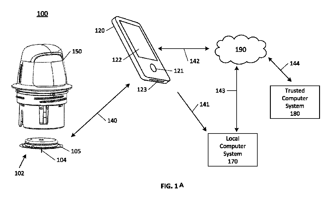
図1Aは、センサアプリケータ150と、センサ制御デバイス102と、データ受信デバイス120とを含む検体モニタシステム100の例示的実施形態を描く概念図である。この場合に、センサアプリケータ150は、センサ制御デバイス102をユーザの皮膚上のモニタ場所に配送するのに使用することができ、この場所でセンサ104は、接着パッチ105によってある期間にわたって動かないように維持される。センサ制御デバイス102に関しては、図2B及び図2Cで更に詳しく説明することにし、センサ制御デバイス102は、有線技術又は無線技術を用いた通信経路140を通してデータ受信デバイス120と通信することができる。例示的無線プロトコルは、Bluetooth、Bluetooth低エネルギ(BLE、BTLE、Bluetoothスマートのような)、近距離無線通信(NFC)、及びその他を含む。ユーザは、データ受信デバイス120上のメモリ内にインストールされたアプリケーションを画面122及び入力121を用いてモニタすることができ、デバイスのバッテリを電力ポート123を用いて再充電することができる。データ受信デバイス120に関するより詳しい詳細に関して、下記で図2Aに明らかにする。データ受信デバイス120は、有線技術又は無線技術を用いた通信経路141を通してローカルコンピュータシステム170と通信することができる。ローカルコンピュータシステム170は、ラップトップ、デスクトップ、タブレット、ファブレット、スマートフォン、セットトップボックス、ビデオゲームコンソール又は他のコンピュータデバイスのうちの1又は2以上を含むことができ、無線通信は、Bluetooth、Bluetooth低エネルギ(BTLE)、Wi-Fi又は他を含むいくつかの適用可能な無線ネットワーク接続プロトコルのうちのいずれかを含むことができる。ローカルコンピュータシステム170は、データ受信デバイス120が通信経路142を通してネットワーク190と通信することができる方式と類似の方式で上述したように有線技術又は無線技術による通信経路143を通してネットワーク190と通信することができる。ネットワーク190は、私設ネットワーク及び公衆ネットワーク、ローカルエリアネットワーク又はワイドエリアネットワークなどのようないくつかのネットワークのうちのいずれかとすることができる。高信頼性コンピュータシステム180はサーバを含むことができ、認証サービス及びセキュアなデータ格納を提供することができ、有線技術又は無線技術による通信経路144を通してネットワーク190と通信することができる。
FIG. 1A is a conceptual diagram illustrating an exemplary embodiment of an
図1Bは、本明細書に説明する技術を具現化する機能を有する検体モニタシステム100の作動環境の別の例示的実施形態を例示している。図示のように、検体モニタシステム100は、人体又は動物体の検体レベルのようなパラメータのモニタを提供するように設計された構成要素のシステムを含むことができ、又は様々な構成要素の構成に基づいて他の作動を可能にすることができる。本明細書に具現化されるように、システムは、ユーザによって着用されるか又は情報が収集されている身体に取り付けられた低電力センサ制御デバイス102を含むことができる。本明細書に具現化されるように、センサ制御デバイス102は、予め決められた実用寿命(例えば、約1日、約14日、約30日のような)を有する密封された配置可能デバイスとすることができる。センサ110は、ユーザの身体の皮膚に適用することができ、センサ寿命の継続時間にわたって接着状態に留まることができ、又は選択的に取り外されて再度適用された時に機能性を留めるように設計することができる。低電力検体モニタシステム100は、センサ制御デバイス102からの検体データを含むデータの取り出し及び送出を容易にするために本明細書に説明するように構成されたデータ読取デバイス120又は多目的データ受信デバイス130を更に含むことができる。
FIG. 1B illustrates another exemplary embodiment of an operating environment for an
本明細書に具現化されるように、検体モニタシステム100は、例えば、リモートアプリケーションサーバ155又はアプリケーションストアフロントサーバ160を通して第三者に提供されて多目的ハードウエアデバイス130、例えば、通信リンクを通してセンサ制御デバイス102と通信する機能を有する携帯電話、タブレット、パーソナルコンピュータデバイス又は他の類似のコンピュータデバイス内に組み込まれたソフトウエア又はファームウエアのライブラリ又はアプリケーションを含むことができる。多目的ハードウエアは、センサ制御デバイス102と通信するように構成された埋め込みライブラリを有するインスリンポンプ又はインスリンペンを含むがこれらに限定されない埋め込みデバイスを更に含むことができる。検体モニタシステム100の図示の実施形態は、図示のデバイスの各々を1つのみを含むが、本発明の開示は、検体モニタシステム100が、それを通して相互作用する複数の各構成要素を組み込むことを考えている。例えば、限定することなく、本明細書に具現化されるように、データ受信デバイス120及び/又は多目的データ受信デバイス130は、複数の各々を含むことができる。本明細書に具現化されるように、複数のデータ受信デバイス130は、本明細書に説明するようにセンサ制御デバイス102と直接に通信することができる。これに加えて又はこれに代えて、データ受信デバイス130は、二次的なデータ受信デバイス130と通信して検体データ又はその視覚表現又は分析結果をユーザ又は権限を有する他の関係者への二次的な表示に関して提供することができる。
As embodied herein, the
図2Aは、スマートフォンとして構成されたデータ受信デバイス120の例示的実施形態を描くブロック図である。この場合に、データ受信デバイス120は、ディスプレイ122と、入力構成要素121と、メモリ223に結合された通信プロセッサ222と、メモリ225に結合されたアプリケーションプロセッサ224とを含む処理コア206とを含むことができる。同様に、別個のメモリ230と、アンテナ229を有するRF送受信機228と、パワーマネージメントモジュール238を有する電源226とを含めることができる。更に、アンテナ234を用いてWi-Fi、NFC、Bluetooth、BTLE、及びGPSを通して通信することができる多機能送受信機232を含めることができる。当業者によって理解されるように、これらの構成要素は、機能デバイスを発生させるように電気的に通信的に結合される。
2A is a block diagram illustrating an exemplary embodiment of a
データ受信デバイス120は、例えば、Wi-Fi又はインターネット対応スマートフォン、タブレット又は携帯情報端末(PDA)のようなモバイル通信デバイスとすることができる。スマートフォンの例は、インターネット接続及び/又はローカルエリアネットワーク(LAN)を通じたデータ通信のためのデータネットワーク接続機能を有するWINDOWS(登録商標)オペレーティングシステム、ANDROID(登録商標)オペレーティングシステム、IPHONE(登録商標)オペレーティングシステム、PALM、WEBOS、BLACKBERRY(登録商標)オペレーティングシステム又はSYMBIANオペレーティングシステムに基づく電話を含むことができるがこれらに限定されない。
The
データ受信デバイス120は、ユーザの眼の上に又はそれに隣接するように着用された光学アセンブリ(例えば、GOOGLE GLASSESのようなスマート単眼鏡又はスマート眼鏡)のようなモバイルスマートウェアラブル電子機器アセンブリとして構成することができる。この光学アセンブリは、ユーザの検体レベル(本明細書に説明する)に関する情報をユーザに対して表示し、同時にユーザの全体的な視覚が最小限にしか妨害されないようにユーザがディスプレイを見通すことを可能にする透明ディスプレイを有することができる。光学アセンブリは、スマートフォンと同種の無線通信の機能を有することができる。ウェアラブル電子機器の他の例は、ユーザの手首の周り又はその周りに着用されるデバイス(例えば、スマートウォッチのような)、首の周り又はその周りに着用されるデバイス(例えば、ネックレスのような)、頭の周り又はその周りに着用されるデバイス(例えば、ヘッドバンド、帽子のような)、胸の周り又はその周りに着用されるデバイスなどを含む。
The
限定ではなく例示の目的で、本発明の開示の主題との併用のための図2Bに示すデータ受信デバイスの別の例示的実施形態120を参照されたい。データ受信デバイス120及び関連の多目的データ受信デバイス130は、センサ制御デバイス102及びその作動の議論に密接に関連する構成要素を含み、追加の構成要素を含めることができる。特定の実施形態では、データ受信デバイス120及び多目的データ受信デバイス130は、第三者によって提供される構成要素とする又はそれらを含むことができ、センサ制御デバイス102と同じ製造業者によって製造されたデバイスを含むことに必ずしも限定されない。
For purposes of illustration and not limitation, see another
図2Bに示すように、データ受信デバイス120は、通信モジュール4040と通信的に結合されたマイクロコントローラ4010と、メモリ4020と、ストレージ4030とを含むASIC4000を含む。データ受信デバイス120の構成要素に対する電力は、本明細書に具体的に示すように再充電可能バッテリを含むことができる電力モジュール4050によって送出することができる。データ受信デバイス120は、センサ制御デバイス102又は他のデバイス(例えば、ユーザデバイス145又はリモートアプリケーションサーバ155)から受信した検体データの精査を容易にするディスプレイ4070を更に含むことができる。データ受信デバイス120は、別個のユーザインタフェース構成要素(例えば、物理的なキー、光センサ、マイクロフォンのような)を含むことができる。
2B, the
通信モジュール4040は、BLEモジュール4041とNFCモジュール4042とを含むことができる。データ受信デバイス120は、センサ制御デバイス102と無線結合し、センサ制御デバイス102に指令を送信し、そこからデータを受信するように構成することができる。本明細書に具現化されるように、データ受信デバイス120は、本明細書に説明するセンサ制御デバイス102に関して通信モジュール4040の特定のモジュール(例えば、BLEモジュール4042又はNFCモジュール4043)を通してNFCスキャナ及びBLE終点として作動するように構成することができる。例えば、データ受信デバイス120は、通信モジュール4040の第1のモジュールを用いてセンサ制御デバイス102に指令(例えば、センサのデータ同報通信モードのための起動指令、データ受信デバイス120を識別するためのペアリング指令、OTAプログラミング指令)を出し、通信モジュール4040の第2のモジュールを用いてセンサ制御デバイス102とデータを送受信することができる。データ受信デバイス120は、通信モジュール4040のユニバーサルシリアルバス(USB)モジュール4045を通じたユーザデバイス145との通信に対して構成することができる。
The
別の例として、通信モジュール4040は、例えば、セルラー無線モジュール4044を含むことができる。セルラー無線モジュール4044は、第3世代(3G)、第4世代(4G)、及び第5世代(5G)のネットワークを含むがこれらに限定されない広帯ゾーンセルラーネットワークを用いて通信するための1又は2以上の無線送受信機を含むことができる。更に、データ受信デバイス120の通信モジュール4040は、「IEEE 802」.11規格(例えば、802.11a、802.11b、802.11g、802.11n(aka Wi-Fi4)、802.11ac(aka Wi-Fi5)、802.11ax(aka Wi-Fi6))のうちの1又は2以上による無線ローカルエリアネットワークを用いた通信のためのWi-Fi無線モジュール4043を含むことができる。セルラー無線モジュール4044又はWi-Fi無線モジュール4043を使用することにより、データ受信デバイス120は、リモートアプリケーションサーバ155と通信して検体データを受信する又は更新情報又はユーザから受信した入力を提供することができる。例示していないが、検体センサ120の通信モジュール5040が、セルラー無線モジュール又はWi-Fi無線モジュールを同じく含むことができる。
As another example, the
本明細書に具現化するように、データ受信デバイス120は、通信モジュール340のユニバーサルシリアルバス(USB)モジュール345を通じた通信に対して構成することができる。データ受信デバイス120は、例えば、USBモジュール345を通してユーザデバイス140と通信することができる。データ受信デバイス120は、例えば、ソフトウエア又はファームウエアの更新をUSBを通して受信することができ、バルクデータをUSBを通して受信することができ、又はデータをユーザデバイス140を通してリモートサーバ150にアップロードすることができる。USB接続は、各差し込み事象において認証することができる。認証は、例えば、異なるキーを用いた2、3、4、又は5通過の認証設計を使用することができる。USBシステムは、暗号化及び認証のための様々な異なるキーセットをサポートすることができる。キーは、様々な役割(臨床、製造業者、ユーザのような)と整合させることができる。セキュリティ情報を漏出させる可能性がある機密指令は、認証付きの追加キーセットを使用する認証付き暗号化をトリガすることができる。
As embodied herein, the
本明細書に具現化されるように、データ受信デバイス120の搭載型ストレージ4030は、センサ制御デバイス102から受信した検体データを格納することができる。更に、データ受信デバイス120、多目的データ受信デバイス130又はユーザデバイス145は、リモートアプリケーションサーバ155とワイドエリアネットワーク上で通信するように構成することができる。本明細書に具現化されるように、センサ制御デバイス102は、データをデータ受信デバイス120又は多目的データ受信デバイス130に提供することができる。データ受信デバイス120は、これらのデータをユーザコンピュータデバイス145に送信することができる。更に、ユーザコンピュータデバイス145(又は多目的データ受信デバイス130)は、これらのデータを処理及び分析に関してリモートアプリケーションサーバ155に送信することができる。
As embodied herein, the on-board storage 4030 of the
本明細書に具現化されるように、データ受信デバイス120は、センサ制御デバイス102の感知ハードウエア5060と類似の又はそれから拡張された感知ハードウエア4060を更に含むことができる。特定の実施形態では、データ受信デバイス120は、センサ制御デバイス102と連携し、そこから受信した検体データに基づいて作動するように構成することができる。一例として、センサ制御デバイス102がグルコースセンサである場合に、データ受信デバイス120は、インスリンポンプ又はインスリン注射ペンとする又はそれらを含むことができる。連携において、互換デバイス130は、検体センサから受信したグルコース値に基づいてユーザに対するインスリン投与量を調節することができる。
As embodied herein, the
図2C及び図2Dは、検体センサ104と、ユーザに対する表示に適する最終結果データをレンダリングするための処理機能の大部分を有することができるセンサ電子機器160とを有するセンサ制御デバイス102の例示的実施形態を描くブロック図である。図2Cには、カスタム特定用途向け集積回路(ASIC)とすることができる単一半導体チップ161が示されている。ASIC161内には、アナログフロントエンド(AFE)162と、パワーマネージメント(又は制御)回路164と、プロセッサ166と、通信回路168(送信機、受信機、送受信機、受動回路又は他に通信プロトコルによるものとして実施することができる)とを含むある一定の高レベル機能ユニットが示されている。この実施形態ではAFE162とプロセッサ166との両方が検体モニタ回路として使用されるが、他の実施形態では、いずれかの回路が検体モニタ機能を実行することができる。プロセッサ166は、各々を別個のチップとするか又はいくつかの異なるチップの間で分散させる(かつこれらのチップの一部分とする)ことができる1又は2以上のプロセッサ、マイクロプロセッサ、コントローラ、及び/又はマイクロコントローラを含むことができる。
2C and 2D are block diagrams illustrating an exemplary embodiment of a
ASIC161の中にはメモリ163も含まれ、メモリ163は、ASIC161の中に存在する様々な機能ユニットによって共有することができる又はこれらの機能ユニットのうちの2又は3以上の間に分散させることができる。メモリ163は、別個のチップとすることができる。メモリ163は、揮発性メモリ及び/又は不揮発性メモリとすることができる。この実施形態では、ASIC161は、コイン電池バッテリなどとすることができる電源172と結合される。AFE162は、生体内検体センサ104と相互接続し、そこから測定データを受け入れ、これらのデータをプロセッサ166にデジタル形態で出力し、プロセッサ166は、更にこれらのデータを最終結果のグルコース個別値及びグルコース傾向値等をもたらすように処理する。次に、これらのデータは、アンテナ171を通して例えばデータ受信デバイス120(図示せず)に送るために通信回路168に供給することができ、データ受信デバイス120では、データを表示するための常駐ソフトウエアアプリケーションによる更に別の処理が僅かしか必要とされない。
Also included within the
図2Dは、図2Cと同様であるが、一緒又は別々にパッケージ化することができる2つの別個の半導体チップ162と174を含む。この場合に、AFE162は、ASIC161上に常駐する。プロセッサ166は、チップ174上でパワーマネージメント回路164及び通信回路168に統合される。AFE162はメモリ163を含み、チップ174は、その内部で隔離するか又は分散させることができるメモリ165を含む。1つの例示的実施形態では、AFE162は、1つのチップ上でパワーマネージメント回路164及びプロセッサ166と組み合わされ、それに対して通信回路168は別個のチップ上にある。別の例示的実施形態では、AFE162と通信回路168の両方が1つのチップ上にあり、プロセッサ166とパワーマネージメント回路164とが別のチップ上にある。各々は、説明する別個の機能を受け持つ又はフェイルセーフ冗長性を達成するために1又は2以上の機能を共有する3又は4以上のチップを含む他のチップ組合せが可能であることに注意しなければならない。
2D is similar to FIG. 2C, but includes two
限定ではなく例示の目的で、図2Eは、本明細書に説明するセキュリティアーキテクチャ及び通信方式に対応するセンサ制御デバイス102の別の例示的実施形態を描いている。
For purposes of illustration and not limitation, FIG. 2E depicts another exemplary embodiment of a
本明細書に具現化されるように、センサ制御デバイス102は、通信モジュール5040に通信的に結合された特定用途向け集積回路(「ASIC」)5000を含むことができる。ASIC5000は、マイクロコントローラコア5010と、搭載型メモリ5020と、ストレージメモリ5030とを含むことができる。ストレージメモリ5030は、認証及び暗号化セキュリティアーキテクチャに使用されるデータを格納することができる。ストレージメモリ5030は、センサ制御デバイス102に対するプログラミング命令を格納することができる。本明細書に具現化されるように、ある一定の通信チップセット(例えば、NFC送受信機5025)をASIC5000内に埋め込むことができる。ASIC5000は、搭載型バッテリのような電力モジュール5050又はNFCパルスから電力を受け入れることができる。ASIC5000のストレージメモリ5030は、識別及び追跡の目的でセンサ制御デバイス102に対する識別子のような情報を含むようにプログラムすることができる。ストレージメモリ5030は、センサ制御デバイス102及びその様々な構成要素によって使用される構成パラメータ又は較正パラメータを用いてプログラムすることができる。ストレージメモリ5030は、書き換え可能メモリ又はワンタイムプログラミング(OTP)メモリを含むことができる。ストレージメモリ5030は、センサ制御デバイス102の有用性を拡張するために本明細書に説明する技術を用いて更新することができる。
As embodied herein, the
特定の実施形態では、本明細書に説明するように、ASIC500のメモリ5020及び通信モジュール5040のメモリ5043の一方又は両方の各々は、メモリの特定のアドレス又は領域に書込を行うことができる回数であって、1回又は予め決められた回数に達するまでの1回よりも多い回数とすることができ、この回数の書込後にメモリを使用不能とマーキングする又は他にプログラミングに利用不能にすることができる上記回数を定めるためのサポートアーキテクチャを含む又は他にそのように構成することができるいわゆる「ワンタイムプログラム可能」(OTP)メモリとすることができる。本明細書に開示する主題は、このOTPメモリを新しい情報で更新するためのシステム及び方法に関する。特に、本明細書に開示する主題は、OTAプログラミングを用いてこのOTPメモリを情報で更新するためのシステム及び方法に関する。
In certain embodiments, as described herein, one or both of the
本明細書に具現化されるように、センサ制御デバイス102の通信モジュール5040は、検体モニタシステム100の他のデバイスとの通信をサポートするための1又は2以上のモジュールとする又はそれらを含むことができる。限定ではなく単なる例として、例示的通信モジュール5040は、本発明の開示を通して使用するBluetooth低エネルギ(「BLE」)モジュール5041を含むことができ、BLEは、エンドユーザに対して簡単なBluetoothデバイスのペアリングを行うように最適化された短距離通信プロトコルを意味する。通信モジュール5040は、データ受信デバイス120又はユーザデバイス145の類似の機能を有する通信モジュールとの対話によってデータ及び指令を送受信することができる。通信モジュール5040は、例えば、「IEEE 802」.15プロトコル、「IEEE 802」.11プロトコルによるパーソナルエリアネットワーク、赤外線データ協会(IrDA)規格による赤外線通信のような類似の短距離通信手法との併用に適する追加の又は代わりのチップセットを含むことができる。
As embodied herein, the
センサ制御デバイス102は、その機能を実行するために、これらの機能に適する感知ハードウエア5060を更に含むことができる。本明細書に具現化されるように、感知ハードウエア5060は、被検者の体液との接触状態で経皮的又は皮下に配置された検体センサを含むことができる。検体センサは、体液内の1又は2以上の検体レベルに対応する値を含有するセンサデータを発生させることができる。
To perform its functions, the
センサ制御デバイス102の構成要素は、適切なユーザ場所への配送の前にユーザによる最終組立を必要とする複数のパッケージでユーザによって取得することができる。図3A~図3Dは、配送に関してセンサを提供するように構成要素を結合する前の別個の構成要素の準備を含むセンサ制御デバイス102に関するユーザによる組立プロセスの例示的実施形態を描いている。図3E~図3Fは、適切な配送場所を選択し、センサ制御デバイス102をこの場所に適用することによる適切なユーザ場所へのデバイス102の配送の例示的実施形態を描いている。
The components of the
図3Aは、この場合は組立プロセスのためのトレイとして構成される(他のパッケージを使用することができるが)容器810をユーザが与える例示的実施形態を描く近接斜視図である。ユーザは、この準備をトレイ810から蓋812を取り外してプラットフォーム808を露出させることにより、例えば、蓋812の接着部分が取り外されるようにトレイ810から蓋812の非接着部分を剥ぎ取ることによって達成することができる。蓋812の取り外しは、様々な実施形態ではプラットフォーム808がトレイ810内で十分に露出される限り適切とすることができる。次に、蓋812を脇に置くことができる。
3A is a close-up perspective view depicting an exemplary embodiment in which a user provides a
図3Bは、組立に関してユーザがアプリケータデバイス150を準備する例示的実施形態を描く側面図である。アプリケータデバイス150は、アプリケータキャップ708によって密封された無菌パッケージ内で提供することができる。アプリケータデバイス150の準備は、ハウジング702をアプリケータキャップ708から切り距離を置いてシース704(図3C)を露出させる段階を含むことができる。この切り離しは、アプリケータキャップ708を捩ってハウジング702から外す(又は他に切り離す)ことによって達成することができる。アプリケータキャップ708を脇に置くことができる。
FIG. 3B is a side view depicting an exemplary embodiment of a user preparing the
図3Cは、組立中にユーザがアプリケータデバイス150をトレイ810の中に挿入する例示的実施形態を描く近接斜視図である。最初に、ユーザは、ハウジング方位機能1302(又はスロット又は凹部)とトレイ方位機能924(当接部又は戻り止め)とが位置合わせされた後にシース704をトレイ810の内側でプラットフォーム808の中に挿入することができる。シース704をプラットフォーム808の中に挿入することにより、シース704がハウジング702から一時的にアンロックされ、プラットフォーム808もトレイ810から一時的にアンロックされる。この段階では、トレイ810からのアプリケータデバイス150の取り外しは、トレイ810内へのアプリケータデバイス150の最初の挿入の前の状態と同じ状態をもたらすことになる(すなわち、このプロセスは、この時点で逆行させ又は中断し、更に影響なく繰り返すことができる)。
3C is a close-up perspective view depicting an exemplary embodiment in which a user inserts the
ハウジング702を遠位に前進させる間に、シース704は、プラットフォーム808内でハウジング702に対する位置を維持し、プラットフォーム808と結合してプラットフォーム808をトレイ810に対して遠位に前進させることができる。この段階は、トレイ810内でプラットフォーム808をアンロックして圧潰させる。シース704は、トレイ810内でロッキング機構(図示せず)に接触してそれを切断させ、それによってシース704がハウジング702からアンロックされ、ハウジング702がプラットフォーム808を遠位に前進させる間にシース704が移動する(相対的に)ことが防止される。ハウジング702及びプラットフォーム808の前進の終了時に、シース704は、ハウジング702から永久にアンロックされる。ハウジング702の遠位前進の終了時に、トレイ810内のシャープ及びセンサ(図示せず)をハウジング702内の電子機器ハウジング(図示せず)と結合することができる。アプリケータデバイス150とトレイ810との作動及び相互作用に関して下記で更に詳しく説明する。
During distal advancement of the
図3Dは、組立中にユーザがアプリケータデバイス150をトレイ810から取り外す例示的実施形態を描く近接斜視図である。ユーザは、ハウジング702をトレイ810に対して近位に前進させる又はアプリケータ150とトレイ810とを切り離すのと同じ終端効果を有する他の動きによってアプリケータ150をトレイ810から取り外すことができる。アプリケータデバイス150は、その内部で完全に組み立てられたセンサ制御デバイス102(シャープ、センサ、電子機器)(図示せず)と共に取り外され、配送に関して配置される。
3D is a close-up perspective view depicting an exemplary embodiment in which a user removes the
図3Eは、患者がアプリケータデバイス150を用いてセンサ制御デバイス102を例えば腹部又は他の適切な場所の上の皮膚のターゲット区域に適用する例示的実施形態を描く近接斜視図である。ハウジング702を前進させることにより、その内部でシース704が遠位に圧潰し、センサ制御デバイス102の底面上の接着層が皮膚に接着するようにセンサがターゲット場所に適用される。シャープは、ハウジング702を完全に前進させた時に自動的に後退し、それに対してセンサ(図示せず)は、定められた位置に残されて検体レベルを測定する。
3E is a close-up perspective view depicting an exemplary embodiment in which a patient applies the
図3Fは、適用位置にセンサ制御デバイス102を有する患者の例示的実施形態を描く近接斜視図である。次に、ユーザは、アプリケータ150を適用部位から取り外すことができる。
Figure 3F is a close-up perspective view depicting an exemplary embodiment of a patient with the
図3A~図3Fに関して説明されて本明細書の他の箇所で説明するシステム100は、従来技術システムと比較してアプリケータ構成要素の偶発的な損壊、永久変形、又は不正な組立の可能性の低減又は排除をもたらすことができる。アプリケータハウジング702は、シース704がアンロックされている間にシース704を通じた間接係合ではなくプラットフォーム808に直接係合するので、シース704とハウジング702の間の相対角度は、アーム又は他の構成要素の損壊又は永久変形をもたらすことにはならない。組立中の比較的強い力(従来のデバイスの場合のような)の潜在性が低減することになり、それによってユーザ組立の失敗の可能性が低減する。
3A-3F and elsewhere herein, the
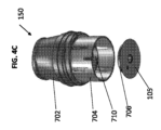
図4Aは、スクリューアプリケータキャップ708に結合されたアプリケータデバイス150の例示的実施形態を描く側面図である。この図は、アプリケータ150がどのように出荷され、ユーザによるセンサとの組立の前にユーザによってどのように荷受けされるかの例である。図4Bは、切り離された後のアプリケータ150とアプリケータキャップ708とを描く側面斜視図である。図4Cは、アプリケータキャップ708が定位置にあった時にシース704のセンサ担体710内で維持されていたと考えられる位置から電子機器ハウジング706及び接着パッチ105が取り外された状態のアプリケータデバイス150の遠位端の例示的実施形態を描く斜視図である。
Figure 4A is a side view depicting an exemplary embodiment of the
限定ではなく例示の目的で図4D~図4Gを参照すると、アプリケータデバイスの別の例示的実施形態20150を単一統合アセンブリとしてユーザに提供することができる。図4D及び図4Eは、それぞれ、アプリケータデバイス20150の斜視上面図及び斜視底面図を提示しており、図4Fは、アプリケータデバイス20150の分解組立図を提示しており、図4Gは、側面破断図を提供する。これらの斜視図は、アプリケータ20150がどのように出荷され、ユーザによってどのように荷受けされるかを示している。分解組立図及び破断図は、アプリケータデバイス20150の構成要素を示している。アプリケータデバイス20150は、ハウジング20702と、ガスケット20701と、シース20704と、シャープ担体201102と、バネ205612と、センサ担体20710(「パック担体」とも呼ぶ)と、シャープハブ205014と、センサ制御デバイス(「パック」とも呼ぶ)20102と、接着パッチ20105と、乾燥剤20502と、アプリケータキャップ20708と、シリアルラベル20709と、未開封証明機能20712とを含むことができる。一部の実施形態では、ユーザが荷受けする時は、ハウジング20702と、アプリケータキャップ20708と、未開封証明機能20712と、ラベル20709としか見えていない。未開封証明機能20712は、例えば、ハウジング20702及びアプリケータキャップ20708の各々に結合されたステッカーとすることができ、更にハウジング20702とアプリケータキャップ20708とを切り離すことによって例えば回復不能に損壊し、それによってハウジング20702とアプリケータキャップ20708とが以前に切り離されたことをユーザに対して示すことができる。これらの機能に関して下記でより詳細に説明する。
4D-4G, for purposes of illustration and not limitation, another exemplary embodiment of an
図5は、滅菌蓋812が取り外し可能に結合されたトレイ810の例示的実施形態を示し、パッケージがどのようにユーザに出荷され、組立前にユーザによってどのように荷受けされるかを表すことができる近接斜視図である。
Figure 5 shows an exemplary embodiment of a
図6Aは、トレイ810内のセンサ配送構成要素を描く近接斜視破断図である。プラットフォーム808は、トレイ810の中に摺動可能に結合される。乾燥剤502が、トレイ810に対して固定される。センサモジュール504が、トレイ810内に装着される。
FIG. 6A is a close-up perspective cutaway view depicting the sensor delivery components within a
図6Bは、センサモジュール504をより詳細に描く近接斜視図である。この場合に、プラットフォーム808の保持アーム延長部1834が、センサモジュール504を定められた位置に解除可能に固定させる。モジュール2200が、コネクタ2300、シャープモジュール2500、及びセンサ(図示せず)と結合され、それによって組立中にこれらを互いにセンサモジュール504として取り外すことができる。
6B is a close-up perspective view depicting the
簡単に図1A及び図3A~図3Gを再度参照すると、ツーピースアーキテクチャシステムでは、センサトレイ810とセンサアプリケータ150とは別個のパッケージとしてユーザに提供され、従って、ユーザが各パッケージを開梱してシステムを最終的に組み立てることを必要とする。一部の用途では、これら別個の密封パッケージは、センサトレイ810とセンサアプリケータ150とを各パッケージの内容物に独特で他方の内容物には適合しない別個の滅菌プロセスで滅菌することを可能にする。より具体的には、センサ104とシャープ220とを含むプラグアセンブリ207を含むセンサトレイ810は、電子ビーム(又は「電子ビーム」)照明のような放射線滅菌を用いて滅菌することができる。適切な放射線滅菌プロセスは、電子ビーム(電子ビーム)照明、ガンマ線照明、X線照明又はこれらのあらゆる組合せを含むがこれらに限定されない。しかし、放射線滅菌は、センサ制御デバイス102の電子機器ハウジングの中に配置された電気構成要素を破損する場合がある。その結果、センサ制御デバイス102の電子機器ハウジングを含むセンサアプリケータ150を滅菌する必要がある場合に、それを例えばエチレンオキシドを用いたガス化学滅菌のような別の方法によって滅菌することができる。しかし、ガス化学滅菌は、センサ104上に含まれる酵素又は他の化学的作用物質及び生物学的作用物質を破損する場合がある。この滅菌非共用性に起因してセンサトレイ810とセンサアプリケータ150とは、一般的に、別個の滅菌プロセスで滅菌され、その後に、別々にパッケージ化され、それによってユーザは、使用に関して最終的に構成要素を組み立てることが必要である。
1A and 3A-3G briefly, in a two-piece architecture system, the
図7A及び図7Bは、それぞれ、1又は2以上の実施形態によるセンサ制御デバイス3702の分解上面図及び分解底面図である。シェル5006とマウント5008とは、センサ制御デバイス3702の様々な電子構成要素を封入するか又は他に実質的に被包する対向するクラムシェル半片として働きをする。図示のように、センサ制御デバイス3702は、複数の電子モジュール3806が結合されたプリント回路基板(PCB)3804を含むプリント回路基板アセンブリ(PCBA)3802を含むことができる。例示的電子モジュール3806は、抵抗器、トランジスタ、コンデンサー、誘導子、ダイオード、及びスイッチを含むがこれらに限定されない。従来のセンサ制御デバイスは、一般的に、PCB構成要素をPCBの一方の側にのみ積み重ねる。それとは対照的に、センサ制御デバイス3702内のPCB構成要素3806は、PCB3804の両側(すなわち、上面と底面)の面区域の周りに分散させることができる。
7A and 7B are exploded top and bottom views, respectively, of a
電子モジュール3806以外に、PCBA3802は、PCB3804に装着されたデータ処理ユニット3808を更に含むことができる。データ処理ユニット3808は、例えば、センサ制御デバイス3702の作動に関する1又は2以上の機能又はルーチンを実施するように構成された特定用途向け集積回路(ASIC)を含むことができる。より具体的には、データ処理ユニット3808は、データ処理機能を実行するように構成することができ、この場合に、そのような機能は、ユーザのサンプリングされた検体レベルに各々が対応する複数のデータ信号のフィルタリング及び符号化を含むことができるがこれらに限定されない。データ処理ユニット3808は、読取器デバイス106と通信するためのアンテナを更に含む又は他にそれと通信することができる。
In addition to the
バッテリ開口3810が、PCB3804内に定められ、かつセンサ制御デバイス3702に給電するように構成されたバッテリ3812を受け入れて着座させるようにサイズ決定することができる。PCB3804には軸線方向バッテリ接点3814a及び半径方向バッテリ接点3814bを結合することができ、これらの接点は、バッテリ開口3810の中に延びてバッテリ3812からPCB3804への電力の伝達を容易にすることができる。名称が示唆する通り、軸線方向バッテリ接点3814aは、バッテリ3812に対して軸線方向接触を与えるように構成することができ、一方で半径方向バッテリ接点3814bは、バッテリ3812に対して半径方向接触を与えることができる。バッテリ接点3814a、3814bを有するバッテリ開口3810の中にバッテリ3812を位置付けることは、センサ制御デバイス3702の高さHを低減することを助け、それによってPCB3804を中心に位置付けし、その構成要素を両側(すなわち、上面と底面)上に分散させることを可能にする。これは、電子機器ハウジング3704上に面取り3718を設けることを容易にすることにも役立つ。
A
センサ3716は、PCB3804に関して中心に位置付けることができ、テール3816と、フラグ3818と、テール3816とフラグ3818とを相互接続するネック3820とを含むことができる。テール3816は、マウント3708の中心開口3720を通って延びてユーザの皮膚の下に経皮的に受け入れられるように構成することができる。更に、テール3816は、その上に含まれて検体モニタを容易にすることを助ける酵素又は他の化学的作用物質を有することができる。
The
フラグ3818は、その上に配置された1又は2以上のセンサ接点3822(図7Bに3つを示す)を有するほぼ平坦な面を含むことができる。センサ接点3822は、PCB3804上に設けられた対応する1又は2以上の回路接点3824(図7Aに3つを示す)に位置合わせされてそれらに係合するように構成することができる。一部の実施形態では、センサ接点3822は、フラグ3818に印刷又は他にデジタルに適用された炭素含浸ポリマーを含むことができる。一般的に、従来のセンサ制御デバイスは、センサとPCBの間の導電性接点として働きをする1又は2以上の柔軟性炭素含浸ポリマーモジュールを被包するシリコーンゴムで製造されたコネクタを含む。それとは対照的に、本発明の開示のセンサ接点3822は、センサ3716とPCB3804の間に直接に接続を与え、それによって従来技術のコネクタに対する必要性が排除され、高さHが有利に低減する。更に、柔軟性炭素含浸ポリマーモジュールを排除することにより、有意な回路抵抗が排除され、従って、回路導電性が改善される。
The
センサ制御デバイス3702は、フラグ3818とシェル3706の内面の間に挟まるように配置することができる柔軟性部材3826を更に含むことができる。より具体的には、シェル3706とマウント3708とが互いに組み込まれる時に、柔軟性部材3826は、強制的にセンサ接点3822を対応する回路接点3824との連続係合状態に入れる受動的付勢荷重をフラグ3818に対して与えるように構成することができる。図示の実施形態では、柔軟性部材3826は、弾性Oリングであるが、これに代えて、本発明の開示の範囲から逸脱することなく圧縮バネなどのいずれかの他のタイプの付勢デバイス又は付勢機能を含むことができると考えられる。
The
センサ制御デバイス3702は、第1のシールド3828a及び第2のシールドとして示す1又は2以上の電磁シールドを更に含むことができる。シェル3706は、第1の方位決定しレセプタクル3830a(図7B)と第2の方位決定しレセプタクル3830b(図7B)とを設けるか又は他に定めることができ、マウント3708は、第1の方位決定しポスト3832a(図7A)と第2の方位決定しポスト3832b(図7A)とを設けるか又は他に定めることができる。第1及び第2の方位決定しレセプタクル3830a、3830bをそれぞれ第1の方位決定しポスト3832a、3832bと嵌合させることにより、シェル3706はマウント3708に適正に位置合わせすることになる。
The
特に図7Aを参照すると、マウント3708の内面は、シェル3706がマウント3708に嵌合される時にセンサ制御デバイス3702の様々な部分構成要素を受け入れるように構成された複数のポケット又は凹部を設けるか又は他に定めることができる。例えば、マウント3708の内面は、センサ制御デバイス3702が組み立てられる時にバッテリ3812の一部分を受け入れるように構成されたバッテリロケータ3834を定めることができる。それに隣接する接点ポケット3836を軸線方向接点3814aの一部分を受け入れるように構成することができる。
7A in particular, the inner surface of the
更に、PCB3804の底部上に配置される様々な電子モジュール3806を受け入れるための複数のモジュールポケット3838をマウント3708の内面内に定めることができる。更に、センサ制御デバイス3702が組み立てられる時に第2のシールド3828bの少なくとも一部分を受け入れるためのシールドロケータ3840をマウント3708の内面内に定めることができる。バッテリロケータ3834、接点ポケット3836、モジュールポケット3838、及びシールドロケータ3840は、全てマウント3708の内面の中に短い距離だけ延び、その結果、センサ制御デバイス3702の全高Hを従来のセンサ制御デバイスと比較して低減することができる。モジュールポケット3838は、PCB構成要素を両側(すなわち、上面と底面)上に配置することを可能にすることによってPCB3804の直径を最小にすることを助けることができる。
Additionally, a plurality of
引き続き図7Aを参照すると、マウント3708は、その外周に散在するように定められた複数の担体把持機能3842(2つを示す)を更に含むことができる。担体把持機能3842は、マウント3708の底部3844から軸線方向にオフセットされ、組立中にそこに転写接着剤(図示せず)を適用することができる。マウントの底部と交差する円錐形担体把持機能を一般的に含む従来のセンサ制御デバイスとは対照的に、本発明の開示の担体把持機能3842は、この平面(すなわち、底部3844)からオフセットされ、そこに転写接着剤が適用される。これは、組立中に配送システムが転写接着剤に不用意に取り付けられないことを保証することを助けるので有利であることを明らかにすることができる。更に、本発明の開示の担体把持機能3842は、スカラップ形転写接着剤に対する必要性を排除し、それによって転写接着剤の製造が容易になり、転写接着剤をマウント3708に対して正確に方位決定する必要性が排除される。同様に、それによって接着面積が増大し、従って、接着強度が高まる。
Continuing to refer to FIG. 7A, the
図7Bを参照すると、マウント3708の底部3844は、マウント3708の外周又はその近くに互いに等距離で離間するように定めることができる複数の溝3846を設けるか又は他に定めることができる。転写接着剤(図示せず)は、底部3844に結合することができ、溝3846は、使用中に湿気をセンサ制御デバイス3702からマウント3708の周りに搬送(移送)することを助けるように構成することができる。一部の実施形態では、溝3846の間隔は、マウント3708の反対側(内面)に定められたモジュールポケット3838(図7A)の間に挟まることができる。察知されるであろうが、溝3846の位置とモジュールポケット3838の位置とを交替させることにより、マウント3708の両側で反対機能が互いの中に延び込まないことを保証する。これは、マウント3708のための材料の使用率を最大に高めることを助け、それによってセンサ制御デバイス3702の最低高さHを維持することを助けることができる。モジュールポケット3838は、モールドの陥没を有意に低減し、転写接着剤が接着する底部3844の平坦性を改善することができる。
7B, the
引き続き図7Bを参照すると、シェル3706の内面も、シェル3706がマウント3708に嵌合される時にセンサ制御デバイス3702の様々な部分構成要素を受け入れるように構成された複数のポケット又は凹部を設けるか又は他に定めることができる。例えば、シェル3706の内面は、マウント3708のバッテリロケータ3834(図7A)の反対に配置可能でセンサ制御デバイス3702が組み立てられる時にバッテリ3812の一部分を受け入れるように構成された対向バッテリロケータ3848を定めることができる。対向バッテリロケータ3848は、シェル3706の内面の中に短い距離だけ延び、これは、センサ制御デバイス3702の全高Hを低減することを助ける。
7B, the inner surface of the
シャープ及びセンサロケータ3852をシェル3706の内面によって設けるか又は他にその上に定めることができる。シャープ及びセンサロケータ3852は、シャープ(図示せず)とセンサ3716の一部分の両方を受け入れるように構成することができる。更に、シャープ及びセンサロケータ3852は、マウント3708の内面上に設けられた対応するシャープ及びセンサロケータ2054(図7A)に位置合わせ及び/又は嵌合するように構成することができる。
A sharp and
本発明の開示の実施形態に従って、代替センサアセンブリ/電子機器アセンブリの接続手法を図8Aから図8Cに例示している。図示のように、センサアセンブリ14702は、センサ14704と、コネクタ支持体14706と、シャープ14708とを含む。取りわけ、電子機器アセンブリ14712のマウントの底部内に凹部又はレセプタクル14710を定めることができ、凹部又はレセプタクル14710は、センサアセンブリ14702を受け入れて電子機器アセンブリ14712に結合され、それによってセンサ制御デバイスを完全に組み立てることができる場所を設けることができる。センサアセンブリ14702の外形は、弾性密封部材14714(回路基板に結合されてセンサ14704の電気接点に位置合わせする導電材料を含む)を含むレセプタクル14710に整合するか又はそれと相補的な方式に成形することができる。従って、センサアセンブリ14702を電子機器アセンブリ14712内に一体形成された凹部14710の中に押し込むことによって電子機器アセンブリ14712にスナップ式又は他に接着された時に、図8Cに示す身体上デバイス14714が形成される。この実施形態は、電子機器アセンブリ14712の中にセンサアセンブリ14702に対する統合コネクタを提供する。
8A-8C illustrate alternative sensor assembly/electronics assembly connection techniques in accordance with an embodiment of the present disclosure. As shown, the
センサアセンブリに関する追加情報は、米国特許出願公開第2013/0150691号明細書及び米国特許出願公開第2021/0204841号明細書に示されており、これらの文献の各々の全内容は、引用によって本明細書に組み込まれている。 Additional information regarding the sensor assembly is provided in U.S. Patent Application Publication No. 2013/0150691 and U.S. Patent Application Publication No. 2021/0204841, the entire contents of each of which are incorporated herein by reference.
本発明の開示の実施形態により、センサ制御デバイス102は、ワンピースアーキテクチャセンサ制御デバイスに特化して設計された滅菌技術を適用することができるワンピースアーキテクチャをもたらすように修正することができる。ワンピースアーキテクチャは、センサアプリケータ150とセンサ制御デバイス102とをいずれの最終ユーザ組立段階も必要としない単一密封パッケージでユーザに出荷することを可能にする。言い換えれば、ユーザは、1つのパッケージを開梱するだけでよく、その後に、センサ制御デバイス102をターゲットモニタ場所に配送する。本明細書に説明するワンピースシステムアーキテクチャは、部分構成要素、様々な加工プロセス段階、及びユーザ組立段階を排除するので有利であることを明らかにすることができる。その結果、パッケージ及び廃棄物が低減し、ユーザ過誤又はシステムの汚染が軽減する。
In accordance with the disclosed embodiments of the present invention, the
図9A及び図9Bは、それぞれ、アプリケータキャップ708が結合されたセンサアプリケータ150の例示的実施形態の側面図及び断面側面図である。より具体的には、図9Aは、センサアプリケータ150をどのような状態でユーザに出荷し、ユーザがどのような状態で荷受けすることができると考えられるかを示しており、図9Bは、センサアプリケータ150の中に配置されたセンサ制御デバイス4402を描いている。これらの図により、完全に組み立てられたセンサ制御デバイス4402は、ユーザに配送される前に既に組み立てられたでセンサアプリケータ150の中に取り付けられており、従って又は他にユーザが具現化しなければならないと考えられるいずれの追加の組立段階も排除される。
9A and 9B are side and cross-sectional side views, respectively, of an exemplary embodiment of a
完全に組み立てられたセンサ制御デバイス4402は、センサアプリケータ150の中に装填することができ、次に、アプリケータキャップ708をセンサアプリケータ150に結合することができる。一部の実施形態では、アプリケータキャップ708は、ハウジング702に螺合することができ、未開封リング4702を含むことができる。ハウジング702に対してアプリケータキャップ708を回転させた(例えば、捻り外した)時に、未開封リング4702がねじ切られ、それによってアプリケータキャップ708をセンサアプリケータ150から解除することができる。
The fully assembled
本発明の開示により、センサアプリケータ150内に装填されている間に、センサ制御デバイス4402に、その電子機器ハウジング4404及びいずれかの他の露出部分を滅菌するように構成されたガス化学滅菌4704を適用することができる。この滅菌をもたらすために、センサアプリケータ150と相互接続されたキャップ210とによって協働的に定められた滅菌チャンバ4706の中に化学物質を注入することができる。一部の用途では、化学物質は、アプリケータキャップ708内でその近位端610に定められた1又は2以上の通気口4708を通して滅菌チャンバ4706の中に注入することができる。ガス化学滅菌4704に使用することができる例示的化学物質は、エチレンオキシド、過酸化水素蒸気、窒素酸化物(例えば、亜酸化窒素、二酸化窒素のような)、及び蒸気を含むがこれらに限定されない。
In accordance with the present disclosure, the
センサ4410及びシャープ4412の遠位部分は、センサキャップ4416内で密封されるので、ガス化学滅菌プロセス中に使用される化学物質は、テール4524及び他のセンサ構成要素の上、例えば、検体流入を調整する膜コーティング上に設けられた酵素、化学的作用物質、生物学的作用物質と相互作用しない。
The distal portion of the
滅菌チャンバ4706内で望ましい無菌性確実にレベルに到達すると、気溶体を除去することができ、滅菌チャンバ4706を曝気することができる。曝気は、一連の真空と、それに続くガス滅菌チャンバ4706を通してガス(例えば、窒素)又は除菌空気を循環させる段階とによって達成することができる。滅菌チャンバ4706が適正に曝気されると、通気口4708をシール4712(破線に示す)で塞ぐことができる。
Once the desired level of sterility has been reached within the
一部の実施形態では、シール4712は、異なる材料から構成される2又は3以上の層を含むことができる。第1の層は、DuPont(登録商標)から利用可能なTyvek(登録商標)のような合成材料(例えば、フラッシュ紡糸密度ポリエチレン繊維)で製造することができる。Tyvek(登録商標)は耐久性が高く、耐穿孔性があり、蒸気の透過を許す。Tyvek(登録商標)層は、ガス化学滅菌プロセスの前に適用することができ、ガス化学滅菌プロセスに続いて、滅菌チャンバ4706内への汚染物質及び湿気の侵入を防止するためにTyvek(登録商標)層の上に箔又は他の耐蒸気性及び耐湿性の材料層を密封(例えば、熱溶融)することができる。他の実施形態では、シール4712は、アプリケータキャップ708に適用された単一保護層のみを含む場合がある。そのような実施形態では、この単層は、滅菌プロセスに関してガス透過性を有することができるが、滅菌プロセスが完了した後に湿気及び他の有害要素に対する保護の機能を有することができる。
In some embodiments, the
シール4712が定位置にある状態で、アプリケータキャップ708は、外部からの汚染に対する障壁を提供し、それによってユーザがアプリケータキャップ708を取り外す(螺脱する)まで組み立てられたセンサ制御デバイス4402に対する無菌環境を維持する。アプリケータキャップ708は、搬送及び保存中に接着パッチ4714が汚くなることを防止する無塵環境を発生させることができる。
With the
図10A及び図10Bは、それぞれ、本発明の開示の1又は2以上の実施形態による別の例示的センサ制御デバイス5002の等角投影図及び側面図である。センサ制御デバイス5002は、図1Aのセンサ制御デバイス102といくつかの点で同様とすることができ、従って、それを参照することで最も明快に理解することができるであろう。更に、センサ制御デバイス5002は、図1Aのセンサ制御デバイス102に置き換わることができ、従って、図1Aのセンサアプリケータ150と併用することができ、センサアプリケータ150は、センサ制御デバイス5002をユーザの皮膚上のターゲットモニタ場所に配送することができる。
10A and 10B are isometric and side views, respectively, of another exemplary
しかし、図1Aのセンサ制御デバイス102とは異なり、センサ制御デバイス5002は、ユーザが複数のパッケージを開梱して適用する前にセンサ制御デバイス5002を最終的に組み立てることを必要としないワンピースシステムアーキテクチャを含むことができる。言い換えれば、ユーザによる荷受け時に、センサ制御デバイス5002は既に完全に組み立てられており、センサアプリケータ150(図1A)の中に適正に位置決めされている。センサ制御デバイス5002を使用するために、ユーザは、使用に関して1つの障壁(例えば、図3Bのアプリケータキャップ708)を開けるだけでよく、その後に直ちにセンサ制御デバイス5002をターゲットモニタ場所に配送する。
However, unlike the
図示のように、センサ制御デバイス5002は、ほぼ円盤形であり、円形断面を有することができる電子機器ハウジング5004を含む。しかし、他の実施形態では、電子機器ハウジング5004は、本発明の開示の範囲から逸脱することなく長円形又は多角形のような他の断面形状を示すことができる。電子機器ハウジング5004は、センサ制御デバイス5002を作動させるのに使用される様々な電気構成要素を格納するか又は他に含むように構成することができる。少なくとも1つの実施形態では、電子機器ハウジング5004の底部に接着パッチ(図示せず)を配置することができる。接着パッチは、図1Aの接着パッチ105と同様とすることができ、従って、使用に関してセンサ制御デバイス5002をユーザの皮膚に接着させることを助けることができる。
As shown, the
図示のように、センサ制御デバイス5002は、シェル5006と、それと嵌合可能なマウント5008とを含む電子機器ハウジング5004を含む。シェル5006は、スナップ式係合、干渉嵌合、音波溶接、1又は2以上の機械ファスナ(例えば、スクリュー)、ガスケット、接着剤、又はこれらのあらゆる組合せのような様々な手法によってマウント5008に固定させることができる。一部の場合に、シェル5006は、マウント5008の間に密封インタフェースが生成されるようにマウント5008に固定させることができる。
As shown, the
センサ制御デバイス5002は、センサ5010(部分的に見えている)と、センサ制御デバイス5002の適用中にセンサ5010をユーザの皮膚の下に経皮的に送出することを助けるように使用されるシャープ5012(部分的に見えている)とを更に含むことができる。図示のように、センサ5010とシャープ5012との対応する部分は、電子機器ハウジング5004(例えば、マウント5008)の底部から遠位に延びる。シャープ5012は、それを固定させて担持するように構成されたシャープハブ5014を含むことができる。図10Bで最も明確に分るように、シャープハブ5014は、嵌合部材5016を含む又は他に定めることができる。シャープ5012をセンサ制御デバイス5002に結合するために、シャープハブ5014がシェル5006の上面に係合し、嵌合部材5016がマウント5008の底部から遠位に延びるまでシャープ5012を電子機器ハウジング5004を通して軸線方向に前進させることができる。シャープ5012が電子機器ハウジング5004を貫通すると、センサ5010の露出部分をシャープ5012の中空部分又は、凹部(円弧形)部分の中に受け入れることができる。センサ5010の残余は、電子機器ハウジング5004内に配置される。
The
センサ制御デバイス5002は、図10A~図10Bでは電子機器ハウジング5004から分解された又は切り離された状態に示すセンサキャップ5018を更に含むことができる。センサキャップ5018は、センサ制御デバイス5002(例えば、電子機器ハウジング5004)にマウント5008の底部又はその近くで取り外し可能に結合することができる。センサキャップ5018は、センサ5010及びシャープ5012の露出部分を囲んでガス化学滅菌から保護する密封障壁を設けることを助けることができる。図示のように、センサキャップ5018は、第1の端部5020aと、その反対にある第2の端部5020bとを有するほぼ円筒形の本体を含むことができる。第1の端部5020aは、本体の中に定められた内側チャンバ5022内へのアクセスを与えるために開口させることができる。それとは対照的に、第2の端部5020bは、閉鎖することができ、係合機能5024を設ける又は他に定めることができる。本明細書に説明するように、係合機能5024は、センサキャップ5018をセンサアプリケータ(例えば、図1及び図3A~図3Gのセンサアプリケータ150)のキャップ(例えば、図3Bのアプリケータキャップ708)に嵌合することを助けることができ、キャップをセンサアプリケータ150から取り外す時にセンサキャップ5018をセンサ制御デバイス5002から取り外すことを助けることができる。
The
センサキャップ5018は、電子機器ハウジング5004にマウント5008の底部又はその近くで取り外し可能に結合することができる。より具体的には、センサキャップ5018は、マウント5008の底部から遠位に延びる嵌合部材5016に取り外し可能に結合することができる。少なくとも1つの実施形態では、例えば、嵌合部材5016は、センサキャップ5018によって定められた雌ネジ5026b(図10A)のセットと嵌合可能な雄ネジ5026a(図10B)のセットを定めることができる。一部の実施形態では、雄ネジ及び雌ネジ5026a、5026bは、これらの部分をモールド成形するのに有利であることを明らかにすることができる角ネジ設計(例えば、螺旋湾曲を欠く)を含むことができる。これに代えて、雄ネジ及び雌ネジ5026a、5026bは、螺旋螺合係合を含むことができる。従って、センサキャップ5018は、センサ制御デバイス5002にシャープハブ5014の嵌合部材5016の場所で螺合可能に結合することができる。他の実施形態では、センサキャップ5018は、干渉嵌合又は摩擦嵌め又は僅かな離脱力(例えば、軸線方向力又は回転力)で破壊することができる易壊性の部材又は物質を含むがこれらに限定されない他のタイプの係合によって嵌合部材5016に取り外し可能に結合することができる。
The
一部の実施形態では、センサキャップ5018は、第1の端部5020aと第2の端部5020bの間を延びるモノリシック(単一)構造体を含むことができる。しかし、他の実施形態では、センサキャップ5018は、2又は3以上の部分構成要素を含むことができる。図示の実施形態では、例えば、センサキャップ5018は、第1の端部5020aに配置されたシールリング5028と、第2の端部5020bに配置された乾燥剤キャップ5030とを含むことができる。シールリング5028は、下記でより詳細に説明するように内側チャンバ5022を密封することを助けることができる。少なくとも1つの実施形態では、シールリング5028は、エラストマーOリングを含むことができる。乾燥剤キャップ5030は、内側チャンバ5022内で好ましい湿度レベルを維持することを助ける乾燥剤を格納する又は含むことができる。更に、乾燥剤キャップ5030は、センサキャップ5018の係合機能5024を定める又は他に設けることができる。
In some embodiments, the
図11A~図11Cは、1又は2以上の実施形態によるセンサアプリケータ150とセンサ制御デバイス5002との組立を示す段階的な断面側面図である。センサ制御デバイス5002が完全に組み立てられると、それをセンサアプリケータ150の中に装填することができる。図11Aを参照すると、シャープハブ5014は、センサ制御デバイス5002をセンサアプリケータ150に結合することを助けるように構成されたハブスナップ爪5302を含む又は他に定めることができる。より具体的には、センサ制御デバイス5002をセンサアプリケータ150内に進め入ることができ、ハブスナップ爪5302をセンサアプリケータ150の中に配置されたシャープ担体5306の対応するアーム5304が受け入れることができる。
11A-11C are step-by-step cross-sectional side views illustrating the assembly of a
図11Bには、シャープ担体5306によって受け入れられ、従って、センサアプリケータ150の中に固定されたセンサ制御デバイス5002が示されている。センサ制御デバイス5002がセンサアプリケータ150の中に装填されると、アプリケータキャップ708をセンサアプリケータ150に結合することができる。一部の実施形態では、アプリケータキャップ708とハウジング702とは、アプリケータキャップ708をハウジング702上に時計周り(又は反時計周り)方向に捻り留め、それによってアプリケータキャップ708をセンサアプリケータ150に固定させることを可能にする反対嵌合可能なネジ山5308のセットを有することができる。
11B shows the
図示のように、センサアプリケータ150の中にシース704が更に配置され、センサアプリケータ150は、シース704が衝撃事象中に早期に圧潰しないことを保証するように構成されたシースロッキング機構5310を含むことができる。図示の実施形態では、シースロッキング機構5310は、アプリケータキャップ708とシース704の間に螺合係合を含むことができる。より具体的には、アプリケータキャップ708の内面上に1又は2以上の雌ネジ5312aを定める又は他に設けることができ、シース704上に1又は2以上の雄ネジ5312bを定める又は他に設けることができる。雌ネジ5312aと雄ネジ5312bは、アプリケータキャップ708がセンサアプリケータ150にネジ山5308では螺合される時に螺合可能に嵌合するように構成することができる。雌ネジ及び雄ネジ5312a、5312bは、アプリケータキャップ708をハウジング702上に捻り留めることを可能にするネジ山5308と同じネジ山ピッチを有することができる。
As shown, the
図11Cには、ハウジング702に完全に螺合(結合)されたアプリケータキャップ708が示されている。図示のように、アプリケータキャップ708は、その内部で中心に位置付けられてアプリケータキャップ708の底部から近位に延びるキャップポスト5314を更に設ける又は他に定めることができる。キャップポスト5314は、アプリケータキャップ708がハウジング702上に捻り留められる時にセンサキャップ5018の少なくとも一部分を受け入れるように構成することができる。
11C shows the
センサ制御デバイス5002がセンサアプリケータ150の中に装填され、アプリケータキャップ708が適正に固定された状態で、次に、センサ制御デバイス5002には、その電子機器ハウジング5004及びいずれかの他の露出部分を滅菌するように構成されたガス化学滅菌を適用することができる。センサ5010及びシャープ5012の遠位部分は、センサキャップ5018の中に密封されるので、ガス化学滅菌プロセス中に使用される化学物質は、テール5104上に設けられた酵素、化学的作用物質、及び生物学的作用物質、並びに他のセンサ構成要素、例えば、検体流入を調整する膜コーティングと相互作用することができない。
With the
図12A~図12Cは、1又は2以上の追加の実施形態によるセンサアプリケータ150とセンサ制御デバイス5002との代替実施形態の組立及び分解を示す段階的な断面側面図である。上記で全体的に上述したように、ハブスナップ爪5302をセンサアプリケータ150の中に配置されたシャープ担体5306のアーム5304の中に結合することにより、完全組み立てられたセンサ制御デバイス5002をセンサアプリケータ150の中に装填することができる。
12A-12C are step-by-step cross-sectional side views illustrating the assembly and disassembly of an alternative embodiment of a
図示の実施形態では、シース704のシースアーム5604は、ハウジング702内に定められた第1の戻り止め5702a及び第2の戻り止め5702bと相互作用するように構成することができる。第1の戻り止め5702aは、これに代えて、「ロッキング」戻り止めと呼ぶ場合があり、第2の戻り止め5702bは、これに代えて、「放出」戻り止めと呼ぶ場合がる。センサ制御デバイス5002が最初にセンサアプリケータ150内に取り付けられる時に、シースアーム5604を第1の戻り止め5702aの中に受け入れることができる。下記で説明するように、シース704を作動させてシースアーム5604を第2の戻り止め5702bまで移動することができ、それによってセンサアプリケータ150は放出位置に置かれる。
In the illustrated embodiment, the
図12Bでは、シース704がアプリケータキャップ708の中に受け入れられるように、アプリケータキャップ708がハウジング702に位置合わせされてハウジング702に関して前進される。アプリケータキャップ708をハウジング702に結合するのに、アプリケータキャップ708をハウジング702に対して回転させる代わりに、アプリケータキャップ708のネジ山をハウジング702の対応するネジ山上にスナップ係止することができる。アプリケータキャップ708内に定められた軸線方向の切れ目又はスロット5703(1つを示す)が、アプリケータキャップ708のうちでその螺刻部に近い部分を外向きに湾曲させてハウジング702の螺刻部との係合状態までスナップ留めすることを可能にすることができる。アプリケータキャップ708がハウジング702にスナップ留めされる時に、相応にセンサキャップ5018をキャップポスト5314の中にスナップ留めすることができる。
12B, the
図11A~図11Cの実施形態と同様に、センサアプリケータ150は、シース704が衝撃事象中に早期に圧潰しないことを保証するように構成されたシースロッキング機構を含むことができる。図示の実施形態では、シースロッキング機構は、シース704のベースの近くに定められて、アプリケータキャップ708のベースの近くに定められた1又は2以上のリブ5706(2つを示す)及びショルダー5708と相互作用するように構成された1又は2以上のリブ5704(1つを示す)を含む。リブ5704は、アプリケータキャップ708をハウジング702に取り付けながらリブ5706とショルダー5708の間に噛み合うように構成することができる。より具体的には、アプリケータキャップ708がハウジング702上にスナップ留めされると、アプリケータキャップ708を回転させることができ(例えば、時計周りに)、この回転により、シース704のリブ5704がアプリケータキャップ708のリブ5706とショルダー5708の間に位置決めされ、これは、ユーザが使用に関してアプリケータキャップ708を取り外すためにアプリケータキャップ708を逆回転させるまでアプリケータキャップ708を定位置に「ロック」する。アプリケータキャップ708のリブ5706とショルダー5708との間へのリブ5704の係合はまた、シース704が早期に圧潰することを防止することができる。
11A-11C, the
図12Cでは、アプリケータキャップ708は、ハウジング702から取り外されている。図12A~図12Cの実施形態の場合と同様に、アプリケータキャップ708は、それを逆回転させることによって取り外すことができ、この回転は、相応にキャップポスト5314を同じ方向に回転させ、上記で全体的に上述したように、センサキャップ5018を嵌合部材5016から螺脱させる。更に、センサキャップ5018をセンサ制御デバイス5002から切り離すことにより、センサ5010及びシャープ5012の遠位部分が露出する。
In FIG. 12C, the
アプリケータキャップ708がハウジング702から捻って外される時に、シース704上に定められたリブ5704は、アプリケータキャップ708上に定められたリブ5706の上部に摺動係合することができる。リブ5706の上部は、対応する立ち上がり面を提供することができ、この立ち上がり面は、アプリケータキャップ708が回転された時にシース704の上方変位をもたらし、シース704を上方に移動する結果としてシースアーム5604は湾曲して第1の戻り止め5702aとの係合から外れ、第2の戻り止め5702bの中に受け入れられる。シース704が第2の戻り止め5702bまで移動する時に、半径方向ショルダー5614は担体アーム5608との半径方向係合から離脱し、それによってバネ5612の受動的バネ力がシャープ担体5306を上方に押し、担体アーム5608を溝5610との係合から強制的に外す。シャープ担体5306がハウジング702内で上方に移動する時に、相応に嵌合部材5016がセンサ制御デバイス5002の底部と面一に、実質的に面一に、又は準面一になるまで後退することができる。この時点で、センサアプリケータ150は放出位置にある。従って、この実施形態では、アプリケータキャップ708を取り外すことにより、相応に嵌合部材5016が後退する。
When the
図13A~図13Fは、センサ制御デバイス102をユーザに適用することを目的とし、シャープ1030を使用されたアプリケータ150の中に安全に後退させて戻す段階を含むアプリケータ150を「放出」する段階の内部デバイスの構成の実施形態の例示的詳細を例示している。全て一緒にこれらの図面は、シャープ1030(センサ制御デバイス102に結合されたセンサを支持している)をユーザの皮膚の中に駆動する段階、センサをユーザの間質液との作動可能接触状態に残しながらシャープを引き出す段階、及びセンサ制御デバイスをユーザの皮膚に接着剤を用いて接着させる段階の例示的シーケンスを表している。これらの図面を参照により、当業者は、代替アプリケータアセンブリの実施形態及び構成要素との併用のためのそのような活動の修正を認めることができる。更に、アプリケータ150は、本明細書に開示するワンピースアーキテクチャ又はツーピースアーキテクチャを有するセンサアプリケータとすることができる。
13A-13F illustrate exemplary details of an embodiment of the internal device configuration for applying the
ここで図13Aに移ると、センサ1102は、ユーザの皮膚1104の僅かに上方でシャープ1030内で支持される。シース704に対するアプリケータ150の動きを制御するために、上側案内セクション1108のレール1106(任意的に3つのレール1106)を設けることができる。シース704は、シャープ1030及びセンサ制御デバイス102がユーザの皮膚1104の中(及びその上)に長手軸線に沿って並進することができるようにアプリケータ150の長手軸線に沿う適切な下向きの力が戻り止め機能1110によって与えられる抵抗力を打ち負かすことになるようにアプリケータ150の中に戻り止め機能1110によって固持される。更に、センサ担体1022のキャッチアーム1112が、シャープ後退アセンブリ1024に係合してシャープ1030をセンサ制御デバイス102との相対的な位置に維持する。
13A, the
図13Bでは、戻り止め機能1110に打ち勝ち、それを無効にするためのユーザの力が印加され、シース704はハウジング702の中に圧潰してセンサ制御デバイス102を(付属の部分と共に)矢印Lに示すように長手軸線に沿って下方に並進するように駆動する。シース704の上側案内セクション1108の内径が、センサ/シャープ挿入プロセスの全ストロークを通して担体アーム1112の位置を拘束する。シャープ後退アセンブリ1024の相補面1116に対する担体アーム1112の止め部面1114の保持により、戻りバネ1118が最大に付勢された状態でこれらの部材の位置が維持される。実施形態により、センサ制御デバイス102を矢印Lに示すように長手軸線に沿って下方に並進するように駆動するのにユーザの力を使用する代わりに、ハウジング702が、センサ制御デバイス102を駆動するための駆動バネ(限定ではなく例としてコイルバネ)を作動させるボタン(限定ではなく例としてプッシュボタン)を含むことができる。
In FIG. 13B, a user force is applied to overcome and disable the
図13Cでは、センサ1102及びシャープ1030は、最大の挿入深さに到達する。そうする際に、担体アーム1112が、上側案内セクション1108の内径を通過する。次に、コイル戻りバネ1118の圧縮力が、曲折止め部面1114を半径方向外向きに駆動し、(スロット付きの又は他に構成された)シャープ1030を図13Dの矢印Rに示すようにユーザの外にかつセンサ1102から離れるように引っ張るようにシャープ後退アセンブリ1024のシャープ担体1102を駆動する力を放出する。
In FIG. 13C, the
図13Eに示すようにシャープ1030が完全に後退した状態で、シース704の上側案内セクション1108に最終ロッキング機構1120が嵌め込まれる。図13Fに示すように、センサ制御デバイス102を置き去りにし、シャープ1030が安全にアプリケータアセンブリ150の内側に固定された状態に使用されたアプリケータアセンブリ150が挿入部位から取り出される。この時点で、使用されたアプリケータアセンブリ150はいつでも廃棄可能である。
With the sharp 1030 fully retracted, as shown in FIG. 13E, the
センサ制御デバイス102を適用する時にアプリケータ150の作動は、シャープ1030の挿入と後退の両方がアプリケータ150の内部機能によって自動的に実施されるという感覚をユーザに与えるように設計される。言い換えれば、本発明は、ユーザが自分でシャープ1030を彼らの皮膚の中に押し込むという感覚を体験することを回避する。従って、ユーザがアプリケータ150の戻り止め機能からの抵抗力に打ち勝つほど十分な力を印加した後に、得られるアプリケータ150の動きは、アプリケータが「トリガ」されることに対する自動応答であると知覚される。シャープ1030を挿入するのに全ての駆動力がユーザによって与えられ、追加の付勢/駆動手段が使用されないにも関わらず、ユーザは、皮膚を穿通するためにシャープ1030を駆動するための追加の力を自分が供給していると知覚しない。上記で図13Cでは詳述したように、シャープ1030の後退は、アプリケータ150のコイル戻りバネ1118によって自動化される。
The actuation of the
本明細書に説明するアプリケータ実施形態のいずれか、並びにシャープ実施形態、シャープモジュール実施形態、及びセンサモジュール実施形態を含むがこれらに限定されないアプリケータ実施形態の構成要素のいずれかに関して、当業者は、これらの実施形態を被検者の表皮、真皮、又は皮下組織内の体液内の検体レベルを感知するように構成されたセンサとの併用に適するように寸法決定及び構成することができることを理解するであろう。一部の実施形態では、例えば、本明細書に開示するシャープ及び検体センサの遠位部分は、特定の末端深さ(すなわち、被検者の身体の組織又は層、例えば、表皮、真皮、又は皮下組織内への最も深い貫入点)に配置されるように寸法決定され、それと共に構成することができる。一部のアプリケータ実施形態に関して、当業者は、シャープのある一定の実施形態を被検者の身体内で検体センサの最終末端深さと比較して異なる末端深さに配置されるように寸法決定及び構成することができることを認めるであろう。一部の実施形態では、例えば、シャープは、後退の前に被検者の表皮内の第1の末端深さに配置することができ、それに対して検体センサの遠位部分は、被検者の真皮内の第2の末端深さに配置することができる。他の実施形態では、シャープは、後退の前に被検者の真皮内の第1の末端深さに配置することができ、それに対して検体センサの遠位部分は、被検者の皮下組織内の第2の末端深さに配置することができる。更に他の実施形態では、シャープは、後退の前に第1の末端深さに配置することができ、検体センサは、第2の末端深さに配置することができ、第1の末端深さと第2の末端深さとは、両方共に被検者の身体の同じ層又は組織内である。 With respect to any of the applicator embodiments described herein, as well as any of the components of the applicator embodiments, including but not limited to the sharps, sharps module, and sensor module embodiments, one skilled in the art will appreciate that these embodiments can be dimensioned and configured to be suitable for use with a sensor configured to sense an analyte level in a bodily fluid in the epidermis, dermis, or subcutaneous tissue of a subject. In some embodiments, for example, the sharps and distal portions of the analyte sensor disclosed herein can be dimensioned and configured to be positioned at a particular distal depth (i.e., the deepest point of penetration into a tissue or layer of the subject's body, e.g., the epidermis, dermis, or subcutaneous tissue). With respect to some applicator embodiments, one skilled in the art will appreciate that certain embodiments of the sharps can be dimensioned and configured to be positioned at a different distal depth within the subject's body as compared to the final distal depth of the analyte sensor. In some embodiments, for example, the sharps can be positioned at a first distal depth within the subject's epidermis prior to retraction, whereas the distal portion of the analyte sensor can be positioned at a second distal depth within the subject's dermis. In other embodiments, the sharp can be positioned at a first distal depth within the dermis of the subject prior to retraction, while a distal portion of the analyte sensor can be positioned at a second distal depth within the subcutaneous tissue of the subject. In yet other embodiments, the sharp can be positioned at a first distal depth prior to retraction, and the analyte sensor can be positioned at a second distal depth, both within the same layer or tissue of the subject's body.
これに加えて、本明細書に説明するアプリケータのうちのいずれに関しても、当業者は、検体センサ、並びに1又は2以上のバネ機能を含むがそれらに限定されない検体センサに結合された1又は2以上の構造化構成要素をアプリケータ内でその1又は2以上の軸線に関する偏心位置に配置することができることを理解するであろう。一部のアプリケータ実施形態では、例えば、検体センサ及びバネ機能は、アプリケータの軸線に関してアプリケータの第1の側にある偏心位置に配置することができ、センサ電子機器は、アプリケータの軸線に関してアプリケータの第2の側にある偏心位置に配置することができる。他のアプリケータ実施形態では、検体センサ、バネ機能、及びセンサ電子機器は、アプリケータの軸線に関して同じ側にある偏心位置に配置することができる。当業者は、検体センサ、バネ機能、センサ電子機器、及びアプリケータの他の構成要素のうちのいずれか又は全ては、アプリケータの1又は2以上の軸線に関して中心にある位置又は偏心した位置に配置される他の組み替え及び構成が可能であり、完全に本発明の開示内にあることを認めるであろう。 In addition, for any of the applicators described herein, one skilled in the art will appreciate that the analyte sensor and one or more structured components coupled to the analyte sensor, including but not limited to one or more spring features, can be positioned in an eccentric location within the applicator relative to one or more axes thereof. In some applicator embodiments, for example, the analyte sensor and spring feature can be positioned in an eccentric location on a first side of the applicator relative to the applicator axis, and the sensor electronics can be positioned in an eccentric location on a second side of the applicator relative to the applicator axis. In other applicator embodiments, the analyte sensor, spring feature, and sensor electronics can be positioned in eccentric locations on the same side of the applicator axis. One skilled in the art will appreciate that other permutations and configurations in which any or all of the analyte sensor, spring feature, sensor electronics, and other components of the applicator are positioned in central or eccentric locations relative to one or more axes of the applicator are possible and fully within the disclosure of the present invention.
適切なデバイス、システム、方法、構成要素、及びこれらの作動の追加の詳細は、関連の特徴と共にRao他に付与された国際公開第2018/136898号、Thomas他に付与された国際公開第2019/236850号、Thomas他に付与された国際公開第2019/236859号、Thomas他に付与された国際公開第2019/236876号、及び2019年6月6日出願の米国特許出願公開第2020/0196919号明細書に説明されており、これらの文献の各々の全内容は、引用によって本明細書に組み込まれている。アプリケータ、その構成要素の実施形態、及びこれらの変形に関する追加の詳細は、米国特許出願公開第2013/0150691号明細書、第2016/0331283号明細書、及び第2018/0235520号明細書に説明されており、これらの文献の全てのものの全内容は、全ての目的で引用によって本明細書に組み込まれている。シャープモジュール、シャープ、その構成要素、及びこれらの変形の実施形態に関する追加の詳細は、米国特許出願公開第2014/0171771号明細書に説明されており、この文献の全内容は、全ての目的で引用によって本明細書に組み込まれている。 Additional details of suitable devices, systems, methods, components, and their operation, along with related features, are described in WO 2018/136898 to Rao et al., WO 2019/236850 to Thomas et al., WO 2019/236859 to Thomas et al., WO 2019/236876 to Thomas et al., and U.S. Patent Application Publication No. 2020/0196919, filed June 6, 2019, the entire contents of each of which are incorporated herein by reference. Additional details regarding embodiments of the applicator, its components, and variations thereof are described in U.S. Patent Application Publication Nos. 2013/0150691, 2016/0331283, and 2018/0235520, the entire contents of all of which are incorporated herein by reference for all purposes. Additional details regarding embodiments of the Sharp Module, the Sharp, its components, and variations thereof are described in U.S. Patent Application Publication No. 2014/0171771, the entire contents of which are incorporated herein by reference for all purposes.
生化学センサは、1又は2以上の感知特性によって説明することができる。一般的な感知特性を生化学センサの感度と呼び、感度は、生化学センサが検出するように設計された化学物質の濃度又は組成に対するセンサの応答性の尺度である。電気化学センサでは、この反応は、電流(電流測定)又は電荷(電量測定)の形態にあるとすることができる。他のタイプのセンサでは、反応は、光子強度(例えば、光)のような異なる形態にあるとすることができる。生化学検体センサの感度は、センサが体外状態又は生体内状態のいずれにあるかを含むいくつかの要因に依存して変化する可能性がある。 A biochemical sensor can be described by one or more sensing properties. A common sensing property is called the sensitivity of a biochemical sensor, which is a measure of the sensor's responsiveness to the concentration or composition of the chemical that the biochemical sensor is designed to detect. In electrochemical sensors, this response can be in the form of current (amperometric) or charge (coulometric). In other types of sensors, the response can be in a different form, such as photon intensity (e.g., light). The sensitivity of a biochemical analyte sensor can vary depending on several factors, including whether the sensor is in an in vitro or in vivo condition.
図14は、電流測定検体センサの体外感度を描くグラフである。体外感度は、センサを様々な検体濃度で体外試験し、次に、得られたデータに対して回帰(例えば、線形又は非線形)又は他の曲線当て嵌めを実施することによって取得することができる。この例では、検体センサの感度は、線形又は実質的に線形であり、yがセンサの出力電流であり、xが検体レベル(又は濃度)であり、mが感度の傾きであり、bが、ほぼ背景信号(例えば、ノイズ)に対応する感度の切片である時に、式y=mx+bに従ってモデル化することができる。線形又は実質的に線形の反応を有するセンサでは、所与の電流に対応する検体レベルを感度の傾き及び切片から決定することができる。非線形感度を有するセンサは、センサの出力電流からもたらされる検体レベルを決定するのに追加情報を必要とし、当業者は、非線形感度をモデル化する方式に精通していると考えられる。生体内センサのある一定の実施形態では、生体内感度は生体内感度と同じ場合があるが、他の実施形態では、体外感度をセンサの意図する生体内使用に適用可能な生体内感度に変換するために伝達(又は変換)関数が使用される。 FIG. 14 is a graph depicting the in vitro sensitivity of an amperometric analyte sensor. In vitro sensitivity can be obtained by testing the sensor in vitro at various analyte concentrations and then performing a regression (e.g., linear or non-linear) or other curve fit on the resulting data. In this example, the sensitivity of the analyte sensor is linear or substantially linear and can be modeled according to the equation y=mx+b, where y is the sensor output current, x is the analyte level (or concentration), m is the slope of the sensitivity, and b is the intercept of the sensitivity that corresponds approximately to the background signal (e.g., noise). For sensors with a linear or substantially linear response, the analyte level corresponding to a given current can be determined from the slope and intercept of the sensitivity. Sensors with non-linear sensitivity require additional information to determine the analyte level resulting from the sensor output current, and one of ordinary skill in the art would be familiar with schemes for modeling non-linear sensitivity. In certain embodiments of an in vivo sensor, the in vivo sensitivity may be the same as the in vivo sensitivity, while in other embodiments, a transfer (or transformation) function is used to convert the in vitro sensitivity to an in vivo sensitivity applicable to the intended in vivo use of the sensor.
較正は、センサの予想出力との差を低減するためにセンサの測定出力を調節することによって精度を改善又は維持するための技術である。感度のようなセンサの感知特性を説明する1又は2以上のパラメータが、較正調節に使用するために決定される。 Calibration is a technique for improving or maintaining accuracy by adjusting the measured output of a sensor to reduce the difference from the sensor's expected output. One or more parameters describing the sensing characteristics of the sensor, such as sensitivity, are determined for use in making the calibration adjustments.
ある一定の生体内検体モニタシステムは、ユーザ又は患者内へのセンサの埋め込みの後にユーザ関与によるか又は自動式にシステム自体によるかのいずれかで較正を行うことを必要とする。例えば、ユーザ関与を必要とする場合に、ユーザは、検体センサが埋め込まれている間に体外測定(例えば、指先穿刺と体外検査ストリップとを用いた血中グルコース(BG)測定)を実行し、測定値をシステムの中に入力する。システムは、体外測定値を生体内信号と比較し、差を用いてセンサの生体内感度の推定値を決定する。次に、生体内感度をアルゴリズムプロセスに用いて、センサを用いて収集されたデータをユーザの検体レベルを示す値に変換することができる。この及び較正を実行するのにユーザアクションを必要とする他のプロセスを「ユーザ較正」と呼ぶ。システムは、感度が経時的にドリフト又は変化するようなセンサの感度の不安定性に起因してユーザ較正を必要とする可能性がある。従って、精度を維持するために複数回のユーザ較正(例えば、定期的(例えば、毎日)の予定、可変の予定に従った、又は必要に応じての)を必要とする可能性がある。本明細書に説明する実施形態は、特定の実施に適するある程度のユーザ較正を組み込むことができるが、一般的には、ユーザ較正は、ユーザが苦痛又は他に高価なBG測定を実行することを必要とし、ユーザ誤差を招き入れる可能性があるので好ましくはない。 Certain in vivo analyte monitor systems require calibration to be performed either by user intervention after implantation of the sensor in a user or patient, or automatically by the system itself. For example, when user intervention is required, the user performs an in vitro measurement (e.g., a blood glucose (BG) measurement using a finger prick and an in vitro test strip) while the analyte sensor is implanted and inputs the measurement into the system. The system compares the in vitro measurement to the in vivo signal and uses the difference to determine an estimate of the in vivo sensitivity of the sensor. The in vivo sensitivity can then be used in an algorithmic process to convert data collected with the sensor into a value indicative of the user's analyte level. This and other processes that require user action to perform a calibration are referred to as "user calibration." Systems may require user calibration due to instability in the sensitivity of the sensor, such that the sensitivity drifts or changes over time. Thus, multiple user calibrations (e.g., on a regular (e.g., daily) schedule, according to a variable schedule, or on demand) may be required to maintain accuracy. The embodiments described herein may incorporate some degree of user calibration as appropriate for a particular implementation, but in general, user calibration is not preferred as it requires the user to perform painful or otherwise expensive BG measurements and can introduce user error.
一部の生体内検体モニタシステムは、システム自体(例えば、ソフトウエアを実行する処理回路)によって行われるセンサ特性の自動測定の使用によって較正パラメータを定期的に調節することができる。システム(ユーザではなく)によって測定される変数に基づくセンサの感度の繰り返し調節は、一般的に、「システム」(又は自動)較正と呼ばれ、早期BG測定のようなユーザ較正と共に又はユーザ較正なしで実行することができる。繰り返しユーザ較正の場合と同様に、一般的に、繰り返しシステム較正は、センサの感度の経時的ドリフトによって必要とされる。従って、本明細書に説明する実施形態は、ある程度自動化されたシステム較正と共に使用することができるが、好ましくは、センサの感度は、実施後較正が必要とされないような経時的に比較的安定したものである。 Some in vivo analyte monitor systems can periodically adjust calibration parameters through the use of automated measurements of sensor characteristics performed by the system itself (e.g., processing circuitry executing the software). Repeated adjustments of the sensor's sensitivity based on variables measured by the system (rather than the user) are generally referred to as "system" (or automatic) calibration, and can be performed with or without user calibration, such as early BG measurements. As with repeated user calibration, repeated system calibration is generally necessitated by drift in the sensor's sensitivity over time. Thus, although the embodiments described herein can be used with some degree of automated system calibration, preferably the sensor's sensitivity is relatively stable over time such that post-implementation calibration is not required.
一部の生体内検体モニタシステムは、工場較正されたセンサを用いて作動する。工場較正は、ユーザ又は医療従事者(HCP)への販売の前の1又は2以上の較正パラメータの決定又は推定を意味する。較正パラメータは、センサ製造業者(又はセンサ製造業者とセンサ制御デバイスの他の構成要素の製造業者とが異なる場合は後者の製造業者)によって決定することができる。多くの生体内センサ製造工程は、生産ロット、製造段階ロット、又は簡潔にロットと呼ばれる群又はバッチでセンサを加工する。単一ロットは、数千個のセンサを含む可能性がある。 Some in vivo analyte monitor systems operate with factory calibrated sensors. Factory calibration refers to the determination or estimation of one or more calibration parameters prior to sale to a user or healthcare professional (HCP). The calibration parameters may be determined by the sensor manufacturer (or by the manufacturer of other components of the sensor control device, if different from the sensor manufacturer). Many in vivo sensor manufacturing processes process sensors in groups or batches called production lots, production stage lots, or simply lots. A single lot may contain thousands of sensors.
センサは、較正コード又は較正パラメータを含むことができ、これは、1又は2以上のセンサ製造工程中に導出又は決定され、製造工程の一部として検体モニタシステムのデータ処理デバイス内に符号化又はプログラムされ、又は例えばセンサ上に示されているバーコード、レーザタグ、RFIDタグ又は他の機械可読情報としてセンサ自体の上に提供することができる。コードが受信機(又は他のデータ処理デバイス)に提供される場合に、センサの生体内使用中のユーザ較正を回避することができ、又はセンサ着用中の生体内較正の頻度を低減することができる。較正コード又は較正パラメータがセンサ自体上に提供される実施形態では、センサ使用前又は開始時に、較正コード又は較正パラメータは、検体モニタシステム内のデータ処理デバイスに自動的に送信又は提供することができる。 The sensor may include a calibration code or parameters that are derived or determined during one or more sensor manufacturing processes, and may be encoded or programmed into a data processing device of the analyte monitoring system as part of the manufacturing process, or may be provided on the sensor itself, for example as a bar code, laser tag, RFID tag, or other machine-readable information shown on the sensor. When the code is provided to a receiver (or other data processing device), user calibration during in vivo use of the sensor may be avoided, or the frequency of in vivo calibration while wearing the sensor may be reduced. In embodiments in which the calibration code or parameters are provided on the sensor itself, the calibration code or parameters may be automatically transmitted or provided to a data processing device in the analyte monitoring system prior to or at the start of sensor use.
一部の生体内検体モニタシステムは、工場較正された、システム較正された、及び/又はユーザ較正されたもののうちの1又は2以上とすることができるセンサを用いて作動する。例えば、センサには、工場較正を可能にすることができる較正コード又は較正パラメータを与えることができる。これらの情報が受信機に提供される(例えば、ユーザによって入力される)場合に、センサは、工場較正されたセンサとして作動することができる。これらの情報が受信機に提供されない場合に、センサは、ユーザ較正されたセンサ及び/又はシステム較正されたセンサとして作動することができる。 Some in vivo analyte monitor systems operate with sensors that can be one or more of factory calibrated, system calibrated, and/or user calibrated. For example, the sensor can be provided with a calibration code or calibration parameters that can enable factory calibration. If this information is provided to the receiver (e.g., entered by a user), the sensor can operate as a factory calibrated sensor. If this information is not provided to the receiver, the sensor can operate as a user calibrated sensor and/or a system calibrated sensor.
更に別の態様では、使用中に生体内センサに時変調節アルゴリズムを与えるためのプログラミング命令又は実行可能命令を検体モニタシステムのデータ処理デバイス及び/又は受信機/コントローラユニット内に設けるか又は格納することができる。例えば、生体に使用される検体センサのレトロスペクティブ統計分析と対応するグルコースレベルフィードバックとに基づいて、安定性プロファイルでの潜在的センサドリフト又は他の要因を補償するための追加の調節を1又は2以上の生体内センサパラメータに加えるように構成された時系列の予め決められた曲線又は分析曲線又はデータベースを発生させることができる。 In yet another aspect, programming or executable instructions can be provided or stored in the data processing device and/or receiver/controller unit of the analyte monitor system for providing a time-varying adjustment algorithm to the in-vivo sensor during use. For example, based on retrospective statistical analysis of the analyte sensor used in vivo and corresponding glucose level feedback, a time series of predetermined curves or analysis curves or databases can be generated that are configured to make additional adjustments to one or more in-vivo sensor parameters to compensate for potential sensor drift or other factors in the stability profile.
本発明の開示の主題により、検体モニタシステムは、センサドリフトプロファイルに基づいてセンサ感度を補償又は調節するように構成することができる。生体内使用中にセンサ挙動の分析に基づいて時変パラメータβ(t)を定義又は決定することができ、かつ時変ドリフトプロファイルを決定することができる。ある一定の態様では、検体センサからセンサデータが受信される時に補償又は調節又はこれらの両方を自動的及び/又は反復的に実施することができるように、センサ感度の補償又は調節は、検体モニタシステムの受信機ユニット、コントローラ又はデータプロセッサ内にプログラムすることができる。本発明の開示の主題により、検体センサ感度プロファイルの調節又は補償が、対応する機能又はルーチンのユーザによる始動又は起動時に又はユーザがセンサ較正コードを入力した時に実施又は実行されるように、調節又は補償のアルゴリズムは、ユーザによって始動又は実行することができる(自己始動又は自己実行ではなく)。 In accordance with the subject matter disclosed herein, the analyte monitor system can be configured to compensate or adjust the sensor sensitivity based on a sensor drift profile. A time-varying parameter β(t) can be defined or determined based on an analysis of the sensor behavior during in vivo use, and a time-varying drift profile can be determined. In certain aspects, the compensation or adjustment of the sensor sensitivity can be programmed into a receiver unit, controller, or data processor of the analyte monitor system such that the compensation or adjustment, or both, can be performed automatically and/or iteratively as sensor data is received from the analyte sensor. In accordance with the subject matter disclosed herein, the adjustment or compensation algorithm can be user-initiated or executed (rather than self-initiated or self-executing) such that the adjustment or compensation of the analyte sensor sensitivity profile is performed or executed upon user initiation or initiation of a corresponding function or routine or when a user enters a sensor calibration code.
本発明の開示の主題により、センサの1又は2以上の点での膜厚のようなセンサの特性を決定又は測定するために、センサロット内の各センサ(一部の実施では生体内試験に使用されるサンプルセンサを含まない)を非破壊的に検査することができ、活性区域の面積/体積のような物理特性を含む他の特性を測定又は決定することができる。そのような測定又は決定は、例えば、光学スキャナ又は他の適切な測定デバイス又は測定システムを用いて自動方式を用いて実施することができ、センサロット内の各センサに関して決定されたセンサ特性は、各センサに割り当てられた較正パラメータ又は較正コードの可能な補正に関してサンプルセンサに基づく対応する平均値と比較される。例えば、センサ感度として定められる較正パラメータでは、感度は、膜厚にほぼ反比例し、従って、例えば、同じセンサロットからサンプリングされたセンサよりも約4%大きい測定膜厚を有するセンサでは、一実施形態ではこのセンサに割り当てられる感度は、このサンプルセンサから選択的に決定された平均を1.04で割り算したものである。同様に、感度は、センサの活性面積にもほぼ比例するので、同じセンサロットからサンプリングされたセンサに関する平均活性面積よりも約3%小さい測定活性面積を有するセンサでは、このセンサに割り当てられる感度は、平均感度に0.97を乗じたものである。割り当てられた感度は、サンプルセンサからの平均感度から当該センサの各検査又は測定に関する複数回の連続する調節によって決定することができる。ある一定の実施形態では、各センサの検査又は測定は、膜厚及び/又は活性感知区域の面積又は体積に加えて膜の粘性又は質感の測定を更に含むことができる。 In accordance with the subject matter of the present disclosure, each sensor in a sensor lot (not including the sample sensor used for in vivo testing in some implementations) can be non-destructively inspected to determine or measure sensor characteristics, such as film thickness at one or more points on the sensor, and other characteristics, including physical characteristics such as the area/volume of the active area, can be measured or determined. Such measurements or determinations can be performed using an automated method, for example, using an optical scanner or other suitable measurement device or system, and the sensor characteristics determined for each sensor in the sensor lot are compared to corresponding average values based on the sample sensors with possible corrections to the calibration parameters or calibration codes assigned to each sensor. For example, with a calibration parameter defined as the sensor sensitivity, the sensitivity is approximately inversely proportional to the film thickness, so that for a sensor having a measured film thickness that is about 4% greater than sensors sampled from the same sensor lot, in one embodiment the sensitivity assigned to the sensor is the average selectively determined from the sample sensors divided by 1.04. Similarly, sensitivity is also approximately proportional to the active area of the sensor, so that for a sensor with a measured active area that is about 3% smaller than the average active area for sensors sampled from the same sensor lot, the assigned sensitivity for that sensor is the average sensitivity multiplied by 0.97. The assigned sensitivity can be determined by multiple successive adjustments for each test or measurement of that sensor from the average sensitivity from the sample sensors. In certain embodiments, the testing or measurement of each sensor can further include measurements of the viscosity or texture of the film in addition to the film thickness and/or area or volume of the active sensing area.
センサ較正に関する追加情報は、米国特許出願公開第2010/0230285号明細書及び米国特許出願公開第2019/0274598号明細書に示されており、これらの文献の各々の全内容は、引用によって本明細書に組み込まれている。 Additional information regarding sensor calibration is provided in U.S. Patent Application Publication No. 2010/0230285 and U.S. Patent Application Publication No. 2019/0274598, the entire contents of each of which are incorporated herein by reference.
センサ制御デバイス102のストレージメモリ5030は、通信モジュールの通信プロトコルに関連するソフトウエアブロックを含むことができる。例えば、ストレージメモリ5030は、BLEモジュール5041をセンサ制御デバイス102のコンピュータハードウエアに対して利用可能にするためのインタフェースを提供する機能を有するBLEサービスソフトウエアブロックを含むことができる。これらのソフトウエア機能は、BLE論理インタフェースとインタフェースパーサとを含むことができる。通信モジュール5040によって提供されるBLEサービスは、汎用アクセスプロファイルサービス、汎用属性サービス、汎用アクセスサービス、デバイス情報サービス、データ送信サービス、及びセキュリティサービスを含むことができる。データ送信サービスは、センサ制御データ、センサステータスデータ、検体測定データ(過去及び現在の)、及び事象ログデータのようなデータを送信するのに使用される主要サービスとすることができる。センサステータスデータは、エラーデータ、アクティブな現在時間、及びソフトウエア状態を含むことができる。検体測定データは、現在及び過去の生測定値、適切なアルゴリズム又はモデルを用いて処理した後の現在及び過去の値、測定レベルの予想及び傾向、患者固有平均に対する他の値の比較、アルゴリズム又はモデルによって決定されたアクションの呼び出し、及び他の類似のタイプのデータのような情報を含むことができる。
The
本発明の開示の主題の態様により、本明細書に具現化されるように、センサ制御デバイス102は、そのハードウエア及び無線機によってサポートされる通信プロトコル又は通信媒体の機能を適応させることにより、複数のデバイスと同時に通信するように構成することができる。一例として、通信モジュール5040のBLEモジュール5041には、中心デバイスとして又は別のデバイスが中心デバイスである場合は周囲デバイスとしてセンサ制御デバイス102と、周囲デバイスとして複数の他のデバイス間の複数の同時接続を可能にするためのソフトウエア又はファームウエアとを提供することができる。
According to aspects of the subject matter of the present disclosure, as embodied herein, the
BLEのような通信プロトコルを用いた2つのデバイス間の接続、及びその結果として発生する通信セッションは、これら2つのデバイス(例えば、センサ制御デバイス102とデータ受信デバイス120)の間で作動する類似の物理チャネルによって特徴付けることができる。物理チャネルは、単一チャネルを含むか、又は限定ではなく例として共通クロックとチャネルホッピング又は周波数ホッピングのシーケンスとによって決定された合意された一連のチャネルを使用する段階を含む一連のチャネルを含むことができる。通信セッションは、類似の量の利用可能な通信スペクトルを使用することができ、複数のそのような通信セッションが近くに存在することができる。ある一定の実施形態では、通信セッション中のデバイスの各集合は、同じ近くにあるデバイスとの干渉を管理するために異なる物理チャネル又は一連のチャネルを使用する。
A connection between two devices using a communication protocol such as BLE, and the resulting communication session, can be characterized by a similar physical channel operating between the two devices (e.g., the
限定ではなく例示の目的で、本発明の開示の主題との併用に適するセンサ-受信機接続のための手順の例示的実施形態を参照する。最初に、データ受信デバイス120を探してセンサ制御デバイス102は、その環境にその接続情報を繰り返し広告する。センサ制御デバイス102は、接続が確立するまで定期的に広告を繰り返すことができる。データ受信デバイス120は、広告パケットを検出し、接続されるセンサ制御デバイス102を探して広告パケット内に与えられるデータを通して走査及びフィルタリングする。次に、データ受信デバイス120が走査要求指令を送り、センサ制御デバイス102は、追加の詳細を提供する走査応答パケットによって応答する。次に、データ受信デバイス120が、関連のBluetoothデバイスアドレスを用いて接続要求を送る。データ受信デバイス120は、特定のBluetoothデバイスアドレスを用いてセンサ制御デバイス102への接続を確立するように絶え間なく要求することができる。次に、データ受信デバイスが、それとセンサとがデータを交換し始めることを可能にする初期接続を確立する。これらのデバイスは、データ交換サービスを初期化し、相互認証手順を実施するためのプロセスを始める。
For purposes of illustration and not limitation, reference is made to an exemplary embodiment of a procedure for sensor-receiver connection suitable for use with the subject matter of the present disclosure. First, the
センサ制御デバイス102とデータ受信デバイス120との初回の接続中に、データ受信デバイス120は、サービス、特性、及び属性の発見手順を初期化することができる。データ受信デバイス120は、センサ制御デバイス102のこれらの機能を評価し、それらをその後の接続中の使用に関して格納することができる。次に、データ受信デバイスは、センサ制御デバイス102とデータ受信デバイス120との相互認証に使用される個々の対応セキュリティサービスに関する通知を有効にする。相互認証手順は、自動化されてユーザ関与を必要としない場合がある。相互認証手順の正常完了に続いて、センサ制御デバイス102は、それによって支配的に選択され、寿命を最大に延ばすように構成された接続パラメータ設定をデータ受信デバイス120が使用するように要求するための接続パラメータ更新情報を送る。
During the first connection between the
次に、データ受信デバイス120は、過去データ、現在データ、事象ログ、及び工場データを埋め戻すためのセンサ制御手順を実行する。一例として、データ受信デバイス120は、各タイプのデータに関して埋め戻しプロセスを開始するための要求を送る。この要求は、例えば、必要に応じて測定値、タイムスタンプなどに基づいて定められた記録範囲を指定することができる。センサ制御デバイス102は、そのメモリ内のそれまでに未送信の全てのデータがデータ受信デバイス120に送出されるまで要求データで応答する。センサ制御デバイス102は、データ受信デバイス120からの埋め戻し要求に対して全てのデータを既に送り終わったという応答を行うことができる。埋め戻しが完了すると、データ受信デバイス120は、定期的な測定読取値を受信する準備が整ったことをセンサ制御デバイス102に通知することができる。センサ制御デバイス102は、読取値を複数の通知結果にわたって繰り返し送ることができる。本明細書に具現化されるように、データが正しく送信されることを保証するために、複数の通知は冗長的な通知とすることができる。これに代えて、複数の通知は、単一ペイロードを含むことができる。
The
限定ではなく例示の目的で、シャットダウン指令をセンサ制御デバイス102に送るための手順の例示的実施形態を参照する。シャットダウン作動は、センサ制御デバイス102が、例えば、エラー状態、挿入失敗状態、又はセンサ失効状態にある場合に実行される。センサ制御デバイス102は、これらの状態にない場合に指令を記録し、エラー状態又はセンサ失効状態に移行した時にシャットダウンを実行することができる。データ受信デバイス120は、適正にフォーマット設定されたシャットダウン指令をセンサ制御デバイス102に送る。センサ制御デバイス102は、アクティブに別の指令を処理中である場合に、ビジーであることを示す標準エラー応答によって応答することになる。そうでなければ、センサ制御デバイス102は、指令を受信した時に応答を送る。更に、センサ制御デバイス102は、指令を受信したことを確認応答するのに固有のセンサ制御によって成功通知を送る。センサ制御デバイス102は、シャットダウン指令を登録する。次の適切な機会(例えば、本明細書に説明する現在センサ状態に依存する)に、センサ制御デバイス102はシャットダウンすることになる。
For purposes of illustration and not limitation, reference is made to an exemplary embodiment of a procedure for sending a shutdown command to the
限定ではなく例示の目的で、図15に示すようにセンサ制御デバイス102が取ることができるアクションの状態機械表現6000の高レベル描写の例示的実施形態を参照する。初期化の後に、センサは、センサ制御デバイス102の製造に関連する状態6005に入る。製造状態6005では、センサ制御デバイス102は、作動に対して構成することができ、例えば、ストレージメモリ5030に書込を行うことができる。状態6005にある間の様々な時点で、センサ制御デバイス102は、受信指令に関して検査を行って保存状態6015に移る。保存状態6015に入ると、センサは、ソフトウエア完全性検査を実行する。保存状態6015にある間に、センサは、起動要求指令を受信することができ、その後に、挿入検出状態6025に進行する。
For purposes of illustration and not limitation, reference is made to an exemplary embodiment of a high-level depiction of a
状態6025に入ると、センサ制御デバイス102は、起動中に設定された通りにセンサと通信するか又は感知ハードウエア5060からの測定値を伝達及び解釈することに関連するアルゴリズムを初期化するように認証されたデバイスに関する情報を格納することができる。センサ制御デバイス102は、そのアクティブ作動時間計数値を維持する役割を受け持つライフサイクルタイマーを初期化し、記録データを送信するために認証デバイスとの通信を始めることができる。挿入検出状態6025にある間に、センサは状態6030に入ることができ、そこで作動時間が予め決められた閾値に等しいか否かをセンサ制御デバイス102が検査する。この作動時間閾値は、挿入が成功したか否かを決定するためのタイムアウト機能に対応することができる。作動時間が閾値に達した場合に、センサ制御デバイス102は状態6035に進行し、そこで平均データ読取量が、正常な挿入の検出をトリガするための予想データ読取量に対応する閾値量よりも大きいか否かを検査する。状態6035にある間にデータ読取量が閾値よりも低い場合に、センサは、挿入失敗に対応する状態6040に進行する。データ読取量が閾値を満足している場合に、センサは、アクティブ対合状態6055に進行する。
Upon entering
センサ制御デバイス102のアクティブ対合状態6055は、センサ制御デバイス102が、測定値を記録すること、測定値を処理すること、及び必要に応じてこれらの測定値を報告することによって正常として作動している状態を反映する。アクティブ対合状態6055にある間に、センサ制御デバイス102は、測定結果を送るか又は受信デバイス120との接続を確立しようと試る。センサ制御デバイス102は、更に作動時間を増分する。センサ制御デバイス102は、予め決められた閾値作動時間に達すると(例えば、作動時間が予め決められた閾値に達すると)、アクティブ失効状態6065に移行する。センサ制御デバイス102のアクティブ失効状態6065は、センサ制御デバイス102が、その最大予め決められた時間量にわたって作動した状態を反映する。
The
アクティブ失効状態6065にある間に、センサ制御デバイス102は、作動を徐々に終了させる段階、及び必要に応じて収集測定値が受信デバイスにセキュアに送信されたことを保証する段階に関連する作動を一般的に実行することができる。例えば、アクティブ失効状態6065にある間に、センサ制御デバイス102は、収集データを送信することができ、接続が利用不能な場合に、隣接する認証デバイスを見出し、それとの接続を確立しようとする試みを強化することができる。アクティブ失効状態6065にある間に、センサ制御デバイス102は、状態6070ではシャットダウン指令を受信することができる。シャットダウン指令が受信されない場合に、センサ制御デバイス102は、状態6075で作動時間が最終作動閾値を超えたか否かを検査することができる。最終作動閾値は、センサ制御デバイス102のバッテリ寿命に基づく場合がある。正常送信状態6080は、センサ制御デバイス102の最終作動に対応し、最終的にセンサ制御デバイス102をシャットダウンする。
While in the
センサが起動される前に、ASIC5000は、低電力保存モード状態にある。起動プロセスは、例えば、入射RF場(例えば、NFC場)がASIC5000への電源の電圧をリセット閾値よりも大きいまで駆動し、それよってセンサ制御デバイス102がスリープ解除状態に入る時に始まることができる。スリープ解除状態にある間に、ASIC5000は、起動シーケンス状態に入る。次に、ASIC5000は、通信モジュール5040をスリープ解除する。通信モジュール5040が初期化され、電源投入時自己診断試験がトリガされる。電源投入時自己診断試験は、ASIC5000が、メモリ及びワンタイムプログラム可能メモリが破損していないことを検証するためにデータを読み書きする指定シーケンスを用いて通信モジュール5040と通信する段階を含むことができる。
Before the sensor is powered up, the
ASIC5000が初めて測定モードに入る時に、適正な測定を行うことができる前にセンサ制御デバイス102が患者の身体上に適正に取り付けられることを検証するための挿入検出シーケンスが実施される。最初に、センサ制御デバイス102が、測定構成プロセスを起動するための指令を解釈してASIC5000を測定指令モードに入れる。次に、センサ制御デバイス102は、挿入が成功したか否かを試験するためのいくつかの連続測定を実行する測定ライフサイクル状態に一時的に入る。通信モジュール5040又はASIC5000は、測定結果を評価して挿入の成否を決定する。センサ制御デバイス102は、挿入が成功したと見なされた時に測定状態に入り、そこで感知ハードウエア5060を用いて定期的な測定値を取得し始める。センサ制御デバイス102は、挿入が成功しなかったと決定した場合に、挿入失敗モードに入るようにトリガされ、そこでASIC5000が、保存モードに戻るように命令され、一方で通信モジュール5040は、それ自体を無効にする。
When the
図1Bは、本明細書に説明する技術との併用に適する無線(「OTA」)更新を適用するための例示的作動環境を更に例示している。検体モニタシステム100のオペレータは、データ受信デバイス120又はセンサ制御デバイス102に対する更新情報を多目的データ受信デバイス130上で実行されるアプリケーションに対する更新情報まで束ねることができる。データ受信デバイス120と多目的データ受信デバイス130とセンサ制御デバイス102との間で利用可能な通信チャネルを用いて、多目的データ受信デバイス130は、データ受信デバイス120又はセンサ制御デバイス102に対する定期的な更新情報を受信し、データ受信デバイス120又はセンサ制御デバイス102上へのこれらの更新情報のインストールを開始することができる。多目的データ受信デバイス130がセンサ制御デバイス102、データ受信デバイス120、及び/又はリモートアプリケーションサーバ155と通信することを可能にするアプリケーションは、ワイドエリアネットワーク接続機能を用いずにデータ受信デバイス120又はセンサ制御デバイス102上のソフトウエア又はファームウエアを更新することができるので、多目的データ受信デバイス130は、データ受信デバイス120又はセンサ制御デバイス102のためのインストールプラットフォーム又は更新プラットフォームとして作用する。
1B further illustrates an exemplary operating environment for applying over-the-air ("OTA") updates suitable for use with the techniques described herein. An operator of the
本明細書に具現化されるように、センサ制御デバイス102の製造業者及び/又は検体モニタシステム100のオペレータが作動させるリモートアプリケーションサーバ155は、検体モニタシステム100のデバイスにソフトウエア更新情報及びファームウエア更新情報を提供することができる。特定の実施形態では、リモートアプリケーションサーバ155は、更新されたソフトウエア及びファームウエアをユーザデバイス140に又は直接多目的データ受信デバイスに提供することができる。本明細書に具現化されるように、リモートアプリケーションサーバ155は、アプリケーションストアフロントで提供されるインタフェースを用いてアプリケーションソフトウエア更新情報をアプリケーションストアフロントサーバ160に提供することができる。多目的データ受信デバイス130は、アプリケーションストアフロントサーバ160と定期的に通信して更新情報をダウンロード及びインストールすることができる。
As embodied herein, a
多目的データ受信デバイス130がデータ受信デバイス120又はセンサ制御デバイス102に対するファームウエア更新情報又はソフトウエア更新情報を含むアプリケーション更新情報をダウンロードした後に、データ受信デバイス120又はセンサ制御デバイス102と多目的データ受信デバイス130とは、接続を確立する。多目的データ受信デバイス130は、データ受信デバイス120又はセンサ制御デバイス102に対するファームウエア更新情報又はソフトウエア更新情報が取得することができることを決定する。多目的データ受信デバイス130は、ソフトウエア更新情報又はファームウエア更新情報をデータ受信デバイス120又はセンサ制御デバイス102への配送に関して与えることができる。一例として、多目的データ受信デバイス130は、ソフトウエア更新情報又はファームウエア更新情報に関連するデータを圧縮又は分割することができ、又はファームウエア更新情報又はソフトウエア更新情報を暗号化又は解読することができ、又はファームウエア更新情報又はソフトウエア更新情報の完全性検査を実行することができる。多目的データ受信デバイス130は、ファームウエア更新情報又はソフトウエア更新情報に関連するデータをデータ受信デバイス120又はセンサ制御デバイス102に送る。更に、多目的データ受信デバイス130は、更新を開始するための指令をデータ受信デバイス120又はセンサ制御デバイス102に送ることができる。これに加えて又はこれに代えて、多目的データ受信デバイス130は、そのユーザに対して通知を提示し、更新が完了するまでデータ受信デバイス120と多目的データ受信デバイス130とを電源に接続された状態及び直近に保つ命令のような更新を容易にするための命令を含めることができる。
After the multipurpose
データ受信デバイス120又はセンサ制御デバイス102は、更新のためのデータと更新を開始するための指令とを多目的データ受信デバイス130から受信する。次に、データ受信デバイス120は、ファームウエア更新情報又はソフトウエア更新情報をインストールすることができる。更新情報をインストールするために、データ受信デバイス120又はセンサ制御デバイス102は、それ自体を限られた作動機能のみを有するいわゆる「セーフ」モードに入れるか又はこのモードで再開することができる。更新が完了すると、データ受信デバイス120又はセンサ制御デバイス102は、標準作動モードに再入するか又はこのモードでリセットする。データ受信デバイス120又はセンサ制御デバイス102は、ファームウエア更新情報又はソフトウエア更新情報が正常にインストールされたことを決定するために1又は2以上の自己診断試験を実行することができる。多目的データ受信デバイス130は、正常更新の通知を受信することができる。次に、多目的データ受信デバイス130は、正常更新の確認をリモートアプリケーションサーバ155に報告することができる。
The
特定の実施形態では、センサ制御デバイス102のストレージメモリ5030は、ワンタイムプログラム可能(OTP)メモリを含む。OTPメモリという用語は、メモリ内の特定のアドレス又はセグメントへの予め決められた回数の書込を容易にするためのアクセスの制限及びセキュリティを含むメモリを意味することができる。メモリ5030は、複数の事前割当されたメモリブロック又はメモリ容器まで事前編成することができる。容器は、固定サイズに事前割当される。ストレージメモリ5030がワンタイムプログラム可能メモリである場合に、容器は、プログラミング不能状態にあると考えることができる。まだ書き込まれていない追加の容器は、プログラム可能又は書込可能な状態にすることができる。このようにしてストレージメモリ5030を容器化することにより、ストレージメモリ5030に書き込むべきコード及びデータの可搬性を改善することができる。OTPメモリに格納されたデバイス(例えば、本明細書に説明するセンサデバイス)のソフトウエアを更新する段階は、メモリ内の全コードを置換するのではなく過去に書き込まれた1又は複数の特定の容器内のコードのみを1又は複数の新しい容器に書き込まれる最新のコードと入れ替えることによって実施することができる。第2の実施形態では、メモリは事前編成されない。代わりに、データに割り当てられる空間が、必要に応じて動的に割り当てられるか又は決定される。更新が予想される様々なサイズの容器が定められる可能性があるので、増分更新情報を送信することができる。
In a particular embodiment, the
図16は、本発明の開示の主題によるセンサ制御デバイス102内のストレージメモリ5030の無線(OTA)プログラミング、並びにOTAプログラミングの後のセンサデバイス110によるプロセスの実行時のメモリの使用に関連する例示的作動フロー及びデータフローを示す図である。図5に示す例示的OTAプログラミング500では、OTAプログラミング(又は再プログラミング)を開始するという要求が、外部デバイス(例えば、データ受信デバイス130)から送られる。511では、センサデバイス110の通信モジュール5040が、OTAプログラミング指令を受信する。通信モジュール5040は、OTAプログラミング指令をセンサデバイス110のマイクロコントローラ5010に送る。
16 illustrates an exemplary operational and data flow diagram associated with over-the-air (OTA) programming of the
531では、OTAプログラミング指令を受信した後に、マイクロコントローラ5010が、OTAプログラミング指令の正当性を確認する。例えば、マイクロコントローラ5010は、OTAプログラミング指令が適切なデジタル署名トークンで署名されているか否かを決定することができる。OTAプログラミング指令が正当であると決定すると、マイクロコントローラ5010は、センサデバイスをOTAプログラミングモードに設定することができる。532では、マイクロコントローラ5010は、OTAプログラミングデータの正当性を確認することができる。533では、マイクロコントローラ5010は、センサデバイス110をプログラミング状態で再初期化するためにセンサデバイス110をリセットすることができる。センサデバイス110がOTAプログラミング状態に移行すると、マイクロコントローラ5010は、534でセンサデバイスの書き換え可能メモリ540(例えば、メモリ5020)にデータを書き込み始め、更に535でセンサデバイスのOTPメモリ550(例えば、ストレージメモリ5030)にデータを書き込むことができる。マイクロコントローラ5010によって書き込まれるデータは、正当性確認されたOTAプログラミングデータに基づく場合がある。マイクロコントローラ5010は、OTPメモリ550の1又は2以上のプログラミングブロック又はプログラミング領域を不正又はアクセス不能とマーキングさせるデータを書き込む場合がある。OTPメモリ550の不正と見なされた又はアクセス不能なプログラミングブロックを置換するためにOTPメモリの空き部分又は未使用部分に書き込まれたデータを使用することができる。マイクロコントローラ5010は、534及び535ではデータをそれぞれのメモリに書き込んだ後に、書込プロセス中にプログラミングブロックの中にエラーが招き入れられなかったことを保証するための1又は2以上のソフトウエア完全性検査を実行することができる。データがエラーなく書き込まれたことを決定することができた後に、マイクロコントローラ5010は、センサデバイスの標準作動を再開することができる。
At 531, after receiving the OTA programming command, the
実行モードでは、536でマイクロコントローラ5010は、書き換え可能メモリ540からプログラミングマニフェスト又はプログラミングプロファイルを取り出すことができる。プログラミングマニフェスト又はプログラミングプロファイルは、正当なソフトウエアプログラミングブロックのリストを含むことができ、更にセンサ制御デバイス102に対するプログラム実行のガイドを含むことができる。プログラミングマニフェスト又はプログラミングプロファイルに従うことにより、マイクロコントローラ5010は、OTPメモリ550のどのメモリブロックを実行するのに適切であるかを決定し、有効満了の又は不正と見なされたプログラミングブロックの実行又は有効満了データへの参照を回避することができる。537では、マイクロコントローラ5010は、OTPメモリ550からメモリブロックを選択的に取り出すことができる。538では、マイクロコントローラ5010は、メモリに格納されたプログラミングコードを実行することによって又は格納された変数を用いて取り出されたメモリブロックを使用することができる。
In the execution mode, the
本明細書に具現化されるように、通信に使用される通信プロトコルによって指定され、そこに組み込まれたセキュリティプロトコルに基づいて、センサ制御デバイス102と他のデバイス間の通信のための第1のセキュリティ層を確立することができる。別のセキュリティ層は、通信するデバイスの直近性を必要とする通信プロトコルに基づく場合がある。更に、ある一定のパケット及び/又はパケットの中に含まれるある一定のデータを暗号化することができ、一方で他のパケット及び/又はパケット内の他のデータは、他に暗号化されるか又は暗号化されない。これに加えて又はこれに代えて、検体モニタシステム100内の他のデバイスとの相互認証及び通信暗号化を確立するために、アプリケーション層暗号化を1又は2以上のブロック暗号又はストリーム暗号と共に使用することができる。
As embodied herein, a first layer of security for communications between the
センサ制御デバイス102のASIC5000は、ストレージメモリ5030の中に保持されたデータを用いて認証キーと暗号化キーとを動的に発生させるように構成することができる。ストレージメモリ5030は、特定のクラスのデバイスと併用するための正当な認証キーと暗号化キーとのセットを用いて事前プログラムすることができる。ASIC5000は、受信データを用いて他のデバイスとの認証手順を具現化し、極秘データを送信する前に発生キーをこれらの極秘データに提供するように更に構成することができる。発生キーは、センサ制御デバイス102に対して固有とすること、1ペアのデバイスに対して固有とすること、センサ制御デバイス102と他デバイス間の通信セッションに対して固有とすること、通信セッション中に送られるメッセージに対して固有とする又はメッセージの中に含まれるデータブロックに対して固有とすることができる。
The
本明細書に具現化するように、センサ制御デバイス102は、1又は2以上のブロック暗号を使用するアプリケーション層暗号化を用いて検体モニタシステム100内の他のデバイスの相互認証及び暗号化を確立することができる。アプリケーション層に実施される非標準暗号化設計の使用はいくつかの利点を有する。この技術の1つの利点は、ある一定の実施形態では、ユーザがセンサ制御デバイス102と別のデバイスとのペアリングを最小限の対話で、例えば、セキュリティピンを入力する又はペアリングを確認することのような追加の入力を必要とすることなくNFC走査のみを用いて完了することができることである。
As embodied herein, the
センサ制御デバイス102とデータ受信デバイス120との両方は、例えば、指令を送信するか又はデータを受信するために通信セッションでの他の当事者の権限を保証することができる。特定の実施形態では、2つの機能によってID認証を実行することができる。最初に、IDをアサートする当事者が、デバイスの製造業者又は検体モニタシステム100のオペレータによって署名された正当な証明を提供する。次に、検体モニタシステム100のデバイスによって決定された又は検体モニタシステム100のオペレータによって決定された公開鍵及び非公開鍵、並びにそこから導出された共有秘密を用いて認証を実行することができる。他の当事者のIDを確認するために、当事者は、それ自体が非公開鍵を管理しているという証明を提供することができる。
Both the
センサ制御デバイス102、データ受信デバイス120の製造業者又は多目的データ受信デバイス130のためのアプリケーションのプロバイダは、これらのデバイスがセキュアなプログラミング及び更新によってセキュアに通信するのに必要な情報及びプログラミングを提供することができる。例えば、製造業者は、センサ制御デバイス102及び任意的にデータ受信デバイス120に対するセキュアルートキーを含む各デバイスに対する暗号化キーを発生させるのに使用することができる情報を提供することができ、これらの情報は、必要に応じてデバイス、セッション又はデータ送信に対して独特な暗号化値を発生させるためにデバイス固有の情報及び作動データ(例えば、エントロピーベースのランダム値)との組合せに使用することができる。
The manufacturer of the
ユーザに関連する検体データは、健康のモニタ及び薬品投与量の決定を含む様々な目的に使用することができることに少なくとも部分的に起因して機密データである。ユーザデータに加えて、検体モニタシステム100は、リバースエンジニアリングしようとする外部の関係者による試みに対抗してセキュリティ強化を実施することができる。通信接続は、デバイス固有又はセッション固有の暗号化キーを用いて暗号化することができる。いずれか2つのデバイス間の暗号化通信又は非暗号化通信は、通信の中に組み込まれた送信完全性検査を用いて検証することができる。センサ制御デバイス102の作動は、通信インタフェースを通じたメモリ5020への読み書きの機能へのアクセスを制限することによって改ざんから保護することができる。センサは、「ホワイトリスト」内に示されている既知の又は「高信頼」デバイス又は製造業者又は他に認証されたユーザに関連する予め決められたコードを提供することができるデバイスにしかアクセスを可能にしないように構成することができる。ホワイトリストは、そこに含まれるもの以外のいずれの接続識別子も使用されることはならないことを意味する限定的な範囲又は最初にホワイトリストが検索されるが、他のデバイスを依然として使用することもできる好ましい範囲を表す場合がある。更に、センサ制御デバイス102は、要求元が通信インタフェースを通して予め決められた期間の範囲(例えば、4秒以内)でログイン手順を完了することができない場合に接続要求を拒否してシャットダウンすることができる。これらの特性は、特定のサービス拒否攻撃、特にBLEインタフェースに対するサービス拒否攻撃に対する保護を適用する。
Analyte data associated with a user is sensitive data due at least in part to the fact that it can be used for a variety of purposes, including health monitoring and drug dosage determination. In addition to user data, the
限定ではなく例示の目的で、図17に示し、かつ1ペアのデバイス、特にセンサ制御デバイス102とデータ受信デバイス120の間の例示的データ交換を例証する本発明の開示の主題との併用に適するメッセージシーケンス図600の例示的実施形態を参照する。データ受信デバイス120は、本明細書に具体的に示すようにデータ受信デバイス120又は多目的データ受信デバイス130とすることができる。段階605では、データ受信デバイス120が、例えば、短距離通信プロトコルによってセンサ起動指令605をセンサ制御デバイス102に送信することができる。センサ制御デバイス102は、段階605の前に、主として休止状態にあるものとし、完全起動が必要になるまでバッテリを保存することができる。段階610中の起動の後に、センサ制御デバイス102が、データを収集する又はセンサ制御デバイス102の感知ハードウエア5060に対して適切な他の作動を実施することができる。段階615では、データ受信デバイス120が、認証要求指令615を開始することができる。認証要求指令615に応答して、センサ制御デバイス102とデータ受信デバイス120との両方は、相互認証プロセス620に関わることができる。相互認証プロセス620は、センサ制御デバイス102及びデータ受信デバイス120が、本明細書に説明する合意されたセキュリティフレームワークを厳守する機能を他方のデバイスが十分に有することを保証することを可能にするチャレンジパラメータを含むデータの移送を含むことができる。相互認証は、オンライン高信頼第三者の関与あり又はなしでチャレンジ応答によって秘密キーの確立を検証する2又は3以上のエンティティの互いの認証のための機能に基づく場合がある。相互認証は、2通過、3通過、4通過、又は5通過の認証又はその類似バージョンを用いて実施することができる。
For purposes of illustration and not limitation, reference is made to an exemplary embodiment of a message sequence diagram 600 shown in FIG. 17 and suitable for use with the subject matter of the present disclosure illustrating an exemplary data exchange between a pair of devices, specifically a
正常な相互認証プロセス620に続いて、段階625では、センサ制御デバイス102は、データ受信デバイス120にセンサ秘密625を提供することができる。センサ秘密は、センサ固有値を含み、製造中に生成されたランダム値から導出することができる。センサ秘密は、それに第三者がアクセスすることを防止するために送信の前又は最中に暗号化することができる。センサ秘密625は、相互認証プロセス620によって又は相応に生成されたキーのうちの1又は2以上によって暗号化することができる。段階630では、データ受信デバイス120が、センサ秘密からセンサ固有暗号化キーを導出することができる。センサ固有暗号化キーは、更にセッション固有とすることができる。従って、センサ固有暗号化キーは、センサ制御デバイス102とデータ受信デバイス120との間で送信されることなく各デバイスによって決定することができる。段階635では、センサ制御デバイス102が、ペイロード内に含めるべきデータを暗号化することができる。段階640では、センサ制御デバイス102が、その適切な通信モデルとデータ受信デバイス120の適切な通信モデルの間に確立された通信リンクを用いて暗号化ペイロード640をデータ受信デバイス120に送信することができる。段階645では、データ受信デバイス120が、段階630中に導出されたセンサ固有暗号化キーを用いてペイロードを解読することができる。段階645に続いて、センサ制御デバイス102が、追加の(新しく収集されたものを含む)データを配送することができ、データ受信デバイス120が、受信データを適切に処理することができる。
Following a successful
本明細書で議論するように、センサ制御デバイス102は、限られた処理パワー、バッテリ供給量、及びストレージのみを有するデバイスである場合がある。センサ制御デバイス102によって使用される暗号化技術(例えば、暗号アルゴリズム又はその実施の選択)は、これらの制限に少なくとも部分的に基づいて選択することができる。データ受信デバイス120は、これらの性質の制限が少ないより強力なデバイスとすることができる。従って、データ受信デバイス120は、暗号のアルゴリズム及び実施のようなより精巧でコンピュータ負荷の高い暗号化技術を使用することができる。
As discussed herein, the
センサ制御デバイス102は、受信デバイスが適切なデータパケットを受信する及び/又は確認応答信号を提供する確率を高めるように又は他に確認応答信号を受信する機能の欠如をもたらす可能性がある制限を低減するように試みるために発見可能性挙動を変更するように構成することができる。センサ制御デバイス102の発見可能性挙動を変更する段階は、限定ではなく例として接続データがデータパケット内に含まれる頻度を変更する段階、一般的にどの程度の頻度でデータパケットが送信されるかを変更する段階、データパケットに対するブロードキャストウィンドウを延長又は短縮する段階、センサ制御デバイス102及び/又はホワイトリスト上の1又は2以上のデバイスとそれまで通信していた1又は2以上のデバイスへの指向性送信(例えば、1又は2以上の試行送信による)を含むブロードキャストの後にセンサ制御デバイス102が確認応答信号又は走査信号を受信待機する時間量を変更する段階、データパケットをブロードキャストする時に通信モジュールに関連する送信電力を変更する(例えば、ブロードキャストの距離を延ばすか又は消費エネルギを低減して検体センサのバッテリの寿命を延ばすように)段階、データパケットを準備及びブロードキャストする速度を変更する段階、又は1又は2以上の他の変更の組合せを含むことができる。これに加えて又はこれに代えて、受信デバイスもまた、接続データを含むデータパケットを受信する可能性を高めるためにデバイスの受信待機挙動に関連するパラメータを調節することができる。
The
本明細書に具現化されるように、センサ制御デバイス102は、2つのタイプのウィンドウを用いてデータパケットをブロードキャストするように構成することができる。第1のウィンドウは、センサ制御デバイス102が通信ハードウエアを作動させるように構成される速度に関連する。第2のウィンドウは、センサ制御デバイス102がデータパケットのアクティブ送信(例えば、ブロードキャスト)状態になるように構成される速度に関連する。一例として、第1のウィンドウは、センサ制御デバイス102が各60秒期間のうちの最初の2秒間にデータパケット(接続データを含む)を送信及び/又は受信するように通信ハードウエアを作動させることを示すことができる。第2のウィンドウは、各2秒ウィンドウの間にセンサ制御デバイス102が60ミリ秒置きにデータパケットを送信することを示すことができる。2秒ウィンドウの間の残りの時間には、センサ制御デバイス102は走査中である。センサ制御デバイス102は、その発見可能性挙動を修正するためにいずれかのウィンドウを延長又は短縮することができる。
As embodied herein, the
特定の実施形態では、検体センサの発見可能性挙動は、発見可能性プロファイルに格納することができ、変更は、センサ制御デバイス102のステータスのような1又は2以上の要因に基づいて、及び/又はセンサ制御デバイス102のステータスに基づく規則を適用することによって加えることができる。例えば、センサ制御デバイス102のバッテリレベルが予め決められた量を下回った時に、これらの規則は、センサ制御デバイス102にブロードキャストプロセスによって消費される電力を低減することができる。別の例としてパケットをブロードキャストするか又は他に送信することに関連する構成設定を周囲温度、センサ制御デバイス102の温度又はセンサ制御デバイス102の通信ハードウエアのある一定の構成要素の温度に基づいて調節することができる。送信電力を修正することに加えて、送信の速度、周波数、及びタイミングを含むがこれらに限定されず、センサ制御デバイス102の通信ハードウエアの送信機能又は送信プロセスに関連する他のパラメータを修正することができる。別の例として被検者が有害な健康事象を受けているか又は見舞われようとすることを検体データが示す時に、上述の規則は、この有害な健康事象を受信デバイスに警告するためにセンサ制御デバイス102にその発見可能性を高めることができる。
In certain embodiments, the discoverability behavior of the analyte sensor can be stored in a discoverability profile and modifications can be made based on one or more factors, such as the status of the
図18は、受信デバイス1900と、センサアセンブリ2000と、外部デバイス2100とを含むシステム1800の例示的実施形態を描く概略図である。限定ではなく単なる例として、システム1800は、検体モニタシステム100のような検体モニタシステムの実施形態とすることができ、受信デバイス1900は、データ受信デバイス120又は多目的データ受信デバイス130の実施形態とすることができ、センサアセンブリは、センサ制御デバイス102の実施形態とすることができる。これらの用語は、特に断らない限り、交換可能に使用することができる。
18 is a schematic diagram illustrating an exemplary embodiment of a
一部の例では、外部デバイス2100は、ユーザに薬品を継続的に(例えば、基礎投与量で)送出するか又は1回に送出される設定投与量(例えば、ボーラス投与量)で送出するように構成されたポンプとすることができる。外部デバイス2100は、外部デバイス2100から又は有線又は無線接続を通して別のデバイス(例えば、センサアセンブリ2000又は受信デバイス1900)からのいずれかで電子的に制御されるポンプを含むことができる。外部デバイス2100は、薬品を貯留することを目的とし、送出箇所と同じアセンブリ(チューブレス外部デバイス)内に位置付けられたリザーバを含むことができる。これに代えて、リザーバは、チューブによって送出箇所に接続することができる。外部デバイス2100は、完全に使い捨てとすることができ、又は使い捨て不能とし、補充可能又は交換可能なリザーバを含むことができる。外部デバイス2100及びその変形は、少数の例を挙げれば、「注入デバイス」、「薬品送出デバイス」、「投薬ポンプ」、「インスリンポンプ」、又は「使い捨てデバイス」と呼ぶ場合がある。
In some examples, the
外部デバイス2100は、通信を通信リンク1802を通してセンサアセンブリ2000と送受信し、それと共に通信リンク1804を通して受信デバイス1900と送受信することができる。本明細書に具現化するように、更に、受信デバイス1900は、通信を通信リンク1806を通してセンサアセンブリ2000と送受信することができる。
The
通信リンク1802、1804、1806は、Bluetooth(登録商標)、Bluetooth(登録商標)低エネルギ(BLE、BTLE、Bluetooth(登録商標)スマートのような)、近距離無線通信(NFC)、及びその他を含む無線プロトコルとすることができる。通信リンク1802、1804、1806の各々は、同じか又は異なる無線プロトコルを使用することができる。システム1800は、2又は3以上の電子デバイスの間であるRF通信リンク、赤外線通信リンク、又はいずれかの他のタイプの適切な無線通信接続等であるがこれらに限定されず、更に一方向又は双方向の通信とすることができる他の無線データ通信リンクを通して通信するように構成することができる。これに代えて、データ通信リンクは、例えば、RS232接続、USB接続、又はシリアルケーブル接続等であるがこれらに限定されない有線ケーブル接続を含むことができる。
The communication links 1802, 1804, 1806 can be wireless protocols including Bluetooth, Bluetooth Low Energy (such as BLE, BTLE, Bluetooth Smart), Near Field Communication (NFC), and others. Each of the
例えば、本明細書に具現化するように、通信リンク1802、1804は、BLEのようなBluetoothプロトコルを使用するように構成することができ、通信リンク1806は、NFCプロトコルを使用するように構成することができる。これに加えて又はこれに代えて、通信リンク1806は、BLE又はNFCとBLEの両方を使用するように構成することができる。これらの通信リンクは、異なる作動を実施するように構成することができる。例えば、通信リンク1806は、センサアセンブリ2000の起動のみを実施するように構成することができる。更に、これらの通信リンクは、全体的なシステムアーキテクチャ又は所与の時点で起動されるか又はシステムに使用される構成要素に依存して異なる構成を有することができる。例えば、本明細書に具現化するように、通信リンク1806は、外部デバイス2100がシステム1800内でアクティブな時に第1の通信構成を有し、外部デバイス2100がアクティブでないか又はシステム1800内に含まれない時に第2の通信構成を有することができる。
For example, as embodied herein, the
第1の通信構成では、通信リンク1806は、NFC無線プロトコルを用いてセンサアセンブリ2000の起動のみを実施するように構成することができる。一部の例では、外部デバイス2100は、この起動を実施するためのNFC機能に対しては構成されない。そのような構成では、センサアセンブリ2000と外部デバイス2100との間でBLE機能が非アクティブ状態に留まることができる(この機能が設けられる場合に)。外部デバイス2100は、センサアセンブリ2000と受信デバイス1900の間の中継デバイスとすることができる。一部の例では、受信デバイス1900は、NFC無線プロトコルを用いてセンサアセンブリ2000を起動し、センサコンテクスト情報を利用可能である。一部の例では、外部デバイス2100は、NFC無線プロトコルを用いてセンサアセンブリ2000を起動し、そこからセンサコンテクスト情報を利用可能である。
In a first communication configuration, the
センサコンテクスト情報は、センサアセンブリ2000との通信セッションを認証するための認証情報と、通信リンクを通じた暗号化データ通信を可能にするための暗号化情報と、センサアセンブリ2000とのBLE接続を開始するためのBLE通信アドレスとを含むことができる。外部デバイス2100は、それがBLEを通してセンサアセンブリ2000と通信することを可能にするために受信デバイス1900からセンサコンテクスト情報を利用可能である。一部の実施形態では、受信デバイス1900は、外部デバイス2100からセンサコンテクスト情報を入手する。作動中に、外部デバイス2100は、センサアセンブリ2000と通信している間にセンサコンテクスト情報を追加することができる。追加のセンサコンテクスト情報は、例えば、最新のグルコース読取値を含むことができる。下記で詳細に説明するように、外部デバイス2100によって更新されたセンサコンテクスト情報は、外部デバイス2100の失効時に受信デバイス1900に送信して戻すことができ、従って、完全なセンサコンテクスト情報は、交換用外部デバイス2100に回復することができる。第2の通信構成では、通信リンク1806は、センサアセンブリ2000において生成された情報(例えば、検体データ)を受信デバイス1900に直接に通信することができるように起動されるBLE機能を有することができる。
The sensor context information may include authentication information for authenticating a communication session with the
システム1800は、1又は2以上の構成要素(センサアセンブリ2000、受信デバイス1900、及び外部デバイス2100)を開ループシステム、閉ループシステム、及びハイブリッド閉ループシステムとして作動させるように構成することができる。開ループシステムは、外部デバイス2100を制御するために手動ユーザ入力を使用する。閉ループシステムは、センサアセンブリ2000からのデータと、ユーザ入力なく外部デバイス2100を制御するためのアルゴリズムとを使用する。ハイブリッドシステムでは、ユーザからの入力を用いて外部デバイス2100を制御し(例えば、食事時の手動ボーラスに関して)、それと共に同じく外部デバイス2100を制御する(例えば、基礎速度を自動的に制御する)アルゴリズムを使用することができる。ハイブリッド閉ループシステムは、閉ループシステムと共に又はその代わりに使用することができる。
The
受信デバイス1900は、それ自体上に、別のデバイス(例えば、多目的データ受信デバイス130)上に、又は受信デバイス1900と直接的又は間接的に通信しているリモートアプリケーションサーバ155内に具現化することができるリモートサーバ1950内に位置付けることができる報告システムにシステムデータをエクスポートすることができる。報告システムは、グルコース、インスリン、及び閉ループシステム又はハイブリッド閉ループシステムに関する評価指標の情報及び視覚化表現を含む報告を発生させることができる。この報告は、ハイブリッド閉ループアルゴリズムの性能が基礎速度、炭水化物比、補正ファクタ、及びインスリンオンボードのような修正可能なハイブリッド閉ループシステムファクタに基づいてどのように改善されるかに関する洞察を含むことができる。
The
図19は、受信デバイス1900の例示的実施形態を描くブロック図である。ソフトウエアライブラリ、ファームウエアライブラリ、又はアプリケーションを第三者に提供し、携帯電話、タブレット、パーソナル受信デバイス、又は他の類似の受信デバイスのような多目的データ受信デバイス130の中に組み込むことができる。デバイスアプリケーションソフトウエアを具現化して実行する受信デバイス1900は、コンピュータデバイス又は多目的デバイスと呼ぶ場合もある。受信デバイス1900は、センサアセンブリ2000及び外部デバイス2100との通信に対して構成されたアプリケーションを実行するか又はソフトウエアライブラリ又はファームウエアライブラリを組み込んだ適切な構成のハードウエアデバイスを意味する。この場合に、受信デバイス1900は、ディスプレイ1902と、入力構成要素1904と、メモリ1908に結合されたプロセッサ1906とを含むことができる。更に、アンテナ1912に結合された通信回路1910と電源1914とを含めることができる。当業者によって理解されるように、これらの構成要素は、機能的なデバイスを含む方式で電子的及び通信的に結合される。本明細書に具現化するように、メモリ1908は、外部デバイス1900及びグルコースセンサ2000に対して構成されたアプリケーションを含むことができる。アプリケーションは、センサアセンブリソフトウエアパッケージ1918を含むことができる外部デバイスアプリケーション1916とすることができる。外部デバイスアプリケーション1916は、外部デバイス2100のプロバイダによって開発されたものとすることができ、センサアセンブリソフトウエアパッケージ1918は、センサアセンブリ2000のプロバイダによって開発されたものとすることができる。これに代えて、アプリケーションは、外部デバイスソフトウエアパッケージを含むことができるセンサアセンブリアプリケーションとすることができる。
19 is a block diagram illustrating an exemplary embodiment of a
受信デバイス1900は、ユーザに対して表示するのに適する最終結果データをレンダリングするためのシステム1800の処理機能の大部分を有することができる。受信デバイス1900は、スマートフォン又はスマートウォッチとすることができる。受信デバイス1900は、薬品送出命令を外部デバイス2100に与えるためにハイブリッド閉ループアルゴリズムを実行するように構成することができる。
The
受信デバイス1900は、グルコースデータを受信し、低グルコースレベル及び高グルコースレベルを計算し、対応するアラームを発生させることができる。受信デバイス1900は、外部デバイス2100又はセンサアセンブリ2000のような別のデバイスが発生させたアラートを忠実に再現することができる。受信デバイス1900は、プロセッサ1906によってグルコースデータを処理し、グルコース関連情報を値、傾向、及びグラフとしてディスプレイ1902上に表示することができる。
The
図20は、グルコースセンサ2002とセンサ電子機器2004(検体モニタ回路を含む)とを有するセンサアセンブリ2000の例示的実施形態を描くブロック図である。グルコースセンサ2002は、生体内検体センサとして約13~15日の使用期間を有することができる。センサアセンブリ2000は、ワイドエリアネットワーク通信機能を持たない可能性がある。他の例では、本明細書に説明する1又は2以上の他の検体のためのセンサを使用することができる。
FIG. 20 is a block diagram illustrating an exemplary embodiment of a
グルコースセンサ2002は、ユーザのグルコースレベルの測定値に関する生データ信号を発生させる。センサ電子機器2004は、グルコースセンサ2002と作動的に結合されてセンサ電子機器2004に関する1又は2以上の予め決められた特性2022を格納したメモリ2016を含む。メモリ2016は、メモリの特定のアドレス又は領域に書込を行うことができる回数であって、1回又は予め決められた回数に達するまでの1回よりも多い回数とすることができ、この回数の書込後にメモリを使用不能とマーキングする又は他にプログラミングに利用不能にすることができる上記回数を定めるためのサポートアーキテクチャを含む又は他にそのように構成することができるいわゆる「ワンタイムプログラム可能」(OTP)メモリとすることができる。本明細書に開示する主題は、このOTPメモリを新しい情報で更新するためのシステム及び方法に関する。 The glucose sensor 2002 generates a raw data signal related to a measurement of the user's glucose level. The sensor electronics 2004 includes a memory 2016 operatively coupled to the glucose sensor 2002 and storing one or more predetermined characteristics 2022 related to the sensor electronics 2004. The memory 2016 may be a so-called "one-time programmable" (OTP) memory that may include or be otherwise configured with a supporting architecture for defining the number of times that a particular address or area of the memory may be written to, which may be one time or more than one time until a predetermined number of writes are reached, after which the memory may be marked as unavailable or otherwise unavailable for programming. The subject matter disclosed herein relates to systems and methods for updating this OTP memory with new information.
センサ電子機器2004は、描いているように、単一半導体チップを含むことができ、カスタム特定用途向け集積回路(ASIC2006)とすることができる。ASIC2006内には、アナログフロントエンド(AFE2008)と、パワーマネージメント(又は制御)回路2010と、プロセッサ2012と、通信回路2014(通信プロトコルに従って送信機、受信機、送受信機、受動回路又は他に実施することができる)とを含むある一定の高レベル機能ユニットが示されている。限定ではなく単なる例として、例示的通信回路2014は、Bluetooth低エネルギ(「BLE」)チップセット、近距離無線通信(「NFC」)チップセット又は例えば、「IEEE 802」.15プロトコル、「IEEE 802」.11プロトコルに従うパーソナルエリアネットワーク、赤外線データ協会規格(IrDA)に従う赤外線通信のような類似の短距離通信方式との併用に適する他のチップセットを含むことができる。通信回路2014は、類似の機能を有する通信モジュールとの対話によってデータ及び指令を送受信することができる。ASIC2006(例えば、NFCアンテナ)内には、ある一定の通信チップセットを埋め込むことができる。
The sensor electronics 2004, as depicted, may include a single semiconductor chip, and may be a custom application specific integrated circuit (ASIC 2006). Within the
センサアセンブリ2000は、システム1800内の他のデバイスとの相互認証及び暗号化を確立するために1又は2以上のブロック暗号を使用するアプリケーション層暗号化を使用することができる。本明細書で議論するように、アプリケーション層に実施される非標準暗号化設計の使用は、いくつかの利点を有する。この技術の1つの利点は、ある一定の実施形態では、ユーザがセンサアセンブリ2000と別のデバイスとのペアリングを最小限の対話しか伴わずに、例えば、セキュリティピンを入力する段階又はペアリングを確認する段階のような追加の入力を必要とする段階を伴わずにNFC走査のみを用いて完了することができることである。センサアセンブリ2000は、認証キー及び暗号化キーを動的に発生させるように構成することができる。センサアセンブリ2000は、特定の部類のデバイスと併用するために正当な認証キーと暗号化キーとのセットを用いて事前プログラムすることができる。ASIC2006は、受信データを用いて他のデバイスとの認証手順(例えば、ハンドシェイク、相互認証のような)を実行し、機密データを送信する前に発生キーをこれらの機密データに適用するように更に構成することができる。
The
この実施形態では、AFE2008とプロセッサ2012との両方が検体モニタ回路として使用されるが、他の実施形態では、いずれかの回路が検体モニタ機能を実行することができる。プロセッサ2012は、1又は2以上のプロセッサ、マイクロプロセッサ、コントローラ、及び/又はマイクロコントローラを含むことができ、これらの各々は、個別チップとする又はいくつかの異なるチップの間で分散させること(及びこれらのチップの一部分とすること)ができる。
In this embodiment, both the
ASIC2006の中に含まれるメモリ2016は、ASIC2006の中に存在する様々な機能ユニットが共有することができ、又はこれらのユニットのうちの2又は3以上の間に分散させることができる。メモリ2016は、別個のチップとすることができる。メモリ2016は、揮発性メモリ及び/又は不揮発性メモリとすることができる。この実施形態では、ASIC2006は、コイン電池バッテリなどとすることができる電源2018と結合される。AFE2008は、グルコースセンサ2002とインタフェースで接続され、そこから測定データを受信し、これらのデータをデジタル形式でプロセッサ2012に出力する。一部の例では、これらのデジタル形式データは、次に、アンテナ2020を通して外部デバイス2100又は受信デバイス1900に送るために通信回路2014に提供することができる。一部の例では、デジタル形式データは、最初にASIC2006によって測定データを本明細書で議論するように変換された及び/又は較正されたデータ表現に変換するように処理することができる。ASIC2006は、処理された又は未処理のデータから、例えば、傾向データ、アラートデータなどを導出するための追加データを更に発生させることができる。
The memory 2016 included in the
これに代えて、グルコースセンサ2002は、限定ではなく例としてケトン(ケトン体)、乳酸、酸素、ヘモグロビンA1C、アルブミン、アルコール、アルカリホスファターゼ、アラニントランスアミナーゼ、アスパルタートアミノトランスフェラーゼ、ビリルビン、血清尿素窒素、カルシウム、二酸化炭素、塩化物、クレアチニン、ヘマトクリット、マグネシウム、酸素、pH、燐、カリウム、ナトリウム、全蛋白、尿酸、アセチルコリン、アミラーゼ、ビリルビン、コレステロール、絨毛性ゴナドトロピン、クレアチンキナーゼ(例えば、CK-MB)、クレアチン、DNA、フルクトサミン、グルタミン、成長ホルモン、ホルモン、過酸化物、前立腺特異抗原、プロトロンビン、RNA、甲状腺刺激ホルモン、及びトロポニンを含む他の検体をモニタするように構成することができる。 Alternatively, the glucose sensor 2002 can be configured to monitor other analytes, including, by way of example and not limitation, ketones (ketone bodies), lactate, oxygen, hemoglobin A1C, albumin, alcohol, alkaline phosphatase, alanine transaminase, aspartate aminotransferase, bilirubin, serum urea nitrogen, calcium, carbon dioxide, chloride, creatinine, hematocrit, magnesium, oxygen, pH, phosphorus, potassium, sodium, total protein, uric acid, acetylcholine, amylase, bilirubin, cholesterol, chorionic gonadotropin, creatine kinase (e.g., CK-MB), creatine, DNA, fructosamine, glutamine, growth hormone, hormones, peroxide, prostate specific antigen, prothrombin, RNA, thyroid stimulating hormone, and troponin.
図21は、外部デバイス2100の例示的実施形態を描くブロック図である。本明細書に具現化するように、外部デバイス2100は使い捨てであり、システムは、少なくとも2つ、すなわち、第1の使い捨てデバイスと第2の使い捨てデバイスとを含む。各外部デバイス2100は、受信デバイス1900とセンサ電子機器2004の両方との無線通信に対して構成される。例えば、外部デバイス2100は、受信デバイス1900及びセンサ電子機器2004とのBluetooth(登録商標)通信を通じた無線通信に対して構成することができる。各外部デバイスは、約3~4日の使用期間を有することができる。
21 is a block diagram illustrating an exemplary embodiment of an
外部デバイス2100は、インスリンポンプのような薬品送出デバイスとすることができる。外部デバイス2100は、リザーバ2116と、投薬ポンプコントローラ2118と、注入カニューレ2120とを含む薬品送出構成要素を含むことができる。リザーバ2116は、薬品、例えば、インスリンを貯留してベースインスリン用量及びボーラスインスリン用量を供給するように構成することができる。投薬ポンプコントローラ2118は、薬品を基礎又はボーラスとして送出するように構成された電子制御ポンプとすることができる。インスリンは、例えば、インスリンが患者に投与されている間又は投与された後の患者のグルコースレベルを含むいくつかのファクタに基づいて決定することができる患者のインスリンプロファイルに従って患者に投与することができる。注入カニューレ2120は、外部デバイス2100の使用中に絶えず患者の皮膚内に挿入された状態に留まるように構成された針とすることができる。
The
図21の参照を続けると、カスタム特定用途向け集積回路(ASIC2102)とすることができる単一半導体チップが示されている。ASIC2102の中に、アナログフロントエンド(AFE2104)と、パワーマネージメント(又は制御)回路2106と、プロセッサ2108と、通信回路2110(送信機、受信機、送受信機、受動回路、又は他に通信プロトコルに従うものとして具現化することができる)とを含むある一定の高レベル機能ユニットが示されている。プロセッサ2108は、各々を別個のチップとするか又はいくつかの異なるチップの間で分散させる(かつこれらのチップの一部分とする)ことができる1又は2以上のプロセッサ、マイクロプロセッサ、コントローラ、及び/又はマイクロコントローラを含むことができる。
Continuing with reference to FIG. 21, there is shown a single semiconductor chip, which may be a custom application specific integrated circuit (ASIC 2102). Within the
ASIC2102の中にはメモリ2111も含まれ、メモリ2111は、ASIC2102の中に存在する様々な機能ユニットによって共有することができ、又はこれらの機能ユニットのうちの2又は3以上の間で分散させることができる。メモリ2111は、別個のチップとことができる。メモリ2111揮発性メモリ及び/又は不揮発性メモリとすることができる。この実施形態では、ASIC2102は、コイン電池バッテリなどとすることができる電源2112と結合される。AFE2104は、センサ電子機器2004とインタフェースで接続され、そこから測定データを受信してそれをデジタル形式でプロセッサ2108に出力する。次に、これらのデータは、アンテナ2114を通して受信デバイス1900に送るために通信回路2110に提供することができる。
Also included in the
メモリは、センサアセンブリ2000から受信した情報に基づいてセンサアセンブリデータを外部デバイス2100に提供するように構成されたセンサアセンブリ埋め込みライブラリ2122を格納することができる。センサアセンブリデータは、グルコース読取値、データタイプ、範囲、実時間及び過去のグルコース及び傾向、センサ作動情報、及びセンサシステム情報を含むことができる。プロセッサ2108は、グルコース読取値を要求するために約5分置きに埋め込みライブラリを呼び出すことができる。一部の例では、プロセッサ2108は、異なる固定速度で(例えば、1分置き、5分置き、10分置き等に)埋め込みライブラリを呼び出すことができる。一部の例では、プロセッサ2018は、埋め込みライブラリを呼び出す速度を変更することができる。呼び出し後に、センサアセンブリ埋め込みライブラリ2122は、センサアセンブリ2000へのグルコース読取値を求める要求を発生させることができる。グルコース読取値を逃した場合に、プロセッサ2108は、約5分の完全サイクルをもう1回待機し、その後にグルコース読取値を要求することができる。プロセッサ2108は、緊急な低グルコースを決定し、緊急低グルコースアラームを発生させることができる。
The memory can store a sensor assembly embedded
図22A及び図22Bは、2つの異なるタイプの外部デバイス2100を描いている。図22Aは、全体の外部デバイス2100がユーザの注入部位に接着剤2150によって装着される自己完了的注入カニューレを有する外部デバイスを描いている。注入カニューレ(図示せず)は、薬品の送出に向けてユーザの皮膚を穿刺するように延ばすことができる。外部デバイス2100の制御は、内部から又は外部の受信デバイス1900から行うことができる。このタイプの外部デバイス2100は、チューブレスウェアラブルパッチポンプと表現することができる。図22Bは、チューブ2154によってデバイス本体2156から分離された注入箇所2152を有する外部デバイスを描いている。デバイス本体2154は、ユーザの腰帯に装着することができ、注入箇所2152は、接着剤を用いてユーザの皮膚に取り付けることができる。注入箇所2152は、ユーザの皮膚を穿刺してインスリンのような薬品を送出するためのカニューレ(図示せず)を含むことができる。しかし、他の構成が可能である。
22A and 22B depict two different types of
図23は、システム1800を使用する方法を示している。2301では、センサ電子機器2004が、センサデータを第1の使い捨てデバイスに送信する。2302では、第1の使い捨てデバイスが、受信センサデータに基づいてセンサコンテクスト情報1852に追加を行う。2303では、第1の使い捨てデバイスが、その失効前にセンサコンテクスト情報1852を受信デバイス1900に伝達する。2304では、受信デバイス1900が、センサコンテクスト情報1852を第2の使い捨てデバイスによってアクセス可能なタイプにパッケージ化する。一部の例では、センサコンテクスト情報1852は、リモートサーバ1950にアップロードして格納することができる。例えば、受信デバイス1900又は別のデバイスが、第1の使い捨てデバイスから受信したセンサコンテクスト情報1852をリモートサーバ1950にアップロードすることができる。
23 illustrates a method of using the
2306では、第1の使い捨てデバイスは、第2の使い捨てデバイスと交換される。例えば、使い捨てデバイス(外部デバイス2100)は、約3~4日の使用期間を有することができ、センサアセンブリ2000の使用期間中に複数回の交換を必要とする場合がある。2308では、受信デバイス1900は、パッケージ化されたセンサコンテクスト情報1852を第2の使い捨てデバイスに送信する。その後に、第2の使い捨てデバイスは、システム1800での使用に向けて準備が整う。一部の例では、センサコンテクスト情報1852は、リモートサーバ1950が取り出すことができ、その後に、第2の使い捨てデバイスに提供される。一例として、センサコンテクスト情報1852は、元の受信デバイスが消失した、交換された、又は別の受信デバイス1900が補充された時などに第2の受信デバイス1900によって取り出すことができる。センサアセンブリ埋め込みライブラリ2122(外部デバイス2100内に位置付けられた)とセンサアセンブリソフトウエアパッケージ1918(受信デバイス1900内に位置付けられた)との両方は、メモリ構造及びライブラリファイルに関して一貫したフォーマットを使用することができる。例えば、埋め込みライブラリ2122及びソフトウエアパッケージ1918の各々は、受信センサデータからの検体値の出力を決定するための同じ論理部を有するライブラリを含むことができ、更に受信センサデータ及び/又は決定出力を格納するための同じか又は類似のメモリ構造を含むことができる。セキュリティの理由から、センサコンテクスト情報1852は暗号化することができる。システム及び方法は、外部デバイス2100又は受信デバイス1900上での障害又はリセットの後にセンサコンテクスト情報1852を回復し、維持するように構成することができる。
At 2306, the first disposable device is replaced with a second disposable device. For example, the disposable device (external device 2100) may have a usage period of about 3-4 days and may require multiple replacements during the usage period of the
本明細書に使用する時に、センサコンテクスト情報1852は、第1の使い捨てデバイスとセンサ電子機器2004との間の認証のための暗号化情報を含むことができる。センサコンテクスト情報1852は、センサ電子機器と各外部デバイス2100との間に直接無線接続を確立するための通信情報を含むことができる。例えば、この通信情報を用いてセンサアセンブリ2000と外部デバイス2100の間にBluetooth接続をセキュアに確立することができる。通信情報は、暗号化情報、デバイスアドレス、及び/又はセンサアセンブリ2000の識別情報を含むことができる。センサコンテクスト情報1852は、グルコースセンサ2002の生データ信号を変換するための構成パラメータを含むことができる。センサコンテクスト情報1852は、グルコースセンサ2002に関する較正情報を含むことができる。センサコンテクスト情報1852は、グルコースセンサ2002と第1の使い捨てデバイスとの間で通信されたデータの編集物を含むことができる。
As used herein, the sensor context information 1852 may include encryption information for authentication between the first disposable device and the sensor electronics 2004. The sensor context information 1852 may include communication information for establishing a direct wireless connection between the sensor electronics and each
図24は、システム1800を使用する追加の方法を示している。2400では、センサ電子機器2004は、センサデータを第1の使い捨てデバイスに送信する。2302では、第1の使い捨てデバイスは、受信センサデータに基づいてセンサコンテクスト情報1852に追加を行う。2402では、第1の使い捨てデバイスは、その失効前に、センサコンテクスト情報1852を第2の使い捨てデバイスによって使用することができる形式にパッケージ化する。2404では、第1の使い捨てデバイスは、パッケージ化されたセンサコンテクスト情報1852を受信デバイス1900に伝達する。一部の例では、センサコンテクスト情報1852は、リモートサーバ1950にアップロードして格納することができる。例えば、受信デバイス1900又は別のデバイスは、第1の使い捨てデバイスから受信したセンサコンテクスト情報1852をリモートサーバ1950にアップロードすることができる。
24 illustrates an additional method of using the
2406では、第1の使い捨てデバイスは、第2の使い捨てデバイスと交換される。例えば、使い捨てデバイス(外部デバイス2100)は、固定の使用期間を有することができ、グルコースアセンブリ2000の使用期間中に複数回の交換を必要とする場合がある。一部の例では、センサコンテクスト情報1852は、リモートサーバ1950によって取り出すことができ、その後に、第2の使い捨てデバイスに提供される。一例として、センサコンテクスト情報1852は、元の受信デバイスが消失した、交換された、又は別の受信デバイス1900が補充された時などに第2の受信デバイス1900によって取り出すことができる。受信デバイス1900は、パッケージ化されたセンサコンテクスト情報1852を第2の使い捨てデバイスに送信する(2408)。その後に、第2の使い捨てデバイスは、システム1800での使用に向けて準備が整う。センサアセンブリ埋め込みライブラリ2122(外部デバイス2100内に位置付けられた)とセンサアセンブリソフトウエアパッケージ1918(受信デバイス1900内に位置付けられた)との両方は、メモリ構造及びライブラリファイルに関して一貫したフォーマットを使用することができる。例えば、埋め込みライブラリ2122及びソフトウエアパッケージ1918の各々は、受信センサデータからの検体値の出力を決定するための同じ論理部を有するライブラリを含むことができ、かつ受信センサデータ及び/又は決定出力を格納するための同じか又は類似のメモリ構造を含むことができる。セキュリティの理由から、センサコンテクスト情報1852は暗号化することができる。システム及び方法は、外部デバイス2100又は受信デバイス1900上での障害又はリセットの後にセンサコンテクスト情報1852を回復し、維持するように構成することができる。
At 2406, the first disposable device is replaced with a second disposable device. For example, the disposable device (external device 2100) may have a fixed life span and may require multiple replacements during the life span of the
システム1800は、様々な制限機構を含むことができる。第1のシステム1800制限は、潜在的な国別及び処方別の制限を考慮することができる地域性制限である。本明細書では、ユーザが外部デバイス2100のサプライヤに関するウェブサイト上にアカウントを発生させることを必要とし、これに加えて又はこれに代えて、外部デバイスアプリケーション1916をダウンロードしてそこにアカウントを発生させることを必要とする例示的な地域性制限を説明する。外部デバイスのウェブサイト又はアプリケーションは、ユーザの処方場所情報を含むある一定のユーザ情報及びデバイス情報を含む製品データ管理情報を要求することができる。外部デバイスサプライヤは、そのソフトウエアをシステム1800が使用される国に基づく地域性情報を用いて構成することができる。国を決定するために、利用可能な場合はユーザの自宅住所又は処方情報から入手される場所のような個人情報を製品データ管理ソフトウエアから使用することができる。地域性は、受信デバイス1900がセンサアセンブリ2000と通信することを可能にするパラメータの一例とすることができる。受信デバイス1900に関する地域性情報とセンサアセンブリ2000に関する地域性情報とが一致しない場合に、センサアセンブリ2000はアクティブにならない。センサアセンブリ2000が正常に起動された時に、受信デバイス1900は、センサコンテクスト情報1852を通して地域性情報を外部デバイス2100に提供することができる。
The
第2のシステム1800制限は、外部デバイスアプリケーション1916を使用するためにシステム1800内に外部デバイス2100を要求することができる。例えば、このシステム制限は、外部デバイスサプライヤが、外部デバイスアプリケーション1916も提供し、外部デバイスアプリケーション1916が、外部デバイス2100なしにセンサアセンブリ2000と技術的に併用可能である状況で適用することができる。ユーザが外部デバイス2100なしに外部デバイスアプリケーション1916を使用することを制限するようなシステム制限を含むことができる。このシステム制限は、外部デバイス2100を接続しなければならないという備忘通知をユーザに与える前に外部デバイスなしの使用を可能にするように構成することができる。外部デバイス2100が接続されない場合に、外部デバイスアプリケーションをシャットダウンするようなシステム制限を含むことができる。
A
適切なデバイス、システム、方法、構成要素、及びその作動の追加の詳細は、関連の特徴と共にSloanに付与された米国特許第10,149,330号明細書、Rush他に付与された米国特許第8,029,460号明細書、Hayter他に付与された米国特許出願公開第2016/0106919号明細書に示されており、これらの文献の各々は、その全体が引用によって本明細書に組み込まれている。 Additional details of suitable devices, systems, methods, components, and their operation, along with related features, are provided in U.S. Pat. No. 10,149,330 to Sloan, U.S. Pat. No. 8,029,460 to Rush et al., and U.S. Patent Application Publication No. 2016/0106919 to Hayter et al., each of which is incorporated herein by reference in its entirety.
本明細書に提供するいずれかの実施形態に関して説明する全ての特徴、要素、構成要素、機能、及び段階は、いずれかの他の実施形態から自由に組合せ可能及び交換可能であるように意図していることに注意しなければならない。ある一定の特徴、要素、構成要素、機能、又は段階を一実施形態だけに関して説明する場合に、他に明示しない限り、そのような特徴、要素、構成要素、機能、又は段階を本明細書に説明する全ての他の実施形態と併用することができることは理解されるものとする。従って、この段落は、様々な実施形態からの機能、要素、構成要素、機能、及び段階を組み合わせるか又は一実施形態からの機能、要素、構成要素、機能、及び段階を別と入れ替える特許請求の範囲の導入に対する先行記載事項及び書面による裏付けとして役割を以下の説明が特定の事例でそのような組合せ又は入れ替えが可能であることを明示しない場合であっても随時提供する。従って、本発明の開示の主題の特定の実施形態の以上の説明は、例示及び説明の目的で提示したものである。可能な全ての組合せ及び入れ替えの明示的な記載は過度に重荷であり、特に各全てのそのような組合せ及び入れ替えの許容性が当業者に容易に認識されることになることを考慮した上でそれを行わないことを明確に認識されたい。 It should be noted that all features, elements, components, functions, and steps described with respect to any embodiment provided herein are intended to be freely combinable and interchangeable with any other embodiment. When a certain feature, element, component, function, or step is described with respect to only one embodiment, it is to be understood that such feature, element, component, function, or step can be used with all other embodiments described herein, unless otherwise expressly stated. Accordingly, this paragraph serves as a pre-existing description and written support for the introduction of claims combining features, elements, components, functions, and steps from various embodiments or substituting features, elements, components, functions, and steps from one embodiment with another, even if the following description does not expressly state that such combinations or substitutions are possible in a particular case. Accordingly, the foregoing description of specific embodiments of the subject matter of the present disclosure has been presented for purposes of illustration and description. It is expressly recognized that an explicit description of all possible combinations and substitutions would be unduly burdensome, especially with the consideration that the permissibility of each and every such combination and substitution would be readily recognized by one of ordinary skill in the art.
同じく開示するのは、以下の条項である。
1.ユーザのグルコースレベルを管理するためのシステムであって、
近位部分と、複数の電極、グルコース反応酵素、及びグルコース流束調整膜を含む遠位部分とを含み、ユーザの皮膚層の下の体液との接触状態で挿入されるように構成され、かつ体液中のグルコースレベルの測定値に対応する生データ信号を発生するように構成されたグルコースセンサと、
グルコースセンサと作動的に結合されたセンサ電子機器であって、それに関連付けられた1又は2以上の予め決められた特性を格納するメモリを含み、グルコースセンサと電子通信している上記センサ電子機器と、
受信デバイスと、
少なくとも第1の使い捨てデバイスと第2の使い捨てデバイスとを含む複数の外部デバイスであって、
各外部デバイスが、受信デバイス及びセンサ電子機器との無線通信に対して構成され、
システムが、第1の使い捨てデバイスから第2の使い捨てデバイスへのセンサコンテクスト情報の伝達を可能にする、
上記複数の外部デバイスと、
を含むシステム。
2.第1の使い捨てデバイスが、センサコンテクスト情報を第2の使い捨てデバイスによって受信デバイスにアップロードされるように構成されたフォーマットにパッケージ化するように構成される条項1のシステム。
3.第1の使い捨てデバイスが、センサコンテクスト情報を受信デバイスに伝達するように構成され、受信デバイスが、センサコンテクスト情報を第2の使い捨てデバイスによってアップロードされるように構成されたフォーマットにパッケージ化するように構成される条項1-2のいずれかのシステム。
4.センサコンテクスト情報が、第1の使い捨てデバイスとセンサ電子機器の間の認証のための暗号化情報を含む条項1-3のいずれかのシステム。
5.センサコンテクスト情報が、センサ電子機器と各外部デバイスの間に直接無線接続を確立するための通信情報を含む条項1-4のいずれかのシステム。
6.センサコンテクスト情報が、グルコースセンサの生データ信号を変換するための構成パラメータを含む条項1-5のいずれかのシステム。
7.センサコンテクスト情報が、グルコースセンサの生データ信号に基づいて較正されたグルコースレベルを発生させるための較正情報を含む条項1-6のいずれかのシステム。
8.センサコンテクスト情報が、グルコースセンサと第1の使い捨てデバイスとの間で通信されたデータの編集物を含む条項1-7のいずれかのシステム。
9.各外部デバイスが、3~4日の使用期間を有する条項1-8のいずれかのシステム。
10.グルコースセンサが、13~15日の使用期間を有する条項1-9のいずれかのシステム。
11.各外部デバイスが、インスリンポンプである条項1-10のいずれかのシステム。
12.インスリンポンプが、チューブレスウェアラブルパッチポンプである条項11のシステム。
13.受信デバイスが、薬品送出命令を外部デバイスに提供するためのハイブリッド閉ループアルゴリズムを実行するように構成される条項11のシステム。
14.受信デバイスが、スマートフォン又はスマートウォッチである条項1-13のいずれかのシステム。
15.各外部デバイスが、Bluetooth(登録商標)通信プロトコルを通じた受信デバイス及びセンサ電子機器との無線通信に対して構成される条項1-15のいずれかのシステム。
16.ユーザのグルコースレベルを管理する方法であって、
第1の使い捨てデバイスと、グルコースセンサと作動的に結合されたセンサ電子機器との間に通信を確立する段階であって、グルコースセンサが、ユーザのグルコースレベルの測定値に対応する生データ信号を発生するように構成され、センサ電子機器が、それに関連付けられた1又は2以上の予め決められた特性を格納するメモリを含む上記確立する段階と、
第1の使い捨てデバイスによってセンサコンテクスト情報を発生させる段階と、
センサコンテクスト情報を第1の使い捨てデバイスから第2の使い捨てデバイスに伝達する段階であって、第1の使い捨てデバイス及び第2の使い捨てデバイスが、センサ電子機器と無線通信するように構成された複数の外部デバイスを含む上記伝達する段階と、
を含む方法。
17.第1の使い捨てデバイス及び第2の使い捨てデバイスがインスリンポンプである条項16の方法。
18.センサコンテクスト情報が、センサ電子機器と少なくとも第1の使い捨てデバイスとの間の認証のための暗号化情報を含む条項16-17のいずれかの方法。
19.センサコンテクスト情報が、センサ電子機器と少なくとも第1の使い捨てデバイスとの間に直接無線接続を確立するための通信情報を含む条項16-18のいずれかの方法。
20.センサコンテクスト情報を第2の使い捨てデバイスによってアップロードされるように構成されたフォーマットに第1の使い捨てデバイスによってパッケージ化する段階を更に含む条項16-19のいずれかの方法。
Also disclosed are the following clauses:
1. A system for managing a user's glucose level, comprising:
a glucose sensor including a proximal portion and a distal portion including a plurality of electrodes, a glucose responsive enzyme, and a glucose flux regulating membrane, the glucose sensor being configured to be inserted in contact with bodily fluid beneath a skin layer of a user and configured to generate a raw data signal corresponding to a measurement of a glucose level in the bodily fluid;
sensor electronics operatively coupled to the glucose sensor, the sensor electronics including a memory storing one or more predetermined characteristics associated therewith, the sensor electronics being in electronic communication with the glucose sensor;
A receiving device;
A plurality of external devices including at least a first disposable device and a second disposable device,
each external device is configured for wireless communication with the receiving device and the sensor electronics;
The system enables communication of sensor context information from a first disposable device to a second disposable device.
The plurality of external devices;
A system including:
2. The system of
3. The system of any of clauses 1-2, wherein the first disposable device is configured to communicate the sensor context information to a receiving device, and the receiving device is configured to package the sensor context information into a format configured to be uploaded by a second disposable device.
4. The system of any of clauses 1-3, wherein the sensor context information includes encrypted information for authentication between the first disposable device and the sensor electronics.
5. The system of any of clauses 1-4, wherein the sensor context information includes communication information for establishing a direct wireless connection between the sensor electronics and each external device.
6. The system of any of clauses 1-5, wherein the sensor context information includes configuration parameters for transforming a raw data signal of the glucose sensor.
7. The system of any of clauses 1-6, wherein the sensor context information includes calibration information for generating a calibrated glucose level based on the raw data signal of the glucose sensor.
8. The system of any of clauses 1-7, wherein the sensor context information comprises a compilation of data communicated between the glucose sensor and the first disposable device.
9. The system of any of clauses 1-8, wherein each external device has a usage period of 3 to 4 days.
10. The system of any of clauses 1-9, wherein the glucose sensor has a period of use of 13 to 15 days.
11. The system of any of clauses 1-10, wherein each external device is an insulin pump.
12. The system of clause 11, wherein the insulin pump is a tubeless wearable patch pump.
13. The system of clause 11, wherein the receiving device is configured to execute a hybrid closed-loop algorithm for providing drug delivery instructions to an external device.
14. The system of any of clauses 1-13, wherein the receiving device is a smartphone or a smartwatch.
15. The system of any of clauses 1-15, wherein each external device is configured for wireless communication with the receiving device and the sensor electronics via a Bluetooth® communications protocol.
16. A method of managing a user's glucose level, comprising:
establishing communication between a first disposable device and sensor electronics operatively coupled to a glucose sensor, the glucose sensor configured to generate a raw data signal corresponding to a measurement of a glucose level of a user, the sensor electronics including a memory storing one or more predetermined characteristics associated therewith;
generating sensor context information by a first disposable device;
communicating sensor context information from a first disposable device to a second disposable device, the first disposable device and the second disposable device including a plurality of external devices configured to wirelessly communicate with the sensor electronics;
The method includes:
17. The method of clause 16, wherein the first disposable device and the second disposable device are insulin pumps.
18. The method of any of clauses 16-17, wherein the sensor context information includes cryptographic information for authentication between the sensor electronics and at least the first disposable device.
19. The method of any of clauses 16-18, wherein the sensor context information includes communication information for establishing a direct wireless connection between the sensor electronics and at least the first disposable device.
20. The method of any of clauses 16-19, further comprising packaging, by the first disposable device, the sensor context information into a format configured to be uploaded by the second disposable device.
実施形態は、様々な修正及び変形を受け易いが、これらの実施形態の特定の例を図面に示して本明細書に詳細に説明した。本発明の開示の主題の方法及びシステムでは、本発明の開示の主題の精神又は範囲から逸脱することなく様々な修正及び変更を加えることができることは当業者には明らかであろう。従って、本発明の開示の主題は、特許請求の範囲及びその均等物の範囲にある修正及び変形を含むように意図している。更に、実施形態のいずれの特徴、機能、段階、又は要素も特許請求の範囲内に説明するか又はそこに追加することができ、更に、本発明の範囲にない特徴、機能、段階、又は要素によって本発明の範囲を定める否定的限定を記載又は追加することができる。 The embodiments are susceptible to various modifications and variations, and specific examples of these embodiments are shown in the drawings and described in detail herein. It will be apparent to those skilled in the art that various modifications and variations can be made in the methods and systems of the presently disclosed subject matter without departing from the spirit or scope of the presently disclosed subject matter. Accordingly, the presently disclosed subject matter is intended to include modifications and variations that are within the scope of the claims and their equivalents. Moreover, any feature, function, step, or element of the embodiments may be described or added to the claims, and further, negative limitations may be described or added that define the scope of the invention by features, functions, steps, or elements not within the scope of the invention.
100 検体モニタシステム
102 センサ制御デバイス
104 生体内検体センサ
150 センサアプリケータ
190 ネットワーク
100
Claims (20)
近位部分と遠位部分とを含むグルコースセンサであって、前記遠位部分が、複数の電極、グルコース反応酵素、及びグルコース流束調整膜を含み、前記グルコースセンサが、前記ユーザの皮膚層の下の体液との接触状態で挿入されるように構成され、前記グルコースセンサが、前記体液中の前記グルコースレベルの測定値に対応する生データ信号を発生するように構成される前記グルコースセンサと、
前記グルコースセンサの前記近位部分に電気的に接続されたセンサ電子機器であって、前記センサ電子機器に関連付けられた1又は2以上の予め決められた特性を格納するメモリを含み、前記グルコースセンサと電子通信している前記センサ電子機器と、
受信デバイスと、
少なくとも第1の使い捨てデバイスと第2の使い捨てデバイスとを含む複数の外部デバイスであって、
各外部デバイスが、前記受信デバイス及び前記センサ電子機器との無線通信に対して構成され、
システムが、前記第1の使い捨てデバイスから前記第2の使い捨てデバイスへのセンサコンテクスト情報の伝達を可能にする、
前記複数の外部デバイスと、
を含むシステム。 1. A system for managing a glucose level of a user, comprising:
a glucose sensor including a proximal portion and a distal portion, the distal portion including a plurality of electrodes, a glucose reactive enzyme, and a glucose flux regulating membrane, the glucose sensor configured to be inserted in contact with bodily fluid beneath a skin layer of the user, the glucose sensor configured to generate a raw data signal corresponding to a measurement of the glucose level in the bodily fluid;
sensor electronics electrically connected to the proximal portion of the glucose sensor, the sensor electronics including a memory storing one or more predetermined characteristics associated with the sensor electronics, the sensor electronics being in electronic communication with the glucose sensor;
A receiving device;
A plurality of external devices including at least a first disposable device and a second disposable device,
each external device is configured for wireless communication with the receiving device and the sensor electronics;
the system enables communication of sensor context information from the first disposable device to the second disposable device;
the plurality of external devices;
A system including:
第1の使い捨てデバイスと、グルコースセンサと作動的に結合されたセンサ電子機器との間に無線通信を確立する段階であって、前記グルコースセンサが、近位部分と遠位部分を含み、前記遠位部分が、複数の電極、グルコース反応酵素、及びグルコース流束調整膜を含み、前記グルコースセンサが、前記ユーザの皮膚層の下の体液との接触状態で挿入されるように構成され、前記グルコースセンサが、前記体液中の前記グルコースレベルの測定値に対応する生データ信号を発生するように構成され、前記センサ電子機器が、前記センサ電子機器に関連付けられた1又は2以上の予め決められた特性を格納するメモリを含む前記確立する段階と、
前記第1の使い捨てデバイスにより、センサコンテクスト情報を発生させる段階と、
前記センサコンテクスト情報を前記第1の使い捨てデバイスから第2の使い捨てデバイスに伝達する段階であって、前記第1の使い捨てデバイス及び前記第2の使い捨てデバイスが、前記センサ電子機器と無線通信するように構成された複数の外部デバイスを含む前記伝達する段階と、
を含む方法。 1. A method of managing a glucose level of a user, comprising:
establishing wireless communication between a first disposable device and sensor electronics operatively coupled to a glucose sensor, the glucose sensor including a proximal portion and a distal portion, the distal portion including a plurality of electrodes, a glucose reactive enzyme, and a glucose flux regulating membrane, the glucose sensor configured to be inserted in contact with bodily fluid beneath a skin layer of the user, the glucose sensor configured to generate raw data signals corresponding to a measurement of the glucose level in the bodily fluid, and the sensor electronics including a memory storing one or more predetermined characteristics associated with the sensor electronics;
generating, by the first disposable device, sensor context information;
communicating the sensor context information from the first disposable device to a second disposable device, the first disposable device and the second disposable device including a plurality of external devices configured to wirelessly communicate with the sensor electronics;
The method includes:
Applications Claiming Priority (3)
| Application Number | Priority Date | Filing Date | Title |
|---|---|---|---|
| US202163254501P | 2021-10-11 | 2021-10-11 | |
| US63/254,501 | 2021-10-11 | ||
| PCT/US2022/046304 WO2023064292A1 (en) | 2021-10-11 | 2022-10-11 | Systems, devices, and methods for communication between an analyte sensor and external devices |
Publications (1)
| Publication Number | Publication Date |
|---|---|
| JP2024542304A true JP2024542304A (en) | 2024-11-14 |
Family
ID=84331704
Family Applications (1)
| Application Number | Title | Priority Date | Filing Date |
|---|---|---|---|
| JP2024521800A Pending JP2024542304A (en) | 2021-10-11 | 2022-10-11 | Systems, devices and methods for communication between an analyte sensor and an external device - Patents.com |
Country Status (7)
| Country | Link |
|---|---|
| US (1) | US20230115793A1 (en) |
| EP (1) | EP4415616A1 (en) |
| JP (1) | JP2024542304A (en) |
| CN (1) | CN118102975A (en) |
| AU (1) | AU2022363525A1 (en) |
| CA (1) | CA3231562A1 (en) |
| WO (1) | WO2023064292A1 (en) |
Families Citing this family (3)
| Publication number | Priority date | Publication date | Assignee | Title |
|---|---|---|---|---|
| US10778435B1 (en) * | 2015-12-30 | 2020-09-15 | Jpmorgan Chase Bank, N.A. | Systems and methods for enhanced mobile device authentication |
| USD999913S1 (en) * | 2020-12-21 | 2023-09-26 | Abbott Diabetes Care Inc | Analyte sensor inserter |
| DK202430080A1 (en) * | 2024-02-15 | 2025-09-23 | Milinq Aps | Digital twin for remote medical device |
Family Cites Families (17)
| Publication number | Priority date | Publication date | Assignee | Title |
|---|---|---|---|---|
| US6558351B1 (en) * | 1999-06-03 | 2003-05-06 | Medtronic Minimed, Inc. | Closed loop system for controlling insulin infusion |
| US6175752B1 (en) * | 1998-04-30 | 2001-01-16 | Therasense, Inc. | Analyte monitoring device and methods of use |
| WO2006102412A2 (en) | 2005-03-21 | 2006-09-28 | Abbott Diabetes Care, Inc. | Method and system for providing integrated medication infusion and analyte monitoring system |
| US20090164239A1 (en) | 2007-12-19 | 2009-06-25 | Abbott Diabetes Care, Inc. | Dynamic Display Of Glucose Information |
| JP2012519038A (en) | 2009-02-26 | 2012-08-23 | アボット ダイアベティス ケア インコーポレイテッド | Improved analyte sensor and method of making and using the same |
| US8582421B2 (en) | 2009-09-09 | 2013-11-12 | Abbott Diabetes Care Inc. | Analyzing wireless communication degradation through comparison of communication links |
| EP4344633B1 (en) | 2011-12-11 | 2025-06-04 | Abbott Diabetes Care, Inc. | Analyte sensor assemblies |
| EP2934315B1 (en) | 2012-12-18 | 2020-07-22 | Abbott Diabetes Care Inc. | Dermal layer analyte sensing devices |
| US10213139B2 (en) | 2015-05-14 | 2019-02-26 | Abbott Diabetes Care Inc. | Systems, devices, and methods for assembling an applicator and sensor control device |
| CN110461217B (en) | 2017-01-23 | 2022-09-16 | 雅培糖尿病护理公司 | Systems, devices, and methods for analyte sensor insertion |
| US10993646B2 (en) | 2017-08-18 | 2021-05-04 | Abbott Diabetes Care Inc. | Systems, devices, and methods related to the individualized calibration and/or manufacturing of medical devices |
| EP4240088A3 (en) * | 2017-10-30 | 2023-11-01 | DexCom, Inc. | Diabetes management partner interface for wireless communication of analyte data |
| US11278668B2 (en) * | 2017-12-22 | 2022-03-22 | Glysens Incorporated | Analyte sensor and medicant delivery data evaluation and error reduction apparatus and methods |
| ES3026571T3 (en) | 2018-06-07 | 2025-06-11 | Abbott Diabetes Care Inc | Analyte monitoring systems |
| ES2956408T3 (en) | 2018-06-07 | 2023-12-20 | Abbott Diabetes Care Inc | Procedure for assembling a system for measuring glucose level |
| US12521041B2 (en) | 2018-12-21 | 2026-01-13 | Abbott Diabetes Care Inc. | Systems, devices, and methods for analyte sensor insertion |
| US12458253B2 (en) * | 2020-02-20 | 2025-11-04 | Dexcom, Inc. | Machine learning in an artificial pancreas |
-
2022
- 2022-10-11 JP JP2024521800A patent/JP2024542304A/en active Pending
- 2022-10-11 AU AU2022363525A patent/AU2022363525A1/en active Pending
- 2022-10-11 CA CA3231562A patent/CA3231562A1/en active Pending
- 2022-10-11 US US17/963,968 patent/US20230115793A1/en active Pending
- 2022-10-11 CN CN202280068573.0A patent/CN118102975A/en active Pending
- 2022-10-11 EP EP22802336.2A patent/EP4415616A1/en active Pending
- 2022-10-11 WO PCT/US2022/046304 patent/WO2023064292A1/en not_active Ceased
Also Published As
| Publication number | Publication date |
|---|---|
| CN118102975A (en) | 2024-05-28 |
| AU2022363525A1 (en) | 2024-03-14 |
| WO2023064292A1 (en) | 2023-04-20 |
| CA3231562A1 (en) | 2023-04-20 |
| EP4415616A1 (en) | 2024-08-21 |
| US20230115793A1 (en) | 2023-04-13 |
Similar Documents
| Publication | Publication Date | Title |
|---|---|---|
| US12462006B2 (en) | Modular analyte connectivity system for extendible communication with different types of physiological sensors | |
| CN116634940A (en) | Systems and methods for analyte detection | |
| US20230115793A1 (en) | Systems, devices, and methods for communication between an analyte sensor and external devices | |
| US20230099851A1 (en) | Adaptive sensor sensitivity for analyte monitoring systems | |
| US20240225491A9 (en) | Facilitating persistent connection to remote analyte monitoring systems | |
| US20230210415A1 (en) | Systems and methods for analyte monitoring | |
| JP2025513692A (en) | Easier access to specimen data | |
| JP2025503519A (en) | Methods and systems for sensing multiple analytes - Patents.com | |
| US12547391B2 (en) | Mobile application updates for analyte data receiving devices | |
| US20230096239A1 (en) | Mobile Application Updates for Analyte Data Receiving Devices | |
| CA3269207A1 (en) | Facilitating persistent connection to remote analyte monitoring systems | |
| CN118043806A (en) | Modular analyte connection system for scalable communication with different types of physiological sensors |
Legal Events
| Date | Code | Title | Description |
|---|---|---|---|
| A621 | Written request for application examination |
Free format text: JAPANESE INTERMEDIATE CODE: A621 Effective date: 20251010 |