JP2024534970A - Self-Steering Intraluminal Devices Using Dynamically Deformable Luminal Maps - Google Patents
Self-Steering Intraluminal Devices Using Dynamically Deformable Luminal Maps Download PDFInfo
- Publication number
- JP2024534970A JP2024534970A JP2024515451A JP2024515451A JP2024534970A JP 2024534970 A JP2024534970 A JP 2024534970A JP 2024515451 A JP2024515451 A JP 2024515451A JP 2024515451 A JP2024515451 A JP 2024515451A JP 2024534970 A JP2024534970 A JP 2024534970A
- Authority
- JP
- Japan
- Prior art keywords
- catheter
- module
- endoluminal
- navigation
- deformation
- Prior art date
- Legal status (The legal status is an assumption and is not a legal conclusion. Google has not performed a legal analysis and makes no representation as to the accuracy of the status listed.)
- Pending
Links
Images


Classifications
-
- A—HUMAN NECESSITIES
- A61—MEDICAL OR VETERINARY SCIENCE; HYGIENE
- A61B—DIAGNOSIS; SURGERY; IDENTIFICATION
- A61B34/00—Computer-aided surgery; Manipulators or robots specially adapted for use in surgery
- A61B34/20—Surgical navigation systems; Devices for tracking or guiding surgical instruments, e.g. for frameless stereotaxis
-
- A—HUMAN NECESSITIES
- A61—MEDICAL OR VETERINARY SCIENCE; HYGIENE
- A61B—DIAGNOSIS; SURGERY; IDENTIFICATION
- A61B1/00—Instruments for performing medical examinations of the interior of cavities or tubes of the body by visual or photographical inspection, e.g. endoscopes; Illuminating arrangements therefor
- A61B1/005—Flexible endoscopes
- A61B1/0051—Flexible endoscopes with controlled bending of insertion part
- A61B1/0057—Constructional details of force transmission elements, e.g. control wires
-
- A—HUMAN NECESSITIES
- A61—MEDICAL OR VETERINARY SCIENCE; HYGIENE
- A61B—DIAGNOSIS; SURGERY; IDENTIFICATION
- A61B1/00—Instruments for performing medical examinations of the interior of cavities or tubes of the body by visual or photographical inspection, e.g. endoscopes; Illuminating arrangements therefor
- A61B1/267—Instruments for performing medical examinations of the interior of cavities or tubes of the body by visual or photographical inspection, e.g. endoscopes; Illuminating arrangements therefor for the respiratory tract, e.g. laryngoscopes, bronchoscopes
- A61B1/2676—Bronchoscopes
-
- A—HUMAN NECESSITIES
- A61—MEDICAL OR VETERINARY SCIENCE; HYGIENE
- A61B—DIAGNOSIS; SURGERY; IDENTIFICATION
- A61B5/00—Measuring for diagnostic purposes; Identification of persons
- A61B5/06—Devices, other than using radiation, for detecting or locating foreign bodies ; Determining position of diagnostic devices within or on the body of the patient
- A61B5/061—Determining position of a probe within the body employing means separate from the probe, e.g. sensing internal probe position employing impedance electrodes on the surface of the body
- A61B5/062—Determining position of a probe within the body employing means separate from the probe, e.g. sensing internal probe position employing impedance electrodes on the surface of the body using magnetic field
-
- A—HUMAN NECESSITIES
- A61—MEDICAL OR VETERINARY SCIENCE; HYGIENE
- A61B—DIAGNOSIS; SURGERY; IDENTIFICATION
- A61B5/00—Measuring for diagnostic purposes; Identification of persons
- A61B5/06—Devices, other than using radiation, for detecting or locating foreign bodies ; Determining position of diagnostic devices within or on the body of the patient
- A61B5/065—Determining position of the probe employing exclusively positioning means located on or in the probe, e.g. using position sensors arranged on the probe
- A61B5/066—Superposing sensor position on an image of the patient, e.g. obtained by ultrasound or x-ray imaging
-
- A—HUMAN NECESSITIES
- A61—MEDICAL OR VETERINARY SCIENCE; HYGIENE
- A61B—DIAGNOSIS; SURGERY; IDENTIFICATION
- A61B5/00—Measuring for diagnostic purposes; Identification of persons
- A61B5/16—Devices for psychotechnics; Testing reaction times ; Devices for evaluating the psychological state
- A61B5/165—Evaluating the state of mind, e.g. depression, anxiety
-
- A—HUMAN NECESSITIES
- A61—MEDICAL OR VETERINARY SCIENCE; HYGIENE
- A61B—DIAGNOSIS; SURGERY; IDENTIFICATION
- A61B5/00—Measuring for diagnostic purposes; Identification of persons
- A61B5/72—Signal processing specially adapted for physiological signals or for diagnostic purposes
- A61B5/7203—Signal processing specially adapted for physiological signals or for diagnostic purposes for noise prevention, reduction or removal
- A61B5/7207—Signal processing specially adapted for physiological signals or for diagnostic purposes for noise prevention, reduction or removal of noise induced by motion artifacts
-
- A—HUMAN NECESSITIES
- A61—MEDICAL OR VETERINARY SCIENCE; HYGIENE
- A61B—DIAGNOSIS; SURGERY; IDENTIFICATION
- A61B90/00—Instruments, implements or accessories specially adapted for surgery or diagnosis and not covered by any of the groups A61B1/00 - A61B50/00, e.g. for luxation treatment or for protecting wound edges
- A61B90/36—Image-producing devices or illumination devices not otherwise provided for
- A61B90/37—Surgical systems with images on a monitor during operation
-
- G—PHYSICS
- G06—COMPUTING OR CALCULATING; COUNTING
- G06N—COMPUTING ARRANGEMENTS BASED ON SPECIFIC COMPUTATIONAL MODELS
- G06N3/00—Computing arrangements based on biological models
- G06N3/02—Neural networks
- G06N3/04—Architecture, e.g. interconnection topology
- G06N3/0464—Convolutional networks [CNN, ConvNet]
-
- G—PHYSICS
- G06—COMPUTING OR CALCULATING; COUNTING
- G06N—COMPUTING ARRANGEMENTS BASED ON SPECIFIC COMPUTATIONAL MODELS
- G06N3/00—Computing arrangements based on biological models
- G06N3/02—Neural networks
- G06N3/08—Learning methods
- G06N3/09—Supervised learning
-
- G—PHYSICS
- G09—EDUCATION; CRYPTOGRAPHY; DISPLAY; ADVERTISING; SEALS
- G09B—EDUCATIONAL OR DEMONSTRATION APPLIANCES; APPLIANCES FOR TEACHING, OR COMMUNICATING WITH, THE BLIND, DEAF OR MUTE; MODELS; PLANETARIA; GLOBES; MAPS; DIAGRAMS
- G09B23/00—Models for scientific, medical, or mathematical purposes, e.g. full-sized devices for demonstration purposes
- G09B23/28—Models for scientific, medical, or mathematical purposes, e.g. full-sized devices for demonstration purposes for medicine
- G09B23/285—Models for scientific, medical, or mathematical purposes, e.g. full-sized devices for demonstration purposes for medicine for injections, endoscopy, bronchoscopy, sigmoidscopy, insertion of contraceptive devices or enemas
-
- A—HUMAN NECESSITIES
- A61—MEDICAL OR VETERINARY SCIENCE; HYGIENE
- A61B—DIAGNOSIS; SURGERY; IDENTIFICATION
- A61B17/00—Surgical instruments, devices or methods
- A61B2017/00743—Type of operation; Specification of treatment sites
- A61B2017/00809—Lung operations
-
- A—HUMAN NECESSITIES
- A61—MEDICAL OR VETERINARY SCIENCE; HYGIENE
- A61B—DIAGNOSIS; SURGERY; IDENTIFICATION
- A61B34/00—Computer-aided surgery; Manipulators or robots specially adapted for use in surgery
- A61B34/10—Computer-aided planning, simulation or modelling of surgical operations
- A61B2034/101—Computer-aided simulation of surgical operations
- A61B2034/105—Modelling of the patient, e.g. for ligaments or bones
-
- A—HUMAN NECESSITIES
- A61—MEDICAL OR VETERINARY SCIENCE; HYGIENE
- A61B—DIAGNOSIS; SURGERY; IDENTIFICATION
- A61B34/00—Computer-aided surgery; Manipulators or robots specially adapted for use in surgery
- A61B34/20—Surgical navigation systems; Devices for tracking or guiding surgical instruments, e.g. for frameless stereotaxis
- A61B2034/2046—Tracking techniques
- A61B2034/2048—Tracking techniques using an accelerometer or inertia sensor
-
- A—HUMAN NECESSITIES
- A61—MEDICAL OR VETERINARY SCIENCE; HYGIENE
- A61B—DIAGNOSIS; SURGERY; IDENTIFICATION
- A61B34/00—Computer-aided surgery; Manipulators or robots specially adapted for use in surgery
- A61B34/20—Surgical navigation systems; Devices for tracking or guiding surgical instruments, e.g. for frameless stereotaxis
- A61B2034/2046—Tracking techniques
- A61B2034/2051—Electromagnetic tracking systems
-
- A—HUMAN NECESSITIES
- A61—MEDICAL OR VETERINARY SCIENCE; HYGIENE
- A61B—DIAGNOSIS; SURGERY; IDENTIFICATION
- A61B34/00—Computer-aided surgery; Manipulators or robots specially adapted for use in surgery
- A61B34/20—Surgical navigation systems; Devices for tracking or guiding surgical instruments, e.g. for frameless stereotaxis
- A61B2034/2046—Tracking techniques
- A61B2034/2061—Tracking techniques using shape-sensors, e.g. fiber shape sensors with Bragg gratings
-
- A—HUMAN NECESSITIES
- A61—MEDICAL OR VETERINARY SCIENCE; HYGIENE
- A61B—DIAGNOSIS; SURGERY; IDENTIFICATION
- A61B34/00—Computer-aided surgery; Manipulators or robots specially adapted for use in surgery
- A61B34/20—Surgical navigation systems; Devices for tracking or guiding surgical instruments, e.g. for frameless stereotaxis
- A61B2034/2046—Tracking techniques
- A61B2034/2065—Tracking using image or pattern recognition
-
- A—HUMAN NECESSITIES
- A61—MEDICAL OR VETERINARY SCIENCE; HYGIENE
- A61B—DIAGNOSIS; SURGERY; IDENTIFICATION
- A61B90/00—Instruments, implements or accessories specially adapted for surgery or diagnosis and not covered by any of the groups A61B1/00 - A61B50/00, e.g. for luxation treatment or for protecting wound edges
- A61B90/36—Image-producing devices or illumination devices not otherwise provided for
- A61B90/37—Surgical systems with images on a monitor during operation
- A61B2090/376—Surgical systems with images on a monitor during operation using X-rays, e.g. fluoroscopy
-
- A—HUMAN NECESSITIES
- A61—MEDICAL OR VETERINARY SCIENCE; HYGIENE
- A61B—DIAGNOSIS; SURGERY; IDENTIFICATION
- A61B2576/00—Medical imaging apparatus involving image processing or analysis
- A61B2576/02—Medical imaging apparatus involving image processing or analysis specially adapted for a particular organ or body part
-
- A—HUMAN NECESSITIES
- A61—MEDICAL OR VETERINARY SCIENCE; HYGIENE
- A61B—DIAGNOSIS; SURGERY; IDENTIFICATION
- A61B5/00—Measuring for diagnostic purposes; Identification of persons
- A61B5/0059—Measuring for diagnostic purposes; Identification of persons using light, e.g. diagnosis by transillumination, diascopy, fluorescence
- A61B5/0062—Arrangements for scanning
- A61B5/0066—Optical coherence imaging
-
- A—HUMAN NECESSITIES
- A61—MEDICAL OR VETERINARY SCIENCE; HYGIENE
- A61B—DIAGNOSIS; SURGERY; IDENTIFICATION
- A61B5/00—Measuring for diagnostic purposes; Identification of persons
- A61B5/02—Detecting, measuring or recording for evaluating the cardiovascular system, e.g. pulse, heart rate, blood pressure or blood flow
- A61B5/02007—Evaluating blood vessel condition, e.g. elasticity, compliance
-
- A—HUMAN NECESSITIES
- A61—MEDICAL OR VETERINARY SCIENCE; HYGIENE
- A61B—DIAGNOSIS; SURGERY; IDENTIFICATION
- A61B90/00—Instruments, implements or accessories specially adapted for surgery or diagnosis and not covered by any of the groups A61B1/00 - A61B50/00, e.g. for luxation treatment or for protecting wound edges
- A61B90/36—Image-producing devices or illumination devices not otherwise provided for
- A61B90/361—Image-producing devices, e.g. surgical cameras
-
- G—PHYSICS
- G06—COMPUTING OR CALCULATING; COUNTING
- G06N—COMPUTING ARRANGEMENTS BASED ON SPECIFIC COMPUTATIONAL MODELS
- G06N3/00—Computing arrangements based on biological models
- G06N3/02—Neural networks
- G06N3/08—Learning methods
- G06N3/088—Non-supervised learning, e.g. competitive learning
Landscapes
- Health & Medical Sciences (AREA)
- Life Sciences & Earth Sciences (AREA)
- Engineering & Computer Science (AREA)
- Surgery (AREA)
- General Health & Medical Sciences (AREA)
- Physics & Mathematics (AREA)
- Molecular Biology (AREA)
- Biomedical Technology (AREA)
- Medical Informatics (AREA)
- Veterinary Medicine (AREA)
- Animal Behavior & Ethology (AREA)
- Public Health (AREA)
- Heart & Thoracic Surgery (AREA)
- Biophysics (AREA)
- Pathology (AREA)
- Nuclear Medicine, Radiotherapy & Molecular Imaging (AREA)
- Radiology & Medical Imaging (AREA)
- Theoretical Computer Science (AREA)
- General Physics & Mathematics (AREA)
- Psychiatry (AREA)
- Pulmonology (AREA)
- Mathematical Physics (AREA)
- Artificial Intelligence (AREA)
- Optics & Photonics (AREA)
- Robotics (AREA)
- Educational Technology (AREA)
- Physiology (AREA)
- Data Mining & Analysis (AREA)
- Evolutionary Computation (AREA)
- Software Systems (AREA)
- Signal Processing (AREA)
- Gynecology & Obstetrics (AREA)
- Human Computer Interaction (AREA)
- General Engineering & Computer Science (AREA)
- Computational Linguistics (AREA)
- Computing Systems (AREA)
- Developmental Disabilities (AREA)
- Hospice & Palliative Care (AREA)
- Psychology (AREA)
- Otolaryngology (AREA)
Abstract
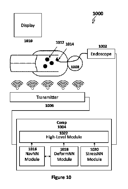
本発明は、自己操縦管腔内システムであって、操縦可能な細長い本体を含む管腔内装置と、1つ以上のモジュールを含むコンピューターメモリ記憶媒体であって、1つ以上のモジュールは、デジタル管腔内マップ内で選択された所望の場所に到達するために、前記管腔内装置の前記操縦可能な細長い本体によって実行されるべきナビゲーション動作を生成するための命令を含むナビゲーションモジュールと、実行される前記ナビゲーション動作によって生じる1つ以上の管腔に対する潜在的な変形を評価するための命令を含む変形モジュールと、前記ナビゲーション動作によって生じる前記管腔上の潜在的な応力レベルを評価するための命令を含む応力モジュールと、前記ナビゲーションモジュール、変形モジュール、及び応力モジュールのうちの1つ以上から情報を受け取り、それに応じて前記管腔内装置の前記操縦可能な細長い本体を駆動し、任意選択でさらに駆動するための命令を生成するための命令を含む高レベルモジュールと、を含むコンピューターメモリ記憶媒体と、を含む自己操縦管腔内システムに関する。
【選択図】図10
The present invention relates to a self-steering endoluminal system comprising: an endoluminal device comprising a steerable elongate body; and a computer memory storage medium comprising one or more modules, the one or more modules including: a navigation module comprising instructions for generating navigation operations to be performed by the steerable elongate body of the endoluminal device to reach a desired location selected within a digital endoluminal map; a deformation module comprising instructions for evaluating potential deformations to one or more lumens caused by the navigation operations performed; a stress module comprising instructions for evaluating potential stress levels on the lumens caused by the navigation operations; and a higher level module comprising instructions for receiving information from one or more of the navigation module, deformation module, and stress module and generating instructions for driving, and optionally further driving, the steerable elongate body of the endoluminal device accordingly.
[Selected figure] Figure 10
Description
関連出願の相互参照
本出願は、米国仮特許出願第63/242,101号(2021年9月9日に出願)及び米国仮特許出願第63/340,512号(2022年5月11日に出願)の優先権の利益を主張する。なお、これらの文献の内容は、その全体において参照により本明細書に組み込まれている。
CROSS-REFERENCE TO RELATED APPLICATIONS This application claims the benefit of priority to U.S. Provisional Patent Application No. 63/242,101, filed September 9, 2021, and U.S. Provisional Patent Application No. 63/340,512, filed May 11, 2022, the contents of which are incorporated by reference in their entireties herein.
本発明は、そのいくつかの実施形態において、1つ以上の管腔内装置をナビゲートするためのシステム及び方法に関し、より詳細には、しかし排他的にではなく、1つ以上の自己操縦管腔内装置をナビゲートするためのシステム及び方法に関する。 The present invention, in some embodiments thereof, relates to systems and methods for navigating one or more endoluminal devices, and more particularly, but not exclusively, to systems and methods for navigating one or more self-steering endoluminal devices.
特定の介入手順では、生検サンプルを得るかまたは局所的な処置を加えるために、医師は、管腔内構造、たとえば肺気管支樹、またはたとえば脳血管系、またはたとえば消化器系の内部の特定の標的組織に到達する必要がある。これを達成するために、管腔内ツール、たとえば肺内の気管支鏡、またはたとえば血管系用のカテーテル挿入キットを使用することが標準的な技術である。これは、リアルタイムの直接視覚イメージング、たとえば直接視、またはたとえば血管造影図に従って、分岐管腔を通して手動で誘導される。これは、特に、標的が末梢場所にある場合、及び/またはその場所に到達するための経路が蛇行性経路である場合、面倒な作業である。そのような場合にツールを駆動する明らかな難しさの1つは、機械的な難しさである。たとえば、肺において、標準的な気管支鏡は通常、それを強制的に入れる必要がある末梢気道(たとえば、直径1mm)と比べて、相対的に厚い(たとえば、直径6mm)。別の問題はナビゲーションに関する。直接視覚化ナビゲーションでは、医師は、ビデオ画像のみに基づいて、肺内の気管支鏡の場所を理解しなくてはならない。しかし、気道のフラクタルな性質により、気道がどんどん小さくなるにつれて、一方の気道を他方の気道から区別することが難しくなることが多く、経験豊富な医師であっても、誤った方向転換を誤って選択して、最終的に所望の標的に到達しない可能性が高くなる。同様に、血管系、たとえば脳血管系、またはたとえば肝血管系では、構造は繊細で狭くなっていて蛇行しており、マイクロカテーテル及びガイドワイヤを誘導するための標準的な血管造影図の使用は困難であり、何年もの訓練及び専門化が必要である。 In certain interventional procedures, the physician needs to reach a specific target tissue inside an endoluminal structure, e.g., the pulmonary bronchial tree, or e.g., the cerebral vasculature, or e.g., the digestive system, in order to obtain a biopsy sample or to apply a localized treatment. To achieve this, it is standard technology to use an endoluminal tool, e.g., an intrapulmonary bronchoscope, or e.g., a catheter insertion kit for the vasculature. This is manually guided through the branching lumens according to real-time direct visual imaging, e.g., direct vision, or e.g., an angiogram. This is a tedious task, especially when the target is in a peripheral location and/or when the path to reach that location is a tortuous path. One obvious difficulty in driving the tool in such cases is the mechanical difficulty. For example, in the lungs, a standard bronchoscope is usually relatively thick (e.g., 6 mm in diameter) compared to the peripheral airways (e.g., 1 mm in diameter) into which it must be forced. Another problem concerns navigation. In direct visualization navigation, the physician must understand the location of the bronchoscope in the lungs based only on a video image. However, due to the fractal nature of airways, as they become smaller and smaller, it is often difficult to distinguish one airway from the other, increasing the likelihood that even experienced physicians will mistakenly choose the wrong turn and ultimately not reach the desired target. Similarly, in the vasculature, e.g., the cerebral vasculature, or, e.g., the hepatic vasculature, the structures are delicate, narrowed, and tortuous, making the use of standard angiograms to guide microcatheters and guidewires challenging and requiring years of training and specialization.
近年は、気管支鏡検査者が肺内の末梢血管介入に対してナビゲーション気管支鏡検査を使用することが、より一般的になっている。このような手順は、通常、CTまたは他のほぼリアルタイムのイメージングに基づいて肺の2D及び/または3Dナビゲーションレンダリングを提供するシステムを使用して実行され、その上に器具の場所の参照が表示される。したがって、このようなシステムは、医師が、気管支鏡、内視鏡、または一般的なカテーテル(カメラの有無にかかわらず)などの器具を標的場所に誘導するのを支援する。このような誘導される器具には、通常、標準的な気管支鏡と比べて直径が小さい(たとえば、3~4mm以下)という利点がある。このような器具は通常、解剖学的構造の内部の所望の場所に到達したら、医師が生検及び/または処置ツールを標的組織に導入できるようにするのに十分に広い作業チャネル(たとえば、直径2mm以上)を有する。 In recent years, it has become more common for bronchoscopists to use navigational bronchoscopy for peripheral vascular interventions within the lungs. Such procedures are typically performed using systems that provide 2D and/or 3D navigational renderings of the lungs based on CT or other near real-time imaging, on which instrument location references are displayed. Such systems thus assist the physician in guiding an instrument, such as a bronchoscope, endoscope, or a common catheter (with or without a camera), to a target location. Such guided instruments typically have the advantage of being small in diameter (e.g., 3-4 mm or less) compared to standard bronchoscopes. Such instruments typically have a working channel (e.g., 2 mm or more in diameter) that is wide enough to allow the physician to introduce biopsy and/or treatment tools into the target tissue once the desired location inside the anatomy is reached.
さらなる背景技術には、欧州特許EP2849669B1が含まれる。これは、プロセッサと、細長い柔軟な本体の長さに沿って配置された追跡システムを含む外科装置とを備える医療システムを開示する。プロセッサは、患者の解剖学的構造の解剖学的通路の第1のモデルを受け取る。第1のモデルには、近位及び遠位分岐を表すモデル通路の組が含まれる。プロセッサはまた、近位及び遠位分岐内に位置する細長い柔軟な本体の形状を追跡システムから受け取る。プロセッサは、細長い柔軟な本体の形状に基づいて、近位及び遠位分岐内に位置する外科装置に応じて患者の解剖学的構造に作用する力の組を決定する。プロセッサはまた、力の組に基づいて第1のモデルを変形させることによって第2のモデルを生成し、第2のモデル及び第2のモデル内の細長い柔軟な本体の表現を表示する。 Further background art includes European Patent EP 2849669 B1, which discloses a medical system comprising a processor and a surgical device including a tracking system disposed along a length of an elongated flexible body. The processor receives a first model of an anatomical passageway of a patient's anatomy. The first model includes a set of model passageways representing proximal and distal branches. The processor also receives from the tracking system a shape of the elongated flexible body located within the proximal and distal branches. The processor determines a set of forces acting on the patient's anatomy in response to a surgical device located within the proximal and distal branches based on the shape of the elongated flexible body. The processor also generates a second model by deforming the first model based on the set of forces and displays the second model and a representation of the elongated flexible body within the second model.
米国特許第10499993B2号には、プロセッサと、コンピューター可読命令が記憶されたメモリとを含む処理システムが開示されている。コンピューター可読命令は、プロセッサによって実行されると、システムに、基準状態における分岐した解剖学的構造の参照3次元立体表現を受け取らせ、参照3次元立体表現に基づいてノード及びリンケージの参照ツリーを取得させる。コンピューター可読命令また、システムに、参照ツリーに基づいて参照3次元幾何学的モデルを取得させ、形状センサーからの測定に基づいて、解剖学的運動による分岐した解剖学的構造の変形を検出させる。コンピューター可読命令はまた、システムに、検出された変形に基づいてノード及びリンケージの変形したツリーを取得させ、分岐した解剖学的構造の検出された変形を表す3次元変形フィールドを作成させ、3次元変形フィールドを参照3次元幾何学的モデルに適用させる。 US Patent No. 10,499,993 B2 discloses a processing system including a processor and a memory having computer readable instructions stored thereon. The computer readable instructions, when executed by the processor, cause the system to receive a reference 3D volumetric representation of a branched anatomical structure in a reference state and obtain a reference tree of nodes and linkages based on the reference 3D volumetric representation. The computer readable instructions also cause the system to obtain a reference 3D geometric model based on the reference tree and detect deformation of the branched anatomical structure due to anatomical motion based on measurements from a shape sensor. The computer readable instructions also cause the system to obtain a deformed tree of nodes and linkages based on the detected deformation, create a 3D deformation field representing the detected deformation of the branched anatomical structure, and apply the 3D deformation field to the reference 3D geometric model.
米国特許第10610306B2号には、解剖学的通路内に少なくとも部分的に位置する装置の形状を決定することを含む方法が開示される。本方法はさらに、装置の複数のセクションに対する変形力の組を決定することを含む。変形力の組を決定することは、装置の複数のセクションの各セクションの剛性を決定することを含む。本方法はさらに、装置の形状、変形力の組(解剖学的通路のそれぞれの部分に対する複数のセクションの各セクションの影響を含む)、解剖学的通路を説明する解剖学的データに基づいて、解剖学的通路に対する装置の位置を示す複合材料モデルを生成することを含む。 U.S. Patent No. 10,610,306 B2 discloses a method that includes determining a shape of a device that is at least partially positioned within an anatomical passageway. The method further includes determining a set of deformation forces for a plurality of sections of the device. Determining the set of deformation forces includes determining a stiffness of each section of the plurality of sections of the device. The method further includes generating a composite material model that indicates the position of the device relative to the anatomical passageway based on the shape of the device, the set of deformation forces (including the effect of each section of the plurality of sections on a respective portion of the anatomical passageway), and anatomical data describing the anatomical passageway.
米国特許第10524641B2号には、内視鏡の操作者に提供されるナビゲーションガイダンスが開示される。提供は、参照フレームに対する内視鏡の現在位置及び形状を決定し、決定された位置及び形状に従って内視鏡コンピューターモデルを生成し、内視鏡コンピューターモデルを、参照フレームを基準とする患者コンピューターモデルとともに表示して、患者内で内視鏡を操縦する間に操作者によって視認できるようにすることによって行われる。 U.S. Patent No. 10,524,641 B2 discloses navigational guidance provided to an endoscope operator by determining the current position and shape of the endoscope relative to a reference frame, generating an endoscope computer model according to the determined position and shape, and displaying the endoscope computer model along with a patient computer model referenced to the reference frame for viewing by the operator while maneuvering the endoscope within the patient.
米国特許出願第20180193100A1号には、ロボットマニピュレータに取り付け可能な外科用器具を含む装置が開示される。外科用器具は細長いアームを含む。細長いアームは、少なくとも1つの関節領域を含む能動的に制御される湾曲可能な領域と、能動的に制御される湾曲可能な領域に結合された遠位端を含む受動的に湾曲可能な領域と、受動的に湾曲可能な領域を通って延び、少なくとも1つの関節領域に結合されて、能動的に制御される湾曲可能な領域を制御する駆動メカニズムと、細長いアームを通って延びるチャネルとを含む。外科用器具はまた、チャネル内に位置する光ファイバーを含む。光ファイバーは、受動的に曲げ可能な領域または能動的に制御される曲げ可能な領域の少なくとも一方内に光ファイバー曲げセンサーを含む。 US Patent Application No. 20180193100A1 discloses an apparatus including a surgical instrument mountable to a robotic manipulator. The surgical instrument includes an elongated arm. The elongated arm includes an actively controlled bendable region including at least one joint region, a passively bendable region including a distal end coupled to the actively controlled bendable region, a drive mechanism extending through the passively bendable region and coupled to the at least one joint region to control the actively controlled bendable region, and a channel extending through the elongated arm. The surgical instrument also includes an optical fiber located within the channel. The optical fiber includes a fiber optic bend sensor within at least one of the passively bendable region or the actively controlled bendable region.
米国特許第9839481B2号には、医療器具の近位端に結合するように構成されたハンドピース本体と、ハンドピース本体内に取り付けられた手動アクチュエータとを含むシステムが開示される。システムはさらに、ハンドピース本体内に取り付けられた複数の駆動入力を含む。駆動入力は、電動式駆動メカニズムと取り外し可能な嵌合を行うように構成されている。第1の駆動コンポーネントが、手動アクチュエータに動作可能に結合され、また複数の駆動入力のうちの1つに動作可能に結合される。第1の駆動コンポーネントは、医療器具の遠位端の第1の方向における動きを制御する。第2の駆動コンポーネントが、手動アクチュエータに動作可能に結合され、また複数の駆動入力のうちの他の1つに動作可能に結合される。第2の駆動コンポーネントは、医療器具の遠位端の第2の方向における動きを制御する。 US Patent No. 9,839,481 B2 discloses a system including a handpiece body configured to couple to a proximal end of a medical instrument and a manual actuator mounted within the handpiece body. The system further includes a plurality of drive inputs mounted within the handpiece body. The drive inputs are configured for releasable mating with the motorized drive mechanism. A first drive component is operably coupled to the manual actuator and to one of the plurality of drive inputs. The first drive component controls movement of the distal end of the medical instrument in a first direction. A second drive component is operably coupled to the manual actuator and to another one of the plurality of drive inputs. The second drive component controls movement of the distal end of the medical instrument in a second direction.
米国特許第9763741B2号には、外科医に、熟練を要する動き及び位置を必要とせずに、ロボット駆動の内視鏡装置を患者内の所望の解剖学的位置に駆動する能力を与えると同時に、内視鏡装置上に取り付けられたデジタルカメラから画質の向上を享受する管腔内ロボットシステムが開示される。 U.S. Patent No. 9,763,741 B2 discloses an intraluminal robotic system that gives the surgeon the ability to drive a robotically driven endoscopic device to a desired anatomical location within a patient without the need for skilled movements and positions, while enjoying the improved image quality from a digital camera mounted on the endoscopic device.
米国特許出願第US20110085720A1号には、分岐構造のデジタル画像と、分岐構造内部のセンサーの場所を表すリアルタイム指標との間の位置合わせが、センサーを使用して構造内部のデジタル画像を「ペイント」することによって達成されることが開示される。十分な場所データが収集されると、位置合わせが達成される。位置合わせは、分岐構造を通るナビゲーションにより必然的にさらなる場所データが収集され、その結果、位置合わせが継続的に改良されるという意味で、「自動」である。 U.S. Patent Application No. US20110085720A1 discloses that alignment between a digital image of a branching structure and a real-time indicia representing the location of a sensor within the branching structure is achieved by using the sensor to "paint" the digital image of the structure's interior. Once sufficient location data is collected, alignment is achieved. The alignment is "automatic" in the sense that navigation through the branching structure necessarily results in the collection of more location data, resulting in continuous refinement of the alignment.
以下は、本発明の実施形態のいくつかの例を含む非排他的なリストである。本発明はまた、以下に明示的に列挙されない場合でも、ある例におけるすべての特徴よりも少ない特徴を含む実施形態、及び複数の例からの特徴を使用する実施形態を含む。 Below is a non-exclusive list including some example embodiments of the present invention. The present invention also includes embodiments including fewer than all of the features in an example, and embodiments that use features from more than one example, even if not explicitly listed below.
例1.自己操縦管腔内システム用の操縦計画を生成する方法であって、
a.自己操縦管腔内装置が到達する必要があるデジタル管腔内マップ内の1つ以上の管腔を通してアクセス可能な場所を選択することと、
b.前記管腔内装置が前記場所に到達するためのナビゲーション動作を生成することと、
c.前記管腔内装置によって実行される前記ナビゲーション動作によって生じる1つ以上の管腔に対する潜在的な変形を評価することと、
d.前記自己操縦管腔内システムが前記場所に到達している間に、前記潜在的な変形を評価した結果に従って前記操縦計画を更新することと、を含む前記方法。
Example 1. A method of generating a steering plan for a self-steering endoluminal system, comprising:
a. selecting a location accessible through one or more lumens in a digital endoluminal map that the self-steering endoluminal device needs to reach;
b. generating a navigation movement for the endoluminal device to reach the location;
c. assessing potential deformations to one or more lumens caused by the navigational movements performed by the endoluminal device;
and updating the steering plan according to an evaluation of the potential deformations while the self-steering endoluminal system is reaching the location.
例2.前記場所に到達するまで前記ナビゲーション動作を実行することをさらに含む、例1に記載の方法。 Example 2. The method of Example 1, further comprising performing the navigation action until the location is reached.
例3.前記操縦計画を前記更新することはリアルタイムで実行される、例1または例2に記載の方法。 Example 3. The method of example 1 or example 2, wherein the updating of the maneuver plan is performed in real time.
例4.前記方法は、前記管腔内装置によって実行される前記ナビゲーション動作によって生じる前記管腔上の潜在的な応力レベルを評価することをさらに含む、例1~3のいずれか1つに記載の方法。 Example 4. The method of any one of Examples 1 to 3, further comprising assessing a potential stress level on the lumen caused by the navigational operation performed by the endoluminal device.
例5.前記方法は、前記潜在的な応力レベルが所定閾値を下回るまで実行される、例4に記載の方法。 Example 5. The method of Example 4, wherein the method is performed until the potential stress level falls below a predetermined threshold.
例6.前記自己操縦管腔内システムに前記計画を提供することをさらに含む、例1~5のいずれか1つに記載の方法。 Example 6. The method of any one of Examples 1 to 5, further comprising providing the plan to the self-steering endoluminal system.
例7.画像に基づいて、前記1つ以上の管腔を含む前記デジタル管腔内マップを生成することをさらに含む、例1~6のいずれか1つに記載の方法。 Example 7. The method of any one of Examples 1 to 6, further comprising generating the digital endoluminal map including the one or more lumens based on the images.
例8.前記画像はCTスキャンである、例7に記載の方法。 Example 8. The method of Example 7, wherein the image is a CT scan.
例9.前記画像は血管造影図である、例7に記載の方法。 Example 9. The method of Example 7, wherein the image is an angiogram.
例10.ナビゲーション動作を前記生成することは、前記ナビゲーション動作の第1のシミュレーションを実行することを含む、例1~9のいずれか1つに記載の方法。 Example 10. The method of any one of Examples 1 to 9, wherein generating the navigation behavior includes performing a first simulation of the navigation behavior.
例11.前記潜在的な変形を評価することは、前記潜在的な変形の第2のシミュレーションを実行することを含む例1~10のいずれか1つに記載の方法。 Example 11. The method of any one of Examples 1 to 10, wherein evaluating the potential deformation includes performing a second simulation of the potential deformation.
例12.前記第2のシミュレーションにおいてシミュレートした前記潜在的な変形に従って、前記デジタル管腔内マップを更新することをさらに含む、例11に記載の方法。 Example 12. The method of Example 11, further comprising updating the digital endoluminal map according to the potential deformations simulated in the second simulation.
例13.前記潜在的な応力レベルを評価することは、前記潜在的な応力レベルのシミュレーションを実行することを含む、例4に記載の方法。 Example 13. The method of example 4, wherein assessing the potential stress level includes performing a simulation of the potential stress level.
例14.前記潜在的な応力レベルを下げるために前記ナビゲーション動作を更新することをさらに含む、例13に記載の方法。 Example 14. The method of example 13, further comprising updating the navigation behavior to reduce the potential stress level.
例15.前記潜在的な変形を評価することは、呼吸、心臓の鼓動、及び他の外因によって生じる変形を評価することをさらに含む、例1~14のいずれか1つに記載の方法。 Example 15. The method of any one of Examples 1 to 14, wherein assessing the potential deformation further includes assessing deformation caused by breathing, heartbeat, and other external factors.
例16.自己操縦管腔内システムであって、
a.自己操縦可能な細長い本体を含む管腔内装置と、
b.1つ以上のモジュールを含むコンピューターメモリ記憶媒体であって、前記1つ以上のモジュールは、
i.デジタル管腔内マップ内で選択された所望の場所に到達するために、前記管腔内装置の前記操縦可能な細長い本体によって実行されるべきナビゲーション動作を生成するための命令を含むナビゲーションモジュールと、
ii.前記管腔内装置の前記操縦可能な細長い本体によって実行される前記ナビゲーション動作によって生じる1つ以上の管腔に対する潜在的な変形を評価するための命令を含む変形モジュールと、
iii.前記ナビゲーションモジュール及び前記変形モジュールのうちの1つ以上から情報を受け取り、それに応じて前記管腔内装置の前記操縦可能な細長い本体を駆動するための命令を含む高レベルモジュールと、を含む前記コンピューターメモリ記憶媒体と、を含む前記自己操縦管腔内システム。
Example 16. A self-steering intraluminal system comprising:
a. an intraluminal device comprising a self-steerable elongate body;
b. a computer memory storage medium including one or more modules, said one or more modules comprising:
i. a navigation module including instructions for generating navigation operations to be performed by the steerable elongate body of the endoluminal device to reach a desired location selected within a digital endoluminal map;
ii. a deformation module comprising instructions for evaluating potential deformations to one or more lumens resulting from the navigational actions performed by the steerable elongate body of the endoluminal device;
and a higher level module including instructions for receiving information from one or more of the navigation module and the deformation module and driving the steerable elongate body of the endoluminal device accordingly.
例17.前記コンピューターメモリ記憶媒体は、前記管腔内装置の前記操縦可能な細長い本体によって実行される前記ナビゲーション動作によって生じる前記管腔上の潜在的な応力レベルを評価するための命令を含む応力モジュールをさらに含む、例16に記載のシステム。 Example 17. The system of Example 16, wherein the computer memory storage medium further includes a stress module including instructions for assessing potential stress levels on the lumen caused by the navigational movements performed by the steerable elongate body of the endoluminal device.
例18.前記高レベルモジュールは、前記応力モジュールから情報を受け取り、それに応じて前記管腔内装置の前記操縦可能な細長い本体を駆動するための命令をさらに含む、例17に記載のシステム。 Example 18. The system of Example 17, wherein the high level module further includes instructions for receiving information from the stress module and responsively driving the steerable elongate body of the endoluminal device.
例19.前記管腔内装置は、前記ナビゲーション動作中の前記管腔内装置の場所をモニタリングするための1つ以上のセンサーを含む、例16~18のいずれか1つに記載のシステム。 Example 19. The system of any one of Examples 16-18, wherein the endoluminal device includes one or more sensors for monitoring the location of the endoluminal device during the navigation operation.
例20.前記モニタリングを可能にするための外部送信機をさらに含む、例19に記載のシステム。 Example 20. The system of Example 19, further comprising an external transmitter for enabling the monitoring.
例21.前記ナビゲーションモジュールは、デジタル管腔内マップ内で選択された所望の場所に到達するのを助けるために、前記管腔内装置の前記操縦可能な細長い本体によって実行されるべきナビゲーション動作を生成するための命令を含む、例16~20のいずれか1つに記載のシステム。 Example 21. The system of any one of Examples 16-20, wherein the navigation module includes instructions for generating navigation operations to be performed by the steerable elongate body of the endoluminal device to assist in reaching a desired location selected within a digital endoluminal map.
例22.前記高レベルモジュールは、前記受け取った情報に基づいて操縦計画を生成するための命令をさらに含む、例16~21のいずれか1つに記載のシステム。 Example 22. The system of any one of Examples 16-21, wherein the high-level module further includes instructions for generating a maneuver plan based on the received information.
例23.前記高レベルモジュールは、画像に基づいて、前記1つ以上の管腔を含む前記デジタル管腔内マップを生成するための命令をさらに含む、例16~22のいずれか1つに記載のシステム。 Example 23. The system of any one of Examples 16 to 22, wherein the high-level module further includes instructions for generating the digital endoluminal map including the one or more lumens based on the image.
例24.前記画像はCTスキャンである、例23に記載のシステム。 Example 24. The system of Example 23, wherein the image is a CT scan.
例25.前記画像は血管造影図である、例23に記載のシステム。 Example 25. The system of Example 23, wherein the image is an angiogram.
例26.前記ナビゲーションモジュールは、前記ナビゲーション動作の第1のシミュレーションを実行するための命令をさらに含む、例16~25のいずれか1つに記載のシステム。 Example 26. The system of any one of Examples 16 to 25, wherein the navigation module further includes instructions for performing a first simulation of the navigation operation.
例27.前記変形モジュールは、前記潜在的な変形の第2のシミュレーションを実行するための命令をさらに含む、例16~26のいずれか1つに記載のシステム。 Example 27. The system of any one of Examples 16 to 26, wherein the deformation module further includes instructions for performing a second simulation of the potential deformation.
例28.前記第2のシミュレーションにおいてシミュレートした前記潜在的な変形に従って、前記デジタル管腔内マップを更新することをさらに含む、例27に記載のシステム。 Example 28. The system of Example 27, further comprising updating the digital endoluminal map according to the potential deformations simulated in the second simulation.
例29.前記応力モジュールは、前記潜在的な応力レベルの第3のシミュレーションを実行するための命令をさらに含む、例17に記載のシステム。 Example 29. The system of Example 17, wherein the stress module further includes instructions for performing a third simulation of the potential stress levels.
例30.前記潜在的な応力レベルを下げるために前記ナビゲーション動作を更新することをさらに含む、例29に記載のシステム。 Example 30. The system of Example 29, further comprising updating the navigation behavior to reduce the potential stress level.
例31.前記潜在的な変形を評価することは、呼吸、心臓の鼓動、及び他の外因によって生じる変形を評価することをさらに含む、例16~30のいずれか1つに記載のシステム。 Example 31. The system of any one of Examples 16 to 30, wherein evaluating the potential deformation further includes evaluating deformation caused by breathing, heartbeat, and other external factors.
例32.前記管腔内装置は、1つ以上のプルワイヤと、1つ以上の事前に湾曲されたシャフトと、1つ以上のシャフトの本体に沿って可変剛性を有する前記1つ以上のシャフトと、1つ以上の同軸管とを含む1つ以上の操縦メカニズムを含む、例16~31のいずれか1つに記載のシステム。 Example 32. The system of any one of Examples 16-31, wherein the intraluminal device includes one or more steering mechanisms including one or more pull wires, one or more pre-curved shafts, one or more shafts having variable stiffness along the body of the one or more shafts, and one or more coaxial tubes.
例33.前記1つ以上の事前に湾曲されたシャフトと、前記1つ以上のシャフトの本体に沿って可変剛性を有する1つ以上のシャフトとのうちの1つ以上が、互いに一体である、例32に記載のシステム。 Example 33. The system of Example 32, wherein one or more of the one or more pre-curved shafts and the one or more shafts having variable stiffness along a body of the one or more shafts are integral with one another.
例34.前記1つ以上の操縦メカニズムは、シャフトの回転と、シャフトの前進/後退と、装置の先端部の偏向と、装置のシャフトの一部の偏向とを含む1つ以上の操縦動作を引き臆すように構成される、例32に記載のシステム。 Example 34. The system of Example 32, wherein the one or more steering mechanisms are configured to effect one or more steering actions including rotating the shaft, advancing/retracting the shaft, deflecting a tip of the device, and deflecting a portion of the shaft of the device.
例35.自己操縦管腔内システム用の操縦計画を生成する方法であって、
a.自己操縦管腔内装置が到達する必要があるデジタル管腔内マップ内の1つ以上の管腔を通してアクセス可能な場所を選択することと、
b.前記管腔内装置が前記場所に到達するためのナビゲーション動作を生成することと、
c.前記管腔内装置によって実行される前記ナビゲーション動作によって生じる1つ以上の管腔に対する潜在的な変形を評価することと、
d.前記管腔内装置によって実行される前記ナビゲーション動作によって生じる前記管腔上の潜在的な応力レベルを評価することと、
e.前記潜在的な応力レベルが所定閾値を下回るまでステップb~dを実行することと、を含む前記方法。
Example 35. A method of generating a steering plan for a self-steering endoluminal system, comprising:
a. selecting a location accessible through one or more lumens in a digital endoluminal map that the self-steering endoluminal device needs to reach;
b. generating a navigation movement for the endoluminal device to reach the location;
c. assessing potential deformations to one or more lumens caused by the navigational movements performed by the endoluminal device;
d. assessing potential stress levels on the lumen caused by the navigational movements performed by the endoluminal device;
e) performing steps b through d until the potential stress level falls below a predetermined threshold.
例36.前記自己操縦管腔内システムに前記計画を提供することをさらに含む、例35に記載の方法。 Example 36. The method of Example 35, further comprising providing the plan to the self-steering endoluminal system.
例37.画像に基づいて、前記1つ以上の管腔を含む前記デジタル管腔内マップを生成することをさらに含む、例35に記載の方法。 Example 37. The method of Example 35, further comprising generating the digital endoluminal map including the one or more lumens based on the images.
例38.前記画像はCTスキャンである、例37に記載の方法。 Example 38. The method of Example 37, wherein the image is a CT scan.
例39.前記画像は血管造影図である、例37に記載の方法。 Example 39. The method of Example 37, wherein the image is an angiogram.
例40.ナビゲーション動作を前記生成することは、前記ナビゲーション動作の第1のシミュレーションを実行することを含む、例35に記載の方法。 Example 40. The method of example 35, wherein generating the navigation behavior includes performing a first simulation of the navigation behavior.
例41.前記潜在的な変形を評価することは、前記潜在的な変形の第2のシミュレーションを実行することを含む、例35に記載の方法。 Example 41. The method of example 35, wherein evaluating the potential deformation includes performing a second simulation of the potential deformation.
例42.前記第2のシミュレーションにおいてシミュレートした前記潜在的な変形に従って、前記デジタル管腔内マップを更新することをさらに含む、例41に記載の方法。 Example 42. The method of Example 41, further comprising updating the digital endoluminal map according to the potential deformations simulated in the second simulation.
例43.前記潜在的な応力レベルを評価することは、前記潜在的な応力レベルのシミュレーションを実行することを含む、例35に記載の方法。 Example 43. The method of example 35, wherein assessing the potential stress level includes performing a simulation of the potential stress level.
例44.前記潜在的な応力レベルを下げるために前記ナビゲーション動作を更新することをさらに含む、例43に記載の方法。 Example 44. The method of example 43, further comprising updating the navigation behavior to reduce the potential stress level.
例45.前記潜在的な変形を評価することは、呼吸、心臓の鼓動、及び他の外因によって生じる変形を評価することをさらに含む、例35に記載の方法。 Example 45. The method of Example 35, wherein assessing the potential deformation further includes assessing deformation caused by breathing, heartbeat, and other external factors.
例46.自己操縦管腔内システムであって、
a.操縦可能な細長い本体を含む管腔内装置と、
b.1つ以上のモジュールを含むコンピューターメモリ記憶媒体であって、前記1つ以上のモジュールは、
i.デジタル管腔内マップ内で選択された所望の場所に到達するために、前記管腔内装置の前記操縦可能な細長い本体によって実行されるべきナビゲーション動作を生成するための命令を含むナビゲーションモジュールと、
ii.前記管腔内装置の前記操縦可能な細長い本体によって実行される前記ナビゲーション動作によって生じる1つ以上の管腔に対する潜在的な変形を評価するための命令を含む変形モジュールと、
iii.前記管腔内装置の前記操縦可能な細長い本体によって実行される前記ナビゲーション動作によって生じる前記管腔上の潜在的な応力レベルを評価するための命令を含む応力モジュールと、
iv.前記ナビゲーションモジュール、変形モジュール、及び応力モジュールのうちの1つ以上から情報を受け取り、それに応じて前記管腔内装置の前記操縦可能な細長い本体を駆動するための命令を含む高レベルモジュールと、を含む前記コンピューターメモリ記憶媒体と、を含む前記自己操縦管腔内システム。
Example 46. A self-steering intraluminal system, comprising:
a. an intraluminal device comprising a steerable elongate body;
b. a computer memory storage medium including one or more modules, said one or more modules comprising:
i. a navigation module including instructions for generating navigation operations to be performed by the steerable elongate body of the endoluminal device to reach a desired location selected within a digital endoluminal map;
ii. a deformation module comprising instructions for evaluating potential deformations to one or more lumens resulting from the navigational actions performed by the steerable elongate body of the endoluminal device;
iii. a stress module including instructions for assessing potential stress levels on the lumen caused by the navigational motion performed by the steerable elongate body of the endoluminal device;
and a higher level module including instructions for receiving information from one or more of the navigation module, deformation module, and stress module and driving the steerable elongate body of the endoluminal device accordingly.
例47.前記管腔内装置は、前記ナビゲーション動作中の前記管腔内装置の場所をモニタリングするための1つ以上のセンサーを含む、例46に記載のシステム。 Example 47. The system of Example 46, wherein the endoluminal device includes one or more sensors for monitoring the location of the endoluminal device during the navigation operation.
例48.前記モニタリングを可能にするための外部送信機をさらに含む、例47に記載のシステム。 Example 48. The system of Example 47, further comprising an external transmitter for enabling the monitoring.
例49.前記ナビゲーションモジュールは、デジタル管腔内マップ内で選択された所望の場所に到達するのを助けるために、前記管腔内装置の前記操縦可能な細長い本体によって実行されるべきナビゲーション動作を生成するための命令を含む、例46に記載のシステム。 Example 49. The system of Example 46, wherein the navigation module includes instructions for generating navigation operations to be performed by the steerable elongate body of the endoluminal device to assist in reaching a desired location selected within a digital endoluminal map.
例50.前記高レベルモジュールは、前記受け取った情報に基づいて操縦計画を生成するための命令をさらに含む、例46に記載のシステム。 Example 50. The system of Example 46, wherein the high-level module further includes instructions for generating a maneuver plan based on the received information.
例51.前記高レベルモジュールは、画像に基づいて、前記1つ以上の管腔を含む前記デジタル管腔内マップを生成するための命令をさらに含む、例46に記載のシステム。 Example 51. The system of Example 46, wherein the high-level module further includes instructions for generating the digital endoluminal map including the one or more lumens based on the image.
例52.前記画像はCTスキャンである、例51に記載のシステム。 Example 52. The system of Example 51, wherein the image is a CT scan.
例53.前記画像は血管造影図である、例51に記載のシステム。 Example 53. The system of Example 51, wherein the image is an angiogram.
例54.前記ナビゲーションモジュールは、前記ナビゲーション動作の第1のシミュレーションを実行するための命令をさらに含む、例46に記載のシステム。 Example 54. The system of Example 46, wherein the navigation module further includes instructions for performing a first simulation of the navigation operation.
例55.前記変形モジュールは、前記潜在的な変形の第2のシミュレーションを実行するための命令をさらに含む、例46に記載のシステム。 Example 55. The system of Example 46, wherein the deformation module further includes instructions for performing a second simulation of the potential deformation.
例56.前記第2のシミュレーションにおいてシミュレートした前記潜在的な変形に従って、前記デジタル管腔内マップを更新することをさらに含む、例55に記載のシステム。 Example 56. The system of Example 55, further comprising updating the digital endoluminal map according to the potential deformations simulated in the second simulation.
例57.前記応力モジュールは、前記潜在的な応力レベルの第3のシミュレーションを実行するための命令をさらに含む、例46に記載のシステム。 Example 57. The system of Example 46, wherein the stress module further includes instructions for performing a third simulation of the potential stress levels.
例58.前記潜在的な応力レベルを下げるために前記ナビゲーション動作を更新することをさらに含む、例57に記載のシステム。 Example 58. The system of Example 57, further comprising updating the navigation behavior to reduce the potential stress level.
例59.前記潜在的な変形を評価することは、呼吸、心臓の鼓動、及び他の外因によって生じる変形を評価することをさらに含む、例46に記載のシステム。 Example 59. The system of Example 46, wherein evaluating the potential deformation further includes evaluating deformation caused by breathing, heartbeat, and other external factors.
別に定義がない限り、本明細書で使用されるすべての技術用語及び/または科学用語は、本発明が属する当業者によって広く理解されるものと同じ意味を有する。本発明の実施形態の実施または試験において、本明細書に記載のものと類似または同等の方法及び材料を使用することができるが、典型的な方法及び/または材料について以下に説明する。矛盾する場合には、特許明細書が、定義も含んで、優先する。加えて、材料、方法、及び例は例示的にすぎず、必ずしも限定することは意図していない。 Unless otherwise defined, all technical and/or scientific terms used herein have the same meaning as commonly understood by one of ordinary skill in the art to which this invention belongs. Although methods and materials similar or equivalent to those described herein can be used in the practice or testing of embodiments of the present invention, exemplary methods and/or materials are described below. In case of conflict, the patent specification, including definitions, will control. In addition, the materials, methods, and examples are illustrative only and are not intended to be necessarily limiting.
本発明のいくつかの実施形態について、本明細書では、単に一例として、添付図面を参照して説明する。ここで、図面を詳細に具体的に参照するが、図示した詳細は、一例として、本発明の実施形態の例示的な説明を目的とするものであることを強調しておく。これに関連して、図面を使った説明は、本発明の実施形態をどのように実施し得るかを当業者に明らかにする。 Some embodiments of the present invention will now be described, by way of example only, with reference to the accompanying drawings. With specific reference now to the drawings in detail, it is emphasized that the particulars shown are intended, by way of example, as an illustrative description of embodiments of the invention. In this regard, the description using the drawings will make clear to one skilled in the art how embodiments of the invention may be put into practice.
本発明は、いくつかの実施形態において、たとえば内視鏡、またはたとえば小型管腔内ロボット装置、またはたとえば血管内カテーテル、またはたとえば血管内ガイドワイヤなどの1つ以上の管腔内装置をナビゲートするためのシステム及び方法に関し、より詳細には、しかし排他的にではなく、1つ以上の自己操縦管腔内装置をナビゲートするためのシステム及び方法に関する。いくつかの実施形態では、2つ以上の装置を使用する場合、それらは同時にナビゲートする。以下の段落では、単一の装置を使用して本発明を説明するが、複数の装置を同時に使用する場合にも同じ説明が当てはまることを理解されたい。 The present invention relates in some embodiments to systems and methods for navigating one or more endoluminal devices, such as, for example, an endoscope, or, for example, a miniature endoluminal robotic device, or, for example, an endovascular catheter, or, for example, an endovascular guidewire, and more particularly, but not exclusively, to systems and methods for navigating one or more self-steering endoluminal devices. In some embodiments, when two or more devices are used, they navigate simultaneously. In the following paragraphs, the invention is described using a single device, but it should be understood that the same description applies when multiple devices are used simultaneously.
いくつかの実施形態では、管腔内装置の位置をナビゲーションマップ上に表示するために、器具をリアルタイムまたはほぼリアルタイムで追跡する。いくつかの実施形態では、器具の位置を特定し、その位置をナビゲーションマップ上に表示するために、電磁シングルセンサー、マルチセンサー、光ファイバー、蛍光透視視覚化などを含む種々の方法を使用することができる。たとえば、いくつかの実施形態では、器具は、単一の追跡センサー(たとえば、電磁センサー)をカテーテルの先端部に有し、6-DOFの位置及び方向(「場所」とも言う。以下、位置及び方向の両方を意味する)をナビゲーションシステムに与える。用語「カテーテル」、「内視鏡」、及び「管腔内装置」は同じ意味であり、管腔の内部で使用される装置であり、本明細書では交換可能に使用される。用語「ナビゲーションマップ」は、種々のモダリティまたは検出方法(たとえば、CT、CTA、血管造影図、MRスキャン、超音波検査、3D超音波再構成、蛍光透視イメージング、トモシンセシス再構成、OCTなど)に基づき得る解剖学的構造の表現を意味する。いくつかの実施形態では、先端部の場所を、患者の解剖学的構造と位置合わせして、ナビゲーションの2D/3Dビュー内に表示する。用語「位置合わせ」は、特に指示がない限り、異なるデータセットを1つの座標系に変換するプロセスを指す。したがって、いくつかの実施形態では、医師は、たとえば肺の内部、またはたとえば脳血管の内部に位置するカテーテルの先端部の表示を見ることができ、カテーテルを所望の標的まで操作することができ、これは通常、提示されたビュー内にも表示される。いくつかの実施形態では、カテーテルの形状は、光ファイバーに基づき得る「形状センサー」を使用して検知する。いくつかの実施形態では、カテーテルの形状のモニタリングを、他の手段を使用して、たとえば、管腔内装置内からの能動的な送信を必要とせずに装置のモニタリングを可能にするRFID技術を使用して、またはほぼリアルタイムで1つ以上の蛍光透視投影を使用してその3D形状を再構成することによって行う。いくつかの実施形態では、蛍光透視投影から装置の3D形状を再構成することは、以下によって実行する。複数の蛍光透視2D投影において装置の先端部及び/または全曲線を識別すること、何らかの基準座標系においてX線透視装置の場所を識別すること(たとえば光学基準を使用して)、逆投影された2D装置の曲線が、蛍光透視投影から観察された2D曲線に適合するように、最適化によって装置の3D場所及び/または形状を見つけること。いくつかの実施形態では、カテーテルの形状を、患者の解剖学的構造に位置合わせして、医師に2D/3Dビューで示す。いくつかの実施形態では、カテーテルは、何らかの参照送信機に対する全カテーテルの位置及び絶対形状の追跡を可能にする複数の位置センサー(たとえば、電磁)を含んでいてもよい。いくつかの実施形態では、カテーテルはいかなるセンサーも含んでいなくてもよい。いくつかの実施形態では、それは、蛍光透視下で目に見える受動カテーテルであってもよい。いくつかの実施形態では、カテーテルの形状は、1つ以上の蛍光透視投影を使用する再構成法による蛍光透視法を使用して追跡されている。いくつかの実施形態では、次いで、カテーテルの形状及び場所を、患者の解剖学的構造に位置合わせして、医師に表示する。いくつかの実施形態では、これらの方法の組み合わせを使用する。 In some embodiments, the instrument is tracked in real-time or near real-time to display the location of the endoluminal device on the navigation map. In some embodiments, various methods can be used to identify the location of the instrument and display its location on the navigation map, including electromagnetic single sensor, multi-sensor, fiber optics, fluoroscopic visualization, etc. For example, in some embodiments, the instrument has a single tracking sensor (e.g., electromagnetic sensor) at the tip of the catheter to provide a 6-DOF position and orientation (also referred to as "location"; hereafter both position and orientation) to the navigation system. The terms "catheter," "endoscope," and "endoluminal device" mean the same thing, a device used inside a lumen, and are used interchangeably herein. The term "navigation map" refers to a representation of the anatomy, which may be based on various modalities or detection methods (e.g., CT, CTA, angiogram, MR scan, ultrasound, 3D ultrasound reconstruction, fluoroscopic imaging, tomosynthesis reconstruction, OCT, etc.). In some embodiments, the tip location is displayed in the navigation 2D/3D view in registration with the patient's anatomy. The term "registration" refers to the process of transforming different data sets into one coordinate system, unless otherwise indicated. Thus, in some embodiments, the physician can see a representation of the tip of the catheter located, for example, inside the lungs, or for example, inside the cerebral blood vessels, and can steer the catheter to the desired target, which is usually also displayed in the presented view. In some embodiments, the shape of the catheter is sensed using a "shape sensor" that may be based on optical fibers. In some embodiments, monitoring of the catheter shape is performed using other means, for example, using RFID technology that allows monitoring of the device without the need for active transmission from within the endoluminal device, or by reconstructing its 3D shape using one or more fluoroscopic projections in near real time. In some embodiments, reconstructing the 3D shape of the device from the fluoroscopic projections is performed by: identifying the tip and/or the entire curve of the device in multiple fluoroscopic 2D projections, identifying the location of the fluoroscope in some reference coordinate system (for example, using optical fiducials), finding the 3D location and/or shape of the device by optimization, such that the backprojected 2D device curve fits the 2D curve observed from the fluoroscopic projections. In some embodiments, the shape of the catheter is shown to the physician in a 2D/3D view, registered to the patient's anatomy. In some embodiments, the catheter may include multiple position sensors (e.g., electromagnetic) that allow tracking of the position and absolute shape of the entire catheter relative to some reference transmitter. In some embodiments, the catheter may not include any sensors. In some embodiments, it may be a passive catheter that is visible under fluoroscopy. In some embodiments, the shape of the catheter is tracked using fluoroscopy with a reconstruction method that uses one or more fluoroscopic projections. In some embodiments, the shape and location of the catheter is then displayed to the physician, registered to the patient's anatomy. In some embodiments, a combination of these methods is used.
いくつかの実施形態では、種々の2D/3Dビューを使用して、ナビゲーションマップに対してカテーテルの場所を表示する。いくつかの実施形態では、このビューを医師が使用して、標的に到達するようにカテーテルを操作する方法を決定する。いくつかの実施形態では、任意選択で、エントリポイントから標的までの予め計画された経路をこれらのビューに表示する。いくつかの実施形態では、介入中に、医師は、表示されたビュー上でリアルタイムで追跡された器具の動きを見ながら、経路に従って、カテーテル先端部を関節運動させて標的の近くまで駆動する。 In some embodiments, various 2D/3D views are used to display the catheter location relative to a navigation map. In some embodiments, the views are used by the physician to determine how to steer the catheter to reach the target. In some embodiments, the views optionally display a pre-planned path from the entry point to the target. In some embodiments, during the intervention, the physician articulates and drives the catheter tip close to the target, following the path while watching the instrument movement tracked in real time on the displayed views.
いくつかの実施形態では、種々のメカニズムを使用して、器具を所望の場所まで駆動することができる。いくつかの実施形態では、メカニズムを手動で駆動し、医師が操作し、1つ以上のレバーがカテーテルの先端部の関節運動をもたらす。いくつかの実施形態では、カテーテルを、遠位端に固定された曲線を伴って手動で挿入してもよい。いくつかの実施形態では、カテーテルを、遠隔制御パネルによって制御されるロボット駆動メカニズムに取り付ける。いくつかの実施形態では、任意の時点において、特に所望の標的に到達するときに、ロボット駆動メカニズムは、カテーテルを空間内または解剖学的構造内に固定して、カテーテルを保持する必要をなくし、カテーテルの位置及び方向を変更することなく作業チャネルを介してツールを安定して挿入できるようにしてもよい。いくつかの実施形態では、カテーテルを解剖学的構造内に固定する潜在的な利点は、場合によって、解剖学的構造が空間内の任意の固定点に対して動くために(たとえば、患者が呼吸している場合)、カテーテルを「空間内」に固定することは十分でなく、そのため、カテーテルを「解剖学的構造内」に固定すること、すなわち、患者の動き/呼吸または組織の動き、たわみまたは変形にかかわらず、それを空間内で自動的に移動して解剖学的標的に対してその位置を維持することは、潜在的に有用であることである。 In some embodiments, various mechanisms can be used to drive the tool to the desired location. In some embodiments, the mechanism is manually driven and operated by the physician, with one or more levers providing articulation of the tip of the catheter. In some embodiments, the catheter may be manually inserted with a fixed curve at the distal end. In some embodiments, the catheter is attached to a robotic drive mechanism controlled by a remote control panel. In some embodiments, at any point, particularly when reaching the desired target, the robotic drive mechanism may fix the catheter in space or in the anatomy, eliminating the need to hold the catheter and allowing for stable insertion of tools through the working channel without changing the position and orientation of the catheter. In some embodiments, a potential advantage of fixing the catheter in the anatomy is that in some cases, fixing the catheter "in space" is not sufficient because the anatomy moves relative to any fixed point in space (e.g., when the patient is breathing), and therefore it is potentially useful to fix the catheter "in the anatomy", i.e., to move it automatically in space and maintain its position relative to the anatomical target, regardless of patient movement/breathing or tissue movement, deflection or deformation.
管腔壁を越えて器具を押すことは有害であり得るか、少なくとも注意が必要であり得る多くの場合がある。手動器具の場合、障壁に対して押されると、抵抗力がカテーテルのハンドルに伝搬され戻って、そこから医師によって感知される。訓練された医師であれば、リスクを認識しているため、カテーテルを慎重に操作する。抵抗力が大きくなって医師が過剰であると判断した値を超えた場合、医師は圧力を追体験してカテーテルを引っ張る場合がある。カテーテルが引っ込められたら、医師は先端部の方向を変えて、標的に向かってゆっくりと前方に押す場合がある。しかし、機械的、電気機械的、及び/または動力駆動のカテーテルの場合、または非常に長いカテーテルの場合、医師はこれらの力を感知することができず、患者を傷つけるかまたはカテーテルを損傷させるリスクが高まる。したがって、いくつかの実施形態では、システムは、失われた自然な力のフィードバックの代わりに、たとえば力センサー及び機械的追跡を用いるメカニズムを含む。 There are many cases where pushing an instrument past a lumen wall can be harmful or at least require caution. With a manual instrument, when pushed against a barrier, a resistance force is transmitted back to the catheter handle, where it is sensed by the physician. A trained physician will be aware of the risks and will manipulate the catheter carefully. If the resistance force increases beyond what the physician determines to be excessive, the physician may relive the pressure and pull the catheter. Once the catheter is retracted, the physician may redirect the tip and slowly push it forward toward the target. However, with mechanical, electromechanical, and/or power-driven catheters, or with very long catheters, the physician may not be able to sense these forces, increasing the risk of injuring the patient or damaging the catheter. Thus, in some embodiments, the system includes mechanisms to replace the lost natural force feedback, using, for example, force sensors and mechanical tracking.
概要
本発明のいくつかの実施形態の態様は、管腔内装置、たとえば気管支内視鏡、またはたとえば血管内装置、たとえばガイドワイヤ、またはたとえばマイクロカテーテル、またはたとえばカテーテル、またはたとえば塞栓回収ツール、またはたとえばコイリングツールを、仮想の動的変形可能な管腔マップを使用してナビゲートするためのシステム及び方法に関する。いくつかの実施形態では、ナビゲーションは、自己操縦管腔内装置を使用するシステムによって自動的に実行させる。いくつかの実施形態では、ナビゲーション及びナビゲーションの更新は、管腔内装置が所望の場所に向かって前進している間にリアルタイムで実行させる。いくつかの実施形態では、変形は、患者の内部の管腔内装置の完全な場所及び/または形状のリアルタイム追跡の産物として、変形認識追跡システムによってリアルタイムで追跡し、仮想の動的変形可能なマップに変換する。いくつかの実施形態では、有益な3D位置特定画像を、完全に追跡された管腔内装置から、または複数の完全に追跡された管腔内装置及び仮想の動的変形可能なマップ(装置の現在のリアルタイム位置及び完全な形状を含む)から、リアルタイムで生成する。いくつかの実施形態では、位置特定画像は、適格な人間及び/またはインテリジェントマシン(AI)が、標的に到達するために任意の場所において要求される最適な駆動動作(たとえば、操縦、前進運動または後退運動)を決定するために必要なすべての情報をエンコードする。いくつかの実施形態では、位置特定画像を、ナビゲーションニューラルネットワーク(NavNN)モジュールによって処理して、インテリジェントな駆動動作を生成することができる。いくつかの実施形態では、非変形の位置特定画像を最初に使用し、変形ニューラルネットワーク(DeformNN)モジュールを使用して変形を見つけて、したがってナビゲーションに対する変形された位置特定画像を生成してもよい。いくつかの実施形態では、システム及び/また方法は多用途であり、たとえば、最初から最後まで完全な自律ナビゲーションを実行するために使用することができ、または別の例では、ナビゲーションは、より小さな人間監視のステップ(たとえば直観的な「タップトゥドライブ」ユーザインターフェースによって制御される)に分割してもよい。このユーザインターフェースでは、たとえば、解剖学的構造内の現在位置から指示された位置(たとえば、タッチスクリーンインターフェース上で「タップ」される)まで、自律ナビゲーションを実行する。いくつかの実施形態では、システム及び/また方法は、人間の医師に対して推奨されるナビゲーション命令を表示するために使用してもよい。いくつかの実施形態では、システム及び/また方法は、自己操縦内視鏡内で使用してもよいが、内視鏡の先端部は、標的までの経路と自動的に位置合わせされ、医師は、先端部を患者の気道に沿って遠位方向または近位方向に前進させるだけである。いくつかの実施形態では、システム及び/また方法は、自己操縦能力を備えた駆動装置が取り付けられた任意の血管内装置(たとえば、カテーテル、ガイドワイヤ、ツール、またはその他)と使用してもよいが、駆動装置は、血管内装置の先端部を、予め計画された経路と自動的に位置合わせするため、医師は、しおれて手動でまたは駆動装置を使用して、先端部を血管の内部で遠位方向または近位方向に前進させることが要求されるだけである。いくつかの実施形態では、システム及び/また方法は、AI性能を向上させる(たとえば、以下でさらに説明するように、1つ以上のニューラルネットワークモジュールに教える)ためにトレーニングデータを収集するのに適している。いくつかの実施形態では、自律運転動作は、さらなる安全メカニズムによって監視され、身体内の装置の安全な操作を確実にする。
Overview An aspect of some embodiments of the present invention relates to a system and method for navigating an endoluminal device, e.g., a bronchoscope, or e.g., an endovascular device, e.g., a guidewire, or e.g., a microcatheter, or e.g., a catheter, or e.g., an embolus retrieval tool, or e.g., a coiling tool, using a virtual dynamically deformable luminal map. In some embodiments, the navigation is performed automatically by the system using a self-steering endoluminal device. In some embodiments, the navigation and navigation updates are performed in real time while the endoluminal device is moving towards the desired location. In some embodiments, the deformations are tracked in real time by a deformation-aware tracking system as a product of real-time tracking of the complete location and/or shape of the endoluminal device inside the patient and converted into a virtual dynamically deformable map. In some embodiments, an informative 3D localization image is generated in real time from the fully tracked endoluminal device or from multiple fully tracked endoluminal devices and the virtual dynamically deformable map (including the current real-time location and complete shape of the device). In some embodiments, the localization image encodes all the information necessary for a competent human and/or an intelligent machine (AI) to determine the optimal driving action (e.g., steering, forward or backward movement) required at any location to reach the target. In some embodiments, the localization image can be processed by a Navigation Neural Network (NavNN) module to generate an intelligent driving action. In some embodiments, the undeformed localization image may be used first and a Deformation Neural Network (DeformNN) module may be used to find the deformations and generate a deformed localization image for navigation accordingly. In some embodiments, the system and/or method is versatile and can be used, for example, to perform a completely autonomous navigation from start to finish, or in another example, the navigation may be divided into smaller human-supervised steps (e.g., controlled by an intuitive "tap-to-drive" user interface), where the autonomous navigation is performed, for example, from a current position in the anatomy to a commanded position (e.g., "tapped" on a touch screen interface). In some embodiments, the system and/or method may be used to display recommended navigation instructions to a human physician. In some embodiments, the system and/or method may be used in a self-steering endoscope, where the tip of the endoscope is automatically aligned with a path to the target, and the physician only needs to advance the tip distally or proximally along the patient's airway. In some embodiments, the system and/or method may be used with any intravascular device (e.g., catheter, guidewire, tool, or other) with an attached drive with self-steering capabilities, where the drive automatically aligns the tip of the intravascular device with a pre-planned path, and the physician only needs to wilt and manually or use the drive to advance the tip distally or proximally inside the blood vessel. In some embodiments, the system and/or method is suitable for collecting training data to improve AI performance (e.g., to teach one or more neural network modules, as further described below). In some embodiments, the autonomous driving operation is monitored by additional safety mechanisms to ensure safe operation of the device within the body.
本発明のいくつかの実施形態の態様は、システムとして、3Dピラミッドプリミティブを3Dレンダーターゲット上にラスタライズし、それを、ナビゲーション手順においてリアルタイム3D位置特定画像をレンダリングするために使用するシステムに関する。いくつかの実施形態では、任意選択で、本方法はGPU ASIC/FPGA内に実装する。いくつかの実施形態では、任意選択で、本方法は、OpenGL拡張機能を通してまたはDirectXによって開発者に公開する。いくつかの実施形態では、任意選択で、本方法は、3Dニューラルネットワークによって処理するためにリアルタイム3D複合データをレンダリングするために使用する。いくつかの実施形態では、任意選択で、本方法は、追跡された手及び指のリアルタイム3D画像をレンダリングするために使用する。 An aspect of some embodiments of the invention relates to a system that rasterizes 3D pyramid primitives onto a 3D render target and uses it to render real-time 3D localization images in a navigation procedure. In some embodiments, the method is optionally implemented in a GPU ASIC/FPGA. In some embodiments, the method is optionally exposed to developers through an OpenGL extension or by DirectX. In some embodiments, the method is optionally used to render real-time 3D composite data for processing by a 3D neural network. In some embodiments, the method is optionally used to render real-time 3D images of tracked hands and fingers.
本発明のいくつかの実施形態の態様は、3Dマルチチャンネル位置特定画像においてナビゲーションデータをエンコードし、任意選択で表示するためのシステム及び/または方法に関する。任意選択で、仮想の3Dマルチチャンネル位置特定画像において。いくつかの実施形態では、任意選択で、チャネルのうちの1つは、セグメント化された管腔構造を含む。いくつかの実施形態では、任意選択で、セグメント化された管腔構造はバイナリである。いくつかの実施形態では、任意選択で、セグメント化された管腔構造はスカラー尤度マップである。いくつかの実施形態では、任意選択で、セグメント化された管腔構造は、変形ニューラルネットワークモジュールを使用して変形させる。いくつかの実施形態では、任意選択で、セグメント化された管腔構造は、その骨格によって表す。いくつかの実施形態では、任意選択で、チャネルのうちの1つは、生のCTデータ、生のMRIデータ、生の血管造影図データ、及びこれらの任意の組み合わせを含む。いくつかの実施形態では、任意選択で、1つ以上のチャネルは、カテーテルを、身体の内部のその推定位置に含む。いくつかの実施形態では、任意選択で、カテーテルは全曲線または部分的な曲線として表す。いくつかの実施形態では、任意選択で、カテーテルはその先端部のみによって表す。いくつかの実施形態では、任意選択で、カテーテルは、解剖学的構造の内部のその変形した位置においてレンダリングする。いくつかの実施形態では、任意選択で、カテーテルは、解剖学的構造の内部のその非変形の位置においてレンダリングする。いくつかの実施形態では、任意選択で、チャネルのうちの1つは標的までの経路を含む。いくつかの実施形態では、任意選択で、チャネルのうちの1つは、セグメント化された標的を含む。いくつかの実施形態では、任意選択で、チャネルのうちの1つは標的球体を含む。いくつかの実施形態では、任意選択で、チャネルのうちの1つは、内視鏡カメラの画像を含む。いくつかの実施形態では、任意選択で、画像は2Dであり、対応する光線に沿った逆投影を使用して3D位置特定画像においてレンダリングする。いくつかの実施形態では、任意選択で、画像は深度チャネルを含み、その深度チャネルを使用して3D表面として3D位置特定画像においてレンダリングする。いくつかの実施形態では、任意選択で、位置特定画像は特別な位置及び配置を有する。いくつかの実施形態では、任意選択で、位置特定画像はカテーテルの先端部に中心がくる。いくつかの実施形態では、任意選択で、位置特定画像は経路に中心がくる。いくつかの実施形態では、任意選択で、位置特定画像は、最も近い経路ポイントに中心がくる。いくつかの実施形態では、任意選択で、位置特定画像はカテーテルの先端部方向と位置合わせする。いくつかの実施形態では、任意選択で、位置特定画像のX軸は、カテーテルの先端部方向と位置合わせする。いくつかの実施形態では、任意選択で、位置特定画像のX軸は、経路方向と位置合わせする。いくつかの実施形態では、任意選択で、位置特定画像のZ軸は、次の分岐点の法線ベクトルと位置合わせする。いくつかの実施形態では、任意選択で、3D位置特定画像入力はリアルタイムで生成する。いくつかの実施形態では、任意選択で、位置特定画像は、3Dピラミッドテッセレーション技術を使用してレンダリングする。いくつかの実施形態では、任意選択で、セグメント化された管腔構造は、変形認識位置特定システムによって計算されるように、その変形状態においてリアルタイムでレンダリングされる。いくつかの実施形態では、任意選択で、セグメント化された管腔構造は、変形ニューラルネットワークを使用して、その変形状態においてリアルタイムでレンダリングする。いくつかの実施形態では、任意選択で、カテーテル位置は、追跡システムによって計算されるように、その位置においてレンダリングする。いくつかの実施形態では、任意選択で、カテーテルの位置は、変形ニューラルネットワークモジュールを使用して、その解剖学的変形が補償された位置においてレンダリングする。 Aspects of some embodiments of the invention relate to systems and/or methods for encoding and optionally displaying navigation data in a 3D multi-channel localization image, optionally in a virtual 3D multi-channel localization image. In some embodiments, optionally one of the channels includes a segmented luminal structure. In some embodiments, optionally the segmented luminal structure is binary. In some embodiments, optionally the segmented luminal structure is a scalar likelihood map. In some embodiments, optionally the segmented luminal structure is deformed using a deformation neural network module. In some embodiments, optionally the segmented luminal structure is represented by its skeleton. In some embodiments, optionally one of the channels includes raw CT data, raw MRI data, raw angiogram data, and any combination thereof. In some embodiments, optionally one or more channels include a catheter at its estimated location inside the body. In some embodiments, optionally the catheter is represented as a full curve or a partial curve. In some embodiments, optionally the catheter is represented only by its tip. In some embodiments, optionally the catheter renders in its deformed position within the anatomy. In some embodiments, optionally the catheter renders in its non-deformed position within the anatomy. In some embodiments, optionally one of the channels includes a path to the target. In some embodiments, optionally one of the channels includes a segmented target. In some embodiments, optionally one of the channels includes a target sphere. In some embodiments, optionally one of the channels includes an image of an endoscopic camera. In some embodiments, optionally the image is 2D and is rendered in a 3D localization image using back projection along corresponding rays. In some embodiments, optionally the image includes a depth channel and is rendered in the 3D localization image using the depth channel as a 3D surface. In some embodiments, optionally the localization image has a special position and arrangement. In some embodiments, optionally the localization image is centered on the tip of the catheter. In some embodiments, optionally the localization image is centered on the path. In some embodiments, optionally the localization image is centered on the closest path point. In some embodiments, the localization image is optionally aligned with the catheter tip direction. In some embodiments, the X-axis of the localization image is optionally aligned with the catheter tip direction. In some embodiments, the X-axis of the localization image is optionally aligned with the path direction. In some embodiments, the Z-axis of the localization image is optionally aligned with the normal vector of the next branch point. In some embodiments, the 3D localization image input is optionally generated in real time. In some embodiments, the localization image is optionally rendered using a 3D pyramid tessellation technique. In some embodiments, the segmented luminal structure is optionally rendered in its deformed state in real time, as calculated by a deformation-aware localization system. In some embodiments, the segmented luminal structure is optionally rendered in its deformed state in real time using a deformation neural network. In some embodiments, the catheter position is optionally rendered in its position, as calculated by the tracking system. In some embodiments, the catheter position is optionally rendered at a position compensated for its anatomical deformations using a deformation neural network module.
本発明のいくつかの実施形態の態様は、自動ナビゲーション駆動動作を生成するためのシステム及び/または方法に関する。いくつかの実施形態では、任意選択で、位置特定画像は、ナビゲーションニューラルネットワーク(NavNN)モジュールを使用して処理する。いくつかの実施形態では、任意選択で、位置特定画像は、3D畳み込みニューラルネットワーク(3D CNN)を使用して処理する。いくつかの実施形態では、任意選択で、位置特定画像は、3D回帰型ニューラルネットワーク(3D RNN)を使用して処理する。いくつかの実施形態では、任意選択で、位置特定画像は、より良好な駆動動作を生成するためのカメラチャネルを含む。いくつかの実施形態では、任意選択で、NavNNはメモリを所有する。いくつかの実施形態では、任意選択で、NavNNは予測間の状態ベクトルを運ぶ。いくつかの実施形態では、任意選択で、高レベルモジュールがNavNNを動作させる。いくつかの実施形態では、任意選択で、高レベルモジュールは、NavNNの最大出力を選択することによって最適な駆動動作を選択する。いくつかの実施形態では、任意選択で、高レベルモジュールは、NavNN出力に基づいてモーターを自動的に起動する。いくつかの実施形態では、任意選択で、高レベルモジュールは、ナビゲーションに探索を追加し、NavNN出力の局所極値点を回避するために、ランダムな駆動動作を定期的に生成する。いくつかの実施形態では、任意選択で、高レベルモジュールは、特定の所定の時間間隔でカテーテルを自動的にロール(回転)させる。いくつかの実施形態では、任意選択で、異なる出力駆動動作間の「ジャンプ」を防止するために、ヒステリシスをNavNN出力に使用する。いくつかの実施形態では、任意選択で、有害な駆動動作を防止するために、安全メカニズムをNavNN出力に強制する。いくつかの実施形態では、任意選択で、患者に特定の力が及ぼされた場合、カテーテルは押さない。いくつかの実施形態では、任意選択で、患者に特定の力が及ぼされた場合、カテーテルは自動的に引き戻す。いくつかの実施形態では、任意選択で、及ぼされた力は、セグメント化された管腔構造の内部の完全なカテーテル曲線を分析することによって計算する。いくつかの実施形態では、任意選択で、及ぼされた力は、カテーテルのハンドル内またはカテーテルの本体に沿った力センサーによって検知する。いくつかの実施形態では、任意選択で、NavNNを、対応する駆動動作によってラベル付けした3D位置特定画像入力を使用して、教師ありトレーニングにおいてトレーニングする。いくつかの実施形態では、任意選択で、ラベル付けしたサンプルを、現実的なシミュレータモジュールを使用して生成する。いくつかの実施形態では、任意選択で、ラベル付けしたサンプルを、現実のロボットナビゲーション手順から収集する。いくつかの実施形態では、任意選択で、ラベル付けしたサンプルを、実際の手動ナビゲーション手順から収集する。いくつかの実施形態では、任意選択で、操作者の手動駆動動作を自動的に分類する。いくつかの実施形態では、任意選択で、駆動動作は、近位及び遠位カテーテルセンサーを使用して分類する。いくつかの実施形態では、任意選択で、カテーテルのハンドルは、操作者の行動を分類するための1つ以上のセンサーを含む。いくつかの実施形態では、任意選択で、NavNNは、3D位置特定画像入力を使用して教師なし学習においてトレーニングする。いくつかの実施形態では、任意選択で、NavNNは、強化学習を使用して現実的なシミュレータモジュールにおいてトレーニングする。 Aspects of some embodiments of the invention relate to systems and/or methods for generating automatic navigation driving behavior. In some embodiments, the localization images are optionally processed using a Navigation Neural Network (NavNN) module. In some embodiments, the localization images are optionally processed using a 3D Convolutional Neural Network (3D CNN). In some embodiments, the localization images are optionally processed using a 3D Recurrent Neural Network (3D RNN). In some embodiments, the localization images optionally include a camera channel for generating better driving behavior. In some embodiments, the NavNN optionally possesses memory. In some embodiments, the NavNN optionally carries a state vector between predictions. In some embodiments, a high-level module optionally operates the NavNN. In some embodiments, the high-level module optionally selects an optimal driving behavior by selecting a maximum output of the NavNN. In some embodiments, the high-level module optionally automatically activates a motor based on the NavNN output. In some embodiments, optionally the high level module periodically generates random drive motions to add exploration to the navigation and avoid local extreme points in the NavNN output. In some embodiments, optionally the high level module automatically rolls the catheter at certain predefined time intervals. In some embodiments, optionally hysteresis is used in the NavNN output to prevent "jumps" between different output drive motions. In some embodiments, optionally a safety mechanism is forced into the NavNN output to prevent harmful drive motions. In some embodiments, optionally the catheter does not push if a certain force is exerted on the patient. In some embodiments, optionally the catheter automatically pulls back if a certain force is exerted on the patient. In some embodiments, optionally the exerted force is calculated by analyzing the complete catheter curve inside the segmented lumen structure. In some embodiments, optionally the exerted force is sensed by a force sensor in the catheter handle or along the body of the catheter. In some embodiments, the NavNN is optionally trained in supervised training using 3D localized image inputs labeled with corresponding driving actions. In some embodiments, the labeled samples are optionally generated using a realistic simulator module. In some embodiments, the labeled samples are optionally collected from a real robot navigation procedure. In some embodiments, the labeled samples are optionally collected from an actual manual navigation procedure. In some embodiments, the manual driving actions of the operator are optionally classified automatically. In some embodiments, the driving actions are optionally classified using proximal and distal catheter sensors. In some embodiments, the catheter handle optionally includes one or more sensors for classifying the operator's actions. In some embodiments, the NavNN is optionally trained in unsupervised learning using 3D localized image inputs. In some embodiments, the NavNN is optionally trained in a realistic simulator module using reinforcement learning.
本発明のいくつかの実施形態の態様は、変形した管腔構造の内部のカテーテルの解剖学的位置を見つけるためのシステム及び/または方法に関する(「変形した管腔構造」についてのさらなる説明については、以下を参照)。いくつかの実施形態では、任意選択で、位置特定画像は、変形ニューラルネットワーク(DeformNN)モジュールを使用して処理する。いくつかの実施形態では、任意選択で、位置特定画像は3D CNNを使用して処理する。いくつかの実施形態では、任意選択で、位置特定画像は3D RNNを使用して処理する。いくつかの実施形態では、任意選択で、位置特定画像は3D U-Netを使用して処理する。いくつかの実施形態では、任意選択で、位置特定画像は、精度を向上させるためのカメラチャネルを含む。いくつかの実施形態では、任意選択で、DeformNNはメモリを所有する。いくつかの実施形態では、任意選択で、DeformNNは予測間の状態ベクトルを運ぶ。いくつかの実施形態では、任意選択で、DeformNNは、変形補償された管腔構造の画像を出力する。いくつかの実施形態では、任意選択で、DeformNNは、入力管腔構造の内部の解剖学的位置にあるカテーテルの画像を出力する。いくつかの実施形態では、任意選択で、DeformNNは、管腔構造の内部の解剖学的位置にある1つ以上の仮想カテーテルの画像を、その対応する信頼レベルとともに出力する。いくつかの実施形態では、任意選択で、DeformNNは、入力管腔構造内の位置における入力カテーテルの信頼度を反映するカテーテルごとの単一の確率を出力する。いくつかの実施形態では、任意選択で、管腔構造の変形を、DeformNNの出力確率を最大にするように検索する。いくつかの実施形態では、任意選択で、高レベルモジュールがDeformNNを動作させる。いくつかの実施形態では、任意選択で、変形した管腔構造を出力する場合、入力及び出力管腔構造を、変形ベクトルを計算するために位置合わせする。いくつかの実施形態では、任意選択で、変形したカテーテル曲線を出力する場合、入力及び出力カテーテルを位置合わせして、変形ベクトルを計算する。いくつかの実施形態では、任意選択で、変形ベクトルを、変形補償されたシステムビューを表示するために、完全な管腔構造またはカテーテル位置に適用する。いくつかの実施形態では、任意選択で、DeformNNの部分位置特定画像出力は、欠落しているチャネルによって操作し、自動駆動動作を生成するためにNavNNに入力する。いくつかの実施形態では、任意選択で、DeformNNを、対応する変形補償された出力画像によってラベル付けした3D位置特定画像入力を使用して、教師ありトレーニングにおいてトレーニングする。いくつかの実施形態では、任意選択で、ラベル付けしたサンプルを、現実的なシミュレータモジュールを使用して生成する。いくつかの実施形態では、任意選択で、管腔構造の変形を、現実的な変形モデルを使用してシミュレータモジュールにおいてシミュレートする。いくつかの実施形態では、任意選択で、管腔構造の変形を、多項式、スプライン、または剛性3D変換を使用してシミュレータにおいてシミュレートする。いくつかの実施形態では、任意選択で、ラベル付けしたサンプルを、実際の手動ナビゲーション手順から収集する。いくつかの実施形態では、任意選択で、1つ以上のカテーテルを既知の解剖学的位置(たとえば、末梢場所)内に挿入し、解剖学的構造を内力及び外力を加えることによって変形して、管腔構造の変形を記録する。いくつかの実施形態では、任意選択で、変形を記録するために、追跡可能なセンサーを器官の内部に配置する。いくつかの実施形態では、任意選択で、複数のCBCT(コーンビームCT)スキャンを実行し、変形可能な位置合わせを使用して位置合わせして、変形ベクトルを計算する。いくつかの実施形態では、任意選択で、DeformNNを、手順の前に、特定の患者の管腔構造に関してさらにトレーニングする。 Aspects of some embodiments of the invention relate to systems and/or methods for locating an anatomical location of a catheter inside a deformed luminal structure (see below for further description of "deformed luminal structure"). In some embodiments, the localization images are optionally processed using a Deformation Neural Network (DeformNN) module. In some embodiments, the localization images are optionally processed using a 3D CNN. In some embodiments, the localization images are optionally processed using a 3D RNN. In some embodiments, the localization images are optionally processed using a 3D U-Net. In some embodiments, the localization images optionally include a camera channel for improved accuracy. In some embodiments, the DeformNN optionally possesses memory. In some embodiments, the DeformNN optionally carries a state vector between predictions. In some embodiments, the DeformNN optionally outputs an image of a deformation-compensated luminal structure. In some embodiments, optionally, DeformNN outputs an image of the catheter in an anatomical location inside the input lumen structure. In some embodiments, optionally, DeformNN outputs an image of one or more virtual catheters in an anatomical location inside the lumen structure with their corresponding confidence levels. In some embodiments, optionally, DeformNN outputs a single probability for each catheter reflecting the confidence of the input catheter at the location in the input lumen structure. In some embodiments, optionally, the deformation of the lumen structure is searched to maximize the output probability of DeformNN. In some embodiments, optionally, a high-level module operates DeformNN. In some embodiments, optionally, when outputting a deformed lumen structure, the input and output lumen structures are aligned to calculate a deformation vector. In some embodiments, optionally, when outputting a deformed catheter curve, the input and output catheters are aligned to calculate a deformation vector. In some embodiments, optionally, the deformation vector is applied to the complete lumen structure or catheter positions to display a deformation-compensated system view. In some embodiments, the partial localization image output of DeformNN is optionally manipulated by missing channels and input to NavNN to generate automated driving behavior. In some embodiments, DeformNN is optionally trained in supervised training using 3D localization image input labeled with corresponding deformation-compensated output images. In some embodiments, the labeled samples are optionally generated using a realistic simulator module. In some embodiments, the deformation of the luminal structure is optionally simulated in the simulator module using a realistic deformation model. In some embodiments, the deformation of the luminal structure is optionally simulated in the simulator using polynomial, spline, or rigid 3D transformations. In some embodiments, the labeled samples are optionally collected from actual manual navigation procedures. In some embodiments, one or more catheters are optionally inserted into known anatomical locations (e.g., peripheral locations), the anatomical structure is deformed by applying internal and external forces, and the deformation of the luminal structure is recorded. In some embodiments, a trackable sensor is optionally placed inside the organ to record the deformation. In some embodiments, multiple CBCT (cone beam CT) scans are optionally performed and aligned using deformable registration to calculate deformation vectors. In some embodiments, DeformNN is optionally further trained on the luminal anatomy of a particular patient prior to the procedure.
本発明のいくつかの実施形態の態様は、ナビゲーション手順において複数のカテーテル仮説を表示するためのシステム及び/または方法に関する。いくつかの実施形態では、任意選択で、信頼レベルに基づいて異なる不透明度または強度を有する2つ以上のカテーテル仮説を、2D/3Dビュー上で管腔構造の内部に表示する。いくつかの実施形態では、任意選択で、単一のカテーテルを、異なる仮説の異なる方向に分割する位置まで表示する。いくつかの実施形態では、任意選択で、カテーテル仮説の共有セグメントは通常表示し、一方で、分割したセグメントは異なる色、強度、または不透明度で表示する。いくつかの実施形態では、任意選択で、カテーテル位置が曖昧な場合、画面を、異なるカテーテル仮説の複数の独立した表示に分割する。いくつかの実施形態では、任意選択で、単一の勝利仮説に戻って、勝利した半分の画面が負けた半分の画面を視界の外に「押し出す」。 Aspects of some embodiments of the invention relate to systems and/or methods for displaying multiple catheter hypotheses in a navigation procedure. In some embodiments, two or more catheter hypotheses are optionally displayed inside the luminal structure on a 2D/3D view with different opacity or intensity based on confidence level. In some embodiments, a single catheter is optionally displayed up to a point where it splits into different directions for different hypotheses. In some embodiments, optionally, shared segments of the catheter hypotheses are displayed normally while splitting segments are displayed with different colors, intensities or opacities. In some embodiments, optionally, when the catheter position is ambiguous, the screen is split into multiple independent displays of different catheter hypotheses. In some embodiments, optionally, reverting to a single winning hypothesis, the winning half of the screen "pushes" the losing half of the screen out of view.
本発明のいくつかの実施形態の態様は、管腔構造の内部のカテーテルの力のリスク推定値を計算するためのシステム及び/または方法に関する。いくつかの実施形態では、任意選択で、力のリスク推定値を、管腔構造の内部のカテーテルの完全に追跡された位置を使用して計算する。いくつかの実施形態では、任意選択で、力のリスク推定値を、接触力及び内部のカテーテル力を推定することによって計算する。いくつかの実施形態では、任意選択で、力のリスク推定値を、管腔構造の内部のカテーテルを視覚化する3D位置特定画像を提供することによって、StressNNを使用して計算する。いくつかの実施形態では、任意選択で、StressNNを、現実的なシミュレータモジュールを使用して生成したラベル付けしたサンプルによってトレーニングする。いくつかの実施形態では、任意選択で、力のリスク推定値を、物理的にシミュレートした力推定値を使用してシミュレータモジュールにおいて計算する。 Aspects of some embodiments of the present invention relate to systems and/or methods for calculating a force risk estimate of a catheter inside a luminal structure. In some embodiments, the force risk estimate is optionally calculated using a fully tracked position of the catheter inside the luminal structure. In some embodiments, the force risk estimate is optionally calculated by estimating contact forces and internal catheter forces. In some embodiments, the force risk estimate is optionally calculated using a StressNN by providing a 3D localization image visualizing the catheter inside the luminal structure. In some embodiments, the StressNN is optionally trained with labeled examples generated using a realistic simulator module. In some embodiments, the force risk estimate is optionally calculated in the simulator module using physically simulated force estimates.
本発明のいくつかの実施形態の態様は、リアルタイム3D位置特定画像を使用して、任意選択的に無線で、任意選択的に使い捨ての管腔内装置を自己操縦するシステム及び方法に関する。いくつかの実施形態では、任意選択で、装置は、手順前のペアリングプロセスにおいて患者と無線でペアリングする。いくつかの実施形態では、任意選択で、患者のデータ(セグメント化された管腔構造、目標計画など)を、NFCまたは任意の他の無線方法を使用して装置に転送する。いくつかの実施形態では、任意選択で、装置は、セグメント化された管腔構造またはカテーテルに変形補償を適用する。いくつかの実施形態では、任意選択で、変形補償は、骨格変形モデル及び最適化方法を使用して行う。いくつかの実施形態では、任意選択で、変形補償は、DeformNNを使用して行う。いくつかの実施形態では、任意選択で、装置は、NavNNを使用して、正確な自動駆動動作及びフィードバックを生成する。いくつかの実施形態では、任意選択で、装置は、NavNN出力に基づいて、ハンドル内の小型モーターを使用してカテーテルを自動的に回転させ(受動的Jカテーテルを利用する場合に特に有用)、カテーテルを標的までの経路に位置合わせする。いくつかの実施形態では、任意選択で、装置は、小型アクチュエータ(たとえば、ハンドル内)を使用して装置の管腔内部分を自動的に押すかまたは引いて、標的に対していずれかの方向に装置を前進させる。いくつかの実施形態では、任意選択で、装置は、LEDまたは振動モーターフィードバックを使用して、ナビゲーション中に操作者に命令を出す。いくつかの実施形態では、任意選択で、装置は手持ち式であり、押す/引く動作は、装置の命令に従って操作者によって運ばれる。いくつかの実施形態では、任意選択で、装置を、ロボット駆動メカニズム内に取り付けて、人間の機械的介入なしに自律的に駆動する。いくつかの実施形態では、任意選択で、自動ナビゲーションは、力のリスク推定値に基づいて停止する。 Aspects of some embodiments of the invention relate to systems and methods for self-steering an endoluminal device, optionally wirelessly, using real-time 3D localization images. In some embodiments, the device optionally wirelessly pairs with the patient in a pre-procedure pairing process. In some embodiments, the patient's data (segmented luminal structure, target plan, etc.) is optionally transferred to the device using NFC or any other wireless method. In some embodiments, the device optionally applies deformation compensation to the segmented luminal structure or catheter. In some embodiments, the deformation compensation is optionally performed using a skeletal deformation model and optimization method. In some embodiments, the deformation compensation is optionally performed using DeformNN. In some embodiments, the device optionally uses NavNN to generate accurate automated driving movements and feedback. In some embodiments, the device optionally uses a small motor in the handle to automatically rotate the catheter (particularly useful when utilizing passive J-catheters) based on the NavNN output, and aligns the catheter to a path to the target. In some embodiments, the device optionally uses a small actuator (e.g., in the handle) to automatically push or pull the intraluminal portion of the device to advance the device in either direction relative to the target. In some embodiments, the device optionally uses LED or vibration motor feedback to provide instructions to the operator during navigation. In some embodiments, the device is optionally handheld, with the pushing/pulling motion carried by the operator following the device's commands. In some embodiments, the device is optionally mounted in a robotic drive mechanism to drive autonomously without human mechanical intervention. In some embodiments, the automatic navigation is optionally halted based on a force risk estimate.
本発明のいくつかの実施形態の態様は、目的地を示すことによって駆動される管腔内装置制御するためのシステム及び/または方法に関する。いくつかの実施形態では、駆動機能は、たとえば、電気機械装置を使用することによって達成する。いくつかの実施形態では、管腔内装置を、他の駆動方法を使用して管腔内で前進させる。たとえば、磁石付き装置に磁界を印加することによって、またはたとえば、装置を駆動するために空気圧または油圧を使用することによって、または他の方法によって前進させる。いくつかの実施形態では、任意選択で、操作者は、器具先端部の所望の最終位置及び方向を示すことによって、器具の先端部を解剖学的構造内の位置にナビゲートさせる。いくつかの実施形態では、任意選択で、目的地を、タッチスクリーン上に表示された器官を表す3Dマップ内の点をタップすることによってマーキングする。いくつかの実施形態では、任意選択で、目的地のマーキングを、解剖学的イメージング、たとえばCTスライス、またはたとえば血管造影図、またはたとえば超音波検査、またはたとえばMRIを表示するコンピューター画面上の場所でマウスポインタをクリックすることによって行う。いくつかの実施形態では、任意選択で、目的地のマーキングを、メニューまたは他のユーザインターフェース(UI)要素から、所定の位置を選択することによって行う。いくつかの実施形態では、任意選択で、目的地はシステムによって自動的に提案される。いくつかの実施形態では、任意選択で、目的地は音声コマンドを発することによって示される。いくつかの実施形態では、任意選択で、目的地は、プログレスバーに似たマルチウェイポイント湾曲平面図マップ上に示される。いくつかの実施形態では、任意選択で、ウェイポイントは、限定された操作をマップ上のそれらの順序に従って順番に実行することによって得られる。いくつかの実施形態では、任意選択で、対象領域内の正確な目的地を示すために「拡大鏡」ビューを使用する。いくつかの実施形態では、任意選択で、対象領域内の正確な目的地を示すために「一人称」ビューを使用する。いくつかの実施形態では、任意選択で、システムは、所定の最大移動距離に従って前進を停止するようにトリガされる。いくつかの実施形態では、任意選択で、デッドマンスイッチを使用して装置の動作を停止する。いくつかの実施形態では、任意選択で、「解剖学的構造内で安定させる」メカニズムを使用して、先端部が決定された構造に対する決定された近傍を横切ることを、電動式微小移動及び調整を使用して能動的に防止する。 An aspect of some embodiments of the invention relates to a system and/or method for controlling an endoluminal device driven by indicating a destination. In some embodiments, the driving function is accomplished, for example, by using an electromechanical device. In some embodiments, the endoluminal device is advanced within the lumen using other driving methods, for example, by applying a magnetic field to a magnetized device, or, for example, by using pneumatic or hydraulic pressure to drive the device, or by other methods. In some embodiments, the operator optionally navigates the instrument tip to a location within the anatomy by indicating a desired final position and orientation of the instrument tip. In some embodiments, the destination is optionally marked by tapping a point in a 3D map representing the organ displayed on a touch screen. In some embodiments, the destination is optionally marked by clicking a mouse pointer at a location on a computer screen displaying an anatomical imaging, for example, a CT slice, or, for example, an angiogram, or, for example, an ultrasound, or, for example, an MRI. In some embodiments, the destination is optionally marked by selecting a predetermined location from a menu or other user interface (UI) element. In some embodiments, the destination is optionally automatically suggested by the system. In some embodiments, the destination is optionally indicated by issuing a voice command. In some embodiments, the destination is optionally indicated on a multi-waypoint curved plan view map similar to a progress bar. In some embodiments, the waypoints are optionally obtained by performing limited operations sequentially according to their order on the map. In some embodiments, a "magnifying glass" view is optionally used to indicate the exact destination within the area of interest. In some embodiments, a "first person" view is optionally used to indicate the exact destination within the area of interest. In some embodiments, the system is optionally triggered to stop forward movement according to a predetermined maximum travel distance. In some embodiments, a deadman switch is optionally used to stop the operation of the device. In some embodiments, a "stabilize in anatomy" mechanism is optionally used to actively prevent the tip from crossing a determined vicinity to the determined structure using motorized micro-movements and adjustments.
本発明の少なくとも1つの実施形態を詳細に説明する前に、本発明は、その適用において、以下の説明に記載され、ならびに/または図面及び/もしくは例に例示されるコンポーネント及び/または方法の構成及び配置の詳細に、必ずしも限定されないことを理解されたい。本発明は、他の実施形態が可能であるか、または種々の方法で実施または実行することが可能である。 Before describing at least one embodiment of the invention in detail, it is to be understood that the invention is not necessarily limited in its application to the details of construction and arrangement of components and/or methods set forth in the following description and/or illustrated in the drawings and/or examples. The invention is capable of other embodiments or of being practiced or carried out in various ways.
典型的な管腔内システム
次に図1を参照して、本発明のいくつかの実施形態による典型的な管腔内システムの概略図を示す。いくつかの実施形態では、管腔内システム100は、管腔内介入用に構成された管腔内装置102(たとえば、内視鏡)を含む。いくつかの実施形態では、管腔内装置102はコンピューター104に接続される。コンピューター104は、管腔内システム100によって実行される動作(いくつかの実施形態では、管腔内装置102の自己操縦動作を含む)をモニタリング及び制御するように構成されている。いくつかの実施形態では、管腔内システム100は送信機106をさらに含む。送信機106は、患者108の内部の管腔内装置102の場所をモニタリングするために管腔内システム100によって使用される電磁界を生成するように構成される。いくつかの実施形態では、管腔内システム100は表示ユニット110をさらに含む。表示ユニット110は、操作者に専用の画像を示すように構成され、これは、管腔内介入中の管腔内装置102のナビゲーション中に操作者を潜在的に支援する。いくつかの実施形態では、管腔内システム100は任意選択で、管腔内介入中に患者108の動きをモニタリングするように構成された1つ以上のセンサー112をさらに含む。いくつかの実施形態では、患者の動きは、患者108の内部での管腔内装置102のナビゲーションを支援するために使用される。管腔内システム100の前述した典型的な部分のそれぞれ、及びその典型的な方法について、以下でさらに説明する。
Exemplary Endoluminal System Referring now to FIG. 1, a schematic diagram of an exemplary endoluminal system according to some embodiments of the present invention is shown. In some embodiments, the
典型的な管腔内装置102及びその追跡システム
次に図2を参照して、本発明のいくつかの実施形態による典型的な管腔内装置の概略図を示す。いくつかの実施形態では、管腔内システム100は、管腔内装置102(たとえば、内視鏡)を含む。いくつかの実施形態では、管腔内装置102は、ハンドル202及び細長い本体204を含む。いくつかの実施形態では、管腔内装置102は、細長い本体204に沿って複数のセンサー206を含む。複数のセンサー206は、送信機106からの送信信号を検出するように構成されている。いくつかの実施形態では、管腔内システム100は、複数のセンサー206を使用して細長い本体204の場所をモニタリングする。
いくつかの実施形態では、複数のセンサー206は、3軸加速度計、3軸ジャイロスコープ、3軸磁力計のうちの1つ以上である。いくつかの実施形態では、複数のセンサー206はデジタルセンサーである。いくつかの実施形態では、複数のセンサー206は、検知したアナログデータをデジタルデータ形式で送信するためにさらなるA2D要素を含むアナログセンサーである。いくつかの実施形態では、複数のセンサー206は、デジタルセンサーとアナログセンサーとの組み合わせである。
In some embodiments, the plurality of
いくつかの実施形態では、細長い本体204は、細長い本体204内にあり及び/またはそれに沿って配置されたフレキシブルプリント回路基板(PCB)を含む。さらなる情報を、国際出願公開第WO2021048837号において見つけることができ、その内容は完全に本明細書に組み込まれている。いくつかの実施形態では、PCBは、たとえば、少数のワイヤライン、たとえば2~4のワイヤを含む同じデータバスによって、マイクロコントローラに通信接続される。たとえば、集積回路間(I2C)が、マイクロコントローラとフレキシブルPCBに沿って設置された複数のセンサー206との間のデジタル接続インターフェースとして使用される。いくつかの実施形態では、管腔内装置は、センサーとマイクロコントローラとの間でデータを交換するために2つのワイヤのみを必要とする。いくつかの実施形態では、このような少数のワイヤを有する潜在的な利点は、小さく保つ必要があるカテーテル内の小さいワイヤ数を保てることである。
In some embodiments, the
いくつかの実施形態では、フレキシブルPCB上には、8、5、10、または任意の好適な数のセンサーが設置されていてもよく、たとえば、すべてが同じI2Cバス(たとえばシリアルデ-タ及びシリアルクロックライン)に接続されていてもよい。いくつかの実施形態では、マイクロコントローラは、4線シールドケーブル(たとえば、電圧線及び/または接地線を含む)を使用してフレキシブルPCBに接続される。いくつかの実施形態では、マイクロコントローラは、たとえば、センサーによるデジタル測定値の読み取り用の2つのデータラインに加えて、デジタルセンサー用の電圧及び/または接地を提供する。いくつかの実施形態では、マイクロコントローラは、たとえば、順次及び/または同時にセンサーを読み取り、センサー読み取り値をコンピューター104に、たとえば有線及び/または無線通信を介して送る。
In some embodiments, there may be 8, 5, 10, or any suitable number of sensors on the flexible PCB, e.g., all connected to the same I2C bus (e.g., serial data and serial clock lines). In some embodiments, the microcontroller is connected to the flexible PCB using a 4-wire shielded cable (e.g., including a voltage and/or ground wire). In some embodiments, the microcontroller provides voltage and/or ground for the digital sensors, e.g., in addition to two data lines for reading digital measurements by the sensors. In some embodiments, the microcontroller reads the sensors, e.g., sequentially and/or simultaneously, and sends the sensor readings to the
いくつかの実施形態では、フレキシブルPCBのデザイン及び/またはその上でのセンサーの位置決めにより、たとえばPCBが真っ直ぐである場合、センサーの位置及び/または方向が与えられる。いくつかの実施形態では、たとえば、製造プロセス中に、PCBは、たとえば細長い本体204に対するセンサー206の位置及び/または方向を決定する方法で、細長い本体204の内部に及び/またはそれに沿って取り付けられる。いくつかの実施形態では、コンピューター104は、センサーの初期6DOFの方向及び/または位置、たとえば、細長い本体204が真っ直ぐである場合のセンサーの6DOFの方向及び/または位置を用いて較正してもよい。いくつかの実施形態では、初期6DOFの方向及び/または位置データは、細長い本体204の剛性及び/または柔軟性制限に関する情報とともに、形状制約としてカテーテル位置特定アルゴリズムに組み込まれる。いくつかの実施形態では、たとえば、組み込まれた形状制約に基づいて、2つの隣接するセンサーは反対方向を指すことができない。いくつかの実施形態では、計算において形状制約を利用する潜在的な利点は、形状制約を考慮に入れたより高度な位置特定アルゴリズムが潜在的に与えられること、システム100をコンパクトな及びロバストの両方にすることが潜在的に可能であることである。いくつかの実施形態では、細長い本体204の全曲線形状に物理的な形状制約を課しながら、すべてのセンサーの6DOFの位置及び/または方向について解くことによって、運動モデルのパラメータの数が潜在的に減少し、したがって、たとえば、測定データの過学習が潜在的に防止される。いくつかの実施形態では、形状制約を使用するさらなる潜在的な利点は、コンピューター104が、ノイズがある測定または歪んだ測定に起因して任意のセンサーの位置及び/または方向を誤って計算することをやめ得ることである。なぜなら、位置及び/または方向の解が、たとえば、隣接するセンサーの位置及び/または方向の解に準拠する必要があり、たとえば、そのため、それらが全体として、滑らかで物理的に妥当な細長い本体204を記述するからである。
In some embodiments, the design of and/or the positioning of the sensor on the flexible PCB provides the position and/or orientation of the sensor, e.g., when the PCB is straight. In some embodiments, e.g., during the manufacturing process, the PCB is attached within and/or along the
いくつかの実施形態では、コンピューター104は、たとえば、正確な解を得るために、位置特定アルゴリズムに歪みを組み込むことによって動的な電磁歪みを考慮する。動的な磁気歪みを補償するために使用される異なる方法が、国際特許公報WO2021048837号に記載されており、その内容は参照により完全に本明細書に組み込まれている。
In some embodiments, the
管腔内装置をモニタリングする典型的な方法
前述したように、管腔内装置をモニタリングする典型的な方法他の場所、たとえば、国際特許公報第WO2021048837号に記載されており、内容は参照により完全に本明細書に組み込まれている。
Exemplary Methods of Monitoring Intraluminal Devices As mentioned above, exemplary methods of monitoring intraluminal devices are described elsewhere, for example, in International Patent Publication No. WO2021048837, the contents of which are incorporated herein by reference in their entirety.
簡単に言えば、いくつかの実施形態では、コンピューター104は、送信機106から、生成された交流電磁界の瞬時位相に関するデータを受け取る。いくつかの実施形態では、コンピューター104は、送信機106によって生成された磁界を検知する細長い本体204に沿った複数のセンサー206によって検知された局所磁界の検知値を受け取る。いくつかの実施形態では、複数のセンサー206は、そのローカル座標系において生成された磁界を検知し、したがって、いくつかの実施形態では、磁界の読み取り値を、送信機106に対するその方向に従って回転させる。いくつかの実施形態では、次いで、コンピューター104は、送信機データとセンサーから検知された磁界との間を関連付ける。いくつかの実施形態では、次いで、コンピューター104は、送信機データ及びセンサーからの検知された磁界に基づいて、検知された磁界値を与えた複数のセンサーの位置及び方向、たとえば、センサーそれぞれの6DOFまたは5DOFの位置特定、及び/または細長い本体204の全体的な位置、方向、及び/または曲線を計算する。いくつかの実施形態では、任意選択で、コンピューター104は、位置特定計算のために、複数のセンサー206に含まれる対応するセンサーの加速度計及び/またはジャイロスコープの読み取り値を使用する。いくつかの実施形態では、送信機106の電磁界周波数は、約10Hzから約100Hzまで制限される。任意選択で約10Hzから約200Hzまで。任意選択で約10Hzから約500Hzまで。任意選択で約10Hzから約1000Hzまで。いくつかの実施形態では、コンピューター104は数学的モデルを利用して、細長い本体204の動きを説明する。いくつかの実施形態では、コンピューター104は、複数のセンサー206のそれぞれを独立に追跡する。たとえば、コンピューター104は、次のタイムフレームの複数のセンサー206のそれぞれの状態を、たとえば、現在のタイムフレームにおける状態に基づいて、及び/または予測を補正するために使用し得る慣性計測ユニット(IMU)(装置の動き及び姿勢の情報を提供する)バンドル測定値に基づいて、予測するように構成されている。いくつかの実施形態では、コンピューター104は、そのカテーテル位置特定アルゴリズムにおいて、複数のセンサー206間の既知の構造的関係を利用して、たとえば、複数のセンサー206のそれぞれに対する位置及び/または方向を別個に計算するのではなく、細長い本体204全体としての位置、方向、及び/または曲線の推定値を計算する。
Briefly, in some embodiments, the
高度なモニタリングシステムの典型的な原理
いくつかの実施形態では、本発明は、管腔内装置に誘導及びいくつかの実施形態では自動操縦(以下でさらに説明する)をもたらす高度なモニタリングシステムを利用するシステムに関する。
Exemplary Principles of an Advanced Monitoring System In some embodiments, the present invention relates to a system that utilizes an advanced monitoring system to provide guidance, and in some embodiments, auto-steering (described further below), to an endoluminal device.
ナビゲーション気管支鏡検査手順の間、医師は、カテーテルを標的の方に近づけるために、システムビュー内に示されるデータに応じてカテーテルに対して実行する最適な駆動動作を選択する必要がある。ハンドヘルド駆動メカニズムならびにロボット駆動メカニズムの両方を使用して、医師は、手動または遠隔のいずれかでカテーテルのハンドルを操作(たとえば、押す/引く/ロールする/湾曲する)して、ビュー内に示されるカテーテルの状態を「改善」しようとする。用語「状態」は、この文脈では、患者の身体内部の所望の場所に向かう所定の経路に従った装置の相対位置を指す。装置が「軌道に乗っている」ほど、所望の標的場所に対する装置の「状態」は良好である。簡単な例として、カテーテルが主気管分岐部(左右の肺を接続する第1の気管分岐部)の前に位置するとき、所望の標的が左肺内に位置すると仮定した場合、医師は、カテーテルの先端部を正確な方向に関節運動させて(たとえば、ロール/湾曲によって)、カテーテルを左肺まで押す必要がある。そうした後で、カテーテルは、リアルタイムシステムビューにおいて左肺内に表示されるため、カテーテルの状態が実際に改善される。代替的に、医師が誤ってカテーテルを右肺まで押した場合、カテーテルは右肺内に表示され、システムビューに表示されるように所望の標的経路からさらに離れているため、カテーテル状態は悪化した。医師は、カテーテルがいま標的までの経路からより遠いことに気付き、カテーテルを引き戻し、正しい肺に再ナビゲートして、目的地の標的に対するカテーテルの状態を改善する。 During a navigational bronchoscopy procedure, the physician must select the optimal driving action to perform on the catheter according to the data shown in the system view in order to move the catheter closer towards the target. Using both handheld as well as robotic driving mechanisms, the physician either manually or remotely manipulates (e.g., pushes/pulls/rolls/curves) the handle of the catheter to try to "improve" the state of the catheter shown in the view. The term "state" in this context refers to the relative position of the device along a predefined path towards the desired location inside the patient's body. The more "on track" the device is, the better the "state" of the device relative to the desired target location. As a simple example, when the catheter is located in front of the main carina (the first carina that connects the left and right lungs), assuming that the desired target is located in the left lung, the physician must articulate (e.g., by rolling/curving) the tip of the catheter in the correct direction to push the catheter to the left lung. After doing so, the catheter is actually improved in state, as it is displayed in the left lung in the real-time system view. Alternatively, if the physician mistakenly pushes the catheter to the right lung, the catheter status has worsened because the catheter appears in the right lung and is further away from the desired target path as displayed in the system view. The physician realizes that the catheter is now further away from the path to the target, pulls the catheter back, and re-navigates to the correct lung, improving the catheter status relative to the destination target.
目的地の標的及び標的の経路に対するカテーテルの状態を推定できることは、些細な作業のように思える場合があるが、カテーテルの状態、マップ、または方向が完全に分かってはいない場合はいつも、非常に注意を要することが分かる場合がある。これらの重要な要因が未知である理由は複数存在するが、とりわけ組織の動的な変形である。組織の動的な変形は、多くの力(有機的または無機的)によって生じる場合がある。たとえば、カテーテルを湾曲すると組織に力が作用して、動的な変形が生じ、カテーテルとともに気道が移動する場合がある。システムによっては、この動的な変形を補償できないことに注意されたい。これらのシステムでは、表示される気道マップは手順の始まりから固定されており、呼吸、手順中に動的に加えられる力(説明したケースなど)、麻酔によって誘起される無気肺、心臓の動き、気胸などによる変化は考慮されていない。 Being able to estimate the state of the catheter relative to the destination target and the target path may seem a trivial task, but it can prove to be very tricky whenever the state, map or direction of the catheter is not fully known. There are several reasons why these important factors are unknown, not least of all the dynamic deformation of the tissue. Dynamic deformation of the tissue can be caused by many forces (organic or inorganic). For example, bending the catheter exerts forces on the tissue, which causes dynamic deformation and may move the airway along with the catheter. It is noted that some systems are not able to compensate for this dynamic deformation. In these systems, the displayed airway map is fixed from the beginning of the procedure and does not take into account changes due to breathing, forces dynamically applied during the procedure (such as in the described case), anesthesia-induced atelectasis, cardiac motion, pneumothorax, etc.
完全なマップ状態に従って決定がなされた場合でも、操作の実行に問題があると、ナビゲーションを妨げる場合があり、試行錯誤の繰り返しが必要になる。たとえば、摩擦力により、カテーテルが所望の気道に進むことが妨げられる場合がある。次いで、熟練した医師の責任で、カテーテルと慎重にやり取りし、システムビューにおいてリアルタイムのカテーテル動作を注意して見て、カテーテルの先端部の方向を様々な方向に変更し、カテーテルを引いて押すことを、カテーテルが正しい気道内を標的に向かって進むまで試みる。別の例では、医師はカテーテルを上葉に向けて進めたいと望む場合がある。そうするために、カテーテルの先端部を鋭角に関節運動する必要がある。しかし、カテーテルは押されると、滑って中葉に向かって前方に進み、曲がりそこねる場合がある。そして、熟練した医師であれば、引き戻して、異なるレベルの湾曲を様々な方向(一部は重要である)及び速度で試みて、なんとか上葉に入るまでカテーテルを進める。 Even when decisions are made according to a perfect map state, problems with maneuver execution may prevent navigation, necessitating repeated trial and error. For example, frictional forces may prevent the catheter from advancing into the desired airway. It is then up to the skilled physician to carefully interact with the catheter, closely watch the real-time catheter movement in the system view, and try to redirect the catheter tip in various directions, pulling and pushing the catheter until it advances in the correct airway toward the target. In another example, the physician may wish to advance the catheter toward the upper lobe. To do so, the catheter tip needs to be articulated at a sharp angle. However, when pushed, the catheter may slip and advance forward toward the middle lobe, missing the turn. The skilled physician may then pull back and advance the catheter, trying different levels of curvature in various directions (some of which are significant) and speeds, until it somehow enters the upper lobe.
前述の例によって分かるように、最適な駆動動作を選択する問題は自明ではなく、単純な幾何学的推論と必ずしも一致するわけではない。幾何学的な観点から動作の最適な選択のように見え得ることが、実際には有益でないことが分かる可能性があり、カテーテルが正しく進められるまで、熟練した医師によって異なる動作を繰り返す必要がある。また、前述したすべての例では、医師に、システムによって、周囲の3D気道及び標的までの経路に対するカテーテルの3D状態を医師が完全にリアルタイムで理解するようにする完全な2D/3Dビューが表示されることが想定されていたことに注意することも重要である。しかし、ヒトの目は、たとえば2Dモニターによって示される2D投影像しか感知できないという事実によって、ビューは本質的に制限される。場合によっては、3D知覚の効果を作り出す特別なヘッドセットまたはメガネを使用して、立体ビューが生成されて、それぞれの目に別個に表示されているが、表示されているデータはやはり本質的に2Dであり、3D世界において仮想カメラによって観察された生の3Dデータの2D投影(または複数の投影)でしかない。システムビューは本質的に生の3Dデータの2D投影であるため、とりわけ、閉塞(たとえば、仮想カメラの視点から、ある気道が他の気道を閉塞する)、奥行きの誤認識(たとえば、2つの特徴部の間の距離が、投影図において実際の距離よりもはるかに小さく見える)などの問題を被る場合がある。これを打開するために、熟練した医師が想像力及び3D知覚を使用して「写真を完成」できるように、ビューがデザインされている。たとえば、閉塞を打開するために、自動カメラ位置決めアルゴリズムを使用して仮想カメラを閉塞が最小の最適位置に配置し、またカメラを自動的に動かすことによって、観察者はある程度まで3D位置を知覚する。しかし、表示された特徴部(たとえば、カテーテル、周囲の気道、及び標的までの経路)の真の3D構造を最終的に理解することは、熟練した医師の3D知覚能力に依存するため、システムは、一般ユーザにとってはそれほど使用に適してはいない。 As can be seen by the above examples, the problem of selecting the optimal drive motion is not trivial and does not necessarily correspond to simple geometric reasoning. What may seem to be an optimal choice of motion from a geometric point of view may turn out to be unhelpful in practice, requiring the skilled physician to repeat different motions until the catheter is correctly advanced. It is also important to note that in all the above examples, it was assumed that the physician would be shown a complete 2D/3D view by the system that would allow the physician to fully understand in real time the 3D status of the catheter relative to the surrounding 3D airway and the path to the target. However, the view is essentially limited by the fact that the human eye can only sense a 2D projection image shown, for example, by a 2D monitor. In some cases, a stereoscopic view has been generated and displayed separately to each eye using special headsets or glasses that create the effect of 3D perception, but the displayed data is still essentially 2D and is merely a 2D projection (or multiple projections) of the raw 3D data observed by a virtual camera in a 3D world. Because the system view is essentially a 2D projection of the raw 3D data, it may suffer from problems such as occlusion (e.g., one airway occludes another from the virtual camera's perspective), false depth perception (e.g., the distance between two features appears much smaller in the projection than it actually is). To overcome this, the view is designed to allow a skilled physician to "complete the picture" using his imagination and 3D perception. For example, to overcome occlusion, an automatic camera positioning algorithm is used to place the virtual camera in an optimal position with minimal occlusion, and by automatically moving the camera, the observer perceives the 3D position to some extent. However, the ultimate understanding of the true 3D structure of the displayed features (e.g., the catheter, the surrounding airways, and the path to the target) relies on the 3D perception ability of the skilled physician, making the system less usable for general users.
いくつかの実施形態では、本発明のシステムは、たとえば手持ち式の可能性がある自己操縦内視鏡を含む。いくつかの実施形態では、医師は、内視鏡を保持し、患者の気道に滑り込ませる。いくつかの実施形態では、内視鏡の先端部は、次の分岐点と位置合わせするように自動的に操縦され、医師は、任意選択で特定及び所定の速度で、内視鏡を前方に押すだけでよい。いくつかの実施形態では、内視鏡の自動操縦は、ナビゲーションニューラルネットワーク(NavNN)モジュールによってパワー供給される。このモジュールは、仮想の動的位置特定画像が供給され、出力駆動動作/コマンドを生成する。 In some embodiments, the system of the present invention includes a self-steering endoscope, which may be, for example, handheld. In some embodiments, the physician holds the endoscope and slides it into the patient's airway. In some embodiments, the tip of the endoscope is automatically steered to align with the next bifurcation point, and the physician only needs to push the endoscope forward, optionally at a specific and pre-defined speed. In some embodiments, the auto-steering of the endoscope is powered by a Navigation Neural Network (NavNN) module, which is fed with a virtual dynamic localization image and generates output driving actions/commands.
NavNNに関するさらなる説明については、以下を参照されたい。 For further explanation of NavNN, see below.
いくつかの実施形態では、ロール及び偏向駆動コマンドは、内視鏡のハンドルの内部の小型モーターまたは他のアクチュエータを使用して機械的操作に変換される。いくつかの実施形態では、任意選択で、次いで、ユーザにはナビゲーションフィードバック(たとえば、押す/引き戻す)が与えられ、NavNNの助けにより、ユーザは所望の標的に安全かつ容易に到達することができる。いくつかの実施形態では、任意選択で、カテーテルを、完全ロボット駆動メカニズムに取り付け、タップトゥドライブのユーザインターフェースを用いて標的までナビゲートし得る。いくつかの実施形態では、遠隔制御装置を用いてカテーテルを手動で操作する代わりに、医師に、カテーテルを標的までの経路に沿ったその位置に表示する画面を提供する。いくつかの実施形態では、医師は次いで、経路に沿って次の最も近い分岐点またはウェイポイントをタップし、ロボットは、NavNNからの出力に基づいて、カテーテルをその現在位置から次のウェイポイントまで進めるために必要な駆動動作を実行する。いくつかの実施形態では、実行される操作は比較的短く、医師の操作者によって監視することができる。いくつかの実施形態では、次のウェイポイントに到達したら、医師は次いで、ロボットに命令を出して、標的に到達するまで次の操作を順次実行させる。いくつかの実施形態では、完全な自律ナビゲーションシナリオにおいて、医師はロボットに命令を出して、2つの連続的な操作を自動的に実行させるか、または標的に到達するためにすべての残りの操作を行わせてもよい。 In some embodiments, the roll and deflection drive commands are translated into mechanical operations using small motors or other actuators inside the handle of the endoscope. In some embodiments, the user is then optionally given navigational feedback (e.g., push/pull back) and, with the aid of the NavNN, the user can safely and easily reach the desired target. In some embodiments, the catheter may be optionally attached to a fully robotic drive mechanism and navigated to the target using a tap-to-drive user interface. In some embodiments, instead of manually steering the catheter with a remote control, the physician is provided with a screen showing the catheter at its location along the path to the target. In some embodiments, the physician then taps the next closest branch or waypoint along the path and the robot performs the necessary drive operations to advance the catheter from its current position to the next waypoint based on the output from the NavNN. In some embodiments, the operations performed are relatively short and can be monitored by the physician operator. In some embodiments, once the next waypoint is reached, the physician then commands the robot to perform the next maneuver sequentially until the target is reached. In some embodiments, in a fully autonomous navigation scenario, the physician may command the robot to automatically perform two consecutive maneuvers or perform all remaining maneuvers to reach the target.
いくつかの実施形態では、システムは、カテーテル応力検出アルゴリズムをさらに含む。これは、完全に追跡されたカテーテルの解剖学的位置における位置及び形状を使用して、力のリスク推定値を使用して表される、患者の管腔の内部のカテーテル応力を推定する。 In some embodiments, the system further includes a catheter stress detection algorithm that uses the position and shape of the fully tracked catheter at the anatomical location to estimate catheter stress inside the patient's lumen, represented using a force risk estimate.
カテーテル応力検出アルゴリズムに関するさらなる説明については、以下を参照されたい。 For further explanation of the catheter stress detection algorithm, see below.
いくつかの実施形態では、アルゴリズムは、カテーテルの形状を調べて、カテーテルが壊れそうになっている場合または気道に過度の力を加え始めた場合などに、警告を出す。いくつかの実施形態では、これらの警告を使用して、ロボットの駆動操作を監視し、ならびに患者の安全性及びシステムの安定性のために手持ち式の場合に警告を出すことができる。いくつかの実施形態では、アルゴリズムは、純粋な幾何学的な考慮事項ならびに専用のStress Neural Network(StressNN)に基づくことができる。 In some embodiments, the algorithm examines the shape of the catheter and issues warnings if the catheter is about to break or starts exerting too much force on the airway, etc. In some embodiments, these warnings can be used to monitor the robot's drive operation as well as to issue warnings in the handheld case for patient safety and system stability. In some embodiments, the algorithm can be based on pure geometric considerations as well as a dedicated Stress Neural Network (StressNN).
応力ニューラルネットワーク(StressNN)に関するさらなる説明については、以下を参照されたい。 For further explanation of Stress Neural Networks (StressNN), see below.
いくつかの実施形態では、力センサーを駆動メカニズムの内部に組み込んで、装置によって管腔に加えられる力を予測してもよいが(医師が手持ち式カテーテルを用いて実行するように)、他のオプションは、ロボットによって実行される前進距離に対する装置追跡情報を利用して、管腔の内部の装置の応力を推定することである。いくつかの実施形態では、本明細書に記載するように、装置の完全に追跡された曲線を、解剖学的構造内部のその局所的な状態において分析して、管腔の内部の装置の応力レベルを正確に予測する。全般的に、装置が滑らかな経路をたどる場合、緩和される可能性が最も高く、組織を損傷する可能性はない。装置が、かなり真っ直ぐな管腔の内部で曲線の形状を構築し始め、ループが形成され始めていると、装置の応力レベルは高いと考えられ、ロボット駆動メカニズムは停止される。いくつかの実施形態では、このような場合、装置は引っ張られて解除され、または別の場合では警告が起動される。いくつかの実施形態では、提案された応力検出メカニズムを外部または内部の力センサーと組み合わせる潜在的な利点は、ロボット駆動カテーテルに対してより十分な保護を潜在的に提供することである。 While in some embodiments force sensors may be incorporated inside the drive mechanism to predict the force applied to the lumen by the device (as a physician would do with a handheld catheter), another option is to utilize device tracking information for the advance distance performed by the robot to estimate the stress of the device inside the lumen. In some embodiments, as described herein, the fully tracked curve of the device is analyzed in its local state inside the anatomical structure to accurately predict the stress level of the device inside the lumen. In general, if the device follows a smooth path, it is most likely to be relaxed and not likely to damage the tissue. If the device begins to build a curved shape inside a fairly straight lumen and loops begin to form, the stress level of the device is considered high and the robotic drive mechanism is stopped. In some embodiments, in such cases the device is pulled and released, or a warning is otherwise activated. In some embodiments, a potential advantage of combining the proposed stress detection mechanism with an external or internal force sensor is that it potentially provides better protection for the robotic driven catheter.
いくつかの実施形態では、任意選択で、システムの精度を高めるために、ナビゲーションに使用する仮想管腔マップを、管腔構造のリアルタイム変形に従って能動的に変形させる。いくつかの実施形態では、仮想管腔マップを変形させる潜在的な利点は、誤ったナビゲーション決定をもたらす可能性がある、潜在的に管腔の境界の外側であっても、装置をその誤った解剖学的位置に表示することが潜在的に回避されることである。いくつかの実施形態では、変形は、たとえば、管腔構造の骨格モデルに基づく、変形認識追跡システムによってリアルタイムで追跡する。いくつかの実施形態では、骨格モデルを、変形した解剖学的構造内で完全に追跡された装置の真の位置を見つけるために、特定の形状制約の下で最適化方法を使用して変形する。いくつかの実施形態では、管腔構造の変形は、多くのトレーニングサンプルに基づく専用の変形ニューラルネットワーク(DeformNN)モジュールを使用して、装置の完全に追跡された位置に基づいてリアルタイムで見出される。 In some embodiments, optionally, the virtual lumen map used for navigation is actively deformed according to real-time deformations of the luminal structure to increase the accuracy of the system. In some embodiments, a potential advantage of deforming the virtual lumen map is that it potentially avoids displaying the device in its incorrect anatomical position, even potentially outside the lumen boundary, which could result in erroneous navigation decisions. In some embodiments, the deformation is tracked in real time by a deformation-aware tracking system, for example, based on a skeletal model of the luminal structure. In some embodiments, the skeletal model is deformed using optimization methods under certain shape constraints to find the true position of the device perfectly tracked within the deformed anatomical structure. In some embodiments, the deformation of the luminal structure is found in real time based on the perfectly tracked position of the device using a dedicated deformation neural network (DeformNN) module based on many training samples.
変形ニューラルネットワーク(DeformNN)モジュールに関するさらなる説明については、以下を参照されたい。 For further explanation of the Deformation Neural Network (DeformNN) module, see below.
いくつかの実施形態では、NavNNモジュールには、非変形の位置特定画像に基づく専用の変形ニューラルネットワークによって生成されたものであっても、または一般的な変形認識追跡システムの製品によって生成されたものであっても、最適な駆動動作を決定するために、最も正確な変形補償された位置特定画像を与える。 In some embodiments, the NavNN module is provided with the most accurate deformation-compensated localization image, whether generated by a dedicated deformation neural network based on the non-deformed localization image, or by a generic production deformation-aware tracking system, to determine the optimal driving action.
仮想/デジタルの動的変形可能な管腔マップの典型的な生成
いくつかの実施形態では、前述したように、システムは、仮想/デジタルの動的変形可能な管腔マップを利用して、患者の身体内部の装置をナビゲートする。いくつかの実施形態では、仮想/デジタルの動的変形可能な管腔マップの生成における開始ステップとして、システムには、たとえば、問題の患者のCT画像(またはMRI画像または血管造影図など)、またはたとえば血管造影図が提供される。いくつかの実施形態では、システムは、画像を分析し、患者の仮想/デジタルの3D体積画像を生成するように構成されている。いくつかの実施形態では、仮想/デジタル3D体積画像は、ナビゲーションを実行するためにシステムによって使用される画像である。いくつかの実施形態では、デジタル3D体積画像は、ナビゲーションニューラルネットワーク(NavNN)モジュール及び/または変形ニューラルネットワーク(DeformNN)モジュール及び/または応力ニューラルネットワーク(StressNN)モジュールに提供される画像である。
Exemplary Generation of a Virtual/Digital Dynamically Deformable Lumen Map In some embodiments, as described above, the system utilizes a virtual/digital dynamically deformable lumen map to navigate a device inside a patient's body. In some embodiments, as a starting step in the generation of a virtual/digital dynamically deformable lumen map, the system is provided with, for example, a CT image (or an MRI image or an angiogram, etc.) of the patient in question, or, for example, an angiogram. In some embodiments, the system is configured to analyze the image and generate a virtual/digital 3D volumetric image of the patient. In some embodiments, the virtual/digital 3D volumetric image is the image used by the system to perform navigation. In some embodiments, the digital 3D volumetric image is the image provided to a Navigation Neural Network (NavNN) module and/or a Deformation Neural Network (DeformNN) module and/or a Stress Neural Network (StressNN) module.
いくつかの実施形態では、手順中、システムは、患者の内部のカテーテルの実際の測定された場所を相関させ、それらの測定された場所を仮想/デジタルの3D体積画像内に組み込むように構成されている。 In some embodiments, during the procedure, the system is configured to correlate the actual measured locations of the catheter inside the patient and incorporate those measured locations into a virtual/digital 3D volumetric image.
典型的なナビゲーションニューラルネットワーク(NavNN)モジュール
いくつかの実施形態では、ナビゲーションニューラルネットワーク(NavNN)モジュールが提供され、リアルタイムシステムビュー(3D位置特定画像)を「見て」、このビューに基づいて最適な駆動動作を決定する。しかし、いくつかの実施形態では、ユーザのように、2D投影図とともに表示される代わりに、位置特定画像は、すべての関連するナビゲーション情報を生の3Dデータとしてエンコードする。いくつかの実施形態では、システムは、2Dまたは3D画像を人間ユーザに表示する固有の問題を打開して、NavNNモジュールが関連情報を生の3Dデータとして分析できるようにすることによって(人間ユーザは3D生データを処理することはできない)、そのユーザがどの経路を取るかを分析して決定できるように構成されている。いくつかの実施形態では、この情報は、閉塞及び奥行き誤認識(人間ユーザに起こる)などの2D投影問題を被らない。いくつかの実施形態では、NavNNは、トレーニングされた重みに基づいてデータを3Dで処理して、出力駆動動作を生成する。たとえば、各NNは、畳み込みフィルター係数、閾値などの「重み」を含み、いくつかの実施形態では、これらの重みは、NNのトレーニングプロセス中に見つけられ、モデルを通したさらなる予測に使用される。いくつかの実施形態では、これらの動作は、次いで、駆動推奨としてユーザに表示される(たとえば、限定することなく、(a)シャフト(カテーテル)を前方にPUSHする/後方にPULLする、(b)シャフト(カテーテル)を時計回り/反時計回りにROTATEさせる、(c)上/下/右/左に関節#1をDEFLECTさせるかまたはセグメント#1を偏向させる、(d)関節#2を時計回り/反時計回りにROTATEさせる、(e)上/下/右/左に関節#3をDEFLECTさせるかまたはセグメント#3を偏向させる等)か、または自律または準自律のナビゲーションシステムにおいて自動的に使用される。いくつかの実施形態では、NavNNは、物理的で現実的なシミュレーションモジュール(以下を参照)からのデータ、または教師ありまたは教師なしの方法を使用する注釈付き記録上でトレーニングされる。たとえば、物理シミュレーションは、現実的な管腔内ナビゲーション手順を模倣する。たとえば、シミュレーションは、ナビゲーション気管支鏡検査中にユーザが利用できるすべての2D/3Dビューを示し得る。ただし、表示される追跡内視鏡は現実ではなく、その代わりに、それは患者のCTスキャン(またはMRIスキャン、または血管造影図など)の内部に配置された物理的にシミュレートした仮想内視鏡である。いくつかの実施形態では、内視鏡と患者との間のすべての相互作用は、ソフトウェアにおいて物理的にシミュレートする。
Exemplary Navigation Neural Network (NavNN) Module In some embodiments, a Navigation Neural Network (NavNN) module is provided that "sees" the real-time system view (3D localization image) and determines optimal driving actions based on this view. However, in some embodiments, instead of being displayed with a 2D projection as a user would, the localization image encodes all relevant navigation information as raw 3D data. In some embodiments, the system is configured to overcome the inherent problems of displaying 2D or 3D images to a human user by allowing the NavNN module to analyze the relevant information as raw 3D data (human users cannot process 3D raw data) so that the user can analyze and decide which path to take. In some embodiments, this information does not suffer from 2D projection problems such as occlusion and depth misperception (as occurs to human users). In some embodiments, the NavNN processes the data in 3D based on trained weights to generate output driving actions. For example, each NN contains "weights" such as convolution filter coefficients, thresholds, etc., and in some embodiments, these weights are found during the training process of the NN and are used for further predictions through the model. In some embodiments, these actions are then displayed to the user as driving recommendations (e.g., without limitation: (a) PUSH the shaft (catheter) forward/PULL back, (b) ROTATE the shaft (catheter) clockwise/counterclockwise, (c) DEFLECT joint #1 or deflect segment #1 up/down/right/left, (d) ROTATE joint #2 clockwise/counterclockwise, (e) DEFLECT joint #3 or deflect segment #3 up/down/right/left, etc.) or used automatically in an autonomous or semi-autonomous navigation system. In some embodiments, the NavNN is trained on data from a physical and realistic simulation module (see below) or on annotated recordings using supervised or unsupervised methods. For example, the physical simulation mimics a realistic endoluminal navigation procedure. For example, the simulation may show all 2D/3D views available to the user during navigational bronchoscopy. However, the tracked endoscope displayed is not real; instead, it is a physically simulated virtual endoscope placed inside the patient's CT scan (or MRI scan, or angiogram, etc.) In some embodiments, all interactions between the endoscope and the patient are physically simulated in software.
次に図3aを参照して、本発明のいくつかの実施形態による、NavNNに提供される典型的なデジタル/仮想3D体積画像の概略図を示す。いくつかの実施形態では、前述したように、NavNNに提供される位置特定画像は、たとえば、患者の術前のCT(またはMRIスキャン、または血管造影図など)から導出される特定の解像度及びスケールのデジタル/仮想3D体積画像である。いくつかの実施形態では、たとえば、画像は、100x100x100のマルチチャンネルボクセル画像であってもよい。各ボクセルは、画像が総空間体積5x5x5cm3をカバーするように、サイズが0.5mm3の立方体である。いくつかの実施形態では、位置特定画像内のチャネルのそれぞれは、異なるナビゲーション機能を表す。いくつかの実施形態では、たとえば、第1のチャネルは、セグメント化された管腔構造302(前述したように、患者の術前のCT/MRI/血管造影図/などから導出される)を表し、第2のチャネルは標的までの経路304を表し、第3のチャネルは、図3aに示すように、リアルタイム追跡システムによって追跡されている、完全なカテーテル曲線306を表す(対象領域(ROI)の位置特定画像ボックスの内部、この場合、単一のカテーテルのみが使用されている)。任意選択で、図3aには示していないが、術前の生の(セグメント化されていない)CTデータ(またはMRIデータ、または血管造影図データなど)を伴う第4のチャネルが追加される。いくつかの実施形態では、生のセグメント化されていないCTデータ(またはMRIデータ、または血管造影図データなど)を提供する潜在的な利点は、NavNNがそのナビゲーション決定を、セグメント化された気道構造だけでなく、非セグメント化の気道(CTスキャン内に存在し、カテーテルによって横断される場合がある)にも基づいてを行うことを潜在的に可能にすることである。いくつかの実施形態では、バイナリセグメント化画像を使用する代わりに、管腔構造を表す第1のチャネル302には、たとえば、管腔セグメント化ニューラルネットワークまたは任意の他の非バイナリ管腔セグメント化アルゴリズムによって出力されるような、各ボクセルが管腔の内部にある可能性を反映するスカラー画像が含まれていてもよい。いくつかの実施形態では、この場合、NavNNモジュールには、セグメント化にバイナリ閾値を適用することによって潜在的に落とされたであろう非常に小さい管腔チューブを含む、完全な管腔構造を説明するより豊富な情報が示される。いくつかの実施形態では、NavNNモジュールは、次いで、そのナビゲーション決定を、バイナリセグメント化された気道構造だけでなく、「ソフトセグメント化された」気道(可能性が小さいもの)にも基づいて行うことができる。いくつかの実施形態では、任意選択で、第2のチャネル304には、標的までの経路の最後に、セグメント化された標的または球形の標的308も含まれるか、または標的は専用の別個のチャネル内に含まれる。いくつかの実施形態では、任意選択で、第1のチャネル302は、セグメント化された管腔構造の骨格を表す。各骨格ボクセルの値は、ボクセルにおけるセグメント化された管腔構造の半径と等しくてもよい。
Referring now to FIG. 3a, a schematic diagram of an exemplary digital/virtual 3D volumetric image provided to a NavNN is shown, according to some embodiments of the present invention. In some embodiments, as previously described, the localized image provided to the NavNN is a digital/virtual 3D volumetric image of a particular resolution and scale derived, for example, from a pre-operative CT (or MRI scan, or angiogram, etc.) of the patient. In some embodiments, for example, the image may be a 100x100x100 multi-channel voxel image. Each voxel is a cube of size 0.5 mm3 such that the image covers a total spatial volume of 5x5x5 cm3 . In some embodiments, each of the channels in the localized image represents a different navigation function. In some embodiments, for example, a first channel represents the segmented lumen structure 302 (derived from the patient's pre-operative CT/MRI/angiogram/etc., as previously described), a second channel represents the
次に図3bを参照して、本発明のいくつかの実施形態による、NavNNに提供されるカメラセンサー画像を含む典型的なデジタル/仮想3D体積画像の概略図を示す。いくつかの実施形態では、任意選択で、たとえば図3bに図示したように、カテーテルの先端部に配置された画像センサーからのデータを含む第5のチャネル310を追加してもよい。いくつかの実施形態では、画像は、たとえばVGA解像度(640x480ピクセル)の2Dフレームであってもよい。いくつかの実施形態では、フレームは2Dであるが、位置特定画像は3Dであるため、後述するように、そのトレーニング及び予測においてNNによるカメラ画像の効果的な使用をもたらす賢明な位置において3D位置特定画像の内部の2Dフレームをレンダリングする方法を指定することが重要である。いくつかの実施形態では、各ピクセルの深さ(カメラセンサーからの各ピクセルの距離を意味する)は通常、不明であるため、それは、3Dカメラの位置(カテーテルの3D追跡により分かっている)から、そのピクセルによって(カメラセンサーの内部のそのx、y位置に従って)決定される3D方向に延びる光線に沿った任意の点に配置され得る。いくつかの実施形態では、各2Dピクセルは、3Dカメラの位置から出発して、そのピクセルの3D方向に、カメラから前方の空間まで延びる完全な光線に沿った逆投影を使用してレンダリングされ、これは、たとえば図3bに例示したように、位置特定画像の境界と衝突するまで行われる。いくつかの実施形態では、深度チャネルがカメラ画像に対して利用可能である場合(たとえば、立体カメラを使用することによって、または3D再構成技術によって、またはLiDARによって、または任意の他の好適な方法によって)、深度値を使用して、各カメラピクセルを空間内のその正確な3D位置においてレンダリングし、その結果、完全な光線に沿って各ピクセルを逆投影するのではなく、3Dにおいてレンダリングされた2D表面が得られる。いくつかの実施形態では、3D位置特定画像の内部の画像センサーデータを組み合わせる潜在的な利点は、NavNNの性能を潜在的に改善できるることである。いくつかの実施形態では、NavNNモジュールは、画像内の管腔通路を(空間内のカテーテルの3D位置に対して)識別し、識別された管腔を使用することによってその出力駆動動作を改善するように構成される。いくつかの実施形態では、トレーニングと予測との間で一貫している限り、チャネルの順序はNavNNにとっては重要ではないことに留意されたい。いくつかの実施形態では、任意選択で、位置特定画像には、上で列挙したチャネルと同様のまたは他の性質の他のナビゲーション機能を備えたさらなるチャネルが含まれる。いくつかの実施形態では、任意選択で、以前に実行したトレーニングプロセスの結果を使用して、出力を予測するときのNavNNの成功へのその寄与に基づいて、入力チャネルのどのデータを使用するかを決定する。
3b, a schematic diagram of an exemplary digital/virtual 3D volumetric image including a camera sensor image provided to a NavNN is shown, according to some embodiments of the present invention. In some embodiments, a
いくつかの実施形態では、ナビゲーションの駆動動作を決定するために、デジタル/仮想3D位置特定画像を、たとえば3D畳み込みニューラルネットワーク(3D CNN)からなることができるNavNNモジュール内に入力する。いくつかの実施形態では、NavNNモジュールは、たとえば、その出力層において複数のシグモイド活性化関数を使用して、各可能な駆動動作ごとに確率を出力するまで、位置特定画像を「深い」多層スキームにおいて処理する。いくつかの実施形態では、次いで、前述したように、高レベルモジュールが、次のナビゲーションの駆動動作に対する選択として、出力確率が最も高い駆動動作を選択し、自動モーターを使用して駆動動作を機械的に実行するか、または提案された駆動動作を医師に表示する。いくつかの実施形態では、高レベルモジュールは、NavNNモジュールの出力をフィルタリングし、及び/または改善し、及び/または精緻化してもよい。いくつかの実施形態では、たとえば、最大出力確率が残りよりもそれほど優れていない場合、高レベルモジュールは、何らかの有用なランダム性(探索)をシステムに導入するために、2つの比較できる出力の間でランダムに選択してもよい。いくつかの実施形態では、このランダム性の潜在的な利点は、システムが空間内の同じ点の周りを行き来し得るナビゲーションシステムの局所極値点を回避するのに潜在的に役立つことである。いくつかの実施形態では、代替的に、高レベルモジュールは、異なる駆動動作間の急速な移行を回避するために、出力確率に何らかのヒステリシスを強制し、それによって駆動プロセスを平滑化し得る。 In some embodiments, to determine the navigation drive action, the digital/virtual 3D localized image is input into a NavNN module, which may consist of, for example, a 3D convolutional neural network (3D CNN). In some embodiments, the NavNN module processes the localized image in a "deep" multi-layer scheme, for example using multiple sigmoid activation functions in its output layer, until it outputs a probability for each possible drive action. In some embodiments, the high-level module then selects the drive action with the highest output probability as the choice for the next navigation drive action, as described above, and either mechanically executes the drive action using an automatic motor or displays the proposed drive action to the physician. In some embodiments, the high-level module may filter and/or improve and/or refine the output of the NavNN module. In some embodiments, for example, if the maximum output probability is not much better than the rest, the high-level module may randomly select between two comparable outputs to introduce some useful randomness (exploration) into the system. In some embodiments, a potential benefit of this randomness is that it can potentially help avoid local extrema points in the navigation system, where the system may oscillate back and forth around the same point in space. Alternatively, in some embodiments, the high-level module may enforce some hysteresis in the output probabilities to avoid rapid transitions between different driving behaviors, thereby smoothing out the driving process.
次に図4a~eを参照して、本発明のいくつかの実施形態による、手順中にリアルタイムで生成され、NavNNモジュールによって処理されるリアルタイム位置特定画像に基づく駆動動作の典型的なシーケンスの概略図を示す。いくつかの実施形態では、出力駆動動作は、自動モーターによって任意選択で実行される。図4a~eの説明では、カテーテルが受動的な「J」カテーテルであり、駆動システムが2アクションシステム、すなわちROLL及びPUSHであると仮定する。さらに、管腔構造は402としてマーキングされ、標的までの経路は404としてマーキングされ、カテーテルは406としてマーキングされている。図4aは、カテーテル406が、経路の最後の球体によって示される標的410に通じていない気道408に向かって左を向いていることを示している。いくつかの実施形態では、NavNNモジュールは、位置特定画像を処理して、ROLL動作に対して最も高い確率を出力する。いくつかの実施形態では、高レベルモジュールは、カテーテルを回転させる電動動作を実行し、その結果、図4bに図示したようにカテーテルが得られる。いくつかの実施形態では、図4bに示したような位置特定画像が提示され、NavNNモジュールは次に、PUSH動作に対してその最も高い確率を出力し、その結果、図4cに示したような画像が得られる。いくつかの実施形態では、次いで、NavNNモジュールはROLLを再び出力して、図4dに示したような画像に至り、カテーテルは標的を指す。いくつかの実施形態では、NavNNモジュールからのPUSH出力によって示されるように、標的に向かって小さな左気道にカテーテルを押すことだけが残り、その結果、標的に到達する図4eに示したような最終状態になる。
4a-e, a schematic diagram of an exemplary sequence of drive actions based on real-time localization images generated in real-time during a procedure and processed by a NavNN module is shown, according to some embodiments of the present invention. In some embodiments, the output drive actions are optionally performed by an automatic motor. For the description of Figs. 4a-e, it is assumed that the catheter is a passive "J" catheter and the drive system is a two-action system, namely ROLL and PUSH. Furthermore, the luminal structure is marked as 402, the path to the target is marked as 404, and the catheter is marked as 406. Fig. 4a shows that the
いくつかの実施形態では、NavNNモジュールは、リアルタイムのナビゲーション命令を生成する。いくつかの実施形態では、前述したように、3D位置特定画像は、重要なナビゲーション機能を含むマルチチャンネル体積画像である(ただし、前述したように、2Dビューであってもよい)。いくつかの実施形態では、特徴部のうちのいくつかは静的であると考えられ得るが(たとえば、セグメント化された管腔構造)、他は、手順中に急速に変化してもよく及び/または変化する可能性がある。たとえば、完全に追跡されたカテーテル位置はリアルタイムで急速に変化するため、それに応じて、3D位置特定画像を更新する必要がある。さらに、いくつかの実施形態では、セグメント化された管腔構造は静的であると考えられ得るが、動的な構造、たとえば、手順中に管腔構造の真の変形状態(または少なくとも管腔構造の仮想的に計算された変形状態)に近似するものを使用することが非常に好ましい。いくつかの実施形態では、手順中に、仮想のリアルタイム変形を追跡するかまたは仮想的に計算する(たとえば、骨格ベースのモデルを使用して、または以下に説明され、また国際特許出願N.PCT/IL2021/051475においてさらに説明される変形ニューラルネットワークを使用して。なおこの文献の内容は参照により完全に本明細書に組み込まれている)。これにより、追跡された/仮想的に計算された変形に従って管腔構造が変更され、それに応じて位置特定画像が更新されて、管腔の仮想のリアルタイム変形状態が反映される。 In some embodiments, the NavNN module generates real-time navigation instructions. In some embodiments, the 3D localization image is a multi-channel volumetric image containing important navigation features (although, as mentioned above, it may be a 2D view). In some embodiments, some of the features may be considered static (e.g., the segmented luminal structure), while others may and/or may change rapidly during the procedure. For example, the fully tracked catheter position changes rapidly in real time, and the 3D localization image needs to be updated accordingly. Furthermore, in some embodiments, the segmented luminal structure may be considered static, but it is highly preferable to use a dynamic structure, e.g., one that approximates the true deformation state of the luminal structure (or at least the virtually calculated deformation state of the luminal structure) during the procedure. In some embodiments, a virtual real-time deformation is tracked or virtually calculated during the procedure (e.g., using a skeleton-based model or using a deformation neural network as described below and further described in International Patent Application No. PCT/IL2021/051475, the contents of which are incorporated herein by reference in their entirety). This modifies the luminal structure according to the tracked/virtually calculated deformations and updates the localized image accordingly to reflect the virtual real-time deformation state of the lumen.
いくつかの実施形態では、既知の構造に基づいてリアルタイム3D体積画像を生成するために1つ以上の技術を使用する。いくつかの実施形態では、管腔構造及び標的までの経路は静的であり、一度生成してもよいが、完全に追跡されたカテーテルはライブであり、3Dラインラスタライゼーション技術を使用して静的な管腔マップ及び経路の上に描画される。すべて変形を無視したものである。いくつかの実施形態では、管腔構造及び標的までの経路は動的に変更して、管腔構造のリアルタイム変形状態に近づいてもよい。いくつかの実施形態では、このシナリオでは、これらの特徴部はリアルタイムで更新され、任意選択で、より大規模な計算技術が必要となる。いくつかの実施形態では、新規なアプローチは、3D位置特定画像をリアルタイムでレンダリングするためにGPUを使用することである。いくつかの実施形態では、この設定では、3D位置特定画像を3Dレンダーターゲットとして結合し、ナビゲーション構造のそれぞれは、それを体積ピラミッドの組に分割することによってレンダリングする。いくつかの実施形態では、この新規な提案された設定では、平面三角形を使用する代わりに、管腔構造などの3D体積特徴部を、3Dピラミッドプリミティブを使用して体積的に「テッセレーション」する。いくつかの実施形態では、次いで、最適化されたGPUアルゴリズムが、標準的な3D表面三角形の処理と同様の方法でピラミッドの組を処理し、それらを3Dレンダーターゲット上にラスタライズし、3D体積構造全体がボクセル内に描画されるまで、ピラミッドの内部のすべてのボクセルを本質的に充填する。いくつかの実施形態では、最新のGPUハードウェアは、前述したような3Dレンダーターゲットへのピラミッドプリミティブのレンダリングをサポートしていないが、専用のGPUプログラムを使用して、そうするように拡張することができる。これは、たとえば、NVIDIAのCUDA(Compute Unified Device Architecture)またはOpenCL(Open Computing Language)を使用して、最適化されたGPUの3Dラスタライゼーションアルゴリズムを実装することによって行う。いくつかの実施形態では、代替的に、ASICまたはFPGAで実装される専用のGPUハードウェアを、3Dプリミティブをレンダリングするために使用することができる。いくつかの実施形態では、3Dレンダーターゲット上への3D体積プリミティブ(ピラミッド)のラスタライゼーションは、2Dレンダーターゲット上への3D表面プリミティブ(三角形)のレンダリングとして効率的に実行することができる。これは、たとえば、CUDA/OpenCLまたはASIC/FPGAで実装することができるように、並列コンピューティング設定におけるバケットレンダリング技術を使用して行うことができる。いくつかの実施形態では、開発者は次いで、OpenGL拡張機能またはDirectXを使用して、追加された機能にアクセスすることができる。たとえば、OpenGLを使用する場合、2Dフレームバッファを作成する代わりに、開発者は、GL_TEXTURE_3Dレンダーターゲット用の3Dフレームバッファを生成して結合することができ、タイプGL_TRIANGLESのプリミティブを描画する代わりに、開発者は、プリミティブごとに4つの頂点からなるタイプGL_PYRAMIDS(新しいGLenumタイプ)のプリミティブを描画する。DirectXを使用する場合、開発者は、D3D11_BIND_RENDER_TARGETバインドフラッグを用いて3Dレンダーターゲットテクスチャを作成して結合することができ、トポロジD3D_PRIMITIVE_TOPOLOGY_TRIANGLELISTのプリミティブを描画する代わりに、開発者は、プリミティブごとに4つの頂点からなるトポロジD3D_PRIMITIVE_TOPOLOGY_PYRAMIDLISTのプリミティブを描画する。 In some embodiments, one or more techniques are used to generate real-time 3D volumetric images based on known structures. In some embodiments, the luminal structure and the path to the target are static and may be generated once, but the fully tracked catheter is live and drawn on top of the static luminal map and path using 3D line rasterization techniques, all ignoring deformations. In some embodiments, the luminal structure and the path to the target may be dynamically changed to approximate the real-time deformation state of the luminal structure. In some embodiments, in this scenario, these features are updated in real-time, optionally requiring more extensive computational techniques. In some embodiments, a novel approach is to use the GPU to render the 3D localization images in real-time. In some embodiments, in this setup, the 3D localization images are combined as a 3D render target, and each of the navigation structures is rendered by partitioning it into a set of volumetric pyramids. In some embodiments, in this novel proposed setup, instead of using planar triangles, 3D volumetric features such as the luminal structure are volumetrically "tessellated" using 3D pyramid primitives. In some embodiments, an optimized GPU algorithm then processes the set of pyramids in a manner similar to the processing of standard 3D surface triangles, rasterizing them onto a 3D render target, essentially filling all voxels inside the pyramid until the entire 3D volumetric structure is rendered within the voxel. In some embodiments, modern GPU hardware does not support rendering pyramid primitives to a 3D render target as described above, but can be extended to do so using a dedicated GPU program. This is done, for example, by implementing an optimized GPU 3D rasterization algorithm using NVIDIA's CUDA (Compute Unified Device Architecture) or OpenCL (Open Computing Language). In some embodiments, alternatively, dedicated GPU hardware implemented in an ASIC or FPGA can be used to render the 3D primitives. In some embodiments, the rasterization of 3D volumetric primitives (pyramids) onto a 3D render target can be performed efficiently as the rendering of 3D surface primitives (triangles) onto a 2D render target. This can be done using bucket rendering techniques in a parallel computing setting, for example, as can be implemented in CUDA/OpenCL or ASIC/FPGA. In some embodiments, the developer can then use OpenGL extensions or DirectX to access the added functionality. For example, when using OpenGL, instead of creating a 2D framebuffer, the developer can generate and bind a 3D framebuffer for a GL_TEXTURE_3D render target, and instead of drawing primitives of type GL_TRIANGLES, the developer draws primitives of type GL_PYRAMIDS (a new GLnum type) consisting of four vertices per primitive. When using DirectX, developers can create and bind a 3D render target texture using the D3D11_BIND_RENDER_TARGET bind flag, and instead of drawing primitives of topology D3D_PRIMITIVE_TOPOLOGY_TRIANGLELIST, developers draw primitives of topology D3D_PRIMITIVE_TOPOLOGY_PYRAMIDLIST, which consists of four vertices per primitive.
次に図5を参照して、本発明のいくつかの実施形態による、3Dピラミッドプリミティブを使用したカテーテルの典型的な体積テッセレーションの概略図を示す。いくつかの実施形態では、3Dピラミッドテッセレーションを使用して3D構造(たとえば、管腔構造、標的までの経路及び完全に追跡されたカテーテル-図5に示す典型的なカテーテル)を表すことにより、それらをリアルタイムで移動及び変形させるための大きな柔軟性が得られ、したがって、変形を認識するNavNNモジュール用のリアルタイムの3D複合位置特定画像を生成する複雑さが減る。いくつかの実施形態では、位置特定画像を更新するためには、ナビゲーション機能を構成する頂点を更新することのみが必要であり、たとえば、カテーテルの頂点は、追跡システムによって報告される完全に追跡されたカテーテル位置に従って更新される。管腔構造及び標的までの経路は、元の管腔セグメント化または骨格へのそれらの関連付けに従ってそれらの頂点を更新することにより、リアルタイム変形追跡システムに従って潜在的に更新される。 Now referring to FIG. 5, a schematic diagram of an exemplary volumetric tessellation of a catheter using 3D pyramid primitives is shown, according to some embodiments of the present invention. In some embodiments, using 3D pyramid tessellation to represent 3D structures (e.g., lumen structure, path to target, and fully tracked catheter - an exemplary catheter shown in FIG. 5) allows great flexibility to move and deform them in real time, thus reducing the complexity of generating a real-time 3D composite localization image for the deformation-aware NavNN module. In some embodiments, to update the localization image, it is only necessary to update the vertices that make up the navigation function, e.g., the catheter vertices are updated according to the fully tracked catheter position reported by the tracking system. The lumen structure and path to the target are potentially updated according to the real-time deformation tracking system by updating their vertices according to their association to the original lumen segmentation or skeleton.
前述した方法は、一般的に用いるために3Dニューラルネットワークによって処理すべき、専用のGPUプログラムまたはASIC/FPGAを使用してリアルタイム3D複合データを生成するための一般的方法と見なせることに留意されたい。たとえば、いくつかの実施形態では、本方法は、自律運転のためまたは潜在的な自動車事故のリアルタイム予測のために、道路上を走行する自動車のリアルタイムの複合体積画像をレンダリングするために使用することができる。別の例として、本方法は、複数のセンサーによって追跡され得る人間の手及び指を、3D体積画像にリアルタイムでレンダリングするために使用することができる。次いで、3D合成画像は、リアルタイムのジェスチャ認識または任意の他の好適な用途のために、NNによって処理することができる。 It should be noted that the above-mentioned method can be considered as a general method for generating real-time 3D composite data using a dedicated GPU program or ASIC/FPGA to be processed by a 3D neural network for general use. For example, in some embodiments, the method can be used to render real-time composite volume images of a car traveling on a road for autonomous driving or for real-time prediction of potential car accidents. As another example, the method can be used to render a human hand and fingers, which may be tracked by multiple sensors, into a 3D volumetric image in real time. The 3D composite image can then be processed by a NN for real-time gesture recognition or any other suitable application.
いくつかの実施形態では、NavNNモジュールは、いくつかの教師あり及び教師なし方法を使用してトレーニングする。いくつかの実施形態では、教師ありの場合、現実的なナビゲーションシミュレータモジュールを利用する。いくつかの実施形態では、モジュールは、有限要素法を使用してカテーテルをモデル化してもよく、位置ベースのダイナミクスを使用して、カテーテルの物理をシミュレートし、カテーテルと管腔構造との間の衝突を処理してもよい。いくつかの実施形態では、管腔構造は、その骨格モデルを使用して、またはCTスキャン(またはMRIスキャン、または血管造影図など)からセグメント化されたようなその生のセグメント化体積を使用して、表してもよい。いくつかの実施形態では、距離変換を、セグメント化された管腔容積に適用してもよく、3D空間内に管腔構造の3D勾配場を作り出すために処理することができ、シミュレートしたカテーテルと管腔構造との間の衝突検出が簡素化される。いくつかの実施形態では、カテーテル先端部及び/または曲線を、たとえば、実際のナビゲーション気管支鏡検査手順において実行されるように、ナビゲーションビューを使用して管腔構造の内部に示すことができる。いくつかの実施形態では、次いで、操作者は、キーボード、遠隔制御装置、または管腔構造の内部の任意の好適な方法を使用して、シミュレートしたカテーテルを任意に選択した標的に向かってナビゲートしてもよい。いくつかの実施形態では、次いで、シミュレートしたナビゲーションの記録を収集してもよい。いくつかの実施形態では、各タイムスタンプにおいて、管腔構造の内部の完全なカテーテルのシミュレートした状態は、シミュレータによって完全に知られる。いくつかの実施形態では、シミュレータモジュールは、既知のシミュレートした状態に基づいて、管腔構造の内部のカテーテルの前述した位置特定画像を、標的までの経路とともに生成してもよい。いくつかの実施形態では、カメラチャネルが含まれるべき場合には、仮想カメラ画像を、レイトレーシング技術を使用してレンダリングすることができ、これは、特定のカメラ仕様に対する実際のカメラ画像に似ている(たとえば、仮想気管支鏡検査において実行されるように)。いくつかの実施形態では、カメラ画像を、深度情報のない2Dフレームとして使用してもよいし、または深度チャネルを含めてもよく、シミュレータによって計算することができる。いくつかの実施形態では、位置特定画像を、次いで、操作者の駆動命令と関係付けてもよい。したがって、いくつかの実施形態では、操作者の命令は、時間内に生成された各位置特定画像ごとのNavNNモジュールに対するラベルと考えられる。いくつかの実施形態では、複数の収集された位置特定画像は、それらの教師ありラベル(操作者の命令)とともに、次いで、NavNNモジュールに対する教師ありトレーニングプロセスにおいて使用される。いくつかの実施形態では、トレーニングプロセスの結果として、NavNNモジュールは操作者の命令を模倣しようとする。いくつかの実施形態では、最悪のシナリオの場合、システムは「平均的な」操作者の決定を模倣するだけであり、最良のシナリオの場合、システムは操作者の命令に加えてさらなる一般化を提供する。いくつかの実施形態では、シミュレータモジュールを複数の操作者に与えてもよく、各操作者は、複数の患者のシミュレートした管腔構造の内部の複数の異なる標的にナビゲートしてもよい。いくつかの実施形態では、このプロセス中に、大量のラベル付けしたサンプルをNavNN結節のトレーニング用に生成し、これにより、トレーニングは、よりロバストでエラー耐性が高くなる。 In some embodiments, the NavNN module trains using several supervised and unsupervised methods. In some embodiments, the supervised case utilizes a realistic navigation simulator module. In some embodiments, the module may model the catheter using finite element methods and may use position-based dynamics to simulate the physics of the catheter and handle collisions between the catheter and the luminal structure. In some embodiments, the luminal structure may be represented using its skeletal model or using its raw segmented volume as segmented from a CT scan (or MRI scan, or angiogram, etc.). In some embodiments, a distance transform may be applied to the segmented luminal volume, which may be processed to create a 3D gradient field of the luminal structure in 3D space, simplifying collision detection between the simulated catheter and the luminal structure. In some embodiments, the catheter tip and/or curves may be shown inside the luminal structure using a navigation view, for example, as performed in an actual navigation bronchoscopy procedure. In some embodiments, the operator may then navigate the simulated catheter toward an arbitrarily selected target using a keyboard, remote control, or any suitable method inside the luminal structure. In some embodiments, a record of the simulated navigation may then be collected. In some embodiments, at each timestamp, the simulated state of the complete catheter inside the luminal structure is fully known by the simulator. In some embodiments, the simulator module may generate the aforementioned localized images of the catheter inside the luminal structure along with the path to the target based on the known simulated state. In some embodiments, if a camera channel is to be included, the virtual camera images may be rendered using ray tracing techniques, which resembles a real camera image for a particular camera specification (e.g., as performed in virtual bronchoscopy). In some embodiments, the camera images may be used as 2D frames without depth information, or may include a depth channel, which may be calculated by the simulator. In some embodiments, the localized images may then be associated with the operator's driving commands. Thus, in some embodiments, the operator's commands are considered as a label for the NavNN module for each localized image generated in time. In some embodiments, the collected localized images along with their supervised labels (operator's commands) are then used in a supervised training process for the NavNN module. In some embodiments, as a result of the training process, the NavNN module tries to mimic the operator's commands. In some embodiments, in the worst case scenario, the system only mimics the decisions of an "average" operator, and in the best case scenario, the system provides further generalization on top of the operator's instructions. In some embodiments, the simulator module may be given to multiple operators, each of whom may navigate to multiple different targets inside the simulated luminal structures of multiple patients. In some embodiments, during this process, a large number of labeled examples are generated for training the NavNN nodes, making the training more robust and error-resistant.
いくつかの実施形態では、シミュレータモジュールを使用する代わりに、ラベル付けしたトレーニングサンプルは、実際の患者及び/または機械的なシミュレートしたモデル、たとえば、管腔構造のプラスチックまたはシリコンモデル、及び/またはたとえば保存された肺(真空チャンバ内で膨張した)に対して実行した実際のナビゲーション手順から収集してもよい。いくつかの実施形態では、ナビゲーション手順は、操作者が遠隔制御を用いてシステムを駆動し、駆動メカニズムに命令を出して、いくつかの可能な駆動動作(たとえば、PUSH/PULL、ROLL、DEFLECT)のうちのいずれかを実行させるという意味で、「ロボット的」であってもよい。いくつかの実施形態では、ロボットの場合、ラベル付けしたトレーニングサンプルを、リアルタイムで生成された各位置特定画像を操作者のロボット命令(たとえばPUSH/ROLL/DEFLECT)と関連付けることによって収集する。いくつかの実施形態では、実際のナビゲーション手順からのデータを使用する潜在的な利点は、カテーテルの物理が現実的であるということである。一方で、シミュレートした場合には、カテーテルの物理は現実の近似でしかない。いくつかの実施形態では、ラベル付けした位置特定画像を、多くの患者に対して異なるシステムを使用して実行した複数の手順から収集してもよい。いくつかの実施形態では、データ収集は通常の手順を妨げない。なぜなら、それはバックグラウンドで実行され、手順の後処理段階においてオフラインで実行してもよいからである。いくつかの実施形態では、手順ソフトウェアは、経時的にシステムのデータ及び状態(たとえば、完全なカテーテル位置、選択した標的、管腔構造の変形状態、カメラビデオ、及びロボット駆動動作)のみを記録してもよい。いくつかの実施形態では、後処理段階は、次いで、記録したシステム状態に基づいて対応する位置特定画像を生成し、それらに、同じタイムスタンプの記録したロボット駆動動作を用いてラベル付けする。いくつかの実施形態では、ラベル付けした位置特定画像を、次いで、ローカルネットワークまたはインターネットを介して専用サーバに送り返すこともできるし、または現場技師によって手動で収集することもできる。いくつかの実施形態では、収集したデータを、最初からトレーニングするためか、またはNavNNモジュールのトレーニングを改善するために使用する。いくつかの実施形態では、NavNNモジュールは、次いで、複数の医師の駆動動作及びナビゲーションの決定を模倣し、これにより、NavNNモジュールを、最も熟練した医師と同等またはそれより優れたものに潜在的にすることができる。 In some embodiments, instead of using a simulator module, the labeled training samples may be collected from actual navigation procedures performed on real patients and/or mechanical simulated models, e.g., plastic or silicon models of luminal structures, and/or, e.g., preserved lungs (inflated in a vacuum chamber). In some embodiments, the navigation procedures may be "robotic" in the sense that an operator drives the system using a remote control and commands the drive mechanism to perform one of several possible drive actions (e.g., PUSH/PULL, ROLL, DEFLECT). In some embodiments, in the robotic case, the labeled training samples are collected by associating each localization image generated in real time with the operator's robotic commands (e.g., PUSH/ROLL/DEFLECT). In some embodiments, a potential advantage of using data from an actual navigation procedure is that the catheter physics is realistic, whereas in the simulated case, the catheter physics is only an approximation of reality. In some embodiments, the labeled localization images may be collected from multiple procedures performed with different systems on many patients. In some embodiments, data collection does not interfere with the normal procedure because it runs in the background and may be performed offline in the post-processing stage of the procedure. In some embodiments, the procedure software may only record the system data and state (e.g., complete catheter position, selected target, deformation state of the luminal structure, camera video, and robot driving motion) over time. In some embodiments, the post-processing stage then generates corresponding localized images based on the recorded system state and labels them with the recorded robot driving motion with the same timestamp. In some embodiments, the labeled localized images can then be sent back to a dedicated server over a local network or the Internet, or collected manually by a field technician. In some embodiments, the collected data is used to train from scratch or to improve the training of the NavNN module. In some embodiments, the NavNN module then mimics the driving motions and navigation decisions of multiple physicians, potentially making the NavNN module as good as or better than the most experienced physicians.
いくつかの実施形態では、ナビゲーション手順が全手動または半手動である場合(すなわち、カテーテルが手持ち式で、完全な駆動システムの助けを借りずに医師によって手動で操作される場合)、カテーテルの手動操作に基づいて位置特定画像にラベル付けすることはより困難であり得る。いくつかの実施形態では、手動操作の場合、カテーテルの操作は、ロボットシステムの場合のようにいくつかの駆動動作の組からの選択として明確ではなく、むしろ医師の手、手首、及び腕操作の結果である。いくつかの実施形態では、この場合、ラベルは、各手動操作を前述したような限定された駆動動作の組に分類することによって、各位置特定画像に依然として関連付けることができる。たとえば、完全に追跡されたカテーテルの最も近位の追跡されたセンサー(カテーテルのハンドルに最も近いもの)を使用して、瞬間的なハンドル操作を分類してもよい。なぜなら、それは、カテーテルのハンドルに対して実行された動作を最も効率的に反映するからである(ロボットが実行したであろう)。一例として、医師がカテーテルを管腔構造内に前方に押した場合、最も近位の追跡されたセンサーが前方に押される可能性が最も高く、したがって、瞬間的な操作は、PUSH動作として分類される。反対に、最も遠位のカテーテルセンサー(カテーテルの先端部にある)は、たとえば摩擦力により、全く移かない場合がある。これは、カテーテルの近位部分が、手動のハンドル操作の性質を識別する際に非常に好ましい理由を示している。別の例として、医師がハンドルを回転させた場合、近位のセンサーがカテーテルのハンドルに従って回転する可能性が最も高く、瞬間的な操作はROLL動作であると識別されるが、遠位のセンサーは、再び所定の位置に留まる場合がある。いくつかの実施形態では、カテーテルハンドルは、ハンドル内の専用センサー(たとえば、6DOFの追跡されたセンサー、IMUセンサー(加速度計、ジャイロスコープ、磁力計、または任意の組み合わせ)、または任意の他の好適なセンサー)を使用して追跡してもよい。いくつかの実施形態では、単一または多関節の偏向可能なカテーテルの場合、カテーテルの偏向を検出し、NavNNモジュールに対して適切なラベル付けを提供するために、遠位のセンサーを使用してもよい。いくつかの実施形態では、代替的に、カテーテルの先端部の偏向は、カテーテルハンドルの内部の操縦ワイヤを押して引くことによって実行されるため、特別なセンサーをハンドル内に配置して、操縦ワイヤの状態を追跡し、NavNNモジュールに対するDEFLECT動作を検出することができる。したがって、いくつかの実施形態では、実際のナビゲーション手順において手動操作したカテーテルの記録を収集し、それらに後処理段階においてラベル付けすることが可能である。これは、カテーテルハンドルの各瞬間的な操作を、たとえば、カテーテルの最も近位の追跡部分を使用して、NavNNモジュールトレーニングによって要求されるように、限定された駆動動作の組に分類することによって行う。 In some embodiments, if the navigation procedure is fully manual or semi-manual (i.e., the catheter is hand-held and manually manipulated by the physician without the aid of a complete drive system), it may be more difficult to label the localization images based on the manual manipulation of the catheter. In some embodiments, in the case of manual manipulation, the manipulation of the catheter is not clearly a selection from a set of several drive actions as in the case of a robotic system, but rather is the result of the physician's hand, wrist, and arm manipulation. In some embodiments, in this case, a label can still be associated with each localization image by classifying each manual manipulation into a limited set of drive actions as described above. For example, the most proximal tracked sensor (the one closest to the catheter handle) of a fully tracked catheter may be used to classify the instantaneous handle manipulation, since it most efficiently reflects the action performed on the catheter handle (as the robot would have performed). As an example, if the physician pushes the catheter forward into the luminal structure, the most proximal tracked sensor is most likely pushed forward, and therefore the instantaneous manipulation is classified as a PUSH action. Conversely, the most distal catheter sensor (at the tip of the catheter) may not move at all, e.g., due to frictional forces. This illustrates why the proximal portion of the catheter is highly favored in identifying the nature of manual handle manipulation. As another example, if the physician rotates the handle, the proximal sensor will most likely rotate with the catheter handle, and the momentary manipulation will be identified as a ROLL motion, while the distal sensor may again remain in place. In some embodiments, the catheter handle may be tracked using a dedicated sensor in the handle (e.g., a 6 DOF tracked sensor, an IMU sensor (accelerometer, gyroscope, magnetometer, or any combination), or any other suitable sensor). In some embodiments, in the case of single or multi-joint deflectable catheters, the distal sensor may be used to detect catheter deflection and provide appropriate labeling to the NavNN module. In some embodiments, the deflection of the catheter tip is alternatively performed by pushing and pulling the steering wire inside the catheter handle, so a special sensor can be placed in the handle to track the state of the steering wire and detect the DEFLECT action to the NavNN module. Thus, in some embodiments, it is possible to collect records of the manually manipulated catheter during the actual navigation procedure and label them in a post-processing stage by classifying each instantaneous manipulation of the catheter handle into a limited set of drive actions as required by the NavNN module training, for example using the most proximal tracked part of the catheter.
いくつかの実施形態では、前述の教師ありトレーニング方法を使用する代わりに、ソフトウェアシミュレータを、強化学習を使用した教師なし学習に対して使用してもよい。いくつかの実施形態では、この場合、NavNNモジュールは、シミュレートしたカテーテルを完全制御し、その目標は、ランダムな患者シミュレーションにおいてランダムに選択した目的地の標的までカテーテルを駆動することである。いくつかの実施形態では、NavNNモジュールは、標的に向かう経路で顕著な前進を行うたびに報酬が与えられ、効果的でない動きをした場合には罰せられる。いくつかの実施形態では、トレーニングの目標は、NavNNモジュールの総報酬を最大にすることである。いくつかの実施形態では、このような教師なし学習の潜在的な利点は、NavNNモジュールを、人間操作者を必要とせずに、異なる患者及び標的の何千ものシミュレーションにわたって並行してトレーニングできることである。 In some embodiments, instead of using the supervised training methods described above, the software simulator may be used for unsupervised learning using reinforcement learning. In some embodiments, in this case, the NavNN module has full control of a simulated catheter, and its goal is to drive the catheter to a randomly selected destination target in a random patient simulation. In some embodiments, the NavNN module is rewarded for each significant advance on the path towards the target and penalized for ineffective movements. In some embodiments, the training goal is to maximize the total reward of the NavNN module. In some embodiments, a potential advantage of such unsupervised learning is that the NavNN module can be trained in parallel across thousands of simulations of different patients and targets without the need for a human operator.
いくつかの実施形態では、システムには、ナビゲーションに対するレベルのランダム性または「探索」を可能にする専用のコマンド(命令)が提供される。いくつかの実施形態では、システムにこのような明らかな自由を提供する潜在的な利点は、局所的な確率の極値点につかまるリスクを潜在的に回避することである。この極値点は、たとえば、NavNNモジュールが、同じ解剖学的点の周りで、PUSH/PULL動作を前後に延々と出力することであり、これは、3D CNNなどのステートレスニューラルネットワーク(すなわち、「メモリ」がないもの)を、単一の位置特定画像入力上で使用する場合、NavNNモジュールが脱出できないナビゲーションの「行き止まり」につながる。いくつかの実施形態では、この特定のレベルのランダム性(または「探索」)は、たとえば、高レベルの動作モジュールによってナビゲーション内に導入してもよい。いくつかの実施形態では、高レベルの動作モジュールは、NavNNモジュールから出力される動作よりも、特定の確率でのランダムな駆動動作を好んでもよい。いくつかの実施形態では、高レベルの動作モジュールはまた、「ループ」(NavNNモジュールが局所的な確率の極値点の周りで振動する状況)を検出し、ランダム探索を強制することによってNavNNモジュールをループから追い出してもい。たとえば、高レベルモジュールは、駆動メカニズムに毎秒100msのROLL動作を強制的に実行させてもよい。いくつかの実施形態では、この動作は、ナビゲーションプロセスにとって無害であり、NavNNモジュールが局所極値点に陥った場合に、そこから脱出できるようにし得る。 In some embodiments, the system is provided with dedicated commands that allow a level of randomness or "exploration" to the navigation. In some embodiments, a potential benefit of providing such apparent freedom to the system is that it potentially avoids the risk of getting caught in an extreme point of local probability, for example, the NavNN module endlessly outputting PUSH/PULL actions back and forth around the same anatomical point, which leads to a navigation "dead end" that the NavNN module cannot escape when using a stateless neural network (i.e., one with no "memory") such as a 3D CNN on a single localized image input. In some embodiments, this certain level of randomness (or "exploration") may be introduced into the navigation by, for example, a higher level operational module. In some embodiments, the higher level operational module may prefer a random driving action with a certain probability over the action output from the NavNN module. In some embodiments, the high-level operation module may also detect "loops" (situations where the NavNN module oscillates around a local probability extreme point) and force the NavNN module out of the loop by forcing a random search. For example, the high-level module may force the drive mechanism to perform a ROLL motion every 100 ms. In some embodiments, this action is harmless to the navigation process and may allow the NavNN module to escape from a local extreme point if it gets stuck there.
いくつかの実施形態では、NavNNモジュールは、以前に記録したカテーテルの状態を利用する。この場合、NavNNモジュールはもはや、完全に「瞬間的」ではない。その代わりに、いくつかの実施形態では、NavNNモジュールベースの出力は、現在の位置特定画像入力だけではなく、履歴に基づく。したがって、いくつかの実施形態では、NavNNモジュールを、ランダムにシャッフルされた単一の位置特定画像に対してトレーニングする代わりに、位置特定画像の時間系列に対してトレーニングする。いくつかの実施形態では、NavNNモジュールは、次いで、以前の予測の出力状態とともに、前と同様に位置特定画像が入力され、更新された状態を次の予測のために出力する。いくつかの実施形態では、NavNNモジュールは、メモリとして、NavNNモジュールが、それが特定の操作をすでに試みたことを「記憶」し、成功しなかったことを「確認する」ことを可能にするメモリを備えており、したがって、同じ操作を繰り返して試みるのではなく、異なる技術を試みることによってループを回避する。いくつかの実施形態では、より一般的な設定において、NavNNモジュールには、過去の位置特定画像の短いシーケンス(たとえば、30の最後のフレームを含む)と、それらの出力動作とともに現在の出力動作が入力され、したがって、その出力は、専用の状態ベクトルを使用せずに履歴に基づいて行われる。いくつかの実施形態では、NavNNモジュールは、過去の位置特定画像の短いシーケンスにわたる3D CNNを使用して、または状態ベクトルを有する3D回帰型ニューラルネットワーク(3D RNN)を使用して、またはメモリの有無にかかわらず任意の他の好適な方法によって実装してもよい。 In some embodiments, the NavNN module utilizes previously recorded catheter states. In this case, the NavNN module is no longer completely "instantaneous". Instead, in some embodiments, the NavNN module based output is based on history, not just the current localization image input. Thus, in some embodiments, instead of training the NavNN module on a single localization image that is randomly shuffled, the NavNN module trains on a time sequence of localization images. In some embodiments, the NavNN module then inputs the localization image as before, along with the output state of the previous prediction, and outputs the updated state for the next prediction. In some embodiments, the NavNN module includes a memory that allows the NavNN module to "remember" that it has already attempted a particular operation and "see" that it was unsuccessful, thus avoiding loops by trying different techniques rather than repeatedly attempting the same operation. In some embodiments, in a more general setting, the NavNN module is input with a short sequence of past localization images (e.g., including the 30 last frames) and their output actions along with the current output action, so that its output is based on history without a dedicated state vector. In some embodiments, the NavNN module may be implemented using a 3D CNN over the short sequence of past localization images, or using a 3D recurrent neural network (3D RNN) with a state vector, or by any other suitable method with or without memory.
次に図6a~bを参照して、本発明のいくつかの実施形態による、異なるオブジェクトに従って中心が決まる典型的な3D位置特定画像の概略図を示す。いくつかの実施形態では、NavNNモジュールには、カテーテルがこの画像の内部のどこに配置されているか、またはどの方向をカテーテルが向いているかを知らされずに、画像(位置特定画像)が与えられるため、NavNNモジュールは、次いで、画像の内部のカテーテルを探すことを強制される場合があるが、これは無駄な労力である。なぜなら、カテーテルの完全な位置に関する情報は、高レベルモジュールにすでに知られているからである。いくつかの実施形態では、NavNNモジュールのタスクは、たとえば、図6aに示すように、カテーテルの先端部を中心602に置き、画像のx軸がカテーテルの先端部方向と位置合わせされている入力画像をそれに提供することによって、「緩和」される。いくつかの実施形態では、次いで、NavNNモジュールは、カテーテルが常に画像の中心に配置され、x軸の方を向いていることを学習し、ナビゲーション機能の残りに焦点を当てて、最適な駆動動作を決定することができる。いくつかの実施形態では、位置特定画像を、たとえば図6bに示すように、中心604に置き、カテーテルの先端部に対して標的までの経路に沿った最接近点に従って配向してもよい。いくつかの実施形態では、それを、画像のx軸が標的までの経路方向と位置合わせされ、画像のz軸が次の分岐点の法線ベクトルと、または直前の分岐点と次の分岐点との間の補間法線ベクトルと位置合わせされ得るように、配向してもよい。このシナリオでは、位置特定画像は、カテーテルの先端部の操作にかかわらず、標的までの経路に沿ってかなり安定した中心及び方向を維持する。なぜなら、それは、もはやカテーテルの先端部に拘束されず、代わりに標的までの経路に結び付けられるからである。いくつかの実施形態では、位置特定画像を中心に位置決めして配向するためのいくつかの他のオプションを使用することができ、このオプションは、前述したオプションの組み合わせであってもよい。たとえば、位置特定画像は、カテーテルの先端部に中心がくるが、標的までの経路に従って配向してもよいし、またはその逆でもよい。いくつかの実施形態では、さらに、位置特定画像のサイズを拡大または縮小することができ、解像度も同様に変更することができる。いくつかの実施形態では、とりわけ任意のそのような構成は、NavNNモジュールにおけるトレーニング及び予測に使用することができる。 6a-b, schematic diagrams of typical 3D localization images centered according to different objects are shown, according to some embodiments of the present invention. In some embodiments, since the NavNN module is given an image (localization image) without knowing where the catheter is located inside this image or in which direction the catheter is pointing, the NavNN module may then be forced to look for the catheter inside the image, which is a wasted effort, since the information about the complete position of the catheter is already known to higher level modules. In some embodiments, the task of the NavNN module is "relaxed" by providing it with an input image in which the tip of the catheter is centered 602, for example, as shown in FIG. 6a, and the x-axis of the image is aligned with the catheter tip direction. In some embodiments, the NavNN module then learns that the catheter is always located in the center of the image and pointing towards the x-axis, and can focus the rest of the navigation function to determine the optimal driving action. In some embodiments, the localization image may be centered 604 and oriented according to the closest point along the path to the target relative to the tip of the catheter, for example as shown in FIG. 6b. In some embodiments, it may be oriented such that the x-axis of the image is aligned with the path direction to the target and the z-axis of the image may be aligned with the normal vector of the next branch point or with an interpolated normal vector between the previous branch point and the next branch point. In this scenario, the localization image maintains a fairly stable center and orientation along the path to the target despite manipulation of the tip of the catheter, since it is no longer constrained to the tip of the catheter, but is instead tied to the path to the target. In some embodiments, several other options for centering and orienting the localization image may be used, which may be a combination of the options mentioned above. For example, the localization image may be centered on the tip of the catheter but oriented according to the path to the target, or vice versa. In some embodiments, the size of the localization image may also be increased or decreased, and the resolution may be changed as well. In some embodiments, any such configuration, among others, may be used for training and prediction in the NavNN module.
典型的な変形ニューラルネットワーク(DeformNN)モジュール
次に図7a~bを参照して、本発明のいくつかの実施形態による、典型的な非変形及び変形の位置特定画像の概略図を示す。いくつかの実施形態では、前述したように、装置の正確なリアルタイム位置特定画像をNavNNモジュールに提供して、より良好な駆動動作を潜在的に生成する。いくつかの実施形態では、位置特定画像には、管腔マップに加えて、別個のチャネルにおいて、管腔構造の上にある完全に追跡されたカテーテルが含まれる。いくつかの実施形態では、より多くの情報を提供して、DeformNNの精度を高めるために、位置特定画像には、さらなる追跡されたカテーテルのさらなるチャネルが含まれる。いくつかの実施形態では、NavNNモジュールの精度を高めるため、及び/またはカテーテルを解剖学的構造の内部のその正しい位置に配置できるように、変形入力をNavNNモジュールに提供する。変形入力には、実際の器官変形に対するリアルタイムベースの情報に関する情報が含まれ、これは、位置特定画像内に示すように管腔構造内の変形に変換される。いくつかの実施形態では、これは、管腔構造の骨格モデルを配置することによって達成され、最適化方法を使用して完全に追跡されたカテーテルに基づいて器官変形を見つけるために使用される。これについては、国際特許出願第PCT/IL2021/051475号においてもさらに説明されている。この文献の内容は参照により完全に本明細書に組み込まれている。いくつかの実施形態では、たとえば図7aに示すように、非変形の管腔構造(いかなる変形補償も有しないもの)を用いて、非変形の画像を構築してもよい。図7aでは、カテーテルは、管腔の境界を交差702するように見え得る。いくつかの実施形態では、NavNNモジュールに非変形の位置特定画像を供給するマイナス面は、管腔の内部のカテーテルの正確な画像が提供されないため、NavNNモジュールの性能が潜在的に低下することである。いくつかの実施形態では、変形追跡アルゴリズムは、実際でもそうであるように、カテーテルが許容可能なチューブの内部に現れるように、管腔構造に対するカテーテルの位置の調整、またはその逆のいずれかを提供する。いくつかの実施形態では、骨格モデルベースの変形追跡アルゴリズムにおいて、管腔構造は、特定の半径の分岐及び接続する分岐点を有する骨格としてモデル化される。いくつかの実施形態では、骨格は、課された器官形状制約の下でカテーテルを管腔の内部に戻すために、特定の変形モデルに従って変形される。
Exemplary Deformation Neural Network (DeformNN) Module Referring now to Figures 7a-b, schematic diagrams of exemplary undeformed and deformed localization images are shown, according to some embodiments of the present invention. In some embodiments, as previously described, an accurate real-time localization image of the device is provided to the NavNN module to potentially generate better actuation motion. In some embodiments, the localization image includes the fully tracked catheter over the luminal structure in a separate channel in addition to the lumen map. In some embodiments, to provide more information and increase the accuracy of DeformNN, the localization image includes an additional channel of the additional tracked catheter. In some embodiments, deformation input is provided to the NavNN module to increase the accuracy of the NavNN module and/or to allow the catheter to be placed in its correct location inside the anatomy. The deformation input includes information regarding real-time based information to the actual organ deformation, which is translated into deformation in the luminal structure as shown in the localization image. In some embodiments, this is achieved by placing a skeletal model of the luminal structure, which is used to find the organ deformation based on the fully tracked catheter using optimization methods. This is also further described in International Patent Application No. PCT/IL2021/051475, the contents of which are incorporated herein by reference in their entirety. In some embodiments, an undeformed image may be constructed using an undeformed luminal structure (one without any deformation compensation), for example as shown in FIG. 7a. In FIG. 7a, the catheter may appear to cross 702 the lumen boundary. In some embodiments, the downside of providing an undeformed localization image to the NavNN module is that it potentially reduces the performance of the NavNN module, since an accurate image of the catheter inside the lumen is not provided. In some embodiments, the deformation tracking algorithm provides either an adjustment of the position of the catheter relative to the luminal structure, or vice versa, so that the catheter appears inside an acceptable tube, as would be the case in reality. In some embodiments, in a skeleton model-based deformation tracking algorithm, the luminal structure is modeled as a skeleton with branches of a particular radius and connecting branch points. In some embodiments, the skeleton is deformed according to a particular deformation model in order to bring the catheter back inside the lumen under the imposed organ shape constraints.
いくつかの実施形態では、AI統計アプローチに基づいて管腔変形を見つけるための新しい方法を提案する。いくつかの実施形態では、骨格モデルを用いて管腔構造を明示的にモデル化し、最適化方法に基づいて変形を見つける代わりに、ニューラルネットワークを使用して変形が暗黙のうちに解決されるAIアプローチに従う。いくつかの実施形態では、NavNNモジュールと同様に、DeformNNモジュールに、前述したように、同じサイズ及び/または中心を配置し及び/または配向することができる位置特定画像を入力する。しかし、いくつかの実施形態では、DeformNNモジュールには、必ずしもその入力チャネルの1つとして標的までの経路を入力するわけでない。なぜなら、この情報は、標的へのナビゲートにはより関連しているが、管腔変形を見つけることにはそれほど関連していないからである。いくつかの実施形態では、加えて、NavNNモジュールには好ましくは、変形された位置特定画像(変形補償を有する)を入力するが、たとえば図7aに示すように、DeformNNモジュールへの入力は、非変形の位置特定画像である。いくつかの実施形態では、DeformNNモジュールに入力する位置特定画像は、たとえば図3bに示すように、カメラチャネルをさらに含むことができる。いくつかの実施形態では、DeformNNモジュールは、管腔構造の最も可能性が高い変形を決定するためにカメラチャネルを利用する。たとえば、たとえば図7aに示すように、管腔構造が変形している場合、カメラ画像は、視覚的な分岐点に対してカテーテルの先端部を位置特定するため、たとえば、解剖学的構造の内部の正しいカテーテル位置を教示し得る。いくつかの実施形態では、DeformNNモジュールは、変形した管腔構造内でのカテーテルの正しい解剖学的位置をより良好に見つけるために、これらの特徴部を使用することを学習してもよい。いくつかの実施形態では、DeformNNモジュールは、たとえば図7bに示すように、非変形の位置特定画像(管腔構造及びカテーテル位置)を取得し、それを同じサイズの正確な変形された位置特定画像に変換することを担う。いくつかの実施形態では、これは、たとえば、3DU-Netニューラルネットワークアーキテクチャを使用して達成することができる。いくつかの実施形態では、出力された変形された位置特定画像を、次いで、さらなるチャネル(適用された変形を伴う標的までの経路)によってリギングすることができ、NavNNモジュールに入力して、より信頼性の高い駆動動作を生成し、カテーテルを標的に向けて正確に導くことができる。いくつかの実施形態では、DeformNNモジュールの出力を、管腔変形を反映するように2D/3Dシステムビューを補正するために、表示のために使用してもよい。これについては、以下でさらに説明し、たとえば図8のフローチャートに示す。 In some embodiments, we propose a new method for finding lumen deformation based on an AI statistical approach. In some embodiments, instead of explicitly modeling the lumen structure with a skeletal model and finding the deformation based on an optimization method, we follow an AI approach where the deformation is implicitly solved using a neural network. In some embodiments, similar to the NavNN module, the DeformNN module inputs a localized image that can be of the same size and/or centered and/or oriented as described above. However, in some embodiments, the DeformNN module does not necessarily input the path to the target as one of its input channels, since this information is more relevant for navigating to the target and less relevant for finding the lumen deformation. In some embodiments, in addition, the NavNN module preferably inputs a deformed localized image (with deformation compensation), while the input to the DeformNN module is a non-deformed localized image, as shown, for example, in FIG. 7a. In some embodiments, the localized image input to the DeformNN module can further include a camera channel, as shown, for example, in FIG. 3b. In some embodiments, the DeformNN module utilizes the camera channel to determine the most likely deformation of the luminal structure. For example, when the luminal structure is deformed, as shown in FIG. 7a, the camera image may teach, for example, the correct catheter position inside the anatomical structure to localize the tip of the catheter relative to the visual bifurcation point. In some embodiments, the DeformNN module may learn to use these features to better find the correct anatomical location of the catheter within the deformed luminal structure. In some embodiments, the DeformNN module is responsible for taking the undeformed localization image (luminal structure and catheter position) and converting it into an accurate deformed localization image of the same size, as shown in FIG. 7b, for example. In some embodiments, this can be achieved using, for example, the 3DU-Net neural network architecture. In some embodiments, the output deformed localization image can then be rigged with additional channels (path to the target with the applied deformation) and input to the NavNN module to generate more reliable driving motion and accurately guide the catheter towards the target. In some embodiments, the output of the DeformNN module may be used for display purposes to correct the 2D/3D system view to reflect the lumen deformation, as described further below and shown, for example, in the flowchart of FIG. 8.
次に図8を参照して、本発明のいくつかの実施形態により、管腔変形を反映するように正しい2D/3Dシステムビューを表示する典型的な方法のフローチャートを示す。いくつかの実施形態では、システムは、非変形の位置特定画像802を生成する。用語「非変形の位置特定画像」は、画像が、潜在的及び/または推定された及び/または計算された変形(カテーテルの動き、または患者の動きなどのいずれかによる)に対して変更及び/または補償されていない位置特定画像を指す。いくつかの実施形態では、次いで、システムは、DeformNNモジュール804を使用して、変形された位置特定画像を生成する。用語「変形された位置特定画像」は、画像が、潜在的及び/または推定された及び/または計算された変形(カテーテルの動き、または患者の動きなどのいずれかによる)に対して変更及び/または補償されている位置特定画像を指す。いくつかの実施形態では、システムビューを、新たに生成された変形された位置特定画像により更新する(806)。いくつかの実施形態では、次いで、新たに生成された変形された位置特定画像をNavNNモジュール内に供給する(808)。いくつかの実施形態では、次いで、NavNNモジュールは、システムによって実行される必要な駆動動作を提供する(810)。
8, a flow chart of an exemplary method for displaying a correct 2D/3D system view to reflect lumen deformation is shown, according to some embodiments of the present invention. In some embodiments, the system generates an undeformed
いくつかの実施形態では、非変形の位置特定画像入力の変形バージョンを出力する代わりに、DeformNNモジュールは、入力位置特定画像の場合と同様に、入力カテーテルが管腔内のその正しい位置にあることを示す1つ以上の確率を出力するだけでよい。このシナリオでは、高レベルの最適化(たとえば、骨格モデルに基づくもの)を使用し、骨格アプローチに基づく変形追跡アルゴリズムの場合と同様に、管腔の変形を検索する。いくつかの実施形態では、単一の確率を出力するとき、より標準的なエネルギー関数(たとえば、分岐点角度制約などをエンコードするもの)のエネルギー最小化に基づいて最適化を行う代わりに、最適化を、DeformNNモジュールの出力確率を最大にするように実行する。変形状態を、それが、DeformNNモジュールによって出力される正しいものである確率が最大になるように検索する。いくつかの実施形態では、DeformNNは、次いで、提案された変形を評価するための指標として機能するが、変形自体は、任意の好適な変形モデルを使用する最適化アルゴリズムにおいて外部で実行される。 In some embodiments, instead of outputting a deformed version of the undeformed localization image input, the DeformNN module may simply output one or more probabilities indicating that the input catheter is in its correct position within the lumen, as in the case of the input localization image. In this scenario, a high level optimization (e.g., based on a skeletal model) is used to search for lumen deformations, as in the case of deformation tracking algorithms based on a skeletal approach. In some embodiments, instead of optimizing based on energy minimization of a more standard energy function (e.g., one that encodes branch point angle constraints, etc.) when outputting a single probability, the optimization is performed to maximize the output probability of the DeformNN module. The deformation state is searched for such that it has the greatest probability of being the correct one output by the DeformNN module. In some embodiments, DeformNN then serves as a metric to evaluate the proposed deformations, but the deformations themselves are performed externally in an optimization algorithm using any suitable deformation model.
いくつかの実施形態では、DeformNNモジュールは、前述したように、完全に変形された位置特定画像におけるカテーテルの位置を出力するようにデザイン及びトレーニングしてもよい。いくつかの実施形態では、DeformNNモジュールは、非変形の管腔構造上の入力カテーテル位置を取得して、それを非変形の管腔構造の内部のその出力(管腔構造が変形していなかったら、レンダリングされていたであろう場所)上でレンダリングする。いくつかの実施形態では、DeformNNモジュールは、修正されたカテーテル位置をレンダリングする単一チャネルを出力する。これは、DeformNNモジュールが管腔構造を非変形状態から変形状態に修正するがカテーテルは無傷のまま残される図7a~bに示したものとは異なる。この場合は、高レベルモジュールは、出力画像内でカテーテルを見つけ、その当初位置における入力カテーテルと、DeformNNモジュールによって出力される解剖学的構造の内部のその変形した位置における出力カテーテルとの間で一致させ得る。いくつかの実施形態では、カテーテルの一致は、両方の3D画像においてカテーテルの先端部を見つけてカテーテルの長さに沿って登ることによって、または任意の他の好適な方法によって、達成することができる。いくつかの実施形態では、変形前後のカテーテルの位置はそれぞれ、以下の曲線関数を使用して表すことができる。
![]()
![]()
いくつかの実施形態では、次いで、変形差の組を、以下を使用して計算することができる。
Δγ=γ0-γ1
In some embodiments, a set of deformation differences can then be calculated using:
Δγ=γ 0 −γ 1
いくつかの実施形態では、DeformNNモジュールが解剖学的構造の内部のカテーテルの位置を見つけるので、γ1(σ)が管腔構造の内部に存在することを安全に仮定することができる。いくつかの実施形態では、非変形の管腔構造に沿った各3D位置γ1(σ)を、次いで、その変形した位置γ0(σ)に、表示または他の計算アルゴリズム用の任意の好適な骨格モデルを使用して、更新することができる。いくつかの実施形態では、変形前後のカテーテル位置(DeformNNモジュールによって出力される)を一致させることによって、管腔構造の変形が間接的に明らかになる。 In some embodiments, since the DeformNN module finds the catheter position inside the anatomical structure, it can be safely assumed that γ 1 (σ) is inside the luminal structure. In some embodiments, each 3D position γ 1 (σ) along the undeformed luminal structure can then be updated to its deformed position γ 0 (σ) using any suitable skeletal model for display or other computational algorithms. In some embodiments, the deformation of the luminal structure is indirectly revealed by matching the catheter positions before and after deformation (output by the DeformNN module).
いくつかの実施形態では、代替的に、より直接的なアプローチにおいて、DeformNNモジュールを、カテーテル位置に基づいて変形管腔構造を出力し、カテーテルを無傷のまま残すようにデザイン及びトレーニングしてもよい。この場合、出力画像は入力管腔構造の変形バージョンであり、表示または他の計算アルゴリズムに使用することができる。たとえば、出力管腔構造は、3D画像位置合わせ技術を使用するか、または入力構造及び出力構造のそれぞれの骨格を使用することによって、入力管腔構造に一致させることができる。いくつかの実施形態では、入力構造と出力構造との間で一致させることによって、変形ベクトルを入力構造及び出力構造の内部の各共有点に対して計算することができる。いくつかの実施形態では、次いで、変形ベクトルを管腔構造の骨格モデルに適用して、DeformNNモジュールによってリアルタイムで解決されるその変形状態を追跡させることができる。 In some embodiments, alternatively, in a more direct approach, the DeformNN module may be designed and trained to output a deformed luminal structure based on the catheter position, leaving the catheter intact. In this case, the output image is a deformed version of the input luminal structure, which can be used for display or other computational algorithms. For example, the output luminal structure can be matched to the input luminal structure using 3D image registration techniques or by using the respective skeletons of the input and output structures. In some embodiments, by matching between the input and output structures, a deformation vector can be calculated for each shared point in the interior of the input and output structures. In some embodiments, the deformation vector can then be applied to a skeleton model of the luminal structure to track its deformation state as it is solved in real time by the DeformNN module.
次に図9a-dを参照して、本発明のいくつかの実施形態による、DeformNNモジュールによって実行される典型的な動作の概略図を示す。いくつかの実施形態では、たとえば図9aに示すように、高い対称性または重大な事前登録システムエラーにより、カテーテルが一方の管腔902の内部にあるのかまたは他の管腔902の内部にあるのかを判定することが難しい場合、DeformNNモジュールは、カテーテルを解剖学的構造の内部のその修正された位置においてレンダリングするようにデザインされている場合には、たとえば図9bに示すように、類似または異なる強度(確率)を有する2つの可能な仮想カテーテル904、906を出力することを選択してもよい。いくつかの実施形態では、これは、DeformNNモジュールが正しい変形を確信していないことを示し、各出力カテーテルの強度は、特定の位置に対するAIの信頼度を反映する。この場合、高レベルモジュールは、出力強度に基づいてまたは他の高レベルの考慮事項に基づいて、出力カテーテル曲線のうちの1つを選択してもよい。たとえば、高レベルモジュールは、システムによってすでに提示されているカテーテルに近い方のカテーテルを表示することを選択してもよく、これによって、異なるカテーテル仮説間の「ジャンプ」が防止される(特に出力強度が類似している場合)。いくつかの実施形態では、代替的に、分割したカテーテルをユーザに表示して、解剖学的構造の内部の実際のカテーテル位置をシステムが確信していないことを反映してもよい。このビューでは、操作者には、管腔構造の内部の2つ以上の仮想カテーテルが提示され、それぞれ、AIによるその出力強度に対応する異なる強度または不透明度を伴って表示される。いくつかの実施形態では、ユーザは、「情報提供」の目的のみでこの情報を有することができる。いくつかの実施形態では、ユーザはこの情報を使用して、システムにどの方向を取るべきかを伝えることができる。いくつかの実施形態では、曖昧さが解消されたら、たとえば図9cに示すように、カテーテル908を標的に向かってさらに先に前進させて、その曲線がより明確な形状になった後で、解剖学的構造の内部の実際のカテーテル位置についてDeformNNモジュールに教示され、たとえば図9dに示すように、分割したカテーテルの出力強度は自然に減少し910、DeformNNモジュールは、その出力において単一の強いカテーテル強度912を出力する。したがって、いくつかの実施形態では、曖昧さが解消されると他のすべての仮想カテーテルの不透明度が減少するため、システムビューは最終的に、解剖学的構造の内部の解明された位置にある単一の強力なカテーテルを示す。いくつかの実施形態では、代替的なビューでは、DeformNNモジュールが複数のカテーテル仮説を出力した場合、システムは、(DeformNNモジュールによって出力される)分割を始める点までのみカテーテルを示すことを選択してもよい。いくつかの実施形態では、次いで、カテーテルの残り(すなわち、左右の分割)を「赤色」または透明でレンダリングして、システムがカテーテルのこの部分の位置について確信していないことをユーザに示してもよい。いくつかの実施形態では、別の代替案ビューでは、カテーテルの曖昧さにより、画面がたとえば左右の画面に分割され、それぞれ解剖学的構造の内部のカテーテルの異なる仮想位置を表示してもよい。いくつかの実施形態では、曖昧さが解消されたら、「勝利」した半分が全画面ビュー内に成長して、残りの半分をビューから押し出す。いくつかの実施形態では、NavNNモジュールは、複数のカテーテル仮説(可能性として、異なる強度を有する)を含む位置特定画像を提示することができ、これらの曖昧な条件下であっても依然としてナビゲーションを継続できるようにトレーニングすることができる。たとえば、NavNNモジュールがメモリを使用している場合、それは、最終的なカテーテル位置に導く特定の駆動動作を試みることができる。いくつかの実施形態では、次いで、NavNNモジュールは、最終的なカテーテル位置が標的に向かって前進しているか否かを「確認」してもよい。そうでない場合、それは、最終的な最終カテーテル位置が標的に向かって進むように、カテーテルを引き戻して、異なる駆動動作を試みることを選択してもよい(そのメモリまたは状態ベクトルにエンコードされているように、第1の駆動動作をすでに試みているため)。
9a-d, schematic diagrams of typical operations performed by the DeformNN module are shown, according to some embodiments of the present invention. In some embodiments, when it is difficult to determine whether the catheter is inside one
いくつかの実施形態では、DeformNNモジュールのトレーニングは、非変形の入力位置特定画像と変形された出力位置特定画像とのペアを提示することによって実行する。いくつかの実施形態では、これらの画像は、NavNNモジュールのトレーニングプロセスに対して前述したように、現実的なシミュレータモジュールを使用することによって収集することができる。このシナリオでは、カテーテルの正確なシミュレートした位置が、シミュレーションには知られている。いくつかの実施形態では、管腔構造の内部のシミュレーションにおけるカテーテルの真の位置を使用して、DeformNNモジュールに対する出力位置特定画像を生成する。この画像では、カテーテルは、DeformNNモジュールによって出力されるはずの、解剖学的構造の内部のその真の位置に正確に配置される。いくつかの実施形態では、入力画像を作成するために、何らかの変形モデルを管腔構造に適用する。たとえば、構造は、標準多項式またはスプライン技術に基づいて、または実際の器官の解剖学的変形を模倣するより複雑な技術を使用して(たとえば、種々の組織及び構造の物理的測定に基づき得る有限要素法及び/または有限体積の物理シミュレーションを使用して)、ランダムに変形することができる。いくつかの実施形態では、変形を管腔構造にのみ適用し、カテーテルには適用しないため、結果は、カテーテルが管腔境界と交差するように見え得る「非変形の」位置特定画像(変形補償を有さないもの)となる。いくつかの実施形態では、これにより、DeformNNモジュールのトレーニングに使用できる画像ペアが作成される。いくつかの実施形態では、NavNNモジュールと同様に、シミュレーションからデータを収集することは、AIモデルのトレーニングを成功させるために重要である、多くの患者、管腔構造の内部の標的及び異なるカテーテル姿勢に関する大規模な組のトレーニングサンプルを形成する可能性がある。 In some embodiments, training of the DeformNN module is performed by presenting pairs of undeformed input localization images and deformed output localization images. In some embodiments, these images can be collected by using a realistic simulator module, as described above for the training process of the NavNN module. In this scenario, the exact simulated position of the catheter is known to the simulation. In some embodiments, the true position of the catheter in the simulation inside the luminal structure is used to generate an output localization image for the DeformNN module. In this image, the catheter is placed exactly in its true position inside the anatomical structure that would be output by the DeformNN module. In some embodiments, some deformation model is applied to the luminal structure to create the input image. For example, the structure can be randomly deformed based on standard polynomial or spline techniques, or using more complex techniques that mimic the anatomical deformation of real organs (e.g., using finite element methods and/or finite volume physical simulations that may be based on physical measurements of various tissues and structures). In some embodiments, deformations are applied only to the luminal structure and not to the catheter, resulting in an "undeformed" localization image (one with no deformation compensation) where the catheter may appear to intersect the luminal boundary. In some embodiments, this creates an image pair that can be used to train the DeformNN module. In some embodiments, as with the NavNN module, collecting data from simulations can form a large set of training samples for many patients, targets inside the luminal structure, and different catheter poses, which is important for successful training of the AI model.
いくつかの実施形態では、実際の手順の記録を使用して、生きた器官、たとえば肺の正確な変形データを収集してもよい。いくつかの実施形態では、カテーテルを肺の内部の特定の既知の気道に導入してもよく、カテーテルの完全な位置を、特定の強制的または自然の変形の下で記録することができ、これにより、その気道の変形について教示される。いくつかの実施形態では、さらに、複数のカテーテルを複数の既知の気道に導入してもよく、それらの完全な位置を記録して、特定の印加された力の下で並行して複数の気道の変形について教示することができる。いくつかの実施形態では、トレーニングサンプルは、NavNNモジュールの場合と同様に、機械的なシミュレートしたモデルから収集することもできる。いくつかの実施形態では、複数の追跡されたセンサーを器官の内部(たとえば、肺の胸膜上)に配置して、変形のリアルタイムデータを記録することができる。いくつかの実施形態では、器官を変形させながら複数のCBCT(コーンビームCT)スキャンを実行することができる、異なるスキャンを、変形可能な位置合わせを使用して位置合わせして、特定の印加された力の下でスキャン間の変形ベクトルを明らかにすることができる。いくつかの実施形態では、変形は、他の手段、たとえば、他の好適な手段の中でも、超音波プローブ、蛍光透視イメージングを使用して、造影剤、マーカー、体外センサーを使用することによって、同様に学習及び測定することができる。 In some embodiments, recording of actual procedures may be used to collect accurate deformation data of a living organ, e.g., a lung. In some embodiments, a catheter may be introduced into a specific known airway inside the lung, and the complete position of the catheter may be recorded under a specific forced or natural deformation, thereby teaching the deformation of that airway. In some embodiments, multiple catheters may also be introduced into multiple known airways, and their complete positions may be recorded to teach the deformation of multiple airways in parallel under a specific applied force. In some embodiments, training samples may also be collected from a mechanical simulated model, as in the case of the NavNN module. In some embodiments, multiple tracked sensors may be placed inside the organ (e.g., on the pleura of the lung) to record real-time data of the deformation. In some embodiments, multiple CBCT (cone beam computed tomography) scans may be performed while deforming the organ, and the different scans may be aligned using deformable registration to reveal the deformation vector between the scans under a specific applied force. In some embodiments, deformations can be learned and measured by other means as well, for example, using ultrasound probes, fluoroscopic imaging, by using contrast agents, markers, external sensors, among other suitable means.
いくつかの実施形態では、DeformNNモジュールを、前述したような変形増強方法を使用して、特定の患者に対する手順前段階においてさらにトレーニングして、モデルを特定の患者の管腔構造に対してさらに適合させ、こうして手順中のAIモデルの性能を向上させることができる。たとえば、手順の前に、患者の管腔構造をオフラインシミュレータモジュールにロードすることができる。いくつかの実施形態では、次いで、シミュレートしたカテーテルを、シミュレートした管腔構造の内部の異なるランダム場所に配置してもよい。いくつかの実施形態では、管腔構造の変形を、シミュレータモジュールによってシミュレートして、非変形の位置特定画像と変形された位置特定画像とのペアを形成することができる。いくつかの実施形態では、トレーニングしたDeformNNモジュールを、新規作成された画像ペアとともに提示することができ、元のトレーニングからのその重みを依然として保持するように、これらのペアに基づいて小さい学習率によりさらにトレーニングすることができるが、これらの重みは次に、現在の患者の変形に適合することに向けて微調整する。いくつかの実施形態では、これらの動作は、現在の患者に対する変形モデルを潜在的に微調整及びバイアスし、現在の患者の解剖学的構造上の変形を解決するための性能を優先してその一般性をわずかに失う。 In some embodiments, the DeformNN module can be further trained in a pre-procedure phase for a particular patient using deformation augmentation methods as described above to further adapt the model to the luminal structure of the particular patient, thus improving the performance of the AI model during the procedure. For example, prior to the procedure, the luminal structure of the patient can be loaded into an offline simulator module. In some embodiments, a simulated catheter can then be placed in different random locations inside the simulated luminal structure. In some embodiments, deformations of the luminal structure can be simulated by the simulator module to form pairs of undeformed and deformed localized images. In some embodiments, the trained DeformNN module can be presented with newly created image pairs and further trained with a small learning rate based on these pairs so that it still retains its weights from the original training, but these weights are then fine-tuned towards adapting to the deformations of the current patient. In some embodiments, these operations potentially fine-tune and bias the deformation model for the current patient, slightly losing its generality in favor of performance for solving the deformations on the anatomical structure of the current patient.
典型的な応力ニューラルネットワーク(StressNN)モジュール
いくつかの実施形態では、システムは、カテーテル応力検出アルゴリズムを含む。これは、追跡されたカテーテルの位置及びその解剖学的位置における形状を利用して、患者の気道の内部のカテーテル応力を推定するものである。いくつかの実施形態では、アルゴリズムは、カテーテルの形状を調べて、カテーテルが壊れそうになっている場合または気道に過度の力を印加し始めた場合などに警告を出す。いくつかの実施形態では、これらの警告を使用して、たとえばロボットの駆動操作を監視するとともに、ならびに手持ち式ケースにおいて警告を出して、患者の安全性及びシステムの安定性を図ることができる。いくつかの実施形態では、アルゴリズムは、純粋な幾何学的考慮事項、ならびにカテーテルの形状を分析する専用の応力ニューラルネットワーク(StressNN)モジュールに基づく。
Exemplary Stress Neural Network (StressNN) Module In some embodiments, the system includes a catheter stress detection algorithm that utilizes the tracked catheter position and its shape at its anatomical location to estimate catheter stress inside the patient's airway. In some embodiments, the algorithm examines the catheter's shape and issues warnings if the catheter is about to break or starts applying too much force to the airway, etc. In some embodiments, these warnings can be used, for example, to monitor the robot's drive operation, as well as to issue warnings in the handheld case to ensure patient safety and system stability. In some embodiments, the algorithm is based on pure geometric considerations as well as a dedicated Stress Neural Network (StressNN) module that analyzes the catheter's shape.
いくつかの実施形態では、力センサーを駆動メカニズムの内部に統合して、カテーテルによって気道に加えられる力(医師が手持ち式カテーテルを用いて行う)を予測してもよいが、他のオプションは、気道の内部のカテーテルの応力を推定するために、ロボットカテーテルが前進する距離に対するカテーテル追跡情報を利用することである。いくつかの実施形態では、本明細書の他の場所で説明するように、カテーテルの完全に追跡された曲線を、解剖学的構造の内部のその位置特定された状態において分析して、気道の内部のカテーテルの応力のレベルを正確に予測する。全般的に、カテーテルが滑らかな経路をたどると、ほぼ間違いなく緩和され、組織を損傷しない。カテーテルが直線の気道の内部で曲線の形状を構築し始め、カテーテル形状のループが形成され始めると、カテーテルの応力レベルは高いと考えられ、ロボット駆動メカニズムを使用したとき、ロボット駆動メカニズムは停止される。いくつかの実施形態では、次いで、カテーテルは引っ張られて開放される。いくつかの実施形態では、提案された応力検出メカニズムを外部または内部の力センサーと組み合わせる潜在的な利点は、ロボット駆動カテーテルに対してより十分な保護を潜在的に提供することである。 In some embodiments, a force sensor may be integrated inside the drive mechanism to predict the force applied by the catheter to the airway (performed by the physician using a handheld catheter), but another option is to utilize catheter tracking information for the distance the robotic catheter advances to estimate the stress of the catheter inside the airway. In some embodiments, the fully tracked curve of the catheter is analyzed in its localized state inside the anatomical structure to accurately predict the level of stress of the catheter inside the airway, as described elsewhere herein. In general, if the catheter follows a smooth path, it is most likely to be relaxed and not damage the tissue. If the catheter begins to build a curved shape inside a straight airway and a loop of the catheter shape begins to form, the stress level of the catheter is considered high and when using a robotic drive mechanism, the robotic drive mechanism is stopped. In some embodiments, the catheter is then pulled and released. In some embodiments, a potential advantage of combining the proposed stress detection mechanism with an external or internal force sensor is that it potentially provides better protection for the robotic drive catheter.
いくつかの実施形態では、たとえば、カテーテルが既知の距離だけ前方に駆動されると、それに応じてカテーテルの先端部が進むことが予想される。カテーテルの先端部が動かない極端な場合は、カテーテルの長さに沿って張力が作られ、先端部の前方への動きに変換されなかったと結論付けられる。いくつかの実施形態では、さらに、カテーテルの瞬間的な形状を分析し、管腔構造の内部のその形状に基づいてカテーテルの長さの応力レベルを推論することができる。 In some embodiments, for example, when the catheter is driven forward a known distance, the tip of the catheter is expected to advance accordingly. In the extreme case where the tip of the catheter does not move, it is concluded that tension was created along the length of the catheter and did not translate into forward movement of the tip. In some embodiments, the instantaneous shape of the catheter can be further analyzed and stress levels in the length of the catheter can be inferred based on its shape inside the luminal structure.
いくつかの実施形態では、たとえば、カテーテル及び管腔構造の物理特性を現実的にシミュレートする物理的有限要素シミュレーションを使用して、解剖学的構造の内部の所与の形状及び位置に対して、カテーテルによって管腔構造に加えられる力を推定することができる。この場合、カテーテルは、手順において追跡した現実的な構造の内部に配置されるのと正確に同じに、シミュレートした管腔構造の内部に配置される。いくつかの実施形態では、これらは介入中にリアルタイムで実行される。いくつかの実施形態では、これらは、シミュレーションにおいてのみ実行され、たとえばNN及び/または他のソフトウェアに教示するための手順中ではないことを意味する。いくつかの実施形態では、次いで、シミュレーションを実行して、物理的なシミュレートした力を、カテーテルのシミュレートした構造及び管腔のシミュレートした挙動に基づいて計算することができる。いくつかの実施形態では、接触力、ならびに内部のカテーテル力を計算したら、バイナリまたは滑らかな閾値を使用して、力のリスク推定値(たとえば、0及び1との間のスカラー)を計算してもよい。 In some embodiments, for example, a physical finite element simulation that realistically simulates the physical properties of the catheter and luminal structures can be used to estimate the forces exerted by the catheter on the luminal structures for a given shape and location inside the anatomical structure. In this case, the catheter is placed inside the simulated luminal structures exactly as it would be placed inside the real structures tracked in the procedure. In some embodiments, these are performed in real time during the intervention. In some embodiments, these are only performed in the simulation, meaning not during the procedure to teach, for example, a NN and/or other software. In some embodiments, a simulation can then be performed to calculate physical simulated forces based on the simulated behavior of the catheter's simulated structures and lumens. In some embodiments, once the contact forces, as well as the internal catheter forces, have been calculated, a binary or smooth threshold may be used to calculate a force risk estimate (e.g., a scalar between 0 and 1).
いくつかの実施形態では、前述したような3D位置特定画像を使用して、管腔構造の内部のカテーテルの形状を3Dで視覚化することができる。いくつかの実施形態では、位置特定画像を、専用の応力ニューラルネットワーク(StressNN)モジュール内に入力することができ、このモジュールは、位置特定画像によって視覚化される、管腔構造の内部のカテーテルの形状に基づいて力のリスク推定値を出力する。たとえば、StressNNモジュールは、カテーテルが管腔構造の内部で開放される場合、0に近い値を出力する場合があり、管腔構造の内部のカテーテルの形状がリスクを示す場合(たとえば、カテーテルの形状が非常に曲がっているか、またはループが形成され始めた場合)、1に近い値を出力する場合がある。この場合、高レベルモジュールは、StressNNモジュールが0により近い値を出力してカテーテルが開放されるまで、カテーテルを引き戻してもよい。いくつかの実施形態では、より高レベルの信頼性をStressNNモジュールに提供するために、より大きいサポートの位置特定画像(たとえば、完全なカテーテルの追跡可能な長さが見えるもの)を提供する。いくつかの実施形態では、これにより、StressNNモジュールは、手順中に曲線及びループが構築され得るカテーテルの近位部分も考慮することができる。 In some embodiments, the 3D localization image as described above can be used to visualize the shape of the catheter inside the luminal structure in 3D. In some embodiments, the localization image can be input into a dedicated Stress Neural Network (StressNN) module, which outputs a force risk estimate based on the shape of the catheter inside the luminal structure as visualized by the localization image. For example, the StressNN module may output a value closer to 0 if the catheter is released inside the luminal structure, and a value closer to 1 if the shape of the catheter inside the luminal structure indicates risk (e.g., if the shape of the catheter is very curved or a loop is beginning to form). In this case, a high-level module may pull back the catheter until the StressNN module outputs a value closer to 0 and the catheter is released. In some embodiments, a localization image of greater support (e.g., one in which a trackable length of the complete catheter is visible) is provided to provide a higher level of confidence to the StressNN module. In some embodiments, this allows the StressNN module to also take into account the proximal portion of the catheter, where curves and loops may be established during the procedure.
いくつかの実施形態では、シミュレータモジュールを使用してStressNNモジュールをトレーニングする。この場合、シミュレートしたカテーテルが管腔構造内に導入され、器官の内部のランダムな位置に移動する。いくつかの実施形態では、接触力及び内部のカテーテル力を物理シミュレーションによって計算し、計算した力に基づいて、位置特定画像をそれらの対応する力のリスク推定値とペアにすることによって、ラベル付けしたサンプルを収集する。いくつかの実施形態では、StressNNモジュールのトレーニングは、以前の医療手順の記録を提供することによって(たとえば、手順中にカテーテル内のセンサーを使用し、力を記録することによって)実行する。たとえば、記録を分析し、ユーザが実行した動作をその瞬間におけるカテーテルのステータスとともに導き出すことによって。 In some embodiments, the StressNN module is trained using a simulator module, where a simulated catheter is introduced into a luminal structure and moved to random positions inside an organ. In some embodiments, the contact forces and internal catheter forces are calculated by physical simulation, and labeled samples are collected by pairing localization images with their corresponding force risk estimates based on the calculated forces. In some embodiments, training of the StressNN module is performed by providing records of previous medical procedures (e.g., by using sensors in the catheter and recording forces during the procedure), e.g., by analyzing the records and deriving the actions performed by the user along with the catheter status at that moment.
いくつかの実施形態では、NavNNは、管腔構造の内部のカテーテル応力を検出するためにも使用する。いくつかの実施形態では、NavNNを、操作者(またはシミュレータ)がカテーテル応力の高レベルを検出するたびに、カテーテルを引き戻すようにトレーニングする。いくつかの実施形態では、これは、NavNNに、3D位置特定画像内に示されるようにカテーテルの応力検出を実行し、応力が形成されている場合にカテーテルを引き戻すことを教示する。いくつかの実施形態では、最終的なカテーテル応力検出は、物理シミュレーションモジュール、専用のStressNNモジュール、NavNNモジュール、または上記の任意の組み合わせによって実行する。 In some embodiments, the NavNN is also used to detect catheter stress inside the luminal structure. In some embodiments, the NavNN is trained to pull back the catheter whenever the operator (or simulator) detects a high level of catheter stress. In some embodiments, this teaches the NavNN to perform catheter stress detection as shown in the 3D localization image and to pull back the catheter if stress is building up. In some embodiments, the final catheter stress detection is performed by a physics simulation module, a dedicated StressNN module, a NavNN module, or any combination of the above.
追跡及びナビゲーションシステムを備えた典型的な管腔内装置の概要
次に図10を参照して、本発明のいくつかの実施形態による、追跡及びナビゲーションシステムを備えた典型的な管腔内装置の概略図を示す。図10に示す管腔内装置は、図1に示した管腔内装置の修正バージョンであり、ナビゲーション、変形、及び応力に関する入力を提供することを担うコンポーネントが追加されている。いくつかの実施形態では、管腔内システム1000は、管腔内介入用に構成された管腔内装置1002、たとえば、内視鏡または気管支鏡または血管カテーテル、または血管ガイドワイヤを備える。いくつかの実施形態では、管腔内装置1002は、1つ以上のカメラ及び/または1つ以上のセンサー1014を、管腔内装置1002の遠位端に含む。いくつかの実施形態では、管腔内装置1002は、管腔内装置1002によって実行される動作(いくつかの実施形態では、以下でさらに説明するように、管腔内装置1002の自己操縦動作を含む)をモニタリング及び制御するように構成されたコンピューター1004に接続される。いくつかの実施形態では、管腔内システム1000は、患者1008の内部の管腔内装置1002の位置をモニタリングするために管腔内システム1000によって使用される電磁界を生成するように構成された送信機1006をさらに含む。いくつかの実施形態では、管腔内システム1000は、操作者に専用の画像を示すように構成された表示ユニット1010をさらに含み、これにより、管腔内介入中の管腔内装置1002のナビゲーション中に操作者を潜在的に支援する。いくつかの実施形態では、管腔内システム1000は、任意選択で、管腔内介入中の患者1008の動きをモニタリングするように構成された1つ以上のセンサー1012をさらに含む。いくつかの実施形態では、患者の動きは、患者1008の内部での管腔内装置1002のナビゲーションを支援するために使用される。いくつかの実施形態では、コンピューター1004は、前述したように、たとえば、1つ以上のカメラ及び/または1つ以上のセンサー1014から正確なリアルタイム位置特定画像を受け取るように構成されたNavNNモジュール1016を含む。いくつかの実施形態では、前述したように、NavNNモジュール1016は、次いで、患者1008の内部の管腔内装置1002が内部の所望の場所に到達するための駆動方向を生成する。いくつかの実施形態では、コンピューター1004は、DeformNNモジュール1018を含む。DeformNNモジュール1018は、変形情報を計算して、変形情報を、解剖学的構造の内部のカテーテル場所のより正確な画像を生成するためにシステム2D/3Dビューに提供し、ならびにNavNNモジュールに提供するように構成されている。NavNNモジュールは、次いでその変形情報を利用して、ナビゲーション及び駆動方向の精度を潜在的に高める。いくつかの実施形態では、コンピューター1004は、管腔内装置1002が操作されている組織に対してカテーテルによって行われる応力を計算及び/または推定するように構成されたStressNNモジュール1020を含む。いくつかの実施形態では、StressNNモジュール1020は、患者の身体1008の内部のカテーテルの位置及び場所に基づいて、任意選択でリアルタイムで計算/推定を実行する。いくつかの実施形態では、コンピューター1004は、高レベルモジュール1022を含む。高レベルモジュール1022は、位置特定システム(送信機及びセンサー)、NavNNモジュール、DeformNNモジュール、及びStressNNモジュールからすべての情報を受け取り、この情報を利用して、管腔内システム1000内の1つ以上のメカニズム、たとえば、管腔内装置1002の遠位端を駆動するロボットメカニズム(操縦-以下を参照)、患者内への及び患者からの管腔内装置1002の前進及び/または回収を駆動するロボットメカニズムを駆動する。
Overview of an Exemplary Intraluminal Device with Tracking and Navigation System Referring now to FIG. 10, a schematic diagram of an exemplary intraluminal device with a tracking and navigation system is shown, according to some embodiments of the present invention. The intraluminal device shown in FIG. 10 is a modified version of the intraluminal device shown in FIG. 1, with the addition of components responsible for providing input regarding navigation, deformation, and stress. In some embodiments, the
典型的な自己操縦管腔内装置及び拡張ビュー
いくつかの実施形態では、管腔内装置1002は、患者の身体1008の内部の所望の場所に向けて管腔内装置1002を方向付けて推進するために手動または自動のいずれかで駆動するように構成された機械的作業遠位端を含む。いくつかの実施形態では、器具(管腔内装置1002)は、その作業先端部を特別な標的に向けて自律的に配向し得るように構成され、好適な空間認識アルゴリズム(たとえば、NavNNモジュール及び/またはDeformNNモジュールから受け取った情報に基づく)及び検知能力を有している。たとえば、管腔内装置ナビゲーションの状況では、システムは自己操縦装置を可能にする。ここでは、操作者が装置を遠位方向または近位方向に移動しながら、装置の先端部が標的に対するその位置に応じて自己操縦する。いくつかの実施形態では、このような標的は、たとえば、装置の先端部が向けられるように構成されている経路上の点であってもよい。この例では、標的までの経路をたどるために、操作者は装置を遠位方向に慎重に押すだけでよく、一方で、先端部が管腔ツリーの分岐点を通って自己操縦し、最終的に装置がその標的に到達する。この例に加えて、いくつかの実施形態では、術前計画が、外部コンピューター装置(たとえば、ラップトップまたはタブレットまたは任意の他の好適な装置)上で作成され、管腔構造がセグメント化されて、標的及び経路が特定される。いくつかの実施形態では、次いで、計画は装置に、物理接続、無線、WiFi、Bluetooth、NFC(近距離無線通信)または他の転送方法及びプロトコルを介して転送してもよい。
Exemplary Self-Steering Intraluminal Device and Expanded View In some embodiments, the
いくつかの実施形態では、自己操縦先端部の空間内の点は、移動体積内の標的、たとえば呼吸している肺、またはたとえば肝臓内の標的、またはたとえば柔らかい血管内の標的、またはたとえば消化器系内の標的であってもよく、一方で、カテーテルの先端部は、操作者の介入なしでこの標的に向かって配向するように構成されている。 In some embodiments, the point in space of the self-steering tip may be a target in the moving volume, e.g., the breathing lungs, or a target in e.g., the liver, or a target in e.g., a soft vasculature, or a target in e.g., the digestive system, while the tip of the catheter is configured to orient towards this target without operator intervention.
いくつかの実施形態では、管腔内装置1002は、必要な電子プロセッサ及び制御コンポーネント、たとえば、必要なアルゴリズム、電源、及び必要な電気機械駆動コンポーネントが入っているハンドルを含んでいてもよい。いくつかの実施形態では、管腔内装置1002は、使い捨て装置、または非使い捨て装置であってもよい。
In some embodiments, the
いくつかの実施形態では、管腔内装置1002は、管腔の内部の器具の位置の更新表示とともに管腔構造の表現が表示される外部スクリーンに接続してもよい。いくつかの実施形態では、器具の位置の表示に加えてまたはその代わりに、システムの状態を通知するために、他のフィードバック手段を操作者に提供する。いくつかの実施形態では、このような通知は、たとえば、器具が標的に到達する軌道に乗っている限り(たとえば、経路に従っている限り)点滅する緑色光であってもよい。標的に到達したら定常的な緑色光の表示になる。いくつかの実施形態では、現在の場所では標的に到達しない場合があり、カテーテルを引き戻す必要がある場合(たとえば、先端部が標的を過ぎているか、または先端部が間違った分岐にある場合)、定常的な赤色光の表示、またはハンドル内の振動モーターを使用した振動フィードバックとなる。いくつかの実施形態では、前述した表示に加えて、音声表示をカテーテルのハンドルの内部の小型スピーカーによって再生して、操作者に手順を案内してもよい。いくつかの実施形態では、さらなる指示及び警告方法についてはここでは言及しないが、本発明の範囲内に含まれる。
In some embodiments, the
いくつかの実施形態では、電気機械駆動コンポーネントは、カテーテルのハンドルの内部の小型モーターからなることができる。いくつかの実施形態では、受動的な「J」カテーテルのロール角を制御する単一の小型モーターが存在することができる。いくつかの実施形態では、NavNNモジュール1016は、2つの駆動動作:PUSH/PULL、ROLLを出力してもよい。いくつかの実施形態では、ROLL動作が必要な場合、高レベルモジュール1022は、カテーテルの内部のロールモーターを自動的に起動してカテーテルの回転を実行するため、カテーテルは常に、標的までの次の分岐点と自動的に位置合わせされている。いくつかの実施形態では、PUSH動作が必要な場合、カテーテルのハンドル上の緑色LEDが点滅して、操作者に、カテーテルが標的までの軌道上にあり、手動で押す必要があることを示してもよい。いくつかの実施形態では、PULL動作が必要な場合、振動フィードバックを、たとえばハンドルの内部の振動モーターを使用して、ハンドル内で起動してもよいし、または赤色LEDをターンオンまたは点滅させて、操作者に、カテーテルが軌道を外れており、引っ込める必要があることを示してもよい。いくつかの実施形態では、PUSHまたはPULL動作が必要な場合、高レベルモジュール1022は、カテーテルの内部の前進/後退モーターを起動して、カテーテルの限定された前進または後退を実行し、その結果、カテーテルは標的に向かって自動的に前進する(またはカテーテルが間違った管腔に入ったときに引き戻される)。いくつかの実施形態では、カテーテルによって実行される移動(前方または後方のいずれか)の寸法(サイズまたは長さ)は、モーター(任意選択で、カテーテルのハンドル内に配置される)の機械的特性によって限定される。いくつかの実施形態では、寸法(サイズまたは長さ)は固定されており、既知である。いくつかの実施形態では、寸法(サイズまたは長さ)は、たとえば、モーターを交換すること、またはモーターによって与えられる力を調節することのいずれかによって能動的に調整可能であり、既知である。いくつかの実施形態では、システムは、「移動の既知の寸法」を使用して、標的に向かうナビゲーションに微調整を与えるように構成されている。いくつかの実施形態では、その代わりにまたはそれに加えて、システムは、たとえば、動く標的に到達するときに、装置を駆動する(前方への起動、後方への起動、及び非起動)ことによって、解剖学的構造の内部の安定性を維持するために「既知の寸法」を使用するように構成されている。システムは、標的が動いても特定の位置を維持できるため、標的に対する解剖学的構造の内部の安定性を維持することができる。
In some embodiments, the electromechanical drive component may consist of a small motor inside the handle of the catheter. In some embodiments, there may be a single small motor that controls the roll angle of the passive "J" catheter. In some embodiments, the
タスクの複雑さを理解するために、以下の例を示す。呼吸によって組織の自然な変形が生じる。たとえば肺内では、肺の下葉が、呼吸中に約2cm~約3cm移動/変形する可能性がある。ナビゲーションに対して最も正確な「画像」を提供するために、システムは、DeformNNモジュールを使用して、管腔マップを、患者の検知した動き(たとえば、呼吸によって生じる)に従ってリアルタイムで更新する。いくつかの実施形態では、動きを、たとえば、患者上及び/またはベッド上及び/または手術台上に配置された1つ以上のセンサーを使用して、モニタリングする。いくつかの実施形態では、動きが動的管腔マップに正確に組み込まれると、他の変形(たとえば、装置をその場所まで実際に駆動することによって生じる変形)も考慮され、動的管腔マップに能動的に組み込まれる。したがって、この時点で、器質的または誘発された動きによって生じる変形に対して常に更新されている3D管腔マップが存在する。これが達成されると、ユーザは、システムに選択した位置を維持するように命令を出すことができる。たとえば、標的に対して所与の距離にいるか(たとえば、標的から15mmに留まる)、またはユーザが選択した管腔マップ上の特定の点上の位置を維持して、選択した点上に装置が保持されるようにする。いくつかの実施形態では、システムは、推進装置を駆動して、装置のナビゲーション及び位置決めの微調整を、駆動によって生じる「移動の既知の寸法」のシステムの「認識」を使用して達成する。いくつかの実施形態では、動く標的に対して管腔構造の内部の解剖学的場所に装置を固定する潜在的な利点は、自由空間内で装置を安定させるかまたは管腔構造に対して装置を安定させるという代替案よりも優れていることである。これは、実際の標的の動きを考慮しておらず、管腔からの他の動きの特性を有する場合がある。3D追跡システムは通常、通常ベッドに固定されている送信機(たとえばEM内)を基準とする追跡座標において装置を追跡する。したがって、装置は「自由な3D空間」において、すなわち、たとえばベッド座標において追跡される。したがって、装置場所は、患者の呼吸または他の器質的もしくは非器質的変形により、その追跡されたx、y、z場所において大きく振動し得る(たとえば2~3cm)が、身体の内部の装置の解剖学的場所は実際には変化しない(たとえば、装置は管腔の内部の同じ場所にある)。しかし標的は、呼吸によって生じる変形により動く。既知の技術は通常、ロボットカテーテルを自由空間内で固定する。これは、カテーテルの場所に何らかの制御メカニズムを適用することによって、ロボット装置を追跡源を基準とした「自由空間内」の同じx、y、z場所に固定することによって行う。場合によって、この方法には大きな欠点がある。なぜなら、追跡源を基準とした固定されたx、y、z場所は、解剖学的構造を基準とした固定場所を反映しないからである。 To understand the complexity of the task, the following example is given: Respiration causes natural deformation of tissue. For example, in the lung, the lower lobe of the lung can move/deform about 2 cm to about 3 cm during breathing. To provide the most accurate "picture" for navigation, the system uses the DeformNN module to update the lumen map in real time according to the detected movement of the patient (e.g., caused by breathing). In some embodiments, the movement is monitored using, for example, one or more sensors placed on the patient and/or on the bed and/or on the operating table. In some embodiments, once the movement is accurately incorporated into the dynamic lumen map, other deformations (e.g., deformations caused by actually driving the device to the location) are also taken into account and actively incorporated into the dynamic lumen map. Thus, at this point, there is a 3D lumen map that is constantly being updated for deformations caused by organic or induced movements. Once this is achieved, the user can command the system to maintain the selected position. For example, the device may be held at a given distance relative to the target (e.g., stay 15 mm from the target) or on a specific point on the lumen map selected by the user, such that the device is held on the selected point. In some embodiments, the system drives the propulsion device to achieve fine adjustments in navigation and positioning of the device using the system's "knowledge" of the "known dimensions of movement" caused by the drive. In some embodiments, a potential advantage of fixing the device to an anatomical location inside the lumen structure relative to a moving target is that it is superior to the alternative of stabilizing the device in free space or stabilizing the device relative to the lumen structure. This does not take into account the actual target motion, which may have other motion characteristics from the lumen. 3D tracking systems typically track the device in tracking coordinates relative to a transmitter (e.g., in the EM), which is typically fixed to the bed. Thus, the device is tracked in "free 3D space", i.e., for example, in bed coordinates. Thus, the device location may vibrate significantly (e.g., 2-3 cm) in its tracked x, y, z location due to the patient's breathing or other organic or non-organic deformations, but the anatomical location of the device inside the body does not actually change (e.g., the device is in the same location inside the lumen). The target, however, moves due to the deformations caused by breathing. Known techniques typically fix the robotic catheter in free space. This is done by fixing the robotic device to the same x, y, z location "in free space" relative to the tracking source by applying some control mechanism to the catheter location. In some cases, this method has a major drawback, since the fixed x, y, z location relative to the tracking source does not reflect a fixed location relative to the anatomy.
いくつかの実施形態では、使い捨てのカテーテルは、完全に無線であり、バッテリなどの電源、マイクロプロセッサ、専用のASIC/FPGA、NFC通信サポート、赤色/緑色表示LED、振動モーター、及びカテーテル用の小型の回転及び/またはフォワードモーターを含む。典型的なシステムフローチャートを、図11に示す。いくつかの実施形態では、術前計画は、特定の患者用のタブレット装置上で実行され、カテーテル患者ペアリング段階1102においてカテーテルをタブレットに取り付けることによって、NFCを使用して無線カテーテルに通信される。いくつかの実施形態では、任意選択で、ペアリング時に、すなわち、患者の計画をカテーテル上に送信することが成功したときに、音声表示を再生してもよいし、LEDをターンオンしてもよい(1104)。いくつかの実施形態では、任意選択で、計画は、セグメント化された管腔構造、標的までの経路計画、及び標的マーキングからなっていてもよい。いくつかの実施形態では、任意選択で、セグメント化された管腔構造はまばらな性質を有し、したがって、たとえば、Huffman符号化または他の好適な方法を使用して、ほとんどのマイクロプロセッサのメモリ制限に適合するように(たとえば、わずか数キロバイト)に圧縮することができる。いくつかの実施形態では、任意選択で、ペアリング時に電磁較正も無線カテーテルに転送してもよい。いくつかの実施形態では、任意選択で、電磁送信機識別子または完全な構成及び較正を無線カテーテルに転送して、カテーテルが手順中に完全に較正された電磁追跡を実行できるようにしてもよい。いくつかの実施形態では、カメラセンサーのサンプリングを実行する(1108)。カテーテルがデジタル電磁センサーからなる場合、完全な6DOF追跡を得るために外部増幅器及びDSPは必要ではなく、ほとんどのマイクロプロセッサ(転送される電磁構成及び較正に依存して)に実装できるソフトウェアアルゴリズム1110のみが必要である。いくつかの実施形態では、手順中に、カテーテルは、次いで、前述したように、その複数のセンサーからの測定磁界を処理することによって、6DOF追跡アルゴリズム1110を使用して完全なカテーテル位置を解決することができる。いくつかの実施形態では、次いで、カテーテル位置を、1つ以上の位置合わせプロセスにおいて管腔構造に適合させる。いくつかの実施形態では、マルチチャンネル3D位置特定画像を、前述した方法を使用して、たとえば、専用のASIC/FPGAチップ内の特別なGPUブロックを使用して、任意選択でリアルタイムでレンダリングしてもよい(1114)。いくつかの実施形態では、位置特定画像は、前述した方法を使用して2Dカメラフレームを3D位置特定画像上にレンダリングすることによって(任意選択で専用GPUによって加速して)、専用のカメラチャネルを含んでもよい。いくつかの実施形態では、2Dカメラフレームを、カテーテルの先端部においてカメラセンサーから取り込んでもよい。いくつかの実施形態では、生のカメラ画像を、ASIC/FPGA内の画像信号プロセッサ(ISP)ブロック1112によって処理してもよい。いくつかの実施形態では、DeformNNモジュールを、レンダリングした位置特定画像を使用して器官の歪みをリアルタイムで追跡するために使用してもよい(1116)。いくつかの実施形態では、変形された位置特定画像を用いてシステムビューを更新する(1118)。いくつかの実施形態では、DeformNNモジュールプロセスは専用のASIC/FPGAチップ上で計算されるため、DeformNNデータをNavNNモジュール1016に送出して、さらなる使用に備える(1120)。いくつかの実施形態では、DeformNN動作に続いて、NavNNを実行して、標的に向けた最適な駆動動作を計算するか(1124)、または動く標的で上カテーテルを安定させることができ、同様に、専用のASIC/FPGAによってハードウェアアクセラレーションすることができる。いくつかの実施形態では、前述したように、NavNNモジュールからの出力を使用して、操作者にフィードバック1122を与える。いくつかの実施形態では、標的に到達したら(高レベルモジュール1022によって実現されるように)、任意選択で、操作者にフィードバックを与えることができ、カテーテル内の特別な作業チャネルを通して生検及び処置ツールを挿入することができる。いくつかの実施形態では、さらに、位置特定画像をNavNNモジュールに渡す前または渡した後に、StressNNモジュールを使用して、管腔構造の内部のカテーテルの力のリスク推定値を推定してもよい。いくつかの実施形態では、力のリスク推定値が1に近い場合、カテーテルが過度の力を管腔構造の内部に加えていること示し、次いで、システムを停止させてもよいし、またはカテーテルを、開放されるまで(力のリスク推定値が再び0に近くなることによって示される)自動的に引き戻してもよい。いくつかの実施形態では、システムフローは、専用チップとすることができるか、または専用のASIC/FPGAチップ内にブロックとして組み込むことができるマイクロプロセッサによって調整する。
In some embodiments, the disposable catheter is completely wireless and includes a power source such as a battery, a microprocessor, a dedicated ASIC/FPGA, NFC communication support, red/green indicator LEDs, a vibration motor, and a small rotation and/or forward motor for the catheter. A typical system flow chart is shown in FIG. 11. In some embodiments, the pre-operative plan is performed on a tablet device for a particular patient and communicated to the wireless catheter using NFC by attaching the catheter to the tablet in a catheter-
いくつかの実施形態では、無線自己操縦カテーテルは、圧縮(たとえば、H.265を使用して)または非圧縮の2D/3Dシステムビューを外部モニターに送信するために、WiFi機器を備えることもできる。この場合、ビューは、カテーテルの専用GPUを使用してリアルタイムで生成してもよく、任意選択で、たとえば、ASIC/FPGAの内部のハードウェアアクセラレーションのH.265エンコーダを使用してエンコードすることができる。いくつかの実施形態では、システムビューは、ウェブサービス、RTSPプロトコルウェブブラウザ、または任意の他のビデオストリーミングソフトウェアを通して、任意のWiFi対応装置によって表示することができる。いくつかの実施形態では、ビューを外部モニター上に表示し、重要な2D/3Dナビゲーション情報を、操作者の医師に対してまたはタブレットまたはスマートフォンにおいて与える。いくつかの実施形態では、内視鏡ビデオは、潜望鏡または拡大鏡ビューと同様に、カテーテルのハンドルに取り付けられた小型のポータブルディスプレイ画面上に表示することができる。いくつかの実施形態では、次いで、操作者は、カテーテルが潜望鏡であるかのように、小型のディスプレイを通して「患者を覗き込んで」もよい。いくつかの実施形態では、表示した内視鏡ビデオを、さらなる3Dナビゲーションデータ、たとえば標的までの経路、標的または他のナビゲーション指示(たとえば、医師への命令)、CT(またはMRIスキャン、または血管造影図など)からのさらなる解剖学的特徴などによって拡張してもよい。いくつかの実施形態では、それに加えてまたはその代わりに、拡張した内視鏡ビデオビューを表示する代わりに、一般的なナビゲーション手順中に外部モニター上に表示されるように、たとえばその管腔構造の内部の解剖学的位置にある完全に追跡されたカテーテルの純粋な仮想3Dビューを表示することができる。 In some embodiments, the wireless self-steering catheter can also be equipped with WiFi equipment to transmit compressed (e.g., using H.265) or uncompressed 2D/3D system views to an external monitor. In this case, the views may be generated in real time using a dedicated GPU in the catheter and can optionally be encoded using, for example, a hardware-accelerated H.265 encoder inside an ASIC/FPGA. In some embodiments, the system views can be displayed by any WiFi-enabled device through web services, RTSP protocol web browsers, or any other video streaming software. In some embodiments, the views are displayed on an external monitor, providing important 2D/3D navigation information to the operator's physician or on a tablet or smartphone. In some embodiments, the endoscopic video can be displayed on a small portable display screen attached to the handle of the catheter, similar to a periscope or magnified view. In some embodiments, the operator can then "look into the patient" through the small display as if the catheter were a periscope. In some embodiments, the displayed endoscopic video may be augmented with additional 3D navigation data, such as a route to the target, targets or other navigation instructions (e.g., physician orders), additional anatomical features from a CT (or MRI scan, or angiogram, etc.). In some embodiments, in addition or instead of displaying an augmented endoscopic video view, a purely virtual 3D view of the fully tracked catheter in its anatomical location inside its luminal structure, for example, as would be displayed on an external monitor during a typical navigation procedure, may be displayed.
いくつかの実施形態では、管腔内装置は、管腔内装置を1つ以上の方向に向けて操作するように構成された1つ以上の操縦メカニズムを含む。いくつかの実施形態では、1つ以上の操縦メカニズムは、以下のうちの1つ以上を含む。 In some embodiments, the endoluminal device includes one or more steering mechanisms configured to orient and steer the endoluminal device in one or more directions. In some embodiments, the one or more steering mechanisms include one or more of the following:
1.1つ以上のプルワイヤ。いくつかの実施形態では、1つ以上のワイヤは、シャフトに沿った1つ以上の関節または点に接続される。 1. One or more pull wires. In some embodiments, one or more wires are connected to one or more joints or points along the shaft.
2.1つ以上の事前に湾曲されたシャフト。いくつかの実施形態では、1つ以上の事前の湾曲は一方が他方の内部に配置され、事前に湾曲されたシャフトの一方が他方に対して回転すると、シャフトのたわみが生じる、たとえば、シャフトの両方の湾曲が位置合わせされている場合、最大のたわみが実現されるが、シャフトの湾曲が互いに反対である場合、最小のたわみが実現される。 2. One or more pre-curved shafts. In some embodiments, one or more pre-curves are placed one inside the other, and when one of the pre-curved shafts is rotated relative to the other, deflection of the shaft occurs, e.g., when both shaft curvatures are aligned, maximum deflection is achieved, but when the shaft curvatures are opposite each other, minimum deflection is achieved.
3.異なる機械的特性を有し、一方が他方の内部にある1つ以上のシャフト。いくつかの実施形態では、シャフトのたわみは、2つのシャフトを使用することによって実現される。一方は、事前に湾曲されたシャフトであり、他方は、事前に湾曲されたシャフトではなく、可変剛性を有する。いくつかの実施形態では、たわみを、シャフトを互いに対して軸方向に平行移動することによって実行する。事前に湾曲されたセクションを可変剛性シャフトのより柔らかいセクションに平行移動することで、最大のたわみが得られ、事前に湾曲されたセクションを可変剛性シャフトのより堅いセクションに平行移動することで、最小のたわみが得られる。 3. One or more shafts with different mechanical properties, one inside the other. In some embodiments, the deflection of the shaft is achieved by using two shafts; one is a pre-curved shaft and the other is not a pre-curved shaft and has variable stiffness. In some embodiments, the deflection is performed by axially translating the shafts relative to each other. Translating the pre-curved section into the softer section of the variable stiffness shaft results in maximum deflection, and translating the pre-curved section into the stiffer section of the variable stiffness shaft results in minimum deflection.
4.たわみを生成するための上記のいずれかの組み合わせ。たとえば、両方のシャフトが事前に湾曲され、可変剛性を有し、または両方であり、回転、軸方向の平行移動、または両方のいずれかを備える。 4. A combination of any of the above to generate deflection. For example, both shafts are pre-curved, have variable stiffness, or both, and have either rotation, axial translation, or both.
5.2つ以上の同軸管。いくつかの実施形態では、シャフトのたわみを2つの同軸管を使用することによって実行する。一方のチューブの剛性はチューブの断面の周囲に沿って均一ではない。いくつかの実施形態では、チューブの断面の周囲に沿って剛性を変えることは、断面の材料組成及び/または構造を変えることによって、円周の周りの材料を選択的に除去することによって、またはそれらの組み合わせによって達成できる。いくつかの実施形態では、たわみは、チューブの一方を他方に対して軸方向に平行移動することによって達成され、シャフトは、圧縮を受けているときは可変剛性チューブのより柔らかい側に向かってたわみ、張力下にあるときはチューブのより堅い側に向かってたわむ。 5. Two or more coaxial tubes. In some embodiments, deflection of the shaft is accomplished by using two coaxial tubes. The stiffness of one tube is not uniform along the circumference of the cross section of the tube. In some embodiments, varying the stiffness along the circumference of the cross section of the tube can be achieved by changing the material composition and/or structure of the cross section, by selectively removing material around the circumference, or a combination thereof. In some embodiments, deflection is achieved by axially translating one of the tubes relative to the other, such that the shaft deflects toward the softer side of the variable stiffness tube when under compression and toward the stiffer side of the tube when under tension.
いくつかの実施形態では、シャフトをたわませることは、両方のチューブが円周に沿って可変剛性を有し、チューブが、堅い側が位置合わせされていない状態で組み立てられている場合に、前述した方法のうちの1つ以上を使用することによって実行する。 In some embodiments, deflecting the shaft is accomplished by using one or more of the methods described above when both tubes have variable stiffness along the circumference and the tubes are assembled with the stiff sides misaligned.
いくつかの実施形態では、シャフトをたわませることは、シャフトに事前の湾曲を与えるか、または複数のセクションにおいて円周に沿って剛性を変えることによって、複数のセクションにおいて、前述した方法(事前に湾曲されたシャフトまたは円周に沿って可変剛性)のうちの1つ以上を使用することによって実行する。いくつかの実施形態では、事前の湾曲及び種々の剛性または異なるセクションを、位置合わせすることもできるし、異なる方向に置くこともできる。 In some embodiments, deflecting the shaft is accomplished by providing a pre-curve to the shaft or by varying stiffness around the circumference in multiple sections using one or more of the methods described above (pre-curved shaft or variable stiffness around the circumference). In some embodiments, the pre-curve and the various stiffnesses or different sections can be aligned or oriented in different directions.
いくつかの実施形態では、操縦動作は以下のうちの1つ以上である。 In some embodiments, the steering action is one or more of the following:
1.シャフトの時計回り及び反時計回りの回転。 1. Clockwise and counterclockwise rotation of the shaft.
2.シャフトの前方または後方への前進。 2. The forward or backward movement of the shaft.
3.たとえば、1つ以上のプルワイヤを使用することによって先端部を偏向させる。 3. Deflect the tip, for example, by using one or more pull wires.
4.一方向の偏向。たとえば、単一のプルワイヤを使用して。 4. Unidirectional deflection, for example using a single pull wire.
5.双方向の偏向。たとえば、2つのプルワイヤを使用することによって。 5. Bidirectional deflection, for example by using two pull wires.
6.多方向の偏向。たとえば、
i.2つを超えるプルワイヤ、たとえば、2つの垂直な平面において4つのワイヤを使用することで、一度に平面あたり1つのワイヤを引っ張りながら反対のワイヤを解放するときに、2つの平面において各平面内で2つの方向に偏向及び矯正することを可能にすることにより。
6. Multi-directional deflection. For example,
i. By using more than two pull wires, e.g., four wires in two perpendicular planes, allowing deflection and straightening in two planes, in two directions within each plane, when pulling one wire per plane at a time while releasing the opposite wire.
ii.2つを超えるプルワイヤ、たとえば3または4つのプルワイヤを、シャフト軸の周りに分配して使用することで、1つ以上のワイヤを引っ張ることの組み合わせによって任意の方向への偏向を可能にする。 ii. Using more than two pull wires, e.g., three or four pull wires, distributed around the shaft axis, allows deflection in any direction by a combination of pulling on one or more wires.
7.1つ以上のプルワイヤを使用して先端部を偏向させ、平面外の3次元偏向を実現する。 7. Deflect the tip using one or more pull wires to achieve out-of-plane, three-dimensional deflection.
i.1つの平面内の二重プルワイヤ。この平面は、シャフトの対称平面からずれており、2つの方向への平面外の偏向を可能にする。これらの方向は平面外であり、互いに反対ではない。 i. Dual pull wires in one plane. This plane is offset from the plane of symmetry of the shaft, allowing out-of-plane deflection in two directions. These directions are out-of-plane and not opposite each other.
ii.1つ以上のプルワイヤを、シャフトの断面の円周に沿って不均一な剛性を有するシャフトに接続する。いくつかの実施形態では、チューブの断面の周囲に沿って剛性を変えることは、断面の材料組成及び/または構造を変えることによって、円周の周りの材料を選択的に除去することによって、またはこれらの方法の組み合わせによって達成できる。いくつかの実施形態では、偏向方向は、円周の周りの剛性分布と比較したプルワイヤの周方向位置によって決定する。 ii. Connect one or more pull wires to a shaft having a non-uniform stiffness around the circumference of the cross-section of the shaft. In some embodiments, varying stiffness around the circumference of the cross-section of the tube can be achieved by varying the material composition and/or structure of the cross-section, by selectively removing material around the circumference, or by a combination of these methods. In some embodiments, the deflection direction is determined by the circumferential position of the pull wire compared to the stiffness distribution around the circumference.
iii.前述した方法における偏向は、断面内の剛性の方向性及び/または断面の全体的な剛性及び/または断面内のプルワイヤの位置のいずれかを変化させることによって、シャフトの断面がその軸に沿って変化し、カテーテルの軸に沿って種々の方向の偏向を形成し、3次元の平面外の偏向を可能にする。 iii. Deflection in the manner described above varies the cross section of the shaft along its axis by varying either the directionality of stiffness within the cross section and/or the overall stiffness of the cross section and/or the position of the pull wire within the cross section, creating deflections in various directions along the axis of the catheter and allowing for three-dimensional out-of-plane deflection.
典型的なタップトゥドライブインターフェース
いくつかの実施形態では、システムは、ユーザが目的地を示すことによって電気機械駆動の管腔内装置を制御できるように構成されたユーザインターフェースを含む。いくつかの実施形態では、管腔内装置を、他の駆動方法を使用して前進させる。たとえば、磁石付き装置に磁界を印加することによって、またはたとえば、装置を駆動するために空気圧または油圧を使用することによって前進させる。いくつかの実施形態では、操作者は、システムに器具先端部の所望の最終位置及び方向を示すことによって、器具の先端部を器官内の位置にナビゲートするようにシステムを駆動する。いくつかの実施形態では、操作者が所望の目的地をシステムに示したら、システムは、結果として得られる位置が身体内の要求された場所及び方向となるように、AIまたは他の方法を使用して器具を操作及び駆動するようにトリガされる。いくつかの実施形態では、安全メカニズムを、望ましくない動きを防止するために設置する。
Exemplary Tap-to-Drive Interface In some embodiments, the system includes a user interface configured to allow the user to control the electromechanically driven intraluminal device by indicating a destination. In some embodiments, the intraluminal device is advanced using other drive methods, such as by applying a magnetic field to a magnetic device, or by using pneumatic or hydraulic pressure to drive the device. In some embodiments, the operator drives the system to navigate the instrument tip to a location within the organ by indicating to the system the desired final location and orientation of the instrument tip. In some embodiments, once the operator indicates the desired destination to the system, the system is triggered to manipulate and drive the instrument using AI or other methods such that the resulting location is the requested location and orientation within the body. In some embodiments, safety mechanisms are in place to prevent undesired motion.
いくつかの実施形態では、操作者は、たとえば、タッチスクリーン上に表示された管腔内構造を表す3Dマップ内の点上でタップすることによって、装置の所望の終了場所及び方向をマーキングする。いくつかの実施形態では、これにより、システムは、装置の先端部を器官内の適切な目的地場所まで操作する。いくつかの実施形態では、たとえば、解剖学的構造の描写、たとえばCTスライス(またはMRIスキャン、または血管造影図など)を表示するコンピューター画面上の場所上でマウスポインタをクリックすることによって、同じことが達成される。いくつかの実施形態では、たとえば、操作者は、メニューまたは他のUI要素から、所定の位置、たとえば肺気管支分岐点、またはたとえば血管分岐点、たとえば解剖学的ランドマーク、またはたとえば所定の標的またはタグ付けされた場所を選択することによって、システムに場所を指示する。いくつかの実施形態では、任意選択で、疑わしい病変として自動的に識別される場所など、目的地場所がシステムによって自動的に提案される。いくつかの実施形態では、任意選択で、操作者は、音声コマンドを発することによって目的地を示す。これらの実施形態は例として提供しており、本発明のさらなる実施形態が、本発明の範囲内で可能であることが理解される。 In some embodiments, the operator marks the desired end location and direction of the device, for example by tapping on a point in a 3D map representing the endoluminal structure displayed on a touch screen. In some embodiments, this causes the system to steer the tip of the device to the appropriate destination location within the organ. In some embodiments, the same is accomplished, for example, by clicking a mouse pointer on a location on a computer screen displaying a representation of the anatomical structure, for example a CT slice (or an MRI scan, or an angiogram, etc.). In some embodiments, for example, the operator indicates the location to the system by selecting a predefined location, for example a pulmonary bronchial bifurcation, or for example a vascular bifurcation, for example an anatomical landmark, or for example a predefined target or tagged location, from a menu or other UI element. In some embodiments, optionally, a destination location is automatically suggested by the system, such as a location that is automatically identified as a suspicious lesion. In some embodiments, optionally, the operator indicates the destination by issuing a voice command. These embodiments are provided by way of example, and it is understood that further embodiments of the invention are possible within the scope of the invention.
いくつかの実施形態では、システムは、たとえば、肺の場合に気管から標的まで、またはたとえば大腿動脈内の入口ポートから脳血管内の標的までの、連続的な2Dビューを形成するために一緒に「ステッチ」されたCT平面(または他の画像モダリティ)の複数のセグメントによって生成された湾曲した平面再構成タイプのビューを表示する。いくつかの実施形態では、たとえば、予め計画された経路に従うこのようなビューにより、ユーザは、標的に至る経路に集中しながら、イメージングにおいてエンコードされた解剖学的詳細を見ることができる。いくつかの実施形態では、各分岐点において、ビューは、標的に至る「正しい」選択肢のみを表示する。いくつかの実施形態では、「間違った進路変更」を取ることは、ナビゲート装置の先端部が、表示したイメージング面から離れるときに、直感的に検出可能である。いくつかの実施形態では、任意選択で、そのような場合には、ユーザへの警告も表示してよい。いくつかの実施形態では、このビューを使用して、ナビゲーションの次のセグメントの目的地をシステムに示してもよい。たとえば、標的を指すことによって、またはたとえば、経路に沿った異なる点(たとえば、各管腔分岐点)に複数のウェイポイントを有することによって、標的に直接。いくつかの実施形態では、これによって、操作者が装置を前進させるための「プログレスバー」スタイルのポイントを容易に選択することが、潜在的に可能になる。いくつかの実施形態では、ウェイポイントには徐々に到達し得る。ユーザは、標的に到達するまで次のウェイポイントに前進するようにシステムに命令を出すのみである。いくつかの実施形態では、ビューはコンパクトであり、半自律ナビゲーションプロセスを監視するために医師に関連するすべての情報をエンコードする。これには、すべての周囲の解剖学的特徴(表示したCTストリップまたは使用した他の画像モダリティに見られる)ならびに最終標的が含まれる。いくつかの実施形態では、ユーザが目的地を指示するとき、このような指示は、管腔内の位置、または管腔外の位置、または他の安全でないかまたは危険な場所に対するものであってもよく、システムは、安全性限界または他の考慮事項に従ってナビゲーションに警告を出し、制限し、及び/または防止する。いくつかの実施形態では、このような制限は、製造者が固定してもよく、及び/または操作者が術前に決定してもよく、及び/または操作者によって(たとえば、操作者の動作に対する応答として呼び出される確認メッセージによって)アドホックに設定してもよい。いくつかの実施形態では、このような安全メカニズムは、適切な操作者の許可が与えられると、任意選択で構成されるかまたは無効にされる。いくつかの実施形態では、たとえば、システムは、グラフィカルユーザインターフェース上に示された任意の点を管腔内であると解釈してもよく、こうして、管腔の外側に示された点を、管腔ツリー上の管腔の内部の最接近点と一致させてもよい。この例では、システムは、次いで、カテーテルの先端部が、管腔の外側でユーザが示した点に向かって正確に向けられるように、カテーテルの先端部を位置決めしてもよい。この例では、システムは、最初に示された位置と比較して修正された位置を示してもよい。いくつかの実施形態では、ユーザに代替的な場所が選択されたことを通知するために、他の表示を行ってもよい。いくつかの実施形態では、システムは、先端部の目的地及び位置合わせの場所をユーザが正確に指すことができるように、対象領域の拡大を表示してもよい。たとえば、これは、ユーザが標的目的地を指定すると呼び出される「拡大鏡」スタイルビューを使用して実行してもよい。いくつかの実施形態では、この拡大図は、次いで、要求された位置の微調整を可能にするか、またはこれは、たとえば病変の3Dレンダー上で操作者が正確な先端部方向を選択するのを助ける「一人称」スタイルビューによって達成してもよい。 In some embodiments, the system displays a curved planar reconstruction type view generated by multiple segments of CT planes (or other imaging modalities) "stitched" together to form a continuous 2D view, e.g., from the trachea to the target in the case of the lungs, or from an entry port in the femoral artery to a target in the cerebral vasculature. In some embodiments, such a view, e.g., following a pre-planned path, allows the user to see the anatomical details encoded in the imaging while focusing on the path to the target. In some embodiments, at each branching point, the view displays only the "right" option to the target. In some embodiments, taking a "wrong turn" is intuitively detectable when the tip of the navigation device moves away from the displayed imaging plane. In some embodiments, optionally, a warning to the user may also be displayed in such cases. In some embodiments, this view may be used to indicate to the system the destination of the next segment of navigation; e.g., directly to the target, by pointing at the target, or, e.g., by having multiple waypoints at different points along the path (e.g., each luminal branching point). In some embodiments, this potentially allows the operator to easily select a “progress bar” style point to advance the device. In some embodiments, waypoints may be reached incrementally. The user simply commands the system to advance to the next waypoint until the target is reached. In some embodiments, the view is compact and encodes all information relevant to the physician to monitor the semi-autonomous navigation process. This includes all surrounding anatomical features (as seen in the displayed CT strip or other imaging modality used) as well as the final target. In some embodiments, when the user indicates a destination, such indication may be to an intraluminal location, or an extraluminal location, or other unsafe or dangerous location, and the system warns, limits, and/or prevents navigation according to safety limits or other considerations. In some embodiments, such limits may be fixed by the manufacturer and/or determined preoperatively by the operator and/or may be set ad-hoc by the operator (e.g., by a confirmation message invoked in response to an operator action). In some embodiments, such safety mechanisms are optionally configured or disabled once appropriate operator permission is given. In some embodiments, for example, the system may interpret any point indicated on the graphical user interface as being within the lumen, and thus may match a point indicated outside the lumen with the closest point inside the lumen on the lumen tree. In this example, the system may then position the catheter tip so that it is pointed precisely towards the point indicated by the user outside the lumen. In this example, the system may show a revised position compared to the originally indicated position. In some embodiments, other indications may be made to inform the user that an alternative location has been selected. In some embodiments, the system may show a magnification of the region of interest so that the user can precisely point to the tip destination and alignment location. For example, this may be done using a "magnifying glass" style view that is invoked once the user specifies the target destination. In some embodiments, this magnification may then allow fine adjustment of the requested location, or this may be accomplished by a "first person" style view that helps the operator select the correct tip orientation, for example on a 3D render of the lesion.
いくつかの実施形態では、システムは、所定の最大移動距離に従って前進を停止するようにトリガされる。たとえば、駆動される装置は、さらなる操作者コマンドを待つ前に、限定された区間を移動することのみが許可される。いくつかの実施形態では、最終目的地を示し得るが、一度に一区間ずつ実行されるため、より優れた制御が発揮される。いくつかの実施形態では、3Dマップ上に安全領域を示してもよく、自動移動は許可されるが、外側への移動は手動で制御しなければならない。 In some embodiments, the system is triggered to stop forward movement according to a predefined maximum travel distance. For example, the driven device is only allowed to travel a limited distance before waiting for further operator commands. In some embodiments, a final destination may be shown, but performed one distance at a time, thus providing greater control. In some embodiments, a safety zone may be shown on the 3D map, and automatic movement is permitted, but outward movement must be manually controlled.
いくつかの実施形態では、インターフェースは、デッドマンスイッチタイプの制御の形態の安全メカニズムによって制限される。これは、トリガスイッチが嵌合されている間のみ装置先端部の動きが可能になり、バネ懸架式の動作によって無効になる。このようなスイッチの別の実施形態はフットパドルであってもよい。これは、押し下げられている間のみ移動が可能になる。他の実施形態では、押して操作するメカニズムの他の方法を使用する。 In some embodiments, the interface is limited by a safety mechanism in the form of a deadman switch type control, which allows movement of the device tip only while a trigger switch is engaged and is overridden by a spring-loaded action. Another embodiment of such a switch may be a foot paddle, which allows movement only while it is depressed. Other embodiments use other methods of push-to-actuate mechanisms.
血管臨床応用におけるシステム典型的な使用
いくつかの実施形態では、たとえば、システムは、大血管閉塞(LVO)によって生じる急性虚血性脳卒中の神経血管の場合、または別のケースでは、たとえば末梢動脈閉塞の場合に使用される。いくつかの実施形態では、血管再生装置を導入して、血栓摘出術を、たとえばステント支援血栓摘出術を、またはたとえば直接吸引血栓摘出術を、1つ以上の装置(たとえばガイドワイヤ、またはマイクロカテーテル、または再灌流カテーテル、またはステント回収装置、またはその他)を使用して、実行する。いくつかの実施形態では、それぞれの遠位セクションに形状及び場所センサーが取り付けられ、それぞれは追跡装置に接続されて、形状、場所、互い及び血管に及ぼされる力の同時追跡を可能にし、また、たとえば、動脈、凝塊、周辺組織などの解剖学的構造のリアルタイム変形の表示を可能にする。たとえば、血管内の場合に使用される別の実施形態では、1つまたは複数の蛍光透視投影からほぼリアルタイムで装置の3D形状を再構成することによって同じことが達成され、装置、及びその形状、場所、互いに及ぼされる力、及び解剖学的管腔を追跡し、たとえば、動脈、凝塊、周辺組織などの解剖学的構造のリアルタイム変形の表示を可能にする。いくつかの実施形態では、蛍光透視投影から装置の3D形状を再構成することは、以下によって実行する。複数の蛍光透視2D投影において装置の先端部または全曲線を特定すること、何らかの基準座標系においてX線透視装置の場所を特定すること(たとえば、光学基準を使用して)、逆投影された2D装置の曲線が、蛍光透視投影から観察された2D曲線に適合するように、最適化によって装置の3D場所及び/または形状を見つけること。
Exemplary Uses of the System in Vascular Clinical Applications In some embodiments, for example, the system is used in neurovascular cases of acute ischemic stroke caused by large vessel occlusion (LVO), or in other cases, for example, peripheral arterial occlusion. In some embodiments, a revascularization device is introduced to perform a thrombectomy, for example, a stent-assisted thrombectomy, or for example, a direct aspiration thrombectomy, using one or more devices (e.g., a guidewire, or a microcatheter, or a reperfusion catheter, or a stent retrieval device, or others). In some embodiments, shape and location sensors are attached to each distal section, each connected to a tracking device, allowing simultaneous tracking of shape, location, and forces exerted on each other and on the vessel, and also allowing display of real-time deformation of anatomical structures, for example, arteries, clots, surrounding tissues, etc. In another embodiment, for example used in intravascular cases, the same is accomplished by reconstructing the 3D shape of the device in near real-time from one or more fluoroscopic projections, tracking the device and its shape, location, forces exerted on each other, and anatomical lumen, allowing for display of real-time deformation of anatomical structures, e.g., arteries, clots, surrounding tissues, etc. In some embodiments, reconstructing the 3D shape of the device from fluoroscopic projections is performed by: identifying the tip or full curve of the device in multiple fluoroscopic 2D projections, identifying the location of the fluoroscope in some reference coordinate system (e.g. using optical fiducials), finding the 3D location and/or shape of the device by optimization, such that the back-projected 2D device curve fits the 2D curve observed from the fluoroscopic projections.
量または値に関して本明細書で使用する場合、用語「約」は、「その20%以内」を意味する。 When used herein with respect to an amount or value, the term "about" means "within 20% of."
用語「含む(comprises)」、「含む(compring)」、「含む(includes)」、「含む(including)」、「有する(has)」、「有する(having)」、及びそれらの同根語は、「含むが、これに限定されない」を意味する。 The terms "comprises," "compring," "includes," "including," "has," "having," and their cognates mean "including but not limited to."
用語「からなる」は、「含み、これに限定される」を意味する。 The term "consisting of" means "including and limited to."
用語「本質的に、からなる」は、組成物、方法、または構造が、さらなる成分、ステップ、及び/または部分を含んでいてもよいが、さらなる成分、ステップ、及び/または部分が、特許請求された組成物、方法、または構造の基本的で新規な特徴を実質的に変えない場合に限ることを意味する。 The term "consisting essentially of" means that a composition, method, or structure may include additional components, steps, and/or moieties, but only if the additional components, steps, and/or moieties do not materially alter the basic and novel characteristics of the claimed composition, method, or structure.
本明細書で使用する場合、単数形「a」、「an」、及び「the」は、文脈上明らかに別の意味が示される場合を除き、複数形への言及を含む。たとえば、用語「化合物」または「少なくとも1つの化合物」は、それらの混合物を含む複数の化合物を含んでいてもよい。 As used herein, the singular forms "a," "an," and "the" include plural references unless the context clearly indicates otherwise. For example, the term "a compound" or "at least one compound" may include a plurality of compounds, including mixtures thereof.
本出願の全体を通して、本発明の実施形態は、範囲形式を参照して示す場合がある。範囲形式での記述は、単に便宜及び簡略のためであり、本発明の範囲に対する柔軟性のない限定として解釈してはならないことを理解されたい。したがって、範囲の記述は、すべての可能な部分範囲、ならびにその範囲内の個々の数値を具体的に開示していると考えるべきである。たとえば、「1~6」などの範囲の記述は、「1~3」、「1~4」、「1~5」、「2~4」、「2~6」、「3~6」などの部分範囲、ならびにその範囲内の個々の数値、たとえば、1、2、3、4、5、及び6を具体的には開示していると考えるべきである。これは、範囲の広さにかかわらず適用される。 Throughout this application, embodiments of the invention may be presented with reference to a range format. It should be understood that the description in range format is merely for convenience and brevity and should not be construed as an inflexible limitation on the scope of the invention. Thus, the description of a range should be considered to specifically disclose all the possible subranges as well as individual numerical values within that range. For example, a description of a range such as "1 to 6" should be considered to specifically disclose subranges such as "1 to 3," "1 to 4," "1 to 5," "2 to 4," "2 to 6," "3 to 6," etc., as well as individual numerical values within that range, e.g., 1, 2, 3, 4, 5, and 6. This applies regardless of the broadness of the range.
本明細書で数値範囲が示される場合(たとえば「10-15」、「10~15」、またはこれらの他のこのような範囲表示によって連結された任意の数値ペア)はいつでも、文脈上明らかに別の意味が示される場合を除き、範囲の限界を含む表示した範囲の限界内の任意の数値(分数または整数)を含むことが意図されている。第1の表示した数値と第2の表示した数値との間の「範囲(range)/範囲(ranging)/範囲(ranges)」という語句、及び第1の表示した数値から第2の表示した数値「まで(to)」、「まで(up to)」、「まで(until)」、または「まで(through)」(または他のこのような範囲表示用語)の「範囲(range)/範囲(ranging)/範囲(ranges)」という語句は、本明細書では交換可能に使用され、第1及び第2の表示した数値と、それらの間のすべての分数及び整数の数値とを含むことが意図されている。 Whenever a numerical range is given herein (e.g., any pair of numerical values connected by "10-15", "10 to 15", or any other such range designation), it is intended to include any numerical value (fractional or integer) within the limits of the indicated range, including the limits of the range, unless the context clearly indicates otherwise. The terms "range/ranging/ranges" between a first indicated numerical value and a second indicated numerical value, and "to", "up to", "until", or "through" a first indicated numerical value to a second indicated numerical value (or other such range designation terms) are used interchangeably herein and are intended to include the first and second indicated numerical values and all fractional and integer numerical values therebetween.
特に断りのない限り、本明細書で使用する数値とそれに基づく任意の数値範囲は、当業者が理解する妥当な測定の精度及び丸め誤差内の近似値である。 Unless otherwise noted, the numerical values used herein and any numerical ranges based thereon are approximations within the reasonable precision of measurement and rounding error that one of ordinary skill in the art would understand.
明瞭にするために別個の実施形態の文脈において記載した本発明のある特徴を、単一の実施形態において組み合わせて提供してもよいことが理解される。逆に、簡略にするために単一の実施形態の文脈において説明した本発明の種々の特徴を、別個に、または任意の好適な部分集合において、または本発明の任意の他の説明した実施形態において好適なものとして提供してもよい。種々の実施形態の文脈において説明した特定の特徴は、実施形態がそれらの要素なしでは動作不能である場合を除いて、それらの実施形態の本質的な特徴と考えてはならない。 It is understood that certain features of the invention that are, for clarity, described in the context of separate embodiments, may also be provided in combination in a single embodiment. Conversely, various features of the invention that are, for brevity, described in the context of a single embodiment, may also be provided separately, or in any suitable subset, or as preferred in any other described embodiment of the invention. Particular features described in the context of various embodiments are not to be construed as essential features of those embodiments, unless the embodiment is inoperable without those elements.
本発明をその特定の実施形態に関連して説明してきたが、多くの代替案、変更、及び変形が当業者には明らかであることが明白である。したがって、添付の特許請求の範囲の趣旨及び広い範囲に含まれるすべてのこのような代替案、変更、及び変形を包含することが意図されている。 While the present invention has been described in conjunction with specific embodiments thereof, it is evident that many alternatives, modifications, and variations will be apparent to those skilled in the art. Accordingly, it is intended to embrace all such alternatives, modifications, and variations that fall within the spirit and broad scope of the appended claims.
本明細書において参照されるすべての刊行物、特許及び特許出願は、それぞれの個々の刊行物、特許、または特許出願が、参照により本明細書に組み込まれると言及されるときに、それらが具体的かつ個別に記載されたかのように、その全体が参照により明細書に組み込まれることが、本出願人(複数可)の意図である。加えて、本出願におけるいずれの参考文献の引用または特定も、そのような参考文献が本発明に対する従来技術として利用できることを認めることと解釈すべきではない。セクションの見出しが使用される範囲で、それは必ずしも限定であると解釈してはならない。加えて、本出願のいずれの優先権書類(複数可)も、本明細書によりその全体において参照により本明細書に組み込まれている。 It is the intention of the applicant(s) that all publications, patents, and patent applications referenced herein are incorporated by reference in their entirety into the specification as if each individual publication, patent, or patent application was specifically and individually set forth as being incorporated by reference herein. In addition, citation or identification of any reference in this application should not be construed as an admission that such reference is available as prior art to the present invention. To the extent that a section heading is used, it should not be construed as necessarily limiting. In addition, any priority document(s) of this application are hereby incorporated by reference in their entirety into the specification.
Claims (34)
a.自己操縦管腔内装置が到達する必要があるデジタル管腔内マップ内の1つ以上の管腔を通してアクセス可能な場所を選択することと、
b.前記管腔内装置が前記場所に到達するためのナビゲーション動作を生成することと、
c.前記管腔内装置によって実行される前記ナビゲーション動作によって生じる1つ以上の管腔に対する潜在的な変形を評価することと、
d.前記自己操縦管腔内システムが前記場所に到達している間に、前記潜在的な変形を評価した結果に従って前記操縦計画を更新することと、を含む前記方法。 1. A method for generating a steering plan for a self-steering endoluminal system, comprising:
a. selecting a location accessible through one or more lumens in a digital endoluminal map that the self-steering endoluminal device needs to reach;
b. generating a navigation movement for the endoluminal device to reach the location;
c. assessing potential deformations to one or more lumens caused by the navigational movements performed by the endoluminal device;
and updating the steering plan according to an evaluation of the potential deformations while the self-steering endoluminal system is reaching the location.
a.自己操縦可能な細長い本体を含む管腔内装置と、
b.1つ以上のモジュールを含むコンピューターメモリ記憶媒体であって、前記1つ以上のモジュールは、
i.デジタル管腔内マップ内で選択された所望の場所に到達するために、前記管腔内装置の前記操縦可能な細長い本体によって実行されるべきナビゲーション動作を生成するための命令を含むナビゲーションモジュールと、
ii.前記管腔内装置の前記操縦可能な細長い本体によって実行される前記ナビゲーション動作によって生じる1つ以上の管腔に対する潜在的な変形を評価するための命令を含む変形モジュールと、
iii.前記ナビゲーションモジュール及び前記変形モジュールのうちの1つ以上から情報を受け取り、それに応じて前記管腔内装置の前記操縦可能な細長い本体を駆動するための命令を含む高レベルモジュールと、を含む前記コンピューターメモリ記憶媒体と、を含む前記自己操縦管腔内システム。 1. A self-steering endoluminal system, comprising:
a. an intraluminal device comprising a self-steerable elongate body;
b. a computer memory storage medium including one or more modules, said one or more modules comprising:
i. a navigation module including instructions for generating navigation operations to be performed by the steerable elongate body of the endoluminal device to reach a desired location selected within a digital endoluminal map;
ii. a deformation module comprising instructions for evaluating potential deformations to one or more lumens resulting from the navigational actions performed by the steerable elongate body of the endoluminal device;
and a higher level module including instructions for receiving information from one or more of the navigation module and the deformation module and driving the steerable elongate body of the endoluminal device accordingly.
33. The system of claim 32, wherein the one or more steering mechanisms are configured to cause one or more steering actions including rotating the shaft, advancing/retracting the shaft, deflecting a tip of the device, and deflecting a portion of the shaft of the device.
Applications Claiming Priority (5)
| Application Number | Priority Date | Filing Date | Title |
|---|---|---|---|
| US202163242101P | 2021-09-09 | 2021-09-09 | |
| US63/242,101 | 2021-09-09 | ||
| US202263340512P | 2022-05-11 | 2022-05-11 | |
| US63/340,512 | 2022-05-11 | ||
| PCT/IL2022/050978 WO2023037367A1 (en) | 2021-09-09 | 2022-09-08 | Self-steering endoluminal device using a dynamic deformable luminal map |
Publications (2)
| Publication Number | Publication Date |
|---|---|
| JP2024534970A true JP2024534970A (en) | 2024-09-26 |
| JPWO2023037367A5 JPWO2023037367A5 (en) | 2025-09-04 |
Family
ID=85507254
Family Applications (1)
| Application Number | Title | Priority Date | Filing Date |
|---|---|---|---|
| JP2024515451A Pending JP2024534970A (en) | 2021-09-09 | 2022-09-08 | Self-Steering Intraluminal Devices Using Dynamically Deformable Luminal Maps |
Country Status (5)
| Country | Link |
|---|---|
| US (1) | US20240382268A1 (en) |
| EP (1) | EP4398833A4 (en) |
| JP (1) | JP2024534970A (en) |
| CN (1) | CN118139598A (en) |
| WO (1) | WO2023037367A1 (en) |
Families Citing this family (7)
| Publication number | Priority date | Publication date | Assignee | Title |
|---|---|---|---|---|
| CN116801828A (en) | 2020-12-10 | 2023-09-22 | 马格尼司帝有限公司 | Dynamic deformation tracking for navigation bronchoscopy |
| JP2025506137A (en) * | 2022-02-08 | 2025-03-07 | キヤノン ユーエスエイ,インコーポレイテッド | Bronchoscope Graphical User Interface with Improved Navigation |
| WO2025019373A1 (en) * | 2023-07-14 | 2025-01-23 | Canon U.S.A., Inc. | Autonomous navigation of a continuum robot |
| US20250073898A1 (en) * | 2023-09-04 | 2025-03-06 | Magnisity Ltd. | Interventional robotic system with curve tracking |
| WO2025074225A1 (en) * | 2023-10-01 | 2025-04-10 | Covidien Lp | Stereoscopic endoscope camera tool depth estimation and point cloud generation for patient anatomy positional registration during lung navigation |
| WO2025243289A1 (en) * | 2024-05-20 | 2025-11-27 | Magnisity Ltd. | System and method for robotically locking on an endoscopic deforming target |
| CN119055362A (en) * | 2024-10-17 | 2024-12-03 | 创润联科(青岛)医疗器械有限公司 | Gastrointestinal surgery assisted positioning and navigation system |
Family Cites Families (6)
| Publication number | Priority date | Publication date | Assignee | Title |
|---|---|---|---|---|
| AU2007350982A1 (en) * | 2006-11-10 | 2008-10-23 | Dorian Averbuch | Adaptive navigation technique for navigating a catheter through a body channel or cavity |
| KR102171520B1 (en) * | 2012-05-14 | 2020-10-29 | 인튜어티브 서지컬 오퍼레이션즈 인코포레이티드 | Systems and methods for deformation compensation using shape sensing |
| KR20160118295A (en) * | 2014-02-04 | 2016-10-11 | 인튜어티브 서지컬 오퍼레이션즈 인코포레이티드 | Systems and methods for non-rigid deformation of tissue for virtual navigation of interventional tools |
| WO2018188466A1 (en) * | 2017-04-12 | 2018-10-18 | Bio-Medical Engineering (HK) Limited | Automated steering systems and methods for a robotic endoscope |
| US11877806B2 (en) * | 2018-12-06 | 2024-01-23 | Covidien Lp | Deformable registration of computer-generated airway models to airway trees |
| CN114630618A (en) * | 2019-09-09 | 2022-06-14 | 马格尼司帝有限公司 | Method and apparatus for authenticating three-dimensional objects |
-
2022
- 2022-09-08 US US18/689,922 patent/US20240382268A1/en active Pending
- 2022-09-08 CN CN202280071277.6A patent/CN118139598A/en active Pending
- 2022-09-08 EP EP22866883.6A patent/EP4398833A4/en active Pending
- 2022-09-08 JP JP2024515451A patent/JP2024534970A/en active Pending
- 2022-09-08 WO PCT/IL2022/050978 patent/WO2023037367A1/en not_active Ceased
Also Published As
| Publication number | Publication date |
|---|---|
| WO2023037367A1 (en) | 2023-03-16 |
| US20240382268A1 (en) | 2024-11-21 |
| EP4398833A4 (en) | 2025-07-09 |
| EP4398833A1 (en) | 2024-07-17 |
| CN118139598A (en) | 2024-06-04 |
Similar Documents
| Publication | Publication Date | Title |
|---|---|---|
| US12364552B2 (en) | Path-based navigation of tubular networks | |
| US11857281B2 (en) | Robot-assisted driving systems and methods | |
| US20240382268A1 (en) | Self-steering endoluminal device using a dynamic deformable luminal map | |
| KR102567087B1 (en) | Robotic systems and methods for navigation of luminal networks detecting physiological noise | |
| US11896364B2 (en) | Systems and methods for registration of multiple vision systems | |
| US20230420107A1 (en) | Systems and methods for filtering localization data | |
| US20240374334A1 (en) | Systems and methods for adaptive input mapping | |
| CN108778113B (en) | Navigation of tubular networks | |
| KR20250133696A (en) | Endoscope positioning system and method | |
| HK40111213A (en) | Self-steering endoluminal device using a dynamic deformable luminal map |
Legal Events
| Date | Code | Title | Description |
|---|---|---|---|
| A521 | Request for written amendment filed |
Free format text: JAPANESE INTERMEDIATE CODE: A821 Effective date: 20240501 |
|
| RD01 | Notification of change of attorney |
Free format text: JAPANESE INTERMEDIATE CODE: A7426 Effective date: 20240501 |
|
| A521 | Request for written amendment filed |
Free format text: JAPANESE INTERMEDIATE CODE: A523 Effective date: 20250826 |
|
| A621 | Written request for application examination |
Free format text: JAPANESE INTERMEDIATE CODE: A621 Effective date: 20250826 |