JP2024522901A - Bellows-type spinal implant - Google Patents
Bellows-type spinal implant Download PDFInfo
- Publication number
- JP2024522901A JP2024522901A JP2023579828A JP2023579828A JP2024522901A JP 2024522901 A JP2024522901 A JP 2024522901A JP 2023579828 A JP2023579828 A JP 2023579828A JP 2023579828 A JP2023579828 A JP 2023579828A JP 2024522901 A JP2024522901 A JP 2024522901A
- Authority
- JP
- Japan
- Prior art keywords
- bellows
- implant
- contact surface
- shaped
- shell
- Prior art date
- Legal status (The legal status is an assumption and is not a legal conclusion. Google has not performed a legal analysis and makes no representation as to the accuracy of the status listed.)
- Pending
Links
Images


Classifications
-
- A—HUMAN NECESSITIES
- A61—MEDICAL OR VETERINARY SCIENCE; HYGIENE
- A61F—FILTERS IMPLANTABLE INTO BLOOD VESSELS; PROSTHESES; DEVICES PROVIDING PATENCY TO, OR PREVENTING COLLAPSING OF, TUBULAR STRUCTURES OF THE BODY, e.g. STENTS; ORTHOPAEDIC, NURSING OR CONTRACEPTIVE DEVICES; FOMENTATION; TREATMENT OR PROTECTION OF EYES OR EARS; BANDAGES, DRESSINGS OR ABSORBENT PADS; FIRST-AID KITS
- A61F2/00—Filters implantable into blood vessels; Prostheses, i.e. artificial substitutes or replacements for parts of the body; Appliances for connecting them with the body; Devices providing patency to, or preventing collapsing of, tubular structures of the body, e.g. stents
- A61F2/02—Prostheses implantable into the body
- A61F2/30—Joints
- A61F2/30721—Accessories
- A61F2/30749—Fixation appliances for connecting prostheses to the body
-
- A—HUMAN NECESSITIES
- A61—MEDICAL OR VETERINARY SCIENCE; HYGIENE
- A61B—DIAGNOSIS; SURGERY; IDENTIFICATION
- A61B17/00—Surgical instruments, devices or methods
- A61B17/56—Surgical instruments or methods for treatment of bones or joints; Devices specially adapted therefor
- A61B17/58—Surgical instruments or methods for treatment of bones or joints; Devices specially adapted therefor for osteosynthesis, e.g. bone plates, screws or setting implements
- A61B17/68—Internal fixation devices, including fasteners and spinal fixators, even if a part thereof projects from the skin
- A61B17/80—Cortical plates, i.e. bone plates; Instruments for holding or positioning cortical plates, or for compressing bones attached to cortical plates
- A61B17/8033—Cortical plates, i.e. bone plates; Instruments for holding or positioning cortical plates, or for compressing bones attached to cortical plates having indirect contact with screw heads, or having contact with screw heads maintained with the aid of additional components, e.g. nuts, wedges or head covers
- A61B17/8042—Cortical plates, i.e. bone plates; Instruments for holding or positioning cortical plates, or for compressing bones attached to cortical plates having indirect contact with screw heads, or having contact with screw heads maintained with the aid of additional components, e.g. nuts, wedges or head covers the additional component being a cover over the screw head
-
- A—HUMAN NECESSITIES
- A61—MEDICAL OR VETERINARY SCIENCE; HYGIENE
- A61F—FILTERS IMPLANTABLE INTO BLOOD VESSELS; PROSTHESES; DEVICES PROVIDING PATENCY TO, OR PREVENTING COLLAPSING OF, TUBULAR STRUCTURES OF THE BODY, e.g. STENTS; ORTHOPAEDIC, NURSING OR CONTRACEPTIVE DEVICES; FOMENTATION; TREATMENT OR PROTECTION OF EYES OR EARS; BANDAGES, DRESSINGS OR ABSORBENT PADS; FIRST-AID KITS
- A61F2/00—Filters implantable into blood vessels; Prostheses, i.e. artificial substitutes or replacements for parts of the body; Appliances for connecting them with the body; Devices providing patency to, or preventing collapsing of, tubular structures of the body, e.g. stents
- A61F2/02—Prostheses implantable into the body
- A61F2/30—Joints
- A61F2/44—Joints for the spine, e.g. vertebrae, spinal discs
- A61F2/442—Intervertebral or spinal discs, e.g. resilient
-
- A—HUMAN NECESSITIES
- A61—MEDICAL OR VETERINARY SCIENCE; HYGIENE
- A61F—FILTERS IMPLANTABLE INTO BLOOD VESSELS; PROSTHESES; DEVICES PROVIDING PATENCY TO, OR PREVENTING COLLAPSING OF, TUBULAR STRUCTURES OF THE BODY, e.g. STENTS; ORTHOPAEDIC, NURSING OR CONTRACEPTIVE DEVICES; FOMENTATION; TREATMENT OR PROTECTION OF EYES OR EARS; BANDAGES, DRESSINGS OR ABSORBENT PADS; FIRST-AID KITS
- A61F2/00—Filters implantable into blood vessels; Prostheses, i.e. artificial substitutes or replacements for parts of the body; Appliances for connecting them with the body; Devices providing patency to, or preventing collapsing of, tubular structures of the body, e.g. stents
- A61F2/02—Prostheses implantable into the body
- A61F2/30—Joints
- A61F2/44—Joints for the spine, e.g. vertebrae, spinal discs
- A61F2/4455—Joints for the spine, e.g. vertebrae, spinal discs for the fusion of spinal bodies, e.g. intervertebral fusion of adjacent spinal bodies, e.g. fusion cages
- A61F2/447—Joints for the spine, e.g. vertebrae, spinal discs for the fusion of spinal bodies, e.g. intervertebral fusion of adjacent spinal bodies, e.g. fusion cages substantially parallelepipedal, e.g. having a rectangular or trapezoidal cross-section
-
- A—HUMAN NECESSITIES
- A61—MEDICAL OR VETERINARY SCIENCE; HYGIENE
- A61F—FILTERS IMPLANTABLE INTO BLOOD VESSELS; PROSTHESES; DEVICES PROVIDING PATENCY TO, OR PREVENTING COLLAPSING OF, TUBULAR STRUCTURES OF THE BODY, e.g. STENTS; ORTHOPAEDIC, NURSING OR CONTRACEPTIVE DEVICES; FOMENTATION; TREATMENT OR PROTECTION OF EYES OR EARS; BANDAGES, DRESSINGS OR ABSORBENT PADS; FIRST-AID KITS
- A61F2/00—Filters implantable into blood vessels; Prostheses, i.e. artificial substitutes or replacements for parts of the body; Appliances for connecting them with the body; Devices providing patency to, or preventing collapsing of, tubular structures of the body, e.g. stents
- A61F2/02—Prostheses implantable into the body
- A61F2/28—Bones
- A61F2002/2835—Bone graft implants for filling a bony defect or an endoprosthesis cavity, e.g. by synthetic material or biological material
-
- A—HUMAN NECESSITIES
- A61—MEDICAL OR VETERINARY SCIENCE; HYGIENE
- A61F—FILTERS IMPLANTABLE INTO BLOOD VESSELS; PROSTHESES; DEVICES PROVIDING PATENCY TO, OR PREVENTING COLLAPSING OF, TUBULAR STRUCTURES OF THE BODY, e.g. STENTS; ORTHOPAEDIC, NURSING OR CONTRACEPTIVE DEVICES; FOMENTATION; TREATMENT OR PROTECTION OF EYES OR EARS; BANDAGES, DRESSINGS OR ABSORBENT PADS; FIRST-AID KITS
- A61F2/00—Filters implantable into blood vessels; Prostheses, i.e. artificial substitutes or replacements for parts of the body; Appliances for connecting them with the body; Devices providing patency to, or preventing collapsing of, tubular structures of the body, e.g. stents
- A61F2/02—Prostheses implantable into the body
- A61F2/30—Joints
- A61F2002/30001—Additional features of subject-matter classified in A61F2/28, A61F2/30 and subgroups thereof
- A61F2002/30003—Material related properties of the prosthesis or of a coating on the prosthesis
- A61F2002/30004—Material related properties of the prosthesis or of a coating on the prosthesis the prosthesis being made from materials having different values of a given property at different locations within the same prosthesis
- A61F2002/30011—Material related properties of the prosthesis or of a coating on the prosthesis the prosthesis being made from materials having different values of a given property at different locations within the same prosthesis differing in porosity
-
- A—HUMAN NECESSITIES
- A61—MEDICAL OR VETERINARY SCIENCE; HYGIENE
- A61F—FILTERS IMPLANTABLE INTO BLOOD VESSELS; PROSTHESES; DEVICES PROVIDING PATENCY TO, OR PREVENTING COLLAPSING OF, TUBULAR STRUCTURES OF THE BODY, e.g. STENTS; ORTHOPAEDIC, NURSING OR CONTRACEPTIVE DEVICES; FOMENTATION; TREATMENT OR PROTECTION OF EYES OR EARS; BANDAGES, DRESSINGS OR ABSORBENT PADS; FIRST-AID KITS
- A61F2/00—Filters implantable into blood vessels; Prostheses, i.e. artificial substitutes or replacements for parts of the body; Appliances for connecting them with the body; Devices providing patency to, or preventing collapsing of, tubular structures of the body, e.g. stents
- A61F2/02—Prostheses implantable into the body
- A61F2/30—Joints
- A61F2002/30001—Additional features of subject-matter classified in A61F2/28, A61F2/30 and subgroups thereof
- A61F2002/30108—Shapes
- A61F2002/3011—Cross-sections or two-dimensional shapes
- A61F2002/30112—Rounded shapes, e.g. with rounded corners
- A61F2002/3013—Rounded shapes, e.g. with rounded corners figure-"8"- or hourglass-shaped
-
- A—HUMAN NECESSITIES
- A61—MEDICAL OR VETERINARY SCIENCE; HYGIENE
- A61F—FILTERS IMPLANTABLE INTO BLOOD VESSELS; PROSTHESES; DEVICES PROVIDING PATENCY TO, OR PREVENTING COLLAPSING OF, TUBULAR STRUCTURES OF THE BODY, e.g. STENTS; ORTHOPAEDIC, NURSING OR CONTRACEPTIVE DEVICES; FOMENTATION; TREATMENT OR PROTECTION OF EYES OR EARS; BANDAGES, DRESSINGS OR ABSORBENT PADS; FIRST-AID KITS
- A61F2/00—Filters implantable into blood vessels; Prostheses, i.e. artificial substitutes or replacements for parts of the body; Appliances for connecting them with the body; Devices providing patency to, or preventing collapsing of, tubular structures of the body, e.g. stents
- A61F2/02—Prostheses implantable into the body
- A61F2/30—Joints
- A61F2002/30001—Additional features of subject-matter classified in A61F2/28, A61F2/30 and subgroups thereof
- A61F2002/30108—Shapes
- A61F2002/3011—Cross-sections or two-dimensional shapes
- A61F2002/30159—Concave polygonal shapes
- A61F2002/30164—Concave polygonal shapes dovetail-shaped
-
- A—HUMAN NECESSITIES
- A61—MEDICAL OR VETERINARY SCIENCE; HYGIENE
- A61F—FILTERS IMPLANTABLE INTO BLOOD VESSELS; PROSTHESES; DEVICES PROVIDING PATENCY TO, OR PREVENTING COLLAPSING OF, TUBULAR STRUCTURES OF THE BODY, e.g. STENTS; ORTHOPAEDIC, NURSING OR CONTRACEPTIVE DEVICES; FOMENTATION; TREATMENT OR PROTECTION OF EYES OR EARS; BANDAGES, DRESSINGS OR ABSORBENT PADS; FIRST-AID KITS
- A61F2/00—Filters implantable into blood vessels; Prostheses, i.e. artificial substitutes or replacements for parts of the body; Appliances for connecting them with the body; Devices providing patency to, or preventing collapsing of, tubular structures of the body, e.g. stents
- A61F2/02—Prostheses implantable into the body
- A61F2/30—Joints
- A61F2002/30001—Additional features of subject-matter classified in A61F2/28, A61F2/30 and subgroups thereof
- A61F2002/30108—Shapes
- A61F2002/3011—Cross-sections or two-dimensional shapes
- A61F2002/30159—Concave polygonal shapes
- A61F2002/30179—X-shaped
-
- A—HUMAN NECESSITIES
- A61—MEDICAL OR VETERINARY SCIENCE; HYGIENE
- A61F—FILTERS IMPLANTABLE INTO BLOOD VESSELS; PROSTHESES; DEVICES PROVIDING PATENCY TO, OR PREVENTING COLLAPSING OF, TUBULAR STRUCTURES OF THE BODY, e.g. STENTS; ORTHOPAEDIC, NURSING OR CONTRACEPTIVE DEVICES; FOMENTATION; TREATMENT OR PROTECTION OF EYES OR EARS; BANDAGES, DRESSINGS OR ABSORBENT PADS; FIRST-AID KITS
- A61F2/00—Filters implantable into blood vessels; Prostheses, i.e. artificial substitutes or replacements for parts of the body; Appliances for connecting them with the body; Devices providing patency to, or preventing collapsing of, tubular structures of the body, e.g. stents
- A61F2/02—Prostheses implantable into the body
- A61F2/30—Joints
- A61F2002/30001—Additional features of subject-matter classified in A61F2/28, A61F2/30 and subgroups thereof
- A61F2002/30108—Shapes
- A61F2002/30199—Three-dimensional shapes
- A61F2002/30261—Three-dimensional shapes parallelepipedal
- A61F2002/30266—Three-dimensional shapes parallelepipedal wedge-shaped parallelepipeds
-
- A—HUMAN NECESSITIES
- A61—MEDICAL OR VETERINARY SCIENCE; HYGIENE
- A61F—FILTERS IMPLANTABLE INTO BLOOD VESSELS; PROSTHESES; DEVICES PROVIDING PATENCY TO, OR PREVENTING COLLAPSING OF, TUBULAR STRUCTURES OF THE BODY, e.g. STENTS; ORTHOPAEDIC, NURSING OR CONTRACEPTIVE DEVICES; FOMENTATION; TREATMENT OR PROTECTION OF EYES OR EARS; BANDAGES, DRESSINGS OR ABSORBENT PADS; FIRST-AID KITS
- A61F2/00—Filters implantable into blood vessels; Prostheses, i.e. artificial substitutes or replacements for parts of the body; Appliances for connecting them with the body; Devices providing patency to, or preventing collapsing of, tubular structures of the body, e.g. stents
- A61F2/02—Prostheses implantable into the body
- A61F2/30—Joints
- A61F2002/30001—Additional features of subject-matter classified in A61F2/28, A61F2/30 and subgroups thereof
- A61F2002/30316—The prosthesis having different structural features at different locations within the same prosthesis; Connections between prosthetic parts; Special structural features of bone or joint prostheses not otherwise provided for
- A61F2002/30329—Connections or couplings between prosthetic parts, e.g. between modular parts; Connecting elements
- A61F2002/30476—Connections or couplings between prosthetic parts, e.g. between modular parts; Connecting elements locked by an additional locking mechanism
- A61F2002/30507—Connections or couplings between prosthetic parts, e.g. between modular parts; Connecting elements locked by an additional locking mechanism using a threaded locking member, e.g. a locking screw or a set screw
-
- A—HUMAN NECESSITIES
- A61—MEDICAL OR VETERINARY SCIENCE; HYGIENE
- A61F—FILTERS IMPLANTABLE INTO BLOOD VESSELS; PROSTHESES; DEVICES PROVIDING PATENCY TO, OR PREVENTING COLLAPSING OF, TUBULAR STRUCTURES OF THE BODY, e.g. STENTS; ORTHOPAEDIC, NURSING OR CONTRACEPTIVE DEVICES; FOMENTATION; TREATMENT OR PROTECTION OF EYES OR EARS; BANDAGES, DRESSINGS OR ABSORBENT PADS; FIRST-AID KITS
- A61F2/00—Filters implantable into blood vessels; Prostheses, i.e. artificial substitutes or replacements for parts of the body; Appliances for connecting them with the body; Devices providing patency to, or preventing collapsing of, tubular structures of the body, e.g. stents
- A61F2/02—Prostheses implantable into the body
- A61F2/30—Joints
- A61F2002/30001—Additional features of subject-matter classified in A61F2/28, A61F2/30 and subgroups thereof
- A61F2002/30316—The prosthesis having different structural features at different locations within the same prosthesis; Connections between prosthetic parts; Special structural features of bone or joint prostheses not otherwise provided for
- A61F2002/30329—Connections or couplings between prosthetic parts, e.g. between modular parts; Connecting elements
- A61F2002/30476—Connections or couplings between prosthetic parts, e.g. between modular parts; Connecting elements locked by an additional locking mechanism
- A61F2002/30517—Connections or couplings between prosthetic parts, e.g. between modular parts; Connecting elements locked by an additional locking mechanism using a locking plate
-
- A—HUMAN NECESSITIES
- A61—MEDICAL OR VETERINARY SCIENCE; HYGIENE
- A61F—FILTERS IMPLANTABLE INTO BLOOD VESSELS; PROSTHESES; DEVICES PROVIDING PATENCY TO, OR PREVENTING COLLAPSING OF, TUBULAR STRUCTURES OF THE BODY, e.g. STENTS; ORTHOPAEDIC, NURSING OR CONTRACEPTIVE DEVICES; FOMENTATION; TREATMENT OR PROTECTION OF EYES OR EARS; BANDAGES, DRESSINGS OR ABSORBENT PADS; FIRST-AID KITS
- A61F2/00—Filters implantable into blood vessels; Prostheses, i.e. artificial substitutes or replacements for parts of the body; Appliances for connecting them with the body; Devices providing patency to, or preventing collapsing of, tubular structures of the body, e.g. stents
- A61F2/02—Prostheses implantable into the body
- A61F2/30—Joints
- A61F2002/30001—Additional features of subject-matter classified in A61F2/28, A61F2/30 and subgroups thereof
- A61F2002/30316—The prosthesis having different structural features at different locations within the same prosthesis; Connections between prosthetic parts; Special structural features of bone or joint prostheses not otherwise provided for
- A61F2002/30535—Special structural features of bone or joint prostheses not otherwise provided for
- A61F2002/30563—Special structural features of bone or joint prostheses not otherwise provided for having elastic means or damping means, different from springs, e.g. including an elastomeric core or shock absorbers
-
- A—HUMAN NECESSITIES
- A61—MEDICAL OR VETERINARY SCIENCE; HYGIENE
- A61F—FILTERS IMPLANTABLE INTO BLOOD VESSELS; PROSTHESES; DEVICES PROVIDING PATENCY TO, OR PREVENTING COLLAPSING OF, TUBULAR STRUCTURES OF THE BODY, e.g. STENTS; ORTHOPAEDIC, NURSING OR CONTRACEPTIVE DEVICES; FOMENTATION; TREATMENT OR PROTECTION OF EYES OR EARS; BANDAGES, DRESSINGS OR ABSORBENT PADS; FIRST-AID KITS
- A61F2/00—Filters implantable into blood vessels; Prostheses, i.e. artificial substitutes or replacements for parts of the body; Appliances for connecting them with the body; Devices providing patency to, or preventing collapsing of, tubular structures of the body, e.g. stents
- A61F2/02—Prostheses implantable into the body
- A61F2/30—Joints
- A61F2002/30001—Additional features of subject-matter classified in A61F2/28, A61F2/30 and subgroups thereof
- A61F2002/30316—The prosthesis having different structural features at different locations within the same prosthesis; Connections between prosthetic parts; Special structural features of bone or joint prostheses not otherwise provided for
- A61F2002/30535—Special structural features of bone or joint prostheses not otherwise provided for
- A61F2002/30576—Special structural features of bone or joint prostheses not otherwise provided for with extending fixation tabs
-
- A—HUMAN NECESSITIES
- A61—MEDICAL OR VETERINARY SCIENCE; HYGIENE
- A61F—FILTERS IMPLANTABLE INTO BLOOD VESSELS; PROSTHESES; DEVICES PROVIDING PATENCY TO, OR PREVENTING COLLAPSING OF, TUBULAR STRUCTURES OF THE BODY, e.g. STENTS; ORTHOPAEDIC, NURSING OR CONTRACEPTIVE DEVICES; FOMENTATION; TREATMENT OR PROTECTION OF EYES OR EARS; BANDAGES, DRESSINGS OR ABSORBENT PADS; FIRST-AID KITS
- A61F2/00—Filters implantable into blood vessels; Prostheses, i.e. artificial substitutes or replacements for parts of the body; Appliances for connecting them with the body; Devices providing patency to, or preventing collapsing of, tubular structures of the body, e.g. stents
- A61F2/02—Prostheses implantable into the body
- A61F2/30—Joints
- A61F2002/30001—Additional features of subject-matter classified in A61F2/28, A61F2/30 and subgroups thereof
- A61F2002/30316—The prosthesis having different structural features at different locations within the same prosthesis; Connections between prosthetic parts; Special structural features of bone or joint prostheses not otherwise provided for
- A61F2002/30535—Special structural features of bone or joint prostheses not otherwise provided for
- A61F2002/30593—Special structural features of bone or joint prostheses not otherwise provided for hollow
-
- A—HUMAN NECESSITIES
- A61—MEDICAL OR VETERINARY SCIENCE; HYGIENE
- A61F—FILTERS IMPLANTABLE INTO BLOOD VESSELS; PROSTHESES; DEVICES PROVIDING PATENCY TO, OR PREVENTING COLLAPSING OF, TUBULAR STRUCTURES OF THE BODY, e.g. STENTS; ORTHOPAEDIC, NURSING OR CONTRACEPTIVE DEVICES; FOMENTATION; TREATMENT OR PROTECTION OF EYES OR EARS; BANDAGES, DRESSINGS OR ABSORBENT PADS; FIRST-AID KITS
- A61F2/00—Filters implantable into blood vessels; Prostheses, i.e. artificial substitutes or replacements for parts of the body; Appliances for connecting them with the body; Devices providing patency to, or preventing collapsing of, tubular structures of the body, e.g. stents
- A61F2/02—Prostheses implantable into the body
- A61F2/30—Joints
- A61F2/30767—Special external or bone-contacting surface, e.g. coating for improving bone ingrowth
- A61F2/30771—Special external or bone-contacting surface, e.g. coating for improving bone ingrowth applied in original prostheses, e.g. holes or grooves
- A61F2002/30772—Apertures or holes, e.g. of circular cross section
- A61F2002/30784—Plurality of holes
- A61F2002/30787—Plurality of holes inclined obliquely with respect to each other
-
- A—HUMAN NECESSITIES
- A61—MEDICAL OR VETERINARY SCIENCE; HYGIENE
- A61F—FILTERS IMPLANTABLE INTO BLOOD VESSELS; PROSTHESES; DEVICES PROVIDING PATENCY TO, OR PREVENTING COLLAPSING OF, TUBULAR STRUCTURES OF THE BODY, e.g. STENTS; ORTHOPAEDIC, NURSING OR CONTRACEPTIVE DEVICES; FOMENTATION; TREATMENT OR PROTECTION OF EYES OR EARS; BANDAGES, DRESSINGS OR ABSORBENT PADS; FIRST-AID KITS
- A61F2/00—Filters implantable into blood vessels; Prostheses, i.e. artificial substitutes or replacements for parts of the body; Appliances for connecting them with the body; Devices providing patency to, or preventing collapsing of, tubular structures of the body, e.g. stents
- A61F2/02—Prostheses implantable into the body
- A61F2/30—Joints
- A61F2/30767—Special external or bone-contacting surface, e.g. coating for improving bone ingrowth
- A61F2002/3092—Special external or bone-contacting surface, e.g. coating for improving bone ingrowth having an open-celled or open-pored structure
-
- A—HUMAN NECESSITIES
- A61—MEDICAL OR VETERINARY SCIENCE; HYGIENE
- A61F—FILTERS IMPLANTABLE INTO BLOOD VESSELS; PROSTHESES; DEVICES PROVIDING PATENCY TO, OR PREVENTING COLLAPSING OF, TUBULAR STRUCTURES OF THE BODY, e.g. STENTS; ORTHOPAEDIC, NURSING OR CONTRACEPTIVE DEVICES; FOMENTATION; TREATMENT OR PROTECTION OF EYES OR EARS; BANDAGES, DRESSINGS OR ABSORBENT PADS; FIRST-AID KITS
- A61F2/00—Filters implantable into blood vessels; Prostheses, i.e. artificial substitutes or replacements for parts of the body; Appliances for connecting them with the body; Devices providing patency to, or preventing collapsing of, tubular structures of the body, e.g. stents
- A61F2/02—Prostheses implantable into the body
- A61F2/30—Joints
- A61F2/30767—Special external or bone-contacting surface, e.g. coating for improving bone ingrowth
- A61F2002/3093—Special external or bone-contacting surface, e.g. coating for improving bone ingrowth for promoting ingrowth of bone tissue
-
- A—HUMAN NECESSITIES
- A61—MEDICAL OR VETERINARY SCIENCE; HYGIENE
- A61F—FILTERS IMPLANTABLE INTO BLOOD VESSELS; PROSTHESES; DEVICES PROVIDING PATENCY TO, OR PREVENTING COLLAPSING OF, TUBULAR STRUCTURES OF THE BODY, e.g. STENTS; ORTHOPAEDIC, NURSING OR CONTRACEPTIVE DEVICES; FOMENTATION; TREATMENT OR PROTECTION OF EYES OR EARS; BANDAGES, DRESSINGS OR ABSORBENT PADS; FIRST-AID KITS
- A61F2/00—Filters implantable into blood vessels; Prostheses, i.e. artificial substitutes or replacements for parts of the body; Appliances for connecting them with the body; Devices providing patency to, or preventing collapsing of, tubular structures of the body, e.g. stents
- A61F2/02—Prostheses implantable into the body
- A61F2/30—Joints
- A61F2/3094—Designing or manufacturing processes
- A61F2/30942—Designing or manufacturing processes for designing or making customized prostheses, e.g. using templates, CT or NMR scans, finite-element analysis or CAD-CAM techniques
- A61F2002/30962—Designing or manufacturing processes for designing or making customized prostheses, e.g. using templates, CT or NMR scans, finite-element analysis or CAD-CAM techniques using stereolithography
-
- A—HUMAN NECESSITIES
- A61—MEDICAL OR VETERINARY SCIENCE; HYGIENE
- A61F—FILTERS IMPLANTABLE INTO BLOOD VESSELS; PROSTHESES; DEVICES PROVIDING PATENCY TO, OR PREVENTING COLLAPSING OF, TUBULAR STRUCTURES OF THE BODY, e.g. STENTS; ORTHOPAEDIC, NURSING OR CONTRACEPTIVE DEVICES; FOMENTATION; TREATMENT OR PROTECTION OF EYES OR EARS; BANDAGES, DRESSINGS OR ABSORBENT PADS; FIRST-AID KITS
- A61F2/00—Filters implantable into blood vessels; Prostheses, i.e. artificial substitutes or replacements for parts of the body; Appliances for connecting them with the body; Devices providing patency to, or preventing collapsing of, tubular structures of the body, e.g. stents
- A61F2/02—Prostheses implantable into the body
- A61F2/30—Joints
- A61F2/3094—Designing or manufacturing processes
- A61F2002/30985—Designing or manufacturing processes using three dimensional printing [3DP]
-
- A—HUMAN NECESSITIES
- A61—MEDICAL OR VETERINARY SCIENCE; HYGIENE
- A61F—FILTERS IMPLANTABLE INTO BLOOD VESSELS; PROSTHESES; DEVICES PROVIDING PATENCY TO, OR PREVENTING COLLAPSING OF, TUBULAR STRUCTURES OF THE BODY, e.g. STENTS; ORTHOPAEDIC, NURSING OR CONTRACEPTIVE DEVICES; FOMENTATION; TREATMENT OR PROTECTION OF EYES OR EARS; BANDAGES, DRESSINGS OR ABSORBENT PADS; FIRST-AID KITS
- A61F2/00—Filters implantable into blood vessels; Prostheses, i.e. artificial substitutes or replacements for parts of the body; Appliances for connecting them with the body; Devices providing patency to, or preventing collapsing of, tubular structures of the body, e.g. stents
- A61F2/02—Prostheses implantable into the body
- A61F2/30—Joints
- A61F2/44—Joints for the spine, e.g. vertebrae, spinal discs
- A61F2/442—Intervertebral or spinal discs, e.g. resilient
- A61F2/4425—Intervertebral or spinal discs, e.g. resilient made of articulated components
- A61F2002/443—Intervertebral or spinal discs, e.g. resilient made of articulated components having two transversal endplates and at least one intermediate component
-
- A—HUMAN NECESSITIES
- A61—MEDICAL OR VETERINARY SCIENCE; HYGIENE
- A61F—FILTERS IMPLANTABLE INTO BLOOD VESSELS; PROSTHESES; DEVICES PROVIDING PATENCY TO, OR PREVENTING COLLAPSING OF, TUBULAR STRUCTURES OF THE BODY, e.g. STENTS; ORTHOPAEDIC, NURSING OR CONTRACEPTIVE DEVICES; FOMENTATION; TREATMENT OR PROTECTION OF EYES OR EARS; BANDAGES, DRESSINGS OR ABSORBENT PADS; FIRST-AID KITS
- A61F2/00—Filters implantable into blood vessels; Prostheses, i.e. artificial substitutes or replacements for parts of the body; Appliances for connecting them with the body; Devices providing patency to, or preventing collapsing of, tubular structures of the body, e.g. stents
- A61F2/02—Prostheses implantable into the body
- A61F2/30—Joints
- A61F2/46—Special tools for implanting artificial joints
- A61F2/4603—Special tools for implanting artificial joints for insertion or extraction of endoprosthetic joints or of accessories thereof
- A61F2002/4629—Special tools for implanting artificial joints for insertion or extraction of endoprosthetic joints or of accessories thereof connected to the endoprosthesis or implant via a threaded connection
-
- A—HUMAN NECESSITIES
- A61—MEDICAL OR VETERINARY SCIENCE; HYGIENE
- A61F—FILTERS IMPLANTABLE INTO BLOOD VESSELS; PROSTHESES; DEVICES PROVIDING PATENCY TO, OR PREVENTING COLLAPSING OF, TUBULAR STRUCTURES OF THE BODY, e.g. STENTS; ORTHOPAEDIC, NURSING OR CONTRACEPTIVE DEVICES; FOMENTATION; TREATMENT OR PROTECTION OF EYES OR EARS; BANDAGES, DRESSINGS OR ABSORBENT PADS; FIRST-AID KITS
- A61F2310/00—Prostheses classified in A61F2/28 or A61F2/30 - A61F2/44 being constructed from or coated with a particular material
- A61F2310/00005—The prosthesis being constructed from a particular material
- A61F2310/00011—Metals or alloys
- A61F2310/00023—Titanium or titanium-based alloys, e.g. Ti-Ni alloys
-
- B—PERFORMING OPERATIONS; TRANSPORTING
- B33—ADDITIVE MANUFACTURING TECHNOLOGY
- B33Y—ADDITIVE MANUFACTURING, i.e. MANUFACTURING OF THREE-DIMENSIONAL [3-D] OBJECTS BY ADDITIVE DEPOSITION, ADDITIVE AGGLOMERATION OR ADDITIVE LAYERING, e.g. BY 3-D PRINTING, STEREOLITHOGRAPHY OR SELECTIVE LASER SINTERING
- B33Y80/00—Products made by additive manufacturing
Landscapes
- Health & Medical Sciences (AREA)
- Engineering & Computer Science (AREA)
- Biomedical Technology (AREA)
- Orthopedic Medicine & Surgery (AREA)
- Neurology (AREA)
- Life Sciences & Earth Sciences (AREA)
- Animal Behavior & Ethology (AREA)
- Veterinary Medicine (AREA)
- Public Health (AREA)
- Heart & Thoracic Surgery (AREA)
- General Health & Medical Sciences (AREA)
- Cardiology (AREA)
- Vascular Medicine (AREA)
- Transplantation (AREA)
- Oral & Maxillofacial Surgery (AREA)
- Surgery (AREA)
- Nuclear Medicine, Radiotherapy & Molecular Imaging (AREA)
- Medical Informatics (AREA)
- Molecular Biology (AREA)
- Prostheses (AREA)
Abstract
貫通する上側開口を有する上側プレートと、貫通する下側開口を有する下側プレートと、上側プレートと下側プレートとの間に延在しそれらを接合するベローズ形シェルとを備える、ベローズ形脊椎インプラント。ベローズ形シェルは、チタンまたはチタンを含有する合金から形成され、周りを囲むように連続的に延在し上側開口および下側開口と連通にある中空内部を画定する壁を含む。壁は、壁を通した放射線撮影を実現するように、0.5mmから1.0mmまでの範囲内の厚さを有する。壁は、同様のサイズのポリエーテルエーテルケトン(PEEK)インプラントの剛性特性に似た剛性をもたらすように、上側プレートと下側プレートとの間において内方または外方に角度付けまたは湾曲される。A bellows-shaped spinal implant comprising an upper plate having an upper opening therethrough, a lower plate having a lower opening therethrough, and a bellows-shaped shell extending between and joining the upper and lower plates. The bellows-shaped shell is formed from titanium or an alloy containing titanium and includes a wall extending continuously around and defining a hollow interior in communication with the upper and lower openings. The wall has a thickness within the range of 0.5 mm to 1.0 mm to achieve radiography through the wall. The wall is angled or curved inwardly or outwardly between the upper and lower plates to provide stiffness characteristics similar to those of a similarly sized polyetheretherketone (PEEK) implant.
Description
関連出願の相互参照
本願は、参照により本明細書にその内容全体が組み込まれる、2021年6月28日出願の米国仮特許出願第63/215,593号の利得を請求する。
CROSS-REFERENCE TO RELATED APPLICATIONS This application claims the benefit of U.S. Provisional Patent Application No. 63/215,593, filed June 28, 2021, the entire contents of which are incorporated herein by reference.
主題発明は、一般に、脊椎インプラントの分野に関し、より詳細には、脊椎の生体力学的特性によく似ており固定プロセスの放射線撮影による観察のための放射線透過性をもたらすように構成される脊椎椎体間固定デバイスに関する。 The subject invention relates generally to the field of spinal implants, and more particularly to a spinal interbody fusion device configured to mimic the biomechanical properties of the spine and provide radiolucency for radiographic observation of the fusion process.
椎体間固定デバイスなどの脊柱インプラントは、変性椎間板疾患、および隣接する椎骨間の椎間板の他の損傷または欠陥を治療するために使用される。椎間板は、ヘルニア形成すること、または様々な変性状態になることがあり、その結果椎間板の解剖学的機能が破綻する。これらの症状に対する最も一般的な外科治療は、罹患した椎間板を囲む2つの椎骨を固定するものである。ほとんどの場合において、椎間板切除手技によって椎間板線維輪の一部分を除く椎間板全体が除去される。次いで、脊椎椎体間固定デバイスが、椎間板腔内に導入され、適切な骨移植片または骨代用材が、2つの隣接する椎骨間の固定を促進するために実質的にこのデバイスの中におよび/またはこのデバイスに隣接して配置される。 Spinal implants, such as interbody fusion devices, are used to treat degenerative disc disease and other injuries or defects of the intervertebral disc between adjacent vertebrae. Intervertebral discs can herniate or undergo various degenerative conditions, resulting in a disruption of the anatomical function of the disc. The most common surgical treatment for these conditions involves the fusion of the two vertebrae surrounding the affected disc. In most cases, a discectomy procedure removes the entire disc except for a portion of the annulus fibrosus. A spinal interbody fusion device is then introduced into the disc space and a suitable bone graft or bone substitute is placed substantially within and/or adjacent to the device to facilitate fusion between the two adjacent vertebrae.
脊椎椎体間固定デバイスは、そのうちのいくつかが拡張可能であり他のものは固定された寸法であり、頚部、胸部および腰部領域の脊椎の症状を治療することに使用することができる。頸椎固定では、そのようなデバイスは、前方から導入され、一方、胸-腰手術では、デバイスは、後方、側方または経椎間孔アプローチで挿入されることもある。選択される特定のアプローチは、主に、外科医によって施される予定の治療のタイプによって決定される。脊椎の解剖学的構造に対応し関節固定を促進するために、椎体間固定デバイスは、脊椎の生体力学的特性を模倣し、対向する椎体の隣接する終板との骨統合性(osteointegration)を達成するように接触を最適なものにすることが好ましい。 Spinal interbody fusion devices, some of which are expandable and others of fixed dimensions, can be used to treat spinal conditions in the cervical, thoracic and lumbar regions. In cervical fusion, such devices are introduced anteriorly, while in thoracic-lumbar surgery, devices may be inserted posteriorly, lateral or transforaminal approaches. The particular approach selected is determined primarily by the type of treatment to be administered by the surgeon. To accommodate the spinal anatomy and promote articular fusion, the interbody fusion device preferably mimics the biomechanical properties of the spine and optimizes contact to achieve osteointegration with the adjacent endplates of the opposing vertebral bodies.
脊椎椎体間固定デバイスのサイズおよび構成に加えて、脊椎固定手技を成功させるための重要な因子は、デバイスに使用される材料である。脊椎椎体間固定デバイスのための材料は生体適合性を有さなければならないが、考慮されるべき他の特性としては、強度、剛性、疲労および放射線透過性が挙げられる。長い間、ヒトの身体との生体適合性だけでなく丈夫で強く骨に固定しやすいことから、選択される材料はチタンであった。チタンは、骨との望ましい骨統合性をもたらすが、椎間板空間内における必要な可撓性および弾性の提供に問題がある。さらに、チタンは、十分な放射線透過性がないので、手術部位を撮影しようとしても、しばしば不明瞭にする。近年、チタンの代わりとして、ポリエーテルエーテルケトン(PEEK)などの合成材料が開発されている。PEEKは、骨と似たような物理的特性を有し、本質的に、撮影の透明性(imaging transparency)を可能にする透光性を有する。残念ながら、PEEKは、骨との骨統合性をもたらさない。その結果、骨への固定を促進する取り組みにおいて、PEEKから形成された脊椎インプラントは、場合によっては、隣接する椎体終板と互いに向き合う表面上にチタン層がコーティングされることがある。 In addition to the size and configuration of the spinal interbody fusion device, a key factor for the success of a spinal fusion procedure is the material used in the device. While materials for spinal interbody fusion devices must be biocompatible, other properties that should be considered include strength, stiffness, fatigue, and radiolucency. For a long time, titanium has been the material of choice due to its biocompatibility with the human body as well as its durability, strength, and ease of fixation to bone. Titanium provides the desired osteointegration with bone, but has problems providing the necessary flexibility and elasticity within the disc space. In addition, titanium is not sufficiently radiolucent, often obscuring attempts to image the surgical site. In recent years, synthetic materials such as polyetheretherketone (PEEK) have been developed as an alternative to titanium. PEEK has similar physical properties to bone and is essentially translucent, allowing imaging transparency. Unfortunately, PEEK does not provide osteointegration with bone. As a result, in an effort to promote fixation to bone, spinal implants made from PEEK are sometimes coated with a layer of titanium on the surfaces that face the adjacent vertebral endplates.
したがって、チタンの頑丈性、強度および骨統合性の特性と、骨と似ているPEEKの放射線透過性をおよび生体力学的特性を有利に組み合わせた椎体間固定デバイスの開発が依然として望まれている。 Therefore, there remains a need for an interbody fusion device that advantageously combines the toughness, strength, and osteointegrative properties of titanium with the bone-like radiopacity and biomechanical properties of PEEK.
本発明の目的は、放射線撮影を実現するように構成され寸法設定された壁を有するベローズ形シェルを備えるベローズ形脊椎インプラントであって、壁が、同様のサイズのポリエーテルエーテルケトン(PEEK)インプラントの剛性特性に似た剛性をもたらすように内方に角度付けおよび寸法設定される、ベローズ形脊椎インプラントを提供することである。 The object of the present invention is to provide a bellows-type spinal implant comprising a bellows-type shell having walls configured and dimensioned to achieve radiography, the walls being angled inwardly and dimensioned to provide stiffness similar to the stiffness characteristics of a similarly sized polyetheretherketone (PEEK) implant.
本発明の他の目的は、対向する椎体の終板と接触するための外側上部および下部接触面を備えるベローズ形脊椎インプラントであって、接触面がマイクロ粗さを有するように形成され、各接触面の少なくとも一部分がナノ粗さを含むように変更される、ベローズ形脊椎インプラントを提供することである。 Another object of the present invention is to provide a bellows-type spinal implant having outer upper and lower contact surfaces for contacting the endplates of opposing vertebral bodies, the contact surfaces being formed to have a micro-roughness, and at least a portion of each contact surface being modified to include a nano-roughness.
次に、本発明の原理の周知および理解を目的として、図面に示され以下の明細書で説明される実施形態が参照される。これは、本発明の範囲の限定を意図するものではないと理解される。さらに、本発明は、例示の実施形態のあらゆる代替および修正を包含し、本発明に関する分野の当業者には普通に想起されるような本発明の原理の他の適用例を包含するものと理解される。 For the purpose of familiarizing and understanding the principles of the present invention, reference will now be made to the embodiments illustrated in the drawings and described in the following specification. It will be understood that no limitation of the scope of the invention is intended in this regard. It will be further understood that the invention encompasses all alterations and modifications of the illustrated embodiments and other applications of the principles of the present invention as would normally occur to one skilled in the art to which the invention pertains.
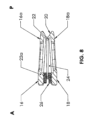
図1および図2を参照すると、本発明の特定の一構成によるベローズ形脊椎インプラント10が挿入されている、ヒトの脊椎の腰椎領域の一区画が示されている。この特定の構成では、脊椎インプラント10は、対向する椎体12と椎体14との間に脊椎の前方(A)方向から後方(P)部に向けて導入される前方腰椎椎体間固定(ALIF)デバイスとしてサイズ設定され、構成される。図示のように、ベローズ形脊椎インプラント10は、挿入に続いて定位置に脊椎インプラントを固定するために、プレートおよび/またはロッドからなる形態の補足的な固定が脊椎インプラント10と一緒に使用されるという点で、従来のALIFデバイスである。以下で述べるように、独立型バージョンとして構成されるベローズ形脊椎インプラントも企図される。ベローズ形脊椎インプラント10は、胸部領域および頚部領域など脊椎の他の部分に挿入されるように構成されてもよいことを理解されたい。
1 and 2, a section of the lumbar region of a human spine is shown into which a bellows-type
次に、図3~図8に移り、ベローズ形脊椎インプラント10の詳細について述べる。脊椎インプラント10は、ベローズ形シェル20によって一緒に接合される上側プレート16と下側プレート18とを備える。上側プレート16は、上椎体14の終板14aと接触するように構成された接触面16aを有し、下側プレート18は、下椎体12の終板12aと接触するように構成された接触面18aである。接触面16aおよび18aは、略平坦であり、椎体12と椎体14との間への挿入後に適当な脊椎前湾をもたらすように、図5に示されるように前方(A)から後方(P)方向に下方に角度付けされ得る。そのような下向きの角度は、例えば、0から30度の間であってよい。接触面16aおよび18aは、それぞれ椎体終板14aおよび12aとのより適当な解剖学的接触をもたらすように、図6に示されるように横方向に沿って若干湾曲されてもよい。図3および図4に示されるように、下側プレート18は、中央開口18bを有し、上側プレート16は、中央開口16bを有する。
3-8, the bellows-shaped
より具体的に図5~図8に見られるように、シェル20は、シェル20の周囲に延在し中空内部24を画定する比較的薄い壁22を有するベローズ形状を有するように構成される。中空内部24は、骨移植片材料のための空間を提供し、上側プレート16の中央開口16bおよび下側プレート18の中央開口18bと流体連通にある。壁22は、上側プレート16と下側プレート18との間で内方に角度付けまたは湾曲され、上側プレート16および下側プレート18のそれぞれの方に向けて両方向に外方に張り出している。したがって、図7に示されるように、角度ベータ、βが壁22に形成される。図7および図8に示されるように、壁22は、以下に述べるように、前方(A)端に、挿入および移植片送達の目的のためにねじ穴26が形成され得る比較的より厚い部分22aを備えることができる。いくつかの例では、適当なスリットまたはカットが、インプラント10の剛化を最小にするように、より厚い部分22a内に横方向に設けられる場合もある。さらに、ベローズ形シェル20の壁22は、図示されないが、上側プレート16および下側プレート18のそれぞれから、上側プレート16と下側プレート18との間のある位置の方に向けて外方に角度付けまたは湾曲されてもよいことを理解されたい。
As seen more specifically in Figs. 5-8, the
記載の特定の構成では、上側プレート16、下側プレート18およびベローズ形シェル20は、一片のベローズ形脊椎インプラント10として一体に形成される。より具体的には、この構成では、ベローズ形脊椎インプラント10はチタンから形成される。本明細書の上記で述べたように、チタンは、生体適合性、強度および骨統合性を含む望ましいインプラント特性を有する。ポリエーテルエーテルケトン(PEEK)などのポリマーとの比較を考えると、放射線透過性の欠如および比較的高い剛性は欠点と考えられ得るが、そのような不足は、脊椎インプラント10の中空ベローズ構成によって相殺される。例えば、ベローズ形シェル20の壁22が約0.5mmの厚さを有するように形成される場合、放射線撮影は、壁22を通って中空内部24内へと到達可能であることが分かった。そのような撮影は、厚さの増加とともに質が低下する傾向があり、おそらく約1.0mmを上回る壁の厚さでは放射線撮影の利点の喪失になる。加えて、約0.5mm未満の壁の厚さは、脊椎インプラント10を有害に弱化させるおそれがあり、さらには潜在的に製造性に影響を与える場合もある。
In the particular configuration described, the
脊椎インプラント10の中空ベローズ構造は、放射線透過性の利点に加えて、所望の剛性に有益な影響をもたらす。薄肉中空ベローズシェル20は、インプラント10が圧縮を受けると曲げ応力が誘起されることにより脊椎インプラント10にある程度の可撓性を与えることが分かった。そのような誘起された屈曲は、剛性を低下させる傾向がある。そのような屈曲の結果としての壁22内の応力は、内方に湾曲した壁22について、角度ベータ、βの関数として変化する。角度ベータ、βがより鋭角になるほど、より高い曲げ応力が生じ、壁22を通してより低い直接圧縮が起こる。そして、角度ベータ、βがより鋭角になるほど、より高いレベルの歪みが構造内に生じ、それによって構造体が弱化される傾向となり、剛性が低くなる。低い剛性は、中空内部24内に収容される骨移植片材料とのウォルフの法則に従った負荷の分担を促進することが既知である。剛性の観点から、シェル20の内方湾曲壁の角度ベータ、βは、は、最小約0°から最大約180°までの範囲とすることができる。ただし、内側湾曲壁22を有する脊椎インプラント10のいくつかの例およびサイズによっては、過度に鋭角な角度はあまり望ましくない場合がある。というのも、壁22の過度の内方突出の結果、骨移植片のための内部容積の損失になり、インプラント10の安定性を低下させる傾向となり得るからである。同様に、180°を上回る角度は、外側湾曲壁22に剛性特性に関する同様の効果をもたらすことに使用され得る。しかし、180°を上回る角度は、接触面の寸法と比較してインプラントの全体的な寸法を増加させ、それによって埋め込みのためのより大きな入口回廊(entry corridor)が必要となることから、あまり望ましくない場合がある。同様の効果は、壁22が上側プレート16および下側プレート18の縁からインセット(inset)されたある位置で上側プレート16と下側プレート18とを接合すれば、180°を上回る角度を用いるインプラントの寸法を増加させることなく達成され得ることを理解されたい。ここで、適切な内側または外側湾曲を有する壁22は、インプラントの剛性を効果的に制御することに用いられ得ることを理解されたい。
In addition to the benefits of radiolucency, the hollow bellows structure of the
角度ベータ、βは、所望の剛性特性を維持するようにインプラントの高さの関数として変化し得ることに留意されよう。高さと剛性との関係により、典型的には、より短い高さのインプラントほど、より高い高さのものよりも鋭い角度を必要とする。典型的には、より高さのあるインプラントほど剛性が比較的より低く、したがってより鋭くない角度は剛性を低減させることに使用される。例えば約180°である角度ベータ、βを有する脊椎インプラント10は、比較的まっすぐであるシェル壁22によって生じる。そのようなインプラントは、インプラント剛性を低減させるように十分な弾性をもたらす高さおよび壁の厚さを有するように作られ、頚部椎体切除術などの脊椎手技に使用され得る。
It will be noted that the angle beta, β, can be varied as a function of the height of the implant to maintain the desired stiffness characteristics. Due to the relationship between height and stiffness, shorter height implants typically require sharper angles than those of greater height. Typically, taller implants are relatively less stiff, and therefore less sharp angles are used to reduce stiffness. For example, a
放射線透過性および低い剛性への有益な影響に加えて、チタンからベローズ形脊椎インプラント10を形成することによって、椎体12および14の終板12aおよび14aに対する脊椎インプラント10の迅速な固定の促進が可能になる。例えば、上側プレート16および下側プレート18のそれぞれの接触面16aおよび18aは、マイクロ粗さの多孔表面をもたらす3-D印刷プロセスによって、骨付着を促進するように容易に変化させることができる。そのような細孔は、脊椎終板12aおよび14aに対する骨移植片の成長による固定のために中空内部24と連通する。加えて、接触面16aおよび18aのマイクロ粗さはさらに、その後で、例えばフェムト秒レーザプロセスを用いたレーザアブレーションによってナノ粗さ表面を加えるように増加させることができる。あるいは、酸エッチングプロセスを用いて、マイクロおよびナノ粗さを含むように接触面16aおよび18aの粗さを変化させてもよい。さらに、接触面16aおよび18aは、マイクロおよびナノ粗さを変化させるように、ナノ秒レーザプロセスとフェムト秒レーザプロセスとの組合せによって、あるいは、パルス持続時間もしくはレーザプロセスの周波数などの選択されるパラメータ、または加えるエネルギー量などを変えることでフェムト秒レーザプロセス単独によって、変更を加えてもよい。したがって、所望の表面粗さは、レーザアブレーション、酸エッチングまたは両方の組合せを含むがこれに限定されない様々な方法によって実現され得る。
In addition to the beneficial effects on radiolucency and low stiffness, forming the bellows-shaped
ALIFデバイスとして使用されるように特別に構成されたベローズ形脊椎インプラント10の1つの例では、図5に示される前方高さは、8から20mmまでの範囲であり、後方高さは、4から16mmの範囲であってよい。図4から見られるように、前方/後方奥行は、22から30mmまでの範囲であり、中央/横方向幅は、24から42mmまでの間であってよい。上側プレート16および下側プレート18のそれぞれの厚さは、約2mmであってよい。シェル壁22の厚さは、約0.5mmであり、ベローズ形シェル20の角度ベータ、βは、約90°であってよい。脊椎外科医が手術ニーズおよび患者の解剖学的構造に基づいて適切な脊椎インプラント10を選択できるように、異なるサイズおよび寸法を有する複数の脊椎インプラント10がキットで提供されてもよい。そうした選択の前に、特定の手術に必要な脊椎インプラント10のサイズおよび構成をシミュレーションする1つまたは複数のトライアルデバイスが提供されてもよい。適切な脊椎インプラント10を決定し選んだ後、それを、適当なねじ付き挿入器の一部を脊椎インプラント10のねじ穴26へ取り付けることによって、椎体12と椎体14との間の腰椎に挿入することができる。次いで、脊椎インプラント10を、そのような挿入器によって終板12aと終板14aとの間の図1および図2に示される位置へと前方方向から手動で押し込む。いくつかの例では、骨移植片が挿入前に中空内部24に予め詰められ得る。他の例では、ねじ付き挿入器の除去に続いて、骨移植片がねじ穴26を通して中空内部24に導入され得る。他の例では、骨移植片が中空内部24に予め詰められ、追加の骨移植片が挿入後にねじ穴26を通して中空内部24に導入され得る。ベローズ形シェル20の構造の結果として、手術に続いて椎体12および14の終板12aおよび14aのそれぞれに対する固定の経過を監視するように、壁22を通して、中空内部24に収容されている骨移植片の放射線画像が蛍光透視法または他の適当な撮影法によって撮られ得る。
In one example of a bellows-shaped
本明細書におけるベローズ形脊椎インプラント10の詳細を述べてきたが、ベローズ形脊椎インプラント10は、チタンから形成される場合、強度および骨統合性などのチタンの利点を維持しつつ、同様のサイズのPEEKインプラントの望ましい特性に似た椎体間デバイスとして使用することができることを理解されたい。加えて、ベローズ形インプラント10によってもたらされるような低い剛性は、終板と骨移植片との均一な接触および負荷分担の促進を助けるように、脊椎の生体力学的特性を模倣するのに役立つ。
Having described the details of the bellows-type
本明細書に記載されるようなベローズ形脊椎インプラント10の好ましい一実施形態は純チタンから形成されるが、同様の有利な結果を有するチタン合金を使用してもよいことも理解されたい。さらに、他の変形形態は、本発明の企図される範囲内でもたらされ得ることを理解されたい。例えば、図9および図10に示されるように、ベローズ形脊椎インプラント10の上側プレート16および下側プレート18は、単一の中央開口16bおよび18bの代わりに複数の開窓部(fenestration)またはより小さな孔27を有するように形成されてもよい。そのような孔27は、依然として、椎体終板12aおよび14aに対する内部骨移植片材料のそこを通した固定を可能にする一方、接触面16aおよび18aの増加された表面積によって、インプラントの強度の向上、ならびに椎体終板12aおよび14aに対する接触面積の増加を可能にする。
Although a preferred embodiment of the bellows-type
ベローズ形脊椎インプラント10は、補足的固定とあわせて使用される従来のALIFデバイスとして本明細書において上述してきたが、独立型デバイスとして構成されてもよい。図11から図13に示されるように、上側プレート16および下側プレート18は、固定ねじ32および34の受容のための、ねじ穴26に隣接して貫通して斜めに形成される固定開口28および30を有するように形成され得る。固定ねじ32および34は、それぞれ開口28および30を通って椎体終板14aおよび12aに螺着可能に取り付けられ得る。互いに反対に延在する突起36aおよび36bを備える適当なロッキング要素36は、インプラント挿入後に固定ねじ32および34が外れることを防止するために設けられ得る。ロッキング要素36は、脊椎インプラント10のねじ穴26に螺着される適当なロッキングねじ38によってベローズ形脊椎インプラント10に取り付けられ得る。突起36aおよび36bは、ロッキングねじ38による脊椎インプラント10へのロッキング要素36の取り付けのとき椎体12および14からの固定ねじ32および34の外れを防ぐようにそれぞれ固定ねじ32および34の上になるように構成される。ロッキング要素36およびロッキングねじ38は、撮影のアーチファクト(imaging artifact)を最小にし、脊椎インプラント10の所望の剛性を維持するように、PEEK材料から形成され得る。
Although the bellows-type
図面および前述の説明の中で本発明を詳細に図示および説明したが、これらは、その性質として例示的なものであり非限定的なものとして解釈されるべきである。したがって、好ましい実施形態を提示したにすぎず、本発明の趣旨の範囲内に含まれるあらゆる変更、修正、および他の適用例の保護を求める点を理解されよう。 While the invention has been illustrated and described in detail in the drawings and foregoing description, these are to be considered as illustrative and not restrictive in nature. It will therefore be understood that only preferred embodiments have been presented and that the protection of all changes, modifications and other applications which come within the spirit and scope of the invention is sought.
10 ベローズ形脊椎インプラント
12 椎体
12a 終板
14 椎体
14a 終板
16 上側プレート
16a 接触面
16b 中央開口
18 下側プレート
18a 接触面
18b 中央開口
20 ベローズ形シェル
22 壁
22a より厚い部分
24 中空内部
26 ねじ穴
27 孔
28 開口
30 開口
32 固定ねじ
34 固定ねじ
36 ロッキング要素
36a 突起
36b 突起
38 ロッキングねじ
10 Bellows-type spinal implant
12 Vertebral body
12a Endplate
14 Vertebrae
14a Endplate
16 Upper Plate
16a Contact Surface
16b Central opening
18 Lower Plate
18a Contact Surface
18b Central opening
20 Bellows shell
22 Wall
22a Thicker part
24 Hollow Interior
26 screw holes
27 holes
28 Opening
30 Opening
32 Fixing screw
34 Fixing screw
36 Locking Elements
36a Protrusion
36b Protrusion
38 Locking screw
Claims (27)
貫通する下側開口を有する下側プレートと、
前記上側プレートと前記下側プレートとの間に延在しそれらを接合するベローズ形シェルとを備え、前記ベローズ形シェルは、チタンまたはチタンを含有する合金から形成され、周りを囲むように延在し前記上側開口および前記下側開口と連通する中空内部を画定する壁を含み、前記壁が0.5mmから1.0mmまでの範囲内の厚さを有し前記上側プレートと前記下側プレートとの間で角度付けまたは湾曲される、
ベローズ形脊椎インプラント。 an upper plate having an upper opening therethrough;
a lower plate having a lower opening therethrough;
a bellows-shaped shell extending between and joining said upper plate and said lower plate, said bellows-shaped shell being formed from titanium or an alloy containing titanium and including a wall extending circumferentially and defining a hollow interior communicating with said upper opening and said lower opening, said wall having a thickness within the range of 0.5 mm to 1.0 mm and angled or curved between said upper plate and said lower plate.
Bellows-shaped spinal implant.
貫通して延在する複数の細孔を画定する3-D印刷プロセスによって形成されたマイクロ粗さを含む多孔表面を有する外側下部接触面を含む、下側プレートと、
前記上側プレートと前記下側プレートとの間に延在しそれらを接合するベローズ形シェルとを備え、前記ベローズ形シェルは、チタンまたはチタンを含有する合金から形成され、周りを囲むように延在し前記上側プレートおよび前記下側プレートの前記細孔と連通する中空内部を画定する壁を含み、前記壁が、前記上側プレートと前記下側プレートとの間で角度付けまたは湾曲される、
ベローズ形脊椎インプラント。 an upper plate including an outer top contact surface having a porous surface with micro-roughness formed by a 3-D printing process defining a plurality of pores extending therethrough;
a lower plate including an outer lower contact surface having a porous surface including micro-roughness formed by a 3-D printing process defining a plurality of pores extending therethrough;
a bellows-shaped shell extending between and joining said upper plate and said lower plate, said bellows-shaped shell being formed from titanium or an alloy containing titanium and including a wall extending circumferentially therearound and defining a hollow interior in communication with said pores of said upper plate and said lower plate, said wall being angled or curved between said upper plate and said lower plate.
Bellows-shaped spinal implant.
貫通する下側開口を有する下側プレートと、
前記上側プレートと前記下側プレートとの間に延在しそれらを接合するベローズ形シェルとを備え、前記ベローズ形シェルは、チタンまたはチタンを含有する合金から形成され、周りを囲むように連続的に延在し前記上側開口および前記下側開口と連通する中空内部を画定する壁を含み、前記壁が、前記上側プレートと前記下側プレートとの間において角度付けまたは湾曲され、前記壁を通した放射線撮影を実現するように構成され寸法設定された厚さを有し、同様のサイズのポリエーテルエーテルケトン(PEEK)インプラントの剛性特性に似た剛性をもたらすように構成され寸法設定される、
ベローズ形脊椎インプラント。 an upper plate having an upper opening therethrough;
a lower plate having a lower opening therethrough;
a bellows-shaped shell extending between and joining the upper and lower plates, the bellows-shaped shell being formed from titanium or an alloy containing titanium and including a wall extending continuously around and defining a hollow interior communicating with the upper and lower openings, the wall being angled or curved between the upper and lower plates, having a thickness configured and dimensioned to permit radiography through the wall, and configured and dimensioned to provide a stiffness similar to the stiffness characteristics of a similarly sized polyetheretherketone (PEEK) implant.
Bellows-shaped spinal implant.
Applications Claiming Priority (3)
| Application Number | Priority Date | Filing Date | Title |
|---|---|---|---|
| US202163215593P | 2021-06-28 | 2021-06-28 | |
| US63/215,593 | 2021-06-28 | ||
| PCT/US2022/034709 WO2023278243A1 (en) | 2021-06-28 | 2022-06-23 | Bellows shaped spinal implant |
Publications (1)
| Publication Number | Publication Date |
|---|---|
| JP2024522901A true JP2024522901A (en) | 2024-06-21 |
Family
ID=84543579
Family Applications (1)
| Application Number | Title | Priority Date | Filing Date |
|---|---|---|---|
| JP2023579828A Pending JP2024522901A (en) | 2021-06-28 | 2022-06-23 | Bellows-type spinal implant |
Country Status (5)
| Country | Link |
|---|---|
| US (1) | US11701241B2 (en) |
| EP (1) | EP4362857A4 (en) |
| JP (1) | JP2024522901A (en) |
| AU (1) | AU2022304563A1 (en) |
| WO (1) | WO2023278243A1 (en) |
Families Citing this family (2)
| Publication number | Priority date | Publication date | Assignee | Title |
|---|---|---|---|---|
| US20250025308A1 (en) * | 2023-07-21 | 2025-01-23 | Spinal Simplicity, Llc | Porous fusion device |
| US20250120815A1 (en) * | 2023-10-17 | 2025-04-17 | Spectrum Spine IP Holdings, Inc. | Implant fusion device with enhanced osteoinductivity |
Family Cites Families (41)
| Publication number | Priority date | Publication date | Assignee | Title |
|---|---|---|---|---|
| CH671691A5 (en) * | 1987-01-08 | 1989-09-29 | Sulzer Ag | |
| DE8807485U1 (en) * | 1988-06-06 | 1989-08-10 | Mecron Medizinische Produkte Gmbh, 1000 Berlin | Intervertebral disc endoprosthesis |
| DE9000094U1 (en) | 1990-01-04 | 1991-01-31 | Mecron Medizinische Produkte Gmbh, 1000 Berlin | Intervertebral disc endoprosthesis |
| FR2709949B1 (en) * | 1993-09-14 | 1995-10-13 | Commissariat Energie Atomique | Intervertebral disc prosthesis. |
| FR2787019B1 (en) * | 1998-12-11 | 2001-03-02 | Dimso Sa | INTERVERTEBRAL DISC PROSTHESIS WITH IMPROVED MECHANICAL BEHAVIOR |
| FR2787016B1 (en) | 1998-12-11 | 2001-03-02 | Dimso Sa | INTERVERTEBRAL DISK PROSTHESIS |
| FR2787018B1 (en) | 1998-12-11 | 2001-03-02 | Dimso Sa | INTERVERTEBRAL DISC PROSTHESIS WITH LIQUID ENCLOSURE |
| FR2787015B1 (en) | 1998-12-11 | 2001-04-27 | Dimso Sa | INTERVERTEBRAL DISC PROSTHESIS WITH COMPRESSIBLE BODY |
| US7331994B2 (en) * | 1999-05-17 | 2008-02-19 | Vanderbilt University | Intervertebral disc replacement prosthesis |
| WO2002009626A1 (en) * | 1999-07-26 | 2002-02-07 | Advanced Prosthetic Technologies, Inc. | Improved spinal surgical prosthesis |
| US6264695B1 (en) * | 1999-09-30 | 2001-07-24 | Replication Medical, Inc. | Spinal nucleus implant |
| US7918888B2 (en) | 1999-10-13 | 2011-04-05 | Hamada James S | Spinal fusion instrumentation, implant and method |
| US6468310B1 (en) | 2001-07-16 | 2002-10-22 | Third Millennium Engineering, Llc | Intervertebral spacer device having a wave washer force restoring element |
| US7153310B2 (en) | 2001-07-16 | 2006-12-26 | Spinecore, Inc. | Vertebral bone distraction instruments |
| CA2502058A1 (en) | 2002-10-28 | 2004-05-06 | Mathys Medizinaltechnik Ag | Intervertebral disk prosthesis or artificial vertebra |
| CA2519162A1 (en) * | 2003-03-24 | 2004-10-07 | Mathys Medizinaltechnik Ag | Vertebral disc or intervertebral disc prosthesis |
| EP1615597A1 (en) | 2003-04-03 | 2006-01-18 | Enztec Limited | Load bearing intervertebral disk |
| US6981989B1 (en) | 2003-04-22 | 2006-01-03 | X-Pantu-Flex Drd Limited Liability Company | Rotatable and reversibly expandable spinal hydraulic prosthetic device |
| US7153325B2 (en) * | 2003-08-01 | 2006-12-26 | Ultra-Kinetics, Inc. | Prosthetic intervertebral disc and methods for using the same |
| ATE390101T1 (en) * | 2003-11-18 | 2008-04-15 | Zimmer Gmbh | DISC IMPLANT |
| US7309357B2 (en) | 2004-12-30 | 2007-12-18 | Infinesse, Corporation | Prosthetic spinal discs |
| US7578848B2 (en) | 2005-03-03 | 2009-08-25 | Cervical Xpand, Llc | Intervertebral stabilizer |
| US8814939B2 (en) * | 2005-05-06 | 2014-08-26 | Titan Spine, Llc | Implants having three distinct surfaces |
| US7892285B2 (en) | 2007-01-02 | 2011-02-22 | Zimmer Spine, Inc. | Universal joint total disc replacement |
| US20090069896A1 (en) * | 2007-03-31 | 2009-03-12 | Spinal Kinetics, Inc. | Prosthetic intervertebral discs with particulate-containing cores that are implantable by minimally invasive surgical techniques |
| US20090069895A1 (en) * | 2007-03-31 | 2009-03-12 | Spinal Kinetics, Inc. | Prosthetic Intervertebral Discs Having Folding End Plates That Are Implantable By Minimally Invasive Surgical Techniques |
| US8273124B2 (en) | 2007-05-17 | 2012-09-25 | Depuy Spine, Inc. | Self-distracting cage |
| WO2009005819A1 (en) * | 2007-07-03 | 2009-01-08 | Scribner Robert M | Mobile spinal fusion implant |
| US20090157185A1 (en) | 2007-12-18 | 2009-06-18 | Chong Chol Kim | Prosthetic Monolithic Spinal Discs and Method of Customizing and Constructing Discs |
| US20110082552A1 (en) * | 2009-04-27 | 2011-04-07 | Wistrom Elizabeth V | Prosthetic Intervertebral Discs Implantable By Minimally Invasive Surgical Techniques |
| WO2010145036A1 (en) * | 2009-06-18 | 2010-12-23 | The Royal Institution For The Advancement Of Learning/Mcgill University | Hollow highly-expandable prosthetic vertebral body |
| US20120277861A1 (en) * | 2011-04-28 | 2012-11-01 | Warsaw Orthopedic, Inc. | Expandable spinal interbody implant |
| US8945228B2 (en) * | 2012-11-15 | 2015-02-03 | DePuy Synthes Products, LLC | Endplate for a vertebral implant |
| KR20180095853A (en) * | 2015-12-16 | 2018-08-28 | 너바시브 인코퍼레이티드 | Porous Spine Fusion Implant |
| WO2018053403A1 (en) | 2016-09-16 | 2018-03-22 | Mirus Llc | Interbody fusion devices and related methods of manufacture |
| US10624760B2 (en) | 2017-05-22 | 2020-04-21 | Warsaw Orthopedic, Inc. | Spinal implant system and method |
| US10881523B2 (en) * | 2017-07-05 | 2021-01-05 | Keith L Doty | Motion preserving spinal total disc replacement apparatus, method and related systems |
| US10617532B2 (en) * | 2018-05-08 | 2020-04-14 | Globus Medical, Inc. | Intervertebral spinal implant |
| US11957812B2 (en) | 2018-12-21 | 2024-04-16 | Ctl Medical Corporation | Silicon nitride implants and coatings |
| US11185423B2 (en) | 2019-01-09 | 2021-11-30 | Osseus Fusion Systems | Highly radiographically opaque metal based interbody |
| US11744711B2 (en) | 2021-03-22 | 2023-09-05 | Orthofix Us Llc | Spinal interbody devices with density gradients and associated methods |
-
2022
- 2022-06-23 JP JP2023579828A patent/JP2024522901A/en active Pending
- 2022-06-23 EP EP22833951.1A patent/EP4362857A4/en active Pending
- 2022-06-23 US US17/847,873 patent/US11701241B2/en active Active
- 2022-06-23 WO PCT/US2022/034709 patent/WO2023278243A1/en not_active Ceased
- 2022-06-23 AU AU2022304563A patent/AU2022304563A1/en active Pending
Also Published As
| Publication number | Publication date |
|---|---|
| US20220409390A1 (en) | 2022-12-29 |
| EP4362857A4 (en) | 2025-04-23 |
| US11701241B2 (en) | 2023-07-18 |
| AU2022304563A1 (en) | 2024-01-18 |
| EP4362857A1 (en) | 2024-05-08 |
| WO2023278243A1 (en) | 2023-01-05 |
Similar Documents
| Publication | Publication Date | Title |
|---|---|---|
| US11596527B2 (en) | Intervertebral cage with porosity gradient | |
| US20220273459A1 (en) | Method and spacer device for spanning a space formed upon removal of an intervertebral disc | |
| US6458159B1 (en) | Disc prosthesis | |
| US7226480B2 (en) | Disc prosthesis | |
| US8231681B2 (en) | Self-contained expandable implant and method | |
| US11045328B2 (en) | Dynamic intervertebral spacer implant | |
| US7776097B2 (en) | Double shell implant for cementless anchorage of joint prostheses | |
| GB2338652A (en) | Vertebral body replacement | |
| AU2008237452A1 (en) | Implant face plates | |
| JP2010537729A (en) | Spinal interbody replacement device | |
| US12383410B2 (en) | Dynamic inter vertebral spacer implant | |
| US20060129243A1 (en) | Interbody spinal device | |
| US12303402B2 (en) | Spinal interbody fusion device | |
| JP2024522901A (en) | Bellows-type spinal implant | |
| EP1251806A1 (en) | Improved disc prosthesis | |
| WO2024137976A1 (en) | Bellows shaped spinal implant having gyroid lattice structures | |
| EP4034046A1 (en) | Dynamic intervertebral spacer implant |
Legal Events
| Date | Code | Title | Description |
|---|---|---|---|
| A521 | Request for written amendment filed |
Free format text: JAPANESE INTERMEDIATE CODE: A523 Effective date: 20240227 |
|
| A621 | Written request for application examination |
Free format text: JAPANESE INTERMEDIATE CODE: A621 Effective date: 20250516 |