JP2024520197A - Microneedle-Based Delivery Systems - Google Patents
Microneedle-Based Delivery Systems Download PDFInfo
- Publication number
- JP2024520197A JP2024520197A JP2023569660A JP2023569660A JP2024520197A JP 2024520197 A JP2024520197 A JP 2024520197A JP 2023569660 A JP2023569660 A JP 2023569660A JP 2023569660 A JP2023569660 A JP 2023569660A JP 2024520197 A JP2024520197 A JP 2024520197A
- Authority
- JP
- Japan
- Prior art keywords
- microneedle
- section
- delivery system
- microneedles
- based delivery
- Prior art date
- Legal status (The legal status is an assumption and is not a legal conclusion. Google has not performed a legal analysis and makes no representation as to the accuracy of the status listed.)
- Pending
Links
- 230000007704 transition Effects 0.000 claims abstract description 20
- 239000012530 fluid Substances 0.000 claims description 49
- 238000006073 displacement reaction Methods 0.000 claims description 27
- 238000004891 communication Methods 0.000 claims description 16
- 230000007246 mechanism Effects 0.000 claims description 14
- 230000014759 maintenance of location Effects 0.000 claims description 4
- 230000004044 response Effects 0.000 claims description 3
- 238000006243 chemical reaction Methods 0.000 claims description 2
- 238000007789 sealing Methods 0.000 claims description 2
- 238000012377 drug delivery Methods 0.000 abstract description 14
- 238000004873 anchoring Methods 0.000 abstract description 7
- 239000011159 matrix material Substances 0.000 abstract 1
- 210000001519 tissue Anatomy 0.000 description 68
- 239000007924 injection Substances 0.000 description 59
- 238000002347 injection Methods 0.000 description 59
- 210000003491 skin Anatomy 0.000 description 43
- 239000003814 drug Substances 0.000 description 18
- 229940079593 drug Drugs 0.000 description 16
- 238000000034 method Methods 0.000 description 12
- 230000033001 locomotion Effects 0.000 description 9
- 239000000243 solution Substances 0.000 description 9
- 230000006870 function Effects 0.000 description 8
- 238000003780 insertion Methods 0.000 description 8
- 230000037431 insertion Effects 0.000 description 8
- 239000000463 material Substances 0.000 description 8
- 239000000203 mixture Substances 0.000 description 8
- 210000004207 dermis Anatomy 0.000 description 7
- 238000009472 formulation Methods 0.000 description 7
- 230000035515 penetration Effects 0.000 description 7
- 210000003811 finger Anatomy 0.000 description 6
- 210000003813 thumb Anatomy 0.000 description 6
- 208000002352 blister Diseases 0.000 description 5
- 238000000338 in vitro Methods 0.000 description 5
- 229960005486 vaccine Drugs 0.000 description 5
- 230000006872 improvement Effects 0.000 description 4
- 230000000007 visual effect Effects 0.000 description 4
- 230000008901 benefit Effects 0.000 description 3
- 229960000074 biopharmaceutical Drugs 0.000 description 3
- 230000015572 biosynthetic process Effects 0.000 description 3
- 230000000052 comparative effect Effects 0.000 description 3
- 230000000295 complement effect Effects 0.000 description 3
- 238000007906 compression Methods 0.000 description 3
- 230000006835 compression Effects 0.000 description 3
- 230000008878 coupling Effects 0.000 description 3
- 238000010168 coupling process Methods 0.000 description 3
- 238000005859 coupling reaction Methods 0.000 description 3
- 238000009826 distribution Methods 0.000 description 3
- 238000002474 experimental method Methods 0.000 description 3
- 238000004519 manufacturing process Methods 0.000 description 3
- 229920000642 polymer Polymers 0.000 description 3
- 239000011347 resin Substances 0.000 description 3
- 229920005989 resin Polymers 0.000 description 3
- 239000008174 sterile solution Substances 0.000 description 3
- 238000012360 testing method Methods 0.000 description 3
- RBTBFTRPCNLSDE-UHFFFAOYSA-N 3,7-bis(dimethylamino)phenothiazin-5-ium Chemical compound C1=CC(N(C)C)=CC2=[S+]C3=CC(N(C)C)=CC=C3N=C21 RBTBFTRPCNLSDE-UHFFFAOYSA-N 0.000 description 2
- 206010015150 Erythema Diseases 0.000 description 2
- LFQSCWFLJHTTHZ-UHFFFAOYSA-N Ethanol Chemical compound CCO LFQSCWFLJHTTHZ-UHFFFAOYSA-N 0.000 description 2
- 230000009471 action Effects 0.000 description 2
- 238000004458 analytical method Methods 0.000 description 2
- 230000003466 anti-cipated effect Effects 0.000 description 2
- 239000011324 bead Substances 0.000 description 2
- 238000005452 bending Methods 0.000 description 2
- 230000009286 beneficial effect Effects 0.000 description 2
- 230000006378 damage Effects 0.000 description 2
- LOKCTEFSRHRXRJ-UHFFFAOYSA-I dipotassium trisodium dihydrogen phosphate hydrogen phosphate dichloride Chemical compound P(=O)(O)(O)[O-].[K+].P(=O)(O)([O-])[O-].[Na+].[Na+].[Cl-].[K+].[Cl-].[Na+] LOKCTEFSRHRXRJ-UHFFFAOYSA-I 0.000 description 2
- 230000000694 effects Effects 0.000 description 2
- 229920001971 elastomer Polymers 0.000 description 2
- 231100000321 erythema Toxicity 0.000 description 2
- 238000011156 evaluation Methods 0.000 description 2
- 210000000245 forearm Anatomy 0.000 description 2
- 210000003128 head Anatomy 0.000 description 2
- 238000001727 in vivo Methods 0.000 description 2
- 238000007918 intramuscular administration Methods 0.000 description 2
- 239000007788 liquid Substances 0.000 description 2
- 229910052751 metal Inorganic materials 0.000 description 2
- 239000002184 metal Substances 0.000 description 2
- 229960000907 methylthioninium chloride Drugs 0.000 description 2
- 238000012014 optical coherence tomography Methods 0.000 description 2
- 239000002953 phosphate buffered saline Substances 0.000 description 2
- 230000009467 reduction Effects 0.000 description 2
- 229910001220 stainless steel Inorganic materials 0.000 description 2
- 239000010935 stainless steel Substances 0.000 description 2
- 239000000758 substrate Substances 0.000 description 2
- 229940124597 therapeutic agent Drugs 0.000 description 2
- 230000000451 tissue damage Effects 0.000 description 2
- 231100000827 tissue damage Toxicity 0.000 description 2
- 238000011282 treatment Methods 0.000 description 2
- 238000010146 3D printing Methods 0.000 description 1
- 206010006784 Burning sensation Diseases 0.000 description 1
- 206010067482 No adverse event Diseases 0.000 description 1
- 235000013290 Sagittaria latifolia Nutrition 0.000 description 1
- XUIMIQQOPSSXEZ-UHFFFAOYSA-N Silicon Chemical compound [Si] XUIMIQQOPSSXEZ-UHFFFAOYSA-N 0.000 description 1
- WPMWEFXCIYCJSA-UHFFFAOYSA-N Tetraethylene glycol monododecyl ether Chemical compound CCCCCCCCCCCCOCCOCCOCCOCCO WPMWEFXCIYCJSA-UHFFFAOYSA-N 0.000 description 1
- RTAQQCXQSZGOHL-UHFFFAOYSA-N Titanium Chemical compound [Ti] RTAQQCXQSZGOHL-UHFFFAOYSA-N 0.000 description 1
- 239000008186 active pharmaceutical agent Substances 0.000 description 1
- 210000000612 antigen-presenting cell Anatomy 0.000 description 1
- 238000013459 approach Methods 0.000 description 1
- 238000003491 array Methods 0.000 description 1
- 238000007664 blowing Methods 0.000 description 1
- 239000011248 coating agent Substances 0.000 description 1
- 238000000576 coating method Methods 0.000 description 1
- 230000002301 combined effect Effects 0.000 description 1
- 235000015246 common arrowhead Nutrition 0.000 description 1
- 230000001143 conditioned effect Effects 0.000 description 1
- 238000010276 construction Methods 0.000 description 1
- 239000007799 cork Substances 0.000 description 1
- 239000013078 crystal Substances 0.000 description 1
- 230000002939 deleterious effect Effects 0.000 description 1
- 230000008021 deposition Effects 0.000 description 1
- 238000009792 diffusion process Methods 0.000 description 1
- 238000010790 dilution Methods 0.000 description 1
- 239000012895 dilution Substances 0.000 description 1
- 230000002500 effect on skin Effects 0.000 description 1
- 239000000806 elastomer Substances 0.000 description 1
- 238000005516 engineering process Methods 0.000 description 1
- 210000002615 epidermis Anatomy 0.000 description 1
- 238000010579 first pass effect Methods 0.000 description 1
- 210000001035 gastrointestinal tract Anatomy 0.000 description 1
- 230000028993 immune response Effects 0.000 description 1
- 208000015181 infectious disease Diseases 0.000 description 1
- 208000014674 injury Diseases 0.000 description 1
- 238000007689 inspection Methods 0.000 description 1
- 230000003993 interaction Effects 0.000 description 1
- 238000002955 isolation Methods 0.000 description 1
- 239000012669 liquid formulation Substances 0.000 description 1
- 210000004324 lymphatic system Anatomy 0.000 description 1
- 238000002156 mixing Methods 0.000 description 1
- 230000004048 modification Effects 0.000 description 1
- 238000012986 modification Methods 0.000 description 1
- 210000002200 mouth mucosa Anatomy 0.000 description 1
- 210000003205 muscle Anatomy 0.000 description 1
- 230000000149 penetrating effect Effects 0.000 description 1
- 229920001296 polysiloxane Polymers 0.000 description 1
- 238000002360 preparation method Methods 0.000 description 1
- 238000003825 pressing Methods 0.000 description 1
- 230000037452 priming Effects 0.000 description 1
- 230000008569 process Effects 0.000 description 1
- 238000011084 recovery Methods 0.000 description 1
- 210000003786 sclera Anatomy 0.000 description 1
- 230000035807 sensation Effects 0.000 description 1
- 238000000926 separation method Methods 0.000 description 1
- 229910052710 silicon Inorganic materials 0.000 description 1
- 239000010703 silicon Substances 0.000 description 1
- 239000008354 sodium chloride injection Substances 0.000 description 1
- 239000007787 solid Substances 0.000 description 1
- 230000006641 stabilisation Effects 0.000 description 1
- 238000011105 stabilization Methods 0.000 description 1
- 230000001954 sterilising effect Effects 0.000 description 1
- 238000004659 sterilization and disinfection Methods 0.000 description 1
- 239000000126 substance Substances 0.000 description 1
- 239000004094 surface-active agent Substances 0.000 description 1
- 238000001356 surgical procedure Methods 0.000 description 1
- 230000009885 systemic effect Effects 0.000 description 1
- 230000008685 targeting Effects 0.000 description 1
- 230000001225 therapeutic effect Effects 0.000 description 1
- 239000010936 titanium Substances 0.000 description 1
- 229910052719 titanium Inorganic materials 0.000 description 1
- 229940043263 traditional drug Drugs 0.000 description 1
- 230000001052 transient effect Effects 0.000 description 1
- 230000008733 trauma Effects 0.000 description 1
Images


Classifications
-
- A—HUMAN NECESSITIES
- A61—MEDICAL OR VETERINARY SCIENCE; HYGIENE
- A61M—DEVICES FOR INTRODUCING MEDIA INTO, OR ONTO, THE BODY; DEVICES FOR TRANSDUCING BODY MEDIA OR FOR TAKING MEDIA FROM THE BODY; DEVICES FOR PRODUCING OR ENDING SLEEP OR STUPOR
- A61M37/00—Other apparatus for introducing media into the body; Percutany, i.e. introducing medicines into the body by diffusion through the skin
- A61M37/0015—Other apparatus for introducing media into the body; Percutany, i.e. introducing medicines into the body by diffusion through the skin by using microneedles
- A61M2037/0023—Drug applicators using microneedles
-
- A—HUMAN NECESSITIES
- A61—MEDICAL OR VETERINARY SCIENCE; HYGIENE
- A61M—DEVICES FOR INTRODUCING MEDIA INTO, OR ONTO, THE BODY; DEVICES FOR TRANSDUCING BODY MEDIA OR FOR TAKING MEDIA FROM THE BODY; DEVICES FOR PRODUCING OR ENDING SLEEP OR STUPOR
- A61M37/00—Other apparatus for introducing media into the body; Percutany, i.e. introducing medicines into the body by diffusion through the skin
- A61M37/0015—Other apparatus for introducing media into the body; Percutany, i.e. introducing medicines into the body by diffusion through the skin by using microneedles
- A61M2037/003—Other apparatus for introducing media into the body; Percutany, i.e. introducing medicines into the body by diffusion through the skin by using microneedles having a lumen
Landscapes
- Health & Medical Sciences (AREA)
- Engineering & Computer Science (AREA)
- Dermatology (AREA)
- Medical Informatics (AREA)
- Anesthesiology (AREA)
- Biomedical Technology (AREA)
- Heart & Thoracic Surgery (AREA)
- Hematology (AREA)
- Life Sciences & Earth Sciences (AREA)
- Animal Behavior & Ethology (AREA)
- General Health & Medical Sciences (AREA)
- Public Health (AREA)
- Veterinary Medicine (AREA)
- Infusion, Injection, And Reservoir Apparatuses (AREA)
- Media Introduction/Drainage Providing Device (AREA)
- Pharmaceuticals Containing Other Organic And Inorganic Compounds (AREA)
- Radiation-Therapy Devices (AREA)
- Medicines That Contain Protein Lipid Enzymes And Other Medicines (AREA)
Abstract
本発明は、自己アンカー固定式マイクロニードルに基づいた送達システムに関し、このシステムは、標的薬物送達のために、眼などの組織基質内にマイクロニードルを迅速かつ容易に展開するように動作可能であり、互いに対して変位可能な第一セクション及び第二セクションを有する本体と、第一セクションに設けられた第一中空マイクロニードル及び第二セクションに設けられた第二中空マイクロニードルとを含み、第一セクション及び第二セクションは、マイクロニードルを係脱状態と係合状態との間で移行させるために、互いに対して変位可能である。
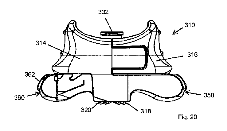
【選択図】図20
The present invention relates to a self-anchoring microneedle based delivery system operable to quickly and easily deploy microneedles within a tissue matrix, such as the eye, for targeted drug delivery, the system comprising a body having first and second sections displaceable relative to one another, a first hollow microneedle provided in the first section and a second hollow microneedle provided in the second section, the first and second sections being displaceable relative to one another to transition the microneedles between a disengaged and an engaged state.
[Selection] Figure 20
Description
本発明は、マイクロニードルに基づいた送達システムに関し、特に、使用が正確かつ容易である、皮膚組織などの標的組織に薬物またはワクチンを送達するようなシステムに関する。 The present invention relates to a microneedle-based delivery system, in particular to such a system that is precise and easy to use to deliver drugs or vaccines to target tissue, such as skin tissue.
マイクロニードルは、例えば、組織外傷の減少、手術時間及び患者回復の短縮、感染のリスクの減少、及びマイクロニードルに基づいた装置を伴う手技中に必要な外科用または医療用機器を最小にするなど、患者及び医療従事者の両方に多くの利益が実証されていることを考慮して、様々な医療用途での使用の増加を得ている。これらのようなマイクロニードルは、組織への極めて正確でかつ浅い展開が可能になると、様々な用途、例えば、薬物送達、より具体的には、皮膚、眼球組織及び口腔粘膜などの敏感または繊細な組織への薬物送達に有益であることができる。 Microneedles are gaining increasing use in various medical applications given the many demonstrated benefits to both patients and medical personnel, such as, for example, reduced tissue trauma, shortened surgical time and patient recovery, reduced risk of infection, and minimizing surgical or medical equipment required during procedures involving microneedle-based devices. Microneedles such as these, allowing for extremely precise and shallow deployment into tissue, can be beneficial in a variety of applications, for example, drug delivery, more specifically, drug delivery to sensitive or delicate tissues such as skin, ocular tissue, and oral mucosa.
国際特許出願WO2018/069543及びWO2019/201903は、様々な外科的及び治療的用途のための組織基質への適用のための装置の形態に設けられることができるマイクロニードル及び対向するマイクロニードルアレイの構成及び操作の詳細な開示を提示し、1つの特定の用途は、提示されたマイクロニードルから直接の、またはマイクロニードルを介した薬物送達である。WO2018/069543及びWO2019/201903の開示は、その全体が本明細書に組み込まれる。 International Patent Applications WO2018/069543 and WO2019/201903 provide detailed disclosures of the construction and operation of microneedles and opposing microneedle arrays that can be arranged in the form of devices for application to tissue matrices for various surgical and therapeutic applications, one particular application being drug delivery directly from or through the microneedles provided. The disclosures of WO2018/069543 and WO2019/201903 are incorporated herein in their entirety.
薬物及びワクチンの皮内送達は、ワクチン及び薬物の従来の筋肉内及び経口送達経路に比べて顕著な利点を提示する。皮膚毛細血管及びリンパ系を介した治療薬の全身的な取り込みは、初回通過代謝の有害効果の回避、迅速な薬物作用発現、及び消化管の粘膜層を介して容易に吸収されない生物製剤など、APIのバイオアベイラビリティの改善を含む、多くの利点をもたらす。さらに、皮膚の真皮層は、抗原提示細胞で満たされているため、増強された免疫応答を引き出すために、また場合によっては、標準的な筋肉内投与よりも少ない投与量を用いて、ワクチンの送達に最適な位置を表す。 Intradermal delivery of drugs and vaccines presents significant advantages over traditional intramuscular and oral delivery routes of vaccines and drugs. Systemic uptake of therapeutic agents via the skin capillaries and lymphatic system offers many advantages, including avoidance of the deleterious effects of first-pass metabolism, rapid onset of drug action, and improved bioavailability of APIs, such as biologics, that are not readily absorbed through the mucosal layers of the gastrointestinal tract. Furthermore, the dermal layer of the skin is filled with antigen-presenting cells and therefore represents an optimal location for delivery of vaccines to elicit enhanced immune responses and, in some cases, using smaller doses than standard intramuscular administration.
皮膚の粘弾性で大きく変形可能な性質は、中空マイクロニードル及び皮下針に基づいたアプローチを使用して、低体積及び高体積ならびに低粘度及び高粘度の両方の液体製剤(例えば、特定の生物製剤の場合であることができる)を皮膚の特異的な深さまで送達する際に、顕著な臨床上の課題を課す。皮膚の制御されない変形により、標的とする深さの正確さが著しく制限され、さらに、皮膚の厚さ及び生体力学的特性の自然な対象間及び対象内の解剖学的ばらつきが複雑になる。これらの装置の配置及び適用により引き起こされる皮膚の変形及び圧縮は、注入圧の要件を高め、流量に影響し、送達できる物理的な体積及び粘度を著しく制限し、そのうえ皮内ブレブ/ボーラス拡散キネティクスも損なう。さらに、特に皮内注入の間、マイクロニードル技術の固有の固定法が存在しないことにより、注入圧に対抗するために注入装置またはパッチに手動で追加の機械的作業を適用することが必要になる。平衡が保たれていないかぎり、この注入圧成分は、排出させ、皮膚及び/または針先の相対的な移動を引き起こし、送達部位に影響するが、その結果、製剤が漏れ、排出され、吹き返されることができる。ここで、取扱い及び注入の間のオペレータの運動(複数可)は、標的深さ正確さ及び用量送達にさらに影響する別の要因であり、固有のアンカー固定が存在しないことにより、皮膚に対する針先の総体的な運動が促進され、意図した皮膚内の標的深さから離れて注入が分配されることができる。 The viscoelastic and highly deformable nature of the skin poses significant clinical challenges in delivering both low and high volume and low and high viscosity liquid formulations (as may be the case for certain biologics, for example) to specific depths in the skin using hollow microneedle and hypodermic needle based approaches. Uncontrolled deformation of the skin significantly limits the accuracy of the targeting depth, further compounded by natural inter- and intra-subject anatomical variations in skin thickness and biomechanical properties. Skin deformation and compression caused by the placement and application of these devices increases the injection pressure requirements, affects the flow rate, significantly limits the physical volume and viscosity that can be delivered, and also impairs intradermal bleb/bolus diffusion kinetics. Furthermore, the lack of inherent fixation of microneedle technology, especially during intradermal injection, necessitates the application of additional manual mechanical work to the injection device or patch to counter the injection pressure. Unless balanced, this injection pressure component can cause drainage and relative movement of the skin and/or needle tip, affecting the delivery site, resulting in the formulation leaking, draining, and blowing back. Here, operator motion(s) during handling and injection are another factor that further impacts target depth accuracy and dose delivery, and the absence of inherent anchoring promotes gross motion of the needle tip relative to the skin, which can distribute the injection away from the intended target depth within the skin.
眼の層状構造は、眼球組織の繊細な性質及び眼球の手術または治療の任意の形式の間の損傷または合併症の可能性の高さに加えて、眼への薬物の標的送達の際に、特に、薬物を眼の意図しない部分に送達するときに、有効性を改善し、起こり得る副作用を潜在的に回避するために、眼内の特定の層に薬物を送達する必要がある場合に、困難を示している。従来の眼への薬物送達は、眼の強膜(最外層)の厚さにおける自然で大きいばらつきのために複雑になる。さらに、注入中に眼は、容易に回転するため、安定化を必要とし、注入中に眼組織の変形が生じるため、眼の特異的な領域を標的にする能力が制限される。注入中の注射器の相対運動及び薬物の排出も起こり、手順をさらに複雑にし、ペイロード送達の効率を損なう。 The layered structure of the eye, in addition to the delicate nature of ocular tissues and the high potential for damage or complications during any form of ocular surgery or treatment, presents challenges during targeted delivery of drugs to the eye, particularly when drugs need to be delivered to specific layers within the eye to improve efficacy and potentially avoid possible side effects when delivering drugs to unintended parts of the eye. Traditional drug delivery to the eye is complicated by the natural large variability in the thickness of the sclera (outermost layer) of the eye. Furthermore, the eye easily rotates during injection, requiring stabilization, and deformation of the ocular tissue occurs during injection, limiting the ability to target specific regions of the eye. Relative motion of the syringe and expulsion of the drug during injection also occurs, further complicating the procedure and compromising the efficiency of payload delivery.
したがって、本発明の目的は、低粘度溶液及び高粘度溶液(例えば、生物製剤)の低体積及び高体積の両方の標的薬物送達の目的で、マイクロニードルを皮膚及び眼などの組織基質内に迅速かつ容易に展開するように動作可能である、自己アンカー固定式マイクロニードルに基づいた送達システムを提供することである。 It is therefore an object of the present invention to provide a self-anchoring microneedle-based delivery system that is operable to rapidly and easily deploy microneedles into tissue matrices such as the skin and eye for targeted drug delivery of both low and high volumes of low and high viscosity solutions (e.g., biologics).
本発明によれば、マイクロニードルに基づいた送達システムが提供され、この送達システムは、互いに対して変位可能な第一セクション及び第二セクションを有する本体と、第一セクションに設けられた少なくとも1つの第一中空マイクロニードル及び第二セクションに設けられた少なくとも1つの第二中空マイクロニードルであって、第一セクション及び第二セクションはマイクロニードルを係脱状態と係合状態との間で移行するために互いに対して変位可能である、少なくとも1つの第二中空マイクロニードルと、第一中空マイクロニードル及び第二中空マイクロニードルと流体連通している送達マニホールドとを含む。 According to the present invention, there is provided a microneedle-based delivery system, comprising a body having a first section and a second section displaceable relative to one another, at least one first hollow microneedle provided in the first section and at least one second hollow microneedle provided in the second section, the first section and the second section being displaceable relative to one another to transition the microneedles between a disengaged state and an engaged state, and a delivery manifold in fluid communication with the first hollow microneedle and the second hollow microneedle.
好ましくは、少なくとも1つの第一マイクロニードルの長手方向軸は、第一セクションと第二セクションとの間の変位方向に対して第一斜角で延出し、少なくとも1つの第二マイクロニードルの長手方向軸は、第一セクションと第二セクションとの間の変位方向に対して第二斜角に延出する。 Preferably, the longitudinal axis of the at least one first microneedle extends at a first oblique angle relative to the direction of displacement between the first and second sections, and the longitudinal axis of the at least one second microneedle extends at a second oblique angle relative to the direction of displacement between the first and second sections.
好ましくは、第一斜角は、第二斜角から離れて延出する。 Preferably, the first beveled angle extends away from the second beveled angle.
好ましくは、少なくとも1つの第一マイクロニードルは、第一セクションと第二セクションとの間の変位方向に対して少なくとも1つの第二マイクロニードルに横方向にオフセットされる。 Preferably, the at least one first microneedle is laterally offset to the at least one second microneedle relative to the direction of displacement between the first and second sections.
好ましくは、第一セクション及び第二セクションは、互いに関して摺動可能に及び/または蝶着して変位可能である。 Preferably, the first section and the second section are slidably and/or hingedly displaceable relative to each other.
好ましくは、少なくともマイクロニードルが係合状態にあるとき、送達マニホールドは、第一セクションと第二セクションとの間に取り込まれる。 Preferably, at least when the microneedles are engaged, the delivery manifold is captured between the first section and the second section.
好ましくは、送達マニホールドは、マイクロニードルが係合状態にあるとき、送達マニホールドと本体との間に流体密封シールを確立するように、本体に対してクランプされる。 Preferably, the delivery manifold is clamped against the body so as to establish a fluid-tight seal between the delivery manifold and the body when the microneedles are in an engaged state.
好ましくは、送達マニホールドは、流体リザーバと連結するように適合された入口、及び入口が中空マイクロニードルと流体連通するように本体と係合可能な出口を含む。 Preferably, the delivery manifold includes an inlet adapted to couple to the fluid reservoir and an outlet engageable with the body such that the inlet is in fluid communication with the hollow microneedle.
好ましくは、本体は、チャンバを第一セクションと第二セクションとの間に画定し、このチャンバ内に送達マニホールドの出口が取り込まれ、チャンバは、少なくともシステムが係合状態にあるとき、出口にバイアスをかけて本体と密閉係合するように配置される。 Preferably, the body defines a chamber between the first and second sections within which the outlet of the delivery manifold is captured, the chamber being arranged to bias the outlet into sealing engagement with the body, at least when the system is in an engaged state.
好ましくは、本体は、送達マニホールドを少なくとも部分的に包囲する筐体を画定する。 Preferably, the body defines a housing that at least partially surrounds the delivery manifold.
好ましくは、送達マニホールドは、少なくとも1つの第一マイクロニードルと流体連通している第一流体流路、及び少なくとも1つの第二マイクロニードルと流体連通している独立した第二流体流路を画定する。 Preferably, the delivery manifold defines a first fluid flow path in fluid communication with at least one first microneedle and an independent second fluid flow path in fluid communication with at least one second microneedle.
好ましくは、本体の第一セクション及び第二セクションはそれぞれ細長いアームを画定し、この細長いアームの自由端に、それぞれの少なくとも1つのマイクロニードルが設けられる。 Preferably, the first and second sections of the body each define an elongate arm, the free end of which carries at least one microneedle.
好ましくは、各アームは下端部と反対側の上端部、及び上端部と下端部との間にアームに通して延在する流体流路を画定し、送達マニホールドは、各アームの上端部で流体流路と流体連通している。 Preferably, each arm defines a lower end and an opposite upper end, and a fluid flow path extending through the arm between the upper and lower ends, and the delivery manifold is in fluid communication with the fluid flow path at the upper end of each arm.
好ましくは、マイクロニードルが係合状態及び係脱状態の両方であるとき、送達マニホールドは、流体流路の端部と流体連通している。 Preferably, the delivery manifold is in fluid communication with the ends of the fluid flow paths when the microneedles are both engaged and disengaged.
好ましくは、マイクロニードルに基づいた送達システムは、第一セクション及び第二セクションのそれぞれの上にトリガによって画定され、係脱状態へのシステムの手動による変位を容易にするように配置された、解放機構を含む。 Preferably, the microneedle-based delivery system includes a release mechanism defined by a trigger on each of the first and second sections and positioned to facilitate manual displacement of the system to the engaged or disengaged state.
好ましくは、マイクロニードルに基づいた送達システムは、システムを係合状態に解放可能に固定するためのロック機構を含む。 Preferably, the microneedle-based delivery system includes a locking mechanism for releasably securing the system in the engaged state.
好ましくは、ロック機構はトリガのうちの少なくとも1つと統合され、トリガの作動によって解放可能である。 Preferably, the locking mechanism is integral with at least one of the triggers and is releasable by actuation of the trigger.
好ましくは、ロック機構が統合される少なくとも1つのトリガは、弾性的に変形可能である。 Preferably, at least one trigger in which the locking mechanism is integrated is elastically deformable.
好ましくは、マイクロニードルに基づいた送達システムは、第一セクションと第二セクションとの間の相対変位を制限するために本体に解放可能に係合可能なストップを含む。 Preferably, the microneedle-based delivery system includes a stop releasably engageable with the body to limit relative displacement between the first and second sections.
好ましくは、送達システムは、第一セクション及び第二セクションが係脱状態を越えて互いから分離することを防止するように動作可能な保定ロックを含む。 Preferably, the delivery system includes a retention lock operable to prevent the first and second sections from separating from one another beyond the disengaged state.
好ましくは、送達システムは、一対の組織接触フィートを含み、それぞれが第一中空マイクロニードル及び第二中空マイクロニードルと実質的に長手方向にアライメントされる組織接触面を画定する。 Preferably, the delivery system includes a pair of tissue contacting feet, each defining a tissue contacting surface substantially longitudinally aligned with the first and second hollow microneedles.
好ましくは、マイクロニードルに基づいた送達システムは、インターロック要素を含み、インターロック要素は、要素がインターロック状態にある場合、第一セクション及び第二セクションが係脱状態から係合状態に変位するのを防止するように動作可能であり、下向きの圧力及び接触した組織によってフィートに加えられる反力に応じて分離可能である。 Preferably, the microneedle-based delivery system includes an interlocking element operable to prevent the first and second sections from disengaging from an engaged state to an engaged state when the elements are in an interlocked state and separable in response to downward pressure and reaction forces exerted on the foot by contacted tissue.
本発明は、これより以下の添付の図面を参照して説明される。 The invention will now be described with reference to the accompanying drawings, in which:
ここで添付の図面の図1~図8を参照すると、1つまたは複数の流体、特に液体形態の薬物または治療薬の投与量を組織の標的領域に送達する際に使用するために、概して10として示されたマイクロニードルに基づいた送達システムが示されている。送達システム10は、広範囲の組織、例えば皮膚または筋肉での使用に適しているが、特に、眼の脈絡膜下領域または脈絡膜上領域(図示せず)などの眼球組織に薬物を送達する際の使用に適している。また送達システム10は、好ましくは外部流体供給部、最も好ましくは以降本明細書で説明されるように従来のシリンジSに結合され、流体をシリンジSまたは他の外部流体供給部から標的組織に分注することが可能になるように適合される。
1-8 of the accompanying drawings, there is shown a microneedle-based delivery system, generally designated 10, for use in delivering a dose of one or more fluids, particularly a liquid form of a drug or therapeutic agent, to a target area of tissue. The
送達システム10は、第一セクション14及び第二セクション16を有する本体12を含み、これら第一及び第二セクションには、それぞれ少なくとも1つの第一中空マイクロニードル18及び少なくとも1つの第二中空マイクロニードル20が設けられ、標的組織内に可逆的に挿入可能であることで、中空マイクロニードル18、20を通じた薬物送達が可能になるように適合され、その動作を以降本明細書で詳細に説明する。マイクロニードル18、20の数は、例えば、特定の用途、標的領域、送達される薬物及び/または送達レートに適するように変動してもよく、1つまたは複数の中実マイクロニードル(図示せず)が、信頼できる薬物送達を達成するために中空マイクロニードル18、20を標的組織にしっかりアンカー固定するように設けられてもよいことも予想される。マイクロニードル18、20の材料、寸法、向き、及び相対位置決めは、必要に応じて変動してもよい。例えば、マイクロニードル18、20の寸法及び/または向きは、標的組織への所望の挿入深さをもたらすように配置され得ることにより、組織の特異的な位置または層への正確な薬物送達を容易にすることができる。
The
好ましい実施形態では、本体12は実質的に1つ以上のポリマーから形成され、送達システム10は単回使用製品として意図されたものである。マイクロニードル18、20は、ポリマーから形成されてもよく、または金属もしくは別の材料であってもよく、第一及び第二セクション14、16に適切に固定されてもよい。しかしながら、システム10が実質的にステンレス鋼、チタン等の金属、または耐摩耗性ポリマーから形成され得、例えばオートクレーブで、滅菌後に再利用可能であってよいことも予想される。マイクロニードル18、20は、本体12に解放可能に固定可能なモジュラ構成要素として設けられることができることにより、本体12が再利用可能でありながら単回使用することができる。
In a preferred embodiment, the
本体12の第一及び第二セクション14、16は、互いに固定されるが、一定距離だけ互いに対して変位可能であり、図示された実施形態では、システム10を、特にマイクロニードル18、20を例えば図1、図2及び図4に示されるような係脱状態と、例えば図3及び図5に示されるような係合状態との間で移行させるために、互いに対して摺動可能に変位可能である。係脱状態では、マイクロニードル18、20は、標的組織への適用前に互いに対して第一向きにあり、係合状態では、互いに対して第二向きにある。使用時、マイクロニードル18、20は係脱状態では標的組織に対して適用され、次いで、システム10は第一及び第二セクション14、16を互いに向けて手動で進めることによって係合状態に変位し、この作動は、マイクロニードル18、20を標的組織に引き込みアンカー固定する方法で、マイクロニードル18、20の相対変位を引き起こすことで、以降本明細書に説明されるように薬物送達が可能になる。
The first and
この展開技術の基礎となる方法は、上述の国際出願WO2018/069543及びWO2019/201903に詳細に記載されている。参照を容易にするために以降本明細書では、方向または寸法は、送達システム10の第一及び第二セクション14、16とマイクロニードル18、20との間の方向では「X」座標または方向と呼ばれ、横方向に、または幅に沿って「Y」座標と呼ばれ、深さに沿って「Z」座標と呼ばれ、送達システム10に対して図4に概略的に示される。
The method underlying this deployment technique is described in detail in the above-mentioned international applications WO2018/069543 and WO2019/201903. For ease of reference, directions or dimensions will be referred to hereinafter as "X" coordinates or directions in the direction between the first and
特に正確に係合するまたは穿刺することが比較的難しい組織の場合には、マイクロニードル18、20を正確に位置決めすることを可能にするために、本体12は、第一セクション14から延出する第一アーム22、及び第二セクション16から延出する、隣接する第二アーム24を含み、これら両方は、「Z」または深さ方向に細長い形態であるため、眼球組織など、比較的アクセスしにくい組織と係合するのに有益である。少なくとも1つの第一マイクロニードル18は、第一アーム22の下端部上に設けられ、少なくとも1つの第二マイクロニードル20は、第二アーム24の下端部上に設けられる。図示された実施形態では、アーム22、24は、本体12から離れてマイクロニードル18、20に向かい延出するにつれて内向きにテーパ状になることにより、マイクロニードル18、20を配置する下端部に画定する設置面積が比較的小さくなるため、標的組織への適用の間にマイクロニードル18、20及び周囲組織の正確な位置及び良好な視界の両方が可能になる。当然のことながら、アーム22、24の形状、向き及び寸法が必要に応じて、特に送達システム10の用途及び/または標的組織のタイプ及び/または位置に応じて、変動し得ることが理解されよう。
To allow for accurate positioning of the
図示された実施形態では、第一及び第二アーム22、24は、互いに隣接しているが、「Y」方向ではオフセットされ、第一及び第二セクション14、16が互いに対して変位可能である「X」方向に対して横方向にあるように位置している。これにより、特に図4及び図5に示されることができるように、マイクロニードル18、20を組織に引き込む、係合状態にシステム10が移行する場合、アーム22、24は重なるアライメントに移動することができる。しかしながら、他の幾何学的形状及び配置も可能であり、例えば、係合状態中のとき、一方のアームに他方のアームを少なくとも部分的に受け入れるためのチャネルを設けてもよく、またはアームは係脱状態及び係合状態の両方で互いから分離されたもしくは離隔されたままであってもよい。
In the illustrated embodiment, the first and
中空マイクロニードル18、20を通じた薬物送達を可能にするために、少なくとも第一アーム22には、アーム22の長さに沿って(「Z」方向で)内部に延出し、少なくとも1つの第一マイクロニードル18と流体連通した第一送達コンジット26が設けられる。図示された好ましい実施形態では、第二アーム24には、第二アーム24の長さに沿って内部に延出し、少なくとも1つの第二マイクロニードル20と流体連通した第二送達コンジット28が設けられる。システム10が第一または第二マイクロニードル18、20のみに供給する単一送達コンジットによって機能してもよいが、中空マイクロニードル18、20の両方が供給され、標的組織への薬物送達のために使用されることができることが好ましいことを理解されたい。
To enable drug delivery through the
第一及び第二アーム22、24はそれぞれ、送達コンジット26、28が開いている上端部または上面30で終端することにより、上面30からアーム22、24に通してマイクロニードル18、20への流体流路を確立する。図4を参照すると、システム10が係脱状態にあるとき、送達コンジット26、28の上端部が「X」方向では互いから間隔をあけられ、図5に示されるようにシステム10が係合段階に移行するとき、送達コンジット26、28の上端部が互いに隣接しているため、「X」方向では重なるまたはアライメントされることがわかる。送達コンジット26、28の上端部より上に位置しており、これら上端部を封入する送達マニホールド32は、入口34、出口36及びその間に延在するルーメン38を含む。出口36は、送達コンジット26、28の上端部を封入するように上面30とレジストレーションしていることにより、送達マニホールド32を通って送達コンジット26、28に入り、最終的にマイクロニードル18、20への流体送達が可能になる。入口34は、シリンジSの従来のルアーロックコネクタまたはヘッドHに解放可能に固定されるように適合されるが、任意の他の所望の外部流体供給部(図示せず)に流体密封連結するように適合されてよい。したがって、送達される薬物またはその他の流体を含むシリンジSを、送達マニホールド32を介してシステム10に連結することができることにより、流体をシリンジSからマイクロニードル18、20を介して標的組織へ、信頼でき正確な方法で分注することができることが理解されよう。
The first and
送達マニホールド32を本体12に固定するために、少なくともマイクロニードル18、20が係合状態にあるとき、送達マニホールド32、最も好ましくは出口36は、第一及び第二セクション14、16の間に取り込まれる。図1~図8の実施形態では、本体12はチャンバ40を画定し、このチャンバは、上面30の真上に位置し、部分的に上面30によって画定され、チャンバ40の一方の部分または側は、第一セクション14内に形成され、チャンバ40の他方の側は、互いに対向する第二セクション16内に形成される。チャンバ40は、出口36を被包する形状及び寸法に作られ、開口部42は、チャンバ40の上壁部内に設けられ、この開口部を通って、送達マニホールド32は、本体12によって画定された筐体44内に延出する。筐体44は、好ましくは、使用時、送達マニホールド32ひいてはシリンジSへの連結部がアクセスできないように、送達マニホールド32を包囲し、効果的に封入する形状及び寸法に作られる。筐体44の上部領域には、シリンジSを収容するためのマウス46が形成される。マウス46が第一セクション14と第二セクション16との間の境界面を横切って延在するため、システム10が係脱状態にありながら、マウス46が拡大すると、シリンジSがチャンバ44内に進み、ヘッドHが送達マニホールド32の入口34と結合することが可能になることが理解されよう。システム10が係合状態に移行するとき、マウス46は、シリンジSの本体の周囲を部分的に閉じ、シリンジSのあらゆる意図しない運動または結合解除を回避する。
To secure the
特に図4及び図5に示されるように、送達マニホールド32の出口36とアーム22、24の上面30との間の境界面では、システム10が図4の係脱状態及び図5の係合状態の両方にあるとき、出口36は送達コンジット26、28の上端部を封入する寸法に作られるが、システム10が係合状態にあるとき、システム10は、出口36のみが送達コンジット26、28の上端部を封入するように適合されてもよい。しかしながら、シリンジ内に対象に注入される空気が存在しないことを確保するために、流体を分注する前にシリンジをプライミングすることが必要であることが多い。したがって、システム10が係脱状態にあるとき、送達コンジット26、28の上端部を封入する寸法に出口36を作らせることによって、シリンジSとマイクロニードル18、20との間に流体流路が存在するため、シリンジSの空気をプライミングまたはパージしてから、標的組織にマイクロニードル18、20を適用することができる。マイクロニードル18、20が標的組織に固定されるとき、システム10は係合状態になり、出口36がこの状態では送達コンジット26、28の上端部も封入するため、シリンジSの内容物がマイクロニードル18、20を介して標的組織に送達されることができる。
4 and 5, at the interface between the
一対の独立した流体流路を画定し、一対の独立した流体流路がそれぞれ送達コンジット26、28のうちの1つと流体連通して配置されることにより、2つの異なる流体が修正されたシリンジ(図示せず)または一対のシリンジ(図示せず)またはその他の流体供給部を介して第一及び第二マイクロニードル18、20に送達されることが可能になるように修正されたマニホールド(図示せず)とマニホールド32が置換されることができることが予想される。
It is anticipated that the manifold 32 can be replaced with a modified manifold (not shown) that defines a pair of independent fluid flow paths, each of which is disposed in fluid communication with one of the
出口36とアーム22、24の上面30との間の境界面ではシリンジSの内容物の望ましくない漏れを防止するために、適切な流体密封シールは境界面に確立される。このシールは、多くの方法で、例えば、出口36とアーム22、24の上面30との間のガスケット、変形性ゴム/エラストマーシール、コーティング、幾何学形状のシール形成、機械的インターロック、またはしまりばめを使用して、達成されることができる。図1~図8の実施形態では、このシールは、出口36及びチャンバ40の、特に「Z」方向での相補的な寸法形成によって確立されることにより、チャンバ40の高さまたは「Z」寸法は、チャンバ40の上壁部が出口36の上壁部に接触し、アーム22、24の上面30に対して出口36にバイアスをかけ、それらの間にシールを確立するようなものである。特に好ましい配置では、チャンバ40の上壁部及び出口36の上壁部は、対向して係合しているが、例えば1°または2°の領域、任意選択で第一セクション14と第二セクション16との間の相対変位の「X」方向で最大5°または10°またはそれ以上の領域内で対応するドラフトまたは傾斜を有する。このようにして、システム10を係合状態に移行させる際に第一及び第二セクション14、16が互いに向かい変位する場合、出口36に加えられるバイアスが増大することにより、出口36とアーム22、24の上面30との間の境界面でのシールが増大する。この配置は、出口36に作用する機械的圧縮力を係脱状態中の公称から係合状態中の最大まで増大させる。これにより、圧力が低い組織内への注入前にシリンジS及びマイクロニードル18、20の上述のプライミングが可能になり、マイクロニードル18、20が組織内に展開されると、漏れの心配なく、注入に関連する圧力を高くすることが可能になる。
At the interface between the
使用時、送達システム10は、好ましくは筐体44の外壁部を介して、本体12の第一及び第二セクション14、16に手動で圧力を加えることによって、係脱状態から係合状態に移行する。図6及び図7に示されるように、筐体44を画定する本体12の壁部は、第一セクション14上に延出部48、及び第二セクション16上に対応するガイドウェイ50を含み、これらは、制限された相対変位を可能にしながら、セクション14、16を合わせて固定するようにインターロック状態になる。タブ52は、システム10が係合状態に正しく移行したときに対応する窓部54を通して可視であるように延出部48内に設けられ、マイクロニードル18、20が埋め込まれ、シリンジSからの流体送達を行うことができることを使用者に知らせるために、視覚的インジケーションを提供する。さらにタブ52は、第一及び第二セクション14、16が互いから係脱することができないことを確保するように機能する。システム10を係合状態に移行させるために第一及び第二セクション14、16を変位させる必要がある正しい方向を指示するために、グラフィカルインディシア56を本体12の周りに設けることができる。システム10には、例えば筐体44内に位置している、本体12と解放可能に係合可能なストップ(図示せず)が設けられてもよく、ストップは、特定の用途または解剖学的考察に適するようにマイクロニードル18、20の侵入深さを制限する手段として、第一セクション14と第二セクション16との間の相対変位を制限してもよい。
In use, the
標的組織への流体の送達が完了すると、システム10、特にマイクロニードル18、20を組織から係脱する必要がある。したがって、使用者は、システム10を係脱状態に移行させることにより、マイクロニードル18、20の離脱に影響するように、第一セクション14及び第二セクション16を変位させて互いから離す必要がある。この作動を容易にするために、システム10は、第一及び第二トリガ58、60の形態の解放機構を含み、それぞれがアーム22、24の上面30の領域内の第一及び第二セクション14、16上に設けられ、筐体44の下に位置決めされる。各トリガ58、60は、使用者がアクセスできるように、カンチレバー式で、対向するセクション14、16の筐体44の壁部に向かい、壁部をわずかに越えて延出する。各トリガ58、60は、拡大したパドル62で終端し、このパドルは、使用者の指または親指と操作可能に係合する形状及び寸法に作られる。したがって、トリガ58、60は、システム10が係脱状態と係合状態との間で変位するとき、システム10の変位を妨げることなく、並んで位置決めされ、互いに対して摺動する。図6を参照すると、システム10には好ましくはロック機構が設けられ、このロック機構は、システム10を係合状態及びまたは係脱状態に固定し、特に、例えば流体を組織に送達している間、マイクロニードル18、20のあらゆる意図しない離脱を回避する。図示の実施形態では、ロック機構は、第一トリガ58の上面の上の突出部またはデテント64、ならびに第一トリガ58の上面と対向し、図8a、図8b及び図8cで可視である筐体44の下側の上に対応する形状及び寸法に作られた第一ソケット66及び第二ソケット68の形態で設けられる。第一ソケット66及び第二ソケット68は、第一セクション14及び第二セクション16が変位可能である距離だけ互いから離隔される。第一ソケット66は、システム10が図8aに示されるように係合状態にあるとき、デテント64を受け入れ、システム10を係合状態に解放可能に固定するように位置している。
Once delivery of fluid to the target tissue is complete, the
特に図8a、図8b及び図8cを参照すると、係合状態から係脱状態へのシステム10の変位をもたらすステップのシーケンスが示されている。図8aは、デテント64が第一ソケット66に取り込まれている係合状態でシステム10を示す。第一セクション14及び第二セクション16を変位させて互いから離し始めるために、システム10は、例えば親指と人差し指との間で、トリガ58、60によって挟持される。少なくとも第一トリガ58は弾性で変形可能であるため、使用者は、パドル62を介して第一トリガ58に圧力を加え、図8bに示されるように、デテント64を第一ソケット66から引き出すような方法で第一トリガ58を変形させる。この時点で、使用者は、トリガ58、60の両方に圧力を加えて、トリガ58、60を互いに向けて効果的に押すことができる。これは、図8cに示されるようにシステム10を係脱状態に移行させ、組織からマイクロニードル18、20を引き出すように第一セクション14と第二セクション16との間の相対変位をもたらす。この配置では、デテント64は第二ソケット68とアライメントされ、圧力が解放されると、第一トリガ58は戻り、デテント64は第二ソケット68に入り、システム10を係脱状態にロックする。その後、システム10を組織から後退させることができる。
8a, 8b and 8c, a sequence of steps is shown which results in the transition of the
ここで図9~図12を参照すると、概して110として示される、本発明による、マイクロニードルに基づいた送達システムの代替の実施形態が示されている。この代替的実施形態では、同様の構成要素には同様の参照番号が与えられており、特に明記しない限り、同様の機能を実行する。 9-12, there is shown an alternative embodiment of a microneedle-based delivery system according to the present invention, generally designated as 110. In this alternative embodiment, like components are given like reference numbers and perform like functions unless otherwise noted.
送達システム110は、第一セクション114及び第二セクション116を有する本体112を含み、これらセクションは、係脱状態と係合状態との間でシステム110を移行させるために互いに対して変位可能である。システム110は、第一セクション114上に設けられた第一中空マイクロニードル118と、第二セクション116上に設けられた第二中空マイクロニードル120とを含む。本体112は、細長い第一及び第二アーム122、124を画定し、これらアームの自由端にマイクロニードル118、120が設けられる。図示されていないが、第一及び第二送達コンジット(図示せず)は、アーム122、124を通って延在し、マイクロニードル118、120と流体連通している。送達マニホールド132を第一セクション114と第二セクション116との間に取り込んで、図1~図8に示されたシステム10に関して上述されたものと同じ方法で、マイクロニードル118、120を介して送達するためのシステム110へのシリンジ(図示せず)またはその他の流体供給部の結合を容易にする。本体112は、アーム122、124より上に筐体144を画定し、この筐体内に送達マニホールド132は含まれ、マウス146を通して筐体144の上部にアクセス可能である。
The
システム110の全体的な構成、外観及び全般的な動作は、図1~図8に示されたシステム10に関して上述されたものと同じである。ただし、システム10とは異なり、システム110を係脱状態と係合状態との間で移行させるために、システム110の第一及び第二セクション114、116が互いに対して枢動して変位可能である。第一セクション114及び第二セクション116は、マウス146の対向する側の上に配置される一対のヒンジ180によって互いに固定されているが、この枢動による相対変位を可能にするために多くのその他の構成が採用されてもよいことが理解されよう。
The overall configuration, appearance, and general operation of the
したがって、第一及び第二セクション114、116が係合状態に向けて変位する場合、マイクロニードル118、120が円弧に沿って互いに対して移動することで、マイクロニードル118、120が標的組織内に進入する。システム110が組織に埋め込まれたマイクロニードル118、120と係合段階にあると、流体は、システム10について上述されたものと同じ方法で、結合したシリンジ(図示せず)から組織内に送達されることができる。システム110には、例えば筐体144内に位置している、本体112と解放可能に係合可能なストップ(図示せず)が設けられてもよく、ストップは、マイクロニードル118、120の侵入深さを制限する手段として、第一セクション114と第二セクション116との間の相対変位を制限してもよい。
Thus, when the first and
同様に、上述されたものと同様の方法で、一対のトリガ158、160の形態の解放機構を利用して、第一及び第二セクション114、116を互いから離して円弧状経路に沿って一対のヒンジ180の周囲で変位させることによって、システム110を流体送達後に組織から係脱させることができる。
Similarly, in a manner similar to that described above, a release mechanism in the form of a pair of
ここで図13~図16を参照すると、概して210として示される、本発明によるマイクロニードルに基づいた送達システムのさらなる代替の実施形態が示されている。この代替的実施形態では、同様の構成要素には同様の参照番号が与えられており、特に明記しない限り、同様の機能を実行する。 Referring now to Figures 13-16, there is shown a further alternative embodiment of a microneedle-based delivery system according to the present invention, generally designated as 210. In this alternative embodiment, like components are given like reference numerals and perform like functions unless otherwise noted.
送達システム210は、実質的にシステム110の変形であり、第一セクション214及び第二セクション216を有する本体212を含み、これらセクションもまた、係脱状態と係合状態との間でシステム210を移行させるために互いに対して蝶着して変位可能である。システム210は、第一セクション214上に設けられた第一中空マイクロニードル218と、第二セクション216上に設けられた第二中空マイクロニードル220とを含む。この実施形態では、増大した組織侵入を可能にするために、マイクロニードル218、220は前の実施形態に対して増大した長さのものである。
本体212は、細長い第一及び第二アーム222、224を画定し、これらアームの自由端にマイクロニードル218、220が設けられる。システム210の第一セクション214及び第二セクション216は、一対のヒンジ280によって互いに固定されるが、この枢動による相対変位を可能にするために多くのその他の構成が採用されてもよいことがさらに理解されよう。第一セクション214に設けられたタブ252は、第二セクション216上の窓部254内に位置しており、両方が第一及び第二セクション214、216の変位のレベル、従ってマイクロニードル218、220の展開について視覚的インジケーションを提供し、第一及び第二セクション214、216が互いから係脱することを防止する。
The
システム210には任意選択で、図16に分離して示されたストップ290が設けられ、使用時、本体212の第一セクション214と第二セクション216との間に画定されたチャンバ(図示せず)内に位置しており、マイクロニードル218、220の侵入深さを制限する手段として第一セクション214と第二セクション216との間の相対変位を選択的に制限するように配置される。ストップ290は、高さを増加させる第一、第二、及び第三ステップ292、294、296を含むことにより、ストップ290は、ステップ292、294、296のうちの1つがタブ252と窓部254との間に取り込まれるように、窓部254を通って外向きに突出するように選択的に位置決めされてよい。窓部254内に位置したステップ292、294、296の深さは、第一及び第二セクション214、216を合わせて変位させることができる程度、ひいてはシステム210を係合状態に変位させることができる程度を決定する。例えば、図14は、第一相対位置でマイクロニードル218、220と部分係合状態に変位したシステム210を示し、図15は、図14よりも大きい組織侵入を達成する第二相対位置でマイクロニードル218、220と完全係合状態に変位したシステム210を示す。これら2つの状態は、窓部254内にストップ290の種々のステップ292、294、296を配置することによって可能になってもよい。ストップ290は、窓部254を通って突出する最大ステップ296によって位置決めされてもよく、この最大ステップは、例えば取り扱い中、特にシステム210に結合されるシリンジ(図示せず)にトルクを加えるとき、マイクロニードル218、220の偶発的な展開を防止するために、係脱状態でシステム210を効果的にロックする寸法に作られてもよい。
Optionally, the
図17~図28を参照すると、概して310として示される、本発明によるマイクロニードルに基づいた送達システムのさらなる代替の実施形態が示されている。この代替的実施形態では、同様の構成要素には同様の参照番号が与えられており、特に明記しない限り、同様の機能を実行する。 17-28, there is shown a further alternative embodiment of a microneedle-based delivery system according to the present invention, generally designated as 310. In this alternative embodiment, like components are given like reference numerals and perform like functions unless otherwise noted.
送達システム310は、第一セクション314及び第二セクション316を有する本体312を含み、これらセクションは、実質的に前の実施形態を参照して本明細書で先に説明されるように、係脱状態と係合状態との間でシステム310を移行させるために互いに対して変位可能である。第一及び第二セクション314、316の外側端壁部は、標的組織上への展開中に固定保持を確立するために、送達システム310の動作中に使用者の指及び/または親指が係合し得る人間工学による及び/または保定可能なフォームファクタを提供するように輪郭が形成されてよく、及び/またはその他の方法で配置されてもよい。このようにして、使用者は、本明細書で先に説明されるように、第一セクション314及び第二セクション316を親指と人差し指との間で固定して挟持し、次いでセクション314、316を合わせて押し込み、送達システム310を係脱状態から係合状態に移動させることができる。
The
システム310は、第一セクション314上に設けられた第一中空マイクロニードル318と、第二セクション316上に設けられた第二中空マイクロニードル320とを含む。先の実施形態と同様に、マイクロニードル318、320の材料、寸法、向き、及び相対位置決めは、必要に応じて変動してもよい。例えば、マイクロニードル318、320の寸法及び/または向きは、標的組織への所望の挿入深さをもたらすように配置され得ることにより、組織の特異的な位置または層への正確な薬物送達を容易にすることができる。マイクロニードル318、320の特定の向きは、例えばそれぞれのニードル318、320の軸に対して垂直な平面を中心とした回転、または(この座標系の軸のうちの1つがニードル318、320の長手方向軸とアライメントされる)ニードル318、320の本体固定座標系を中心とした一連のオイラー回転によって、送達システム310の製造容易性をさらに向上させてもよい。このような向きは、さらなる性能の改善をもたらし得ることにより、展開中、第一及び第二セクション314、316の運動方向に対して垂直な平面では、皮膚またはその他の組織にさらなるせん断ひずみまたは変形が加えられる。これは、皮膚内へのニードル318、320の垂直方向深さに沿ってせん断ひずみ勾配を作り出すことによって挿入効率をさらに高め、挿入でさらなるスクラッチ固定を提供し、使用者が経験する痛み及び/または不快感を潜在的に低減させるように機能することができる。さらにニードル318、320をこのように指向することにより、ニードル318、320の展開が挿入中の理想的な通常の向きからのわずかな偏向に影響されにくくなることにより、送達システム310に連結されたシリンジ(図示せず)が皮膚に垂直であるため、使いやすさを改善することができる。
The
本体312の第一及び第二セクション314、316は、合わせて固定されているが、例えば図17及び図18に示されるような係脱状態と、例えば図19及び図20に示されるような係合状態との間でシステム310を移行させるために、固定された距離だけ互いに対して摺動自在に変位可能である。係脱段階では、マイクロニードル318、320は、標的組織への適用前に互いに対して第一向きにあり、係合状態では、互いに対して第二向きにある。先に説明された実施形態と同様に、マイクロニードル318、320は係脱状態では標的組織に対して適用され、次いで、システム310は、マイクロニードル318、320を標的組織に引き込んでアンカー固定するように第一及び第二セクション314、316を互いに向けて手動で前進させることによって係合状態に変位することで、以降本明細書に説明されるように薬物送達が可能になる。
The first and
本体312は、第一セクション314から延出する第一アーム322と、第二セクション316から延出する、隣接する第二アーム324とを含み、これらアームのそれぞれの下端部上に、それぞれのマイクロニードル318、320が設けられる。アーム322、324の形状、向き及び寸法は、必要に応じて変動することができる。アーム322、324は、本明細書で先に説明されるように、送達マニホールド332とそれぞれのマイクロニードル318、320との間に流体連通をもたらす内部送達コンジット(図示せず)を画定する。送達マニホールド332は、液体薬物組成物など、送達される媒体のシリンジ(図示せず)または同等のリザーバと連結するように動作可能な上部入口334と、下部出口336とを含み、これらの間にルーメン338が延在しており、下部出口336及びルーメン338は、好ましくは、各アーム322、324を通して両方のマイクロニードル318、320のセットに供給するように二股(図示せず)になっている。マニホールド332は、第一セクション314と第二セクション316との間に画定された筐体344に受け入れられるが、筐体が開いているため、マニホールド332への使用者の視覚的アクセスが可能になることで、シリンジ(図示せず)の連結または連結切断が支援され得る。上述のように、使用時に、出口336は、マニホールド332からアーム322、324内への、そして最終的にマイクロニードル318、320内への流体の漏れのない送達を確保するために、アーム322、324と流体密封して接触した第一セクション314と第二セクション316との間に取り込まれる。これは、本明細書の先で説明されるように、または任意の他の適切な代替の機能配置によって達成され得る。マニホールドはベースプレート339を含み、このベースプレートは、入口334へのルアーロックシリンジ(図示せず)の係合中に反トルク抵抗を与えるような方法で筐体344のテーパ状の表面との接合部を提供することにより、出口336をトルク荷重から隔離することで、アーム322、324とのミスアライメントの可能性がなくなる。さらに、トルクの時計回りの性質は、インターロック状態の延出部348及びガイドウェイ350の相互作用によって強く抵抗され、装置310がウェッジで離されることを防止する。マニホールド332の別の重要な機能は、「Y」方向で2つのセクション314、316が離れることを防止するために、筐体344の内面に対する当接面を設けることである。
The
図示された実施形態では、第一セクション314及び第二セクション316は同じ構成要素であるが、図示されるように、互いに係合可能であるように配置される。特に、各セクション314、316は、右側から突出する側方延出部348と、左側では、それと摺動して係合し、延出部348を受け入れるように、それに対応した形状及び寸法に作られたガイドウェイ350とを画定する。このようにして、2つの同一部分314、316が互いに対向している状態で、各セクション314、316の右側の延出部は、反対側のセクション314、316の左側のガイドウェイ350に受け入れ可能である。この配置は、両方のセクション314、316を設けるために単一部品のみを必要とするため、送達システム310の製造中に顕著な改善をもたらすが、当然のことながら、対向するセクションが依然として上述の機能をもたらす異なる形態/幾何学的形状を有し得ることが理解される。図27及び図28には、製造用に設計された第一セクション314の例示的であるが非限定的な形態が示されることにより、セクション314が合わせて固定されるのに適し得る2つの部品から形成される。
In the illustrated embodiment, the
先の実施形態と同様に、第一及び第二アーム322、324は、互いに隣接しているが、各セクション314、316上の「Y」方向ではオフセットされ、第一及び第二セクション314、316が互いに対して変位可能である「X」方向に対して横方向にあるように位置している。図示された実施形態では、各アーム324、326は右側にオフセットされるため、ここでも同一セクション314、316が対向しており、互いにインターロック状態にあるとき、アーム324、326は、互いに並んで、対向して係合するように配置される。このようにして、アーム322、324は、システム310が係合状態に移行して、マイクロニードル318、320を組織に引き込む場合、互いに並んで移動することができる。
As in the previous embodiment, the first and
薬物などが組織中に分注されると、使用者がマイクロニードル318、320を離脱させることを可能にするために、送達システム310には、好ましくは、第一及び第二セクション314、316上にそれぞれ設けられた第一及び第二トリガ358、360の形態で解放機構が設けられる。各トリガ358、360は、使用者がアクセスできるように、カンチレバー式で、対向するセクション314、316の筐体344の壁部に向かい、壁部をわずかに越えて延出する。各トリガ358、360は、パドル362で終端し、このパドルは、使用者の指または親指によって操作可能に係合するサイズ及び寸法に作られ、以降本明細書に詳述されるように周囲のトリガ358、360に対して独立して変形可能であり、特に、カンチレバー式トリガ358、360内に取り込まれている、独立したカンチレバー式構成要素として形成されることで、トリガ358、360の偏向から独立して偏向できる。システム310には好ましくはロック機構が設けられ、このロック機構は、システム310を係合状態に固定し、特に、例えば流体を組織に送達している間、マイクロニードル318、320のあらゆる意図しない離脱を回避する。図示の実施形態では、ロック機構は、それぞれのトリガ358、360の上面と対向して係合している第一及び第二セクション314、316の下側の上に突出部またはデテント364と、パドル362の上面の上にそれに対応する形状及び寸法に作られた第一ソケット366及び第二ソケット368との形態で設けられる。第一ソケット366及び第二ソケット368は、第一セクション314及び第二セクション316が係脱状態と係合状態との間で変位可能である距離だけ互いから離隔される。第一ソケット366は、システム310が係脱状態にあるときにデテント364を受け入れるように配置され、ソケット366及びデテント364は、例えば相補面を有することによって、セクション314、316の相対運動に比較的低い抵抗を与えるように配置され、これら相補面は、比較的容易に互いを過ぎて/越えて摺動することができ、それぞれのセクション314、316の下側から離れるようなパドル362の変形によって収容され得る。このようにして、第一ソケット366内のデテント364の位置では、係脱状態ではシステム310の保定レベルが低くなるが、それでも日常的な取り扱い中にシステム310の意図しない展開を防止するのに十分である。システム310が係脱状態から係合状態に変位するとき、各トリガ358、360及び一体型パドル362は、それぞれのデテント364に対して移動し、パドル362は、偏向してセクション314、316の下側から離れ、デテント364及び第一ソケット366を係脱する。次いで、システム310が完全係合状態に達する場合、デテント364は、第二ソケット368とレジストレーションされ、システム310を係合状態に保定するために第二ソケット368とスナップ係合する。デテント364及び第二ソケット368は、以降本明細書で詳述されるように、使用者が積極的に作動させない限り、システム310が係合状態から係脱状態に戻るといういかなる逆転も防止するように配置される。
To allow the user to release the
またシステム310には、特にシリンジ(図示せず)が連結されているとき、係合状態への意図しない展開を防止するためのさらなるセーフティ機能が設けられてもよい。延出部348の底縁部とそれぞれのトリガ358、360の上面との間の空間内に設けられたチャンバまたは開口部(図示せず)内に、ピン(図示せず)などが位置していてもよく、ピンが使用者によって能動的に取り除かれるまで、システム310の意図しない展開を防止する。この機能を提供するために、当然のことながら追加または代替のセーフティ機能を用いてもよい。
第一セクション314及び第二セクション316を変位させて互いから離し、システム310を係脱状態に戻すことを可能にするために、システム310は、各トリガ358、360のパドル362によって、例えば親指と人差し指との間で挟持される。各パドル362は弾性で変形可能であるため、使用者は、第二ソケット368をデテント364とのレジストレーションから下方に引き出すように圧力を加えてパドル362を変形させる。この時点で、使用者は、トリガ358、360の両方に圧力を加えて、トリガ358、360を互いに向けて効果的に押すことができる。これは、システム310を係脱状態に移行させ、組織からマイクロニードル318、320を引き出すように第一セクション314と第二セクション316との間の相対変位をもたらす。この配置では、デテント364は第一ソケット366ともアライメントされ、圧力が解放されると、パドル362は戻り、デテント364は第一ソケット366に入り、システム310を係脱状態に保持する。その後、システム310を組織から後退させることができる。
To allow the
また送達システム310は、使用者が意図せずにそのような変位を行わないことを確保するために、第一及び第二セクション314、316が係脱状態を越えて互いから引き分けられる、または引き離されることを防止するように適合されてもよい。したがって、システム310は、それぞれのセクション314、316の下側の上に設けられた第二突出部またはデテント370と、それぞれのトリガ358、360内に設けられたそれに対応する第三ソケット372とを含む保定ロックを備えてもよい。第二デテント370及び第三ソケット372は、例えば図18に示されるように、システム310が係脱状態にあるときに係合するように位置決めされ、セクション314、316が係合状態に変位する場合、互いから移動して離れることで、この運動に対する抵抗がなくなる。しかしながら、デテント370及びソケット372の形状及び配置は、セクション314、316が係脱状態にあるときに係合し、セクション314、316が互いからさらに分離されることを防止するようなものである。
The
しかしながら、例えば図22に示される初期係合位置から、2つの同一の半体またはセクション314、316が互いに最初にレジストレーションすることを可能にするために、セクション314、316が互いから完全に分離されている状態から、初期係脱状態に向けて接合される場合、各トリガ358、360は第二デテント370を通過することができる必要がある。図示された実施形態では、これは、第二デテント370が備えた傾斜している、または傾いている表面374、トリガ358、360のそれぞれの接触部分が備えた湾曲しているまたは傾斜している表面376という相補面を設けることによって容易になる。これらの表面は、セクション314、316が最初に接合される場合に接触し、トリガ358、360がカンチレバー式のものであるため、セクション314、316が係脱状態に向けて前進するにつれて、第二デテント370から離れて下方に偏向させられることで、シングルステージのラチェット配置を実質的に画定する。図示された特に好ましい配置では、傾斜面376を画定するトリガ358、360の部分は、短手方向または「Y」方向に加えて、長手方向または「X」方向の両方でカンチレバー式であるため、トリガ358、360が第二デテント370を通過することが可能になるように容易に偏向される。第一及び第二セクション314、316が係脱位置または状態に達する場合、トリガ358、360の傾斜面376は、第二デテント370を通過し、次いで所定の位置に戻るため、第二デテント370が第三ソケット372に取り込まれることにより、2つのセクション314、316が係脱状態を越えて逆に分離されることを防止する。この時点で、デテント364も第一ソケット366内に位置していることにより、送達システム310を、使用する準備ができた係脱状態に軽く保定する。
However, to allow the two identical halves or
本明細書で先に詳述されるように、また国際特許出願WO2018/069543及びWO2019/201903でより詳細に述べられるように、組織と係合したときのマイクロニードル318、320の相対変位は、マイクロニードル318、320の侵入及びアンカー固定を改善するために、標的組織の特定の変形を生じ、せん断力を加える。この作動をさらに改善するために、送達装置310には一対の組織接触フィート380が設けられ、好都合には、トリガ358、360の下側または組織接触面の上に形成される、またはこれによって画定される。しかしながら、フィートは、別個の構成要素として設けられてもよい。フィート380は、好ましくは、マイクロニードル318、320とほぼアライメントされる下面を有するように、すなわち、ほぼ同じ深さまたは「Z」寸法になるように配置される。このようにして、送達装置310が最初に係脱状態で皮膚に適用される場合、一対のフィート80も、好ましくは「X」方向で互いから長手方向に離隔されてマイクロニードル318、320を越えた位置で、皮膚に接触する。次いで、セクション314、316が係合状態に向けて変位する場合、一対のフィート380は、互いから、また「X」方向ではマイクロニードル318、320から長手方向に離れて変位し、介在する皮膚に張力を加えるように作用することにより、マイクロニードル318、320の侵入有効性を改善する。一対のフィート380によって行われた皮膚接触は、使用者によって送達システム310に加えられるあらゆる過剰な荷重を散逸させることにより、マイクロニードル318、320の周囲及び下の皮膚を過剰な圧縮から保護し、注入圧要件を減少させて、通針性を改善する。フィート380の組織接触面は、その機能をさらに高めるために、皮膚または他の組織との摩擦を増大させるような状態になってもよく、またはその他の方法でそのように適合されてもよい。
As detailed herein above and in more detail in International Patent Applications WO2018/069543 and WO2019/201903, the relative displacement of the
また送達システム310には、特にシステム310が取り扱われており、皮膚表面上に導入されているとき、係合状態への意図しない展開を防止するためにさらなるセーフティシステムが設けられてもよい。フィート380及びトリガ358、360はカンチレバー要素(図示せず)を含んでもよく、カンチレバー要素は、下向きの圧力及び皮膚によってフィート380に加えられる反力に応答して、組み込まれたデテント(図示せず)を移動させてそれぞれのセクション314、316の下側の上の凹部とのレジストレーションから外すことにより、システム310を荷重応答方法で係脱状態から係合状態に移行させることが可能になる。
The
図29~図32は、本発明による、概して410として示される、マイクロニードルに基づいた送達システムのさらなる実施形態を示す。この実施形態では、同様の構成要素には同様の参照番号が与えられており、特に明記しない限り、同様の機能を実行する。送達システム410は、図17~図28に示されたシステム310の配置及び全般的な動作を反映するが、その操作性を改善するために1つの変更形態がある。具体的には、この実施形態では、送達システム410は、第二デテント470、ならびに第一及び第二トリガ458、460を含み、これらトリガは、傾斜面476に隣接して垂直な傾斜した/テーパ状の表面482を画定するように変更され、「Y」方向で内向きにフレアになる。第一及び第二セクション414、416の初期係合中、第二デテント470は、本明細書で先に説明されるように初期分離状態から係脱状態に向かう第一及び第二セクション414、416の変位中、トリガ458、460を「Y」方向の外向きと「Z」方向の部分的に下向きとの両方で偏向させるために、傾斜面476とテーパ状面482との両方に接触する。第二デテントは、外側フレア面484を含み、この外側フレア面がテーパ状面482と咬合することで、第二デテント470及びトリガ458、460が摺動し、互いに通過して接触し、トリガ458、460の側方の変形をもたらすことが可能になる。このようにして、第二デテント470に必要なクリアランスを生じるための、矢状面内のトリガ458、460のカンチレバーの曲げの程度が著しく低下する。したがって、取り外し面内のトリガ458、460の曲げ剛性が増大することができ、製造容易性を改善するが、取り外し中のトリガの偏向の程度も低下させ、第二デテント470が第三ソケット472に係合して、システム410が引き離されることを防止することを確保することができる。さらに、図32に最も明確に示されるように、傾斜面476及びテーパ状面482によって画定されたトリガ458、460上の切欠き部は、一対の三角形状または矢印形状の特徴を好都合に作り出すために、中心面を中心として鏡像される。これらは、装置410の配置及び動作によって、係脱配置では使用者から隠されているが、装置410が係合状態に展開されるときにのみ見えるようになる。この態様をさらに強調するために、矢印の頭のようなカラーインディシア(図示せず)などを傾斜面476上に設けてもよい。これにより、カラーコードの有無にかかわらず、装置410の把持、感触、及び取り扱いの改善に加えて、使用者に取り外し方法を直感的に指示することによって使いやすさを改善することができる。
29-32 show a further embodiment of a microneedle-based delivery system, generally designated 410, in accordance with the present invention. In this embodiment, like components are given like reference numbers and perform like functions unless otherwise noted.
実験結果の実施例
本発明による中空マイクロニードル送達システム10、110、210、310、410の上述の実施形態のプロトタイプを製造し、一連のインビトロ及びインビボ実験における送達システムの初期の製造容易性、機能及び通針性を評価し、その結果を以降本明細書に示す。
EXAMPLES OF EXPERIMENTAL RESULTS Prototypes of the above-described embodiments of hollow
実施例1-本発明の実施形態のプロトタイプの製造
樹脂ベースの3Dプリントシステムを使用して製造した個々のラピッドプロトタイプ部品(Photon Mono、AnyoCubic、China;z軸解像度25μm及びx-yスポットサイズ48μm)に埋め込んだ、市販のステンレス鋼31Gの皮下針(Microfine(商標)、Becton Dickinson&Company、USA)を使用して、本発明の上記の実施形態の完全機能、高忠実度のプロトタイプを製造した。本体及びマニホールドをABSライクフォトポリマーグレーレジン(Elegoo、China)で製造し、可撓性樹脂(eResin-Flex、eSUN、China)を使用して、流体密封接合部を達成するためにマニホールドの下側に一体化された変形可能なシールを製造した。これらのプロトタイプ装置は、2×3の構成で6本の31Gのマイクロニードルのアレイを示し、それぞれが基板に対して27°の角度をなし、基板から820μmの垂直方向の先端高さと、1,500μmの間隔を有した。横方向のロウ間の間隔は2,000μmであり、それらの間の相対的な直線移動は4,600μm以下であり、皮膚でのはずした(係脱)状態から着けた(係合)状態へのシステムの移行に対する変位に対応した。初期の検査及びテストを使用して、全ての皮下針がマニホールドと流体連通し、以下に説明されるようにテストのために解放前に流体密封シールを達成したことを確認した。
Example 1 - Fabrication of Prototypes of the Present Invention Embodiments Fully functional, high fidelity prototypes of the above-described embodiments of the present invention were fabricated using commercially available stainless steel 31G hypodermic needles (Microfine™, Becton Dickinson & Company, USA) embedded in individual rapid prototype parts fabricated using a resin-based 3D printing system (Photon Mono, AnyoCubic, China; z-axis resolution 25 μm and
実施例2-ブタの皮膚における低粘度製剤のインビトロ通針性評価
少量及び多量の低粘度材料をエクスビボの皮膚サンプル内に送達するための、上記に従って調製した本発明のプロトタイプを、対照Mantoux技法(27Gの皮下針を使用する)及び比較装置(NanoSoft(商標)、NanoPass、Israel)と比較して通針性を評価するために以下の研究を実施した。(NanoSoft(商標)は、0.6mm、中空のピラミッド形状のシリコン結晶製マイクロニードル(約80μmのルーメン直径)を3本備えた注入装置であり、45°の角度で皮膚に適用される)。採取したばかりのブタ全層皮膚サンプル(約20cm×20cm)を1.5cm厚のシリコン製縫合モデル上に置き、ピンで下にあるコルクボードに固定した。リン酸緩衝食塩水(PBS)の溶液内でメチレンブルー(1%)を溶解させ、蛍光ビーズ(1~10倍希釈)を加えたことで、注入用の低粘度(約1センチポアズ(cp))溶液を調製した。注入方法(Mantoux、NanoSoft(商標)装置及び本発明)ごとに材料量(0.1ml及び0.5ml)あたりN=3回の注入を皮膚に投与し、評価した。パイロットテストではNanoSoft(商標)装置によってこの材料量を送達する際に直面した課題が原因で、追加の1ml群を対照Mantoux技法及び本発明にのみ実施した。装置を単回注入のみを実施するために使用し、再利用しなかった。通針性(展開及び除去の容易さ、漏れ及び皮膚ブレブ形成を含む)を定性的に評価し、組織断裂及び注入分布を、光干渉断層撮影(OCT)、凍結切片及び組織学的解析を用いて定性的に評価した。
Example 2 - In vitro needle passability evaluation of low viscosity formulations in porcine skin The following study was conducted to evaluate the needle passability of prototypes of the invention prepared as described above compared to a control Mantoux technique (using a 27G hypodermic needle) and a comparative device (NanoSoft™, NanoPass, Israel) for the delivery of small and large volumes of low viscosity material into ex vivo skin samples. (NanoSoft™ is an injection device with three 0.6 mm hollow pyramidal shaped silicon crystal microneedles (approximately 80 μm lumen diameter) that are applied to the skin at a 45° angle.) Freshly harvested porcine full thickness skin samples (approximately 20 cm x 20 cm) were placed on a 1.5 cm thick silicone suture model and secured to the underlying cork board with pins. A low viscosity (approximately 1 centipoise (cp)) solution for injection was prepared by dissolving methylene blue (1%) in a solution of phosphate buffered saline (PBS) and adding fluorescent beads (1-10 fold dilution). N=3 injections per volume of material (0.1 ml and 0.5 ml) per injection method (Mantoux, NanoSoft™ device and present invention) were administered into the skin and evaluated. Due to challenges encountered in delivering this volume of material with the NanoSoft™ device in pilot testing, an additional 1 ml group was performed only for the control Mantoux technique and present invention. Devices were used to perform only a single injection and were not reused. Needle passability (including ease of deployment and removal, leakage and skin blebbing) was assessed qualitatively, and tissue disruption and injection distribution were assessed qualitatively using optical coherence tomography (OCT), frozen sections and histological analysis.
結果
注入プロセスは、全ての装置に対して1cp溶液0.1mlを注入する簡単なものであった。しかしながら、注入量の増加に伴い、NanoSoft(商標)及びMantoux注入では、注入背圧の相応の増加が見られたが、本発明による装置では見られなかった。これは、本発明によって達成された注入の間のアンカー固定と組み合わされて、対照及び比較装置を上回る注入のユーザエクスペリエンスの全体的な改善に寄与した属性を区別するものとして認められた。巨視的画像は、NanoSoft(商標)装置での表皮/真皮浅層内の分布と、Mantoux及び本発明を使用した注入での真皮のより深い分布とを示す。いずれの装置でも、注入部位の皮膚表面に著しい損傷がなかった。皮膚の切片及び組織学的解析により、NanoSoft(商標)では注入材料の真皮浅層/表皮での限定的な分布と、本発明を使用した注入及びMantoux注入ではより深い真皮での分布が確認され、これは、NanoSoft(商標)装置の比較的小さい垂直方向のマイクロニードルの高さ(すなわち、600μm)及びより急勾配の適用角度(すなわち、皮膚表面に対して45°)の複合効果の結果、注入沈着が比較的浅くなることに起因し得る可能性が最も高い。多量(すなわち、0.5ml)をNanoSoft(商標)で注入したときに、微小断裂が真皮浅層内に認められた。Mantoux注入では、注入部位及び真皮深層の組織損傷が見られた。予想されたように、組織損傷は若干存在したが、多量(500ul及び1ml)を注入した場合でも、本発明の注入部位及び真皮で観察された微小断裂は最小であった。注入した溶液は、Mantoux及びNanoSoft(商標)の双方の注入と比較して、本発明の注入部位からさらに離れて分布したことが観察された。
Results The injection process was simple with 0.1 ml of 1 cp solution injected for all devices. However, with increasing injection volume, a commensurate increase in injection back pressure was observed with the NanoSoft™ and Mantoux injections, but not with the device according to the invention. This, combined with the anchoring during injection achieved by the invention, was recognized as a distinguishing attribute that contributed to an overall improvement in the user experience of injection over the control and comparative devices. Macroscopic images show distribution within the epidermis/superficial dermis with the NanoSoft™ device, and deeper dermis with injections using Mantoux and the invention. There was no significant damage to the skin surface at the injection site with either device. Skin sectioning and histological analysis confirmed limited distribution of injected material in the superficial/epidermal dermis for NanoSoft™ and deeper dermis for injections using the present invention and Mantoux injections, most likely due to the combined effect of the smaller vertical microneedle height (i.e., 600 μm) and steeper application angle (i.e., 45° to the skin surface) of the NanoSoft™ device, resulting in shallower injection deposition. Microtears were observed in the superficial dermis when larger volumes (i.e., 0.5 ml) were injected with NanoSoft™. Tissue damage was observed at the injection site and in the deeper dermis with Mantoux injections. As expected, some tissue damage was present, but even with larger volumes (500 ul and 1 ml) injected, minimal microtears were observed at the injection site and in the dermis of the present invention. It was observed that the injected solution distributed further away from the injection site with the present invention compared to injections of both Mantoux and NanoSoft™.
実施例3-ブタの皮膚における高粘度製剤のインビトロ通針性評価
実施例2の装置及び材料を使用して、3つの量(0.1ml、0.5ml及び1ml)の高粘度製剤(3830±610cp(平均±SD)であると決定されたクロスモデルを用いて3つのサンプルの平均ゼロのせん断粘度)をインビトロでブタの皮膚に送達する、さらなる実験セットを行った。この溶液(製剤B)を、以下のように調製した:20mlの製剤A(45mlの粘度標準(20℃で18.8cP)(VWR Chemicals)、5mlのメチレンブルー溶液、及び1mlのBrij 30界面活性剤を混合することによって調製)を、2mlの30nm黄緑色蛍光ビーズと混合した。装置(Mantoux Techniques、NanoSoft(商標)及び本発明)ごとに、注入量(0.1ml、0.5ml及び1ml)あたりN=1回の注入をインビトロでブタの皮膚に投与した。新しい装置を、それぞれ単回注入のみを実施するために使用し、再利用しなかった。通針性(展開及び除去の容易さ、漏れ及び皮膚ブレブ形成を含む)を定性的に評価した。
Example 3 - In vitro needle passability evaluation of high viscosity formulations in porcine skin A further set of experiments was carried out using the equipment and materials of Example 2 to deliver three volumes (0.1 ml, 0.5 ml and 1 ml) of the high viscosity formulation (mean zero shear viscosity of three samples using a cross model determined to be 3830±610 cp (mean±SD)) to porcine skin in vitro. This solution (Formulation B) was prepared as follows: 20 ml of Formulation A (prepared by mixing 45 ml of viscosity standard (18.8 cP at 20° C.) (VWR Chemicals), 5 ml of methylene blue solution, and 1 ml of
結果
本発明は、3つ全ての注入量で優れた通針性(全体的な注入の成功の形式で最も顕著なのは、背圧だけでなく注入速度の著しい低下)に関連していた。Mantoux技法(27Gの皮下針を備えた)では、3つ全ての量でうまく送達できたが、これは比較的高い背圧と関連しており、全ての注入をゆっくりと実施する必要があった。NanoSoft(商標)装置は、全ての注入レベルで最も高い背圧及び最も遅い注入時間と常に関連し、0.5mlを超える高粘度溶液の投与には使用することができなかった。全ての注入技法及び装置において、注入量の増加に伴う注入背圧の相応の増加が観察された。さらに結果として生じる皮膚でのブレブ形成は、低粘度実験(実施例2)の低粘度製剤ほど分散するように見えず、これは背圧発生に影響している可能性が高いと推測される。実施例2と同様に、本発明によって達成される注入の間のアンカー固定と結びついた優れた通針性は、対照及び比較装置を上回る注入のユーザエクスペリエンスの全体的な改善に寄与した属性を区別するものとして認められた。
Results The present invention was associated with superior needle passability at all three injection volumes (most notable in the form of overall injection success, a significant reduction in back pressure as well as injection rate). The Mantoux technique (with a 27G hypodermic needle) was able to deliver all three volumes successfully, but this was associated with a relatively high back pressure, necessitating all injections to be performed slowly. The NanoSoft™ device was consistently associated with the highest back pressure and slowest injection time at all injection levels, and could not be used to administer high viscosity solutions greater than 0.5 ml. A corresponding increase in injection back pressure was observed with increasing injection volume for all injection techniques and devices. Furthermore, the resulting blebbing at the skin did not appear to be as dispersed as the low viscosity formulation of the low viscosity experiment (Example 2), which is likely to have influenced back pressure generation. As in Example 2, the superior needle passability combined with anchoring during injection achieved by the present invention was recognized as a distinguishing attribute that contributed to the overall improvement of the injection user experience over the control and comparative devices.
実施例4-健常者への滅菌溶液のインビボ注入
第一ステップでは、上記の手順に従って調製された本発明の実施形態のプロトタイプを70%アルコール溶液中で滅菌した。3mlの0.9%塩化ナトリウム注射液BP(BBraun、Germany)を入れた滅菌シリンジをシリンジカップリングに取り付けた。健常者は、自分の利き手でない手で、アルコール系製剤を用いて予め洗浄して滅菌した利き手(右手)の前腕上の部位に、クリック動作を用いて装置を自己装着した。次いで、装置を皮膚にアンカー固定した状態で、利き手でない手をシリンジフランジ及びプランジャに移動させて、その手を使用して、それらシリンジフランジ及びプランジャを挟持し、注射液を投与した。健常者の経験と、注射後2時間まで規則的な間隔で撮像した部位の巨視的画像とを、本発明の実施形態の通針性の尺度として定性的に評価した。
Example 4 - In vivo injection of sterile solution into a healthy subject In a first step, a prototype of an embodiment of the invention prepared according to the procedure above was sterilized in a 70% alcohol solution. A sterile syringe containing 3 ml of 0.9% sodium chloride injection BP (BBraun, Germany) was attached to the syringe coupling. The healthy subject self-applied the device with their non-dominant hand using a clicking action at a site on the forearm of their dominant (right) hand that had been previously cleaned and sterilized with an alcohol-based preparation. With the device anchored to the skin, the non-dominant hand was then moved to the syringe flange and plunger and used to pinch them and administer the injection. The healthy subject's experience and macroscopic images of the site taken at regular intervals up to 2 hours after injection were qualitatively evaluated as a measure of needle passability of an embodiment of the invention.
結果
健常者は、装置を操作し、装置を自分の右前腕に取り付け、3mlの滅菌溶液を全量投与し、問題なく自分の利き手でない手を使って装置を取り外すことができた。健常者は、装置装着時の軽度の痛み(0~10の視覚アナログ尺度(VAS)で1)のみを報告し、同様に、ごく初期の注入段階中に、非常に軽度で一時的な「熱感」(VASで1)を報告した。注射に対する抵抗は、この初期の即時注射段階後に劇的に低下したことが観察され、注射を最小限の労力及び感覚(VASで0~1)で行うことができ、この初期のデモンストレーションでは3mlの全量投与にかかった時間は20s未満であった(ただし、健常者はこれをより迅速に行うことができると感じたと報告した)。注射は、マイクロニードル取り付け部位から離れる全方向に放射状に広がったと観察されたブレブ形成に関連しており、その結果、直径約25~30mm、高さ約2~4mm(マイクロニードル挿入部位の真上)のブレブが生じた。装置のマニホールドまたは注射部位での漏れは認められなかった。巨視的画像は、35分~80分の間にブレブのサイズの著しい減少を示し、注射後2時間まで、マイクロニードルの挿入によって生じた微小断裂に関連するわずかな紅斑を除いて、ブレブは周囲の皮膚から実質的に区別できなかった。マイクロニードルの適用または滅菌溶液の投与に対する有害反応は認められず、マイクロニードル挿入に関連する紅斑は1~2日以内に消失することが観察された。
Results: The healthy subject was able to operate the device, attach it to his right forearm, administer the full 3 ml of sterile solution, and remove the device using his non-dominant hand without issue. The healthy subject reported only mild pain when applying the device (1 on a 0-10 visual analog scale (VAS)), as well as a very mild and transient "burning sensation" (VAS 1) during the very initial injection phase. Resistance to injection was observed to drop dramatically after this initial immediate injection phase, and the injection could be performed with minimal effort and sensation (VAS 0-1), and this initial demonstration took less than 20 s to administer the full 3 ml (although the healthy subject reported feeling that this could be done more quickly). The injection was associated with bleb formation that was observed to radiate in all directions away from the microneedle attachment site, resulting in a bleb approximately 25-30 mm in diameter and approximately 2-4 mm in height (directly above the microneedle insertion site). No leakage was observed at the device manifold or injection site. Macroscopic images showed a significant reduction in the size of the bleb between 35 and 80 minutes, and by 2 hours after injection, the bleb was virtually indistinguishable from the surrounding skin, except for slight erythema associated with the microtears caused by the insertion of the microneedle. No adverse reactions to the application of the microneedles or administration of the sterile solution were noted, and the erythema associated with the microneedle insertion was observed to resolve within 1-2 days.
したがって、本発明のマイクロニードルに基づいた送達システム10、110、210、310、410は、標的部位に薬物などの流体の高度標的型送達を行うことで、正確な表面配置及び深さ選択が可能になり、操作が簡単で、従来のシリンジへの連結が可能になり、係合及びアンカー固定を容易にすることにより、眼球治療で特に有用であり、そのうえ、所望の皮膚の深さ、または脈絡膜下もしくは脈絡膜上領域などの所望の眼の層に薬物またはワクチンの正確な送達が可能になる。
The microneedle-based
本発明は、本明細書に記載する実施形態に限定されず、本発明の範囲から逸脱することなく補正または修正することができる。 The present invention is not limited to the embodiments described herein and may be amended or modified without departing from the scope of the present invention.
Claims (18)
前記マイクロニードルに基づいた送達システム。 1. A microneedle-based delivery system comprising: a body having first and second sections displaceable with respect to one another; at least one first hollow microneedle disposed on the first section and at least one second hollow microneedle disposed on the second section, the first and second sections being displaceable with respect to one another to transition the microneedles between a disengaged state and an engaged state; and a delivery manifold in fluid communication with the first and second hollow microneedles.
The microneedle-based delivery system.
Applications Claiming Priority (3)
| Application Number | Priority Date | Filing Date | Title |
|---|---|---|---|
| EP21173092.4A EP4088774A1 (en) | 2021-05-10 | 2021-05-10 | Microneedle based delivery system |
| EP21173092.4 | 2021-05-10 | ||
| PCT/EP2022/062653 WO2022238411A1 (en) | 2021-05-10 | 2022-05-10 | Microneedle based delivery system |
Publications (2)
| Publication Number | Publication Date |
|---|---|
| JP2024520197A true JP2024520197A (en) | 2024-05-22 |
| JPWO2022238411A5 JPWO2022238411A5 (en) | 2025-05-20 |
Family
ID=75887950
Family Applications (1)
| Application Number | Title | Priority Date | Filing Date |
|---|---|---|---|
| JP2023569660A Pending JP2024520197A (en) | 2021-05-10 | 2022-05-10 | Microneedle-Based Delivery Systems |
Country Status (7)
| Country | Link |
|---|---|
| US (1) | US20240207589A1 (en) |
| EP (2) | EP4088774A1 (en) |
| JP (1) | JP2024520197A (en) |
| CN (1) | CN117295536A (en) |
| AU (1) | AU2022273985A1 (en) |
| CA (1) | CA3218075A1 (en) |
| WO (1) | WO2022238411A1 (en) |
Families Citing this family (2)
| Publication number | Priority date | Publication date | Assignee | Title |
|---|---|---|---|---|
| EP4529943A1 (en) * | 2023-09-29 | 2025-04-02 | Latch Medical Limited | Needle assembly with integrated guard |
| WO2025101931A1 (en) * | 2023-11-09 | 2025-05-15 | The Trustees Of Columbia University In The City Of New York | Microneedles and related methods |
Family Cites Families (4)
| Publication number | Priority date | Publication date | Assignee | Title |
|---|---|---|---|---|
| WO2012006677A1 (en) * | 2010-07-14 | 2012-01-19 | The University Of Queensland | Patch applying apparatus |
| JP7004180B2 (en) * | 2016-07-15 | 2022-01-21 | 凸版印刷株式会社 | Lancing device for microneedles |
| GB2554928A (en) | 2016-10-14 | 2018-04-18 | Univ College Dublin Nat Univ Ireland Dublin | A tissue anchor and wound closure system |
| GB2572967A (en) | 2018-04-17 | 2019-10-23 | Univ Dublin | Microneedle-based stabilisation system for medical devices |
-
2021
- 2021-05-10 EP EP21173092.4A patent/EP4088774A1/en not_active Withdrawn
-
2022
- 2022-05-10 US US18/288,850 patent/US20240207589A1/en active Pending
- 2022-05-10 WO PCT/EP2022/062653 patent/WO2022238411A1/en not_active Ceased
- 2022-05-10 CN CN202280034597.4A patent/CN117295536A/en active Pending
- 2022-05-10 CA CA3218075A patent/CA3218075A1/en active Pending
- 2022-05-10 JP JP2023569660A patent/JP2024520197A/en active Pending
- 2022-05-10 AU AU2022273985A patent/AU2022273985A1/en active Pending
- 2022-05-10 EP EP22728539.2A patent/EP4337297A1/en active Pending
Also Published As
| Publication number | Publication date |
|---|---|
| CN117295536A (en) | 2023-12-26 |
| WO2022238411A1 (en) | 2022-11-17 |
| AU2022273985A1 (en) | 2023-11-30 |
| EP4088774A1 (en) | 2022-11-16 |
| US20240207589A1 (en) | 2024-06-27 |
| EP4337297A1 (en) | 2024-03-20 |
| CA3218075A1 (en) | 2022-11-17 |
Similar Documents
| Publication | Publication Date | Title |
|---|---|---|
| JP6334592B2 (en) | Hollow microneedle array and method | |
| RU2447907C2 (en) | Infusion device | |
| US7998119B2 (en) | System and method for delivering fluid into flexible biological barrier | |
| CN108348292B (en) | Microneedle device with mechanical guidance | |
| JP7414905B2 (en) | Portable fluid transfer devices and systems | |
| US8007466B2 (en) | System and method for delivering fluid into flexible biological barrier | |
| JP2008510577A (en) | Method and apparatus for supplying a substance containing a coating | |
| BR112015029865B1 (en) | Microneedle injection apparatus comprising an inverted actuator | |
| US20090247953A1 (en) | Microneedle adaptor for dosed drug delivery devices | |
| JP2024520197A (en) | Microneedle-Based Delivery Systems | |
| US20250312535A1 (en) | Medical Agent Dispensing Apparatuses, Systems, and Methods | |
| EP4374834A1 (en) | Ophthalmic injection assembly and injection device, and use method | |
| JP5905968B2 (en) | Syringe | |
| CN222676665U (en) | An ultra-precise retractable microneedle device | |
| HK40109362A (en) | Ophthalmic injection assembly and injection device, and use method | |
| KR20070091115A (en) | Systems and methods for delivering fluids to flexible biological barriers |
Legal Events
| Date | Code | Title | Description |
|---|---|---|---|
| A521 | Request for written amendment filed |
Free format text: JAPANESE INTERMEDIATE CODE: A523 Effective date: 20250512 |
|
| A621 | Written request for application examination |
Free format text: JAPANESE INTERMEDIATE CODE: A621 Effective date: 20250512 |