JP2024516143A - Novel lamination process for producing laminated vacuum insulating glazing assemblies. - Google Patents
Novel lamination process for producing laminated vacuum insulating glazing assemblies. Download PDFInfo
- Publication number
- JP2024516143A JP2024516143A JP2023564107A JP2023564107A JP2024516143A JP 2024516143 A JP2024516143 A JP 2024516143A JP 2023564107 A JP2023564107 A JP 2023564107A JP 2023564107 A JP2023564107 A JP 2023564107A JP 2024516143 A JP2024516143 A JP 2024516143A
- Authority
- JP
- Japan
- Prior art keywords
- bar
- minutes
- glass
- laminated
- manufacturing
- Prior art date
- Legal status (The legal status is an assumption and is not a legal conclusion. Google has not performed a legal analysis and makes no representation as to the accuracy of the status listed.)
- Pending
Links
Classifications
-
- B—PERFORMING OPERATIONS; TRANSPORTING
- B32—LAYERED PRODUCTS
- B32B—LAYERED PRODUCTS, i.e. PRODUCTS BUILT-UP OF STRATA OF FLAT OR NON-FLAT, e.g. CELLULAR OR HONEYCOMB, FORM
- B32B17/00—Layered products essentially comprising sheet glass, or glass, slag, or like fibres
- B32B17/06—Layered products essentially comprising sheet glass, or glass, slag, or like fibres comprising glass as the main or only constituent of a layer, next to another layer of a specific material
- B32B17/10—Layered products essentially comprising sheet glass, or glass, slag, or like fibres comprising glass as the main or only constituent of a layer, next to another layer of a specific material of synthetic resin
- B32B17/10005—Layered products essentially comprising sheet glass, or glass, slag, or like fibres comprising glass as the main or only constituent of a layer, next to another layer of a specific material of synthetic resin laminated safety glass or glazing
- B32B17/10009—Layered products essentially comprising sheet glass, or glass, slag, or like fibres comprising glass as the main or only constituent of a layer, next to another layer of a specific material of synthetic resin laminated safety glass or glazing characterized by the number, the constitution or treatment of glass sheets
- B32B17/10036—Layered products essentially comprising sheet glass, or glass, slag, or like fibres comprising glass as the main or only constituent of a layer, next to another layer of a specific material of synthetic resin laminated safety glass or glazing characterized by the number, the constitution or treatment of glass sheets comprising two outer glass sheets
- B32B17/10045—Layered products essentially comprising sheet glass, or glass, slag, or like fibres comprising glass as the main or only constituent of a layer, next to another layer of a specific material of synthetic resin laminated safety glass or glazing characterized by the number, the constitution or treatment of glass sheets comprising two outer glass sheets with at least one intermediate layer consisting of a glass sheet
- B32B17/10055—Layered products essentially comprising sheet glass, or glass, slag, or like fibres comprising glass as the main or only constituent of a layer, next to another layer of a specific material of synthetic resin laminated safety glass or glazing characterized by the number, the constitution or treatment of glass sheets comprising two outer glass sheets with at least one intermediate layer consisting of a glass sheet with at least one intermediate air space
-
- B—PERFORMING OPERATIONS; TRANSPORTING
- B32—LAYERED PRODUCTS
- B32B—LAYERED PRODUCTS, i.e. PRODUCTS BUILT-UP OF STRATA OF FLAT OR NON-FLAT, e.g. CELLULAR OR HONEYCOMB, FORM
- B32B17/00—Layered products essentially comprising sheet glass, or glass, slag, or like fibres
- B32B17/06—Layered products essentially comprising sheet glass, or glass, slag, or like fibres comprising glass as the main or only constituent of a layer, next to another layer of a specific material
- B32B17/10—Layered products essentially comprising sheet glass, or glass, slag, or like fibres comprising glass as the main or only constituent of a layer, next to another layer of a specific material of synthetic resin
- B32B17/10005—Layered products essentially comprising sheet glass, or glass, slag, or like fibres comprising glass as the main or only constituent of a layer, next to another layer of a specific material of synthetic resin laminated safety glass or glazing
- B32B17/10009—Layered products essentially comprising sheet glass, or glass, slag, or like fibres comprising glass as the main or only constituent of a layer, next to another layer of a specific material of synthetic resin laminated safety glass or glazing characterized by the number, the constitution or treatment of glass sheets
- B32B17/10082—Properties of the bulk of a glass sheet
- B32B17/10091—Properties of the bulk of a glass sheet thermally hardened
-
- B—PERFORMING OPERATIONS; TRANSPORTING
- B32—LAYERED PRODUCTS
- B32B—LAYERED PRODUCTS, i.e. PRODUCTS BUILT-UP OF STRATA OF FLAT OR NON-FLAT, e.g. CELLULAR OR HONEYCOMB, FORM
- B32B17/00—Layered products essentially comprising sheet glass, or glass, slag, or like fibres
- B32B17/06—Layered products essentially comprising sheet glass, or glass, slag, or like fibres comprising glass as the main or only constituent of a layer, next to another layer of a specific material
- B32B17/10—Layered products essentially comprising sheet glass, or glass, slag, or like fibres comprising glass as the main or only constituent of a layer, next to another layer of a specific material of synthetic resin
- B32B17/10005—Layered products essentially comprising sheet glass, or glass, slag, or like fibres comprising glass as the main or only constituent of a layer, next to another layer of a specific material of synthetic resin laminated safety glass or glazing
- B32B17/10009—Layered products essentially comprising sheet glass, or glass, slag, or like fibres comprising glass as the main or only constituent of a layer, next to another layer of a specific material of synthetic resin laminated safety glass or glazing characterized by the number, the constitution or treatment of glass sheets
- B32B17/10128—Treatment of at least one glass sheet
- B32B17/10137—Chemical strengthening
-
- B—PERFORMING OPERATIONS; TRANSPORTING
- B32—LAYERED PRODUCTS
- B32B—LAYERED PRODUCTS, i.e. PRODUCTS BUILT-UP OF STRATA OF FLAT OR NON-FLAT, e.g. CELLULAR OR HONEYCOMB, FORM
- B32B17/00—Layered products essentially comprising sheet glass, or glass, slag, or like fibres
- B32B17/06—Layered products essentially comprising sheet glass, or glass, slag, or like fibres comprising glass as the main or only constituent of a layer, next to another layer of a specific material
- B32B17/10—Layered products essentially comprising sheet glass, or glass, slag, or like fibres comprising glass as the main or only constituent of a layer, next to another layer of a specific material of synthetic resin
- B32B17/10005—Layered products essentially comprising sheet glass, or glass, slag, or like fibres comprising glass as the main or only constituent of a layer, next to another layer of a specific material of synthetic resin laminated safety glass or glazing
- B32B17/10165—Functional features of the laminated safety glass or glazing
- B32B17/10311—Intumescent layers for fire protection
-
- B—PERFORMING OPERATIONS; TRANSPORTING
- B32—LAYERED PRODUCTS
- B32B—LAYERED PRODUCTS, i.e. PRODUCTS BUILT-UP OF STRATA OF FLAT OR NON-FLAT, e.g. CELLULAR OR HONEYCOMB, FORM
- B32B17/00—Layered products essentially comprising sheet glass, or glass, slag, or like fibres
- B32B17/06—Layered products essentially comprising sheet glass, or glass, slag, or like fibres comprising glass as the main or only constituent of a layer, next to another layer of a specific material
- B32B17/10—Layered products essentially comprising sheet glass, or glass, slag, or like fibres comprising glass as the main or only constituent of a layer, next to another layer of a specific material of synthetic resin
- B32B17/10005—Layered products essentially comprising sheet glass, or glass, slag, or like fibres comprising glass as the main or only constituent of a layer, next to another layer of a specific material of synthetic resin laminated safety glass or glazing
- B32B17/1055—Layered products essentially comprising sheet glass, or glass, slag, or like fibres comprising glass as the main or only constituent of a layer, next to another layer of a specific material of synthetic resin laminated safety glass or glazing characterized by the resin layer, i.e. interlayer
- B32B17/10761—Layered products essentially comprising sheet glass, or glass, slag, or like fibres comprising glass as the main or only constituent of a layer, next to another layer of a specific material of synthetic resin laminated safety glass or glazing characterized by the resin layer, i.e. interlayer containing vinyl acetal
-
- B—PERFORMING OPERATIONS; TRANSPORTING
- B32—LAYERED PRODUCTS
- B32B—LAYERED PRODUCTS, i.e. PRODUCTS BUILT-UP OF STRATA OF FLAT OR NON-FLAT, e.g. CELLULAR OR HONEYCOMB, FORM
- B32B17/00—Layered products essentially comprising sheet glass, or glass, slag, or like fibres
- B32B17/06—Layered products essentially comprising sheet glass, or glass, slag, or like fibres comprising glass as the main or only constituent of a layer, next to another layer of a specific material
- B32B17/10—Layered products essentially comprising sheet glass, or glass, slag, or like fibres comprising glass as the main or only constituent of a layer, next to another layer of a specific material of synthetic resin
- B32B17/10005—Layered products essentially comprising sheet glass, or glass, slag, or like fibres comprising glass as the main or only constituent of a layer, next to another layer of a specific material of synthetic resin laminated safety glass or glazing
- B32B17/1055—Layered products essentially comprising sheet glass, or glass, slag, or like fibres comprising glass as the main or only constituent of a layer, next to another layer of a specific material of synthetic resin laminated safety glass or glazing characterized by the resin layer, i.e. interlayer
- B32B17/1077—Layered products essentially comprising sheet glass, or glass, slag, or like fibres comprising glass as the main or only constituent of a layer, next to another layer of a specific material of synthetic resin laminated safety glass or glazing characterized by the resin layer, i.e. interlayer containing polyurethane
-
- B—PERFORMING OPERATIONS; TRANSPORTING
- B32—LAYERED PRODUCTS
- B32B—LAYERED PRODUCTS, i.e. PRODUCTS BUILT-UP OF STRATA OF FLAT OR NON-FLAT, e.g. CELLULAR OR HONEYCOMB, FORM
- B32B17/00—Layered products essentially comprising sheet glass, or glass, slag, or like fibres
- B32B17/06—Layered products essentially comprising sheet glass, or glass, slag, or like fibres comprising glass as the main or only constituent of a layer, next to another layer of a specific material
- B32B17/10—Layered products essentially comprising sheet glass, or glass, slag, or like fibres comprising glass as the main or only constituent of a layer, next to another layer of a specific material of synthetic resin
- B32B17/10005—Layered products essentially comprising sheet glass, or glass, slag, or like fibres comprising glass as the main or only constituent of a layer, next to another layer of a specific material of synthetic resin laminated safety glass or glazing
- B32B17/1055—Layered products essentially comprising sheet glass, or glass, slag, or like fibres comprising glass as the main or only constituent of a layer, next to another layer of a specific material of synthetic resin laminated safety glass or glazing characterized by the resin layer, i.e. interlayer
- B32B17/10788—Layered products essentially comprising sheet glass, or glass, slag, or like fibres comprising glass as the main or only constituent of a layer, next to another layer of a specific material of synthetic resin laminated safety glass or glazing characterized by the resin layer, i.e. interlayer containing ethylene vinylacetate
-
- B—PERFORMING OPERATIONS; TRANSPORTING
- B32—LAYERED PRODUCTS
- B32B—LAYERED PRODUCTS, i.e. PRODUCTS BUILT-UP OF STRATA OF FLAT OR NON-FLAT, e.g. CELLULAR OR HONEYCOMB, FORM
- B32B17/00—Layered products essentially comprising sheet glass, or glass, slag, or like fibres
- B32B17/06—Layered products essentially comprising sheet glass, or glass, slag, or like fibres comprising glass as the main or only constituent of a layer, next to another layer of a specific material
- B32B17/10—Layered products essentially comprising sheet glass, or glass, slag, or like fibres comprising glass as the main or only constituent of a layer, next to another layer of a specific material of synthetic resin
- B32B17/10005—Layered products essentially comprising sheet glass, or glass, slag, or like fibres comprising glass as the main or only constituent of a layer, next to another layer of a specific material of synthetic resin laminated safety glass or glazing
- B32B17/10807—Making laminated safety glass or glazing; Apparatus therefor
- B32B17/10816—Making laminated safety glass or glazing; Apparatus therefor by pressing
- B32B17/10825—Isostatic pressing, i.e. using non rigid pressure-exerting members against rigid parts
- B32B17/10834—Isostatic pressing, i.e. using non rigid pressure-exerting members against rigid parts using a fluid
- B32B17/10844—Isostatic pressing, i.e. using non rigid pressure-exerting members against rigid parts using a fluid using a membrane between the layered product and the fluid
-
- B—PERFORMING OPERATIONS; TRANSPORTING
- B32—LAYERED PRODUCTS
- B32B—LAYERED PRODUCTS, i.e. PRODUCTS BUILT-UP OF STRATA OF FLAT OR NON-FLAT, e.g. CELLULAR OR HONEYCOMB, FORM
- B32B17/00—Layered products essentially comprising sheet glass, or glass, slag, or like fibres
- B32B17/06—Layered products essentially comprising sheet glass, or glass, slag, or like fibres comprising glass as the main or only constituent of a layer, next to another layer of a specific material
- B32B17/10—Layered products essentially comprising sheet glass, or glass, slag, or like fibres comprising glass as the main or only constituent of a layer, next to another layer of a specific material of synthetic resin
- B32B17/10005—Layered products essentially comprising sheet glass, or glass, slag, or like fibres comprising glass as the main or only constituent of a layer, next to another layer of a specific material of synthetic resin laminated safety glass or glazing
- B32B17/10807—Making laminated safety glass or glazing; Apparatus therefor
- B32B17/10816—Making laminated safety glass or glazing; Apparatus therefor by pressing
- B32B17/10871—Making laminated safety glass or glazing; Apparatus therefor by pressing in combination with particular heat treatment
-
- B—PERFORMING OPERATIONS; TRANSPORTING
- B32—LAYERED PRODUCTS
- B32B—LAYERED PRODUCTS, i.e. PRODUCTS BUILT-UP OF STRATA OF FLAT OR NON-FLAT, e.g. CELLULAR OR HONEYCOMB, FORM
- B32B17/00—Layered products essentially comprising sheet glass, or glass, slag, or like fibres
- B32B17/06—Layered products essentially comprising sheet glass, or glass, slag, or like fibres comprising glass as the main or only constituent of a layer, next to another layer of a specific material
- B32B17/10—Layered products essentially comprising sheet glass, or glass, slag, or like fibres comprising glass as the main or only constituent of a layer, next to another layer of a specific material of synthetic resin
- B32B17/10005—Layered products essentially comprising sheet glass, or glass, slag, or like fibres comprising glass as the main or only constituent of a layer, next to another layer of a specific material of synthetic resin laminated safety glass or glazing
- B32B17/10807—Making laminated safety glass or glazing; Apparatus therefor
- B32B17/1088—Making laminated safety glass or glazing; Apparatus therefor by superposing a plurality of layered products
-
- B—PERFORMING OPERATIONS; TRANSPORTING
- B32—LAYERED PRODUCTS
- B32B—LAYERED PRODUCTS, i.e. PRODUCTS BUILT-UP OF STRATA OF FLAT OR NON-FLAT, e.g. CELLULAR OR HONEYCOMB, FORM
- B32B17/00—Layered products essentially comprising sheet glass, or glass, slag, or like fibres
- B32B17/06—Layered products essentially comprising sheet glass, or glass, slag, or like fibres comprising glass as the main or only constituent of a layer, next to another layer of a specific material
- B32B17/10—Layered products essentially comprising sheet glass, or glass, slag, or like fibres comprising glass as the main or only constituent of a layer, next to another layer of a specific material of synthetic resin
- B32B17/10005—Layered products essentially comprising sheet glass, or glass, slag, or like fibres comprising glass as the main or only constituent of a layer, next to another layer of a specific material of synthetic resin laminated safety glass or glazing
- B32B17/10807—Making laminated safety glass or glazing; Apparatus therefor
- B32B17/10972—Degassing during the lamination
-
- B—PERFORMING OPERATIONS; TRANSPORTING
- B32—LAYERED PRODUCTS
- B32B—LAYERED PRODUCTS, i.e. PRODUCTS BUILT-UP OF STRATA OF FLAT OR NON-FLAT, e.g. CELLULAR OR HONEYCOMB, FORM
- B32B27/00—Layered products comprising a layer of synthetic resin
- B32B27/32—Layered products comprising a layer of synthetic resin comprising polyolefins
- B32B27/325—Layered products comprising a layer of synthetic resin comprising polyolefins comprising polycycloolefins
-
- E—FIXED CONSTRUCTIONS
- E06—DOORS, WINDOWS, SHUTTERS, OR ROLLER BLINDS IN GENERAL; LADDERS
- E06B—FIXED OR MOVABLE CLOSURES FOR OPENINGS IN BUILDINGS, VEHICLES, FENCES OR LIKE ENCLOSURES IN GENERAL, e.g. DOORS, WINDOWS, BLINDS, GATES
- E06B3/00—Window sashes, door leaves, or like elements for closing wall or like openings; Layout of fixed or moving closures, e.g. windows in wall or like openings; Features of rigidly-mounted outer frames relating to the mounting of wing frames
- E06B3/66—Units comprising two or more parallel glass or like panes permanently secured together
- E06B3/6612—Evacuated glazing units
-
- E—FIXED CONSTRUCTIONS
- E06—DOORS, WINDOWS, SHUTTERS, OR ROLLER BLINDS IN GENERAL; LADDERS
- E06B—FIXED OR MOVABLE CLOSURES FOR OPENINGS IN BUILDINGS, VEHICLES, FENCES OR LIKE ENCLOSURES IN GENERAL, e.g. DOORS, WINDOWS, BLINDS, GATES
- E06B3/00—Window sashes, door leaves, or like elements for closing wall or like openings; Layout of fixed or moving closures, e.g. windows in wall or like openings; Features of rigidly-mounted outer frames relating to the mounting of wing frames
- E06B3/66—Units comprising two or more parallel glass or like panes permanently secured together
- E06B3/663—Elements for spacing panes
- E06B3/66304—Discrete spacing elements, e.g. for evacuated glazing units
-
- E—FIXED CONSTRUCTIONS
- E06—DOORS, WINDOWS, SHUTTERS, OR ROLLER BLINDS IN GENERAL; LADDERS
- E06B—FIXED OR MOVABLE CLOSURES FOR OPENINGS IN BUILDINGS, VEHICLES, FENCES OR LIKE ENCLOSURES IN GENERAL, e.g. DOORS, WINDOWS, BLINDS, GATES
- E06B3/00—Window sashes, door leaves, or like elements for closing wall or like openings; Layout of fixed or moving closures, e.g. windows in wall or like openings; Features of rigidly-mounted outer frames relating to the mounting of wing frames
- E06B3/66—Units comprising two or more parallel glass or like panes permanently secured together
- E06B3/677—Evacuating or filling the gap between the panes ; Equilibration of inside and outside pressure; Preventing condensation in the gap between the panes; Cleaning the gap between the panes
- E06B3/6775—Evacuating or filling the gap during assembly
-
- B—PERFORMING OPERATIONS; TRANSPORTING
- B32—LAYERED PRODUCTS
- B32B—LAYERED PRODUCTS, i.e. PRODUCTS BUILT-UP OF STRATA OF FLAT OR NON-FLAT, e.g. CELLULAR OR HONEYCOMB, FORM
- B32B2307/00—Properties of the layers or laminate
- B32B2307/10—Properties of the layers or laminate having particular acoustical properties
- B32B2307/102—Insulating
-
- Y—GENERAL TAGGING OF NEW TECHNOLOGICAL DEVELOPMENTS; GENERAL TAGGING OF CROSS-SECTIONAL TECHNOLOGIES SPANNING OVER SEVERAL SECTIONS OF THE IPC; TECHNICAL SUBJECTS COVERED BY FORMER USPC CROSS-REFERENCE ART COLLECTIONS [XRACs] AND DIGESTS
- Y02—TECHNOLOGIES OR APPLICATIONS FOR MITIGATION OR ADAPTATION AGAINST CLIMATE CHANGE
- Y02B—CLIMATE CHANGE MITIGATION TECHNOLOGIES RELATED TO BUILDINGS, e.g. HOUSING, HOUSE APPLIANCES OR RELATED END-USER APPLICATIONS
- Y02B80/00—Architectural or constructional elements improving the thermal performance of buildings
- Y02B80/22—Glazing, e.g. vaccum glazing
Landscapes
- Engineering & Computer Science (AREA)
- Civil Engineering (AREA)
- Structural Engineering (AREA)
- Physics & Mathematics (AREA)
- Thermal Sciences (AREA)
- Chemical & Material Sciences (AREA)
- Chemical Kinetics & Catalysis (AREA)
- General Chemical & Material Sciences (AREA)
- Joining Of Glass To Other Materials (AREA)
- Securing Of Glass Panes Or The Like (AREA)
- Laminated Bodies (AREA)
- Re-Forming, After-Treatment, Cutting And Transporting Of Glass Products (AREA)
Abstract
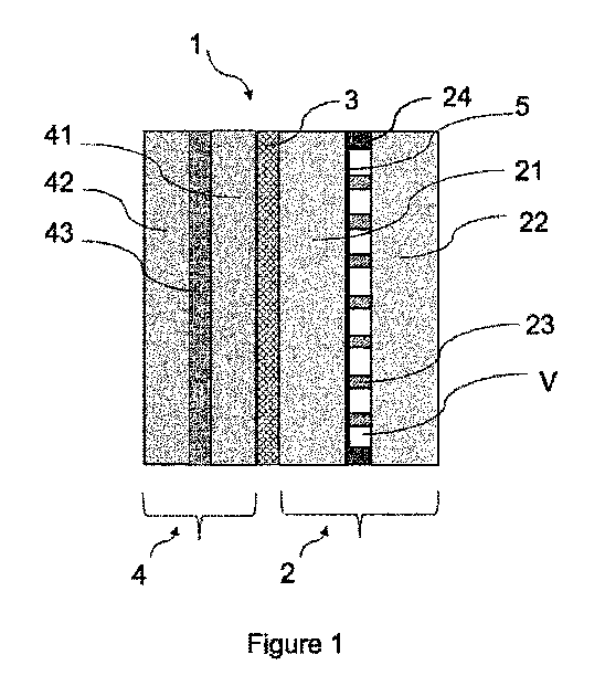
別個に製造された少なくとも1つの真空断熱グレージング(2)、少なくとも1つの中間ユニットポリマー(3)、及び少なくとも1つの機能ユニット(4)を有するラミネート真空断熱グレージング組立体(1)をISO12543-4:2011に合格させるための製造方法は、少なくとも、1)(2)と(3)と(4)とを積層し、それにより予備組立体を生成させるステップと、ただし(4)は5.5~15バールの処理圧で処理される、2)真空リング又はバッグ内に予備組立体を挿入するステップと、3)少なくとも、a.真空リング又はバッグ内をマイナス0.1~マイナス1バールの真空に排気し、b.予備組立体を50~200℃に加熱し、c.予備組立体を4.5バール以下の過圧下で加圧することにより予備組立体を処理して(1)を生成させるステップと、4)排気3)a)、加熱3)b)、及び過圧3)c)を解放するステップとを含む。
【選択図】図1
A manufacturing method for making a laminated vacuum insulation glazing assembly (1) having at least one separately manufactured vacuum insulation glazing (2), at least one intermediate unit polymer (3), and at least one functional unit (4) pass ISO 12543-4:2011 includes at least the steps of 1) laminating (2), (3), and (4) to produce a preassembly, where (4) is treated at a treatment pressure of 5.5 to 15 bar, 2) inserting the preassembly into a vacuum ring or bag, 3) treating the preassembly by at least a. evacuating the vacuum ring or bag to a vacuum of minus 0.1 to minus 1 bar, b. heating the preassembly to 50 to 200°C, and c. pressurizing the preassembly under an overpressure of 4.5 bar or less to produce (1), and 4) releasing the evacuation 3)a), heating 3)b), and overpressure 3)c).
[Selected Figure] Figure 1
Description
本発明は、音響、安全、セキュリティ、防火性、及び/又は装飾などの付加的性能を提供するラミネート真空断熱グレージング組立体の新規な製造方法に関する。 The present invention relates to a novel method for manufacturing a laminated vacuum insulated glazing assembly that provides additional performance such as acoustics, safety, security, fire protection, and/or decoration.
真空断熱グレージングは、相対的に高い断熱に対する市場のニーズに応えている。これらは、通常、真空が生成されて大気圧下においてガラスペインの間の直接的接触を防止するように離散スペーサが配置されている内部空間によって分離された少なくとも2枚のガラスペインから構成されている。断熱性能に加えて、ガラス市場は、安全性、セキュリティ、音響、防火性、装飾などのような更なる利益を真空断熱グレージングに追加することを求めている。 Vacuum insulated glazing meets the market need for relatively high thermal insulation. They usually consist of at least two glass panes separated by an internal space where discrete spacers are placed so that a vacuum is created and prevents direct contact between the glass panes at atmospheric pressure. In addition to thermal insulation performance, the glass market is seeking to add further benefits to vacuum insulated glazing such as safety, security, acoustics, fire protection, decoration, etc.
このような付加的利益は、通常、ラミネーション法により、真空断熱グレージングに対してもたらされている。ほぼすべてのラミネーション法は、受け入れ可能な品質のラミネートガラスを製造するために、10気圧超の圧力及び最大で150℃の温度における加圧されたオートクレーブ仕上げ処理を必要としている。実際に、ラミネーションの際には、通常、中間層を軟化させ、中間層がガラス基材の表面に追従して基材間隔が不均等であり得るエリア内に中間層を流すことを支援するために、温度を最大で150℃まで上昇させている。中間層が追従したら、中間層の移動可能なポリマー鎖がガラスとの間において接着を生成している。また、上昇した温度は、ガラス/中間層インターフェイスから中間層内への残留空気及び/又は湿気ポケットの拡散を加速させている。圧力は、ガラスラミネートの製造において2つの重要な役割を演じているものと考えられる。第1に、圧力は、中間層のフローを促進している。第2に、圧力は、システム内において捕獲された水及び空気の結合蒸気圧力によって生成されることになる気泡の形成を抑圧している。プリプレス(即ち、接合されていないガラス及び中間層の層状の組立体)内において捕獲されている水及び空気は、プリプレス組立体が約100℃超の仕上げ温度まで大気圧において加熱された際に気泡として膨張する傾向を有する。気泡形成を抑圧するために、通常、プリプレス内において捕獲された空気及び水が加熱された際に生成される膨張力に対抗するように、圧倒的な圧力によって伴われた熱がオートクレーブ容器内の組立体に対して印加されている。そして、最後に、時間がラミネーションにおいて重要な役割を演じている。温度及び圧力がラミネーションを加速させ得る一方で、良好な品質のラミネートガラスを製造するためには、特定の臨界時間が常に経過しなければならない。 Such additional benefits are typically provided to vacuum insulated glazing by lamination techniques. Nearly all lamination techniques require a pressurized autoclave finishing process at pressures above 10 atmospheres and temperatures up to 150°C to produce laminated glass of acceptable quality. In practice, during lamination, the temperature is typically increased up to 150°C to soften the interlayer and help it conform to the surface of the glass substrates and flow into areas where the substrate spacing may be uneven. Once the interlayer conforms, the mobile polymer chains of the interlayer create a bond with the glass. The elevated temperature also accelerates the diffusion of residual air and/or moisture pockets from the glass/interlayer interface into the interlayer. It is believed that pressure plays two important roles in the manufacture of glass laminates. First, pressure promotes the flow of the interlayer. Second, pressure suppresses the formation of air bubbles that would be created by the combined vapor pressure of water and air trapped in the system. The water and air trapped in the pre-press (i.e., the layered assembly of unbonded glass and interlayer) have a tendency to expand as bubbles when the pre-press assembly is heated at atmospheric pressure to a finishing temperature of above about 100° C. To suppress bubble formation, heat accompanied by overwhelming pressure is usually applied to the assembly in an autoclave vessel to counter the expansion forces generated when the air and water trapped in the pre-press are heated. And finally, time plays an important role in lamination. While temperature and pressure can accelerate lamination, a certain critical time must always elapse to produce good quality laminated glass.
但し、高圧及び/又は高温要件に起因して、このような従来のラミネーション法は、真空断熱グレージングに対して使用することができない。具体的には、加圧された処理ステップは、真空断熱グレージングの本質的な特性に適合してはおらず、真空断熱グレージングの2枚のガラスペインの間において配置された離散スペーサは、必要とされる圧力に抵抗することができず、及び/又は、微細な亀裂がこれらの離散スペーサの周りにおいてガラスペイン上において出現し、真空断熱グレージングの機械的強度及びその熱性能を格段に劣化させる可能性がある。 However, due to the high pressure and/or high temperature requirements, such conventional lamination methods cannot be used for vacuum insulated glazing. In particular, the pressurized processing steps are not compatible with the essential properties of vacuum insulated glazing, and the discrete spacers placed between the two glass panes of the vacuum insulated glazing cannot withstand the required pressure, and/or microscopic cracks may appear on the glass panes around these discrete spacers, significantly degrading the mechanical strength of the vacuum insulated glazing and its thermal performance.
従って、真空断熱グレージングに対して付加的ガラスシートをラミネートするために、大気圧における又は非常に低い圧力下におけるラミネーションが使用されている。例えば、国際公開第2020203550号パンフレットは、中間フィルムを介して真空断熱グレージングに透明プレートをラミネートする方法を開示している。真空断熱グレージングは、第1ガラスパネルと、第2ガラスパネルと、第1及び第2ガラスパネルの間において配置された真空空間と、樹脂から製造された複数のスペーサと、を有する。真空断熱グレージング及び透明プレートを1つにラミネートするための処理圧力は、複数のスペーサの圧縮強度よりも小さい。 Therefore, lamination at atmospheric pressure or under very low pressure is used to laminate additional glass sheets to vacuum insulating glazing. For example, WO2020203550 discloses a method for laminating a transparent plate to vacuum insulating glazing via an intermediate film. The vacuum insulating glazing comprises a first glass panel, a second glass panel, a vacuum space disposed between the first and second glass panels, and a number of spacers made of resin. The process pressure for laminating the vacuum insulating glazing and the transparent plate together is less than the compressive strength of the number of spacers.
但し、このような低い圧力要件は、真空断熱グレージングに付加され得る更なる利益の選択肢の柔軟性を格段に低減している。機能ユニットによってもたらされる付加的利益の大部分は、実際には、真空断熱グレージングの機械的抵抗力に起因して真空断熱グレージング上において直接的に処理される高温及び/又は高圧を必要としている。 However, such low pressure requirements significantly reduce the flexibility of options for additional benefits that can be added to the vacuum insulating glazing. Most of the additional benefits provided by the functional units actually require high temperatures and/or pressures that are processed directly on the vacuum insulating glazing due to the mechanical resistance of the vacuum insulating glazing.
従って、当業者は、真空断熱グレージングの機械的及び機能的な特性を劣化させることなしに真空断熱グレージングの利益を機能ユニットの性能と組み合わせることを許容する付加的な優れた利益を真空断熱グレージングにもたらすための新規のラミネーション法を追及している。従って、ラミネーション法に対して抵抗し、更なる利益が機能ユニットを介して真空断熱ユニットに追加されるように、真空断熱ユニットは、
(1)離散スペーサの機械的抵抗力、ガラスペインの厚さ、大気圧などのような真空断熱グレージング設計自体に固有のすべての応力である本質的負荷(Lint)、
(2)真空断熱グレージングに対するラミネーション法によってもたらされるすべての応力であるラミネーション負荷(Llam)、及び、
(3)内側及び外側環境の間の温度差、風、などのような真空断熱グレージングの使用の条件によって生成されるすべての応力である使用付加(Luse)、
という負荷に対して抵抗するように設計されることを要する。
Therefore, those skilled in the art are searching for new lamination methods to provide additional superior benefits to the vacuum insulated glazing, which allow the benefits of the vacuum insulated glazing to be combined with the performance of the functional unit without degrading the mechanical and functional properties of the vacuum insulated glazing. Thus, to resist the lamination method, the vacuum insulated unit is designed to have the following properties, so that further benefits are added to the vacuum insulated unit via the functional unit:
(1) the intrinsic load (L int ), which is all the stresses inherent to the vacuum insulated glazing design itself, such as the mechanical resistance of the discrete spacers, the thickness of the glass panes, the atmospheric pressure, etc.;
(2) the lamination load (L lam ), which is the total stress introduced by the lamination process on the vacuum insulated glazing; and
(3) Use Load (L use ), which is all the stresses generated by the conditions of use of the vacuum insulated glazing, such as temperature difference between the inside and outside environment, wind, etc.
The load must be designed to withstand the load.
従って、製造方法を費用効率に優れたもの及び単純なものとして維持しつつ、真空断熱グレージング及び機能ユニットの両方のものの機械的及び機能的な特性を劣化させることなしに機能ユニットの性能を真空断熱グレージングの利益に対して追加することを許容する新規な製造方法を提供することが本発明の目的である。 It is therefore an object of the present invention to provide a novel manufacturing method that allows the performance of a functional unit to be added to the benefits of the vacuum insulation glazing without compromising the mechanical and functional properties of both the vacuum insulation glazing and the functional unit, while keeping the manufacturing method cost-effective and simple.
本発明は、高温試験の規格ISO12543-4:2011に合格するラミネート真空断熱グレージング組立体(1)の製造方法に関する。この方法は、少なくとも、
1)真空断熱グレージング(2)と、中間ユニットポリマー(3)と、機能ユニット(4)とを積層し、それにより、予備組立体を生成させるステップと、ただし前記機能ユニットは、5.5バール~15.0バール(5.5バール≧PP≧15.0バール)、好ましくは7.5バール~14.0バール(7.5バール≧PP≧14.0バール)、更に好ましくは10.0バール~14.0バール(10.0バール≧PP≧14.0バール)の処理圧力(PP)において処理されている、
2)真空リング又は真空バッグ内に、好ましくは真空バッグ内に、前記予備組立体を挿入するステップと、
3)少なくとも、
a.前記真空リング又は真空バッグ内を、マイナス0.1バール~マイナス1バール、好ましくはマイナス0.5バール~マイナス1バールの真空に排気するサブステップ、
b.前記予備組立体を50℃~200℃、好ましくは75℃~175℃、更に好ましくは90℃~150℃の範囲の温度に加熱するサブステップ、
c.前記予備組立体を4.5バール以下の過圧(OP)(OP≦4.5バール)下において加圧するサブステップ、
により、前記予備組立体を処理してラミネートVIG組立体を生成させるステップと、
4)前記排気3)a)、前記加熱3)b)、及び前記過圧3)c)を解放するステップと、
を含む。
The present invention relates to a method for manufacturing a laminated vacuum insulation glazing assembly (1) that meets the high temperature test standard ISO 12543-4:2011. The method comprises at least
1) laminating a vacuum insulation glazing (2), an intermediate unit polymer (3) and a functional unit (4) thereby producing a preassembly, wherein said functional unit is processed at a processing pressure (PP) of 5.5 bar to 15.0 bar (5.5 bar > PP > 15.0 bar), preferably 7.5 bar to 14.0 bar (7.5 bar > PP > 14.0 bar), more preferably 10.0 bar to 14.0 bar (10.0 bar > PP > 14.0 bar),
2) inserting the pre-assembly into a vacuum ring or vacuum bag, preferably into a vacuum bag;
3) At a minimum,
a. evacuating the inside of the vacuum ring or vacuum bag to a vacuum of minus 0.1 bar to minus 1 bar, preferably minus 0.5 bar to minus 1 bar;
b. heating the preassembly to a temperature in the range of 50° C. to 200° C., preferably 75° C. to 175° C., more preferably 90° C. to 150° C.;
c) pressurizing the preassembly under an overpressure (OP) of 4.5 bar or less (OP≦4.5 bar);
processing the pre-assembly to produce a laminated VIG assembly by
4) releasing the exhaust 3) a), the heating 3) b), and the overpressure 3) c);
including.
好適な一実施形態において、機能ユニットは、少なくとも2枚のシートを含み、好ましくは、シートの少なくとも1つは、ガラスシートであり、更に好ましくは、少なくとも2枚のシートは、ガラスシートである。 In a preferred embodiment, the functional unit includes at least two sheets, preferably at least one of the sheets is a glass sheet, and more preferably at least two of the sheets are glass sheets.
好適な一実施形態において、サブステップ3)c)の過圧は、4.0バール以下であり(OP≦4.0バール)、好ましくは3.0バール以下であり(OP≦3.0バール)、好ましくは2.0バール以下であり(OP≦2.0バール)、好ましくは1.5バール以下であり(OP≦1.5バール)、好ましくは1.0バール以下であり(OP≦1.0バール)、好ましくは0.5バール以下であり(OP≦0.5バール)、更に好ましくは0バールに等しい(OP=0バール)。 In a preferred embodiment, the overpressure in substep 3)c) is less than or equal to 4.0 bar (OP≦4.0 bar), preferably less than or equal to 3.0 bar (OP≦3.0 bar), preferably less than or equal to 2.0 bar (OP≦2.0 bar), preferably less than or equal to 1.5 bar (OP≦1.5 bar), preferably less than or equal to 1.0 bar (OP≦1.0 bar), preferably less than or equal to 0.5 bar (OP≦0.5 bar), and more preferably equal to 0 bar (OP=0 bar).
好適な一実施形態において、処理ステップ3)のサブステップは、排気サブステップ3)a)、加熱サブステップ3)b)、及び加圧サブステップ3)c)の順序で実現され、好ましくは、加熱サブステップ3)b)及び加圧サブステップ3)c)は、同時に開始される。 In a preferred embodiment, the substeps of the process step 3) are realized in the following order: evacuation substep 3)a), heating substep 3)b), and pressurization substep 3)c), preferably heating substep 3)b) and pressurization substep 3)c) are started simultaneously.
好適な一実施形態において、処理ステップ3)の排気サブステップ3)a)は、5分~40分、好ましくは10分~30分、更に好ましくは20分~30分の期間にわたって周辺温度において行われる。 In a preferred embodiment, evacuation substep 3)a) of process step 3) is carried out at ambient temperature for a period of 5 minutes to 40 minutes, preferably 10 minutes to 30 minutes, more preferably 20 minutes to 30 minutes.
好適な一実施形態において、解放ステップ4)は、好ましくは、VIGラミネート組立体の温度が50℃~60℃、更に好ましくは周辺温度に到達したときに、まず加熱を解放し、次いで、排気を解放することにより、好ましくは排気及び加圧を一緒に解放することにより、実現される。 In a preferred embodiment, the releasing step 4) is preferably achieved by first releasing the heat and then releasing the exhaust, preferably releasing the exhaust and pressure together, when the temperature of the VIG laminate assembly reaches 50°C to 60°C, more preferably ambient temperature.
好適な一実施形態において、ステップ(4)内の加熱解放ステップは、好ましくは130℃~30℃の温度において、1~10℃/分、好ましくは2~9℃/分、好ましくは3~8℃/分、好ましくは4~7℃/分、更に好ましくは5~6℃/分の割合で実行される。これは、中間ユニットポリマーがエチレンビニルアセテート及び/又はイオノマーであるときに、好ましくはエチレンビニルアセテートであるときに、特に好適である。 In a preferred embodiment, the heat release step in step (4) is preferably carried out at a temperature of 130°C to 30°C at a rate of 1 to 10°C/min, preferably 2 to 9°C/min, preferably 3 to 8°C/min, preferably 4 to 7°C/min, more preferably 5 to 6°C/min. This is particularly suitable when the intermediate unit polymer is ethylene vinyl acetate and/or an ionomer, preferably ethylene vinyl acetate.
好適な一実施形態において、ラミネート真空断熱グレージング組立体は、Llam≦[Lint(SF-1)]+[Luse×SF]という負荷式を満たしており、ここで、
-Llamは、真空断熱グレージングに対するラミネーション法によってもたらされるすべての応力であるラミネーション負荷であり、
-Lintは、それ自体が真空断熱グレージング設計に固有であるすべての応力である本質的負荷であり、
-SFは、セキュリティ係数であり、
-Luseは、真空断熱グレージングの使用条件によって生成されるすべての応力である使用負荷である。
In a preferred embodiment, the laminated vacuum insulated glazing assembly satisfies the loading formula L lam ≦[L int (SF−1)]+[L use ×SF], where:
- L lam is the lamination load, which is the total stress caused by the lamination process on the vacuum insulated glazing;
- L int is the intrinsic load, which is all the stresses inherent in the vacuum insulated glazing design;
-SF is the security factor,
-L use is the service load, which is all the stresses generated by the use conditions of the vacuum insulating glazing.
好適な一実施形態において、中間ユニットポリマーは、エチレンビニルアセテート(EVA)、シクロポリオレフィンポリマー(COP)、オートクレーブフリーポリビニルブチラール(オートクレーブフリーPVB)、ポリウレタン(PU)、及び/又はイオノマーからなる群から選択され、好ましくは、エチレンビニルアセテート(EVA)及び/又はオートクレーブフリーポリビニルブチラール(オートクレーブフリーPVB)から選択されている。 In a preferred embodiment, the intermediate unit polymer is selected from the group consisting of ethylene vinyl acetate (EVA), cyclopolyolefin polymer (COP), autoclave-free polyvinyl butyral (autoclave-free PVB), polyurethane (PU), and/or ionomer, preferably selected from ethylene vinyl acetate (EVA) and/or autoclave-free polyvinyl butyral (autoclave-free PVB).
中間ユニットポリマーがオートクレーブフリーポリビニルブチラールである好適な一実施形態においては、処理ステップ3)の加熱サブステップb)の温度は、好ましくは20~180分の範囲の期間にわたって、更に好ましくは60分にわたって、90℃~150℃、好ましくは115℃~150℃、好ましくは135℃~145℃の範囲であり、更に好ましくは140℃である。 In a preferred embodiment in which the intermediate unit polymer is autoclave-free polyvinyl butyral, the temperature of heating substep b) of process step 3) is in the range of 90°C to 150°C, preferably 115°C to 150°C, preferably 135°C to 145°C, more preferably 140°C, for a period in the range of 20 to 180 minutes, more preferably 60 minutes.
中間ユニットがポリウレタンである好適な一実施形態においては、処理ステップ3)の加熱サブステップb)の温度は、20~180分の範囲の期間にわたって、更に好ましくは60分にわたって、90℃~150℃、好ましくは110℃~120℃の範囲である。好適な一実施形態において、加圧サブステップ3)c)は、2.0バール~4.5バール(2.0バール≦OP≦4.5バール)、好ましくは2.0バール~4.0バール(2.0バール≦OP≦4.0バール)、更に好ましくは3.0バールの過圧(OP)下において実行される。 In a preferred embodiment, where the intermediate unit is polyurethane, the temperature of heating substep b) of process step 3) is in the range of 90°C to 150°C, preferably 110°C to 120°C, for a period in the range of 20 to 180 minutes, more preferably 60 minutes. In a preferred embodiment, pressurizing substep 3)c) is carried out under an overpressure (OP) of 2.0 bar to 4.5 bar (2.0 bar < OP < 4.5 bar), preferably 2.0 bar to 4.0 bar (2.0 bar < OP < 4.0 bar), more preferably 3.0 bar.
中間ユニットポリマーがエチレンビニルアセテート及び/又はシクロポリオレフィンポリマーである、好ましくはエチレンビニルアセテートである、好適な一実施形態においては、処理ステップ3)の加熱サブステップb)の温度は、90℃~150℃、好ましくは110℃~145℃の範囲である。 In a preferred embodiment, where the intermediate unit polymer is ethylene vinyl acetate and/or a cyclopolyolefin polymer, preferably ethylene vinyl acetate, the temperature of heating substep b) of process step 3) is in the range of 90°C to 150°C, preferably 110°C to 145°C.
中間ユニットポリマーがエチレンビニルアセテートである好適な一実施形態においては、処理ステップ(3)は、サブステップb)の前に、好ましくは10~60分、更に好ましくは15分~40分の期間にわたって75℃~95℃の範囲の中間温度に加熱する更なるサブステップb*)を含む。 In a preferred embodiment in which the intermediate unit polymer is ethylene vinyl acetate, processing step (3) comprises, prior to substep b), a further substep b*) of heating to an intermediate temperature in the range of 75°C to 95°C for a period of preferably 10 to 60 minutes, more preferably 15 to 40 minutes.
中間ユニットポリマーがエチレンビニルアセテートである好適な一実施形態においては、処理ステップ(3)のサブステップは、
a)5分~40分、好ましくは10分~30分、更に好ましくは20分~30分の期間にわたって室温において排気するサブステップ、
b*)好ましくは10~60分、更に好ましくは15分~40分の期間にわたって、75℃~95℃の範囲の中間温度に加熱するサブステップ、
b)45分~300分の期間にわたって、110℃~145℃、好ましくは130℃~140℃の範囲の温度に加熱するサブステップ、
c)2.0バール以下(OP≦2.0バール)、好ましくは1.5バール以下(OP≦1.5バール)、好ましくは1.0バール以下(OP≦1.0バール)、好ましくは0.5バール以下(OP≦0.5バール)の過圧(OP)下において、更に好ましくは0バール(OP=0バール)の過圧なし下において、加圧するサブステップ、
の処理順序で実現され、
この場合に、好ましくは、サブステップb)及びサブステップc)は、同時に行われる。
In a preferred embodiment in which the intermediate unit polymer is ethylene vinyl acetate, the sub-steps of process step (3) include:
a) evacuation at room temperature for a period of 5 minutes to 40 minutes, preferably 10 minutes to 30 minutes, more preferably 20 minutes to 30 minutes;
b*) heating to an intermediate temperature in the range of 75°C to 95°C, preferably for a period of 10 to 60 minutes, more preferably 15 to 40 minutes;
b) heating to a temperature in the range of 110° C. to 145° C., preferably 130° C. to 140° C., for a period of 45 min to 300 min;
c) pressurizing under an overpressure (OP) of 2.0 bar or less (OP≦2.0 bar), preferably 1.5 bar or less (OP≦1.5 bar), preferably 1.0 bar or less (OP≦1.0 bar), preferably 0.5 bar or less (OP≦0.5 bar), more preferably under no overpressure of 0 bar (OP=0 bar);
This is achieved in the following processing order:
In this case, preferably sub-steps b) and c) are carried out simultaneously.
中間ユニットポリマーがイオノマーである好適な一実施形態においては、処理ステップ(3)の加熱サブステップb)は、好ましくは45分~75分の期間にわたって、好ましくは60分にわたって、90℃~150℃、好ましくは130℃~135℃の温度下において実行される。 In a preferred embodiment in which the intermediate unit polymer is an ionomer, the heating substep b) of process step (3) is carried out at a temperature of 90°C to 150°C, preferably 130°C to 135°C, for a period of preferably 45 minutes to 75 minutes, preferably 60 minutes.
好適な一実施形態において、機能ユニットは、ポリビニルブチラールポリマー中間層によってラミネートされた少なくとも2枚のガラスシートを含む。 In one preferred embodiment, the functional unit includes at least two glass sheets laminated with a polyvinyl butyral polymer interlayer.
好適な一実施形態において、機能ユニットは、少なくとも1つのポリビニルブチラールポリマー中間層及び少なくとも1つのポリウレタンポリマー中間層によってラミネートされた少なくとも1枚の構造的プラスチックシート、好ましくはポリカーボネートシート及び少なくとも1枚のガラスシートを含む。 In one preferred embodiment, the functional unit includes at least one structural plastic sheet, preferably a polycarbonate sheet, and at least one glass sheet laminated with at least one polyvinyl butyral polymer interlayer and at least one polyurethane polymer interlayer.
好適な一実施形態において、ポリビニルブチラールポリマー中間層は、音響ポリビニルブチラールポリマー中間層であり、及び/又は、複数のシートは、それぞれ異なる厚さを有する。 In a preferred embodiment, the polyvinyl butyral polymer interlayer is an acoustic polyvinyl butyral polymer interlayer and/or the multiple sheets each have a different thickness.
好適な一実施形態において、機能ユニットは、膨張材料、好ましくは水酸化アルカリ金属シリケートによって分離された少なくとも2枚のガラスシートを含む。好適な一実施形態において、機能ユニットは、周辺スペーサを更に含み、それにより、2枚のガラスシートの間に膨張材料を有するための空間を生成しており、この場合に、処理ステップ3)の加熱サブステップb)は、120℃以下、好ましくは110℃以下、好ましくは100℃以下、更に好ましくは90℃以下の温度下において実現される。 In a preferred embodiment, the functional unit comprises at least two glass sheets separated by an expansion material, preferably an alkali metal hydroxide silicate. In a preferred embodiment, the functional unit further comprises a peripheral spacer, thereby creating a space between the two glass sheets for the expansion material, in which case the heating substep b) of the process step 3) is realized at a temperature of 120°C or less, preferably 110°C or less, preferably 100°C or less, more preferably 90°C or less.
好適な一実施形態において、真空断熱グレージングの第1及び第2ガラスペインの少なくとも1つ及び/又は機能ユニットのシートの少なくとも1つは、熱強化ガラス、熱強靭化安全ガラス、又は化学強化ガラスである。 In a preferred embodiment, at least one of the first and second glass panes of the vacuum insulated glazing and/or at least one of the sheets of the functional unit is heat strengthened glass, heat toughened safety glass, or chemically strengthened glass.
好適な一実施形態において、真空断熱グレージングの離散スペーサは、金属材料、石英ガラス、セラミック材料、及び/又は樹脂、好ましくは、樹脂、更に好ましくはポリイミド樹脂から製造されている。 In a preferred embodiment, the discrete spacers of the vacuum insulating glazing are made of a metal material, quartz glass, a ceramic material, and/or a resin, preferably a resin, more preferably a polyimide resin.
本発明は、以下において「VIG」と呼称されている真空断熱グレージング及び機能ユニットという少なくとも2つの別個のユニットを有する以下において「ラミネートVIG組立体」と呼称されている「ラミネート真空断熱グレージング組立体」の製造方法に関する。VIG及び機能ユニットは、中間ユニットポリマーと1つに積層される前に、本発明の製造方法においてラミネートVIG組立体を形成するためのラミネート予備組立体として別個に製造されている。 The present invention relates to a method for manufacturing a "laminated vacuum insulated glazing assembly", hereinafter referred to as a "laminated VIG assembly", having at least two separate units: a vacuum insulated glazing, hereinafter referred to as a "VIG", and a functional unit. The VIG and the functional unit are manufactured separately as a laminate preassembly before being laminated together with an intermediate unit polymer to form the laminated VIG assembly in the manufacturing method of the present invention.
当業者は、本明細書において使用されている「1つの(a)」、「1つの(an)」、又は「その(the)」という用語は、少なくとも「1つ」を意味しており、そうではない旨が明示的に示されていない限り、「1つのみ」に限定されてはならないことを十分に理解している。 Those skilled in the art will appreciate that the terms "a," "an," or "the" as used herein mean at least "one" and should not be limited to "only one," unless expressly indicated otherwise.
方法
本発明の目的は、真空断熱グレージングユニット又は機能ユニットの機能的又は機械的な特性を劣化させることなしに真空断熱グレージングの優れた断熱性、厚さ、及び重量特性を機能ユニットによってもたらされる安全、セキュリティ、音響、防火性、装飾などの特性のようないくつかのその他の機能と組み合わせたラミネート真空断熱グレージング組立体を製造するということにある。
Method The object of the present invention is to produce a laminated vacuum insulated glazing assembly that combines the excellent insulation, thickness and weight properties of vacuum insulated glazing with several other functions such as safety, security, acoustic, fire protection, decorative etc. properties provided by the functional unit without degrading the functional or mechanical properties of the vacuum insulated glazing unit or functional unit.
本発明の更なる目的は、VIG、機能ユニット、及び/又はラミネートVIG組立体全体の過剰設計を回避しつつ、このような優れた性能を得ることにあり、その理由は、過剰設計は、不必要な複雑さ、費用をもたらすと共に、ラミネートVIG組立体の熱性能、光透明性、重量、厚さ、加工可能性、及び輸送、などを劣化させ得るからである。 A further object of the present invention is to obtain such superior performance while avoiding over-designing the VIGs, functional units, and/or the entire laminate VIG assembly, which can result in unnecessary complexity, expense, and can degrade the thermal performance, optical clarity, weight, thickness, processability, and shipping of the laminate VIG assembly.
高温及び/又は高圧条件が適用されている一般的なラミネーション法は、いくつかの例において、真空断熱グレージングの機械的特性及び/又は熱性能を劣化させることが見出されている。驚いたことに、真空断熱グレージング及び機能ユニットが別個に製造され、次いで、穏やかな過圧条件下において1つにラミネートされている本発明の方法は、真空断熱グレージングの完全性を維持することと、本発明の方法によらなければ真空断熱グレージングにもたらされ得ない優れた機能的特性をラミネートVIG組立体にもたらすことと、を可能にすることが見出されている。 Conventional lamination methods, in which high temperature and/or high pressure conditions are applied, have been found in some instances to degrade the mechanical properties and/or thermal performance of the vacuum insulated glazing. Surprisingly, it has been found that the method of the present invention, in which the vacuum insulated glazing and the functional unit are manufactured separately and then laminated together under mild overpressure conditions, allows the integrity of the vacuum insulated glazing to be maintained and provides the laminated VIG assembly with superior functional properties that cannot otherwise be provided to the vacuum insulated glazing by the method of the present invention.
従って、本発明は、ラミネートVIG組立体が、様々な負荷、即ち、本質的負荷、使用負荷、及びラミネーション負荷、を支持するために設計及び処理されることを要する方式を対象としている。ラミネートVIG組立体及びその製造方法は、
(1)ラミネートVIG組立体が、Design load≧(Lint+Luse)×SFのように特定の設計セキュリティ係数によっていずれもが補足された本質的負荷(Lint)及び使用負荷(Luse)に抵抗するように、しかも、
(2)ラミネートVIG組立体が、同様に、Design Load≧Lint+Llamのように結合された本質的及びラミネーション負荷に抵抗するように、
設計されることを要することが見出されている。従って、ラミネーション負荷は、Llam≦[Lint(SF-1)]+[Luse×SF]という式を満たしている。
Thus, the present invention is directed to the manner in which a laminated VIG assembly must be designed and engineered to support a variety of loads, i.e., intrinsic loads, service loads, and lamination loads. The laminated VIG assembly and its method of manufacture include:
(1) The laminate VIG assembly is designed to withstand an intrinsic load (L int ) and a service load (L use ), both of which are supplemented by a specified design security factor, such that: Design load >= (L int +L use ) x SF; and
(2) The laminate VIG assembly similarly resists the combined intrinsic and lamination loads such that Design Load >= L int + L lam .
It has been found that the lamination load needs to be designed such that L lam ≦[L int (SF−1)]+[L use ×SF].
当業者には、上述の式に従ってラミネーション法によってもたらされる負荷(Llam)に抵抗するために、従って、真空断熱グレージングの機能的又は機械的な特性の損傷を回避するために、異なるルートが提供されている。
(1)1つの潜在的ルートは、使用負荷を増大させるというものとなろう。但し、ラミネートVIG組立体が相対的に大きな使用負荷に抵抗するように設計される場合には、それは、不必要に過剰設計されることとなろう。
(2)別の潜在的ルートは、VIGのガラスペインの厚さを増大させることにより、セキュリティ係数を増大させるというものとなろう。この場合にも、ラミネートVIG組立体は、不必要に過剰設計されることになり、これは、VIGの厚さ及び軽量という有利な特性を劣化させることになろう。
(3)別の技術的方式は、本質的負荷の低減及びlam負荷の低減を許容するために、離散スペーサの数を増大させるというものとなろう。但し、このようなルートは、VIGの熱性能を大幅に低減することになり、不必要に過剰設計されることになろう。
このような過剰設計は、回避することを要し、その理由は、これらが不必要な複雑さ、費用をもたらすと共に、ラミネートVIG組立体の熱性能、光透明性、重量、厚さ、加工可能性、及び輸送、などを劣化させ得るからである。
(4)最後に、従って、最後の潜在的なルートは、ラミネーション負荷が低減された製造方法、即ち、相対的に低い圧力及び/又は低い温度における製造方法、を設計するというものである。但し、このような製造方法は、実際に高い圧力及び/又は高い温度状態の生成を必要としているすべての機能ユニットの活用を許容することにはならないであろう。
The skilled person is offered different routes to resist the loads (L lam ) brought about by the lamination process according to the above formula and thus to avoid damage to the functional or mechanical properties of the vacuum insulation glazing.
(1) One potential route would be to increase the service loads, however, if the laminate VIG assembly were designed to withstand relatively large service loads, it would be unnecessarily over-engineered.
(2) Another potential route would be to increase the thickness of the glass panes of the VIG, thereby increasing the security factor. Again, this would result in the laminate VIG assembly being unnecessarily over-engineered, which would degrade the advantageous properties of the VIG's thickness and light weight.
(3) Another engineering approach would be to increase the number of discrete spacers to allow for reduced intrinsic and lam loading, however, such a route would significantly reduce the thermal performance of the VIG and would be unnecessarily over-engineered.
Such over-engineering should be avoided because it introduces unnecessary complexity, expense, and can degrade the thermal performance, optical clarity, weight, thickness, processability, and shipping of the laminated VIG assembly.
(4) Finally, therefore, the last potential route is to design a manufacturing method with reduced lamination loads, i.e. at relatively low pressures and/or temperatures, although such a manufacturing method would not allow the utilization of all functional units that actually require the creation of high pressure and/or high temperature conditions.
上述のように、真空断熱グレージングの過剰設計は、経済的に実現可能な選択肢ではない。相対的に低い圧力におけるラミネーションは、実際に高圧及び/又は高温条件を必要としている機能ユニットを排除することになろう。このような機能ユニットは、通常、5.5バール~15.0バールの処理圧力(PP)において処理されている。従って、VIGの優れた熱特性のみならず追加された機能ユニットの機能的特性を組み合わせて維持する製造方法を開発するニーズが依然として存在している。機能ユニット及びVIGが別個のステップにおいて製造され、次いで、穏やかな過圧の下において1つにラミネートされている本発明の新規な製造方法は、VIGコンポーネントの過剰設計及び/又は熱性能の低減を回避しつつ、VIGに対する付加的技術性能における最大の柔軟性を提供することが見出されている。実際に、本発明は、低圧におけるラミネーション法を介した、VIGに対する高圧において処理された機能的ユニットの追加を許容している。 As mentioned above, over-engineering of vacuum insulation glazing is not an economically viable option. Lamination at relatively low pressure would actually eliminate functional units that require high pressure and/or high temperature conditions. Such functional units are usually processed at processing pressures (PP) of 5.5 bar to 15.0 bar. Therefore, there remains a need to develop a manufacturing method that combines and maintains the excellent thermal properties of the VIG as well as the functional properties of the added functional units. It has been found that the novel manufacturing method of the present invention, in which the functional units and the VIG are manufactured in separate steps and then laminated together under moderate overpressure, offers maximum flexibility in additional technical performance to the VIG while avoiding over-engineering and/or reducing the thermal performance of the VIG components. In fact, the present invention allows the addition of high pressure processed functional units to the VIG via a lamination method at low pressure.
更には、ラミネートVIG組立体用の新規な製造方法は、単一の産業機器内において単一段階において実行することが可能であり、従って、容易であり、単純であり、効率的であり、費用効果に優れている。 Furthermore, the novel manufacturing method for laminated VIG assemblies can be performed in a single step in a single industrial machine, and is therefore easy, simple, efficient, and cost-effective.
ラミネートVIG組立体は、少なくとも1つのVIGと、少なくとも1つの機能ユニットとを有することができる。通常、ラミネートVIG組立体は、1つのVIGと、1つの機能ユニットとを有する。但し、いくつかの実施形態において、ラミネートVIG組立体は、VIGの同一の面に、又はVIGの両方の面に、追加された複数の機能ユニットを有することができる。また、ラミネートVIG組立体が、1つ又は複数の機能ユニットと共に、複数のVIGを有する実施形態も想定され得るであろう。本明細書には、1つ又は複数のVIG及び1つ又は複数の機能ユニットのすべての組合せが包含されている。 A laminated VIG assembly can have at least one VIG and at least one functional unit. Typically, a laminated VIG assembly has one VIG and one functional unit. However, in some embodiments, a laminated VIG assembly can have multiple functional units added to the same side of the VIG or to both sides of the VIG. Also, embodiments in which a laminated VIG assembly has multiple VIGs with one or more functional units could be envisioned. All combinations of one or more VIGs and one or more functional units are encompassed herein.
本発明の好適な一実施形態において、ラミネートVIG組立体は、1つのVIGと、1つの機能ユニットとを有する。 In a preferred embodiment of the present invention, the laminated VIG assembly has one VIG and one functional unit.
ラミネート組立体、即ち、VIG及び機能ユニット、のみならず、VIGのペイン及び機能ユニットのシートは、長手方向軸X及び垂直方向軸Zによって定義された平面Pに沿って延在している。これらの要素のそれぞれは、平面Pに垂直の方向において計測される厚さを有し、平面Pに沿って延在する表面を有する。 The laminate assembly, i.e., the VIG and functional units, as well as the panes of the VIG and the sheets of the functional units, extend along a plane P defined by a longitudinal axis X and a vertical axis Z. Each of these elements has a thickness measured in a direction perpendicular to the plane P and has a surface extending along the plane P.
本発明は、VIG(2)及び機能ユニット(4)を有するラミネートVIG組立体(1)を製造する方法に関し、この場合に、VIG及び機能ユニットは、別個のステップにおいて製造されている。本発明のラミネートVIG組立体を形成するために機能ユニット及びVIGをラミネートするために本発明の方法において使用されるべき適切な中間ユニットポリマーは、穏やかな過圧においてラミネーションによって適切な機械的接着を提供する能力を有するポリマーである。 The present invention relates to a method for producing a laminated VIG assembly (1) having a VIG (2) and a functional unit (4), where the VIG and the functional unit are produced in separate steps. Suitable intermediate unit polymers to be used in the method of the present invention to laminate the functional unit and the VIG to form the laminated VIG assembly of the present invention are polymers that have the ability to provide adequate mechanical adhesion upon lamination at moderate overpressure.
積層の際に、中間ユニットポリマーは、VIG及び/又は機能ユニットの表面上に堆積させることが可能であり、真空断熱グレージングと機能ユニットの間に配置され、それにより、予備組立体を生成している。 During lamination, the intermediate unit polymer can be deposited on the surface of the VIG and/or functional unit and disposed between the vacuum insulating glazing and the functional unit, thereby creating a preassembly.
ラミネーションによる適切な機械的接着は、結果的に得られるラミネートVIG組立体が、2011年10月付けのNBN EN ISO 12543という規格の耐久性セクションである「Glass in building-Laminated glass and laminated safety glass-Part 4:Test methods for durability(ISO12543-4:2011)」の高温試験(ベイク試験とも呼称される)に合格することを意味している。 Proper mechanical adhesion through lamination means that the resulting laminated VIG assembly will pass the high temperature test (also called the bake test) of the durability section of the NBN EN ISO 12543 standard dated October 2011, "Glass in building - Laminated glass and laminated safety glass - Part 4: Test methods for durability (ISO12543-4:2011)".
過圧は、大気圧超の更なる圧力を意味している。穏やかな過圧は、4.5バール以下(OP≦4.5バール)、好ましくは4.0バール以下(OP≦4.0バール)、好ましくは3.0バール以下(OP≦3.0バール)、好ましくは2.0バール以下(OP≦2.0バール)の、好ましくは1.5バール以下(OP≦1.5バール)、好ましくは1バール以下(OP≦1バール)、好ましくは0.5バール以下(OP≦0.5バール)、更に好ましくは0バールに等しい(OP=0バール)過圧を意味している。 Overpressure means an additional pressure above atmospheric pressure. Mild overpressure means an overpressure of less than or equal to 4.5 bar (OP≦4.5 bar), preferably less than or equal to 4.0 bar (OP≦4.0 bar), preferably less than or equal to 3.0 bar (OP≦3.0 bar), preferably less than or equal to 2.0 bar (OP≦2.0 bar), preferably less than or equal to 1.5 bar (OP≦1.5 bar), preferably less than or equal to 1 bar (OP≦1 bar), preferably less than or equal to 0.5 bar (OP≦0.5 bar), more preferably equal to 0 bar (OP=0 bar).
従って、本発明の方法において使用されるべき適切な中間ユニットポリマーは、結果的に得られるラミネートVIG組立体が、4.5バール以下(OP≦4.5バール)、好ましくは4.0バール以下(OP≦4.0バール)、好ましくは3.0バール以下(OP≦3.0バール)、好ましくは2.0バール以下(OP≦2.0バール)、好ましくは1.5バール以下(OP≦1.5バール)、好ましくは1バール以下(OP≦1バール)、好ましくは0.5バール以下(OP≦0.5バール)、更に好ましくは0バールに等しい(OP=0バール)過圧において高温試験ISO12543-4:2011に合格するように、機能ユニットとVIGの間に適切な機械的接着を提供するものである。 Therefore, suitable intermediate unit polymers to be used in the method of the present invention are those that provide adequate mechanical adhesion between the functional unit and the VIG such that the resulting laminated VIG assembly passes the high temperature test ISO 12543-4:2011 at an overpressure of 4.5 bar or less (OP≦4.5 bar), preferably 4.0 bar or less (OP≦4.0 bar), preferably 3.0 bar or less (OP≦3.0 bar), preferably 2.0 bar or less (OP≦2.0 bar), preferably 1.5 bar or less (OP≦1.5 bar), preferably 1 bar or less (OP≦1 bar), preferably 0.5 bar or less (OP≦0.5 bar), and more preferably equal to 0 bar (OP=0 bar).
好適な一実施形態において、本発明の方法において使用されるべき適切な中間ユニットポリマーは、エチレンビニルアセテート(EVA)、シクロオレフィンポリマー(COP)、オートクレーブフリーポリビニルブチラール(以下においては、オートクレーブフリーPVBと呼称される)、ポリウレタン(PU)、SentryGlas(商標)のようなイオノマー、及びこれらの組合せからなる群から選択されている。 In a preferred embodiment, suitable intermediate unit polymers to be used in the process of the present invention are selected from the group consisting of ethylene vinyl acetate (EVA), cycloolefin polymer (COP), autoclave-free polyvinyl butyral (hereinafter referred to as autoclave-free PVB), polyurethane (PU), ionomers such as SentryGlas™, and combinations thereof.
本発明は、高温試験の規格ISO12543-4:2011に合格するラミネート真空断熱グレージング組立体(1)の製造方法に関し、これは、少なくとも、
1)真空断熱グレージング(2)と、中間ユニットポリマー(3)と、機能ユニット(4)とを積層し、それにより、予備組立体を生成させるステップと、ただし前記機能ユニットは、5.5バール~15.0バール(5.5バール≧PP≧15.0バール)、好ましくは7.5バール~14.0バール(7.5バール≧PP≧14.0バール)、更に好ましくは10.0バール~14.0バール(10.0バール≧PP≧14.0バール)の処理圧力(PP)において処理されている、
2)真空リング又は真空バッグ内に、好ましくは真空バッグ内に、前記予備組立体を挿入するステップと、
3)少なくとも、
a.前記真空リング又は真空バッグ内を、マイナス0.1バール~マイナス1バール、好ましくはマイナス0.5バール~マイナス1バールの真空に排気するサブステップ、
b.前記予備組立体を50℃~200℃、好ましくは75℃~175℃、更に好ましくは90℃~150℃の範囲の温度に加熱するサブステップ、
c.前記予備組立体を4.5バール以下の過圧(OP)(OP≦4.5バール)下において加圧するサブステップ、
により、前記予備組立体を処理してラミネートVIG組立体を生成させるステップと、
4)前記排気3)a)、前記加熱3)b)、及び前記過圧3)c)を解放するステップと、
を含む。
The present invention relates to a method for manufacturing a laminated vacuum insulation glazing assembly (1) that meets the high temperature test standard ISO 12543-4:2011, which comprises at least:
1) laminating a vacuum insulation glazing (2), an intermediate unit polymer (3) and a functional unit (4) thereby producing a preassembly, wherein said functional unit is processed at a processing pressure (PP) of 5.5 bar to 15.0 bar (5.5 bar > PP > 15.0 bar), preferably 7.5 bar to 14.0 bar (7.5 bar > PP > 14.0 bar), more preferably 10.0 bar to 14.0 bar (10.0 bar > PP > 14.0 bar),
2) inserting the pre-assembly into a vacuum ring or vacuum bag, preferably into a vacuum bag;
3) At a minimum,
a. evacuating the inside of the vacuum ring or vacuum bag to a vacuum of minus 0.1 bar to minus 1 bar, preferably minus 0.5 bar to minus 1 bar;
b. heating the preassembly to a temperature in the range of 50° C. to 200° C., preferably 75° C. to 175° C., more preferably 90° C. to 150° C.;
c) pressurizing the preassembly under an overpressure (OP) of 4.5 bar or less (OP≦4.5 bar);
processing the pre-assembly to produce a laminated VIG assembly by
4) releasing the exhaust 3) a), the heating 3) b), and the overpressure 3) c);
including.
本明細書における機能ユニットは、優れた利益を提供するために高圧において、即ち、5.5バール~15.0バール(5.5バール≧PP≧15.0バール)、好ましくは7.5バール~14.0バール(7.5バール≧PP≧14.0バール)、更に好ましくは10.0バール~14.0バール(10.0バール≧PP≧14.0バール)の処理圧力(PP)において処理されている。機能ユニットは、好ましくは少なくとも2枚のシートを有し、好ましくはシートの少なくとも1つは、ガラスシートであり、更に好ましくは、少なくとも2枚のシートは、ガラスシートである。 The functional units herein are processed at high pressures, i.e., at processing pressures (PP) of 5.5 bar to 15.0 bar (5.5 bar > PP > 15.0 bar), preferably 7.5 bar to 14.0 bar (7.5 bar > PP > 14.0 bar), more preferably 10.0 bar to 14.0 bar (10.0 bar > PP > 14.0 bar), to provide superior benefits. The functional units preferably have at least two sheets, preferably at least one of the sheets is a glass sheet, more preferably at least two of the sheets are glass sheets.
本発明の方法の好適な一実施形態において、処理ステップ3)のサブステップb)の過圧は、4.0バール以下(OP≦4.0バール)、好ましくは3.0バール以下(OP≦3.0バール)、好ましくは2.0バール以下(OP≦2.0バール)、好ましくは1.5バール以下(OP≦1.5バール)、好ましくは1.0バール以下(OP≦1.0バール)、好ましくは0.5バール以下(OP≦0.5バール)であり、更に好ましくは0バールに等しい(OP=0バール)。 In a preferred embodiment of the method of the present invention, the overpressure in substep b) of process step 3) is less than or equal to 4.0 bar (OP≦4.0 bar), preferably less than or equal to 3.0 bar (OP≦3.0 bar), preferably less than or equal to 2.0 bar (OP≦2.0 bar), preferably less than or equal to 1.5 bar (OP≦1.5 bar), preferably less than or equal to 1.0 bar (OP≦1.0 bar), preferably less than or equal to 0.5 bar (OP≦0.5 bar), and more preferably equal to 0 bar (OP=0 bar).
当業者は、本発明の方法が0バールに等しい過圧において実行された際には、これは、更なる過圧を伴うことなしに、即ち、大気圧において実行され、過圧の解放が必要とされてはいないことを十分に理解している。 The skilled artisan will appreciate that when the method of the present invention is carried out at an overpressure equal to 0 bar, this is carried out without further overpressure, i.e. at atmospheric pressure, and no release of overpressure is required.
当業者は、特に過圧が使用されていない(OP=0バール)本発明の方法においては、予備組立体を真空に晒すという同一の目的を実現するために、真空チャンバなどの任意のその他の真空装置を真空バッグ又は真空リングの代わりに使用し得ることを十分に理解している。真空バッグが使用される際には、脱気現象を増大させるように、ブリーザフレームによって予備組立体を取り囲むことが好ましい。 Those skilled in the art will appreciate that any other vacuum device, such as a vacuum chamber, may be used instead of a vacuum bag or vacuum ring to achieve the same purpose of exposing the pre-assembly to a vacuum, especially in the method of the present invention where no overpressure is used (OP=0 bar). When a vacuum bag is used, it is preferable to surround the pre-assembly with a breather frame to increase the degassing phenomenon.
好ましくは、本発明の方法は、機械的抵抗力の劣化を回避するために、及びラミネートVIG組立体の完全性を維持するために、過圧がカレンダロール、ニップローラー、又は任意のその他のローラーを介して実現されないように、圧力ローラー又はカレンダ(シングル又はダブル)のシステムを有することにならない。 Preferably, the method of the present invention will not have a system of pressure rollers or calenders (single or double) so that overpressure is not achieved through calender rolls, nip rollers, or any other rollers to avoid degradation of mechanical resistance and to maintain the integrity of the laminated VIG assembly.
処理ステップ3)のサブステップが排気a)である状態において、加熱b)及び加圧c)は、任意の順序で行われることができる。但し、本発明の好適な一実施形態において、処理ステップ3)のサブステップは、排気サブステップ3)a)、加熱サブステップ3)b)、及び加圧サブステップ3)c)の処理順序で実現され、好ましくは、加熱サブステップ3)b)及び加圧サブステップ3)c)は、同時に開始される。このような好適な実施形態は、低温における空気の排気を改善することが見出される。圧力の増大は、排気を支援することになり、加熱は、組立体のエッジ封止が構造への空気の戻りを防止するようにすることになる。 With the sub-step of process step 3) being evacuation a), heating b) and pressurization c) can be performed in any order. However, in a preferred embodiment of the present invention, the sub-steps of process step 3) are realized in the process order of evacuation sub-step 3)a), heating sub-step 3)b), and pressurization sub-step 3)c), and preferably heating sub-step 3)b) and pressurization sub-step 3)c) are started simultaneously. Such a preferred embodiment is found to improve the evacuation of air at low temperatures. The increased pressure will assist the evacuation and the heating will allow the edge seal of the assembly to prevent air from returning to the structure.
本発明の好適な一実施形態において、処理ステップ3)の排気サブステップa)は、加熱サブステップ3)b)が開始される前に、5分~40分、好ましくは10分~30分、更に好ましくは20分~30分にわたって、周辺温度において開始される。このような好適な実施形態は、中間ユニットポリマーとVIG及び/又は機能ユニットの間において捕捉された滑らかな空気排気を許容することが見出されている。 In a preferred embodiment of the present invention, evacuation substep a) of process step 3) is initiated at ambient temperature for 5 to 40 minutes, preferably 10 to 30 minutes, more preferably 20 to 30 minutes, before heating substep 3)b) is initiated. Such a preferred embodiment has been found to allow smooth evacuation of air trapped between the intermediate unit polymer and the VIG and/or functional units.
本発明の更なる好適な一実施形態において、本発明の方法の解放ステップ4)は、まず加熱を解放し、次いで排気を解放する、好ましくは排気及び加圧を一緒に解放する、ことにより、実現されている。これは、好ましくはVIGラミネート組立体の温度が、50℃~60℃に到達したとき、更に好ましくは周辺温度に到達したときに実行される。実際に、真空下における冷却は、有利であり、その理由は、その結果、ラミネートVIG組立体内におけるエアポケット及び曇りの形成が低減されるからである。 In a further preferred embodiment of the present invention, the releasing step 4) of the method of the present invention is realized by first releasing the heat and then releasing the evacuation, preferably releasing the evacuation and the pressure together. This is preferably performed when the temperature of the VIG laminate assembly reaches 50°C to 60°C, more preferably when it reaches ambient temperature. In fact, cooling under vacuum is advantageous because it reduces the formation of air pockets and haze in the laminate VIG assembly.
本発明の更なる好適な一実施形態において、方法のステップ(4)の加熱解放サブステップは、特に130℃~30℃の温度範囲において、1~10℃/分、好ましくは2~9℃/分、好ましくは3~8℃/分、好ましくは4~7℃/分、更に好ましくは5~6℃/分の減少を実現するように実行される。実際に、これは、ラミネートVIGユニットを形成するために使用されている中間ユニットポリマーがEVA、COP、及び/又はイオノマーである実施形態において特に好適である。本発明の方法の冷却ステップは、好ましくは、ヘイズの出現を回避するために高速で実行されることになる。熱交換機を伴う又は伴わないファンなどによる冷却ガスのフローを利用した対流冷却又は伝導冷却を使用することができる。 In a further preferred embodiment of the present invention, the heat release sub-step of step (4) of the method is carried out to achieve a decrease of 1-10°C/min, preferably 2-9°C/min, preferably 3-8°C/min, preferably 4-7°C/min, more preferably 5-6°C/min, especially in the temperature range of 130°C to 30°C. Indeed, this is particularly preferred in embodiments where the intermediate unit polymers used to form the laminated VIG units are EVA, COP, and/or ionomers. The cooling step of the method of the present invention will preferably be carried out at a high speed to avoid the appearance of haze. Convection cooling or conduction cooling using a flow of cooling gas, such as by a fan with or without a heat exchanger, can be used.
通常、本発明の方法は、必要とされる際に特定の温度及び低湿気レベルを尊重するために、のみならず、汚染を回避するために、クリーンルーム内において実現されている。 The method of the invention is usually carried out in a clean room to avoid contamination as well as to respect specific temperatures and low humidity levels when required.
好適な一実施形態において、本発明の方法において使用されるべき適切な中間ユニットポリマーは、エチレンビニルアセテート(EVA)、シクロオレフィンポリマー(COP)、オートクレーブフリーポリビニルブチラール(以下においては、オートクレーブフリーPVBと呼称される)、ポリウレタン(PU)、及び/又はSentryGlas(商標)のようなイオノマーからなる群から選択されている。 In a preferred embodiment, suitable intermediate unit polymers to be used in the process of the present invention are selected from the group consisting of ethylene vinyl acetate (EVA), cycloolefin polymer (COP), autoclave-free polyvinyl butyral (hereinafter referred to as autoclave-free PVB), polyurethane (PU), and/or ionomers such as SentryGlas™.
オートクレーブフリーPVBを伴う方法
ラミネートVIG組立体を形成するために使用される中間ユニットポリマーがオートクレーブフリーPVBである本発明の方法においては、オートクレーブフリーPVBを特定の相対湿度及び温度条件に事前コンディショニングするという初期ステップが好ましくは追加されている。これは、特にラミネーションサイクルの後にラミネートVIG組立体の良好な品質を得るために、特にラミネートVIG組立体のエッジにおける気泡形成を回避するために、好ましい。このようなオートクレーブフリーPVBは、通常、例えば、20%未満、好ましくは15%未満、更に好ましくは10%未満の湿気含有量と、15℃~30℃、好ましくは18℃~25℃の温度とを示すように、保存及び処理のための特定の湿度条件を必要としている。従って、中間ユニットポリマーがオートクレーブフリーPVBであるこの実施形態においては、本発明の方法は、好ましくは、10%以上の相対湿度及び25℃において、少なくとも10時間、好ましくは少なくとも12時間にわたって、オートクレーブフリーPVBを事前コンディショニングする初期ステップを有する。
Methods involving autoclave-free PVB In the method of the invention, where the intermediate unit polymer used to form the laminated VIG assembly is autoclave-free PVB, an initial step of preconditioning the autoclave-free PVB to specific relative humidity and temperature conditions is preferably added. This is preferred in order to obtain good quality of the laminated VIG assembly, especially after the lamination cycle, and in particular to avoid bubble formation at the edges of the laminated VIG assembly. Such autoclave-free PVB usually requires specific humidity conditions for storage and processing, e.g. exhibiting a moisture content of less than 20%, preferably less than 15%, more preferably less than 10%, and a temperature of 15°C to 30°C, preferably 18°C to 25°C. Thus, in this embodiment where the intermediate unit polymer is autoclave-free PVB, the method of the invention preferably has an initial step of preconditioning the autoclave-free PVB at a relative humidity of 10% or more and at 25°C for at least 10 hours, preferably at least 12 hours.
この実施形態において、本発明の方法の処理ステップ3)の加熱サブステップb)は、好ましくは、90℃~150℃、好ましくは115℃~150℃、好ましくは135℃~145℃、更に好ましくは140℃の温度において予備組立体を加熱することになる。これは、好ましくは、20~180分の範囲の期間にわたって、好ましくは60分にわたって実現される。 In this embodiment, the heating substep b) of process step 3) of the method of the present invention preferably involves heating the pre-assembly at a temperature between 90°C and 150°C, preferably between 115°C and 150°C, preferably between 135°C and 145°C, more preferably at 140°C. This is preferably achieved over a period in the range of 20 to 180 minutes, preferably for 60 minutes.
従って、本発明の好適な一実施形態において、本発明の方法の処理ステップ(3)のサブステップa)及びb)は、
a.5分~40分、好ましくは10分~30分、更に好ましくは20分~30分の範囲の期間にわたって、室温において、真空リング又は真空バッグ内を、マイナス0.1バール~マイナス1バール、好ましくはマイナス0.5バール~マイナス1バールの真空に排気するステップ、
b.好ましくは20~180分の範囲の期間にわたって、好ましくは60分にわたって、90℃~150℃、好ましくは115℃~150℃、好ましくは135℃~145℃、更に好ましくは140℃の温度において加熱するステップ、
という処理順序で実現される。
Thus, in one preferred embodiment of the present invention, substeps a) and b) of process step (3) of the method of the present invention comprise:
a. evacuating to a vacuum of minus 0.1 bar to minus 1 bar, preferably minus 0.5 bar to minus 1 bar, in a vacuum ring or vacuum bag at room temperature for a period ranging from 5 minutes to 40 minutes, preferably from 10 minutes to 30 minutes, more preferably from 20 minutes to 30 minutes;
b. heating at a temperature of 90°C to 150°C, preferably 115°C to 150°C, preferably 135°C to 145°C, more preferably 140°C, for a period preferably in the range of 20 to 180 minutes, preferably for 60 minutes;
This is realized in the following processing order.
更なる好適な一実施形態において、加圧サブステップ3)c)は、2.0バール以下(OP≦2.0バール)、好ましくは1.5バール以下(OP≦1.5バール)、好ましくは1.0バール以下(OP≦1.0バール)、好ましくは0.5バール以下(OP≦0.5バール)、の過圧(OP)下において、更に好ましくは0バールの過圧なし(OP=0バール)下において、実行される。 In a further preferred embodiment, the pressurization substep 3)c) is carried out under an overpressure (OP) of 2.0 bar or less (OP≦2.0 bar), preferably 1.5 bar or less (OP≦1.5 bar), preferably 1.0 bar or less (OP≦1.0 bar), preferably 0.5 bar or less (OP≦0.5 bar), more preferably under no overpressure of 0 bar (OP=0 bar).
好ましくは、処理ステップ3)の加熱サブステップb)及び加圧サブステップc)は、同時に開始される。 Preferably, the heating substep b) and the pressure applying substep c) of process step 3) are initiated simultaneously.
これらの好適な特徴のすべては、中間ユニットポリマーがオートクレーブフリーPVBである本発明の更に好適な方法として組み合わせられている。 All of these preferred features are combined in a further preferred method of the present invention in which the intermediate unit polymer is autoclave-free PVB.
PUを有する方法
ラミネートVIG組立体を形成するために使用される中間ユニットポリマーがポリウレタン(PU)である本発明の方法においては、本発明の方法の処理ステップ3)の加熱ステップb)は、好ましくは、90℃~150℃、好ましくは110℃~120℃、の温度において予備組立体を加熱することになる。これは、好ましくは、20~180分の範囲の期間にわたって、更に好ましくは60分にわたって、実現される。
In the process of the present invention where the intermediate unit polymer used to form the laminate VIG assembly is polyurethane (PU), the heating step b) of processing step 3) of the process of the present invention preferably involves heating the pre-assembly at a temperature of from 90° C. to 150° C., preferably from 110° C. to 120° C. This is preferably achieved for a period in the range of from 20 to 180 minutes, more preferably for 60 minutes.
従って、本発明のこのような好適な実施形態において、本発明の方法の処理ステップ(3)のサブステップa)及びb)は、
a.5分~40分、好ましくは10分~30分、更に好ましくは20分~30分、の範囲の期間にわたって、室温において、真空リング又は真空バッグ内を、マイナス0.1バール~マイナス1バール、好ましくはマイナス0.5バール~マイナス1バールの真空に排気するステップ、
b.好ましくは20~180分の範囲の期間にわたって、好ましくは60分にわたって、90℃~150℃、好ましくは110℃~120℃の温度において加熱するステップ、
の処理順序で実現される。
Thus, in such a preferred embodiment of the present invention, sub-steps a) and b) of process step (3) of the method of the present invention comprise:
a. evacuating to a vacuum of minus 0.1 bar to minus 1 bar, preferably minus 0.5 bar to minus 1 bar, in a vacuum ring or vacuum bag at room temperature for a period ranging from 5 minutes to 40 minutes, preferably from 10 minutes to 30 minutes, more preferably from 20 minutes to 30 minutes;
b. heating at a temperature of 90°C to 150°C, preferably 110°C to 120°C, for a period preferably in the range of 20 to 180 minutes, preferably 60 minutes;
This is realized in the processing order.
更なる好適な一実施形態において、加圧サブステップ3)c)は、2.0バール~4.5バール(2.0バール≦OP≦4.5バール)、好ましくは2.0バール~4.0バール(2.0バール≦OP≦4.0バール)、更に好ましくは約3.0バールである過圧(OP)下において実行される。 In a further preferred embodiment, the pressurization substep 3)c) is carried out under an overpressure (OP) of 2.0 bar to 4.5 bar (2.0 bar <= OP <= 4.5 bar), preferably 2.0 bar to 4.0 bar (2.0 bar <= OP <= 4.0 bar), more preferably about 3.0 bar.
好ましくは、処理ステップ3)の加熱サブステップb)及び加圧サブステップc)は、同時に開始される。 Preferably, the heating substep b) and the pressure applying substep c) of process step 3) are initiated simultaneously.
これらの好適な特徴のすべては、中間ユニットポリマーがポリウレタン(PU)である本発明の更に好適な方法において組み合わせられている。 All of these preferred features are combined in a further preferred method of the present invention in which the intermediate unit polymer is polyurethane (PU).
EVA及び/又はCOPを有する方法
本発明の方法において、ラミネートVIGを形成するための好適な中間ユニットポリマーは、EVA及び/又はCOPから選択され、更に好ましくは、EVAである。
Process with EVA and/or COP In the process of the present invention, the preferred intermediate unit polymer for forming the laminate VIG is selected from EVA and/or COP, more preferably EVA.
ラミネートVIG組立体を形成するために使用される中間ユニットポリマーがEVA及び/又はCOPである本発明の方法においては、真空及び温度プロファイルの品質に対して特定の配慮を施すことを要する。温度範囲及びその持続時間は、合計厚さ、ガラスの熱慣性、ガラスの容積、などのようなラミネートVIG組立体のパラメータに応じて、当業者により、容易に適合される。 In the process of the present invention, where the intermediate unit polymers used to form the laminated VIG assembly are EVA and/or COP, particular attention must be paid to the quality of the vacuum and temperature profile. The temperature ranges and their durations are easily adapted by those skilled in the art depending on the parameters of the laminated VIG assembly such as total thickness, thermal inertia of the glass, volume of glass, etc.
従って、ラミネートVIGユニットを形成するために使用される中間ユニットポリマーがEVA及び/又はCOPである好適な一実施形態においては、本発明の方法の処理ステップ3)の加熱サブステップb)は、好ましくは、EVAポリマー又はシクロオレフィンポリマーの得られた最適な粘度に起因して、EVA又はCOP中間ユニットポリマーとVIG及び機能ユニットのガラス表面の間の閉じ込められた空気の排除を提供するために、好ましくは10~60分、更に好ましくは15分~40分の期間にわたって、75℃~95℃の温度下における加熱により、EVA中間ユニットポリマーを事前接合する初期ステップを有することになる。 Thus, in a preferred embodiment where the intermediate unit polymers used to form the laminated VIG unit are EVA and/or COP, the heating substep b) of process step 3) of the method of the present invention will preferably comprise an initial step of pre-bonding the EVA intermediate unit polymer by heating at a temperature of 75°C to 95°C for a period of preferably 10 to 60 minutes, more preferably 15 to 40 minutes, to provide for the elimination of trapped air between the EVA or COP intermediate unit polymer and the glass surface of the VIG and functional units due to the obtained optimal viscosity of the EVA polymer or cycloolefin polymer.
ラミネートVIGユニットを形成するために使用される中間ユニットポリマーがEVA及び/又はCOPである実施形態においては、本発明の方法の処理ステップ3)の加熱サブステップb)は、好ましくは、90℃~150℃の温度下において、更に好ましくは110℃~145℃の温度下において、実行されることになる。これらの温度範囲は、中間ユニットポリマーの最適な架橋を許容し、最適な接着及び耐久性を許容している。 In embodiments where the intermediate unit polymers used to form the laminate VIG unit are EVA and/or COP, the heating substep b) of process step 3) of the method of the present invention will preferably be carried out at a temperature of 90°C to 150°C, more preferably at a temperature of 110°C to 145°C. These temperature ranges allow optimal crosslinking of the intermediate unit polymers, allowing optimal adhesion and durability.
ラミネートVIGユニットを形成するために使用される中間ユニットポリマーがEVA及び/又はCOPである実施形態において、処理ステップ(3)のサブステップは、
a)5分~40分、好ましくは10分~30分、更に好ましくは20分~30分、の期間にわたって、室温において、真空リング又は真空バッグ内を、マイナス0.1バール~マイナス1バール、好ましくはマイナス0.5バール~マイナス1バールの真空に排気するステップ、
b*)好ましくは10~60分、更に好ましくは15分~40分の期間にわたって、75℃~95℃の範囲の中間温度に加熱するステップ、
b)45分~300分の期間にわたって、110℃~145℃、好ましくは130℃~140℃の範囲の温度に加熱するステップ、
の処理順序で実現される。
In embodiments in which the intermediate unit polymer used to form the laminate VIG unit is EVA and/or COP, the sub-steps of processing step (3) include:
a) evacuating to a vacuum of minus 0.1 bar to minus 1 bar, preferably minus 0.5 bar to minus 1 bar in a vacuum ring or vacuum bag at room temperature for a period of 5 minutes to 40 minutes, preferably 10 minutes to 30 minutes, more preferably 20 minutes to 30 minutes;
b*) heating to an intermediate temperature in the range of 75°C to 95°C, preferably for a period of 10 to 60 minutes, more preferably 15 to 40 minutes;
b) heating to a temperature in the range of 110°C to 145°C, preferably 130°C to 140°C, for a period of 45 minutes to 300 minutes;
This is realized in the processing order.
更なる好適な一実施形態において、加圧サブステップ3)c)は、2.0バール以下(OP≦2.0バール)、好ましくは1.5バール以下(OP≦1.5バール)、好ましくは1.0バール以下(OP≦1.0バール)、好ましくは0.5バール以下(OP≦0.5バール)の過圧(OP)下において、更に好ましくは0バールの過圧なし(OP=0バール)下において、実行される。 In a further preferred embodiment, the pressurization substep 3)c) is carried out under an overpressure (OP) of 2.0 bar or less (OP≦2.0 bar), preferably 1.5 bar or less (OP≦1.5 bar), preferably 1.0 bar or less (OP≦1.0 bar), preferably 0.5 bar or less (OP≦0.5 bar), more preferably under no overpressure of 0 bar (OP=0 bar).
好ましくは、処理ステップ3)の加熱サブステップb)及び加圧サブステップc)は、同時に開始される。 Preferably, the heating substep b) and the pressure applying substep c) of process step 3) are initiated simultaneously.
これらの好適な特徴のすべては、中間ユニットポリマーがEVA及び/又はCOPである、好ましくはEVAである、本発明の更に好適な方法において組み合わせられる。 All of these preferred features are combined in a further preferred method of the present invention, in which the intermediate unit polymer is EVA and/or COP, preferably EVA.
イオノマーを有する方法
ラミネートVIG組立体を形成するために使用される中間ユニットポリマーがイオノマーである本発明の方法においては、供給者によって推奨される湿度及び温度条件、通常は15%以下の相対湿度、におけるこのようなイオノマーの保存に対して特別な配慮を払うことを要する。
Processes with Ionomers In processes of the present invention where the intermediate unit polymer used to form the laminate VIG assembly is an ionomer, special consideration must be given to storage of such ionomers at the humidity and temperature conditions recommended by the supplier, usually 15% relative humidity or less.
中間ユニットポリマーがイオノマーである本発明の方法は、好ましくは、脱ガスステップ及びエッジ事前封止ステップを必要としている。実際に、中間ユニットポリマーとの間のVIG及び機能ユニットインターフェイスにおいて配置された空気が排気され、次いで、本発明の方法の処理ステップにおける空気貫通を回避するためにエッジが事前封止されることが好ましい。このような初期脱ガスステップは、圧力ローラー又はカレンダ(シングル又はダブル)のシステムにより、又は真空法により、実現することができる。本明細書においては、真空法は、機械的抵抗力の劣化を回避するために、及びラミネートVIG組立体の完全性を維持するために、好適である。 The process of the present invention, in which the intermediate unit polymer is an ionomer, preferably requires a degassing step and an edge pre-sealing step. In practice, it is preferred that the air located at the VIG and functional unit interface between the intermediate unit polymer is evacuated and then the edges are pre-sealed to avoid air penetration in the processing steps of the process of the present invention. Such an initial degassing step can be achieved by a system of pressure rollers or calenders (single or double) or by a vacuum method. In the present specification, the vacuum method is preferred to avoid deterioration of the mechanical resistance and to maintain the integrity of the laminate VIG assembly.
この実施形態において、処理ステップ(3)の加熱サブステップb)は、好ましくは45~75分の期間にわたって、更に好ましくは60分にわたって、好ましくは90℃~150℃、更に好ましくは130℃~135℃の温度下において実行される。 In this embodiment, the heating substep b) of the process step (3) is preferably carried out for a period of 45 to 75 minutes, more preferably for 60 minutes, at a temperature of preferably 90°C to 150°C, more preferably 130°C to 135°C.
中間ユニットポリマー
好適な一実施形態において、本発明の処理において使用されるべき適切な中間ユニットポリマーは、エチレンビニルアセテート(EVA)、シクロオレフィンポリマー(COP)、オートクレーブフリーポリビニルブチラール(以下においては、オートクレーブフリーPVBと呼称される)、ポリウレタン(PU)、SentryGlas(商標)のようなイオノマー、及びこれらの組合せからなる群から選択される。更に好適な一実施形態において、中間ユニットポリマーは、エチレンビニルアセテート(EVA)及び/又はオートクレーブフリーPVBからなる群から選択される。
Intermediate Unit Polymer In a preferred embodiment, a suitable intermediate unit polymer to be used in the process of the present invention is selected from the group consisting of ethylene vinyl acetate (EVA), cycloolefin polymer (COP), autoclave-free polyvinyl butyral (hereinafter referred to as autoclave-free PVB), polyurethane (PU), ionomers such as SentryGlas™, and combinations thereof. In a further preferred embodiment, the intermediate unit polymer is selected from the group consisting of ethylene vinyl acetate (EVA) and/or autoclave-free PVB.
中間ユニットポリマーの厚さは、ラミネートVIG組立体が、4.5バール以下の過圧においてISO12543-4:2011の高温試験に合格する限り、及びラミネートVIG組立体の透明性が維持されている限り、特に制限されないが、例えば、0.25mm~5mm、好ましくは0.3mm~4mm、好ましくは0.3~3mm、更に好ましくは0.3mm~2mmであってよい。 The thickness of the intermediate unit polymer is not particularly limited as long as the laminated VIG assembly passes the high temperature test of ISO 12543-4:2011 at an overpressure of 4.5 bar or less and as long as the transparency of the laminated VIG assembly is maintained, but may be, for example, 0.25 mm to 5 mm, preferably 0.3 mm to 4 mm, preferably 0.3 to 3 mm, and more preferably 0.3 mm to 2 mm.
好ましくは、本発明の方法において使用される場合には、中間ユニットポリマーは、オートクレーブフリーPVBである。当業者には十分に理解されるように、オートクレーブフリーPVBは、穏やかな過圧、即ち、4.5バール以下(OP≦4.5バール)、好ましくは4.0バール以下(OP≦4.0バール)、好ましくは3.0バール以下(OP≦3.0バール)、好ましくは2.0バール以下(OP≦2.0バール)、好ましくは1.5バール以下(OP≦1.5バール)、好ましくは1.0バール以下(OP≦1.0バール)、好ましくは0.5バール以下(OP≦0.5バール)、或いは、更に好ましくは0バールに等しい(OP=0バール)過圧においてさえもラミネーション法において有効であるPVBである。 Preferably, when used in the process of the present invention, the intermediate unit polymer is an autoclave-free PVB. As will be appreciated by those skilled in the art, an autoclave-free PVB is a PVB that is effective in lamination processes even at moderate overpressures, i.e., OP ≦4.5 bar (OP≦4.5 bar), preferably OP ≦4.0 bar (OP≦4.0 bar), preferably OP ≦3.0 bar (OP≦3.0 bar), preferably OP ≦2.0 bar (OP≦2.0 bar), preferably OP ≦1.5 bar (OP≦1.5 bar), preferably OP ≦1.0 bar (OP≦1.0 bar), preferably OP ≦0.5 bar (OP≦0.5 bar), or even more preferably equal to 0 bar (OP=0 bar).
適切なオートクレーブフリーPVBは、0.35重量%未満の低い水含有量、120~150℃、好ましくは135℃、の動作範囲温度を有し、ラミネーション法がオートクレーブ仕上げ処理を伴うことなしに実現されることを可能にする、Eastmanによる国際公開第2003/057478号パンフレットの段落[0020]~[0026]において記述されているPVB中間層である。このようなオートクレーブ-オートクレーブフリーPVBシートは、Eastmanから「Saflex@」中間層として市販されている。その他の適切なオートクレーブフリーPVBは、Kurarayから市販されており、「Trosifol(登録商標)」PVBフィルムは、オートクレーブフリー処理のために推奨され、特にTrosifol(登録商標)HRが適切である。 A suitable autoclave-free PVB is the PVB interlayer described in paragraphs [0020] to [0026] of WO 2003/057478 by Eastman, which has a low water content of less than 0.35% by weight, an operating temperature range of 120-150°C, preferably 135°C, and allows the lamination process to be realized without an autoclave finishing process. Such autoclave-autoclave-free PVB sheets are commercially available from Eastman as "Saflex@" interlayers. Other suitable autoclave-free PVBs are commercially available from Kuraray, with "Trosifol®" PVB films being recommended for autoclave-free processing, particularly Trosifol® HR.
更には、適切な中間ユニットポリマーとしてオートクレーブフリーPVBを使用することにより、穏やかな過圧において必要とされているラミネーション特性が提供される一方で、透明性においても優れており、安全性及びセキュリティ性能のために改善された強度も得られることが見出されている。 Furthermore, it has been found that the use of autoclave-free PVB as a suitable intermediate unit polymer provides the required lamination properties at moderate overpressures while also providing excellent transparency and improved strength for safety and security performance.
好ましくは、本発明の方法において使用される場合に、中間ユニットポリマーは、ポリウレタン(PU)である。適切な市販のPUは、HuntsmanによるKrystalflex(登録商標)TPUフィルム(PE399又はPE900)であり、これは、ガラス、ポリカーボネート、アクリル、CABラミネーション用途用の及び航空宇宙、輸送、セキュリティ、及び建築市場用として推奨される高性能脂肪族ポリエーテルフィルムである。これは、低温度衝撃抵抗力、ガラス、ポリカーボネート(PC)、及びポリメチルメタクリレート(PMMA)への優れた接着、湿気抵抗力、PMMAに適合した低ラミネーション温度を提供しており、二倍の曲率を有する複雑な表面の場合にも、ラミネーションが可能である。 Preferably, when used in the method of the present invention, the intermediate unit polymer is a polyurethane (PU). A suitable commercially available PU is Krystalflex® TPU film (PE399 or PE900) by Huntsman, which is a high performance aliphatic polyether film recommended for glass, polycarbonate, acrylic, CAB lamination applications and for the aerospace, transportation, security, and construction markets. It offers low temperature impact resistance, excellent adhesion to glass, polycarbonate (PC), and polymethyl methacrylate (PMMA), moisture resistance, low lamination temperature compatible with PMMA, and lamination is possible even for complex surfaces with double curvature.
好ましくは、本発明の方法において使用される場合に、中間ユニットポリマーは、エチレンビニルアセテートである。EVAが好ましく、その理由は、これは、透明性及び柔軟性において優れているのみならず、改善された散乱抵抗力をも提供しているからである。更には、これは、相対的に低いプロセス温度においても使用することができる。 Preferably, when used in the method of the present invention, the intermediate unit polymer is ethylene vinyl acetate. EVA is preferred because it not only has excellent transparency and flexibility, but also provides improved scattering resistance. Moreover, it can be used at relatively low process temperatures.
適切な市販のEVAは、以下のとおりである。
-GLAASTという供給者からのEVAに基づいたラミネーションフィルムは、「ガラスラミネーション」のために特に設計されており、この場合に、DAYLIGHT EV200シリーズは、エージングにおける非常に高い性能、高い静的負荷能力、接着、フロー及び衝撃抵抗力、透明性、高光透過、及び例外的なUVカット特性を特徴としている。
-本発明の方法において使用される別の適切なEVAは、Satinalという供給者からのSTRATO(登録商標)PLUS EVAである。これは、同時に低温ラミネーションの場合にも最高レベルの透明性を保証する歪も気泡の問題も伴わないそのハイレベルな透明性及びUV保護に起因した、完全に自然で中性的な見た目のガラスを提供している。
-また、HORNOS Pujolという供給者によるEvalam Visualも好適である。
Suitable commercially available EVAs are:
- EVA-based lamination films from the supplier GLAAST are specially designed for "glass lamination", in which the DAYLIGHT EV200 series is characterized by very high performance in aging, high static load capacity, adhesion, flow and impact resistance, transparency, high light transmission and exceptional UV protection properties.
Another suitable EVA to be used in the method of the invention is STRATO® PLUS EVA from the supplier Satinal, which offers a completely natural and neutral looking glass due to its high level of transparency and UV protection without distortion or bubble problems, which at the same time guarantees the highest level of transparency even in the case of low temperature lamination.
Also suitable is the Evalam Visual from the supplier HORNOS Pujol.
好ましくは、本発明の方法において使用される場合に、中間ユニットポリマーは、シクロオレフィンポリマーである。COPは、十分に非晶質であり、しかも高度に透明な熱可塑性樹脂である。市販のCOPは、Zeonx(登録商標)という名称の下に供給者であるZeonによって販売されている。これらは、高い透明度及び小さな光学複屈折、小さなヘイズ、極めて小さな水吸収及び湿気浸透、大きな熱抵抗力、大きな機械的剛性、傑出した寸法安定性、良好な衝撃抵抗力、及び良好な成形可能性、高いフロー能力、小さな成形収縮を提供している。 Preferably, when used in the process of the present invention, the intermediate unit polymer is a cycloolefin polymer. COPs are fully amorphous and highly transparent thermoplastics. Commercially available COPs are sold by supplier Zeon under the name Zeonx®. They offer high transparency and low optical birefringence, low haze, extremely low water absorption and moisture penetration, high heat resistance, high mechanical stiffness, outstanding dimensional stability, good impact resistance, and good moldability, high flow capacity, low mold shrinkage.
好ましくは、本発明の方法において使用される場合に、中間ユニットポリマーは、イオノマーである。イオノマーは、可塑剤を含んでおらず、イオノプラスト化学に基づいている。イオノマーは、固有の化学に起因した温度の範囲において構造的性能を提供している。イオノマーは、その優れた機械的特性、高い強度、強力な安定性、湿気抵抗力に起因して好ましい。イオノマーラミネートガラスは、無色、透明、及び紫外線防止型である。 Preferably, when used in the method of the present invention, the intermediate unit polymer is an ionomer. Ionomers are plasticizer-free and based on ionoplast chemistry. Ionomers provide structural performance over a range of temperatures due to their unique chemistry. Ionomers are preferred due to their excellent mechanical properties, high strength, strong stability, and moisture resistance. Ionomer laminated glass is colorless, transparent, and UV resistant.
適切な市販のイオノマーは、SentryGlas(登録商標)イオノマーである。これは、従来の中間層よりも、最大で100倍の剛性を有し、しかも最大で5倍強力であり、相対的に薄いラミネートが規定されている風負荷又は構造的要件を充足することを支援している。剛性のSentryGlas(登録商標)によって製造されたラミネートガラスは、高応力負荷に耐えることができる。 A suitable commercially available ionomer is SentryGlas® ionomer, which is up to 100 times stiffer and up to 5 times stronger than conventional interlayers, helping relatively thin laminates meet prescribed wind loads or structural requirements. Laminated glass made with stiff SentryGlas® can withstand high stress loads.
機能ユニット
機能ユニットは、ラミネートVIG組立体の製造法とは別個のプロセスにおいて処理されている。これは、5.5バール~15.0バール(5.5バール≧PP≧15.0バール)、好ましくは7.5バール~14.0バール(7.5バール≧PP≧14.0バール)、更に好ましくは10.0バール~14.0バール(10.0バール≧PP≧14.0バール)の処理圧力(PP)において処理されている。
The functional unit is processed in a process separate from the manufacturing process of the laminated VIG assembly. It is processed at a processing pressure (PP) of 5.5 bar to 15.0 bar (5.5 bar > PP > 15.0 bar), preferably 7.5 bar to 14.0 bar (7.5 bar > PP > 14.0 bar), more preferably 10.0 bar to 14.0 bar (10.0 bar > PP > 14.0 bar).
後述するように、本発明のラミネートVIG組立体の機能ユニット(4)は、通常、少なくとも1つのシート及び機能層(43)、好ましくは機能層(43)によって分離された少なくとも2枚のシート(41、42)を有する。好適な一実施形態において、シートの少なくとも1つは、ガラスシートであり、更に好ましくは、少なくとも2枚のシートは、ガラスシートである。機能層は、通常、ポリマー中間層及び/又は膨張材料である。従って、このような機能ユニットは、安全性、セキュリティ、音響中間層、太陽光制御、及び/又は防火性、などのような機能的利益を提供している。 As described below, the functional unit (4) of the laminated VIG assembly of the present invention typically comprises at least one sheet and a functional layer (43), preferably at least two sheets (41, 42) separated by a functional layer (43). In a preferred embodiment, at least one of the sheets is a glass sheet, more preferably at least two sheets are glass sheets. The functional layer is typically a polymer interlayer and/or an intumescent material. Thus, such a functional unit provides a functional benefit such as safety, security, an acoustic interlayer, solar control, and/or fire protection, etc.
実際に高圧ラミネーション法下において製造された機能ユニットは、VIGに対して直接的にラミネートすることができないことが見出されており、その理由は、VIGは、その物理的完全性及び機能を保持するためにそのような高い圧力において更に処理することができないからである。従って、本発明の方法は、さもなければ低圧ラミネーション法によっては得ることができないVIGの高断熱特性に加えて非常に効率的な機能的利益を提供するラミネートVIG組立体を設計することを許容している。実際に、本発明は、高圧において処理された機能ユニットを低圧におけるラミネーション法を介してVIGに追加することを許容している。これに加えて、穏やかな過圧におけるこのような方法は、機能ユニットの性能及び特性を維持していることも見出されている。 It has been found that functional units made under high pressure lamination processes cannot be laminated directly to VIG because VIG cannot be further processed at such high pressures to retain its physical integrity and functionality. Thus, the method of the present invention allows for the design of laminated VIG assemblies that provide highly efficient functional benefits in addition to the high thermal insulation properties of VIG that are otherwise not obtainable by low pressure lamination processes. In fact, the present invention allows for functional units processed at high pressure to be added to VIG via lamination processes at low pressure. In addition, it has been found that such processes at moderate overpressure maintain the performance and properties of the functional units.
本発明のラミネートVIG組立体において予想されている性能に応じて、異なる機能を提供するために、異なる機能ユニットをVIGにラミネートすることができる。例えば、ボート用途の場合には、防火性と防爆性を組み合わせることが非常に望ましく、或いは、都市窓の場合には、音響及び安全性能を組み合わせることが非常に望ましい。従って、同一の又は異なる機能ユニットのいくつかをVIGの一方又は両方の面にラミネートすることができる。 Depending on the performance expected in the laminated VIG assembly of the present invention, different functional units can be laminated to the VIG to provide different functions. For example, in the case of boat applications, it is highly desirable to combine fire and explosion protection, or in the case of urban windows, it is highly desirable to combine acoustic and safety performance. Thus, several of the same or different functional units can be laminated to one or both sides of the VIG.
機能ユニットは、当技術分野において既知の方法の任意のものに従って調製することができる。 The functional units can be prepared according to any method known in the art.
本発明の一実施形態において、機能ユニットは、安全及び/又はセキュリティ機能ユニットである。安全及びセキュリティガラスの主な機能は、開口部を通じた貫通を許容することなしに、物体からの打撃によって生成されるものなどのエネルギーを吸収し、閉じ込められたエリア内の物体又は人物に対する損傷又は負傷を極小化するというものである。従って、安全及び/又はセキュリティラミネートユニットは、偶発的衝撃に起因した負傷からの保護、スルーガラスの落下からの保護、並びに、侵入及び破壊行為からの保護を提供している。 In one embodiment of the invention, the functional unit is a safety and/or security functional unit. The primary function of safety and security glass is to absorb energy, such as that generated by an impact from an object, without allowing penetration through the opening, minimizing damage or injury to objects or persons within the enclosed area. Thus, the safety and/or security laminating unit provides protection from injury due to accidental impact, protection from falling through glass, and protection from intrusion and vandalism.
予想されている性能に応じて、安全及び/又はセキュリティ機能ユニットは、それぞれがポリマー中間層によって分離された2枚以上のガラスシートを有することができる。通常、当業者は、0.2mm、好ましくは0.5mm、好ましくは1mm、更に好ましくは3mmから、12mm、好ましくは6mmまでの範囲のガラスシートの厚さを有し、0.2mm、好ましくは0.35mm、から5mm、好ましくは2.5mmまでの範囲のポリマー中間層の厚さを有する、2~8枚、好ましくは2~4枚の範囲の数のガラスシートを有する安全及び/又はセキュリティ機能ユニットを設計することになる。 Depending on the expected performance, the safety and/or security functional unit may have two or more glass sheets, each separated by a polymer interlayer. Typically, a person skilled in the art will design a safety and/or security functional unit with a number of glass sheets ranging from 2 to 8, preferably 2 to 4, with glass sheet thicknesses ranging from 0.2 mm, preferably 0.5 mm, preferably 1 mm, more preferably 3 mm, up to 12 mm, preferably 6 mm, and polymer interlayer thicknesses ranging from 0.2 mm, preferably 0.35 mm, up to 5 mm, preferably 2.5 mm.
このような機能ユニット内において使用されるべき通常のポリマー中間層は、エチレンビニルアセテート(EVA)、ポリイソブチレン(PIB)、ポリビニルブチラール(PVB)、ポリウレタン(PU)、ポリビニルクロライド(PVC)、ポリエステル、コポリエステル、ポリアセタル、シクロオレフィンポリマー(COP)、イオノマー、及び/又は紫外線によって活性化される接着剤、並びに、ガラスラミネート製造の技術分野において既知のその他のものからなる群から選択された材料を有する。好ましくは、ポリマー中間層は、ポリビニルブチラールである。補強された遮音は、特定のPVBなどの特定の音響性能を有するポリマー中間層によって提供することができる。 Typical polymer interlayers to be used in such functional units include materials selected from the group consisting of ethylene vinyl acetate (EVA), polyisobutylene (PIB), polyvinyl butyral (PVB), polyurethane (PU), polyvinyl chloride (PVC), polyester, copolyester, polyacetal, cycloolefin polymer (COP), ionomers, and/or UV-activated adhesives, as well as others known in the art of glass laminate manufacturing. Preferably, the polymer interlayer is polyvinyl butyral. Reinforced sound insulation can be provided by polymer interlayers with specific acoustic performance, such as certain PVBs.
EN356という規格は、投げられた物体に抵抗するラミネートガラスペインの能力を表す試験に基づいて8つの性能レベルを定義しており、レベルP1A~P5Aは、破壊行為及び窃盗の試みを含む衝撃からの保護に相当し、レベルP6B~P8Bは、窃盗の試みからの補強された保護に相当している。通常、外側環境からの衝撃の場合に、セキュリティ機能ユニットは、0.76mmの厚さのポリビニルブチラールのポリマー中間層によってそれぞれが接合された3mmの2枚のガラスシートを有するラミネートユニットに起因してP1Aセキュリティレベルを有する。通常のP2Aレベルは、0.76mmの厚さのポリビニルブチラール中間層及びそれぞれ4mmの2枚のガラスシートを有するセキュリティ機能ユニットによって得られることになる。ポリビニルブチラール中間層の厚さは、P4Aの場合には1.52mmの厚さに、P5Aレベルの場合には2.28に、増大させることができる。EN356規格のレベルP6B~P8Bに合格するには、セキュリティ機能ユニットは、通常、8mm超の厚さのガラスペインを有する。 The EN 356 standard defines eight performance levels based on tests that describe the ability of laminated glass panes to resist thrown objects, with levels P1A to P5A corresponding to protection from impacts, including vandalism and theft attempts, and levels P6B to P8B corresponding to reinforced protection from theft attempts. Typically, in case of impact from the external environment, a security function unit has a P1A security level due to a laminate unit having two glass sheets of 3 mm each joined by a polymer interlayer of polyvinyl butyral of 0.76 mm thickness. A typical P2A level would be obtained by a security function unit having a polyvinyl butyral interlayer of 0.76 mm thickness and two glass sheets of 4 mm each. The thickness of the polyvinyl butyral interlayer can be increased to a thickness of 1.52 mm for P4A and to 2.28 for P5A level. To meet EN356 standard levels P6B to P8B, security function units typically have glass panes that are greater than 8mm thick.
その他の実施形態において、本発明の方法において使用されるべきセキュリティ機能ユニットは、0.76mmのPVBによってラミネートされた、それぞれ4mm、又はそれぞれ6mmの、又は場合によってはそれぞれ8mmの、2枚のガラスシートを有することができる。このようなユニットは、本発明の方法を通じて4mm及び/又は6mmの厚さの通常は2枚のガラスペインを有するVIGにラミネートすることができる。 In other embodiments, a security feature unit to be used in the method of the present invention may have two sheets of glass, each 4 mm, or each 6 mm, or possibly each 8 mm, laminated with 0.76 mm PVB. Such a unit may be laminated through the method of the present invention to a VIG, which typically has two panes of glass, 4 mm and/or 6 mm thick.
本発明の一実施形態において、機能ユニットは、音響機能ユニットである。方法が音響ラミネートVIG組立体を製造するために使用されている本発明の実施形態においては、VIG及び/又は音響機能ユニットは、異なる厚さのガラスペイン/ガラスシートから製造されることが好ましい。実際に、非対称な構成は、ガラスの自発的な振動をもたらすことになる共振周波数を意味するガラスの臨界可聴周波数の周りの音波侵入の遮断を支援している。 In one embodiment of the present invention, the functional unit is an acoustic functional unit. In an embodiment of the present invention where the method is used to manufacture an acoustic laminate VIG assembly, the VIG and/or the acoustic functional unit are preferably manufactured from glass panes/glass sheets of different thicknesses. In fact, the asymmetric configuration helps block sound wave penetration around the critical audio frequency of the glass, meaning the resonant frequency that would result in spontaneous vibration of the glass.
また、通常の音響機能ユニットは、例えば、EastmanからのSaflex(登録商標)音響PVB中間層又はKurarayからのTrosifol(登録商標)音響PVB層などの特定のポリビニルブチラールコンポーネントなどの特定の音響性能を有するポリマー中間層によって分離された2枚以上のガラスシートを有することができよう。 Also, a typical acoustic functional unit could have two or more glass sheets separated by a polymer interlayer having specific acoustic performance, such as a specific polyvinyl butyral component, for example a Saflex® acoustic PVB interlayer from Eastman or a Trosifol® acoustic PVB layer from Kuraray.
通常、音響機能ユニットは、好ましくは0.2mm、好ましくは0.5mm、1mm、3mm、4mmから12mm、8mm、6mmまでの範囲の異なる厚さのガラスシートである2枚のガラスシートを有する。ポリマー中間層の厚さは、0.2mm、好ましくは0.35mmから5mm、好ましくは3mmまでの範囲である。 Typically, the acoustic functional unit has two glass sheets, preferably glass sheets of different thickness ranging from 0.2 mm, preferably 0.5 mm, 1 mm, 3 mm, 4 mm to 12 mm, 8 mm, 6 mm. The thickness of the polymer interlayer ranges from 0.2 mm, preferably 0.35 mm to 5 mm, preferably 3 mm.
いくつかの実施形態において、本発明の方法において使用されるべき音響機能ユニットは、0.76mmの音響PVBによってそれぞれがラミネートされた、それぞれ4mm、又はそれぞれの6mm、又は場合によっては8mmの、好ましくは異なる厚さの、2枚のガラスシートを有することができる。このようなユニットは、本発明の方法を通じて、4mm及び/又は6mmの通常の厚さの、好ましくは4mm及び6mmの異なる厚さの、2枚のガラスペインを有するVIGにラミネートすることができる。 In some embodiments, an acoustic functional unit to be used in the method of the present invention may have two glass sheets, preferably of different thicknesses, each 4 mm, or each 6 mm, or possibly 8 mm, each laminated with 0.76 mm acoustic PVB. Such a unit may be laminated through the method of the present invention to a VIG with two glass panes of normal thickness of 4 mm and/or 6 mm, preferably of different thicknesses of 4 mm and 6 mm.
本発明の別の実施形態においては、機能ユニットは、防弾又は防爆ユニットである。EN356という規格に相当する窃盗の試み及び場合によってはそれぞれEN1063及びEN13541という規格に相当する火器及び爆発などからの補強されたセキュリティ保護を実現するために、機能ガラスユニットは、従来、いくつかのPVB及び/又はポリウレタンポリマー中間層と共に組み立てられた、しばしば異なる厚さの、潜在的に構造的プラスチックシートと組み合わせられたいくつかのガラスシートを有するように設計されている。 In another embodiment of the invention, the functional unit is a bulletproof or explosion-proof unit. To achieve enhanced security protection against theft attempts corresponding to the standard EN 356 and possibly fire and explosions corresponding to the standards EN 1063 and EN 13541, respectively, functional glass units are conventionally designed to have several glass sheets combined with potentially structural plastic sheets, often of different thicknesses, assembled with several PVB and/or polyurethane polymer interlayers.
このような防弾及び防爆機能ユニットは、通常、2~10枚のシート、好ましくは2~7枚のシートと、少なくともポリマー中間層の対応する層と、を有する。好ましくは、シートは、ガラスシート、又は構造的プラスチックシート、好ましくはポリカーボネートシート、である。このような用途において使用されるべき通常のポリマー中間層は、エチレンビニルアセテート(EVA)、ポリイソブチレン(PIB)、ポリビニルブチラール(PVB)、ポリウレタン(PU)、ポリビニルクロライド(PVC)、ポリエステル、コポリエステル、ポリアセタル、シクロオレフィンポリマー(COP)、イオノマー、及び/又は紫外線によって活性化される接着剤、及びガラスラミネートの製造の技術分野において既知のその他のものからなる群から選択された材料を有する。好ましくは、ポリマー中間層は、ポリウレタン及び/又はポリビニルブチラールである。補強された遮音は、特定のPVBなどの特定の音響性能を有するポリマー中間層によって提供することができる。これらのポリマー中間層用の通常の厚さは、0.2mm、好ましくは0.3mm、更に好ましくは0.75mmから4.5mm、好ましくは3.0mm、更に好ましくは1.75mmまでである。 Such bulletproof and explosion-proof functional units usually have 2 to 10 sheets, preferably 2 to 7 sheets, and at least a corresponding layer of polymer interlayer. Preferably, the sheets are glass sheets or structural plastic sheets, preferably polycarbonate sheets. Typical polymer interlayers to be used in such applications have materials selected from the group consisting of ethylene vinyl acetate (EVA), polyisobutylene (PIB), polyvinyl butyral (PVB), polyurethane (PU), polyvinyl chloride (PVC), polyester, copolyester, polyacetal, cycloolefin polymer (COP), ionomers, and/or adhesives activated by ultraviolet light, and others known in the art of manufacturing glass laminates. Preferably, the polymer interlayer is polyurethane and/or polyvinyl butyral. Reinforced sound insulation can be provided by polymer interlayers with specific acoustic performance, such as certain PVBs. Typical thicknesses for these polymer interlayers are from 0.2 mm, preferably 0.3 mm, more preferably 0.75 mm to 4.5 mm, preferably 3.0 mm, more preferably 1.75 mm.
一実施形態において、機能ユニットは、少なくとも1枚の構造的プラスチックシート、好ましくはポリカーボネートシート、更に好ましくは最大で2.0mmの厚さを有するポリカーボネートと、少なくとも1枚のポリビニルブチラールポリマー中間層及び少なくとも1枚のポリウレタンポリマー中間層によってラミネートされた少なくとも1枚のガラスシートとを有する。好ましくは、ポリマー中間層は、少なくとも0.76mmの厚さを有する。 In one embodiment, the functional unit comprises at least one structural plastic sheet, preferably a polycarbonate sheet, more preferably polycarbonate having a thickness of up to 2.0 mm, and at least one glass sheet laminated with at least one polyvinyl butyral polymer interlayer and at least one polyurethane polymer interlayer. Preferably, the polymer interlayer has a thickness of at least 0.76 mm.
本発明の一実施形態において、機能ユニットは、特別な太陽光制御機能ユニットである。機能ユニットは、通常はガラスシート上において提供される既存の被覆層によってはもたらされ得ない太陽光の利益を提供することができる。特別な太陽光機能中間層ポリマーは、UV放射からの保護を提供することが可能であり、或いは、植物用途のための太陽光放射の完全な自然スペクトルを許容することが可能であり、或いは、太陽から赤外(IR)光波長を吸収することができる。 In one embodiment of the present invention, the functional unit is a special solar control functional unit. The functional unit can provide solar benefits that cannot be provided by existing coating layers normally provided on glass sheets. The special solar functional interlayer polymer can provide protection from UV radiation, or can allow the full natural spectrum of solar radiation for plant applications, or can absorb infrared (IR) light wavelengths from the sun.
太陽光機能ユニットは、通常、太陽光機能中間層ポリマーによって分離された少なくとも2枚のガラスシートを有する。通常、太陽光機能ユニットは、2~8枚の、好ましくは2~4枚の、ガラスシートを有することになり、この場合に、ガラスシートの厚さは、0.2mm、好ましくは0.5mm、好ましくは1mm、更に好ましくは3mmから12mm、好ましくは6mmまでの範囲であり、太陽光中間層ポリマーの厚さは、0.2mm、好ましくは0.35mmから5mm、好ましくは2.5mmまでの範囲である。 The solar functional unit typically has at least two glass sheets separated by a solar functional interlayer polymer. Typically, the solar functional unit will have 2 to 8, preferably 2 to 4, glass sheets, where the thickness of the glass sheets ranges from 0.2 mm, preferably 0.5 mm, preferably 1 mm, more preferably 3 mm to 12 mm, preferably 6 mm, and the thickness of the solar interlayer polymer ranges from 0.2 mm, preferably 0.35 mm to 5 mm, preferably 2.5 mm.
適切な太陽光機能中間層ポリマーは、例えば、PVB及びIRカットPVB(インジウムすず酸化物(ITO)の粒子又はセシウムタングステン酸化物(ceWox)粒子がポリビニルブチレートの層内において分散している)の層内において含まれたXIRフォイル(ポリビニルブチレートの層の間においてラミネートされたPET上の金属性被覆)である。市販の太陽光機能中間層ポリマーは、供給者であるEastmanからのSaflex(登録商標)太陽光範囲中間層、PVB及びガラスの2つの層の間においてXIR「heat rejecting」フィルムをカプセル化したSouthwallのXIR(登録商標)ラミネート製品、及び供給者であるSekisuiからのS-LEC(商標)Sound and Solar Filmである。 Suitable solar-functional interlayer polymers are, for example, PVB and XIR foil (metallic coating on PET laminated between layers of polyvinyl butyrate) contained within a layer of IR-cut PVB (particles of indium tin oxide (ITO) or cesium tungsten oxide (ceWox) particles dispersed within a layer of polyvinyl butyrate). Commercially available solar-functional interlayer polymers are Saflex® solar range interlayer from supplier Eastman, Southwall's XIR® laminate product encapsulating an XIR "heat rejecting" film between two layers of PVB and glass, and S-LEC™ Sound and Solar Film from supplier Sekisui.
好ましくは、本発明の方法によって製造されるラミネートVIG組立体は、安全/セキュリティ、音響、防弾/防爆、及び/又は特別な太陽光制御、好ましくは、安全/セキュリティ及び音響といういくつかの機能を組み合わせることになる。従って、好適な一実施形態において、機能ユニットは、ポリビニルブチラールポリマー中間層によってラミネートされた少なくとも2枚のガラスシートを有する。好ましくは、別の好適な実施形態において、機能ユニットは、少なくとも1つのポリビニルブチラールポリマー中間層及び少なくとも1つのポリウレタンポリマー中間層によってラミネートされた少なくとも1枚のポリカーボネートシート及び少なくとも1枚のガラスシートを有する。好ましくは、ポリビニルブチラールポリマー中間層は、音響ポリビニルブチラールポリマー中間層であり、及び/又は、シートは、異なる厚さを有する。 Preferably, the laminated VIG assembly produced by the method of the present invention will combine several functions: safety/security, acoustics, bullet/explosion proof, and/or special solar control, preferably safety/security and acoustics. Thus, in one preferred embodiment, the functional unit comprises at least two glass sheets laminated with a polyvinyl butyral polymer interlayer. Preferably, in another preferred embodiment, the functional unit comprises at least one polycarbonate sheet and at least one glass sheet laminated with at least one polyvinyl butyral polymer interlayer and at least one polyurethane polymer interlayer. Preferably, the polyvinyl butyral polymer interlayer is an acoustic polyvinyl butyral polymer interlayer and/or the sheets have different thicknesses.
本発明の一実施形態において、機能ユニットは、防火性機能ユニットである。防火性機能ユニットは、通常、膨張材料の層によって分離されたガラスの少なくとも2枚のシートを有する。防火性グレージングの重量及び厚さは、ガラスシートの数及び膨張材料の層を定義する必要とされている防火性性能レベルに応じて、大きなものになり得る。膨張材料の層は、最もしばしば、水酸化アルカリ金属シリケートから構成されている。この代わりに、有機及び/又は無機ヒドロゲルが使用されてもよい。熱の影響下においては、膨張材料は、熱の影響下においてフラグメント化された際にもガラス壁を定位置において維持する放射に対して不透明な発泡体を形成することにより、膨張している。 In one embodiment of the present invention, the functional unit is a fire-resistant functional unit. A fire-resistant functional unit usually comprises at least two sheets of glass separated by a layer of intumescent material. The weight and thickness of the fire-resistant glazing can be large, depending on the number of glass sheets and the required fire performance level that defines the layer of intumescent material. The layer of intumescent material is most often composed of hydroxide alkali metal silicates. Alternatively, organic and/or inorganic hydrogels may be used. Under the effect of heat, the intumescent material expands by forming a foam opaque to radiation that keeps the glass walls in place even when fragmented under the effect of heat.
防火性機能ユニットの製造における水酸化アルカリ金属シリケートの使用は、主には、2つの別個のモードに従って実行されている。第1モードは、「乾燥プロセス」と呼称されており、その理由は、このような防火性機能ユニットが、通常、第1の乾燥段階と、これに後続する通常は約110℃の温度及び11~13バールの圧力におけるオートクレーブ段階とを有する2つの段階において処理されているからである。 The use of alkali metal hydroxide silicates in the manufacture of fire-retardant functional units is mainly carried out according to two distinct modes. The first mode is called the "drying process", since such fire-retardant functional units are usually treated in two stages, with a first drying stage followed by an autoclave stage, usually at a temperature of about 110°C and a pressure of 11-13 bar.
第1モードにおいては、ガラスペイン上においてこれらのシリケートの溶液を適用することにより、そして固体層が得られる時点までそれなりに長い乾燥ステップを実行することにより、膨張材料の層が得られている。望ましい防火性性能を有する製品を得るために、いくつかの組立体層/ガラスペインを積層することができる。形成された膨張材料の最後の層は、通常、最終的なガラスシートによってカバーされている。 In the first mode, a layer of intumescent material is obtained by applying a solution of these silicates on a glass pane and performing a rather long drying step until a solid layer is obtained. Several assembly layers/glass panes can be laminated to obtain a product with the desired fire retardant properties. The last layer of intumescent material formed is usually covered by a final glass sheet.
このような第1モードにおいて、防火性機能ユニットは、好ましくは2~9枚のガラスシート、更に好ましくは3~5枚のガラスシートを有する。このようなガラスシートは、好ましくは、3mm~8mmの厚さであり、膨張材料の層は、好ましくは、1~8mm、好ましくは1~5mm、更に好ましくは1mm~4mmの厚さである。 In such a first mode, the fire-retardant functional unit preferably comprises 2 to 9 glass sheets, more preferably 3 to 5 glass sheets. Such glass sheets are preferably 3 mm to 8 mm thick, and the layer of intumescent material is preferably 1 to 8 mm, preferably 1 to 5 mm, more preferably 1 to 4 mm thick.
好適な一実施形態において、防火性機能ユニットは、3枚のガラスシートと、膨張材料の2つの層と、を有する。通常、このような防火性ユニットは、3mmの第1ガラスシート+1.5~2mmの膨張材料+8mmの第2ガラスシート+1.5~2mmの膨張材料+3mmの第3ガラスシートを有することになる。通常、このような防火性ユニットは、0.76mmのEVAなどの中間ユニットポリマーを介してそれぞれ6mmの2枚のガラスペインを有するVIGなどのVIGにラミネートすることができる。 In a preferred embodiment, the fire retardant functional unit has three glass sheets and two layers of intumescent material. Typically, such a fire retardant unit will have a 3mm first glass sheet + 1.5-2mm intumescent material + 8mm second glass sheet + 1.5-2mm intumescent material + 3mm third glass sheet. Typically, such a fire retardant unit can be laminated to a VIG, such as a VIG with two glass panes of 6mm each, via an intermediate unit polymer such as 0.76mm EVA.
別の好適な実施形態において、防火性機能ユニットは、5枚のガラスシートと、膨張材料の4つの層と、を有する。通常、このような防火性ユニットは、3mmの第1ガラスシート+1.5~2mmの膨張材料+3mmの第2ガラスシート+1.5~2mmの膨張材料+8mmの第3ガラスシート及び再度1.5~2mmの膨張材料によって分離された3mmの2枚のガラスシートを有することになる。通常、このような防火性ユニットは、0.76mmのEVAなどの中間ユニットポリマーを介してそれぞれ6mmの2枚のガラスペインを有するVIGなどのVIGにラミネートすることができる。 In another preferred embodiment, the fire resistant functional unit has 5 glass sheets and 4 layers of intumescent material. Typically, such a fire resistant unit would have a 3mm first glass sheet + 1.5-2mm intumescent material + 3mm second glass sheet + 1.5-2mm intumescent material + 8mm third glass sheet and then 2 3mm glass sheets separated again by 1.5-2mm intumescent material. Typically, such a fire resistant unit can be laminated to a VIG such as a VIG with 2 glass panes of 6mm each via an intermediate unit polymer such as 0.76mm EVA.
別の好適な実施形態において、防火性ユニットは、1.5~2mmの膨張材料の層によって分離されたそれぞれ3mmの2枚のガラスペインである2枚のガラスシート及び膨張材料の1つの層を有する。通常、このような防火性ユニットは、0.76mmのEVAなどの中間ユニットポリマーを介してそれぞれ6mmの2枚のガラスペインを有するVIGなどのVIGにラミネートすることができる。 In another preferred embodiment, the fire resistant unit has two glass sheets, two panes of glass, each 3 mm, separated by a layer of intumescent material of 1.5-2 mm, and one layer of intumescent material. Typically, such a fire resistant unit can be laminated to a VIG, such as a VIG with two panes of glass, each 6 mm, via an intermediate unit polymer, such as EVA, 0.76 mm.
改善された音響特性を目的として、異なる厚さのガラスペイン及びガラスシートを使用することが想定され得るであろう。 It may be envisaged to use glass panes and sheets of different thicknesses for improved acoustic properties.
第2モードは、「キャストインプレース法」と呼称されており、その理由は、このような防火性機能ユニットは、通常、周辺スペーサを有するダブルグレージングが最大で20バールの圧力において生成され、膨張材料が注がれる空間が生成されている通常は周辺温度における第1組立段階と、これに後続する通常は約70~90℃の温度及び大気圧における膨張材料の細網化の段階とという2つの段階において処理されているからである。 The second mode is called the "cast-in-place method", because such fire-resistant functional units are usually processed in two stages: a first assembly stage, usually at ambient temperature, in which the double glazing with peripheral spacers is produced at a pressure of up to 20 bar, creating a space into which the intumescent material is poured, followed by a stage of reticulation of the intumescent material, usually at temperatures of around 70-90°C and atmospheric pressure.
防火性機能ユニットのこのような第2モードにおいては、シリケート溶液は、シリケート溶液のゲル化を促進するために、「硬化剤」、「架橋剤」として適格である製品の追加により、又は別の方法により、改質されている。これらは、シリケート溶液へのその追加の後に、シリケート溶液が、休止状態において残された際に、乾燥ステップの実行の必要性を伴うことなしに相対的に短い時間において膨張層として自発的に硬化するように、慎重に選択されている。これらの製品の場合には、ゲルの形成の前に、溶液及びその最終的な添加剤が2枚のガラスペインの間の空洞内において注がれている。ガラスペインは、その周囲において、互いから一定の距離において自身を維持する2枚のガラスペインと共に溶液が注がれる漏洩防止空洞を定義するスペーサにより、結合されている。 In this second mode of fire-retardant functional units, the silicate solution is modified by the addition of products qualifying as "hardeners", "crosslinkers" or in another way to accelerate the gelation of the silicate solution. These are carefully selected so that after their addition to the silicate solution, the silicate solution, when left at rest, hardens spontaneously as an intumescent layer in a relatively short time without the need to carry out a drying step. In the case of these products, before the formation of the gel, the solution and its final additives are poured into a cavity between two glass panes. The glass panes are joined at their periphery by a spacer that defines a leak-proof cavity into which the solution is poured with the two glass panes maintaining themselves at a certain distance from each other.
このような第2モードにおいては、防火性機能ユニットは、好ましくは2~4枚のガラスシートを有する。このようなガラスシートは、好ましくは、3mm~6mmの厚さであり、膨張材料の層は、好ましくは3~30mmの厚さである。 In such a second mode, the fire-retardant functional unit preferably comprises 2 to 4 glass sheets. Such glass sheets are preferably 3 mm to 6 mm thick, and the layer of intumescent material is preferably 3 to 30 mm thick.
このような第2モードの好適な一実施形態において、防火性機能ユニットは、2枚のガラスシートと、膨張材料の1つの層とを有する。通常、このような防火性ユニットは、6mmの好ましくは強化された第1ガラスシート+4~6mmの膨張材料+6mmの好ましくは強化された第2ガラスシートを有することになる。通常、このような防火性ユニットは、0.76mmのEVAなどの中間ポリマーを介してそれぞれ6mmの2枚のガラスペインを有するVIGなどのVIGにラミネートすることができる。 In one preferred embodiment of such second mode, the fire resistant functional unit has two glass sheets and one layer of intumescent material. Typically, such a fire resistant unit will have a 6mm first glass sheet, preferably tempered, + 4-6mm intumescent material + 6mm second glass sheet, preferably tempered. Typically, such a fire resistant unit can be laminated to a VIG, such as a VIG with two glass panes of 6mm each, via an intermediate polymer such as 0.76mm EVA.
機能ユニットが、防火性機能ユニットの第2モードである、即ち、膨張材料を有する空間を生成するために周辺スペーサによって分離された少なくとも2枚のガラスシートを有する本発明の方法においては、処理ステップ3)の加熱サブステップb)は、好ましくは120℃以下、好ましくは110℃以下、好ましくは100℃以下、更に好ましくは90℃以下の温度下において実現される。 In the method of the present invention, in which the functional unit is a second mode of a fire-retardant functional unit, i.e. having at least two glass sheets separated by a peripheral spacer to create a space with the intumescent material, the heating substep b) of the process step 3) is preferably realized at a temperature of not more than 120°C, preferably not more than 110°C, preferably not more than 100°C, more preferably not more than 90°C.
その他の機能ユニット
高い温度及び/又は圧力における更なる処理に耐えられないかなりデリケートな技術であって、本発明の方法によって同様に製造され得るかなりデリケートな技術を含むいくつかのその他の付加的利益を機能ユニットに付与することができる。
Other Functional Units Several other additional benefits can be imparted to the functional units, including fairly delicate technology that cannot withstand further processing at high temperatures and/or pressures, which can also be produced by the methods of the present invention.
それらは、エレクトロクロミック、サーモクロミック、フォトクロミック、又は光起電性要素を有する機能ユニットペインであり、これらも、本発明と互換性を有する。本発明において使用されるべきその他の適切な電子機能ユニットは、極めて効率的な透明な導電性層を介してパワー供給されるLED(発光ダイオード)-モノクローム又はRGB(赤色、緑色、青色)-である。更なる電子機能ユニットは、ディスプレイ、電磁信号を送受信し得るアンテナシステム、接触機能、などを有することができる。その他のものは、通常はPVBフレーム内への紙、織物、石様のフィルムの装飾的インサートを有する装飾的機能ユニットである。 They are functional unit panes with electrochromic, thermochromic, photochromic or photovoltaic elements, which are also compatible with the present invention. Other suitable electronic functional units to be used in the present invention are LEDs (light emitting diodes) - monochrome or RGB (red, green, blue) - powered through a highly efficient transparent conductive layer. Further electronic functional units can have displays, antenna systems capable of sending and receiving electromagnetic signals, contact functions, etc. Others are decorative functional units, usually with decorative inserts of paper, fabric, stone-like films into a PVB frame.
VIG
本発明の方法によって製造されるラミネートVIG組立体(1)の真空断熱グレージング(2)は、通常、
-第1ガラスペイン(21)及び第2ガラスペイン(21)と、
-第1ガラスペインと第2ガラスペインの間の距離を維持するために第1ガラスペインと第2ガラスペインの間に配置された一組の離散スペーサ(23)と、
-その境界線にわたって第1及び第2ガラスペインの間の距離を封止する密封接合封止(24)と、
-第1及び第2ガラスペイン及び離散スペーサの組によって規定され、密封接合封止によって閉鎖され、0.1ミリバール未満の圧力の絶対真空が存在している内部容積Vと、
を有する。
V.I.G.
The vacuum insulating glazing (2) of the laminated VIG assembly (1) produced by the method of the present invention is usually
a first glass pane (21) and a second glass pane (21),
a set of discrete spacers (23) arranged between the first and second glass panes to maintain the distance between them;
- a hermetic joint seal (24) sealing the distance between the first and second glass panes across their border;
an internal volume V defined by the first and second glass panes and the set of discrete spacers, closed by a hermetic bonded seal, in which an absolute vacuum exists with a pressure of less than 0.1 mbar;
has.
一般に、高性能な断熱(U<1.2W/m2K、好ましくはU<0.8W/m2Kである熱貫流率U)を実現するために、グレージングユニットの内側の圧力は、通常、0.1ミリバール以下であり、一般に、2枚のガラスペインの少なくとも1つは、低E被覆によってカバーされている。 Generally, to achieve high performance insulation (thermal transmission coefficient U<1.2 W/ m2K , preferably U<0.8 W/ m2K ), the pressure inside the glazing unit is usually below 0.1 mbar and generally at least one of the two glass panes is covered by a low-E coating.
ガラスペインユニットの製造の方法
VIGを組み立てるための異なる方法が存在している。オーバーラップし得る3つのメインステップを有する例示用の組立方法が欧州特許出願公開第EP2851351A1号明細書において記述されている。第1に、第1ガラスペインが水平方向において配置され、ガラスフリットが堆積され、ピラーが配置され、第2ペインが上部において配設され、第1加熱期間(最大で450℃)が、その外側エッジにおいて両方のガラスペインの密封封止を許容し、その間に空間を残している。第2ステップは、0.1ミリバール以下の残留圧力への内側ガスのポンピングである。ガラスユニットの内部空間内の真空の形成との関係において、内部空間を外側に接続する中空ガラスチューブが、一般にはガラスシートの1つのものの主面上において提供されている。従って、ガラスチューブの外側端部に接続されたポンプを利用して存在しているガスを内部空間内にポンピングすることにより、真空が内部空間内において生成される。例えば、欧州特許出願公開第EP1506945A1号明細書は、このようなガラスチューブの使用について記述しており、このガラスチューブは、ガラスシートの1つのものの主面内において提供されたスルーホール内において定位置において溶接されている。この第2ステップにおいては、温度が、ある程度減少しており、ガラスペインが、最大で、オートクレーブフリー空間を定義するピラーに到達するほどに近接している。2枚のガラスペインの間の最終的な空間は、2mm以下である。第3ステップは、最大で465℃への第2加熱期間を有しており、ピラーがガラスペインに接着することを可能にしており、また、密封封止を完了させている。この技法は、ガラスシートの1つのものの表面上において可視突出部が形成されていないことから、ガラスペインの美的外観を劣化させている。
Method of Manufacturing a Glass Pane Unit There are different methods for assembling a VIG. An exemplary assembly method is described in EP 2851351 A1, which has three main steps that may overlap. First, the first glass pane is placed horizontally, the glass frit is deposited, the pillars are placed, the second pane is placed on top, and a first heating period (up to 450° C.) allows the hermetic sealing of both glass panes at their outer edges, leaving a space between them. The second step is the pumping of the inner gas to a residual pressure of less than 0.1 mbar. In connection with the formation of a vacuum in the internal space of the glass unit, a hollow glass tube is provided, generally on the main surface of one of the glass sheets, which connects the internal space to the outside. Thus, a vacuum is created in the internal space by pumping the gas present into the internal space with the aid of a pump connected to the outer end of the glass tube. For example, European Patent Application Publication No. EP 1506945 A1 describes the use of such a glass tube, which is welded in place in a through hole provided in the main face of one of the glass sheets. In this second step, the temperature is reduced to a certain extent and the glass panes are brought close enough to reach the pillars that define the autoclave-free space. The final space between the two glass panes is no more than 2 mm. The third step involves a second heating period up to 465° C., allowing the pillars to adhere to the glass panes and completing the hermetic seal. This technique degrades the aesthetic appearance of the glass panes, since no visible protrusions are formed on the surface of one of the glass sheets.
また、接合ステップ[0011]~[0025]、挿入ステップ[0026]~[0027]、減圧ステップ[0028]~[0043]、及び封止ステップ[0044]~[005]のみならず、後述されているこのようなステップの変更を有する国際公開第2019/230220号パンフレットにおいて記述されている製造方法も好適である。プロセスの温度は、約300℃以下であり、熱強化及び熱強靭化ガラスペインを有する真空断熱グレージングの処理を許容している。 Also suitable is the manufacturing method described in WO 2019/230220, including the joining steps [0011]-[0025], the insertion steps [0026]-[0027], the depressurization steps [0028]-[0043], and the sealing steps [0044]-[005], as well as the variations of such steps described below. The process temperature is about 300° C. or less, allowing the processing of vacuum insulated glazing with heat strengthened and heat toughened glass panes.
スペーサ
離散スペーサ(「ピラー」とも呼称される)は、第1ガラスペインと第2ガラスペインの間に配置され、その間の距離を維持し、10mm~100mm(10mm≦λ≦100mm)のピッチλを有するアレイを形成している。ピッチは、離散スペーサの間のインターバルを意味している。好適な一実施形態において、ピッチは、20mm~80mm(20mm≦λ≦80mm)、更に好ましくは20mm~50mm(20mm≦λ≦50mm)である。本発明におけるアレイは、通常、正三角形、正方形、又は六角形方式に基づいた、好ましくは正方形方式に基づいた、規則的なアレイである。離散スペーサは、円筒形、球形、糸状、砂時計、C字形状、十字形、プリズム形状、などのような異なる形状を有することができる。小さなピラー、即ち、5mm2以下、好ましくは3mm2以下、更に好ましくは1mm2以下のその外周によって定義された全体としてガラスペインに対する接触表面を有するピラー、を使用することが好ましい。これらの値は、美的でありつつ、良好な機械的抵抗力を提供することができる。
Spacers Discrete spacers (also called "pillars") are placed between the first and second glass panes, maintaining the distance therebetween, forming an array with a pitch λ between 10 mm and 100 mm (10 mm≦λ≦100 mm). Pitch means the interval between the discrete spacers. In a preferred embodiment, the pitch is between 20 mm and 80 mm (20 mm≦λ≦80 mm), more preferably between 20 mm and 50 mm (20 mm≦λ≦50 mm). The array in the present invention is a regular array, usually based on an equilateral triangular, square or hexagonal scheme, preferably based on a square scheme. The discrete spacers can have different shapes, like cylindrical, spherical, thread-like, hourglass, C-shaped, cross-shaped, prism-shaped, etc. It is preferred to use small pillars, i.e. pillars having a contact surface towards the glass pane as a whole defined by their circumference of 5 mm2 or less, preferably 3 mm2 or less, more preferably 1 mm2 or less. These values can provide good mechanical resistance while being aesthetic.
通常の離散スペーサは、VIGのプロセスを生成する圧力及び高温に耐え得る強度を有する材料であって、ガラスペインが製造された後にガスを放出しない材料から製造されている。このような材料は、好ましくは、金属材料、石英ガラス、又はセラミック材料、特に鉄、タングステン、ニッケル、クローム、チタニウム、モリブデン、炭素鋼、クローム鋼、ニッケル鋼、ステンレス鋼、ニッケル-クローム鋼、マンガン鋼、クローム-マンガン鋼、クローム-モリブデン鋼、ケイ素鋼、ニクロム、ジュラルミン、又はこれらに類似したものなどの金属材料、などの硬質材料である。別のこのような材料は、コランダム、アルミナ、ムライト、マグネシア、イットリア、窒化アルミニウム、窒化ケイ素、又はこれらに類似したものなどのセラミック材料である。但し、このような材料が相対的に大きな機械的抵抗力を提供する場合には、これらは、熱伝導性においてかなり乏しい性能を提供している。従って、本発明のラミネートVIG組立体のVIG要素用の好ましい離散スペーサは、好ましくはポリイミド樹脂から製造された樹脂などの相対的に低い伝導性プロファイルの材料から製造されている。この場合において、スペーサの熱伝導性を抑圧することが可能であり、熱は、第1及び第2ガラスシートとの接触状態にある離散スペーサを介して伝達されることがない。 Conventional discrete spacers are manufactured from materials that have the strength to withstand the pressures and high temperatures that generate the VIG process and that do not outgas after the glass pane is manufactured. Such materials are preferably hard materials such as metallic materials, quartz glass, or ceramic materials, especially metallic materials such as iron, tungsten, nickel, chromium, titanium, molybdenum, carbon steel, chromium steel, nickel steel, stainless steel, nickel-chromium steel, manganese steel, chromium-manganese steel, chromium-molybdenum steel, silicon steel, nichrome, duralumin, or the like. Another such material is a ceramic material such as corundum, alumina, mullite, magnesia, yttria, aluminium nitride, silicon nitride, or the like. However, while such materials offer relatively high mechanical resistance, they offer rather poor performance in terms of thermal conductivity. Therefore, the preferred discrete spacers for the VIG elements of the laminated VIG assembly of the present invention are made from a material with a relatively low conductivity profile, such as a resin preferably made from a polyimide resin. In this case, it is possible to suppress the thermal conductivity of the spacers, and heat is not transferred through the discrete spacers in contact with the first and second glass sheets.
密封接合封止
VIGの内部容積は、前記内部空間の周りのガラスペインの周囲において配置されたこのような密封接合封止によって閉鎖されている。密封接合封止は、雰囲気中に存在する空気又は任意のその他のガスに対する不透過性を有する。様々な密封接合封止技術が存在している。(最も広く使用されている)封止の第1のタイプは、融点が、グレージングユニットのガラスペインのガラスのものよりも低いはんだガラスに基づいた封止である。これは、通常は、500℃未満、好ましくは450℃未満、更に好ましくは400℃未満である。例は、ビスマスに基づいたガラスフリット、鉛に基づいたガラスフリット、及びバナジウムに基づいたガラスフリット、及びこれらの混合物などの低融点ガラスフリットである。封止の第2タイプは、例えば、ソフトなすず合金はんだなどのはんだ付け可能な材料の層によって少なくとも部分的にカバーされたタイアンダー層によってグレージングユニットの周囲にはんだ付けされた小さな厚さ(<500μm)の金属ストリップなどの金属封止を有する。
Hermetic joint seal The internal volume of the VIG is closed by such a hermetic joint seal arranged at the periphery of the glass pane around said internal space. The hermetic joint seal has impermeability to air or any other gas present in the atmosphere. There are various hermetic joint seal technologies. The first type of seal (the most widely used) is a seal based on a solder glass whose melting point is lower than that of the glass of the glass pane of the glazing unit. This is usually below 500°C, preferably below 450°C, more preferably below 400°C. Examples are low melting point glass frits such as bismuth-based glass frits, lead-based glass frits and vanadium-based glass frits and mixtures thereof. The second type of seal comprises a metallic seal, for example a metal strip of small thickness (<500 μm) soldered to the periphery of the glazing unit by a tie-under layer at least partially covered by a layer of solderable material such as a soft tin alloy solder.
内部容積
第1及び第2ガラスペイン及び離散スペーサの組によって定義され且つVIG内の密封接合封止によって閉鎖された内部容積V内には、0.1ミリバール未満の、好ましくは0.01ミリバール未満の絶対圧力の真空が生成されている。真空断熱グレージングユニット内において所与の真空レベルを持続時間にわたって維持するためには、ゲッタを使用することができる。一般に、このようなゲッタは、ジルコニウム、バナジウム、鉄、コバルト、アルミニウム、などの合金から構成され、(厚さが数ミクロンの)薄い層の形態において、或いは、ガラスペインの間に配置されたブロックの形態において、堆積されている。
Inner Volume In the inner volume V defined by the first and second glass panes and the set of discrete spacers and closed by the hermetically bonded seal in the VIG, a vacuum is created with an absolute pressure of less than 0.1 mbar, preferably less than 0.01 mbar. To maintain a given vacuum level in the vacuum insulating glazing unit for a sustained period of time, getters can be used. Typically, such getters are made of alloys of zirconium, vanadium, iron, cobalt, aluminum, etc., and are deposited in the form of a thin layer (a few microns thick) or in the form of a block placed between the glass panes.
ペイン及びシート
VIGのペイン及び機能ユニットの1枚又は複数枚のシートは、ガラス、金属シート、又は低減された重量を目的としたポリカーボネートシートなどの構造的プラスチックシートのうちにおいて選択することが可能であり、好ましくは、フロートクリア、エクストラクリア、又は着色ガラスのうちにおいて選択されている。ガラスペインは、任意選択により、安全性を目的としてエッジを研磨することができる。好ましくは、本発明によるVIGのペイン及び機能ユニットのシートは、ガラス、通常はソーダライムシリカガラス、アルミノシリケートガラス、又はボロシリケートガラスから製造されており、望ましくは、ソーダライムシリカガラスである。テスクチャが付与された、構造化された、印刷された、ガラスが適している。音響性能を目的として、VIGのガラスペイン及び機能中間ユニットのシートは、異なる厚さを有することが好ましい。また、更には、ガラスペインが外部及び内部環境の間の温度差に晒されている使用の際にVIG内の誘発された熱応力に対する抵抗力を改善するために、Luseを低減するために、VIGのガラスペインが異なる厚さを有することも好ましい。
Panes and Sheets The panes and functional units of the VIG can be selected from glass, metal sheets, or structural plastic sheets such as polycarbonate sheets for reduced weight, preferably from float clear, extra clear, or tinted glass. The glass panes can optionally have polished edges for safety purposes. Preferably, the panes and functional units of the VIG according to the invention are made of glass, usually soda-lime silica glass, aluminosilicate glass, or borosilicate glass, preferably soda-lime silica glass. Textured, structured, printed glass is suitable. For acoustic performance, it is preferred that the glass panes of the VIG and the sheets of the functional intermediate units have different thicknesses. It is also preferred that the glass panes of the VIG have different thicknesses to improve resistance to induced thermal stresses in the VIG during use, where the glass panes are exposed to temperature differences between the external and internal environments, and to reduce L use .
通常、ガラスペイン/シートは、アニーリングされたガラスペイン/シートである。但し、相対的に高い機械的性能を有するラミネートVIG組立体を提供するために、及び/又は、VIG及び/又は機能ユニットの安全性を更に改善するために、ラミネートVIG組立体の1枚又は複数枚のガラスペイン及び/又は機能ユニットの1枚又は複数枚のガラスシート用に、プリストレスガラスを使用することが想定され得る。プリストレスガラスは、本明細書においては、熱強化ガラス、熱強靭化安全ガラス、又は化学強化ガラスを意味している。 Typically, the glass panes/sheets are annealed glass panes/sheets. However, in order to provide a laminated VIG assembly with relatively high mechanical performance and/or to further improve the safety of the VIG and/or functional units, it may be envisaged to use prestressed glass for one or more glass panes of the laminated VIG assembly and/or for one or more glass sheets of the functional units. Prestressed glass means in this specification heat strengthened glass, heat toughened safety glass or chemically strengthened glass.
熱強化ガラスは、一方のガラス表面を圧縮下におき、他方のガラス表面を張力下において配置する制御された加熱及び冷却の方法を使用して熱処理されている。この熱処理方法は、アニーリングされたガラスよりも大きな、但し、熱強靭化安全ガラスよりも小さな、折り曲げ強度をガラスに供給している。 Heat-strengthened glass is heat-treated using a controlled heating and cooling method that places one glass surface under compression and the other under tension. This heat treatment method gives the glass a bending strength greater than that of annealed glass, but less than that of heat-toughened safety glass.
熱強靭化安全ガラスは、1つのガラス表面を圧縮下において且つ他方のガラス表面を張力下において配置する制御された加熱及び冷却の方法を使用して熱処理されている。このような応力は、ガラスが、衝撃の際に、ギザギザの破片として散乱する代わりに、小さな粒状粒子として破壊されるようにしている。粒状粒子は、乗員を負傷させる又は物体を損傷する可能性が相対的に低い。 Heat-toughened safety glass is heat-treated using a controlled heating and cooling method that places one glass surface under compression and the other under tension. Such stresses cause the glass to break into small granular particles upon impact, instead of scattering into jagged shards. The granular particles are less likely to injure occupants or damage objects.
ガラス物品の化学的強化は、例えば、アルカリカリウムイオンなどの相対的に大きなイオンによるガラスの表面層内の相対的に小さなアルカリナトリウムイオンの置換を伴う熱誘発型のイオン交換である。相対的に大きなイオンがナトリウムイオンによって以前に占有されていた小さなサイト内に「楔」状に差し込まれるのに伴って、増大した表面圧縮応力がガラス内において発生している。このような化学的処理は、一般に、温度及び時間の正確な制御を伴って、ガラスを相対的に大きなイオンの1つ又は複数の溶融塩を収容したイオン交換溶融槽内において浸漬することにより、実行されている。また、例えば、Asahi Glass Co.からのDragonTrail(登録商標)という製品群からのもの又はCorning Inc.からのGorilla(登録商標)という製品群からのものなどのアルミノシリケートタイプのガラス組成も、化学的強化のために非常に効率的であることが知られている。 Chemical strengthening of glass articles is a thermally induced ion exchange involving the replacement of relatively small alkali sodium ions in the surface layer of the glass with relatively large ions, such as, for example, alkali potassium ions. Increased surface compressive stresses are generated in the glass as the relatively large ions are "wedge" into the small sites previously occupied by the sodium ions. Such chemical treatment is typically carried out by immersing the glass in an ion exchange melting bath containing one or more molten salts of the relatively large ions with precise control of temperature and time. Aluminosilicate type glass compositions, such as those from the DragonTrail® family of products from Asahi Glass Co. or the Gorilla® family of products from Corning Inc., are also known to be very efficient for chemical strengthening.
好ましくは、ガラスペイン/シート用の組成は、ガラスの合計重量との関係において表現された重量百分率において以下の成分を有する(比較例A)。更に好ましくは、ガラス組成(比較例B)は、ガラスの合計重量との関係において表現された重量百分率において以下の成分を有する組成のベースガラスマトリックスを有するソーダライムシリケートタイプガラスである。

その他の好適なガラスは、ガラスの合計重量との関係において表現された重量百分率において以下の成分を有する。
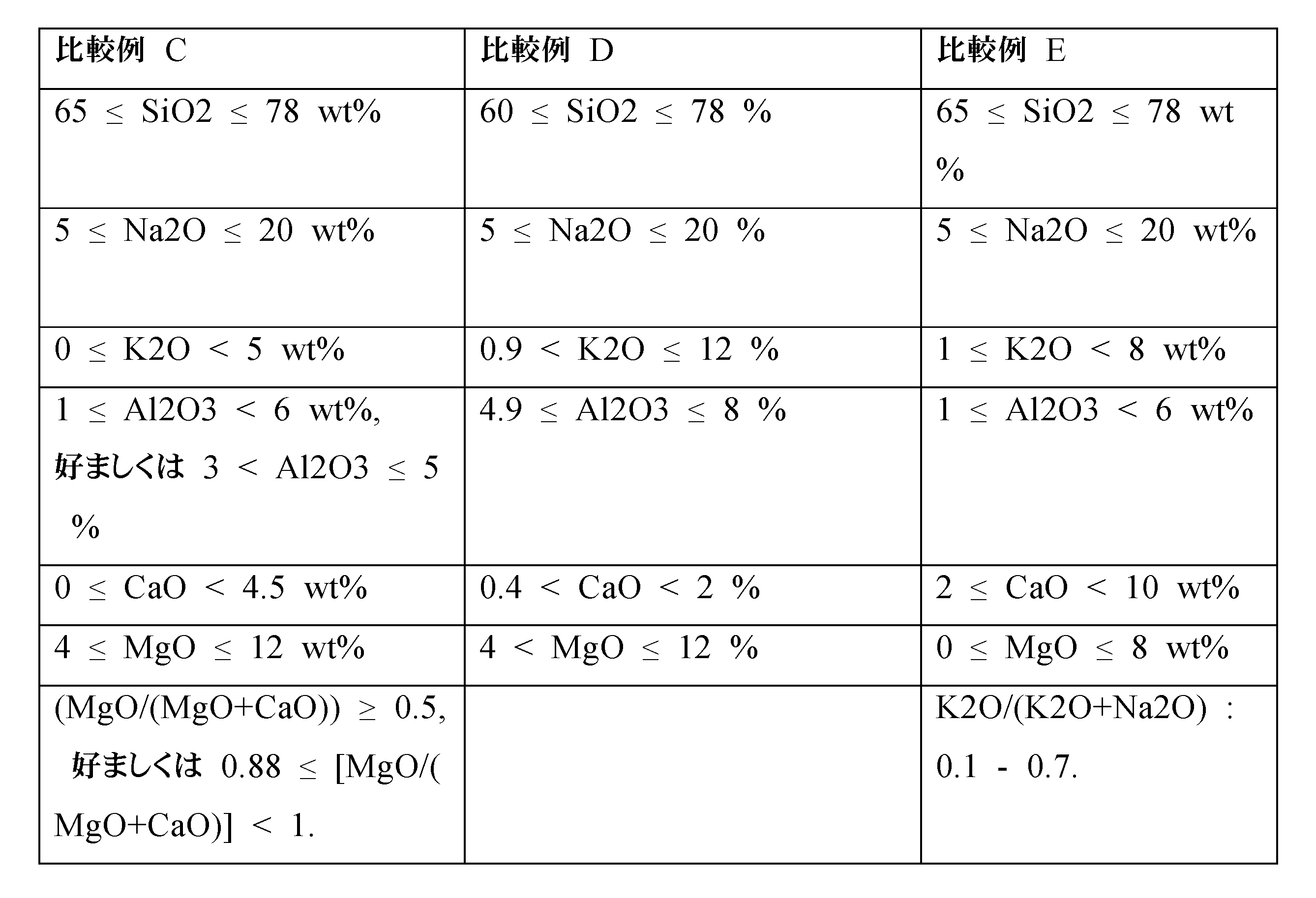
本発明のいくつかの実施形態においては、低放射フィルム、太陽光制御フィルム(熱線反射フィルム)、反射防止フィルム、曇り止めフィルムなどのフィルム、好ましくは熱線反射フィルム又は低放射フィルムを機能ブロック内のガラスシート上の最終的にはVIGのガラスペインの少なくとも1つ上において提供することができる。 In some embodiments of the present invention, a film such as a low emissivity film, a solar control film (heat reflective film), an anti-reflective film, an anti-fog film, preferably a heat reflective film or a low emissivity film, can be provided on the glass sheets in the functional block and ultimately on at least one of the glass panes of the VIG.
図1は、本発明の方法によって中間ユニットポリマー(3)を介してラミネートされたVIG(2)及び機能ユニット(4)を有するラミネートVIG組立体(1)を示している。VIG(2)は、第1ガラスペイン(21)及び第2ガラスペイン(21)、並びに、その間の距離を維持する第1及び第2ガラスペインの間において位置決めされた個別のスペーサの組(23)を有する。これは、その境界線にわたって第1及び第2ガラスペインの間の距離を封止し、従って内部容積Vを定義する密封接合封止(24)によって閉鎖されており、その内部には、0.1ミリバール未満の圧力の絶対真空が存在している。低放射フィルム又は熱線反射フィルム(5)が、VIGの第2ガラスペインの内側面ペイン上において提供されている。機能ユニット(4)は、中間層ポリマー(43)によって第2ガラスシート(42)にラミネートされた第1ガラスシート(41)を有する。 Figure 1 shows a laminated VIG assembly (1) having a VIG (2) and a functional unit (4) laminated by the method of the present invention through an intermediate unit polymer (3). The VIG (2) has a first glass pane (21) and a second glass pane (21) and a set of individual spacers (23) positioned between the first and second glass panes to maintain the distance therebetween. It is closed by a hermetic joint seal (24) that seals the distance between the first and second glass panes across its border and thus defines an internal volume V, inside which there is an absolute vacuum with a pressure of less than 0.1 mbar. A low-emissivity film or a heat-reflecting film (5) is provided on the inner surface pane of the second glass pane of the VIG. The functional unit (4) has a first glass sheet (41) laminated to a second glass sheet (42) by an intermediate layer polymer (43).
当業者は、本発明が決して上述の好適な実施形態に限定されるものはないことを理解している。逆に、多くの変更及び変形が添付請求項の範囲内において可能である。更には、本発明は、本明細書において記述され且つ請求項において記載されている特徴及び好適な特徴のすべての可能な組合せにも関することに留意されたい。 Those skilled in the art understand that the present invention is in no way limited to the preferred embodiments described above. On the contrary, many modifications and variations are possible within the scope of the appended claims. It should be noted further that the present invention also relates to all possible combinations of the features and preferred features described in this specification and claimed in the claims.
以下の例は、例示を目的として提供されており、本発明の範囲を限定することを意図したものではない。 The following examples are provided for illustrative purposes and are not intended to limit the scope of the invention.
例1:音響ラミネートVIG組立体
2枚の標準的なソーダライムシリカガラスシート(それぞれ8mmの厚さ)及び1つの音響ポリビニルブチラール(0.76mmの厚さ)を有する音響機能ユニットを140℃の温度及び12バールの圧力においてニップローラー及びオートクレーブ技術を有する標準的なラミネーション法によって製造した。
Example 1: Acoustic Laminate VIG Assembly An acoustic functional unit with two standard soda lime silica glass sheets (each 8 mm thick) and one acoustic polyvinyl butyral (0.76 mm thick) was produced by standard lamination methods with nip roller and autoclave techniques at a temperature of 140° C. and a pressure of 12 bar.
VIGは、ガラスフリットによって封止された2枚の標準的なソーダライムシリカガラスペイン(それぞれ6mmの厚さ)、20mmのピッチを有する樹脂材料のピラーを有する。このようなVIG(U)の熱性能は、0.7W/m2Kである。 The VIG has two standard soda-lime-silica glass panes (each 6 mm thick) sealed by glass frit, pillars of resin material with a pitch of 20 mm. The thermal performance of such a VIG(U) is 0.7 W/ m2K .
オートクレーブ内において、
1)VIGと、(機能ユニットの表面上において堆積された)0.76mmの中間ユニットポリマーEVAと、及び機能ユニットとを積層することにより、予備組立体を調製するステップと、
2)予備組立体を真空バッグ内に挿入するステップと、
3)予備組立体を処理してラミネートVIG組立体を生成させるステップ、
・30分にわたって周辺温度において-1バールの真空に排気するサブステップ、
・継続された真空下において30分にわたって85~90℃の中間温度において加熱するサブステップ、
・継続された真空下において105分にわたって130℃の温度において加熱するサブステップ、
・0.2バールの過圧(OP=0.2バール)
4)ラミネートVIG組立体が35分以内に周辺温度に到達するように、真空及び加熱を解放するステップ及び周辺温度において過圧を解放するステップと
によって音響ラミネートVIG組立体を製造した。
In the autoclave,
1) preparing a pre-assembly by laminating VIG, 0.76 mm of intermediate unit polymer EVA (deposited on the surface of the functional unit), and the functional unit;
2) inserting the pre-assembly into a vacuum bag;
3) processing the preassembly to produce a laminated VIG assembly;
- Evacuation to a vacuum of -1 bar at ambient temperature for 30 minutes;
heating at intermediate temperature of 85-90° C. for 30 minutes under sustained vacuum;
- heating at a temperature of 130° C. for 105 minutes under sustained vacuum;
0.2 bar overpressure (OP=0.2 bar)
4) An acoustic laminate VIG assembly was prepared by releasing the vacuum and heat and releasing the overpressure at ambient temperature such that the laminate VIG assembly reached ambient temperature within 35 minutes.
本発明の方法を介して製造された音響ラミネートVIG組立体は、ISO12543-4:2011という規格の高温試験に合格しており、VIGの物理的な完全性を維持する優れた特性、特にピラーの、圧縮されたピラーの、周りの微細亀裂の兆候なし、優れた熱性能の維持、優れた音響特性、並びに、非常に限られた厚さにおけるこれらの実現を実証している。 Acoustic laminate VIG assemblies produced via the method of the present invention have passed high temperature testing to ISO 12543-4:2011 and have demonstrated excellent properties of maintaining the physical integrity of the VIG, particularly around the compressed pillars with no signs of microcracking, maintaining excellent thermal performance, and excellent acoustic properties, as well as achieving this at very limited thicknesses.
具体的には、以下の表Iは、本発明の方法によって得られた音響ラミネートVIG組立体が、VIGのみの音響性能よりも良好な、場合によっては音響機能ユニット及びVIGの同一の2つのユニットを有するダブルグレージングよりも良好な、優れた音響特性を提供することを示している。 Specifically, Table I below shows that the acoustic laminate VIG assembly obtained by the method of the present invention provides superior acoustic properties, better than the acoustic performance of VIG alone and in some cases better than double glazing having two identical units of acoustic functional unit and VIG.
ISO 10140-2:2010:Acoustics-Laboratory measurement of sound insulation of building elements-Part 2:Measurement of airborne sound insulationによれば、Rw(C;Ctr)であり、この場合に、Rwは、重み付けされたサウンド低減インデックスを表し、C及びCtrは、補正ファクタであり、即ち、Cは、中間周波数範囲用であり、Ctrは、低周波数範囲用である。1だけRwを増大させることは、ノイズレベルにおける約1dbの低減に相当している。
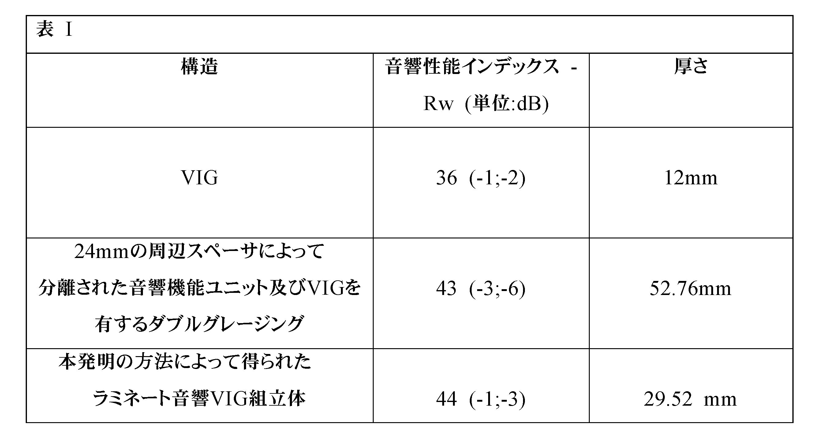
例2:セキュリティラミネートVIG組立体
それぞれが0.38mmの厚さのPVBの6つの層によってラミネートされたそれぞれ4mmの厚さを有する2枚の標準ソーダライムシリカガラスシートを有するセキュリティ機能ユニットを140℃の温度及び12バールの圧力においてニップローラー及びオートクレーブ技術を有する標準ラミネーション法によって製造した。
Example 2: Security Laminated VIG Assembly A security functional unit comprising two standard soda lime silica glass sheets, each with a thickness of 4 mm, laminated with six layers of PVB, each with a thickness of 0.38 mm, was produced by standard lamination methods with nip roller and autoclave techniques at a temperature of 140° C. and a pressure of 12 bar.
VIGは、ガラスフリットによって封止された2枚の標準ソーダライムシリカガラスペイン(それぞれ4mmの厚さ)、20mmのピッチを有する樹脂材料のピラーを有する。このようなVIG(U)の熱性能は、0.7W/m2Kである。 The VIG has two standard soda lime silica glass panes (each 4 mm thick) sealed by glass frit, pillars of resin material with a pitch of 20 mm. The thermal performance of such a VIG(U) is 0.7 W/ m2K .
過圧なし下において、オーブン内において、
1)VIGと、(機能ユニットの表面上において堆積された)0.76mmの中間ユニットポリマーEVAと、機能ユニットとを積層することにより、予備組立体を調製するステップと、
2)予備組立体を真空バッグ内に挿入するステップと、
3)予備組立体を処理してラミネート真空断熱グレージング組立体を生成させるステップと、
・30分にわたって周辺温度において-1バールの真空に排気するサブステップ、
・継続された真空下において30分にわたって85~90℃の中間温度において加熱するサブステップ、
・継続された真空下において80分にわたって130度の温度において加熱するサブステップ、
・過圧なし(OP=0バール)
4)ラミネートVIG組立体が30分以内に周辺温度に到達するように、真空及び加熱を解放するステップと、
によってセキュリティラミネートVIG組立体を製造した。
In an oven without overpressure,
1) preparing a pre-assembly by laminating VIG, 0.76 mm of intermediate unit polymer EVA (deposited on the surface of the functional unit), and the functional unit;
2) inserting the pre-assembly into a vacuum bag;
3) processing the preassembly to produce a laminated vacuum insulated glazing assembly;
- Evacuation to a vacuum of -1 bar at ambient temperature for 30 minutes;
heating at intermediate temperature of 85-90° C. for 30 minutes under sustained vacuum;
- heating at a temperature of 130 degrees for 80 minutes under sustained vacuum;
- No overpressure (OP = 0 bar)
4) releasing the vacuum and heat so that the laminated VIG assembly reaches ambient temperature within 30 minutes;
A security laminate VIG assembly was manufactured by
本発明の方法を介して製造されたセキュリティラミネートVIG組立体は、ISO12543-4:2011という規格の高温試験に合格しており、VIGの物理的な完全性を維持する優れた特性、特にピラーの、圧縮されたピラーの、周りの微細亀裂の兆候なし、優れた熱性能の維持、及び優れたセキュリティ特性を実証している。 Security laminate VIG assemblies produced via the method of the present invention have passed high temperature testing to ISO 12543-4:2011 and have demonstrated excellent properties in maintaining the physical integrity of the VIG, particularly around the compressed pillars, with no signs of microcracking, excellent thermal performance maintenance, and excellent security properties.
具体的には、以下の表IIは、本発明の方法によって得られたラミネートVIG組立体が優れたセキュリティ特性を提供することを示している。それぞれ4mmの2枚のガラスシートから製造されたVIGは、EN356という規格による機械的性能を示してはいない。セキュリティ機能ユニットにラミネートされた際に、本発明の方法によって製造されたラミネートVIGは、Ref.No.EN 356:1999 Eというセキュリティ規格におけるP5A分類を実証している。
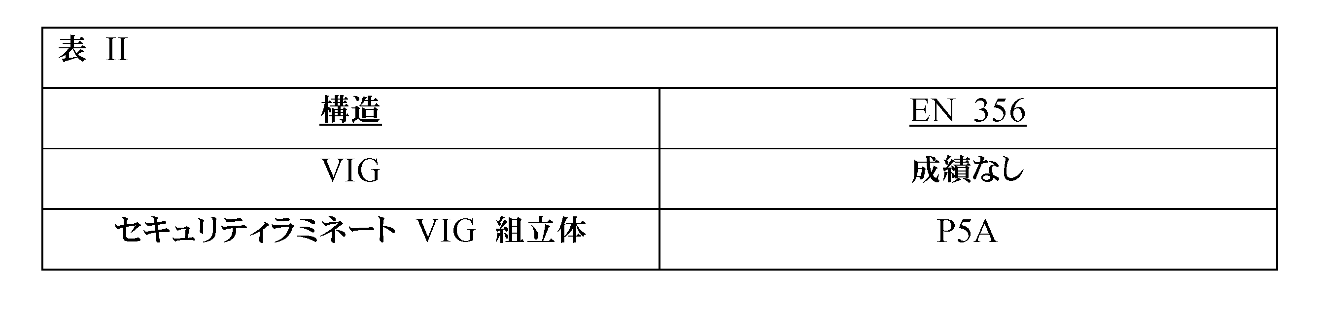
Claims (23)
1)真空断熱グレージング(2)と、中間ユニットポリマー(3)と、機能ユニット(4)とを積層し、それにより、予備組立体を生成させるステップと、ただし前記機能ユニットは、5.5バール~15.0バール(5.5バール≧PP≧15.0バール)、好ましくは7.5バール~14.0バール(7.5バール≧PP≧14.0バール)、更に好ましくは10.0バール~14.0バール(10.0バール≧PP≧14.0バール)の処理圧力(PP)において処理されている、
2)真空リング又は真空バッグ内に、好ましくは真空バッグ内に、前記予備組立体を挿入するステップと、
3)少なくとも、
a.前記真空リング又は真空バッグ内を、マイナス0.1バール~マイナス1バール、好ましくはマイナス0.5バール~マイナス1バールの真空に排気するサブステップ、
b.前記予備組立体を50℃~200℃、好ましくは75℃~175℃、更に好ましくは90℃~150℃の範囲の温度に加熱するサブステップ、
c.前記予備組立体を4.5バール以下の過圧(OP)(OP≦4.5バール)下において加圧するサブステップ、
により、前記予備組立体を処理してラミネートVIG組立体を生成させるステップと、
4)前記排気3)a)、前記加熱3)b)、及び前記過圧3)c)を解放するステップと、
を含む、方法。 A method for manufacturing a laminated vacuum insulation glazing assembly (1) that meets the high temperature test standard ISO 12543-4: 2011, comprising at least:
1) laminating a vacuum insulation glazing (2), an intermediate unit polymer (3) and a functional unit (4) thereby producing a preassembly, wherein said functional unit is processed at a processing pressure (PP) of 5.5 bar to 15.0 bar (5.5 bar > PP > 15.0 bar), preferably 7.5 bar to 14.0 bar (7.5 bar > PP > 14.0 bar), more preferably 10.0 bar to 14.0 bar (10.0 bar > PP > 14.0 bar),
2) inserting the pre-assembly into a vacuum ring or vacuum bag, preferably into a vacuum bag;
3) At a minimum,
a. evacuating the inside of the vacuum ring or vacuum bag to a vacuum of minus 0.1 bar to minus 1 bar, preferably minus 0.5 bar to minus 1 bar;
b. heating the preassembly to a temperature in the range of 50° C. to 200° C., preferably 75° C. to 175° C., more preferably 90° C. to 150° C.;
c) pressurizing the preassembly under an overpressure (OP) of 4.5 bar or less (OP≦4.5 bar);
processing the pre-assembly to produce a laminated VIG assembly by
4) releasing the exhaust 3) a), the heating 3) b), and the overpressure 3) c);
A method comprising:
-Llamは、前記真空断熱グレージングへのラミネーションによってもたらされるすべての応力であるラミネーション負荷であり、
-Lintは、それ自体が前記真空断熱グレージングの設計に固有のすべての応力である本質的負荷であり、
-SFは、セキュリティファクタであり、
-Luseは、前記真空断熱グレージングの使用条件によってもたらされるすべての応力である使用負荷である、請求項1~7のいずれか1項に記載のラミネート真空断熱グレージング組立体の製造方法。 The laminated vacuum insulation glazing assembly satisfies the load formula L lam ≦[L int (SF-1)] + [L use × SF];
- L lam is the lamination load, which is the total stress caused by laminations on the vacuum insulating glazing,
- L int is the intrinsic load, which is itself all the stresses inherent in the design of said vacuum insulating glazing,
- SF is the security factor,
A method for manufacturing a laminated vacuum insulation glazing assembly as described in any one of claims 1 to 7, wherein -L use is a usage load which is all stresses caused by the usage conditions of the vacuum insulation glazing.
a)5分~40分、好ましくは10分~30分、更に好ましくは20分~30分の期間にわたって室温において排気するサブステップ、
b*)好ましくは10分~60分、更に好ましくは15分~40分の期間にわたって、75℃~95℃の範囲の中間温度に加熱するサブステップ、
b)45分~300分の期間にわたって、110℃~145℃、好ましくは130℃~140℃の範囲の温度に加熱するサブステップ、
c)2.0バール以下(OP≦2.0バール)、好ましくは1.5バール以下(OP≦1.5バール)、好ましくは1.0バール以下(OP≦1.0バール)、好ましくは0.5バール以下(OP≦0.5バール)の過圧(OP)下において、更に好ましくは0バールの過圧なし(OP=0バール)下において、加圧するサブステップ、
の処理順序で実現され、
好ましくは、前記サブステップb)及びサブステップc)は、同時に行われる、請求項13又は14に記載のラミネート真空断熱グレージング組立体の製造方法。 The sub-steps of the processing step (3) include:
a) evacuation at room temperature for a period of 5 minutes to 40 minutes, preferably 10 minutes to 30 minutes, more preferably 20 minutes to 30 minutes;
b*) heating to an intermediate temperature in the range of 75°C to 95°C, preferably for a period of 10 minutes to 60 minutes, more preferably 15 minutes to 40 minutes;
b) heating to a temperature in the range of 110° C. to 145° C., preferably 130° C. to 140° C., for a period of 45 min to 300 min;
c) pressurizing under an overpressure (OP) of 2.0 bar or less (OP≦2.0 bar), preferably 1.5 bar or less (OP≦1.5 bar), preferably 1.0 bar or less (OP≦1.0 bar), preferably 0.5 bar or less (OP≦0.5 bar), more preferably under no overpressure of 0 bar (OP=0 bar);
This is achieved in the following processing order:
A method for manufacturing a laminated vacuum insulating glazing assembly according to claim 13 or 14, preferably wherein sub-steps b) and c) are performed simultaneously.
Applications Claiming Priority (3)
| Application Number | Priority Date | Filing Date | Title |
|---|---|---|---|
| EP21169721.4 | 2021-04-21 | ||
| EP21169721 | 2021-04-21 | ||
| PCT/EP2022/060369 WO2022223586A1 (en) | 2021-04-21 | 2022-04-20 | Novel lamination process to produce laminated vacuum insulating glazing assembly |
Publications (2)
| Publication Number | Publication Date |
|---|---|
| JP2024516143A true JP2024516143A (en) | 2024-04-12 |
| JPWO2022223586A5 JPWO2022223586A5 (en) | 2025-03-28 |
Family
ID=75639698
Family Applications (1)
| Application Number | Title | Priority Date | Filing Date |
|---|---|---|---|
| JP2023564107A Pending JP2024516143A (en) | 2021-04-21 | 2022-04-20 | Novel lamination process for producing laminated vacuum insulating glazing assemblies. |
Country Status (3)
| Country | Link |
|---|---|
| EP (1) | EP4326551A1 (en) |
| JP (1) | JP2024516143A (en) |
| WO (1) | WO2022223586A1 (en) |
Family Cites Families (7)
| Publication number | Priority date | Publication date | Assignee | Title |
|---|---|---|---|---|
| DE2457037B2 (en) * | 1974-12-03 | 1976-09-16 | Flachglas Ag Delog-Detag, 4650 Gelsenkirchen | GLAZING UNIT, IN PARTICULAR INSULATING GLASS, FOR FIRE PROTECTION PURPOSES |
| US7704342B2 (en) | 2001-12-27 | 2010-04-27 | Solutia, Inc. | Glass lamination process |
| JP4109491B2 (en) | 2002-05-07 | 2008-07-02 | 日本板硝子株式会社 | Translucent glass panel |
| BR112014028689B1 (en) | 2012-05-18 | 2021-01-26 | Panasonic Intellectual Property Management Co., Ltd. | multiple sheet production method |
| US11285703B2 (en) * | 2018-05-24 | 2022-03-29 | Vkr Holding A/S | VIG unit lamination |
| WO2019230220A1 (en) | 2018-05-30 | 2019-12-05 | パナソニックIpマネジメント株式会社 | Glass panel unit manufacturing method |
| WO2020203550A1 (en) | 2019-03-29 | 2020-10-08 | パナソニックIpマネジメント株式会社 | Method for manufacturing laminate, and laminate |
-
2022
- 2022-04-20 EP EP22723638.7A patent/EP4326551A1/en active Pending
- 2022-04-20 JP JP2023564107A patent/JP2024516143A/en active Pending
- 2022-04-20 WO PCT/EP2022/060369 patent/WO2022223586A1/en not_active Ceased
Also Published As
| Publication number | Publication date |
|---|---|
| WO2022223586A1 (en) | 2022-10-27 |
| EP4326551A1 (en) | 2024-02-28 |
Similar Documents
| Publication | Publication Date | Title |
|---|---|---|
| US20220072827A1 (en) | Glass laminated articles and layered articles | |
| EP2104608B1 (en) | Laminated glazings | |
| EP3794204B1 (en) | Asymmetrical safe vacuum-insulated glazing unit | |
| US20090311449A1 (en) | Method of manufacturing an insulated, impact resistant window | |
| US20220402244A1 (en) | Fire resistant vacuum insulating glazing | |
| US12516566B2 (en) | Fire resistant vacuum insulating glazing | |
| JP2002226237A (en) | Double-layered glass with heat screening film | |
| JP2024516143A (en) | Novel lamination process for producing laminated vacuum insulating glazing assemblies. | |
| US12503908B2 (en) | Fire resistant vacuum insulating glazing | |
| EA047907B1 (en) | A NEW LAYERING METHOD FOR PRODUCING A LAMINATED VACUUM INSULATING GLAZING UNIT | |
| US20230415457A1 (en) | Glass laminates containing low expansion glass | |
| JP7337847B2 (en) | Asymmetric vacuum-insulated glazing unit | |
| JP7337849B2 (en) | High performance vacuum insulated glazing unit | |
| CA3120163A1 (en) | Laminated vacuum-insulated glazing assembly | |
| JP7550163B2 (en) | Asymmetric vacuum insulated glazing unit | |
| CN214294750U (en) | Laminated glass | |
| EP4402331A1 (en) | Multiple glazing with asymmetric vacuum-insulating glazing unit | |
| EA040088B1 (en) | ASYMMETRIC SAFETY VACUUM INSULATION GLAZING UNIT | |
| JP2024536726A (en) | Composite glazing, including laminated vacuum insulated glazing units | |
| EA045606B1 (en) | FIRE RESISTANT VACUUM INSULATED GLAZING | |
| EA042419B1 (en) | ASSEMBLY OF MULTILAYER VACUUM INSULATION GLAZING | |
| KR20210137529A (en) | Asymmetrical vacuum-insulated glazing unit | |
| KR20210137429A (en) | Asymmetrical vacuum-insulated glazing unit |
Legal Events
| Date | Code | Title | Description |
|---|---|---|---|
| A521 | Request for written amendment filed |
Free format text: JAPANESE INTERMEDIATE CODE: A821 Effective date: 20231019 |
|
| A521 | Request for written amendment filed |
Free format text: JAPANESE INTERMEDIATE CODE: A523 Effective date: 20250319 |
|
| A621 | Written request for application examination |
Free format text: JAPANESE INTERMEDIATE CODE: A621 Effective date: 20250319 |