JP2024508303A - Method and electronic device for decoding inter-predicted video blocks of a video stream - Google Patents
Method and electronic device for decoding inter-predicted video blocks of a video stream Download PDFInfo
- Publication number
- JP2024508303A JP2024508303A JP2023553176A JP2023553176A JP2024508303A JP 2024508303 A JP2024508303 A JP 2024508303A JP 2023553176 A JP2023553176 A JP 2023553176A JP 2023553176 A JP2023553176 A JP 2023553176A JP 2024508303 A JP2024508303 A JP 2024508303A
- Authority
- JP
- Japan
- Prior art keywords
- mvd
- motion vector
- video
- magnitude
- determining
- Prior art date
- Legal status (The legal status is an assumption and is not a legal conclusion. Google has not performed a legal analysis and makes no representation as to the accuracy of the status listed.)
- Granted
Links
Images


Classifications
-
- H—ELECTRICITY
- H04—ELECTRIC COMMUNICATION TECHNIQUE
- H04N—PICTORIAL COMMUNICATION, e.g. TELEVISION
- H04N19/00—Methods or arrangements for coding, decoding, compressing or decompressing digital video signals
- H04N19/10—Methods or arrangements for coding, decoding, compressing or decompressing digital video signals using adaptive coding
- H04N19/134—Methods or arrangements for coding, decoding, compressing or decompressing digital video signals using adaptive coding characterised by the element, parameter or criterion affecting or controlling the adaptive coding
- H04N19/136—Incoming video signal characteristics or properties
- H04N19/137—Motion inside a coding unit, e.g. average field, frame or block difference
- H04N19/139—Analysis of motion vectors, e.g. their magnitude, direction, variance or reliability
-
- H—ELECTRICITY
- H04—ELECTRIC COMMUNICATION TECHNIQUE
- H04N—PICTORIAL COMMUNICATION, e.g. TELEVISION
- H04N19/00—Methods or arrangements for coding, decoding, compressing or decompressing digital video signals
- H04N19/10—Methods or arrangements for coding, decoding, compressing or decompressing digital video signals using adaptive coding
- H04N19/102—Methods or arrangements for coding, decoding, compressing or decompressing digital video signals using adaptive coding characterised by the element, parameter or selection affected or controlled by the adaptive coding
- H04N19/103—Selection of coding mode or of prediction mode
- H04N19/105—Selection of the reference unit for prediction within a chosen coding or prediction mode, e.g. adaptive choice of position and number of pixels used for prediction
-
- H—ELECTRICITY
- H04—ELECTRIC COMMUNICATION TECHNIQUE
- H04N—PICTORIAL COMMUNICATION, e.g. TELEVISION
- H04N19/00—Methods or arrangements for coding, decoding, compressing or decompressing digital video signals
- H04N19/10—Methods or arrangements for coding, decoding, compressing or decompressing digital video signals using adaptive coding
- H04N19/134—Methods or arrangements for coding, decoding, compressing or decompressing digital video signals using adaptive coding characterised by the element, parameter or criterion affecting or controlling the adaptive coding
- H04N19/157—Assigned coding mode, i.e. the coding mode being predefined or preselected to be further used for selection of another element or parameter
- H04N19/159—Prediction type, e.g. intra-frame, inter-frame or bidirectional frame prediction
-
- H—ELECTRICITY
- H04—ELECTRIC COMMUNICATION TECHNIQUE
- H04N—PICTORIAL COMMUNICATION, e.g. TELEVISION
- H04N19/00—Methods or arrangements for coding, decoding, compressing or decompressing digital video signals
- H04N19/10—Methods or arrangements for coding, decoding, compressing or decompressing digital video signals using adaptive coding
- H04N19/169—Methods or arrangements for coding, decoding, compressing or decompressing digital video signals using adaptive coding characterised by the coding unit, i.e. the structural portion or semantic portion of the video signal being the object or the subject of the adaptive coding
- H04N19/17—Methods or arrangements for coding, decoding, compressing or decompressing digital video signals using adaptive coding characterised by the coding unit, i.e. the structural portion or semantic portion of the video signal being the object or the subject of the adaptive coding the unit being an image region, e.g. an object
- H04N19/176—Methods or arrangements for coding, decoding, compressing or decompressing digital video signals using adaptive coding characterised by the coding unit, i.e. the structural portion or semantic portion of the video signal being the object or the subject of the adaptive coding the unit being an image region, e.g. an object the region being a block, e.g. a macroblock
-
- H—ELECTRICITY
- H04—ELECTRIC COMMUNICATION TECHNIQUE
- H04N—PICTORIAL COMMUNICATION, e.g. TELEVISION
- H04N19/00—Methods or arrangements for coding, decoding, compressing or decompressing digital video signals
- H04N19/50—Methods or arrangements for coding, decoding, compressing or decompressing digital video signals using predictive coding
- H04N19/503—Methods or arrangements for coding, decoding, compressing or decompressing digital video signals using predictive coding involving temporal prediction
- H04N19/51—Motion estimation or motion compensation
- H04N19/513—Processing of motion vectors
- H04N19/517—Processing of motion vectors by encoding
- H04N19/52—Processing of motion vectors by encoding by predictive encoding
-
- H—ELECTRICITY
- H04—ELECTRIC COMMUNICATION TECHNIQUE
- H04N—PICTORIAL COMMUNICATION, e.g. TELEVISION
- H04N19/00—Methods or arrangements for coding, decoding, compressing or decompressing digital video signals
- H04N19/50—Methods or arrangements for coding, decoding, compressing or decompressing digital video signals using predictive coding
- H04N19/503—Methods or arrangements for coding, decoding, compressing or decompressing digital video signals using predictive coding involving temporal prediction
- H04N19/51—Motion estimation or motion compensation
- H04N19/523—Motion estimation or motion compensation with sub-pixel accuracy
-
- H—ELECTRICITY
- H04—ELECTRIC COMMUNICATION TECHNIQUE
- H04N—PICTORIAL COMMUNICATION, e.g. TELEVISION
- H04N19/00—Methods or arrangements for coding, decoding, compressing or decompressing digital video signals
- H04N19/70—Methods or arrangements for coding, decoding, compressing or decompressing digital video signals characterised by syntax aspects related to video coding, e.g. related to compression standards
Landscapes
- Engineering & Computer Science (AREA)
- Multimedia (AREA)
- Signal Processing (AREA)
- Compression Or Coding Systems Of Tv Signals (AREA)
Abstract
本開示は、ビデオブロックをインター予測するための運動ベクトル差分のエンコーディング及びデコーディングに関する。ビデオストリームのインター予測ビデオブロックをデコーディングするための実施例が開示されている。本方法は、インター予測ビデオブロックに関連付けられた動きベクトルが、動きベクトルと参照動きベクトルとの間の動きベクトル差分(MVD)としてエンコードされることを決定するステップと;ビデオストリームから、動きベクトル差分についての複数の所定の大きさ範囲の中のMVDの大きさ範囲の表示を取得するステップと;大きさ範囲に従ってMVDのためのピクセル解像度を決定するステップと;ピクセル解像度に基づいてビデオストリーム内の付加的なMVD情報を識別するステップと;ビデオストリームから付加的なMVD情報を抽出するステップと;動きベクトルに関連付けられる基準フレーム、基準動きベクトル、付加的なMVD情報、及びピクセル解像度に基づいてインター予測ビデオブロックをデコードするステップと、を含む。
The present disclosure relates to motion vector difference encoding and decoding for inter-predicting video blocks. Embodiments are disclosed for decoding inter-predicted video blocks of a video stream. The method includes: determining that a motion vector associated with an inter-predicted video block is encoded as a motion vector difference (MVD) between the motion vector and a reference motion vector; obtaining an indication of a size range for the MVD within a plurality of predetermined size ranges for; determining a pixel resolution for the MVD according to the size range; identifying additional MVD information; extracting additional MVD information from the video stream; decoding the predicted video block.
Description
参照による援用
この国際PCT出願は、2021年10月21日に出願された米国仮特許出願第63/270,397号及び2021年12月13日に出願された米国仮特許出願第63/289,122号の 「Adaptive Resolution for Motion Vector Difference」 に基づき、その優先権を主張する2022年3月30日に出願された優先権米国非仮特許出願第17/708,801号に基づき、その利益を主張する。これらの先行特許出願は、その全体が参照により本明細書に組み込まれる。
Incorporated by reference This international PCT application is incorporated by reference in U.S. Provisional Patent Application No. 63/270,397, filed on October 21, 2021, and in U.S. Provisional Patent Application No. 63/289, filed on December 13, 2021. No. 122, “Adaptive Resolution for Motion Vector Difference,” and the benefit of priority U.S. non-provisional patent application Ser. claim. These prior patent applications are incorporated herein by reference in their entirety.
技術分野
この開示は、概してビデオコーディング、特にビデオブロックのインター予測における動きベクトル差分に対する適応解像度を提供するための方法及びシステムに関する。
Technical field
This disclosure relates generally to video coding, and in particular to methods and systems for providing adaptive resolution for motion vector differences in inter prediction of video blocks.
本明細書で提供される背景説明は、本開示のコンテキストを全般的に提示するためのものである。現在名前を挙げている発明者の研究は、この背景セクションに記載されている限りにおいて、本出願の出願時に先行技術として認められない可能性のある説明の態様は、本開示に対する先行技術として明示的にも黙示的にも認められない。 The background description provided herein is to generally present the context of the disclosure. To the extent that the work of the currently named inventors is described in this background section, any aspects of the description that may not be admitted as prior art at the time of filing this application are expressly disclosed as prior art to this disclosure. It is not permitted either explicitly or implicitly.
ビデオコーディングとデコーディングは、動き補正を伴うインター画像予測(inter-picture prediction)を用いて行うことができる。非圧縮ディジタルビデオは、一連の画像を含むことができ、各画像は、例えば、1920×1080の輝度サンプル及び関連するフル又はサブサンプルのクロミナンスサンプルの空間寸法を有する。一連の画像は、例えば、毎秒60画像又は毎秒60フレームの固定又は可変の画像レート(又はフレームレートと称される)を有することができる。非圧縮ビデオには、スツリーミング又はデータ処理のための特定のビットレート要件がある。例えば、ピクセル解像度が1920×1080、フレームレートが60フレーム/秒、カラーチャネルあたりピクセルあたり8ビットで4:2:0のクロマサブサンプリングを行うビデオには、1.5Gbit/s近い帯域幅が必要である。このようなビデオの1時間は、600Gバイトを超えるストレージ領域を必要とする。 Video coding and decoding can be performed using inter-picture prediction with motion compensation. Uncompressed digital video may include a series of images, each image having a spatial dimension of, for example, 1920×1080 luminance samples and associated full or sub-sampled chrominance samples. The series of images may have a fixed or variable image rate (or referred to as frame rate), for example, 60 images per second or 60 frames per second. Uncompressed video has specific bit rate requirements for streaming or data processing. For example, a video with a pixel resolution of 1920x1080, a frame rate of 60 frames/s, and 4:2:0 chroma subsampling at 8 bits per pixel per color channel requires a bandwidth close to 1.5 Gbit/s. It is. One hour of such video requires over 600 GB of storage space.
ビデオコーディング及びデコーディングの1つの目的は、圧縮を介した非圧縮入力ビデオ信号の冗長性の低減である。圧縮は、前述の帯域幅やストレージスペースの要件を、場合によっては2桁以上削減するのに役立つ。可逆圧縮と非可逆圧縮の両方、及びそれらの組み合わせを用いることができる。可逆圧縮とは、圧縮された元の信号からデコードプロセスを介して元の信号の正確なコピーを再構築できる技術を指す。非可逆圧縮とは、元のビデオ情報がコーディング中に完全に保持されず、デコード中に完全に回復できないコーディング/デコードプロセスを指す。非可逆圧縮を使用する場合、再構成された信号は元の信号と同一ではない可能性があるが、元の信号と再構成された信号の間の歪みは十分に小さくなり、再構成された信号は、多少の情報損失はあるが、目的のアプリケーションに役立つようになる。ビデオの場合、非可逆圧縮は多くのアプリケーションで広く採用されている。許容できる歪みの量はアプリケーションによって異なる。例えば、特定の消費者向けビデオスツリーミングアプリケーションのユーザは、映画やテレビ放送アプリケーションのユーザよりも高い歪みを許容する場合がある。特定のコーディングアルゴリズムによって達成可能な圧縮比は、さまざまな歪み許容度を反映するように選択又は調整できる。一般に、許容可能な歪みが大きいほど、損失が大きく圧縮比が高いコーディングアルゴリズムが可能になる。 One goal of video coding and decoding is the reduction of redundancy in uncompressed input video signals through compression. Compression helps reduce the aforementioned bandwidth and storage space requirements, sometimes by more than two orders of magnitude. Both lossless and lossy compression, and combinations thereof, can be used. Lossless compression refers to a technique in which an exact copy of the original signal can be reconstructed from the compressed original signal through a decoding process. Lossy compression refers to a coding/decoding process in which the original video information is not fully preserved during coding and cannot be fully recovered during decoding. When using lossy compression, the reconstructed signal may not be identical to the original signal, but the distortion between the original and reconstructed signal will be small enough that the reconstructed The signal becomes useful for the intended application with some loss of information. In the case of video, lossy compression is widely adopted in many applications. The amount of distortion that can be tolerated depends on the application. For example, users of certain consumer video streaming applications may tolerate higher distortion than users of movie and television broadcast applications. The compression ratio achievable by a particular coding algorithm can be selected or adjusted to reflect different distortion tolerances. In general, higher tolerable distortions allow for coding algorithms with higher loss and higher compression ratios.
ビデオエンコーダ及びデコーダは、動き補償、フーリエ変換、量子化、エントロピーコーディングなど、いくつかの広範なカテゴリとステップの技術を利用することができる。 Video encoders and decoders can utilize several broad categories and steps of techniques, such as motion compensation, Fourier transform, quantization, and entropy coding.
ビデオコーデック技術は、イントラコーディングとして知られる技術を含むことができる。イントラコーディングでは、サンプル値は、以前に再構成された参照画像からのサンプル又は他のデータを参照することなく表現される。いくつかのビデオコーデックでは、画像は空間的にサンプルのブロックに細分割(subdivided)される。サンプルのすべてのブロックがイントラモードでコーディングされている場合、その画像はイントラ画像と称されことができる。イントラ画像と、独立デコーダリフレッシュ画像等のそれらの派生物は、デコーダ状態をリセットするために用いられることができ、したがって、コーディングされたビデオビットスツリーム及びビデオセッションにおける第1画像として、又は静止画像として用いられることができる。イントラ予測後のブロックのサンプルは、その後、周波数ドメインへの変換を受けることができ、そのように生成された変換係数は、エントロピーコーディングの前に量子化されることができる。イントラ予測は、変換前ドメインにおけるサンプル値を最小化する技術を表す。場合によっては、変換後のDC値がより小さく、AC係数がより小さいほど、エントロピーコーディング後にブロックを表すための所与の量子化ステップサイズで必要なビットが少なくなる。 Video codec techniques may include a technique known as intra-coding. In intra-coding, sample values are expressed without reference to samples or other data from previously reconstructed reference images. In some video codecs, the image is spatially subdivided into blocks of samples. If all blocks of samples are coded in intra mode, the image can be referred to as an intra image. Intra images and their derivatives, such as independent decoder refresh images, can be used to reset the decoder state and thus be used as the first image in a coded video bitstream and video session, or as a static image. Can be used as an image. The samples of the block after intra-prediction can then undergo a transformation to the frequency domain, and the transform coefficients so generated can be quantized before entropy coding. Intra prediction refers to a technique that minimizes sample values in the pre-transform domain. In some cases, the smaller the DC value and the smaller the AC coefficient after the transform, the fewer bits are needed for a given quantization step size to represent the block after entropy coding.
例えばMPEG-2世代のコーディング技術から知られるような従来のイントラコーディングは、イントラ予測を使用しない。しかしながら、一部のより新しいビデオ圧縮技術には、例えば、空間的に隣接するのエンコーディング及び/又はデコーディング中に取得された周囲のサンプルデータ及び/又はメタデータに基づいてブロックのコーディング/デコーディングを試みる、デコーディング順序において、イントラコーディング又はデコーディングされるデータのブロックに先行する技術が含まれている。このような技術は、以後「イントラ予測」技術と称される。少なくともいくつかのケースでは、イントラ予測は再構成中の現在の画像からの参照データのみを使用し、他の参照画像からの参照データは使用しないことに留意されたい。 Conventional intra-coding, as known for example from MPEG-2 generation coding techniques, does not use intra-prediction. However, some newer video compression techniques include, for example, coding/decoding of blocks based on surrounding sample data and/or metadata obtained during encoding and/or decoding of spatially adjacent Techniques that attempt to precede blocks of data being intra-coded or decoded in the decoding order are included. Such techniques are hereinafter referred to as "intra-prediction" techniques. Note that, at least in some cases, intra-prediction only uses reference data from the current image being reconstructed and not from other reference images.
さまざまな形式のイントラ予測があり得る。かかる技術のうちの1つ以上が、所与のビデオコーディング技術において用いられることができる場合、使用中の技術は、イントラ予測モードと称されるされることができる。特定のコーデックでは、1つ以上のイントラ予測モードが提供され得る。特定のケースでは、モードはサブモードを有することができ、及び/又はさまざまなパラメータに関連付けることができ、モード/サブモード情報とビデオブロックのイントラコーディングパラメータは、個別に又はモードコードワードにまとめてコーディングされることができる。所与のモード、サブモード、及び/又はパラメータの組み合わせに使用するコードワードは、イントラ予測によるコーディング効率の向上に影響を与えることができ、したがって、コードワードをビットスツリームに変換するために使用されるエントロピーコーディングテクノロジーも影響を及ぼすことができる。 There can be various forms of intra prediction. If one or more of such techniques can be used in a given video coding technique, the technique in use can be referred to as an intra-prediction mode. A particular codec may provide one or more intra prediction modes. In certain cases, a mode may have sub-modes and/or be associated with various parameters, and mode/sub-mode information and intra-coding parameters of a video block may be separately or collectively in a mode codeword. Can be coded. The codewords used for a given mode, submode, and/or parameter combination can influence the coding efficiency improvement due to intra-prediction, and therefore The entropy coding technology used can also have an impact.
特定のイントラ予測モードがH.264で導入され、H.265で改良され、共同探索モデル(JEM:joint exploration model)、汎用ビデオコーディング(VVC:versatile video coding)、及びベンチマークセット(BMS:benchmark set)等のより新しいコーディング技術でさらに改良された。概して、イントラ予測ではは予測ブロックを利用可能になった隣接するサンプル値を使用して形成されることができる。例えば、特定の方向及び/又はラインに沿った隣接するサンプルの特定のセットの利用可能な値を予測ブロックにコピーできる。使用中の方向への参照は、ビットスツリームでコーディングされることができ、又はそれ自体が予測されることがある。 A specific intra prediction mode is H. H.264 and H.264. H.265 and further improved with newer coding techniques such as joint exploration model (JEM), versatile video coding (VVC), and benchmark set (BMS). Generally, in intra-prediction, a prediction block can be formed using available adjacent sample values. For example, the available values of a particular set of adjacent samples along a particular direction and/or line can be copied into a prediction block. The reference to the direction in use may be coded in the bitstream, or may itself be predicted.
図1Aを参照すると、右下に示されているのは、(H.265で指定された35個のイントラモードの33個の角度モードに対応する、)H.265の33個の可能なイントラ予測子方向で指定された9個の予測子方向のサブセットである。矢印が集中する点(101)は、予測されているサンプルを表す。矢印は、隣接するサンプルを使用して101のサンプルを予測する方向を表す。例えば、矢印(102)は、横方向から45度の角度で、隣接する複数のサンプルから右上にサンプル(101)が予測されることを示す。同様に、矢印(103)は、横方向から22.5度の角度で、隣接する複数のサンプルからサンプル(101)の左下にサンプル(101)が予測されることを示します。 Referring to FIG. 1A, shown at the bottom right are the H. is a subset of 9 predictor directions specified by the 33 possible intra-predictor directions in H.265. The point where the arrows are concentrated (101) represents the predicted sample. The arrow represents the direction of predicting 101 samples using neighboring samples. For example, the arrow (102) indicates that the sample (101) is predicted to the upper right from adjacent samples at a 45 degree angle from the horizontal direction. Similarly, arrow (103) indicates that sample (101) is predicted to the lower left of sample (101) from adjacent samples at an angle of 22.5 degrees from the horizontal direction.
さらに図1Aを参照すると、左上には、4×4サンプルの正方形ブロック(104)が示されている(破線の太線で示されている)。正方形ブロック(104)は、16個のサンプルを含み、各サンプルは「S」でラベル付けされ、Y次元におけるその位置(例えば、行インデックス)及びX次元におけるその位置(例えば、列インデックス)を含む。例えば、サンプルS21は、Y次元の(頂部から)2番目のサンプル及びX次元の(左側から)1番目のサンプルである。同様に、サンプルS44は、ブロック(104)内でY及びX次元の両方において4番目のサンプルである。ブロックのサイズが4×4サンプルであるので、S44は右下にある。さらに、同様の番号付けスキームにしたがった参照サンプルの例を示す。参照サンプルは、R、ブロック(104)に対するそのY位置(例えば、行インデックス)及びX位置(列インデックス)でラベル付けされる。H.264とH.265の両方で、再構成中のブロックに隣接する予測サンプルが使用される。 Still referring to FIG. 1A, in the upper left corner a square block (104) of 4×4 samples is shown (indicated by a thick dashed line). The square block (104) includes 16 samples, each sample labeled with "S" and including its position in the Y dimension (e.g., row index) and its position in the X dimension (e.g., column index). . For example, sample S21 is the second sample in the Y dimension (from the top) and the first sample in the X dimension (from the left). Similarly, sample S44 is the fourth sample in both the Y and X dimensions within block (104). Since the block size is 4×4 samples, S44 is at the bottom right. Additionally, reference sample examples following a similar numbering scheme are shown. The reference sample is labeled with R, its Y position (eg, row index) and X position (column index) relative to block (104). H. 264 and H. In both H.265, predictive samples adjacent to the block being reconstructed are used.
ブロック104のイントラ画像予測は、シグナリングされた予測方向に従って、隣接するサンプルから参照サンプル値をコピーすることによって開始することができる。例えば、コーディングされたビデオビットスツリームは、このブロック104について、矢印(102)の予測方向を示すシグナリングが含まれていると仮定すると、つまり、サンプルは1つ以上の予測サンプルから右上に、水平方向から45度の角度で予測される。かかる場合、サンプルS41、S32、S23、及びS14は同じ参照サンプルR05から予測される。その後、サンプルS44は、参照サンプルR08から予測される。
Intra image prediction of
特定の場合には、特に方向が45度で均等に割り切れない場合には、参照サンプルを計算するために、複数の参照サンプルの値を、例えば内挿によって組み合わせることができる。 In certain cases, especially when the orientation is not evenly divisible by 45 degrees, the values of multiple reference samples can be combined, for example by interpolation, to calculate the reference sample.
ビデオコーディング技術の発達に伴って可能性のある方向の数が増加している。例えば、H.264(2003年)では、イントラ予測には9つの異なる方向が利用可能である。これは、H.265(2013年)で33に増加し、本開示時の時点では、JEM/VVC/BMSは、最大65の方向性をサポートできる。最適なイントラ予測方向を特定するのに役立つ実験的研究が行われており、エントロピーコーディングの特定の技術を使用して、それらの最適な方向を少数のビットでエンコードし、方向に対して特定のビットペナルティを受け入れることができる。さらに、デコードされた隣接ブロックのイントラ予測で使用される隣接方向から方向自体を予測できる場合もある。 The number of possible directions is increasing with the development of video coding technology. For example, H. In H.264 (2003), nine different directions are available for intra prediction. This is H. As of the time of this disclosure, JEM/VVC/BMS can support up to 65 orientations. Experimental studies have been carried out to help identify optimal intra-prediction directions, using specific techniques of entropy coding to encode those optimal directions in a small number of bits and to A bit penalty can be accepted. Furthermore, in some cases, the direction itself can be predicted from the neighboring directions used in intra prediction of decoded neighboring blocks.
図1Bは、時間の経過とともに開発された様々なエンコーディング技術における予測方向の数の増加を示すために、JEMによる65のイントラ予測方向を示す概略図(180)を示す。 FIG. 1B shows a schematic diagram (180) showing 65 intra-prediction directions by JEM to illustrate the increase in the number of prediction directions in various encoding techniques developed over time.
イントラ予測方向を表すビットをコーディングされたビデオビットスツリームにおける予測方向にマッピングする方法は、ビデオコーディング技術によって異なる場合があり:例えば、予測方向の単純な直接マッピングから、イントラ予測モード、コード名、最も可能性の高いモードを含む複合適応方式、及び類似の技術にまで及ぶことができる。しかしながら、どのような場合でも、イントラ予測には、他の特定の方向よりも統計的にビデオコンテンツで発生する可能性が低い特定の方向が存在する可能性がある。ビデオ圧縮の目的は冗長性の削減であるため、適切に設計されたビデオコーディング技術では、それらの可能性の低い方向は、可能性の高い方向よりも多くのビット数で表される可能性がある。 The way the bits representing the intra-prediction direction are mapped to the prediction direction in the coded video bitstream may vary depending on the video coding technology: for example, from a simple direct mapping of the prediction direction to the intra-prediction mode, the code name , multiple adaptive schemes including the most likely mode, and similar techniques. However, in any case, there may be certain directions for intra prediction that are statistically less likely to occur in video content than certain other directions. Since the purpose of video compression is redundancy reduction, with a properly designed video coding technique those less likely directions are likely to be represented by a greater number of bits than more likely directions. be.
インター画像予測又はインター予測は、動き補償に基づいている場合がある。動き補正は、以前に再構成された画像又はその一部(参照画像)からのサンプルデータを、動きベクトル(以下MV)で示される方向に空間的にシフトした後、新しく再構成された画像又は画像部分(例:ブロック)の予測に使用することができる。場合によっては、参照画像は現在再構成中の画像と同一であることもできる。MVは、X及びYの2次元、又は3次元を有することができ、第3次元は、使用中の参照画像の表示である(時間次元に類似する)。 Inter-picture prediction or inter-prediction may be based on motion compensation. Motion compensation involves spatially shifting sample data from a previously reconstructed image or a portion thereof (reference image) in the direction indicated by a motion vector (hereinafter referred to as MV), and then converting it to a newly reconstructed image or It can be used to predict image parts (eg blocks). In some cases, the reference image may be the same as the image currently being reconstructed. The MV can have two dimensions, X and Y, or three dimensions, with the third dimension being a representation of the reference image in use (analogous to the time dimension).
いくつかのビデオ圧縮技術では、サンプルデータの特定のエリアに適用可能な現在のMVは、他のMVから予測されることができ、例えば、再構築中のエリアに空間的に隣接し、デコード順で現在のMVよりも先行するサンプルデータの他のエリアに関連する他のMVから予測されることができる。このようにして、相関MVの冗長性を除去することに依存することで、MVのコーディングに必要なデータの全体量を大幅に低減でき、圧縮効率を高めることができる。MV予測は、例えば、カメラから導かれる入力映像信号(自然映像として知られる)をコーディングする場合、1つのMVが適用されるエリアよりも大きなエリアが、映像シーケンス内で類似の方向に移動する統計的な可能性があるため、場合によっては、隣接エリアのMVから導かれる類似の動きベクトルを使用して予測することができるため、効果的に機能する。その結果、所与のエリアの実際のMVは、周囲のMVから予測されるMVと類似又は同一になる。かかるMVは、エントロピーコーディングの後、MVが隣接する(1つ以上の)MVから予測されるのではなく直接コーディングされる場合に使用されるビット数よりも少ないビット数で表されることがある。場合によっては、MV予測は、元の信号(すなわち、サンプルスツリーム)から導出された信号(すなわち、MV)の可逆圧縮の例であり得る。他の場合には、MV予測それ自体は、例えば、いくつかの周囲MVから予測子を計算する際の丸め誤差のために、非可逆的であり得る。 In some video compression techniques, the current MV applicable to a particular area of sample data can be predicted from other MVs, e.g. spatially adjacent to the area under reconstruction and in decoding order. can be predicted from other MVs associated with other areas of sample data that precede the current MV. In this way, by relying on removing redundancy in correlated MVs, the overall amount of data required for coding MVs can be significantly reduced and compression efficiency can be increased. MV prediction is the statistic that when coding an input video signal derived from a camera (known as natural video), for example, an area larger than the area to which one MV is applied moves in a similar direction within the video sequence. In some cases, similar motion vectors derived from the MVs of adjacent areas can be used for prediction, which works effectively. As a result, the actual MV of a given area will be similar or identical to the MV predicted from the surrounding MVs. Such MVs may be represented by fewer bits after entropy coding than would be used if the MVs were coded directly rather than predicted from neighboring MV(s). . In some cases, MV prediction may be an example of lossless compression of a signal (i.e., MV) derived from the original signal (i.e., sample stream). In other cases, the MV prediction itself may be irreversible, e.g. due to rounding errors in calculating the predictor from several surrounding MVs.
様々なMV予測メカニズムがH.265/HEVC (ITU-T Rec. H.265, High Efficiency Video Coding, December 2016)に、記述されている。H.265で規定されている多くのMV予測メカニズムのうち、以下で説明するのは、以降「空間マージ」と称される技術である。 Various MV prediction mechanisms are available in H. It is described in H.265/HEVC (ITU-T Rec. H.265, High Efficiency Video Coding, December 2016). H. Among the many MV prediction mechanisms specified in H.265, the one described below is a technique hereinafter referred to as "spatial merging."
詳しくは、図2を参照すると、現在ブロック(201)は、空間的にシフトされた同じサイズの以前のブロックから予測可能であることが、モーションサーチプロセス中にエンコーダによって見出されたサンプルを含む。そのMVを直接コーディングする代わりに、1つ以上の参照画像に関連付けられたメタデータから、例えば、A0、A1、及びB0、B1、B2(それぞれ202から206)と示される5つの周囲のサンプルのいずれかに関連付けられたMVを使用して、(デコード順において)最新の参照画像から、MVを導出することができる。H.265では、MV予測は、隣接ブロックが使用しているのと同じいくつかの参照画像からの予測子を使用することができる。 In detail, referring to FIG. 2, the current block (201) contains samples found by the encoder during the motion search process to be predictable from a previous block of the same size that has been spatially shifted. . Instead of directly coding that MV, from the metadata associated with one or more reference images, for example, five surrounding samples, denoted A0, A1, and B0, B1, B2 (202 to 206, respectively). The MV associated with either can be used to derive the MV from the latest reference image (in decoding order). H. In H.265, MV prediction can use predictors from some of the same reference pictures that neighboring blocks are using.
まとめ
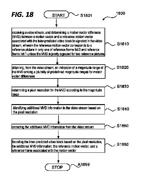
本開示は、概してビデオコーディングに関連し、特にビデオブロックのインター予測における動きベクトル差分の適応解像度を提供するための方法及びシステムに関連する。一実施形態では、ビデオストリームのインター予測ビデオブロックをデコードする方法であって:方法は、ビデオストリームを受信するステップと;インター予測ビデオブロックと関連付けられた参照動きベクトルと動きベクトルとの間の動きベクトル差分(MVD)がビデオストリーム内でシグナリングされることを決定するステップであって、参照動きベクトルは、MVDが2つの参照画像に対して共同でシグナリングされない限り、参照フレームリスト0と参照フレームリスト1のうちの1つだけの参照画像に対応し;ビデオストリームから、動きベクトル差分についての複数の所定の大きさ範囲のうち、MVDの大きさ範囲の表示を取得するステップと;大きさ範囲に従ってMVDのためのピクセル解像度を決定するステップと;ピクセル解像度に基づいてビデオストリーム内の付加的なMVD情報を識別するステップと;ビデオストリームから付加的なMVD情報を抽出するステップと;動きベクトルに関連付けられる参照フレーム、参照動きベクトル、付加的なMVD情報、及びピクセル解像度に基づいてインター予測ビデオブロックをデコードするステップと、を含む。
Summary The present disclosure relates generally to video coding, and more particularly to methods and systems for providing adaptive resolution of motion vector differences in inter-prediction of video blocks. In one embodiment, a method of decoding an inter-predicted video block of a video stream comprises the steps of: receiving a video stream; determining that a vector difference (MVD) is signaled in the video stream, the reference motion vector being a
上記の例示的実施形態において、ピクセル解像度は2n-pel(2nピクセル)であり、nは整数であり、-6以上11以下である。 In the exemplary embodiment described above, the pixel resolution is 2n-pel (2n pixels), where n is an integer greater than or equal to -6 and less than or equal to 11.
上記の例示的実施態様のいずれかにおいて、動きベクトル差分についての複数の所定の大きさ範囲は、所定の方法で、非昇順のピクセル解像度と関連付けられ、より高いピクセル解像度は、より小さいピクセル解像度値と関連付けられる。 In any of the above exemplary embodiments, the plurality of predetermined magnitude ranges for motion vector differences are associated with non-increasing pixel resolutions in a predetermined manner, with higher pixel resolutions having lower pixel resolution values. associated with.
上記の例示的実施態様のいずれかにおいて、MVDの大きさ範囲の表示を取得するステップは、MVDクラスの所定のセットのうちのMVDのMVDクラスを示すビデオストリームから第1所定構文要素(a first predefined syntax element)を抽出するステップであって、より低いMVDクラスはより小さいMVD大きさ範囲に対応する、ステップと;MVDクラスに従ってMVDの大きさ範囲を決定するステップと、を含む。 In any of the above exemplary embodiments, obtaining an indication of the size range of the MVDs includes obtaining a first predetermined syntax element (a first a lower MVD class corresponds to a smaller MVD size range; and determining the MVD size range according to the MVD class.
上記の例示的実施態様のいずれかにおいて、大きさ範囲に従ってMVDのためのピクセル解像度を決定するステップは:大きさ範囲が所定のMVD範囲閾値レベルよりも高いかどうかを決定するステップと;大きさ範囲が所定のMVD範囲閾値よりも高いかどうかを決定することで、ピクセル解像度が整数のピクセル数であることを決定するステップと、大きさ範囲が所定のMVD範囲閾値レベルよりも高いかどうかを決定することで、ピクセル解像度がピクセルの部分(a fraction of a pixel)であると決定するステップと、を含む。 In any of the above exemplary embodiments, determining a pixel resolution for MVD according to a magnitude range includes: determining whether the magnitude range is greater than a predetermined MVD range threshold level; determining that the pixel resolution is an integer number of pixels by determining whether the range is greater than a predetermined MVD range threshold level; determining that the pixel resolution is a fraction of a pixel.
上記の例示的実施態様のいずれかにおいて、ピクセル解像度に基づいてビデオストリームの付加的なMVD情報を識別するステップは:第2所定構文要素に従ってビデオストリームをパースし、MVDの整数ピクセル部分(an integer pixel portion)を取得する、ステップと;前記ピクセル解像度がピクセルの部分であると決定すると、少なくとも第3所定構文要素に従ってビデオストリームをさらにパースし、前記MVDの分数ピクセル部分(a fractional pixel portion)を取得する、ステップと、を含む。 In any of the above exemplary embodiments, the step of identifying additional MVD information of a video stream based on pixel resolution includes: parsing the video stream according to a second predetermined syntax element; obtaining a fractional pixel portion of the MVD; upon determining that the pixel resolution is in pixels, further parsing the video stream according to at least a third predetermined syntax element to obtain a fractional pixel portion of the MVD; The steps include: obtaining.
上記の例示的実施態様のいずれかにおいて、MVD範囲閾値レベルは、MVDクラスの所定のセットの中で最も低いもの又は2番目に低いものを含む。 In any of the above exemplary embodiments, the MVD range threshold level includes the lowest or second lowest of the predetermined set of MVD classes.
上記の例示的実施態様のいずれかにおいて、所定MVD範囲閾値レベルよりも高い大きさ範囲を有するMVDクラスの所定のセットのそれぞれは、単一の許容される整数MVDピクセル値に関連付けられる。 In any of the above exemplary embodiments, each of the predetermined set of MVD classes having a magnitude range greater than a predetermined MVD range threshold level is associated with a single permissible integer MVD pixel value.
上記の例示的実施態様のいずれかにおいて、単一の許容される整数ピクセル値は、対応する大きさ範囲のうちのより高いもの(a higher of the corresponding magnitude range)に対応するピクセル値を含む。 In any of the above exemplary embodiments, the single allowed integer pixel value includes a pixel value corresponding to a higher of the corresponding magnitude range.
上記の例示的実施態様のいずれかにおいて、単一の許容される整数ピクセル値は、対応する大きさ範囲のうちの中間点に対応するピクセル値を含む。 In any of the above exemplary embodiments, the single permissible integer pixel value includes the pixel value corresponding to the midpoint of the corresponding magnitude range.
上記の例示的実施態様のいずれかにおいて、大きさ範囲に従ってMVDのためのピクセル解像度を決定するステップは:大きさ範囲が、MVD閾値の所定の大きさ値(a predetermined MVD threshold magnitude value)よりも、低いか、含むか、又は高いかを決定する、ステップと、大きさ範囲がMVD閾値の所定の大きさ値よりも高いことを決定することで、ピクセル解像度が整数のピクセル数であることを決定するステップと、大きさ範囲がMVD閾値の所定の大きさ値よりも高くないことを決定することで、ピクセル解像度がピクセルの部分であると決定するステップと、を含むことができる。 In any of the above exemplary embodiments, the step of determining a pixel resolution for MVD according to a magnitude range includes: a magnitude range that is greater than a predetermined MVD threshold magnitude value; , determining whether the pixel resolution is an integer number of pixels by determining whether the magnitude range is greater than a predetermined magnitude value of the MVD threshold; and determining that the magnitude range is not higher than a predetermined magnitude value of a MVD threshold, thereby determining the pixel resolution to be in parts of pixels.
上記の例示的実施態様のいずれかにおいて、本方法は、さらに、大きさ範囲が前記MVD閾値の所定の大きさ値を含むことを決定することで、大きさ範囲が前記MVD閾値の所定の大きさ値を含むことを決定することで、MVDの大きさ範囲の開始大きさに関連するMVDのMVD大きさオフセットを示すビデオストリームから、第2所定構文要素を抽出する、ステップと;MVDのMVD大きさオフセット及び大きさ範囲に基づいて前記MVDの整数の大きさを取得するステップと;MVDの整数の大きさがMVD閾値の所定の大きさよりも高くない場合、ピクセル解像度が分数(fractional)であると決定するステップと;MVDの整数の大きさがMVD閾値の所定の大きさよりも高い場合、ピクセル解像度が非分数(non-fractional)であると決定するステップと、を含むことができる。 In any of the above exemplary embodiments, the method further comprises determining that the magnitude range includes a predetermined magnitude value of the MVD threshold. extracting a second predetermined syntax element from the video stream indicating an MVD magnitude offset of the MVD relative to a starting magnitude of a magnitude range of the MVD; obtaining an integer magnitude of the MVD based on a magnitude offset and a magnitude range; if the integer magnitude of the MVD is not higher than a predetermined magnitude of an MVD threshold, the pixel resolution is fractional; and determining that the pixel resolution is non-fractional if the integer magnitude of the MVD is greater than a predetermined magnitude of an MVD threshold.
上記の例示的実施態様のいずれかにおいて、ピクセル解像度が分数であると決定すると、ピクセル解像度に基づいてビデオストリーム内の付加的なMVD情報を識別するステップは、所定の第3構文要素に従って前記ビデオストリームをパースし、前記MVDの分数部分を取得する、ステップ、を含むことができる。 In any of the above exemplary embodiments, once the pixel resolution is determined to be fractional, identifying additional MVD information in the video stream based on the pixel resolution comprises: parsing the stream and obtaining a fractional portion of the MVD.
上記の例示的実施態様のいずれかにおいて、MVD閾値の大きさ値は4ピクセルより小さい。 In any of the above exemplary embodiments, the MVD threshold magnitude value is less than 4 pixels.
上記の例示的実施態様のいずれかにおいて、動きベクトル差分の複数の所定の大きさ範囲に関連付けられたMVDピクセル解像度は、大きさ範囲ごとに異なる。 In any of the above exemplary implementations, the MVD pixel resolution associated with the plurality of predetermined magnitude ranges of motion vector differences is different for each magnitude range.
いくつかの他の例示的実施形態において、ビデオストリームのインター予測ビデオブロックをデコードする方法が開示される。本方法は、ビデオストリームを受信するステップと;インター予測ビデオブロックと関連付けられた参照動きベクトルと動きベクトルとの間の動きベクトル差分(MVD)がビデオストリーム内でシグナリングされることを決定するステップであって、参照動きベクトルは、MVDが2つの参照画像に対して共同でシグナリングされない限り、参照フレームリスト0と参照フレームリスト1のうちの1つのみの参照画像に対応する、ステップと;ビデオストリームから、MVDの大きさの整数部分を抽出するステップと;MVDの大きさの整数部分に従ってMVDについてのピクセル解像度を決定するステップと;ピクセル解像度に基づいてビデオストリーム内の付加的なMVD情報を識別するステップと:動きベクトルに関連付けられる参照フレーム、参照動きベクトル、付加的なMVD情報、MVDの大きさの整数部分及びピクセル解像度に基づいてインター予測ビデオブロックをデコードするステップと、を含むことができる。
In some other example embodiments, a method of decoding inter-predicted video blocks of a video stream is disclosed. The method includes the steps of: receiving a video stream; and determining that a motion vector difference (MVD) between a reference motion vector and a motion vector associated with an inter-predicted video block is signaled in the video stream. the reference motion vector corresponds to a reference picture in only one of
上記の例示的実施形態において、MVDピクセル解像度は、非昇順で、MVD大きさに依存する。 In the above exemplary embodiment, the MVD pixel resolution depends on the MVD size in a non-increasing order.
上記の例示的実施態様のいずれかにおいて、MVDの大きさの整数部分に従ってMVDのためのピクセル解像度を決定するステップは:MVDの大きさの整数部分が所定MVD閾値大きさ値より高いかどうか決定するステップと;MVDの大きさの整数部分が所定MVD閾値大きさ値よりも高いことを決定することで、ピクセル解像度が整数のピクセル数であることを決定するステップと;MVDの大きさの整数部分が所定MVD閾値大きさ値よりも高くないことを決定することで、ピクセル解像度がピクセルの部分であると決定するステップと、を含むことができる。 In any of the above exemplary embodiments, determining a pixel resolution for the MVD according to an integer portion of the MVD magnitude includes: determining whether the integer portion of the MVD magnitude is higher than a predetermined MVD threshold magnitude value; determining that the pixel resolution is an integer number of pixels by determining that an integer portion of the MVD magnitude is greater than a predetermined MVD threshold magnitude value; determining that the pixel resolution is the portion of the pixel by determining that the portion is not higher than a predetermined MVD threshold magnitude value.
本開示の態様はまた、上記の方法実施形態のいずれかを実行するように構成された回路を含む、ビデオエンコーディング又はデコーディングデバイス又は装置を提供する。 Aspects of the present disclosure also provide a video encoding or decoding device or apparatus that includes a circuit configured to perform any of the method embodiments described above.
本開示の態様は、ビデオデコーディング及び/又はエンコーディングのためにコンピュータによって実行されると、ビデオデコーディング及び/又はエンコーディングのための方法をコンピュータに実行させる命令を格納する非一時的コンピュータ可読媒体も提供する。 Aspects of the present disclosure also include non-transitory computer-readable media storing instructions that, when executed by a computer for video decoding and/or encoding, cause the computer to perform a method for video decoding and/or encoding. provide.
開示された主題のさらなる特徴、性質、及び様々な利点は、以下の詳細な説明及び添付の図面からより明らかになるであろう。
明細書及び特許請求の範囲全体を通して、用語は、明示的に述べられた意味を超えて、文脈において示唆又は暗示されたニュアンスを持つことがある。ここで使用される「ある実施形態において」又は 「いくつかの実施形態において」という語句は、必ずしも同じ実施形態を指すとは限らず、ここで使用される「別の実施形態において」又は「別の実施形態において」という語句は、必ずしも別の実施形態を指すとは限らない。同様に、ここで使用される「ある実装で」又は「いくつかの実装で」という語句は、必ずしも同じ実装を指すとは限らず、ここで使用される「別の実装で」又は「他の実装で」という語句は、必ずしも別の実装を指すとは限らない。例えば、クレームされた主題には、全体又は一部の例示的な実施形態/実装の組み合わせが含まれることが意図されている。 Throughout the specification and claims, terms may have nuances beyond their expressly stated meanings that are implied or implied in the context. The phrases "in one embodiment" or "in some embodiments" as used herein do not necessarily refer to the same embodiment; The phrase "in an embodiment of" does not necessarily refer to another embodiment. Similarly, the phrases "in one implementation" or "in some implementations" as used herein do not necessarily refer to the same implementation; The phrase "in an implementation" does not necessarily refer to a different implementation. For example, the claimed subject matter is intended to include combinations of example embodiments/implementations, in whole or in part.
一般に、用語は、少なくとも部分的には文脈での使用から理解することができる。例えば、ここで使用される「及び(and)」、「又は(or)」、又は「及び/又は(and/or)」などの用語は、そのような用語が使用される文脈に少なくとも部分的に依存する可能性のある様々な意味を含むことができる。通常、「又は」は、A、B又はCなどのリストを関連付けるために使用される場合、ここでは包括的な意味で使用されるA、B、及びCだけでなく、ここでは排他的な意味で使用されるA、B、又はCも意味することを意図している。さらに、ここで使用される「1つ以上」又は「少なくとも1つ」という用語は、少なくとも部分的に文脈に応じて、任意の特徴、構造、又は特性を単一の意味で記述するために使用される場合もあれば、特徴、構造、又は特性の組み合わせを複数の意味で記述するために使用される場合もある。同様に、「1つの(”a”, ”an”)」、又は「その又は前記(the)」などの用語も、少なくとも部分的に文脈に応じて、単数の用法を伝えるため、又は複数の用法を伝えるために理解される場合がある。さらに、「に基づく(based on)」又は「によって決定される(determined by)」という用語は、必ずしも要素の排他的なセットを伝えることを意図していないと理解されることができ、代わりに、少なくとも部分的に文脈に応じて、必ずしも明示的に記述されていない追加的な要素の存在を可能にすることができる。図3は、本開示の一実施形態による通信システム(300)の簡略化されたブロック図を示す。通信システム(300)は、例えばネットワーク(350)を介して互いに通信することができる複数の端末デバイスを含む。例えば、通信システム(300)は、ネットワーク(350)を介して相互接続された第1対の端末デバイス(310)及び(320)を含む。図3の実施例では、第1対の端末デバイス(310)及び(320)は、データの一方向送信を行う。例えば、端末デバイス(310)は、ネットワーク(350)を介して他の端末デバイス(320)に伝送するためにビデオデータ(例えば、端末デバイス(310)によって捕捉されるビデオ画像のスツリーム)をコーディングすることができる。エンコードされた画像データは、1つ以上のコーディングされたビデオビットスツリームの形態で送信されることができる。端末デバイス(320)は、ネットワーク(350)からコーディングされたビデオデータを受信し、コーディングされたビデオデータをデコードして、ビデオ画像を復元し、復元されたビデオデータにしたがってビデオ画像を表示することができる。一方向性データ伝送は、メディア提供アプリケーション等において一般的であり得る。 Generally, terms can be understood at least in part from their use in context. For example, as used herein, terms such as "and," "or," or "and/or" depend at least in part on the context in which such terms are used. can have a variety of meanings that may depend on. Typically, when "or" is used to relate a list such as A, B or C, A, B, and C are used here in an inclusive sense, as well as in an exclusive sense here. A, B, or C used in is also intended to mean. Additionally, the terms "one or more" or "at least one" as used herein, depending at least in part on the context, are used to describe any feature, structure, or characteristic in a single sense. Sometimes it is used to describe a feature, structure, or combination of properties in more than one sense. Similarly, terms such as "a", "an", or "the" may also be used to convey singular or plural usage, depending at least in part on the context. Sometimes understood to convey usage. Additionally, the terms "based on" or "determined by" can be understood as not necessarily intended to convey an exclusive set of elements, but instead , at least partially depending on the context, may allow for the presence of additional elements not necessarily explicitly stated. FIG. 3 shows a simplified block diagram of a communication system (300) according to one embodiment of the present disclosure. The communication system (300) includes a plurality of terminal devices that can communicate with each other via, for example, a network (350). For example, a communication system (300) includes a first pair of terminal devices (310) and (320) interconnected via a network (350). In the example of FIG. 3, the first pair of terminal devices (310) and (320) perform unidirectional transmission of data. For example, the terminal device (310) codes video data (e.g., a stream of video images captured by the terminal device (310)) for transmission to other terminal devices (320) over the network (350). be able to. Encoded image data may be transmitted in the form of one or more coded video bitstreams. The terminal device (320) receives the coded video data from the network (350), decodes the coded video data, recovers the video image, and displays the video image according to the recovered video data. Can be done. Unidirectional data transmission may be common, such as in media serving applications.
別の例では、通信システム(300)は、第2対の端末デバイス(330)及び(340)を含み、例えばビデオ会議アプリケーション中に、実装され得るコーディングされたビデオデータの双方向伝送を行う。データの双方向伝送のために、例えば、端末デバイス(330)及び(340)の各端末デバイスは、ネットワーク(350)を介して端末デバイス(330)及び(340)の他方の端末デバイスに伝送するために、ビデオデータ(例えば、端末デバイスによって捕捉されるビデオ画像のスツリーム)をコーディングし得る。端末デバイス(330)及び(340)の各端末デバイスは、端末デバイス(330)及び(340)の他方の端末デバイスによって送信されたコーディングされたビデオデータを受信し、コーディングされたビデオデータをデコードして、ビデオ画像を復元し、復元されたビデオデータにしたがって、アクセス可能な表示デバイスにビデオ画像を表示し得る。 In another example, the communication system (300) includes a second pair of terminal devices (330) and (340) for bidirectional transmission of coded video data that may be implemented, for example, during a video conferencing application. For bidirectional transmission of data, for example, each terminal device (330) and (340) transmits to the other terminal device (330) and (340) via the network (350). Video data (eg, a stream of video images captured by a terminal device) may be coded for purposes. Each of the terminal devices (330) and (340) receives the coded video data transmitted by the other terminal device of the terminal devices (330) and (340) and decodes the coded video data. and may restore the video image and display the video image on an accessible display device according to the restored video data.
図3の例では、端末デバイス(310)、(320)、(330)及び(340)は、サーバ、パーソナルコンピュータ及びスマートフォンとして実装され得るが、本発明の基礎となる原理の適用可能性はこれらに限定されない。本開示の実施形態は、デスクトップコンピュータ、ラップトップコンピュータ、タブレットコンピュータ、メディアプレーヤー、ウェアラブルコンピュータ、専用のビデオ会議機器などに実装することができる。ネットワーク(350)は、例えばワイヤライン(有線)及び/又は無線通信ネットワークを含む、端末デバイス(310)、(320)、(330)及び(340)の間でコーディングされたビデオデータを伝達する任意の数のネットワークを表す。通信ネットワーク(350)9は、回線交換、パケット交換、及び/又はその他の種類のチャネルでデータを交換することができる。代表的なネットワークには、テレコミュニケーションネットワーク、ローカルエリアネットワーク、ワイドエリアネットワーク及び/又はインターネットが含まれる。本説明の目的上、ネットワーク(350)のアーキテクチャ及びトポロジーは、ここで明示的に説明されない限り、本開示の動作にとって重要でない場合がある。 In the example of Figure 3, the terminal devices (310), (320), (330) and (340) may be implemented as servers, personal computers and smartphones, but the applicability of the principles underlying the invention is limited to these. but not limited to. Embodiments of the present disclosure can be implemented on desktop computers, laptop computers, tablet computers, media players, wearable computers, specialized video conferencing equipment, and the like. Network (350) may include any wireline and/or wireless communication network that conveys coded video data between terminal devices (310), (320), (330), and (340). represents a network of numbers. The communication network (350) 9 may exchange data over circuit-switched, packet-switched, and/or other types of channels. Representative networks include telecommunications networks, local area networks, wide area networks, and/or the Internet. For purposes of this description, the architecture and topology of network (350) may not be important to the operation of this disclosure unless explicitly described herein.
図4は、開示された主題の適用例として、ビデオスツリーミング環境におけるビデオエンコーダ及びビデオデコーダの配置を示す。開示された主題は、例えば、ビデオ会議、デジタルTV放送、ゲーム、仮想現実、CD、DVD、メモリスティックなどを含むデジタルメディアへの圧縮ビデオの保存など、他のビデオアプリケーションにも同様に適用することができる。 FIG. 4 illustrates the placement of video encoders and video decoders in a video streaming environment as an example application of the disclosed subject matter. The disclosed subject matter applies equally to other video applications, such as, for example, video conferencing, digital TV broadcasting, gaming, virtual reality, storage of compressed video on digital media including CDs, DVDs, memory sticks, etc. Can be done.
ビデオスツリーミングシステムは、例えば、非圧縮のビデオ画像又は画像(402)のスツリームを生成するビデオソース(401)、例えばデジタルカメラを含むことができるキャプチャサブシステム(413)を含み得る。一実施形態では、ビデオ画像のスツリーム(402)は、ビデオソース401のデジタルカメラによって撮影されるサンプルを含む。エンコードされたビデオデータ(404)(又はコーディングされたビデオビットスツリーム)と比較した場合に、高データ量を強調するために太線として描かれたビデオ画像のスツリーム(402)は、ビデオソース(401)に結合されたビデオエンコーダ(403)を含む電子デバイス(420)によって処理されることができる。ビデオエンコーダ(403)は、ハードウェア、ソフトウェア、又はそれらの組み合わせを含むことができ、以下により詳細に説明されるように、開示された主題の態様を可能にし、又は実施する。エンコードされたビデオデータ(404)(又はエンコードされたビデオビットスツリーム(404))は、圧縮されていないビデオ画像(402)のスツリームと比較した場合に、より低いデータ量を強調するために細線として示され、将来の使用のためにスツリーミングサーバ(405)に保存することも、ダウンスツリームのビデオデバイス(図示せず)に直接保存することもできる。図4のクライアントサブシステム(406)及び(408)等の1つ以上のスツリーミングクライアントサブシステムは、スツリーミングサーバ(405)にアクセスすることができ、エンコードされたビデオデータ(404)のコピー(407)及び(409)を読み出すことができる。クライアントサブシステム(406)は、例えば電子デバイス(430)内のビデオデコーダ(410)を含むことができる。ビデオデコーダ(410)は、エンコードされたビデオデータの入力コピー(407)をデコードし、ディスプレイ(412)(例えばディスプレイスクリーン)又は他のレンダリングデバイス(図示せず)上にレンダリングすることができる、圧縮されていないビデオ画像の出力スツリーム(411)を生成する。ビデオデコーダ410は、この開示に記載されているさまざまな機能の一部又は全てを実行するように構成できる。いくつかのスツリーミングシステムでは、エンコードされたビデオデータ(404)、(407)及び(409)(例えば、ビデオビットスツリーム)は、特定のビデオコーディング/圧縮標準にしたがってコーディングされることができる。これらの標準の例は、ITU-T勧告H.265を含む。例えば、開発中のビデオコーディング規格は、汎用ビデオコーディング(VVC)として非公式に知られている。開示された主題は、VVC、及びその他のビデオコーディング標準の文脈で使用される場合があります。
The video streaming system may include, for example, a capture subsystem (413) that may include a video source (401), such as a digital camera, that generates an uncompressed video image or stream of images (402). In one embodiment, the stream of video images (402) includes samples taken by a digital camera of
電子デバイス(420)及び(430)は、他の構成要素(図示せず)を含むことができることに留意されたい。例えば、電子デバイス(420)は、ビデオデコーダ(図示せず)を含むことができ、電子デバイス(430)は、ビデオエンコーダ(図示せず)も含むことができる。 Note that electronic devices (420) and (430) may include other components (not shown). For example, electronic device (420) can include a video decoder (not shown), and electronic device (430) can also include a video encoder (not shown).
図5は、以下の本開示のいずれかの実施形態によるビデオデコーダ(510)のブロック図を示す。ビデオデコーダ(510)は、電子デバイス(530)に含まれることができる。電子デバイス(530)は、受信器(531)(例えば、受信回路)を含むことができる。図4の例では、ビデオデコーダ(410)の代わりにビデオデコーダ(510)を使用することができる。 FIG. 5 shows a block diagram of a video decoder (510) according to any embodiment of the present disclosure below. A video decoder (510) may be included in an electronic device (530). The electronic device (530) can include a receiver (531) (eg, a receiving circuit). In the example of FIG. 4, a video decoder (510) can be used instead of the video decoder (410).
受信器(531)は、ビデオデコーダ(510)によってデコードされるべき1つ以上のコーディングされたビデオシーケンスを受信することができ、同一又は別の実施形態では、一度に1つのコーディングされたビデオシーケンスをデコードすることができ、その際、各コーディングされたビデオシーケンスのデコーディングは、他のコーディングされたビデオシーケンスから独立している。各ビデオシーケンスは、複数のビデオフレーム又はイメージと関連付けることができる。コーディングされたビデオシーケンスは、チャネル(501)から受信することができ、このチャネルは、エンコードされたビデオデータを格納するストレージデバイス又はエンコードされたビデオデータを伝送するスツリーミングソースへのハードウェア/ソフトウェアリンクであり得る。受信器(531)は、コーディングされたオーディオデータ及び/又は補助的なデータスツリームなどの他のデータとともにエンコードされたビデオデータを受信することができ、これらはそれぞれの処理回路(図示せず)に転送することができる。受信器(531)は、コーディングされたビデオシーケンスを他のデータから分離することができる。ネットワークジッタに対処するために、バッファメモリ(515)が、受信器(531)とエントロピーデコーダ/パーサ(520)(以後「パーサ(520)」)との間に配置され得る。特定の用途では、バッファメモリ(515)はビデオデコーダ(510)の一部として実装することができる。他の用途では、ビデオデコーダ(510)(図示せず)の外部にあって、ビデオデコーダから分離することができる。さらに別の用途には、例えばネットワークジッタに対処するために、ビデオデコーダ(510)の外部にバッファメモリ(図示せず)が存在することができ、さらに、例えば再生タイミング(playout timing)を処理するために、ビデオデコーダ(510)の内部に別の追加のバッファメモリ(515)が存在することもできる。受信器(531)が、十分な帯域幅及び制御可能性の記憶/転送デバイスから、又は、アイソクロナスネットワーク(isosynchronous network)から、データを受信している場合、バッファメモリ(515)は不要であるか、又は小さくてもよい。インターネットなどのベストエフォートパケットネットワークで使用する場合、十分なサイズのバッファメモリ(515)が必要な場合があり、そのサイズは比較的大きくなる可能性がある。このようなバッファメモリは、適応可能なサイズで実装することができ、少なくとも部分的には、ビデオデコーダ(510)の外部のオペレーティングシステム又は同様の要素(図には示されていない)に実装することができる。 The receiver (531) may receive one or more coded video sequences to be decoded by the video decoder (510), in the same or another embodiment, one coded video sequence at a time. can be decoded, where the decoding of each coded video sequence is independent from other coded video sequences. Each video sequence can be associated with multiple video frames or images. A coded video sequence may be received from a channel (501), which is a hardware/streaming source to a storage device storing encoded video data or a streaming source transmitting encoded video data. Can be a software link. The receiver (531) may receive encoded video data along with other data such as encoded audio data and/or ancillary data streams, which are processed by respective processing circuits (not shown). can be transferred to. A receiver (531) can separate the coded video sequence from other data. To address network jitter, a buffer memory (515) may be placed between the receiver (531) and the entropy decoder/parser (520) (hereinafter "parser (520)"). In certain applications, buffer memory (515) may be implemented as part of a video decoder (510). In other applications, it may be external to and separate from the video decoder (510) (not shown). For further applications, there may be a buffer memory (not shown) external to the video decoder (510), e.g. to address network jitter, and also to handle playout timing, e.g. There may also be another additional buffer memory (515) inside the video decoder (510) for this purpose. If the receiver (531) is receiving data from a storage/transfer device with sufficient bandwidth and controllability or from an isosynchronous network, the buffer memory (515) is not required. , or may be small. For use in a best effort packet network such as the Internet, a buffer memory (515) of sufficient size may be required, and its size can be relatively large. Such buffer memory may be implemented with an adaptable size and may be implemented, at least in part, in an operating system or similar element (not shown) external to the video decoder (510). be able to.
ビデオデコーダ(510)は、コーディングされたビデオシーケンスからシンボル(521)を再構成するためのパーサ(520)を含み得る。これらのシンボルのカテゴリには、ビデオデコーダ(510)の動作を管理するために使用される情報と、電子デバイス(530)の一体部分であってもなくてもよいが、電子デバイス(530)に結合され得るディスプレイ(512)(例えば、ディスプレイスクリーン)などのレンダリングデバイスを制御するための潜在的な情報が含まれる可能性がある。(複数の)レンダリングデバイスの制御情報は、付加拡張情報(SEIメッセージ)又はビデオユーザビリティ情報(VUI)パラメータセットフラグメント(図示せず)の形態であり得る。パーサ(520)は、パーサ(520)によって受信されるコーディングされたビデオシーケンスをパースし/エントロピーデコードすることができる。コーディングされたビデオシーケンスのエントロピーコーディングは、ビデオコーディング技術又は標準に従うことができ、可変長コーディング、ハフマンコーディング、コンテキスト感度を伴う又は伴わない算術コーディングなどを含む種々の原理に従うことができる。パーサ(520)は、サブグループに対応する少なくとも1つのパラメータに基づいて、ビデオデコーダ内のピクセルのサブグループのうちの少なくとも1つに対するサブグループパラメータのセットを、コーディングされたビデオシーケンスから抽出し得る。サブグループは、画像グループ(GOP)、画像、タイル、スライス、マクロブロック、コーディングユニット(CU)、ブロック、変換ユニット(TU)、予測ユニット(PU)等を含み得る。 The video decoder (510) may include a parser (520) for reconstructing symbols (521) from the coded video sequence. These categories of symbols include information used to manage the operation of the video decoder (510) and information that may or may not be an integral part of the electronic device (530). Potential information may be included for controlling a rendering device such as a display (512) (eg, a display screen) that may be coupled. The rendering device(s) control information may be in the form of supplemental enhancement information (SEI messages) or video usability information (VUI) parameter set fragments (not shown). A parser (520) may parse/entropy decode the coded video sequence received by the parser (520). Entropy coding of a coded video sequence may follow a video coding technique or standard and may follow various principles including variable length coding, Huffman coding, arithmetic coding with or without context sensitivity, and the like. A parser (520) may extract a set of subgroup parameters for at least one of the subgroups of pixels in the video decoder from the coded video sequence based on at least one parameter corresponding to the subgroup. . Subgroups may include groups of pictures (GOPs), images, tiles, slices, macroblocks, coding units (CUs), blocks, transform units (TUs), prediction units (PUs), and so on.
パーサ(520)はまた、変換係数(例えば、フーリエ変換係数)、量子化パラメータ値、動きベクトル等の情報を、コーディングされたビデオシーケンスから抽出し得る。パーサ(520)は、シンボル(521)を生成するように、バッファメモリ(515)から受信したビデオシーケンスに、エントロピーデコード/パース動作を実行し得る。 Parser (520) may also extract information such as transform coefficients (eg, Fourier transform coefficients), quantization parameter values, motion vectors, etc. from the coded video sequence. A parser (520) may perform entropy decoding/parsing operations on the video sequence received from the buffer memory (515) to generate symbols (521).
シンボル(521)の再構成は、コーディングされたビデオ画像又はその部分のタイプ(例えば、ンター及びイントラ画像、インター及びイントラブロック内)及び他の要因に応じて、複数の異なる処理又は機能ユニットを含むことができる。関与するユニット及びそれらがどのように関与するかは、パーサ(320)によってコーディングされたビデオシーケンスからパースされたサブグループ制御情報によって制御されることができる。パーサ(520)と以下の複数ユニットとの間のかかるサブグループ制御情報のフローは、単純化のために図示されていない。 Reconstruction of the symbols (521) may involve a number of different processing or functional units, depending on the type of coded video image or portion thereof (e.g. inter and intra images, within inter and intra blocks) and other factors. be able to. The participating units and how they participate can be controlled by subgroup control information parsed from the coded video sequence by the parser (320). The flow of such subgroup control information between the parser (520) and the following units is not shown for simplicity.
すでに述べた機能ブロックの他に、ビデオデコーダ(510)は、概念的に、以下に説明するように、いくつかの機能ユニットに分割されることができる。商業的制約の下で動作する実用的な実装では、これらの機能ユニットの多くは互いに密接に相互作用し、少なくとも部分的に互いに統合されることができる。しかし、開示された主題の様々な機能を明確に説明する目的で、以下の開示では機能ユニットへの概念的な細分化が採用されている。 Besides the functional blocks already mentioned, the video decoder (510) can be conceptually divided into several functional units, as explained below. In practical implementations operating under commercial constraints, many of these functional units interact closely with each other and can be at least partially integrated with each other. However, for the purpose of clearly describing the various features of the disclosed subject matter, a conceptual subdivision into functional units is employed in the following disclosure.
第1ユニットは、スケーラ/逆変換ユニット(551)であり得る。スケーラ/逆変換ユニット(551)は、パーサ(520)から、量子化された変換係数、並びに、使用する逆変換のタイプ、ブロックサイズ、量子化係数/パラメータ、量子化スケーリング行列、及び(1つ以上の)シンボルとしての偽(521)を示す情報を含む制御情報を受信し得る。スケーラ/逆変換ユニット(551)は、アグリゲータ(555)に入力可能なサンプル値を含むブロックを出力することができる。 The first unit may be a scaler/inverse transform unit (551). The scaler/inverse transform unit (551) receives the quantized transform coefficients from the parser (520) as well as the type of inverse transform to use, block size, quantization coefficients/parameters, quantization scaling matrix, and (1) Control information including information indicating a false (521) symbol (above) may be received. The scaler/inverse transform unit (551) can output blocks containing sample values that can be input to the aggregator (555).
場合によっては、スケーラ/逆変換(551)の出力サンプルは、イントラコーディングされたブロックに関係することができ、すなわち、以前に再構成された画像からの予測情報を使用していないが、現在の画像の以前に再構成された部分からの予測情報を使用することができるブロックに関連付けることができる。かかる予測情報は、イントラ画像予測ユニット(552)によって提供されることができる。場合によっては、イントラ画像予測ユニット(552)は、現在の画像バッファ(558)に格納された既に再構成された周辺ブロックを使用して、再構成中のブロックと同じサイズ及び形状のブロックを生成し得る。現在の画像バッファ(558)は、例えば、部分的に再構成された現在の画像及び/又は完全に再構成された現在の画像をバッファする。アグリゲータ(555)は、いくつかの実装形態では、サンプル毎に、イントラ予測ユニット(552)が生成した予測情報を、スケーラ/逆変換ユニット(551)によって提供される出力サンプル情報に加算し得る。 In some cases, the output samples of the scaler/inverse transform (551) may relate to intra-coded blocks, i.e., not using prediction information from a previously reconstructed image, but using the current Prediction information from previously reconstructed parts of the image can be associated with blocks that can be used. Such prediction information may be provided by an intra image prediction unit (552). In some cases, the intra image prediction unit (552) uses already reconstructed surrounding blocks stored in the current image buffer (558) to generate a block of the same size and shape as the block being reconstructed. It is possible. A current image buffer (558) buffers, for example, a partially reconstructed current image and/or a fully reconstructed current image. The aggregator (555) may add the prediction information generated by the intra prediction unit (552) to the output sample information provided by the scaler/inverse transform unit (551) on a sample-by-sample basis in some implementations.
他の場合には、スケーラ/逆変換ユニット(551)の出力サンプルは、インターコーディングに関係し、潜在的に動き補償ブロックに関係することができる。かかる場合、動き補償予測ユニット(553)は、インター画像予測に使用されるサンプルをフェッチするために参照画像メモリ(557)にアクセスすることができる。ブロックに関連するシンボル(521)にしたがって、フェッチされたサンプルを動き補償した後、これらのサンプルは、出力サンプル情報を生成するために、アグリゲータ(555)によって、スケーラ/逆変換ユニット(551)の出力(ユニット551の出力は、残差サンプル又は残差信号と称されることができる)に加算されることができる。動き補償予測ユニット(553)が予測サンプルをフェッチする参照ピクチャメモリ(557)内のアドレスは、例えば、X、Yコンポーネント(シフト)、及び参照画像コンポーネント(時間)を有するシンボル(521)の形態で動き補償予測ユニット(553)に利用可能な動きベクトルによって制御することができる。動き補償はまた、サブサンプルの正確な動きベクトルが使用されている場合には、参照画像メモリ(557)からフェッチされるようにサンプル値を補間することを含むことができ、動きベクトル予測メカニズムに関連付けること等もできる。
In other cases, the output samples of the scaler/inverse transform unit (551) may be related to inter-coding and potentially motion compensation blocks. In such a case, the motion compensated prediction unit (553) may access the reference picture memory (557) to fetch samples used for inter picture prediction. After motion compensating the fetched samples according to the symbols (521) associated with the block, these samples are processed by the aggregator (555) of the scaler/inverse transform unit (551) to generate output sample information. The output (the output of
アグリゲータ(555)の出力サンプルは、ループフィルタユニット(556)内の種々のループフィルタリング技術を受けることができる。ビデオ圧縮技術は、インループフィルタ技術(in-loop filter technologies)を含むことができ、コーディングされたビデオシーケンス(コーディングされたビデオビットスツリームとも称される)に含まれるパラメータによって制御され、パーサ(520)からシンボル(521)としてループフィルタユニット(556)に利用可能にされるが、コーディングされた画像又はコーディングされたビデオシーケンスと(デコード順において)先行する部分のデコードの間で得られるメタ情報に応答することができると共に、先行して再構成されループフィルタリングされたサンプル値に応答することができる、インループフィルタ技術を含むことができる。いくつかのタイプのループフィルタが、さまざまな順序でループフィルタユニット556の一部として含まれる場合があるが、これについては後述する
The output samples of the aggregator (555) can be subjected to various loop filtering techniques in a loop filter unit (556). Video compression techniques can include in-loop filter technologies, which are controlled by parameters contained in a coded video sequence (also referred to as a coded video bitstream) and (520) to the loop filter unit (556) as symbols (521), but the metadata obtained between the decoding of the coded image or coded video sequence and the preceding part (in decoding order). In-loop filter techniques can be included that can be responsive to information and can be responsive to previously reconstructed and loop-filtered sample values. Several types of loop filters may be included as part of
ループフィルタユニット(556)の出力は、レンダリングデバイス(512)に出力されることができ、また将来のインター画像予測に使用するために参照画像メモリ(557)に記憶されることができるサンプルスツリームであることができる。 The output of the loop filter unit (556) is a sample tree that can be output to a rendering device (512) and stored in a reference picture memory (557) for use in future inter-picture predictions. can be
特定のコーディングされた画像は、一旦完全に再構成されると、将来のインター予測のための参照画像として使用されることができる。例えば、一旦現在の画像に対応するコーディング画像が完全に再構成され、(例えば、パーサ(520)によって)コーディングされた画像が参照画像として識別されると、現在の画像バッファ(4558)は参照画像メモリ(557)の一部となることができ、新たな現在画像バッファは、後続のコーディング画像の再構成を開始する前に再割当てされ得る。 Once a particular coded image is fully reconstructed, it can be used as a reference image for future inter predictions. For example, once the coding image corresponding to the current image has been fully reconstructed and the coded image has been identified as a reference image (e.g., by the parser (520)), the current image buffer (4558) The new current image buffer can be part of the memory (557) and can be reallocated before starting reconstruction of subsequent coding images.
ビデオデコーダ(510)は、ITU-T Rec.H.265.等の標準で採用されたの所定のビデオ圧縮技術にしたがってデコーディング動作を実行し得る。コーディングされたビデオシーケンスは、コーディングされたビデオシーケンスが、ビデオ圧縮技術若しくは標準のシンタックス、及び、ビデオ圧縮技術若しくは標準に文書化されているプロファイルの両方に準拠するという意味で、使用されているビデオ圧縮技術又は標準によって特定されたシンタックスに適合し得る。具体的には、プロファイルは、そのプロファイルで使用できる唯一のツールとして、ビデオ圧縮テクノロジ又は標準で使用可能なすべてのツールから特定のツールを選択できる。また、標準に準拠するために、コーディングされたビデオシーケンスの複雑さが、ビデオ圧縮技術又は標準のレベルによって定義される範囲内にあることであり得る。場合によっては、レベルは、最大画像サイズ、最大フレームレート、最大再構成サンプルレート(例えば、毎秒メガサンプルで測定される)、最大参照画像サイズなどを制限する。レベルによって設定された制限は、場合によっては、仮想参照デコーダ(HRD:Hypothetical Reference Decoder)の仕様と、コーディングされたビデオシーケンスでシグナリングされるHRDバッファ管理のメタデータによってさらに制限され得る。 The video decoder (510) is an ITU-T Rec. H. 265. The decoding operation may be performed according to a predetermined video compression technique adopted in a standard such as . Coded video sequence is used in the sense that the coded video sequence conforms to both the syntax of a video compression technology or standard and the profile documented in the video compression technology or standard. It may conform to the syntax specified by the video compression technology or standard. Specifically, a profile can select a particular tool from all the tools available in a video compression technology or standard as the only tool available for use with that profile. Also, to comply with a standard, the complexity of the coded video sequence may be within a range defined by the level of video compression technology or standard. In some cases, the level limits maximum image size, maximum frame rate, maximum reconstruction sample rate (eg, measured in megasamples per second), maximum reference image size, etc. The limits set by the levels may in some cases be further limited by the Hypothetical Reference Decoder (HRD) specification and HRD buffer management metadata signaled in the coded video sequence.
いくつかの例示的実施形態では、受信器(531)は、エンコードされたビデオと共に追加の(冗長な)データを受信することができる。追加データは、コーディングされた(複数の)ビデオシーケンスの部分として含まれ得る。追加のデータは、データを適切にデコードするため、及び/又は元のビデオデータをより正確に再構成するために、ビデオデコーダ(510)によって使用され得る。追加のデータは、例えば、時間的、空間的、又は信号雑音比(SNR)拡張層、冗長スライス、冗長画像、前方エラー補正コードなどの形態であり得る。 In some example embodiments, the receiver (531) may receive additional (redundant) data along with the encoded video. Additional data may be included as part of the coded video sequence(s). The additional data may be used by the video decoder (510) to properly decode the data and/or more accurately reconstruct the original video data. The additional data may be in the form of, for example, temporal, spatial, or signal-to-noise ratio (SNR) enhancement layers, redundant slices, redundant images, forward error correction codes, and the like.
図6は、本開示の例示的実施形態によるビデオエンコーダ(603)のブロック図を示す。ビデオエンコーダ(603)は、電子デバイス(620)に含まれることができる。電子デバイス(620)は、送信器(640)(例えば送信回路)をさらに含むことができる。図4の例のビデオエンコーダ(403)の代わりに、ビデオエンコーダ(603)を用いることができる。 FIG. 6 shows a block diagram of a video encoder (603) according to an example embodiment of the present disclosure. A video encoder (603) may be included in an electronic device (620). Electronic device (620) can further include a transmitter (640) (eg, transmit circuitry). A video encoder (603) can be used instead of the video encoder (403) in the example of FIG.
ビデオエンコーダ(603)は、ビデオエンコーダ(603)によってコーディングされる(1つ以上の)ビデオ映像を捕捉することができるビデオソース(601)(図6の例では電子デバイス(620)の一部ではない)からビデオサンプルを受信し得る。別の例では、ビデオソース(601)は、電子デバイス(620)の一部として実装されることができる。 The video encoder (603) is part of a video source (601) (in the example of FIG. may receive video samples from In another example, video source (601) may be implemented as part of electronic device (620).
ビデオソース(601)は、任意の適切なビット深さ(例えば、8ビット、10ビット、12ビット、...)、任意の色空間(例えば、BT.601 Y CrCB、RGB、...)、及び任意の適切なサンプリング構造(例えば、Y CrCb 4:2:0、Y CrCb 4:4:4)を有することができるデジタルビデオサンプルスツリームの形態で、ビデオエンコーダ(603)によってコーディングされるべきソースビデオシーケンスを提供し得る。メディア配信システムにおいて、ビデオソース(601)は、予め準備されたビデオを記憶できる記憶デバイスであり得る。ビデオ会議システムでは、ビデオソース(601)は、局所映像情報をビデオシーケンスとして捕捉するカメラであり得る。ビデオデータは、シーケンスで見たときに動きをもたらす複数の個々の画像又は映像として提供され得る。画像自体は、ピクセルの空間アレイとして組織化されることができ、各ピクセルは、使用中のサンプリング構造、色空間等に応じて、1つ以上のサンプルを含むことができる。当業者は、ピクセルとサンプルとの間の関係を容易に理解することができる。以下の説明は、サンプルに焦点を当てている。 The video source (601) can be of any suitable bit depth (e.g. 8 bits, 10 bits, 12 bits,...), any color space (e.g. BT.601 Y CrCB, RGB,...) , and coded by a video encoder (603) in the form of a digital video sample stream that may have any suitable sampling structure (e.g., Y CrCb 4:2:0, Y CrCb 4:4:4). A source video sequence to be used may be provided. In a media distribution system, a video source (601) may be a storage device that can store pre-prepared videos. In a video conferencing system, the video source (601) may be a camera that captures local video information as a video sequence. Video data may be provided as multiple individual images or videos that when viewed in sequence create motion. The image itself can be organized as a spatial array of pixels, and each pixel can contain one or more samples depending on the sampling structure, color space, etc. in use. Those skilled in the art can easily understand the relationship between pixels and samples. The following discussion focuses on the sample.
いくつかの例示的実施形態によれば、ビデオエンコーダ(603)は、ソースビデオシーケンスの画像を、リアルタイムで、又はアプリケーションによって要求される任意の他の時間制約下で、コーディングされたビデオシーケンス(643)にコーディングし、圧縮し得る。適切なコーディングスピードを実現することは、コントローラ(650)の一つの機能である。いくつかの実施形態では、コントローラ(650)は、後述するように他の機能ユニットに機能的に接続されることができて、他の機能ユニットを制御することができる。カップリングは、単純化のため表されない。コントローラ(650)によって設定されるパラメータは、レート制御関連パラメータ(画像スキップ、量子化器、レート歪み最適化技術のラムダ値、...)、画像サイズ、画像グループレ(GOP)イアウト、最大動きベクトル探索範囲等を含むことができる。コントローラ(650)は、特定のシステム設計のために最適化されたビデオエンコーダ(603)に関連する他の適切な機能を有するように構成されることができる。 According to some example embodiments, the video encoder (603) converts images of the source video sequence into a coded video sequence (643) in real time or under any other time constraints required by the application. ) and can be compressed. Achieving appropriate coding speed is one function of the controller (650). In some embodiments, controller (650) can be functionally connected to and control other functional units as described below. Couplings are not represented for simplicity. The parameters set by the controller (650) include rate control related parameters (image skip, quantizer, lambda value of rate distortion optimization technique,...), image size, group of images (GOP) layout, maximum motion. It can include a vector search range, etc. Controller (650) may be configured with other suitable functionality related to video encoder (603) optimized for a particular system design.
いくつかの例示的実施形態では、ビデオエンコーダ(603)は、コーディングループで動作するように構成され得る。過剰に単純化された説明として、一例において、コーディングループは、(例えば、コーディングされるべき入力画像及び参照画像に基づいて、シンボルスツリーム等のシンボルを生成する責任を担う)ソースコーダ(630)と、ビデオエンコーダ(603)に埋め込まれた(ローカル)デコーダ(633)とを含むことができる。デコーダ(633)は、埋め込みデコーダ633がエントロピーコーディングなしでソースコーダ630によってコーディングされたビデオストリームを処理する場合でも、(リモート)デコーダが作成するのと同様の方法でサンプルデータを作成するようにシンボルを再構成する(エントロピーコーディングにおけるシンボルとコーディングされたビデオビットスツリームとの間の圧縮は、開示された主題で考慮されるビデオ圧縮技術では無損失であり得るからである)。再構成されたサンプルスツリーム(サンプルデータ)は、参照画像メモリ(634)に入力される。シンボルスツリームのデコーディングは、デコーダロケーション(ローカル又はリモート)に依存しないビットイクザクトな結果(bit-exact results)をもたらすので、参照画像メモリ(634)中の内容もまた、ローカルエンコーダとリモートエンコーダとの間でビットイクザクトである。換言すれば、エンコーダの予測部分は、デコーダがデコード中に予測を使用するときに「見る」のとまったく同じサンプル値を参照画像サンプルとして「見る」。参照画像同期性のこの基本原理(及び、例えばチャンネルエラーのために、同期性が維持できない場合の結果として生じるドリフト)は、コーディング品質を改善するために使用される。
In some example embodiments, video encoder (603) may be configured to operate in a coding loop. As an oversimplified explanation, in one example, the coding loop includes a source coder (630 ) and a (local) decoder (633) embedded in the video encoder (603). The decoder (633) uses symbols to create sample data in a similar way that the (remote) decoder would create, even if the embedded
「ローカル」デコーダ(533)の動作は、ビデオデコーダ(410)等の「リモート」デコーダと同じであることができ、これは、図5と関連して詳細に既に上述したとおりである。しかしながら、図5も簡単に参照すると、シンボルが利用可能であり、エントロピーコーダ(645)及びパーサ(520)によるコーディングビデオシーケンスへのシンボルのエンコーディング/デコーディングが可逆的であることができるので、バッファメモリ(515)を含むビデオデコーダ(510)のエントロピーデコーディング部分及びパーサ(520)は、エンコーダのローカルデコーダ(633)に完全には実装されない場合がある。 The operation of the "local" decoder (533) may be the same as a "remote" decoder, such as the video decoder (410), as already described in detail above in connection with FIG. 5. However, referring also briefly to FIG. 5, the buffer is The entropy decoding portion of the video decoder (510) including memory (515) and parser (520) may not be fully implemented in the encoder's local decoder (633).
この点で行うことができる観察は、デコーダ内にのみ存在することができるパース/エントロピーデコーディングを除く任意のデコーダ技術であり、対応するエンコーダ内に実質的に同一の機能的形態で存在する必要があり得るということである。このために、開示された主題は、エンコーダのデコーディング部分に関連するデコーダ動作に焦点を当てることがある。したがって、エンコーダ技術の説明は、包括的に説明されているデコーダ技術の逆であるため、省略できる。特定の領域又は側面についてのみ、エンコーダのより詳細な説明を以下に示す。 An observation that can be made in this regard is that any decoder technique except parsing/entropy decoding, which can only exist within the decoder, must exist in substantially the same functional form within the corresponding encoder. This means that it is possible. To this end, the disclosed subject matter may focus on decoder operations related to the decoding portion of the encoder. Therefore, the description of the encoder technology can be omitted since it is the opposite of the comprehensively described decoder technology. A more detailed description of the encoder is provided below, only for specific areas or aspects.
いくつかの実装例での動作中に、ソースコーダ(630)は、「参照画像」として指定されたビデオシーケンスからの、先行してコーディングされた1つ以上の画像を参照して入力画像を予測的にコーディングする、動き補償予測コーディングを実行し得る。このようにして、コーディングエンジン(632)は、入力画像のピクセルブロックと、入力画像に対する(1つ以上の)予測参照として選択され得る(1つ以上の)参照画像のピクセルブロックとの間の差分(残差)をコーディングする。用語「残差(residue)」とその形容詞形「残差(residual)」は同じ意味で使用されることがある。 During operation in some implementations, the source coder (630) predicts an input image with reference to one or more previously coded images from a video sequence designated as a "reference image." Motion-compensated predictive coding may be performed, where the data is automatically coded. In this way, the coding engine (632) determines the difference between a pixel block of an input image and a pixel block of a reference image(s) that may be selected as a predictive reference(s) for the input image. (residuals). The term "residual" and its adjective form "residual" are sometimes used interchangeably.
ローカルビデオデコーダ(633)は、ソースコーダ(630)によって生成されたシンボルに基づいて、参照画像として指定され得る画像のコーディングされたビデオデータをデコードし得る。コーディングエンジン(632)の動作は、有利には、非可逆プロセスであり得る。コーディングされたビデオデータがビデオデコーダ(図6には示されていない)でデコードされ得る場合、再構成されたビデオシーケンスは、典型的には、いくつかのエラーを伴うソースビデオシーケンスの複であり得る。ローカルビデオデコーダ(633)は、参照画像上でビデオデコーダによって実行され、参照画像キャッシュ(634)に記憶されるべき再構成された参照画像を生じさせ得るデコーディング処理を繰り返す。このようにして、ビデオエンコーダ(603)は、遠位端(リモート)ビデオデコーダによって得られるであろう(伝送エラーの無い)再構成された参照画像として、共通のコンテンツを有する再構成された参照画像のコピーをローカルに記憶することができる。 A local video decoder (633) may decode the coded video data of the image, which may be designated as a reference image, based on the symbols generated by the source coder (630). Operation of the coding engine (632) may advantageously be a non-reversible process. If the coded video data can be decoded with a video decoder (not shown in Figure 6), the reconstructed video sequence is typically a duplicate of the source video sequence with some errors. obtain. The local video decoder (633) repeats the decoding process performed by the video decoder on the reference image and may result in a reconstructed reference image to be stored in the reference image cache (634). In this way, the video encoder (603) uses the reconstructed reference image with common content as the reconstructed reference image (without transmission errors) that would be obtained by the distal end (remote) video decoder. A copy of the image can be stored locally.
予測器(635)は、コーディングエンジン(632)について予測サーチを実行し得る。すなわち、コーディングされるべき新しい画像について、予測器(635)は、新しい画像についての適切な予測参照として役立ち得る、参照画像動きベクトル、ブロック形状等の特定のメタデータ、又は、サンプルデータ(参照ピクセルブロックの候補として)、について参照画像メモリ(634)を検索し得る。予測器(635)は、適切な予測参照を見出すために、サンプルブロック毎に動作し得る。場合によっては、予測器(635)によって得られた検索結果によって決定されるように、入力画像は、参照画像メモリ(634)に記憶された複数の参照画像から引き出された予測参照を有し得る。 Predictor (635) may perform a predictive search on coding engine (632). That is, for a new picture to be coded, the predictor (635) uses certain metadata such as a reference picture motion vector, block shape, or sample data (reference pixel) that can serve as a suitable predictive reference for the new picture. The reference image memory (634) may be searched for (as a candidate block). A predictor (635) may operate on a sample block-by-sample block basis to find an appropriate prediction reference. In some cases, the input image may have a predicted reference drawn from a plurality of reference images stored in the reference image memory (634), as determined by the search results obtained by the predictor (635). .
コントローラ(650)は、例えば、ビデオデータをエンコードするために使用されるパラメータ及びサブグループパラメータの設定を含む、ソースコーダ(630)のコーディング動作を管理し得る。 Controller (650) may manage coding operations of source coder (630), including, for example, setting parameters and subgroup parameters used to encode video data.
上述した機能ユニットの全ての出力は、エントロピーコーダ(645)におけるエントロピーコーディングを受け得る。エントロピーコーダ(645)は、ハフマンコーディング、可変長コーディング、算術コーディング等の技術にしたがって、シンボルを可逆的に圧縮することによって、種々の機能ユニットによって生成されたシンボルをコーディングされたビデオシーケンスに変換する。 All outputs of the functional units mentioned above may be subjected to entropy coding in an entropy coder (645). The entropy coder (645) converts the symbols generated by the various functional units into a coded video sequence by reversibly compressing the symbols according to techniques such as Huffman coding, variable length coding, arithmetic coding, etc. .
送信器(640)は、エントロピーコーダ(645)によって作成されたコーディングされたビデオシーケンスをバッファすることができ、エンコードされたビデオデータを格納するであろうストレージデバイスへのハードウェア/ソフトウェアリンクであり得る通信チャネル(660)を経由した送信のために用意する。送信器(640)は、ビデオ・コーダ(603)からのコーディングされたビデオデータを、例えばコーディングされたオーディオデータ及び/又は補助的なデータ・スツリーム(図示せず)等の、送信されるべき他のデータとともにマージし得る。 The transmitter (640) is a hardware/software link to a storage device that can buffer the coded video sequence created by the entropy coder (645) and will store the encoded video data. and prepare for transmission via a communication channel (660) obtained. A transmitter (640) transmits the coded video data from the video coder (603) to other sources to be transmitted, such as coded audio data and/or an auxiliary data stream (not shown). can be merged with other data.
コントローラ(650)は、ビデオエンコーダ(603)の動作を管理し得る。コーディングの間、コントローラ(650)は、各コーディングされた画像に、特定のコーディングされた画像タイプを割り当てることができ、これは、各画像に適用され得るコーディング技術に影響を及ぼし得る。例えば、画像は、しばしば、次の画像タイプの1つとして割り当てられる: A controller (650) may manage the operation of the video encoder (603). During coding, the controller (650) may assign each coded image a particular coded image type, which may affect the coding technique that may be applied to each image. For example, images are often assigned as one of the following image types:
イントラ画像(I画像)は、予測ソースとしてシーケンス内の他の画像を使用することなく、コーディングされ、デコードされ得る。いくつかのビデオコーデックは、例えば、独立デコーダリフレッシュ(「IDR」:Independent Decoder Refresh)画像を含む、異なるタイプのイントラ画像を許容する。当業者は、I画像のこれらの変形例、並びにそれらのそれぞれの用途及び特徴を認識している。 Intra pictures (I pictures) can be coded and decoded without using other pictures in the sequence as prediction sources. Some video codecs allow different types of intra images, including, for example, Independent Decoder Refresh (“IDR”) images. Those skilled in the art are aware of these variations of I-images and their respective uses and characteristics.
予測画像(P画像)は、各ブロックのサンプル値を予測するために、最大で1つの運動ベクトルと参照インデックスを用いるインター予測又はイントラ予測を使用して、コーディングされ、デコードされ得るものであり得る。 A predicted picture (P-picture) can be coded and decoded using inter-prediction or intra-prediction using at most one motion vector and a reference index to predict the sample values of each block. .
双方向(bi-directionally)予測画像(B画像)は、各ブロックのサンプル値を予測するために、最大で2つの動きベクトルと参照インデックスを用いるインター予測又はイントラ予測を使用して、コーディングされ、デコードされ得るものであり得る。同様に、複数の予測画像は、1つのブロックの再構成のために、2つ以上の参照画像及び関連するメタデータを使用することができる。 A bi-directionally predicted picture (B picture) is coded using inter-prediction or intra-prediction using up to two motion vectors and a reference index to predict the sample values of each block; It can be something that can be decoded. Similarly, multiple predicted images may use more than one reference image and associated metadata for the reconstruction of a block.
ソース画像は、通常、空間的に複数のサンプルコーディングブロック(例えば、各サンプル4×4、8×8、4×8、又は16×16のブロック)に細分割され、ブロック毎にコーディングされる。ブロックは、ブロックのそれぞれの画像に適用されるコーディング割り当てによって決定された、他の(既にコーディングされた)ブロックを参照して予測的にコーディングされ得る。例えば、I画像のブロックは、非予測的にコーディングされるか、又は、それらは、同じ画像の既にコーディングされたブロック(空間予測又はイントラ予測)を参照して予測的にコーディングされ得る。P画像の画素ブロックは、先行してコーディングされた一つの参照画像を参照して、空間的予測又は時間的予測を介して予測的にコーディングされ得る。B画像のブロックは、1つ又は2つの、先行してコーディングされた参照画像を参照して、空間的予測を介して、又は時間的予測を介して予測的にコーディングされ得る。ソース画像又は中間処理された画像は、他の目的のために他のタイプのブロックに細分割されることがある。以下でさらに詳細に説明するように、コーディングブロック及び他のタイプのブロックの分割は、同じ方法に従う場合もあれば、そうでない場合もある。 A source image is typically subdivided spatially into multiple sample coding blocks (eg, blocks of 4x4, 8x8, 4x8, or 16x16 samples each) and coded block by block. Blocks may be predictively coded with reference to other (already coded) blocks, determined by a coding assignment applied to the block's respective image. For example, blocks of an I-picture may be coded non-predictively, or they may be coded predictively with reference to already coded blocks (spatial or intra-prediction) of the same picture. A pixel block of a P picture may be predictively coded via spatial or temporal prediction with reference to one previously coded reference picture. A block of B pictures may be predictively coded via spatial prediction or via temporal prediction with reference to one or two previously coded reference pictures. The source or intermediate processed image may be subdivided into other types of blocks for other purposes. As explained in more detail below, the partitioning of coding blocks and other types of blocks may or may not follow the same method.
ビデオエンコーダ(603)は、所定のビデオコーディング技術又はITU-T Rec.H.265.等の標準にしたがってコーディング動作を実行し得る。その動作において、ビデオエンコーダ(603)は、入力ビデオシーケンスにおける時間的及び空間的冗長性を活用する予測コーディング動作を含む種々の圧縮動作を実行し得る。したがって、コーディングされたビデオデータは、使用されているビデオコーディング技術又は標準によって指定されたシンタックスに準拠し得る。 The video encoder (603) uses a predetermined video coding technology or ITU-T Rec. H. 265. Coding operations may be performed according to standards such as . In its operation, the video encoder (603) may perform various compression operations, including predictive coding operations that exploit temporal and spatial redundancies in the input video sequence. Thus, the coded video data may conform to the syntax specified by the video coding technology or standard being used.
一実施形態では、送信器(640)は、エンコードされたビデオと共に追加データを送信し得る。ソースコーダ(630)は、コーディングされたビデオシーケンスの一部としてかかるデータを含めることができる。追加のデータは、時間的/空間的/SNR強調レイヤーや、他の形式の冗長データ、例えば冗長画像及びスライス、SEIメッセージ、VUIパラメータセットフラグメント等を含み得る。 In one embodiment, transmitter (640) may transmit additional data along with the encoded video. The source coder (630) may include such data as part of the coded video sequence. Additional data may include temporal/spatial/SNR enhancement layers and other forms of redundant data, such as redundant images and slices, SEI messages, VUI parameter set fragments, etc.
ビデオは、時間シーケンスにおいて複数のソース画像(ビデオ画像)として捕捉され得る。イントラ画像予測(Intra-picture prediction)(しばしば、イントラ予測と略される)は、所与の画像における空間的相関を使用し、インター画像予測(inter-picture prediction)は、画像間の時間的又は他の相関を使用する。一例では、現在画像と称されるコーディング/デコーディング中の特定の画像は、ブロックに仕切られる(partitioned into blocks)。現在画像内のブロックが、ビデオ内の、先行してコーディングされ、まだバッファされている参照画像内の参照ブロックに類似する場合、現在の画像内ブロックは、動きベクトルと称されるベクトルによってコーディングされ得る。動きベクトルは、参照画像内の参照ブロックを指し、複数の参照画像が使用されている場合には、参照画像を識別する第3次元を有することができる。 Video may be captured as multiple source images (video images) in a time sequence. Intra-picture prediction (often abbreviated as intra-prediction) uses spatial correlation in a given image, while inter-picture prediction uses temporal or Use other correlations. In one example, a particular image being coded/decoded, referred to as the current image, is partitioned into blocks. If a block in the current picture is similar to a reference block in a previously coded and still buffered reference picture in the video, then the block in the current picture is coded by a vector called a motion vector. obtain. A motion vector points to a reference block within a reference image and can have a third dimension that identifies the reference image if multiple reference images are used.
いくつかの実施形態において、双方向予測技術(bi-prediction technique)は、インター画像予測のために使用されることができる。双方向予測技術によれば、ビデオ内の現在画像に対してデコード順では両方とも先行する(ただし、表示順では、それぞれ過去又は未来であり得る)第1参照画像及び第2参照画像等の2つの参照画像が使用される。現在画像内のブロックは、第1参照画像内の第1参照ブロックを指す第1動きベクトルと、第2参照画像内の第2参照ブロックを指す第2の動きベクトルとによってコーディングされることができる。ブロックは、第1参照ブロックと第2参照ブロックとの組み合わせによって予測されることができる。 In some embodiments, bi-prediction techniques may be used for inter-image prediction. According to bidirectional prediction techniques, two reference images, such as a first reference image and a second reference image, which both precede the current image in the video in the decoding order (but can be in the past or the future, respectively, in the display order) One reference image is used. A block in the current picture may be coded by a first motion vector pointing to a first reference block in a first reference picture and a second motion vector pointing to a second reference block in a second reference picture. . A block can be predicted by a combination of a first reference block and a second reference block.
さらに、コーディング効率を改善するために、インター画像予測においてマージモード技術を使用することができる。 Furthermore, merge mode techniques can be used in inter-image prediction to improve coding efficiency.
本開示のいくつかの実施形態によれば、インター画像予測及びイントラ画像予測等の予測は、ブロックの単位で実行される。例えば、ビデオ画像シーケンス中の画像は、圧縮のためにコーディングツリーユニット(CTU)に仕切られ、画像中のCTUは、64×64ピクセル、32×32ピクセル、又は16×16ピクセル等の、同じサイズを有する。一般に、CTUは、1つのルマCTBと2つのクロマCTBである3つのコーディングツリーブロック(CTB)を含む。各CTUは、1つ又は複数のコーディング単位(CU)に再帰的にクオドツリースプリットすることができる。例えば、64×64ピクセルのCTUは、64×64ピクセルの1つのCU、32×32ピクセルの4つのCUにスプリットすることができる。32×32ブロックの各一つ以上は、16×16ピクセルの4つのCUに、さらにスプリットされることができる。例では、各CUは、インター予測タイプ又はイントラ予測タイプ等の、CUの予測タイプを決定するために分析される。CUは時間的及び/又は空間的予測可能性に依存して1つ以上の予測単位(PU)にスプリットされる。一般に、各PUは1つのルマ予測ブロック(PB)と2つのクロマPBを含む。一実施形態では、コーディング(エンコーディング/デコーディング)における予測動作は、予測ブロックのユニットにおいて実行される。CUのPU(又は異なるカラーチャネルのPB)へのスプリットは、様々な空間パターンで実行され得る。例えば、ルマ又はクロマPBは、8×8ピクセル、16×16ピクセル、8×16ピクセル、16×8サンプルなどのサンプルについての値(例えば、ルマ値)のマトリックスを含むことができる。 According to some embodiments of the present disclosure, predictions, such as inter-image prediction and intra-image prediction, are performed on a block-by-block basis. For example, images in a video image sequence are partitioned into coding tree units (CTUs) for compression, and the CTUs in an image are of the same size, such as 64x64 pixels, 32x32 pixels, or 16x16 pixels. has. Generally, a CTU includes three coding tree blocks (CTBs): one luma CTB and two chroma CTBs. Each CTU may be recursively quadtree split into one or more coding units (CUs). For example, a CTU of 64x64 pixels can be split into one CU of 64x64 pixels and four CUs of 32x32 pixels. Each one or more of the 32x32 blocks can be further split into four CUs of 16x16 pixels. In the example, each CU is analyzed to determine the CU's prediction type, such as an inter-prediction type or an intra-prediction type. A CU is split into one or more prediction units (PUs) depending on temporal and/or spatial predictability. Generally, each PU includes one luma prediction block (PB) and two chroma PBs. In one embodiment, prediction operations in coding (encoding/decoding) are performed in units of prediction blocks. The splitting of CU into PUs (or PBs of different color channels) may be performed in various spatial patterns. For example, a luma or chroma PB can include a matrix of values (eg, luma values) for samples such as 8x8 pixels, 16x16 pixels, 8x16 pixels, 16x8 samples, etc.
図7は、本開示の別の例示的実施形態によるビデオエンコーダ(703)の図を示す。ビデオエンコーダ(703)は、ビデオ画像シーケンス内の現在ビデオ画像内のサンプル値の処理ブロック(例えば、予測ブロック)を受信し、処理ブロックをコーディングされたビデオシーケンスの一部であるコーディングされた画像にエンコードするように構成されている。図4の例のビデオエンコーダ(403)の代わりに、ビデオエンコーダ(603)を用いることができる。 FIG. 7 shows a diagram of a video encoder (703) according to another example embodiment of the present disclosure. A video encoder (703) receives a processing block (e.g., a prediction block) of sample values in a current video image in a video image sequence and converts the processing block into a coded image that is part of the coded video sequence. is configured to encode. A video encoder (603) can be used instead of the video encoder (403) in the example of FIG.
例えば、ビデオエンコーダ(703)は、8×8サンプルの予測ブロック等の処理ブロックに対するサンプル値のマトリックスを受信する。ビデオエンコーダ(703)は、処理ブロックが、例えばレート歪み最適化を使用して、イントラモード、インターモード、又は双方向予測モードを使用して、最良にコーディングされるかどうかを決定する。処理ブロックがイントラモードでコーディングされる場合、ビデオエンコーダ(703)は、処理ブロックをコーディングされた画像にエンコードするためにイントラ予測技術を使用することができ、処理ブロックがインターモード又は双方向予測モードでコーディングされるべきものである場合、ビデオエンコーダ(703)は、処理ブロックをコーディングされた画像にコーディングするために、それぞれ、インター予測技術又は双方向予測技術を使用し得る。いくつかの例示的実施形態では、マージモードは、予測器外部のコード化された動きベクトル成分の利益なしに、動きベクトルが1つ以上の動きベクトル予測器から導出されるインター画像予測サブモードであり得る。いくつかの例示的実施形態では、対象ブロックに適用可能な動きベクトル成分が存在し得る。したがって、ビデオエンコーダ(703)は、処理ブロックのパーディションモードを決定するために、モード決定モジュールなどの図7に明示的に示されていないコンポーネントを含むことがある。 For example, the video encoder (703) receives a matrix of sample values for a processing block, such as an 8x8 sample prediction block. The video encoder (703) determines whether the processing block is best coded using intra mode, inter mode, or bidirectional prediction mode, for example using rate-distortion optimization. If the processing block is coded in intra mode, the video encoder (703) may use intra prediction techniques to encode the processing block into the coded image, and if the processing block is coded in inter mode or bi-directional prediction mode. , the video encoder (703) may use inter-prediction techniques or bi-directional prediction techniques, respectively, to code the processing blocks into the coded image. In some exemplary embodiments, merge mode is an inter-picture prediction submode in which motion vectors are derived from one or more motion vector predictors without the benefit of coded motion vector components external to the predictor. could be. In some example embodiments, there may be motion vector components applicable to the current block. Accordingly, the video encoder (703) may include components not explicitly shown in FIG. 7, such as a mode determination module, to determine the partition mode of a processing block.
図7の例では、ビデオエンコーダ(703)は、図7の例示的配置に示すように、一緒に結合されたエントロピーエンコーダ(725)と、インターエンコーダ(730)と、イントラエンコーダ(722)と、残差計算器(723)と、スイッチ(726)と、残差エンコーダ(724)と、汎用コントローラ(721)と、を含む。 In the example of FIG. 7, the video encoder (703) includes an entropy encoder (725), an inter-encoder (730), and an intra-encoder (722) coupled together as shown in the exemplary arrangement of FIG. It includes a residual calculator (723), a switch (726), a residual encoder (724), and a general-purpose controller (721).
インターエンコーダ(730)は、現在ブロック(例えば、処理ブロック)のサンプルを受信し、ブロックを参照画像内の1つ以上の参照ブロックと比較し(例えば、先行する画像内及び後の画像内のブロック)、インター予測情報(例えば、インターエンコーディング技術による冗長情報の記述、動きベクトル、マージモード情報)を生成し、任意の適切な技術を使用して、インター予測情報に基づいてインター予測結果(例えば、予測ブロック)を計算するように構成される。いくつかの実施例では、参照画像は、図6の例示的エンコーダ620に埋め込まれたデコードユニット633を使用して、エンコードされたビデオ情報に基づいてデコードされた、デコードされた参照画像である(図7の残差デコーダ728として示されており、以下でさらに詳細に説明する)。
An inter-encoder (730) receives samples of a current block (e.g., a processed block) and compares the block to one or more reference blocks in a reference image (e.g., blocks in a preceding image and in a later image). ), generate inter-prediction information (e.g., description of redundant information by inter-encoding techniques, motion vectors, merge mode information) and use any suitable technique to generate inter-prediction results (e.g., the predicted block). In some examples, the reference image is a decoded reference image that is decoded based on encoded video information using a
イントラエンコーダ(722)は、現在ブロック(例えば、処理ブロック)のサンプルを受信し、ブロックを同じ画像内で既にコーディングされたブロックと比較し、変換後に量子化された係数を生成し、場合によっては、イントラ予測情報(例えば、1つ以上のイントラコーディング技術に従ったイントラ予測方向情報)も生成するように構成されている。イントラエンコーダ(722)はまた、同じ画像内のイントラ予測情報及び参照ブロックに基づいて、イントラ予測結果(例えば、予測ブロック)を計算することができる。 The intra-encoder (722) receives samples of the current block (e.g., processing block), compares the block with blocks already coded within the same image, produces quantized coefficients after transformation, and optionally , is also configured to generate intra-prediction information (eg, intra-prediction direction information according to one or more intra-coding techniques). Intra encoder (722) may also compute intra prediction results (eg, prediction blocks) based on intra prediction information and reference blocks within the same image.
汎用コントローラ(721)は、汎用制御データを決定し、汎用制御データに基づいてビデオエンコーダ(703)の他の構成要素を制御するように構成され得る。一実施形態では、汎用コントローラ(721)は、ブロックの予測モードを決定し、その予測モードに基づいてスイッチ(726)に制御信号を供給する。例えば、予測モードがイントラモードの場合、汎用コントローラ(721)は、スイッチ(726)を制御して、残差計算器(723)が使用するイントラモードの結果を選択し、エントロピーエンコーダ(725)を制御して、イントラ予測情報を選択し、ビットスツリームにイントラ予測情報を含め、予測モードがインターモードの場合、汎用コントローラ(721)は、スイッチ(726)を制御して、残差計算器(723)が使用するインター予測結果を選択し、エントロピーエンコーダ(725)を制御して、インター予測情報を選択し、ビットスツリームにインター予測情報を含める。 A general-purpose controller (721) may be configured to determine general-purpose control data and control other components of the video encoder (703) based on the general-purpose control data. In one embodiment, the general purpose controller (721) determines a prediction mode for the block and provides a control signal to the switch (726) based on the prediction mode. For example, if the prediction mode is intra mode, the general purpose controller (721) controls the switch (726) to select the intra mode result for use by the residual calculator (723) and the entropy encoder (725). If the control selects intra prediction information and includes the intra prediction information in the bitstream and the prediction mode is inter mode, the general purpose controller (721) controls the switch (726) to select the intra prediction information and include the intra prediction information in the bitstream. (723) selects the inter-prediction results to use and controls the entropy encoder (725) to select inter-prediction information and include the inter-prediction information in the bitstream.
残差計算器(723)は、受信されたブロックと、イントラエンコーダ(722)又はインターエンコーダ(730)から選択されたブロックに対する予測結果との差分(残差データ)を計算するように構成され得る。残差エンコーダ(724)は、残差データをエンコードして変換係数を生成するように構成されることができる。一実施例では、残差エンコーダ(724)は、残差データを空間ドメインから周波数ドメインにコンバートし、変換係数を生成するように構成され得る。それから、変換係数は量子化処理に従属して、量子化変換係数を得る。様々な例示的実施形態では、ビデオエンコーダ(703)は、残差デコーダ(728)も含む。残差デコーダ(728)は、逆変換を実行し、デコードされた残差データを生成するように構成される。デコードされた残差データは、イントラエンコーダ(722)及びインターエンコーダ(730)によって適切に使用されることができる。例えば、インターエンコーダ(730)は、デコードされた残差データ及びインター予測情報に基づいてデコードされたブロックを生成することができ、イントラエンコーダ(722)は、デコードされた残差データ及びイントラ予測情報に基づいてデコードされたブロックを生成することができる。デコードされたブロックは、デコードされた画像を生成するために適切に処理され、デコードされた画像は、メモリ回路(図示せず)内でバッファされ、参照画像として使用され得る。 The residual calculator (723) may be configured to calculate the difference (residual data) between the received block and the prediction result for the selected block from the intra encoder (722) or the inter encoder (730). . A residual encoder (724) may be configured to encode residual data to generate transform coefficients. In one example, the residual encoder (724) may be configured to convert the residual data from the spatial domain to the frequency domain and generate transform coefficients. The transform coefficients are then subjected to a quantization process to obtain quantized transform coefficients. In various exemplary embodiments, the video encoder (703) also includes a residual decoder (728). A residual decoder (728) is configured to perform an inverse transform and produce decoded residual data. The decoded residual data can be suitably used by the intra-encoder (722) and the inter-encoder (730). For example, the inter encoder (730) may generate a decoded block based on the decoded residual data and inter prediction information, and the intra encoder (722) may generate a decoded block based on the decoded residual data and intra prediction information. A decoded block can be generated based on . The decoded blocks are suitably processed to generate a decoded image, which can be buffered in memory circuitry (not shown) and used as a reference image.
エントロピーエンコーダ(725)は、エンコードされたブロックを含むようにビットスツリームをフォーマットするように構成されている。エントリピーエンコーダ(725)は、種々の情報をビット列に含めるように構成される。例えば、エントロピーエンコーダ(725)は、汎用制御データ、選択された予測情報(例えば、イントラ予測情報又はインター予測情報)、残差情報、及びビットスツリーム内の他の適切な情報を含むように構成される。インターモード又は双方向予測モードのいずれかのマージサブモードにおけるブロックをコーディングする場合、残差情報は存在しないことがある。 The entropy encoder (725) is configured to format the bitstream to include encoded blocks. The EntryP encoder (725) is configured to include various information in the bit string. For example, the entropy encoder (725) may include general control data, selected prediction information (e.g., intra-prediction information or inter-prediction information), residual information, and other suitable information in the bitstream. configured. When coding blocks in merge submodes of either inter mode or bidirectional prediction mode, residual information may not be present.
図8は、本開示の別の実施形態による例示的ビデオデコーダ(810)の図を示す。ビデオデコーダ(810)は、コーディングされたビデオシーケンスの一部であるコーディングされた画像を受信し、コーディングされた画像をデコードして再構成画像を生成するように構成されている。一実施形態では、ビデオデコーダ(810)は、図4の実施形態のビデオデコーダ(410)の代わりに使用される。 FIG. 8 shows a diagram of an example video decoder (810) according to another embodiment of the present disclosure. A video decoder (810) is configured to receive a coded image that is part of a coded video sequence, and to decode the coded image to generate a reconstructed image. In one embodiment, video decoder (810) is used in place of video decoder (410) in the embodiment of FIG.
図8の実施例では、ビデオデコーダ(810)は、図8の例示的配置に示すように、一緒に結合されたイントラデコーダ(872)と、エントロピーデコーダ(871)と、インターデコーダ(880)と、残差デコーダ(873)と、再構成モジュール(874)と、及びを含む。 In the embodiment of FIG. 8, the video decoder (810) includes an intra-decoder (872), an entropy decoder (871), and an inter-decoder (880) coupled together as shown in the exemplary arrangement of FIG. , a residual decoder (873), and a reconstruction module (874).
エントロピーデコーダ(871)は、コーディングされた画像から、そのコーディング画像を作成する(of which the coded picture is made up)シンタックス要素を表す特定のシンボルを再構成するように構成することができる。かかるシンボルは、例えば、ブロックがコーディングされるモード(例えば、イントラモード、インターモード、双方向予測モード、マージサブモード又は別のサブモードにおけるインターモード、双方向予測モード等)、予測情報(例えば、イントラ予測情報又はインター予測情報)を含むことができ、それらは、イントラデコーダ(822)又はインターデコーダ(880)による予測のために使用される特定のサンプル又はメタデータ、例えば量子化された変換係数の形態の残差情報等、を識別することができる。実施例において、予測モードがインターモードであるか双方向予測モードであるときに、インター予測情報はインターデコーダ(880)に提供され;そして、予測タイプがイントラ予測タイプであるときに、イントラ予測情報はイントラデコーダ(872)に提供される。残差情報は、逆量子化を受けることができ、残差デコーダ(873)に提供される。 The entropy decoder (871) may be configured to reconstruct from a coded image certain symbols that represent syntax elements of which the coded picture is made up. Such symbols include, for example, the mode in which the block is coded (e.g., intra mode, inter mode, bidirectional prediction mode, inter mode in merge submode or another submode, bidirectional prediction mode, etc.), prediction information (e.g., intra-prediction information or inter-prediction information), which may include specific samples or metadata used for prediction by the intra-decoder (822) or inter-decoder (880), such as quantized transform coefficients. Residual information in the form of , etc. can be identified. In an embodiment, inter prediction information is provided to the inter decoder (880) when the prediction mode is inter mode or bidirectional prediction mode; and intra prediction information is provided when the prediction type is intra prediction type. is provided to the intra-decoder (872). The residual information may be subjected to inverse quantization and provided to a residual decoder (873).
インターデコーダ(880)は、インター予測情報を受信し、インター予測情報に基づいてインター予測結果を生成するように構成される。 The inter-decoder (880) is configured to receive inter-prediction information and generate inter-prediction results based on the inter-prediction information.
イントラデコーダ(872)は、イントラ予測情報を受信し、イントラ予測情報に基づいて予測結果を生成するように構成される。 The intra decoder (872) is configured to receive intra prediction information and generate prediction results based on the intra prediction information.
残差デコーダ(873)は、逆量子化変換係数(de-quantized transform coefficients)を抽出するために逆量子化を実行し、逆量子化変換係数を処理して残差を周波数ドメインから空間ドメインにコンバートするように構成される。残差デコーダ(873)はまた、特定の制御情報(量子化器パラメータ(QP)を含む)を利用することがあり、その情報は、エントロピーデコーダ(871)によって提供され得る(データパスは、低データボリューム制御情報のみであるため、図示されていない)。 The residual decoder (873) performs dequantization to extract de-quantized transform coefficients and processes the de-quantized transform coefficients to convert the residual from the frequency domain to the spatial domain. configured to convert. The residual decoder (873) may also utilize certain control information (including quantizer parameters (QP)), which information may be provided by the entropy decoder (871) (the data path is (not shown as it is only data volume control information).
再構成モジュール(874)は、空間ドメインにおいて、(場合によってはインター又はイントラ予測モジュールによる出力として)予測結果と、残差デコーダ(873)による出力としての残差とを組み合わせ、再構成されたビデオの一部として再構成された画像の一部を形成する再構成ブロックを形成する、ように構成され得る。デブロッキング動作等の他の適切な動作を行って、視覚品質を改善することができることに留意されたい。 The reconstruction module (874) combines the prediction result (possibly as an output by an inter or intra prediction module) and the residual as an output by a residual decoder (873) in the spatial domain to generate a reconstructed video. may be configured to form a reconstruction block that forms part of the reconstructed image as part of the image. Note that other suitable operations, such as deblocking operations, may be performed to improve visual quality.
なお、ビデオエンコーダ(403)、(603)及び(703)と、ビデオデコーダ(410)、(510)、及び(810)とは、任意の適切な技術を用いて実現することができる。いくつかの例示的実施形態では、ビデオエンコーダ(403)、(603)及び(703)と、ビデオデコーダ(410)、(510)及び(810)とは、1つ以上の集積回路を使用して実装され得る。別の実施形態では、ビデオエンコーダ(403)、(603)及び(603)と、ビデオデコーダ(410)、(510)、及び(810)とは、ソフトウェア命令を実行する1つ以上のプロセッサを使用して実現することができる。 Note that the video encoders (403), (603), and (703) and the video decoders (410), (510), and (810) can be implemented using any appropriate technology. In some exemplary embodiments, video encoders (403), (603) and (703) and video decoders (410), (510) and (810) are configured using one or more integrated circuits. Can be implemented. In another embodiment, video encoders (403), (603) and (603) and video decoders (410), (510) and (810) employ one or more processors that execute software instructions. It can be realized by
コーディング及びデコーディングのためのブロック分割に目を向けると、一般的な分割又はパーティショニング(partitioning)はベースブロックから始まり、所定のルールセット、特定のパターン、パーティションツリー、又は任意のパーティション構造又はスキームに従うことができる。分割は階層的かつ再帰的である。以下に示す分割手順や他の手順の例、又はそれらの組み合わせに従ってベースブロックを区分け(dividing)又はパーティショニングした後、最終的なパーティション又はコーディングブロックのセットを得ることができる。これらの各パーティションは、パーティション階層内のさまざまなパーティションレベルのいずれかにあり、種々の形状であり得る。各パーティションは、コーディングブロック(CB)と称され得る。以下でさらに説明するパーティショニングの種々の実施例では、結果として得られる各CBは、許容されるサイズとパーティションレベルのいずれかであることができる。かかるパーティションは、基本的なコーディング/デコーディングの決定が行われるユニットを形成し、コーディング/デコーディング パラメータが最適化され、決定され、エンコードされたビデオビットスツリームでシグナリングされる可能性があるため、コーディングブロックと称される。最終パーティションの最上又は最深レベルは、ツリーのコーディングブロックパーティション構造の深さを表す。コーディングブロックには、ルミナンスコーディングブロック又はクロマコーディングブロックがある。各色のCBツリー構造は、コーディングブロックツリー(CBT)と称されることがある。 Turning to block partitioning for coding and decoding, general partitioning starts from a base block and follows a predetermined set of rules, a specific pattern, a partition tree, or an arbitrary partition structure or scheme. can be followed. Partitioning is hierarchical and recursive. After dividing or partitioning the base blocks according to example partitioning procedures and other procedures described below, or combinations thereof, a final partition or set of coding blocks can be obtained. Each of these partitions can be at any of various partition levels within the partition hierarchy and can be of various shapes. Each partition may be referred to as a coding block (CB). In various examples of partitioning, described further below, each resulting CB can be of any allowed size and partition level. Such partitions form units in which basic coding/decoding decisions are made and coding/decoding parameters may be optimized, determined and signaled in the encoded video bitstream. Therefore, it is called a coding block. The top or deepest level of the final partition represents the depth of the coding block partition structure of the tree. Coding blocks include luminance coding blocks or chroma coding blocks. The CB tree structure for each color is sometimes referred to as a coding block tree (CBT).
すべてのカラーチャネルのコーディングブロックは、まとめてコーディングユニット(CU)と称されることがある。すべてのカラーチャネルの階層構造は、まとめてコーディングツリーユニット(CTU)と称されることがある。CTU内の種々のカラーチャネルのパーティショニングパターン又は構造は、同じである場合とそうでない場合がある。 The coding blocks of all color channels may be collectively referred to as a coding unit (CU). The hierarchical structure of all color channels is sometimes collectively referred to as a coding tree unit (CTU). The partitioning pattern or structure of the various color channels within a CTU may or may not be the same.
いくつかの実装では、ルマチャネル及びクロマチャネルに使用されるパーティショニングツリースキーム又は構造が同じである必要がない場合がある。つまり、ルマチャネル及びクロマチャネルは別個のコーディングツリー構造又はパターンを有することができる。さらに、ルマチャネル及びクロマチャネルが同じ又は別のコーディングパーティショニングツリー構造を使用するかどうか、及び使用される実際のコーディングパーティショニングツリー構造は、コーディングされるスライスがP、B、又はIスライスであるかによって異なる。例えば、Iスライスの場合、クロマチャネルとルマチャネルは別個のコーディングパーティションツリー構造又はコーディングパーティションツリー構造モードを有することがあるが、P又はBスライスの場合、ルマチャネルとクロマチャネルは同じコーディングパーティションツリー構造を共有することがある。別個のコーディングパーティションツリー構造又はモードが適用される場合、ルマチャネルは1つのコーディングパーティションツリー構造によってCBに分割され、クロマチャネルは別のコーディングパーティションツリー構造によってクロマCBに分割され得る。 In some implementations, the partitioning tree scheme or structure used for luma and chroma channels may not need to be the same. That is, luma channels and chroma channels can have separate coding tree structures or patterns. Furthermore, whether the luma and chroma channels use the same or different coding partitioning tree structures, and the actual coding partitioning tree structure used depends on whether the slices being coded are P, B, or I slices. It depends. For example, for I slices, chroma and luma channels may have separate coding partition tree structures or coding partition tree structure modes, whereas for P or B slices, luma and chroma channels share the same coding partition tree structure. There are things to do. If separate coding partition tree structures or modes are applied, the luma channel may be divided into CBs by one coding partition tree structure, and the chroma channel may be partitioned into chroma CBs by another coding partition tree structure.
いくつかの例示的実施形態では、所定のパーティショニングパターンがベースブロックに適用され得る。図9に示すように、4方向パーティションツリー(4-way partition tree)の例では、第1所定レベル(例:基本ブロックサイズとして64×64ブロックレベル又は他のサイズ)から開始し、ベースブロックを所定の最下位レベル(例:4×4レベル)まで階層的に分割することができる。例えば、ベースブロックは、902,904,906と908で示される4つの所定のパーティションオプション又はパターンの対象となり、Rとして指定されたパーティションは、図9に示されるのと同じパーティションオプションで、最下位レベル(例:4×4レベル)までより低いスケールで繰り返すことができるという再帰的パーティショニングが許可される。いくつかの実装では、図9のパーティショニングスキームに追加の制限が適用され得る。図9の実装では、長方形のパーティション(例:1:2/2:1の長方形のパーティション)は許可され得るが、再帰的であることは許可されない場合がある一方、正方形のパーティションは再帰的であることができる。図9に続く再帰を伴うパーティショニングは、必要に応じて、コーディングブロックの最終セットを生成する。ルートノード又はルートブロックからのスプリッティング深さを示すために、コーディングツリー深さを画定することができる。例えば、64×64ブロックなどのルートノード又はルートブロックのコーディングツリー深さを0に設定し、図9に続いてルートブロックをさらに一度スプリットした後、コーディングツリー深さを1増やすことができる。64×64ベースブロックから4×4の最小パーティションまでの最大又は最も深いレベルは、上記のスキームでは(レベル0から開始)して4になる。かかるパーティショニングスキームは、1つ以上のカラーチャネルに適用される場合がある。各カラーチャネルは、図9のスキームに従って独立してパーティショニングされ得る(例えば、所定のパターンの中のパーティショニングパターン又はオプションは、各階層レベルでカラーチャネルのそれぞれについて独立して決定され得る)。あるいは、2つ以上のカラーチャネルは、図9の同じ階層パターンツリーを共有する場合がある(例えば、各階層レベルの2つ以上のカラーチャネルに対して、所定のパターンの中から同じパーティショニングパターン又はオプションを選択することができる)。 In some example embodiments, a predetermined partitioning pattern may be applied to the base blocks. As shown in FIG. 9, in the example of a 4-way partition tree, starting from the first predetermined level (e.g., 64x64 block level or other size as the basic block size), the base block is It is possible to hierarchically divide up to a predetermined lowest level (eg, 4×4 level). For example, a base block is subject to four predetermined partition options or patterns shown at 902, 904, 906, and 908, and the partition designated as R is the same partition option as shown in FIG. Recursive partitioning is allowed that can be repeated at lower scales up to a level (eg 4x4 level). In some implementations, additional restrictions may be applied to the partitioning scheme of FIG. 9. In the implementation of Figure 9, rectangular partitions (e.g. 1:2/2:1 rectangular partitions) may be allowed but may not be allowed to be recursive, while square partitions may not be recursive. Something can happen. Partitioning with recursion following FIG. 9 generates the final set of coding blocks as required. A coding tree depth may be defined to indicate the splitting depth from the root node or root block. For example, the coding tree depth of a root node or root block such as a 64x64 block may be set to 0, and the coding tree depth may be increased by 1 after the root block is split once more following FIG. 9 . The maximum or deepest level from the 64x64 base block to the 4x4 minimum partition would be 4 (starting from level 0) in the above scheme. Such a partitioning scheme may be applied to one or more color channels. Each color channel may be independently partitioned according to the scheme of FIG. 9 (eg, a partitioning pattern or option within a predetermined pattern may be determined independently for each of the color channels at each hierarchical level). Alternatively, two or more color channels may share the same hierarchical pattern tree of FIG. or option can be selected).
図10は、再帰パーティショニングがパーティショニングツリーを形成することを可能にする別の例示的所定のパーティショニングパターンの例を示している。図10に示すように、10通りのパーティショニング構造又はパターンの例が予め定められることができる。ルートブロックは、所定のレベル(例えば、128×128レベル、又は64×64レベルのベースブロックから)で開始することができる。図10の例示的パーティショニング構造は、様々な2:1/1:2及び4:1/1:4の長方形パーティションを含む。図10の2行目に1002、1004、1006、1008と示されている3つのサブパーティションを有するパーティションの種類は、「T型」パーティションと称されることがある。「T型」パーティション1002、1004、1006、及び1008は、Left T-Type、Top T-Type、Right T-Type、Bottom T-Typeと称されることがある。いくつかの実装例では、図10の長方形パーティションのいずれも、さらに細分割することはできない。ルートノート又はルートブロックからのスプリッティング深さを示すために、コーディングツリー深さをさらに画定することができる。例えば、ルートノード又はルートブロックのコーディングツリー深さ、例えば、128×128ブロック、を0に設定し、図10にしたがってルートブロックをさらに1回スプリットした後、コーディングツリーの深さを1増やす。いくつかの実装では、図10のパターンに従って、パーティショニングツリーの次のレベルに再帰的にパーティショニングするために、1010の全て正方形のパーティションのみが許可される場合がある。つまり、T型のパターン1002、1004、1006、及び1008内の正方形のパーティションには、再帰的パーティショニングが許可されない場合がある。図10に続く、再帰を伴うパーティショニング手順は、必要に応じて、コーディングブロックの最終セットを生成する。かかるスキームは、1つ以上のカラーチャネルに適用できる。いくつかの実装では、8×8レベル以下のパーティションの使用に、より柔軟性が付加される場合がある。例えば、2×2クロマインター予測が特定のケースで使用される場合がある。
FIG. 10 illustrates an example of another example predetermined partitioning pattern that allows recursive partitioning to form a partitioning tree. As shown in FIG. 10, ten examples of partitioning structures or patterns can be predefined. The root block may start at a predetermined level (eg, from a 128x128 level, or a 64x64 level base block). The exemplary partitioning structure of FIG. 10 includes various 2:1/1:2 and 4:1/1:4 rectangular partitions. The type of partition that has three subpartitions, shown as 1002, 1004, 1006, and 1008 in the second line of FIG. 10, is sometimes referred to as a "T-type" partition. “T-type”
コーディングブロックパーティショニングのためのいくつかの他の例示的実装では、ベースブロック又は中間ブロックをクオドツリーパーティションにスプリットするためにクオドツリー構造を使用することができる。かかるクオドツリースプリッティングは、任意の正方形のパーティションに階層的かつ再帰的に適用することができる。ベースブロックと中間ブロック又はパーティションのどちらがさらにクオドツリースプリットであるかどうかは、ベースブロック又は中間ブロック/パーティションの種々の局所的特性に適応させることができる。画像境界でのクオドツリーパーティショニングは、さらに適応させることができる。例えば、サイズが画像境界にフィットするまでブロックがクオドツリースプリッティングを維持するように、暗黙的なクオドツリースプリッティングを画像境界で実行することができる。 Some other example implementations for coding block partitioning may use a quadtree structure to split base blocks or intermediate blocks into quadtree partitions. Such quadtree splitting can be applied hierarchically and recursively to arbitrary square partitions. Whether the base block and intermediate blocks or partitions are further quadtree splits can be adapted to various local characteristics of the base blocks or intermediate blocks/partitions. Quadtree partitioning at image boundaries can be further adapted. For example, implicit quadtree splitting can be performed at image boundaries such that the block remains quadtree split until the size fits the image boundaries.
いくつかの他の例示的実装では、ベースブロックからの階層的バイナリパーティショニングを使用することができる。かかるスキームでは、ベースブロック又は中間レベルブロックを2つのパーティションに分割することができる。バイナリパーティションは、水平又は垂直のいずれかである。例えば、水平バイナリパーティションは、ベースブロック又は中間ブロックを均等な左右のパーティションにスプリットすることができる。同様に、垂直バイナリパーティショニングは、ベースブロック又は中間ブロックを均等な上下のパーティションにスプリットすることができます。このようなバイナリパーティショニングは階層的かつ再帰的である。バイナリパーティショニングスキームを継続するかどうか、またスキームがさらに継続する場合は水平又は垂直のバイナリパーティショニングを使用すべきかどうかは、ベースブロック又は中間ブロックのそれぞれで決定される。いくつかの実装では、さらなるパーティショニングは所定の最低パーティションサイズで(両方又は片方の時限において)停止する場合がある。あるいは、さらなるパーティショニングは、一旦、所定のパーティショニングレベル又はベースブロックからの深さに達すると、停止する場合がある。いくつかの実装では、パーティションのアスペクト比が制限される場合がある。例えば、パーティションのアスペクト比は1:4(又は4:1より大きい)より小さくなり得ない。そのため、垂直対水平のアスペクト比が4:1を有する垂直ストリップパーティションは、さらに、それぞれ垂直対水平のアスペクト比が2:1を有する上部及び下部のパーティションに、垂直方向にバイナリパーティションされ得る。 Some other example implementations may use hierarchical binary partitioning from base blocks. In such a scheme, a base block or intermediate level block can be divided into two partitions. Binary partitions are either horizontal or vertical. For example, a horizontal binary partition can split a base block or intermediate block into equal left and right partitions. Similarly, vertical binary partitioning can split a base block or intermediate block into equal upper and lower partitions. Such binary partitioning is hierarchical and recursive. The decision whether to continue the binary partitioning scheme and whether horizontal or vertical binary partitioning should be used if the scheme continues further is determined in each base block or intermediate block. In some implementations, further partitioning may stop (in either or both time periods) at a predetermined minimum partition size. Alternatively, further partitioning may stop once a predetermined partitioning level or depth from the base block is reached. Some implementations may limit the aspect ratio of a partition. For example, the aspect ratio of a partition cannot be less than 1:4 (or greater than 4:1). Therefore, a vertical strip partition having a vertical to horizontal aspect ratio of 4:1 may be further vertically binary partitioned into upper and lower partitions each having a vertical to horizontal aspect ratio of 2:1.
さらにいくつかの他の実施例では、図13に示すように、ベースブロック又は任意の中間ブロックをパーティショニングするためにターナリパーティショニングスキームを使用することができる。ターナリパターンは、図13の1302に示すように垂直に実装することも、図13の1304に示すように水平に実装することもできる。図13のスプリット比の例は、垂直又は水平のいずれかで1:2:1と示されているが、他の比率が事前に定義されている場合もある。いくつかの実装では、2つ以上の異なる比率が事前に定義されている場合があります。かかるターナリパーティショニングスキームは、クオドツリー又はバイナリパーティショニング構造を補完するために使用されることができ、かかるトリプルツリーパーティショニングは、ブロックの中心にあるオブジェクトを1つの隣接するパーティションに捕捉することができるが、クオドツリー及びバイナリツリーは常にブロックの中心に沿ってスプリッティングされるため、オブジェクトを別個のパーティションにスプリットする。いくつかの実装では、追加の変換を避けるために、例示的トリプルツリーのパーティションの幅と高さは常に2の累乗になる。 In still some other embodiments, a ternary partitioning scheme can be used to partition the base block or any intermediate blocks, as shown in FIG. 13. The ternary pattern can be implemented vertically, as shown at 1302 in FIG. 13, or horizontally, as shown at 1304 in FIG. The example split ratios in FIG. 13 are shown as 1:2:1 either vertically or horizontally, but other ratios may be predefined. In some implementations, two or more different ratios may be predefined. Such ternary partitioning schemes can be used to complement quadtree or binary partitioning structures, and such triple-tree partitioning can capture objects in the center of a block into one adjacent partition. However, quadtrees and binary trees are always split along the center of the block, thus splitting objects into separate partitions. In some implementations, the width and height of the exemplary triple tree partitions are always powers of two to avoid additional transformations.
上記のパーティショニングスキームは、異なるパーティショニングレベルで任意の方法で組み合わせることができる。一実施例として、上記のクオドツリー及びバイナリパーティショニングスキームを組み合わせて、ベースブロックをクオドツリーバイナリ(QTBT)構造にパーティショニングすることができる。かかるスキームでは、ベースブロック又は中間ブロック/パーティションは、指定されている場合、一連の定義済み条件に従って、クオドツリースプリット又はバイナリパースプリットのいずれかになる。特定の実施例を図14に示す。図14の実施例では、ベースブロックはまず、1402、1404、1406、及び1408で示されるように、4つのパーティションにスプリットされたクオドツリーである。その後、結果として得られる各パーティションは、クオドツリーでさらに4つのパーティションにパーティショニングされるか(1408のように)、次のレベルでさらに2つのパーティションにバイナリスプリットされる(例えば、1402又は1406のように水平又は垂直のいずれかで、どちらも対称である)か、又はスプリットされない(1404のように)。バイナリ又はクオドツリーのスプリッティングは、1410の全体的な例示的パーティショニングパターンと、1420の対応するツリー構造/表現とによって示されているように、正方形のパーティションに対して再帰的に許可されることがあり、実線はクオドツリースプリッティングを表し、破線はバイナリのスプリッティングを表す。バイナリスプリッティングノード(非リーフバイナリパーティション)ごとにフラグを使用して、バイナリスプリッティングが水平か垂直かを示すことができる。例えば、1420に示すように、1410のパーティショニング構造と一致して、フラグ「0」は水平バイナリスプリッティングを表し、フラグ「1」は垂直バイナリスプリッティングを表すことができる。クオドツリースプリットパーティションでは、クオドツリースプリッティングは常にブロック又はパーティションを水平及び垂直にスプリッティングして、同じサイズの4つのサブブロック/パーティションを生成するため、スプリッティングの種類を示す必要はない。いくつかの実装では、フラグ「1」が水平バイナリスプリッティングを表し、フラグ「0」が垂直バイナリスプリッティングを表す場合がある。 The above partitioning schemes can be combined in any way at different partitioning levels. As one example, the above quadtree and binary partitioning schemes may be combined to partition the base blocks into a quadtree binary (QTBT) structure. In such schemes, base blocks or intermediate blocks/partitions, if specified, are either quadtree split or binary parse split according to a set of predefined conditions. A specific example is shown in FIG. In the example of FIG. 14, the base block is initially a quadtree that is split into four partitions, as shown at 1402, 1404, 1406, and 1408. Each resulting partition is then further partitioned in a quadtree into four partitions (such as 1408) or binary split into two more partitions at the next level (such as 1402 or 1406). either horizontally or vertically, both symmetrical), or not split (as in 1404). Binary or quadtree splitting may be allowed recursively for square partitions, as illustrated by the overall exemplary partitioning pattern at 1410 and the corresponding tree structure/representation at 1420. Yes, solid lines represent quadtree splitting and dashed lines represent binary splitting. A flag can be used on each binary splitting node (non-leaf binary partition) to indicate whether the binary splitting is horizontal or vertical. For example, as shown at 1420, consistent with the partitioning structure of 1410, a flag '0' may represent horizontal binary splitting and a flag '1' may represent vertical binary splitting. For quadtree split partitions, there is no need to indicate the type of splitting because quadtree splitting always splits a block or partition horizontally and vertically to produce four subblocks/partitions of the same size. In some implementations, a flag '1' may represent horizontal binary splitting and a flag '0' may represent vertical binary splitting.
いくつかのQTBTの例示的実装では、クオドツリー及びバイナリスプリッティングルールセットは、次の所定のパラメータとそれに関連付けられた対応する関数によって表される場合がある。
- CTUサイズ:クオドツリーのルートノードのサイズ(ベースブロックのサイズ)
- MinQTSize:最小許容クオドツリーリーフノードサイズ
- MaxBTSize:最大許容バイナリツリールートノードサイズ
- MaxBTDepth:最大許容バイナリツリー深さ
- MinBTSize:最小許容バイナリツリールートノードサイズ
QTBTパーティショニング構造のいくつかの実装例では、CTUサイズは、クロマサンプルの2つの対応する64×64ブロックを含む128×128ルマサンプルとして設定でき(クロマサブサンプリングの例を考慮して使用する場合)、MinQTSizeは16×16に設定でき、MaxBTSizeは64×64に設定でき、MinBTSize(幅と高さの両方)は4×4に設定でき、MaxBTDepthは4に設定できる。クオドツリーパーティショニングは、クオドツリーリーフノードを生成するために最初にCTUに適用される。クオドツリーリーフノードは、16×16(すなわち、MinQTSize)から128×128(すなわち、CTUサイズ)までの最小許容サイズを有する。リーフQTノードが128×128の場合、サイズがMaxBTSize(すなわち64×64)を超えるため、最初にバイナリツリーによってスプリットされることはない。さもなければ、MaxBTSizeを超えないノードがバイナリツリーによってパーティショニングされることができる。図14の例では、ベースブロックは128×128である。ベーシックブロックは、所定のルールセットに従って、クオドツリースプリットのみが可能である。バーシックブロックのパーティショニング深さは0である。結果として得られる4つのパーティションはそれぞれ64×64で、MaxBTSizeを超えず、レベル1でさらにクオドツリー又はバイナリツリースプリットされ得る。プロセスは続行される。バイナリツリー深さがMaxBTDepth(すなわち4)に達した場合、それ以上のスプリッティングは考慮されない。バイナリツリーノードがMinBTSizeに等しい幅を有する場合(すなわち4)、それ以上の水平スプリッティングは考慮されない。同様に、バイナリツリーノードがMinBTSizeに等しい高さを有する場合、それ以上の垂直スプリッティングは考慮されない。
In some example implementations of QTBT, quadtrees and binary splitting rule sets may be represented by the following predetermined parameters and corresponding functions associated therewith.
- CTU size: size of the root node of the quadtree (size of base block)
- MinQTSize: Minimum allowable quadtree leaf node size - MaxBTSize: Maximum allowable binary tree root node size - MaxBTDepth: Maximum allowable binary tree depth - MinBTSize: Minimum allowable binary tree root node size In some implementations of the QTBT partitioning structure: , the CTU size can be set as 128x128 luma samples containing two corresponding 64x64 blocks of chroma samples (when used considering the chroma subsampling example), MinQTSize can be set as 16x16, MaxBTSize can be set to 64x64, MinBTSize (both width and height) can be set to 4x4, and MaxBTDepth can be set to 4. Quadtree partitioning is first applied to the CTUs to generate quadtree leaf nodes. Quadtree leaf nodes have a minimum allowed size from 16x16 (i.e., MinQTSize) to 128x128 (i.e., CTU size). If a leaf QT node is 128x128, it will not be split by the binary tree first because its size exceeds MaxBTSize (i.e. 64x64). Otherwise, nodes not exceeding MaxBTSize can be partitioned by the binary tree. In the example of FIG. 14, the base block is 128x128. Basic blocks are only capable of quadtree splitting according to a predetermined set of rules. The partitioning depth of basic blocks is 0. The resulting four partitions are each 64x64, do not exceed MaxBTSize, and can be further quadtree or binary tree split at
いくつかの例示的実装では、上部のQTBTスキームは、ルマ及びクロマが同じQTBT構造又は別個のQTBT構造を有する柔軟性をサポートするように構成される場合がある。例えば、PスライスとBスライスでは、1つのCTUのルマ及びクロマCTBが同じQTBT構造を共有している。しかしながら、Iスライスの場合、ルマCTBはQTBT構造によってCBにパーティショニングされ、クロマCTBは別のQTBT構造によってクロマCUにパーティショニングされる。これは、CUを使用してIスライス内の異なるカラーチャネルを参照できることを意味し、例えば、Iスライスはルマ成分のコーディングブロックまたは2つのクロマ成分のコーディングブロックで構成され、P又はBスライス内のCUは3つのカラー成分全てのコーディングブロックで構成され得る。 In some example implementations, the upper QTBT scheme may be configured to support the flexibility of luma and chroma having the same QTBT structure or separate QTBT structures. For example, in P slices and B slices, the luma and chroma CTBs of one CTU share the same QTBT structure. However, for I-slices, the luma CTB is partitioned into CBs by a QTBT structure, and the chroma CTB is partitioned into chroma CUs by another QTBT structure. This means that the CU can be used to refer to different color channels within an I-slice, for example, an I-slice may consist of a luma component coding block or two chroma component coding blocks, and a CU may be used to refer to different color channels within an I-slice. A CU may consist of coding blocks for all three color components.
いくつかの他の実装では、QTBTスキームは、上述のターナリスキームで補われることができる。かかる実装は、マルチタイプツリー(MTT)構造と称され得る。例えば、ノードのバイナリスプリッティングに加えて、図13のターナリパーティションパターンのうちの1つが使用されることができる。いくつかの実装では、スクエアノードのみがターナリスプリッティングの対象となり得る。追加のフラグを使用して、ターナリパーティショニングが水平か垂直かを示すことができる。 In some other implementations, the QTBT scheme can be supplemented with the ternary scheme described above. Such an implementation may be referred to as a multi-type tree (MTT) structure. For example, in addition to binary splitting of nodes, one of the ternary partition patterns of FIG. 13 can be used. In some implementations, only square nodes may be subject to ternary splitting. An additional flag can be used to indicate whether the ternary partitioning is horizontal or vertical.
QTBT実装やターナリスプリッティングによって補完されたQTBT実装などの2レベル又はマルチレベルツリーの設計は、主に複雑さの軽減によって動機付けられ得る。理論的には、ツリーを横断する複雑さは、TDであり、Tはスプリットタイプの数を示し、Dはツリーの深さを示す。深さ(D)を低減しながら、複数のタイプ(T)を使用することでトレードオフを行うことができる。 Two-level or multi-level tree designs, such as QTBT implementations or QTBT implementations supplemented by ternary splitting, may be primarily motivated by complexity reduction. Theoretically, the complexity of traversing the tree is T D , where T indicates the number of split types and D indicates the depth of the tree. Trade-offs can be made by using multiple types (T) while reducing depth (D).
いくつかの実装では、CBをさらにパーティショニングされ得る。例えば、CBは、コーディング及びデコードプロセス中のイントラフレーム又はインターフレーム予測の目的で、複数の予測ブロック(PB)にさらにパーティショニングされ得る。換言すると、CBはさらに、異なるサブパーティションに分割され、個々の予測決定/構成が行われ得る。並行して、CBは、ビデオデータの変換又は逆変換が実行されるレベルを描写する目的で、複数の変換ブロック(TB)にさらにパーティショニングされ得る。CBをPB及びTBへとパーティショニングするスキームは、同じである場合とそうでない場合がある。例えば、各パーティショニングスキームは、例えばビデオデータのさまざまな特性に基づいて、独自の手順を使用して実行される場合がある。PB及びTBパーティショニングスキームは、いくつかの例示的実装では独立している場合がある。PB及びTBのパーティショニングスキーム及び境界は、いくつかの他の例示的実装では相関する場合がある。いくつかの実装では、例えば、TBはPBのパーティショニング後にパーティショニングされることができ、特に、各PBは、コーディングブロックのパーティショニング後に決定され、その後、さらに1つ以上のTBにパーティショニングされ得る。例えば、いくつかの実装では、PBは1、2、4、又はその他の数のTBにスプリットされる場合がある。 In some implementations, the CB may be further partitioned. For example, a CB may be further partitioned into multiple prediction blocks (PBs) for the purpose of intra-frame or inter-frame prediction during the coding and decoding process. In other words, the CB can be further divided into different sub-partitions and individual prediction decisions/configurations can be made. In parallel, the CB may be further partitioned into multiple transform blocks (TB) for the purpose of delineating the levels at which transformation or inverse transformation of video data is performed. The scheme for partitioning CB into PB and TB may or may not be the same. For example, each partitioning scheme may be performed using unique procedures, eg, based on different characteristics of the video data. The PB and TB partitioning schemes may be independent in some example implementations. The PB and TB partitioning schemes and boundaries may be correlated in some other example implementations. In some implementations, for example, the TBs may be partitioned after partitioning the PBs, and in particular, each PB may be determined after partitioning the coding blocks and then further partitioned into one or more TBs. obtain. For example, in some implementations, a PB may be split into 1, 2, 4, or other number of TBs.
いくつかの実装では、ベースブロックをコーディングブロックにパーティショニングし、さらに予測ブロック及び/又は変換ブロックにパーティショニングする場合、ルミナンスチャネルとクロマチャネルを別々に扱うことができる。例えば、いくつかの実装では、コーディングブロックを予測ブロック及び/又は変換ブロックにパーティショニングすることは、ルマチャネルに対して許可されることができるが、そのようなコーディングブロックを予測ブロック及び/又は変換ブロックにパーティショニングすることは、(1つ以上の)クロマチャネルでは許可されない場合がある。そのような実装では、ルミナンスブロックの変換や予測は、したがって、コーディングブロックレベルでのみ実行される場合がある。別の実施例として、(1つ以上の)ルマチャネル及びクロマチャネルについての最小変換ブロックサイズは異なる場合があり、例えば、ルマチャネルのためのコーディングブロックは、クロマチャネルよりも小さな変換ブロック及び/又は予測ブロックにパーティショニングすることが許可される場合がある。さらにまた別の実施例として、コーディングブロックを変換ブロック及び/又は予測ブロックにパーティショニングする最大深さは、ルマチャネル及びクロマチャネルの間で異なる場合があり、例えば、ルマチャネルのためのコーディングブロックは、(1つ以上の)クロマチャネルよりも深い変換ブロック及び/又は予測ブロックにパーティショニングすることが許可される場合がある。具体的な実施例として、ルマコーディングブロックは、複数のサイズの変換ブロックにパーティショニングされ、最大2レベルダウンの再帰的パーティションで表すことができ、正方形、2:1/1:2、4:1/1:4などの変換ブロックの形状と、4×4から64×64までの変換ブロックのサイズが許可される場合がある。ただし、クロマブロックの場合は、ルマブロックに指定された可能な最大の変換ブロックのみが許可される場合がある。 In some implementations, when partitioning a base block into coding blocks and further partitioning into prediction blocks and/or transform blocks, luma channels and chroma channels may be treated separately. For example, in some implementations, partitioning a coding block into prediction blocks and/or transform blocks may be allowed for a luma channel; Partitioning may not be allowed on the chroma channel(s). In such implementations, luminance block transformations and predictions may therefore only be performed at the coding block level. As another example, the minimum transform block size for the luma channel(s) and chroma channel(s) may be different, e.g., the coding block for the luma channel may be smaller than the transform block and/or prediction block for the chroma channel. Partitioning may be permitted. As yet another example, the maximum depth for partitioning a coding block into transform blocks and/or prediction blocks may differ between luma and chroma channels, e.g., the coding blocks for a luma channel may be ( Partitioning into transform blocks and/or prediction blocks deeper than one or more chroma channels may be allowed. As a specific example, a luma coding block can be partitioned into transform blocks of multiple sizes and can be represented by recursive partitions up to two levels down, square, 2:1/1:2, 4:1 Transform block shapes such as /1:4 and transform block sizes from 4x4 to 64x64 may be permitted. However, for chroma blocks, only the largest possible transform block specified for the luma block may be allowed.
コーディングブロックをPBにパーティショニングするいくつかの実装例では、PBパーティショニングの深さ、形状、及び/又はその他の特性は、PBがイントラ又はインターコーディングされているかどうかによって異なる場合がある。 In some implementations of partitioning coding blocks into PBs, the depth, shape, and/or other characteristics of the PB partitioning may vary depending on whether the PB is intra- or inter-coded.
コーディングブロック(又は予測ブロック)の変換ブロックへのパーティショニングは、再帰的又は非再帰的に、コーディングブロック又は予測ブロックの境界にある変換ブロックをさらに考慮して、クオドツリースプリッティング及び所定のパターンスプリッティングを含むがこれに限定されない、さまざまな例のスキームで実装される場合がある。一般に、結果として得られる変換ブロックは、異なるスプリットレベルであってもよく、同じサイズであってもよく、形状が正方形である必要がない場合もある(例えば、いくつかの許容されたサイズとアスペクト比で長方形にすることができる。)。さらなる例は、図15、16及び17に関連して以下でさらに詳細に説明する。 The partitioning of coding blocks (or prediction blocks) into transform blocks can be performed using quadtree splitting and predetermined pattern splitting, recursively or non-recursively, further considering transform blocks at the boundaries of coding blocks or prediction blocks. It may be implemented in a variety of example schemes, including but not limited to: In general, the resulting transform blocks may be of different split levels, may be of the same size, and may not even need to be square in shape (e.g. some allowed sizes and aspects). (can be made into a rectangle by ratio). Further examples are described in further detail below in connection with FIGS. 15, 16 and 17.
しかし、いくつかの他の実装では、上記のパーティショニングスキームのいずれかを介して得られたCBを、予測及び/又は変換のためのベーシック又は最小のコーディングブロックとして使用することができる。つまり、インター予測/イントラ予測の目的及び/又は変換の目的で、それ以上のスプリッティングは行われない。例えば、上記のQTBTスキームから得られたCBは、予測を実行するための単位として直接使用される場合がある。具体的には、このようなQTBT構造は、複数のパーティションの種類の概念を削除する、すなわち、CU、PU、及びTUの分離を削除し、上記のようにCU/CBパーティション形状のより柔軟性をサポートする。かかるなQTBTブロック構造では、CU/CBは正方形又は長方形のいずれかの形状を有することができる。かかるQTBTのリーフノードは、それ以上パーティショニングすることなく、予測及び変換処理の単位として使用される。これは、かかる例示的QTBTコーディングブロック構造では、CU、PU、及びTUのブロックサイズが同じであることを意味する。 However, in some other implementations, the CB obtained via any of the above partitioning schemes may be used as a basic or minimal coding block for prediction and/or transformation. That is, no further splitting is performed for inter-prediction/intra-prediction purposes and/or for conversion purposes. For example, the CB obtained from the above QTBT scheme may be used directly as a unit for performing predictions. Specifically, such a QTBT structure removes the concept of multiple partition types, i.e., removes the separation of CU, PU, and TU, and allows for more flexibility in CU/CB partition shapes as described above. support. In such a QTBT block structure, the CU/CB can have either a square or rectangular shape. The leaf nodes of such a QTBT are used as a unit of prediction and transformation processing without further partitioning. This means that in such an exemplary QTBT coding block structure, the block sizes of the CU, PU, and TU are the same.
上記のさまざまなCBパーティショニングスキームと、CBのPB及び/又はTBへのさらなるパーティショニング(PB/TBパーティショニングなしを含む)は、任意の方法で組み合わせることができる。次の特定の実装は、非制限の例として提供されている。 The various CB partitioning schemes described above and further partitioning of CBs into PBs and/or TBs (including no PB/TB partitioning) can be combined in any manner. The following specific implementation is provided as a non-limiting example.
コーディングブロックと変換ブロックのパーティショニングの具体的な実装例を次に示す。かかる例示的実装では、再帰的なクオドツリーパーティショニング、又は前述の所定のスプリッティングパターン(図9及び図10のような)を使用して、ベースブロックをコーディングブロックにスプリットできる。各レベルで、特定のパーティションのさらなるクオドツリースプリッティングを継続するかどうかは、ローカルのビデオデータ特性によって決定される場合がある。結果のCBは、さまざまなクオドツリースプリッティングレベルで、さまざまなサイズになり得る。インター画像(時間的)予測又はイントラ画像(空間的)予測を使用して画像領域をコーディングするかどうかの決定を、CUレベルで行うことができる(又はCUレベル、全ての3色チャンネル)。各CBは、所定のPBスプリッティングタイプに従って、さらに1、2、4、又はその他の数のPBにスプリットされる。1つのPBの内部では、同じ予測プロセスが適用され、関連する情報がPBベースでデコーダに送信されることがある。PBスプリッティングタイプに基づく予測プロセスを適用して残余ブロックを取得した後、CBのコーディングツリーに似た別のクオドツリー構造に従ってCBをTBにパーティショニングできる。この特定の実装では、CB又はTBは正方形に限定される必要はない。さらに、この特定の例では、PBは、インター予測の場合は正方形又は長方形の形状である場合があり、イントラ予測の場合は正方形のみの場合がある。コーディングブロックは、例えば4つの正方形のTBにスプリットすることができる。各TBは、さらに再帰的に(クオドツリースプリットを使用して)より小さなTBにスプリットすることができ、これは残差クオドツリー(Residual Quadtree:RQT)と称される。 A specific implementation example of partitioning coding blocks and transformation blocks is shown below. In such example implementations, the base block may be split into coding blocks using recursive quadtree partitioning or the predetermined splitting patterns described above (such as in FIGS. 9 and 10). At each level, whether to continue further quadtree splitting for a particular partition may be determined by local video data characteristics. The resulting CB can be of different sizes at different quadtree splitting levels. The decision whether to code an image region using inter-picture (temporal) prediction or intra-picture (spatial) prediction can be made at the CU level (or CU level, all three color channels). Each CB is further split into 1, 2, 4, or any other number of PBs according to a predetermined PB splitting type. Within one PB, the same prediction process may be applied and related information may be sent to the decoder on a PB basis. After applying the prediction process based on the PB splitting type to obtain the residual blocks, the CB can be partitioned into TBs according to another quadtree structure similar to the coding tree of the CB. In this particular implementation, CB or TB need not be limited to squares. Furthermore, in this particular example, the PB may be square or rectangular in shape for inter-prediction, and may only be square for intra-prediction. The coding block can be split into four square TBs, for example. Each TB can be further split recursively (using quadtree splitting) into smaller TBs, which is referred to as a residual quadtree (RQT).
ベースブロックをCB、PB、又はTBにパーティショニングする別の例示的実装を以下にさらに説明する。例えば、図9や図10に示されているような複数のパーティションユニットタイプを使用するのではなく、バイナリ及びターナリスプリットセグメンテーション構造(例えば、上記のようなターナリスプリッティングを伴うQTBTやQTBT)を使用したネストされた複数タイプツリーを有するクオドツリーを使用することができる。CB、PB及びTBの分離(すなわち、CBをPB及び/又はTBにパーティショニングし、PBをTBにパーティショニングする)は、かかるCBがさらにスプリッティングする必要がある場合があり、最大変換長に対して大きすぎるサイズのCBに必要な場合を除いて、放棄することができる。この例示的パーティショニングスキームは、さらなるパーティショニングを行わずに予測と変換の両方をCBレベルで実行できるように、CBパーティショニング形状のより柔軟性をサポートするように設計することができる。かかるコーディングツリー構造では、CBは正方形又は長方形のいずれかの形状をとることができる。具体的には、コーディングツリーブロック(CTB)は、最初にクオドツリー構造によってパーティショニングされることがある。その後、クオドツリーリーフノードは、ネストされたマルチタイプツリー構造によってさらにパーティショニングされることがある。バイナリ又はターナリスプリッティングを使用したネストされたマルチタイプのツリー構造の例を図11に示す。具体的には、図11の例示的マルチタイプツリー構造は、垂直バイナリスプリッティング(SPLIT_BT_VER)(1102)、水平バイナリスプリッティング(SPLIT_BT_HOR)(1104)、垂直ターナリスプリッティング(SPLIT_TT_VER)(1106)、水平ターナリスプリッティング(SPLIT_TT_HOR)(1108)と称される4つのスプリッティングタイプが含まれる。その後、CBはマルチタイプツリーのリーフに対応する。この例示的実装では、CBが最大変換長に対して大きすぎる場合を除き、このセグメント化は予測と変換処理の両方に使用され、それ以上のパーティショニングは行われない。これは、ほとんどの場合、CB、PB、TBは、ネストされたマルチタイプのツリーコーディングブロック構造有するクオドツリーで同じブロックサイズを有することを意味する。サポートされる最大変換長がCBのカラーコンポーネントの幅又は高さよりも小さい場合、例外が発生する。いくつかの実装では、バイナリ又はターナリスプリッティングに加えて、図11のネストされたパターンには、クオドツリースプリッティングがさらに含まれ得る。 Another example implementation of partitioning base blocks into CBs, PBs, or TBs is further described below. For example, use binary and ternary split segmentation structures (e.g., QTBT or QTBT with ternary splitting as described above) rather than using multiple partition unit types as shown in Figures 9 and 10. Quadtrees with nested multiple type trees can be used. Separation of CBs, PBs and TBs (i.e. partitioning CBs into PBs and/or TBs and partitioning PBs into TBs) may require further splitting of such CBs and is limited to maximum transform lengths. can be abandoned unless necessary for a CB of too large size. This example partitioning scheme can be designed to support more flexibility in CB partitioning shapes so that both prediction and transformation can be performed at the CB level without further partitioning. In such a coding tree structure, the CB can take the shape of either a square or a rectangle. Specifically, a coding tree block (CTB) may first be partitioned by a quadtree structure. The quadtree leaf nodes may then be further partitioned by a nested multi-type tree structure. An example of a nested multi-type tree structure using binary or ternary splitting is shown in FIG. Specifically, the example multi-type tree structure of FIG. Four splitting types are included, referred to as splitting (SPLIT_TT_HOR) (1108). The CBs then correspond to the leaves of the multitype tree. In this example implementation, this segmentation is used for both prediction and transform processing, and no further partitioning occurs unless the CB is too large for the maximum transform length. This means that in most cases CB, PB, TB have the same block size in a quadtree with a nested multi-type tree coding block structure. An exception occurs if the maximum supported transform length is less than the width or height of the color components of the CB. In some implementations, in addition to binary or ternary splitting, the nested pattern of FIG. 11 may further include quadtree splitting.
1つのベースブロックに対するブロックパーティション(クオドツリー、バイナリ、及びターナリスプリッティングオプションを含む)のネストされたマルチタイプのツリーコーディングブロック構造を有するクオドツリーの具体例を図12に示す。より詳細には、図12は、ベースブロック1200が四つの正方形のパーティション1202、1204、1206、1208にスプリットされたクオドツリーであることを示す。図11のマルチタイプのツリー構造と、さらなるスプリッティングのためのクオドツリーをさらに使用する決定は、クオドツリースプリットされたパーティションごとに行われる。図12の実施例では、パーティション1204はさらにスプリットされない。パーティション1202及び1208はそれぞれ別のクオドツリースプリットを採用する。パーティション1202の場合、第2レベルのクオドツリースプリットの左上、右上、左下、及び右下のパーティションは、それぞれクオドツリーの第3レベルスプリッティング、図11の水平バイナリスプリッティング1104、図11の非スプリッティング、水平ターナリスプリッティング1108を採用している。パーティション1208は別のクオドツリースプリットを採用し、第2レベルのクオドツリースプリットの左上、右上、左下、右下のパーティションは、それぞれ図11の垂直ターナリスプリッティング1106、図11の非スプリッティング、非パーティショニング、水平バイナリスプリッティング1104の第3レベルスプリッティングを採用している。第3レベルの左上パーティション1208の2つのサブパーティションは、それぞれ図11の水平バイナリスプリッティング1104と水平ターナリスプリッティング1108に従ってさらにスプリットされる。パーティション1206は、図11の垂直バイナリスプリッティング1102に続く第2レベルスプリットパターンを、図11の水平ターナリパーティショニング1108と垂直バイナリパーティショニング1102に従ってさらに第3レベルでスプリットされる2つのパーティションに採用する。第4レベルスプリッティングは、図11の水平バイナリスプリッティング1104に従ってさらにそれらの一方に適用される。
An example of a quadtree with a nested multi-type tree coding block structure of block partitions (including quadtree, binary, and ternary splitting options) for one base block is shown in FIG. 12. More specifically, FIG. 12 shows that
上記の具体例では、最大ルマ変換サイズは64×64であり、サポートされる最大クロマ変換サイズは、例えば32×32でルマと異なる可能性がある。図12の上の例のCBは、全体的に、より小さなPB及び/又はTBにさらにスプリットされていないが、ルマコーディングブロック又はクロマコーディングブロックの幅又は高さが最大変換幅又は高さよりも大きい場合、ルマコーディングブロック又はクロマコーディングブロックは、水平方向及び/又は垂直方向の変換サイズの制限を満たすように、その方向に自動的にスプリットされることができる。 In the specific example above, the maximum luma transform size is 64x64, and the maximum supported chroma transform size may be different from luma, for example 32x32. The CB in the upper example of FIG. 12 is overall not further split into smaller PBs and/or TBs, but the width or height of the luma coding block or chroma coding block is greater than the maximum transform width or height. In this case, the luma coding block or chroma coding block can be automatically split in the horizontal and/or vertical direction to meet the transform size constraints in that direction.
ベースブロックを上記のCBにパーティショニングする具体例では、前述のように、コーディングツリースキームは、ルマ及びクロマが別々のブロックツリー構造を有する能力をサポートする場合がある。例えば、PスライスとBスライスでは、1つのCTUのルマ及びクロマCTBが同じコーディングツリー構造を共有している。例えば、Iスライスの場合、ルマとクロマは別々のコーディングブロックツリー構造を持つことができる。個別のブロックツリー構造を適用すると、ルマCTBは1つのコーディングツリー構造によってルマCUにパーティションされ、クロマCTBは別のコーディングツリー構造によってクロマCUにパーティションされる。これは、Iスライス中のCUは、ルマ成分のコーディングブロック又は2つのクロマ成分のコーディングブロックを含むことができ、Pスライス又はBスライス中のCUは、ビデオがモノクロでない限り常に、3つのカラー成分すべてのコーディングブロックを含むことができることを意味する。 In the example of partitioning base blocks into CBs as described above, the coding tree scheme may support the ability for luma and chroma to have separate block tree structures, as described above. For example, in P slices and B slices, the luma and chroma CTBs of one CTU share the same coding tree structure. For example, for I-slices, luma and chroma can have separate coding block tree structures. Applying separate block tree structures, a luma CTB is partitioned into luma CUs by one coding tree structure, and a chroma CTB is partitioned into chroma CUs by another coding tree structure. This means that a CU in an I-slice can contain a luma component coding block or two chroma-component coding blocks, and a CU in a P-slice or B-slice always contains three color components unless the video is monochrome. This means that it can contain all coding blocks.
コーディングブロックがさらに複数の変換ブロックにパーティショニングされる場合、その中の変換ブロックは、さまざまな順序又はスキャン方法に従ってビットスツリーム内で順序付けされることがある。コーディングブロック又は予測ブロックを変換ブロックにパーティショニングする実例示的装及び変換ブロックのコーディング順序については、以下でさらに詳細に説明する。いくつかの例示的実装では、前述のように、変換パーティショニングは、例えば4×4から64×64までの変換ブロックサイズで、例えば1:1(正方形)、1:2/2:1、及び1:4/4:1などの複数の形状の変換ブロックをサポートすることがある。いくつかの実装では、コーディングブロックが64×64以下の場合、変換ブロックパーティショニングはルマコンポーネントにのみ適用される場合があり、クロマブロックの場合、変換ブロックサイズはコーディングブロックサイズと同じになる。それ以外の場合、コーディングブロックの幅又は高さが64より大きい場合、ルマブロックとクロマコーディングブロックの両方が、それぞれmin(W、64)×min(H、64)及びmin(W、32)×min(H32)の倍数の変換ブロックに暗黙的にスプリットされることがある。 If the coding block is further partitioned into multiple transform blocks, the transform blocks therein may be ordered within the bitstream according to different orders or scanning methods. An example scheme for partitioning a coding block or prediction block into transform blocks and the coding order of the transform blocks is described in further detail below. In some example implementations, as described above, the transform partitioning is, e.g., 1:1 (square), 1:2/2:1, and It may support multiple shapes of transform blocks such as 1:4/4:1. In some implementations, if the coding block is 64x64 or smaller, transform block partitioning may be applied only to the luma component, and for chroma blocks, the transform block size will be the same as the coding block size. Otherwise, if the width or height of the coding block is greater than 64, both the luma and chroma coding blocks are min(W, 64) x min(H, 64) and min(W, 32) x It may be implicitly split into transform blocks that are multiples of min(H32).
変換ブロックパーティショニングのいくつかの例示的実装では、イントラコーディングブロック及びインターコーディングブロックの両方について、コーディングブロックは、所定の数のレベル(例:2レベル)までのパーティショニング深さを有する複数の変換ブロックにさらにパーティショニングされることがある。変換ブロックのパーティショニング深さとサイズは関連することがある。いくつかの例示的実装では、現在の深さの変換サイズから次の深さの変換サイズへのマッピングを表1に示す。

表1の例示的マッピングに基づいて、1:1正方形ブロックの場合、次のレベルの変換スプリットによって4つの1:1正方形サブ変換ブロックが作成されることがある。変換パーティションは、例えば4 x 4でストップすることがある。そのため、4x4の現在深さの変換サイズは、次の深さの同じ4x4のサイズに対応する。表1の例では、1:2/2:1非正方形ブロックの場合、次のレベルの変換スプリットによって2つの1:1正方形サブ変換ブロックが作成されることがあり、1:4/4:1非正方形ブロックの場合、次のレベルの変換パーティショニングによって2つの1:2/2:1サブ変換ブロックが作成されることがある。 Based on the example mapping in Table 1, for a 1:1 square block, the next level transform split may create four 1:1 square sub-transform blocks. The conversion partition may stop at 4 x 4, for example. Therefore, the transform size of the current depth of 4x4 corresponds to the same 4x4 size of the next depth. In the example in Table 1, for a 1:2/2:1 non-square block, the next level of transform splitting may create two 1:1 square sub-transform blocks, and the 1:4/4:1 For non-square blocks, the next level of transform partitioning may create two 1:2/2:1 sub-transform blocks.
いくつかの例示的実装では、イントラコーディングブロックのルマコンポーネントに対して、変換ブロックのパーティショニングに関して追加の制限が適用される場合がある。例えば、変換パーティショニングのレベルごとに、すべてのサブ変換ブロックが同じサイズを有するように制限される場合がある。例えば、32×16のコーディングブロックの場合、レベル1の変換スプリットで、2つの16×16サブ変換ブロックが作成され、レベル2の変換スプリットでは8つの8×8サブ変換ブロックが作成される。換言すると、変換ユニットを同じサイズに保つには、第2レベルのスプリットを全ての第1レベルのサブブロックに適用する必要がある。表1に従ったイントラコーディング正方形ブロックの変換ブロックパーティショニングの例が、矢印で示すコーディング順序とともに、図15に示されている。具体的には、1502は正方形コーディングブロックを示す。表1に従って4つの同じサイズの変換ブロックにスプリットされた第1レベルは、矢印で示すコーディング順序で1504に示されている。表1に従って、第1レベルの全ての同じサイズのブロックを16個の同じサイズの変換ブロックにスプリットした第2レベルスプリットは、矢印で示されたコーディング順序で1506に示されている。
In some example implementations, additional restrictions may be applied regarding partitioning of transform blocks for the luma components of intra-coding blocks. For example, for each level of transform partitioning, all sub-transform blocks may be restricted to have the same size. For example, for a 32x16 coding block, a
いくつかの例示的実装では、インターコーディングブロックのルマコンポーネントについて、上記のイントラコーディングの制限が適用されない場合がある。例えば、変換スプリッティングの第1レベルの後に、サブ変換ブロックのいずれか1つが、さらに1つのレベルで独立してスプリットされる場合がある。したがって、結果の変換ブロックは同じサイズになる場合とならない場合がある。インターコーディングされたブロックをそのコーディング順序で変換ブロックにスプリットする例を図16に示す。図16の例では、インターコーディングされたブロック1602は、表1に従って2つのレベルで変換ブロックにスプリットされる。第1レベルでは、インターコーディングされたブロックは、同じサイズの4つの変換ブロックにスプリットされる。次に、4つの変換ブロックのうちの1つだけ(全てではない)が4つのサブ変換ブロックにさらにスプリットされ、1604で示すように、2つの異なるサイズを有する合計7つの変換ブロックになる。これら7つの変換ブロックのコーディング順序の例は、図16の1604の矢印で示されている。
In some example implementations, the above intra-coding restrictions may not apply for the luma components of inter-coding blocks. For example, after the first level of transform splitting, any one of the sub-transform blocks may be independently split in one further level. Therefore, the resulting transform blocks may or may not be of the same size. An example of splitting inter-coded blocks into transformed blocks in their coding order is shown in FIG. In the example of FIG. 16,
いくつかの例示的実装では、(1つ以上の)クロマコンポーネントについて、変換ブロックの追加の制限が適用される場合がある。例えば、(1つ以上の)クロマコンポーネントの場合、変換ブロックのサイズはコーディングブロックのサイズと同じ大きさにすることができるが、8×8などの予め定義されたサイズより小さくすることはできない。 In some example implementations, additional constraints on the transform block may be applied for the chroma component(s). For example, for the chroma component(s), the size of the transform block can be as large as the size of the coding block, but cannot be smaller than a predefined size, such as 8x8.
他のいくつかの例示的実装では、幅(W)又は高さ(H)のいずれかが64より大きいコーディングブロックの場合、ルマコーディングブロックとクロマコーディングブロックの両方が、それぞれmin(W、64)×min(H、64)及びmin(W、32)×min(H、32)の倍数の変換ユニットに暗黙的にスプリットされることがある。ここで、本開示では、「min(a,b)」はaとbの間のより小さい値を返すことがある。 In some other example implementations, for coding blocks where either the width (W) or the height (H) is greater than 64, both the luma coding block and the chroma coding block are each min(W, 64) It may be implicitly split into multiples of transformation units of ×min(H, 64) and min(W, 32)×min(H, 32). Here, in this disclosure, "min(a, b)" may return a smaller value between a and b.
図17はさらに、コーディングブロック又は予測ブロックを変換ブロックにパーティショニングする別の代替的実施例スキームを示す。図17に示すように、再帰的な変換パーティショニングを使用する代わりに、コーディングブロックの変換タイプに応じて、予め定義された一連のパーティショニングタイプをコーディングブロックに適用することができる。図17に示す特定の例では、6つの例示的パーティショニングタイプのいずれかを適用して、コーディングブロックをさまざまな数の変換ブロックにスプリットすることができる。かかる変換ブロックパーティショニングを生成するスキームは、コーディングブロック又は予測ブロックのいずれかに適用することができる。 FIG. 17 further illustrates another alternative example scheme for partitioning coding blocks or prediction blocks into transform blocks. As shown in FIG. 17, instead of using recursive transform partitioning, a series of predefined partitioning types can be applied to a coding block depending on the transform type of the coding block. In the particular example shown in FIG. 17, any of six example partitioning types may be applied to split the coding block into different numbers of transform blocks. Such a scheme for generating transform block partitioning can be applied to either coding blocks or prediction blocks.
より詳細には、図17のパーティショニングスキームは、任意の所与の変換タイプに対して最大6つの例示的パーティショニングタイプを提供する(変換タイプは、ADSTなどの例えば一次変換のタイプを指す)。このスキームでは、全コーディングブロック又は予測ブロックに、例えばレート歪みコストに基づいて変換パーティションタイプを割り当てることができる。実施例では、コーディングブロック又は予測ブロックに割り当てられる変換パーティションタイプは、コーディングブロック又は予測ブロックの変換タイプに基づいて決定されることがある。特定の変換パーティションタイプは、図17に示す6つの変換パーティションタイプによって示されるように、変換ブロックスプリットのサイズとパターンに対応することがある。さまざまな変換タイプとさまざまな変換パーティションタイプとの間の対応関係を予め定義する(predefined)ことができる。次に、レート歪みコストに基づいてコーディングブロック又は予測ブロックに割り当てることができる変換パーティションタイプを示す大文字のラベルの例を示します。 More specifically, the partitioning scheme of FIG. 17 provides up to six exemplary partitioning types for any given transformation type (transformation type refers to the type of e.g. linear transformation, such as ADST). . In this scheme, all coding blocks or prediction blocks can be assigned a transform partition type based on rate-distortion cost, for example. In embodiments, the transform partition type assigned to a coding block or prediction block may be determined based on the transform type of the coding block or prediction block. A particular transform partition type may correspond to a size and pattern of transform block splits, as illustrated by the six transform partition types shown in FIG. 17. Correspondences between various transformation types and various transformation partition types may be predefined. The following is an example of an uppercase label indicating the transform partition type that can be assigned to a coding or prediction block based on rate-distortion cost.
・ PARTITION_NONE:ブロックサイズと同じ変換サイズを割り当てる ・ PARTITION_NONE: Allocate the same conversion size as the block size
・ PARTITION_SPLIT:ブロックサイズの1/2の幅及びブロックサイズの1/2の高さの変換サイズを割り当てる ・ PARTITION_SPLIT: Allocate a transformation size of 1/2 width of block size and 1/2 height of block size
・ PARTITION_HORZ:ブロックサイズと同じ幅及びブロックサイズの1/2の高さの変換サイズを割り当てる - PARTITION_HORZ: Allocate a conversion size with the same width as the block size and 1/2 the height of the block size.
・ PARTITION_VERT:ブロックサイズの1/2の幅及びブロックサイズと同じ高さの変換サイズを割り当てる ・ PARTITION_VERT: Allocate a transformation size with a width of 1/2 of the block size and a height equal to the block size.
・ PARTITION_HORZ4:ブロックサイズと同じ幅及びブロックサイズの1/4の高さの変換サイズを割り当てる - PARTITION_HORZ4: Allocate a conversion size with the same width as the block size and 1/4 the height of the block size.
・ PARTITION_VERT4:ブロックサイズの1/4の幅、ブロックサイズと同じ高さの変換サイズを割り当てる ・ PARTITION_VERT4: Allocate a conversion size with a width of 1/4 of the block size and the same height as the block size.
上記の例では、図17に示すような変換パーティションタイプは全て、パーティションされた変換ブロックについて均一な変換サイズが含まれている。これは制限ではなく単なる例示である。他のいくつかの実装では、特定のパーティションタイプ(又はパターン)のパーティションされた変換ブロックに対して、混合された変換ブロックサイズが使用されることがある。 In the above example, all transform partition types as shown in FIG. 17 include uniform transform sizes for partitioned transform blocks. This is merely an example, not a limitation. In some other implementations, mixed transform block sizes may be used for partitioned transform blocks of a particular partition type (or pattern).
上記のパーティショニングスキームのいずれかから取得されたPB(又はCB、予測ブロックにさらにパーティショニングされていない場合はPBとも称される)は、イントラ又はインター予測を介するコーディングのための個々のブロックになることがある。現在のPBのインター予測の場合、現在のブロックと予測ブロックとの間の残差が生成され、コーディングされ、コーディングされたビットスツリームに含まれることがある。 The PB (or CB, also referred to as PB if not further partitioned into predictive blocks) obtained from any of the above partitioning schemes is divided into individual blocks for coding via intra or inter prediction. It may happen. For inter-prediction of the current PB, a residual between the current block and the predicted block may be generated, coded, and included in the coded bitstream.
インター予測は、例えば、単一参照モード又は複合参照モードで実装できる。いくつかの実装では、現在のブロックがインターコーディングされていてスキップされないかどうかを示すために、スキップフラグをまず、現在ブロックのビットスツリーム(又はより高いレベル)に含めることができる。現在ブロックがインターコーディングされている場合は、現在のブロックに単一参照モード又は複合参照モードが使用されているかどうかを示す信号として、別のフラグをさらにビットスツリームに含めることができる。単一参照モードの場合は、1つの参照ブロックを使用して現在ブロックの予測ブロックを生成できる。複合参照モードでは、2つ以上の参照ブロックを使用して、例えば加重平均によって予測ブロックを生成することができる。複合参照モードは、複数参照モード(more-than-one-reference mode)、2参照モード、(two-reference mode)又はマルチ参照モード(multiple-reference mode)と称されることがある。1つ以上の参照ブロックは、例えば水平及び垂直ピクセルで、1つ以上の参照フレームインデックスを使用して、さらに参照ブロックと現在のブロックとの間の位置の移動を示す対応する1つ以上の動きベクトルを使用して、識別することができる。例えば、現在ブロックのインター予測ブロックは、単一参照モードの予測ブロックとして参照フレーム内の1つの動きベクトルによって識別される単一参照ブロックから生成される場合があるが、複合参照モードの場合、予測ブロックは、2つの動きベクトルによって示される2つの参照フレーム内の2つの参照ブロックの加重平均によって生成される場合がある。(1つ以上の)動きベクトルは、さまざまな方法でコーディングされてビットスツリームに含まれることがある。 Inter prediction can be implemented in, for example, single reference mode or mixed reference mode. In some implementations, a skip flag may first be included in the bitstream (or higher level) of the current block to indicate whether the current block is intercoded and not skipped. If the current block is inter-coded, another flag may be further included in the bitstream to signal whether single reference mode or composite reference mode is being used for the current block. For single reference mode, one reference block can be used to generate a predictive block for the current block. In composite reference mode, two or more reference blocks may be used to generate a predictive block, for example by weighted averaging. A multiple reference mode is sometimes referred to as a more-than-one-reference mode, a two-reference mode, or a multiple-reference mode. The one or more reference blocks may further include one or more corresponding movements indicating the movement of position between the reference block and the current block, for example in horizontal and vertical pixels, using one or more reference frame indices. Vectors can be used to identify. For example, the inter-predicted block of the current block may be generated from a single reference block identified by one motion vector in the reference frame as a single-reference mode predictive block, but for a composite reference mode, the inter-predicted A block may be generated by a weighted average of two reference blocks in two reference frames indicated by two motion vectors. Motion vector(s) may be coded and included in a bitstream in a variety of ways.
いくつかの実装では、エンコード又はデコードシステムがデコードされた画像バッファ(DPB)を維持することがある。一部のイメージ/ピクチャ又は画像(images/pictures)は(デコードシステムで)表示されるのを待ってDPBで維持される場合があり、DPB内の一部のイメージ/画像は、インター予測を可能にするための参照フレームとして使用される場合がある。実装によっては、DPB内の参照フレームは、エンコード又はデコードされている現在の画像の短期参照又は長期参照のいずれかとしてタグ付けされる場合がある。例えば、短期参照フレームは、現在フレーム内又はデコード順で現在フレームに最も近い後続のビデオフレームの所定の数(例えば2)内の、ブロックのインター予測に使用されるフレームを含むことができる。長期参照フレームは、現在フレームからデコード順で所定のフレーム数よりも多く離れたフレーム内のイメージブロックを予測するために使用できるDPB内のフレームを含むことができる。短期及び長期の参照フレームのかかるタグに関する情報は、参照画像セット (Reference Picture Set:RPS) と称され、エンコードされたビットスツリームの各フレームのヘッダーに追加される場合がある。エンコードされたビデオストリームの各フレームは、ピクチャ順序カウンタ(Picture Order Counter:POC)によって識別される場合があり、これは絶対的な方法で再生シーケンスに従って番号付けされるか、例えばIフレームから始まる画像グループに関連して番号付けされる。 In some implementations, an encoding or decoding system may maintain a decoded picture buffer (DPB). Some images/pictures may be maintained in the DPB waiting to be displayed (in a decoding system), and some images/pictures in the DPB can be inter-predicted. may be used as a reference frame for Depending on the implementation, reference frames in the DPB may be tagged as either short-term or long-term references for the current image being encoded or decoded. For example, a short-term reference frame may include a frame used for inter-prediction of a block within the current frame or within a predetermined number (eg, 2) of subsequent video frames closest to the current frame in decoding order. Long-term reference frames may include frames in a DPB that can be used to predict image blocks in frames that are more than a predetermined number of frames away from the current frame in decoding order. Information about such tags for short-term and long-term reference frames is referred to as a Reference Picture Set (RPS) and may be added to the header of each frame of the encoded bitstream. Each frame of an encoded video stream may be identified by a Picture Order Counter (POC), which is numbered according to the playback sequence in an absolute manner, or by numbering the pictures starting from, e.g., an I frame. numbered relative to the group.
いくつかの例示的実装では、インター予測のための短期及び長期の参照フレームの識別を含む1つ以上の参照画像リストがRPS内の情報に基づいて形成される場合がある。例えば、単一方向のインター予測のために、L0参照(又は参照リスト0)として示される単一の画像参照リストが形成される場合があるが、双方向インター予測のために、2つの予測方向のそれぞれについて、L0(又は参照リスト0)及びL1(又は参照リスト1)として示される2つの画像参照リストが形成される場合がある。L0及びL1リストに含まれる参照フレームは、さまざまな予め定義された方法で順序付けられることがある。L0及びL1リストの長さは、ビデオビットスツリームでシグナリングされることがある。単一方向インター予測は、複合予測モードで加重平均による予測ブロックを生成するための複数の参照が、予測されるべきブロックの同じ側にある場合複合予測モードであるか、又は単一参照モードであるか、のいずれかである。双方向インター予測は、双方向のインター予測が少なくとも2つの参照ブロックを含むという点で、複合モードでのみ可能である。 In some example implementations, one or more reference picture lists including identification of short-term and long-term reference frames for inter prediction may be formed based on information in the RPS. For example, for unidirectional inter-prediction, a single image reference list may be formed, denoted as L0 reference (or reference list 0), whereas for bidirectional inter-prediction, two prediction directions may be formed. Two image reference lists may be formed, denoted as L0 (or reference list 0) and L1 (or reference list 1), respectively. The reference frames included in the L0 and L1 lists may be ordered in various predefined ways. The length of the L0 and L1 lists may be signaled in the video bitstream. Unidirectional inter prediction is a composite prediction mode where multiple references to generate a predicted block by weighted average are on the same side of the block to be predicted in a composite prediction mode or a single reference mode. Either there is or there is. Bidirectional inter prediction is only possible in combined mode in that bidirectional inter prediction includes at least two reference blocks.
いくつかの実装では、インター予測のマージモード(MM)が実装される場合がある。一般に、マージモードの場合、単一参照予測の動きベクトル、又は現在PBの複合参照予測の1つ以上の動きベクトルは、独立して計算されてシグナリングされるのではなく、他の動きベクトルから導出される場合がある。例えば、エンコードシステムでは、現在PBのための(1つ以上の)現在動きベクトルは、(1つ以上の)現在動きベクトルと他の1つ以上の既にコーディングされた動きベクトル(参照動きベクトルと称される)との(1つ以上の)差分に縮小される場合がある。(1つ以上の)現在動きベクトル全体ではなく、(1つ以上の)動きベクトルにおける(1つ以上の)かかる差分は、エンコードされてビットスツリームに含まれ、(1つ以上の)参照動きベクトルにリンクされることがある。これに対応してデコードシステムでは、現在PBに対応する(1つ以上の)動きベクトルは、デコードされた動きベクトル差分とそれにリンクされたデコードされた(1つ以上の)参照動きベクトルに基づいて導出されることがある。一般的なマージモード(MM)インター予測の特定の形式として、動きベクトル差分に基づくかかるインター予測は、動きベクトル差分を伴うマージモード (Merge Mode with Motion Vector Difference:MMVD)と称されることがある。したがって、一般にMM又は特にMMVDは、コーディング効率を向上させるために、異なるPBに関連付けられた動きベクトル間の相関関係を活用するために実装されることがある。例えば、隣接するPBは類似の動きベクトルを有することがある。別の例として、空間内で同様に配置され/位置決めされたブロックに対して、動きベクトルが時間的(フレーム間)に相関することがある。 In some implementations, a merge mode (MM) of inter-prediction may be implemented. In general, for merge mode, the motion vectors of a single reference prediction, or one or more motion vectors of a composite reference prediction of the current PB, are derived from other motion vectors rather than being computed and signaled independently. may be done. For example, in an encoding system, the current motion vector(s) for the current PB are the current motion vector(s) and one or more other previously coded motion vectors (referred to as reference motion vectors). may be reduced to one or more differences between the Such difference(s) in the motion vector(s), rather than the entire current motion vector(s), are encoded and included in the bitstream and are May be linked to motion vectors. Correspondingly, in the decoding system, the motion vector(s) corresponding to the current PB are determined based on the decoded motion vector difference and the decoded reference motion vector(s) linked thereto. May be derived. As a specific form of general merge mode (MM) inter prediction, such inter prediction based on motion vector differences is sometimes referred to as Merge Mode with Motion Vector Difference (MMVD). . Therefore, MM in general or MMVD in particular may be implemented to exploit the correlation between motion vectors associated with different PBs to improve coding efficiency. For example, adjacent PBs may have similar motion vectors. As another example, motion vectors may be temporally (inter-frame) correlated for blocks that are similarly placed/positioned in space.
いくつかの実装例では、現在のPBがマージモードであるかどうかを示すためのエンコードプロセス中にMMフラグがビットスツリームに含まれることがある。付加的に又は代替的に、エンコードプロセス中にMMVDフラグが含まれ、現在PBがMMVDモードであるかどうかを示すためにビットスツリーム内でシグナリングされることもある。MM及び/又はMMVDフラグ又はインジケータは、PBレベル、CBレベル、CUレベル、CTBレベル、CTUレベル、スライスレベル、画像レベルなどで提供されることがある。特定の例として、MMフラグとMMVDフラグとの両方が現在のCUに含まれることがあり、MMVDフラグはスキップフラグとMMフラグの直後にシグナリングされ、現在CUにMMVDモードを使用するかどうかを指定することができる。 In some implementations, an MM flag may be included in the bitstream during the encoding process to indicate whether the current PB is in merge mode. Additionally or alternatively, an MMVD flag may be included during the encoding process and signaled within the bitstream to indicate whether the PB is currently in MMVD mode. MM and/or MMVD flags or indicators may be provided at the PB level, CB level, CU level, CTB level, CTU level, slice level, image level, etc. As a specific example, both the MM and MMVD flags may be included in the current CU, and the MMVD flag is signaled immediately after the skip and MM flags to specify whether to use MMVD mode for the current CU. can do.
MMVDのいくつかの例示的実装では、予測中のブロックに対して、動きベクトル予測のためのマージ候補のリストが形成されることがある。マージ候補リストには、現在動きベクトルの予測のために動きベクトルが使用される可能性があるMV予測候補ブロックの所定の数(例:2)が含まれることがある。MVD候補ブロックは、同じフレーム及び/又は一時的ブロック(temporal blocks)(例えば、現在のフレームの前後のフレームで同じ位置にあるブロック)内の隣り合うブロックから選択されたブロックを含み得る。これらのオプションは、現在のブロックと類似又は同一の動きベクトルを有する可能性が高い、現在のブロックと関連して空間的又は時間的な位置にあるブロックを表す。MV予測候補のリストのサイズは予め決定される場合がある。例えば、リストに2つの候補が含まれる場合がある。マージ候補のリストに含まれるためには、例えば、候補ブロックは、現在のブロックと同じ(1つ以上の)参照フレームを有する必要があり、存在する必要があり(例えば、現在ブロックがフレームのエッジ付近にある場合、境界チェックを実行する必要がある。)、エンコードプロセス中にすでにエンコードされている必要があり、及び/又はデコードプロセス中にすでにデコードされている必要がある。いくつかの実装では、マージ候補のリストは、利用可能であり記の条件を満たしている場合は、最初に空間的に隣り合うブロック(特定の所定の順序でスキャンされる)で占められ、リスト内でスペースがまだ利用可能な場合は一次的ブロックで占められる場合がある。隣り合う候補ブロックは、例えば、現在のブロックの左ブロックと上ブロックから選択される場合がある。マージMV予測候補のリストは、ビットスツリームでシグナリングされる場合がある。 In some example implementations of MMVD, a list of merge candidates for motion vector prediction may be formed for the block being predicted. The merge candidate list may include a predetermined number (eg, 2) of MV prediction candidate blocks whose motion vectors may currently be used for motion vector prediction. MVD candidate blocks may include blocks selected from neighboring blocks within the same frame and/or temporal blocks (eg, blocks at the same location in frames before and after the current frame). These options represent blocks at spatial or temporal locations relative to the current block that are likely to have similar or identical motion vectors to the current block. The size of the list of MV prediction candidates may be predetermined. For example, the list may include two candidates. To be included in the list of merge candidates, for example, a candidate block must have the same (one or more) reference frames as the current block, must exist (e.g. if the current block is at the edge of a frame If it is nearby, a bounds check needs to be performed), it must have already been encoded during the encoding process, and/or it must have already been decoded during the decoding process. In some implementations, the list of merge candidates is first populated with spatially adjacent blocks (scanned in a certain predetermined order), if available and the conditions described above are met, and the list may be occupied by temporary blocks if space is still available within. Adjacent candidate blocks may be selected from, for example, the left block and the upper block of the current block. A list of merge MV prediction candidates may be signaled in the bitstream.
いくつかの実装では、現在ブロックの動きベクトルを予測するための参照動きベクトルとして使用されている実際のマージ候補がシグナリングされる場合がある。マージ候補リストに2つの候補が含まれている場合は、マージ候補フラグと称される1ビットフラグを使用して、参照マージ候補の選択を示すことができる。複合モードで予測される現在ブロックについては、MV予測器を使用して予測される複数の動きベクトルのそれぞれを、マージ候補リストからの参照動きベクトルに関連付けることができる。 In some implementations, the actual merge candidate that is currently being used as a reference motion vector to predict the block's motion vector may be signaled. If the merge candidate list contains two candidates, a 1-bit flag, referred to as a merge candidate flag, may be used to indicate the selection of the reference merge candidate. For a current block predicted in composite mode, each of the multiple motion vectors predicted using the MV predictor may be associated with a reference motion vector from the merge candidate list.
MMVDのいくつかの例示的実装では、マージ候補が選択され、予測されるべき動きベクトルのための動きベクトル予測のベースとして使用された後、エンコードシステムで動きベクトル差分(予測されるべき動きベクトルと参照候補の動きベクトルとの差分を表すMVD又はデルタMV)が計算されることができる。かかるMVDには、MV差分の大きさとMV差の方向を表す情報が含まれることができ、ビットスツリームでシグナリングされる場合がある。動き差分大きさ及び動き差分方向は、さまざまな方法でシグナリングされることができる。 In some example implementations of MMVD, after a merge candidate is selected and used as the basis of motion vector prediction for the motion vector to be predicted, the encoding system calculates the motion vector difference (between the motion vector to be predicted and the motion vector to be predicted). MVD or delta MV) representing the difference with the motion vector of the reference candidate can be calculated. Such MVD may include information representing the magnitude of the MV difference and the direction of the MV difference, and may be signaled in a bitstream. The motion difference magnitude and motion difference direction can be signaled in various ways.
MMVDのいくつかの例示的実装では、距離インデックスを使用して、動きベクトル差分の大きさ情報を指定し、開始点(参照動きベクトル)からの所定の動きベクトルの差分を表す予め定義されたたオフセットのセットのうちの1つを示すことができる。その後、シグナリングされたインデックスに従ったMVオフセットを、開始(参照)動きベクトルの水平成分又は垂直成分のいずれかに追加することができる。参照動きベクトルの水平成分又は垂直成分のいずれかをオフセットする必要があるが、これはMVDの例示的方向情報によって決定される。距離インデックスと所定のオフセットとの間の所定の関係の例は、表2に示される。

MMVDのいくつかの例示的実装では、方向インデックスがさらにシグナリングされ、参照動きベクトルに対するMVDの方向を表すために使用され得る。いくつかの実装では、方向は、水平方向及び垂直方向のいずれかに制限され得る。2ビットの方向インデックスの例を表3に示す。表3の例では、MVDの解釈は、開始/参照MVの情報に従って変化する可能性がある。例えば、開始/参照MVがユニ予測ブロックに対応するか、又は、両方の参照フレームリストが現在画像の同じ側を指すバイ予測ブロックに対応する場合(すなわち、2つの参照ピクチャのPOCが両方とも現在画像のPOCよりも大きいか、又は両方とも現在画像のPOCよりも小さい)、表3の符号は、開始/参照MVに追加されたMVオフセットの符号(方向)を特定し得る。開始/参照MVが、現在画像の異なる側にある2つの参照画像を有するバイ予測ブロックに対応する場合(すなわち、1つの参照画像のPOCは現在画像のPOCよりも大きく、他の参照画像のPOCは現在画像のPOCよりも小さい)、かつ、画像参照リスト0の参照POCと現在フレームとの間の差分が、画像参照リスト1の参照POCと現在フレームとの間の差分よりも大きく、表3の符号は、画像参照リスト0の参照画像に対応する参照MVに追加されたMVオフセットの符号を指定することができ、画像参照リスト1の参照画像に対応するMVのオフセットの符号は、反対の値(オフセットの反対の符号)を有し得る。そうでない場合、画像参照リスト1の参照POCと現在フレームとの間の差分が、画像参照リスト0の参照POCと現在フレームとの間の差分よりも大きいとき、その場合、表3の符号は、画像参照リスト1に関連付けられた参照MVに追加されたMVオフセットの符号を指定することができ、画像参照リスト0に関連付けられた参照MVへのオフセットの符号は、反対の値を有する。

いくつかの例示的実装では、MVDは各方向のPOCの差分に応じてスケーリングされる場合がある。両方のリストのPOCの差分が同じ場合、スケーリングは必要ない。それ以外の場合、参照リスト0のPOCの差分が参照リスト1のPOCより大きい場合、参照リスト1のためのMVDはスケーリングされる。参照リスト1のPOCの差分がリスト0より大きい場合、リスト0のMVDも同じ方法でスケーリングされる。開始MVがユニ予測の場合、MVDは利用可能又は参照MVに追加される。
In some example implementations, the MVD may be scaled according to the POC difference in each direction. If the POC differences of both lists are the same, no scaling is necessary. Otherwise, if the difference in the POC of
双方向複合予測のためのMVDコーディングとシグナリングのいくつかの例示的実装では、2つのMVDを別々にコーディングしてシグナリングすることに加えて又は代えて、対称MVDコーディングが実装され、1つのシグナリングされたMVDから導出されることができる。かかる実装では、リスト0とリスト1の両方の参照画像インデックスを含む動き情報がシグナリングされる。しかしながら、例えば、参照リスト0に関連付けられたMVDのみがシグナリングされ、参照リスト1に関連付けられたMVDは信号されずに導出される。具体的には、スライスレベルで、ビットスツリームにフラグを含めることができ、これは「mvd_l 1_0_flag」と称され、参照リスト1がビットスツリームでシグナリングされていないかどうかを示す。このフラグが1で、参照リスト1が0に等しい(したがって市郡リングされていない)ことを示す場合、「BiDirPredFlag」と称される双方向予測フラグが0に設定されることがあり、これは双方向予測がないことを意味する。それ以外の場合、mvd_l 1_0_flagが0の場合に、リスト0内の最も近い参照画像とリスト1内の最も近い参照画像が、参照画像の前方と後方のペア又は後方と前方のペアを形成すると、BiDirPredFlagが1に設定されることがあり、リスト0とリスト1の両方の参照画像が短期参照画像になる。それ以外の場合、BiDirPredFlagは0に設定される。BiDirPredFlagが1の場合は、対称モードフラグがビットスツリーム内で追加的にシグナリングされることを示す。BiDirPredFlagが1の場合、デコーダはビットスツリームから対称モードフラグを抽出できる。例えば、対称モードフラグはCUレベルで(必要に応じて)シグナリングされる場合があり、対応するCUに対称MVDコーディングモードが使用されているかどうかを示す。対称モードフラグが1の場合は、対称MVDコーディングモードの使用を示し、リスト0とリスト1の両方の参照画像インデックス(「mvp_l 0_flag」及び「mvp_l 1_flag」と称される)のみがリスト0に関連付けられたMVD(「MVD0」と称される)でシグナリングされ、他の動きベクトル差分である「MVD1」がシグナリングされるのではなく導出されることを示す。例えば、MVD1は、-MVD0として導出される場合がある。そのため、対称MVDモードの例では、1つのMVDのみがシグナリングされる。MV予測の他の実装例では、単一参照モードと複合参照モードの両方のMV予測に対して、全般マージモード、MMVD、及びその他のいくつかのタイプのMV予測を実装するために、調和スキームを使用できる。さまざまな構文要素を使用して、現在ブロックのMVが予測される方法をシグナリングできる。
In some example implementations of MVD coding and signaling for bidirectional composite prediction, in addition to or instead of coding and signaling two MVDs separately, symmetric MVD coding is implemented and one signaling can be derived from the MVD. In such an implementation, motion information is signaled that includes reference image indices for both
例えば、単一参照モードの場合、次のMV予測モードがシグナリングされることがある。 For example, for single reference mode, the next MV prediction mode may be signaled.
NEARMV ‐ DRL(Dynamic Reference List)インデックスによって示されるリスト内の動きベクトル予測(MVP)の1つを、MVDなしで直接使用する。 NEARMV - Use one of the motion vector predictions (MVPs) in the list indicated by the DRL (Dynamic Reference List) index directly without MVD.
NEWMV ‐ DRLインデックスによってシグナリングされたリスト内の動きベクトル予測 (MVP) の1つを参照として使用し、MVPにデルタを適用します(例:MVDの使用)。 NEWMV - Uses one of the motion vector predictions (MVPs) in the list signaled by the DRL index as a reference and applies a delta to the MVP (e.g. using MVD).
GLOBALMV ‐ フレームレベルのグローバルモーションパラメータに基づく動きベクトルを使用する。 GLOBALMV - Uses motion vectors based on frame-level global motion parameters.
同様に、予測されるべき2つのMVに対応する2つの参照フレームを使用する複合参照インター予測モードでは、次のMV予測モードがシグナリングされる場合がある。 Similarly, in a composite reference inter prediction mode using two reference frames corresponding to two MVs to be predicted, the next MV prediction mode may be signaled.
NEAR_NEARMV ‐ 予測されるべき2つのMVのそれぞれについて、MVDを使用せずにDRLインデックスによってシグナリングされるリスト内の動きベクトル予測(MVP)の1つを使用する。 NEAR_NEARMV - For each of the two MVs to be predicted, use one of the motion vector predictions (MVPs) in the list signaled by the DRL index without using MVD.
NEAR_NEWMV ‐ 2つの動きベクトルのうちの第1を予測する場合、DRLインデックスによってシグナリングされるリスト内の動きベクトル予測(MVP)の1つを、MVDを使用せずに参照MVとして使用する。2つの動きベクトルのうちの第2を予測する場合、DRLインデックスによってシグナリングされるリスト内の動きベクトル予測(MVP)の1つを、追加でシグナリングされるデルタMV(MVD)と組み合わせて参照MVとして使用する。 NEAR_NEWMV - When predicting the first of two motion vectors, use one of the motion vector predictions (MVPs) in the list signaled by the DRL index as the reference MV without using MVD. When predicting the second of two motion vectors, one of the motion vector predictions (MVP) in the list signaled by the DRL index is combined with an additionally signaled delta MV (MVD) as a reference MV. use.
NEW_NEARMV ‐ 2つの動きベクトルのうちの第2を予測する場合、DRLインデックスによってシグナリングされるリスト内の動きベクトル予測(MVP)の1つを、MVDを使用しないで参照MVとして使用する。2つの動きベクトルのうちの第1を予測する場合、DRLインデックスによってシグナリングされるリスト内の動きベクトル予測(MVP)の1つを、追加でシグナリングされるデルタMV(MVD)と組み合わせて参照MVとして使用する。 NEW_NEARMV - When predicting the second of two motion vectors, use one of the motion vector predictions (MVPs) in the list signaled by the DRL index as the reference MV without using MVD. When predicting the first of two motion vectors, one of the motion vector predictions (MVP) in the list signaled by the DRL index is combined with an additionally signaled delta MV (MVD) as a reference MV. use.
NEW_NEWMV ‐ DRLインデックスによってシグナリングされるリスト内の動きベクトル予測(MVP)の1つを参照MVとして使用し、追加でシグナリングされるデルタMVと組み合わせて使用して、2つのMVのそれぞれを予測する。 NEW_NEWMV - Predict each of the two MVs using one of the motion vector predictions (MVPs) in the list signaled by the DRL index as a reference MV, in combination with an additionally signaled delta MV.
GLOBAL_GLOBALMV ‐ フレームレベルのグローバル動きパラメータに基づいて、各参照からのMVを使用する。 GLOBAL_GLOBALMV - Use MV from each reference based on frame-level global motion parameters.
したがって、上記の「NEAR」という用語は、全体的なマージモードとしてMVDを使用せずに参照MVを使用したMV予測を指すが、「NEW」という用語は、参照MVを使用し、MMVDモードのようにシグナリングされたMVDでオフセットすることを含むMV予測を指す。複合インター予測では、参照ベースの動きベクトルと上記の動きベクトルデルタとの両方が、2つの参照間で全体的に異なるか独立している場合があるが、それらは相関関係があり、かかる相関関係を利用して、2つの動きベクトルデルタをシグナリングするために必要な情報の量を減らすことができる。かかる状況では、2つのMVDの共同シグナリングが実装され、ビットスツリームで示される場合がある。 Therefore, the term "NEAR" above refers to MV prediction using the reference MV without using MVD as the overall merge mode, whereas the term "NEW" refers to the MV prediction using the reference MV and for MMVD mode. Refers to MV prediction that includes offsetting with MVD signaled as follows. In compound inter-prediction, both the reference-based motion vector and the above-mentioned motion vector delta may be totally different or independent between the two references, but they are correlated and such correlation can be utilized to reduce the amount of information required to signal the two motion vector deltas. In such situations, joint signaling of the two MVDs may be implemented and indicated in the bitstream.
上記のダイナミック参照リスト(DRL)は、動的に維持され、動きベクトル予測の候補として考慮されるインデックス付き動きベクトルのセットを保持するために使用される場合がある。 The dynamic reference list (DRL) described above is dynamically maintained and may be used to maintain a set of indexed motion vectors that are considered as candidates for motion vector prediction.
いくつかの実装例では、MVDの予め定義された解像度が許可される場合がある。例えば、1/8ピクセルの動きベクトル精度(又は正確度)が許可される場合がある。さまざまなMV予測モードで前述したMVDは、さまざまな方法で構築され、シグナリングされる場合がある。いくつかの実装では、さまざまな構文要素を使用して、参照フレームリスト0又はリスト1の上記の(1つ以上の)動きベクトル差分をシグナリングすることができる。
In some implementations, MVD predefined resolutions may be allowed. For example, a motion vector precision (or accuracy) of 1/8 pixel may be allowed. The MVDs described above in various MV prediction modes may be constructed and signaled in various ways. In some implementations, various syntax elements may be used to signal the above motion vector difference(s) for
例えば、「mv_joint」 と称される構文要素は、それに関連付けられている動きベクトル差分のどのコンポーネントが非ゼロであるかを指定することができる。MVDの場合、これはすべての非ゼロコンポーネントについして共同でシグナリングされる。例えば、mv_jointの値の
0は、水平方向又は垂直方向のいずれかに沿って非ゼロのMVDが存在しないことを示すことができる;
1は、水平方向にのみ沿って非ゼロのMVDが存在することを示すことができる;
2は、垂直方向にのみゼロ以外のMVDが存在することを示すことができる;
3は、水平方向と垂直方向の両方に沿ってゼロ以外のMVDが存在することを示すことができる。
For example, a syntax element called "mv_joint" may specify which components of the motion vector difference associated with it are non-zero. For MVD, this is jointly signaled for all non-zero components. For example, a value of 0 for mv_joint may indicate that there is no non-zero MVD along either the horizontal or vertical direction;
1 can indicate that there is a non-zero MVD only along the horizontal direction;
2 can indicate that there is a non-zero MVD only in the vertical direction;
3 can indicate that there is a non-zero MVD along both the horizontal and vertical directions.
MVDの「mv_joint」構文要素が非ゼロのMVDコンポーネントが存在しないことをシグナリングする場合、それ以上のMVD情報はシグナリングされない場合がある。しかしながら、「mv_joint」構文が非ゼロのコンポーネントが1つ又は2つ存在することをシグナリングする場合、以下に示すように、非ゼロのMVDコンポーネントごとに追加の構文要素がさらにシグナリングされる場合がある。 If the MVD's "mv_joint" syntax element signals that there are no non-zero MVD components, no further MVD information may be signaled. However, if the "mv_joint" syntax signals the presence of one or two non-zero components, additional syntax elements may still be signaled for each non-zero MVD component, as shown below. .
例えば、「mv_sign」と称される構文要素を使用して、対応する動きベクトル差分のコンポーネントが正か負かを追加で指定できる。 For example, a syntax element called "mv_sign" can be used to additionally specify whether the corresponding motion vector difference component is positive or negative.
別の例として、「mv_class」と称される構文要素を使用して、対応する非ゼロのMVDコンポーネントの所定のみクラスセット間の動きベクトル差分のクラスを指定できる。動きベクトル差分の所定のクラスは、例えば、動きベクトル差分の連続する大きさ空間を、MVDクラスに対応する各範囲と重複しない範囲に分離するために使用できる。したがって、シグナリングされたMVDクラスは、対応するMVDコンポーネントの大きさの範囲を示す。表4に示す例示的実装では、上位クラスは、より大きな大きさの範囲を有する動きベクトル差分に対応する。表4では、記号(n,m]は、nピクセルより大きく、mピクセル以下の動きベクトル差分の範囲を表すために使用される。

他のいくつかの例では、「mv_bit」と称される構文要素をさらに使用して、非ゼロの動きベクトル差分コンポーネントと、対応するシグナリングされたMVクラスの開始マグニチュードとの間のオフセットの整数部分を指定することができる。各MVDクラスの全範囲をシグナリングするために「my_bit」で必要なビット数は、MVクラスの関数によって異なる場合がある。例えば、表4の実装におけるMV_CLASS0とMV_CLASS1とは、0のMVDの開始から1又は2の整数ピクセルオフセットを示すために1ビットだけが必要な場合がある。それぞれの上位MV_CLASSは、先行するMV_CLASSよりも「mv_bit」に1ビット多く必要になる場合がある。 Some other examples further use a syntax element called "mv_bit" to define the integer portion of the offset between the non-zero motion vector difference component and the starting magnitude of the corresponding signaled MV class. can be specified. The number of bits required in "my_bit" to signal the full range of each MVD class may vary depending on the function of the MV class. For example, MV_CLASS0 and MV_CLASS1 in the implementation of Table 4 may only require 1 bit to indicate an integer pixel offset of 1 or 2 from the start of MVD of 0. Each upper MV_CLASS may require one more bit in "mv_bit" than the preceding MV_CLASS.
他のいくつかの実施例では、「mv_fr」と称される構文要素をさらに使用して、対応する非ゼロのMVDコンポーネントの動きベクトル差分の最初の2つの分数ビットを指定することができるが、「mv_hp」と称される構文要素を使用して、対応する非ゼロのMVDコンポーネントの動きベクトル差分の第3分数ビット(高解像度ビット)を指定することができる。2ビットの「mv_fr」は基本的に1/4ピクセルのMVD解像度を提供し、「mv_hp」ビットはさらに1/8ピクセルの解像度を提供する場合がある。他のいくつかの実装では、1/8ピクセルより細かいMVDピクセル解像度を提供するために1つを超える「mv_hp」ビットが使用される場合がある。いくつかの例示的実装では、1/8ピクセル以上のMVD解像度がサポートされているかどうかを示すために、さまざまなレベルの1つ以上で追加のフラグがシグナリングされる場合がある。MVD解像度が特定のコーディングユニットに適用されていない場合は、対応するサポートされていないMVD解像度の上記の構文要素がシグナリングされない場合がある。 In some other examples, a syntax element called "mv_fr" may be further used to specify the first two fractional bits of the motion vector difference of the corresponding non-zero MVD component, but A syntax element called "mv_hp" can be used to specify the third fractional bit (high resolution bit) of the motion vector difference of the corresponding non-zero MVD component. The 2-bit "mv_fr" essentially provides 1/4 pixel MVD resolution, and the "mv_hp" bit may provide an additional 1/8 pixel resolution. In some other implementations, more than one "mv_hp" bit may be used to provide MVD pixel resolution finer than 1/8 pixel. In some example implementations, additional flags may be signaled at one or more of various levels to indicate whether MVD resolutions of 1/8 pixel or higher are supported. If no MVD resolution is applied to a particular coding unit, the above syntax elements for the corresponding unsupported MVD resolution may not be signaled.
上記のいくつかの例示的実装では、分数解像度は異なるMVDクラスに依存しない場合がある。換言すると、動きベクトル差分の大きさに関係なく、非ゼロMVDコンポーネントの分数MVDをシグナリングするために、予め定義された数の「mv_fr」及び「mv_hp」ビットを使用して、動きベクトル解像度の同様のオプションを提供することができる。 In some example implementations above, fractional resolution may not depend on different MVD classes. In other words, a predefined number of "mv_fr" and "mv_hp" bits are used to signal the fractional MVD of a non-zero MVD component, regardless of the magnitude of the motion vector difference options can be provided.
ただし、他のいくつかの実装例では、さまざまなMVDマグニチュードクラスの動きベクトルの差の解像度が区別されることがある。具体的には、より高いMVDクラスの大きなMVDマグニチュードの高解像度MVDは、圧縮効率の統計的に有意な改善を提供しないことがある。そのため、MVDは、より高いMVDマグニチュードクラスに対応する、より大きなMVDマグニチュード範囲の解像度を下げる(整数ピクセル解像度又は分数ピクセル解像度)ことでコード化されることがある。同様に、MVDは、一般に、より大きなMVD値の解像度を下げる(整数ピクセル解像度又は分数ピクセル解像度)ことでコード化されることがある。このようなMVDクラス依存又はMVDマグニチュード依存のMVD解像度は、一般に適応型MVD解像度と呼ばれることがある。適応型MVD解像度は、全体的により優れた圧縮効率を達成するために、以下の実装例で説明されているように、さまざまな事項で実装されることがある。特に、低精度のMVDを目指すことによるの信号ビット数の削減は、このような低精度のMVDの結果としてインター予測の残差に必要な追加ビットよりも大きくなる可能性があります。これは、低マグニチュード又は低クラスのMVDと同様の大規模又は高クラスのMVDのMVD解像度を非適応的な方法で処理しても、インター予測の残差符号化効率が大幅に向上しない可能性があるという統計的観察によるものである。 However, in some other implementations, the resolution of motion vector differences for various MVD magnitude classes may be differentiated. Specifically, high resolution MVD with large MVD magnitude in higher MVD classes may not provide a statistically significant improvement in compression efficiency. As such, MVDs may be encoded by reducing the resolution (integer pixel resolution or fractional pixel resolution) of larger MVD magnitude ranges corresponding to higher MVD magnitude classes. Similarly, MVD may generally be encoded by reducing the resolution (integer pixel resolution or fractional pixel resolution) of larger MVD values. Such MVD class-dependent or MVD magnitude-dependent MVD resolution is sometimes generally referred to as adaptive MVD resolution. Adaptive MVD resolution may be implemented in various ways, as described in the example implementations below, to achieve better overall compression efficiency. In particular, the reduction in the number of signal bits by aiming for a low-precision MVD can be greater than the additional bits needed for the inter-prediction residuals as a result of such a low-precision MVD. This suggests that processing the MVD resolution of a similar large-scale or high-class MVD with a low-magnitude or low-class MVD in a non-adaptive manner may not significantly improve the residual coding efficiency of inter-prediction. This is due to the statistical observation that there is.
いくつかの全体的な例示的実装では、MVDのピクセル解像度又は精度は、MVDの大きさの増加に伴って減少するか、増加しないことがある。MVDのピクセル解像度を減少させることは、より粗いMVD(又は1つのMVDレベルから次のレベルへのより大きなステップ)に対応する。いくつかの実装では、MVDピクセル解像度とMVDクラスとの間の対応は、指定され、予め定義され、又は予め設定されることがあるため、エンコードビットスツリームでシグナリングする必要はない場合がある。 In some overall example implementations, the pixel resolution or precision of the MVD may decrease or not increase as the size of the MVD increases. Decreasing the pixel resolution of the MVD corresponds to a coarser MVD (or a larger step from one MVD level to the next). In some implementations, the correspondence between MVD pixel resolution and MVD class may be specified, predefined, or preconfigured and thus may not need to be signaled in the encoded bitstream. .
いくつかの実装例では、表3のMVクラスがそれぞれ異なるMVDピクセル解像度に関連付けられることがある。 In some implementations, each MV class in Table 3 may be associated with a different MVD pixel resolution.
いくつかの例示的実装では、各MVDクラスが単一の許可された解像度に関連付けられることがある。他のいくつかの実装では、1つ以上のMVDクラスが2つ以上のオプションのMVDピクセル解像度に関連付けられることがある。したがって、かかるMVDクラスのビットスツリーム内の信号の後に、現在のMVDコンポーネントに対してどのオプションのピクセル解像度が選択されているかを示す追加のシグナリングが続くことがある。 In some example implementations, each MVD class may be associated with a single allowed resolution. In some other implementations, one or more MVD classes may be associated with two or more optional MVD pixel resolutions. Therefore, a signal in the bitstream of such an MVD class may be followed by additional signaling indicating which optional pixel resolution is selected for the current MVD component.
いくつかの例示的実装例では、応的に許可されるMVDピクセル解像度には、1/64pel(ピクセル)、1/132pel、1/16pel、1/8pel、1-4pel、1/2-pel、1-pel、2-pel、4-pel...(解像度の降順)が含まれることがあるが、これに限定されない。そのため、昇順のMVDクラスのそれぞれが、昇順ではない方法でこれらの解像度のいずれかに関連付けられることがある。いくつかの実装では、MVDクラスが上記の2つ以上の解像度に関連付けられ、より高い解像度が先行するMVDクラスの低い解像度以下になることがある。例えば、表4のMV_CLASS_3がオプションの1-pel及び2-pelの解像度に関連付けられる場合、表4のMV_CLASS_4が関連付けられる可能性のある最高解像度は2-pelになる。他のいくつかの実装では、MVクラスの最大許容解像度が、先行する(下位の)MVクラスの最小許容解像度よりも高くなることがある。しかしながら、昇順のMVクラスの許容解像度の平均は非昇順のみになることがある。 In some exemplary implementations, the optionally allowed MVD pixel resolutions include 1/64 pel (pixel), 1/132 pel, 1/16 pel, 1/8 pel, 1-4 pel, 1/2-pel, 1-pel, 2-pel, 4-pel. .. .. (in descending order of resolution), but is not limited to this. As such, each of the ascending MVD classes may be associated with any of these resolutions in a non-ascending manner. In some implementations, an MVD class may be associated with more than one of the above resolutions, with the higher resolution being less than or equal to the lower resolution of the preceding MVD class. For example, if MV_CLASS_3 in Table 4 is associated with optional 1-pel and 2-pel resolutions, then the highest resolution that MV_CLASS_4 in Table 4 may be associated with is 2-pel. In some other implementations, the maximum allowed resolution of an MV class may be higher than the minimum allowed resolution of the preceding (subordinate) MV class. However, the average allowed resolution for ascending MV classes may only be non-ascending.
いくつかの実装では、1/8pelよりも高い分数ピクセル解像度(fractional pixel resolution)が許可されている場合、「mv_fr」及び「mv_hp」シグナリングは対応して合計3つ以上の分数ビットに拡張され得る。 In some implementations, if a fractional pixel resolution higher than 1/8 pel is allowed, the "mv_fr" and "mv_hp" signaling may be correspondingly extended to a total of three or more fractional bits. .
いくつかの例示的実装では、分数ピクセル解像度は、閾値MVDクラス以下のMVDクラスに対してのみ許可される場合があります。例えば、分数ピクセル解像度はMVD-CLASS0に対してのみ許可され、表4の他のすべてのMVクラスに対しては許可されないことがある。同様に、分数ピクセル解像度は表4の他のMVクラスのいずれか1つ以下のMVDクラスに対してのみ許可されることがある。閾値MVDクラスを超える他のMVDクラスでは、MVDのための整数ピクセル解像度のみが許可される。このようにして、「mv-fr」ビット及び/又は「mv-hp」ビットのうちの1つ以上などの分数解像度シグナリングは、閾値MVDクラス以上のMVDクラスでシグナリングされるMVDのためにシグナリングするする必要がない場合がある。1ピクセル未満の解像度を持つMVDクラスの場合、「mv-bit」シグナリングのビット数はさらに低減される場合がある。例えば、表4のMV_CLASS_5の場合、MVDピクセルオフセットの範囲は(32,64]であるため、1pelの解像度で範囲全体にシグナリングするには5ビットが必要である。しかしながら、MV_CLASS_5が2pelのMVD解像度に関連付けられている場合、「mv-bit」には5ビットではなく4ビットが必要になることがあり、MV-CLASS_5として「mv_class」のシグナリングに続いて「mv-fr」及び「mv-hp」のいずれもシグナリングする必要はない。 In some example implementations, fractional pixel resolution may only be allowed for MVD classes below a threshold MVD class. For example, fractional pixel resolution may only be allowed for MVD-CLASS0 and not for all other MV classes in Table 4. Similarly, fractional pixel resolution may only be allowed for MVD classes less than or equal to any one of the other MV classes in Table 4. For other MVD classes above the threshold MVD class, only integer pixel resolutions for MVD are allowed. In this way, fractional resolution signaling, such as one or more of the "mv-fr" bits and/or the "mv-hp" bits, is signaled for MVDs that are signaled in an MVD class equal to or greater than the threshold MVD class. There may be no need to do so. For MVD classes with resolutions less than 1 pixel, the number of bits of "mv-bit" signaling may be further reduced. For example, for MV_CLASS_5 in Table 4, the MVD pixel offset range is (32, 64], so 5 bits are required to signal the entire range at 1 pel resolution. However, MV_CLASS_5 has a 2 pel MVD resolution , "mv-bit" may require 4 bits instead of 5, and "mv_class" signaling is followed by "mv-fr" and "mv-hp" as MV-CLASS_5. ” need not be signaled.
いくつかの例示的実装では、整数値が閾値整数ピクセル値を下回るMVDに対してのみ、分数ピクセル解像度が許可されることがある。例えば、分数ピクセル解像度は5ピクセル未満のMVDに対してのみ許可されることがある。この例に対応して、表4のMV_CLASS_0及びMV_CLASS_1に対して分数解像度が許可され、他のすべてのMVクラスでは許可されないことがある。別の実施例として、7ピクセル未満のMVDでのみ分数ピクセル解像度が許可されることがある。この実施例に対応して、表4のMV_CLASS_0とMV_CLASS_1(範囲が5ピクセル未満)に対して分数解像度が許可され、MV_CLASS_3以上(範囲が5ピクセル以上)に対して許可されないことがある。ピクセル範囲が5ピクセルを含むMV_CLASS_2に属するMVDの場合、MVDの分数ピクセル解像度は「m-bit」値に応じて、許可される場合と許可されない場合がある。「m-bit」値が1又は2としてシグナリングされている場合(シグナリングされたMVDの整数部分が5又は6になるように、「m-bit」で示されるオフセット1又は2を有するMV_CLASS_2に対するピクセル範囲の開始として計算される)、分数ピクセル解像度が許可されることがある。それ以外の場合、「m-bit」値が3又は4としてシグナルされている場合(シグナリングされたMVDの整数部分が7又は8であるように)、分数ピクセル解像度が許可されないことがある。 In some example implementations, fractional pixel resolution may be allowed only for MVDs whose integer value is below a threshold integer pixel value. For example, fractional pixel resolution may only be allowed for MVDs less than 5 pixels. Corresponding to this example, fractional resolution may be allowed for MV_CLASS_0 and MV_CLASS_1 in Table 4, but not for all other MV classes. As another example, fractional pixel resolution may be allowed only with MVDs less than 7 pixels. Corresponding to this example, fractional resolution may be allowed for MV_CLASS_0 and MV_CLASS_1 (with a range of less than 5 pixels) in Table 4, and may not be allowed for MV_CLASS_3 and above (with a range of 5 pixels or more). For MVDs belonging to MV_CLASS_2 whose pixel range includes 5 pixels, the fractional pixel resolution of the MVD may or may not be allowed depending on the "m-bit" value. If the "m-bit" value is signaled as 1 or 2 (such that the integer part of the signaled MVD is 5 or 6, then the pixel for MV_CLASS_2 with an offset 1 or 2 indicated by "m-bit" (calculated as the start of the range), fractional pixel resolution may be allowed. Otherwise, fractional pixel resolution may not be allowed if the "m-bit" value is signaled as 3 or 4 (such that the integer part of the signaled MVD is 7 or 8).
他のいくつかの実装では、閾値MVクラス以上のMVクラスについては、1つのMVD値のみが許可されることがある。例えば、かかる閾値MVクラスはMV_CLASS 2となることがある。したがって、MV_CLASS_2以上では、単一のMVD値を有することのみが許可され、分数ピクセル解像度は使用できない場合があります。これらのMVクラスで許可される単一のMVD値は、事前に定義されている場合があります。いくつかの例では、許可される単一の値は、表4のこれらのMVクラスのそれぞれの範囲の上限値である場合があります。例えば、MV_CLASS_2からMV_CLASS_10は、しきい値class_2以上の場合があり、これらのクラスの単一の許可されるMVD値は、それぞれ8、16、32、64,128,256,512、1024、及び2048として事前定義されている場合があります。他のいくつかの例では、許可される単一の値は、表4のこれらのMVクラスのそれぞれの範囲の中央値である場合があります。例えば、MV_CLASS_2からMV_CLASS_10はクラスのしきい値を超える場合があり、これらのクラスの単一の許可されるMVD値は、それぞれ3、6、12、24、48、96、192,384,768、及び1536として事前定義されている場合があります。範囲内のその他の値も、それぞれのMVDクラスで許可される単一の解像度として定義できます。
In some other implementations, only one MVD value may be allowed for MV classes above the threshold MV class. For example, such a threshold MV class may be
上記の実装では、シグナリングされた「mv_class」が所定のMVDクラス閾値以上の場合、「mv_class」シグナリングだけでMVD値を決定するのに十分である。その後、MVDの大きさと方向は「mv_class」及び「mv_sign」を使用して決定される。 In the above implementation, "mv_class" signaling alone is sufficient to determine the MVD value if the signaled "mv_class" is greater than or equal to a predetermined MVD class threshold. The magnitude and direction of the MVD is then determined using "mv_class" and "mv_sign".
MVDが1つの基準フレーム(参照フレームリスト0又はリスト1からのいずれか一方で、両方ではない)に対してのみシグナリングする場合、又は2つの基準フレームに対して共同でシグナリングする場合、MVDの精度(又は解像度)は、表3の関連する動きベクトル差分のクラス及び/又はMVDの大きさに依存し得る。
The accuracy of the MVD if it only signals for one reference frame (either from
他のいくつかの実装では、MVDのピクセル解像度又は精度は、MVDの大きさの増加に伴って減少するか、増加しない場合があります。例えば、ピクセル解像度はMVDの大きさの整数部分に依存する場合があります。一部の実装では、振幅しきい値以下のMVDの大きさに対してのみ、分数ピクセル解像度が許可される場合がある。デコーダの場合、MVDの大きさの整数部分が最初にビットスツリームから抽出される場合があります。その後、ピクセル解像度が決定され、任意の分数MVDがビットスツリームに存在し、解析する必要があるかどうかが決定される場合があります(例えば、抽出された特定のMVD整数の大きさに対して分数ピクセル解像度が許可されていない場合、抽出を必要とするビットスツリームには分数MVDビットが含まれていない可能性があります。)。MVDクラスに依存する適応型MVDピクセル解像度に関連する上記の実装例は、MVDの大きさに依存する適応型MVDピクセル解像度に適用されます。特定の例では、大きさのしきい値を超える、又はそれを含むMVDクラスは、1つの定義済みの値のみを持つことが許可される場合があります。 In some other implementations, the pixel resolution or precision of the MVD may decrease or not increase as the MVD size increases. For example, pixel resolution may depend on the integer part of the MVD size. In some implementations, fractional pixel resolution may be allowed only for MVD magnitudes below an amplitude threshold. For a decoder, the integer part of the MVD size may be extracted from the bitstream first. The pixel resolution is then determined, and it may be determined whether any fractional MVD is present in the bitstream and needs to be parsed (e.g. for a given MVD integer magnitude extracted). (If your browser does not allow fractional pixel resolution, the bitstream that requires extraction may not contain fractional MVD bits.) The above implementation examples related to adaptive MVD pixel resolution depending on MVD class apply to adaptive MVD pixel resolution depending on MVD size. In certain instances, MVD classes that exceed or contain a size threshold may only be allowed to have one defined value.
上記の種々の例示的実装は、単一参照モードに適用される。これらの実装は、MMVDの複合予測のNEW_NEARMV、NEAR_NEWMV、及び/又はNEW_NEWMVモードの例にも適用される。これらの実装は、一般にMVDのシグナリングに適用される。 The various example implementations described above apply to single reference mode. These implementations also apply to the NEW_NEARMV, NEAR_NEWMV, and/or NEW_NEWMV mode examples of MMVD composite prediction. These implementations are generally applied to MVD signaling.
図18は、適応型MVD解像度のための上記の実装の基礎となる原則に従う例示的方法のフローチャート1800を示す。デコーディング方法の例のフローは1801からスタートする。S 1810では、ビデオストリームを受信し、インター予測ビデオブロックに関連する基準動きベクトルと動きベクトルとの間の動きベクトル差分(MVD)がビデオストリーム内でシグナリングされていることを決定し、ここで、基準動きベクトルは、MVDが2つの参照画像に対して共同でシグナリングされていない限り、参照フレームリスト0と参照フレームリスト1のうちの1つだけの参照画像に対応する。S1820において、動きベクトル差分の複数の所定の大きさの範囲の中のMVDの大きさの範囲の指示が、ビデオストリームから取得される。S 1830では、大きさ範囲に応じてMVDのピクセル解像度を決定する。S 1840では、ピクセル解像度に基づいてビデオストリーム内の追加のMVD情報を識別する。S 1850では、ビデオストリームから追加のMVD情報を抽出する。S 1860では、インター予測ビデオブロックは、ピクセル解像度、追加のMVD情報、基準動きベクトル、及び動きベクトルに関連付けられた基準フレームに基づいてデコードされる。同様に、バイナリツリーノードの高さがMinBTSizeと等しい場合、それ以上の垂直パーティショニングは考慮されません。
FIG. 18 shows a
図19は、適応型MVD解像度のために上記の実装の基礎となる原則に従う例示的方法の別のフローチャート1900を示す。例示的方法のフローは1901から始まる。S1910では、ビデオストリームを受信し、インター予測ビデオブロックに関連する基準動きベクトルと動きベクトルとの間の動きベクトル差分(MVD)がビデオストリーム内でシグナリングされていることを決定し、ここで、基準動きベクトルは、MVDが2つの参照画像に対して共同でシグナリングされていない限り、参照フレームリスト0と参照フレームリスト1のうちの1つだけの参照画像に対応する。S1920では、MVDの大きさの整数部分がビデオストリームから抽出される。S1930では、MVDの大きさの整数部分に従ってMVDについてのピクセル解像度を決定する。S1940では、ピクセル解像度に基づいてビデオストリーム内の付加的なMVD情報を識別する。S1950において、インター予測ビデオブロックは、ピクセル解像度、MVDの大きさの整数部分、追加のMVD情報、基準動きベクトル、及び動きベクトルに関連付けられた基準フレームに基づいて、デコードされる。実施例方法フローは、S1999で終わる。
FIG. 19 shows another
本開示の実施形態及び実装では、任意のステップ及び/又は動作を、必要に応じて任意の量又は順序で組み合わせ又は配置することができる。2つ以上のステップ及び/又は動作を並行して実行することができる。開示における実施形態及び実装は、別々に使用することも、任意の順序で組み合わせて使用することもできる。さらに、方法(又は実施形態)、エンコーダ、及びデコーダの各々は、処理回路(例えば、1つ以上のプロセッサ、又は1つ以上の集積回路)によって実装され得る。一実施例では、1つ以上のプロセッサは、非一時的コンピュータ可読媒体に格納されたプログラムを実行する。開示における実施形態は、ルマブロック又はクロマブロックに適用することができる。以下では、ブロックという用語は、予測ブロック、コーディングブロック、又はコーディングユニット、すなわちCUとして解釈され得る。ここでの「ブロック」という用語は、変換ブロックを指すためにも使用され得る。以下の項目では、ブロックサイズと言う場合、ブロックの幅又は高さ、又は幅及び高さの最大値、又は幅及び高さの最小値、又はエリアサイズ(幅*高さ)、又はブロックのアスペクト比(幅:高さ、高さ:幅)のいずれかを指すことがある。 In embodiments and implementations of the present disclosure, any steps and/or acts may be combined or arranged in any amount or order as desired. Two or more steps and/or actions can be performed in parallel. The embodiments and implementations in the disclosure can be used separately or in combination in any order. Additionally, each of the methods (or embodiments), encoders, and decoders may be implemented by processing circuitry (eg, one or more processors, or one or more integrated circuits). In one embodiment, one or more processors execute programs stored on non-transitory computer-readable media. Embodiments in the disclosure can be applied to luma blocks or chroma blocks. In the following, the term block may be interpreted as predictive block, coding block or coding unit, or CU. The term "block" herein may also be used to refer to a transform block. In the following items, when we refer to block size, we refer to the width or height of the block, the maximum width and height, or the minimum width and height, or the area size (width * height), or the aspect of the block. It may refer to either the ratio (width:height, height:width).
上記の技術は、コンピュータ可読命令を用いたコンピュータソフトウェアとして行うことができて、物理的に一つ以上のコンピュータ可読媒体に格納されることができる。例えば、図20は、開示された主題の特定の実施形態を実施するのに適しているコンピュータシステム(2000)を示す。 The techniques described above can be implemented as computer software using computer readable instructions and physically stored on one or more computer readable media. For example, FIG. 20 depicts a computer system (2000) suitable for implementing certain embodiments of the disclosed subject matter.
コンピュータソフトウェアは、アセンブリ、コンパイル、リンク、又は類似のメカニズムの対象となり得る任意の適切な機械コード若しくはコンピュータ言語を使用してコーディングされることができ、直接実行されることができるか、又は、1つ以上のコンピュータ中央処理装置(CPU)、グラフィックス処理装置(GPU)等による、実施、マイクロコード実行等を介して実行されることができる命令を含むコードを作成する。 Computer software can be coded using any suitable machine code or computer language that can be subjected to assembly, compilation, linking, or similar mechanisms, and can be directly executed or Code is created that includes instructions that can be executed via implementation, microcode execution, etc., by one or more computer central processing units (CPUs), graphics processing units (GPUs), etc.
命令は、例えば、パーソナルコンピュータ、タブレットコンピュータ、サーバ、スマートフォン、ゲームデバイス、物品のインターネット等を含む種々のタイプのコンピュータ又はその構成要素上で実行されることができる。 The instructions may be executed on various types of computers or components thereof, including, for example, personal computers, tablet computers, servers, smartphones, gaming devices, Internet of Things, and the like.
コンピュータシステム(2000)のための図20に示されるコンポーネントは、例示的な性質のものであり、本開示の実施形態を実装するコンピュータソフトウェアの使用範囲又は機能性に関する制限を示唆することを意図するものではない。また、コンポーネントの構成は、コンピュータシステム(2000)の例示的な実施形態に示されるコンポーネントのいずれか1つ又は組み合わせに関連する依存性又は要件を有すると解釈されるべきではない。 The components shown in FIG. 20 for computer system (2000) are exemplary in nature and are not intended to suggest any limitations as to the scope of use or functionality of computer software implementing embodiments of the present disclosure. It's not a thing. Additionally, the arrangement of components should not be construed as having any dependency or requirement relating to any one or combination of components illustrated in the exemplary embodiment of computer system (2000).
コンピュータシステム(2000)は、特定のヒューマンインタフェース入力デバイスを含み得る。このようなヒューマンインタフェース入力デバイスは、例えば、触覚入力(例えば、キーストローク、スイッピング、データグローブの動き)、音声入力(例えば、音声、拍手)、視覚入力(例えば、ジェスチャ)、嗅覚入力(図示せず)を介して、一人又は複数の人間ユーザによる入力に応答し得る。また、ヒューマンインタフェースデバイスは、オーディオ(例えば、音声、音楽、周囲の音声)、画像(例えば、走査画像、静止画像カメラから得られる写真画像)、ビデオ(例えば、2次元ビデオ、立体画像を含む3次元ビデオ)等の、人間による意識的入力に必ずしも直接関係しない特定の媒体を捕捉するために用いられ得る。 Computer system (2000) may include certain human interface input devices. Such human interface input devices may include, for example, tactile input (e.g., keystrokes, swings, data glove movements), audio input (e.g., voice, clap), visual input (e.g., gestures), olfactory input (not shown). may respond to input by one or more human users via Human interface devices may also be capable of producing three-dimensional images, including audio (e.g., voices, music, ambient sounds), images (e.g., scanned images, photographic images obtained from a still image camera), video (e.g., two-dimensional video, stereoscopic images), and video (e.g., two-dimensional video, stereoscopic images). It can be used to capture certain media that are not necessarily directly related to conscious human input, such as dimensional video).
入力ヒューマンインタフェースデバイスには、次のものが1つ以上含まれ得る(それぞれ1つのみ表されている):キーボード(2001)、マウス(2002)、トラックパッド(2003)、タッチスクリーン(2010)、データグローブ(図示せず)、ジョイスティック(2005)、マイクロホン(2006)、スキャナ(2007)、カメラ(2008)。 Input human interface devices may include one or more of the following (only one of each is represented): keyboard (2001), mouse (2002), trackpad (2003), touch screen (2010), Data glove (not shown), joystick (2005), microphone (2006), scanner (2007), camera (2008).
コンピュータシステム(2000)はまた、特定のヒューマンインタフェース出力デバイスを含み得る。かかるヒューマンインタフェース出力デバイスは、例えば、触覚出力、音、光、及び嗅覚/味覚を通して、1人又は複数の人間ユーザの感覚を刺激し得る。かかるヒューマンインタフェース出力デバイスは、触覚出力デバイス(例えば、タッチスクリーン(2010)、データグローブ(図示せず)、又はジョイスティック(2005)による触覚フィードバック)、入力デバイスとして働かない触覚フィードバックデバイスであることもでき)と、オーディオ出力デバイス(例えば、スピーカー(2009)、ヘッドフォン(図示せず))と、視覚出力デバイス(例えば、CRTスクリーン、LCDスクリーン、プラズマスクリーン、OLEDスクリーンを含むスクリーン(2010)であり、各々が触覚フィードバック能力を有するか又は有さず、各々が触覚フィードバック能力を有するか又は有さず、そのうちのいくつかは、仮想現実眼鏡(図示せず)、ホログラフィックディスプレイ及びスモークタンク(図示せず)等の立体出力のような手段を介して2次元視出力又は3次元以上の出力を可能にし得るもの)と、プリンタ(図示せず)と、を含み得る。 Computer system (2000) may also include certain human interface output devices. Such human interface output devices may stimulate the senses of one or more human users through, for example, tactile output, sound, light, and smell/taste. Such a human interface output device can also be a tactile output device (e.g., tactile feedback with a touch screen (2010), a data glove (not shown), or a joystick (2005)), a tactile feedback device that does not act as an input device. ), audio output devices (e.g., speakers (2009), headphones (not shown)), and visual output devices (e.g., screens including CRT screens, LCD screens, plasma screens, OLED screens (2010), each with or without haptic feedback capability, each with or without haptic feedback capability, some of which include virtual reality glasses (not shown), holographic displays and smoke tanks (not shown). ), and a printer (not shown).
コンピュータシステム(2000)はまた、人間がアクセス可能な記憶デバイスと、それらのアクセス可能な媒体とを含むことができ、媒体は、例えば、CD/DVD等の媒体921によるCD/DVD ROM/RWを含む光学媒体ドライブ(2020)、USBメモリ(2022)、着脱可能ヘッドドライブ又はソリッドステートドライブ(2023)、テープ、フロッピーディスク(図示せず)等の従来の磁気媒体、セキュリティドングル等の特殊化されたROM/ASIC/PLDベースデバイス等である。 The computer system (2000) may also include human-accessible storage devices and their accessible media, the media including, for example, CD/DVD ROM/RW by media 921 such as CD/DVD. Optical media drives (2020), USB memory (2022), removable head drives or solid state drives (2023), conventional magnetic media such as tapes, floppy disks (not shown), specialized media such as security dongles, etc. These include ROM/ASIC/PLD-based devices.
当業者はまた、現在開示されている主題に関連して使用される「コンピュータ可読媒体」という用語は、伝送媒体、搬送波、又は他の一時的な信号を包含しないことを理解されたい。 Those skilled in the art will also appreciate that the term "computer-readable medium" as used in connection with the presently disclosed subject matter does not encompass transmission media, carrier waves, or other transitory signals.
コンピュータシステム(2000)はまた、1つ以上の通信ネットワーク(2055)へのインタフェース(2054)を含むことができる。ネットワークは、例えば、無線、有線、光であり得る。ネットワークは、さらに、ローカル、広域、大都市、車両及び工業、リアルタイム、遅延耐性等であり得る。ネットワークの例は、イーサネット、無線LAN等のローカルエリアネットワークや、GSM、3G、4G、5G、LTE等を含むセルラーネットワークや、ケーブルTV、衛星TV、及び地上放送TVを含む有線若しくはTV無線広域デジタルネットワーク、及び、CANBusを含む産業用及び車両用のネットワーク等を含む。特定のネットワークは、一般に、特定の汎用データポート又はペリフェラルバス(2049)(たとえば、コンピュータシステム(2000)のUSBポート)に接続された外部ネットワークインターフェイスアダプタを必要とする;他のものは、一般に、以下に説明するようにシステムバスに接続することによってコンピュータシステム(2000)のコアに統合される(例えば、PCコンピュータシステムへのイーサネットインターフェースまたはスマートフォンコンピュータシステムへのセルラーネットワークインターフェース)。これらのネットワークのいずれかを使用して、コンピュータシステム(2000)は、他のエンティティと通信することができる。かかる通信は、単指向性通信、受信のみ(例えば、放送テレビ)通信、単指向性送信専用(例えば、特定のCANバスデバイスへのCANバス)通信、又は、例えばローカル又は広域デジタルネットワークを使用する他のコンピュータシステムへの、双方向通信であることができる。特定のプロトコル及びプロトコルスタックは、上述のように、それらのネットワーク及びネットワークインタフェースの各々で使用されることができる。 Computer system (2000) may also include an interface (2054) to one or more communication networks (2055). The network can be, for example, wireless, wired, or optical. Networks can also be local, wide-area, metropolitan, vehicular and industrial, real-time, delay-tolerant, etc. Examples of networks include local area networks such as Ethernet, wireless LAN, cellular networks including GSM, 3G, 4G, 5G, LTE, etc., wired or TV wireless wide area digital networks including cable TV, satellite TV, and terrestrial TV. networks, and industrial and vehicular networks including CANBus. Certain networks typically require external network interface adapters connected to specific general purpose data ports or peripheral buses (2049) (e.g., USB ports on computer system (2000)); others generally require: It is integrated into the core of the computer system (2000) by connecting to a system bus as described below (eg, an Ethernet interface to a PC computer system or a cellular network interface to a smartphone computer system). Using any of these networks, the computer system (2000) can communicate with other entities. Such communications may be unidirectional communications, receive-only (e.g., broadcast television) communications, unidirectional transmit-only (e.g., CAN bus to specific CAN bus devices) communications, or use, for example, local or wide area digital networks. It can be a two-way communication to other computer systems. Specific protocols and protocol stacks may be used in each of those networks and network interfaces, as described above.
前述のヒューマンインタフェースデバイス、人間がアクセス可能な記憶デバイス、及びネットワークインタフェースは、コンピュータシステム(2000)のコア(2040)に接続されることができる。 The aforementioned human interface devices, human accessible storage devices, and network interfaces may be connected to the core (2040) of the computer system (2000).
コア(2040)は、1つ以上の中央処理デバイス(CPU)(2041)、グラフィックス処理デバイス(GPU)(2042)、フィールドプログラマブルゲートエリア(FPGA)(2043)の形態の特殊なプログラマブル処理デバイス、特定のタスクのためのハードウェアアクセラレータ(2044)、グラフィックアダプタ(2050)等を含むことができる。これらのデバイスは、読出し専用メモリ(ROM)(2045)、ランダムアクセスメモリ(2046)、内部大容量記憶デバイス、例えば内部非ユーザクセス可能ハードドライブ、SSD等(2047)と共に、システムバス(2048)を介して接続され得る。いくつかのコンピュータシステムでは、システムバス(2048)は、追加のCPU、GPU等による拡張を可能にするために、1つ又は複数の物理プラグの形態でアクセス可能である。周辺デバイスは、コアのシステムバス(2048)に直接接続するか、又は周辺バス(2049)を介して接続することができる。実施例において、スクリーン(2010)は、グラフィックアダプタ(2050)に接続されることができる。周辺バスのアーキテクチャは、PCI、USB等を含む。 The core (2040) includes specialized programmable processing devices in the form of one or more central processing devices (CPUs) (2041), graphics processing devices (GPUs) (2042), field programmable gate areas (FPGAs) (2043), It may include hardware accelerators (2044), graphics adapters (2050), etc. for specific tasks. These devices connect the system bus (2048), along with read-only memory (ROM) (2045), random access memory (2046), internal mass storage devices such as internal non-user accessible hard drives, SSDs, etc. (2047). can be connected via. In some computer systems, the system bus (2048) is accessible in the form of one or more physical plugs to allow expansion with additional CPUs, GPUs, etc. Peripheral devices can be connected directly to the core's system bus (2048) or through a peripheral bus (2049). In embodiments, the screen (2010) can be connected to a graphics adapter (2050). Peripheral bus architectures include PCI, USB, etc.
CPU(2041)、GPU(2042)、FPGA(2043)、及びアクセラレータ(2044)は、組み合わされて、上述のコンピュータコードを構成することができる特定の命令を実行することができる。そのコンピュータコードは、ROM(2045)又はRAM(2046)に格納されることができる。移行データはRAM(2046)に格納されることもできるが、例えば、内部大容量記憶装置(2047)で、永続的なデータは格納されることができる。1つ以上のCPU(2041)、GPU(2042)、大容量記憶デバイス(2047)、ROM(2045)、RAM(2046)等と密接に関連付けることができるキャッシュメモリを使用することによって、メモリデバイスのいずれかへの高速記憶及び検索を可能にすることができる。 The CPU (2041), GPU (2042), FPGA (2043), and accelerator (2044) can be combined to execute specific instructions that can constitute the computer code described above. The computer code can be stored in ROM (2045) or RAM (2046). While migration data may be stored in RAM (2046), permanent data may be stored, for example, in internal mass storage (2047). of memory devices by using cache memory, which can be closely associated with one or more CPUs (2041), GPUs (2042), mass storage devices (2047), ROM (2045), RAM (2046), etc. Can enable fast storage and retrieval to either.
コンピュータ可読媒体は、各種のコンピュータ実施動作(computer-implemented operations)を実行するためにその上のコンピュータコードを有することができる。メディア及びコンピュータコードは特別に設計されたそれらであることができて、本開示のために作成されることができる、又は、それらはよく公知で、コンピュータソフトウェア技術の技術を有するそれらが利用できる種類でありえる。 A computer-readable medium can have computer code thereon for performing various computer-implemented operations. The media and computer code can be those specially designed and created for this disclosure, or they can be of the type well known and available to those skilled in the computer software arts. It can be.
限定的ではない例として、アーキテクチャ(200)を有するコンピュータシステム、具体的にはコア(2040)は、1つ以上の有形のコンピュータ可読媒体に具現化されたソフトウェアを実行するプロセッサ(CPU、GPU、FPGA、アクセラレータ等を含む)の結果として機能性を提供することができる。かかるコンピュータ可読媒体は、コア-内部大容量記憶デバイス(2047)又はROM(2045)等の一時的でない性質のコア(2040)の特定の記憶デバイスと同様に、上述のようにユーザがアクセス可能な大容量記憶デバイスに関連する媒体であることができる。本開示の様々な実施形態を実装するソフトウェアは、かかるデバイスに記憶され、コア(2040)によって実行され得る。コンピュータ読取可能媒体は、特定のニーズに応じて、1つ以上のメモリデバイス又はチップを含むことができる。ソフトウェアは、コア(2040)及びその中の具体的にプロセッサ(CPU、GPU、FPGA等を含む)に、RAM(2046)に記憶されたデータ構造を定義し、ソフトウェアによって定義されたプロセスにしたがって、かかるデータ構造を変更することを含む、本明細書に記載された特定のプロセス又は特定の部分を実行させることができる。付加的に又は代替的に、コンピュータシステムは、回路(例えば、アクセラレータ(2044))内に配線された、又は他の方法で具現化されたロジックの結果として、機能性を提供することができ、これは、本明細書に記載される特定のプロセス又は特定のプロセスの特定の部分を実行するために、ソフトウェアの代わりに、又はソフトウェアと共に動作することができる。ソフトウェアへの言及は、論理を含み、また、必要に応じて、その逆も可能である。コンピュータ読取り可能媒体への参照は、実行のためのソフトウェアを記憶する(集積回路(IC)等の)回路、実行のためのロジックを具体化する回路、又は適切な場合にはその両方を含むことができる。本開示は、ハードウェア及びソフトウェアの任意の適切な組み合わせを包含する。 By way of non-limiting example, a computer system having an architecture (200), and specifically a core (2040), includes a processor (CPU, GPU, (including FPGAs, accelerators, etc.). Such computer-readable media may be user-accessible as described above, as well as certain storage devices of the core (2040) of a non-transitory nature, such as core-internal mass storage devices (2047) or ROM (2045). The media can be associated with mass storage devices. Software implementing various embodiments of the present disclosure may be stored on such devices and executed by the core (2040). The computer-readable medium can include one or more memory devices or chips, depending on particular needs. The software defines data structures stored in the RAM (2046) for the core (2040) and specifically processors therein (including CPU, GPU, FPGA, etc.), and according to processes defined by the software. Certain processes or portions described herein may be performed that involve modifying such data structures. Additionally or alternatively, the computer system may provide functionality as a result of logic hardwired or otherwise embodied in circuitry (e.g., accelerator (2044)); It can operate in place of or in conjunction with software to perform certain processes or certain parts of certain processes described herein. References to software include logic, and vice versa, as appropriate. Reference to a computer-readable medium includes circuitry (such as an integrated circuit (IC)) that stores software for execution, circuitry that embodies logic for execution, or both, as appropriate. Can be done. This disclosure encompasses any suitable combination of hardware and software.
本開示はいくつかの例示的な実施形態を説明しているが、本発明の範囲内に入る、変更、置換、及び様々な均等物が存在する。したがって、当業者は、本明細書に明示的に示されていないか又は記載されていないが、本発明の原理を実施し、したがってその概念及び範囲内にある多数のシステム及び方法を創造することができることが理解されよう。 Although this disclosure describes several exemplary embodiments, there are alterations, permutations, and various equivalents that fall within the scope of the invention. Accordingly, those skilled in the art will be able to create numerous systems and methods that carry out the principles of the invention, and thus are within its concept and scope, although not expressly shown or described herein. It will be understood that this is possible.
付録A:
頭字語
JEM:ジョイント探索モデル
VVC:広用途ビデオコーディング
BMS:ベンチマークセット
MV:動きベクトル
HEVC:高効率ビデオコーディング
SEI:付加強化情報
VUI:ビデオユーザビリティ情報
GOP:画像グループ
TU:変換ユニット
PU:予測ユニット
CTU:コーディングツリーユニット
CTB:コーディングツリーブロック
PB:予測ブロック
HRD:仮想参照デコーダ
SNR:信号雑音比
CPU:中央処理装置
GPU:グラフィックスプロセッシングユニット
CRT:陰極線管
LCD:液晶ディスプレイ
OLED:有機発光ダイオード
CD:コンパクト・ディスク
DVD:デジタルビデオディスク
ROM:リードオンリーメモリ
RAM:ランダムアクセスメモリ
ASIC:特定用途向け集積回路
PLD:プログラマブルロジックデバイス
LAN:ローカルエリアネットワーク
GSM:グローバスシステムフォーモバイルコミュニケーション
LTE:ロングタームエヴォリューション
CANバス:コントローラエリアネットワークバス
USB:ユニバーサルシリアル・バス
PCI:ペリフェラルコンポーネントインターコネクト
FPGA:フィールドプログラマブルゲートエリア
SSD:ソリッドステートドライブ
IC:集積回路
HDR:高ダイナミックレンジ
SDR:標準ダイナミクスクレンジ
JVET:Joint Video Exploration Team
MPM:最確モード(most probable mode)
WAIP:ワイドアングルイントラ予測
CU:コーディングユニット
PU:予測ユニット
TU:変換ユニット
CTU:コーディングツリーユニット
PDPC:位置依存予測組合せ
ISP:イントラサブ予測
SPS:シークエンスパラメータセッティング
PPS:画像パラメータ設定
APS:適応パラメータ設定
VPS:ビデオパラメータ設定
DPS:デコードパラメータ設定
ALF:適応ループフィルタ
SAO:サンプル適用オフセット
CC-ALF:クロスコンポーネント適応ループフィルタ
CDEF:拘束指向性強化フィルタ
CCSO:クロスコンポーネントサンプルオフセット
LSO:ローカルサンプルオフセット
LR:ループ復元フィルタ
AV1:AOメディアビデオ1
AV2:AOメディアビデオ2
MVD:動きベクトル差分
CfL:ルマからのクロマ
SDT:セミデカップルツリー
SDP:セミデカップルパーティショニング
SST:セミセパレートツリー
SB:スーパーブロック
IBC(又はIntraBC):イントラブロックコピー
CDF:累積密度関数
SCC:スクリーンコンテンツコーディング
GBI:GBI予測
BCW:CUレベル重み付けを有するBi予測
CIIP:複合イントラインター予測
POC:画像順序カウント
RPS:参照画像設定
DPB:デコードされた画像バッファ
MMVD:動きベクトル差分を有するマージモード
Appendix A:
Acronym JEM: Joint Search Model VVC: Versatile Video Coding BMS: Benchmark Set MV: Motion Vector HEVC: High Efficiency Video Coding SEI: Additional Enhancement Information VUI: Video Usability Information GOP: Image Group TU: Transform Unit PU: Prediction Unit CTU : Coding tree unit CTB: Coding tree block PB: Prediction block HRD: Virtual reference decoder SNR: Signal to noise ratio CPU: Central processing unit GPU: Graphics processing unit CRT: Cathode ray tube LCD: Liquid crystal display OLED: Organic light emitting diode CD: Compact・Disc DVD: Digital video disk ROM: Read-only memory RAM: Random access memory ASIC: Application-specific integrated circuit PLD: Programmable logic device LAN: Local area network GSM: Global system for mobile communications LTE: Long-term evolution CAN bus : Controller Area Network Bus USB: Universal Serial Bus PCI: Peripheral Component Interconnect FPGA: Field Programmable Gate Area SSD: Solid State Drive IC: Integrated Circuit HDR: High Dynamic Range SDR: Standard Dynamics Clean JVET: Joint Video Exploration Team
MPM: most probable mode
WAIP: Wide-angle intra prediction CU: Coding unit PU: Prediction unit TU: Transformation unit CTU: Coding tree unit PDPC: Position-dependent prediction combination ISP: Intra sub-prediction SPS: Sequence parameter setting PPS: Image parameter setting APS: Adaptive parameter setting VPS : Video parameter setting DPS: Decoding parameter setting ALF: Adaptive loop filter SAO: Sample application offset CC-ALF: Cross component adaptive loop filter CDEF: Constraint directivity enhancement filter CCSO: Cross component sample offset LSO: Local sample offset LR: Loop restoration Filter AV1:
AV2:
MVD: Motion vector difference CfL: Chroma from luma SDT: Semi-decoupled tree SDP: Semi-decoupled partitioning SST: Semi-separate tree SB: Super block IBC (or IntraBC): Intra block copy CDF: Cumulative density function SCC: Screen content coding GBI: GBI prediction BCW: Bi prediction with CU level weighting CIIP: Composite intra-inter prediction POC: Picture order count RPS: Reference picture setting DPB: Decoded picture buffer MMVD: Merge mode with motion vector differences
Claims (20)
前記ビデオストリームを受信するステップと;
前記インター予測ビデオブロックと関連付けられた参照動きベクトルと動きベクトルとの間の動きベクトル差分(MVD)がビデオストリーム内でシグナリングされることを決定するステップであって、前記参照動きベクトルは、MVDが2つの参照画像に対して共同でシグナリングされない限り、参照フレームリスト0及び参照フレームリスト1のうちの1つのみの参照画像に対応する、ステップと;
前記ビデオストリームから、前記動きベクトル差分についての複数の所定の大きさ範囲の中の前記MVDの大きさ範囲の表示を取得するステップと;
前記大きさ範囲に従って前記MVDのためのピクセル解像度を決定するステップと;
前記ピクセル解像度に基づいて前記ビデオストリーム内の付加的なMVD情報を識別するステップと;
前記ビデオストリームから前記付加的なMVD情報を抽出するステップと;
前記動きベクトルに関連付けられる参照フレーム、前記参照動きベクトル、前記付加的なMVD情報、及び前記ピクセル解像度に基づいて前記インター予測ビデオブロックをデコードするステップと、
を含む方法。 A method of decoding inter-predicted video blocks of a video stream, performed by a decoder, comprising:
receiving the video stream;
determining that a motion vector difference (MVD) between a reference motion vector associated with the inter-predicted video block and a motion vector is signaled in a video stream, wherein the reference motion vector is such that the MVD is corresponding to only one reference image of reference frame list 0 and reference frame list 1 unless jointly signaled for the two reference images;
obtaining from the video stream an indication of the magnitude range of the MVD among a plurality of predetermined magnitude ranges for the motion vector difference;
determining a pixel resolution for the MVD according to the size range;
identifying additional MVD information in the video stream based on the pixel resolution;
extracting the additional MVD information from the video stream;
decoding the inter-predicted video block based on a reference frame associated with the motion vector, the reference motion vector, the additional MVD information, and the pixel resolution;
method including.
請求項1記載の方法。 The pixel resolution is 2n-pel (2n pixels), where n is an integer and is greater than or equal to -6 and less than or equal to 11.
The method according to claim 1.
請求項1記載の方法。 the plurality of predetermined magnitude ranges for motion vector differences are associated with non-increasing pixel resolutions in a predetermined manner, with higher pixel resolutions being associated with lower pixel resolution values;
The method according to claim 1.
MVDクラスの所定のセットの中のMVDのMVDクラスを示す前記ビデオストリームから第1所定構文要素を抽出するステップであって、より低いMVDクラスはより小さいMVD大きさ範囲に対応する、ステップと;
前記MVDクラスに従って前記MVDの大きさ範囲を決定するステップと;を含む、
請求項1乃至3いずれか1項記載の方法。 Obtaining an indication of the size range of the MVD includes:
extracting a first predetermined syntax element from the video stream indicating an MVD class of an MVD in a predetermined set of MVD classes, wherein lower MVD classes correspond to smaller MVD size ranges;
determining a size range of the MVD according to the MVD class;
A method according to any one of claims 1 to 3.
前記大きさ範囲が所定のMVD範囲閾値レベルよりも高いかどうかを決定するステップと;
前記大きさ範囲が前記所定のMVD範囲閾値レベルよりも高いかどうかを決定すると、前記ピクセル解像度が整数のピクセル数であることを決定するステップと;
前記大きさ範囲が前記所定のMVD範囲閾値レベルよりも高いかどうかを決定すると、前記ピクセル解像度がピクセルの部分であることを決定するステップと、を含む
請求項4記載の方法。 Determining the pixel resolution for the MVD according to the size range includes:
determining whether the magnitude range is above a predetermined MVD range threshold level;
upon determining whether the size range is greater than the predetermined MVD range threshold level, determining that the pixel resolution is an integer number of pixels;
5. The method of claim 4, further comprising determining whether the size range is above the predetermined MVD range threshold level, determining that the pixel resolution is in parts of pixels.
第2所定構文要素に従って前記ビデオストリームをパースし、前記MVDの整数ピクセル部分を取得する、ステップと;
前記ピクセル解像度がピクセルの部分であると決定すると、少なくとも第3所定構文要素に従って前記ビデオストリームをさらにパースし、前記MVDの分数ピクセル部分を取得する、ステップと、を含む、
請求項5記載の方法。 Identifying additional MVD information of the video stream based on the pixel resolution:
parsing the video stream according to a second predetermined syntax element to obtain an integer pixel portion of the MVD;
upon determining that the pixel resolution is in pixel portions, further parsing the video stream according to at least a third predetermined syntax element to obtain fractional pixel portions of the MVD;
The method according to claim 5.
請求項5記載の方法。 the MVD range threshold level includes the lowest or second lowest of a predetermined set of MVD classes;
The method according to claim 5.
請求項5記載の方法。 each of the predetermined set of MVD classes having a magnitude range greater than the predetermined MVD range threshold level is associated with a single permissible integer MVD pixel value;
The method according to claim 5.
請求項8記載の方法。 the single allowed integer pixel value includes a pixel value corresponding to a higher one of the corresponding magnitude ranges;
The method according to claim 8.
請求項8記載の方法。 the single allowed integer pixel value includes a pixel value corresponding to a midpoint of the corresponding magnitude range;
The method according to claim 8.
前記大きさ範囲が、MVD閾値の所定の大きさ値よりも、低いか、含むか、又は高いかを決定する、ステップと、
前記大きさ範囲が前記MVD閾値の所定の大きさ値よりも高いことを決定することで、前記ピクセル解像度が整数のピクセル数であることを決定するステップと、
前記大きさ範囲が前記MVD閾値の所定の大きさ値よりも高くないことを決定することで、前記ピクセル解像度がピクセルの部分であると決定するステップと、を含む、
請求項6記載の方法。 Determining a pixel resolution for the MVD according to the size range:
determining whether the magnitude range is less than, includes, or above a predetermined magnitude value of a MVD threshold;
determining that the pixel resolution is an integer number of pixels by determining that the magnitude range is greater than a predetermined magnitude value of the MVD threshold;
determining that the pixel resolution is in parts of pixels by determining that the magnitude range is not higher than a predetermined magnitude value of the MVD threshold;
The method according to claim 6.
前記MVDの前記MVD大きさオフセット及び前記大きさ範囲に基づいて前記MVDの整数の大きさを取得するステップと;
前記MVDの前記整数の大きさが前記MVD閾値の所定の大きさよりも高くない場合、前記ピクセル解像度が分数であると決定するステップと;
前記MVDの前記整数の大きさが前記MVD閾値の所定の大きさよりも高い場合、前記ピクセル解像度が非分数であると決定するステップと、を含む、
請求項11記載の方法。 from the video stream indicating an MVD magnitude offset of the MVD relative to a starting magnitude of the MVD magnitude range by determining that the magnitude range includes a predetermined magnitude value of the MVD threshold; extracting a second predetermined syntactic element;
obtaining an integer size of the MVD based on the MVD size offset and the size range of the MVD;
determining that the pixel resolution is fractional if the integer magnitude of the MVD is not higher than a predetermined magnitude of the MVD threshold;
determining that the pixel resolution is non-fractional if the integer magnitude of the MVD is higher than a predetermined magnitude of the MVD threshold;
The method according to claim 11.
前記ピクセル解像度に基づいて前記ビデオストリームの付加的なMVD情報を識別するステップは:
第3所定構文要素に従って前記ビデオストリームをパースし、前記MVDの分数部分を取得する、ステップ、を含む、
請求項12記載の方法。 Determining that the pixel resolution is fractional,
Identifying additional MVD information of the video stream based on the pixel resolution:
parsing the video stream according to a third predetermined syntax element to obtain a fractional portion of the MVD;
13. The method according to claim 12.
請求項11記載の方法。 the MVD threshold magnitude value is less than 4 pixels;
The method according to claim 11.
請求項1乃至3いずれか1項記載の方法。 MVD pixel resolutions associated with the plurality of predetermined magnitude ranges of motion vector differences are different for each magnitude range;
A method according to any one of claims 1 to 3.
ビデオストリームを受信するステップと;
前記インター予測ビデオブロックと関連付けられた参照動きベクトルと動きベクトルとの間の動きベクトル差分(MVD)がビデオストリーム内でシグナリングされることを決定するステップであって、前記参照動きベクトルは、前記MVDが2つの参照画像に対して共同でシグナリングされない限り、参照フレームリスト0及び参照フレームリスト1のうちの1つのみの参照画像に対応する、ステップと;
前記ビデオストリームから、前記MVDの大きさの整数部分を抽出するステップと;
前記MVDの前記大きさの前記整数部分に従って前記MVDのためのピクセル解像度を決定するステップと;
前記ピクセル解像度に基づいて前記ビデオストリームの付加的なMVD情報を識別するステップと:
前記動きベクトルに関連付けられる参照フレーム、前記参照動きベクトル、前記付加的なMVD情報、前記MVDの前記大きさの前記整数部分及び前記ピクセル解像度に基づいて前記インター予測ビデオブロックをデコードするステップと、
を含む方法。 A method of decoding inter-predicted video blocks of a video stream, performed by a decoder, comprising:
receiving a video stream;
determining that a motion vector difference (MVD) between a reference motion vector associated with the inter-predicted video block and a motion vector is signaled in a video stream, wherein the reference motion vector corresponds to a reference image in only one of reference frame list 0 and reference frame list 1, unless is jointly signaled for two reference images;
extracting an integer portion of the MVD size from the video stream;
determining a pixel resolution for the MVD according to the integer portion of the size of the MVD;
identifying additional MVD information of the video stream based on the pixel resolution;
decoding the inter-predicted video block based on a reference frame associated with the motion vector, the reference motion vector, the additional MVD information, the integer portion of the magnitude of the MVD, and the pixel resolution;
method including.
請求項16記載の方法。 MVD pixel resolution depends on MVD size, not in ascending order.
17. The method according to claim 16.
前記MVDの前記大きさの前記整数部分が所定のMVD閾値大きさ値より高いかどうか決定するステップと;
前記MVDの前記大きさの前記整数部分が前記所定のMVD閾値大きさ値よりも高いことを決定することで、前記ピクセル解像度が整数のピクセル数であることを決定するステップと;
前記MVDの前記大きさの前記整数部分が前記所定のMVD閾値大きさ値よりも高くないことを決定することで、前記ピクセル解像度がピクセルの部分であると決定するステップと、を含む、
請求項16又は17記載の方法。 Determining a pixel resolution for the MVD according to the integer portion of the size of the MVD includes:
determining whether the integer portion of the magnitude of the MVD is greater than a predetermined MVD threshold magnitude value;
determining that the pixel resolution is an integer number of pixels by determining that the integer portion of the magnitude of the MVD is greater than the predetermined MVD threshold magnitude value;
determining that the pixel resolution is in parts of pixels by determining that the integer portion of the magnitude of the MVD is not higher than the predetermined MVD threshold magnitude value;
18. The method according to claim 16 or 17.
前記プロセッサは、前記コンピュータ命令を実行するときに、電子デバイスに:
前記ビデオストリームを受信させ;
前記インター予測ビデオブロックと関連付けられた参照動きベクトルと動きベクトルとの間の動きベクトル差分(MVD)がビデオストリーム内でシグナリングされることを決定させ、前記参照動きベクトルは、MVDが2つの参照画像に対して共同でシグナリングされない限り、参照フレームリスト0と参照フレームリスト1のうちの1つだけの基準画像に対応し;
前記ビデオストリームから、動きベクトル差分についての複数の所定の大きさ範囲のうち、前記MVDの大きさ範囲の表示を取得させ;
前記大きさ範囲に従って前記MVDのためのピクセル解像度を決定させ;
前記ピクセル解像度に基づいて前記ビデオストリームの付加的なMVD情報を識別させ;
前記ビデオストリームから前記付加的なMVD情報を抽出させ;
前記動きベクトルに関連付けられる参照フレーム、前記参照動きベクトル、前記付加的なMVD情報、及び前記ピクセル解像度に基づいて前記インター予測ビデオブロックをデコードさせる、ように構成されている、
電子デバイス。 An electronic device for decoding inter-predicted video blocks of a video stream, the electronic device comprising a memory storing computer instructions and a processor in communication with the memory;
When the processor executes the computer instructions, the processor causes the electronic device to:
receiving the video stream;
determining that a motion vector difference (MVD) between a reference motion vector associated with the inter-predicted video block and a motion vector is signaled in a video stream, wherein the reference motion vector corresponding to only one reference image of reference frame list 0 and reference frame list 1, unless jointly signaled to;
obtaining an indication of the size range of the MVD among a plurality of predetermined size ranges for motion vector differences from the video stream;
determining a pixel resolution for the MVD according to the size range;
identifying additional MVD information of the video stream based on the pixel resolution;
extracting the additional MVD information from the video stream;
decoding the inter-predicted video block based on a reference frame associated with the motion vector, the reference motion vector, the additional MVD information, and the pixel resolution;
electronic device.
前記プロセッサは、前記コンピュータ命令を実行するときに、前記電子デバイスに請求項16又は17記載の方法を実行させるように構成されている、
電子デバイス。
An electronic device for decoding inter-predicted video blocks of a video stream, the electronic device comprising a memory storing computer instructions and a processor in communication with the memory;
The processor, when executing the computer instructions, is configured to cause the electronic device to perform the method of claim 16 or 17.
electronic device.
Priority Applications (1)
| Application Number | Priority Date | Filing Date | Title |
|---|---|---|---|
| JP2025160044A JP2026004391A (en) | 2021-10-21 | 2025-09-26 | Method and electronic device for decoding inter-predicted video blocks of a video stream |
Applications Claiming Priority (7)
| Application Number | Priority Date | Filing Date | Title |
|---|---|---|---|
| US202163270397P | 2021-10-21 | 2021-10-21 | |
| US63/270,397 | 2021-10-21 | ||
| US202163289122P | 2021-12-13 | 2021-12-13 | |
| US63/289,122 | 2021-12-13 | ||
| US17/708,801 US11991364B2 (en) | 2021-10-21 | 2022-03-30 | Adaptive resolution for motion vector difference |
| US17/708,801 | 2022-03-30 | ||
| PCT/US2022/024633 WO2023069140A1 (en) | 2021-10-21 | 2022-04-13 | Adaptive resolution for motion vector difference |
Related Child Applications (1)
| Application Number | Title | Priority Date | Filing Date |
|---|---|---|---|
| JP2025160044A Division JP2026004391A (en) | 2021-10-21 | 2025-09-26 | Method and electronic device for decoding inter-predicted video blocks of a video stream |
Publications (2)
| Publication Number | Publication Date |
|---|---|
| JP2024508303A true JP2024508303A (en) | 2024-02-26 |
| JP7760827B2 JP7760827B2 (en) | 2025-10-28 |
Family
ID=86056328
Family Applications (2)
| Application Number | Title | Priority Date | Filing Date |
|---|---|---|---|
| JP2023553176A Active JP7760827B2 (en) | 2021-10-21 | 2022-04-13 | Method and electronic device for decoding inter-predicted video blocks of a video stream |
| JP2025160044A Pending JP2026004391A (en) | 2021-10-21 | 2025-09-26 | Method and electronic device for decoding inter-predicted video blocks of a video stream |
Family Applications After (1)
| Application Number | Title | Priority Date | Filing Date |
|---|---|---|---|
| JP2025160044A Pending JP2026004391A (en) | 2021-10-21 | 2025-09-26 | Method and electronic device for decoding inter-predicted video blocks of a video stream |
Country Status (6)
| Country | Link |
|---|---|
| US (3) | US11991364B2 (en) |
| EP (1) | EP4193600A4 (en) |
| JP (2) | JP7760827B2 (en) |
| KR (1) | KR20230117428A (en) |
| CN (2) | CN116601955B (en) |
| WO (1) | WO2023069140A1 (en) |
Families Citing this family (2)
| Publication number | Priority date | Publication date | Assignee | Title |
|---|---|---|---|---|
| US12022112B2 (en) * | 2021-11-18 | 2024-06-25 | Tencent America LLC | MVD scaling for joint MVD coding |
| CN117640992B (en) * | 2023-12-13 | 2024-08-16 | 北京拓目科技有限公司 | Video display method and system for MVPS-series video processing system |
Citations (3)
| Publication number | Priority date | Publication date | Assignee | Title |
|---|---|---|---|---|
| US20170318297A1 (en) * | 2013-01-30 | 2017-11-02 | Intel Corporation | Content adaptive prediction and entropy coding of motion vectors for next generation video |
| JP2018533298A (en) * | 2015-09-24 | 2018-11-08 | エルジー エレクトロニクス インコーポレイティド | Video coding method and apparatus based on AMVR in video coding system |
| WO2020131659A2 (en) * | 2018-12-17 | 2020-06-25 | Interdigital Vc Holdings, Inc. | Mmvd and smvd combination with motion and prediction models |
Family Cites Families (2)
| Publication number | Priority date | Publication date | Assignee | Title |
|---|---|---|---|---|
| US10582212B2 (en) * | 2017-10-07 | 2020-03-03 | Google Llc | Warped reference motion vectors for video compression |
| WO2020138997A1 (en) * | 2018-12-28 | 2020-07-02 | 엘지전자 주식회사 | Method and device for processing video signal by using inter prediction |
-
2022
- 2022-03-30 US US17/708,801 patent/US11991364B2/en active Active
- 2022-04-13 KR KR1020237023123A patent/KR20230117428A/en active Pending
- 2022-04-13 WO PCT/US2022/024633 patent/WO2023069140A1/en not_active Ceased
- 2022-04-13 CN CN202280007737.9A patent/CN116601955B/en active Active
- 2022-04-13 CN CN202510202134.XA patent/CN120050422A/en active Pending
- 2022-04-13 EP EP22854148.8A patent/EP4193600A4/en active Pending
- 2022-04-13 JP JP2023553176A patent/JP7760827B2/en active Active
-
2024
- 2024-04-17 US US18/638,087 patent/US12368860B2/en active Active
-
2025
- 2025-07-22 US US19/277,024 patent/US20250350736A1/en active Pending
- 2025-09-26 JP JP2025160044A patent/JP2026004391A/en active Pending
Patent Citations (3)
| Publication number | Priority date | Publication date | Assignee | Title |
|---|---|---|---|---|
| US20170318297A1 (en) * | 2013-01-30 | 2017-11-02 | Intel Corporation | Content adaptive prediction and entropy coding of motion vectors for next generation video |
| JP2018533298A (en) * | 2015-09-24 | 2018-11-08 | エルジー エレクトロニクス インコーポレイティド | Video coding method and apparatus based on AMVR in video coding system |
| WO2020131659A2 (en) * | 2018-12-17 | 2020-06-25 | Interdigital Vc Holdings, Inc. | Mmvd and smvd combination with motion and prediction models |
Non-Patent Citations (1)
| Title |
|---|
| JICHENG AN, ET AL.: "Progressive MV Resolution", JOINT COLLABORATIVE TEAM ON VIDEO CODING (JCT-VC) OF ITU-T SG16 WP3 AND ISO/IEC JTC1/SC29/WG11, vol. JCTVC-F125-v2, JPN6024037128, 15 July 2011 (2011-07-15), pages 1 - 4, ISSN: 0005553159 * |
Also Published As
| Publication number | Publication date |
|---|---|
| US20240267526A1 (en) | 2024-08-08 |
| JP7760827B2 (en) | 2025-10-28 |
| CN116601955B (en) | 2025-02-14 |
| US20250350736A1 (en) | 2025-11-13 |
| US20230126830A1 (en) | 2023-04-27 |
| WO2023069140A1 (en) | 2023-04-27 |
| EP4193600A4 (en) | 2024-01-17 |
| EP4193600A1 (en) | 2023-06-14 |
| CN116601955A (en) | 2023-08-15 |
| US11991364B2 (en) | 2024-05-21 |
| JP2026004391A (en) | 2026-01-14 |
| CN120050422A (en) | 2025-05-27 |
| KR20230117428A (en) | 2023-08-08 |
| US12368860B2 (en) | 2025-07-22 |
Similar Documents
| Publication | Publication Date | Title |
|---|---|---|
| JP7254187B2 (en) | Method, apparatus and program for video decoding | |
| JP7605992B2 (en) | Method and apparatus for improved signaling of motion vector differences - Patents.com | |
| JP2025505071A (en) | Joint coding for adaptive motion vector difference resolution | |
| JP2024539787A (en) | Method for joint signaling of motion vector differentials - Patents.com | |
| JP2024539785A (en) | MVD Scaling for Joint MVD Coding | |
| JP2024539784A (en) | Motion vectors derived with single reference signaling - Patents.com | |
| JP2026004391A (en) | Method and electronic device for decoding inter-predicted video blocks of a video stream | |
| JP2025108412A (en) | Joint motion vector differential coding | |
| JP2024539783A (en) | Joint coding of motion vector differences | |
| JP2023553996A (en) | Derivation of offset in inter-component transform coefficient level restoration | |
| JP2025094027A (en) | A scheme for adjusting the adaptive resolution of motion vector differences. | |
| JP2023533904A (en) | Zero residual flag coding | |
| JP7804087B2 (en) | Temporal motion vector predictor candidate search | |
| US12101502B2 (en) | Methods and devices for refining motion vector candidates | |
| JP7562856B2 (en) | Method and apparatus for adaptive reordering of reference frames - Patents.com | |
| JP7439344B2 (en) | Methods, devices and computer programs for video decoding | |
| KR20240046574A (en) | Method and apparatus for implicitly indicating motion vector predictor precision | |
| KR20240068697A (en) | Method and apparatus for motion vector prediction based on subblock motion vectors | |
| JP2025501805A (en) | VIDEO DECODING METHOD AND APPARATUS, AND VIDEO ENCODING METHOD - Patent application | |
| JP2025503349A (en) | Cross-channel prediction based on multiple prediction modes | |
| JP7758420B2 (en) | Adaptive resolution for single-reference motion vector differencing. | |
| JP7383038B2 (en) | Methods, devices and programs for video coding | |
| JP2024539780A (en) | Improved context derivation for motion vector differential coding | |
| JP2024538898A (en) | Method and device for limiting motion vector difference - Patents.com | |
| JP2023543586A (en) | Skip conversion flag encoding |
Legal Events
| Date | Code | Title | Description |
|---|---|---|---|
| A621 | Written request for application examination |
Free format text: JAPANESE INTERMEDIATE CODE: A621 Effective date: 20230901 |
|
| A977 | Report on retrieval |
Free format text: JAPANESE INTERMEDIATE CODE: A971007 Effective date: 20240906 |
|
| A131 | Notification of reasons for refusal |
Free format text: JAPANESE INTERMEDIATE CODE: A131 Effective date: 20240917 |
|
| A521 | Request for written amendment filed |
Free format text: JAPANESE INTERMEDIATE CODE: A523 Effective date: 20241217 |
|
| A131 | Notification of reasons for refusal |
Free format text: JAPANESE INTERMEDIATE CODE: A131 Effective date: 20250318 |
|
| A521 | Request for written amendment filed |
Free format text: JAPANESE INTERMEDIATE CODE: A523 Effective date: 20250617 |
|
| TRDD | Decision of grant or rejection written | ||
| A01 | Written decision to grant a patent or to grant a registration (utility model) |
Free format text: JAPANESE INTERMEDIATE CODE: A01 Effective date: 20250916 |
|
| A61 | First payment of annual fees (during grant procedure) |
Free format text: JAPANESE INTERMEDIATE CODE: A61 Effective date: 20250926 |
|
| R150 | Certificate of patent or registration of utility model |
Ref document number: 7760827 Country of ref document: JP Free format text: JAPANESE INTERMEDIATE CODE: R150 |