JP2024506407A - Foveal optical lens for near eye display - Google Patents
Foveal optical lens for near eye display Download PDFInfo
- Publication number
- JP2024506407A JP2024506407A JP2023549543A JP2023549543A JP2024506407A JP 2024506407 A JP2024506407 A JP 2024506407A JP 2023549543 A JP2023549543 A JP 2023549543A JP 2023549543 A JP2023549543 A JP 2023549543A JP 2024506407 A JP2024506407 A JP 2024506407A
- Authority
- JP
- Japan
- Prior art keywords
- optical system
- eye
- axis
- optical
- image
- Prior art date
- Legal status (The legal status is an assumption and is not a legal conclusion. Google has not performed a legal analysis and makes no representation as to the accuracy of the status listed.)
- Pending
Links
Images


Classifications
-
- G—PHYSICS
- G02—OPTICS
- G02B—OPTICAL ELEMENTS, SYSTEMS OR APPARATUS
- G02B27/00—Optical systems or apparatus not provided for by any of the groups G02B1/00 - G02B26/00, G02B30/00
- G02B27/01—Head-up displays
- G02B27/017—Head mounted
- G02B27/0172—Head mounted characterised by optical features
-
- G—PHYSICS
- G02—OPTICS
- G02B—OPTICAL ELEMENTS, SYSTEMS OR APPARATUS
- G02B17/00—Systems with reflecting surfaces, with or without refracting elements
- G02B17/08—Catadioptric systems
- G02B17/0804—Catadioptric systems using two curved mirrors
-
- G—PHYSICS
- G02—OPTICS
- G02B—OPTICAL ELEMENTS, SYSTEMS OR APPARATUS
- G02B27/00—Optical systems or apparatus not provided for by any of the groups G02B1/00 - G02B26/00, G02B30/00
- G02B27/01—Head-up displays
- G02B27/0101—Head-up displays characterised by optical features
- G02B2027/0123—Head-up displays characterised by optical features comprising devices increasing the field of view
- G02B2027/0125—Field-of-view increase by wavefront division
Landscapes
- Physics & Mathematics (AREA)
- General Physics & Mathematics (AREA)
- Optics & Photonics (AREA)
- Lenses (AREA)
- Eyeglasses (AREA)
Abstract
光学システムは、光学システム軸と、ディスプレイと、少なくとも1つのレンズとを備え、眼で観るための、ディスプレイによって放出された画像の仮想画像を形成し、眼は、光学眼軸を有し、第1の仮想画像位置及び約5度~約30度の間である関連する第1の視野角における仮想画像の第1の網膜像は、眼軸がシステム軸と実質的に一致するとき、第1の画像解像度を有し、眼軸が第1の視野角において眼と仮想画像との間に延びる第1の視野軸と実質的に一致するように眼が回転されたとき、第2の画像解像度を有し、第2の画像解像度は、第1の画像解像度よりも大きい。
The optical system includes an optical system axis, a display, and at least one lens to form a virtual image of the image emitted by the display for viewing by the eye, the eye having an optical axis and having an optical axis. a first retinal image of the virtual image at one virtual image position and an associated first viewing angle that is between about 5 degrees and about 30 degrees, when the ocular axis substantially coincides with the system axis; and a second image resolution when the eye is rotated such that the eye axis substantially coincides with a first viewing axis extending between the eye and the virtual image at the first viewing angle. , and the second image resolution is greater than the first image resolution.
Description
本明細書のいくつかの態様では、光学システム軸と、ディスプレイと、少なくとも1つのレンズとを含む光学システムが提供される。光学システムは、眼で観るための、ディスプレイによって放出された画像の仮想画像を形成する。眼は、光学眼軸を有し、第1の仮想画像位置及び約5度~約30度の間である関連する第1の視野角における仮想画像の第1の網膜像は、眼軸がシステム軸と実質的に一致するとき、第1の画像解像度を有し、眼軸が第1の視野角において眼と仮想画像との間に延びる第1の視野軸と実質的に一致するように眼が回転されたとき、第2の画像解像度を有する。第2の画像解像度は、第1の画像解像度よりも大きい。 Some aspects herein provide an optical system that includes an optical system axis, a display, and at least one lens. The optical system forms a virtual image of the image emitted by the display for viewing by the eye. The eye has an optical axis, and a first retinal image of the virtual image at a first virtual image position and an associated first viewing angle that is between about 5 degrees and about 30 degrees is such that the eye has an optical axis. the eye such that the eye has a first image resolution when the eye is substantially coincident with the first viewing axis and the eye axis is substantially coincident with the first viewing axis extending between the eye and the virtual image at the first viewing angle; has a second image resolution when rotated. The second image resolution is greater than the first image resolution.
本明細書のいくつかの態様では、光学システム軸と、少なくとも1つのレンズを有するレンズアセンブリと、観察者の眼に近接して配置されるように構成された眼側と、ディスプレイに近接して配置されるように構成されたディスプレイ側とを含む光学システムを提供する。光学システムは、ディスプレイによって放出された画像の仮想画像を観察者の眼に表示するように構成されている。システム軸に対して約5度~約30度の第1の角度をなす第1の方向に沿って伝搬する実質的にコリメートされた光が、光学システムの眼側から光学システムを照明し、光学システムの眼側に近接して配置された視野絞りを通って、かつ視野絞りを実質的に満たして、光学システムに入射し、レンズアセンブリを通過して光学システムを光学システムのディスプレイ側から出射した後に焦点スポットに集束するとき、焦点スポットは、視野絞りがシステム軸の実質的に中心にあるときに、第1の最小サイズを有し、視野絞りが第1の方向に実質的に垂直であるように視野絞りが観察者の眼の中心に近接する第1の中心を中心として回転したときに、第2の最小サイズを有し、第2の最小サイズは、第1の最小サイズよりも小さい。 Some aspects herein include an optical system axis, a lens assembly having at least one lens, an eye side configured to be positioned proximate an observer's eye, and proximate a display. and a display side configured to be arranged. The optical system is configured to display to a viewer's eye a virtual image of the image emitted by the display. Substantially collimated light propagating along a first direction at a first angle of about 5 degrees to about 30 degrees with respect to the system axis illuminates the optical system from the eye side of the optical system and enters the optical system through a field stop located proximate to the eye side of the system and substantially fills the field stop, passes through a lens assembly and exits the optical system from the display side of the optical system; When subsequently focused into a focal spot, the focal spot has a first minimum size when the field aperture is substantially centered on the system axis and the field aperture is substantially perpendicular to the first direction. so that the field stop has a second minimum size when rotated about a first center proximate to the center of the observer's eye, and the second minimum size is smaller than the first minimum size. .
本明細書のいくつかの態様では、光学システム軸と、ディスプレイと、少なくとも1つのレンズとを含む光学システムが提供される。光学システムは、眼が光学システムの眼側の眼位置に近接して配置されると、眼で観るための、ディスプレイによって放出された画像の仮想画像を形成する。システム軸に対して約5度~約30度の第1の視野角における各第1の仮想画像位置について、撮像システム軸を中心とする撮像システム(例えば、対物レンズを有するカメラ)が眼位置に近接して配置され、第1の仮想画像位置に対応する仮想画像の画像を形成するとき、撮像システム軸が第1の視野角に近づくように撮像システムが少なくとも回転されるにつれて、形成画像の解像度が増加する。 Some aspects herein provide an optical system that includes an optical system axis, a display, and at least one lens. The optical system forms a virtual image of the image emitted by the display for viewing by the eye when the eye is placed proximate an eye position on the eye side of the optical system. For each first virtual image position at a first viewing angle of about 5 degrees to about 30 degrees with respect to the system axis, an imaging system (e.g., a camera with an objective lens) centered on the imaging system axis is positioned at the eye position. When forming images of virtual images that are arranged in close proximity and correspond to a first virtual image position, the resolution of the formed images increases as the imaging system is rotated at least such that the imaging system axis approaches the first viewing angle. increases.
本明細書のいくつかの態様では、光学システム軸と、ディスプレイと、少なくとも1つのレンズと、部分反射体と、反射偏光子とを含む光学システムが提供される。光学システムは、眼で観るための、ディスプレイによって放出された画像の仮想画像を形成する。眼は、眼の中心窩の中心から眼の瞳孔の中心に延びる光学眼軸を有する。第1の仮想画像位置及び約5度~約30度の間である関連する第1の視野角における仮想画像の第1の網膜像は、眼軸がシステム軸と実質的に一致するとき、第1の画像解像度を有し、眼軸が第1の視野軸と実質的に一致するように眼が回転されたとき、第2の画像解像度を有する。第1の視野軸は、第1の視野角で眼と仮想画像との間に延びる。第2の画像解像度は、第1の画像解像度よりも大きい。 Some aspects herein provide an optical system that includes an optical system axis, a display, at least one lens, a partial reflector, and a reflective polarizer. The optical system forms a virtual image of the image emitted by the display for viewing by the eye. The eye has an optical axis that extends from the center of the fovea of the eye to the center of the pupil of the eye. A first retinal image of the virtual image at a first virtual image position and an associated first viewing angle that is between about 5 degrees and about 30 degrees is a first retinal image of the virtual image when the eye axis substantially coincides with the system axis. and a second image resolution when the eye is rotated such that the eye axis substantially coincides with the first viewing axis. A first viewing axis extends between the eye and the virtual image at a first viewing angle. The second image resolution is greater than the first image resolution.
以下の説明では、本明細書の一部を構成し、様々な実施形態が実例として示される、添付図面が参照される。図面は、必ずしも正確な比率の縮尺ではない。本開示の範囲又は趣旨から逸脱することなく、他の実施形態が想到され、実施可能である点を理解されたい。したがって、以下の発明を実施するための形態は、限定的な意味では解釈されない。 In the following description, reference is made to the accompanying drawings, which form a part hereof, and in which the various embodiments are illustrated by way of illustration. The drawings are not necessarily to scale. It is to be understood that other embodiments may be devised and made without departing from the scope or spirit of this disclosure. Therefore, the following detailed description is not to be interpreted in a limiting sense.
ニアアイディスプレイ(例えば、ヘッドマウントディスプレイ、ウェアラブルディスプレイ、仮想現実ヘッドセット)は、一方又は両方の眼の視野内に仮想画像を生成するために使用される。ニアアイディスプレイは、画像がある距離に現れ(例えば、ユーザの前に表示される)、仮想画像を生成する対応する小型ディスプレイによって生成される実際の画像よりも大きく見えるように、仮想画像を生成する。ニアアイディスプレイで使用される光学レンズの主要な性能測定基準は、視解像度、瞳孔スイム(pupil swim)(眼がレンズの周りを動くときの画像歪み)、画像コントラスト、及びゴースト(レンズの表面からの反射によって引き起こされる望ましくない画像)を含む。眼鏡内のレンズは、選択された視野角及び距離に対して最良の光学特性を提供するように設計することができるが(例えば、腕の長さでコンピュータディスプレイに焦点を合わせる)、同じ方法は、ヘッドマウント仮想現実(VR)ヘッドセットに対して同様に機能しない場合がある。これは、VRシステムが広い視野(例えば、85度を超える視野)を必要とし、その広い視野にわたる眼の回転が画像問題を引き起こす可能性があるためである。例えば、眼の瞳孔がより広い視野にわたって動くにつれて、視線が主光軸から外れる(例えば、上及び左を注視する)とき、画像は、鮮明度又は解像度を失う場合がある。 Near-eye displays (e.g., head-mounted displays, wearable displays, virtual reality headsets) are used to generate virtual images within the field of view of one or both eyes. A near-eye display generates a virtual image such that the image appears at a certain distance (e.g., displayed in front of the user) and appears larger than the actual image produced by the corresponding small display that generates the virtual image. do. The key performance metrics for optical lenses used in near-eye displays are visual resolution, pupil swim (image distortion as the eye moves around the lens), image contrast, and ghosting (distortion from the surface of the lens). images caused by reflections). While the lenses in glasses can be designed to provide the best optical properties for a selected viewing angle and distance (e.g. focusing on a computer display at arm's length), the same method , may not work as well for head-mounted virtual reality (VR) headsets. This is because VR systems require a wide field of view (eg, greater than 85 degrees), and eye rotation across that wide field of view can cause imaging problems. For example, as the pupil of the eye moves over a wider field of view, the image may lose sharpness or resolution as the gaze moves away from the main optical axis (eg, gazing up and to the left).
本明細書のいくつかの態様によれば、光学システムは、広い視野にわたって最適な視覚特性を提供するように構成されている。これは、例えば、光学システム内のレンズ又はレンズアセンブリを設計することによって行われてもよく、レンズ構成要素及び表面は、眼が光学システム軸と実質的に整列しているときの網膜像解像度と比較して、ユーザの眼が光学システム軸とある角度で(例えば、光学システム軸と約5度~約30度の上向き角度で)回転されたとき、等しい又は増加する網膜像解像度を提供するように構成されている。いくつかの実施形態では、光学システムは、光学システム軸と、ディスプレイと、少なくとも1つのレンズとを含む。いくつかの実施形態では、光学システムは、眼で観るための、ディスプレイによって放出された画像の仮想画像を形成してもよい。いくつかの実施形態では、眼は、光学眼軸を有してもよく、第1の仮想画像位置及び約5度~約30度の間である関連する第1の視野角における仮想画像の第1の網膜像は、眼軸がシステム軸と実質的に一致するとき、第1の画像解像度を有してもよく、眼軸が第1の視野角において眼と仮想画像との間に延びる第1の視野軸と実質的に一致するように眼が回転されたとき、第2の画像解像度を有してもよい。いくつかの実施形態では、第2の画像解像度は、第1の画像解像度よりも大きい。いくつかの実施形態では、第2の画像解像度は、約5度から約30度の間の全ての第1の視野角に対して第1の画像解像度よりも大きくてもよい。 According to some aspects herein, an optical system is configured to provide optimal visual characteristics over a wide field of view. This may be done, for example, by designing the lenses or lens assemblies within the optical system such that the lens components and surfaces match the retinal image resolution when the eye is substantially aligned with the optical system axis. In comparison, when the user's eyes are rotated at an angle with the optical system axis (e.g., at an upward angle of about 5 degrees to about 30 degrees with the optical system axis), the retinal image resolution is reduced. It is composed of In some embodiments, the optical system includes an optical system axis, a display, and at least one lens. In some embodiments, the optical system may form a virtual image of the image emitted by the display for viewing by the eye. In some embodiments, the eye may have an optical axis, and the eye may have a first virtual image position and an associated first viewing angle that is between about 5 degrees and about 30 degrees. The first retinal image may have a first image resolution when the ocular axis substantially coincides with the system axis, and the first retinal image may have a first image resolution when the ocular axis substantially coincides with the system axis and the ocular axis extends between the eye and the virtual image at the first viewing angle. The image may have a second image resolution when the eye is rotated to be substantially aligned with the first viewing axis. In some embodiments, the second image resolution is greater than the first image resolution. In some embodiments, the second image resolution may be greater than the first image resolution for all first viewing angles between about 5 degrees and about 30 degrees.
いくつかの実施形態では、光学システムは、部分反射体(例えば、50/50ビームスプリッタ層又はコーティング)、反射偏光子、及び光学リターダ(例えば、1/4波長板)のうちの1つ以上を更に含んでもよい。いくつかの実施形態では、光学システム軸は、折り曲げられた光軸であってもよい。いくつかの実施形態では、光学システム軸は、光学システム軸の第1のセグメントが光学システム軸の異なる第2のセグメントと実質的に一致するように、折り曲げられてもよい。例えば、いくつかの実施形態では、少なくとも1つのレンズは、少なくとも第1のディスプレイ側レンズ構成要素及び第2の眼側レンズ構成要素を伴うレンズアセンブリであってもよい。部分反射体は、ディスプレイ側レンズ構成要素のディスプレイに最も近い側に配置されてもよい。光学リターダは、ディスプレイ側レンズ構成要素と眼側レンズ構成要素との間に配置されてもよい。反射偏光子は、眼側レンズ構成要素の観察者の眼に近い側に配置されてもよい。そのような実施形態では、光軸は、ディスプレイから、部分反射体及び光学リターダを通過してもよく、反射偏光子に反射され、光学リターダを通して戻り、次いで、部分反射体に反射され、光学リターダ及び反射偏光子を通して戻り(偏光状態はここで、光学リターダを3回通過した後に変化しているため)、最終的に、観察者の眼に向かって、反射偏光子を通して眼側レンズ構成要素を離れる。 In some embodiments, the optical system includes one or more of a partial reflector (e.g., a 50/50 beam splitter layer or coating), a reflective polarizer, and an optical retarder (e.g., a quarter wave plate). It may further contain. In some embodiments, the optical system axis may be a folded optical axis. In some embodiments, the optical system axis may be folded such that a first segment of the optical system axis substantially coincides with a different second segment of the optical system axis. For example, in some embodiments, the at least one lens may be a lens assembly with at least a first display-side lens component and a second eye-side lens component. The partial reflector may be placed on the side of the display-side lens component closest to the display. An optical retarder may be placed between the display-side lens component and the eye-side lens component. The reflective polarizer may be placed on the side of the ocular lens component that is closer to the observer's eye. In such embodiments, the optical axis may pass from the display, through the partial reflector and the optical retarder, be reflected to the reflective polarizer, return through the optical retarder, and then be reflected to the partial reflector and pass through the optical retarder. and back through the reflective polarizer (as the polarization state has now changed after three passes through the optical retarder), and finally the ocular lens component through the reflective polarizer toward the observer's eye. Leave.
本明細書の目的のために、用語「光学システム軸」、「システム軸」、及び「光軸」は同義であり、これらの用語は、光が光学システムを通って伝搬する経路を規定する仮想線を意味するように定義されるものとし、光路はその周りである程度の回転対称性を示す。いくつかの実施形態では、光学システム軸は、折り曲げられてもよい(すなわち、光は、光の経路が厳密に線形ではなく折り曲げられるように、1つ以上の光学構成要素(例えば、レンズ、光学フィルム、光学リターダなど)を通過し、それによって反射され、それによって屈折され、又は別様にそれによって影響を受けてもよい)。しかしながら、折り曲げられた光軸を有するシステムにおいても、本明細書で使用される場合、これらの用語は、光学システムにおいてそれに沿って回転対称性が存在する仮想線であると定義されるものとする。 For the purposes of this specification, the terms "optical system axis," "system axis," and "optical axis" are synonymous, and these terms refer to the virtual path that defines the path that light propagates through an optical system. shall be defined to mean a line around which the optical path exhibits some degree of rotational symmetry. In some embodiments, the optical system axis may be folded (i.e., the light passes through one or more optical components (e.g., lenses, optics) such that the path of the light is bent rather than strictly linear. film, optical retarder, etc.), reflected by it, refracted by it, or otherwise influenced by it). However, even in systems with folded optical axes, as used herein these terms shall be defined to be imaginary lines along which rotational symmetry exists in the optical system. .
いくつかの実施形態では、少なくとも1つのレンズは、反対向きの第1及び第2の主面を伴う第1の光学レンズと、反対向きの第3及び第4の主面を伴う第2の光学レンズとを含んでもよい。いくつかの実施形態では、第2及び第3の主面は、互いに面してもよい。いくつかの実施形態では、第1~第4の主面は、サグS1~S4をそれぞれ有してもよく、サグの各々は、以下の式によって定義される。

-0.7は、S1/S2以下、かつS1/S2は、1以下、
-0.2は、S1/S4以下、かつS1/S4は、0.4以下、
S1/S2及びS1/S4の各々に対する最良の4次多項式フィッティングは、約0.95よりも大きいr二乗値を有する。
In some embodiments, the at least one lens includes a first optical lens with oppositely oriented first and second major surfaces and a second optical lens with oppositely oriented third and fourth major surfaces. It may also include a lens. In some embodiments, the second and third major surfaces may face each other. In some embodiments, the first through fourth major surfaces may have sags S1 through S4, respectively, where each sag is defined by the following equation.
-0.7 is less than or equal to S1/S2, and S1/S2 is less than or equal to 1,
-0.2 is S1/S4 or less, and S1/S4 is 0.4 or less,
The best fourth-order polynomial fit for each of S1/S2 and S1/S4 has an r-squared value greater than about 0.95.
本明細書のいくつかの態様によれば、光学システムは、光学システム軸と、少なくとも1つのレンズを有するレンズアセンブリと、観察者の眼に近接して配置されるように構成された眼側と、ディスプレイ(例えば、発光ダイオードディスプレイ、液晶ディスプレイ、有機LEDディスプレイなど)に近接して配置されるように構成されたディスプレイ側とを含んでもよい。いくつかの実施形態では、光学システムは、観察者によって観られるように、ディスプレイによって放出された画像の仮想画像を形成するように構成されてもよい(例えば、仮想画像は、ユーザがVRヘッドセットを装着しているときに観られる)。いくつかの実施形態では、システム軸に対して約5度~約30度の第1の角度をなす第1の方向に沿って伝搬する実質的にコリメートされた光が、光学システムの眼側から光学システムを照明し、光学システムの眼側に近接して配置された視野絞りを通って、かつ視野絞りを実質的に満たして、光学システムに入射し、レンズアセンブリを通過して光学システムを光学システムのディスプレイ側から出射した後に焦点スポットに集束するとき、焦点スポットは、視野絞りがシステム軸の実質的に中心にあるときに、第1の最小サイズを有してもよい。視野絞りが第1の方向に実質的に垂直であるように視野絞りが観察者の眼の中心に近接する第1の中心を中心として回転したときに、焦点スポットは、第2の最小サイズを有してもよい。いくつかの実施形態では、第2の最小サイズは、第1の最小サイズよりも小さい。いくつかの実施形態では、視野絞りは、約1ミリメートル(mm)~約10mm、約2mm~約9mm、約2mm~約8mm、約2mm~約7mm、又は約3mm~約7mmのサイズを有してもよい。いくつかの実施形態では、光学システムは、部分反射体、反射偏光子、及び光学リターダのうちの1つ以上を更に含んでもよい。 According to some aspects herein, an optical system includes an optical system axis, a lens assembly having at least one lens, and an ocular side configured to be positioned proximate an observer's eye. , a display side configured to be disposed proximate a display (eg, a light emitting diode display, a liquid crystal display, an organic LED display, etc.). In some embodiments, the optical system may be configured to form a virtual image of the image emitted by the display as viewed by a viewer (e.g., the virtual image may be created by a user using a VR headset). ). In some embodiments, the substantially collimated light propagating along a first direction at a first angle of about 5 degrees to about 30 degrees with respect to the system axis is from the eye side of the optical system. illuminating the optical system, passing through and substantially filling the field stop located close to the eye side of the optical system, entering the optical system, passing through a lens assembly, and illuminating the optical system. When focused into a focal spot after exiting the display side of the system, the focal spot may have a first minimum size when the field stop is substantially centered on the system axis. The focal spot has a second minimum size when the field stop is rotated about a first center proximate to the center of the observer's eye such that the field stop is substantially perpendicular to the first direction. May have. In some embodiments, the second minimum size is smaller than the first minimum size. In some embodiments, the field stop has a size of about 1 millimeter (mm) to about 10 mm, about 2 mm to about 9 mm, about 2 mm to about 8 mm, about 2 mm to about 7 mm, or about 3 mm to about 7 mm. You can. In some embodiments, the optical system may further include one or more of a partial reflector, a reflective polarizer, and an optical retarder.
本明細書のいくつかの態様によれば、光学システムは、光学システム軸と、ディスプレイと、少なくとも1つのレンズとを含んでもよい。いくつかの実施形態では、少なくとも1つのレンズは、構造化された主面を有するフレネルレンズである第1のレンズを含んでもよい。いくつかの実施形態では、光学システムは、部分反射体、反射偏光子、及び光学リターダを更に含んでもよい。いくつかの実施形態では、光学システムは、眼が光学システムの眼側の眼位置に近接して配置される(例えば、VRヘッドセット内のニアアイディスプレイの近傍に配置される)と、眼で観るための、ディスプレイによって放出された画像の仮想画像を形成してもよい。いくつかの実施形態では、システム軸に対して約5度~約30度の第1の視野角における各第1の仮想画像位置について、撮像システム軸を中心とする撮像システムが眼位置に近接して配置され、第1の仮想画像位置に対応する仮想画像の画像を形成するとき、撮像システム軸が第1の視野角に近づくように撮像システムが少なくとも回転されるにつれて、形成画像の解像度が増加し得る。 According to some aspects herein, an optical system may include an optical system axis, a display, and at least one lens. In some embodiments, the at least one lens may include a first lens that is a Fresnel lens with a structured major surface. In some embodiments, the optical system may further include a partial reflector, a reflective polarizer, and an optical retarder. In some embodiments, the optical system is configured to allow the optical system to perform an optical function on the eye when the eye is placed in close proximity to the eye position on the eye side of the optical system (e.g., placed in close proximity to a near-eye display in a VR headset). A virtual image of the image emitted by the display may be created for viewing. In some embodiments, for each first virtual image location at a first viewing angle of about 5 degrees to about 30 degrees about the system axis, the imaging system centered about the imaging system axis is proximate to the eye location. and forming an image of the virtual image corresponding to the first virtual image position, the resolution of the formed image increases as the imaging system is rotated at least such that the imaging system axis approaches the first viewing angle. It is possible.
本明細書のいくつかの態様によれば、光学システムは、光学システム軸と、ディスプレイと、少なくとも1つのレンズと、部分反射体と、反射偏光子とを含んでもよい。いくつかの実施形態では、光学システムは、観察者によって観られるように、ディスプレイによって放出された画像の仮想画像を形成するように構成されてもよい(例えば、仮想画像は、ユーザが仮想現実ヘッドセットを装着しているときに観られる)。いくつかの実施形態では、眼は、眼の中心窩の中心から眼の瞳孔の中心に延びる光学眼軸を有してもよい。中心窩(fovea)又は中心窩(fovea centralis)は、密接に密集した錐体から構成された眼の後面における小さなくぼみであり、鋭い中心視(すなわち、中心窩視)を担う。中心窩視は、眼において最高の解像度を提供する(例えば、高い視覚的詳細を知覚するために重要である)。いくつかの実施形態では、第1の仮想画像位置及び約5度~約30度の間である関連する第1の視野角における仮想画像の第1の網膜像は、眼軸がシステム軸と実質的に一致するとき、第1の画像解像度を有してもよく、眼軸が第1の視野軸と実質的に一致するように眼が回転されたとき、第2の画像解像度を有する。いくつかの実施形態では、第1の視野軸は、第1の視野角において眼と仮想画像との間に延びてもよい。いくつかの実施形態では、第2の画像解像度は、第1の画像解像度よりも大きくてもよい。 According to some aspects herein, an optical system may include an optical system axis, a display, at least one lens, a partial reflector, and a reflective polarizer. In some embodiments, the optical system may be configured to form a virtual image of the image emitted by the display as viewed by a viewer (e.g., the virtual image is created by a user using a virtual reality head). (can be viewed while wearing the set). In some embodiments, the eye may have an optical axis that extends from the center of the fovea of the eye to the center of the pupil of the eye. The fovea or fovea centralis is a small depression in the back of the eye that is made up of closely packed cones and is responsible for sharp central vision (ie, foveal vision). Foveal vision provides the highest resolution in the eye (eg, important for perceiving high visual details). In some embodiments, the first retinal image of the virtual image at the first virtual image position and an associated first viewing angle that is between about 5 degrees and about 30 degrees is such that the eye axis is substantially parallel to the system axis. may have a first image resolution when the eye axis substantially coincides with the first visual field axis, and a second image resolution when the eye is rotated such that the eye axis substantially coincides with the first visual axis. In some embodiments, a first viewing axis may extend between the eye and the virtual image at the first viewing angle. In some embodiments, the second image resolution may be greater than the first image resolution.
いくつかの実施形態では、光学システムは、部分反射体、反射偏光子、及び光学リターダのうちの1つ以上を更に含んでもよい。いくつかの実施形態では、光学システム軸は、折り曲げられてもよい。例えば、いくつかの実施形態では、光学システム軸は、システム軸の第1のセグメントがシステム軸の異なる第2のセグメントと実質的に一致するように、折り曲げられてもよい。いくつかの実施形態では、1つ以上の光学層(例えば、部分反射体、反射偏光子、光学リターダなど)の存在は、折り曲げられた光学システム軸を生成することを補助し得る。 In some embodiments, the optical system may further include one or more of a partial reflector, a reflective polarizer, and an optical retarder. In some embodiments, the optical system axis may be folded. For example, in some embodiments, the optical system axis may be folded such that a first segment of the system axis substantially coincides with a different second segment of the system axis. In some embodiments, the presence of one or more optical layers (eg, partial reflectors, reflective polarizers, optical retarders, etc.) may help create a folded optical system axis.
図面を参照すると、図1は、本明細書による、中心窩光学レンズを含む光学システムの側面図である。いくつかの実施形態では、光学システム300は、ディスプレイ20と、光学システム軸10と、少なくとも1つのレンズ(例えば、レンズ30/40など)とを含む。いくつかの実施形態では、レンズ30及び40は、レンズアセンブリ内の別個のレンズ構成要素であってもよい。いくつかの実施形態では、光学システムは、部分反射体50(例えば、50/50ビームスプリッタコーティング又はフィルム)、反射偏光子60、及び光学リターダ90(例えば、1/4波長板)のうちの1つ以上を更に含んでもよい。
Referring to the drawings, FIG. 1 is a side view of an optical system including a foveal optical lens in accordance with the present disclosure. In some embodiments,
いくつかの実施形態では、光学システム300は、ディスプレイ20によって放出された画像41の仮想画像70を形成する。仮想画像70は、眼80の網膜上の第1の網膜像82として観察者の眼80で観ることができる。眼80は、光軸81を有してもよい。眼80は、眼80の光軸81が光学システム軸10と実質的に一致するように回転され得、眼80は、光軸81が光学システム軸10と整列しないように回転され得る(例えば、眼80は、図1に示されるように、角度α1だけ上方に回転され得、その結果、観察者は、仮想画像70上のより高い位置を見ている)。
In some embodiments,
光学システム300は、実質的に眼80に面する眼側301と、眼80から離れる方に面し、かつディスプレイ20に面するディスプレイ側302とを有してもよい。光学システム300は、眼80が眼位置84に近接して配置されたとき、仮想画像70を眼80に最適に提供するように構成されてもよい。いくつかの実施形態では、光軸81が角度α1だけ回転されたときの眼80の網膜上に形成される網膜像82の解像度は、光軸81が光学システム軸10と実質的に整列したときの網膜像82の解像度より大きくてもよい。いくつかの実施形態では、角度α1は、約5度~約30度の間であってもよい。
図2A及び図2Bは、図1の光学システムの光軸の視覚的描写を提供し、更なる詳細を提供する。簡略化のために、図1に示される少なくとも1つのレンズ及びディスプレイは、図2A及び図2Bでは省略されており、したがって、示されている部分的な光学システムは、300aと再ラベル付けされる。図2A及び図2Bに示される構成要素は、別段の定めがない限り、本明細書の他の図における同様の番号が付された構成要素と共通の機能及び/又は目的を有する。図2Aは、眼位置84(すなわち、光学システムが視野全体に対して光学解像度を提供するように構成された位置)に近接して位置する観察者の眼80を示し、光学眼軸81は、眼80の中心窩87の中心から眼80の中心83を通って瞳孔88まで延びる。動作中、仮想画像70の網膜像82が網膜86上に形成される。図2Aでは、光学眼軸81は、光学システム軸10と実質的に整列するように配置される(すなわち、眼80を、光学システム軸10に沿って直接、又は実質的に平行に見るように回転させる)。
2A and 2B provide a visual depiction of the optical axis of the optical system of FIG. 1 and provide further details. For simplicity, the at least one lens and display shown in FIG. 1 have been omitted in FIGS. 2A and 2B, and the partial optical system shown is therefore relabeled 300a. . Components illustrated in FIGS. 2A and 2B have common function and/or purpose with like-numbered components in other figures herein, unless otherwise specified. FIG. 2A shows an observer's
図2Bでは、眼80を、光学眼軸81が眼80と第1の仮想画像位置71との間に延びる第1の視野軸72と実質的に整列するように、上方に回転させる。いくつかの実施形態では、第1の視野軸72は、光学システム軸10と第1の視野角α1をなす。いくつかの実施形態では、第1の視野角α1は、約5度~約30度の間であってもよい。
In FIG. 2B,
いくつかの実施形態では、第1の網膜像82は、光学眼軸81が光学システム軸10と実質的に一致するとき、第1の仮想画像位置71の第1の画像解像度を有し、第1の網膜像82は、光学眼軸が第1の視野軸72と実質的に一致するとき、第1の仮想画像位置71の第2の画像解像度を有する。いくつかの実施形態では、第2の画像解像度は、第1の画像解像度よりも大きくてもよい。別の言い方をすれば、第1の網膜像82は、眼80が光学システム軸10と整列したときよりも、眼80が第1の視野軸72と整列するように回転されたときに、より高い画像解像度を有してもよい。
In some embodiments, the first
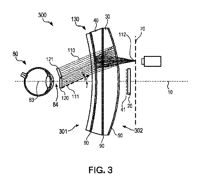
図3及び図4は、本明細書による、光学システムの一部としての中心窩光学レンズの側面図を提供する。図3及び図4は、本質的に同じ光学システムを示すが、眼80は、2つの異なる回転角にある。以下の考察に関して、図3及び図4を一緒に参照すべきである。図3及び図4の両方に共通の同様の番号が付された構成要素は、本明細書において別段の定めがない限り、同じ機能及び説明を有するものとする。
3 and 4 provide side views of a foveal optical lens as part of an optical system in accordance with the present specification. 3 and 4 show essentially the same optical system, but the
光学システム300は、光学システム軸10と、レンズアセンブリ130と、ディスプレイ20とを含む。いくつかの実施形態では、レンズアセンブリ130は、観察者の眼80に近接して配置されるように構成された眼側301と、ディスプレイ20に近接して配置されるように構成されたディスプレイ側302とを有する。いくつかの実施形態では、レンズアセンブリ130は、ディスプレイ20のより近くに配置された第1のレンズ構成要素30と、反対側(すなわち、ディスプレイ20から離れる方に面する側)で第1のレンズ構成要素30に近接して配置された第2のレンズ構成要素40とを含む。いくつかの実施形態では、レンズアセンブリ130は、第1のレンズ構成要素30の、ディスプレイ20に最も近い側(例えば、ディスプレイ側302)に配置された部分反射体50と、第1のレンズ構成要素30と第2のレンズ構成要素40との間に配置された光学リターダと、第2のレンズ構成要素40の、眼80に最も近い側(例えば、眼側301)に配置された反射偏光子60とを更に含んでもよい。いくつかの実施形態では、光学システム300は、ディスプレイ20によって放出された画像41の仮想画像70を観察者の眼80に表示するように構成されている。
いくつかの実施形態では、実質的にコリメートされた光110は、第1の方向111に沿って伝搬する。第1の方向111は、光学システム軸10と第1の角度θ1をなす。いくつかの実施形態では、第1の角度θ1は、約5度~約30度の間であってもよい。実質的にコリメートされた光110が眼側301から光学システム300を照明し、光学システム300に入り、眼側301に近接して配置された視野絞り120/121を実質的に満たすとき、光110は、レンズアセンブリ130を通過し、ディスプレイ側302から光学システム300を出た後、焦点スポット112に集束する。
In some embodiments, substantially collimated light 110 propagates along a
いくつかの実施形態では、眼80が眼位置84に近接して配置されるとき、焦点スポット112は、視野絞り120/121が光学システム軸10の実質的に中心にあるとき(位置120において、眼80を図3に示されるように回転させる)、第1の最小サイズを有してもよく、焦点スポット112は、視野絞り120/121が第1の方向111に実質的に垂直であるように、視野絞り120/121が観察者の眼80の中心に近接する第1の中心83を中心として回転されたとき(位置121において、眼80を図4に示されるように回転させる)、第2の最小サイズを有してもよい。いくつかの実施形態では、第2の最小サイズは、第1の最小サイズよりも小さくてもよい。いくつかの実施形態では、視野絞り120/121の最大寸法は、成人の人間の瞳孔の公称サイズに基づいてもよい。いくつかの実施形態では、視野絞り120/121の最大寸法は、約2ミリメートル(mm)~約8mmであってもよい。
In some embodiments, when the
図5A及び図5Bは、図1の光学システム300などの光学システムの光軸の視覚的描写を提供し、観察者の眼80は、撮像システム軸141を中心とする撮像システム40(例えば、仮想画像に焦点を合わせることができる対物レンズを有するカメラ)に置き換えられている。簡略化のために、本明細書の他の場所で説明され、図2A及び図2Bで行われたように、図1に示されるレンズ(少なくとも1つのレンズ)及びディスプレイは省略されており、したがって、示される部分的光学システムは、300bと再ラベル付けされている。図5A及び図5Bに示される構成要素は、別段の定めがない限り、本明細書の他の図における同様の番号が付された構成要素と共通の機能及び/又は目的を有する。
5A and 5B provide a visual depiction of the optical axis of an optical system, such as
光学システム300bは、光学システム軸10と、ディスプレイ(図1に示されるようなディスプレイ20など)と、少なくとも1つのレンズ(図1に示されるようなレンズ構成要素30及び40など)とを含む。いくつかの実施形態では、光学システム300bは、眼が眼位置84に近接して配置されると、眼(図1に示される眼80など)で観るための仮想画像70を形成してもよい。いくつかの実施形態では、第1の視野角α1における各第1の仮想画像位置71に対して、撮像システム140が撮像システム軸141を中心として眼位置84に近接して配置され、第1の仮想画像位置71に対応する仮想画像70の画像を形成するとき、形成された仮想画像70の解像度は、撮像システム軸141が光学システム軸10と一致する状態から離れて第1の視野角α1に近づくように撮像システム140が回転されるにつれて(すなわち、撮像システム140と第1の視野軸α1における第1の仮想画像位置71との間に延びる第1の視野軸72と実質的に一致するように上方に回転して近づくにつれて)増加し得る。
図6A及び図6Bは、具体的に規定された表面曲線を有するレンズを含む光学システムの一実施形態の詳細を提供する。光学システム400は、図1及び図4の光学システム300、図2A及び図2Bの光学システム300a、並びに図5A及び図5Bの光学システム300bを含む、本明細書で論じられた光学システムのうちのいずれかであってもよい。
6A and 6B provide details of one embodiment of an optical system that includes a lens with a specifically defined surface curve.
いくつかの実施形態では、光学システム400は、第1の光学レンズ40と、第2の光学レンズ30とを含んでもよい。いくつかの実施形態では、第1の光学レンズ40は、第1の主面41と、反対向きの第2の主面42とを含む。いくつかの実施形態では、第2の光学レンズ30は、第3の主面31と、反対向きの第4の主面32とを含む。いくつかの実施形態では、第1の光学レンズ40の第2の主面42と第3の主面31とは互いに面している。いくつかの実施形態では、第1の主面41は、環状の凹状外側部分44によって囲まれた凸状の中央部分43を有してもよい。図6Bは、一実施形態について、凸状の中央部分43及び環状の凹状外側部分44を識別する第1の主面41の正面図を提供する。いくつかの実施形態では、第2の主面42は、凸状であってもよく、第3の主面は、実質的に平坦であってもよく、第4の主面は、凸状であってもよい。
In some embodiments,
いくつかの実施形態では、光学システム400は、部分反射体50(例えば、50/50ビームスプリッタコーティング又はフィルム)、反射偏光子60、及び光学リターダ90(例えば、1/4波長板)のうちの1つ以上を更に含んでもよい。このような実施形態では、部分反射体50は、第2の光学レンズ30の第4の主面32上に配置されてもよく、反射偏光子は、第1の光学レンズ40の第2の主面42上に配置されてもよく、光学リターダ90は、第1の光学レンズ40の第2の主面42と第2の光学レンズ30の第3の主面31との間に配置されてもよい。部分反射体50、反射偏光子60、及び光学リターダ90のうちの1つ以上が存在するこのような実施形態では、光学システム軸10は、図6Aの光路85によって示されるように、折り曲げられてもよい(例えば、レンズ及び反射フィルムの1つ以上の表面から1回以上反射される)。すなわち、ディスプレイ20の画像41によって放出された光85は、光学感知システム145(例えば、図5の140などの撮像システム、又は図1に示されるような観察者80の眼)に到達する前に、光学システム400を通過して複数回方向転換されてもよい。
In some embodiments,
いくつかの実施形態では、第1の主面(41)、第2の主面(42)、第3の主面(31)、第4の主面(32)は、サグS1~S4をそれぞれ有してもよく、サグの各々は、以下によって定義され、

図7Bは、図7Aで使用されたサグsの定義を提供する。本明細書で使用される場合、サグsは、レンズの凸曲率又は凹曲率のいずれかに適用され、曲線に沿った頂点(曲線の最高点又は最低点)と曲線に垂直に引かれた線99の中心点との間の物理的距離rを表す。サグsは、曲線上の所与の点についてのサジタルデプスと呼ばれることもある。 FIG. 7B provides the definition of sag s used in FIG. 7A. As used herein, sag applies to either convex or concave curvature of a lens, between the apex along the curve (the highest or lowest point of the curve) and a line drawn perpendicular to the curve. represents the physical distance r between the center point of 99. Sag s is sometimes referred to as the sagittal depth for a given point on the curve.
最後に、図8A及び図8Bは、図6Aの第1の光学レンズ40及び第2の光学レンズ30の主曲線のサグ値のいくつかの間の関係を定義する。図8Aは、光学システムの一実施形態に関するS1/S2(すなわち、第1の主面41のS1サグを第2の主面42のS2サグで除算したもの)のプロットを示す。図8Aは、S1/S4(すなわち、第1の主面41のS1サグを第4の主面32のS4サグで除算したもの)のプロットを示す。いくつかの実施形態では、約1mmから少なくとも約25mmに及ぶrの値について、
-0.7≦S1/S2≦1及び-0.2≦S1/S4≦0.4である。
Finally, FIGS. 8A and 8B define the relationship between some of the sag values of the principal curves of the first
-0.7≦S1/S2≦1 and -0.2≦S1/S4≦0.4.
いくつかの実施形態では、S1/S2及びS1/S4の各々に対する最良の4次多項式フィッティングは、約0.95よりも大きいr二乗値を有する。例えば、図8Bに示される最良の4次多項式フィッティングのプロット(S1/S4のプロットと実質的に同一)を参照されたい。 In some embodiments, the best fourth-order polynomial fit for each of S1/S2 and S1/S4 has an r-squared value greater than about 0.95. See, for example, the plot of the best fourth-order polynomial fit shown in FIG. 8B (substantially identical to the S1/S4 plot).
「約(about)」などの用語は、これらが本明細書に使用及び記載されている文脈において、当業者によって理解されよう。特徴部のサイズ、量、及び物理的特性を表す量に適用される「約」の使用が、本明細書に使用及び記載されている文脈において、当業者にとって別途明らかではない場合、「約」とは、特定の値の10パーセント以内を意味すると理解されよう。特定の値の約、ほぼとして与えられる量は、正確に特定の値であり得る。例えば、それが本明細書で使用及び記載されている文脈において当業者にとって別途明らかではない場合には、約1の値を有する量とは、その量が0.9~1.1の値を有すること、及び、その値が1である場合もあることを意味する。 Terms such as "about" will be understood by those skilled in the art in the context in which they are used and described herein. When the use of "about" as applied to quantities describing the size, quantity, and physical properties of a feature is not otherwise apparent to a person skilled in the art in the context of its use and description herein, "about" will be understood to mean within 10 percent of a specified value. A quantity given as about or approximately a particular value may be exactly the particular value. For example, unless it is otherwise clear to a person skilled in the art in the context of use and description herein, an amount having a value of about 1 means that the amount has a value between 0.9 and 1.1. It means that it has and its value may be 1.
「実質的に(substantially)」などの用語は、これらが本明細書に使用及び記載されている文脈において、当業者によって理解されよう。「実質的に等しい(substantially equal)」の使用が、本明細書に使用及び記載されている文脈において、当業者にとって明らかではない場合、「実質的に等しい」は、ほぼ等しいことを意味し、ほぼ(about)は上記のとおりである。「実質的に平行(substantially parallel)」の使用が、本明細書に使用及び記載されている文脈において、当業者にとって明らかではない場合、「実質的に平行」は、平行の30度以内を意味する。互いに実質的に平行として記載されている方向又は表面は、いくつかの実施形態では、平行の20度以内、若しくは10度以内であり得る、又は平行若しくは名目上平行であり得る。「実質的に整列している(substantially aligned)」の使用が、本明細書に使用及び記載されている文脈において、当業者にとって明らかではない場合、「実質的に整列している」は、整列している対象の幅の20%以内で整列していることを意味する。実質的に整列していると記載されている対象は、いくつかの実施形態では、整列している対象の幅の10%以内又は5%以内で位整列してもよい。 Terms such as "substantially" will be understood by those skilled in the art in the context in which they are used and described herein. If the use of "substantially equal" is not obvious to one of ordinary skill in the art in the context of use and description herein, "substantially equal" means approximately equal; About is as above. If the use of "substantially parallel" is not obvious to one of ordinary skill in the art in the context of its use and description herein, "substantially parallel" means within 30 degrees of parallel. do. Directions or surfaces described as substantially parallel to each other can be within 20 degrees of parallel, or within 10 degrees of parallel, or can be parallel or nominally parallel, in some embodiments. If the use of "substantially aligned" is not obvious to one of ordinary skill in the art in the context of use and description herein, "substantially aligned" means This means that they are aligned within 20% of the width of the object being displayed. Objects described as being substantially aligned may, in some embodiments, be aligned within 10% or within 5% of the width of the objects being aligned.
上記において参照された参照文献、特許、又は特許出願の全ては、それらの全体が参照により本明細書に一貫して組み込まれている。組み込まれた参照文献の一部と本出願との間に不一致又は矛盾がある場合、前述の記載における情報が優先するものとする。 All references, patents, or patent applications referenced above are hereby incorporated by reference in their entirety. In the event of any discrepancy or inconsistency between some of the incorporated references and this application, the information in the foregoing description shall prevail.
図面中の要素の説明は、別段の指示がない限り、他の図面中の対応する要素に等しく適用されるものと理解されたい。特定の実施形態が本明細書において図示及び説明されているが、図示及び記載されている特定の実施形態は、本開示の範囲を逸脱することなく、様々な代替的実施態様及び/又は等価の実施態様によって置き換えられ得ることが、当業者には理解されよう。本出願は、本明細書で論じられた特定の実施形態のいずれの適応例又は変形例も包含することが意図されている。したがって、本開示は、特許請求の範囲及びその均等物によってのみ限定されることが意図されている。
Descriptions of elements in the drawings should be understood to apply equally to corresponding elements in other drawings, unless indicated otherwise. Although specific embodiments are illustrated and described herein, the specific embodiments illustrated and described may be modified from various alternative implementations and/or equivalents without departing from the scope of this disclosure. It will be understood by those skilled in the art that embodiments may be substituted. This application is intended to cover any adaptations or variations of the specific embodiments discussed herein. Accordingly, it is intended that the disclosure be limited only by the claims and their equivalents.
Claims (20)

前記第1の主面は、環状の凹状の外側部分によって囲まれた凸状の中央部分を含み、前記第2の主面は、凸状であり、前記第3の主面は、実質的に平坦であり、前記第4の主面は、凸状であり、
約1mmから少なくとも約25mmに及ぶrについて、
-0.7≦S1/S2≦1、
-0.2≦S1/S4≦0.4であり、
前記S1/S2及びS1/S4の各々に対する最良の4次多項式フィッティングは、約0.95よりも大きいr二乗値を有する、
請求項1に記載の光学システム。 The at least one lens is a first optical lens that includes oppositely oriented first and second major surfaces and faces a second optical lens that includes oppositely oriented third and fourth major surfaces. , a first optical lens, the second and third principal surfaces face each other, the first to fourth principal surfaces have sags S1 to S4, respectively, and each of the sags includes: defined by
The first major surface includes a convex central portion surrounded by an annular concave outer portion, the second major surface is convex, and the third major surface includes a substantially is flat, and the fourth main surface is convex;
For r ranging from about 1 mm to at least about 25 mm,
-0.7≦S1/S2≦1,
-0.2≦S1/S4≦0.4,
the best fourth-order polynomial fit for each of the S1/S2 and S1/S4 has an r-squared value greater than about 0.95;
Optical system according to claim 1.
前記光学システム軸に対して約5度~約30度の第1の角度をなす第1の方向に沿って伝搬する実質的にコリメートされた光が、前記光学システムの前記眼側から前記光学システムを照明し、前記光学システムの前記眼側に近接して配置された視野絞りを通って、かつ前記視野絞りを実質的に満たして、前記光学システムに入射し、前記レンズアセンブリを通過して前記光学システムを前記光学システムの前記ディスプレイ側から出射した後に焦点スポットに集束するとき、前記焦点スポットは、前記視野絞りが前記光学システム軸の実質的に中心にあるときに、第1の最小サイズを有し、前記視野絞りが前記第1の方向に実質的に垂直であるように前記視野絞りが前記観察者の前記眼の中心に近接する第1の中心を中心として回転したときに、第2の最小サイズを有し、前記第2の最小サイズは、前記第1の最小サイズよりも小さい、
光学システム。 an optical system axis; a lens assembly including at least one lens; an eye side configured to be placed proximate an observer's eye; and a display side configured to be placed proximate a display. an optical system configured to display a virtual image of an image emitted by the display to the eye of the observer;
substantially collimated light propagating along a first direction at a first angle of about 5 degrees to about 30 degrees with respect to the optical system axis from the eye side of the optical system to the optical system; enters the optical system through a field stop disposed proximate the eye side of the optical system and substantially fills the field stop, passes through the lens assembly and passes through the lens assembly to the optical system. When focusing the optical system to a focal spot after exiting the display side of the optical system, the focal spot has a first minimum size when the field stop is substantially centered on the optical system axis. a second direction when the field stop is rotated about a first center proximate the center of the eye of the observer such that the field stop is substantially perpendicular to the first direction; the second minimum size is smaller than the first minimum size;
optical system.
前記システム軸に対して約5度~約30度の第1の視野角における各第1の仮想画像位置について、撮像システム軸を中心とする撮像システムが前記眼位置に近接して配置され、前記第1の仮想画像位置に対応する前記仮想画像の形成画像を形成するとき、前記撮像システム軸が前記第1の視野角に近づくように前記撮像システムが少なくとも回転されるにつれて、前記形成画像の解像度が増加する、
光学システム。 an optical system comprising an optical system axis, a display, and at least one lens for viewing with the eye when the eye is positioned proximate an eye position on the eye side of the optical system; form a virtual image of the image emitted by,
For each first virtual image location at a first viewing angle of about 5 degrees to about 30 degrees with respect to the system axis, an imaging system centered on the imaging system axis is positioned proximate to the eye location; When forming a formed image of the virtual image corresponding to a first virtual image position, as the imaging system is rotated at least such that the imaging system axis approaches the first viewing angle, the resolution of the formed image increases,
optical system.
第1の仮想画像位置及び約5度~約30度の間である関連する第1の視野角における前記仮想画像の第1の網膜像は、前記眼軸が前記システム軸と実質的に一致するとき、第1の画像解像度を有し、
前記眼軸が前記第1の視野角において前記眼と前記仮想画像との間に延びる第1の視野軸と実質的に一致するように前記眼が回転されたとき、第2の画像解像度を有し、前記第2の画像解像度は、前記第1の画像解像度よりも大きい、
光学システム。 An optical system comprising an optical system axis, a display, at least one lens, a partial reflector, and a reflective polarizer, the optical system forming a virtual image of an image emitted by the display for viewing by the eye. , the eye has an optical axis extending from the center of the fovea of the eye to the center of the pupil of the eye;
a first retinal image of the virtual image at a first virtual image position and an associated first viewing angle that is between about 5 degrees and about 30 degrees, the eye axis substantially coinciding with the system axis; has a first image resolution,
a second image resolution when the eye is rotated such that the eye axis substantially coincides with a first viewing axis extending between the eye and the virtual image at the first viewing angle; and the second image resolution is greater than the first image resolution.
optical system.
18. The optical system of claim 17, wherein the optical system axis is folded such that a first segment of the system axis substantially coincides with a different second segment of the system axis.
Applications Claiming Priority (3)
| Application Number | Priority Date | Filing Date | Title |
|---|---|---|---|
| US202163200142P | 2021-02-17 | 2021-02-17 | |
| US63/200,142 | 2021-02-17 | ||
| PCT/IB2022/051334 WO2022175813A1 (en) | 2021-02-17 | 2022-02-15 | Foveated optical lens for near eye display |
Publications (2)
| Publication Number | Publication Date |
|---|---|
| JP2024506407A true JP2024506407A (en) | 2024-02-13 |
| JPWO2022175813A5 JPWO2022175813A5 (en) | 2025-02-21 |
Family
ID=80461290
Family Applications (1)
| Application Number | Title | Priority Date | Filing Date |
|---|---|---|---|
| JP2023549543A Pending JP2024506407A (en) | 2021-02-17 | 2022-02-15 | Foveal optical lens for near eye display |
Country Status (6)
| Country | Link |
|---|---|
| US (1) | US20240310630A1 (en) |
| EP (1) | EP4295193A1 (en) |
| JP (1) | JP2024506407A (en) |
| CN (1) | CN116802545A (en) |
| TW (1) | TW202246842A (en) |
| WO (1) | WO2022175813A1 (en) |
Families Citing this family (2)
| Publication number | Priority date | Publication date | Assignee | Title |
|---|---|---|---|---|
| CN117310981A (en) * | 2022-06-22 | 2023-12-29 | 北京字跳网络技术有限公司 | Optical systems and display devices |
| CN116594170B (en) * | 2023-05-23 | 2026-01-02 | 浙江舜宇光学有限公司 | Visual system and VR device including the visual system |
Citations (5)
| Publication number | Priority date | Publication date | Assignee | Title |
|---|---|---|---|---|
| US20170269368A1 (en) * | 2015-09-03 | 2017-09-21 | 3M Innovative Properties Company | Optical stack and optical system |
| JP2018510372A (en) * | 2015-01-21 | 2018-04-12 | テッセランド・エルエルシーTesseland Llc | Imaging optics adapted to human eye resolution |
| US20190086679A1 (en) * | 2017-09-19 | 2019-03-21 | Intel Corporation | Head-mounted displays having curved lens arrays and generating elemental images for displaying |
| JP2019207342A (en) * | 2018-05-30 | 2019-12-05 | キヤノン株式会社 | Observation optical system and observation device including the same |
| JP2020519964A (en) * | 2017-05-16 | 2020-07-02 | スリーエム イノベイティブ プロパティズ カンパニー | Optical system |
Family Cites Families (2)
| Publication number | Priority date | Publication date | Assignee | Title |
|---|---|---|---|---|
| US9993335B2 (en) * | 2014-01-08 | 2018-06-12 | Spy Eye, Llc | Variable resolution eye mounted displays |
| KR102594527B1 (en) * | 2018-04-27 | 2023-10-25 | 테세랜드 엘엘씨 | Human vision adaptive light field display |
-
2022
- 2022-02-15 JP JP2023549543A patent/JP2024506407A/en active Pending
- 2022-02-15 EP EP22706403.7A patent/EP4295193A1/en active Pending
- 2022-02-15 CN CN202280012308.0A patent/CN116802545A/en active Pending
- 2022-02-15 WO PCT/IB2022/051334 patent/WO2022175813A1/en not_active Ceased
- 2022-02-15 US US18/274,303 patent/US20240310630A1/en active Pending
- 2022-02-17 TW TW111105832A patent/TW202246842A/en unknown
Patent Citations (5)
| Publication number | Priority date | Publication date | Assignee | Title |
|---|---|---|---|---|
| JP2018510372A (en) * | 2015-01-21 | 2018-04-12 | テッセランド・エルエルシーTesseland Llc | Imaging optics adapted to human eye resolution |
| US20170269368A1 (en) * | 2015-09-03 | 2017-09-21 | 3M Innovative Properties Company | Optical stack and optical system |
| JP2020519964A (en) * | 2017-05-16 | 2020-07-02 | スリーエム イノベイティブ プロパティズ カンパニー | Optical system |
| US20190086679A1 (en) * | 2017-09-19 | 2019-03-21 | Intel Corporation | Head-mounted displays having curved lens arrays and generating elemental images for displaying |
| JP2019207342A (en) * | 2018-05-30 | 2019-12-05 | キヤノン株式会社 | Observation optical system and observation device including the same |
Also Published As
| Publication number | Publication date |
|---|---|
| WO2022175813A1 (en) | 2022-08-25 |
| CN116802545A (en) | 2023-09-22 |
| US20240310630A1 (en) | 2024-09-19 |
| EP4295193A1 (en) | 2023-12-27 |
| TW202246842A (en) | 2022-12-01 |
Similar Documents
| Publication | Publication Date | Title |
|---|---|---|
| KR102192942B1 (en) | Optical device for augmented reality having improved light efficiency | |
| JP6994940B2 (en) | Head-mounted imaging device using optical coupling | |
| JP6895258B2 (en) | Near-eye display system with pellicle as a combiner | |
| JP2021060625A (en) | Spectacle lens for display device that can be fitted on head of user and generates image | |
| JP6697455B2 (en) | Head-mounted viewing system including crossed optics | |
| JP6637881B2 (en) | A spectacle lens for a display device that generates an image and that can be mounted on the user's head, and a display device including the spectacle lens | |
| TWI531817B (en) | Virtual image display module and optical lens | |
| JP6670431B2 (en) | Imaging optics and smart glasses | |
| JP2013532297A (en) | Embedded lattice structure | |
| KR20210006980A (en) | Optical device with light guide for head mounted display | |
| KR102255781B1 (en) | Compatct type optical device for augmented reality | |
| CN109073896B (en) | Spectacle lenses for imaging optical units and data goggles | |
| CN107966821A (en) | Augmented reality glasses | |
| JP6812649B2 (en) | Image display device | |
| CN111328380A (en) | Head-mounted display and method for designing wide-focus lens used in head-mounted display | |
| CN114341708A (en) | Optical device for improving optical efficiency | |
| CN101424787A (en) | Virtual image display device for combined optical application of semi-reflection and refraction optical effect | |
| JP2024506407A (en) | Foveal optical lens for near eye display | |
| EP2947498A1 (en) | Display device | |
| US12276791B2 (en) | Optical apparatus for augmented reality with vision correction function | |
| KR102438997B1 (en) | Optical device for augmented reality with vision correction function | |
| KR20130116548A (en) | Optical system for see-through type head mounted display | |
| CN113366376B (en) | Enhanced on-the-fly optical device capable of providing enhanced on-the-fly images at close range | |
| JP7202740B2 (en) | Compact augmented reality optical device | |
| TWI677711B (en) | System for augmented reality-image |
Legal Events
| Date | Code | Title | Description |
|---|---|---|---|
| A521 | Request for written amendment filed |
Free format text: JAPANESE INTERMEDIATE CODE: A523 Effective date: 20250212 |
|
| A621 | Written request for application examination |
Free format text: JAPANESE INTERMEDIATE CODE: A621 Effective date: 20250212 |
|
| A131 | Notification of reasons for refusal |
Free format text: JAPANESE INTERMEDIATE CODE: A131 Effective date: 20251104 |
|
| A521 | Request for written amendment filed |
Free format text: JAPANESE INTERMEDIATE CODE: A523 Effective date: 20260203 |