JP2024506333A - Tissue anchors and techniques for their use - Google Patents
Tissue anchors and techniques for their use Download PDFInfo
- Publication number
- JP2024506333A JP2024506333A JP2023547859A JP2023547859A JP2024506333A JP 2024506333 A JP2024506333 A JP 2024506333A JP 2023547859 A JP2023547859 A JP 2023547859A JP 2023547859 A JP2023547859 A JP 2023547859A JP 2024506333 A JP2024506333 A JP 2024506333A
- Authority
- JP
- Japan
- Prior art keywords
- anchor
- tissue
- tether
- applications
- tube
- Prior art date
- Legal status (The legal status is an assumption and is not a legal conclusion. Google has not performed a legal analysis and makes no representation as to the accuracy of the status listed.)
- Granted
Links
Images


Classifications
-
- A—HUMAN NECESSITIES
- A61—MEDICAL OR VETERINARY SCIENCE; HYGIENE
- A61B—DIAGNOSIS; SURGERY; IDENTIFICATION
- A61B17/00—Surgical instruments, devices or methods
- A61B17/04—Surgical instruments, devices or methods for suturing wounds; Holders or packages for needles or suture materials
- A61B17/0401—Suture anchors, buttons or pledgets, i.e. means for attaching sutures to bone, cartilage or soft tissue; Instruments for applying or removing suture anchors
-
- A—HUMAN NECESSITIES
- A61—MEDICAL OR VETERINARY SCIENCE; HYGIENE
- A61F—FILTERS IMPLANTABLE INTO BLOOD VESSELS; PROSTHESES; DEVICES PROVIDING PATENCY TO, OR PREVENTING COLLAPSING OF, TUBULAR STRUCTURES OF THE BODY, e.g. STENTS; ORTHOPAEDIC, NURSING OR CONTRACEPTIVE DEVICES; FOMENTATION; TREATMENT OR PROTECTION OF EYES OR EARS; BANDAGES, DRESSINGS OR ABSORBENT PADS; FIRST-AID KITS
- A61F2/00—Filters implantable into blood vessels; Prostheses, i.e. artificial substitutes or replacements for parts of the body; Appliances for connecting them with the body; Devices providing patency to, or preventing collapsing of, tubular structures of the body, e.g. stents
- A61F2/02—Prostheses implantable into the body
- A61F2/24—Heart valves ; Vascular valves, e.g. venous valves; Heart implants, e.g. passive devices for improving the function of the native valve or the heart muscle; Transmyocardial revascularisation [TMR] devices; Valves implantable in the body
- A61F2/2442—Annuloplasty rings or inserts for correcting the valve shape; Implants for improving the function of a native heart valve
-
- A—HUMAN NECESSITIES
- A61—MEDICAL OR VETERINARY SCIENCE; HYGIENE
- A61B—DIAGNOSIS; SURGERY; IDENTIFICATION
- A61B17/00—Surgical instruments, devices or methods
- A61B17/04—Surgical instruments, devices or methods for suturing wounds; Holders or packages for needles or suture materials
- A61B17/0467—Instruments for cutting sutures
-
- A—HUMAN NECESSITIES
- A61—MEDICAL OR VETERINARY SCIENCE; HYGIENE
- A61B—DIAGNOSIS; SURGERY; IDENTIFICATION
- A61B17/00—Surgical instruments, devices or methods
- A61B17/04—Surgical instruments, devices or methods for suturing wounds; Holders or packages for needles or suture materials
- A61B17/0487—Suture clamps, clips or locks, e.g. for replacing suture knots; Instruments for applying or removing suture clamps, clips or locks
-
- A—HUMAN NECESSITIES
- A61—MEDICAL OR VETERINARY SCIENCE; HYGIENE
- A61F—FILTERS IMPLANTABLE INTO BLOOD VESSELS; PROSTHESES; DEVICES PROVIDING PATENCY TO, OR PREVENTING COLLAPSING OF, TUBULAR STRUCTURES OF THE BODY, e.g. STENTS; ORTHOPAEDIC, NURSING OR CONTRACEPTIVE DEVICES; FOMENTATION; TREATMENT OR PROTECTION OF EYES OR EARS; BANDAGES, DRESSINGS OR ABSORBENT PADS; FIRST-AID KITS
- A61F2/00—Filters implantable into blood vessels; Prostheses, i.e. artificial substitutes or replacements for parts of the body; Appliances for connecting them with the body; Devices providing patency to, or preventing collapsing of, tubular structures of the body, e.g. stents
- A61F2/02—Prostheses implantable into the body
- A61F2/24—Heart valves ; Vascular valves, e.g. venous valves; Heart implants, e.g. passive devices for improving the function of the native valve or the heart muscle; Transmyocardial revascularisation [TMR] devices; Valves implantable in the body
- A61F2/2442—Annuloplasty rings or inserts for correcting the valve shape; Implants for improving the function of a native heart valve
- A61F2/2445—Annuloplasty rings in direct contact with the valve annulus
-
- A—HUMAN NECESSITIES
- A61—MEDICAL OR VETERINARY SCIENCE; HYGIENE
- A61F—FILTERS IMPLANTABLE INTO BLOOD VESSELS; PROSTHESES; DEVICES PROVIDING PATENCY TO, OR PREVENTING COLLAPSING OF, TUBULAR STRUCTURES OF THE BODY, e.g. STENTS; ORTHOPAEDIC, NURSING OR CONTRACEPTIVE DEVICES; FOMENTATION; TREATMENT OR PROTECTION OF EYES OR EARS; BANDAGES, DRESSINGS OR ABSORBENT PADS; FIRST-AID KITS
- A61F2/00—Filters implantable into blood vessels; Prostheses, i.e. artificial substitutes or replacements for parts of the body; Appliances for connecting them with the body; Devices providing patency to, or preventing collapsing of, tubular structures of the body, e.g. stents
- A61F2/02—Prostheses implantable into the body
- A61F2/24—Heart valves ; Vascular valves, e.g. venous valves; Heart implants, e.g. passive devices for improving the function of the native valve or the heart muscle; Transmyocardial revascularisation [TMR] devices; Valves implantable in the body
- A61F2/2442—Annuloplasty rings or inserts for correcting the valve shape; Implants for improving the function of a native heart valve
- A61F2/246—Devices for obstructing a leak through a native valve in a closed condition
-
- A—HUMAN NECESSITIES
- A61—MEDICAL OR VETERINARY SCIENCE; HYGIENE
- A61B—DIAGNOSIS; SURGERY; IDENTIFICATION
- A61B17/00—Surgical instruments, devices or methods
- A61B17/00234—Surgical instruments, devices or methods for minimally invasive surgery
- A61B2017/00238—Type of minimally invasive operation
- A61B2017/00243—Type of minimally invasive operation cardiac
-
- A—HUMAN NECESSITIES
- A61—MEDICAL OR VETERINARY SCIENCE; HYGIENE
- A61B—DIAGNOSIS; SURGERY; IDENTIFICATION
- A61B17/00—Surgical instruments, devices or methods
- A61B17/04—Surgical instruments, devices or methods for suturing wounds; Holders or packages for needles or suture materials
- A61B17/0401—Suture anchors, buttons or pledgets, i.e. means for attaching sutures to bone, cartilage or soft tissue; Instruments for applying or removing suture anchors
- A61B2017/0409—Instruments for applying suture anchors
-
- A—HUMAN NECESSITIES
- A61—MEDICAL OR VETERINARY SCIENCE; HYGIENE
- A61B—DIAGNOSIS; SURGERY; IDENTIFICATION
- A61B17/00—Surgical instruments, devices or methods
- A61B17/04—Surgical instruments, devices or methods for suturing wounds; Holders or packages for needles or suture materials
- A61B17/0401—Suture anchors, buttons or pledgets, i.e. means for attaching sutures to bone, cartilage or soft tissue; Instruments for applying or removing suture anchors
- A61B2017/0414—Suture anchors, buttons or pledgets, i.e. means for attaching sutures to bone, cartilage or soft tissue; Instruments for applying or removing suture anchors having a suture-receiving opening, e.g. lateral opening
-
- A—HUMAN NECESSITIES
- A61—MEDICAL OR VETERINARY SCIENCE; HYGIENE
- A61B—DIAGNOSIS; SURGERY; IDENTIFICATION
- A61B17/00—Surgical instruments, devices or methods
- A61B17/04—Surgical instruments, devices or methods for suturing wounds; Holders or packages for needles or suture materials
- A61B17/0401—Suture anchors, buttons or pledgets, i.e. means for attaching sutures to bone, cartilage or soft tissue; Instruments for applying or removing suture anchors
- A61B2017/0417—T-fasteners
-
- A—HUMAN NECESSITIES
- A61—MEDICAL OR VETERINARY SCIENCE; HYGIENE
- A61B—DIAGNOSIS; SURGERY; IDENTIFICATION
- A61B17/00—Surgical instruments, devices or methods
- A61B17/04—Surgical instruments, devices or methods for suturing wounds; Holders or packages for needles or suture materials
- A61B17/0401—Suture anchors, buttons or pledgets, i.e. means for attaching sutures to bone, cartilage or soft tissue; Instruments for applying or removing suture anchors
- A61B2017/0427—Suture anchors, buttons or pledgets, i.e. means for attaching sutures to bone, cartilage or soft tissue; Instruments for applying or removing suture anchors having anchoring barbs or pins extending outwardly from the anchor body
- A61B2017/0437—Suture anchors, buttons or pledgets, i.e. means for attaching sutures to bone, cartilage or soft tissue; Instruments for applying or removing suture anchors having anchoring barbs or pins extending outwardly from the anchor body the barbs being resilient or spring-like
-
- A—HUMAN NECESSITIES
- A61—MEDICAL OR VETERINARY SCIENCE; HYGIENE
- A61B—DIAGNOSIS; SURGERY; IDENTIFICATION
- A61B17/00—Surgical instruments, devices or methods
- A61B17/04—Surgical instruments, devices or methods for suturing wounds; Holders or packages for needles or suture materials
- A61B17/0401—Suture anchors, buttons or pledgets, i.e. means for attaching sutures to bone, cartilage or soft tissue; Instruments for applying or removing suture anchors
- A61B2017/044—Suture anchors, buttons or pledgets, i.e. means for attaching sutures to bone, cartilage or soft tissue; Instruments for applying or removing suture anchors with a threaded shaft, e.g. screws
- A61B2017/0441—Suture anchors, buttons or pledgets, i.e. means for attaching sutures to bone, cartilage or soft tissue; Instruments for applying or removing suture anchors with a threaded shaft, e.g. screws the shaft being a rigid coil or spiral
-
- A—HUMAN NECESSITIES
- A61—MEDICAL OR VETERINARY SCIENCE; HYGIENE
- A61B—DIAGNOSIS; SURGERY; IDENTIFICATION
- A61B17/00—Surgical instruments, devices or methods
- A61B17/04—Surgical instruments, devices or methods for suturing wounds; Holders or packages for needles or suture materials
- A61B17/0487—Suture clamps, clips or locks, e.g. for replacing suture knots; Instruments for applying or removing suture clamps, clips or locks
- A61B2017/0488—Instruments for applying suture clamps, clips or locks
-
- A—HUMAN NECESSITIES
- A61—MEDICAL OR VETERINARY SCIENCE; HYGIENE
- A61B—DIAGNOSIS; SURGERY; IDENTIFICATION
- A61B17/00—Surgical instruments, devices or methods
- A61B17/04—Surgical instruments, devices or methods for suturing wounds; Holders or packages for needles or suture materials
- A61B2017/0496—Surgical instruments, devices or methods for suturing wounds; Holders or packages for needles or suture materials for tensioning sutures
-
- A—HUMAN NECESSITIES
- A61—MEDICAL OR VETERINARY SCIENCE; HYGIENE
- A61B—DIAGNOSIS; SURGERY; IDENTIFICATION
- A61B17/00—Surgical instruments, devices or methods
- A61B17/064—Surgical staples, i.e. penetrating the tissue
- A61B2017/0645—Surgical staples, i.e. penetrating the tissue being elastically deformed for insertion
Landscapes
- Health & Medical Sciences (AREA)
- Life Sciences & Earth Sciences (AREA)
- Surgery (AREA)
- Biomedical Technology (AREA)
- Public Health (AREA)
- Engineering & Computer Science (AREA)
- Heart & Thoracic Surgery (AREA)
- Veterinary Medicine (AREA)
- Animal Behavior & Ethology (AREA)
- General Health & Medical Sciences (AREA)
- Cardiology (AREA)
- Medical Informatics (AREA)
- Nuclear Medicine, Radiotherapy & Molecular Imaging (AREA)
- Molecular Biology (AREA)
- Rheumatology (AREA)
- Oral & Maxillofacial Surgery (AREA)
- Vascular Medicine (AREA)
- Transplantation (AREA)
- Surgical Instruments (AREA)
- Prostheses (AREA)
- Materials For Medical Uses (AREA)
Abstract
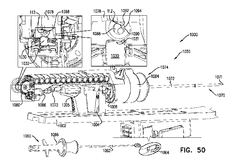
管(1072)の近位端に結合される体外ユニット(1074)は、配備位置につながる軌道(1080)を含む。一連の各カートリッジ(1020)は、それぞれのアンカー(120)を保持し、それぞれの初期位置で体外ユニットに結合される。各カートリッジが、カートリッジが近位開口部の反対側のそれぞれのアンカーを保持するように、配備位置まで軌道に沿って移動可能である。アンカードライバー(1060)は、(i)各アンカーが、配備位置にあるそれぞれのカートリッジによって近位開口部の反対側に保持される間、アンカーに力を加え、(ii)アンカーをそれぞれのカートリッジから遠位に近位開口部を通して、前進させるように構成される。
Extracorporeal unit (1074) coupled to the proximal end of tube (1072) includes a track (1080) leading to a deployment position. Each cartridge (1020) in the series carries a respective anchor (120) and is coupled to the extracorporeal unit in a respective initial position. Each cartridge is moveable along the track to a deployed position such that the cartridge retains a respective anchor on opposite sides of the proximal opening. Anchor driver (1060) (i) applies a force to the anchors while each anchor is held opposite the proximal opening by the respective cartridge in the deployed position, and (ii) removes the anchor from the respective cartridge. The device is configured to be advanced distally through the proximal opening.
Description
関連出願への相互参照
本出願は、以下の優先権を主張する。2021年2月9日に出願され、「Tissue anchors and techniques for use therewith」と題された、Shafigh等による米国仮特許出願第63/147,699号、および2021年3月17日に出願され、「Tissue anchors and techniques for use therewith」と題された、Shafigh等による米国仮特許出願第63/162,443号。
CROSS REFERENCES TO RELATED APPLICATIONS This application claims the following priority rights: U.S. Provisional Patent Application No. 63/147,699 by Shafigh et al., filed on February 9, 2021 and entitled “Tissue anchors and techniques for use therewith,” and filed on March 17, 2021; U.S. Provisional Patent Application No. 63/162,443 by Shafig et al., entitled "Tissue anchors and techniques for use therewith."
上記出願の各々が、参照により本明細書に組み込まれる。 Each of the above applications is incorporated herein by reference.
弁輪形成術は、弁輪の組織リモデリングすることを含む。これは、弁輪の周りの組織を引っ張って新しい形状にすることによって行うことができる。組織アンカーを用いて、弁輪形成術、組織の他のリモデリング、インプラントを固定することを含む医療処置を容易にすることができる。場合によっては、組織アンカーが、縫合糸の代替として使用されることができる。例えば、組織アンカーが、標的への見通し線がない処置に使用され得る。 Annuloplasty involves tissue remodeling of the valve annulus. This can be done by pulling the tissue around the valve annulus into a new shape. Tissue anchors can be used to facilitate medical procedures including annuloplasty, other remodeling of tissue, and securing implants. In some cases, tissue anchors can be used as an alternative to sutures. For example, tissue anchors may be used in procedures where there is no line of sight to the target.
本概要は、一部の例を提供することを意図しており、範囲をいかようにも制限することを目的としていない。例えば、本概要の一例に含まれるいかなる特徴も、特許請求の範囲がそれらの特徴を明示的に列挙しない限り、特許請求の範囲によって要求されない。また、本概要および本開示の他の箇所における例で説明される特徴、構成要素、ステップ、概念などは、さまざまに組み合わせることができる。本開示の他の箇所に記載されるさまざまな特徴およびステップは、本明細書に要約される例に含まれ得る。 This summary is intended to provide some examples and is not intended to limit the scope in any way. For example, no feature included in the Exemplary Summary is required by a claim unless the claim explicitly recite those features. Additionally, the features, components, steps, concepts, etc. described in the examples in this Summary and elsewhere in this disclosure may be combined in various ways. Various features and steps described elsewhere in this disclosure may be included in the examples summarized herein.
本明細書に記載されるシステム、装置、および技術の一部、ならびにその適用は、テザーまたは収縮部材などに摺動可能に結合される複数の組織アンカーを含むインプラントとともに使用されるか、または使用されるように構成される。インプラントが、テザーなどの張力によって組織を収縮させる組織調整インプラントとすることができる。インプラントが、対象の心臓で使用するためのものであり得る。例えば、インプラントが、弁輪形成インプラントとすることができる。 Some of the systems, devices, and techniques described herein, and applications thereof, may be used with or used with implants that include a plurality of tissue anchors slidably coupled to a tether or retractable member, etc. configured to be used. The implant can be a tissue conditioning implant that contracts tissue through tension, such as a tether. The implant may be for use in the subject's heart. For example, the implant can be an annuloplasty implant.
いくつかの適用例は、テザー(例えば、線、ワイヤ、リボン、ロープ、編組、収縮部材、縫合糸など)に沿って、(i)テザーと整列している間(すなわち、平行または同軸)、および(ii)テザーに直交して配向している間、摺動可能であるように構成される(例えば、形状される)組織アンカーに関する。これは、特に、(i)経カテーテル送達中にテザーと整列しながら、テザーに沿ってアンカーを前進させること、および(ii)例えば、テザーがアンカーに直交している間、移植後のアンカーに対するテザーがその後摺動すること、を容易にすると考えられる。 Some applications include: along the tether (e.g., line, wire, ribbon, rope, braid, constrictor, suture, etc.) (i) while aligned (i.e., parallel or coaxial) with the tether; and (ii) relates to a tissue anchor configured (e.g., shaped) to be slidable while oriented orthogonally to the tether. This includes, among other things, (i) advancing the anchor along the tether while aligning with the tether during transcatheter delivery, and (ii) e.g. It is believed that this facilitates the subsequent sliding of the tether.
組織アンカーが、(i)組織係合要素と、(ii)および組織係合要素の近位端にヘッドとを含み得る。ヘッドが、それを通して開口を画定する、アイレットまたは他のコネクターを画定することができる。 The tissue anchor may include (i) a tissue-engaging element; and (ii) a head at a proximal end of the tissue-engaging element. The head may define an eyelet or other connector defining an opening therethrough.
さまざまな異なる組織係合要素構成が、本開示に記載されるさまざまなアンカーのいずれかに対して可能である。いくつかの適用例では、組織係合要素が、軸を有するらせんとして形状付けられ、軸に沿って中央ルーメンを画定し、軸に沿って組織にねじ込まれるように構成され得る。いくつかの適用例では、組織係合要素が、組織に軸方向に押し込まれてもよく、一部の状況では、組織係合要素を組織内に保持するための有刺または有刺部分を含み得る。いくつかの適用例では、組織係合要素が、フックまたは複数のフックを含み得る。いくつかの適用例では、組織係合要素が、クランプ、クリップ、ピンチ装置、ダーツ、ステープル、尖叉などのうちの一つまたは複数を含み得る。他の組織係合要素またはアンカーの一部も可能である。 A variety of different tissue-engaging element configurations are possible for any of the various anchors described in this disclosure. In some applications, the tissue-engaging element may be shaped as a helix having an axis, defining a central lumen along the axis, and configured to be threaded into tissue along the axis. In some applications, the tissue-engaging element may be pushed axially into the tissue, and in some situations may include barbed or barbed portions to retain the tissue-engaging element within the tissue. obtain. In some applications, the tissue engaging element may include a hook or hooks. In some applications, the tissue engagement elements may include one or more of clamps, clips, pinch devices, darts, staples, tines, and the like. Other tissue engaging elements or portions of the anchor are also possible.
アイレットが、組織アンカーの軸から横方向に配置することができる。いくつかの適用例では、アイレットが、(i)アンカーがテザーと平行な時、および(ii)アンカーがテザーに対して直交する配向にあるとき、テザーに沿ってスムーズに摺動することを容易にする様式で回転可能である。アイレットの回転により、アイレットが、テザーに対するアンカーのこれらの配向のそれぞれにおいて、テザーが通過するための、そのアイレットの開口を通るそれぞれのクリアーな直線経路を画定することができる。 An eyelet can be disposed laterally from the axis of the tissue anchor. In some applications, the eyelet facilitates smooth sliding along the tether (i) when the anchor is parallel to the tether, and (ii) when the anchor is in an orthogonal orientation to the tether. It can be rotated in the following manner. Rotation of the eyelet allows the eyelet to define a respective clear straight path through the opening of the eyelet for the tether to pass through in each of these orientations of the anchor relative to the tether.
いくつかの適用例では、一つまたは複数のスペーサーまたはディバイダー(例えば、管、固体壁管、レーザー切断管、ロッドコイル、ばねなど)が、アンカー間にテザーを通される。一部のこうした適用例では、アイレットが、アンカーの安全で安定した間隔および/またはアンカー間の力の分布を提供するために、スペーサーまたはディバイダーが当接する平面を画定する。 In some applications, one or more spacers or dividers (eg, tubes, solid wall tubes, laser cut tubes, rod coils, springs, etc.) are threaded between the anchors with the tether. In some such applications, the eyelets define a plane against which the spacers or dividers abut to provide safe and stable spacing of the anchors and/or force distribution between the anchors.
いくつかの適用例では、組織アンカーは組織係合要素およびヘッドを含む。アンカードライバーが、ヘッドでアンカーと係合し(例えば、ヘッドに可逆的に取り付けられる)、組織係合要素を組織に入れることができる。組織係合要素が、本明細書の他の組織係合要素と同一または類似であり得る。 In some applications, the tissue anchor includes a tissue engaging element and a head. An anchor driver can engage the anchor at the head (eg, be reversibly attached to the head) and drive the tissue engaging element into tissue. The tissue engaging element can be the same or similar to other tissue engaging elements herein.
いくつかの適用例では、カテーテル装置が、アンカー(例えば、テザーを通されたアンカーを含むインプラント)の前進および固定のために提供される。カテーテル装置が、管および体外ユニットを含むことができ、体外ユニット上に取り付けられる一連のカートリッジが、アンカーを保持して、ドライバーが管を通して前進するために、アンカーの各々を順次、管の近位開口部に運ぶことを容易にすることができる。体外ユニットが、カートリッジとともに、ドライバーとアンカーとの間の係合の検証を容易にするバリアを含んでもよく、こうした検証がない場合にアンカーの前進を妨害し得る。 In some applications, a catheter device is provided for advancement and fixation of an anchor (eg, an implant that includes a tethered anchor). A catheter device can include a tube and an extracorporeal unit, and a series of cartridges mounted on the extracorporeal unit hold the anchors and move each of the anchors in turn proximal to the tube for advancement through the tube by a driver. It can be easily carried into the opening. The extracorporeal unit may include a barrier, along with the cartridge, that facilitates verification of engagement between the driver and the anchor, and may impede advancement of the anchor in the absence of such verification.
いくつかの適用例では、アンカーが、組織に面した開口部を有する筐体を含み、組織係合要素はらせん状であり、組織に面した開口部が組織に面している間、筐体に対する組織係合要素の回転により、組織係合要素が、組織に面した開口部を介して筐体をらせん状で、組織内にねじ込むように、筐体内に格納される。一部のこうした適用例では、組織係合要素が、筐体内で軸方向に圧縮され、組織に面した開口部から出る際に軸方向に拡張する。 In some applications, the anchor includes a housing having a tissue-facing opening, the tissue-engaging element is helical, and the tissue-engaging element is helical while the tissue-facing opening faces the tissue. Rotation of the tissue-engaging element relative to the tissue-engaging element causes the tissue-engaging element to be retracted within the housing such that the housing is helically threaded through the tissue-facing opening and into the tissue. In some such applications, the tissue engaging element is axially compressed within the housing and expands axially upon exiting the tissue-facing opening.
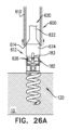
いくつかの適用例では、組織アンカーが、鋭利な遠位先端、先端から近位の中空体、および中空体に拘束されたばねを含む。組織アンカーが、中空体が組織内に配置されるように、組織先端に最初に打ち込まれるように構成され、次いで、ばねが、中空体の横方向ポートから横方向に鋭利な端部を押し出し、アンカーの固定をさらに確実するようにリリースされる。 In some applications, the tissue anchor includes a sharp distal tip, a hollow body proximal to the tip, and a spring constrained to the hollow body. The tissue anchor is configured to be first driven into the tissue tip such that the hollow body is disposed within the tissue, and then the spring forces the sharp end laterally out of the lateral port of the hollow body; Released to further ensure fixation of the anchor.
いくつかの適用例では、組織アンカーが、管およびドライバーを含むツールを使用して送達される。ツールが、管の遠位開口部を組織内に打ち込み、開口部が組織に沈み込んだままである間、ドライバーが、アンカーの組織係合要素を開口部から組織内に打ち込む。 In some applications, tissue anchors are delivered using tools that include tubes and drivers. The tool drives the distal opening of the tube into the tissue, and while the opening remains sunk into the tissue, the driver drives the tissue engaging element of the anchor through the opening and into the tissue.
いくつかの適用例では、組織アンカーが、ヘッド、および互いに向かって移動する、組織に向かって直線的に移動し、組織に対してヘッドの組織対向側を押し付けるように構成される、複数の組織係合要素を有する。ヘッドが、組織係合要素の互いに向かう動きが、グリップを組織に対して押すように、グリップを画定することができる。一部のこうした適用例では、各組織係合要素が、横方向のバーブを画定し、バーブは、組織係合要素の互いへの移動時に露出し得る。 In some applications, the tissue anchor comprises a head and a plurality of tissues that move toward each other, that move linearly toward the tissue, and that are configured to press tissue-opposed sides of the head against the tissue. It has an engagement element. The head can define the grip such that movement of the tissue engaging elements toward each other forces the grip against tissue. In some such applications, each tissue-engaging element defines a lateral barb that may be exposed upon movement of the tissue-engaging elements relative to each other.
いくつかの適用例では、例えば、余分なテザーを切断して除去する前に、テザー内の張力を係止するために、テザー取り扱い装置が使用される。例えば、テザー取り扱い装置が、テザー上にクランプするクランプを含み得る。テザー取り扱い装置がまた、例えば、隣接する組織を損傷するカット端部の可能性を低減するために、切断後に残されたテザーの残留片を管理する(例えば、移動、閉じ込め、カバー、および/または遮蔽する)ように構成することができる。 In some applications, a tether handling device is used, for example, to lock tension in the tether before cutting and removing excess tether. For example, a tether handling device may include a clamp that clamps onto the tether. The tether handling device also manages residual pieces of the tether left after cutting (e.g., moves, confines, covers, and/or (shielding).
いくつかの適用例では、テザー取り扱い装置が、移植片の最終組織アンカーの近傍で、複数のアンカーを含む組織調整インプラントのテザーに係止されるように構成されるストッパー(または締め具)として使用される。テザーに係止される場合、テザー取り扱い装置が、最終組織アンカーに対するテザーの移動を制限するように構成される。従って、テザーに張力が印加された後、テザー取り扱い装置がテザーに係止されると、テザー取り扱い装置がテザー内の張力を係止する。 In some applications, the tether handling device is used as a stopper (or fastener) that is configured to lock onto a tether of a tissue conditioning implant that includes a plurality of anchors in the vicinity of the final tissue anchor of the graft. be done. When locked to the tether, a tether handling device is configured to limit movement of the tether relative to the final tissue anchor. Thus, when the tether handling device is locked to the tether after tension is applied to the tether, the tether handling device locks the tension in the tether.
いくつかの適用例は、ばねおよび拘束具を含むテンショナーに関する。拘束具が、弾性的に変形された(すなわち、歪みのある)状態でばねを拘束するが、所与の速度で生体吸収性である。従って、拘束具が対象の体内で分解した後(例えば、移植後の所定の期間後)、ばねを拘束することを停止し、ばねが、例えば、その静止状態に向かって、その弾性変形状態から離れて移動する。ばねが、ばねのこの動きがテザーを引っ張り(例えば、張力をかける)、アンカーを互いに向かって引き寄せるように、二つのアンカー間の少なくとも一つのテザーに結合される。テザーへの張力のこの遅延適用は、望ましい組織調整を達成する程度まで張力を増加させる前に、テザーがより低い量の張力下にある間、アンカーの固定を強化するための、組織回収および成長などの生理学的プロセスを可能にすると仮定される。 Some applications relate to tensioners that include springs and restraints. A restraint restrains the spring in an elastically deformed (ie, strained) state, but is bioabsorbable at a given velocity. Thus, after the restraint disintegrates within the subject's body (e.g., after a predetermined period of time after implantation), it ceases to restrain the spring and the spring is e.g. move away. A spring is coupled to at least one tether between the two anchors such that this movement of the spring pulls (eg, tensions) the tether and draws the anchors toward each other. This delayed application of tension to the tether allows for tissue retrieval and growth to enhance fixation of the anchor while the tether is under a lower amount of tension before increasing the tension to the extent that desired tissue adjustment is achieved. It is hypothesized that physiological processes such as
いくつかの適用例は、対象の組織から組織アンカーを経管腔的に固定解除し、アンカーを対象から除去するために使用され得るアンカー取り扱いアセンブリーに関する。これらのアンカー取り扱いアセンブリーの各々が、スリーブおよびツールを含み得る。スリーブの遠位端が、アンカーのヘッドにわたって前進することができ、ツールの顎は、次いで、スリーブ内で前進し、アンカーのアンカーヘッドと係合することができる。スリーブの遠位部分の内寸法は、それが顎を閉状態に保持するようにすることができ、ツールが、顎が閉状態、例えば、スナップ嵌めの間、アンカーヘッドのインターフェイスに係止され得るように構成され得る。次に、ツールがアンカーを固定解除することができ、アンカーはその後、アンカー取り扱いアセンブリーを使用して対象から除去される。 Some applications relate to anchor handling assemblies that can be used to transluminally de-secure tissue anchors from tissue of a subject and remove the anchor from the subject. Each of these anchor handling assemblies may include a sleeve and a tool. The distal end of the sleeve can be advanced over the head of the anchor, and the jaws of the tool can then be advanced within the sleeve and engage the anchor head of the anchor. The internal dimensions of the distal portion of the sleeve may be such that it holds the jaws in the closed position, such that a tool can be locked to the interface of the anchor head while the jaws are in the closed position, e.g., during a snap fit. It can be configured as follows. A tool can then unsecure the anchor, which is then removed from the object using an anchor handling assembly.
いくつかの適用例は、例えば、ドライバーインターフェイスによって画定される凹部内に、ドライバーヘッドの一部を横方向に移動させることによって、アンカーのドライバーインターフェイスに係止される、ドライバーヘッドを有する、アンカードライバーに関する。例えば、フィンが、フィンの間に遠位に延在するロッドによって横方向に押すことができる。任意選択で、ドライバーヘッドのカムは、シャフトの回転により、カムが回転し、シャフトから横方向に突出するように、ドライバーのシャフトを通って延在し、シャフトに対して偏心するロッドの遠位パートに結合され得る。 Some applications include, for example, an anchor driver having a driver head that is locked to a driver interface of the anchor by laterally moving a portion of the driver head into a recess defined by the driver interface. Regarding. For example, the fins can be pushed laterally by rods extending distally between the fins. Optionally, the cam of the driver head is mounted distally on a rod extending through the shaft of the driver and eccentric with respect to the shaft such that rotation of the shaft causes the cam to rotate and project laterally from the shaft. Can be combined into parts.
いくつかの適用例では、システム、装置、および技術が、テザーを通された複数のアンカーを含むインプラントとの使用のために説明され、それによって、アンカーを組織に固定した後、アンカーが他のアンカー間のテザーに追加され、固定され、または他のアンカー間のテザーから固定解除され、およびテザーから除去される。いくつかの適用例では、磁石は各アンカーのヘッドに配置され、アンカーへのナビゲーションを容易にする。いくつかの適用例では、アンカーヘッドが、アンカーヘッドが代わりに通常のアイレットを含む場合に必要なテザーの軸方向の通しを必要とするのではなく、テザーをシャックルの開口部を通して横方向に移動させることを可能にすることによって、これを促進するシャックルを含む。 In some applications, the systems, devices, and techniques are described for use with implants that include multiple anchors threaded through tethers, whereby after securing the anchors to tissue, the anchors are attached to other Added to tethers between anchors, fixed, unfixed from tethers between other anchors, and removed from tethers. In some applications, a magnet is placed in the head of each anchor to facilitate navigation to the anchor. In some applications, the anchor head moves the tether laterally through an opening in the shackle, rather than requiring axial threading of the tether as would be required if the anchor head instead included a regular eyelet. includes a shackle that facilitates this by allowing the
いくつかの適用例に従い、管および体外ユニットを含むカテーテル装置を含む、対象に使用するシステムが提供される。管が、対象内に経管腔的に前進するように構成される遠位開口部、および近位開口部を画定する近位端を有し得る。体外ユニットが、管の近位端に結合されてもよく、および/または配備位置を画定することができる。体外ユニットが、配備位置につながる軌道、および/または(i)バリアが近位開口部を妨害する閉状態と、(ii)開状態との間で移動可能なバリアを含み得る。いくつかの適用例では、軌道は使用されず、カートリッジが、例えば、手で取り付ける、定位置に回転するなど、他の手段によって定位置に移動することができる。 In accordance with some applications, a system for use in a subject is provided that includes a catheter device that includes a tube and an extracorporeal unit. A tube can have a distal opening configured to be advanced transluminally into a subject, and a proximal end defining a proximal opening. An extracorporeal unit may be coupled to the proximal end of the tube and/or may define a deployment location. The extracorporeal unit may include a track leading to a deployed position and/or a barrier movable between (i) a closed state in which the barrier obstructs the proximal opening, and (ii) an open state. In some applications, a track is not used and the cartridge can be moved into position by other means, such as by hand-installing or rotating into position.
システムが、一連のアンカーをさらに含み得る。 The system may further include a series of anchors.
いくつかの適用例では、システムが一連のカートリッジを含み、カートリッジの各々が一連のアンカーのそれぞれのアンカーを保持し、一連の初期位置のそれぞれの初期位置で体外ユニットに結合される。カートリッジのそれぞれが、体外ユニットに結合されたままである間、(i)配備位置では、カートリッジを近位開口部の反対側のそれぞれのアンカーを保持し、(ii)バリアは閉状態にあるように、それぞれの初期位置から配備位置まで軌道に沿って移動可能であるように(または、軌道が含まれていない場合には、配備位置に移動可能であるように)構成され得る。 In some applications, the system includes a series of cartridges, each cartridge holding a respective anchor of the series of anchors and coupled to the extracorporeal unit at a respective initial position of the series of initial positions. While each of the cartridges remains coupled to the extracorporeal unit, (i) in the deployed position the cartridge is held with its respective anchor opposite the proximal opening, and (ii) the barrier is in a closed state. , may be configured to be movable along a trajectory from a respective initial position to a deployed position (or movable to a deployed position if a trajectory is not included).
システムが、アンカーの各々に対して、アンカーが、配備位置のそれぞれのカートリッジによって近位開口部の反対側に保持される間、(i)アンカーと係合し、および(ii)アンカーと係合している間、バリアをその開状態に移行させるアンカーに力を加えるように構成される、アンカードライバーをさらに含み得る。アンカーの各々に対して、アンカードライバーが、バリアが開状態に留まっている間、アンカーをそれぞれのカートリッジから遠位に、近位開口部を通って、管を通って遠位開口部に前進させるように構成され得る。 For each of the anchors, the system (i) engages the anchor while the anchor is held opposite the proximal opening by the respective cartridge in the deployed position; and (ii) engages the anchor. The anchor driver may further include an anchor driver configured to apply a force to the anchor that transitions the barrier to its open state while moving the barrier. For each of the anchors, an anchor driver advances the anchor distally from the respective cartridge, through the proximal opening, through the tube and into the distal opening while the barrier remains open. It can be configured as follows.
いくつかの適用例では、力は、アンカードライバーによるアンカーの係合に挑む係合検証力である。 In some applications, the force is an engagement verification force that challenges engagement of the anchor by the anchor driver.
いくつかの適用例では、バリアは、旋回することによってその閉状態からその開状態に移動するように構成される。 In some applications, the barrier is configured to move from its closed state to its open state by pivoting.
いくつかの適用例では、力は近位引っ張り力であり、アンカードライバーは、アンカーの各々に対して、アンカーと係合している間、近位引っ張り力をアンカーに印加するように構成される。 In some applications, the force is a proximal pull force, and the anchor driver is configured for each of the anchors to apply a proximal pull force to the anchor while engaged with the anchor. .
いくつかの適用例では、システムが、力の閾値の大きさを画定するように構成され、バリアは、力が閾値の大きさを超えるときのみに力に応答して開状態に移行する。 In some applications, the system is configured to define a threshold magnitude of force, and the barrier transitions to an open state in response to a force only when the force exceeds the threshold magnitude.
いくつかの適用例では、カートリッジの各々について、カートリッジが、力に応答して立体構造変化を経るように構成され、アンカードライバーが、それぞれのアンカーに力を印加することによって立体構造変化を誘発することによって、バリアをその開状態に移行させるように構成される。 In some applications, for each of the cartridges, the cartridge is configured to undergo a conformational change in response to a force, and the anchor driver induces the conformational change by applying a force to the respective anchor. The barrier is configured to transition to its open state by causing the barrier to enter its open state.
いくつかの適用例では、バリアが、開状態に向かって付勢される。 In some applications, the barrier is biased toward an open state.
いくつかの適用例では、体外ユニットが、アンカードライバーによってアンカーに印加される力に応答して、バリアをその開状態に移行するように構成されるばね式変位機構を含む。 In some applications, the extracorporeal unit includes a spring-loaded displacement mechanism configured to transition the barrier to its open state in response to a force applied to the anchor by an anchor driver.
いくつかの適用例では、カートリッジの各々が、配備位置に到達すると体外ユニットに係止するように構成される。 In some applications, each of the cartridges is configured to lock into the extracorporeal unit upon reaching the deployment position.
いくつかの適用例では、カートリッジの各々が、人間のオペレーターが手で掴むように形状付けられ、オペレーターが手で軌道に沿って移動させるように構成される。 In some applications, each of the cartridges is shaped to be grasped by a human operator and configured to be manually moved along the trajectory by the operator.
いくつかの適用例では、カテーテル装置が、管の近位開口部にポートをさらに含む。いくつかの適用例では、システムが、流体フィッティング、ノズル、およびその間のチャネルを含むフラッシングアダプターをさらに含む。いくつかの適用例では、フラッシングアダプターは、(i)流体フィッティングがカテーテル装置の外部からアクセス可能であり、(ii)流体フィッティングを介してフラッシングアダプターに駆動される流体が管を通して遠位に配向されるように、ノズルがポートと流体連通する、フラッシング位置に、体外ユニットに可逆的に係止可能である。 In some applications, the catheter device further includes a port at the proximal opening of the tube. In some applications, the system further includes a flushing adapter that includes a fluid fitting, a nozzle, and a channel therebetween. In some applications, the flushing adapter comprises: (i) the fluid fitting is accessible from the exterior of the catheter device; and (ii) fluid driven through the fluid fitting and into the flushing adapter is directed distally through the tubing. The nozzle is reversibly lockable to the extracorporeal unit in a flushing position, such that the nozzle is in fluid communication with the port.
いくつかの適用例では、フラッシング位置で、バリアはその開状態にあり、チャネルはバリアを越えて遠位に延在する。 In some applications, in the flushing position, the barrier is in its open state and the channel extends distally beyond the barrier.
いくつかの適用例では、フラッシング位置は、配備位置と実質的に一致している。 In some applications, the flushing location substantially coincides with the deployment location.
いくつかの適用例では、流体フィッティングはルアーフィッティングである。 In some applications, the fluid fitting is a Luer fitting.
いくつかの適用例では、ポートが、封止膜を含み、アンカードライバーが、アンカーの各々に対して、アンカーを膜を通して遠位に、管内に前進させるように構成される。 In some applications, the port includes a sealing membrane and an anchor driver is configured for each of the anchors to advance the anchor distally through the membrane and into the vessel.
いくつかの適用例では、フラッシング位置で、ノズルは膜から近位にあるポートで封止する。 In some applications, in the flushing position, the nozzle seals with a port that is proximal to the membrane.
いくつかの適用例では、ポートが、膜から近位のルーメンを画定するテーパ付き内側壁を有し、ポートのルーメンは膜に向かって遠位に先細である。 In some applications, the port has a tapered inner wall defining a lumen proximally from the membrane, and the lumen of the port tapers distally toward the membrane.
いくつかの適用例では、ノズルは、フラッシングアダプターがフラッシング位置で体外ユニットに係止されるとき、ノズルが膜から近位にテーパ付き内側壁に対して封止されるように寸法設定される。 In some applications, the nozzle is sized such that when the flushing adapter is locked to the extracorporeal unit in the flushing position, the nozzle seals against the tapered inner wall proximally from the membrane.
いくつかの適用例では、膜は、膜を貫通する第一の開口、膜を貫通する第二の開口、および第一の開口を第二の開口と連結する閉鎖スリットを画定するように形状付けられる。 In some applications, the membrane is shaped to define a first aperture through the membrane, a second aperture through the membrane, and a closure slit connecting the first aperture with the second aperture. It will be done.
いくつかの適用例では、第一の開口が、第二の開口よりも直径が広い。 In some applications, the first aperture is wider in diameter than the second aperture.
いくつかの適用例では、第一の開口が、第二の開口の3~10倍大きい。 In some applications, the first aperture is 3-10 times larger than the second aperture.
いくつかの適用例では、アンカーのそれぞれが組織係合要素を含む。いくつかの適用例では、アンカーの各々が、アイレットを含むヘッドを含む。いくつかの適用例では、ポートが、カートリッジの各々について、カートリッジが配備位置にあり、近位開口部の反対側のそれぞれのアンカーを保持するように配置される間、(i)それぞれの組織アンカーの組織係合要素が第一の開口と整列され、これにより、アンカー前進軸を、各組織アンカーから第一の開口を通って管を通って、画定し、(ii)各組織アンカーのアイレットが第二の開口と整列されるように、配置される。組織係合要素が、本明細書の他の組織係合要素と同一または類似であり得る。 In some applications, each of the anchors includes a tissue-engaging element. In some applications, each anchor includes a head that includes an eyelet. In some applications, the port is configured for each of the cartridges to hold (i) a respective tissue anchor while the cartridge is in the deployed position and retains the respective anchor opposite the proximal opening; (ii) the tissue engaging elements of each tissue anchor are aligned with the first aperture, thereby defining an anchor advancement axis from each tissue anchor through the first aperture and through the canal; The second opening is arranged to be aligned with the second opening. The tissue engaging element can be the same or similar to other tissue engaging elements herein.
いくつかの適用例では、システムがプラットフォームをさらに含み、管の近位端は長手方向軸を画定する。いくつかの適用例では、体外ユニットが、長手方向軸の周りの体外ユニットの回転を容易にする様式でプラットフォーム上に取り付けられるように構成される。いくつかの適用例では、体外ユニットが、長手方向軸の周りの体外ユニットの回転が管を回転するように、管に回転固定される。 In some applications, the system further includes a platform and the proximal end of the tube defines a longitudinal axis. In some applications, the extracorporeal unit is configured to be mounted on the platform in a manner that facilitates rotation of the extracorporeal unit about a longitudinal axis. In some applications, the extracorporeal unit is rotationally fixed to the tube such that rotation of the extracorporeal unit about the longitudinal axis rotates the tube.
いくつかの適用例では、システムが、長手方向軸の周りの体外ユニットの別個の回転配向のアレイを画定し、体外ユニットが、別個の回転配向の各々において体外ユニットの配向を容易にする様式でプラットフォーム上に取り付けられるように構成される。 In some applications, the system defines an array of distinct rotational orientations of the extracorporeal units about a longitudinal axis, the extracorporeal units configured in a manner that facilitates orientation of the extracorporeal units in each of the distinct rotational orientations. Configured to be mounted on a platform.
いくつかの適用例では、システムがさらに、別個の回転配向の各々に体外ユニットを固定するように構成される少なくとも一つの戻り止めを含む。 In some applications, the system further includes at least one detent configured to secure the extracorporeal unit in each of the distinct rotational orientations.
いくつかの適用例では、少なくとも一つの戻り止めが、別個の回転配向の各々に体外ユニットのスナップ嵌めを提供することによって、別個の回転配向の各々に体外ユニットを固定するように構成される。 In some applications, at least one detent is configured to secure the extracorporeal unit in each of the distinct rotational orientations by providing a snap fit of the extracorporeal unit in each of the distinct rotational orientations.
いくつかの適用例では、体外ユニットが、別個の回転配向のアレイに対応する凹部のアレイを画定する。いくつかの適用例では、少なくとも一つの戻り止めが、対応する凹部内に突出する、別個の回転配向の各々に対して、別個の回転配向の各々に体外ユニットを固定するように構成される。 In some applications, the extracorporeal unit defines an array of recesses that correspond to an array of distinct rotational orientations. In some applications, at least one detent is configured to secure the extracorporeal unit in each of the distinct rotational orientations for each of the distinct rotational orientations protruding into the corresponding recess.
いくつかの適用例では、システムが、ブラケットをさらに含み、体外ユニットが、ブラケットとプラットフォームとの間の連結を介してプラットフォーム上に取り付けられるように構成される。いくつかの適用例では、体外ユニットが、長手方向軸の周りの体外ユニットの回転を容易にする様式でブラケットに回転可能に結合される。いくつかの適用例では、少なくとも一つの戻り止めが、体外ユニットが別個の回転配向のいずれかに配置される間、ブラケットに対する体外ユニットの回転を阻害することによって、別個の回転配向の各々に体外ユニットを固定するように構成される。 In some applications, the system further includes a bracket and the extracorporeal unit is configured to be mounted on the platform via a connection between the bracket and the platform. In some applications, the extracorporeal unit is rotatably coupled to the bracket in a manner that facilitates rotation of the extracorporeal unit about a longitudinal axis. In some applications, the at least one detent moves the extracorporeal unit into each of the separate rotational orientations by inhibiting rotation of the extracorporeal unit relative to the bracket while the extracorporeal unit is placed in one of the separate rotational orientations. Configured to secure the unit.
いくつかの適用例では、少なくとも一つの戻り止めがばね式である。 In some applications, at least one detent is spring loaded.
いくつかの適用例では、カートリッジの各々について、バリアは、配備位置に向かうカートリッジの移動に応答して、その閉状態に移行するように構成される。 In some applications, for each of the cartridges, the barrier is configured to transition to its closed state in response to movement of the cartridge toward a deployed position.
いくつかの適用例では、カートリッジの各々について、バリアは、配備位置にカートリッジが到着するのに応答して、その閉状態に移行するように構成される。 In some applications, for each of the cartridges, the barrier is configured to transition to its closed state in response to arrival of the cartridge at the deployment location.
いくつかの適用例では、カートリッジの各々について、カートリッジが、カートリッジが配備位置に到着したときに、バリアをその閉状態に向けて押すように構成される。 In some applications, for each of the cartridges, the cartridge is configured to push the barrier toward its closed condition when the cartridge reaches the deployment position.
いくつかの適用例では、カートリッジの各々について、カートリッジが、(i)それぞれのアンカーを保持し、(ii)カートリッジが配備位置に到着すると、バリアを閉状態に向けて押し出す面を確定し、および(iii)カートリッジが、バリアが閉状態にある状態で、配備位置に留まっている間、それぞれのアンカーへの力の印加が、バリアが応答して開状態へと移行するように面を変位させるように構成される、第一のピースおよび第二のピースを含む。 In some applications, for each of the cartridges, the cartridge defines a surface that (i) retains a respective anchor, (ii) pushes the barrier toward a closed state when the cartridge reaches a deployed position, and (iii) While the cartridge remains in the deployed position with the barrier in the closed state, application of a force to each anchor displaces the face such that the barrier responds and transitions to the open state. A first piece and a second piece configured as follows.
いくつかの適用例では、カートリッジが、カートリッジが、バリアが閉状態にある状態で、配備位置に留まっている間、それぞれのアンカーへの力の印加が面を近位に移動させるように構成される。いくつかの適用例では、バリアは、面の動きに近位に応答して開状態に移行するように構成される。 In some applications, the cartridge is configured such that application of a force to each anchor moves the surface proximally while the cartridge remains in the deployed position with the barrier in the closed state. Ru. In some applications, the barrier is configured to transition to an open state in response to movement of the surface proximally.
いくつかの適用例では、面は第二のピースによって画定され、カートリッジが、カートリッジが、バリアが閉状態にある状態で、配備位置に留まっている間、それぞれのアンカーへの力の印加が、第一のピースに対して第二のピースを摺動させることによって面を変位させるように構成される。 In some applications, the surface is defined by the second piece and the application of a force to the respective anchor while the cartridge remains in the deployed position with the barrier in the closed state. The surface is configured to be displaced by sliding the second piece relative to the first piece.
いくつかの適用例では、カートリッジの各々について、カートリッジが、第一のピースと体外ユニットとの間の結合を介して体外ユニットに結合される。 In some applications, for each of the cartridges, the cartridge is coupled to the extracorporeal unit via a connection between the first piece and the extracorporeal unit.
いくつかの適用例では、第二のピースが第一のピースの内部に取り付けられる。 In some applications, a second piece is attached inside the first piece.
いくつかの適用例では、第一のピースが人間のオペレーターが手で掴めるように形状付けられる。 In some applications, the first piece is shaped so that it can be grasped by a human operator's hand.
いくつかの適用例では、配備位置が一連の連続するカートリッジに対して空になるように、配備位置からカートリッジの各々が取り外し可能である。 In some applications, each of the cartridges is removable from the deployment location such that the deployment location is emptied for a series of successive cartridges.
いくつかの適用例では、配備位置から、カートリッジの各々が、体外ユニットから取り外されることによって取り外し可能である。 In some applications, each of the cartridges is removable from the deployed position by being removed from the extracorporeal unit.
いくつかの適用例では、アンカードライバーが、アンカーの各々に対して、それぞれのカートリッジが配備位置に留まっている間、アンカーを、それぞれのカートリッジから外へ遠位に、近位開口部を通し、そして管を通して遠位開口部に向かって前進させるように構成される。 In some applications, for each of the anchors, the anchor driver passes the anchor distally out of the respective cartridge and through the proximal opening while the respective cartridge remains in the deployed position; and configured to be advanced through the tube toward the distal opening.
いくつかの適用例では、カートリッジの各々について、カートリッジは、(i)カートリッジが配備位置にある間、および(ii)アンカードライバーがカートリッジを越えて遠位に、かつ管を通って遠位開口部に向かって延在する間、アンカードライバーが配備位置からカートリッジの取り外しを妨げるように、構成される。 In some applications, for each of the cartridges, the cartridge (i) while the cartridge is in the deployed position, and (ii) the anchor driver distally beyond the cartridge and through the tube into the distal opening. The anchor driver is configured to prevent removal of the cartridge from the deployed position while extending toward the anchor driver.
いくつかの適用例では、アンカーのそれぞれが、組織係合要素と、アイレットを含むヘッドとを含む。いくつかの適用例では、システムがさらに、アンカーのそれぞれのアイレットを通り、テザーの近位端を含む近位部分を有し、テザーの遠位端を含む遠位部分を有する、テザー(例えば、線、ワイヤ、リボン、ロープ、編組、収縮部材、縫合糸など)を含み得る。いくつかの適用例では、テザーの遠位端が、管を通って対象内に遠位に前進可能である一方、テザーの近位端は対象の外側に留まる。組織係合要素が、本明細書の他の組織係合要素と同一または類似であり得る。 In some applications, each of the anchors includes a tissue-engaging element and a head that includes an eyelet. In some applications, the system further includes a tether (e.g., wires, ribbons, ropes, braids, shrinkable members, sutures, etc.). In some applications, the distal end of the tether can be advanced distally through the tube and into the subject, while the proximal end of the tether remains outside the subject. The tissue engaging element can be the same or similar to other tissue engaging elements herein.
いくつかの適用例では、管が、管の遠位端から近位に延在する横方向スリットを画定し、横方向スリットが、アンカーではなく、テザーが管の遠位端から横方向に管から出ることを可能にするように寸法設定される。 In some applications, the tube defines a transverse slit extending proximally from the distal end of the tube, and the transverse slit is such that the tether, rather than the anchor, extends proximally from the distal end of the tube. dimensioned to allow exit from the
いくつかの適用例では、管が、テザーが狭まった入口を介して横方向スリットを遠位に出るのを阻害するが、排除しないように構成される、横方向スリット内に狭まった入口を画定するように形状付けられる。 In some applications, the tube defines a constricted inlet within the lateral slit that is configured to inhibit, but not exclude, the tether from exiting the lateral slit distally through the constricted inlet. Shaped to.
いくつかの適用例では、管が、横方向スリットおよび狭まった入口を維持する先端フレームを含む。 In some applications, the tube includes a tip frame that maintains a transverse slit and a narrowed entrance.
いくつかの適用例では、先端フレームは弾性である。 In some applications, the tip frame is resilient.
いくつかの適用例では、アンカーの各々に対して、(i)組織係合要素が、アンカーの中央長手方向軸を画定し、鋭利な遠位先端を有し、および対象の組織に打ち込まれるように構成され、(ii)ヘッドが、組織係合要素の近位端に結合され、インターフェイスをさらに含み、アンカードライバーによって可逆的に係合されるように構成され、および(iii)アイレットが、アンカーの中央長手方向軸の周りに回転できるように、取り付けられる。 In some applications, for each of the anchors: (i) a tissue-engaging element defines a central longitudinal axis of the anchor, has a sharp distal tip, and is configured to be driven into the tissue of interest; (ii) the head is coupled to the proximal end of the tissue engagement element, further includes an interface, and configured to be reversibly engaged by the anchor driver, and (iii) the eyelet is configured to mounted for rotation about a central longitudinal axis.
いくつかの適用例では、アンカーの各々に対して、アイレットが、(i)開口および開口を通る摺動軸を画定し、(ii)アンカーの中央長手方向軸から横方向に配置され、それによって中央長手方向軸に直交する、アイレット軸を画定し、および(iii)摺動軸を、アイレット軸に直交するように拘束する様式で、アイレット軸の周りを回転可能なように取り付けられる。 In some applications, for each of the anchors, an eyelet (i) defines an aperture and a sliding axis through the aperture, and (ii) is disposed laterally from the central longitudinal axis of the anchor, thereby defining an eyelet axis perpendicular to the central longitudinal axis, and (iii) being rotatably mounted about the eyelet axis in a manner that constrains the sliding axis to be perpendicular to the eyelet axis.
いくつかの適用例では、アンカーの各々に対して、アイレットが、(i)開口および開口を通る摺動軸を画定し、(ii)アンカーの中央長手方向軸から横方向に配置され、(iii)摺動軸が、アイレット軸に直交するように拘束されたままである間、中央長手方向軸の周りに回転できるように取り付けられる。 In some applications, for each of the anchors, an eyelet (i) defines an aperture and a sliding axis through the aperture, (ii) is disposed laterally from the central longitudinal axis of the anchor, and (iii ) The sliding axis is mounted for rotation about a central longitudinal axis while remaining constrained perpendicular to the eyelet axis.
いくつかの適用例では、インターフェイスがアンカーの中央長手方向軸上に配置される。 In some applications, the interface is located on the central longitudinal axis of the anchor.
いくつかの適用例では、組織係合要素がらせん状であり、中央長手方向軸の周りに、かつそれに沿って、らせん状に延在することによって中央長手方向軸を画定し、対象の組織にねじ込まれるように構成される。 In some applications, the tissue engaging element is helical and defines a central longitudinal axis by extending helically around and along the central longitudinal axis and engages the tissue of interest. Constructed to be screwed.
いくつかの適用例では、ヘッドが、中央長手方向軸を囲み、組織係合要素に回転可能に結合されるカラーを含み、また、アイレットがカラーに取り付けられ、中央長手方向軸の周りのカラー回転によって中央長手方向軸の周りを回転可能である。 In some applications, the head includes a collar surrounding a central longitudinal axis and rotatably coupled to the tissue-engaging element, and an eyelet is attached to the collar to facilitate rotation of the collar about the central longitudinal axis. is rotatable about a central longitudinal axis by.
いくつかの適用例では、システムが、アンカーと交互にテザーを通された一連の管状スペーサーをさらに含む。 In some applications, the system further includes a series of tubular spacers threaded with tethers alternating with anchors.
いくつかの適用例では、スペーサーの各々が、たわみにおいて弾性的に可撓性である。 In some applications, each of the spacers is elastically flexible in deflection.
いくつかの適用例では、スペーサーの各々が、管状スペーサーの各端部に、硬質リングを含む。 In some applications, each of the spacers includes a rigid ring at each end of the tubular spacer.
いくつかの適用例では、スペーサーの各々が、軸方向の圧縮に抵抗する。 In some applications, each spacer resists axial compression.
いくつかの適用例では、スペーサーの各々が、コイルとして形状付けられたらせん状ワイヤによって画定される。 In some applications, each spacer is defined by a helical wire shaped as a coil.
いくつかの適用例では、アンカードライバーが、アンカーの各々に対して、アンカーのアイレットがテザーを通されたまま、アンカーを、それぞれのカートリッジから外へ遠位に、近位開口部を通して、そして管を通して遠位開口部に向かって前進させるように構成される。 In some applications, the anchor driver, for each of the anchors, moves the anchor distally out of the respective cartridge, through the proximal opening, and into the tube, with the eyelet of the anchor threaded through the tether. the distal opening.
いくつかの適用例では、カテーテル装置が、管の近位開口部にポートをさらに含み、ポートが膜を含む。いくつかの適用例では、膜は、膜を貫通する第一の開口、膜を貫通する第二の開口、および第一の開口を第二の開口と連結する閉鎖スリットを画定するように形状付けられる。いくつかの適用例では、ポートが、アンカーの各々に対して、アンカードライバーが、アンカーをそれぞれのカートリッジから外へ遠位に、膜を貫通して前進させるように構成され、組織係合要素が第一の開口を貫通し、テザーが第二の開口を貫通して延在する、ように配置される。 In some applications, the catheter device further includes a port at the proximal opening of the tube, and the port includes a membrane. In some applications, the membrane is shaped to define a first aperture through the membrane, a second aperture through the membrane, and a closure slit connecting the first aperture with the second aperture. It will be done. In some applications, the port is configured for each of the anchors, the anchor driver advances the anchor distally out of the respective cartridge, through the membrane, and the tissue engaging element is configured to advance the anchor distally out of the respective cartridge and through the membrane. The tether is arranged to extend through the first aperture and the tether extends through the second aperture.
いくつかの適用例では、カテーテル装置が、テザーの近位部分に結合され、テザー上の張力を維持するように構成されるばね式ウィンチを含むテンショナーをさらに含む。 In some applications, the catheter device further includes a tensioner coupled to the proximal portion of the tether and including a spring-loaded winch configured to maintain tension on the tether.
いくつかの適用例に従い、カテーテル装置と併用する方法であって、(i)カテーテル装置の管の遠位部分を対象の心臓に経管腔的に前進させることであって、カテーテル装置が、管の近位端に結合される体外ユニットと、初期位置で体外ユニットに結合され、アンカーを保持するカートリッジとを含むように、前進させることと、(ii)カートリッジを、初期位置から、カートリッジが、カテーテルの近位開口部の反対側のアンカーを保持する、配備位置への軌道に沿って、摺動させることであって、体外ユニットが近位開口部を妨害するバリアを含むように、摺動させることと、を含む、方法が提供される。いくつかの適用例では、軌道は使用されず、カートリッジが、例えば、手で取り付ける、定位置に回転するなど、他の手段によって定位置に移動することができる。 In accordance with some applications, a method for use with a catheter device comprising: (i) transluminally advancing a distal portion of a tube of the catheter device into a subject's heart, the catheter device comprising: (ii) advancing the cartridge from the initial position to include an extracorporeal unit coupled to a proximal end of the extracorporeal unit and a cartridge coupled to the extracorporeal unit in an initial position and retaining an anchor; sliding the extracorporeal unit along a trajectory to a deployed position holding the anchor opposite the proximal opening of the catheter, the extracorporeal unit including a barrier obstructing the proximal opening; A method is provided, comprising: In some applications, a track is not used and the cartridge can be moved into position by other means, such as by hand-installing or rotating into position.
方法は、その後、アンカーと係合するアンカードライバーを使用して、アンカーに力を印加することによってバリアを開くことをさらに含んでもよい。 The method may then further include opening the barrier by applying a force to the anchor using an anchor driver that engages the anchor.
方法はさらに、アンカードライバーを使用してバリアを開放した後に、アンカーを、近位開口部を通して、そして管の遠位部分に向かって管を通して、カートリッジから遠位に前進させることを含み得る。 The method may further include advancing the anchor distally from the cartridge through the proximal opening and through the tube toward the distal portion of the tube after opening the barrier using the anchor driver.
いくつかの適用例に従い、管および体外ユニットを含む、カテーテル装置を含む、対象に使用するシステムが提供される。管が、近位開口部、および対象内に経管腔的に前進するように構成される遠位開口部を有し得る。体外ユニットが、配備位置につながる軌道、および/または(i)バリアが近位開口部を妨害する閉状態と、(ii)開状態との間で移動可能なバリアを含み得る。 In accordance with some applications, a system is provided for use in a subject, including a catheter device, including a tube and an extracorporeal unit. A tube can have a proximal opening and a distal opening configured for transluminal advancement into a subject. The extracorporeal unit may include a track leading to a deployed position and/or a barrier movable between (i) a closed state in which the barrier obstructs the proximal opening, and (ii) an open state.
このシステムが、第一のアンカーを保持し、体外ユニットに結合され、体外ユニットに結合されたまま、(i)第一のカートリッジが近位開口部の反対側の第一のアンカーを保持し、(ii)バリアが閉状態にあるように、第一の初期位置から配備位置まで軌道に沿って移動可能である、第一のカートリッジをさらに含み得る。 the system retains a first anchor and is coupled to the extracorporeal unit, and while coupled to the extracorporeal unit: (i) the first cartridge retains the first anchor opposite the proximal opening; (ii) may further include a first cartridge movable along the trajectory from a first initial position to a deployed position such that the barrier is in a closed state.
このシステムが、第二のアンカーを保持し、体外ユニットに結合され、体外ユニットに結合されたまま、(i)第二のカートリッジが近位開口部の反対側の第二のアンカーを保持し、(ii)バリアが閉状態にあるように、第二の初期位置から配備位置まで軌道に沿って移動可能である、第二のカートリッジをさらに含み得る。 the system retains a second anchor and is coupled to the extracorporeal unit, and while coupled to the extracorporeal unit, (i) the second cartridge retains the second anchor opposite the proximal opening; (ii) may further include a second cartridge movable along the trajectory from a second initial position to a deployed position such that the barrier is in a closed state.
システムが、(i)第一のアンカーが近位開口部の反対側の第一のカートリッジによって保持される間、第一のアンカーに結合可能である、および/または(ii)バリアが開状態にある間、第一のアンカーを近位開口部を通して管を通して第一のカートリッジから遠位に前進させるように構成される、アンカードライバーをさらに含み得る。アンカードライバーが、第二のアンカーが近位開口部の反対側の第二のカートリッジによって保持される間、その後第二のアンカーに連結可能であり、および/またはバリアがその開状態にある間、第二のアンカーを近位開口部を通して、かつ管を通して第一のアンカーに向かって第二のカートリッジから遠位に前進させるように構成され得る。 The system is coupled to the first anchor while (i) the first anchor is held by the first cartridge opposite the proximal opening, and/or (ii) the barrier is in an open state. The anchor driver may further include an anchor driver configured to advance the first anchor distally from the first cartridge through the proximal opening and through the tube. the anchor driver is then connectable to the second anchor while the second anchor is held by the second cartridge opposite the proximal opening and/or while the barrier is in its open state; The second anchor may be configured to be advanced distally from the second cartridge through the proximal opening and through the tube toward the first anchor.
いくつかの適用例では、ドライバーが、(i)第一のカートリッジが配備位置にあり、(ii)バリアが開状態であり、および(iii)第二のカートリッジが第二の初期位置に留まっている間、第一のアンカーを第一のカートリッジから、近位開口部を通って、管を通って遠位に前進させるように構成される。 In some applications, the driver determines that (i) the first cartridge is in the deployed position, (ii) the barrier is in the open position, and (iii) the second cartridge remains in the second initial position. The first anchor is configured to be advanced from the first cartridge, through the proximal opening, and distally through the canal while the first anchor is in the first cartridge.
いくつかの適用例では、第一のカートリッジおよび第二のカートリッジのそれぞれが、配備位置に到着すると体外ユニットに係止されるように構成される。 In some applications, each of the first cartridge and the second cartridge is configured to be locked to the extracorporeal unit upon reaching the deployment position.
いくつかの適用例では、第一のカートリッジおよび第二のカートリッジのそれぞれが、人間のオペレーターが手で掴むように形状付けられ、人間のオペレーターが手で軌道に沿って移動させるように構成される。 In some applications, each of the first cartridge and the second cartridge is configured to be grasped by a human operator and configured to be manually moved along the trajectory by a human operator. .
いくつかの適用例では、軌道は使用されず、カートリッジが、例えば、手で取り付ける、定位置に回転するなど、他の手段によって定位置に移動することができる。 In some applications, a track is not used and the cartridge can be moved into position by other means, such as by hand-installing or rotating into position.
いくつかの適用例では、第一のカートリッジおよび第二のカートリッジのそれぞれが、体外ユニットから取り外されることによって配備位置から取り外し可能である。 In some applications, each of the first cartridge and the second cartridge is removable from the deployed position by being removed from the extracorporeal unit.
いくつかの適用例では、システムが、第三のアンカーを保持し、体外ユニットに結合され、体外ユニットに結合されたまま、第三のカートリッジが近位開口部の反対側に第三のアンカーを保持するように、第三の初期位置から配備位置に軌道に沿って移動可能である第三のカートリッジをさらに含む。 In some applications, the system retains a third anchor and is coupled to the extracorporeal unit, and the third cartridge retains the third anchor on the opposite side of the proximal opening while remaining coupled to the extracorporeal unit. The cartridge further includes a third cartridge movable along the track from a third initial position to a deployed position so as to retain the cartridge.
いくつかの適用例では、第一のアンカーが、第一の組織係合要素と、第一のアイレットを含む第一のヘッドとを含み、第二のアンカーが、第二の組織係合要素と、第二のアイレットを含む第二のヘッドとを含む。第一の組織係合要素および第二の組織係合要素が、本明細書に記載される他の組織係合要素と同じまたは類似のものであり得る。 In some applications, the first anchor includes a first tissue-engaging element and a first head that includes a first eyelet, and the second anchor includes a second tissue-engaging element and a first head that includes a first eyelet. , a second head including a second eyelet. The first tissue-engaging element and the second tissue-engaging element can be the same or similar to other tissue-engaging elements described herein.
いくつかの適用例では、システムは、第一のアイレットおよび第二のアイレットに通されるテザー(例えば、線、ワイヤ、リボン、ロープ、編組、収縮部材、縫合糸など)をさらに含み、テザーは、テザーの近位端を含む近位部分とテザーの遠位端を含む遠位部分とを有し、テザーの近位端が対象の外側にある間、テザーの遠位端は、管を通って対象の中へ遠位に前進可能である。 In some applications, the system further includes a tether (e.g., line, wire, ribbon, rope, braid, retractable member, suture, etc.) threaded through the first eyelet and the second eyelet, the tether , having a proximal portion including a proximal end of the tether and a distal portion including a distal end of the tether, the distal end of the tether passing through the tube while the proximal end of the tether is outside the subject. can be advanced distally into the subject.
いくつかの適用例では、アンカードライバーが、第一のアンカーの第一のアイレットがテザーを通されたままである間、第一のアンカーを、第一のカートリッジから外へ遠位に、近位開口部を通し、そして管を通して前進させるように構成され、アンカードライバーが、第二のアンカーの第二のアイレットがテザーを通されたままである間、第二のアンカーを、第二のカートリッジから外へ遠位に、近位開口部を通し、そして管を通して前進させるように構成される。 In some applications, the anchor driver moves the first anchor distally out of the first cartridge and into the proximal opening while the first eyelet of the first anchor remains tethered. and the anchor driver advances the second anchor out of the second cartridge while the second eyelet of the second anchor remains threaded with the tether. Distally, it is configured to pass through the proximal opening and be advanced through the tube.
いくつかの適用例では、カテーテル装置が、第一のアンカーの前進および第二のアンカーの前進中に、テザーに対する張力を維持するように構成される張力付与装置をさらに含む。 In some applications, the catheter device further includes a tensioning device configured to maintain tension on the tether during advancement of the first anchor and advancement of the second anchor.
いくつかの適用例では、張力付与装置が、ばねおよびスプールを含み、スプールが第一の方向へ回転してばねに応力を印加するように、スプールがねじに連結し、テザーの遠位部分を管を通して遠位に前進させると、スプールが第一の方向に回転するように、テザーの近位部分がスプールに巻かれる。 In some applications, the tensioning device includes a spring and a spool, the spool coupled to the screw and tensioning the distal portion of the tether such that the spool rotates in a first direction to apply a stress to the spring. When advanced distally through the tube, the proximal portion of the tether is wrapped around the spool such that the spool rotates in a first direction.
いくつかの適用例に従い、対象に使用するためのシステムであって、管および体外ユニットを含むカテーテル装置を含むシステムが提供される。管が、対象の組織に経管腔的に前進するように構成される遠位開口部、および/または長手方向管軸を画定する近位部分を有し得る。体外ユニットが、管の近位部分に結合され得る。 In accordance with some applications, a system is provided for use in a subject that includes a catheter device that includes a tube and an extracorporeal unit. The tube may have a distal opening configured for transluminal advancement into a tissue of interest, and/or a proximal portion defining a longitudinal tube axis. An extracorporeal unit may be coupled to the proximal portion of the tube.
システムが、一連のアンカーをさらに含み得、アンカーの各々が、(i)組織係合要素、および/または組織係合要素の近位端に結合され、インターフェイスおよびアイレットを含む、ヘッドを含む。組織係合要素が、本明細書の他の組織係合要素と同一または類似であり得る。 The system may further include a series of anchors, each anchor including (i) a tissue-engaging element and/or a head coupled to a proximal end of the tissue-engaging element and including an interface and an eyelet. The tissue engaging element can be the same or similar to other tissue engaging elements herein.
システムがさらに、アンカーの各々のアイレットに通されたテザー(例えば、線、ワイヤ、リボン、ロープ、編組、収縮部材、縫合糸など)を含み得る。 The system may further include a tether (eg, wire, wire, ribbon, rope, braid, constriction member, suture, etc.) threaded through each eyelet of the anchor.
システムが、アンカーの各々に対して、(i)アンカーのインターフェイスと係合する、および/または(ii)アンカーと係合している間、アンカーを遠位開口部に向かって管を通して遠位に前進させ、組織係合要素を組織に打ち込むように構成される、アンカードライバーをさらに含み得る。 For each of the anchors, the system (i) engages the anchor's interface, and/or (ii) moves the anchor distally through the tube toward the distal opening while engaged with the anchor. The anchor driver may further include an anchor driver configured to advance and drive the tissue engaging element into tissue.
システムが、プラットフォームをさらに含み得る。システムが、長手方向管軸の周りの体外ユニットの別個の回転配向のアレイを画定することができる。体外ユニットが、別個の回転配向のいずれかで配向されるように、長手方向管軸の周りの体外ユニットの回転を容易にする様式でプラットフォーム上に取り付けられるように構成され得る。体外ユニットが、長手方向管軸の周りの体外ユニットの回転が管を回転するように、管に回転固定され得る。 The system may further include a platform. The system can define an array of discrete rotational orientations of extracorporeal units about a longitudinal tube axis. The extracorporeal unit may be configured to be mounted on the platform in a manner that facilitates rotation of the extracorporeal unit about the longitudinal tube axis so that it is oriented in any of the distinct rotational orientations. The extracorporeal unit may be rotationally secured to the tube such that rotation of the extracorporeal unit about the longitudinal tube axis rotates the tube.
いくつかの適用例では、テザーが近位端と、テザーの近位端が対象の外側に留まりながら管を通って対象内へ遠位に前進可能な遠位端とを有する。 In some applications, the tether has a proximal end and a distal end that is advanceable distally through the tube and into the subject while the proximal end of the tether remains outside the subject.
いくつかの適用例では、管が、管の遠位端から近位に延在する横方向スリットを画定する。いくつかの適用例では、横方向スリットが、アンカーではなく、テザーが管の遠位端から横方向に管から近位に出ることを可能にするように寸法設定される。 In some applications, the tube defines a transverse slit extending proximally from the distal end of the tube. In some applications, the transverse slit is sized to allow the tether, rather than the anchor, to exit proximally from the tube laterally from the distal end of the tube.
いくつかの適用例では、管が、テザーが狭まった入口を介して横方向スリットを遠位に出るのを阻害するが、排除しないように構成される、横方向スリット内に狭まった入口を画定するように形状付けられる。 In some applications, the tube defines a constricted inlet within the lateral slit that is configured to inhibit, but not exclude, the tether from exiting the lateral slit distally through the constricted inlet. Shaped to.
いくつかの適用例では、管が、狭まったスリットおよび狭まった入口を維持する先端フレームを含む。 In some applications, the tube includes a tip frame that maintains a narrowed slit and a narrowed entrance.
いくつかの適用例では、先端フレームは弾性である。 In some applications, the tip frame is resilient.
いくつかの適用例では、システムがさらに、別個の回転配向の各々に体外ユニットを固定するように構成される少なくとも一つの戻り止めを含む。 In some applications, the system further includes at least one detent configured to secure the extracorporeal unit in each of the distinct rotational orientations.
いくつかの適用例では、少なくとも一つの戻り止めがばね式である。 In some applications, at least one detent is spring loaded.
いくつかの適用例では、少なくとも一つの戻り止めが、別個の回転配向の各々に体外ユニットのスナップ嵌めを提供することによって、別個の回転配向の各々に体外ユニットを固定するように構成される。 In some applications, at least one detent is configured to secure the extracorporeal unit in each of the distinct rotational orientations by providing a snap fit of the extracorporeal unit in each of the distinct rotational orientations.
いくつかの適用例では、体外ユニットが、別個の回転配向のアレイに対応する凹部のアレイを画定する。いくつかの適用例では、少なくとも一つの戻り止めが、対応する凹部内に突出する、別個の回転配向の各々に対して、別個の回転配向の各々に体外ユニットを固定するように構成される。 In some applications, the extracorporeal unit defines an array of recesses that correspond to an array of distinct rotational orientations. In some applications, at least one detent is configured to secure the extracorporeal unit in each of the distinct rotational orientations for each of the distinct rotational orientations protruding into the corresponding recess.
いくつかの適用例では、システムが、ブラケットをさらに含み、体外ユニットが、ブラケットとプラットフォームとの間の連結を介してプラットフォーム上に取り付けられるように構成される。いくつかの適用例では、体外ユニットが、長手方向管軸の周りの体外ユニットの回転を容易にする様式でブラケットに回転可能に結合される。いくつかの適用例では、少なくとも一つの戻り止めが、体外ユニットが別個の回転配向のいずれかに配置される間、ブラケットに対する体外ユニットの回転を阻害することによって、別個の回転配向の各々に体外ユニットを固定するように構成される。 In some applications, the system further includes a bracket and the extracorporeal unit is configured to be mounted on the platform via a connection between the bracket and the platform. In some applications, the extracorporeal unit is rotatably coupled to the bracket in a manner that facilitates rotation of the extracorporeal unit about a longitudinal tube axis. In some applications, the at least one detent moves the extracorporeal unit into each of the separate rotational orientations by inhibiting rotation of the extracorporeal unit relative to the bracket while the extracorporeal unit is placed in one of the separate rotational orientations. Configured to secure the unit.
いくつかの適用例では、システムが、アンカーと交互にテザーを通された一連の管状スペーサーをさらに含む。 In some applications, the system further includes a series of tubular spacers threaded with tethers alternating with anchors.
いくつかの適用例では、スペーサーの各々が、たわみにおいて弾性的に可撓性である。 In some applications, each of the spacers is elastically flexible in deflection.
いくつかの適用例では、スペーサーの各々が、管状スペーサーの各端部に、硬質リングを含む。 In some applications, each of the spacers includes a rigid ring at each end of the tubular spacer.
いくつかの適用例では、スペーサーの各々が、軸方向の圧縮に抵抗する。 In some applications, each spacer resists axial compression.
いくつかの適用例では、スペーサーの各々が、コイルとして形状付けられたらせん状ワイヤによって画定される。 In some applications, each spacer is defined by a helical wire shaped as a coil.
いくつかの適用例では、アンカーの各々に対して、(i)組織係合要素が、アンカーの中央長手方向アンカー軸を画定し、(ii)アイレットが、中央長手方向アンカー軸の周りを回転できるように取り付けられる。 In some applications, for each of the anchors, (i) the tissue engagement element defines a central longitudinal anchor axis of the anchor, and (ii) the eyelet is rotatable about the central longitudinal anchor axis. It can be installed like this.
いくつかの適用例では、アンカーの各々に対して、アイレットが、(i)開口および開口を通る摺動軸を画定し、(ii)中央長手方向アンカー軸から横方向に配置され、それによって中央長手方向アンカー軸に直交する、アイレット軸を画定し、および(iii)摺動軸を、アイレット軸に直交するように拘束する様式で、アイレット軸の周りを回転可能なように取り付けられる。 In some applications, for each of the anchors, an eyelet (i) defines an aperture and a sliding axis through the aperture, and (ii) is disposed laterally from a central longitudinal anchor axis, thereby defining an eyelet axis perpendicular to the longitudinal anchor axis, and (iii) being rotatably mounted about the eyelet axis in a manner that constrains the sliding axis to be perpendicular to the eyelet axis.
いくつかの適用例では、アンカーの各々に対して、アイレットが、(i)開口および開口を通る摺動軸を画定し、(ii)中央長手方向アンカー軸から横方向に配置され、(iii)摺動軸が、アイレット軸に直交するように拘束されたままである間、中央長手方向アンカー軸の周りに回転できるように取り付けられる。 In some applications, for each of the anchors, an eyelet (i) defines an aperture and a sliding axis through the aperture, (ii) is disposed laterally from a central longitudinal anchor axis, and (iii) A sliding axis is mounted for rotation about a central longitudinal anchor axis while remaining constrained perpendicular to the eyelet axis.
いくつかの適用例では、インターフェイスがアンカーの中央長手方向軸上に配置される。 In some applications, the interface is located on the central longitudinal axis of the anchor.
いくつかの適用例では、組織係合要素がらせん状であり、中央長手方向アンカー軸の周りに、かつそれに沿って、らせん状に延在することによって中央長手方向アンカー軸を画定し、対象の組織にねじ込まれるように構成される。 In some applications, the tissue engagement element is helical and defines a central longitudinal anchor axis by extending helically around and along the central longitudinal anchor axis, and Constructed to be screwed into tissue.
いくつかの適用例に従い、対象に使用するシステムであって、管および管の近位部分に結合される体外ユニットを含むカテーテル装置を含む、システムが提供される。管が、対象の組織に経管腔的に前進するように構成される遠位開口部を有し得る。管の近位部分は、長手方向管軸を画定することができる。 In accordance with some applications, a system is provided for use in a subject that includes a catheter device including a tube and an extracorporeal unit coupled to a proximal portion of the tube. The tube can have a distal opening configured to be advanced transluminally into the tissue of interest. The proximal portion of the tube can define a longitudinal tube axis.
システムが、長手方向管軸の周りの体外ユニットの別個の回転配向のアレイを画定することができる。 The system can define an array of discrete rotational orientations of extracorporeal units about a longitudinal tube axis.
システムが、体外ユニットが、別個の回転配向のいずれかで配向されるように、長手方向管軸の周りの体外ユニットの回転を容易にする様式で取り付けられるように構成される、プラットフォームを含み得る。 The system may include a platform configured to be mounted in a manner that facilitates rotation of the extracorporeal unit about a longitudinal tube axis such that the extracorporeal unit is oriented in any of the discrete rotational orientations. .
体外ユニットが、長手方向管軸の周りの体外ユニットの回転が管を回転するように、管に回転固定され得る。 The extracorporeal unit may be rotationally secured to the tube such that rotation of the extracorporeal unit about the longitudinal tube axis rotates the tube.
いくつかの適用例では、システムが、一連のアンカーをさらに含み、アンカーの各々が管を通して前進可能であり、組織係合要素と、組織係合要素の近位端に結合されるヘッドとを含む。組織係合要素が、本明細書の他の組織係合要素と同一または類似であり得る。 In some applications, the system further includes a series of anchors, each of which is advanceable through the tube, and includes a tissue-engaging element and a head coupled to a proximal end of the tissue-engaging element. . The tissue engaging element can be the same or similar to other tissue engaging elements herein.
いくつかの適用例では、アンカーの各々のヘッドが、インターフェイスおよびアイレットを含み、システムが、アンカーの各々のアイレットに通されたテザー(例えば、線、ワイヤ、リボン、ロープ、編組、収縮部材、縫合糸など)をさらに含む。 In some applications, the head of each anchor includes an interface and an eyelet, and the system includes a tether (e.g., line, wire, ribbon, rope, braid, retractable member, suture) threaded through each eyelet of the anchor. yarn, etc.).
いくつかの適用例では、システムが、アンカーの各々に対して、アンカーのインターフェイスと係合し、アンカーと係合している間、遠位開口部に向かって管を通して遠位にアンカーを前進させ、組織係合要素を組織に打ち込むように構成される、アンカードライバーをさらに含む。 In some applications, the system, for each of the anchors, engages the anchor's interface and advances the anchor distally through the tube toward the distal opening while engaged with the anchor. , further including an anchor driver configured to drive the tissue engaging element into tissue.
いくつかの適用例に従い、対象の心臓に使用するための方法であって、システムのカテーテル装置の管の遠位部分を経管腔的に心臓に前進させることを含む、方法が提供される。カテーテル装置が、管の近位部分に結合され、管の近位部分が長手方向管軸を画定する、体外ユニットを含む。いくつかの適用例では、システムが、一連のアンカー、アンカーのそれぞれのアイレットに通されたテザー(例えば、線、ワイヤ、リボン、ロープ、編組、収縮部材、縫合糸など)、アンカードライバー、およびプラットフォームをさらに含む。 In accordance with some applications, a method is provided for use in a subject's heart, the method comprising transluminally advancing a distal portion of a tube of a catheter device of the system into the heart. A catheter device includes an extracorporeal unit coupled to a proximal portion of the tube, the proximal portion of the tube defining a longitudinal tube axis. In some applications, the system includes a series of anchors, a tether (e.g., line, wire, ribbon, rope, braid, retractable member, suture, etc.) threaded through each eyelet of the anchor, an anchor driver, and a platform. further including.
いくつかの適用例では、体外ユニットが、長手方向管軸の周りの体外ユニットの別個の回転配向のアレイを画定する様式でプラットフォーム上に取り付けられる。 In some applications, the extracorporeal units are mounted on the platform in a manner that defines an array of discrete rotational orientations of the extracorporeal units about a longitudinal tube axis.
いくつかの適用例では、方法は、体外ユニットが、別個の回転配向の第一の位置にあり、アンカードライバーを使用して、一連のアンカーのうちの第一のアンカーを遠位開口部に向かって管を通して遠位に前進させ、第一のアンカーを心臓の組織の第一の部位に固定することを含む。 In some applications, the method includes the extracorporeal unit in a first position in a discrete rotational orientation and using an anchor driver to direct a first anchor of the series of anchors toward the distal opening. and advancing the first anchor distally through the tube to secure the first anchor to the first site of cardiac tissue.
いくつかの適用例では、方法は、その後、体外ユニットを別個の回転配向の第二の方向に回転させることによって、所定の回転角度で管を回転させることを含む。 For some applications, the method then includes rotating the tube at a predetermined rotation angle by rotating the extracorporeal unit in a second direction of a distinct rotational orientation.
いくつかの適用例では、方法は、その後、体外ユニットが別個の回転配向の第二の位置に留まる間、アンカードライバーを使用して、一連のアンカーのうちの第二のアンカーを、管を通して遠位に、かつテザー上およびそれに沿って遠位開口部に向かって前進させ、第二のアンカーを心臓の組織の第二の部位に固定することを含む。 In some applications, the method then uses an anchor driver to remotely drive a second anchor of the series through the tube while the extracorporeal unit remains in the second position in a separate rotational orientation. and advancing the second anchor over and along the tether toward the distal opening and securing the second anchor to the second portion of the cardiac tissue.
いくつかの適用例では、方法は、その後、テザーに張力をかけることによって、第一のアンカーおよび第二のアンカーを互いに向かって引くことをさらに含む。 For some applications, the method further includes then pulling the first anchor and the second anchor toward each other by tensioning the tether.
いくつかの適用例に従い、対象に使用するためのシステムであって、管および体外ユニットを含むカテーテル装置を含むシステムが提供される。管が、(i)近位端を含む近位部分、(ii)対象の組織に経管腔的に前進するように構成される遠位部分、および(iii)近位部分と遠位部分との間に延在する中間部分を有し得る。体外ユニットが、管の近位部分に結合され得る。管の遠位部分は、ルーメン、遠位開口部、および遠位開口部から近位に延在する横方向スリットを画定することができる。管の遠位部分は、横方向スリットがルーメンの周りに回転可能であるように、中間部分に回転可能に結合され得る。 In accordance with some applications, a system is provided for use in a subject that includes a catheter device that includes a tube and an extracorporeal unit. The tube has (i) a proximal portion including a proximal end, (ii) a distal portion configured to be advanced transluminally into a tissue of interest, and (iii) a proximal portion and a distal portion. and an intermediate portion extending therebetween. An extracorporeal unit may be coupled to the proximal portion of the tube. The distal portion of the tube can define a lumen, a distal opening, and a transverse slit extending proximally from the distal opening. The distal portion of the tube may be rotatably coupled to the intermediate portion such that the transverse slit is rotatable about the lumen.
システムが一連のアンカーをさらに含み得、アンカーの各々が(i)組織係合要素、および(ii)組織係合要素の近位端に結合され、インターフェイスおよびアイレットを含むヘッドを含む。 The system may further include a series of anchors, each anchor including (i) a tissue-engaging element, and (ii) a head coupled to a proximal end of the tissue-engaging element and including an interface and an eyelet.
システムがさらに、アンカーの各々のアイレットに通されたテザー(例えば、線、ワイヤ、リボン、ロープ、編組、収縮部材、縫合糸など)を含み得る。 The system may further include a tether (eg, wire, wire, ribbon, rope, braid, constriction member, suture, etc.) threaded through each eyelet of the anchor.
システムが、アンカーの各々に対して、(i)アンカーのインターフェイスと係合し、および/またはアンカーと係合している間、アンカーを遠位部分に向かって管を通して遠位に前進させ、組織係合要素を組織に打ち込むように構成される、アンカードライバーをさらに含み得る。 For each of the anchors, the system (i) engages the anchor's interface and/or advances the anchor distally through the canal toward the distal portion while engaged with the anchor, and An anchor driver may further be included that is configured to drive the engagement element into tissue.
アンカーのそれぞれが、アンカードライバーによって遠位開口部を介してルーメンから遠位に前進するように寸法設定され得る。横方向スリットが、アンカーではなくテザーがスリットを通して横方向にルーメンを出ることを可能にするように寸法設定することができる。 Each of the anchors may be sized to be advanced distally from the lumen through the distal opening by an anchor driver. The lateral slit can be dimensioned to allow the tether, rather than the anchor, to exit the lumen laterally through the slit.
いくつかの適用例では、遠位部分は、テザーが狭まった入口を介して横方向スリットを遠位に出るのを阻害するが、排除しないように構成される、横方向スリット内に狭まった入口を画定するように形状付けられる。 In some applications, the distal portion is configured to have a narrowed inlet within the lateral slit that is configured to inhibit, but not exclude, the tether from exiting the lateral slit distally through the narrowed inlet. shaped to define.
いくつかの適用例では、テザーが近位端と、テザーの近位端が対象の外側に留まりながら管を通って対象内へ遠位に前進可能な遠位端とを有する。 In some applications, the tether has a proximal end and a distal end that is advanceable distally through the tube and into the subject while the proximal end of the tether remains outside the subject.
いくつかの適用例では、システムが、アンカーと交互にテザーを通された一連の管状スペーサーをさらに含む。 In some applications, the system further includes a series of tubular spacers threaded with tethers alternating with anchors.
いくつかの適用例では、スペーサーの各々が、たわみにおいて弾性的に可撓性である。 In some applications, each of the spacers is elastically flexible in deflection.
いくつかの適用例では、スペーサーの各々が、管状スペーサーの各端部に、硬質リングを含む。 In some applications, each of the spacers includes a rigid ring at each end of the tubular spacer.
いくつかの適用例では、スペーサーの各々が、軸方向の圧縮に抵抗する。 In some applications, each spacer resists axial compression.
いくつかの適用例では、スペーサーの各々が、コイルとして形状付けられたらせん状ワイヤによって画定される。 In some applications, each spacer is defined by a helical wire shaped as a coil.
いくつかの適用例では、アンカーの各々に対して、(i)組織係合要素が、アンカーの中央長手方向アンカー軸を画定し、(ii)アイレットが、中央長手方向アンカー軸の周りを回転できるように取り付けられる。 In some applications, for each of the anchors, (i) the tissue engagement element defines a central longitudinal anchor axis of the anchor, and (ii) the eyelet is rotatable about the central longitudinal anchor axis. It can be installed like this.
いくつかの適用例では、アンカーの各々に対して、アイレットが、(i)開口および開口を通る摺動軸を画定し、(ii)中央長手方向アンカー軸から横方向に配置され、それによって中央長手方向アンカー軸に直交する、アイレット軸を画定し、および(iii)摺動軸を、アイレット軸に直交するように拘束する様式で、アイレット軸の周りを回転可能なように取り付けられる。 In some applications, for each of the anchors, an eyelet (i) defines an aperture and a sliding axis through the aperture, and (ii) is disposed laterally from a central longitudinal anchor axis, thereby defining an eyelet axis perpendicular to the longitudinal anchor axis, and (iii) being rotatably mounted about the eyelet axis in a manner that constrains the sliding axis to be perpendicular to the eyelet axis.
いくつかの適用例では、アンカーの各々に対して、アイレットが、(i)開口および開口を通る摺動軸を画定し、(ii)中央長手方向アンカー軸から横方向に配置され、(iii)摺動軸が、アイレット軸に直交するように拘束されたままである間、中央長手方向アンカー軸の周りに回転できるように取り付けられる。 In some applications, for each of the anchors, an eyelet (i) defines an aperture and a sliding axis through the aperture, (ii) is disposed laterally from a central longitudinal anchor axis, and (iii) A sliding axis is mounted for rotation about a central longitudinal anchor axis while remaining constrained perpendicular to the eyelet axis.
いくつかの適用例では、インターフェイスがアンカーの中央長手方向軸上に配置される。 In some applications, the interface is located on the central longitudinal axis of the anchor.
いくつかの適用例では、組織係合要素がらせん状であり、中央長手方向アンカー軸の周りに、かつそれに沿って、らせん状に延在することによって中央長手方向アンカー軸を画定し、対象の組織にねじ込まれるように構成される。 In some applications, the tissue engagement element is helical and defines a central longitudinal anchor axis by extending helically around and along the central longitudinal anchor axis, and Constructed to be screwed into tissue.
いくつかの適用例に従い、組織アンカーを含むシステムおよび/または装置が提供され、組織アンカーはらせん状の組織係合要素およびヘッドを含む。組織係合要素が、近位ターン、および鋭利な遠位先端を画定する遠位ターンを有し得る。組織係合要素が、組織アンカーの中央アンカー軸の周りにらせん状に延在することができる。ヘッドが、コア、フランジ、および/またはキャップを含み得る。コアは、中央長手方向軸上に配置することができる。フランジが、コアに固定することができ、近位対向面を有することができる。組織係合要素の近位ターンは、フランジの近位対向面上にあり得る。キャップが、フランジの近位対向面に近位ターンを挟むことによって、組織係合要素をヘッドに固定する様式でコアに固定することができる。 In accordance with some applications, a system and/or device is provided that includes a tissue anchor that includes a helical tissue engaging element and a head. The tissue engaging element can have a proximal turn and a distal turn defining a sharpened distal tip. A tissue engagement element can extend helically about a central anchor axis of the tissue anchor. The head may include a core, a flange, and/or a cap. The core can be arranged on a central longitudinal axis. A flange can be secured to the core and can have a proximally facing surface. A proximal turn of the tissue engaging element can be on a proximal opposing surface of the flange. The cap can be secured to the core in a manner that secures the tissue engaging element to the head by sandwiching a proximal turn on a proximal opposing surface of the flange.
いくつかの適用例では、キャップが、キャップおよびコアによって画定される相補的なねじ山を介してコアに固定される。 In some applications, the cap is secured to the core via complementary threads defined by the cap and core.
いくつかの適用例では、フランジが第一のフランジであり、キャップが第二のフランジを画定するように形状付けられ、キャップが、第二のフランジと第一のフランジの近位対向面との間に近位ターンを挟むことによって、組織係合要素をヘッドに固定する様式でコアに固定される。 In some applications, the flange is a first flange, the cap is shaped to define a second flange, and the cap is configured to The tissue engaging element is secured to the core in a manner that secures the tissue engaging element to the head by sandwiching the proximal turns therebetween.
いくつかの適用例では、フランジが、近位対向面が中央アンカー軸に対して傾斜するように形状付けられる。 In some applications, the flange is shaped such that the proximal facing surface is angled relative to the central anchor axis.
いくつかの適用例では、フランジが、近位対向面が部分らせんを画定するように形状付けられる。 In some applications, the flange is shaped such that the proximal opposing surfaces define a partial helix.
いくつかの適用例では、組織係合要素が、近位ターンから直ぐに遠位に第二のターンを有し、フランジが近位ターンと第二のターンとの間に配置される。 In some applications, the tissue engaging element has a second turn immediately distal from the proximal turn, and the flange is disposed between the proximal turn and the second turn.
いくつかの適用例では、フランジがコアを超えて横方向に突出する。 In some applications, the flange projects laterally beyond the core.
いくつかの適用例では、フランジがコアを超えて半径方向に突出する。 In some applications, the flange projects radially beyond the core.
いくつかの適用例では、装置がさらにワッシャーを含み、キャップが、ワッシャーとフランジの近位対向面表面との間に近位ターンを挟むことによって、組織係合要素をヘッドに固定する様式でコアに固定される。 In some applications, the device further includes a washer and the cap secures the tissue engaging element to the head in a manner that secures the tissue engaging element to the head by sandwiching the proximal turn between the washer and the proximal opposing surface of the flange. Fixed.
いくつかの適用例では、近位ターンがその中にノッチを有し、ワッシャーがスパーを画定するように形状付けられ、キャップが、ワッシャーとフランジの近位対向面表面との間に近位ターンを挟み、そのスパーがノッチ内に配置されることによって、組織係合要素をヘッドに固定する様式でコアに固定される。 In some applications, the proximal turn has a notch therein, the washer is shaped to define a spar, and a cap is provided between the washer and the proximal opposing surface of the flange. is secured to the core in a manner that secures the tissue engaging element to the head by placing the spar within the notch.
いくつかの適用例では、コアはポストとして形状付けされ、キャップが、ポストが配置される空洞を画定するように形状付けられる。 In some applications, the core is shaped as a post and the cap is shaped to define a cavity in which the post is placed.
いくつかの適用例では、ヘッドが、(i)フランジとキャップとの間に軸方向に配置され、ポストを囲んで、ポストの周りに回転可能なカラーと、(ii)カラー上に取り付けられ、ポストの周りにカラーの回転によって中央アンカー軸の周りに回転可能な、アイレットとをさらに含む。 In some applications, the head includes: (i) a collar disposed axially between the flange and the cap, surrounding the post and rotatable about the post; and (ii) mounted on the collar; and an eyelet rotatable about the central anchor axis by rotation of the collar about the post.
いくつかの適用例では、キャップが、空洞を画定し、ポストとカラーとの間に同軸に配置される管状壁を画定する。 In some applications, the cap defines a cavity and defines a tubular wall coaxially disposed between the post and the collar.
いくつかの適用例では、キャップが、管状壁の遠位端とフランジの近位対向面との間に近位ターンを挟むことによって、組織係合要素をヘッドに固定する様式でコアに固定される。 In some applications, the cap is secured to the core in a manner that secures the tissue engaging element to the head by sandwiching the proximal turn between the distal end of the tubular wall and the proximal opposing surface of the flange. Ru.
いくつかの適用例に従い、ヘッドおよびらせん組織係合要素を含む組織アンカーを製造する方法であって、らせん組織係合要素の近位ターンを、ヘッドのフランジの近位対向面上に配置することを含む、方法が提供される。いくつかの適用例では、ヘッドが、組織アンカーの中央アンカー軸上に配置されるコアを含み、組織係合要素が、中央アンカー軸の周りにらせん状に延在し、鋭利な遠位先端を画定する遠位ターンを有する。いくつかの適用例では、方法は、キャップをコアに固定することによって、フランジの近位対向面に対して近位ターンを挟むことを含む。 In accordance with some applications, a method of manufacturing a tissue anchor including a head and a helical tissue engaging element, the proximal turn of the helical tissue engaging element being disposed on a proximal opposing surface of a flange of the head. A method is provided, including. In some applications, the head includes a core disposed on the central anchor axis of the tissue anchor, and the tissue engagement element extends helically about the central anchor axis and includes a sharp distal tip. having a defining distal turn. In some applications, the method includes sandwiching the proximal turn against the proximal opposing surface of the flange by securing the cap to the core.
いくつかの適用例では、キャップをコアに固定することが、キャップをコアにねじ留めすることを含む。 For some applications, securing the cap to the core includes screwing the cap to the core.
いくつかの適用例では、フランジが第一のフランジであり、キャップが第二のフランジを画定するように形状付けられ、フランジの近位対向面に対して近位ターンを挟むことが、第二のフランジと第一のフランジの近位対向面との間に近位ターンを挟むことを含む。 In some applications, the flange is a first flange, the cap is shaped to define a second flange, and sandwiching the proximal turn against a proximal opposing surface of the flange is a second flange. sandwiching a proximal turn between the flange of the first flange and a proximal opposing surface of the first flange.
いくつかの適用例では、フランジの近位対向面に対して近位ターンを挟むことが、キャップをコアに固定することによって、ワッシャーとフランジの近位対向面との間の近位ターンを挟むことを含む。 In some applications, sandwiching the proximal turn between the washer and the proximal opposing surface of the flange by securing the cap to the core may include sandwiching the proximal turn against the proximal opposing surface of the flange. Including.
いくつかの適用例では、近位ターンがその中にノッチを有し、ワッシャーがスパーを画定するように形状付けられ、ワッシャーとフランジの近位対向面表面との間に近位ターンを挟むことが、スパーがノッチ内に配置されるようにキャップをコアに固定することによって、ワッシャーとフランジの近位対向面表面との間に近位ターンを挟むことを含む。 In some applications, the proximal turn has a notch therein and the washer is shaped to define a spar, sandwiching the proximal turn between the washer and a proximal opposing surface of the flange. includes sandwiching the proximal turn between the washer and the proximal facing surface of the flange by securing the cap to the core such that the spar is disposed within the notch.
いくつかの適用例では、コアはポストとして形状付けされ、キャップが空洞を画定するように形状付けられ、キャップをコアに固定することが、ポストを空洞内に位置付けることを含む。 In some applications, the core is shaped as a post, the cap is shaped to define a cavity, and securing the cap to the core includes positioning the post within the cavity.
いくつかの適用例では、方法は、カラーがポストを囲み、ポストの周りに回転できるように、フランジとキャップとの間に軸方向にカラーを配置することをさらに含み、カラーが、アイレットがポストの周りを回転することによって中央アンカー軸の周りに回転可能であるように、その上取り付けられるアイレットを有する。 In some applications, the method further includes positioning the collar axially between the flange and the cap such that the collar surrounds the post and is rotatable about the post, and the collar is configured such that the eyelet is rotated about the post. has an eyelet mounted thereon so as to be rotatable about the central anchor axis by rotating about the central anchor axis.
いくつかの適用例では、キャップが、空洞を画定する管状壁を画定し、キャップをコアに固定することが、ポストとカラーとの間に同軸に管状壁を位置付けることを含む。 In some applications, the cap defines a tubular wall that defines the cavity, and securing the cap to the core includes positioning the tubular wall coaxially between the post and the collar.
いくつかの適用例では、キャップをコアに固定することによってフランジの近位対向面に対して近位ターンを挟むことが、キャップをコアに固定することによって、管状壁の遠位端とフランジの近位対向面との間に近位ターンを挟むことを含む。 In some applications, securing the cap to the core may sandwich the proximal turn against the proximal opposing surface of the flange; and sandwiching a proximal turn between the proximal facing surface and the proximal facing surface.
いくつかの適用例に従い、対象に使用するためのシステムであって、管および体外ユニットを含むカテーテル装置を含むシステムが提供される。管が、(i)近位端を含む近位部分、および(ii)対象の組織に経管腔的に前進するように構成される遠位部分を有し得る。体外ユニットが、管の近位部分に結合され得る。 In accordance with some applications, a system is provided for use in a subject that includes a catheter device that includes a tube and an extracorporeal unit. The tube can have (i) a proximal portion including a proximal end, and (ii) a distal portion configured to be advanced transluminally into a tissue of interest. An extracorporeal unit may be coupled to the proximal portion of the tube.
システムが、先端、根部、および先端と根部との間に延在する中間部分を有するフラップを含む蛍光透視ガイドをさらに含み得る。 The system can further include a fluoroscopic guide that includes a flap having a tip, a root, and an intermediate portion extending between the tip and the root.
根部では、フラップが、(i)フラップが管と実質的に平行な退避状態と、(ii)フラップが管から横方向に延在する伸張状態との間で、フラップが管に対してたわみ可能である様式で、管の遠位部分に旋回可能に結合される。 At the root, the flap is deflectable relative to the canal between (i) a retracted condition in which the flap is substantially parallel to the canal, and (ii) an extended condition in which the flap extends laterally from the canal. The tube is pivotably coupled to the distal portion of the tube in a manner that is.
中間部分は、放射線不透過性であってもよく、中間部分を押すと中間部分の湾曲が変化するように可撓性であり得る。 The middle section may be radiopaque and flexible such that pressing on the middle section changes the curvature of the middle section.
蛍光透視ガイドが、(i)制御ロッドの前進が、フラップの先端を押すことにより伸張状態に向かってフラップをたわませ、および/または(ii)制御ロッドの退避が、フラップの先端を引くことによって、退避状態に向かってフラップをたわませるように、管の遠位部分からフラップの先端まで延在する、制御ロッドをさらに含み得る。 The fluoroscopic guide is configured such that (i) advancement of the control rod deflects the flap toward an extended state by pushing on the tip of the flap, and/or (ii) retraction of the control rod pulls the tip of the flap. The control rod may further include a control rod extending from the distal portion of the tube to the tip of the flap to deflect the flap toward a retracted condition.
いくつかの適用例では、蛍光透視ガイドが、制御ロッドの前進が、フラップの先端を遠位に押すことによって、フラップを伸張状態に向けてたわませるように構成される。 In some applications, the fluoroscopic guide is configured such that advancement of the control rod deflects the flap toward an extended state by pushing the tip of the flap distally.
いくつかの適用例では、蛍光透視ガイドが、制御ロッドの退避が、フラップの先端を近位に引くことによって、フラップを伸張状態に向けてたわませるように構成される。 In some applications, the fluoroscopic guide is configured such that retraction of the control rod deflects the flap toward an extended state by pulling the tip of the flap proximally.
いくつかの適用例では、システムが、アンカー、および遠位部分に向かって管を通して遠位にアンカーを前進させ、アンカーを組織に打ち込むように構成されるアンカードライバーをさらに含む。 In some applications, the system further includes an anchor and an anchor driver configured to advance the anchor distally through the tube toward the distal portion and drive the anchor into tissue.
いくつかの適用例では、制御ロッドが、体外ユニットから、管に沿って、制御ロッドが管からフラップの先端まで延在する出口点まで延在する。 In some applications, the control rod extends from the extracorporeal unit along the tube to an exit point where the control rod extends from the tube to the tip of the flap.
いくつかの適用例では、退避状態では、フラップの先端が管の遠位部分に対して配置される。 In some applications, in the retracted state, the tip of the flap is positioned against the distal portion of the tube.
いくつかの適用例では、退避状態では、フラップの先端が、フラップの根部から近位に配置される。 In some applications, in the retracted state, the tip of the flap is positioned proximally from the root of the flap.
いくつかの適用例では、伸張状態では、フラップが管から遠位遠位外側方向に延在する。 In some applications, in the extended state, the flap extends in a distal-lateral direction from the tube.
いくつかの適用例では、管の遠位部分が、管の遠位端を含み、フラップの根部が、管の遠位端で管の遠位部分に旋回可能に結合される。 In some applications, the distal portion of the tube includes a distal end of the tube, and the root of the flap is pivotally coupled to the distal portion of the tube at the distal end of the tube.
いくつかの適用例では、制御ロッドが、フラップを伸張状態に向かってたわませる制御ロッドの前進によって、制御ロッドを管の遠位部分から離れて横方向に曲げるように可撓性である。 In some applications, the control rod is flexible such that advancement of the control rod that deflects the flap toward an extended state bends the control rod laterally away from the distal portion of the tube.
いくつかの適用例では、フラップが、退避状態と伸張状態との間のフラップの角度範囲が80~160度となるように、管の遠位部分に旋回可能に結合される。 In some applications, the flap is pivotally coupled to the distal portion of the tube such that the angular range of the flap between the retracted and extended states is 80-160 degrees.
いくつかの適用例では、フラップが、退避状態と伸張状態との間のフラップの角度範囲が90~140度となるように、管の遠位部分に旋回可能に結合される。 In some applications, the flap is pivotally coupled to the distal portion of the tube such that the angular range of the flap between the retracted and extended states is 90-140 degrees.
いくつかの適用例では、フラップが、退避状態と伸張状態との間のフラップの角度範囲が100~130度となるように、管の遠位部分に旋回可能に結合される。 In some applications, the flap is pivotally coupled to the distal portion of the tube such that the angular range of the flap between the retracted and extended states is 100-130 degrees.
いくつかの適用例では、伸張状態では、フラップが管に対して80~160度に配置される。 In some applications, the flap is positioned at 80-160 degrees relative to the tube in the extended state.
いくつかの適用例では、伸張状態では、フラップが管に対して90~140度に配置される。 In some applications, the flaps are positioned at 90-140 degrees to the tube in the extended state.
いくつかの適用例では、伸張状態では、フラップが管に対して100~130度に配置される。 In some applications, the flaps are positioned at 100-130 degrees relative to the tube in the extended state.
いくつかの適用例に従い、対象の心臓に、カテーテル装置の管の遠位部分を経管腔的に前進させることを含み、カテーテル装置が蛍光透視ガイドを含む、方法が提供される。いくつかの適用例では、蛍光透視ガイドが、(i)先端、(ii)フラップが管の遠位部分に枢動可能に結合される根部、および(iii)先端と根部との間に延在する可撓性の中間部分を有するフラップを含む。いくつかの適用例では、蛍光透視ガイドはまた、管の遠位部分からフラップの先端まで延在する制御ロッドを含む。 In accordance with some applications, a method is provided that includes transluminally advancing a distal portion of a tube of a catheter device into a heart of a subject, the catheter device including a fluoroscopic guide. In some applications, the fluoroscopic guide includes (i) a tip, (ii) a root in which the flap is pivotally coupled to a distal portion of the canal, and (iii) extending between the tip and the root. including a flap having a flexible intermediate portion. In some applications, the fluoroscopic guide also includes a control rod that extends from the distal portion of the tube to the tip of the flap.
いくつかの適用例では、方法は、管の遠位端を心臓の弁に近接する心臓の組織部位に対して配置することをさらに含む。いくつかの適用例では、方法は、心臓内で、制御ロッドがフラップの先端を管から離れて押すように制御ロッドを前進させることによって、フラップをその伸張状態に向かってたわませることを含む。 For some applications, the method further includes positioning the distal end of the tube against a tissue site of the heart proximate a heart valve. In some applications, the method includes deflecting the flap toward its extended state within the heart by advancing the control rod such that the control rod pushes the tip of the flap away from the canal. .
いくつかの適用例では、方法は、管の遠位端が組織部位に対して残り、フラップがその伸張状態に留まっている間、中間部分の湾曲を蛍光透視観察することを含む。 In some applications, the method includes fluoroscopically observing the curvature of the midsection while the distal end of the tube remains against the tissue site and the flap remains in its extended state.
いくつかの適用例では、方法は、観察に応答して、アンカーを組織部位内に打ち込むかどうかを決定することを含む。 For some applications, the method includes determining whether to drive an anchor into the tissue site in response to the observation.
いくつかの適用例では、方法は、判定に応答して、アンカーを組織部位内に駆動することを含む。 For some applications, the method includes driving the anchor into the tissue site in response to the determination.
いくつかの適用例では、伸張状態に向かってフラップをたわませることが、制御ロッドがフラップの先端を遠位に押すように制御ロッドを前進させることによって、伸張状態に向かってフラップをたわませることを含む。 In some applications, deflecting the flap toward the extended state may include deflecting the flap toward the extended state by advancing the control rod such that the control rod pushes the tip of the flap distally. Including causing.
いくつかの適用例では、湾曲を蛍光透視観察することが、湾曲の蛍光透視観察振動を含む。 In some applications, fluoroscopically viewing the curvature includes fluoroscopically viewing vibrations of the curvature.
いくつかの適用例では、カテーテル装置が、管の近位部分に結合される体外ユニットを含み、制御ロッドが、管に沿って体外ユニットから、制御ロッドが管からフラップの先端に延在する出口点まで延在する。いくつかの適用例では、方法は、制御ロッドを前進させることによって伸張状態に向かってフラップをたわませることを含み、制御ロッドを体外ユニットから押すことによってその伸張状態に向かってフラップをたわませることを含む。 In some applications, the catheter device includes an extracorporeal unit coupled to a proximal portion of the tube, a control rod extending from the extracorporeal unit along the tube, and an outlet where the control rod extends from the tube to the tip of the flap. Extends to a point. In some applications, the method includes deflecting the flap toward the extended state by advancing a control rod, and deflecting the flap toward the extended state by pushing the control rod from the extracorporeal unit. Including causing.
いくつかの適用例では、管の遠位部分を経管腔的に前進させることが、フラップが、フラップの先端が管の遠位部分に対して配置される退避状態にある間、管の遠位部分を経管腔的に前進させることを含む。 In some applications, transluminally advancing the distal portion of the tube while the flap is in a retracted state in which the tip of the flap is positioned against the distal portion of the tube. transluminally advancing the distal portion.
いくつかの適用例では、管の遠位部分を経管腔的に前進させることが、フラップが、フラップの先端がフラップの根部から近位に配置される退避状態にある間、管の遠位部分を経管腔的に前進させることを含む。 In some applications, transluminally advancing the distal portion of the canal while the flap is in a retracted state in which the tip of the flap is positioned proximally from the root of the flap. including transluminally advancing the segment.
いくつかの適用例では、伸張状態では、フラップが管から遠位遠位外側方向に延び、フラップを伸張状態に向かってたわませることが、フラップが管から遠位遠位外側方向に伸びる伸張状態に向かってフラップをたわませることを含む。 In some applications, in the extended state, the flap extends in a distal-distal direction from the canal, and deflecting the flap toward the extended state includes an extended state in which the flap extends in a distal-distal direction from the canal. Including deflecting the flap toward the condition.
いくつかの適用例では、管の遠位部分が管の遠位端を含み、フラップの根部が、管の遠位端にある旋回点で管の遠位部分に旋回可能に結合され、フラップを伸張状態に向かってたわませることが、フラップを管の遠位部分にある旋回点の周りにたわませることを含む。 In some applications, the distal portion of the tube includes a distal end of the tube, and the root of the flap is pivotably coupled to the distal portion of the tube at a pivot point at the distal end of the tube, and the flap Deflecting toward the extended state includes deflecting the flap about a pivot point at a distal portion of the tube.
いくつかの適用例では、制御ロッドが可撓性であり、制御ロッドを前進させることが、制御ロッドが管の遠位部分から横方向にたわみ、フラップの先端を管の遠位部分から離れて押すように、制御ロッドを前進させることを含む。 In some applications, the control rod is flexible and advancing the control rod causes the control rod to deflect laterally from the distal portion of the tube, causing the tip of the flap to move away from the distal portion of the tube. The pushing includes advancing the control rod.
いくつかの適用例では、方法は、その後観察するために、制御ロッドがフラップの先端を管に向かって引き込むように、制御ロッドを退避させることによって、フラップをその退避状態に向かってたわませることをさらに含む。 In some applications, the method includes deflecting the flap toward its retracted state by retracting the control rod such that the control rod retracts the tip of the flap toward the tube for subsequent observation. It further includes:
いくつかの適用例では、フラップを退避状態に向かってたわませることが、制御ロッドがフラップの先端を近位に引き寄せるように、制御ロッドを退避させることによって、退避状態に向かってフラップをたわませることを含む。 In some applications, deflecting the flap toward the retracted state may include deflecting the flap toward the retracted state by retracting the control rod such that the control rod draws the tip of the flap proximally. Including causing a disturbance.
いくつかの適用例では、組織部位は弁の弁輪上の部位であり、管の遠位端を組織部位に対して配置することが、管の遠位端を弁の弁輪上の部位に対して配置することを含む。 In some applications, the tissue site is a site on the annulus of a valve, and positioning the distal end of the tube relative to the tissue site includes positioning the distal end of the tube at a site on the annulus of the valve. Including placing against.
いくつかの適用例では、フラップを伸張状態に向けてたわませることが、フラップの中間部分が、弁の弁尖が弁輪に接続する弁のヒンジに対して押されるように、フラップを伸張状態に向かってたわませることを含む。 In some applications, deflecting the flap toward an extended state may include extending the flap such that the middle portion of the flap is pressed against the valve hinge where the leaflets of the valve connect to the valve annulus. Including deflecting towards the state.
いくつかの適用例では、方法は、弁の弁尖が弁輪に接続される弁のヒンジに対してフラップの中間部分を押すことをさらに含む。 For some applications, the method further includes pushing the middle portion of the flap against a hinge of the valve where the leaflets of the valve are connected to the annulus.
いくつかの適用例では、伸張状態に向かってフラップをたわませることが、フラップを80~160度たわませることを含む。 In some applications, deflecting the flap toward the extended state includes deflecting the flap 80 to 160 degrees.
いくつかの適用例では、伸張状態に向かってフラップをたわませることが、フラップを90~140度たわませることを含む。 In some applications, deflecting the flap toward the extended state includes deflecting the flap 90 to 140 degrees.
いくつかの適用例では、伸張状態に向かってフラップをたわませることが、フラップを100~130度たわませることを含む。 In some applications, deflecting the flap toward the extended state includes deflecting the flap 100-130 degrees.
いくつかの適用例では、伸張状態では、フラップが管に対して80~160度に配置され、伸張状態に向かってフラップをたわませることが、フラップが管に対して80~160度に配置されるようにフラップをたわませることを含む。 In some applications, in the extended state, the flaps are positioned at 80 to 160 degrees to the tube, and deflecting the flaps toward the stretched state is such that the flaps are positioned at 80 to 160 degrees to the tube. This includes flexing the flaps so that the
いくつかの適用例では、伸張状態では、フラップが管に対して90~140度に配置され、伸張状態に向かってフラップをたわませることが、フラップが管に対して90~140度に配置されるようにフラップをたわませることを含む。 In some applications, in the extended state, the flaps are positioned at 90 to 140 degrees to the tube, and deflecting the flaps toward the extended state is such that the flaps are positioned at 90 to 140 degrees to the tube. This includes flexing the flaps so that the
いくつかの適用例では、伸張状態では、フラップが管に対して100~130度に配置され、伸張状態に向かってフラップをたわませることが、フラップが管に対して100~130度に配置されるようにフラップをたわませることを含む。 In some applications, in the extended state, the flaps are positioned at 100 to 130 degrees to the tube, and deflecting the flaps toward the extended state is such that the flaps are positioned at 100 to 130 degrees to the tube. This includes flexing the flaps so that the
いくつかの適用例に従い、対象の組織に使用するためのアンカーを含むシステムおよび/または装置が提供され、アンカーが、筐体の内側から筐体の外側へ組織に面した開口部を画定する組織対向側を有する筐体と、軸の周りに複数のターンを有し、遠位先端を有するらせんを画定するように形状付けられる組織係合要素と含む。組織係合要素が、筐体内に配置(および軸方向に圧縮)され、軸の周りの組織係合要素の回転が組織に面した開口部から遠位にらせんを供給されるように配置され得る。組織係合要素が、組織内にねじ込まれ、筐体を組織に固定するように構成されてもよく、組織対向側は、アンカーのヘッドとしての役割を果たす。 In accordance with some applications, a system and/or device is provided that includes an anchor for use in a tissue of interest, the anchor defining a tissue-facing opening from the inside of the housing to the outside of the housing. a housing having opposed sides and a tissue engaging element shaped to define a helix having a plurality of turns about an axis and having a distal tip. A tissue-engaging element may be disposed (and axially compressed) within the housing and arranged such that rotation of the tissue-engaging element about an axis is fed spirally distally from the tissue-facing opening. . A tissue-engaging element may be configured to be threaded into tissue and secure the housing to the tissue, with the tissue-facing side serving as the head of the anchor.
いくつかの適用例では、遠位先端が鋭利である。 For some applications, the distal tip is sharp.
いくつかの適用例では、アンカーが、組織係合要素を組織にねじ込むことが、組織対向側を組織に対して押し付けるように構成される。 In some applications, the anchor is configured such that threading the tissue-engaging element into the tissue forces the tissue-opposed side against the tissue.
いくつかの適用例では、筐体側面が、組織係合要素を組織へねじ込むことが組織にグリップを押し付けるように、組織対向側のグリップを画定する。 In some applications, the housing side defines a tissue-opposed grip such that threading the tissue-engaging element into tissue forces the grip against the tissue.
いくつかの適用例では、アンカーが、組織係合要素を組織にねじ込むことが、組織対向側に向かって組織係合要素の近位パートを移動させるように構成される。 In some applications, the anchor is configured such that threading the tissue-engaging element into tissue moves a proximal portion of the tissue-engaging element toward the tissue-opposing side.
いくつかの適用例では、筐体が、組織対向側に対向するドライバー側をさらに有し、かつ、筐体の外側からインターフェイスへのアクセスを提供するドライバー開口部を画定し、および(アンカーが、組織係合要素を組織内にねじ込むことが、組織係合要素の近位パートをドライバー側から離れて移動させるように構成される。 In some applications, the housing further has a driver side opposite the tissue-facing side and defines a driver opening that provides access to the interface from outside the housing, and (where the anchor is Threading the tissue engaging element into tissue is configured to move a proximal portion of the tissue engaging element away from the driver side.
いくつかの適用例では、筐体が、組織対向側に対向するドライバー側をさらに有し、かつ筐体の外側からインターフェイスへのアクセスを提供するドライバー開口部を画定し、および筐体が、ドライバー側が組織対向側に向かって組織係合要素の近位パートを追従するように、らせんが組織に面した開口部から遠位に供給される際に自動的に収縮するように構成される。 In some applications, the housing further has a driver side opposite the tissue-facing side and defines a driver opening that provides access to the interface from outside the housing, and the housing further has a driver side opposite the tissue-facing side and defines a driver opening that provides access to the interface from outside the housing. The helix is configured to automatically retract as it is fed distally from the tissue-facing opening such that the side follows the proximal part of the tissue-engaging element towards the tissue-facing side.
いくつかの適用例では、アンカーが、組織係合要素を組織にねじ込むことが、組織と組織係合要素の近位パートとの間の組織対向側を挟むように構成される。 In some applications, the anchor is configured such that threading the tissue-engaging element into tissue sandwiches opposite tissue sides between the tissue and a proximal portion of the tissue-engaging element.
いくつかの適用例では、組織係合要素が、らせんが組織に面した開口部から供給される際に、らせんの漸進的な近位部分が、筐体の外部に配置されるとき軸方向に拡張するように構成される。 In some applications, the tissue-engaging element is such that the progressive proximal portions of the helix are axially disposed externally of the housing when the helix is delivered from the tissue-facing opening. Configured to expand.
いくつかの適用例では、らせんが筐体内に完全に配置される間、らせんは、圧縮ピッチを有し、筐体の外側に配置されるらせんの一部は、圧縮ピッチの少なくとも二倍大きい拡張ピッチを有する。 In some applications, while the helix is placed completely within the housing, the helix has a compressed pitch and the portion of the helix that is placed outside the housing has an expansion that is at least twice the compressed pitch. It has a pitch.
いくつかの適用例では、アンカーが、組織係合要素の近位パートにインターフェイスを含み、筐体が、筐体の内側から外側へのドライバー開口部を画定するドライバー側をさらに有し、ドライバー開口部がインターフェイスへのアクセスを提供する。 In some applications, the anchor includes an interface on a proximal portion of the tissue engagement element, and the housing further has a driver side defining a driver opening from the inside to the outside of the housing, the driver opening section provides access to the interface.
いくつかの適用例では、アンカーが、組織係合要素を組織にねじ込むことが、インターフェイスをドライバー側から離れて、組織対向側に向かって移動させるように構成される。 In some applications, the anchor is configured such that threading the tissue-engaging element into tissue moves the interface away from the driver side and toward the tissue-opposing side.
いくつかの適用例では、アンカーが、組織係合要素を組織にねじ込むことが、組織とインターフェイスとの間の組織対向側を挟むように構成される。 In some applications, the anchor is configured such that threading the tissue-engaging element into the tissue sandwiches opposite tissue sides between the tissue and the interface.
いくつかの適用例では、インターフェイスが、組織係合要素のらせんで、回転係止される。 In some applications, the interface is rotationally locked with a helix of tissue engaging elements.
いくつかの適用例では、ドライバー開口部が、インターフェイスの前に配置される。 In some applications, a driver opening is placed in front of the interface.
いくつかの適用例では、インターフェイスがドライバー開口部を介して目に見える。 In some applications, the interface is visible through the driver opening.
いくつかの適用例では、インターフェイスが、軸に対して横断し、かつドライバー開口部に平行なバーを含む。 In some applications, the interface includes a bar transverse to the axis and parallel to the driver opening.
いくつかの適用例では、ドライバー側は組織対向側の反対側にある。 In some applications, the driver side is opposite the tissue-facing side.
いくつかの適用例では、システムおよび/または装置が、ドライバーの遠位部分にドライバーヘッドを有するドライバーをさらに含み、ドライバーヘッドが、ドライバー開口部を介して外部からインターフェイスにアクセスするために寸法設定され、およびインターフェイスと係合し、インターフェイスにトルクをかけることによって組織係合要素を回転させるように構成される。 In some applications, the system and/or apparatus further includes a driver having a driver head on a distal portion of the driver, the driver head dimensioned to externally access the interface through a driver opening. , and configured to engage the interface and rotate the tissue engagement element by applying a torque to the interface.
いくつかの適用例では、ドライバーヘッドが、導入状態および係止状態を有し、アンカーヘッドが、ドライバーヘッドが導入状態である間、それを通してドライバーヘッドによってインターフェイスがアクセス可能な近位開口部を画定するように形状付けられ、およびアンカードライバーが、ドライバーヘッドの一部を横方向に移動させることによって、ドライバーヘッドを係止状態に移行させることによって、ドライバーヘッドをインターフェイスに係止するように構成される。 In some applications, the driver head has an introduced state and a locked state, and the anchor head defines a proximal opening through which the interface is accessible by the driver head while the driver head is in the introduced state. and the anchor driver is configured to lock the driver head to the interface by laterally moving a portion of the driver head to transition the driver head into a locked condition. Ru.
いくつかの適用例では、アンカードライバーが可撓性シャフトと、シャフトを通って延在するロッドとを含み、アンカーヘッドがシャフトの遠位端に配置され、ロッドが、ドライバーヘッドに力を加えることによって、ドライバーヘッドを係止状態に移行させるように構成される。 In some applications, the anchor driver includes a flexible shaft and a rod extending through the shaft, the anchor head is disposed at a distal end of the shaft, and the rod applies a force to the driver head. The driver head is configured to be moved to a locked state by .
いくつかの適用例では、ドライバーヘッドがフィンを含み、ロッドが、フィンがインターフェイスに係止されるようにロッドが径方向外側にフィンを押し出すように、フィンの間に遠位に前進することによって、ドライバーヘッドを係止状態に移行させるように構成される。 In some applications, the driver head includes fins and the rod is advanced distally between the fins such that the rod pushes the fins radially outward such that the fins are locked at the interface. , configured to transition the driver head into a locked state.
いくつかの適用例では、フィンが、ロッドによって半径方向外側に押し出されるとき、摩擦嵌めを介してインターフェイスに係止するように構成される。 In some applications, the fins are configured to lock onto the interface via a friction fit when pushed radially outward by the rod.
いくつかの適用例では、ドライバーヘッドがカムを含み、ロッドがカムに結合され、かつカムの少なくとも一部が横方向に突出するように、カムを回転させることによってドライバーヘッドを係止状態に移行させるように構成される。 In some applications, the driver head includes a cam, the rod is coupled to the cam, and the driver head is moved into the locked state by rotating the cam such that at least a portion of the cam projects laterally. is configured to allow
いくつかの適用例では、ロッドがシャフトに対して偏心する。 In some applications, the rod is eccentric with respect to the shaft.
いくつかの適用例では、ロッドがカムに対して偏心している。 In some applications, the rod is eccentric with respect to the cam.
いくつかの適用例では、導入状態では、カムはシャフトと面一である。 In some applications, the cam is flush with the shaft in the deployed state.
いくつかの適用例では、アンカードライバーが、シャフトによって画定される長手方向軸を有し、シャフトおよびカムは横断断面で円形である。 In some applications, the anchor driver has a longitudinal axis defined by a shaft, and the shaft and cam are circular in cross-section.
いくつかの適用例では、インターフェイスが、複数の凹部を画定するように形状付けられ、それぞれが横方向に突出するとき、カムを受けるように寸法設定される。 In some applications, the interface is shaped to define a plurality of recesses, each dimensioned to receive a cam when laterally projecting.
いくつかの適用例に従い、アンカードライバーと使用するための組織アンカーを含むシステムおよび/または装置が提供され、組織アンカーが、アンカーの中央長手方向軸を画定し、鋭利な遠位先端を有し、対象の組織に打ち込まれるように構成される、組織係合要素と、組織係合要素の近位端に結合されるアンカーヘッドとを含む。アンカーヘッドが、アンカードライバーによって可逆的に係合されるように構成されるインターフェイスと、アイレットとを含み得る。アイレットが、開口および開口を通る摺動軸を画定し、中央長手方向軸から横方向に配置されてもよく、それによって中央長手方向軸に直交するアイレット軸を画定する。アイレットが、摺動軸を、アイレット軸に対して直交するように拘束する様式で、アイレットが、アイレット軸の周りで回転可能であるように取り付けることができる。 In accordance with some applications, a system and/or device is provided that includes a tissue anchor for use with an anchor driver, the tissue anchor defining a central longitudinal axis of the anchor and having a sharp distal tip; It includes a tissue-engaging element configured to be driven into target tissue and an anchor head coupled to a proximal end of the tissue-engaging element. The anchor head may include an eyelet and an interface configured to be reversibly engaged by the anchor driver. An eyelet defines an aperture and a sliding axis through the aperture and may be disposed transversely from the central longitudinal axis, thereby defining an eyelet axis perpendicular to the central longitudinal axis. The eyelet can be mounted for rotation about the eyelet axis in such a way that the eyelet constrains the sliding axis orthogonally to the eyelet axis.
いくつかの適用例では、インターフェイスがアンカーの中央長手方向軸上に配置される。 In some applications, the interface is located on the central longitudinal axis of the anchor.
いくつかの適用例では、組織係合要素がらせん状であり、中央長手方向軸の周りに、かつそれに沿って、らせん状に延在することによって中央長手方向軸を画定し、対象の組織にねじ込まれるように構成される。 In some applications, the tissue engaging element is helical and defines a central longitudinal axis by extending helically around and along the central longitudinal axis and engages the tissue of interest. Constructed to be screwed.
いくつかの適用例では、摺動軸が、アイレット軸に直交するように拘束されたままである間、アイレットが中央長手方向軸の周りで回転可能であるように、アイレットが取り付けられる。 In some applications, the eyelet is mounted such that the eyelet is rotatable about a central longitudinal axis while the sliding axis remains constrained perpendicular to the eyelet axis.
いくつかの適用例では、アンカーヘッドが、中央長手方向軸を囲み、組織係合要素に回転可能に結合されるカラーを含み、また、アイレットがカラーに取り付けられ、中央長手方向軸の周りのカラー回転によって中央長手方向軸の周りを回転可能である。 In some applications, the anchor head includes a collar surrounding the central longitudinal axis and rotatably coupled to the tissue-engaging element, and an eyelet is attached to the collar and the collar surrounds the central longitudinal axis. The rotation is rotatable about a central longitudinal axis.
いくつかの適用例では、アイレットが、カラーに内側に配置されるフランジ、およびカラーを横切って横方向に延在し、フランジを開口に結合するステムを画定する。 In some applications, the eyelet defines a flange disposed internally to the collar and a stem extending laterally across the collar and coupling the flange to the aperture.
いくつかの適用例では、カラーが、ステムを支持する凹部を画定する閉カラーである。 In some applications, the collar is a closed collar that defines a recess that supports the stem.
いくつかの適用例では、カラーが、ステムを共に支持する自由端を有する開放カラーである。 In some applications, the collar is an open collar with free ends that support the stem together.
いくつかの適用例では、アイレットが、第一の平面および第二の平面を画定するように形状付けられ、開口が、第一の平面から第二の平面までアイレットを通って延在し、第二の平面は第一の平面の反対側にある。 In some applications, the eyelet is shaped to define a first plane and a second plane, and the opening extends through the eyelet from the first plane to the second plane, and the opening extends through the eyelet from the first plane to the second plane. The second plane is on the opposite side of the first plane.
いくつかの適用例では、システムおよび/または装置が、アンカー、および開口に通されたテザー(例えば、線、ワイヤ、リボン、ロープ、編組、収縮部材、縫合糸など)を含むインプラントを含む。 In some applications, the system and/or device includes an implant that includes an anchor and a tether (eg, wire, wire, ribbon, rope, braid, constriction member, suture, etc.) threaded through the opening.
いくつかの適用例では、第一の平面は、アイレット軸と平行である。 In some applications, the first plane is parallel to the eyelet axis.
いくつかの適用例では、第一の平面は摺動軸に直交する。 In some applications, the first plane is perpendicular to the sliding axis.
いくつかの適用例では、第一の平面は第二の平面と平行である。 In some applications, the first plane is parallel to the second plane.
いくつかの適用例では、アイレットが、開口の最も狭い部分が第一の平面と第二の平面との間に中間となるように、第一の平面と第二の平面との間に開口を画定する内側表面を有する。 In some applications, the eyelet defines an aperture between the first plane and the second plane such that the narrowest portion of the aperture is intermediate between the first plane and the second plane. having an inner surface defining a surface.
いくつかの適用例では、アイレットが、アイレットの内側表面を超ボロイドとして画定する。 In some applications, the eyelet defines the inner surface of the eyelet as a hyperboloid.
いくつかの適用例では、アイレットが、カテノイドとしてアイレットの内側表面を画定する。 In some applications, the eyelet defines the inner surface of the eyelet as a catenoid.
いくつかの適用例では、システムおよび/または装置が、アンカー、および開口に通されたテザー(例えば、線、ワイヤ、リボン、ロープ、編組、収縮部材、縫合糸など)を含むインプラントを含む。 In some applications, the system and/or device includes an implant that includes an anchor and a tether (eg, wire, wire, ribbon, rope, braid, constriction member, suture, etc.) threaded through the opening.
いくつかの適用例では、アンカーはインプラントの第一のアンカーであり、インプラントが、第二のアンカーおよび管状であり、二つのスペーサー端部とその間のルーメンを有する、スペーサーまたはディバイダー(例えば、ロッド、管、固体壁管、レーザー切断管、コイル、ばねなど)をさらに含み得、スペーサーが、第一のアンカーと第二のアンカーとの間にテザーを通され、テザーがスペーサールーメンを通過する。 In some applications, the anchor is the first anchor of the implant, and the implant includes a second anchor and a spacer or divider (e.g., rod, tubular, having two spacer ends and a lumen therebetween). a spacer is threaded between the first anchor and the second anchor, the tether passing through the spacer lumen.
いくつかの適用例では、スペーサーが、たわみにおいて弾性的に可撓性である。 In some applications, the spacer is elastically flexible in deflection.
いくつかの適用例では、スペーサーが一般的に軸方向に圧縮できない。 In some applications, the spacer is generally not axially compressible.
いくつかの適用例では、スペーサーが、スペーサールーメンを画定するコイルとして形状付けられたらせん状ワイヤによって画定される。 In some applications, the spacer is defined by a helical wire shaped as a coil that defines a spacer lumen.
いくつかの適用例では、スペーサーが、第一のアンカーと第二のアンカーとの間の近接を制限するように構成される。 In some applications, the spacer is configured to limit proximity between the first anchor and the second anchor.
いくつかの適用例では、アンカーの各々に対して、アイレットが、二つの平面を画定するように形状付けられ、開口が、平面の間のアイレットを通して延在し、スペーサーが、スペーサー端部の一方が、第一のアンカーのアイレットの平面の一方に面し、スペーサー端部の他方が、第二のアンカーのアイレットの平面の一方に面するように、第一のアンカーと第二のアンカーとの間にテザーを通され、およびスペーサー端部の各々が、直面した平面に面一で、当接して寸法設定される。 In some applications, for each of the anchors, the eyelet is shaped to define two planes, the aperture extends through the eyelet between the planes, and the spacer extends through one of the spacer ends. between the first anchor and the second anchor such that the spacer ends face one of the planes of the eyelets of the first anchor and the other end of the spacer faces one of the planes of the eyelets of the second anchor. The tether is threaded therebetween and each of the spacer ends are dimensioned flush with and abutting the facing plane.
いくつかの適用例では、システムおよび/または装置がアンカードライバーをさらに含む。 In some applications, the system and/or device further includes an anchor driver.
いくつかの適用例では、アンカードライバーが、導入状態および係止状態を有するドライバーヘッドを有し、アンカーヘッドが、ドライバーヘッドが導入状態である間、それを通してドライバーヘッドによってインターフェイスがアクセス可能な近位開口部を画定するように形状付けられ、およびアンカードライバーが、ドライバーヘッドの一部を横方向に移動させることによって、ドライバーヘッドを係止状態に移行させることによって、ドライバーヘッドをインターフェイスに係止するように構成される。 In some applications, the anchor driver has a driver head having an introduced state and a locked state, the anchor head having a proximal interface through which the interface is accessible by the driver head while the driver head is in the introduced state. an anchor driver configured to define an opening and lock the driver head to the interface by laterally moving a portion of the driver head to transition the driver head into a locked state; It is configured as follows.
いくつかの適用例では、アンカードライバーが可撓性シャフトと、シャフトを通って延在するロッドとを含み、アンカーヘッドがシャフトの遠位端に配置され、ロッドが、ドライバーヘッドに力を加えることによって、ドライバーヘッドを係止状態に移行させるように構成される。 In some applications, the anchor driver includes a flexible shaft and a rod extending through the shaft, the anchor head is disposed at a distal end of the shaft, and the rod applies a force to the driver head. The driver head is configured to be moved to a locked state by .
いくつかの適用例では、ドライバーヘッドがフィンを含み、ロッドが、フィンがインターフェイスに係止されるようにロッドが径方向外側にフィンを押し出すように、フィンの間に遠位に前進することによって、ドライバーヘッドを係止状態に移行させるように構成される。 In some applications, the driver head includes fins and the rod is advanced distally between the fins such that the rod pushes the fins radially outward such that the fins are locked at the interface. , configured to transition the driver head into a locked state.
いくつかの適用例では、フィンが、ロッドによって半径方向外側に押し出されるとき、摩擦嵌めを介してインターフェイスに係止するように構成される。 In some applications, the fins are configured to lock onto the interface via a friction fit when pushed radially outward by the rod.
いくつかの適用例では、ドライバーヘッドがカムを含み、ロッドがカムに結合され、かつカムの少なくとも一部が横方向に突出するように、カムを回転させることによってドライバーヘッドを係止状態に移行させるように構成される。 In some applications, the driver head includes a cam, the rod is coupled to the cam, and the driver head is moved into the locked state by rotating the cam such that at least a portion of the cam projects laterally. configured to allow
いくつかの適用例では、ロッドがシャフトに対して偏心する。 In some applications, the rod is eccentric with respect to the shaft.
いくつかの適用例では、ロッドがカムに対して偏心している。 In some applications, the rod is eccentric with respect to the cam.
いくつかの適用例では、導入状態では、カムはシャフトと面一である。 In some applications, the cam is flush with the shaft in the deployed state.
いくつかの適用例では、アンカードライバーが、シャフトによって画定される長手方向軸を有し、シャフトおよびカムは横断断面で円形である。 In some applications, the anchor driver has a longitudinal axis defined by a shaft, and the shaft and cam are circular in cross-section.
いくつかの適用例では、インターフェイスが、複数の凹部を画定するように形状付けられ、それぞれが横方向に突出するとき、カムを受けるように寸法設定される。 In some applications, the interface is shaped to define a plurality of recesses, each dimensioned to receive a cam when laterally projecting.
いくつかの適用例では、システムおよび/または装置が、アンカードライバーおよび経皮的に前進可能な管を含む送達ツールを含み、アンカードライバーがアンカーと係合している間、アンカードライバーおよびアンカーは管を通して摺動可能である。 In some applications, the system and/or device includes a delivery tool that includes an anchor driver and a percutaneously advanceable tube while the anchor driver engages the anchor. can be slid through.
いくつかの適用例では、管が、主チャネル領域および副チャネル領域を画定する、キーホール形状の直交断面を有する内部チャネルを画定し、主チャネル領域が、副チャネル領域よりも大きな断面積を有し、およびアンカーが、チャネルを通して摺動可能であり、組織係合要素が主チャネル領域を通ってぴったりと摺動し、アイレットが副チャネル領域をぴったりと摺動する。 In some applications, the tube defines an internal channel with a keyhole-shaped orthogonal cross-section defining a primary channel region and a minor channel region, the major channel region having a larger cross-sectional area than the minor channel region. and the anchor is slidable through the channel, the tissue engaging element sliding snugly through the major channel region, and the eyelet snugly sliding through the minor channel region.
いくつかの適用例では、システムおよび/または装置が、テザーおよび組織アンカーを含むインプラントを含み、テザーが、副チャネル領域内に配置され、かつ中央長手方向軸と平行である間、アイレットが(i)副チャネル領域を通して、および(ii)テザーにわたって、同時に、スムーズに摺動することを容易にするように、アイレットが形状付けられる。 In some applications, the system and/or device includes an implant that includes a tether and a tissue anchor, the tether being disposed within the minor channel region and parallel to the central longitudinal axis while the eyelet (i The eyelet is shaped to facilitate smooth sliding through the secondary channel region and (ii) simultaneously across the tether.
いくつかの適用例では、アンカーが管の遠位端から出て前進可能であり、管が管の遠位端から近位に延在する横方向スリットを画定し、スリットが副チャネル領域に隣接し、スリットがアンカーではなくテザーが管の遠位端から横方向に管を出ることを可能にする。 In some applications, the anchor is advanceable out of the distal end of the tube, the tube defines a transverse slit extending proximally from the distal end of the tube, and the slit is adjacent to the secondary channel region. However, the slit allows the tether, rather than the anchor, to exit the tube laterally from the distal end of the tube.
いくつかの適用例では、システムおよび/または装置が、テザー(例えば、線、ワイヤ、リボン、ロープ、編組、収縮部材、縫合糸など)および組織アンカーを含むインプラントを含み、およびアイレットが、(i)テザーが中央長手方向軸と平行である間、および(ii)テザーが中央長手方向軸に直交して配向される間、テザーが開口を通してスムーズに摺動することを容易にするように、形状付けられる。 In some applications, the system and/or device includes an implant that includes a tether (e.g., line, wire, ribbon, rope, braid, retractable member, suture, etc.) and a tissue anchor, and the eyelet includes (i (ii) the tether is oriented perpendicular to the central longitudinal axis; and (ii) the tether is shaped to facilitate smooth sliding of the tether through the opening. Can be attached.
いくつかの適用例では、テザーが厚さを有し、開口の最も狭い部分はテザーの厚さの二倍以下である。 In some applications, the tether has a thickness and the narrowest portion of the opening is less than or equal to twice the thickness of the tether.
いくつかの適用例では、開口の最も狭い部分は、テザーの厚さの50%%以下である。 In some applications, the narrowest portion of the aperture is 50% or less of the tether thickness.
いくつかの適用例では、開口の最も狭い部分は、テザーの厚さの20%%以下である。 In some applications, the narrowest portion of the aperture is 20% or less of the tether thickness.
いくつかの適用例に従い、対象の心臓で使用するためのインプラントを含むシステムおよび/または装置が提供され、インプラントが、第一のアンカーと、第二のアンカーと、第一のアンカーを第二のアンカーに結合する少なくとも一つのテザー(例えば、線、ワイヤ、リボン、ロープ、編組、収縮部材、縫合糸など)と、第一のアンカーと第二のアンカーとの間に少なくとも一つのテザーに結合されるテンショナーとを含む。 In accordance with some applications, a system and/or device is provided that includes an implant for use in a subject's heart, the implant having a first anchor, a second anchor, and a first anchor connected to a second anchor. at least one tether (e.g., wire, wire, ribbon, rope, braid, retractable member, suture, etc.) coupled to the anchor; and at least one tether coupled between the first anchor and the second anchor. tensioner.
いくつかの適用例では、テンショナーがばねと、ばねを弾性的に変形された形状で拘束する拘束具とを含む。 In some applications, the tensioner includes a spring and a restraint that restrains the spring in an elastically deformed shape.
いくつかの適用例では、拘束具が、心臓内のインプラントの移植後、拘束具の分解が拘束具からばねをリリースするように、生体吸収性であり、ばねが、拘束具からリリースされると、弾性変形状態から第二の形状に向かって自動的に離れるように構成される。 In some applications, the restraint is bioabsorbable such that disassembly of the restraint releases the spring from the restraint after implantation of the implant within the heart, and the spring is released from the restraint. , configured to automatically move away from the elastically deformed state towards the second shape.
いくつかの適用例では、ばねの少なくとも一つのテザーへの結合は、ばねが弾性変形状態から第二の形状に向かって離れて動くことが、少なくとも一つのテザーを介して、第一のアンカーおよび第二のアンカーを互いに向かって引くようなものである。 In some applications, the coupling of the spring to the at least one tether is such that the spring moves away from the elastically deformed state toward the second shape through the at least one tether and the first anchor and It's like pulling a second anchor towards each other.
いくつかの適用例では、拘束具が縫合糸を含む。いくつかの適用例では、拘束具がバンドを含む。 In some applications, the restraint includes a suture. In some applications, the restraint includes a band.
いくつかの適用例では、拘束具が、スペーサーまたはディバイダーを含む。 In some applications, the restraint includes a spacer or divider.
いくつかの適用例では、拘束具が、ばねの一部を一緒に保持することによってばねを拘束する。 In some applications, a restraint restrains a spring by holding a portion of the spring together.
いくつかの適用例では、拘束具が、ばねの一部を互いに離して保持することによってばねを拘束する。 In some applications, a restraint restrains the spring by holding portions of the spring apart from each other.
いくつかの適用例では、第一のアンカーは組織穿刺アンカーである。いくつかの適用例では、第一のアンカーはクリップである。 In some applications, the first anchor is a tissue piercing anchor. In some applications, the first anchor is a clip.
いくつかの適用例では、ばねが引っ張りばねである。いくつかの適用例では、ばねがコイル状構造を有する。 In some applications, the spring is a tension spring. In some applications, the spring has a coiled structure.
いくつかの適用例では、ばねがセルを画定し、ばねが第二の形状に向かって弾性変形状態から離れて動くことが、セルが第一の寸法でより小さくなり、第二の方向でより大きくなることを含む。 In some applications, a spring defines a cell and the spring moves away from an elastically deformed state toward a second shape, causing the cell to become smaller in a first dimension and smaller in a second direction. Including getting bigger.
いくつかの適用例では、ばねが短縮ばねであり、ばねが第二の形状に向かって弾性変形状態から離れて動くことがばねの短縮を含む。 In some applications, the spring is a shortening spring, and moving the spring away from the elastically deformed state toward the second shape includes shortening the spring.
いくつかの適用例では、少なくとも一つのテザー(例えば、線、ワイヤ、リボン、ロープ、編組、収縮部材、縫合糸など)は、ばねを介して第一のアンカーから第二のアンカーへの経路を画定し、ばねの少なくとも一つのテザーへの連結は、ばねが弾性変形状態から第二の形状に向かって離れて動くことが、屈曲を少なくとも一つのテザーの経路に向かって生じさせることによって、第一のアンカーおよび第二のアンカーを、互いに向かってひくようなものである。 In some applications, at least one tether (e.g., line, wire, ribbon, rope, braid, retractable member, suture, etc.) provides a path from a first anchor to a second anchor via a spring. defining and coupling the spring to the at least one tether such that movement of the spring away from the elastically deformed state toward the second configuration causes a flexion toward the path of the at least one tether; It is like pulling one anchor and a second anchor towards each other.
いくつかの適用例では、拘束具が第一の拘束具であり、テンショナーが第二の拘束具をさらに含み、第二の拘束具が、第一の拘束具からばねがリリースされたときに、ばねが弾性変形状態から離れて動くことを制限するように構成され、それによって第一のアンカーおよび第二のアンカーの互いへの引き込みに制限をかける。 In some applications, the restraint is a first restraint, the tensioner further includes a second restraint, and the second restraint is configured such that when the spring is released from the first restraint, The spring is configured to limit movement away from the elastically deformed state, thereby limiting retraction of the first anchor and the second anchor into each other.
いくつかの適用例では、第二の拘束具が、第二の拘束具の分解が第二の拘束具からばねをリリースし、それによってばねが、限界を超えて、第一のアンカーおよび第二のアンカーを互いに向かってさらに引き抜くことができるように、生体吸収性である。 In some applications, the second restraint is such that disassembly of the second restraint releases the spring from the second restraint, such that the spring is It is bioabsorbable so that the anchors can be further withdrawn towards each other.
いくつかの適用例では、第一の拘束具が、第一の拘束具からのばねのリリースが、心臓内のインプラントの移植後の第一の期間の後に起こるように、第二の速度で生体吸収性であり、第二の拘束具が、第二の拘束具からのばねのリリースが、心臓内のインプラントの移植後の第二の期間の後に起こるように、第一の速度で生体吸収性であり、第二の期間が、第一の期間よりも長い。 In some applications, the first restraint moves the body at a second rate such that release of the spring from the first restraint occurs after a first period of time after implantation of the implant in the heart. absorbable, and the second restraint is bioabsorbable at a first rate such that release of the spring from the second restraint occurs after a second period of time after implantation of the implant within the heart. and the second period is longer than the first period.
いくつかの適用例では、第一の速度は、第一の期間が1~3か月であるようなものである。 In some applications, the first rate is such that the first period is 1-3 months.
いくつかの適用例では、第二の速度は、第二の期間が3か月~1年の間であるようなものである。 In some applications, the second rate is such that the second time period is between 3 months and 1 year.
いくつかの適用例では、インプラントが、弁輪形成構造であり、第一のアンカーおよび第二のアンカーが、心臓の弁の弁輪の組織に打ち込まれるように構成され、インプラントが、第一のアンカーおよび第二のアンカーを互いに向かっての引くことによって、弁輪を再形成するように構成される。 In some applications, the implant is an annuloplasty structure, the first anchor and the second anchor are configured to be driven into the tissue of the annulus of a heart valve, and the implant is The anchor is configured to reshape the annulus by pulling the anchor and the second anchor towards each other.
いくつかの適用例では、少なくとも一つのテザーが第一の少なくとも一つのテザーであり、テンショナーは第一のテンショナーであり、インプラントが、第三のアンカー、第三のアンカーに結合される第二の少なくとも一つのテザー、および第二の少なくとも一つのテザーに結合される第二のテンショナーをさらに含む。 In some applications, the at least one tether is a first at least one tether, the tensioner is a first tensioner, and the implant is a third anchor, a second tensioner coupled to the third anchor. The tether further includes at least one tether and a second tensioner coupled to the second at least one tether.
いくつかの適用例では、第二の少なくとも一つのテザーが第三のアンカーを第二のアンカーに結合し、第二のテンショナーが第三のアンカーと第二のアンカーとの間の第二の少なくとも一つのテザーに結合される。 In some applications, a second at least one tether couples the third anchor to the second anchor, and a second tensioner couples the second at least one tether between the third anchor and the second anchor. combined into one tether.
いくつかの適用例では、少なくとも一つのテザーが、第一のアンカーをばねの第一のパートにつなぐ第一のテザーと、第一のテザーとは別個で、第二のアンカーをばねの第二のパートにつなぐ第二のテザーとを含み、第一および第二のテザーがそれによってばねを介して第一のアンカーを第二のアンカーに連結する。 In some applications, the at least one tether is separate from the first tether, the first tether connecting the first anchor to the first part of the spring, and the at least one tether connecting the second anchor to the second part of the spring. and a second tether connecting the first and second tethers to the second anchor through the spring.
いくつかの適用例では、第一のパートと第二のパートとの間のパート間距離は、弾性変形状態よりも第二の状態の方が小さい。 In some applications, the inter-part distance between the first part and the second part is smaller in the second state than in the elastically deformed state.
いくつかの適用例に従い、対象の組織に使用するアンカーを含むシステムおよび/または装置が提供され、アンカーが、鋭利な遠位先端と、遠位先端から近位の中空体と、ばねとを含む。中空体が、チャンバー、チャンバーの周りの横方向壁、および横方向壁内に一つまたは複数の(例えば、二つの)ポートを画定するように形状付けされ得る。アンカーのアンカー軸が、チャンバーおよび先端を通過することができる。ばねが、一つまたは複数の(例えば、二つの)端部を有し、その間にループを画定できる細長い要素を含み得る。多くの場合、少なくともループはチャンバー内に配置される。いくつかの適用例では、アンカーが、ばねが外横方向壁によって拘束される第一の状態を有し、アンカーが、第一の状態から第一の状態に対して、ばね(例えば、その細長い要素)がより少ない歪みの下にある第二の状態に移行可能であり、端部の各々が、ポートのそれぞれの一つを介して中空体から横方向に突出する。第二の状態では、端部が、第一の状態と比較して、互いにさらに離れて配置され得る。 In accordance with some applications, a system and/or device is provided that includes an anchor for use in a tissue of interest, the anchor including a sharp distal tip, a hollow body proximal to the distal tip, and a spring. . The hollow body may be shaped to define a chamber, a lateral wall around the chamber, and one or more (eg, two) ports within the lateral wall. An anchor shaft of the anchor can pass through the chamber and the tip. A spring may include an elongated element having one or more (eg, two) ends and capable of defining a loop therebetween. Often at least the loop will be placed within the chamber. In some applications, the anchor has a first state in which the spring is constrained by the outer lateral wall, and the anchor has a spring (e.g., an elongated element) is transitionable to a second state under less strain, each of the ends protruding laterally from the hollow body through a respective one of the ports. In the second state, the ends may be positioned further apart from each other compared to the first state.
いくつかの適用例では、端部が鋭利である。 In some applications, the edges are sharp.
いくつかの適用例では、第一の状態では、端部が中空体から横方向に突出しない。 In some applications, in the first state, the end does not protrude laterally from the hollow body.
いくつかの適用例では、アンカーが、アンカーが第一の状態から第二の状態に移行するとき、ループが小さくなるように構成される。 In some applications, the anchor is configured such that the loop becomes smaller when the anchor transitions from the first state to the second state.
いくつかの適用例では、アンカーが、アンカーが第一の状態から第二の状態に移行する時、ループがチャンバー内で軸方向に移動するように構成される。 In some applications, the anchor is configured such that the loop moves axially within the chamber when the anchor transitions from a first state to a second state.
いくつかの適用例では、アンカーが、アンカードライバーによって可逆的に係合されるように構成されるインターフェイスを画定するヘッドをさらに含む。 In some applications, the anchor further includes a head defining an interface configured to be reversibly engaged by the anchor driver.
いくつかの適用例では、システムおよび/または装置が、テザー(例えば、線、ワイヤ、リボン、ロープ、編組、収縮部材、縫合糸など)をさらに含み、ヘッドが、テザーを通されたアイレットを画定する。 In some applications, the system and/or device further includes a tether (e.g., wire, wire, ribbon, rope, braid, constriction member, suture, etc.), and the head defines an eyelet through which the tether is threaded. do.
いくつかの適用例では、第一の状態で、端部がループから遠位に配置される。 In some applications, in the first state, the end is disposed distally from the loop.
いくつかの適用例では、第二の状態で、端部がループから遠位に配置される。 In some applications, in the second state, the end is disposed distally from the loop.
いくつかの適用例では、第二の状態で、端部がループから近位に配置される。 In some applications, the end portion is disposed proximally from the loop in the second state.
いくつかの適用例では、システムおよび/または装置が、リテーナーをさらに含み、中空体が、外横方向壁に少なくとも一つの窓を画定するように形状付けられ、リテーナーが、窓を通ってループ内に延在することによって、アンカーを第一の状態に保持するように構成される。 In some applications, the system and/or apparatus further includes a retainer, the hollow body is shaped to define at least one window in the outer lateral wall, and the retainer extends through the window and into the loop. The anchor is configured to maintain the anchor in the first condition by extending.
いくつかの適用例では、第一の状態において、端部の各々、それぞれのポートに配置され、アンカーが、アンカーが第一の状態から第二の状態に移行するとき、ループがチャンバー内で軸方向に動くように構成され、リテーナーが、ループがチャンバー内で軸方向に動くのを阻害することによって、アンカーを第一の状態に保持するように構成される。 In some applications, in a first state, each of the ends is placed in a respective port, and the anchor is rotated within the chamber when the anchor transitions from the first state to the second state. directional movement, and the retainer is configured to maintain the anchor in the first condition by inhibiting axial movement of the loop within the chamber.
いくつかの適用例では、中空体が、横方向壁に二つの窓を画定するように形状付けられ、二つの窓は互いに対向し、二つのポートから回転的にオフセットされる。 In some applications, the hollow body is shaped to define two windows in the lateral wall, the two windows being opposite each other and rotationally offset from the two ports.
いくつかの適用例では、リテーナーが、窓の一方を通りループを通って窓の他方から外に延在する。 In some applications, the retainer extends through one of the windows through a loop and out the other window.
いくつかの適用例では、ポート軸が二つのポートおよびアンカー軸を通過し、窓軸が二つの窓およびアンカー軸を通過し、ポート軸に直交する。 In some applications, the port axis passes through the two ports and the anchor axis, and the window axis passes through the two windows and the anchor axis and is orthogonal to the port axis.
いくつかの適用例では、窓はポートから軸方向にオフセットされる。 In some applications, the window is axially offset from the port.
いくつかの適用例に従い、対象の心臓の組織に使用するためのシステムおよび/または装置が提供され、システムおよび/または装置がツールおよびアンカーを含む。ツールが、心臓に経管腔的に前進可能であってもよく、開口部を画定する遠位端を有する管と、管の少なくとも一部を通って延在するドライバーとを含み得る。アンカーが、管内に少なくとも部分的に配置され得、組織係合要素を含み、アンカーが、組織内に打ち込まれる組織係合要素によって組織に固定されるように構成される。ドライバーが、ドライバーの遠位端が管内のアンカーと可逆的に係合した状態で、管の少なくとも一部を通って延在することができる。ツールが、アンカーが管内に少なくとも部分的に配置されるままである間、開口部が組織内に浸漬されるように、管の遠位端を組織に貫通するように構成され得る。ドライバーが、開口部が組織内に配置される間、組織係合要素を開口部から外へ、および組織内に打ち込むように構成することができる。組織係合要素が、本明細書の他の組織係合要素と同一または類似であり得る。 In accordance with some applications, a system and/or device is provided for use with cardiac tissue of interest, the system and/or device including a tool and an anchor. A tool may be transluminally advanceable into the heart and may include a tube having a distal end defining an opening and a driver extending through at least a portion of the tube. An anchor may be at least partially disposed within the vessel and include a tissue-engaging element, the anchor being configured to be secured to tissue by the tissue-engaging element driven into the tissue. A driver can extend through at least a portion of the tube with a distal end of the driver reversibly engaging an anchor within the tube. The tool may be configured to penetrate the distal end of the tube into the tissue such that the opening is immersed into the tissue while the anchor remains at least partially disposed within the tube. A driver can be configured to drive the tissue engaging element out of the opening and into the tissue while the opening is placed in the tissue. The tissue engaging element can be the same or similar to other tissue engaging elements herein.
いくつかの適用例では、遠位端が先細である。 For some applications, the distal end is tapered.
いくつかの適用例では、遠位端が鋭利である。 For some applications, the distal end is sharp.
いくつかの適用例では、アンカーは完全に管内に配置される。 In some applications, the anchor is placed completely within the canal.
いくつかの適用例では、アンカーはヘッドをさらに含み、ドライバーがヘッドと可逆的に係合することによってアンカーと可逆的に係合される。 In some applications, the anchor further includes a head and is reversibly engaged with the anchor by the driver reversibly engaging the head.
いくつかの適用例では、システムおよび/または装置が、テザー(例えば、線、ワイヤ、リボン、ロープ、編組、収縮部材、縫合糸など)をさらに含み、アンカーが、テザーが通るアイレットを画定するヘッドをさらに含む。 In some applications, the system and/or device further includes a tether (e.g., line, wire, ribbon, rope, braid, constriction member, suture, etc.), and the anchor has a head defining an eyelet through which the tether passes. further including.
いくつかの適用例では、組織係合要素の少なくとも一部は、管によって拘束され、開口部から出ると組織内の形状を自動的に変更するよう構成される。 In some applications, at least a portion of the tissue-engaging element is constrained by the tube and configured to automatically change shape within the tissue upon exiting the opening.
いくつかの適用例では、組織係合要素の部分は、尖叉である。 In some applications, portions of the tissue engaging element are tines.
いくつかの適用例では、組織係合要素の部分はフランジである。 In some applications, the portion of the tissue engaging element is a flange.
いくつかの適用例では、フランジがポリマーを含む。 In some applications, the flange includes a polymer.
いくつかの適用例では、フランジがシートおよびシートを支持する自己拡張フレームを含む。 In some applications, the flange includes a seat and a self-expanding frame supporting the seat.
いくつかの適用例では、組織係合要素の遠位先端が開口部の外側に配置され、ツールが、遠位先端が開口部の外側に配置される間、開口部が組織内に浸漬されるように、管の遠位端を組織に貫通するように構成される。 In some applications, the distal tip of the tissue engaging element is placed outside the opening, and the tool is immersed into the tissue while the distal tip is placed outside the opening. The distal end of the tube is configured to penetrate tissue.
いくつかの適用例では、組織係合要素が、ツールが管の遠位端を組織に貫通する間、組織係合要素が開口部を塞ぐように、開口部内にぴったりと嵌合するように形状付けられる。 In some applications, the tissue-engaging element is shaped to fit snugly within the opening such that the tissue-engaging element occludes the opening while the tool penetrates the tissue through the distal end of the tube. Can be attached.
いくつかの適用例では、遠位先端が鋭利であり、組織係合要素の遠位先端と管の遠位端が共に先細り点を画定し、遠位先端が先細り点の遠位部分であり、管の遠位端が先細り点の近位部分である。 In some applications, the distal tip is sharp, the distal tip of the tissue engaging element and the distal end of the tube together define a tapered point, the distal tip is a distal portion of the tapered point, The distal end of the tube is the proximal portion of the tapered point.
いくつかの適用例では、管が、中央チャネル領域および横方向チャネル領域を有するチャネルを画定し、アンカーが、ヘッドおよび尖叉を含み、ヘッドが中央チャネル領域内に配置され、尖叉の各々が、チャネル内に、アンカーが軸方向に摺動可能であるが、回転が拘束されるように、それぞれの横方向チャネル領域内に配置される。 In some applications, the tube defines a channel having a central channel region and a lateral channel region, the anchor includes a head and tines, the head is disposed within the central channel region, and each of the tines has a , within the channels, anchors are positioned within the respective lateral channel regions such that they are axially slidable but rotationally constrained.
いくつかの適用例では、チャネルは、横方向チャネル領域よりも中央チャネル領域の方が幅が広い。 In some applications, the channel is wider in the central channel region than in the lateral channel regions.
いくつかの適用例では、開口部が、管の遠位端に達するチャネルによって画定され、開口部の形状が、管の遠位端をくちばしに似ているように形状化する。 In some applications, the opening is defined by a channel that reaches the distal end of the tube, and the shape of the opening shapes the distal end of the tube to resemble a beak.
いくつかの適用例に従い、対象の心臓の組織に使用するためのシステムおよび/または装置が提供され、システムおよび/または装置が、ヘッドおよび複数の組織係合要素を含む組織アンカーを含む。ヘッドが、複数のグリップを画定するように形状付けされた組織対向側を有してもよく、また、アイレットを画定する対向側を有し得る。組織係合要素が、グリップから横方向に配置され得る。組織係合要素の各々が、しばしば、鋭利な先端、組織係合要素が、グリップが組織に接触するまで組織内に直線的に打ち込まれるように構成される送達状態、および把持状態を有する。組織係合要素が、複数の組織係合要素が組織に接触しているグリップを有する組織内に配置される間、組織係合要素を把持状態に向けて移行させることで、先端が互いに向かって移動し、組織に対してグリップを押し付けるように構成され得る。組織係合要素が、本明細書の他の組織係合要素と同一または類似であり得る。 In accordance with some applications, a system and/or device is provided for use with cardiac tissue of a subject, the system and/or device including a tissue anchor that includes a head and a plurality of tissue-engaging elements. The head may have a tissue-facing side shaped to define a plurality of grips and may have an opposing side defining an eyelet. A tissue engaging element may be disposed laterally from the grip. Each of the tissue engaging elements often has a sharp tip, a delivery state in which the tissue engaging element is configured to be driven linearly into tissue until the grip contacts the tissue, and a grasping state. While the tissue-engaging elements are placed into tissue with a grip in which a plurality of tissue-engaging elements are in contact with the tissue, transitioning the tissue-engaging elements toward a grasping state causes the tips to move toward each other. The grip may be configured to move and press the grip against tissue. The tissue engaging element can be the same or similar to other tissue engaging elements herein.
いくつかの適用例では、複数の組織係合要素が、複数の組織係合要素が、組織に接触しているグリップを有する組織内に配置される間、組織係合要素を把持状態に向かって移行させることが、複数の組織係合要素の間に組織を押し込むように、集合的に構成される。 In some applications, the plurality of tissue-engaging elements move the tissue-engaging elements toward a grasping state while the plurality of tissue-engaging elements are placed into tissue with the grip in contact with the tissue. The transitioning is collectively configured to force tissue between the plurality of tissue engaging elements.
いくつかの適用例では、組織係合要素の各々が、たわみ部分、およびたわみ部分をヘッドに接続する静止部分を有し、たわみ部分および静止部分の両方が、組織係合要素が送達状態にある間、組織内に直線的に打ち込まれるように構成され、組織係合要素が、組織係合要素が把持状態に向かって移行するとき、(i)静止部分が、ヘッドに対して静止したままであり、および(ii)たわみ部分が、静止部分に対して、およびヘッドに対してたわむ、ように構成される。 In some applications, each of the tissue-engaging elements has a flexible portion and a stationary portion connecting the flexible portion to the head, and both the flexible portion and the stationary portion are such that the tissue-engaging element is in the delivered state. (i) the stationary portion remains stationary relative to the head; and (ii) the flexible portion is configured to deflect relative to the stationary portion and relative to the head.
いくつかの適用例では、システムおよび/または装置が、組織アンカー、およびアイレットに通されるテザー(例えば、線、ワイヤ、リボン、ロープ、編組、収縮部材、縫合糸など)を含むインプラントを含む。 In some applications, the system and/or device includes an implant that includes a tissue anchor and a tether (eg, wire, wire, ribbon, rope, braid, constriction member, suture, etc.) threaded through the eyelet.
いくつかの適用例では、送達状態において、組織係合要素の各々が、内側および横方向側を有し、内側は、他の組織係合要素に対して外側側面よりも近く、組織係合要素の各々が、横方向側上にバーブを画定するように形状付けられる。 In some applications, in the delivered state, each of the tissue-engaging elements has a medial and lateral side, the medial side being closer to the other tissue-engaging elements than the lateral side; each is shaped to define a barb on the lateral side.
いくつかの適用例では、組織係合要素の各々が、送達状態ではバーブが遮蔽され、把持状態ではバーブが露出されるように構成される。 In some applications, each of the tissue engagement elements is configured such that the barbs are occluded in the delivery state and the barbs are exposed in the grasping state.
いくつかの適用例では、組織係合要素の各々が、たわみ部分、およびたわみ部分をヘッドに接続する静止部分を有し、たわみ部分および静止部分の両方が、組織係合要素が送達状態にある間、組織内に直線的に打ち込まれるように構成され、組織係合要素が、組織係合要素が把持状態に向かって移行するとき、(i)静止部分が、ヘッドに対して静止したままであり、および(ii)たわみ部分が、静止部分に対して、およびヘッドに対してたわむ、ように構成される。 In some applications, each of the tissue-engaging elements has a flexible portion and a stationary portion connecting the flexible portion to the head, and both the flexible portion and the stationary portion are such that the tissue-engaging element is in the delivered state. (i) the stationary portion remains stationary relative to the head; and (ii) the flexible portion is configured to deflect relative to the stationary portion and relative to the head.
いくつかの適用例では、組織係合要素のそれぞれについて、バーブは、静止部分によって画定される。 In some applications, for each tissue-engaging element, the barb is defined by a stationary portion.
いくつかの適用例では、組織係合要素のそれぞれについて、バーブはたわみ部分によって画定される。 In some applications, for each tissue-engaging element, the barb is defined by a flexure.
いくつかの適用例に従い、対象の心臓の組織に使用するシステムおよび/または装置が提供され、システムおよび/または装置が、アンカーと、アンカーに結合されるテザー(例えば、線、ワイヤ、リボン、ロープ、編組、収縮部材、縫合糸など)と、テザー取り扱い装置と、ツールとを含む。アンカーが、アンカーから近位に延びるテザーで組織に固定されるように構成される。 In accordance with some applications, a system and/or device is provided for use with cardiac tissue of interest, the system and/or device comprising an anchor and a tether (e.g., wire, ribbon, rope, etc.) coupled to the anchor. , braids, retractable members, sutures, etc.), tether handling devices, and tools. An anchor is configured to be secured to tissue with a tether extending proximally from the anchor.
いくつかの適用例では、テザー取り扱い装置が、それを通る通路を画定するように形状付けされ得るハウジングを含んでもよく、テザーが、アンカーへのテザー上およびそれに沿って、遠位にハウジングの管経管腔的摺動を容易にする様式で通路を通って延在する。テザー取り扱い装置がまた、ハウジングに結合され、かつテザーに対してハウジングが摺動することを阻害する様式で通路内のテザー上にクランプするように付勢されたクランプを含み得る。 In some applications, the tether handling device may include a housing that may be shaped to define a passage therethrough, such that the tether is distally connected to a tube in the housing on and along the tether to the anchor. It extends through the passageway in a manner that facilitates transluminal sliding. The tether handling device may also include a clamp coupled to the housing and biased to clamp onto the tether within the passageway in a manner that inhibits sliding of the housing relative to the tether.
いくつかの適用例では、テザー取り扱い装置がまた、ハウジングから近位に延在し得る、およびハウジングからテザーの一部分を近位に受けるように形状付けされた導管、および導管をハウジングに連結するレバーを含む、アームを含んでもよい。 In some applications, the tether handling device may also include a conduit extending proximally from the housing and configured to proximally receive a portion of the tether from the housing, and a lever coupling the conduit to the housing. may include an arm.
いくつかの適用例では、レバーは付勢されて、導管を通路に対してオフセット位置に置く。ツールが、管を含み得る。 In some applications, the lever is biased to place the conduit in an offset position relative to the passageway. The tool may include a tube.
いくつかの適用例では、システムおよび/または装置が、管が、クランプが締め付けるのを阻害する通路内に、およびに導管を通路に対してインライン位置に拘束する様式で導管内に配置された状態で、ツールがテザー取り扱い装置に結合された、送達状態を有し得る。いくつかの適用例では、送達状態では、ツールが、テザー取り扱い装置をアンカーに向かってテザー上およびそれに沿って遠位に経管腔的に前進させるように構成される。 In some applications, the system and/or device is positioned within the conduit in a manner that inhibits the clamp from tightening the conduit and in a manner that constrains the conduit in an in-line position with respect to the passageway. , the tool may have a delivery state coupled to the tether handling device. In some applications, in the delivery state, the tool is configured to transluminally advance the tether handling device distally over and along the tether toward the anchor.
いくつかの適用例では、導管は開いた横方向側を持つ。 In some applications, the conduit has open lateral sides.
いくつかの適用例では、テザーがハウジングの近位側から外に延在し、レバーは付勢されて、ハウジングの近位側に対して導管を配置する。 In some applications, the tether extends out from the proximal side of the housing and the lever is biased to position the conduit against the proximal side of the housing.
いくつかの適用例では、クランプの付勢が、管が通路に配置されていないにもかかわらず、クランプが、通路内のテザー上に、テザーに対してハウジングが摺動することを阻害する様式で自動的にクランプするものである。 In some applications, the biasing of the clamp is such that the clamp inhibits sliding of the housing over and relative to the tether in the passageway even though the tube is not positioned in the passageway. It clamps automatically.
いくつかの適用例では、送達状態において、管が、導管を通って、かつ通路内に遠位に延在することによって、通路内および導管内に配置される。 In some applications, in the delivery state, a tube is disposed within the passageway and within the conduit by extending distally through the conduit and into the passageway.
いくつかの適用例では、システムおよび/または装置が、管を通路から近位に退避させるが、導管からは退避させないことによって、送達状態から中間状態に移行可能である。 In some applications, the system and/or device can transition from the delivery state to the intermediate state by retracting the tube proximally from the passageway, but not from the conduit.
いくつかの適用例では、中間状態では、管の遠位パートがハウジング内に配置されるままである。 In some applications, the distal portion of the tube remains disposed within the housing in the intermediate state.
いくつかの適用例では、テザーがレバーの付勢に対して十分な引っ張り強度を有し、管が導管内に配置されていないにもかかわらず、レバーは、クランプから近位にテザーに張力をかけることによって、導管をオフセット位置に動かすことを阻害することができる。 In some applications, the tether has sufficient tensile strength for the biasing of the lever and the lever applies tension to the tether proximally from the clamp, even though the tube is not placed within the conduit. The conduit can be inhibited from moving to the offset position by applying the voltage.
いくつかの適用例では、システムおよび/または装置が、管に対して軸方向に移動可能な、テザー上およびそれに沿って前進可能な、導管からテザーを近位に切断するように構成される、カッターをさらに含む。 In some applications, the system and/or device is configured to proximally sever the tether from the conduit, advanceable over and along the tether, movable axially relative to the conduit; Also includes a cutter.
いくつかの適用例では、テザーがクランプから近位に張力を受ける間、導管から近位にテザーを切断することが、レバーをトリガーして導管をオフセット位置に動かす。 In some applications, cutting the tether proximally from the conduit while the tether receives tension proximally from the clamp triggers a lever to move the conduit to an offset position.
いくつかの適用例では、カッターが、導管から近位に突出するテザーの残留片を残す様式で、導管から近位にテザーを切断するように構成され、アームが、レバーが導管をオフセット位置に動かすことにより、テザーの残留片を導管内に引き込むように構成される。 In some applications, the cutter is configured to cut the tether proximally from the conduit in a manner that leaves a residual piece of the tether proximally protruding from the conduit, and the arm is configured to cause the lever to place the conduit in an offset position. The movement is configured to draw the remaining piece of the tether into the conduit.
いくつかの適用例では、管はカッター内で摺動可能である。 In some applications, the tube is slidable within the cutter.
いくつかの適用例に従い、テザーと併用するためのシステムおよび/または装置が提供され、システムおよび/または装置が、チャックおよびばねを含み得るクランプを含む。チャックが、スリーブおよびコレットを含み得る。チャックが、長手方向軸を有してもよく、スリーブが長手方向軸を囲む。スリーブが、テーパ付き内側表面を有し得る。いくつかの適用例では、コレットがスリーブ内に配置され、それを通してテザーを受けるように寸法設定される。いくつかの適用例では、コレットがスリーブによって内側へ押し込まれるように、ばねが、テーパ付き内側表面に対して、コレットを軸方向に押すことができる。 In accordance with some applications, a system and/or apparatus is provided for use with a tether, the system and/or apparatus including a clamp that may include a chuck and a spring. A chuck may include a sleeve and a collet. The chuck may have a longitudinal axis, and the sleeve surrounds the longitudinal axis. The sleeve may have a tapered inner surface. In some applications, a collet is placed within the sleeve and sized to receive a tether therethrough. In some applications, a spring can push the collet axially against the tapered inner surface such that the collet is forced inwardly by the sleeve.
いくつかの適用例では、スリーブおよびコレットが、長手方向軸と同心である。 In some applications, the sleeve and collet are concentric with the longitudinal axis.
いくつかの適用例では、ばねが長手方向軸と同心である。 In some applications, the spring is concentric with the longitudinal axis.
いくつかの適用例では、ばねが圧縮ばねである。 In some applications, the spring is a compression spring.
いくつかの適用例では、ばねがらせん状である。 In some applications, the spring is helical.
いくつかの適用例では、ばねが長手方向軸を囲み、スリーブ、コレット、およびばねがテザーを囲うように、クランプがテザーを通されるように構成される。 In some applications, the clamp is configured to be threaded through the tether such that the spring surrounds the longitudinal axis and the sleeve, collet, and spring surround the tether.
いくつかの適用例では、スリーブが、対向表面を有し、ばねが、対向表面とコレットとの間の圧縮下で維持される。 In some applications, the sleeve has opposing surfaces and the spring is maintained under compression between the opposing surfaces and the collet.
いくつかの適用例では、システムおよび/または装置がさらに、テザーを含み、クランプが、コレットおよびスリーブを通してテザーを受けるように構成され、ばねが、コレットがテザーをクランプして、故に少なくとも第一の軸方向に、コレットを通して、テザーの摺動を阻害するように、スリーブに対して第一の軸方向に、コレットを押すことによって、テーパ付き内側表面に対してコレットを軸方向に押す。 In some applications, the system and/or apparatus further includes a tether, the clamp is configured to receive the tether through the collet and the sleeve, and the spring causes the collet to clamp the tether such that at least the first Pushing the collet axially against the tapered inner surface by pushing the collet in a first axial direction against the sleeve so as to inhibit sliding of the tether through the collet.
いくつかの適用例では、クランプが、コレットをテーパ付き内側表面から軸方向に離して押し、それによって、コレットによるテザーの締付を低減する、第二の軸方向におけるスリーブを通してテザーの移動により、第一の軸方向とは反対の第二の軸方向に、コレットを通して、テザーの摺動を容易にするように構成される。 In some applications, movement of the tether through the sleeve in a second axial direction causes the clamp to push the collet axially away from the tapered inner surface, thereby reducing tightening of the tether by the collet. The tether is configured to facilitate sliding of the tether through the collet in a second axial direction opposite the first axial direction.
いくつかの適用例では、スリーブが、コレットを軸方向に押す間、ばねが対向する力を印加する対向表面を有する。 In some applications, the sleeve has opposing surfaces on which the spring applies an opposing force while pushing the collet axially.
いくつかの適用例では、システムおよび/または装置がさらに、テザーを含み、クランプが近位端および遠位端を有し、テーパ付き内側表面が遠位端に向かってテーパ状であり、チャックが、遠位端が近位端を先導する遠位方向に、テザーに沿ってクランプを摺動させることを容易にし、チャックが、近位端が遠位端を先導する近位方向に、テザーに沿ってクランプを摺動することを阻害する。 In some applications, the system and/or apparatus further includes a tether, the clamp has a proximal end and a distal end, the tapered inner surface tapers toward the distal end, and the chuck has a proximal end and a distal end. , the chuck facilitates sliding the clamp along the tether in a distal direction where the distal end leads the proximal end, and the chuck attaches to the tether in a proximal direction where the proximal end leads the distal end. prevent the clamp from sliding along.
いくつかの適用例では、システムおよび/または装置がさらに、スリーブから近位に延在し、かつシースが、遠位に配向される力をシースに印加することによってスリーブ上に遠位に退避可能であり、かつ遠位に配向される力の除去に応答して、シースが近位に自動的に再拡張する様式で、スリーブに弾性的に結合されるシースをさらに含む。 In some applications, the system and/or device further extends proximally from the sleeve and the sheath is retractable distally onto the sleeve by applying a distally directed force to the sheath. and further includes a sheath resiliently coupled to the sleeve in such a manner that the sheath automatically re-expands proximally in response to removal of a distally directed force.
いくつかの適用例では、シースは剛直である。 In some applications, the sheath is rigid.
いくつかの適用例では、システムおよび/または装置が、カッターを含むツールをさらに含み、ツールが、シースに遠位に配向される力を印加することによって、シースをスリーブ上に遠位に退避させるように構成される。いくつかの適用例では、ツールが、シース上に遠位に配向される力を維持しながら、テザーがそのコレットを通って近位に摺動するように、テザーに近位に配向される力を印加することによってテザーに張力を与えるように構成される。いくつかの適用例では、ツールが、その後、スリーブから近位に突出するテザーの残留片を残し、シースが自動的に近位に再拡張し、テザーの残留片を閉じ込めるように、遠位に配向される力を除去する様式で、スリーブから近位にテザーを切断するように構成される。 In some applications, the system and/or device further includes a tool including a cutter, the tool applying a distally directed force to the sheath to retract the sheath distally onto the sleeve. It is configured as follows. In some applications, the tool applies a force oriented proximally to the tether such that the tether slides proximally through its collet while maintaining a force oriented distally on the sheath. is configured to tension the tether by applying . In some applications, the tool then leaves a residual piece of the tether protruding proximally from the sleeve and distally so that the sheath automatically re-expands proximally and traps the residual piece of tether. The tether is configured to sever the tether proximally from the sleeve in a manner that eliminates the directed force.
いくつかの適用例では、ツールが、チャックから近位に突出するテザーの残留片を残す様式で、テザーをスリーブから近位に切断するように構成される。 In some applications, the tool is configured to cut the tether proximally from the sleeve in a manner that leaves a residual piece of the tether protruding proximally from the chuck.
いくつかの適用例では、ばねが第一のばねであり、クランプがスリーブから横方向に配置され、シースのスリーブへの弾性結合を提供する第二のばねをさらに含む。 In some applications, the spring is a first spring and the clamp further includes a second spring disposed laterally from the sleeve to provide a resilient connection of the sheath to the sleeve.
いくつかの適用例では、スリーブがスリーブから横方向に延在するフランジを画定し、第二のばねが、シースへの遠位に配向される力の印加がフランジに対してばねを圧縮するように、スリーブから横方向に配置される圧縮ばねである。 In some applications, the sleeve defines a flange extending laterally from the sleeve, and the second spring is configured such that application of a distally directed force to the sheath compresses the spring against the flange. and a compression spring disposed laterally from the sleeve.
いくつかの適用例では、第二のばねがらせんばねである。 In some applications, the second spring is a helical spring.
いくつかの適用例では、第二のばねがスリーブを囲む。 In some applications, a second spring surrounds the sleeve.
いくつかの適用例に従い、対象の心臓に移植されるように構成されるインプラントを含むシステムおよび/または装置が、提供され、インプラントが、テザー(例えば、線、ワイヤ、リボン、ロープ、編組、収縮部材、縫合糸など)と、テザーに摺動可能に結合され、かつテザーを心臓の組織に固定するように構成されるアンカーと、ばねと、拘束具とを含む。ばねが、静止状態を有し、ばねの静止状態に向かう動きがテザーに張力をかける様式でテザーに結合される。いくつかの適用例では、拘束具は、ばねが静止状態に向かって動くのを阻害する様式でばねに結合され得る。拘束具が、心臓内に分解するように構成される材料(例えば、生体吸収性材料)を含むことができ、材料の分解が拘束具によるばねの阻害を減少させるように構成され得る。 In accordance with some applications, a system and/or device is provided that includes an implant configured to be implanted in a subject's heart, the implant having a tether (e.g., line, wire, ribbon, rope, braid, constriction). an anchor slidably coupled to the tether and configured to secure the tether to cardiac tissue, a spring, and a restraint. A spring is coupled to the tether in such a way that it has a rest state and movement of the spring toward the rest state tensions the tether. In some applications, a restraint may be coupled to a spring in a manner that inhibits movement of the spring toward a resting state. The restraint can include a material that is configured to degrade within the heart (eg, a bioabsorbable material), and can be configured such that degradation of the material reduces inhibition of the spring by the restraint.
いくつかの適用例では、ばねがらせんコイルばねである。 In some applications, the spring is a helical coil spring.
いくつかの適用例では、拘束具が、拘束具の分解の閾値量後、拘束具がもはやばねを阻害しないように構成され、材料は、心臓へのインプラントの移植後1日~2年の間、分解の閾値量に達するように構成される。 In some applications, the restraint is configured such that after a threshold amount of disassembly of the restraint, the restraint no longer impedes the spring, and the material is compressed for a period of one day to two years after implantation of the implant into the heart. , configured to reach a threshold amount of decomposition.
いくつかの適用例では、材料は、心臓へのインプラントの移植後15日~2年の間に分解の閾値量に達するように構成される。 In some applications, the material is configured to reach a threshold amount of degradation between 15 days and 2 years after implantation of the implant into the heart.
いくつかの適用例では、材料は、心臓へのインプラントの移植後15日~1年の間、分解の閾値量に達するように構成される。 In some applications, the material is configured to reach a threshold amount of degradation between 15 days and 1 year after implantation of the implant into the heart.
いくつかの適用例では、材料は、心臓へのインプラントの移植後、15日~6sの間に分解の閾値量に達するように構成される。 In some applications, the material is configured to reach a threshold amount of degradation between 15 days and 6 seconds after implantation of the implant into the heart.
いくつかの適用例では、材料は、心臓へのインプラントの移植後1~3か月の間、分解の閾値量に達するように構成される。 In some applications, the material is configured to reach a threshold amount of degradation between 1 and 3 months after implantation of the implant into the heart.
いくつかの適用例では、材料は、心臓へのインプラントの移植後1~2か月の間、分解の閾値量に達するように構成される。 In some applications, the material is configured to reach a threshold amount of degradation for 1-2 months after implantation of the implant into the heart.
いくつかの適用例では、拘束具が第一の拘束具であり、第一の寿命の満了時に第一の拘束具がばねをもはや阻害しないようにインプラントの移植後に第一の寿命を有するように構成される、およびインプラントがインプラントの移植後に第二の寿命を有するように構成される第二の拘束具をさらに含み、第二の寿命は第一の寿命よりも長い。 In some applications, the restraint is a first restraint and has a first life after implantation such that upon expiration of the first life, the first restraint no longer inhibits the spring. further comprising a second restraint configured and configured such that the implant has a second lifespan after implantation of the implant, the second lifespan being longer than the first lifespan.
いくつかの適用例では、第二の拘束具が、ばねが静止状態に向かって動くのを阻害する様式でばねに結合され、それによって、インプラント移植後、(i)第一の寿命の満了時に、ばねが、静止状態に向かって途中まで動くが、第二の拘束具によって阻害されたままである、(ii)第二の寿命の満了時に、第二の拘束具が、ばねをもはや阻害せず、ばねが静止状態に向かってさらに移動する、ようにシステムおよび/または装置を構成する。 In some applications, the second restraint is coupled to the spring in a manner that inhibits movement of the spring toward the resting state, such that after implantation, (i) at the expiration of the first lifespan; , the spring moves part way towards the rest state but remains inhibited by the second restraint; (ii) at the expiration of the second life, the second restraint no longer inhibits the spring; , the system and/or device is configured such that the spring moves further toward a resting state.
いくつかの適用例では、ばねが第一のばねであり、インプラントが、静止状態を有し、第二のばねの静止状態への動きがテザーに張力をかける様式でテザーに結合される第二のばねをさらに含む。 In some applications, the spring is a first spring, the implant has a rest state, and a second spring is coupled to the tether in such a manner that movement of the second spring to the rest state tensions the tether. Further including a spring.
いくつかの適用例では、第二の拘束具が、第二のばねが第二のばねの静止状態に向かって動くのを阻害する様式で第二のばねに結合され、第二の寿命の満了時に、第二の拘束具が第二のばねをもはや阻害しないように構成される。 In some applications, the second restraint is coupled to the second spring in a manner that inhibits movement of the second spring toward the rest state of the second spring, and the second restraint is coupled to the second spring in a manner that inhibits movement of the second spring toward the rest state of the second spring. Sometimes, the second restraint is configured to no longer impede the second spring.
いくつかの適用例では、第一の拘束具および第二の拘束具が、第二の寿命が第一の寿命の少なくとも二倍大きいように構成される。 In some applications, the first restraint and the second restraint are configured such that the second life span is at least twice as great as the first life span.
いくつかの適用例では、第一の拘束具および第二の拘束具が、第二の寿命が第一の寿命の少なくとも三倍大きいように構成される。 In some applications, the first restraint and the second restraint are configured such that the second life span is at least three times greater than the first life span.
いくつかの適用例では、第一の拘束具および第二の拘束具が、第一の寿命が1~3か月であり、第二の寿命が3か月~1年であるように構成される。 In some applications, the first restraint and the second restraint are configured such that the first has a lifespan of 1 to 3 months and the second has a lifespan of 3 months to 1 year. Ru.
いくつかの適用例では、第一の拘束具および第二の拘束具が、第一の寿命が1~3か月であり、第二の寿命が3~6か月であるように構成される。 In some applications, the first restraint and the second restraint are configured such that the first has a lifespan of 1 to 3 months and the second has a lifespan of 3 to 6 months. .
いくつかの適用例では、第一の拘束具および第二の拘束具が、第一の寿命が1か月~2か月、第二の寿命が3か月~1年であるように構成される。 In some applications, the first restraint and the second restraint are configured such that the first has a lifespan of 1 month to 2 months and the second has a lifespan of 3 months to 1 year. Ru.
いくつかの適用例では、第一の拘束具および第二の拘束具が、第一の寿命が1~2か月であり、第二の寿命が3~6か月であるように構成される。 In some applications, the first restraint and the second restraint are configured such that the first has a lifespan of 1 to 2 months and the second has a lifespan of 3 to 6 months. .
いくつかの適用例では、拘束具が伸張抵抗性であり、拘束具抵抗延伸によってばねが静止状態に向かって動くのを阻害する様式でばねに結合される。 In some applications, the restraint is stretch resistant and coupled to the spring in a manner that inhibits movement of the spring toward a resting state by restraint resisting stretch.
いくつかの適用例では、拘束具が、ばねの一方の部分をばねの別の部分につなぐテザーであり、それによってばねの一方の部分がばねの他方の部分から離れるのを阻害する。 In some applications, the restraint is a tether that connects one portion of the spring to another portion of the spring, thereby preventing one portion of the spring from separating from the other portion of the spring.
いくつかの適用例では、拘束具が、ばねが配置される管である。 In some applications, the restraint is a tube in which a spring is disposed.
いくつかの適用例では、拘束具が耐圧縮性であり、拘束具抵抗圧縮によってばねが静止状態に向かって動くのを阻害する様式でばねに結合される。 In some applications, the restraint is compression resistant and coupled to the spring in a manner that inhibits movement of the spring toward a resting state by restraint-resistant compression.
いくつかの適用例では、拘束具が、ばねの一つの部分とばねの別の部分との間に配置される障害物であり、それによってばねの一つの部分がばねの別の部分の方へ動くのを阻害する。 In some applications, the restraint is an obstruction placed between one portion of the spring and another portion of the spring, thereby causing one portion of the spring to move toward another portion of the spring. impede movement.
いくつかの適用例では、ばねが、第一の寸法および第二の寸法を有するセルを画定するように形状付けられ、第一の寸法で収縮し、第二の寸法で膨張することによって、静止状態に向かって移動するように構成される。 In some applications, the spring is shaped to define a cell having a first dimension and a second dimension, and is brought to rest by contracting in the first dimension and expanding in the second dimension. configured to move toward a state.
いくつかの適用例では、拘束具によって阻害されるが、ばねが、第二の寸法よりも第一の寸法が長い。 In some applications, hindered by the restraint, the spring is longer in the first dimension than the second dimension.
いくつかの適用例では、セルは第一のセルであり、ばねが第二のセルをさらに画定するように形状付けられる。 In some applications, the cell is a first cell and the spring is shaped to further define a second cell.
いくつかの適用例に従い、対象の心臓の組織に使用するためのシステムおよび/または装置が、提供され、システムおよび/または装置が、アンカーおよびアンカー取り扱いアセンブリーを含む。アンカーは一般に、鋭利な遠位先端を有することができ、組織内に打ち込まれることによってアンカーを組織に固定するように構成され得る、組織係合要素を含む。アンカーヘッドが、組織係合要素の近位端に結合され、インターフェイスを含む。アンカー取り扱いアセンブリーは、スリーブおよびツールを含み得る。スリーブが、スリーブの遠位端を含む遠位部分を有し、遠位部分は、組織に固定されたアンカーに経管腔的に前進可能である。遠位端が、アンカーヘッド上にぴったりと嵌合するように寸法設定され得る。組織係合要素が、本明細書の他の組織係合要素と同一または類似であり得る。 In accordance with some applications, a system and/or device is provided for use with cardiac tissue of interest, the system and/or device including an anchor and an anchor handling assembly. Anchors generally include a tissue-engaging element that can have a sharp distal tip and that can be configured to be driven into tissue to secure the anchor to tissue. An anchor head is coupled to the proximal end of the tissue engagement element and includes an interface. An anchor handling assembly may include a sleeve and a tool. A sleeve has a distal portion including a distal end of the sleeve, the distal portion being transluminally advanceable to an anchor secured to tissue. The distal end can be sized to fit snugly over the anchor head. The tissue engaging element can be the same or similar to other tissue engaging elements herein.
いくつかの適用例では、ツールが、可撓性シャフトと、可撓性シャフトの遠位端に結合されたツールヘッドとを含む。ツールヘッドが、開状態を想定するために付勢され、および閉状態に可逆的に押し込むことができる顎を含むことができる。ツールヘッドが、スリーブの遠位部分におけるツールヘッドの配置が顎を閉状態に押し込むように、スリーブの遠位部分の内寸法に対して、寸法設定され得る。 In some applications, the tool includes a flexible shaft and a tool head coupled to a distal end of the flexible shaft. The tool head can include jaws that are biased to assume an open condition and can be reversibly pushed into a closed condition. The tool head may be sized relative to the internal dimensions of the distal portion of the sleeve such that placement of the tool head in the distal portion of the sleeve forces the jaws into a closed condition.
いくつかの適用例では、ツールが、スリーブを通して遠位部分までツールヘッドを前進させ、顎が閉状態のままで、顎をインターフェイスに係止し、顎がインターフェイスに係止されたままで、アンカーヘッドに固定解除力を加えるように構成され得る。 In some applications, the tool advances the tool head through the sleeve to the distal portion, locks the jaws to the interface while the jaws remain closed, and locks the jaws to the interface while the jaws remain locked to the interface and locks the anchor head. may be configured to apply an unclamping force to the.
いくつかの適用例では、ツールヘッドがインターフェイスに係止され、スリーブの遠位端がアンカーヘッド上にぴったりと配置される間、顎が、スリーブの遠位部分が、顎を閉状態に押し込むのを停止し、顎が自動的に離れるように、アンカーヘッドおよびツールヘッドに対してスリーブを近位に退避させることによって、インターフェイスから係止解除可能である。 In some applications, while the tool head is locked to the interface and the distal end of the sleeve is snugly positioned over the anchor head, the jaws are compressed so that the distal portion of the sleeve forces the jaws into the closed position. can be unlocked from the interface by stopping and retracting the sleeve proximally relative to the anchor head and tool head so that the jaws automatically separate.
いくつかの適用例では、ツールが、ドライバーヘッドをアンカーヘッドに対して押すことによって、顎が閉状態のままである間、顎をインターフェイスに係止するように構成される。 In some applications, the tool is configured to lock the jaws to the interface while the jaws remain closed by pushing the driver head against the anchor head.
いくつかの適用例では、閉状態で、顎がその間のギャップを画定し、および閉状態のままである間、顎が、(i)顎を離間してたわませるインターフェイスによって、顎が、大きさを有する遠位に配向される力によってインターフェイス上に押し込まれることに応答して、インターフェイスをギャップ内に受容することによってインターフェイスに係止され、および(ii)ギャップを残すインターフェイスによって、インターフェイスから係止解除されることに抵抗するように構成され、大きさを有する近位に配向される力で顎を引っ張ることは、顎をインターフェイスから引っ張り出すのに不十分である。 In some applications, in the closed state, the jaws define a gap therebetween, and while remaining in the closed state, the jaws are configured to: (i) have an interface that deflects the jaws apart; (ii) latches from the interface by receiving the interface into the gap in response to being pushed onto the interface by a distally directed force having a Pulling on the jaw with a proximally oriented force configured and sized to resist release is insufficient to pull the jaw out of the interface.
いくつかの適用例では、スリーブが、遠位部分から近位であり、スリーブの中間部分におけるツールヘッドの配置が顎を閉状態に押し込まないように内部寸法設定される、中間部分を有する。 In some applications, the sleeve has an intermediate portion that is proximal from the distal portion and is internally dimensioned such that placement of the tool head in the intermediate portion of the sleeve does not force the jaws into a closed condition.
いくつかの適用例では、顎およびインターフェイスが、スナップ嵌めを画定するように構成され、ツールが、顎が顎をインターフェイスにスナップ嵌めすることによって、閉状態に留まる間、顎をインターフェイスに係止するように構成される。 In some applications, the jaws and the interface are configured to define a snap fit, and the tool locks the jaws to the interface while the jaws remain closed by snapping the jaws to the interface. It is configured as follows.
いくつかの適用例では、固定解除力は固定解除トルクであり、ツールが、顎がインターフェイスに係止されたままである間、固定解除トルクをアンカーヘッドに印加するように構成される。 In some applications, the unlocking force is an unlocking torque, and the tool is configured to apply the unlocking torque to the anchor head while the jaw remains locked to the interface.
いくつかの適用例に従い、対象の心臓の組織に沿って固定されたテザーと併用するためのシステムおよび/または装置が提供され、システムおよび/または装置が、アンカーおよびアンカー取り扱いアセンブリーを含む。アンカーが、組織係合要素と、組織係合要素の近位パートに結合されるヘッドとを含む。ヘッドが、可逆的に開くことができる開口部を有するシャックルを含み得る。アンカー取り扱いアセンブリーは、心臓に経管腔的に前進可能であり、ドライバーおよびリンクツールを含む。ドライバーが、組織係合要素を組織に固定するように構成される。リンクツールが、心臓内で、一時的に開口部を開き、テザーを開口部を通して横方向に通過させるように構成され得る。 In accordance with some applications, a system and/or apparatus is provided for use with a tether secured along tissue of a subject's heart, the system and/or apparatus including an anchor and an anchor handling assembly. The anchor includes a tissue-engaging element and a head coupled to a proximal portion of the tissue-engaging element. The head may include a shackle having an opening that can be reversibly opened. An anchor handling assembly is transluminally advanceable into the heart and includes a driver and a link tool. A driver is configured to secure the tissue engaging element to tissue. A link tool may be configured to temporarily open an opening within the heart and pass the tether laterally through the opening.
いくつかの適用例では、リンクツールが、心臓内で、一時的に開口部を開き、テザーを開口部を通して横方向に、そしてシャックル内に通過させることによって、アンカーをテザーに摺動可能に結合するように構成される。 In some applications, the link tool slidably couples the anchor to the tether within the heart by temporarily opening an opening and passing the tether laterally through the opening and into the shackle. configured to do so.
いくつかの適用例では、ドライバーが、組織係合要素を組織にねじ込むことによって、組織係合要素を組織に打ち込むように構成される。 In some applications, the driver is configured to drive the tissue-engaging element into tissue by threading the tissue-engaging element into the tissue.
いくつかの適用例では、開口部で、シャックルがばね式ゲートを含む。 In some applications, at the opening, the shackle includes a spring-loaded gate.
いくつかの適用例では、ばね式ゲートが単一のゲートである。 In some applications, the spring-loaded gate is a single gate.
いくつかの適用例では、ばね式ゲートが二重ゲートである。 In some applications, the spring gate is a double gate.
いくつかの適用例では、ばね式ゲートが、内向きに開放するが、外向きには開放しないように構成される。 In some applications, the spring-loaded gate is configured to open inwardly but not outwardly.
いくつかの適用例では、リンクツールが、心臓内で、開口部を一時的に開き、開口部を通してシャックルから横方向にテザーを通過させることによって、アンカーをテザーから分離するように構成される。 In some applications, the linking tool is configured to separate the anchor from the tether within the heart by temporarily opening an opening and passing the tether laterally from the shackle through the opening.
いくつかの適用例では、ヘッドがさらに磁石を含み、ツールが磁石に磁気的に引き付けられるように構成される。 In some applications, the head further includes a magnet and the tool is configured to be magnetically attracted to the magnet.
いくつかの適用例に従い、対象の心臓の組織に使用する方法が提供され、方法が、テザーが複数のアンカーの間におよび組織に沿って延びるように、複数のアンカーを組織のそれぞれの部位に固定することによって、テザー(例えば、線、ワイヤ、リボン、ロープ、編組、収縮部材、縫合糸など)を、組織に沿って、経管腔的に固定することを含み、複数の各アンカーが、テザーが通るそれぞれのアイレットを有する。 In accordance with some applications, a method is provided for use in cardiac tissue of interest, the method comprising placing a plurality of anchors at respective sites in the tissue such that the tether extends between and along the tissue. The anchoring includes transluminally anchoring a tether (e.g., wire, wire, ribbon, rope, braid, constriction member, suture, etc.) along the tissue, each of the plurality of anchors comprising: Each has an eyelet through which a tether passes.
いくつかの適用例では、方法は、複数のアンカーが組織に固定されたままである間、経管腔的に、(i)追加のアンカーを複数のアンカーの二つ間のテザーに摺動可能に結合すること、および(ii)追加のアンカーを組織に固定することを含む。 In some applications, the method includes transluminally, while the plurality of anchors remain fixed to the tissue, (i) allowing an additional anchor to be slidable onto the tether between two of the plurality of anchors; and (ii) securing additional anchors to the tissue.
いくつかの適用例では、追加のアンカーを組織に固定することが、追加のアンカーをテザーに摺動可能に結合した後に、追加のアンカーを組織に固定することを含む。 For some applications, securing the additional anchor to the tissue includes slidably coupling the additional anchor to the tether and then securing the additional anchor to the tissue.
いくつかの適用例では、追加のアンカーを組織に固定することが、追加のアンカーをテザーに摺動可能に結合する前に、追加のアンカーを組織に固定することを含む。 For some applications, securing the additional anchor to the tissue includes securing the additional anchor to the tissue prior to slidably coupling the additional anchor to the tether.
いくつかの適用例では、複数の各アンカーについて、アンカーを組織のそれぞれの部位に固定することが、アンカーの組織係合要素を組織のそれぞれの部位内に駆動することを含む。 In some applications, for each of the plurality of anchors, securing the anchor to a respective site of tissue includes driving a tissue engaging element of the anchor into a respective site of tissue.
いくつかの適用例では、複数の各アンカーについて、アンカーの組織係合要素を組織のそれぞれの部位内に駆動することが、アンカーの組織係合要素を組織のそれぞれの部位内にねじ込むことを含む。 In some applications, for each of the plurality of anchors, driving the tissue engaging element of the anchor into the respective site of tissue includes threading the tissue engaging element of the anchor into the respective site of tissue. .
いくつかの適用例では、方法は、テザーに張力をかけることによって組織を収縮させることをさらに含む。 For some applications, the method further includes contracting the tissue by applying tension to the tether.
いくつかの適用例では、テザーに張力をかけることが、追加のアンカーを組織に固定した後にテザーに張力をかけることを含む。 For some applications, tensioning the tether includes tensioning the tether after securing additional anchors to tissue.
いくつかの適用例では、テザーに張力をかけることが、追加のアンカーをテザーに摺動可能に結合する前にテザーに張力をかけることを含む。 In some applications, tensioning the tether includes tensioning the tether prior to slidably coupling additional anchors to the tether.
いくつかの適用例では、方法は、テザーに張力をかけ後に、および追加のアンカーをテザーに摺動可能に結合する前に、テザーを弛緩させることをさらに含む。 For some applications, the method further includes relaxing the tether after tensioning the tether and before slidably coupling additional anchors to the tether.
いくつかの適用例では、方法は、追加のアンカーを組織に固定した後にテザーに再張力をかけることをさらに含む。 For some applications, the method further includes retensioning the tether after securing additional anchors to the tissue.
いくつかの適用例では、追加のアンカーをテザーに摺動可能に結合することが、追加のアンカーをテザーにクリッピングすることを含む。 In some applications, slidably coupling the additional anchor to the tether includes clipping the additional anchor to the tether.
いくつかの適用例では、追加のアンカーがシャックルを含むヘッドを含み、追加のアンカーをテザーにクリッピングすることが、シャックルがテザーに摺動可能に結合されるように、追加のアンカーを組織に固着した後に、テザーを経管腔的に掴み、テザーをシャックル内に横方向に押すことを含む。 In some applications, the additional anchor includes a head that includes a shackle, and clipping the additional anchor to the tether secures the additional anchor to the tissue such that the shackle is slidably coupled to the tether. and then transluminally grasping the tether and pushing the tether laterally into the shackle.
いくつかの適用例では、シャックルがスナップシャックルであり、テザーをシャックル内に横方向に押すことが、テザーがスナップシャックルにスナップするように、テザーをスナップシャックル内に横方向に押すことを含む。 In some applications, the shackle is a snap shackle and pushing the tether laterally into the shackle includes pushing the tether laterally into the snap shackle such that the tether snaps to the snap shackle.
上記の方法、およびステップは、死体、死体の心臓、シミュレーター(例えば、シミュレーションされる身体の一部、心臓、組織等)など、生きている動物で、またはシミュレーションで実施することができる。 The methods and steps described above can be performed in a living animal or in a simulation, such as a cadaver, a cadaveric heart, a simulator (eg, a simulated body part, heart, tissue, etc.).
いくつかの適用例に従い、対象の心臓の組織に使用する方法が提供され、方法が、テザーが複数のアンカーの間におよび組織に沿って延びるように、複数のアンカーを組織のそれぞれの部位に固定することによって、テザー(例えば、線、ワイヤ、リボン、ロープ、編組、収縮部材、縫合糸など)を、組織に沿って、経管腔的に固定することであって、複数の各アンカーが、テザーが通るそれぞれのアイレットを有するように、固定することと、複数の二つの他のアンカーの間から複数の一つのアンカーを、テザーから経管腔的に分離することと、を含む。 In accordance with some applications, a method is provided for use in cardiac tissue of interest, the method comprising placing a plurality of anchors at respective sites in the tissue such that the tether extends between and along the tissue. By anchoring, a tether (e.g., wire, wire, ribbon, rope, braid, constriction member, suture, etc.) is transluminally secured along the tissue, wherein each of the plurality of anchors , fixing the tether to have a respective eyelet therethrough, and transluminally separating one of the plurality of anchors from the tether from between two of the plurality of other anchors.
いくつかの適用例では、一つのアンカーが、鋭利な遠位先端を有する組織係合要素と、組織係合要素の近位パートに結合されるヘッドとを含み、ヘッドが、磁気要素を含み、および方法が、ツールを一つのアンカーに経管腔的に前進させることをさらに含み、ツールと磁気要素との間の磁気引力によって促進され、一つのアンカーをテザーから分離することが、ツールを使用して一つのアンカーをテザーから分離することを含む。組織係合要素が、本明細書の他の組織係合要素と同一または類似であり得る。 In some applications, one anchor includes a tissue-engaging element having a sharp distal tip and a head coupled to a proximal portion of the tissue-engaging element, the head including a magnetic element; and the method further comprises transluminally advancing the tool onto the one anchor, the separation of the one anchor from the tether being facilitated by magnetic attraction between the tool and the magnetic element, using the tool. and separating one anchor from the tether. The tissue engaging element can be the same or similar to other tissue engaging elements herein.
いくつかの適用例では、方法は、複数の二つの他のアンカーが組織に固定されたままである間、一つのアンカーを組織から固定解除することをさらに含む。 For some applications, the method further includes unsecuring one anchor from the tissue while a plurality of two other anchors remain secured to the tissue.
いくつかの適用例では、一つのアンカーを組織から固定解除することが、一つのアンカーをテザーから分離する前に、一つのアンカーを組織から固定解除することを含む。 In some applications, unsecuring the one anchor from the tissue includes unsecuring the one anchor from the tissue before separating the one anchor from the tether.
いくつかの適用例では、一つのアンカーを組織から固定解除することが、一つのアンカーをテザーから分離した後に、一つのアンカーを組織から固定解除することを含む。 For some applications, unsecuring the one anchor from the tissue includes separating the one anchor from the tether and then unsecuring the one anchor from the tissue.
いくつかの適用例では、複数の各アンカーについて、アンカーを組織のそれぞれの部位に固定することが、アンカーの組織係合要素を組織のそれぞれの部位内に駆動することを含む。 In some applications, for each of the plurality of anchors, securing the anchor to a respective site of tissue includes driving a tissue engaging element of the anchor into a respective site of tissue.
いくつかの適用例では、複数の各アンカーについて、アンカーの組織係合要素を組織のそれぞれの部位内に駆動することが、アンカーの組織係合要素を組織のそれぞれの部位内にねじ込むことを含む。 In some applications, for each of the plurality of anchors, driving the tissue engaging element of the anchor into the respective site of tissue includes threading the tissue engaging element of the anchor into the respective site of tissue. .
いくつかの適用例では、方法は、テザーに張力をかけることによって組織を収縮させることをさらに含む。 For some applications, the method further includes contracting the tissue by applying tension to the tether.
いくつかの適用例では、テザーに張力をかけることが、一つのアンカーをテザーから分離した後に、テザーに張力をかけることを含む。 In some applications, tensioning the tether includes tensioning the tether after separating one anchor from the tether.
いくつかの適用例では、テザーに張力をかけることが、一つのアンカーをテザーから分離する前にテザーに張力をかけることを含む。 In some applications, tensioning the tether includes tensioning the tether prior to separating one anchor from the tether.
いくつかの適用例では、方法は、テザーに張力をかけた後に、およびテザーから一つのアンカーを分離する前に、テザーを弛緩させることをさらに含む。 For some applications, the method further includes relaxing the tether after tensioning the tether and before separating one anchor from the tether.
いくつかの適用例では、方法は、一つのアンカーをテザーから分離した後に、テザーに再張力をかけることをさらに含む。 For some applications, the method further includes retensioning the tether after separating one anchor from the tether.
いくつかの適用例では、一つのアンカーをテザーから分離することが、追加のアンカーをテザーからクリップ解除することを含む。 In some applications, separating one anchor from the tether includes unclipping additional anchors from the tether.
いくつかの適用例では、一つのアンカーが、シャックルを含むヘッドを含み、一つのアンカーをテザーからクリップ解除することが、シャックルを経管腔的に開放することを含む。 In some applications, one anchor includes a head that includes a shackle, and unclipping the one anchor from the tether includes opening the shackle transluminally.
上記の方法、およびステップは、死体、死体の心臓、シミュレーター(例えば、シミュレーションされる身体の一部、心臓、組織等)など、生きている動物で、またはシミュレーションで実施することができる。 The methods and steps described above can be performed in a living animal or in a simulation, such as a cadaver, a cadaveric heart, a simulator (eg, a simulated body part, heart, tissue, etc.).
いくつかの適用例に従い、組織アンカーを含むシステムおよび/または装置が提供される。アンカーが、鋭利な遠位先端を有し、対象の組織に打ち込まれるように構成されるアンカーの中央長手方向軸を画定する組織係合要素を含むことができる。アンカーが、組織係合要素の近位端に結合されるアンカーヘッドをさらに含み得る。アンカーヘッドが、ストック、ボールジョイント、およびボールジョイントを介してストックに結合されるアイレットを含み得る。組織係合要素が、本明細書の他の組織係合要素と同一または類似であり得る。 In accordance with some applications, systems and/or devices that include tissue anchors are provided. The anchor can include a tissue engaging element having a sharp distal tip and defining a central longitudinal axis of the anchor that is configured to be driven into the tissue of interest. The anchor may further include an anchor head coupled to the proximal end of the tissue engagement element. An anchor head may include a stock, a ball joint, and an eyelet coupled to the stock via the ball joint. The tissue engaging element can be the same or similar to other tissue engaging elements herein.
いくつかの適用例では、ボールジョイントが中央長手方向軸上に配置される。 In some applications, a ball joint is located on the central longitudinal axis.
いくつかの適用例では、アンカーヘッドが、ボールジョイントおよびアイレットを通してアイレット軸を画定し、ボールジョイントが、アイレット軸が中央長手方向軸に直交する位置にアイレットを移動することを可能にする。 In some applications, the anchor head defines an eyelet axis through the ball joint and the eyelet, and the ball joint allows the eyelet to move to a position where the eyelet axis is perpendicular to the central longitudinal axis.
いくつかの適用例では、ストックが組織係合要素に固定結合される。 In some applications, the stock is fixedly coupled to the tissue engaging element.
いくつかの適用例では、組織係合要素がらせん状であり、中央長手方向軸の周りに、かつそれに沿って、らせん状に延在することによって中央長手方向軸を画定し、対象の組織にねじ込まれるように構成される。 In some applications, the tissue engaging element is helical and defines a central longitudinal axis by extending helically around and along the central longitudinal axis and engages the tissue of interest. Constructed to be screwed.
いくつかの適用例では、アイレットが、中央長手方向軸から横方向に配置される。 In some applications, the eyelets are disposed laterally from the central longitudinal axis.
いくつかの適用例では、ボールジョイントが、中央長手方向軸から横方向に配置される。 In some applications, the ball joint is disposed laterally from the central longitudinal axis.
いくつかの適用例では、アンカーヘッドが、ストックを囲み、それに回転可能に結合されるカラーを含み、ボールジョイントが、ストックの周りのカラーを回転させることによって中央長手方向軸の周りを回転可能であるように、ボールジョイントがカラーに取り付けられる。 In some applications, the anchor head includes a collar surrounding and rotatably coupled to the stock, and the ball joint is rotatable about a central longitudinal axis by rotating the collar about the stock. As shown, a ball joint is attached to the collar.
いくつかの適用例では、ストックが中央長手方向軸上に配置される。 In some applications, the stock is positioned on a central longitudinal axis.
いくつかの適用例では、ボールジョイントが、ソケットおよびベアリングスタッドを含み、ベアリングスタッドが、スタッドの第一の端部でボールを画定し、ボールがソケット内に配置され、スタッドの第二の端部が、アイレットを画定する。 In some applications, the ball joint includes a socket and a bearing stud, the bearing stud defining a ball at a first end of the stud, the ball disposed within the socket, and a second end of the stud. defines an eyelet.
ボールジョイントが、(i)ボールジョイントが、ソケットについて、ベアリングスタッドが角度配置へたわむことを可能にするたわみの球面セクター、および(ii)ボールジョイントが、ベアリングスタッドがたわみの球面セクターを超えてたわむことを許容するたわみ平面を画定することができ、たわみ平面の外側では、ボールジョイントが、ベアリングスタッドがたわみの球面セクターを超えてたわむことを阻害する。 The ball joint includes (i) a spherical sector of deflection in which the ball joint allows the bearing stud to deflect into an angular configuration with respect to the socket, and (ii) a ball joint in which the ball joint deflects beyond the spherical sector of deflection in which the bearing stud deflects into an angular configuration. A flexure plane can be defined that allows the flexure to occur, and outside the flexure plane, the ball joint prevents the bearing stud from flexing beyond the spherical sector of flexure.
いくつかの適用例では、たわみの球面セクターが中間点を有し、ボールジョイントが、中間点が中央長手方向軸上にあるように位置付けられる。 In some applications, the spherical sector of deflection has a midpoint and the ball joint is positioned such that the midpoint is on the central longitudinal axis.
いくつかの適用例では、ボールジョイントが中央長手方向軸上に配置される。 In some applications, a ball joint is located on the central longitudinal axis.
いくつかの適用例では、ボールジョイントが、少なくとも1ステラジアンの立体角を有するように、たわみの球面セクターを画定する。 In some applications, the ball joint defines a spherical sector of deflection such that it has a solid angle of at least 1 steradian.
いくつかの適用例では、ボールジョイントが、少なくとも2ステラジアンである立体角を画定する。 In some applications, the ball joint defines a solid angle that is at least two steradians.
いくつかの適用例では、ボールジョイントが、2~5ステラジアンである立体角を画定する。 In some applications, the ball joint defines a solid angle that is between 2 and 5 steradians.
いくつかの適用例では、ボールジョイントが、3~5ステラジアンである立体角を画定する。 In some applications, the ball joint defines a solid angle that is between 3 and 5 steradians.
いくつかの適用例では、ボールジョイントが、たわみ平面上に、少なくとも110度のたわみの平面角弧を画定し、およびたわみ平面上に、ボールジョイントが、ベアリングスタッドがたわみの平面角弧のみの境界を越えてたわむことを許容にする。 In some applications, the ball joint defines a planar arc of deflection of at least 110 degrees on the deflection plane, and the ball joint defines a planar arc of deflection of at least 110 degrees on the deflection plane, and the bearing stud bounds only a planar arc of deflection on the deflection plane. Allows deflection beyond .
いくつかの適用例では、ボールジョイントが、少なくとも120度であるたわみの平面角弧を画定する。 In some applications, the ball joint defines a planar arc of deflection that is at least 120 degrees.
いくつかの適用例では、ボールジョイントが、少なくとも140度であるたわみの平面角弧を画定する。 In some applications, the ball joint defines a planar arc of deflection that is at least 140 degrees.
いくつかの適用例では、ボールジョイントが、少なくとも160度であるたわみの平面角弧を画定する。 In some applications, the ball joint defines a planar arc of deflection that is at least 160 degrees.
いくつかの適用例では、ボールジョイントが、少なくとも180度であるたわみの平面角弧を画定する。 In some applications, the ball joint defines a planar arc of deflection that is at least 180 degrees.
いくつかの適用例では、ボールジョイントが、少なくとも200度であるたわみの平面角弧を画定する。 In some applications, the ball joint defines a planar arc of deflection that is at least 200 degrees.
いくつかの適用例では、ボールジョイントが、180度以下であるたわみの平面角弧を画定する。 In some applications, the ball joint defines a planar angular arc of deflection that is 180 degrees or less.
いくつかの適用例では、ボールジョイントが、160度以下であるたわみの平面角弧を画定する。 In some applications, the ball joint defines a planar angular arc of deflection that is 160 degrees or less.
いくつかの適用例では、ボールジョイントが、140度以下であるたわみの平面角弧を画定する。 In some applications, the ball joint defines a planar arc of deflection that is 140 degrees or less.
いくつかの適用例では、アイレットが、第一の面、および第一の面と反対側の第二の面を画定するように形状付けられ、アイレットが、アイレットの内側表面によって画定される開口を有し、開口が、第一の面と第二の面との間に延在し、開口の最も狭い部分は、第一の面と第二の面との間の中間にある。 In some applications, the eyelet is shaped to define a first surface and a second surface opposite the first surface, and the eyelet has an opening defined by an inner surface of the eyelet. an aperture extending between the first surface and the second surface, the narrowest portion of the aperture being intermediate between the first surface and the second surface.
いくつかの適用例では、アイレットの内側表面が超ボロイドである。 In some applications, the inner surface of the eyelet is hyperboloid.
いくつかの適用例では、アイレットの内側表面がカテノイドである。 In some applications, the inner surface of the eyelet is catenoid.
いくつかの適用例では、システム/装置には、テザー(例えば、線、ワイヤ、リボン、ロープ、編組、収縮部材、縫合糸など)とアンカーとを含むインプラントが含まれ、その上、アイレットがテザーを通される。 In some applications, the system/device includes an implant that includes a tether (e.g., wire, wire, ribbon, rope, braid, constriction member, suture, etc.) and an anchor, wherein the eyelet is attached to the tether. will be passed through.
いくつかの適用例では、アンカーが、インプラントの第一のアンカーであり、インプラントが、第二のアンカー、第二のアンカーのアイレットがテザーを通されることをさらに含む。 In some applications, the anchor is a first anchor of the implant, and the implant further includes a second anchor, an eyelet of the second anchor threaded through the tether.
いくつかの適用例では、インプラントが、管状であり、二つのスペーサー端部およびその間のルーメンを有するスペーサーまたはディバイダーをさらに含み、スペーサーが、第一のアンカーと第二のアンカーとの間にテザーを通され、テザーがスペーサールーメンを通過する。 In some applications, the implant further includes a spacer or divider that is tubular and has two spacer ends and a lumen therebetween, the spacer connecting a tether between the first anchor and the second anchor. The tether passes through the spacer lumen.
いくつかの適用例では、スペーサーが、たわみにおいて弾性的に可撓性である。 In some applications, the spacer is elastically flexible in deflection.
いくつかの適用例では、スペーサーが軸方向の圧縮に抵抗する。 In some applications, the spacer resists axial compression.
いくつかの適用例では、スペーサーが、スペーサールーメンを画定するコイルとして形状付けられたらせん状ワイヤによって画定される。 In some applications, the spacer is defined by a helical wire shaped as a coil that defines a spacer lumen.
いくつかの適用例では、アイレットが、開口を画定し、アイレットが、開口を通して通されるテザーによってテザーを通され、アンカーヘッドが、(i)テザーが中央長手方向軸と平行である間、および(ii)テザーが中央長手方向軸に直交して配向される間、開口を通してテザーがスムーズに摺動することを容易にするように構成される。 In some applications, the eyelet defines an aperture, the eyelet is tethered by a tether threaded through the aperture, and the anchor head is configured such that: (i) the tether is parallel to the central longitudinal axis; (ii) configured to facilitate smooth sliding of the tether through the aperture while the tether is oriented perpendicular to the central longitudinal axis;
いくつかの適用例では、テザーが厚さを有し、開口の最も狭い部分はテザーの厚さの二倍以下である。 In some applications, the tether has a thickness and the narrowest portion of the opening is less than or equal to twice the thickness of the tether.
いくつかの適用例では、開口の最も狭い部分は、テザーの厚さの50%%以下である。 In some applications, the narrowest portion of the aperture is 50% or less of the tether thickness.
いくつかの適用例では、開口の最も狭い部分は、テザーの厚さの20%%以下である。 In some applications, the narrowest portion of the aperture is 20% or less of the tether thickness.
いくつかの適用例では、アンカーヘッドが、ドライバーインターフェイスをさらに含み、システム/装置が、ドライバーインターフェイスと可逆的に係合するように構成され、かつドライバーインターフェイスと係合している間、(i)アンカーを組織に経管腔的に前進させ、および(ii)組織係合要素を組織内に打ち込むように構成される、アンカードライバーをさらに含む。 In some applications, the anchor head further includes a driver interface, and the system/device is configured to reversibly engage the driver interface, and while engaged with the driver interface: (i) The method further includes an anchor driver configured to transluminally advance the anchor into the tissue and (ii) drive the tissue engagement element into the tissue.
いくつかの適用例では、インターフェイスがアンカーの中央長手方向軸上に配置される。 In some applications, the interface is located on the central longitudinal axis of the anchor.
いくつかの適用例では、システム/装置が、経皮的に前進可能な管およびアンカードライバーを含む送達ツールを含み、アンカードライバーが、ドライバーインターフェイスと係合している間、アンカーを管を通して摺動させることによって、アンカーを組織に経管腔的に前進させるように構成される。 In some applications, the system/device includes a delivery tool that includes a percutaneously advanceable tube and an anchor driver, the anchor driver sliding the anchor through the tube while engaged with the driver interface. The anchor is configured to be advanced transluminally into the tissue by causing the anchor to transluminally advance into the tissue.
いくつかの適用例では、管が、主チャネル領域および副チャネル領域を画定する、断面を有する内部チャネルを画定し、主チャネル領域が、副チャネル領域よりも大きな断面積を有し、およびアンカーが、チャネルを通して摺動可能であり、組織係合要素が主チャネル領域を通って摺動し、アイレットが副チャネル領域を摺動する。 In some applications, the tube defines an internal channel having a cross-section that defines a major channel region and a minor channel region, the major channel region has a larger cross-sectional area than the minor channel region, and the anchor , slidable through the channel, the tissue engaging element sliding through the primary channel region and the eyelet sliding through the minor channel region.
いくつかの適用例に従い、組織アンカーを含むシステムおよび/または装置が提供され、アンカーが、アンカーの中央長手方向軸を画定すし、鋭利な遠位先端を有し、対象の組織に打ち込まれるように構成される組織係合要素と、アンカーヘッドとを含む。アンカーヘッドが、組織係合要素の近位端に結合されるストックと、ストックに結合されるドライバーインターフェイスと、ドライバーインターフェイス上で、アイレットが旋回可能であるように、ストックにヒンジ結合されるアイレットとを含み得る。組織係合要素が、本明細書の他の組織係合要素と同一または類似であり得る。 In accordance with some applications, a system and/or device is provided that includes a tissue anchor, the anchor defining a central longitudinal axis of the anchor and having a sharp distal tip to be driven into the tissue of interest. a tissue engaging element configured and an anchor head. an anchor head coupled to a proximal end of the tissue engagement element; a driver interface coupled to the stock; and an eyelet hingedly coupled to the stock such that the eyelet is pivotable on the driver interface. may include. The tissue engaging element can be the same or similar to other tissue engaging elements herein.
いくつかの適用例では、ストックが組織係合要素の近位端に固定結合される。 In some applications, the stock is fixedly coupled to the proximal end of the tissue engagement element.
いくつかの適用例では、ドライバーインターフェイスが、ストックに固定結合される。 In some applications, the driver interface is fixedly coupled to the stock.
いくつかの適用例では、ストックが、ドライバーインターフェイスから組織係合要素にトルクを伝達する様式で、組織係合要素の近位端およびドライバーインターフェイスに結合される。 In some applications, a stock is coupled to the proximal end of the tissue-engaging element and the driver interface in a manner that transmits torque from the driver interface to the tissue-engaging element.
いくつかの適用例では、アイレットが、中央長手方向軸上に位置可能である。 In some applications, the eyelet can be located on the central longitudinal axis.
いくつかの適用例では、アイレットのストックへのヒンジ結合が、アイレットがドライバーインターフェイスの第一の側上に位置付けられ、ドライバーインターフェイスの第二の側上にドライバーインターフェイス上に旋回可能であり、第二の側が第一の側の反対側である。 In some applications, the hinged connection of the eyelet to the stock includes the eyelet being positioned on a first side of the driver interface, pivotable on the driver interface and on a second side of the driver interface, and a second is the opposite side to the first side.
いくつかの適用例では、アイレットのストックへのヒンジ結合が、アイレットが180度を超える弧の中のドライバーインターフェイス上で旋回可能であるようなものである。 In some applications, the hinge connection of the eyelet to the stock is such that the eyelet is pivotable on the driver interface in an arc of more than 180 degrees.
いくつかの適用例では、組織係合要素がらせん状であり、中央長手方向軸の周りに、かつそれに沿って、らせん状に延在することによって中央長手方向軸を画定し、対象の組織にねじ込まれるように構成される。 In some applications, the tissue engaging element is helical and defines a central longitudinal axis by extending helically around and along the central longitudinal axis and engages the tissue of interest. Constructed to be screwed.
いくつかの適用例では、アンカーヘッドが、アイレットの少なくとも一部を画定するアーチを含み、アーチが二つの基部末端を有し、基部末端の各々が、互いに対向するそれぞれのヒンジ点でストックにヒンジ結合される。 In some applications, the anchor head includes an arch defining at least a portion of the eyelet, the arch having two proximal ends, each of the proximal ends hinged to the stock at respective hinge points opposite each other. be combined.
いくつかの適用例では、アンカーヘッドが、ストックを囲み、それに回転可能に結合されるカラーを含み、アイレットが、ヒンジ点のそれぞれの一つで、基部末端の各々がカラーにヒンジ結合される基部端末の各々によって、ストックにヒンジ結合される。 In some applications, the anchor head includes a collar surrounding and rotatably coupled to the stock, and the eyelet includes a proximal end with each proximal end hingedly coupled to the collar at a respective one of the hinge points. Each of the terminals is hinged to the stock.
いくつかの適用例では、ヒンジ点の各々で、カラーはそれぞれの凹部を画定し、それぞれの基部末端は、凹部内に突出することによってカラーにヒンジ結合される。 In some applications, at each hinge point, the collar defines a respective recess and a respective proximal end is hinged to the collar by protruding into the recess.
いくつかの適用例では、アイレットがアーチ上に中央に配置される。 In some applications, the eyelet is centered on the arch.
いくつかの適用例では、アイレットがアーチ上に偏心して配置される。 In some applications, the eyelet is placed eccentrically on the arch.
いくつかの適用例では、システム/装置には、テザー(例えば、線、ワイヤ、リボン、ロープ、編組、収縮部材、縫合糸など)とアンカーとを含むインプラントが含まれ、その上、アイレットがテザーを通される。 In some applications, the system/device includes an implant that includes a tether (e.g., wire, wire, ribbon, rope, braid, constriction member, suture, etc.) and an anchor, wherein the eyelet is attached to the tether. will be passed through.
いくつかの適用例では、アンカーが、インプラントの第一のアンカーであり、インプラントが、第二のアンカー、第二のアンカーのアイレットがテザーを通されることをさらに含む。 In some applications, the anchor is a first anchor of the implant, and the implant further includes a second anchor, an eyelet of the second anchor threaded through the tether.
いくつかの適用例では、インプラントが、管状であり、二つのスペーサー端部およびその間のルーメンを有するスペーサーまたはディバイダーをさらに含み、スペーサーが、第一のアンカーと第二のアンカーとの間にテザーを通され、テザーがスペーサールーメンを通過する。 In some applications, the implant further includes a spacer or divider that is tubular and has two spacer ends and a lumen therebetween, the spacer connecting a tether between the first anchor and the second anchor. The tether passes through the spacer lumen.
いくつかの適用例では、スペーサーが、たわみにおいて弾性的に可撓性である。 In some applications, the spacer is elastically flexible in deflection.
いくつかの適用例では、スペーサーが軸方向の圧縮に抵抗する。 In some applications, the spacer resists axial compression.
いくつかの適用例では、スペーサーが、スペーサールーメンを画定するコイルとして形状付けられたらせん状ワイヤによって画定される。 In some applications, the spacer is defined by a helical wire shaped as a coil that defines a spacer lumen.
いくつかの適用例では、アイレットが、開口を画定し、アイレットが、開口を通して通されるテザーによってテザーを通され、アンカーヘッドが、(i)テザーが中央長手方向軸と平行である間、および(ii)テザーが中央長手方向軸に直交して配向される間、開口を通してテザーがスムーズに摺動することを容易にするように構成される。 In some applications, the eyelet defines an aperture, the eyelet is tethered by a tether threaded through the aperture, and the anchor head is configured such that: (i) the tether is parallel to the central longitudinal axis; (ii) configured to facilitate smooth sliding of the tether through the aperture while the tether is oriented perpendicular to the central longitudinal axis;
いくつかの適用例では、システム/装置が、ドライバーインターフェイスと可逆的に係合するように構成され、かつドライバーインターフェイスと係合している間、(i)アンカーを組織に経管腔的に前進させ、および(ii)組織係合要素を組織内に打ち込むように構成される、アンカードライバーをさらに含む。 In some applications, the system/device is configured to reversibly engage the driver interface, and while engaging the driver interface, (i) advances the anchor transluminally into the tissue; and (ii) configured to drive the tissue engaging element into the tissue.
いくつかの適用例では、インターフェイスがアンカーの中央長手方向軸上に配置される。 In some applications, the interface is located on the central longitudinal axis of the anchor.
いくつかの適用例では、システム/装置が、経皮的に前進可能な管およびアンカードライバーを含む送達ツールを含み、アンカードライバーが、ドライバーインターフェイスと係合している間、アンカーを管を通して摺動させることによって、アンカーを組織に経管腔的に前進させるように構成される。 In some applications, the system/device includes a delivery tool that includes a percutaneously advanceable tube and an anchor driver, the anchor driver sliding the anchor through the tube while engaged with the driver interface. The anchor is configured to be advanced transluminally into the tissue by causing the anchor to transluminally advance into the tissue.
いくつかの適用例に従い、対象の心臓に結合されるインプラントに、ホルダおよびカッターを含む細長いツールを経管腔的に前進させる方法が提供される。インプラントが、張力下のテザー(例えば、線、ワイヤ、リボン、ロープ、編組、収縮部材、縫合糸など)と、およびテザーの第一の部分に係止されることによってテザー内の張力を係止するストッパーとを含み得る。方法は、ストッパーをホルダに固定することと、ストッパーがホルダに固定され、テザーの第一の部分に係止される間、(i)カッターでテザーを切断することによってテザーの張力を緩和することと、(ii)テザーの第二の部分を心臓に結合されたまま残しながら、ツール、ストッパー、およびテザーの第一の部分を対象から抜去することとを含む。 In accordance with some applications, a method is provided for transluminally advancing an elongate tool including a holder and a cutter into an implant coupled to a heart of a subject. The implant locks the tension in the tether by locking the tether (e.g., wire, wire, ribbon, rope, braid, constriction member, suture, etc.) under tension and to a first portion of the tether. A stopper may be included. The method includes fixing the stopper to the holder and, while the stopper is fixed to the holder and latched to the first portion of the tether, (i) relieving the tension in the tether by cutting the tether with a cutter; and (ii) withdrawing the tool, the stopper, and the first portion of the tether from the subject while leaving the second portion of the tether coupled to the heart.
いくつかの適用例では、インプラントが、テザーに結合され、心臓に固定されたアンカーを含み、ツール、ストッパー、およびテザーの第一の部分を抜去することが、アンカーを心臓に固定したまま、対象からツール、ストッパー、およびテザーの第一の部分を抜去することを含む。 In some applications, the implant includes an anchor coupled to a tether and secured to the heart, and removal of the tool, stopper, and first portion of the tether leaves the anchor secured to the heart and the target including removing the tool, the stopper, and the first portion of the tether from the tether.
いくつかの適用例では、ホルダがチャンバーおよびチャンバーへの開口部を含み、カッターが開口部に配置され、ストッパーを固定することが、ストッパーをカッターおよび開口部を超えてチャンバー内に前進させることを含む。 In some applications, the holder includes a chamber and an opening to the chamber, the cutter is disposed in the opening, and securing the stopper causes the stopper to be advanced beyond the cutter and the opening into the chamber. include.
いくつかの適用例では、ストッパーを固定することが、ストッパーが開口部を介してチャンバーから出るのを阻害するために、カッターを使用することを含む。 In some applications, securing the stopper includes using a cutter to prevent the stopper from exiting the chamber through the opening.
いくつかの適用例では、カッターを使用して、ストッパーが開口部を介してチャンバーからでることを阻害することが、カッターを作動させて開口部を妨害することを含む。 In some applications, using the cutter to prevent the stopper from exiting the chamber through the opening includes actuating the cutter to obstruct the opening.
いくつかの適用例では、カッターを作動させて開口部を妨害することが、カッターのブレードを移動させて開口部を妨害することを含み、テザーを切断することが、カッターのブレードをさらに移動させることによって、テザーをブレードで切断することを含む。 In some applications, actuating the cutter to disrupt the opening includes moving a blade of the cutter to disrupt the opening, and cutting the tether further moves the blade of the cutter. This includes cutting the tether with a blade.
いくつかの適用例では、インプラントが心臓内に配置され、細長いツールをインプラントに経管腔的に前進させることが、細長いツールを心臓内に配置されるインプラントに経管腔的に前進させることを含む。 In some applications, an implant is placed within the heart and advancing the elongate tool transluminally into the implant comprises: transluminally advancing the elongate tool into the implant placed within the heart. include.
いくつかの適用例では、インプラントが、心臓の弁の弁輪に結合される弁輪形成インプラントであり、細長いツールをインプラントに経管腔的に前進させることが、細長いツールを、弁輪に結合される弁輪形成インプラントに経管腔的に前進させることを含む。 In some applications, the implant is an annuloplasty implant that is coupled to the annulus of a heart valve, and advancing the elongated tool transluminally into the implant couples the elongated tool to the annulus. annuloplasty implant.
いくつかの適用例では、方法は、テザー上の張力を緩和した後に、心臓の弁輪内に人工弁を配備することをさらに含む。 For some applications, the method further includes deploying the prosthetic valve within the annulus of the heart after relieving the tension on the tether.
いくつかの適用例では、弁輪形成インプラントが、弁輪の周りに少なくとも途中の経路に延在し、経路に沿って複数の部位で弁輪に結合され、細長いツールをインプラントに経管腔的に前進させることが、細長いツールを、弁輪の周りに少なくとも途中の経路に延在し、経路に沿って複数の部位で弁輪に結合される、弁輪形成インプラントに経管腔的に前進させることを含む。 In some applications, the annuloplasty implant extends at least part way around the annulus, is coupled to the annulus at multiple sites along the path, and an elongated tool is transluminally attached to the implant. advancing an elongated tool transluminally into an annuloplasty implant that extends at least part way around the annulus and is coupled to the annuloplasty at multiple sites along the path; Including causing.
いくつかの適用例では、インプラントが、テザーに摺動可能に結合され、心臓に固定されたアンカーを含み、ストッパーが、テザーの第一の部分がアンカーに対して摺動することを阻害することによって、テザーに張力を係止し、細長いツールをインプラントに経管腔的に前進させることが、細長いツールを、テザーに摺動可能に結合され、心臓に固定されたアンカーを含むインプラントに経管腔的に前進させることを含み、ストッパーが、テザーの第一の部分がアンカーに対して摺動することを阻害することによって、テザーに張力を係止する。 In some applications, the implant includes an anchor slidably coupled to the tether and secured to the heart, and the stopper inhibits sliding of the first portion of the tether relative to the anchor. locking tension on the tether and transluminally advancing the elongated tool into the implant, the elongated tool being slidably coupled to the tether and containing an anchor secured to the heart. The stopper locks tension on the tether by inhibiting sliding of the first portion of the tether relative to the anchor.
いくつかの適用例では、ストッパーが、ストッパーがアンカーに当接することによって、テザーの第一の部分がアンカーに対し摺動することを阻害し、細長いツールをインプラントに経管腔的に前進させることが、細長いツールを、ストッパーが、ストッパーがアンカーに当接することよってテザーの第一の部分がアンカーに対して摺動することを阻害する、インプラントに経管腔的に前進させることを含む。 In some applications, the stopper inhibits sliding of the first portion of the tether relative to the anchor by abutting the stopper against the anchor and transluminally advancing the elongate tool into the implant. includes advancing the elongate tool transluminally into the implant, the stopper abutting the anchor thereby inhibiting sliding of the first portion of the tether relative to the anchor.
いくつかの適用例では、テザーを切断することが、ストッパーとアンカーとの間のテザーを切断することを含む。 In some applications, cutting the tether includes cutting the tether between the stopper and the anchor.
いくつかの適用例では、テザーを切断することによってテザー上の張力を緩和することが、切断することが、テザーの第一の切断端部および第二の切断端部を形成し、テザーの第二の部分が第二の切断端部をカッターから引き離し、アンカーを通過させるようにテザーを切断することを含む。テザーの第一の部分を抜去することが、第一の切断端部とともにテザーの第一の部分を抜去することを含むことができる。テザーの第二の部分を残すことが、テザーの第二の部分を第二の切断端部とともに残すことを含むことができる。 In some applications, relieving tension on the tether by cutting the tether includes cutting the tether forming a first cut end and a second cut end of the tether; A second portion includes pulling the second cutting end away from the cutter and cutting the tether to pass the anchor. Removing the first portion of the tether may include removing the first portion of the tether along with the first cut end. Leaving the second portion of the tether can include leaving the second portion of the tether with a second cut end.
いくつかの適用例では、アンカーが第一のアンカーであり、インプラントが、テザーに摺動可能に結合され、かつ心臓に固定された、第二のアンカーを含み、かつテザーを切断することが、テザーの第二の部分が、第二の切断端部をカッターから離れて引き、第一のアンカーを通り過ぎるが、第二のアンカーを通り過ぎないように、テザーを切断することを含む。 In some applications, the anchor is a first anchor, the implant includes a second anchor slidably coupled to the tether and secured to the heart, and cutting the tether comprises: cutting the tether such that the second portion of the tether pulls the second cutting end away from the cutter and passes the first anchor but not the second anchor.
いくつかの適用例では、テザーの第二の部分が第二の切断端部をカッターから離れて引き、アンカーを通過するように、テザーを切断することが、テザーの第二の部分が第二の切断端部をカッターから離れて引き、アンカーを通過することによってアンカーをテザーから分離するようにテザーを切断することを含む。 In some applications, the tether can be cut such that the second portion of the tether pulls the second cutting end away from the cutter and passes through the anchor. cutting the tether so as to separate the anchor from the tether by pulling the cut end of the cutter away from the cutter and past the anchor.
いくつかの適用例では、アンカーが、アンカーのアイレットがテザーを通されることによってテザーに摺動可能に結合され、テザーの第二の部分がアンカーをテザーから分離することを含むように、テザーを切断することが、テザーの第二の部分が、第二の切断端部をカッターから離れて、およびアイレットを通して引くことによって、アンカーをテザーから外れるように、テザーを切断することを含む。 In some applications, the anchor is slidably coupled to the tether by threading the anchor's eyelet through the tether, and a second portion of the tether separates the anchor from the tether. cutting the tether includes cutting the tether such that the second portion of the tether disengages the anchor from the tether by pulling the second cutting end away from the cutter and through the eyelet.
上記の方法、およびステップは、死体、死体の心臓、シミュレーター(例えば、シミュレーションされる身体の一部、心臓、組織等)など、生きている動物で、またはシミュレーションで実施することができる。 The methods and steps described above can be performed in a living animal or in a simulation, such as a cadaver, a cadaveric heart, a simulator (eg, a simulated body part, heart, tissue, etc.).
いくつかの適用例に従い、細長いツールを張力下にあり、対象の心臓内に配置されるテザー(例えば、線、ワイヤ、リボン、ロープ、編組、収縮部材、縫合糸など)に経管腔的に前進させることを含む方法が提供される。細長いツールが、ホルダおよびカッターを含み得る。方法は、テザーの第一の部分をホルダに固定することと、テザーの第一の部分がホルダに固定されたままである間、(i)テザーをカッターで切断することによってテザー上の張力を緩和し、それによってテザーの第一の部分をテザーの第二の部分から分離することと、(ii)テザーの第二の部分を心臓に結合されたままにして、ツールおよびテザーの第一の部分を対象から抜去することとをさらに含んでもよい。 In accordance with some applications, an elongated tool is placed under tension and transluminally into a tether (e.g., wire, wire, ribbon, rope, braid, retractable member, suture, etc.) that is placed within the subject's heart. A method is provided that includes advancing. The elongated tool may include a holder and a cutter. The method comprises securing a first portion of the tether to the holder and, while the first portion of the tether remains secured to the holder, (i) relieving the tension on the tether by cutting the tether with a cutter; (ii) separating the first portion of the tether from the tool and the first portion of the tether, thereby leaving the second portion of the tether coupled to the heart; The method may further include removing the target from the target.
いくつかの適用例では、テザーの第一の部分が、テザー内の張力を係止する結び目を含み、テザーの第一の部分を抜去することが、対象から結び目を抜去することを含む。 In some applications, the first portion of the tether includes a knot that locks tension within the tether, and removing the first portion of the tether includes removing the knot from the subject.
いくつかの適用例では、テザーの第一の部分が、それに固定されたストッパーを有し、ストッパーがテザー内の張力を係止し、テザーの第一の部分を抜去することが、ストッパーを対象から抜去することを含む。 In some applications, the first portion of the tether has a stopper secured thereto, the stopper locks tension within the tether, and withdrawal of the first portion of the tether targets the stopper. including removal from the
いくつかの適用例では、テザーが心臓に固定されたアンカーに結合され、ツールおよびテザーの第一の部分を抜去することが、アンカーを心臓に固定したまま、ツールおよびテザーの第一の部分を対象から抜去することを含む。 In some applications, the tether is coupled to an anchor secured to the heart, and withdrawing the tool and the first portion of the tether may be performed while the anchor remains secured to the heart. Including removing from the subject.
上記の方法、およびステップは、死体、死体の心臓、シミュレーター(例えば、シミュレーションされる身体の一部、心臓、組織等)など、生きている動物で、またはシミュレーションで実施することができる。 The methods and steps described above can be performed in a living animal or in a simulation, such as a cadaver, a cadaveric heart, a simulator (eg, a simulated body part, heart, tissue, etc.).
いくつかの適用例に従い、組織アンカーを含むシステムおよび/または装置が提供され、アンカーが、ヒンジ軸を画定する外旋ジョイントと、第一のアームと、第二のアームとを含む。第一のアームが、第一のカップリング、およびヒンジ軸の周りに、かつヒンジ軸から離れるように湾曲し、第一の先端に終結し、第一のフックの湾曲がヒンジ軸の周りに第一の方向にある、第一のフックを画定することができる。第二のアームが、外旋ジョイントを介して第一のアームにヒンジ結合されてもよく、第二のカップリング、およびヒンジ軸の周りおよびそこから離れて湾曲し、第二の先端で終結し、第二のフックの湾曲がヒンジ軸の周りの第二の方向にあり、第二の方向が第一の方向と反対である、第二のフックを画定することができる。 In accordance with some applications, a system and/or device is provided that includes a tissue anchor, the anchor including an external rotation joint defining a hinge axis, a first arm, and a second arm. a first arm curves around the first coupling and the hinge axis and away from the hinge axis, terminating in the first tip; A first hook can be defined in one direction. A second arm may be hinged to the first arm via an external rotation joint, a second coupling, and a second arm curved about and away from the hinge axis and terminating in a second tip. , a second hook may be defined, wherein the curvature of the second hook is in a second direction about the hinge axis, the second direction being opposite to the first direction.
第二のアームの第一のアームへのヒンジ結合が、アンカーが(i)第一のアームがヒンジ軸の周りの第一の回転位置にあり、第一のフックと第二のフックが、その間に空間を画定し、第一の先端と第二の先端が、その間に空間へのギャップを画定し、第一のカップリングと第二のカップリングが互いに係合解除される、開状態、および(ii)第一のアームがヒンジ軸の周りの第二の回転位置にあり、ギャップが、開状態よりも小さく、第一のカップリングと第二のカップリングが互いに係合し、第一のカップリングと第二のカップリングとの間の係合が、アンカーが閉状態から移行することを阻害する、閉状態の間で移行可能であるようにすることができる。 The hinged connection of the second arm to the first arm is such that the anchor is in a position such that (i) the first arm is in a first rotational position about the hinge axis, and the first hook and the second hook are connected between them; an open state, wherein the first tip and the second tip define a space between them, and the first coupling and the second coupling are disengaged from each other; (ii) the first arm is in a second rotational position about the hinge axis, the gap is smaller than in the open condition, the first coupling and the second coupling engage each other, and the first arm is in a second rotational position about the hinge axis; The engagement between the coupling and the second coupling may be transitionable between closed states, inhibiting transition of the anchor from the closed state.
いくつかの適用例では、第一のフックおよび第二のフックのそれぞれについて、フックの曲率半径は、外旋ジョイントからの距離とともに増加する。 In some applications, for each of the first hook and the second hook, the radius of curvature of the hook increases with distance from the external rotation joint.
いくつかの適用例では、閉状態では、第一の先端および第二の先端が、互いから離れるように面する。 In some applications, the first tip and the second tip face away from each other in the closed state.
いくつかの適用例では、アンカーが、ヒンジ軸の周りの所与の回転位置に向かって第一のアームを付勢するように構成されるばねをさらに含む。 In some applications, the anchor further includes a spring configured to bias the first arm toward a given rotational position about the hinge axis.
いくつかの適用例では、ばねが、係止を閉状態に向けて付勢するように構成される。 In some applications, a spring is configured to bias the lock toward a closed condition.
いくつかの適用例では、ばねがねじりばねである。 In some applications, the spring is a torsion spring.
いくつかの適用例では、外旋ジョイントが、第一のアームおよび第二のアームを通って延在するピンを含み、ねじりばねがピン上に取り付けられる。 In some applications, the external rotation joint includes a pin extending through the first arm and the second arm, and the torsion spring is mounted on the pin.
いくつかの適用例では、第一のアームが第一のビームを画定し、第二のアームが第二のビームを画定し、外旋ジョイントが、第一のアームが、支点が外旋ジョイントであるクラスIのレバーとなるように、第一のビームと第一のフックの間、および第二のビームと第二のフックとの間、配置される。 In some applications, the first arm defines the first beam, the second arm defines the second beam, the external rotation joint is the first arm, the fulcrum is the external rotation joint. The lever is arranged between the first beam and the first hook and between the second beam and the second hook to provide a Class I lever.
いくつかの適用例では、アンカーが、その支点が外旋ジョイントであるクラスIの二重レバーである。 In some applications, the anchor is a Class I dual lever whose fulcrum is an external rotation joint.
いくつかの適用例では、アンカーが、第一のビームをヒンジ軸の周りに駆動することによって、開状態から閉状態へと移行可能である。 In some applications, the anchor can be transitioned from an open state to a closed state by driving the first beam about the hinge axis.
いくつかの適用例では、アンカーが、第一のビームと第二のビームとの間の整列を増加させることによって、開状態から閉状態へと移行可能である。 In some applications, the anchor can transition from an open state to a closed state by increasing the alignment between the first beam and the second beam.
いくつかの適用例では、第一のカップリングが第一のビーム上に配置され、第二のカップリングが第二のビーム上に配置され、第二のアームの第一のアームに対するヒンジ結合が、第一のカップリングと第二のカップリングがお互いに応答して係合するよう、アンカーが、第一のビームを第二のビームと整列させることにより、閉状態に移行可能であるようなものである。 In some applications, the first coupling is disposed on the first beam, the second coupling is disposed on the second beam, and the second arm is hinged to the first arm. , such that the anchor is transitionable to a closed state by aligning the first beam with the second beam such that the first coupling and the second coupling responsively engage each other. It is something.
いくつかの適用例では、第一のカップリングが突起部を含み、第二のカップリングが凹部を含む。 In some applications, the first coupling includes a protrusion and the second coupling includes a recess.
いくつかの適用例に従い、心臓の組織に使用するシステムおよび/または装置が提供され、システム/装置が、テザー(例えば、線、ワイヤ、リボン、ロープ、編組、収縮部材、縫合糸など)および組織アンカーを含む。組織アンカーが、ステム、アーム、ヒンジ、およびヘッドを含み得る。アームが、ヒンジを介してステムの遠位端に結合することができる。ヘッドが、ステムの近位パートに結合することができる。テザーが、ヘッドに摺動可能に結合され得る。ステムが、遠位端と近位パートとの間に中間パートを有し得る。 In accordance with some applications, a system and/or device for use with cardiac tissue is provided, the system/device comprising a tether (e.g., line, wire, ribbon, rope, braid, constriction member, suture, etc.) and tissue. Including anchor. A tissue anchor can include a stem, an arm, a hinge, and a head. An arm can be coupled to the distal end of the stem via a hinge. A head can be coupled to the proximal part of the stem. A tether may be slidably coupled to the head. The stem may have an intermediate part between the distal end and the proximal part.
アンカーが、ステムが組織の遠位端および組織内のヒンジから組織の上方の近位パートに延びるように、組織内に、連続して、アームの第一の側、ヒンジ、およびステムの中間パートを前進させることによって、組織内に固定され得る。アームが、アンカーが組織内で、アームがステムの遠位端にわたって横方向に延在する拘束状態に向かって移行可能であるように、組織内のヒンジの周りに旋回可能である。ヘッドが、ステムに沿ってヒンジに向かって遠位に移動させることによって、アームとヘッドとの間に組織を挟むように構成され得る。 The anchor extends continuously into the tissue such that the stem extends from the distal end of the tissue and the hinge in the tissue to the proximal part above the tissue. can be secured within the tissue by advancing the. The arm is pivotable about a hinge within the tissue such that the anchor is movable within the tissue toward a restrained state in which the arm extends laterally across the distal end of the stem. The head may be configured to sandwich tissue between the arm and the head by moving distally along the stem toward the hinge.
いくつかの適用例では、システム/装置が、鋭利な先端を有し、組織に貫通するよう構成される中空針をさらに含む。アームが、針内で組織に送達されるように構成され得る。ステムが、組織内の針から配備されると、自動的に湾曲するように付勢され得る。針が、ステムが針内に配置される間、ステムの湾曲を阻害するように構成され得る。 In some applications, the system/device further includes a hollow needle having a sharp tip and configured to penetrate tissue. The arm may be configured to be delivered to tissue within the needle. The stem may be biased to automatically curve when deployed from the needle within tissue. The needle may be configured to inhibit curvature of the stem while the stem is placed within the needle.
いくつかの適用例では、アームが第二の側を有し、ヒンジが、アンカーが拘束状態に向かって移行することが、組織内で、アームの第一の側がステムに対して近位に動き、アームの第二の側がステムに対して遠位に動くように、アームをステムに対して旋回させるように、第一の側と第二の側との間にアームに結合される。 In some applications, the arm has a second side and the hinge moves the first side of the arm proximally relative to the stem within tissue such that the anchor transitions toward the restrained state. , coupled to the arm between the first side and the second side to pivot the arm relative to the stem such that the second side of the arm moves distally relative to the stem.
いくつかの適用例では、アンカーが、アームが組織内に配置される間、ステムへの近位引っ張り力の印加時に、拘束状態に向かって自動的に移行するように構成される。 In some applications, the anchor is configured to automatically transition toward a restrained state upon application of a proximal pull force to the stem while the arm is placed in tissue.
いくつかの適用例では、第二の側の先端とヒンジとの間で測定される第二の側は、第一の側の先端とヒンジとの間で測定される第一の側よりも長い。 In some applications, the second side, measured between the tip of the second side and the hinge, is longer than the first side, measured between the tip of the first side and the hinge. .
いくつかの適用例では、第二の側は偏心した先端を有する。 In some applications, the second side has an eccentric tip.
いくつかの適用例では、偏心した先端が鋭利である。 For some applications, the eccentric tip is sharp.
いくつかの適用例では、第一の側は、中央集中型先端を有する。 In some applications, the first side has a centralized tip.
いくつかの適用例では、中央集中型先端が鋭利である。 For some applications, the centralized tip is sharp.
いくつかの適用例では、システム/装置が、回収ラインを近位に引くことによって、アームの第一の側がステムに対して遠位に動き、アームの第二の側がステムに対して近位に動くように、アームを、組織内で、ステムに対して旋回させることによって、アンカーを拘束状態から移行させる様式で、第二の側に結合する、回収ラインをさらに含む。 In some applications, the system/device moves a first side of the arm distally relative to the stem and a second side of the arm proximally relative to the stem by drawing the retrieval line proximally. It further includes a retrieval line coupled to the second side in a manner that moves the anchor from the restrained state by movably pivoting the arm relative to the stem within the tissue.
いくつかの適用例では、システム/装置がさらに、回収ラインおよびステム上およびそれに沿って遠位に前進可能な管を含み、アンカーが、回収ライン、ステム、およびアームの第二の側を管内に引き込むことによって組織から固定解除されるように構成される。 In some applications, the system/apparatus further includes a tube advanceable distally over and along the retrieval line and stem, and the anchor extends the second side of the retrieval line, stem, and arm into the canal. It is configured to be unlocked from tissue by retraction.
いくつかの適用例では、回収ラインが、アンカーから体内で分離可能である。 In some applications, the retrieval line is internally separable from the anchor.
いくつかの適用例に従い、対象の心臓の組織にインプラントを移植するための方法が提供され、方法は、対象に、ステムと、ステムの近位パートに結合されるヘッドと、アームと、アームがステムに結合されるヒンジとを含む組織アンカーを導入することを含み、ステムが遠位端と近位パートとの間に中間パートを有する。 In accordance with some applications, a method is provided for implanting an implant in cardiac tissue of a subject, the method comprising: a stem; a head coupled to a proximal portion of the stem; an arm; and a hinge coupled to the stem, the stem having an intermediate part between the distal end and the proximal part.
方法はさらに、ヘッドがテザー上に摺動する状態で、心臓に向かって、テザー(例えば、線、ワイヤ、リボン、ロープ、編組、収縮部材、縫合糸など)に沿って、アンカーを経管腔的に前進させることと、ステムの近位パートが組織の上に延びるように、組織内に、連続して、アームの第一の側、ヒンジ、およびステムの中間パートを前進させることとを含み得る。 The method further includes transluminally positioning the anchor along the tether (e.g., wire, wire, ribbon, rope, braid, retractable member, suture, etc.) toward the heart, with the head sliding over the tether. and advancing the first side of the arm, the hinge, and the intermediate part of the stem sequentially into the tissue such that the proximal part of the stem extends over the tissue. obtain.
方法は、組織内で、アームがステムの遠位端を横切って横方向に延在するように、ヒンジの周りにアームを旋回させることによってその拘束状態に向かってアンカーを移行すること、およびその後、ヘッドをヒンジに向かってステムに沿って遠位に移動させることによって、アームとヘッドとの間に組織を挟むことをさらに含み得る。 The method includes transitioning the anchor within tissue toward its restrained state by pivoting the arm about a hinge such that the arm extends laterally across the distal end of the stem, and then , may further include sandwiching tissue between the arm and the head by moving the head distally along the stem toward the hinge.
いくつかの適用例では、方法はさらに、鋭利な先端を有する針を組織内に前進させることを含み、組織内に、アームの第一の端部、ヒンジ、およびステムの中間パートを前進させることが、針から組織内に、連続して、アームの第一の端部、ヒンジ、およびステムの中間パートを前進させることを含む。 For some applications, the method further includes advancing the sharp-tipped needle into the tissue, and advancing the first end of the arm, the hinge, and the intermediate part of the stem into the tissue. includes successively advancing the first end of the arm, the hinge, and the intermediate part of the stem from the needle into the tissue.
いくつかの適用例では、アームの第一の側を組織内に前進させることが、アームが弁輪に沿って配置される冠動脈に対して略直交している間、アームの第一の側を心臓の房室弁の弁輪内に前進させることを含む。 In some applications, advancing the first side of the arm into the tissue may include advancing the first side of the arm into the tissue while the arm is substantially orthogonal to a coronary artery disposed along the annulus. It involves advancement into the annulus of the atrioventricular valve of the heart.
いくつかの適用例では、アームをヒンジの周りに旋回させることが、アームが冠動脈と略平行になるように、アームをヒンジの周りに旋回させることを含む。 In some applications, pivoting the arm about the hinge includes pivoting the arm about the hinge such that the arm is substantially parallel to a coronary artery.
いくつかの適用例では、アームが第二の側を有し、ヒンジが第一の側と第二の側との間でアームに結合され、アンカーを保持状態に向かって移行することが、組織内で、アームの第一の側がステムに対して近位に動き、アームの第二の側がステムに対して遠位に動くように、アームをステムに対して旋回させることを含む。 In some applications, the arm has a second side, a hinge is coupled to the arm between the first side and the second side, and transitioning the anchor toward the holding state is possible when the tissue including pivoting the arm relative to the stem such that a first side of the arm moves proximally relative to the stem and a second side of the arm moves distally relative to the stem.
いくつかの適用例では、アームをヒンジの周りで旋回させることが、回収ラインが第二の側に結合される間、アームをヒンジの周りで旋回させることを含み、方法はその後、アンカーから回収ラインを体内で分離することをさらに含む。 In some applications, pivoting the arm about the hinge includes pivoting the arm about the hinge while the retrieval line is coupled to the second side, and the method then includes retrieving the arm from the anchor. Further including isolating the line within the body.
いくつかの適用例では、アームをステムに対して旋回させることが、アンカーが拘束状態に向かって自動的に移行するように、近位の引っ張り力をステムに印加することを含む。 In some applications, pivoting the arm relative to the stem includes applying a proximal pulling force to the stem such that the anchor automatically transitions toward the restrained state.
いくつかの適用例では、第二の側の先端とヒンジとの間で測定される第二の側は、第一の側の先端とヒンジとの間で測定される第一の側よりも長く、ステムに対してアームを旋回させることが、組織とより長い第二の側との間の相互作用がステムに対してアームを旋回させるように、ステムに近位引っ張り力を印加することを含む。 In some applications, the second side, measured between the tip of the second side and the hinge, is longer than the first side, measured between the tip of the first side and the hinge. , pivoting the arm relative to the stem includes applying a proximal pulling force to the stem such that interaction between the tissue and the longer second side causes pivoting the arm relative to the stem. .
いくつかの適用例では、第二の側は偏心した先端を有し、ステムに対してアームを旋回させることが、組織と偏心した先端側との間の相互作用がステムに対してアームを旋回させるように、ステムに近位の引っ張り力を印加することを含む。 In some applications, the second side has an eccentric tip and pivoting the arm relative to the stem may cause interaction between the tissue and the eccentric distal side to pivot the arm relative to the stem. applying a proximal pulling force to the stem to cause the stem to move.
いくつかの適用例では、アームの第一の側は、中央集中型先端を有し、アームの第一の側を組織に前進させることが、組織を中央集中型先端で貫通することを含む。 In some applications, the first side of the arm has a centralized tip, and advancing the first side of the arm into tissue includes penetrating the tissue with the centralized tip.
いくつかの適用例では、方法は、(i)組織内で、アームの第一の側がステムに対して遠位に動き、アームの第二の側がステムに対して近位に動くように、第二の側に結合される回収ラインを近位に引くことによってステムに対してアームを旋回させること、および(ii)その後、組織からアームを第二の側を最初に、引くことによって、アンカーを組織から固定解除することをさらに含む。 In some applications, the method includes (i) moving a first side of the arm within the tissue such that a first side of the arm moves distally relative to the stem and a second side of the arm moves proximally relative to the stem; (ii) pivoting the arm relative to the stem by pulling proximally the retrieval line connected to the second side; and (ii) then removing the anchor by pulling the arm, second side first, away from the tissue. Further comprising unfixing from the tissue.
いくつかの適用例では、方法は、回収ラインおよびステム上およびそれに沿って管を前進させることをさらに含み、アームを組織から引き出すことが、アームを第二の側を最初に、管内に、および組織から引き出すことを含む。 In some applications, the method further includes advancing the tube over and along the retrieval line and the stem, and withdrawing the arm from the tissue, the arm second side first, into the tube, and Including drawing from the organization.
上記の方法、およびステップは、死体、死体の心臓、シミュレーター(例えば、シミュレーションされる身体の一部、心臓、組織等)など、生きている動物で、またはシミュレーションで実施することができる。 The methods and steps described above can be performed in a living animal or in a simulation, such as a cadaver, a cadaveric heart, a simulator (eg, a simulated body part, heart, tissue, etc.).
いくつかの適用例に従い、対象の心臓の組織に使用するシステムおよび/または装置が提供され、システム/装置が、テザー(例えば、線、ワイヤ、リボン、ロープ、編組、収縮部材、縫合糸など)と、第一のアンカーと、第二のアンカーとを含むインプラントを含む。第一および第二のアンカーの各々が、テザーに摺動可能に結合されるヘッドと、アンカーおよびテザーを組織に固定するように構成される組織係合要素とを含み得る。組織係合要素が、本明細書の他の組織係合要素と同一または類似であり得る。 In accordance with some applications, a system and/or device is provided for use with cardiac tissue of interest, the system/device comprising a tether (e.g., line, wire, ribbon, rope, braid, constriction member, suture, etc.). an implant including a first anchor, and a second anchor. Each of the first and second anchors may include a head slidably coupled to the tether and a tissue engagement element configured to secure the anchor and tether to tissue. The tissue engaging element can be the same or similar to other tissue engaging elements herein.
いくつかの適用例では、システム/装置が、スペーサー軸に沿ってルーメンを画定し、(i)たわみにおいて可撓性である一次領域、および(ii)一次領域の各端部に、一次領域よりも柔軟性の低い二次領域を有する、管状スペーサーまたはディバイダーをさらに含み、ルーメンが一次領域、および両方の二次領域を貫通する。管状スペーサーが、ルーメンを通過するテザーによって、第一のアンカーと第二のアンカーとの間にテザーを通されることができる。 In some applications, the system/apparatus defines a lumen along the spacer axis, and includes (i) a primary region that is flexible in deflection, and (ii) a lumen at each end of the primary region that is more flexible than the primary region. The method further includes a tubular spacer or divider having a less flexible secondary region, with the lumen passing through the primary region and both secondary regions. A tubular spacer can be tethered between the first anchor and the second anchor with the tether passing through the lumen.
いくつかの適用例では、一次領域は、たわみにおいて弾性的に可撓性である。 In some applications, the primary region is elastically flexible in deflection.
いくつかの適用例では、一次領域は軸方向の圧縮に抵抗する。 In some applications, the primary region resists axial compression.
いくつかの適用例では、二次領域の各々が、一次領域よりも軸方向の圧縮に対する耐性が高い。 In some applications, each of the secondary regions is more resistant to axial compression than the primary region.
いくつかの適用例では、二次領域の各々が、一次領域よりも短い。 In some applications, each of the secondary regions is shorter than the primary region.
いくつかの適用例では、二次領域の両方の組み合わされた長さは、一次領域よりも短い。 In some applications, the combined length of both secondary regions is shorter than the primary region.
いくつかの適用例では、二次領域の各々が、一次領域の30%未満の長さである。いくつかの適用例では、二次領域の各々が、一次領域の20%未満の長さである。いくつかの適用例では、二次領域の各々が、一次領域の10%未満の長さである。いくつかの適用例では、二次領域の各々が、一次領域の少なくとも2%の長さである。いくつかの適用例では、二次領域の各々が、一次領域の少なくとも5%の長さである。 In some applications, each of the secondary regions is less than 30% as long as the primary region. In some applications, each of the secondary regions is less than 20% as long as the primary region. In some applications, each of the secondary regions is less than 10% as long as the primary region. In some applications, each of the secondary regions is at least 2% as long as the primary region. In some applications, each of the secondary regions is at least 5% as long as the primary region.
いくつかの適用例では、スペーサーまたはディバイダーは、一次領域に沿って延在するらせんコイルを含む。 In some applications, the spacer or divider includes a helical coil extending along the primary region.
いくつかの適用例では、らせんコイルは、らせんコイルを形成するためにコイル状に巻かれたワイヤを含み、ワイヤは、放射線不透過性材料を含むコアを有する。 In some applications, the helical coil includes a wire that is coiled to form a helical coil, the wire having a core that includes a radiopaque material.
いくつかの適用例では、ワイヤはコバルトクロムを含み、コアはプラチナを含む。 In some applications, the wire includes cobalt chromium and the core includes platinum.
いくつかの適用例では、コイルは二次領域内に延在する。 In some applications, the coil extends into the secondary region.
いくつかの適用例では、らせんコイルは、らせんコイルを形成するようにコイル状に巻かれたワイヤを含み、ワイヤが、ワイヤ厚を有し、らせんコイルの静止状態では、らせんコイルは、ワイヤ厚の1.4~2倍であるピッチを有する。 In some applications, the helical coil includes a wire coiled to form a helical coil, the wire having a wire thickness, and in the rest state of the helical coil, the helical coil includes a wire having a wire thickness. It has a pitch that is 1.4 to 2 times that of .
いくつかの適用例では、静止状態では、らせんコイルのピッチは、ワイヤの厚さの1.6~1.8倍である。 In some applications, at rest, the pitch of the helical coil is 1.6 to 1.8 times the thickness of the wire.
いくつかの適用例では、スペーサーが、二次領域の各々で、らせんコイルの端に結合される硬質リングを含む。 In some applications, the spacer includes a rigid ring coupled to the end of the helical coil in each of the secondary regions.
いくつかの適用例では、らせんコイルは、らせんコイルを形成するためにコイル状に巻かれたワイヤを含み、ワイヤが、ワイヤの厚さを有し、リングの各々が、スペーサー軸に沿って、ワイヤの厚さの少なくとも二倍の長さを有する。 In some applications, the helical coil includes a wire that is coiled to form a helical coil, the wire having a thickness of wire, and each of the rings along the spacer axis. It has a length at least twice the thickness of the wire.
いくつかの適用例では、リングの各々が、らせんコイルの少なくとも部分的に内部に配置される。 In some applications, each of the rings is disposed at least partially within the helical coil.
いくつかの適用例では、リングの各々が、らせんコイルの外側に配置されるフランジを有し、フランジが、そのテザーが摺動することを容易にするように構成されるベアリング表面を提供する。 In some applications, each ring has a flange disposed on the outside of the helical coil, the flange providing a bearing surface configured to facilitate sliding of the tether.
いくつかの適用例に従い、対象に使用する、システムおよび/または装置が提供され、システムおよび/または装置が送達ツールおよびストッパーを含む。送達ツールが、対象内に経皮的に前進可能であり、空洞を有することができる。ストッパーが、それを通る第一の通路を画定する第一のプレートを含む第一の要素と、それを通る第二の通路を画定する第二のプレートを含む第二の要素と、ねじりバーとを含み得る。 In accordance with some applications, a system and/or device is provided for use on a subject, the system and/or device including a delivery tool and a stopper. The delivery tool is percutaneously advanceable into the subject and can have a cavity. The stopper includes a first element including a first plate defining a first passage therethrough, a second element including a second plate defining a second passage therethrough, and a torsion bar. may include.
いくつかの適用例では、ねじりバーは、(i)ねじりバーが、ストッパーを、第一の通路と第二の通路が互いに対してオフセットする把持状態に向かって付勢させ、(ii)ストッパーが、ストッパーが空洞内に配置される間、送達ツールがストッパーを開状態に保持し、ストッパーが、ねじりバー上の応力を増大させ、第一の通路と第二の通路との間の整列によって、開状態に移行可能であるように、寸法設定される、様式で、第一のプレートを第二のプレートに接続することができる。 In some applications, the torsion bar (i) causes the torsion bar to bias the stopper toward a gripped state in which the first passageway and the second passageway are offset with respect to each other; and (ii) the stopper , the delivery tool holds the stopper open while the stopper is placed within the cavity, the stopper increases the stress on the torsion bar, and the alignment between the first passageway and the second passageway causes the stopper to increase the stress on the torsion bar. The first plate can be connected to the second plate in a dimensioned manner such that it can be moved into an open state.
いくつかの適用例では、把持状態および開状態の両方において、第一の通路および第二の通路の両方がねじりバーと平行である。 In some applications, both the first passageway and the second passageway are parallel to the torsion bar in both the gripped and open states.
いくつかの適用例では、空洞は、送達ツールの内側表面によって画定され、内側表面が、第一のプレートおよび第二のプレートに対して押すことによって、ストッパーを開状態に保持する状態で、ストッパーが、第一のプレートおよび第二のプレートが空洞内に配置される様式で空洞内に配置されるように寸法設定される。 In some applications, the cavity is defined by an inner surface of the delivery tool, and the inner surface holds the stopper open by pressing against the first plate and the second plate. are dimensioned to be disposed within the cavity in such a manner that the first plate and the second plate are disposed within the cavity.
いくつかの適用例では、ストッパーが空洞内に配置される間、第一のプレートおよび第二の状態に対して押す内側表面が、ねじりバーのねじり応力除去を阻止し、ストッパーが、空洞から排出されることに応答して、第二のプレートに対して第一のプレートを動かすねじりバーのねじり応力除去によって、把持状態に向かって移行するように構成される。 In some applications, the inner surface pressing against the first plate and the second state prevents torsional stress relief of the torsion bar while the stopper is disposed within the cavity, and the stopper is ejected from the cavity. The first plate is configured to transition toward a gripped state by torsional stress relief of the torsion bar that moves the first plate relative to the second plate in response to being held.
いくつかの適用例では、ストッパーの開状態で、ストッパーが、第一のプレートの中心および第二のプレートの中心を通過する中央長手方向軸を画定し、ストッパーの把持状態への移行は、第一のプレートおよび第二のプレートの少なくとも一つの中心を、中央長手方向軸に対してオフセットする。 In some applications, in the open state of the stopper, the stopper defines a central longitudinal axis that passes through the center of the first plate and the center of the second plate, and the transition of the stopper to the grasped state occurs in the second A center of at least one of the first plate and the second plate is offset relative to the central longitudinal axis.
いくつかの適用例では、開状態および把持状態の両方で、第一の通路および第二の通路の両方が長手方向軸と平行である。 In some applications, both the first passageway and the second passageway are parallel to the longitudinal axis in both the open and grasped states.
いくつかの適用例では、把持状態で、第一のプレートが第二のプレートと非軸状である。 In some applications, the first plate is off-axis with the second plate in the gripped state.
いくつかの適用例では、送達ツールがカテーテルである。 In some applications, the delivery tool is a catheter.
いくつかの適用例では、システム/装置がさらに、テザー(例えば、線、ワイヤ、リボン、ロープ、編組、収縮部材、縫合糸など)を含み、ストッパーが開状態の間、第一の通路と第二の通路との間の整列が、ストッパーを通してテザーを摺動可能にするのに十分であり、テザーがストッパーを通して配置される間、ストッパーが把持状態に移行することが、ストッパー内のテザーを掴み、それによって、テザーがストッパーを通して摺動することを阻害する。 In some applications, the system/device further includes a tether (e.g., line, wire, ribbon, rope, braid, retractable member, suture, etc.) that connects the first passageway and the second passageway while the stopper is in the open state. The alignment between the two passageways is sufficient to allow the tether to slide through the stopper, and while the tether is placed through the stopper, the stopper transitions to a grasping state that grips the tether within the stopper. , thereby inhibiting the tether from sliding through the stopper.
いくつかの適用例では、システム/装置が、テザーを含むインプラントを含み、インプラントがテザーに張力をかけることによって収縮可能であり、ストッパーの把持状態では、ストッパーがテザーを握ることによってテザー内の張力を係止するように構成される。 In some applications, the system/device includes an implant that includes a tether, the implant is retractable by applying tension to the tether, and in the stopper gripping state, the stopper grips the tether to apply tension in the tether. configured to lock.
いくつかの適用例では、ストッパーの開状態で、第一の要素および第二の要素が、ストッパーが円筒形となるように、互いに対して整列される。 In some applications, in the open state of the stopper, the first element and the second element are aligned with respect to each other such that the stopper is cylindrical.
いくつかの適用例では、把持状態では、第一の要素が、ストッパーが非円筒形であるように、第二の要素に対してオフセットされる。 In some applications, in the gripping state, the first element is offset relative to the second element such that the stop is non-cylindrical.
本発明は、図面とともに本発明の明細書の以下の詳細な記述からより完全に理解されるであろう。 The invention will be more fully understood from the following detailed description of the specification together with the drawings.
以下の説明では、本開示のさまざまな態様について説明する。説明の目的で、本開示のさまざまな態様を完全に理解するために、特定の構造および詳細が記載される。しかし、当業者には、本開示が本明細書において提示される特定の詳細なしで実施されることができることも明らかであろう。さらに、よく知られている特徴は、本開示を不明瞭にしないために省略されるか、または簡略化され得る。 The following discussion describes various aspects of the disclosure. For purposes of explanation, specific structures and details are set forth to provide a thorough understanding of various aspects of the disclosure. However, it will also be apparent to one of ordinary skill in the art that the present disclosure may be practiced without the specific details presented herein. Additionally, well-known features may be omitted or simplified in order not to obscure the present disclosure.
本明細書全体を通して、要素の異なる実装を示すために同一の名称が使用される。別段の記載がない限り、本明細書に記載のデバイス、システム、および技術の適用例は、要素が別の同一名要素で置換される任意の変形例を含み得る。さらに、図全体を通して、同じ参照番号に対する異なる接尾辞の有無は、同じ要素の異なる実装を示すために使用される。別段の記載がない限り、本明細書に記載されるデバイス、システム、および技術の適用例は、接尾辞付きまたはなしで示されるかどうかにかかわらず、要素が、同じ参照番号を有する別の要素で置換される任意の変形例を含み得る。特定の図面に参照番号やリード線が多すぎることによる過度の混乱を避けるために、一部の要素は一つまたは複数の図面を介して導入され、その要素を含む後続の全ての図面では明示的に識別されない。 The same names are used throughout this specification to indicate different implementations of elements. Unless otherwise stated, applications of the devices, systems, and techniques described herein may include any variations in which an element is replaced with another identically named element. Furthermore, throughout the figures, the presence or absence of different suffixes for the same reference number is used to indicate different implementations of the same element. Unless otherwise noted, applications of the devices, systems, and techniques described herein refer to the examples in which an element, whether depicted with or without a suffix, is another element having the same reference numeral. may include any variations in which . To avoid undue confusion due to too many reference numbers or leads in a particular drawing, some elements are introduced through one or more drawings and must be explicitly displayed in all subsequent drawings containing that element. is not identified.
いくつかの適用例に従い、組織アンカー120、組織アンカーを含むインプラント110、インプラントを含むシステム100、およびそれらとともに使用するための技術の例の概略図である、図1A~I、2A~B、3A~D、および4A~Bを参照する。システム100は、組織調整システムであり、組織構造(例えば、軟組織)の寸法を調整するために使用することができる。例えば、システム100は弁輪形成システムであってもよく、インプラント110は弁輪形成構造(例えば、弁輪形成リング、弁輪形成インプラントなど)であり得る。
1A-I, 2A-B, 3A are schematic illustrations of example tissue anchors 120,
図1Aは、アンカー120の等角図を示し、図1Bは、分解図を示し、図1Cおよび1Eはそれぞれ、側面図およびトップダウン図、ならびに図1Dおよび1Fはそれぞれ、長手方向および横方向の断面を示す。
1A shows an isometric view of
アンカー120は、組織係合要素130およびヘッド180を含む。組織係合要素が、さまざまな方法で構成することができ、本明細書に記載の他の組織係合要素と同じまたは類似のものとすることができる。いくつかの適用例では、図1A~4Fに示すように、組織係合要素が、近位端132、遠位端134を有し、アンカー120の中央長手方向軸ax1を画定する。遠位端134において、組織係合要素130は、鋭利な遠位先端138を有し、組織係合要素が、対象の組織(例えば、軟組織)内に打ち込まれる(例えば、ねじ込まれる、押し込まれるなど)ように構成される。いくつかの適用例では、示すように、組織係合要素130はらせん状であり、軸ax1に沿って中央ルーメンを画定する。任意選択で、組織係合要素130は、ダーツ、ステープル、フック、クリップ、クランプ、ピンチ装置、および/または図13~図17を参照して以下に記載されるような、別のタイプの組織係合要素であり得る。いくつかの適用例では、組織係合要素が、フック形状、直線状、角度付き、および/または別の構成であり得る。いくつかの適用例では、組織係合要素が、組織に組織係合要素を保持するバーブまたは有刺部分を含み得る。
組織係合要素130は、横方向幅d1を有する。組織係合要素130がらせん状である適用例では、幅d1は、らせんの外径である。ヘッド180は、組織係合要素130の近位端132に結合し、ドライバーインターフェイス182と、そこを通る開口146を画定するアイレット140(または他のコネクター)とを含む。ドライバーインターフェイス182は、アンカードライバー160(図3A)によって可逆的に係合されるように構成される。ドライバー160は、細長い可撓性シャフト162と、シャフトの遠位端に結合するドライバーヘッド164とを含み得る。ドライバーヘッド164は、ドライバーインターフェイス182に可逆的に係合するアンカードライバー160の構成要素である。ドライバーインターフェイス182は、組織係合要素130に結合(例えば、固定結合)することができる。いくつかの適用例では、および示されるように、インターフェイス182は、軸ax1に対して横断できるバー183を含む。
いくつかの適用例では、図示するように、ドライバーインターフェイス182は、中央長手方向軸ax1上に配置されるか、または中心に配置され、およびアイレット140は、軸ax1から横方向に配置され(例えば、偏心する)、それによって軸ax1に直交するアイレット軸ax2を画定する。すなわち、アイレット軸ax2は、軸ax1からアイレット140を通って横方向に直交して延在する軸である。アイレット140は、それに沿ってテザー(例えば、線、ワイヤ、リボン、ロープ、編組、収縮部材、縫合糸など)が開口146を通して摺動可能である摺動軸ax3を画定するように形状付けられる。多くの場合、摺動軸ax3は、開口146に対して横断する。多くの場合、摺動軸ax3は、開口146を通して最も抵抗の少ない軸である。
In some applications, as shown, the
図1Gは、軸ax1に対する異なる回転配向の、アイレット140を示す。図1Hは、軸ax1の周りの異なる位置にある、アイレット140を示す。図1Iは、アイレット140のさまざまな図を示す。
FIG. 1G shows
いくつかの適用例では、摺動軸ax3は、アイレット140の開口平面p1に対して画定され得る。こうした適用例では、摺動軸ax3は、摺動軸ax3に対して横断し得る。開口平面p1は、開口146が囲まれて現れる、アイレット140を通る断面平面である(例えば、開口平面p1上の断面である図1IのフレームFを参照)。多くの場合、開口146が囲まれて現れる、アイレット140を通る全ての可能な断面平面の中で、開口平面p1は、開口146が最小の断面積を有するものである(例えば、図1IのフレームBおよびEを参照)。いくつかの適用例では、開口平面p1の断面において、開口146は円形に見える(例えば、図1IのフレームFを参照)。いくつかの適用例では、開口平面p1は、アイレットを二つの同一の半分に分割するように、アイレット140に対して中央で角度付けられて配置される。いくつかの適用例では、および図1Iに示されるように、アイレット軸ax2は開口平面p1上にある。
In some applications, sliding axis ax3 may be defined relative to the aperture plane p1 of
いくつかの適用例では、アイレット140は、二つの平面148を画定するように形状付けられ、開口146は面の間にアイレットを通して延在士、例えば、面のうちの一つは開口の各端部にある。いくつかの適用例では、面148は互いに平行である。いくつかの適用例では、面148の少なくとも一つは、摺動軸ax3に対して直交し、および/または、アイレット軸ax2と平行である。以下でより詳細に説明するように、面148は、管状スペーサーまたはディバイダー(例えば、管、固体壁管、レーザー切断管、ロッドコイル、ばねなど)との相互作用を容易にするように成形される。
In some applications, the
いくつかの適用例では、開口146の最も狭い部分は、平面148の間の中間である。いくつかの適用例では、開口平面p1は、平面の中間であり、平面と平行である。図1IのフレームBおよびFは、平面p1上の平面148の間の中間にあるとして、開口146の最も狭い部分を示す。
In some applications, the narrowest portion of
いくつかの適用例では、アイレット140の内側表面が、カテノイド形状である。いくつかの適用例では、アイレット140の内側表面が、超ボロイド形状である。例えば、図1IのフレームBおよびEを参照のこと。
In some applications, the inner surface of
以下により詳細に説明するように、アイレット140は、アンカーがテザーと整列されている間、すなわち、軸ax1がテザーと平行である間、テザーに沿ってアンカー120が摺動すること(またはアイレットを通してテザーが摺動すること)を容易にするように構成されている。また、以下により詳細に説明するように、アイレット140はまた、アンカーがテザーに対して直角に配向されている間、つまり、軸ax1がテザーに対して直交している間、テザーに沿ってアンカーが摺動すること(またはアイレットを通してテザーが摺動すること)を容易にするように構成されている。これは、例えば、摺動軸ax3が軸ax1と平行に、または軸ax1に対して直交するように、また一般にその間の任意の配向で配向され得るように、少なくとも部分的には回転可能である、アイレット140によって達成される。アイレット140は、摺動軸ax3をアイレット軸ax2に直交するように拘束する様式で回転可能に取り付けることができる。アイレット140の回転性は図1Gによって図示され、フレームの各々が軸ax1に対して異なる回転配向でアイレットを示す。左のフレームは軸ax3が軸ax1と平行な回転配向を示す。
As explained in more detail below, the
いくつかの適用例では、アイレット140の取り付けはまた、軸ax3が軸ax2に対して直交するように拘束されたままである間、アイレットが軸ax1の周りで回転可能であるようなものである。これは、図1Hによって図示され、各フレームは、軸ax1の周りの異なる位置において、アイレット140を示す(インターフェイス182および組織係合要素130は、フレームのそれぞれにおいて同じ位置にある)。こうしたアンカー120の構成は、アイレット140のたわみではなく回転および回動を可能にするが、例えば、チェーン内のリンクのように、アイレットが緩く結合されるアンカーと比較して、有利には、予測可能性を増大させ、テザー上の摩耗を低減させると仮定される。
In some applications, the attachment of
いくつかの適用例では、アイレット140の取り付けは、アイレットが回転可能に取り付けられるカラー184(リングとも呼ぶことができる)を含むヘッド180によって達成される。カラー184は、例えば、組織係合要素に固定結合されたヘッド180の別の構成要素に回転可能に結合されるなど、組織係合要素130に回転可能に結合されることによって、軸ax1を取り囲み、軸ax1の周りで回転可能である。例えば、カラー184は、例えば、インターフェイス182から組織係合要素130にトルクを伝達する様式で、組織係合要素130に結合(例えば、固定結合)され、組織係合要素をインターフェイス182に結合(例えば、固定結合)する、ストック128に回転可能に結合され得る。ストック128は、マウントとみなされることができ、および/またはマウントと呼んでもよい。ストック128は、中央長手方向軸ax1上に配置することができる。
In some applications, attachment of the
示されるように、ストック128は、互いに固定して取り付けられる二つの構成要素、構成要素128’および構成要素128’’によって形成され得る。構成要素128’’は、組織係合要素130および構成要素128’に固定して取り付けることができる。例えば、および示されるように、構成要素128’’は、コア129を画定するように形状付けされてもよく、構成要素128’’は、コアに(例えば、の上に)固定されるキャップとして機能し得る。コア129は、軸ax1上に配置することができる。構成要素128’はまた、インターフェイス182の少なくとも一部として画定および/または機能することができる。構成要素128’は、構成要素128’’よりも、組織係合要素130からさらに離れてもよい。
As shown, the
ストック128へのカラー184の回転可能な結合が、ストックを囲い、ストックによって画定される一つまたは複数のフランジ122、例えば、構成要素128’によって画定される近位フランジ122’、および/または構成要素128’’によって画定される遠位フランジ122’によって軸方向に拘束されるカラーによって促進され得る。
Rotatable coupling of
別の方法としてまたは追加的に、アイレット140のカラー184への回転可能な結合が、カラー184に内側に配置されるフランジ142およびカラーを横方向に通り抜けて延び、フランジ142をアイレットの開口に結合するステム144を画定する、アイレットによって容易にすることができる。いくつかの適用例では、これらの構成要素が、それによって、アイレット140とカラー184との間に外旋ジョイントを形成する。図2A~Bは、この二つの例を示す。図2Aは、共にステム144を支持する自由端部186を有する(例えば、自由端部がベアリング表面である)、開放カラー184aとしてのカラー184を示す。図2Bは、ステム144を支持する凹部188を画定する閉カラー184bとしてのカラー184を示す(例えば、カラーが、凹部の少なくとも一部を描写するベアリング表面を画定する)。
Alternatively or additionally, a rotatable coupling of
上述したように、アンカー120(例えば、そのアイレット140)は、アンカーがテザーと整列されている間、例えば、軸ax1がテザーと平行である間、テザーに沿ってアンカーが摺動すること(またはアンカーを通してテザーが摺動すること)を容易にするように構成されている。これは、テザーに沿ったアンカー120の経カテーテルの前進を容易にすると仮定される。また、上述したように、アンカー120(例えば、そのアイレット140)は、アンカーがテザーに対して直角に配向されている間、例えば、軸ax1が、テザーに対して直交している間、テザーに沿ってアンカーが摺動すること(またはアンカーを通るテザーが摺動する)を容易にするように構成される。これは、特に、弁輪形成術などの解剖学的寸法を調整するために埋め込み後にテザーに張力をかける適用に有用であると仮定される。図3A~Dは、組織10が、例えば、僧帽弁または三尖弁などの生来の心臓弁の弁輪の組織を表し、インプラント110が、テザー112(例えば、線、ワイヤ、リボン、ロープ、編組、収縮部材、縫合糸など)および複数のアンカー120を含む弁輪形成構造である、このような適用例を示す。
As discussed above, the anchor 120 (e.g., its eyelet 140) is configured such that the anchor slides along the tether (or The tether is configured to facilitate sliding of the tether through the anchor. This is hypothesized to facilitate transcatheter advancement of
図3A~Dは、インプラント110と、インプラントの経皮的(例えば、経管腔的、例えば経大腿的)埋め込みのための送達ツール150とを含む、システム100を示す。ツール150は、アンカー120のドライバーインターフェイス182と可逆的に係合するように構成される、可撓性のアンカードライバー160を含む。この係合を介して、ドライバー160は、組織係合要素130を組織10内に打ち込む(例えば、ねじ込み)ように構成される。いくつかの適用例では、ツール150は、可撓性管152(例えば、経管カテーテル)をさらに含み、それによりドライバー160と係合する各アンカー120はアンカーが固定される組織へ前進可能である。
3A-D illustrate a
図3Aでは、三つのアンカー120は、すでに組織10に固定されており、第四のアンカーは管152の遠位部分内にある。固定されるアンカーの第一のアンカーを近位に通過するテザー112が摺動することが、テザーに係止されたストッパー114aの存在によって阻害される。これらのアンカーの各々が、管152を通して、一般に軸ax1に平行である間、テザー112がアイレット140の開口146を通って延在する送達状態を前進させた。これは、挿入図AおよびBによって図示される。
In FIG. 3A, three
所与のアンカー120が組織10に固定された後、後続のアンカーが同じ組織に固定されると、テザー112は、所与のアンカーに対して直交して、例えば、組織と平行に配向される。アイレット140は、テザー112が、今は回転している摺動軸ax3に沿って、アイレットの開口146を通って、まだクリアーな直線経路を取ることができるように、応答して回転する。これは、挿入図Cに図示される。
After a given
所望の数のアンカー120が固定された後(例えば、図3Cに示すように)、調整ツール190が(例えば、テザー112の近位部分上およびそれに沿って)導入され、テザーの張力を容易にするために使用される。基準力が、テザー112が近位に引き出され間、ツールによって、および/または管152によって(例えば、固定される最後のアンカーに対して)提供される。テザー112の遠位端が、例えば、ストッパー114aの存在に起因して、第一のアンカーから外へ摺動できない(例えば、第一のアンカーに固定される)。従って、テザー112の張力はアンカー120を互いに近づけ、それによってアンカーが固定されている組織を収縮させる(図3C~D)。これは、上述したように、テザーがアンカーに対して直角である間、アイレット140が開口146を通るテザー112がスムーズに摺動することを提供することによって促進される。張力は、第二のストッパー114bを最後のアンカーの近位のテザー112に固定することなどによって、インプラント110に係止される。次いで、余分なテザー112を切断し、対象から除去することができる。図3Dは、ストッパー114bがテザー112に固定され、余分なテザーが切断され、対象から引き出されたと示される調整ツール190に引き出された後のインプラント110の状態を示す。
After the desired number of
いくつかの適用例では、ストッパー114bは、適宜変更して、以下に記述されるテザー取り扱い装置410または460などのテザー取り扱い装置、および/または参照により本明細書に組み込まれる、適宜変更してして、Kasher等によるWO2021/084407の図35A~46Bを参照して記述されるものなどの、収縮部材カバー装置、および/または締め具を示す(またはそれらで代用される)。
In some applications, the
簡単のため、図3A、図3C、および図3Dは、インプラント110が直線構成に配置された状態を示している。しかし、弁輪形成の場合、インプラント110は、多くの場合、弁輪の周りに曲線状に(または完全なリング)埋め込まれ、その結果、収縮が弁輪のサイズを縮小させ、弁尖の接合が改善される。図4Aおよび4Bは、それぞれ僧帽弁12(図4A)の弁輪および三尖弁14(図4B)の弁輪の周りの途中で移植されたインプラント110を示す。
For simplicity, FIGS. 3A, 3C, and 3D depict
上述したように、いくつかの適用例では、アイレット140は軸ax1を中心に回転可能であるように取り付けられる。従って、これにより、アイレットの回転位置と組織係合要素130の回転位置との間には独立性がもたらされる。組織係合要素130がらせん状である適用例では、この独立性により、アンカーが特定の回転配向で終了する必要なく、最適な固定に必要な範囲まで組織係合要素を組織内にねじ込むことが有利に可能になると仮定される。使用される組織係合要素130のタイプに関係なく、この独立性により、アイレット140(およびテザー112)は、所定の適用例について、各アンカー120の軸ax1に対して最適な位置にあることが可能になると仮定される。例えば、インプラント110が弁輪形成術に使用される適用例では、アンカー120は弁輪の周囲の曲線に固定されることが多く、アイレット140およびテザー112は軸ax1に対して曲線の内側に配置されることが多い。
As mentioned above, in some applications,
いくつかの適用例では(例えば、図29A~30Bを参照して以下に示す)、ドライバーヘッド164は、導入状態および係止状態を有し、アンカーヘッド180は、ドライバーヘッドが導入状態(例えば、係止状態ではない)である間、インターフェイス182がドライバーヘッドによってアクセス可能な近位開口部を画定するように形状付けされてもよく、およびアンカードライバー160は、ドライバーヘッドの一部を横方向に移動させることによって、ドライバーヘッドを係止状態に移行させることにより、ドライバーヘッド164をインターフェイス182に係止するよう構成され得る。
In some applications (e.g., shown below with reference to FIGS. 29A-30B),
いくつかの適用例では、図示されているように、管152は、送達中および固定中に、軸ax1および/または組織係合要素130に対するアイレット140の回転位置を制御するように形状付けられる。一部のこうした適用例では、管152は、主チャネル領域154aおよび副チャネル領域154bを画定する内部チャネル(例えば、ルーメン)154を画定する(図3B)。主チャネル領域154aは、副チャネル領域154bよりも大きな断面積を有する。アンカー120は、組織係合要素130が主チャネル領域154aを通って(典型的にはぴったりと)摺動し、アイレット140が副チャネル領域154bを通ってテザー112に沿って(典型的にはぴったりと)摺動し、チャネル154を通って摺動可能である。それにより、管152の回転制御は、各アンカーの軸ax1の周りのアイレット140の位置、従ってテザー112の位置を制御する。ドライバーインターフェイス182および組織係合要素130は、管152内で回転可能(例えば、組織係合要素を組織10へねじ込む間)であるが、カラー184およびアイレット140(およびそれによって、テザー112)は依然として保持され、それによって、テザーがアンカーの周りに巻き込まれる可能性を低減する。いくつかの適用例では、および示すように、チャネル154は、キーホール形状の直交断面を有する。
In some applications, as shown,
アンカー120を固定するために、ドライバー160が管に対してドライバーインターフェイス182(従って組織係合要素130)を回転させながら、および副チャネル領域154bが、管に対してカラー184の回転をしばしば阻止しながら、アンカーは管152の遠位端から前進する。いくつかの適用例では、例えば図3Aに示すように、アンカーの固定中に、管の遠位端が組織10に対して配置される(または押し付けられる)ことが有利である。いくつかの適用例では、管152は、スリットが管の遠位開口部と連続するように、管の遠位端から近位方向に延びる横方向スリット156を画定する。いくつかの適用例では、スリット156は副チャネル領域154bに隣接し(例えば、横方向外側に)、アンカー120ではなくテザー112が管の遠位端から横方向に管152から出ることを可能にする。これにより、例えば、テザー112が、組織に対して挟まれることなく管152を出ることを可能にすることによって、および/またはアンカーを固定している間、テザーをうっかり閉じ込める可能性を低減することによって、テザー(例えば、線、ワイヤ、リボン、ロープ、編組、収縮部材、縫合糸など)に結合される(例えば、に通される)複数のアンカーを含む、インプラント110などのインプラントの移植を容易にすると考えられる。
To secure
いくつかの適用例では、開口146の最も狭い部分は、テザー112の厚さの二倍以下の幅である。例えば、開口146の最も狭い部分は、テザー112の厚さの50%以下、例えば、20%以下、例えば、5%以下であり得る。
In some applications, the narrowest portion of
アンカー120は、移植中のアンカーに対するテザーの配向の変化にもかかわらず、移植中および移植後にもテザー112に通されたままであることに留意されたい。これは、アンカーが塞栓化する可能性を有利に減少させると仮定される。
Note that
いくつかの適用例では、インプラント110は、多くの場合、各スペーサーがアンカー120の二つの間に配置される、テザー112に通された、一つまたは複数のスペーサーまたはディバイダー170を含む。各スペーサー170は、管状であってもよく、二つの端部およびその間にルーメンを画定する。テザー112は、ルーメン、およびスペーサーがその間に配置されるアンカー120の平面148に面するスペーサーの端部を通過する。
In some applications,
スペーサー170は、たわみにおいて可撓性であり、いくつかの適用例では、弾性的に可撓性である。これは、力の印加によって横方向にたわみ、力の除去時にその静止形状に向かって弾性的に戻ることができることを意味する。いくつかの適用例では、および示されるように、静止形状が開シリンダーのそれである。たわみにおいて弾性的に可撓性であるにもかかわらず、スペーサー170は軸方向の圧縮に抵抗する。いくつかの適用例では、スペーサー170は一般的に軸方向に圧縮可能ではなく、その静止形状では、スペーサーが、その通常の使用においてスペーサーによって経験されるであろう大きさを有する力によって軸方向に圧縮可能ではないことを意味する。
いくつかの適用例では、スペーサー170は、スペーサーのルーメンを画定するらせんコイルとして形状付けられるワイヤを含む(例えば、によって画定される)。一部のこうした適用例では、スペーサー170は、(典型的には、軸方向の圧縮に対するある程度の抵抗を提供するが)最初は軸方向に圧縮可能であり、その後、コイルの隣接するターンが互いに接触する程度まで圧縮されると、一般に軸方向にさらに圧縮可能ではない。いくつかの適用例では、コイルの静止状態で、コイルのピッチは、コイルが実質的に閉じているように見えるほど、例えば、管状に見えるほど十分に小さい。例えば、コイルのピッチは、ワイヤの厚さの二倍未満であり得る(例えば、ワイヤの厚さの1.6~1.8倍など、ワイヤの厚さの1.7倍など、ワイヤの厚さの1.4~2倍)。いくつかの適用例では、コイルの静止状態で、コイルは閉コイルであり、すなわち、コイルの各ターンは、その隣接するコイルと接触する。
In some applications,
いくつかの適用例では、スリット156は、テザー112に通されたスペーサー170が、管の遠位端から近位に横方向に管152を出ることを可能にするように寸法設定される。
In some applications, slit 156 is sized to allow
スペーサー170は、それが配置されるアンカー120間の近接を制限するように構成される。すなわち、テザー112が張力を受け、アンカー120が互いにより近くなるにつれて、スペーサー170がその間に配置されるアンカーのアンカーが、スペーサーの長さによって画定される限界に到達すると、さらに互いに近づくことを阻害される。
いくつかの適用例では、図3Dの挿入図に示されるように、スペーサー170の端部が、アンカー120の平面148に面一で、当接して寸法設定される。これは、テザー112の収縮が、平面148をスペーサー170の端部に押し付けるとき、安定した構成をもたらすと仮定される。例えば、この平坦な同一平面のインターフェイスは、隣接するアイレットに対するスペーサーの横方向のずれを引き起こすテザーへの張力の可能性を低減しながら、テザー112にスペーサー170およびアイレット140を通して連続ルーメンを設ける、と仮定される。
In some applications, the end of the
いくつかの適用例では、アンカー120および/またはインプラント110は、適宜変更して以下の参照のうちの一つまたは複数に記載される方法/技術を使用して、装置、システム、および/またはインプラントと組み合わせて使用することができ、それら各々が、全ての目的に対して、参照によりその全体が本明細書に組み込まれる。
・米国特許出願第2015/0272734号として公開された、2015年4月21日に出願された、Sheps等による米国特許出願第14/437,373号(現在の米国特許第9,949,828号)。
・米国特許出願第2018/0049875号として公開された、2017年10月12日に出願された、Iflah等による米国特許出願第15/782,687号(現在の米国特許第10,765,514号)。
・米国特許出願第2020/0015971号として公開された、2019年8月7日に出願された、Brauon等による米国特許出願第16/534,875号(現在の米国特許第11,123,191号)。
・国際特許出願第2020/012481号として公開された、Brauon等による国際特許出願PCT/IL2019/050777号。
・国際特許出願第2021/084407号として公開された、Kasher等による国際特許出願PCT/IB2020/060044号。
・米国特許出願第2021/0145584号として公開された、2021年1月8日に出願された、Kasher等による米国特許出願第17/145,258号。
・2021年9月23日に出願された、Halabi等による国際特許出願PCT/IB2021/058665号。
In some applications, the
- U.S. Patent Application No. 14/437,373 by Sheps et al., filed April 21, 2015, published as U.S. Patent Application No. 2015/0272734 (currently U.S. Patent No. 9,949,828) ).
- U.S. Patent Application No. 15/782,687 (now U.S. Patent No. 10,765,514) by Iflah et al., filed October 12, 2017, published as U.S. Patent Application No. 2018/0049875 ).
- U.S. Patent Application No. 16/534,875 (currently U.S. Patent No. 11,123,191) by Brauon et al., filed August 7, 2019, published as U.S. Patent Application No. 2020/0015971 ).
- International patent application PCT/IL2019/050777 by Brauon et al., published as International Patent Application No. 2020/012481.
- International patent application PCT/IB2020/060044 by Kasher et al., published as International Patent Application No. 2021/084407.
- U.S. Patent Application No. 17/145,258 by Kasher et al., filed January 8, 2021, published as U.S. Patent Application No. 2021/0145584.
- International patent application No. PCT/IB2021/058665 by Halabi et al., filed on September 23, 2021.
さらに、本明細書の適用例とともに使用できる本明細書に組み込まれる参考文献に記載または示唆される、技術、方法、ステップなどは、生きている動物に対して、または死体、死体の心臓、シミュレーター(例えば、シミュレートされる身体部分、組織などで)などの非生体シミュレーションに対して実行することができる。 Additionally, the techniques, methods, steps, etc. described or suggested in the references incorporated herein that can be used in conjunction with the applications herein may be applied to live animals, or to cadavers, cadaveric hearts, simulators, etc. (e.g., with simulated body parts, tissues, etc.).
いくつかの適用例に従い、対象の組織(例えば、軟組織)に使用するためのアンカー220の概略図である、図5A~Dおよび図6A~Cを参照する。図5Aは切り取り図を示し、図5Bは断面図を示し、図5Cは分解図を示し、図5Dは投影を示す。いくつかの適用例では、アンカー220は、適宜変更して、本明細書に記述される他のアンカーの代わりに使用することができる。例えば、いくつかの適用例では、アンカー220は、本明細書の上で記載したインプラント110のアンカー120の代わりに使用することができ、簡略化のために、アンカー220は、アイレットを有すると記載されていないが、インプラント110で使用するために、アイレット140などのアイレットをアンカー220に追加することができる。
Reference is made to FIGS. 5A-D and 6A-C, which are schematic illustrations of an
いくつかの適用例に従い、アンカー220の変形例であるアンカー220’および220’’の概略図である、図7A~C、および8A~Cを参照する。適宜変更して、これらの変形例が、アンカー220について記載されるように使用することができ、注記される場合を除き、アンカー220と同じ構成要素および機能を有する。
Reference is made to FIGS. 7A-C and 8A-C, which are schematic illustrations of anchors 220' and 220'', which are variations of
アンカー220は、筐体222および組織係合要素230を含む。筐体222は、筐体の内側から筐体の外側まで組織に面した開口部225を画定する組織対向側224を有する。いくつかの適用例では、組織係合要素230は、軸ax4(例えば、アンカー220の中央長手方向軸)の周りに複数のターンを有する、および鋭利であることができる遠位先端238を有する、らせんを画定するように形状付けられる。
アンカー220は、筐体222内に配置され、軸ax4の周りの組織係合要素の回転が開口部225から遠位にらせんを供給されるように位置付けられる、組織係合要素230を提供することができる。組織係合要素230は、組織内にねじ込まれ、筐体222を組織に固定するように構成され、組織対向側224はアンカー220のヘッドとして機能する。図6A~Cは、いくつかの適用例に従い、組織10へのアンカー220の固定の実施例を示す。アンカー220は、アンカーを固定するまで組織係合要素230を有利に隠蔽し、それによって、例えば、アンカーの前進および/または位置決めの間、不注意でおよび/または早期に組織または装置を係合する可能性を低減すると仮定される。
いくつかの適用例では、および示されるように、組織係合要素230は、筐体222内で軸方向に圧縮される。こうした適用例では、らせんが組織に面した開口部225から供給されると、らせんの漸進的近位部分が、それらが筐体222の外側に配置されるにつれて(図6A~C)、自動的に(例えば、弾性的に)軸方向に拡張する。例えば、組織係合要素230は、圧縮ばねである。一部のこのような適用例では、筐体の外側に配置されるらせんの部分は、らせんが完全に筐体内に配置されたときに、らせんの元の圧縮ピッチの少なくとも二倍大きい拡張ピッチを有する。組織係合要素230のこの構成は、有利には、(i)剛直な組織係合要素で可能になるものよりも、所与のサイズの筐体222内により大きな数のらせんターンを格納することを容易にし、および/または(ii)組織係合要素の回転時に組織に面した開口部225から遠位先端238がでることを容易にする、と仮定される。
In some applications, and as shown,
図6Aに示すように、組織対向側224は、組織係合要素230の回転前に組織に対して配置され得る。いくつかの適用例では、この配置は、組織と組織に対する回転を阻害する筐体222との間の接触によって組織係合要素230を組織にねじ込むことを容易にし、その結果、組織係合要素の回転(例えば、組織に対する)も、筐体に対する回転である。組織係合要素230を組織内にねじ込むことが、組織対向側224を組織に対してさらに押し付ける。変形例アンカー220’は、筐体の組織対向側224’上にグリップ226を画定する筐体222’を有し、この場合、組織に対して押すと、組織に対する筐体の回転をさらに阻害することによって、組織係合要素230を組織にねじ込むことを促進する。
As shown in FIG. 6A, tissue-facing
アンカー220は、組織係合要素230の近位パートにドライバーインターフェイス228を含む。インターフェイス228とインターフェイスすることにより、アンカードライバー210(ドライバー160と同一または異なる)は、組織係合要素230を回転させ、組織係合要素を組織に打ち込むことができる。いくつかの適用例では、および示されるように、インターフェイス228は、組織係合要素230のらせんで、回転係止される。示される例では、インターフェイス228は、軸ax4に対して横断することができ、かつ組織係合要素230の近位パートによって画定され得るバーを含む。例えば、単一片のストック(例えば、ワイヤ)は、組織係合要素230のらせん、およびインターフェイス228の両方を画定するように形状付けされ得る。しかしながら、本明細書で別に記載されるものを含む、ドライバーおよびドライバーインターフェイスの他の構成を使用することができる。
筐体222は、いくつかの適用例では、筐体の内側から外側へのドライバー開口部236を画定するドライバー側234を有してもよく、それによってインターフェイス228へのアクセスを提供する。いくつかの適用例では、および示されるように、ドライバー開口部236は、インターフェイス228の前に配置され、および/またはインターフェイスが、ドライバー開口部を介して見える。インターフェイス228がバーを含む適用例では、バーはドライバー開口部236と平行であり得る(すなわち、開口部がある平面に対して)。
The
いくつかの適用例では、および示されるように、ドライバー側234は、組織対向側224と反対である(例えば、組織対向側と平行である)。
In some applications, and as shown,
アンカードライバー210の遠位部分では、ドライバーが、例えば、適宜変更して、アンカー120について記載するように、インターフェイス228と係合し、インターフェイスにトルクをかけることによって組織係合要素を回転させるように構成される、ドライバーヘッド214を有する。いくつかの適用例では、ドライバーヘッド214は、ドライバー開口部236を介して外側筐体222からインターフェイス228にアクセスするように寸法設定される。
The distal portion of
示されるように、アンカー220は、組織係合要素230を組織にねじ込むことが、インターフェイス228および/または組織係合要素の近位パートを組織対向側224に向かって移動させるように構成され得る。示されるように、これは、最終的には、組織と組織係合要素のインターフェイス/近位パートとの間、組織対向側224挟むことをもたらし得る。いくつかの適用例では、および示されるように、組織係合要素のインターフェイス228および/または近位パートのこの移動も、ドライバー側234から離れる動きである。しかしながら、変形アンカー220’’において、図8A~Cに示すように、アンカーの筐体222’’は弾性であり、ドライバー側234が組織対向側224に向かって組織係合要素のインターフェイス/近位パートに従うように、らせんが組織に面した開口部225から遠位に供給される際に自動的に収縮するように構成される。
As shown,
いくつかの適用例に従い、組織アンカー240の概略図である、図9A~Cおよび10A~Cを参照する。いくつかの適用例では、アンカー240は、テザー(例えば、線、ワイヤ、リボン、ロープ、編組、収縮部材、縫合糸など)によって接続される複数のアンカーを含むインプラントなどのインプラントの構成要素として使用され得る。例えば、アンカー240が、適宜変更して、アンカー120の代わりに、インプラント110で使用することができる。この理由から、アンカー240は、いくつかの適用例では、上記で説明されるアイレット140に、または参照により本明細書に組み込まれるKasher等によるWO2021/084407に記載されるアイレットに、適宜変更して、類似(または同一)し得るアイレット242を含むものとして示される。いくつかの適用例では、アンカー240は、他の目的のために使用することができ、また、アイレットを含まなくてもよい。
Reference is made to FIGS. 9A-C and 10A-C, which are schematic illustrations of a
アンカー240は、鋭利な遠位先端244および先端244から近位の中空体246を有する組織係合要素241を含む。中空体246は、チャンバー254およびチャンバーの周りの横方向壁256を画定するように形状付けられる。アンカー240の中央長手方向軸ax5は、一般にチャンバー254および先端244を通過する。一つまたは複数の(例えば、二つの)ポート258は、横方向壁256内に画定される。
アンカー240(例えば、その組織係合要素241)は、二つの端部262を有し、その間にループ264を画定する細長い要素261をしばしば含むばね260をさらに含む。ループ264は、チャンバー254内に配置され得る。いくつかの適用例では、ばね260はらせん状のねじりばねである。いくつかの適用例では、および示されるように、端部262は、例えば、組織10の穿刺を容易にするために鋭利である。
Anchor 240 (eg,
アンカー240の第一の状態において、ばね260は、例えば、図9A、9C、10Aおよび10Bに示すように、横方向壁256によって、(例えば、内側に)拘束される。以下でより詳細に説明するように、アンカー240は、第一の状態から、第一の状態に対して、ばね260(例えば、その細長い要素261)が、より少ないひずみ下であり、端部262が、互いにさらに離れて配置される(例えば、図10Cに示すように)、第二の状態に移行可能である。第二の状態では、端部262の各々が、それぞれのポート258を介して中空体246から横方向に突出する。多くの場合、第一の状態では、端部が中空体から横方向に突出しない。
In the first state of
いくつかの適用例では、アンカー240は、アンカードライバー280によって可逆的に係合されるように構成されるドライバーインターフェイス252を含むことができるアンカーヘッド250を有する。いくつかの適用例では、ドライバー280は、適宜変更して、本明細書で上述したドライバー160と同一であり得る。
In some applications,
図10A~Cは、アンカー240の典型的な使用を示す。アンカー240は、アンカーがその第一の状態(図10A)にある間、対象内に送達されてもよく、遠位に組織10内に前進し、多くの場合、先端244が組織に穿刺される(図10B)。この前進は、例えば、ほとんどまたは全く回転することなく、主に軸方向とすることができる。中空体246(または少なくともポート258が)が組織10内に配置されると、アンカーが、端部262がポート258を介して中空体246から横方向に突出して組織10内に突出し、それによってアンカーを組織内に固定するように、その第二の状態に移行される(図10C)。
10A-C illustrate typical uses of
ばね260の性質により、いくつかの適用例では、アンカー240がその第一の状態から第二の状態に移行すると、ループ264は小さくなる。
Due to the nature of
いくつかの適用例では、アンカー240がその第一の状態からその第二の状態に移行するとき、ループ264は、例えば、図10Bから図10Cへの移行によって示されるように、チャンバー254内で軸方向(例えば、遠位)に移動する。
In some applications, when
いくつかの適用例では、および示されるように、第一の状態端部262は、ループ264から遠位に配置される。任意選択で、端部262は、第一の状態でループ264から近位に配置され得る。いくつかの適用例では、および示されるように、第二の状態端部262は、ループ264から近位に配置される(ただし本体246の外側)。任意選択で、端部262は、第二の状態でループ264から遠位に配置され得る。
In some applications, and as shown,
いくつかの適用例では、および示されるように、ばね260は、アンカーを第二の状態に自動的に移行するように付勢される。こうした適用例では、アンカー240をその第一の状態に(例えば、経管腔送達および/または組織への挿入のために)保持するために、リテーナー282を使用することができる。リテーナー282は、ばね260が動くのを阻害する様式でばね260に結合され得る。示される例では、アンカー240をその第一の状態からその第二の状態に移行するために、ループ264はチャンバー254内で遠位に移動する。リテーナー282は、ばね260(例えば、そのループ264)がチャンバー内で遠位に移動することを阻止することによって、その第一の状態でアンカー240を保持し、それによって端部262がポート258から外へ摺動することを防止する。
In some applications, and as shown,
いくつかの適用例では、少なくとも一つの窓266は、横方向壁256に画定され、リテーナー282は、窓を通ってループ264内に延在することによって、第一の状態でアンカー240を保持するように構成される。例えば、および示されるように、二つの窓266は、横方向壁256内に画定されてもよく、リテーナーが、窓のうちの一つを通して、ループを通して、および窓の他方から外に延在することができる。一部のこうした適用例では、二つの窓は、互いに対向し、二つのポート258から回転的にオフセットされ得る。例えば、ポート258を通過するポート軸ax6は、窓266を通過する窓軸ax7に直交し得る。軸ax6および/または軸ax7は、軸ax5と交差し得る。いくつかの適用例では、および示されるように、窓266はポート258から軸方向にオフセットされる。
In some applications, at least one
いくつかの適用例に従い、それぞれのシステム300および320の概略図である、図11A~Dおよび12A~Eを参照する。システム300は、組織アンカー302およびツール310を含み、システム320は、組織アンカー322およびツール330を含む。いくつかの適用例では、アンカー302および/またはアンカー322はそれぞれ、テザー(例えば、線、ワイヤ、リボン、ロープ、編組、収縮部材、縫合糸など)によって接続される複数のアンカーを含むインプラントなどのインプラントの構成要素として使用することができる。例えば、アンカー302および/またはアンカー322は、適宜変更して、アンカー120の代わりに、インプラント110において、使用することができる。こうした場合、アンカー302および/またはアンカー322(例えば、そのヘッド)は、アイレットを含み得る。アンカー302は、アイレット304を含むヘッド303とともに示され、アンカー322は、アイレットなしに示される。いくつかの適用例では、アンカー302および/またはアンカー322は、上記で記載されるアイレット140、または参照により本明細書に組み込まれる、Kasher等によるWO2021/084407に記載されるアイレットに、適宜変更して、類似する(または同一)アイレットを有することができる。任意選択で、アンカー240は、他の目的のために使用することができ、示されるように、アイレットを含まなくてもよい。
Reference is made to FIGS. 11A-D and 12A-E, which are schematic illustrations of
ツール310は心臓に前進可能であり、管312と、管の少なくとも一部を通って延在するドライバー314とを含む。ドライバー314は、アンカー302のヘッド303と可逆的に係合する。簡略化のために、この係合は本明細書には詳細に記載されていないが、いくつかの適用例では、本明細書に記述される他のアンカーおよびドライバーのうちの一つまたは複数について記載されるとおりである。管312は、開口部316を画定する遠位端を有する。アンカー302は、組織係合要素306を含み、組織内に打ち込まれる組織係合要素によって組織10に固定されるように構成される。
ツール330は心臓に前進可能であり、管332およびドライバー334を含む。ドライバー334は、アンカー322のヘッド323と可逆的に係合する。簡略化のために、この係合は本明細書には詳細に記載されていないが、いくつかの適用例では、本明細書に記述される他のアンカーおよびドライバーのうちの一つまたは複数について記載されるとおりである。管332は、開口部336を画定する遠位端を有する。アンカー322は、組織係合要素326を含み、組織内に打ち込まれる組織係合要素によって組織10に固定されるように構成される。
システム300および320のそれぞれについて、経管腔前進の間、および/またはアンカーを固定する直前に、アンカーは少なくとも部分的に管内に配置される。示されるように、システム300アンカー302は、管312内に完全に配置されてもよく、システム320については、アンカー322(例えば、組織係合要素326の)の少なくとも遠位先端が、開口部336から露出され得る。
For each of
ツール310および330のそれぞれが、それぞれのアンカーがそれぞれの管内に少なくとも部分的に配置されるままである間、開口部が組織内に浸漬されるように、それぞれの管の遠位端を組織10に貫通するように構成される(図11Cおよび12C)。
Each of the
ドライバー314および334の各々が、そのそれぞれの管の少なくとも一部を通って延在し、ドライバーの遠位端が管内のそれぞれのアンカーと可逆的に係合される。ドライバーが、開口部が組織内に配置されるままである間、それぞれの管の開口部から組織10へとそれぞれのアンカーの組織係合要素を打ち込むように構成される。
Each of
いくつかの適用例では、および示されるように、管312および332の遠位端が、先細りおよび/または鋭利である。
In some applications, and as shown, the distal ends of
いくつかの適用例では、システム300および320のそれぞれについて、組織係合要素の少なくとも一部は、管によって(例えば、経管腔的前進の間、および/またはアンカーを固定する直前に)拘束され、開口部から出ると、組織内の形状を自動的に変更するように構成される。例えば、アンカー302の組織係合要素306は、開口部316の出口で自動的にたわむ、および/または曲がる(例えば、横方向)ことを容易にする一つまたは複数の尖叉308を含み、アンカー322の組織係合要素326は、開口部336の出口で自動的にたわむ、拡張する、および/または曲がる(例えば、横方向)一つまたは複数のフランジを含む。
In some applications, for each of
いくつかの適用例では、尖叉308は金属であり、例えば、ニチノールなどの超弾性および/または形状記憶材料を含む。いくつかの適用例では、フランジ328は、シートおよびシートを支持する自己拡張フレームを含む。いくつかの適用例では、フランジ328(例えば、そのシート)はポリマーを含む。
In some applications, tines 308 are metal and include, for example, a superelastic and/or shape memory material such as Nitinol. In some applications,
いくつかの適用例では、および示されるように(例えば、図11A~B)、管312は、中央チャネル領域313aおよび横方向チャネル領域313bを有する、チャネル313を画定し、アンカー302を収容し、アンカーのヘッド(図示の例では、アンカーのヘッドが、アイレット304を含む)が、中央チャネル領域内に配置され、およびチャネル内で、アンカーが軸方向に摺動可能であるが、回転しないように、尖叉308の各々が横方向チャネル領域のそれぞれの一つに配置される。これは、適宜変更して、システム100のチャネルの構成によって提供されるものとして記載されるものと同様の利点を提供すると仮定される。
In some applications, and as shown (e.g., FIGS. 11A-B), the
いくつかの適用例では、および示されるように、チャネル313は、横方向チャネル領域313bよりも中央チャネル領域313aで幅が広い。
In some applications, and as shown, the
開口部316は、管312の遠位端に達するチャネル313によって画定され得る。いくつかの適用例では、および示されるように、開口部316の形状(例えば、管312の遠位端のテーパ形成とともに)は、管312の遠位端をくちばしに似ているように形状化する。
Opening 316 may be defined by
いくつかの適用例では、システム320は、経管腔前進中、および/または固定する直前に、アンカー322の組織係合要素326の遠位先端329が、開口部336の外側(例えば、遠位側)に配置され、ツール330が、遠位先端が開口部の外側に配置される間、開口部が組織内に浸漬されるように、管332の遠位端を組織10に貫通するように構成される(図12C)。こうした適用例では、アンカー322(例えば、その組織係合要素326)は、ツール330が管332の遠位端を組織10内に貫通する間、アンカー(例えば、その組織係合要素)が開口部を塞ぐように、開口部336内にぴったりと嵌合するように形状付けられる。この構成は、組織10が管332に入ることなく組織の穿刺を有利に促進すると仮定される。一部のこのような適用例について、また示されるように、遠位先端329および管332の遠位端が共に先細り点を画定し、遠位先端が先細り点の遠位部分であり、管の遠位端が先細り点の近位部分である。この構成は、組織10への円滑な進入を有利に促進すると仮定される。
In some applications, the
いくつかの適用例に従い、それぞれの組織アンカーの概略図である、図13~17を参照する。いくつかの適用例では、これらのアンカーはそれぞれ、テザー(例えば、線、ワイヤ、リボン、ロープ、編組、収縮部材、縫合糸など)によって接続される複数のアンカーを含むインプラントなどのインプラントの構成要素として使用することができる。例えば、これらのアンカーが、適宜変更して、アンカー120の代わりに、インプラント110において使用することができる。これらのアンカーの各々が、図13~図17では単純なリングとして示されるが、任意で、上記で説明されたアイレット140に、または、全ての目的のために参照により本明細書に組み込まれる、Kasher等によるWO2021/084407で説明されたアイレットに、適宜変更して、類似(または同一)し得るアイレットを有する。任意選択で、これらのアンカーが、他の目的に使用でき、示されるように、アイレットを含まなくてもよい。
Reference is made to FIGS. 13-17, which are schematic illustrations of respective tissue anchors in accordance with some applications. In some applications, each of these anchors is a component of an implant, such as an implant containing multiple anchors connected by a tether (e.g., wire, wire, ribbon, rope, braid, constriction member, suture, etc.) It can be used as For example, these anchors can be used in
図13は、ヘッド351、および複数の組織係合要素352を含む組織アンカー350を示す。ヘッド351は、組織対向側353、およびアイレット355を画定する対向側354を有する。組織係合要素352は、ヘッド351から横方向に配置され、各々が鋭利な先端を有する。アンカー350(左フレーム)の送達状態で、組織係合要素352は、組織10(中間フレーム)内に直線的に打ち込まれるように構成される。組織係合要素352が組織内に配置される間、アンカー350(例えば、その組織係合要素)の把持状態に向けて移行させることで、先端が互いに向かって移動し、ヘッド351の組織対向側353を組織(右フレーム)に対して押し付ける。
FIG. 13 shows a
図14~図17の各々が、アンカー350に類似したそれぞれの組織アンカーを示し、アンカーのヘッドの組織対向側の追加特徴はグリップを画定する。これらの組織アンカーについて、アンカーの把持状態への移行は、グリップを組織に対して押し付ける。
Each of FIGS. 14-17 shows a respective tissue anchor similar to
図14は、ヘッド361および組織係合要素362を含む組織アンカー360を示す。ヘッド361は、グリップ366を画定するように形状付けされた組織対向側363、およびアイレット365を画定する対向側364を有する。組織係合要素362は、ヘッド361から横方向に配置され、各々が鋭利な先端を有する。アンカー360(左フレーム)の送達状態では、組織係合要素362は、例えば、グリップ366が組織(中間フレーム)に接触するように、組織10内に直線的に打ち込まれるように構成される。組織係合要素362が組織内に配置される間、アンカー360(例えば、その組織係合要素)を把持状態に向けて移行させることで、先端が互いに向かって移動し、組織(右フレーム)に対してグリップ366を押す。
FIG. 14 shows a
図15は、ヘッド371および組織係合要素372を含む組織アンカー370を示す。ヘッド371は、グリップ376を画定するように形状付けされた組織対向側373と、アイレット375を画定する対向側374とを有する。組織係合要素372は、ヘッド371から横方向に配置され、各々が鋭利な先端を有する。アンカー370(左フレーム)の送達状態では、組織係合要素372は、例えば、グリップ376が組織(中間フレーム)に接触するように、組織10内に直線的に打ち込まれるように構成される。組織係合要素372が組織内に配置される間、アンカー370(例えば、その組織係合要素)を把持状態に向けて移行させることで、先端が互いに向かって移動し、組織(右フレーム)に対してグリップ376を押す。
FIG. 15
図16は、ヘッド381および組織係合要素382を含む組織アンカー380を示す。ヘッド381は、グリップ386を画定するように形状付けされた組織対向側383と、アイレット385を画定する対向側384とを有する。組織係合要素382は、ヘッド381から横方向に配置され、各々が鋭利な先端を有する。アンカー380(左フレーム)の送達状態では、組織係合要素382は、例えば、グリップ386が組織(中間フレーム)に接触するように、組織10内に直線的に打ち込まれるように構成される。組織係合要素382が組織内に配置される間、アンカー380(例えば、その組織係合要素)を把持状態に向けて移行させることで、先端が互いに向かって移動し、組織(右フレーム)に対してグリップ386を押す。
FIG. 16 shows a
図17は、ヘッド391および組織係合要素392を含む組織アンカー390を示す。ヘッド391は、グリップ396を画定するように形状付けされた組織対向側393、およびアイレット395を画定する対向側394を有する。組織係合要素392は、ヘッド391から横方向に配置され、各々が鋭利な先端を有する。アンカー390(左フレーム)の送達状態では、組織係合要素392は、例えば、グリップ396が組織(中間フレーム)に接触するように、組織10内に直線的に打ち込まれるように構成される。組織係合要素392が組織内に配置される間、アンカー390(例えば、その組織係合要素)を把持状態に向けて移行させることで、先端が互いに向かって移動し、組織(右フレーム)に対して把持396を押す。
FIG. 17 shows a
再び図13~17を参照する。いくつかの適用例では、組織係合要素を把持状態に向かって移行させることにより、複数の組織係合要素間で組織を押し込む。 Referring again to FIGS. 13-17. In some applications, transitioning the tissue-engaging elements toward a grasping state forces tissue between the plurality of tissue-engaging elements.
再び図13~17を参照する。いくつかの適用例(例えば、アンカー380に示されるように)では、組織係合要素の各々が、たわみ部分、およびたわみ部分をヘッドに接続する静止部分、たわみ部分および組織係合要素が送達状態にある間に組織内に直線的に打ち込まれるように構成される静止部分の両方を有する。こうした適用例では、組織係合要素が、組織係合要素が把持状態に向かって移行するとき、(i)静止部分がヘッドに対して静止したままであり、(ii)たわみ部分が、静止部分に対して、およびヘッドに対してたわむよう構成され得る。 Referring again to FIGS. 13-17. In some applications (e.g., as shown in anchor 380), each of the tissue-engaging elements includes a flexible portion and a stationary portion connecting the flexible portion to the head, when the flexible portion and the tissue-engaging element are in the delivered state. has both a stationary portion configured to be driven linearly into tissue while in place. In such applications, the tissue-engaging element is such that when the tissue-engaging element transitions toward the grasping state, (i) the stationary portion remains stationary relative to the head, and (ii) the deflection portion and to the head.
再び図13~17を参照する。いくつかの適用例(例えば、アンカー360、370、および380に示されるように)では、組織係合要素の各々が、内側および横方向側を有し、内側は、他の組織係合要素(少なくとも送達状態で)に対して横方向側よりも近く、組織係合要素の各々が、横方向側上にバーブ(367、377、387)を画定するように形状付けられる。一部のこうした適用例(例えば、アンカー360に示されるように)では、送達状態では、バーブが遮蔽され(例えば、組織係合要素の別の部分によって)、把持状態では、バーブが露出する。さらに、組織係合要素が、静止部分およびたわみ部分を有する、こうした一部の適用例では、バーブは、静止部分によって画定され得る。他のこうした適用例では、バーブはたわみ部分によって画定され得る。
Referring again to FIGS. 13-17. In some applications (e.g., as shown in
各々が、それぞれのテザー取り扱い装置410、460を含む、いくつかの適用例に従い、テザー取り扱いシステム400および450の概略図である、図18A~C、19A~D、20A~C、および21A~Eを参照する。テザーが、縫合糸および/またはインプラントの構成要素として含む、さまざまな医療処置で使用される。一般的に、手技の特定のポイントでこのようなテザーを係止または固定することが必要である。インプラント110のテザー112の上記例では、ストッパー(例えば、ストッパー114b)がこの目的のために使用される。テザー取り扱い装置410および460の各々が、例えば、ストッパー114bの代わりに、および/または全ての目的で参照により本明細書に組み込まれる、Kasher等によるWO2021/084407に記載されるインプラントにおける類似の目的のために、テザー112などのテザーを固定するために使用することができる。
18A-C, 19A-D, 20A-C, and 21A-E are schematic illustrations of
さらに、テザー取り扱い装置410および460のそれぞれが、例えば、テザーの移動、閉じ込め、被覆、および/または遮蔽によってテザーの残留片を管理するように構成されることによって、テザーを切断する(例えば、システム100に記述される)適用例にも有用であり得る。これは、隣接する組織に損傷を与える硬質および/または鋭利な切断端の可能性を低減するために、テザーの切断端が硬質および/または鋭利である適用例に特に有利であると仮定される。
Additionally, each of the
いくつかの適用例では、上記に記載されるシステム100(および他の類似のシステム)について、このテザー112の係止および取り扱いは、インプラントの最終アンカーが移植された後実施される。図19A~Dおよび21A~Eにおいて、この最終アンカーが、参照番号120fによって示されるブロックによって表される。ブロックは、最終アンカーのヘッド、またはアイレットなどのヘッドの構成要素を概略的に表すことができる。
In some applications, for
図18A~Cおよび19A~Dは、例えば、ストッパー114bの代わりにシステム100で使用するための、テザー取り扱い装置410を含むシステム400を示す。図18Aは投影図を示し、図18Bは分解図を示し、図18Cは断面を示す。
18A-C and 19A-D illustrate a
装置410は、それを通して通路414を画定するように形状付けされたハウジング412を含む。装置410は、ハウジング412に結合され、テザーに対し、ハウジング(および全体としての係止装置)が摺動することを阻害する様式で、通路414内のテザー112上にクランプするように付勢されたクランプ416をさらに含む。
いくつかの適用例では、装置410は、ハウジング412から近位に延びるアーム420をさらに含む。アーム420は、ハウジングからテザーの一部分を近位に受けるように成形された導管422を含み得る。導管422は、円周方向に閉じてもよく、または示されるように、開いた横方向側を有し得る。アーム420はまた、導管422をハウジング412へ結合し、および通路414に対するオフセット位置に導管を置くように付勢される、レバー424を含む。このオフセット位置の一例を以下に記載する図19Dに示す。
In some applications,
システム400は、管432を含むツール430をさらに含む。図18Aおよび19Aは、システム400の送達状態を示し、ツール430は装置410に結合される。送達状態では、管432は、(i)クランプ416が締め付けるのを阻害する様式で通路414内に配置され、(ii)導管422内では、導管を通路に対してインライン位置に拘束する様式で(すなわち、レバー424の付勢にもかかわらず)配置される。例えば、および示されるように、管432は、導管422を通って、通路414内に遠位に延在することができる。
この文脈では、用語「インライン」(明細書および特許請求の範囲を含む)は、通路414と導管422との間、略真っ直ぐなままで、テザー112が延在し得ることを意味することに留意されたい。
Note that in this context, the term "in-line" (including the specification and claims) means that
最終アンカー120fが固定された後、テザー112は、最終アンカーから近位に延長し続ける。送達状態では、装置410は、アンカー120fに向かって、テザー112上およびそれに沿って遠位に経管腔的に摺動し、テザーが通路414を通って延在する(図19A)。いくつかの適用例では、最終アンカー120fが移植された後、テザー112は通路414に通され、最終アンカーに固定するために使用されたアンカードライバーが抜去される。いくつかの適用例では、ツール430は、装置410(例えば、そのハウジング412)と可逆的に係合する前進部材(例えば、プッシャー)438を含み、かつアンカー120fに向かってテザー112上およびそれに沿って装置410を経管腔的に摺動させるために使用される。管432は、前進部材438から横方向に、または前進部材(図示)を通して配置することができる。
After final anchor 12Of is secured,
いくつかの適用例では、一旦装置410がアンカー120fに配置されると、インプラント110が固定される組織を収縮させるために、(例えば、対象の外部から)テザーを引くことによって、張力をテザー112に印加することができ、一方で装置410によって(例えば、アンカー120fに対して前進部材438が装置410を押すことによって)アンカー120fに対して基準力が提供される。次に、張力は、クランプ416をもはや阻害しなくなるまで、管432を通路414から引き出すことによって、装置410をテザー112に固定することによってインプラント110内に係止され、それによって、クランプがテザー上に自動的に固定される(図19B)。
In some applications, once
管432が十分に退避されると(例えば、導管422から外に)、多くの場合、導管422から近位の位置に、テザー112が切断される(図19C)。結果として生じるアーム420のリリースが、レバー424をトリガーして、導管422を通路414に対するオフセット位置に移動させる(図19C~D)。この文脈において、用語「オフセット」(明細書および特許請求の範囲を含む)は、テザー112が通路414と導管422との間に延在するために、テザーが屈曲しなければならないことを意味することに留意されたい。いくつかの適用例では、および示されるように、レバー424は、ハウジング412の近位側に対して導管422を配置するように付勢される。
Once
テザー112を切断することが、ツール430の構成要素とすることができるカッター434を使用して行うことができる。カッター434は、テザー112の上およびそれに沿って前進可能であり、管432に対して軸方向に移動可能であり(例えば、上およびそれに沿って前進可能)、例えば、管はカッター内で摺動可能である。前進部材438は、カッター434の前進前(または少なくともテザー112の切断前)に取り外されたと示されるが、いくつかの適用例では、カッター434は前進部材438を通して前進することができる。
Cutting
いくつかの適用例では、システム400は、管432が通路414から退避されたが、導管422から退避されない中間状態を有するように構成される。一部のこうした適用例では、中間状態では、管432の遠位パートが、例えば、通路414および/またはクランプ416から近位に、ハウジング412内に配置されるままである。中間状態では、管432はもはやクランプ416を阻害せず、それによってクランプが自動的にテザー112上にクランプする。図19Bは、こうした中間状態の実施例を示す。
In some applications,
いくつかの適用例では、テザー112は、管432の非存在下であっても、クランプ416から近位にテザー112への張力が、レバーが導管422をオフセット位置に移動させることを阻止し得る、レバー424の付勢に対して十分な引っ張り強度を有する。それにもかかわらず、この張力は、テザー112の切断時に排除され、レバー424をトリガーして、上述したように導管422をオフセット位置に動かす。
In some applications,
テザー112を切断することが、多くの場合、テザーの残留片を残し得る。例えば、および示されるように、導管422から近位にテザー112を切断することが、導管から近位に突出するテザーの残留片を残し得る。アーム420は、導管422のオフセット位置への移動が、テザー112の残留片をハウジング412に向かって移動させ、例えば、ハウジングに近い残留片を閉じ込めるように構成される。いくつかの適用例では、結果として得られるテザー112の残留片の湾曲形状は、テザーの端部が導管内にあるように、残留片が導管422内に引き込まれることを意味する。
Cutting the
図20A~Cおよび21A~Eは、例えば、ストッパー114bの代わりにシステム100で使用するための、テザー取り扱い装置460を含むシステム450を示す。システム450は、適宜変更して、システム400と類似の目的に使用することができる。図20Aは装置460の投影図を示し、図20Bは分解図を示し、図20Cは断面を示す。システム450は、多くの場合、以下に説明されるツール480をさらに含む。
20A-C and 21A-E illustrate a
装置460は、チャック464およびばね472を含むクランプ462を含む。チャック464は、長手方向軸ax8を有し、スリーブ466およびコレット470を含む。スリーブ466は、一緒に固定される二つの別個のサブ構成要素を含むものとして示される。図20Bでは単独で、これらのサブ構成要素が466aおよび466bと標識される。いくつかの適用例では、スリーブ466の全体が、単一の統合部材、例えば、単一片のストックから作製される。コレット470は、二つの別個のサブ構成要素を含むものとして示される。しかしながら、場合により、コレット470は、三つ以上のサブ構成要素を具備し得る。さらに、コレット470のサブ構成要素は、離散的でなくてもよく、例えば、それらは、例えば、単一片のストックから作製された、統合された部材に統合された、移動可能な(例えば、可撓性の)部品であり得る。
いくつかの適用例では、スリーブ466は、軸ax8(例えば、それによって軸ax8をチャック464の長手方向軸として画定する)を囲み、テーパ付き内側表面468を有する。コレット470は、スリーブ466内に配置されてもよく、それを通して(例えば、それを通る通路を画定するために寸法を設定)、テザー112などのテザーを受けるように寸法設定される。ばね472は、コレットがスリーブ466によって(例えば、その表面468によって)内側へ押し込まれるように、表面468に対して、コレット470を軸方向に押す。テザー112がコレット470内に存在する場合、コレットのこの押し込みにより、コレットがテザー上にクランプし、それによって、少なくとも一つの軸方向で、コレットを通してテザーが摺動することが阻害される。この軸方向は、遠位であり得る(図21A~Eにおいて、これは、コレット470に対する右方向である)。多くの場合、この軸方向は、ばね472が、コレット470を表面468に対して軸方向に押す同じ軸方向である(図21A~Eにおいて、これは、スリーブ466に対して右方向である)。
In some applications,
いくつかの適用例では、コレット470の内側表面が、粗面化または刻み付けされて、テザー112の把持を容易にする。
In some applications, the inner surface of
いくつかの適用例では、および示されるように、スリーブ466およびコレット470は軸ax8と同心である。示されるように、ばね472はまた、軸ax8と同心であり得る。
In some applications, and as shown,
いくつかの適用例では、示されるように、ばね472は、らせん状の圧縮ばねなどの圧縮ばねである。一部のこのような適用例については、図示するように、ばね472は軸ax8を囲み、装置460は、スリーブ466、コレット470、およびばねがテザーを囲み込むようにテザーを通されるように構成される。
In some applications, as shown,
いくつかの適用例では、図示するように、スリーブ466は、対向表面469を有し、ばね472は、対向表面とコレット470との間の圧縮下で維持される(例えば、ばねの弛緩状態では、ばねが対向表面とコレットとの間の距離よりも長い)。すなわち、こうした適用例では、ばね472は、表面469に対して対向する力を印加し、一方で、コレット470を表面468に対して軸方向に押し出す。
In some applications, as shown, the
図21A~Eは、いくつかの適用例に従い、システム450を使用する例示的な手順のステップを示す。装置460は、テザー112に通されている(図21A)。これは、最終アンカー120fが組織に固定された後で実施され得る。ツール480(例えば、その管状部材482)は、最終アンカー120f(図21B~C)に向かって、テザー112上およびそれに沿って遠位に装置460を押すように使用される。装置460が最終アンカー120fと接触すると、ツール480は、装置460を介して、最終アンカーに対して基準力を提供し、テザーが近位に引っ張られる際にテザー112の張力を容易にする(図21C)。望ましい程度の張力(または組織の望ましい程度の収縮)が達成されると、カッター484を使用して、クランプ462からテザー112を近位に切断し、ツール480を対象から取り外す(図21D~E)。クランプ462は、クランプに対するテザーの移動を阻止することによって、テザー112上の張力を維持する。カッター484は、例えば、管状部材482内に配置される、ツール480の構成要素とすることができる。カッター484は、管状部材482に対して(例えば、示されるように)軸方向に固定的に位置付けられてもよく、または管状部材内で軸方向に移動可能である。
21A-E illustrate steps of an example procedure for using
いくつかの適用例では、および示されるように、クランプ462は、第一の軸方向のみ、コレット470を通してテザー112が摺動することを阻止し、また、第二の反対の軸方向(図21A~Eにおいて左方向)においてコレット470を通してテザーが摺動することを容易にするように構成される。これは、能動的に係止解除および/または係止される必要性クランプ462を有利に不要にすると仮定される。例えば、および図21B~Cに示すように、クランプ462をテザー112に沿って遠位に押すことにより、テザーをクランプを通して(例えば、そのスリーブ466を通して)近位に移動させ、その結果、テザーがコレット470を表面468(およびばね472に対して)から軸方向に離れるように押し、それによって、コレットによるそのテザーの締付を解放/低減し、テザーがクランプを通して近位に摺動することを可能にする。コレット470のこの押し出しは、図21Cの挿入図の中の、コレットと表面468との間の小さなギャップによって表され、この中で、テザー112は、クランプ462に対して近位に移動している(例えば、テザーがクランプに対して固定される図21Aの挿入図と比較して)。
In some applications, and as shown, the
上述したように、クランプ462(例えば、そのチャック464)は、テザー112に沿って装置460が一方向に摺動することを促進する。上述の技術を容易にするために、装置460は、この一方向が遠位である、すなわち、クランプ462(例えば、装置460全体)がテザーに沿って遠位に摺動可能であるが、テザーに沿って近位に摺動することが禁止されるような配向で、テザー112に通され得る。これにより、この配向は、近位端463pおよび遠位端463dを有するクランプ462を画定し、クランプが、近位端を先導する遠位端を有するテザー112に沿って遠位に摺動可能である。表面468は多くの場合、遠位端463dに向かってテーパ状になる。
As discussed above, clamp 462 (eg, chuck 464 thereof) facilitates unidirectional sliding of
適宜変更して、システム400を参照して記載するように、テザー112を切断することが、例えば、チャック464から近位に突出するテザーの残留片を残すことができる。上述したように、テザーの残留片を移動、閉じ込め、カバー、および/または遮蔽することが有利であると仮定される。いくつかの適用例では、装置460は、スリーブ466に弾性的に結合されるシース474を含む。静止状態では、シース474はスリーブ466から近位に延びる(図21A)。シース474のスリーブ466への弾性結合が、(i)シースが、シースに遠位に配向される力をかけることによって、スリーブにわたって遠位に退避可能であり、(ii)遠位に配向される力の除去に応答して、シースが自動的に近位に再拡張するようなものである。いくつかの適用例では、シースは、少なくともたわみに対して剛直である。
Modified, cutting
いくつかの適用例では、ツール480は、例えば、テザー112に沿って装置460を遠位に押すときに、この遠位に配向される力を提供するように構成される。例えば、ツール480の少なくとも遠位パート(例えば、その管状部材482)は、ツールによる装置460の押し出しがシースを遠位に退避する様式で、シース474に接触するように寸法設定され得る(図21B~C)。一部のこうした適用例について、また図示するように、シース474は、ツール480(例えば、その管状部材482)がスリーブ466に接触するほど十分に退避する。
In some applications,
いくつかの適用例では、および示されるように、カッター484は、シース474が遠位に退避される間、テザー112を切断する(図23D)。その結果、ツール480の抜去時に(それによって、ツールがシースに印加する遠位に配向される力の除去)、シースは、自動的に近位に再拡張し、テザーの残留片を閉じ込める(図23E)。
In some applications, and as shown,
いくつかの適用例では、シース474のスリーブ466への弾性結合が、ばね476によって提供され、例えば、ばね472は、コレットばねであり、ばね476は、シースばねである。ばね476は、スリーブ466から横方向に配置されてもよく、例えば、スリーブを囲むことができる。示されるように、ばね476はらせんばねとすることができる。ばね476は、遠位に配向される力がシース474に印加され、シースがスリーブ466の上に応答して収縮するとき、ばね476がスリーブ466から横方向に延在するフランジ478に対して圧縮されるように取り付けられる、圧縮ばねであり得る。
In some applications, resilient coupling of
示されるように、ばね476は、ばね472に対して十分に弱いので(例えば、十分に低いばね定数を有する)、シース474は、テザー112に沿って装置460を遠位に押す間に完全に退避する(例えば、ツール480がスリーブ466と接触する)。任意選択で、ばね476は、装置460が、シース474が完全に退避することなく、テザー112に沿って押し出されるほど、ばね472に対して十分に強い(例えば、十分に高いばね定数を有する)。例えば、アンカー120fが装置460のさらなる遠位前進に抵抗する時、シース474はさらに退避し得る。
As shown,
いくつかの適用例に従い、さまざまなテンショナーの概略図である、図22A~B、23A~B、および24A~Dを参照する。図22A~Bは、テンショナー500を示し、図23A~Bは、テンショナー530を示し、図24A~Dは、テンショナー560を示す。
Reference is made to FIGS. 22A-B, 23A-B, and 24A-D, which are schematic illustrations of various tensioners in accordance with some applications. 22A-
張力が組織の収縮を引き起こすテザー(例えば、線、ワイヤ、リボン、ロープ、編組、収縮部材、縫合糸など)を含む組織調整インプラント(上記に説明されるインプラント110など)は、テザーが組織に固定される部位、例えば、組織アンカーが固定される部位で組織に力をかけることができる。いくつかの適用例では、例えば、固定後の組織回復および/または成長がアンカー作用を強化することができ、それによって、固定解除の可能性、または望ましい最終量のテザー張力および組織収縮が達成される前(または後)に起こる別の有害な事象を低減するように、テザーへの張力の少なくとも一部の印加を遅らせることが有利であると仮定される。
Tissue conditioning implants (such as
テンショナー500、530、および560は、インプラント110で使用するため本明細書に記載されるが、本開示の範囲は、適宜変更して、他の組織調整インプラントで、他の状況でのこれらのテンショナーの使用を含むことに留意されたい。同様に、テンショナーが、組織穿刺アンカーであるアンカー120とともに使用されるものとして示されるが、テンショナーが代替的にまたは追加的に、適宜変更して、クリップ、または、他のタイプのアンカーとともに、使用され得ることに留意されたい。
Although
テンショナー500、530、および560の各々が、二つのアンカー(例えば、アンカー120)間の少なくとも一つのテザー(例えば、テザー112)に結合されるように構成され、ばねおよびばねを弾性変形形状で拘束する拘束具を含む。拘束具が、心臓内のインプラントの移植後、拘束具の分解が拘束具からばねをリリースするように、生体吸収性である。ばねが、拘束具からリリースされると、弾性変形状態から第二の形状(例えば、弛緩または静止形状)に向かって自動的に離れるように構成される。ばねのテザーへの結合が、ばねが弾性変形状態から離れて第二の形状に向かっての動くことがテザーを介して、二つのアンカーを互いに向かって引くようなものである。すなわち、拘束具の分解により、ばねがテザーに張力を印加し、それによってアンカーを互いに向かって引き込むことができる。従って、テンショナー500、530、および560は、遅延張力付与装置とみなされ得る。多くの場合、インプラントが移植された(例えば、同じ処置の間)とき、一定の張力がテザーに印加され、拘束具の分解時にばねによって追加の張力が加えられる。テザー112上の張力により、ばねが実際にはその第二の形状に達しえないことであることに留意されたい。
いくつかの適用例に従い、第一のアンカー、第二のアンカー、および第一のアンカーを第二のアンカーに連結する少なくとも一つのテザーを含むインプラントが提供される。テンショナーがまた、第一のアンカーと第二のアンカーとの間の少なくとも一つのテザーに結合されてもよく、ばねと、ばねを弾性的に変形されたばねの形状で拘束する拘束具を含んでもよい。 In accordance with some applications, an implant is provided that includes a first anchor, a second anchor, and at least one tether connecting the first anchor to the second anchor. A tensioner may also be coupled to the at least one tether between the first anchor and the second anchor and may include a spring and a restraint that constrains the spring in the shape of an elastically deformed spring. .
いくつかの適用例では、拘束具が、心臓内のインプラントの移植後、拘束具の分解により、拘束具からばねがリリースされるように、生体吸収性である。いくつかの適用例では、ばねが、拘束具からリリースされると、弾性変形状態から第二の形状に向かって自動的に離れるように構成される。いくつかの適用例では、ばねの少なくとも一つのテザーへの結合が、ばねが弾性変形状態から第二の形状に向かって離れて動くことが、少なくとも一つのテザーを介して、第一のアンカーおよび第二のアンカーを互いに向かって引くようなものである。 In some applications, the restraint is bioabsorbable such that disassembly of the restraint releases the springs from the restraint after implantation of the implant within the heart. In some applications, the spring is configured to automatically move away from the elastically deformed state toward the second shape upon release from the restraint. In some applications, coupling the spring to the at least one tether such that the spring moves away from the elastically deformed state toward the second shape is coupled to the first anchor and the spring through the at least one tether. It's like pulling a second anchor towards each other.
いくつかの適用例では、テザーと、テザーに摺動可能に結合され、かつテザーを心臓の組織に固定するように構成されるアンカーと、静止状態を有し、かつばねの静止状態に向かう動きがテザーに張力をかける様式で、テザーに結合されるばねと拘束具とを含む、インプラントが提供される。 In some applications, a tether, an anchor slidably coupled to the tether and configured to secure the tether to cardiac tissue, having a resting state and movement toward the resting state of the spring. An implant is provided that includes a spring and a restraint coupled to the tether in a manner that tensions the tether.
いくつかの適用例では、拘束具が、ばねが静止状態に向かって動くのを阻害する様式でばねに結合される。いくつかの適用例では、拘束具が、心臓内で分解するように構成され、および材料の分解が拘束具によるばねの阻害を減少させるように構成される材料を含む。 In some applications, a restraint is coupled to the spring in a manner that inhibits movement of the spring toward a resting state. In some applications, the restraint includes a material configured to degrade within the heart and such that degradation of the material reduces inhibition of the spring by the restraint.
図22A~Bは、いくつかの適用例に従い、テンショナー500の形態のテンショナーの例を示す。テンショナー500は、参照番号110’が割り当てられた、修正されたインプラント110の構成要素として示される。テンショナー500は、ばね510および拘束具520を含む。図22Aは、移植直後のインプラント110’を示し、ばね510はその弾性変形状態にある。図22Bは、拘束具520の分解およびばね510の第二の形状への動きの後、その後のインプラント110’を示す。
22A-B illustrate an example tensioner in the form of
ばね510は、短縮ばねであり、セル構造を有することができ、すなわち、一つまたは複数のセル512を画定する。ばね510がその弾性変形状態からその第二の形状に向かって動く(すなわち、短縮する)と、セル512は、第一の寸法(図22A~Bで水平方向)に小さくなり、第二の方向(図22A~Bで垂直方向)に大きくなる。いくつかの適用例では、その弾性変形状態にある間、ばね510は、第二の寸法よりも第一の寸法でより長い。一部のこのような適用例では、その第二の状態で、ばね510は、第二の寸法よりも第一の寸法で短い。ばね510は、引っ張りばねである(またはそれとしての役割を果たす)ことに留意されたい。
図22A~Bにおいて、テザー112は、テンショナー500を介して互いに接続される複数の別個のテザーを実際に含むものとして示される。各テンショナー500について、これらの個別のテザーのうちの一つは、ばね510の第一のパート516’に結合され、これらの個別のテザーのうちの別のものは、ばねの第二のパート516’’に結合される。第一のパート516’と第二のパート516’’との間のパート間距離d2は、弾性変形状態よりも第二の状態の方が小さい。従って、いくつかの適用例では、第一のテザーが、第一のアンカーをばねの第一のパートにつなぐ、第一のテザーとは別個の第二のテザーが、第二のアンカーをばねの第二のパートにつなぐ、それによって、第一および第二のテザーが、ばねを介して第一のアンカーを第二のアンカーに結合する。
In FIGS. 22A-B,
いくつかの適用例では、拘束具520は、ばねの一部を一緒に保持することによってばね510を拘束する。この文脈において、用語「一緒に」(明細書および特許請求の範囲を含む)は、ばねの部分が互いに接触している変形例、およびそれらが一緒に保持されるが互いに接触していない変形例を含む、ばねの部分が互いに離れることを阻害することを意味することに留意されたい。拘束具520は、伸張抵抗であってもよく、テザー(例えば、線、ワイヤ、リボン、ロープ、編組、収縮部材、縫合糸など)、バンド、またはリング、例えば、引っ張り強度を有する要素を含むことができる。いくつかの適用例では、および示されるように、ばね510は、アイレット514、または拘束具520がばねに結合され、および/またはばねに対して移動することを阻害される、ノッチなどの他の類似の特徴を有し得る。例えば、および示されるように、拘束具520は、アイレット514を通し得る。他のアイレット、または類似の特徴は、テザー112のそれへの結合を容易にするために、部品516’および516’’上に存在し得る。
In some applications,
図23A~Bは、いくつかの適用例に従い、テンショナー530の形態のテンショナーの例を示す。テンショナー530は、ばね540および拘束具550を含む。図23Aは、ばね540がその弾性変形状態にあるテンショナー530を示す。図23Bは、拘束具550の分解およびばね540の第二の形状への動きの後のテンショナー530を示す。
23A-B illustrate an example tensioner in the form of
ばね540はばね510と類似しているが、少なくとも二つのセル542、例えば三つ以上のセルを画定することが多い。
いくつかの適用例では、拘束具550は、ばねの一部を一緒に保持することによってばね540を拘束する。例えば、および示されるように、拘束具520は管を含むことができる。しかしながら、拘束具550は、例えば、テンショナー500について記載するように、縫合糸、バンド、またはリングを随意に含むことができる。
In some applications,
図23A~Bにおいて、テザー112は、例えば、適宜変更して、テンショナー500について本明細書で上述したように、ばね540のそれぞれの部分に接続される複数の別個のテザーを実際に含むものとして示される。
In FIGS. 23A-B,
図24A~Bは、いくつかの適用例に従い、テンショナー560の形態のテンショナーの例を示す。テンショナー560は、ばね570および複数の拘束具580a、580b、および580cを含む。図24Aは、ばね570がその弾性変形状態にある、テンショナー560を示す。図24B~Cは、拘束具580a、580b、および580cの連続的な分解後、その第二の形状に向かって漸進的に移動しているテンショナー560を示す。
24A-B illustrate an example tensioner in the form of
ばね570は、引っ張りばねとすることができる。例えば、および示されるように、ばね570は、らせんコイルなどのコイル状構造を有し得る。
いくつかの適用例では、拘束具580は、ばねの部分を互いに離して保持することによってばね570を拘束する。例えば、および示されるように、拘束具580のそれぞれが、一つまたは複数のスペーサーまたはディバイダー582を含むことができる。各スペーサー582は、耐圧縮性であってもよく、ばね570の隣接する部分(例えば、ターン)を互いに離れて保持することができる。拘束具580は、スペーサー582が直列に互いに接続される、くしのような構造を有するものとして示される。しかしながら、その拘束具580および/またはそのスペーサー582は、例えば、適宜変更して、ばね570の形状およびタイプに従って、異なる形状とすることができる。
In some applications, restraint 580 restrains
インテンショナー500、530、および560のそれぞれについて、テンショナーの拘束具の少なくとも一つの寿命(拘束具の生物学的吸収/分解の速度に依存する)は、プラントの心臓への移植後、1日~2年の間(例えば、15日~2年の間、例えば、15日~1年の間、例えば、15日~6ヶ月の間、例えば、1ヶ月~3ヶ月の間、例えば、1ヶ月~2ヶ月の間)である。
For each of
テンショナー500、530、および560のそれぞれについて、テンショナーの拘束具のうちの少なくとも一つの寿命は、プラントの心臓への移植後、1日~2年の間(例えば、15日~2年の間、例えば、15日~1年の間、例えば、15日~6ヶ月の間、例えば、1ヶ月~3ヶ月の間、例えば、1ヶ月~2ヶ月の間)とすることができる。
For each of
拘束具580の各々が、心臓への移植後のそれぞれの期間の後に分解の閾値量に達するように構成され、閾値に到達した後、拘束具が、そのそれぞれのばねをもはや阻害しない。これは事実上、所定の拘束具の寿命である。拘束具580は、ばね570を徐々にリリースする(例えば、ばねのそれぞれの部分を互い違いにリリースする)ために、異なる寿命を有するように構成されてもよく、それによって、徐々に(例えば、互い違いに)経時的にテザーの張力を増加させる。すなわち、各寿命の満了時に、ばね570は、静止状態に向かって途中まで動くが、残りの拘束具580によって阻害されるままである。これは最短寿命を有する拘束具580a(その満了は図24Bに表される)、次の最短寿命を有する拘束具580b(その満了は図24Cに表される)、および最長寿命を有する拘束具580c(その満了は図24Dに表される)として図24A~Dに示される。
Each of the restraints 580 is configured to reach a threshold amount of degradation after a respective period of time after implantation into the heart, after which the restraint no longer inhibits its respective spring. This is effectively the life of a given restraint. The restraint 580 may be configured to have different lifespans to gradually release the spring 570 (e.g., release each portion of the spring in a staggered manner), thereby gradually (e.g., staggered release) the spring 570. ) increasing tether tension over time. That is, at the end of each life, the
同様の効果は、適宜変更して、複数のテンショナー500または530を使用することによって達成することができる。例えば、使用される各テンショナー500または530の拘束具が、異なる寿命を有し得る。代替的にまたは追加的に、所与のテンショナーが、それぞれ異なる寿命を有する複数の拘束具を有し得る。例えば、テンショナー530は、ばね540のセル542当たり一つの拘束具550を含み得るか、またはテンショナー500および530は、セル当たり複数の拘束具を含み得る。
A similar effect can be achieved by using
複数の拘束具を有するテンショナーについては、最も短い寿命を有する拘束具が、テンショナーの第一の拘束具と称することができ、より長い寿命を有する拘束具が、テンショナーの第二の拘束具と称することができる。いくつかの適用例では、第二の拘束具の寿命は、第一の拘束具の寿命の少なくとも二倍(例えば、少なくとも三倍)である。いくつかの適用例では、第一の拘束具の寿命は、1~3か月(例えば、1~2か月)であり、第二の拘束具の寿命は、3か月~1年(例えば、3~6か月)である。 For tensioners with multiple restraints, the restraint with the shortest life can be referred to as the tensioner's first restraint, and the restraint with the longer life can be referred to as the tensioner's second restraint. be able to. In some applications, the life of the second restraint is at least twice (eg, at least three times) the life of the first restraint. In some applications, the first restraint has a lifespan of 1 to 3 months (e.g., 1 to 2 months) and the second restraint has a lifespan of 3 months to 1 year (e.g., , 3 to 6 months).
上述したように、テンショナー500、530、および560の各々が、テンショナーを介して互いに接続される複数の別個のテザーを実際に含むテザーによってテザーとともに使用されるものとして記述される。しかしながら、任意選択で、いくつかの適用例では、各テンショナーを、切れていない連続的なテザーとともに使用することができる。こうした適用例では、テンショナーが、ばねが弾性変形状態から第二の形状に向かって離れて動くことが、屈曲をテザーが取る経路に生じさせるように、テザーに結合される。こうした適用例によっては、テザーがテンショナーの一部を通すことができる。こうした構成は、例えば、移植中および/またはインプラントの初期収縮中など、テザーに沿ってテンショナーが摺動することを有利に促進し得ると仮定される。
As mentioned above, each of the
いくつかの適用例では、本明細書に記載のテンショナーのうちの一つまたは複数が、組織アンカーのヘッド上に取り付けられる。 In some applications, one or more of the tensioners described herein are mounted on the head of a tissue anchor.
いくつかの適用例に従い、アンカー取り扱いアセンブリー600の概略図である、図25A~Fおよび26A~Bを参照する。アセンブリー600は、特に、インプラント110の移植中に、例えば、所与のアンカーが最適には固定されていないと識別したときに、アンカー120を固定解除し、除去するために使用され得る。アセンブリー600は、インプラント110のアンカー120とともに使用されると記載されるが、範囲は、適宜変更して、他のアンカーとのアセンブリー600の使用を含むことに留意されたい。
Reference is made to FIGS. 25A-F and 26A-B, which are schematic illustrations of an
アンカー取り扱いアセンブリー600は、スリーブ610およびツール620を含む。スリーブ610は、スリーブの遠位端614を含む遠位部分612を有する。
図25Aは、三つのアンカー120が組織10に固定される、その移植中のインプラント110を示す。左端のアンカー(最も最近固定されたアンカーである)が、固定解除され、取り除かれるべきであると決定された場合、スリーブ610の遠位部分612は、アンカーに対して、およびアンカーのアンカーヘッド180の上に、経管腔的に前進される(図25B~C)。スリーブ610の遠位端614は、アンカーヘッド180上にぴったりと嵌合するように寸法設定され得る。
FIG. 25A shows the
ツール620は、可撓性シャフト622と、シャフトの遠位端に結合され、顎626を含むツールヘッド624とを含む。顎626は、開状態を想定するために付勢され、閉状態に可逆的に押し込むことができる。
遠位端614がアンカーヘッド180の上に配置されるままである間、ツールヘッド624は、スリーブ610を通して遠位部分612まで遠位に前進する(図25D)。スリーブの遠位部分におけるツールヘッド624の配置が、顎を閉状態に押し込むように、スリーブ610の遠位部分612の内寸法に対して、顎626は寸法付けられる。顎626は閉状態のままである間、例えば、ツールヘッド624をさらに遠位に前進させることによって、それによって、例えば、インターフェイス(例えば、そのバー183)が顎の間のギャップ内に受けられるように、アンカーヘッド180(図25E)に対してツールヘッド624を押すことによって、インターフェイス182(例えば、そのバー183)に係止される。
いくつかの適用例では、顎626およびインターフェイス182は、スナップ嵌めを画定するように構成され、アセンブリー600(例えば、そのツール620)は、顎をインターフェイスにスナップ嵌めすることによって閉状態にある間、顎をインターフェイスに係止するように構成される。
In some applications,
いくつかの適用例では、アセンブリー600は、ツールヘッド624が遠位部分612に配置される間、顎626がインターフェイス182から係止解除されることに抵抗するように、例えば、ドライバーヘッドをインターフェイスから除去するために必要な引っ張り力が、顎をインターフェイスに係止するために必要な押す力(例えば、顎がインターフェイスから係止解除可能である)よりも大きいように構成される。つまり閉状態のまま、顎が、(i)顎を離間(例えば、一過性)してたわませるインターフェイスによって、顎が大きさを有する遠位に配向される力によってインターフェイス上に押し込まれることに応答して、インターフェイスをギャップ内に受容することによってインターフェイスに係止され、および(ii)ギャップを残すインターフェイスによって、インターフェイスから係止解除されることに抵抗するように構成され、大きさを有する近位に配向される力で顎を引っ張ることが、顎をインターフェイスから引っ張り出すのに不十分である。
In some applications, the
顎626がインターフェイス182に係止される間、ツール620は、アンカーヘッド180に、例えば、アンカーを移植するために以前に使用されていたものと反対の回転方向のトルクの、固定解除力を加えるために使用される(図25F)。いくつかの適用例では、また示されるように、アンカー120が固定解除ツール620となり、スリーブ610が協調して近位に退避され、それによって顎626が閉状態になる。
While
ツール620(例えば、その顎626)は、スリーブ610をアンカーヘッド180およびツールヘッド624に対して近位に退避させることによって、インターフェイス182から係止解除することができ、その結果、スリーブの遠位部分が顎を閉状態に押し込むことを停止し、顎(スリーブから露出し得る)が自動的に離れる(図26A)。次いで、ツール620(またはアセンブリー600全体)を退避することができる(図26B)。いくつかの適用例では、この係止解除は、アンカーが実際には固定解除されるべきではないか、または固定解除に対して最適ではない条件が存在すると決定したときに実施され得る。いくつかの適用例では、係止解除は、アセンブリー600が、アンカーの固定解除のためではなく、アンカーの初期固定のために使用される場合に実施され得る。
Tool 620 (e.g., its jaws 626) can be unlocked from
いくつかの適用例では、スリーブ610は、遠位部分612から近位にある、およびその中のツールヘッド624の配置が、顎626を閉状態に押し込まないように、内部寸法化される、中間部分618を有する。従って、いくつかの適用例では、顎626は、ツールヘッド624を中間部分618から遠位部分612に遠位に前進させることによって、その閉状態に押し込まれる。
In some applications, the
いくつかの適用例に従い、アンカー取り扱いアセンブリー600’の概略図である、図27A~Cおよび28A~Bを参照する。アンカー取り扱いアセンブリー600’は、アセンブリー600と類似の対応する構成要素を含み、同じ全体的な機能性を有するが、わずかに異なる構造を有する。例えば、アセンブリー600’の顎626’は、より長く湾曲しており、アセンブリー600の顎626よりも可撓性であり得る。図27A~Cは、適宜変更して、アセンブリー600の図25D~Fに示したものと同等の、アセンブリー600’を使用する際のステップを示している。図28A~Bは、適宜変更して、アセンブリー600の図26A~Bに示したものと同等の、アセンブリー600’を使用する際のステップを示している。
Reference is made to FIGS. 27A-C and 28A-B, which are schematic illustrations of an anchor handling assembly 600' in accordance with some applications. Anchor handling assembly 600' includes corresponding components similar to
いくつかの適用例に従い、アンカーシステム630および660の概略図である、図29A~Bおよび30A~Bを参照する。図29A~Bは、組織アンカー640およびそれとともに使用するためのアンカードライバー650を含むアンカーシステム630を示し、図30A~Bは、組織アンカー670およびそれとともに使用するためのアンカードライバー680を含む、アンカーシステム660を示す。システム630および660は、例えば、適宜変更して、アンカー(またはそのアンカーヘッド)およびアンカードライバー(またはそのドライバーヘッド)を代用することによって、本明細書の別の箇所で説明されるシステム、装置、および技術とともに使用することができる。例えば、アンカードライバー650および680は、それぞれアンカー640および670を固定解除および除去、ならびに/またはアンカーを送達および固定するために使用することができる。
Reference is made to FIGS. 29A-B and 30A-B, which are schematic illustrations of
アンカー640は、組織係合要素642およびアンカーヘッド644を含む。アンカードライバー650は、可撓性シャフト652と、シャフトの遠位端に配置されたドライバーヘッド654とを含む。アンカー670は、組織係合要素672およびアンカーヘッド674を含む。アンカードライバー680は、可撓性シャフト682と、シャフトの遠位端に配置されたドライバーヘッド684とを含む。
いくつかの適用例では、システム630および660のそれぞれについて、アンカーヘッドがドライバーインターフェイス646または676を有し、ドライバーヘッドが導入状態(図29Aおよび30A)、ならびに係止状態(図29Bおよび30B)を有し、アンカーヘッドが、ドライバーヘッドが導入状態にある間にドライバーインターフェイスがドライバーヘッドによってアクセス可能な近位開口部645または675を画定するように形状付けられ、およびアンカードライバーが、ドライバーヘッドの一部を横方向に移動させることによってドライバーヘッドを係止状態に移行させることによって、ドライバーヘッドをインターフェイスに係止するように構成される。
In some applications, for
いくつかの適用例では、システム630および660のそれぞれについて、アンカードライバーが、シャフトを通って延在するロッド656または686を含み、ロッドが、ドライバーヘッドに力を印加することによって、ドライバーヘッドを係止状態に移行させるように構成される。
In some applications, for each of
システム630については、ドライバーヘッド654は、ロッド656に結合されるカム658を含み、ロッドが、カムの少なくとも一部が横方向に突出するようにカムを回転させることによって、ドライバーヘッド654をその係止状態に移行させるように構成される。いくつかの適用例では、および示されるように、これは、ロッド656がシャフト652に対して、および/またはカム658に対して偏心することによって達成される。
For
いくつかの適用例では、カム658は、導入状態では全く横方向に突出しない(例えば、カムはシャフト652と面一である)。
In some applications,
いくつかの適用例では、シャフト652の長手方向軸に対する横断面において、シャフト652、および/またはカム658円形である。
In some applications,
いくつかの適用例では、および示されるように、インターフェイス646は、複数の凹部648を画定するように形状付けられ、それぞれが横方向に突出するカム658を受けるように寸法設定される。これにより、ドライバー650は、アンカーに対してドライバーの複数の回転配向でアンカー640と係合することが可能になる。
In some applications, and as shown, the
システム660については、ドライバーヘッド684はフィン688を含み、ロッド686は、フィンがインターフェイス676に係止されるようにロッドが径方向外側にフィンをプッシュするようにフィンの間に遠位に前進することによって、ドライバーヘッド684をその係止状態に移行させるように構成される。フィン688は、ロッド686によって半径方向外側に押すと、摩擦嵌めを介してインターフェイス676に係止するように構成され得る。いくつかの適用例では、および示されるように、インターフェイス676は、円錐台チャンバー678を画定するように形状付けされ得る(例えば、開口部675からより狭い基部よりも広い基部を有する)。ドライバー680は、アンカーに対してドライバーの任意の回転配向でアンカー670と一般に係合することができる。
For
いくつかの適用例に従い、心臓弁で使用するためのシステム、装置、および技術の概略図である、図31A~B、32A~B、33A~B、34A~C、および35A~Cを参照する。本明細書で上記に記載される(例えば、図25A~27C)のは、アンカーの固定解除/除去である。例えば、インプラント110などのテザーに結合される(例えば、に通された)複数のアンカーを含む組織調整インプラントについては、一番最近に固定されたアンカーのみを固定解除/除去することが可能であることに留意されたい。例えば、最新の固定したアンカーを所定の位置のままにすることが所望される場合、最新の固定アンカーが、固定解除アンカー(例えば、より遠位のアンカー)が取り除かれること(例えば、テザーに沿って近位に摺動すること)を妨害し得る。追加のアンカーを送達/固定する場合にも同様の課題が存在し得る。すなわち、こうしたインプラントの性質は、遠位から近位への順序へのアンカーの追加を制限してもよく、および/または近位から遠位への順序へのアンカーの減算を制限し得る。
31A-B, 32A-B, 33A-B, 34A-C, and 35A-C, which are schematic illustrations of systems, devices, and techniques for use with heart valves, in accordance with some applications. . Described herein above (eg, FIGS. 25A-27C) is anchor unlocking/removal. For example, for tissue conditioning implants that include multiple anchors coupled to (e.g., threaded through) a tether, such as
図31Aは、インプラント110の5つのアンカー120が、僧帽弁12の弁輪の組織10に固定されるが、テザー112の張力が弁輪を再形成し、弁の弁尖が接合しない逆流部位16を最適とは言えないで放置するシナリオを示す。図31Bは、以前に固定されたアンカー間のテザー112に結合され(例えば、摺動可能に結合され)、組織に固定された追加のアンカー120xを示し、逆流部位が低減(例えば、除去)されるように、弁輪をさらに変形させる。すなわち、図31A~Bは、遠位から近位への順序とは独立して、アンカー120xの追加を示す。
FIG. 31A shows that the five
図32Aは、インプラント110のいくつかのアンカー120が、僧帽弁12の弁輪の組織10に固定されるが、テザー112の張力が、弁の望ましくない変形をもたらす様式で弁輪を再形成するシナリオを示す。図32Bは、以前に固定されたアンカー間から、テザー112から固定解除され分離され、それによって変形が緩和(例えば、除去)される、これらのアンカー(図32Aでは120yと標識された)のうちの一つを示す。すなわち、図32A~Bは、近位から遠位への順序とは独立して、アンカー120yの減算を示す。
FIG. 32A shows that
図33A~B、34A~Cおよび35A~Cは、こうした順序非依存性技術を容易にするように構成されるシステムおよび/または装置を示す。順序に依存しない方法でアンカーを追加または減算する際の課題の一つは、ツールを正しい位置にナビゲートすることである。例えば、一番最近に固定されたアンカーにアクセスするために、例えば、図25A~Fに示すように、テザー112に沿ってツールを前進させることが可能である。しかしながら、例えば、一番最近に固定されたアンカーがテザーに沿ったツールの前進を妨害するため、より遠位のアンカーにアクセスするためにこのような技術を使用することは困難であり得る。図31A~32Bを参照して説明したアンカーの各々が、適宜変更して、図33A~図35Cに示されるアンカーのうちの一つまたは複数の代わりに使用され得る。
33A-B, 34A-C and 35A-C illustrate systems and/or apparatus configured to facilitate such order-independent techniques. One of the challenges in adding or subtracting anchors in an order-independent manner is navigating the tool to the correct location. For example, to access the most recently secured anchor, the tool can be advanced along the
図33Aおよび33Bはそれぞれ、一つまたは複数の磁石704を含むアンカーヘッド702を有する組織アンカー700の実装700aおよび700bを示す。アンカー700aのアンカーヘッド702aは、例えば、アンカーヘッドの周りに円周方向に分布する、複数の磁石704aを含む。アンカー700bのアンカーヘッド702bは、中央に位置することができ、例えば、円盤形状または輪形状である、磁石704bを含む。アンカー700は、ツールをテザーに沿って前進させることなく、アンカー(例えば、最新のアンカー以外のアンカー)へのツールのナビゲーションを容易にするように構成される。磁石704は、ツールがアンカーの閾値近接内にナビゲートされると、例えば、ツールをアンカー702と係合する方向に引き込む704ことにより、必要なナビゲーション精度を減少させ得る。 33A and 33B show implementations 700a and 700b, respectively, of a tissue anchor 700 having an anchor head 702 that includes one or more magnets 704. Anchor head 702a of anchor 700a, for example, includes a plurality of magnets 704a distributed circumferentially around the anchor head. Anchor head 702b of anchor 700b includes a magnet 704b, which can be centrally located and is, for example, disc-shaped or ring-shaped. Anchor 700 is configured to facilitate navigation of the tool to an anchor (eg, an anchor other than the most recent anchor) without advancing the tool along the tether. Magnet 704 may reduce the required navigation precision by, for example, pulling 704 the tool into engagement with anchor 702 once the tool is navigated within a threshold proximity of the anchor.
図34A~Cは、いくつかの適用例に従い、組織アンカー712およびアンカー取り扱いアセンブリー730を含むシステム710を示す。アンカー712は、いくつかの適用例に従い、シャックル716を含むアンカーヘッド714を有する。シャックル716は、それを介して、テザー(例えば、テザー112)が、開口部を一時的に開くことによって横方向に通過可能である、可逆的に開くことができる開口部718を有する(図34A~B)、例えば、それによってアンカーをテザーに摺動可能に結合する(図34C)。別の方法として、または追加的に、シャックル716は、適宜変更して、アンカーからのテザーの分離を容易にするように構成され得る。この文脈において、用語「横方向」(明細書および特許請求の範囲を含む)は、テザーのシャックルへの通過(これは、多くの場合、テザーの端部へのアクセスなしに発生する可能性がある)と、テザーを軸方向移動とみなされ得る通常のアイレットへ通すことを区別することが意図されることに留意されたい。
34A-C illustrate a
いくつかの適用例では、開口部718で、シャックル716はばね式ゲート720を含む(例えば、シャックル716はスナップシャックルである)。ゲート720は、単一のゲートとして示されるが、任意に二重ゲートであり得る。いくつかの適用例では、ゲート720は、内向きに開放するが、外向きには開放しないように構成される。
In some applications, at opening 718,
アンカー取り扱いアセンブリー730は、多くの場合、リンクツール732をさらに含む。
いくつかの適用例では、ツール732は、心臓内で、一時的に開口部718を開放し、開口部を通って横方向に、およびシャックル716内にテザー112を通過させ、それによってテザー112をアンカー712に摺動可能に結合する(例えば、図31A~Bを参照して記述される結果を達成するために)。例えば、ツール732は、(i)ゲート720を作動させてそれを開く(例えば、ゲートに対して押すことによって)ように構成されるアクチュエーター734、および/または(ii)開いたゲート720を通ってシャックル716の中へと、テザー112を移動させるように構成される、肢736を含み得る。いくつかの適用例では、アンカー取り扱いアセンブリー730はまた、例えば、ヘッド714(例えば、シャックル716に)にトルクをかけることによって、組織係合要素を組織に打ち込むことによってアンカーを固定するように構成される、ドライバー740を含む。簡略化のために、図34A~Cは組織を示していないが、アンカー712が固定された直後のように描かれる、すなわち、アンカーが固定された直後に、テザー112のアンカーへの結合が実施される。しかしながら、範囲は、適宜変更して、アンカーを固定する前に、アンカーへのテザー112の結合を含むことが理解されるべきである。さらに、ドライバー740は、リンクツール732と同軸として示されるが、ドライバーおよびリンクツールが、互いに平行であってもよく、または互いに独立し得る。
In some applications,
いくつかの適用例では、ツール732は、心臓内で、一時的に開口部718を開放し、シャックル716の開口部を通って横方向にテザー112を通過し、それによってテザー112をアンカー712から分離する(例えば、図32A~Bを参照して記述される結果を達成するために)。例えば、肢736は、開いたゲート718を通って、シャックル716から出て、テザー112を動かすように構成され得る。いくつかの適用例では、ドライバー740は、例えば、ヘッド714(例えば、シャックル716)にトルクをかけることによって、アンカーを固定解除(例えば、ネジを外す)するように構成される。範囲は、適宜変更して、アンカーを固定解除する前または後に、アンカーを切り離すためのテザー112の分離を含むことが理解されるべきである。
In some applications,
明確にするために、図34A~Bおよび35A~Bは、テザー112をテザーを通る断面に類似した単一のドットとして示すことに留意されたい。
Note that for clarity, FIGS. 34A-B and 35A-
いくつかの適用例に従い、(i)テザーが組織のアンカーの間および組織に沿って延在するように、複数のアンカーを組織のそれぞれの部位に固定することによって、組織に沿ってテザーを経管腔的に固定することであって、複数の各アンカーが、テザーが通過するそれぞれのアイレットを有するように、固定することと(ii)複数のアンカーが組織に固定されたままである間、複数のアンカーのうちの二つの間、追加のアンカーをテザーに経管腔的に摺動可能に結合し、追加のアンカーを組織に固定することと、を含む、方法が提供される。 In accordance with some applications, (i) passing the tether along the tissue by securing a plurality of anchors to respective sites in the tissue such that the tether extends between and along the tissue anchors; (ii) fixating the plurality of anchors luminally such that each anchor of the plurality has a respective eyelet through which the tether passes; and (ii) while the plurality of anchors remain fixed to the tissue; A method is provided comprising: transluminally slidably coupling an additional anchor to the tether between two of the anchors of the tether and securing the additional anchor to tissue.
それゆえ、いくつかの適用例に従い、(i)テザーが複数のアンカーの間および組織に沿って延在するように、複数のアンカーを組織のそれぞれの部位に固定することによって、テザーを組織に沿って経管腔的に固定することであって、複数の各アンカーが、テザーが通過するそれぞれのアイレットを有するように、固定することと、(ii)複数のアンカーのうちの一つのアンカーを、複数の二つの他のアンカーの間から、テザーから経管腔的に分離することとを含む、方法が提供される。 Therefore, in accordance with some applications, (i) attaching a tether to tissue by securing multiple anchors to respective sites in the tissue such that the tether extends between and along the tissue; (ii) transluminally securing one of the plurality of anchors along the plurality of anchors, each anchor of the plurality having a respective eyelet through which the tether passes; transluminally separating the tether from between the plurality of two other anchors.
上記の方法、およびステップは、死体、死体の心臓、シミュレーター(例えば、シミュレーションされる身体の一部、心臓、組織等)など、生きている動物で、またはシミュレーションで実施することができる。 The methods and steps described above can be performed in a living animal or in a simulation, such as a cadaver, a cadaveric heart, a simulator (eg, a simulated body part, heart, tissue, etc.).
図35A~Cは、いくつかの適用例に従い、組織アンカー752およびアンカー取り扱いアセンブリー770を含むシステム750を示す。アンカー752は、いくつかの適用例に従い、シャックル756を含むアンカーヘッド754を有する。シャックル756は、それを介して、テザー(例えば、テザー112)が、開口部を一時的に開くことによって横方向に通過可能である、可逆的に開くことができる開口部758を有する(図34A~B)、例えば、それによってアンカーをテザーに摺動可能に結合する(図34C)。別の方法として、または追加的に、シャックル756は、適宜変更して、アンカーからのテザーの分離を容易にするように構成され得る。
35A-C illustrate a
いくつかの適用例では、シャックル756は、シャックルへの、および/またはシャックルから外にテザーのクリッピングを容易にするように構成される。例えば、シャックル756は、テザーが横方向に押されると一時的に開き、開口部758を通過して、それによってシャックル内にスナップするスナップシャックルであり得る。
In some applications,
アンカー取り扱いアセンブリー770は、多くの場合、リンクツール772をさらに含む。
いくつかの適用例では、ツール772は、心臓内で、一時的に開口部758を開放し、開口部を通して横方向に、およびシャックル756内にテザー112を通過し、それによってテザー112をアンカー752に摺動可能に結合する(例えば、図31A~Bを参照して記述される結果を達成するために)。例えば、および示されるように、ツール772は、テザー112を横方向に開口部758内に、かつ開口部758を通して押し出すことができ、開口部が、テザーが通過するにつれて一時的に開口する。いくつかの適用例では、アンカー取り扱いアセンブリー770はまた、例えば、ヘッド754(例えば、シャックル756へ)にトルクをかけることによって、組織係合要素を組織に打ち込むことによってアンカーを固定するように構成される、ドライバー780を含む。簡略化のために、図35A~Cは組織を示していないが、アンカー712が固定された直後のように描かれる、すなわち、アンカーが固定された直後に、テザー112のアンカーへの結合が実施される。しかしながら、範囲は、適宜変更して、アンカーを固定する前に、アンカーへのテザー112の結合を含むことが理解されるべきである。さらに、ドライバー780は、リンクツール772と同軸として示されるが、ドライバーおよびリンクツールが、互いに平行であってもよく、または互いに独立し得る。
In some applications,
いくつかの適用例では、ツール772は、心臓内で、一時的に開口部758を開放し、テザー112を開口部を通して、シャックル756の外に横方向に通過させ、それによって、テザー112をアンカー752から分離する(例えば、図32A~Bを参照して記述される結果を達成するために)。例えば、テザーがシャックル756から出る途中で通過するとき、開口部が一時的に開口する状態で、ツール772は、テザー112を開口部758内に、および開口部758を通して横方向に引き抜くことができる。いくつかの適用例では、ドライバー780は、例えば、ヘッド754(例えば、シャックル756)にトルクをかけることによって、アンカーを固定解除(例えば、ネジを外す)するように構成される。範囲は、適宜変更して、アンカーを固定解除する前または後に、アンカーを切り離すためのテザー112の分離を含むことが理解されるべきである。
In some applications,
再び図31A~Bを参照する。いくつかの適用例では、例えば、アンカーを追加する必要性は、テザーの張力によってのみ特定されるため、テザー112は、追加のアンカー120xを追加する前に張力を受ける。一部のこうした適用例では、テザー112は、張力が加わった後(例えば、追加のアンカーの必要性を特定した後)、およびアンカー120xが追加される前に緩和される。次に、テザー112は、追加のアンカーを追加した後、再び張力を加えることができる。
Referring again to FIGS. 31A-B. In some applications, for example, the need to add anchors is determined solely by the tension in the tether, so
再び図32A~Bを参照する。いくつかの適用例では、例えば、アンカーを取り外す必要性は、テザーの張力によってのみ特定されるため、アンカー120yを取り外す前にテザー112が張力を受ける。一部のこのような適用例では、テザー112は、張力が加わった後(例えば、アンカーを取り外す必要性を特定した後)、およびアンカー120yが取り除かれる前に緩和される。次いで、テザー112は、アンカー120yを除去した後、再び張力を加えることができる。
Referring again to FIGS. 32A-B. In some applications,
いくつかの適用例に従い、さまざまな組織アンカーおよびそれとともに使用するための技術の概略図である、図36A~B、37A~D、38A~B、39A~C、40A~D、41、および42参照する。特記がない限り、これらのアンカーおよびその構成要素の各々が、適宜変更して、アンカー120およびその同一名称の構成要素について記載したものとすることができる。さらに、これらのアンカーの各々が、適宜変更して、例えば、上記で記載したように、テザーをさらに含むインプラントの構成要素として使用することができる。例えば、これらのアンカーの各々が、組織係合要素と、アイレットを含むヘッドと、組織係合要素に結合される(例えば、固定結合される)ドライバーインターフェイスとを含み得る。組織係合要素が、本明細書の他の組織係合要素と同一または類似であり得る。
FIGS. 36A-B, 37A-D, 38A-B, 39A-C, 40A-D, 41, and 42 are schematic illustrations of various tissue anchors and techniques for use therewith, according to some applications. refer. Unless otherwise specified, each of these anchors and their components may be modified as appropriate to describe
アンカー120と同様に、これらのアンカーの各々が、(i)テザーがアンカーの中央長手方向軸と平行である間(例えば、心臓への送達中)、および(ii)テザーが中央長手方向軸に対して直角に配向される間(例えば、アンカーが心臓の組織に固定された後)、アイレットの開口を通りテザーがスムーズに摺動することを容易にするように構成され得る。いくつかの適用例では、例えば、適宜変更して、アンカー120について記載したものと同様に、アイレットが、例えば、回転可能なカラー上に取り付けられることによって、アンカーの中央長手方向軸を中心に、回動可能または回転可能である。以下でより詳細に説明するように、アイレットが、アンカーの中央長手方向軸に対してたわみ可能である。
Similar to
これらのアンカーのそれぞれについて、アンカーのヘッドが、例えば、他のアンカーについて本明細書に上述されるように、アンカーを前進および固定するアンカードライバーによって可逆的に係合されるように構成されるドライバーインターフェイスを含み得る。ドライバーインターフェイスが、アンカーの中央長手方向軸上に配置されてもよく、またはアンカーの中央長手方向軸と同心に配置され得る。 For each of these anchors, a driver configured such that the head of the anchor is reversibly engaged by an anchor driver that advances and secures the anchor, e.g., as described herein above for the other anchors. may include an interface. A driver interface may be disposed on the central longitudinal axis of the anchor or concentrically with the central longitudinal axis of the anchor.
図36A~Bは、アンカー120のアイレット140と同様に、アンカー800の中央長手方向軸ax9から横方向に配置され、すなわち偏心している、アイレット810を含む、アンカーヘッド802を含む組織アンカー800を示す。しかしながら、アンカー120のアイレット140は、カラー184に(例えば、その間の外旋ジョイントによって)のみ回転可能に結合されるのに対し、アイレット810は、ボールジョイント812を介してアンカー800のカラー808に結合される。(例えば、アイレット140とカラー184との間の外旋ジョイントと同様に)アイレット810の回転を可能にすることに加えて、ボールジョイント812は、カラー808に対する、およびアンカーの軸ax9に対する、アイレットのたわみを可能にする。この構成がアイレット810に付加する余分な自由度によって、有利に、アイレットが、例えば、インプラントの他のアンカーの相対位置に従って、テザー112の張力によって、最適な配向を仮定することを可能にし、それによって、アイレットを通してテザーがスムーズに摺動することを容易にすると仮定される。さらに、この構成は、例えば、チェーン内のリンクのように、アイレットが緩く結合されるアンカーと比較して、インプラントの予測可能性を高め、テザー上の摩耗を減少させると仮定される。
36A-B illustrate a
図37A~Dは、アンカー800と同様に、ボールジョイント832を介して結合される、アイレット830を含むアンカーヘッド822を含む、組織アンカー820を示す。しかしながら、アンカー800のボールジョイント812が、アンカーの中央長手方向軸から横方向に配置される(すなわち、偏心する)のに対し、ボールジョイント832(例えば、そのボール835)は、アンカー820の中央長手方向軸ax10上に配置される。図38A~Bは、例えば、適宜変更して、インプラント110のアンカー120について図3A~Dを参照して本明細書で説明したのと同様に、インプラントの構成要素として使用されるアンカー820を示す。
37A-D illustrate a
アンカー800は、本明細書で上述した組織係合要素130を含むものとして示され、アンカー820は、本明細書で上述した組織係合要素241を含むものとして示される。しかしながら、本特許出願全体を通して、アンカーヘッドと組織係合要素のその他の組み合わせが可能であり、意図されることが理解されるべきである。例えば、アンカー800の組織係合要素130は、適宜変更して、組織係合要素241で置換され得る。
従って、アンカー800および820の各々が、(i)鋭利な遠位先端を有し、対象の組織に打ち込まれるように構成されるアンカーの中央長手方向軸を画定する組織係合要素、および(ii)組織係合要素の近位端に結合されるアンカーヘッドを含む。アンカーヘッドが、ストック(例えば、アンカー800のストック804、およびアンカー820のストック824、これらの各々が、適宜変更して、本明細書において他のアンカーについて説明した通りである。)と、ボールジョイントと、ボールジョイントを介してストックに結合されるアイレットとを含む。
Accordingly, each of
アンカー800および820のそれぞれのアンカーヘッドについては、アイレット軸(アンカー800のヘッド802のアイレット軸811、およびアンカー820のヘッド822のアイレット軸831)は、ボールジョイントのボールの中心およびアイレットの中心を通過し、ボールジョイントが一般に、アイレットが、アンカーの中央長手方向軸から例えば、アイレット軸が、例えば、経管腔送達のために、中央長手方向軸に直交する位置に、横方向に移動するのを可能にする。例えば、このような構成では、例えば、適宜変更して、アンカー120について本明細書で上述したように、アンカーが、管152を通って前進することができ、アンカーの組織係合要素が、主チャネル領域154aを通って摺動し、またアンカーのアイレットが、副チャネル領域154bを通って摺動する。
For each anchor head of
ボールジョイント812は、ソケット814と、ベアリングスタッドの第一の端部にボール815を画定するベアリングスタッド816とを含み、ボールがソケット内に配置される。ベアリングスタッド816の他方の端部が、アイレット810を画定する(またはこれに結合される)。同様に、ボールジョイント832は、ソケット834と、ベアリングスタッドの第一の端部にボール835を画定するベアリングスタッド836とを含み、ボールがソケット内に配置される。ベアリングスタッド836の他方の端部が、アイレット830を画定する(またはこれに結合される)。
当技術分野で公知のボールジョイントと同様に、ボールジョイント812および832の各々が、たわみの所定の球面セクター内で、ベアリングスタッドが任意の角度配置へたわむことを可能にする。たわみの球面セクターは、例えば、たわみの球面セクターの中間点からの角度たわみの所与の大きさで、ソケットの縁によって妨害されるベアリングスタッドによって区切られ得る。いくつかの適用例では、たわみの球面セクターは、少なくとも1ステラジアン(例えば、少なくとも二つのステラジアン、例えば、3~5ステラジアンなどの2~5ステラジアン)の立体角を有する。いくつかの適用例では、ボールをソケット内に保持するために、ソケットが、半球状よりも大きいため、たわみの球面セクターの立体角は、2πステラジアン未満(例えば、5ステラジアン未満など、6ステラジアン未満)である。 Similar to ball joints known in the art, each ball joint 812 and 832 allows the bearing stud to deflect into any angular configuration within a predetermined spherical sector of deflection. A spherical sector of deflection may be delimited, for example, by a bearing stud interrupted by the edge of a socket at a given magnitude of angular deflection from the midpoint of the spherical sector of deflection. In some applications, the spherical sector of deflection has a solid angle of at least 1 steradian (eg, at least two steradians, eg, 2-5 steradians, such as 3-5 steradians). In some applications, to retain the ball within the socket, the socket is larger than hemispherical so that the solid angle of the spherical sector of deflection is less than 2π steradians (e.g., less than 5 steradians, less than 6 steradians). ).
図37Bおよび37Dは、ボールジョイント832のたわみの球面セクター面面839を示す。いくつかの適用例では、および示されるように、たわみ839の球面セクターの中間点は、アンカー820の中央長手方向軸ax10上にある。
37B and 37D show the
いくつかの適用例では、および示されるように、ボールジョイント832(例えば、そのソケット834)は、特定のたわみ平面838上で、たわみ839の球面セクターの限界を超えて(例えば、たわみ839の球面セクターの中間点からのより大きな角度たわみへの)ベアリングスタッド836のたわみを可能にする。これは、ベアリングスタッド836が通過し得るノッチ837を画定するソケット834の縁によって提供され得る。たわみ平面838上で、ボールジョイント832は、それによって、ベアリングスタッド836が平面的にたわみ、たわみの球面セクターの限界を超えて延在する、たわみの平面角弧821を画定する。いくつかの適用例では、たわみの平面角弧821、少なくとも110度(少なくとも200度などのように、例えば、少なくとも120度、例えば、少なくとも140度、例えば、少なくとも160度、例えば、少なくとも180度)である。いくつかの適用例では、たわみの平面角弧821は、200度以下(140度以下などのように、例えば、180度以下、例えば、160度以下)である。
In some applications, and as shown, the ball joint 832 (e.g., its socket 834) may extend beyond the limits of the spherical sector of
アイレット140について、上述したのと同じように、アイレット810および/またはアイレット830の開口の最も狭い部分は、アイレットの対向する面の間の中間とすることができる。いくつかの適用例では、アイレット810および/またはアイレット830の内側表面が、超ボロイド形状である。いくつかの適用例では、アイレット810および/またはアイレット830の内側表面が、カテノイド形状である。
As described above for
図38A~Bは、いくつかの適用例に従い、テザー112に(例えば、に通されて)摺動可能に結合される複数の組織アンカー820を含むインプラントの移植におけるステップを示す。このインプラントが、本明細書の上記に記載されるインプラント110に類似しているが、アンカー120の代わりに複数のアンカー820を含み、および図40A~Bは、適宜変更して、図3A~Bに類似する。図38A~Bは、アンカー820の間で、テザー112に通されたスペーサーを含まないインプラントを示すが、スペーサー、または本明細書の他の箇所で説明されるようなディバイダーを使用することができる。アンカー800は、適宜変更して、同じ方法で使用することができる。
38A-B illustrate steps in implanting an implant that includes a plurality of tissue anchors 820 slidably coupled to (eg, threaded through)
図38A~Bに示すように、アンカー820が、例えば、管152などの管を通して、テザー112に沿って経管腔的に前進可能であるように、アイレットが軸ax10から横方向にたわみ可能である。例えば、アイレット軸831は、軸ax10に直交し得る。
As shown in FIGS. 38A-B, the eyelet is laterally deflectable from axis ax10 such that
いくつかの適用例では、またアンカー120のアイレット140の開口と同様に、アイレット810および830の開口が、テザーの厚さの二倍以下(例えば、テザーの厚さの20%以下など、テザーの厚さの50%以下)であり得る。
In some applications, and similar to the opening in
図39A~Cは、組織アンカー840のさまざまな図を示し、図40A~Dは、いくつかの適用例に従い、テザー112に(例えば、に通されて)摺動可能に結合される複数のこうした組織アンカーを含むインプラントの移植における少なくともいくつかのステップを示す。このインプラントが、上述のインプラント110に類似しているが、アンカー120の代わりに複数のアンカー840を含み、図40A~Dは、適宜変更して、図3A~Dに類似している。アンカー840は、ストック844、ドライバーインターフェイス843、およびアイレット850を含むアンカーヘッド842を含む。ストック844は、アンカー840の組織係合要素(示される例では、組織係合要素130)の近位端に結合され(例えば、固定結合され)、例えば、インターフェイス843から組織係合要素にトルクを伝達する様式で、ドライバーインターフェイス843に結合される(例えば、固定され結合される)。
39A-C depict various views of a
アイレット850は、例えば、アイレットがドライバーインターフェイスの第一の側上に位置付けられ、ドライバーインターフェイスの第二の反対側に、ドライバーインターフェイスの上に旋回可能であり、第二の側が第一の側と反対であるように、アイレットがインターフェイス843上で旋回可能であるように、ストック844にヒンジ結合される。旋回によって、また、アイレット850をアンカー840の中央長手方向軸ax11上に位置付けることが可能になる。アイレット850の旋回を図39B~Cに示す。図39B~Cは、約100度の旋回を示すが、ヒンジ結合が、最大180度または180度を超える弧において、アイレット850が旋回可能であるようにすることができる。
The
いくつかの適用例では、アイレット850は、例えば、アイレットがヘッド842のカラー848に結合され、カラーがストックに回転可能に結合され、それによって軸ax11の周りを回転可能であることによって、ストック844に回転可能に結合される。
In some applications, the
いくつかの適用例では、および示されるように、ヘッド842は、アーチ851を含み、二つの基部末端855を有する。一部のこうした適用例では、アーチ851は、少なくとも一部のアイレット850を画定する。基部末端855が互いに対向するそれぞれのヒンジ点においてストック844にヒンジ結合されることによって、アイレット850のストック844へのヒンジ結合を達成することができる。ヘッド842がカラー808を含む、適用例において、および示されるように、アイレット850のストック844へのヒンジ結合が、ヒンジ点でカラーにヒンジ結合される基部末端855によって達成され得る。例えば、および示されるように、カラー808は、ヒンジ点のそれぞれに凹部を画定し得、それぞれの基部末端は、凹部内に突出することによってカラーにヒンジ結合される。
In some applications, and as shown,
従って、アイレット850の結合が、アイレットが(i)軸ax11に対してたわむこと、および(ii)軸ax11の周りを回転/回動することの両方を可能にする。
Thus, the coupling of
アンカー840は、アーチ851のほとんどが、アイレットの少なくともいくつかの配向で、インターフェイス843が、アイレット850内に配置されるように、アイレット850の一部である状態で示される。図41および図42は、アンカーのアンカーインターフェイスからアイレットを離間する様式で、アイレットがアーチ上に配置されるアンカー840の変形例を示す。図41は、例えば、少なくとも一つの配向で、アイレットがアンカーの中央長手方向軸上に位置付けられるように、アーチ851’上に中央に配置される、アイレット850’を含む、アンカー840の変形例840’を示す。図42は、例えば、アイレットの任意の可能な配向で、アイレットがアンカーの中央長手方向軸から横方向となるように、アーチ851’’上に偏心して配置される、アイレット850’’を含む、アンカー840の変形840’’を示す。
図40A~Bに示すように、アンカー840がテザー112に沿って、例えば、ドライバー160または他のドライバーを使用することによってなど、管852を通して、経管腔的に前進可能であるように、アイレット850は、軸ax11から横方向にたわみ可能である。例えば、アーチ851は、軸ax11、および/または、アイレット850を通過するアイレット軸に対して直交してもよく、およびヒンジ点は、軸ax11に対して直交であり得る。管852は、上述した管152と同様または同一とすることができる。
As shown in FIGS. 40A-B, the
図40Cは、五つのアンカー840が固定され、テザー112が各アンカーのアイレット850を通って、および対象から近位に、延長することを示す。図40Dは、例えば、適宜変更して、インプラント110について記載されるように、張力がかかったテザー112と、張力をテザー内に係止するために、前進して、テザーに係止されたストッパー114bとを示す。
FIG. 40C shows five
ヘッド842は、アイレットが、アンカーの中央長手方向軸から例えば、アイレット軸が、経管腔送達などのために、中央長手方向軸に直交する位置に、横方向に移動するのを可能にする。例えば、このような構成では、例えば、適宜変更して、アンカー120について本明細書で上述したのと同様に、アンカーが、管852を通って前進することができ、アンカーの組織係合要素が、管の主チャネル領域を摺動し、およびアンカーのアイレットが、管の副チャネル領域を摺動する。
図40A~Dは、アンカー840の間で、テザー112に通されたスペーサーを含まないインプラントを使用できることを示すが、本明細書の他の箇所で説明されるようなスペーサー、またはディバイダーを使用できる。
Although FIGS. 40A-D show that an implant without a spacer threaded through
いくつかの適用例に従い、組織アンカー870およびその変形例870’の概略図である、図43A~Cを参照する。アンカー870は、例えば、適宜変更して、本明細書で上記の他のアンカーについて記載するように、テザーを含むインプラントのアンカーとして使用することができる。あるいは、アンカー870は、他の方法で用いられてもよい。
Reference is made to FIGS. 43A-C, which are schematic illustrations of a
本明細書に記載される他のアンカーと同様に、アンカー870は、例えば、対象の心臓に、経管腔的に送達可能である。アンカー870は、ヒンジ軸ax12を画定する外旋ジョイント874で互いにヒンジ結合される二つのアーム872(例えば、第一のアーム872aおよび第二のアーム872b)を含む。外旋ジョイント874は、多くの場合、各アーム872を通って延在するピン875を含む。アーム872の各々が、剛直であり得る。各アーム872は、カップリング876およびフック878を画定し、例えば、アーム872aは、第一のカップリング876aおよび第一のフック878aを画定し、アーム872bは、第二のカップリング876bおよび第二のフック878bを画定する。各フック878は、ヒンジ軸ax12の周りを離れて湾曲し、鋭利であることができる、それぞれの先端879(すなわち、第一の先端879aおよび第二の先端879b)で終結する。フック878がヒンジ軸ax12の周りの反対方向に曲がる。いくつかの適用例では、フック878は、それぞれの平面上にあり、平面は互いに平行であり、ヒンジ軸ax12に対して直交する。
Like other anchors described herein,
アンカー870は、開状態(例えば、図43Aに示す通り)と閉状態(例えば、図43Bに示す通り)との間で移行可能である。開状態では、アーム872aはヒンジ軸ax12の周りの第一の回転位置にあり、フック878aおよび878bはその間に空間880を画定し、先端879aおよび879bはその間に空間内にギャップ882を画定する。例えば、フック878は、互いに面するそれぞれの凹部、両方の凹部を含む空間880を画定し得る。閉状態では、アーム872aはヒンジ軸ax12の周りの第二の回転位置にあり、ギャップ882は開状態おいてより小さい。例えば、および図43Bに示すように、空間880内にフック878の間に実質的にギャップがなくてもよい、それによって、空間880を、フック878によって画定されるアイレットの開口内に形成し得る。
前述の段落は、ヒンジ軸ax12周りのアーム872aの回転位置に関する開状態および閉状態を記述するが、これらの位置はアーム872bに相対的である。すなわち、開状態アーム872aおよび872bでは、ヒンジ軸ax12の周りの第一の回転並置にあり、閉状態アーム872aおよび872bでは、ヒンジ軸の周りの第二の回転並置にある。いくつかの適用例では、アンカー870の閉状態への移行は、ヒンジ軸ax12の周りで両方のアーム872を回転させることを伴う(例えば、アンカーを前進および作動するために使用されるアンカードライバーなどの別の構成要素に対して)。しかしながら、いくつかの適用例では、アンカー870の閉状態への移行は、アーム872のうちの一つのみを回転させることを伴う。
The preceding paragraph describes the open and closed states with respect to the rotational position of arm 872a about hinge axis ax12, but these positions are relative to arm 872b. That is, open arms 872a and 872b are in a first rotational juxtaposition about the hinge axis ax12, and closed arms 872a and 872b are in a second rotational juxtaposition about the hinge axis. In some applications, transitioning
開状態先端879では、例えば、組織へのフック878の貫通を容易にするために、一般に互いに同じ方向に面し得る。アンカー870は、先端879が組織に貫通された後、閉状態に向かって移行することができ、移行は典型的には、フック878を組織にさらに前進させる。集合的に、フック878はそれによって、アンカー870の組織係合要素871としての役割を果たす。
Open tips 879 may generally face in the same direction as each other, for example, to facilitate penetration of hook 878 into tissue.
いくつかの適用例では、および示されるように、閉状態では、先端879は、互いに離れて面する。 In some applications, and as shown, in the closed state, tips 879 face apart from each other.
開状態では、カップリング876aおよび876bは互いに係合解除するが、閉状態ではカップリングが互いに係合する。係合は、アンカー870が閉状態から移行することを阻止し、それによってアンカーの組織からの固定解除を阻害する。いくつかの適用例では、カップリング876のうちの一つ(図示の例ではカップリング876b)は突起部を含み、他方(図示の例ではカップリング876a)は凹部を含み、カップリングが凹部内に突出する突起部によって互いに係合する。いくつかの適用例では、カップリング876は、互いに整列させたときに、互いに自動的に係合するように構成される。例えば、および示されるように、アーム872は、カップリング876bの突起部が、カップリングが整列するようになるとカップリング876aの凹部内にスナップする、軸ax12に沿って互いに十分に近接し得る。
In the open state, couplings 876a and 876b disengage each other, whereas in the closed state, the couplings engage each other. Engagement prevents
いくつかの適用例では、各アーム872は、それぞれのビーム884を画定する(例えば、アーム872aはビーム884aを画定し、アーム872bはビーム884bを画定する)。いくつかのこのような適用例について、また示されるように、外旋ジョイント874は、各アームが、その支点がその外旋ジョイントであるクラスIレバーであり、それゆえ、アンカー870が、その支点がその外旋ジョイントであるクラスIの二重レバーであるように、各アーム872のビームとフックとの間に配置される(例えば、ピン875は、ビームとフックの間の各アームを通って延在する)。一部のこうした適用例では、アンカー870は、ヒンジ軸ax12の周りで一方または両方のビーム884を駆動することによって、開状態から閉状態に移行可能である。すなわち、一部のこうした適用例では、アンカー870は、一方または両方のビーム884に力を加えることによって、作動可能である(例えば、ビーム884と係合するアンカードライバーによる)。
In some applications, each arm 872 defines a respective beam 884 (eg, arm 872a defines beam 884a and arm 872b defines beam 884b). For some such applications, and as shown, the external rotation joint 874 is a class I lever in which each arm has its fulcrum at its external rotation joint, and therefore the
各アーム872がそれぞれのビーム884を画定する適用例では、アンカー870をその閉状態に向けて移行することが、ビーム間の整列を増加させることによって達成することができる。例えば、および示されるように、カップリング876は、ビーム884上に配置されてもよく、アーム872間のヒンジ結合が、カップリングが応答して係合するようにビームを互いに整列させることによって、アンカー870が閉状態に移行可能であるようにすることができる。
In applications where each arm 872 defines a respective beam 884, transitioning
いくつかの適用例では、および示されるように、各フック878の曲率半径は、外旋ジョイント874からの距離とともに増加する。従って、いくつかの適用例では、各フック878の湾曲は、一回転未満(例えば、半回転未満)であるにもかかわらず、一般にらせん状であるとみなすことができる。こうした形状が、例えば、外旋ジョイント874の周りのアーム872の回転へのアンカーに印加される引っ張り力の変換を低減することによってなど、アンカーリングを改善することによって、より円形の曲線を有するフックと比較して有利であると仮定される。 In some applications, and as shown, the radius of curvature of each hook 878 increases with distance from the external rotation joint 874. Thus, in some applications, the curvature of each hook 878 can be considered generally helical, even though it is less than one turn (eg, less than half a turn). Such a shape improves the anchor ring, such as by reducing the translation of the pulling force applied to the anchor into rotation of the arm 872 about the external rotation joint 874, by hooks having a more circular curve. is assumed to be advantageous compared to
変形例870’(図43C)は、記載がない限り、アンカー870と同一であり得る。アンカー870と比較して、変形例870’は、アーム872の少なくとも一つをヒンジ軸ax12の周りのそれぞれの所与の回転位置に向かって付勢するように構成されるばね886をさらに含む。示される例では、ばね886は、アンカーを閉状態に付勢するように構成される。いくつかの適用例では、ばね886およびカップリング876は、アンカーをその開状態に戻すために、ばねおよびカップリングの係合の両方を克服するために十分な力が印加されなければならないように、相乗効果を生じる。ばね886は、例えば、示されるように、アームの穴を通して突出することによってなど、アームのそれぞれの一つに接続されるばねの各端部によって、両方のアーム872に結合され得る。いくつかの適用例では、および示されるように、ばね886は、例えば、示されるように、各アームのフック878に接続される。任意選択で、ばね886を各アームのビーム884に接続することができる。
Variant 870' (FIG. 43C) may be the same as
いくつかの適用例では、ばね886はねじりばねである。示されるように、いくつかのこのような適用例では、ばね886は、例えば、より長い、および/またはばねを保持するための追加のフランジを含む、ピン875’により、ばねを収容することを除いて、ピン875と同一であり得る、ピン875’上に取り付けられる。
In some applications,
いくつかの適用例に従い、組織アンカー900および920、およびその使用技術の概略図である、図44A~Eおよび45A~Eを参照する。組織アンカー900および920の各々が、ステム(アンカー900については902、アンカー920については922)と、アーム(アンカー900については904、アンカー920については924)と、それを介して、アームがステムに、多くの場合、ステムの遠位パート(例えば、遠位端)で結合される、ヒンジ(アンカー900については906、およびアンカー920については926)とを含む。ステムがまた、近位パート、および近位パートと遠位パートとの間の中間パートを有する。アーム904および924の各々が、第一の側(アーム904については904a、アーム924については924a)および第二の側(アーム904については904b、アーム924については924b)を有する。アームが、ヒンジがアームの第一の側と第二の側の間、例えば、ヒンジの位置がアームの第一の側および第二の側を限定するように、ヒンジに結合され得る。
Reference is made to FIGS. 44A-E and 45A-E, which are schematic illustrations of tissue anchors 900 and 920 and techniques for their use, in accordance with some applications. Each of tissue anchors 900 and 920 includes a stem (902 for
アンカー900および920のそれぞれについて、例えば、図44A(アンカー900の場合)および図45A(アンカー920の場合)に示すように、ステムがステムの遠位端とヒンジ(組織内にある)から、組織の上のステムの近位パートに延在するように、アンカーが、組織内に、連続して、アームの第一の側(すなわち、先行アームとして機能するアームの第一の側)、ヒンジ、および、ステムの中間パートを前進させることによって、組織(例えば、組織10)内に固定可能である。アンカー920(例えば、そのアーム924)は、組織内に貫通するよう構成される鋭利な先端を有する中空針930内で組織に前進することができる。アンカー900(例えば、そのアーム904)は、中空針なしで、例えば、露出して、組織に直接打ち込まれるように構成され得る。これを容易にするために、アーム904の第一の側904aは、従って、鋭利な先端908を有し得る。先端908は、組織を通したアーム904の直線的な前進を容易にするために、中央集中化することができる。いくつかの適用例では、第二の側904bは、第一の側904aよりも長く(例えば、5~50%長く、例えば、5~30%長く、例えば、10~30%長く)、代替的にまたは追加的に、例えば、遠位方向にアーム904上に正の長手方向安定性を与えることによって、組織を通したアーム904の直線的な前進を促進できる。
For each of
例えば、図44B(アンカー900用)および図45B(アンカー920用)に示すように、組織内で、アーム904および924の各々が、それぞれのアンカーが、アームがステムを横切って横方向に延在する拘束状態に向かって移行可能であるように、それぞれのヒンジの周りに旋回可能である。拘束状態では、アームが組織からのアンカーの引き出しを阻害する。従って、アンカー900および920の各々が、アームおよび多くの場合はステムの少なくとも一部を含む組織係合要素を含むとみなすことができる。アームの旋回中、アームの第一の側はステムに対して近位に移動し、アームの第二の側はステムに対して遠位に移動する。この旋回は、例えば、組織からアンカーを抽出するように、アンカーのステムを近位に引っ張ること(すなわち、近位の引っ張り力を加える)によって達成されてもよく、アームが引っ張ることに応答して自動的にたわむ。アンカー900におけるこの挙動を容易にするために、アーム904の第二の側904bは、組織を近位に通したアンカー900の初期移動に応答して、先端910が一方の側に引き寄せられて、アーム904の旋回を引き起こすように、偏心し得る(図示44B)鋭利な先端910を有することができる。第二の側904bが第一の側904aよりも長い適用例では、代替的にまたは追加的に、例えば、アーム904上に近位方向に負の長手方向安定性を与えることによって、組織を通したアンカー900の初期近位移動に応答してアーム904の旋回を促進することができる。
For example, as shown in FIG. 44B (for anchor 900) and FIG. 45B (for anchor 920), each of the
アンカー920は、組織を通して近位にアンカーの初期移動に応答してアーム(アーム924)の旋回を容易にする別の特徴とともに示される。ステム922は、組織内の針930から配備されると(図45B)、自動的に湾曲するように付勢され、針が、ステムが針内に配置される間にステムの湾曲を阻害するように構成される。例えば、ステム922は、弾性または形状記憶材料を含み得る。配備時のステム922の湾曲は、アーム924に対してステムを横方向に移動させ、それによってステムとアームの第二の側924bとの間のギャップを作り出すことができる。組織を通して近位にアンカー920の初期移動が行われると、組織は、アーム924が応答的に旋回するように、第二の側624bに抵抗する。
いくつかの適用例では、アンカー900および920の各々が、アンカーのステムに結合される(例えば、ステムの近位パートに結合される)ヘッドをさらに含む。アンカー900のヘッド912が図44Eに示されており、同様の配置が、適宜変更して、アンカー920に対して、可能であることが理解されるべきである。ヘッド912は、本明細書に記載される他のアンカーのうちの一つまたは複数のうちのヘッドを表してもよく、またはその特徴を含み得る。任意選択で、本明細書に記載の他のアンカーのうちの一つまたは複数のヘッドが、ヘッド912の特徴を含むように修正され得る。
In some applications, each of
図44Eは、アンカー900が、インプラント110に類似するインプラント901の構成要素として使用される適用例を示す。こうした適用例のために、ヘッド912は、テザー112に(例えば、に通されて)、摺動可能に結合され得る。ヘッド912は、組織10がヘッドとアーム904の間に挟まれるように、ステム902に沿ってヒンジ906に向かって遠位に移動されるように構成される。これは、組織内のアンカーを有利に安定化し、アンカーリングを改善すると仮定される。ステム902に沿ったヘッド912の移動性は、例えば、ヘッドおよびテザー112が組織10の表面により近いため、血行力学的に有利であり得ることがさらに仮定される。
FIG. 44E shows an application where
図44Eは、僧帽弁12で使用されるインプラント901を示すが、インプラントが、例えば三尖弁などの他の心臓弁などの他の部位で使用され得ることに留意されたい。
Although FIG. 44E shows the
いくつかの適用例では、図示するように、回収ライン914は、アームの第一の側がステムに対して遠位に動き、アームの第二の側がステムに対して近位に動くように、アームをステムに対して旋回させることによって、回収ラインの近位の引き込みがアンカーを拘束状態から離れて、すなわち、アンカーが最初に組織に入った状態に向かって、移行させる様式で、アームの第二の側に結合される。回収ライン914は、例えば、アンカーの位置またはアンカーの固定が最適でないと決定される場合に、アンカー900またはアンカー920を固定解除する選択肢をドライバーに提供することが多い。
In some applications, as shown, the
図44C~Dは、アーム904の第二の側904bに結合され、アンカー900の固定解除を容易にするために使用される、回収ライン914を示す。回収ライン914の近位の引き(すなわち、張力)は、第一の側904aがステムに対して遠位に動き、第二の側904bがステムに対して近位に動くように、アーム904をステム902に対して旋回することによって、その拘束状態から離れてアンカー900を移行させる(図44C)。その後、典型的には、張力が回収ライン914上に維持される間、アンカー900は、例えば、ステム902の近位引き抜きによって組織から引き出される(図44D)。図44D~Eは、針930(または別の管)が、回収ライン914およびステム922上およびそれに沿って遠位に前進することができ、アンカーの引き出しが、回収ライン、ステム、およびアーム924の少なくとも第二の側924bを針(または他の管)内に引き込むことを含むことができることを除いて、アンカー920の類似のプロセスを示す。いくつかの適用例では、針930(または他の管)のステム922上およびそれに沿った前進は、ステムを再直線化する。
44C-D
アンカーが最適に固定されたと判定すると、回収ライン914はアンカーから分離され、対象から引き出され、アンカーが組織内に配置されるままとなる。例えば、回収ライン914は、アームの第二の側の中のアイレットを通してループすることができ、ループ解除することによってアンカーから分離することができる。しかしながら、他の可逆的カップリングを使用することができることが理解されるべきである。
Once the anchor is determined to be optimally secured, the
いくつかの適用例に従い、対象の心臓の組織にインプラントを移植する方法であって、(i)対象に、ステムと、ステムの近位パートに結合されるヘッドと、アームと、アームがステムに結合されるヒンジとを含む組織アンカーを導入することであって、ステムが遠位端と近位パートとの間に中間パートを有するように、導入することと、(ii)心臓に向かってアンカーを、ヘッドがテザーの上に摺動した状態で、テザーに沿って経管腔的に前進させることと、を含む、方法が提供される。 In accordance with some applications, a method of implanting an implant in cardiac tissue of a subject, comprising: (i) a stem, a head coupled to a proximal portion of the stem, and an arm, the arm being coupled to the stem; (ii) introducing a tissue anchor comprising a hinge coupled thereto, such that the stem has an intermediate part between the distal end and the proximal part; and (ii) the anchor toward the heart. transluminally advancing the tether along the tether with the head slid over the tether.
いくつかの適用例では、方法は、ステムの近位パートが組織の上方に延びるように、組織内に、連続して、アームの第一の側、ヒンジ、およびステムの中間パートを前進させることを含む。 In some applications, the method includes advancing the first side of the arm, the hinge, and the intermediate part of the stem sequentially into the tissue such that the proximal part of the stem extends above the tissue. including.
いくつかの適用例では、方法は、組織内に、アームがステムの遠位端を横切って横方向に延在するように、アームをヒンジの周りに旋回させることによって、アンカーをその拘束状態に向かって移行させることを含む。 In some applications, the method includes placing the anchor in its restrained state within the tissue by pivoting the arm about a hinge such that the arm extends laterally across the distal end of the stem. Including moving towards.
いくつかの適用例では、方法は、その後、ヘッドをステムに沿ってヒンジに向かって遠位に移動させることによって、アームとヘッドとの間に組織を挟むことを含む。 For some applications, the method then includes sandwiching tissue between the arms and the head by moving the head distally along the stem toward the hinge.
アンカー900または920が、弁輪形成インプラント(例えば、インプラント110に類似したインプラント)の構成要素として使用される適用例では、アンカーが、治療される心臓弁の弁輪内に打ち込まれ得る。僧帽弁および三尖弁の両方について、冠動脈は、弁の弁輪の近く、弁の上流の房の壁内に配置され、例えば、房の少なくとも一部に沿って配置される。アンカー(例えば、弁輪形成インプラントのアンカー)を弁輪に固定する場合、冠動脈を避けることが望ましい。アンカー900および920は、アンカーのアームが一般に冠動脈に直交している間、この状態のアンカーの狭さが冠動脈の回避を容易にする状態で、弁輪内に有利に前進可能であると仮定される。いくつかの適用例では、アンカーが、拘束状態に移行すると、アームが冠動脈と略平行になるように、回転方向に配向される。それによってアンカーがこのように広がっても、冠動脈を回避する。これは、図45Eに示されており、ここで、インプラント901のアンカー900は、各アンカーのアーム904が左冠動脈7と略平行な状態で、僧帽弁12の弁輪(組織10)に固定される。
In applications where
ここでは、いくつかの適用例に従い、スペーサーまたはディバイダー170’および170’’の概略図である、図46A~Cおよび47A~Cを参照する。スペーサーまたはディバイダー170’および170’’は、本明細書の上述したスペーサーまたはディバイダー170の変形例であり、スペーサーまたはディバイダー170について本明細書の上述したように使用することができる。スペーサーまたはディバイダー170’および170’’の各々が、スペーサーまたはディバイダーのルーメン942を画定するらせんコイルとして形状付けられたワイヤ940を含む。いくつかの適用例では、および示されるように、コイルの静止状態で、コイルのピッチd3は、コイルが実質的に閉じた、例えば、管状に見えるほど十分に小さい。例えば、ピッチd3は、ワイヤの厚さd4の二倍未満であり得る(例えば、ワイヤの厚さの1.4~2倍、ワイヤの厚さの1.6~1.8倍など、ワイヤの厚さの1.7倍など)。いくつかの適用例では、コイルの静止状態では、コイルは閉コイルであり、すなわち、コイルの各ターンは、その隣接するコイルと接触する。
Reference is now made to FIGS. 46A-C and 47A-C, which are schematic illustrations of spacers or dividers 170' and 170'' according to some applications. Spacers or dividers 170' and 170'' are variations of spacers or
スペーサーまたはディバイダー170’および170’’は、たわみにおいて可撓性であり、一般に弾性的に可撓性であり、すなわち、力の印加によって横方向にたわませることができ、力の除去時にその静止形状に向かって弾性的に戻る。いくつかの適用例では、その静止状態で開始して、スペーサーまたはディバイダー170’および170’’は、最初は軸方向に圧縮可能(例えば、軸方向の圧縮に対するある程度の抵抗を提供する)であり、その後、コイルの隣接するターンが互いに接触する程度まで圧縮されると、一般に軸方向にさらに圧縮可能ではない。 The spacers or dividers 170' and 170'' are flexible in deflection and are generally elastically flexible, i.e., capable of being deflected laterally upon application of a force and upon removal of the force. It returns elastically towards its resting shape. In some applications, starting in its rest state, spacers or dividers 170' and 170'' are initially axially compressible (e.g., provide some resistance to axial compression). , and then, once adjacent turns of the coil are compressed to the extent that they touch each other, they are generally not further compressible in the axial direction.
スペーサーまたはディバイダー170’および170’’の各々が、一次領域944、および一次領域の各端部で二次領域946を有する。スペーサーまたはディバイダー170’および170’’の一次領域は、互いに同一であってもよく、従って共通の参照番号944が提供される。スペーサーまたはディバイダー170’の二次領域は、必ずしもスペーサーまたはディバイダー170’’の領域と同一ではなく、従って、スペーサーまたはディバイダー170’および170’’の二次領域はさらに、それぞれの参照番号946’および946’’が提供されてきた。
Each spacer or divider 170' and 170'' has a
いくつかの適用例では、および示されるように、スペーサーまたはディバイダー170’および170’’の上述のピッチ、柔軟性、および圧縮性特性は、一次領域944にのみ適用され、二次領域946は、一次領域とは異なる特性を一つまたは複数有する。例えば、二次領域946は、一次領域946よりもたわみにおいて柔軟性が低く、かつ/または軸方向に圧縮性が低くてもよい。いくつかの適用例では、この低減された柔軟性および/または圧縮性は、例えば示されるように、一次領域944よりも二次領域946で小さいワイヤ940のコイルのピッチに少なくとも部分的による。別の方法として、または追加的に、低減された柔軟性および/または圧縮性は、各二次領域でワイヤ940に結合され、リング948(スペーサーまたはディバイダー170’用)または950(スペーサーまたはディバイダー170’’用)を含むスペーサーまたはディバイダーに少なくとも部分的による。
In some applications, and as shown, the pitch, flexibility, and compressibility characteristics described above of spacers or dividers 170' and 170'' are applied only to
一次領域944および二次領域946は、軸方向領域である、すなわち、所与の領域の長さは、軸ax13に沿った領域の長さを指す。いくつかの適用例では、所与のスペーサーまたはディバイダー170’または170’’について、各二次領域946は、一次領域944よりも短くてもよい。さらに、所与のスペーサーまたはディバイダー170’または170’’について、両方の二次領域946の複合長は、一次領域944よりも短くてもよい。いくつかの適用例では、所与のスペーサーまたはディバイダー170’または170’’について、各二次領域946は、一次領域944の長さの30%未満(例えば、長さ20%未満、例えば、長さ10%未満)であり、および/または一次領域の長さ少なくとも2%(例えば、少なくとも5%以上)である。例えば、各二次領域946は、一次領域944の長さの5~10%とすることができる。
リング948および950は、硬質であってもよく、単一片のストック材料から形成され得る。リング948および950は、ワイヤ940のコイルの内側(例えば、示されるように)に配置され得るが、いくつかの適用例では、コイルの外側の周りに配置され得る。リング948および950は、溶接、ろう付け、接着、および/または締まり嵌めによって、ワイヤ940に結合することができる。
いくつかの適用例では、リング948および950の各々が、軸ax13に沿って、ワイヤ厚d4よりも大きい(例えば、少なくとも二倍大きい)長さを有する。いくつかの適用例では、リングが、ワイヤ940のコイルの少なくとも2ターンを超えて延在する。いくつかの適用例では、所与のスペーサーまたはディバイダー170’または170’’について、各リング948または950は、一次領域944よりも短くてもよい。さらに、いくつかの適用例では、所与のスペーサーまたはディバイダー170’または170’’の場合、両方のリング948または950の複合長さは、一次領域944よりも短くてもよい。いくつかの適用例では、所与のスペーサーまたはディバイダー170’または170’’の場合、各リング948または950は、一次領域944の長さの30%未満(例えば、20%未満、例えば、10%未満)、および/または一次領域長さの2%超(例えば、5%超)である、である。例えば、各リング948または950は、一次領域944の長さの5~10%であり得る。
In some applications, rings 948 and 950 each have a length along axis ax13 that is greater (eg, at least twice greater) than wire thickness d4. In some applications, the ring extends beyond at least two turns of the coil of
リング948および950は、スペーサーまたはディバイダー170’および170’’と、それらが使用されるインプラントのアンカーとの相互作用を改善すると仮定される。例えば、アンカー120を含むインプラント110で使用される場合、インプラントリング948および950の収縮時に、アンカー120のアイレット140の平面148に安定的に面一で当接し得る。さらに、リング948および950は、スペーサーまたはディバイダー(例えば、らせんコイルの一部)の一部が、インプラントの収縮時に内側で圧縮され、インプラントのアンカーのアイレットの中に引き込まれる可能性を低減し得ると仮定される。
いくつかの適用例では、リング948および950は、ワイヤ940のコイルの端部を遮蔽し、それによってコイルのターンの間にテザー112が入る可能性を低減する。
In some applications, rings 948 and 950 shield the ends of the coil of
リング948は単純なリングであり得るが、リング950は多くの場合、その端にフランジ952を有する。いくつかの適用例では、フランジ952は、リング950のワイヤ940のコイルへの結合を容易にする。いくつかの適用例では、フランジ952は、スペーサーまたはディバイダー170’’にリング950の非存在下で提供されるであろうもの(例えば、ワイヤ940のみによって提供されるものよりも)よりも大きな曲率半径を有する縁954を提供する。このより大きな曲率半径は、例えば、リムがテザーと係合し、かつ/またはテザーを損傷する可能性を低減することによって、テザー112が摺動しもよいベアリング表面として、リム954に利点をもたらすと仮定される。
いくつかの適用例では、リング950は、その形状が、例えば、ワイヤ940のコイルの形状と合致するように、その間の結合を容易にするために、非対称に形状付けられてもよい。これは、ワイヤ940のコイルの末端ターンを収容するために、軸ax13の周りの異なる周方向位置でフランジ952の高さが異なる、図47Aおよび47Cの挿入図において目視可能である。
In some applications,
いくつかの適用例では、ワイヤ940のコイル内のリング948および950の位置は、二次領域946におけるルーメン942の直径を減少させる。いくつかの適用例では、この減少直径は有利には、スペーサーまたはディバイダーの中央長手方向軸ax13に向かってテザー112を付勢し、それによってテザーとワイヤ940のコイルとの間の望ましくない相互作用の可能性を低減すると仮定される。
In some applications, the position of
リング948および950は「リング」と名付けられているが、図に示されるよりも長い長さを有し得るため、いくつかの適用例では管として記述され得ることに留意されたい。
Note that although
リング948および950は、コバルトクロム合金を含み得る。ワイヤ940は、コバルトクロム合金を含み得る。いくつかの適用例では、および示されるように、ワイヤ940は、白金などの放射線不透過性材料を含むコア941を有する。例えば、ワイヤ940は、延伸された充填管を含み得る。結果として生じるコア941の放射線不透過性は、インプラント(例えば、インプラント110)の移植および/または収縮の蛍光透視誘導を容易にするために仮定される。例えば、スペーサーまたはディバイダー170’または170’’の蛍光透視下で見える長さは、アンカーリング中のアンカーの間隔を空けるための参照として、および/またはインプラントの収縮の程度の表示として使用することができる。
いくつかの適用例に従い、テザー取り扱いシステム970の概略図である、図48A~Eを参照する。システム970は、ストッパー971を含み、多くの場合、ストッパーで使用するためのツール976をさらに含む。テザーが、縫合糸および/またはインプラントの構成要素として含む、さまざまな医療処置で使用される。一般的に、手技の特定のポイントでこのようなテザーを係止または固定することが必要である。インプラント110のテザー112の上記例では、ストッパー(例えば、ストッパー114b)がこの目的のために使用される。ストッパー971は、例えば、ストッパー114bの代わりに、および/または参照により全ての目的で本明細書に組み込まれる、Kasher等によるWO2021/084407に記載されるインプラントの類似の目的のために、テザー112などのテザーを固定するために使用することができる。
Reference is made to FIGS. 48A-E, which are schematic illustrations of a
いくつかの適用例では、上記に記載されるシステム100(および他の類似のシステム)について、このテザー112の係止は、インプラントの最終アンカーが移植された後実施される。図48D~Eにおいて、この最終アンカーが、参照番号978によって示される組織アンカーの一部分によって表される。
In some applications, for
図48A~Eは、例えば、ストッパー114bの代わりにシステム100で使用するためのストッパー971を含むシステム970を示す。図48Aは、ストッパーの分解図を示し、図48Bは、開状態(「A」)および把持状態(「B」)の両方のストッパーの斜視図を示し、図48Cは、開状態(「A」)および把持状態(「B」)のストッパーのエンドビューを示し、図48D~Eは、ストッパーが開状態でツール976を使用して、送達され(図48D)、および送達ツールから外に送達されるときに把持状態移行にすることを示す(図48E)。
48A-E illustrate a
ストッパー971は、第一の要素971aおよび第二の要素971bを含む。これらの要素の各々が、少なくとも一つのプレートを含み、多くの場合、互いに強固に結合される複数のプレートを含む。例えば、第一の要素971aは、一次プレート973aと、一つまたは複数の補助プレート975aとを含み、および第二の要素971bは、一次プレート973と、一つまたは複数の補助プレート975bとを含む。
要素971aの各プレートが、それを通してそれぞれの通路974aを画定する。素子971aが、各々がそれぞれの通路974aを画定する複数のプレートを含む適用例では、複数の通路974aは、例えば、示されるように、互いに整列することができる。同様に、要素971bの各プレートが、それを通してそれぞれの通路974bを画定する。素子971bがそれぞれの通路974bを画定する複数のプレートを含む適用例では、複数の通路974bは、例えば、示されるように、互いに整列することができる。
Each plate of
ストッパー971の少なくともいくつかの状態で、二つの要素が、通路974aおよび974bがストッパーを通してチャネル974を集合的に画定するように配置される。ストッパー971は、テザー112に通され、テザーがチャネル974を通って延在するように構成され得る。
In at least some states of
要素971aおよび971bの各々が複数のプレートを含む適用例では、それらは、例えば、図示するように、相互に間隔を置いた補助プレートと結合され得る。
In applications where each of
第一の要素971aは、ねじりバーがストッパーの把持状態に向かってストッパーを付勢させる様式で(以下、「把持状態」という用語は本明細書で説明する)、ねじりバー972を介して第二の要素971bに結合され得る。把持状態では、第一の通路974aおよび第二の通路974bは、互いに対してオフセットされる。この付勢が、例えば、二つのプレートが互いにオフセットして位置付けられるように付勢される様式で、第一の要素971aの一次プレート973a、および第二の要素971bの一次プレート973bの両方に固定取り付け(例えば、溶接、ろう付け、または接着)されるねじりバー972によって達成され得る。
The
ねじりバー972がストッパーの把持状態に向かってストッパー971を付勢するが、通路974aと974bとの間の整列が増加するように、ねじりバーがその周りに(すなわち、ねじりバーの中央長手方向軸ax14の周りで)ねじられるように、ストッパーが、ねじりバーに対する応力を増加させることによって、「開状態」(以下で「開状態」という用語を説明する)に移行することができる。ストッパー971の開状態では、テザー112はチャネル974を通してして摺動可能である。
The
いくつかの適用例では、ツール976は、ストッパー971を開状態に保持するための空洞977を画定する。いくつかの適用例では、ツール976は、対象の心臓に向かってストッパー971を送達するための送達ツール、例えば、カテーテルまたはシースであり、送達ツールの少なくとも一部は空洞を画定する。いくつかの適用例では、ストッパー971は、ストッパーが空洞内に配置される間、ツールがストッパーを開状態に維持するように寸法設定される。これは、空洞977の壁が第一の要素971a(例えば、その少なくとも一次プレート973a)および第二の要素971b(例えば、その少なくとも一次プレート973b)に対して押し、それによって、互いに対する二つの要素の整列を強制するように、十分に狭い空洞によって達成され得る。ストッパー971の開状態への移行は、ねじりバー972をねじる(すなわち、それにねじり応力を増加させる)。いくつかの適用例では、ストッパー971は、ストッパーを空洞977内に導入することによって、その開状態に移行される。
In some applications,
いくつかの適用例では、テザー112は、それがインプラント(例えば、インプラント110)の構成要素であり得る心臓内から、送達ツールを通して、および対象から外へ延在するように適合される。一部のこうした適用例では、ストッパー971は、ストッパーがテザーを通され、開状態で維持される間、ツール976内で、対象の心臓に向かってテザー112上およびそれに沿って、経管腔的に前進可能である。
In some applications,
いくつかの適用例では、空洞977は、送達ツールを通って延在するルーメンであり、ストッパー971は、ルーメンを通って、かつ心臓に向かってテザー上およびそれに沿って摺動可能である。任意選択で、ツール976は、その中に配置されるストッパー971(例えば、空洞内に固定された)で心臓に向かって空洞977を前進させる。
In some applications,
開状態におけるねじりバー972のねじり応力は、例えば、送達ツールの遠位パートから、対象の心臓の中へと、ツール976の空洞977からストッパー971を排出することが、ねじりバーのねじり応力除去(すなわち、ねじりバーが中央長手方向軸ax14の周りにねじれること)によって、ストッパーを把持状態に移行させるようなものである。これにより、通路974aおよび974bが互いに整列しにくくなり、従って、図48Eのストッパーの拡大図に示すように、チャネル974内のテザーをつかむ。すなわち、通路974aと974bとの間のオフセットが、テザーがストッパーを通してもはや摺動することがなく、従ってテザーがストッパー内に本質的に閉じ込められるようなものである。
The torsional stress of the
いくつかの適用例では、ツール976からの吐出時のねじりバー972のねじり応力除去が、ねじりバー972がねじり応力から解放させ(少なくとも部分的に)、少なくとも一次プレート973aおよび973bが互いに対して移動するように、空洞977の壁による素子971aおよび971bの押圧の除去によって誘導される。
In some applications, torsional stress relief of
いくつかの適用例では、および示されるように、第一の要素971aおよび第二の要素971bは、互いに間隔を置いている補助プレートと嵌合するように適合される。いくつかの適用例では、第一の要素971aは、第二の要素971bと同一である。いくつかの適用例では、第一の要素971aは、第二の要素971bの鏡像である。
In some applications, and as shown, the
いくつかの適用例では、ストッパー971の開状態で、図48B~Cに示すように、二つの要素は円筒形の構成を想定する。いくつかの適用例では、空洞977は、開状態で保持されるストッパー971がそれを通してぴったりと摺動するように、略円形の断面を有する。
In some applications, in the open state of
いくつかの適用例では、ストッパー971の把持状態では、第一の要素の補助プレート975aは、ストッパーの把持状態では、第一の要素および第二の要素が共に嵌合しにくくなるように、第二の要素971bの補助プレート975bとオフセットされる。ストッパー971が開状態で円筒形である適用例の場合、ストッパーが、例えば図48B~Cの状態「B」で示されるように、把持状態で円筒形でなくなることができる。
In some applications, in the gripping state of the
いくつかの適用例に従い、対象の心臓に結合されたインプラントで使用するための技術における少なくともいくつかのステップの概略図である、図49A~Dを参照する。いくつかの適用例では、この技術は、張力下で係止され、心臓の組織に結合され、かつテザーに摺動可能に結合される複数のアンカーを含み得るテザーを含むインプラントで使用される。例えば、および図49A~Dに示すように、この技術がインプラント110で使用され得る。技術は、生きている動物または非生体シミュレーション上で実施することができる。本技術が使用され得るインプラントのその他の例には、各々が参照により本明細書に組み込まれる、以下のうちの一つまたは複数に記載されるインプラントまたは弁輪形成構造が含まれる。
・米国特許出願第2015/0272734号として公開された、2015年4月21日に出願された、Sheps等による米国特許出願第14/437,373号(現在の米国特許第9,949,828号)。
・米国特許出願第2018/0049875号として公開された、2017年10月12日に出願された、Iflah等による米国特許出願第15/782,687号(現在の米国特許第10,765,514号)。
・米国特許出願第2020/0015971号として公開された、2019年8月7日に出願された、Brauon等による米国特許出願第16/534,875号(現在の米国特許第11,123,191号)。
・国際特許出願第2020/012481号として公開された、Brauon等による国際特許出願PCT/IL2019/050777号。
・国際特許出願第2021/084407号として公開された、Kasher等による国際特許出願PCT/IB2020/060044号。
・米国特許出願第2021/0145584号として公開された、2021年1月8日に出願された、Kasher等による米国特許出願第17/145,258号。
・2021年9月23日に出願された、Halabi等による国際特許出願PCT/IB2021/058665号。
Reference is made to FIGS. 49A-D, which are schematic illustrations of at least some steps in a technique for use with an implant coupled to a subject's heart, according to some applications. In some applications, this technique is used with implants that include a tether that may include multiple anchors that are locked under tension, coupled to heart tissue, and slidably coupled to the tether. For example, and as shown in FIGS. 49A-D, this technique may be used with
- U.S. Patent Application No. 14/437,373 by Sheps et al., filed April 21, 2015, published as U.S. Patent Application No. 2015/0272734 (currently U.S. Patent No. 9,949,828) ).
- U.S. Patent Application No. 15/782,687 (now U.S. Patent No. 10,765,514) by Iflah et al., filed October 12, 2017, published as U.S. Patent Application No. 2018/0049875 ).
- U.S. Patent Application No. 16/534,875 (currently U.S. Patent No. 11,123,191) by Brauon et al., filed August 7, 2019, published as U.S. Patent Application No. 2020/0015971 ).
- International patent application PCT/IL2019/050777 by Brauon et al., published as International Patent Application No. 2020/012481.
- International patent application PCT/IB2020/060044 by Kasher et al., published as International Patent Application No. 2021/084407.
- U.S. Patent Application No. 17/145,258 by Kasher et al., filed January 8, 2021, published as U.S. Patent Application No. 2021/0145584.
- International patent application No. PCT/IB2021/058665 by Halabi et al., filed on September 23, 2021.
この技術は、インプラントのテザー上の張力を緩和するためのものであり得る。例えば、インプラントが弁輪形成構造である適用例については、インプラントの移植後(例えば、数か月後、または数年後)のある時点で、例えば、生来の心臓弁のさらなる劣化に起因して、人工弁を生来の心臓弁に移植することが有利であるか、または必要であると判定され得る。一部のこのような適用例では、弁輪形成構造および/または弁輪形成構造によって収縮される収縮した弁輪は、人工弁の移植を妨げ得、および/または移植された人工弁に対して有害であり得る。従って、いくつかの適用例では、例えば、人工弁を移植する前に、生来の心臓弁が弛緩および/または再膨張することを可能にするために、インプラントのテザーに対する張力を緩和することが有利であると仮定される。 This technique may be to relieve tension on the tether of the implant. For example, for applications where the implant is an annuloplasty structure, at some point after implantation (e.g., months or years), e.g. due to further deterioration of the native heart valve. , it may be determined that it is advantageous or necessary to implant a prosthetic valve into a native heart valve. In some such applications, the annuloplasty structure and/or the contracted annulus contracted by the annuloplasty structure may interfere with implantation of the prosthetic valve and/or may cause damage to the implanted prosthetic valve. Can be harmful. Therefore, in some applications it is advantageous to relieve tension on the tether of the implant, e.g., to allow the native heart valve to relax and/or re-inflate before implanting the prosthetic valve. It is assumed that
図49Aは、例えば、上記で説明したように、僧帽弁12に移植されたインプラント110を示す。インプラント110では、張力は、ストッパー114bによって、多くの場合、ストッパーがテザーの第一の部分112’に係止されることによって、例えば、ストッパーがアンカーに当接するなど、少なくとも一つのアンカー120に対してテザーの第一の部分が摺動することを阻害することによって、テザー112に係止され得る。
FIG. 49A shows an
上述したように、インプラント110は、スペーサーまたはディバイダー170を含んでもよいし、そうしなくてもよい。明確にするために、インプラント110をスペーサーまたはディバイダーなしで図49A~Dに示す。図49A~Dは、本明細書に記載のスペーサーまたはディバイダーを含むインプラント、ならびにスペーサーまたはディバイダーを含まないインプラントで使用することができる。
As mentioned above, the
図49Aは、例えば、上述したように、バルブ12に移植されたインプラント110を示す。図49は、図4Aに類似し得る。インプラント110の移植後(例えば、人工弁の移植に有益または必要であると決定した場合)のある時点で、ホルダ961およびカッター962を含む細長いツール960がインプラントに前進する(図49B)。テザー内の張力を係止しているストッパー、すなわちこの場合にはストッパー114bは、ホルダ961に固定される。例えば、および示されるように、ホルダ961は、チャンバー966を含んでもよく、ストッパーが、例えば、ストッパー(図49Bの挿入図A)上に開口部を前進させることによって、ホルダの開口部(例えば、遠位開口部)を通して、およびチャンバー内に、ストッパーを前進させることによって、ホルダに固定することができる。さらに、カッター962は、開口部に配置されてもよく、ストッパーが、開口部を通過し、例えば、示されるように、カッターを通過してチャンバー966の中へと通過する。カッター962(例えば、そのブレード)は、特にカッターが起動された後(図49Bの挿入図B)、ストッパー114bが開口部を介してチャンバーを再び出ることを妨害し得る。示される例では、カッター962は、互いに対してテーパ表面が摺動することでカッターが動くように、一つまたは複数のプルワイヤ963を引っ張ることによって作動する。例えば、テーパ表面964は、プルワイヤ963に固定されてもよく、テーパ表面965は、カッター962(例えば、そのブレード)に固定されてもよく、プルワイヤ963を引くと、表面965は、表面964に対して、かつテザー112に向かって摺動し得る。しかしながら、他のカッターおよびその作動機構を使用し得る。
FIG. 49A shows an
カッター962の十分な作動は、テザー112を切断し、それによってテザー上の張力を緩和する(図49Bの挿入図B)。いくつかの適用例では、および示されるように、ストッパー114bと、それに対してストッパーが当接するアンカー120との間、テザーが切断される。一部のこうした適用例では、これは、例えば図49Bの挿入図Aに示されるように、ツール960を、ツールの遠位パートがアンカー120(例えば、そのアイレット)に当接するまで前進させることによって達成される。切断は、テザーの第一の切断端部116’および第二の切断端部116’’、テザーの第一の部分112’に属する第一の切断端部、およびテザーの第二の部分112’に属する第二の切断端部を形成する。いくつかの適用例では、切断時に、テザーの第二の部分112’’は、第二の切断端部116’’をカッター962から引き離し、アンカー120を通過(例えば、テザー112が通されていたアンカーのアイレットの外)し、それによってテザーの張力が除去される。いくつかの適用例では、第二の切断端部116’’は、アンカー120のサブセットのみを通過して引かれ(例えば、第一のアンカー、すなわち、ストッパーが当接するアンカーのみを通過)、アンカーの別のサブセット(例えば、第二のアンカー)を通過せず、それによってアンカーのその他のサブセットに結合されるままである。
Sufficient actuation of
ツール960、ストッパー114b、および第一の部分112’は、次に、対象から引き出され、テザーの第二の部分112’’は心臓に結合されるままとなる(図49Bの挿入図C)。図49Cは、応答してたるみを持つテザー(例えば、その第二の部分112’’)、および弛緩および拡張した、僧帽弁12を示す。図49Dは、その後、僧帽弁に(例えば、中へ)移植された人工弁968を示す。
The
いくつかの適用例に従い、対象の心臓に結合されるインプラントに、ホルダおよびカッターを含む細長いツールを経管腔的に前進させることを含む方法が提供され、インプラントが、(i)張力下のテザーと、(ii)テザーの第一の部分に係止されることによってテザー内の張力を係止するストッパーとを含む。方法はまた、ストッパーをホルダに固定することを含む。 In accordance with some applications, a method is provided that includes transluminally advancing an elongated tool including a holder and a cutter into an implant coupled to a subject's heart, the implant having: (i) a tether under tension; and (ii) a stopper that locks tension in the tether by locking to the first portion of the tether. The method also includes securing the stopper to the holder.
いくつかの適用例では、方法は、ストッパーがホルダに固定され、テザーの第一の部分に係止される間、(a)カッターでテザーを切断することによってテザーの張力を緩和することと、(b)テザーの第二の部分を心臓に結合されたまま残しながら、ツール、ストッパー、およびテザーの第一の部分を対象から抜去することとを含む。 In some applications, the method includes, while the stopper is secured to the holder and locked to the first portion of the tether, (a) relieving tension in the tether by cutting the tether with a cutter; (b) removing the tool, the stopper, and the first portion of the tether from the subject while leaving the second portion of the tether coupled to the heart;
上述の例では、張力はストッパーによってインプラントのテザーに係止されるが、この技術は、張力が結び目によってなど、他の手段によってテザーに係止されるインプラントに印加されることに留意されたい。張力がストッパーまたは他の手段によってテザーに係止されるかどうかに関わらず、技術は、例えば、テザーの他の部分を心臓に結合したまま、切断テザーの一方の部分を対象から取り外すことを含み得る。例えば、ストッパー係止されたインプラントについては、ストッパーが係止されるカットテザー(例えば、上述の第一の部分112’)の一部を対象から取り外すことができ、また、結び目係止されたインプラントについては、結び目を含むテザーの一部を対象から取り外すことができる。 Note that in the example described above, tension is locked to the tether of the implant by a stopper, but this technique applies tension to the implant locked to the tether by other means, such as by a knot. Regardless of whether the tension is secured to the tether by a stopper or other means, the technique may include, for example, removing one portion of the cutting tether from the subject while leaving the other portion of the tether coupled to the heart. obtain. For example, for a stopper-locked implant, a portion of the cut tether to which the stopper is locked (e.g., the first portion 112' described above) can be removed from the subject, and for a knot-locked implant, can remove part of the tether, including the knot, from the target.
いくつかの適用例に従い、(i)細長いツールを、張力下にあり、対象の心臓内に配置されるテザーに経管腔的に前進させることであって、細長いツールがホルダおよびカッターを含むように、前進させることと、(ii)テザーの第一の部分をホルダに固定することと、(iii)テザーの第一の部分がホルダに固定されたままで、(a)カッターでテザーを切断することによって、テザー上の張力を緩和し、それによって、テザーの第一の部分をテザーの第二の部分から分離することと、および(b)テザーの第二の部分を心臓に結合したまま、ツールおよびテザーの第一の部分を対象から抜去することと、を含む、方法が提供される。 In accordance with some applications, (i) transluminally advancing an elongate tool into a tether under tension and placed within a heart of a subject, the elongate tool including a holder and a cutter; (ii) securing the first portion of the tether to the holder; and (iii) while the first portion of the tether remains secured to the holder, (a) cutting the tether with a cutter; (b) relaxing the tension on the tether, thereby separating the first portion of the tether from the second portion of the tether, and (b) leaving the second portion of the tether coupled to the heart; and removing the tool and the first portion of the tether from the subject.
図49A~Dの技術は、以前に経管腔的移植されたインプラントで使用されることが記載されており、いくつかの適用例では、この技術は、以前に外科的に移植されたインプラントで使用され得ることに留意されたい。 The technique of Figures 49A-D has been described for use with previously transluminally implanted implants, and in some applications, this technique may be used with previously surgically implanted implants. Note that it can be used.
いくつかの適用例に従い、対象に使用するためのシステム1000の概略図である、図50、図51、図52A~F、図53A~Eを参照する。図50は、インプラントおよび送達ツール1050を含むシステム1000の概要を示す。
Reference is made to FIGS. 50, 51, 52A-F, and 53A-E, which are schematic illustrations of a
システム1000の記述では、システムのインプラントが、例えば、図1A~4Bを参照して、本明細書に上述してより詳細に記述される、インプラント110として説明および示されている。しかしながら、システム1000は、適宜変更して、他のインプラントを含んでもよい、例えば、送達ツール1050を、適宜変更して、他のインプラントをインプラントするために使用され得ることが理解されるべきである。例えば、システム1000は、本明細書に記載するインプラントおよび/またはアンカー、および/または参照により本明細書に組み込まれる、Kasher等によるWO2021/084407に記載されるインプラントおよび/またはアンカーなど(これらに限定されない)、複数のアンカーを含むか、またはそれらで固定される他のインプラント(例えば、テザーに摺動可能に結合される(に通され)複数のアンカーを含むインプラント)を含むことができる。あるいはまたは追加的に、送達ツール1050および/またはその構成要素が、各々が参照により本明細書に組み込まれる、Sheps等によるWO2014/064694、および/またはIflah等によるWO2016/174669に記載されるインプラント(例えば、弁輪形成構造)の移植を容易にするために、適宜変更して、使用することができる。さらに、より広くは、システム1000および/またはこれとともに使用するために記載される技術は、本段落で言及される参照文献に記載される一つまたは複数のシステムおよび/または技術と組み合わせて使用することができる。
In the description of
上述したように、インプラント110は、複数の組織アンカー120と、組織アンカーが通されるテザー112とを含む。以下でより詳細に説明するように、埋め込み中、テザー112の遠位部分のみが対象に埋め込まれたままである間、一方、テザーの近位部分は送達ツール1050に取り付けられるままである。それにもかかわらず、簡略化のために、インプラント110はテザーを含むとして本明細書で記載される。
As mentioned above,
組織アンカー120は、テザー112に沿って直列に分散されており、送達ツール1050は、各アンカー120に対して連続的に使用されるアンカードライバー1060によってインプラント110を移植するために使用され、アンカーを対象内に遠位に前進させ、アンカーを、例えば、図1A~4Bを参照して上述したように、対象の内部組織に固定する。例えば、示すように、インプラント110は、対象の生来の心臓弁、例えば僧帽弁や三尖弁の弁輪の少なくとも一部の周りにアンカー120を配置させることによって埋め込まれた、弁輪形成インプラントであることができる。さらに、いくつかの適用例では、テザー112の遠位端が、第一のアンカーとともに対象内に遠位に前進し、その後のアンカーをテザーに沿って遠位に摺動させることにより前進させることができる。
The tissue anchors 120 are distributed in series along the
送達ツール1050は、アンカードライバー1060、および対象に前進するよう構成される可撓性管(例えば、カテーテル)1072を含むカテーテル装置1070を含む。いくつかの適用例では、送達ツール1050は、上記で説明した(例えば、図1A~4Bを参照して)送達ツール150として機能することができる。いくつかの適用例では、管1072は、上記に記載される(例えば、図1A~4Bを参照して)管152として機能できる、それに対応する、および/またはそれに代用され得る。いくつかの適用例では、ドライバー1060は、ドライバー160または本明細書に記載される他のアンカードライバーのいずれかとして機能し、それに対応し、および/またはそれに代用され得る。
インプラント110が弁輪形成インプラントである適用例の場合、図示のように、管1072は経管腔的に(例えば、経大腿的に)前進可能なカテーテルであり得る。いくつかの適用例では、管1072の遠位部分で、管が、管の遠位端から近位に延在する横方向スリット1056を画定し、その結果、スリットが管の遠位開口部1071と連続的である(図51)。いくつかの適用例では、スリット1056は、本明細書で上述したスリット156と構造および/または機能において類似している。例えば、スリット1056は、アンカー120ではなく、テザー112および典型的にはスペーサーまたはディバイダー170が、管の遠位端から近位に横方向に管1072から出ることを可能にする。しかしながら、スリット1056は、テザーが、例えば、未熟および/または不注意で、横方向スリットから遠位に出ることを阻害する(排除するものではないが)ように構成される、横方向スリット内に狭まった入口1058を画定するように形状付けられる。いくつかの適用例では、管1072は、横方向スリット1056、狭まった入口1058、および/または遠位開口部1071を維持する(例えば、支持体)先端フレーム1054を含む。一部のこうした適用例では、先端フレーム1054は、例えば、組織への損傷の可能性を低減するために、組織に押し付けられることに応答して変形するために、弾性である。
For applications where
装置1070は、対象の身体の外側にとどまるように構成される体外ユニット(例えば、体外制御ユニット)1074をさらに含む。いくつかの適用例では、体外ユニット1074は、装置1070のハンドルを画定するか、またはそれに結合される。一部の出願では、体外ユニット1074は、2021年9月23日に出願され、参照により本明細書に組み込まれる、Halabi等による国際特許出願PCT/IB2021/058665に記載される、体外ユニット1074、1074、および1474のうちの一つまたは複数と、一つまたは複数の特徴を共有する。さらに、デバイス1070は、参照により本明細書に組み込まれる、Kasher等による米国特許出願公開第2021/0145584号に記載されるインプラントの任意の移植を容易にするために、適宜変更して、使用することができる。
システム/装置、例えば、カテーテル装置1070は、一連のカートリッジ1020を含み、各々がそれぞれのアンカー120を保持(例えば、受けいれ)している。図50および52Aは、装置1070の初期状態を示しており、カートリッジ1020の各々がそれぞれの初期位置にある体外ユニット1074に結合している。いくつかの適用例では、体外ユニット1074は、カートリッジのそれぞれの初期位置から、カートリッジが管1072の近位開口部1073の反対側のその組織アンカー120を保持する配備位置まで、体外ユニットに結合されたままである間、各カートリッジ1020が移動可能(例えば、摺動可能など)である、一つまたは複数の軌道1080(例えば、図示されているような溝、レール、スロットなど)を含むか、または画定する。こうした移動の実施例は、図52Aと図52Bとの間の移行に示されており、第一のカートリッジ1020f(第一のアンカー120fを保持する)がその初期位置(図52A)から配備位置(図52B)へと移動される(例えば、摺動する)。これは、手でカートリッジを掴むオペレーターによって手作業で実行されることができる。いくつかの適用例では、軌道は使用されず、カートリッジが、例えば、手で別々に所定位置に取り付けたり、所定位置に回転させたりするなど、他の手段によって所定位置に移動させることができる。
A system/device, eg,
示されるように、初期位置から配備位置への移動は、カートリッジ1020が回転する(例えば、カテーテル装置1070の近位端の周り)、例えば、Uターンを行うことを含み得る。従って、各アンカー120は、最初はその組織係合要素130がカテーテル装置1070に対して近位側を向くように配向され(図52A)、その後、その組織係合要素がカテーテル装置に対して遠位側を向くように配向される(図52B)。さらに、カートリッジ1020は、典型的には、最初に「逆」順序で配置され、第一のカートリッジ1020fが、送達ツール1050全体に対してカートリッジの最も近位である(図50および52A)。同様に、テザー112の遠位端が、最初にテザーの最も近位に位置付けられる部分であり得る。
As shown, moving from the initial position to the deployed position may include
上述したように、第一のアンカー120fは、例えば、ストッパー114aによって、またはテザーに固定して取り付けることによって、テザー112から摺動するのを阻害する。従って、第一のアンカー120fを担持する第一のカートリッジ1020fは、それとともにテザー112の遠位端を、配備位置へもたらす(図52B)。いくつかの適用例では、図示されているように、この配置は、テザー112が回転するベアリング(例えば、シーブ、またはプーリホイール)1078(例えば、近位ベアリング)を含む体外ユニット1074による装置によって促進される。軌道1080は、各カートリッジをその初期位置から、Uターンを実行するベアリング1078の周り、および配備位置へと誘導する。
As discussed above,
テザー112が近位方向に延び、次に遠位方向に延びる装置1070を上述したように構成すると、操作者が特にアクセスしやすい様式でカートリッジ1020を有利に配置できると仮定される。例えば、これは、各カートリッジ1020(およびその中のアンカー120)が、後続のカートリッジによって妨害されることなく、カテーテル装置1070の近位端でアクセスできるようにする。
It is hypothesized that configuring
いくつかの適用例では、各カートリッジ1020は、配備位置に到達すると体外ユニット1074に係止するように構成される。このような構成は、例えば、体外ユニット1074が一つまたは複数のラッチ1082を含むラッチ機構を使用して達成されることができ、各カートリッジ1020は、一つまたは複数のラッチによって係止されるように対応して成形される。ラッチ1082は、カートリッジ1020の到着に応答して一時的に(例えば外側に)屈曲し、その後、カートリッジが配備位置に完全に配置されると(例えばスナップ嵌め)自動的にカートリッジに係止されるように、弾性またはばね式とすることができる。
In some applications, each
システム1000は、アンカードライバー1060が、各アンカー120に対して、そのカートリッジ1020が配備位置にある間にアンカーと係合し、アンカーをカートリッジから遠位に、管1072を通って前進させ、アンカーを組織(例えば、心臓の組織)内に打ち込むように構成される。これは図52Eに示される。しかしながら、いくつかの適用例では、また示されるように、体外ユニット1074は、その閉状態で近位開口部1073を妨害するバリア1030を含む。この文脈において、「妨害する」は、必ずしもバリア1030が開口部1073を完全に覆うことを意味するわけではない。むしろ、示されるように、「妨害する」は、バリアが、例えば、カートリッジ内のアンカーとカテーテルの近位開口部との間に直接配置されるバリアによって、近位開口部1073を介して、カートリッジ1020を出るおよび/または管1072に入るアンカー120の障害物であることを意味し得る。しかしながら、いくつかの適用例では、バリア1030は、開口部1073を完全に覆うように構成され得る。
各カートリッジ1020は、初期位置から配備位置まで軌道1080に沿って移動可能であり、配備位置では、カートリッジが近位開口部の反対側にそれぞれのアンカーを保持し、バリア1030が閉状態にある。いくつかの適用例では、バリア1030は、カートリッジを配備位置へ移動する前に閉じてもよい(例えば、手動で、および/または別個のステップを介して)。いくつかの適用例では、および示されるように、バリア1030は、例えば、配備位置にカートリッジが到着することに応答して、配備位置に向かうカートリッジの移動に応答して、その閉状態に移行するように構成される(図52B)。示される特定の例では、カートリッジ1020(例えば、それによって画定される面1021)は、カートリッジが配備位置に到着したときに、バリア1030をその閉状態に押し込むように構成される。
Each
カートリッジ1020が配備位置内にあり、管1072の近位開口部1073に対向するアンカー120を保持すると、オペレーターは、アンカードライバー1060をアンカー、例えば、アンカーのヘッド180のインターフェイス182と係合する(図52C)。アンカードライバー1060は、細長い可撓性シャフト1062、シャフトの遠位端に結合されるドライバーヘッド1064、および例えば、ハンドルからドライバーヘッドへ延在する制御ロッドを介して、ドライバーヘッドをアンカー120と可逆的に係合するように構成される作動ハンドル1066を含み得る。ドライバー1060がアンカー120と係合している間、バリア1030をその開状態に移行させるアンカーに、ドライバーが力を加えることができる(図52D)。この力は、アンカードライバーによるアンカーの係合に挑む係合検証力とすることができる。システム1000は、バリアが、力が閾値の大きさを超えるときのみ力に応答して開状態に移行するように、力の閾値の大きさを画定するように構成される。示される例では、この閾値の大きさは、主に各カートリッジ1020の構成によって画定され得る。しかしながら、本開示の範囲は、閾値の大きさの画定に寄与するシステム1000の他の構成要素を含むことに留意されたい。アンカードライバー1060は、アンカー120と最適には係合しない場合、閾値の大きさを下回る力を加えるとアンカーから係合解除され、バリア1030は閉じたままとなる。さらに進むには、ドライバー(または新しいドライバー)がアンカーと再び係合しなければならない。閾値の大きさで、またはそれ以上でアンカーに印加した力が成功したときにのみ、それによってアンカーの係合が検証され、バリア1030が開き、ドライバー1060が、バリアを超えて、管1072内およびそこを通って遠位にアンカー120を前進させることができる。こうした構成は、最適とは言えない係合されたアンカーが、管1072または対象の身体内のドライバー1060から不注意により(例えば、組織内に固定する前に)早期リリースされる可能性、および/またはドライバーがアンカーを組織に打ち込むために必要な力を加えることができないことの可能性を低減すると仮定される。
With the
示される例では、力(例えば、係合検証力)は近位引っ張り力である。しかしながら、本開示の範囲は、適宜変更して、例えばトルクなどの他の力の使用を含むことが理解されるべきである。 In the example shown, the force (eg, engagement verification force) is a proximal pull force. However, it should be understood that the scope of this disclosure includes the use of other forces, such as, for example, torque, mutatis mutandis.
いくつかの適用例、および示されるように、アンカー120にドライバー1060によって加えられる力(例えば、係合検証力)は、カートリッジ1020に立体構造変化を誘発することによって、バリア1030をその開状態に移行させるが、例えば、バリア1030は、立体構造変化に応答してその開状態に移行するように構成され得る。
In some applications, and as shown, a force (e.g., an engagement verification force) applied by
いくつかの適用例では、および示されるように、バリア1030は、その開状態に向かって付勢され得る(例えば、ばね1032などのばね式変位機構によって)。
In some applications, and as shown,
(i)バリア1030がカートリッジ1020の立体構造変化に応答して開き、(ii)バリアが開放に向かって付勢される、いくつかの適用例では、第一の立体配置中にカートリッジ1020が配備位置に到着すると、バリア1030に閉鎖力が印加され(図52B)、係合検証力によって生じるカートリッジの立体構造変化が、バリアから閉鎖力を解放し(例えば、除去する)、それによってバリアが開放するのを可能にする(図52D)。示される例では、バリア1030は旋回可能に取り付けられ(例えば、ピン1034上)、旋回によって開閉する。いくつかの適用例では、および示されるように、閉鎖力は、カートリッジ1020(例えば、その面1021)がバリア1030、例えば、その前縁部1031に対して押すことによって加えられる、遠位に配向される押す力である。
In some applications,
いくつかの適用例では、および示されるように、各カートリッジ1020は、第一のピース1022および第二のピース1024を含み、例えば、各ピースは、単一片の材料から作製されたそれぞれのモノリシック構造である。
In some applications, and as shown, each
いくつかの適用例では、および示されるように、カートリッジ1020は、例えば、軌道1080と摺動可能に係合される第一のピースによって、第一のピース1022と体外ユニットとの間の結合を介して体外ユニット1074に結合される。いくつかの適用例では、および示されるように、第一のピース1022は、人間のオペレーターが手で掴むように形状付けられ、および/または位置付けられる。
In some applications, and as shown, the
いくつかの適用例では、図示するように、第二のピース1024はアンカー120を保持(例えば、受けいれ)する。いくつかの適用例では、図示するように、第二のピース1024は第一のピース1022の内側に取り付けられる。
In some applications,
いくつかの適用例では、上述の立体構造変化は、面1021が変位し、それによって閉鎖力が除去されるように、ピース1022と1024との間の相対移動を含む。例えば、および示されるように、立体構造変化は、第二のピース1024が第一のピース1022に対して近位に摺動し、例えば、ドライバー1060によってアンカー120に印加される近位に配向される係合検証力によって近位に引かれ、それによって面1021を近位に変位させることを含んでもよい(図52D)。こうした適用例については、面1021は、面が第二のピース1024によって画定され得る。第二のピース1024が第一のピース1022の内側に取り付けられ、かつアンカー120を保持する適用例では、この近位移動/変位は、バリア1030が、その開状態に向かって戻る際に移動(例えば、旋回)することができる、カートリッジ1020(例えば、第二のピースが以前にあった第一のピース内)に遠位に面する凹部1026を生成する。
In some applications, the conformational change described above includes relative movement between
カートリッジ1020に立体構造変化を誘発することによってバリアの開放が達成される適用例では、閾値の大きさは、各カートリッジの構成、例えば、立体構造変化に対する抵抗によって少なくとも部分的に画定され得る。例えば、立体構造変化が、カートリッジのピース間の(例えば、ピース1022と1024との間の)相対移動を含む適用例では、閾値の大きさは、そのピース間の移動に対するカートリッジの抵抗によって少なくとも部分的に画定され得る。例えば、ピースが、それらの間に特定の程度の摩擦を有するように嵌合されてもよく、および/またはカートリッジが、閾値の大きさを超える力によってのみ克服される隆起またはキャッチを画定することができる。
In applications where barrier opening is achieved by inducing a conformational change in
バリア1030が開かれると、ドライバー1060を使用して、アンカー120を、バリアを超えて遠位に、開口部1073を通して管1072(図52E)内に、カテーテルを通して組織(例えば、心臓の組織)に前進させ、そしてアンカーを組織に固定することができる。示されるように、これは、カートリッジ1020が、例えば、ドライバー1060(例えば、シャフト1062)がカートリッジを通って延在する状態で、配備位置に留まっている間に実施され得る。固定後、ドライバー1060は、アンカー120から係合解除されて引き出され得る(図52F)。
Once
上述したように、第一のアンカー120fは、テザー112が摺動するのを阻害するため、第一のアンカー120fを担持する第一のカートリッジ1020fはテザー112の遠位端を配備位置にもたらす(図52B)。同様に、第一のアンカー120fの前進により、管1072を通してテザー112の遠位端を組織に前進させ、第一のアンカーを固定することはテザーの遠位端を組織に固定する。ドライバー1060の抜去時、カテーテルを通した後続のアンカー120の前進が、後続のアンカーを、以前に固定されたアンカーに向かって、テザー上およびそれに沿って摺動させることを含むように、テザー112は、管1072を通して延長したままである(図52F)。
As mentioned above, the first anchor 12Of prevents the
各カートリッジ1020について、そのアンカー120が固定されると、カートリッジが、配備位置が連続するカートリッジに対して空になるように、配備位置から取り外し可能である。いくつかの適用例では、カートリッジ1020の除去は、体外ユニット1074上のリリースラッチ1076を作動させることによって促進される。いくつかの適用例では、配備位置からのカートリッジの除去は、体外ユニット1074からのカートリッジ全体の除去を伴う。これは、カートリッジ1020がアンカー120を介してのみ、テザー112に摺動可能に結合され、それによって、アンカーがカートリッジを出るとテザーから分離されることによって促進され得る。いくつかの適用例では、カートリッジの除去は、ドライバー1060が回収された後、行われ、いくつかの適用例では、ドライバー(例えば、カートリッジ内のその存在)は、カートリッジの除去を阻害し得る。
For each
いくつかの適用例では、体外ユニット1074は、インプラント110の移植中に、テザー112上のたるみを低減し、および/または一般にテザーを管理する、テンショナー1084(例えば、ばね式ウィンチを含む)を含む。テザー112がねじれたり絡まったりする可能性、またはテザーが搬送中のアンカーと意図せずに係合する可能性が有利に低減されると仮定される。人間のオペレーターがテザーの近位端を手動で引き寄せるよりも、ウィンチを使用してたるみを減らすことにより、テザーに加えられる張力の大きさおよび一貫性に対するより優れた制御が有利に行われ、必要な人間のオペレーターの数をさらに有利に減らすことができるとさらに仮定される。一部の出願では、テンショナー1084は、2021年9月23日に出願され、参照により本明細書に組み込まれる、Halabi等による国際特許出願PCT/IB2021/058665に記載されるとおりであり、。しかしながら、システム1000(カートリッジ1020およびバリア1030などであるがこれらに限定されない)の態様は、テンショナー1084(または任意のテンショナー)とは独立して使用され得ることに留意されたい。従って、本開示の範囲には、テンショナー1084を含まないシステム1000の変形例、およびテンショナーをまったく含まない変形例が含まれる。
In some applications,
示されるように、スペーサーまたはディバイダー170(またはその変形例)が使用される適用例(すなわち、インプラント110がスペーサーまたはディバイダーを含む適用例)では、移植前に、それらは体外ユニット1074に配置され、アンカー120と交互にテザー112に通され得る。いくつかの適用例では、各カートリッジ1020は、(図示するように)カートリッジによって収容されるアンカーに先行するスペーサー、またはカートリッジによって収容されるアンカーに追従するスペーサーなどのスペーサーのうちの一つを保持することができる。
As shown, in applications where spacers or dividers 170 (or variations thereof) are used (i.e., applications where
いくつかの適用例では、ポート1086が管1072の近位開口部1073に配置される。ポート1086は、管1072内へのアンカー120の滑らかな前進を容易にするテーパ付きルーメンを有することができる。
In some applications,
ポート1086は、埋め込み処置中に止血シーリングする膜1088を含み得る。膜1088は、シリコーンから成形されることができる。膜1088が成形される材料(例えば、シリコーン)は、38~42(例えば、40)のShore A硬度を有することができる。膜1088は、約1mmの厚さとすることができる。膜1088は、管1072の近位端に対して実質的に横断方向に配向されることができる。
膜1088は、閉鎖スリット1094によって接続された第一の開口1090および第二の開口1092を画定するような形状にすることができる。いくつかの適用例では、第一の開口1090は、第二の開口1092よりも直径が大きい(例えば、少なくとも二倍大きい、例えば、少なくとも三倍大きい、例えば、3~10倍大きい、例えば、少なくとも4倍大きい)。例えば、第一の開口1090は、直径1.5~2.5mm(1.9mmのように、例えば、1.7~2.2mm、例えば、1.8~2.0mm)であることができ、第二の開口1092は、直径0.2~0.7mm(0.4mmのように、例えば、0.2~0.6mm、例えば、0.3~0.5mm)であることができる。
示すように、ポート1086(例えば、その膜1088)は、第一の開口1090が、ドライバー1060およびアンカー120の組織係合要素が前進する軸上に沿ってあるように配向されることができる。カートリッジ1020が配備位置(図52B)にある間、その組織アンカー120の組織係合要素が、第一の開口1090と整列されてもよく、それによって、組織アンカーから、第一の開口を通り、そして管1072を通るアンカー前進軸を画定する。
As shown, the port 1086 (eg, its membrane 1088) can be oriented such that the
また示すように、第二の開口1092は、通常、テザー112が沿って前進する軸上にある。各アンカーが、(i)その中央長手方向軸および/または組織係合要素が第一の開口1090と整列し、および(ii)テザー112に通されるそのアイレットが、第二の開口1092と整列して、膜1088を通って、前進することができる。
Also shown, the
典型的には、開口1090(従ってアンカー前進軸)も開口1092も、管1072に対して中心に整列しないことに留意されたい。むしろ、第一の開口1090の中心はカテーテルの中心軸の一方の側に配置することができ、第二の開口1092の中心はカテーテルの中心軸の反対側に配置することができる。しかし、第一の開口1090が十分に大きい適用例では、(カテーテルの中心軸を中心としていないにもかかわらず)第一の開口が、カテーテルの中心軸と重なり合ってもよい。
Note that typically neither aperture 1090 (and thus the anchor advancement axis) nor
各アンカー120が膜1088を遠位に通過すると、スリット1094、および典型的には開口1090および1092も、応答して一時的に開くかまたは広がり、その後、アンカーの後ろで閉じるかまたは再び狭くなる。
As each
いくつかの適用例では、開口1090は、ドライバー1060(例えば、そのシャフト1062)の周りを封止するように寸法設定され、これはアンカー120のヘッドよりも狭くすることができる。例えば、いくつかの適用例では、開口1090の直径は、シャフト1062の厚さの80~120%(例えば、90~110%)である。
In some applications,
いくつかの適用例では、開口1092は、アンカー120のアイレットよりも狭い、テザー112の周りを封止するように寸法設定される。例えば、いくつかの適用例では、開口1092の直径は、テザー112の厚さの50~200(例えば、80~120%、例えば、90~110%)である。
In some applications,
ドライバー1060が膜1088を通して近位方向に引き抜かれるとき、テザー112は通常、第二の開口1092を通して伸張したままである(図52F)。
As
膜1088の二重開口構造は、有利なことに、他の構造、例えば単一のより大きな開口またはスリットと比較して、埋め込み処置のためのより良い止血シーリングを提供すると仮定される。例えば、アンカー120の固定中(その時点で、テザー112およびシャフト1062は、テザーとドライバーとの間に配置される膜1088スリット1094を通って延在し得る)、閉じてもよい。
It is hypothesized that the dual aperture structure of
いくつかの適用例に従い、フラッシングアダプター1100の概略図である、図56A~Bおよび57A~Bを参照する。フラッシングアダプター1100は、システム1000の任意の構成要素である。図56A~Bは、フラッシングアダプター1100の斜視図であり、図57A~Bはそれぞれ、いくつかの適用例に従い、システム1000のカテーテル装置1070の体外ユニット1074に係止されたフラッシングアダプターの斜視図および断面図である。
56A-B and 57A-B, which are schematic illustrations of a
フラッシングアダプター1100は、流体フィッティング1102(入口として機能する)、ノズル1104(出口として機能する)、およびその間のチャネル1106を含むことができる。いくつかの適用例では、フラッシングアダプター1100は、(i)フィッティング1102がカテーテル装置1070の外側からアクセス可能であり、(ii)ノズル1104が、フィッティングを介してフラッシングアダプターに駆動される流体が管1072を通して遠位に配向されるように、ポート1086と流体連通(例えば、密封された流体連通)しているフラッシング位置で体外ユニット1074に可逆的に係止される。
一般に、生理食塩水などの液体を用いたカテーテル装置のフラッシングは、カテーテル装置が洗浄されている(例えば、空気または血液について)ことを保証するために、経カテーテル処置の前および/または間に実施され得る。しかしながら、既存のカテーテル装置では、フラッシング液は、例えば、カテーテルの近位端の遠位の点で、横方向に導入され得る。対照的に、フラッシングアダプター1100は、管1072の近位端に位置する。こうした近位配置は、例えば、管1072の近位端から漏れるフラッシング液体の可能性を減少させるように、システム1000に特に有利であると仮定される。例えば、システム1000が膜1088を含む適用例では、特定の点で、処置の開口1090および/または開口1092が開放され、遮られる(例えば、図52A~D参照)、従って、近位開口部1073の遠位の点で横方向に導入される場合、フラッシング流体が管1072を通して遠位に強制されるのではなく、近位に逃れることができる。
Typically, flushing of the catheter device with a liquid such as saline is performed before and/or during a transcatheter procedure to ensure that the catheter device is cleansed (e.g., of air or blood). can be done. However, in existing catheter devices, flushing fluid may be introduced laterally, for example, at a point distal to the proximal end of the catheter. In contrast, flushing
体外ユニット1074へのフラッシングアダプター1100の係止は、例えば、体外ユニットの対応する構成要素にスナップ嵌めし、フラッシングアダプターを体外ユニットから取り外すためにユーザーによって手動で押し込まれることができる弾性ウィング1110によって促進され得る、スナップ嵌めであり得る。
Locking of the
流体フィッティング1102は、ルアーフィッティング、またはフラッシング液体の供給源を接続することができる任意の他の適切なフィッティングであり得る。
いくつかの適用例、および示されるように、フラッシング位置(すなわち、フラッシングアダプター1100が体外ユニット1074に係止される位置)は、配備位置(すなわち、カートリッジ1020が、管1072の近位開口部1073に対向するアンカー120を保持するために配置される位置)と一致する。例えば、フラッシングアダプターは、その配備位置でカートリッジ1020と体外ユニットの実質的に同じ領域に結合され得る。
For some applications, and as shown, the flushing position (i.e., the position in which the
図57Bに示すように、(i)カートリッジ1020が、配備位置に到着したときにバリア1030を閉じ、(ii)フラッシング位置が配備位置と一致する、適用例においても、フラッシングアダプター1100が、通常、フラッシング位置への配置時にバリアを閉じない。例えば、および示されるように、アダプター1100は、チャネル1106が、例えば、アダプターがバリアを押し閉じずに、バリア1030を遠位に越して延在するように、形状およびサイズ付けされ得る。従って、ノズル1104は、ポート1086で封止するように、バリア1030を超えて遠位に配置され得る。
As shown in FIG. 57B, flushing
いくつかの適用例では、および示されるように、ノズル1104は、膜1088から近位にポート1086で封止する。いくつかの適用例では、および示されるように、ノズル1104は、ポート1086のテーパ付き内側壁で封止する。ノズル1104は、Oリング1108またはこのような封止を容易にする他のシールを含み得る。
In some applications, and as shown,
いくつかの適用例では、フラッシングが第一のアンカー120fの固定に望ましい場合、それゆえ、テザー112がポート1086を通って延在する間、ノズル1104(例えば、Oリング1108)は、テザーを、例えば、テザーに対するOリングの封止で、ポートのテーパ付き内側壁に対して一時的に挟むことができる。
In some applications, if flushing is desired to secure the
いくつかの適用例に従い、横方向スリットを有するカテーテルの使用を容易にするための装置および技術の概略図である、図53A~E、54、および55A~Cを参照する。いくつかの適用例では、心臓弁の弁輪に沿って/周囲などのインプラント110などのインプラントを湾曲に移植するために管(例えば、カテーテル)を使用する場合、管の遠位端の回転配向は、管が湾曲の周りを移動する際に組織に対して一定に維持することができる。従って、管の遠位端の回転配向は、現在組織に固定されるインプラントの部分、例えば、インプラントのその部分の曲線のタンジェントに対して変化し得る。いくつかの適用例では、これは、管の遠位端が横方向スリット(例えば、横方向スリット156または横方向スリット1056)および/または管の回転対称性を減少させる別の特徴を有する場合、特に材料であり得る。例えば、インプラントの第一のアンカー以外のアンカー120を配置するとき、テザー112が、例えば、横方向スリットの側面に対して摩擦する、および/または管の外側の周りを湾曲させるよりも、横方向スリットを通して、先行するアンカーにきれいに伸び得るように、横方向スリットを先行するアンカーに向かって配向することが有利であると仮定される。しかしながら、管の遠位端の回転配向が、インプラントが曲線の周りに移植される際に組織に対して一定であった場合、第二のアンカーを配置するのに最適化された配向は、後のアンカーを配置するのに最適ではないことがある。これは、例えば、図53Bを図53Dと比較することによって理解することができる。第二のアンカーを配置する時(図53B)、横方向スリット1056は、第一のアンカーに実質的に面しており、テザー112は、横方向スリットを通って、横方向スリットと第一のアンカーとの間の略直線で、きれいに延在する。管1072が、最終アンカー(図53D)の配置のために同じ配向にとどまった場合、横方向スリット1056は、先行するアンカー(終わりから二番目のアンカー)に面せず、弁の前側面に面することができる。
Reference is made to FIGS. 53A-E, 54, and 55A-C, which are schematic illustrations of devices and techniques to facilitate the use of catheters with transverse slits, in accordance with some applications. In some applications, when using a tube (e.g., a catheter) to implant an implant in a curve, such as along/around the annulus of a heart valve, such as
図53A~Dは、いくつかの適用例に従い、システム1000のカテーテル装置1070を使用したインプラント110の移植におけるいくつかのステップを示す。いくつかの適用例では、および示されるように、システム1000(例えば、そのカテーテル装置1070)は、前述の段落に記載される効果を収容する(例えば、補償する)ように構成される。例えば、および示されるように、プラットフォーム1002上に取り付けられ得る体外ユニット1074は、管1072の近位端によって画定される長手方向軸ax15の周りの体外ユニットの回転を容易にする様式で、プラットフォーム上に(例えば、ブラケット1004を介して)取り付けることができる。体外ユニット1074は、管1072に回転固定されてもよく、従って、長手方向軸の周りの体外ユニットの回転は、管を回転させる。こうした配置は、先行するアンカーに対する各アンカー120の位置に従って横方向スリット1056を最適に配向するように、管1072の遠位端の回転を容易にすると仮定される。例えば、図53B、53Cおよび53Dのそれぞれにおいて、体外ユニット1074は異なる回転配向にあり、横方向スリット1056は、従って異なる方向に面しており、毎回、実質的に先行するアンカーに向かっている。
53A-D illustrate several steps in implanting an
いくつかの適用例では、システム1000は、長手方向軸の周りの別個の回転配向のアレイを画定し、体外ユニット1074は、別個の回転配向の各々において体外ユニットを配向するのを容易にする様式で、プラットフォーム1002上に取り付けられる(または実装されるよう構成される)。例えば、および示されるように、システム1000(例えば、プラットフォーム1002、体外ユニット1074、またはブラケット1004)は、例えば、スナップ嵌めを介して、別個の回転配向の各々に体外ユニットを固定するように構成される、少なくとも一つの戻り止め1006(例えば、ばね式戻り止め)を含んでもよい。例えば、システム1000はまた、別個の回転配向の各々において戻り止め1006が対応する凹部内に突出し、それによって、別個の回転配向から外れた回転を阻害するように、別個の回転配向のアレイに対応する凹部1008のアレイを画定し得る。示される例では、凹部1008は、体外ユニット1074(例えば、テンショナー1084の筐体の外部によって)によって画定され、戻り止め1006はブラケット1004の構成要素であるか、またはブラケット1004に結合される。
In some applications,
示されるように、ブラケット1004は、プラットフォーム1002に軸方向に摺動可能に結合され得る。ブラケット1004は、体外部分が回転可能に結合されることによって、体外ユニット1074のプラットフォーム1002への回転結合を提供することができる。この回転可能な結合が、ブラケット1004と管1072の近位部分との間の回転可能な結合によって促進され得る。例えば、および示されるように、ブラケット1004は、それを通して、管1072の近位部分が通過する、一つまたは複数のチャネル1005を画定してもよく、例えば、管1072の近位部分がヒンジの「ピン」としての役割を果たすバレルヒンジを画定し、およびヒンジの「ナックル」としての役割を果たすチャネル1005を画定するブラケット1004の部分を画定できる。
As shown,
図53Aは、インプラント110の第一のアンカー120fの配置のために位置付けられる、管1072の遠位端を示す。図53Bは、固定された第一のアンカー120fを示し、管1072の遠位端が第二のアンカーの配置のために位置付けられている。両方の図53Aおよび53Bにおいて、体外ユニット1074は、同じ別個の回転配向に配置され、戻り止め1006は、同じ凹部1008内に突出する。図53Cは、スペーサーまたはディバイダー170がその間に配置され、管1072の遠位端が第四のアンカーの配置のために位置付けられている、固定された三つのアンカー120を示す。横方向スリット1056が実質的に第四のアンカーに面するように、管1072の遠位端を配向するために、体外ユニット1074は、その別個の回転配向の別の配向(戻り止め1006が凹部1008の別のものに突出する)に回転される。図53Dは、スペーサーまたはディバイダー170がその間に配置され、管1072の遠位端が第八のアンカーの配置のために位置付けられている、固定された七つのアンカー120を示す。体外ユニット1074は、横方向スリット1056が第八のアンカーに向かって実質的に面するように、管1072の遠位端を配向するために、その別個の回転配向のさらに別の配向(戻り止め1006が凹部1008のさらに別のものに突出する)に回転している。インプラント110が、前外側交連の近傍で(例えば、反時計方向の曲線で)第一のアンカー120fで、僧帽弁12の後部弁輪に沿って移植される、示される例では、インプラントが漸進的に移植される際に、体外ユニット1074は、反時計方向に回転される。
FIG. 53A shows the distal end of
図53Eは、弁12の弁輪を収縮させ、弁を通した逆流を減少させるために、完了したインプラント110の移植と、張力をかけたテザー112を示す。
FIG. 53E shows completed
図53A~Eを参照して、記述される特徴は、インプラント110などのインプラントの移植に使用されないカテーテル装置、カートリッジ1020などのカートリッジを含まない、および/またはカートリッジで使用されないカテーテル装置、およびバリア1030などのバリアを持たないカテーテル装置を含むがこれらに限定されない、他のカテーテル装置に適用できることに留意されたい。いくつかの適用例に従い、カテーテル装置およびプラットフォームを含むシステムが提供される。カテーテル装置が、(1)(a)対象の組織に経管腔的に前進するよう構成される遠位開口部、および(b)長手方向管軸を画定する近位部分、を有する管、および(2)管の近位部分に結合される体外ユニット、を含み得る。システムが、長手方向管軸の周りの体外ユニットの別個の回転配向のアレイを画定することができ、体外ユニットが、別個の回転配向のいずれかで配向されるように、長手方向管軸の周りの体外ユニットの回転を容易にする様式で、プラットフォーム上に取り付けられるように構成される。こうした適用例では、体外ユニットが、長手方向管軸の周りの体外ユニットの回転が管を回転するように、管に回転固定され得る。
With reference to FIGS. 53A-E, the features described include catheter devices that are not used for implantation of an implant such as
一部のこうした適用例については、システムが、アンカーの各々のヘッドのアイレットに通されたテザーによってテザーを通された一連のアンカーをさらに含む。一部のこうした適用例については、システムが、アンカーの各々に対して、アンカーのヘッドと係合し、遠位開口部に向かって管を通して遠位にアンカーを前進させ、アンカーを組織に固定するように構成される、アンカードライバーをさらに含む。 For some such applications, the system further includes a series of anchors tethered by a tether threaded through an eyelet in the head of each anchor. For some such applications, the system, for each of the anchors, engages the head of the anchor, advances the anchor distally through the tube toward the distal opening, and secures the anchor to the tissue. It further includes an anchor driver configured to.
図54および55A~Cは、いくつかの適用例に従い、横方向スリットを画定する管の遠位部分が、例えば、管のより近位部分に対して回転可能である、別のアプローチを示す。典型的には、可撓性管(例えば、カテーテル)1072aが提供される。管1072aは、システム1000の管1072、および/またはシステム100の管152の変形例であるとみなされ得る。従って、いくつかの適用例では、管1072および/または管152は、適宜変更して、管1072aで置換されてもよい。管1072aは、近位端(図示せず)、遠位部分1120、および近位部分と遠位部分との間に延在する中間部分1122を含む近位部分を有する。近位部分および/または中間部分1122は、適宜変更して、管1072および/または管152に対して記載されるとおりである。さらに、遠位部分1120は、例えば、適宜変更して、スリット156および/またはスリット1056について記載するように、横方向スリット1124を画定する。
54 and 55A-C illustrate another approach in which the distal portion of the tube defining the transverse slit is rotatable relative to a more proximal portion of the tube, for example, according to some applications. Typically, a flexible tube (eg, catheter) 1072a is provided.
管1072および152のように、管1072aは、それを介してアンカー(例えば、アンカー120)が前進可能である、ルーメンを画定する。遠位部分1120は、横方向スリット1124がルーメンの周りで回転可能であるように、中間部分1122に回転可能に結合される。例えば、管1072aは、それを介して遠位部分1120が中間部分1122に結合される、回転ベアリング1126を画定することができる。回転ベアリング1126は、中間部分1122によって画定される周方向軌道にスナップ嵌めされる遠位部分1120として示されるが、本開示の範囲は、代替的に、または追加的に、回転要素ベアリング(例えば、ボールベアリングまたはローラーベアリングを含む)を含むがこれらに限定されない他のベアリングタイプを使用することを含む。
Like
いくつかの適用例において、および示されるように、管1072aのルーメンは、例えば、組織係合要素および横方向のアイレットを含むアンカー(例えば、アンカー120)が、例えば、適宜変更して、本明細書で上述したように、主チャネル領域を通りその組織係合要素を有する管を通って摺動可能であり、またそのアイレットが、副チャネル領域を通って摺動するように、主チャネル領域1128aおよびより小さな副チャネル領域1128bを画定する。しかしながら、こうした一部の適用例では、主チャネル領域と副チャネル領域との間の区別は、遠位部分1120に継続しない。例えば、および示されるように、管1072aのルーメンの実質的に円錐状領域1130(例えば、中間部分1122の遠位パートで)は、遠位部分1120に向かって幅を広げ、および/または円状にすることができる。
In some applications, and as shown, the lumen of
図55A~Cは、管1072aを含むカテーテルツールを使用したインプラント110の移植のステップを示す。図53A~Dについて記述されるものと同様、管の遠位端が曲線内で移動される(例えば、弁12の弁輪の周りにインプラント110を移植するために)際に、横方向スリットが、管のルーメンの周りの横方向スリットの回転を介して、以前に固定されたアンカーに向かって一般に向けられるように維持される。しかしながら、管1072aについては、この回転は、例えば、中間部分の回転がない場合、中間部分1122に対する遠位部分1120の回転によって達成される。いくつかの適用例では、この回転は受動的であり、例えば、横方向スリット1124は、テザー112によって、例えば、以前に固定されたアンカーと横方向スリットとの間に現在配置されるテザーの一部分の配向/ベクトルによって、整列して移動/保持される。
55A-C illustrate the steps of implanting
いくつかの適用例に従い、蛍光透視ガイド1140の概略図である、図58A~Cを参照する。ガイド1140は、例えば、アンカーを弁輪内に固定するために、心臓の弁輪に対する管(例えば、カテーテル)の遠位端の経皮的(例えば、経管腔的)位置決めを容易にするように構成される。図示の例では、ガイド1140は、管1072bとともに使用され、これは、ガイド1140を添加した管1072または管152の変形例とみなすことができる。しかしながら、ガイド1140は、適宜変更して、他の管と併用することができる。同様に、図示の例では、ガイドが、管1072bの遠位端を、僧帽弁12の弁輪18に対して位置付けるのに使用されるが、それは他の心臓弁で使用することができる。
Reference is made to FIGS. 58A-C, which are schematic illustrations of a
弁12は、心臓の房(例えば、左房)6と心室(例えば、左心室)8との間に配置され、弁の弁輪18に取り付けられる各弁尖の根部である弁尖20を含む。弁12でのインプラントの弁輪形成術および/または移植などの一部の処置については、一つまたは複数のアンカーを、例えば、弁尖20内または房6の壁内ではなく、弁輪の組織に打ち込むことが有利であると仮定される。インプラント110の移植は、このような処置である。従って、こうした適用例では、(アンカーが固定される)管の端部を、弁尖の根部の近く(弁尖上ではない)に配置することが有利であり得る。ガイド1140は、こうした位置決めを容易にするように構成される。
ガイド1140は、フラップ1142、および少なくとも一つの制御ロッド(例えば、正確に一つ、正確に二つ、または二つを超える制御ロッド)1150を含む。フラップ1142は、先端1144、根部1148、および先端と根部との間に延在する中間部分1146を有する。根部1148で、フラップ1142は、(i)フラップが管と実質的に平行な退避状態(図58A)と、(ii)フラップが管から横方向に延在する伸張状態(図58B)との間で、フラップが管に対してたわみ可能である様式で、管1072bの遠位部分(例えば、管の遠位端)に旋回可能に結合される。中間部分1146は、放射線不透過性であり、例えば、中間部分を押すことでその湾曲が変化するような可撓性である。いくつかの適用例では、フラップ1142(例えば、その中間部分1146)は、放射線不透過性コーティングを有する生地を含む。いくつかの適用例では、フラップ1142(例えば、その中間部分1146)は、可撓性金属の薄いストリップを含む。
制御ロッド1150は、(i)制御ロッドの前進が、先端1144を(例えば、遠位に)押すことによって伸張状態に向かってフラップをたわませ、(ii)制御ロッドの退避が、先端1144を(例えば、近位に)引くことによって退避状態に向かってフラップをたわませるように、管の遠位部分からフラップ1142の先端1144まで延在する。いくつかの適用例では、および示されるように、制御ロッド1150は、管1072bに沿って(例えば、体外ユニット1074から、図示せず)、制御ロッドが管からフラップの先端1144まで延在する出口点1151まで延在する。示されるように、制御ロッド1150は、フラップを伸張状態に向かってたわませる制御ロッドの前進によって、制御ロッドが管の遠位部分から横方向に屈曲するほど十分に可撓性であり得る(図58B)。
The
いくつかの適用例では、および図58Aに示すように、退避状態の先端1144は、根部1148から近位に配置され、および/または管1072bの遠位部分に対して配置される。
In some applications, and as shown in FIG. 58A, the retracted
いくつかの適用例では、および図58Bに示すように、伸張状態において、フラップ1142は、少なくともフラップ上に他の力が存在しない場合、管1072bから遠位遠位外側方向に延在する。
In some applications, and as shown in FIG. 58B, in the extended state,
いくつかの適用例では、伸張状態において、フラップ1142は、管に対して80~160度(例えば、100~130度など、90~140度)に配置される。
In some applications, in the extended state,
いくつかの適用例では、フラップ1142の管1072bへの旋回可能な結合が、退避状態と伸張状態との間のフラップの角度範囲(すなわち、フラップが通過する角度)が、少なくともフラップ上の他の力の非存在下で、80~160度(例えば、100~130度などの90~40度)である。
In some applications, the pivotable coupling of the
図58Cは、いくつかの適用例に従い、ガイド1140によって促進される、弁12の弁輪18上に最適に置かれた、管1072bの遠位端(すなわち、遠位開口部)を示す概略図である。この位置では、根部1148に最も近いフラップ1142の中間部分1146の領域は、例えば、弁輪が弁輪に対してフラップのその領域を押し出すことに抵抗することによって、弁輪18によって近位に(管1072bに対して)押され得る。心室収縮期(図58Cの左フレーム)の間、先端1144に近い中間部分1146の領域はまた、弁尖20によるが、心室圧に応答して、近位/上流に押し出され得る。しかしながら、心室拡張期(図58Cの右フレーム)の間、弁尖20が下流に移動すると、先端1144に近い中間部分1146の領域は、例えば、制御ロッド1150が先端に力を加え続けるため、遠位/下流に移動し得る。放射線不透過性であるフラップ1142の湾曲は、管1072bの遠位端/開口部の位置の最適性に関する蛍光透視表示を提供する。例えば、いくつかの適用例では、最適な位置決めが、(i)根部1148に最も近いフラップ1142の中間部分1146の領域が近位に押されること(例えば、安定した位置にとどまる)、(ii)先端1144が心周期で上流および下流に振動すること、および/または(iii)中間部分1146の湾曲の変化を振動することによって、蛍光透視的に識別され得る。
FIG. 58C is a schematic diagram illustrating the distal end (i.e., distal opening) of
いくつかの適用例に従い、対象の心臓に、カテーテル装置の管の遠位部分を経管腔的に前進させることを含み、カテーテル装置が蛍光透視ガイドを含む、方法が提供される。いくつかの適用例では、蛍光透視ガイドが、(i)先端、(ii)フラップが管の遠位部分に旋回可能に結合される根部、および(iii)先端と根部との間に延在する可撓性の中間部分を有するフラップを含む。いくつかの適用例では、蛍光透視ガイドが、管の遠位部分からフラップの先端まで延在する制御ロッドを含む。 In accordance with some applications, a method is provided that includes transluminally advancing a distal portion of a tube of a catheter device into a heart of a subject, the catheter device including a fluoroscopic guide. In some applications, a fluoroscopic guide extends between (i) a tip, (ii) a root where the flap is pivotally coupled to a distal portion of the canal, and (iii) the tip and the root. It includes a flap with a flexible middle portion. In some applications, the fluoroscopic guide includes a control rod that extends from the distal portion of the tube to the tip of the flap.
いくつかの適用例では、方法は、管の遠位端を心臓の弁に近接する心臓の組織部位に対して配置することを含む。 For some applications, the method includes positioning the distal end of the tube against a tissue site of the heart proximate a heart valve.
いくつかの適用例では、方法は、心臓内で、制御ロッドがフラップの先端を管から離れて押すように制御ロッドを前進させることによって、フラップをその伸張状態に向かってたわませることを含む。 In some applications, the method includes deflecting the flap toward its extended state within the heart by advancing the control rod such that the control rod pushes the tip of the flap away from the canal. .
いくつかの適用例では、方法は、管の遠位端が組織部位に対して残り、フラップがその伸張状態に留まっている間、中間部分の湾曲を蛍光透視観察することを含む。いくつかの適用例では、方法は、(i)観察することに応答して、アンカーを組織部位内に打ち込むかどうかを決定することと、(ii)その決定に応答して、アンカーを組織部位内に打ち込むこととを含む。 In some applications, the method includes fluoroscopically observing the curvature of the midsection while the distal end of the tube remains against the tissue site and the flap remains in its extended state. In some applications, the method includes (i) determining whether to drive the anchor into the tissue site in response to observing; and (ii) driving the anchor into the tissue site in response to the determination. Including typing into one's mind.
いくつかの適用例に従い、アンカー120aの概略図である、図59A~Bを参照する。アンカー120aは、アンカー120の変形例であり、アンカー120について上述したように使用することができる。アンカー120aは、主にその製造方法でアンカー120とは異なる。アンカー120の組織係合要素130(例えば、組織係合要素の近位ターン)は、例えば、組織係合要素をインターフェイス182に固定結合する様式で、ヘッド180(例えば、そのフランジ122’’の遠位対向面)に溶接またはろう付けすることができる。アンカー120aは、溶接への依存を低減し、実際には全く溶接を利用しないことがあり得る。
Reference is made to FIGS. 59A-B, which are schematic illustrations of
アンカー120aは、いくつかの適用例では、組織係合要素130aの近位ターン131は、その中にノッチ1164を有することができること以外、組織係合要素130に類似している、組織係合要素130aを含む。アンカー120と同様に、アンカー120aは、コア129a、コアに固定されたフランジ122a’’、およびインターフェイス182を画定するキャップ128a’を含むヘッド180aを含む。しかしながら、組織係合要素130aは、主に(i)フランジ122a’’の近位対向面表面1166上に横たわる近位ターン131、および(ii)フランジの近位表面に対して近位ターンを挟む様式でコア129aに固定されるキャップ128a’、によって、ヘッド180aに固定される。フランジ122a’’は、近位ターン131と、近位ターンからすぐ遠位にある組織係合要素130aの第二のターンとの間に配置され得る。
フランジ122a’’は、典型的には、コア129aを超えて横方向(例えば、半径方向)に突出する。
フランジ122a’’は、例えば、軸ax16に対して傾斜している、および/または近位ターンに対して相補的に形状付けられた溝を画定する近位表面1166によって、近位ターン131を受けるように形状付けられ得る。例えば、および示されるように、フランジ122a’’は、近位表面1166および/またはその中の溝が部分らせんを画定するように成形され得る。
いくつかの適用例では、および示されるように、アンカー120a(例えば、そのヘッド180a)は、ワッシャー1160をさらに含み、近位ターン131を挟むことが、フランジ122a’’の近位表面とワッシャーの間にある。一部のこうした適用例では、ワッシャー1160は、ノッチ1164に配置されることによって近位ターン131を定位置にさらに固定する、スパー1162を画定するように形状付けられる。別の方法としてまたは追加的に、別のフランジ(例えば、キャップ128a’によって画定される)は、ワッシャー1160と類似の機能を果たすことができる。
In some applications, and as shown, the
いくつかの適用例では、および示されるように、コア129aはポストとして形状付けられる。いくつかの適用例では、および示されるように、キャップ128a’は、ポストが配置される空洞を画定するように形状付けられる。例えば、キャップ128a’は、空洞を囲むことによって空洞を画定する管状壁1168を画定することができる。いくつかの適用例では、コア129aへのキャップ128a’の固定は、空洞内のポストのこの位置決めによって少なくとも部分的に提供される。一部のこうした適用例では、コア129aのポストが、おねじを画定し、キャップ(例えば、その管状壁1168)は、雌ねじを画定する。
In some applications, and as shown,
アンカー120aがワッシャー1160を含み、キャップ128a’が管状壁1168を画定するいくつかの適用例では、ワッシャー1160とフランジ122a’’との間に近位ターン131を挟むことが、コア129a上に遠位に延在し、ワッシャーに対して押す、すなわち、管状壁の遠位端がワッシャーに対して押すのに十分に長い管状壁によって促進され得る。
In some applications where the
いくつかの適用例では、アンカー120aは、例えば、本明細書の上記で他のアンカーについて記載したように、カラーおよびアイレットを含む。こうした適用例のために、カラーが、管状壁がカラーとコア129a(例えば、そのポスト)との間に同軸に配置されるように、管状壁1168を囲んでもよい。カラーは自由に回転可能であるが、キャップ128a’によって画定される近位フランジ122a’によって軸方向に拘束され得る。
In some applications,
アンカー120aおよびその低減された溶接製造技術は、有利に、より効率的な製造を容易にしてもよく、および/またはアンカーに、より大きな強度および/または移植後の長寿命を付与し得ると仮定される。いくつかの適用例に従い、ヘッドおよびらせん状の組織係合要素を含む組織アンカーを製造する方法であって、(i)らせん状の組織係合要素の近位ターンをヘッドのフランジの近位表面上に配置することであって、ヘッドが組織アンカーの中央アンカー軸上に配置されるコアを含み、組織係合要素が中央アンカー軸の周りにらせん状に延在し、鋭利な遠位先端を画定する遠位ターンを有するように、(ii)コアにキャップを固定することによって、フランジの近位表面に対して近位ターンを挟むことと、を含む、方法が提供される。
It is hypothesized that
再び図1A~59Bを参照する。本明細書に開示される組織アンカーの各々が、組織係合要素およびヘッドを含むものとして記載される。組織アンカーの各々が、特定のヘッドと組み合わされた特定の組織係合要素を有するとして示され、および/または記述されるが、本明細書に記載されるヘッドの各々が、任意に、本明細書に記載される組織係合要素のいずれか、または上記の参照により本明細書に組み込まれる参照文献のいずれかと組み合わされる(すなわち、結合される)ことができる。同様に、本明細書に記載の組織係合要素の各々が、任意に、本明細書に記載されるヘッドのいずれか、または上記の参照により本明細書に組み込まれる参照文献のいずれかと組み合わされ得る(すなわち、結合される)。さらに、特定のヘッドまたは特定の組織係合要素について本明細書に記述された有利な特徴は、本明細書に記述されたもの、および上記の参照により本明細書に組み込まれる参照文献のいずれかに記述されたものを含む、別のヘッドまたは組織係合要素上にその特徴を含むことによって利用され得る。 Referring again to FIGS. 1A-59B. Each of the tissue anchors disclosed herein is described as including a tissue engaging element and a head. Although each of the tissue anchors is shown and/or described as having a particular tissue-engaging element associated with a particular head, each of the heads described herein is optionally or any of the references herein incorporated by reference above. Similarly, each of the tissue-engaging elements described herein is optionally combined with any of the heads described herein or with any of the references incorporated herein by reference above. obtain (i.e., be combined). Additionally, the advantageous features described herein for a particular head or a particular tissue-engaging element may be incorporated by reference herein and any of the references herein incorporated by reference above. may be utilized by including the feature on another head or tissue engaging element, including those described in .
再び図1A~59Bを参照する。本明細書に開示されるツールが、典型的には、特定のインプラント、特定の組織アンカー、および/または特定のアンカーヘッドとともに(または文脈において)記載される。そのようなツールの各々が、本明細書に記載されるもの、ならびに上記の参照により本明細書に組み込まれる参照文献のいずれかに記述されたものを含む、他のインプラント、他の組織アンカー、および/または他のアンカーヘッドで、(またはその文脈において)、適宜変更して、使用され得ることに留意されたい。さらに、特定のツールについて本明細書に記述された有利な特徴は、本明細書に記述されたもの、および上記の参照により本明細書に組み込まれる参照文献のいずれかに記述されたものを含む、別のツール上にその特徴を含むことによって利用され得る。 Referring again to FIGS. 1A-59B. The tools disclosed herein are typically described in conjunction with (or in the context of) a particular implant, a particular tissue anchor, and/or a particular anchor head. Each such tool may include other implants, other tissue anchors, including those described herein as well as those described in any of the references herein incorporated by reference above. It should be noted that it may be used with (or in the context of) and/or other anchor heads, with appropriate modifications. Additionally, the advantageous features described herein for particular tools include those described herein and in any of the references herein incorporated by reference above. , can be exploited by including that feature on another tool.
本発明は、これまでに特に図示し説明した例に限定されるものではない。むしろ、本発明の範囲は、上述したさまざまな特徴の組み合わせおよび部分的組み合わせの両方、ならびに上記の説明を読むことで当業者が想到するであろう、先行技術にはないその変更および修正を含む。さらに、本明細書に記載または示唆される治療技術、方法、ステップなど、または本明細書に組み込まれる参考文献は、生きている動物に対して、または死体、死体の心臓、シミュレーター(例えば、シミュレートされる身体部分、組織などで)などの非生体シミュレーションに対して実行することができる。 The invention is not limited to the examples particularly shown and described above. Rather, the scope of the invention includes both combinations and subcombinations of the various features described above, as well as changes and modifications thereof not found in the prior art, which will occur to those skilled in the art upon reading the above description. . Additionally, the therapeutic techniques, methods, steps, etc. described or suggested herein, or the references incorporated herein, may be used with respect to live animals, cadavers, cadaveric hearts, simulators (e.g., It can be performed for non-living simulations, such as body parts, tissues, etc.
実施例適用(本明細書の概念のいくつかの非限定的な実施例は以下に列挙される)。
実施例1.
対象に使用するためのシステムであって、(A)(i)対象内に経管腔的に前進するように構成される遠位開口部、および近位開口部を画定する近位端を有する管と、(ii)管の近位端に結合され、配備位置を画定し、配備位置につながる軌道を含む体外ユニットとを含む、カテーテル装置と、(B)一連のアンカーと、(C)カートリッジの各々が(i)一連のアンカーの各々のアンカーを保持し、(ii)一連の初期位置のそれぞれの初期位置において体外ユニットに結合され、(iii)体外ユニットに結合されるままである間、配備位置において、カートリッジが、近位開口部の反対側でそれぞれのアンカーを保持するように、各初期位置から配備位置へ軌道に沿って移動可能である、一連のカートリッジと、(D)アンカーの各々に対して、(i)アンカーが、配備位置にあるそれぞれのカートリッジによって近位開口部の反対側に保持される間、アンカーと係合し、および(ii)アンカーを、近位開口部を通して、遠位開口部に向かって管を通してそれぞれのカートリッジから遠位に前進させるよう構成される、アンカードライバーとを含む、システム。
Example Application (Some non-limiting examples of the concepts herein are listed below).
Example 1.
A system for use in a subject, the system having: (A) (i) a distal opening configured to be advanced transluminally into the subject; and a proximal end defining a proximal opening; a catheter device comprising a tube; (ii) an extracorporeal unit coupled to a proximal end of the tube, defining a deployment position and including a track leading to the deployment position; (B) a series of anchors; and (C) a cartridge. each of (i) retains an anchor of each of the series of anchors, (ii) is coupled to the extracorporeal unit in each of the series of initial positions, and (iii) remains coupled to the extracorporeal unit; (D) a series of cartridges movable along a trajectory from each initial position to a deployed position such that, in the deployed position, the cartridges hold respective anchors on opposite sides of the proximal opening; For each, (i) engaging the anchor while the anchor is held opposite the proximal opening by the respective cartridge in the deployed position, and (ii) passing the anchor through the proximal opening. and an anchor driver configured to advance distally from the respective cartridge through the tube toward the distal opening.
実施例2.
体外ユニットが、バリアが、近位開口部を妨害する閉状態と開状態の間を移動可能なバリアを含み、アンカードライバーが、アンカーの各々に対して、(A)アンカーが、配備位置にあるそれぞれのカートリッジによって近位開口部の反対側に保持される間、(i)アンカーと係合し、(ii)アンカーと係合している間、バリアを開状態に移行させるアンカーに力を加える、および(ii)バリアが開状態に留まっている間、アンカーをそれぞれのカートリッジから遠位に、近位開口部を通して、および管を通して遠位開口部に向かって前進させる、ように構成される、実施例1に記載のシステム。
Example 2.
the extracorporeal unit includes a barrier movable between a closed state and an open state in which the barrier obstructs the proximal opening; and an anchor driver for each of the anchors (A) in which the anchor is in a deployed position; (i) engages the anchor while being held opposite the proximal opening by the respective cartridge; and (ii) applies a force to the anchor that transitions the barrier to an open state while engaged with the anchor. , and (ii) configured to advance an anchor distally from the respective cartridge, through the proximal opening, and through the tube toward the distal opening while the barrier remains open. System as described in Example 1.
実施例3.
力が、アンカードライバーによるアンカーの係合に挑む係合検証力である、実施例2に記載のシステム。
Example 3.
The system of Example 2, wherein the force is an engagement verification force that challenges engagement of the anchor by the anchor driver.
実施例4.
力が近位引っ張り力であり、アンカーの各々に対して、アンカードライバーが、アンカーと係合している間、近位引っ張り力をアンカーに印加するように構成される、実施例2~3のいずれか一つに記載のシステム。
Example 4.
Examples 2-3, wherein the force is a proximal pull force, and for each of the anchors, the anchor driver is configured to apply a proximal pull force to the anchor while engaged with the anchor. Any one of the systems listed.
実施例5.
システムが、力の閾値の大きさを画定するように構成され、バリアが、力が閾値の大きさを超えるときのみ力に応答して開状態に移行する、実施例2~4のいずれか一つに記載のシステム。
Example 5.
Any one of embodiments 2-4, wherein the system is configured to define a threshold magnitude of force, and wherein the barrier transitions to the open state in response to the force only when the force exceeds the threshold magnitude. The system described in.
実施例6.
カートリッジの各々について、カートリッジが、力に応答して立体構造変化を行うように構成され、アンカードライバーが、それぞれのアンカーに力をかけることによって立体構造変化を誘発することによって、バリアを開状態に移行するように構成される、実施例2~5のいずれか一つに記載のシステム。
Example 6.
For each of the cartridges, the cartridge is configured to undergo a conformational change in response to a force, and the anchor driver causes the barrier to open by inducing the conformational change by applying a force to the respective anchor. 6. The system according to any one of Examples 2-5, configured to migrate.
実施例7.
バリアが開状態に向かって付勢される、実施例2~6のいずれか一つに記載のシステム。
Example 7.
7. The system according to any one of Examples 2-6, wherein the barrier is biased towards an open condition.
実施例8.
体外ユニットが、アンカードライバーによってアンカーに印加される力に応答してバリアを開状態に移行させるように構成されるばね式変位機構を含む、実施例2~7のいずれか一つに記載のシステム。
Example 8.
The system of any one of Examples 2-7, wherein the extracorporeal unit includes a spring-loaded displacement mechanism configured to transition the barrier to an open state in response to a force applied to the anchor by the anchor driver. .
実施例9.
カートリッジの各々が、配備位置に到達すると、体外ユニットに係止するように構成される、実施例1~8のいずれか一つに記載のシステム。
Example 9.
9. The system as in any one of Examples 1-8, wherein each of the cartridges is configured to lock into the extracorporeal unit upon reaching the deployment position.
実施例10.
カートリッジの各々が、人間のオペレーターが手で掴むように形状付けられ、軌道に沿ってオペレーターによって手で移動されるように構成される、実施例1~9のいずれか一つに記載のシステム。
Example 10.
10. The system of any one of Examples 1-9, wherein each of the cartridges is configured to be manually grasped by a human operator and to be manually moved by the operator along the trajectory.
実施例11.
カテーテル装置が、管の近位開口部にポートをさらに含み、システムが、(i)流体フィッティングと、ノズルと、その間のチャネルとを含み、(ii)流体フィッティングを介してフラッシングアダプターに駆動される流体が管を通して遠位に配向されるように、流体フィッティングがカテーテル装置の外部からアクセス可能であり、ノズルがポートと流体連通するフラッシング位置で、体外ユニットに可逆的に係止可能である、フラッシングアダプターをさらに含む、実施例1~10のいずれか一つに記載のシステム。
Example 11.
The catheter device further includes a port at the proximal opening of the tube, and the system includes (i) a fluid fitting, a nozzle, and a channel therebetween; and (ii) is driven through the fluid fitting to the flushing adapter. a flushing, wherein the fluid fitting is accessible from the exterior of the catheter device and is reversibly lockable to the extracorporeal unit in a flushing position where the nozzle is in fluid communication with the port so that fluid is directed distally through the tube; The system according to any one of Examples 1-10, further comprising an adapter.
実施例12.
フラッシング位置で、体外ユニットのバリアが開状態にあり、チャネルがバリアを遠位に越して延在する、実施例11に記載のシステム。
Example 12.
12. The system of Example 11, wherein in the flushing position, the barrier of the extracorporeal unit is open and the channel extends distally beyond the barrier.
実施例13.
フラッシング位置が、配備位置と実質的に一致している、実施例11に記載のシステム。
Example 13.
12. The system of Example 11, wherein the flushing location substantially coincides with the deployment location.
実施例14.
流体フィッティングがルアーフィッティングである、実施例11に記載のシステム。
Example 14.
The system of Example 11, wherein the fluid fitting is a Luer fitting.
実施例15.
ポートが封止膜を含み、アンカードライバーがアンカーの各々に対して、膜を通してアンカーを遠位に管内に前進させるように構成される、実施例11に記載のシステム。
Example 15.
12. The system of Example 11, wherein the port includes a sealing membrane and the anchor driver is configured for each of the anchors to advance the anchor distally through the membrane and into the vessel.
実施例16.
フラッシング位置で、ノズルが膜から近位にポートで封止する、実施例15に記載のシステム。
Example 16.
The system of Example 15, wherein the nozzle seals with a port proximally from the membrane in the flushing position.
実施例17.
ポートが、膜から近位にルーメンを画定するテーパ付き内側壁を有し、ポートのルーメンが膜に向かって遠位に先細である、実施例16に記載のシステム。
Example 17.
17. The system of Example 16, wherein the port has a tapered inner wall defining a lumen proximally from the membrane, and the lumen of the port tapers distally toward the membrane.
実施例18.
ノズルが、フラッシングアダプターがフラッシング位置の体外ユニットに係止されるとき、ノズルが膜からテーパ付き内側壁に対して近位に封止されるように寸法設定される、実施例17に記載のシステム。
Example 18.
The system of Example 17, wherein the nozzle is dimensioned such that when the flushing adapter is locked to the extracorporeal unit in the flushing position, the nozzle is sealed proximally from the membrane against the tapered inner wall. .
実施例19.
膜は、膜を通る第一の開口、膜を通る第二の開口、および第一の開口と第二の開口を接続する閉鎖スリットを画定するように形状付けられる、実施例15に記載のシステム。
Example 19.
The system of Example 15, wherein the membrane is shaped to define a first aperture through the membrane, a second aperture through the membrane, and a closing slit connecting the first aperture and the second aperture. .
実施例20.
第一の開口部が第二の開口部よりも直径が広い、実施例19に記載のシステム。
Example 20.
20. The system of Example 19, wherein the first opening is wider in diameter than the second opening.
実施例21.
第一の開口が、第二の開口よりも3~10倍大きい、実施例20に記載のシステム。
Example 21.
The system of Example 20, wherein the first aperture is 3 to 10 times larger than the second aperture.
実施例22.
(A)アンカーのそれぞれが、組織係合要素と、アイレットを含むヘッドとを含み、(B)ポートが、カートリッジの各々について、カートリッジが配備位置にあり、それぞれのアンカーを近位開口部の反対側に保持している間、(i)それぞれの組織アンカーの組織係合要素が、第一の開口と整列され、それによって、第一の開口を通る、および管を通るそれぞれの組織アンカーからのアンカー前進軸を画定し、および(ii)それぞれの組織アンカーのアイレットが、第二の開口と整列している、実施例20に記載のシステム。
Example 22.
(A) each of the anchors includes a tissue-engaging element and a head that includes an eyelet, and (B) the port is configured for each of the cartridges with the cartridge in the deployed position and the respective anchors positioned opposite the proximal opening. While held to the side, (i) the tissue-engaging elements of each tissue anchor are aligned with the first aperture such that the tissue-engaging elements of each tissue anchor are aligned with the first aperture, thereby allowing the 21. The system of Example 20, defining an anchor advancement axis, and (ii) the eyelet of each tissue anchor is aligned with the second aperture.
実施例23.
(i)システムが、プラットフォームをさらに含み、(ii)管の近位端が長手方向軸を画定し、(iii)体外ユニットが、長手方向軸の周りの体外ユニットの回転を容易にする様式で、プラットフォーム上に取り付けられるように構成され、(iv)体外ユニットが長手方向軸の周りを回転することが、管を開店させるように、体外ユニットが管に回転固定される、実施例1~22のいずれか一つに記載のシステム。
Example 23.
(i) the system further includes a platform; (ii) the proximal end of the tube defines a longitudinal axis; and (iii) the extracorporeal unit is arranged in a manner that facilitates rotation of the extracorporeal unit about the longitudinal axis. (iv) the extracorporeal unit is rotationally secured to the tube such that rotation of the extracorporeal unit about the longitudinal axis opens the tube; A system described in any one of the following.
実施例24.
システムが、長手方向軸の周りの体外ユニットの別個の回転配向のアレイを画定し、体外ユニットが、別個の回転配向の各々において体外ユニットを配向するのを容易にする様式で、プラットフォーム上に取り付けられるように構成される、実施例23に記載のシステム。
Example 24.
The system defines an array of distinct rotational orientations of the extracorporeal units about a longitudinal axis, and the extracorporeal units are mounted on the platform in a manner that facilitates orienting the extracorporeal units in each of the distinct rotational orientations. 24. The system of Example 23, wherein the system is configured to
実施例25.
別個の回転配向の各々に体外ユニットを固定するように構成される少なくとも一つの戻り止めをさらに含む、実施例24に記載のシステム。
Example 25.
25. The system of Example 24, further comprising at least one detent configured to secure the extracorporeal unit in each of the distinct rotational orientations.
実施例26.
少なくとも一つの戻り止めが、別個の回転配向の各々に体外ユニットのスナップ嵌めを提供することによって、別個の回転配向の各々に体外ユニットを固定するように構成される、実施例25に記載のシステム。
Example 26.
The system of Example 25, wherein the at least one detent is configured to secure the extracorporeal unit in each of the distinct rotational orientations by providing a snap fit of the extracorporeal unit in each of the distinct rotational orientations. .
実施例27.
体外ユニットが、別個の回転配向のアレイに対応する凹部のアレイを画定し、少なくとも一つの戻り止めが、別個の回転配向のそれぞれに対して、対応する凹部内に突出することにより、体外ユニットを別個の回転配向のそれぞれに固定するように構成される、実施例25に記載のシステム。
Example 27.
the extracorporeal unit defining an array of recesses corresponding to the array of distinct rotational orientations, and at least one detent projecting into the corresponding recess for each of the distinct rotational orientations; 26. The system of Example 25, configured to lock in each of the distinct rotational orientations.
実施例28.
(i)システムがブラケットをさらに含み、体外ユニットがブラケットとプラットフォームとの間の結合を介してプラットフォーム上に取り付けられるように構成され、(ii)体外ユニットが、長手方向軸の周りの体外ユニットの回転を容易にする様式で、ブラケットに回転可能に結合され、および(iii)少なくとも一つの戻り止めが、体外ユニットが、別個の回転配向のいずれかに配置される間、ブラケットに対する体外ユニットの回転を阻害することによって、体外ユニットを別個の回転配向の各々に固定するよう構成される、実施例25に記載のシステム。
Example 28.
(i) the system further includes a bracket and the extracorporeal unit is configured to be mounted on the platform via a coupling between the bracket and the platform; and (iii) at least one detent is rotatably coupled to the bracket in a manner that facilitates rotation of the extracorporeal unit relative to the bracket while the extracorporeal unit is placed in one of the discrete rotational orientations. 26. The system of Example 25, wherein the system is configured to lock the extracorporeal unit in each of the distinct rotational orientations by inhibiting the rotational orientation.
実施例29.
少なくとも一つの戻り止めがばね式である、実施例25に記載のシステム。
Example 29.
26. The system of Example 25, wherein the at least one detent is spring loaded.
実施例30.
カートリッジの各々について、体外ユニットのバリアが、配備位置に向かうカートリッジの移動に応答して閉状態に移行するように構成される、実施例1~29のいずれか一つに記載のシステム。
Example 30.
30. The system of any one of Examples 1-29, wherein, for each of the cartridges, the barrier of the extracorporeal unit is configured to transition to a closed state in response to movement of the cartridge toward the deployment position.
実施例31.
カートリッジの各々について、カートリッジが配備位置に到着することに応答して、バリアが閉状態に移行するように構成される、実施例30に記載のシステム。
Example 31.
31. The system of example 30, wherein, for each cartridge, the barrier is configured to transition to a closed state in response to the cartridge arriving at the deployment position.
実施例32.
カートリッジの各々について、カートリッジが、カートリッジが配備位置に到着したときに、バリアを閉状態に向けて押すように構成される、実施例31に記載のシステム。
Example 32.
32. The system of Example 31, wherein for each of the cartridges, the cartridge is configured to push the barrier toward the closed condition when the cartridge reaches the deployment position.
実施例33.
カートリッジの各々について、カートリッジが、(i)それぞれのアンカーを保持する第一のピースおよび第二のピースを含み、(ii)カートリッジが配備位置に到着すると、バリアを閉状態に向けて押し出す面を確定し、および(iii)カートリッジが、バリアが閉状態にある状態で、配備位置に留まっている間、それぞれのアンカーへの力の印加が、バリアが応答して開状態へと移行するように面を変位させるように構成される、実施例32に記載のシステム。
Example 33.
For each of the cartridges, the cartridge includes (i) a first piece and a second piece that retain a respective anchor; and (ii) a surface that urges the barrier toward a closed condition when the cartridge reaches the deployed position. and (iii) while the cartridge remains in the deployed position with the barrier in the closed state, application of a force to each anchor causes the barrier to transition to the open state in response. 33. The system of Example 32, configured to displace a surface.
実施例34.
カートリッジが、バリアが閉状態にある状態で、配備位置に留まっている間、それぞれのアンカーへの力の印加が、面を近位に移動させ、バリアが、面の近位の移動に応答して開状態に移行するように、カートリッジが構成される、実施例33に記載のシステム。
Example 34.
While the cartridge remains in the deployed position with the barrier in the closed state, application of a force to each anchor causes the surface to move proximally and the barrier responds to the proximal movement of the surface. 34. The system of Example 33, wherein the cartridge is configured to transition to an open state.
実施例35.
面が第二のピースによって画定され、カートリッジが、バリアが閉状態にある状態で、配備位置に留まっている間、それぞれのアンカーへの力の印加が、第一のピースに対して第二のピースを摺動させることによって面を変位させるように、カートリッジが構成される、実施例33に記載のシステム。
Example 35.
While the plane is defined by the second piece and the cartridge remains in the deployed position with the barrier in the closed state, application of a force to each anchor causes the second 34. The system of Example 33, wherein the cartridge is configured to displace the surface by sliding the pieces.
実施例36.
カートリッジの各々について、カートリッジが、第一のピースと体外ユニットとの間の結合を介して体外ユニットに結合される、実施例33に記載のシステム。
Example 36.
34. The system of Example 33, wherein for each of the cartridges, the cartridge is coupled to the extracorporeal unit via a connection between the first piece and the extracorporeal unit.
実施例37.
第二のピースが、第一のピースの内側に取り付けられる、実施例33に記載のシステム。
Example 37.
34. The system of Example 33, wherein the second piece is attached inside the first piece.
実施例38.
第一のピースが、人間のオペレーターが手で掴むことができるように形状付けられる、実施例37に記載のシステム。
Example 38.
38. The system of example 37, wherein the first piece is shaped so that it can be grasped by hand by a human operator.
実施例39.
配備位置が一連の連続するカートリッジに対して空になるように、配備位置からカートリッジの各々が取り外し可能である、実施例1に記載のシステム。
Example 39.
The system of Example 1, wherein each of the cartridges is removable from the deployment location such that the deployment location is emptied for a series of successive cartridges.
実施例40.
カートリッジの各々が、体外ユニットから取り外されることによって、配備位置から取り外すことができる、実施例39に記載のシステム。
Example 40.
40. The system of Example 39, wherein each of the cartridges can be removed from the deployed position by being removed from the extracorporeal unit.
実施例41.
アンカードライバーが、アンカーの各々に対して、それぞれのカートリッジが配備位置に留まっている間、アンカーを、それぞれのカートリッジから外へ遠位に、近位開口部を通し、そして管を通して遠位開口部に向かって前進させるように構成される、実施例1~40のいずれか一つに記載のシステム。
Example 41.
For each of the anchors, the anchor driver drives the anchor distally out of the respective cartridge through the proximal opening and through the tube into the distal opening while the respective cartridge remains in the deployed position. 41. The system according to any one of Examples 1-40, configured to advance towards.
実施例42.
カートリッジの各々について、カートリッジが、(i)カートリッジが配備位置にある間、および(ii)アンカードライバーがカートリッジを越えて遠位に、かつ管を通って遠位開口部に向かって延在する間、アンカードライバーが、カートリッジが配備位置から取り外されるのを妨げるように、構成される、実施例41に記載のシステム。
Example 42.
For each of the cartridges: (i) while the cartridge is in the deployed position; and (ii) while the anchor driver extends distally beyond the cartridge and through the tube toward the distal opening. 42. The system of Example 41, wherein the anchor driver is configured to prevent the cartridge from being removed from the deployed position.
実施例43.
アンカーの各々が、組織係合要素を含み、アイレットを含むヘッドを含み、システムが、(i)アンカーの各々アイレットに通され、(ii)テザーの近位端を含む近位部分を有し、(iii)テザーの遠位端を含む遠位部分を有し、テザーの遠位端が、テザーの近位端は対象の外側に留まる間、対象内に管を通して遠位に前進可能である、テザーをさらに含む、実施例1~42のいずれか一つに記載のシステム。
Example 43.
each of the anchors includes a tissue-engaging element and includes a head including an eyelet, the system having a proximal portion (i) threaded through each eyelet of the anchor; (ii) including a proximal end of the tether; (iii) having a distal portion including a distal end of the tether, the distal end of the tether being advanceable distally through the tube into the subject while the proximal end of the tether remains outside the subject; 43. The system of any one of Examples 1-42, further comprising a tether.
実施例44.
管が管の遠位端から近位に延在する横方向スリットを画定し、横方向スリットが、アンカーではなくテザーが管の遠位端から近位に管から横方向に出ることができるように寸法設定される、実施例43に記載のシステム。
Example 44.
The tube defines a transverse slit extending proximally from the distal end of the tube, the transverse slit allowing the tether, rather than the anchor, to exit laterally from the tube proximally from the distal end of the tube. 44. The system of Example 43, wherein the system is dimensioned to.
実施例45.
管が、テザーが狭まった入口を介して横方向スリットを遠位に出るのを阻害するが、排除しないように構成される、横方向スリット内に狭まった入口を画定するように形状付けられる、実施例44に記載のシステム。
Example 45.
the tube is configured to define a constricted inlet within the transverse slit configured to inhibit, but not exclude, the tether from exiting the transverse slit distally through the constricted inlet; The system described in Example 44.
実施例46.
管が、横方向スリットおよび狭まった入口を維持する先端フレームを含む、実施例45に記載のシステム。
Example 46.
46. The system of Example 45, wherein the tube includes a lateral slit and a tip frame that maintains a constricted entrance.
実施例47.
先端フレームが弾性である、実施例46に記載のシステム。
Example 47.
47. The system of Example 46, wherein the tip frame is resilient.
実施例48.
アンカーの各々に対して(i)組織係合要素が、アンカーの中央長手方向軸を画定し、鋭利な遠位先端を有し、および対象の組織に打ち込まれるように構成され、(ii)ヘッドが、組織係合要素の近位端に結合され、インターフェイスをさらに含み、アンカードライバーによって可逆的に係合されるように構成され、および(iii)アイレットが、アンカーの中央長手方向軸の周りに回転できるように、取り付けられる、実施例43に記載のシステム。
Example 48.
For each of the anchors: (i) a tissue-engaging element defines a central longitudinal axis of the anchor, has a sharp distal tip, and is configured to be driven into the target tissue; and (ii) a head. is coupled to the proximal end of the tissue engagement element, further includes an interface, and is configured to be reversibly engaged by the anchor driver, and (iii) an eyelet about the central longitudinal axis of the anchor. 44. The system of Example 43, wherein the system is rotatably mounted.
実施例49.
アンカーの各々に対して、アイレットが、(i)開口および開口を通る摺動軸を画定し、(ii)アンカーの中央長手方向軸から横方向に配置され、それによって中央長手方向軸に直交する、アイレット軸を画定し、および(iii)摺動軸を、アイレット軸に直交するように拘束する様式で、アイレット軸の周りを回転可能なように取り付けられる、実施例48に記載のシステム。
Example 49.
For each of the anchors, an eyelet (i) defines an aperture and a sliding axis through the aperture, and (ii) is disposed laterally from the central longitudinal axis of the anchor, thereby orthogonal to the central longitudinal axis. , defining an eyelet axis, and (iii) being rotatably mounted about the eyelet axis in a manner that constrains the sliding axis orthogonally to the eyelet axis.
実施例50.
アンカーの各々に対して、アイレットが、(i)開口および開口を通る摺動軸を画定し、(ii)アンカーの中央長手方向軸から横方向に配置され、それによって中央長手方向軸に直交する、アイレット軸を画定し、および(iii)摺動軸が、その上、アイレット軸に直交するように拘束されるままである間、中央長手方向軸の周りに回転可能であるように取り付けられる、実施例48に記載のシステム。
Example 50.
For each of the anchors, an eyelet (i) defines an aperture and a sliding axis through the aperture, and (ii) is disposed laterally from the central longitudinal axis of the anchor, thereby orthogonal to the central longitudinal axis. , defining an eyelet axis, and (iii) the sliding axis being rotatably mounted about a central longitudinal axis while remaining constrained perpendicularly to the eyelet axis; The system described in Example 48.
実施例51.
インターフェイスが、アンカーの中央長手方向軸上に配置される、実施例48に記載のシステム。
Example 51.
49. The system of Example 48, wherein the interface is located on the central longitudinal axis of the anchor.
実施例52.
組織係合要素がらせん状であり、中央長手方向軸の周りに、かつそれに沿って、らせん状に延在することによって中央長手方向軸を画定し、対象の組織にねじ込まれるように構成される、実施例48に記載のシステム。
Example 52.
The tissue engaging element is helical and defines a central longitudinal axis by extending helically around and along the central longitudinal axis and is configured to be threaded into the tissue of interest. , the system described in Example 48.
実施例53.
ヘッドが、中央長手方向軸を囲み、組織係合要素に回転可能に結合されるカラーを含み、また、アイレットがカラーに取り付けられ、中央長手方向軸の周りのカラー回転によって中央長手方向軸の周りを回転可能である、実施例48に記載のシステム。
Example 53.
The head includes a collar surrounding a central longitudinal axis and rotatably coupled to the tissue engaging element, and an eyelet is attached to the collar and rotates the collar about the central longitudinal axis. 49. The system of Example 48, wherein the system is rotatable.
実施例54.
アンカーと交互にテザーを通された一連の管状スペーサーをさらに含む、実施例43に記載のシステム。
Example 54.
44. The system of Example 43 further comprising a series of tubular spacers threaded with tethers alternating with anchors.
実施例55.
スペーサーの各々が、たわみにおいて弾性的に可撓性である。実施例54に記載のシステム。
Example 55.
Each of the spacers is elastically flexible in flexure. The system described in Example 54.
実施例56.
スペーサーの各々が、管状スペーサーの各端部に、硬質リングを含む、実施例55に記載のシステム。
Example 56.
56. The system of Example 55, wherein each of the spacers includes a rigid ring at each end of the tubular spacer.
実施例57.
スペーサーの各々が、軸方向の圧縮に抵抗する、実施例54に記載のシステム。
Example 57.
55. The system of Example 54, wherein each of the spacers resists axial compression.
実施例58.
スペーサーの各々が、コイルとして形状付けられたらせん状ワイヤによって画定される、実施例54に記載のシステム。
Example 58.
55. The system of Example 54, wherein each spacer is defined by a helical wire shaped as a coil.
実施例59.
アンカードライバーが、アンカーの各々に対して、アンカーのアイレットがテザーを通されたまま、アンカーを、それぞれのカートリッジから外へ遠位に、近位開口部を通して、そして管を通して遠位開口部に向かって前進させるように構成される、実施例43に記載のシステム。
Example 59.
For each anchor, an anchor driver drives the anchor distally out of the respective cartridge, through the proximal opening, and through the tube toward the distal opening, with the anchor's eyelet threaded through the tether. 44. The system of Example 43, wherein the system is configured to advance.
実施例60.
(i)カテーテル装置が、管の近位開口部にポートをさらに含み、ポートが膜を含み、(ii)膜が、膜を通る第一の開口、膜を通る第二の開口、および第一の開口を第二の開口と接続する閉鎖スリットを画定するように形状付けられ、および(iii)ポートが、アンカーの各々に対して、アンカードライバーが、組織係合要素が第一の開口を通過し、テザーが第二の開口を通って延びる状態で、アンカーをそれぞれのカートリッジから遠位に、膜を通って前進させるように構成される、実施例59に記載のシステム。
Example 60.
(i) the catheter device further includes a port at the proximal opening of the tube, the port includes a membrane; (ii) the membrane includes a first opening through the membrane, a second opening through the membrane, and a first opening through the membrane; and (iii) the port is configured to define a closure slit connecting the opening of the anchor with the second opening, and (iii) for each of the anchors, the anchor driver causes the tissue engaging element to pass through the first opening. and configured to advance the anchor distally from the respective cartridge through the membrane with the tether extending through the second opening.
実施例61.
カテーテル装置が、テザーの近位部分に結合され、テザー上の張力を維持するように構成されるばね式ウィンチを含む、テンショナーをさらに含む、実施例43に記載のシステム。
Example 61.
44. The system of Example 43, wherein the catheter device further includes a tensioner coupled to a proximal portion of the tether and including a spring-loaded winch configured to maintain tension on the tether.
実施例62.
カテーテル装置で使用する方法であって、(i)カテーテル装置の管の遠位部分を対象の心臓に経管腔的に前進させることであって、カテーテル装置が、管の近位端に結合される体外ユニットを含み、カートリッジが初期位置で体外ユニットに結合され、アンカーを保持するように、前進させることと、(ii)カートリッジを、初期位置から、カートリッジが管の近位開口部の反対側のアンカーを保持する配備位置への軌道に沿って、摺動させることであって、体外ユニットが近位開口部を妨害するバリアを含むように、摺動させることと、(iii)その後、アンカーと係合するアンカードライバーを使用して、アンカーに力を印加することによってバリアを開くことと、(iv)その後、アンカードライバーを使用して、アンカーをカートリッジから遠位に、近位開口部を通して、管を通して管の遠位部分に向かって前進させることと、を含む、方法。
Example 62.
A method for use with a catheter device, comprising: (i) transluminally advancing a distal portion of a tube of the catheter device into a subject's heart, the catheter device being coupled to a proximal end of the tube; (ii) advancing the cartridge from the initial position so that the cartridge is coupled to the extracorporeal unit and retains the anchor; (iii) thereafter sliding the extracorporeal unit along a trajectory to a deployed position retaining the anchor, the extracorporeal unit including a barrier obstructing the proximal opening; (iv) then using the anchor driver to move the anchor distally from the cartridge and through the proximal opening; , advancing the tube through the tube toward a distal portion of the tube.
実施例63.
対象に使用するためのシステムであって、(A)(i)近位開口部、および対象内に経管腔的に前進するように構成される遠位開口部を有する管と、(ii)配備位置につながる軌道を含む体外ユニットとを含む、カテーテル装置と、(B)第一のアンカーを保持し、体外ユニットに結合され、体外ユニットに結合されたままである間、第一のカートリッジが第一のアンカーを近位開口部の反対側に保持するように、第一の初期位置から配備位置へ軌道に沿って移動可能である、第一のカートリッジと、(C)第二のアンカーを保持し、体外ユニットに結合され、体外ユニットに結合されたままである間、第二のカートリッジが近位開口部の反対側の第二のアンカーを保持するように、軌道に沿って第二の初期位置から配備位置に移動可能である、第二のカートリッジと、(D)(i)第一のアンカーが第一のカートリッジによって近位開口部の反対側に保持される間、第一のアンカーに結合可能であり、(ii)第一のアンカーを第一のカートリッジから近位開口部を通って管を通って遠位に前進させるように構成され、(iii)その後、第二のアンカーが近位開口部の反対側の第二のカートリッジによって保持される間、第二のアンカーに結合可能であり、(iv)第二のアンカーを第二のカートリッジから近位開口部を通して、かつ管を通して第一のアンカーに向かって遠位に前進させるように構成される、アンカードライバーと、を含む、システム。
Example 63.
A system for use in a subject, comprising: (A) a tube having (i) a proximal opening and a distal opening configured to be advanced transluminally into the subject; (B) retaining a first anchor and being coupled to the extracorporeal unit, while the first cartridge is coupled to the extracorporeal unit; (C) retaining a second anchor; (C) a first cartridge movable along a trajectory from a first initial position to a deployed position so as to retain one anchor opposite the proximal opening; and a second initial position along the trajectory such that the second cartridge retains the second anchor opposite the proximal opening while remaining coupled to the extracorporeal unit. (D) a second cartridge movable from the cartridge to a deployed position; and (D) (i) coupled to the first anchor while the first anchor is held opposite the proximal opening by the first cartridge; (ii) configured to advance the first anchor distally from the first cartridge through the proximal opening and through the canal; and (iii) then the second anchor is advanced proximally through the canal. (iv) coupling the second anchor from the second cartridge through the proximal opening and through the tube to the first anchor while being retained by the second cartridge on the opposite side of the opening; an anchor driver configured to advance distally toward an anchor of the system.
実施例64.
体外ユニットが、バリアが近位開口部を妨害する閉状態と開状態との間で移動可能なバリアを含み、アンカードライバーが、(i)第一のアンカーに結合され、バリアが開状態である間、第一のアンカーを第一のカートリッジから、近位開口部を通して、管を通して遠位に前進させるように構成され、(ii)その後、第二のアンカーに結合され、バリアが開状態である間、第二のアンカーを、第二のカートリッジから、近位開口部を通して、かつ管を通して第一のアンカーに向かって遠位に前進させるように構成される、実施例63に記載のシステム。
Example 64.
the extracorporeal unit includes a barrier movable between a closed state and an open state in which the barrier obstructs the proximal opening, the anchor driver (i) being coupled to the first anchor and the barrier being in the open state; (ii) is then coupled to the second anchor and the barrier is in an open state; 64. The system of Example 63, wherein the second anchor is configured to advance distally from the second cartridge through the proximal opening and through the tube toward the first anchor.
実施例65.
ドライバーが、(i)第一のカートリッジが配備位置にあり、(ii)バリアが開状態であり、および(iii)第二のカートリッジが第二の初期位置に留まっている間、第一のアンカーを第一のカートリッジから、近位開口部を通って、管を通って遠位に前進させるように構成される、実施例64に記載のシステム。
Example 65.
The driver engages the first anchor while (i) the first cartridge is in the deployed position, (ii) the barrier is open, and (iii) the second cartridge remains in the second initial position. 65. The system of Example 64, wherein the system is configured to advance the first cartridge from the first cartridge through the proximal opening and distally through the tube.
実施例66.
第一のカートリッジおよび第二のカートリッジのそれぞれが、配備位置に到着すると体外ユニットに係止されるように構成される、実施例63~65のいずれか一つに記載のシステム。
Example 66.
66. The system of any one of Examples 63-65, wherein each of the first cartridge and the second cartridge is configured to be locked to the extracorporeal unit upon arrival at the deployment location.
実施例67.
第一のカートリッジおよび第二のカートリッジの各々が、人間のオペレーターによって手で掴まれるように形状付けられ、人間のオペレーターによって手で軌道に沿って移動するよう構成され、第一のカートリッジおよび第二のカートリッジの各々が、体外ユニットから取り外されることによって、配備位置から取り外し可能である、実施例63~66のいずれか一つに記載のシステム。
Example 67.
Each of the first cartridge and the second cartridge is configured to be manually grasped by a human operator and is configured to be manually moved along a trajectory by the human operator, and the first cartridge and the second cartridge 67. The system of any one of Examples 63-66, wherein each of the cartridges is removable from the deployed position by being removed from the extracorporeal unit.
実施例68.
第三のアンカーを保持し、体外ユニットに結合され、体外ユニットに結合されたまま、第三のカートリッジが近位開口部の反対側に第三のアンカーを保持するように、第三の初期位置から配備位置に軌道に沿って移動可能である第三のカートリッジをさらに含む、実施例63~67のいずれか一つに記載のシステム。
Example 68.
a third initial position such that the third cartridge retains the third anchor and is coupled to the extracorporeal unit and retains the third anchor on the opposite side of the proximal opening while remaining coupled to the extracorporeal unit; 68. The system as in any one of Examples 63-67, further comprising a third cartridge moveable along the trajectory from to a deployed position.
実施例69.
第一のアンカーが、第一の組織係合要素および第一のアイレットを含む第一のヘッドを含み、第二のアンカーが、第二の組織係合要素および第二のアイレットを含む第二のヘッドを含む、実施例63~68のいずれか一つに記載のシステム。
Example 69.
The first anchor includes a first head including a first tissue-engaging element and a first eyelet, and the second anchor includes a second head including a second tissue-engaging element and a second eyelet. 69. The system of any one of Examples 63-68, comprising a head.
実施例70.
第一のアイレットおよび第二のアイレットに通されるテザーをさらに含み、テザーが、テザーの近位端を含む近位部分とテザーの遠位端を含む遠位部分とを有し、テザーの近位端が対象の外側にある間、テザーの遠位端が、管を通って対象の中へ遠位に前進可能である、実施例69に記載のシステム。
Example 70.
further comprising a tether threaded through the first eyelet and the second eyelet, the tether having a proximal portion including a proximal end of the tether and a distal portion including a distal end of the tether; 70. The system of Example 69, wherein the distal end of the tether is advanceable distally through the tube and into the subject while the distal end is outside the subject.
実施例71.
アンカードライバーは、第一のアンカーの第一のアイレットにテザーを通したままである間、第一のアンカーを、第一のカートリッジから外へ遠位に、近位開口部を通し、そして管を通して前進させるように構成され、アンカードライバーは、第二のアンカーの第二のアイレットがテザーを通されたままである間、第二のアンカーを、第二のカートリッジから外へ遠位に、近位開口部を通し、そして管を通して前進させるように構成される、実施例70に記載のシステム。
Example 71.
The anchor driver threads the first anchor distally out of the first cartridge, through the proximal opening, and through the tube while leaving the tether threaded through the first eyelet of the first anchor. The anchor driver is configured to advance the second anchor distally out of the second cartridge and into the proximal opening while the second eyelet of the second anchor remains threaded through the tether. 71. The system of Example 70, wherein the system is configured to advance through a tube and through a tube.
実施例72.
カテーテル装置が、第一のアンカーの前進および第二のアンカーの前進中に、テザーに対する張力を維持するように構成される張力付与装置をさらに含む、実施例71に記載のシステム。
Example 72.
72. The system of Example 71, wherein the catheter device further includes a tensioning device configured to maintain tension on the tether during advancement of the first anchor and advancement of the second anchor.
実施例73.
張力付与装置がばねおよびスプールを含み、スプールが第一の方向へ回転してばねに応力を印加するように、スプールがねじに結合し、テザーの遠位部分を、管を通して遠位に前進させると、スプールが第一の方向に回転するように、テザーの近位部分がスプールに巻かれる、実施例72に記載のシステム。
Example 73.
The tensioning device includes a spring and a spool, the spool coupled to the screw and advancing the distal portion of the tether distally through the tube such that the spool rotates in a first direction to apply a stress to the spring. and the proximal portion of the tether is wrapped around the spool such that the spool rotates in the first direction.
実施例74.
対象に使用するためのシステムであって、(A)(i)対象の組織および近位部分へと経管腔的に前進するように構成される遠位開口部を有する管と、(ii)管の近位部分に結合される体外ユニットとを含む、カテーテル装置と、(B)各々が、(i)組織係合要素と、(ii)組織係合要素の近位端に結合され、インターフェイスおよびアイレットを含む、ヘッドとを含む、一連のアンカーと、(C)アンカーの各々のアイレット通されるテザーと、(D)アンカーの各々に対して、(i)アンカーのインターフェイスと係合し、および(ii)アンカーと係合している間、アンカーを、管を通して遠位に遠位開口部に向かって前進させ、組織係合要素を組織に打ち込むように構成される、アンカードライバーと、を含む、システム。
Example 74.
A system for use in a subject, comprising: (A) a tube having a distal opening configured to (i) be advanced transluminally into tissue and a proximal portion of the subject; and (ii) an extracorporeal unit coupled to a proximal portion of the tube; (B) each coupled to (i) a tissue engaging element; and (ii) a proximal end of the tissue engaging element; and a head comprising an eyelet; (C) a tether threaded through the eyelet of each of the anchors; and (D) for each of the anchors: (i) engaging an interface of the anchor; and (ii) an anchor driver configured, while engaged with the anchor, to advance the anchor distally through the tube toward the distal opening and drive the tissue engaging element into the tissue. Including, system.
実施例75.
(i)システムが、管の近位部分の長手方向管軸の周りに体外ユニットの別個の回転配向のアレイを画定し、(ii)体外ユニットが、別個の回転配向のいずれかで配向されるように、長手方向管軸の周りの体外ユニットの回転を容易にする様式で、プラットフォーム上に取り付けられるように構成され、(iii)体外ユニットが、長手方向管軸の周りの体外ユニットの回転が管を回転するように、管に回転固定される、実施例74に記載のシステム。
Example 75.
(i) the system defines an array of distinct rotational orientations of extracorporeal units about a longitudinal tube axis of a proximal portion of the tube; and (ii) the extracorporeal units are oriented in any of the distinct rotational orientations. (iii) the extracorporeal unit is configured to be mounted on the platform in a manner that facilitates rotation of the extracorporeal unit about the longitudinal tube axis; 75. The system of Example 74, wherein the system is rotationally secured to the tube to rotate the tube.
実施例76.
管が、管の遠位開口部から近位に延在する横方向スリットを画定し、横方向スリットが、アンカーではなくテザーが管の遠位開口部から近位に管から横方向に出ることができるように寸法設定される、実施例74~75のいずれか一つに記載のシステム。
Example 76.
The tube defines a transverse slit extending proximally from the distal opening of the tube, the transverse slit allowing the tether, rather than the anchor, to exit laterally from the tube proximally from the distal opening of the tube. 76. The system according to any one of Examples 74-75, wherein the system is dimensioned to allow.
実施例77.
管が、テザーが狭まった入口を介して横方向スリットを遠位に出るのを阻害するが、排除しないように構成される、横方向スリット内に狭まった入口を画定するように形状付けられる、実施例76に記載のシステム。
Example 77.
the tube is shaped to define a constricted inlet within the transverse slit configured to inhibit, but not exclude, the tether from exiting the transverse slit distally through the constricted inlet; The system described in Example 76.
実施例78.
管が、横方向スリットおよび狭まった入口を維持する先端フレームを含む、実施例77に記載のシステム。
Example 78.
78. The system of Example 77, wherein the tube includes a lateral slit and a tip frame that maintains a narrowed entrance.
実施例79.
先端フレームが弾性である、実施例78に記載のシステム。
Example 79.
79. The system of Example 78, wherein the tip frame is resilient.
実施例80.
別個の回転配向の各々に体外ユニットを固定するように構成される少なくとも一つの戻り止めをさらに含む、実施例74~79のいずれか一つに記載のシステム。
Example 80.
79. The system of any one of Examples 74-79, further comprising at least one detent configured to secure the extracorporeal unit in each of the distinct rotational orientations.
実施例81.
少なくとも一つの戻り止めがばね式である、実施例80に記載のシステム。
Example 81.
81. The system of Example 80, wherein the at least one detent is spring loaded.
実施例82.
少なくとも一つの戻り止めが、別個の回転配向の各々に体外ユニットのスナップ嵌めを提供することによって、別個の回転配向の各々に体外ユニットを固定するように構成される、実施例80に記載のシステム。
Example 82.
The system of Example 80, wherein the at least one detent is configured to secure the extracorporeal unit in each of the distinct rotational orientations by providing a snap fit of the extracorporeal unit in each of the distinct rotational orientations. .
実施例83.
体外ユニットが、別個の回転配向のアレイに対応する凹部のアレイを画定し、少なくとも一つの戻り止めが、別個の回転配向のそれぞれに対して、対応する凹部内に突出することにより、体外ユニットを別個の回転配向のそれぞれに固定するように構成される、実施例80に記載のシステム。
Example 83.
the extracorporeal unit defining an array of recesses corresponding to the array of distinct rotational orientations, and at least one detent projecting into the corresponding recess for each of the distinct rotational orientations; 81. The system of example 80, configured to lock in each of the distinct rotational orientations.
実施例84.
(i)システムがブラケットをさらに含み、体外ユニットがブラケットとプラットフォームとの間の結合を介してプラットフォーム上に取り付けられるように構成され、(ii)体外ユニットが、管の近位部分の長手方向管軸の周りの体外ユニットの回転を容易にする様式で、ブラケットに回転可能に結合され、および(iii)少なくとも一つの戻り止めが、体外ユニットが、別個の回転配向のいずれかに配置される間、ブラケットに対する体外ユニットの回転を阻害することによって、体外ユニットを別個の回転配向の各々に固定するよう構成される、実施例80に記載のシステム。
Example 84.
(i) the system further includes a bracket and the extracorporeal unit is configured to be mounted on the platform via a coupling between the bracket and the platform; rotatably coupled to the bracket in a manner that facilitates rotation of the extracorporeal unit about the axis, and (iii) at least one detent while the extracorporeal unit is placed in one of the discrete rotational orientations; 81. The system of example 80, wherein the system is configured to secure the extracorporeal unit in each of the distinct rotational orientations by inhibiting rotation of the extracorporeal unit relative to the bracket.
実施例85.
アンカーと交互にテザーを通された一連の管状スペーサーをさらに含む、実施例74~84のいずれか一つに記載のシステム。
Example 85.
85. The system of any one of Examples 74-84, further comprising a series of tubular spacers threaded with tethers alternating with anchors.
実施例86.
スペーサーの各々が、たわみにおいて弾性的に可撓性である、実施例85に記載のシステム。
Example 86.
86. The system of Example 85, wherein each of the spacers is elastically flexible in deflection.
実施例87.
スペーサーの各々が、管状スペーサーの各端部に、硬質リングを含む、実施例85~86のいずれか一つに記載のシステム。
Example 87.
87. The system of any one of Examples 85-86, wherein each of the spacers includes a rigid ring at each end of the tubular spacer.
実施例88.
スペーサーの各々が、軸方向の圧縮に抵抗する、実施例85~87のいずれか一つに記載のシステム。
Example 88.
88. The system according to any one of Examples 85-87, wherein each of the spacers resists axial compression.
実施例89.
スペーサーの各々が、コイルとして形状付けられたらせん状ワイヤによって画定される、実施例85~88のいずれか一つに記載のシステム。
Example 89.
89. The system according to any one of Examples 85-88, wherein each of the spacers is defined by a helical wire shaped as a coil.
実施例90.
アンカーの各々に対して、(i)組織係合要素が、アンカーの中央長手方向アンカー軸を画定し、(ii)アイレットが、中央長手方向アンカー軸の周りを回転できるように取り付けられる、実施例74~89のいずれか一つに記載のシステム。
Example 90.
An example embodiment in which, for each of the anchors, (i) the tissue engagement element defines a central longitudinal anchor axis of the anchor, and (ii) the eyelet is rotatably attached about the central longitudinal anchor axis. 89. The system according to any one of 74 to 89.
実施例91.
アンカーの各々に対して、アイレットが、(i)開口および開口を通る摺動軸を画定し、(ii)中央長手方向アンカー軸から横方向に配置され、それによって中央長手方向アンカー軸に直交する、アイレット軸を画定し、および(iii)摺動軸を、アイレット軸に直交するように拘束する様式で、アイレット軸の周りを回転可能なように取り付けられる、実施例90に記載のシステム。
Example 91.
For each of the anchors, an eyelet (i) defines an aperture and a sliding axis through the aperture, and (ii) is disposed laterally from the central longitudinal anchor axis, thereby orthogonal to the central longitudinal anchor axis. , defining an eyelet axis, and (iii) being rotatably mounted about the eyelet axis in a manner that constrains the sliding axis orthogonally to the eyelet axis.
実施例92.
アンカーの各々に対して、アイレットが、(i)開口および開口を通る摺動軸を画定し、(ii)中央長手方向アンカー軸から横方向に配置され、それによって中央長手方向アンカー軸に直交する、アイレット軸を画定し、および(iii)摺動軸が、その上、アイレット軸に直交するように拘束されるままである間、中央長手方向軸の周りに回転可能であるように取り付けられる、実施例90に記載のシステム。
Example 92.
For each of the anchors, an eyelet (i) defines an aperture and a sliding axis through the aperture, and (ii) is disposed laterally from the central longitudinal anchor axis, thereby orthogonal to the central longitudinal anchor axis. , defining an eyelet axis, and (iii) the sliding axis being rotatably mounted about a central longitudinal axis while remaining constrained perpendicularly to the eyelet axis; The system described in Example 90.
実施例93.
インターフェイスが、アンカーの中央長手方向軸上に配置される、実施例90に記載のシステム。
Example 93.
91. The system of Example 90, wherein the interface is located on the central longitudinal axis of the anchor.
実施例94.
組織係合要素がらせん状であり、中央長手方向アンカー軸の周りに、かつそれらに沿って、らせん状に延在することによって中央長手方向アンカー軸を画定し、対象の組織にねじ込まれるように構成される、実施例90に記載のシステム。
Example 94.
The tissue engaging element is helical and extends helically around and along the central longitudinal anchor axis to define the central longitudinal anchor axis and to be threaded into the tissue of interest. 91. The system of Example 90, configured.
実施例95.
対象に使用するためのシステムであって、(A)(i)対象の組織に経管腔的に前進するように構成される遠位開口部、および長手方向管軸を画定する近位部分を有する管と、(ii)管の近位部分に結合される体外ユニットとを含む、カテーテル装置と(B)プラットフォームとを含み、(1)システムが、長手方向管軸の周りの体外ユニットの別個の回転配向のアレイを画定し、(2)体外ユニットが、別個の回転配向のいずれかで配向されるように、体外ユニットの長手方向管軸の周りの回転を容易にする様式で、プラットフォーム上に取り付けられるように構成され、(3)体外ユニットが、長手方向管軸の周りの体外ユニットの回転が管を回転させるように、管に回転固定される、システム。
Example 95.
A system for use in a subject, the system comprising: (A) (i) a distal opening configured to be advanced transluminally into tissue of the subject; and a proximal portion defining a longitudinal tube axis; and (ii) an extracorporeal unit coupled to a proximal portion of the tube; (2) defining an array of rotational orientations of the extracorporeal unit on the platform in a manner that facilitates rotation about the longitudinal tube axis of the extracorporeal unit such that the extracorporeal unit is oriented in any of the distinct rotational orientations; (3) the extracorporeal unit is rotationally secured to the tube such that rotation of the extracorporeal unit about the longitudinal tube axis rotates the tube.
実施例96.
一連のアンカーをさらに含み、アンカーの各々が管を通して前進可能であり、(i)組織係合要素と、(ii)組織係合要素の近位端に結合されるヘッドとを含む、実施例95に記載のシステム。
Example 96.
Example 95 further comprising a series of anchors, each anchor advanceable through the tube and including (i) a tissue-engaging element and (ii) a head coupled to a proximal end of the tissue-engaging element. system described in.
実施例97.
アンカーの各々のヘッドが、インターフェイスおよびアイレットを含み、システムが、アンカーの各々のアイレットを通るテザーをさらに含む、実施例96に記載のシステム。
Example 97.
97. The system of Example 96, wherein the head of each anchor includes an interface and an eyelet, and the system further includes a tether passing through the eyelet of each anchor.
実施例98.
アンカーの各々に対して、アンカーのインターフェイスと係合し、アンカーと係合している間、アンカーを、管を通して遠位に遠位開口部に向かって前進させ、組織係合要素を組織に打ち込むように構成される、アンカードライバーをさらに含む、実施例97に記載のシステム。
Example 98.
for each of the anchors, engaging the anchor interface and advancing the anchor distally through the tube toward the distal opening while engaged with the anchor to drive the tissue engaging element into the tissue; 98. The system of Example 97, further comprising an anchor driver configured to.
実施例99.
対象の心臓で使用するための方法であって、(A)心臓に、システムのカテーテル装置の管の遠位部分を経管腔的に前進させることであって、カテーテル装置が、管の近位部分に結合される体外ユニットをさらに含み、管の近位部分が長手方向管軸を画定し、およびシステムが、(i)一連のアンカーと、(ii)アンカーのそれぞれのアイレットに通されるテザーと、(iii)アンカードライバーと、(iv)プラットフォームとをさらに含み、体外ユニットが、長手方向管軸の周りの体外ユニットの別個の回転配向のアレイを画定する様式でプラットフォーム上に取り付けられるように、前進させることと、(B)体外ユニットが別個の回転配向の第一の位置にある間、アンカードライバーを使用して、一連の第一のアンカーを、管を通して管の遠位開口部に向かって遠位に前進させることと、第一のアンカーを心臓の組織の第一の部位に固定することと、(C)その後、体外ユニットを別個の回転配向の第二の方向に回転させることによって、所定の回転角度で管を回転させることと、(D)その後、体外ユニットが別個の回転配向の第二に留まる間、アンカードライバーを使用して、一連の第二のアンカーを、管を通して、テザー上およびそれに沿って遠位開口部に向かって遠位に前進させることと、第二のアンカーを心臓の組織の第二の部位に固定することとを含む、方法。
Example 99.
1. A method for use in a heart of a subject, comprising: (A) transluminally advancing a distal portion of a tube of a catheter device of the system into the heart, the catheter device proximal to the tube; the system further includes an extracorporeal unit coupled to the portion, the proximal portion of the tube defining a longitudinal tube axis, and the system comprising: (i) a series of anchors; and (ii) a tether threaded through each eyelet of the anchor. (iii) an anchor driver; and (iv) a platform, the extracorporeal units being mounted on the platform in a manner defining an array of discrete rotational orientations of the extracorporeal units about a longitudinal tube axis. (B) While the extracorporeal unit is in a first position in a separate rotational orientation, using an anchor driver, direct a series of first anchors through the tube toward the distal opening of the tube. (C) by subsequently advancing the extracorporeal unit in a second direction in a separate rotational orientation; , rotating the tube at a predetermined rotational angle; and (D) then using an anchor driver to thread a series of second anchors through the tube while the extracorporeal unit remains in a second distinct rotational orientation. A method comprising advancing distally on and along the tether toward a distal opening and securing a second anchor to a second site of cardiac tissue.
実施例100.
その後、テザーに張力をかけることによって、第一のアンカーおよび第二のアンカーを互いに向かって引くことをさらに含む、実施例99に記載の方法。
Example 100.
100. The method of Example 99, further comprising thereafter pulling the first anchor and the second anchor toward each other by tensioning the tether.
実施例101.
対象に使用するためのシステムであって、(A)(i)近位端含む近位部分、対象の組織に経管腔的に前進するように構成される遠位部分、および近位部分と遠位部分との間に延在する中間部分を有する管と、(ii)管の近位部分に結合される体外ユニットとを含む、カテーテル装置と、(B)アンカーの各々が、(i)組織係合要素と、(ii)組織係合要素の近位端に結合され、インターフェイスおよびアイレットを具備するヘッドとを含む、一連のアンカーと、(C)アンカーの各々のアイレットに通される、テザーと、(D)アンカーの各々に対して、(i)アンカーのインターフェイスと係合し、(ii)アンカーと係合している間、アンカーを、管を通して遠位に遠位部分に向かって前進させ、組織係合要素を組織に打ち込むように構成される、アンカードライバーとを含み、(1)遠位部分がルーメン、遠位開口部、および遠位開口部から近位に延在する横方向スリットを画定し、(2)アンカーの各々が、アンカードライバーによって遠位開口部を介してルーメンから遠位に前進するように寸法設定され、(3)横方向スリットが、アンカーではなくテザーが横方向スリットを通してルーメンを横方向に出、および(4)遠位部分が、横方向スリットがルーメンの周りを回転可能であるように、中間部分に回転可能に結合される、システム。
Example 101.
A system for use in a subject comprising: (A) (i) a proximal portion including a proximal end; a distal portion configured to be advanced transluminally into tissue of the subject; and a proximal portion; a catheter device comprising: a tube having an intermediate portion extending between a distal portion; and (ii) an extracorporeal unit coupled to a proximal portion of the tube; and (B) each anchor comprising: (i) a series of anchors including a tissue-engaging element; (ii) a head coupled to a proximal end of the tissue-engaging element and comprising an interface and an eyelet; (C) threaded through each eyelet of the anchor; and (D) for each of the anchors, (i) engaging the interface of the anchor, and (ii) driving the anchor distally through the tube toward the distal portion while engaged with the anchor. an anchor driver configured to advance and drive the tissue-engaging element into tissue, the anchor driver having a distal portion extending proximally from the lumen, the distal opening, and the distal opening; (2) each of the anchors is dimensioned to be advanced distally from the lumen through the distal opening by the anchor driver; and (3) the transverse slit is dimensioned such that the tether rather than the anchor is advanced distally from the lumen by the anchor driver. a system that laterally exits the lumen through a transverse slit, and (4) the distal portion is rotatably coupled to the intermediate portion such that the transverse slit is rotatable about the lumen.
実施例102.
遠位部分が、テザーが狭まった入口を介して横方向スリットを遠位に出るのを阻害するが、排除しないように構成される、横方向スリット内に狭まった入口を画定するように形状付けられる、実施例101に記載のシステム。
Example 102.
The distal portion is shaped to define a constricted inlet within the lateral slit configured to inhibit, but not exclude, the tether from exiting the lateral slit distally through the constricted inlet. 102. The system of Example 101.
実施例103.
テザーが近位端、およびテザーの近位端が対象の外側に留まっている間、管を通して対象内に遠位に前進可能な遠位端を有する、実施例101~102のいずれか一つに記載のシステム。
Example 103.
In any one of Examples 101-102, the tether has a proximal end and a distal end that is advanceable distally through the tube and into the subject while the proximal end of the tether remains outside the subject. The system described.
実施例104.
アンカーと交互にテザーを通された一連の管状スペーサーをさらに含む、実施例101~103のいずれか一つに記載のシステム。
Example 104.
104. The system of any one of Examples 101-103, further comprising a series of tubular spacers threaded with tethers alternating with anchors.
実施例105.
スペーサーの各々が、たわみにおいて弾性的に可撓性である、実施例104に記載のシステム。
Example 105.
105. The system of example 104, wherein each of the spacers is elastically flexible in deflection.
実施例106.
スペーサーの各々が、管状スペーサーの各端部に、硬質リングを含む、実施例105に記載のシステム。
Example 106.
106. The system of example 105, wherein each of the spacers includes a rigid ring at each end of the tubular spacer.
実施例107.
スペーサーの各々が、軸方向の圧縮に抵抗する、実施例104に記載のシステム。
Example 107.
105. The system of example 104, wherein each of the spacers resists axial compression.
実施例108.
スペーサーの各々が、コイルとして形状付けられたらせん状ワイヤによって画定される、実施例104に記載のシステム。
Example 108.
105. The system of example 104, wherein each spacer is defined by a helical wire shaped as a coil.
実施例109.
アンカーの各々に対して、(i)組織係合要素が、アンカーの中央長手方向アンカー軸を画定し、(ii)アイレットが、中央長手方向アンカー軸の周りを回転できるように取り付けられる、実施例101~108のいずれか一つに記載のシステム。
Example 109.
An example embodiment in which, for each of the anchors, (i) the tissue engagement element defines a central longitudinal anchor axis of the anchor, and (ii) the eyelet is rotatably attached about the central longitudinal anchor axis. The system according to any one of 101 to 108.
実施例110.
アンカーの各々に対して、アイレットが、(i)開口および開口を通る摺動軸を画定し、(ii)中央長手方向アンカー軸から横方向に配置され、それによって中央長手方向アンカー軸に直交する、アイレット軸を画定し、および(iii)摺動軸を、アイレット軸に直交するように拘束する様式で、アイレット軸の周りを回転可能なように取り付けられる、実施例109に記載のシステム。
Example 110.
For each of the anchors, an eyelet (i) defines an aperture and a sliding axis through the aperture, and (ii) is disposed laterally from the central longitudinal anchor axis, thereby orthogonal to the central longitudinal anchor axis. , defining an eyelet axis, and (iii) being rotatably mounted about the eyelet axis in a manner that constrains the sliding axis orthogonally to the eyelet axis.
実施例111.
アンカーの各々に対して、アイレットが、(i)開口および開口を通る摺動軸を画定し、(ii)中央長手方向アンカー軸から横方向に配置され、それによって中央長手方向アンカー軸に直交する、アイレット軸を画定し、および(iii)摺動軸が、その上、アイレット軸に直交するように拘束されるままである間、中央長手方向軸の周りに回転可能であるように取り付けられる、実施例109に記載のシステム。
Example 111.
For each of the anchors, an eyelet (i) defines an aperture and a sliding axis through the aperture, and (ii) is disposed laterally from the central longitudinal anchor axis, thereby orthogonal to the central longitudinal anchor axis. , defining an eyelet axis, and (iii) the sliding axis being rotatably mounted about a central longitudinal axis while remaining constrained perpendicularly to the eyelet axis; The system described in Example 109.
実施例112.
インターフェイスが、アンカーの中央長手方向軸上に配置される、実施例109に記載のシステム。
Example 112.
110. The system of example 109, wherein the interface is located on the central longitudinal axis of the anchor.
実施例113.
組織係合要素がらせん状であり、中央長手方向アンカー軸の周りに、かつそれらに沿って、らせん状に延在することによって中央長手方向アンカー軸を画定し、対象の組織にねじ込まれるように構成される、実施例109に記載のシステム。
Example 113.
The tissue engaging element is helical and extends helically around and along the central longitudinal anchor axis to define the central longitudinal anchor axis and to be threaded into the tissue of interest. 109. The system of Example 109, wherein the system is configured.
実施例114.
組織アンカーであって、(A)(i)近位ターン、および鋭利な遠位先端を画定する遠位ターンを有し、および(ii)組織アンカーの中央アンカー軸の周りにらせん状に延在する、らせん組織係合要素と、(B)(i)中央長手方向軸上に配置された、コアと、(ii)コアに固定され、近位対向面を有し、近位ターンが近位対向面上に横たわる、フランジと、(iii)フランジの近位対向面に近位ターンを挟むことによって、組織係合要素をヘッドに固定する様式で、コアに固定される、キャップとを含む、ヘッドとを含む、組織アンカー。
Example 114.
A tissue anchor (A) having (i) a proximal turn and a distal turn defining a sharp distal tip, and (ii) extending helically about a central anchor axis of the tissue anchor; (B) (i) a core disposed on a central longitudinal axis; (ii) secured to the core and having a proximally facing surface, the proximal turn being proximal; (iii) a cap secured to the core in a manner that secures the tissue engaging element to the head by sandwiching a proximal turn on the proximal facing surfaces of the flange; A tissue anchor, including a head.
実施例115.
キャップが、キャップおよびコアによって画定される相補的なねじ山を介してコアに固定される、実施例114に記載の組織アンカー。
Example 115.
115. The tissue anchor of Example 114, wherein the cap is secured to the core via complementary threads defined by the cap and the core.
実施例116.
フランジが第一のフランジであり、キャップが第二のフランジを画定するように形状付けられ、キャップが、第二のフランジと第一のフランジの近位対向面との間に近位ターンを挟むことによって、組織係合要素をヘッドに固定する様式でコアに固定される、実施例114~115のいずれか一つに記載の組織アンカー。
Example 116.
the flange is a first flange and the cap is shaped to define a second flange, the cap sandwiching a proximal turn between the second flange and a proximal opposing surface of the first flange. 116. The tissue anchor of any one of Examples 114-115, wherein the tissue anchor is secured to the core in a manner that secures the tissue engaging element to the head.
実施例117.
フランジが、近位対向面が中央アンカー軸に対して傾斜するように形状付けられる、実施例114~116のいずれか一つに記載の組織アンカー。
Example 117.
117. The tissue anchor of any one of Examples 114-116, wherein the flange is shaped such that the proximal facing surface is oblique to the central anchor axis.
実施例118.
フランジが、近位対向面が部分らせんを画定するように形状付けられる、実施例114~117のいずれか一つに記載の組織アンカー。
Example 118.
118. The tissue anchor of any one of Examples 114-117, wherein the flange is shaped such that the proximal opposing surfaces define a partial helix.
実施例119.
組織係合要素が、近位ターンからすぐ遠位に第二のターンを有し、フランジが近位ターンと第二のターンとの間に配置される、実施例114~118のいずれか一つに記載の組織アンカー。
Example 119.
Any one of Examples 114-118, wherein the tissue engaging element has a second turn just distal from the proximal turn, and the flange is disposed between the proximal turn and the second turn. Tissue anchors as described in .
実施例120.
フランジがコアを超えて横方向に突出する、実施例114~119のいずれか一つに記載の組織アンカー。
Example 120.
120. The tissue anchor of any one of Examples 114-119, wherein the flange projects laterally beyond the core.
実施例121.
フランジがコアを超えて半径方向に突出する、実施例114~120のいずれか一つに記載の組織アンカー。
Example 121.
121. The tissue anchor of any one of Examples 114-120, wherein the flange projects radially beyond the core.
実施例122.
ワッシャーをさらに含み、キャップが、ワッシャーとフランジの近位対向面との間で近位ターンを挟むことによって、組織係合要素をヘッドに固定する様式でコアに固定される。実施例114~121のいずれか一つに記載の組織アンカー。
Example 122.
The cap further includes a washer, and the cap is secured to the core in a manner that secures the tissue engaging element to the head by sandwiching the proximal turn between the washer and the proximal opposing surface of the flange. The tissue anchor according to any one of Examples 114-121.
実施例123.
近位ターンがその中にノッチを有し、ワッシャーがスパーを画定するように形状付けられ、キャップが、ワッシャーとフランジの近位対向面表面との間に近位ターンを挟み、そのスパーがノッチ内に配置されることによって、組織係合要素をヘッドに固定する様式でコアに固定される、実施例122に記載の組織アンカー。
Example 123.
the proximal turn has a notch therein, the washer is shaped to define a spar, and the cap sandwiches the proximal turn between the washer and a proximal opposing surface of the flange, the spar having a notch therein; 123. The tissue anchor of Example 122, wherein the tissue anchor is secured to the core in a manner that secures the tissue engaging element to the head by being disposed within.
実施例124.
コアがポストとして形状付けされ、キャップがポストが、配置される空洞を画定するように形状付けられる、実施例114~123のいずれか一つに記載の組織アンカー。
Example 124.
124. The tissue anchor of any one of Examples 114-123, wherein the core is shaped as a post and the cap is shaped to define a cavity in which the post is disposed.
実施例125.
ヘッドが、(i)フランジとキャップとの間に軸方向に配置され、ポストを囲んで、ポストの周りに回転可能なカラーと、(ii)カラー上に取り付けられ、ポストの周りにカラーの回転によって中央アンカー軸の周りに回転可能な、アイレットとをさらに含む、実施例124に記載の組織アンカー。
Example 125.
A head includes: (i) a collar axially disposed between the flange and the cap, surrounding the post and rotatable about the post; and (ii) mounted on the collar and configured for rotation of the collar about the post. and an eyelet rotatable about the central anchor axis by the tissue anchor.
実施例126.
キャップが、空洞を画定し、ポストとカラーとの間に同軸に配置される管状壁を画定する、実施例125に記載の組織アンカー。
Example 126.
126. The tissue anchor of Example 125, wherein the cap defines a cavity and defines a tubular wall coaxially disposed between the post and the collar.
実施例127.
キャップが、管状壁の遠位端とフランジの近位対向面との間に近位ターンを挟むことによって、組織係合要素をヘッドに固定する様式でコアに固定される、実施例126に記載の組織アンカー。
Example 127.
Described in Example 126, wherein the cap is secured to the core in a manner that secures the tissue engaging element to the head by sandwiching the proximal turn between the distal end of the tubular wall and the proximal opposing surface of the flange. organizational anchor.
実施例128.
組織アンカーを製造する方法であって、アンカーが、ヘッドおよびらせん状の組織係合要素を含み、方法が、(i)らせん状の組織係合要素の近位ターンをヘッドのフランジの近位対向面上に配置することであって、ヘッドが組織アンカーの中央アンカー軸上に配置されるコアを含み、組織係合要素が中央アンカー軸の周りにらせん状に延在し、鋭利な遠位先端を画定する遠位ターンを有するように、(ii)コアにキャップを固定することによって、フランジの近位対向面に対して近位ターンを挟むことと、を含む、方法。
Example 128.
A method of manufacturing a tissue anchor, the anchor comprising a head and a helical tissue-engaging element, the method comprising: (i) positioning a proximal turn of the helical tissue-engaging element proximally opposite a flange of the head; the head comprising a core disposed on a central anchor axis of the tissue anchor, the tissue engaging element extending helically about the central anchor axis, and a sharp distal tip; (ii) sandwiching the proximal turn against a proximal opposing surface of the flange by securing a cap to the core so as to have a distal turn defining a flange.
実施例129.
キャップをコアに固定することが、キャップをコア上にねじ留めすることを含む、実施例128に記載の方法。
Example 129.
129. The method of example 128, wherein securing the cap to the core includes screwing the cap onto the core.
実施例130.
フランジが第一のフランジであり、キャップが第二のフランジを画定するように形状付けられ、フランジの近位対向面に対して近位ターンを挟むことが、第二のフランジと第一のフランジの近位対向面との間に近位ターンを挟むことを含む、実施例128~129のいずれか一つに記載の方法。
Example 130.
the flange is a first flange, the cap is shaped to define a second flange, and the cap is configured to sandwich a proximal turn against a proximal opposing surface of the flange between the second flange and the first flange. 130. The method of any one of Examples 128-129, comprising sandwiching a proximal turn between a proximal opposing surface of the material.
実施例131.
フランジの近位対向面に対して近位ターンを挟むことが、キャップをコアに固定することによって、ワッシャーとフランジの近位対向面との間の近位ターンを挟むことを含む、実施例128~130のいずれか一つに記載の方法。
Example 131.
Example 128, wherein sandwiching the proximal turn against the proximal opposing surface of the flange comprises sandwiching the proximal turn between the washer and the proximal opposing surface of the flange by securing the cap to the core. The method according to any one of ~130.
実施例132.
近位ターンがその中にノッチを有し、ワッシャーがスパーを画定するように形状付けられ、ワッシャーとフランジの近位対向面表面との間に近位ターンを挟むことが、スパーがノッチ内に配置されるようにキャップをコアに固定することによって、ワッシャーとフランジの近位対向面表面との間に近位ターンを挟むことを含む、実施例131に記載の方法。
Example 132.
the proximal turn has a notch therein, the washer is shaped to define a spar, and sandwiching the proximal turn between the washer and the proximal facing surface of the flange, the spar being in the notch. 132. The method of Example 131, comprising sandwiching the proximal turn between the washer and the proximal facing surface of the flange by securing the cap to the core such that the cap is disposed.
実施例133.
コアがポストとして形状付けされ、キャップが空洞を画定するように形状付けられ、キャップをコアに固定することが、ポストを空洞内に位置付けることを含む、実施例128~132のいずれか一つに記載の方法。
Example 133.
In any one of Examples 128-132, the core is configured as a post, the cap is configured to define a cavity, and securing the cap to the core includes positioning the post within the cavity. Method described.
実施例134.
カラーがポストを囲み、ポストの周りに回転できるように、フランジとキャップとの間に軸方向にカラーを配置することをさらに含み、カラーが、アイレットがポストの周りを回転することによって中央アンカー軸の周りに回転可能であるように、その上取り付けられるアイレットを有する、実施例133に記載の方法。
Example 134.
further comprising axially positioning the collar between the flange and the cap such that the collar surrounds the post and is rotatable about the post, the collar being rotated around the post so that the collar is rotated around the post such that the collar is rotated around the post so that the collar can rotate around the post. 134. The method of Example 133, having an eyelet mounted thereon so as to be rotatable about the.
実施例135.
キャップが空洞を画定する管状壁を画定し、キャップをコアに固定することが、ポストとカラーとの間に同軸で管状壁を位置付けることを含む、実施例134に記載の方法。
Example 135.
135. The method of example 134, wherein the cap defines a tubular wall defining the cavity, and securing the cap to the core includes positioning the tubular wall coaxially between the post and the collar.
実施例136.
キャップをコアに固定することによってフランジの近位対向面に近位ターンを挟むことが、キャップをコアに固定することによって、管状壁の遠位端とフランジの近位対向面との間に近位ターンを挟むことを含む、実施例135に記載の方法。
Example 136.
By securing the cap to the core, the proximal turn is sandwiched between the proximal facing surface of the flange, and by securing the cap to the core, the proximal turn is sandwiched between the distal end of the tubular wall and the proximal facing surface of the flange. 136. The method of Example 135, comprising interposing a second turn.
実施例137.
対象に使用するシステムであって、カテーテル装置を含み、カテーテル装置が、(A)(i)近位端を含む近位部分、および(ii)対象の組織に経管腔的に前進するよう構成される遠位部分を有する管と、(B)管の近位部分に結合される体外ユニットと、(C)(i)(a)先端、(b)フラップが、管に対して、フラップが管と実質的に平行な退避状態と、フラップが管から横方向に延在する伸張状態との間で、管に対してたわみ可能である様式で、フラップが、管の遠位部分に旋回可能に結合される、根部、および(c)先端と根部との間に延在する中間部分であって、中間部分を押すと、中間部分の湾曲が変化するように、放射線不透過性および可撓性を有する、中間部分を有する、フラップと、(ii)(a)制御ロッドの前進が、フラップの先端を押してフラップを伸張状態に向かってたわませ、および(b)制御ロッドの退避が、フラップの先端を引くことによって、フラップを退避状態に向かってたわませるように、管の遠位部分からフラップの先端まで延在する、制御ロッドとを含む、蛍光透視ガイドと、を含む、システム。
Example 137.
A system for use in a subject comprising a catheter device configured to be advanced transluminally into (A) (i) a proximal portion including a proximal end; and (ii) tissue of the subject. (B) an extracorporeal unit coupled to a proximal portion of the tube; A flap is pivotable to the distal portion of the tube in a manner that is deflectable relative to the tube between a retracted condition substantially parallel to the tube and an extended condition in which the flap extends laterally from the tube. (c) an intermediate portion extending between the tip and the root, the intermediate portion being radiopaque and flexible such that pressing on the intermediate portion changes the curvature of the intermediate portion; (ii) (a) advancement of the control rod pushes a tip of the flap to deflect the flap toward an extended condition, and (b) retraction of the control rod has a control rod extending from a distal portion of the tube to a tip of the flap to deflect the flap toward a retracted condition by pulling on the tip of the flap; .
実施例138.
蛍光透視ガイドが、制御ロッドの前進が、フラップの先端を遠位に押すことによって、フラップを伸張状態に向けてたわませるように構成される、実施例137に記載のシステム。
Example 138.
138. The system of example 137, wherein the fluoroscopic guide is configured such that advancement of the control rod deflects the flap toward the extended state by pushing the tip of the flap distally.
実施例139.
蛍光透視ガイドが、制御ロッドの退避が、フラップの先端を近位に引くことによって、フラップを伸張状態に向けてたわませるように構成される、実施例137~138のいずれか一つに記載のシステム。
Example 139.
as in any one of Examples 137-138, wherein the fluoroscopic guide is configured such that retraction of the control rod deflects the flap toward the extended state by pulling the tip of the flap proximally; system.
実施例140.
アンカーと、アンカーを遠位部分に向かって管を通して遠位に前進させ、アンカーを組織に打ち込むように構成されるアンカードライバーとをさらに含む、実施例137~139のいずれか一つに記載のシステム。
Example 140.
The system of any one of Examples 137-139, further comprising an anchor and an anchor driver configured to advance the anchor distally through the tube toward the distal portion and drive the anchor into tissue. .
実施例141.
制御ロッドが、管に沿って体外ユニットから、制御ロッドが管からフラップの先端に延在する出口点まで延在する、実施例137~140のいずれか一つに記載のシステム。
Example 141.
141. The system of any one of embodiments 137-140, wherein the control rod extends from the extracorporeal unit along the tube to an exit point where the control rod extends from the tube to the tip of the flap.
実施例142.
退避状態では、フラップの先端が管の遠位部分に対して配置される、実施例137~141のいずれか一つに記載のシステム。
Example 142.
142. The system according to any one of Examples 137-141, wherein in the retracted state, the tip of the flap is positioned against the distal portion of the tube.
実施例143.
退避状態では、フラップの先端が、フラップの根部から近位に配置される、実施例137~142のいずれか一つに記載のシステム。
Example 143.
143. The system of any one of Examples 137-142, wherein in the retracted state, the tip of the flap is disposed proximally from the root of the flap.
実施例144.
伸張状態では、フラップが管から遠位外側方向に延在する、実施例137~143のいずれか一つに記載のシステム。
Example 144.
144. The system of any one of Examples 137-143, wherein in the extended state, the flap extends distally outwardly from the tube.
実施例145.
管の遠位部分が管の遠位端を含み、フラップの根部が管の遠位端で管の遠位部分に旋回可能に結合される、実施例137~144のいずれか一つに記載のシステム。
Example 145.
according to any one of Examples 137-144, wherein the distal portion of the tube includes a distal end of the tube, and the flap root is pivotally coupled to the distal portion of the tube at the distal end of the tube. system.
実施例146.
制御ロッドが、フラップを伸張状態に向かってたわませる制御ロッドの前進により、制御ロッドが管の遠位部分から横方向にたわむように、可撓性である、実施例137~145のいずれか一つに記載のシステム。
Example 146.
Any of Examples 137-145, wherein the control rod is flexible such that advancement of the control rod that deflects the flap toward the extended state causes the control rod to deflect laterally from the distal portion of the tube. The system described in one.
実施例147.
フラップが、退避状態と伸張状態との間のフラップの角度範囲が80~160度となるように、管の遠位部分に旋回可能に結合される、実施例137~146のいずれか一つに記載のシステム。
Example 147.
Any one of embodiments 137-146, wherein the flap is pivotally coupled to the distal portion of the tube such that the angular range of the flap between the retracted and extended states is 80 to 160 degrees. The system described.
実施例148.
フラップが、退避状態と伸張状態との間のフラップの角度範囲が90~140度となるように、管の遠位部分に旋回可能に結合される、実施例147に記載のシステム。
Example 148.
148. The system of example 147, wherein the flap is pivotally coupled to the distal portion of the tube such that the angular range of the flap between the retracted and extended states is 90-140 degrees.
実施例149.
フラップが、退避状態と伸張状態との間のフラップの角度範囲が100~130度となるように、管の遠位部分に旋回可能に結合される、実施例148に記載のシステム。
Example 149.
149. The system of example 148, wherein the flap is pivotally coupled to the distal portion of the tube such that the angular range of the flap between the retracted and extended states is 100-130 degrees.
実施例150.
伸張状態では、フラップが管に対して80~160度に配置される、実施例137~149のいずれか一つに記載のシステム。
Example 150.
150. The system according to any one of Examples 137-149, wherein in the extended state, the flap is positioned at 80 to 160 degrees relative to the tube.
実施例151.
伸張状態では、フラップが管に対して90~140度に配置される、実施例150に記載のシステム。
Example 151.
151. The system of Example 150, wherein in the extended state, the flap is positioned at 90-140 degrees relative to the tube.
実施例152.
伸張状態では、フラップが管に対して100~130度に配置される、実施例151に記載のシステム。
Example 152.
152. The system of Example 151, wherein in the extended state, the flap is positioned at 100-130 degrees relative to the tube.
実施例153.
方法であって、(A)対象の心臓に、カテーテル装置の管の遠位部分を経管腔的に前進させることであって、カテーテル装置が、(i)(a)先端、(b)フラップが管の遠位部分に旋回可能に結合される根部、および(c)先端と根部との間に延在する可撓性の中間部分、を有するフラップと、(ii)管の遠位部分からフラップの先端まで延在する制御ロッドと、を含む、蛍光透視ガイドを含むように、前進させることと、(B)管の遠位端を、心臓の弁に近接した心臓の組織部位に対して配置することと、(C)心臓内に、制御ロッドがフラップの先端を管から押し離すように、制御ロッドを前進させることによって、フラップをその伸張状態に向けてたわませることと、(D)管の遠位端が組織部位に対して留まり、フラップが伸張状態に留まっている間、中間部分の湾曲を蛍光透視観察することと、(E)その観察に応答して、組織部位内にアンカーを打ち込むかどうかを決定することと、(F)その決定に応答して、アンカーを組織部位内に打ち込むこととを含む、方法。
Example 153.
1. A method comprising: (A) transluminally advancing a distal portion of a tube of a catheter device into a subject's heart, the catheter device comprising: (i) (a) a tip; (b) a flap; a flap having a root portion pivotably coupled to a distal portion of the tube, and (c) a flexible intermediate portion extending between the tip and the root portion; and (ii) from a distal portion of the tube. (B) advancing the distal end of the tube to a tissue site of the heart proximate the heart valve; (C) deflecting the flap toward its extended state by advancing the control rod such that the control rod pushes the tip of the flap away from the canal within the heart; ) fluoroscopically observing the curvature of the midsection while the distal end of the tube remains against the tissue site and the flap remains in tension; A method comprising: determining whether to drive an anchor; and (F) driving an anchor into a tissue site in response to the determination.
実施例154.
フラップを伸張状態に向かってたわませることが、制御ロッドがフラップの先端を遠位に押すように、制御ロッドを前進させることによって、フラップを伸張状態に向かってたわませることを含む、実施例153に記載の方法。
Example 154.
Deflecting the flap toward the extended state includes deflecting the flap toward the extended state by advancing the control rod such that the control rod pushes a tip of the flap distally. The method described in Example 153.
実施例155.
湾曲を蛍光透視観察することが、湾曲の蛍光透視観察振動を含む、実施例153~154のいずれか一つに記載の方法。
Example 155.
155. The method of any one of Examples 153-154, wherein fluoroscopically viewing the curvature comprises fluoroscopically viewing vibrations of the curvature.
実施例156.
(i)カテーテル装置が、管の近位部分に結合される体外ユニットを含み、(ii)制御ロッドが体外ユニットから、管に沿って、制御ロッドが管からフラップの先端まで延在する出口点に延在し、および(iii)制御ロッドを前進させることによってフラップを伸張状態に向かってたわませることが、体外ユニットから制御ロッドを押すことによって、フラップを伸張状態に向かってたわませることを含む、実施例153~155のいずれか一つに記載の方法。
Example 156.
(i) the catheter device includes an extracorporeal unit coupled to a proximal portion of the tube; and (ii) a control rod extends from the extracorporeal unit along the tube to an exit point at which the control rod extends from the tube to the tip of the flap. and (iii) deflecting the flap toward the extended state by advancing the control rod, and deflecting the flap toward the extended state by pushing the control rod from the extracorporeal unit. The method of any one of Examples 153-155, comprising:
実施例157.
管の遠位部分を経管腔的に前進させることが、フラップが、フラップの先端が管の遠位部分に対して配置される退避状態にある間、管の遠位部分を経管腔的に前進させることを含む、実施例153~156のいずれか一つに記載の方法。
Example 157.
Transluminally advancing the distal portion of the tube while the flap is in a retracted state in which the tip of the flap is positioned against the distal portion of the tube. 157. The method according to any one of Examples 153-156, comprising advancing the method to.
実施例158.
管の遠位部分を経管腔的に前進させることが、フラップが、フラップの先端がフラップの根部から近位に配置される退避状態にある間、管の遠位部分を経管腔的に前進させることを含む、実施例153~157のいずれか一つに記載の方法。
Example 158.
transluminally advancing the distal portion of the canal while the flap is in a retracted state in which the tip of the flap is positioned proximally from the root of the flap. 158. The method of any one of Examples 153-157, comprising advancing.
実施例159.
伸張状態では、フラップが管から遠位外側方向に延在し、フラップを伸張状態に向かってたわませることが、フラップが管から遠位外側方向に延在する伸張状態に向かってフラップをたわませることを含む、実施例153~158のいずれか一つに記載の方法。
Example 159.
In the extended state, the flap extends in a distal-lateral direction from the canal, and deflecting the flap toward the extended state causes the flap to extend toward the extended state, in which the flap extends in a distal-lateral direction from the canal. 159. The method of any one of Examples 153-158, comprising deflecting.
実施例160.
フラップの根部が、管の遠位端にある旋回点で管の遠位部分に旋回可能に結合され、伸張状態に向かってフラップをたわませることが、管の遠位部分にある旋回点の周りのフラップをたわませることを含む、実施例153~159のいずれか一つに記載の方法。
Example 160.
The root of the flap is pivotally coupled to the distal portion of the tube at a pivot point at the distal end of the tube, and deflecting the flap toward an extended condition is caused by a pivot point at the distal end of the tube. 159. The method of any one of Examples 153-159, comprising deflecting a surrounding flap.
実施例161.
制御ロッドが可撓性であり、制御ロッドを前進させることが、制御ロッドが管の遠位部分から横方向にたわみ、フラップの先端を管の遠位部分から離れて押すように、制御ロッドを前進させることを含む、実施例153~160のいずれか一つに記載の方法。
Example 161.
The control rod is flexible and advancing the control rod causes the control rod to deflect laterally from the distal portion of the tube and push the tip of the flap away from the distal portion of the tube. 161. The method of any one of Examples 153-160, comprising advancing.
実施例162.
その後観察するために、制御ロッドがフラップの先端を管に向かって引き込むように、制御ロッドを退避させることによって、フラップをその退避状態に向かってたわませることをさらに含む、実施例153~161のいずれか一つに記載の方法。
Example 162.
Examples 153-161 further comprising deflecting the flap toward its retracted state by retracting the control rod such that the control rod retracts the tip of the flap toward the tube for subsequent observation. The method described in any one of the following.
実施例163.
フラップを退避状態に向かってたわませることが、制御ロッドがフラップの先端を近位に引き寄せるように、制御ロッドを退避させることによって、退避状態に向かってフラップをたわませることを含む、実施例162に記載の方法。
Example 163.
Deflecting the flap toward the retracted condition includes deflecting the flap toward the retracted condition by retracting the control rod such that the control rod draws a tip of the flap proximally. The method described in Example 162.
実施例164.
組織部位が弁輪上の部位であり、管の遠位端を組織部位に対して配置することが、管の遠位端を弁輪上の部位に対して配置することを含む、実施例153~163のいずれか一つに記載の方法。
Example 164.
Example 153, wherein the tissue site is a site on the annulus, and positioning the distal end of the tube relative to the tissue site includes positioning the distal end of the tube relative to the site on the annulus. The method described in any one of ~163.
実施例165.
フラップを伸張状態に向けてたわませることが、フラップの中間部分が、弁の弁尖が弁輪に接続する弁のヒンジに対して押されるように、フラップを伸張状態に向かってたわませることを含む、実施例164に記載の方法。
Example 165.
Deflecting the flap toward the extended state such that the middle portion of the flap is pressed against the valve hinge where the leaflets of the valve connect to the valve annulus. The method of Example 164, comprising:
実施例166.
弁の弁尖が弁輪に接続する弁のヒンジに対してフラップの中間部分を押すことをさらに含む、実施例164に記載の方法。
Example 166.
165. The method of example 164, further comprising pressing the middle portion of the flap against a hinge of the valve where the leaflets of the valve connect to the annulus.
実施例167.
伸張状態に向かってフラップをたわませることが、フラップを80~160度たわませることを含む、実施例153~166のいずれか一つに記載の方法。
Example 167.
167. The method of any one of Examples 153-166, wherein deflecting the flap toward the extended state includes deflecting the flap 80 to 160 degrees.
実施例168.
フラップを伸張状態に向かってたわませることが、フラップを90~140度たわませることを含む、実施例167に記載の方法。
Example 168.
168. The method of Example 167, wherein deflecting the flap toward the extended state includes deflecting the flap 90 to 140 degrees.
実施例169.
フラップを伸張状態に向かってたわませることが、フラップを100~130度たわませることを含む、実施例168に記載の方法。
Example 169.
169. The method of Example 168, wherein deflecting the flap toward the extended state includes deflecting the
実施例170.
伸張状態では、フラップが管に対して80~160度に配置され、フラップを伸張状態に向かってたわませることが、フラップが管に対して80~160度に配置されるようにフラップをたわませることを含む、実施例153~169のいずれか一つに記載の方法。
Example 170.
In the extended state, the flaps are placed at 80-160 degrees to the tube, and deflecting the flaps toward the extended state is flexing the flaps so that the flaps are placed at 80-160 degrees to the tube. 169. The method of any one of Examples 153-169, comprising deflecting.
実施例171.
伸張状態では、フラップが管に対して90~140度に配置され、フラップを伸張状態に向かってたわませることが、フラップが管に対して90~140度に配置されるようにフラップをたわませることを含む、実施例170に記載の方法。
Example 171.
In the extended state, the flaps are placed at 90-140 degrees to the tube, and deflecting the flaps toward the extended state is flexing the flaps so that the flaps are placed at 90-140 degrees to the tube. 171. The method of Example 170, comprising deflecting.
実施例172.
伸張状態では、フラップが管に対して100~130度に配置され、フラップを伸張状態に向かってたわませることが、フラップが管に対して100~130度に配置されるようにフラップをたわませることを含む、実施例171に記載の方法。
Example 172.
In the extended state, the flaps are placed at 100-130 degrees to the tube, and deflecting the flaps toward the extended state is achieved by flexing the flaps so that the flaps are placed at 100-130 degrees to the tube. 172. The method of Example 171, comprising deflecting.
実施例173.
対象の組織に使用するためのアンカーを含むシステムであって、アンカーが、(A)筐体の内側から筐体の外側へと組織に面した開口部を画定する組織対向側を有する、筐体と、(B)(i)軸の周りに複数のターンを有するらせんを画定するように形状付けされ、(ii)筐体内で軸方向に圧縮され、および軸の周りの組織係合要素の回転が、組織に面した開口部から遠位にらせんを供給するように位置付けられ、および(iii)組織にねじ込まれ、躯体を組織に固定するように構成され、組織対向側が、アンカーのアンカーヘッドとしての役割を果たす、組織係合要素とを含む、システム。
Example 173.
A system comprising an anchor for use with a tissue of interest, the anchor having: (A) a tissue-facing side defining a tissue-facing opening from the inside of the housing to the outside of the housing; and (B) (i) shaped to define a helix having a plurality of turns about the axis, (ii) axially compressed within the housing, and rotation of the tissue-engaging element about the axis. is positioned to feed the helix distally from the tissue-facing opening, and (iii) is configured to be threaded into the tissue to secure the body to the tissue, with the tissue-facing side serving as the anchor head of the anchor. and a tissue-engaging element that acts as a system.
実施例174.
組織係合要素の遠位先端が鋭利である、実施例173に記載のシステム。
Example 174.
174. The system of Example 173, wherein the distal tip of the tissue engaging element is sharp.
実施例175.
アンカーが、組織係合要素を組織にねじ込むことが、組織に対して組織対向側を押し付けるように構成される、実施例173~174のいずれか一つに記載のシステム。
Example 175.
175. The system of any one of embodiments 173-174, wherein the anchor is configured such that threading the tissue engaging element into the tissue forces the opposing tissue side against the tissue.
実施例176.
筐体側面が、組織係合要素を組織にねじ込むことが組織にグリップを押し付けるように、組織対向側のグリップを画定する、実施例175に記載のシステム。
Example 176.
176. The system of example 175, wherein the housing side defines a tissue-opposed grip such that threading the tissue-engaging element into tissue forces the grip against the tissue.
実施例177.
アンカーが、組織係合要素を組織にねじ込むことが、組織対向側に向かって組織係合要素の近位パートを移動させるように構成される、実施例173~176のいずれか一つに記載のシステム。
Example 177.
177, wherein the anchor is configured such that threading the tissue-engaging element into the tissue moves a proximal portion of the tissue-engaging element toward the tissue-opposing side. system.
実施例178.
(i)筐体が、組織対向側に対向するドライバー側をさらに有し、かつ、筐体の外側からインターフェイスへのアクセスを提供するドライバー開口部を画定し、および(ii)アンカーが、組織係合要素を組織内にねじ込むことが、組織係合要素の近位パートをドライバー側から離れて移動させるように構成される、実施例177に記載のシステム。
Example 178.
(i) the housing further has a driver side opposite the tissue-facing side and defines a driver opening providing access to the interface from outside the housing; and (ii) the anchor is in a tissue-engaging position. 178. The system of example 177, wherein threading the engagement element into tissue is configured to move a proximal portion of the tissue engagement element away from the driver side.
実施例179.
(i)筐体が、組織対向側に対向するドライバー側をさらに有し、かつ筐体の外側からインターフェイスへのアクセスを提供するドライバー開口部を画定し、および(ii)筐体が、ドライバー側が組織対向側に向かって組織係合要素の近位パートを追従するように、らせんが組織に面した開口部から遠位に供給される際に自動的に収縮するように構成される、実施例177に記載のシステム。
Example 179.
(i) the housing further has a driver side opposite the tissue-facing side and defines a driver opening providing access to the interface from outside the housing; and (ii) the housing further has a driver side opposite the tissue-facing side and defines a driver opening providing access to the interface from outside the housing; An embodiment in which the helix is configured to automatically retract as it is fed distally from the tissue-facing opening to follow the proximal part of the tissue-engaging element toward the tissue-facing side. The system described in 177.
実施例180.
アンカーが、組織係合要素を組織にねじ込むことが、組織と組織係合要素の近位パートとの間に組織対向側を挟むように構成される、実施例177に記載のシステム。
Example 180.
178. The system of example 177, wherein the anchor is configured such that threading the tissue-engaging element into the tissue sandwiches the tissue-opposed side between the tissue and a proximal portion of the tissue-engaging element.
実施例181.
組織係合要素が、らせんが組織に面した開口部から供給される際に、らせんの漸進的な近位部分が、筐体の外部に配置されるとき軸方向に拡張するように構成される、実施例173~180のいずれか一つに記載のシステム。
Example 181.
The tissue-engaging element is configured such that progressively proximal portions of the helix expand axially when disposed externally of the housing as the helix is delivered from the tissue-facing opening. , the system as described in any one of Examples 173-180.
実施例182.
らせんが筐体内に完全に配置される間、らせんは、圧縮ピッチを有し、筐体の外側に配置されるらせんの一部は、圧縮ピッチの少なくとも二倍大きい拡張ピッチを有する、実施例181に記載のシステム。
Example 182.
Example 181, wherein while the helix is disposed completely within the housing, the helix has a compressed pitch, and the portion of the helix that is disposed outside the housing has an expanded pitch that is at least twice the compressed pitch. system described in.
実施例183.
(i)アンカーが、組織係合要素の近位パートにインターフェイスを含み、(ii)筐体が、筐体の内側から外側へのドライバー開口部を画定するドライバー側をさらに有し、ドライバー開口部がインターフェイスへのアクセスを提供する、実施例173~182のいずれか一つに記載のシステム。
Example 183.
(i) the anchor includes an interface on a proximal portion of the tissue-engaging element; (ii) the housing further has a driver side defining a driver opening from the inside to the outside of the housing; 183. The system as in any one of embodiments 173-182, wherein the system provides access to the interface.
実施例184.
アンカーが、組織係合要素を組織にねじ込むことが、インターフェイスをドライバー側から離れて、組織対向側に向かって移動させるように構成される、実施例173~183のいずれか一つに記載のシステム。
Example 184.
184. The system of any one of Examples 173-183, wherein the anchor is configured such that threading the tissue engaging element into the tissue moves the interface away from the driver side and toward the tissue opposing side. .
実施例185.
アンカーが、組織係合要素を組織にねじ込むことが、組織とインターフェイスとの間に組織対向側を挟むように構成される、実施例184に記載のシステム。
Example 185.
185. The system of example 184, wherein the anchor is configured such that threading the tissue-engaging element into the tissue sandwiches the tissue-opposed side between the tissue and the interface.
実施例186.
インターフェイスが、組織係合要素のらせんで、回転係止される、実施例183に記載のシステム。
Example 186.
184. The system of example 183, wherein the interface is rotationally locked with a helix of tissue engaging elements.
実施例187.
ドライバー開口部がインターフェイスの前に配置される、実施例183に記載のシステム。
Example 187.
184. The system of example 183, wherein the driver opening is located in front of the interface.
実施例188.
インターフェイスがドライバー開口部を介して目に見える、実施例183に記載のシステム。
Example 188.
184. The system of example 183, wherein the interface is visible through the driver opening.
実施例189.
インターフェイスが、軸に対して横断し、かつドライバー開口部に平行なバーを含む、実施例183に記載のシステム。
Example 189.
184. The system of example 183, wherein the interface includes a bar transverse to the axis and parallel to the driver opening.
実施例190.
ドライバー側が組織対向側と反対である、実施例183に記載のシステム。
Example 190.
184. The system of Example 183, wherein the driver side is opposite the tissue-facing side.
実施例191.
システムが、ドライバーの遠位部分にドライバーヘッドを有するドライバーをさらに含み、ドライバーヘッドが、(i)ドライバー開口部を介して外部からインターフェイスにアクセスするために寸法設定され、および(ii)インターフェイスと係合し、インターフェイスにトルクをかけることによって組織係合要素を回転させるように構成される、実施例183に記載のシステム。
Example 191.
The system further includes a driver having a driver head on a distal portion of the driver, the driver head being (i) dimensioned for accessing the interface externally through the driver opening, and (ii) engaging the interface. 184. The system of example 183, wherein the system is configured to rotate the tissue engaging element by applying a torque to the interface.
実施例192.
(i)ドライバーヘッドが、導入状態および係止状態を有し、(ii)アンカーヘッドが、ドライバーヘッドが導入状態である間、それを通してドライバーヘッドによってインターフェイスがアクセス可能な近位開口部を画定するように形状付けられ、および(iii)アンカードライバーが、ドライバーヘッドの一部を横方向に移動させることによって、ドライバーヘッドを係止状態に移行させることによって、ドライバーヘッドをインターフェイスに係止するように構成される、実施例191に記載のシステム。
Example 192.
(i) the driver head has an introduced state and a locked state, and (ii) the anchor head defines a proximal opening through which the interface is accessible by the driver head while the driver head is in the introduced state. and (iii) the anchor driver is configured to lock the driver head to the interface by laterally moving a portion of the driver head to transition the driver head into a locked condition. 192. The system of Example 191, configured.
実施例193.
(i)アンカードライバーが可撓性シャフトと、シャフトを通って延在するロッドとを含み、(ii)アンカーヘッドがシャフトの遠位端に配置され、(iii)ロッドが、ドライバーヘッドに力を加えることによって、ドライバーヘッドを係止状態に移行させるように構成される、実施例192に記載のシステム。
Example 193.
(i) an anchor driver includes a flexible shaft and a rod extending through the shaft; (ii) an anchor head is disposed at a distal end of the shaft; and (iii) the rod applies a force to the driver head. 193. The system of Example 192, wherein the system is configured to transition the driver head to a locked state by adding.
実施例194.
ドライバーヘッドがフィンを含み、ロッドが、フィンがインターフェイスに係止されるようにロッドが径方向外側にフィンを押し出すように、フィンの間に遠位に前進することによって、ドライバーヘッドを係止状態に移行させるように構成される、実施例193に記載のシステム。
Example 194.
The driver head includes fins and the rod locks the driver head by advancing distally between the fins such that the rod pushes the fins radially outward such that the fins are locked at the interface. 194. The system of Example 193, configured to transition to.
実施例195.
フィンが、ロッドによって半径方向外側に押されると、摩擦嵌めを介してインターフェイスに係止するように構成される、実施例194に記載のシステム。
Example 195.
195. The system of example 194, wherein the fin is configured to lock to the interface via a friction fit when pushed radially outward by the rod.
実施例196.
ドライバーヘッドがカムを含み、ロッドがカムに結合され、かつカムの少なくとも一部が横方向に突出するように、カムを回転させることによってドライバーヘッドを係止状態に移行させるように構成される、実施例193に記載のシステム。
Example 196.
the driver head includes a cam, the rod is coupled to the cam, and is configured to transition the driver head into a locked state by rotating the cam such that at least a portion of the cam projects laterally; The system described in Example 193.
実施例197.
ロッドがシャフトに対して偏心する、実施例196に記載のシステム。
Example 197.
197. The system of Example 196, wherein the rod is eccentric with respect to the shaft.
実施例198.
ロッドがカムに対して偏心する、実施例196に記載のシステム。
Example 198.
197. The system of Example 196, wherein the rod is eccentric with respect to the cam.
実施例199.
導入状態では、カムがシャフトと面一である、実施例196に記載のシステム。
Example 199.
197. The system of Example 196, wherein in the installed state the cam is flush with the shaft.
実施例200.
アンカードライバーがシャフトによって画定される長手方向軸を有し、シャフトおよびカムが横断断面で円形である、実施例196に記載のシステム。
Example 200.
197. The system of Example 196, wherein the anchor driver has a longitudinal axis defined by a shaft, and the shaft and cam are circular in cross-section.
実施例201.
インターフェイスが複数の凹部を画定するように形状付けられ、それぞれが横方向に突出するカムを受ける寸法である、実施例196に記載のシステム。
Example 201.
197. The system of example 196, wherein the interface is shaped to define a plurality of recesses, each sized to receive a laterally projecting cam.
実施例202.
アンカードライバーで使用するための組織アンカーを含む装置であって、アンカーが、(A)アンカーの中央長手方向軸を画定し、鋭利な遠位先端を有し、対象の組織に打ち込まれるように構成される、組織係合要素と、(B)組織係合要素の近位端に結合されるアンカーヘッドであって、(i)アンカードライバーによって可逆的に係合されるように構成されるインターフェイスと、(ii)開口および開口を通る摺動軸を画定するアイレットであって、アイレットが中央長手方向軸から横方向に配置され、それによって中央長手方向軸に直交するアイレット軸を画定し、摺動軸がアイレット軸に直交するように拘束する様式で、アイレットがアイレット軸の周りで回転可能であるように取り付けられる、アイレットと、を含むアンカーヘッドと、を含む、装置。
Example 202.
A device comprising a tissue anchor for use with an anchor driver, the anchor (A) defining a central longitudinal axis of the anchor, having a sharp distal tip, and configured to be driven into tissue of interest; (B) an anchor head coupled to the proximal end of the tissue engagement element, the interface being configured to be reversibly engaged by (i) an anchor driver; , (ii) an eyelet defining an aperture and a sliding axis through the aperture, the eyelet being disposed transversely from the central longitudinal axis, thereby defining an eyelet axis orthogonal to the central longitudinal axis; An apparatus comprising an eyelet and an anchor head mounted such that the eyelet is rotatable about the eyelet axis in a manner that constrains the axis to be orthogonal to the eyelet axis.
実施例203.
インターフェイスがアンカーの中央長手方向軸上に配置される、実施例202に記載の装置。
Example 203.
203. The apparatus of example 202, wherein the interface is located on the central longitudinal axis of the anchor.
実施例204.
組織係合要素がらせん状であり、中央長手方向軸の周りおよび中央長手方向軸に沿って、らせん状に延在することによって中央長手方向軸を画定し、対象の組織にねじ込まれるように構成される、実施例202に記載の装置。
Example 204.
The tissue engaging element is helical and defines a central longitudinal axis by extending helically around and along the central longitudinal axis and is configured to be threaded into the tissue of interest. 203. The apparatus of Example 202.
実施例205.
摺動軸が、アイレット軸に直交するように拘束されたままである間、アイレットが中央長手方向軸の周りで回転可能であるように、アイレットが取り付けられる、実施例202~204のいずれか一つに記載の装置。
Example 205.
Any one of embodiments 202-204, wherein the eyelet is mounted such that the eyelet is rotatable about a central longitudinal axis while the sliding axis remains constrained perpendicular to the eyelet axis. The device described in.
実施例206.
アンカーヘッドが、中央長手方向軸を囲み、組織係合要素に回転可能に結合されるカラーを含み、かつ、アイレットがカラーに取り付けられ、中央長手方向軸の周りのカラーを回転させることによって中央長手方向軸の周りを回転可能である、実施例205に記載の装置。
Example 206.
the anchor head includes a collar surrounding the central longitudinal axis and rotatably coupled to the tissue engaging element; and an eyelet is attached to the collar and the central longitudinal axis is rotated by rotation of the collar about the central longitudinal axis. 206. The device of example 205, wherein the device is rotatable about a directional axis.
実施例207.
アイレットが、
Example 207.
The eyelet is
カラーに内側に配置されるフランジと、 a flange placed inside the collar;
カラーを通過して横方向に延在し、フランジを開口に結合するステムを画定する、実施例206に記載の装置。 207. The apparatus of example 206, defining a stem extending laterally through the collar and coupling the flange to the aperture.
実施例208.
カラーが、ステムを支持する凹部を画定する閉カラーである、実施例207に記載の装置。
Example 208.
208. The device of example 207, wherein the collar is a closed collar that defines a recess that supports the stem.
実施例209.
カラーが、ステムを共に支持する自由端を有する開放カラーである、実施例207に記載の装置。
Example 209.
208. The device of example 207, wherein the collar is an open collar having free ends that support the stem together.
実施例210.
アイレットが、第一の平面および第二の平面を画定するように形状付けられ、開口が、第一の平面から第二の平面までアイレットを通って延在し、第二の平面は第一の平面の反対側にある、実施例202~209のいずれか一つに記載の装置。
Example 210.
The eyelet is shaped to define a first plane and a second plane, and an opening extends through the eyelet from the first plane to the second plane, the second plane extending from the first plane. The device according to any one of Examples 202 to 209, on opposite sides of the plane.
実施例211.
装置が、アンカーを含むインプラント、および開口に通させれるテザーを含む、実施例210に記載の装置。
Example 211.
211. The device of Example 210, wherein the device includes an implant that includes an anchor and a tether that is threaded through the aperture.
実施例212.
第一の平面が、アイレット軸と平行である、実施例210に記載の装置。
Example 212.
211. The device of Example 210, wherein the first plane is parallel to the eyelet axis.
実施例213.
第一の平面が摺動軸に直交する、実施例210に記載の装置。
Example 213.
211. The device of example 210, wherein the first plane is perpendicular to the sliding axis.
実施例214.
第一の平面が第二の平面と平行である、実施例210に記載の装置。
Example 214.
211. The apparatus of example 210, wherein the first plane is parallel to the second plane.
実施例215.
アイレットが、開口の最も狭い部分が第一の平面と第二の平面との間に中間にあるように、第一の平面と第二の平面との間に開口を画定する内側表面を有する、実施例210に記載の装置。
Example 215.
the eyelet has an inner surface defining an aperture between the first plane and the second plane such that the narrowest portion of the aperture is intermediate between the first plane and the second plane; Apparatus as described in Example 210.
実施例216.
アイレットが、アイレットの内側表面を超ボロイドとして画定する、実施例215に記載の装置。
Example 216.
216. The device of Example 215, wherein the eyelet defines an inner surface of the eyelet as hyperboloid.
実施例217.
アイレットが、アイレットの内側表面をカテノイドとして画定する、実施例215に記載の装置。
Example 217.
216. The device of Example 215, wherein the eyelet defines an inner surface of the eyelet as a catenoid.
実施例218.
装置が、アンカーを含むインプラント、および開口に通されるテザーを含む、実施例202~217のいずれか一つに記載の装置。
Example 218.
218. The device of any one of Examples 202-217, wherein the device includes an implant including an anchor and a tether threaded through the aperture.
実施例219.
アンカーがインプラントの第一のアンカーであり、インプラントが、(i)第二のアンカー、および(ii)管状であり、二つのスペーサー端部とスペーサールーメンをその間に有するスペーサーをさらに含み、スペーサーが、第一のアンカーと第二のアンカーとの間にテザーを通され、テザーがスペーサールーメンを通過する、実施例218に記載の装置。
Example 219.
the anchor is a first anchor of the implant, the implant further includes (i) a second anchor, and (ii) a spacer that is tubular and has two spacer ends and a spacer lumen therebetween, the spacer comprising: 220. The device of example 218, wherein a tether is threaded between the first anchor and the second anchor, the tether passing through the spacer lumen.
実施例220.
スペーサーが、たわみにおいて弾性的に可撓性である、実施例219に記載の装置。
Example 220.
220. The device of Example 219, wherein the spacer is elastically flexible in deflection.
実施例221.
スペーサーが軸方向の圧縮に抵抗する、実施例219に記載の装置。
Example 221.
220. The device of Example 219, wherein the spacer resists axial compression.
実施例222.
スペーサーが、スペーサールーメンを画定するコイルとして形状付けられたらせん状ワイヤによって画定される、実施例219に記載の装置。
Example 222.
220. The apparatus of example 219, wherein the spacer is defined by a helical wire shaped as a coil defining a spacer lumen.
実施例223.
スペーサーが、第一のアンカーと第二のアンカーとの間の近接を制限するように構成される、実施例219に記載の装置。
Example 223.
220. The apparatus of example 219, wherein the spacer is configured to limit proximity between the first anchor and the second anchor.
実施例224.
(i)アンカーの各々に対して、アイレットが、二つの平面を画定するように形状付けられ、開口が、平面の間のアイレットを通して延在し、(ii)スペーサーが、スペーサー端部の一方が、第一のアンカーのアイレットの平面の一方に面し、スペーサー端部の他方が、第二のアンカーのアイレットの平面の一方に面するように、第一のアンカーと第二のアンカーとの間にテザーを通され、および(iii)スペーサー端部の各々が、直面した平面に面一で、当接して寸法設定される、実施例219に記載の装置。
Example 224.
(i) for each of the anchors, an eyelet is shaped to define two planes, an aperture extending through the eyelet between the planes, and (ii) a spacer, with one of the spacer ends , between the first anchor and the second anchor such that the first anchor faces one of the planes of the eyelet and the other of the spacer ends faces one of the planes of the eyelet of the second anchor. and (iii) each of the spacer ends is dimensioned flush with and abutting the facing plane.
実施例225.
アンカードライバーをさらに含む、実施例202~224のいずれか一つに記載の装置。
Example 225.
225. The apparatus of any one of Examples 202-224, further comprising an anchor driver.
実施例226.
(i)アンカードライバーが、導入状態および係止状態を有するドライバーヘッドを有し、(ii)アンカーヘッドが、ドライバーヘッドが導入状態である間、それを通してドライバーヘッドによってインターフェイスがアクセス可能な近位開口部を画定するように形状付けられ、および(iii)アンカードライバーが、ドライバーヘッドの一部を横方向に移動させることによって、ドライバーヘッドを係止状態に移行させることによって、ドライバーヘッドをインターフェイスに係止するように構成される、実施例225に記載の装置。
Example 226.
(i) the anchor driver has a driver head having an introduced state and a locked state; and (ii) the anchor head has a proximal opening through which the interface is accessible by the driver head while the driver head is in the introduced state. and (iii) the anchor driver locks the driver head to the interface by transversely moving a portion of the driver head to transition the driver head into a locked condition. 226. The apparatus of example 225, configured to stop.
実施例227.
(i)アンカードライバーが可撓性シャフトと、シャフトを通って延在するロッドとを含み、(ii)アンカーヘッドがシャフトの遠位端に配置され、(iii)ロッドが、ドライバーヘッドに力を加えることによって、ドライバーヘッドを係止状態に移行させるように構成される、実施例226に記載の装置。
Example 227.
(i) an anchor driver includes a flexible shaft and a rod extending through the shaft; (ii) an anchor head is disposed at a distal end of the shaft; and (iii) the rod applies a force to the driver head. 227. The apparatus of example 226, wherein the apparatus is configured to transition the driver head to a locked state by adding.
実施例228.
ドライバーヘッドがフィンを含み、ロッドが、フィンがインターフェイスに係止されるようにロッドが径方向外側にフィンを押し出すように、フィンの間に遠位に前進することによって、ドライバーヘッドを係止状態に移行させるように構成される、実施例227に記載の装置。
Example 228.
The driver head includes fins and the rod locks the driver head by advancing distally between the fins such that the rod pushes the fins radially outward such that the fins are locked at the interface. 228. The apparatus of example 227, configured to transition to.
実施例229.
フィンが、ロッドによって半径方向外側に押されると、摩擦嵌めを介してインターフェイスに係止するように構成される、実施例228に記載の装置。
Example 229.
229. The apparatus of example 228, wherein the fin is configured to lock to the interface via a friction fit when pushed radially outward by the rod.
実施例230.
ドライバーヘッドがカムを含み、ロッドがカムに結合され、かつカムの少なくとも一部が横方向に突出するように、カムを回転させることによってドライバーヘッドを係止状態に移行させるように構成される、実施例227に記載の装置。
Example 230.
the driver head includes a cam, the rod is coupled to the cam, and is configured to transition the driver head into a locked state by rotating the cam such that at least a portion of the cam projects laterally; Apparatus as described in Example 227.
実施例231.
ロッドがシャフトに対して偏心する、実施例230に記載の装置。
Example 231.
231. The apparatus of example 230, wherein the rod is eccentric with respect to the shaft.
実施例232.
ロッドがカムに対して偏心する、実施例230に記載の装置。
Example 232.
231. The apparatus of example 230, wherein the rod is eccentric with respect to the cam.
実施例233.
導入状態で、カムがシャフトと面一である、実施例230に記載の装置。
Example 233.
231. The device of example 230, wherein the cam is flush with the shaft in the deployed state.
実施例234.
アンカードライバーがシャフトによって画定される長手方向軸を有し、シャフトおよびカムが横断断面で円形である、実施例230に記載の装置。
Example 234.
231. The apparatus of example 230, wherein the anchor driver has a longitudinal axis defined by a shaft, and the shaft and cam are circular in cross-section.
実施例235.
インターフェイスが複数の凹部を画定するように形状付けられ、それぞれが横方向に突出するカムを受ける寸法である、実施例230に記載の装置。
Example 235.
231. The apparatus of example 230, wherein the interface is shaped to define a plurality of recesses, each sized to receive a laterally projecting cam.
実施例236.
(i)装置が、アンカードライバーおよび経皮的に前進可能な管を含む送達ツールを含み、(ii)アンカードライバーがアンカーと係合している間、アンカードライバーおよびアンカーは管を通して摺動可能である、実施例226~235のいずれか一つに記載の装置。
Example 236.
(i) the device includes a delivery tool including an anchor driver and a percutaneously advanceable tube; and (ii) the anchor driver and anchor are slidable through the tube while the anchor driver engages the anchor. The apparatus of any one of Examples 226-235.
実施例237.
(i)管が、主チャネル領域および副チャネル領域を画定する、キーホール形状の直交断面を有する内部チャネルを画定し、(ii)主チャネル領域が、副チャネル領域よりも大きな断面積を有し、および(iii)アンカーが、チャネルを通して摺動可能であり、組織係合要素が主チャネル領域を通ってぴったりと摺動し、アイレットが副チャネル領域をぴったりと摺動する、実施例236に記載の装置。
Example 237.
(i) the tube defines an internal channel having a keyhole-shaped orthogonal cross-section defining a major channel region and a minor channel region; (ii) the major channel region has a larger cross-sectional area than the minor channel region; , and (iii) the anchor is slidable through the channel, the tissue engaging element sliding snugly through the major channel region, and the eyelet snugly sliding through the minor channel region. equipment.
実施例238.
(A)装置が、テザーおよび組織アンカーを含むインプラントを含み、(B)アイレットが、テザーが副チャネル領域内に配置され、かつ中央長手方向軸と平行である間、(i)副チャネル領域を通して、および(ii)テザーにわたって、同時に、アイレットがスムーズに摺動することを容易にするように形状付けられる、実施例237に記載の装置。
Example 238.
(A) the device includes an implant including a tether and a tissue anchor; (B) an eyelet is inserted through the minor channel region while the tether is disposed within the minor channel region and parallel to the central longitudinal axis; , and (ii) simultaneously shaped to facilitate smooth sliding of the eyelet over the tether.
実施例239.
(i)アンカーが管の遠位端から出て前進可能であり、(ii)管が管の遠位端から近位に延在する横方向スリットを画定し、(iii)横方向スリットが副チャネル領域に隣接し、(iv)横方向スリットがアンカーではなくテザーが管の遠位端から横方向に管を出ることを可能にする、実施例238に記載の装置。
Example 239.
(i) the anchor is advanceable out of the distal end of the tube; (ii) the tube defines a lateral slit extending proximally from the distal end of the tube; and (iii) the lateral slit is secondary. 239. The device of Example 238, wherein the device is adjacent to the channel region and (iv) the lateral slit allows the tether, rather than the anchor, to exit the tube laterally from the distal end of the tube.
実施例240.
管が、テザーが、狭まった入口を介して横方向スリットを遠位に出るのを阻害するが、排除しないように構成される、横方向スリット内に狭まった入口を画定するように形状付けられる、実施例239に記載の装置。
Example 240.
The tube is shaped to define a constricted inlet within the transverse slit configured to inhibit, but not exclude, the tether from exiting the transverse slit distally through the constricted inlet. , Example 239.
実施例241.
管が、狭まったスリットおよび狭まった入口を維持する先端フレームを含む、実施例240に記載の装置。
Example 241.
241. The device of example 240, wherein the tube includes a tip frame that maintains a narrowed slit and a narrowed entrance.
実施例242.
先端フレームが弾性である、実施例241に記載の装置。
Example 242.
242. The device of Example 241, wherein the tip frame is resilient.
実施例243.
(A)装置が、テザーおよび組織アンカーを含むインプラントを含み、(B)(i)テザーが中央長手方向軸と平行である間、および(ii)テザーが中央長手方向軸に直交して配向される間、アイレットが、開口を通してテザーがスムーズに摺動することを容易にするように形状付けられる、実施例202~239のいずれか一つに記載の装置。
Example 243.
(A) the device includes an implant including a tether and a tissue anchor; (B) (i) the tether is parallel to the central longitudinal axis; and (ii) the tether is oriented perpendicular to the central longitudinal axis. 240. The device of any one of Examples 202-239, wherein the eyelet is shaped to facilitate smooth sliding of the tether through the opening.
実施例244.
テザーが厚さを有し、開口の最も狭い部分がテザーの厚さの二倍以下の幅である、実施例243に記載の装置。
Example 244.
244. The device of Example 243, wherein the tether has a thickness and the narrowest portion of the opening is less than or equal to twice the width of the tether.
実施例245.
開口の最も狭い部分が、テザーの厚さの50%以下である、実施例244に記載の装置。
Example 245.
245. The device of Example 244, wherein the narrowest portion of the opening is no more than 50% of the thickness of the tether.
実施例246.
開口の最も狭い部分が、テザーの厚さの20%以下である、実施例245に記載の装置。
Example 246.
246. The device of Example 245, wherein the narrowest part of the opening is 20% or less of the thickness of the tether.
実施例247.
対象の心臓で使用するためのインプラントを含むシステムであって、インプラントが、(A)第一のアンカーと、(B)第二のアンカーと、(C)第一のアンカーを第二のアンカーに結合する少なくとも一つのテザーと、(D)第一のアンカーと第二のアンカーとの間の少なくとも一つのテザーに結合され、および(i)ばねと、(ii)ばねを、ばねの弾性的に変形された形状に拘束する、拘束具とを含む、テンショナーとを含み、(1)拘束具が、心臓内にインプラントを移植した後、拘束具の分解が、拘束具からばねをリリースするように、生体吸収性であり、(2)ばねが、拘束具からリリースされると、弾性変形状態から第二の形状に向かって自動的に離れておよび(3)ばねの少なくとも一つのテザーへの結合が、ばねが弾性変形状態から第二の形状に向かって離れて動くことが、少なくとも一つのテザーを介して、第一のアンカーおよび第二のアンカーを互いに向かって引くようなものである、システム。
Example 247.
A system comprising an implant for use in a subject's heart, the implant comprising: (A) a first anchor; (B) a second anchor; and (C) the first anchor connected to a second anchor. (D) at least one tether coupled to the at least one tether between the first anchor and the second anchor; and (i) a spring; and a tensioner for constraining the constraint to the deformed shape, the constraint being configured to: (1) disassemble the constraint to release the spring from the constraint after implantation of the implant within the heart; , is bioabsorbable, (2) the spring automatically moves away from the elastically deformed state toward the second shape upon release from the restraint, and (3) coupling the spring to the at least one tether. is such that the spring moves away from the elastically deformed state toward the second shape, such that it pulls the first anchor and the second anchor toward each other via the at least one tether. .
実施例248.
拘束具が縫合糸を含む、実施例247に記載のシステム。
Example 248.
248. The system of Example 247, wherein the restraint comprises a suture.
実施例249.
拘束具がバンドを含む、実施例247に記載のシステム。
Example 249.
248. The system of example 247, wherein the restraint comprises a band.
実施例250.
拘束具がスペーサーを含む、実施例247に記載のシステム。
Example 250.
248. The system of example 247, wherein the restraint includes a spacer.
実施例251.
拘束具が、ばねの一部を一緒に保持することによってばねを拘束する、実施例247に記載のシステム。
Example 251.
248. The system of example 247, wherein the restraint restrains the spring by holding a portion of the spring together.
実施例252.
拘束具が、ばねの一部を互いに離して保持することによってばねを拘束する、実施例247に記載のシステム。
Example 252.
248. The system of example 247, wherein the restraint restrains the spring by holding portions of the spring apart from each other.
実施例253.
第一のアンカーが組織穿刺アンカーである、実施例247に記載のシステム。
Example 253.
248. The system of Example 247, wherein the first anchor is a tissue piercing anchor.
実施例254.
第一のアンカーがクリップである、実施例247に記載のシステム。
Example 254.
248. The system of example 247, wherein the first anchor is a clip.
実施例255.
ばねが引っ張りばねである、実施例247に記載のシステム。
Example 255.
248. The system of Example 247, wherein the spring is a tension spring.
実施例256.
ばねが、コイル状構造を有する、実施例247に記載のシステム。
Example 256.
248. The system of Example 247, wherein the spring has a coiled structure.
実施例257.
ばねがセルを画定し、ばねが第二の形状に向かって弾性変形状態から離れて動くことが、セルが第一の寸法でより小さくなり、第二の方向でより大きくなることを含む、実施例247~256のいずれか一つに記載のシステム。
Example 257.
The spring defines a cell, and the spring moving away from the elastically deformed state toward a second shape includes the cell becoming smaller in a first dimension and larger in a second direction. The system according to any one of Examples 247-256.
実施例258.
ばねが短縮ばねであり、ばねが第二の形状に向かって弾性変形状態から離れて動くことがばねの短縮を含む、実施例247~256のいずれか一つに記載のシステム。
Example 258.
257. The system as in any one of embodiments 247-256, wherein the spring is a shortening spring, and moving the spring away from the elastically deformed state toward the second configuration includes shortening the spring.
実施例259.
(i)少なくとも一つのテザーが、ばねを介して第二のアンカーへの第一のアンカーからの経路を画定し、(ii)ばねの少なくとも一つのテザーへの連結が、ばねが弾性変形状態から第二の形状に向かって離れて動くことが、屈曲を少なくとも一つのテザーの経路に導入することによって、第一のアンカーおよび第二のアンカーを、互いに向かって引くようなものである、実施例247~258のいずれか一つに記載のシステム。
Example 259.
(i) the at least one tether defines a path from the first anchor to the second anchor via the spring; and (ii) the connection of the spring to the at least one tether causes the spring to be removed from an elastically deformed state. An embodiment wherein moving away toward the second shape is such as pulling the first anchor and the second anchor toward each other by introducing a bend into the path of the at least one tether. 247-258.
実施例260.
(i)拘束具が第一の拘束具であり、(ii)テンショナーが第二の拘束具をさらに含み、(iii)第二の拘束具が、第一の拘束具からばねがリリースされたときに、ばねが弾性変形状態から離れて動くことを制限するように構成され、それによって、第一のアンカーおよび第二のアンカーを互いに向かって引くことに制限を適用し、(iv)第二の拘束具が、第二の拘束具の分解が第二の拘束具からばねをリリースし、それによって、ばねが、限界を超えて、第一のアンカーおよび第二のアンカーを互いに向かって引くように、生体吸収性であり、(v)第一の拘束具が、第一の拘束具からのばねのリリースが、心臓内のインプラントの移植後の第一の期間の後に発生するように、第一の速度で生体吸収性であり、(vi)第二の拘束具が、第二の拘束具からのばねのリリースが、心臓内のインプラントの移植後の第二の期間の後に発生するように、第二の速度で生体吸収性であり、第二の期間が第一の期間よりも長い、実施例247~259のいずれか一つに記載のシステム。
Example 260.
(i) the restraint is the first restraint, (ii) the tensioner further includes a second restraint, and (iii) the second restraint is the first restraint when the spring is released from the first restraint. (iv) the spring is configured to restrict movement away from the elastically deformed state, thereby applying a restriction to pulling the first anchor and the second anchor toward each other; The restraint is configured such that disassembly of the second restraint releases a spring from the second restraint, thereby causing the spring to pull the first anchor and the second anchor toward each other beyond a limit. , bioabsorbable, and (v) the first restraint is configured such that release of the spring from the first restraint occurs after a first period of time after implantation of the implant in the heart; (vi) the second restraint is bioabsorbable at a rate of , and (vi) the second restraint is such that release of the spring from the second restraint occurs after a second period of time after implantation of the implant within the heart; 260. The system of any one of Examples 247-259, wherein the system is bioabsorbable at a second rate, and the second time period is longer than the first time period.
実施例261.
第一の速度が、第一の期間が1~3ヵ月の間であるようなものである、実施例260に記載のシステム。
Example 261.
261. The system of example 260, wherein the first rate is such that the first period is between 1 and 3 months.
実施例262.
第二の速度が、第二の期間が3か月~1年の間であるようなものである、実施例260に記載のシステム。
Example 262.
261. The system of example 260, wherein the second rate is such that the second time period is between 3 months and 1 year.
実施例263.
インプラントが、弁輪形成構造であり、第一のアンカーおよび第二のアンカーが、心臓の弁の弁輪の組織に打ち込まれるように構成され、インプラントが、第一のアンカーおよび第二のアンカーを互いに向かっての引くことによって、弁輪を再形成するように構成される、実施例247~262のいずれか一つに記載のシステム。
Example 263.
the implant is an annuloplasty structure, the first anchor and the second anchor are configured to be driven into tissue of an annulus of a heart valve, the implant is an annuloplasty structure; 263. The system of any one of embodiments 247-262, configured to reshape the annulus by pulling toward each other.
実施例264.
(i)少なくとも一つのテザーが第一の少なくとも一つのテザーであり、(ii)テンショナーが第一のテンショナーであり、(iii)インプラントが、第三のアンカー、第三のアンカーに結合される第二の少なくとも一つのテザー、および第二の少なくとも一つのテザーに結合される第二のテンショナーをさらに含む、実施例263に記載のシステム。
Example 264.
(i) the at least one tether is a first at least one tether, (ii) the tensioner is a first tensioner, and (iii) the implant is a third anchor, a third anchor coupled to the third anchor. 264. The system of example 263, further comprising a second at least one tether and a second tensioner coupled to the second at least one tether.
実施例265.
第二の少なくとも一つのテザーが第三のアンカーを第二のアンカーに結合し、第二のテンショナーが第三のアンカーと第二のアンカーとの間の第二の少なくとも一つのテザーに結合される、実施例264に記載のシステム。
Example 265.
A second at least one tether couples the third anchor to the second anchor, and a second tensioner is coupled to the second at least one tether between the third anchor and the second anchor. , Example 264.
実施例266.
少なくとも一つのテザーが、(i)第一のアンカーをばねの第一のパートにつなぐ第一のテザーと、(ii)第一のテザーとは別個で、第二のアンカーをばねの第二のパートにつなぐ第二のテザーとを含み、第一および第二のテザーがそれによってばねを介して第一のアンカーを第二のアンカーに連結する、実施例247~265のいずれか一つに記載のシステム。
Example 266.
At least one tether includes (i) a first tether connecting the first anchor to the first part of the spring; and (ii) a first tether separate from the first tether and connecting the second anchor to the second part of the spring. a second tether connecting to the part, the first and second tethers thereby connecting the first anchor to the second anchor via the spring. system.
実施例267.
第一のパートと第二のパートとの間のパート間距離が、弾性変形状態よりも第二の状態の方が小さい、実施例266に記載のシステム。
Example 267.
267. The system of Example 266, wherein the inter-part distance between the first part and the second part is smaller in the second state than in the elastically deformed state.
実施例268.
対象の組織に使用するためのアンカーを含む装置であって、アンカーが、(A)鋭利な遠位先端と、(B)遠位先端から近位に、(i)チャンバー、(ii)チャンバーの周りの横方向壁であって、アンカーのアンカー軸がチャンバーおよび先端を通過する、横方向壁および(iii)横方向壁の二つのポート、を画定するよう形状付けされた中空体と、(C)二つの端部を有し、その間にループを画定する細長い要素を含み、少なくともループがチャンバー内に配置される、ばねとを含み、アンカーが、(1)ばねが横方向壁によって拘束される第一の状態を有し、および(2)第一の状態から、第一の状態に対して、細長い要素が、より少ない歪み下にあり、端部が互いにさらに離れて配置され、端部のそれぞれがポートのそれぞれの一つを介して中空体から横方向に突出する、第二の状態に移行可能である、装置。
Example 268.
A device comprising an anchor for use in a tissue of interest, the anchor having (A) a sharp distal tip; (B) proximally from the distal tip: (i) a chamber; (ii) a chamber; a hollow body shaped to define a surrounding lateral wall and (iii) two ports in the lateral wall through which the anchor axis of the anchor passes through the chamber and the tip; ) a spring having two ends and defining a loop therebetween, at least the loop being disposed within the chamber, the anchor comprising: (1) the spring being restrained by the transverse wall; and (2) from the first state, relative to the first state, the elongate element is under less strain and the ends are disposed further apart from each other, and A device, each projecting laterally from the hollow body via a respective one of the ports, capable of transitioning to a second state.
実施例269.
端部が鋭利である、実施例268に記載の装置。
Example 269.
269. The device of Example 268, wherein the edge is sharp.
実施例270.
第一の状態では、端部が中空体から横方向に突出しない、実施例268に記載の装置。
Example 270.
269. The device of example 268, wherein in the first state the end does not protrude laterally from the hollow body.
実施例271.
アンカーが、アンカーが第一の状態から第二の状態に移行するとき、ループがより小さくなるように構成される、実施例268~270のいずれか一つに記載の装置。
Example 271.
271. The apparatus of any one of embodiments 268-270, wherein the anchor is configured such that the loop becomes smaller when the anchor transitions from the first state to the second state.
実施例272.
アンカーが、アンカーが第一の状態から第二の状態に移行する時、ループがチャンバー内で軸方向に移動するように構成される、実施例268~270のいずれか一つに記載の装置。
Example 272.
271. The apparatus of any one of embodiments 268-270, wherein the anchor is configured such that the loop moves axially within the chamber when the anchor transitions from the first state to the second state.
実施例273.
アンカーが、アンカードライバーによって可逆的に係合されるように構成されるインターフェイスを画定するヘッドをさらに含む、実施例268~272のいずれか一つに記載の装置。
Example 273.
273. The apparatus as in any one of embodiments 268-272, wherein the anchor further comprises a head defining an interface configured to be reversibly engaged by an anchor driver.
実施例274.
さらにテザーを含み、ヘッドがテザーを通されたアイレットを画定する、実施例273に記載の装置。
Example 274.
274. The device of example 273, further comprising a tether, and wherein the head defines an eyelet through which the tether is threaded.
実施例275.
第一の状態では、端部がループから遠位に配置される、実施例268~274のいずれか一つに記載の装置。
Example 275.
275. The device of any one of Examples 268-274, wherein in the first state, the end is disposed distal to the loop.
実施例276.
第二の状態において、端部がループから遠位に配置される、実施例275に記載の装置。
Example 276.
276. The device of example 275, wherein in the second state, the end is disposed distal to the loop.
実施例277.
第二の状態で、端部がループから近位に配置される、実施例275に記載の装置。
Example 277.
276. The device of example 275, wherein in the second state, the end is disposed proximally from the loop.
実施例278.
リテーナーをさらに含み、(i)中空体が、外横方向壁に少なくとも一つの窓を画定するように形状付けられ、(ii)リテーナーが、窓を通ってループ内に延在することによって、アンカーを第一の状態に保持するように構成される、実施例268~277のいずれか一つに記載の装置。
Example 278.
further comprising a retainer, (i) the hollow body is shaped to define at least one window in the outer lateral wall, and (ii) the retainer extends through the window and into the loop to provide for the anchoring. 278. The apparatus of any one of Examples 268-277, configured to maintain the apparatus in a first state.
実施例279.
(i)第一の状態において、端部の各々、それぞれのポートに配置され、(ii)アンカーが、アンカーが第一の状態から第二の状態に移行するとき、ループがチャンバー内で軸方向に動くように構成され、(iii)リテーナーが、ループがチャンバー内で軸方向に動くのを阻害することによって、アンカーを第一の状態に保持するように構成される、実施例278に記載の装置。
Example 279.
(i) in a first state, each of the ends is disposed in a respective port; and (ii) the anchor is oriented axially within the chamber when the anchor transitions from the first state to the second state. and (iii) the retainer is configured to maintain the anchor in the first condition by inhibiting axial movement of the loop within the chamber. Device.
実施例280.
中空体が、横方向壁に二つの窓を画定するように形状付けられ、二つの窓は互いに対向し、二つのポートから回転的にオフセットされる、実施例278に記載の装置。
Example 280.
279. The apparatus of example 278, wherein the hollow body is shaped to define two windows in the lateral wall, the two windows facing each other and rotationally offset from the two ports.
実施例281.
リテーナーが、窓の一つを通して、ループを通して、および窓の他方の外に延在する、実施例280に記載の装置。
Example 281.
281. The device of example 280, wherein the retainer extends through one of the windows, through the loop, and out of the other of the windows.
実施例282.
(i)ポート軸が二つのポートおよびアンカー軸を通過し、(ii)窓軸が二つの窓およびアンカー軸を通過し、ポート軸に直交する、実施例280に記載の装置。
Example 282.
281. The apparatus of Example 280, wherein: (i) the port axis passes through the two ports and the anchor axis; and (ii) the window axis passes through the two windows and the anchor axis and is orthogonal to the port axis.
実施例283.
窓がポートから軸方向にオフセットされる、実施例280に記載の装置。
Example 283.
281. The apparatus of example 280, wherein the window is axially offset from the port.
実施例284.
対象の心臓の組織に使用するための装置であって、(A)心臓に経管腔的に前進可能であり、開口部を画定する遠位端を有する管を含む、ツールと、(B)管内に少なくとも部分的に配置され、組織係合要素を含む、アンカーであって、組織内に打ち込まれる組織係合要素によって組織に固定されるように構成されるアンカーと、(C)管の少なくとも一部を通って延在するドライバーであって、ドライバーの遠位端が、管内のアンカーと可逆的に係合され、開口部が組織内に配置される間、組織係合要素を開口部から組織内に打ち込むように構成されるドライバーとを含み、ツールが、アンカーが管内に少なくとも部分的に配置されるままである間、開口部が組織内に浸漬されるように、管の遠位端を組織に貫通させる、装置。
Example 284.
An apparatus for use on tissue of a heart of interest, the tool comprising: (A) a tube that is advanceable transluminally into the heart and has a distal end defining an opening; and (B) (C) an anchor disposed at least partially within the canal and including a tissue-engaging element, the anchor being configured to be secured to tissue by the tissue-engaging element being driven into the tissue; a driver extending through the portion, the distal end of the driver being reversibly engaged with an anchor within the canal to move a tissue engaging element from the opening while the opening is placed in tissue; a driver configured to drive into tissue, the distal end of the tube such that the tool is immersed into the tissue while the anchor remains at least partially disposed within the tube; A device that penetrates tissue.
実施例285.
遠位端が先細である、実施例284に記載の装置。
Example 285.
285. The device of Example 284, wherein the distal end is tapered.
実施例286.
遠位端が鋭利である、実施例284に記載の装置。
Example 286.
285. The device of Example 284, wherein the distal end is sharp.
実施例287.
アンカーは完全に管内に配置されている、実施例284に記載の装置。
Example 287.
285. The device of Example 284, wherein the anchor is placed entirely within the canal.
実施例288.
アンカーがヘッドをさらに含み、ドライバーがヘッドと可逆的に係合することによってアンカーと可逆的に係合される、実施例284に記載の装置。
Example 288.
285. The apparatus of example 284, wherein the anchor further includes a head and the driver is reversibly engaged with the anchor by reversibly engaging the head.
実施例289.
テザーをさらに含み、アンカーが、テザーが通るアイレットを画定するヘッドをさらに含む、実施例284~288のいずれか一つに記載の装置。
Example 289.
289. The apparatus of any one of Examples 284-288, further comprising a tether, and wherein the anchor further comprises a head defining an eyelet through which the tether passes.
実施例290.
組織係合要素の少なくとも一部が管によって拘束され、開口部を出ると組織内の形状を自動的に変化させるように構成される、実施例284~289のいずれか一つに記載の装置。
Example 290.
289. The device of any one of Examples 284-289, wherein at least a portion of the tissue engaging element is constrained by the tube and configured to automatically change shape within the tissue upon exiting the opening.
実施例291.
組織係合要素の部分が、尖叉である、実施例290に記載の装置。
Example 291.
291. The device of Example 290, wherein portions of the tissue engaging element are tines.
実施例292.
組織係合要素の部分がフランジである、実施例290に記載の装置。
Example 292.
291. The device of Example 290, wherein the portion of the tissue engaging element is a flange.
実施例293.
フランジがポリマーを含む、実施例292に記載の装置。
Example 293.
293. The device of Example 292, wherein the flange comprises a polymer.
実施例294.
フランジがシートおよびシートを支持する自己拡張フレームを含む、実施例292に記載の装置。
Example 294.
293. The apparatus of Example 292, wherein the flange includes a sheet and a self-expanding frame supporting the sheet.
実施例295.
組織係合要素の遠位先端が開口部の外側に配置され、ツールが、遠位先端が開口部の外側に配置される間、開口部が組織内に浸漬されるように、管の遠位端を組織に貫通するように構成される、実施例284~294のいずれか一つに記載の装置。
Example 295.
The distal tip of the tissue-engaging element is positioned outside the opening, and the tool is inserted into the distal end of the tube such that the opening is immersed into the tissue while the distal tip is positioned outside the opening. 295. The device of any one of Examples 284-294, wherein the end is configured to penetrate tissue.
実施例296.
組織係合要素が、ツールが管の遠位端を組織に貫通する間、組織係合要素が開口部を塞ぐように、開口部内にぴったりと嵌合するように形状付けられる、実施例295に記載の装置。
Example 296.
In Example 295, the tissue-engaging element is shaped to fit snugly within the opening such that the tissue-engaging element occludes the opening while the tool penetrates the tissue through the distal end of the tube. The device described.
実施例297.
遠位先端が鋭利であり、組織係合要素の遠位先端と管の遠位端が共に先細り点を画定し、遠位先端が先細り点の遠位部分であり、管の遠位端が先細り点の近位部分である、実施例295に記載の装置。
Example 297.
the distal tip is sharp, the distal tip of the tissue engaging element and the distal end of the tube together define a tapered point, the distal tip is a distal portion of the tapered point, and the distal end of the tube is tapered. 296. The device of example 295, which is the proximal portion of the point.
実施例298.
(i)管が、中央チャネル領域および横方向チャネル領域を有するチャネルを画定し、(ii)アンカーが、ヘッドおよび尖叉を含み、ヘッドが中央チャネル領域内に配置され、尖叉の各々が、チャネル内に、アンカーが軸方向に摺動可能であるが、回転が拘束されるように、それぞれの横方向チャネル領域内に配置される、実施例284~297のいずれか一つに記載の装置。
Example 298.
(i) the tube defines a channel having a central channel region and a lateral channel region; (ii) the anchor includes a head and tines, the head being disposed within the central channel region, and each of the tines comprising: Apparatus according to any one of embodiments 284 to 297, wherein the anchor is disposed within the respective lateral channel region such that the anchor is slidable axially but restrained rotationally within the channel. .
実施例299.
チャネルが、横方向チャネル領域よりも中央チャネル領域の方が、幅が広い、実施例298に記載の装置。
Example 299.
299. The device of Example 298, wherein the channel is wider in the central channel region than in the lateral channel regions.
実施例300.
開口部が、管の遠位端に達するチャネルによって画定され、開口部の形状が、管の遠位端をくちばしに似ているように形状化する、実施例298に記載の装置。
Example 300.
299. The device of Example 298, wherein the opening is defined by a channel that reaches the distal end of the tube, and the shape of the opening shapes the distal end of the tube to resemble a beak.
実施例301.
対象の心臓の組織に使用するためのシステムであって、システムが組織アンカーを含み、組織アンカーが、(A)(i)複数のグリップを画定するように形状付けられる、組織対向側を有し、および(ii)アイレットを画定する対向側を有する、ヘッドと、(B)グリップから横方向に配置さる、複数の組織係合要素であって、(i)各々が鋭利な先端を有し、(ii)各々が、組織係合要素が、グリップが組織と接触まで組織に直線的に打ち込まれるように構成される送達状態、および把持状態を有し、(iii)複数の組織係合要素が、組織に接触しているグリップとともに組織内に配置されている間、組織係合要素を把持状態に向けて移行させることで、先端が互いに向かって移動し、グリップを組織に対して押し付けるように、集合的に構成される、複数の組織係合要素と、を含む、システム。
Example 301.
A system for use with cardiac tissue of a subject, the system comprising a tissue anchor, the tissue anchor having a tissue-facing side shaped to (A) (i) define a plurality of grips; , and (ii) a head having opposing sides defining an eyelet; and (B) a plurality of tissue-engaging elements disposed laterally from the grip, (i) each having a sharp tip; (ii) each has a delivery state and a grasping state in which the tissue-engaging elements are configured to be driven linearly into tissue until the grip contacts the tissue, and (iii) the plurality of tissue-engaging elements are , while disposed within the tissue with the grip in contact with the tissue, transitioning the tissue-engaging elements toward the grasping state causes the tips to move toward each other and to force the grip against the tissue. , a plurality of tissue-engaging elements collectively configured.
実施例302.
複数の組織係合要素が、複数の組織係合要素が、組織に接触しているグリップを有する組織内に配置される間、組織係合要素を把持状態に向かって移行させることが、複数の組織係合要素の間に組織を押し込むように、集合的に構成される、実施例301に記載のシステム。
Example 302.
While the plurality of tissue-engaging elements are disposed within tissue with the grip in contact with the tissue, transitioning the tissue-engaging elements toward a grasping state may include a plurality of 302. The system of example 301, wherein the system is collectively configured to force tissue between the tissue engaging elements.
実施例303.
組織係合要素の各々が、たわみ部分、およびたわみ部分をヘッドに接続する静止部分を有し、組織内に直線的に打ち込まれるように構成されるたわみ部分および静止部分の両方が、組織係合要素が送達状態にある間、組織内に直線的に打ち込まれるよう構成され、組織係合要素が、組織係合要素が把持状態に向かって移行するとき、(i)静止部分が、ヘッドに対して静止したままであり、および(ii)たわみ部分が、静止部分に対して、およびヘッドに対してたわむように、構成される、実施例301~302のいずれか一つに記載のシステム。
Example 303.
Each of the tissue-engaging elements has a flexible portion and a stationary portion connecting the flexible portion to the head, with both the flexible portion and the stationary portion configured to be driven linearly into tissue. While the element is in the delivery state, the tissue-engaging element is configured to be driven linearly into tissue, and as the tissue-engaging element transitions toward the grasping state, (i) the stationary portion is aligned with the head; 303. The system of any one of embodiments 301-302, wherein the system remains stationary with respect to the stationary portion, and (ii) the deflectable portion is configured to deflect with respect to the stationary portion and with respect to the head.
実施例304.
システムが、(i)組織アンカー、および(ii)アイレットに通されるテザーを含むインプラントを含む、実施例301~303のいずれか一つに記載のシステム。
Example 304.
304. The system of any one of Examples 301-303, wherein the system includes an implant that includes (i) a tissue anchor, and (ii) a tether threaded through the eyelet.
実施例305.
(i)送達状態において、組織係合要素の各々が、内側および横方向側を有し、内側は、他の組織係合要素に対して横方向側よりも近く、および(ii)組織係合要素の各々が、横方向側にバーブを画定するように形状付けられる、実施例301~304のいずれか一つに記載のシステム。
Example 305.
(i) in the delivered state, each of the tissue-engaging elements has a medial side and a lateral side, the medial side being closer to the other tissue-engaging elements than the lateral side; and (ii) tissue-engaging elements. 305. The system as in any one of examples 301-304, wherein each of the elements is shaped to define a barb on a lateral side.
実施例306.
組織係合要素の各々が、送達状態ではバーブが遮蔽され、把持状態ではバーブが露出されるように構成される、実施例305に記載のシステム。
Example 306.
306. The system of example 305, wherein each of the tissue engagement elements is configured such that the barb is occluded in the delivery state and the barb is exposed in the grasping state.
実施例307.
組織係合要素の各々が、たわみ部分、およびたわみ部分をヘッドに接続する静止部分を有し、たわみ部分および静止部分の両方が、組織係合要素が送達状態にある間、組織内に直線的に打ち込まれるように構成され、組織係合要素が、組織係合要素が把持状態に向かって移行するとき、(i)静止部分が、ヘッドに対して静止したままであり、および(ii)たわみ部分が、静止部分に対して、およびヘッドに対してたわむ、ように構成される、実施例305に記載のシステム。
Example 307.
Each of the tissue-engaging elements has a flexible portion and a stationary portion connecting the flexible portion to the head, with both the flexible portion and the stationary portion being linearly aligned within the tissue while the tissue-engaging element is in the delivery state. the tissue-engaging element is configured to be driven into the tissue-engaging element such that (i) the stationary portion remains stationary relative to the head, and (ii) the tissue-engaging element flexes as the tissue-engaging element transitions toward the grasping state. 306. The system of example 305, wherein the portion is configured to flex relative to the stationary portion and relative to the head.
実施例308.
組織係合要素のそれぞれについて、バーブは静止部分によって画定される、実施例307に記載のシステム。
Example 308.
308. The system of example 307, wherein for each tissue engaging element, the barb is defined by a stationary portion.
実施例309.
組織係合要素のそれぞれについて、バーブはたわみ部分によって画定される、実施例307に記載のシステム。
Example 309.
308. The system of example 307, wherein for each tissue engaging element, the barb is defined by a flexible portion.
実施例310.
対象の心臓の組織に使用するためのシステムであって、(A)アンカーと、(B)アンカーに結合され、アンカーが、テザーがアンカーから近位に延在するように、組織に固定されるように構成される、テザーと、(C)(i)それを通る通路を画定するように形状付けられ、テザーが、アンカーへのテザー上およびそれに沿って、遠位にハウジングの経管腔的摺動を容易にする様式で、遠位通路を通って延在する、ハウジングと、(ii)ハウジングに結合され、テザーに対してハウジングの摺動を阻害する様式で、通路内のテザー上にクランプするように付勢される、クランプと、(iii)ハウジングから近位に延在し、ハウジングからテザーの一部分を近位に受けるように形状付けられた導管と、導管をハウジングに結合し、導管を通路に対してオフセット位置に位置付けるために付勢される、レバーとを有するアームとを含む、テザー取り扱い装置と、(D)管を含み、システムが、(1)ツールが、管が(a)クランプが締め付けるのを阻害する様式で通路内、および(b)通路に対して導管をインライン位置に拘束する様式で、導管内、に配置される状態でテザー取り扱い装置に結合され、および(2)テザー取り扱い装置をアンカーに向かってテザーの上方およびそれに沿って遠位に経管腔的に前進させるように構成される、送達状態を有する、ツールと、を含む、システム。
Example 310.
A system for use with cardiac tissue of a subject, the system comprising: (A) an anchor; and (B) coupled to the anchor, the anchor being secured to the tissue such that the tether extends proximally from the anchor. (C) a tether configured to: (i) be shaped to define a passageway therethrough, the tether distally on and along the tether to the housing; a housing extending through the distal passageway in a manner that facilitates sliding; (ii) a tether coupled to the housing and on a tether within the passageway in a manner that inhibits sliding of the housing relative to the tether; a clamp biased to clamp; (iii) a conduit extending proximally from the housing and configured to proximally receive a portion of the tether from the housing; coupling the conduit to the housing; a lever biased to position the conduit in an offset position with respect to the passageway; and an arm having a lever; (D) a tube; coupled to the tether handling device while disposed within the conduit: a) within the passageway in a manner that inhibits the clamp from tightening; and (b) within the conduit in a manner that restrains the conduit in an in-line position with respect to the passageway; 2) a system comprising: a tool having a delivery condition configured to transluminally advance a tether handling device distally over and along the tether toward the anchor;
実施例311.
導管が開いた横方向側を有する、実施例310に記載のシステム。
Example 311.
311. The system of Example 310, wherein the conduit has an open lateral side.
実施例312.
テザーがハウジングの近位側から延在し、レバーが付勢されてハウジングの近位側に対して導管を配置する、実施例310に記載のシステム。
Example 312.
311. The system of example 310, wherein the tether extends from the proximal side of the housing and the lever is biased to position the conduit against the proximal side of the housing.
実施例313.
クランプの付勢が、管が通路に配置されていないにもかかわらず、クランプが、通路内のテザー上に、テザーに対してハウジングが摺動することを阻害する様式で自動的にクランプするものである、実施例310~312のいずれか一つに記載のシステム。
Example 313.
The biasing of the clamp automatically causes the clamp to clamp onto the tether in the passageway in a manner that inhibits sliding of the housing relative to the tether even though the tube is not placed in the passageway. The system according to any one of Examples 310-312, wherein:
実施例314.
送達状態において、管が、導管を通って、かつ通路内に遠位に延在することによって、通路内および導管内に配置される、実施例313に記載のシステム。
Example 314.
314. The system of example 313, wherein in the delivery state, the tube is disposed within the passageway and within the conduit by extending distally through the conduit and into the passageway.
実施例315.
システムが、管を通路から近位に退避させるが、導管からは退避させないことよって、送達状態から中間状態に移行可能である、実施例313に記載のシステム。
Example 315.
314. The system of Example 313, wherein the system is capable of transitioning from the delivery state to the intermediate state by retracting the tube proximally from the passageway, but not from the conduit.
実施例316.
中間状態では、管の遠位パートがハウジング内に配置されるままである、実施例313に記載のシステム。
Example 316.
314. The system of example 313, wherein in the intermediate state, the distal part of the tube remains disposed within the housing.
実施例317.
テザーがレバーの付勢に対して十分な引っ張り強度を有し、管が導管内に配置されていないにもかかわらず、レバーは、クランプから近位にテザーに張力をかけることによって、導管をオフセット位置に動かすことを阻害することができる、実施例313~316のいずれか一つに記載のシステム。
Example 317.
Even though the tether has sufficient tensile strength for the lever's bias and the tube is not placed within the conduit, the lever offsets the conduit by tensioning the tether proximally from the clamp. 317. The system of any one of Examples 313-316, wherein the system can be inhibited from moving into position.
実施例318.
テザー上およびそれに沿って前進可能であり、管に対して軸方向に移動可能であり、導管からテザーを近位に切断するように構成される、カッターをさらに含む、実施例317に記載のシステム。
Example 318.
The system of Example 317, further comprising a cutter advanceable on and along the tether and movable axially relative to the conduit and configured to proximally cut the tether from the conduit. .
実施例319.
テザーがクランプから近位に張力を受ける間、導管から近位にテザーを切断することが、レバーをトリガーして導管をオフセット位置に動かす、実施例318に記載のシステム。
Example 319.
319. The system of example 318, wherein cutting the tether proximally from the conduit while the tether receives tension proximally from the clamp triggers a lever to move the conduit to the offset position.
実施例320.
(i)カッターが、導管から近位に突出するテザーの残留片を残す様式で、導管から近位にテザーを切断するように構成され、(ii)アームが、レバーが導管をオフセット位置に動かすことにより、テザーの残留片を導管内に引き込むように構成される、実施例319に記載のシステム。
Example 320.
(i) the cutter is configured to cut the tether proximally from the conduit in a manner that leaves a residual piece of the tether projecting proximally from the conduit; and (ii) the arm is configured such that the lever moves the conduit to an offset position. 320. The system of Example 319, wherein the system is configured to draw residual pieces of the tether into the conduit.
実施例321.
管がカッター内で摺動可能である、実施例318に記載のシステム。
Example 321.
319. The system of Example 318, wherein the tube is slidable within the cutter.
実施例322.
テザーで使用する装置であって、(A)長手方向軸を有し、(i)長手方向軸を囲み、テーパ付き内側表面を有するスリーブと、(ii)スリーブ内に配置され、スリーブを通してテザーを受ける寸法を有する、コレットとを含む、チャックと(B)コレットがスリーブによって内側へ押し込まれるように、コレットをテーパ付き内側表面に対して軸方向に押す、ばねとを含む、クランプを含む、装置。
Example 322.
An apparatus for use with a tether, comprising: (A) having a longitudinal axis; (i) a sleeve surrounding the longitudinal axis and having a tapered inner surface; and (ii) disposed within the sleeve and threading the tether through the sleeve. a collet having dimensions to receive the chuck; and (B) a clamp comprising a spring that urges the collet axially against the tapered inner surface such that the collet is forced inwardly by the sleeve. .
実施例323.
スリーブおよびコレットが長手軸と同心である、実施例322に記載の装置。
Example 323.
323. The apparatus of Example 322, wherein the sleeve and collet are concentric with the longitudinal axis.
実施例324.
ばねが長手方向軸と同心である、実施例323に記載の装置。
Example 324.
324. The device of Example 323, wherein the spring is concentric with the longitudinal axis.
実施例325.
ばねが圧縮ばねである、実施例322~324のいずれか一つに記載の装置。
Example 325.
325. The device according to any one of Examples 322-324, wherein the spring is a compression spring.
実施例326.
ばねがらせん状である、実施例325に記載の装置。
Example 326.
326. The device of Example 325, wherein the spring is helical.
実施例327.
ばねが長手方向軸を囲み、スリーブ、コレット、およびばねがテザーを囲うように、クランプがテザーを通されるように構成される、実施例325に記載の装置。
Example 327.
326. The apparatus of example 325, wherein the clamp is configured to be threaded through the tether such that the spring surrounds the longitudinal axis and the sleeve, collet, and spring surround the tether.
実施例328.
スリーブが対向表面を有し、ばねが対向表面とコレットとの間の圧縮下で維持される、実施例325に記載の装置。
Example 328.
326. The apparatus of example 325, wherein the sleeve has opposing surfaces and the spring is maintained under compression between the opposing surfaces and the collet.
実施例329.
テザーをさらに含み、(i)クランプが、コレットおよびスリーブを通してテザーを受けるように構成され、(ii)ばねが、コレットがテザーをクランプして、故に少なくとも第一の軸方向に、コレットを通して、テザーの摺動を阻害するように、スリーブに対して第一の軸方向に、コレットを押すことによって、テーパ付き内側表面に対してコレットを軸方向に押す、実施例322~328のいずれか一つに記載の装置。
Example 329.
further comprising a tether, (i) a clamp configured to receive the tether through the collet and the sleeve, and (ii) a spring configured to clamp the tether such that the collet clamps the tether so that the clamp is configured to receive the tether through the collet in at least a first axial direction. Any one of Examples 322-328, wherein the collet is pushed axially against the tapered inner surface by pushing the collet in a first axial direction relative to the sleeve so as to inhibit sliding of the collet. The device described in.
実施例330.
クランプが、コレットをテーパ付き内側表面から軸方向に離して押し、それによって、コレットによるテザーの締付を低減する、第二の軸方向におけるスリーブを通してテザーの移動により、第一の軸方向とは反対の第二の軸方向に、コレットを通して、テザーの摺動を容易にするように構成される、実施例329に記載の装置。
Example 330.
Movement of the tether through the sleeve in a second axial direction, where the clamp pushes the collet axially away from the tapered inner surface, thereby reducing tightening of the tether by the collet, relative to the first axial direction. 330. The apparatus of Example 329, configured to facilitate sliding of the tether through the collet in an opposite second axial direction.
実施例331.
スリーブが、ばねが、軸方向に、コレットを押しながら、対向する力を印加する、対向表面を有する、実施例322~330のいずれか一つに記載の装置。
Example 331.
331. The apparatus of any one of embodiments 322-330, wherein the sleeve has opposing surfaces where the spring applies an opposing force while pushing the collet in an axial direction.
実施例332.
さらにテザーを含み、(i)クランプが近位端および遠位端を有し、テーパ付き内側表面が遠位端に向かってテーパ状であり、(ii)チャックが、遠位端が近位端を先導する遠位方向に、テザーに沿ってクランプを摺動させることを容易にし、(iii)チャックが、近位端が遠位端を先導する近位方向に、テザーに沿ってクランプを摺動することを阻害する、実施例331に記載の装置。
Example 332.
further comprising a tether, (i) the clamp has a proximal end and a distal end, and the tapered inner surface tapers toward the distal end; (ii) the chuck has a proximal end and a tapered inner surface tapered toward the distal end; (iii) the chuck facilitates sliding the clamp along the tether in a distal direction with the proximal end leading the distal end; 332. The device of Example 331, which inhibits movement.
実施例333.
スリーブから近位に延在し、かつ(i)シースが、遠位に配向される力をシースに印加することによってスリーブ上に遠位に退避可能であり、かつ(ii)遠位に配向される力の除去に応答して、シースが近位に自動的に再拡張する様式で、スリーブに弾性的に結合されるシースをさらに含む、実施例332に記載の装置。
Example 333.
extending proximally from the sleeve, and (i) the sheath is retractable distally onto the sleeve by applying a distally oriented force to the sheath, and (ii) the sheath is distally oriented. 333. The device of example 332, further comprising a sheath resiliently coupled to the sleeve in such a manner that the sheath automatically re-expands proximally in response to removal of the force.
実施例334.
シースは剛直である、実施例333に記載の装置。
Example 334.
334. The device of Example 333, wherein the sheath is rigid.
実施例335.
カッターを含むツールをさらに含み、ツールが、(i)シースに遠位に配向される力を印加することによって、シースをスリーブ上に遠位に退避し、(ii)シースに対して遠位に配向される力を維持しながら、(a)テザーがコレットを通して近位に摺動するように、近位に配向される力をテザーに印加することによって、テザーに張力をかけ、および(b)その後、スリーブから近位に突出するテザーの残留片を残す様式で、スリーブからテザーを近位に切断するおよび(iii)シースが近位で自動的に再拡張し、テザーの残留片部分を包囲するように、遠位に配向される力を除去する、ように構成される、実施例333に記載の装置。
Example 335.
further comprising a tool including a cutter, the tool (i) retracting the sheath distally onto the sleeve by applying a force directed distally to the sheath; and (ii) retracting the sheath distally relative to the sheath. (a) tensioning the tether by applying a proximally directed force to the tether such that the tether slides proximally through the collet while maintaining the directed force; and (b) then cutting the tether proximally from the sleeve in a manner that leaves a residual piece of the tether protruding proximally from the sleeve, and (iii) the sheath automatically re-expands proximally to enclose the residual piece of the tether. 334. The device of Example 333, configured to remove a distally directed force to do so.
実施例336.
ツールが、チャックから近位に突出するテザーの残留片を残す様式で、テザーをスリーブから近位に切断するように構成される、実施例335に記載の装置。
Example 336.
336. The apparatus of example 335, wherein the tool is configured to cut the tether proximally from the sleeve in a manner that leaves a residual piece of the tether proximally protruding from the chuck.
実施例337.
ばねが第一のばねであり、クランプがスリーブから横方向に配置され、シースの弾性結合をスリーブに提供する第二のばねをさらに含む、実施例333に記載の装置。
Example 337.
334. The apparatus of example 333, wherein the spring is a first spring and the clamp further includes a second spring disposed laterally from the sleeve to provide resilient coupling of the sheath to the sleeve.
実施例338.
(i)スリーブがスリーブから横方向に延在するフランジを画定し、(ii)第二のばねが、シースへの遠位に配向される力の印加がフランジに対してばねを圧縮するように、スリーブから横方向に配置される、圧縮ばねである、実施例337に記載の装置。
Example 338.
(i) the sleeve defines a flange extending laterally from the sleeve; and (ii) a second spring is configured such that application of a distally directed force to the sheath compresses the spring against the flange. , a compression spring disposed laterally from the sleeve.
実施例339.
第二のばねがらせんばねである、実施例337に記載の装置。
Example 339.
338. The device of Example 337, wherein the second spring is a helical spring.
実施例340.
第二のばねがスリーブを囲む、実施例337に記載の装置。
Example 340.
338. The device of example 337, wherein the second spring surrounds the sleeve.
実施例341.
対象の心臓に移植されるように構成されるインプラントを含むシステムであって、インプラントが、(A)テザーと、(B)テザーに摺動可能に結合され、テザーを心臓の組織に固定するよう構成される、アンカーと、(C)静止状態を有し、静止状態に向かうばねの動きが、テザーに張力をかける様式で、テザーに結合される、ばねと、(D)(i)ばねが静止状態に向かって動くのを阻害する様式でばねに結合され、(ii)心臓内で分解するように構成される材料を含み、および(iii)材料の分解が、拘束具によるばねの阻害を減少させるように構成される、拘束具とを含む、システム。
Example 341.
A system comprising an implant configured to be implanted in a heart of a subject, the implant comprising: (A) a tether; and (B) slidably coupled to the tether to secure the tether to tissue of the heart. (C) a spring coupled to the tether in such a manner that the spring has a resting state and movement of the spring toward the resting state tensions the tether; and (D) (i) the spring is is coupled to the spring in a manner that inhibits movement toward a resting state; (ii) includes a material configured to degrade within the heart; and (iii) degradation of the material inhibits inhibition of the spring by the restraint. and a restraint configured to reduce.
実施例342.
ばねがらせんコイルばねである、実施例341に記載のシステム。
Example 342.
342. The system of Example 341, wherein the spring is a helical coil spring.
実施例343.
(i)拘束具が、拘束具の分解の閾値量の後、拘束具がばねをもはや阻害しないように構成され、および(ii)材料が、心臓におけるインプラントの移植後、1日~2年の間に分解の閾値量に達するように構成される、実施例341~342のいずれか一つに記載のシステム。
Example 343.
(i) the restraint is configured such that the restraint no longer inhibits the springs after a threshold amount of degradation of the restraint, and (ii) the material is configured such that after implantation of the implant in the heart, the material is 343. The system of any one of embodiments 341-342, wherein the system is configured to reach a threshold amount of decomposition during a period of time.
実施例344.
材料が、心臓へのインプラントの移植後15日~2年の間に分解の閾値量に達するように構成される、実施例343に記載のシステム。
Example 344.
344. The system of Example 343, wherein the material is configured to reach a threshold amount of degradation between 15 days and 2 years after implantation of the implant into the heart.
実施例345.
材料が、心臓へのインプラントの移植後15日~1年の間、分解の閾値量に達するように構成される、実施例344に記載のシステム。
Example 345.
345. The system of Example 344, wherein the material is configured to reach a threshold amount of degradation between 15 days and 1 year after implantation of the implant into the heart.
実施例346.
材料が、心臓へのインプラントの移植後、15日~6sの間に分解の閾値量に達するように構成される、実施例345に記載のシステム。
Example 346.
346. The system of Example 345, wherein the material is configured to reach a threshold amount of degradation between 15 days and 6 seconds after implantation of the implant into the heart.
実施例347.
材料が、心臓におけるインプラントの移植後1~3か月の間、分解の閾値量に達するように構成される、実施例346に記載のシステム。
Example 347.
347. The system of Example 346, wherein the material is configured to reach a threshold amount of degradation between 1 and 3 months after implantation of the implant in the heart.
実施例348.
材料が、心臓へのインプラントの移植後1~2か月の間、分解の閾値量に達するように構成される、実施例347に記載のシステム。
Example 348.
348. The system of Example 347, wherein the material is configured to reach a threshold amount of degradation for 1-2 months after implantation of the implant into the heart.
実施例349.
(i)拘束具が第一の拘束具であり、第一の寿命の満了時に第一の拘束具がばねをもはや阻害しないようにインプラントの移植後に第一の寿命を有するように構成される、および(ii)インプラントがインプラントの移植後に第二の寿命を有するように構成される第二の拘束具をさらに含み、第二の寿命は第一の寿命よりも長い、実施例341~348のいずれか一つに記載のシステム。
Example 349.
(i) the restraint is a first restraint and is configured to have a first life after implantation of the implant such that at the expiration of the first life, the first restraint no longer impedes the spring; and (ii) any of Examples 341-348, further comprising a second restraint configured such that the implant has a second lifespan after implantation, the second lifespan being greater than the first lifespan. The system described in one of the following.
実施例350.
第二の拘束具が、ばねが静止状態に向かって動くのを阻害する様式でばねに結合され、それによって、インプラント移植後、(i)第一の寿命の満了時に、ばねが、静止状態に向かって途中まで動くが、第二の拘束具によって阻害されたままである、(ii)第二の寿命の満了時に、第二の拘束具が、ばねをもはや阻害せず、ばねが静止状態に向かってさらに移動する、ようにシステムを構成する、実施例349に記載のシステム。
Example 350.
A second restraint is coupled to the spring in a manner that inhibits movement of the spring toward the resting state, thereby causing the spring to return to the resting state after implantation: (i) at the expiration of the first lifespan; (ii) at the expiration of the second life, the second restraint no longer inhibits the spring and the spring moves towards rest; 350. The system of Example 349, wherein the system is configured to further move.
実施例351.
(i)ばねが第一のばねであり、(ii)インプラントが、静止状態を有し、静止状態に向かう第二のばねの動きが、テザーに張力をかける様式で、テザーに結合される、第二のばねをさらに含み、(iii)第二の拘束具が、第二のばねが第二のばねの静止状態に向かって動くのを阻害する様式で、第二のばねに結合され、第二の寿命の満了時に、第二の拘束具が、第二のばねをもはや阻害しない、ように構成される、実施例349に記載のシステム。
Example 351.
(i) the spring is a first spring; (ii) the implant is coupled to the tether in such a manner that the implant has a resting state and movement of the second spring toward the resting state tensions the tether; further comprising a second spring, (iii) a second restraint coupled to the second spring in a manner that inhibits movement of the second spring toward a rest state of the second spring; 350. The system of example 349, wherein the second restraint is configured such that upon expiration of the second life, the second restraint no longer impedes the second spring.
実施例352.
第一の拘束具および第二の拘束具が、第二の寿命が第一の寿命の少なくとも二倍大きいように構成される、実施例349に記載のシステム。
Example 352.
350. The system of example 349, wherein the first restraint and the second restraint are configured such that the second life span is at least twice as great as the first life span.
実施例353.
第一の拘束具および第二の拘束具が、第二の寿命が第一の寿命の少なくとも三倍大きいように構成される、実施例349に記載のシステム。
Example 353.
350. The system of example 349, wherein the first restraint and the second restraint are configured such that the second lifetime is at least three times greater than the first lifetime.
実施例354.
第一の拘束具および第二の拘束具が、第一の寿命が1~3か月であり、第二の寿命が3か月~1年であるように構成される、実施例349に記載のシステム。
Example 354.
Described in Example 349, wherein the first restraint and the second restraint are configured such that the first life span is 1 to 3 months and the second life span is 3 months to 1 year. system.
実施例355.
第一の拘束具および第二の拘束具が、第一の寿命が1~3か月であり、第二の寿命が3~6か月であるように構成される、実施例354に記載のシステム。
Example 355.
The method of Example 354, wherein the first restraint and the second restraint are configured to have a first lifespan of 1 to 3 months and a second lifespan of 3 to 6 months. system.
実施例356.
第一の拘束具および第二の拘束具が、第一の寿命が1~2か月であり、第二の寿命が3か月~1年であるように構成される、実施例354に記載のシステム。
Example 356.
Described in Example 354, wherein the first restraint and the second restraint are configured such that the first life span is 1 to 2 months and the second life span is 3 months to 1 year. system.
実施例357.
第一の拘束具および第二の拘束具が、第一の寿命が1か月~2か月、第二の寿命が3か月~6か月であるように構成される、実施例356に記載のシステム。
Example 357.
In Example 356, the first restraint and the second restraint are configured such that the first life span is 1 month to 2 months and the second life span is 3 months to 6 months. The system described.
実施例358.
拘束具が伸張抵抗であり、ばねが拘束具抵抗延伸によって静止状態に向かって動くのを阻害する様式でばねに結合される、実施例341~357のいずれか一つに記載のシステム。
Example 358.
358. The system of any one of Examples 341-357, wherein the restraint is stretch resistant and the spring is coupled to the spring in a manner that inhibits movement toward the resting state due to restraint resisted stretch.
実施例359.
拘束具が、ばねの一方の部分をばねの別の部分につなぐテザーであり、それによってばねの一方の部分がばねの他方の部分から離れるのを阻害する、実施例358に記載のシステム。
Example 359.
359. The system of example 358, wherein the restraint is a tether connecting one portion of the spring to another portion of the spring, thereby inhibiting separation of one portion of the spring from the other portion of the spring.
実施例360.
拘束具が、ばねが配置される管である、実施例358に記載のシステム。
Example 360.
359. The system of example 358, wherein the restraint is a tube in which the spring is disposed.
実施例361.
拘束具が耐圧縮性であり、拘束具抵抗圧縮によってばねが静止状態に向かって動くのを阻害する様式でばねに結合される、実施例341~360のいずれか一つに記載のシステム。
Example 361.
361. The system of any one of embodiments 341-360, wherein the restraint is compression resistant and coupled to the spring in a manner that inhibits movement of the spring toward a resting state by restraint resistant compression.
実施例362.
拘束具が、ばねの一つの部分とばねの別の部分との間に配置される障害物であり、それによってばねの一つの部分がばねの別の部分の方へ動くのを妨害する、実施例361に記載のシステム。
Example 362.
An implementation in which a restraint is an obstruction placed between one portion of the spring and another portion of the spring, thereby preventing movement of one portion of the spring toward another portion of the spring. The system described in Example 361.
実施例363.
ばねが、(i)第一の寸法および第二の寸法を有するセルを画定するように形状付けられ、(i)第一の寸法で収縮し、第二の寸法で膨張することによって、静止状態に向かって移動するように構成される、実施例341~362のいずれか一つに記載のシステム。
Example 363.
the spring is shaped to define a cell having (i) a first dimension and a second dimension; 363. The system of any one of embodiments 341-362, wherein the system is configured to move toward.
実施例364.
拘束具によって阻害されるが、ばねが第二の寸法よりも第一の寸法が長い、実施例363に記載のシステム。
Example 364.
364. The system of example 363, wherein the spring is longer in the first dimension than the second dimension, although inhibited by the restraint.
実施例365.
セルが第一のセルであり、ばねが第二のセルをさらに画定するように形状付けられる、実施例363に記載のシステム。
Example 365.
364. The system of example 363, wherein the cell is a first cell and the spring is shaped to further define a second cell.
実施例366.
対象の心臓の組織に使用するためのシステムであって、(A)(i)鋭利な遠位先端を有し、組織に打ち込まれることによって、アンカーを組織に固定するように構成される、組織係合要素と、(ii)組織係合要素の近位端に結合され、インターフェイスを含む、アンカーヘッドとを含む、アンカーと、(B)(i)スリーブの遠位端を含む遠位部分を有するスリーブであって、遠位部分が、組織に固定されたアンカーに経管腔的に前進可能であり、遠位端が、アンカーヘッド上にぴったりと嵌合するように寸法設定される、スリーブと、(ii)(a)可撓性シャフトと、(b)可撓性シャフトの遠位端に結合され、開状態を仮定するために付勢され、可逆的に閉状態へと押し込まれ、スリーブの遠位部分におけるツールヘッドの配置が顎を閉状態に押し込むように、スリーブの遠位部分の内寸法に対して、寸法設定される、顎を含む、ツールヘッドとを含む、ツールとを含む、アンカー取り扱いアセンブリーとを含み、ツールが、(1)ツールヘッドを、スリーブを通して遠位部分に遠位に前進させ、(2)顎が閉状態のままである間、顎をインターフェイスに係止し、および(3)顎がインターフェイスに係止される間、アンカーヘッドに固定解除力を印加する、ように構成される、システム。
Example 366.
A system for use with cardiac tissue of a subject, the system comprising: (A) (i) a sharp distal tip configured to secure an anchor to the tissue by being driven into the tissue; an engagement element; (ii) an anchor head coupled to the proximal end of the tissue engagement element and including an interface; and (B) a distal portion including (i) a distal end of the sleeve. a sleeve having a distal portion transluminally advanceable over an anchor secured to tissue, the distal end being dimensioned to fit snugly over the anchor head; (ii) (a) a flexible shaft; and (b) coupled to a distal end of the flexible shaft, biased to assume an open condition and reversibly pushed to a closed condition; the tool, including the jaws, including the tool head, being dimensioned relative to the internal dimensions of the distal portion of the sleeve such that placement of the tool head in the distal portion of the sleeve urges the jaws into a closed condition; an anchor handling assembly, the tool comprising: (1) advancing the tool head distally through the sleeve to the distal portion; and (2) locking the jaws to the interface while the jaws remain closed. and (3) applying a release force to the anchor head while the jaws are locked to the interface.
実施例367.
ツールヘッドがインターフェイスに係止され、スリーブの遠位端がアンカーヘッド上にぴったりと配置される間、顎が、スリーブの遠位部分が、顎を閉状態に押し込むのを停止し、顎が自動的に離れるように、アンカーヘッドおよびツールヘッドに対してスリーブを近位に退避させることによって、インターフェイスから係止解除可能である、実施例366に記載のシステム。
Example 367.
While the tool head is locked to the interface and the distal end of the sleeve is placed snugly over the anchor head, the jaws stop pushing the jaws into the closed position and the jaws automatically 367. The system of Example 366, wherein the system is unlockable from the interface by retracting the sleeve proximally relative to the anchor head and the tool head so as to separate the anchor head and the tool head.
実施例368.
ツールが、ドライバーヘッドをアンカーヘッドに対して押すことによって、顎が閉状態のままである間、顎をインターフェイスに係止するように構成される、実施例366に記載のシステム。
Example 368.
367. The system of example 366, wherein the tool is configured to lock the jaws to the interface while the jaws remain closed by pushing the driver head against the anchor head.
実施例369.
(i)閉状態で、顎がその間のギャップを画定し、および(ii)閉状態のままである間、顎が、(a)顎を離間してたわませるインターフェイスによって、顎が、大きさを有する遠位に配向される力によってインターフェイス上に押し込まれることに応答して、インターフェイスをギャップ内に受容することによってインターフェイスに係止され、および(b)ギャップを残すインターフェイスによって、インターフェイスから係止解除されることに抵抗するように構成され、大きさを有する近位に配向される力で顎を引っ張ることが、顎をインターフェイスから引っ張り出すのに不十分である、実施例366~368のいずれか一つに記載のシステム。
Example 369.
(i) in the closed state, the jaws define a gap therebetween; and (ii) while remaining in the closed state, the jaws (a) are flexed apart by an interface that causes the jaws to flex in size. (b) locked from the interface by the interface leaving the gap in response to being pushed onto the interface by a distally directed force having a Any of Examples 366-368, wherein pulling the jaw with a proximally oriented force configured and having a magnitude to resist release is insufficient to pull the jaw out of the interface. The system described in one of the following.
実施例370.
スリーブが、遠位部分から近位であり、スリーブの中間部分におけるツールヘッドの配置が顎を閉状態に押し込まないように内部寸法設定される、中間部分を有する、実施例366~369のいずれか一つに記載のシステム。
Example 370.
Any of Examples 366-369, wherein the sleeve has an intermediate portion that is proximal to the distal portion and is internally dimensioned such that placement of the tool head in the intermediate portion of the sleeve does not force the jaws into a closed condition. The system described in one.
実施例371.
顎およびインターフェイスが、スナップ嵌めを画定するように構成され、ツールが、顎が顎をインターフェイスにスナップ嵌めすることによって、閉状態に留まる間、顎をインターフェイスに係止するように構成される、実施例366~370のいずれか一つに記載のシステム。
Example 371.
the jaws and the interface are configured to define a snap fit, and the tool is configured to lock the jaws to the interface while the jaws remain closed by snapping the jaws to the interface; The system according to any one of Examples 366-370.
実施例372.
固定解除力が固定解除トルクであり、ツールが、顎がインターフェイスに係止されたままである間、固定解除トルクをアンカーヘッドに印加するよう構成される、実施例366~371のいずれか一つに記載のシステム。
Example 372.
Any one of embodiments 366-371, wherein the unlocking force is an unlocking torque, and the tool is configured to apply the unlocking torque to the anchor head while the jaw remains locked to the interface. The system described.
実施例373.
対象の心臓の組織に沿って固定されたテザーで使用するためのシステムであって、(A)(i)鋭利な遠位先端を有する組織係合要素と、(ii)組織係合要素の近位パートに結合され、可逆的に開くことができる開口部を有するシャックルを含む、ヘッドとを含む、アンカーと、(B)心臓への経管腔的前進が可能で、(i)組織係合要素を組織に打ち込むように構成される、ドライバーと(ii)心臓内に、開口部を一時的に開いて、テザーを開口部を通して横方向に通過させるように構成される、リンクツールとを含む、アンカー取り扱いアセンブリーとを含む、システム。
Example 373.
A system for use with a tether secured along tissue of a subject's heart, the system comprising: (A) (i) a tissue-engaging element having a sharp distal tip; and (ii) proximal to the tissue-engaging element. an anchor (B) capable of transluminal advancement into the heart; (B) capable of transluminal advancement into the heart; a driver configured to drive the element into tissue; and (ii) a linking tool configured to temporarily open an opening in the heart and pass the tether laterally through the opening. and an anchor handling assembly.
実施例374.
リンクツールが、心臓内で、一時的に開口部を開き、テザーを、開口部を通して横方向に、そしてシャックル内に通過させることによって、アンカーをテザーに摺動可能に結合するように構成される、実施例373に記載のシステム。
Example 374.
A linking tool is configured to slidably couple the anchor to the tether within the heart by temporarily opening an opening and passing the tether laterally through the opening and into the shackle. , Example 373.
実施例375.
ドライバーが、組織係合要素を組織にねじ込むことによって、組織係合要素を組織に打ち込むように構成される、実施例373に記載のシステム。
Example 375.
374. The system of example 373, wherein the driver is configured to drive the tissue-engaging element into the tissue by threading the tissue-engaging element into the tissue.
実施例376.
開口部で、シャックルがばね式ゲートを含む、実施例373~375のいずれか一つに記載のシステム。
Example 376.
376. The system of any one of Examples 373-375, wherein at the opening, the shackle includes a spring-loaded gate.
実施例377.
ばね式ゲートが単一のゲートである、実施例376に記載のシステム。
Example 377.
377. The system of example 376, wherein the spring-loaded gate is a single gate.
実施例378.
ばね式ゲートが二重ゲートである、実施例376に記載のシステム。
Example 378.
377. The system of Example 376, wherein the spring-loaded gate is a double gate.
実施例379.
ばね式ゲートが、内向きに開くが外向きには開かないように構成される、実施例376に記載のシステム。
Example 379.
377. The system of example 376, wherein the spring-loaded gate is configured to open inwardly but not outwardly.
実施例380.
リンクツールが、心臓内で、開口部を一時的に開き、テザーを、開口部を通って、シャックルから横方向に通過させることによって、アンカーをテザーから分離するように構成される、実施例373~379のいずれか一つに記載のシステム。
Example 380.
Example 373, wherein the link tool is configured to separate the anchor from the tether within the heart by temporarily opening an opening and passing the tether laterally through the opening and from the shackle. The system described in any one of 379 to 379.
実施例381.
ヘッドが磁石をさらに含み、ツールが磁石に磁気的に引き付けられるように構成される、実施例380に記載のシステム。
Example 381.
381. The system of example 380, wherein the head further includes a magnet and the tool is configured to be magnetically attracted to the magnet.
実施例382.
対象の心臓の組織に使用する方法であって、(i)テザーが組織のアンカーの間および組織に沿って延在するように、複数のアンカーを組織のそれぞれの部位に固定することによって、組織に沿ってテザーを経管腔的に固定することであって、複数の各アンカーが、テザーが通過するそれぞれのアイレットを有するように、固定することと(ii)複数のアンカーが組織に固定されたままである間、複数のアンカーのうちの二つの間、(a)追加のアンカーをテザーに経管腔的に摺動可能に結合することと、(b)追加のアンカーを組織に固定することと、を含む、方法。
Example 382.
A method for use on cardiac tissue of interest, comprising: (i) securing a plurality of anchors to respective portions of the tissue such that the tether extends between and along the tissue anchors; (ii) the plurality of anchors are secured to tissue transluminally, each anchor of the plurality having a respective eyelet through which the tether passes; (a) transluminally slidably coupling an additional anchor to the tether; and (b) securing the additional anchor to tissue between two of the plurality of anchors while remaining in place. and a method including.
実施例383.
組織に追加のアンカーを固定することが、追加のアンカーを組織に固定し、その後、追加のアンカーをテザーに摺動可能に結合することを含む、実施例382に記載の方法。
Example 383.
383. The method of example 382, wherein securing the additional anchor to the tissue includes securing the additional anchor to the tissue and then slidably coupling the additional anchor to the tether.
実施例384.
組織に追加のアンカーを固定することが、追加のアンカーをテザーに摺動可能に結合する前に、追加のアンカーを組織に固定することを含む、実施例382に記載の方法。
Example 384.
383. The method of example 382, wherein securing the additional anchor to the tissue includes securing the additional anchor to the tissue prior to slidably coupling the additional anchor to the tether.
実施例385.
複数の各アンカーに対して、組織のそれぞれの部位にアンカーを固定することが、アンカーの組織係合要素を組織のそれぞれの部位に駆動することを含む、実施例382~384のいずれか一つに記載の方法。
Example 385.
Any one of embodiments 382-384, wherein for each of the plurality of anchors, securing the anchor to a respective site of tissue includes driving a tissue engaging element of the anchor to a respective site of tissue. The method described in.
実施例386.
複数の各アンカーに対して、アンカーの組織係合要素を組織のそれぞれの部位内に駆動することが、アンカーの組織係合要素を組織のそれぞれの部位内にねじ込むことを含む、実施例385に記載の方法。
Example 386.
Example 385, wherein for each of the plurality of anchors, driving the tissue engaging element of the anchor into the respective site of tissue includes threading the tissue engaging element of the anchor into the respective site of tissue. Method described.
実施例387.
テザーに張力をかけることによって組織を収縮させることをさらに含む、実施例382~386のいずれか一つに記載の方法。
Example 387.
387. The method of any one of Examples 382-386, further comprising contracting the tissue by applying tension to the tether.
実施例388.
テザーに張力をかけることが、追加のアンカーを組織に固定した後に、テザーに張力をかけることを含む、実施例387に記載の方法。
Example 388.
388. The method of Example 387, wherein tensioning the tether comprises tensioning the tether after securing additional anchors to the tissue.
実施例389.
テザーに張力をかけることが、追加のアンカーをテザーに摺動可能に結合する前にテザーに張力をかけることを含む、実施例387に記載の方法。
Example 389.
388. The method of Example 387, wherein tensioning the tether comprises tensioning the tether prior to slidably coupling the additional anchor to the tether.
実施例390.
テザーに張力をかける後に、および追加のアンカーをテザーに摺動可能に結合する前にテザーを弛緩させることをさらに含む、実施例389に記載の方法。
Example 390.
The method of Example 389, further comprising relaxing the tether after tensioning the tether and before slidably coupling the additional anchor to the tether.
実施例391.
追加のアンカーを組織に固定した後に、テザーに再度張力をかけることをさらに含む、実施例390に記載の方法。
Example 391.
391. The method of Example 390, further comprising retensioning the tether after securing the additional anchor to the tissue.
実施例392.
追加のアンカーをテザーに摺動可能に結合することが、追加のアンカーをテザーにクリッピングすることを含む、実施例382~391のいずれか一つに記載の方法。
Example 392.
392. The method of any one of Examples 382-391, wherein slidably coupling the additional anchor to the tether comprises clipping the additional anchor to the tether.
実施例393.
追加のアンカーがシャックルを含むヘッドを含み、追加のアンカーをテザーにクリッピングすることが、シャックルがテザーに摺動可能に結合されるように、追加のアンカーを組織に固定した後に、テザーを経管腔的に掴み、テザーをシャックル内に横方向に押すことを含む、実施例392に記載の方法。
Example 393.
The additional anchor includes a head that includes a shackle, and clipping the additional anchor to the tether allows the tether to be transluminated after securing the additional anchor to tissue such that the shackle is slidably coupled to the tether. 393. The method of Example 392, comprising lumenally grasping and pushing the tether laterally into the shackle.
実施例394.
シャックルがスナップシャックルであり、テザーをシャックルに横方向に押すことが、テザーがスナップシャックルにスナップするように、テザーをスナップシャックルに横方向に押すことを含む、実施例393に記載の方法。
Example 394.
394. The method of Example 393, wherein the shackle is a snap shackle and pushing the tether laterally onto the shackle includes pushing the tether laterally onto the snap shackle such that the tether snaps to the snap shackle.
実施例395.
対象の心臓の組織に使用する方法であって、(i)テザーが複数のアンカーの間および組織に沿って延在するように、複数のアンカーを組織のそれぞれの部位に固定することによって、テザーを組織に沿って経管腔的に固定することであって、複数の各アンカーが、テザーが通過するそれぞれのアイレットを有するように、固定することと、(ii)複数のアンカーのうちの一つのアンカーを、複数の二つの他のアンカーの間から、テザーから経管腔的に分離することとを含む、方法。
Example 395.
A method for use in cardiac tissue of interest, comprising: (i) securing a plurality of anchors to respective portions of tissue such that the tethers extend between and along the tissue; transluminally along tissue, each anchor of the plurality having a respective eyelet through which the tether passes; (ii) one of the plurality of anchors; transluminally separating one anchor from a tether from between a plurality of two other anchors.
実施例396.
(i)一つのアンカーが、鋭利な遠位先端を有する組織係合要素と、組織係合要素の近位パートに結合されるヘッドとを含み、ヘッドが、磁気要素を含み、および(ii)方法が、ツールを一つのアンカーに経管腔的に前進させることをさらに含み、ツールと磁気要素との間の磁気引力によって促進され、一つのアンカーをテザーから分離することが、ツールを使用して一つのアンカーをテザーから分離することを含む、実施例395に記載の方法。
Example 396.
(i) one anchor includes a tissue-engaging element having a sharp distal tip and a head coupled to a proximal portion of the tissue-engaging element, the head includes a magnetic element; and (ii) The method further includes transluminally advancing the tool onto the one anchor, the separation of the one anchor from the tether being facilitated by magnetic attraction between the tool and the magnetic element using the tool. 396. The method of Example 395, comprising separating one anchor from the tether using a tether.
実施例397.
複数の二つの他のアンカーが、組織に固定されたままである間、一つのアンカーを組織から固定解除することをさらに含む、実施例395~396のいずれか一つに記載の方法。
Example 397.
397. The method of any one of Examples 395-396, further comprising unsecuring one anchor from the tissue while a plurality of two other anchors remain secured to the tissue.
実施例398.
一つのアンカーを組織から固定解除することが、が、一つのアンカーをテザーから分離する前に、一つのアンカーを組織から固定解除することを含む、実施例397に記載の方法。
Example 398.
398. The method of example 397, wherein unsecuring the one anchor from the tissue includes unsecuring the one anchor from the tissue before separating the one anchor from the tether.
実施例399.
一つのアンカーを組織から固定解除することが、その一つのアンカーを組織から固定解除し、その後、その一つのアンカーをテザーから引き離すことを含む、実施例397に記載の方法。
Example 399.
398. The method of example 397, wherein unsecuring the one anchor from the tissue includes unsecuring the one anchor from the tissue and then pulling the one anchor away from the tether.
実施例400.
複数の各アンカーに対して、アンカーを組織のそれぞれの部位に固定することが、アンカーの組織係合要素を組織のそれぞれの部位内に駆動することを含む、実施例395~399のいずれか一つに記載の方法。
Example 400.
For each of the plurality of anchors, securing the anchor to the respective site of tissue includes driving the tissue engaging element of the anchor into the respective site of tissue. The method described in.
実施例401.
複数の各アンカーに対して、アンカーの組織係合要素を組織のそれぞれの部位内に駆動することが、アンカーの組織係合要素を組織のそれぞれの部位内にねじ込むことを含む、実施例400に記載の方法。
Example 401.
In
実施例402.
テザーに張力をかけることによって組織を収縮させることをさらに含む。実施例395~401のいずれか一つに記載の方法。
Example 402.
Further comprising contracting the tissue by applying tension to the tether. A method as described in any one of Examples 395-401.
実施例403.
テザーに張力をかけることが、一つのアンカーをテザーから分離した後に、テザーに張力をかけることを含む、実施例402に記載の方法。
Example 403.
403. The method of example 402, wherein tensioning the tether comprises tensioning the tether after separating one anchor from the tether.
実施例404.
テザーに張力をかけることが、一つのアンカーをテザーから分離する前にテザーに張力をかけることを含む、実施例402に記載の方法。
Example 404.
403. The method of example 402, wherein tensioning the tether includes tensioning the tether before separating one anchor from the tether.
実施例405.
テザーに張力をかけた後に、およびテザーから一つのアンカーを分離する前に、テザーを弛緩させることをさらに含む、実施例404に記載の方法。
Example 405.
405. The method of Example 404, further comprising relaxing the tether after tensioning the tether and before separating one anchor from the tether.
実施例406.
一つのアンカーをテザーから分離した後に、テザーに再張力をかけることをさらに含む、実施例405に記載の方法。
Example 406.
406. The method of Example 405, further comprising retensioning the tether after separating one anchor from the tether.
実施例407.
一つのアンカーをテザーから分離することが、追加のアンカーをテザーからクリップ解除することを含む、実施例395に記載の方法。
Example 407.
396. The method of example 395, wherein separating one anchor from the tether includes unclipping an additional anchor from the tether.
実施例408.
一つのアンカーがシャックルを含むヘッドを含み、一つのアンカーをテザーからクリップ解除することが、シャックルを経管腔的に開放することを含む、実施例407に記載の方法。
Example 408.
408. The method of example 407, wherein one anchor includes a head that includes a shackle, and unclipping the one anchor from the tether includes transluminally opening the shackle.
実施例409.
組織アンカーを含む装置であって、アンカーが、(A)中央長手方向軸を画定し、鋭利な遠位先端を有し、および対象の組織に打ち込まれるように構成される、アンカーの組織係合要素と、(B)組織係合要素の近位端に結合されるアンカーヘッドであって、(i)ストックと、(ii)ボールジョイントと、(iii)ボールジョイントを介してストックに結合されるアイレットとを含む、アンカーヘッドとを含む、装置。
Example 409.
A tissue-engaging device comprising a tissue anchor, wherein the anchor (A) defines a central longitudinal axis, has a sharp distal tip, and is configured to be driven into a target tissue; and (B) an anchor head coupled to the proximal end of the tissue-engaging element, the anchor head being coupled to the stock via the (i) stock, (ii) a ball joint, and (iii) the ball joint. an eyelet, an anchor head;
実施例410.
ボールジョイントが中央長手方向軸上に配置される、実施例409に記載の装置。
Example 410.
409. The apparatus of example 409, wherein the ball joint is located on the central longitudinal axis.
実施例411.
アンカーヘッドが、ボールジョイントおよびアイレットを通してアイレット軸を画定し、ボールジョイントが、アイレット軸が中央長手方向軸に直交する位置にアイレットを移動することを可能にする、実施例409~410のいずれか一つに記載の装置。
Example 411.
Any one of embodiments 409-410, wherein the anchor head defines an eyelet axis through the ball joint and the eyelet, and the ball joint allows the eyelet to move to a position where the eyelet axis is perpendicular to the central longitudinal axis. The device described in.
実施例412.
ストックが、組織係合要素に固定結合される、実施例409~411のいずれか一つに記載の装置。
Example 412.
412. The device of any one of Examples 409-411, wherein the stock is fixedly coupled to the tissue engaging element.
実施例413.
組織係合要素がらせん状であり、中央長手方向軸の周りおよび中央長手方向軸に沿って、らせん状に延在することによって中央長手方向軸を画定し、対象の組織にねじ込まれるように構成される、実施例409~412のいずれか一つに記載の装置。
Example 413.
The tissue engaging element is helical and defines a central longitudinal axis by extending helically around and along the central longitudinal axis and is configured to be threaded into the tissue of interest. The apparatus according to any one of Examples 409-412, wherein
実施例414.
アイレットが中央長手方向軸から横方向に配置される、実施例409~413のいずれか一つに記載の装置。
Example 414.
414. The device according to any one of Examples 409-413, wherein the eyelet is disposed laterally from the central longitudinal axis.
実施例415.
ボールジョイントが、中央長手方向軸から横方向に配置される、実施例414に記載の装置。
Example 415.
415. The apparatus of example 414, wherein the ball joint is disposed laterally from the central longitudinal axis.
実施例416.
アンカーヘッドが、ストックを囲み、それに回転可能に結合されるカラーを含み、ボールジョイントが、ストックの周りのカラーを回転させることによって中央長手方向軸の周りを回転可能であるように、ボールジョイントがカラーに取り付けられる、実施例415に記載の装置。
Example 416.
The ball joint is such that the anchor head includes a collar surrounding and rotatably coupled to the stock, and the ball joint is rotatable about a central longitudinal axis by rotating the collar about the stock. 416. The device of Example 415, attached to a collar.
実施例417.
ストックが中央長手方向軸上に配置される、実施例415に記載の装置。
Example 417.
416. The apparatus of Example 415, wherein the stock is disposed on a central longitudinal axis.
実施例418.
(i)ボールジョイントがソケットと、ベアリングスタッドとを含み、(ii)ベアリングスタッドが、スタッドの第一の端部にボールを画定し、ボールがソケット内に配置され、(iii)スタッドの第二の端部が、アイレットを画定し、および(iv)ボールジョイントが、(a)ボールジョイントが、ソケットについて、ベアリングスタッドが角度配置へたわむことを可能にするたわみの球面セクター、および(b)ボールジョイントが、ベアリングスタッドがたわみの球面セクターを超えてたわむことを許容するたわみ平面を画定する、たわみ平面の外側では、ボールジョイントが、ベアリングスタッドがたわみの球面セクターを超えてたわむことを阻害する、実施例409~417のいずれか一つに記載の装置。
Example 418.
(i) a ball joint includes a socket and a bearing stud; (ii) the bearing stud defines a ball at a first end of the stud, the ball being disposed within the socket; and (iii) a second end of the stud. an end of the ball joint defines an eyelet, and (iv) the ball joint has (a) a spherical sector of deflection that allows the ball joint to deflect into an angular configuration with respect to the socket, and (b) a ball. the joint defines a deflection plane that allows the bearing stud to deflect beyond the spherical sector of deflection; outside the deflection plane, the ball joint inhibits the bearing stud from deflecting beyond the spherical sector of deflection; The apparatus according to any one of Examples 409-417.
実施例419.
たわみの球面セクターが中間点を有し、ボールジョイントが、中間点が中央長手方向軸上にあるように位置付けられる、実施例418に記載の装置。
Example 419.
419. The apparatus of example 418, wherein the spherical sector of deflection has a midpoint and the ball joint is positioned such that the midpoint is on the central longitudinal axis.
実施例420.
ボールジョイントが中央長手方向軸上に配置される、実施例418に記載の装置。
Example 420.
419. The apparatus of example 418, wherein the ball joint is located on the central longitudinal axis.
実施例421.
ボールジョイントが、少なくとも1ステラジアンの立体角を有するように、たわみ球面セクターを画定する、実施例418に記載の装置。
Example 421.
419. The apparatus of example 418, wherein the ball joint defines a deflection spherical sector such that the ball joint has a solid angle of at least 1 steradian.
実施例422.
ボールジョイントが、少なくとも2ステラジアンである立体角を画定する、実施例421に記載の装置。
Example 422.
422. The apparatus of example 421, wherein the ball joint defines a solid angle that is at least 2 steradians.
実施例423.
ボールジョイントが、2~5ステラジアンである立体角を画定する、実施例422に記載の装置。
Example 423.
423. The apparatus of Example 422, wherein the ball joint defines a solid angle that is between 2 and 5 steradians.
実施例424.
ボールジョイントが、3~5ステラジアンである立体角を画定する、実施例423に記載の装置。
Example 424.
424. The apparatus of Example 423, wherein the ball joint defines a solid angle that is between 3 and 5 steradians.
実施例425.
(i)ボールジョイントが、たわみ平面上に、少なくとも110度のたわみの平面角弧を画定し、および(ii)たわみ平面上に、ボールジョイントが、ベアリングスタッドがたわみの平面角弧のみの境界を越えてたわむことを許容にする、実施例418に記載の装置。
Example 425.
(i) the ball joint defines a plane arc of deflection of at least 110 degrees on the deflection plane; and (ii) the ball joint defines a plane arc of deflection of at least 110 degrees on the deflection plane; 419. The device of Example 418, wherein the device allows deflection beyond.
実施例426.
ボールジョイントが、少なくとも120度である、たわみの平面角弧を画定する、実施例425に記載の装置。
Example 426.
426. The apparatus of example 425, wherein the ball joint defines a plane angular arc of deflection that is at least 120 degrees.
実施例427.
ボールジョイントが、少なくとも140度である、たわみの平面角弧を画定する、実施例426に記載の装置。
Example 427.
427. The apparatus of example 426, wherein the ball joint defines a planar arc of deflection that is at least 140 degrees.
実施例428.
ボールジョイントが、少なくとも160度である、たわみの平面角弧を画定する、実施例427に記載の装置。
Example 428.
428. The apparatus of example 427, wherein the ball joint defines a planar arc of deflection that is at least 160 degrees.
実施例429.
ボールジョイントが、少なくとも180度であるたわみの平面角弧を画定する、実施例428に記載の装置。
Example 429.
429. The apparatus of example 428, wherein the ball joint defines a planar arc of deflection that is at least 180 degrees.
実施例430.
ボールジョイントが、少なくとも200度であるたわみの平面角弧を画定する、実施例429に記載の装置。
Example 430.
430. The apparatus of Example 429, wherein the ball joint defines a planar arc of deflection that is at least 200 degrees.
実施例431.
ボールジョイントが、180度以下であるたわみの平面角弧を画定する、実施例425に記載の装置。
Example 431.
426. The apparatus of example 425, wherein the ball joint defines a planar arc of deflection that is 180 degrees or less.
実施例432.
ボールジョイントが、160度以下であるたわみの平面角弧を画定する、実施例431に記載の装置。
Example 432.
432. The apparatus of example 431, wherein the ball joint defines a planar angular arc of deflection that is 160 degrees or less.
実施例433.
ボールジョイントが、140度以下であるたわみの平面角弧を画定する、実施例432に記載の装置。
Example 433.
433. The apparatus of example 432, wherein the ball joint defines a planar arc of deflection that is 140 degrees or less.
実施例434.
(i)アイレットが、第一の面、および第一の面と反対側の第二の面を画定するように形状付けられ、(ii)アイレットが、アイレットの内側表面によって画定される開口を有し、開口が、第一の面と第二の面との間に延在し、開口の最も狭い部分は、第一の面と第二の面との間の中間にある、実施例409~433のいずれか一つに記載の装置。
Example 434.
(i) the eyelet is shaped to define a first side and a second side opposite the first side; and (ii) the eyelet has an opening defined by an inner surface of the eyelet. Examples 409--, wherein the aperture extends between the first surface and the second surface, and the narrowest portion of the aperture is intermediate between the first surface and the second surface. 433. The device according to any one of 433.
実施例435.
アイレットの内側表面が超ボロイドである、実施例434に記載の装置。
Example 435.
435. The device of Example 434, wherein the inner surface of the eyelet is hyperboloid.
実施例436.
アイレットの内側表面がカテノイドである、実施例434に記載の装置。
Example 436.
435. The device of Example 434, wherein the inner surface of the eyelet is catenoid.
実施例437.
装置が、テザーおよびアンカーを含むインプラントを含み、アイレットがテザーを通される、実施例409~436のいずれか一つに記載の装置。
Example 437.
437. The device of any one of Examples 409-436, wherein the device includes an implant that includes a tether and an anchor, and the eyelet is threaded through the tether.
実施例438.
(i)アンカーがインプラントの第一のアンカーであり、(ii)インプラントが第二のアンカーをさらに含み、第二のアンカーのアイレットがテザーを通される、実施例437に記載の装置。
Example 438.
438. The apparatus of Example 437, wherein (i) the anchor is a first anchor of the implant, and (ii) the implant further includes a second anchor, and the eyelet of the second anchor is threaded through the tether.
実施例439.
(i)インプラントが、管状であり、二つのスペーサー端部とその間にルーメンを有するスペーサーをさらに含み、および(ii)スペーサーが第一のアンカーと第二のアンカーとの間にテザーを通され、テザーがスペーサールーメンを通過する、実施例438に記載の装置。
Example 439.
(i) the implant further includes a spacer that is tubular and has two spacer ends and a lumen therebetween; and (ii) the spacer is tethered between the first anchor and the second anchor; 439. The device of Example 438, wherein the tether passes through the spacer lumen.
実施例440.
スペーサーが、たわみにおいて弾性的に可撓性である、実施例439に記載の装置。
Example 440.
440. The device of Example 439, wherein the spacer is elastically flexible in deflection.
実施例441.
スペーサーが軸方向の圧縮に抵抗する、実施例439に記載の装置。
Example 441.
440. The device of Example 439, wherein the spacer resists axial compression.
実施例442.
スペーサーが、スペーサールーメンを画定するコイルとして形状付けられたらせん状ワイヤによって画定される、実施例439に記載の装置。
Example 442.
440. The apparatus of example 439, wherein the spacer is defined by a helical wire shaped as a coil defining a spacer lumen.
実施例443.
アイレットが、開口を画定し、アイレットが、開口を通して通されるテザーによってテザーを通され、アンカーヘッドが、(i)テザーが中央長手方向軸と平行である間、および(ii)テザーが中央長手方向軸に直交して配向される間、開口を通してテザーがスムーズに摺動することを容易にするように構成される、実施例437に記載の装置。
Example 443.
an eyelet defining an aperture, the eyelet being tethered by a tether threaded through the aperture, and an anchor head configured such that: (i) the tether is parallel to the central longitudinal axis; and (ii) the tether is parallel to the central longitudinal axis. 438. The device of example 437, configured to facilitate smooth sliding of the tether through the aperture while oriented perpendicular to the directional axis.
実施例444.
テザーが厚さを有し、開口の最も狭い部分がテザーの厚さの二倍以下の幅である、実施例443に記載の装置。
Example 444.
444. The device of Example 443, wherein the tether has a thickness and the narrowest portion of the opening is no more than twice the width of the tether.
実施例445.
開口の最も狭い部分が、テザーの厚さの50%%以下である、実施例444に記載の装置。
Example 445.
445. The device of Example 444, wherein the narrowest portion of the opening is 50% or less of the thickness of the tether.
実施例446.
開口の最も狭い部分が、テザーの厚さの20%%以下である、実施例445に記載の装置。
Example 446.
446. The device of Example 445, wherein the narrowest portion of the aperture is 20% or less of the thickness of the tether.
実施例447.
アンカーヘッドが、ドライバーインターフェイスをさらに含み、装置が、ドライバーインターフェイスと可逆的に係合するように構成され、かつドライバーインターフェイスと係合している間、(i)アンカーを組織に経管腔的に前進させ、および(ii)組織係合要素を組織内に打ち込むように構成される、アンカードライバーをさらに含む、実施例409~446のいずれか一つに記載の装置。
Example 447.
the anchor head further includes a driver interface, and the device is configured to reversibly engage the driver interface, and while engaging the driver interface, (i) transluminally inserts the anchor into tissue; 447. The device of any one of Examples 409-446, further comprising an anchor driver configured to advance and (ii) drive the tissue engaging element into tissue.
実施例448.
インターフェイスがアンカーの中央長手方向軸上に配置される、実施例447に記載の装置。
Example 448.
448. The apparatus of Example 447, wherein the interface is located on the central longitudinal axis of the anchor.
実施例449.
(i)装置が、経皮的に前進可能な管およびアンカードライバーを含む送達ツールを含み、(ii)アンカードライバーが、ドライバーインターフェイスと係合している間、アンカーを、管を通して摺動させることによって、アンカーを組織に経管腔的に前進させるように構成される、実施例447に記載の装置。
Example 449.
(i) the device includes a delivery tool including a percutaneously advanceable tube and an anchor driver; and (ii) sliding the anchor through the tube while the anchor driver is engaged with the driver interface. 448. The device of Example 447, configured to transluminally advance the anchor into the tissue by.
実施例450.
(i)管が、主チャネル領域および副チャネル領域を画定する、断面を有する内部チャネルを画定し、(ii)主チャネル領域が、副チャネル領域よりも大きな断面積を有し、および(iii)アンカーが、チャネルを通して摺動可能であり、組織係合要素が主チャネル領域を通って摺動し、アイレットが副チャネル領域を摺動する、実施例449に記載の装置。
Example 450.
(i) the tube defines an internal channel having a cross-section defining a major channel region and a minor channel region; (ii) the major channel region has a larger cross-sectional area than the minor channel region; and (iii) 450. The device of Example 449, wherein the anchor is slidable through the channel, the tissue engaging element slides through the major channel region, and the eyelet slides through the minor channel region.
実施例451.
組織アンカーを含む装置であって、アンカーが、(A)アンカーの中央長手方向軸を画定し、鋭利な遠位先端を有し、対象の組織に打ち込まれるように構成される、組織係合要素と、(B)(i)組織係合要素の近位端に結合されるストックと、(ii)ストックに結合されるドライバーインターフェイスと、(iii)アイレットがドライバーインターフェイス上に旋回可能なように、ストックにヒンジ結合される、アイレットとを含む、アンカーヘッドとを含む、装置。
Example 451.
An apparatus comprising a tissue anchor, the anchor comprising: (A) a tissue-engaging element defining a central longitudinal axis of the anchor, having a sharpened distal tip, and configured to be driven into tissue of interest; and (B) (i) a stock coupled to the proximal end of the tissue engagement element, (ii) a driver interface coupled to the stock, and (iii) an eyelet pivotable on the driver interface. An apparatus comprising an eyelet and an anchor head hingedly connected to the stock.
実施例452.
ストックが、組織係合要素の近位端に固定結合される、実施例451に記載の装置。
Example 452.
452. The device of Example 451, wherein the stock is fixedly coupled to the proximal end of the tissue engaging element.
実施例453.
ドライバーインターフェイスがストックに固定結合される、実施例451~452のいずれか一つに記載の装置。
Example 453.
453. The device of any one of Examples 451-452, wherein the driver interface is fixedly coupled to the stock.
実施例454.
ストックが、ドライバーインターフェイスから組織係合要素にトルクを伝達する様式で、組織係合要素の近位端およびドライバーインターフェイスに結合される、実施例451~453のいずれか一つに記載の装置。
Example 454.
454. The device of any one of Examples 451-453, wherein the stock is coupled to the proximal end of the tissue engaging element and the driver interface in a manner that transmits torque from the driver interface to the tissue engaging element.
実施例455.
アイレットが中央長手方向軸上に位置可能である、実施例451~454のいずれか一つに記載の装置。
Example 455.
455. The device according to any one of Examples 451-454, wherein the eyelet is positionable on the central longitudinal axis.
実施例456.
アイレットのストックへのヒンジ結合が、アイレットがドライバーインターフェイスの第一の側上に位置付けられ、ドライバーインターフェイスの第二の側上にドライバーインターフェイス上に旋回可能であり、第二の側が第一の側の反対側である、実施例451~455のいずれか一つに記載の装置。
Example 456.
The eyelet is hingedly coupled to the stock such that the eyelet is positioned on a first side of the driver interface, pivotable onto the driver interface on a second side of the driver interface, and the second side is positioned on the first side of the driver interface. The device according to any one of Examples 451-455, on the opposite side.
実施例457.
アイレットのストックへのヒンジ結合が、アイレットが180度を超える弧の中のドライバーインターフェイス上で旋回可能であるようなものである、実施例451~456のいずれか一つに記載の装置。
Example 457.
457. The apparatus of any one of Examples 451-456, wherein the hinge connection of the eyelet to the stock is such that the eyelet is pivotable on the driver interface in an arc of more than 180 degrees.
実施例458.
組織係合要素がらせん状であり、中央長手方向軸の周りおよび周りでらせんに延在することによって中央長手方向軸を画定し、対象の組織にねじ込まれるように構成される、実施例451~457のいずれか一つに記載の装置。
Example 458.
Examples 451--wherein the tissue-engaging element is helical and defines a central longitudinal axis by extending helically around and around the central longitudinal axis and is configured to be threaded into the tissue of interest. 457.
実施例459.
アンカーヘッドが、アイレットの少なくとも一部を画定するアーチを含み、両方の基部末端を有する、アーチが二つの基部末端を有し、それぞれの基部末端が互いに対向するそれぞれのヒンジ点で、ストックにヒンジ結合される、実施例451~456のいずれか一つに記載の装置。
Example 459.
the anchor head includes an arch defining at least a portion of the eyelet and having both proximal ends, the arch having two proximal ends, each proximal end hinged to the stock at respective hinge points opposite each other; A device according to any one of Examples 451-456, wherein the device is combined with the device of any one of Examples 451-456.
実施例460.
(i)アンカーヘッドが、ストックを囲み、それに回転可能に結合されるカラーを含み、(ii)アイレットが、ヒンジ点のそれぞれの一つで、基部末端の各々がカラーにヒンジ結合される基部端末の各々によって、ストックにヒンジ結合される、実施例459に記載の装置。
Example 460.
(i) the anchor head includes a collar surrounding and rotatably coupled to the stock, and (ii) the eyelet includes a proximal end with each of the proximal ends hingedly coupled to the collar at a respective one of the hinge points. 459. The device of Example 459, wherein the device is hinged to the stock by each of the.
実施例461.
ヒンジ点の各々で、カラーがそれぞれの凹部を画定し、それぞれの基部末端が凹部内に突出することによってカラーにヒンジ結合される、実施例460に記載の装置。
Example 461.
461. The device of example 460, wherein at each of the hinge points, the collar defines a respective recess and a respective proximal end is hinged to the collar by protruding into the recess.
実施例462.
アイレットがアーチの中央に配置される、実施例459に記載の装置。
Example 462.
460. The device of Example 459, wherein the eyelet is located in the center of the arch.
実施例463.
アイレットがアーチ上に偏心して配置される、実施例459に記載の装置。
Example 463.
460. The device of Example 459, wherein the eyelet is placed eccentrically on the arch.
実施例464.
装置が、テザーおよびアンカーを含むインプラントを含み、アイレットがテザーを通される、実施例451~463のいずれか一つに記載の装置。
Example 464.
464. The device of any one of Examples 451-463, wherein the device includes an implant that includes a tether and an anchor, and the eyelet is threaded through the tether.
実施例465.
(i)アンカーがインプラントの第一のアンカーであり、(ii)インプラントが第二のアンカーをさらに含み、第二のアンカーのアイレットがテザーを通される、実施例464に記載の装置。
Example 465.
465. The apparatus of Example 464, wherein (i) the anchor is a first anchor of the implant, and (ii) the implant further includes a second anchor, and the eyelet of the second anchor is threaded with a tether.
実施例466.
(i)インプラントが、管状であり、二つのスペーサー端部とその間にルーメンを有するスペーサーをさらに含み、および(ii)スペーサーが第一のアンカーと第二のアンカーとの間にテザーを通され、テザーがスペーサールーメンを通過する、実施例465に記載の装置。
Example 466.
(i) the implant further includes a spacer that is tubular and has two spacer ends and a lumen therebetween; and (ii) the spacer is tethered between the first anchor and the second anchor; 466. The device of Example 465, wherein the tether passes through the spacer lumen.
実施例467.
スペーサーが、たわみにおいて弾性的に可撓性である、実施例466に記載の装置。
Example 467.
467. The device of Example 466, wherein the spacer is elastically flexible in deflection.
実施例468.
スペーサーが軸方向の圧縮に抵抗する、実施例466に記載の装置。
Example 468.
467. The device of Example 466, wherein the spacer resists axial compression.
実施例469.
スペーサーが、スペーサールーメンを画定するコイルとして形状付けられたらせん状ワイヤによって画定される、実施例466に記載の装置。
Example 469.
467. The apparatus of example 466, wherein the spacer is defined by a helical wire shaped as a coil defining a spacer lumen.
実施例470.
アイレットが、開口を画定し、アイレットが、開口を通して通されるテザーによってテザーを通され、アンカーヘッドが、(i)テザーが中央長手方向軸と平行である間、および(ii)テザーが中央長手方向軸に直交して配向される間、開口を通してテザーがスムーズに摺動することを容易にするように構成される、実施例464に記載の装置。
Example 470.
an eyelet defining an aperture, the eyelet being tethered by a tether threaded through the aperture, and an anchor head configured such that: (i) the tether is parallel to the central longitudinal axis; and (ii) the tether is parallel to the central longitudinal axis. 465. The device of Example 464, configured to facilitate smooth sliding of the tether through the aperture while oriented perpendicular to the directional axis.
実施例471.
装置が、ドライバーインターフェイスと可逆的に係合するように構成され、かつドライバーインターフェイスと係合している間、(i)アンカーを組織に経管腔的に前進させ、および(ii)組織係合要素を組織に打ち込むように構成される、アンカードライバーをさらに含む、実施例451~470のいずれか一つに記載の装置。
Example 471.
The device is configured to reversibly engage the driver interface, and while engaged with the driver interface: (i) transluminally advancing the anchor into tissue; and (ii) engaging the tissue. 470. The apparatus of any one of Examples 451-470, further comprising an anchor driver configured to drive the element into tissue.
実施例472.
インターフェイスがアンカーの中央長手方向軸上に配置される、実施例471に記載の装置。
Example 472.
472. The apparatus of Example 471, wherein the interface is located on the central longitudinal axis of the anchor.
実施例473.
(i)装置が、経皮的に前進可能な管およびアンカードライバーを含む送達ツールを含み、(ii)アンカードライバーが、ドライバーインターフェイスと係合している間、アンカーを、管を通して摺動させることによって、アンカーを組織に経管腔的に前進させるように構成される、実施例471に記載の装置。
Example 473.
(i) the device includes a delivery tool including a percutaneously advanceable tube and an anchor driver; and (ii) sliding the anchor through the tube while the anchor driver is engaged with the driver interface. 472. The device of Example 471, configured to transluminally advance the anchor into the tissue by.
実施例474.
方法であって、(A)対象の心臓に結合されるインプラントに、ホルダおよびカッターを含む細長いツールを経管腔的に前進させることであって、インプラントが、(i)張力下のテザーと、(ii)テザーの第一の部分に係止されることによって、テザー内に張力を係止するストッパーとを含む、ように前進させることと、(B)ストッパーをホルダに固定することと、(C)ストッパーがホルダに固定され、テザーの第一の部分に係止される間、(i)カッターでテザーを切断することによって、テザー上の張力を緩和することと、(ii)心臓に結合されるテザーの第二の部分を残しながら、対象から、ツール、ストッパー、およびのテザーの第一の部分を抜去することと、を含む、方法。
Example 474.
1. A method comprising: (A) transluminally advancing an elongate tool including a holder and a cutter into an implant coupled to a subject's heart, the implant comprising: (i) a tether under tension; (ii) a stopper latched to a first portion of the tether thereby locking tension within the tether; (B) securing the stopper to the holder; C) while the stopper is secured to the holder and locked to the first portion of the tether, (i) relieving the tension on the tether by cutting the tether with a cutter; and (ii) binding to the heart. removing a first portion of the tether of the tool, the stopper, and the object from the subject while leaving a second portion of the tether to be removed.
実施例475.
インプラントが、テザーに結合され、心臓に固定されたアンカーを含み、ツール、ストッパー、およびテザーの第一の部分を抜去することが、アンカーを心臓に固定したまま、対象からツール、ストッパー、およびテザーの第一の部分を抜去することを含む、実施例474に記載の方法。
Example 475.
The implant includes an anchor coupled to a tether and secured to the heart, and removal of the first portion of the tool, stopper, and tether removes the tool, stopper, and tether from the subject while the anchor remains secured to the heart. 475. The method of Example 474, comprising removing the first portion of the.
実施例476.
ホルダがチャンバーおよびチャンバーへの開口部を含み、カッターが開口部に配置され、ストッパーを固定することが、ストッパーをカッターおよび開口部を超えてチャンバー内に前進させることを含む、実施例474~475のいずれか一つに記載の方法。
Example 476.
Examples 474-475, wherein the holder includes a chamber and an opening to the chamber, the cutter is disposed in the opening, and securing the stopper includes advancing the stopper past the cutter and the opening and into the chamber. The method described in any one of the following.
実施例477.
ストッパーを固定することが、ストッパーが開口部を介してチャンバーから出るのを阻害するためにカッターを使用することを含む、実施例476に記載の方法。
Example 477.
477. The method of Example 476, wherein securing the stopper includes using a cutter to prevent the stopper from exiting the chamber through the opening.
実施例478.
カッターを使用して、ストッパーが開口部を介してチャンバーから出るのを妨害することが、カッターを作動させて開口部を塞ぐことを含む、実施例477に記載の方法。
Example 478.
478. The method of example 477, wherein using the cutter to prevent the stopper from exiting the chamber through the opening includes activating the cutter to occlude the opening.
実施例479.
開口部を妨害するためにカッターを作動させることが、開口部を妨害するためにカッターのブレードを動かすことを含み、テザーを切断することが、カッターのブレードをさらに移動することによって、ブレードでテザーを切断することを含む、実施例478に記載の方法。
Example 479.
activating the cutter to disrupt the opening includes moving a blade of the cutter to disrupt the opening, and cutting the tether includes further moving the blade of the cutter to cause the blade to cut the tether. 479. The method of Example 478, comprising cutting.
実施例480.
インプラントが心臓内に配置され、細長いツールをインプラントに経管腔的に前進させることが、細長いツールを心臓内に配置されるインプラントに経管腔的に前進させることを含む、実施例474~479のいずれか一つに記載の方法。
Example 480.
Examples 474-479 wherein the implant is placed within the heart and transluminally advancing the elongated tool onto the implant comprises transluminally advancing the elongate tool onto the implant placed within the heart. The method described in any one of the following.
実施例481.
インプラントが、心臓の弁の弁輪に結合される弁輪形成インプラントであり、細長いツールをインプラントに経管腔的に前進させることが、細長いツールを、弁輪に結合される弁輪形成インプラントに経管腔的に前進させることを含む、実施例480に記載の方法。
Example 481.
the implant is an annuloplasty implant coupled to an annulus of a heart valve, and transluminally advancing the elongated tool into the implant includes coupling the elongated tool to an annuloplasty implant coupled to the annulus; 481. The method of Example 480, comprising transluminally advancing.
実施例482.
テザー上の張力を緩和した後に、心臓の弁の弁輪内に人工弁を配備することをさらに含む、実施例481に記載の方法。
Example 482.
482. The method of Example 481, further comprising deploying the prosthetic valve within the annulus of the heart valve after relieving the tension on the tether.
実施例483.
弁輪形成インプラントが、弁輪の周りに少なくとも途中の経路に延在し、経路に沿って複数の部位で弁輪に結合され、細長いツールをインプラントに経管腔的に前進させることが、細長いツールを、弁輪の周りに少なくとも途中の経路に延在し、経路に沿って複数の部位で弁輪に結合される、弁輪形成インプラントに経管腔的に前進させることを含む、実施例481に記載の方法。
Example 483.
an annuloplasty implant extending at least part way around the annulus, coupled to the annulus at multiple sites along the path, and transluminally advancing an elongated tool into the implant, the elongated Examples include transluminally advancing a tool into an annuloplasty implant that extends at least part way around the annulus and is coupled to the annuloplasty implant at multiple locations along the path. 481.
実施例484.
インプラントが、テザーに摺動可能に結合され、心臓に固定されたアンカーを含み、ストッパーが、テザーの第一の部分がアンカーに対して摺動することを阻害することによって、テザーに張力を係止し、細長いツールをインプラントに経管腔的に前進させることが、細長いツールを、テザーに摺動可能に結合され、心臓に固定されたアンカーを含むインプラントに経管腔的に前進させることを含み、ストッパーが、テザーの第一の部分がアンカーに対して摺動することを阻害することによって、テザーに張力を係止する、実施例474~483のいずれか一つに記載の方法。
Example 484.
The implant includes an anchor slidably coupled to the tether and secured to the heart, and a stopper applies tension to the tether by inhibiting sliding of a first portion of the tether relative to the anchor. stopping and transluminally advancing the elongate tool into the implant including an anchor slidably coupled to the tether and secured to the heart. 484. The method of any one of Examples 474-483, wherein the stopper tension-locks the tether by inhibiting sliding of the first portion of the tether relative to the anchor.
実施例485.
ストッパーが、ストッパーがアンカーに当接することによって、テザーの第一の部分がアンカーに対し摺動することを阻害し、細長いツールをインプラントに経管腔的に前進させることが、細長いツールを、ストッパーが、ストッパーがアンカーに当接することよってテザーの第一の部分がアンカーに対して摺動することを阻害する、インプラントに経管腔的に前進させることを含む、実施例484に記載の方法。
Example 485.
A stopper inhibits sliding of the first portion of the tether relative to the anchor by abutment of the stopper against the anchor, and advancing the elongated tool transluminally into the implant causes the elongated tool to slide into the implant. 485. The method of Example 484, wherein the stopper abuts the anchor, thereby inhibiting sliding of the first portion of the tether relative to the anchor.
実施例486.
テザーを切断することが、ストッパーとアンカーとの間にテザーを切断することを含む、実施例484に記載の方法。
Example 486.
485. The method of Example 484, wherein cutting the tether comprises cutting the tether between the stopper and the anchor.
実施例487.
(i)テザーを切断することによってテザー上の張力を緩和することが、切断することがテザーの第一の切断端部および第二の切断端部を形成するように、テザーを切断することを含み、テザーの第二の部分が、第二の切断端部をカッターから引き離し、アンカーを通過し、(ii)テザーの第一の部分を抜去することが、第一の切断端部とともにテザーの第一の部分を抜去することを含み、および(iii)テザーの第二の部分を残すことが、テザーの第二の部分を第二の切断端部とともに残すことを含む、実施例486に記載の方法。
Example 487.
(i) relieving the tension on the tether by cutting the tether, cutting the tether such that cutting forms a first cut end and a second cut end of the tether; (ii) withdrawing the first portion of the tether causes the second portion of the tether to pull the second cutting end away from the cutter and pass through the anchor; Described in Example 486, wherein removing the first portion and (iii) leaving the second portion of the tether comprises leaving the second portion of the tether with the second cut end. the method of.
実施例488.
(i)アンカーが第一のアンカーであり、(ii)インプラントが、テザーに摺動可能に結合され、かつ心臓に固定された、第二のアンカーを含み、かつ(iii)テザーを切断することが、テザーの第二の部分が、第二の切断端部をカッターから離れて引き、第一のアンカーを通り過ぎるが、第二のアンカーを通り過ぎないように、テザーを切断することを含む、実施例487に記載の方法。
Example 488.
(i) the anchor is a first anchor; (ii) the implant includes a second anchor slidably coupled to the tether and secured to the heart; and (iii) cutting the tether. includes cutting the tether such that the second portion of the tether pulls the second cutting end away from the cutter and past the first anchor but not past the second anchor. The method described in Example 487.
実施例489.
テザーの第二の部分が第二の切断端部をカッターから離れて引き、アンカーを通過するように、テザーを切断することが、テザーの第二の部分が第二の切断端部をカッターから離れて引き、アンカーを通過することによってアンカーをテザーから分離するようにテザーを切断することを含む、実施例487に記載の方法。
Example 489.
cutting the tether such that the second portion of the tether pulls the second cutting end away from the cutter and past the anchor; 488. The method of Example 487, comprising cutting the tether to separate the anchor from the tether by pulling it apart and passing through the anchor.
実施例490.
(i)アンカーが、アンカーのアイレットがテザーを通されることにより、テザーに摺動可能に結合され、(ii)テザーの第二の部分がアンカーをテザーから切り離すように、テザーを切断することが、テザーの第二の部分が、第二の切断端部をカッターから離れて、およびアイレットを通して引くことによって、アンカーをテザーから外れるように、テザーを切断することを含む、実施例489に記載の方法。
Example 490.
(i) the anchor is slidably coupled to the tether by threading an eyelet of the anchor through the tether; and (ii) cutting the tether such that a second portion of the tether separates the anchor from the tether. described in Example 489, wherein the second portion of the tether comprises cutting the tether such that the anchor is disengaged from the tether by pulling the second cut end away from the cutter and through the eyelet. the method of.
実施例491.
方法であって、(A)細長いツールを、張力下にあり、対象の心臓内に配置されるテザーに経管腔的に前進させることであって、細長いツールがホルダおよびカッターを含むように、前進させることと、(B)テザーの第一の部分をホルダに固定することと、(C)テザーの第一の部分がホルダに固定されたままで、(i)カッターでテザーを切断することによって、テザー上の張力を緩和し、それによって、テザーの第一の部分をテザーの第二の部分から分離することと、および(ii)テザーの第二の部分を心臓に結合したまま、ツールおよびテザーの第一の部分を対象から抜去することと、を含む、方法。
Example 491.
A method comprising: (A) transluminally advancing an elongate tool into a tether under tension and placed within a heart of a subject, the elongate tool including a holder and a cutter; (B) securing the first portion of the tether to the holder; and (C) while the first portion of the tether remains secured to the holder, (i) cutting the tether with a cutter; , relieving the tension on the tether, thereby separating the first portion of the tether from the second portion of the tether; and (ii) keeping the second portion of the tether coupled to the heart, the tool and and removing the first portion of the tether from the subject.
実施例492.
テザーの第一の部分が、テザー内の張力を係止する結び目を含み、テザーの第一の部分を抜去することが、対象から結び目を抜去することを含む、実施例491に記載の方法。
Example 492.
492. The method of Example 491, wherein the first portion of the tether includes a knot that locks tension in the tether, and wherein withdrawing the first portion of the tether includes withdrawing the knot from the subject.
実施例493.
テザーの第一の部分がそれに係止されたストッパーを有し、ストッパーがテザーに張力を係止し、テザーの第一の部分を抜去することがストッパーを対象から抜去することを含む、実施例491に記載の方法。
Example 493.
An embodiment in which the first portion of the tether has a stopper locked thereto, the stopper locking tension on the tether, and removing the first portion of the tether includes removing the stopper from the subject. 491.
実施例494.
テザーが心臓に固定されるアンカーに結合され、ツールおよびテザーの第一の部分を抜去することが、アンカーを心臓に固定したまま、ツールおよびテザーの第一の部分を対象から抜去することを含む、実施例491~493のいずれか一つに記載の方法。
Example 494.
The tether is coupled to an anchor secured to the heart, and removing the tool and the first portion of the tether includes withdrawing the tool and the first portion of the tether from the subject while the anchor remains secured to the heart. , the method described in any one of Examples 491-493.
実施例495.
組織アンカーを含む装置であって、アンカーが、(A)ヒンジ軸を画定する外旋ジョイントと、(B)(i)第一のカップリング、および(ii)第一の先端で終結する、ヒンジ軸の周りに、かつヒンジ軸から離れるように湾曲する第一のフックを画定し、第一のフックの湾曲が、ヒンジ軸の周りの第一の方向にある、第一のアームと、(C)外旋ジョイントを介して第一のアームにヒンジ結合され、(i)第二のカップリング、および(ii)第二の先端で終結する、ヒンジ軸の周りに、かつヒンジ軸から離れるように湾曲する第二のフックを画定し、第二のフックの湾曲が、ヒンジ軸の周りの第二の方向にあり、第二の方向が第一の方向と反対である、第二のアームとを含み、第二のアームの第一のアームへのヒンジ結合が、アンカーが、(1)(a)第一のアームが、ヒンジ軸の周りの第一の回転位置にあり、(b)第一のフックと第二のフックが、その間に空間を画定し、(c)第一の先端と第二の先端が、空間へのギャップの間に画定し、および(d)第一のカップリングと第二のカップリングが互いに係合解除される、開状態と、(2)(a)第一のアームが、ヒンジ軸の周りの第二の回転位置にあり、(b)ギャップが、開状態よりも小さい、および(c)第一のカップリングおよび第二のカップリングが互いに係合し、第一のカップリングと第二のカップリングとの間の係合が、アンカーが閉状態から移行することを阻害する、閉状態と、の間に移行可能である、装置。
Example 495.
A device comprising a tissue anchor, the anchor terminating in (A) an external rotation joint defining a hinge axis; and (B) (i) a first coupling; and (ii) a first tip. a first arm defining a first hook that curves about the axis and away from the hinge axis, the curvature of the first hook being in a first direction about the hinge axis; ) hinged to the first arm via an external rotation joint and terminating in (i) a second coupling, and (ii) a second tip, about and away from the hinge axis; a second arm defining a curved second hook, the curvature of the second hook being in a second direction about the hinge axis, the second direction being opposite the first direction; the second arm being hingedly coupled to the first arm, the anchor being configured such that: (1) (a) the first arm is in a first rotational position about the hinge axis; and (b) the first a hook of and a second hook defining a space therebetween, (c) a first tip and a second tip defining a gap to the space, and (d) a first coupling and an open condition in which the second couplings are disengaged from each other; and (2) (a) the first arm is in a second rotational position about the hinge axis, and (b) the gap is in the open condition. and (c) the first coupling and the second coupling engage each other, and the engagement between the first coupling and the second coupling causes the anchor to transition from the closed state. device that is transitionable between a closed state and a closed state that inhibits
実施例496.
第一のフックおよび第二のフックのそれぞれについて、フックの曲率半径が、外旋ジョイントからの距離とともに増加する、実施例495に記載の装置。
Example 496.
496. The apparatus of Example 495, wherein for each of the first hook and the second hook, the radius of curvature of the hook increases with distance from the external rotation joint.
実施例497.
閉状態では、第一の先端および第二の先端が互いに離れて面する、実施例495~496のいずれか一つに記載の装置。
Example 497.
497. The device according to any one of Examples 495-496, wherein in the closed state, the first tip and the second tip face apart from each other.
実施例498.
アンカーが、ヒンジ軸の周りの所与の回転位置に向かって第一のアームを付勢するように構成されるばねをさらに含む、実施例495~496のいずれか一つに記載の装置。
Example 498.
497. The apparatus according to any one of embodiments 495-496, wherein the anchor further includes a spring configured to bias the first arm toward a given rotational position about the hinge axis.
実施例499.
ばねが、係止を閉状態に付勢するように構成される、実施例498に記載の装置。
Example 499.
499. The apparatus of example 498, wherein the spring is configured to bias the lock toward the closed condition.
実施例500.
ばねがねじりばねである、実施例498に記載の装置。
Example 500.
499. The device of Example 498, wherein the spring is a torsion spring.
実施例501.
外旋ジョイントが、第一のアームおよび第二のアームを通って延在するピンを含み、ねじりばねがピン上に取り付けられる、実施例500に記載の装置。
Example 501.
501. The apparatus of example 500, wherein the external rotation joint includes a pin extending through the first arm and the second arm, and the torsion spring is mounted on the pin.
実施例502.
(i)第一のアームが第一のビームを画定し、(ii)第二のアームが第二のビームを画定し、(iii)外旋ジョイントが、第一のアームが、支点が外旋ジョイントであるクラスIのレバーとなるように、第一のビームと第一のフックの間、および第二のビームと第二のフックとの間、配置される、実施例495~501のいずれか一つに記載の装置。
Example 502.
(i) the first arm defines a first beam; (ii) the second arm defines a second beam; and (iii) an external rotation joint is configured such that the first arm Any of Examples 495 to 501, arranged between the first beam and the first hook and between the second beam and the second hook so as to be a class I lever that is a joint. The device described in one.
実施例503.
アンカーが、その支点が外旋ジョイントであるクラスIの二重レバーである、実施例502に記載の装置。
Example 503.
503. The device of Example 502, wherein the anchor is a Class I dual lever whose fulcrum is an external rotation joint.
実施例504.
アンカーが、ヒンジ軸の周りで第一のビームを駆動することによって、開状態から閉状態へ移行可能である、実施例502に記載の装置。
Example 504.
503. The apparatus of example 502, wherein the anchor is transitionable from an open state to a closed state by driving the first beam about the hinge axis.
実施例505.
アンカーが、第一のビームと第二のビームとの間の整列を増加させることによって、開状態から閉状態へと移行可能である、実施例504に記載の装置。
Example 505.
505. The apparatus of example 504, wherein the anchor is transitionable from an open state to a closed state by increasing alignment between the first beam and the second beam.
実施例506.
(i)第一のカップリングが第一のビーム上に配置され、(ii)第二のカップリングが第二のビーム上に配置され、(iii)第二のアームの第一のアームに対するヒンジ結合が、第一のカップリングと第二のカップリングがお互いに応答して係合するよう、アンカーが、第一のビームを第二のビームと整列させることにより、閉状態に移行可能であるようなものである、実施例505に記載の装置。
Example 506.
(i) a first coupling is disposed on the first beam; (ii) a second coupling is disposed on the second beam; and (iii) a hinge of the second arm to the first arm. The coupling is transitionable to a closed state by the anchor aligning the first beam with the second beam such that the first coupling and the second coupling responsively engage each other. The apparatus of Example 505, wherein the apparatus is as follows.
実施例507.
第一のカップリングが突起部を含み、第二のカップリングが凹部を含む、実施例506に記載の装置。
Example 507.
507. The apparatus of example 506, wherein the first coupling includes a protrusion and the second coupling includes a recess.
実施例508.
心臓の組織に使用するための装置であって、(A)テザーと、(B)(i)ステムと、(ii)アームと、(iii)アームがヒンジを介してステムの遠位端に結合される、ヒンジと、(iv)ステムの近位パートに結合され、テザーがヘッドに摺動可能に結合され、ステムが遠位端と近位パートとの間に中間パートを有する、ヘッドとを含む、組織アンカーとを含み、(1)ステムが、遠位端と組織内のヒンジとから、組織上の近位パートまで、延在するように、アンカーが、組織内に、連続して、アームの第一の側、ヒンジ、ステムの中間パートを前進させることによって、組織内に固定可能であり、(2)アームが、アンカーが、組織内で、アームがステムの遠位端を横切って横方向に延在する拘束状態に向かって、移行可能であるように、組織内のヒンジの周りを旋回可能であり、および(3)ヘッドが、ステムに沿ってヒンジに向かって遠位に移動することによって、アームとヘッドとの間に組織を挟むように構成される、装置。
Example 508.
A device for use on cardiac tissue, the device comprising: (A) a tether; (B) (i) a stem; (ii) an arm; and (iii) the arm is coupled to a distal end of the stem via a hinge. (iv) a head coupled to a proximal part of the stem, the tether being slidably coupled to the head, the stem having an intermediate part between the distal end and the proximal part; (1) the anchor continuously within the tissue such that the stem extends from the distal end and the hinge within the tissue to a proximal portion on the tissue; (2) the arm is anchorable within the tissue by advancing the first side of the arm, the hinge, and the intermediate portion of the stem; (3) the head moves distally along the stem toward the hinge so as to be transitionable toward a laterally extending restraint state; and (3) the head moves distally toward the hinge along the stem. an apparatus configured to sandwich tissue between an arm and a head by
実施例509.
中空針をさらに含み、(i)針が、組織内に貫通するように構成される鋭利な先端を有し、(ii)アームが、針内で、組織内に送達されるように構成され、(iii)ステムが、組織内の針から配備したときに、自動的に湾曲するように付勢され、(iv)針が、ステムが針内に配置される間、ステムの湾曲を阻害するように構成される、実施例508に記載の装置。
Example 509.
further comprising a hollow needle, (i) the needle has a sharp tip configured to penetrate into the tissue, (ii) the arm is configured to be delivered within the needle and into the tissue; (iii) the stem is biased to automatically curve upon deployment from the needle in tissue; and (iv) the needle is biased to inhibit curvature of the stem while the stem is positioned within the needle. 509. The apparatus of Example 508, configured to.
実施例510.
アームが第二の側を有し、ヒンジが、アンカーが拘束状態に向かって移行することが、組織内で、アームの第一の側がステムに対して近位に動き、アームの第二の側がステムに対して遠位に動くように、アームをステムに対して旋回させるように、第一の側と第二の側との間にアームに結合される、実施例508~509のいずれか一つに記載の装置。
Example 510.
The arm has a second side and the hinge allows the anchor to transition toward the restrained state within the tissue, the first side of the arm moves proximally relative to the stem, and the second side of the arm moves proximally relative to the stem. Any one of embodiments 508-509 is coupled to the arm between the first side and the second side for pivoting the arm relative to the stem for distal movement relative to the stem. The device described in.
実施例511.
アンカーが、アームが組織内に配置される間、ステムに近位の引っ張り力が加えられると、拘束状態に向かって自動的に移行するように構成される、実施例510に記載の装置。
Example 511.
511. The device of example 510, wherein the anchor is configured to automatically transition toward the restrained state upon application of a proximal pulling force to the stem while the arm is placed in the tissue.
実施例512.
第二の側の先端とヒンジとの間で測定される第二の側が、第一の側の先端とヒンジとの間で測定される第一の側よりも長い、実施例511に記載の装置。
Example 512.
The device of Example 511, wherein the second side, measured between the tip of the second side and the hinge, is longer than the first side, measured between the tip of the first side and the hinge. .
実施例513.
第二の側が偏心した先端を有する、実施例511に記載の装置。
Example 513.
512. The device of Example 511, wherein the second side has an eccentric tip.
実施例514.
偏心した先端が鋭利である、実施例513に記載の装置。
Example 514.
514. The device of Example 513, wherein the eccentric tip is sharp.
実施例515.
第一の側が、中央集中型先端を有する、実施例513に記載の装置。
Example 515.
514. The device of Example 513, wherein the first side has a centralized tip.
実施例516.
中央集中型先端が鋭利である、実施例515に記載の装置。
Example 516.
516. The device of Example 515, wherein the centralized tip is sharp.
実施例517.
回収ラインを近位に引くことによって、アームの第一の側がステムに対して遠位に動き、アームの第二の側がステムに対して近位に動くように、アームを、組織内で、ステムに対して旋回させることによって、アンカーを拘束状態から移行させる様式で、第二の側に結合する、回収ラインをさらに含む、実施例510に記載の装置。
Example 517.
By drawing the retrieval line proximally, the arm is moved through the tissue so that the first side of the arm moves distally relative to the stem and the second side of the arm moves proximally relative to the stem. 511. The apparatus of Example 510, further comprising a retrieval line coupled to the second side in a manner that transitions the anchor from the restrained state by pivoting relative to the anchor.
実施例518.
回収ラインおよびステム上およびそれに沿って遠位に前進可能な管をさらに含み、アンカーが、回収ライン、ステム、およびアームの第二の側を管内に引くことによって組織から固定解除されるように構成される、実施例517に記載の装置。
Example 518.
further comprising a tube advanceable distally over and along the retrieval line and the stem, and configured such that the anchor is unlocked from the tissue by pulling the second side of the retrieval line, stem, and arm into the canal. 517. The apparatus of Example 517.
実施例519.
回収ラインが、アンカーから体内で分離可能である、実施例517に記載の装置。
Example 519.
518. The device of Example 517, wherein the retrieval line is internally separable from the anchor.
実施例520.
対象の心臓の組織にインプラントを移植する方法であって、(A)対象に、ステムと、ステムの近位パートに結合されるヘッドと、アームと、アームがステムに結合されるヒンジとを含む組織アンカーを導入することであって、ステムが遠位端と近位パートとの間に中間パートを有するように、導入することと、(B)心臓に向かって、アンカーを、ヘッドがテザーの上に摺動する状態で、テザーに沿って経管腔的に前進させることと、(C)ステムの近位パートが組織の上方に延在するように、組織内に、連続して、アームの第一の側、ヒンジ、およびステムの中間パートを前進させることと、(D)組織内に、アームがステムの遠位端を横切って横方向に延在するように、ヒンジの周りでアームを旋回することによって、アンカーをその拘束状態に向けて移行させることと、(E)その後、ヘッドをステムに沿ってヒンジに向かって遠位に移動させることによって、アームとヘッドとの間に組織を挟むこととと、を含む、方法。
Example 520.
1. A method of implanting an implant in cardiac tissue of a subject, the subject comprising: (A) a stem, a head coupled to a proximal portion of the stem, an arm, and a hinge coupled to the arm; (B) introducing a tissue anchor such that the stem has an intermediate part between the distal end and the proximal part; (C) advancing the arm transluminally along the tether while sliding upward; and (C) advancing the arm successively into the tissue such that the proximal part of the stem extends above the tissue. (D) advancing the first side of the hinge, and the middle part of the stem, into the tissue, the arm around the hinge such that the arm extends laterally across the distal end of the stem; (E) then moving the head distally along the stem toward the hinge to create tissue between the arm and the head. A method including sandwiching and.
実施例521.
鋭利な先端を有する針を組織内に前進させることをさらに含み、ステムの第一の端部、アーム、ヒンジ、および中間パートを組織内に前進させることが、針から、および組織内に、連続して、アームの第一の端部、ヒンジ、およびステムの中間パートを前進させることを含む、実施例520に記載の方法。
Example 521.
further comprising advancing the needle with the sharp tip into the tissue, and advancing the first end, the arm, the hinge, and the middle part of the stem into the tissue, the needle being continuous from the needle and into the tissue. 521. The method of example 520, comprising advancing the first end of the arm, the hinge, and the intermediate part of the stem.
実施例522.
アームの第一の側を組織内に前進させることが、アームが弁輪に沿って配置される冠動脈に対して略直交している間、アームの第一の側を心臓の房室弁の弁輪内に前進させることを含む、実施例520~521のいずれか一つに記載の方法。
Example 522.
Advancing the first side of the arm into the tissue allows the first side of the arm to cross the valve of the atrioventricular valve of the heart while the arm is substantially perpendicular to the coronary artery positioned along the annulus. 522. The method of any one of Examples 520-521, comprising advancing into the annulus.
実施例523.
アームをヒンジの周りに旋回させることが、アームが冠動脈と略平行になるように、アームをヒンジの周りに旋回させることを含む、実施例522に記載の方法。
Example 523.
523. The method of example 522, wherein pivoting the arm about the hinge includes pivoting the arm about the hinge such that the arm is substantially parallel to a coronary artery.
実施例524.
アームが第二の側を有し、ヒンジが第一の側と第二の側との間でアームに結合され、アンカーを保持状態に向かって移行することが、組織内で、アームの第一の側がステムに対して近位に動き、アームの第二の側がステムに対して遠位に動くように、アームをステムに対して旋回させることを含む、実施例520~523のいずれか一つに記載の方法。
Example 524.
the arm has a second side, a hinge is coupled to the arm between the first side and the second side, and transitioning the anchor toward the holding state is configured to move the first side of the arm in tissue; any one of embodiments 520-523, comprising pivoting the arm relative to the stem such that a side of the arm moves proximally relative to the stem and a second side of the arm moves distally relative to the stem. The method described in.
実施例525.
アームをヒンジの周りで旋回させることが、回収ラインが第二の側に結合される間、アームをヒンジの周りで旋回させることを含み、方法は、その後、アンカーから回収ラインを体内で分離することをさらに含む、実施例524に記載の方法。
Example 525.
Pivoting the arm about the hinge includes pivoting the arm about the hinge while the retrieval line is coupled to the second side, the method then internally separating the retrieval line from the anchor. 525. The method of Example 524, further comprising:
実施例526.
ステムに対してアームを旋回させることが、アンカーが拘束状態に向かって自動的に移行するように、ステムに近位の引っ張り力を印加することを含む、実施例524に記載の方法。
Example 526.
525. The method of example 524, wherein pivoting the arm relative to the stem includes applying a proximal pulling force to the stem such that the anchor automatically transitions toward the restrained state.
実施例527.
第二の側は、第二の側の先端とヒンジとの間で測定される、第一の側の先端とヒンジとの間で測定される第一の側よりも長く、ステムに対してアームを旋回させることが、組織とより長い第二の側との間の相互作用がステムに対してアームを旋回させるように、ステムに近位引っ張り力を印加することを含む、実施例526に記載の方法。
Example 527.
The second side is longer than the first side, measured between the tip of the second side and the hinge, and the arm relative to the stem is longer than the first side, measured between the tip of the second side and the hinge. Described in Example 526, wherein pivoting the stem includes applying a proximal pulling force to the stem such that the interaction between the tissue and the longer second side pivots the arm relative to the stem. the method of.
実施例528.
第二の側が偏心した先端を有し、ステムに対してアームを旋回させることが、組織と偏心した先端側面との間の相互作用がステムに対してアームを旋回させるように、ステムに近位引っ張り力を印加することを含む、実施例526に記載の方法。
Example 528.
The second side has an eccentric tip and is proximal to the stem such that the arm pivots relative to the stem such that interaction between the tissue and the eccentric tip side pivots the arm relative to the stem. 527. The method of Example 526, comprising applying a tensile force.
実施例529.
アームの第一の側が、中央集中型先端を有し、アームの第一の側を組織に前進させることが、組織を中央集中型先端で貫通することを含む、実施例528に記載の方法。
Example 529.
529. The method of example 528, wherein the first side of the arm has a centralized tip and advancing the first side of the arm into the tissue includes penetrating the tissue with the centralized tip.
実施例530.
(i)組織内で、アームの第一の側がステムに対して遠位に動き、アームの第二の側がステムに対して近位に動くように、第二の側に結合される回収ラインを近位に引くことによってステムに対してアームを旋回させること、および(ii)その後、組織からアームを第二の側を最初に、引くことによって、アンカーを組織から固定解除することをさらに含む、実施例524に記載の方法。
Example 530.
(i) a retrieval line coupled to the second side within the tissue such that the first side of the arm moves distally relative to the stem and the second side of the arm moves proximally relative to the stem; further comprising: pivoting the arm relative to the stem by pulling proximally; and (ii) then unsecuring the anchor from the tissue by pulling the arm, second side first, from the tissue. The method described in Example 524.
実施例531.
回収ラインおよびステム上およびそれに沿って管を前進させることをさらに含み、アームを組織から引き出すことが、アームを第二の側を最初に、管内に、および組織から引き出すことを含む、実施例530に記載の方法。
Example 531.
Example 530, further comprising advancing the tube over and along the retrieval line and the stem, and withdrawing the arm from the tissue includes withdrawing the arm second side first into the tube and from the tissue. The method described in.
実施例532.
インプラントであって、(A)テザーと、(B)第一および第二のアンカーの各々が、(i)テザーに摺動可能に結合された、ヘッドと、(ii)アンカーおよびテザーを組織に固定するように構成される、組織係合要素とを含む、第一のアンカーおよび第二のアンカーと、(C)スペーサー軸に沿ってルーメンを画定し、(i)可撓性のたわみを有する一次領域、およびおよび(ii)一次領域の各端で、一次領域よりも柔軟性の低い二次領域を有し、ルーメンが一次領域および両方の二次領域を通って延在する、管状スペーサーとを含み、管状スペーサーが、ルーメンを通過するテザーによって、第一のアンカーと第二のアンカーとの間にテザーを通される、インプラント。
Example 532.
An implant comprising: (A) a tether; and (B) each of the first and second anchors comprising: (i) a head slidably coupled to the tether; and (ii) the anchor and the tether in tissue. a first anchor and a second anchor comprising a tissue engaging element configured to fixate the anchor; (C) defining a lumen along the spacer axis; and (i) having a flexible deflection; a primary region, and (ii) at each end of the primary region, a tubular spacer having a secondary region that is less flexible than the primary region, with a lumen extending through the primary region and both secondary regions; an implant, the tubular spacer being tethered between the first anchor and the second anchor with the tether passing through the lumen.
実施例533.
一次領域が、たわみにおいて弾性的に可撓性である、実施例532に記載のインプラント。
Example 533.
533. The implant of Example 532, wherein the primary region is elastically flexible in deflection.
実施例534.
一次領域が軸方向の圧縮に抵抗する、実施例532~533のいずれか一つに記載のインプラント。
Example 534.
534. The implant of any one of Examples 532-533, wherein the primary region resists axial compression.
実施例535.
二次領域の各々が、一次領域よりも軸方向の圧縮に対する耐性が高い、実施例534に記載のインプラント。
Example 535.
535. The implant of Example 534, wherein each of the secondary regions is more resistant to axial compression than the primary region.
実施例536.
二次領域の各々が、一次領域よりも短い、実施例532~535のいずれか一つに記載のインプラント。
Example 536.
536. The implant of any one of Examples 532-535, wherein each of the secondary regions is shorter than the primary region.
実施例537.
二次領域の両方の組み合わされた長さが、一次領域よりも短い、実施例536に記載のインプラント。
Example 537.
537. The implant of Example 536, wherein the combined length of both secondary regions is shorter than the primary region.
実施例538.
二次領域の各々が、一次領域の30%未満の長さである、実施例536に記載のインプラント。
Example 538.
537. The implant of Example 536, wherein each of the secondary regions is less than 30% of the length of the primary region.
実施例539.
二次領域の各々が、一次領域の20%未満の長さである、実施例538に記載のインプラント。
Example 539.
539. The implant of Example 538, wherein each of the secondary regions is less than 20% as long as the primary region.
実施例540.
二次領域の各々が、一次領域の10%未満の長さである、実施例539に記載のインプラント。
Example 540.
The implant of Example 539, wherein each of the secondary regions is less than 10% of the length of the primary region.
実施例541.
二次領域の各々が、一次領域の少なくとも2%の長さである、実施例540に記載のインプラント。
Example 541.
541. The implant of Example 540, wherein each of the secondary regions is at least 2% as long as the primary region.
実施例542.
二次領域の各々が、一次領域の少なくとも5%である、実施例540に記載のインプラント。
Example 542.
The implant of Example 540, wherein each of the secondary areas is at least 5% of the primary area.
実施例543.
スペーサーが、一次領域に沿って延在するらせんコイルを含む、実施例532~542のいずれか一つに記載のインプラント。
Example 543.
543. The implant of any one of Examples 532-542, wherein the spacer comprises a helical coil extending along the primary region.
実施例544.
らせんコイルが、らせんコイルを形成するためにコイル状に巻かれたワイヤを含み、ワイヤが放射線不透過性材料を含むコアを有する、実施例543に記載のインプラント。
Example 544.
544. The implant of Example 543, wherein the helical coil includes a wire coiled to form a helical coil, the wire having a core comprising a radiopaque material.
実施例545.
ワイヤがコバルトクロムを含み、コアがプラチナを含む、実施例544に記載のインプラント。
Example 545.
545. The implant of Example 544, wherein the wire comprises cobalt chromium and the core comprises platinum.
実施例546.
コイルが二次領域内に延在する、実施例543に記載のインプラント。
Example 546.
544. The implant of Example 543, wherein the coil extends into the secondary region.
実施例547.
らせんコイルが、らせんコイルを形成するためにコイル状に巻かれたワイヤを含み、ワイヤが、ワイヤの厚さを有し、らせんコイルの静止状態では、らせんコイルは、ワイヤの厚さの1.4~2倍のピッチを有する、実施例543に記載のインプラント。
Example 547.
The helical coil includes a wire coiled to form a helical coil, the wire having a thickness of the wire, and in the rest state of the helical coil, the helical coil has a thickness of 1.0 mm of the thickness of the wire. The implant of Example 543, having a pitch of 4 to 2 times.
実施例548.
静止状態では、らせんコイルのピッチは、ワイヤの厚さの1.6~1.8倍である、実施例547に記載のインプラント。
Example 548.
548. The implant of Example 547, wherein in the resting state, the pitch of the helical coil is 1.6 to 1.8 times the thickness of the wire.
実施例549.
スペーサーが、二次領域の各々で、らせんコイルの端に結合される硬質リングを含む、実施例543に記載のインプラント。
Example 549.
544. The implant of Example 543, wherein the spacer includes a rigid ring coupled to the end of the helical coil in each of the secondary regions.
実施例550.
らせんコイルがらせんコイルを形成するためにコイル状に巻かれたワイヤを含み、ワイヤが、ワイヤの厚さを有し、リングの各々が、スペーサー軸に沿って、ワイヤの厚さの少なくとも二倍の長さを有する、実施例549に記載のインプラント。
Example 550.
The helical coil includes a wire coiled to form a helical coil, the wire having a thickness of the wire, and each of the rings along the spacer axis at least twice the thickness of the wire. The implant of Example 549, having a length of .
実施例551.
リングの各々が、らせんコイルの少なくとも部分的に内部に配置される、実施例549に記載のインプラント。
Example 551.
549. The implant of Example 549, wherein each of the rings is disposed at least partially within the helical coil.
実施例552.
リングの各々が、らせんコイルの外側に配置されるフランジを有し、フランジが、そのテザーが摺動することを容易にするように構成されるベアリング表面を提供する、実施例549に記載のインプラント。
Example 552.
The implant of Example 549, wherein each of the rings has a flange disposed on the outside of the helical coil, the flange providing a bearing surface configured to facilitate sliding of the tether. .
実施例553.
対象に使用するためのシステムであって、(A)対象に経皮的に前進可能であり、空洞を有する、送達ツールと、(B)(i)それを通る第一の通路を画定する第一のプレートを含む、第一の要素と、(ii)それを通る第二の通路を画定する第二のプレートを含む、第二の要素と、(iii)第一のプレートを、(a)ねじりバーが、ストッパーを、第一の通路および第二の通路が互いに対してオフセットされる把持状態に向かって付勢し、(b)ストッパーが、ストッパーが空洞内に配置される間、送達ツールがストッパーを開状態に保持し、ストッパーが、ねじりバー上の応力を増大させ、第一の通路と第二の通路との間の整列によって、開状態に移行可能であるように、寸法設定される、様式で、第二のプレートに接続する、ねじりバーとを含む、ストッパーと、を含む、システム。
Example 553.
A system for use on a subject comprising: (A) a delivery tool percutaneously advanceable into the subject and having a cavity; (B) (i) a first passageway defining a first passageway therethrough; (ii) a second element including a second plate defining a second passageway therethrough; (iii) the first plate; a torsion bar biases the stopper toward a gripped condition in which the first passageway and the second passageway are offset with respect to each other; holds the stopper in the open condition, and the stopper is dimensioned such that the stopper can be transitioned to the open condition by increasing the stress on the torsion bar and alignment between the first passageway and the second passageway. a stopper and a torsion bar connected to the second plate in a manner that includes a stopper;
実施例554.
把持状態および開状態の両方において、第一の通路および第二の通路の両方がねじりバーと平行である、実施例553に記載のシステム。
Example 554.
554. The system of example 553, wherein both the first passageway and the second passageway are parallel to the torsion bar in both the gripped and open states.
実施例555.
(i)空洞は送達ツールの内側表面によって画定され、(ii)内側表面が、第一のプレートおよび第二のプレートに対して押すことによって、ストッパーを開状態に保持する状態で、ストッパーが、第一のプレートおよび第二のプレートが空洞内に配置される様式で空洞内に配置されるように寸法設定される、実施例553~554のいずれか一つに記載のシステム。
Example 555.
(i) the cavity is defined by an inner surface of the delivery tool; and (ii) the stopper is configured such that the inner surface holds the stopper open by pressing against the first plate and the second plate. 555. The system according to any one of Examples 553-554, wherein the first plate and the second plate are dimensioned to be disposed within the cavity in such a manner that the first plate and the second plate are disposed within the cavity.
実施例556.
(i)ストッパーが空洞内に配置される間、第一のプレートおよび第二の状態に対して押す内側表面が、ねじりバーのねじり応力除去を阻害し、(ii)ストッパーが、空洞から排出されるのに応答して、第二のプレートに対して第一のプレートを動かすねじりバーのねじり応力除去によって、把持状態に移行するように構成される、実施例555に記載のシステム。
Example 556.
(i) the inner surface pressing against the first plate and the second condition inhibits torsional stress relief of the torsion bar while the stopper is disposed within the cavity; and (ii) the stopper is ejected from the cavity. 556. The system of example 555, wherein the system is configured to transition to the grasping state by torsional stress relief of a torsion bar that moves the first plate relative to the second plate in response to the movement of the first plate relative to the second plate.
実施例557.
(i)ストッパーの開状態において、ストッパーが、第一のプレートの中心および第二のプレートの中心を通過する中央長手方向軸を画定し、(ii)ストッパーの把持状態への移行は、第一のプレートおよび第二のプレートの少なくとも一つの中心を、中央長手方向軸に対してオフセットする、実施例555に記載のシステム。
Example 557.
(i) in the open state of the stopper, the stopper defines a central longitudinal axis passing through the center of the first plate and the center of the second plate, and (ii) transition of the stopper to the gripped state 556. The system of Example 555, wherein the center of at least one of the plate and the second plate is offset with respect to the central longitudinal axis.
実施例558.
開状態および把持状態の両方において、第一の通路および第二の通路の両方が長手方向軸と平行である、実施例557に記載のシステム。
Example 558.
558. The system of example 557, wherein both the first passageway and the second passageway are parallel to the longitudinal axis in both the open and grasped states.
実施例559.
把持状態で、第一のプレートが第二のプレートと非軸状である、実施例557に記載のシステム。
Example 559.
558. The system of example 557, wherein the first plate is off-axis with the second plate in the gripped state.
実施例560.
送達ツールがカテーテルである、実施例557に記載のシステム。
Example 560.
558. The system of example 557, wherein the delivery tool is a catheter.
実施例561.
テザーをさらに含み、(i)ストッパーが開状態である間、第一の通路と第二の通路との間の整列が、テザーがストッパーを通して摺動可能であるのに十分であり、(ii)テザーがストッパーを通して配置される間、ストッパーが把持状態に移行することが、ストッパー内でテザーを掴み、それによって、テザーがストッパーを通して摺動することを阻害する、実施例553~560のいずれか一つに記載のシステム。
Example 561.
further comprising a tether, (i) while the stopper is in an open state, the alignment between the first passageway and the second passageway is sufficient to allow the tether to be slidable through the stopper; and (ii) Any one of Examples 553-560, wherein while the tether is placed through the stopper, the stopper transitioning to the gripping state grips the tether within the stopper, thereby inhibiting sliding of the tether through the stopper. The system described in.
実施例562.
システムが、テザーを含むインプラントを含み、インプラントが、テザーに張力をかけることによって収縮可能であり、ストッパーの把持状態で、ストッパーが、テザーを握ることによってテザー内の張力を係止するように構成される、実施例561に記載のシステム。
Example 562.
The system includes an implant that includes a tether, the implant is retractable by applying tension to the tether, and in a gripping state of the stopper, the stopper is configured to lock the tension in the tether by squeezing the tether. 562. The system of Example 561.
実施例563.
ストッパーの開状態で、第一の要素および第二の要素が、ストッパーが円筒形となるように、互いに対して整列される、実施例553~562のいずれか一つに記載のシステム。
Example 563.
563. The system of any one of embodiments 553-562, wherein in the open state of the stopper, the first element and the second element are aligned with respect to each other such that the stopper is cylindrical.
実施例564.
把持状態では、第一の要素が、ストッパーが非円筒形であるように、第二の要素に対してオフセットされる、実施例563に記載のシステム。
Example 564.
564. The system of example 563, wherein in the gripping state, the first element is offset relative to the second element such that the stop is non-cylindrical.
実施例565.
対象に使用するためのシステムであって、(A)(i)近位開口部、および対象に経管腔的に前進するように構成される遠位開口部を有する管と、(ii)配備位置につながる軌道と、バリアが近位開口部を妨害する閉状態と開状態との間で移動可能なバリアとを含む、体外ユニットとを含む、カテーテル装置と、(B)第一のアンカーを保持し、体外ユニットに結合され、体外ユニットに結合されたままである間、(i)第一のカートリッジが、近位開口部の反対側の第一のアンカーを保持し、および(ii)バリアが閉状態にあるように、第一の初期位置から配備位置へ軌道に沿って移動可能である、第一のカートリッジと、(C)第二のアンカーを保持し、体外ユニットに結合され、体外ユニットに結合されたままである間、(i)第二のカートリッジが、近位開口部の反対側の第二のアンカーを保持し、および(ii)バリアが閉状態にあるように、第二の初期位置から配備位置へ軌道に沿って移動可能である、第二のカートリッジと、(D)(i)第一のアンカーが近位開口部の反対側の第一のカートリッジによって保持される間、第一のアンカーに結合可能であり、(ii)バリアが開状態の間、第一のアンカーを第一のカートリッジから近位開口部を通して、管を通して遠位に前進させように構成され、(iii)その後、第二のアンカーが近位開口部の反対側にある第二のカートリッジによって保持される間、第二のアンカーに結合可能であり、(iv)バリアが開状態の間、第二のアンカーを、第二のカートリッジから、近位開口部を通して、かつ管を通して、第一のアンカーに向かって遠位に前進させるように構成される、アンカードライバーと、を含む、システム。
Example 565.
A system for use on a subject, comprising: (A) a tube having (i) a proximal opening and a distal opening configured to be advanced transluminally into the subject; and (ii) deployment. (B) an extracorporeal unit comprising a track leading to a position and a barrier movable between a closed state and an open state in which the barrier obstructs the proximal opening; and while remaining coupled to the extracorporeal unit, (i) the first cartridge retains the first anchor opposite the proximal opening, and (ii) the barrier (C) a first cartridge that is movable along a trajectory from a first initial position to a deployed position so as to be in a closed state; and (C) a second anchor coupled to the extracorporeal unit; (i) the second cartridge retains the second anchor opposite the proximal opening; and (ii) the barrier is in the closed state. (D) a second cartridge movable along a trajectory from a position to a deployed position; (ii) configured to advance the first anchor distally from the first cartridge through the proximal opening and through the canal while the barrier is in the open state; (iii) the second anchor is then coupled to the second anchor while the second anchor is held by the second cartridge on the opposite side of the proximal opening; and (iv) the second anchor is coupled while the barrier is in the open state. an anchor driver configured to advance the first anchor distally from the second cartridge through the proximal opening and through the tube.
実施例566.
ドライバーが、(i)第一のカートリッジが配備位置にあり、(ii)バリアが開状態であり、および(iii)第二のカートリッジが第二の初期位置に留まっている間、第一のアンカーを第一のカートリッジから、近位開口部を通って、管を通って遠位に前進させるように構成される、実施例565に記載のシステム。
Example 566.
The driver engages the first anchor while (i) the first cartridge is in the deployed position, (ii) the barrier is open, and (iii) the second cartridge remains in the second initial position. 566. The system of example 565, wherein the system is configured to advance the first cartridge from the first cartridge through the proximal opening and distally through the tube.
実施例567.
第一のカートリッジおよび第二のカートリッジの各々が、配備位置に到着すると、体外ユニットに係止されるように構成される、実施例565~566のいずれか一つに記載のシステム。
Example 567.
567. The system of any one of embodiments 565-566, wherein each of the first cartridge and the second cartridge is configured to be locked to the extracorporeal unit upon arrival at the deployment location.
実施例568.
第一のカートリッジおよび第二のカートリッジの各々が、人間のオペレーターによって手で掴まれるように形状付けられ、人間のオペレーターによって手で軌道に沿って移動するよう構成され、第一のカートリッジおよび第二のカートリッジの各々が、体外ユニットから取り外されることによって、配備位置から取り外し可能である、実施例565~567のいずれか一つに記載のシステム。
Example 568.
Each of the first cartridge and the second cartridge is configured to be manually grasped by a human operator and is configured to be manually moved along a trajectory by the human operator, and the first cartridge and the second cartridge 568. The system of any one of embodiments 565-567, wherein each of the cartridges is removable from the deployed position by being removed from the extracorporeal unit.
実施例569.
第三のアンカーを保持し、体外ユニットに結合され、体外ユニットに結合されたまま、第三のカートリッジが近位開口部の反対側に第三のアンカーを保持するように、第三の初期位置から配備位置に軌道に沿って移動可能である第三のカートリッジをさらに含む、実施例565~568のいずれか一つに記載のシステム。
Example 569.
a third initial position such that the third cartridge retains the third anchor and is coupled to the extracorporeal unit and retains the third anchor on the opposite side of the proximal opening while remaining coupled to the extracorporeal unit; 569. The system as in any one of embodiments 565-568, further comprising a third cartridge moveable along the trajectory from to the deployed position.
実施例570.
第一のアンカーが、第一の組織係合要素および第一のアイレットを含む第一のヘッドを含み、第二のアンカーが、第二の組織係合要素および第二のアイレットを含む第二のヘッドを含む、実施例565~569のいずれか一つに記載のシステム。
Example 570.
The first anchor includes a first head including a first tissue-engaging element and a first eyelet, and the second anchor includes a second head including a second tissue-engaging element and a second eyelet. 570. The system of any one of Examples 565-569, comprising a head.
実施例571.
第一のアイレットおよび第二のアイレットに通されるテザーをさらに含み、テザーが、テザーの近位端を含む近位部分とテザーの遠位端を含む遠位部分とを有し、テザーの近位端が対象の外側にある間、テザーの遠位端が、管を通って対象の中へ遠位に前進可能である、実施例570に記載のシステム。
Example 571.
further comprising a tether threaded through the first eyelet and the second eyelet, the tether having a proximal portion including a proximal end of the tether and a distal portion including a distal end of the tether; 571. The system of example 570, wherein the distal end of the tether is advanceable distally through the tube and into the subject while the distal end is outside the subject.
実施例572.
アンカードライバーが、第一のアンカーの第一のアイレットにテザーを通したままである間、第一のアンカーを、第一のカートリッジから外へ遠位に、近位開口部を通し、そして管を通して前進させるように構成され、アンカードライバーが、第二のアンカーの第二のアイレットがテザーを通されたままである間、第二のアンカーを、第二のカートリッジから外へ遠位に、近位開口部を通し、そして管を通して前進させるように構成される、実施例571に記載のシステム。
Example 572.
While the anchor driver remains threaded with the tether through the first eyelet of the first anchor, the first anchor is threaded distally out of the first cartridge, through the proximal opening, and through the tube. the anchor driver is configured to advance the second anchor distally out of the second cartridge and into the proximal opening while the second eyelet of the second anchor remains threaded through the tether. 572. The system of Example 571, wherein the system is configured to advance through the tube and through the tube.
実施例573.
カテーテル装置が、第一のアンカーの前進および第二のアンカーの前進中に、テザーに対する張力を維持するように構成される張力付与装置をさらに含む、実施例572に記載のシステム。
Example 573.
573. The system of example 572, wherein the catheter device further includes a tensioning device configured to maintain tension on the tether during advancement of the first anchor and advancement of the second anchor.
実施例574.
張力付与装置がばねおよびスプールを含み、スプールが第一の方向へ回転してばねに応力を印加するように、スプールがねじに結合し、テザーの遠位部分を、管を通して遠位に前進させると、スプールが第一の方向に回転するように、テザーの近位部分がスプールに巻かれる、実施例573に記載のシステム。
Example 574.
The tensioning device includes a spring and a spool, the spool coupled to the screw to advance the distal portion of the tether distally through the tube such that the spool rotates in a first direction to apply a stress to the spring. and the proximal portion of the tether is wrapped around the spool such that the spool rotates in the first direction.
Claims (129)
カテーテル装置であって、
管であって、
前記対象内に経管腔的に前進するように構成された遠位開口部、および
近位開口部を画定する近位端を有する、管と、
前記管の前記近位端に結合され、配備位置を画定し、前記配備位置につながる軌道を含む体外ユニットと、を含む、カテーテル装置と、
一連のアンカーと、
一連のカートリッジであって、それぞれが、
前記一連のアンカーのそれぞれのアンカーを保持し、
一連の初期位置のそれぞれの初期位置で前記体外ユニットに結合し、
前記体外ユニットに結合されたままで、前記配備位置において、前記カートリッジが前記近位開口部の反対側の前記それぞれのアンカーを保持するように、前記それぞれの初期位置から前記配備位置へ前記軌道に沿って移動可能である、一連のカートリッジと、
前記アンカーの各々に対して、
前記アンカーが、前記配備位置の前記それぞれのカートリッジによって前記近位開口部の反対側に保持される間、前記アンカーと係合し、および
前記アンカーを、前記それぞれのカートリッジから遠位に、前記近位開口部を通して、および前記管を通して前記遠位開口部に向かって前進させる、ように構成されるアンカードライバーと、を含む、システム。 A system for use on a target,
A catheter device,
A tube,
a tube having a distal opening configured to be advanced transluminally into the subject, and a proximal end defining a proximal opening;
an extracorporeal unit coupled to the proximal end of the tube, defining a deployment location and including a track leading to the deployment location;
a series of anchors,
A series of cartridges, each containing:
holding each anchor of the series of anchors;
coupled to the extracorporeal unit at each of a series of initial positions;
along the trajectory from the respective initial position to the deployed position such that, while remaining coupled to the extracorporeal unit, the cartridge retains the respective anchor opposite the proximal opening in the deployed position; a series of cartridges, the cartridges being movable;
For each of the anchors,
engaging the anchor while the anchor is held opposite the proximal opening by the respective cartridge in the deployed position; and moving the anchor distally from the respective cartridge into the proximal opening. an anchor driver configured to advance the anchor driver through the distal opening and through the tube toward the distal opening.
前記アンカーが、前記配備位置の前記それぞれのカートリッジによって前記近位開口部の反対側に保持される間、
前記アンカーと係合し、および
前記アンカーと係合している間、前記バリアを前記開状態に移行させる力を前記アンカーに印加し、および
前記バリアが前記開状態のままである間、前記アンカーを前記それぞれのカートリッジから遠位に、前記近位開口部を通して、および前記管を通して前記遠位開口部に向かって前進させる、ように構成される、請求項1に記載のシステム。 the extracorporeal unit includes a barrier movable between a closed state and an open state in which the barrier obstructs the proximal opening; and the anchor driver is configured to: for each of the anchors;
while the anchor is held opposite the proximal opening by the respective cartridge in the deployed position;
engaging the anchor, and applying a force to the anchor that causes the barrier to transition to the open state while engaged with the anchor; and applying a force to the anchor while the barrier remains in the open state. 2. The system of claim 1, wherein the system is configured to advance a cartridge distally from the respective cartridge, through the proximal opening, and through the tube toward the distal opening.
前記カートリッジが、前記力に応答して立体構造変化を受けるように構成され、
前記アンカードライバーが、前記力を前記それぞれのアンカーに印加することによって、前記立体構造変化を誘発することによって、前記バリアを前記開状態に移行させるように構成される、請求項2~5のいずれか一項に記載のシステム。 For each of said cartridges,
the cartridge is configured to undergo a conformational change in response to the force;
Any of claims 2 to 5, wherein the anchor driver is configured to apply the force to the respective anchor to cause the barrier to enter the open state by inducing the conformational change. The system described in item 1.
前記システムが、フラッシングアダプターであって、
流体フィッティング、ノズル、およびその間のチャネルを含み、および
前記流体フィッティングが、前記カテーテル装置の外部からアクセス可能であり、および
前記流体フィッティングを介して前記フラッシングアダプターに駆動される流体が前記管を通して遠位に配向されるように、前記ノズルが前記ポートと流体連通する、フラッシング位置の前記体外ユニットに、可逆的に係止可能である、フラッシングアダプターをさらに含む、請求項1~10のいずれか一項に記載のシステム。 the catheter device further includes a port at the proximal opening of the tube;
The system is a flushing adapter,
a fluid fitting, a nozzle, and a channel therebetween; and the fluid fitting is accessible from the exterior of the catheter device, and fluid driven through the fluid fitting to the flushing adapter is directed distally through the tube. 11. Any one of claims 1 to 10 further comprising a flushing adapter reversibly lockable to the extracorporeal unit in a flushing position, the nozzle being in fluid communication with the port such that the nozzle is oriented in a flushing position. system described in.
前記ポートが、前記カートリッジの各々に対して、前記カートリッジが前記配備位置にあり、前記近位開口部の反対側の前記それぞれのアンカーを保持する間、
前記それぞれの組織アンカーの前記組織係合要素が、第一の開口と整列され、それによって、前記それぞれの組織アンカーから、前記第一の開口を通って前記管を通るアンカー前進軸を画定し、
前記それぞれの組織アンカーの前記アイレットが、前記第二の開口と整列している、ように配置される、請求項20に記載のシステム。 each of the anchors includes a tissue engaging element and a head including an eyelet;
the port is for each of the cartridges while the cartridge is in the deployed position and retains the respective anchor opposite the proximal opening;
the tissue engaging element of the respective tissue anchor is aligned with a first aperture, thereby defining an axis of anchor advancement from the respective tissue anchor, through the first aperture and through the tube;
21. The system of claim 20, wherein the eyelet of the respective tissue anchor is arranged such that it is aligned with the second aperture.
前記管の前記近位端が長手方向軸を画定し、
前記体外ユニットが、前記長手方向軸の周りの前記体外ユニットの回転を容易にする様式で前記プラットフォーム上に取り付けられるように構成され、
前記体外ユニットが、前記長手方向軸の周りの前記体外ユニットの回転が前記管を回転するように、前記管に回転固定される、請求項1~22のいずれか一項に記載のシステム。 The system further includes a platform;
the proximal end of the tube defines a longitudinal axis;
the extracorporeal unit is configured to be mounted on the platform in a manner that facilitates rotation of the extracorporeal unit about the longitudinal axis;
23. A system according to any preceding claim, wherein the extracorporeal unit is rotationally secured to the tube such that rotation of the extracorporeal unit about the longitudinal axis rotates the tube.
前記体外ユニットが、前記別個の回転配向のそれぞれにおいて前記体外ユニットを配向するのを容易にする様式で前記プラットフォーム上に取り付けられるように構成される、請求項23に記載のシステム。 the system defines an array of discrete rotational orientations of the extracorporeal units about the longitudinal axis;
24. The system of claim 23, wherein the extracorporeal unit is configured to be mounted on the platform in a manner that facilitates orienting the extracorporeal unit in each of the distinct rotational orientations.
前記少なくとも一つの戻り止めが、前記別個の回転配向のそれぞれに対して、前記対応する凹部内に突出することによって、前記別個の回転配向のそれぞれに前記体外ユニットを固定するように構成される、請求項25に記載のシステム。 the extracorporeal unit defines an array of recesses corresponding to the array of distinct rotational orientations;
the at least one detent is configured to secure the extracorporeal unit in each of the distinct rotational orientations by protruding into the corresponding recess for each of the distinct rotational orientations; 26. The system of claim 25.
前記体外ユニットが、前記長手方向軸の周りの前記体外ユニットの回転を容易にする様式で前記ブラケットに回転可能に結合され、
前記少なくとも一つの戻り止めが、前記体外ユニットが前記別個の回転配向のいずれかに配置される間、前記ブラケットに対する前記体外ユニットの回転を阻害することによって、前記別個の回転配向の各々に前記体外ユニットを固定するように構成される、請求項25に記載のシステム。 The system further includes a bracket, and the extracorporeal unit is configured to be mounted on the platform via a coupling between the bracket and the platform;
the extracorporeal unit is rotatably coupled to the bracket in a manner that facilitates rotation of the extracorporeal unit about the longitudinal axis;
The at least one detent rotates the extracorporeal unit into each of the distinct rotational orientations by inhibiting rotation of the extracorporeal unit relative to the bracket while the extracorporeal unit is placed in any of the distinct rotational orientations. 26. The system of claim 25, configured to secure the unit.
第一のピースと、
前記それぞれのアンカーを保持し、
前記カートリッジが前記配備位置に到着すると、前記バリアを前記閉状態に向けて押す、面を画定し、および
前記カートリッジが、前記バリアが前記閉状態にある状態で、前記配備位置に留まっている間、前記それぞれのアンカーへの力の印加が、前記バリアが応答して開状態に移行するように前記面を変位させるように構成される、第二のピースと、を含む、請求項32に記載のシステム。 For each of the cartridges, the cartridge includes:
The first piece and
holding each of said anchors;
defining a surface that pushes the barrier toward the closed state when the cartridge arrives at the deployed position; and while the cartridge remains in the deployed position with the barrier in the closed state. , a second piece configured to displace the surface such that application of a force to the respective anchor causes the barrier to transition to an open state in response. system.
前記バリアが、前記面の近位への前記移動に応答して前記開状態に移行するように構成される、請求項33に記載のシステム。 The cartridge is configured such that application of the force to the respective anchor moves the surface proximally while the cartridge remains in the deployed position with the barrier in the closed state. 34. The system of claim 33, wherein the barrier is configured to transition to the open state in response to the proximal movement of the surface.
前記カートリッジが、前記バリアが前記閉状態にある状態で、前記カートリッジが前記配備位置に留まっている間、前記それぞれのアンカーへの前記力の印加が、前記第一のピースに対して前記第二のピースを摺動させることによって前記面を変位させるように、構成される、請求項33に記載のシステム。 the surface is defined by the second piece;
While the cartridge remains in the deployed position with the barrier in the closed state, the application of the force to the respective anchors causes the second piece to move against the first piece. 34. The system of claim 33, configured to displace the surface by sliding a piece of.
前記システムが、テザーであって、
前記アンカーのそれぞれの前記アイレットに通され、
前記テザーの近位端を含む近位部分を有し、
前記テザーの遠位端を含む遠位部分を有し、前記テザーの前記近位端が前記対象の外側に留まっている間、前記テザーの前記遠位端が、前記管を通って前記対象内に遠位に前進可能である、テザーをさらに含む、請求項1~42のいずれか一項に記載のシステム。 each of the anchors includes a tissue engaging element and a head including an eyelet;
The system is a tether,
threaded through the eyelet of each of the anchors;
a proximal portion including a proximal end of the tether;
a distal portion including a distal end of the tether, the distal end of the tether passing through the tube and into the subject while the proximal end of the tether remains outside the subject; 43. The system of any one of claims 1-42, further comprising a tether, the tether being distally advanceable.
前記横方向スリットが、前記アンカーではなく、前記テザーが前記管の前記遠位端から横方向に前記管から近位に出ることを可能にするように寸法設定される、請求項43に記載のシステム。 the tube defines a transverse slit extending proximally from the distal end of the tube;
44. The transverse slit is sized to allow the tether, but not the anchor, to exit proximally from the tube laterally from the distal end of the tube. system.
前記組織係合要素が、前記アンカーの中央長手方向軸を画定し、鋭利な遠位先端を有し、前記対象の組織に打ち込まれるように構成され、
前記ヘッドが、前記組織係合要素の近位端に結合され、前記アンカードライバーによって可逆的に係合されるように構成されるインターフェイスをさらに含み、
前記アンカーの前記中央長手方向軸の周りに回転できるように、前記アイレットが取り付けられる、請求項43に記載のシステム。 For each of the anchors,
the tissue engaging element defines a central longitudinal axis of the anchor, has a sharpened distal tip, and is configured to be driven into the target tissue;
the head further comprising an interface coupled to a proximal end of the tissue engagement element and configured to be reversibly engaged by the anchor driver;
44. The system of claim 43, wherein the eyelet is mounted for rotation about the central longitudinal axis of the anchor.
開口および前記開口を通して摺動軸を画定し、
前記アンカーの前記中央長手方向軸から横方向に配置され、それによって前記中央長手方向軸に直交するアイレット軸を画定し、
前記摺動軸が前記アイレット軸に直交するように拘束する様式で、前記アイレット軸の周りを回転できるように取り付けられる、請求項48に記載のシステム。 For each of the anchors, the eyelet is
defining an aperture and a sliding axis through the aperture;
an eyelet axis disposed laterally from the central longitudinal axis of the anchor, thereby defining an eyelet axis perpendicular to the central longitudinal axis;
49. The system of claim 48, wherein the sliding axis is mounted for rotation about the eyelet axis in a constraint orthogonal manner to the eyelet axis.
開口および前記開口を通して摺動軸を画定し、
前記アンカーの前記中央長手方向軸から横方向に配置され、それによって前記中央長手方向軸に直交するアイレット軸を画定し、
前記摺動軸が前記アイレット軸に直交するように拘束されたままである間、前記中央長手方向軸の周りを回転できるように取り付けられる、請求項48に記載のシステム。 For each of the anchors, the eyelet is
defining an aperture and a sliding axis through the aperture;
an eyelet axis disposed laterally from the central longitudinal axis of the anchor, thereby defining an eyelet axis perpendicular to the central longitudinal axis;
49. The system of claim 48, wherein the sliding axis is mounted for rotation about the central longitudinal axis while remaining constrained perpendicular to the eyelet axis.
前記アイレットが、前記カラーに取り付けられ、前記中央長手方向軸の周りで前記カラーが回転することによって前記中央長手方向軸の周りを回転可能である、請求項48に記載のシステム。 the head includes a collar surrounding the central longitudinal axis and rotatably coupled to the tissue engaging element;
49. The system of claim 48, wherein the eyelet is attached to the collar and is rotatable about the central longitudinal axis by rotation of the collar about the central longitudinal axis.
前記膜が、前記膜を貫通する第一の開口、前記膜を貫通する第二の開口、および前記第一の開口を前記第二の開口と連結する閉鎖スリットを画定するように形状付けられ、
前記ポートが、前記アンカーの各々に対して、前記アンカードライバーが、前記アンカーを前記それぞれのカートリッジから外へ遠位に、前記膜を貫通して前進させるように構成され、前記組織係合要素が前記第一の開口を貫通し、前記テザーが前記第二の開口を貫通して延在する、ように配置される、請求項59に記載のシステム。 the catheter device further includes a port at the proximal opening of the tube, the port including a membrane;
the membrane is shaped to define a first aperture through the membrane, a second aperture through the membrane, and a closing slit connecting the first aperture with the second aperture;
The port is configured for each of the anchors, the anchor driver advances the anchor distally out of the respective cartridge and through the membrane, and the tissue engagement element is configured to 60. The system of claim 59, arranged such that the tether extends through the first aperture and the tether extends through the second aperture.
カテーテル装置であって、
近位開口部、および前記対象内に経管腔的に前進するように構成される遠位開口部を有する管と、
配備位置につながる軌道を含む体外ユニットと、を含む、カテーテル装置と、
第一のアンカーを保持し、体外ユニットに結合され、前記体外ユニットに結合されたまま、第一のカートリッジが前記近位開口部の反対側の前記第一のアンカーを保持するように、第一の初期位置から前記配備位置まで前記軌道に沿って移動可能である、第一のカートリッジと、
第二のアンカーを保持し、前記体外ユニットに結合され、前記体外ユニットに結合されたまま、第二のカートリッジが前記近位開口部の反対側の前記第二のアンカーを保持するように、第二の初期位置から前記配備位置まで前記軌道に沿って移動可能である、第二のカートリッジと、
アンカードライバーであって、
前記第一のアンカーが、前記近位開口部の反対側の前記第一のカートリッジによって保持される間、前記第一のアンカーに連結可能であり、
前記第一のアンカーを前記第一のカートリッジから前記近位開口部を通して前記管を通して遠位に前進させるように構成され、
前記第二のアンカーが前記近位開口部の反対側の前記第二のカートリッジによって保持される間、前記第二のアンカーにその後連結可能となり、
前記第二のアンカーを前記第二のカートリッジから前記近位開口部を通して、かつ前記管を通して前記第一のアンカーに向かって遠位に前進させるように構成される、アンカードライバーと、を含む、システム。 A system for use on a target,
A catheter device,
a tube having a proximal opening and a distal opening configured to be advanced transluminally into the subject;
an extracorporeal unit including a track leading to a deployment location;
a first cartridge retaining a first anchor and coupled to an extracorporeal unit, such that a first cartridge retains said first anchor opposite said proximal opening while remaining coupled to said extracorporeal unit; a first cartridge movable along the trajectory from an initial position to the deployed position;
a second cartridge retaining a second anchor and coupled to the extracorporeal unit, such that a second cartridge retains the second anchor opposite the proximal opening while being coupled to the extracorporeal unit; a second cartridge movable along the trajectory from a second initial position to the deployed position;
An anchor driver,
connectable to the first anchor while the first anchor is retained by the first cartridge opposite the proximal opening;
configured to advance the first anchor distally from the first cartridge through the proximal opening and through the tube;
subsequently connectable to the second anchor while the second anchor is retained by the second cartridge opposite the proximal opening;
an anchor driver configured to advance the second anchor distally from the second cartridge through the proximal opening and through the tube toward the first anchor. .
前記第一のアンカーに結合され、かつ前記バリアが前記開状態である間、前記第一のアンカーを前記第一のカートリッジから前記近位開口部を通して前記管を通して遠位に前進させるように構成され、
その後、前記第二のアンカーに結合され、前記バリアが前記開状態である間、前記第二のアンカーを、前記近位開口部を通して、かつ前記管を通して前記第一のアンカーに向かって前記第二のカートリッジから遠位に前進させるように構成される、請求項62に記載のシステム。 the extracorporeal unit includes a barrier movable between a closed state and an open state in which the barrier obstructs the proximal opening, and the anchor driver comprises:
coupled to the first anchor and configured to advance the first anchor distally from the first cartridge through the proximal opening and through the tube while the barrier is in the open state; ,
The second anchor is then coupled to the second anchor, and while the barrier is in the open state, the second anchor is moved through the proximal opening and through the tube toward the first anchor. 63. The system of claim 62, configured to be advanced distally from a cartridge.
前記第一のカートリッジが前記配備位置にあり、
前記バリアが前記開状態であり、および
前記第二のカートリッジが、前記第二の初期位置にとどまる、間、前記第一のアンカーを前記第一のカートリッジから前記近位開口部を通って、前記管を通して遠位に前進させるように構成される、請求項63に記載のシステム。 The driver,
the first cartridge is in the deployed position;
passing the first anchor from the first cartridge through the proximal opening while the barrier is in the open state and the second cartridge remains in the second initial position; 64. The system of claim 63, configured to be advanced distally through a tube.
カテーテル装置であって、
管であって、
前記対象の組織まで経管腔的に前進するように構成された遠位開口部、および
近位部分を有する管と、
前記管の前記近位部分に結合される体外ユニットと、を含む、カテーテル装置と、
一連のアンカーであって、各々が、
組織係合要素と、
前記組織係合要素の近位端に結合され、インターフェイスおよびアイレットを含むヘッドと、を含む、一連のアンカーと、
前記アンカーの各々の前記アイレットに通されたテザーと、
前記アンカーの各々に対して、
前記アンカーの前記インターフェイスと係合し、および
前記アンカーと係合している間、前記アンカーを、前記管を通して遠位に前記遠位開口部に向かって前進させ、前記組織係合要素を前記組織に打ち込む、ように構成されるアンカードライバーと、を含む、システム。 A system for use on a target,
A catheter device,
A tube,
a tube having a distal opening configured to be advanced transluminally to the target tissue, and a proximal portion;
an extracorporeal unit coupled to the proximal portion of the tube;
a series of anchors, each anchor
a tissue-engaging element;
a series of anchors including a head coupled to the proximal end of the tissue engagement element and including an interface and an eyelet;
a tether threaded through the eyelet of each of the anchors;
For each of the anchors,
engaging the interface of the anchor; and while engaging the anchor, advancing the anchor distally through the tube toward the distal opening and moving the tissue engaging element into the tissue. an anchor driver configured to drive into the system;
前記体外ユニットが、前記別個の回転配向のいずれかで配向されるように、前記長手方向管軸の周りの前記体外ユニットの回転を容易にする様式でプラットフォーム上に取り付けられるように構成され、および
前記体外ユニットが、前記長手方向管軸の周りの前記体外ユニットの回転が前記管を回転するように、前記管に回転固定される、請求項73に記載のシステム。 the system defines an array of discrete rotational orientations of the extracorporeal units about a longitudinal tube axis of the proximal portion of the tube;
the extracorporeal unit is configured to be mounted on a platform in a manner that facilitates rotation of the extracorporeal unit about the longitudinal tube axis such that the extracorporeal unit is oriented in any of the distinct rotational orientations; and 74. The system of claim 73, wherein the extracorporeal unit is rotationally secured to the tube such that rotation of the extracorporeal unit about the longitudinal tube axis rotates the tube.
前記横方向スリットが、前記アンカーではなく、前記テザーが前記管の前記遠位開口部から近位に前記管を横方向に出ることを可能にするように寸法設定される、請求項73~74のいずれか一項に記載のシステム。 the tube defines a transverse slit extending proximally from the distal opening of the tube;
Claims 73-74, wherein the lateral slit is sized to allow the tether, but not the anchor, to exit the tube laterally proximally from the distal opening of the tube. The system according to any one of the following.
前記少なくとも一つの戻り止めが、前記別個の回転配向のそれぞれに対して、前記対応する凹部内に突出することによって、前記別個の回転配向のそれぞれに前記体外ユニットを固定するように構成される、請求項79に記載のシステム。 the extracorporeal unit defines an array of recesses corresponding to the array of distinct rotational orientations;
the at least one detent is configured to secure the extracorporeal unit in each of the distinct rotational orientations by protruding into the corresponding recess for each of the distinct rotational orientations; 80. The system of claim 79.
前記体外ユニットが、前記管の前記近位部分の長手方向管軸の周りの前記体外ユニットの回転を容易にする様式で、前記ブラケットに回転可能に結合され、および
前記少なくとも一つの戻り止めが、前記体外ユニットが前記別個の回転配向のいずれかに配置される間、前記ブラケットに対する前記体外ユニットの回転を阻害することによって、前記別個の回転配向の各々に前記体外ユニットを固定するように構成される、請求項79に記載のシステム。 The system further includes a bracket, and the extracorporeal unit is configured to be mounted on a platform via a coupling between the bracket and the platform;
the extracorporeal unit is rotatably coupled to the bracket in a manner that facilitates rotation of the extracorporeal unit about a longitudinal tube axis of the proximal portion of the tube, and the at least one detent; configured to secure the extracorporeal unit in each of the distinct rotational orientations by inhibiting rotation of the extracorporeal unit relative to the bracket while the extracorporeal unit is disposed in any of the distinct rotational orientations; 80. The system of claim 79.
前記組織係合要素が、前記アンカーの中央長手方向アンカー軸を画定し、および
前記アイレットが、前記中央長手方向アンカー軸の周りを回転できるように取り付けられる、請求項73~88のいずれか一項に記載のシステム。 For each of the anchors,
89. Any one of claims 73-88, wherein the tissue engagement element defines a central longitudinal anchor axis of the anchor, and wherein the eyelet is rotatably mounted about the central longitudinal anchor axis. system described in.
開口および前記開口を通して摺動軸を画定し、
前記中央長手方向アンカー軸から横方向に配置され、それによって、前記中央長手方向アンカー軸に直交する、アイレット軸を画定し、および
前記摺動軸が前記アイレット軸に直交するように拘束する様式で、前記アイレット軸の周りを回転できるように取り付けられる、請求項89に記載のシステム。 For each of the anchors, the eyelet is
defining an aperture and a sliding axis through the aperture;
defining an eyelet axis disposed laterally from the central longitudinal anchor axis, thereby orthogonal to the central longitudinal anchor axis, and in a manner that constrains the sliding axis to be orthogonal to the eyelet axis; 90. The system of claim 89, wherein the system is rotatably mounted about the eyelet axis.
開口および前記開口を通して摺動軸を画定し、
前記中央長手方向アンカー軸から横方向に配置され、それによって、前記中央長手方向軸に直交するアイレット軸を画定し、および
前記摺動軸が前記アイレット軸に直交するように拘束されたままである間、前記中央長手方向アンカー軸の周りを回転できるように取り付けられる、請求項89に記載のシステム。 For each of the anchors, the eyelet is
defining an aperture and a sliding axis through the aperture;
disposed laterally from said central longitudinal anchor axis, thereby defining an eyelet axis perpendicular to said central longitudinal axis, and while said sliding axis remains constrained to be perpendicular to said eyelet axis; 90. The system of claim 89, wherein the system is rotatably mounted about the central longitudinal anchor axis.
カテーテル装置であって、
管であって、
前記対象の組織まで経管腔的に前進するように構成された遠位開口部、および
長手方向管軸を画定する近位部分を有する、管と、
前記管の前記近位部分に結合される体外ユニットと、を含む、カテーテル装置と、
プラットフォームと、を含み、
前記システムが、前記長手方向管軸の周りの前記体外ユニットの別個の回転配向のアレイを画定し、
前記体外ユニットが、前記別個の回転配向のいずれかで配向されるように、前記長手方向管軸の周りの前記体外ユニットの回転を容易にする様式で前記プラットフォーム上に取り付けられるように構成され、および
前記体外ユニットが、前記長手方向管軸の周りの前記体外ユニットの回転が前記管を回転するように、前記管に回転固定される、システム。 A system for use on a target,
A catheter device,
A tube,
a tube having a distal opening configured to be advanced transluminally to the target tissue, and a proximal portion defining a longitudinal tube axis;
an extracorporeal unit coupled to the proximal portion of the tube;
including a platform;
the system defines an array of discrete rotational orientations of the extracorporeal units about the longitudinal tube axis;
the extracorporeal unit is configured to be mounted on the platform in a manner that facilitates rotation of the extracorporeal unit about the longitudinal tube axis such that the extracorporeal unit is oriented in any of the discrete rotational orientations; and a system wherein the extracorporeal unit is rotationally secured to the tube such that rotation of the extracorporeal unit about the longitudinal tube axis rotates the tube.
組織係合要素と、
前記組織係合要素の近位端に結合されるヘッドと、を含む、一連のアンカーをさらに含む、請求項94に記載のシステム。 a series of anchors, each advanceable through the tube;
a tissue-engaging element;
95. The system of claim 94, further comprising a series of anchors including a head coupled to a proximal end of the tissue engagement element.
カテーテル装置であって、
管であって、
近位端を含む近位部分、
前記対象の組織に経管腔的に前進するように構成される遠位部分、および
前記近位部分と前記遠位部分との間に延在する中間部分を有する、管と、
前記管の前記近位部分に結合される体外ユニットと、を含む、カテーテル装置と、
一連のアンカーであって、各々が、
組織係合要素と、
前記組織係合要素の近位端に結合され、インターフェイスおよびアイレットを含むヘッドと、を含む、一連のアンカーと、
前記アンカーの各々の前記アイレットに通されたテザーと
前記アンカーの各々に対して、
前記アンカーの前記インターフェイスと係合し、および
前記アンカーと係合している間、前記アンカーを、前記管を通して遠位に前記遠位部分に向かって前進させ、前記組織係合要素を前記組織に打ち込む、ように構成されるアンカードライバーと、を含み、
前記遠位部分が、ルーメン、遠位開口部、および前記遠位開口部から近位に延在する横方向スリットを画定し、
前記アンカーのそれぞれが、前記アンカードライバーによって前記遠位開口部を介して前記ルーメンから遠位に前進するように寸法設定され、
前記横方向スリットが、前記アンカーではなく、前記テザーが前記横方向スリットを通して前記ルーメンを横方向に出ることを可能にするように寸法設定され、および
前記遠位部分が、前記横方向スリットが前記ルーメンの周りに回転可能であるように、前記中間部分に回転可能に結合される、システム。 A system for use on a target,
A catheter device,
A tube,
a proximal portion including a proximal end;
a tube having a distal portion configured to be advanced transluminally into the target tissue; and an intermediate portion extending between the proximal portion and the distal portion;
an extracorporeal unit coupled to the proximal portion of the tube;
a series of anchors, each anchor
a tissue-engaging element;
a series of anchors including a head coupled to the proximal end of the tissue engagement element and including an interface and an eyelet;
a tether threaded through the eyelet of each of the anchors; and for each of the anchors;
engaging the interface of the anchor; and, while engaged with the anchor, advancing the anchor distally through the tube toward the distal portion and engaging the tissue engaging element into the tissue. an anchor driver configured to drive;
the distal portion defines a lumen, a distal opening, and a transverse slit extending proximally from the distal opening;
each of the anchors being sized to be advanced distally from the lumen through the distal opening by the anchor driver;
the lateral slit is sized to allow the tether, but not the anchor, to exit the lumen laterally through the lateral slit; and the distal portion is sized such that the tether, but not the anchor, a system rotatably coupled to said intermediate portion so as to be rotatable about the lumen.
らせん状の組織係合要素であって、
近位ターンと、鋭利な遠位先端を画定する遠位ターンを有し、および
前記組織アンカーの中央アンカー軸の周りにらせん状に延在する、らせん状の組織係合要素と、
ヘッドであって、
前記中央長手方向軸上に配置されるコアと、
前記コアに固定され、かつ近位対向面を有するフランジであって、前記近位ターンが前記近位対向面上に横たわる、フランジと、
前記フランジの前記近位対向面に対して前記近位ターンを挟むことによって、前記組織係合要素を前記ヘッドに固定する様式で前記コアに固定されたキャップと、を含むヘッドと、を含む、組織アンカー。 An organizational anchor,
a helical tissue-engaging element,
a helical tissue-engaging element having a proximal turn and a distal turn defining a sharp distal tip, and extending helically about a central anchor axis of the tissue anchor;
A head,
a core disposed on the central longitudinal axis;
a flange secured to the core and having a proximal facing surface, the proximal turn overlying the proximal facing surface;
a cap secured to the core in a manner that secures the tissue engaging element to the head by sandwiching the proximal turn against the proximal opposing surface of the flange; tissue anchor.
前記らせん状の組織係合要素の近位ターンを前記ヘッドのフランジの近位対向面上に配置することであって、前記ヘッドが前記組織アンカーの中央アンカー軸上に配置されるコアを含み、前記組織係合要素が前記中央アンカー軸の周りにらせん状に延び、かつ鋭利な遠位先端を画定する遠位ターンを有する、配置することと、
前記コアにキャップを固定することによって、前記フランジの前記近位対向面に対して前記近位ターンを挟むことと、を含む、方法。 A method of manufacturing a tissue anchor, the anchor comprising a head and a helical tissue engaging element, the method comprising:
disposing a proximal turn of the helical tissue engaging element on a proximal opposing surface of a flange of the head, the head including a core disposed on a central anchor axis of the tissue anchor; arranging the tissue engagement element to extend helically about the central anchor axis and have a distal turn defining a sharpened distal tip;
sandwiching the proximal turn against the proximal opposing surface of the flange by securing a cap to the core.
管であって、
近位端を含む近位部分、および
前記対象の組織に経管腔的に前進するように構成される遠位部分を有する、管と、
前記管の前記近位部分に結合される体外ユニットと、
蛍光透視ガイドであって、
フラップであって、
先端部、
前記フラップが前記管に対して、
前記フラップが前記管と実質的に平行である退避状態と、
前記フラップが前記管から横方向に延在する、伸張状態との間でたわみ可能である様式で、前記フラップが前記管の前記遠位部分に旋回可能に結合される、根部、および
前記先端と前記根部との間に延在する中間部分であって、
放射線不透過性、および
前記中間部分を押すと、前記中間部分の湾曲が変化するように可撓性である、中間部分を有する、フラップと、
制御ロッドであって、
前記制御ロッドの前進が、前記フラップの先端を押して前記フラップを前記伸張状態に向かってたわませ、および
前記制御ロッドの退避が、前記フラップの前記先端を引くことによって、前記フラップを前記退避状態に向かってたわませるように構成される、ように、前記管の前記遠位部分から前記フラップの前記先端まで延在する、制御ロッドと、を含む蛍光透視ガイドと、を含む、システム。 A system for use in a subject comprising a catheter device, the catheter device comprising:
A tube,
a tube having a proximal portion including a proximal end; and a distal portion configured to be advanced transluminally into the target tissue;
an extracorporeal unit coupled to the proximal portion of the tube;
A fluoroscopic guide,
A flap,
tip,
the flap against the tube;
a retracted state in which the flap is substantially parallel to the tube;
a root portion, the flap extending laterally from the tube, the flap being pivotally coupled to the distal portion of the tube in a manner deflectable between extended states, and the tip; An intermediate portion extending between the root portion,
a flap having an intermediate portion that is radiopaque and flexible such that upon pressing the intermediate portion, the curvature of the intermediate portion changes;
A control rod,
Advancement of the control rod pushes the tip of the flap to deflect the flap toward the extended condition, and retraction of the control rod pulls the tip of the flap to deflect the flap into the retracted condition. a control rod configured to deflect toward the distal end of the flap, and a control rod extending from the distal portion of the tube to the tip of the flap.
筐体の内側から筐体前記の外側への組織に面した開口部を画定する組織対向側を有する、筐体と、
組織係合要素であって、
軸の周りに複数のターンを有するらせんを画定するように形状付けされ、
前記筐体内に軸方向に圧縮され、前記軸の周りの前記組織係合要素の回転が前記組織に面した開口部から遠位に前記らせんを供給されるように配置され、および
前記組織にねじ込まれ、前記筐体を前記組織に固定するよう構成され、前記組織対向側が前記アンカーのアンカーヘッドとしての役割を果たす、組織係合要素と、を含む、システム。 an anchor for use on a tissue of interest, the anchor comprising:
a housing having a tissue-facing side defining a tissue-facing opening from the inside of the housing to the outside of the housing;
a tissue-engaging element,
shaped to define a helix having multiple turns around an axis;
axially compressed within the housing and arranged such that rotation of the tissue engaging element about the axis feeds the helix distally from an opening facing the tissue; and screwed into the tissue. a tissue-engaging element configured to secure the housing to the tissue, the tissue-facing side serving as an anchor head of the anchor.
前記筐体が、前記組織対向側の反対側であり、前記筐体の外側から前記インターフェイスへのアクセスを提供するドライバー開口部を画定する、ドライバー側をさらに有し、および
前記組織係合要素を前記組織にねじ込むことが、前記組織係合要素の前記近位パートを前記ドライバー側から離れて移動させるように、前記アンカーが構成される、請求項105のいずれか一項に記載のシステム。 the anchor is configured such that threading the tissue-engaging element into the tissue moves a proximal portion of the tissue-engaging element toward the tissue-opposing side;
the housing further has a driver side opposite the tissue-facing side and defining a driver opening that provides access to the interface from outside the housing; and 106. The system of any one of Claims 105, wherein the anchor is configured such that threading into the tissue moves the proximal part of the tissue engagement element away from the driver side.
鋭利な遠位先端を有し、対象の組織に打ち込まれるように構成される前記アンカーの中央長手方向軸を画定する組織係合要素と、
前記組織係合要素の近位端に結合されるアンカーヘッドであって、
前記アンカードライバーによって可逆的に係合されるように構成されたインターフェイスと、
アイレットであって、
開口および前記開口を通して摺動軸を画定し、
前記中央長手方向軸から横方向に配置され、それによって前記中央長手方向軸に直交するアイレット軸を画定し、および
前記摺動軸が前記アイレット軸に直交するように拘束する様式で、前記アイレットが前記アイレット軸の周りで回転可能であるように取り付けられる、アイレットと、を含むアンカーヘッドと、を含む、装置。 A device comprising a tissue anchor for use with an anchor driver, the anchor comprising:
a tissue engaging element having a sharp distal tip and defining a central longitudinal axis of the anchor configured to be driven into tissue of interest;
an anchor head coupled to the proximal end of the tissue engagement element, the anchor head comprising:
an interface configured to be reversibly engaged by the anchor driver;
An eyelet,
defining an aperture and a sliding axis through the aperture;
the eyelet is disposed laterally from the central longitudinal axis, thereby defining an eyelet axis orthogonal to the central longitudinal axis, and in a manner that constrains the sliding axis to be orthogonal to the eyelet axis; an anchor head including an eyelet, the anchor head being rotatably mounted about the eyelet axis.
前記アンカーが前記インプラントの第一のアンカーであり、
前記インプラントが、
第二のアンカーと、
管状であり、二つのスペーサー端部と、その間にスペーサールーメンを有するスペーサーとをさらに含み、
前記スペーサーが、前記第一のアンカーと前記第二のアンカーとの間に前記テザーを通され、前記テザーが前記スペーサールーメンを通過する、請求項108に記載の装置。 the device includes an implant including the anchor and a tether threaded through the aperture;
the anchor is a first anchor of the implant;
The implant is
a second anchor;
the spacer is tubular and further includes a spacer having two spacer ends and a spacer lumen therebetween;
109. The apparatus of claim 108, wherein the spacer is threaded with the tether between the first anchor and the second anchor, the tether passing through the spacer lumen.
前記アンカードライバーが、導入状態および係止状態を有するドライバーヘッドを有し、
前記アンカーヘッドが、前記ドライバーヘッドが前記導入状態にある間に前記インターフェイスが前記ドライバーヘッドによってアクセス可能な近位開口部を画定するように形状付けられ、
前記アンカードライバーが、前記ドライバーヘッドの一部を横方向に移動させることによって、前記ドライバーヘッドを前記係止状態に移行させることによって、前記ドライバーヘッドを前記インターフェイスに係止するように構成される、請求項108~109のいずれか一項に記載の装置。 further comprising the anchor driver,
the anchor driver has a driver head having an introduced state and a locked state;
the anchor head is shaped such that the interface defines a proximal opening accessible by the driver head while the driver head is in the introduced state;
the anchor driver is configured to lock the driver head to the interface by laterally moving a portion of the driver head to transition the driver head to the locked state; Apparatus according to any one of claims 108 to 109.
第一のアンカーと、
第二のアンカーと、
前記第一のアンカーを前記第二のアンカーに結合する少なくとも一つのテザーと、
前記第一のアンカーと前記第二のアンカーとの間の前記少なくとも一つのテザーに結合され、
ばねと、
前記ばねを前記ばねの弾性的に変形された形状に拘束する拘束具と、を含むテンショナーと、を含み、
前記心臓内の前記インプラントの移植後、前記拘束具の分解が前記拘束具からばねをリリースするように、前記拘束具が生体吸収性であり、
前記ばねが、前記拘束具からリリースされると、前記弾性変形状態から第二の形状に向かって自動的に離れるように構成され、
前記ばねの前記少なくとも一つのテザーへの前記結合が、前記ばねが前記弾性変形状態から前記第二の形状に向かって離れて動くことが、前記少なくとも一つのテザーを介して、前記第一のアンカーおよび前記第二のアンカーを互いに向かって引くようなものである、システム。 A system comprising an implant for use in a subject's heart, the implant comprising:
the first anchor,
a second anchor;
at least one tether coupling the first anchor to the second anchor;
coupled to the at least one tether between the first anchor and the second anchor;
spring and
a tensioner including a restraint that restrains the spring to the elastically deformed shape of the spring;
the restraint is bioabsorbable such that after implantation of the implant within the heart, disassembly of the restraint releases a spring from the restraint;
the spring is configured to automatically move away from the elastically deformed state toward the second shape when released from the restraint;
The coupling of the spring to the at least one tether is such that the spring moves away from the elastically deformed state toward the second configuration via the at least one tether to the first anchor. and said second anchor towards each other.
鋭利な遠位先端と、
前記遠位先端から近位で、および
チャンバー、
前記チャンバーの周りの横方向壁、前記チャンバーおよび前記先端を通過する前記アンカーのアンカー軸、および
前記横方向壁内の二つのポート、を画定するように形状付けられた中空体と、
二つの端部を有し、その間にループを画定する細長い要素を含み、少なくとも前記ループが前記チャンバー内に配置される、ばねと、を含み、
前記アンカーが、
前記ばねが前記外横方向壁によって拘束される第一の状態を有し、
前記第一の状態から、前記第一の状態に対して、前記細長い要素がより少ない歪み下にあり、前記端部が互いにさらに離れて配置され、前記端部の各々が、前記ポートのそれぞれ一つを介して前記中空体から横方向に突出する、第二の状態に移行可能である、装置。 A device comprising an anchor for use in a target tissue, the anchor comprising:
a sharp distal tip;
proximally from said distal tip, and a chamber;
a hollow body shaped to define a lateral wall around the chamber, an anchor axis of the anchor passing through the chamber and the tip, and two ports in the lateral wall;
a spring including an elongated element having two ends defining a loop therebetween, at least the loop being disposed within the chamber;
The anchor is
a first condition in which the spring is constrained by the outer lateral wall;
From said first state, relative to said first state, said elongate element is under less strain and said ends are disposed further apart from each other, each of said ends being connected to a respective one of said ports. A device projecting laterally from said hollow body via a second state, said device being capable of transitioning into a second state.
前記心臓に経管腔的に前進可能であり、開口部を画定する遠位端を有する管を含むツールと、
前記管内に少なくとも部分的に配置され、組織係合要素を含むアンカーであって、前記組織内に打ち込まれる前記組織係合要素によって前記組織に固定されるように構成される、アンカーと、
前記管の少なくとも一部を通って延在するドライバーであって、前記ドライバーの遠位端が前記管内の前記アンカーと可逆的に係合し、前記開口部が前記組織内に配置される間、前記ドライバーが前記開口部から外に、および前記組織内に前記組織係合要素を打ち込むように構成される、ドライバーと、を含み、
前記ツールが、前記アンカーが前記管内に少なくとも部分的に配置されるままである間、前記開口部が前記組織内に浸漬されるように、前記管の前記遠位端を前記組織に貫通するように構成される、装置。 A device for use on cardiac tissue of interest, the device comprising:
a tool that is advanceable transluminally into the heart and includes a tube having a distal end defining an opening;
an anchor disposed at least partially within the vessel and including a tissue-engaging element, the anchor being configured to be secured to the tissue by the tissue-engaging element being driven into the tissue;
a driver extending through at least a portion of the tube, the distal end of the driver reversibly engaging the anchor in the tube while the opening is disposed within the tissue; a driver, the driver configured to drive the tissue engaging element out of the opening and into the tissue;
The tool is configured to penetrate the distal end of the tube into the tissue such that the opening is immersed into the tissue while the anchor remains at least partially disposed within the tube. A device configured to.
ヘッドであって、
複数のグリップを画定するように形状付けられる、組織対向側、および
アイレットを画定する対向側を有する、ヘッドと、
前記グリップから横方向に配置される複数の組織係合要素であって、
各々が鋭利な先端を有し、
各々が、
前記組織係合要素が、前記グリップが前記組織に接触するまで前記組織に直線的に打ち込まれるように構成される送達状態、および
把持状態を有し、
前記複数の組織係合要素が前記組織と接触するグリップを有する前記組織内に配置される間、前記組織係合要素を前記把持状態に向けて移行させることで、前記先端が互いに向かって移動し、前記グリップを前記組織に対して押すように、集合的に構成される、複数の組織係合要素と、を含む、システム。 A system for use with cardiac tissue of a subject, the system comprising a tissue anchor, the tissue anchor comprising:
A head,
a head having a tissue-facing side shaped to define a plurality of grips, and an opposing side defining an eyelet;
a plurality of tissue engaging elements disposed laterally from the grip;
Each has a sharp tip,
Each is
a delivery state in which the tissue engaging element is configured to be driven linearly into the tissue until the grip contacts the tissue, and a grasping state;
While the plurality of tissue-engaging elements are disposed within the tissue with grips in contact with the tissue, transitioning the tissue-engaging elements toward the grasping state causes the tips to move toward each other. , a plurality of tissue engaging elements collectively configured to push the grip against the tissue.
アンカーと、
前記アンカーに結合されるテザーであって、前記テザーが前記アンカーから近位に延びるように、前記アンカーが前記組織に固定されるように構成される、テザーと、
テザー取り扱い装置であって、
それを通る通路を画定するように形状付けされ、前記テザーが、前記アンカーへの前記テザー上およびそれに沿って遠位にハウジングが経管腔的に摺動することを容易にする様式で、前記通路を通って延在する、ハウジングと、
前記ハウジングに結合され、前記テザーに対して前記ハウジングが摺動することを阻害する様式で前記通路内の前記テザー上にクランプするように付勢されたクランプと、
前記ハウジングから近位に延在し、
前記ハウジングから前記テザーの一部分を近位に受けるように形状付けされた導管と、
前記導管を前記ハウジングに連結し、前記導管を前記通路に対してオフセット位置に付勢したレバーと、を含む、アームとを含む、テザー取り扱い装置と、
管を含むツールと、を含み、
前記システムが、前記ツールが、
前記クランプが締め付けるのを阻害する様式で前記通路内に、および
前記通路に対してインライン位置に前記導管を拘束する様式で前記導管内に、配置された前記管で、前記テザー取り扱い装置に結合され、
前記テザー取り扱い装置を前記アンカーに向かって前記テザー上およびそれに沿って遠位に経管腔的に前進させるように構成される、送達状態を有する、システム。 A system for use on cardiac tissue of interest, the system comprising:
anchor and
a tether coupled to the anchor, the tether configured to secure the anchor to the tissue such that the tether extends proximally from the anchor;
A tether handling device,
the tether is shaped to define a passageway therethrough, the tether in a manner that facilitates transluminal sliding of the housing distally over and along the tether to the anchor; a housing extending through the passage;
a clamp coupled to the housing and biased to clamp onto the tether in the passageway in a manner that inhibits sliding movement of the housing relative to the tether;
extending proximally from the housing;
a conduit configured to proximally receive a portion of the tether from the housing;
a tether handling device including an arm that connects the conduit to the housing and biases the conduit to an offset position with respect to the passageway;
a tool including a tube;
The system, the tool,
coupled to the tether handling device with the tube disposed within the passageway in a manner that inhibits the clamp from tightening and within the conduit in a manner that restrains the conduit in an in-line position with respect to the passageway; ,
The system has a delivery condition configured to transluminally advance the tether handling device distally over and along the tether toward the anchor.
長手方向軸を有し、
前記長軸方向軸を囲み、テーパ付き内側表面を有するスリーブと、
前記スリーブ内に配置され、それを通して前記テザーを受けるように寸法設定される、コレットと、を含む、チャックと、
前記コレットが前記スリーブによって内側へ押し込まれるように、前記テーパ付き内側表面に対して前記コレットを軸方向に押す、ばねと、を含むクランプを含む、装置。 A device used in a tether,
has a longitudinal axis;
a sleeve surrounding the longitudinal axis and having a tapered inner surface;
a collet disposed within the sleeve and dimensioned to receive the tether therethrough;
an apparatus including a clamp including a spring that urges the collet axially against the tapered inner surface such that the collet is forced inwardly by the sleeve.
テザーと、
前記テザーに摺動可能に結合され、前記テザーを前記心臓の組織に固定するように構成される、アンカーと、
静止状態を有し、前記ばねの前記静止状態に向かう動きが前記テザーに張力をかける様式で前記テザーに結合される、ばねと、
拘束具であって、
前記ばねが前記静止状態に向かって動くのを阻害する様式で前記ばねに結合され、
前記心臓内で分解するように構成される材料を含み、
前記材料の分解が、前記拘束具による前記ばねの阻害を減少させるように構成される、拘束具と、を含む、システム。 A system comprising an implant configured to be implanted in a subject's heart, the implant comprising:
tether and
an anchor slidably coupled to the tether and configured to secure the tether to tissue of the heart;
a spring having a rest state and coupled to the tether in such a manner that movement of the spring toward the rest state tensions the tether;
A restraint,
coupled to the spring in a manner that inhibits movement of the spring toward the rest state;
comprising a material configured to degrade within the heart;
a restraint, wherein decomposition of the material is configured to reduce inhibition of the spring by the restraint.
アンカーであって、
鋭利な遠位先端を有し、前記組織に打ち込まれることによって前記組織に前記アンカーを固定するように構成される、組織係合要素と、
前記組織係合要素の近位端に結合され、インターフェイスを含む、アンカーヘッドと、を含む、アンカーと、
アンカー取り扱いアセンブリーであって、
スリーブの遠位端を含む遠位部分を有するスリーブであって、前記遠位部分が前記組織に固定された前記アンカーに経管腔的に前進可能であり、前記遠位端が前記アンカーヘッド上にぴったりと嵌合するように寸法設定される、スリーブと、
ツールであって、
可撓性シャフトと、
ツールヘッドであって、
前記可撓性シャフトの遠位端に結合され、
開状態をとるために付勢され、閉状態に可逆的に押し込むことができる顎を含み、および
前記スリーブの前記遠位部分における前記ツールヘッドの前記配置が前記顎を前記閉状態に押し込むように、前記スリーブの前記遠位部分の内寸法に対して寸法設定される、ツールヘッドと、を含む、ツールとを含む、アンカー取り扱いアセンブリーと、を含み、
前記ツールが、
前記ツールヘッドを、前記スリーブを通して前記遠位部分に遠位に前進させ、
前記顎が前記閉状態のままである間、前記顎を前記インターフェイスに係止し、および
前記顎が前記インターフェイスに係止されたままの間、前記アンカーヘッドに固定解除力を加える、ように構成される、システム。 A system for use on cardiac tissue of interest, the system comprising:
An anchor,
a tissue engagement element having a sharp distal tip and configured to secure the anchor to the tissue by being driven into the tissue;
an anchor head coupled to the proximal end of the tissue engagement element and including an interface;
An anchor handling assembly,
A sleeve having a distal portion including a distal end of the sleeve, the distal portion being transluminally advanceable onto the anchor secured to the tissue, the distal end being on the anchor head. a sleeve dimensioned for a snug fit;
It is a tool,
a flexible shaft;
A tool head,
coupled to the distal end of the flexible shaft;
comprising a jaw biased to assume an open condition and reversibly forced into a closed condition, and such that the positioning of the tool head in the distal portion of the sleeve urges the jaw into the closed condition. an anchor handling assembly including a tool; a tool head dimensioned relative to an internal dimension of the distal portion of the sleeve;
The tool is
advancing the tool head distally through the sleeve and into the distal portion;
locking the jaw to the interface while the jaw remains locked to the interface; and applying an unlocking force to the anchor head while the jaw remains locked to the interface. system.
アンカーであって、
鋭利な遠位先端を有する組織係合要素と、
前記組織係合要素の近位パートに結合され、可逆的に開くことができる開口部を有するシャックルを含む、ヘッドと、を含む、アンカーと、
前記心臓に経管腔的に前進可能であって、
前記組織係合要素を前記組織に打ち込むように構成されるドライバーと、
前記心臓内で、前記開口部を一時的に開き、前記テザーを、前記開口部を通して横方向に通過させるように構成されるリンクツールと、を含む、アンカー取り扱いアセンブリーと、を含む、システム。 A system for use with a tether secured along tissue of a subject's heart, the system comprising:
An anchor,
a tissue engaging element having a sharp distal tip;
a head including a shackle coupled to a proximal portion of the tissue engagement element and having an opening that is reversibly openable;
can be advanced transluminally into the heart,
a driver configured to drive the tissue engaging element into the tissue;
an anchor handling assembly configured to temporarily open the aperture and pass the tether laterally through the aperture within the heart.
鋭利な遠位先端を有し、対象の組織に打ち込まれるように構成される前記アンカーの中央長手方向軸を画定する組織係合要素と、
前記組織係合要素の近位端に結合されるアンカーヘッドであって、
ストックと、
ボールジョイントと、
前記ボールジョイントを介して前記ストックに結合される、アイレットと、を含むアンカーヘッドと、を含む、装置。 A device comprising a tissue anchor, the anchor comprising:
a tissue engaging element having a sharp distal tip and defining a central longitudinal axis of the anchor configured to be driven into tissue of interest;
an anchor head coupled to the proximal end of the tissue engagement element, the anchor head comprising:
stock and
ball joint and
an anchor head including an eyelet coupled to the stock via the ball joint.
前記ベアリングスタッドが、前記スタッドの第一の端部でボールを画定し、前記ボールが前記ソケット内に配置され、
前記スタッドの第二の端部が、前記アイレットを画定し、
前記ボールジョイントが、
前記ボールジョイントが、前記ベアリングスタッドが前記ソケットに対して任意の角度配置へたわむことを可能にする、たわみの球面セクター、および
前記ボールジョイントが、前記球面セクターのたわみを超えて前記ベアリングスタッドのたわみを許容する、前記たわみ平面の外側で、前記ボールジョイントが、たわみの球面セクターを超えて前記ベアリングスタッドのたわみを阻害する、たわみ平面を画定する、請求項120に記載の装置。 the ball joint includes a socket and a bearing stud;
the bearing stud defines a ball at a first end of the stud, the ball being disposed within the socket;
a second end of the stud defines the eyelet;
The ball joint is
the ball joint has a spherical sector of deflection that allows the bearing stud to deflect into any angular configuration with respect to the socket; and the ball joint has a deflection of the bearing stud that exceeds the deflection of the spherical sector. 121. The apparatus of claim 120, wherein the ball joint defines a deflection plane that inhibits deflection of the bearing stud beyond a spherical sector of deflection, outside of the deflection plane that allows.
鋭利な遠位先端を有し、対象の組織に打ち込まれるように構成される前記アンカーの中央長手方向軸を画定する組織係合要素と、
アンカーヘッドであって、
前記組織係合要素の近位端に結合されるストックと、
前記ストックに結合されるドライバーインターフェイスと、
アイレットが前記ドライバーインターフェイス上で旋回可能であるように、前記ストックにヒンジ結合されるアイレットと、を含む、アンカーヘッドと、を含む、装置。 A device comprising a tissue anchor, the anchor comprising:
a tissue engaging element having a sharp distal tip and defining a central longitudinal axis of the anchor configured to be driven into tissue of interest;
Anchor head,
a stock coupled to the proximal end of the tissue engaging element;
a driver interface coupled to the stock;
an anchor head that includes an eyelet hinged to the stock such that the eyelet is pivotable on the driver interface.
対象の心臓に結合されるインプラントに、ホルダおよびカッターを含む細長いツールを経管腔的に前進させることであって、前記インプラントが、
張力下のテザーと、
前記テザーの第一の部分に係止されることによって、前記テザーに前記張力を係止するストッパーと、を含む、前進させることと、
前記ストッパーを前記ホルダに固定することと、
前記ストッパーが前記ホルダに固定され、前記テザーの前記第一の部分に係止される間、
前記カッターで前記テザーを切断することによって、前記テザー上の前記張力を緩和することと、
前記テザーの前記第二の部分を前記心臓に結合したまま、前記ツール、前記ストッパー、および前記テザーの前記第一の部分を前記対象から抜去することと、を含む、方法。 A method,
transluminally advancing an elongate tool including a holder and a cutter into an implant coupled to the subject's heart, the implant comprising:
with a tether under tension;
a stopper latched to a first portion of the tether to lock the tension on the tether;
fixing the stopper to the holder;
while the stopper is fixed to the holder and locked to the first portion of the tether;
Relieving the tension on the tether by cutting the tether with the cutter;
removing the tool, the stopper, and the first portion of the tether from the subject while the second portion of the tether remains coupled to the heart.
細長いツールを、張力下にあり、かつ対象の心臓内に配置されるテザーに経管腔的に前進させることであって、前記細長いツールがホルダおよびカッターを含む、前進させることと、
前記テザーの第一の部分を前記ホルダに固定することと、
前記テザーの前記第一の部分が前記ホルダに固定される間、
前記カッターで前記テザーを切断することによって前記テザー上の前記張力を緩和し、それによって前記テザーの前記第一の部分を前記テザーの第二の部分から分離することと、
前記テザーの前記第二の部分を前記心臓に結合したまま、前記ツールおよび前記テザーの前記第一の部分を前記対象から抜去することと、を含む、方法。 A method,
transluminally advancing an elongate tool onto a tether under tension and positioned within the subject's heart, the elongate tool including a holder and a cutter;
securing a first portion of the tether to the holder;
while the first portion of the tether is secured to the holder;
relieving the tension on the tether by cutting the tether with the cutter, thereby separating the first portion of the tether from the second portion of the tether;
removing the tool and the first portion of the tether from the subject while the second portion of the tether remains coupled to the heart.
ヒンジ軸を画定する外旋ジョイントと、
第一のアームであって、
第一のカップリング、および
前記ヒンジ軸の周りに、かつ前記ヒンジ軸から離れるように湾曲し、第一の先端に終結する第一のフックであって、前記第一のフックの前記湾曲が前記ヒンジ軸の周りに第一の方向にある、第一のフックを画定する、第一のアームと、
前記外旋ジョイントを介して前記第一のアームにヒンジ結合され、
第二のカップリング、および
前記ヒンジ軸の周りおよびそこから離れて曲がる第二のフックであって、第二の先端で終了し、前記第二のフックの前記湾曲が前記ヒンジ軸の周りの第二の方向にあり、前記第二の方向が前記第一の方向と反対である、第二のフックを画定する、第二のアームと、を含み、
前記第二のアームの前記第一のアームへの前記ヒンジ結合が、前記アンカーが、
前記第一のアームが、前記ヒンジ軸の周りの第一の回転位置にあり、
前記第一のフックと前記第二のフックが、間に空間を画定し、
前記第一の先端と前記第二の先端が、その間に前記空間へのギャップを画定し、および
前記第一のカップリングおよび前記第二のカップリングが互いに係合解除される、開状態と、
前記第一のアームが、前記ヒンジ軸の周りの第二の回転位置にあり、
前記ギャップが、前記開状態において、より小さい、および
前記第一のカップリングおよび前記第二のカップリングが互いに係合し、前記第一のカップリングと前記第二のカップリングとの間の前記係合が、前記アンカーが前記閉状態から移行するのを阻害する、閉状態との間に移行可能であるようなものである、装置。 A device comprising a tissue anchor, the anchor comprising:
an external rotation joint defining a hinge axis;
a first arm,
a first coupling; and a first hook curved about and away from the hinge axis and terminating in a first tip, wherein the curvature of the first hook a first arm defining a first hook in a first direction about the hinge axis;
hinged to the first arm via the external rotation joint;
a second coupling, and a second hook that bends around and away from the hinge axis, terminating in a second tip, the curvature of the second hook bending around the hinge axis and away from the hinge axis; a second arm defining a second hook in two directions, said second direction being opposite to said first direction;
The hinged connection of the second arm to the first arm is such that the anchor is
the first arm is in a first rotational position about the hinge axis;
the first hook and the second hook define a space therebetween;
an open condition, wherein the first tip and the second tip define a gap to the space therebetween, and the first coupling and the second coupling are disengaged from each other;
the first arm is in a second rotational position about the hinge axis;
the gap is smaller in the open state, and the first coupling and the second coupling engage each other, and the gap between the first coupling and the second coupling is smaller; The device is such that the engagement is transitionable to and from the closed state, inhibiting the anchor from transitioning from the closed state.
テザーと、
組織アンカーであって、
ステムと、
アームと、
前記アームが、ヒンジを介して前記ステムの遠位端に結合される、ヒンジと、
前記ステムの近位パートに結合されるヘッドであって、前記テザーが前記ヘッドに摺動可能に結合され、前記ステムが前記遠位端と前記近位パートとの間に中間パートを有する、ヘッドとを含む、組織アンカーと、を含み、
前記アンカーが、ステムが前記遠位端および前記組織内の前記ヒンジから前記組織の上方の前記近位パートに延在するように、前記アームの第一の側、前記ヒンジ、および前記ステムの前記中間パートを、連続的に前記組織に前進させることによって、前記組織内に固定可能であり、
前記アームが、前記アンカーが前記組織内において、前記アームが前記ステムの前記遠位端を横切って横方向に延在する拘束状態に向かって移行可能であるように、前記組織内の前記ヒンジの周りに旋回可能であり、
前記ヘッドが、前記ステムに沿って前記ヒンジに向かって遠位に移動することによって、前記アームと前記ヘッドとの間に前記組織を挟むように構成される、装置。 A device for use on cardiac tissue, the device comprising:
tether and
An organizational anchor,
stem and
arm and
a hinge, the arm being coupled to the distal end of the stem via a hinge;
a head coupled to a proximal part of the stem, the tether being slidably coupled to the head, and the stem having an intermediate part between the distal end and the proximal part; and a tissue anchor;
The anchor is attached to a first side of the arm, the hinge, and the stem such that the stem extends from the distal end and the hinge in the tissue to the proximal part above the tissue. an intermediate part can be secured within the tissue by successively advancing the intermediate part into the tissue;
The arm is configured such that the anchor is movable within the tissue toward a restrained state in which the arm extends laterally across the distal end of the stem. can be rotated around
The device, wherein the head is configured to sandwich the tissue between the arm and the head by moving distally along the stem toward the hinge.
前記対象内に、ステムと、前記ステムの近位パートに結合されるヘッドと、アームと、前記アームが前記ステムに結合されるヒンジとを含む組織アンカーを導入することであって、前記ステムが前記遠位端と前記近位パートとの間に中間パートを有する、導入することと、
前記心臓に向かって、前記アンカーを、テザーに沿って前記ヘッドが前記テザーの上に摺動する状態で、経管腔的に前進させることと、
前記ステムの近位パートが前記組織の上方に延びるように、前記組織内に、連続して、前記アームの第一の側、前記ヒンジ、および前記ステムの前記中間パートを前進させることと、
前記組織内に、前記アームが前記ステムの前記遠位端を横切って横方向に延在するように、前記ヒンジの周りで前記アームを旋回させることによって、前記アンカーをその拘束状態に向けて移行させることと、
その後、前記ヘッドを前記ステムに沿って前記ヒンジに向かって遠位に移動させることによって、前記アームと前記ヘッドとの間に前記組織を挟むことと、を含む、方法。 A method of implanting an implant into target heart tissue, the method comprising:
Introducing into the subject a tissue anchor that includes a stem, a head coupled to a proximal portion of the stem, an arm, and a hinge coupled to the stem, the stem comprising: having an intermediate part between the distal end and the proximal part;
transluminally advancing the anchor toward the heart, along a tether with the head sliding over the tether;
successively advancing the first side of the arm, the hinge, and the intermediate part of the stem into the tissue such that a proximal part of the stem extends above the tissue;
transitioning the anchor toward its captive state by pivoting the arm about the hinge such that the arm extends laterally across the distal end of the stem into the tissue; and
then sandwiching the tissue between the arm and the head by moving the head distally along the stem toward the hinge.
テザーと、
第一および第二のアンカーの各々が、
前記テザーに摺動可能に結合されるヘッドと、
前記アンカーおよび前記テザーを前記組織に固定するように構成される、組織係合要素と、を含む、第一のアンカーおよび第二のアンカーと、
スペーサー軸に沿ってルーメンを画定し、
たわみが可撓性である一次領域、および
前記一次領域の各端部で、前記一次領域よりもたわみにおいて柔軟性の低い二次領域であって、前記ルーメンが前記一次領域および両方の二次領域を通って延在する、二次領域を有する、管状スペーサーと、を含み、
前記管状スペーサーが、前記ルーメンを通過する前記テザーによって、前記第一のアンカーと前記第二のアンカーとの間に前記テザーを通される、インプラント。 An implant,
tether and
Each of the first and second anchors is
a head slidably coupled to the tether;
a first anchor and a second anchor comprising a tissue engaging element configured to secure the anchor and the tether to the tissue;
defining a lumen along the spacer axis;
a primary region that is flexible in deflection; and a secondary region that is less flexible in deflection than said primary region at each end of said primary region, wherein said lumen is flexible in said primary region and both secondary regions. a tubular spacer having a secondary region extending through the tubular spacer;
The implant, wherein the tubular spacer is threaded between the first anchor and the second anchor with the tether passing through the lumen.
前記対象内に経皮的に前進可能であり、空洞を有する送達ツールと、
ストッパーであって、
それを通って第一の通路を画定する第一のプレートを含む第一の要素と、
それを通って第二の通路を画定する第二のプレートを含む第二の要素と、
ねじりバーであって、
前記ねじりバーが、前記ストッパーを、前記第一の通路および前記第二の通路が互いに対してオフセットしている把持状態に向かって付勢させ、および
前記ストッパーが前記空洞内に配置される間、前記送達ツールが前記ストッパーを開状態に維持し、前記ストッパーが前記ねじりバー上の応力を増大させ、前記第一の通路と前記第二の通路との間の整列によって前記開状態に移行可能であるように、前記ストッパーが寸法設定される、様式で、前記第一のプレートを前記第二のプレートに接続するねじりバーとを含む、ストッパーと、を含む、システム。 A system for use on a target,
a delivery tool that is percutaneously advanceable into the subject and has a cavity;
A stopper,
a first element including a first plate defining a first passageway therethrough;
a second element including a second plate defining a second passageway therethrough;
A torsion bar,
the torsion bar biases the stopper toward a gripped condition in which the first passageway and the second passageway are offset with respect to each other, and while the stopper is disposed within the cavity; the delivery tool maintains the stopper in an open state, the stopper increasing stress on the torsion bar and being transitionable to the open state by alignment between the first passageway and the second passageway; and a torsion bar connecting the first plate to the second plate in a manner such that the stopper is dimensioned.
Applications Claiming Priority (5)
| Application Number | Priority Date | Filing Date | Title |
|---|---|---|---|
| US202163147699P | 2021-02-09 | 2021-02-09 | |
| US63/147,699 | 2021-02-09 | ||
| US202163162443P | 2021-03-17 | 2021-03-17 | |
| US63/162,443 | 2021-03-17 | ||
| PCT/IB2022/051099 WO2022172149A1 (en) | 2021-02-09 | 2022-02-08 | Tissue anchors and techniques for use therewith |
Publications (3)
| Publication Number | Publication Date |
|---|---|
| JP2024506333A true JP2024506333A (en) | 2024-02-13 |
| JPWO2022172149A5 JPWO2022172149A5 (en) | 2025-02-18 |
| JP7796131B2 JP7796131B2 (en) | 2026-01-08 |
Family
ID=80595403
Family Applications (1)
| Application Number | Title | Priority Date | Filing Date |
|---|---|---|---|
| JP2023547859A Active JP7796131B2 (en) | 2021-02-09 | 2022-02-08 | Tissue anchors and techniques for their use - Patents.com |
Country Status (11)
| Country | Link |
|---|---|
| US (1) | US20240032908A1 (en) |
| EP (1) | EP4291103A1 (en) |
| JP (1) | JP7796131B2 (en) |
| KR (1) | KR20230144584A (en) |
| CN (2) | CN217886297U (en) |
| AU (1) | AU2022220270A1 (en) |
| BR (1) | BR112023015419A2 (en) |
| CA (1) | CA3209108A1 (en) |
| IL (1) | IL304546A (en) |
| MX (1) | MX2023008781A (en) |
| WO (1) | WO2022172149A1 (en) |
Families Citing this family (50)
| Publication number | Priority date | Publication date | Assignee | Title |
|---|---|---|---|---|
| US8333777B2 (en) | 2005-04-22 | 2012-12-18 | Benvenue Medical, Inc. | Catheter-based tissue remodeling devices and methods |
| US11660190B2 (en) | 2007-03-13 | 2023-05-30 | Edwards Lifesciences Corporation | Tissue anchors, systems and methods, and devices |
| WO2012176195A2 (en) | 2011-06-23 | 2012-12-27 | Valtech Cardio, Ltd. | Closure element for use with annuloplasty structure |
| US10517719B2 (en) | 2008-12-22 | 2019-12-31 | Valtech Cardio, Ltd. | Implantation of repair devices in the heart |
| US8926696B2 (en) | 2008-12-22 | 2015-01-06 | Valtech Cardio, Ltd. | Adjustable annuloplasty devices and adjustment mechanisms therefor |
| US8715342B2 (en) | 2009-05-07 | 2014-05-06 | Valtech Cardio, Ltd. | Annuloplasty ring with intra-ring anchoring |
| US8911494B2 (en) | 2009-05-04 | 2014-12-16 | Valtech Cardio, Ltd. | Deployment techniques for annuloplasty ring |
| US9968452B2 (en) | 2009-05-04 | 2018-05-15 | Valtech Cardio, Ltd. | Annuloplasty ring delivery cathethers |
| US12485010B2 (en) | 2009-05-07 | 2025-12-02 | Edwards Lifesciences Innovation (Israel) Ltd. | Multiple anchor delivery tool |
| US10098737B2 (en) | 2009-10-29 | 2018-10-16 | Valtech Cardio, Ltd. | Tissue anchor for annuloplasty device |
| US10792152B2 (en) | 2011-06-23 | 2020-10-06 | Valtech Cardio, Ltd. | Closed band for percutaneous annuloplasty |
| US8858623B2 (en) | 2011-11-04 | 2014-10-14 | Valtech Cardio, Ltd. | Implant having multiple rotational assemblies |
| EP3970627B1 (en) | 2011-11-08 | 2023-12-20 | Edwards Lifesciences Innovation (Israel) Ltd. | Controlled steering functionality for implant-delivery tool |
| EP2881083B1 (en) | 2011-12-12 | 2017-03-22 | David Alon | Heart valve repair device |
| EP3730066A1 (en) | 2012-10-23 | 2020-10-28 | Valtech Cardio, Ltd. | Percutaneous tissue anchor techniques |
| WO2014064694A2 (en) | 2012-10-23 | 2014-05-01 | Valtech Cardio, Ltd. | Controlled steering functionality for implant-delivery tool |
| US9724084B2 (en) | 2013-02-26 | 2017-08-08 | Mitralign, Inc. | Devices and methods for percutaneous tricuspid valve repair |
| US10449333B2 (en) | 2013-03-14 | 2019-10-22 | Valtech Cardio, Ltd. | Guidewire feeder |
| US9724195B2 (en) | 2013-03-15 | 2017-08-08 | Mitralign, Inc. | Translation catheters and systems |
| US10070857B2 (en) | 2013-08-31 | 2018-09-11 | Mitralign, Inc. | Devices and methods for locating and implanting tissue anchors at mitral valve commissure |
| US10299793B2 (en) | 2013-10-23 | 2019-05-28 | Valtech Cardio, Ltd. | Anchor magazine |
| SG10202010021SA (en) | 2015-04-30 | 2020-11-27 | Valtech Cardio Ltd | Annuloplasty technologies |
| US10828160B2 (en) | 2015-12-30 | 2020-11-10 | Edwards Lifesciences Corporation | System and method for reducing tricuspid regurgitation |
| GB201611910D0 (en) | 2016-07-08 | 2016-08-24 | Valtech Cardio Ltd | Adjustable annuloplasty device with alternating peaks and troughs |
| US11045627B2 (en) | 2017-04-18 | 2021-06-29 | Edwards Lifesciences Corporation | Catheter system with linear actuation control mechanism |
| US10835221B2 (en) | 2017-11-02 | 2020-11-17 | Valtech Cardio, Ltd. | Implant-cinching devices and systems |
| US11135062B2 (en) | 2017-11-20 | 2021-10-05 | Valtech Cardio Ltd. | Cinching of dilated heart muscle |
| CN116531147A (en) | 2018-01-24 | 2023-08-04 | 爱德华兹生命科学创新(以色列)有限公司 | Contraction of annuloplasty structures |
| SG11202013066PA (en) | 2018-07-12 | 2021-01-28 | Valtech Cardio Ltd | Annuloplasty systems and locking tools therefor |
| SG11202112651QA (en) | 2019-05-29 | 2021-12-30 | Valtech Cardio Ltd | Tissue anchor handling systems and methods |
| CN114423356B (en) | 2019-07-16 | 2024-12-27 | 爱德华兹生命科学公司 | Systems and methods for tissue remodeling |
| JP7592647B2 (en) | 2019-07-23 | 2024-12-02 | エドワーズ ライフサイエンシーズ イノベーション (イスラエル) リミテッド | Contraction of valvular structures |
| WO2021038560A1 (en) | 2019-08-28 | 2021-03-04 | Valtech Cardio, Ltd. | Low-profile steerable catheter |
| JP2022546160A (en) | 2019-08-30 | 2022-11-04 | エドワーズ ライフサイエンシーズ イノベーション (イスラエル) リミテッド | Anchor channel tip |
| WO2021061945A1 (en) | 2019-09-25 | 2021-04-01 | Cardiac Implants Llc | Cardiac valve annulus reduction system |
| CA3142906A1 (en) | 2019-10-29 | 2021-05-06 | Valtech Cardio, Ltd. | Annuloplasty and tissue anchor technologies |
| WO2021236634A2 (en) | 2020-05-20 | 2021-11-25 | Cardiac Implants, Llc | Reducing the diameter of a cardiac valve annulus with independent control over each of the anchors that are launched into the annulus |
| EP4408348A1 (en) | 2021-09-30 | 2024-08-07 | Edwards Lifesciences Innovation (Israel) Ltd. | Protection of coronary blood vessels during cardiac procedures |
| WO2023119064A1 (en) | 2021-12-21 | 2023-06-29 | Edwards Lifesciences Innovation (Israel) Ltd. | Tissue anchors |
| WO2024069302A1 (en) | 2022-09-28 | 2024-04-04 | Edwards Lifesciences Innovation (Israel) Ltd. | Tissue anchors and methods of construction thereof |
| EP4608283A1 (en) | 2022-10-28 | 2025-09-03 | Edwards Lifesciences Innovation (Israel) Ltd. | Systems and methods for contracting implants |
| CN120615002A (en) | 2022-12-08 | 2025-09-09 | 爱德华兹生命科学创新(以色列)有限公司 | Annuloplasty implant and system for the same |
| CN120456871A (en) * | 2022-12-20 | 2025-08-08 | 爱德华兹生命科学公司 | Anchor storage device with spiral channel |
| CN119326462B (en) * | 2023-07-19 | 2025-09-19 | 杭州德晋医疗科技有限公司 | Anchor, anchor delivery device, implant and repair system |
| WO2025049422A1 (en) | 2023-08-28 | 2025-03-06 | Edwards Lifesciences Corporation | Systems and methods for utilizing data from transluminal procedures |
| WO2025088396A1 (en) | 2023-10-27 | 2025-05-01 | Edwards Lifesciences Innovation (Israel) Ltd. | Systems for guiding and positioning an implant |
| WO2025093990A1 (en) | 2023-10-31 | 2025-05-08 | Edwards Lifesciences Innovation (Israel) Ltd. | Systems for anchoring in tissue |
| WO2025117165A1 (en) | 2023-11-30 | 2025-06-05 | Edwards Lifesciences Corporation | Implant drivers and methods of use therewith |
| WO2025219808A1 (en) | 2024-04-16 | 2025-10-23 | Edwards Lifesciences Innovation (Israel) Ltd. | Valve-spanning tethers |
| WO2025248408A1 (en) | 2024-05-30 | 2025-12-04 | Edwards Lifesciences Innovation (Israel) Ltd. | Systems and methods for anchoring medical implants |
Citations (3)
| Publication number | Priority date | Publication date | Assignee | Title |
|---|---|---|---|---|
| JP2007514455A (en) * | 2003-09-04 | 2007-06-07 | ガイデッド デリバリー システムズ, インコーポレイテッド | Delivery apparatus and method for heart valve repair |
| US20130253537A1 (en) * | 2004-05-07 | 2013-09-26 | Usgi Medical, Inc. | Apparatus and methods for rapid deployment of tissue anchors |
| WO2020117920A1 (en) * | 2018-12-05 | 2020-06-11 | Apollo Endosurgery Us, Inc. | Endoscopic tissue approximation system and methods |
Family Cites Families (13)
| Publication number | Priority date | Publication date | Assignee | Title |
|---|---|---|---|---|
| US5662683A (en) * | 1995-08-22 | 1997-09-02 | Ortho Helix Limited | Open helical organic tissue anchor and method of facilitating healing |
| US20060069429A1 (en) * | 2001-04-24 | 2006-03-30 | Spence Paul A | Tissue fastening systems and methods utilizing magnetic guidance |
| US9492277B2 (en) * | 2005-08-30 | 2016-11-15 | Mayo Foundation For Medical Education And Research | Soft body tissue remodeling methods and apparatus |
| WO2014064694A2 (en) | 2012-10-23 | 2014-05-01 | Valtech Cardio, Ltd. | Controlled steering functionality for implant-delivery tool |
| US10299793B2 (en) * | 2013-10-23 | 2019-05-28 | Valtech Cardio, Ltd. | Anchor magazine |
| SG10202010021SA (en) | 2015-04-30 | 2020-11-27 | Valtech Cardio Ltd | Annuloplasty technologies |
| US10687804B2 (en) * | 2016-12-07 | 2020-06-23 | Ethicon, Inc. | Applicator instruments having surgical fastener insertion tools for dispensing surgical fasteners |
| SG11202013066PA (en) | 2018-07-12 | 2021-01-28 | Valtech Cardio Ltd | Annuloplasty systems and locking tools therefor |
| KR102180828B1 (en) | 2018-09-21 | 2020-11-19 | 주식회사 포스코 | Coating control device and method |
| CN114423356B (en) * | 2019-07-16 | 2024-12-27 | 爱德华兹生命科学公司 | Systems and methods for tissue remodeling |
| EP3797597B1 (en) | 2019-09-27 | 2025-12-24 | Wirth, Roland | Maturing chamber and method for maturing astringent fruits |
| CA3142906A1 (en) | 2019-10-29 | 2021-05-06 | Valtech Cardio, Ltd. | Annuloplasty and tissue anchor technologies |
| CN114305796A (en) * | 2020-09-25 | 2022-04-12 | 瓦尔泰克卡迪欧有限公司 | Anchor Nail Cartridge |
-
2022
- 2022-02-08 CA CA3209108A patent/CA3209108A1/en active Pending
- 2022-02-08 AU AU2022220270A patent/AU2022220270A1/en not_active Abandoned
- 2022-02-08 EP EP22706912.7A patent/EP4291103A1/en active Pending
- 2022-02-08 CN CN202220252759.9U patent/CN217886297U/en active Active
- 2022-02-08 CN CN202210120231.0A patent/CN115300183A/en active Pending
- 2022-02-08 MX MX2023008781A patent/MX2023008781A/en unknown
- 2022-02-08 KR KR1020237030493A patent/KR20230144584A/en active Pending
- 2022-02-08 WO PCT/IB2022/051099 patent/WO2022172149A1/en not_active Ceased
- 2022-02-08 JP JP2023547859A patent/JP7796131B2/en active Active
- 2022-02-08 BR BR112023015419A patent/BR112023015419A2/en unknown
-
2023
- 2023-07-18 IL IL304546A patent/IL304546A/en unknown
- 2023-08-08 US US18/446,409 patent/US20240032908A1/en active Pending
Patent Citations (3)
| Publication number | Priority date | Publication date | Assignee | Title |
|---|---|---|---|---|
| JP2007514455A (en) * | 2003-09-04 | 2007-06-07 | ガイデッド デリバリー システムズ, インコーポレイテッド | Delivery apparatus and method for heart valve repair |
| US20130253537A1 (en) * | 2004-05-07 | 2013-09-26 | Usgi Medical, Inc. | Apparatus and methods for rapid deployment of tissue anchors |
| WO2020117920A1 (en) * | 2018-12-05 | 2020-06-11 | Apollo Endosurgery Us, Inc. | Endoscopic tissue approximation system and methods |
Also Published As
| Publication number | Publication date |
|---|---|
| AU2022220270A9 (en) | 2024-09-19 |
| CA3209108A1 (en) | 2022-08-18 |
| CN115300183A (en) | 2022-11-08 |
| EP4291103A1 (en) | 2023-12-20 |
| JP7796131B2 (en) | 2026-01-08 |
| WO2022172149A1 (en) | 2022-08-18 |
| WO2022172149A9 (en) | 2022-09-22 |
| AU2022220270A1 (en) | 2023-08-10 |
| MX2023008781A (en) | 2023-09-25 |
| BR112023015419A2 (en) | 2023-10-10 |
| IL304546A (en) | 2023-09-01 |
| US20240032908A1 (en) | 2024-02-01 |
| KR20230144584A (en) | 2023-10-16 |
| CN217886297U (en) | 2022-11-25 |
Similar Documents
| Publication | Publication Date | Title |
|---|---|---|
| JP7796131B2 (en) | Tissue anchors and techniques for their use - Patents.com | |
| US12350149B2 (en) | Method and apparatus for repairing a heart valve | |
| EP4051182B1 (en) | Annuloplasty and tissue anchor technologies | |
| US11173030B2 (en) | Suture length adjustment for minimally invasive heart valve repair | |
| US8147542B2 (en) | Adjustable repair chords and spool mechanism therefor | |
| US10492909B2 (en) | Tool for actuating an adjusting mechanism | |
| EP2427144B1 (en) | Repair chords for heart | |
| US8940002B2 (en) | Tissue anchor system | |
| EP3335671B1 (en) | Deployment techniques for annuloplasty ring and over-wire rotation tool | |
| US9204964B2 (en) | Medical device, kit and method for constricting tissue or a bodily orifice, for example, a mitral valve | |
| US20240008986A1 (en) | Implant tether tensioning and locking systems and methods | |
| CN219579144U (en) | System for use with an object | |
| EP4518803A1 (en) | Annuloplasty implant delivery systems and methods | |
| HK40081547A (en) | Tissue anchors and techniques for use therewith | |
| JP2025515124A (en) | ANNULOPLASTY SYSTEM AND METHOD WITH PRELOADED TETHERS | |
| BR122025002406A2 (en) | FABRIC ANCHORS AND TECHNIQUES FOR USE WITH THEM | |
| US20240293114A1 (en) | Implant tether cutting systems and methods | |
| HK40079527A (en) | Annuloplasty and tissue anchor technologies |
Legal Events
| Date | Code | Title | Description |
|---|---|---|---|
| A521 | Request for written amendment filed |
Free format text: JAPANESE INTERMEDIATE CODE: A523 Effective date: 20250207 |
|
| A621 | Written request for application examination |
Free format text: JAPANESE INTERMEDIATE CODE: A621 Effective date: 20250207 |
|
| TRDD | Decision of grant or rejection written | ||
| A977 | Report on retrieval |
Free format text: JAPANESE INTERMEDIATE CODE: A971007 Effective date: 20251126 |
|
| A01 | Written decision to grant a patent or to grant a registration (utility model) |
Free format text: JAPANESE INTERMEDIATE CODE: A01 Effective date: 20251202 |
|
| A61 | First payment of annual fees (during grant procedure) |
Free format text: JAPANESE INTERMEDIATE CODE: A61 Effective date: 20251222 |
|
| R150 | Certificate of patent or registration of utility model |
Ref document number: 7796131 Country of ref document: JP Free format text: JAPANESE INTERMEDIATE CODE: R150 |