以下の実施形態は、本発明を具体化した一例であって、本発明の技術的範囲を限定するものではない。
The following embodiment is an example of the present invention and does not limit the technical scope of the present invention.
本発明の作業車両の一例として、コンバイン1を挙げて説明する。図1に示すように、本発明の実施形態に係る走行システム10は、コンバイン1と操作端末30とを含んでいる。コンバイン1及び操作端末30は、通信網N1を介して通信可能である。例えば、コンバイン1及び操作端末30は、携帯電話回線網、パケット回線網、又は無線LANを介して通信可能である。
A combine harvester 1 will be described as an example of a work vehicle of the present invention. As shown in FIG. 1, a traveling system 10 according to an embodiment of the present invention includes a combine harvester 1 and an operation terminal 30. The combine harvester 1 and the operation terminal 30 can communicate with each other via a communication network N1. For example, the combine harvester 1 and the operation terminal 30 can communicate with each other via a mobile phone line network, a packet line network, or a wireless LAN.
コンバイン1は、圃場において刈取等の農作業(例えば収穫作業)を行う作業車両である。例えば、コンバイン1は、圃場内を走行しながら穀稈の刈取作業を行うとともに、コンバイン1に搭載されたGNSSアンテナのGNSS情報、すなわちコンバイン1の自車位置を計測点データとして操作端末30に送信する。
The combine harvester 1 is a work vehicle that performs agricultural work such as harvesting in a field. For example, the combine harvester 1 harvests stalks while traveling in the field, and transmits GNSS information from a GNSS antenna mounted on the combine harvester 1, i.e., the vehicle position of the combine harvester 1, to the operation terminal 30 as measurement point data.
また、コンバイン1は、予め設定された目標経路に従って自動走行を行うことが可能である。なお、コンバイン1は、圃場の一部の領域(例えば直進経路)を自動走行し、他の領域(例えば旋回経路)を手動走行する構成であってもよい。例えばコンバイン1は、操作端末30から各種の設定情報を受信して、設定情報に従って自動走行を行う。
The combine harvester 1 can also travel automatically according to a preset target route. The combine harvester 1 may be configured to travel automatically in some areas of the field (e.g., straight routes) and manually in other areas (e.g., turning routes). For example, the combine harvester 1 receives various setting information from the operation terminal 30 and travels automatically according to the setting information.
また、コンバイン1は、圃場内に予め設定された排出場所において、刈り取った穀稈の穀粒(収穫物)を回収車両に排出する排出作業を行う。回収車両は、例えば圃場外において前記排出場所に横付けされて、コンバイン1から排出される穀粒を回収部内に回収する。回収車両は、回収した穀粒を所定の場所に搬送する搬送車である。
The combine harvester 1 also discharges the harvested grains (harvested product) from the harvested stalks to a collection vehicle at a discharge location set up in advance in the field. The collection vehicle is parked next to the discharge location outside the field, for example, and collects the grains discharged from the combine harvester 1 into a collection section. The collection vehicle is a transport vehicle that transports the collected grains to a specified location.
操作端末30は、コンバイン1を遠隔操作可能な携帯端末であって、例えば、タブレット端末、ノート型のパーソナルコンピュータ、スマートフォン等で構成される。なお、操作端末30と同様の操作装置がコンバイン1に搭載されていてもよい。
The operation terminal 30 is a mobile terminal capable of remotely operating the combine harvester 1, and is configured, for example, as a tablet terminal, a notebook personal computer, a smartphone, etc. Note that an operation device similar to the operation terminal 30 may be mounted on the combine harvester 1.
作業者(オペレータ)は、操作端末30において、各種の設定項目について設定操作を行うことが可能である。また、操作端末30は、自動走行中のコンバイン1の作業状況、走行状況などの情報を表示させる。また、操作端末30は、穀粒の排出作業中の排出状況などの情報を表示させる。作業者は、操作端末30において作業状況、走行状況、排出状況などを把握することが可能である。なお、本発明において、操作端末30は省略されてもよい。
The worker (operator) can perform setting operations for various setting items on the operation terminal 30. The operation terminal 30 also displays information such as the work status and running status of the combine harvester 1 while it is automatically traveling. The operation terminal 30 also displays information such as the discharge status during grain discharge work. The worker can grasp the work status, running status, discharge status, etc. on the operation terminal 30. Note that in the present invention, the operation terminal 30 may be omitted.
図4には、圃場Fに対して設定された目標経路Rの一例を示している。例えば、コンバイン1は、圃場F内において、目標経路Rに従って開始位置Sから終了位置Gまで、外周側から内周側へ向かって走行しながら刈取作業(「回り刈り」、「往復刈り」)を行う。具体的には、コンバイン1は、圃場Fの外周側の外周領域F1では、圃場端(外周)に沿って走行しながら刈取作業を行う。また、圃場Fの内周側の内周領域F2では、コンバイン1は、図4の上下方向において各作業経路を直進走行しながら刈取作業を行い、左右方向において刈取作業を行わずに旋回走行及び直進走行を行って作業経路間を移動する。
Figure 4 shows an example of a target route R set for a field F. For example, the combine harvester 1 performs mowing work ("circular mowing", "reciprocating mowing") while traveling from the outer periphery to the inner periphery in the field F according to the target route R from the start position S to the end position G. Specifically, in the outer periphery region F1 on the outer periphery of the field F, the combine harvester 1 performs mowing work while traveling along the edge of the field (outer periphery). Also, in the inner periphery region F2 on the inner periphery of the field F, the combine harvester 1 performs mowing work while traveling straight along each work route in the up-down direction of Figure 4, and moves between work routes by turning and traveling straight without performing mowing work in the left-right direction.
コンバイン1の作業手順の一例を図5を用いて説明する。先ず、コンバイン1は、開始位置Sにおいて自動走行を開始すると、圃場Fの外周に沿って穀稈を刈り取りながら走行する。また、コンバイン1は、刈り取った穀稈を脱穀すると、藁屑などの排藁を機体後方から外部に排出する。これにより、コンバイン1の走行跡には排藁B1が堆積され、コンバイン1が刈取作業を終えた経路には排藁列が形成される。なお、コンバイン1は、刈り取り対象の穀稈の位置に、刈り取った当該穀稈の排藁を排出するように設定されており、排藁B1の位置、幅(排藁列の左右方向の横幅)、長さなどを把握可能に構成されている。例えば、排藁B1は、コンバイン1の左右方向の中心を基準にして、機体の横幅よりも狭い幅で排出される。
An example of the operation procedure of the combine harvester 1 will be described with reference to FIG. 5. First, the combine harvester 1 starts automatic travel at the start position S and travels along the outer periphery of the field F while harvesting the stalks. After threshing the harvested stalks, the combine harvester 1 discharges waste straw such as straw chips to the outside from the rear of the machine body. As a result, waste straw B1 is piled up in the path of the combine harvester 1, and a straw row is formed on the path where the combine harvester 1 has finished harvesting. The combine harvester 1 is set to discharge waste straw from the harvested stalks at the position of the stalks to be harvested, and is configured to be able to grasp the position, width (horizontal width of the straw row in the left-right direction), length, etc. of the waste straw B1. For example, the waste straw B1 is discharged with a width narrower than the width of the machine body, based on the center of the left-right direction of the combine harvester 1.
例えば、コンバイン1は、外周領域F1を2周する。この場合、2周分の排藁列が形成される。なお、外周領域F1の周回数は2周に限定されず、1周又は3周以上であってもよい。
For example, the combine 1 makes two revolutions around the outer peripheral region F1. In this case, two rows of straw are formed. Note that the number of revolutions around the outer peripheral region F1 is not limited to two, and may be one or three or more revolutions.
コンバイン1は、外周領域F1の刈取作業を終えると、内周領域F2に進入して、内周領域F2の刈取作業を開始する。内周領域F2では、コンバイン1は、上下方向において各作業経路を直進走行しながら刈取作業を行い、左右方向において刈取作業を行わずに外周領域F1(作業済領域、既刈領域)を旋回走行及び直進走行を行って作業経路間を移動する。コンバイン1は、内周領域F2において刈取作業を行い、終了位置Gに到達すると自動走行及び刈取作業を終了する。
When the combine harvester 1 finishes the harvesting work in the outer peripheral area F1, it enters the inner peripheral area F2 and starts harvesting work in the inner peripheral area F2. In the inner peripheral area F2, the combine harvester 1 performs harvesting work while traveling straight along each work path in the vertical direction, and moves between work paths by turning and traveling straight along the outer peripheral area F1 (worked area, already-cut area) without performing harvesting work in the horizontal direction. The combine harvester 1 performs harvesting work in the inner peripheral area F2, and when it reaches the end position G, it ends automatic traveling and harvesting work.
また、コンバイン1は、刈取作業中に収穫した穀粒の貯留量が所定量(上限値)に達すると、圃場F内の排出場所Haに移動して貯留タンク27(図2参照)に貯留されている穀粒を回収車両60(図5参照)に排出する。
When the amount of grains stored during harvesting reaches a predetermined amount (upper limit), the combine 1 moves to a discharge location Ha in the field F and discharges the grains stored in the storage tank 27 (see Figure 2) to a collection vehicle 60 (see Figure 5).
コンバイン1は、上記のように圃場F内において目標経路Rに従って自動走行しながら刈取作業及び排出作業を行う。なお、コンバイン1は、作業者が搭乗しないで自動走行する構成であってもよいし、作業者が搭乗して作業者の操作を受け付けながら自動走行する構成であってもよいし、作業者の手動操舵に応じて走行(手動走行)する構成であってもよい。また、コンバイン1は、作業者の設定操作に応じて、自動走行モードと手動走行モードとを切り替え可能であってもよい。
As described above, the combine harvester 1 performs harvesting and discharging operations while automatically traveling along the target route R within the field F. The combine harvester 1 may be configured to automatically travel without an operator on board, or may be configured to automatically travel with an operator on board and receiving operations from the operator, or may be configured to travel in response to manual steering by the operator (manual travel). The combine harvester 1 may also be capable of switching between an automatic travel mode and a manual travel mode in response to settings set by the operator.
[操作端末30]
図1に示すように、操作端末30は、操作制御部31、記憶部32、操作表示部33、及び通信部34などを備える情報処理装置である。操作端末30は、例えばタブレット端末で構成される。
[Operation terminal 30]
1, the operation terminal 30 is an information processing device including an operation control unit 31, a storage unit 32, an operation display unit 33, and a communication unit 34. The operation terminal 30 is, for example, a tablet terminal.
通信部34は、操作端末30を有線又は無線で通信網N1に接続し、通信網N1を介して一又は複数のコンバイン1などの外部機器との間で所定の通信プロトコルに従ったデータ通信を実行するための通信インターフェースである。
The communication unit 34 is a communication interface that connects the operation terminal 30 to the communication network N1 by wire or wirelessly and performs data communication in accordance with a predetermined communication protocol with one or more external devices such as a combine 1 via the communication network N1.
操作表示部33は、各種の情報を表示する液晶ディスプレイ又は有機ELディスプレイのような表示部と、操作を受け付けるタッチパネル、マウス、又はキーボードのような操作部とを備えるユーザーインターフェースである。作業者は、前記表示部に表示される操作画面において、前記操作部を操作して各種の設定情報を登録する操作を行うことが可能である。また、作業者は、前記操作部を操作してコンバイン1に対する自動走行指示を行うことが可能である。さらに、作業者は、コンバイン1から離れた場所において、操作端末30に表示される走行軌跡により、圃場F内を自動走行するコンバイン1の走行状態を把握することが可能である。また、作業者は、コンバイン1から離れた場所において、操作端末30に表示される排出状況を把握することが可能である。
The operation display unit 33 is a user interface that includes a display unit such as a liquid crystal display or an organic EL display that displays various information, and an operation unit such as a touch panel, a mouse, or a keyboard that accepts operations. The operator can operate the operation unit to register various setting information on the operation screen displayed on the display unit. The operator can also operate the operation unit to give automatic driving instructions to the combine harvester 1. Furthermore, the operator can grasp the driving status of the combine harvester 1 that is automatically driving within the field F from the driving trajectory displayed on the operation terminal 30 at a location away from the combine harvester 1. The operator can also grasp the discharge status displayed on the operation terminal 30 at a location away from the combine harvester 1.
記憶部32は、各種の情報を記憶するHDD(Hard Disk Drive)、SSD(Solid State Drive)、フラッシュメモリーなどの不揮発性の記憶部である。記憶部32には、操作制御部31に所定の制御処理を実行させるための制御プログラムが記憶されている。例えば、前記制御プログラムは、フラッシュROM、EEPROM、CD、又はDVDなどのコンピュータ読取可能な記録媒体に非一時的に記録されており、操作端末30が備える所定の読取装置(不図示)で読み取られて記憶部32に記憶される。なお、前記制御プログラムは、サーバー(不図示)から通信網N1を介して操作端末30にダウンロードされて記憶部32に記憶されてもよい。また、記憶部32は、コンバイン1から送信される作業情報を記憶してもよい。
The storage unit 32 is a non-volatile storage unit such as a hard disk drive (HDD), a solid state drive (SSD), or a flash memory that stores various information. The storage unit 32 stores a control program for causing the operation control unit 31 to execute a predetermined control process. For example, the control program is non-temporarily recorded on a computer-readable recording medium such as a flash ROM, an EEPROM, a CD, or a DVD, and is read by a predetermined reading device (not shown) provided in the operation terminal 30 and stored in the storage unit 32. The control program may be downloaded from a server (not shown) to the operation terminal 30 via the communication network N1 and stored in the storage unit 32. The storage unit 32 may also store work information transmitted from the combine harvester 1.
また、記憶部32には、コンバイン1を自動走行させるための専用アプリケーションがインストールされている。操作制御部31は、前記専用アプリケーションを起動させて、コンバイン1に関する各種設定情報の設定処理、コンバイン1に対する自動走行指示などを行う。
In addition, a dedicated application for automatically driving the combine harvester 1 is installed in the memory unit 32. The operation control unit 31 starts up the dedicated application to perform setting processing for various setting information related to the combine harvester 1, and to issue automatic driving instructions to the combine harvester 1.
操作制御部31は、CPU、ROM、及びRAMなどの制御機器を有する。前記CPUは、各種の演算処理を実行するプロセッサーである。前記ROMは、前記CPUに各種の演算処理を実行させるためのBIOS及びOSなどの制御プログラムが予め記憶される不揮発性の記憶部である。前記RAMは、各種の情報を記憶する揮発性又は不揮発性の記憶部であり、前記CPUが実行する各種の処理の一時記憶メモリーとして使用される。そして、操作制御部31は、前記ROM又は記憶部32に予め記憶された各種の制御プログラムを前記CPUで実行することにより操作端末30を制御する。
The operation control unit 31 has control devices such as a CPU, a ROM, and a RAM. The CPU is a processor that executes various arithmetic processes. The ROM is a non-volatile storage unit in which control programs such as a BIOS and an OS for causing the CPU to execute various arithmetic processes are stored in advance. The RAM is a volatile or non-volatile storage unit that stores various information, and is used as a temporary storage memory for various processes executed by the CPU. The operation control unit 31 controls the operation terminal 30 by having the CPU execute various control programs that are stored in advance in the ROM or the storage unit 32.
図1に示すように、操作制御部31は、設定処理部311、出力処理部312などの各種の処理部を含む。なお、操作制御部31は、前記CPUで前記制御プログラムに従った各種の処理を実行することによって前記各種の処理部として機能する。また、一部又は全部の前記処理部が電子回路で構成されていてもよい。なお、前記制御プログラムは、複数のプロセッサーを前記処理部として機能させるためのプログラムであってもよい。
As shown in FIG. 1, the operation control unit 31 includes various processing units such as a setting processing unit 311 and an output processing unit 312. The operation control unit 31 functions as the various processing units by executing various processes according to the control program with the CPU. Some or all of the processing units may be configured with electronic circuits. The control program may be a program for causing multiple processors to function as the processing units.
設定処理部311は、コンバイン1が自動走行を行うための各種の設定情報を設定する。具体的には、設定処理部311は、圃場に関する圃場情報を設定する。前記圃場情報は、例えば、圃場最外周の形状、大きさ、及び位置情報(座標など)、圃場最外周を構成する計測点データ、圃場で作業を行う圃場内作業領域の形状、大きさ、及び位置情報(座標など)などを含む。また、前記圃場情報は、圃場の住所、圃場情報の登録名及び登録日、圃場内作業領域の登録名及び登録日などを含む。設定処理部311は、作業者による圃場情報の登録操作を受け付けて圃場情報を設定する。
The setting processing unit 311 sets various setting information for the combine harvester 1 to travel automatically. Specifically, the setting processing unit 311 sets field information related to the field. The field information includes, for example, the shape, size, and position information (such as coordinates) of the outermost periphery of the field, measurement point data constituting the outermost periphery of the field, and the shape, size, and position information (such as coordinates) of the work area within the field where work is performed. The field information also includes the address of the field, the registration name and registration date of the field information, the registration name and registration date of the work area within the field, and the like. The setting processing unit 311 accepts the registration operation of the field information by the operator and sets the field information.
また、設定処理部311は、作業経路及び旋回経路を含む目標経路Rを作成する。例えば、作業者は、設定画面(不図示)において、経路パターン、旋回タイプなどを選択する。前記経路パターンには、複数の行程を往復する「往復刈り」と、圃場内作業領域の内周に沿った行程の周回を中央側にずらしながら繰り返す「回り刈り」とが含まれ、作業者はいずれかの経路パターンを選択する。また、作業者は、前記設定画面において、往復刈り及び回り刈りの作業で旋回する際の旋回半径を補正することが可能である。
The setting processing unit 311 also creates a target route R that includes a work route and a turning route. For example, the worker selects a route pattern, a turning type, and the like on a setting screen (not shown). The route patterns include "reciprocating mowing," which involves multiple round trips, and "circular mowing," which involves repeating a circuit of a route along the inner circumference of the work area in the field while shifting toward the center, and the worker selects one of the route patterns. The worker can also correct the turning radius when turning during reciprocating mowing and circular mowing work on the setting screen.
また、設定処理部311は、前記圃場情報、前記経路パターン、前記旋回タイプ、前記旋回半径などの情報に基づいて作業経路を作成する。設定処理部311は、作成した作業経路の経路情報(目標経路R)を圃場Fに対応付けて登録する。
The setting processing unit 311 also creates a work route based on information such as the field information, the route pattern, the turning type, and the turning radius. The setting processing unit 311 registers the route information (target route R) of the created work route in association with the field F.
また、設定処理部311は、コンバイン1が実施する作業に関する作業情報を設定する。前記作業情報には、刈取作業に関する情報、コンバイン1が刈取作業の途中に所定位置において行う途中作業の情報などが含まれる。例えば、コンバイン1は、刈取作業中に貯留タンク27(図2参照)の貯留量が所定量(上限値)に達すると、圃場F内の排出場所Haに移動して貯留タンク27に貯留されている穀粒を回収車両60に排出する。また例えば、コンバイン1は、刈取作業中に燃料が所定量(下限値)に達すると、圃場F内の補給場所に移動して燃料を補給する。設定処理部311は、作業者の設定操作に応じて、圃場F内の任意の位置に排出場所Ha、補給場所を設定する。前記作業情報には、前記貯留量の上限値及び排出場所Ha、前記燃料の下限値及び補給場所などの情報が含まれる。なお、設定処理部311は、コンバイン1が刈取作業中に、コンバイン1に設けられたカメラ(不図示)により撮像された撮像画像を解析して回収車両60を検出し、回収車両60の位置に応じて排出場所Haを設定してもよい。回収車両60の検出方法は、車体の形状を照合する方法、車体に付された識別情報を認識する方法など周知の方法を適用することができる。
The setting processing unit 311 also sets work information related to the work performed by the combine harvester 1. The work information includes information related to the harvesting work, information on the intermediate work performed by the combine harvester 1 at a predetermined position during the harvesting work, and the like. For example, when the storage amount in the storage tank 27 (see FIG. 2) reaches a predetermined amount (upper limit) during the harvesting work, the combine harvester 1 moves to a discharge location Ha in the field F and discharges the grains stored in the storage tank 27 to the collection vehicle 60. Also, for example, when the fuel reaches a predetermined amount (lower limit) during the harvesting work, the combine harvester 1 moves to a supply location in the field F and supplies fuel. The setting processing unit 311 sets the discharge location Ha and the supply location at any position in the field F according to the setting operation of the operator. The work information includes information such as the upper limit and discharge location Ha of the storage amount, the lower limit and supply location of the fuel, and the like. The setting processing unit 311 may detect the collection vehicle 60 by analyzing images captured by a camera (not shown) installed on the combine harvester 1 while the combine harvester 1 is performing harvesting work, and set the discharge location Ha according to the position of the collection vehicle 60. The collection vehicle 60 may be detected by a known method such as a method of matching the shape of the vehicle body or a method of recognizing identification information attached to the vehicle body.
また、設定処理部311は、コンバイン1の走行速度(車速)を設定する。例えば、作業者は、前記設定画面において、作業時及び非作業時の直進車速、旋回車速、後進車速を設定することが可能である。
The setting processing unit 311 also sets the running speed (vehicle speed) of the combine harvester 1. For example, the operator can set the straight-line vehicle speed, turning vehicle speed, and reverse vehicle speed during working and non-working on the setting screen.
設定処理部311は、上述の情報に加えて、コンバイン1の種類(最大刈取条数)、車幅、車両長さなど周知の情報を設定する。
In addition to the information described above, the setting processing unit 311 sets well-known information such as the type of combine 1 (maximum number of cutting rows), vehicle width, and vehicle length.
出力処理部312は、設定処理部311により設定された各種の設定情報をコンバイン1に出力する。また、出力処理部312は、作業者の操作に基づいて、作業開始指示及び作業終了指示をコンバイン1に出力する。
The output processing unit 312 outputs various setting information set by the setting processing unit 311 to the combine harvester 1. The output processing unit 312 also outputs work start instructions and work end instructions to the combine harvester 1 based on the operation of the operator.
操作制御部31が作業者から前記作業開始指示操作を受け付けると、出力処理部312は前記作業開始指示をコンバイン1に出力する。これにより、コンバイン1の制御装置11は、操作端末30から前記作業開始指示を取得する。制御装置11は、前記作業開始指示を取得すると、コンバイン1の作業及び走行を開始させる。また、操作制御部31が作業者から前記作業停止指示操作を受け付けると、出力処理部312は前記作業停止指示をコンバイン1に出力する。これにより、コンバイン1の制御装置11は、操作端末30から前記作業停止指示を取得する。制御装置11は、前記作業停止指示を取得すると、コンバイン1の作業及び走行を停止させる。
When the operation control unit 31 receives the work start instruction operation from the operator, the output processing unit 312 outputs the work start instruction to the combine harvester 1. As a result, the control device 11 of the combine harvester 1 acquires the work start instruction from the operation terminal 30. Upon acquiring the work start instruction, the control device 11 starts the work and running of the combine harvester 1. Furthermore, when the operation control unit 31 receives the work stop instruction operation from the operator, the output processing unit 312 outputs the work stop instruction to the combine harvester 1. As a result, the control device 11 of the combine harvester 1 acquires the work stop instruction from the operation terminal 30. Upon acquiring the work stop instruction, the control device 11 stops the work and running of the combine harvester 1.
なお、操作端末30は、サーバー(不図示)が提供する農業支援サービスのウェブサイト(農業支援サイト)に通信網N1を介してアクセス可能であってもよい。この場合、操作端末30は、操作制御部31によってブラウザプログラムが実行されることにより、前記サーバーの操作用端末として機能することが可能である。そして、前記サーバーは、上述の各処理部を備え、各処理を実行する。
The operation terminal 30 may be able to access an agricultural support service website (agricultural support site) provided by a server (not shown) via the communication network N1. In this case, the operation terminal 30 can function as an operation terminal for the server by executing a browser program by the operation control unit 31. The server is provided with each of the processing units described above and executes each process.
[コンバイン1]
図2にはコンバイン1を側方から見た外観図を示し、図3にはコンバイン1を上方から見た外観図を示している。図1~図3に示すように、コンバイン1は、走行部2、刈取部3、脱穀部4、選別部5、貯留部6、排藁処理部7、動力部8、操縦部9、制御装置11、記憶部51、測位ユニット52、検知部53、通信部54などを備える。コンバイン1は、走行部2によって走行しつつ、刈取部3によって穀稈を刈り取り、刈り取った穀稈を脱穀部4で脱穀し、選別部5で穀粒(収穫物)を選別して貯留部6に貯える。また、コンバイン1は、脱穀後の排藁を排藁処理部7によって処理する。コンバイン1は、動力部8が供給する動力によって、走行部2、刈取部3、脱穀部4、選別部5、貯留部6、及び排藁処理部7を駆動する。
[Combine 1]
Fig. 2 shows an external view of the combine harvester 1 as seen from the side, and Fig. 3 shows an external view of the combine harvester 1 as seen from above. As shown in Figs. 1 to 3, the combine harvester 1 includes a traveling section 2, a reaping section 3, a threshing section 4, a sorting section 5, a storage section 6, a straw waste processing section 7, a power section 8, a steering section 9, a control device 11, a memory section 51, a positioning unit 52, a detection section 53, a communication section 54, etc. While traveling on the traveling section 2, the combine harvester 1 reaps culms with the reaping section 3, threshes the reaped culms with the threshing section 4, and sorts the grains (harvested product) with the sorting section 5 and stores them in the storage section 6. In addition, the combine harvester 1 processes the straw waste after threshing with the straw waste processing section 7. The combine harvester 1 drives the traveling section 2, the harvesting section 3, the threshing section 4, the sorting section 5, the storage section 6, and the straw waste processing section 7 using power supplied by the power section 8.
走行部2は、機体フレーム12の下方に設けられており、左右一対のクローラ式走行装置23と、トランスミッション(不図示)とを備える。走行部2は、動力部8のエンジン20から伝達される動力(例えば回転動力)によって、クローラ式走行装置23のクローラを回転することで、コンバイン1を前後方向に走行させたり、左右方向に旋回させたりする。トランスミッションは、動力部8の動力(回転動力)をクローラ式走行装置23に伝達するものであり、回転動力を変速することもできる。
The traveling unit 2 is provided below the machine frame 12 and includes a pair of left and right crawler-type traveling devices 23 and a transmission (not shown). The traveling unit 2 rotates the crawlers of the crawler-type traveling devices 23 using power (e.g., rotational power) transmitted from the engine 20 of the power unit 8, causing the combine 1 to travel in the forward/rearward direction and turn in the left/right direction. The transmission transmits the power (rotational power) of the power unit 8 to the crawler-type traveling devices 23, and can also change the speed of the rotational power.
刈取部3は、作業対象の圃場Fに対して作業を行う作業機であり、走行部2の前方に設けられ、圃場Fの未作業領域である未刈穀稈を有する領域(以下、未刈領域と称する)における所定の刈取幅の穀稈の刈取を行う。刈取部3は、デバイダ13と、掻込リール14と、刈刃15と、掻込オーガ16と、フィーダハウス17と、搬送コンベヤ18とを備えている。また、刈取部3は、刈取作業を行うための回転作業の回転速度(作業速度)を検出する回転検出部(不図示)を備えている。前記回転検出部は、例えば、掻込リール14の回転速度、掻込オーガ16の回転速度、搬送コンベヤ18の回転速度などを検出する回転センサーで構成される。
The harvesting unit 3 is a working machine that performs work on the target field F, and is provided in front of the traveling unit 2. It harvests a specified harvest width of stalks in an unworked area of the field F that contains uncut stalks (hereinafter referred to as the uncut area). The harvesting unit 3 includes a divider 13, a raking reel 14, a cutting blade 15, a raking auger 16, a feeder house 17, and a transport conveyor 18. The harvesting unit 3 also includes a rotation detection unit (not shown) that detects the rotation speed (working speed) of the rotation work for performing the harvesting work. The rotation detection unit is composed of a rotation sensor that detects, for example, the rotation speed of the raking reel 14, the rotation speed of the raking auger 16, the rotation speed of the transport conveyor 18, etc.
デバイダ13は、刈取部3の左前端及び右前端から前方に突出して設けられ、未刈領域の穀稈を刈取幅内に案内する。掻込リール14は、デバイダ13の後方に配置され、左右方向に延びた回転軸周りに回転可能に設けられる。掻込リール14は、デバイダ13によって案内された穀稈の刈取を補助するために、回転駆動することによって穀稈を引き起こしながら穀稈の穂先側を掻き込む。刈刃15は、掻込リール14の下方に配置され、掻込リール14によって掻き込まれた穀稈の稈元側を切断して穀稈の刈取を行う。
The dividers 13 are provided to protrude forward from the left and right front ends of the reaping section 3, and guide the culms in the uncut area within the reaping width. The raking reel 14 is provided behind the dividers 13 and is rotatable around a rotation axis extending in the left-right direction. To assist in the reaping of the culms guided by the dividers 13, the raking reel 14 raks in the tip side of the culms while raising the culms by rotating. The cutting blade 15 is provided below the raking reel 14 and cuts the base side of the culms raked in by the raking reel 14 to reaper the culms.
掻込オーガ16は、掻込リール14及び刈刃15の後方に配置され、左右方向に延びた回転軸周りに回転可能に設けられている。掻込オーガ16は、回転駆動することによって、刈刃15により刈り取った穀稈を掻き込んで後方へ搬送する。
The raking auger 16 is disposed behind the raking reel 14 and the cutting blade 15 and is rotatable around a rotation axis extending in the left-right direction. When driven to rotate, the raking auger 16 raks in the stalks cut by the cutting blade 15 and transports them rearward.
フィーダハウス17は、機体フレーム12から前方に延びていて掻込オーガ16の後方に配置され、機体フレーム12に昇降可能に支持されている。また、フィーダハウス17が昇降することによってデバイダ13、掻込リール14、刈刃15及び掻込オーガ16が昇降し、すなわち刈取部3が昇降する。
The feeder house 17 extends forward from the machine frame 12, is positioned behind the raking auger 16, and is supported on the machine frame 12 so that it can be raised and lowered. When the feeder house 17 is raised and lowered, the divider 13, raking reel 14, cutting blade 15, and raking auger 16 are raised and lowered, i.e., the cutting unit 3 is raised and lowered.
なお、コンバイン1は、フィーダハウス17を昇降させて刈取部3を昇降させる昇降装置19を機体フレーム12に備えており、刈取部3を作業位置(図2参照)と非作業位置(不図示)との間で昇降させる。昇降装置19は、例えば、エンジン20から動力を受けて稼動する油圧シリンダ等で構成される。
The combine harvester 1 is provided with a lifting device 19 on the machine frame 12 that raises and lowers the feeder house 17 to raise and lower the harvesting unit 3, and raises and lowers the harvesting unit 3 between a working position (see FIG. 2) and a non-working position (not shown). The lifting device 19 is, for example, composed of a hydraulic cylinder that is operated by receiving power from the engine 20.
搬送コンベヤ18は、フィーダハウス17内に回転可能に設けられており、フィーダハウス17の昇降に伴って移動する。搬送コンベヤ18は、回転駆動することによって、掻込オーガ16によってフィーダハウス17内に搬送された穀稈を更に後方に向かって脱穀部4へと搬送する。
The transport conveyor 18 is rotatably installed inside the feeder house 17 and moves as the feeder house 17 rises and falls. By rotating, the transport conveyor 18 transports the stalks transported into the feeder house 17 by the raking auger 16 further rearward to the threshing section 4.
脱穀部4は、刈取部3のフィーダハウス17の後方に設けられており、フィーダハウス17から搬送された穀稈を脱穀する。脱穀部4は、扱胴21と、受網22とを備える。扱胴21は、フィーダハウス17から搬送された穀稈から穀粒を脱穀するとともに、脱穀後の穀稈、すなわち排藁を排藁処理部7へと搬送する。受網22は、扱胴21によって搬送される穀稈を支持するとともに、穀粒をふるいにかけて落下させる。
The threshing section 4 is provided behind the feeder house 17 of the harvesting section 3, and threshes the stew transported from the feeder house 17. The threshing section 4 includes a threshing drum 21 and a receiving net 22. The threshing drum 21 threshes the grains from the stew transported from the feeder house 17, and transports the threshed stew, i.e., waste straw, to the straw waste processing section 7. The receiving net 22 supports the stew transported by the threshing drum 21, and sifts and drops the grains.
選別部5は、脱穀部4の下方に設けられている。選別部5は、揺動選別装置24と、送風選別装置25と、穀粒搬送装置(不図示)と、藁屑排出装置(不図示)とを備える。揺動選別装置24は、脱穀部4から落下した脱穀物をふるいにかけて穀粒と藁屑等に選別する。送風選別装置25は、脱穀部4から落下した脱穀物や揺動選別装置24によって選別された脱穀物を送風によって更に穀粒と藁屑等に選別する。穀粒搬送装置は、揺動選別装置24及び送風選別装置25によって選別された穀粒(収穫物)を貯留部6へ搬送する。藁屑排出装置は、揺動選別装置24及び送風選別装置25によって選別された穀粒以外の藁屑等を機外へ排出する。
The sorting section 5 is provided below the threshing section 4. The sorting section 5 includes an oscillating sorting device 24, an air blowing sorting device 25, a grain conveying device (not shown), and a straw dust discharge device (not shown). The oscillating sorting device 24 sifts the threshed grains that have fallen from the threshing section 4 to separate them into grains, straw dust, etc. The air blowing sorting device 25 further separates the threshed grains that have fallen from the threshing section 4 and the threshed grains that have been sorted by the oscillating sorting device 24 into grains, straw dust, etc. by blowing air. The grain conveying device transports the grains (harvest product) that have been sorted by the oscillating sorting device 24 and the air blowing sorting device 25 to the storage section 6. The straw dust discharge device discharges straw dust, etc. other than the grains that have been sorted by the oscillating sorting device 24 and the air blowing sorting device 25 to the outside of the machine.
貯留部6は、脱穀部4の右側方に設けられている。貯留部6は、貯留タンク(グレンタンク)27と、穀粒排出装置28とを備える。貯留タンク27は、選別部5から搬送されてきた穀粒を貯留する。穀粒排出装置28は、本発明の排出部の一例である。
The storage section 6 is provided to the right of the threshing section 4. The storage section 6 includes a storage tank (grain tank) 27 and a grain discharge device 28. The storage tank 27 stores the grains transported from the sorting section 5. The grain discharge device 28 is an example of a discharge section of the present invention.
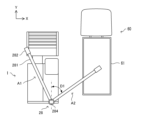
穀粒排出装置28は、収穫物である穀粒の排出作業を行う。具体的には、穀粒排出装置28は、貯留タンク27に貯留されている穀粒を予め設定された排出場所Haにおいて回収車両60に排出する(図5参照)。図6A及び図6Bには排出作業の方法を模式的に示している。穀粒排出装置28は、穀粒の外部への排出方向を調整可能な排出シュータ282(本発明の排出口の一例)と、収穫作業時の格納位置と排出作業時の排出位置との間で移動可能であって、排出作業において貯留タンク27内の穀粒を排出シュータ282に搬送する排出オーガ281(本発明の排出アームの一例)とを含む。排出オーガ281は、車両本体に固定された回転軸284を支点にして水平方向及び垂直方向に回転可能に設けられている。コンバイン1が刈取作業を行っている間、排出オーガ281は格納位置A1(図6A参照)に格納されており非動作状態となる。コンバイン1が排出作業を行う場合、排出オーガ281は格納位置A1から排出位置A2(図6A参照)に移動して動作状態となる。排出オーガ281の排出位置A2は、例えばコンバイン1の進行方向(Y方向)に対する角度D1に応じて設定される。
The grain discharge device 28 discharges grains, which are harvested products. Specifically, the grain discharge device 28 discharges the grains stored in the storage tank 27 to the collection vehicle 60 at a preset discharge location Ha (see FIG. 5). FIGS. 6A and 6B show a schematic diagram of the discharge method. The grain discharge device 28 includes a discharge chute 282 (an example of a discharge port of the present invention) that can adjust the discharge direction of the grains to the outside, and a discharge auger 281 (an example of a discharge arm of the present invention) that can move between a storage position during harvesting and a discharge position during discharge, and transports the grains in the storage tank 27 to the discharge chute 282 during discharge. The discharge auger 281 is provided so as to be rotatable in the horizontal and vertical directions with a rotating shaft 284 fixed to the vehicle body as a fulcrum. While the combine 1 is performing the harvesting operation, the discharge auger 281 is stored in the storage position A1 (see FIG. 6A) and is in an inoperative state. When the combine harvester 1 performs the discharge operation, the discharge auger 281 moves from the storage position A1 to the discharge position A2 (see FIG. 6A) and enters an operating state. The discharge position A2 of the discharge auger 281 is set according to, for example, an angle D1 with respect to the traveling direction (Y direction) of the combine harvester 1.
排出シュータ282は、排出オーガ281の先端に設けられており、また排出オーガ281に固定された回転軸285を支点にして回転可能に設けられている(図6B参照)。例えば排出シュータ282は、回転軸285を支点にして排出オーガ281の延伸方向(図6Bの矢印方向)に回転可能に構成されている。
The discharge chute 282 is provided at the tip of the discharge auger 281 and is rotatable about a rotating shaft 285 fixed to the discharge auger 281 (see FIG. 6B). For example, the discharge chute 282 is configured to be rotatable in the extension direction of the discharge auger 281 (the direction of the arrow in FIG. 6B) about the rotating shaft 285.
また穀粒排出装置28は、カメラ283を備えている。カメラ283は、排出オーガ281の先端又は排出シュータ282に設けられており、上方から下方に向けて撮影範囲を撮像する。例えば図6Bに示す状態ではカメラ283は、回収車両60の回収部61を含む範囲を上方から撮像する。カメラ283は、所定のフレームレートで撮像処理を実行して画像データを制御装置11に送信する。
The grain discharge device 28 also includes a camera 283. The camera 283 is provided at the tip of the discharge auger 281 or on the discharge chute 282, and captures an image of the shooting range from above downward. For example, in the state shown in FIG. 6B, the camera 283 captures an image of an area including the collection section 61 of the collection vehicle 60 from above. The camera 283 executes an imaging process at a predetermined frame rate and transmits image data to the control device 11.
制御装置11は、排出作業において、排出オーガ281及び排出シュータ282の位置(回転角度)を制御する。具体的な制御方法については後述する。
During the discharge operation, the control device 11 controls the positions (rotation angles) of the discharge auger 281 and the discharge chute 282. The specific control method will be described later.
排藁処理部7は、脱穀部4の後方に設けられている。排藁処理部7は、例えば、排藁搬送装置(不図示)と、排藁切断装置(不図示)とを備えている。排藁処理部7は、脱穀部4から搬送された排藁を排藁搬送装置によって排藁切断装置へ搬送して、排藁切断装置によって切断した後でコンバイン1の後方に排出する(図5参照)。
The straw waste processing section 7 is provided behind the threshing section 4. The straw waste processing section 7 is equipped with, for example, a straw waste conveying device (not shown) and a straw waste cutting device (not shown). The straw waste processing section 7 transports the straw transported from the threshing section 4 to the straw waste cutting device by the straw waste conveying device, cuts the straw by the straw waste cutting device, and then discharges it to the rear of the combine 1 (see Figure 5).
動力部8は、走行部2の上方、かつ貯留部6の下方に設けられている。動力部8は、回転動力を発生させるエンジン20を備えている。動力部8は、エンジン20が発生させた回転動力を、走行部2、刈取部3、脱穀部4、選別部5、貯留部6及び排藁処理部7に伝達する。また、コンバイン1は、動力部8のエンジン20へ供給する燃料を収容する燃料タンクを備えている。
The power unit 8 is provided above the traveling section 2 and below the storage section 6. The power unit 8 is equipped with an engine 20 that generates rotational power. The power unit 8 transmits the rotational power generated by the engine 20 to the traveling section 2, the reaping section 3, the threshing section 4, the sorting section 5, the storage section 6, and the straw waste processing section 7. The combine 1 also has a fuel tank that stores fuel to be supplied to the engine 20 of the power unit 8.
操縦部9は、動力部8の上方に設けられている。操縦部9は、作業者が座る座席40である運転席の周囲に、コンバイン1の走行を操縦するための操作具として、コンバイン1の機体の旋回を指示するためのハンドル、コンバイン1の前後進の速度変更を指示するための主変速レバー及び副変速レバー等を備える。コンバイン1の手動走行は、操縦部9のハンドル、主変速レバー、及び副変速レバーの操作を受け付けた走行部2によって実行される。また、操縦部9は、刈取部3による刈取作業、脱穀部4による脱穀作業、貯留部6の穀粒排出装置28による排出作業等を操作するための機構を備える。
The control unit 9 is provided above the power unit 8. Around the driver's seat, which is the seat 40 where the operator sits, the control unit 9 is provided with operating tools for controlling the travel of the combine harvester 1, such as a handle for instructing the turning of the combine harvester 1 body, and a main speed change lever and a sub-speed change lever for instructing changes in the forward and reverse speed of the combine harvester 1. Manual travel of the combine harvester 1 is performed by the travel unit 2 which receives operation of the handle, main speed change lever, and sub-speed change lever of the control unit 9. The control unit 9 also has mechanisms for operating the reaping operation by the reaping unit 3, the threshing operation by the threshing unit 4, the discharge operation by the grain discharge device 28 of the storage unit 6, etc.
測位ユニット52は、GPS等の衛星測位システムを利用してコンバイン1の自車位置を取得する。例えば、測位ユニット52は、測位アンテナを介して測位衛星から測位信号を受信し、測位信号に基づいて測位ユニット52の位置情報、すなわちコンバイン1の自車位置(計測点データ)を取得する。測位ユニット52は、測位アンテナに代えて、量子コンパスで構成されてもよい。
The positioning unit 52 acquires the vehicle position of the combine harvester 1 using a satellite positioning system such as GPS. For example, the positioning unit 52 receives a positioning signal from a positioning satellite via a positioning antenna, and acquires the position information of the positioning unit 52, i.e., the vehicle position of the combine harvester 1 (measurement point data), based on the positioning signal. The positioning unit 52 may be configured with a quantum compass instead of a positioning antenna.
通信部54は、コンバイン1を有線又は無線で通信網N1に接続し、通信網N1を介して操作端末30などの外部機器との間で所定の通信プロトコルに従ったデータ通信を実行するための通信インターフェースである。
The communication unit 54 is a communication interface that connects the combine 1 to the communication network N1 by wire or wirelessly and performs data communication with external devices such as the operation terminal 30 via the communication network N1 in accordance with a predetermined communication protocol.
記憶部51は、各種の情報を記憶するHDD、SSD、フラッシュメモリーなどの不揮発性の記憶部である。記憶部51には、制御装置11に後述の排出制御処理(図14参照)を実行させるための排出制御プログラムなどの制御プログラムが記憶されている。例えば、前記排出制御プログラムは、フラッシュROM、EEPROM、CD、又はDVDなどのコンピュータ読取可能な記録媒体に非一時的に記録されており、所定の読取装置(不図示)で読み取られて記憶部51に記憶される。なお、前記排出制御プログラムは、サーバー(不図示)から通信網N1を介してコンバイン1にダウンロードされて記憶部51に記憶されてもよい。また、記憶部51には、操作端末30から取得する各種設定情報が記憶される。
The storage unit 51 is a non-volatile storage unit such as an HDD, SSD, or flash memory that stores various information. The storage unit 51 stores a control program such as a discharge control program for causing the control device 11 to execute the discharge control process (see FIG. 14) described below. For example, the discharge control program is non-temporarily recorded on a computer-readable recording medium such as a flash ROM, EEPROM, CD, or DVD, and is read by a predetermined reading device (not shown) and stored in the storage unit 51. The discharge control program may be downloaded from a server (not shown) to the combine 1 via the communication network N1 and stored in the storage unit 51. The storage unit 51 also stores various setting information acquired from the operation terminal 30.
検知部53は、赤外線、超音波などを利用して所定の検知範囲の検知対象を検知するセンサーである。例えば、検知部53は、レーザーを用いて測定対象物(検知対象)までの距離を3次元で測定可能なライダーセンサ(距離センサ)であってもよいし、超音波を用いて測定対象物までの距離を測定可能な複数のソナーを有するソナーセンサであってもよい。検知部53は、コンバイン1の機体の前部及び後部に配置されてもよいし、コンバイン1の機体の前後左右の各部に配置されてもよい。
The detection unit 53 is a sensor that detects a detection target within a predetermined detection range using infrared rays, ultrasonic waves, etc. For example, the detection unit 53 may be a lidar sensor (distance sensor) that can measure the distance to the measurement target (detection target) in three dimensions using a laser, or a sonar sensor with multiple sonars that can measure the distance to the measurement target using ultrasonic waves. The detection unit 53 may be disposed at the front and rear of the body of the combine harvester 1, or may be disposed at each of the front, rear, left and right parts of the body of the combine harvester 1.
検知部53は、測定情報(検知情報)を制御装置11に送信する。制御装置11は、検知部53から取得する測定情報に基づいて検知対象を検知するとともに検知対象の位置を特定する。制御装置11は、コンバイン1が自動走行中に報知エリアにおいて検知対象を検知した場合に、警報を外部に報知させる。また、制御装置11は、コンバイン1が自動走行中に減速エリアにおいて検知対象を検知した場合に、コンバイン1を減速させる。また、制御装置11は、コンバイン1が自動走行中に停止エリアにおいて検知対象を検知した場合に、コンバイン1を停止させる。制御装置11は、特定した検知対象の位置を示す位置情報を操作端末30に出力してもよい。
The detection unit 53 transmits measurement information (detection information) to the control device 11. The control device 11 detects the detection target based on the measurement information acquired from the detection unit 53 and identifies the position of the detection target. When the control device 11 detects the detection target in the notification area while the combine harvester 1 is traveling automatically, the control device 11 issues an alarm to the outside. Furthermore, when the control device 11 detects the detection target in the deceleration area while the combine harvester 1 is traveling automatically, the control device 11 decelerates the combine harvester 1. Furthermore, when the control device 11 detects the detection target in the stop area while the combine harvester 1 is traveling automatically, the control device 11 stops the combine harvester 1. The control device 11 may output position information indicating the position of the identified detection target to the operation terminal 30.
制御装置11は、CPU、ROM、及びRAMなどの制御機器を有する。前記CPUは、各種の演算処理を実行するプロセッサーである。前記ROMは、前記CPUに各種の演算処理を実行させるためのBIOS及びOSなどの制御プログラムが予め記憶される不揮発性の記憶部である。前記RAMは、各種の情報を記憶する揮発性又は不揮発性の記憶部であり、前記CPUが実行する各種の処理の一時記憶メモリーとして使用される。そして、制御装置11は、前記ROM又は記憶部51に予め記憶された各種の制御プログラムを前記CPUで実行することによりコンバイン1を制御する。
The control device 11 has control devices such as a CPU, a ROM, and a RAM. The CPU is a processor that executes various arithmetic processes. The ROM is a non-volatile storage unit in which control programs such as a BIOS and an OS for causing the CPU to execute various arithmetic processes are stored in advance. The RAM is a volatile or non-volatile storage unit that stores various information, and is used as a temporary storage memory for various processes executed by the CPU. The control device 11 controls the combine harvester 1 by executing the various control programs stored in advance in the ROM or the storage unit 51 with the CPU.
ところで、従来の技術では、例えば作業車両が排出場所に到着すると、収穫物が回収車両の回収部内に満遍なく収容されるように作業者が手動により作業車両の排出部(穀粒排出装置)を操作する必要がある。このため、作業者に負担が掛かったり、作業者の熟練度によって回収部内の収穫物の収容状態にばらつきが生じたりするなど、作業効率が低下する問題が生じる。これに対して、本実施形態に係るコンバイン1は、以下に示すように、収穫物の排出作業の作業効率を向上させることが可能な構成を備えている。
However, in conventional technology, for example, when a work vehicle arrives at a discharge location, an operator must manually operate the discharge section (grain discharge device) of the work vehicle so that the harvest is evenly stored in the collection section of the collection vehicle. This creates problems that reduce work efficiency, such as placing a burden on the operator and causing variations in the state of storage of the harvest in the collection section depending on the operator's level of skill. In response to this, the combine harvester 1 of this embodiment has a configuration that can improve the work efficiency of the harvest discharge work, as described below.
具体的には、図1に示すように、制御装置11は、走行処理部111、動作処理部112、排出処理部113などの各種の処理部を含む。なお、制御装置11は、前記CPUで前記排出制御プログラムに従った各種の処理を実行することによって前記各種の処理部として機能する。また、一部又は全部の前記処理部が電子回路で構成されていてもよい。なお、前記排出制御プログラムは、複数のプロセッサーを前記処理部として機能させるためのプログラムであってもよい。
Specifically, as shown in FIG. 1, the control device 11 includes various processing units such as a driving processing unit 111, an operation processing unit 112, and an emission processing unit 113. The control device 11 functions as the various processing units by executing various processes according to the emission control program with the CPU. Some or all of the processing units may be configured with electronic circuits. The emission control program may be a program for causing multiple processors to function as the processing units.
走行処理部111は、コンバイン1を走行させる走行処理を実行する。具体的には、走行処理部111は、圃場Fに対して設定された目標経路Rに従ってコンバイン1を自動走行させる。走行処理部111は、目標経路Rに含まれる、コンバイン1に所定の作業(刈取作業)を行なわせる複数の作業経路と、複数の作業経路間を接続する移動経路(旋回経路など)とに従ってコンバイン1を走行させる。走行処理部111は、圃場Fに対して設定される各種設定情報を操作端末30から取得する。また、走行処理部111は、刈取作業において、測位ユニット52からコンバイン1の自車位置を取得し、自車位置と目標経路Rに含まれる作業経路とに基づいて、コンバイン1が作業経路に沿って自動走行及び刈取作業を行うように走行部2、刈取部3、及び動力部8を制御する。
The driving processing unit 111 executes a driving process for driving the combine harvester 1. Specifically, the driving processing unit 111 automatically drives the combine harvester 1 according to a target route R set for the field F. The driving processing unit 111 drives the combine harvester 1 according to a plurality of work routes included in the target route R that cause the combine harvester 1 to perform a predetermined task (reap work) and a movement route (such as a turning route) that connects the plurality of work routes. The driving processing unit 111 acquires various setting information set for the field F from the operation terminal 30. In addition, the driving processing unit 111 acquires the vehicle position of the combine harvester 1 from the positioning unit 52 during the reap work, and controls the driving unit 2, the reaper unit 3, and the power unit 8 so that the combine harvester 1 automatically drives and reaps along the work route based on the vehicle position and the work route included in the target route R.
例えば図5に示すように、走行処理部111は、コンバイン1を、開始位置Sから外周領域F1において外周に沿って自動走行及び刈取作業を実行させた後、内周領域F2において終了位置Gまで自動走行及び刈取作業を実行させる。
For example, as shown in FIG. 5, the driving processing unit 111 causes the combine 1 to perform automatic driving and mowing operations along the outer periphery in the outer periphery area F1 from the start position S, and then performs automatic driving and mowing operations in the inner periphery area F2 to the end position G.
また、走行処理部111は、刈取作業中に貯留タンク27の貯留量が所定量(上限値)に達すると、刈取部3を非作業位置に上昇させて刈取作業を停止し、コンバイン1を現在位置(作業中断位置)から排出場所Ha(図5参照)までの移動経路を走行させる。走行処理部111は、例えば現在位置から排出場所Haまでの最短経路を生成して、コンバイン1を最短経路に従って自動走行させる。なお、走行処理部111は、現在位置から排出場所Haまで作業者の手動操舵に応じて走行(手動走行)させてもよい。
When the amount of storage in the storage tank 27 reaches a predetermined amount (upper limit) during harvesting, the travel processing unit 111 raises the harvesting unit 3 to a non-working position to stop harvesting, and causes the combine harvester 1 to travel along a path from the current position (work interruption position) to the discharge location Ha (see FIG. 5). The travel processing unit 111, for example, generates the shortest path from the current position to the discharge location Ha, and causes the combine harvester 1 to automatically travel along the shortest path. The travel processing unit 111 may also cause the combine harvester 1 to travel (manually travel) from the current position to the discharge location Ha in response to manual steering by the operator.
動作処理部112及び排出処理部113は、排出作業に関する処理を実行する。動作処理部112は、排出作業においてコンバイン1及び穀粒排出装置28の少なくともいずれかの動作を制御する。すなわち、動作処理部112は、排出作業において、作業者の手動操作によらず、コンバイン1及び穀粒排出装置28の少なくともいずれかを動作させる。また、動作処理部112は、排出作業において、回収部61内に収容される穀粒(収穫物)が満遍なく満杯の状態になるように、コンバイン1及び穀粒排出装置28の少なくともいずれかを動作させる。排出処理部113は、穀粒排出装置28から穀粒を回収部61に排出させる。
The operation processing unit 112 and the discharge processing unit 113 execute processing related to the discharge operation. The operation processing unit 112 controls the operation of at least one of the combine harvester 1 and the grain discharge device 28 during the discharge operation. That is, the operation processing unit 112 operates at least one of the combine harvester 1 and the grain discharge device 28 during the discharge operation without manual operation by the operator. Furthermore, the operation processing unit 112 operates at least one of the combine harvester 1 and the grain discharge device 28 during the discharge operation so that the grains (harvest product) stored in the collection unit 61 are evenly filled. The discharge processing unit 113 discharges grains from the grain discharge device 28 to the collection unit 61.
具体的には、動作処理部112は、回収車両60の回収部61に対するコンバイン1の位置を制御する。例えば、動作処理部112は、排出場所Haに到着したコンバイン1を、コンバイン1の進行方向が回収部61の側辺に実質的に平行(略平行)になる位置に移動させる。すなわち、動作処理部112は、コンバイン1が回収部61に対して平行になる位置に停車させる。
Specifically, the operation processing unit 112 controls the position of the combine harvester 1 relative to the recovery unit 61 of the recovery vehicle 60. For example, the operation processing unit 112 moves the combine harvester 1 that has arrived at the discharge location Ha to a position where the direction of travel of the combine harvester 1 is substantially parallel (approximately parallel) to the side of the recovery unit 61. In other words, the operation processing unit 112 stops the combine harvester 1 at a position where it is parallel to the recovery unit 61.
例えばコンバイン1が排出場所Haに到着すると、動作処理部112は、カメラ283の撮影範囲に回収部61全体が入る位置まで排出オーガ281を移動させる(図6参照)。カメラ283は、前記撮影範囲を撮像すると撮像画像P1を制御装置11に送信する。図7には撮像画像P1の一例を示している。動作処理部112は、カメラ283から撮像画像P1を取得すると、撮像画像P1における回収部61の傾き(角度D0)(図7参照)と、排出オーガ281の回転角度D1(図6A参照)とに基づいて、コンバイン1と回収部61との角度差を算出し、算出した角度差に基づいてコンバイン1の位置を調整する。これにより、コンバイン1を、進行方向(Y方向)が回収部61の側辺に略平行になる位置に合わせることができる。
For example, when the combine harvester 1 arrives at the discharge location Ha, the operation processing unit 112 moves the discharge auger 281 to a position where the entire collection unit 61 is within the shooting range of the camera 283 (see FIG. 6). When the camera 283 captures the shooting range, it transmits the captured image P1 to the control device 11. FIG. 7 shows an example of the captured image P1. When the operation processing unit 112 obtains the captured image P1 from the camera 283, it calculates the angle difference between the combine harvester 1 and the collection unit 61 based on the inclination (angle D0) of the collection unit 61 in the captured image P1 (see FIG. 7) and the rotation angle D1 of the discharge auger 281 (see FIG. 6A), and adjusts the position of the combine harvester 1 based on the calculated angle difference. This allows the combine harvester 1 to be aligned to a position where its traveling direction (Y direction) is approximately parallel to the side of the collection unit 61.
コンバイン1の位置を調整する方法は上記方法に限定されない。例えば、コンバイン1の側面に設けられた検知部53が回収部61までの距離を測定し、動作処理部112が、測定距離に基づいて、コンバイン1を回収部61に平行になる位置に調整してもよい。また、回収車両60がカメラ又は検知センサーを備える場合、回収車両60がコンバイン1に平行になるように位置を調整してもよい。また、制御装置11は、回収車両60とデータ通信可能な場合、回収車両60を自動走行させて位置を調整してもよい。
The method of adjusting the position of the combine harvester 1 is not limited to the above method. For example, the detection unit 53 provided on the side of the combine harvester 1 may measure the distance to the recovery unit 61, and the operation processing unit 112 may adjust the combine harvester 1 to a position parallel to the recovery unit 61 based on the measured distance. In addition, if the recovery vehicle 60 is equipped with a camera or a detection sensor, the position of the recovery vehicle 60 may be adjusted to be parallel to the combine harvester 1. In addition, if the control device 11 is capable of data communication with the recovery vehicle 60, it may adjust the position by automatically driving the recovery vehicle 60.
他の方法として、制御装置11は、コンバイン1が自動走行中にカメラ、検知センサーなどの検知結果に基づいて、回収車両60が圃場Fの外形(圃場辺)に対して略平行に停車しているか否か、又は、圃場辺に対して何度ずれているかを判定する。回収車両60が圃場辺に対して略平行に停車している場合には、制御装置11は、コンバイン1を圃場辺に略平行となるように排出場所Haに移動させる。回収車両60が圃場辺に対して所定角度だけずれている場合には、制御装置11は、コンバイン1を圃場辺に対して当該所定角度だけずれるように排出場所Haに移動させる。他の方法として、制御装置11は、回収車両60の側面の前後方向に付された複数の読取媒体(マーカーなど)を検出して、圃場Fに対する回収車両60の位置、及び、圃場辺に対する角度(車両方位)を特定し、特定した位置及び角度に基づいて、コンバイン1を回収車両60に略平行になるように排出場所Haに移動させてもよい。
As another method, the control device 11 determines whether the collection vehicle 60 is parked approximately parallel to the outline (field edge) of the field F, or how many degrees it is misaligned from the field edge, based on the detection results of cameras, detection sensors, etc. while the combine harvester 1 is traveling automatically. If the collection vehicle 60 is parked approximately parallel to the field edge, the control device 11 moves the combine harvester 1 to the discharge location Ha so that it is approximately parallel to the field edge. If the collection vehicle 60 is misaligned from the field edge by a predetermined angle, the control device 11 moves the combine harvester 1 to the discharge location Ha so that it is misaligned from the field edge by the predetermined angle. As another method, the control device 11 can detect multiple reading media (such as markers) attached to the front and rear sides of the collection vehicle 60 to determine the position of the collection vehicle 60 relative to the field F and its angle with respect to the field edge (vehicle orientation), and then move the combine 1 to the discharge location Ha so that it is approximately parallel to the collection vehicle 60 based on the determined position and angle.
コンバイン1が排出場所Haにおいて回収部61に対して略平行な位置に停車すると、動作処理部112及び排出処理部113は排出処理を実行する。具体的には、動作処理部112は、回収部61内の穀粒の排出状態に基づいて、コンバイン1及び穀粒排出装置28の少なくともいずれかの動作を制御する。以下、排出処理の具体的な方法(第1実施例~第4実施例)を説明する。
When the combine harvester 1 stops at a position approximately parallel to the collection unit 61 at the discharge location Ha, the operation processing unit 112 and the discharge processing unit 113 execute the discharge process. Specifically, the operation processing unit 112 controls the operation of at least one of the combine harvester 1 and the grain discharge device 28 based on the discharge state of the grains in the collection unit 61. Specific methods of the discharge process (first to fourth examples) are described below.
[第1実施例]
図8A及び図8Bは、第1実施例の排出方法を示す模式図である。第1実施例では、先ず、動作処理部112は、排出オーガ281をコンバイン1の進行方向(Y方向)に対して実質的に垂直(略垂直)になる位置に移動(回転)させる。例えば図8Aに示すように、動作処理部112は、排出オーガ281をコンバイン1の進行方向(Y方向)に対する角度D1が90度になる位置に移動させる。また、動作処理部112は、排出シュータ282が回収部61の後端に合うようにコンバイン1を位置合わせ(前後進)する。例えば動作処理部112は、カメラ283の撮像画像に基づいて、コンバイン1を位置合わせする。また、動作処理部112は、排出シュータ282の向き(排出方向)が垂直方向(下向き)にセットされた状態のときに回収部61の中心(X方向の中心)に合うように、コンバイン1の位置(コンバイン1と回収部61との間の距離)及び排出オーガ281の上下方向の角度を調整する。
[First embodiment]
8A and 8B are schematic diagrams showing the discharge method of the first embodiment. In the first embodiment, first, the operation processing unit 112 moves (rotates) the discharge auger 281 to a position that is substantially perpendicular (approximately perpendicular) to the traveling direction (Y direction) of the combine 1. For example, as shown in FIG. 8A, the operation processing unit 112 moves the discharge auger 281 to a position where the angle D1 with respect to the traveling direction (Y direction) of the combine 1 is 90 degrees. In addition, the operation processing unit 112 aligns (forward and backward) the combine 1 so that the discharge chute 282 is aligned with the rear end of the collection unit 61. For example, the operation processing unit 112 aligns the combine 1 based on the image captured by the camera 283. In addition, the operation processing unit 112 adjusts the position of the combine 1 (the distance between the combine 1 and the recovery unit 61) and the vertical angle of the discharge auger 281 so that it is aligned with the center (center in the X direction) of the recovery unit 61 when the orientation (discharge direction) of the discharge chute 282 is set vertically (downward).
コンバイン1及び排出オーガ281の位置合わせが終了すると、排出処理部113は、貯留タンク27に貯留されている穀粒を、排出オーガ281内を通過させて排出シュータ282から外部(回収部61)へ排出させる排出処理を開始する。排出シュータ282から穀粒を回収部61に排出させながら、動作処理部112は、排出シュータ282の向き(排出方向)を変更する(図6B参照)。例えば、排出シュータ282が垂直下向きの位置にセットされた状態で排出処理を実行し、回収部61内の後端に山積された穀粒の頂上が回収部61の上端に近付いた時点で、動作処理部112は、排出シュータ282の向きを図8Bにおける右側に変更する。続いて、回収部61内の後端の右側に山積された穀粒の頂上が回収部61の上端に近付いた時点で、動作処理部112は、排出シュータ282の向きを図8Bにおける左側に変更する。これにより、回収部61内の後端側が満遍なく満杯の状態になる。なお、動作処理部112は、カメラ283の撮像画像に基づいて回収部61内の排出状態(穀粒が積まれた山の状態)を判定して、排出シュータ282の向きを調整する。
When the alignment of the combine harvester 1 and the discharge auger 281 is completed, the discharge processing unit 113 starts the discharge processing to pass the grains stored in the storage tank 27 through the discharge auger 281 and discharge them from the discharge chute 282 to the outside (collection unit 61). While discharging the grains from the discharge chute 282 to the collection unit 61, the operation processing unit 112 changes the direction (discharge direction) of the discharge chute 282 (see FIG. 6B). For example, the discharge processing is performed with the discharge chute 282 set in a vertically downward position, and when the top of the grains piled up at the rear end of the collection unit 61 approaches the upper end of the collection unit 61, the operation processing unit 112 changes the direction of the discharge chute 282 to the right in FIG. 8B. Next, when the top of the grains piled up on the right side of the rear end of the collection unit 61 approaches the upper end of the collection unit 61, the operation processing unit 112 changes the direction of the discharge chute 282 to the left in FIG. 8B. This ensures that the rear end of the collection section 61 is evenly filled. The operation processing section 112 determines the discharge state (state of the pile of grains) in the collection section 61 based on the image captured by the camera 283, and adjusts the orientation of the discharge chute 282.
続いて、動作処理部112は、排出シュータ282の向きを垂直下向きに変更するとともに、コンバイン1を進行方向(Y方向)に所定距離L1だけ前進走行させる。なお、動作処理部112による排出シュータ282及びコンバイン1の上記動作制御の間、排出処理部113は排出処理を継続してもよい。コンバイン1が所定距離L1だけ前進した位置において、動作処理部112は、排出シュータ282の向き(排出方向)を左右に変更しながら、排出処理部113が穀粒を回収部61内に排出させる。所定距離L1の位置において回収部61内が満遍なく満杯の状態になると、動作処理部112は、再度、排出シュータ282の向きを垂直下向きに変更するとともに、コンバイン1を進行方向(Y方向)に所定距離L1だけ前進走行させる。
Then, the operation processing unit 112 changes the direction of the discharge chute 282 vertically downward and causes the combine harvester 1 to travel forward a predetermined distance L1 in the traveling direction (Y direction). The discharge processing unit 113 may continue the discharge process while the operation processing unit 112 controls the above-mentioned operation of the discharge chute 282 and the combine harvester 1. When the combine harvester 1 has traveled forward a predetermined distance L1, the operation processing unit 112 changes the direction (discharge direction) of the discharge chute 282 left and right, while the discharge processing unit 113 discharges the grains into the collection unit 61. When the collection unit 61 is evenly filled at the position of the predetermined distance L1, the operation processing unit 112 again changes the direction of the discharge chute 282 vertically downward and causes the combine harvester 1 to travel forward a predetermined distance L1 in the traveling direction (Y direction).
動作処理部112は、排出オーガ281及び排出シュータ282が回収部61の前端に移動するまで上述の動作を繰り返し実行する。そして、回収部61の前端の位置において回収部61内が満遍なく満杯の状態になると、排出処理部113は排出処理を終了する。排出作業が終了すると、動作処理部112は、排出オーガ281を格納位置A1(図6A参照)に戻す。その後、走行処理部111は、コンバイン1を排出場所Haから作業中断位置まで自動走行させ、作業中断位置から刈取作業を再開させる。
The operation processing unit 112 repeatedly executes the above-mentioned operations until the discharge auger 281 and discharge chute 282 move to the front end of the collection unit 61. Then, when the collection unit 61 is evenly filled at the front end position of the collection unit 61, the discharge processing unit 113 ends the discharge process. When the discharge work is completed, the operation processing unit 112 returns the discharge auger 281 to the storage position A1 (see FIG. 6A). Thereafter, the travel processing unit 111 automatically travels the combine 1 from the discharge location Ha to the work interruption position, and resumes the harvesting work from the work interruption position.
以上のように、第1実施例に係る排出方法では、動作処理部112は、コンバイン1を回収部61の側辺に略平行になる位置に移動させ、排出オーガ281をコンバイン1の進行方向(Y方向)に対して略垂直になる位置(90度)に移動させる。また、動作処理部112は、排出シュータ282から穀粒を回収部61に排出させている間、排出オーガ281を90度に維持して、コンバイン1を所定距離L1ずつ前進走行させ、かつ、排出シュータ282の排出方向を前記進行方向に対して直交する左右方向(X方向)に変更する。
As described above, in the discharge method according to the first embodiment, the operation processing unit 112 moves the combine 1 to a position approximately parallel to the side of the collection unit 61, and moves the discharge auger 281 to a position approximately perpendicular (90 degrees) to the traveling direction (Y direction) of the combine 1. In addition, while discharging grains from the discharge chute 282 to the collection unit 61, the operation processing unit 112 maintains the discharge auger 281 at 90 degrees, moves the combine 1 forward a predetermined distance L1 at a time, and changes the discharge direction of the discharge chute 282 to the left-right direction (X direction) perpendicular to the traveling direction.
なお、動作処理部112は、排出作業においてコンバイン1を回収部61の前端側から所定距離L1ずつ後進走行させてもよい。また、動作処理部112は、排出作業において前進走行と後進走行とを組み合わせてもよい。すなわち、排出作業においてコンバイン1の進行方向は、前進方向であってもよいし後進方向であってもよい。第1実施例の排出方法によれば、穀粒を回収部61に満遍なく満杯の状態に排出することができる。
The operation processing unit 112 may cause the combine harvester 1 to travel backwards a predetermined distance L1 from the front end side of the collection unit 61 during the discharge operation. The operation processing unit 112 may also combine forward travel and backward travel during the discharge operation. In other words, the direction of travel of the combine harvester 1 during the discharge operation may be either the forward direction or the backward direction. According to the discharge method of the first embodiment, grains can be discharged evenly into the collection unit 61 until it is fully filled.
[第2実施例]
図9A及び図9Bは、第2実施例の排出方法を示す模式図である。第2実施例では、制御装置11は、回収部61に対して、コンバイン1の進行方向(Y方向)に直交する方向(X方向)に複数の排出目標位置を設定する。図9に示す例では、制御装置11は、X方向に3つの排出目標位置(第1排出目標位置K1、第2排出目標位置K2、第3排出目標位置K3)を設定する。例えば、制御装置11は、回収部61の横幅(X方向)を4等分する3つの排出目標位置を設定する。ここでは、コンバイン1から最も遠い排出目標位置を「第1排出目標位置K1」とし、コンバイン1に最も近い排出目標位置を「第3排出目標位置K3」とし、中間の排出目標位置を「第2排出目標位置K2」とする。
[Second embodiment]
9A and 9B are schematic diagrams showing a discharge method of the second embodiment. In the second embodiment, the control device 11 sets a plurality of discharge target positions in a direction (X direction) perpendicular to the traveling direction (Y direction) of the combine 1 with respect to the collection section 61. In the example shown in FIG. 9, the control device 11 sets three discharge target positions (first discharge target position K1, second discharge target position K2, and third discharge target position K3) in the X direction. For example, the control device 11 sets three discharge target positions that divide the width (X direction) of the collection section 61 into four equal parts. Here, the discharge target position farthest from the combine 1 is set as the "first discharge target position K1", the discharge target position closest to the combine 1 is set as the "third discharge target position K3", and the intermediate discharge target position is set as the "second discharge target position K2".
先ず、動作処理部112は、排出オーガ281をコンバイン1の進行方向(Y方向)に対して角度Da(例えば、Da<90度)になる位置に移動(回転)させる。また、動作処理部112は、カメラ283の撮像画像に基づいて、排出シュータ282が回収部61の後端に合うようにコンバイン1を位置合わせ(前後進)する。また、動作処理部112は、排出シュータ282の排出方向が垂直方向(下向き)にセットされた状態のときに回収部61の第1排出目標位置K1に合うように、コンバイン1の位置(コンバイン1と回収部61との間の距離)及び排出オーガ281の上下方向の角度を調整する。なお、動作処理部112は、排出シュータ282が第1排出目標位置K1に合うように、排出オーガ281の水平方向の角度Daを調整してもよい。
First, the operation processing unit 112 moves (rotates) the discharge auger 281 to a position where the angle is Da (for example, Da<90 degrees) with respect to the traveling direction (Y direction) of the combine harvester 1. The operation processing unit 112 also aligns (forward and backward) the combine harvester 1 so that the discharge chute 282 is aligned with the rear end of the recovery unit 61 based on the image captured by the camera 283. The operation processing unit 112 also adjusts the position of the combine harvester 1 (the distance between the combine harvester 1 and the recovery unit 61) and the vertical angle of the discharge auger 281 so that the discharge chute 282 is aligned with the first discharge target position K1 of the recovery unit 61 when the discharge direction of the discharge chute 282 is set vertically (downward). The operation processing unit 112 may also adjust the horizontal angle Da of the discharge auger 281 so that the discharge chute 282 is aligned with the first discharge target position K1.
コンバイン1及び排出オーガ281の位置合わせが終了すると、排出処理部113は排出処理を開始する。排出シュータ282が垂直下向きの位置にセットされた状態で排出処理が開始されて、第1排出目標位置K1において回収部61内の後端に山積された穀粒の頂上が回収部61の上端に近付くと、動作処理部112は、第1排出目標位置K1に沿ってコンバイン1を所定距離だけ前進走行させる。コンバイン1が所定距離だけ移動した位置において回収部61内に山積された穀粒の頂上が回収部61の上端に近付くと、動作処理部112は、さらに第1排出目標位置K1に沿ってコンバイン1を所定距離だけ前進走行させる。動作処理部112は、第1排出目標位置K1に沿って排出オーガ281及び排出シュータ282が回収部61の前端に移動するまで上述の動作を繰り返し実行する。
When the alignment of the combine 1 and the discharge auger 281 is completed, the discharge processing unit 113 starts the discharge processing. When the discharge processing is started with the discharge chute 282 set in a vertically downward position, and the top of the grains piled up at the rear end of the collection unit 61 at the first discharge target position K1 approaches the upper end of the collection unit 61, the operation processing unit 112 causes the combine 1 to travel forward a predetermined distance along the first discharge target position K1. When the top of the grains piled up in the collection unit 61 approaches the upper end of the collection unit 61 at a position where the combine 1 has moved a predetermined distance, the operation processing unit 112 causes the combine 1 to travel forward a predetermined distance along the first discharge target position K1. The operation processing unit 112 repeatedly performs the above-mentioned operations until the discharge auger 281 and the discharge chute 282 move to the front end of the collection unit 61 along the first discharge target position K1.
第1排出目標位置K1に対応する穀粒M1(図9B参照)が回収部61内で満遍なく収容されると、続いて、動作処理部112は、排出シュータ282が第2排出目標位置K2に合うように、コンバイン1を後進走行させ、排出オーガ281を角度Db(Db<Da)の位置に移動させる。
When the grains M1 (see FIG. 9B) corresponding to the first discharge target position K1 are evenly stored in the collection section 61, the operation processing section 112 then reverses the combine 1 and moves the discharge auger 281 to a position at angle Db (Db<Da) so that the discharge chute 282 is aligned with the second discharge target position K2.
コンバイン1及び排出オーガ281の位置合わせが終了すると、排出処理部113は穀粒を回収部61内の中央部分に排出させる。第2排出目標位置K2において回収部61内の後端に山積された穀粒の頂上が回収部61の上端に近付くと、動作処理部112は、第2排出目標位置K2に沿ってコンバイン1を所定距離だけ前進走行させる。コンバイン1が所定距離だけ移動した位置において回収部61内に山積された穀粒の頂上が回収部61の上端に近付くと、動作処理部112は、さらに第2排出目標位置K2に沿ってコンバイン1を所定距離だけ前進走行させる。動作処理部112は、第2排出目標位置K2に沿って排出オーガ281及び排出シュータ282が回収部61の前端に移動するまで上述の動作を繰り返し実行する。
When the alignment of the combine 1 and the discharge auger 281 is completed, the discharge processing unit 113 discharges the grains to the center of the collection unit 61. When the top of the grains piled at the rear end of the collection unit 61 approaches the upper end of the collection unit 61 at the second discharge target position K2, the operation processing unit 112 causes the combine 1 to travel forward a predetermined distance along the second discharge target position K2. When the top of the grains piled in the collection unit 61 approaches the upper end of the collection unit 61 at a position where the combine 1 has moved a predetermined distance, the operation processing unit 112 causes the combine 1 to travel forward a predetermined distance along the second discharge target position K2. The operation processing unit 112 repeatedly performs the above-mentioned operations until the discharge auger 281 and the discharge chute 282 move to the front end of the collection unit 61 along the second discharge target position K2.
第2排出目標位置K2に対応する穀粒M2(図9B参照)が回収部61内で満遍なく収容されると、続いて、動作処理部112は、排出シュータ282が第3排出目標位置K3に合うように、コンバイン1を後進走行させ、排出オーガ281を角度Dc(Dc<Db)の位置に移動させる。
When the grains M2 (see FIG. 9B) corresponding to the second discharge target position K2 are evenly stored in the collection section 61, the operation processing section 112 then reverses the combine 1 and moves the discharge auger 281 to a position at angle Dc (Dc<Db) so that the discharge chute 282 is aligned with the third discharge target position K3.
コンバイン1及び排出オーガ281の位置合わせが終了すると、排出処理部113は穀粒を回収部61内の左側に排出させる。第3排出目標位置K3において回収部61内の後端に山積された穀粒の頂上が回収部61の上端に近付くと、動作処理部112は、第3排出目標位置K3に沿ってコンバイン1を所定距離だけ前進走行させる。コンバイン1が所定距離だけ移動した位置において回収部61内に山積された穀粒の頂上が回収部61の上端に近付くと、動作処理部112は、さらに第3排出目標位置K3に沿ってコンバイン1を所定距離だけ前進走行させる。動作処理部112は、第3排出目標位置K3に沿って排出オーガ281及び排出シュータ282が回収部61の前端に移動するまで上述の動作を繰り返し実行する。これにより、回収部61内の全体が満遍なく満杯の状態になる。
When the alignment of the combine 1 and the discharge auger 281 is completed, the discharge processing unit 113 discharges the grains to the left side of the collection unit 61. When the top of the grains piled up at the rear end of the collection unit 61 at the third discharge target position K3 approaches the upper end of the collection unit 61, the operation processing unit 112 causes the combine 1 to travel forward a predetermined distance along the third discharge target position K3. When the top of the grains piled up in the collection unit 61 approaches the upper end of the collection unit 61 at a position where the combine 1 has moved a predetermined distance, the operation processing unit 112 causes the combine 1 to travel forward a predetermined distance along the third discharge target position K3. The operation processing unit 112 repeatedly performs the above-mentioned operations until the discharge auger 281 and the discharge chute 282 move to the front end of the collection unit 61 along the third discharge target position K3. As a result, the entire collection unit 61 becomes evenly filled.
回収部61内の全体が満遍なく満杯の状態になると、排出処理部113は排出処理を終了する。
When the entire collection section 61 is evenly filled, the discharge processing section 113 ends the discharge process.
以上のように、第2実施例に係る排出方法では、回収部61に対して、コンバイン1の進行方向(Y方向)に直交する方向(X方向)に複数の排出目標位置を設定する。また、動作処理部112は、コンバイン1を回収部の側辺に略平行になる位置に移動させ、排出オーガ281を、排出シュータ282が複数の排出目標位置のいずれかに対応する位置に移動させて、排出シュータ282から穀粒を回収部61に排出させる排出処理を開始させ、排出処理中、コンバイン1を進行方向に走行(前進走行及び後進走行)させる。また、動作処理部112は、排出処理中、複数の排出目標位置のそれぞれに排出オーガ281を順に移動させる。なお、図9に示す例において、制御装置11は、第2排出目標位置K2の排出処理を行った後に、第1排出目標位置K1及び第3排出目標位置K3の排出処理を行ってもよい。第2実施例の排出方法によれば、穀粒を回収部61に満遍なく満杯の状態に排出することができる。
As described above, in the discharge method according to the second embodiment, a plurality of discharge target positions are set for the collection unit 61 in the direction (X direction) perpendicular to the traveling direction (Y direction) of the combine 1. The operation processing unit 112 also moves the combine 1 to a position that is approximately parallel to the side of the collection unit, moves the discharge auger 281 to a position where the discharge chute 282 corresponds to one of the plurality of discharge target positions, starts a discharge process in which the discharge chute 282 discharges grains to the collection unit 61, and makes the combine 1 travel in the traveling direction (forward travel and backward travel) during the discharge process. The operation processing unit 112 also moves the discharge auger 281 in sequence to each of the plurality of discharge target positions during the discharge process. In the example shown in FIG. 9, the control device 11 may perform the discharge process of the first discharge target position K1 and the third discharge target position K3 after performing the discharge process of the second discharge target position K2. According to the discharge method of the second embodiment, grains can be discharged evenly into the collection unit 61 in a full state.
また、他の実施形態として、制御装置11は、右端の排出目標位置においてコンバイン1を前進走行させながら排出処理を実行させ、次に中央の排出目標位置においてコンバイン1を後進走行させながら排出処理を実行させ、次に左端の排出目標位置においてコンバイン1を前進走行させながら排出処理を実行させてもよい。また、制御装置11は、右端の排出目標位置においてコンバイン1を後進走行させながら排出処理を実行させ、次に中央の排出目標位置においてコンバイン1を前進走行させながら排出処理を実行させ、次に左端の排出目標位置においてコンバイン1を後進走行させながら排出処理を実行させてもよい。すなわち、制御装置11は、複数の排出目標位置について、コンバイン1を前進走行及び後進走行を順に切り替えながら排出処理を実行させてもよい。
In another embodiment, the control device 11 may execute the discharge process while causing the combine harvester 1 to travel forward at the rightmost discharge target position, then execute the discharge process while causing the combine harvester 1 to travel backward at the central discharge target position, and then execute the discharge process while causing the combine harvester 1 to travel forward at the leftmost discharge target position. The control device 11 may also execute the discharge process while causing the combine harvester 1 to travel backward at the rightmost discharge target position, then execute the discharge process while causing the combine harvester 1 to travel forward at the central discharge target position, and then execute the discharge process while causing the combine harvester 1 to travel backward at the leftmost discharge target position. In other words, the control device 11 may execute the discharge process while switching the combine harvester 1 between forward and backward travel in sequence for multiple discharge target positions.
[第3実施例]
図10A及び図10Bは、第3実施例の排出方法を示す模式図である。第3実施例では、第2実施例と同様に、制御装置11は、回収部61に対して、コンバイン1の進行方向(Y方向)に直交する方向(X方向)に複数の排出目標位置を設定する。ここでは、コンバイン1から最も遠い排出目標位置を「第2排出目標位置K2」とし、コンバイン1に最も近い排出目標位置を「第3排出目標位置K3」とし、中間の排出目標位置を「第1排出目標位置K1」とする。
[Third Example]
10A and 10B are schematic diagrams showing the discharge method of the third embodiment. In the third embodiment, similarly to the second embodiment, the control device 11 sets a plurality of discharge target positions for the collection unit 61 in a direction (X direction) perpendicular to the traveling direction (Y direction) of the combine 1. Here, the discharge target position farthest from the combine 1 is set as the "second discharge target position K2", the discharge target position closest to the combine 1 is set as the "third discharge target position K3", and the intermediate discharge target position is set as the "first discharge target position K1".
先ず、動作処理部112は、排出オーガ281をコンバイン1の進行方向(Y方向)に対して90度(D1=90度)になる位置に移動(回転)させる。また、動作処理部112は、カメラ283の撮像画像に基づいて、排出シュータ282が回収部61の後端に合うようにコンバイン1を位置合わせ(前後進)する。また、動作処理部112は、排出シュータ282の排出方向が垂直方向(下向き)にセットされた状態のときに回収部61の第1排出目標位置K1に合うように、コンバイン1の位置(コンバイン1と回収部61との間の距離)及び排出オーガ281の上下方向の角度を調整する。
First, the operation processing unit 112 moves (rotates) the discharge auger 281 to a position that is 90 degrees (D1 = 90 degrees) relative to the traveling direction (Y direction) of the combine harvester 1. The operation processing unit 112 also aligns (forward and backward) the combine harvester 1 so that the discharge chute 282 is aligned with the rear end of the recovery unit 61 based on the image captured by the camera 283. The operation processing unit 112 also adjusts the position of the combine harvester 1 (the distance between the combine harvester 1 and the recovery unit 61) and the vertical angle of the discharge auger 281 so that the discharge chute 282 is aligned with the first discharge target position K1 of the recovery unit 61 when the discharge direction of the discharge chute 282 is set vertically (downward).
コンバイン1及び排出オーガ281の位置合わせが終了すると、排出処理部113は排出処理を開始する。排出シュータ282が垂直下向きの位置にセットされた状態で排出処理が開始されて、第1排出目標位置K1において回収部61内の後端に山積された穀粒の頂上が回収部61の上端に近付くと、動作処理部112は、第1排出目標位置K1に沿ってコンバイン1を所定距離だけ前進走行させる。コンバイン1が所定距離だけ移動した位置において回収部61内に山積された穀粒の頂上が回収部61の上端に近付くと、動作処理部112は、さらに第1排出目標位置K1に沿ってコンバイン1を所定距離だけ前進走行させる。動作処理部112は、第1排出目標位置K1に沿って排出オーガ281及び排出シュータ282が回収部61の前端に移動するまで上述の動作を繰り返し実行する。
When the alignment of the combine 1 and the discharge auger 281 is completed, the discharge processing unit 113 starts the discharge processing. When the discharge processing is started with the discharge chute 282 set in a vertically downward position, and the top of the grains piled up at the rear end of the collection unit 61 at the first discharge target position K1 approaches the upper end of the collection unit 61, the operation processing unit 112 causes the combine 1 to travel forward a predetermined distance along the first discharge target position K1. When the top of the grains piled up in the collection unit 61 approaches the upper end of the collection unit 61 at a position where the combine 1 has moved a predetermined distance, the operation processing unit 112 causes the combine 1 to travel forward a predetermined distance along the first discharge target position K1. The operation processing unit 112 repeatedly performs the above-mentioned operations until the discharge auger 281 and the discharge chute 282 move to the front end of the collection unit 61 along the first discharge target position K1.
第1排出目標位置K1に対応する穀粒M1(図10B参照)が回収部61内で満遍なく収容されると、続いて、動作処理部112は、コンバイン1を回収部61の後端位置に合うまで後進走行させ、排出シュータ282の排出方向を右側に向けて第2排出目標位置K2に合わせる。
When the grains M1 (see FIG. 10B) corresponding to the first discharge target position K1 are evenly stored in the collection section 61, the operation processing section 112 then reverses the combine 1 until it is aligned with the rear end position of the collection section 61, and aligns the discharge direction of the discharge chute 282 to the right side, so as to match the second discharge target position K2.
コンバイン1及び排出シュータ282の位置合わせが終了すると、排出処理部113は穀粒を回収部61内の右側に排出させる。第2排出目標位置K2において回収部61内の後端に山積された穀粒の頂上が回収部61の上端に近付くと、動作処理部112は、第2排出目標位置K2に沿ってコンバイン1を所定距離だけ前進走行させる。コンバイン1が所定距離だけ移動した位置において回収部61内に山積された穀粒の頂上が回収部61の上端に近付くと、動作処理部112は、さらに第2排出目標位置K2に沿ってコンバイン1を所定距離だけ前進走行させる。動作処理部112は、第2排出目標位置K2に沿って排出オーガ281及び排出シュータ282が回収部61の前端に移動するまで上述の動作を繰り返し実行する。
When the alignment of the combine harvester 1 and the discharge chute 282 is completed, the discharge processing unit 113 discharges the grains to the right side of the collection unit 61. When the top of the grains piled at the rear end of the collection unit 61 approaches the upper end of the collection unit 61 at the second discharge target position K2, the operation processing unit 112 causes the combine harvester 1 to travel forward a predetermined distance along the second discharge target position K2. When the top of the grains piled in the collection unit 61 approaches the upper end of the collection unit 61 at a position where the combine harvester 1 has moved a predetermined distance, the operation processing unit 112 causes the combine harvester 1 to travel forward a predetermined distance along the second discharge target position K2. The operation processing unit 112 repeatedly performs the above-mentioned operations until the discharge auger 281 and the discharge chute 282 move to the front end of the collection unit 61 along the second discharge target position K2.
第2排出目標位置K2に対応する穀粒M2(図10B参照)が回収部61内で満遍なく収容されると、続いて、動作処理部112は、コンバイン1を回収部61の後端位置に合うまで後進走行させ、排出シュータ282の排出方向を左側に向けて第3排出目標位置K3に合わせる。
When the grains M2 (see FIG. 10B) corresponding to the second discharge target position K2 are evenly stored in the collection section 61, the operation processing section 112 then reverses the combine 1 until it is aligned with the rear end position of the collection section 61, and aligns the discharge direction of the discharge chute 282 to the left side, so as to match the third discharge target position K3.
コンバイン1及び排出オーガ281の位置合わせが終了すると、排出処理部113は穀粒を回収部61内の左側に排出させる。第3排出目標位置K3において回収部61内の後端に山積された穀粒の頂上が回収部61の上端に近付くと、動作処理部112は、第3排出目標位置K3に沿ってコンバイン1を所定距離だけ前進走行させる。コンバイン1が所定距離だけ移動した位置において回収部61内に山積された穀粒の頂上が回収部61の上端に近付くと、動作処理部112は、さらに第3排出目標位置K3に沿ってコンバイン1を所定距離だけ前進走行させる。動作処理部112は、第3排出目標位置K3に沿って排出オーガ281及び排出シュータ282が回収部61の前端に移動するまで上述の動作を繰り返し実行する。これにより、回収部61内の全体が満遍なく満杯の状態になる。
When the alignment of the combine 1 and the discharge auger 281 is completed, the discharge processing unit 113 discharges the grains to the left side of the collection unit 61. When the top of the grains piled up at the rear end of the collection unit 61 at the third discharge target position K3 approaches the upper end of the collection unit 61, the operation processing unit 112 causes the combine 1 to travel forward a predetermined distance along the third discharge target position K3. When the top of the grains piled up in the collection unit 61 approaches the upper end of the collection unit 61 at a position where the combine 1 has moved a predetermined distance, the operation processing unit 112 causes the combine 1 to travel forward a predetermined distance along the third discharge target position K3. The operation processing unit 112 repeatedly performs the above-mentioned operations until the discharge auger 281 and the discharge chute 282 move to the front end of the collection unit 61 along the third discharge target position K3. As a result, the entire collection unit 61 becomes evenly filled.
回収部61内の全体が満遍なく満杯の状態になると、排出処理部113は排出処理を終了する。
When the entire collection section 61 is evenly filled, the discharge processing section 113 ends the discharge process.
以上のように、実施例3に係る排出処理では、回収部61に対して、コンバイン1の進行方向(Y方向)に直交する方向(X方向)に複数の排出目標位置を設定する。また、動作処理部112は、コンバイン1を回収部の側辺に略平行になる位置に移動させ、排出オーガ281をコンバイン1の進行方向(Y方向)に対して略垂直になる位置(90度)に移動させる。また、動作処理部112は、排出シュータ282から穀粒を回収部61に排出させている間、排出オーガ281を90度に維持する。また、動作処理部112は、複数の排出目標位置のそれぞれに対応して、排出シュータ282の排出方向を変更させる。なお、図10に示す例において、制御装置11は、第2排出目標位置K2又は第3排出目標位置K3の排出処理を行った後に、第1排出目標位置K1の排出処理を行ってもよい。第3実施例の排出方法によれば、穀粒を回収部61に満遍なく満杯の状態に排出することができる。
As described above, in the discharge process according to the third embodiment, multiple discharge target positions are set for the recovery unit 61 in the direction (X direction) perpendicular to the traveling direction (Y direction) of the combine 1. The operation processing unit 112 also moves the combine 1 to a position that is approximately parallel to the side of the recovery unit, and moves the discharge auger 281 to a position (90 degrees) that is approximately perpendicular to the traveling direction (Y direction) of the combine 1. The operation processing unit 112 also maintains the discharge auger 281 at 90 degrees while discharging grains from the discharge chute 282 to the recovery unit 61. The operation processing unit 112 also changes the discharge direction of the discharge chute 282 in accordance with each of the multiple discharge target positions. In the example shown in FIG. 10, the control device 11 may perform the discharge process of the first discharge target position K1 after performing the discharge process of the second discharge target position K2 or the third discharge target position K3. According to the discharge method of the third embodiment, the grains can be discharged evenly into the collection section 61 until it is completely filled.
[第4実施例]
図11~図13は、第4実施例の排出方法を示す模式図である。第4実施例では、制御装置11は、先ず回収部61の中心部に穀粒を排出させ、その後に周囲を埋めるように穀粒を排出することにより満遍なく満杯の状態にする。
[Fourth embodiment]
11 to 13 are schematic diagrams showing a discharging method according to the fourth embodiment. In the fourth embodiment, the control device 11 first discharges grains into the center of the collection section 61, and then discharges grains so as to fill the periphery, thereby filling the collection section evenly.
具体的には、先ず図11A及び図11Bに示すように、動作処理部112は、排出オーガ281をコンバイン1の進行方向(Y方向)に対して90度(D1=90度)になる位置に移動(回転)させる。また、動作処理部112は、排出シュータ282が回収部61の横方向(X方向)及び縦方向(Y方向)の中心に合うように、コンバイン1の位置(コンバイン1と回収部61との間の距離)及び排出オーガ281の上下方向の角度を調整する。
Specifically, first, as shown in Figures 11A and 11B, the operation processing unit 112 moves (rotates) the discharge auger 281 to a position that is 90 degrees (D1 = 90 degrees) relative to the traveling direction (Y direction) of the combine harvester 1. In addition, the operation processing unit 112 adjusts the position of the combine harvester 1 (the distance between the combine harvester 1 and the recovery unit 61) and the vertical angle of the discharge auger 281 so that the discharge chute 282 is aligned with the center of the recovery unit 61 in the horizontal direction (X direction) and vertical direction (Y direction).
コンバイン1及び排出オーガ281の位置合わせが終了すると、排出処理部113は排出処理を開始する(図11A参照)。排出シュータ282が垂直下向きの位置にセットされた状態で排出処理が開始されて、回収部61の中心部に山積された穀粒M1(図11B参照)の頂上が回収部61の上端に近付くと、動作処理部112は、排出シュータ282の排出方向を右側に向けるとともに、コンバイン1を前進走行及び後進走行させる(図12A参照)。これにより、回収部61の右側の谷部を埋めるように穀粒M2(図12B参照)が収容される。
When the alignment of the combine 1 and the discharge auger 281 is complete, the discharge processing unit 113 starts the discharge process (see FIG. 11A). The discharge process is started with the discharge chute 282 set in a vertically downward position, and when the top of the grains M1 (see FIG. 11B) piled in the center of the collection unit 61 approaches the upper end of the collection unit 61, the operation processing unit 112 turns the discharge direction of the discharge chute 282 to the right and causes the combine 1 to travel forward and backward (see FIG. 12A). This causes the grains M2 (see FIG. 12B) to be stored so as to fill the valley on the right side of the collection unit 61.
続いて、動作処理部112は、排出シュータ282の排出方向を左側に向けるとともに、コンバイン1を前進走行及び後進走行させる(図12A参照)。これにより、回収部61の左側の谷部を埋めるように穀粒M3(図12B参照)が収容される。
Next, the operation processing unit 112 turns the discharge direction of the discharge chute 282 to the left and causes the combine 1 to travel forward and backward (see FIG. 12A). This causes the grains M3 (see FIG. 12B) to be stored so as to fill the valley on the left side of the collection unit 61.
続いて、動作処理部112は、排出シュータ282の排出方向を穀粒M1と穀粒M2の間の谷部に向けるとともに、コンバイン1を前進走行及び後進走行させる(図13A参照)。これにより、回収部61の穀粒M1と穀粒M2の間の谷部を埋めるように穀粒M4(図13B参照)が収容される。
Then, the operation processing unit 112 directs the discharge direction of the discharge chute 282 toward the valley between the grains M1 and M2, and causes the combine 1 to travel forward and backward (see FIG. 13A). As a result, the grain M4 (see FIG. 13B) is stored in the collection unit 61 so as to fill the valley between the grains M1 and M2.
続いて、動作処理部112は、排出シュータ282の排出方向を穀粒M1と穀粒M3の間の谷部に向けるとともに、コンバイン1を前進走行及び後進走行させる(図13A参照)。これにより、回収部61の穀粒M1と穀粒M3の間の谷部を埋めるように穀粒M5(図13B参照)が収容される。これにより、回収部61内の全体が満遍なく満杯の状態になる。
Then, the operation processing unit 112 directs the discharge direction of the discharge chute 282 toward the valley between grains M1 and M3, and causes the combine 1 to travel forward and backward (see FIG. 13A). As a result, grains M5 (see FIG. 13B) are stored in the collection unit 61 so as to fill the valley between grains M1 and M3. This causes the entire collection unit 61 to become evenly filled.
回収部61内の全体が満遍なく満杯の状態になると、排出処理部113は排出処理を終了する。
When the entire collection section 61 is evenly filled, the discharge processing section 113 ends the discharge process.
以上のように、実施例4に係る排出処理では、動作処理部112は、コンバイン1を回収部の側辺に略平行になる位置に移動させ、排出オーガ281をコンバイン1の進行方向(Y方向)に対して略垂直になる位置(90度)に移動させる。また、動作処理部112は、排出オーガ281を回収部61の中心部にセットし、排出シュータ282から穀粒を回収部61に排出させている間、排出オーガ281を90度に維持する。また、動作処理部112は、コンバイン1を前進走行及び後進走行させながら排出シュータ282の排出方向を調整する。このように、制御装置11は、先に回収部61の中心に穀粒の山を作り、その後に周りの隙間を埋めていくように穀粒を排出させる。
As described above, in the discharge process of Example 4, the operation processing unit 112 moves the combine 1 to a position approximately parallel to the side of the collection unit, and moves the discharge auger 281 to a position approximately perpendicular (90 degrees) to the traveling direction (Y direction) of the combine 1. The operation processing unit 112 also sets the discharge auger 281 at the center of the collection unit 61, and maintains the discharge auger 281 at 90 degrees while discharging grains from the discharge chute 282 to the collection unit 61. The operation processing unit 112 also adjusts the discharge direction of the discharge chute 282 while causing the combine 1 to travel forward and backward. In this way, the control device 11 first creates a pile of grains in the center of the collection unit 61, and then discharges the grains so as to fill the gaps around them.
以上のように、動作処理部112は、穀粒の排出作業においてコンバイン1及び穀粒排出装置28の少なくともいずれかの動作を制御する。具体的には、動作処理部112は、第1実施例~第4実施例のいずれかの排出方法を実行する。例えば、動作処理部112は、第1実施例~第4実施例の排出方法のうち、貯留タンク27の穀粒の貯留量に基づいて排出方法を決定してもよい。また、動作処理部112は、第1実施例~第4実施例の排出方法のうち、回収部61の形状又は収容可能量に基づいて排出方法を決定してもよい。また、動作処理部112は、第1実施例~第4実施例の排出方法のうち、排出所要時間に基づいて排出方法を決定してもよい。例えば、動作処理部112は、排出所要時間を短く設定する場合、コンバイン1の前後進距離が最短となる第4実施例の排出方法を決定する。
As described above, the operation processing unit 112 controls the operation of at least one of the combine harvester 1 and the grain discharge device 28 during the grain discharge operation. Specifically, the operation processing unit 112 executes one of the discharge methods of the first to fourth embodiments. For example, the operation processing unit 112 may determine the discharge method based on the amount of grain stored in the storage tank 27 from among the discharge methods of the first to fourth embodiments. Also, the operation processing unit 112 may determine the discharge method based on the shape or storage capacity of the collection unit 61 from among the discharge methods of the first to fourth embodiments. Also, the operation processing unit 112 may determine the discharge method based on the required discharge time from among the discharge methods of the first to fourth embodiments. For example, when the required discharge time is set to be short, the operation processing unit 112 determines the discharge method of the fourth embodiment in which the forward and backward movement distance of the combine harvester 1 is the shortest.
また、動作処理部112は、第1実施例~第4実施例の排出方法のうち、作業者が選択した排出方法を決定してもよい。
The operation processing unit 112 may also determine the discharge method selected by the worker from among the discharge methods of the first to fourth embodiments.
また、動作処理部112は、第1実施例~第4実施例の排出方法のいずれかの排出方法を実行し、排出状態に応じて他の排出方法に変更してもよい。すなわち、動作処理部112は、排出状態に応じて動的に排出方法を変更してもよい。
The operation processing unit 112 may also execute any one of the ejection methods of the first to fourth embodiments, and change to another ejection method depending on the ejection state. In other words, the operation processing unit 112 may dynamically change the ejection method depending on the ejection state.
また、制御装置11は、予め作成する作業計画に排出計画を含めてもよい。例えば制御装置11は、作業内容、経路情報、圃場情報、回収車両60の種別などに基づいて、排出計画を作成し、排出計画において第1実施例~第4実施例の排出方法のいずれかの排出方法を設定する。以上のように、本発明において制御装置11は、排出方法を予め決定してもよいし、排出状態に応じて動的に決定してもよい。
The control device 11 may also include a discharge plan in a work plan that is created in advance. For example, the control device 11 creates a discharge plan based on the work content, route information, field information, type of collection vehicle 60, etc., and sets a discharge method from any of the discharge methods of the first to fourth embodiments in the discharge plan. As described above, in the present invention, the control device 11 may determine the discharge method in advance, or may determine it dynamically depending on the discharge status.
[排出制御処理]
以下、図14を参照しつつ、走行システム10が実行する前記排出制御処理の一例について説明する。
[Discharge control process]
Hereinafter, an example of the emission control process executed by the driving system 10 will be described with reference to FIG.
なお、本発明は、前記排出制御処理に含まれる一又は複数のステップを実行する排出方法の発明として捉えることができる。また、ここで説明する前記排出制御処理に含まれる一又は複数のステップは適宜省略されてもよい。また、前記排出制御処理における各ステップは同様の作用効果を生じる範囲で実行順序が異なってもよい。さらに、ここではコンバイン1の制御装置11が前記排出制御処理における各ステップを実行する場合を例に挙げて説明するが、一又は複数のプロセッサーが当該排出制御処理における各ステップを分散して実行する排出方法も他の実施形態として考えられる。
The present invention can be understood as an invention of a discharge method that executes one or more steps included in the discharge control process. One or more steps included in the discharge control process described here may be omitted as appropriate. The steps in the discharge control process may be executed in a different order as long as the same action and effect is achieved. Furthermore, although an example is described here in which the control device 11 of the combine 1 executes each step in the discharge control process, another embodiment can also be considered in which one or more processors execute each step in the discharge control process in a distributed manner.
ステップS1において、制御装置11は、排出作業の開始指示を取得したか否かを判定する。制御装置11は、刈取作業中に貯留タンク27の貯留量が所定量(上限値)に達すると、排出作業の開始指示を取得する。なお、制御装置11は、作業者が排出作業の開始指示(排出指示操作)を行った場合に、前記開始指示を取得してもよい。制御装置11は、排出作業の開始指示を取得すると(S1:Yes)、処理をステップS2に移行させる。制御装置11は、排出作業の開始指示を取得するまで待機する(S1:No)。
In step S1, the control device 11 determines whether or not an instruction to start the discharge work has been acquired. When the storage volume in the storage tank 27 reaches a predetermined volume (upper limit value) during harvesting work, the control device 11 acquires an instruction to start the discharge work. The control device 11 may also acquire the start instruction when the worker issues an instruction to start the discharge work (discharge instruction operation). When the control device 11 acquires an instruction to start the discharge work (S1: Yes), it transitions the process to step S2. The control device 11 waits until an instruction to start the discharge work is acquired (S1: No).
ステップS2において、制御装置11は、コンバイン1を排出場所Ha(図5参照)に移動させる。具体的には、制御装置11は、刈取部3を非作業位置に上昇させて刈取作業を停止し、コンバイン1を現在位置(作業中断位置)から排出場所Haまでの移動経路を生成して、コンバイン1を移動経路に従って自動走行させる。
In step S2, the control device 11 moves the combine harvester 1 to the discharge location Ha (see FIG. 5). Specifically, the control device 11 raises the harvesting unit 3 to a non-working position to stop harvesting, generates a movement path for the combine harvester 1 from the current position (work interruption position) to the discharge location Ha, and automatically drives the combine harvester 1 along the movement path.
次にステップS3において、制御装置11は、コンバイン1が回収車両60の回収部61の側辺に略平行になる位置に停車したか否かを判定する。制御装置11は、コンバイン1を排出場所Haに移動させると、コンバイン1が回収車両60の回収部61の側辺に略平行になるように調整する。例えば、制御装置11は、撮像画像P1に対する回収部61の傾き(角度D0)(図7参照)と、排出オーガ281の回転角度D1(図6A参照)とに基づいてコンバイン1と回収部61との角度差を算出し、算出した角度差に基づいてコンバイン1の位置を調整する。制御装置11は、コンバイン1が回収車両60の回収部61の側辺に略平行になると(S3:Yes)、処理をステップS4に移行させる。制御装置11は、コンバイン1が回収車両60の回収部61の側辺に略平行になるまで位置合わせする(S3:No)。
Next, in step S3, the control device 11 determines whether the combine harvester 1 has stopped at a position where it is approximately parallel to the side of the recovery section 61 of the recovery vehicle 60. When the control device 11 moves the combine harvester 1 to the discharge location Ha, the control device 11 adjusts the combine harvester 1 so that it is approximately parallel to the side of the recovery section 61 of the recovery vehicle 60. For example, the control device 11 calculates the angle difference between the combine harvester 1 and the recovery section 61 based on the inclination (angle D0) of the recovery section 61 relative to the captured image P1 (see FIG. 7) and the rotation angle D1 of the discharge auger 281 (see FIG. 6A), and adjusts the position of the combine harvester 1 based on the calculated angle difference. When the combine harvester 1 becomes approximately parallel to the side of the recovery section 61 of the recovery vehicle 60 (S3: Yes), the control device 11 shifts the process to step S4. The control device 11 aligns the combine harvester 1 until it becomes approximately parallel to the side of the recovery section 61 of the recovery vehicle 60 (S3: No).
ステップS4において、制御装置11は、所定の排出方法による排出処理を実行する。具体的には、制御装置11は、上述した第1実施例~第4実施例のいずれかの排出方法を実行する。制御装置11は、貯留タンク27に貯留されている全ての穀粒を回収部61に排出、又は、回収部61が満杯になると、排出作業を終了する(S5:Yes)。制御装置11は、排出作業が終了するまで排出処理を継続する(S5:No)。
In step S4, the control device 11 executes a discharge process using a predetermined discharge method. Specifically, the control device 11 executes any of the discharge methods of the first to fourth embodiments described above. The control device 11 ends the discharge operation when all of the grains stored in the storage tank 27 are discharged to the collection section 61 or when the collection section 61 becomes full (S5: Yes). The control device 11 continues the discharge process until the discharge operation is completed (S5: No).
制御装置11は、排出作業が終了すると、排出オーガ281を格納位置A1(図6A参照)に戻して、コンバイン1を排出場所Haから作業中断位置まで自動走行させ、作業中断位置から刈取作業を再開させる。制御装置11は、排出作業の開始指示を取得するごとに前記排出制御処理を実行する。
When the discharge operation is completed, the control device 11 returns the discharge auger 281 to the storage position A1 (see FIG. 6A), automatically drives the combine harvester 1 from the discharge location Ha to the work interruption position, and resumes the harvesting operation from the work interruption position. The control device 11 executes the discharge control process each time it receives an instruction to start the discharge operation.
以上説明したように、本実施形態に係るコンバイン1は、収穫した穀粒(収穫物)を穀粒排出装置28(排出部)から収穫物を回収する回収部61(回収部)に排出させる。また、コンバイン1は、排出作業においてコンバイン1及び穀粒排出装置28の少なくともいずれかの動作を制御し、穀粒排出装置28から穀粒を回収部61に排出させる。
As described above, the combine harvester 1 according to this embodiment discharges the harvested grains (harvest product) from the grain discharge device 28 (discharge section) to the recovery section 61 (recovery section) which recovers the harvest product. In addition, the combine harvester 1 controls the operation of at least one of the combine harvester 1 and the grain discharge device 28 during the discharge operation, and discharges the grains from the grain discharge device 28 to the recovery section 61.
具体的には、コンバイン1は、回収部61内の穀粒の排出状態に基づいて、コンバイン1及び穀粒排出装置28の少なくともいずれかの動作を制御する。また、穀粒排出装置28は、穀粒の外部への排出方向を調整可能な排出シュータ282と、収穫作業時の格納位置A1と排出作業時の排出位置A2との間で移動可能であって、排出作業において穀粒を排出シュータ282に搬送する排出オーガ281とを含み、回収部61に対する排出オーガ281の排出位置、及び、回収部61に対する排出シュータ282の排出方向の少なくともいずれかを制御する。
Specifically, the combine harvester 1 controls the operation of at least one of the combine harvester 1 and the grain discharge device 28 based on the discharge state of the grains in the collection section 61. The grain discharge device 28 also includes a discharge chute 282 that can adjust the discharge direction of the grains to the outside, and a discharge auger 281 that can move between a storage position A1 during harvesting and a discharge position A2 during discharge and transports the grains to the discharge chute 282 during discharge, and controls at least one of the discharge position of the discharge auger 281 relative to the collection section 61 and the discharge direction of the discharge chute 282 relative to the collection section 61.
上記構成によれば、排出作業において作業者が操作を行う必要がないため作業者の負担を軽減することができる。また、作業者による排出作業のばらつきを防止することができる。また、回収部61内の排出状態に応じて、コンバイン1、排出オーガ281、及び排出シュータ282のそれぞれの位置が変更されるため効率よく排出作業を行うことができる。
The above configuration reduces the burden on the worker because there is no need for the worker to perform any operation during the discharge work. It also prevents variation in the discharge work performed by the worker. In addition, the positions of the combine 1, discharge auger 281, and discharge chute 282 are changed depending on the discharge state in the collection section 61, so that the discharge work can be performed efficiently.
[他の実施形態]
本発明は上述した実施形態に限定されない。本発明の他の実施形態について、以下に説明する。
[Other embodiments]
The present invention is not limited to the above-described embodiment, and other embodiments of the present invention will be described below.
上述の実施形態では、動作処理部112は、排出場所Haに到着したコンバイン1を、コンバイン1の進行方向が回収部61の側辺に略平行になるように位置調整しているが、他の実施形態として、動作処理部112は、コンバイン1を回収部61の側辺に対して非平行な位置に停車させてもよい。例えば図15に示すように、動作処理部112は、排出オーガ281の旋回円r1が回収部61の前辺61a及び後辺61bと交わる位置にコンバイン1を移動させてもよい。この場合、動作処理部112は、穀稈の排出処理中、コンバイン1を停車させたまま、排出オーガ281を旋回円r1に沿って移動させ、かつ排出シュータ282の排出方向を変更する。また、動作処理部112は、旋回円r1の旋回半径に基づいて、回収部61に対するコンバイン1の角度(相対位置)を決定してもよい。
In the above embodiment, the operation processing unit 112 adjusts the position of the combine harvester 1 that has arrived at the discharge location Ha so that the direction of travel of the combine harvester 1 is approximately parallel to the side of the collection unit 61. In another embodiment, the operation processing unit 112 may stop the combine harvester 1 at a position that is not parallel to the side of the collection unit 61. For example, as shown in FIG. 15, the operation processing unit 112 may move the combine harvester 1 to a position where the turning circle r1 of the discharge auger 281 intersects with the front side 61a and the rear side 61b of the collection unit 61. In this case, the operation processing unit 112 moves the discharge auger 281 along the turning circle r1 while keeping the combine harvester 1 stopped during the discharge process of the stalks, and changes the discharge direction of the discharge chute 282. The operation processing unit 112 may also determine the angle (relative position) of the combine harvester 1 with respect to the collection unit 61 based on the turning radius of the turning circle r1.
本発明の他の実施形態として、図16に示すように、動作処理部112は、コンバイン1を回収車両60(回収部61)に対して略垂直になる方向に停車させてもよい。この場合、動作処理部112は、排出オーガ281をコンバイン1の進行方向(Y方向)に対して180度(D1=180度)になる位置に移動(回転)させる。圃場Fに対して設定する排出場所Haの位置に応じて図16に示す構成を採用することも可能である。
As another embodiment of the present invention, as shown in FIG. 16, the operation processing unit 112 may stop the combine harvester 1 in a direction that is approximately perpendicular to the collection vehicle 60 (collection unit 61). In this case, the operation processing unit 112 moves (rotates) the discharge auger 281 to a position that is 180 degrees (D1 = 180 degrees) relative to the traveling direction (Y direction) of the combine harvester 1. It is also possible to adopt the configuration shown in FIG. 16 depending on the position of the discharge location Ha to be set for the field F.
本発明の他の実施形態として、排出オーガ281は伸縮可能に構成されてもよい。この場合、動作処理部112は、穀稈の排出処理中、排出状態に応じて排出オーガ281を伸縮させることができる。これにより、排出作業の作業効率をさらに向上させることができる。
In another embodiment of the present invention, the discharge auger 281 may be configured to be extendable. In this case, the operation processing unit 112 can extend or retract the discharge auger 281 depending on the discharge state during the grain stalk discharge process. This can further improve the work efficiency of the discharge work.
本発明の他の実施形態として、排出シュータ282は、排出方向を調整可能な機構(回転機能など)を備えていなくてもよい。例えば、排出シュータ282は、所定の一方向に穀粒を排出可能に排出オーガ281の先端に固定されてもよい。回転機構を有しない排出シュータ282は、例えば前記第2実施例(図9A及び図9B)に適用することができる。この場合、制御装置11は、排出オーガ281のみを動作制御して排出処理を実行する。すなわち、本発明の排出部(穀粒排出装置28)は、収穫物を外部へ排出する排出口(排出シュータ282)と、収穫作業時の格納位置と排出作業時の排出位置との間で移動可能であって、排出作業において収穫物を前記排出口に搬送する排出アーム(排出オーガ281)とを含み、回収部(回収部61)に対する前記排出アームの前記排出位置、及び、前記回収部に対する前記排出口の排出方向の少なくともいずれかを制御するものである。また、前記排出口は、排出方向を調整可能な機構を備えてもよいし、当該機構を備えていなくてもよい。また、前記排出部は、排出口(排出シュータ282)が省略され、排出アーム(排出オーガ281)により構成されてもよい。この場合、前記排出アームは、先端部から収穫物を排出する。
In another embodiment of the present invention, the discharge chute 282 may not have a mechanism (such as a rotation function) that can adjust the discharge direction. For example, the discharge chute 282 may be fixed to the tip of the discharge auger 281 so that the grains can be discharged in a predetermined direction. The discharge chute 282 without a rotation mechanism can be applied to, for example, the second embodiment (FIGS. 9A and 9B). In this case, the control device 11 controls the operation of only the discharge auger 281 to perform the discharge process. That is, the discharge unit (grain discharge device 28) of the present invention includes a discharge port (discharge chute 282) that discharges the harvested product to the outside, and a discharge arm (discharge auger 281) that is movable between a storage position during harvesting and a discharge position during discharge and transports the harvested product to the discharge port during discharge, and controls at least one of the discharge position of the discharge arm relative to the collection unit (collection unit 61) and the discharge direction of the discharge port relative to the collection unit. In addition, the discharge port may or may not have a mechanism that can adjust the discharge direction. The discharge section may also be configured with a discharge arm (discharge auger 281) without the discharge port (discharge chute 282). In this case, the discharge arm discharges the harvested product from its tip.
本発明の他の実施形態として、制御装置11は、コンバイン1が回収車両60に対して略平行に停車可能であるか否かを判定し、判定結果に基づいて、排出処理を実行する構成であってもよい。例えば、制御装置11は、圃場Fの外形、未刈領域などを確認してコンバイン1を回収車両60に略平行に停車可能であるか否かを判定する。制御装置11は、コンバイン1を回収車両60に略平行に停車可能であると判定すると、上述した第1実施例~第4実施例(図8~図13参照)のいずれかの排出処理を実行する。一方、制御装置11は、コンバイン1を回収車両60に略平行に停車できないと判定すると、図15に示すように、コンバイン1を停車させた状態で排出オーガ281を移動させて排出処理を実行する。例えば、制御装置11は、排出オーガ281を回転移動及び上下移動させるとともに、排出シュータ282を回転移動させて、穀稈を回収部61に排出する。
In another embodiment of the present invention, the control device 11 may be configured to determine whether the combine harvester 1 can be parked approximately parallel to the collection vehicle 60, and to execute the discharge process based on the determination result. For example, the control device 11 checks the outer shape of the field F, the uncut area, etc., and determines whether the combine harvester 1 can be parked approximately parallel to the collection vehicle 60. If the control device 11 determines that the combine harvester 1 can be parked approximately parallel to the collection vehicle 60, it executes the discharge process of any of the first to fourth embodiments (see Figures 8 to 13) described above. On the other hand, if the control device 11 determines that the combine harvester 1 cannot be parked approximately parallel to the collection vehicle 60, it moves the discharge auger 281 while the combine harvester 1 is stopped, as shown in Figure 15, to execute the discharge process. For example, the control device 11 rotates and moves the discharge auger 281 up and down, and rotates and moves the discharge chute 282 to discharge the stalks to the collection section 61.
また、コンバイン1を回収車両60に略平行に停車できない場合には、排出オーガ281の制御のみでは排出処理を適切に行うことができない場合がある。この場合、例えば図17に示すように、制御装置11は、コンバイン1を移動(前後進、旋回など)させながら、排出オーガ281を制御(旋回位置及び高さの制御、排出シュータ282の駆動制御など)してもよい。図17に示す一点鎖線は圃場Fの境界(圃場辺)を示し、点線は回収車両60が通行、停車する道路辺を示している。制御装置11は、圃場外形や未刈領域などを確認してコンバイン1の移動経路を生成してもよい。
In addition, if the combine harvester 1 cannot be parked approximately parallel to the recovery vehicle 60, the discharge process may not be performed properly by controlling the discharge auger 281 alone. In this case, for example, as shown in FIG. 17, the control device 11 may control the discharge auger 281 (controlling the turning position and height, driving the discharge chute 282, etc.) while moving the combine harvester 1 (forward/reverse, turning, etc.). The dashed dotted line in FIG. 17 indicates the boundary (field side) of the field F, and the dotted line indicates the road side where the recovery vehicle 60 travels and stops. The control device 11 may generate a movement path for the combine harvester 1 by checking the field outline and uncut areas, etc.
ここで、排出作業時の排出オーガ281の上下移動の制御方法について補足する。図18に示すように、排出オーガ281の下限位置Pa及び上限位置Pbが予め設定されており、排出オーガ281は下限位置Paと上限位置Pbとの間で上下移動可能に構成されてもよい。例えば、制御装置11は、回収車両60の回収部61の高さH1に所定高さh1を加算した高さH2(=H1+h1)を下限位置Paに設定し、高さH1に所定高さh2(但し、h2>h1)を加算した高さH3(=H1+h2)を上限位置Pbに設定する。所定高さh1は、排出オーガ281を下げた場合に回収部61の上端に近接しつつ接触しない高さに設定される。また、所定高さh2は、回収車両60の上方の障害物に接触しない高さに設定される。例えば、制御装置11は、コンバイン1が自動走行中にカメラの撮像画像及び検知センサーの検知結果に基づいて、回収車両60の回収部61の上端と、回収車両60の上方の障害物(電線、構造物など)とを検出し、検出結果に基づいて所定高さh1、h2を設定してもよい。また、排出オーガ281を高い位置に移動して穀稈を排出すると、穀稈が飛散して回収部61内に適切に回収できないことも考えられる。特に、風が強い場合に穀稈が飛散し易くなる。そこで、他の実施形態として、制御装置11は、風などの気象条件、外的要因などを考慮して上限位置Pbを設定してもよい。例えば、制御装置11は、その日の風速及び風向に基づいて所定高さh2を決定して、上限位置Pbを設定してもよい。
Here, a method for controlling the vertical movement of the discharge auger 281 during discharge work will be described in more detail. As shown in FIG. 18, the lower limit position Pa and the upper limit position Pb of the discharge auger 281 may be set in advance, and the discharge auger 281 may be configured to be able to move up and down between the lower limit position Pa and the upper limit position Pb. For example, the control device 11 sets the lower limit position Pa to a height H2 (=H1+h1) obtained by adding a predetermined height h1 to the height H1 of the collection section 61 of the collection vehicle 60, and sets the upper limit position Pb to a height H3 (=H1+h2) obtained by adding a predetermined height h2 (where h2>h1) to the height H1. The predetermined height h1 is set to a height that approaches the upper end of the collection section 61 when the discharge auger 281 is lowered but does not come into contact with it. The predetermined height h2 is also set to a height that does not come into contact with an obstacle above the collection vehicle 60. For example, the control device 11 may detect the upper end of the collection section 61 of the collection vehicle 60 and obstacles (electric wires, structures, etc.) above the collection vehicle 60 based on the image captured by the camera and the detection results of the detection sensor while the combine harvester 1 is traveling automatically, and set the predetermined heights h1 and h2 based on the detection results. In addition, if the discharge auger 281 is moved to a high position to discharge the stalks, the stalks may scatter and may not be properly collected in the collection section 61. In particular, when the wind is strong, the stalks are likely to scatter. Therefore, in another embodiment, the control device 11 may set the upper limit position Pb taking into account weather conditions such as wind, external factors, etc. For example, the control device 11 may determine the predetermined height h2 based on the wind speed and wind direction of the day, and set the upper limit position Pb.
図18に示す構成では、排出オーガ281の上下移動させることにより、回収部61に対する排出シュータ282の左右方向(図6A等のX方向)の位置を移動させることができる。例えば図18に示すように、排出オーガ281が下限位置Paにある場合、排出シュータ282を回収部61の右側に位置させることができ、排出オーガ281が中間位置Pcにある場合、排出シュータ282を回収部61の左右方向の中央に位置させることができ、排出オーガ281が上限位置Pbにある場合、排出シュータ282を回収部61の左側に位置させることができる。上記構成によれば、穀粒を回収部61に満遍なく排出することができる。
In the configuration shown in FIG. 18, the position of the discharge chute 282 in the left-right direction (X direction in FIG. 6A, etc.) relative to the collection section 61 can be moved by moving the discharge auger 281 up and down. For example, as shown in FIG. 18, when the discharge auger 281 is in the lower limit position Pa, the discharge chute 282 can be positioned on the right side of the collection section 61, when the discharge auger 281 is in the intermediate position Pc, the discharge chute 282 can be positioned in the left-right center of the collection section 61, and when the discharge auger 281 is in the upper limit position Pb, the discharge chute 282 can be positioned on the left side of the collection section 61. With the above configuration, the grains can be discharged evenly into the collection section 61.
本発明の他の実施形態として、制御装置11は、コンバイン1を移動させながら排出作業を行う(移動排出モード)か、又は、コンバイン1を停車させた状態で排出作業を行う(停車排出モード)かを決定する構成を備えてもよい。例えば作業者は、操作端末30において、前記移動排出モード及び前記停車排出モードのいずれかを設定することが可能である。例えば、作業者は、排出作業を早く終えたい場合に前記移動排出モードに設定し、圃場Fを荒したくない場合に前記停車排出モードに設定する。制御装置11は、作業者の設定操作に応じて排出処理を実行する。なお、制御装置11は、作業進捗状況、貯留タンク27の貯留量などに基づいて、自動的に前記移動排出モード及び前記停車排出モードのいずれかを設定してもよい。
In another embodiment of the present invention, the control device 11 may be configured to determine whether to perform the discharge operation while moving the combine harvester 1 (mobile discharge mode) or to perform the discharge operation while the combine harvester 1 is stopped (stationary discharge mode). For example, the operator can set either the mobile discharge mode or the stationary discharge mode on the operation terminal 30. For example, the operator sets the mobile discharge mode when he wants to finish the discharge operation quickly, and sets the stationary discharge mode when he does not want to disturb the field F. The control device 11 executes the discharge process according to the setting operation of the operator. The control device 11 may automatically set either the mobile discharge mode or the stationary discharge mode based on the work progress status, the storage amount in the storage tank 27, etc.
作業者が前記移動排出モードに設定した場合、制御装置11は、コンバイン1を排出場所Haに移動させた後、コンバイン1を移動(前後進、旋回など)させながら、穀稈を回収部61に排出する。なお、コンバイン1が回収車両60に略平行に移動可能な場合は、制御装置11は、コンバイン1を前後進させながら排出オーガ281及び排出シュータ282を移動させる。一方、コンバイン1が回収車両60に略平行に移動できない場合は(図17参照)、制御装置11は、コンバイン1を前後進及び旋回させながら排出オーガ281及び排出シュータ282を移動させる。
When the operator sets the mobile discharge mode, the control device 11 moves the combine 1 to the discharge location Ha, and then discharges the stalks to the collection section 61 while moving the combine 1 (forward and backward movement, turning, etc.). If the combine 1 can move approximately parallel to the collection vehicle 60, the control device 11 moves the discharge auger 281 and discharge chute 282 while moving the combine 1 forward and backward. On the other hand, if the combine 1 cannot move approximately parallel to the collection vehicle 60 (see FIG. 17), the control device 11 moves the discharge auger 281 and discharge chute 282 while moving the combine 1 forward and backward and turning.
また、作業者が前記停車排出モードに設定した場合、制御装置11は、コンバイン1を排出場所Haに移動させた後、コンバイン1を停車した状態で、排出オーガ281及び排出シュータ282を移動させながら、穀稈を回収部61に排出する。また、作業者は、前記停車排出モードに設定して排出作業が完了しない場合に、前記移動排出モードに切り替えてもよい。この場合、制御装置11は、コンバイン1を移動(前後進、旋回など)させながら、穀稈を回収部61に排出する。さらに、制御装置11は、コンバイン1を移動させるとともに、排出オーガ281及び排出シュータ282を移動させながら、穀稈を回収部61に排出してもよい。
When the operator sets the stationary discharge mode, the control device 11 moves the combine harvester 1 to the discharge location Ha, and then, while the combine harvester 1 is stopped, moves the discharge auger 281 and the discharge chute 282 to discharge the stalks to the collection section 61. When the operator sets the stationary discharge mode and the discharge operation is not completed, the control device 11 may switch to the moving discharge mode. In this case, the control device 11 discharges the stalks to the collection section 61 while moving the combine harvester 1 (forward/rearward, turning, etc.). Furthermore, the control device 11 may move the combine harvester 1 and discharge the stalks to the collection section 61 while moving the discharge auger 281 and the discharge chute 282.
上述の各実施形態では、制御装置11は、排出作業において、コンバイン1を移動(前後進、旋回など)させながら、排出オーガ281及び排出シュータ282の駆動(回転、上下、伸縮など)を制御している。他の実施形態として、制御装置11は、作業者が操作端末30又は操作リモコンによりコンバイン1を移動(前後進、旋回など)させる手動操舵に従って、排出オーガ281及び排出シュータ282の駆動を制御してもよい。例えば、制御装置11は、手動操舵によるコンバイン1の移動距離及び移動速度に応じて、排出オーガ281の回転角度及び回転速度、上下移動量及び移動速度を制御する。
In each of the above-described embodiments, the control device 11 controls the drive (rotation, up/down, extension, etc.) of the discharge auger 281 and the discharge chute 282 while moving the combine harvester 1 (forward/backward, turning, etc.) during the discharge operation. In another embodiment, the control device 11 may control the drive of the discharge auger 281 and the discharge chute 282 according to manual steering by an operator using the operation terminal 30 or an operation remote control to move the combine harvester 1 (forward/backward, turning, etc.). For example, the control device 11 controls the rotation angle and rotation speed, and the amount of up/down movement and movement speed of the discharge auger 281 according to the movement distance and movement speed of the combine harvester 1 due to manual steering.
上述の各実施形態では、作業車両の一例としてコンバイン1を挙げたが、本発明の作業車両は、コンバイン1に限定されず、収穫物を収穫して排出部(排出車両)に排出する各種の作業車両が含まれる。また、本発明の作業車両は、収穫作業を作業者の手動操作(手動走行)により実行し、排出作業を制御装置11の制御(自動排出処理)により実行する作業車両であってもよい。
In each of the above-described embodiments, a combine harvester 1 is given as an example of a work vehicle, but the work vehicle of the present invention is not limited to the combine harvester 1, and includes various work vehicles that harvest crops and discharge them to a discharge section (discharge vehicle). In addition, the work vehicle of the present invention may be a work vehicle that performs the harvesting work by manual operation (manual driving) by a worker and performs the discharge work by control of the control device 11 (automatic discharge processing).
[発明の付記]
以下、上述の各実施形態から抽出される発明の概要について付記する。なお、以下の付記で説明する各構成及び各処理機能は取捨選択して任意に組み合わせることが可能である。
[Notes on the invention]
The following will provide an overview of the invention extracted from the above-described embodiments. Note that the configurations and processing functions described in the following supplementary notes can be selected and combined as desired.
<付記1>
作業車両により収穫された収穫物を前記作業車両の排出部から前記収穫物を回収する回収部に排出させる排出方法であって、
前記収穫物の排出作業において前記作業車両及び前記排出部の少なくともいずれかの動作を制御することと、
前記排出部から前記収穫物を前記回収部に排出させることと、
を実行する排出方法。
<Appendix 1>
A method for discharging crops harvested by a work vehicle from a discharge section of the work vehicle to a recovery section that recovers the crops, comprising:
Controlling the operation of at least one of the work vehicle and the discharge unit during the harvest discharge operation;
Discharging the harvested product from the discharge section to the collection section;
Perform the ejection method.
<付記2>
前記回収部内の前記収穫物の排出状態に基づいて、前記作業車両及び前記排出部の少なくともいずれかの動作を制御する、
付記1に記載の排出方法。
<Appendix 2>
and controlling an operation of at least one of the work vehicle and the discharge unit based on a discharge state of the harvest product in the collection unit.
The discharge method according to claim 1.
<付記3>
前記排出部は、前記収穫物を外部へ排出する排出口と、収穫作業時の格納位置と前記排出作業時の排出位置との間で移動可能であって、前記排出作業において前記収穫物を前記排出口に搬送する排出アームとを含み、
前記回収部に対する前記排出アームの前記排出位置、及び、前記回収部に対する前記排出口の排出方向の少なくともいずれかを制御する、
付記1又は2に記載の排出方法。
<Appendix 3>
The discharge section includes a discharge port that discharges the harvested product to the outside, and a discharge arm that is movable between a storage position during a harvesting operation and a discharge position during the discharge operation and transports the harvested product to the discharge port during the discharge operation,
controlling at least one of the discharge position of the discharge arm relative to the collection unit and the discharge direction of the discharge port relative to the collection unit;
3. The method for discharging according to claim 1 or 2.
<付記4>
前記回収部に対する前記作業車両の位置を制御する、
付記1~3のいずれかに記載の排出方法。
<Appendix 4>
Controlling the position of the work vehicle relative to the recovery unit.
The discharge method according to any one of appendix 1 to 3.
<付記5>
前記作業車両を、前記回収部の側方の所定の排出場所に移動させ、
前記排出アームを前記作業車両の進行方向に対して実質的に垂直になる位置に移動させ、
前記排出口から前記収穫物を前記回収部に排出させている間、前記作業車両を前記進行方向に走行させる、
付記1~4のいずれかに記載の排出方法。
<Appendix 5>
The work vehicle is moved to a predetermined discharge location on the side of the recovery section,
moving the ejection arm to a position substantially perpendicular to a direction of travel of the work vehicle;
While the harvested product is being discharged from the discharge port to the collection section, the work vehicle is caused to travel in the travel direction.
The discharge method according to any one of appendix 1 to 4.
<付記6>
前記作業車両を、前記進行方向が前記回収部の側辺に実質的に平行になる位置に移動させる、
付記5に記載の排出方法。
<Appendix 6>
moving the work vehicle to a position where the traveling direction is substantially parallel to a side of the recovery section;
The discharge method according to claim 5.
<付記7>
前記排出口から前記収穫物を前記回収部に排出させている間、前記作業車両を前記進行方向に走行させ、かつ、前記排出口の排出方向を前記進行方向に対して直交する方向に変更する、
付記6に記載の排出方法。
<Appendix 7>
While the harvested product is being discharged from the discharge outlet to the collection section, the work vehicle is caused to travel in the traveling direction, and the discharge direction of the discharge outlet is changed to a direction perpendicular to the traveling direction.
The discharge method described in Appendix 6.
<付記8>
前記排出部は、前記収穫物を外部へ排出する排出口と、収穫作業時の格納位置と前記排出作業時の排出位置との間で移動可能であって、前記排出作業において前記収穫物を前記排出口に搬送する排出アームとを含み、
前記回収部に対して、前記作業車両の進行方向に直交する方向に複数の排出目標位置を設定し、
前記作業車両を、前記進行方向が前記回収部の側辺に実質的に平行になる位置に移動させ、
前記排出アームを、前記排出口が前記複数の排出目標位置のいずれかに対応する位置に移動させて、前記排出口から前記収穫物を前記回収部に排出させる排出処理を開始させ、
前記排出処理中、前記作業車両を前記進行方向に走行させる、
付記1~7のいずれかに記載の排出方法。
<Appendix 8>
The discharge section includes a discharge port that discharges the harvested product to the outside, and a discharge arm that is movable between a storage position during a harvesting operation and a discharge position during the discharge operation and transports the harvested product to the discharge port during the discharge operation,
A plurality of discharge target positions are set for the recovery unit in a direction perpendicular to the traveling direction of the work vehicle,
The work vehicle is moved to a position where the traveling direction is substantially parallel to a side of the recovery section;
moving the discharge arm to a position where the discharge outlet corresponds to any one of the plurality of discharge target positions, and starting a discharge process of discharging the harvested product from the discharge outlet to the collecting section;
During the discharge process, the work vehicle is caused to travel in the travel direction.
The discharge method according to any one of appendix 1 to 7.
<付記9>
前記排出処理中、前記複数の排出目標位置のそれぞれに前記排出アームを順に移動させる、
付記8に記載の排出方法。
<Appendix 9>
During the discharge process, the discharge arm is moved to each of the plurality of discharge target positions in sequence.
The discharge method according to claim 8.
<付記10>
前記作業車両を前記回収部の側方の所定の排出場所に停車させた状態で、前記排出アームを移動させながら前記排出口から前記収穫物を前記回収部に排出させる、
付記3に記載の排出方法。
<Appendix 10>
With the work vehicle parked at a predetermined discharge location beside the collection section, the harvested product is discharged from the discharge port to the collection section while moving the discharge arm.
The discharge method described in Appendix 3.
<付記11>
前記作業車両を前記回収部の側方の所定の排出場所に停車させた状態で前記排出アームを移動させて前記収穫物を前記回収部に排出させるか、又は、前記作業車両を前記排出場所で移動させながら前記収穫物を前記回収部に排出させるかを設定する、
付記3に記載の排出方法。
<Appendix 11>
A setting is made as to whether the harvested product is discharged to the collection section by moving the discharge arm while the work vehicle is parked at a predetermined discharge location beside the collection section, or whether the harvested product is discharged to the collection section while moving the work vehicle at the discharge location.
The discharge method described in Appendix 3.
<付記12>
付記1~11のいずれかに記載の排出方法を実行する作業車両。
<Appendix 12>
A work vehicle that performs the discharge method according to any one of appendixes 1 to 11.