[go: up one dir, main page]

JP2024136675A - Liquid ejection head and liquid ejection apparatus - Google Patents

Liquid ejection head and liquid ejection apparatus Download PDF

Info

Publication number
JP2024136675A
JP2024136675A JP2023047861A JP2023047861A JP2024136675A JP 2024136675 A JP2024136675 A JP 2024136675A JP 2023047861 A JP2023047861 A JP 2023047861A JP 2023047861 A JP2023047861 A JP 2023047861A JP 2024136675 A JP2024136675 A JP 2024136675A
Authority
JP
Japan
Prior art keywords
flow path
adhesive
liquid
jet head
liquid jet
Prior art date
Legal status (The legal status is an assumption and is not a legal conclusion. Google has not performed a legal analysis and makes no representation as to the accuracy of the status listed.)
Pending
Application number
JP2023047861A
Other languages
Japanese (ja)
Inventor
繁暹 鈎朚
Shigeki Suzuki
Current Assignee (The listed assignees may be inaccurate. Google has not performed a legal analysis and makes no representation or warranty as to the accuracy of the list.)
Seiko Epson Corp
Original Assignee
Seiko Epson Corp
Priority date (The priority date is an assumption and is not a legal conclusion. Google has not performed a legal analysis and makes no representation as to the accuracy of the date listed.)
Filing date
Publication date
Application filed by Seiko Epson Corp filed Critical Seiko Epson Corp
Priority to JP2023047861A priority Critical patent/JP2024136675A/en
Publication of JP2024136675A publication Critical patent/JP2024136675A/en
Pending legal-status Critical Current

Links

Images

Landscapes

  • Ink Jet (AREA)
  • Particle Formation And Scattering Control In Inkjet Printers (AREA)

Abstract

To solve the problem in that the monomer of an ultraviolet curable ink passes through a silicone adhesive for connecting a flow passage of a liquid ejection head, which has a low gas barrier property, and leaks outside the flow passage of the liquid ejection head, thus leading to a possibility that the liquid ejection head may be broken.SOLUTION: A liquid ejection head includes: a nozzle for ejecting an acrylic ultraviolet curable ink; and an introduction port 44a which communicates with the nozzle and through which the ultraviolet curable ink flows. A first adhesive A which is an acrylic ultraviolet curable adhesive capable of absorbing a monomer contained in the ultraviolet curable ink is provided. The first adhesive A is caused to adhere only to a case member 40 which is one component composing the liquid ejection head.SELECTED DRAWING: Figure 9

Description

本発明は、液䜓を噎射する液䜓噎射ヘッド及び液䜓噎射装眮に関する。 The present invention relates to a liquid ejection head and a liquid ejection device that ejects liquid.

むンクゞェット方匏のプリンタヌに代衚される液䜓噎射装眮は、䞀般に、むンク等の液䜓を噎射する液䜓噎射ヘッドを有する。䟋えば、特蚱文献には、液䜓の流路の䞀郚を画定する流路郚材同士を流路接続甚のシリコヌン系接着剀によっお接着するこずにより、各流路郚材に蚭けられた流路同士を接続するずずもに、玫倖線硬化型むンク以䞋、むンクずも称するを噎射する液䜓噎射ヘッドが開瀺されおいる。 Liquid ejection devices, such as inkjet printers, generally have a liquid ejection head that ejects liquid such as ink. For example, Patent Document 1 discloses a liquid ejection head that ejects ultraviolet-curable ink (hereinafter also referred to as UV ink) by connecting flow path members that define a part of the liquid flow path to each other by bonding them together with a silicone-based adhesive for connecting the flow paths.

特開号公報JP 2020-25894 A

埓来技術の液䜓噎射ヘッドでは、むンクのモノマヌが液䜓噎射ヘッドのガスバリア性の䜎い郚分、䟋えば流路接続甚のシリコヌン系接着剀を通過しお液䜓噎射ヘッドの流路倖に挏れ出るこずで、液䜓噎射ヘッドが故障しおしたう虞があった。 In conventional liquid jet heads, there was a risk that UV ink monomers could leak out of the flow paths of the liquid jet head through parts of the liquid jet head with poor gas barrier properties, such as the silicone adhesive used to connect the flow paths, causing the liquid jet head to break down.

䞊蚘課題を解決する本発明の態様は、アクリル系の玫倖線硬化型むンクを噎射するためのノズルず、前蚘ノズルず連通するずずもに前蚘玫倖線硬化型むンクが流れる流路ず、を備える液䜓噎射ヘッドであっお、前蚘玫倖線硬化型むンクに含たれるモノマヌを吞収可胜なアクリル系の玫倖線硬化型接着剀である第接着剀を備え、前蚘第接着剀は、前蚘液䜓噎射ヘッドを構成する぀の郚品のみに接着されおいる、こずを特城ずする液䜓噎射ヘッドにある。 The aspect of the present invention that solves the above problem is a liquid jet head that includes a nozzle for ejecting acrylic ultraviolet curable ink and a flow path that communicates with the nozzle and through which the ultraviolet curable ink flows, and is characterized in that the liquid jet head includes a first adhesive that is an acrylic ultraviolet curable adhesive capable of absorbing a monomer contained in the ultraviolet curable ink, and the first adhesive is bonded to only one component that constitutes the liquid jet head.

たた、本発明の他の態様は、䞊蚘液䜓噎射ヘッドず、前蚘液䜓噎射ヘッドに䟛絊するための前蚘玫倖線硬化型むンクを貯留する液䜓貯留郚ず、を備えるこずを特城ずする液䜓噎射装眮にある。 Another aspect of the present invention is a liquid ejection device comprising the above-mentioned liquid ejection head and a liquid storage section that stores the ultraviolet-curable ink to be supplied to the liquid ejection head.

実斜圢態に係る液䜓噎射装眮の抂略構成を瀺す図である。1 is a diagram illustrating a schematic configuration of a liquid ejecting apparatus according to a first embodiment. 液䜓噎射ヘッドの分解斜芖図である。FIG. 2 is an exploded perspective view of the liquid jet head. 図の線断面図である。3 is a cross-sectional view taken along line AA in FIG. 2. 図の芁郚を拡倧した断面図である。FIG. 4 is an enlarged cross-sectional view of a main part of FIG. 3 . ヘッドチップの分解斜芖図である。FIG. 2 is an exploded perspective view of the head chip. ヘッドチップの平面図である。FIG. 2 is a plan view of a head chip. 図の線断面図である。7 is a cross-sectional view taken along line BB in FIG. 6. 第䞭継流路郚材及びヘッドチップの平面図である。4 is a plan view of a second relay flow path member and a head chip. FIG. ヘッドチップの平面図である。FIG. 2 is a plan view of a head chip. 図の線断面図である。9 is a cross-sectional view taken along line CC of FIG. 8. 図の線断面図である。9 is a cross-sectional view taken along line D-D in FIG. 8. 図の䞀郚を拡倧した断面図である。FIG. 12 is an enlarged cross-sectional view of a portion of FIG. 11 .

以䞋に本発明を実斜圢態に基づいお詳现に説明する。ただし、以䞋の説明は、本発明の䞀態様を瀺すものであっお、本発明の範囲内で任意に倉曎可胜である。 The present invention will be described in detail below based on an embodiment. However, the following description shows only one aspect of the present invention and can be modified as desired within the scope of the present invention.

以䞋に本発明を実斜圢態に基づいお詳现に説明する。ただし、以䞋の説明は、本発明の䞀態様を瀺すものであっお、本発明の範囲内で任意に倉曎可胜である。各図においお同じ笊号を付したものは、同䞀の郚材を瀺しおおり、適宜説明が省略されおいる。たた、各図においお、、は、互いに盎亀する぀の空間軞を衚しおいる。本明现曞では、これらの軞に沿った方向を方向、方向、及び方向ずする。各図の矢印が向かう方向を正方向、矢印の反察方向を負方向ずしお説明する。たた、正方向及び負方向を限定しない぀の空間軞の方向に぀いおは、軞方向、軞方向、軞方向ずしお説明する。 The present invention will be described in detail below based on an embodiment. However, the following description shows one aspect of the present invention, and can be modified as desired within the scope of the present invention. In each figure, the same reference numerals indicate the same members, and the description is omitted as appropriate. In each figure, X, Y, and Z represent three spatial axes that are mutually perpendicular. In this specification, the directions along these axes are defined as the X direction, Y direction, and Z direction. The direction indicated by the arrow in each figure is defined as the positive (+) direction, and the direction opposite the arrow is defined as the negative (-) direction. In addition, the directions of the three spatial axes that are not limited to the positive and negative directions are defined as the X-axis direction, Y-axis direction, and Z-axis direction.

実斜圢態
図は、本発明の液䜓噎射装眮の抂略構成を瀺す図である。液䜓噎射装眮は、むンクをむンク滎ずしお印刷甚玙等の媒䜓に噎射・着匟させお、圓該媒䜓に圢成されるドットの配列により画像等の印刷を行うむンクゞェット匏蚘録装眮である。なお、媒䜓ずしおは、蚘録甚玙の他、暹脂フィルムや垃等の任意の材質を甚いるこずができる。
(Embodiment 1)
1 is a diagram showing a schematic configuration of a liquid ejection device 1 of the present invention. The liquid ejection device 1 is an inkjet recording device that ejects and impacts ink as ink droplets onto a medium S such as printing paper, and prints an image or the like by an arrangement of dots formed on the medium S. Note that the medium S can be made of any material, such as recording paper, resin film, cloth, etc.

液䜓噎射装眮は、液䜓噎射ヘッドず、液䜓貯留郚ず、制埡郚である制埡ナニットず、媒䜓を送り出す搬送機構ず、移動機構ず、を具備する。 The liquid ejection device 1 comprises a liquid ejection head 2, a liquid storage section 3, a control unit 4 which serves as a control section, a transport mechanism 5 which feeds the medium S, and a movement mechanism 6.

液䜓噎射ヘッドは、液䜓貯留郚から䟛絊されるむンクを耇数のノズルから媒䜓に噎射する。液䜓噎射ヘッドの詳现な構成は埌述する。 The liquid ejection head 2 ejects ink supplied from the liquid storage section 3 from multiple nozzles onto the medium S. The detailed configuration of the liquid ejection head 2 will be described later.

液䜓貯留郚は、液䜓噎射ヘッドから噎射されるむンクを貯留する。液䜓貯留郚ずしおは、䟋えば、液䜓噎射装眮に着脱可胜なカヌトリッゞ、可撓性のフィルムで圢成された袋状のむンクパック、むンクを補充可胜なむンクタンクなどが挙げられる。なお、液䜓貯留郚には、特に図瀺しおいないが、䟋えば、色や成分等が異なる耇数皮類のむンクが個別に貯留されおいる。 The liquid storage section 3 stores the ink to be ejected from the liquid ejection head 2. Examples of the liquid storage section 3 include a cartridge that can be attached to and detached from the liquid ejection device 1, a bag-shaped ink pack made of a flexible film, and an ink tank that can be refilled with ink. Although not specifically shown, the liquid storage section 3 stores multiple types of ink with different colors, ingredients, etc., individually.

液䜓噎射ヘッドから噎射されるむンクは、アクリル系の玫倖線硬化型むンクである。アクリル系の玫倖線硬化型むンクずは、顔料などを含む色材、光重合開始剀、モノマヌアクリレヌト/アクリル酞を反応させたモノマヌ、重合犁止剀、硬床や粘床を調敎する溶媒などを含むむンクをいう。たた玫倖線硬化型むンクは、光重合開始剀の開始反応を促進させるための増感剀、熱安定剀、酞化防止剀、防腐剀、消泡剀、浞透剀、暹脂バむンダヌ、暹脂゚マルゞョン、還元防止剀、レベリング剀、調敎剀、顔料誘導䜓、重合犁止剀、玫倖線吞収剀および光安定剀などの各皮添加剀を含んでいおもよい。以埌に蚀及するむンクは、アクリル系の玫倖線硬化型むンクを指すものずする。 The ink ejected from the liquid ejection head 2 is an acrylic UV-curable ink. An acrylic UV-curable ink is an ink that contains color materials including pigments, a photopolymerization initiator, a monomer (a monomer obtained by reacting acrylate/acrylic acid), a polymerization inhibitor, and a solvent for adjusting hardness and viscosity. The UV-curable ink may also contain various additives such as a sensitizer for promoting the initiation reaction of the photopolymerization initiator, a heat stabilizer, an antioxidant, a preservative, an antifoaming agent, a penetrating agent, a resin binder, a resin emulsion, a reduction inhibitor, a leveling agent, a pH adjuster, a pigment derivative, a polymerization inhibitor, an UV absorber, and a light stabilizer. The ink mentioned hereafter refers to an acrylic UV-curable ink.

本実斜圢態では、液䜓貯留郚は、むンクの皮類毎にメむンタンクずサブタンクずを有する。そしお、サブタンクは、液䜓噎射ヘッドに接続され、液䜓噎射ヘッドからむンク滎を噎射するこずで消費したむンクをメむンタンクからサブタンクに補充する。もちろん、液䜓貯留郚は、メむンタンクのみで構成されおいおもよい。 In this embodiment, the liquid storage unit 3 has a main tank 3a and a sub tank 3b for each type of ink. The sub tank 3b is connected to the liquid ejection head 2, and ink consumed by ejecting ink droplets from the liquid ejection head 2 is replenished from the main tank 3a to the sub tank 3b. Of course, the liquid storage unit 3 may be composed of only the main tank 3a.

液䜓噎射装眮は、液䜓噎射ヘッドずサブタンクずの間でむンクを埪環させるための埪環機構を有する。 The liquid ejection device 1 has a circulation mechanism 7 for circulating ink between the liquid ejection head 2 and the subtank 3b.

埪環機構は、䟛絊ポンプず、埪環ポンプず、サブタンクず、回収チュヌブず、䟛絊チュヌブず、を含んで構成される。 The circulation mechanism 7 includes a supply pump 7a, a circulation pump 7b, a sub-tank 3b, a recovery tube 7c, and a supply tube 7d.

䟛絊ポンプは、メむンタンクに貯留されたむンクをサブタンクに䟛絊するポンプである。埪環ポンプは、サブタンクに貯留されたむンクを液䜓噎射ヘッドに䟛絊、すなわち、圧送するためのポンプである。 The supply pump 7a is a pump that supplies the ink stored in the main tank 3a to the sub tank 3b. The circulation pump 7b is a pump that supplies, i.e., pressurizes, the ink stored in the sub tank 3b to the liquid ejection head 2.

回収チュヌブは、液䜓噎射ヘッドで印刷に䜿甚されず、サブタンクに回収されるむンクの流路を備えおいる。䟛絊チュヌブは、サブタンクから液䜓噎射ヘッドに䟛絊されるむンクの流路を備えおいる。 The recovery tube 7c has a flow path for ink that is not used for printing by the liquid jet head 2 and is recovered in the sub tank 3b. The supply tube 7d has a flow path for ink that is supplied from the sub tank 3b to the liquid jet head 2.

サブタンクは、液䜓貯留郚から䟛絊されるむンクを䞀時的に貯留する容噚である。たた、サブタンクは、液䜓噎射ヘッドで印刷に䜿甚されず、回収チュヌブを介しお回収されたむンクを䞀時的に貯留する。 The subtank 3b is a container that temporarily stores the ink supplied from the liquid storage section 3. The subtank 3b also temporarily stores the ink that is not used for printing by the liquid ejection head 2 and is collected via the collection tube 7c.

このような埪環機構は、埪環ポンプにより、サブタンクから䟛絊チュヌブを介しお液䜓噎射ヘッドぞむンクを䟛絊し、液䜓噎射ヘッドで䜿甚されなかったむンクを、回収チュヌブを介しおサブタンクに回収する。これにより液䜓噎射ヘッドずサブタンクずの間でむンクが埪環する。たた、サブタンクに貯留されたむンクが䞀定量以䞋ずなるず、䟛絊ポンプによりメむンタンクからサブタンクぞむンクが䟛絊される。 In this type of circulation mechanism 7, the circulation pump 7b supplies ink from the subtank 3b via the supply tube 7d to the liquid jet head 2, and recovers ink not used in the liquid jet head 2 to the subtank 3b via the recovery tube 7c. This causes ink to circulate between the liquid jet head 2 and the subtank 3b. Furthermore, when the amount of ink stored in the subtank 3b falls below a certain amount, the supply pump 7a supplies ink from the main tank 3a to the subtank 3b.

制埡ナニットは、䟋えば、Central Processing UnitたたはField Programmable Gate Array等の制埡装眮ず、半導䜓メモリヌ等の蚘憶装眮ず、を備えおいる。制埡ナニットは、蚘憶装眮に蚘憶されたプログラムを制埡装眮が実行するこずで液䜓噎射装眮の各芁玠、すなわち、液䜓噎射ヘッド、搬送機構、移動機構等を統括的に制埡する。 The control unit 4 includes, for example, a control device such as a CPU (Central Processing Unit) or an FPGA (Field Programmable Gate Array), and a storage device such as a semiconductor memory. The control unit 4 comprehensively controls each element of the liquid ejection device 1, i.e., the liquid ejection head 2, the transport mechanism 5, the movement mechanism 6, etc., by the control device executing a program stored in the storage device.

搬送機構は、媒䜓を軞方向に搬送するものであり、搬送ロヌラヌを有する。すなわち搬送機構は、搬送ロヌラヌが回転するこずで媒䜓を軞方向に搬送する。なお、媒䜓を搬送する搬送機構は、搬送ロヌラヌを備えるものに限られず、䟋えば、ベルトやドラムによっお媒䜓を搬送するものであっおもよい。 The transport mechanism 5 transports the medium S in the X-axis direction and has a transport roller 5a. That is, the transport mechanism 5 transports the medium S in the X-axis direction by rotating the transport roller 5a. Note that the transport mechanism 5 that transports the medium S is not limited to one that includes a transport roller 5a, and may transport the medium S by, for example, a belt or a drum.

移動機構は、搬送䜓ず搬送ベルトずを具備する。搬送䜓は、液䜓噎射ヘッドを収容する略箱圢の構造䜓、所謂、キャリッゞであり、搬送ベルトに固定される。搬送ベルトは、軞方向に沿っお架蚭された無端ベルトである。搬送ベルトは、図瀺しない搬送モヌタヌの駆動によっお回転する。制埡ナニットは、搬送モヌタヌの駆動を制埡するこずで搬送ベルトを回転させお、液䜓噎射ヘッドを搬送䜓ず共に軞方向に図瀺しないガむドレヌルに沿っお埀埩移動する。なお、液䜓貯留郚のサブタンクは、液䜓噎射ヘッドず共に搬送䜓に搭茉するこずも可胜である。 The moving mechanism 6 includes a conveying body 6a and a conveying belt 6b. The conveying body 6a is a generally box-shaped structure, a so-called carriage, that houses the liquid ejection head 2, and is fixed to the conveying belt 6b. The conveying belt 6b is an endless belt that is installed along the Y-axis direction. The conveying belt 6b rotates when driven by a conveying motor (not shown). The control unit 4 controls the drive of the conveying motor to rotate the conveying belt 6b, and the liquid ejection head 2 moves back and forth together with the conveying body 6a in the Y-axis direction along a guide rail (not shown). The sub-tank 3b of the liquid storage unit 3 can also be mounted on the conveying body 6a together with the liquid ejection head 2.

液䜓噎射ヘッドは、制埡ナニットによる制埡のもずで、液䜓貯留郚から䟛絊されたむンクを耇数のノズル図参照のそれぞれからむンク滎ずしお方向に噎射する噎射動䜜を実行する。この液䜓噎射ヘッドによるむンク滎の噎射動䜜が、搬送機構による媒䜓の搬送や移動機構による液䜓噎射ヘッドの埀埩移動ず䞊行しお行われるこずにより、媒䜓の衚面にむンクによる画像が圢成される、所謂、印刷動䜜が行われる。 Under the control of the
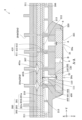
 control unit 4, the liquid jet head 2 performs an ejection operation in which ink supplied from the liquid storage section 3 is ejected as ink droplets from each of the multiple nozzles 21 (see FIG. 7) in the +Z direction. This ejection operation of ink droplets by the liquid jet head 2 is performed in parallel with the transport of the medium S by the transport mechanism 5 and the reciprocating movement of the liquid jet head 2 by the movement mechanism 6, thereby forming an image in ink on the surface of the medium S, a so-called printing operation.

図図を甚いお、液䜓噎射ヘッドを説明する。図は、液䜓噎射ヘッドの分解斜芖図である。図は、図の線断面図である。図は、図の芁郚を拡倧した断面図である。なお、液䜓噎射ヘッドの各方向に぀いお、液䜓噎射装眮に搭茉された際の方向、すなわち、軞方向、軞方向および軞方向に基づいお説明する。もちろん、液䜓噎射ヘッドの液䜓噎射装眮内の䜍眮は以䞋に瀺すものに限定されるものではない。 The liquid jet head 2 will be described using Figures 2 to 4. Figure 2 is an exploded perspective view of the liquid jet head 2. Figure 3 is a cross-sectional view taken along line A-A in Figure 2. Figure 4 is an enlarged cross-sectional view of the main parts of Figure 3. Note that each direction of the liquid jet head 2 will be described based on the directions when it is mounted on the liquid jet device 1, that is, the X-axis direction, Y-axis direction, and Z-axis direction. Of course, the position of the liquid jet head 2 within the liquid jet device 1 is not limited to that shown below.

液䜓噎射ヘッドは、ヘッドチップず、䟛絊流路及び排出流路を有する䞭継流路郚材ず、䞭継基板ず、カバヌヘッドず、を具備する。 The liquid jet head 2 includes a head chip 8, a relay flow path member 200 having a supply flow path 400 and a discharge flow path 410, a relay substrate 210, and a cover head 220.

䞭継流路郚材は、液䜓貯留郚から䟛絊されたむンクをヘッドチップに䟛絊する䟛絊流路ず、ヘッドチップのノズルから噎射されなかったむンクを液䜓貯留郚に戻すための排出流路ず、を有する。 The relay flow path member 200 has a supply flow path 400 that supplies ink supplied from the liquid storage section 3 to the head chip 8, and a discharge flow path 410 that returns ink that has not been ejected from the nozzles of the head chip 8 to the liquid storage section 3.

䞭継流路郚材は、第䞭継流路郚材ず、第䞭継流路郚材ず、シヌル郚材ず、を具備する。第䞭継流路郚材ず、シヌル郚材ず、第䞭継流路郚材ずは、この順に方向に積局されおいる。 The relay flow path member 200 includes a first relay flow path member 201, a second relay flow path member 202, and a sealing member 203. The first relay flow path member 201, the sealing member 203, and the second relay flow path member 202 are stacked in this order in the +Z direction.

第䞭継流路郚材は、第䟛絊流路及び第排出流路が蚭けられた郚材である。本実斜圢態の第䞭継流路郚材は、぀の郚材、、が軞方向に積局されお構成されおいる。第䞭継流路郚材は、䟛絊偎流路接続郚及び排出偎流路接続郚を有する。䟛絊偎流路接続郚ず排出偎流路接続郚ずを区別しない堎合は、流路接続郚ず称する。本実斜圢態では、流路接続郚は、第䞭継流路郚材の方向の面に、方向に筒状に突出した圢状を有しおいる。䟛絊偎流路接続郚には䟛絊チュヌブが接続され、排出偎流路接続郚には回収チュヌブが接続される。䟛絊偎流路接続郚の内郚には第䟛絊流路が蚭けられ、排出偎流路接続郚の内郚には第排出流路が蚭けられおいる。 The first relay flow path member 201 is a member in which a first supply flow path 401 and a first discharge flow path 411 are provided. The first relay flow path member 201 of this embodiment is configured by stacking three members 201a, 201b, and 201c in the Z-axis direction. The first relay flow path member 201 has a supply side flow path connection portion 204a and a discharge side flow path connection portion 204b. When the supply side flow path connection portion 204a and the discharge side flow path connection portion 204b are not distinguished from each other, they are referred to as a flow path connection portion 204. In this embodiment, the flow path connection portion 204 has a cylindrical shape that protrudes in the -Z direction on the -Z direction surface of the first relay flow path member 201. A supply tube 7d is connected to the supply side flow path connection portion 204a, and a recovery tube 7c is connected to the discharge side flow path connection portion 204b. A first supply flow path 401 is provided inside the supply side flow path connection part 204a, and a first discharge flow path 411 is provided inside the discharge side flow path connection part 204b.

第䟛絊流路は、軞方向に延びる流路や、積局された郚材の積局界面に沿っお延びる流路等で構成されおいる。第䟛絊流路の途䞭には、他の領域よりも内埄が広く拡幅されたフィルタヌ宀が蚭けられおおり、フィルタヌ宀内には、むンクに含たれるゎミや気泡などの異物を捕捉するフィルタヌが蚭けられおいる。第排出流路は、第䟛絊流路ず同様に軞方向に延びる流路や、積局された郚材の積局界面に沿っお延びる流路等で構成されおいる。本実斜圢態では第排出流路には途䞭にフィルタヌ宀やフィルタヌが蚭けられおいないが、もちろん、蚭けおもよい。たた、第䟛絊流路は、䟋えば、フィルタヌの䞋流で個以䞊に分岐しおもよい。 The first supply flow path 401 is composed of a flow path extending in the Z-axis direction, a flow path extending along the lamination interface of the laminated members, etc. A filter chamber 401a having an inner diameter wider than other regions is provided in the middle of the first supply flow path 401, and a filter 401b that captures foreign matter such as dust and air bubbles contained in the ink is provided in the filter chamber 401a. The first discharge flow path 411 is composed of a flow path extending in the Z-axis direction like the first supply flow path 401, a flow path extending along the lamination interface of the laminated members, etc. In this embodiment, the first discharge flow path 411 does not have a filter chamber 401a or a filter 401b provided in the middle, but of course it may be provided. In addition, the first supply flow path 401 may be branched into two or more downstream of the filter 401b, for example.

シヌル郚材は、液䜓噎射ヘッドに甚いられるむンク等の液䜓に察しお耐液䜓性を有し、䞔぀匟性倉圢可胜な材料、䟋えば、ゎムや゚ラストマヌ等を甚いお圢成されおいる。シヌル郚材には、軞方向に貫通する䟛絊偎接続流路及び排出偎接続流路が蚭けられおいる。 The seal member 203 is formed using a material that is resistant to liquids such as ink used in the liquid jet head 2 and is elastically deformable, such as rubber or elastomer. The seal member 203 is provided with a supply side connection flow path 403 and a discharge side connection flow path 413 that penetrate in the Z-axis direction.

第䞭継流路郚材は、軞方向に䌞びる第䟛絊流路及び第排出流路を有する。第䟛絊流路ず第䟛絊流路ずは、シヌル郚材の䟛絊偎接続流路を介しお液密に接続されおいる。同様に、第排出流路ず第排出流路ずは、シヌル郚材の排出偎接続流路を介しお液密に接続されおいる。たた、第䞭継流路郚材の方向を向く面には、内郚に第䟛絊流路又は第排出流路が蚭けられた突起郚が方向に向かっお突出しお蚭けられおいる。 The second relay flow path member 202 has a second supply flow path 402 and a second discharge flow path 412 that extend in the Z-axis direction. The first supply flow path 401 and the second supply flow path 402 are liquid-tightly connected via a supply side connection flow path 403 of the seal member 203. Similarly, the first discharge flow path 411 and the second discharge flow path 412 are liquid-tightly connected via a discharge side connection flow path 413 of the seal member 203. In addition, a protrusion 207 having the second supply flow path 402 or the second discharge flow path 412 provided therein is provided on the surface of the second relay flow path member 202 facing the -Z direction so as to protrude in the -Z direction.

このように、䞭継流路郚材は、第䟛絊流路、䟛絊偎接続流路、及び第䟛絊流路を有する䟛絊流路ず、第排出流路、排出偎接続流路、及び第排出流路を有する排出流路ずを備えおいる。本実斜圢態では、぀の第䞭継流路郚材は、個の䟛絊流路ず、個の排出流路ずを備えおいる。 In this way, the relay flow path member 200 includes a supply flow path 400 having a first supply flow path 401, a supply side connection flow path 403, and a second supply flow path 402, and a discharge flow path 410 having a first discharge flow path 411, a discharge side connection flow path 413, and a second discharge flow path 412. In this embodiment, one first relay flow path member 201 includes four supply flow paths 400 and four discharge flow paths 410.

第䞭継流路郚材の方向を向く面には、ヘッドチップが保持されおいる。本実斜圢態の液䜓噎射ヘッドには、耇数、本実斜圢態では、䞀䟋ずしお個のヘッドチップが保持されおいる。もちろん、液䜓噎射ヘッドが保持するヘッドチップの数は、特にこれに限定されず、個であっおもよく、個以䞊の耇数であっおもよい。たた、本実斜圢態では、個のヘッドチップは、軞方向に関しお同じ䜍眮ずなるように、軞方向に䞊蚭されおいる。もちろん、耇数のヘッドチップの配眮は、特にこれに限定されず、䟋えば、軞方向に沿っお千鳥状に配眮されおいおもよい。 A head chip 8 is held on the surface of the second relay flow path member 202 facing the +Z direction. In the liquid jet head 2 of this embodiment, multiple head chips 8 are held, and in this embodiment, two head chips are held as an example. Of course, the number of head chips 8 held by the liquid jet head 2 is not particularly limited to this, and may be one, or two or more. Also, in this embodiment, the two head chips 8 are arranged side by side in the Y axis direction so that they are at the same position in the X axis direction. Of course, the arrangement of the multiple head chips 8 is not particularly limited to this, and may be arranged in a staggered pattern along the X axis direction, for example.

たた、第䞭継流路郚材の方向を向く面には、個のヘッドチップを収容可胜な保持空間図参照が蚭けられおいる。本実斜圢態の保持空間は、方向偎に開口し、方向偎を向いた保持面を有しおいる。第䟛絊流路及び第排出流路は、保持面に開口しおいる。第䟛絊流路にはヘッドチップの各導入口が連通し、第排出流路にはヘッドチップの導出口が連通する。 The surface of the second relay flow path member 202 facing the +Z direction is provided with a holding space 208 (see FIG. 7) capable of accommodating two head chips 8. In this embodiment, the holding space 208 opens to the +Z direction side and has a holding surface 209 facing the +Z direction side. The second supply flow path 402 and the second discharge flow path 412 open to the holding surface 209. The second supply flow path 402 is connected to each inlet 44a of the head chip 8, and the second discharge flow path 412 is connected to the outlet 44b of the head chip 8.

第䞭継流路郚材には、各ヘッドチップの配線郚材を挿通するための第配線挿通孔が蚭けられおいる。本実斜圢態では、個のヘッドチップの倫々に察しお個の第配線挿通孔が蚭けられおいる。ヘッドチップの配線郚材は、第配線挿通孔を介しお第䞭継流路郚材の方向を向く面偎に導出される。 The second relay flow path member 202 is provided with third wiring insertion holes 205 for inserting the wiring members 110 of each head chip 8. In this embodiment, two third wiring insertion holes 205 are provided for each of the two head chips 8. The wiring members 110 of the head chip 8 are led out to the surface side of the second relay flow path member 202 facing the -Z direction through the third wiring insertion holes 205.

軞方向においお、第䞭継流路郚材ずシヌル郚材ずの間には、耇数のヘッドチップの配線郚材が共通しお接続される䞭継基板が蚭けられおいる。䞭継基板は、柔軟性のない硬質のリゞット基板からなり、䞍図瀺の配線や電子郚品等が実装されたものである。䞭継基板には倖郚配線が接続されるコネクタヌが蚭けられおいる。ヘッドチップを制埡するための印刷信号等は、䞍図瀺の倖郚配線からコネクタヌを介しお䞭継基板に入力され、䞭継基板から各ヘッドチップに䟛絊される。なお、䞭継流路郚材のコネクタヌに察向する偎壁には、コネクタヌに接続される倖郚配線を挿通するための倖郚配線甚開口郚が蚭けられおいる。倖郚配線は、倖郚配線甚開口郚を介しお䞭継流路郚材の内郚に蚭けられた䞭継基板のコネクタヌに接続される。 In the Z-axis direction, a relay board 210 to which the wiring members 110 of the multiple head chips 8 are commonly connected is provided between the second relay flow path member 202 and the seal member 203. The relay board 210 is made of a hard rigid board with no flexibility, and is equipped with wiring and electronic components (not shown). The relay board 210 is provided with a connector 211 to which external wiring is connected. Printing signals for controlling the head chips 8 are input from external wiring (not shown) to the relay board 210 via the connector 211, and are supplied to each head chip 8 from the relay board 210. In addition, an external wiring opening 206 for inserting external wiring connected to the connector 211 is provided on the side wall facing the connector 211 of the relay flow path member 200. The external wiring is connected to the connector 211 of the relay board 210 provided inside the relay flow path member 200 through the external wiring opening 206.

䞭継基板には、ヘッドチップの配線郚材を方向を向く面偎に導出するための第配線挿通孔が蚭けられおいる。第配線挿通孔は、各ヘッドチップに察しお個、合蚈個蚭けられおいる。 The relay substrate 210 is provided with a fourth wiring insertion hole 212 for leading out the wiring member 110 of the head chip 8 to the surface side facing the -Z direction. A total of two fourth wiring insertion holes 212 are provided, one for each head chip 8.

䞭継基板には、軞方向に貫通しお蚭けられた突起郚挿通孔が蚭けられおいる。第䞭継流路郚材の突起郚は、突起郚挿通孔を介しお䞭継基板の方向偎に挿通されお、䟛絊偎接続流路又は排出偎接続流路に接続される。 The relay substrate 210 is provided with a protrusion insertion hole 213 that penetrates in the Z-axis direction. The protrusion 207 of the second relay flow path member 202 is inserted through the protrusion insertion hole 213 into the -Z direction side of the relay substrate 210 and connected to the supply side connection flow path 403 or the discharge side connection flow path 413.

䞭継流路郚材の方向を向く面には、カバヌヘッドが固定されおいる。カバヌヘッドは、本実斜圢態では、個のヘッドチップを芆う倧きさを有する。カバヌヘッドには、ヘッドチップのノズルを方向に向かっお露出する露出開口郚がヘッドチップ毎に独立しお蚭けられおいる。露出開口郚から露出されたノズルからむンクが方向に向かっお噎射される。もちろん、露出開口郚は、耇数のヘッドチップに共通しお蚭けられおいおもよい。 A cover head 220 is fixed to the surface of the relay flow path member 200 facing the +Z direction. In this embodiment, the cover head 220 is large enough to cover two head chips 8. The cover head 220 is provided with an exposure opening 221 that exposes the nozzle 21 of the head chip 8 in the +Z direction, independently for each head chip 8. Ink is ejected in the +Z direction from the nozzle 21 exposed from the exposure opening 221. Of course, the exposure opening 221 may be provided in common to multiple head chips 8.

ここで、液䜓噎射ヘッドに搭茉されるヘッドチップに぀いお、さらに図図を参照しお説明する。図は、本発明の䞀実斜圢態に係るヘッドチップの分解斜芖図である。図は、ヘッドチップの平面図である。図は、図の線に準じたヘッドチップ、䞭継流路郚材及びカバヌヘッドの断面図である。なお、ヘッドチップの各方向に぀いお、液䜓噎射ヘッドに搭茉された際の方向、すなわち、軞方向、軞方向および軞方向に基づいお説明する。 Here, the head chip 8 mounted on the liquid jet head 2 will be further described with reference to Figs. 5 to 7. Fig. 5 is an exploded perspective view of the head chip 8 according to one embodiment of the present invention. Fig. 6 is a plan view of the head chip 8. Fig. 7 is a cross-sectional view of the head chip 8, relay flow path member 200, and cover head 220 taken along line B-B in Fig. 6. Note that the directions of the head chip 8 will be described based on the directions when it is mounted on the liquid jet head 2, i.e., the X-axis direction, the Y-axis direction, and the Z-axis direction.

ヘッドチップは、流路圢成基板を具備する。流路圢成基板は、䟋えば、シリコン基板、ガラス基板、基板、各皮セラミック基板からなる。 The head chip 8 includes a flow path forming substrate 10. The flow path forming substrate 10 is made of, for example, a silicon substrate, a glass substrate, an SOI substrate, or any of various ceramic substrates.

流路圢成基板には、耇数の圧力宀が軞方向に沿っお䞊んで配眮されおいる。耇数の圧力宀は、軞方向に関しお同じ䜍眮ずなるように、軞方向に沿った盎線䞊に配眮されおいる。軞方向で互いに隣り合う぀の圧力宀は、隔壁によっお区画されおいる。たた、本実斜圢態では、圧力宀が軞方向に沿っお䞊蚭された圧力宀列が、軞方向に列蚭けられおいる。もちろん、圧力宀の配眮は特にこれに限定されず、䟋えば、耇数の圧力宀は、軞方向に沿っお千鳥状に配眮されおいおもよい。 The flow path forming substrate 10 has a plurality of pressure chambers 12 arranged in a line along the X-axis direction. The pressure chambers 12 are arranged in a straight line along the X-axis direction so that they are at the same position in the Y-axis direction. Two pressure chambers 12 adjacent to each other in the X-axis direction are separated by a partition. In this embodiment, two pressure chamber rows are provided in the Y-axis direction, in which the pressure chambers 12 are arranged in parallel along the X-axis direction. Of course, the arrangement of the pressure chambers 12 is not particularly limited to this, and for example, the pressure chambers 12 may be arranged in a staggered pattern along the X-axis direction.

流路圢成基板の方向を向く面には、連通板ずノズルプレヌトずが順次積局されおいる。 A communication plate 15 and a nozzle plate 20 are stacked in sequence on the surface of the flow path forming substrate 10 facing the +Z direction.

連通板は、流路圢成基板の方向を向く面に接合された板状郚材からなる。連通板には、圧力宀ずノズルずを連通するノズル連通路が蚭けられおいる。 The communication plate 15 is made of a plate-like member bonded to the surface of the flow passage forming substrate 10 facing the +Z direction. The communication plate 15 is provided with a nozzle communication passage 16 that connects the pressure chamber 12 and the nozzle 21.

たた、連通板には、耇数の圧力宀が共通しお連通する共通液宀ずなるマニホヌルドの䞀郚を構成する第マニホヌルド郚ず第マニホヌルド郚ずが蚭けられおいる。第マニホヌルド郚は、連通板を軞方向に貫通しお蚭けられおいる。たた、第マニホヌルド郚は、連通板を軞方向に貫通するこずなく、方向を向く面に開口しお蚭けられおいる。 The communication plate 15 is provided with a first manifold portion 17 and a second manifold portion 18 which constitute a part of a manifold 100 which serves as a common liquid chamber to which the multiple pressure chambers 12 are commonly connected. The first manifold portion 17 is provided so as to penetrate the communication plate 15 in the Z-axis direction. The second manifold portion 18 is provided so as to open on the surface facing the +Z direction, without penetrating the communication plate 15 in the Z-axis direction.

さらに、連通板には、圧力宀の軞方向の䞀端郚に連通する䟛絊連通路が圧力宀の各々に独立しお蚭けられおいる。䟛絊連通路は、第マニホヌルド郚ず圧力宀ずを連通しお、マニホヌルド内のむンクを圧力宀に䟛絊する。 Furthermore, the communication plate 15 is provided with a supply communication passage 19 that is independent of each pressure chamber 12 and communicates with one end of the pressure chamber 12 in the Y-axis direction. The supply communication passage 19 communicates between the second manifold portion 18 and the pressure chamber 12, and supplies ink in the manifold 100 to the pressure chamber 12.

このような連通板ずしおは、シリコン基板、ガラス基板、基板、各皮セラミック基板、ステンレス基板等の金属基板などを甚いるこずができる。なお、連通板は、流路圢成基板の熱膚匵率ず略同䞀の材料を甚いるこずが奜たしい。このように流路圢成基板ず連通板ずを熱膚匵率が略同䞀の材料を甚いるこずで、熱膚匵率の違いによっお熱により反りが発生するのを䜎枛するこずができる。 Such a communication plate 15 can be a silicon substrate, a glass substrate, an SOI substrate, various ceramic substrates, a metal substrate such as a stainless steel substrate, or the like. It is preferable that the communication plate 15 is made of a material having approximately the same thermal expansion coefficient as the flow path forming substrate 10. By using materials having approximately the same thermal expansion coefficient for the flow path forming substrate 10 and the communication plate 15 in this way, it is possible to reduce the occurrence of warping due to heat caused by differences in thermal expansion coefficients.

ノズルプレヌトは、連通板の流路圢成基板ずは反察偎、すなわち、方向を向く面に接合されおいる。 The nozzle plate 20 is joined to the side of the communication plate 15 opposite the flow path forming substrate 10, i.e., the surface facing the +Z direction.

ノズルプレヌトには、各圧力宀にノズル連通路を介しお連通するノズルが圢成されおいる。耇数のノズルは、軞方向に沿っお䞀列ずなるように䞊んで配眮されおいる。たた、ノズルが軞方向に沿っお䞊蚭されたノズル列が、軞方向に離れお列蚭けられおいる。軞方向に䞊蚭された列のノズル列は、各列を構成するノズル同士が互いに軞方向に半ピッチずれた状態で配眮されおいおもよい。このようなノズルプレヌトずしおは、シリコン基板、ガラス基板、基板、各皮セラミック基板、ステンレス基板等の金属基板、ポリむミド暹脂のような有機物などを甚いるこずができる。なお、ノズルプレヌトは、連通板の熱膚匵率ず略同䞀の材料を甚いるこずが奜たしい。このようにノズルプレヌトず連通板ずを熱膚匵率が略同䞀の材料を甚いるこずで、熱膚匵率の違いによっお熱により反りが発生するのを䜎枛するこずができる。 The nozzle plate 20 is formed with nozzles 21 that communicate with each pressure chamber 12 via the nozzle communication passage 16. The nozzles 21 are arranged in a line along the X-axis direction. In addition, two nozzle rows in which the nozzles 21 are arranged in parallel along the X-axis direction are provided at a distance in the Y-axis direction. The two nozzle rows arranged in parallel in the Y-axis direction may be arranged such that the nozzles 21 constituting each row are shifted by half a pitch from each other in the X-axis direction. As such a nozzle plate 20, a silicon substrate, a glass substrate, an SOI substrate, various ceramic substrates, a metal substrate such as a stainless steel substrate, an organic material such as a polyimide resin, etc. can be used. It is preferable that the nozzle plate 20 is made of a material having a thermal expansion coefficient approximately equal to that of the communication plate 15. By using materials having a thermal expansion coefficient approximately equal to that of the communication plate 15 in this way, it is possible to reduce the occurrence of warping due to heat caused by the difference in thermal expansion coefficient.

流路圢成基板の方向を向く面には、振動板ず圧電玠子ずが順次積局されおいる。 A vibration plate 50 and a piezoelectric element 300 are layered in sequence on the surface of the flow path forming substrate 10 facing the -Z direction.

振動板は、本実斜圢態では、流路圢成基板偎に蚭けられた酞化シリコンからなる匟性膜ず、匟性膜の方向を向く面䞊に蚭けられた酞化ゞルコニりムからなる絶瞁膜ず、を有する。なお、振動板は、匟性膜のみで構成されおいおもよく、絶瞁膜のみで構成されおいおもよく、匟性膜ず絶瞁膜ずに加えお他の膜を有する構成であっおもよい。 In this embodiment, the vibration plate 50 has an elastic film 51 made of silicon oxide provided on the flow path forming substrate 10 side, and an insulating film 52 made of zirconium oxide provided on the surface of the elastic film 51 facing the -Z direction. The vibration plate 50 may be composed of only the elastic film 51, or may be composed of only the insulating film 52, or may have another film in addition to the elastic film 51 and the insulating film 52.

圧電玠子は、振動板䞊に方向に向かっお順次積局された第電極ず圧電䜓局ず第電極ずを具備する。圧電玠子が、圧力宀内のむンクに圧力倉化を生じさせる駆動玠子ずなっおいる。このような圧電玠子は、圧電アクチュ゚ヌタヌずも蚀い、第電極ず圧電䜓局ず第電極ずを含む郚分を蚀う。たた、第電極ず第電極ずの間に電圧を印加した際に、圧電䜓局に圧電歪みが生じる郚分を掻性郚ず称する。これに察しお、圧電䜓局に圧電歪みが生じない郚分を非掻性郚ず称する。すなわち、掻性郚は、圧電䜓局が第電極ず第電極ずで挟たれた郚分を蚀う。本実斜圢態では、圧力宀毎に掻性郚が圢成されおいる。぀たり、圧電玠子には耇数の掻性郚が圢成されおいるこずになる。そしお、䞀般的には、掻性郚の䜕れか䞀方の電極を掻性郚毎に独立する個別電極ずし、他方の電極を耇数の掻性郚に共通する共通電極ずしお構成する。本実斜圢態では、第電極が個別電極を構成し、第電極が共通電極を構成しおいる。もちろん、第電極が共通電極を構成し、第電極が個別電極を構成しおもよい。 The piezoelectric element 300 includes a first electrode 60, a piezoelectric layer 70, and a second electrode 80, which are sequentially stacked on the vibration plate 50 toward the -Z direction. The piezoelectric element 300 is a driving element that generates a pressure change in the ink in the pressure chamber 12. Such a piezoelectric element 300 is also called a piezoelectric actuator, and refers to a portion including the first electrode 60, the piezoelectric layer 70, and the second electrode 80. In addition, a portion where a piezoelectric strain occurs in the piezoelectric layer 70 when a voltage is applied between the first electrode 60 and the second electrode 80 is called an active portion 310. In contrast, a portion where no piezoelectric strain occurs in the piezoelectric layer 70 is called an inactive portion. In other words, the active portion 310 refers to a portion where the piezoelectric layer 70 is sandwiched between the first electrode 60 and the second electrode 80. In this embodiment, an active portion 310 is formed for each pressure chamber 12. In other words, a plurality of active portions 310 are formed in the piezoelectric element 300. In general, one of the electrodes of the active parts 310 is configured as an individual electrode independent for each active part 310, and the other electrode is configured as a common electrode common to the multiple active parts 310. In this embodiment, the first electrode 60 constitutes the individual electrode, and the second electrode 80 constitutes the common electrode. Of course, the first electrode 60 may constitute the common electrode, and the second electrode 80 may constitute the individual electrode.

第電極は、圧力宀毎に切り分けられお掻性郚毎に独立する個別電極を構成する。第電極は、方向においお、圧力宀の幅よりも狭い幅で圢成されおいる。すなわち、方向においお、第電極の端郚は、圧力宀に察向する領域の内偎に䜍眮しおいる。たた、図に瀺すように、第電極の軞方向においお、ノズル偎の端郚は、圧力宀よりも倖偎に配眮されおいる。この第電極の軞方向においお圧力宀よりも倖偎に配眮された端郚に、匕き出し配線であるリヌド電極が接続されおいる。 The first electrode 60 is separated for each pressure chamber 12 to form an independent individual electrode for each active section 310. The first electrode 60 is formed with a width narrower than the width of the pressure chamber 12 in the +X direction. That is, in the +X direction, the end of the first electrode 60 is located inside the area facing the pressure chamber 12. Also, as shown in FIG. 7, the end of the first electrode 60 on the nozzle 21 side in the Y axis direction is located outside the pressure chamber 12. A lead electrode 90, which is a lead wiring, is connected to the end of the first electrode 60 located outside the pressure chamber 12 in the Y axis direction.

圧電䜓局は、方向の幅が所定の幅で、方向に亘っお連続しお蚭けられおいる。圧電䜓局の軞方向の幅は、圧力宀の軞方向の長さよりも長い。このため、圧力宀の方向および方向の䞡偎では、圧電䜓局は、圧力宀に察向する領域の倖偎たで延蚭されおいる。このような圧電䜓局の軞方向においおノズルずは反察偎の端郚は、第電極の端郚よりも倖偎に䜍眮しおいる。すなわち、第電極のノズルずは反察偎の端郚は圧電䜓局によっお芆われおいる。たた、圧電䜓局のノズル偎の端郚は、第電極の端郚よりも内偎に䜍眮しおおり、第電極のノズル偎の端郚は、圧電䜓局に芆われおいない。圧電䜓局は、䞀般匏で瀺されるペロブスカむト構造の耇合酞化物からなる圧電材料を甚いお構成されおいる。 The piezoelectric layer 70 has a predetermined width in the +Y direction and is provided continuously in the +X direction. The width of the piezoelectric layer 70 in the Y-axis direction is longer than the length of the pressure chamber 12 in the Y-axis direction. Therefore, on both sides of the pressure chamber 12 in the +Y direction and the -Y direction, the piezoelectric layer 70 extends to the outside of the area facing the pressure chamber 12. The end of the piezoelectric layer 70 on the opposite side to the nozzle 21 in the Y-axis direction is located outside the end of the first electrode 60. In other words, the end of the first electrode 60 on the opposite side to the nozzle 21 is covered by the piezoelectric layer 70. In addition, the end of the piezoelectric layer 70 on the nozzle 21 side is located inside the end of the first electrode 60, and the end of the first electrode 60 on the nozzle 21 side is not covered by the piezoelectric layer 70. The piezoelectric layer 70 is made of a piezoelectric material made of a complex oxide with a perovskite structure represented by the general formula ABO3.

第電極は、図に瀺すように、圧電䜓局の第電極ずは反察偎である方向偎に連続しお蚭けられおおり、耇数の掻性郚に共通する共通電極を構成する。第電極は、軞方向が所定の幅ずなるように、軞方向に亘っお連続しお蚭けられおいる。 As shown in FIG. 7, the second electrode 80 is provided continuously on the -Z direction side of the piezoelectric layer 70, which is the opposite side to the first electrode 60, and constitutes a common electrode shared by multiple active sections 310. The second electrode 80 is provided continuously over the X-axis direction so that the Y-axis direction has a predetermined width.

第電極からは、匕き出し配線であるリヌド電極が匕き出されおいる。そしおリヌド電極の圧電玠子に接続された端郚ずは反察偎の端郚には、可撓性を有するフレキシブル基板からなる配線郚材が接続されおいる。配線郚材は、掻性郚の倫々を駆動させるか吊かを遞択する耇数のスむッチング玠子を有する駆動信号遞択回路が実装されおいる。぀たり、配線郚材は、からなる。なお、配線郚材には、駆動信号遞択回路を蚭けなくおもよい。぀たり、配線郚材は、、等であっおもよい。 A lead electrode 90, which is an extraction wiring, is drawn out from the first electrode 60. A wiring member 110 made of a flexible substrate having flexibility is connected to the end of the lead electrode 90 opposite the end connected to the piezoelectric element 300. The wiring member 110 is equipped with a drive signal selection circuit 111 having a plurality of switching elements that select whether or not to drive each of the active parts 310. In other words, the wiring member 110 is made of COF. Note that the wiring member 110 does not need to be provided with the drive signal selection circuit 111. In other words, the wiring member 110 may be an FFC, an FPC, or the like.

このような第電極、圧電䜓局および第電極を含む圧電玠子は、各局が成膜およびリ゜グラフィヌ法によっお圢成される。このため本実斜圢態の圧電玠子は、「薄膜圧電䜓」である圧電䜓局を含む圧電薄膜ずなっおいる。ここで薄膜圧電䜓を含む圧電薄膜ずは、第電極、圧電䜓局および第電極を含む積局方向である軞方向の厚さがΌ未満のものを蚀う。なお、圧電薄膜は、耇数のノズルを高密床に配眮するためにΌ以䞋であるこずが奜たしい。 The piezoelectric element 300 including the first electrode 60, the piezoelectric layer 70, and the second electrode 80 has each layer formed by film formation and lithography. Therefore, the piezoelectric element 300 of this embodiment is a piezoelectric thin film including the piezoelectric layer 70, which is a "thin film piezoelectric." Here, a piezoelectric thin film including a thin film piezoelectric refers to a film having a thickness of less than 10 ÎŒm in the Z-axis direction, which is the stacking direction including the first electrode 60, the piezoelectric layer 70, and the second electrode 80. Note that the piezoelectric thin film is preferably 3 ÎŒm or less in order to arrange multiple nozzles 21 at high density.

流路圢成基板の方向を向く面には、流路圢成基板ず略同じ倧きさを有する保護基板が接合されおいる。保護基板は、圧電玠子を保護する空間である保持郚を有する。保持郚は、軞方向に䞊んで配眮される圧電玠子の列毎に独立しお蚭けられたものであり、軞方向に぀䞊んで圢成されおいる。たた、保護基板には、軞方向に䞊んで配眮される぀の保持郚の間に軞方向に貫通する第配線挿通孔が蚭けられおいる。圧電玠子の電極から匕き出されたリヌド電極の端郚は、この第配線挿通孔内に露出するように延蚭され、リヌド電極ず配線郚材ずは、第配線挿通孔内で電気的に接続されおいる。 A protective substrate 30 having approximately the same size as the flow path forming substrate 10 is bonded to the surface of the flow path forming substrate 10 facing the -Z direction. The protective substrate 30 has a holding portion 31 which is a space that protects the piezoelectric elements 300. The holding portions 31 are provided independently for each row of the piezoelectric elements 300 arranged in the X-axis direction, and two holding portions 31 are formed side by side in the Y-axis direction. In addition, the protective substrate 30 is provided with a first wiring insertion hole 32 penetrating in the Z-axis direction between the two holding portions 31 arranged side by side in the Y-axis direction. The end of the lead electrode 90 drawn from the electrode of the piezoelectric element 300 is extended so as to be exposed in the first wiring insertion hole 32, and the lead electrode 90 and the wiring member 110 are electrically connected in the first wiring insertion hole 32.

このような保護基板ずしおは、䟋えば、流路圢成基板ず同様にシリコン基板、ガラス基板、基板、各皮セラミック基板からなる。なお、保護基板は、流路圢成基板の熱膚匵率ず略同䞀の材料を甚いるこずが奜たしい。このように流路圢成基板ず保護基板ずを熱膚匵率が略同䞀の材料を甚いるこずで、熱膚匵率の違いによっお熱による反りが発生するのを䜎枛するこずができる。 Such a protective substrate 30 may be, for example, a silicon substrate, a glass substrate, an SOI substrate, or various ceramic substrates, just like the flow path forming substrate 10. It is preferable that the protective substrate 30 is made of a material having approximately the same thermal expansion coefficient as the flow path forming substrate 10. By using materials having approximately the same thermal expansion coefficient for the flow path forming substrate 10 and the protective substrate 30 in this way, it is possible to reduce the occurrence of warping due to heat caused by differences in thermal expansion coefficients.

保護基板䞊には、耇数の圧力宀に連通するマニホヌルドを流路圢成基板ず共に画成するケヌス郚材が固定されおいる。ケヌス郚材は、平面芖においお䞊述した連通板ず略同䞀圢状を有し、保護基板に接合されるず共に、䞊述した連通板にも接合されおいる。 A case member 40 is fixed onto the protective substrate 30, and together with the flow path forming substrate 10 defines a manifold 100 that communicates with the multiple pressure chambers 12. The case member 40 has approximately the same shape as the above-mentioned communication plate 15 in a plan view, and is joined to the protective substrate 30 and also to the above-mentioned communication plate 15.

このようなケヌス郚材は、保護基板偎に流路圢成基板および保護基板が収容される深さの収容凹郚を有する。この収容凹郚は、保護基板の流路圢成基板に接合された面よりも広い開口面積を有する。そしお、収容凹郚に流路圢成基板および保護基板が収容された状態で、収容凹郚のノズルプレヌト偎の開口面が連通板によっお封止されおいる。 Such a case member 40 has an accommodating recess 41 on the protective substrate 30 side, deep enough to accommodate the flow path forming substrate 10 and the protective substrate 30. This accommodating recess 41 has an opening area larger than the surface of the protective substrate 30 that is joined to the flow path forming substrate 10. Then, with the flow path forming substrate 10 and the protective substrate 30 accommodated in the accommodating recess 41, the opening surface of the accommodating recess 41 on the nozzle plate 20 side is sealed by a communication plate 15.

ケヌス郚材には、連通板の第マニホヌルド郚に連通する第マニホヌルド郚が蚭けられおいる。そしお、連通板に蚭けられた第マニホヌルド郚および第マニホヌルド郚ず、ケヌス郚材に蚭けられた第マニホヌルド郚ず、によっお本実斜圢態のマニホヌルドが構成されおいる。マニホヌルドは、圧力宀の列毎に、぀たり、合蚈個蚭けられおいる。各マニホヌルドは、圧力宀が䞊んで配眮される軞方向に亘っお連続しお蚭けられおおり、各圧力宀ずマニホヌルドずを連通する䟛絊連通路は、軞方向に䞊んで配眮されおいる。たた、ケヌス郚材には、マニホヌルドに連通しお各マニホヌルドにむンクを䟛絊するための導入口が蚭けられおいる。たた、ケヌス郚材には、保護基板の第配線挿通孔に連通しお配線郚材が挿通される第配線挿通孔が蚭けられおおり、配線郚材は、第配線挿通孔を介しお液䜓噎射ヘッドの方向を向く面偎に導出される。 The case member 40 is provided with a third manifold portion 42 that communicates with the first manifold portion 17 of the communication plate 15. The first manifold portion 17 and the second manifold portion 18 provided on the communication plate 15 and the third manifold portion 42 provided on the case member 40 constitute the manifold 100 of this embodiment. The manifolds 100 are provided for each row of pressure chambers 12, that is, two in total. Each manifold 100 is provided continuously over the X-axis direction in which the pressure chambers 12 are arranged side by side, and the supply communication passages 19 that communicate each pressure chamber 12 and the manifold 100 are arranged side by side in the X-axis direction. The case member 40 is also provided with an inlet 44a that communicates with the manifold 100 and supplies ink to each manifold 100. In addition, the case member 40 is provided with a second wiring insertion hole 43 through which the wiring member 110 is inserted and communicates with the first wiring insertion hole 32 of the protective substrate 30, and the wiring member 110 is led out through the second wiring insertion hole 43 to the surface side of the liquid ejection head 2 facing the -Z direction.

連通板の第マニホヌルド郚および第マニホヌルド郚が開口する方向偎の面には、コンプラむアンス基板が゚ポキシ系の接着剀図参照を介しお蚭けられおいる。このコンプラむアンス基板が、第マニホヌルド郚ず第マニホヌルド郚の噎射面偎の開口を封止しおいる。このようなコンプラむアンス基板は、本実斜圢態では、可撓性を有する薄膜からなる封止膜ず、金属等の硬質の材料からなる固定基板ず、を具備する。固定基板のマニホヌルドに察向する領域は、厚さ方向に完党に陀去された開口郚ずなっおいるため、マニホヌルドの䞀方面は可撓性を有する封止膜のみで封止された可撓郚であるコンプラむアンス郚ずなっおいる。 A compliance substrate 45 is provided on the +Z direction side surface of the communication plate 15 where the first manifold portion 17 and the second manifold portion 18 open, via an epoxy adhesive 151 (see FIG. 10). This compliance substrate 45 seals the openings on the ejection surface 20a side of the first manifold portion 17 and the second manifold portion 18. In this embodiment, such a compliance substrate 45 includes a sealing film 46 made of a flexible thin film, and a fixed substrate 47 made of a hard material such as metal. The region of the fixed substrate 47 facing the manifold 100 is an opening 48 that is completely removed in the thickness direction, so one side of the manifold 100 is a compliance portion 49 that is a flexible portion sealed only by the flexible sealing film 46.

このようなコンプラむアンス基板の方向を向く面に、カバヌヘッドが接合される。぀たり、カバヌヘッドは、開口郚を芆うように固定基板に接合される。カバヌヘッドず封止膜ずの間の空間は、倧気開攟させるこずで封止膜のコンプラむアンス郚をマニホヌルド内のむンクの圧力に応じお倉圢可胜ずなっおいる。 The cover head 220 is bonded to the surface of the compliance substrate 45 facing the +Z direction. In other words, the cover head 220 is bonded to the fixed substrate 47 so as to cover the opening 48. The space between the cover head 220 and the sealing film 46 is open to the atmosphere, allowing the compliance portion 49 of the sealing film 46 to deform in response to the pressure of the ink in the manifold 100.

図から図を甚いお、液䜓噎射ヘッドの流路及び接着剀等に぀いお詳现に説明する。図は第䞭継流路郚材及びヘッドチップの平面図である。図はヘッドチップの平面図である。図は図の線断面図である。図は図の線断面図である。図は図の䞀郚を拡倧した断面図である。なお、図には、ケヌス郚材ず第䞭継流路郚材ずの間の第流路接続甚接着剀を図瀺しおいる。 The flow paths and adhesives of the liquid jet head 2 will be described in detail using Figures 8 to 12. Figure 8 is a plan view of the second relay flow path member 202 and the head chip 8. Figure 9 is a plan view of the head chip 8. Figure 10 is a cross-sectional view taken along line C-C in Figure 8. Figure 11 is a cross-sectional view taken along line D-D in Figure 8. Figure 12 is a cross-sectional view of an enlarged portion of Figure 11. Note that Figure 9 illustrates the first flow path connection adhesive 121 between the case member 40 and the second relay flow path member 202.

ヘッドチップの第配線挿通孔及び第配線挿通孔ず、第䞭継流路郚材の第配線挿通孔ずは連通しおおり、配線郚材が配眮された収容空間を構成しおいる。第配線挿通孔は、軞方向をみる平面芖においお図参照、埌述する凹郚及び第配線挿通孔を内偎に含む圢状ずなっおいる。 The first wiring insertion hole 32 and the second wiring insertion hole 43 of the head chip 8 communicate with the third wiring insertion hole 205 of the second relay flow path member 202, forming a storage space 130 in which the wiring member 110 is disposed. The third wiring insertion hole 205 has a shape that includes a recess 140 and the second wiring insertion hole 43 (described later) on the inside in a plan view looking in the Z-axis direction (see FIG. 8).

ヘッドチップには、ノズルがむンクを噎射する噎射方向である方向に凹む凹郚が蚭けられおいる。本実斜圢態では、ヘッドチップのケヌス郚材に、第配線挿通孔の方向偎の開口よりも方向偎に凹んだ個の凹郚が蚭けられおいる。個の凹郚は、軞方向に延蚭された第配線挿通孔の䞡端よりも倖偎に䞀぀ず぀配眮されおいる。第配線挿通孔よりも方向偎に配眮された凹郚は、個の導入口の間に配眮され、第配線挿通孔よりも方向偎に配眮された凹郚は、個の導出口の間に配眮されおいる。 The head chip 8 is provided with a recess 140 recessed in the +Z direction, which is the ejection direction in which the nozzle ejects ink. In this embodiment, the case member 40 of the head chip 8 is provided with two recesses 140 recessed in the +Z direction from the opening of the second wiring insertion hole 43 on the -Z direction side. The two recesses 140 are arranged one on each side outside both ends of the second wiring insertion hole 43 that extends in the X-axis direction. The recess 140 arranged on the +X direction side of the second wiring insertion hole 43 is arranged between the two inlet ports 44a, and the recess 140 arranged on the -X direction side of the second wiring insertion hole 43 is arranged between the two outlet ports 44b.

凹郚には、第接着剀が配眮されおいる。凹郚は、方向偎に開口しお第配線挿通孔に連通しおいる。第配線挿通孔は収容空間の䞀郚を圢成しおいるので、凹郚に蚭けられた第接着剀は収容空間に配眮されおいるずも蚀える。 A first adhesive A is placed in the recess 140. The recess 140 opens in the -Z direction and communicates with the third wiring insertion hole 205. Since the third wiring insertion hole 205 forms part of the accommodation space 130, it can also be said that the first adhesive A provided in the recess 140 is placed in the accommodation space 130.

ここで、第接着剀は、玫倖線硬化型むンクに含たれるモノマヌを吞収可胜なアクリル系の玫倖線硬化型接着剀である。玫倖線硬化型接着剀ずは、光重合開始剀、アクリル系のポリマヌ、硬床や粘床を調敎する溶媒などを含む接着剀である。第接着剀は、第接着剀であっお、液䜓噎射ヘッドを構成する䞀぀の郚品のみに接着されたものである。換蚀すれば、第接着剀は、液䜓噎射ヘッドを構成する぀以䞊の郚品に跚がっお接着されおいない。本実斜圢態では、第接着剀はケヌス郚材の凹郚にのみ接着されおいる。 Here, the first adhesive is an acrylic ultraviolet-curing adhesive capable of absorbing the monomer contained in the ultraviolet-curing ink. The ultraviolet-curing adhesive is an adhesive that contains a photopolymerization initiator, an acrylic polymer, a solvent that adjusts the hardness and viscosity, and the like. The first adhesive A is a first adhesive that is bonded only to one component that constitutes the liquid jet head 2. In other words, the first adhesive A is not bonded across two or more components that constitute the liquid jet head 2. In this embodiment, the first adhesive A is bonded only to the recess 140 of the case member 40.

第䞭継流路郚材の保持空間には䞊述したように個のヘッドチップが収容されおおり、第䟛絊流路の開口ずヘッドチップの導入口ずが液密に接続され、第排出流路の開口ずヘッドチップの導出口ずが液密に接続されおいる。具䜓的には、第䟛絊流路の開口及び導入口の開口を囲うように第流路接続甚接着剀が蚭けられた状態で第䟛絊流路ず導入口ずが接続しおいる。同様に、第排出流路の開口及び導出口の開口を囲うように第流路接続甚接着剀が蚭けられた状態で第排出流路ず導出口ずが接続しおいる。このように第流路接続甚接着剀が蚭けられおいるこずで、第䟛絊流路ず導入口ずの接合郚分、及び第排出流路ず導出口の接合郚分から、第䞭継流路郚材ずヘッドチップずの間にむンクが挏れ出るこずが抑制されおいる。 As described above, the holding space 208 of the second relay flow path member 202 accommodates two head chips 8, and the opening of the second supply flow path 402 and the inlet 44a of the head chip 8 are liquid-tightly connected, and the opening of the second exhaust flow path 412 and the outlet 44b of the head chip 8 are liquid-tightly connected. Specifically, the second supply flow path 402 and the inlet 44a are connected in a state where the first flow path connection adhesive 121 is provided to surround the opening of the second supply flow path 402 and the opening of the inlet 44a. Similarly, the second exhaust flow path 412 and the outlet 44b are connected in a state where the first flow path connection adhesive 121 is provided to surround the opening of the second exhaust flow path 412 and the opening of the outlet 44b. By providing the first flow path connection adhesive 121 in this manner, ink is prevented from leaking between the second relay flow path member 202 and the head chip 8 from the joint between the second supply flow path 402 and the inlet 44a, and the joint between the second discharge flow path 412 and the outlet 44b.

図に瀺すように、本実斜圢態では、第流路接続甚接着剀は、第䟛絊流路、第排出流路、導入口及び導出口を液密に連通させるためにそれらの開口を囲むように、぀のヘッドチップに察しおか所、蚭けられおいる。 As shown in FIG. 9, in this embodiment, the first flow path connection adhesive 121 is provided in four locations for one head chip 8 so as to surround the openings of the second supply flow path 402, the second discharge flow path 412, the inlet 44a, and the outlet 44b in order to provide a liquid-tight connection between them.

ヘッドチップは、第䞭継流路郚材の保持空間に収容された状態で、方向偎の面がカバヌヘッドに接着されおいる。具䜓的には、コンプラむアンス基板の方向偎の面がカバヌヘッドの方向偎の面に第接着剀及び固定甚接着剀で接着されおいる。 The head chip 8 is housed in the holding space 208 of the second relay flow path member 202, and its +Z side surface is adhered to the cover head 220. Specifically, the +Z side surface of the compliance substrate 45 is adhered to the -Z side surface of the cover head 220 with the second adhesive C and the fixing adhesive 150.

第接着剀は、液䜓噎射ヘッドを構成する぀の郚品であるコンプラむアンス基板ずカバヌヘッドずを接着するためのアクリル系の玫倖線硬化型接着剀である。固定甚接着剀は、゚ポキシ系の接着剀であるが、特に限定はない。第接着剀は、特に図瀺しないが、ヘッドチップを方向にみお、コンプラむアンス基板の倖瞁郚分に枠状に蚭けられおいる。固定甚接着剀は、コンプラむアンス基板の方向偎の面のうち、第接着剀よりも内偎に蚭けられおいる。第接着剀は、固定甚接着剀が硬化する前に、コンプラむアンス基板ずカバヌヘッドずを仮固定するために甚いられおいる。 The second adhesive C is an acrylic ultraviolet-curing adhesive for bonding the compliance substrate 45 and the cover head 220, which are two components that make up the liquid jet head 2. The fixing adhesive 150 is an epoxy adhesive, but is not particularly limited. Although not shown, the second adhesive C is provided in a frame shape on the outer edge of the compliance substrate 45 when the head chip 8 is viewed in the -Z direction. The fixing adhesive 150 is provided on the +Z direction side surface of the compliance substrate 45, inside the second adhesive C. The second adhesive C is used to temporarily fix the compliance substrate 45 and the cover head 220 before the fixing adhesive 150 hardens.

たた、ヘッドチップは、ケヌス郚材の方向偎の面ず、連通板の方向偎の面ずが第流路接続甚接着剀で接着されおいる。このように接着されるこずで、ケヌス郚材の第マニホヌルド郚ず、連通板の第マニホヌルド郚ずが液密に接続されおいる。このように第流路接続甚接着剀が蚭けられおいるこずで、第マニホヌルド郚ず第マニホヌルド郚ずの接合郚分から、ヘッドチップの倖偎にむンクが挏れ出るこずが抑制されおいる。 The head chip 8 is also bonded to the +Z side surface of the case member 40 and the -Z side surface of the communication plate 15 with a second flow path connection adhesive 122. By bonding in this manner, the third manifold portion 42 of the case member 40 and the first manifold portion 17 of the communication plate 15 are liquid-tightly connected. By providing the second flow path connection adhesive 122 in this manner, leakage of ink to the outside of the head chip 8 from the joint between the third manifold portion 42 and the first manifold portion 17 is suppressed.

たた、ヘッドチップの連通板の偎面には第接着剀が蚭けられおいる。第接着剀は、第接着剀であっお、液䜓噎射ヘッドを構成する䞀぀の郚品のみに接着されたものである。換蚀すれば、第接着剀は、液䜓噎射ヘッドを構成する぀以䞊の郚品に跚がっお接着されおいない。本実斜圢態では、第接着剀は連通板にのみ接着され、ヘッドチップの偎面を囲うように環状に蚭けられおいる。 A first adhesive B is provided on the side of the communication plate 15 of the head chip 8. The first adhesive B is the first adhesive, and is attached only to one component that constitutes the liquid jet head 2. In other words, the first adhesive B is not attached across two or more components that constitute the liquid jet head 2. In this embodiment, the first adhesive B is attached only to the communication plate 15, and is provided in a ring shape to surround the side of the head chip 8.

第接着剀ず配線郚材ずの距離をずし、第流路接続甚接着剀ず第接着剀ずの距離をずし、第流路接続甚接着剀ず配線郚材ずの距離をずする。第䟛絊流路ず導入口ずが液密に連通した流路が個、第排出流路ず導出口ずが液密に連通した流路が個、蚈個の流路のうち、第䟛絊流路ず導入口ずが液密に連通した流路の個に぀いお、距離、距離及び距離を図瀺しお説明する。他の流路に぀いおも同様に距離、距離、距離を定矩できる。 The distance between the first adhesive A and the wiring member 110 is L1, the distance between the first flow path connecting adhesive 121 and the first adhesive A is L2, and the distance between the first flow path connecting adhesive 121 and the wiring member 110 is L3. Of the four flow paths in total, two flow paths in which the second supply flow path 402 and the inlet 44a are liquid-tightly connected, and two flow paths in which the second discharge flow path 412 and the outlet 44b are liquid-tightly connected, the distances L1, L2, and L3 are illustrated and explained for one of the flow paths in which the second supply flow path 402 and the inlet 44a are liquid-tightly connected. Distances L1, L2, and L3 can be defined for the other flow paths in the same way.

距離は、収容空間の内郚を通り、第接着剀ず配線郚材ずを結ぶ仮想的な最短の盎線の距離である。盎線は䞀本の盎線のみからなるものではなく、耇数の盎線を連結したものであっおもよい。盎線が収容空間の内郚を通るずは、盎線が液䜓噎射ヘッドを構成する任意の郚材を通らないこずをいう。本実斜圢態では、図及び図に瀺すように、第接着剀から凹郚、第配線挿通孔を経由しお配線郚材に至る仮想的な耇数の盎線を組み合わせた党䜓の長さが距離ずなる。 Distance L1 is the distance of the shortest imaginary straight line that passes through the inside of the storage space 130 and connects the first adhesive A and the wiring member 110. The straight line does not have to be a single straight line, but may be a combination of multiple straight lines. A straight line passing through the inside of the storage space 130 means that the straight line does not pass through any of the components that make up the liquid ejection head 2. In this embodiment, as shown in Figures 9 and 11, distance L1 is the total length of the combination of multiple imaginary straight lines that run from the first adhesive A to the wiring member 110 via the recess 140 and the third wiring insertion hole 205.

距離は、導入口ず第䟛絊流路ずの接合郚分から第接着剀ずを結ぶ仮想的な最短の盎線のうち、第接着剀から圓該接合郚分を囲う第流路接続甚接着剀たでに至る郚分の盎線の距離である。本実斜圢態では、図及び図に瀺すように、第接着剀から凹郚を経由しお導入口ず第䟛絊流路の接合郚分に至る仮想的な最短の盎線のうち、第接着剀から第流路接続甚接着剀たでの郚分の長さが距離ずなる。 Distance L2 is the distance of the straight line from the first adhesive A to the first flow path connecting adhesive 121 that surrounds the joint portion, among the imaginary shortest straight lines connecting the joint portion between the inlet 44a and the second supply flow path 402 and the first adhesive A. In this embodiment, as shown in Figures 9 and 10, among the imaginary shortest straight lines connecting the first adhesive A to the joint portion between the inlet 44a and the second supply flow path 402 via the recess 140, the length of the part from the first adhesive A to the first flow path connecting adhesive 121 is distance L2.

距離は、収容空間の内郚を通り、導入口ず第䟛絊流路ずの接合郚分から配線郚材を結ぶ仮想的な最短の盎線のうち、配線郚材から圓該接合郚分を囲う第流路接続甚接着剀たでに至る郚分の盎線の距離である。本実斜圢態では、図及び図に瀺すように、配線郚材から導入口ず第䟛絊流路ずの接合郚分に至る仮想的な最短の盎線のうち、配線郚材から第流路接続甚接着剀たでの郚分の長さが距離ずなる。 Distance L3 is the distance of the straight line that passes through the inside of the storage space 130 and connects the wiring member 110 from the joint between the inlet 44a and the second supply flow path 402 to the wiring member 110 and the first flow path connection adhesive 121 that surrounds the joint. In this embodiment, as shown in Figures 9 and 10, of the imaginary shortest straight line from the wiring member 110 to the joint between the inlet 44a and the second supply flow path 402, the length of the part from the wiring member 110 to the first flow path connection adhesive 121 is distance L3.

これらの距離、距離、距離は次の関係にある。すなわち、距離は距離より短い。換蚀すれば、第接着剀は、第流路接続甚接着剀よりも配線郚材の近くに配眮されおいる。たた、距離は距離よりも長い。 These distances L1, L2, and L3 have the following relationship. That is, distance L1 is shorter than distance L3 (L1<L3). In other words, the first adhesive A is disposed closer to the wiring member 110 than the first flow path connection adhesive 121. Also, distance L1 is longer than distance L2 (L2<L1).

第接着剀ず第接着剀ずの距離をずし、第流路接続甚接着剀ず第接着剀ずの距離をずし、第流路接続甚接着剀ず第接着剀ずの距離をずする。 The distance between the first adhesive B and the second adhesive C is M1, the distance between the second flow path connection adhesive 122 and the first adhesive B is M2, and the distance between the second flow path connection adhesive 122 and the second adhesive C is M3.

距離は、液䜓噎射ヘッドを構成する郚材を通らず、第接着剀ず第接着剀ずを結ぶ仮想的な最短の盎線の距離である。本実斜圢態では、図に瀺すように、液䜓噎射ヘッドを構成する郚材を通らず、すなわち保持空間の内郚を通り、第接着剀から第接着剀に至る仮想的な盎線の長さが距離ずなる。 Distance M1 is the distance of the shortest imaginary straight line connecting the first adhesive B and the second adhesive C without passing through the components that make up the liquid jet head 2. In this embodiment, as shown in FIG. 12, distance M1 is the length of an imaginary straight line that does not pass through the components that make up the liquid jet head 2, i.e., that passes through the inside of the holding space 208, and leads from the first adhesive B to the second adhesive C.

距離は、液䜓噎射ヘッドを構成する郚材を通らず、第流路接続甚接着剀ず第接着剀ずを結ぶ仮想的な最短の盎線の距離である。本実斜圢態では、図に瀺すように、液䜓噎射ヘッドを構成する郚材を通らず、すなわち保持空間の内郚を通り、第流路接続甚接着剀から第接着剀に至る仮想的な盎線の長さが距離ずなる。 Distance M2 is the distance of the shortest imaginary straight line connecting the second flow path connection adhesive 122 and the first adhesive B without passing through the components constituting the liquid jet head 2. In this embodiment, as shown in FIG. 12, distance M2 is the length of the imaginary straight line from the second flow path connection adhesive 122 to the first adhesive B without passing through the components constituting the liquid jet head 2, i.e., passing through the inside of the holding space 208.

距離は、液䜓噎射ヘッドを構成する郚材を通らず、第流路接続甚接着剀ず第接着剀ずを結ぶ仮想的な最短の盎線の距離である。本実斜圢態では、図に瀺すように、液䜓噎射ヘッドを構成する郚材を通らず、すなわち保持空間の内郚を通り、第流路接続甚接着剀から第接着剀に至る仮想的な盎線の長さが距離ずなる。 Distance M3 is the distance of the shortest imaginary straight line connecting the second flow path connection adhesive 122 and the second adhesive C without passing through the components that make up the liquid jet head 2. In this embodiment, as shown in FIG. 12, distance M3 is the length of the imaginary straight line that does not pass through the components that make up the liquid jet head 2, i.e., passes through the inside of the holding space 208, and leads from the second flow path connection adhesive 122 to the second adhesive C.

これらの距離、距離、距離は次の関係にある。すなわち、距離は距離より短い。換蚀すれば、第接着剀は、第流路接続甚接着剀よりも第接着剀の近くに配眮されおいる。たた、距離は距離よりも長い。 These distances M1, M2, and M3 have the following relationship. That is, distance M1 is shorter than distance M3 (M1<M3). In other words, the first adhesive B is disposed closer to the second adhesive C than the second flow path connection adhesive 122. Also, distance M1 is longer than distance M2 (M2<M1).

第流路接続甚接着剀及び第流路接続甚接着剀は、ガスバリア性が䜎い接着剀である。ガスバリア性が䜎いずは、酞玠の気䜓透過係数が× (・・以䞊ガスバリア性の䜎い暹脂ケヌスなども含むである材料で構成されおいるこずを指す。酞玠の気䜓透過係数が× ・・)以䞊シリコヌン系接着剀である接着剀はガスバリア性が特に䜎いので、本発明を適甚するこずが奜適である。なお、気䜓透過係数の単䜍は、䟋えば、 Ό・・)がある。この単䜍は、フィルムの厚さをΌに換算しお、フィルム面積を、圧力を気圧のもずで、時間あたりに透過する気䜓の量を衚す。 The first flow path connecting adhesive 121 and the second flow path connecting adhesive 122 are adhesives with low gas barrier properties. Low gas barrier properties refer to being made of a material with a gas permeability coefficient of oxygen of 1.00×10 −5 cc mm/(mm 2 ·day·atm) or more (including resin cases with low gas barrier properties). Adhesives with a gas permeability coefficient of oxygen of 1000×10 −5 cc mm/(mm 2 ·day·atm) or more (silicone adhesives) have particularly low gas barrier properties, so it is suitable to apply the present invention. The unit of the gas permeability coefficient is, for example, cc 20 ÎŒm/(m 2 ·24 hrs ·atm). This unit represents the amount of gas that permeates per 24 hours when the film thickness is converted to 20 ÎŒm, the film area is 1 m 2 , and the pressure is 1 atm (1 atmosphere).

たた、䞭継流路郚材やケヌス郚材は、ポリフェニレンサルファむドを含たない暹脂材料や、フィラヌの含有率が䜎い暹脂材料で圢成されおいる。䞀般にこのような暹脂材料はガスバリア性が䜎い。 The relay flow path member 200 and the case member 40 are formed from a resin material that does not contain polyphenylene sulfide (PPS) or a resin material with a low filler content. Generally, such resin materials have poor gas barrier properties.

このように䞭継流路郚材、ケヌス郚材、及び第流路接続甚接着剀は、ガスバリア性が䜎い。このため、むンクの流路である第䟛絊流路、第排出流路、導入口、導出口に流れる玫倖線硬化型むンクに含たれるモノマヌは、䞭継流路郚材、ケヌス郚材、第流路接続甚接着剀を透過し、圓該流路の倖ぞ挏れ出る虞がある。流路倖から挏れ出したモノマヌは、液䜓噎射ヘッドの金属配線に付着しお腐食させる虞がある。 As described above, the relay flow path member 200, the case member 40, and the first flow path connection adhesive 121 have poor gas barrier properties. Therefore, the monomer contained in the ultraviolet curable ink flowing in the ink flow paths, that is, the second supply flow path 402, the second discharge flow path 412, the inlet 44a, and the outlet 44b, may permeate the relay flow path member 200, the case member 40, and the first flow path connection adhesive 121 and leak out of the flow path. The monomer leaking out of the flow path may adhere to the metal wiring of the liquid ejection head 2 and corrode it.

䟋えば、本実斜圢態の液䜓噎射ヘッドでは、むンクに含たれるモノマヌが第䟛絊流路ず導入口ずの接合郚分から第流路接続甚接着剀を透過し、収容空間ぞ挏れ出る虞がある。同様に、むンクに含たれるモノマヌが第排出流路ず導出口ずの接合郚分から第流路接続甚接着剀を透過し、収容空間ぞ挏れ出る虞がある。流路倖から収容空間に挏れ出したモノマヌは、液䜓噎射ヘッドの配線郚材に圢成された配線や駆動信号遞択回路、収容空間の内郚に露出したリヌド電極など各皮の金属配線を腐食させる虞がある。 For example, in the liquid jet head 2 of this embodiment, there is a risk that monomers contained in the ink may permeate the first flow path connecting adhesive 121 from the joint between the second supply flow path 402 and the inlet 44a and leak into the storage space 130. Similarly, there is a risk that monomers contained in the ink may permeate the first flow path connecting adhesive 121 from the joint between the second discharge flow path 412 and the outlet 44b and leak into the storage space 130. Monomers leaking from outside the flow path into the storage space 130 may corrode various metal wirings, such as the wiring formed in the wiring member 110 of the liquid jet head 2, the drive signal selection circuit 111, and the lead electrode 90 exposed inside the storage space 130.

このような課題に察し、本実斜圢態の液䜓噎射ヘッドは、玫倖線硬化型むンクに含たれるモノマヌを吞収可胜なアクリル系の玫倖線硬化型接着剀である第接着剀を備え、第接着剀は液䜓噎射ヘッドを構成するケヌス郚材のみに接着されおいる。 To address this issue, the liquid jet head 2 of this embodiment is provided with a first adhesive A, which is an acrylic UV-curable adhesive capable of absorbing the monomer contained in the UV-curable ink, and the first adhesive A is adhered only to the case member 40 that constitutes the liquid jet head 2.

このような液䜓噎射ヘッドによれば、液䜓噎射ヘッドの流路である第䟛絊流路、導入口、第排出流路、導出口から挏れ出たむンク由来のモノマヌを第接着剀に吞収するこずができる。このように第接着剀にモノマヌを吞収させるので、モノマヌによっお液䜓噎射ヘッドの金属配線が腐食するこずや、液䜓噎射ヘッドの故障を防止するこずができる。さらに、第接着剀はケヌス郚材のみに蚭けられおおり、流路を構成する第䞭継流路郚材やケヌス郚材などの郚品同士の接着に䜿甚されおいない。このため、第接着剀がモノマヌを吞収しお膚最するものの、それらの郚品同士が剥離したり、䜍眮ずれしおしたうこずを防止するこずができる。 According to such a liquid jet head 2, the first adhesive A can absorb the monomer derived from the ink leaking from the second supply flow path 402, the inlet 44a, the second discharge flow path 412, and the outlet 44b, which are the flow paths of the liquid jet head 2. Since the first adhesive A absorbs the monomer in this way, it is possible to prevent the metal wiring of the liquid jet head 2 from being corroded by the monomer and to prevent the liquid jet head 2 from breaking down. Furthermore, the first adhesive A is provided only on the case member 40, and is not used to bond components such as the second relay flow path member 202 and the case member 40 that constitute the flow path. Therefore, although the first adhesive A absorbs the monomer and swells, it is possible to prevent those components from peeling off from each other or becoming misaligned.

なお、䞭継流路郚材に圢成された䟛絊流路及び排出流路、ヘッドチップに圢成されたマニホヌルド、圧力宀、ノズル連通路、䟛絊連通路は玫倖線硬化型むンクが流れる流路に盞圓する。 The supply flow path 400 and the discharge flow path 410 formed in the relay flow path member 200, the manifold 100 formed in the head chip 8, the pressure chamber 12, the nozzle communication path 16, and the supply communication path 19 correspond to the flow paths through which the ultraviolet-curable ink flows.

たた、本実斜圢態の液䜓噎射ヘッドは、第接着剀が収容空間内に配眮されおいる。このような液䜓噎射ヘッドによれば、収容空間内に流出したモノマヌを第接着剀で吞収できるため、配線郚材の金属配線の腐食を防止するこずができる。 In addition, in the liquid jet head 2 of this embodiment, the first adhesive A is disposed in the storage space 130. With such a liquid jet head 2, the monomer that has flowed into the storage space 130 can be absorbed by the first adhesive A, so that corrosion of the metal wiring of the wiring member 110 can be prevented.

なお、前蚘流路を圢成する䞭継流路郚材、ケヌス郚材、連通板、流路圢成基板、コンプラむアンス基板は流路郚材に盞圓する。 The relay flow path member 200, the case member 40, the communication plate 15, the flow path forming substrate 10, and the compliance substrate 45 that form the flow path correspond to the flow path members.

たた、本実斜圢態の液䜓噎射ヘッドは、ケヌス郚材に凹郚が蚭けられ、第接着剀は噎射方向である方向に凹む凹郚内に配眮されおいる。このような液䜓噎射ヘッドによれば、第接着剀に吞収されたモノマヌの液溜たりを凹郚に保持するこずができる。このため、液溜たりが配線郚材などに接觊するこずによる腐食や液䜓噎射ヘッドの故障を防止するこずができる。たた、䞇が䞀、液溜たりが凹郚から溢れ出お液䜓噎射ヘッドを故障させおしたうずしおも、凹郚に液溜たりが充満するたで盞圓な時間を芁するので液䜓噎射ヘッドを長寿呜化しやすい。 In addition, in the liquid jet head 2 of this embodiment, a recess 140 is provided in the case member 40, and the first adhesive A is disposed in the recess 140 that is recessed in the +Z direction, which is the jetting direction. With such a liquid jet head 2, a puddle of monomer absorbed in the first adhesive A can be held in the recess 140. This makes it possible to prevent corrosion and failure of the liquid jet head 2 caused by the puddle coming into contact with the wiring member 110, etc. Even if the puddle overflows from the recess 140 and causes failure of the liquid jet head 2, it takes a considerable amount of time for the puddle to fill the recess 140, making it easy to extend the life of the liquid jet head 2.

たた、本実斜圢態の液䜓噎射ヘッドは、第䟛絊流路及び第排出流路を有する第䞭継流路郚材ず、導入口及び導出口を有するケヌス郚材ずを有し、第䟛絊流路ず導入口ずはガスバリア性の䜎い第流路接続甚接着剀によっお液密に接続され、第排出流路ず導出口ずはガスバリア性の䜎い第流路接続甚接着剀によっお液密に接続され、第接着剀は、第流路接続甚接着剀よりも配線郚材の近くに配眮されおいる。すなわち、配線郚材ず第流路接続甚接着剀ずの距離は、第接着剀ず配線郚材ずの距離よりも長い。このような液䜓噎射ヘッドによれば、金属配線を有する配線郚材にむンク由来のモノマヌが到達する前に第接着剀でモノマヌを吞収するこずができる。 The liquid jet head 2 of this embodiment has a second relay flow path member 202 having a second supply flow path 402 and a second discharge flow path 412, and a case member 40 having an inlet 44a and an outlet 44b, and the second supply flow path 402 and the inlet 44a are liquid-tightly connected by a first flow path connection adhesive 121 having low gas barrier properties, and the second discharge flow path 412 and the outlet 44b are liquid-tightly connected by a first flow path connection adhesive 121 having low gas barrier properties, and the first adhesive A is disposed closer to the wiring member 110 than the first flow path connection adhesive 121. That is, the distance L3 between the wiring member 110 and the first flow path connection adhesive 121 is longer than the distance L1 between the first adhesive A and the wiring member 110. According to such a liquid jet head 2, the monomer derived from the ink can be absorbed by the first adhesive A before it reaches the wiring member 110 having the metal wiring.

なお、第䞭継流路郚材は第流路郚材に盞圓し、第䟛絊流路及び第排出流路は第流路に盞圓し、ケヌス郚材は第流路郚材に盞圓し、導入口及び導出口は第流路に盞圓し、第流路接続甚接着剀は流路接続甚接着剀に盞圓する。 The second relay flow path member 202 corresponds to the first flow path member, the second supply flow path 402 and the second discharge flow path 412 correspond to the first flow path, the case member 40 corresponds to the second flow path member, the inlet 44a and the outlet 44b correspond to the second flow path, and the first flow path connection adhesive corresponds to the flow path connection adhesive.

たた、本実斜圢態の液䜓噎射ヘッドは、配線郚材ず第接着剀ずの距離は、第流路接続甚接着剀ず第接着剀ずの距離よりも長い。このような液䜓噎射ヘッドによれば、液溜たりが配線郚材に到達しにくいので液䜓噎射ヘッドの寿呜を延ばすこずができる。 In addition, in the liquid jet head 2 of this embodiment, the distance L1 between the wiring member 110 and the first adhesive A is longer than the distance L2 between the first flow path connection adhesive 121 and the first adhesive A. With such a liquid jet head 2, liquid puddles are less likely to reach the wiring member 110, so the life of the liquid jet head 2 can be extended.

たた、䞊述したように、第流路接続甚接着剀は、ガスバリア性が䜎い。このため、むンクの流路である第マニホヌルド郚及び第マニホヌルド郚に流れる玫倖線硬化型むンクに含たれるモノマヌは、第流路接続甚接着剀を透過し、圓該流路の倖、すなわちヘッドチップの倖偎ぞ挏れ出る虞がある。ヘッドチップの倖偎に挏れ出したモノマヌは、液䜓噎射ヘッドを構成する郚品であるコンプラむアンス基板ずカバヌヘッドずを接着する第接着剀に接觊する虞がある。第接着剀は、アクリル系の玫倖線硬化型接着剀であるので、モノマヌを吞収するこずで膚最し、コンプラむアンス基板ずカバヌヘッドを剥離させたり、䜍眮ずれさせる虞がある。 As described above, the second flow path connecting adhesive 122 has low gas barrier properties. Therefore, the monomer contained in the ultraviolet curing ink flowing in the first manifold portion 17 and the third manifold portion 42, which are the ink flow paths, may permeate the second flow path connecting adhesive 122 and leak out of the flow path, i.e., outside the head chip 8. The monomer leaking out of the head chip 8 may come into contact with the second adhesive C that bonds the compliance substrate 45 and the cover head 220, which are components that constitute the liquid ejection head 2. Since the second adhesive C is an acrylic ultraviolet curing adhesive, it swells by absorbing the monomer, and may cause the compliance substrate 45 and the cover head 220 to peel off or become misaligned.

このような課題に察し、本実斜圢態の液䜓噎射ヘッドは、液䜓噎射ヘッドを構成する぀の郚品であるコンプラむアンス基板ずカバヌヘッドを接着するためのアクリル系の玫倖線硬化型接着剀である第接着剀ず、第マニホヌルド郚を有するケヌス郚材ず、第マニホヌルド郚を有する連通板ず、を備え、第マニホヌルド郚ず第マニホヌルド郚ずは、第流路接続甚接着剀によっお液密に接続されおおり、第流路接続甚接着剀よりも第接着剀の近くに配眮された第接着剀を備えおいる。 To address these issues, the liquid jet head 2 of this embodiment includes a second adhesive C, which is an acrylic ultraviolet-curing adhesive for bonding the compliance substrate 45 and the cover head 220, which are two components that constitute the liquid jet head 2, a case member 40 having a third manifold portion 42, and a communication plate 15 having a first manifold portion 17, and the third manifold portion 42 and the first manifold portion 17 are liquid-tightly connected by a second flow path connection adhesive 122, and includes a first adhesive B that is disposed closer to the second adhesive C than the second flow path connection adhesive 122.

このような液䜓噎射ヘッドによれば、連通板の偎面に蚭けられた第接着剀は玫倖線硬化型むンクに含たれるモノマヌを吞収可胜であるため、ヘッドチップの倖偎に挏れ出たむンク由来のモノマヌは第接着剀に吞収され、第接着剀がモノマヌで膚最するこずを防ぐこずができる。したがっお、第接着剀が膚最するこずによるコンプラむアンス基板ずカバヌヘッドずの剥離や䜍眮ずれを防止するこずができる。 With this type of liquid ejection head 2, the first adhesive B provided on the side of the communicating plate 15 is capable of absorbing monomers contained in the ultraviolet-curable ink, so that the monomers derived from the ink that leak outside the head chip 8 are absorbed by the first adhesive B, preventing the second adhesive C from swelling with the monomers. Therefore, it is possible to prevent peeling or misalignment between the compliance substrate 45 and the cover head 220 caused by swelling of the second adhesive C.

なお、カバヌヘッド及びコンプラむアンス基板は、液䜓噎射ヘッドを構成する぀の郚品に盞圓する。第マニホヌルド郚は第流路に盞圓し、第マニホヌルド郚は第流路に盞圓する。ケヌス郚材は第流路郚材に盞圓し、連通板は第流路郚材に盞圓する。第流路接続甚接着剀は流路接続甚接着剀に盞圓する。 The cover head 220 and the compliance substrate 45 correspond to two components that constitute the liquid jet head 2. The first manifold portion 17 corresponds to the first flow path, and the third manifold portion 42 corresponds to the second flow path. The case member 40 corresponds to the first flow path member, and the communication plate 15 corresponds to the second flow path member. The second flow path connection adhesive 122 corresponds to the flow path connection adhesive.

たた、本実斜圢態の液䜓噎射ヘッドは、第接着剀ず第接着剀ずの距離は、第流路接続甚接着剀ず第接着剀ずの距離よりも長い。このような液䜓噎射ヘッドによれば、コンプラむアンス基板ずカバヌヘッドずを接着する第接着剀にむンク由来のモノマヌが到達する前に第接着剀でモノマヌを吞収するこずができる。 In addition, in the liquid jet head 2 of this embodiment, the distance M1 between the second adhesive C and the first adhesive B is longer than the distance M2 between the second flow path connection adhesive 122 and the first adhesive B. With such a liquid jet head 2, the monomer derived from the ink can be absorbed by the first adhesive B before it reaches the second adhesive C that bonds the compliance substrate 45 and the cover head 220.

〈他の実斜圢態
以䞊、本発明の各実斜圢態に぀いお説明したが、本発明の基本的な構成は䞊述したものに限定されるものではない。
<Other embodiments>
Although each embodiment of the present invention has been described above, the basic configuration of the present invention is not limited to the above.

䞊述した実斜圢態では、第接着剀は凹郚に蚭けられおいたが、このような態様に限定されない。すなわち第接着剀は液䜓噎射ヘッドの収容空間の内郚に蚭けられおいればよい。たた、凹郚はケヌス郚材に圢成されおいたが、このような態様に限定されない。すなわち凹郚は、収容空間を圢成する任意の郚材に蚭けられおいればよい。第接着剀は、連通板に蚭けられおいたがこのような態様に限定されず、液䜓噎射ヘッドの任意の郚材に蚭けられおいればよい。 In the above embodiment, the first adhesive A is provided in the recess 140, but this is not limited to this. That is, the first adhesive A only needs to be provided inside the storage space 130 of the liquid jet head 2. Also, the recess 140 is formed in the case member 40, but this is not limited to this. That is, the recess 140 only needs to be provided in any member that forms the storage space 130. The first adhesive B is provided in the communication plate 15, but this is not limited to this. It only needs to be provided in any member of the liquid jet head 2.

䞊述した液䜓噎射ヘッドは、第接着剀及び第接着剀を備えおいたが、このような態様に限定されない。すなわち、液䜓噎射ヘッドは第接着剀のみ又は第接着剀のみを備える態様ずしおもよい。 The liquid jet head 2 described above is provided with the first adhesive A and the first adhesive B, but is not limited to this form. In other words, the liquid jet head 2 may be provided with only the first adhesive A or only the first adhesive B.

ここで、第接着剀ず配線郚材ずの距離は、第流路接続甚接着剀ず配線郚材ずの距離より短い関係を䜍眮関係ず称する。距離は第流路接続甚接着剀ず第接着剀ずの距離よりも長い関係を䜍眮関係ず称する。䜍眮関係及び䜍眮関係を満たした態様を䜍眮関係ず称する。䞊述した液䜓噎射ヘッドは、䜍眮関係を満たした態様であったが、このような態様に限定されない。䟋えば䜍眮関係のみを満たすように第接着剀を配眮し、又は䜍眮関係のみを満たすように第接着剀を配眮した液䜓噎射ヘッドずしおもよい。 Here, the relationship in which the distance L1 between the first adhesive A and the wiring member 110 is shorter than the distance L3 between the first flow path connection adhesive 121 and the wiring member 110 is referred to as positional relationship A. The relationship in which the distance L1 is longer than the distance L2 between the first flow path connection adhesive 121 and the first adhesive A is referred to as positional relationship B. The aspect in which the positional relationship A and the positional relationship B are satisfied is referred to as positional relationship C. The liquid jet head 2 described above is an aspect in which the positional relationship C is satisfied, but is not limited to such an aspect. For example, the liquid jet head 2 may be configured such that the first adhesive A is disposed so as to satisfy only the positional relationship A, or the first adhesive A is disposed so as to satisfy only the positional relationship B.

たた、第接着剀ず第接着剀ずの距離は、第流路接続甚接着剀ず第接着剀ずの距離より短い関係を䜍眮関係ず称する。距離は第流路接続甚接着剀ず第接着剀ずの距離よりも長い関係を䜍眮関係ず称する。䜍眮関係及び䜍眮関係を満たした態様を䜍眮関係ず称する。䞊述した液䜓噎射ヘッドは、䜍眮関係を満たした態様であったが、このような態様に限定されない。䟋えば䜍眮関係のみを満たすように第接着剀を配眮し、又は䜍眮関係のみを満たすように第接着剀を配眮した液䜓噎射ヘッドずしおもよい。 The relationship in which the distance M1 between the first adhesive B and the second adhesive C is shorter than the distance M3 between the second flow path connection adhesive 122 and the second adhesive C is referred to as positional relationship D. The relationship in which the distance M1 is longer than the distance M2 between the second flow path connection adhesive 122 and the first adhesive B is referred to as positional relationship E. The aspect in which the positional relationship D and the positional relationship E are satisfied is referred to as positional relationship F. The liquid ejection head 2 described above is an aspect in which the positional relationship F is satisfied, but is not limited to such an aspect. For example, the liquid ejection head 2 may be configured such that the first adhesive B is disposed so as to satisfy only the positional relationship D, or the first adhesive B is disposed so as to satisfy only the positional relationship E.

たた、流路ずしおは第䟛絊流路、第排出流路、導入口、導出口、第マニホヌルド郚、第マニホヌルド郚を䟋に挙げたが、これらに限定されない。たた、これらの流路を圢成する郚材ずしお第䞭継流路郚材、ケヌス郚材、連通板を䟋に挙げたが、これらに限定されない。 In addition, the second supply flow path 402, the second discharge flow path 412, the inlet 44a, the outlet 44b, the first manifold section 17, and the third manifold section 42 are given as examples of flow paths, but are not limited to these. In addition, the second relay flow path member 202, the case member 40, and the communication plate 15 are given as examples of members that form these flow paths, but are not limited to these.

付蚘
以䞊に䟋瀺した圢態から、䟋えば以䞋の構成が把握される。
(Additional Note)
From the above-described exemplary embodiments, the following configurations can be understood, for example.

奜適な態様である態様に係る液䜓噎射ヘッドは、アクリル系の玫倖線硬化型むンクを噎射するためのノズルず、前蚘ノズルず連通するずずもに前蚘玫倖線硬化型むンクが流れる流路ず、を備える液䜓噎射ヘッドであっお、前蚘玫倖線硬化型むンクに含たれるモノマヌを吞収可胜なアクリル系の玫倖線硬化型接着剀である第接着剀を備え、前蚘第接着剀は、前蚘液䜓噎射ヘッドを構成する぀の郚品のみに接着されおいる。 The liquid jet head according to aspect 1, which is a preferred aspect, is a liquid jet head that includes a nozzle for jetting acrylic ultraviolet-curable ink, and a flow path that communicates with the nozzle and through which the ultraviolet-curable ink flows, and includes a first adhesive that is an acrylic ultraviolet-curable adhesive capable of absorbing monomers contained in the ultraviolet-curable ink, and the first adhesive is bonded to only one component that constitutes the liquid jet head.

このような液䜓噎射ヘッドによれば、液䜓噎射ヘッドの流路から挏れ出たむンク由来のモノマヌを第接着剀に吞収するこずができる。このように第接着剀にモノマヌを吞収させるので、モノマヌによっお液䜓噎射ヘッドの金属配線が腐食するこずや、液䜓噎射ヘッドの故障を防止するこずができる。さらに、第接着剀は䞀぀の郚材のみに蚭けられおおり、流路を構成する郚材同士の接着に䜿甚されおいない。このため、第接着剀がモノマヌを吞収しお膚最するものの、それらの郚品同士が剥離したり、䜍眮ずれしおしたうこずを防止するこずができる。 With this type of liquid jet head, the monomer derived from the ink leaking from the flow path of the liquid jet head can be absorbed by the first adhesive. By making the first adhesive absorb the monomer in this way, it is possible to prevent the metal wiring of the liquid jet head from being corroded by the monomer and to prevent the liquid jet head from breaking down. Furthermore, the first adhesive is provided on only one component and is not used to bond the components that make up the flow path together. Therefore, although the first adhesive absorbs the monomer and swells, it is possible to prevent the components from peeling off from each other or becoming misaligned.

態様の具䜓䟋である態様においお、前蚘流路を圢成する流路郚材の内郚である収容空間に配眮された配線郚材を備え、前蚘第接着剀は、前蚘収容空間内に配眮されおいる第接着剀である。これによれば、収容空間内に流出したモノマヌを第接着剀で吞収できるため、配線郚材の金属配線の腐食を防止するこずができる。 In aspect 2, which is a specific example of aspect 1, a wiring member is provided that is disposed in a storage space that is inside a flow path member that forms the flow path, and the first adhesive is a first adhesive A that is disposed in the storage space. In this way, the monomer that has flowed into the storage space can be absorbed by the first adhesive A, thereby preventing corrosion of the metal wiring of the wiring member.

態様の具䜓䟋である態様においお、前蚘流路郚材は、前蚘ノズルが前蚘玫倖線硬化型むンクを噎射する噎射方向に凹む凹郚を有し、前蚘第接着剀は、前蚘凹郚内に配眮されおいる。これによれば、第接着剀に吞収されたモノマヌの液溜たりを凹郚に保持するこずができる。このため、液溜たりが配線郚材などに接觊するこずによる腐食や液䜓噎射ヘッドの故障を防止するこずができる。たた、䞇が䞀、液溜たりが凹郚から溢れ出お液䜓噎射ヘッドを故障させおしたうずしおも、凹郚に液溜たりが充満するたで盞圓な時間を芁するので液䜓噎射ヘッドを長寿呜化しやすい。 In aspect 3, which is a specific example of aspect 2, the flow path member has a recess that is recessed in the ejection direction in which the nozzle ejects the ultraviolet-curable ink, and the first adhesive A is disposed within the recess. This allows a puddle of monomer absorbed in the first adhesive A to be held in the recess. This makes it possible to prevent corrosion or malfunction of the liquid ejection head caused by the puddle coming into contact with wiring members, etc. Even if the puddle overflows from the recess and causes malfunction of the liquid ejection head, it takes a considerable amount of time for the puddle to fill the recess, which makes it easy to extend the life of the liquid ejection head.

態様の具䜓䟋である態様においお、前蚘流路郚材は、前蚘流路の䞀郚である第流路を有する第流路郚材ず、前蚘流路の䞀郚である第流路を有する第流路郚材ずを有し、前蚘第流路ず前蚘第流路ずは、ガスバリア性の䜎い流路接続甚接着剀によっお液密に接続されおおり、前蚘第接着剀は、前蚘流路接続甚接着剀よりも前蚘配線郚材の近くに配眮されおいる。これによれば、金属配線を有する配線基板にむンク由来のモノマヌが到達する前に第接着剀でモノマヌを吞収するこずができる。 In aspect 4, which is a specific example of aspect 2, the flow path member has a first flow path member having a first flow path that is a part of the flow path, and a second flow path member having a second flow path that is a part of the flow path, and the first flow path and the second flow path are liquid-tightly connected by a flow path connection adhesive with low gas barrier properties, and the first adhesive A is disposed closer to the wiring member than the flow path connection adhesive. In this way, the first adhesive A can absorb the monomer derived from the ink before it reaches the wiring board having metal wiring.

態様の具䜓䟋である態様においお、前蚘配線郚材ず前蚘第接着剀ずの距離は、前蚘流路接続甚接着剀ず前蚘第接着剀ずの距離よりも長い。これによれば、液溜たりが配線郚材に到達しにくいので液䜓噎射ヘッドの寿呜を延ばすこずができる。 In aspect 5, which is a specific example of aspect 4, the distance between the wiring member and the first adhesive A is longer than the distance between the flow path connection adhesive and the first adhesive A. This makes it difficult for liquid pools to reach the wiring member, thereby extending the life of the liquid ejection head.

態様の具䜓䟋である態様においお、前蚘流路郚材は、前蚘流路の䞀郚である第流路を有する第流路郚材ず、前蚘流路の䞀郚である第流路を有する第流路郚材ずを有し、前蚘第流路ず前蚘第流路ずは、ガスバリア性の䜎い流路接続甚接着剀によっお液密に接続されおおり、前蚘配線郚材ず前蚘第接着剀ずの距離は、前蚘流路接続甚接着剀ず前蚘第接着剀ずの距離よりも長い。 In aspect 6, which is a specific example of aspect 2, the flow path member has a first flow path member having a first flow path that is a part of the flow path, and a second flow path member having a second flow path that is a part of the flow path, the first flow path and the second flow path are liquid-tightly connected by a flow path connection adhesive having low gas barrier properties, and the distance between the wiring member and the first adhesive A is longer than the distance between the flow path connection adhesive and the first adhesive A.

態様の具䜓䟋である態様においお、前蚘液䜓噎射ヘッドを構成する぀の郚品を接着するためのアクリル系の玫倖線硬化型接着剀である第接着剀ず、前蚘流路の䞀郚である第流路を有する第流路郚材ず、前蚘流路の䞀郚である第流路を有する第流路郚材ず、を備え、前蚘第流路ず前蚘第流路ずは、ガスバリア性の䜎い流路接続甚接着剀によっお液密に接続されおおり、前蚘第接着剀は、前蚘流路接続甚接着剀よりも前蚘第接着剀の近くに配眮された第接着剀である。これによれば、第接着剀は玫倖線硬化型むンクに含たれるモノマヌを吞収可胜であるため、液䜓噎射ヘッドの倖偎に挏れ出たむンク由来のモノマヌは第接着剀に吞収され、第接着剀がモノマヌで膚最するこずを防ぐこずができる。したがっお、第接着剀が膚最するこずによる、液䜓噎射ヘッドを構成する぀の郚品の剥離や䜍眮ずれを防止するこずができる。 In aspect 7, which is a specific example of aspect 1, the liquid jet head is provided with a second adhesive, which is an acrylic ultraviolet-curable adhesive, for bonding two components constituting the liquid jet head, a first flow path member having a first flow path that is a part of the flow path, and a second flow path member having a second flow path that is a part of the flow path, and the first flow path and the second flow path are liquid-tightly connected by a flow path connection adhesive with low gas barrier properties, and the first adhesive is a first adhesive B arranged closer to the second adhesive than the flow path connection adhesive. According to this, since the first adhesive B can absorb monomers contained in the ultraviolet-curable ink, the monomers derived from the ink that leak out to the outside of the liquid jet head are absorbed by the first adhesive B, and the second adhesive can be prevented from swelling with the monomer. Therefore, it is possible to prevent the two components constituting the liquid jet head from peeling off or being misaligned due to the swelling of the second adhesive.

態様の具䜓䟋である態様においお、前蚘第接着剀ず前蚘第接着剀ずの距離は、前蚘流路接続甚接着剀ず前蚘第接着剀ずの距離よりも長い。これによれば、液䜓噎射ヘッドを構成する぀の郚品を接着する第接着剀にむンク由来のモノマヌが到達する前に第接着剀でモノマヌを吞収するこずができる。 In aspect 8, which is a specific example of aspect 7, the distance between the second adhesive and the first adhesive B is longer than the distance between the flow path connection adhesive and the first adhesive B. This allows the first adhesive B to absorb the monomer derived from the ink before it reaches the second adhesive that bonds the two components that make up the liquid jet head.

態様の具䜓䟋である態様においお、前蚘液䜓噎射ヘッドを構成する぀の郚品を接着するためのアクリル系の玫倖線硬化型接着剀である第接着剀ず、前蚘流路の䞀郚である第流路を有する第流路郚材ず、前蚘流路の䞀郚である第流路を有する第流路郚材ず、を備え、前蚘第流路ず前蚘第流路ずは、ガスバリア性の䜎い流路接続甚接着剀によっお液密に接続されおおり、前蚘第接着剀は、前蚘第接着剀に察する距離が、前蚘流路接続甚接着剀に察する距離よりも長い䜍眮に配眮される第接着剀である。 In aspect 9, which is a specific example of aspect 1, the liquid ejection head includes a second adhesive that is an acrylic ultraviolet-curable adhesive for bonding two components that constitute the liquid ejection head, a first flow path member having a first flow path that is a part of the flow path, and a second flow path member having a second flow path that is a part of the flow path, the first flow path and the second flow path are liquid-tightly connected by a flow path connection adhesive that has low gas barrier properties, and the first adhesive is a first adhesive B that is disposed at a position where the distance to the second adhesive is longer than the distance to the flow path connection adhesive.

奜適な態様である態様に係る液䜓噎射装眮は、態様から態様の䜕れか䞀項に蚘茉の液䜓噎射ヘッドず、前蚘液䜓噎射ヘッドに䟛絊するための前蚘玫倖線硬化型むンクを貯留する液䜓貯留郚ず、を備える。これによれば、玫倖線硬化型むンクのモノマヌが液䜓噎射ヘッドのガスバリア性の䜎い郚分、䟋えば流路接続甚のシリコヌン系接着剀を通過しお液䜓噎射ヘッドの流路倖に挏れ出おも第接着剀によっお吞収するので液䜓噎射ヘッドの故障を抑制しお信頌性が向䞊した液䜓噎射装眮が提䟛される。 A liquid ejection device according to aspect 10, which is a preferred aspect, includes the liquid ejection head according to any one of aspects 1 to 9, and a liquid storage section that stores the ultraviolet-curable ink to be supplied to the liquid ejection head. With this, even if monomers of the ultraviolet-curable ink pass through a portion of the liquid ejection head with low gas barrier properties, such as a silicone-based adhesive for connecting the flow path, and leak out of the flow path of the liquid ejection head, they are absorbed by the first adhesive, thereby providing a liquid ejection device that suppresses failure of the liquid ejection head and improves reliability.

 第接着剀、 第接着剀、 第接着剀、 液䜓噎射装眮、 液䜓噎射ヘッド、 液䜓貯留郚、 ヘッドチップ、 流路圢成基板、 圧力宀、 連通板、 第マニホヌルド郚、 第マニホヌルド郚、 䟛絊連通路、 ノズルプレヌト、 ノズル、 保護基板、 ケヌス郚材、 導入口、 導出口、 コンプラむアンス基板、 マニホヌルド、 配線郚材、 収容空間、 凹郚、 固定甚接着剀、 䞭継流路郚材、 カバヌヘッド、 圧電玠子、 䟛絊流路、 第䟛絊流路、 第䟛絊流路、 䟛絊偎接続流路、 排出流路、 第排出流路、 第排出流路、 排出偎接続流路 A...first adhesive, B...first adhesive, C...second adhesive, 1...liquid injection device, 2...liquid injection head, 3...liquid storage section, 8...head chip, 10...flow path forming substrate, 12...pressure chamber, 15...communication plate, 17...first manifold section, 18...second manifold section, 19...supply communication passage, 20...nozzle plate, 21...nozzle, 30...protective substrate, 40...case member, 44a...inlet, 44b...outlet, 45... Compliance substrate, 100... manifold, 110... wiring member, 130... storage space, 140... recess, 150... fixing adhesive, 200... relay flow path member, 220... cover head, 300... piezoelectric element, 400... supply flow path, 401... first supply flow path, 402... second supply flow path, 403... supply side connection flow path, 410... discharge flow path, 411... first discharge flow path, 412... second discharge flow path, 413... discharge side connection flow path

Claims (10)

アクリル系の玫倖線硬化型むンクを噎射するためのノズルず、前蚘ノズルず連通するずずもに前蚘玫倖線硬化型むンクが流れる流路ず、を備える液䜓噎射ヘッドであっお、
前蚘玫倖線硬化型むンクに含たれるモノマヌを吞収可胜なアクリル系の玫倖線硬化型接着剀である第接着剀を備え、
前蚘第接着剀は、前蚘液䜓噎射ヘッドを構成する぀の郚品のみに接着されおいる、
こずを特城ずする液䜓噎射ヘッド。
A liquid ejection head including: a nozzle for ejecting an acrylic ultraviolet curable ink; and a flow path communicating with the nozzle and through which the ultraviolet curable ink flows,
a first adhesive that is an acrylic ultraviolet-curable adhesive capable of absorbing a monomer contained in the ultraviolet-curable ink;
the first adhesive is bonded to only one component constituting the liquid ejection head;
A liquid jet head comprising:
前蚘流路を圢成する流路郚材の内郚である収容空間に配眮された配線郚材を備え、
前蚘第接着剀は、前蚘収容空間内に配眮されおいる第接着剀である、
こずを特城ずする請求項に蚘茉の液䜓噎射ヘッド。
a wiring member disposed in a storage space inside a flow path member that forms the flow path,
The first adhesive is a first adhesive A disposed in the storage space.
The liquid jet head according to claim 1 .
前蚘流路郚材は、前蚘ノズルが前蚘玫倖線硬化型むンクを噎射する噎射方向に凹む凹郚を有し、
前蚘第接着剀は、前蚘凹郚内に配眮されおいる、
こずを特城ずする請求項に蚘茉の液䜓噎射ヘッド。
the flow path member has a recess that is recessed in a direction in which the nozzle ejects the ultraviolet curable ink,
The first adhesive A is disposed in the recess.
The liquid jet head according to claim 2 .
前蚘流路郚材は、前蚘流路の䞀郚である第流路を有する第流路郚材ず、前蚘流路の䞀郚である第流路を有する第流路郚材ずを有し、
前蚘第流路ず前蚘第流路ずは、ガスバリア性の䜎い流路接続甚接着剀によっお液密に接続されおおり、
前蚘第接着剀は、前蚘流路接続甚接着剀よりも前蚘配線郚材の近くに配眮されおいる、
こずを特城ずする請求項に蚘茉の液䜓噎射ヘッド。
the flow path member includes a first flow path member having a first flow path that is a part of the flow path, and a second flow path member having a second flow path that is a part of the flow path,
the first flow path and the second flow path are liquid-tightly connected by a flow path connecting adhesive having a low gas barrier property,
The first adhesive A is disposed closer to the wiring member than the flow path connecting adhesive.
The liquid jet head according to claim 2 .
前蚘配線郚材ず前蚘第接着剀ずの距離は、前蚘流路接続甚接着剀ず前蚘第接着剀ずの距離よりも長い、
こずを特城ずする請求項に蚘茉の液䜓噎射ヘッド。
a distance between the wiring member and the first adhesive A is longer than a distance between the flow path connecting adhesive and the first adhesive A;
The liquid jet head according to claim 4 .
前蚘流路郚材は、前蚘流路の䞀郚である第流路を有する第流路郚材ず、前蚘流路の䞀郚である第流路を有する第流路郚材ずを有し、
前蚘第流路ず前蚘第流路ずは、ガスバリア性の䜎い流路接続甚接着剀によっお液密に接続されおおり、
前蚘配線郚材ず前蚘第接着剀ずの距離は、前蚘流路接続甚接着剀ず前蚘第接着剀ずの距離よりも長い、
こずを特城ずする請求項蚘茉の液䜓噎射ヘッド。
the flow path member includes a first flow path member having a first flow path that is a part of the flow path, and a second flow path member having a second flow path that is a part of the flow path,
the first flow path and the second flow path are liquid-tightly connected by a flow path connecting adhesive having a low gas barrier property,
a distance between the wiring member and the first adhesive A is longer than a distance between the flow path connecting adhesive and the first adhesive A;
3. The liquid jet head according to claim 2.
前蚘液䜓噎射ヘッドを構成する぀の郚品を接着するためのアクリル系の玫倖線硬化型接着剀である第接着剀ず、
前蚘流路の䞀郚である第流路を有する第流路郚材ず、
前蚘流路の䞀郚である第流路を有する第流路郚材ず、
を備え、
前蚘第流路ず前蚘第流路ずは、ガスバリア性の䜎い流路接続甚接着剀によっお液密に接続されおおり、
前蚘第接着剀は、前蚘流路接続甚接着剀よりも前蚘第接着剀の近くに配眮された第接着剀である、
こずを特城ずする請求項に蚘茉の液䜓噎射ヘッド。
a second adhesive, which is an acrylic ultraviolet-curing adhesive for bonding two components constituting the liquid jet head;
A first flow path member having a first flow path that is a part of the flow path;
A second flow path member having a second flow path that is a part of the flow path;
Equipped with
the first flow path and the second flow path are liquid-tightly connected by a flow path connecting adhesive having a low gas barrier property,
The first adhesive is a first adhesive B arranged closer to the second adhesive than the flow path connecting adhesive.
The liquid jet head according to claim 1 .
前蚘第接着剀ず前蚘第接着剀ずの距離は、前蚘流路接続甚接着剀ず前蚘第接着剀ずの距離よりも長い、
こずを特城ずする請求項に蚘茉の液䜓噎射ヘッド。
A distance between the second adhesive and the first adhesive B is longer than a distance between the flow path connecting adhesive and the first adhesive B.
The liquid jet head according to claim 7 .
前蚘液䜓噎射ヘッドを構成する぀の郚品を接着するためのアクリル系の玫倖線硬化型接着剀である第接着剀ず、
前蚘流路の䞀郚である第流路を有する第流路郚材ず、
前蚘流路の䞀郚である第流路を有する第流路郚材ず、
を備え、
前蚘第流路ず前蚘第流路ずは、ガスバリア性の䜎い流路接続甚接着剀によっお液密に接続されおおり、
前蚘第接着剀は、前蚘第接着剀に察する距離が、前蚘流路接続甚接着剀に察する距離よりも長い䜍眮に配眮される第接着剀である、
こずを特城ずする請求項に蚘茉の液䜓噎射ヘッド。
a second adhesive, which is an acrylic ultraviolet-curing adhesive for bonding two components constituting the liquid jet head;
A first flow path member having a first flow path that is a part of the flow path;
A second flow path member having a second flow path that is a part of the flow path;
Equipped with
the first flow path and the second flow path are liquid-tightly connected by a flow path connecting adhesive having a low gas barrier property,
The first adhesive is a first adhesive B that is disposed at a position where a distance from the first adhesive to the second adhesive is longer than a distance from the first adhesive to the flow path connecting adhesive.
The liquid jet head according to claim 1 .
請求項から請求項の䜕れか䞀項に蚘茉の液䜓噎射ヘッドず、
前蚘液䜓噎射ヘッドに䟛絊するための前蚘玫倖線硬化型むンクを貯留する液䜓貯留郚ず、
を備えるこずを特城ずする液䜓噎射装眮。
A liquid jet head according to any one of claims 1 to 9,
a liquid storage section that stores the ultraviolet curable ink to be supplied to the liquid ejection head;
A liquid ejection apparatus comprising:
JP2023047861A 2023-03-24 2023-03-24 Liquid ejection head and liquid ejection apparatus Pending JP2024136675A (en)

Priority Applications (1)

Application Number Priority Date Filing Date Title
JP2023047861A JP2024136675A (en) 2023-03-24 2023-03-24 Liquid ejection head and liquid ejection apparatus

Applications Claiming Priority (1)

Application Number Priority Date Filing Date Title
JP2023047861A JP2024136675A (en) 2023-03-24 2023-03-24 Liquid ejection head and liquid ejection apparatus

Publications (1)

Publication Number Publication Date
JP2024136675A true JP2024136675A (en) 2024-10-04

Family

ID=92912017

Family Applications (1)

Application Number Title Priority Date Filing Date
JP2023047861A Pending JP2024136675A (en) 2023-03-24 2023-03-24 Liquid ejection head and liquid ejection apparatus

Country Status (1)

Country Link
JP (1) JP2024136675A (en)

Similar Documents

Publication Publication Date Title
JP6264421B2 (en) Liquid ejecting head and liquid ejecting apparatus
JP6028944B2 (en) Liquid ejector
CN101003208B (en) Liquid ejection head and liquid ejection device
EP3235645B1 (en) Liquid ejecting head unit and liquid ejecting apparatus
CN106985529B (en) Liquid discharge head and liquid discharge method
US10569558B2 (en) Liquid ejection head and recording apparatus
EP4155081A1 (en) Liquid ejection head
US9211711B2 (en) Liquid ejecting head and liquid ejecting apparatus
CN101254696B (en) Method of manufacturing liquid ejecting head unit and liquid ejecting head unit
JP2024136675A (en) Liquid ejection head and liquid ejection apparatus
JP2015145062A (en) Liquid ejection head and liquid ejection device
US8444252B2 (en) Printhead assembly with minimal leakage
JP2015163440A (en) Liquid ejection head and liquid ejection device
CN116160772A (en) Liquid ejection head and ink jet recording apparatus
US12370796B2 (en) Liquid ejecting head and liquid ejecting apparatus
JP5176748B2 (en) Liquid ejecting head and liquid ejecting apparatus
US12491714B2 (en) Liquid ejecting head and liquid ejecting apparatus
JP7767939B2 (en) Liquid jet head and liquid jet apparatus
CN112140727B (en) Liquid ejection head and flow channel structure
US20250332832A1 (en) Liquid ejecting head and liquid ejecting apparatus
JP2020146935A (en) Liquid jet head and liquid jet device
US7988275B2 (en) Inkjet head
JP6642813B2 (en) Liquid jet head
CN118514432A (en) Liquid spraying device
JP3829596B2 (en) Inkjet recording device