JP2024015392A - Surgical devices containing sterile adapters with mechanical lockouts - Google Patents
Surgical devices containing sterile adapters with mechanical lockouts Download PDFInfo
- Publication number
- JP2024015392A JP2024015392A JP2023210497A JP2023210497A JP2024015392A JP 2024015392 A JP2024015392 A JP 2024015392A JP 2023210497 A JP2023210497 A JP 2023210497A JP 2023210497 A JP2023210497 A JP 2023210497A JP 2024015392 A JP2024015392 A JP 2024015392A
- Authority
- JP
- Japan
- Prior art keywords
- assembly
- preload
- instrument
- sterile adapter
- adapter assembly
- Prior art date
- Legal status (The legal status is an assumption and is not a legal conclusion. Google has not performed a legal analysis and makes no representation as to the accuracy of the status listed.)
- Granted
Links
Images


Classifications
-
- A—HUMAN NECESSITIES
- A61—MEDICAL OR VETERINARY SCIENCE; HYGIENE
- A61B—DIAGNOSIS; SURGERY; IDENTIFICATION
- A61B34/00—Computer-aided surgery; Manipulators or robots specially adapted for use in surgery
- A61B34/30—Surgical robots
-
- A—HUMAN NECESSITIES
- A61—MEDICAL OR VETERINARY SCIENCE; HYGIENE
- A61B—DIAGNOSIS; SURGERY; IDENTIFICATION
- A61B46/00—Surgical drapes
- A61B46/10—Surgical drapes specially adapted for instruments, e.g. microscopes
-
- A—HUMAN NECESSITIES
- A61—MEDICAL OR VETERINARY SCIENCE; HYGIENE
- A61B—DIAGNOSIS; SURGERY; IDENTIFICATION
- A61B34/00—Computer-aided surgery; Manipulators or robots specially adapted for use in surgery
-
- A—HUMAN NECESSITIES
- A61—MEDICAL OR VETERINARY SCIENCE; HYGIENE
- A61B—DIAGNOSIS; SURGERY; IDENTIFICATION
- A61B34/00—Computer-aided surgery; Manipulators or robots specially adapted for use in surgery
- A61B34/70—Manipulators specially adapted for use in surgery
-
- A—HUMAN NECESSITIES
- A61—MEDICAL OR VETERINARY SCIENCE; HYGIENE
- A61B—DIAGNOSIS; SURGERY; IDENTIFICATION
- A61B90/00—Instruments, implements or accessories specially adapted for surgery or diagnosis and not covered by any of the groups A61B1/00 - A61B50/00, e.g. for luxation treatment or for protecting wound edges
-
- A—HUMAN NECESSITIES
- A61—MEDICAL OR VETERINARY SCIENCE; HYGIENE
- A61B—DIAGNOSIS; SURGERY; IDENTIFICATION
- A61B17/00—Surgical instruments, devices or methods
- A61B2017/00477—Coupling
-
- A—HUMAN NECESSITIES
- A61—MEDICAL OR VETERINARY SCIENCE; HYGIENE
- A61B—DIAGNOSIS; SURGERY; IDENTIFICATION
- A61B34/00—Computer-aided surgery; Manipulators or robots specially adapted for use in surgery
- A61B34/30—Surgical robots
- A61B2034/302—Surgical robots specifically adapted for manipulations within body cavities, e.g. within abdominal or thoracic cavities
-
- A—HUMAN NECESSITIES
- A61—MEDICAL OR VETERINARY SCIENCE; HYGIENE
- A61B—DIAGNOSIS; SURGERY; IDENTIFICATION
- A61B90/00—Instruments, implements or accessories specially adapted for surgery or diagnosis and not covered by any of the groups A61B1/00 - A61B50/00, e.g. for luxation treatment or for protecting wound edges
- A61B90/08—Accessories or related features not otherwise provided for
- A61B2090/0813—Accessories designed for easy sterilising, i.e. re-usable
Landscapes
- Health & Medical Sciences (AREA)
- Surgery (AREA)
- Life Sciences & Earth Sciences (AREA)
- Engineering & Computer Science (AREA)
- Medical Informatics (AREA)
- Biomedical Technology (AREA)
- Heart & Thoracic Surgery (AREA)
- Molecular Biology (AREA)
- Animal Behavior & Ethology (AREA)
- General Health & Medical Sciences (AREA)
- Public Health (AREA)
- Veterinary Medicine (AREA)
- Nuclear Medicine, Radiotherapy & Molecular Imaging (AREA)
- Robotics (AREA)
- Oral & Maxillofacial Surgery (AREA)
- Pathology (AREA)
- Manipulator (AREA)
Abstract
Description
(関連出願)
本出願は、その全体が参照により本出願に援用される、2016年7月14日に出願された“A SURGICAL APPARATUS INCLUDING A STERILE ADAPTER HAVING MECHANICAL LOCKOUTS”と題する、米国仮特許出願第62/362,183号の優先権及びその出願日の利益を主張する。
(Related application)
This application is based on U.S. Provisional Patent Application No. 62/362,183, entitled “A SURGICAL APPARATUS INCLUDING A STERILE ADAPTER HAVING MECHANICAL LOCKOUTS,” filed July 14, 2016, which is incorporated herein by reference in its entirety. claim priority and the benefit of its filing date.
本発明は、概して遠隔操作器具およびシステムに関し、より具体的にはプリロード力を利用する遠隔操作器具およびシステムに関する。 TECHNICAL FIELD This invention relates generally to remote control instruments and systems, and more particularly to remote control instruments and systems that utilize preload forces.
低侵襲医療処置に使用されるようなロボット制御システムは、比較的小さいツールまたは器具を正確に制御し且つ駆動するための大きく複雑な装置を含むことができる。(本明細書で使用されるとき、用語「ロボット」または「ロボット式に」などは、遠隔操作または遠隔ロボットの態様を含む。)図1Aは、既知のロボット制御システム100の一例を示している。例えば、Intuitive Surgical, Inc.によって市販されているda Vinci(登録商標) Surgical Systemの一部であり得るシステム100は、複数のアーム130を有する患者側システム110を含む。各アーム130は、器具150の取り付けおよび器具150の操作のための機械的動力を提供するための機械的インタフェースを持つ駆動システムを一般的に含む駆動システム140を備えたドッキングポートを有する。アーム130は、医療処置中に、処置のためにそれぞれの器具150を移動および位置決めするために使用されることができる。
Robotic control systems, such as those used in minimally invasive medical procedures, can include large and complex devices for precisely controlling and driving relatively small tools or instruments. (As used herein, the terms "robot" or "robotically" and the like include aspects of teleoperation or telerobots.) FIG. 1A shows an example of a known
図1Bは、既知の器具150の底面図を示す。器具150は、概して、伝達機構またはバックエンド機構152と、バックエンド機構152から延びるメインチューブ154と、メインチューブ154の遠位端部にある機能的先端部156とを含む。先端部156は、一般に、医療処置中に使用することができるメス、ハサミ、鉗子、または焼灼器具などの医療用ツールを含む。駆動ケーブルまたはテンドン155が先端部156に接続され、メインチューブ154を通ってバックエンド機構152に延びる。バックエンド機構152は典型的には、器具150の駆動テンドン155と駆動システム140の機械的インタフェースの電動軸との間に機械的結合を提供する。特に、歯車またはディスク153が、駆動システム140の機械的インタフェース上の相補的な特徴部と係合するように位置決めされ、サイズ決めされ、そして形作られる突起または穴のような特徴部を有する。典型的な器具では、ディスク153の回転は、それぞれの駆動テンドン155を引き寄せ、先端部156の対応する機械的リンクを作動させる。したがって、システム100は、先端部156を位置決めし、配向し、操作するために必要に応じて駆動テンドン155における動きおよび張力を制御することができる。既知の手術システムのさらなる詳細は、その全体が参照により本明細書に組み込まれる、“Surgical Robotic Tools, Data Architecture, and Use”と題する、Tierney他に対する2001年8月13日に出願された特許文献1に記載されている。
FIG. 1B shows a bottom view of a known
システム100の器具150は、駆動システム140から1つの器具150を取り外し、次いで取り外した器具の代わりに別の器具150を装着することによって交換することができる。一般に装着プロセスは、ディスク153上の特徴部が駆動システム140の相補的特徴部と適切に係合することを必要とする。しかし、装着前には、器具150上のディスク153の向きは一般に患者側システム110に知られていない。
さらに、患者側システム110などの機器は、医療処置間の複雑な機器の洗浄および滅菌が困難であるため、医療処置のために滅菌バリア(例えば、プラスチックシートドレープ)によってしばしば覆われる。この滅菌バリアは、駆動システム140に関連付けられたドッキングポートと器具のバックエンド機構152との間に置かれた滅菌アダプタを含み得る。例えば、それぞれがその全体が参照により本明細書に組み込まれ、いくつかの例示的な滅菌バリアおよびアダプタシステムを記載する、特許文献1およびAnderson他に対する特許文献2(2006年3月31日に出願)に記載されている。
Additionally, equipment such as patient-
器具150の典型的な装着プロセスは、場合によっては介在する滅菌アダプタで、駆動システム140上のディスク153の向きに関係なくバックエンド機構152を取り付けることを含む。次いで、駆動システム140の駆動モータは、新たに装着された器具150の動作のために相補的特徴部が互いに噛み合いかつ確実に互いに係合することを確実にするために装着プロセス中に複数回前後に回転され得る。装着プロセス中のある時点で、駆動モータはそれぞれのディスク153を回転させるようにしっかり係合するようになる。しかし、駆動モータは器具150のそれぞれのディスク153と異なる予想外のときに確実に係合するので、装着されている器具150は装着プロセス中の時点で予想外の方法で動く可能性がある。特定の用途では、そのような予想外の動きは許容できない。一般に、装着プロセス中の器具先端部のランダムな動きに対応するために、器具150の周囲には開けたまたは制限された空間が必要とされる。
A typical installation process for
コンピュータ支援手術装置は、プリロードアセンブリおよびコントローラを含む。コントローラはプリロードアセンブリに結合されている。プリロードアセンブリは、プリロード係合/係合解除機構を含む。コントローラは、プリロードアセンブリが完全に引き込まれるまでプリロードアセンブリを動かすように;プリロードアセンブリが完全に引き込まれた場合にプリロード係合/係合解除機構を作動させるように;およびプリロード係合/係合解除機構を作動させた後に、プリロードアセンブリをホーム位置に移動させるように、構成されている。 The computer assisted surgical device includes a preload assembly and a controller. A controller is coupled to the preload assembly. The preload assembly includes a preload engagement/disengagement mechanism. The controller is configured to move the preload assembly until the preload assembly is fully retracted; actuate the preload engagement/disengagement mechanism when the preload assembly is fully retracted; and preload engagement/disengagement. The preload assembly is configured to move to a home position after actuating the mechanism.
装置はまた、プリロードアセンブリと、ハウジングと、ハウジング内に移動可能に取り付けられたモータパックとを含む手術器具マニピュレータアセンブリを含む。プリロードアセンブリは、ホイールおよびボディを含むカム従動アセンブリを含む。ホイールはプリロードトラックに乗るように構成されている。カム従動アセンブリのボディは、第1のピボットピンに回転可能に結合されている。ボディは第1および第2の端部を含む。ボディの第2の端部はモータパックに結合されている。ボディの第1の端部はホイールに結合されている。 The apparatus also includes a surgical instrument manipulator assembly that includes a preload assembly, a housing, and a motor pack movably mounted within the housing. The preload assembly includes a cam follower assembly that includes a wheel and a body. The wheels are configured to ride on preload tracks. The body of the cam follower assembly is rotatably coupled to the first pivot pin. The body includes first and second ends. A second end of the body is coupled to a motor pack. A first end of the body is coupled to the wheel.
一態様では、プリロード係合/係合解除機構はまた、第1の端部と第2の端部とを有するプリロード係合アームを含む。プリロード係合アームの第1の端部は第1のピボットピンに結合されている。ローリングピンがプリロード係合アームの第2の端部に取り付けられている。 In one aspect, the preload engagement/disengagement mechanism also includes a preload engagement arm having a first end and a second end. A first end of the preload engagement arm is coupled to a first pivot pin. A rolling pin is attached to the second end of the preload engagement arm.
この態様では、プリロード係合/係合解除機構は、第2のピボットピンと、第2のピボットピンに回転可能に結合されたプリロードの係合/係合解除アームとをさらに含む。プリロード係合/係合解除アームは、ローリングピンに結合可能且つローリングピンから分離可能である。トーションスプリングが第2のピボットピンに取り付けられ、プリロード係合/係合解除アームに結合されている。トーションスプリングは、プリロード係合/係合解除アームをローリングピンからの係合解除位置に保持するためにプリロード係合/係合解除アームにトルクを与えるように構成されている。 In this aspect, the preload engagement/disengagement mechanism further includes a second pivot pin and a preload engagement/disengagement arm rotatably coupled to the second pivot pin. The preload engagement/disengagement arm is connectable to and separable from the rolling pin. A torsion spring is attached to the second pivot pin and coupled to the preload engagement/disengagement arm. The torsion spring is configured to impart a torque to the preload engagement/disengagement arm to maintain the preload engagement/disengagement arm in a disengaged position from the rolling pin.
プリロード係合/係合解除機構は、プリロード係合/係合解除アームおよびコントローラに結合された電子アクチュエータをさらに含む。コントローラからの係合コマンドが電子アクチュエータによって受信される場合、電子アクチュエータは、プリロード係合/係合解除アームをローリングピンに対して係合位置に保持するためにプリロード係合/係合解除アームにトルクを与え、これは、プリロードがかけられている(係合されている)(engaged)と称される。プリロード係合/係合解除機構はまた、プリロード係合/係合解除アームに結合された緊急器具解放ボタンを含む。 The preload engagement/disengagement mechanism further includes an electronic actuator coupled to a preload engagement/disengagement arm and a controller. When an engagement command from the controller is received by the electronic actuator, the electronic actuator engages the preload engagement/disengagement arm to hold the preload engagement/disengagement arm in the engaged position relative to the rolling pin. torque, which is referred to as being preloaded (engaged). The preload engagement/disengagement mechanism also includes an emergency instrument release button coupled to the preload engagement/disengagement arm.
別の態様では、装置は手術器具マニピュレータアセンブリ、挿入アセンブリ、およびコントローラを含む。手術器具マニピュレータアセンブリは、ハウジング、モータパック、およびプリロードアセンブリを含む。モータパックはハウジング内に移動可能に取り付けられている。プリロードアセンブリは、プリロード係合/係合解除機構を含む。挿入アセンブリは手術器具マニピュレータアセンブリに結合されている。挿入アセンブリはプリロードトラックを含む。コントローラは、手術器具マニピュレータアセンブリ、挿入アセンブリ、およびプリロードアセンブリに結合されている。コントローラは、プリロードアセンブリが完全に引き込まれるまでプリロードアセンブリを動かすよう挿入アセンブリに命令するように;プリロードアセンブリが完全に引き込まれた場合、プリロード係合/係合解除機構にプリロードをかける(engage)ように命令するように;およびプリロードをかけた後にプリロードアセンブリをホーム位置に移動させるように挿入アセンブリに命令するように;構成される。この装置において、プリロード係合/係合解除機構は上述したものと同じである。 In another aspect, an apparatus includes a surgical instrument manipulator assembly, an insertion assembly, and a controller. A surgical instrument manipulator assembly includes a housing, a motor pack, and a preload assembly. A motor pack is movably mounted within the housing. The preload assembly includes a preload engagement/disengagement mechanism. The insertion assembly is coupled to a surgical instrument manipulator assembly. The insertion assembly includes a preload track. A controller is coupled to the surgical instrument manipulator assembly, the insertion assembly, and the preload assembly. the controller to command the insertion assembly to move the preload assembly until the preload assembly is fully retracted; and to preload the preload engagement/disengagement mechanism when the preload assembly is fully retracted; and configured to command the insertion assembly to move the preload assembly to a home position after applying the preload. In this device, the preload engagement/disengagement mechanism is the same as described above.
方法が、手術器具マニピュレータアセンブリを完全に引き込まれた位置に移動させることによって、手術器具マニピュレータアセンブリのモータパックに対するプリロード力を解放するステップを含む。 The method includes releasing a preload force on a motor pack of a surgical instrument manipulator assembly by moving the surgical instrument manipulator assembly to a fully retracted position.
別の方法は、コントローラが、手術器具マニピュレータアセンブリを完全に引き込まれた位置に動かすステップを含む。この方法はまた、コントローラが、プリロードをかけるように手術器具マニピュレータアセンブリのプリロードアセンブリに指令するステップを含む。方法は、プリロードがかけられた後に、コントローラが手術器具マニピュレータアセンブリをホーム位置に動かすステップをさらに含む。この方法はまた、コントローラが、プリロードを自動的に解放するように手術器具マニピュレータアセンブリを完全に引き込まれた位置に動かすステップを含むことができる。 Another method includes the controller moving the surgical instrument manipulator assembly to a fully retracted position. The method also includes the step of the controller commanding a preload assembly of the surgical instrument manipulator assembly to apply a preload. The method further includes the controller moving the surgical instrument manipulator assembly to a home position after the preload is applied. The method can also include the step of the controller moving the surgical instrument manipulator assembly to a fully retracted position to automatically release the preload.
手術装置は、手術器具マニピュレータアセンブリおよび滅菌アダプタアセンブリを含む。滅菌アダプタアセンブリは、手術器具マニピュレータアセンブリの遠位面に取り付けられている。プリロードアセンブリが、手術器具マニピュレータアセンブリを滅菌アダプタアセンブリにプリロード力を加えるように設定するとき、滅菌アダプタアセンブリは手術器具マニピュレータの遠位面から取り外し可能である。 The surgical device includes a surgical instrument manipulator assembly and a sterile adapter assembly. A sterile adapter assembly is attached to a distal surface of the surgical instrument manipulator assembly. The sterile adapter assembly is removable from the distal surface of the surgical instrument manipulator when the preload assembly configures the surgical instrument manipulator assembly to apply a preload force to the sterile adapter assembly.
一態様では、滅菌アダプタアセンブリは、機械的滅菌アダプタアセンブリ取り外しロックアウトおよび機械的手術器具取り外しロックアウトを含む。手術装置は、一態様では、滅菌アダプタアセンブリに取り付けられた手術器具も含む。手術器具を滅菌アダプタアセンブリに取り付けることは、機械的滅菌アダプタアセンブリ取り外しロックアウトを作動させる。 In one aspect, the sterile adapter assembly includes a mechanical sterile adapter assembly removal lockout and a mechanical surgical instrument removal lockout. The surgical device also includes, in one aspect, a surgical instrument attached to a sterile adapter assembly. Attaching a surgical instrument to the sterile adapter assembly activates a mechanical sterile adapter assembly removal lockout.
別の態様では、手術装置はまた、手術器具マニピュレータアセンブリに接続された挿入アセンブリを含む。手術器具マニピュレータアセンブリが遠位方向に所定の距離動かされる場合、手術器具マニピュレータアセンブリは滅菌アダプタ取り外しロックアウトを作動させる。 In another aspect, the surgical device also includes an insertion assembly connected to the surgical instrument manipulator assembly. When the surgical instrument manipulator assembly is moved distally a predetermined distance, the surgical instrument manipulator assembly activates a sterile adapter removal lockout.
この態様では、手術器具マニピュレータアセンブリはまた、クラッチボタンを含む。クラッチボタンおよび緊急解放ボタンは、手術器具マニピュレータアセンブリの唯一のユーザ操作インタフェースである。 In this aspect, the surgical instrument manipulator assembly also includes a clutch button. The clutch button and emergency release button are the only user operating interfaces of the surgical instrument manipulator assembly.
一態様では、滅菌アダプタアセンブリはフレームを含む。この態様では、機械的手術器具取り外しロックアウトは、滅菌アダプタアセンブリのフレームに移動可能に取り付けられた可動ボディを含む。可動ボディの第1の位置では、手術器具は滅菌アダプタアセンブリから取り外されることができ、一方、可動ボディの第2の位置では、手術器具は滅菌アダプタアセンブリの所定の位置にロックされる。 In one aspect, the sterile adapter assembly includes a frame. In this aspect, the mechanical surgical instrument removal lockout includes a movable body movably attached to the frame of the sterile adapter assembly. In the first position of the movable body, the surgical instrument can be removed from the sterile adapter assembly, while in the second position of the movable body, the surgical instrument is locked in place on the sterile adapter assembly.
さらに別の態様では、滅菌アダプタアセンブリは、第1の端部および第2の端部を有するビームをさらに含み、第1の端部は第2の端部の反対側にある。ビームは、滅菌アダプタアセンブリのフレームに旋回可能(pivotally)に接続される。複数のフック延長部がビームの第2の端部から延びる。複数のフック延長部のそれぞれは、手術器具マニピュレータアセンブリのフックレシーバと係合するように構成されたフックを含む。滅菌アダプタアセンブリ解放ボタンがビームの第1の端部に結合されている。滅菌アダプタアセンブリ解放ボタンを第1の方向に押すことは、各フックをフックレシーバから係合解除するように複数のフック延長部を第2の方向に移動させる。機械的滅菌アダプタアセンブリ取り外しロックアウトは、手術器具が滅菌アダプタアセンブリに取り付けられている場合、手術器具が滅菌アダプタアセンブリボタンの第1の方向への移動を妨げ、したがって滅菌アダプタアセンブリの手術器具マニピュレータアセンブリからの取り外しを不能にするビームの第1端部を有する。 In yet another aspect, the sterile adapter assembly further includes a beam having a first end and a second end, the first end being opposite the second end. The beam is pivotally connected to the frame of the sterile adapter assembly. A plurality of hook extensions extend from the second end of the beam. Each of the plurality of hook extensions includes a hook configured to engage a hook receiver of a surgical instrument manipulator assembly. A sterile adapter assembly release button is coupled to the first end of the beam. Pushing the sterile adapter assembly release button in a first direction moves the plurality of hook extensions in a second direction to disengage each hook from the hook receiver. The mechanical sterile adapter assembly removal lockout prevents the surgical instrument from moving the sterile adapter assembly button in the first direction when the surgical instrument is attached to the sterile adapter assembly, thus preventing the surgical instrument manipulator assembly of the sterile adapter assembly from moving in the first direction. having a first end of the beam that is not removable from the beam;
一態様では、手術器具マニピュレータアセンブリは、ハウジング、ハウジング内に取り付けられたクラッチボタン、および緊急器具解放ボタンを含むプリロードアセンブリを含む。クラッチボタンおよび緊急器具解放ボタンは、手術器具マニピュレータアセンブリの唯一のユーザ操作ボタンである。 In one aspect, a surgical instrument manipulator assembly includes a preload assembly that includes a housing, a clutch button mounted within the housing, and an emergency instrument release button. The clutch button and emergency instrument release button are the only user-operated buttons on the surgical instrument manipulator assembly.
方法は、手術器具マニピュレータアセンブリおよび滅菌アダプタアセンブリの組み合わせを、手術器具マニピュレータアセンブリが滅菌アダプタアセンブリに第2のプリロード力を加える第2の位置から手術器具マニピュレータアセンブリが滅菌アダプタアセンブリに第1のプリロード力を加える第1の位置へ動かすステップを含み、ここで第2のプリロード力は第1のプリロード力より大きい。この方法はまた、第1のプリロード力が滅菌アダプタアセンブリに加えられている状態で、手術器具マニピュレータアセンブリから滅菌アダプタアセンブリを取り外すステップを含む。 The method includes coupling a combination of a surgical instrument manipulator assembly and a sterile adapter assembly to a second position where the surgical instrument manipulator assembly applies a first preload force to the sterile adapter assembly from a second position where the surgical instrument manipulator assembly applies a first preload force to the sterile adapter assembly. to a first position where the second preload force is greater than the first preload force. The method also includes removing the sterile adapter assembly from the surgical instrument manipulator assembly with the first preload force applied to the sterile adapter assembly.
さらなる態様では、コンピュータ支援手術システムが、手術器具マニピュレータアセンブリおよびコントローラを含む。手術器具マニピュレータアセンブリは、プリロードアセンブリを含む。コントローラはプリロードアセンブリに結合されている。コントローラは、プリロードアセンブリへのコマンドを通じて、プリロード機構によって提供されるプリロードを直接制御する。 In a further aspect, a computer assisted surgical system includes a surgical instrument manipulator assembly and a controller. The surgical instrument manipulator assembly includes a preload assembly. A controller is coupled to the preload assembly. The controller directly controls the preload provided by the preload mechanism through commands to the preload assembly.
この態様では、手術器具マニピュレータアセンブリは、ハウジングおよびハウジング内に移動可能に取り付けられたモータパックを含む。プリロードアセンブリはハウジングに接続されている。プリロードアセンブリは、コントローラの制御下でモータパックをハウジングに対して動かすように構成される。 In this aspect, the surgical instrument manipulator assembly includes a housing and a motor pack movably mounted within the housing. A preload assembly is connected to the housing. The preload assembly is configured to move the motor pack relative to the housing under control of the controller.
プリロードアセンブリは、モータおよびナットを含む。モータはコントローラに結合されている。モータがナットを第1の方向および第2の方向に動かすように、ナットはモータに結合されている。プリロードアセンブリはまた、モータパックに連結されたアームおよびアームに旋回可能に取り付けられたプリロード解放レバーを含む。プリロード解放レバーはナットに結合可能であり且つナットから結合解除可能である。プリロード解放レバーがナットに結合されている場合、ナットの動きはアームに伝達される。プリロードアセンブリはまた、プリロード解放レバーに結合された緊急器具解放ボタンを含む。 The preload assembly includes a motor and a nut. The motor is coupled to a controller. The nut is coupled to the motor such that the motor moves the nut in a first direction and a second direction. The preload assembly also includes an arm coupled to the motor pack and a preload release lever pivotally attached to the arm. A preload release lever is connectable to and disconnectable from the nut. If the preload release lever is coupled to the nut, the movement of the nut is transmitted to the arm. The preload assembly also includes an emergency instrument release button coupled to the preload release lever.
さらに別の態様では、コンピュータ支援手術システムは、手術器具マニピュレータアセンブリ、挿入アセンブリ、およびコントローラを含む。手術器具マニピュレータアセンブリは、ハウジング、モータパック、およびプリロードアセンブリを含む。モータパックはハウジング内に移動可能に取り付けられている。挿入アセンブリは、手術器具マニピュレータアセンブリを動かすために手術器具マニピュレータアセンブリに結合されている。コントローラは、手術器具マニピュレータアセンブリ、挿入アセンブリ、およびプリロードアセンブリに結合されている。コントローラは、プリロードアセンブリに対する挿入アセンブリの位置とは無関係に且つ挿入アセンブリが動いているか静止しているかとは無関係に、モータパックのハウジングに対するモータパックの位置を変えるようにプリロードアセンブリに指令するように構成される。 In yet another aspect, a computer assisted surgical system includes a surgical instrument manipulator assembly, an insertion assembly, and a controller. A surgical instrument manipulator assembly includes a housing, a motor pack, and a preload assembly. A motor pack is movably mounted within the housing. The insertion assembly is coupled to the surgical instrument manipulator assembly for moving the surgical instrument manipulator assembly. A controller is coupled to the surgical instrument manipulator assembly, the insertion assembly, and the preload assembly. The controller is configured to direct the preload assembly to change the position of the motor pack relative to the motor pack housing regardless of the position of the insert assembly relative to the preload assembly and regardless of whether the insert assembly is moving or stationary. configured.
別の方法は、指令を直接プリロードアセンブリに発するコントローラが手術器具マニピュレータアセンブリのモータパックへのプリロード力を制御するステップを含む。 Another method includes controlling a preload force to a motor pack of a surgical instrument manipulator assembly by a controller issuing commands directly to the preload assembly.
さらに別の方法は、手術器具マニピュレータアセンブリがホーム位置のような停止位置に留まる間に、コントローラが、手術器具マニピュレータアセンブリのハウジングに対して手術器具マニピュレータアセンブリのモータパックをプリロード無し位置から低プリロード位置に動かすステップを含む。この方法は、コントローラが、手術器具マニピュレータが取り付けられている挿入アセンブリの制御とは無関係に、手術器具マニピュレータアセンブリのハウジングに対して手術器具マニピュレータアセンブリのモータパックを、高プリロード位置から低プリロード位置へ動かすステップをさらに含む。 Yet another method includes the controller moving a motor pack of a surgical instrument manipulator assembly from a no preload position to a low preload position relative to a housing of the surgical instrument manipulator assembly while the surgical instrument manipulator assembly remains in a parked position, such as a home position. including the step of moving to. The method includes a controller that moves a motor pack of a surgical instrument manipulator assembly relative to a housing of the surgical instrument manipulator assembly from a high preload position to a low preload position independently of control of the insertion assembly to which the surgical instrument manipulator is attached. It further includes the step of moving.
図面において、1桁の図面番号に関して、要素の参照番号の最初の数字は、その要素が最初に現れる図面である。2桁の図面番号に関して、要素の参照番号の最初の2桁は、その要素が最初に現れる図面である。 In the drawings, for single-digit drawing numbers, the first digit of an element's reference number is the drawing in which the element first appears. For two-digit drawing numbers, the first two digits of an element's reference number are the drawings in which the element first appears.
一態様では、システム200と呼ばれることもあるコンピュータ支援遠隔操作システム200(図2)、例えば、低侵襲コンピュータ支援遠隔操作システムは、アーム220を有する患者側支持システム210を含む。アーム220の端部にはエントリガイドマニピュレータアセンブリ230(エントリガイドマニピュレータ230とも呼ばれる)がある。エントリガイドマニピュレータ230に取り付けられているのは、複数の手術装置アセンブリを支持するマスター器具マニピュレータ280である。一態様では、手術装置アセンブリは、器具マニピュレータアセンブリ240、器具滅菌アダプタアセンブリ250、および器具260を含む。一態様では、器具滅菌アダプタアセンブリ250は、ドレープエントリガイドマニピュレータ230および各器具マニピュレータアセンブリ240に使用される滅菌ドレープに取り付けられる。
In one aspect, a computer-assisted remote control system 200 (FIG. 2), sometimes referred to as
器具マニピュレータアセンブリ240は、器具マニピュレータアセンブリ240と呼ばれることがある。器具滅菌アダプタアセンブリ250は、滅菌アダプタアセンブリ250と呼ばれることがある。
エントリガイドマニピュレータ230は、グループとして手術装置アセンブリのピッチおよびヨーを変更する。各器具260のメインチューブは、単一ポートエントリガイド270内の異なるチャネルを通って延びる。この態様では、単一ポートエントリガイド270はカニューレ内に取り付けられている。単一ポートは、患者内部の手術部位への単一のアクセス位置(例えば、単一の切開部、単一の自然開口部など)を指す。
本明細書で使用されるとき、カニューレは、患者の体壁を貫通し、患者と直接接触するチューブである。カニューレは一般に患者に対して内外にスライドしないが、カニューレは動作の遠隔中心(remote center of motion)と呼ばれるその軸上のあるポイントを中心にピッチ運動およびヨー運動をすることができる。 As used herein, a cannula is a tube that passes through a patient's body wall and is in direct contact with the patient. Although the cannula generally does not slide in or out relative to the patient, the cannula can pitch and yaw about a point on its axis called the remote center of motion.
本明細書で使用されるとき、単一ポートエントリガイド270は、全ての手術器具およびカメラ器具が患者内部の位置に達するために通過しなければならないチューブである。エントリガイド270は各器具のための別々の管腔を有する。エントリガイド270は、カニューレを通過し、カニューレに対してねじれ得る。
As used herein, a single
コントローラ290が、外科医の制御コンソール(図示せず)および患者側支持システム210に結合されている。コントローラ290は、システム200の様々なコントローラを表す。コントローラ290は、第1の制御指令に応答して器具260に第2の制御指令を送る。第1の制御指令は、外科医による外科医の制御コンソールのマスターの動きに基づいている。システムコントローラ290の表示制御モジュールはまた、スレーブ器具260が第2の制御指令に応答して動くときに外科医の制御コンソールの表示装置によって生成された手術部位の立体映像を更新する。
A
コントローラ290として説明されているが、コントローラ290は、実際には、ハードウェア、プロセッサ上で実行されるソフトウェア、およびファームウェアの任意の組み合わせによって実装され得ることを理解されたい。また、本明細書で説明されるその機能は、1つのユニットによって実行されてもよく、またはハードウェア、プロセッサ上で実行されるソフトウェア、およびファームウェアの任意の組合せによってそれぞれが実装され得る異なる構成要素に分割されてもよい。異なる構成要素間で分割されるとき、構成要素は、分散処理目的のために1つの場所に集中されるかまたはシステム200にわたって分散され得る。プロセッサは、少なくとも論理ユニットと論理ユニットに関連するメモリとを含むと理解されるべきである。
Although described as
以下でより完全に説明されるように、一態様では、コントローラ290は、器具マニピュレータアセンブリ240をホーム位置に最も近い完全に引き込まれた位置に移動させることによって、器具マニピュレータアセンブリ240のモータパックに対するプリロード力を解放する。
As described more fully below, in one aspect, the
プリロードをかけるために、コントローラ290は器具マニピュレータアセンブリ240を完全に引き込まれた位置に動かし、次いでコントローラ290は、プリロードをかけるように器具マニピュレータアセンブリ240のプリロードアセンブリに命令を出す。プリロードがかけられた後、コントローラ290は器具マニピュレータアセンブリ240をホーム位置に動かす。ここで、コントローラ290が動作を実行すると述べられている場合、それは、コントローラが動作を実行する構成要素に指令または信号を出すことを意味する。
To apply a preload,
別の態様では、コントローラ290は、器具マニピュレータアセンブリ240の位置とは無関係に、かつ器具マニピュレータアセンブリ240が動いているか静止しているかに無関係に、プリロードを変更することができる。コントローラ290は、プリロードアセンブリ内のモータを制御し、それは次にプリロードアセンブリによって加えられるプリロードを決定する。器具マニピュレータアセンブリ240を動かすためのコントローラ290から挿入アセンブリへの指令は、この態様におけるプリロードに影響を及ぼさない。プリロードはコントローラ290の直接制御下にあり、必要に応じてコントローラ290によって変更されることができる。
In another aspect,
以下により完全に説明されるように、コンピュータ支援遠隔操作システム200は、従来のシステムのいくつかの特徴を含み、従来のシステムは:
米国特許出願公開第2016/0184037号(“PRELOADED SURGICAL INTSTRUMENT INTERFACE”を開示);
米国特許出願公開第2016/0184036号(“VARIABLE INSTRUMENT PRELOAD MECHANISM CONTROLLER”を開示);
米国特許出願公開第2016/0184035号(“ACTUATOR INTERFACE TO INSTRUMENT STERILE ADAPTER”を開示);
国際公開第2015/023834号(“INSTRUMENT STERILE ADAPTER DRIVE FEATURES”を開示);
国際公開第2015/023840号(“INSTRUMENT STERILE ADAPTER DRIVE INTERFACE”を開示);および
国際公開第2015/023853号(“ROBOTIC INSTRUMENT DRIVEN ELEMENT”を開示);
に提示されており、これらのそれぞれは、その全体が参照により本明細書に組み込まれる。
従来のシステムおよびシステム200の両方に共通の特徴は、本明細書に記載された本発明の態様を損なうことを避けるために本明細書に詳細には記載されていない。
As described more fully below, computer-assisted
US Patent Application Publication No. 2016/0184037 (disclosing “PRELOADED SURGICAL INTSTRUMENT INTERFACE”);
US Patent Application Publication No. 2016/0184036 (disclosing “VARIABLE INSTRUMENT PRELOAD MECHANISM CONTROLLER”);
US Patent Application Publication No. 2016/0184035 (disclosing “ACTUATOR INTERFACE TO INSTRUMENT STERILE ADAPTER”);
International Publication No. 2015/023834 (discloses “INSTRUMENT STERILE ADAPTER DRIVE FEATURES”);
International Publication No. 2015/023840 (discloses “INSTRUMENT STERILE ADAPTER DRIVE INTERFACE”); and International Publication No. 2015/023853 (discloses “ROBOTIC INSTRUMENT DRIVEN ELEMENT”);
, each of which is incorporated herein by reference in its entirety.
Features common to both the conventional system and
上記に引用した刊行物に記載されているシステムの一態様では、各器具マニピュレータアセンブリは、滅菌アダプタ解放ラッチ、クラッチボタン、およびプリロード解放ボタンを含んでいた。より完全に説明されるように、システム200内の器具マニピュレータアセンブリは、滅菌アダプタ解放ラッチまたはプリロードベースの滅菌アダプタ解放ロックアウトを含まない。
In one aspect of the system described in the above-cited publication, each instrument manipulator assembly included a sterile adapter release latch, a clutch button, and a preload release button. As more fully described, the instrument manipulator assembly within
器具マニピュレータアセンブリ240は、器具マニピュレータアセンブリ240のハウジング内に取り付けられたクラッチボタンおよび緊急器具解放ボタンを含む。クラッチボタンおよび緊急解放ボタンは、器具マニピュレータアセンブリ240の唯一のユーザ操作ボタンである。したがって、クラッチボタンおよび緊急解放ボタンは、器具マニピュレータアセンブリ240の唯一のユーザ操作インタフェースである。器具マニピュレータアセンブリ240上のボタンの数の減少は、器具マニピュレータアセンブリ240上の様々なボタンの機能についての混乱のために、ユーザが誤って間違ったボタンを押すまたは危機的な時間において手間取る可能性を最小限に抑えることによって、ユーザエクスペリエンスを向上させる。
上記の引用された刊行物に記載されたシステムの一態様では、プリロード解放ボタンは二重の機能を有していた。プリロード解放ボタンは、滅菌アダプタを取り外すことができるように、滅菌アダプタ取り外しロックアウト機能を無効にするために押された。プリロード解放ボタンはまた、緊急時にプリロードを解放するためにも使用された。対照的に、以下でより完全に説明されるように、システム200の複数の器具マニピュレータのそれぞれの上の緊急器具解放ボタンは、ディスクスタックへのプリロード力を解放するためにのみ使用される。加えて、システム200のドレーピングを容易にするために、プリロードの解放およびプリロードの作動は、プリロードが解放されてドレーピングプロセスを容易にすることができ、ドレーピングが完了した後にプリロードが作動されることができるように、コントローラ290の制御下にある。
In one aspect of the system described in the above-cited publication, the preload release button had a dual function. The preload release button was pressed to disable the sterile adapter removal lockout feature so that the sterile adapter could be removed. The preload release button was also used to release the preload in an emergency. In contrast, as described more fully below, the emergency instrument release button on each of the plurality of instrument manipulators of
図3A及び3Bは、エントリガイドマニピュレータ230に取り付けられた4つの手術装置アセンブリ300の図である。図3Aにおいて、手術装置アセンブリ300は、「ホーム位置」とも呼ばれる、初期位置、例えば第1の位置に配置される。機械的インタフェースは、器具マニピュレータアセンブリ240内のモータと器具260の伝動ユニット内のシャフトとの間のディスクスタックを含む。図3Aの構成では、ドレーピングに続いて、第1のプリロード力がディスクスタックに加えられる、例えば、第1の所定の力がディスクスタックに加えられる。
3A and 3B are illustrations of four
この第1のプリロード力では、第1のプリロード力がディスクスタック内のディスクを互いに緊密に締め付けて機械的インタフェース内のディスク間の相対運動を防止するのに十分ではないため、機械的インタフェースは多少のバックラッシュを有する可能性がある。しかし、第1のプリロード力と組み合わせた機械的インタフェース内のディスクスタック内のディスクの設計は、バックラッシュが最小化されるまで、ディスクスタック内のディスクが係合したままであること、例えば部分的に結合されたままであることを確実にする。 At this first preload force, the mechanical interface will be somewhat strained because the first preload force is not sufficient to tightly clamp the disks in the disk stack together to prevent relative movement between the disks in the mechanical interface. may have backlash. However, the design of the discs in the disc stack in the mechanical interface combined with the first preload force ensures that the discs in the disc stack remain engaged until backlash is minimized, e.g. to ensure that it remains connected to the
低いプリロード力である第1のプリロード力では、機械的インタフェース内のディスクは、第1のトルクレベル、例えば、0.1の摩擦係数を仮定して1.17in-lb(0.132NM)までゼロバックラッシュを有する。第1のトルクレベルより上では、既知の小さなバックラッシュ、例えば1.13度があり得る。以下でより完全に説明されるように、摩擦を克服し、ディスクを素早く動的にかみ合わせるためにディスクを回転させるのに十分な力が使用されるので、この力は典型的には第1のトルクレベルよりも大きいものを提供する。この場合、機械的インタフェース内のディスクは非ゼロバックラッシュを有する。したがって、機械的インタフェースはこの場合、非ゼロバックラッシュを有すると言われる。 At a first preload force, which is a low preload force, the disc in the mechanical interface will be zeroed to the first torque level, e.g., 1.17 in-lb (0.132 NM) assuming a coefficient of friction of 0.1. Has a backlash. Above the first torque level, there may be a known small backlash, for example 1.13 degrees. This force is typically the first since sufficient force is used to rotate the discs to overcome friction and quickly dynamically engage the discs, as explained more fully below. torque level. In this case, the disk in the mechanical interface has non-zero backlash. Therefore, the mechanical interface is said to have non-zero backlash in this case.
図3Bでは、4つの手術装置アセンブリのうち3つが遠位方向に動かされている。矢印390は遠位方向および近位方向を定める。ここで、遠位方向は、患者201に向かい且つマスター器具マニピュレータ280から離れる方向である。近位方向は、患者201から離れ且つマスター器具マニピュレータ280に向かう方向である。遠位方向は、第1の方向の一例であり、近位方向は、第1の方向と反対である第2の方向の一例である。
In FIG. 3B, three of the four surgical device assemblies have been moved distally.
手術装置アセンブリ300が挿入アセンブリ331上を遠位方向に移動すると、ディスクスタックへのプリロード力は、第1のプリロード力から第2のプリロード力へと自動的に増大する。第2プリロード力は、第2の所定の力の一例である。第2のプリロード力は、手術処置で使用されるトルクレベルに対して、機械的インタフェースのバックラッシュ、すなわちディスクスタック内のディスク間のバックラッシュをゼロに減らす。
As
一態様では、第2のプリロード力は高いプリロード力、例えば2.3ポンド(1.0kg)である。ちょうど述べたように、機械的インタフェース内のディスク、したがって機械的インタフェースは、手術処置で使用されるトルクレベルでゼロバックラッシュを有する。一例では、摩擦係数が0.1であると仮定される場合、機械的インタフェースは4.9in-lb(0.55NM)までのトルクレベルに対してゼロバックラッシュを有する。器具260がエンドエフェクタにおいて手術で有用な力を加えるためには、機械的インタフェースにおいてあるトルクがディスクに加えられなければならない。これは手術で有用なトルクと見なされる。一例では、手術で有用なトルクは4.425in-lb(0.500NM)であり得るので、この局面において手術処置において使用されるトルクレベルに対して機械的インタフェースはゼロバックラッシュを有する。
In one aspect, the second preload force is a high preload force, such as 2.3 pounds (1.0 kg). As just mentioned, the disc within the mechanical interface, and therefore the mechanical interface, has zero backlash at the torque levels used in surgical procedures. In one example, if the coefficient of friction is assumed to be 0.1, the mechanical interface has zero backlash for torque levels up to 4.9 in-lb (0.55 NM). In order for
図4A乃至4Gは、器具マニピュレータアセンブリへの滅菌アダプタアセンブリおよび器具の取り付けを示すブロック図である。図4A乃至4Gに示す他の態様は、バックラッシュを減少させるためのプリロード係合/係合解除機構、器具取り外しロックアウト、滅菌アダプタアセンブリ取り外しロックアウト、プリロード解放、および自動プリロードリセットの動作を含む。これらの機械的ロックアウト機構は、システム200がシステム200の異なる状態間で禁じられている遷移を起こすことがないことを確実にするために使用される。
4A-4G are block diagrams illustrating attachment of a sterile adapter assembly and instrument to an instrument manipulator assembly. Other aspects shown in FIGS. 4A-4G include operation of a preload engagement/disengagement mechanism to reduce backlash, instrument removal lockout, sterile adapter assembly removal lockout, preload release, and automatic preload reset. . These mechanical lockout mechanisms are used to ensure that
図4A乃至4Gは一定の縮尺ではない。図4A乃至4Gの矢印390は、図4A乃至4Gのそれぞれにおける近位方向および遠位方向を示す。
4A-4G are not to scale.
図4Aは、挿入アセンブリ431に付けられた器具マニピュレータアセンブリ440を示す。器具マニピュレータアセンブリ440は、器具マニピュレータアセンブリ240の一例である。挿入アセンブリ431は、挿入アセンブリ331の一例である。
FIG. 4A shows
ハウジング448とも呼ばれる器具マニピュレータアセンブリハウジング448は、挿入アセンブリ431の遠位端部に固定して取り付けられているので、器具マニピュレータアセンブリハウジング448は、挿入アセンブリ431の動きと共に動く。しかし、器具マニピュレータアセンブリハウジング448内のモータパック446はレール439上を動き得る。モータパック446は器具マニピュレータアセンブリハウジング448に対して遠位方向および近位方向に動くことができる。モータパック446は、リターンスプリング447とも呼ばれるモータパックリターンスプリング447によって器具マニピュレータアセンブリハウジング448に結合される。
Instrument
モータパック446は、プリロードアセンブリ480によって挿入アセンブリ431に移動可能に連結されている。一態様では、プリロードアセンブリ480は、挿入アセンブリ431内のプリロードトラック上に乗っている。以下により完全に説明されるように、プリロードアセンブリ480が遠位方向に動くとき、プリロードアセンブリ480はモータパック446に遠位方向の長手方向力を与える。プリロードアセンブリ480は緊急器具解放ボタン482を含む。
モータパック446は、複数の駆動ユニット441を含む。複数の駆動ユニット441は、複数の駆動モータおよび複数の駆動出力アセンブリを含む。複数の駆動モータの各駆動モータは、複数の駆動出力アセンブリの対応する駆動出力アセンブリ443に結合される。
駆動出力アセンブリ443は、プリロードスプリングアセンブリおよび駆動出力ディスク445を含む。駆動出力アセンブリ443はまた、プリロードスプリングアセンブリと駆動出力ディスク445との間に位置する低バックラッシュカプラを含む。駆動出力ディスク445は、入力ピンのセットによって低バックラッシュカプラに結合される。
駆動出力ディスク445は、遠位端面を含む円柱ディスクである。各駆動出力ディスク445の遠位端部は駆動インタフェースを有する。駆動インタフェースは、駆動ドグ及びアライメント要素を含む。動ドグは、遠位端面から遠位方向に延びる。複数の駆動ユニット441を含むモータパック446として使用するのに適したモータパックおよび複数の駆動ユニットの例は、米国特許出願公開第2016/0184037号に開示され(“PRELOADED SURGICAL INTSTRUMENT INTERFACE”を開示)、これは、以前に参照により組み込まれた。
モータパック446は、複数のハードストップ437を含む。複数のハードストップ437の各々は、モータパック446に高いプリロードがあるとき、モータパック446の遠位面から延びるように構成される。
図4Aは、プリロード無し位置、すなわちプリロード機構が解放された状態におけるモータパック446を伴う器具マニピュレータアセンブリ440を示す。この構成では、プリロード機構が係合していない場合、例えばプリロードがかけられていない場合、モータパック446にプリロードがないため、駆動出力ディスク445を含む複数の駆動出力ディスクは、ホーム位置に対する器具マニピュレータアセンブリ440の位置とは無関係に、器具マニピュレータアセンブリハウジング448の遠位面から延びない。モータパック446の遠位面はプリロード無し位置432にある。逆に、プリロード機構が係合していて器具マニピュレータアセンブリ440がホーム位置にある場合、モータパック446に第1のプリロード力がかかるので、駆動出力ディスク445を含む複数の駆動出力ディスクは、器具マニピュレータアセンブリハウジング448の遠位面から延びる。これは、モータパックが器具マニピュレータアセンブリハウジング448に対して低いプリロード位置433にあるときに生じる。
FIG. 4A shows
典型的には、使用前に、患者側支持システム210の少なくとも一部が、システム200を使用する前に、滅菌手術ドレープでドレープされる。器具マニピュレータアセンブリ440の制御状態のいくつかはドレーピングプロセス中に提供される信号に依存するので、図4B乃至4Gに提示されるように、システム200の機械的ロックアウト安全機構を検討する前に、患者側支持システム210および滅菌手術ドレープの態様を考慮することは有用である。
Typically, prior to use, at least a portion of the
一態様では、手術ドレープ560とも呼ばれる滅菌手術ドレープ560(図5)が、患者側支持システム210の一部をドレープするために使用される。一態様では、滅菌手術ドレープ560は、第1の部分561および第2の部分562を含む。
In one aspect, a sterile surgical drape 560 (FIG. 5), also referred to as
滅菌手術ドレープ560の第1の部分561は回転可能シール565の静止部分に接続され、第2の部分562は回転可能シール565の可動部分に接続される。一態様では、回転可能シール565はラビリンスシールであり、静止部分はラビリンスシールのロールカバー部分であり、可動部分はラビリンスシールのベースコーム部分である。
A
滅菌手術ドレープ560の第2の部分562は、一態様では、複数のドレープスリーブ562-1、562-2、複数のブーツ563-1、563-2、および複数の機械的インタフェース要素564-1、564-2を含む。典型的には、滅菌手術ドレープ560は、システム200の各器具マニピュレータアセンブリ240に対して1つのドレープスリーブ、1つのブーツ、および1つの機械的インタフェース要素を含む。
The
複数の機械的インタフェース要素564-1、564-2のそれぞれは、複数のブーツ563-1、563-2の対応するブーツに結合されている。複数のブーツ563-1、563-2のそれぞれは、複数のドレープスリーブ562-1、562-2の対応するドレープスリーブに結合されている。複数のドレープスリーブ562-1、562-2の各ドレープスリーブの開口部は、回転可能シール565の可動部分に接続され、この回転可能シールは、一態様では、開口部を有する複数の楔形の「フレーム」を形成するリブを有するディスクであり、各フレームは、器具マニピュレータアセンブリを囲む大きさである。複数のドレープスリーブ562-1、562-2のそれぞれの開放端部は、複数の楔形フレームのうちの異なる1つに結合されている。複数のブーツ563-1、563-2のそれぞれは、挿入アセンブリによってエントリガイドマニピュレータアセンブリに結合されている器具マニピュレータアセンブリの周りに嵌合する。
Each of the plurality of mechanical interface elements 564-1, 564-2 is coupled to a corresponding boot of the plurality of boots 563-1, 563-2. Each of the plurality of boots 563-1, 563-2 is coupled to a corresponding drape sleeve of the plurality of drape sleeves 562-1, 562-2. The opening in each drape sleeve of the plurality of drape sleeves 562-1, 562-2 is connected to a movable portion of a
図6Aは、ドレーピングを開始するための構成にある患者側支持システム210の一態様の図である。図2および6Aに示すように、エントリガイドマニピュレータ230とも呼ばれるエントリガイドマニピュレータアセンブリ230は、ジョイントによって結合された4つのリンク613、615、617、および619を含む。図6Aに示すように、マニピュレータアセンブリヨージョイント611がセットアップリンク606の端部と第1のマニピュレータリンク613の第2の端部、例えば近位端部との間に結合されている。ヨージョイント611は、第1のマニピュレータリンク613がリンク606に対してマニピュレータアセンブリヨー軸の周りを「ヨー」として任意に定義され得る動きで動くことを可能にする。
FIG. 6A is an illustration of one aspect of a
一実施形態では、セットアップリンク606は、水平面またはx、y平面内で回転可能であり、ヨージョイント611は、エントリガイドマニピュレータ230の第1のマニピュレータリンク613がヨー軸の周りに回転することを可能にするように構成される。セットアップリンク606、ヨージョイント611、および第1のマニピュレータリンク613は、エントリガイドマニピュレータ230に対して常に垂直なヨー軸を提供する。
In one embodiment,
第1のマニピュレータリンク613の第1の端部は、第1の能動制御回転ジョイント614によって第2のマニピュレータリンク615の第2の端部に結合される。第2のマニピュレータリンク615の第1の端部は、第2の能動制御回転ジョイント616によって第3のマニピュレータリンクの第2の端部に結合される。第3のマニピュレータリンク617の第1の端部は、第3の能動的制御回転ジョイントによって第4のマニピュレータリンク619の遠位部分に結合される。
A first end of the
一実施形態では、リンク615、617、および619は、結合運動機構として作用するように互いに結合されている。結合運動機構はよく知られている(例えば、そのような機構は、入力および出力リンク運動が互いに平行に保たれるときの平行運動リンケージとして知られている)。例えば、回転ジョイント614が能動的に回転する場合、ジョイント616および618も、リンク619がリンク615に対して一定の関係で動くように、能動的に回転する。したがって、ジョイント614、616、および618の回転軸は平行であることがわかる。これらの軸がジョイント611の回転軸に対して垂直であるとき、リンク615、617、および619は、マニピュレータアセンブリピッチ軸の周りの「ピッチ」として任意に定義され得る動きでリンク613に対して動く。リンク615、617、および619は単一のアセンブリとして動くので、第1のマニピュレータリンク613は能動近位マニピュレータリンクと見なすことができ、第2から第4のマニピュレータリンク615、617、および619はまとめて能動遠位マニピュレータリンクと見なすことができる。
In one embodiment,
一態様では、第1のマニピュレータリンク613は、位置合わせレセプタクル613Cを含む第1の端部613-1(図6B)と、2つの位置合わせレセプタクル613A、613Bを含む第2の端部613-2(図6C)とを含む。一態様では、位置合わせレセプタクル613A、613B、613Cの各々は磁石を含み、手術ドレープ560に固定された取り付け装置は位置合わせレセプタクル613A、613B、613Cに合うように形作られ、磁石に引き付けられて磁石と結合する金属でできている。
In one aspect, the
一態様では、位置合わせレセプタクル613A、613B、613Cのそれぞれは、取り付けセンサを含むまたは位置合わせレセプタクルに関連付けられた取り付けセンサを有する。手術ドレープ560が患者側支持システム210に取り付けられたことを取り付けセンサが検出すると、手術ドレープ560の取り付けを示すドレープ取り付け信号がコントローラ290に送られる。具体的には、手術ドレープ560に取り付けられた取り付け装置は、手術ドレープ560を患者側支持システム210の一部に取り付けるために対応する位置合わせレセプタクルと係合され、取り付けセンサは取り付け装置の存在を検出する。
In one aspect, each of the
ドレープ取り付け装置の存在を検出するように構成されたセンサは、例えば、誘導センサであり得る。誘導センサは、例えば誘導ループを介して、センサによって感知される磁界を放出する。金属部材、すなわち取り付け装置がセンサに近接しているとき、金属部材はインダクタンスを変化させ、これは取り付け装置の存在を示すためにセンサによって検出される。誘導センサの使用は例示的なものにすぎず、限定することを意図するものではない。 A sensor configured to detect the presence of a drape attachment device may be, for example, an inductive sensor. Inductive sensors emit, for example via an inductive loop, a magnetic field that is sensed by the sensor. When the metal member, ie the attachment device, is in close proximity to the sensor, the metal member changes its inductance, which is detected by the sensor to indicate the presence of the attachment device. The use of inductive sensors is exemplary only and is not intended to be limiting.
手術ドレープ560の取り付けを検出するためのセンサは、例えば光学センサであり得る。光学センサは、手術ドレープ560がいつ取り付けられたかを検出するために、例えば、ドレープ取り付け装置から反射された光またはドレープ560自体から反射された光を使用し得る。別の例では、光学センサは、光線を発して光線を受けるが、手術ドレープ560または取り付け装置がビームを遮断するときに手術ドレープ560の存在を感知するセンサであり得る。センサはまた、手術ドレープ560が取り付けられたときに生じる静電容量の変化を感知する容量性センサであり得る。別の例では、センサは、手術ドレープ560が患者側支持システム210のリンク613に取り付けられたときに、ドレープ取り付け装置または手術ドレープ560によって機械的に押し下げられるか、そうでなければ切り替えられるスイッチであり得る。
The sensor for detecting attachment of
図7Aは、リンク619の一端のプラットホーム632に取り付けるためにホーム位置に動かされている手術ドレープ装着パッケージ770を示す。手術ドレープ装着パッケージ770は、滅菌手術ドレープ560が取り付けられる手術ドレープ装着補助具を含む。
FIG. 7A shows surgical
図7Bは、プラットホーム632に取り付けられた手術ドレープ装着パッケージ770を示す。特に、回転可能シール565の複数のラッチのそれぞれは、プラットホーム632の対応するラッチレセプタクルに係合している。手術ドレープ装着パッケージの一例は、その全体が参照により本明細書に組み込まれている、同一出願人による共通出願の米国特許出願第62/362,190号(2016年7月14日出願の“Surgical Drape Installation Aid”を開示)に提示されている。
FIG. 7B shows surgical
手術ドレープ装着パッケージ770がプラットホーム632に取り付けられるとき、ドレープ取り付けセンサは、手術ドレープ装着パッケージ770の取り付けを示すドレープ取り付け信号をコントローラ290に送信する。一態様では、ドレープ取り付けセンサは、回転可能シール565の静止部分の取り付けによって作動する機械的スイッチ、例えばプランジャを含む。代替として、機械式センサの代わりに、ドレープ取り付けセンサは、上述したものと同様の誘導センサ、静電容量センサ、または光学センサであることができる。
When the
図4B乃至4Gの考察に戻ると、これらの図は、器具マニピュレータアセンブリ240および器具マニピュレータアセンブリ440の状態ワークフロー図800(図8)と組み合わせて説明されている。図8では、ワークフロー図800の異なる状態は、通常モード891およびイリーガル(ILLEGAL)状態モード892に分割される。状態間の通常の経路は、図8において太い実線で示されている。
Returning to a discussion of FIGS. 4B-4G, these figures are described in conjunction with
コンピュータ支援遠隔操作システム200の器具マニピュレータアセンブリ440のスタート状態801では、プリロードアセンブリ480のプリロード係合/係合解除機構は係合解除されている。したがって、モータパック446の駆動ディスクにはプリロード力がない、例えば、モータパック446は器具マニピュレータハウジング448に対してプリロード無し位置432にある。また、スタート状態801において、器具マニピュレータアセンブリ440(図4A)は、器具マニピュレータアセンブリ440がまだホーム位置にない場合、器具マニピュレータアセンブリ440がホーム位置にあるように、動かされる。したがって、スタート状態801では、プリロード係合/係合解除解放機構は作動されず、したがって器具マニピュレータアセンブリ440が挿入アセンブリ431によって動かされるとき、プリロード力は生成されない。
In the starting
ドレーピングのために展開するためのユーザインタフェースからの指令に応答して、ドレープ装着動作815が開始される。ドレープ装着動作815において、エントリガイドマニピュレータ230がコントローラ290によって図6Aに示される位置に移動され、マスター器具マニピュレータ280がドレーピングを容易にするために複数の器具マニピュレータアセンブリを可能な限り遠くに動かす。次に、手術ドレープ装着パッケージ770がエントリガイドマニピュレータアセンブリプラットフォーム632に取り付けられ、パッケージ770の取り付けに応答して、ドレープマウント信号がコントローラ290に送信される。
A
滅菌手術ドレープ560の第1の部分561は、エントリガイドマニピュレータ230のリンク619、617、および615の上に延びる。最後に、第1の部分561は、リンク613の位置合わせレセプタクル613A、613B、および613Cに取り付けられる。上で説明したように、リンク613への滅菌ドレープ560の取り付けは、ドレープアタッチ信号をコントローラ290に送信させる。エントリガイドマニピュレータ230のリンクのドレーピングが完了すると、ユーザは、典型的には、エントリガイドマニピュレータ230を動かして図7Aおよび7Bに示す傾斜位置から垂直位置に戻す。
A
ドレープマウント信号を受信した後にコントローラ290がドレープアタッチ信号を受信すると、器具マニピュレータアセンブリ440の状態は、スタート状態801から、ドレーピングプロセス810の状態811とも呼ばれるドレープがマウントされた状態811に遷移する(状態811)。状態811に入ると、器具マニピュレータアセンブリ440は、ユーザが器具マニピュレータアセンブリ440を押す場合に、器具マニピュレータアセンブリ440がユーザによって加えられた力の方向に自動的に動くように構成される。これは、ユーザが滅菌ドレープ560のスリーブを挿入アセンブリ431および器具マニピュレータアセンブリ440の周りに位置決めするのを助ける。
When
したがって、挿入拡張動作816において、ユーザは器具マニピュレータアセンブリ440を遠位方向に押す。ユーザによって供給された力に応答して、コントローラ290は、挿入アセンブリ430に器具マニピュレータアセンブリ440を遠位方向に移動させる。ユーザタップ(user tap)に応答して器具マニピュレータを動かすコントローラの一例は、その全体が参照により本明細書に組み込まれる、同一出願人による共通出願の米国特許出願第62/362,192号(2016年7月14日に出願され“Automatic Manipulator Assembly Deployment for Draping”を開示)に記載されている。挿入アセンブリ431が伸長された後、ドレープがマウントされた状態811は挿入拡張状態812に移行する。挿入アセンブリ431が伸長されても、プリロードアセンブリ480のプリロード係合/係合解除機構は係合解除されているので、プリロード動作はない。
Thus, in the insertion and
器具拡張マニピュレータ440が挿入拡張状態812の状態で、滅菌アダプタ装着動作817において、手術装置インタフェース要素450、例えば、滅菌アダプタアセンブリが、図4Bに示される構成を得るように、器具マニピュレータアセンブリ440に取り付けられる。手術装置インタフェース要素450は、滅菌アダプタアセンブリ250の一例である。プリロード係合/係合解除機構は係合していないので、モータパック446はハウジング448に対して遠位方向に変位せず、したがってこの構成で手術装置インタフェース要素450を取り付けることは、手術装置インタフェース要素450の取り付け中に、駆動出力アセンブリ443内のプリロードスプリングアセンブリを含む複数のプリロードスプリングアセンブリを圧縮することを必要としない。
With the
モータパック446にプリロード力がない状態では、手術装置インタフェース要素450上のフックが器具マニピュレータアセンブリ440のフック受け部に係合するまで、手術装置インタフェース要素450を近位方向に移動させることによって手術装置インタフェース要素450は取り付けられている。手術器具インタフェース要素の一端を器具マニピュレータアセンブリ内に配置し、手術器具インタフェース要素の反対側の端部をラッチされるまで旋回する必要がある従来技術の手術装置インタフェース要素と異なり、手術装置インタフェース要素450は、器具マニピュレータアセンブリ440の遠位面に対して垂直な方向に動かされる。手術装置インタフェース要素450の取り付けは、センサに滅菌アダプタ取り付け信号をコントローラ290に送信させ、その結果、滅菌アダプタ装着状態813への移行をもたらす。一態様では、センサは、手術装置インタフェース要素450が取り付けられると、状態を変化させる機械的スイッチである。代替的には、センサは、上記のように、光学センサ、誘導センサ、または容量センサであり得る。
With no preload force on the
したがって、ユーザが滅菌アダプタ装着動作817を実行すると、器具マニピュレータアセンブリ440の状態は、挿入拡張状態812から図4Bに表されている滅菌アダプタ装着状態813に進む。滅菌アダプタ装着状態813において、挿入アセンブリ431は伸張され、プリロード係合/係合解除機構は係合していない。
Accordingly, when the user performs the sterile
手術装置インタフェース要素450が器具マニピュレータアセンブリのそれぞれに取り付けられると、ドレーピングプロセス810は完了する。ドレーピングプロセス810の完了に続いて、ユーザは、器具マニピュレータアセンブリ440を手動でホーム位置に移動させるために器具マニピュレータアセンブリ440上のクラッチボタンを使用する。
Once the surgical
挿入引き込み動作818において、器具マニピュレータアセンブリのそれぞれは引き込まれてホーム位置に戻される。挿入引き込み動作818が完了すると、器具マニピュレータアセンブリのそれぞれは、状態820とも呼ばれる、滅菌アダプタが装着され、挿入引き込まれた状態820にある。状態820では、プリロード係合/係合解除機構は依然として係合解除されているので、手術装置インタフェース要素450にプリロード力はない。
In an insertion and
器具マニピュレータアセンブリ440のさらなる動作を検討する前に、手術装置インタフェース要素450の構造が最初に記載される。この態様では、手術装置インタフェース要素450は、フレーム451と可動マニピュレータ-器具インタフェースプレート451Cとを含む。可動ボディ451Cとも呼ばれる可動マニピュレータ-器具インタフェースプレート451Cは、可動ボディ451Cがフレーム451内で近位方向および遠位方向に移動できるようにフレーム451に取り付けられる。複数の中間ディスクが、複数の中間ディスクのそれぞれがフレーム451に対して回転できるように、マニピュレータ-器具インタフェースプレート451Cに取り付けられる。
Before considering further operation of
この態様では、複数のディスクの各中間ディスクは同じであるので、中間ディスク453は複数の中間ディスクのそれぞれを表す。複数の中間ディスクの各中間ディスク453は、第1の中間ディスクインタフェースとも呼ばれる中間被駆動インタフェース455と、第2の中間ディスクインタフェースとも呼ばれる中間駆動インタフェース456とを含む。中間被駆動インタフェース455は、中間駆動インタフェース456の反対側にあり、中間駆動インタフェース456から取り外されている。一態様では、中間被駆動インタフェース455は、第1の位置合わせレセプタクルおよび駆動ドグレセプタクルを含む。中間駆動インタフェース456は駆動ドグおよび係合構造を含む。図4A乃至4Gの可動マニピュレータ-器具インタフェースプレート451Cおよび複数の中間ディスクとしての使用に適した可動マニピュレータ-器具インタフェースプレートおよび複数の中間ディスクの例は、米国特許出願公開第US2016/0184035号、国際公開第2015/023834号、および国際公開第2015/023840号に提示されており、これらのそれぞれは先に参照により組み込まれている。
In this embodiment, each intermediate disk of the plurality of disks is the same, so
可動ボディ451Cはまた、複数のハードストップレセプタクル457を含む。複数のハードストップレセプタクル457は、可動ボディ451Cの近位面から遠位方向に可動ボディ451C内に延びる。
器具マニピュレータアセンブリ440が状態820にあるように器具マニピュレータアセンブリ440がホーム位置に引き込まれているとき、コントローラ290は、滅菌アダプタ係合シーケンス動作821を開始する。滅菌アダプタ係合シーケンス動作821において、コントローラ290は、一態様では、挿入アセンブリ431に器具マニピュレータアセンブリ440を、ホーム位置の近位にある第1の所定の位置、すなわち完全に引き込まれた位置に移動させる。
When
器具マニピュレータアセンブリ440が完全に引き込まれた位置にあるとき、一態様では、コントローラ290は、プリロードアセンブリ480内のプリロード係合/係合解除機構485にプリロード起動信号486を送信する。プリロード起動信号486に応答して、プリロード係合/係合解除機構485はプリロードをかけ、次いでコントローラ290は挿入アセンブリ431をホーム位置に戻す(図4C)。挿入アセンブリ431が器具マニピュレータアセンブリ440を完全引き込み位置からホーム位置に移動させると、モータパック446は、器具マニピュレータアセンブリ440のハウジング448に対して遠位方向に、プリロード無し位置432から低プリロード位置433まで変位する。この変位は、モータパックリターンスプリング447を伸ばす。プリロード係合/係合解除機構の係合は、モータパック446に遠位方向にプリロード力があるように、モータパック446をハウジング448に対して遠位に変位した位置に保持する。
When
したがって、器具マニピュレータアセンブリ440がホーム位置に移動するとき、ハウジング448に対するモータパック446のプリロード無し位置432から低プリロード位置433への変位は、複数の駆動出力ディスクの各駆動出力ディスク445の駆動インタフェースを、複数の中間ディスクの複数の中間被駆動インタフェースのうちの対応する中間被駆動インタフェース455と接触させる。したがって、器具マニピュレータアセンブリ440の動きは、各中間ディスク453を可動ボディ451Cに接触させ、可動ボディ451Cを遠位方向に移動させる。可動ボディ451Cがフレーム451内で可能な限り遠位に移動するとき、駆動出力ディスク445の遠位方向へのさらなる移動が阻止される。
Accordingly, when
その結果、器具マニピュレータアセンブリ440がホーム位置に移動し続けると、複数の駆動出力アセンブリの各駆動出力アセンブリ443のプリロードスプリングアセンブリは、プリロード力が複数の駆動出力ディスクの各駆動出力ディスク445に加えられるように、圧縮される。このプリロード力は、第1のプリロード力または低プリロード力とも呼ばれる。プリロード力は、駆動出力ディスク445および対応する中間被駆動インタフェース455を押すので、プリロード力は、手術装置インタフェース要素450の複数の中間ディスクの各中間ディスク453に伝達される。この構成は、図4Cに示される。
As a result, as the
手術装置インタフェースとも呼ばれる手術装置インタフェース要素450が最初に器具マニピュレータアセンブリ440に取り付けられるとき、中間被駆動インタフェース455の要素は駆動出力ディスク上の駆動インタフェースの対応する要素と位置合わせされていない(整列されていない)ことがある。ディスク453および445の要素が位置合わせされていない場合、2つのディスクは駆動および中間被駆動インタフェース内の特徴部によって部分的に互いに結合されるが、2つのディスクは互いに、結合されていない、例えば噛み合っていない。
When a surgical
次に、滅菌アダプタ係合シーケンス動作821において、コントローラ290は、器具マニピュレータアセンブリ440に信号を送り、駆動出力ディスク445を回転させる。中間ディスク453の回転は禁止され、駆動出力ディスク445は駆動出力ディスク445の駆動インタフェースが、中間ディスク453の中間被駆動ディスク455と噛み合うまで回転される。駆動ディスク445上の駆動インタフェースの要素の中間ディスク453上の中間被駆動インタフェース455の対応する要素との部分的結合は、2つのディスクが、2つのディスクが回転するときプリロード力の下で部分的に結合されたままであることを確実にする。一態様では、2つのディスクが結合されるとき、別のセンサがディスクスタックの高さの変化を検出し、駆動出力ディスク445の回転を停止させるようにコントローラ290に信号を送信する。2つのディスクが噛み合うとき、第1のプリロード力がディスク上にある。駆動出力ディスク445と中間ディスク453との噛み合いは、米国特許出願公開第2016/0184035号に記載されているような対応するディスクの噛み合いと同じである。
Next, in a sterile adapter
器具マニピュレータアセンブリ440の各駆動出力ディスクが手術装置インタフェース要素450の対応する中間ディスクと噛み合うと、滅菌アダプタ係合動作821が完了する。器具マニピュレータアセンブリ440は、通常使用プロセス830の低プリロードが設定され、ディスク係合状態831にある。
Sterile
器具マニピュレータアセンブリ440が、低プリロードが設定され、ディスク係合状態831にあるとき、いくつかの動作が可能である。例えば、ユーザは器具を装着して手術処置を続けることができる。以下でより完全に説明されるように、手術処置が完了すると、通常使用プロセス830は、低プリロードが設定され、ディスク係合状態831に戻り、その後、ユーザは、患者側支持システム210からドレープを外す。したがって、これらの動作のそれぞれは、順番に考慮される。
When the
器具マニピュレータアセンブリ440が、低プリロードが設定され、ディスク係合状態831にあるとき、ユーザは、緊急器具解放(EIR)ボタン動作822において緊急器具解放ボタン482を押すことができる。緊急器具解放ボタン482を作動させること、例えばボタンを押すこと482は、プリロード係合/係合解除機構485に、プリロードアセンブリ480のプリロード係合/係合解除機構を解放させるので、ディスクスタックへの低プリロード力が解放される。これは、器具マニピュレータアセンブリ440を滅菌アダプタ装着済み、挿入が引き込まれた状態820に戻す。
When the
代替的には、器具マニピュレータアセンブリ440が、低プリロードが設定され、ディスク係合状態831にあるとき、ユーザは器具を手術装置インタフェース要素450に装着することができる。したがって、器具を装着する動作835において、器具460の第1の端部は、図4Eに示されるように器具460が適切な位置に保持されるまで、手術装置インタフェース要素450のフレーム451の傾斜路に沿ってスライドする。低プリロードの器具マニピュレータアセンブリ440のこの状態では、可動マニピュレータ-器具インタフェースプレート451Cはある位置に固定されず、近位に移動することができる。したがって、器具460が傾斜路に沿ってスライドすると、可動マニピュレータ-器具インタフェースプレート451Cは近位に変位し、これは第1のプリロードスプリングアセンブリをさらに圧縮し、したがってディスク445、453、および463からなるディスクスタックへのプリロード力は、およそ第1のプリロードになると言われる。
Alternatively, a user may attach an instrument to the surgical
器具装着動作835が完了すると、器具マニピュレータセンブリ440は、状態832とも呼ばれる器具が装着された状態832にある。状態832では、ディスク445、453、および463からなるディスクスタックへのプリロード力はおよそ第1のプリロードであり、被駆動ディスク464の被駆動インタフェースは、おそらく中間ディスク453の中間駆動インタフェース456と噛み合っていない。
Upon completion of the
器具マニピュレータアセンブリ440の状態を器具装着状態832から器具係合状態833に変更する器具係合シーケンス動作836を検討する前に、器具460の特徴について簡単に考察する。器具460は、一態様では、米国特許出願公開第2016/0184037号に記載されている手術器具と同じである。
Before discussing the instrument
この態様では、器具460(図4E)は、ボディ465およびメインチューブ467を含む。メインチューブ467は、ボディ465から遠位に延びる。ボディ465は、被駆動ディスクレセプタクル463、シャフト466、および被駆動ディスク464を含む。シャフト466および被駆動ディスク464は、受けたトルクを器具を通って器具の1又は複数の構成要素に伝達する伝動ユニットの一部である。
In this embodiment, instrument 460 (FIG. 4E) includes a
シャフト466の近位端部は、被駆動ディスクレセプタクル463の中に延び、被駆動ディスク464は、被駆動ディスク464が被駆動ディスクレセプタクル463の中に位置するように、シャフト466の近位端部に取り付けられる。被駆動ディスク464は、中間ディスク453の中間駆動インタフェース456と相互作用する被駆動インタフェースを含む。
The proximal end of
被駆動ディスク464の被駆動インタフェースは、係合レセプタクル、駆動ドグレセプタクル、及び回転不能化要素を含む。回転不能化要素は、回転ロック機構を含む。回転不能化要素の係合に際し、回転ロック機構は、被駆動ディスクレセプタクル464に係合し、被駆動ディスク464の回転を妨げる。
The driven interface of driven
器具460が器具マニピュレータアセンブリ440に結合されるとき、各被駆動ディスク464は、手術装置インタフェース要素450の対応する中間ディスク453を近位に押すので、中間ディスク453は自由に回転することができる。これは、ディスクスタックへのプリロード力を増加させる。しかし、器具460が最初に手術装置インタフェース要素450に取り付けられるとき、中間駆動インタフェース456の要素は、被駆動ディスク464上の被駆動インタフェースの対応する要素と位置合わせされていないかもしれない。2つのディスク453及び464の要素が位置合わせされていない場合、2つのディスクは、中間駆動インタフェース456及び被駆動インタフェースの特徴部によって部分的に一緒に結合されるが、2つのディスクは互いに噛み合っていない。
When
中間ディスク453の中間駆動インタフェース456が被駆動ディスク464の対応する被駆動インタフェースと位置合わせされていないとき、中間ディスク453の中間駆動インタフェース456上の係合構造が、器具460の被駆動ディスク464上の回転不能化要素と係合する。回転不能化要素は回転ロック機構を含む。回転不能化要素が係合すると、回転ロック機構は被駆動ディスクレセプタクル464と係合して被駆動ディスク464の回転を妨げる。
When the
器具460が器具マニピュレータアセンブリ440に結合されるとき、器具マニピュレータアセンブリ440は器具460の存在を検出し、信号をコントローラ290に送信する。信号に応答して、コントローラ290は信号を器具マニピュレータアセンブリ440に送信し、動作836と呼ばれることもある、器具係合シーケンス動作836を実行する。
When
コントローラ290からの信号に応答して、器具マニピュレータアセンブリ440は駆動出力ディスク445を回転させ、それは次に中間ディスク453を回転させる。中間ディスク453の中間駆動インタフェース456が適所に固定された被駆動ディスク464と共に回転すると、中間駆動インタフェース456上の各要素は、回転して被駆動ディスク464の被駆動インタフェースの対応する要素と位置合わせし、対応する要素と噛み合う。中間駆動インタフェース456および被駆動ディスク464上の被駆動インタフェースの結合は、被駆動ディスク464上の回転ロックを解放する。したがって、ディスクのスタック、ディスク445、453、及び464は、一体として回転する。ディスク453と464が結合されるとき、センサは再びディスクスタックの高さの変化を検出し、駆動出力ディスク445の回転を停止させるためにコントローラ290に信号を送る。ディスクのスタックが噛み合わされるとき、ディスクスタックに加えられるプリロード力は、第1の長手方向力、すなわち第1のプリロード力と呼ばれる。
In response to signals from
手術装置インタフェース要素450の中間ディスクと器具460のディスクとが噛み合うと、器具マニピュレータアセンブリ440は、通常使用プロセス830の、状態833とも呼ばれる、器具係合状態833にある。状態833において、器具460が装着され、プリロードは低プリロードであり、器具460は、手術装置インタフェース要素450から取り外されることができる。低プリロードでは、可動マニピュレータ-器具インタフェースプレート451Cが定位置にロックされておらず、近位方向に変位することができるので、器具460は取り外されることができる。
When the intermediate disk of surgical
図4Eの構成では、手術装置インタフェース要素450は、器具460を取り外すことなしに、取り外すことはできない。器具460の装着は、手術装置インタフェース要素450の側部の解放ボタンの使用を妨げる。したがって、手術装置インタフェース要素450は、機械的滅菌アダプタアセンブリ取り外しロックアウトを含むので、器具460が手術装置インタフェース要素450に取り付けられるとき、器具460が機械的滅菌アダプタアセンブリ取り外しロックアウトを作動させる。
In the configuration of FIG. 4E, surgical
プリロード力が存在するときはいつでも手術装置インタフェース要素のための機械的解放ボタンの操作を禁止した従来のシステムとは異なり、プリロード状態に基づく手術装置インタフェース要素450のインターロックはない。手術装置インタフェース要素450上の唯一のインターロックは、器具460が手術装置インタフェース要素450に取り付けられているかどうかに基づく機械的インターロックである。
Unlike conventional systems that inhibited operation of the mechanical release button for the surgical device interface element whenever a preload force was present, there is no interlocking of the surgical
しかし、図4Eの構成では、器具460は依然として取り外されることができる。米国特許出願公開第2016/0184036号にさらに完全に説明されているように、一態様では、器具460の各側部に解放ボタンがある。解放ボタンを係合することは、中間ディスク453と被駆動ディスク464が係合解除されて器具460が取り外されることができるように、器具460の機構に、手術装置インタフェース要素450の可動ボディ451Cを近位に押させる。
However, in the configuration of FIG. 4E,
したがって、器具取外し動作838において、ユーザは、中間ディスク453および被駆動ディスク464を係合解除する器具460の各側部の解放ボタンを操作し、次いでユーザは器具460を手術装置インタフェース要素450からスライドさせる。器具460の取り外しは、器具マニピュレータアセンブリ440の状態を変化させて、器具係合状態833から通常使用プロセス830の低プリロードが設定され、ディスク係合状態831に戻す。
Accordingly, in an
拡張挿入動作837は、器具マニピュレータアセンブリ440の状態を、器具係合状態833から、状態834とも呼ばれる高プリロードを使用する器具状態834に変更する。状態834は、通常使用プロセス830とカニューレを超えた器具先端状態850の両方にある。
The
拡張挿入動作837において、器具460の遠位端部は、器具マニピュレータアセンブリ440を遠位方向に動かす挿入アセンブリ431によってカニューレ内にそしてカニューレを通って動かされる。器具460の遠位端部が器具マニピュレータアセンブリ440を動かす挿入アセンブリ431によってカニューレ内に挿入されると、メインチューブ467に結合された端部構成要素がカニューレの遠位端部から突出する前に、第2のプリロード力が、プリロードアセンブリ480によってディスク445、453、および464のディスクスタックに加えられる。
In an
具体的には、器具460が遠位に移動すると、プリロードアセンブリ480はプリロードトラックに沿って遠位に移動する。一態様では、器具マニピュレータアセンブリ440が遠位に所定の距離Zload移動すると、プリロードアセンブリ480は、モータパック446を、所定の距離Zloadプラス追加の距離Δ移動させる。別の態様では、モータコントローラは、挿入アセンブリ431による器具マニピュレータアセンブリ440の移動とは無関係にまたはそれと協調して、モータパック446をハウジング448に対して距離Δ移動させる。
Specifically, as
これらの態様の両方において、ハウジング448に対するモータパック446の追加の距離Δの移動は、複数の駆動出力アセンブリの各駆動出力アセンブリ443内のプリロードスプリングアセンブリを圧縮するので、第2のプリロード力が複数の駆動出力ディスクの各駆動出力ディスク545に加えられる。第2のプリロード力は、器具260の遠位端部がカニューレを出る前に、駆動ユニット441のモータシャフトの回転と器具460のシャフト466の回転との間の如何なるバックラッシュも0.7度未満に減少させる。
In both of these aspects, movement of the
モータパック446の追加距離Δの移動はまたリターンスプリング447をさらに伸ばし、さらに複数のハードストップ437のそれぞれを複数のハードストップレセプタクル457の対応するハードストップレセプタクルに挿入する。複数のハードストップ437は、手術装置インタフェース要素450の可動ボディ451Cの如何なる近位移動も妨げる。複数のハードストップ437と複数のハードストップレセプタクル457との組み合わせは、器具取り外しインターロックを形成し、器具460の取り外しを妨げる。器具460の解放ボタンを押そうとする場合、複数のハードストップ437が可動ボディ451Cの近位の動きを妨げるので、器具460の機構は、手術装置インタフェース要素450の可動ボディ451Cを近位に押すことができず、中間ディスク453および被駆動ディスク464は係合解除できない。
Movement of the
複数のハードストップレセプタクル457の使用は例示的なものにすぎず、限定することを意図するものではない。別の態様では、複数のハードストップレセプタクル457は使用されていない。代わりに、複数のハードストップ437が可動ボディ451Cの近位面に接触し、可動ボディ451Cの近位方向への移動を防止する。拡張挿入動作837が完了すると、器具マニピュレータアセンブリ440は、高プリロードを使用する器具状態834にある。状態834において、ディスク445、453、および464のディスクスタック内のすべてのディスクが係合され、ディスクスタックには第2のプリロードがある。手術装置インタフェース要素450も器具460も状態834では取り外されることができない。
The use of multiple
挿入引き込み動作839は、器具マニピュレータアセンブリ440の状態を、高プリロードを使用する器具状態834から器具係合状態833に変更する。挿入引き込み動作839において、器具マニピュレータアセンブリ440は、ユーザによって挿入アセンブリ431に沿ってホーム位置に動かされる。器具マニピュレータアセンブリ440がホーム位置に移動されると、器具460の遠位端部はカニューレを通ってもはや延びず、第2のプリロード力は、プリロードアセンブリ480のプリロード係合/係合解除機構485によって第1のプリロード力に変更される。すなわち、器具マニピュレータアセンブリ440が引き込まれると、モータパック446はハウジング448に対して高プリロード位置434から低プリロード位置433へ移動する。
The
何らかの理由で、状態834において器具460の遠位先端部がカニューレの遠位端部を超えて延びている間に器具460を取り外す必要がある場合、人は緊急器具解放ボタン動作851を実施するために緊急器具解放ボタン482を押す。緊急器具解放(EIR)ボタン動作851は、器具マニピュレータアセンブリ440の状態を、高プリロードを使用する器具状態834からユーザインタフェース(UI)誘導リカバリプロセス860のプリロード無し状態861に変更する。ユーザインタフェース誘導リカバリプロセス860の状態は、イリーガルな(illegal)器具状態である。
If for any reason it is necessary to remove the
緊急器具解放ボタン動作851において、緊急器具解放ボタン482を作動させることは、モータパック446にかかる長手方向の力を解放させる。その結果、リターンスプリング447は、モータパック446をハウジング448内の完全に引き込まれた位置に引き戻す。
In emergency instrument
モータパック446が完全に引き込まれると、複数のハードストップ437は、手術装置インタフェース要素450の可動ボディ451Cの複数のハードストップレセプタクル457から引き込まれ、ディスク453および464はもはやいかなるプリロード力も受けない。したがって、器具460の解放ボタンを使用して、挿入アセンブリ431の任意の位置で手術装置インタフェース要素450から器具460を取り外すことができる。
When
しかし、カニューレから器具460を取り外すために、挿入引込み動作865が実行される。挿入引き込み動作865は、器具マニピュレータアセンブリ440の状態を、プリロード無し状態861から、ユーザインタフェース誘導リカバリプロセス860のプリロード無し挿入ホーム状態862に変更する。挿入引き込み動作865において、ユーザは、器具マニピュレータアセンブリ440のクラッチボタンを押し(engages the clutch button)、器具マニピュレータアセンブリ440を挿入アセンブリ431に沿ってホーム位置に移動させる。
However, to remove
器具マニピュレータアセンブリ440が、器具460が装着され且つ低プリロードである器具係合状態833にある場合、緊急器具解放ボタン動作867を実行することができる。緊急器具解放ボタン動作867において、緊急器具解放ボタン482を作動させることは、モータパック446への長手方向の力を解放させる。その結果、リターンスプリング447は、プリロードがないように、モータパック446をハウジング448内の完全に引き込まれた位置に引き戻す。緊急器具解放ボタン動作867の実行は、器具マニピュレータアセンブリ440の状態を器具係合状態833からプリロード無し、挿入ホーム状態862に変更する。
When the
プリロード無し、挿入ホーム状態862において、器具460はカニューレから引き抜かれ、ディスクスタックにプリロード力はない。したがって、手術装置インタフェース要素450から器具460を取り外すことは安全であり可能である。
In the no preload,
器具取り外し動作866において、ユーザは、中間ディスク453および被駆動ディスク464を係合解除する器具460の各側部の解放ボタンを操作し、次いでユーザは器具460を手術装置インタフェース要素450からスライドさせる。器具取り外し動作866の完了は、器具マニピュレータアセンブリ440の状態をプリロード無し、挿入ホーム状態862から滅菌アダプタ装着、挿入引き込み状態820に変更する。
In an
通常の手術処置の間、器具引き込み動作839は、器具マニピュレータアセンブリ440の状態を、高プリロードを使用する器具状態834から器具係合状態833に変えるように実行される。次に、器具取り外し動作838が、器具マニピュレータアセンブリ440の状態を、器具係合状態833から低プリロードが設定され、ディスク係合状態831に変えるように実行される。
During a typical surgical procedure, an
手術処置が完了したので、ドレープは患者側支持システム210から取り外される必要がある。ドレープ取り外し(UNDRAPING)プロセス840を容易にするために、拡張挿入動作841において、ユーザは器具マニピュレータアセンブリ440上のクラッチボタンを使用して器具マニピュレータを遠位に動かす。器具マニピュレータアセンブリ440が遠位に動くと、プリロードアセンブリ480はプリロードトラックに沿って遠位に動く。一態様では、器具マニピュレータアセンブリ440が所定の距離Zloadだけ遠位に動く、プリロードアセンブリ480は、モータパック446を、所定の距離Zloadプラス追加の距離Δだけハウジング448に対して高プリロード位置434まで動かす。追加の距離Δのモータパック446の移動は、第2のプリロード力が複数の駆動出力ディスクの各駆動出力ディスク545に加えられるように、複数の駆動出力アセンブリの各駆動出力アセンブリ443のプリロードスプリングアセンブリを圧縮する。この第2のプリロード力は、上述のように、低プリロード力に対する高いプリロード力とも呼ばれる。
Now that the surgical procedure is complete, the drape needs to be removed from the
モータパック446の追加の距離Δの移動もまた、リターンスプリング447をさらに伸ばし、加えて複数のハードストップ437のそれぞれを複数のハードストップレセプタクル457の対応するハードストップレセプタクルに挿入する。複数のハードストップ437は、手術装置インタフェース要素450の可動ボディ451Cの如何なる近位移動も妨げる。この構成は、図4Dに示されている。したがって、拡張挿入動作841は、器具マニピュレータアセンブリ440の状態を、通常使用プロセス830の低プリロード設定滅菌アダプタ係合状態から、ドレープ取り外しプロセス840の滅菌アダプタ装着高プリロード状態842に変更する。滅菌アダプタ装着高プリロード状態842では、第2のプリロードは、器具マニピュレータアセンブリ440に取り付けられた手術装置インタフェース要素450を用いて、係合したディスク(駆動出力ディスク445および中間ディスク453)に加えられる。
Movement of the
第1のプリロード状態または第2のプリロード状態のいずれかについての従来のシステムでは、滅菌アダプタの取り外しは、最初に器具マニピュレータアセンブリのプリロード解除ボタンを押してプリロード状態を解除し、また器具マニピュレータアセンブリの滅菌アダプタ解放ボタンのロックを無効にする必要があった。次いで、器具マニピュレータアセンブリの滅菌アダプタ解放ボタンが、滅菌アダプタを取り外すために使用された。従来のシステムの詳細については、米国特許出願公開第2016/0184037号を参照されたい。 In conventional systems for either the first preload state or the second preload state, removal of the sterile adapter requires first pressing the preload release button on the instrument manipulator assembly to release the preload state and also sterilizing the instrument manipulator assembly. I had to disable the adapter release button lock. The sterile adapter release button on the instrument manipulator assembly was then used to remove the sterile adapter. For details of conventional systems, please refer to US Patent Application Publication No. 2016/0184037.
対照的に、滅菌アダプタ/ドレープ取り外し動作843において、ユーザは、手術装置インタフェース要素450の側部の解放ボタンを押して、第2のプリロード条件がアクティブであるかどうかにかかわらず、手術装置インタフェース要素450を器具マニピュレータアセンブリ440の遠位面から離れて遠位方向に移動させる。第2のプリロード条件下で手術装置インタフェース要素450を取り外すために器具マニピュレータアセンブリ440のボタンを操作する必要はない。手術装置インタフェース要素450の特徴部のみが手術装置インタフェース要素450を取り外すために使用されるので、これは手術装置インタフェース要素450の取り外しをより直観的にする。緊急器具解放ボタン482は、任意のプリロード条件下での手術装置インタフェース要素450の取り外しのために使用されない又は必要とされないので、それは混乱を減らす。手術装置インタフェース要素450の取り外しの後、ユーザは患者側支持システム210から手術ドレープを取り外す。
In contrast, in the sterile adapter/
滅菌アダプタ取り外し動作843が完了すると、器具マニピュレータアセンブリ440は挿入拡張状態844にある。ユーザは、器具マニピュレータアセンブリ440の状態を挿入拡張状態844から挿入ホーム状態846に変更するために挿入引き込み動作845を実行する。
Upon completion of the sterile
挿入引き込み動作845では、器具マニピュレータアセンブリのそれぞれは、器具マニピュレータアセンブリ440をホーム位置に移動させるようにその器具マニピュレータアセンブリ440上のクラッチボタンをユーザが使用することによって、引き込まれてホーム位置に戻される。
In an
器具マニピュレータアセンブリ440がホーム位置にある状態で、コントローラ290は、プリロード解放動作847を実行して器具マニピュレータアセンブリ440の状態をスタート状態801に変更する。一態様では、コントローラは、器具マニピュレータアセンブリ440を近位にホーム位置に動かすように命令し、これは、以下でより完全に説明されるように、自動的にプリロードを解放する。別の態様では、コントローラ290は、モータパック446をプリロード無し位置に動かすようにモータに命令する。
With
図9Aは、挿入アセンブリ931に固定された挿入マニピュレータアセンブリ940の一例を示し、この挿入アセンブリは、挿入軸ベースアセンブリ932に取り付けられる。挿入軸ベースアセンブリ932は、挿入アセンブリ931を移動させるためのモータおよびパワーエレクトロニクスを含む。器具マニピュレータアセンブリ940は、器具マニピュレータアセンブリ240および器具マニピュレータアセンブリ440の一例である。挿入アセンブリ931は、挿入アセンブリ331および挿入アセンブリ431の一例である。
FIG. 9A shows an example of an
器具マニピュレータアセンブリ940は、2つのボタン、すなわちクラッチボタン944および緊急器具解放ボタンを含み、これらは見えない。緊急器具解放ボタンは緊急器具解放ボタン482の一例である。ユーザがクラッチボタン944を押す、すなわち作動させる場合、ユーザは手動で器具マニピュレータアセンブリ940を挿入アセンブリ931に沿って近位方向および遠位方向の両方に動かすことができる。緊急器具解放ボタンは、図8に関して説明したように、プリロードを解放するために使用される。
器具マニピュレータアセンブリ940はまた、駆動ユニットアセンブリ941および駆動出力ユニット942を含む。この態様では、駆動出力ユニット942は複数の駆動出力アセンブリ、例えば8つの駆動出力アセンブリを含む。本明細書では、駆動出力アセンブリ943は、8つの駆動出力アセンブリのうちのいずれか1つを指す。一態様では、8つの駆動出力アセンブリのうち6つだけが使用される。駆動出力アセンブリ943は、低バックラッシュカプラおよび駆動出力ディスクを含む。駆動ユニットアセンブリ、駆動出力ユニット942、および駆動出力アセンブリ943は、米国特許出願公開第2016/0184035号に記載されているものと同等である。
滅菌アダプタアセンブリ250(図9B乃至9G)は、滅菌アダプタフレーム951および滅菌ドレープ(図示せず)を含む。滅菌ドレープは滅菌アダプタフレーム951に固定して取り付けられている。滅菌アダプタアセンブリ250は手術装置インタフェース要素の一例である。滅菌アダプタフレーム951は、手術装置インタフェース要素ボディの一例である。より一般的に言うと、手術装置インタフェース要素は、駆動システムの駆動インタフェースと手術器具またはカメラ器具のような器具の被駆動インタフェースとの間の機械的インタフェースを含む構造である。
Sterile adapter assembly 250 (FIGS. 9B-9G) includes a
滅菌アダプタアセンブリ250のフレーム951は、前端部951FE、すなわち第1の端部、後端部951RE、すなわち第2の端部、第1の側部951S1および第2の側部951S2を有する。第2の端部951REは、器具が挿入される端部であり、したがって器具を受け入れるために開いているので、第2の端部951REは、滅菌アダプタアセンブリ250および滅菌アダプタフレーム951の開放端部とも呼ばれる。
ビーム955とも呼ばれる第1のビーム955は、滅菌アダプタフレーム951の第1の側部951S1の内側に移動可能に取り付けられているので、ビーム955の遠位端部(第1の端部)が第1の方向(内側)に移動し、ビーム955の近位端部(第2の端部)は、第1の方向と反対の第2の方向(外側)に移動する。ビーム956とも呼ばれる第2のビーム956は、滅菌アダプタフレーム951の第2の側部951S2の内側に移動可能に取り付けられているので、ビーム956の遠位端部(第1の端部)が第1の方向(内側)に移動し、ビーム956の近位端部(第2の端部)は、第1の方向とは反対の第2の方向(外側)に移動する。ビーム955および956の構成は同じであり、各ビームは同じ特徴を有する。
A
一態様では、
ビーム955は、ビーム955の遠位端部が内側に移動するときにビーム955の近位端部は外側に移動するように、第1の撓み部によって第1の側部951S1の内側に取り付けられている。ビーム956は、ビーム956の第1の端部が内側に移動したときにビーム956の近位端部が外側に移動するように、第2の撓み部によって第2の側部951S2の内側に取り付けられている。
In one aspect,
別の態様では、ビーム955は第1の側部951S1の内側に旋回可能に取り付けられ、ビーム955の近位端部を係合位置に維持するスプリングを含む。力がビーム955の遠位端部に加えられるとき、ビーム955の近位端部は係合解除位置まで旋回する。同様に、ビーム956は第2の側部951S3の内側に旋回可能に取り付けられ、ビーム956の近位端部を係合位置に維持するスプリングを含む。力がビーム956の遠位端部に加えられるとき、ビーム955の近位端部は係合解除位置まで旋回する。
In another aspect,
第1のフック延長部955HE1が、ビーム955から近位方向に延びる。第1のフック延長部955HE1は、ビーム955の第3の端部に隣接する。第2のフック延長部955HE2は、ビーム955から近位方向に延びる。第2のフック延長部955HE2は、ビーム955の第4の端部に隣接し、ここで、ビーム955の第3の端部は、ビーム955の第4の端部から取り除かれ、交差しない。
A first hook extension 955HE1 extends proximally from
第1のフック延長部956HE1は、ビーム956から近位方向に延びる。第1のフック延長部956HE1は、ビーム956の第3の端部に隣接する。第2のフック延長部956HE2は、ビーム956から近位方向に延びる。第2のフック延長部956HE2は、ビーム956の第4の端部に隣接し、ここで、ビーム956の第3の端部は、ビーム956の第4の端部から取り除かれ、交差しない。
A first hook extension 956HE1 extends proximally from
側部951S1は、側部951S1の近位エッジから延びる貫通開口部959(図9B、9C、および9D)を含む。解放ボタン961とも呼ばれる滅菌アダプタ解放ボタン961が、貫通開口部959内に配置されている。滅菌アダプタ解放ボタン961は、ビーム955の外側表面に固定されている。
Side 951S1 includes a through opening 959 (FIGS. 9B, 9C, and 9D) extending from the proximal edge of side 951S1. A sterile
第2の側部951S2は、第2の側部951S2の近位エッジから延びる貫通開口部960(図9Eおよび9F)を含む。解放ボタン962とも呼ばれる滅菌アダプタ解放ボタン962が貫通開口部960内に配置されている。滅菌アダプタ解放ボタン962は、ビーム956の外側表面に固定されている。
Second side 951S2 includes a through opening 960 (FIGS. 9E and 9F) extending from the proximal edge of second side 951S2. A sterile
ビーム955および956のそれぞれの内側は、それぞれ、パーキングスロットで終端する器具挿入スキッドプレート963および964を含む。器具挿入スキッドプレート963は、ビーム955の内側に形成されている。器具挿入スキッドプレート963は、ビーム955の第4の端部から、ビーム955の第3の端部に隣接するパーキングスロット965まで延びている。器具挿入スキッドプレート964は、ビーム956の内側に形成されている。器具挿入スキッドプレート964は、ビーム956の第4の端部から、ビーム956の第3の端部に隣接するパーキングスロット966まで延びる。
The inside of each of
滅菌アダプタフレーム951は、可動ボディ951Cと呼ばれる可動マニピュレータ-器具インタフェースプレート951Cを含む。可動マニピュレータ-器具インタフェースプレート951Cは、滅菌アダプタフレーム951内で遠位方向および近位方向、例えば第1および第2の方向に移動することができる。
可動マニピュレータ-器具インタフェースプレート951Cは、複数の中間ディスク953Pの中の各中間ディスクのためのレセプタクルを含む。可動ボディ951Cはまた、オプションである複数のハードストップレセプタクル957(図9C)を含む。
Movable manipulator-
各中間ディスクは円筒ボディを有する。複数の中間ディスク953Pのそれぞれは、各中間ディスクが滅菌アダプタフレーム951に対して、および可動ボディ951Cに対して回転できるように、可動ボディ951Cの複数の中間ディスクレセプタクルの対応する中間ディスクレセプタクルに取り付けられる。したがって、複数の中間ディスク953Pは、滅菌アダプタフレーム951に回転可能に取り付けられている。また、各中間ディスクは、中間ディスクレセプタクル内で遠位方向および近位方向に移動することができる。
Each intermediate disk has a cylindrical body. Each of the plurality of
各中間ディスクは、中間ディスクの第1の側部上の中間被駆動インタフェースおよび中間ディスクの第2の側部上の中間駆動インタフェースを含む。中間被駆動インタフェースは、駆動出力ユニット942の駆動出力ディスク上の駆動インタフェースと噛み合うように構成される。可動ボディ951Cおよび複数の中間ディスク953Pは、参照により以前に組み込まれた、国際公開第2015/023840号に記載されている滅菌アダプタの可動ボディおよび複数の中間ディスクと同等である。
Each intermediate disk includes an intermediate driven interface on a first side of the intermediate disk and an intermediate drive interface on a second side of the intermediate disk. The intermediate driven interface is configured to mate with the drive interface on the drive output disk of
図10Aおよび図10Bは、滅菌アダプタアセンブリ250を、挿入アセンブリ1031(図10A)に接続されている器具マニピュレータアセンブリ1040に取り付ける、および滅菌アダプタアセンブリ250を器具マニピュレータアセンブリ1040(図10B)から取り外すのに必要な動きおよび力を示す。器具マニピュレータアセンブリ1040はまた、駆動ユニットアセンブリおよび駆動出力ユニットを含む。この態様では、駆動出力ユニットは複数の駆動出力アセンブリ、例えば8つの駆動出力アセンブリを含む。各駆動出力アセンブリは、低バックラッシュカプラおよび駆動出力ディスクを含む。駆動ユニットアセンブリ、駆動出力ユニット、および駆動出力アセンブリは、米国特許出願公開第2016/0184035号に記載されているものと同等である。
10A and 10B illustrate attaching
器具マニピュレータアセンブリ1040は、器具マニピュレータアセンブリ240および器具マニピュレータアセンブリ440の別の例である。挿入アセンブリ1031は、挿入アセンブリ331および挿入アセンブリ431の別の例である。器具マニピュレータアセンブリ1040は、2つのボタン-すなわちクラッチボタン1044および緊急器具解放ボタン1082を含む。緊急器具解放ボタン1082は緊急解放ボタン482の一例である。
クラッチボタン1044は、器具マニピュレータアセンブリ1040のハウジングに取り付けられている。ユーザがクラッチボタン1044を押す、すなわち作動させる場合、ユーザは、器具マニピュレータアセンブリ1040を挿入アセンブリ1031に沿って近位方向および遠位方向の両方に手動で動かすことができる。
A
緊急器具解放ボタン1082は、器具マニピュレータアセンブリ1040のプリロードアセンブリ1080に取り付けられている。緊急器具解放ボタンは、図8に関して説明したようにプリロードを解放するために使用される。
Emergency
滅菌アダプタアセンブリ250を器具マニピュレータアセンブリ1040に取り付けるために、ユーザは、滅菌アダプタアセンブリ250を近位方向である方向1091に移動させ、滅菌アダプタアセンブリ250を器具マニピュレータアセンブリ1040の遠位面に押し込む。滅菌アダプタアセンブリ250のフック延長部は移動可能であり、フック延長部のそれぞれのフックが器具マニピュレータアセンブリ1040の遠位面にスナップ嵌めして滅菌アダプタアセンブリ250を器具マニピュレータアセンブリ1040にしっかりと取り付けることを可能にする。
To attach
図10Aに示されるように、滅菌アダプタアセンブリ250が器具マニピュレータアセンブリ1040に取り付けられるとき、器具マニピュレータアセンブリ1040のプランジャが押し下げられて光線を遮断し、それが次に滅菌アダプタアセンブリ250の存在をコントローラ290に示す信号を生成する。代替的には、滅菌アダプタアセンブリ250の存在または不在を検出するために、上記の他のセンサのうちの1つを使用することができる。
As shown in FIG. 10A, when the
滅菌アダプタアセンブリ250を取り外すために、ユーザは、滅菌アダプタアセンブリ250にプリロードがあるかどうかに関係なく、(内側への)力1092Aおよび1092Bそれぞれを使用して、滅菌アダプタ解放ボタン961および962を内側方向に押す。ボタン961および962への内向きの力はビームを旋回させ、これは、フック1071および1072(図10C)を含むフックを解放し、滅菌アダプタアセンブリ250を器具マニピュレータアセンブリ1040に保持し、したがって滅菌アダプタアセンブリ250の容易な取り外しを可能にする。滅菌アダプタアセンブリ250が器具マニピュレータアセンブリ1040から取り外されるとき、器具マニピュレータアセンブリ240のプランジャはもはや押し下げられず、これは次に、滅菌アダプタアセンブリ250が存在しないことをコントローラ290に示す信号を生成する。
To remove
図10Cは、滅菌アダプタアセンブリ250の遠位面に滅菌アダプタアセンブリ250を取り付けて保持するために使用されるフックおよびフックレシーバラッチ機構を示すために、滅菌アダプタアセンブリ250および器具マニピュレータアセンブリ1040の部品を取り外した状態の器具マニピュレータアセンブリ1040に取り付けられた滅菌アダプタアセンブリ250の図である。滅菌アダプタアセンブリ250および器具マニピュレータアセンブリ1040に関する以下の説明では、図10Cに関して、滅菌アダプタアセンブリ250および器具マニピュレータアセンブリ1040の左側および右側の構成は同じである。したがって、図10Cの左側が説明され、各参照番号は、滅菌アダプタアセンブリ250および器具マニピュレータアセンブリ1040の左側および右側に関して異なる参照番号での説明が重複するのを避けるために、図10Cの右側の特徴の対応する特徴についての参照番号が続く。
FIG. 10C shows parts of
器具マニピュレータアセンブリ1040は、第1の側部部材1073と第2の側部部材1074とを含む。側部部材1073(1074)は、側部部材1073(1074)のフックレシーバ1077(1078)の一部を形成する傾斜側面1075(1076)を含む。フックレシーバ1077(1078)は、ビーム955(956)のフック延長部955HE2(956HE2)に形成されたフック1071(1072)と係合するように形作られている。例えば、フックレシーバはフック延長部のフックに収まる。
滅菌アダプタアセンブリ250では、ビーム955(956)は、屈曲部(flexure)1083(1084)によって滅菌アダプタアセンブリ250の側壁に移動可能に接続される。この態様では、ビーム955(956)および屈曲部1083(1084)は単一部品として形成されている。より一般的には、屈曲部1083(1084)の第1の端部は、ビーム部955の遠位端部と近位端部との間の位置でビーム部955に接続されている。位置は、屈曲がビーム955(956)のフック延長部955HE2(956HE2)に形成されたフック1071(1072)を側部ビーム1073(1074)のフックレシーバ1077(1078)に係合およびそのフックレシーバ1077(1078)から係合解除することを可能にするように選択される。屈曲部1083(1084)の第2の端部は、滅菌アダプタアセンブリ250の側壁に接続される。さらに一般的には、ビーム955(956)は、ビーム955(956)の遠位端部と近位端部との間の位置で側壁に旋回可能に接続される。
In
器具マニピュレータアセンブリ1040から滅菌アダプタアセンブリ250を取り外すために、ユーザは、解放ボタン961、962のそれぞれを滅菌アダプタアセンブリの内部に向かって押し下げる、すなわち、解放ボタン961に力1092Aを与え、解放ボタン962に力1092Bを与える。解放ボタン961および962への力1092Aおよび1092Bは、ビーム955および956の遠位端部に加えられる。
To remove the
ビーム955および956の遠位端部への力は、フック延長部955HE1および956HE2のフックが器具マニピュレータアセンブリ1040を二分し、器具マニピュレータアセンブリ1040の長手方向軸を含む平面から離れるように外向きに回転するように屈曲部1083および1084を曲げる。フックの外向きの回転は、フックをフックレシーバから外し、それは、滅菌アダプタアセンブリ250が器具マニピュレータアセンブリ1040から遠位方向に移動することを可能にする。
The force on the distal ends of
図11Aは、滅菌アダプタアセンブリ250に取り付けることができる従来技術の手術器具のより詳細な図である。器具260は、この態様では、被駆動インタフェースアセンブリ1161、伝動ユニット1165、メインチューブ1167、平行運動機構1168、リストジョイント1169、およびエンドエフェクタ1170を含む。リストジョイント1169は、例えば、米国特許出願公開第2003/0036748号(“Surgical Tool Having Positively Positionable Tendon-Activated Multi-Disk Wrist Joint”を開示)に記載され、これは参照により本明細書に組み込まれる。平行運動機構1168は、例えば、米国特許第7,942,868号(2007年6月13日に出願され、“Surgical Instrument With Parallel Motion Mechanism”を開示)に記載されている。
FIG. 11A is a more detailed view of a prior art surgical instrument that can be attached to a
図11Bに示されるように、被駆動インタフェースアセンブリ1161は、複数の被駆動ディスク1164Pを含む。複数の被駆動ディスク1164Pは被動インタフェース要素の一例である。被駆動ディスク1164は、複数の被駆動ディスク1164Pの各被駆動ディスクを表す。被駆動ディスク1164は、伝動ユニット1165のシャフトに取り付けられている。また、各被駆動ディスク1164は、被駆動インタフェースアセンブリ1161のボディ内のレセプタクルに取り付けられている。
As shown in FIG. 11B, driven
伝動ユニット1165の機械的構成要素(例えば、ギア、レバー、ジンバル、ケーブルなど)は、平行運動機構1168、リストジョイント1169、およびエンドエフェクタ1170の運動を制御するために、複数の被駆動ディスク1164Pからのトルクを、メインチューブ1167を通って延びるケーブル、ワイヤ、および/またはケーブル、ワイヤ、およびハイポチューブの組み合わせに伝える。メインチューブ1167は、実質的に剛性であるが、伝動ユニット1165とエントリガイド270との間でわずかに曲げることができる。この曲げは、エントリガイド270内の器具ボディチューブの穴が、他の方法で許容される伝動ユニットの大きさよりも互いに接近して離間されることを可能にする。器具260がエントリガイド270から引き抜かれるときにメインチューブ1167がその真っ直ぐな形状をとるように、曲げは弾性である(メインチューブは永久的な曲げで形成されてもよく、それは器具ボディの回転を妨げるであろう)。
Mechanical components (e.g., gears, levers, gimbals, cables, etc.) of the
被駆動インタフェースアセンブリ1161は、両側に一対の取り付けウイング(1162A1、1162B1)および(1162A2、1162B2)を有する。また、伝動ユニット1165の両側には解放ボタン1163A、1163Bがある。取り付けウイング1162B2および解放ボタン1163Bを図10に示す。
Driven
器具260を滅菌アダプタフレーム951に取り付けるために、最初に、取り付けウイング1162A1、1162A2が滅菌アダプタフレーム951の開口端部951REでスキッドプレート963、964(図9E、9F、および12乃至14)上に配置される。図12乃至14は、滅菌アダプタフレーム951およびビーム956の外側面を取り除いた断面図である。
To attach the
取り付けウイング1162A1は、ビーム956の内側壁から延びるスキッドプレート964上に載置されている。器具260がスキッドプレート964上をスキッドプレート964の反対側の端部にあるパーキングスロット966に向かって滑動すると(図12)、第1の取り付けウイング1162A1、1162A2の上面は、可動ボディ951Cのリップ1251Aの底部エッジと接触し、これは可動ボディ951Cを近位方向に移動させる(図12および図13)。可動ボディ951Cの近位の動きは、器具マニピュレータアセンブリ1040のプランジャ1246を近位方向に押し下げ、それにより、器具260が滅菌アダプタアセンブリ250に装填されているという信号をコントローラ290に生成する。
Attachment wing 1162A1 rests on
取り付けウイング1162A1がパーキングスロット966(図14)に達すると、第1の取り付けウイング1162A1、1162A2の上面は、もはや可動ボディ951Cのリップ1251Aの底部エッジと接触しない。その結果、可動ボディ951Cへのプリロード力は、ボディ951Cを遠位方向(図13)に移動させ、第1の取り付けウイング1162A1を所定の位置にロックする。第1の取り付けウイング1162A1が滅菌アダプタフレーム951の端部に達すると、第2の取り付けウイング1162B1は、滅菌アダプタフレーム951の開口端部近くのスキッドプレート964の平らな部分に載る(図14)。
When the attachment wing 1162A1 reaches the parking slot 966 (FIG. 14), the top surface of the first attachment wing 1162A1, 1162A2 no longer contacts the bottom edge of the
滅菌アダプタフレーム951の各中間ディスク953は、器具マニピュレータアセンブリの複数の駆動出力ディスクへのプリロード力によって遠位方向に軸方向に押されている。したがって、器具260が滅菌アダプタフレーム951に取り付けられると、複数の中間ディスク953Pが第1のプリロード力を可動ボディ951Cに伝え、それによってプリロード力が取り付けウイング1162A1に加えられる。このプリロード力は、器具260を滅菌アダプタフレーム951内に容易に滑り込ませることができ、かつ小さなプリロード力がすべてのディスクに維持されるように選択される。
Each intermediate disk 953 of the
器具260が滅菌アダプタアセンブリ250に取り付けられるとき、器具マニピュレータアセンブリ1040は器具260の存在を検出し、器具260の存在を示す信号をコントローラ290に送信する。信号に応答して、システム200のコントローラ290は、器具マニピュレータアセンブリ1040の複数の駆動出力ディスクの各駆動出力ディスクを回転させるために、器具マニピュレータアセンブリ1040に信号を送る。
When
米国特許出願公開第2016/0184037号により完全に説明されているように、駆動出力ユニット942の各駆動出力アセンブリ943はバネ荷重され、滅菌アダプタアセンブリ250が器具マニピュレータアセンブリ1040に取り付けられた後に各駆動出力ディスクにプリロード力が加えられるように自動的に位置決めされる。プリロード力は、駆動出力ディスクと、滅菌アダプタフレーム951の中間ディスク953の対応する中間被駆動インタフェースとを押す。
As more fully described by U.S. Patent Application Publication No. 2016/0184037, each drive
しかし、器具260が最初に滅菌アダプタアセンブリ250に取り付けられるとき、中間ディスク953の中間駆動インタフェースの要素は、被駆動ディスク1164上の被駆動インタフェース1180の対応する要素と位置合わせされていないことがある。2つのディスク953と1164の要素が位置合わせされていない場合、2つのディスクは部分的に結合されているが、2つのディスクは互いに噛み合っていない。したがって、駆動ディスク、中間ディスクおよび被駆動ディスクを含むディスクスタックは部分的に結合される。ディスクを噛み合わせるために、器具係合シーケンス動作836が実行される。
However, when
一態様では、滅菌アダプタフレーム951、可動ボディ951C、および複数の中間ディスク653Pのそれぞれは、射出成形によって作製される。滅菌アダプタフレーム951、可動ボディ951C、および複数の中間ディスク953Pに適した材料には、ポリカーボネート、ポリフェニレンスルホン(PPSU)、ポリエチレンイミン(PEI)などが含まれる。
In one aspect,
滅菌アダプタアセンブリ250のビーム955および956は、滅菌アダプタアセンブリ250の取り付け器具260によって作動される機械的器具取り外しロックアウトに含まれる。具体的には、ビーム955および956の近位端部が解放ボタン961および962を押すことによって内側に移動できない場合、滅菌アダプタアセンブリ250のフックは、器具マニピュレータアセンブリ1040のフックレシーバから係合解除されることができない。器具260が滅菌アダプタアセンブリ250に取り付けられるとき、器具のボディはビーム955および956の内方への移動を防止し、したがって、器具260は、ビーム955および956である機械的器具ロックアウトを作動させると言われる。
より具体的には、図15に示すように、ビーム955と956との間の距離1501は、器具260のボディのサイズに基づいて選択される。器具150が滅菌アダプタアセンブリ250に取り付けられるとき、ビーム955および956の近位端部のいかなる動きも、器具マニピュレータアセンブリ1040のフックレシーバから滅菌アダプタアセンブリ250のフックを係合解除するのに十分ではないように、距離1501が選択される。したがって、滅菌アダプタアセンブリ250の偶発的な解放を防ぐために、器具260のボディは、ビーム955および946の移動を物理的に阻止し、それによって器具260が存在するときに滅菌アダプタアセンブリ250の取り外しを防止する。このロックアウトは、存在する可能性のあるプリロード力とは無関係である。
More specifically, as shown in FIG. 15, the
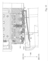
図16は、挿入アセンブリ331の一態様のより詳細な図である。挿入アセンブリ331は、フレーム1610、中間キャリッジ1620、および遠位キャリッジ1630を含む。中間キャリッジ1620は、フレーム1610のボールねじ1611に乗る。一態様では、ボールねじ1611は6mmピッチを有し、したがって中間キャリッジ1620はバックドライブ可能(back drivable)である。中間キャリッジ1620は、遠位キャリッジ1630を駆動する金属ベルト1621を含む。遠位キャリッジ1630は、器具マニピュレータアセンブリ240の器具マニピュレータアセンブリハウジングに取り付けられる。一態様では、遠位キャリッジ1630は、中間キャリッジ1620の2倍遠くに動く。
FIG. 16 is a more detailed view of one aspect of
図17Aおよび17Bは、プリロードアセンブリ1080およびプリロードアセンブリ1080の動作を示す。プリロードアセンブリ480および980の構成および動作は、一態様では、図17Aおよび17Bに示すものと同じである。説明を簡単にするために、器具260、滅菌アダプタアセンブリ250、器具マニピュレータアセンブリ1040のハウジング、および挿入アセンブリ331は、図17Aおよび17Bには示されていない。プリロードアセンブリ1080が図17Aに示される構成にあるとき、器具260の遠位端部は、例えば、エントリガイド270のチャネルへの入口に位置する。同様に、図18A乃至18Eおよび19A乃至19Cでは、プリロードアセンブリを理解するのに必要な要素のみが示されている。図17A、17B、18A乃至18E、および19A乃至19Cに関連する実際の構成は、図9A乃至9E、10A乃至10C、11Aおよび11Bに関して図示および説明したすべての要素を含む。
17A and 17B illustrate
プリロードアセンブリ1080の動作を検討する前に、プリロードアセンブリ1080内の要素を説明する。米国特許出願公開第2016/0184036号に記載されているプリロードアセンブリとは異なり、プリロードアセンブリ980によって供給されるプリロードは、コントローラ290によって自動的に解放されることができるとともにユーザによって手動で解放されることができる。米国特許出願公開第2016/0184036号に記載されているプリロードアセンブリによって供給されるプリロードは、ユーザによって手動でのみ解放され得る。
Before discussing the operation of
図17A、17B、18A乃至18E、および19A乃至19Cでは、プリロードトラック1725が中間キャリッジ1620に取り付けられている。谷部がプリロードトラック1725の近位端部に配置されている。プリロードトラック1725の傾斜路1725Rが谷部をプリロードトラック1725の平らな部分に接続する。プリロード係合リッジ1726は、プリロードトラック1725から傾斜路1725Rより遠位に延びている。プリロードトラック1725としての使用に適したプリロードトラックの説明は、米国特許出願公開第2016/0184036号に提示されており、その全体が参照により本明細書に組み込まれる。
17A, 17B, 18A-18E, and 19A-19C,
ホイール1783Wがカムフォロアアセンブリ1783の第1の端部に回転可能に取り付けられている。ホイール1783Wはプリロードトラック1725上に乗る(図17A、17B、18A乃至18E、および19A乃至19Cのいくつかにおいて、ホイール1783Wはプリロードトラック1725から変位しているように見える。図17A、17B、18A乃至18E、および19A乃至19Cに示されるすべての例において、ホイール1783Wは、プリロードトラック1725と接触してその上に乗る。)。
A
カムフォロアアセンブリ1783は、第1のピボットピンであるピボットピン1784の周りを旋回する。カムフォロアアセンブリ1783は、プリロードアセンブリ1080のアーム1782の第1の端部に回転可能に接続されている。アーム1782の第1の端部、例えば遠位端部は、モータパックブラケット1781に接続されている。カムフォロアアセンブリ1783としての使用に適したカムフォロアアセンブリの説明は、米国特許出願公開第2016/0184036号に提示されている。
モータパックブラケット1781は、モータパック1746に固定されている。したがって、アーム1782は、モータパック1746に結合されている。上記のように、器具マニピュレータアセンブリハウジングは、遠位キャリッジ1630に固定されている。モータパック1746の一例が米国特許出願公開第2016/0184036号に提示されている。
プリロード係合アーム1786の第2端部、近位端部が、ピボットピン1784に回転可能に結合されている。ピボットピン1784は、器具マニピュレータアセンブリ1040のハウジングにスライド可能に結合されている。
A second, proximal end of
ローリングピン1786Pが、プリロード係合アーム1786の第1の端部、遠位端部に取り付けられている。プリロード係合アーム1786の第1の端部におけるローリングピン1786Pに近接して、表面1786Sとも呼ばれるプリロード係合面1786Sがある。この態様では、プリロード係合面1786Sは、プリロードトラック1725の平坦部分に対して垂直である。プリロード係合アーム1786は、リニアレール1787に結合されている。プリロード係合アーム1786およびリニアレール1787としての使用に適したプリロード係合アームおよびリニアレールの説明は、米国特許出願公開第2016/0184036号に提示されている。
A
この態様では、アーム1785とも呼ばれるプリロード係合/係合解除アーム1785は、クロスバーおよび脚部を有するT字形構造である。T字形構造の脚部が水平になるように、またはより一般的にはクロスバーに対して垂直になるように、T字形構造は垂直に対して時計回りに90度回転される。T字形構造の使用は任意選択である。下記の動作を実行することができる任意の形状のプリロード係合/係合解除アーム1785を使用することができる。
In this aspect, the preload engagement/
プリロード係合/係合解除アーム1785のクロスバーはてこ(lever)として機能し、したがってプリロード係合/係合解除アーム1785のてこまたはてこ部分と呼ばれる。プリロード係合/係合解除アーム1785のクロスバーの第2の端部、近位端部、のフックは、プリロードが有効になるときアーム1785の第2の端部でローリングピン1786Pと係合し、プリロードが無効になるときローリングピン1786Pと係合解除する。緊急器具解放ボタン1082は、プリロード係合/係合解除アーム1785のクロスバーの第1の端部、遠位端部、に連結される、例えばこれと接触する。緊急器具解放ボタン1082は緊急器具解放ボタン482および緊急器具解放ボタン982の一例である。
The crossbar of the preload engagement/
プリロード係合/係合解除アーム1785のクロスバーの第1端部と第2端部との間に、プリロード係合/係合解除アーム1785は、プリロード係合/係合解除アームのてこ作用の支点として機能する別のピボットピン1788、第2ピボットピンに回転可能に取り付けられている。T字形構造の脚部はアーム1785のてこ部分から延びているので、ピボットピン1788はT字形構造の脚部に対して中心にある。したがって、プリロード係合/係合解除アーム1785の脚部は第1の端部および第2の端部を有し、第1の端部はプリロード係合/係合解除アーム1785のクロスバーに接続されている。
Between the first and second ends of the crossbar of the preload engagement/
ピボットピン1788と同心のトーションスプリング1789(図17C)は、プリロード係合/係合解除アーム1785に反時計回りのトルク(図17A、17B、18A乃至18E、および19A乃至19Cに対して反時計回り)を及ぼす。トーションスプリング1789は、プリロード係合/係合解除アーム1785に力を与え、それは、プリロード係合/係合解除アーム1785のフックをピボットピン1784およびピボットピン1788を通って延びる軸から離れるように動かす。ピボットピン1784およびピボットピン1788を通って延びる軸は、ピボットピン1784の長手方向軸およびピボットピン1788の長手方向軸に対して垂直である。トーションスプリング1789は、プリロード係合/係合解除アーム1785をプリロード解放方向に回転させ、これはプリロード係合/係合解除アーム1785を図18A、18B、18C、19B、および19Cに示される解放位置に維持するのに必要である。
A torsion spring 1789 (FIG. 17C) concentric with
一態様では、緊急器具解放ボタン1082に関して、支点が力(effort)(緊急器具解放ボタン1082によって供給される力)と荷重(load)(フックとローリングピン1786Pの間の結合)との間であるので、プリロード係合/係合解除アーム1785のてこ部分はクラス1てこ(Class 1 lever)である。この例では、プリロード係合/係合解除アーム1785はクラス1てことして実施されているが、これは例示にすぎず、限定することを意図するものではない。他の態様では、クラス2てこまたはクラス3てこを使用することができる。クラス2てこの場合、荷重は支点と力との間にあり、クラス3てこの場合、力は支点と荷重との間にある。
In one aspect, with respect to the emergency
プリロード係合/係合解除アーム1785の脚部の第2の端部はリンク1723の第2の端部に接続されている。リンク1723の第1の端部は電気アクチュエータに接続され、これはこの例ではプランジャ1721を有するソレノイド1720として実現される。この態様では、リンク1723の第1の端部はプランジャ1721に接続されている。電気アクチュエータはコントローラ290に接続されている。コントローラ290からの指令に応答して、電気アクチュエータは有効および無効にされる。
The second end of the leg of preload engagement/
緊急器具解放ボタン1082、プリロード係合/係合解除アーム1785、プリロード係合アーム1786、トーションスプリング1789、電気アクチュエータおよびリンク1723は、プリロードアセンブリ1080のプリロード係合/係合解除機構を形成する。したがって、プリロード係合/係合解除機構およびプリロードアセンブリ1080の両方は、コントローラに結合された機械的構造である。
Emergency
プリロード係合/係合解除アーム1785は、第2ピボットピン1788に回転可能に結合されている。プリロード係合/係合解除アーム1785は、プリロード係合アーム1786のローリングピン1786Pに結合及び分離可能である。トーションスプリング1789は、第2ピボットピン1788に取り付けられ、プリロード係合/係合解除アーム1785に結合されている。トーションスプリング1789は、プリロード係合/係合解除アーム1785をローリングピン1786Pからの係合解除位置に保持するよう、プリロード係合/係合解除アーム1785にトルクを与えるように構成されている。図18Aおよび18Bを参照されたい。
Preload engagement/
最初に、図17Aに示されるように、プリロードアセンブリ1080のカムフォロアアセンブリ1783は、中間キャリッジ1620上のプリロードトラック1725の谷部に位置する、例えば、プリロードトラック1725の第1の位置-ホーム位置-に位置する。第1の位置では、モータパック1746の各駆動出力アセンブリ内の軽プリロードスプリングが圧縮されており、第1のプリロード力がディスクスタックの各ディスクに加えられる(図4E参照)。手術装置アセンブリ300が、挿入アセンブリ331によって第1の位置から第2の位置まで距離Zloadだけ遠位に動かされると、器具マニピュレータアセンブリハウジングは距離Zloadだけ動かされる。
Initially, as shown in FIG. 17A, the
カムフォロアアセンブリ1783が回転可能に取り付けられているピボットピン1784は、器具マニピュレータアセンブリ1040の器具マニピュレータアセンブリハウジングに結合されている。したがって、挿入アセンブリ331が器具マニピュレータアセンブリハウジングを遠位に距離Zloadだけ動かすと、ピボットピン1784は、カムフォロアアセンブリ1783を同じ距離Zloadだけ動かす。一態様では、距離Zloadは3.85インチ(9.80cm)である。
A
上述のように、ホイール1783Wはカムフォロアアセンブリ1783の第1の端部に回転可能に取り付けられ、ホイール1783Wはプリロードトラック1725上に乗る。したがって、カムフォロアアセンブリ1783が遠位に移動すると、ホイール1783Wはプリロードトラック1725の輪郭に追従する。しかし、プリロードトラック1725とピボットピン1784との間の距離は、カムフォロアアセンブリ1783が遠位に動くにつれて減少する。その結果、カムフォロアアセンブリ1783がプリロードトラック1725内の傾斜路1725Rに乗り上げると、カムフォロアアセンブリ1783は図17Aに示す第1の位置から図17Bに示す第2の位置まで回転し、モータパック1746を器具マニピュレータアセンブリハウジングによって移動した距離より大きい距離だけ移動させる。したがって、カムフォロアアセンブリ1783の回転は、器具マニピュレータアセンブリハウジングに対して遠位方向に所定距離Δだけモータパック1746を変位させる。
As described above,
カムフォロアアセンブリ1783がプリロードトラック1725に沿って移動するときに、カムフォロアアセンブリ1783によって2つの動作が行われる。カムフォロアアセンブリ1783が傾斜路1725Rを上に移動して回転すると、カムフォロアアセンブリ1783の回転はモータパックを遠位方向に距離Zloadより大きい距離だけ押す、例えばモータパック1746は距離(Zload+Δ)を移動する。加えて、カムフォロアアセンブリ1783が傾斜路1725Rを上に移動すると、カムフォロアアセンブリ1783は力をモータパック1746に伝達し、これは、各駆動出力アセンブリ内の軽プリロードスプリングおよび高プリロードスプリングの両方を圧縮するので、第2のプリロード力-高プリロード力-が器具マニピュレータアセンブリ1040の各駆動出力ディスクに、高いプリロード力がアサートされる(asserted)。もちろん、そうでなければスプリングは圧縮されないので、器具が装着されているときにのみ当てはまる。
Two operations are performed by
図18A乃至18Eは、プリロードアセンブリ1080によるプリロードの自動設定において実行される動作の一実装形態の図である。プリロードアセンブリ480および980の動作は、一態様では、図18A乃至18Eに示すものと同じである。
18A-18E are illustrations of one implementation of operations performed in automatic configuration of preload by
滅菌アダプタアセンブリ250が、滅菌アダプタ装着動作817で器具マニピュレータアセンブリ1040に取り付けられるとき、器具マニピュレータアセンブリ1040は、滅菌アダプタアセンブリ250の存在を示す信号をコントローラ290に送信する。
When
ユーザがクラッチボタン1044を押して器具マニピュレータアセンブリ1040を近位に動かすとき、器具マニピュレータアセンブリハウジングは、プリロードトラック1725上のプリロード係合リッジ(preload engagement ridge)1726の2倍の速さで近位に動く。これは、器具マニピュレータアセンブリ1040が取り付けられている遠位キャリッジ1630が、プリロードトラック1725が取り付けられている中間キャリッジ1620の2倍遠くに動くためである。この態様では、プリロード係合リッジ1726は、プリロードトラック1725の遠位部分から延びる。
When a user presses
最初に、器具マニピュレータアセンブリ1040がホーム位置にあるとき、プリロードトラック1725上のプリロード係合リッジ1726とプリロード係合アーム1786のプリロード係合面1786Sとの間にギャップ1801がある。コントローラ290は、挿入アセンブリに器具マニピュレータアセンブリをホーム位置から近位方向に動かすように命令する。器具マニピュレータアセンブリハウジングが近位に動くと、プリロード係合リッジ1726はプリロード係合アーム1786の半分の速度で近位に動き、器具マニピュレータアセンブリハウジングおよび挿入アセンブリ331は短くなる。したがって、中間キャリッジ1620および遠位キャリッジ1630は、互いに相対的に接近して移動してプリロードトラック1725上のプリロード係合リッジ1726とプリロード係合アーム1786のプリロード係合面1786Sとの間のギャップ1801を閉じる。
Initially, when
ギャップ1801が閉じると(図18B)、プリロード係合アーム1786の表面1786Sは、プリロードトラック1725上のプリロード係合リッジ1726と係合する。プリロード係合アーム1786の近位の動きは、プリロードトラック1725と共に近位に動くように拘束されるが、器具マニピュレータアセンブリ1040は、遠位キャリッジ1630と共に近位に移動し続け、リニアレール1787が器具マニピュレータハウジング内のレールに対してスライドする。器具マニピュレータハウジングが近位方向に移動し続け、これはモータパックリターンスプリングを延ばすので、アーム1782はモータパック1746を所定の位置に保持する。
When
器具マニピュレータアセンブリ1040がホーム位置に近い所定の距離、例えば2mmであるとき、プリロード係合/係合解除アーム1785に含まれるてこの第2の端部のフックは、プリロード係合アーム1786の第1の端部のローリングピン1786Pに近い(図18C)。しかし、ピボットピン1788の周りのトーションスプリング1789は、プリロード係合/係合解除アーム1785が時計方向に回転してローリングピン1786Pに係合するのを防止する。
When the
器具マニピュレータアセンブリが完全に引き込まれた位置(第3の位置)に達すると、コントローラ290はソレノイド1720を発射させ、それはプランジャ1721を近位方向に動かす。プランジャ1721の近位方向への動きは、リンク1723を近位方向に動かし、これは、プリロード係合/係合解除アーム1785のフックがローリングピン1786Pに係合するまで、プリロード係合/係合解除アーム1785のフックを時計方向に回転させる(図18D)。
When the instrument manipulator assembly reaches the fully retracted position (third position),
プリロード係合/係合解除アーム1785のフックのローリングピン1786Pへの係合後、コントローラ290は、器具マニピュレータアセンブリ1040をホーム位置まで遠位方向に移動させるので、プリロードトラック1725上のプリロード係合リッジ1726とプリロード係合アーム1786のプリロード係合面1786Sとの間にはギャップがある(図18E)。この位置では、器具マニピュレータアセンブリのモータパックリターンスプリングが、モータパック1746を遠位方向に引っ張る。モータパックリターンスプリングによって供給される力は、プリロード係合/係合解除アーム1785のフックをローリングピン1786Pと係合させ続けるのに十分である。これはフックを張力下に置くので、トーションスプリング1789はプリロード係合/係合解除アーム1785を反時計方向に回転させることができない。その結果、コントローラ290は、ソレノイド1720への発射指令を解除する。図18A乃至18Eに示されるように、器具マニピュレータアセンブリ1040は、コントローラ290の制御下でモータパック1746に第1のプリロードを設定するように自動的に構成される。
After engagement of the hook of preload engagement/
図19A乃至19Cは、一態様において、プリロードアセンブリ1080によるプリロードの自動解放において実行される動作の一実装形態の図である。プリロードアセンブリ480および980の動作は、図19A乃至19Cに示すものと同じである。
19A-19C are illustrations of one implementation of operations performed in automatic release of preload by
器具マニピュレータアセンブリ1040およびプリロードアセンブリ1080が近位に動かされると、カムフォロアアセンブリ1783(図17B)が近位に動き、ホイール1783Wはプリロードトラック1725の輪郭を追従する。しかし、カムフォロアアセンブリ1783が近位方向に移動すると、プリロードトラック1725とピボットピン1784との間の距離は増大する。その結果、カムフォロアアセンブリ1783がプリロードトラック1725の傾斜路1725Rを降りると、カムフォロアアセンブリ1783は図17Bに示す第2の位置から図17Aに示す位置まで回転する。これは、図19Aに示すように、プリロードアセンブリ1080がホーム位置にあるとき、第1のプリロード力のみが作用するように、第2のプリロードを解放する。これはまた、ハードストップが引き込められるときに可動マニピュレータ-器具インタフェースプレートが近位方向に移動され得るので、器具260が取り外され得るように、滅菌アダプタアセンブリ250からハードストップを引き込める。
As
図19Aに関して、コントローラ290は、器具マニピュレータアセンブリ1040を近位に動かすモータを作動させる。器具マニピュレータアセンブリハウジングは、プリロードトラック1725のプリロード係合リッジ1726の2倍の速さで近位方向に動く。これは、器具マニピュレータアセンブリ1040が取り付けられる遠位キャリッジ1630が、プリロードトラック1725が取り付けられる中間キャリッジ1620の2倍遠くに動くためである。
With respect to FIG. 19A,
最初に、プリロードトラック1725のプリロード係合リッジ1726とプリロード係合アーム1786のプリロード係合面1786Sとの間にギャップがある(図19A)。器具マニピュレータアセンブリハウジングが近位に動くと、プリロード係合リッジ1726はプリロード係合アーム1786の半分の速度で近位に動き、器具マニピュレータアセンブリハウジングおよび挿入アセンブリ331は短くなる。したがって、中間キャリッジ1620および遠位キャリッジ1630は、互いに相対的により接近して移動して、プリロードトラック1725のプリロード係合リッジ1726とプリロード係合アーム1786のプリロード係合面1786Sとの間のギャップを閉じる。
Initially, there is a gap between the
ギャップが閉じると(図19B)、プリロード係合アーム1786の表面1786Sは、プリロードトラック1725のプリロード係合リッジ1726と係合する。プリロード係合アーム1786の近位の動きは、プリロードトラック1725と共に近位に動くように拘束されるが、器具マニピュレータアセンブリ1040は、遠位キャリッジ1630と共に近位に移動し続け、リニアレール1787が器具マニピュレータハウジングのレールに対してスライドする。
When the gap is closed (FIG. 19B),
器具マニピュレータアセンブリ1040がホーム位置に近い所定の距離、例えば2mmであるとき、プリロード係合/係合解除アーム1785に含まれるてこの第2の端部のフックは、プリロード係合アーム1786の第1の端部のローリングピン1786Pに近い(図18C)。ソレノイド1720は作動していないので、ピボットピン1788周りのトーションスプリング1789は、フックをローリングピン1786Pから係合解除するように、プリロード係合/係合解除アーム1785を反時計回りに回転させる。
When the
プリロード係合/係合解除アーム1785のフックのローリングピン1786Pへの係合解除後、コントローラ290は器具マニピュレータアセンブリ1040を遠位にホーム位置に移動させる。プリロード係合/係合解除アーム1785のフックがプリロード係合アーム1786から係合解除されているので、モータパック1746に遠位方向への力はない。モータパックは器具マニピュレータハウジングに対して遠位方向に変位せず、したがって、器具マニピュレータアセンブリ1040が遠位に動かされるときにプリロード力はない。このようにして、図19A乃至19Cに示すように、器具マニピュレータアセンブリ1040は、コントローラ290の制御下で、モータパック1746への第1のプリロードをリセットし、器具マニピュレータアセンブリ1040が完全引込み位置から遠位にホームを超えて移動するときのプリロード力の印加を防ぐように、自動的に構成される。
After disengaging the hook of preload engagement/
挿入アセンブリ331が伸長位置で引っかかる(jams)場合、器具260を取り外すことができるように高いプリロード力が解放されなければならない。器具260を取り外すために、ユーザは緊急器具解放ボタン1082(図10A)を押す。ユーザによって提供された力に応答して、緊急器具解放ボタン1082は、プリロード係合/係合解除アーム1785の第1の端部に力を加える。プリロード係合/係合解除アーム1785の第1の端部への力は、プリロード係合/係合解除アーム1785をピボットピン1788の周りに回転させ、プリロード係合/係合解除アーム1785の第2の端部のフックを、プリロード係合アーム1786の第2の端部に取り付けられているローリングピン1786Pから係合解除させる。
If
モータパックリターンスプリングが、器具マニピュレータアセンブリハウジングとモータパック1746との間に取り付けられており、高プリロード力が加えられたときに引き伸ばされることを思い出されたい。その結果、プリロード係合/係合解除アーム1785がプリロード係合アーム1786から係合解除されると、モータパックリターンスプリングはモータパック1746を完全に引き込まれた位置に後退させる。
Recall that a motor pack return spring is mounted between the instrument manipulator assembly housing and the
完全に引き込まれた位置では、プリロード力がないので、駆動出力ディスクは中間ディスクから係合解除される。加えて、器具滅菌アダプタアセンブリ250および器具260の両方を取り外すことができるように、複数のハードストップが引き込まれる。器具260の遠位端部がまっすぐでない場合、人が器具を引き抜くとき、プリロード力がなく且つ駆動出力ディスクが係合していないディスクスタックはバックドライブ可能であるため、カニューレは器具260の遠位端部を強制的にまっすぐにする。
In the fully retracted position, there is no preload force and the drive output disc is disengaged from the intermediate disc. Additionally, a plurality of hard stops are retracted so that both instrument
図20Aは、挿入アセンブリ2031(挿入機構2031とも呼ばれる)に固定された器具マニピュレータアセンブリ2040を示す。器具マニピュレータアセンブリ2040は、器具マニピュレータアセンブリ240、440、および1040のそれぞれの別の例である。挿入アセンブリ2031は、挿入アセンブリ331の例である。器具マニピュレータアセンブリ2040の位置は、挿入アセンブリ2031によって決定され、ホーム位置から完全に伸長した位置まで変化する。完全に伸長した位置では、挿入アセンブリ2031は完全に伸長している。
FIG. 20A shows
ハウジング2048とも呼ばれる器具マニピュレータアセンブリハウジング2048は、挿入アセンブリ2031の遠位端部に固定して取り付けられているので、器具マニピュレータアセンブリハウジング2048は、挿入アセンブリ2031の移動と共にホーム位置から完全に伸張した位置まで移動する。
Instrument
器具マニピュレータアセンブリハウジング2048内のモータパック2046はレール2039上を移動することができる。モータパック2046は器具マニピュレータアセンブリハウジング2048に対して遠位方向および近位方向に移動することができる。モータパック2046は、リターンスプリング2047とも呼ばれるモータパックリターンスプリング2047によって器具マニピュレータアセンブリハウジング2048に結合される。モータパック2046に含まれる要素は、一態様では、モータパック446に関して上述した要素と同じである。モータパックリターンスプリング2047は、モータパックリターンスプリング447と同等である。
A
プリロードアセンブリ2080は器具マニピュレータアセンブリハウジング2048に取り付けられているので、ハウジング2048と共に動く。プリロードアセンブリ2080はアーム2088によってモータパック2046に接続されている。プリロードアセンブリ2080は緊急器具解放ボタン2082を含む。
プリロードアセンブリ480によって挿入アセンブリ431に移動可能に結合されるモータパック446とは異なり、モータパック2046は、プリロードアセンブリ2080によって挿入アセンブリ2031に可動に結合されない。しかし、プリロードアセンブリ2080は、ホーム位置に対する器具マニピュレータアセンブリ2040の位置に関係なく、ハウジング2048に対してモータパック2046を動かす能力を有する。したがって、器具マニピュレータアセンブリがホーム位置から移動するにつれて、プリロードアセンブリがトラックに沿って移動し、第1のプリロードから第2のプリロードまでプリロードが増加された、図18A乃至18Eおよび19A乃至19Cの態様とは対照的に、ここでは、プリロードアセンブリ2080は、コントローラ290、例えばコントローラ290のモータコントローラの直接の制御下にあり、したがって、プリロードは、ホーム位置に対する器具マニピュレータアセンブリ2040の位置に関係なく且つ器具マニピュレータアセンブリ2040が挿入アセンブリ2031によって動かされているのか静止しているのかに関係なく、増減されることができる。
Unlike
プリロード無しが望まれるとき、およびモータパック2046が器具マニピュレータアセンブリハウジング2048に対して遠位方向に変位しないとき、コントローラ290はいかなる動作もしない。(一態様では、図8に関して上述したように、器具マニピュレータアセンブリ2040の状態によって所望のプリロードが決定されることに留意されたい。)この場合、モータパック2046は、ホーム位置と完全に伸長した位置との間のどこに器具マニピュレータアセンブリが位置しているかに関係なく、器具マニピュレータハウジング2048に対してプリロード無し位置2032にある。
When no preload is desired and when
ホーム位置から完全に伸張した位置へのまたは完全引き込まれた位置からホーム位置への器具マニピュレータアセンブリ2040単独の移動は、プリロードを変化させない。コントローラ290が変化をもたらすために指令をプリロードアセンブリ2080に直接送る場合、または緊急器具解放ボタン2082が作動される場合にのみ、プリロードは変化する。モータパック2046がプリロード無し位置2032にあるとき、滅菌アダプタアセンブリが器具マニピュレータアセンブリ2040の遠位面に取り付けられている場合、滅菌アダプタアセンブリの中間ディスクにプリロード力はかからないであろう。
Movement of the
低プリロードが望まれる場合そしてモータパック2046が器具マニピュレータアセンブリハウジング2048に対して遠位方向に変位しない場合、すなわちモータパックがプリロード無し位置2032にある場合、コントローラ290はアーム2088を遠位に動かすようにプリロードアセンブリ2080に命令して、モータパック2046を低プリロード位置2033に動かす。モータパック2046が器具マニピュレータハウジング2048に対して遠位に移動すると、モータパックリターンスプリング2047が伸びる。
If a low preload is desired and the
滅菌アダプタアセンブリが、低プリロード位置2033のモータパック2046と共に器具マニピュレータアセンブリ2040の遠位面に取り付けられている場合、滅菌アダプタアセンブリの中間ディスクに低プリロード力、例えば、第1のプリロード力があるであろう。図20Aおよび20Bの例では、プリロード力はコントローラ290によって増大されたが、器具マニピュレータアセンブリ2040は挿入アセンブリ2031によって動かされなかった。代替的には、器具マニピュレータアセンブリが挿入アセンブリ290によって動かされるとき、プリロード力はコントローラ290によって増大されることができる。モータパック2046が低プリロード位置2033にあるときに緊急器具解放ボタン2082が作動される場合、プリロードアセンブリ2080のプリロード機構は係合解除され、モータパックリターンスプリング2047はモータパック2046を近位方向にプリロード無し位置2032に後退させる。
When the sterile adapter assembly is attached to the distal face of the
低プリロードが望まれる場合そしてモータパック2046が器具マニピュレータアセンブリハウジング2048に対して高プリロード位置2034にある場合、すなわち、モータパックが高プリロード位置2034にある場合、コントローラ290はプリロードアセンブリ2080にアーム2088を近位方向動かしてモータパック2046を低プリロード位置に動かすように指令する。モータパック2046が器具マニピュレータハウジング2048に対して近位に動かされると、モータパックリターンスプリング2047は収縮する。この場合も同様に、これは、挿入機構が器具マニピュレータアセンブリ2040を動かすことなしに又は挿入機構が器具マニピュレータアセンブリ2040を動かしながら行われることができる。なぜなら、プリロードアセンブリ2080によって供給されるプリロード力は、ホーム位置に対するプリロードアセンブリの位置とは無関係におよび挿入アセンブリ2031が器具マニピュレータアセンブリ2040を動かしているかどうかに無関係に変更されることができるからである。プリロードの変化は、器具マニピュレータアセンブリ2040の位置を変更するためのコントローラ290から挿入アセンブリ2031への指令には依存せず、これは図19A乃至19Cに関して説明した実施形態とは異なる。
When a low preload is desired and the
コントローラ290によるプリロードの制御は、器具マニピュレータアセンブリ2040が取り付けられている挿入アセンブリ2031の制御とは無関係である。これは、前述の態様とは異なり、器具マニピュレータアセンブリ2040の位置を変更するためのコントローラ290による挿入機構2031へのコマンドがプリロードを変更できないことを意味する。むしろ、コントローラ290は、プリロードを変更するようにプリロードアセンブリ2080に直接指令する。コントローラ290は、器具マニピュレータアセンブリ2040の位置に基づいてプリロードを変更するようにプリロードアセンブリ2080に指令することができることを認識されたい。したがって、プリロードアセンブリ2080への指令は、挿入アセンブリ2031への指令に結合され得るが、挿入アセンブリ2031への指令は、この態様では、2031はプリロードを変更することができないので、コントローラ290によるプリロードの制御は、器具マニピュレータアセンブリ2040が取り付けられている挿入アセンブリ2031の制御とは無関係であると言われる。
Control of preload by
プリロード無しが望まれる場合そしてモータパック2046が器具マニピュレータアセンブリハウジング2048に対して低プリロード位置2033にある場合、すなわち、モータパック2046が低プリロード位置2033にある場合、コントローラ290はアーム2088を近位方向に動かしてモータパック2046をプリロード無し位置2032に動かすようにプリロードアセンブリ2080に指令する。モータパック2046が器具マニピュレータハウジング2048に対して近位に動かされると、モータパックリターンスプリング2047は収縮される。さらにこの場合も同様に、これは、挿入機構2031が器具マニピュレータアセンブリ2040を動かすことなしに又は挿入機構2031が器具マニピュレータアセンブリ2040を動かしながら行われることができる。なぜなら、プリロードアセンブリ2080によって供給されるプリロード力は、挿入アセンブリ2031に対するプリロードアセンブリ2080の位置とは無関係におよびホーム位置に対する器具マニピュレータアセンブリ2040の位置とは無関係にコントローラ290によって変えられることができるためである。もちろん、これは、挿入アセンブリ2031が器具マニピュレータアセンブリ2040を動かすときにも行われ得る。
If no preload is desired and the
高プリロードが望まれる場合、コントローラ290は、プリロードアセンブリ2080にアーム2088を遠位方向に動かしてモータパック2046を高プリロード位置2034に動かすように指令する。モータパック2046が器具マニピュレータハウジング2048に対して遠位に動かされるとき、モータパックリターンスプリング2047は伸長されている。
If a high preload is desired,
滅菌アダプタアセンブリが、高プリロード位置2034のモータパック2046とともに器具マニピュレータアセンブリ2040の遠位面に取り付けられる場合、滅菌アダプタアセンブリ中間ディスクに高プリロード力、例えば、第2のプリロード力がある。モータパック2046が高プリロード位置2034にあるときに緊急器具解放ボタン2082が作動されると、プリロードアセンブリ2080のプリロード機構は係合解除され、モータパックリターンスプリング2047はモータパック2046を近位方向にプリロード無し位置2032に引き込み、これは高プリロード力を取り除く。
When the sterile adapter assembly is attached to the distal face of the
モータパック2046が器具マニピュレータアセンブリハウジング2048に対して高プリロード位置2033である場合、コントローラ290は、プリロードアセンブリ2080に、モータパック2046を近位に低プリロード位置2033またはプリロード無し位置2032のいずれかに動かすように指令することができる。図20A、20B、および20Cの例では、プリロード力はコントローラ290によって増大されたが、挿入アセンブリ2031は器具マニピュレータアセンブリ2040を動かさなかった。挿入アセンブリ2031が器具マニピュレータアセンブリ2040を動かすとき、プリロード力はまた、これらの例のそれぞれにおいてコントローラ290によって変えられ得る。
When the
図21A乃至21Cに関して以下に説明する例および図4A乃至4Gに示す例では、機械的器具取り外しロックアウト(滅菌アダプタアセンブリの可動ボディが近位に動くのを防止する)は、器具マニピュレータアセンブリのモータパックを動かすことによって作動される。図21Dおよび21Eに示す別の態様では、機械的器具取り外しロックアウトは、器具マニピュレータアセンブリ2040のどの部分の運動とも無関係である。この態様では、機械的器具取り外しロックアウトアセンブリ2090は、器具マニピュレータアセンブリ2040のハウジング2048に取り付けられている。機械的器具取り外しロックアウトアセンブリ2090は、アーム2091とも呼ばれるロックアウトアーム2091に接続され、このアームは近位端部に複数の停止部(stops)を含む。複数の停止部は任意選択であり、前述の滅菌アダプタアセンブリと相互作用する(interfacing)ための例として使用される。より一般的には、例えば、アーム2091の遠位面は、滅菌アダプタアセンブリの可動ボディの近位面と相互作用することができる。この態様では、緊急器具解放ボタン2082Aがプリロードアセンブリ2080と機械的器具取り外しロックアウトアセンブリ2090との間で共有されている。一態様では、ロックアウトリターンスプリング2047Aが、ロックアウトアーム2091の近位端部とハウジング2048との間に接続されている。
In the example described below with respect to FIGS. 21A-21C and illustrated in FIGS. 4A-4G, the mechanical instrument removal lockout (which prevents proximal movement of the movable body of the sterile adapter assembly) Activated by moving the puck. In another aspect, shown in FIGS. 21D and 21E, the mechanical instrument removal lockout is independent of movement of any portion of the
滅菌アダプタアセンブリ2050(図20D)は、器具マニピュレータアセンブリ2040の遠位面に取り付けられる。滅菌アダプタアセンブリ2050は、可動ボディ2051Cとも呼ばれる可動マニピュレータ-器具インタフェースプレート2051Cを含み、これは滅菌アダプタアセンブリ2050のフレームに対して近位方向および遠位方向に動くことができる。滅菌アダプタアセンブリ250は、滅菌アダプタアセンブリ2050の一例であり、滅菌アダプタアセンブリ2050はさらに詳細には説明されない。
A sterile adapter assembly 2050 (FIG. 20D) is attached to the distal surface of the
先に説明したように、器具が滅菌アダプタアセンブリ2050に取り付けられ、またはそこから取り外されると、可動ボディ2051Cは近位方向に移動する。器具の取り外しを防ぐために、可動ボディ2051Cを定位置にロックすることによって、可動ボディ2051Cが機械的器具取り外しロックアウトアセンブリ2090によって近位方向に動くのを防ぐ。
As previously discussed, when an instrument is attached to or removed from
オプションの機械的器具取り外しロックアウトアセンブリ2090(図20D)が、コントローラ290、例えば、コントローラ290のモータコントローラの直接制御下にある。機械的器具取り外しロックアウトは、ホーム位置に対するマニピュレータアセンブリ2040の位置に関係なく、器具マニピュレータアセンブリ2040が挿入アセンブリ2031によって動かされているか静止しているかに関係なく、およびハウジング2048に対するモータパック2046の位置に関係なく、作動または停止されることができる。アーム2091の運動は、器具マニピュレータアセンブリ2040の運動から独立し且つモータパック2046の運動から独立している。アーム2091は、コントローラ290が機械的器具取外しロックアウトアセンブリ2090にアーム2091を動かすように指令したとき、またはアーム2091が伸張位置にあり、かつ緊急器具解放ボタン2082Aがユーザによって作動されたときにのみ動く。
An optional mechanical instrument removal lockout assembly 2090 (FIG. 20D) is under direct control of
この態様では、アーム2091は、図20Dに示される近位位置および図20Eに示される遠位位置を有する。近位位置、第2の位置では、アーム2091のどの部分も滅菌アダプタアセンブリ2050の可動ボディ2051Cと接触していない。機械的器具取り外しロックアウトアセンブリ2090がコントローラ290から係合ロックアウトコマンドを受け取ると、機械的器具取り外しロックアウトアセンブリ2090は、アーム2091を遠位位置(図20E)に移動させ、これは、可動ボディ2051Cを滅菌アダプタアセンブリ2050の遠位位置にロックする。可動ボディ2051Cを遠位位置でロックされた状態では、滅菌アダプタアセンブリに装着された器具は取り外されることができない。
In this embodiment,
アーム2091が遠位位置に移動すると、リターンスプリング2047Aが伸ばされる。緊急器具解放ボタン2082Aが作動されると、アーム2091が機械的器具取り外しロックアウトアセンブリ2090から係合解除外され、リターンスプリング2047Aがアーム2091をその近位位置に引っ張る(図20D)。これにより、可動ボディ2051Cは、近位方向に移動されることができ、器具は取り外されることができる。
When
代替的には、コントローラ290は、係合解除ロックアウトコマンドを機械的器具取り外しロックアウトアセンブリ2090に送信することができる。機械的器具取り外しロックアウトアセンブリ2090がコントローラ290から係合解除ロックアウトコマンドを受信すると、機械的器具取り外しロックアウトアセンブリ2090はアーム2091を遠位位置20Eから近位位置20Dに動かし、これは、滅菌アダプタアセンブリ2050の可動ボディ2051Cをロック解除し、可動ボディ2051Cの移動を可能にする。
Alternatively,
図21A乃至21Cは、図20A乃至20Cの器具マニピュレータアセンブリ2040およびプリロードアセンブリ2080の一態様の例である。図4Aのものと同じ参照番号を持つ図21A乃至21Cの器具マニピュレータアセンブリ2040内の要素は、図4Aのものと同等の要素であるため、図4Aに関する要素の説明はここでは繰り返されない。
21A-21C are examples of one embodiment of the
この態様では、プリロードアセンブリ2080は、コントローラ290に接続されたモータ2181、例えばサーボモータを含む。モータ2181はハウジング2048に取り付けられている。モータ2181はねじ2183を駆動する。ナット2184がねじ2183に取り付けられ、モータ2181がねじ2183を回転させると近位又は遠位に移動する。一態様では、ねじ2183は、モータ2181のねじ付きシャフトである。モータ2181のシャフトの回転、したがってナット2184の遠位または近位の移動は、コントローラ290によって制御される。モータ、ねじ、およびナットの組み合わせは、軸に沿った位置がコントローラ290によって直接制御される可動アセンブリの一例である。
In this aspect,
プリロードタブ2184Tが、ナット2184の遠位端部に隣接するナット2184の外側面から延びる。プリロードタブ2184Tは、遠位面上の第1の平面と近位面上の第2の平面とを有する。第1の平面は、第2の平面よりもナット2184の外側面からさらに延びる。したがって、第1の平面を第2の平面に接合する面は傾斜面である。
A
プリロード解放レバー2186がピボットピン2187に取り付けられている。トーションスプリングがピボットピンの周りに取り付けられ、緊急器具解放ボタン2082が押されていない場合、プリロード解放レバー2186をプリロード係合位置に維持するようにプリロード解放レバー2186に取り付けられている。ピボットピン2187は、モータパック2046に接続されているアーム2088に取り付けられている。この例では、アーム2088は、レール2139上でハウジング2048に対して近位および遠位に移動する。レール2139は任意選択である。
A
プリロード解放レバー2186の遠位端部、すなわち第1の端部は、プリロードタブ2184Tと係合および係合解除するフック2186Aを含む。この例では、フック2186Aは、プリロード解放レバー2186の側面から延びる平らな平面を有する。フック2186Aの平らな平面は、プリロードタブ2184Tの遠位移動がプリロード解放レバー2186をプリロードタブ2184Tと共に遠位に移動させるように、プリロードタブ2084Tの第1の平面に接触するように構成される。
The distal or first end of
傾斜面が、プリロード解放レバー2186の側面から取り外されたプリロード解放レバー2186の平らな平面の端部からプリロード解放レバー2186の遠位端部まで延びている。プリロード解放レバー2186の遠位端部において傾斜面の傾斜は、タブ2184T上の傾斜面の傾斜とは反対にあるので、プリロードが解放されたときにフック2186Aおよびタブ2184Tは互いによって近位方向に移動することができる。
A ramp extends from the flat planar end of the
緊急器具解放ボタン2082は、プリロード解放レバー2186の近位端部、第2の端部に力を加えるために取り付けられている。図21Bおよび21Cの例では、緊急器具解放ボタン2082が作動される場合、緊急器具解放ボタン2082は、プリロード解除力をプリロード解放レバー2186の近位端部に加え、これはプリロード解放レバー2186をピボットピン2187周りにプリロード解除方向、図20Bおよび20Cにおける時計回りに旋回させる。
An emergency
プリロード解除方向のピボットピン2187周りのプリロード解放レバー2186の旋回は、フック2186Aをナット2184のタブ2184Tから係合解除させる。その結果、モータパックリターンスプリング2047は、モータパック2046を器具マニピュレータアセンブリハウジング2048に対して近位方向にプリロード無し位置2032に移動させる。
Pivoting of the
プリロードを係合させるために、コントローラ290は、モータ2181に、図21Bの位置または図20Cの位置のいずれかから図20Aの位置までナット2184を近位に移動させるように命令する。タブ2184Tはフック2186Aの遠位にあるので、ナット2184がタブ2184Tを近位に移動させると、タブ2184Tの傾斜面はプリロード解放レバー2186のフック2186Aの傾斜面と接触する。タブ2184Tが近位に動き続けると、タブ2184Tの傾斜面は、第1の平面(遠位平坦面)がフック2186Aの第1の平面を通過する(clears)までプリロード解放レバー2186を旋回させ、次いでピボットピン2187周りのトーションスプリングは、フック2186Aをプリロード係合方向に回転させるので、フック2186Aの第1の平らな平面とタブ2184Tの第1の平らな平面が接触している。今度はタブ2184Tが動くとき、フック2186Aが動き、それが今度はモータパック2046を動かすので、これはプリロード機構を係合させる。
To engage the preload,
具体的には、図21Aおよび21Bに示すように、プリロード機構が係合され、モータパック2046がプリロード位置2032になく、コントローラ290がプリロードアセンブリ2080にモータパック2046を低プリロード位置2033に動かすよう指令するとき、モータ2181はナット2184を遠位方向に移動させる。ナット2184を遠位方向の移動は、タブ2184Tにフック2186Aへの力を遠位方向に加えさせる。フック2186Aへの力はアーム2088を遠位方向に動かし、これはモータパック2046を器具マニピュレータハウジング2048に対して遠位方向に低プリロード位置2033へ動かす。
Specifically, as shown in FIGS. 21A and 21B, when the preload mechanism is engaged and the
図21Bおよび21Cに示されるように、プリロード機構が係合され、モータパック2046が低プリロード位置2033にあり、コントローラ290がプリロードアセンブリ2080にモータパック2046を高プリロード位置2034に動かすように指令すると、モータ2181はナット2184を遠位方向に動かす。遠位方向のナット2184の移動は、タブ2184Tにフック2186Aへの力を遠位方向に加えさせる。フック2186Aへの力はアーム2088を遠位方向に動かし、これはモータパック2046を器具マニピュレータハウジング2048に対して遠位方向に高プリロード位置2034へ動かす。
As shown in FIGS. 21B and 21C, when the preload mechanism is engaged and the
図21A乃至21Cに示す態様では、緊急器具解放ボタン2082に関して、支点(ピボットピン2187)が力(プリロード解放ボタン3082によって供給される力)と荷重(フック2186Aとタブ2184Tの間の結合)の間にあるので、プリロード解放レバー2186はクラス1てこである。この例では、プリロード解放レバー2186はクラス1てことして実施されているが、これは例示にすぎず、限定することを意図するものではない。他の態様では、クラス2てこまたはクラス3てこを使用することができる。クラス2てこの場合、荷重は支点と力の間にあり、クラス3てこの場合、力は支点と荷重の間にある。
In the embodiment shown in FIGS. 21A-21C, for emergency
図8のすべての状態およびすべての動作は、プリロードアセンブリ2080を含む器具マニピュレータアセンブリ2040を使用して達成することができる。したがって、図8の説明は、プリロードアセンブリ2080を含む器具マニピュレータアセンブリ2040の態様に対して繰り返されない。ここで、コントローラ290はプリロードを直接制御し、プリロードは挿入機構2031による器具マニピュレータアセンブリ2040の移動には依存しない。したがって、コントローラ290がプリロード機構を設定又はリセットするために器具マニピュレータアセンブリを動かした図8の動作は、プリロードアセンブリ2080を含む器具マニピュレータアセンブリ2040が使用されるとき、必要とされない。
All states and all operations of FIG. 8 can be achieved using
したがって、一態様では、滅菌アダプタアセンブリ2050が器具マニピュレータアセンブリ2040に取り付けられていない場合、コントローラ290は器具マニピュレータアセンブリ2040のモータパック2046にプリロード力無しを維持する。滅菌アダプタアセンブリ2050が器具マニピュレータアセンブリ2040に取り付けられた後、コントローラは、器具マニピュレータアセンブリ240のモータパック2046へのプリロード力を、プリロード力無しから第1のプリロード力に増大させるようにプリロードアセンブリ2080に直接指令を出す。コントローラは、器具が滅菌アダプタアセンブリ2050に取り付けられた後、器具マニピュレータアセンブリ240のモータパック2046へのプリロード力を、第1のプリロード力から第2のプリロード力に増大させるようにプリロードアセンブリ2080に直接別の指令を出す。
Thus, in one aspect, when
一態様では、機械的器具取り外しロックアウトアセンブリ2090は、図21Aのプリロードアセンブリ2080について示されているものと同等の要素とともに実装されているので、機械的器具取り外しロックアウトアセンブリ2090についての説明は繰り返さない。他の態様では、アセンブリ2080および2090は、2つの機能が互いに独立している状態で、プリロード機能および機械的器具取り外しロック機能の両方を実行する単一のアセンブリに組み合わされる。
In one aspect, the mechanical instrument
上記の例のいくつかにおいて、用語「近位」または「近位に」は、システム運動の運動学的連鎖に沿ったマニピュレータアームベースにより近いかまたはシステム運動の運動学的連鎖に沿った運動の遠隔中心(または手術部位)から離れている物体または要素を説明するために一般的な方法で使用されている。同様に、「遠位」または「遠位に」という用語は、システム運動の運動学的連鎖に沿ったマニピュレータアームベースから離れているかまたはシステム運動の運動学的連鎖に沿った運動の遠隔中心(または手術部位)に近い物体または要素を説明するために一般的な方法で使用されている。 In some of the above examples, the term "proximal" or "proximally" refers to closer to the manipulator arm base along the kinematic chain of system motion or of motion along the kinematic chain of system motion. Used in a general way to describe objects or elements that are remote from the center (or surgical site). Similarly, the term "distal" or "distally" refers to a distance from the manipulator arm base along the kinematic chain of system motion or a remote center of motion along the kinematic chain of system motion ( used in a general way to describe objects or elements near the surgical site (or surgical site).
本明細書で使用されるとき、「第1」、「第2」、「第3」、「第4」などは、異なる構成要素または要素を区別するために使用される形容詞である。したがって、「第1」、「第2」、「第3」、「第4」などは、構成要素または要素の順序を意味することを意図するものではない。 As used herein, "first," "second," "third," "fourth," etc. are adjectives used to distinguish between different components or elements. Thus, "first," "second," "third," "fourth," etc. are not intended to imply a component or order of elements.
本発明の態様および実施形態を示す上記の説明および添付の図面は、限定として解釈されるべきではなく、特許請求の範囲が保護される発明を定義する。この説明および特許請求の範囲の精神および範囲から逸脱することなく、様々な機械的、組成的、構造的、電気的、および動作上の変更を加えることができる。いくつかの例では、本発明を曖昧にすることを避けるために、よく知られている回路、構造、および技法は詳細に示されていないかまたは説明されていない。 The above description and accompanying drawings illustrating aspects and embodiments of the invention are not to be construed as limitations, but rather define the invention that is protected by the claims. Various mechanical, compositional, structural, electrical, and operational changes may be made without departing from the spirit and scope of this description and the claims. In some instances, well-known circuits, structures, and techniques are not shown or described in detail to avoid obscuring the present invention.
さらに、この説明の用語は本発明を限定することを意図するものではない。例えば、「下(beneath)」、「下(below)」、「下(lower)」、「上(above)」、「上(upper)」、「近位」、「遠位」などの空間的に相対的な用語を使用して、図面に示されるように1つの要素または特徴の他の要素または特徴との関係を説明することができる。これらの空間的に相対的な用語は、図に示される位置および向きに加えて、使用中または動作中の装置の異なる位置(すなわち場所)および向き(すなわち回転配置)を包含することを意図している。例えば、図中の装置がひっくり返される場合、他の要素または特徴の「下(below)」または「下(beneath)」として説明される要素は、他の要素または特徴の「上(above)」または「上(over)」になる。したがって、例示的な用語「下」は、上下の位置および向きの両方を包含し得る。装置は他の方向を向いていてもよく(90度または他の方向に回転して)、本明細書で使用される空間的に相対的な記述子はそれに応じて解釈される。同様に、様々な軸に沿った及びその周りの動きの説明は、様々な特別な装置位置及び向きを含む。 Furthermore, this descriptive terminology is not intended to limit the invention. For example, spatial terms such as "beneath", "below", "lower", "above", "upper", "proximal", "distal", etc. Relative terms may be used to describe the relationship of one element or feature to other elements or features as shown in the drawings. These spatially relative terms are intended to encompass different positions (i.e., locations) and orientations (i.e., rotational orientation) of the device in use or operation in addition to the positions and orientations shown in the figures. ing. For example, if the device in the figures is turned over, elements described as "below" or "beneath" other elements or features may be described as "above" or "beneath" other elements or features. Becomes “over.” Thus, the exemplary term "bottom" may encompass both top and bottom positions and orientations. The device may be oriented in other directions (rotated 90 degrees or in other directions) and the spatially relative descriptors used herein are interpreted accordingly. Similarly, descriptions of movement along and about various axes include various specific device positions and orientations.
単数形“a”、“an”、および“the”は、文脈が他に指示しない限り、複数形も含むことを意図している。用語「有する」、「備える」、「含む」などは、述べられた特徴、ステップ、動作、要素、および/または構成要素の存在を指定するが、1つまたは複数の他の特徴、ステップ、動作、要素、構成要素、および/またはグループの存在または追加を排除するものではない。結合されていると記載された構成要素は、電気的または機械的に直接結合されていてもよく、あるいは1つまたは複数の中間構成要素を介して間接的に結合されていてもよい。 The singular forms "a," "an," and "the" are intended to include the plural unless the context dictates otherwise. The terms "comprising," "comprising," "comprising," and the like specify the presence of the stated feature, step, act, element, and/or component, but also include one or more other features, steps, acts, etc. , the presence or addition of elements, components and/or groups. Components described as coupled may be electrically or mechanically coupled directly, or indirectly via one or more intermediate components.
すべての実施例および例示的な参考文献は非限定的であり、特許請求の範囲を本明細書に記載の特定の実装形態および実施形態、ならびにそれらの均等物に限定するために使用されるべきではない。1つの見出しの下のテキストは相互参照したり、1つまたは複数の見出しの下のテキストに適用される可能性があるため、見出しはフォーマット設定のみを目的としたものであり、如何なる方法でも主題を限定するために使用されるべきではない。最後に、本開示に鑑みて、図面に具体的に示されていないかまたは本文に記述されていなくても、一態様または実施形態に関して説明した特定の特徴は、本発明の他の開示された態様または実施形態に適用することができる。
次の付記を記す。
All examples and exemplary references are non-limiting and should be used to limit the claims to the specific implementations and embodiments described herein and equivalents thereof. isn't it. Headings are for formatting purposes only and are not subject to change in any way, as text under one heading may cross-reference or apply to text under one or more headings. should not be used to limit Finally, in view of this disclosure, certain features described with respect to one aspect or embodiment, even if not specifically shown in the drawings or described in the text, may be included in other disclosed aspects of the invention. may apply to any aspect or embodiment.
Please note the following additional notes.
(付記1) 手術器具マニピュレータアセンブリであって:
プリロードアセンブリ;および
遠位面;を有する、
手術器具マニピュレータアセンブリと;
前記手術器具マニピュレータアセンブリの前記遠位面に取り付けられる滅菌アダプタアセンブリであって、第1のプリロード力を前記滅菌アダプタアセンブリに加えるように前記プリロードアセンブリが前記手術器具マニピュレータアセンブリを設定する場合、前記滅菌アダプタアセンブリは前記手術器具マニピュレータアセンブリの前記遠位面から取り外し可能である、滅菌アダプタアセンブリと;を有する、
手術装置。
(付記2) 前記滅菌アダプタアセンブリは:
機械的滅菌アダプタアセンブリ取り外しロックアウトを有する、
付記1に記載の手術装置。
(付記3) 前記滅菌アダプタアセンブリは:
機械的手術器具取り外しロックアウトをさらに有する、
付記2に記載の手術装置。
(付記4) 前記滅菌アダプタアセンブリに取り付けられる手術器具であって、前記機械的滅菌アダプタアセンブリ取り外しロックアウトを作動させる、手術器具をさらに有する、
付記3に記載の手術装置。
(付記5) 前記手術器具マニピュレータアセンブリに接続される挿入アセンブリをさらに有し、
前記手術器具マニピュレータアセンブリのモータパックが遠位方向に所定距離動かされる場合、前記モータパックは、前記機械的滅菌アダプタアセンブリ取り外しロックアウトを作動させる、
付記2、又は付記3若しくは4のいずれか1項に記載の手術装置。
(付記6) 前記滅菌アダプタアセンブリは:
機械的手術器具取り外しロックアウトをさらに有する、
付記1、又は付記2乃至4のいずれか1項に記載の手術装置。
(付記7) 前記手術器具マニピュレータアセンブリはクラッチボタンをさらに有し、前記クラッチボタンおよび緊急解放ボタンは、前記手術器具マニピュレータアセンブリの唯一のユーザ操作インタフェースである、
付記1、又は付記2乃至4のいずれか1項に記載の手術装置。
(付記8) 滅菌アダプタアセンブリであって:
機械的手術器具取り外しロックアウト;および
機械的滅菌アダプタアセンブリ取り外しロックアウト;を含み、
手術器具が前記滅菌アダプタアセンブリに取り付けられた場合、前記機械的滅菌アダプタアセンブリ取り外しロックアウトが作動され;
前記手術器具が前記滅菌アダプタアセンブリに取り付けられ且つ手術器具マニピュレータアセンブリが所定距離遠位方向に動かされた場合、前記機械的手術器具取り外しロックアウトが前記手術器具マニピュレータアセンブリによって作動される;
滅菌アダプタアセンブリ;を有する、
手術装置。
(付記9) 前記滅菌アダプタアセンブリはフレームを有し;
前記機械的手術器具取り外しロックアウトは、前記滅菌アダプタアセンブリの前記フレームに移動可能に取り付けられた可動ボディを有し;
前記可動ボディの第1の位置では、前記手術器具は前記滅菌アダプタアセンブリから取り外されることができ;
前記可動ボディの第2の位置では、前記手術器具は前記滅菌アダプタアセンブリの所定の位置にロックされる、
付記8に記載の手術装置。
(付記10) 前記滅菌アダプタアセンブリは:
第1の端部および第2の端部を有するビームであって、前記第1の端部は前記第2の端部の反対側にあり、前記ビームの前記第1の端部と前記第2の端部との間で前記フレームに旋回可能に接続される、ビームと;
前記ビームの前記第2の端部から延びる複数のフック延長部であって、前記複数のフック延長部のそれぞれは、前記手術器具マニピュレータアセンブリのフックレシーバと係合するように構成されたフックを含む、複数のフック延長部と;
前記ビームの前記第1の端部に結合された滅菌アダプタアセンブリ解放ボタンであって、前記滅菌アダプタアセンブリ解放ボタンを第1の方向に押すことは、各前記フックを前記フックレシーバから係合解除するように前記複数のフック延長部を第2の方向に移動させる、滅菌アダプタアセンブリ解放ボタンと;をさらに有し、
前記機械的滅菌アダプタアセンブリ取り外しロックアウトは、前記ビームの前記第1の端部を含み;
前記手術器具が前記滅菌アダプタアセンブリに取り付けられている場合、前記手術器具は、前記滅菌アダプタアセンブリの前記手術器具マニピュレータアセンブリからの取り外しを不能にするように、前記滅菌アダプタアセンブリ解放ボタンの前記第1の方向の移動を妨げる、
付記9に記載の手術装置。
(付記11) 前記機械的滅菌アダプタアセンブリ取り外しロックアウトは:
第1の端部および第2の端部を有するビームであって、前記第1の端部は前記第2の端部の反対側にあり、前記ビームの前記第1の端部と前記第2の端部との間でフレームに旋回可能に接続される、ビームと;
前記ビームの前記第2の端部から延びる複数のフック延長部であって、前記複数のフック延長部のそれぞれは、前記手術器具マニピュレータアセンブリのフックレシーバと係合するように構成されたフックを含む、複数のフック延長部と;
前記ビームの前記第1の端部に結合された滅菌アダプタアセンブリ解放ボタンであって、前記滅菌アダプタアセンブリ解放ボタンを第1の方向に押すことは、各前記フックを前記フックレシーバから係合解除するように前記複数のフック延長部を第2の方向に移動させる、滅菌アダプタアセンブリ解放ボタンと;を有し、
前記手術器具が前記滅菌アダプタアセンブリに取り付けられている場合、前記手術器具は、前記滅菌アダプタアセンブリの前記手術器具マニピュレータアセンブリからの取り外しを不能にするように、前記滅菌アダプタアセンブリ解放ボタンの前記第1の方向の移動を妨げる、
付記8、又は付記9若しくは10のいずれか1項に記載の手術装置。
(付記12) 前記手術器具マニピュレータアセンブリをさらに有し、前記手術器具マニピュレータアセンブリは:
遠位面;および
緊急器具解放ボタンを含むプリロードアセンブリ;を有し、
前記滅菌アダプタアセンブリは、前記手術器具マニピュレータアセンブリの前記遠位面に取り付けられるように構成され;
前記手術器具マニピュレータアセンブリの前記遠位面からの前記滅菌アダプタアセンブリの取り外しは、前記緊急器具解放ボタンを使用することを必要としない、
付記8、又は付記9若しくは10のいずれか1項に記載の手術装置。
(付記13) 滅菌アダプタアセンブリであって:
フレーム;
第1の端部および第2の端部を有するビームであって、前記第1の端部は前記第2の端部の反対側にあり、前記フレームに旋回可能に接続される、ビーム;
前記ビームの前記第2の端部から延びる複数のフック延長部であって、前記複数のフック延長部のそれぞれは、手術器具マニピュレータアセンブリのフックレシーバと係合するように構成されたフックを含む、複数のフック延長部;並びに
前記ビームの前記第1の端部に結合された滅菌アダプタアセンブリ解放ボタンであって、前記滅菌アダプタアセンブリ解放ボタンを第1の方向に押すことは、各前記フックを前記フックレシーバから係合解除するように前記複数のフック延長部を第2の方向に移動させる、滅菌アダプタアセンブリ解放ボタン;を有する、
滅菌アダプタアセンブリと;
前記滅菌アダプタアセンブリに取り付けられる手術器具であって、前記滅菌アダプタアセンブリの前記手術器具マニピュレータアセンブリからの取り外しを不能にするように、前記滅菌アダプタアセンブリ解放ボタンの前記第1の方向の移動を妨げる、手術器具と;を有する、
手術装置。
(付記14) 前記滅菌アダプタアセンブリは:
前記滅菌アダプタアセンブリの前記フレームに移動可能に取り付けられた可動ボディをさらに有し;
前記可動ボディの第1の位置では、前記手術器具は前記滅菌アダプタアセンブリから取り外されることができ;
前記可動ボディの第2の位置では、前記手術器具は前記滅菌アダプタアセンブリの所定の位置にロックされる、
付記13に記載の手術装置。
(付記15) 手術器具マニピュレータアセンブリであって:
ハウジングと;
前記ハウジングに取り付けられたクラッチボタンと;
緊急器具解放ボタンを含むプリロードアセンブリであって、前記クラッチボタンおよび前記緊急器具解放ボタンは、前記手術器具マニピュレータアセンブリの唯一のユーザ操作ボタンである、プリロードアセンブリと;を有する、
手術器具マニピュレータアセンブリを有する、
手術装置。
(付記16) フレームおよび機械的手術器具取り外しロックアウトを有する滅菌アダプタアセンブリ;を有し、
前記機械的手術器具取り外しロックアウトは、前記滅菌アダプタアセンブリの前記フレームに移動可能に取り付けられた可動ボディを有し、前記可動ボディは第1の位置および第2の位置を有し、前記第1の位置および前記第2の位置は、前記滅菌アダプタアセンブリが取り付けられる手術器具マニピュレータアセンブリのいずれの部分の位置からも独立し、
前記可動ボディの前記第1の位置では、前記滅菌アダプタアセンブリに取り付けられた手術器具は前記滅菌アダプタアセンブリから取り外されることができ;
前記可動ボディの前記第2の位置では、前記手術器具は前記滅菌アダプタアセンブリの所定の位置にロックされる、
手術装置。
(付記17) 手術器具マニピュレータアセンブリおよび滅菌アダプタアセンブリの組み合わせを、前記手術器具マニピュレータアセンブリが第2のプリロード力を前記滅菌アダプタアセンブリに加える第2の位置から前記手術器具マニピュレータアセンブリが第1のプリロード力を前記滅菌アダプタアセンブリに加える第1の位置に動かすステップであって、前記第2のプリロード力は前記第1のプリロード力より大きい、ステップと;
前記第1のプリロード力が前記滅菌アダプタアセンブリに加えられている状態で前記手術器具マニピュレータアセンブリから前記滅菌アダプタアセンブリを取り外すステップと;
を含む、
方法。
(Additional Note 1) A surgical instrument manipulator assembly comprising:
a preload assembly; and a distal surface.
a surgical instrument manipulator assembly;
a sterile adapter assembly attached to the distal face of the surgical instrument manipulator assembly, the preload assembly configuring the surgical instrument manipulator assembly to apply a first preload force to the sterile adapter assembly; a sterile adapter assembly, the adapter assembly being removable from the distal surface of the surgical instrument manipulator assembly;
Surgical equipment.
(Additional Note 2) The sterile adapter assembly:
Mechanical sterilization adapter assembly with removal lockout;
The surgical device according to Supplementary Note 1.
(Additional Note 3) The sterile adapter assembly:
further comprising a mechanical surgical instrument removal lockout;
The surgical device according to appendix 2.
(Supplementary Note 4) A surgical instrument attached to the sterile adapter assembly, further comprising a surgical instrument that activates the mechanical sterile adapter assembly removal lockout.
The surgical device according to
(Supplementary note 5) further comprising an insertion assembly connected to the surgical instrument manipulator assembly,
when a motor pack of the surgical instrument manipulator assembly is moved a predetermined distance in a distal direction, the motor pack activates the mechanical sterilization adapter assembly removal lockout;
Supplementary Note 2, or the surgical device according to any one of
(Additional Note 6) The sterile adapter assembly:
further comprising a mechanical surgical instrument removal lockout;
The surgical device according to appendix 1 or any one of appendixes 2 to 4.
Attachment 7: The surgical instrument manipulator assembly further includes a clutch button, the clutch button and the emergency release button being the only user operation interface of the surgical instrument manipulator assembly.
The surgical device according to appendix 1 or any one of appendixes 2 to 4.
(Additional Note 8) A sterile adapter assembly comprising:
a mechanical surgical instrument removal lockout; and a mechanical sterile adapter assembly removal lockout;
when a surgical instrument is attached to the sterile adapter assembly, the mechanical sterile adapter assembly removal lockout is activated;
the mechanical surgical instrument removal lockout is actuated by the surgical instrument manipulator assembly when the surgical instrument is attached to the sterile adapter assembly and the surgical instrument manipulator assembly is moved distally a predetermined distance;
a sterile adapter assembly;
Surgical equipment.
(Supplementary Note 9) The sterile adapter assembly has a frame;
the mechanical surgical instrument removal lockout has a movable body movably attached to the frame of the sterile adapter assembly;
In the first position of the movable body, the surgical instrument can be removed from the sterile adapter assembly;
in the second position of the movable body, the surgical instrument is locked in place on the sterile adapter assembly;
The surgical device according to appendix 8.
(Additional Note 10) The sterile adapter assembly:
a beam having a first end and a second end, the first end being opposite the second end; a beam pivotally connected to the frame between ends of the beam;
a plurality of hook extensions extending from the second end of the beam, each of the plurality of hook extensions including a hook configured to engage a hook receiver of the surgical instrument manipulator assembly; , with a plurality of hook extensions;
a sterile adapter assembly release button coupled to the first end of the beam, wherein pushing the sterile adapter assembly release button in a first direction disengages each of the hooks from the hook receiver; a sterile adapter assembly release button for moving the plurality of hook extensions in a second direction;
the mechanical sterilization adapter assembly removal lockout includes the first end of the beam;
When the surgical instrument is attached to the sterile adapter assembly, the surgical instrument is attached to the first of the sterile adapter assembly release buttons to prevent removal of the sterile adapter assembly from the surgical instrument manipulator assembly. prevents movement in the direction of
The surgical device according to appendix 9.
(Addendum 11) The mechanical sterilization adapter assembly removal lockout:
a beam having a first end and a second end, the first end being opposite the second end; a beam pivotally connected to the frame between ends of the beam;
a plurality of hook extensions extending from the second end of the beam, each of the plurality of hook extensions including a hook configured to engage a hook receiver of the surgical instrument manipulator assembly; , with a plurality of hook extensions;
a sterile adapter assembly release button coupled to the first end of the beam, wherein pushing the sterile adapter assembly release button in a first direction disengages each of the hooks from the hook receiver; a sterile adapter assembly release button for moving the plurality of hook extensions in a second direction;
When the surgical instrument is attached to the sterile adapter assembly, the surgical instrument is attached to the first of the sterile adapter assembly release buttons to prevent removal of the sterile adapter assembly from the surgical instrument manipulator assembly. prevents movement in the direction of
The surgical device according to any one of appendix 8, appendix 9, or 10.
(Supplementary Note 12) The surgical instrument manipulator assembly further comprises:
a distal surface; and a preload assembly including an emergency instrument release button;
the sterile adapter assembly is configured to be attached to the distal surface of the surgical instrument manipulator assembly;
removal of the sterile adapter assembly from the distal face of the surgical instrument manipulator assembly does not require use of the emergency instrument release button;
The surgical device according to any one of appendix 8, appendix 9, or 10.
(Additional Note 13) A sterile adapter assembly comprising:
flame;
a beam having a first end and a second end, the first end being opposite the second end and pivotally connected to the frame;
a plurality of hook extensions extending from the second end of the beam, each of the plurality of hook extensions including a hook configured to engage a hook receiver of a surgical instrument manipulator assembly; a plurality of hook extensions; and a sterile adapter assembly release button coupled to the first end of the beam, wherein pushing the sterile adapter assembly release button in a first direction causes each of the hooks to a sterile adapter assembly release button for moving the plurality of hook extensions in a second direction to disengage from the hook receiver;
a sterile adapter assembly;
a surgical instrument attached to the sterile adapter assembly that prevents movement of the sterile adapter assembly release button in the first direction to prevent removal of the sterile adapter assembly from the surgical instrument manipulator assembly; having a surgical instrument;
Surgical equipment.
(Additional Note 14) The sterile adapter assembly:
further comprising a movable body movably attached to the frame of the sterile adapter assembly;
In the first position of the movable body, the surgical instrument can be removed from the sterile adapter assembly;
in the second position of the movable body, the surgical instrument is locked in place on the sterile adapter assembly;
The surgical device according to appendix 13.
(Additional Note 15) A surgical instrument manipulator assembly comprising:
housing;
a clutch button attached to the housing;
a preload assembly including an emergency instrument release button, wherein the clutch button and the emergency instrument release button are the only user-operated buttons of the surgical instrument manipulator assembly;
having a surgical instrument manipulator assembly;
Surgical equipment.
(Appendix 16) A sterile adapter assembly having a frame and a mechanical surgical instrument removal lockout;
The mechanical surgical instrument removal lockout has a movable body movably attached to the frame of the sterile adapter assembly, the movable body having a first position and a second position, and the movable body having a first position and a second position; and the second position are independent of the position of any part of the surgical instrument manipulator assembly to which the sterile adapter assembly is attached;
In the first position of the movable body, a surgical instrument attached to the sterile adapter assembly can be removed from the sterile adapter assembly;
in the second position of the movable body, the surgical instrument is locked in place on the sterile adapter assembly;
Surgical equipment.
Supplementary Note 17: Combining the surgical instrument manipulator assembly and sterile adapter assembly from a second position where the surgical instrument manipulator assembly applies a second preload force to the sterile adapter assembly to a second position where the surgical instrument manipulator assembly applies a first preload force to the sterile adapter assembly. to a first position on the sterile adapter assembly, the second preload force being greater than the first preload force;
removing the sterile adapter assembly from the surgical instrument manipulator assembly with the first preload force applied to the sterile adapter assembly;
including,
Method.
Claims (15)
機械的手術器具取り外しロックアウトと;
機械的滅菌アダプタアセンブリ取り外しロックアウトと;を有し、
前記機械的滅菌アダプタアセンブリ取り外しロックアウトは、手術器具が前記滅菌アダプタアセンブリに取り付けられている条件で作動され;
機械的手術器具取り外しロックアウトは、前記手術器具が前記滅菌アダプタアセンブリに取り付けられているとともに所定の距離の手術器具マニピュレータアセンブリの動きの条件で前記手術器具マニピュレータアセンブリによって作動される;
滅菌アダプタアセンブリ;を有する、
手術装置。 A sterile adapter assembly comprising:
mechanical surgical instrument removal lockout;
Mechanical sterilization adapter assembly with removal lockout;
the mechanical sterile adapter assembly removal lockout is activated under the condition that a surgical instrument is attached to the sterile adapter assembly;
a mechanical surgical instrument removal lockout is actuated by the surgical instrument manipulator assembly under conditions of the surgical instrument being attached to the sterile adapter assembly and movement of the surgical instrument manipulator assembly a predetermined distance;
a sterile adapter assembly;
Surgical equipment.
前記機械的手術器具取り外しロックアウトは、前記滅菌アダプタアセンブリの前記フレーム内に移動可能に取り付けられたボディを有し、前記ボディの第1の位置において、前記手術器具は前記滅菌アダプタアセンブリから取り外し可能であり、
前記ボディの第2の位置において、前記手術器具は、前記滅菌アダプタアセンブリにおいて所定の位置にロックされる、
請求項1に記載の手術装置。 The sterile adapter assembly has a frame:
The mechanical surgical instrument removal lockout has a body movably mounted within the frame of the sterile adapter assembly, and in a first position of the body the surgical instrument is removable from the sterile adapter assembly. and
in the second position of the body, the surgical instrument is locked in place in the sterile adapter assembly;
The surgical device according to claim 1.
第1の端部と、前記第1の端部の反対側の第2の端部とを有するビームであって、前記ビームの前記第1の端部と前記第2の端部との間で前記フレームに旋回可能に接続される、ビームと;
前記ビームの前記第2の端部から延びる複数のフック延長部であって、前記複数のフック延長部のそれぞれは、前記手術器具マニピュレータアセンブリのフックレシーバと係合するように構成されたフックを含む、複数のフック延長部と;
前記ビームの前記第1の端部に結合された滅菌アダプタアセンブリ解放ボタンであって、前記滅菌アダプタアセンブリ解放ボタンを第1の方向に押すことは、各前記フックを前記フックレシーバから係合解除するように前記複数のフック延長部を第2の方向に移動させる、前記滅菌アダプタアセンブリ解放ボタンと;を有する、
請求項2に記載の手術装置。 The sterile adapter assembly further includes:
a beam having a first end and a second end opposite the first end, the beam having a first end and a second end opposite the first end; a beam pivotally connected to the frame;
a plurality of hook extensions extending from the second end of the beam, each of the plurality of hook extensions including a hook configured to engage a hook receiver of the surgical instrument manipulator assembly; , with a plurality of hook extensions;
a sterile adapter assembly release button coupled to the first end of the beam, wherein pushing the sterile adapter assembly release button in a first direction disengages each of the hooks from the hook receiver; the sterile adapter assembly release button for moving the plurality of hook extensions in a second direction;
The surgical device according to claim 2.
請求項3に記載の手術装置。 the first end of the beam has the mechanical sterilization adapter assembly removal lockout;
The surgical device according to claim 3.
請求項3に記載の手術装置。 With the surgical instrument attached to the sterile adapter assembly, the surgical instrument may be attached to the sterile adapter assembly release button such that removal of the sterile adapter assembly from the surgical instrument manipulator assembly is disabled. prevents movement in one direction;
The surgical device according to claim 3.
遠位面と、
緊急解放ボタンを有するプリロードアセンブリと、を有し、
前記滅菌アダプタアセンブリは、前記手術器具マニピュレータアセンブリの前記遠位面に取り外し可能に取り付けられるように構成され、
前記滅菌アダプタアセンブリは、前記緊急解放ボタンの作動と無関係に前記手術器具マニピュレータアセンブリの前記遠位面から取り外し可能である、
請求項1に記載の手術装置。 The surgical instrument manipulator assembly further comprises:
a distal surface;
a preload assembly having an emergency release button;
the sterile adapter assembly is configured to be removably attached to the distal surface of the surgical instrument manipulator assembly;
the sterile adapter assembly is removable from the distal face of the surgical instrument manipulator assembly independent of actuation of the emergency release button;
The surgical device according to claim 1.
前記機械的手術器具取り外しロックアウトは、前記滅菌アダプタアセンブリの前記フレーム内に移動可能に取り付けられたボディを有し、前記ボディは、第1の位置及び第2の位置を有し、前記第1の位置及び前記第2の位置は、前記滅菌アダプタアセンブリが取り付けられた手術器具マニピュレータアセンブリのどの部分の位置とも無関係であり、
前記ボディの前記第1の位置において、前記滅菌アダプタアセンブリに取り付けられた手術器具は前記滅菌アダプタアセンブリから取り外し可能であり、
前記ボディの前記第2の位置において、前記手術器具は、前記滅菌アダプタアセンブリにおいて所定の位置にロックされる、
請求項1に記載の手術装置。 The sterile adapter assembly has a frame:
The mechanical surgical instrument removal lockout has a body movably mounted within the frame of the sterile adapter assembly, the body having a first position and a second position; and the second position are independent of the position of any portion of the surgical instrument manipulator assembly to which the sterile adapter assembly is attached;
in the first position of the body, a surgical instrument attached to the sterile adapter assembly is removable from the sterile adapter assembly;
in the second position of the body, the surgical instrument is locked in place in the sterile adapter assembly;
The surgical device according to claim 1.
作動されている条件で、前記滅菌アダプタアセンブリに取り付けられた状態からの医療器具の取り外しを防ぐように構成された第1の機械的ロックアウトと;
作動されている条件で、マニピュレータアセンブリに取り付けられた状態からの前記滅菌アダプタアセンブリの取り外しを防ぐように構成された第2の機械的ロックアウトと;を有し、
前記第2の機械的ロックアウトは、前記滅菌アダプタアセンブリに取り付けられた前記状態の前記医療器具の存在によって作動され、
前記第1の機械的ロックアウトは、前記マニピュレータアセンブリへの前記滅菌アダプタアセンブリの取り付けられた前記状態において、第1の位置から第2の位置への前記マニピュレータアセンブリの部分の動きによって作動される、
滅菌アダプタアセンブリ、を有する、
医療装置。 A sterile adapter assembly comprising:
a first mechanical lockout configured to prevent removal of a medical device from attached to the sterile adapter assembly in an activated condition;
a second mechanical lockout configured to prevent removal of the sterile adapter assembly from attachment to a manipulator assembly in an activated condition;
the second mechanical lockout is actuated by the presence of the medical device in the condition attached to the sterile adapter assembly;
the first mechanical lockout is actuated by movement of a portion of the manipulator assembly from a first position to a second position in the attached state of the sterile adapter assembly to the manipulator assembly;
a sterile adapter assembly, comprising:
medical equipment.
前記第1の位置は、前記滅菌アダプタアセンブリに第1のプリロード力を供給するように構成される前記プリロードアセンブリの位置に対応し;
前記第2の位置は、前記滅菌アダプタアセンブリに第2のプリロード力を供給するように構成される前記プリロードアセンブリの位置に対応し、前記第2のプリロード力は前記第1のプリロード力より大きい、
請求項8に記載の医療装置。 the portion of the manipulator assembly has a preload assembly;
the first position corresponds to a position of the preload assembly configured to provide a first preload force to the sterile adapter assembly;
the second position corresponds to a position of the preload assembly configured to provide a second preload force to the sterile adapter assembly, the second preload force being greater than the first preload force;
The medical device according to claim 8.
前記第2の機械的ロックアウトは、前記医療器具が前記滅菌アダプタアセンブリに取り付けられた前記状態において、前記マニピュレータアセンブリからの前記マニピュレータラッチ機構の係合解除を防ぐように構成される、
請求項8に記載の医療装置。 The sterile adapter assembly has a manipulator latch mechanism engageable with the manipulator assembly, and when engaged with the manipulator assembly, the manipulator latch mechanism holds the sterile adapter assembly attached to the manipulator assembly. hold;
the second mechanical lockout is configured to prevent disengagement of the manipulator latch mechanism from the manipulator assembly in the state in which the medical device is attached to the sterile adapter assembly;
The medical device according to claim 8.
前記第2の機械的ロックアウトは、作動されている条件において、前記解放要素の作動を防ぐ、
請求項10に記載の医療装置。 the sterile adapter assembly has a release element operable to disengage the manipulator latch mechanism from the engaged state;
the second mechanical lockout prevents actuation of the release element in an actuated condition;
The medical device according to claim 10.
前記第2の機械的ロックアウトが前記取り付けられた状態の前記医療器具によって作動されている条件で、前記医療器具は、前記第2の機械的ロックアウトと係合するとともに、前記第1の方向の前記第2の機械的ロックアウトの動きを防ぐ、
請求項11に記載の医療装置。 the release element is actuatable in response to movement of the second mechanical lockout in a first direction;
With the second mechanical lockout being actuated by the attached medical device, the medical device engages the second mechanical lockout and moves in the first direction. preventing movement of said second mechanical lockout of;
The medical device according to claim 11.
前記第1の機械的ロックアウトが作動されている条件で、前記第1の機械的ロックアウトは、前記医療器具からの前記器具ラッチ機構の係合解除を防ぐ、
請求項8に記載の医療装置。 The sterile adapter assembly has an instrument latch mechanism engageable with the medical instrument, and in the engaged state, the instrument latch mechanism holds the medical instrument in the attached state to the sterile adapter assembly. hold;
with the condition that the first mechanical lockout is activated, the first mechanical lockout prevents disengagement of the instrument latch mechanism from the medical instrument;
The medical device according to claim 8.
前記器具ラッチ機構は、前記フレームに取り付けられるとともに第1の位置と第2の位置との間で移動可能であるボディを有し;
前記ボディの第1の位置において、前記医療器具は前記滅菌アダプタアセンブリから取り外し可能であり、
前記ボディの第2の位置において、前記医療器具は、前記滅菌アダプタアセンブリにおいて所定の位置にロックされる、
請求項13に記載の医療装置。 The sterile adapter assembly has a frame:
the instrument latch mechanism has a body attached to the frame and movable between a first position and a second position;
in the first position of the body, the medical device is removable from the sterile adapter assembly;
in the second position of the body, the medical device is locked in place in the sterile adapter assembly;
The medical device according to claim 13.
請求項14に記載の医療装置。 The first mechanical lockout is configured to engage the manipulator assembly in an actuated condition to prevent movement of the body from the second position to the first position. having a body part;
The medical device according to claim 14.
Applications Claiming Priority (5)
| Application Number | Priority Date | Filing Date | Title |
|---|---|---|---|
| US201662362183P | 2016-07-14 | 2016-07-14 | |
| US62/362,183 | 2016-07-14 | ||
| PCT/US2017/038462 WO2018013305A1 (en) | 2016-07-14 | 2017-06-21 | A surgical apparatus including a sterile adapter having mechanical lockouts |
| JP2019501457A JP7079238B2 (en) | 2016-07-14 | 2017-06-21 | Surgical equipment including sterilization adapter with mechanical lockout |
| JP2022016026A JP7404413B2 (en) | 2016-07-14 | 2022-02-04 | Surgical devices containing sterile adapters with mechanical lockouts |
Related Parent Applications (1)
| Application Number | Title | Priority Date | Filing Date |
|---|---|---|---|
| JP2022016026A Division JP7404413B2 (en) | 2016-07-14 | 2022-02-04 | Surgical devices containing sterile adapters with mechanical lockouts |
Publications (2)
| Publication Number | Publication Date |
|---|---|
| JP2024015392A true JP2024015392A (en) | 2024-02-01 |
| JP7683171B2 JP7683171B2 (en) | 2025-05-27 |
Family
ID=60952592
Family Applications (3)
| Application Number | Title | Priority Date | Filing Date |
|---|---|---|---|
| JP2019501457A Active JP7079238B2 (en) | 2016-07-14 | 2017-06-21 | Surgical equipment including sterilization adapter with mechanical lockout |
| JP2022016026A Active JP7404413B2 (en) | 2016-07-14 | 2022-02-04 | Surgical devices containing sterile adapters with mechanical lockouts |
| JP2023210497A Active JP7683171B2 (en) | 2016-07-14 | 2023-12-13 | Surgical device including a sterile adapter having a mechanical lockout - Patents.com |
Family Applications Before (2)
| Application Number | Title | Priority Date | Filing Date |
|---|---|---|---|
| JP2019501457A Active JP7079238B2 (en) | 2016-07-14 | 2017-06-21 | Surgical equipment including sterilization adapter with mechanical lockout |
| JP2022016026A Active JP7404413B2 (en) | 2016-07-14 | 2022-02-04 | Surgical devices containing sterile adapters with mechanical lockouts |
Country Status (6)
| Country | Link |
|---|---|
| US (2) | US11219497B2 (en) |
| EP (1) | EP3484399B1 (en) |
| JP (3) | JP7079238B2 (en) |
| KR (1) | KR102421380B1 (en) |
| CN (2) | CN109640865B (en) |
| WO (1) | WO2018013305A1 (en) |
Families Citing this family (32)
| Publication number | Priority date | Publication date | Assignee | Title |
|---|---|---|---|---|
| US20140005640A1 (en) | 2012-06-28 | 2014-01-02 | Ethicon Endo-Surgery, Inc. | Surgical end effector jaw and electrode configurations |
| EP3730087A1 (en) | 2013-08-15 | 2020-10-28 | Intuitive Surgical Operations, Inc. | Robotic instrument driven element |
| CN108784838B (en) | 2013-08-15 | 2021-06-08 | 直观外科手术操作公司 | Instrument sterile adapter drive interface |
| CN109602495B (en) | 2013-08-15 | 2021-05-11 | 直观外科手术操作公司 | Instrument sterile adapter drive features |
| EP3708105B1 (en) | 2013-08-15 | 2022-02-09 | Intuitive Surgical Operations, Inc. | Preloaded surgical instrument interface |
| US10932868B2 (en) * | 2013-08-15 | 2021-03-02 | Intuitive Surgical Operations, Inc. | Variable instrument preload mechanism controller |
| US10987188B2 (en) * | 2014-10-19 | 2021-04-27 | Joshua Betts | Sterile barrier for surgical lightheads |
| CN119097426A (en) | 2015-02-20 | 2024-12-10 | 史赛克公司 | Installing the system |
| WO2018013187A1 (en) | 2016-07-14 | 2018-01-18 | Intuitive Surgical Operations, Inc. | Instrument release |
| CN109640865B (en) | 2016-07-14 | 2022-06-17 | 直观外科手术操作公司 | Surgical equipment including sterile adapter with mechanical closure |
| JP6823022B2 (en) | 2018-08-28 | 2021-01-27 | 株式会社メディカロイド | Drive interface |
| EP3890643A2 (en) | 2018-12-04 | 2021-10-13 | Mako Surgical Corporation | Mounting system with sterile barrier assembly for use in coupling surgical components |
| US11413102B2 (en) | 2019-06-27 | 2022-08-16 | Cilag Gmbh International | Multi-access port for surgical robotic systems |
| US11399906B2 (en) | 2019-06-27 | 2022-08-02 | Cilag Gmbh International | Robotic surgical system for controlling close operation of end-effectors |
| US11369443B2 (en) * | 2019-06-27 | 2022-06-28 | Cilag Gmbh International | Method of using a surgical modular robotic assembly |
| US11278362B2 (en) | 2019-06-27 | 2022-03-22 | Cilag Gmbh International | Surgical instrument drive systems |
| US11607278B2 (en) | 2019-06-27 | 2023-03-21 | Cilag Gmbh International | Cooperative robotic surgical systems |
| US11547468B2 (en) | 2019-06-27 | 2023-01-10 | Cilag Gmbh International | Robotic surgical system with safety and cooperative sensing control |
| US11723729B2 (en) | 2019-06-27 | 2023-08-15 | Cilag Gmbh International | Robotic surgical assembly coupling safety mechanisms |
| US11207146B2 (en) | 2019-06-27 | 2021-12-28 | Cilag Gmbh International | Surgical instrument drive systems with cable-tightening system |
| US11376082B2 (en) | 2019-06-27 | 2022-07-05 | Cilag Gmbh International | Robotic surgical system with local sensing of functional parameters based on measurements of multiple physical inputs |
| US11612445B2 (en) | 2019-06-27 | 2023-03-28 | Cilag Gmbh International | Cooperative operation of robotic arms |
| US11376083B2 (en) | 2019-06-27 | 2022-07-05 | Cilag Gmbh International | Determining robotic surgical assembly coupling status |
| WO2021140626A1 (en) | 2020-01-09 | 2021-07-15 | リバーフィールド株式会社 | Surgical tool |
| IT202000002536A1 (en) * | 2020-02-10 | 2021-08-10 | Medical Microinstruments Spa | STERILE ADAPTER FOR A ROBOTIC SURGERY SYSTEM, ASSEMBLY, SYSTEM AND METHOD |
| JP7640111B2 (en) * | 2020-02-10 | 2025-03-05 | メディカル・マイクロインストゥルメンツ・インコーポレイテッド | Sterile Barrier Assembly and Robotic Surgery Systems |
| US11974829B2 (en) | 2021-06-30 | 2024-05-07 | Cilag Gmbh International | Link-driven articulation device for a surgical device |
| US12358136B2 (en) | 2021-06-30 | 2025-07-15 | Cilag Gmbh International | Grasping work determination and indications thereof |
| US11931026B2 (en) | 2021-06-30 | 2024-03-19 | Cilag Gmbh International | Staple cartridge replacement |
| CN115804654A (en) * | 2022-12-01 | 2023-03-17 | 深圳市爱博医疗机器人有限公司 | Sterile isolation cover for interventional operation robot |
| CN117942176B (en) * | 2024-03-26 | 2024-06-21 | 北京云力境安科技有限公司 | Automatic engagement press release device |
| CN119033476B (en) * | 2024-10-31 | 2025-04-18 | 艺柏湾医疗科技(上海)有限公司 | Sterilization isolator, instrument manipulator and surgical robot |
Citations (2)
| Publication number | Priority date | Publication date | Assignee | Title |
|---|---|---|---|---|
| WO2015023834A1 (en) * | 2013-08-15 | 2015-02-19 | Intuitive Surgical Operations, Inc. | Instrument sterile adapter drive features |
| JP2017512531A (en) * | 2014-03-17 | 2017-05-25 | インテュイティブ サージカル オペレーションズ, インコーポレイテッド | Alignment and engagement for remotely operated surgical instruments |
Family Cites Families (22)
| Publication number | Priority date | Publication date | Assignee | Title |
|---|---|---|---|---|
| EP0836425B1 (en) * | 1995-06-07 | 2005-08-10 | Sri International | Surgical manipulator for a telerobotic system |
| US7666191B2 (en) * | 1996-12-12 | 2010-02-23 | Intuitive Surgical, Inc. | Robotic surgical system with sterile surgical adaptor |
| US8206406B2 (en) * | 1996-12-12 | 2012-06-26 | Intuitive Surgical Operations, Inc. | Disposable sterile surgical adaptor |
| US6331181B1 (en) | 1998-12-08 | 2001-12-18 | Intuitive Surgical, Inc. | Surgical robotic tools, data architecture, and use |
| US7699855B2 (en) | 1996-12-12 | 2010-04-20 | Intuitive Surgical Operations, Inc. | Sterile surgical adaptor |
| US8273076B2 (en) * | 2005-06-30 | 2012-09-25 | Intuitive Surgical Operations, Inc. | Indicator for tool state and communication in multi-arm robotic telesurgery |
| KR101477125B1 (en) | 2006-06-13 | 2014-12-29 | 인튜어티브 서지컬 인코포레이티드 | Minimally invasive surgical system |
| US9096033B2 (en) | 2007-06-13 | 2015-08-04 | Intuitive Surgical Operations, Inc. | Surgical system instrument sterile adapter |
| WO2011037394A2 (en) | 2009-09-23 | 2011-03-31 | 주식회사 이턴 | Sterile adapter, fastening structure of wheels, and fastening structure of surgical instrument |
| KR101128931B1 (en) | 2010-08-11 | 2012-03-27 | 삼성전기주식회사 | Camera module |
| US9241766B2 (en) * | 2010-12-22 | 2016-01-26 | Intuitive Surgical Operations, Inc. | Alternate instrument removal |
| US9931167B2 (en) * | 2012-02-15 | 2018-04-03 | Intuitive Surgical Operations, Inc. | Minimally invasive surgical instrument to provide needle-based therapy |
| US20130317519A1 (en) * | 2012-05-25 | 2013-11-28 | Hansen Medical, Inc. | Low friction instrument driver interface for robotic systems |
| CN108324377B (en) * | 2012-11-02 | 2022-10-11 | 直观外科手术操作公司 | Flow delivery connector and system, flow disambiguation, and system and method for mapping flow supply paths |
| US10932868B2 (en) | 2013-08-15 | 2021-03-02 | Intuitive Surgical Operations, Inc. | Variable instrument preload mechanism controller |
| EP3730087A1 (en) * | 2013-08-15 | 2020-10-28 | Intuitive Surgical Operations, Inc. | Robotic instrument driven element |
| WO2015023813A1 (en) * | 2013-08-15 | 2015-02-19 | Intuitive Surgical Operations, Inc. | Actuator interface to instrument sterile adapter |
| EP3708105B1 (en) | 2013-08-15 | 2022-02-09 | Intuitive Surgical Operations, Inc. | Preloaded surgical instrument interface |
| CN108784838B (en) | 2013-08-15 | 2021-06-08 | 直观外科手术操作公司 | Instrument sterile adapter drive interface |
| WO2016025544A1 (en) * | 2014-08-15 | 2016-02-18 | Intuitive Surgical Operations, Inc. | A surgical system with variable entry guide configurations |
| US20160052146A1 (en) * | 2014-08-20 | 2016-02-25 | Ati Industrial Automation, Inc. | Robotic tool changer with tool stand decouple power supply |
| CN109640865B (en) | 2016-07-14 | 2022-06-17 | 直观外科手术操作公司 | Surgical equipment including sterile adapter with mechanical closure |
-
2017
- 2017-06-21 CN CN201780051981.4A patent/CN109640865B/en active Active
- 2017-06-21 CN CN202210614003.9A patent/CN114983575A/en active Pending
- 2017-06-21 WO PCT/US2017/038462 patent/WO2018013305A1/en not_active Ceased
- 2017-06-21 US US16/317,294 patent/US11219497B2/en active Active
- 2017-06-21 EP EP17828148.1A patent/EP3484399B1/en active Active
- 2017-06-21 JP JP2019501457A patent/JP7079238B2/en active Active
- 2017-06-21 KR KR1020197004199A patent/KR102421380B1/en active Active
-
2021
- 2021-11-19 US US17/530,540 patent/US12502238B2/en active Active
-
2022
- 2022-02-04 JP JP2022016026A patent/JP7404413B2/en active Active
-
2023
- 2023-12-13 JP JP2023210497A patent/JP7683171B2/en active Active
Patent Citations (3)
| Publication number | Priority date | Publication date | Assignee | Title |
|---|---|---|---|---|
| WO2015023834A1 (en) * | 2013-08-15 | 2015-02-19 | Intuitive Surgical Operations, Inc. | Instrument sterile adapter drive features |
| JP2016530004A (en) * | 2013-08-15 | 2016-09-29 | インテュイティブ サージカル オペレーションズ, インコーポレイテッド | Instrument sterilization adapter drive configuration |
| JP2017512531A (en) * | 2014-03-17 | 2017-05-25 | インテュイティブ サージカル オペレーションズ, インコーポレイテッド | Alignment and engagement for remotely operated surgical instruments |
Also Published As
| Publication number | Publication date |
|---|---|
| JP7404413B2 (en) | 2023-12-25 |
| JP7683171B2 (en) | 2025-05-27 |
| US20220151722A1 (en) | 2022-05-19 |
| CN114983575A (en) | 2022-09-02 |
| EP3484399A4 (en) | 2020-03-18 |
| JP7079238B2 (en) | 2022-06-01 |
| EP3484399A1 (en) | 2019-05-22 |
| WO2018013305A1 (en) | 2018-01-18 |
| EP3484399B1 (en) | 2025-01-22 |
| JP2019521786A (en) | 2019-08-08 |
| KR102421380B1 (en) | 2022-07-18 |
| CN109640865A (en) | 2019-04-16 |
| KR20190018752A (en) | 2019-02-25 |
| US12502238B2 (en) | 2025-12-23 |
| JP2022066206A (en) | 2022-04-28 |
| CN109640865B (en) | 2022-06-17 |
| US20190298471A1 (en) | 2019-10-03 |
| US11219497B2 (en) | 2022-01-11 |
Similar Documents
| Publication | Publication Date | Title |
|---|---|---|
| JP7404413B2 (en) | Surgical devices containing sterile adapters with mechanical lockouts | |
| US11986262B2 (en) | Controller controlled instrument preload mechanism | |
| JP6983951B2 (en) | Driven element of robot equipment | |
| JP6659798B2 (en) | Variable appliance preload mechanism controller | |
| US12102398B2 (en) | Automated instrument preload engage/disengage mechanism | |
| JP6830940B2 (en) | Actuator interface to sterilizer adapter | |
| JP6674377B2 (en) | Apparatus with proximal and distal driven discs | |
| JP6553607B2 (en) | Preloaded surgical instrument interface | |
| EP3033035B1 (en) | Instrument sterile adapter drive features |
Legal Events
| Date | Code | Title | Description |
|---|---|---|---|
| A621 | Written request for application examination |
Free format text: JAPANESE INTERMEDIATE CODE: A621 Effective date: 20240112 |
|
| A131 | Notification of reasons for refusal |
Free format text: JAPANESE INTERMEDIATE CODE: A131 Effective date: 20250107 |
|
| TRDD | Decision of grant or rejection written | ||
| A01 | Written decision to grant a patent or to grant a registration (utility model) |
Free format text: JAPANESE INTERMEDIATE CODE: A01 Effective date: 20250415 |
|
| A61 | First payment of annual fees (during grant procedure) |
Free format text: JAPANESE INTERMEDIATE CODE: A61 Effective date: 20250425 |
|
| R150 | Certificate of patent or registration of utility model |
Ref document number: 7683171 Country of ref document: JP Free format text: JAPANESE INTERMEDIATE CODE: R150 |