JP2023543757A - Devices, systems, and methods for implantable heart valve adapters - Google Patents
Devices, systems, and methods for implantable heart valve adapters Download PDFInfo
- Publication number
- JP2023543757A JP2023543757A JP2023518762A JP2023518762A JP2023543757A JP 2023543757 A JP2023543757 A JP 2023543757A JP 2023518762 A JP2023518762 A JP 2023518762A JP 2023518762 A JP2023518762 A JP 2023518762A JP 2023543757 A JP2023543757 A JP 2023543757A
- Authority
- JP
- Japan
- Prior art keywords
- heart valve
- adapter
- tubular braided
- braided frame
- implantable heart
- Prior art date
- Legal status (The legal status is an assumption and is not a legal conclusion. Google has not performed a legal analysis and makes no representation as to the accuracy of the status listed.)
- Pending
Links
Images


Classifications
-
- A—HUMAN NECESSITIES
- A61—MEDICAL OR VETERINARY SCIENCE; HYGIENE
- A61F—FILTERS IMPLANTABLE INTO BLOOD VESSELS; PROSTHESES; DEVICES PROVIDING PATENCY TO, OR PREVENTING COLLAPSING OF, TUBULAR STRUCTURES OF THE BODY, e.g. STENTS; ORTHOPAEDIC, NURSING OR CONTRACEPTIVE DEVICES; FOMENTATION; TREATMENT OR PROTECTION OF EYES OR EARS; BANDAGES, DRESSINGS OR ABSORBENT PADS; FIRST-AID KITS
- A61F2/00—Filters implantable into blood vessels; Prostheses, i.e. artificial substitutes or replacements for parts of the body; Appliances for connecting them with the body; Devices providing patency to, or preventing collapsing of, tubular structures of the body, e.g. stents
- A61F2/02—Prostheses implantable into the body
- A61F2/24—Heart valves ; Vascular valves, e.g. venous valves; Heart implants, e.g. passive devices for improving the function of the native valve or the heart muscle; Transmyocardial revascularisation [TMR] devices; Valves implantable in the body
- A61F2/2427—Devices for manipulating or deploying heart valves during implantation
-
- A—HUMAN NECESSITIES
- A61—MEDICAL OR VETERINARY SCIENCE; HYGIENE
- A61F—FILTERS IMPLANTABLE INTO BLOOD VESSELS; PROSTHESES; DEVICES PROVIDING PATENCY TO, OR PREVENTING COLLAPSING OF, TUBULAR STRUCTURES OF THE BODY, e.g. STENTS; ORTHOPAEDIC, NURSING OR CONTRACEPTIVE DEVICES; FOMENTATION; TREATMENT OR PROTECTION OF EYES OR EARS; BANDAGES, DRESSINGS OR ABSORBENT PADS; FIRST-AID KITS
- A61F2/00—Filters implantable into blood vessels; Prostheses, i.e. artificial substitutes or replacements for parts of the body; Appliances for connecting them with the body; Devices providing patency to, or preventing collapsing of, tubular structures of the body, e.g. stents
- A61F2/02—Prostheses implantable into the body
- A61F2/24—Heart valves ; Vascular valves, e.g. venous valves; Heart implants, e.g. passive devices for improving the function of the native valve or the heart muscle; Transmyocardial revascularisation [TMR] devices; Valves implantable in the body
- A61F2/2409—Support rings therefor, e.g. for connecting valves to tissue
-
- A—HUMAN NECESSITIES
- A61—MEDICAL OR VETERINARY SCIENCE; HYGIENE
- A61F—FILTERS IMPLANTABLE INTO BLOOD VESSELS; PROSTHESES; DEVICES PROVIDING PATENCY TO, OR PREVENTING COLLAPSING OF, TUBULAR STRUCTURES OF THE BODY, e.g. STENTS; ORTHOPAEDIC, NURSING OR CONTRACEPTIVE DEVICES; FOMENTATION; TREATMENT OR PROTECTION OF EYES OR EARS; BANDAGES, DRESSINGS OR ABSORBENT PADS; FIRST-AID KITS
- A61F2/00—Filters implantable into blood vessels; Prostheses, i.e. artificial substitutes or replacements for parts of the body; Appliances for connecting them with the body; Devices providing patency to, or preventing collapsing of, tubular structures of the body, e.g. stents
- A61F2/02—Prostheses implantable into the body
- A61F2/24—Heart valves ; Vascular valves, e.g. venous valves; Heart implants, e.g. passive devices for improving the function of the native valve or the heart muscle; Transmyocardial revascularisation [TMR] devices; Valves implantable in the body
- A61F2/2412—Heart valves ; Vascular valves, e.g. venous valves; Heart implants, e.g. passive devices for improving the function of the native valve or the heart muscle; Transmyocardial revascularisation [TMR] devices; Valves implantable in the body with soft flexible valve members, e.g. tissue valves shaped like natural valves
- A61F2/2418—Scaffolds therefor, e.g. support stents
-
- A—HUMAN NECESSITIES
- A61—MEDICAL OR VETERINARY SCIENCE; HYGIENE
- A61F—FILTERS IMPLANTABLE INTO BLOOD VESSELS; PROSTHESES; DEVICES PROVIDING PATENCY TO, OR PREVENTING COLLAPSING OF, TUBULAR STRUCTURES OF THE BODY, e.g. STENTS; ORTHOPAEDIC, NURSING OR CONTRACEPTIVE DEVICES; FOMENTATION; TREATMENT OR PROTECTION OF EYES OR EARS; BANDAGES, DRESSINGS OR ABSORBENT PADS; FIRST-AID KITS
- A61F2/00—Filters implantable into blood vessels; Prostheses, i.e. artificial substitutes or replacements for parts of the body; Appliances for connecting them with the body; Devices providing patency to, or preventing collapsing of, tubular structures of the body, e.g. stents
- A61F2/02—Prostheses implantable into the body
- A61F2/24—Heart valves ; Vascular valves, e.g. venous valves; Heart implants, e.g. passive devices for improving the function of the native valve or the heart muscle; Transmyocardial revascularisation [TMR] devices; Valves implantable in the body
- A61F2/2427—Devices for manipulating or deploying heart valves during implantation
- A61F2/2439—Expansion controlled by filaments
-
- A—HUMAN NECESSITIES
- A61—MEDICAL OR VETERINARY SCIENCE; HYGIENE
- A61F—FILTERS IMPLANTABLE INTO BLOOD VESSELS; PROSTHESES; DEVICES PROVIDING PATENCY TO, OR PREVENTING COLLAPSING OF, TUBULAR STRUCTURES OF THE BODY, e.g. STENTS; ORTHOPAEDIC, NURSING OR CONTRACEPTIVE DEVICES; FOMENTATION; TREATMENT OR PROTECTION OF EYES OR EARS; BANDAGES, DRESSINGS OR ABSORBENT PADS; FIRST-AID KITS
- A61F2210/00—Particular material properties of prostheses classified in groups A61F2/00 - A61F2/26 or A61F2/82 or A61F9/00 or A61F11/00 or subgroups thereof
- A61F2210/0014—Particular material properties of prostheses classified in groups A61F2/00 - A61F2/26 or A61F2/82 or A61F9/00 or A61F11/00 or subgroups thereof using shape memory or superelastic materials, e.g. nitinol
-
- A—HUMAN NECESSITIES
- A61—MEDICAL OR VETERINARY SCIENCE; HYGIENE
- A61F—FILTERS IMPLANTABLE INTO BLOOD VESSELS; PROSTHESES; DEVICES PROVIDING PATENCY TO, OR PREVENTING COLLAPSING OF, TUBULAR STRUCTURES OF THE BODY, e.g. STENTS; ORTHOPAEDIC, NURSING OR CONTRACEPTIVE DEVICES; FOMENTATION; TREATMENT OR PROTECTION OF EYES OR EARS; BANDAGES, DRESSINGS OR ABSORBENT PADS; FIRST-AID KITS
- A61F2220/00—Fixations or connections for prostheses classified in groups A61F2/00 - A61F2/26 or A61F2/82 or A61F9/00 or A61F11/00 or subgroups thereof
- A61F2220/0008—Fixation appliances for connecting prostheses to the body
- A61F2220/0016—Fixation appliances for connecting prostheses to the body with sharp anchoring protrusions, e.g. barbs, pins, spikes
-
- A—HUMAN NECESSITIES
- A61—MEDICAL OR VETERINARY SCIENCE; HYGIENE
- A61F—FILTERS IMPLANTABLE INTO BLOOD VESSELS; PROSTHESES; DEVICES PROVIDING PATENCY TO, OR PREVENTING COLLAPSING OF, TUBULAR STRUCTURES OF THE BODY, e.g. STENTS; ORTHOPAEDIC, NURSING OR CONTRACEPTIVE DEVICES; FOMENTATION; TREATMENT OR PROTECTION OF EYES OR EARS; BANDAGES, DRESSINGS OR ABSORBENT PADS; FIRST-AID KITS
- A61F2220/00—Fixations or connections for prostheses classified in groups A61F2/00 - A61F2/26 or A61F2/82 or A61F9/00 or A61F11/00 or subgroups thereof
- A61F2220/0025—Connections or couplings between prosthetic parts, e.g. between modular parts; Connecting elements
- A61F2220/0075—Connections or couplings between prosthetic parts, e.g. between modular parts; Connecting elements sutured, ligatured or stitched, retained or tied with a rope, string, thread, wire or cable
-
- A—HUMAN NECESSITIES
- A61—MEDICAL OR VETERINARY SCIENCE; HYGIENE
- A61F—FILTERS IMPLANTABLE INTO BLOOD VESSELS; PROSTHESES; DEVICES PROVIDING PATENCY TO, OR PREVENTING COLLAPSING OF, TUBULAR STRUCTURES OF THE BODY, e.g. STENTS; ORTHOPAEDIC, NURSING OR CONTRACEPTIVE DEVICES; FOMENTATION; TREATMENT OR PROTECTION OF EYES OR EARS; BANDAGES, DRESSINGS OR ABSORBENT PADS; FIRST-AID KITS
- A61F2230/00—Geometry of prostheses classified in groups A61F2/00 - A61F2/26 or A61F2/82 or A61F9/00 or A61F11/00 or subgroups thereof
- A61F2230/0063—Three-dimensional shapes
- A61F2230/0069—Three-dimensional shapes cylindrical
-
- A—HUMAN NECESSITIES
- A61—MEDICAL OR VETERINARY SCIENCE; HYGIENE
- A61F—FILTERS IMPLANTABLE INTO BLOOD VESSELS; PROSTHESES; DEVICES PROVIDING PATENCY TO, OR PREVENTING COLLAPSING OF, TUBULAR STRUCTURES OF THE BODY, e.g. STENTS; ORTHOPAEDIC, NURSING OR CONTRACEPTIVE DEVICES; FOMENTATION; TREATMENT OR PROTECTION OF EYES OR EARS; BANDAGES, DRESSINGS OR ABSORBENT PADS; FIRST-AID KITS
- A61F2250/00—Special features of prostheses classified in groups A61F2/00 - A61F2/26 or A61F2/82 or A61F9/00 or A61F11/00 or subgroups thereof
- A61F2250/0004—Special features of prostheses classified in groups A61F2/00 - A61F2/26 or A61F2/82 or A61F9/00 or A61F11/00 or subgroups thereof adjustable
- A61F2250/001—Special features of prostheses classified in groups A61F2/00 - A61F2/26 or A61F2/82 or A61F9/00 or A61F11/00 or subgroups thereof adjustable for adjusting a diameter
-
- A—HUMAN NECESSITIES
- A61—MEDICAL OR VETERINARY SCIENCE; HYGIENE
- A61F—FILTERS IMPLANTABLE INTO BLOOD VESSELS; PROSTHESES; DEVICES PROVIDING PATENCY TO, OR PREVENTING COLLAPSING OF, TUBULAR STRUCTURES OF THE BODY, e.g. STENTS; ORTHOPAEDIC, NURSING OR CONTRACEPTIVE DEVICES; FOMENTATION; TREATMENT OR PROTECTION OF EYES OR EARS; BANDAGES, DRESSINGS OR ABSORBENT PADS; FIRST-AID KITS
- A61F2250/00—Special features of prostheses classified in groups A61F2/00 - A61F2/26 or A61F2/82 or A61F9/00 or A61F11/00 or subgroups thereof
- A61F2250/0014—Special features of prostheses classified in groups A61F2/00 - A61F2/26 or A61F2/82 or A61F9/00 or A61F11/00 or subgroups thereof having different values of a given property or geometrical feature, e.g. mechanical property or material property, at different locations within the same prosthesis
- A61F2250/0039—Special features of prostheses classified in groups A61F2/00 - A61F2/26 or A61F2/82 or A61F9/00 or A61F11/00 or subgroups thereof having different values of a given property or geometrical feature, e.g. mechanical property or material property, at different locations within the same prosthesis differing in diameter
-
- A—HUMAN NECESSITIES
- A61—MEDICAL OR VETERINARY SCIENCE; HYGIENE
- A61F—FILTERS IMPLANTABLE INTO BLOOD VESSELS; PROSTHESES; DEVICES PROVIDING PATENCY TO, OR PREVENTING COLLAPSING OF, TUBULAR STRUCTURES OF THE BODY, e.g. STENTS; ORTHOPAEDIC, NURSING OR CONTRACEPTIVE DEVICES; FOMENTATION; TREATMENT OR PROTECTION OF EYES OR EARS; BANDAGES, DRESSINGS OR ABSORBENT PADS; FIRST-AID KITS
- A61F2250/00—Special features of prostheses classified in groups A61F2/00 - A61F2/26 or A61F2/82 or A61F9/00 or A61F11/00 or subgroups thereof
- A61F2250/0058—Additional features; Implant or prostheses properties not otherwise provided for
- A61F2250/006—Additional features; Implant or prostheses properties not otherwise provided for modular
Landscapes
- Health & Medical Sciences (AREA)
- Cardiology (AREA)
- Engineering & Computer Science (AREA)
- Biomedical Technology (AREA)
- Heart & Thoracic Surgery (AREA)
- Transplantation (AREA)
- Oral & Maxillofacial Surgery (AREA)
- Vascular Medicine (AREA)
- Life Sciences & Earth Sciences (AREA)
- Animal Behavior & Ethology (AREA)
- General Health & Medical Sciences (AREA)
- Public Health (AREA)
- Veterinary Medicine (AREA)
- Prostheses (AREA)
Abstract
心臓へのコンパクトかつ安全な送達を可能にし、植え込み中のアダプタの好都合な制御、並びに、植え込み、取り出し、置換時の弁の拡大及び収縮の好都合な制御を可能にする、植え込み式心臓弁アダプタのための装置、システム、及び方法である。
【選択図】図2
Implantable heart valve adapters that enable compact and safe delivery to the heart and allow convenient control of the adapter during implantation and of valve expansion and contraction during implantation, removal, and replacement. Apparatus, system, and method for.
[Selection diagram] Figure 2
Description
(関連出願)
本出願は、2020年9月23日出願の米国仮出願第63/082,035号「Devices, Systems, and Methods for a Mitral-Valve Adapter Attachment」の優先権及び利益を主張し、その開示内容全体は、引用によって本明細書に組み込まれる。
(Related application)
This application claims priority and benefit from U.S. Provisional Application No. 63/082,035, "Devices, Systems, and Methods for a Mitral-Valve Adapter Attachment," filed September 23, 2020, and the entire disclosure thereof is incorporated herein by reference. is incorporated herein by reference.
(技術分野)
本開示は、一般に、心臓弁の置換技術、及び、例えば僧帽弁などの植え込み式心臓弁アダプタのための装置、システム、及び方法に関し、より具体的には、意図された治療場所への植え込みに関する。開示さえる心臓弁アダプタの特徴としては、高い可撓性、弾力性、適合性、及び、置換可能な心臓弁の受け部としての役目を果たすことが挙げられる。
(Technical field)
TECHNICAL FIELD The present disclosure relates generally to heart valve replacement techniques and devices, systems, and methods for implantable heart valve adapters, such as mitral valves, and more particularly to implantation at intended treatment locations. Regarding. Features of the disclosed heart valve adapter include high flexibility, resiliency, conformability, and ability to serve as a receptacle for a replaceable heart valve.
心臓全開手術など、心臓弁介入は、多くの場合、血液が心臓を適切に流れるのを保つために協働する4つの心臓弁のうちの1又は2以上の心臓弁の病気を治療するために必要とされる。心臓弁の置換及び/又は修復は、多くの場合、弁が「漏れ」ている(例えば、弁逆流がある)場合、又は、弁が狭窄化されて適切に開かない場合(例えば、弁狭窄症)に必要される。典型的には、僧帽弁置換術などの心臓弁置換術は、心臓の本来の弁(天然弁)の機械弁及び/又は組織弁(生体プロテーゼ弁)との置換を伴う。弁及び/又は弁を支えるフレームの置換に関する共通の問題としては、a)弁尖(弁のような構造)の劣化、b)フレームの破損又は故障(特にレーザーカットされたニチノールフレームに関する)、c)天然弁輪の望ましくない大きさの変化を挙げることができる。心臓弁の置換は、植え込み後にさらなる問題が生じる。例えば、置換弁は、心臓内の所望の場所に設置された後に動くか又は移動する場合がある、又は、その場所が左心室の流出路のような器官の他の部分を通る血液の適切な方向の流れを可能にしない場合がある。また、置換弁は、容易に取り出すことができず、その理由は、ほとんどの場合このような取り出しが周囲の心臓組織を損傷する可能性があるからである。このことは、特に、例えば、置換弁が生来の心臓内に植え込まれたときに置換弁が適切かつ正確に配置されなかった場合に、並びに、初期植え込みから何年か後に発生する可能性がある置換弁の故障開始の場合に問題である可能性がある。さらなる問題は、典型的な置換弁、特にレーザーカットされた弁フレームは、比較的剛性があり可撓性ではなく、その結果、ポンプ機能を有する心臓の動的な動きに対して可撓性のない弁となる可能性があることである。このような非可撓性の弁は、このような動的な動きに適合せず、これによって、心臓表面への外傷が生じ、フレーム自体の破断が生じ、さもなければ、植え込み中又は植え込み後の問題が生じるか又は悪化する可能性がある。 Heart valve interventions, such as open-heart surgery, are often used to treat diseases of one or more of the four heart valves that work together to keep blood flowing properly through the heart. Needed. Heart valve replacement and/or repair is often performed when the valve is "leaky" (e.g., there is valvular regurgitation) or when the valve is narrowed and does not open properly (e.g., valvular stenosis). ) is required. Typically, heart valve replacement surgery, such as mitral valve replacement surgery, involves replacing the heart's natural valve with a mechanical and/or tissue valve (bioprosthetic valve). Common problems with valve and/or valve-supporting frame replacement include a) deterioration of the leaflets (valve-like structures), b) frame breakage or failure (particularly with respect to laser-cut nitinol frames), c) ) undesirable changes in the size of the natural valve annulus. Heart valve replacement presents additional problems after implantation. For example, a replacement valve may move or shift after being placed in a desired location within the heart, or the location may be a suitable location for blood flow through other parts of the organ, such as the left ventricular outflow tract. Directional flow may not be possible. Also, replacement valves cannot be easily removed, most often because such removal can damage surrounding heart tissue. This is particularly true if, for example, the replacement valve is not properly and accurately placed when it is implanted within the native heart, as well as potentially occurring years after initial implantation. This may be a problem in the event of a failure initiation of a certain replacement valve. A further problem is that typical replacement valves, especially laser-cut valve frames, are relatively rigid and non-flexible, resulting in a lack of flexibility relative to the dynamic movement of the heart with its pumping function. There is a possibility that the valve will not work properly. Such inflexible valves are not compatible with such dynamic movements, which can lead to trauma to the heart surface, rupture of the frame itself, and otherwise damage during or after implantation. problems may arise or worsen.
従って、心臓弁アダプタによって弁植え込みを改善及び容易にする装置、システム、及び方法が必要であり、心臓弁アダプタは、心臓へのコンパクトかつ確実な送達、及び、植え込み時のアダプタの好都合な制御、並びに、好ましくは完全にカテーテルを用いた植え込み又は取り出し/置換時の弁の拡大及び収縮の好都合な制御を可能にする。また、弁置換処置中及びその後の心臓を通る血液の適切な方向の流れを保証するための装置、システム、及び方法が必要とされる。 Therefore, there is a need for devices, systems, and methods that improve and facilitate valve implantation with heart valve adapters that provide compact and secure delivery to the heart, convenient control of the adapter during implantation, It also allows convenient control of valve expansion and deflation upon implantation or removal/replacement, preferably entirely catheter-based. Additionally, devices, systems, and methods are needed to ensure proper directional flow of blood through the heart during and after a valve replacement procedure.
以下は、本発明の開示の一部の実施形態の基本的な理解を提供するために例示的実施形態の簡単な概要を提示するものである。この概要は、例示的な実施形態の広範な概要ではない。それは、例示的な実施形態の重要な又は決定的な要素を識別するようにも又は添付の特許請求の範囲を説明するようにも意図していない。その唯一の目的は、本明細書で以下に提示するより詳細な説明への導入として簡単な形態で例示的な実施形態の一部の概念を提示することである。以下の全体説明とそれに続く詳細説明との両方は、単に例示的かつ説明的であり、限定的ではないことは理解されるものとする。 The following presents a brief summary of exemplary embodiments in order to provide a basic understanding of some embodiments of the present disclosure. This summary is not an extensive overview of example embodiments. It is not intended to identify key or critical elements of the exemplary embodiments or to explain the scope of the appended claims. Its sole purpose is to present some concepts of the exemplary embodiments in a simplified form as a prelude to the more detailed description that is presented herein below. It is to be understood that both the general description and the detailed description that follows are illustrative and explanatory only and not restrictive.
本開示は、心臓弁アダプタのための装置、システム、及び方法に関し、弁尖及び弁膜下構造体の係止、封止、及び弁尖及び弁膜下構造体の位置の管理/制御という目的に役立つ。アダプタは、非常に可撓性、弾力性、耐疲労性であり、弁の受け部を天然弁組織に固定する。本明細書に開示されるように、アダプタの受け部は、僧帽弁逆流の再発などの問題が生じた場合に、植え込みから数年後に置換することができる置換用心臓弁を受け取る。 The present disclosure relates to devices, systems, and methods for heart valve adapters that serve the purpose of locking, sealing, and managing/controlling the position of valve leaflets and subvalvular structures. . The adapter is highly flexible, resilient, fatigue resistant, and secures the valve receiver to the native valve tissue. As disclosed herein, the adapter receiver receives a replacement heart valve that can be replaced several years after implantation in the event of a problem such as recurrence of mitral regurgitation.
本発明の開示の更に他の利点、実施形態、及び特徴は、本発明の開示を実施するのに最適な最良モードのうちの1つを単に例示的に本発明の開示の好ましい実施形態を示して説明している以下の説明から当業者には直ちに明らかになるであろう。以下で認められることになるが、本発明の開示は、全て本明細書の範囲から逸脱することなく又はそれを限定することなく他の異なる実施形態が可能であり、そのいくつかの詳細は、様々な明白な実施形態において修正が可能である。従って、図面及び説明は、限定的ではなく本質的に例示的であると見なされることになる。 Still other advantages, embodiments, and features of the present disclosure describe preferred embodiments of the present disclosure merely by way of illustration of one of the best modes for carrying out the present disclosure. It will be readily apparent to those skilled in the art from the following description. It will be appreciated below that the present disclosure is capable of other different embodiments, all without departing from the scope of the present specification or limiting it, some details of which are as follows: Modifications are possible in various obvious embodiments. Accordingly, the drawings and description are to be regarded as illustrative in nature rather than as restrictive.
本明細書に組み込まれ、本明細書の一部を構成する添付の図面は、本開示の実施形態を示し、上記の本開示の一般的説明及び以下の図面の詳細な説明とともに、本開示の原理を説明するのに役立つ。特定の例では、本開示の理解に必要でない詳細、又は他の詳細を理解するのを難しくする詳細は、省略されている場合がある。 The accompanying drawings, which are incorporated in and constitute a part of this specification, illustrate embodiments of the disclosure and, together with the general description of the disclosure above and the detailed description of the drawings below, illustrate embodiments of the disclosure. Helps explain the principle. In certain examples, details that are not necessary for understanding the disclosure or that make other details difficult to understand may be omitted.
本システム及び方法を開示及び説明する前に、本システム及び方法は、特定の方法、特定の構成要素、又は特定の実装に限定されないことを理解されたい。また、本明細書で使用される用語は、特定の実施形態を説明する目的だけのものであり、限定することを意図したものではないことも理解されたい。様々な実施形態が、図面を参照して説明される。以下の説明では、説明のために、1又は2以上の実施形態の完全な理解を可能にするために、多数の特定の詳細が記載される。しかしながら、様々な実施形態は、これらの具体的な詳細なしに実施され得ることは明らかであろう。場合によっては、これらの実施形態の説明を容易にするために、周知の構造及び装置はブロック図の形態で示される。 Before disclosing and describing the present systems and methods, it is to be understood that the present systems and methods are not limited to particular methods, components, or particular implementations. It should also be understood that the terminology used herein is for the purpose of describing particular embodiments only and is not intended to be limiting. Various embodiments are described with reference to the drawings. In the following description, numerous specific details are set forth for purposes of explanation and to provide a thorough understanding of one or more embodiments. However, it will be obvious that various embodiments may be practiced without these specific details. In some instances, well-known structures and devices are shown in block diagram form in order to facilitate describing these embodiments.
本明細書には、より薄型の心臓弁アダプタを提供すると同時に、係止/安定化要素の剛性及び強度を高める装置、システム、及び方法が開示される。さらに、少なくとも折り畳み可能なアダプタ本体、及び、一緒になって封止部分をもたらす役割を果たす封止スカート組立体を備える心臓弁アダプタ(本明細書において、使用を簡単にするために単に「アダプタ」と呼ばれる)が開示される。僧帽弁病理の治療に適用される本明細書で説明する開示内容及び対応する概念は、大動脈弁、並びに、三尖弁及び肺動脈弁の治療に同様に適用することができる。 Disclosed herein are devices, systems, and methods that provide a lower profile heart valve adapter while increasing the stiffness and strength of the locking/stabilizing element. Additionally, a heart valve adapter (herein referred to simply as an "adapter" for ease of use) comprising at least a collapsible adapter body and a sealing skirt assembly that together serve to provide a sealing portion. ) will be disclosed. The disclosures and corresponding concepts described herein that are applied to the treatment of mitral valve pathology are equally applicable to the treatment of the aortic valve, as well as the tricuspid and pulmonic valves.
アダプタは、カテーテルを用いて送達され、一般的なカテーテル案内技術によって容易に制御して確実に展開させることができる。アダプタは、天然弁膜に固定する目的で、係止付属物などの弁膜係合装着具を備えることができる。例えば、アダプタは、後尖に近接して配置することができ、120度から180度までの任意の場所、好ましい実施形態において150度のスパンで延びて位置決めされた固定及び係止機能を有する。アダプタは、カテーテル送達、位置決め、及び部分的展開、及び取り出しのための装着具及び追加の特徴部をさらに備えることができる。 The adapter is delivered using a catheter and can be easily controlled and reliably deployed using common catheter guidance techniques. The adapter may include a leaflet-engaging fitting, such as a locking appendage, for securing to the natural leaflets. For example, the adapter can be placed proximal to the posterior leaflet and has anchoring and locking features positioned extending anywhere from 120 degrees to 180 degrees, in a preferred embodiment a span of 150 degrees. The adapter can further include fittings and additional features for catheter delivery, positioning, and partial deployment and removal.
図1は、本明細書に開示される心臓弁アダプタの実施形態を概略的に示す。実施形態において、図1に示すように、アダプタは、流入端及び流出端を有する少なくとも本体105部分を備える管状編組フレームである。アダプタは、一部の実施形態において、管状編組フレームの流入端から外に延びる心房封止スカート110部分をさらに備えることができる。アダプタ本体105及び封止スカート110は、様々な材料で構成することができ、様々な寸法とすることができる。例えば、アダプタ本体105及び封止スカート110は、異なる直径を有する1又は2以上のワイヤのワイヤ編組で構成することができ、ワイヤは、本体105部分から離れるフランジとして外に延び、その延びたフランジは、封止スカート110を構成する。ワイヤは、ニチノールなどの材料で作ることができ、カテーテル内に送達されるように、4mmから6mmなどの小さな直径に圧縮されるように設計することができる。アダプタ本体105及び封止スカート110は、解放されると、大きさが拡大する(すなわち、本体は、直径25mm以上に拡大し、封止スカートは、直径40mmから70mmの範囲に拡大する)ことができる。ワイヤを作ることができる他の材料としては、ステンレス鋼、コバルトクロム、及びナイロンが挙げられるが、これらに限定されない。
FIG. 1 schematically depicts an embodiment of a heart valve adapter disclosed herein. In an embodiment, as shown in FIG. 1, the adapter is a tubular braided frame with at least a
アダプタ本体105及び封止スカート110は、流れの封止、及び/又は、植え込み後の組織成長を促す(例えば、促進又は抑制のいずれかに影響を与える)目的で、布地115で戦略的に覆うことができる。他の実施形態において、布地115は、封止スカート110又は後述する係合装着具の一部のみを覆うことができる。布地115は、本体105、封止スカート110、及び/又は何らかの係合装着具を含むことができる管状編組フレームの内側部分及び外側部分に広がることができる。
The
また、一部の実施形態において、アダプタ本体105の外面は、管状編組フレームの延長部であり、係合装着具として機能するように流出端から外に延びる複数の小さく短い棘部(barb)120で覆うことができる。棘部120は、僧帽弁などの機能不全の心臓弁の弁尖又は弁輪に係合するために使用することができる。棘部120は、基本的な短いワイヤで構成することができる、及び/又は、環状組織を固定的に保持するために、釣り針棘部のような、特別な棘構成要素を有することもできる。
Additionally, in some embodiments, the outer surface of the
また、アダプタ本体105は、天然弁組織の下に引っ掛けることができる、大きさが異なる1又は2以上のフック125又は135を有することができる(棘部120よりも数が多いか又は少ない)。これらのより大きなフックは、釣り針タイプの棘部を有することができるか又は有さない場合もある。より大きなフックは、天然弁組織と係合して弁組織が動くのを防止する、ばねのような機能を有することができる。フック125又は135は、一部の実施形態において、管状編組フレームの延長部であり、係合装着具として機能するために流出端から外に延びる。
The
好ましい実施形態において、封止スカート110はカテーテルに結合することができ、アダプタは、アダプタ本体105が解放されて環状組織と係合するとカテーテルから順次解放される。封止スカート110は、アダプタ本体105と封止スカート110との間の接合部を画定する平面に向かって又はそれを通過して下向きに曲がるように設計することができる。アダプタ本体105上の複数の棘部120は、アダプタ本体105が天然弁輪に強く係合して封止スカート110の下向きの圧力に抗するのを保証するために協働し、封止スカート110は、天然弁輪を取り囲む心房組織に対して強固なシールを生成するようになっている。
In a preferred embodiment, the sealing
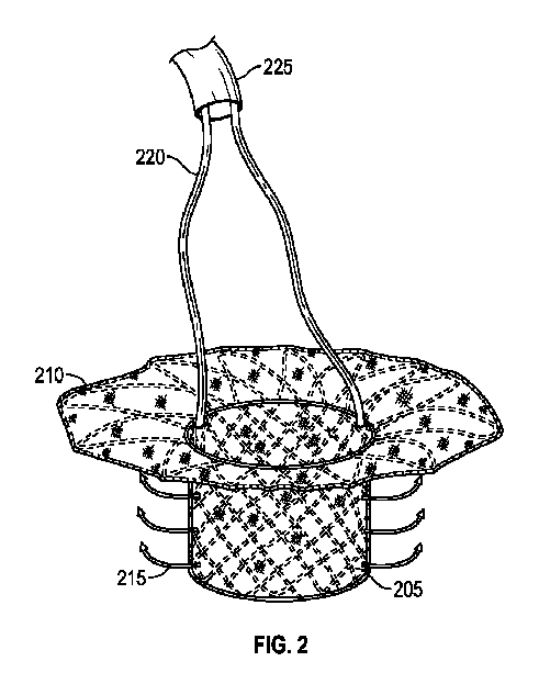
図2は、本明細書に開示される心臓弁アダプタの1つの実施形態を概略的に示す。図2に示すように、アダプタは、アダプタ本体205及び封止スカート210を備え、封止スカート210は、アダプタ本体205と封止スカート210との間の接合部の平面にほぼ近い箇所で拡大している。アダプタは、カテーテル225を通る紐220を介して収縮される能力を有する棘部215をさらに含むことができる。棘部215は、天然弁膜を固定可能に捉えてアダプタ本体205に押し付けることができる。棘部215が収縮すると、紐220は、カテーテル225を介して取り出すことができる。
FIG. 2 schematically depicts one embodiment of the heart valve adapter disclosed herein. As shown in FIG. 2, the adapter includes an
アダプタは、本明細書に開示される係合装着具に類似する係止機能性をさらに含むことができる。例えば、アダプタは、脊索に係止することができる。1つの実施形態において、これは、締め付けることができる弁尖/脊索構造の後方に意図的にループさせた縫合糸で行うことができる。別の実施形態において、係止は、一方向の動きを可能にする棘部などの、一方向に保持して脊索を巻き込むつる型構造体で達成することができる。 The adapter can further include locking functionality similar to the engagement fittings disclosed herein. For example, the adapter can be locked to the notochord. In one embodiment, this can be done with a suture intentionally looped behind the leaflet/chordal structure that can be tightened. In another embodiment, locking can be accomplished with vine-shaped structures that hold in one direction and wrap around the notochord, such as barbs that allow movement in one direction.
図3Aから図3Dは、本明細書に開示される心臓弁アダプタの1つの実施形態を概略的に示す。これらの図において、封止スカートは、例示を容易にするために図示されていない。図3Aに示すように、アダプタ本体305は、アダプタ本体が最初は丸い断面を有するように、異なる織り密度及び/又はワイヤ直径の編組で設計される、及び/又は、解放可能な機構と組み合わされる。アダプタ本体305は、天然弁膜350に係合するように設計された棘部310を有する。棘部310が係合すると、アダプタ係止/装着機能によって、アダプタは、「D字形」又は他の非対称形状に適合し、他の弁構造体を受けるために受け本体305を円筒形か又は特別な形状に維持する。この適応及び適合は、異なる織り方、ワイヤ径、又はこのようなことを可能にする機構を介して達成される。図3Bに示すように、形状の変化によってD字形状を作るために、より鋭い曲線半径が生成される。円形断面からD字形断面への変化は、弁尖を引っ張ることができ、これは、例えば、アダプタ本体などの移植片が流出路閉塞を引き起こす可能性がある僧帽弁で有用な場合がある。図3C及び図3Dは、図3A及び図3Bに対応する構造及び機構の斜視図を開示する。また、図3Aから図3Dに開示する実施形態は、先の図面で示した封止スカート及び他の特徴部を備えることができる。
3A-3D schematically illustrate one embodiment of a heart valve adapter disclosed herein. In these figures, the sealing skirt is not shown for ease of illustration. As shown in FIG. 3A, the
図4は、本明細書に開示される心臓弁アダプタの1つの実施形態を概略的に示す。図4は、心臓の左側、具体的には、前尖405、後尖410、及び大動脈弁420に至る左心室流出路(LVOT)415と呼ばれる前尖の左側に対する空間を有する僧帽弁の断面を開示する。図4は、以下の図で開示する実施形態を詳細に説明する役割を果たす。
FIG. 4 schematically depicts one embodiment of the heart valve adapter disclosed herein. FIG. 4 shows a cross-section of the mitral valve with the left side of the heart, specifically the
図5は、本明細書に開示される心臓弁アダプタの実施形態を概略的に示す。図5は、機能不全の僧帽弁に植え込まれたアダプタの実施形態を開示し、アダプタ本体505は、僧帽弁において展開され、封止スカート510は、左心房の床に対して展開される。この実施形態において、アダプタ本体505は、アダプタ本体505が展開すると、後尖515に対して付勢されるように、わずかな角度(すなわち、スカートの平面に対して10から30度)で配向される。
FIG. 5 schematically depicts an embodiment of a heart valve adapter disclosed herein. FIG. 5 discloses an embodiment of an adapter implanted into a dysfunctional mitral valve, with the
図5に開示されたような展開によって、後尖への(必ずしも前尖ではない)棘部の良好な係合が保証される。システムは、通常、この幾何学的状態にあるように設計されるが、前尖に係合するように拡大し、その後、棘部及び/又はフックが前尖に係合した後に解放されて通常の位置に戻ることができるように、設計によって機械的に拡大可能とすることができる。これにより、前尖は、後尖の方へ及びLVOTから離れるように押し進められ、これが処置後に閉塞されないことが保証される。また、送達カテーテル520及びガイドワイヤ525が示されている。
Deployment as disclosed in FIG. 5 ensures good engagement of the barb to the posterior leaflet (not necessarily the anterior leaflet). The system is typically designed to be in this geometry, but expands to engage the anterior leaflet, and then is released after the barbs and/or hooks have engaged the anterior leaflet. It may be mechanically expandable by design so that it can be returned to its original position. This forces the anterior leaflet toward the posterior leaflet and away from the LVOT, ensuring that it does not become occluded after the procedure. Also shown is a
図6は、本明細書に開示される心臓弁アダプタの実施形態を概略的に示す。図6は、アダプタ本体605が、図3Aから図3Dの開示に従ってD字形断面に構成される実施形態を開示する。
FIG. 6 schematically depicts an embodiment of a heart valve adapter disclosed herein. FIG. 6 discloses an embodiment in which the
図7は、本明細書に開示される心臓弁アダプタの実施形態を概略的に示す。図7に示すように、アダプタの実施形態は、植え込み後に機械的に拡大し、バルーンカテーテルを使用して、前尖又は他の係止機構の係合をもたらすことができる。このようなバルーンカテーテルによるアプローチは、弁及び血管のステント処置に一般的であり、本技術分野で公知である。アダプタ本体の一時的な機械的拡大の方法は、引っ張る又は作動させて、その後に解放することができる締め付け機構及び事前にばね付勢された(pre-sprung)ワイヤなどを備えるが、これらに限定されない。 FIG. 7 schematically depicts an embodiment of a heart valve adapter disclosed herein. As shown in FIG. 7, an embodiment of the adapter can be mechanically expanded after implantation to effect engagement of the anterior leaflet or other locking mechanism using a balloon catheter. Such balloon catheter approaches are common for valve and vascular stenting and are known in the art. Methods of temporary mechanical expansion of the adapter body include, but are not limited to, tightening mechanisms that can be pulled or actuated and then released, and pre-sprung wires. Not done.
別の実施形態において、アダプタ本体は、弁尖を棘部に係合させるために使用することができ、本体は、弁尖との係合を保証するために、展開時の直径よりも大きい直径に拡大する。デバイスがさらに展開されると、係合部分の直径は、最終的な構成(対称又は非対称)に縮小し、その結果、弁尖は、LVOTから離れてデバイスの方に引っ張られる。 In another embodiment, the adapter body can be used to engage the leaflets with the barbs, and the body has a diameter that is larger than the deployed diameter to ensure engagement with the leaflets. Expand to. As the device is further deployed, the diameter of the engagement portion decreases to the final configuration (symmetrical or asymmetrical) so that the leaflets are pulled away from the LVOT and toward the device.
図8は、本明細書に開示される心臓弁アダプタの1つの実施形態を概略的に示す。図8は、解放後の元の位置にあるアダプタの最終的な構成を開示しており、前尖は、後尖に向かって引き寄せられ保持され、LVOTの閉塞がないことが保証される。 FIG. 8 schematically depicts one embodiment of the heart valve adapter disclosed herein. Figure 8 discloses the final configuration of the adapter in its original position after release, with the anterior leaflet drawn and held toward the posterior leaflet, ensuring no occlusion of the LVOT.
図9Aは、本明細書に開示される心臓弁アダプタの実施形態を概略的に示す。図9は、アダプタを構成するワイヤ編組フレームを開示する。図9にさらに示すように、ワイヤ編組フレームは、二重後尖係止部905を有する24点の編組パターンを備えることができ、二重後尖係止部905は、対称性を維持し、さらに2倍の構造的係止をもたらすために使用される。また、ワイヤ編組フレームは、二重安定化係止部910を構えることができる。また、ワイヤ編組フレームは、15度単位で利用可能な係止位置を有することができることが示されている。係止部は、一部の実施形態において、管状編組フレームの延長部とすることができ、係合装着具として機能するために流出端から外に延びることができる。
FIG. 9A schematically depicts an embodiment of a heart valve adapter disclosed herein. Figure 9 discloses the wire braided frame that makes up the adapter. As further shown in FIG. 9, the wire braided frame can include a 24-point braid pattern with dual posterior leaflet locks 905, which maintain symmetry and Used to provide twice as much structural locking. The wire braided frame can also feature dual stabilizing
他の実施形態において、アダプタのワイヤ編組フレームは、接合される係止部(又は、本明細書に開示される、棘部、フック、又はクリップ)を有することができる。例えば、図9Aは、大きさの異なるワイヤの間の界面での接合操作による、より大きなゲージワイヤ(0.0175’’から0.02’’)(安定化係止部910によって表される)と、より小さなゲージワイヤ(0.012’’から0.0175’’)(後尖係止部905によって表され、追加ワイヤ915によってさらに表される)との組み合わせを示す。接合界面は、溶着部又は支持管との溶着部とすることができる。
In other embodiments, the wire braided frame of the adapter can have a detent (or barb, hook, or clip, as disclosed herein) attached thereto. For example, FIG. 9A shows a larger gauge wire (0.0175'' to 0.02'') (represented by stabilizing stop 910) due to a bonding operation at the interface between wires of different sizes. and a smaller gauge wire (0.012'' to 0.0175'') (represented by
図9Bは、本明細書に開示される心臓弁アダプタの1つの実施形態を概略的に示す。図9Bに示すように、安定化係止部910は、U字形の端部上に第2の屈曲部を含むように形状設定することができる。他の実施形態において、安定化係止部は、150度のスパンでP2係止部と対称に配置される。この角度で、安定化係止部は、後尖の後方に最適に挿入され、線維性三角の近くで僧帽弁輪まで延びる。
FIG. 9B schematically depicts one embodiment of the heart valve adapter disclosed herein. As shown in FIG. 9B, the stabilizing
図9Cは、本明細書に開示される心臓弁アダプタの1つの実施形態を概略的に示す。図9Cに示すように、ワイヤ編組フレームは、安定化係止部ではなく後尖係止部905を備えることができる。この実施形態において、後尖係止部905及びフランジ920は、移植片の必要な固定及び天然弁輪への係止をもたらす。他の実施形態において、P4係止部として指定された単一の4重係止部は、2つのみではなく4つのループを延ばすことによって、さらに多くの構造的係止をもたらすことができる。P4は、これまではP2係止部の位置での4つのこぶのある係止部を指す。これらの係止部の数及び位置は、上述の係止特徴部の180度のスパンの中の何らかの場所に収まることができる。また、追加の係止部及び/又は弁尖クリップは、後尖係止部を強化することができる。
FIG. 9C schematically depicts one embodiment of the heart valve adapter disclosed herein. As shown in FIG. 9C, the wire braided frame can include a
図10Aから図10Eは、本明細書に開示される心臓弁アダプタの1つの実施形態を概略的に示す。1つの実施形態において、図10Aに示すように、アダプタは、流れの封止及び/又は植え込み後の組織成長を促す(例えば、促進又は抑制のいずれかに影響を与える)目的で、全てが布地で覆われる心房封止スカート1005、アダプタ本体1010、及び安定化係止部1015を備えることができる。実施形態は、布地で覆われないクリップ1020をさらに備えることができる。
10A-10E schematically depict one embodiment of a heart valve adapter disclosed herein. In one embodiment, as shown in FIG. 10A, the adapter is made entirely of fabric for the purpose of flow sealing and/or promoting (e.g., affecting either promoting or inhibiting) tissue growth after implantation. An
図10B及び図10Cは、アダプタの実施形態を示す。図10Bは、いずれも布で覆われない安定化係止部1025のみを備えるアダプタを示す。図10Cは、布地層及びクリップ1035を有する後尖係止部1030を備えるアダプタを示す。
10B and 10C illustrate embodiments of adapters. FIG. 10B shows an adapter with only stabilizing
図10Dは、送達ロッド1040が挿通されるアダプタの実施形態を示す。図10Dに示すように、縫合糸又は剛性ロッドはアダプタの流入端のタブに通すことができ、移植片を中間圧縮状態に制約するために使用することができる。図10Eは、図10Eに示すアダプタの底部の実施形態を示す。
FIG. 10D shows an embodiment of an adapter through which a
図11Aから図11Cは、本明細書に開示される心臓弁アダプタの1つの実施形態を概略的に示す。これらの図は、送達カテーテルへのアダプタの確実な取り付けを介して送達制御を向上させる目的で、及び、弁尖装着の効率及び有効性を向上させる目的で、クリップ構成要素を備えるアダプタの1つの実施形態を示す。 11A-11C schematically illustrate one embodiment of the heart valve adapter disclosed herein. These figures depict one of the adapters with clip components for the purpose of improving delivery control through secure attachment of the adapter to the delivery catheter and for improving the efficiency and effectiveness of leaflet attachment. An embodiment is shown.
図11Aは、クリップ1105を有するアダプタのワイヤフレームの平坦パターンの概略図であり、クリップ1105は、ワイヤフレームの本体から外に延びるワイヤフレームのループ状部分とすることができる。一部の実施形態において、クリップ1105は、アダプタの円周部の周りの2又は3以上の別々の場所に位置決めすることができる。他の実施形態において、クリップ1105は、天然弁輪上にクリップ留めされるフック形状をもたらすことができるように、180度形状設定される。例えば、アダプタが送達システムから解放されると、クリップ1105は、天然弁輪に取り付けることができ、アダプタの固定がもたらされる。
FIG. 11A is a schematic illustration of a wireframe flat pattern of an adapter with a
図11Bは、クリップ1105、後尖係止部1110及びフランジ1115を有するアダプタのワイヤフレームの実施形態を示す。図11Cは、クリップ1105、後尖係止部1110及びフランジ1115を有するアダプタのワイヤフレームの実施形態を示す。様々な実施形態において、係合装着具(係止部、棘部、フック、及びクリップ)の一部又は全ては、この係合装着具の一部又は全てを覆う材料層を有することができる。
FIG. 11B shows a wire frame embodiment of an adapter having a
さらに、本明細書に開示される係止部及びクリップは、アダプタの制御及び取り出しを向上させるという目的に役立つ。例えば、係止部及びクリップは、係止部及びクリップに縫合糸及び/又は他のコードタイプの制御特徴部を取り付け、その後、このラインをアダプタのフレームに通すことによって制御することができる(例えば、部分的に又は完全に収縮させる)。 Moreover, the locks and clips disclosed herein serve the purpose of improving control and retrieval of the adapter. For example, the locks and clips can be controlled by attaching sutures and/or other cord-type control features to the locks and clips and then passing this line through the frame of the adapter (e.g. , partially or completely deflated).
折り畳み式係止部の1つの実施形態において、コードは、係止部の先端に5回から7回通して縫い付け、余分な部分を8の字結びで締め付ける。その後、コードの両端は、アダプタの内側に通して巻き付けられ、フランジの既存の穴から底部へ引き抜かれる。4mmの余分なコードを残し、両端は、2つの角結びで結ばれ、端は、切り落とされる。これらの固定された縫合糸は、垂直の力を使って係止部又はクリップを折り畳むために鉗子で掴んで引き離すことができるプルタブになる。 In one embodiment of the foldable lock, the cord is sewn five to seven times over the tip of the lock, and the excess is tightened with a figure-eight knot. Both ends of the cord are then wrapped around the inside of the adapter and pulled through the existing hole in the flange to the bottom. Leaving 4mm of extra cord, the ends are tied with two square knots and the ends are cut off. These fixed sutures become pull tabs that can be grasped and pulled apart with forceps to collapse the lock or clip using vertical force.
折り畳み式フランジの実施形態において、コードは、フランジの既存の穴を通してループ状にされ、アダプタの頂部に向く菱形パターンが残る。コードの両端は、2つの四角い結び目でともに結ばれ、閉じたループができる。これは、鉗子がコードを掴んでフランジを折り畳むことを可能にするためである。他の実施形態において、係止部/クリップ及びフランジの両方は、同時に折り畳まれ、その結果、アダプタを取り出す能力がさらに向上する。 In the foldable flange embodiment, the cord is looped through the existing holes in the flange, leaving a diamond pattern pointing towards the top of the adapter. The ends of the cord are tied together with two square knots, creating a closed loop. This is to allow the forceps to grab the cord and fold the flange. In other embodiments, both the catch/clip and flange are folded down simultaneously, which further improves the ability to remove the adapter.
さらに、折り畳み式係止部及びフランジは、アダプタの展開中に係止部/クリップ及びフランジを制御する能力を可能にして向上させることができる。例えば、プルタブによって残されたループにコードを通すことによって、係止部は、カテーテルなどの送達デバイスの基部から一方又は両方を折り畳むことによって制御することができる。これは、アダプタを送達するときに有用であり、医師が係止部/安定化要素の配置及び位置決めをより正確に制御する能力を与える。 Additionally, the collapsible lock and flange may enable and enhance the ability to control the lock/clip and flange during deployment of the adapter. For example, by threading a cord through a loop left by a pull tab, the lock can be controlled by folding one or both from the base of a delivery device such as a catheter. This is useful when delivering the adapter and gives the physician the ability to more precisely control the placement and positioning of the lock/stabilizing element.
図12A及び図12Bは、本明細書に開示される心臓弁アダプタの1つの実施形態を概略的に示す。図12Aは、アダプタの上面図を示し、図12Bは、アダプタの下面図を示す。図12A及び図12Bに示すように、アダプタの流入端は、流れ部分を通り抜けてフランジの下側に至る係止部収縮コードを備えることができる。この縫合糸は、コードを引っ張る及び解放することによる係止部の制御を可能にする。あるいは、縫合糸は、係止部の同様の操作をもたらすために送達システムに解放可能に取り付けることができる。図12Bは、さらに、係止部に取り付けられたコードを開示する。 12A and 12B schematically illustrate one embodiment of the heart valve adapter disclosed herein. FIG. 12A shows a top view of the adapter and FIG. 12B shows a bottom view of the adapter. As shown in FIGS. 12A and 12B, the inflow end of the adapter can include a stop retraction cord that passes through the flow section and onto the underside of the flange. This suture allows control of the lock by pulling and releasing the cord. Alternatively, the suture can be releasably attached to the delivery system to provide similar manipulation of the lock. FIG. 12B further discloses a cord attached to the lock.
図13Aから図13Cは、本明細書に開示される心臓弁アダプタの1つの実施形態を概略的に示す。図13Aから図13Cは、折り畳み式フランジの取り付け構成を示す。図13Cは、1つの実施形態において、送達システムから延びる縫合糸がアダプタ上の地点に接続され、展開中にフランジの再位置決め及び/又は配向を制御することを可能にする方法を示す。 13A-13C schematically depict one embodiment of a heart valve adapter disclosed herein. 13A-13C illustrate a folding flange attachment configuration. FIG. 13C shows how, in one embodiment, sutures extending from the delivery system are connected to points on the adapter to allow for controlled repositioning and/or orientation of the flange during deployment.
図14Aから図14Dは、本明細書に開示される心臓弁アダプタの1つの実施形態を概略的に示す。図14Aから図14Dは、折り畳み式係止部及びクリップの取り付け構成を示し、さらに、アダプタの全ての角度から係止部を折り畳んで制御するために使用される縫合パターンの拡大図を開示する。これらの実施形態において、例えば1又は2以上の縫合ラインを備える送達構成要素は、第1の端部で係合装着具に接続され、1又は2以上の縫合ラインは、第2の端部で制御機構部に接続される。 14A-14D schematically depict one embodiment of a heart valve adapter disclosed herein. 14A-14D illustrate the folding lock and clip attachment configuration and also disclose close-up views of the stitching patterns used to fold and control the lock from all angles of the adapter. In these embodiments, a delivery component comprising, for example, one or more suture lines is connected to the engagement fitting at a first end, and the one or more suture lines are connected to the engagement fitting at a second end. Connected to the control mechanism section.
図15は、本明細書に開示される心臓弁アダプタの実施形態を概略的に示す。図9に示すように、アダプタの実施形態は、バルサルバ洞構造を支持する形状及び構造体を備えることができる。このような構造体は、冠動脈の開存性を保証し、天然弁機能を模倣することによって、又は、装置の近位部分に弁尖状の心臓弁膜尖などのさらなる血行力学応答性部材を追加することによって、冠動脈灌流を強化することができる。 FIG. 15 schematically depicts an embodiment of a heart valve adapter disclosed herein. As shown in FIG. 9, an embodiment of the adapter can include a shape and structure that supports a Valsalva sinus structure. Such structures ensure coronary artery patency by mimicking native valve function or by adding additional hemodynamically responsive members such as leaflet-like leaflets to the proximal portion of the device. Coronary perfusion can be enhanced by
本明細書に開示されかつ図9に対応するように、フレームの適合性及び非対称な解剖学的構造の固有の適応性は、石灰化組織のバルーン拡大が非対称形状のオリフィスをもたらす場合に大動脈弁位置で使用することができるデバイスに対する満たされない必要性に適する。 As disclosed herein and corresponds to FIG. Suitable for an unmet need for a device that can be used at any location.
図16A及び図16Bは、本明細書に開示される心臓弁アダプタの1つの実施形態を概略的に示す。図16A及び図16Bに示すように、アダプタの実施形態は、アダプタフレームの外側の周りの連続的な材料片を備えることができる。アダプタのスカートから延びる連続的なシールは、アダプタの受け部分の流入縁から受け本体の外側に延びる材料(布地など)から構成することができる。スカートの流入縁の周りに内部に伸びる布地ストリップを縫い付けることができ、非多孔質被覆は、心室内に延びる連続的なシールを形成する。 16A and 16B schematically illustrate one embodiment of a heart valve adapter disclosed herein. As shown in FIGS. 16A and 16B, embodiments of the adapter can include a continuous piece of material around the outside of the adapter frame. A continuous seal extending from the skirt of the adapter may be constructed from a material (such as fabric) extending from the inlet edge of the receiving portion of the adapter to the outside of the receiving body. An inwardly extending fabric strip can be sewn around the inflow edge of the skirt, and the non-porous covering forms a continuous seal that extends into the ventricle.
布地の連続表面は、組織付着が望まれない場所の医療用ポリマーでの被覆、空間充填又は潜在作用が望まれるヒドロゲル、又は親水性組織接着剤など、調節する又は相反する特性について局所的に影響を与え特徴付けることができる。布地の連続的な材料構造は、ボリューム感のあるものとすることができ、空間を満たし、円形心臓弁を弁輪の非対称な形状に適合させる。他の取り付け方法と組み合わせて、この方法で製作された僧帽弁アダプタの実施形態は、弁尖組織及び他の弁膜下構造体の係合及び取り付けを助ける。部分的に多孔質の布地は、置換弁のシール向上をもたらし、布地の適合性による不規則な形状の解剖学的構造への適応を可能にする。 The continuous surface of the fabric can be locally influenced for modulating or conflicting properties, such as coating with medical polymers where tissue attachment is not desired, hydrogels where space-filling or latent action is desired, or hydrophilic tissue adhesives. can be given and characterized. The continuous material structure of the fabric can be voluminous, filling the space and conforming the circular heart valve to the asymmetric shape of the annulus. In conjunction with other attachment methods, embodiments of mitral valve adapters made with this method aid in engagement and attachment of leaflet tissue and other subvalvular structures. The partially porous fabric provides improved sealing of the replacement valve and allows adaptation to irregularly shaped anatomies through the conformability of the fabric.
図17A及び図17Bは、本明細書に開示される心臓弁アダプタの1つの実施形態を概略的に示す。図17A及び17Bに示すように、アダプタの実施形態は、デバイス性能に影響を与える材料を取り付けながら、僧帽弁アダプタフレームを特定の寸法で保持する制約を用いて製作することができる。無負荷状態においてフレーム構造の相対する部材間に存在する固有の移動の自由と予測不可能性を取り除き、編組ワイヤフレームの配置に影響を与えるように作用する製作技術が開示される。この技術は、その制限されない「自由な」寸法以外の特定の寸法で保持するために、構造体を通って又は構造体の周りに何らかの数の縫合糸を供給するなどの、制約付きでフレームの半径方向の拡大を制限することを含む。その後の製作工程において、構造体は、この新しい構成を採用してこれが最終的な寸法とみなされる組立体に組み込まれる。制約が編組フレームから除去されると、この編組フレームは、所望の寸法に制約されながら周囲の構造体に追加の半径方向の力を加え、元の「自由な」寸法に復帰しようとする。 17A and 17B schematically illustrate one embodiment of a heart valve adapter disclosed herein. As shown in FIGS. 17A and 17B, embodiments of the adapter can be fabricated with constraints that hold the mitral valve adapter frame at specific dimensions while attaching materials that affect device performance. Fabrication techniques are disclosed that operate to influence the placement of a braided wire frame by eliminating the inherent freedom of movement and unpredictability that exists between opposing members of a frame structure in unloaded conditions. This technique involves using a frame with constraints, such as feeding some number of sutures through or around the structure to hold it at a specific dimension other than its unrestricted "free" dimension. Including limiting radial expansion. In subsequent fabrication steps, the structure is assembled into an assembly that takes this new configuration and assumes its final dimensions. When the constraint is removed from the braided frame, the braided frame exerts additional radial forces on the surrounding structure while being constrained to the desired dimensions and attempts to return to its original "free" dimensions.
一部の実施形態において、アダプタの管状編組フレームは、1又は2以上のワイヤの編組とすることができ、1又は2以上のワイヤの編組は、ジグザグ編組又は上下二連式編組である。 In some embodiments, the tubular braided frame of the adapter can be a braid of one or more wires, and the braid of one or more wires is a zigzag braid or a top-bottom double-braid.
図18は、本明細書に開示される心臓弁アダプタの1つの実施形態を概略的に示す。図18に示すように、引き紐1805は、弁部分の除去を容易にするために締め付けられる引き結び1810に含むことができる。図18は、ループを介して弁の流出端を取り囲む引き結びを有する、ハングマンズ結びに類似した、締め付け引き結び及び繋留セグメント1815から構築された折り畳み式弁アダプタの流出端を締め付ける引き紐1805を示す。結び目から延びる長い端部は、露出した縫合材料の引っ掛け可能な部分を形成する交連柱に繋留することができる。引っ掛け具を繋留具に導きやすいように放射線不透過性のマーカーを繋留具の両端に付与することができる。
FIG. 18 schematically depicts one embodiment of a heart valve adapter disclosed herein. As shown in FIG. 18, a
図19は、本明細書に開示される心臓弁アダプタの実施形態を概略的に示す。図19に示すように、追加の円筒管円筒形1905を使用して締め付け引き結びの締め付けを可能にする反対牽引(countertraction)をもたらすことができる。張力/反対牽引の増大によって、結果的に、弁端部は、結び目の摩擦に起因して不可逆的に折り畳まれることになる。従って、弁は、より簡単かつ安全に縮小させて本体から取り出すことができる。
FIG. 19 schematically depicts an embodiment of a heart valve adapter disclosed herein. As shown in FIG. 19, an additional
図20は、本明細書に開示される心臓弁アダプタの1つの実施形態を概略的に示す。より具体的には、図20は、引き紐が締め付けられた後の部分的に圧縮された弁を示す。 FIG. 20 schematically depicts one embodiment of the heart valve adapter disclosed herein. More specifically, FIG. 20 shows the partially compressed valve after the drawstring has been tightened.
フレームから布材に伝達された半径方向の力の程度は、最適な組み合わせ又は性能特性を達成するために必要に応じて調整することができる。詳細には、構造体の歪みエネルギー密度は、より均一とすることができる。より少ない材料でより大きな剛性が達成され(より優れたシールがもたらされる)、その結果、より薄型の構造体が得られる。縫合糸は、最終的に、弁構造体のための望ましい直径及び高さを目的とした構造体の付勢を可能にする。 The degree of radial force transferred from the frame to the fabric can be adjusted as necessary to achieve the optimum combination or performance characteristics. In particular, the strain energy density of the structure can be made more uniform. Greater stiffness is achieved with less material (resulting in a better seal), resulting in a thinner structure. The suture ultimately allows biasing of the structure toward the desired diameter and height for the valve structure.
概念をさらに拡大するために、本明細書で説明する特徴部を有する構造体は、僧帽弁装置及び大動脈弁装置及び/又は弁輪の両方に係合するように、単独で又は結合したデザインで共同展開することができる。その意図は、心室を通る流れの最も効果的な管理及び流出路の効率の最大化を保証するために、両方の弁の弁尖、並びに互いに対する弁の角度に影響を与えることである。 To further expand the concept, structures having the features described herein can be designed alone or in combination to engage both the mitral and aortic valve systems and/or the annulus. can be jointly developed. The intent is to influence the leaflets of both valves, as well as the angle of the valves relative to each other, to ensure the most effective management of flow through the ventricle and maximum efficiency of the outflow tract.
他の実施形態は、例えば、説明した実施形態の場合とは異なる順序で特徴を与えるか又は適用すること、一実施形態から個々の特徴を取り出し、そのような特徴を別の実施形態の中に組み込むこと、実施形態から1又は2以上の特徴を除去すること、又は実施形態から1又は2以上の特徴を除去し、それと共に1又は2以上の他の実施形態から取り出した1又は2以上の特徴を追加することに対応する実施形態を含むいくつかの図で説明した又は図示した特徴の組合せ及び部分結合をそのような組み合わせ及び部分的組み合わせに組み込まれる特徴の利点をもたらしながら含むことができる。この段落に使用する1又は複数の「特徴」は、装置の構造及び/又は機能、製造又はシステムの製品、及び/又は方法の段階、実施、又は方法様式を指す場合がある。 Other embodiments may include, for example, providing or applying features in a different order than in the described embodiment, taking individual features from one embodiment, and incorporating such features into another embodiment. Incorporating, removing one or more features from an embodiment, or removing one or more features from an embodiment together with one or more features taken from one or more other embodiments. Combinations and subcombinations of features described or illustrated in the several figures, including embodiments corresponding to the addition of features, may be included while providing the benefits of the features incorporated in such combinations and subcombinations. . As used in this paragraph, one or more "features" may refer to the structure and/or function of an apparatus, product of manufacture or system, and/or method steps, implementation, or method mode.
本明細書を通じて「1つの実施形態」、「一実施形態」、「例示的な実施形態」などへの参照は、説明する実施形態が特定の特徴、構造、又は特性を有することができるが、全ての実施形態が必ずしもこれらの特定の特徴、構造、又は特性を含まない場合があることを示している。さらに、そのような語句は、必ずしも同じ実施形態を指しているとは限らない。さらに、特定の特徴、構造、又は特性を1つの実施形態に関して説明する時は、明示的に説明するか否かに関わらず、この説明が、他の実施形態に関するそのような特徴、構造、又は特性に影響を及ぼすことは当業者の知識範囲内であろう。 References throughout this specification to "one embodiment," "one embodiment," "exemplary embodiment," etc. refer to "one embodiment," "one embodiment," "exemplary embodiment," and the like, although the described embodiment may have particular features, structures, or characteristics. It is indicated that not all embodiments may necessarily include these particular features, structures, or characteristics. Moreover, such phrases are not necessarily referring to the same embodiment. Furthermore, when a particular feature, structure, or characteristic is described with respect to one embodiment, whether or not explicitly described, this description also applies to such feature, structure, or characteristic with respect to other embodiments. It would be within the knowledge of those skilled in the art to influence the properties.
状況が明らかに他を示さない限り、(1)「及び」という言葉は接続的であることを示し、(2)「又は」という言葉は離接的であることを示し、(3)物品を離接的に表し、それに「又はこれらの両方」、という言葉が続く時に、接続的であること及び離接的であることの両方を意図し、(4)連記する最後の2つの品目の間の「及び」又は「又は」という言葉は、連記する全ての項目に適用される。 Unless the circumstances clearly indicate otherwise, (1) the word "and" indicates conjunctive; (2) the word "or" indicates disjunctive; and (3) the word "and" indicates disjunctive; When expressed disjunctively and followed by the words "or both," it is intended to be both conjunctive and disjunctive; (4) between the last two items listed; The words “and” or “or” apply to all items listed together.
複数の名詞が後に続く「1又は2以上」という用語を用いて群を表す場合に、この群の1又は2以上の構成要素を指示するための当該名詞のいずれかの追加の使用は、その名詞の単数形と複数形の両方を示すものとする。例えば、群の「構成要素」の記載が後に続く「1又は2以上の構成要素」を有するとして表す群は、当該群に唯1つの構成要素しか存在しない場合は「当該構成要素」を意味するものとする。 When a group is denoted by the term "one or more" followed by a plurality of nouns, the additional use of any of the nouns to designate one or more members of the group Both singular and plural nouns shall be indicated. For example, a group expressed as having "one or more members" followed by a statement of "members" of the group means "that member" if only one member is present in the group. shall be taken as a thing.
用語「a」及び「an」エンティティは、1又は2以上の当該エンティティを意味する。従って、本明細書では、用語「a」(又は「an」)、「1又は2以上」、及び「少なくとも1つ」は、交換可能に使用することができる。用語「備える」、「含む」、及び「有する」は、交換可能に使用することができることにも留意されたい。 The terms "a" and "an" entity refer to one or more such entities. Accordingly, the terms "a" (or "an"), "one or more," and "at least one" may be used interchangeably herein. It is also noted that the terms "comprising," "including," and "having" can be used interchangeably.
205 アダプタ本体
210 封止スカート
215 棘部
225 カテーテル
220 紐
205
Claims (18)
前記管状編組フレームは、流入端及び流出端と備え、
前記管状編組フレームは、前記流入端から外に延びて少なくとも1つのフランジを形成し、
前記管状編組フレームは、前記流出端から外に延びて少なくとも1つの係合装着具を形成する、
植え込み式心臓弁アダプタ装置。 An implantable heart valve adapter device comprising a tubular braided frame, the device comprising:
the tubular braided frame comprises an inlet end and an outlet end;
the tubular braided frame extends outwardly from the inlet end to form at least one flange;
the tubular braided frame extends outwardly from the outflow end to form at least one engagement fitting;
Implantable heart valve adapter device.
管状編組フレームを含む植え込み式心臓弁アダプタであって、
前記管状編組フレームは、流入端及び流出端を備え、
前記管状編組フレームは、前記流入端から外に延びて少なくとも1つのフランジを形成し、
前記管状編組フレームは、前記流出端から外に延びて少なくとも1つの係合装着具を形成する、植え込み式心臓弁アダプタと、
第1の端部上で前記少なくとも1つの係合装着具に接続された1又は2以上の縫合ラインを含む送達構成要素と、
を備え、
前記1又は2以上の縫合ラインは、第2の端部上で制御機構部に接続する、植え込み式心臓弁アダプタ送達システム。 An implantable heart valve adapter delivery system comprising:
An implantable heart valve adapter comprising a tubular braided frame, the adapter comprising:
the tubular braided frame has an inlet end and an outlet end;
the tubular braided frame extends outwardly from the inlet end to form at least one flange;
an implantable heart valve adapter, wherein the tubular braided frame extends outwardly from the outflow end to form at least one engagement fitting;
a delivery component comprising one or more suture lines connected to the at least one engagement fitting on a first end;
Equipped with
An implantable heart valve adapter delivery system, wherein the one or more suture lines connect to a control mechanism on a second end.
植え込み式心臓弁アダプタ及び送達構成要素、
を備え、
前記植え込み式心臓弁アダプタは、管状編組フレームと、流入端及び流出端を含み、
前記管状編組フレームは、前記流入端から外に延びて少なくとも1つのフランジを形成し、
前記管状編組フレームは、前記流出端から外に延びて少なくとも1つの係合装着具を形成し、
前記送達構成要素は、1又は2以上の縫合ラインを含み、
前記1又は2以上の縫合ラインは、前記少なくとも1つの係合装着具を通り抜けて制御機構部に接続し、前記制御機構部は、前記1又は2以上の縫合ラインを引っ張ることを制御し、
前記方法は、
前記植え込み式心臓弁アダプタを静脈又は動脈の一方に経皮的に配置するステップと、
前記植え込み式心臓弁アダプタを天然心臓弁に送達するステップと、
前記植え込み式心臓弁アダプタを前記天然心臓弁の位置に配置するステップと、
前記1又は2以上の縫合ラインを引っ張って前記少なくとも1つの係合装着具を拡大させるステップと、
を含む、方法。 1. A method for percutaneous deployment and positioning of an implantable heart valve adapter, the method comprising:
implantable heart valve adapters and delivery components;
Equipped with
The implantable heart valve adapter includes a tubular braided frame, an inflow end and an outflow end;
the tubular braided frame extends outwardly from the inlet end to form at least one flange;
the tubular braided frame extends outwardly from the outflow end to form at least one engagement fitting;
the delivery component includes one or more suture lines;
the one or more suture lines pass through the at least one engagement fitment and connect to a control mechanism, the control mechanism controlling tensioning of the one or more suture lines;
The method includes:
percutaneously placing the implantable heart valve adapter into one of a vein or artery;
delivering the implantable heart valve adapter to a native heart valve;
placing the implantable heart valve adapter at the location of the native heart valve;
stretching the one or more suture lines to expand the at least one engagement appliance;
including methods.
Applications Claiming Priority (3)
| Application Number | Priority Date | Filing Date | Title |
|---|---|---|---|
| US202063082035P | 2020-09-23 | 2020-09-23 | |
| US63/082,035 | 2020-09-23 | ||
| PCT/US2021/051828 WO2022066961A1 (en) | 2020-09-23 | 2021-09-23 | Devices, systems, and methods for an implantable heart-valve adapter |
Publications (1)
| Publication Number | Publication Date |
|---|---|
| JP2023543757A true JP2023543757A (en) | 2023-10-18 |
Family
ID=80846886
Family Applications (1)
| Application Number | Title | Priority Date | Filing Date |
|---|---|---|---|
| JP2023518762A Pending JP2023543757A (en) | 2020-09-23 | 2021-09-23 | Devices, systems, and methods for implantable heart valve adapters |
Country Status (6)
| Country | Link |
|---|---|
| US (1) | US20230372085A1 (en) |
| EP (1) | EP4216875A4 (en) |
| JP (1) | JP2023543757A (en) |
| CA (1) | CA3196598A1 (en) |
| IL (1) | IL301478A (en) |
| WO (1) | WO2022066961A1 (en) |
Families Citing this family (4)
| Publication number | Priority date | Publication date | Assignee | Title |
|---|---|---|---|---|
| EP3881801B1 (en) * | 2020-03-18 | 2025-04-23 | Medtronic Inc. | Improvements in or relating to the delivery and unsheathing of prosthetic heart valves |
| US20240415643A1 (en) * | 2020-04-24 | 2024-12-19 | ReValve Solutions Inc. | Devices, systems, and methods for a valve replacement |
| CN218420135U (en) * | 2022-04-24 | 2023-02-03 | 上海微创心通医疗科技有限公司 | Valve stent and valve prosthesis |
| CN115252224A (en) * | 2022-07-12 | 2022-11-01 | 上海以心医疗器械有限公司 | Heart valve support and heart valve prosthesis |
Citations (1)
| Publication number | Priority date | Publication date | Assignee | Title |
|---|---|---|---|---|
| JP2013512765A (en) * | 2009-12-08 | 2013-04-18 | アヴァロン メディカル リミテッド | Devices and systems for transcatheter mitral valve replacement |
Family Cites Families (11)
| Publication number | Priority date | Publication date | Assignee | Title |
|---|---|---|---|---|
| US8449599B2 (en) | 2009-12-04 | 2013-05-28 | Edwards Lifesciences Corporation | Prosthetic valve for replacing mitral valve |
| US9072603B2 (en) * | 2010-02-24 | 2015-07-07 | Medtronic Ventor Technologies, Ltd. | Mitral prosthesis and methods for implantation |
| US9132009B2 (en) * | 2010-07-21 | 2015-09-15 | Mitraltech Ltd. | Guide wires with commissural anchors to advance a prosthetic valve |
| US20140324164A1 (en) * | 2011-08-05 | 2014-10-30 | Mitraltech Ltd. | Techniques for percutaneous mitral valve replacement and sealing |
| US20140296969A1 (en) * | 2013-04-02 | 2014-10-02 | Tendyne Holdlings, Inc. | Anterior Leaflet Clip Device for Prosthetic Mitral Valve |
| EP2896387A1 (en) * | 2014-01-20 | 2015-07-22 | Mitricares | Heart valve anchoring device |
| US9986993B2 (en) * | 2014-02-11 | 2018-06-05 | Tendyne Holdings, Inc. | Adjustable tether and epicardial pad system for prosthetic heart valve |
| EP3139865B1 (en) * | 2014-05-07 | 2025-07-16 | Baylor College of Medicine | Artificial, flexible valves |
| CA3033666A1 (en) * | 2016-08-19 | 2018-02-22 | Edwards Lifesciences Corporation | Steerable delivery system for replacement mitral valve and methods of use |
| EP3592294B1 (en) * | 2017-03-06 | 2024-12-18 | Boston Scientific Scimed, Inc. | Replacement heart valve system having docking station with sacrificial valve |
| WO2019165213A1 (en) * | 2018-02-22 | 2019-08-29 | Medtronic Vascular, Inc. | Prosthetic heart valve delivery systems and methods |
-
2021
- 2021-09-23 JP JP2023518762A patent/JP2023543757A/en active Pending
- 2021-09-23 IL IL301478A patent/IL301478A/en unknown
- 2021-09-23 CA CA3196598A patent/CA3196598A1/en active Pending
- 2021-09-23 WO PCT/US2021/051828 patent/WO2022066961A1/en not_active Ceased
- 2021-09-23 EP EP21873465.5A patent/EP4216875A4/en active Pending
- 2021-09-23 US US18/028,212 patent/US20230372085A1/en active Pending
Patent Citations (1)
| Publication number | Priority date | Publication date | Assignee | Title |
|---|---|---|---|---|
| JP2013512765A (en) * | 2009-12-08 | 2013-04-18 | アヴァロン メディカル リミテッド | Devices and systems for transcatheter mitral valve replacement |
Also Published As
| Publication number | Publication date |
|---|---|
| US20230372085A1 (en) | 2023-11-23 |
| EP4216875A4 (en) | 2024-11-13 |
| CA3196598A1 (en) | 2022-03-31 |
| EP4216875A1 (en) | 2023-08-02 |
| IL301478A (en) | 2023-05-01 |
| WO2022066961A1 (en) | 2022-03-31 |
Similar Documents
| Publication | Publication Date | Title |
|---|---|---|
| AU2023200569B2 (en) | Heart valve docking coils and systems | |
| JP6600028B2 (en) | Transcatheter valve replacement | |
| JP6080266B2 (en) | Devices and methods for improving the function of heart valves | |
| JP2023543757A (en) | Devices, systems, and methods for implantable heart valve adapters | |
| US20190029811A1 (en) | Heart valve | |
| US20170354500A1 (en) | Mitral prolapse valve restrictor | |
| JP2018521766A (en) | Non-sutured prosthetic heart valve | |
| JP2007526011A (en) | Tensioner and system for treating mitral regurgitation | |
| JP2010516333A (en) | Methods and devices for cardiac tissue repair | |
| US20220054259A1 (en) | Flexible Anchor For Prosthetic Heart Valve | |
| US20260020952A1 (en) | Devices, Systems, and Methods for an Implantable Heart-Valve Adapter | |
| HK40037733B (en) | Heart valve docking coils and systems | |
| HK40005520A (en) | Heart valve docking coils and systems | |
| HK40005520B (en) | Heart valve docking coils and systems |
Legal Events
| Date | Code | Title | Description |
|---|---|---|---|
| A621 | Written request for application examination |
Free format text: JAPANESE INTERMEDIATE CODE: A621 Effective date: 20240906 |
|
| A977 | Report on retrieval |
Free format text: JAPANESE INTERMEDIATE CODE: A971007 Effective date: 20250521 |
|
| A131 | Notification of reasons for refusal |
Free format text: JAPANESE INTERMEDIATE CODE: A131 Effective date: 20250526 |
|
| A521 | Request for written amendment filed |
Free format text: JAPANESE INTERMEDIATE CODE: A523 Effective date: 20250813 |
|
| A02 | Decision of refusal |
Free format text: JAPANESE INTERMEDIATE CODE: A02 Effective date: 20251110 |