JP2023526316A - Delivery of Fluids to the Ocular Channels - Google Patents
Delivery of Fluids to the Ocular Channels Download PDFInfo
- Publication number
- JP2023526316A JP2023526316A JP2022569455A JP2022569455A JP2023526316A JP 2023526316 A JP2023526316 A JP 2023526316A JP 2022569455 A JP2022569455 A JP 2022569455A JP 2022569455 A JP2022569455 A JP 2022569455A JP 2023526316 A JP2023526316 A JP 2023526316A
- Authority
- JP
- Japan
- Prior art keywords
- cannula
- catheter
- distal end
- fluid
- adapter
- Prior art date
- Legal status (The legal status is an assumption and is not a legal conclusion. Google has not performed a legal analysis and makes no representation as to the accuracy of the status listed.)
- Granted
Links
Images


Classifications
-
- A—HUMAN NECESSITIES
- A61—MEDICAL OR VETERINARY SCIENCE; HYGIENE
- A61F—FILTERS IMPLANTABLE INTO BLOOD VESSELS; PROSTHESES; DEVICES PROVIDING PATENCY TO, OR PREVENTING COLLAPSING OF, TUBULAR STRUCTURES OF THE BODY, e.g. STENTS; ORTHOPAEDIC, NURSING OR CONTRACEPTIVE DEVICES; FOMENTATION; TREATMENT OR PROTECTION OF EYES OR EARS; BANDAGES, DRESSINGS OR ABSORBENT PADS; FIRST-AID KITS
- A61F9/00—Methods or devices for treatment of the eyes; Devices for putting in contact-lenses; Devices to correct squinting; Apparatus to guide the blind; Protective devices for the eyes, carried on the body or in the hand
- A61F9/0008—Introducing ophthalmic products into the ocular cavity or retaining products therein
- A61F9/0017—Introducing ophthalmic products into the ocular cavity or retaining products therein implantable in, or in contact with, the eye, e.g. ocular inserts
-
- A—HUMAN NECESSITIES
- A61—MEDICAL OR VETERINARY SCIENCE; HYGIENE
- A61F—FILTERS IMPLANTABLE INTO BLOOD VESSELS; PROSTHESES; DEVICES PROVIDING PATENCY TO, OR PREVENTING COLLAPSING OF, TUBULAR STRUCTURES OF THE BODY, e.g. STENTS; ORTHOPAEDIC, NURSING OR CONTRACEPTIVE DEVICES; FOMENTATION; TREATMENT OR PROTECTION OF EYES OR EARS; BANDAGES, DRESSINGS OR ABSORBENT PADS; FIRST-AID KITS
- A61F9/00—Methods or devices for treatment of the eyes; Devices for putting in contact-lenses; Devices to correct squinting; Apparatus to guide the blind; Protective devices for the eyes, carried on the body or in the hand
- A61F9/0008—Introducing ophthalmic products into the ocular cavity or retaining products therein
-
- A—HUMAN NECESSITIES
- A61—MEDICAL OR VETERINARY SCIENCE; HYGIENE
- A61M—DEVICES FOR INTRODUCING MEDIA INTO, OR ONTO, THE BODY; DEVICES FOR TRANSDUCING BODY MEDIA OR FOR TAKING MEDIA FROM THE BODY; DEVICES FOR PRODUCING OR ENDING SLEEP OR STUPOR
- A61M5/00—Devices for bringing media into the body in a subcutaneous, intra-vascular or intramuscular way; Accessories therefor, e.g. filling or cleaning devices, arm-rests
- A61M5/178—Syringes
- A61M5/31—Details
- A61M5/32—Needles; Details of needles pertaining to their connection with syringe or hub; Accessories for bringing the needle into, or holding the needle on, the body; Devices for protection of needles
- A61M5/3286—Needle tip design, e.g. for improved penetration
-
- A—HUMAN NECESSITIES
- A61—MEDICAL OR VETERINARY SCIENCE; HYGIENE
- A61M—DEVICES FOR INTRODUCING MEDIA INTO, OR ONTO, THE BODY; DEVICES FOR TRANSDUCING BODY MEDIA OR FOR TAKING MEDIA FROM THE BODY; DEVICES FOR PRODUCING OR ENDING SLEEP OR STUPOR
- A61M5/00—Devices for bringing media into the body in a subcutaneous, intra-vascular or intramuscular way; Accessories therefor, e.g. filling or cleaning devices, arm-rests
- A61M5/178—Syringes
- A61M5/31—Details
- A61M5/32—Needles; Details of needles pertaining to their connection with syringe or hub; Accessories for bringing the needle into, or holding the needle on, the body; Devices for protection of needles
- A61M5/3287—Accessories for bringing the needle into the body; Automatic needle insertion
-
- A—HUMAN NECESSITIES
- A61—MEDICAL OR VETERINARY SCIENCE; HYGIENE
- A61M—DEVICES FOR INTRODUCING MEDIA INTO, OR ONTO, THE BODY; DEVICES FOR TRANSDUCING BODY MEDIA OR FOR TAKING MEDIA FROM THE BODY; DEVICES FOR PRODUCING OR ENDING SLEEP OR STUPOR
- A61M5/00—Devices for bringing media into the body in a subcutaneous, intra-vascular or intramuscular way; Accessories therefor, e.g. filling or cleaning devices, arm-rests
- A61M5/178—Syringes
- A61M5/31—Details
- A61M5/32—Needles; Details of needles pertaining to their connection with syringe or hub; Accessories for bringing the needle into, or holding the needle on, the body; Devices for protection of needles
- A61M5/329—Needles; Details of needles pertaining to their connection with syringe or hub; Accessories for bringing the needle into, or holding the needle on, the body; Devices for protection of needles characterised by features of the needle shaft
-
- A—HUMAN NECESSITIES
- A61—MEDICAL OR VETERINARY SCIENCE; HYGIENE
- A61M—DEVICES FOR INTRODUCING MEDIA INTO, OR ONTO, THE BODY; DEVICES FOR TRANSDUCING BODY MEDIA OR FOR TAKING MEDIA FROM THE BODY; DEVICES FOR PRODUCING OR ENDING SLEEP OR STUPOR
- A61M5/00—Devices for bringing media into the body in a subcutaneous, intra-vascular or intramuscular way; Accessories therefor, e.g. filling or cleaning devices, arm-rests
- A61M5/178—Syringes
- A61M5/31—Details
- A61M5/32—Needles; Details of needles pertaining to their connection with syringe or hub; Accessories for bringing the needle into, or holding the needle on, the body; Devices for protection of needles
- A61M5/34—Constructions for connecting the needle, e.g. to syringe nozzle or needle hub
-
- A—HUMAN NECESSITIES
- A61—MEDICAL OR VETERINARY SCIENCE; HYGIENE
- A61M—DEVICES FOR INTRODUCING MEDIA INTO, OR ONTO, THE BODY; DEVICES FOR TRANSDUCING BODY MEDIA OR FOR TAKING MEDIA FROM THE BODY; DEVICES FOR PRODUCING OR ENDING SLEEP OR STUPOR
- A61M5/00—Devices for bringing media into the body in a subcutaneous, intra-vascular or intramuscular way; Accessories therefor, e.g. filling or cleaning devices, arm-rests
- A61M5/178—Syringes
- A61M5/31—Details
- A61M2005/3128—Incorporating one-way valves, e.g. pressure-relief or non-return valves
-
- A—HUMAN NECESSITIES
- A61—MEDICAL OR VETERINARY SCIENCE; HYGIENE
- A61M—DEVICES FOR INTRODUCING MEDIA INTO, OR ONTO, THE BODY; DEVICES FOR TRANSDUCING BODY MEDIA OR FOR TAKING MEDIA FROM THE BODY; DEVICES FOR PRODUCING OR ENDING SLEEP OR STUPOR
- A61M5/00—Devices for bringing media into the body in a subcutaneous, intra-vascular or intramuscular way; Accessories therefor, e.g. filling or cleaning devices, arm-rests
- A61M5/14—Infusion devices, e.g. infusing by gravity; Blood infusion; Accessories therefor
- A61M5/142—Pressure infusion, e.g. using pumps
- A61M5/14212—Pumping with an aspiration and an expulsion action
- A61M5/14232—Roller pumps
-
- A—HUMAN NECESSITIES
- A61—MEDICAL OR VETERINARY SCIENCE; HYGIENE
- A61M—DEVICES FOR INTRODUCING MEDIA INTO, OR ONTO, THE BODY; DEVICES FOR TRANSDUCING BODY MEDIA OR FOR TAKING MEDIA FROM THE BODY; DEVICES FOR PRODUCING OR ENDING SLEEP OR STUPOR
- A61M5/00—Devices for bringing media into the body in a subcutaneous, intra-vascular or intramuscular way; Accessories therefor, e.g. filling or cleaning devices, arm-rests
- A61M5/178—Syringes
- A61M5/20—Automatic syringes, e.g. with automatically actuated piston rod, with automatic needle injection, filling automatically
- A61M5/2053—Media being expelled from injector by pressurised fluid or vacuum
Landscapes
- Health & Medical Sciences (AREA)
- Public Health (AREA)
- Vascular Medicine (AREA)
- Engineering & Computer Science (AREA)
- Biomedical Technology (AREA)
- Heart & Thoracic Surgery (AREA)
- Veterinary Medicine (AREA)
- Life Sciences & Earth Sciences (AREA)
- Animal Behavior & Ethology (AREA)
- General Health & Medical Sciences (AREA)
- Anesthesiology (AREA)
- Hematology (AREA)
- Ophthalmology & Optometry (AREA)
- Infusion, Injection, And Reservoir Apparatuses (AREA)
Abstract
カニューレから外にカテーテルを導き、貯めからの流体を分与するカニューレアダプターが開示される。カニューレアダプターは、第1の滑動可能な部材を備え、第1の滑動可能な部材は、第1の滑動可能な部材の遠位への動きが、カテーテルがカニューレ内でおよびカニューレから外へ動く原因となるよう操作することができるように、カテーテルに接続されている。カニューレアダプターは、第2の滑動可能な部材を備え、第2の滑動可能な部材は、第2の滑動可能な部材の近位への動きとそれに続く遠位への動きとが、流体を貯めからおよびカテーテルから外へ分与するよう操作することができるように、プランジャーおよび貯めに接続されている。【選択図】図17AA cannula adapter is disclosed for guiding the catheter out of the cannula and dispensing fluid from the reservoir. The cannula adapter comprises a first slidable member, wherein distal movement of the first slidable member causes the catheter to move within and out of the cannula. connected to the catheter so that it can be manipulated to The cannula adapter comprises a second slidable member, wherein proximal movement of the second slidable member followed by distal movement causes fluid to accumulate. It is connected to the plunger and reservoir so that it can be manipulated to dispense from and out of the catheter. [Selection drawing] Fig. 17A
Description
<優先出願への参照による組み込み>
本出願は、参照によりここで内容全体が本明細書に組み込まれる2020年5月11日出願の米国特許仮出願第63/023,162号による優先権を主張する。
<Incorporation by Reference into Priority Application>
This application claims priority from US Provisional Application No. 63/023,162, filed May 11, 2020, which is hereby incorporated by reference in its entirety.
シュレム管、コレクターチャネルおよび下流の上強膜静脈網への少量の粘弾剤の送達は、開放隅角緑内障を有する患者の眼圧を低下させることが示された。 Delivery of low-dose viscoelastic agents into Schlemm's canal, collector channel and downstream episcleral venous network has been shown to reduce intraocular pressure in patients with open-angle glaucoma.
いくつかの実施形態によれば、流体(例えば、粘弾剤、手術用流体、標的型ドラッグ、化学物質、溶液、治療薬またはその他の液体もしくは気体)を送達するための装置は、筐体(例えば、近位の筐体)を備え、筐体は、流体を貯えるための充填可能な貯めと、薬剤充填済み(pre-filled)流体キャニスターまたはバイアル(例えば眼粘弾剤装置または注射器)に流体結合されるように構成されたコネクターと、を備える。装置は、近位端、遠位端およびルーメンを有するカニューレをさらに含み、カニューレの近位端は、筐体の遠位端に結合され、カニューレの遠位端は、角膜切開部を通って患者の眼に侵入するように構成され、カニューレのルーメンは、カニューレの近位端から遠位端に延在する。装置は、近位端、遠位端およびルーメンを有するカテーテルも備え、カテーテルの近位端は、貯めに流体結合され、ルーメンは、カテーテルの近位端からカテーテルの遠位端に延在する。 According to some embodiments, a device for delivering fluids (e.g., viscoelastic agents, surgical fluids, targeted drugs, chemicals, solutions, therapeutic agents, or other liquids or gases) includes a housing ( a proximal housing), the housing containing a fillable reservoir for storing fluid and a pre-filled fluid canister or vial (e.g., an ocular viscoelastic device or syringe); a connector configured to be mated. The device further includes a cannula having a proximal end, a distal end and a lumen, the proximal end of the cannula being coupled to the distal end of the housing and the distal end of the cannula extending through the corneal incision into the patient. The cannula lumen extends from the proximal end to the distal end of the cannula. The device also includes a catheter having a proximal end, a distal end and a lumen, the proximal end of the catheter being fluidly coupled to the reservoir and the lumen extending from the proximal end of the catheter to the distal end of the catheter.
流体送達装置は、作動するとカニューレのルーメンに沿ってカテーテルを進ませ、カテーテルがカニューレの遠位端から出る原因になるように構成された第1のアクチュエーターも備えることがある。流体送達装置は、作動すると貯めの中に貯えられた流体がカテーテルを通って流れ、カテーテルの遠位端から出る原因となるように構成された第2のアクチュエーターをさらに備えることがある。カテーテルのルーメンは、貯めの中に貯えられた流体がカテーテルを通り、患者の眼の中に流れることを可能にするように構成される。カテーテルは、第1のアクチュエーターが作動するとカニューレの遠位端から外に、患者のシュレム管の360°の周全体に沿って延在するような大きさにされる。 The fluid delivery device may also include a first actuator configured to advance the catheter along the lumen of the cannula when actuated and cause the catheter to exit the distal end of the cannula. The fluid delivery device may further comprise a second actuator configured to cause fluid stored in the reservoir to flow through the catheter and out the distal end of the catheter when actuated. The lumen of the catheter is configured to allow fluid stored in the reservoir to flow through the catheter and into the patient's eye. The catheter is sized to extend out from the distal end of the cannula and along the entire 360° circumference of the patient's Schlemm's canal when the first actuator is actuated.
いくつかの実体化において、カニューレの遠位端は、尖った先端を有するへら(scoop)を備える。カニューレの遠位端部分は、予め湾曲させられるかまたは角度を有することがある。カテーテルの少なくとも遠位部分は、シュレム管の曲率半径をほぼなぞるかまたはシュレム管の曲率半径にほぼ合致するように予め形成されることがある。 In some implementations, the distal end of the cannula is provided with a scoop with a sharp tip. The distal end portion of the cannula may be pre-curved or angled. At least the distal portion of the catheter may be preformed to substantially follow or substantially match the radius of curvature of Schlemm's canal.
いくつかの実体化において、カテーテルの少なくとも遠位部分は、可撓性である。いくつかの実体化において、カニューレは、剛直な材料を含む。 In some implementations, at least the distal portion of the catheter is flexible. In some implementations, the cannula comprises a rigid material.
いくつかの実体化において、カニューレの遠位端は、切削用の先端または表面を形成するために1つ以上の切れ込み(例えば1つの切れ込み、2つの隣り合った切れ込み)および/または2つ以上のアンカーを備える。いくつかの実体化において、カニューレの遠位端は、斜角を付けられた先端を備える。 In some implementations, the distal end of the cannula has one or more cuts (eg, one cut, two adjacent cuts) and/or two or more cuts to form a cutting tip or surface. Equipped with an anchor. In some implementations, the distal end of the cannula comprises a beveled tip.
筐体は、チャネル(例えば滑動チャネル)をさらに備えることがある。第1のアクチュエーターは、近位位置と遠位位置との間のチャネル内で軸方向に移動するようになっている第1の滑動トリガーを含むことがあり、第2のアクチュエーターは、近位位置と遠位位置との間のチャネル内で軸方向に移動するようになっている第2の滑動トリガーを含むことがある。第1の滑動トリガーが近位位置にあるとき、カテーテルの遠位端は、カニューレの近位端と遠位端との間に位置する。第1の滑動トリガーが遠位位置にあるとき、カテーテルの遠位端は、カニューレの遠位端を過ぎて進んでいる。近位位置と遠位位置との間の第2の滑動トリガーの動き(例えば軸方向の動き)は、予め定められた量の流体がカテーテルの遠位端を通って分与される原因となることがある。いくつかの実体化において、チャネルに沿った第2の滑動トリガーの軸方向の動きの量は、カテーテルから分与される流体の量に対応する。 The housing may further comprise channels (eg, sliding channels). The first actuator may include a first sliding trigger adapted to move axially within the channel between the proximal position and the distal position, and the second actuator may move to the proximal position. and a second sliding trigger adapted to move axially within the channel between the and the distal position. When the first sliding trigger is in the proximal position, the distal end of the catheter is located between the proximal and distal ends of the cannula. When the first sliding trigger is in the distal position, the distal end of the catheter has advanced past the distal end of the cannula. Movement (e.g., axial movement) of the second sliding trigger between the proximal and distal positions causes a predetermined amount of fluid to be dispensed through the distal end of the catheter. Sometimes. In some implementations, the amount of axial movement of the second sliding trigger along the channel corresponds to the amount of fluid dispensed from the catheter.
いくつかの構成において、カテーテルは、第1のアクチュエーターがチャネル内の最近位位置まで引き込まれたときカテーテルの遠位端がカニューレの遠位端と位置を揃えることになるような位置および大きさにされる。第1のアクチュエーターおよび第2のアクチュエーターは、1人の操作者または使用者の片手によって作動させることができるように構成される。 In some configurations, the catheter is positioned and sized such that the distal end of the catheter is aligned with the distal end of the cannula when the first actuator is retracted to a proximal-most position within the channel. be done. The first actuator and the second actuator are configured so that they can be actuated by one hand of a single operator or user.
いくつかの実施形態によれば、少なくとも1つの眼排出路(例えばシュレム管、コレクターチャネル、上強膜静脈系、網膜下腔、強膜下腔)に流体(例えば粘弾剤)を送達するように構成された装置は、近位コネクターおよび貯めを備える筐体を備え、貯めは、流体を貯えるように構成され、近位コネクターは、薬剤充填済み眼粘弾剤装置またはその他の流体源に流体結合されるように構成される。装置は、角膜切開部を通ってシュレム管に挿入されるように構成されたカニューレをさらに備え、カニューレは、ルーメンを備える。装置は、近位端、遠位端およびルーメンを有するカテーテルも備え、近位端は、貯めに流体結合され、遠位端は、カニューレの遠位端を過ぎて進むように構成され、ルーメンは、貯めの中に貯えられた流体がカテーテルを通って流れ、カテーテルの遠位端を通って分与されることを可能にするように構成される。 According to some embodiments, to deliver a fluid (e.g., a viscoelastic agent) to at least one ocular drainage (e.g., Schlemm's canal, collector channel, episcleral venous system, subretinal space, subscleral space). The device comprises a housing with a proximal connector and a reservoir, the reservoir configured to store a fluid, the proximal connector connecting the fluid to a drug-filled ocular viscoelastic device or other fluid source. configured to be combined. The device further comprises a cannula configured to be inserted through the corneal incision and into Schlemm's canal, the cannula comprising a lumen. The device also includes a catheter having a proximal end, a distal end and a lumen, the proximal end fluidly coupled to the reservoir, the distal end configured to advance past the distal end of the cannula, the lumen , configured to allow fluid stored in the reservoir to flow through the catheter and be dispensed through the distal end of the catheter.
装置は、カテーテルがカニューレのルーメンに沿って、カニューレの遠位端を過ぎて進む原因となるために、非作動位置と作動位置との間で動く(例えば指または親指によって)ように構成された第1の滑動可能トリガーをさらに備える。装置は、貯めの中に貯えられた流体がカテーテルのルーメンを通ってシュレム管に分与される原因となるために、非作動位置と作動位置との間で動くように構成された第2の滑動可能トリガーも備える。 The device was configured to move (e.g., by a finger or thumb) between a non-actuated position and an actuated position to cause the catheter to be advanced along the lumen of the cannula and past the distal end of the cannula. Further comprising a first slidable trigger. The device is configured to move between a non-actuated position and an actuated position to cause fluid stored in the reservoir to be dispensed through the lumen of the catheter and into Schlemm's canal. It also has a slidable trigger.
いくつかの実施形態によれば、少なくとも1つの眼排出路に流体を送達するように構成された装置は、流体を貯えるように構成された貯めと、ルーメンを含み、角膜切開部を通って患者の眼に侵入するように構成されたカニューレと、カニューレのルーメンに沿って進むように構成されたカテーテルと、を備える。カテーテルは、貯めの中に貯えられた流体がカテーテルを通って分与されることを可能にするように構成されたルーメンを備える。装置は、第1のアクチュエーターおよび第2のアクチュエーターも備え、第1のアクチュエーターの作動は、カテーテルがカニューレに沿って進む原因となり、第2のアクチュエーターの作動は、流体が貯めからカテーテルを通って分与される原因となる。 According to some embodiments, a device configured to deliver fluid to at least one ocular drainage path includes a reservoir configured to store fluid and a lumen for delivery to a patient through a corneal incision. a cannula configured to enter the eye of the eye; and a catheter configured to pass along a lumen of the cannula. The catheter includes a lumen configured to allow fluid stored in the reservoir to be dispensed through the catheter. The device also includes a first actuator and a second actuator, wherein actuation of the first actuator causes the catheter to advance along the cannula and actuation of the second actuator causes fluid to divert from the reservoir through the catheter. cause to be given.
いくつかの実体化において、第2のアクチュエーターは、流体が分与される原因となるために、非作動位置と作動位置との間で滑動するように構成される。分与される流体の量は、少なくとも部分的に非作動位置と作動位置の間の距離に基づく。 In some implementations, the second actuator is configured to slide between a non-actuated position and an actuated position to cause fluid to be dispensed. The amount of fluid dispensed is based, at least in part, on the distance between the non-actuated position and the actuated position.
いくつかの実体化において、カテーテルは、球根形の遠位先端を含む。カテーテルの少なくとも一部分がリン光着色剤を備えることがある。カテーテルの少なくとも一部分が、カテーテルの長さに沿って離間したコントラストマークを備えることがある。カニューレの少なくとも遠位端は、形状記憶材料で構成されることがある。いくつかの実体化において、カニューレの少なくとも遠位端は、カニューレの遠位端の多節変形(articulation)を助長するためにノッチを備える。 In some implementations, the catheter includes a bulbous distal tip. At least a portion of the catheter may comprise a phosphorescent colorant. At least a portion of the catheter may include contrast marks spaced along the length of the catheter. At least the distal end of the cannula may be constructed of a shape memory material. In some implementations, at least the distal end of the cannula comprises a notch to facilitate articulation of the distal end of the cannula.
いくつかの実施形態によれば、シュレム管への単一の進入点を通る1回の通過時にシュレム管の最大360°の全周に粘弾剤を送達するために、薬剤充填済み眼粘弾剤装置とともに使用するように構成されたカニューレアダプターは、近位筐体を備え、近位筐体は、その中にある滑動チャネルおよび滑動チャネル内で軸方向前後に移動するように構成されたコネクターを備える。コネクターの近位端は、薬剤充填済み眼粘弾剤装置に流体結合されるように構成される。アダプターは、外部カニューレをさらに備え、外部カニューレは、筐体の遠位端に結合された近位端、角膜切開部を通ってシュレム管に挿入されるように構成された遠位端、および外部カニューレの近位端から遠位端に延在するルーメンを備える細長いカニューレ部分を備える。アダプターは、内部カテーテルを備え、内部カテーテルは、コネクターの遠位端に流体結合された近位端と、シュレム管の周の少なくとも一部分に沿って進むように構成された鈍角または丸められた遠位端と、内部カテーテルの近位端から内部カテーテルの遠位端に延在するルーメンを備える細長いカテーテル部分とを備える。内部カテーテルは、外部カニューレのルーメン内に嵌合し、ルーメンに沿って進むような大きさにされる。内部カテーテルのルーメンは、眼粘弾剤装置からシュレム管に粘弾剤を送達するように構成される。内部カテーテルは、コネクターが滑動チャネル内の最遠位位置に進められたとき外部カニューレの遠位端から外へ、シュレム管の360°の周全体に沿って延在するような大きさにされる。 According to some embodiments, a pre-loaded ocular viscoelastic is used to deliver the viscoelastic agent up to 360° of circumference of Schlemm's canal in a single pass through a single entry point into Schlemm's canal. A cannula adapter configured for use with a drug device includes a proximal housing having a sliding channel therein and a connector configured to move axially back and forth within the sliding channel. Prepare. A proximal end of the connector is configured to be fluidly coupled to a pre-filled ocular viscoelastic device. The adapter further comprises an outer cannula having a proximal end coupled to the distal end of the housing, a distal end configured to be inserted into Schlemm's canal through the corneal incision, and an external cannula. An elongated cannula portion is provided with a lumen extending from the proximal end to the distal end of the cannula. The adapter comprises an inner catheter having a proximal end fluidly coupled to the distal end of the connector and an obtuse or rounded distal end configured to travel along at least a portion of the circumference of Schlemm's canal. and an elongated catheter portion with a lumen extending from the proximal end of the inner catheter to the distal end of the inner catheter. The inner catheter is sized to fit within and advance along the lumen of the outer cannula. A lumen of the inner catheter is configured to deliver viscoelastic agent from the ocular viscoelastic device to Schlemm's canal. The inner catheter is sized to extend out the distal end of the outer cannula and along the entire 360° circumference of Schlemm's canal when the connector is advanced to the distal-most position within the sliding channel. .
いくつかの実体化において、外部カニューレの遠位端は、尖った先端を有するへらを備える。いくつかの実体化において、外部カニューレの遠位端は、予め湾曲している。内部カテーテルの少なくとも遠位部分は、シュレム管の曲率半径をほぼなぞるように予め形成されることがある。内部カテーテルの少なくとも遠位部分は、可撓性のことがある。外部カニューレは、剛直な材料を含むことがある。内部カテーテルは、コネクターが滑動チャネル内の最近位位置まで引き込まれたとき内部カテーテルの遠位端が外部カニューレの遠位端と揃うことになるような位置および大きさにされることがある。 In some implementations, the distal end of the outer cannula comprises a spatula with a sharp tip. In some implementations, the distal end of the outer cannula is pre-curved. At least the distal portion of the inner catheter may be preformed to generally follow the radius of curvature of Schlemm's canal. At least a distal portion of the inner catheter may be flexible. The outer cannula may comprise rigid material. The inner catheter may be positioned and sized such that the distal end of the inner catheter will align with the distal end of the outer cannula when the connector is retracted to a proximal-most position within the sliding channel.
いくつかの実体化において、カニューレアダプターは、薬剤充填済み眼粘弾剤装置の近位端に取り付けられるように構成された流体調節アダプターをさらに備える。カニューレアダプターは、コネクターに機械結合され、筐体に対して軸方向に移動するようになっている滑動トリガーをさらに備えることがある。 In some implementations, the cannula adapter further comprises a fluid adjustment adapter configured to attach to the proximal end of the pre-filled ocular viscoelastic device. The cannula adapter may further comprise a sliding trigger mechanically coupled to the connector and adapted for axial movement relative to the housing.
いくつかの実施形態によれば、少なくとも1つの眼排出路に粘弾剤を送達するために、薬剤充填済み眼粘弾剤装置とともに使用するように構成されたカニューレアダプターは、近位筐体を備え、近位筐体は、その中にある滑動チャネル、および滑動チャネル内で軸方向前後に移動するように構成されたコネクターを備える。コネクターの近位端は、薬剤充填済み眼粘弾剤装置に流体結合されるように構成される。カニューレアダプターは、外部カニューレをさらに備え、外部カニューレは、筐体の遠位端に結合された近位端、角膜切開部を通ってシュレム管に挿入されるように構成された遠位端、および外部カニューレの近位端から遠位端に延在するルーメンを備える細長いカニューレ部分を有する。カニューレアダプターは、内部カテーテルも備え、内部カテーテルは、コネクターの遠位端に流体結合された近位端、シュレム管の周の少なくとも一部分に沿って進むように構成された遠位端、および内部カテーテルの近位端から内部カテーテルの遠位端に延在するルーメンを備える細長いカテーテル部分を備える。内部カテーテルのルーメンは、眼粘弾剤装置からシュレム管に粘弾剤を送達するように構成される。 According to some embodiments, a cannula adapter configured for use with a pre-filled ocular viscoelastic device to deliver viscoelastic to at least one ocular drainage channel comprises a proximal housing. A proximal housing comprises a slide channel therein and a connector configured to move axially back and forth within the slide channel. A proximal end of the connector is configured to be fluidly coupled to a pre-filled ocular viscoelastic device. The cannula adapter further comprises an outer cannula having a proximal end coupled to the distal end of the housing, a distal end configured to be inserted through the corneal incision and into Schlemm's canal, and It has an elongated cannula portion with a lumen extending from the proximal end to the distal end of the outer cannula. The cannula adapter also comprises an inner catheter, the inner catheter having a proximal end fluidly coupled to the distal end of the connector, a distal end configured to travel along at least a portion of the circumference of Schlemm's canal, and an inner catheter. an elongated catheter section with a lumen extending from the proximal end of the inner catheter to the distal end of the inner catheter. A lumen of the inner catheter is configured to deliver viscoelastic agent from the ocular viscoelastic device to Schlemm's canal.
いくつかの実施形態によれば、少なくとも1つの眼排出路に粘弾剤を送達するように構成されたカニューレアダプターは、近位筐体を備え、近位筐体は、回転可能ダイヤルおよびアクチュエーターを備える。カニューレアダプターは、外部カニューレをさらに備え、外部カニューレは、近位筐体に機械結合された近位端、角膜切開部を通ってシュレム管に挿入されるように構成された遠位端、および外部カニューレの近位端から遠位端に延在するルーメンを備える細長いカニューレ部分を備える。カニューレアダプターは、内部カテーテルも備え、内部カテーテルは、操作可能なように回転可能ダイヤルに結合された近位端、シュレム管の周の少なくとも一部分に沿って進むように構成された遠位端、および内部カテーテルの近位端から内部カテーテルの遠位端に延在するルーメンを備える細長いカテーテル部分を有する。内部カテーテルの細長いカテーテル部分は、外部カニューレ内に嵌合し、外部カニューレに沿って進むように配置される。アダプターは、ダイヤルの回転が外部カニューレに沿い、次にシュレム管の周に入り、シュレム管の最大360°の周に沿った内部カテーテルの前進の原因となるように構成される。内部カテーテルの近位端は、流体分与機構に流体結合される。アクチュエーターの操作者作動は、流体が流体分与機構の流体貯めから内部カテーテルを通ってシュレム管に分与されることを可能にする。 According to some embodiments, a cannula adapter configured to deliver a viscoelastic agent to at least one ocular drainage channel comprises a proximal housing, the proximal housing carrying a rotatable dial and an actuator. Prepare. The cannula adapter further comprises an outer cannula having a proximal end mechanically coupled to the proximal housing, a distal end configured to be inserted into Schlemm's canal through the corneal incision, and an outer cannula. An elongated cannula portion is provided with a lumen extending from the proximal end to the distal end of the cannula. The cannula adapter also includes an inner catheter having a proximal end operably coupled to the rotatable dial, a distal end configured to travel along at least a portion of the circumference of Schlemm's canal, and It has an elongated catheter section with a lumen extending from the proximal end of the inner catheter to the distal end of the inner catheter. An elongated catheter portion of the inner catheter is arranged to fit within and pass along the outer cannula. The adapter is configured such that rotation of the dial along the outer cannula and then into the circumference of Schlemm's canal causes advancement of the inner catheter along up to 360° of the circumference of Schlemm's canal. A proximal end of the inner catheter is fluidly coupled to a fluid dispensing mechanism. Operator actuation of the actuator allows fluid to be dispensed from the fluid reservoir of the fluid dispensing mechanism through the inner catheter and into Schlemm's canal.
いくつかの実体化において、アクチュエーターは、操作者の指または親指によって押されるようになっているボタンを備え、ダイヤルは、アダプターが操作者の片手の中に保持されている間に操作者の親指または指によって回転させられるようになっている。貯めは、あらゆる量およびあらゆるタイプの流体で満たすことが可能なことがある。 In some implementations, the actuator comprises a button adapted to be pressed by the operator's finger or thumb, and the dial is pressed against the operator's thumb while the adapter is held in the operator's one hand. Or it is designed to be rotated by a finger. The reservoir may be able to be filled with any amount and any type of fluid.
流体分与機構は、バネ駆動型システムを含むことがある。流体分与機構は、注入され、放出させられるようになっている弾性管またはしなやかな管を含むことがある。いくつかの実体化において、流体分与機構は、ペリスタル型ポンプを含む。内部カテーテルは、球根形の遠位先端を備えることがある。内部カテーテルの少なくとも一部分は、リン光着色剤を備えることがある。内部カテーテルの少なくとも一部分は、内部カテーテルの長さに沿って離間したコントラストマークを備えることがある。外部カニューレの少なくとも遠位端は、形状記憶材料で構成されることがある。外部カニューレの少なくとも遠位端は、外部カニューレの遠位端の多節変形を助長するためにノッチを備えることがある。 The fluid dispensing mechanism may include a spring driven system. Fluid dispensing mechanisms may include elastic or flexible tubes adapted to be injected and expelled. In some implementations, the fluid dispensing mechanism includes a peristaltic pump. The inner catheter may have a bulbous distal tip. At least a portion of the inner catheter may comprise a phosphorescent colorant. At least a portion of the inner catheter may include contrast marks spaced along the length of the inner catheter. At least the distal end of the outer cannula may be constructed of a shape memory material. At least the distal end of the outer cannula may be provided with a notch to facilitate multi-node deformation of the distal end of the outer cannula.
本明細書には、哺乳類の眼(例えばヒトの眼またはその他の哺乳類、例えばサルまたはウマの眼)内の眼の流路または腔(例えば、シュレム管、コレクターチャネル、下流の上強膜静脈網、眼の組織管、脈絡膜上腔、結膜下腔、網膜下腔)への(例えば内への)流体(例えば粘弾性流体、液体形または流体形の薬物、化学物質、溶液)の送達を助長するシステム、装置および方法の様々な実施形態が記載され、例示される。例えば、眼の流路または腔は、眼圧を調節する(例えば低下させる)ために房水の排出を助長するようになっていることがある。眼圧の調節は、緑内障またはその他の眼疾患または症状と関連する徴候を処置または軽減することがある。 As used herein, ocular channels or cavities (e.g., Schlemm's canal, collector channels, downstream episcleral venous plexus) in mammalian eyes (e.g., human eyes or other mammalian, e.g. monkey or horse eyes) , ocular tissue ducts, suprachoroidal space, subconjunctival space, subretinal space) to (e.g., into) the delivery of fluids (e.g., viscoelastic fluids, drugs, chemicals, solutions in liquid or fluid form) Various embodiments of systems, devices, and methods are described and illustrated. For example, the eye's channels or cavities may be adapted to facilitate drainage of aqueous humor to regulate (eg, lower) intraocular pressure. Modulation of intraocular pressure may treat or alleviate symptoms associated with glaucoma or other eye diseases or conditions.
いくつかの実施形態によれば、本明細書に記載され、例示されるシステム、装置および方法は、シュレム管の最大360°への、この管に沿った、かつ単一の最小侵襲性切開部(例えば自己封止性角膜切開部)を通る1回の通過、またはたった1度の通行での粘弾剤またはその他の流体の送達に、簡単な、調節され、潜在的に低コストの解決策を提供する。 According to some embodiments, the systems, devices and methods described and illustrated herein perform a single minimally invasive incision up to 360° of Schlemm's canal and along this canal. A simple, controlled, and potentially low-cost solution for delivery of viscoelastics or other fluids in a single pass through (e.g., a self-sealing corneal incision), or in just one pass. I will provide a.
いくつかの実施形態によれば、本明細書に記載され、例示されるシステム、装置および方法は、(i)既存の処置選択肢より低いコスト、(ii)既存の処置選択肢より複雑でない使いやすさの改善、(iii)既存の粘弾剤注射器または眼粘性剤手術装置に適応し、事前充填ステップの必要をなくす、(iv)分与がカテーテルの動きと切り離され、それによって手順時にいかなる時点でも流体の正確な分与位置および体積を可能にすることによる性能の改善、(v)最小限に侵襲性であり、1回の切開だけを必要とする、(vi)1回の通過によりシュレム管の最大360°を処置するように構成されている、(vii)使用するために広範な訓練も経験も必要としない、(viii)処置において患者に依存および/または位置に依存する柔軟さ、(ix)流体分与とカテーテルの動きとの独立した調節を提供する1人操作、(x)片手操作、(xi)単一の尖った先端を有する構成部品、(xii)シュレム管内の内部カテーテルの位置の追跡性の増大、(xiii)粘弾剤またはその他の流体のあらゆる選択または操作者の判断および種々の量の粘弾剤またはその他の流体を受け容れる、(xiv)調節型または固定型の体積のマイクロボーラス(microbolus)分与、および/または(xv)別々に挿入される複数の別々の機器に代わるオールインワン型統合システム、という利点または利益の1つ以上を提供する。 According to some embodiments, the systems, devices and methods described and illustrated herein are (i) lower cost than existing treatment options, (ii) less complex and easier to use than existing treatment options (iii) adaptable to existing viscoelastic syringes or ocular viscous surgical devices, eliminating the need for a pre-filling step; (iv) dispensing is decoupled from catheter movement, thereby allowing any time during the procedure Improved performance by allowing precise dispensing location and volume of fluid; (v) minimally invasive, requiring only one incision; (vi) single passage through Schlemm's canal; (vii) does not require extensive training or experience to use; (viii) patient- and/or location-dependent flexibility in treatment; ix) single-person operation to provide independent control of fluid dispensing and catheter movement; (x) one-handed operation; (xi) components with a single pointed tip; (xiii) accomodation of any choice or operator judgment of viscoelastic or other fluid and varying amounts of viscoelastic or other fluid; (xiv) adjustable or fixed It provides one or more of the advantages or benefits of microbolus dispensing of volume and/or (xv) an all-in-one integrated system that replaces multiple separate devices that are separately inserted.
いくつかの実施形態によれば、本明細書に記載されるシステムおよび装置は、粘弾剤またはその他の流体の量が、多くの場合に粘弾剤またはその他の流体の送達不足をもたらす、送達用カテーテルの戻り排出量(return displacement)に比例するシステムと比較して性能の改善を提供する。固定された送達体積を含むシステムは、有効処置体積は患者に依存し、位置に依存するという論理的な推定を無視している。さらに、送達を戻り排出量に限定すると、シュレム管などの組織を通る送達用カテーテルの前進時に操作者(例えば外科医)が潜在的な障害物を通して流体を送達することが妨げられる。 According to some embodiments, the systems and devices described herein provide a delivery system where the amount of viscoelastic or other fluid often results in under-delivery of the viscoelastic or other fluid. It offers improved performance compared to systems that are proportional to the return displacement of the catheter. Systems that include a fixed delivery volume ignore the logical assumption that the effective treatment volume is patient dependent and location dependent. Furthermore, limiting delivery to return displacement prevents an operator (eg, a surgeon) from delivering fluid through potential obstructions during advancement of the delivery catheter through tissue such as Schlemm's canal.
図1Aおよび図1Bは、非展開配置および展開配置にあるカニューレアダプター100の実施形態の上面図をそれぞれ概略例示している。カニューレアダプター100は、コネクター105、筐体110、内部カテーテル115および外部カニューレ120を備える。
1A and 1B schematically illustrate top views of an embodiment of
コネクター105(例えば標準ルアーコネクター)は、カニューレアダプター100の筐体110内の制約された軸方向範囲に沿って滑動するようになっていることがある。コネクター105は、方位角回転も制約されることがある。内部カテーテル115は、可撓性ルーメン含むことがあり、可撓性ルーメンは、シュレム管を通して導入され、かつ滑動コネクター105の遠位端に流体結合される。内部カテーテル115のルーメンは、内部カテーテル115の近位端から遠位端に延在することがある。内部カテーテル115は、滑動コネクター105が最近位位置、例えば図1Aに示される非展開配置にあるとき内部カテーテル115の遠位先端と外部カニューレ120の遠位先端とが位置を揃えるように、外部カニューレ120のルーメン内に嵌合し、外部カニューレ120のルーメンを通って延在するようになっていることがある。
Connector 105 (eg, a standard luer connector) may be adapted to slide along a restricted axial extent within
外部カニューレ120の近位端は、筐体110の遠位端部分(および内部でコネクター105が軸方向に移動する筐体の滑動チャネル122の遠位端)に結合することができる。コネクター105が最遠位位置(例えば筐体110内の滑動チャネル122が終るまでコネクター105が前方に押されたときの図1Bに示される完全展開配置)にあるとき、内部カテーテル115の遠位先端は、外部カニューレ120の遠位先端を過ぎて予め定められた距離まで延在することができる。いくつかの実体化において、予め定められた距離は、シュレム管の周(例えば360°)にほぼ等しくすることができる。コネクター105が筐体110の滑動チャネル122内の最遠位位置にあるとき外部カニューレ120の遠位先端から外に延在する内部カテーテル115の部分の長さは、ヒトまたは他の哺乳類のシュレム管の周の上部範囲の値(例えば知られている最大の値)に対応する長さまたは平均値もしくは中央値に対応する長さを有するように構成されることがある。
The proximal end of
内部カテーテル115の遠位部分(例えば少なくとも遠位先端を含むを過ぎて延在する部分)は、シュレム管の曲率半径(例えば予め定められた中央値または平均値)を大体なぞるように予め形成(例えば銅-アルミニウム-ニッケル合金またはニッケル-チタン合金などの形状記憶材料を用いて設定された形状)されるか、あるいはシュレム管の外側の壁に沿って曲げるのに十分可撓性がある材料(例えばポリ塩化ビニル、ポリエーテルエーテルケトン、ポリエチレン、ポリテトラフルオロエチレン、熱可塑性ポリウレタン、ポリアミド、ポリイミド、ポリメタクリル酸メチル(PMMA)、アクリロニトリルブタジエンスチレン、シリコーンおよび/またはその他の十分に可撓性の材料)で製作されることがある。 A distal portion of the inner catheter 115 (e.g., the portion extending past at least including the distal tip) is preformed (e.g., the portion extending past at least including the distal tip) to generally follow the radius of curvature of Schlemm's canal (e.g., a predetermined median or mean value). shape set using a shape memory material such as a copper-aluminum-nickel alloy or a nickel-titanium alloy), or a material that is flexible enough to bend along the outer wall of Schlemm's canal. For example polyvinyl chloride, polyetheretherketone, polyethylene, polytetrafluoroethylene, thermoplastic polyurethane, polyamide, polyimide, polymethyl methacrylate (PMMA), acrylonitrile butadiene styrene, silicone and/or other sufficiently flexible materials ) may be produced.
図1Aおよび図1Bのカニューレアダプター100は、あらゆる標準的な「既製品」または市販の眼粘弾剤手術装置(OVD)またはその他の粘弾剤送達装置、例えばジョンソン・エンド・ジョンソン社によって市販されているヒーロン(HEALON)(登録商標)粘弾剤注射器で使用されるようになっていることがある。例えば、図1Cに示されるように筐体110の近位端に薬剤充填済み眼粘弾剤装置(例えば注射器)125を挿入し、滑動コネクター105と堅固にロックするように回転させることができる。使用の例として、操作者(例えば臨床医または開業医)は、内部カテーテル115を外部カニューレ120から延び出させる(例えば滑動コネクター105の移動によって)ために、一方の手で筐体110を保持し、筐体110に対して注射器125を前に(例えば遠位にまたは患者の方へ)移動させるために他方の手を用い(例えば注射器125の近位ストップ127を押すことによって)、次に、所望の量の流体126(例えば粘弾剤またはその他の眼粘弾剤手術装置(OVD)流体)を送達するために注射器125を押し込む(例えば図1Dに示されるように注射器125の近位プランジャーアクチュエーター128を押すことによって)ことができる。所望の量は、患者特異的または位置特異的なことがあり、操作者によって所望および/または要求に応じて決定されることがある。
The
外部カニューレ120は、最小侵襲性の一時的かつ明確な角膜切開部を通って挿入されるようにすることができる。角膜切開部は、縫合を必要とせずに自己封止されるような大きさにされることがある。図1Eは、上部挿入手法を用いる手術挿入の一方法例を例示する。例示されるように、外部カニューレ120の遠位部分121は、上部(superior)線維柱帯(TM)部分の侵入を助長し、図1Fに示されるように内部カテーテル115をシュレム管(SC)の中に360°導くような形状(例えば尖った先端を有するへら)にされることがある。あるいは、外部カニューレ120の遠位先端は、図1Gおよび図1Hに示されるように、鼻線維柱帯を通る鼻挿入手法を用いて挿入されることがある。
The
いくつかの実体化において、例えば鼻挿入手法を用いるとき、内部カテーテル115は、シュレム管の最初の180°を通り、次にシュレム管の残りの180°を通って進むようになっていることがある。例えば、外部カニューレ120の遠位部分121は、内部カテーテル115が挿入位置からシュレム管の最初の180°を通ってシュレム管の中に進むように線維柱帯を通ってシュレム管に挿入されることがある。次に、内部カテーテル115が引き込まれ、外部カニューレ120の遠位先端121が回転させられるかまたはシュレム管から抜き出され、シュレム管の残りの180°が内部カテーテル115によって通行されるような方法で進入点から反対方向に再挿入されることがある。外部カニューレ120の遠位先端は、予め湾曲しているかまたはシュレム管の外壁と接触したら曲がるのに十分可撓性のことがある。予め湾曲している場合、外部カニューレ120の遠位先端は、上部または鼻挿入手法を目的とするかどうかに依存して異なる湾曲または曲げ構成を有することがある。いくつかの実体化において、単一の180°部分だけが処置される。
In some implementations, for example when using a nasal insertion technique, the
図1Iに移ると、いくつかの実体化による粘弾剤またはその他の流体(例えば薬物、化学物質、溶液、その他の液体)の精密に調節された送達を助長するために、注射器125の近位端に流体制御アダプター130を取り付けることができる。そのような実体化において、注射器125のプランジャーハンドルが取り除かれることがある。例示される実施形態において、流体制御アダプター130は、普通の空気圧接着ディスペンサー(例えばノードソンEFD社によって市販されている空気圧ディスペンサー)のような、注射器125に取り付けられるようになっているディスペンサー取り付け用付属品132を含む。取り付け用付属品132は、相補形のネジ式「ボルトタイプ」プランジャー推進装置133と回転可能なノブ134を受け容れるためのネジ式貫通孔を有することがある。ノブ134(およびそれによってプランジャードライバー133)を時計回りに回転させると、注射器125の内部プランジャーを押し、従って流体126(例えば粘弾剤またはその他のOVD流体)を分与することができる。この分与の感度は、ネジ切りのピッチによって調節することができる。流体調節アダプター130は、注射器125に堅固に接続することができ、従ってアダプター130の軸方向の動き(例えばノブ134の回転に由来するノブ134の軸方向の動きによって引き起こされる)は、内部カテーテル115の延び出しを生じる結果を生むことができる。回転可能なノブ134は、任意選択として、刻み目のある頭部を含むことがある。
Turning to FIG. 1I, to facilitate precisely controlled delivery of viscoelastic or other fluids (eg, drugs, chemicals, solutions, other liquids) by some embodiments, the proximal end of
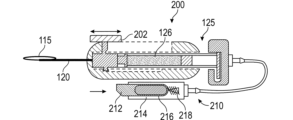
図2Aおよび図2Bを参照すると、カニューレアダプター200は、内部滑動コネクター105に堅固に取り付けられ(例えば製造時に一体成型された部品)、筐体110に対して軸方向に滑動することができる滑動トリガー202を備えるように適応されるかまたは改変されることがある。その場合、操作者は、注射器125の近位ストップを押す(例えば図1Dに示されるように注射器125の近位プランジャーアクチュエーター128を押す)代わりに単に操作者の指または親指の遠位の動き(すなわち患者の方への動き)によって内部カテーテル115を延ばすことができる。滑動トリガー135の外表面は、操作者の指または親指に対して把持または摩擦を助長するようになっている表面構成要素(例えば稜、溝など)を有することがある。
2A and 2B,
図2Cは、操作者の片手での内部カテーテル115の作動と粘弾剤またはその他の流体の分与とを可能にするようになっている、図2Aおよび図2Bのカニューレアダプター200のさらなる改変形または適応形を例示している。例示される実施形態は、内部カテーテル115を延ばすために図2Aおよび図2Bにおいて導入された滑動トリガー202を備えることができ、粘弾剤注射器125を加圧するようになっている空気圧システム210を組み込んでいる。空気圧システム210は、図2Dおよび図2Eにおいてその構成部品および操作に関して拡大され、さらに詳細に例示されている。
FIG. 2C is a further modification of the
空気圧システム210は、操作者の指(例えば人差し指)によって作動するようになっているトリガー212を利用することができる。図2Dは、トリガー212が押し込まれる前の空気圧システム210を例示し、図2Eは、トリガーが押し込まれた(例えばバネ218を圧縮するために患者から離れる方向に押された)後の空気圧システム210を例示している。トリガー212が押し込まれる(例えばその作動位置に動く)と、ミニチュアの弁解放加圧カートリッジ216(例えばピコシル(Picocyl)によって市販されているピコシリンダー)が、注射器プランジャーの近位側に流体結合されているチャンバー214に加圧するために開く(例えば普通の空気圧接着ディスペンサーと同様な付属品を用いて)ことができる。この配置または機構は、注射器125からの安定した、加圧された流体126(例えば粘弾剤またはその他のOVD流体)の供給の調節された分与を有利に可能にすることができる。トリガー212が解放されると、バネ218は、圧縮されていない配置に緩和することができ、圧力カートリッジ216をその名目上の位置に押し戻し、チャンバー214は、例えば粘弾剤またはその他の流体分与を突然止めるために切れ込み220を介して通気される。図2Eに示されるように、トリガー142が押し込まれると圧力カートリッジ216の弁222が開き、バネ218が圧縮され、トリガー212が解放されると弁222が閉じ、バネ218は緩和されるかまたは伸びている(例えばその非作動位置へ戻る)ことがある。
トリガー212は、その本体の側面に形成された切れ込み220を備えることができる。トリガー212が押し込まれる前、切れ込み220は、チャンバー214と流体接続されていないことがある。トリガー212が押し込まれるにつれて、切れ込み220がチャンバー214と環境との間の通路を作り出すことができる。トリガー212が完全に圧縮され、チャンバー214を加圧するためにカートリッジ216が開くと、切れ込み220は、チャンバー214の中の圧力が保持されるように、環境から切り離されることがある。トリガー212が解放され、その非作動位置に戻ると、切れ込み220は、例えば本明細書に記載されるように、粘弾剤またはその他の流体分与を急に止めるためにチャンバー214に通気するべくチャンバー214と環境との間の通路を作り出すことができる。
図3A~図3Dは、本明細書に記載されている実施形態の何れにも組み込まれることがある弁およびバネを組み込んでいる粘弾剤分与機構の代替実施形態を例示する。図3Aは、粘弾剤カートリッジ/プランジャー306への力を保持するために、圧縮されたバネ304を利用するカニューレアダプター300を示す。本明細書に記載されているように、滑動トリガー202を作動させる(例えば患者の方へ滑らせる)と、カテーテル115を外部カニューレ120の遠位端から延び出させることができる。図3Aに例示される例において、コネクター105は、分与ボタン302および弁308を備えることができる。分与ボタン302は、非作動位置と作動位置とを有することができる。非作動位置にある(図3Cに示されるように)とき、分与ボタン302の本体は、コネクター105内の流路を遮断することができ、例えば流体126が粘弾剤カートリッジ306からカテーテル115の中へ流れることを妨げることができる。作動位置にある(例えば図3Dに示されるようにバネ310を圧縮するために下に押される)とき、分与ボタン302内に形成されたルーメン320が、コネクター105内ならびに粘弾剤カートリッジ306とカテーテル115との間の流路と接続することができる。分与ボタン302が解放されると、バネ310は、分与ボタン302が非作動位置に戻り、粘弾剤カートリッジ306とカテーテル115との間の流路を遮断するように強制することができる。
Figures 3A-3D illustrate alternative embodiments of viscoelastic dispensing mechanisms incorporating valves and springs that may be incorporated into any of the embodiments described herein. FIG. 3A shows a
いくつかの実体化において、図3Aに示されるように、粘弾剤カートリッジ306は、任意選択のダイヤフラム330を備え、コネクター105(例えば図1Aに示されるルアーコネクター)は、ダイヤフラム330に穿孔するために皮下注射針312を備えることができる。
In some implementations, as shown in FIG. 3A,
粘弾剤カートリッジ306は、単一の滑動アセンブリーの中に収納される(図3Aに示されるように)かまたはプランジャーバネ304を有する別個の付属品を有する(図3B~図3Dに示されるように)ことがある。粘弾剤分与機構の動作をより良好に例示する図3B~図3Dを参照すると、内部カテーテル115をシュレム管に出し入れして作動させる(図3Cおよび図3Dに示されるように)ために親指スライダー/トリガー202を用いることができ、一方、粘弾剤カートリッジ306から流体126(例えば粘弾剤またはその他のOVD流体)を分与するために分与ボタン302を用いる(図3Dに示されるように)。
The
いくつかの実施形態によれば、本明細書に記載され、例示されるカニューレアダプターは、図4A~図4Cに概略図示されるように複数の滑動層で構成されることがある。複数の滑動層は、角膜を通る侵入のために設計された尖った遠位先端を含む針アセンブリー420と、前眼房を通り抜け、線維柱帯に侵入するように設計された先端を含むカニューレアセンブリー440と、粘弾剤またはその他の流体を送達するためにシュレム管およびルーメンを通り抜けるように設計された鈍角または丸型の遠位先端を有する内部カテーテルアセンブリー460と、の3つの層を含むことがある。図4Aは、カニューレアダプター400(図4Eに示される)の針アセンブリー420を例示し、図4Bは、カニューレアセンブリー440を例示し、図4Cは、内部カテーテルアセンブリー460を例示する。
According to some embodiments, the cannula adapters described and illustrated herein may be composed of multiple gliding layers as schematically illustrated in FIGS. 4A-4C. The multiple sliding layers include a
針アセンブリー420およびカニューレアセンブリー440は、例示されるようにスロットを含むことがある。針アセンブリー420は、本体422、ルーメン404、上スロット426、下スロット428および針430を備えることができる。針430は、本体422と一体化されることがある。スロット426、428は、本体422上で互いに反対側に形成されることができる。いくつかの実体化において、スロット426、428の位置は、図4Aに例示される例と異なってよい。カニューレアダプター440は、本体442、ルーメン444、上スロット446、カニューレスライダー448および先端450を備えることができる。先端450およびカニューレスライダー448は、カニューレスライダー448の動きを本体442と先端部450との動きに移し替えることができるように本体442と一体化させることができる。上スロット446は、本体442上に形成されることがある。内部カテーテルアセンブリー460は、本体462、カテーテルスライダー464およびカテーテル115を備えることができる。カテーテルスライダー464およびカテーテル115は、カテーテルスライダー464の動きを本体462およびカテーテル115の動きに移し替えることができるように本体と一体化されることがある。
カニューレアダプター400の3つの滑動層の操作および組み立てられた配置が図4E~図4Gに概略図示される。カニューレアダプター440は、カニューレアダプター440の上スロット446が針アセンブリー420の上スロット426の少なくとも一部分と重なり、カニューレスライダー448が針アセンブリー420の下スロット428内に配置されるように、針アセンブリー420内に配置することができる。カテーテルアセンブリー460は、カテーテルスライダー464が針アセンブリー420およびカニューレアセンブリー440の上スロット426、446内にそれぞれ配置されるように、カニューレアセンブリー440内に配置することができる。
The operation and assembled arrangement of the three sliding layers of
針430は、本明細書に記載されるように、患者の角膜に侵入することができる。カニューレスライダー448は、針アセンブリー420内でカニューレアセンブリー440滑動させるために針アセンブリー420のスロット428内で滑動することができる。カニューレスライダー448が遠位に(例えば患者の方へ)動くとき、カニューレアセンブリー440の先端450は、遠位に動くことができ、例えば、患者の上部線維柱帯(TM)部分に侵入することができる。カニューレアダプター440のスロット446は、カテーテルスライダー464がスロット426、446内で遠位に(例えば患者の方へ)および近位に(例えば患者から離れて)滑動することを可能にするために針アセンブリー420のスロット426の少なくとも一部と重なることができる。カテーテルスライダー444が遠位に(例えば患者の方へ)動かされるとき、カテーテル115は、例えば、先端450の遠位端を通って出、例えば、シュレム管に入り、シュレム管に沿って移動することができる。図4Dは、カテーテル115の遠位先端の拡大側面図を示す。図4Dに示されるように、カテーテル115は、粘弾性流体またはその他の流体が通って流れることを可能にする、丸くなった先端452およびルーメン454を備えることができる。
The
図4A~図4Gに図示され、記載されている3つの滑動層アセンブリーは、複数の別々の手術器具の必要を有利に取り除き、それによって手術を簡素化することがある。 The three sliding layer assemblies shown and described in FIGS. 4A-4G may advantageously eliminate the need for multiple separate surgical instruments, thereby simplifying surgery.
図5A~図8Bは、本明細書に記載されているカニューレアダプターの様々な実施形態の内部構成部品を例示する。より大きなカテーテル延長に伴う明確な難題は、内部カテーテル115が外部カニューレ120を通って供給される際の内部屈曲の防止である。図5A~図8Bは、屈曲を防止し、外部カニューレ120に沿って内部カテーテル115を導くように設計された(別々に用いられるかまたは1つ以上の機構が一緒に組み合わされることがある)様々な内部支持機構を示している。
5A-8B illustrate the internal components of various embodiments of cannula adapters described herein. A distinct challenge with larger catheter extensions is preventing internal bending as the
図5Aおよび図5Bは、内部カテーテル115より少しだけ大きい内径と筐体110によって閉じ込められる外径とを有する折り畳み可能ならせん形の支持体152を備えるカニューレアダプター500の側面図(それぞれ非展開配置および完全展開配置)を例示する。らせん形の支持体152は、ゼロに近いバネ力を有するが、それでも半径方向の安定性を維持することができる。
5A and 5B show side views of a
図6Aおよび図6Bは、内部カテーテル115を嵌合させる大きさの内径と外部カニューレ120内で滑動する大きさの外径とを有する剛直な支持管154を備えるカニューレアダプター600の側面図(それぞれ非展開配置および完全展開配置)を例示している。剛直な支持管154は、あらゆる適当な剛性材料(例えば300系統ステンレス鋼)で形成されることがある。いくつかの実体化において、剛直な支持管154の使用は、外部カニューレ120の直径の増加の原因となることがある。
6A and 6B show side views of a cannula adapter 600 (each non deployed configuration and fully deployed configuration) are illustrated.
図7Aおよび図7Bは、ホイール701およびカテーテルフィーダー702、704を備えるカニューレアダプター700の側面図を例示している。カテーテルフィーダー702、704は、カテーテル115を、それが遠位に(例えば患者の方へ)または近位に(例えば患者から離れて)動く際に安定させ、屈曲を防止することができる。ホイール701は、ホイール701の回転をカテーテルフィーダー702の回転に移し替えることができるようにカテーテルフィーダー702に結合させることができる。例えば、図7Bに図示されるように、ホイール701の反時計周りの回転は、カテーテルフィーダー702の時計周りの回転を引き起こすことができる。カテーテルフィーダー702の時計周りの回転は、カテーテル115を遠位に(例えば患者の方へ)移動させることができる。同様に、ホイール701の時計周りの回転は、カテーテルフィーダー702の反時計周りの回転を引き起こすことができ、そのことは、カテーテル115を近位に(例えば患者から離れて)移動させることができる。いくつかの実体化において、カテーテルフィーダー702、704は、一方の回転が別のものの回転を引き起こすように互いに結合される。例えば、カテーテルフィーダー702の時計周りの回転は、カテーテルフィーダー704の反時計周りの回転を引き起こすことができる(図7Bに図示されるように)。いくつかの実体化において、カテーテル115の動き(例えば遠位または近位)は、カテーテルフィーダー704の回転を引き起こすことができる。いくつかの実体化において、カテーテル115は、単に注射器125からアセンブリーを引く(例えばホイール700を時計回り方向に回転させる代わりに)ことによって引き込むことができる。
7A and 7B illustrate side views of
図8Aおよび図8Bは、作動時に折り畳まれながらカテーテル115のための支持を提供し、本明細書に記載されるかまたは例示されるカニューレアダプターまたは流体(例えば粘弾剤)送達装置の実施形態の何れにも組み込まれることがある、入れ子式の管(telescoping tube)158の側面図(例えばそれぞれ非展開配置および完全展開配置)を例示する。
8A and 8B illustrate embodiments of cannula adapters or fluid (e.g., viscoelastic) delivery devices described or illustrated herein that provide support for
図9A~図9Fは、外部カニューレ120の中にカテーテル115を供給するために用いられることがある供給機構900を例示する。供給機構900は、本明細書に記載されるかまたは例示されるカニューレアダプターの実施形態の何れにも組み込まれることがある。供給機構900は、操作者による片手操作を助長するために筐体110の遠位端の近くに配置された親指制御型ダイヤル901を備えることができる。
9A-9F illustrate a
ダイヤル901は、操作者の親指によってダイヤル901から上方に延在するこぶまたは突出部904との相互作用により回転させることができる。あるいは、こぶまたは突出部904は、くぼみ(dimple)または刻み目(indent)を備えることができよう。ダイヤル901は、例えばダイヤル901の時計回りの回転は、内部カテーテル115を外部カニューレ120に沿って、次に外部カニューレから外へ、およびシュレム管に入りシュレム管に沿って、調節された方法で進ませ、例えばダイヤル901の反時計回りの回転は、内部カテーテル115を引き戻すような操作が可能になるように、内部カテーテル115の近位端に結合させることができる。もちろん、これらの方向は、所望および/または要求に応じて逆にすることができよう。ダイヤル901を回し切った際に外部カニューレ120の遠位先端から延び出るようになっている内部カテーテル115の遠位部分(例えば内部ループ)は、本明細書に記載されているように、シュレム管の360°の周全体に一致するかまたは対応する(例えばほぼ等しい)ようになっている長さを有することがある。いくつかの実体化において、ダイヤル901の360°回転(図9Bおよび図9Dに図示される)は、カテーテル115によるシュレム管に沿った360°の移動に対応する。さらに、内部カテーテル115の遠位部分は、予め形状が定められた(例えばシュレム管の曲率半径に対応する定められた曲率半径を有する、形状設定された材料)または本明細書に記載される可撓性材料構成要素を備えることがある。
The
ダイヤル901は、操作者の親指によって押し込むことができるボタン902を備えることができる。ボタン902は、作動する(例えば非作動位置から作動位置へ動く)と、粘弾剤またはその他の粘性手術流体の分与を引き起こすことがある。例えば、ボタン902は、作動すると、制御弁が粘弾剤またはその他の粘性手術流体を分与する原因となる(例えば作動させる)ことができる。粘弾剤またはその他の粘性手術流体の分与は、一定の速度、ボタン902が押し込まれる量に基づく可変速度、または予め定められたボタン押下あたりのボーラス(bolus)量で行われることがある。いくつかの実体化において、ボタン902の作動は、容量型ポンプ(positive displacement pump)などのポンプを作動させることがある。
Dial 901 can include a
いくつかの実体化において、供給機構900は、ダイヤル901の周りの時計時刻に配置された刻み目(indents)または爪(detents)を備えることがある。刻み目または爪は、画像化方法による実際の視覚化を必要とすることなくシュレム管内のカテーテル115の方位位置の間接的な示標を操作者に提供することができる。例えば、各時計時刻における爪は、触覚フィードバック(例えば擬似停止位置)を操作者に提供するか、または可聴フィードバックを操作者に提供するために可聴クリックを発生することがある。操作者は、所定の時計時刻で停止し、所定の体積の粘弾剤またはその他の流体を分与し、それから次の時計時刻に移ることができる。
In some implementations, the
カテーテル115は、1種類または複数種類の接合された材料、例えばナイロン/ピーバックス(Pebax)(登録商標)ポリマー、ポリイミド等で製作されることがある。カテーテル115の近位端は、ダイヤル機構の中に重ね成形される(overmolded)(例えば挿入成形される(insert molded))かまたはダイヤル機構に接着される(例えば接着剤によって)ことがある。外部カニューレ120の中にカテーテル115を供給するチャネル部は、別個の成形構成部品または金属構成部品であるか、あるいはカニューレアダプター100の筐体110によって形成されることがある。図9Eおよび図9Fは、ダイヤル901がどのようにして筐体110に組み込まれるかまたは筐体110とともに組み立てられるかの例を例示している。内部カテーテル115は、カテーテル115に流体結合された別個の配管906の区間を介して(図9Eおよび図9Fに図示されるように)、あるいは成形構成部品の中に形成されたチャネルを介して、弁または注射器(例えば本明細書に記載されるもの)などの流体送達システム(図示せず)に接続されることがある。いくつかの構成において、ダイヤル機構の中に弁が直接統合されることがある。
本明細書に記載され、例示されるカニューレアダプターは、様々な異なる粘弾剤分与機構またはシステムを組み込むことがある。図10A~図10Cは、図9A~図9Fのカニューレアダプター900による送達システム1050の実施形態を例示している。送達システム1050は、貯め1001、バネ1002、コネクター1004、ストッパー1006および基部部材168を備えることができる。カニューレアダプター900の筐体110に取り外し可能に結合される(例えば摩擦嵌合、対応し合う係合構成要素、ラッチおよびノッチ等)ことがある貯め1001(またはカートリッジ)。貯め1001は、図10Aに示されるように、使用前に圧縮された位置(または配置)に引き込ませることができるバネ1002を備えることができる。ストッパー1006(例えばゴムストッパー)は、貯め1001の近位端(例えば供給機構900と反対側の端)内および近くに配置することができる。コネクター167(例えばメスのルアーコネクター)は、あらゆる標準的な粘弾剤注射器またはその他の粘性手術装置(例えば薬剤充填済み眼粘弾剤装置125)への直接接続を助長するために、貯め1001の遠位端(例えば供給機構900に近位の端)に配置することができる。いくつかの実体化(図示せず)において、貯め1001の遠位端に針または分与カニューレで穿孔することができるセプタムが存在することがある。
The cannula adapters described and illustrated herein may incorporate a variety of different viscoelastic dispensing mechanisms or systems. 10A-10C illustrate an embodiment of
貯め1001は、標準的な粘弾剤注射器125のプランジャーを押し込むことによって流体126(例えば粘弾剤またはその他の眼粘性剤手術装置(OVD)流体)で満たされることがある。貯め1001が満たされるにつれてストッパー1006を圧縮されたバネ1002の方へ押し戻すことができる。この充填時にさらなる空気のパージを可能にするために、貯め1001に通気弁または通気性材料、例えば多孔性プラスチックまたは多孔性ポリマー材料が統合されることがある。貯め1001に所望の量の流体126(例えば粘弾剤またはその他の流体)が加えられたら、カテーテル115を備える筐体110に送達システム1050を接続することができる。送達システム1050が筐体110に接続されたら、ストッパー1006に力を加えるようにバネ1002を解放するために、基部部材1008を回転させることができる。バネ1002は、基部部材168の作動に際してバネ1008の係合(例えば圧縮および緩和)を助長するために操作することが可能なように基部部材1008に結合されることがある。いくつかの実体化において、基部部材1008の回転は、バネ1008の圧縮または緩和を引き起こすことができる。いくつかの実施形態によれば、図10A~図10Cの送達システム1050は、あらゆる粘弾剤またはその他の流体の選択ならびに種々の量の粘弾剤またはその他の流体を有利に受け容れることができる。送達システム1050は、充填されると貯め1001に一貫したバネ力が加えられることを確実にすることができる。
図11Aおよび図11Bを参照すると、充填可能なカニューレアダプター1100が本明細書において開示されている。図11Aおよび図11Bに例示されるカニューレアダプター1100の実施形態は、カニューレアダプター1100の筐体110または本明細書に記載されるカニューレアダプターの他の実施形態の筐体に組み込むことができるネジ駆動型(またはネジ式プランジャー)システムを利用している。カニューレアダプター1100は、ネジ式プランジャー1112、ホイール1110、貯め1101およびコネクター1104(例えば標準的ルアーコネクターまたは逆止弁)を備えることができる。貯め1101は、注射器125(例えば標準的な粘弾剤注射器)からの流体126で満たされ(例えば呼び液注入され(primed))てよく、操作前に貯め1101の後端にキャップまたはその他の封止部材が配置されてよい。ホイール1110は、筐体110の腹(例えば底側または下側)に形成されたスロットを介してホイール1110にアクセス可能であるように位置を定め、配置することができる。ホイール1110は、筐体110が操作者の手の中に親指をダイヤル900の上にして保持されているとき、操作者の人差し指または中指によって回転させるのに好都合なように配置されることがある。ネジ式プランジャー1112は、ネジ式プランジャー1112がホイール1110の回転によって作動するような操作が可能であるように、かつ機械的にホイール1110に結合させることができる。ネジ式プランジャー1112およびホイール1110は、配管(例えば可撓性シリコーン配管)に流体結合されているルーメンを備えることができ、配管は、今度はカテーテル115のルーメンに流体結合されている。いくつかの実体化において、ネジ式プランジャー1112のルーメンは、カテーテル115のルーメンに中間の配管なしで直接結合されることがある。ネジ式プランジャー1112が貯め1101を押すにつれて、流体126(例えば粘弾剤またはその他の眼粘性剤手術装置(OVD)流体)は、プランジャー1112を通ってカテーテル115の方へ後方分与される。
11A and 11B, a
図11Aおよび図11Bに例示される流体送達システムは、図9A~図9Fに関連して記載され、例示された供給機構900に結合されているが、図11Aおよび図11Bの流体送達システムは、理論的には適当なあらゆる供給システム実施形態で有効であろう。いくつかの実施形態によれば、カテーテル115は、ネジ式プランジャー1112とは独立に(例えば供給機構900によって)動かすことができ、そのため、操作者は、いつでも流体を分与することができる。この独立した移動能力は、たるみを有する可撓性の管(例えばシリコーン配管)を介してプランジャー管(例えばホイール1110およびプランジャー1112のルーメンを通って延びる管)をカテーテル115に連結することによって実施されることがある。あるいは、プランジャー管とカテーテル115との間の接続は、ピーバックス(Pebax)(登録商標)ポリマー配管または他のもっと耐久性が高い配管を用いて、あるいはカテーテル115の独立した動きを可能にするためにバネのような形状の剛直な配管を用いて行われることがある。
Although the fluid delivery system illustrated in FIGS. 11A and 11B is coupled to the illustrated
コネクター1104(例えばメスコネクター)は、図10A~図10Cに例示される送達システム1050の場合と同様に、操作者があらゆる標準的な粘弾剤注射器125を用いて貯め1101を満たすことを可能にすることができる。貯め1101および下流のシステム全体は、注射器125を用いて呼び液注入されてよいだろう。貯め1101およびストッパー1106(例えばゴムストッパー)は、充填手順を簡素化し、望ましくない空気の捕捉を防ぐような形状にされることがある。次に、操作者は、粘弾剤注射器125を取り外し、プラグまたはキャップ1105で置き換えてよいだろう。プラグまたはキャップ1105は、ハンドルの残りを人間工学に合せて形成するような形状にされることがある。キャップ1105は、取り付けられたときに接続部から最後の少量の空気をみな追い出すために貯め1101の中に突き出る延長部も有することがある。あるいは、装置は、呼び液注入(priming)が完了したときに閉じることができる弁を備えることがある。
Connector 1104 (eg, female connector) allows the operator to fill
筐体110のホイール1110(例えば筐体110の腹に露出されている)は、分与される体積の示標を提供するために爪を備えることがある。例えば、爪は、体積の増分毎に可聴性のクリック音または触覚フィードバックを発生することができる。爪は、操作者が、例えば2μL毎にクリックまたは5μL毎にクリックを有することを選ぶことができるように使用者に合せた設定が可能なことがある。もちろん、望みに応じておよび/または求めに応じて他の体積指標が用いられることがある。いくつかの実施形態において、筐体110の腹(または下面)は、それまでに分与された総体積または貯め(例えば貯め1101)の中に残された残りの体積を示す、複数の離間した線形の指標を備えることがある。この機構は、線形の動きを増幅するためにもっと粗いピッチを有する、結合されたネジによって、または例えばギアおよびピニオンシステム上で駆動させることができよう。
いくつかの実施形態によれば、図11Aおよび図11Bに例示されるカニューレアダプター1100は、操作者に馴染み深いはずである片手使用に合せて構成された流体送達システムを有利に備えることができる。流体送達システムは、内部カテーテルの動きに結合されるのとは対照的に、粘弾剤またはその他の流体の分与をいつでも可能にし、それによって操作者が、内部カテーテルがシュレム管に沿って移動する間に当たるかまたは接触する障壁または妨害物を通って動かすことを可能にする。
According to some embodiments, the
図12Aおよび図12Bは、本明細書に記載されるカニューレアダプターに組み込まれることがある送達システム1250の実施形態を例示する。送達システム1250は、調節されたマイクロボーラス分与を有利に可能にすることがある。送達システム1250は、弾性(例えばしなやかな)管1210を備えることができ、弾性管1210は、管1210の遠位端1214を閉じ、管1210の近位端1212を加圧された(例えばバネで押された)貯め1200に開くことによって注入される(is charged)。貯め1200は、図10A~図10Cに関連して記載された送達システム1050と同様な構造上および操作上の特徴を有するバネ1202およびストッパー1204を備えることがある。図12Aに示される管1210の注入後、操作者は、弾性管1210からカテーテル115までを空にするために近位端1212を閉じ、遠位端1214を開くためにスイッチ(図示せず)をトグル切り替えすることがある。弾性管1210の長さ、直径および硬さ測定装置は、所望のボーラス体積を実現するために変えることができる。
Figures 12A and 12B illustrate an embodiment of a
近位端1212と遠位端1214との開閉は、コントローラーがブロック1220を異なる位置の間で動かすように仕向けることによって助長することができる。例えば、ブロック1220は、第1の位置(図12Aに示される)と第2の位置(図12Bに示される)とを有することができる。ブロック1220が第1の位置にあるとき、ブロック1220の第1の開口1222は、管1210の近位端1212と貯め1200とを流体接続することができ、一方、第2の開口1224は、遠位端1212とカテーテル115とを流体遮断するために遠位端1214からずらされることができる。従って、ブロック1220が第1の位置にあるとき、貯め1200の中に貯えられた流体126(例えば粘弾剤またはその他の眼粘性剤手術装置(OVD)流体)は、近位端1212を通って管1210に入り、管1210を遠位端1214まで満たすことができる。ブロック1220が第2の位置にあるとき、第1の開口1222は、貯め1200と近位端1212とを流体遮断するために近位端1212からずらされることができ、一方、第2の開口1224は、遠位端1214とカテーテル115とを流体接続させることができる。従って、ブロックが第2の位置にあるとき、管1200の中(例えば近位端1212と遠位端1214との間)に貯えられた流体は、第2の開口1224を通ってカテーテル115の中に放出させることができる。
The opening and closing of
図13A~図13Cは、ペリスタル型流体送達システム1300の実施形態を例示する。ペリスタル型流体送達システム1300は、弾性(またはしなやかな)管1320と、流体126を貯えている貯め1300とカテーテル115との間で液体を運ぶために管1320の長さに沿って離間した位置において管1320を順次圧縮または絞るようになっている突出部1350(例えばローラーまたはボールベアリング)を備えるペリスタル型ポンプ1310(図13Bおよび図13Cに示される)と、を備えることができる。管1320および突出部1350の少なくとも一部分は、円形のポンプケース1360内に収められることがある。ペリスタル型ポンプ1310は、回転ペリスタル型ポンプ(図示される)または直線型ペリスタル型ポンプのことがある。
13A-13C illustrate an embodiment of a peristaltic
例示される実施形態において、管1320は、ローター1352上の突出部1350(例えばボールベアリング)の周りでポンプケース1360内に配置することができる。ポンプケース1360は、管1320の少なくとも一部分を突出部1350ではさむ(例えば圧縮する)ように作動させる(例えばローター1352の方へ押す)ことができる。ポンプケース1360が作動している間、ローター1352の回転が流体126を管1320に沿って下流に押しやる。ポンプ要素1350のそれぞれが管1320から外れるにつれて、管1320のそのそれぞれの部分の中に流体の流れが誘導される。図13Bおよび図13Cは、ペリスタル型ポンプ1310の断面図を例示している。ペリスタル型流体送達システム1300は、管1320がポンプ要素1350と係合する前に呼び液注入される(例えば流体126が管1320に入ることを可能にする)ことがある。いくつかの実施形態において、ポンプ1310は、呼び液注入後にローター1352を回転させることによって作動させることができる。
In the illustrated embodiment,
図14は、カテーテル115の、それがシュレム管に沿って進むときの、可視化または追跡を助長するカテーテル形状および特徴に関連する様々な概念を例示している。粘剤送達またはその他の流体送達手順の重要な難問は、内部カテーテルの先端が、好ましくない解剖学的部位(例えば標的がシュレム管であるとき脈絡膜上腔)に移動しないように、どこにあるか知ることである。一番上の図は、標準的なカテーテルルーメンを示している。上から2番目の図は、内部カテーテルの遠位端が球根形の先端を備えることがあることを示している。球根形の先端は、押し出し成形されたルーメンに材料を重ね成形することによって実現されることがある。中段の3番目の図を参照すると、カテーテル自体(例えばカテーテル115)が、顕微鏡光または紫外光/青色光源で賦活され、次に明りが減光されると発光することができるように、リン光着色剤を有するポリマーを用いて形成されることがある。あるいは、操作者は、リン光カテーテルを見やすくするために手順時にスイッチを入れることができる、外科手術用顕微鏡に取り付けられた紫外光/青色光源を有することがある。4番目(一番下から2番目)の図に例示される実施形態において、カテーテルは、リン光着色剤(例えばアルミン酸ストロンチウムなどの暗所で発光する材料)で着色されている球根形の遠位先端を備えている。球根形の先端は、押し出し成形されたルーメンの遠位端に重ね成形されることがある。一番下にある最終図は、カテーテル115が、内部カテーテルの可視化を助長する(例えば見えている内部カテーテルのどの部分が線維柱帯を通っているか示す)ために、内部カテーテルの長さに沿って離間したコントラストマーク1400を備えることがあることを示している。遠位先端は、内部カテーテルの遠位先端を示すためにより高度な(例えばより長いかまたはより広い)コントラストマークを備えることがある。本明細書に記載されるカニューレアダプターは、コストを引き下げるために光ファイバーケーブルなしでの使用のために設計されることがある。
FIG. 14 illustrates various concepts related to catheter geometry and features that facilitate visualization or tracking of
図15Aおよび図15Bは、形状設定された遠位先端部1520を形成するために形状記憶材料(例えばニチノール(nitinol)またはその他の形状記憶合金材料)を利用する外部カニューレ1500の操作を概略例示している。カニューレの遠位先端1520は、導入体の針(introducer needle)1510(例えば304ステンレス鋼材料、その他の300系統ステンレス鋼材料またはその他の材料)によって閉じ込められているときは直線形にすることができるが、もはや束縛されていない(例えば導入体の針によって)ときは湾曲して設定された形状になる。この形状設定された構成は、外部カニューレ1500が剛直な導入体の針1510内では滑動するが、導入体の針1510から出て前方に滑動するときはシュレム管に入るために湾曲することを可能にする。
15A and 15B schematically illustrate the operation of
図16は、外部カニューレの遠位端部分(例えば遠位先端)120の実施形態を例示している。図示されるように、遠位端部分(例えば遠位先端)は、カニューレ120が特定の方向に多節変形すること(to articulate)を可能にするために、配管中にノッチ1600を備えることがある。いくつかの実体化において、遠位端部分(例えば遠位先端)は、ノッチのある遠位先端の近くにおけるカニューレ120の多節変形を操作者が調節することができるように引きワイヤーに接続される。いくつかの実体化において、外部カニューレ120の先端は、例えば粘剤またはその他の流体の送達手順時の不注意による先端の動きを防ぐために、シュレム管の後ろの壁に着座するかまたは固定されるように構成されることがある。
FIG. 16 illustrates an embodiment of a distal end portion (eg, distal tip) 120 of an outer cannula. As shown, the distal end portion (e.g., distal tip) can include
図17A~図17Hを参照すると、カニューレアダプターまたは流体送達装置の実施形態1700が開示されている。カニューレアダプター1700は、筐体110、第1のスライダー1702、第2のスライダー1704、チャネル1703、流体送達導路1716、ストッパー1790および遠位端1706を備えることができる。遠位端1706は、カニューレ120を受け容れるような大きさの開口を備えることができる。第1のスライダー1702は、貯め1780およびプランジャー1712に機械的におよび/または操作することができるように結合されることができる。第2のスライダー1704は、例えば第2のスライダー1704の下側に形成されることができるインサート1740を備えることができる。
17A-17H, a cannula adapter or fluid
流体送達導路1716は、近位基部1709、本体1708および管1714を備えることができる。流体送達導路1716は、第2のスライダー1704のインサート1740の内部に配置される(図17Hに示されるように)ことができる。いくつかの実体化において、本体1708および基部1709の少なくとも一部分は、第2のスライダー1704のインサート1740の内部に配置される。流体送達導路1716の管1714は、流体送達導路1716の遠位および近位の動きがカテーテル115を遠位または近位に動かすことができるように、操作することができるようにカテーテル115と結合されることができる。いくつかの実体化において、管1714は、カテーテル115に直接接続される。いくつかの実体化において、管1714は、中間の管を介してカテーテル115に間接接続される。管1714は、カテーテル115に流体結合される。
流体送達導路1716は、流体(例えば粘弾性流体)が貯め1780からカテーテル115に流れることを可能にすることができる。図17Dおよび図17Eに示されるように、流体送達導路1716の本体1708は、プランジャー1712を受け容れることができる穴(bore)1720を備えることができ、プランジャー1712は、本体1708の穴1720内で滑動することができる。プランジャー1712は、流体(例えば粘弾性流体)がプランジャー1712を通り、流体送達導路1716の穴1720に入り、管1714を通ってカテーテル115の方へ流れることを可能にすることができるルーメン1722を備えることができる。
操作時に、第1のスライダー1702および第2のスライダー1704は、チャネル1703に沿って遠位に(例えば遠位端1706の方へ)一緒に動くことができる。本明細書に記載されるように、第2のスライダー1704の遠位への動きは、流体送達導路1716の遠位への動き(例えば遠位端1706の方への動き)を引き起こすことができ,そのことは、今度はカテーテル115が遠位に、およびカニューレ120から出る原因となることができる。図1Fに例示される例を参照すると、操作者は、カニューレ120の遠位部分121を用いて線維柱帯上腔(TM)部分に侵入し、カテーテル115をカニューレ120から、およびシュレム管(SC)の中に導くために第1のスライダー1702および第2のスライダー1704を滑動させることができる。
In operation,
カテーテル115がカニューレ120から外に延び(例えばシュレム管(SC)の中に導かれ)たら、貯め1780の中に貯えられた流体(例えば粘弾性流体)を分与するために第1のスライダー1702を用いることができる。貯め1780の中に貯えられた流体を分与するために、第1のスライダー1702は、チャネル1703に沿って近位に(例えば遠位端1706から離れるように)動かされ、続いてチャネル1703に沿って第2のスライダー1704に対して遠位に(例えば遠位端1706の方へ)動かされることがある。いくつかの実体化において、第2のスライダー1704は、(例えばカテーテル115が動かないことを確実にするために)静止したままであり、一方、第1のスライダー1702は、貯め1780の中に貯えられた流体(例えば流体126)を分与するためにチャネル1703に沿って動かされる。第1のスライダー1702がチャネル1703に沿って第2のスライダー1704に対して近位に動かされるとき、プランジャー1712は、流体送達導路1716の本体1708の穴1720内で近位に動かされることができる。穴1720内でのプランジャー1712の近位の動き(例えば流体送達導路1716に対する)は、貯め1780の中に貯えられた流体が球1730およびガスケット1731を過ぎ、プランジャー1712のルーメン1722の中に、および流体送達導路1716の穴1720の中に流れる原因となることができる。流体が流体送達導路1716の穴1720の中に流れたら、流体を穴1720から、および管1714の中に押しやるためにプランジャー1712をチャネル1703に沿って遠位に動かすことができる。いくつかの実体化において、球1730(およびガスケット1731)は、貯め1780から、およびプランジャー1712のルーメン1722の中に流れる流体の量を限定することができる。
Once
いくつかの実体化において、操作者(例えば臨床医、外科医、介護提供者)は、チャネル1703に沿って第1のスライダー1702が動く距離を変えることによって、分与される流体の量を変えることができる。例えば、チャネル1703に沿って第1のスライダー1702が近位に(例えば操作者の方へ)動くほど、カテーテル115を介して流体が多く分与され、その逆も成立する。いくつかの実体化において、チャネル1703(または第1のスライダー1702)は、第1のスライダー1702がチャネル1703に沿って遠位に戻って動かされたらどのくらいの量の流体が分与されるかを示すために、第1のスライダー1702がチャネル1703に沿って近位に(例えば操作者の方へ)どれくらい動かされるかについての触覚フィードバックを提供することができる爪を備えることができる。
In some implementations, an operator (e.g., clinician, surgeon, care provider) can vary the amount of fluid dispensed by varying the distance
球1730およびガスケット1731は、一緒になってプランジャー1712のための逆止弁として機能することができる。球1730およびガスケット1731は、流体(例えば流体126)が球1730およびガスケット1731を過ぎて後方へ(例えば貯め1780の方へ)流れることを防ぎながら、流体(例えば流体126)が貯め1780から分与されることを可能にすることができる。従って、流体は、球1730およびガスケット1731を過ぎて流れたら、貯め1780へ逆に流れることができない。いくつかの実体化において、貯め1780からプランジャー1712を通る流体(例えば流体126)の一方向の流れを提供するために、他のタイプの適当な弁が用いられることがある。
いくつかの実体化において、使用者は、貯め1780から流体を分与するために第2のスライダー1704を前後へ滑動させるとき、カテーテル115をカニューレ120から外へ動かすために第1のスライダー1702の両方を滑らせるときより増加した抵抗を経験することがある。この抵抗は、第1のスライダー1702とチャネル1703との間より大きな第2のスライダー1704と第1のスライダー1702(とチャネル1703)との間の摩擦によって引き起こされることがある。この抵抗の差は、例えば、使用者がカテーテル分与の動き(例えば第1のスライダー1702を滑動させる)と流体分与の動き(例えば第2のスライダー1704を滑動させる)とを識別することを可能にすることができる触覚フィードバックを提供することができる。
In some implementations, the user slides the
いくつかの実体化において、第2のスライダー1704は、溝1705を備えることができ、第1のスライダー1702は、溝1705を通って遠位または近位に動く(例えば滑動する)ことができる。第1のスライダー1702および第2のスライダー1704は、操作者(例えば介護提供者)のためにより良好な把持を提供することができる稜1752および溝1750を備えることができる。
In some implementations, the
いくつかの実体化において、カニューレ120は、突出部1750を備えることができ、突出部1750は、遠位端1706の内部に形成されたインサートにカニューレ120を固定して取り付ける(図17Fに例示される例に示されるように)ことができる。従って、遠位端1706は、カニューレ120の配向、従ってカニューレ120の遠位部分121の配向を変えるために回転させることができる。このことは、操作者が、カニューレアダプター1700の配向を変え(例えばカニューレアダプターの長さと平行な軸の周りに回転させ)なくても遠位端1706を回転させることによってカニューレ120の配向を変えることを有利に可能にすることができる。
In some implementations,
カニューレアダプター1700は、チャネル1703の内部に配置することができるストッパー1790を備えることができる。ストッパー1790は、例えば、貯蔵または操作時に第1のスライダー1702および第2のスライダー1704の遠位移動を防ぐことができる。このことは、カテーテル115が偶然にまたは不注意によりカニューレ120から延び出ることを有利に防ぐことができる。
図17Eの例に示されるように、流体送達導路1716の基部1709の内部にガスケット1710が配置されることがある。ガスケット1710は、基部1709内にぴったりと嵌合し、プランジャー1712を受け容れるために開口(例えば円形の開口)を備えるような寸法にされることがある。いくつかの実体化において、ガスケット1710は、本体1708の穴1720内のプランジャー1712の滑らかな調節された動きの原因となるのに十分な抵抗を発生させるために、プランジャー1712の外表面と接触することができる。
A
図18A~図18Dは、カニューレ120およびカテーテル115の様々な図を例示する。本明細書に記載されるように、カニューレ120は、先端1800および端面1804を用いて線維柱帯(TM)上腔部分に侵入することができる遠位部分121を備えることができる。端面1804は、カニューレ120の本体に平行な軸に対して角度をなして(例えば斜めに)形成されることがある。表面1804は、例えば線維柱帯(TM)上腔部分の侵入を助長することができる。いくつかの実体化において、端面1804は、カニューレ120の本体に平行な軸に対して直角(または実質的に直角)のことがある。先端1800は、切削用の縁(cutting edge)を助長するために斜角を付けられた遠位先端を形成することがある。遠位部分121は、カテーテル115がカニューレ120のルーメン1802からある角度で延び切る(例えば出る)ことを可能にするために湾曲させられることがあり、このことは、シュレム管(SC)の中へのおよびシュレム管(SC)を周るカテーテル115の動きを助長することができる。カテーテル115は、先細り形の縁部分1812を有する遠位端1810を備えることができる。テーパー形の縁部分1812は、湾曲した遠位部分121内およびシュレム管(SC)の内部のカテーテル115の動きを助長し、誘導することができる。
18A-18D illustrate various views of
図18E~図18Hは、カニューレ120の遠位部分121の他の例を例示している。遠位部分121は、1つ以上の切削用の縁または表面を提供するために遠位部分121の先端1800に形成されてよい1つ以上の切れ込み1852を備えることができる。いくつかの実体化において、切れ込み1852は、遠位部分121の遠位の縁(例えば遠位部分121に近位のカニューレ120の部分から遠い方の縁)に形成されてよい。複数の切れ込み1852を含むいくつかの実体化において、切れ込み1852は、互いに隣接して形成されて(例えば図18Gおよび図18Hに示されるように)よい。切れ込み1852は、カテーテル(例えばカテーテル115)を介する流体の分与時に表面(例えばシュレム管の後壁)に当接し、カニューレ120を安定させる(例えばカニューレ120の遠位部分121が動き回ることを防ぐ)ことができるアンカー1854を備えることができる。いくつかの実体化において、アンカー1854は、使用時に、組織表面(例えばシュレム管の後壁)に侵入することができる。本明細書に記載され、図18E~図18Hに示される遠位部分121は、本明細書に記載されるカニューレ120の何れの実体化にも組み込まれることがある。
18E-18H illustrate other examples of
図19Aおよび図19Bは、カニューレアダプター1900の操作方式例を例示している。カニューレアダプター1900は、スライダー202、カニューレ120、分与機構1902および貯め1904を備えることができる。操作者は、例えばカテーテルをカニューレ120から外へ、およびシュレム管の中に導くために、スライダー202を遠位に(例えば患者の方へ)滑動させることができる。続いて、操作者は、流体をカテーテル115の中に、およびカテーテル115から分与するために、貯め1904を作動させることができる。いくつかの実体化において、分与機構1902は、貯め1904内に配置された固定型のプランジャーを備えることがあり、プランジャーは、貯め1904がカニューレアダプター1900の長さに平行な軸の周りに回転させられると流体を貯め1904から押し出す。いくつかの実体化において、分与機構1902は、貯め1904内に配置され、弾性部材(例えばバネ)に接続されたプランジャーを備えることがあり、プランジャーは、例えば貯め1904の近位端が遠位に(例えば患者の方へ)押されると流体を貯め1904から外へ、およびカテーテル115の方へ押すことができる。
19A and 19B illustrate an example method of operation of cannula adapter 1900. FIG. Cannula adapter 1900 can comprise
いくつかの実体化によれば、充填の前にトリパン(Trypan)ブルーまたはなんらかの他の生体適合色素(例えばブリリアントブルー、インドシアニングリーン、フルオレセイン)が貯め164の中に。生体適合色素を導入すると、操作者がシュレム管中の拡張の程度および下流の上強膜静脈網を可視化することが可能になることがある。 According to some implementations, Trypan blue or some other biocompatible dye (eg, brilliant blue, indocyanine green, fluorescein) is placed in reservoir 164 prior to filling. The introduction of biocompatible dyes may allow the operator to visualize the degree of dilation in Schlemm's canal and the downstream episcleral venous network.
いくつかの追加の構成要素が上記の諸概念と統合されることがある。例えば、房水漏出を防ぐために手術時に角膜切開部内部に嵌合するかまたは角膜切開部に対して押すしなやかな/エラストマーの重ね成形物またはO-リングのような、外部カニューレ120または導入体の針の外側に巻かれた封止用構成要素。あるいは、チャンバー安定性を提供するために、外部カニューレ120を通る緩衝塩類溶液(BSS)潅流路が用いられることがある。
Several additional components may be integrated with the above concepts. For example, an
主にシュレム管内の粘弾剤の送達に関して記載されたが、本明細書に記載され、例示される装置および方法は、眼と関連する(例えばコレクターチャネル、下流の上強膜静脈網、眼の組織管、脈絡膜上腔、結膜下腔、網膜下腔)か、あるいは眼以外の部位におけるか、のどちらかで、その他の既存のまたは創出された解剖学的通路、チャネル、空間、ルーメンまたは血管への粘弾剤またはその他の流体の送達と関連して用いることができよう。粘弾剤以外の流体(例えば他の液剤、医薬品、溶液、化学物質等)が用いることがある。 Although described primarily in terms of delivery of viscoelastic agents within Schlemm's canal, the devices and methods described and exemplified herein are relevant to the eye (e.g., collector channels, downstream episcleral venous network, ocular tissue ducts, suprachoroidal space, subconjunctival space, subretinal space) or other existing or created anatomical passageways, channels, spaces, lumens or vessels, either at sites other than the eye It could be used in connection with the delivery of viscoelastic agents or other fluids to the body. Fluids other than viscoelastics (eg, other liquids, drugs, solutions, chemicals, etc.) may be used.
条件的文言、例えば、とりわけ「できる(can)」、「できよう(could)」、「かもしれない(might)」または「ことがある(may)」は、特に断らない限り、一般に用いられている文脈において、特定の実施形態は、特定の特徴物、要素および/またはステップを備え、一方、他の実施形態は、特定の特徴物、要素および/またはステップを備えないことを伝えていると、別に理解される。従って、条件を述べるそのような文言は、一般に、特徴物、要素および/またはステップが1つ以上の実施形態のために何らかの意味で必要であること、あるいは使用者の入力または催促の有無にかかわらずこれらの特徴物、要素および/またはステップが何れかの特定の実施形態に含まれるかまたは実施されるかどうか決定するための論理を1つ以上の実施形態が必然的に含むことを暗に意味するものではない。 Conditional language such as ``can'', ``could'', ``might'' or ``may'', among others, is generally used unless otherwise noted. In the context of the document, certain embodiments comprise certain features, elements and/or steps, while other embodiments do not comprise certain features, elements and/or steps. , to be understood separately. Thus, such language stating a condition generally implies that the features, elements and/or steps are in some way necessary for one or more embodiments, or that with or without user input or prompting. without implying that one or more embodiments necessarily include logic for determining whether these features, elements and/or steps are included or implemented in any particular embodiment. does not mean
句「X、YおよびZの少なくとも1つ」などの接続的文言は、特に断らない限り、一般に用いられる文脈で、品目、項目等がX、YまたはZのどれかであることを伝えていると、別に理解される。従って、そのような接続的文言は、特定の実施形態がXの少なくとも1つ、Yの少なくとも1つおよびZの少なくとも1つがそれぞれ存在することを必要とすることを一般的に暗に意味するものではない。 Conjunctive language such as the phrase "at least one of X, Y and Z" conveys that an item, item, etc. is either X, Y or Z in the context in which it is commonly used unless otherwise indicated. and understood differently. Thus, such conjunctive language generally implies that certain embodiments require the presence of at least one of X, at least one of Y, and at least one of Z, respectively. isn't it.
いくつかの実施形態が添付の図面と関連付けられて記載されてきた。しかし、これらの図は、一定の比率で描かれてはいない。距離、角度等は、単に例示であり、例示される装置の実際の寸法およびレイアウトとの正確な関係を必ずしも備えない。構成部品を追加し、取り除き、および/または配置を変えることができる。さらに、様々な実施形態と関連するあらゆる特定の特徴物、側面、方法、性質、特性、品質、属性、要素などの本明細書における開示は、本明細書に示される他のすべての実施形態において用いることができる。 Several embodiments have been described in connection with the accompanying drawings. However, these figures are not drawn to scale. Distances, angles, etc. are exemplary only and do not necessarily have an exact relationship to the actual dimensions and layout of the illustrated apparatus. Components can be added, removed, and/or rearranged. Moreover, disclosure herein of any particular feature, aspect, method, property, characteristic, quality, attribute, element, etc. associated with various embodiments may be applied in all other embodiments presented herein. can be used.
上記に記載の実施形態に多数の変化および変更が施されることがあり、上記に記載の実施形態の要素は、他の許容される例の中にあると理解されることが強調されるべきである。そのようなすべての変更および変化は、本開示の範囲内で本明細書に含まれるものとする。 It should be emphasized that numerous variations and modifications may be made to the embodiments described above, and elements of the embodiments described above will be understood to be among other permissible examples. is. All such modifications and variations are intended to be included herein within the scope of this disclosure.
Claims (49)
筐体であって、流体を貯えるための充填可能な貯めおよび薬剤充填済み眼粘弾剤装置に流体結合されるように構成されたコネクターを含む筐体と、
近位端、遠位端およびルーメンを含むカニューレであって、前記カニューレの近位端は、前記筐体の遠位端に結合され、前記カニューレの遠位端は、角膜切開部を通って患者の眼に侵入するように構成され、前記カニューレのルーメンは、前記カニューレの近位端から遠位端に延在するカニューレと、
近位端、遠位端およびルーメンを含むカテーテルであって、前記カテーテルの近位端は、前記貯めに流体結合され、前記ルーメンは、前記カテーテルの近位端から前記カテーテルの遠位端に延在するカテーテルと、
作動すると前記カニューレのルーメンに沿って前記カテーテルを進ませ、前記カテーテルが前記カニューレの遠位端を通って出る原因となるように構成された第1のアクチュエーターと、
作動すると前記貯めの中に貯えられた流体が前記カテーテルを通って流れ、前記カテーテルの遠位端を通って出る原因となるように構成された第2のアクチュエーターと、
を含み、
前記カテーテルのルーメンは、前記貯めの中に貯えられた流体が前記カテーテルを通り、前記患者の眼の中に流れることを可能にするように構成され、
前記カテーテルは、第1のアクチュエーターが作動すると前記カニューレの遠位端から外に、前記患者のシュレム管の360°の周全体に沿って延在するような大きさである、
装置。 A device for delivering fluid, comprising:
a housing including a fillable reservoir for storing fluid and a connector configured to be fluidly coupled to a pre-filled ocular viscoelastic device;
A cannula including a proximal end, a distal end and a lumen, wherein the proximal end of the cannula is coupled to the distal end of the housing and the distal end of the cannula extends through a corneal incision into a patient. a cannula configured to enter an eye of the eye, wherein a lumen of the cannula extends from a proximal end to a distal end of the cannula;
A catheter comprising a proximal end, a distal end and a lumen, the proximal end of the catheter being fluidly coupled to the reservoir and the lumen extending from the proximal end of the catheter to the distal end of the catheter. an existing catheter;
a first actuator configured to advance the catheter along the lumen of the cannula when actuated to cause the catheter to exit through the distal end of the cannula;
a second actuator configured to act to cause fluid stored in the reservoir to flow through the catheter and out through a distal end of the catheter;
including
the lumen of the catheter is configured to allow fluid stored in the reservoir to flow through the catheter and into the eye of the patient;
the catheter is sized to extend out from the distal end of the cannula and along the entire 360° circumference of the patient's Schlemm's canal when a first actuator is actuated;
Device.
前記第1のアクチュエーターは、近位位置と遠位位置との間の前記チャネル内で軸方向に移動するようになっている第1の滑動トリガーを含み、
前記第2のアクチュエーターは、近位位置と遠位位置との間の前記チャネル内で軸方向に移動するようになっている第2の滑動トリガーを含む、
請求項1~8の何れか一項に記載の装置。 the housing further includes a channel;
the first actuator includes a first sliding trigger adapted to move axially within the channel between a proximal position and a distal position;
said second actuator includes a second sliding trigger adapted to move axially within said channel between a proximal position and a distal position;
Apparatus according to any one of claims 1-8.
前記第1の滑動トリガーが前記遠位位置にあるとき、前記カテーテルの遠位端は、前記カニューレの遠位端を過ぎて進み、
前記近位位置と前記遠位位置との間の前記第2の滑動トリガーの動きは、予め定められた量の流体が前記カテーテルの遠位端を通って分与される原因となる、
請求項9に記載の装置。 when the first sliding trigger is in the proximal position, the distal end of the catheter is located between the proximal and distal ends of the cannula;
when the first sliding trigger is in the distal position, the distal end of the catheter advances past the distal end of the cannula;
movement of the second sliding trigger between the proximal and distal positions causes a predetermined amount of fluid to be dispensed through the distal end of the catheter;
10. Apparatus according to claim 9.
近位コネクターおよび貯めを含み、前記貯めは、流体を貯えるように構成され、前記近位コネクターは、薬剤充填済み眼粘弾剤装置に流体結合されるように構成された筐体と、
角膜切開部を通ってシュレム管に挿入されるように構成されたカニューレであって、ルーメンを含むカニューレと、
近位端、遠位端およびルーメンを含み、前記近位端は、前記貯めに流体結合され、遠位端は、前記カニューレの遠位端を過ぎて進むように構成され、前記ルーメンは、前記貯めの中に貯えられた流体が前記カテーテルを通って流れ、前記カテーテルの遠位端を通って分与されることを可能にするように構成されたカテーテルと、
前記カテーテルが前記カニューレのルーメンに沿って、前記カニューレの遠位端を過ぎて進む原因となるために、非作動位置と作動位置との間で動くように構成された第1の滑動可能トリガーと、
前記貯めの中に貯えられた流体が前記カテーテルのルーメンを通ってシュレム管の中に分与される原因となるために、非作動位置と作動位置との間で動くように構成された第2の滑動可能トリガーと、
を含む装置。 A device configured to deliver fluid to at least one ocular drainage, comprising:
a housing comprising a proximal connector and a reservoir, the reservoir configured to store a fluid, the proximal connector configured to be fluidly coupled to a drug-filled ocular viscoelastic device;
a cannula configured to be inserted through a corneal incision and into Schlemm's canal, the cannula including a lumen;
a proximal end, a distal end and a lumen, the proximal end being fluidly coupled to the reservoir, the distal end configured to advance past the distal end of the cannula, the lumen being connected to the cannula; a catheter configured to allow fluid stored in a reservoir to flow through the catheter and be dispensed through a distal end of the catheter;
a first slidable trigger configured to move between a non-actuated position and an actuated position to cause the catheter to advance along the lumen of the cannula and past the distal end of the cannula; ,
a second device configured to move between an inoperative position and an operative position to cause fluid stored in the reservoir to be dispensed through the lumen of the catheter and into Schlemm's canal; a slidable trigger of
equipment, including
流体を貯えるように構成された貯めと、
ルーメンを含み、角膜切開部を通って患者の眼に侵入するように構成されたカニューレと、
前記カニューレのルーメンに沿って進むように構成されたカテーテルであって、前記貯めの中に貯えられた流体が前記カテーテルを通って分与されることを可能にするように構成されたルーメンを含むカテーテルと、
第1のアクチュエーターと、
第2のアクチュエーターと、
を含み、
前記第1のアクチュエーターの作動は、前記カテーテルが前記カニューレに沿って進む原因となり、
前記第2のアクチュエーターの作動は、前記流体が前記貯めから前記カテーテルを通って分与される原因となる、
装置。 A device configured to deliver fluid to at least one ocular drainage, comprising:
a reservoir configured to store a fluid;
a cannula comprising a lumen and configured to enter the patient's eye through the corneal incision;
A catheter configured to advance along a lumen of the cannula, including a lumen configured to allow fluid stored in the reservoir to be dispensed through the catheter. a catheter;
a first actuator;
a second actuator;
including
actuation of the first actuator causes the catheter to advance along the cannula;
actuation of the second actuator causes the fluid to be dispensed from the reservoir through the catheter;
Device.
分与される前記流体の量は、少なくとも部分的に前記非作動位置と前記作動位置との間の距離に基づく、
請求項14に記載の装置。 the second actuator is configured to slide between a non-actuated position and an actuated position to cause the fluid to be dispensed;
the amount of fluid dispensed is based, at least in part, on the distance between the non-actuated position and the actuated position;
15. Apparatus according to claim 14.
近位筐体であって、その中にある滑動チャネルおよび前記滑動チャネル内で軸方向前後に移動するように構成されたコネクターを備え、前記コネクターの近位端は、前記薬剤充填済み眼粘弾剤装置に流体結合されるように構成されている筐体と、
外部カニューレであって、前記筐体の遠位端に結合された近位端、角膜切開部を通ってシュレム管に挿入されるように構成された遠位端、および前記外部カニューレの近位端から遠位端に延在するルーメンを含む細長いカニューレ部分を含む外部カニューレと、
内部カテーテルであって、前記コネクターの遠位端に流体結合された近位端、シュレム管の周の少なくとも一部分に沿って進むように構成された鈍角または丸められた遠位端、および前記内部カテーテルの近位端から前記内部カテーテルの遠位端に延在するルーメンを含む細長いカテーテル部分を含む内部カテーテルと、
を含み、
前記内部カテーテルは、前記外部カニューレのルーメン内に嵌合し、前記外部カニューレのルーメンに沿って進むような大きさであり、
前記内部カテーテルのルーメンは、前記眼粘弾剤装置からシュレム管に粘弾剤を送達するように構成され、
前記内部カテーテルは、前記コネクターが前記滑動チャネル内の最遠位位置に進められたとき、前記外部カニューレの遠位端から外へ、シュレム管の360°の周全体に沿って延在するような大きさにされる、
アダプター。 Configured for use with a pre-filled ocular viscoelastic device to deliver viscoelastic to up to 360° of full circumference of Schlemm's canal in a single pass through a single entry point into Schlemm's canal a cannula adapter with a
a proximal housing comprising a sliding channel therein and a connector configured to move axially back and forth within the sliding channel, the proximal end of the connector being connected to the drug-filled ocular viscoelastic; a housing configured to be fluidly coupled to the agent device;
an outer cannula, a proximal end coupled to the distal end of the housing, a distal end configured to be inserted into Schlemm's canal through a corneal incision, and a proximal end of the outer cannula an outer cannula including an elongated cannula portion including a lumen extending distally from the
an inner catheter, a proximal end fluidly coupled to the distal end of the connector, a blunt or rounded distal end configured to travel along at least a portion of the circumference of Schlemm's canal, and the inner catheter. an inner catheter comprising an elongated catheter portion including a lumen extending from a proximal end of the inner catheter to a distal end of the inner catheter;
including
the inner catheter is sized to fit within and advance along the lumen of the outer cannula;
the lumen of the inner catheter is configured to deliver viscoelastic agent from the ocular viscoelastic device to Schlemm's canal;
The inner catheter extends out from the distal end of the outer cannula and along the entire 360° circumference of Schlemm's canal when the connector is advanced to a distal-most position within the sliding channel. sized,
adapter.
近位筐体であって、その中にある滑動チャネルおよび前記滑動チャネル内で軸方向前後に移動するように構成されたコネクターを備え、前記コネクターの近位端は、前記薬剤充填済み眼粘弾剤装置に流体結合されるように構成されている筐体と、
外部カニューレであって、前記筐体の遠位端に結合された近位端、角膜切開部を通ってシュレム管に挿入されるように構成された遠位端、および前記外部カニューレの近位端から遠位端に延在するルーメンを含む細長いカニューレ部分を含む外部カニューレと、
内部カテーテルであって、前記コネクターの遠位端に流体結合された近位端、シュレム管の周の少なくとも一部分に沿って進むように構成された遠位端、および前記内部カテーテルの近位端から前記内部カテーテルの遠位端に延在するルーメンを含む細長いカテーテル部分を含む内部カテーテルと、
を含み、
前記内部カテーテルのルーメンは、前記眼粘弾剤装置からシュレム管に粘弾剤を送達するように構成されている、
アダプター。 A cannula adapter configured for use with a pre-filled ocular viscoelastic device to deliver viscoelastic to at least one ocular drainage channel, comprising:
a proximal housing comprising a sliding channel therein and a connector configured to move axially back and forth within the sliding channel, the proximal end of the connector being connected to the drug-filled ocular viscoelastic; a housing configured to be fluidly coupled to the agent device;
an outer cannula, a proximal end coupled to the distal end of the housing, a distal end configured to be inserted into Schlemm's canal through a corneal incision, and a proximal end of the outer cannula an outer cannula including an elongated cannula portion including a lumen extending distally from the
from a proximal end fluidly coupled to the distal end of the connector, a distal end configured to travel along at least a portion of the circumference of Schlemm's canal, and the proximal end of the inner catheter; an inner catheter comprising an elongated catheter section including a lumen extending to a distal end of said inner catheter;
including
the lumen of the inner catheter is configured to deliver viscoelastic agent from the ocular viscoelastic device to Schlemm's canal;
adapter.
近位筐体であって、回転可能ダイヤルおよびアクチュエーターを含む近位筐体と、
外部カニューレであって、前記近位筐体に機械結合された近位端、角膜切開部を通ってシュレム管に挿入されるように構成された遠位端、および前記外部カニューレの近位端から遠位端に延在するルーメンを含む細長いカニューレ部分を含む外部カニューレと、
内部カテーテルであって、操作可能なように前記回転可能ダイヤルに結合された近位端、シュレム管の周の少なくとも一部分に沿って進むように構成された遠位端、および前記内部カテーテルの近位端から前記内部カテーテルの遠位端に延在するルーメンを含む細長いカテーテル部分を含む内部カテーテルと、
を含み、
前記内部カテーテルの細長いカテーテル部分は、前記外部カニューレ内に嵌合し、前記外部カニューレに沿って進むように配置され、
前記アダプターは、前記ダイヤルの回転が、前記外部カニューレに沿い、次にシュレム管の周に入り、シュレム管の最大360°の周に沿った前記内部カテーテルの前進の原因となるように構成され、
前記内部カテーテルの近位端は、流体分与機構に流体結合され、
前記アクチュエーターの操作者作動は、流体が前記流体分与機構の流体貯めから前記内部カテーテルを通り、シュレム管の中に分与されることを可能にする、
アダプター。 a cannula adapter configured to deliver a viscoelastic agent to at least one ocular drainage channel,
a proximal housing including a rotatable dial and an actuator;
from a proximal end of an outer cannula mechanically coupled to the proximal housing, a distal end configured to be inserted into Schlemm's canal through a corneal incision, and the proximal end of the outer cannula; an outer cannula including an elongated cannula portion including a lumen extending at a distal end;
an inner catheter, a proximal end operably coupled to the rotatable dial, a distal end configured to advance along at least a portion of the circumference of Schlemm's canal, and a proximal end of the inner catheter. an inner catheter comprising an elongated catheter section including a lumen extending from an end to a distal end of said inner catheter;
including
an elongated catheter portion of the inner catheter is positioned to fit within and advance along the outer cannula;
the adapter is configured such that rotation of the dial along the outer cannula and then into the circumference of Schlemm's canal causes advancement of the inner catheter along up to 360° of the circumference of Schlemm's canal;
a proximal end of the inner catheter is fluidly coupled to a fluid dispensing mechanism;
operator actuation of the actuator allows fluid to be dispensed from the fluid reservoir of the fluid dispensing mechanism, through the inner catheter, and into Schlemm's canal;
adapter.
Applications Claiming Priority (3)
| Application Number | Priority Date | Filing Date | Title |
|---|---|---|---|
| US202063023162P | 2020-05-11 | 2020-05-11 | |
| US63/023,162 | 2020-05-11 | ||
| PCT/US2021/031823 WO2021231461A1 (en) | 2020-05-11 | 2021-05-11 | Delivery of fluid to ophthalmic passages |
Publications (3)
| Publication Number | Publication Date |
|---|---|
| JP2023526316A true JP2023526316A (en) | 2023-06-21 |
| JPWO2021231461A5 JPWO2021231461A5 (en) | 2024-05-22 |
| JP7768900B2 JP7768900B2 (en) | 2025-11-12 |
Family
ID=76553794
Family Applications (1)
| Application Number | Title | Priority Date | Filing Date |
|---|---|---|---|
| JP2022569455A Active JP7768900B2 (en) | 2020-05-11 | 2021-05-11 | Fluid Delivery to the Eye's Flow Channels |
Country Status (6)
| Country | Link |
|---|---|
| US (1) | US20210361477A1 (en) |
| EP (1) | EP4149589A1 (en) |
| JP (1) | JP7768900B2 (en) |
| AU (1) | AU2021272910B2 (en) |
| CA (1) | CA3179328A1 (en) |
| WO (1) | WO2021231461A1 (en) |
Families Citing this family (5)
| Publication number | Priority date | Publication date | Assignee | Title |
|---|---|---|---|---|
| KR102687459B1 (en) | 2020-05-15 | 2024-07-23 | 아이플로우 인코포레이티드 | Device for implantation into the normal aqueous humor outflow path of the mammalian eye |
| CA3202776A1 (en) * | 2021-01-11 | 2022-07-14 | Wayne A. Noda | Systems and methods for viscoelastic delivery |
| US20230301832A1 (en) * | 2022-03-23 | 2023-09-28 | New World Medical, Inc. | Ophthalmic device |
| WO2024020632A1 (en) * | 2022-07-27 | 2024-02-01 | Nova Eye, Inc. | Mechanically aided fluid dispensing device |
| WO2025193952A1 (en) * | 2024-03-13 | 2025-09-18 | The Johns Hopkins University | Systems and methods for visualizing ophthalmic viscosurgical device during and following ocular surgery and viscosurgery |
Citations (3)
| Publication number | Priority date | Publication date | Assignee | Title |
|---|---|---|---|---|
| JP2002522116A (en) * | 1998-08-03 | 2002-07-23 | インサイト・ビジョン・インコーポレイテッド | Injection device and method of using the same |
| US20160287438A1 (en) * | 2015-03-31 | 2016-10-06 | Sight Sciences, Inc. | Ocular delivery systems and methods |
| WO2019202603A1 (en) * | 2018-04-19 | 2019-10-24 | Everads Therapy Ltd | Device for injecting a substance into an interlayer of a body tissue or organ |
Family Cites Families (6)
| Publication number | Priority date | Publication date | Assignee | Title |
|---|---|---|---|---|
| US9320647B2 (en) * | 2010-03-31 | 2016-04-26 | Ocuject, Llc | Device and method for intraocular drug delivery |
| CA2956273A1 (en) * | 2014-08-12 | 2016-02-18 | Patrick Gooi | Device, delivery system, and method for ocular therapy |
| US20180333296A1 (en) * | 2015-09-02 | 2018-11-22 | Dose Medical Corporation | Drug delivery implants as intraocular drug depots and methods of using same |
| ES2954983T3 (en) * | 2015-09-17 | 2023-11-28 | Oxular Ltd | Ophthalmic injection device |
| CN109890333A (en) * | 2016-09-02 | 2019-06-14 | 爱瑞制药公司 | Implantation material applicator |
| EP3773375B1 (en) * | 2018-04-12 | 2023-04-12 | New World Medical, Inc. | Device for intraocular fluid injection |
-
2021
- 2021-05-11 CA CA3179328A patent/CA3179328A1/en active Pending
- 2021-05-11 AU AU2021272910A patent/AU2021272910B2/en active Active
- 2021-05-11 US US17/317,531 patent/US20210361477A1/en active Pending
- 2021-05-11 JP JP2022569455A patent/JP7768900B2/en active Active
- 2021-05-11 WO PCT/US2021/031823 patent/WO2021231461A1/en not_active Ceased
- 2021-05-11 EP EP21734032.2A patent/EP4149589A1/en active Pending
Patent Citations (3)
| Publication number | Priority date | Publication date | Assignee | Title |
|---|---|---|---|---|
| JP2002522116A (en) * | 1998-08-03 | 2002-07-23 | インサイト・ビジョン・インコーポレイテッド | Injection device and method of using the same |
| US20160287438A1 (en) * | 2015-03-31 | 2016-10-06 | Sight Sciences, Inc. | Ocular delivery systems and methods |
| WO2019202603A1 (en) * | 2018-04-19 | 2019-10-24 | Everads Therapy Ltd | Device for injecting a substance into an interlayer of a body tissue or organ |
Also Published As
| Publication number | Publication date |
|---|---|
| CA3179328A1 (en) | 2021-11-18 |
| JP7768900B2 (en) | 2025-11-12 |
| EP4149589A1 (en) | 2023-03-22 |
| AU2021272910B2 (en) | 2025-12-18 |
| AU2021272910A1 (en) | 2022-12-01 |
| WO2021231461A1 (en) | 2021-11-18 |
| WO2021231461A8 (en) | 2021-12-30 |
| US20210361477A1 (en) | 2021-11-25 |
Similar Documents
| Publication | Publication Date | Title |
|---|---|---|
| JP7768900B2 (en) | Fluid Delivery to the Eye's Flow Channels | |
| JP7153650B2 (en) | Ocular therapy device and related method of use | |
| US11540940B2 (en) | Systems and methods for viscoelastic delivery | |
| US7468065B2 (en) | Apparatus for delivery of ocular implants | |
| JP6733994B2 (en) | Ophthalmic delivery device | |
| CN113226230B (en) | Ophthalmic device | |
| CA2495621C (en) | Methods and apparatus for delivery of ocular implants | |
| US20050203542A1 (en) | Apparatus for delivery of ocular implants with reduced incidence of ocular adverse events | |
| US20230301832A1 (en) | Ophthalmic device | |
| EP3448465B1 (en) | Self-powered syringe | |
| CN116669659A (en) | Systems and methods for viscoelastic delivery | |
| RU2854635C1 (en) | Systems and methods for delivering viscoelastic material | |
| ZA200501251B (en) | Methods and apparatus for delivery of ocular implants |
Legal Events
| Date | Code | Title | Description |
|---|---|---|---|
| A521 | Request for written amendment filed |
Free format text: JAPANESE INTERMEDIATE CODE: A523 Effective date: 20240510 |
|
| A621 | Written request for application examination |
Free format text: JAPANESE INTERMEDIATE CODE: A621 Effective date: 20240510 |
|
| A977 | Report on retrieval |
Free format text: JAPANESE INTERMEDIATE CODE: A971007 Effective date: 20250221 |
|
| A131 | Notification of reasons for refusal |
Free format text: JAPANESE INTERMEDIATE CODE: A131 Effective date: 20250313 |
|
| A601 | Written request for extension of time |
Free format text: JAPANESE INTERMEDIATE CODE: A601 Effective date: 20250611 |
|
| A521 | Request for written amendment filed |
Free format text: JAPANESE INTERMEDIATE CODE: A523 Effective date: 20250804 |
|
| TRDD | Decision of grant or rejection written | ||
| A01 | Written decision to grant a patent or to grant a registration (utility model) |
Free format text: JAPANESE INTERMEDIATE CODE: A01 Effective date: 20251020 |
|
| A61 | First payment of annual fees (during grant procedure) |
Free format text: JAPANESE INTERMEDIATE CODE: A61 Effective date: 20251030 |
|
| R150 | Certificate of patent or registration of utility model |
Ref document number: 7768900 Country of ref document: JP Free format text: JAPANESE INTERMEDIATE CODE: R150 |