JP2023524636A - Equipment and method for assembling heater assemblies for nicotine pod assemblies - Google Patents
Equipment and method for assembling heater assemblies for nicotine pod assemblies Download PDFInfo
- Publication number
- JP2023524636A JP2023524636A JP2022562795A JP2022562795A JP2023524636A JP 2023524636 A JP2023524636 A JP 2023524636A JP 2022562795 A JP2022562795 A JP 2022562795A JP 2022562795 A JP2022562795 A JP 2022562795A JP 2023524636 A JP2023524636 A JP 2023524636A
- Authority
- JP
- Japan
- Prior art keywords
- wick
- base
- holder
- support
- slide
- Prior art date
- Legal status (The legal status is an assumption and is not a legal conclusion. Google has not performed a legal analysis and makes no representation as to the accuracy of the status listed.)
- Granted
Links
Images


Classifications
-
- A—HUMAN NECESSITIES
- A24—TOBACCO; CIGARS; CIGARETTES; SIMULATED SMOKING DEVICES; SMOKERS' REQUISITES
- A24F—SMOKERS' REQUISITES; MATCH BOXES; SIMULATED SMOKING DEVICES
- A24F40/00—Electrically operated smoking devices; Component parts thereof; Manufacture thereof; Maintenance or testing thereof; Charging means specially adapted therefor
- A24F40/70—Manufacture
-
- A—HUMAN NECESSITIES
- A24—TOBACCO; CIGARS; CIGARETTES; SIMULATED SMOKING DEVICES; SMOKERS' REQUISITES
- A24F—SMOKERS' REQUISITES; MATCH BOXES; SIMULATED SMOKING DEVICES
- A24F40/00—Electrically operated smoking devices; Component parts thereof; Manufacture thereof; Maintenance or testing thereof; Charging means specially adapted therefor
- A24F40/40—Constructional details, e.g. connection of cartridges and battery parts
- A24F40/42—Cartridges or containers for inhalable precursors
-
- A—HUMAN NECESSITIES
- A24—TOBACCO; CIGARS; CIGARETTES; SIMULATED SMOKING DEVICES; SMOKERS' REQUISITES
- A24F—SMOKERS' REQUISITES; MATCH BOXES; SIMULATED SMOKING DEVICES
- A24F40/00—Electrically operated smoking devices; Component parts thereof; Manufacture thereof; Maintenance or testing thereof; Charging means specially adapted therefor
- A24F40/40—Constructional details, e.g. connection of cartridges and battery parts
- A24F40/44—Wicks
-
- A—HUMAN NECESSITIES
- A24—TOBACCO; CIGARS; CIGARETTES; SIMULATED SMOKING DEVICES; SMOKERS' REQUISITES
- A24F—SMOKERS' REQUISITES; MATCH BOXES; SIMULATED SMOKING DEVICES
- A24F40/00—Electrically operated smoking devices; Component parts thereof; Manufacture thereof; Maintenance or testing thereof; Charging means specially adapted therefor
- A24F40/40—Constructional details, e.g. connection of cartridges and battery parts
- A24F40/46—Shape or structure of electric heating means
-
- A—HUMAN NECESSITIES
- A24—TOBACCO; CIGARS; CIGARETTES; SIMULATED SMOKING DEVICES; SMOKERS' REQUISITES
- A24F—SMOKERS' REQUISITES; MATCH BOXES; SIMULATED SMOKING DEVICES
- A24F40/00—Electrically operated smoking devices; Component parts thereof; Manufacture thereof; Maintenance or testing thereof; Charging means specially adapted therefor
- A24F40/40—Constructional details, e.g. connection of cartridges and battery parts
- A24F40/48—Fluid transfer means, e.g. pumps
- A24F40/485—Valves; Apertures
-
- B—PERFORMING OPERATIONS; TRANSPORTING
- B23—MACHINE TOOLS; METAL-WORKING NOT OTHERWISE PROVIDED FOR
- B23P—METAL-WORKING NOT OTHERWISE PROVIDED FOR; COMBINED OPERATIONS; UNIVERSAL MACHINE TOOLS
- B23P19/00—Machines for simply fitting together or separating metal parts or objects, or metal and non-metal parts, whether or not involving some deformation; Tools or devices therefor so far as not provided for in other classes
- B23P19/001—Article feeders for assembling machines
-
- B—PERFORMING OPERATIONS; TRANSPORTING
- B25—HAND TOOLS; PORTABLE POWER-DRIVEN TOOLS; MANIPULATORS
- B25B—TOOLS OR BENCH DEVICES NOT OTHERWISE PROVIDED FOR, FOR FASTENING, CONNECTING, DISENGAGING OR HOLDING
- B25B11/00—Work holders not covered by any preceding group in the subclass, e.g. magnetic work holders, vacuum work holders
- B25B11/02—Assembly jigs
-
- A—HUMAN NECESSITIES
- A24—TOBACCO; CIGARS; CIGARETTES; SIMULATED SMOKING DEVICES; SMOKERS' REQUISITES
- A24F—SMOKERS' REQUISITES; MATCH BOXES; SIMULATED SMOKING DEVICES
- A24F40/00—Electrically operated smoking devices; Component parts thereof; Manufacture thereof; Maintenance or testing thereof; Charging means specially adapted therefor
- A24F40/10—Devices using liquid inhalable precursors
-
- A—HUMAN NECESSITIES
- A61—MEDICAL OR VETERINARY SCIENCE; HYGIENE
- A61M—DEVICES FOR INTRODUCING MEDIA INTO, OR ONTO, THE BODY; DEVICES FOR TRANSDUCING BODY MEDIA OR FOR TAKING MEDIA FROM THE BODY; DEVICES FOR PRODUCING OR ENDING SLEEP OR STUPOR
- A61M2207/00—Methods of manufacture, assembly or production
- A61M2207/10—Device therefor
Landscapes
- Engineering & Computer Science (AREA)
- Mechanical Engineering (AREA)
- Catching Or Destruction (AREA)
- Pharmaceuticals Containing Other Organic And Inorganic Compounds (AREA)
- Packaging Of Annular Or Rod-Shaped Articles, Wearing Apparel, Cassettes, Or The Like (AREA)
Abstract
ニコチンポッド組立品用のヒーター組立品を組み立てるための設備(10)は、基部(14)、ウィックフィード(234)、スライド(22)、およびホルダー(30)を含む。ウィックフィード(234)は、基部(14)に向かって延び、また毛細管作用を介してニコチンプレベイパー製剤を引き出すように構造化されたウィックを受容するように構成されたチャネル(242)を画定する。スライド(22)は、基部(14)の上面上の平面に沿って移動するように構成される。ホルダー(30)は、基部(14)の上面上に配置される。【選択図】図1AA facility (10) for assembling a heater assembly for a nicotine pod assembly includes a base (14), a wick feed (234), a slide (22) and a holder (30). A wick feed (234) extends toward the base (14) and defines a channel (242) configured to receive a wick structured to draw the nicotine prevapor formulation via capillary action. . The slide (22) is configured to move along a plane on the top surface of the base (14). A holder (30) is placed on the top surface of the base (14). [Selection drawing] Fig. 1A
Description
本開示は、ニコチンポッド組立品用のヒーター組立品の調製および組み立てに使用される設備に関する。 The present disclosure relates to equipment used to prepare and assemble heater assemblies for nicotine pod assemblies.
ニコチン電子ベイピング装置またはニコチンeベイピング装置は、ニコチンプレベイパー製剤を気化してニコチンベイパーを生成する発熱体を含む。 A nicotine electronic vaping device or nicotine e-vaping device includes a heating element that vaporizes a nicotine pre-vapor formulation to produce nicotine vapor.
ニコチンeベイピング装置は、装置内に配設された電源(再充電可能電池など)を含む。電源はヒーターに電気的に接続される。電源は、ヒーターがニコチンプレベイパー製剤をニコチンベイパーへと変換するために十分な温度まで加熱するように、ヒーターに電力を提供する。ニコチンベイパーは、少なくとも一つの出口を含むマウスピースを通して、ニコチンeベイピング装置を出る。 A nicotine e-vaping device includes a power source (such as a rechargeable battery) disposed within the device. A power source is electrically connected to the heater. A power supply provides power to the heater such that the heater heats the nicotine pre-vapor formulation to a temperature sufficient to convert it to nicotine vapor. Nicotine vapor exits the nicotine e-vaping device through a mouthpiece that includes at least one outlet.
このセクションは、本開示の一般的な概要を提供するものであり、その全範囲またはその特徴すべての包括的な開示ではない。 This section provides a general overview of the disclosure and is not a comprehensive disclosure of its full scope or all of its features.
少なくとも一つの例示の実施形態は、ニコチンポッド組立品用のヒーター組立品を組み立てるための設備に関し、基部、ウィックフィード、スライド、およびホルダーを含む。ウィックフィードは基部に向かって延び、そして毛細管作用を介してニコチンプレベイパー製剤を引き出すように構造化されたウィックを受容するように構成されたチャネルを画定する。スライドは、基部の上面上の平面に沿って移動するように構成される。ホルダーは、基部の上面上に配置される。 At least one exemplary embodiment relates to equipment for assembling a heater assembly for a nicotine pod assembly, including a base, wick feed, slide, and holder. A wick feed extends toward the base and defines a channel configured to receive a wick structured to draw the nicotine prevapor formulation through capillary action. The slide is configured to move along a plane on the top surface of the base. A holder is placed on the top surface of the base.
例示の設備は、ウィックをチャネル内に保持するために、ウィックフィードに平行に、かつ隣接して延びるウィックリテーナーを含んでもよい。 Exemplary fixtures may include a wick retainer extending parallel and adjacent to the wick feed to retain the wick within the channel.
例示の設備は、ウィックを切断するためにスライドの上面に沿って摺動するように構成されたブレードを有するカッターを含んでもよい。 Exemplary equipment may include a cutter having blades configured to slide along the top surface of the slide to cut the wick.
例示の設備内のウィックフィードは、基部に対して回転するように構成されてもよい。 A wick feed in the example installation may be configured to rotate with respect to the base.
例示的な設備は、基部に固定されたブロックを含んでもよい。ウィックフィードは、ブロックに回転可能に取り付けられ、かつブロックによって支持されてもよい。 An exemplary fixture may include a block fixed to the base. The wick feed may be rotatably attached to and supported by the block.
例示の設備のホルダーは、その中にヒーター組立品の支持体を受容するように構成されてもよく、ホルダーは、ウィックを挿入するための基部に対して支持体を固定するように構成される。 A holder of the example fixture may be configured to receive the support of the heater assembly therein, the holder configured to secure the support to the base for inserting the wick. .
例示の設備のウィックフィード内のチャネルは、支持体上のヒーターと整列するようウィックを案内するように構成されてもよい。 A channel in the wick feed of the example installation may be configured to guide the wick into alignment with the heater on the support.
例示の設備のウィックフィードは、基部に対して直角に延びてもよい。 The wick feed of the example installation may extend perpendicular to the base.
例示の設備のホルダーは、ヒーター組立品の支持体を係合し、かつ支持体をホルダー内に保持するように構成された係止フィンガーを含んでもよい。 The exemplary fixture holder may include locking fingers configured to engage a support of the heater assembly and retain the support within the holder.
例示の設備のホルダーは、ヒーター組立品の支持体を固定するように構成されてもよい。スライドは、基部の上面に対して直角な前面を含んでもよい。スライドは、支持体上のヒーターのフィンガーと接触して、ウィックを圧縮するようにフィンガーを垂直位置へと動かすように構成されてもよい。 An example fixture holder may be configured to secure a support for a heater assembly. The slide may include a front surface perpendicular to the top surface of the base. The slide may be configured to contact the fingers of the heater on the support and move the fingers to a vertical position to compress the wick.
例示の設備のウィックフィードは、プレートおよびリテーナーを含んでもよい。プレートは、基部に対して直角に配置されてもよく、またチャネルを画定してもよい。リテーナーは、基部に対して直角に、かつプレートに隣接して配置されてもよい。リテーナーおよびプレートは、ウィックを案内するためのスロットを画定してもよい。 An example installation wick feed may include a plate and a retainer. The plate may be arranged perpendicular to the base and may define a channel. The retainer may be positioned perpendicular to the base and adjacent to the plate. The retainer and plate may define slots for guiding the wick.
例示の設備は、基部に固定されたブロックを含んでもよい。プレートは、ブロックに対して回転可能に取り付けられ、かつブロックによって支持されてもよい。 Exemplary equipment may include a block fixed to the base. The plate may be rotatably attached to and supported by the block.
例示の設備のリテーナーは、プレートに固定されてもよく、これによりリテーナーおよびプレートは、基部およびブロックに対して回転するように構成される。 The retainer of the example installation may be fixed to the plate, whereby the retainer and plate are configured to rotate relative to the base and block.
例示の設備のホルダーは、ヒーター組立品の支持体を固定し、かつ基部に対する支持体の位置を係止するように構成されてもよい。 The example fixture holder may be configured to secure the support of the heater assembly and lock the position of the support relative to the base.
例示の設備のホルダーは、支持体を係合し、かつ支持体をホルダー内に保持するように構成された係止フィンガーを含んでもよい。 The exemplary fixture holder may include locking fingers configured to engage the support and retain the support within the holder.
例示の設備は、スライドの上面に沿って摺動するように構成されたブレードを含んでもよい。 Exemplary equipment may include a blade configured to slide along the top surface of the slide.
少なくとも一つの例示の実施形態は、ニコチンポッド組立品用のヒーター組立品を組み立てる方法に関し、そしてホルダーを用いて、ヒーター組立品の支持体を基部に対して固定することと、基部へと取り付けられたガイドプレートを用いて、支持体のヒーター内のウィックストリップを整列することであって、ウィックストリップが毛細管作用を介してニコチンプレベイパー製剤を引き出すように構造化されることと、基部に対して摺動するように構成されたブレードを用いて、ウィックストリップの一部分を切断することと、基部に対して摺動するように構成されたスライドを用いて、ヒーターの一部分をウィックストリップの部分の周りに締め付けることと、ホルダーを用いて、支持体を基部から解放することと、を含む。 At least one exemplary embodiment relates to a method of assembling a heater assembly for a nicotine pod assembly and includes securing a support of the heater assembly to a base and attaching to the base using a holder. aligning the wickstrip within the heater of the support with a guide plate, the wickstrip being structured to draw the nicotine prevapor formulation through capillary action; cutting a portion of the wick strip using a blade configured to slide; and cutting a portion of the heater around the portion of the wick strip using a slide configured to slide relative to the base. and releasing the support from the base using the holder.
例示の方法の基部に対して支持体を固定することは、支持体をホルダー内に係止することを含んでもよい。 Securing the support relative to the base of the example method may include locking the support within a holder.
例示の方法の支持体のヒーター内でウィックストリップを整列することは、ウィックストリップをガイドプレート内のチャネルの中へと挿入することを含んでもよい。 Aligning the wick strips within the heater of the support in the exemplary method may include inserting the wick strips into channels within the guide plate.
支持体のヒーター内でウィックストリップを整列することは、ガイドプレート内のチャネルと、ガイドプレートに固定されたリテーナープレートとによって画定される間隙の中へとウィックストリップを挿入することを含んでもよい。 Aligning the wick strip within the heater of the support may include inserting the wick strip into a gap defined by a channel within the guide plate and a retainer plate secured to the guide plate.
本明細書で提供される記述から、適用可能なさらなる分野が明らかになるであろう。この概要での記述および具体的な実施例は、例証の目的のみを意図しており、また本開示の範囲を限定することは意図していない。 Further areas of applicability will become apparent from the description provided herein. The description and specific examples in this summary are intended for illustrative purposes only and are not intended to limit the scope of the present disclosure.
本明細書の非限定的な実施形態の様々な特徴および利点は、詳細な記述を添付の図面と併せて検討すると、より明らかになる場合がある。添付の図面は単に例証的な目的のために提供され、また「特許請求の範囲」の範囲を限定するものと解釈されるべきではない。添付の図面は、明記されていない限り、実寸に比例して描かれているとは考えられない。明瞭化の目的で、図面の様々な寸法は誇張されている場合がある。 Various features and advantages of non-limiting embodiments herein may become more apparent when the detailed description is considered in conjunction with the accompanying drawings. The accompanying drawings are provided solely for illustrative purposes and should not be construed as limiting the scope of the claims. The accompanying drawings are not considered to be drawn to scale unless specified. Various dimensions in the drawings may be exaggerated for purposes of clarity.
一部の詳細な例示の実施形態が本明細書で開示されている。しかしながら、本明細書に開示されている特定の構造の詳細および機能の詳細は、例示の実施形態を記述する目的のための単なる典型にすぎない。しかしながら、例示の実施形態は、数多くの代替的な形態で具体化されてもよく、また本明細書に記載の例示の実施形態のみに限定されるものと解釈されるべきではない。 Some detailed exemplary embodiments are disclosed herein. However, specific structural and functional details disclosed herein are merely representative for the purpose of describing example embodiments. Example embodiments may, however, be embodied in many alternative forms and should not be construed as limited to only the example embodiments set forth herein.
その結果、例示の実施形態は、様々な修正および代替的形態が可能である一方で、その例示の実施形態は例として図面に示されており、本明細書で詳細に記述されることになる。しかし、当然のことながら、例示の実施形態を、開示された特定の形態に限定する意図はなく、反対に、例示の実施形態は、例示の実施形態の範囲内に収まるすべての修正、均等物、および代替物を網羅する。同様の数字は、図の記述全体を通して同様の要素を指す。 As a result, while example embodiments are capable of various modifications and alternative forms, example embodiments thereof have been shown by way of example in the drawings and will herein be described in detail. . It should be understood, however, that the example embodiments are not intended to be limited to the particular forms disclosed, but rather the example embodiments cover all modifications, equivalents, and modifications that fall within the scope of the example embodiments. , and alternatives. Like numbers refer to like elements throughout the description of the figures.
ニコチン電子ベイピング装置またはニコチンeベイピング装置は、ニコチンプレベイパー製剤を気化してニコチンベイパーを生成する発熱体を含む。ニコチンプレベイパー製剤は、ハウジングまたはニコチンポッド組立品内に封入されてもよい。ニコチン電子ベイピング装置は、装置内に配設された電源(再充電可能電池など)を含む。電源は、ニコチンポッド組立品用のヒーター組立品へと電気的に接続される。電源は、ヒーター組立品が、ニコチンポッド組立品内のニコチンプレベイパー製剤をニコチンベイパーへと変換するのに十分な温度へと加熱するように、ヒーター組立品へと電力を提供する。ニコチンベイパーは、少なくとも一つの出口を含むマウスピースを通して、ニコチン電子ベイピング装置を出る。 A nicotine electronic vaping device or nicotine e-vaping device includes a heating element that vaporizes a nicotine pre-vapor formulation to produce nicotine vapor. The nicotine prevapor formulation may be enclosed within the housing or nicotine pod assembly. A nicotine electronic vaping device includes a power source (such as a rechargeable battery) disposed within the device. A power source is electrically connected to the heater assembly for the nicotine pod assembly. A power supply provides power to the heater assembly such that the heater assembly heats the nicotine pre-vapor formulation within the nicotine pod assembly to a temperature sufficient to convert it to nicotine vapor. Nicotine vapor exits the nicotine electronic vaping device through a mouthpiece that includes at least one outlet.
ニコチンプレベイパー製剤は、ニコチンベイパーへと変形されうる材料または材料の組み合わせである。例えば、ニコチンプレベイパー製剤は、液体、固体、またはゲル製剤を含んでもよい。これらとしては、例えば、水、油、エマルション、ビーズ、溶媒、活性成分、エタノール、植物抽出物、ニコチン、天然または人工風味、グリセリンおよびプロピレングリコールなどのベイパー形成体、ならびにベイピングのために適する場合がある任意の他の成分が挙げられてもよく、またこれらに限定されない。ベイピング中に、ニコチン電子ベイピング装置は、ニコチンプレベイパー製剤を加熱してニコチンベイパーを生成するように構成される。ニコチンベイパー、ニコチンエアロゾル、およびニコチン分散体は、互換的に使用され、また開示される装置、特許請求の範囲である装置、およびその均等物によって生成または出力される物質を指し、こうした物質はニコチンを含有する。ニコチンeベイピング装置は、電子ニコチン送達システム(ENDS)と見なされてもよい。 A nicotine pre-vapor formulation is a material or combination of materials that can be transformed into a nicotine vapor. For example, nicotine prevapor formulations may include liquid, solid, or gel formulations. These include, for example, water, oils, emulsions, beads, solvents, active ingredients, ethanol, plant extracts, nicotine, natural or artificial flavors, vapor formers such as glycerin and propylene glycol, and may be suitable for vaping. Certain optional other ingredients may be included and are not limited to these. During vaping, the nicotine electronic vaping device is configured to heat the nicotine pre-vapor formulation to produce nicotine vapor. Nicotine vapor, nicotine aerosol, and nicotine dispersion are used interchangeably and refer to the substance produced or output by the disclosed device, the claimed device, and equivalents thereof, wherein such substance is nicotine contains A nicotine e-vaping device may be considered an electronic nicotine delivery system (ENDS).
図1Aおよび図1Bは、少なくとも一つの例示の実施形態による、ニコチンポッド組立品用のヒーター組立品を組み立てるための設備または器具の前方斜視図および後方斜視図である。設備は、本明細書に記述されるように、ニコチンポッド組立品用のヒーター組立品を調製し、かつ組み立てるために、少なくとも一つの例示の実施形態では、図10に例証したカッター、および少なくとも一つの例示の実施形態では、図13および図14に図示したスライシングガイドおよびブレードと併せて使用されてもよい。 1A and 1B are front and rear perspective views of a facility or apparatus for assembling a heater assembly for a nicotine pod assembly, according to at least one exemplary embodiment; Equipment includes, in at least one exemplary embodiment, a cutter illustrated in FIG. In one exemplary embodiment, it may be used in conjunction with the slicing guide and blade illustrated in FIGS.
図1Aおよび図1Bを参照すると、少なくとも一つの例示の実施形態では、設備または器具10は、基部14、ガイド18、スライド22、ウィックガイド26(またはニコチンウィックガイド)、ホルダー30、およびブロック34を含む。
1A and 1B, in at least one exemplary embodiment, the fixture or
少なくとも一つの例示の実施形態では、基部14の詳細な例証が図3に示される。基部14は、側壁42、46を有する長軸方向チャネル38を含んでもよい。各側壁は、長軸方向チャネル38の幅を増加する段50、54を含む。長軸方向チャネル38は、長軸方向チャネル38の基部または底部58において第一の幅W1を有してもよく、段50、54の上方の長軸方向チャネル38の上部62において第二の幅W2を有してもよく、第二の幅W2は第一の幅W1より大きい。
In at least one exemplary embodiment, a detailed illustration of
図1A、図1B、および図3に示す例示の実施形態では、例えば、基部14は、横方向チャネル66を含んでもよく、側壁70、74は横方向チャネル66を画定する。横方向チャネル66は、長軸方向チャネル38に対して直角に延び、かつこれと交差してもよい。横方向チャネル66の側壁のうちの一方70は、段78を含んでもよく、一方で側壁のうちのもう一方74は平坦である。段78は、横方向チャネル66の幅を増加してもよい。横方向チャネル66は、横方向チャネル66の基部または底部82において第一の幅LW1を有してもよく、また段78の上方の横方向チャネル66の上部86において第二の幅LW2を有してもよく、第二の幅LW2は第一の幅LW1より大きい。
In the exemplary embodiment shown in FIGS. 1A, 1B, and 3, for example,
側壁70は、ホルダー30の位置にノッチ88を含んでもよい。したがって、ノッチ88は、側壁70を二つの部分70(a)および70(b)へと分離してもよい。
図1A、図1B、および図3に示す例示の実施形態では、例えば、基部14は、基部14を通して直角に延びる複数の開口90、94、98を含んでもよい。開口90は、ガイド18を基部14の上面100上に固定するための締結具(例えば、ボルト、ねじ、または他の締結具)を受容してもよい。開口94は、ホルダー30を基部14に固定するための締結具(例えば、ボルト、ねじ、または他の締結具)を受容してもよい。開口98は、ブロック34を基部14に固定するための締結具(例えば、ボルト、ねじ、または他の締結具)を受容してもよい。開口部98の間に、スロット102もまた基部14によって画定されてもよい。スロット102は、ブロック34の一部分を受容してもよい。
In the exemplary embodiment shown in FIGS. 1A, 1B, and 3, for example,
基部14は、追加的に、ホルダー30を受容するための長軸方向チャネル38および開口94と整列したホルダー切り欠き部106を含んでもよい。ホルダー切り欠き部106は、ホルダー30の幅において幅に対して対応してもよく、したがって基部14上のホルダー30の組立を単純化する。
長軸方向チャネル38と横方向チャネル66との間の交点において、支持体切り欠き部110が基部14によって画定されてもよい。支持体切り欠き部110は、ニコチンポッド組立品用のヒーター組立品の構成要素をホルダー30に挿入するためのトラックまたはガイドを提供してもよい。支持体切り欠き部の幅SWは、長軸方向チャネル38の幅W1およびホルダー切り欠き部106の幅HCWより小さくてもよい。支持体切り欠き部110は、長軸方向チャネル38と横方向チャネル66との間の交点から、側壁70の平面を越えて、ノッチ88の中へと、かつホルダー切り欠き部106を有する基部14のセクションへと延びてもよい。
A
図2Aおよび図2Bは、図1Aに示す設備または器具10の組み立てられた基部14およびガイド18の例示の実施形態の斜視図である。前に述べたように、ガイド18は、基部14上の開口90において基部14に固定されてもよい。ガイド18は、基部14内の開口90と整列し、かつガイド18を基部14へと固定するための締結具を受容する、対応する第一の開口114を含んでもよい。
2A and 2B are perspective views of an exemplary embodiment of the assembled
ガイド18は、第二の開口118、第三の開口122、およびスロット126を含んでもよい。スロット126は、基部14内のチャネル38の上方で、ガイド18の中心に沿って長軸方向に位置付けられてもよい。第二の開口118は、スロット126の各側面130、134に沿って、かつスロット126の前方端138に位置付けられてもよい。第二の開口118は、第二の開口118を通って延びるピン、ロッド、またはねじを受容して、スライド22に軽い圧力を加え、スライド22の動きがピン150の作動によって制御されることを確保してよい。第三の開口122は、スライド22の機能的移送距離を設定するためにピン、ロッド、またはねじを受容し、またガイド18の前面142の横方向の中心に位置付けられ、かつスロット126の前方端138を通って延びてもよい。
図4Aおよび図4Bは、図1Aに示す設備または器具10の組み立てられた基部14およびスライド22の例示の実施形態の斜視図である。スライド22は、長軸方向チャネル38内で摺動可能である。スライド22は、プレート146およびその上面154から延びるピン150を含んでもよい。プレート146は、各段50、54の上面158、162上に置かれ、かつ摺動可能であってもよい。プレート146の前方端166は、基部14におけるノッチ88内で摺動可能な前面174を有するタブまたは突出部170を含んでもよい。
4A and 4B are perspective views of an exemplary embodiment of the assembled
ピン150は、プレート146に対して直角に延びてもよく、例えば、図1Aおよび図1Bで例証されるように、ガイド18内のスロット126の中に受容されてもよい。スロット126は、ピン150用のガイドトラックとして、そして停止部として機能してもよい。完全な前方位置では、ピン150は、スロット126の前方端138に隣接(例えば、接触)し、またスライド22上のタブ170の前面174に沿った平面は、横方向チャネル66の側壁70に沿った平面と整列する。完全な後方位置では、ピン150は、スロット126の後方端178と隣接(例えば、接触)し、またスライド22のプレート146の後面182に沿った平面は、基部14の後面186に沿った平面と整列する。
図5を参照すると、図1Aに示す設備または器具10の例示の実施形態の斜視図が、ガイドを取り外した状態で例証される。図1A、図1B、および図5に示すように、例えば、ウィックガイド26は、ブロック34によって基部14上に固定されてもよい。以前に述べたように、ブロック34は、開口98において締結具によって、かつスロット102において、基部14に固定されてもよい。加えて、後退ばね190は、ブロック34の外側の前方面194および基部14の前方面198に固定されてもよく、前方面194に沿った平面を、前方面198に沿った平面と整列させ、そして、ブロック34の前方面194の移動を、基部14の前方面198を超えて突出することから制限する。
Referring to FIG. 5, a perspective view of the exemplary embodiment of the equipment or
ウィックガイド26は、例えば、図1Aおよび図8A~図9Bに例証するように、肩付きねじ202などの締結具によってブロック34に固定されてもよい。一部の例示の実施形態では、締結具202(図8C)は、上部206と、滑らかな部分214および螺刻された部分218を有する本体210とを含んでもよい。螺刻された部分218は、ブロック34(図8B)内の開口222内のねじと係合してもよい。開口222は、締結具202の滑らかな部分214の一部と嵌合する大直径部分226と、かつ締結具202の螺刻した部分218と螺刻され、嵌合する小直径部分230とを有する、皿穴付き開口であってもよい。締結具202の上部206は、簡単な開口222への挿入および開口222からの取り外しのために、ローレットがけ、すり割り付き、またはローレットがけおよびすり割り付きであってもよい。
図9Aおよび図9Bの例示の実施形態で例証されるように、ウィックガイド26は、ウィックフィード234(またはニコチンウィックフィード)およびウィックリテーナー238(またはニコチンウィックリテイナー)を含んでもよい。ウィックフィード234は、その中に形成されるチャネルまたはスロット242を有する、プレートまたはチャネル付きプレートであってもよい。チャネル242は、ウィックフィード234の幅を横切って延びてもよく、また毛細管作用を介してニコチンプレベイパー製剤を引き出すように構成されたウィックを収容するのに十分な幅であってもよい(下記でさらに詳細に考察する)。例えば、チャネル242は、0.0625インチ~1インチの範囲内、より具体的には、0.125インチ~0.5インチの範囲内の幅を有してもよい。例示の幅が提供されるが、チャネル242の幅は、毛細管作用を介してニコチンプレベイパー製剤を引き出すように構成された様々なサイズにされたウィックに適合するように異なるサイズが設定されてもよいことが理解される。
As illustrated in the exemplary embodiment of Figures 9A and 9B, the
ウィックリテーナー238は、ウィックフィード234内のチャネル242を有するガイドまたはトラック246を画定するために、組立中にニコチンを吸い出すためのウィックがその中に挿入されるウィックフィード234と整列する(かつそれに固定される)平坦なプレートであってもよい(以下でさらに詳細に説明する)。ウィックリテーナー238は、ウィックリテーナー238をウィックフィード234へと固定するために、締結具をその中に受容する、ウィックフィード234内の開口254(図1B)と整列する開口250を含んでもよい。開口250のうちの一つを通って延びる締結具またはピンは、ウィックフィード234を超えて延び、かつブロック34内のトラック258の中に嵌合してもよく、それによって、ウィックフィード234がブロック34に対して旋回することを可能にしてもよい。追加的に、締結具202の滑らかな部分214は、ウィックガイド26内の開口の中に受容され、ウィックガイド26がその周りに回転してもよい旋回点を提供する。
A
図6~図7Fは、図1Aに示す設備または器具10のホルダーの例示の実施形態の詳細図を例証する。ホルダー30は、基部262、ロック266、および弾性部材270(例えば、ばね)を含んでもよい。基部262は、ニコチンポッド組立品(下記にさらに記述する)用のヒーター組立品の1本以上のフィンガー、およびロック266の部分のうちの少なくとも一つを受容するためのスロット274をさらに含んでもよい。基部262はまた、基部14内の開口94と整列し、かつホルダー30を基部14へと固定するために締結具を受容するように構成された開口278も含んでもよい。
6-7F illustrate detailed views of an exemplary embodiment of a holder for the equipment or
一部の例示の実施形態では、ロック266は、トグル282および少なくとも一つの係止フィンガー286をさらに含んでもよい。ロック266は、トグル282内の開口290において基部262に回転可能に固定されてもよい。トグル282内の開口290は、基部262内の開口294と整列して、その中にロッドまたはピンを受容してもよい。ロッドまたはピンは、トグル282がこれを中心として回転してもよい旋回点を提供してもよい。トグル282は、第一の前方位置と第二の後方位置との間でトグル282を移動させるために、組立技術員によって操作されるように構成された突出部またはレバー298を含んでもよい。第一の位置では、係止フィンガー286は、開位置または係止解除位置(下記にさらに記述される)にあってもよく、第二の位置では、係止フィンガー286は、閉位置または係止位置(下記にさらに記述される)にあってもよい。
In some exemplary embodiments, lock 266 may further include
係止フィンガー286は、トグル282の前面302に固定されてもよく、またトグル282の回転とともに回転してもよい。一部の例示の実施形態では、3本の係止フィンガー286が、トグル282に固定されてもよい。しかしながら、任意の数の係止フィンガー286が含まれてもよいことが理解される。一部の例示の実施形態では、係止フィンガー286の各々は、長方形の本体306およびフック310を含むプレートであってもよい(図7F)。フック310は、くぼみ314および先端部318によって画定されてもよい。
トグル282の前面302からの反対側にあるタブ322は、弾性部材270(例えば、ばね)と接触する。弾性部材270は、本体326と、本体326から延びるタブまたは突出部330とを有する、平坦な板様のばねである。弾性部材270の本体326は、締結具(単なる例であるが、ねじまたはボルト)によって開口334において基部262に固定される。開口334は、基部262内の開口278と整列し、そして締結具を受容するように構成される。タブ330は、片持ち梁と同様に延び、そしてトグル282のタブ322と重ね合う。弾性部材270のタブ330は、係止フィンガー286が係止された閉位置に付勢されるように、トグル282を第二の後方位置に付勢するようにトグル282上に反力を提供する。
A
図10は、図1Aに示す設備または器具10とともに使用されてもよいカッター338の例示の実施形態の斜視図である。カッター338は、ブロック342およびブレード346を含む。ブレード346は、ブロック342の前面350上に位置付けられてもよい。一部の実施形態では、ブレード346は、一つ以上の締結具によってブロック342に固定されてもよい。
FIG. 10 is a perspective view of an exemplary embodiment of
カッター338は、スライド22の上面154に沿って第一の位置から第二の位置へと摺動可能であってもよい。第一の位置では、カッター338は、スライド22の上面154上で、ウィックガイド26とガイド18との間に配置されてもよい。第二の位置では、カッター338は、スライド22の上面154上で、ブレード346がホルダー30に隣接し、かつウィックガイド26の下に配置された状態で、配置されてもよい。
依然として図1~図10に示す例示の実施形態を参照すると、設備または器具10およびカッター338は、ニコチンポッド組立品用のヒーター組立品を調製および組み立てる方法400で使用されてもよい。方法400は、404において開始してもよい。工程408において、ウィックパッド500(図12)は、スライシングガイド504(図13)で覆われる。例えば、スライシングガイド504は、ウィックパッド500上に設定されてもよい。
Still referring to the exemplary embodiment shown in FIGS. 1-10, the equipment or
少なくとも一つの例示の実施形態では、ウィックパッド500(またはニコチンウィックパッド)は、毛細管作用を介してニコチンプレベイパー製剤を引き出す能力を有するフィラメント(またはスレッド)を含んでもよい。例えば、ウィックパッド500は、一緒に織られたガラス(もしくはセラミック)繊維またはフィラメントのシートであってもよい。少なくとも一つの例示の実施形態では、ウィックパッド500は任意の適切な材料または材料の組み合わせを含んでもよい。適切な材料の例は、ガラス、セラミック系材料、または黒鉛系材料であってもよいが、これらに限定されない。
In at least one exemplary embodiment, the wickpad 500 (or nicotine wickpad) may comprise filaments (or threads) capable of drawing the nicotine pre-vapor formulation through capillary action. For example,
ウィックパッド500は、密度、粘度、表面張力、および蒸気圧などの異なる物理的特性を有するニコチンプレベイパー製剤に対応するように、任意の適切な毛細管引き出し作用を有してもよい。毛細管引き出し作用は、接着力、凝集力、および表面張力に起因する、多孔性ウィックパッド500材料の空間内のニコチンプレベイパー製剤(例えば、ニコチンおよびその中に溶解された他の物質を有する液体)の移動である。毛細管作用は、液体の分子が、多孔性構造の内部表面に引き付けられ、かつ付着している間(付着)に、ともに密接な状態に留まる(凝集)時に生じる。特に、毛細管作用は、液体の分子が構造物の壁への付着が、分子間の凝集力よりも強いときに生じる。ニコチンプレベイパー製剤は、様々な物質(水、油、エマルション、ビーズ、溶媒、活性成分、エタノール、植物抽出物、ニコチン、天然または人工の風味、グリセリンおよびプロピレングリコールなどのベイパー形成体、ならびに前述のように、ベイピングに適する場合がある任意の他の成分など、しかしこれらに限定されない)を含む場合があるので、ニコチンプレベイパー製剤を引き出すよう構造化された吸い出し材料は、特定の製剤用に設計されてもよい。したがって、ウィックパッド500の材料は、特定のニコチンプレベイパー製剤に対する毛細管作用を促進するための異なる構造および異なる化合物のうちの少なくとも一つを有してもよい。例えば、ウィックパッド500材料内の細孔の直径、すきま空間の寸法、または細孔の直径およびすきま空間の寸法は、毛細管作用を介したニコチンプレベイパー製剤の引き出しを容易にするために、製剤の物理的特性(例えば、表面張力)および材料の物理的特性(例えば、親水性)に基づいて、適切にサイズ設定されてもよい。例えば、毛細管空間のサイズは、液体の密度が増加するにつれて増加する必要がある場合がある。追加的に、例示の実施形態では、ウィックパッド500は非導電性であってもよい。
The
例示のウィックパッド500は、図12では円形状シートとして例証されているが、ウィックパッド500は、長方形シート、正方形シート、または任意の他の形状のシートを含むように、任意の形状を取ってもよいことが理解される。
Although the
図13に例証するように、例示のスライシングガイド504は、その厚さを貫通する一つ以上のスロットまたはチャネル508を含んでもよい。チャネル508の各々は、スライシングガイド504の長さ方向に延びてもよく、またスライシングガイド504の幅方向に整列されてもよい。チャネル508は、ウィックパッド500が切断または分割された時に等しい幅のストリップが生成されるように、幅方向で均等に広げられてもよい。
As illustrated in FIG. 13, the
開口512は、各チャネル508の一方の端上にあってもよい。一部の実施形態では、開口512は、チャネル508の交互の端上にあってもよい。チャネル508の端上の開口512は、ブレード516の挿入を容易にする場合がある(下記にさらに記述する)。チャネル508の交互の端上の開口512を用いて、ブレード516は、より効率的な様態で各チャネルを通して挿入され、かつスライスされてもよい。
An
工程412において、ブレード516またはカミソリは、ウィックパッド500をウィックストリップ520へと切断または分割するために、スライシングガイド504内の各チャネル508を通してスライスする(図16A)。図14で例証される例示の実施形態では、ブレード516は、刃先522とグリップ526とを含んでもよい。刃先522は、ウィックパッド500をウィックストリップ520(またはニコチンウィックストリップ)へと切断または分割するために使用される鋭利な縁であってもよい。グリップ526は、例えば、組立技術員が把持するためにブレード516の一部分を提供するための、ブレード516の鈍くした縁、またはブレード516の刃先522とは反対側の縁上の上張りであってもよい。
At
図15Aおよび図15Bで例証されるように、ブレード516の刃先522は、スライシングガイド504の各チャネル508の開口512の中へと挿入され、そしてチャネル508の長さを通して通され、またはスライスされる。ブレード516のこの動きは、スライシングガイド504の下に位置付けられたウィックパッド500を切断または分離する。次いで、ブレード516は、スライシングガイド504の各チャネル508内でスライスが作製されるまで、次のチャネル508へと移動する。
As illustrated in FIGS. 15A and 15B, cutting
工程416において、スライシングガイド504は取り外され、そしてウィックストリップ520はウィックパッド500から分離される。図16Aおよび図16Bで例証されるように、スライシングガイド504がウィックパッド500から取り外されると、ウィックパッド500は、チャネル508の位置に対応する複数のウィックストリップ520へと分割される。各ウィックストリップ520は、隣接するストリップ520から分離されてもよい。
At
工程420において、ウィックストリップ520は、ウィックガイド26のガイドまたはトラック246内に挿入される。図17Aで例証されるように、ガイドまたはトラック246を画定するチャネル242の幅は、ウィックストリップ520を収容および案内するために、ウィックストリップ520の幅よりわずかに大きい。
At
工程424において、カッター338を使用して、ウィックストリップ520の端が除去される。図17Bおよび図18に例証されるように、切断中にウィックストリップ520の移動を拘束するために、設備または器具10のスライド22を、ウィックストリップ520をホルダー30に対して締め付ける位置へと動かす。カッター338は、ウィックストリップ520と接触しない位置から、ウィックストリップ520と接触する位置へと移動される。具体的には、カッター338のブレード346は、ウィックストリップ520をスライスする位置へと移動され、スライド22の上面154上の平面に平行に延びる縁を生成する。
At
工程428において、ウィックガイド26は、締結具202を中心として回転する。少なくとも一つの例示の実施形態では、ウィックガイド26は、締結具202によってブロック24に対して回転可能に固定される。締結具202の本体210は、ウィックリテーナー238、ウィックプレート234、およびブロック24内の開口222を通って延びる。ウィックプレート234の後側から延びる突出部またはその他の部分は、ウィックガイド26がブロック24に対して回転する際に、ブロック34内のトラック258内で摺動してもよい。図19に例証するように、ウィックガイド26は、ウィックガイド26の長軸方向軸Aが基部14の上面100上の平面と平行な位置から、ウィックガイド26の長軸方向軸Aが基部14の上面100上の平面と交差する位置へと回転されてもよい。一部の実施形態では、ウィックガイド26は、長軸方向軸Aが、45°~90°の範囲内、そしてより具体的には、75°~90°の範囲内にある基部14の上面100上の平面との角度を形成するように、時計回りに回転されてもよい。
At
工程432において、ロック266のトグル282上のレバー298が係合して、係止フィンガー286を第一の位置へと動かし、これにより、フィンガーは係止解除され、そして開位置になる。一部の実施形態では、ロック266は、トグル282の開口290内のロッドまたはピンを中心として回転するように、基部262へと回転可能に固定されてもよい。係止フィンガー286は、トグル282の回転とともに回転してもよい。一実施形態では、図20Aで例証されるように、トグル282上のレバー298が前方に押されて、係止フィンガー286を第一の位置へと動かす。
At
トグル282の前面302から反対側上にあるタブ322は、弾性部材270と接触する。弾性部材270は、本体326と、本体326から延びるタブまたは突出部330とを有する、平坦な板様のばねである。弾性部材270の本体326は、基部262に固定される。タブ330は、片持ち梁と同様に延び、そしてトグル282のタブ322と重ね合う。弾性部材270のタブ330は、係止フィンガー286が係止された閉位置に付勢されるように、トグル282を第二の後方位置に付勢するように、トグル282上に反力を提供する。
A
したがって、ロック266のトグル282上のレバー298が、係止フィンガー286を第一の位置へと動かすように係合すると、タブ322によって弾性部材270に力が加えられる。
Thus, when
工程436において、ニコチンポッド組立品用の予備ヒーター配設524(または予備ニコチンヒーター配設)がホルダー30の中へと挿入される。図20Aおよび図20Bに例証するように、少なくとも一つの例示の実施形態では、ニコチンポッド組立品用の予備ヒーター配設524は、基部528、およびコイル536を形成するワイヤループまたは蛇行する形状に延びるワイヤを有する発熱体532を含んでもよい。コイルを形成するために使用されるワイヤは、金属であってもよい。ワイヤループの第一の組536aは、基部528の上面540に対して垂直に延びてもよい。ワイヤループの第二の組536bは、ワイヤループの第一の組536aおよび上面540に対してある角度で延びてもよい。単なる例としてであるが、ワイヤループの第二の組536bは、上面540に対して30°~60°の範囲内の角度で延びてもよく、またより具体的には、上面540に対して45°の角度で延びてもよい。
At
発熱体532は、基部528の幅を横切って完全にまたは部分的に延びてもよい。一部の例示の実施形態では、発熱体532は、組み立てられたウィックと接触(例えば、直接接触)してもよい(下記にさらに記述する)。
ホルダー30は、ノッチ88が支持体切り欠き部110の上方のある場所においてホルダー30と基部14との間に存在するように、基部14のホルダー切り欠き部106内に配置される。したがって、ニコチンポッド組立品の予備ヒーター配設524がホルダー30の中へと挿入されると、基部528は、少なくとも部分的にホルダー30の下の位置において、支持体切り欠き部110およびノッチ88の中へと挿入される。
ニコチンポッド組立品用の予備ヒーター配設524は、ワイヤループの第一の組536aが、ホルダー30上のスロット274の近くのある場所でホルダー30に接触するまで、ホルダー30の中へと挿入される。
A
工程440において、トグル282のレバー298は解放され、これによりトグル282は第二の位置に戻る。以前に述べたように、弾性部材270のタブ330は、係止フィンガー286が係止された閉位置に付勢されるように、トグル282を第二の後方位置に付勢するようにトグル282上に反力を提供する。図20Bで示すように、トグル282が第二の位置へと動くと、係止フィンガー286は、ワイヤループの第一の組536aと係合して、予備ヒーター配設524をホルダー30に対して保持する。
At
工程444において、ウィックガイド26は、ウィックガイド26の長軸方向軸Aが基部14の上面100上の平面と平行になる位置へと、反時計回りに回転される。以前に述べたように、ウィックガイド26は、締結具202によってブロック24に回転可能に固定される。締結具202の本体210は、ウィックリテーナー238、ウィックプレート234、およびブロック24内の開口222を通って延びる。ウィックプレート234の後側から延びる突出部またはその他の部分は、ウィックガイド26がブロック24に対して回転する際に、ブロック34内のトラック258内で摺動してもよい。ウィックガイド26は、ウィックガイド26の長軸方向軸Aが基部14の上面100上の平面と交差する位置から、ウィックガイド26の長軸方向軸Aが基部14の上面100上の平面と平行な位置へと回転されてもよい。
At
工程448において、ウィックストリップ520は、ニコチンポッド組立品用の予備ヒーター配設524の基部528の上面540と接触する位置へと、ウィックガイド26内のチャネル242の中へと摺動される。図21Aおよび図21Bで例証されるように、ウィックストリップ520は、スライド22の上面154上の平面に平行に延びる縁544を含む。縁544は、予備ヒーター配設524の基部528の上面540と接触する位置へと移動する。ウィックストリップ520は、ワイヤループの第一の組536aに追加的に接触する。
At
工程452において、スライド22のピン150は、完全な前方位置へと動かされ、ここでピン150はスロット126の前方端138と接触し、またスライド22上のタブ170の前面174に沿った平面は、横方向チャネル66の側壁70に沿った平面と整列する。
At
図21Bおよび図21Cで例証されるように、スライド22の完全な前方位置への移動中に、スライド22上のタブ170の前面174は、ワイヤループの第二の組536bと接触し、ワイヤループの第二の組536bを、ワイヤループの第一の組536aおよび上面540に対して角度を有する位置から、ワイヤループの第一の組536aと実質的に平行で、かつウィックストリップ520と接触する位置へと曲げる。完全な前方位置では、スライド22上のタブ170の前面174は、ワイヤループの第一の組536aとワイヤループの第二の組536bとを一緒に締め付けて、ウィックストリップ520を圧縮し、そして予備ヒーター配設524に関してウィックストリップ520を固定して、ヒーター組立品またはヒーター‐ウィック組立品524’を形成する。
As illustrated in FIGS. 21B and 21C, during movement of the
工程456において、ウィックストリップ520を切断して、ウィック548(またはニコチンウィック)を作り出す。一部の実施形態では、ウィックストリップ520の端は、カッター338を使用して除去される。図21Dで例証されるように、カッター338は、ウィックストリップ520と接触しない位置から、ウィックストリップ520と接触する位置へと移動される。具体的には、カッター338のブレード346は、ウィックストリップ520をスライスする位置へと移動され、スライド22の上面154上の平面に平行に延びる縁を生成する。結果として得られた切断片は、ウィック548である。
At
工程460において、ウィックガイド26は時計回りに回転される。図22で例証されるように、ウィックガイド26は、締結具202を中心として回転される。ウィックガイド26は、ウィックガイド26の長軸方向軸Aが基部14の上面100上の平面と平行な位置から、ウィックガイド26の長軸方向軸Aが基部14の上面100上の平面と交差する位置へと回転されてもよい。一部の実施形態では、ウィックガイド26は、長軸方向軸Aが、45°~90°の範囲内、そしてより具体的には、75°~90°の範囲内にある基部14の上面100上の平面との角度を形成するように、時計回りに回転されてもよい。
At
工程464において、スライド22のピン150を移動させて、ニコチンポッド組立品用のヒーター組立品524’(またはニコチンヒーター組立品)を解放する。一部の実施形態では、ピン150は、図23に示すように、完全な後方位置へと動く。完全な後方位置では、ピン150は、スロット126の後方端178と接触してもよく、またスライド22のプレート146の後面182に沿った平面は、基部14の後面186に沿った平面と整列してもよい。
At
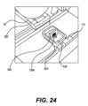
工程468において、トグル282のレバー298が係合して、ロック266を解放する。レバー298の係合は、係止フィンガー286を第一の位置へと動かし、これにより、フィンガーは係止解除され、そして開位置になる。一部の実施形態では、ロック266は、トグル282の開口290内のロッドまたはピンを中心として回転するように、基部262へと回転可能に固定されてもよい。係止フィンガー286は、トグル282の回転とともに回転してもよい。一実施形態では、図24で例証されるように、トグル282上のレバー298が前方に押されて、係止フィンガー286を第一の位置へと動かす。
At
トグル282の前面302から反対側上にあるタブ322は、弾性部材270と接触する。弾性部材270は、片持ち梁と同様に延び、そしてトグル282のタブ322と重ね合わさる。弾性部材270は、係止フィンガー286が係止された閉位置に付勢されるように、トグル282を第二の後方位置に付勢するように、トグル282上に反力を提供する。したがって、ロック266のトグル282上のレバー298が、係止フィンガー286を第一の位置へと動かすように係合すると、タブ322によって弾性部材270に力が加えられる。
A
工程472において、ニコチンポッド組立品用のヒーター組立品524’をホルダー30から取り外す。図23および図24で例証されるように、ヒーター組立品524’は、ノッチ88および支持体切り欠き部110内で、ヒーター組立品524’がホルダー30の縁を通過するまでホルダー30から離れるようにヒーター組立品524’を摺動することによって、ホルダー30から取り外される。次いでニコチンポッド組立品用のヒーター組立品524’は、支持体切り欠き部110から取り外される。
At
工程476において、トグル282のレバー298は解放され、これによりトグル282は第二の位置に戻る。以前に述べたように、弾性部材270のタブ330は、係止フィンガー286が係止された閉位置に付勢されるように、トグル282を第二の後方位置に付勢するように、トグル282上に反力を提供する。
At
工程480において、方法400は終了する。
At
ここで図25を参照すると、ニコチンポッド組立品用の組み立てられたヒーター組立品524’の実施形態が例証されている。ウィック548は、ワイヤループの第一の組536aとワイヤループの第二の組536bとの間に締め付けられ、これによりウィック548はヒーター組立品524’に対して固定される。例示のヒーター組立品は、2019年11月26日に出願された、「NICOTINE POD ASSEMBLIES AND NICOTINE E-VAPING DEVICES」と題される、米国特許出願第16/696,007号に開示され、その開示は、参照によりその全体が本明細書に組み込まれる。
Referring now to Figure 25, an embodiment of an assembled heater assembly 524' for a nicotine pod assembly is illustrated. A
当然のことながら、要素または層が別の要素もしくは層「の上にある」、「に接続される」、「に連結される」、または「を覆う」と言及される時、これはもう一方の要素もしくは層の上に直接あってもよく、それに直接的に接続されてもよく、それに直接的に連結されてもよく、またはそれを直接的に覆ってもよく、あるいは介在する要素もしくは層が存在してもよい。対照的に、要素が別の要素もしくは層「上に直接ある」、「に直接接続されている」、または「に直接連結されている」と言及される時、介在する要素もしくは層は存在しない。同様の数字は、本明細書の全体を通して同様の要素を指す。 It will be appreciated that when an element or layer is referred to as being "overlying," "connected to," "coupled with," or "covering" another element or layer, this refers to the other element or layer. may be directly on, directly connected to, directly coupled to, or directly overlying an element or layer of, or an intervening element or layer of may exist. In contrast, when an element is referred to as being “directly on,” “directly connected to,” or “directly coupled to” another element or layer, there are no intervening elements or layers present. . Like numbers refer to like elements throughout the specification.
当然のことながら、第一の、第二の、第三の、またはこれに類するものなどの用語は、様々な要素、構成要素、領域、層、またはセクションを記述するために本明細書で使用されてもよいが、これらの要素、構成要素、領域、層、またはセクションはこれらの用語によって限定されるべきではない。これらの用語は、一つの要素、構成要素、領域、層、またはセクションを別の領域、層、またはセクションと区別するためにのみ使用される。したがって、下記で考察されている第一の要素、構成要素、領域、層、またはセクションは、例示の実施形態の教示内容から逸脱することなく、第二の要素、構成要素、領域、層、またはセクションと呼ぶことができる。 It will be appreciated that terms such as first, second, third or the like are used herein to describe various elements, components, regions, layers or sections. However, these elements, components, regions, layers or sections should not be limited by these terms. These terms are only used to distinguish one element, component, region, layer or section from another region, layer or section. Thus, a first element, component, region, layer or section discussed below could be removed from a second element, component, region, layer or section without departing from the teachings of the exemplary embodiments. can be called a section.
空間的関係の用語(例えば、「下に」、「下方に」、「下部」、「上方に」、「上部」、およびこれに類するもの)は、図中で例証する際に、一つの要素または特徴と別の要素または特徴との間の関係を記述するための記述の簡単のために本明細書で使用されてもよい。当然のことながら、空間的関係の用語は、図に図示されている向きに加えて、使用時または動作時に装置の異なる向きを包含することが意図されている。例えば、図中の装置をひっくり返した場合、他の要素または特徴部の「下方に」または「下に」と記述されている要素は、その後は他の要素または特徴の「上方に」向きを合わされることになる。したがって、「下方に」という用語は上方と下方の両方の向きを包含する場合がある。装置は別の方法で(90度回転して、または他の向きで)向きを合わされる場合があり、そして本明細書で使用される空間的関係の記述語は適宜に解釈される。 Spatial relationship terms (e.g., "below", "below", "below", "above", "above", and the like) refer to one element when illustrated in the figures. or may be used herein for ease of description to describe the relationship between a feature and another element or feature. It will be appreciated that the spatial relationship terminology is intended to encompass different orientations of the device in use or operation in addition to the orientation illustrated in the figures. For example, if the device in the figures were turned over, an element described as being "below" or "below" another element or feature would then be oriented "above" the other element or feature. will be matched. Thus, the term "downwardly" may encompass both upward and downward orientations. The device may be otherwise oriented (rotated 90 degrees or at other orientations) and the spatial relationship descriptors used herein interpreted accordingly.
本明細書で使用される用語は、様々な例示の実施形態を記述する目的のみのためのものであり、例示の実施形態を限定することを意図しない。本明細書で使用される場合、単数形「一つの(a)」、「一つの(an)」、および「その(the)」は、文脈が明確に別段の指示をしない限り、複数形も含むことが意図される。さらに当然のことながら、本明細書で使用される時、「含む(includes)」、「含む(including)」「備える(comprises)」、および「備える(comprising)」という用語は、述べられた特徴、整数、工程、動作、要素、または構成要素の存在を特定するが、一つ以上の他の特徴、整数、工程、動作、要素、構成要素、およびこれらの群の存在または追加を除外しない。 The terminology used herein is for the purpose of describing various example embodiments only and is not intended to be limiting of example embodiments. As used herein, the singular forms "a," "an," and "the" refer to the plural as well, unless the context clearly dictates otherwise. intended to include It should also be appreciated that the terms "includes," "including," "comprises," and "comprising," as used herein, refer to the features mentioned. , integers, steps, acts, elements or components, but does not exclude the presence or addition of one or more other features, integers, steps, acts, elements, components, and groups thereof.
例示の実施形態は、例示の実施形態の理想的な実施形態(および中間構造)の概略図である断面図を参照しながら本明細書に記述される。このように、例えば、製造技法または公差の結果としてもたらされた、例証の形状からの変形形態が予想される。したがって、例示の実施形態は、本明細書に例証された領域の形状を限定するものとして解釈されるべきでなく、例えば、製造から結果としてもたらされる形状の逸脱を含むべきである。 Example embodiments are described herein with reference to cross-section illustrations that are schematic illustrations of idealized embodiments (and intermediate structures) of example embodiments. As such, variations from the illustrated shapes are anticipated, for example, as a result of manufacturing techniques or tolerances. Accordingly, the example embodiments should not be construed as limiting the shapes of the regions illustrated herein, and should include, for example, deviations in shape resulting from manufacturing.
別段の定義のない限り、本明細書で使用されるすべての用語(技術的用語および科学的用語を含む)は、例示の実施形態が属する技術分野の当業者が一般的に理解しているものと同じ意味を有する。さらに当然のことながら、用語(一般的に使用されている辞書で定義される用語を含む)は、本明細書で明示的にそのように定義されているのでない限り、関連する技術分野の文脈でのそれらの用語の意味と一致する意味を有するものと解釈されるべきであり、また理想的なまたは過度に正式な意味で解釈されない。 Unless otherwise defined, all terms (including technical and scientific terms) used herein are commonly understood by one of ordinary skill in the art to which the illustrative embodiments belong. have the same meaning as It should also be understood that terms (including terms defined in commonly used dictionaries) are defined in the context of the relevant technical field, unless explicitly so defined herein. are to be construed as having a meaning consistent with the meaning of those terms in and not in an idealized or overly formal sense.
例示の実施形態が本明細書に開示される。当然のことながら、他の変形が可能である場合がある。こうした変形は本開示の範囲からの逸脱と見なされるべきではなく、また当業者には明らかであろうすべてのこうした修正は、以下の「特許請求の範囲」の範囲内に含まれることが意図される。 Exemplary embodiments are disclosed herein. Of course, other variations may be possible. Such variations should not be considered a departure from the scope of the present disclosure, and all such modifications that would be apparent to those skilled in the art are intended to be included within the scope of the following claims. be.
Claims (20)
基部と、
前記基部に向かって延び、かつ毛細管作用を介してニコチンプレベイパー製剤を引き出すように構造化されたウィックを受容するように構成されたチャネルを画定する、ウィックフィードと、
前記基部の上面上の平面に沿って移動するように構成された、スライドと、
前記基部の前記上面上に配置されたホルダーと、を備える、設備。 A facility for assembling a heater assembly for a nicotine pod assembly comprising:
a base;
a wick feed defining a channel extending toward said base and configured to receive a wick structured to draw a nicotine pre-vapor formulation through capillary action;
a slide configured to move along a plane on the top surface of the base;
a holder positioned on the top surface of the base.
前記ウィックフィードが、前記ブロックに回転可能に取り付けられ、かつ前記ブロックによって支持される、請求項1~4のいずれか一項に記載の設備。 further comprising a block fixed to the base;
Equipment according to any preceding claim, wherein the wick feed is rotatably mounted on and supported by the block.
前記プレートが前記ブロックに回転可能に取り付けられ、かつ前記ブロックによって支持される、請求項11に記載の設備。 further comprising a block fixed to the base;
12. Equipment according to claim 11, wherein the plate is rotatably mounted on and supported by the block.
ホルダーを用いて、基部に対して前記ヒーター組立品の支持体を固定することと、
前記基部に取り付けられたガイドプレートを用いて、前記支持体のヒーター内でウィックストリップを整列させることであって、毛細管作用を介してニコチンプレベイパー製剤を引き出すように前記ウィックストリップが構造化された、整列させることと、
前記基部に対して摺動するように構成されたブレードを用いて、前記ウィックストリップの一部分を切断することと、
前記基部に対して摺動するように構成されたスライドを用いて、前記ウィックストリップの前記部分の周りに前記ヒーターの一部分を締め付けることと、
前記ホルダーを用いて、前記支持体を前記基部から解放することと、を含む、方法。 A method of assembling a heater assembly for a nicotine pod assembly, said method comprising:
securing a support of the heater assembly to a base with a holder;
Aligning a wick strip within the heater of the support using a guide plate attached to the base, the wick strip being structured to draw the nicotine prevapor formulation through capillary action. , aligning, and
cutting a portion of the wick strip with a blade configured to slide against the base;
clamping a portion of the heater around the portion of the wick strip using a slide configured to slide relative to the base;
releasing the support from the base using the holder.
Applications Claiming Priority (3)
| Application Number | Priority Date | Filing Date | Title |
|---|---|---|---|
| US16/856,476 | 2020-04-23 | ||
| US16/856,476 US11882884B2 (en) | 2020-04-23 | 2020-04-23 | Apparatus and method for assembling a heater assembly for a nicotine pod assembly |
| PCT/EP2021/060752 WO2021214331A1 (en) | 2020-04-23 | 2021-04-23 | Apparatus and method for assembling a heater assembly for a nicotine pod assembly |
Publications (3)
| Publication Number | Publication Date |
|---|---|
| JP2023524636A true JP2023524636A (en) | 2023-06-13 |
| JPWO2021214331A5 JPWO2021214331A5 (en) | 2024-05-07 |
| JP7712952B2 JP7712952B2 (en) | 2025-07-24 |
Family
ID=75746588
Family Applications (1)
| Application Number | Title | Priority Date | Filing Date |
|---|---|---|---|
| JP2022562795A Active JP7712952B2 (en) | 2020-04-23 | 2021-04-23 | Apparatus and method for assembling a heater assembly for a nicotine pod assembly |
Country Status (7)
| Country | Link |
|---|---|
| US (3) | US11882884B2 (en) |
| EP (1) | EP4138592B1 (en) |
| JP (1) | JP7712952B2 (en) |
| KR (1) | KR20230002854A (en) |
| CN (1) | CN115484844A (en) |
| BR (1) | BR112022019024A2 (en) |
| WO (1) | WO2021214331A1 (en) |
Families Citing this family (8)
| Publication number | Priority date | Publication date | Assignee | Title |
|---|---|---|---|---|
| EP3675661B1 (en) * | 2017-08-28 | 2023-06-07 | Juul Labs, Inc. | Wick for vaporizer device |
| GB201717497D0 (en) | 2017-10-24 | 2017-12-06 | British American Tobacco Investments Ltd | A mouthpiece assembly |
| GB201717496D0 (en) | 2017-10-24 | 2017-12-06 | British American Tobacco Investments Ltd | A cartridge for an aerosol provision device |
| GB201717498D0 (en) * | 2017-10-24 | 2017-12-06 | British American Tobacco Investments Ltd | Aerosol provision device |
| WO2021158758A1 (en) | 2020-02-04 | 2021-08-12 | Juul Labs, Inc. | Aerosol dispensing device with disposable container |
| US11882883B2 (en) * | 2020-04-23 | 2024-01-30 | Altria Client Services Llc | Apparatus and method for assembling a heater assembly for a non-nicotine pod assembly |
| US11882884B2 (en) * | 2020-04-23 | 2024-01-30 | Altria Client Services Llc | Apparatus and method for assembling a heater assembly for a nicotine pod assembly |
| CN116062302B (en) * | 2023-02-20 | 2026-01-27 | 立讯电子科技(昆山)有限公司 | Processing bearing device |
Citations (3)
| Publication number | Priority date | Publication date | Assignee | Title |
|---|---|---|---|---|
| US20140261408A1 (en) * | 2013-03-15 | 2014-09-18 | R.J. Reynolds Tobacco Company | Cartridge for an aerosol delivery device and method for assembling a cartridge for a smoking article |
| JP2016503647A (en) * | 2012-12-07 | 2016-02-08 | アール・ジエイ・レイノルズ・タバコ・カンパニー | Apparatus and method for winding a substantially continuous heating element around a substantially continuous core |
| JP2016509361A (en) * | 2013-03-15 | 2016-03-24 | フィリップ・モーリス・プロダクツ・ソシエテ・アノニム | Method for manufacturing a heater assembly using a liquid-filled cartridge |
Family Cites Families (14)
| Publication number | Priority date | Publication date | Assignee | Title |
|---|---|---|---|---|
| EP2113178A1 (en) | 2008-04-30 | 2009-11-04 | Philip Morris Products S.A. | An electrically heated smoking system having a liquid storage portion |
| KR102773348B1 (en) | 2013-03-15 | 2025-02-26 | 레이 스트라티직 홀딩스, 인크. | Heating elements formed from a sheet of a material, input sheets and methods for the production of a plurality of atomizers, cartridge for an aerosol delivery device and method for assembling a cartridge for a smoking article |
| US20170224021A1 (en) * | 2014-10-27 | 2017-08-10 | Huizhou Kimree Technology Co., Ltd. | Forming method for heating element of electronic cigarette and manufacturing method for atomization assembly |
| WO2016065605A1 (en) * | 2014-10-31 | 2016-05-06 | 惠州市吉瑞科技有限公司 | Electric heating wire winding apparatus and manufacturing method for electric heating wire component |
| CN206525545U (en) * | 2014-10-31 | 2017-09-29 | 惠州市吉瑞科技有限公司深圳分公司 | A kind of heating wire Winder |
| CN107249365B (en) | 2015-03-10 | 2021-05-18 | 日本烟草产业株式会社 | Non-combustible aroma aspirator, atomizing unit and manufacturing method thereof, atomizing unit assembly |
| KR102618134B1 (en) | 2015-10-22 | 2023-12-27 | 필립모리스 프로덕츠 에스.에이. | Aerosol-generating articles, aerosol-generating systems and methods for manufacturing aerosol-generating articles |
| WO2018051346A1 (en) | 2016-09-14 | 2018-03-22 | Yossef Raichman | Smoking device |
| CN211932559U (en) | 2018-10-15 | 2020-11-17 | 尤尔实验室有限公司 | Evaporator device and heating element and atomizer assembly of evaporator device |
| JP2020161215A (en) * | 2019-03-25 | 2020-10-01 | Nittoku株式会社 | Coil winding device and coil winding method |
| US11490656B2 (en) | 2019-11-26 | 2022-11-08 | Altria Client Services Llc | Nicotine pod assemblies and nicotine e-vaping devices |
| US11528938B2 (en) | 2019-11-26 | 2022-12-20 | Altria Client Services Llc | Non-nicotine pod assemblies and non-nicotine e-vaping devices |
| US11882884B2 (en) * | 2020-04-23 | 2024-01-30 | Altria Client Services Llc | Apparatus and method for assembling a heater assembly for a nicotine pod assembly |
| US11882883B2 (en) * | 2020-04-23 | 2024-01-30 | Altria Client Services Llc | Apparatus and method for assembling a heater assembly for a non-nicotine pod assembly |
-
2020
- 2020-04-23 US US16/856,476 patent/US11882884B2/en active Active
-
2021
- 2021-04-23 CN CN202180030085.6A patent/CN115484844A/en active Pending
- 2021-04-23 WO PCT/EP2021/060752 patent/WO2021214331A1/en not_active Ceased
- 2021-04-23 JP JP2022562795A patent/JP7712952B2/en active Active
- 2021-04-23 KR KR1020227040330A patent/KR20230002854A/en active Pending
- 2021-04-23 EP EP21722392.4A patent/EP4138592B1/en active Active
- 2021-04-23 BR BR112022019024A patent/BR112022019024A2/en unknown
-
2023
- 2023-12-28 US US18/398,584 patent/US12439974B2/en active Active
-
2025
- 2025-07-25 US US19/280,597 patent/US20250344770A1/en active Pending
Patent Citations (3)
| Publication number | Priority date | Publication date | Assignee | Title |
|---|---|---|---|---|
| JP2016503647A (en) * | 2012-12-07 | 2016-02-08 | アール・ジエイ・レイノルズ・タバコ・カンパニー | Apparatus and method for winding a substantially continuous heating element around a substantially continuous core |
| US20140261408A1 (en) * | 2013-03-15 | 2014-09-18 | R.J. Reynolds Tobacco Company | Cartridge for an aerosol delivery device and method for assembling a cartridge for a smoking article |
| JP2016509361A (en) * | 2013-03-15 | 2016-03-24 | フィリップ・モーリス・プロダクツ・ソシエテ・アノニム | Method for manufacturing a heater assembly using a liquid-filled cartridge |
Also Published As
| Publication number | Publication date |
|---|---|
| BR112022019024A2 (en) | 2022-11-01 |
| JP7712952B2 (en) | 2025-07-24 |
| CN115484844A (en) | 2022-12-16 |
| WO2021214331A1 (en) | 2021-10-28 |
| US11882884B2 (en) | 2024-01-30 |
| US20250344770A1 (en) | 2025-11-13 |
| US12439974B2 (en) | 2025-10-14 |
| US20240130439A1 (en) | 2024-04-25 |
| EP4138592B1 (en) | 2024-03-13 |
| EP4138592A1 (en) | 2023-03-01 |
| US20210329976A1 (en) | 2021-10-28 |
| KR20230002854A (en) | 2023-01-05 |
| EP4138592C0 (en) | 2024-03-13 |
Similar Documents
| Publication | Publication Date | Title |
|---|---|---|
| JP7712952B2 (en) | Apparatus and method for assembling a heater assembly for a nicotine pod assembly | |
| US20250344769A1 (en) | Apparatus and method for assembling a heater assembly for a non-nicotine pod assembly | |
| CN101567531B (en) | Stripping pliers | |
| CN114206227A (en) | Surgical stapling device with bending tool assembly | |
| JP2001235654A (en) | Optical connector | |
| US8414200B2 (en) | Device for installing an optical fibre in a splice connector | |
| TW200940294A (en) | Paper trimmer | |
| RU2827971C1 (en) | Device and method for assembling heating unit for nicotine module | |
| US20230118410A1 (en) | Everyday retractable utility cutter | |
| JPS5946619B2 (en) | Shaving head of dry shaving device | |
| JPWO2021214331A5 (en) | ||
| US1690133A (en) | Shaving implement | |
| CN1334763A (en) | Disposable cutting head for clippers | |
| JP5422359B2 (en) | Microtome sword holder device | |
| CN222987038U (en) | Sheet cutting device | |
| JP3936145B2 (en) | Optical fiber connection tool | |
| TWI310350B (en) | Clip binding device with punch | |
| JPH11258430A (en) | Optical fiber coating removal equipment | |
| JPWO2021216266A5 (en) | ||
| CN212206795U (en) | An EVA film sample preparation device | |
| JPH0339908A (en) | Optical fiber holder | |
| SU629062A1 (en) | Elextric razor head | |
| JP2005156321A (en) | Microtome blade and holder device of microtome blade | |
| CN120680585A (en) | Large tissue section embedding clamping assembly | |
| JP2011013344A (en) | Assembling tool of optical connector and method of assembling optical connector |
Legal Events
| Date | Code | Title | Description |
|---|---|---|---|
| A521 | Request for written amendment filed |
Free format text: JAPANESE INTERMEDIATE CODE: A523 Effective date: 20240423 |
|
| A621 | Written request for application examination |
Free format text: JAPANESE INTERMEDIATE CODE: A621 Effective date: 20240423 |
|
| A131 | Notification of reasons for refusal |
Free format text: JAPANESE INTERMEDIATE CODE: A131 Effective date: 20250303 |
|
| A521 | Request for written amendment filed |
Free format text: JAPANESE INTERMEDIATE CODE: A523 Effective date: 20250603 |
|
| TRDD | Decision of grant or rejection written | ||
| A01 | Written decision to grant a patent or to grant a registration (utility model) |
Free format text: JAPANESE INTERMEDIATE CODE: A01 Effective date: 20250612 |
|
| A61 | First payment of annual fees (during grant procedure) |
Free format text: JAPANESE INTERMEDIATE CODE: A61 Effective date: 20250711 |
|
| R150 | Certificate of patent or registration of utility model |
Ref document number: 7712952 Country of ref document: JP Free format text: JAPANESE INTERMEDIATE CODE: R150 |