JP2023511451A - An actuation system for an auxiliary device attached to a drug delivery device - Google Patents
An actuation system for an auxiliary device attached to a drug delivery device Download PDFInfo
- Publication number
- JP2023511451A JP2023511451A JP2022545419A JP2022545419A JP2023511451A JP 2023511451 A JP2023511451 A JP 2023511451A JP 2022545419 A JP2022545419 A JP 2022545419A JP 2022545419 A JP2022545419 A JP 2022545419A JP 2023511451 A JP2023511451 A JP 2023511451A
- Authority
- JP
- Japan
- Prior art keywords
- module
- drug delivery
- battery
- delivery device
- housing
- Prior art date
- Legal status (The legal status is an assumption and is not a legal conclusion. Google has not performed a legal analysis and makes no representation as to the accuracy of the status listed.)
- Pending
Links
Images


Classifications
-
- A—HUMAN NECESSITIES
- A61—MEDICAL OR VETERINARY SCIENCE; HYGIENE
- A61M—DEVICES FOR INTRODUCING MEDIA INTO, OR ONTO, THE BODY; DEVICES FOR TRANSDUCING BODY MEDIA OR FOR TAKING MEDIA FROM THE BODY; DEVICES FOR PRODUCING OR ENDING SLEEP OR STUPOR
- A61M5/00—Devices for bringing media into the body in a subcutaneous, intra-vascular or intramuscular way; Accessories therefor, e.g. filling or cleaning devices, arm-rests
- A61M5/178—Syringes
- A61M5/31—Details
- A61M5/315—Pistons; Piston-rods; Guiding, blocking or restricting the movement of the rod or piston; Appliances on the rod for facilitating dosing ; Dosing mechanisms
- A61M5/31565—Administration mechanisms, i.e. constructional features, modes of administering a dose
- A61M5/31566—Means improving security or handling thereof
-
- A—HUMAN NECESSITIES
- A61—MEDICAL OR VETERINARY SCIENCE; HYGIENE
- A61M—DEVICES FOR INTRODUCING MEDIA INTO, OR ONTO, THE BODY; DEVICES FOR TRANSDUCING BODY MEDIA OR FOR TAKING MEDIA FROM THE BODY; DEVICES FOR PRODUCING OR ENDING SLEEP OR STUPOR
- A61M5/00—Devices for bringing media into the body in a subcutaneous, intra-vascular or intramuscular way; Accessories therefor, e.g. filling or cleaning devices, arm-rests
- A61M5/178—Syringes
- A61M5/31—Details
- A61M5/315—Pistons; Piston-rods; Guiding, blocking or restricting the movement of the rod or piston; Appliances on the rod for facilitating dosing ; Dosing mechanisms
- A61M5/31565—Administration mechanisms, i.e. constructional features, modes of administering a dose
- A61M5/31566—Means improving security or handling thereof
- A61M5/31568—Means keeping track of the total dose administered, e.g. since the cartridge was inserted
-
- A—HUMAN NECESSITIES
- A61—MEDICAL OR VETERINARY SCIENCE; HYGIENE
- A61M—DEVICES FOR INTRODUCING MEDIA INTO, OR ONTO, THE BODY; DEVICES FOR TRANSDUCING BODY MEDIA OR FOR TAKING MEDIA FROM THE BODY; DEVICES FOR PRODUCING OR ENDING SLEEP OR STUPOR
- A61M5/00—Devices for bringing media into the body in a subcutaneous, intra-vascular or intramuscular way; Accessories therefor, e.g. filling or cleaning devices, arm-rests
- A61M5/178—Syringes
- A61M5/20—Automatic syringes, e.g. with automatically actuated piston rod, with automatic needle injection, filling automatically
-
- A—HUMAN NECESSITIES
- A61—MEDICAL OR VETERINARY SCIENCE; HYGIENE
- A61M—DEVICES FOR INTRODUCING MEDIA INTO, OR ONTO, THE BODY; DEVICES FOR TRANSDUCING BODY MEDIA OR FOR TAKING MEDIA FROM THE BODY; DEVICES FOR PRODUCING OR ENDING SLEEP OR STUPOR
- A61M5/00—Devices for bringing media into the body in a subcutaneous, intra-vascular or intramuscular way; Accessories therefor, e.g. filling or cleaning devices, arm-rests
- A61M5/178—Syringes
- A61M5/31—Details
- A61M5/315—Pistons; Piston-rods; Guiding, blocking or restricting the movement of the rod or piston; Appliances on the rod for facilitating dosing ; Dosing mechanisms
- A61M5/31533—Dosing mechanisms, i.e. setting a dose
- A61M5/31545—Setting modes for dosing
-
- A—HUMAN NECESSITIES
- A61—MEDICAL OR VETERINARY SCIENCE; HYGIENE
- A61M—DEVICES FOR INTRODUCING MEDIA INTO, OR ONTO, THE BODY; DEVICES FOR TRANSDUCING BODY MEDIA OR FOR TAKING MEDIA FROM THE BODY; DEVICES FOR PRODUCING OR ENDING SLEEP OR STUPOR
- A61M5/00—Devices for bringing media into the body in a subcutaneous, intra-vascular or intramuscular way; Accessories therefor, e.g. filling or cleaning devices, arm-rests
- A61M5/178—Syringes
- A61M5/31—Details
- A61M5/32—Needles; Details of needles pertaining to their connection with syringe or hub; Accessories for bringing the needle into, or holding the needle on, the body; Devices for protection of needles
- A61M5/3202—Devices for protection of the needle before use, e.g. caps
- A61M5/3204—Needle cap remover, i.e. devices to dislodge protection cover from needle or needle hub, e.g. deshielding devices
-
- G—PHYSICS
- G16—INFORMATION AND COMMUNICATION TECHNOLOGY [ICT] SPECIALLY ADAPTED FOR SPECIFIC APPLICATION FIELDS
- G16H—HEALTHCARE INFORMATICS, i.e. INFORMATION AND COMMUNICATION TECHNOLOGY [ICT] SPECIALLY ADAPTED FOR THE HANDLING OR PROCESSING OF MEDICAL OR HEALTHCARE DATA
- G16H20/00—ICT specially adapted for therapies or health-improving plans, e.g. for handling prescriptions, for steering therapy or for monitoring patient compliance
- G16H20/10—ICT specially adapted for therapies or health-improving plans, e.g. for handling prescriptions, for steering therapy or for monitoring patient compliance relating to drugs or medications, e.g. for ensuring correct administration to patients
- G16H20/17—ICT specially adapted for therapies or health-improving plans, e.g. for handling prescriptions, for steering therapy or for monitoring patient compliance relating to drugs or medications, e.g. for ensuring correct administration to patients delivered via infusion or injection
-
- A—HUMAN NECESSITIES
- A61—MEDICAL OR VETERINARY SCIENCE; HYGIENE
- A61M—DEVICES FOR INTRODUCING MEDIA INTO, OR ONTO, THE BODY; DEVICES FOR TRANSDUCING BODY MEDIA OR FOR TAKING MEDIA FROM THE BODY; DEVICES FOR PRODUCING OR ENDING SLEEP OR STUPOR
- A61M5/00—Devices for bringing media into the body in a subcutaneous, intra-vascular or intramuscular way; Accessories therefor, e.g. filling or cleaning devices, arm-rests
- A61M5/178—Syringes
- A61M5/20—Automatic syringes, e.g. with automatically actuated piston rod, with automatic needle injection, filling automatically
- A61M2005/2006—Having specific accessories
-
- A—HUMAN NECESSITIES
- A61—MEDICAL OR VETERINARY SCIENCE; HYGIENE
- A61M—DEVICES FOR INTRODUCING MEDIA INTO, OR ONTO, THE BODY; DEVICES FOR TRANSDUCING BODY MEDIA OR FOR TAKING MEDIA FROM THE BODY; DEVICES FOR PRODUCING OR ENDING SLEEP OR STUPOR
- A61M2205/00—General characteristics of the apparatus
- A61M2205/35—Communication
- A61M2205/3546—Range
- A61M2205/3561—Range local, e.g. within room or hospital
-
- A—HUMAN NECESSITIES
- A61—MEDICAL OR VETERINARY SCIENCE; HYGIENE
- A61M—DEVICES FOR INTRODUCING MEDIA INTO, OR ONTO, THE BODY; DEVICES FOR TRANSDUCING BODY MEDIA OR FOR TAKING MEDIA FROM THE BODY; DEVICES FOR PRODUCING OR ENDING SLEEP OR STUPOR
- A61M2205/00—General characteristics of the apparatus
- A61M2205/35—Communication
- A61M2205/3576—Communication with non implanted data transmission devices, e.g. using external transmitter or receiver
-
- A—HUMAN NECESSITIES
- A61—MEDICAL OR VETERINARY SCIENCE; HYGIENE
- A61M—DEVICES FOR INTRODUCING MEDIA INTO, OR ONTO, THE BODY; DEVICES FOR TRANSDUCING BODY MEDIA OR FOR TAKING MEDIA FROM THE BODY; DEVICES FOR PRODUCING OR ENDING SLEEP OR STUPOR
- A61M2205/00—General characteristics of the apparatus
- A61M2205/50—General characteristics of the apparatus with microprocessors or computers
- A61M2205/52—General characteristics of the apparatus with microprocessors or computers with memories providing a history of measured variating parameters of apparatus or patient
-
- A—HUMAN NECESSITIES
- A61—MEDICAL OR VETERINARY SCIENCE; HYGIENE
- A61M—DEVICES FOR INTRODUCING MEDIA INTO, OR ONTO, THE BODY; DEVICES FOR TRANSDUCING BODY MEDIA OR FOR TAKING MEDIA FROM THE BODY; DEVICES FOR PRODUCING OR ENDING SLEEP OR STUPOR
- A61M2205/00—General characteristics of the apparatus
- A61M2205/82—Internal energy supply devices
- A61M2205/8206—Internal energy supply devices battery-operated
Landscapes
- Health & Medical Sciences (AREA)
- Engineering & Computer Science (AREA)
- Public Health (AREA)
- General Health & Medical Sciences (AREA)
- Heart & Thoracic Surgery (AREA)
- Veterinary Medicine (AREA)
- Hematology (AREA)
- Life Sciences & Earth Sciences (AREA)
- Animal Behavior & Ethology (AREA)
- Anesthesiology (AREA)
- Vascular Medicine (AREA)
- Biomedical Technology (AREA)
- Chemical & Material Sciences (AREA)
- Bioinformatics & Cheminformatics (AREA)
- Medicinal Chemistry (AREA)
- Epidemiology (AREA)
- Medical Informatics (AREA)
- Primary Health Care (AREA)
- Infusion, Injection, And Reservoir Apparatuses (AREA)
- Medicines That Contain Protein Lipid Enzymes And Other Medicines (AREA)
Abstract
本開示は、既存の設計の薬剤送達デバイスに対して装着される補助デバイスの作動システムに関する。薬剤送達デバイスから保護キャップまたは他のカバーを除去することにより、電気接触子同士の間からブロック要素が引かれて、バッテリモジュールと電源との間の回路を閉じ、それによりバッテリモジュールを作動させる。補助デバイスは、薬剤送達デバイスの使用に関する情報を例えばスマートデバイスなどの外部デバイスに対して通信するための送信機をさらに備え得る。また、固有識別データを有するメモリストレージ要素が、備えられ得る。また、本開示は、補助デバイスが装着された薬剤送達デバイスに関する。
The present disclosure relates to an auxiliary device actuation system that attaches to a drug delivery device of existing design. Removal of the protective cap or other cover from the drug delivery device pulls the blocking element from between the electrical contacts to close the circuit between the battery module and the power source, thereby activating the battery module. The ancillary device may further comprise a transmitter for communicating information regarding use of the medication delivery device to an external device, eg a smart device. A memory storage element having unique identification data may also be provided. The present disclosure also relates to drug delivery devices fitted with ancillary devices.
Description
本発明は、薬剤送達デバイスに対して装着される補助デバイスであって、薬剤送達デバイスに関する固有情報を送信し得る情報プロバイダとして機能することが可能な補助デバイスに関する。この補助デバイスは、薬剤送達デバイスからカバーを除去することにより作動される。補助デバイスは、薬剤送達デバイスの使用をモニタリングし、外部スマートデバイスと通信を行い得る。 The present invention relates to an auxiliary device attached to a medication delivery device, the auxiliary device being capable of acting as an information provider capable of transmitting unique information about the medication delivery device. This auxiliary device is activated by removing the cover from the drug delivery device. Auxiliary devices may monitor use of the drug delivery device and communicate with external smart devices.
特に自己投与により薬剤送達を行うように設計された薬剤送達デバイスが、長年にわたり市場に存在している。これらのデバイスは、非専門家による取扱いのために、使用が容易で直観的なものである必要がある。さらに、多くの薬剤が患者にとって必須であるまたは少なくとも非常に重要なものであるため、医師および他の専門家からは、指示した計画通りに患者が自己投与を行ったという情報を取得したいという要望がある。この要求されている情報には、薬剤タイプ、送達時間、日時、用量サイズ、無菌性などの安全情報が含まれ得る。また、薬剤もしくはデバイス自体が偽物であるか否か、または不正開封されているか否かが非常に重要である。同様に、医師にとって有益となり得る情報は、薬剤が正しい手順でおよび使用命令に従って摂取されたか否か、薬剤送達の前および最中において所定温度にて薬剤が維持されていたか、正しい注入深度で使用されたか、ならびに薬剤送達デバイスが注射器である場合に正しい注入速度で使用されたかに関するものがある。 Drug delivery devices specifically designed for drug delivery by self-administration have existed on the market for many years. These devices need to be easy and intuitive to use for handling by non-professionals. In addition, many drugs are essential or at least very important to the patient, and the desire to obtain information from physicians and other professionals that the patient self-administered according to the prescribed schedule. There is This requested information may include safety information such as drug type, time of delivery, date and time, dose size, sterility. It is also very important whether the drug or device itself is counterfeit or tampered with. Similarly, information that may be useful to the physician is whether the drug was taken in the correct procedure and according to instructions for use, whether the drug was maintained at a given temperature before and during drug delivery, and whether the drug was used at the correct infusion depth. was used, and if the drug delivery device was a syringe, was it used at the correct infusion rate.
薬剤送達デバイスから情報を取得するためのシステムが知られている。例えば、特許文献1は、薬剤情報を表示および配信するためのシステムについて開示しており、薬剤送達デバイスが、例えばセルラー電話もしくは携帯電話またはパーソナルデジタルアシスタント(PDA)などの外部デバイスとの通信が可能な通信機構と共に構成される。好ましい通信規格はBluetooth(登録商標)である。この薬剤送達デバイスは、例えば用量送達シーケンスなどをモニタリングおよび記録するための複数のセンサと共に構成される。この案は、外部デバイスの機能を、例えば外部デバイスのディスプレイ、プロセッサ、キーボード等を使用するというものであり、かようなフィーチャを備える薬剤送達デバイスを提供するものではない。こういった機能を外部デバイスに移転することにより、かかる機能を有する薬剤送達デバイスに比べて、本薬剤送達デバイスのコストが削減される。 Systems are known for obtaining information from drug delivery devices. For example, US Pat. No. 6,200,000 discloses a system for displaying and distributing drug information, wherein a drug delivery device is capable of communicating with external devices such as cellular or mobile phones or personal digital assistants (PDAs). communication mechanism. A preferred communication standard is Bluetooth®. The drug delivery device is configured with a plurality of sensors for monitoring and recording eg dose delivery sequences. This proposal uses the functionality of the external device, eg, the external device's display, processor, keyboard, etc., and does not provide a drug delivery device with such features. Transferring these functions to an external device reduces the cost of the drug delivery device as compared to drug delivery devices having such functions.
しかし、特許文献1によるこの解決策の欠点は、Bluetooth(登録商標)回路、または例えばANTもしくはZigBeeなどの同様の無線通信システムが、薬剤送達デバイスのハウジング内に組み込まれる点である。回路に電力供給するためのバッテリを有するこの通信システムは、薬剤送達デバイス内の専用空間を必要とする。追加バッテリモジュールを収容するために既存のデバイス設計に改ざんを加えると、予期せぬ規制上の問題に抵触し得る。既知のデータ収集デバイスのもう1つの問題は、バッテリモジュールが製造され薬剤送達デバイスに対して装着される時点において、電源が電気回路に対して直接的に接続される点である。これは、早期におけるバッテリ消耗を引き起こし得る。さらに、かかるシステムは、バッテリモジュールを作動させる個別のおよび特定のステップのユーザによる実施を必要とし、これは常に正常に実施されるとは限らない場合がある。 However, a drawback of this solution according to WO 2005/030003 is that the Bluetooth® circuit or similar wireless communication system, eg ANT or ZigBee, is integrated into the housing of the drug delivery device. This communication system, which has a battery to power the circuitry, requires dedicated space within the drug delivery device. Tampering with existing device designs to accommodate additional battery modules may run into unforeseen regulatory issues. Another problem with known data collection devices is that the power source is directly connected to the electrical circuit at the time the battery module is manufactured and attached to the drug delivery device. This can cause premature battery drain. Moreover, such systems require the user to perform discrete and specific steps to activate the battery modules, which may not always be successfully performed.
したがって、既存の設計を修正することまたは通信システムが提供し得る追加機能を既存の設計に容易に与えることは、さほど容易ではない。そのため、自動化された、および薬剤送達デバイスの通常使用の一部として実施される作動システムを提供することが必要である。 Therefore, it is not so easy to modify an existing design or to easily give it additional functionality that a communication system can provide. Therefore, there is a need to provide an actuation system that is automated and implemented as part of normal use of drug delivery devices.
本発明の目的は、既存の薬剤送達デバイスに対して装着可能な補助デバイスの作動機構を提供することである。この装着は、薬剤送達デバイスの既存の設計を修正または他の方法で変更することを必要としない。1つの特に好ましい補助デバイスは、複数の異なる薬剤送達デバイス上でまたはそれらと共に使用することが可能であり、とりわけ薬剤の自己投与用の薬剤送達デバイス上で使用されるように構成され得る、情報プロバイダデバイスである。好ましくは、かかる情報プロバイダと共に構成された薬剤送達デバイスは、市場において一般的である従来の外部スマートデバイスと共に使用することが可能であり、自己投与用の薬剤送達デバイスを取り扱う患者の大半が使用可能なものである。 It is an object of the present invention to provide an auxiliary device actuation mechanism that can be attached to existing drug delivery devices. This attachment does not require modifying or otherwise altering the existing design of the drug delivery device. One particularly preferred ancillary device is an information provider capable of being used on or in conjunction with a plurality of different drug delivery devices, and in particular configured for use on drug delivery devices for self-administration of drugs. Device. Preferably, a drug delivery device configured with such an information provider can be used with conventional external smart devices that are common in the market and can be used by the majority of patients dealing with drug delivery devices for self-administration. It is.
本開示では、「遠位方向」という用語が使用される場合に、これは、薬剤送達デバイスの使用中において用量送達部位から離れる方向を向いた方向を示す。「遠位部分/遠位端部」という用語が使用される場合に、これは、薬剤送達デバイスの使用下において用量送達部位から最も遠くに離れて位置する送達デバイスの部分/端部または送達デバイスの部材の部分/端部を示す。これと対応して、「近位方向」という用語が使用される場合に、これは、薬剤送達デバイスの使用中において用量送達部位に向かう方向を向いた方向を示す。「近位部分/近位端部」という用語が使用される場合に、これは、薬剤送達デバイスの使用下において用量送達部位から最も近くに位置する薬剤送達デバイスの部分/端部または薬剤送達デバイスの部材の部分/端部を示す。 In this disclosure, when the term "distal direction" is used, it indicates the direction facing away from the dose delivery site during use of the drug delivery device. When the term "distal portion/distal end" is used, this refers to the portion/end of the delivery device located furthest away from the dose delivery site under use of the drug delivery device or the delivery device indicates a part/end of a member of Correspondingly, when the term "proximal direction" is used, it denotes the direction facing towards the dose delivery site during use of the drug delivery device. When the term "proximal portion/proximal end" is used, this refers to the portion/end of the drug delivery device or the drug delivery device that is located closest to the dose delivery site under use of the drug delivery device. indicates a part/end of a member of
さらに、「長手方向の」、「長手方向に」、「軸方向に」、および「軸方向の」という用語は、典型的にはデバイスおよび/または構成要素の最長延在部の方向における、デバイスまたはデバイスの構成要素に沿って近位端部から遠位端部まで延在する方向を示す。 Furthermore, the terms “longitudinal,” “longitudinal,” “axially,” and “axially” typically refer to the direction of the device and/or component along the direction of the longest extension of the device. or directions extending from the proximal end to the distal end along the components of the device.
同様に、「横方向の(transverse, transversal)」および「横方向に」という用語は、長手方向に対してほぼ垂直となる方向を示す。 Similarly, the terms "transverse, transversal" and "laterally" refer to directions that are generally perpendicular to the longitudinal direction.
本明細書において、「薬剤」という用語は、例えばカニューレまたは中空ニードルなどの送達手段を通り制御的に送られることが可能な、例えば液体、溶液、ゲル、または微細懸濁液などの、任意の薬剤含有流動性医薬品を包含するように意図される。代表的な薬剤としては、固体形態(調剤済み)および液体形態の両方における、例えばペプチド、タンパク質、ホルモン、生物由来製剤もしくは活性剤、ホルモン剤および遺伝子ベース剤、栄養調製物、および他の物質などの調合薬が含まれる。例示の実施形態の説明においては、インスリンの使用が参照とされる。これに対応して、「皮下」注入(infusion, injection)は、被験者に対する任意の経皮送達方法を包含するように意図される。 As used herein, the term "medicament" refers to any drug, e.g., a liquid, solution, gel, or microsuspension, capable of being controllably delivered through a delivery means, e.g., a cannula or hollow needle. It is intended to encompass drug-containing flowable pharmaceuticals. Representative agents include, for example, peptides, proteins, hormones, biological or active agents, hormonal and genetically-based agents, nutritional preparations, and other substances, both in solid (pre-formulated) and liquid form. including the preparation of In the description of the exemplary embodiments reference is made to the use of insulin. Correspondingly, "subcutaneous" infusion, injection is intended to encompass any method of transdermal delivery to a subject.
本開示において、「モジュール」という用語は、例えば電子構成要素または電子構成要素および関連配線のアセンブリなどの、それ自体において規定タスクを実施し他の同様のユニットとリンクされてより大型のシステムを形成し得る、自己完結型のユニットまたはアイテムを包含するように意図される。 In this disclosure, the term "module" refers to an electronic component or an assembly of electronic components and associated wiring, for example, which in itself performs a defined task and is linked with other similar units to form a larger system. It is intended to encompass self-contained units or items that may be
本発明の主要な態様によれば、補助デバイスは、電力が補助デバイスにまたは補助デバイスから供給されない接続解除状態に最初にあるバッテリによって電力供給される。換言すれば、補助デバイスは、例えば製造または組み立ての最中などのデバイスの使用前に薬剤送達デバイスに対して、バッテリが補助デバイスの他の構成要素との電気接続を一時的に電気的に絶縁された状態である非通電状態において装着されることが可能である。バッテリは、機械的に開かれた常時閉スイッチの使用または2つの電気接触子間に位置決めされる絶縁材料シート、絶縁材料リボン、もしくは絶縁材料ストリップの使用によって、絶縁状態または接続解除状態に維持される。常時閉スイッチを開状態に保持することは、例えば常時閉スイッチを開位置に保持するスイッチブロックなどの、スイッチに対して適用された除去可能な機械的介入物を介して実現され得る。この機械的介入物を除去することにより、スイッチは閉じられ、したがってバッテリが回路に接続される。同様に、絶縁材料を除去することにより、電気接触子同士が閉じられるかまたは他の方法で一体になり、それにより電気接続部が形成されて、バッテリからの電気がこれらの接触子を通りおよびこれらの接触子間を流れ、したがって他の電気構成要素に対して接続された電気回路が閉じられるまたは通電される。以降においては「ブロック要素」とまとめて呼ばれる機械的介入物または絶縁材料を電気接触子間から除去することは、従来のラインスイッチを閉じることと類似する。 According to a primary aspect of the invention, the auxiliary device is powered by a battery that is initially in a disconnected state in which no power is supplied to or from the auxiliary device. In other words, the ancillary device may temporarily electrically isolate the battery from electrical connections with other components of the ancillary device to the drug delivery device prior to use of the device, such as during manufacture or assembly. It can be installed in a non-energized state, which is a state in which it is turned on. The battery is maintained insulated or disconnected by the use of a normally closed switch that is mechanically opened or by the use of a sheet, ribbon, or strip of insulating material positioned between two electrical contacts. be. Holding the normally closed switch in the open state may be accomplished via a removable mechanical intervention applied to the switch, such as a switch block that holds the normally closed switch in the open position. By removing this mechanical intervention, the switch is closed, thus connecting the battery to the circuit. Similarly, the removal of the insulating material closes or otherwise brings together the electrical contacts, thereby forming an electrical connection to allow electricity from the battery to pass through and through these contacts. An electrical circuit flowing between these contacts and thus connected to other electrical components is closed or energized. Removing the mechanical intervention or insulating material, hereinafter collectively referred to as "blocking elements", from between the electrical contacts is analogous to closing a conventional line switch.
好ましくは、補助デバイスからブロック要素を物理的に除去することは、薬剤送達デバイスを使用する所要ステップの一部として達成される。例えば、薬剤送達デバイスの場合に、用量送達出口部材の保護キャップまたは他のカバーの除去は、通常は薬剤送達デバイスの使用前に必要となる。キャップの除去をブロック要素除去手順に組み込むことは、好ましい方法である。なぜならば、これによりデバイスユーザが別個のステップまたは手順を実施する必要性が解消されるからである。この薬剤送達デバイスからのキャップまたはカバーの同時的な除去と、補助デバイスの作動とは、薬剤送達デバイス上に位置するキャップまたは他のカバーに対してブロック要素を連結することによって実現され得る。キャップに対してブロック要素をしっかりとかつ強力に連結することにより、ユーザが薬剤送達デバイスからキャップを除去し廃棄することによって、電気接触子間からブロック要素が完全に除去されることが確保される。 Preferably, physically removing the blocking element from the auxiliary device is accomplished as part of the required steps of using the drug delivery device. For example, in the case of drug delivery devices, removal of a protective cap or other cover on the dose delivery outlet member is usually required prior to use of the drug delivery device. Incorporating cap removal into the blocking element removal procedure is a preferred method. This is because it eliminates the need for the device user to perform separate steps or procedures. Simultaneous removal of the cap or cover from the drug delivery device and actuation of the auxiliary device may be achieved by coupling a blocking element to the cap or other cover located on the drug delivery device. Firmly and strongly coupling the blocking element to the cap ensures that removal and disposal of the cap from the drug delivery device by the user completely removes the blocking element from between the electrical contacts. .
薬剤送達デバイスのハウジングの近位端部から保護キャップを除去することは、ハウジングに対するキャップの純直線移動もしくは純軸方向移動によって、キャップの純回転によって、または回転移動および軸方向移動の両者の組合せによって実現される。キャップがハウジングの近位端部から分離される様態に関わらず、本開示の作動機構は、キャップに対して装着されるブロック要素がキャップ除去の最中にキャップに対して固定的に装着された状態に留まるように構成される。これにより、ブロック要素は接触子間から完全に除去され、したがって結果として補助デバイスがバッテリにより通電されバッテリから電力を受領するように電気回路が閉じられることが確保される。 Removal of the protective cap from the proximal end of the housing of the drug delivery device can be by pure linear or pure axial movement of the cap relative to the housing, by pure rotation of the cap, or a combination of both rotational and axial movements. realized by Regardless of how the cap is separated from the proximal end of the housing, the actuation mechanism of the present disclosure ensures that the blocking element attached to the cap is fixedly attached to the cap during cap removal. configured to stay in state. This ensures that the blocking element is completely removed from between the contacts, thus resulting in a closed electrical circuit so that the auxiliary device is energized by and receives power from the battery.
本開示の可能な一実施形態は、薬剤送達デバイスに対して装着された補助デバイスを作動するためのシステムに関する。この薬剤送達デバイスは、近位端部を有するハウジングと、ハウジング内に位置決めされた薬剤容器と、この近位端部の終端部を介してアクセス可能な用量送達出口とを備える。キャップが薬剤送達デバイスから完全に除去されるまで、用量送達出口がアクセス不能となるように、除去可能キャップがハウジングの近位端部に対して装着される。補助デバイスは、ハウジングに対して、好ましくはハウジングの近位端部に対して、またはキャップに対して装着されるバッテリモジュールを備える。このバッテリモジュールは、バッテリと、接触パッドと、バッテリおよび接触パッドに対して動作的に連結されたスイッチとを備え得る。スイッチの一部が、バッテリモジュールがハウジングに対して装着される場合に除去可能キャップに対して直接的に連結されるか、またはスイッチの一部が、バッテリモジュールがキャップに対して装着される場合にハウジングに対して直接的に連結される。追加的には、補助デバイスは、バッテリモジュールに対して接続可能であるかまたはバッテリモジュールの一部として含まれ、外部デバイスにデータを送信するように構成された、通信モジュールをさらに備える。レコーダが、バッテリモジュールの一部としてまたは通信モジュールの一部として備えられ得る。このレコーダは、薬剤送達デバイスに関する情報を取得および記憶するように構成される。好ましくは、スイッチは、最初は、レコーダがバッテリから電力を受領することが防止された/バッテリから電力を受領しない第1の状態にあり、ハウジングに対するキャップの近位方向移動により、バッテリがレコーダおよび/または通信モジュールに対して電力を供給する第2の状態へとスイッチが変更される。 One possible embodiment of the present disclosure relates to a system for actuating an auxiliary device attached to a drug delivery device. The drug delivery device comprises a housing having a proximal end, a drug container positioned within the housing, and a dose delivery outlet accessible through a terminal end of the proximal end. A removable cap is attached to the proximal end of the housing such that the dose delivery outlet is inaccessible until the cap is completely removed from the drug delivery device. The auxiliary device comprises a battery module attached to the housing, preferably to the proximal end of the housing or to the cap. The battery module may comprise a battery, a contact pad, and a switch operatively coupled to the battery and contact pad. A portion of the switch is directly coupled to the removable cap when the battery module is attached to the housing, or a portion of the switch is attached to the cap when the battery module is attached to the housing directly. Additionally, the auxiliary device further comprises a communication module connectable to or included as part of the battery module and configured to transmit data to the external device. A recorder may be provided as part of the battery module or as part of the communications module. The recorder is configured to obtain and store information regarding the medication delivery device. Preferably, the switch is initially in a first state in which the recorder is prevented/not receiving power from the battery, and proximal movement of the cap relative to the housing causes the battery to move between the recorder and the battery. /or the switch is changed to a second state that supplies power to the communication module.
スイッチは、1回のみ第1の状態になり得るように構成され得る。これは、第2の状態から第1の状態への変化が防止される/第2の状態から第1の状態への変化が不可能となるようにスイッチを構成することによって最善に達成される。かかる変化を防止する可能な一構成は、一時的に開位置に物理的に保持される常時閉スイッチの使用を、またはバッテリと接触パッドとの間に動作的に連結された材料シート、材料リボン、もしくは材料ストリップの使用を伴う。好ましいシート材料は、シートが導電を防止するすなわち電気を伝導することができないように、絶縁材料から作製される。シートは、接触子同士が相互に接触せず、したがって電気回路を開状態に維持し、すなわちバッテリが補助デバイスを構成する他の電気構成要素から絶縁され接続されないように、2つの電気接触子内または間に取り付けられる絶縁材料ストリップの形態をとるようにサイズ設定され得る。 The switch may be configured such that it can be in the first state only once. This is best achieved by configuring the switch such that changing from the second state to the first state is prevented/change from the second state to the first state is not possible . One possible configuration to prevent such changes is the use of a normally closed switch that is temporarily physically held in an open position, or a sheet of material, a ribbon of material, operatively connected between the battery and the contact pads. , or with the use of material strips. A preferred sheet material is made of an insulating material so that the sheet prevents or is unable to conduct electricity. A sheet is formed within the two electrical contacts so that the contacts do not touch each other and thus keep the electrical circuit open, i.e. the battery is isolated and not connected to the other electrical components that make up the auxiliary device. or may be sized to take the form of strips of insulating material attached between them.
常時閉機構スイッチが使用されるいくつかの例では、材料ストリップは、スイッチ内に機械的に取り付けられて回路が開状態になるようにスイッチの一部を開位置に機械的に保持する剛性ロッドまたは剛性シャフトであることが可能である。この剛性ロッドまたは剛性シャフトは、直接的に連結されることが可能であり、または保護キャップの一体部分である(例えばキャップと一体成形される)ことが可能である。このロッドまたはシャフトは、保護キャップから離れるように遠位方向に延在し、補助デバイス内に嵌入するように構成されることが可能である。キャップが、それが取り付けられた薬剤送達デバイスハウジングから、およびハウジングに対して装着された補助デバイスから引き離されると、シャフトもまたスイッチから引き出されることになり、次いで常時閉機構スイッチは閉じられ、したがってバッテリを伴う電気回路(を閉じること)が完結する。 In some instances where a normally closed mechanism switch is used, the strip of material is a rigid rod that is mechanically mounted within the switch to mechanically hold a portion of the switch in an open position so that the circuit is open. Or it can be a rigid shaft. This rigid rod or rigid shaft can be directly connected or can be an integral part of the protective cap (eg integrally molded with the cap). The rod or shaft extends distally away from the protective cap and can be configured to fit within the auxiliary device. When the cap is pulled away from the drug delivery device housing to which it is attached and from the ancillary device attached to the housing, the shaft will also be pulled out of the switch and the normally closed mechanism switch will then be closed, thus The electrical circuit (closing) with the battery is completed.
スイッチの一部を形成する絶縁材料の一方の端部が、キャップに対して直接的に連結されることが可能であり、この連結は、キャップの外部表面または内部表面に対してなされ得る。1つの装着方法は、接着剤の使用によるものであるが、スナップ嵌めまたは超音波溶接もまた利用され得る。好ましくは、絶縁材料の他方の端部は、接触子同士の間から容易かつ平滑に引き出され得る自由端部またはテールとして形成される。いくつかの例では、接触子同士が相互に向かって付勢されるように接触子に対して軸方向力を印加する1つまたは複数の付勢構成要素を使用することが必要である場合がある。この付勢力は、絶縁シート材料が例えばデバイスの組み立て、発送、および一般的な使用前の取扱いなどの最中に接触子同士の間に留まるのを確保する。付勢構成要素は、バッテリに動作的に関連付けられた接触表面に向かって付勢されるように、接触パッドに対してのみ力を印加することが可能である。同様に、付勢構成要素は、接触パッドおよびバッテリの一方を接触パッドおよびバッテリの一方に向かう方向に付勢することが可能である。代替的には、付勢構成要素は、接触パッドに向かってバッテリ自体またはバッテリホルダを付勢するにすぎない。好ましくは、絶縁材料の自由端部またはテールは、補助デバイスの製造および組み立ての最中にならびに補助デバイスが薬剤送達デバイスに装着される前に、電気接触子間に位置決めされる。このようにすることで、補助デバイスが薬剤送達デバイスに対して最終的に接続される前に、バッテリ寿命が十分に保護され得る。本開示の補助デバイスは単体で提供され得ることが、すなわち薬剤送達デバイスおよびカバー部分またはキャップを備えるアセンブリを備える必要がないことが予期される。換言すれば、補助デバイスは、スタンドアローンユニットとして提供され得る。しかし、かかる例では、絶縁部の一方の端部は、薬剤送達デバイスの使用前にキャップまたは他のカバーに対して装着されなければならない。 One end of the insulating material forming part of the switch can be directly connected to the cap, and this connection can be to the outer surface or the inner surface of the cap. One method of attachment is through the use of adhesives, but snap fits or ultrasonic welding can also be utilized. Preferably, the other end of the insulating material is formed as a free end or tail that can be easily and smoothly pulled out from between the contacts. In some instances, it may be necessary to use one or more biasing components that apply an axial force to the contacts so that the contacts are biased toward each other. be. This biasing force ensures that the insulating sheet material remains between the contacts during, for example, device assembly, shipping, and general pre-use handling. The biasing component is capable of applying force only to the contact pads so as to be biased toward the contact surfaces operatively associated with the battery. Similarly, the biasing component is capable of biasing one of the contact pads and the battery in a direction toward one of the contact pads and the battery. Alternatively, the biasing component simply biases the battery itself or the battery holder towards the contact pads. Preferably, the free ends or tails of insulating material are positioned between the electrical contacts during manufacture and assembly of the auxiliary device and before the auxiliary device is attached to the drug delivery device. In this way, battery life can be well preserved before the auxiliary device is finally connected to the drug delivery device. It is anticipated that the ancillary device of the present disclosure may be provided singly, i.e. need not comprise an assembly comprising a drug delivery device and a cover portion or cap. In other words, the auxiliary device can be provided as a stand-alone unit. However, in such instances, one end of the insulation must be attached to a cap or other cover prior to use of the drug delivery device.
本開示の作動システムは、2つのステップが完了した場合に形成される。一方のステップは、ハウジングに対してまたは薬剤送達デバイスのキャップに対して補助デバイスを装着することを伴い、他方のステップは、薬剤送達デバイスが最終的に意図された設計目的で使用される前に除去される必要がある保護キャップまたは他のカバーに対して、または、補助デバイスがキャップに装着されている場合ハウジングに対して、スイッチの一部をすなわちブロック要素を装着することを伴う。補助デバイスの装着は、薬剤送達デバイスのハウジング上の任意の位置に対して可能である。さらに、この装着は、ハウジングまたはキャップおよびバッテリモジュールが使い捨て式となるように、すなわち再利用不能であり、ハウジングまたはバッテリモジュールの破壊を伴わずにまた同様にキャップまたはバッテリモジュールの破壊を伴わずに、相互から分離されるのを防止されるすなわち相互から分離不能となるように、永久的なものであることが可能である。代替的には、補助デバイスの装着は、補助デバイスが、薬剤送達デバイスの作動後ではあるがその耐用寿命の終了前に除去されることが可能となるように構成され得る。かかる状況では、補助デバイスは、使い捨て用として、または別のもしくは同一の薬剤送達デバイスと再利用できるように構成されてもよい。この後者の例では、補助デバイスは、薬剤送達デバイスから除去された場合に、ユーザがバッテリ寿命を延ばすように「オフに切り替える」(バッテリを接続解除する)ことが可能になるように、別個の第2のスイッチ構成要素と共に構成され得る。補助デバイスが、他のまたは同一の薬剤送達デバイスと共に再利用されるときに、ユーザは、この第2のスイッチを「オンに切り替える」ことにより、補助デバイス内のバッテリと他の電気構成要素との間で回路を再び閉じることが可能となり、したがって補助デバイス内のこれらの構成要素に通電することが可能となる。 The actuation system of the present disclosure is formed when two steps are completed. One step involves mounting the ancillary device to the housing or to the cap of the drug delivery device and the other step before the drug delivery device is used for its final intended design purpose. It involves mounting part of the switch, ie the blocking element, to a protective cap or other cover that needs to be removed, or to the housing if an auxiliary device is mounted on the cap. Attachment of the auxiliary device is possible for any position on the housing of the drug delivery device. Moreover, this mounting is such that the housing or cap and battery module are disposable, i.e. not reusable, without destruction of the housing or battery module and likewise without destruction of the cap or battery module. , can be permanent such that they are prevented from being separated from each other or are inseparable from each other. Alternatively, the attachment of the auxiliary device may be configured to allow the auxiliary device to be removed after actuation of the drug delivery device but before the end of its useful life. In such situations, the ancillary device may be configured for single use or for reuse with another or the same drug delivery device. In this latter example, the ancillary device is a separate device that, when removed from the drug delivery device, allows the user to "switch off" (disconnect the battery) to extend battery life. It can be configured with a second switch component. When the ancillary device is reused with another or the same drug delivery device, the user can "switch on" this second switch to switch the battery and other electrical components within the ancillary device. It is possible to reclose the circuit in between, thus allowing these components in the auxiliary device to be energized.
本開示のスイッチが、別個のニードルカバーまたはシールドを囲み包囲する保護キャップを有する例えば自動インジェクタなどの既存の注入デバイスと共に使用される場合には、ブロック要素の使用は、典型的には保護キャップの軸方向移動または回転移動によりニードルカバーが同時に除去されるように構成される、保護キャップおよびニードルカバーアセンブリの除去に通常必要とされる力以外のさらなる大きな力のユーザによる印加は不要であることが望ましい。1つの解決策は、ブロック要素の除去前にキャップおよびニードルカバーアセンブリを完全に除去することである。これは、キャップ/ニードルカバーが除去されるときにコイル位置、ラップ位置、または他の収納位置から延在する長尺テザーを使用することによって実現されることが可能であり、キャップ/ニードルカバーアセンブリがインジェクタから解放されると、次いでキャップ/ニードルカバーアセンブリのさらなる移動により、ブロック要素がテザーの限界範囲に達することにより、キャップ/ニードルカバーアセンブリが、インジェクタハウジング上に位置するバッテリモジュールからブロック要素を引き除去する。このテザーは、長尺テザーが露出され、それが交絡状態になり得ることによりバッテリモジュールから誤って時期尚早に引かれ除去されてしまうのを回避するために、バッテリモジュール内部にコイル状にまたはラップ状になされ収容され得る。 When the switch of the present disclosure is used with an existing injection device, such as an autoinjector, which has a separate needle cover or protective cap that surrounds and encloses the shield, the use of the blocking element is typically The user may not need to apply any additional force beyond that normally required to remove the protective cap and needle cover assembly, which is configured such that the needle cover is removed simultaneously by axial or rotational movement. desirable. One solution is to completely remove the cap and needle cover assembly prior to removing the blocking element. This can be accomplished by using an elongated tether that extends from a coiled, wrapped, or other stowed position when the cap/needle cover is removed and the cap/needle cover assembly is removed. is released from the injector, then further movement of the cap/needle cover assembly causes the blocking element to reach the limits of the tether, thereby allowing the cap/needle cover assembly to move the blocking element away from the battery module located on the injector housing. pull away. The tether is coiled or wrapped inside the battery module to avoid accidental pulling and premature removal from the battery module by exposing the long tether and potentially entangling it. can be shaped and accommodated.
他の実施形態では、補助デバイスは、一体または独立のいずれかであり相互に装着可能である2つ以上のモジュールを備えてもよい。例えば、第1のバッテリモジュールが、薬剤送達デバイスのハウジングに対してまたはキャップに対して永久的に装着されるすなわち解除不能に結合されるように構成され得る。接着剤、溶接、および一方向スナップ嵌めが、この永久装着を実現する方法である。通信モジュール、センサモジュール、ログモジュール等の構成要素モジュール、各構成要素モジュールは、例えばレコーダ等の他の電気構成要素を含み得る。一例では、この構成要素モジュールは、バッテリモジュールに対して除去可能に装着されるように構成されてもよく、これにより、再利用され、他のバッテリモジュールに対して装着されることが可能となる。かかる例では、第1のバッテリモジュールは、第1の薬剤送達デバイスのハウジングまたはキャップと共に処分され、除去された構成要素モジュールは、次いで新品のバッテリを含む第2のバッテリモジュールに対して装着される。新規の絶縁シートが、第2のバッテリモジュールと前回使用された構成要素モジュールとの間に挿入され得る。これは、第2のバッテリモジュールが第2の薬剤送達デバイスハウジングまたはキャップに対して装着される前または後に行うことが可能である。次いで、絶縁材料の一方の端部が、第2の薬剤送達デバイスのハウジングに対して装着された保護キャップまたは他のカバーに対して固定される。 In other embodiments, the auxiliary device may comprise two or more modules, either integral or independent, attachable to each other. For example, the first battery module may be configured to be permanently attached or non-releasably coupled to the housing of the drug delivery device or to the cap. Adhesives, welding, and one-way snap-fits are ways to achieve this permanent attachment. Component modules such as communication modules, sensor modules, log modules, etc., each component module may include other electrical components such as recorders. In one example, this component module may be configured to be removably attached to a battery module, thereby allowing it to be reused and attached to other battery modules. . In such an example, the first battery module is discarded along with the housing or cap of the first drug delivery device, and the removed component module is then attached to a second battery module containing fresh batteries. . A new insulating sheet may be inserted between the second battery module and the previously used component module. This can be done before or after the second battery module is attached to the second drug delivery device housing or cap. One end of the insulating material is then secured to a protective cap or other cover attached to the housing of the second drug delivery device.
ハウジングまたはキャップの上に保護デバイスをまたはバッテリモジュールのみを位置決めすることは、薬剤送達デバイスの製造業者により、保健医療提供者により、またはデバイスのユーザにより実施されることが可能である。好ましくは、補助デバイスの形状は、補助デバイスが装着される薬剤送達デバイスのハウジングの形状と一致するまたは形状合致する。ペンタイプ注入デバイスの場合には、補助デバイスの形状は、円錐状であることが可能であり、またはバッテリモジュールが取り付けられた場合に軸方向および回転方向にロックされるように、薬剤送達デバイスに対して軸方向におよび/または摺動自在に装着されるように構成された実質的な円錐形状部分を有することが可能である。 Positioning the protective device, or just the battery module, on the housing or cap can be performed by the manufacturer of the drug delivery device, by the health care provider, or by the user of the device. Preferably, the shape of the auxiliary device matches or conforms to the shape of the housing of the drug delivery device to which the auxiliary device is attached. In the case of pen-type injection devices, the shape of the auxiliary device can be conical or attached to the drug delivery device so that it is axially and rotationally locked when the battery module is attached. It may have a substantially conical portion configured to be axially and/or slidably mounted thereon.
補助デバイスからの情報の転送は、他の電気構成要素を含む電気回路に対してバッテリを接続することにより補助デバイスが作動されるまでは防止される/不可能である。作動されると、薬剤送達デバイスの状態に関する情報の補助デバイスへの転送は、ガルバニック手段、または例えば音声、光学、振動、もしくは電磁などの非ガルバニック手段によるものであってもよい。 Transfer of information from the auxiliary device is prevented/disabled until the auxiliary device is activated by connecting the battery to an electrical circuit containing other electrical components. Once actuated, the transfer of information about the state of the drug delivery device to the auxiliary device may be by galvanic or non-galvanic means such as audio, optical, vibrational or electromagnetic.
薬剤排出機構は、機械的または実質的に機械的な、すなわち電気機械的なものであってもよく、またいくつかの電子構成要素を備えることが可能である。補助デバイスは、限定するものではないが例えば無線IRまたはRF手段によって外部デバイスに対してデータを転送するための手段を備え得る。 The drug ejection mechanism may be mechanical or substantially mechanical, ie electromechanical, and may comprise some electronic components. Auxiliary devices may comprise means for transferring data to external devices, for example, but not limited to, by wireless IR or RF means.
補助デバイスは、例えば用量ドラムなどの容量設定機構の回転音などを検出し得る音響センサなどのセンサをさらに備え得る。また、処理ユニットが、補助デバイス内に収容された光センサまたは他のセンサからの出力信号を処理するために配置され得る。音響センサは、用量設定が回転ノブで主導的に開始されると処理ユニットを作動させるように構成され得る。また、音響センサは、処理ユニットに組み込まれたまたは別個のユニットとしてのメモリ(例えばRAMランダムアクセスメモリまたは他の種類のメモリ)を備えてもよい。メモリユニットは、補助デバイス内に配置された1つまたは複数のセンサからのデータを受領し記録するために構成される。用量設定機構の動作音または例えば用量設定ドラムの回転音などを検出する音響センサは、マイクロフォン、加速度計、および振動センサのうちの1つから選択されてもよい。 The auxiliary device may further comprise sensors, such as acoustic sensors, which may detect, for example, the sound of rotation of a volume setting mechanism, such as a dose drum. A processing unit may also be arranged to process the output signals from the optical or other sensors contained within the auxiliary device. The acoustic sensor may be configured to activate the processing unit when dose setting is manually initiated with the rotary knob. The acoustic sensor may also include memory (eg, RAM random access memory or other type of memory) integrated with the processing unit or as a separate unit. The memory unit is configured to receive and record data from one or more sensors located within the auxiliary device. Acoustic sensors that detect the operating sound of the dose setting mechanism or, for example, the sound of rotation of the dose setting drum, may be selected from one of a microphone, an accelerometer, and a vibration sensor.
補助デバイスは、外部デバイスに対して用量データを通信および送信するための通信モジュールをさらに備えてもよく、この外部デバイスは、例えば用量、送達時間、日時、頻度、薬剤等の注入薬剤送達データまたは吸入薬剤送達データの記録、記憶、およびモニタリングを行うための、例えば携帯電話またはセルラー電話などのモバイルデバイス、コンピュータ、および例えばクラウドなどのリモートサーバのうちの1つであることが可能である。また、メモリユニットは、補助デバイス内に配置されることも可能である。補助デバイスは、補助デバイスの手動リセットを可能にするリセットボタンをさらに備えてもよい。かかるリセット特徴部は、補助デバイスまたは補助デバイスの一部が例えば別の薬剤送達デバイス上などで再利用可能である場合には有益である。 The ancillary device may further comprise a communication module for communicating and transmitting dose data to an external device, which external device may receive infusion drug delivery data such as dose, time of delivery, date and time, frequency, drug or It can be one of a mobile device, eg, a mobile or cellular phone, a computer, and a remote server, eg, a cloud, for recording, storing, and monitoring inhaled drug delivery data. The memory unit can also be located within the auxiliary device. The auxiliary device may further comprise a reset button to allow manual resetting of the auxiliary device. Such a reset feature is beneficial if the auxiliary device or part of the auxiliary device is reusable, such as on another drug delivery device.
本発明の他の態様によれば、例えば用量情報、送達時間、頻度、薬剤、日時等の薬剤送達データを薬剤送達デバイスから収集および記録する方法が提供される。薬剤送達デバイスは、例えば用量設定ドラム等の容量インジケータを有する用量設定機構を有する、ペンタイプインジェクタ、自動インジェクタ、または吸入器であることが可能である。容量インジケータが、その表面上に用量値インジケータを、および/または薬剤送達デバイス周囲表面上に用量値を表示するための用量表示ウィンドウもしくは用量表示開口を有する場合には、この方法は、例えば用量設定ドラムまたは他の種類の設定機構による回転音などの容量インジケータの動作による音を音響センサにより検出するステップと、処理ユニットを音響センサにより作動させるステップとを含み得る。 According to another aspect of the invention, a method is provided for collecting and recording medication delivery data, such as dosage information, delivery time, frequency, medication, date and time, from a medication delivery device. The drug delivery device can be a pen-type injector, an automatic injector or an inhaler having a dose setting mechanism with a volume indicator, for example a dose setting drum. If the volume indicator has a dose value indicator on its surface and/or a dose display window or aperture for displaying the dose value on the surface surrounding the drug delivery device, the method may be performed, for example, by dose setting Detecting sound from operation of the volume indicator, such as the sound of rotation by a drum or other type of setting mechanism, with an acoustic sensor; and activating the processing unit with the acoustic sensor.
既述のように、補助デバイスは、バッテリモジュールおよび通信モジュールを備えてもよく、これらのモジュールのいずれか一方が、薬剤送達デバイスの構成要素のうちの少なくとも1つの動作を検出するように構成された1つまたは複数のセンサを備える。また、補助デバイスが、任意の他のモジュールに対して接続可能であり、薬剤送達デバイスの構成要素のうちの少なくとも1つの動作を検出するように構成された1つまたは複数のセンサを備えるセンサモジュールを備えることが考えられる。また、センサモジュールは、例えばバッテリモジュール、通信モジュールなどの任意の他のモジュールの一部として備えられてもよい。同様に、補助デバイスは、例えばバッテリモジュール、通信モジュール、またはセンサモジュールなどの任意の他のモジュールに対して接続可能な、または任意の他のモジュールの一部として備えられたロギングモジュールをさらに備えてもよい。ロギングモジュールは、薬剤送達デバイスのユーザ挙動を追跡するように構成され、このユーザ挙動は、1つまたは複数のセンサにより検出されたモーションに基づく。薬剤送達デバイスのモーション追跡により、研究、トレーニング、またはコンプライアンスを目的としたユーザ挙動の追跡が改善され、これにより薬剤送達が促進される。 As already mentioned, the auxiliary device may comprise a battery module and a communication module, either one of which is configured to detect operation of at least one of the components of the drug delivery device. with one or more sensors. Also, the auxiliary device is connectable to any other module and comprises one or more sensors configured to detect movement of at least one of the components of the drug delivery device. It is conceivable to provide The sensor module may also be included as part of any other module, such as a battery module, a communication module, etc. Similarly, the auxiliary device further comprises a logging module connectable to or included as part of any other module, such as a battery module, a communication module, or a sensor module. good too. The logging module is configured to track user behavior of the medication delivery device, the user behavior being based on motion detected by the one or more sensors. Motion tracking of drug delivery devices improves tracking of user behavior for research, training, or compliance purposes, thereby facilitating drug delivery.
本開示で使用される場合に、1つまたは複数のセンサは、移動を検出し得る任意の種類のセンサを一般的に示し得る。好ましくは、1つまたは複数のセンサは、以下のセンサ、すなわち磁力計、ジャイロスコープ、および/または加速度計のうちの1つまたは複数であってもよく、非常に高精度のモーション追跡が改善される。 As used in this disclosure, one or more sensors may generally refer to any type of sensor capable of detecting movement. Preferably, the one or more sensors may be one or more of the following sensors: magnetometer, gyroscope, and/or accelerometer to improve very high precision motion tracking be.
このシステムは、任意の他のモジュールに対して接続可能なまたは任意の他のモジュールの一部として備えられたメモリモジュールをさらに備える。このメモリモジュールは、データを記憶するように構成され、通信モジュールは、外部デバイスに対してこのデータを無線送信するように構成される。好ましくは、メモリモジュールは、ロギングモジュールからのデータを記憶するように構成され、ユーザにとって追跡が容易になる。メモリモジュールは、不揮発性メモリを備えてもよい。一実施形態によれば、通信モジュールは、レコーダ、ロギングモジュール、またはメモリモジュールからのデータを無線または有線で送信するように構成されてもよく、実施された追跡のリアルタイム視覚化が可能である。バッテリモジュールは、薬剤送達デバイスの近位端部に対して装着された薬剤送達デバイス上のキャップまたは他のカバーが近位端部に対して移動された場合に通電される。 The system further comprises a memory module connectable to or included as part of any other module. The memory module is configured to store data and the communication module is configured to wirelessly transmit this data to an external device. Preferably, the memory module is configured to store data from the logging module to facilitate tracking for the user. The memory module may comprise non-volatile memory. According to one embodiment, the communication module may be configured to transmit data from the recorder, logging module, or memory module wirelessly or by wire, allowing real-time visualization of the performed tracking. The battery module is energized when a cap or other cover on the drug delivery device attached to the proximal end of the drug delivery device is moved relative to the proximal end.
薬剤送達デバイスは、薬剤を注入するための実送達デバイスであってもよく、または人的要因研究もしくはトレーニングのための実物大デモンストレーションデバイスであってもよい。 The drug delivery device may be a real delivery device for infusing drugs or a full scale demonstration device for human factors research or training.
他の態様によれば、本開示のシステムは、補助デバイスに対して結合された薬剤送達デバイスであることが可能であり、例えばディスプレイデバイスを有する携帯電話などの、薬剤送達デバイスおよび補助デバイスの外部に位置するコンピュータデバイスをさらに備えることが可能である。この場合に、通信モジュールは、ロギングモジュールからのリアルタイムデータを、薬剤送達デバイスの外部に位置するコンピュータデバイスに対しておよび/または後の分析のために遠隔位置に対して無線および/または有線で送信するように構成され得る。また、通信モジュールは、メモリモジュールに記憶されたロギングモジュールからのデータを薬剤送達デバイスの外部に位置するコンピュータデバイスに対してまたは後の分析のために遠隔位置に対して無線および/または有線で送信するように構成されてもよい。 According to other aspects, the system of the present disclosure can be a drug delivery device coupled to an ancillary device, such as a mobile phone having a display device, external to the drug delivery device and ancillary device. It can further comprise a computing device located at the . In this case, the communication module wirelessly and/or wiredly transmits real-time data from the logging module to a computing device located external to the drug delivery device and/or to a remote location for later analysis. can be configured to The communication module also wirelessly and/or wiredly transmits data from the logging module stored in the memory module to a computing device located external to the drug delivery device or to a remote location for later analysis. may be configured to
薬剤送達デバイスの保護キャップまたはカバー部分は、例えば薬剤送達デバイス上に取り付けられた場合にまたは薬剤容器に対して固定された場合に、用量送達出口を覆うように構成される。薬剤送達デバイスがペンタイプインジェクタである場合には、キャップは、インジェクタの近位部分の長形部分を受けるように構成されたほぼ長形の空洞部を有することが好ましい。例えば絶縁シートまたは絶縁ストリップなどのブロック要素の長さは、デバイスハウジングの近位部分に対するキャップの装着度合いに対して正比例的であり相関的である。同様に、キャップから取り付けられた補助デバイスまでの距離は、絶縁ストリップの長さと比較した場合に、ストリップが接触子間から除去されて補助デバイスが作動されるまでに、近位方向におけるキャップの軸方向移動がどの程度まで可能であるか(許容されるか)を示唆する。いくつかの状況では、キャップと薬剤送達デバイスハウジングの近位部分の終端部との間において小さい軸方向相対移動量を可能にすることが必要であるまたは望ましい場合がある。しかし、用量送達出口の無菌性に依拠した薬剤送達デバイスの場合には、補助デバイスが作動されるまでに、非常に小さいキャップ移動が許容される。これは、特に、用量送達出口が、保護キャップに対して軸方向に固定された固有の別個の可撓性ニードルシールドを有する注入ニードルである場合に当てはまる。換言すれば、デバイスハウジングから離れるようなキャップの軸方向移動により、結果としてニードルの近位端部から離れるようなニードルシールドの軸方向移動が得られ、これにより無菌状態が破壊され得る。 A protective cap or cover portion of the medicament delivery device is configured to cover the dose delivery outlet, for example when mounted on the medicament delivery device or when secured to the medicament container. Where the drug delivery device is a pen-type injector, the cap preferably has a generally elongated cavity configured to receive an elongated portion of the proximal portion of the injector. The length of the blocking element, eg, an insulating sheet or strip, is directly proportional and correlative to the fit of the cap to the proximal portion of the device housing. Similarly, the distance from the cap to the attached ancillary device, when compared to the length of the insulating strip, is the axis of the cap in the proximal direction until the strip is removed from between the contacts and the ancillary device is actuated. Suggests to what extent directional movement is possible (acceptable). In some situations, it may be necessary or desirable to allow a small amount of relative axial movement between the cap and the terminal end of the proximal portion of the drug delivery device housing. However, for drug delivery devices that rely on sterility of the dose delivery outlet, very little cap movement is allowed before the ancillary device is actuated. This is especially true when the dose delivery outlet is an injection needle with its own separate flexible needle shield axially fixed to the protective cap. In other words, axial movement of the cap away from the device housing can result in axial movement of the needle shield away from the proximal end of the needle, thereby destroying sterility.
上記の理由により、補助デバイスは、キャップの軸方向相対移動に関するデータを収集するセンサ構成要素の一部としてまたはこのセンサ構成要素に追加してレコーダ構成要素を備えることが望ましい場合がある。換言すれば、補助デバイスの作動が、キャップの移動または完全な除去に対して直接的に相関付けられ得る。かかる設計では、作動された補助デバイスは、その通信構成要素を経由して外部デバイスへ信号を送出して、相関するキャップの移動が発生したことを通知するようにプログラミングされ得る。この通知は、絶縁ストリップの除去および補助デバイスの作動の後に即座に自動的に行われるようにプログラミングされ得る。 For the above reasons, it may be desirable for the auxiliary device to comprise a recorder component as part of or in addition to the sensor component that collects data regarding relative axial movement of the cap. In other words, actuation of the auxiliary device can be directly correlated to movement or complete removal of the cap. In such designs, the actuated ancillary device may be programmed to send a signal via its communication component to the external device to notify that correlating cap movement has occurred. This notification can be programmed to occur automatically immediately after removal of the insulating strip and activation of the auxiliary device.
ブロック要素の長さを操作することおよび/またはハウジングの近位端部上に補助デバイスを配置することにより、ハウジングの終端部からのあらかじめ定められたキャップの分離に基づき作動が行われ得る。例えば、絶縁ストリップの長さおよび/またはハウジング上における補助デバイスの配置は、キャップが薬剤送達デバイスハウジングから完全に除去された場合にのみ補助デバイスが作動されるように、選択することが可能である。補助デバイス内の制御構成要素は、かようなあらかじめ定められたイベントパターンを検出するように、およびイベントの発生を外部デバイスへ通知するように構成され得る。また、制御構成要素は、時間に対する検出されたイベントを示すタイムログを生成し得る。 By manipulating the length of the blocking element and/or placing an auxiliary device on the proximal end of the housing, actuation can be performed based on a predetermined separation of the cap from the terminal end of the housing. For example, the length of the insulating strip and/or the placement of the auxiliary device on the housing can be selected such that the auxiliary device is activated only when the cap is completely removed from the drug delivery device housing. . A control component within the auxiliary device may be configured to detect such predetermined event patterns and to notify the external device of the occurrence of the event. Also, the control component may generate a timelog showing detected events against time.
好ましくは、本開示の作動システムにおいて使用され得るバッテリは、時としてコインバッテリまたは時計バッテリと呼ばれるボタンバッテリである。かかるバッテリは、1回使用向けの使い捨て式であることが可能であり、または再充電可能なものであることが可能である。好ましくは、バッテリは、少なくとも数年、最も好ましくは少なくとも4年の保管寿命または未使用寿命を有するべきである。さらに、バッテリは、作動されると、約30日および3週間以上のランタイムを与える電力を供給することが可能であるべきである。補助デバイスが薬剤送達デバイスハウジングに対して装着される場合に、バッテリへのアクセスをユーザに与えるバッテリカバーが提供され得る。 Preferably, the batteries that may be used in the actuation system of the present disclosure are button batteries, sometimes referred to as coin batteries or watch batteries. Such batteries may be disposable for single use or may be rechargeable. Preferably, the battery should have a shelf life or unused life of at least several years, most preferably at least four years. Additionally, the battery should be capable of providing power that, when activated, gives a runtime of about 30 days and 3 weeks or more. A battery cover may be provided that gives the user access to the battery when the auxiliary device is attached to the drug delivery device housing.
本開示のシステムは、補助デバイス内の通信構成要素または通信モジュールを介して、例えばコンピュータまたは例えばスマートフォンもしくはタブレット等のハンドヘルドパーソナルデジタルアシスタント(PDA)などの外部デバイスと通信することが可能である。通信モジュールによるデータ送信は、補助デバイスからの材料シートの除去後に発生する、通信モジュールまたはレコーダのバッテリからの電力受領の直後に開始され得る。外部デバイスへのこのデータ送信は、無線によりまたは有線接続を経由して行われ得る。上記のシステムでは、薬剤送達デバイスとデータ収集デバイスとの間におけるデータ送信は、例えばRF、IR、静電容量式、または誘導式などの無線手段によって行われてもよい。データ送信は、データ収集デバイスおよび薬剤送達デバイスが、例えば所与範囲内になど、相互の近傍に位置する場合に、自動的に行われてもよい。 The system of the present disclosure can communicate with external devices, such as computers or handheld personal digital assistants (PDAs), such as smartphones or tablets, via communication components or modules within the auxiliary device. Data transmission by the communications module may begin immediately upon receipt of power from the communications module or the recorder's battery, which occurs after removal of the sheet of material from the auxiliary device. This data transmission to the external device can be done wirelessly or via a wired connection. In the above system, data transmission between the drug delivery device and the data collection device may be by wireless means such as RF, IR, capacitive or inductive. Data transmission may occur automatically when the data collection device and drug delivery device are located in close proximity to each other, eg, within a given range.
電子回路は、以下の群、すなわち薬剤排出機構により設定された用量サイズを表すデータを生成すること、薬剤排出機構により排出された用量サイズを表すデータを生成すること、薬剤排出機構により設定された用量サイズを表すデータに関するタイムログを生成および記憶すること、薬剤排出機構により排出された用量サイズを表すデータに関するタイムログを生成および記憶すること、外部受信機にデータを送信すること、外部送信機からデータを受信すること、ユーザ可読情報を表示するように構成されたディスプレイを制御すること、二次電源が再充電される必要がある場合を示すように構成された指示手段を制御すること、および二次電源が再充電される必要がある場合に容量が設定または排出されるのを防止するように構成された制御手段を制御することからなる群より選択される1つまたは複数の機能を実施するように構成され得る。 The electronic circuit performs the following groups: generating data representing the dose size set by the drug ejection mechanism; generating data representing the dose size ejected by the drug ejection mechanism; generating and storing a timelog for data representing dose size, generating and storing a timelog for data representing dose size expelled by a drug ejection mechanism, transmitting data to an external receiver, an external transmitter controlling a display configured to display user-readable information; controlling an indicating means configured to indicate when the secondary power source needs to be recharged; and a control means configured to prevent the capacity from being set or drained when the secondary power source needs to be recharged. can be configured to implement
外部デバイスまたはデータ収集デバイスは、以下のデバイス、すなわちBGM、CGM、薬剤送達デバイス、機械制御される薬剤送達デバイス、電子制御される薬剤送達デバイス、PDA、携帯電話、キーリングデバイス、クレジットカードサイズデバイス、メディカルハブ、ルータ、ネックレス、スマートウォッチ、または使い捨て式モニタリングユニットのうちの1つの形態であってもよい。 External devices or data collection devices are the following devices: background music, CGM, drug delivery devices, mechanically controlled drug delivery devices, electronically controlled drug delivery devices, PDAs, mobile phones, key ring devices, credit card size devices, It may be in the form of one of a medical hub, router, necklace, smartwatch, or disposable monitoring unit.
本開示の別の実施形態では、補助デバイスを作動する方法が提供される。薬剤送達デバイスに関する情報を含むデータの送信は、薬剤送達デバイスの近位部分に対して装着される保護キャップまたは他のカバーが、薬剤送達デバイスハウジングの近位部分に対して軸方向に移動されるか、または薬剤送達デバイスハウジングから完全に除去されると、行われる。この方法は、例えば絶縁シートまたは絶縁ストリップなどのブロック要素を、パッテリおよび接触パッドに対して動作的に連結されたスイッチを含み得る補助デバイスの電気回路の一部であるバッテリに対して直接的に接触される電気接触子から除去することを伴う。この場合に、スイッチの一部は、キャップに対して直接的に連結される。レコーダが、薬剤送達デバイスに関する情報を取得および記憶するように構成され、通信モジュールが、レコーダにより記録されたデータを外部デバイスへと送信するために使用され得る。 In another embodiment of the present disclosure, a method of activating an auxiliary device is provided. Transmission of data containing information about the drug delivery device is accomplished by axially moving a protective cap or other cover attached to the proximal portion of the drug delivery device relative to the proximal portion of the drug delivery device housing. or completely removed from the drug delivery device housing. This method places a blocking element, such as an insulating sheet or strip, directly against the battery, which is part of the electrical circuit of the auxiliary device, which may include a switch operatively connected to the battery and contact pads. It involves removing from the electrical contacts to be contacted. In this case part of the switch is directly connected to the cap. A recorder may be configured to obtain and store information about the medication delivery device, and a communication module may be used to transmit data recorded by the recorder to an external device.
スイッチは、最初は、バッテリモジュールがバッテリから電力を受領することが防止された/バッテリから電力を受領しない第1の状態にあり、ハウジングに対するキャップの近位方向移動により、バッテリがバッテリモジュールに対しておよびバッテリモジュール内に備えられる場合には通信モジュールに対して電力を供給する第2の状態へとスイッチが変更される。バッテリからの電力は、バッテリモジュールに通電することにより、バッテリモジュールは、薬剤送達デバイスに関する情報を受領することが可能となる。いくつかの例では、この情報またはデータは、レコーダに記録され、次いで通信モジュールにより外部デバイスへとさらに送信される。また、補助デバイスは、バッテリモジュールが作動された場合に発信されるフィードバック信号を有し得る。フィードバックは、音声信号および/または触覚信号であることが可能である。電気回路、エネルギー源(バッテリ)、スイッチ、スピーカユニット、および/または圧電ユニットはいずれも、フィードバック信号の生成のために使用することが可能である。さらに、本開示の他の態様によれば、補助デバイスは、クロック機能を有する制御ユニットであることが可能である。別の態様は、シミュレーション用量送達の期間を測定しそれをあらかじめ定められた時間値と比較し、正確なシミュレーション用量送達または誤ったシミュレーション用量送達の発生をユーザに示すためにフィードバック信号を制御する制御ユニットを伴うことが可能である。ユーザに対して提供されるフィードバックの品質をさらに改善するために、電子回路は、ニードル貫通および/または用量送達の開始を示すように構成されてもよいだけではなく、さらにトレーニングデバイスをトレーニング注入部位に対して押し当てるための所要時間をユーザに示してもよい。 The switch is initially in a first state in which the battery module is prevented/not receiving power from the battery, and proximal movement of the cap relative to the housing causes the battery to move relative to the battery module. The switch is changed to a second state to power the communication module, if provided in the battery module and the communication module. Power from the battery energizes the battery module, thereby enabling the battery module to receive information regarding the drug delivery device. In some examples, this information or data is recorded on a recorder and then further transmitted by a communication module to an external device. Also, the auxiliary device may have a feedback signal emitted when the battery module is activated. Feedback can be an audio signal and/or a haptic signal. Electrical circuits, energy sources (batteries), switches, loudspeaker units and/or piezoelectric units can all be used for generating the feedback signal. Furthermore, according to other aspects of the present disclosure, the auxiliary device can be a control unit with clock functionality. Another aspect is a control that measures the duration of simulated dose delivery and compares it to a predetermined time value and controls a feedback signal to indicate to the user the occurrence of correct or incorrect simulated dose delivery. It is possible to accompany the unit. To further improve the quality of the feedback provided to the user, the electronic circuitry may not only be configured to indicate the initiation of needle penetration and/or dose delivery, but also the training device to the training injection site. may indicate to the user how long it will take to press against.
また、補助デバイスは、アンテナを備えてもよく、このアンテナは、前記通信モジュールに対して、および薬剤送達デバイスに関する固有識別データを有するメモリストレージ要素に対して動作可能に連結される。 The auxiliary device may also comprise an antenna operably coupled to said communication module and to a memory storage element having unique identification data for the medication delivery device.
したがって、本開示の主な案のうちの1つは、補助デバイスが作動前には作動不能であるというものである。利用される技術のタイプによっては、作動不能は、バッテリが回路に対して電力を供給するまで回路がオンに切り替えられないことを意味し得る。従来のコインバッテリについて説明したが、補助デバイスを作動させるための電源またはエネルギー源は、例えば光起電性パネル等のあまり従来的ではない供給源に由来するものであってもよく、これは本開示の範囲内に含まれる。 Therefore, one of the main proposals of this disclosure is that the auxiliary device is inoperable prior to activation. Depending on the type of technology utilized, inoperability may mean that the circuit cannot be switched on until the battery powers the circuit. Although a conventional coin battery has been described, the power or energy source for powering the auxiliary device may also come from less conventional sources such as photovoltaic panels, for example, which is the subject of this application. included within the scope of the disclosure.
他の好適な解決策によれば、補助デバイスは、デバイスに対して装着可能な可撓性ラベル中に構成され得る。ラベルは、複数の利点をもたらす。ラベルをデバイスの外部表面に対して装着することにより、情報送信器からデバイスへと機能を付加することが容易となる。この解決策により、補助デバイスは、既存の薬剤送達デバイスハウジングの外部表面に対して容易に追加することが可能となる。そのため、この補助デバイスは、薬剤送達デバイスに組み込まれる必要はない。さらに、ラベルは、かなり薄いものであってもよく、装着された場合にデバイスに対して実質的な体積を付加しない。ラベルとしての情報送信器は、例えば文字および数字などのユーザによる読取りが可能な、または例えばQRコード(登録商標)もしくはEANバーコードなどのスキャンデバイスによる読取りが可能な、追加情報または印を有してさらに構成されてもよい。 According to another preferred solution, the auxiliary device can be configured in a flexible label attachable to the device. Labels offer multiple advantages. Attaching the label to the exterior surface of the device facilitates adding functionality from the information transmitter to the device. This solution allows the auxiliary device to be easily added to the external surface of an existing drug delivery device housing. As such, this ancillary device need not be incorporated into the drug delivery device. Additionally, the label may be fairly thin and does not add substantial volume to the device when worn. The information transmitter as a label has additional information or indicia readable by the user, e.g. letters and numbers, or readable by a scanning device, e.g. a QR code or an EAN bar code. may be further configured.
さらに、可撓性ラベルは、例えば絶縁ストリップなどの上述のブロック要素を備えて構成されてもよく、薬剤送達デバイスの保護キャップまたは他のカバー構成要素に対してより容易に装着されてもよい。ブロック要素は、薬剤送達デバイスの終端近位端部とのキャップの装着点を越えて延在するラベルの部分に組み込まれることが可能である。かかる解決策により、電子回路は、ラベルの一部が切り離されるか、または他の方法でユーザにより除去される場合に作動され得る。これは、直観的な作動操作を可能にする。 Additionally, the flexible label may be configured with the above-described blocking elements, such as insulating strips, for example, and may be more easily attached to the protective cap or other cover component of the drug delivery device. A blocking element can be incorporated into the portion of the label that extends beyond the attachment point of the cap with the terminal proximal end of the drug delivery device. With such a solution the electronic circuit can be activated when part of the label is detached or otherwise removed by the user. This allows an intuitive actuation operation.
既述のように、装着された補助デバイスおよび特にラベルの形態の補助デバイスの使用により大いに利益を被り得るデバイスは、特に自己投与用の薬剤送達デバイスである。この場合には、補助デバイスを含むラベルが、既存の薬剤送達デバイスを設計変更するまたは既存の薬剤送達デバイスに対して修正を行う必要性を伴うことなく既存の周知の薬剤送達デバイスの外方表面に対して装着され得る。この点において、可撓性ラベルは、ブロック要素を組み込んだ引裂きラインが使用前にハウジング部分と切り離される部分との間に位置決めされるように、前記薬剤送達デバイスに対して装着可能であり得る。既述のように、これは、例えば通常は使用前に除去される保護キャップであってもよい。また、保護キャップの除去も、直観的なステップであり、これによりラベルの一部およびそれと共にブロック要素が切り離され、それにより補助デバイスの電子回路が、例えばバッテリなどの電源ユニットを電子回路に対して電気接続することによって作動される。 As already mentioned, devices that can greatly benefit from the use of attached auxiliary devices, and especially auxiliary devices in the form of labels, are drug delivery devices, in particular for self-administration. In this case, the label containing the ancillary device can be applied to the outer surface of an existing known drug delivery device without the need to redesign or make modifications to the existing drug delivery device. can be attached to the In this regard, the flexible label may be attachable to the drug delivery device such that the tear line incorporating blocking elements is positioned between the housing portion and the portion to be separated prior to use. As already mentioned, this may for example be a protective cap which is normally removed before use. Removal of the protective cap is also an intuitive step, which detaches part of the label and with it the blocking element, so that the electronic circuitry of the auxiliary device can connect a power supply unit, e.g. a battery, to the electronic circuitry. is actuated by making an electrical connection with
利用可能な技術に関して、補助デバイスの電子回路は、Bluetooth(登録商標)技術を備えてもよく、この技術はいくつかの利点を有する。Bluetooth(登録商標)送信機が、スマートデバイスと通信してもよく、このスマートデバイスは、例えばNFC技術などのような近距に位置しなくてもよい。今日における大半のスマートデバイスは、Bluetooth(登録商標)通信回路と共に構成され、これは、情報送信器からスマートデバイスへの情報送信を容易にする。Bluetooth(登録商標)のさらなる利点は、ある特定のユーザに対して提供された薬剤送達デバイスの情報送信器が、前記特定のユーザのスマートデバイスに接着されることが可能である点である。したがって、ユーザが受け取り使用することとなる薬剤送達デバイスと、ユーザ個人のスマートデバイスとの間の緊密な接続が得られる。したがって、特定の薬剤送達デバイスからの情報が、特定のスマートデバイスのみに対して送信される。 Regarding available technology, the electronics of the auxiliary device may comprise Bluetooth® technology, which has several advantages. A Bluetooth® transmitter may communicate with a smart device, which does not have to be in close proximity, such as with NFC technology, for example. Most smart devices today are configured with Bluetooth® communication circuitry, which facilitates information transmission from an information transmitter to the smart device. A further advantage of Bluetooth® is that the information transmitter of a medication delivery device provided for a particular user can be glued to the smart device of said particular user. Thus, a close connection is provided between the medication delivery device that the user will receive and use and the user's personal smart device. Therefore, information from a specific drug delivery device is sent only to a specific smart device.
本発明のこれらのおよび他の態様ならびに利点は、本発明の以下の詳細な説明および添付の図面から明らかになろう。 These and other aspects and advantages of the present invention will become apparent from the following detailed description of the invention and the accompanying drawings.
本発明の以下の詳細な説明では、添付の図面を参照とする。 In the following detailed description of the invention, reference is made to the accompanying drawings.
以下の説明において、スマートデバイスという表現が使用される。本文脈において、スマートデバイスは、コンピュータプログラムの実行が可能であるプロセッサと、種々の外部ソースから取得されたプログラムおよびデータを格納するためのストレージ空間とを備える電子デバイスを含み得る。さらに、スマートデバイスは、種々のデータベースにアクセスするためにデータネットワークと通信可能な通信システムを備える点を理解されたい。データベースは、インターネット、いわゆるクラウドサービス、および/またはローカルエリアネットワークに直接的に接続されこのローカルエリアネットワークを経由してアクセスされるデータベースを介してアクセスされ得る点を理解されたい。さらに、本文脈におけるスマートデバイスには、双方向通信のためのある種のヒューマン-マシンインターフェースが含まれる点を理解されたい。このヒューマン-マシンインターフェースは、ディスプレイ、キーボード、マイクロフォン、ラウドスピーカ、周辺機器の接続用のI/Oポートを備え得る。さらに、スマートデバイスは、ネットワークとの無線通信用のアンテナを備え得る。また、スマートデバイスは、NFCタグと通信可能な送受信機構と、NFCタグとの通信を確立およびハンドリングすることが可能なプログラムと共に構成され得る。 In the following description, the expression smart device is used. In this context, a smart device may include an electronic device comprising a processor capable of executing computer programs and storage space for storing programs and data obtained from various external sources. Further, it should be appreciated that smart devices are equipped with communication systems capable of communicating with data networks to access various databases. It should be appreciated that the database may be accessed via the Internet, a so-called cloud service, and/or a database directly connected to and accessed via a local area network. Further, it should be appreciated that smart devices in this context include some human-machine interface for two-way communication. This human-machine interface may include a display, keyboard, microphone, loudspeakers, and I/O ports for connection of peripherals. Additionally, the smart device may be equipped with an antenna for wireless communication with the network. Also, the smart device can be configured with a transmitting/receiving mechanism capable of communicating with the NFC tag, and a program capable of establishing and handling communication with the NFC tag.
さらに、以下の説明では、薬剤送達デバイスという表現が使用される。本文脈において、薬剤送達デバイスは、例えば注入ニードルを有するまたは有さない注入デバイス、粉末、被動エアロゾル、ガスなどのあらゆる種類の吸入器、マウスピースもしくはネーザルピースを有するネブライザ、タブレット形態の薬剤用のディスペンサなどの、ユーザに対して特定用量の薬剤を送達可能な複数のデバイスを含み得る。薬剤送達デバイスは、使い捨てタイプまたは再利用可能タイプのいずれかのものであってもよく、特定形態の特定の薬剤向けに適するように構成された薬剤容器を備え得る。 Furthermore, in the following description the expression drug delivery device is used. In the present context, drug delivery devices are e.g. injection devices with or without an injection needle, inhalers of all kinds such as powders, driven aerosols, gases, etc., nebulizers with mouthpiece or nasal piece, dispensers for drugs in tablet form. , etc., capable of delivering a specific dose of medication to a user. The medicament delivery device may be of either the disposable or reusable type, and may comprise a medicament container suitably configured for a particular medicament in a particular form.
最初に図1を参照すると、本作動システムにおいて使用可能な補助デバイスの基本回路図が概略的に示される。コイン型バッテリとして示されるエネルギー源2が、バッテリモジュールに対して電気接続される。このバッテリモジュールは、上述のような1つまたは複数のセンサ/センサモジュールと、外部デバイスにデータを送信するための通信モジュールと、レコーダモジュールまたはメモリモジュールと、コントローラ(制御ユニット)とを含み得る。センサとしては、磁気計、ジャイロスコープ、および/または加速度計が含まれ得る。磁気計は、装着された補助デバイスを有する薬剤送達デバイスの自動注入器ニードルの位置を検出するために使用され得る。ジャイロスコープは、薬剤送達デバイスの位置を検出するために使用されてもよく、加速度計は、ある特定の方向における移動を検出するために使用され得る。ジャイロスコープおよび3つの加速度計の組合せを使用することにより、高精度トラッキングが可能となり得る。また、図1の補助デバイスは、付勢要素3、接触パッド7、例えば絶縁シートなどのブロック要素4を備えるスイッチ機構を備えるエネルギー絶縁特徴部をさらに含む。図2は、常時閉機構スイッチ3aを使用したもう1つの可能なスイッチ機構を示す。このスイッチ3aは、機械的に開状態に保持されるが、キャップが除去されると、次いでそれによりスイッチが閉じられ回路が完成される。ブロック要素4の近位端部は、例えば図3および図4に示す注入デバイスなどの薬剤送達デバイスのキャップまたはカバーに対して直接連結するための装着特徴部5を備えてもよい。薬剤送達デバイスの外方ハウジング24の近位端部に対して装着された補助デバイス10が図示されるが、この補助デバイスは、外方ハウジング24の長さに沿った任意の位置に装着されることが可能である。
Referring first to Figure 1, a basic circuit diagram of an auxiliary device that can be used in the present actuation system is shown schematically. An energy source 2, shown as a coin cell battery, is electrically connected to the battery module. This battery module may include one or more sensors/sensor modules as described above, a communication module for transmitting data to an external device, a recorder module or memory module, and a controller (control unit). Sensors may include magnetometers, gyroscopes, and/or accelerometers. A magnetometer can be used to detect the position of an auto-injector needle of a drug delivery device with attached ancillary devices. A gyroscope may be used to detect the position of the drug delivery device and an accelerometer may be used to detect movement in a particular direction. Using a combination of a gyroscope and three accelerometers can enable high precision tracking. Also, the auxiliary device of FIG. 1 further comprises an energy isolating feature comprising a switch mechanism comprising a biasing element 3, a contact pad 7 and a blocking element 4 such as an insulating sheet. FIG. 2 shows another possible switch mechanism using a normally closed
メモリモジュールが存在する場合には、このメモリモジュールは、センサ/センサモジュールからおよび/またはロギングモジュールからのデータを記憶するための不揮発性メモリであることが可能である。この不揮発性メモリは、例えばリードオンリーメモリ、フラッシュメモリ、強誘電体RAM(F-RAM)、ほとんどのタイプの磁気コンピュータ記憶デバイス(例えばハードディスクフロッピーディスク、および磁気テープ)、光ディスクなどであってもよい。不揮発性メモリは、外部デバイスのリーダに挿入されるようにリムーバブルであってもよい。補助デバイスは、コンタクトインターフェースをさらに備えてもよく、これによりケーブル接続を介して記憶データを外部デバイスへアップロードすることが可能となる。通信モジュールが存在する場合には、この通信モジュールは、実データおよび/または記憶データの外部デバイスへのアップロードを可能にする。通信モジュールは、ロギングモジュールからリアルタイムデータを無線送信および/または有線送信するように、あるいはメモリモジュールから記憶データ送信するように構成される。通信モジュールは、例えばwi-fi、Bluetooth(登録商標)、またはBLEなどを備えてもよい。 If a memory module is present, this memory module can be non-volatile memory for storing data from the sensors/sensor modules and/or from the logging module. This non-volatile memory can be, for example, read-only memory, flash memory, ferroelectric RAM (F-RAM), most types of magnetic computer storage devices (eg, hard disk floppy disks, and magnetic tape), optical disks, and the like. . The non-volatile memory may be removable to be inserted into the reader of the external device. The auxiliary device may further comprise a contact interface allowing uploading of stored data to an external device via a cable connection. If a communication module is present, this communication module allows uploading of actual and/or stored data to external devices. The communication module is configured to wirelessly and/or wireline transmit real-time data from the logging module or to transmit stored data from the memory module. The communication module may comprise, for example, wi-fi, Bluetooth®, or BLE.
図1に示すように、以降においてもっぱら一例として絶縁シート4であるとされるブロック要素は、接触パッド7同士の間に位置決めされ、それによりある接触部から他の接触部への電流が発生せず、すなわち開回路が成立し、エネルギー源によるバッテリモジュールの作動もしくは通電が防止される/エネルギー源によるバッテリモジュールの作動もしくは通電が不可能となる。付勢要素3は、接触部同士を相互に向かって付勢する圧縮力を印加することによってこれらの接触部間において絶縁シート4を定位置に保持する役割を果たす。絶縁シート4の除去により、結果として接触部の隙間がよりぴたりと閉じ、回路が閉じられ、したがってエネルギー源によるバッテリモジュールへの電力供給が可能となる。いくつかの例では、例えば図4に示すように、これらの接触部のうちの1つがバッテリ自体の一部分であり、設計によっては単一の付勢要素のみが必要となる。 As shown in FIG. 1, a blocking element, hereinafter referred to as insulating sheet 4 solely by way of example, is positioned between contact pads 7 so that current flow from one contact to another can occur. ie, an open circuit is established preventing the energy source from activating or energizing the battery module/disabling the energy source from activating or energizing the battery module. The biasing element 3 serves to hold the insulating sheet 4 in place between the contacts by applying a compressive force that biases the contacts towards each other. Removal of the insulating sheet 4 results in a tighter contact gap closure and a closed circuit, thus allowing the energy source to power the battery module. In some instances, one of these contacts is part of the battery itself, and in some designs only a single biasing element is required, for example as shown in FIG.
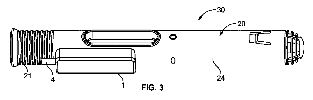
図3~図6を参照すると、可能な構成30を示す。ここでは、バッテリモジュールは、薬剤送達デバイス20の外方ハウジング24に対して装着され、薬剤送達デバイス20は、保護キャップ21を有し、用量送達出口60すなわちニードルシールド62により覆われた固定ニードルを有する薬剤容器65を収容する。ニードルシールドリムーバ61が、保護キャップ21に対して装着され、ハウジング24からキャップ21を除去することにより、ニードルからニードルシールド62が必ず除去される。テザー4から構成されるブロック要素の一部が、キャップ21に対して装着される。このテザー4は、絶縁材料から構成されることが可能であり、テザーの一部分が、付勢要素3とバッテリ2との間に配置される。
Referring to FIGS. 3-6, a
いくつかの例では、保護キャップは、テザー4が電気回路から除去される前に、最初にデバイスハウジングから除去されることが望ましい。これにより、キャップを除去するユーザは、保護キャップを定位置に保持する固定力を最初に克服することが可能となり、その後にテザーを定位置に保持する保持力をさらに克服することが必要となる。そのため、テザーの長さは、保護キャップがデバイスから完全に除去され、すなわちキャップ保持力がゼロへと低下され、その後にユーザがテザーに対して対向力を印加し、最終的にこの対向力によりバッテリモジュールの電子スイッチ構成要素の成果としてテザーに対する保持力の克服が得られるように、設計および構成され得る。したがって、テザーの長さは、1)所望のバッテリ作動タイミングを実現するように、ならびに/または2)キャップおよびテザーが共に薬剤送達デバイスおよびバッテリモジュールからそれぞれ除去されるときにユーザが発揮する除去力を制御するように、あらかじめ定められ構成され得る。 In some instances, it may be desirable to first remove the protective cap from the device housing before tether 4 is removed from the electrical circuit. This allows the user removing the cap to first overcome the locking force that holds the protective cap in place, and then is required to further overcome the holding force that holds the tether in place. . As such, the length of the tether is reduced when the protective cap is completely removed from the device, i.e., the cap retention force is reduced to zero, after which the user applies an opposing force against the tether, and this opposing force eventually The electronic switch component of the battery module may be designed and configured to overcome retention forces on the tether as a result. Therefore, the length of the tether is adjusted to 1) achieve the desired battery actuation timing and/or 2) the removal force exerted by the user when both the cap and tether are removed from the drug delivery device and battery module, respectively. may be predetermined and configured to control the
図4および図5に示すように、保護キャップが最初に除去され得るようにテザー4があらかじめ定められた長さを有することが望ましい場合には、必要なテザーの余剰長さは、折畳み構成またはアコーディオン構成4aでバッテリモジュール内部に収納され得るテザーの部分に相当する。代替的には、図6に示すように、テザーは、ラップ構成4bで収納され得る。図7は、テザーが延在構成4cにある場合に、保護キャップ21、ニードルシールドリムーバ61、およびニードルシールド62がニードルハブ63から完全に除去されているが、ブロック要素4dが依然として定位置にあり、その結果として回路からバッテリが絶縁されるような長さを有してテザーが設計される状況を示す。ハウジング24から離れるようにキャップ21をさらに移動させることにより、ブロック要素はバッテリモジュールから除去され、したがって電気回路が閉じられ、バッテリがバッテリモジュールに通電することが可能となる。
If it is desired that the tether 4 has a predetermined length so that the protective cap can be removed first, as shown in FIGS. It corresponds to the part of the tether that can be housed inside the battery module in
また、図4は、バッテリモジュールが、例えば通信モジュール1b、データ記憶装置を有するレコーダ1d、およびプロセッサまたは制御ユニット1cなどの複数の電気構成要素を備える一実施形態を示す。これらの構成要素/モジュールはいずれも、回路基板1eを介して電気接続状態にあり、カバー1aにより囲まれる。
Figure 4 also shows an embodiment in which the battery module comprises a plurality of electrical components, for example a
また、本発明の補助デバイス内に収容されたバッテリモジュールの通信モジュール1bは、無線周波数識別技術RFIDを利用し得る。具体的には高周波RFIDは、通信に関して複数の利点をもたらす。HF RFID活用の可能性は、無数に存在し、具体的には近距離無線通信NFCの利用を可能にする。NFCは、スマートフォンおよび同様のスマートデバイスが無線通信を確立するための一連の規格であるため特に適する。NFCは、典型的には10cm以下の距離を必要とする一連の短距離無線技術である。NFCは、ISO/IEC 18000-3エアインターフェースにおいて13.56MHzで、および106kbit/s~424kbit/sの範囲の速度で動作する。NFCは、イニシエータおよびターゲットを常に伴い、イニシエータは、受動ターゲットに電力供給し得るRF場を能動的に発生させる。これにより、NFCターゲットは、例えばバッテリを必要としないタグ、ステッカ、キーフォブ、またはカードなどの非常に単純な形態のフォームファクタをとることが可能となる。
Also, the
利用される技術の以下の説明において、NFCタグという語が使用される場合がある。本文脈では、NFCタグは、回路およびアンテナに対して接続されたNFCチップを含む点を理解されたい。NFCタグは、パッチまたはラベルに組み込まれるとは限らず、スタンドアローンユニットであってもよく、または薬剤送達デバイスの製造のために使用される材料中に組み込まれてもよい。さらに、NFCタグは、以降で明らかになるように、所要または所望の目的および用途に必要なさらなる特徴および構成要素を備えてもよい。 In the following description of the technology utilized, the term NFC tag may be used. In this context, it should be understood that an NFC tag includes an NFC chip connected to circuitry and an antenna. The NFC tag need not be incorporated into a patch or label, but may be a stand-alone unit or incorporated into the material used for manufacturing the drug delivery device. Additionally, the NFC tag may comprise additional features and components necessary for required or desired purposes and applications, as will become apparent hereinafter.
NFCタグは、データを収容し、典型的には読取り専用であるが、書換え可能であってもよい。NFCタグは、製造業者によってカスタムエンコードされるか、または技術推進および主要規格の設定を担当する業界団体であるNFC Forumにより提供される仕様書を使用することが可能である。タグは、情報の中でもとりわけデビットカードおよびクレジットカードの情報、ロイヤルティプログラムデータ、PIN、およびネットワーキングコンタクトなどの個人データを安全に格納することが可能である。 NFC tags contain data and are typically read-only, but may be rewritable. NFC tags can be custom encoded by manufacturers or use specifications provided by the NFC Forum, an industry group responsible for driving technology and setting key standards. The tags can securely store personal data such as debit and credit card information, loyalty program data, PINs, and networking contacts, among other information.
薬剤送達デバイスに関して、これらのデバイスは、複数のタスクを実施するためにNFCタグと共に構成され得る。NFCタグは、本発明の上述の補助デバイスの一部として構成され、好都合には薬剤送達デバイスのハウジングの外方表面に対して装着されるラベルに組み込まれ得る。 With respect to drug delivery devices, these devices can be configured with NFC tags to perform multiple tasks. The NFC tag may be configured as part of the aforementioned auxiliary device of the invention and conveniently incorporated into a label attached to the outer surface of the housing of the drug delivery device.
補助デバイスにおいて利用され得る短距離無線技術(SRWT)としては、ANT+、RFID、Zigbee、およびBluetooth(登録商標)が含まれる。この場合に1つの好ましい技術は、Bluetooth(登録商標)技術である。Bluetooth(登録商標)技術は、ライセンス不要の産業科学医療用(ISM)バンドで2.4~2.485GHzにて、スペクトル拡散、周波数ホッピング、全二重信号を利用して1600ホップ/秒の公称レートで動作する。2.4GHz ISMバンドは、ほとんどの国々において利用可能でありライセンス不要である。特に、Bluetooth(登録商標) Low EnergyおよびBluetooth(登録商標) Smartは、薬剤送達デバイスおよび要求されるその機能と連係して利用され得る。Bluetooth(登録商標)回路は、例えば固有識別番号またはデータなどを送信しタイムスタンプを記録することが可能な送信機を備える。好ましくは、Bluetooth(登録商標)回路は、例えばコインバッテリなどの上述の電源により駆動され、絶縁ストリップの除去が、バッテリとBluetooth(登録商標)回路との間に配置されるスイッチに作用して、薬剤送達デバイスの状態発生または状態変更があった場合にのみBluetooth(登録商標)回路を作動させる。 Short-range wireless technologies (SRWT) that may be utilized in assistive devices include ANT+, RFID, Zigbee, and Bluetooth®. One preferred technology in this case is Bluetooth® technology. Bluetooth® technology operates at a nominal rate of 1600 hops per second in the unlicensed industrial, scientific and medical (ISM) band from 2.4 to 2.485 GHz using spread spectrum, frequency hopping, full-duplex signaling do. The 2.4GHz ISM band is available and license-free in most countries. In particular, Bluetooth® Low Energy and Bluetooth® Smart may be utilized in conjunction with the drug delivery device and its functionality required. A Bluetooth® circuit comprises a transmitter capable of transmitting, for example, a unique identification number or data and recording a time stamp. Preferably, the Bluetooth® circuit is powered by a power source as described above, for example a coin battery, and removal of the insulating strip acts on a switch placed between the battery and the Bluetooth® circuit to Activate the Bluetooth® circuit only when there is a state occurrence or state change of the drug delivery device.
図8は、本開示の1つの可能なシステム30を概略的に示し、薬剤送達デバイス20は、補助デバイス10に対して装着されている。補助デバイス10は、薬剤送達デバイスハウジング24の近位部分23の外方表面に対して接着剤により装着される。補助デバイス10は、バッテリモジュールと、バッテリコンパートメント6と、オプションの付勢部材3と、絶縁シート4の遠位端部または自由端部によりバッテリ2から絶縁される接触パッド7とを備える。絶縁シート4は、例えば薬剤送達デバイス20の保護キャップ21に対して近位端部5にて接着剤により固定される。重要な点は、絶縁シート4は、キャップ21がデバイス20の近位端部23に対して装着される連結点22に跨る点である。保護キャップ21は、例えばハウジング24の終端近位端部のみを介してアクセス可能な注入ニードルなどの用量送達出口60を覆う。
FIG. 8 schematically shows one
ハウジング24からキャップ21を除去することにより、絶縁ストリップ4がキャップと共に移動され、したがって絶縁ストリップ4がバッテリ2と接触パッド7との間から除去される。次いで、これにより回路が閉じられて、バッテリが作動しバッテリモジュールに通電し得る。
By removing the
本開示の作動システムのもう1つの可能な実施形態では(図3を参照)、補助デバイスの設計は、バッテリモジュールがバッテリハウジング6'から除去され再利用され得るようなものである。コネクタ8を介してバッテリハウジング6'に対して装着されたバッテリモジュールは、解除可能であってもよく、このコネクタ8は、ねじ連結特徴部、スナップ嵌め連結特徴部、脆弱接着剤連結特徴部、または他の解除可能装着特徴部であってもよい。
In another possible embodiment of the actuation system of the present disclosure (see Figure 3), the design of the auxiliary device is such that the battery module can be removed from the battery housing 6' and reused. A battery module attached to the battery housing 6' via a
図9は、本開示の作動システムのさらに別の実施形態を示す。この作動システムは、例えば薬剤送達デバイス20のハウジング24など、薬剤送達デバイスの外方ハウジングに対して固着されるように設計されたラベル50の一部であるか、またはこのラベル50に組み込まれる。ラベル50は、バッテリモジュールに加えて、別個のRFIDタグおよびアンテナの組合せ体9を備え得る。ストリップまたはテザー4の形態の絶縁シートが、ラベル50の近位端部部分中に埋設され、バッテリ2は、RFIDタグおよびアンテナの組合せ体9にバッテリモジュールを接続する回路から電気絶縁される。この電気回路要素は、ラベル中に設計され、近位端部の一部分が、例えば保護キャップ21などの薬剤送達デバイス用量送達出口を完全に覆う薬剤送達デバイスのキャップまたは他のカバーとハウジング24との間の境界部をほぼたどる引裂きライン51上に延在するように、薬剤送達デバイス上に位置決めされる。薬剤送達デバイスが使用されることとなるときには、保護キャップが除去され、それによりラベル50は引裂きライン51に沿って引裂かれ、さらにこれにより絶縁テザー4がさらに除去され、したがってハウジングに固着状態に留まるラベルからテザーが引き離される。テザーのこの引離しにより、回路が閉じられて、バッテリが回路に対して電力供給することが可能となる。
FIG. 9 shows yet another embodiment of the actuation system of the present disclosure. This actuation system is part of or incorporated in a
図10は、本開示の作動システムを代表する1つの可能な論理流れ図を示す。回路が、状態情報を提示するために補助デバイス内の複数のモジュールまたは構成要素に対して接続され得る。かかる状態情報は、用量送達の完了を含み得る。例えば、ユーザは、注入シーケンスが終了したときを、および注入部位からデバイスを除去することが安全であることを知ることが重要である場合があり得る。この場合に、回路は、用量送達の終了時に構成要素を移動することによって影響される場合があり、回路がスイッチとして機能する。SRWTにより検出されたこのスイッチ情報は、スマートデバイスへ送信され、スマートデバイスは、デバイスが安全に除去され得ることをユーザに示唆するように構成される。また、この情報は、デバイスが使用されたことの確認となる。 FIG. 10 shows one possible logic flow diagram representative of the actuation system of the present disclosure. Circuitry may be connected to multiple modules or components within the auxiliary device to present status information. Such status information may include completion of dose delivery. For example, it may be important for the user to know when the injection sequence is finished and when it is safe to remove the device from the injection site. In this case the circuit may be affected by moving components at the end of dose delivery, the circuit acting as a switch. This switch information detected by the SRWT is sent to the smart device, which is configured to suggest to the user that the device can be safely removed. This information also serves as confirmation that the device has been used.
回路およびスイッチは、インタラクティブな段階的指示としてさらに使用され得る。例えば、スマートデバイスは、デバイスをどのように取り扱うべきであるかを段階的にユーザに示す指示アプリケーションを備えてもよい。あるステップが実施され、それによりある特定の回路が影響されSRWTにより検出され、スマートデバイスへと送信されると、OK応答または肯定応答が、スマートデバイスにより提供され、ユーザに対して表示される。次いで、指示アプリケーションは、行うべき次の取扱いステップを示す。このようにして、すべてのステップがそれぞれ異なる回路に影響し、次いでそれによりSRWTチップに状態情報が提供される。この状態情報は、スマートデバイスへと遂次送信され、適切な情報が、指示アプリケーションによりユーザに対して表示される。 Circuits and switches can also be used as interactive step-by-step instructions. For example, a smart device may include an instructional application that shows the user step by step how the device should be handled. When a step is performed that affects a particular circuit and is detected by the SRWT and sent to the smart device, an OK or acknowledgment is provided by the smart device and displayed to the user. The instruction application then indicates the next handling step to take. In this way, every step affects a different circuit, which in turn provides state information to the SRWT chip. This state information is then serialized to the smart device and appropriate information is displayed to the user by the instructional application.
補助デバイスの使用による薬剤送達デバイスとスマートデバイスとの統合向上に関連して(図6を参照)、ある特定の治療計画の効果の理解を高めるために、例えば病勢モニタリングなどのさらなる情報の収集が可能となる。この薬剤送達デバイスとの連携においてスマートデバイスで使用されるプログラムまたはアプリケーションは、用量送達動作に関連してユーザにより記入がなされる質問表をさらに含み得る。この質問表は、患者の現状に関する複数の質問を含んでもよく、好ましくは治療、疾患、およびユーザのニーズに応じて設定可能であってもよい。取り扱われ得る領域としては、クオリティオブライフ(QOL)、認知機能、痛み、疲労、嘔気、メンタルヘルス等が含まれ得る。次いで、患者の認識症状との関連において治療計画と薬剤タイプとの間の相関関係の正負を判断するための処理および評価を目的として、質問表への回答が、SWRTタグを介して収集された情報と共にスマートデバイスから外部データベースへと送信され得る。 In conjunction with the increased integration of drug delivery devices with smart devices through the use of ancillary devices (see Figure 6), the collection of additional information, such as disease status monitoring, is needed to enhance understanding of the efficacy of a given treatment regimen. It becomes possible. The program or application used on the smart device in conjunction with this medication delivery device may further include a questionnaire filled out by the user in relation to the dose delivery operation. This questionnaire may include a number of questions regarding the patient's current status, and may preferably be configurable according to treatment, disease, and user needs. Areas that may be addressed may include quality of life (QOL), cognitive function, pain, fatigue, nausea, mental health, and the like. Questionnaire responses were then collected via the SWRT tag for processing and evaluation to determine the positive or negative correlation between treatment regimen and drug type in relation to the patient's perceived symptoms. It can be sent with the information from the smart device to the external database.
さらに、スマートデバイスがNFCリーダを備えない場合には、アタッチメントがかかるNFCリーダを備えることが可能であり、これによりスマートデバイスに対して機能を追加できる。薬剤送達デバイスおよびスマートデバイスの統合により、NFCタグのリアルタイム読取りによる薬剤送達デバイスとスマートデバイスとの間の緊密な連携によって、リアルタイムのインタラクティブなユーザ指示と、正確な注入時間、日時、および用量とがさらに提供される。注入時間、日時、および用量は、さらなる処理および送信のためにスマートデバイスに直接記録され得る。 Furthermore, if the smart device does not have an NFC reader, the attachment can have such an NFC reader, thereby adding functionality to the smart device. Integration of drug delivery devices and smart devices enables real-time interactive user instructions and accurate infusion times, dates and doses through close cooperation between drug delivery devices and smart devices through real-time reading of NFC tags. Further provided. Infusion times, dates and doses can be recorded directly on the smart device for further processing and transmission.
多くのスマートデバイスは、三次元のモーションセンサと共に構成され、その機能は、薬剤送達デバイスの取扱いと連係して使用され得る。例えば、スマートデバイスは、スマートデバイスおよびしたがって薬剤送達デバイスがどのように保持されているかを検出し得る。これは、薬剤送達デバイスが、使用時のいくつかのステップの最中にある特定の方向に保持される必要があるため、いくつかのタイプの薬剤の場合およびいくつかのタイプの薬剤送達デバイスの場合には重要となり得る。例えば、これは、薬剤容器が混合およびプライミングの最中にどのように保持されるかが重要となり得るいわゆるデュアルチャンバ薬剤容器を使用した薬剤送達デバイスであることが可能である。この場合に、スマートデバイスのモーションセンサは、薬剤送達デバイスがどのように保持されるかを検出するために使用され、このデバイスをどのように保持すべきかをユーザに伝え、デバイスが指示通りに保持されていない場合にはユーザに警告することが可能である。 Many smart devices are configured with three-dimensional motion sensors, the functionality of which can be used in conjunction with the handling of drug delivery devices. For example, the smart device may detect how the smart device and thus the drug delivery device are being held. This is the case for some types of drugs and for some types of drug delivery devices because the drug delivery device needs to be held in a certain orientation during several steps in use. can be important in some cases. For example, this could be a drug delivery device using a so-called dual-chamber drug container where how the drug container is held during mixing and priming can be important. In this case, the smart device's motion sensors are used to detect how the drug delivery device is held, tell the user how to hold the device, and allow the device to hold as instructed. If not, it is possible to warn the user.
この統合化された薬剤送達デバイスと共に使用され得るスマートデバイスのさらなる特徴としては、しばしばスマートデバイスの内臓パーツであるカメラの使用が含まれる。この場合に、カメラは、多くの場合において透明である薬剤容器の内容物の写真を撮影するために使用され、それにより薬剤の状態に関する情報を取得し得る。例えば、薬剤の色合いまたは透明性は、薬剤を使用すべきでないような例えば指定範囲外の温度にさらされるなど薬剤に対して何らかの不都合が生じたことを示唆する場合がある。色合いまたは透明性の比較は、スマートデバイス内のアプリケーションにおいてユーザにより直接的に実施されてもよく、または画像が、スマートデバイスにより外部サイトへ送信されて、そこで技術者が、比較を行い、薬剤に欠陥があれば患者へ警告し、どのように進めるかについてアドバイスを行う。 Additional smart device features that may be used with this integrated drug delivery device include the use of a camera, which is often an integral part of the smart device. In this case, the camera may be used to take pictures of the contents of the often transparent drug container, thereby obtaining information about the state of the drug. For example, the tint or clarity of the drug may indicate that something has gone wrong with the drug, such as exposure to temperatures outside the specified range, such that the drug should not be used. A comparison of hue or transparency may be performed directly by the user in an application within the smart device, or the image may be sent by the smart device to an external site where a technician may make the comparison and apply the drug. Alert the patient of any deficiencies and give advice on how to proceed.
固守および患者責任に関して、使用され得るいくつかの特徴および機能がスマートデバイスに存在する。一部の薬剤および治療計画は、国家の保健医療当局にとって非常に金額的な負担が高く、
治療計画の厳密な固守については、大きな責任がユーザに対して課せられる。世界のいくつかの国々では、患者が高額治療を固守しない場合には、治療継続のために全額または一部の支払いを強制されるべきだという議論があり、こういった主張は、治療に対して十分な関心のない人々は治療費を支払うべきであるというものである。NFCタグから取得される情報および薬剤送達履歴は、この固守をモニタリングするために利用することが可能である。
With respect to adherence and patient responsibility, there are several features and functions in smart devices that can be used. Some drugs and treatment regimens are very expensive for national health authorities and
A great deal of responsibility is placed on the user for strict adherence to the treatment regimen. In several countries around the world, there is an argument that if a patient does not adhere to high-cost treatment, he or she should be forced to pay in full or in part for continued treatment, and these arguments are against treatment. people who do not have sufficient interest in treatment should pay for treatment. Information obtained from NFC tags and drug delivery history can be used to monitor this adherence.
これに関して、例えば指紋センサ、スマートデバイス上のカメラによる目および/または顔の認識などのバイオメトリカルセンサが、ある特定の薬剤送達デバイスのユーザであるという認証を行い、それにより、用量送達のために薬剤送達デバイスを作動させた正規ユーザであると認証することができる。さらに、バイオメトリカルセンサは、第三者によるデバイスの偶然のまたは意図的な使用を防止する/第三者による偶然のまたは意図的な使用を不可能にすることを確保するために使用されてもよい。 In this regard, biometric sensors, such as fingerprint sensors, eye and/or face recognition by cameras on smart devices, provide authentication as a user of a particular drug delivery device, thereby providing a means for dose delivery. can be authenticated as an authorized user who has activated the drug delivery device at the time. Additionally, biometric sensors are used to ensure that accidental or intentional use of the device by third parties is prevented/disabled by third parties. good too.
例えば、大型バッテリが使用される場合には、NFCタグは、NFCチップに内蔵される温度センサを使用し得る。これは、例えば輸送中などにおける薬剤送達デバイスおよび/または薬剤容器の温度のモニタリングおよびロギングがなされ得るため有利となり得る。これは、温度の影響を被りやすい複数の薬剤にとって重要である場合があり、薬剤品質が認可範囲外の温度変化による影響を被っていないことが確保され得る。また、温度センサは、薬剤が送達のために目標温度に到達した場合に情報を提供するために使用され得る。次いで、この情報は、スマートデバイスへ通信され、そこでスマートデバイスは、取扱い情報および温度情報をユーザに対して提供する。 For example, if a large battery is used, the NFC tag may use a temperature sensor built into the NFC chip. This can be advantageous as the temperature of the drug delivery device and/or drug container can be monitored and logged, eg during transport. This can be important for temperature sensitive drugs and can ensure that drug quality is not affected by temperature changes outside the approved range. A temperature sensor may also be used to provide information when the drug has reached the target temperature for delivery. This information is then communicated to the smart device, where the smart device provides handling and temperature information to the user.
上述のおよび図に示した実施形態は、本発明の非限定的な例としてのみ見なされるべきであり、特許保護範囲内において多くの様式で修正がなされ得る点を理解されたい。 It should be understood that the embodiments described above and shown in the figures should be considered as non-limiting examples of the invention only, and may be modified in many ways within the scope of patent protection.
1a カバー
1b 通信モジュール
1c 制御ユニット
1d レコーダ
1e 回路基板
2 エネルギー源、バッテリ
3 付勢要素、付勢部材
3a 常時閉機構スイッチ
4 ブロック要素、絶縁シート、絶縁ストリップ、絶縁テザー
4a アコーディオン構成
4b ラップ構成
4c 延在構成
4d ブロック要素
5 装着特徴部、近位端部
6 バッテリコンパートメント、バッテリハウジング
7 接触パッド
8 コネクタ
9 RFIDタグおよびアンテナの組合せ体
10 補助デバイス
20 薬剤送達デバイス
21 保護キャップ
22 連結点
23 薬剤送達デバイスハウジングの近位部分、デバイスの近位端部
24 外方ハウジング
30 可能な構成、可能なシステム
50 ラベル
51 引裂きライン
60 用量送達出口
61 ニードルシールドリムーバ
62 ニードルシールド
63 ニードルハブ
65 薬剤容器
1a cover
1b communication module
1c control unit
1d recorder
1e circuit board
2 energy source, battery
3 biasing element, biasing member
3a normally closed mechanism switch
4 Block Elements, Insulating Sheets, Insulating Strips, Insulating Tethers
4a accordion composition
4b wrap configuration
4c extended configuration
4d block element
5 Mounting Feature, Proximal End
6 battery compartment, battery housing
7 contact pads
8 connectors
9 RFID tag and antenna combination
10 auxiliary devices
20 drug delivery devices
21 Protective cap
22 connection points
23 Proximal portion of drug delivery device housing, proximal end of device
24 outer housing
30 possible configurations, possible systems
50 labels
51 tear line
60 dose delivery outlet
61 Needle shield remover
62 Needle Shield
63 Needle hub
65 drug container
Claims (15)
薬剤送達デバイスであって、
ハウジング(24)、
前記ハウジング内に位置決めされた薬剤容器(65)、
前記ハウジングの終端部を介してアクセス可能な用量送達出口(60)、および
前記ハウジングに対して装着された除去可能キャップ(21)であって、前記キャップが前記薬剤送達デバイスから完全に除去されるまで、前記用量送達出口がアクセス可能になるのを防止するような、除去可能キャップ(21)
を備える、薬剤送達デバイスと、
前記補助デバイスであって、
前記ハウジングに対してまたは前記キャップに対して装着されたバッテリモジュールであって、前記バッテリモジュールは、バッテリ(2)と、接触パッド(7)と、前記バッテリおよび前記接触パッドに対して動作的に連結されたスイッチとを備え、前記スイッチの一部が、前記バッテリモジュールが前記ハウジングに対して装着される場合に前記キャップに対して直接的に連結されるか、または前記スイッチの一部が、前記バッテリモジュールが前記キャップに対して装着される場合に前記ハウジングに対して直接的に連結される、バッテリモジュール、および
前記バッテリモジュールに対して接続可能であるかまたは前記バッテリモジュールの一部として含まれ、外部デバイスにデータを送信するように構成された、通信モジュール(1b)であって、前記データは、前記スイッチの状態に直接的に関連する情報を含み、前記スイッチは、最初は、前記通信モジュールが前記バッテリから電力を受領することが防止された第1の状態にあり、前記ハウジングに対する前記キャップの移動により、前記バッテリが前記通信モジュールに対して電力を供給する第2の状態へと前記スイッチが変更される、通信モジュール(1b)
を備える、前記補助デバイスと
を備える、システム(30)。 A system (30) for actuating an auxiliary device (1) attached to a drug delivery device (20), comprising:
A drug delivery device comprising:
housing (24),
a medicament container (65) positioned within said housing;
a dose delivery outlet (60) accessible through the terminal end of said housing, and a removable cap (21) attached to said housing, said cap being completely removed from said drug delivery device. a removable cap (21) such as to prevent said dose delivery outlet from becoming accessible until
a drug delivery device comprising
The auxiliary device,
a battery module mounted to said housing or to said cap, said battery module being operable with respect to a battery (2), a contact pad (7) and said battery and said contact pad; a coupled switch, a portion of the switch directly coupled to the cap when the battery module is mounted to the housing; or a portion of the switch a battery module directly coupled to the housing when the battery module is attached to the cap; and a battery module connectable to or included as part of the battery module. a communication module (1b) configured to transmit data to an external device, said data including information directly related to the state of said switch, said switch initially A communications module is in a first state that prevents it from receiving power from the battery, and movement of the cap relative to the housing places the battery in a second state that supplies power to the communications module. Communication module (1b), wherein the switch is changed
A system (30) comprising: said ancillary device comprising:
Applications Claiming Priority (3)
| Application Number | Priority Date | Filing Date | Title |
|---|---|---|---|
| EP20155998.6 | 2020-02-07 | ||
| EP20155998 | 2020-02-07 | ||
| PCT/EP2020/085607 WO2021155981A1 (en) | 2020-02-07 | 2020-12-10 | Activation system for a supplemental device attached to a medicament delivery device |
Publications (1)
| Publication Number | Publication Date |
|---|---|
| JP2023511451A true JP2023511451A (en) | 2023-03-17 |
Family
ID=69526135
Family Applications (1)
| Application Number | Title | Priority Date | Filing Date |
|---|---|---|---|
| JP2022545419A Pending JP2023511451A (en) | 2020-02-07 | 2020-12-10 | An actuation system for an auxiliary device attached to a drug delivery device |
Country Status (6)
| Country | Link |
|---|---|
| US (2) | US12527918B2 (en) |
| EP (1) | EP4100085B1 (en) |
| JP (1) | JP2023511451A (en) |
| KR (1) | KR102718518B1 (en) |
| CN (1) | CN115087477B (en) |
| WO (1) | WO2021155981A1 (en) |
Families Citing this family (8)
| Publication number | Priority date | Publication date | Assignee | Title |
|---|---|---|---|---|
| US10441714B2 (en) * | 2017-10-05 | 2019-10-15 | Pirouette Medical LLC | Protective case for an auto-injector |
| WO2023009742A1 (en) * | 2021-07-29 | 2023-02-02 | Aktivax, Inc. | Administration device with detachable indicium |
| JP7761758B2 (en) * | 2021-10-08 | 2025-10-28 | エスエイチエル・メディカル・アーゲー | Auxiliary Device for Drug Delivery Device - Patent application |
| US20250262387A1 (en) * | 2022-04-19 | 2025-08-21 | Shl Medical Ag | A Label Assembly of a Medicament Delivery Device |
| DE102022119150A1 (en) * | 2022-07-29 | 2024-02-01 | Xeotech Gmbh | Device and method for operating a device |
| USD1105417S1 (en) * | 2022-09-13 | 2025-12-09 | Sensile Medical Ag | Medicine injector |
| EP4661938A1 (en) * | 2023-02-08 | 2025-12-17 | SHL Medical AG | A sub-assembly of a medicament delivery device |
| WO2024165328A1 (en) * | 2023-02-08 | 2024-08-15 | Shl Medical Ag | A cap assembly of a medicament delivery device |
Citations (3)
| Publication number | Priority date | Publication date | Assignee | Title |
|---|---|---|---|---|
| US6270916B1 (en) * | 1997-04-10 | 2001-08-07 | Alcatel | Complete discharge device for lithium battery |
| WO2014064691A2 (en) * | 2012-10-23 | 2014-05-01 | Insuline Medical Ltd. | Drug dispensing-tracking device, system and method |
| WO2016055351A1 (en) * | 2014-10-06 | 2016-04-14 | Carebay Europe Ltd | Information transmitter attached to medication container |
Family Cites Families (32)
| Publication number | Priority date | Publication date | Assignee | Title |
|---|---|---|---|---|
| CN1177623C (en) | 1996-03-12 | 2004-12-01 | 诺沃挪第克公司 | Injection device with electronic display of predetermined dose |
| IL156245A0 (en) | 2000-12-22 | 2004-01-04 | Dca Design Int Ltd | Drive mechanism for an injection device |
| EP1391794A1 (en) | 2002-07-23 | 2004-02-25 | Novo Nordisk A/S | Device with time indicating means |
| SE526357C2 (en) * | 2003-03-18 | 2005-08-30 | Shl Medical Ab | System and procedure for presenting and distributing medication information |
| EP1680175B1 (en) * | 2003-11-06 | 2019-06-05 | LifeScan, Inc. | Drug delivery pen with event notification means |
| US8361026B2 (en) * | 2005-02-01 | 2013-01-29 | Intelliject, Inc. | Apparatus and methods for self-administration of vaccines and other medicaments |
| US9393369B2 (en) * | 2008-09-15 | 2016-07-19 | Medimop Medical Projects Ltd. | Stabilized pen injector |
| US9295784B2 (en) | 2011-05-25 | 2016-03-29 | Sanofi-Aventis Deutschland Gmbh | Medicament delivery device with cap |
| JP6340321B2 (en) * | 2012-02-13 | 2018-06-06 | サノフィ−アベンティス・ドイチュラント・ゲゼルシャフト・ミット・ベシュレンクテル・ハフツング | Pen injection device and electronic clip module for pen injection device |
| GB201402826D0 (en) * | 2014-02-18 | 2014-04-02 | Owen Mumford Ltd | Injection device |
| US10518034B2 (en) * | 2014-07-10 | 2019-12-31 | Sanofi-Aventis Deutschland Gmbh | Apparatus for capturing and processing images |
| KR20170051458A (en) * | 2014-09-08 | 2017-05-11 | 메다소어 피티와이 엘티디 | Injection system |
| EP3021245A1 (en) | 2014-10-06 | 2016-05-18 | Carebay Europe Ltd. | Information provider system |
| EP3204082B1 (en) * | 2014-10-06 | 2020-04-08 | Sanofi-Aventis Deutschland GmbH | Supplementary device for attachment to an injection device for determining the set and/or administered dose with ocr image processing including a method for glare reduction |
| US9519904B2 (en) | 2014-10-19 | 2016-12-13 | Thin Film Electronics Asa | NFC/RF mechanism with multiple valid states for detecting an open container, and methods of making and using the same |
| US10569028B2 (en) * | 2014-11-05 | 2020-02-25 | Insuline Medical Ltd. | Drug tracking device |
| CN107206183B (en) * | 2015-02-09 | 2020-09-01 | 艾斯曲尔医疗公司 | Drug delivery device with usage monitoring |
| CA2980004C (en) | 2015-03-24 | 2023-10-10 | Kaleo, Inc. | Devices and methods for delivering a lyophilized medicament |
| EP3141275A1 (en) * | 2015-09-14 | 2017-03-15 | Carebay Europe Ltd. | Medicament delivery device |
| EP3170525A1 (en) | 2015-11-19 | 2017-05-24 | Carebay Europe Ltd. | Medicament delivery device |
| WO2017100501A1 (en) | 2015-12-09 | 2017-06-15 | Amgen Inc. | Auto-injector with signaling cap |
| EP3184135A1 (en) * | 2015-12-22 | 2017-06-28 | Carebay Europe Ltd. | Communication device for transmitting information from a medicament delivery device |
| EP3416711B1 (en) | 2016-02-17 | 2022-04-06 | Adherium (NZ) Limited | Adherence monitor for a medicament inhaler with tethered cap |
| EP3222309A1 (en) * | 2016-03-22 | 2017-09-27 | Carebay Europe Ltd | Monitoring unit |
| WO2018068986A1 (en) * | 2016-10-14 | 2018-04-19 | Carebay Europe Ltd. | A self-administrative medicament device configured to send data through the human body |
| EP3554590A1 (en) * | 2016-12-13 | 2019-10-23 | Becton, Dickinson and Company | Event capture device for medication delivery instruments |
| DK3366335T3 (en) | 2017-02-22 | 2021-09-20 | Shl Medical Ag | ADMISSION UNIT FOR A MEDICINE DELIVERY DEVICE |
| MA49461A (en) | 2017-06-23 | 2020-04-29 | Amgen Inc | ELECTRONIC DRUG DELIVERY DEVICE INCLUDING A CAP ACTIVATED BY A SWITCH ASSEMBLY |
| CN108283755A (en) | 2017-08-04 | 2018-07-17 | 深圳慎始科技有限公司 | A kind of sleep aid apparatus |
| WO2019158372A1 (en) * | 2018-02-19 | 2019-08-22 | Shl Medical Ag | A medicament delivery device with an easily connected disposable and reusable units |
| WO2019170285A1 (en) | 2018-03-09 | 2019-09-12 | Dussault Dominic Oliver | Apparatus and method for assisting a user during a cardiopulmonary resuscitation and manufacturing method |
| JP7761758B2 (en) * | 2021-10-08 | 2025-10-28 | エスエイチエル・メディカル・アーゲー | Auxiliary Device for Drug Delivery Device - Patent application |
-
2020
- 2020-12-10 JP JP2022545419A patent/JP2023511451A/en active Pending
- 2020-12-10 WO PCT/EP2020/085607 patent/WO2021155981A1/en not_active Ceased
- 2020-12-10 US US17/796,096 patent/US12527918B2/en active Active
- 2020-12-10 CN CN202080095488.4A patent/CN115087477B/en active Active
- 2020-12-10 EP EP20820443.8A patent/EP4100085B1/en active Active
- 2020-12-10 KR KR1020227027099A patent/KR102718518B1/en active Active
-
2025
- 2025-04-07 US US19/171,829 patent/US20250235626A1/en active Pending
Patent Citations (3)
| Publication number | Priority date | Publication date | Assignee | Title |
|---|---|---|---|---|
| US6270916B1 (en) * | 1997-04-10 | 2001-08-07 | Alcatel | Complete discharge device for lithium battery |
| WO2014064691A2 (en) * | 2012-10-23 | 2014-05-01 | Insuline Medical Ltd. | Drug dispensing-tracking device, system and method |
| WO2016055351A1 (en) * | 2014-10-06 | 2016-04-14 | Carebay Europe Ltd | Information transmitter attached to medication container |
Also Published As
| Publication number | Publication date |
|---|---|
| US20250235626A1 (en) | 2025-07-24 |
| EP4100085A1 (en) | 2022-12-14 |
| WO2021155981A1 (en) | 2021-08-12 |
| KR102718518B1 (en) | 2024-10-21 |
| CN115087477B (en) | 2024-08-16 |
| EP4100085B1 (en) | 2026-01-28 |
| US12527918B2 (en) | 2026-01-20 |
| KR20220124231A (en) | 2022-09-13 |
| US20230099408A1 (en) | 2023-03-30 |
| CN115087477A (en) | 2022-09-20 |
Similar Documents
| Publication | Publication Date | Title |
|---|---|---|
| KR102718518B1 (en) | Activation system for an auxiliary device attached to a drug delivery device | |
| US11195604B2 (en) | Medicament delivery device | |
| US8226610B2 (en) | Medical injector with compliance tracking and monitoring | |
| WO2016055305A1 (en) | Medicament delivery device | |
| KR102881134B1 (en) | Activation and detection system for auxiliary devices attached to drug delivery devices |
Legal Events
| Date | Code | Title | Description |
|---|---|---|---|
| A621 | Written request for application examination |
Free format text: JAPANESE INTERMEDIATE CODE: A621 Effective date: 20220726 |
|
| A977 | Report on retrieval |
Free format text: JAPANESE INTERMEDIATE CODE: A971007 Effective date: 20230714 |
|
| A131 | Notification of reasons for refusal |
Free format text: JAPANESE INTERMEDIATE CODE: A131 Effective date: 20230718 |
|
| A521 | Request for written amendment filed |
Free format text: JAPANESE INTERMEDIATE CODE: A523 Effective date: 20231017 |
|
| A02 | Decision of refusal |
Free format text: JAPANESE INTERMEDIATE CODE: A02 Effective date: 20240129 |
|
| A521 | Request for written amendment filed |
Free format text: JAPANESE INTERMEDIATE CODE: A523 Effective date: 20240423 |
|
| A911 | Transfer to examiner for re-examination before appeal (zenchi) |
Free format text: JAPANESE INTERMEDIATE CODE: A911 Effective date: 20240507 |
|
| A912 | Re-examination (zenchi) completed and case transferred to appeal board |
Free format text: JAPANESE INTERMEDIATE CODE: A912 Effective date: 20240802 |
|
| A521 | Request for written amendment filed |
Free format text: JAPANESE INTERMEDIATE CODE: A523 Effective date: 20251113 |