JP2023154228A - communication system - Google Patents
communication system Download PDFInfo
- Publication number
- JP2023154228A JP2023154228A JP2022063417A JP2022063417A JP2023154228A JP 2023154228 A JP2023154228 A JP 2023154228A JP 2022063417 A JP2022063417 A JP 2022063417A JP 2022063417 A JP2022063417 A JP 2022063417A JP 2023154228 A JP2023154228 A JP 2023154228A
- Authority
- JP
- Japan
- Prior art keywords
- call
- terminal
- speaker
- terminals
- sound
- Prior art date
- Legal status (The legal status is an assumption and is not a legal conclusion. Google has not performed a legal analysis and makes no representation as to the accuracy of the status listed.)
- Granted
Links
Images


Landscapes
- Telephonic Communication Services (AREA)
Abstract
Description
本開示は、通話端末を含むIP通話システムを備えたコミュニケーションシステム、又は、IP通話システムとIPスピーカーを含む拡声放送システムを備えたコミュニケーションシステムに関する。 The present disclosure relates to a communication system including an IP call system including a call terminal, or a communication system including a public address system including an IP call system and an IP speaker.
インターカムシステム(IP通話システム)は、主として構内通話を行うシステムである。典型的には、インターカムシステムは、1つ以上の通話端末を含む。インターカムシステムは、1つ以上の拡声機器を含む拡声放送システムとも連携している。各通話端末は、マイクやスピーカーを備え、ネットワークを介して相互に接続されている。各通話端末は、SIPプロトコル等所定のプロトコルに従って、入力された音声を別の通話先の通話端末に伝送することで、構内通話を行う。また、各通話端末は、入力された音声を拡声機器に送信することで、拡声機器からの拡声方法を行う。インターカムシステムの一例が特許文献1に開示されている。
本開示は、通話先の環境(騒音)に応じた通話が可能なIP通話システムを提供することを目的とする。 An object of the present disclosure is to provide an IP phone call system that allows calls to be made depending on the environment (noise) of the call destination.
本開示の第1観点のコミュニケーションシステムは、それぞれがIPネットワークに接続され、それぞれがマイクとスピーカーとを有する複数の通話端末を含み、IPネットワークを介して通話端末間で、通話用プロトコルを用いた音声データの送受信を行う、IP通話システムと、
IPネットワークに通話端末とは別個に接続され、通話端末間の前記通話用プロトコルを用いた音声データの送受信処理を制御するシステムマネージャーとを備え、
前記IP通話システムに属する1の通話端末から、前記IP通話システムに属する他の通話端末に発呼するとき、前記1の通話端末、又は前記システムマネージャーは、前記他の通話端末のマイクから集音して暗騒音を取得し、前記発呼の音量、音質の少なくとも1つを調整する。
A communication system according to a first aspect of the present disclosure includes a plurality of call terminals each connected to an IP network and each having a microphone and a speaker, and uses a call protocol between the call terminals via the IP network. An IP telephone system that transmits and receives voice data;
a system manager that is connected to the IP network separately from the call terminals and controls transmission and reception processing of audio data between the call terminals using the call protocol;
When a call is made from one call terminal belonging to the IP call system to another call terminal belonging to the IP call system, the first call terminal or the system manager collects sound from the microphone of the other call terminal. background noise is acquired, and at least one of the volume and sound quality of the call is adjusted.
ここで、暗騒音とは、通話端末において、通話者が発話しない状態でマイクが集音する音声を言う。 Here, background noise refers to the sound that is collected by a microphone in a call terminal when the caller is not speaking.
本開示の第2観点のコミュニケーションシステムは、マイクとスピーカーとを有する複数の通話端末と、通話端末間の通話用プロトコルを用いた音声データの送受信処理を制御するシステムマネージャーと、を含むIP通話システムと、
前記IP通話システムと共通の通話プロトコルを用いた音声データを受信し、拡声可能なIPスピーカーと、
を備え、
前記IP通話システムに属する1の通話端末から、前記IPスピーカーに発呼して拡声するとき、前記システムマネージャーは、前記IPスピーカーの周辺に配置される他の通話端末を特定し、前記1の通話端末、又は前記システムマネージャーは、特定された他の通話端末のマイクから集音して暗騒音を取得し、暗騒音に基づいて、前記IPスピーカーにて拡声する音量、音質の少なくとも1つを調整する。
A communication system according to a second aspect of the present disclosure is an IP call system including a plurality of call terminals each having a microphone and a speaker, and a system manager that controls transmission and reception processing of audio data using a call protocol between the call terminals. and,
an IP speaker capable of receiving and amplifying voice data using a call protocol common to the IP call system;
Equipped with
When one call terminal belonging to the IP call system makes a call to the IP speaker and amplifies the sound, the system manager identifies other call terminals placed around the IP speaker and terminates the first call. The terminal or the system manager acquires background noise by collecting sound from the microphone of the identified other call terminal, and adjusts at least one of the volume and sound quality of the amplification by the IP speaker based on the background noise. do.
本開示のIP通話システムは、通話先の暗騒音を取得して、発話の音量又は音質を調整するので、通話の品質を向上させることができる。 The IP call system of the present disclosure acquires the background noise of the call destination and adjusts the volume or sound quality of speech, so it is possible to improve the quality of the call.
1.第1実施形態
(1)第1実施形態のコミュニケーションシステム1の構成
本実施形態のコミュニケーションシステム1は、図1に示すように、IP通話システム10と、システムマネージャー20とを備えている。IP通話システム10と、システムマネージャー20とは、ネットワークNを介して相互に接続されている。
1. First Embodiment (1) Configuration of
IP通話システム10は、複数の通話端末11を含む。通話端末11は、音声通話を行う端末であって、ネットワークNを介して他の通話端末11と音声データの送受信を行うことで音声通話を行う機能を有する。各通話端末11には、ネットワークN上で自己を固有に識別する識別子(例えば、IPアドレス)が割り当てられている。通話端末11は、音声通話時、IP通話用のプロトコルに準拠して音声データや映像データの送受信を行う。IP通話用のプロトコルの一例は、IETF(Internet Engineering Task Force:インターネット技術タスクフォース)により標準化されRFC3261にて規定されているSIP(Session Initiation Protocol)である。
システムマネージャー20は、通話端末11がIP通話用プロトコルに従って音声データや映像データの送受信処理を行うための制御装置である。送受信処理は、発呼等の呼制御を含む。例えば、システムマネージャー20は、SIPに準拠して呼制御を行うSIPサーバーである。システムマネージャー20には、ネットワーク上で自己を固有に識別する識別子(例えば、IPアドレス)が割り当てられている。
The
ネットワークNは、図2に示すように、複数のLAN(Local Area Network)と、これらを相互接続するインターネット等のWAN(Wide Area Network)を介して構成されてもよい。IP通話システム10と、システムマネージャー20とのそれぞれがLAN上に構成され、相互接続される。このような構成において、複数のLANを跨いで、異なるIP通話システム10間で通話端末11同士の音声通話を行うなど、多様なコミュニケーションを行うことができる。IP通話システム10がLAN上で構成される場合、通話端末11は、LANを構成するルーターにイーサネットケーブルで接続され、イーサネットケーブルを介して音声データを送信するとともに、イーサネットケーブルを介してPoE(Power over Ethernet)給電されるとよい。
As shown in FIG. 2, the network N may be configured through a plurality of LANs (Local Area Networks) and a WAN (Wide Area Network) such as the Internet that interconnects these LANs. The
以下、IP通話用プロトコルとしてSIPを用いる例で説明する。 An example in which SIP is used as the IP call protocol will be described below.
通話端末11は、図3に示すように、マイク110と、スピーカー111と、カメラ112と、ディスプレイ113と、入力部114と、処理部116と、メモリー117とを備える。マイク110は、通話端末11の筐体から外側に集音方向が向けられた電気音響変換器であり、通話端末11に対して話しかける話者の音声を集音して音声信号を出力する。スピーカー111は、通話端末11の筐体から外側に放音方向が向けられた電気音響変換器であり、音声データが再生されて得た音声を出力する。カメラ112は、CCDイメージセンサーやCMOSイメージセンサー等の撮像素子を含む撮像装置であり、通話端末11の筐体から外側であって通話端末11に対して話しかける話者の姿が映る方向に撮像方向が向けられている。カメラ112は、撮影して得て映像信号から静止画又は動画の映像データを生成して出力する。ディスプレイ113は、LCDや有機EL等の表示素子を含むディスプレイであり、その通話端末11や他の通話端末11のカメラ112で撮影した映像や、その他GUI等に係る画像を表示する。入力部114は、ボタンやスイッチ等、ユーザの操作を受け付ける入力デバイスである。入力部114とディスプレイ113とは統合されてタッチパネルを構成してもよい。通話端末11は、机上や卓上に置くタイプのものや壁掛け、壁埋め込みタイプのものなど、種々の態様を取りうる。通話端末11は、いわば、スピーカーフォン、インターフォン、インターカムと呼ばれる通話装置である。
As shown in FIG. 3, the
図4は、通話端末11の一構成を示す外観図である。通話端末11は、カメラ112、ディスプレイ113、入力部114、受話器115を有している。受話器115は、マイク110とスピーカー111とを含む。図4の通話端末11は、受話器115とは別にマイク110とスピーカー111とを含み、受話器115を本体に置いた状態であっても集音、発音が可能であり、例えば、受話器115を使わないハンズフリー通話に用いられる。
FIG. 4 is an external view showing one configuration of the
通話端末11において、処理部116は、CPU(Central Processing Unit)やMPU(Micro Processing Unit)等を含む。メモリー117は、処理部116が実行可能なコンピュータープログラムを保持する。処理部116がメモリー117に保持されたコンピュータープログラムを実行することにより、通話端末11の各種機能が実現される。メモリー117に保持されるコンピュータープログラムには、通話機能、録画機能、イベント検知機能、AIを用いた判定機能、拡声機能、リアルタイム放送機能、録音放送機能、ダウンロード放送機能、一斉放送機能等、上述した各種機能を実行するプログラム命令が含まれる。
In the
(2)IP通話システム10による基本的な通話方法
基本的なSIP通話の方法について、図5のフローチャートを用いて説明する。
(2) Basic call method using IP call system 10 A basic SIP call method will be explained using the flowchart in FIG. 5.
システムマネージャー20は、SIPサーバー機能を有しており、呼制御を行う。システムマネージャー20は、図6に示すように、コミュニケーションシステム1内の各端末(通話端末11)の情報をテーブル管理している。ここで、各端末の情報とは、「IPアドレス」、及び、各端末の配置されている場所の「名称」である。
The
各端末の名称は、各通話端末11の入力部114からユーザが任意に入力してもよい。
The name of each terminal may be input arbitrarily by the user from the
以降、「2階北」名称が付された通話端末(第1通話端末11a)を発呼元とし、「1階ロビー」名称が付された通話端末(第2通話端末11b)を発呼先とする例に基づき説明する。 From now on, the calling terminal (first calling terminal 11a) named "2nd floor north" will be the calling source, and the calling terminal (second calling terminal 11b) named "1st floor lobby" will be the calling destination. This will be explained based on an example.
ユーザは、最初に、発呼元である「2階北」の第1通話端末11aから、「1階ロビー」の第2通話端末11bに発呼しようとして、第1通話端末11aのディスプレイ113の表示画面(図7参照)において、「1階ロビー」を選択する。ユーザの選択を受けて、第1通話端末11aは、システムマネージャー20に呼び出しを行う(S101)。第1通話端末11aの呼び出しに対して、システムマネージャー20は中継をして、「1階ロビー」にある第2通話端末11bの呼び出しを行う(S102)。第2通話端末11bが呼び出しに応じると、第1通話端末11aと第2通話端末11bの間で通話セッションが開始される(S103)。通話セッションとは、第1通話端末11aのユーザと第2通話端末11bのユーザとの間で通話を可能にするIP通話システム10の状態をいう。
The user first tries to make a call from the first call terminal 11a on the "2nd floor north" which is the calling source, to the second call terminal 11b on the "1st floor lobby", and the user selects the
システムマネージャー20は、通話端末が通話中であるかないかステータス管理をしている。S102~S103に基づき呼び出して、通話セッションが開始すると、発呼元の第1通話端末と発呼先の第2通話端末のステータスをそれぞれ「話し中」にする。終話して通話セッションが終了すると、第1通話端末と第2通話端末のステータスをそれぞれ「話し中ではない」に戻す。
The
(3)暗騒音を低減したIP通話システム10による通話方法
本実施形態のコミュニケーションシステム1において、暗騒音を低減したIP通話システム10による通話方法について、図8のフローチャートを用いて説明する。
(3) Call method using
コミュニケーションシステム1の通話端末11は、建物の複数の場所に配置されている。ここでは、通話端末11の設置されている場所として、「1階ロビー」と「2階北」を想定する。以降、「2階北」名称が付された通話端末(第1通話端末11a)を発呼元とし、「1階ロビー」名称が付された通話端末(第2通話端末11b)を発呼先とする例に基づき説明する。
The
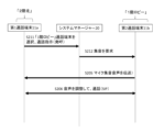
ユーザは、最初に、発呼元である「2階北」の第1通話端末11aから、「1階ロビー」の第2通話端末11bに発呼しようとして、第1通話端末11aのディスプレイ113の表示画面(図7参照)において、「1階ロビー」を選択する。ユーザの入力を受けて、第1通話端末11aは、システムマネージャー20に問い合わせを行う(S201)。通知を受けたシステムマネージャー20は、「1階ロビー」の第2通話端末11bの呼び出しを行うと(S202)ともに、第2通話端末11bのアドレスを第1通話端末11aに通知する(S203)。通知を受けた第1通話端末11aは、「1階ロビー」の第2通話端末11bに集音を要求する(S204)。第1通話端末11aから集音を要求された第2通話端末11bは、マイク110の集音した音声を第1通話端末11aに送る(S205)。ここで、マイク110が集音する時間は、例えば、1~2秒間である。集音するのはいわゆる暗騒音である。ここで、暗騒音とは、通話端末において、通話者が発話しない状態でマイクが集音する音声を言う。第1通話端末11aから第2通話端末11bに送信される音声は、第2通話端末11bのマイク110で集音した音声(暗騒音)に基づいて適宜音量、又は音質が調整される。
The user first tries to make a call from the first call terminal 11a on the "2nd floor north" which is the calling source, to the second call terminal 11b on the "1st floor lobby", and the user selects the
「2階北」の第1通話端末11aと、「1階ロビー」の第2通話端末11bの間で通話セッションが開示されると、第2通話端末11bのマイク110で集音された音声は、第1通話端末11aによって調節され、第2通話端末11bのスピーカー111において、音量、又は音質が調整された状態で出される。たとえば、暗騒音の音量が小さいときは小さな音で、暗騒音の音量が大きいときは大きな音に調整される。あるいは暗騒音の音質が低いときは比較的高い音が、暗騒音の音質が高いときは比較的低い音に調整される。暗騒音の取得と、第1通話端末の音量、音質の調整は、システムマネージャー20が行ってもよい。
When a call session is opened between the first call terminal 11a on the "2nd floor north" and the second call terminal 11b on the "1st floor lobby", the sound collected by the
上記フローの説明において、S202において、第2通話端末11bが話し中である場合、システムマネージャー20はS202以降実行しない。
In the description of the above flow, if the second call terminal 11b is busy in S202, the
(4)変形実施形態1A
上記(3)においては、図8に示すように、ステップS201で、第1通話端末11aから問い合わせをうけたシステムマネージャー20は、第1通話端末11aに「1階ロビー」の通話端末のアドレスを通知し、第1通話端末11aが「1階ロビー」の通話端末に、マイクで集音を行うよう要求する。
(4) Modified embodiment 1A
In (3) above, as shown in FIG. 8, in step S201, the
変形実施形態1Aにおいては、図9に示すように、ステップS201で、第1通話端末11aから問い合わせをうけたシステムマネージャー20は、「1階ロビー」の通話端末(第2通話端末11b)に、マイクで集音を行うように要求する。その他は、上記(3)の通信方法とまったく同様である。
In the modified embodiment 1A, as shown in FIG. 9, in step S201, the
(5)変形実施形態1B
上記(3)においては、マイクで集音を行うのは、通話を行う第2通話端末11bそのものであった。本変形実施形態においては、さらに別の通話端末を用いる。
(5) Modified embodiment 1B
In the above (3), it is the second telephone terminal 11b itself that performs the telephone conversation that collects the sound with the microphone. In this modified embodiment, yet another telephone terminal is used.
変形実施形態1Bの通信方法を図10のフローチャートに示す。 The communication method of modified embodiment 1B is shown in the flowchart of FIG.
変形実施形態1Bの通信方法が、(3)の通信方法と異なるのは、第1通話端末11aから問い合わせをうけたシステムマネージャー20は、「1階ロビー」にある第2通話端末11b以外の第3通話端末11cについてもアドレスを第1通話端末11aに通知する。通知を受けた第1通話端末11aは、「1階ロビー」の第2通話端末11b及び第3通話端末11cに集音を要求する(S204)。第1通話端末11aから音声を要求された第2通話端末11b及び第3通話端末11cは、マイク110の集音した音声を第1通話端末11aに送る(S205)。ここで、マイク110が集音する時間は、例えば、1~2秒間である。集音するのはいわゆる暗騒音である。暗騒音は、第2通話端末11bのマイクが集音した音声及び第3通話端末11cのマイクが集音した音声の両方を考慮して決定する。たとえば、平均したものを用いる。第1通話端末11aから第2通話端末11bに送信される音声は、「1階ロビー」の暗騒音に基づいて適宜音量、又は音質が調整される。
The reason why the communication method of modified embodiment 1B is different from the communication method of (3) is that the
「2階北」の第1通話端末11aと、「1階ロビー」の第2通話端末11bの間で通話セッションが開示されると、第1通話端末11aのマイク110で集音された音声は、第2通話端末11bのスピーカー111において、音量、又は音質が調整された状態で出される。
When a call session is opened between the first call terminal 11a on the "2nd floor north" and the second call terminal 11b on the "1st floor lobby", the sound collected by the
変形実施形態1Bでは、「1階ロビー」の2台の通話端末11b、11cを利用する場合について説明したが、3台以上の通話端末を利用する場合も有効である。 Although the modified embodiment 1B describes the case where two call terminals 11b and 11c in the "first floor lobby" are used, it is also effective when three or more call terminals are used.
2.第2実施形態
(1)第2実施形態のコミュニケーションシステム1aの構成
本実施形態のコミュニケーションシステム1aは、図11に示すように、第1実施形態のコミュニケーションシステム1に加えて、拡声放送システム50を備えている。IP通話システム10と、システムマネージャー20と、ネットワークNは、第1実施形態と同様であるので、詳細な説明を省略する。コミュニケーションシステム1aにおいては、IP通話システム10と、システムマネージャー20と、拡声放送システム50とは、ネットワークNを介して相互に接続されている。
2. Second Embodiment (1) Configuration of
拡声放送システム50は、災害時の避難誘導やBGM等の音楽再生等の用途のため所定のエリア(拡声エリア)に設けられたシステムであり、1つ以上のIPスピーカー51を含む。各IPスピーカー51にはネットワーク上の固有の識別情報(例えば、IPアドレス)が割り当てられている。IPスピーカー51は、通話端末11と同様のIP通話用プロトコルに準拠して、音声データを受信して再生し拡声する機能を有する。また、拡声放送システム50は、IPスピーカー51と同一のネットワークに接続されたページングゲートウェイ52を含む。ページングゲートウェイ52には、ネットワーク上の固有の識別情報(例えば、IPアドレス)が割り当てられている。ページングゲートウェイ52は、通話端末11と同様のIP通話用プロトコルに準拠して、ネットワークを介して音声データを受信し、ネットワークを介してIPスピーカー51に音声データを転送する機能を有する。すなわち、ページングゲートウェイ52は、IPスピーカー51向けの音声データをいったん受け取り、IPスピーカー51に音声データを転送することで一斉同報させることができる。ページングゲートウェイ52は、マルチキャストやブロードキャストにより音声データをIPスピーカー51に転送するとよい。IPスピーカー51は、イーサネットケーブやセルラー通信等の無線通信媒体を介してデジタル化された音声データを受信し、再生する。
The
このように、コミュニケーションシステム1aにおいて、IP通話システム10と、システムマネージャー20と、拡声放送システム50とはネットワークを介して相互接続されており、IP通話システム10の通話端末11同士で音声通話を行ったり、IP通話システム10の通話端末11から拡声放送システム50のIPスピーカー51に音声放送を行ったりすることができる。
In this way, in the
ネットワークNは、図2に示すように、複数のLAN(Local Area Network)と、これらを相互接続するインターネット等のWAN(Wide Area Network)を介して構成されてもよい。IP通話システム10と、システムマネージャー20と、拡声放送システム50とのそれぞれがLAN上に構成され、相互接続される。このような構成において、複数のLANを跨いで、異なるIP通話システム10間で通話端末11同士の音声通話を行ったり、一方のLAN内のIP通話システム10の通話端末11から他方のLAN内の拡声放送システム50のIPスピーカーに音声放送を行ったり、多様なコミュニケーションを行うことができる。IP通話システム10がLAN上で構成される場合、通話端末11は、LANを構成するルーターにイーサネットケーブルで接続され、イーサネットケーブルを介して音声データを送信するとともに、イーサネットケーブルを介してPoE(Power over Ethernet)給電されるとよい。拡声放送システム50がLAN上で構成される場合、IPスピーカー51やページングゲートウェイ52は、LANを構成するルーターにイーサネットケーブルで接続され、イーサネットケーブルを介して音声データを受信するとともに、イーサネットケーブルを介してPoE給電されるとよい。
As shown in FIG. 2, the network N may be configured through a plurality of LANs (Local Area Networks) and a WAN (Wide Area Network) such as the Internet that interconnects these LANs. The
また、第2実施形態においても、第1実施形態と同様に、システムマネージャー20は、SIPサーバー機能を有しており、呼制御を行う。システムマネージャー20は、図12A、12Bに示すように、コミュニケーションシステム1内の各端末(通話端末11、IPスピーカー51等)の情報をテーブル管理している。ここで、各端末の情報とは、「IPアドレス」、及び、各端末の配置されている場所の「名称」である。
Also, in the second embodiment, similarly to the first embodiment, the
各端末の名称は、各通話端末11の入力部114からユーザが任意に入力してもよい。
The name of each terminal may be input arbitrarily by the user from the
各端末の名称は、図12Aに示すように、通話端末11とIPスピーカー51で共通していてもよいし、図12Bに示すように、通話端末11とIPスピーカー51とで異なっていてもよい。
The name of each terminal may be the same between the
また、第2実施形態のコミュニケーションシステム1aにおいても、拡声放送システム50を用いない動作、操作、又は方法については、第1実施形態のコミュニケーションシステム1と同じである。つまり、上記「1.第1実施形態」の「(2)IP通話システム10による基本的な通話方法」、「(3)暗騒音を低減したIP通話システム10による通話方法」、「(4)変形実施形態1A」、「(5)変形実施形態1B」と同じであるので、説明を省略する。
Also, in the
(2)暗騒音を低減したIP通話システム10と拡声放送システム50による拡声放送方法
本実施形態のコミュニケーションシステム1において、暗騒音を低減したIP通話システム10と拡声放送システム50による拡声放送方法について、図13のフローチャートを用いて説明する。
(2) A loudspeaker broadcasting method using the
以降、「2階北」名称が付された通話端末(第1通話端末11a)を発呼元とし、「1階ロビー」名称が付されたIPスピーカー(IPスピーカー51a)を発呼先とする例に基づき説明する。 Thereafter, the call terminal (first call terminal 11a) named "2nd floor north" is used as the calling source, and the IP speaker (IP speaker 51a) named "1st floor lobby" is called as the calling destination. This will be explained based on an example.
コミュニケーションシステム1の通話端末11及びIPスピーカー51は、建物の複数の場所に配置されている。ここでは、通話端末11及びIPスピーカー51の設置されている場所として、「1階ロビー」と「2階北」を想定する。
The
ユーザは、最初に、発呼元である「2階北」の第1通話端末11aから、「1階ロビー」のIPスピーカー51に拡声放送しようとして、たとえば、第1通話端末11aのディスプレイ113の表示画面(図7参照)において、「1階ロビー」を選択する。ユーザの入力を受けて、第1通話端末11aは、システムマネージャー20に問い合わせを行う(S301)。通知を受けたシステムマネージャー20は、「1階ロビー」のIPスピーカー51aの呼び出しを行うと(S302)ともに、IPスピーカー51bの周囲の通話端末を管理テーブル(図12A)で検索する。そして検索された第2通話端末11bのアドレスを第1通話端末11aに通知する(S303)。通知を受けた第1通話端末11aは、「1階ロビー」の第2通話端末11bに集音を要求する(S304)。第1通話端末11aから集音を要求された第2通話端末11bは、マイク110の集音した音声を第1通話端末11aに送る(S305)。ここで、マイク110が集音する時間は、例えば、1~2秒間である。集音するのはいわゆる暗騒音である。ここで、暗騒音とは、通話端末において、通話者が発話しない状態でマイクが集音する音声を言う。第1通話端末11aからIPスピーカー51aに送信される音声は、第1通話端末11aによって調節され、第2通話端末11bのマイク110で集音した音声に基づいて適宜音量、又は音質が調整される。暗騒音の取得と、第1通話端末の音量、音質の調整は、システムマネージャー20が行ってもよい。
First, the user tries to make a loudspeaker broadcast from the first call terminal 11a on the "2nd floor north" which is the calling source to the
次に、「2階北」の第1通話端末11aから、「1階ロビー」のIPスピーカー51aに拡声放送されるときは、第1通話端末11aのマイク110で集音された音声は、第2通話端末11bのスピーカー111において、音量、又は音質が調整された状態で出される(S306)。たとえば、暗騒音の音量が小さいときは小さな音で、暗騒音の音量が大きいときは大きな音に調整される。あるいは暗騒音の音質が低いときは比較的高い音が、暗騒音の音質が高いときは比較的低い音に調整される。
Next, when broadcasting from the first call terminal 11a on the "2nd floor north" to the IP speaker 51a on the "1st floor lobby", the sound collected by the
また、ステップS301で、システムマネージャー20は、第1通話端末11aから、「1階ロビー」のIPスピーカーへの拡声放送の指示を受けた時、同じ「1階ロビー」の名称が付された通話端末が複数ある場合、これら複数の通話端末を特定してもよい。システムマネージャー20は、通話端末が通話中であるかないかステータス管理をしているので、「1階ロビー」の話し中でない通話端末のみが、集音の指示を受け付けるようにしてもよい。
Further, in step S301, when the
あるいは、上記で「1階ロビー」の複数の通話端末を特定した場合に、複数の通話端末に、集音の要求を送ってもよい。第1通話端末は、複数の第2通話端末から集音された暗騒音に基づき、音量又は音質を調整してもよい。例えば、複数の通話端末のマイクが集音した音声の平均したものを用いてもよい。 Alternatively, when a plurality of call terminals in the "first floor lobby" are identified above, a request for sound collection may be sent to the plurality of call terminals. The first call terminal may adjust the volume or sound quality based on the background noise collected from the plurality of second call terminals. For example, the average of voices collected by microphones of a plurality of call terminals may be used.
また、本実施形態においては、ステップS304で、第1通話端末11aが第2通話端末11bに集音要求する際、第2通話端末11bが話し中であると集音は困難である。第1通話端末11aが第2通話端末11bを呼び出した際、第2通話端末11bが話し中である場合に、第2通話端末11bがマイクによる集音を行わないようにしてもよい。 Further, in this embodiment, when the first telephone terminal 11a requests the second telephone terminal 11b to collect sound in step S304, it is difficult to collect the sound if the second telephone terminal 11b is busy. When the first telephone terminal 11a calls the second telephone terminal 11b and the second telephone terminal 11b is busy, the second telephone terminal 11b may not collect sound using the microphone.
また、システムマネージャー20は、SIP呼制御を行っているため、各通話端末11が話し中であるか否かを把握し、管理している。そこで、システムマネージャー20は、ステップS301で、第1通話端末11aから「1階ロビー」のIPスピーカー51aへの放送指示を受けた時、「1階ロビー」の複数の通話端末の内で、話し中であるか否かを特定し、話し中でない通話端末(第2通話端末11bとする)のアドレスを第1通話端末11aに通知(S303)し、第1通話端末11aから第2通話端末11bに集音要求を行ってもよい(S304)。
Moreover, since the
(3)変形実施形態2A
上記(2)においては、図13に示すように、ステップS301で、第1通話端末11aから問い合わせをうけたシステムマネージャー20は、第1通話端末11aに「1階ロビー」の通話端末のアドレスを通知し、第1通話端末11aが「1階ロビー」の通話端末(第2通話端末11b)に、マイクで集音を行うよう要求する。
(3) Modified embodiment 2A
In (2) above, as shown in FIG. 13, in step S301, the
変形実施形態2Aにおいては、図14に示すように、ステップS311で、第1通話端末11aから問い合わせをうけたシステムマネージャー20は、「1階ロビー」のIPスピーカー51aに呼び出しを行うとともに(S312)、「1階ロビー」の通話端末(第2通話端末11b)に、マイクで集音を行うように要求する(S313)。その他は、上記(2)の通信方法とまったく同様である。
In the modified embodiment 2A, as shown in FIG. 14, the
(4)変形実施形態2B
ユーザが「1階ロビー」に発呼するとき、「1階ロビー」に通話端末もIPスピーカーも両方存在するときは、システムマネージャー20がどちらに発呼するかを選択してもよい。図15は、このように発呼を選択するフローを示している。
(4) Modified embodiment 2B
When a user makes a call to the "first floor lobby," if both a telephone terminal and an IP speaker are present in the "first floor lobby," the
図15では、ステップS401において、「2階北」に居るユーザは、第1通話端末11aにおいて、発呼先として「1階ロビー」を選択する。第1通話端末11aは、ユーザが「1階ロビー」を選択したことを、システムマネージャー20に伝送する。システムマネージャー20は、「1階ロビー」にある通話端末に発呼するか、IPスピーカーに発呼するかを決定する。通話端末を選択したときは図8のフローに進み、IPスピーカーを選択したときは図13のフローに進む。
In FIG. 15, in step S401, the user located on the "second floor north" selects the "first floor lobby" as the calling destination on the first call terminal 11a. The first telephone terminal 11a transmits to the
(5)変形実施形態2C
上記(2)においては、ユーザが「1階ロビー」のIPスピーカー51aを選択したとき、ステップS302で、システムマネージャー20は、名称が「1階ロビー」である、第2通話端末11bを特定した。システムマネージャー20が各端末の情報を管理するテーブルが図12Aのような場合は、このように行われる。一方、各端末の情報を管理するテーブルが図12Bのような場合は、名称が「1階ロビー」と完全に一致する通話端末11がないために、システムマネージャー20は、類似した名称(部分一致した名称)で登録する、「1階ロビー受付」の通話端末11、又は/及び、「1階ロビー西」の通話端末11を選択する。
(5) Modified embodiment 2C
In (2) above, when the user selects the IP speaker 51a of "1st floor lobby", in step S302, the
また、以上では、ユーザが「1階ロビー」のIPスピーカー51aを選択したとき、ステップS302で、システムマネージャー20は、名称が「1階ロビー」である、通話端末11を特定した。各端末の情報を管理するテーブルが図12Aのような場合は、各端末の情報を管理するテーブルの「名称」を用いて、端末の検索が容易である。システムマネージャー20は、目的とする通話端末を特定するために、「名称」以外の識別子を用いてもよい。
Further, in the above, when the user selects the IP speaker 51a of "1st floor lobby", in step S302, the
「名称」以外の端末の特定に用いる識別子としては、IPアドレスがある。共通のネットワーク部を持つIPスピーカー51と通話端末11、又は、同じルーターに接続されているIPスピーカー51と通話端末11を特定してもよい。複数のルーターによって複数のLANに分けられている場合や、スイッチ(L2スイッチ、L3スイッチ)によって仮想的に複数のLANに分けられている場合、IPスピーカー51と通話端末の機器識別子の共通度に基づきIPスピーカー51と同一のLANに接続されている通話端末(=近そうな通話端末)を特定してもよい。たとえば、各機器の識別子がIPアドレスである場合、各機器のIPアドレスのネットワーク部を見れば各機器の設置場所が推定できる。すなわち、同一のネットワーク部を持つ機器は、同じネットワークN1に属すると判断できる。例えば、IPアドレスが192.168.1.1と192.168.1.8は同じネットワーク、192.168.2.2と192.168.2.4とは同じネットワークと判断できる。
An IP address is an identifier used to specify a terminal other than the "name". It is also possible to specify the
さらに、別の例としては、システムマネージャー20は、目的とする通話端末11を特定するために、複数の識別子を組み合わせて用いてもよい。たとえば、「名称」と「IPアドレス」を組み合わせて用いてもよい。このようにすることによって、例えば、同一の名称「1階ロビー」として登録されているが、別のビルディングの別のロビーを指している場合、IPアドレスを組み合わせて用いることによって、より適切に、通話端末11を特定することができる。
Furthermore, as another example, the
3.第1、第2実施形態の特徴
(1)コミュニケーションシステム1は、IP通話システム10とシステムマネージャー20とを備えている。IP通話システム10は、複数の通話端末11を含んでいる。通話端末11は、IPネットワークNに接続される。通話端末11は、マイク110とスピーカー111とを有する。システムマネージャー20は、IPネットワークNに通話端末11とは別個に接続され、通話端末11間の通話用プロトコルを用いた音声データ及び映像データの送受信処理を制御する。
3. Features of the first and second embodiments (1) The
コミュニケーションシステム1の通話用プロトコルは、SIPプロトコルであってもよい。
The call protocol of the
第1通話端末11aから、他の場所にある第2通話端末11bを選択して呼び出すとき(S201)、第2通話端末11bのマイクから集音して暗騒音を取得し(S204、S205)、第1通話端末11a、又はシステムマネージャー20は、第1通話端末11aから第2通話端末11bへの発話の音量、音質の少なくとも1つを調整する(S206)。
When selecting and calling a second calling terminal 11b located elsewhere from the first calling terminal 11a (S201), background noise is acquired by collecting sound from the microphone of the second calling terminal 11b (S204, S205), The first call terminal 11a or the
本開示のIP通話システムは、通話先の暗騒音を取得して、発話の音量又は音質を調整するので、通話の品質を向上させることができる。 The IP call system of the present disclosure acquires the background noise of the call destination and adjusts the volume or sound quality of speech, so it is possible to improve the quality of the call.
(2)コミュニケーションシステム1aは、IP通話システム10と、システムマネージャー20と、IPスピーカー51と、を備えている。IP通話システム10は、複数の通話端末11を含んでいる。通話端末11は、IPネットワークNに接続される。通話端末11は、マイク110とスピーカー111とを有する。システムマネージャー20は、IPネットワークNに通話端末11とは別個に接続され、通話端末11間の通話用プロトコルを用いた音声データ及び映像データの送受信処理を制御する。IPスピーカー51は、IPネットワークNに接続され、IP通話システム10と共通の通話プロトコルを用いた音声データを受信し、拡声可能である。
(2) The
コミュニケーションシステム1aの通話用プロトコルは、SIPプロトコルであってもよい。
The call protocol of the
第1通話端末11aから、他の場所にあるIPスピーカー51aに発呼して拡声するとき(S301)、システムマネージャー20は、IPスピーカー51aの周辺に配置される他の通話端末11bを特定し、特定した他の通話端末11bのマイク110から集音して暗騒音を取得し(S305)、第1通話端末11a、又はシステムマネージャー20は、第1通話端末11aからIPスピーカー51aへの発話の音量、音質の少なくとも1つを調整する(S306)。
When making a call from the first call terminal 11a to the IP speaker 51a located elsewhere and amplifying the sound (S301), the
本開示のIP通話システムは、通話先の暗騒音を取得して、発話の音量又は音質を調整するので、通話の品質を向上させることができる。 The IP call system of the present disclosure acquires the background noise of the call destination and adjusts the volume or sound quality of speech, so it is possible to improve the quality of the call.
4.その他の実施形態
その他の実施形態としては、第3実施形態がある。第3実施形態のコミュニケーションシステム1bは、図16に示すように、第2実施形態のコミュニケーションシステム1に加えて、監視カメラシステム40を備えている。IP通話システム10と、システムマネージャー20と、拡声放送システム50と、ネットワークNは、第1実施形態と同様である。コミュニケーションシステム1bにおいては、IP通話システム10と、システムマネージャー20と、監視カメラシステム40と、拡声放送システム50とは、ネットワークNを介して相互に接続されている。
4. Other Embodiments Other embodiments include the third embodiment. As shown in FIG. 16, the
監視カメラシステム40は、防犯用途等で所定のエリア(監視エリア)を監視するためのシステムであり、1つ以上の監視カメラ41とレコーダー42を含む。各監視カメラ41は、CCDやCMOS等の画像センサーで取得した映像信号から映像データを生成し、外部に送信する機能を有する。監視カメラ41は、監視カメラシステム用の伝送プロトコルに準拠して映像をストリーミング送信する。監視カメラシステム用伝送プロトコルの一例は、ONVIF(Open Network Video Interface Forum)規格に準拠したプロトコルである。各監視カメラ41には、ネットワーク上で自己を固有に識別する識別子(例えば、IPアドレス)が割り当てられている。レコーダー42は、HDDやSSD等の記録媒体を備える録画装置であり、接続された監視カメラ41から送信される映像データを録画する機能を有する。レコーダー42は、監視カメラ41と同様に監視カメラシステム用伝送プロトコルに準拠して映像データを受信して録画する。レコーダー42には、ネットワーク上の固有の識別情報(例えば、IPアドレス)が割り当てられている。レコーダー42は、マイクを介した音声入力機能を有し、マイクから入力された音声から音声データを生成し、外部に送信する機能を有する。レコーダー42は、監視カメラシステム用伝送プロトコルに準拠して音声データを送信する。監視カメラシステム40は、VMS(Video Management System)によって統合管理されてもよい。VMSによって統合管理される場合、PC(Personal Computer)にインストールされたVMSソフトウェアによって、監視カメラ41及びレコーダー42が制御され管理される。VMSによって統合管理される場合、レコーダー42は、VMSソフトウェアがインストールされ、HDDやSSD等の記録媒体を備えるPCであってもよく、この場合、PCに備わるマイクから入力された音声の音声データを外部に送信する。
The
監視カメラ41は、CPUやMPU等を含む処理部と、処理部が実行可能なコンピュータープログラムを保持するメモリーとを備える。処理部がメモリーに保持されたコンピュータープログラムを実行することにより、監視カメラ41の各種機能が実現される。メモリーに保持されるコンピュータープログラムには、イベント検知機能等、上述した各種機能を実行するプログラム命令が含まれる。
The
レコーダー42は、CPUやMPU等を含む処理部と、処理部が実行可能なコンピュータープログラムを保持するメモリーとを備える。処理部がメモリーに保持されたコンピュータープログラムを実行することにより、レコーダー42の各種機能が実現される。メモリーに保持されるコンピュータープログラムには、録画機能、イベント検知機能等、上述した各種機能を実行するプログラム命令が含まれる。
The
第3実施形態においても、第1、第2実施形態とまったく同様に、通話端末11及び/又はIPスピーカー51間のコミュニケーションが行われる。
In the third embodiment, communication between the
それに加えて、第3実施形態においては、監視カメラシステムを利用することにより、さらに、円滑なコミュニケーションが実現される可能性がある。例えば、第2実施形態において、図8のステップS201において、システムマネージャー20が第1通話端末11aより放送指示を受けた時、システムマネージャー20が「1階ロビー」の監視カメラ41も検索し、通話セッションの際、「2階北」にある第1通話端末11aのディスプレイ113に「1階ロビー」の監視カメラ41aの映像を表示すれば、ユーザは、「1階ロビー」の状況を確認しながら、発話することが可能になる。
In addition, in the third embodiment, smoother communication may be realized by using a surveillance camera system. For example, in the second embodiment, when the
1、1a、1b コミュニケーションシステム
10 IP通話システム
11 通話端末
11a 第1通話端末
11b 第2通話端末
20 システムマネージャー
50 拡声放送システム
51 IPスピーカー
110 マイク
111 スピーカー
113 (通話端末の)ディスプレイ
1, 1a,
Claims (5)
IPネットワークに通話端末とは別個に接続され、通話端末間の前記通話用プロトコルを用いた音声データの送受信処理を制御するシステムマネージャーとを備え、
前記IP通話システムに属する1の通話端末から、前記IP通話システムに属する他の通話端末に発呼するとき、前記1の通話端末、又は前記システムマネージャーは、前記他の通話端末のマイクから集音して暗騒音を取得し、前記発呼の音量、音質の少なくとも1つを調整する、
コミュニケーションシステム。 An IP telephone call system including a plurality of telephone terminals each connected to an IP network and each having a microphone and a speaker, and transmitting and receiving voice data using a telephone communication protocol between the telephone terminals via the IP network. ,
a system manager that is connected to the IP network separately from the call terminals and controls transmission and reception processing of audio data between the call terminals using the call protocol;
When a call is made from one call terminal belonging to the IP call system to another call terminal belonging to the IP call system, the first call terminal or the system manager collects sound from the microphone of the other call terminal. to obtain background noise, and adjust at least one of the volume and sound quality of the call;
communication system.
IPネットワークに通話端末とは別個に接続され、通話端末間の前記通話用プロトコルを用いた音声データの送受信処理を制御するシステムマネージャーと、
IPネットワークに接続され、前記IP通話システムと共通の通話プロトコルを用いた音声データを受信し、拡声可能なIPスピーカーと、
を備え、
前記IP通話システムに属する1の通話端末から、前記IPスピーカーに発呼して拡声するとき、前記システムマネージャーは、前記IPスピーカーの周辺に配置される他の通話端末を特定し、前記1の通話端末、又は前記システムマネージャーは、特定された他の通話端末のマイクから集音して暗騒音を取得し、暗騒音に基づいて、前記IPスピーカーにて拡声する音量、音質の少なくとも1つを調整する、
コミュニケーションシステム。 An IP telephone call system including a plurality of telephone terminals each connected to an IP network and each having a microphone and a speaker, and transmitting and receiving voice data using a telephone communication protocol between the telephone terminals via the IP network. ,
a system manager that is connected to an IP network separately from the call terminals and controls transmission and reception processing of audio data between the call terminals using the call protocol;
an IP speaker connected to an IP network, capable of receiving audio data using a common communication protocol with the IP communication system, and capable of amplifying the sound;
Equipped with
When one call terminal belonging to the IP call system makes a call to the IP speaker and amplifies the sound, the system manager identifies other call terminals placed around the IP speaker and terminates the first call. The terminal or the system manager acquires background noise by collecting sound from the microphone of the identified other call terminal, and adjusts at least one of the volume and sound quality of the amplification by the IP speaker based on the background noise. do,
communication system.
請求項2に記載のコミュニケーションシステム。 When the system manager identifies other call terminals, the system manager identifies other call terminals having the same or similar name to the name of the IP speaker;
The communication system according to claim 2.
請求項2に記載のコミュニケーションシステム。 When the system manager identifies another call terminal, the system manager identifies another call terminal having a common IP address in which the IP address of the IP speaker and the network part of the IP address are the same.
The communication system according to claim 2.
請求項1又は2に記載のコミュニケーションシステム。 The call protocol is the SIP protocol,
The communication system according to claim 1 or 2.
Priority Applications (1)
| Application Number | Priority Date | Filing Date | Title |
|---|---|---|---|
| JP2022063417A JP7761522B2 (en) | 2022-04-06 | 2022-04-06 | Communication System |
Applications Claiming Priority (1)
| Application Number | Priority Date | Filing Date | Title |
|---|---|---|---|
| JP2022063417A JP7761522B2 (en) | 2022-04-06 | 2022-04-06 | Communication System |
Publications (2)
| Publication Number | Publication Date |
|---|---|
| JP2023154228A true JP2023154228A (en) | 2023-10-19 |
| JP7761522B2 JP7761522B2 (en) | 2025-10-28 |
Family
ID=88372626
Family Applications (1)
| Application Number | Title | Priority Date | Filing Date |
|---|---|---|---|
| JP2022063417A Active JP7761522B2 (en) | 2022-04-06 | 2022-04-06 | Communication System |
Country Status (1)
| Country | Link |
|---|---|
| JP (1) | JP7761522B2 (en) |
Citations (3)
| Publication number | Priority date | Publication date | Assignee | Title |
|---|---|---|---|---|
| JPH07212468A (en) * | 1993-12-29 | 1995-08-11 | At & T Corp | Correction of background noise in telephone communication network |
| JP2001007671A (en) * | 1999-06-21 | 2001-01-12 | Nec Corp | Telephone exchange |
| JP2015050690A (en) * | 2013-09-03 | 2015-03-16 | マグナ通信工業株式会社 | Paging system |
-
2022
- 2022-04-06 JP JP2022063417A patent/JP7761522B2/en active Active
Patent Citations (3)
| Publication number | Priority date | Publication date | Assignee | Title |
|---|---|---|---|---|
| JPH07212468A (en) * | 1993-12-29 | 1995-08-11 | At & T Corp | Correction of background noise in telephone communication network |
| JP2001007671A (en) * | 1999-06-21 | 2001-01-12 | Nec Corp | Telephone exchange |
| JP2015050690A (en) * | 2013-09-03 | 2015-03-16 | マグナ通信工業株式会社 | Paging system |
Also Published As
| Publication number | Publication date |
|---|---|
| JP7761522B2 (en) | 2025-10-28 |
Similar Documents
| Publication | Publication Date | Title |
|---|---|---|
| US8736663B2 (en) | Media detection and packet distribution in a multipoint conference | |
| US7539486B2 (en) | Wireless teleconferencing system | |
| JP2016163222A (en) | COMMUNICATION SYSTEM, COMMUNICATION METHOD, RELAY DEVICE, AND PROGRAM | |
| US20250039285A1 (en) | Call method and terminal, and non-transitory computer-readable storage medium | |
| JP7761522B2 (en) | Communication System | |
| JP2014229990A (en) | Intercom system | |
| JP6476754B2 (en) | Information processing apparatus, calling method, program, communication system | |
| JP7758433B2 (en) | Communication System | |
| JP2004153418A (en) | Video doorphone system | |
| KR102056807B1 (en) | Remote video conference system | |
| JP4006501B2 (en) | Emergency emergency call system | |
| JP2001223747A (en) | Communication device / relay device having hold control function and hold control method thereof | |
| JP2010124232A (en) | Conference system and conference method | |
| JP6569400B2 (en) | Information processing apparatus, information processing system, program, and recording medium | |
| JP2001094604A (en) | Multimedia information communication system and computer device | |
| JP4154184B2 (en) | Voice terminal and voice communication method | |
| JP2004072441A (en) | Ip camera telephone device with image display function | |
| JP7785601B2 (en) | Public address system and IP speaker | |
| JP2003032375A (en) | Intercom system | |
| WO2006107058A1 (en) | Intercom system having networking functionality | |
| EP4583502A1 (en) | A method for managing multimedia in a virtual conferencing system, a related system, a related multimedia management module, and a related virtual conferencing server | |
| KR100698121B1 (en) | Television receiver having extension setting function and extension setting method | |
| JP5114040B2 (en) | Intercom system for housing complex | |
| WO2003094383A1 (en) | Wireless conferencing system | |
| JP2006025295A (en) | Internet videophone / intercom intercom system |
Legal Events
| Date | Code | Title | Description |
|---|---|---|---|
| A621 | Written request for application examination |
Free format text: JAPANESE INTERMEDIATE CODE: A621 Effective date: 20241115 |
|
| A977 | Report on retrieval |
Free format text: JAPANESE INTERMEDIATE CODE: A971007 Effective date: 20250625 |
|
| A131 | Notification of reasons for refusal |
Free format text: JAPANESE INTERMEDIATE CODE: A131 Effective date: 20250701 |
|
| A521 | Request for written amendment filed |
Free format text: JAPANESE INTERMEDIATE CODE: A523 Effective date: 20250829 |
|
| TRDD | Decision of grant or rejection written | ||
| A01 | Written decision to grant a patent or to grant a registration (utility model) |
Free format text: JAPANESE INTERMEDIATE CODE: A01 Effective date: 20251007 |
|
| A61 | First payment of annual fees (during grant procedure) |
Free format text: JAPANESE INTERMEDIATE CODE: A61 Effective date: 20251016 |
|
| R150 | Certificate of patent or registration of utility model |
Ref document number: 7761522 Country of ref document: JP Free format text: JAPANESE INTERMEDIATE CODE: R150 |