JP2023086292A - semiconductor storage device - Google Patents
semiconductor storage device Download PDFInfo
- Publication number
- JP2023086292A JP2023086292A JP2021200707A JP2021200707A JP2023086292A JP 2023086292 A JP2023086292 A JP 2023086292A JP 2021200707 A JP2021200707 A JP 2021200707A JP 2021200707 A JP2021200707 A JP 2021200707A JP 2023086292 A JP2023086292 A JP 2023086292A
- Authority
- JP
- Japan
- Prior art keywords
- memory cell
- level
- verify
- data
- sense amplifier
- Prior art date
- Legal status (The legal status is an assumption and is not a legal conclusion. Google has not performed a legal analysis and makes no representation as to the accuracy of the status listed.)
- Pending
Links
Images


Classifications
-
- G—PHYSICS
- G11—INFORMATION STORAGE
- G11C—STATIC STORES
- G11C16/00—Erasable programmable read-only memories
- G11C16/02—Erasable programmable read-only memories electrically programmable
- G11C16/06—Auxiliary circuits, e.g. for writing into memory
- G11C16/34—Determination of programming status, e.g. threshold voltage, overprogramming or underprogramming, retention
- G11C16/3436—Arrangements for verifying correct programming or erasure
- G11C16/3454—Arrangements for verifying correct programming or for detecting overprogrammed cells
-
- G—PHYSICS
- G11—INFORMATION STORAGE
- G11C—STATIC STORES
- G11C11/00—Digital stores characterised by the use of particular electric or magnetic storage elements; Storage elements therefor
- G11C11/56—Digital stores characterised by the use of particular electric or magnetic storage elements; Storage elements therefor using storage elements with more than two stable states represented by steps, e.g. of voltage, current, phase, frequency
- G11C11/5621—Digital stores characterised by the use of particular electric or magnetic storage elements; Storage elements therefor using storage elements with more than two stable states represented by steps, e.g. of voltage, current, phase, frequency using charge storage in a floating gate
- G11C11/5628—Programming or writing circuits; Data input circuits
-
- G—PHYSICS
- G11—INFORMATION STORAGE
- G11C—STATIC STORES
- G11C11/00—Digital stores characterised by the use of particular electric or magnetic storage elements; Storage elements therefor
- G11C11/56—Digital stores characterised by the use of particular electric or magnetic storage elements; Storage elements therefor using storage elements with more than two stable states represented by steps, e.g. of voltage, current, phase, frequency
- G11C11/5621—Digital stores characterised by the use of particular electric or magnetic storage elements; Storage elements therefor using storage elements with more than two stable states represented by steps, e.g. of voltage, current, phase, frequency using charge storage in a floating gate
- G11C11/5642—Sensing or reading circuits; Data output circuits
-
- G—PHYSICS
- G11—INFORMATION STORAGE
- G11C—STATIC STORES
- G11C11/00—Digital stores characterised by the use of particular electric or magnetic storage elements; Storage elements therefor
- G11C11/56—Digital stores characterised by the use of particular electric or magnetic storage elements; Storage elements therefor using storage elements with more than two stable states represented by steps, e.g. of voltage, current, phase, frequency
- G11C11/5671—Digital stores characterised by the use of particular electric or magnetic storage elements; Storage elements therefor using storage elements with more than two stable states represented by steps, e.g. of voltage, current, phase, frequency using charge trapping in an insulator
-
- G—PHYSICS
- G11—INFORMATION STORAGE
- G11C—STATIC STORES
- G11C16/00—Erasable programmable read-only memories
- G11C16/02—Erasable programmable read-only memories electrically programmable
- G11C16/06—Auxiliary circuits, e.g. for writing into memory
- G11C16/10—Programming or data input circuits
-
- G—PHYSICS
- G11—INFORMATION STORAGE
- G11C—STATIC STORES
- G11C16/00—Erasable programmable read-only memories
- G11C16/02—Erasable programmable read-only memories electrically programmable
- G11C16/06—Auxiliary circuits, e.g. for writing into memory
- G11C16/26—Sensing or reading circuits; Data output circuits
-
- G—PHYSICS
- G11—INFORMATION STORAGE
- G11C—STATIC STORES
- G11C16/00—Erasable programmable read-only memories
- G11C16/02—Erasable programmable read-only memories electrically programmable
- G11C16/06—Auxiliary circuits, e.g. for writing into memory
- G11C16/34—Determination of programming status, e.g. threshold voltage, overprogramming or underprogramming, retention
- G11C16/3436—Arrangements for verifying correct programming or erasure
- G11C16/3454—Arrangements for verifying correct programming or for detecting overprogrammed cells
- G11C16/3459—Circuits or methods to verify correct programming of nonvolatile memory cells
-
- G—PHYSICS
- G11—INFORMATION STORAGE
- G11C—STATIC STORES
- G11C29/00—Checking stores for correct operation ; Subsequent repair; Testing stores during standby or offline operation
- G11C29/04—Detection or location of defective memory elements, e.g. cell constructio details, timing of test signals
- G11C29/08—Functional testing, e.g. testing during refresh, power-on self testing [POST] or distributed testing
- G11C29/12—Built-in arrangements for testing, e.g. built-in self testing [BIST] or interconnection details
- G11C29/38—Response verification devices
- G11C29/42—Response verification devices using error correcting codes [ECC] or parity check
-
- G—PHYSICS
- G11—INFORMATION STORAGE
- G11C—STATIC STORES
- G11C16/00—Erasable programmable read-only memories
- G11C16/02—Erasable programmable read-only memories electrically programmable
- G11C16/04—Erasable programmable read-only memories electrically programmable using variable threshold transistors, e.g. FAMOS
- G11C16/0483—Erasable programmable read-only memories electrically programmable using variable threshold transistors, e.g. FAMOS comprising cells having several storage transistors connected in series
-
- G—PHYSICS
- G11—INFORMATION STORAGE
- G11C—STATIC STORES
- G11C16/00—Erasable programmable read-only memories
- G11C16/02—Erasable programmable read-only memories electrically programmable
- G11C16/06—Auxiliary circuits, e.g. for writing into memory
- G11C16/30—Power supply circuits
-
- G—PHYSICS
- G11—INFORMATION STORAGE
- G11C—STATIC STORES
- G11C16/00—Erasable programmable read-only memories
- G11C16/02—Erasable programmable read-only memories electrically programmable
- G11C16/06—Auxiliary circuits, e.g. for writing into memory
- G11C16/32—Timing circuits
-
- G—PHYSICS
- G11—INFORMATION STORAGE
- G11C—STATIC STORES
- G11C2211/00—Indexing scheme relating to digital stores characterized by the use of particular electric or magnetic storage elements; Storage elements therefor
- G11C2211/56—Indexing scheme relating to G11C11/56 and sub-groups for features not covered by these groups
- G11C2211/564—Miscellaneous aspects
- G11C2211/5642—Multilevel memory with buffers, latches, registers at input or output
Landscapes
- Engineering & Computer Science (AREA)
- Computer Hardware Design (AREA)
- Microelectronics & Electronic Packaging (AREA)
- Read Only Memory (AREA)
Abstract
Description
本発明の実施形態は、半導体記憶装置に関する。 The embodiments of the present invention relate to semiconductor memory devices.
例えばNAND型フラッシュメモリのような半導体記憶装置は、データを記憶するメモリセルトランジスタを複数備えている。メモリセルトランジスタにデータを書き込む際には、メモリセルトランジスタの閾値電圧を変化させるプログラム動作と、閾値電圧が目標のレベルに到達したか否かを判定するベリファイ動作と、が行われる。また、ベリファイ動作の結果から、閾値電圧が目標のレベルに到達していないと判定されたメモリセルトランジスタの数を取得するためのビットスキャン動作も行われる。 A semiconductor memory device such as a NAND flash memory has a plurality of memory cell transistors for storing data. When writing data to a memory cell transistor, a program operation for changing the threshold voltage of the memory cell transistor and a verify operation for determining whether or not the threshold voltage has reached a target level are performed. A bit scan operation is also performed to acquire the number of memory cell transistors whose threshold voltages have not reached the target level based on the result of the verify operation.
開示された実施形態によれば、ビットスキャン動作を短時間で完了させることのできる半導体記憶装置が提供される。 According to the disclosed embodiments, a semiconductor memory device capable of completing a bit scan operation in a short period of time is provided.
実施形態に係る半導体記憶装置は、複数のメモリセルトランジスタを有するメモリセルアレイと、メモリセルアレイの動作を制御する制御回路と、を備える。メモリセルトランジスタの閾値電圧は、予め設定された複数の候補レベルのうちの1つをとり得るものである。制御回路は、メモリセルアレイにデータを書き込むための書き込み動作において、一部のメモリセルトランジスタの閾値電圧を変化させるプログラム動作と、プログラム動作の後に、メモリセルアレイの閾値電圧が特定の候補レベルに到達したか否かを判定するベリファイ動作と、を含むループを複数回繰り返すものである。それぞれのベリファイ動作に続いて、制御回路は、当該ベリファイ動作において閾値電圧が候補レベルに到達していないと判定されたメモリセルトランジスタの数、を取得するビットスキャン動作を行うものである。ビットスキャン動作において、制御回路は、ベリファイ動作の判定に用いられた候補レベルについて、メモリセルトランジスタのそれぞれが、追加のプログラム動作及び当該候補レベルについての再度のベリファイ動作を必要とするか否かを示すベリファイ結果データ、を作成する第1処理と、ベリファイ結果データに基づいて、閾値電圧が当該候補レベルに到達していないメモリセルトランジスタの数を算出する第2処理と、を行い、第1処理では、複数の候補レベルのそれぞれについて、ベリファイ結果データを並行して作成する。 A semiconductor memory device according to an embodiment includes a memory cell array having a plurality of memory cell transistors, and a control circuit that controls operations of the memory cell array. The threshold voltage of the memory cell transistor can take one of a plurality of preset candidate levels. In a write operation for writing data to the memory cell array, the control circuit performs a program operation that changes the threshold voltages of some memory cell transistors, and after the program operation, the threshold voltage of the memory cell array reaches a specific candidate level. A loop including a verify operation for determining whether or not is repeated a plurality of times. Following each verify operation, the control circuit performs a bit scan operation to obtain the number of memory cell transistors for which the verify operation determined that the threshold voltage has not reached the candidate level. In the bit scan operation, the control circuit determines whether each of the memory cell transistors requires an additional program operation and a second verify operation for the candidate level for the candidate level used to determine the verify operation. and a second process of calculating the number of memory cell transistors whose threshold voltages have not reached the candidate level based on the verify result data. Then, verification result data are generated in parallel for each of the plurality of candidate levels.
以下、添付図面を参照しながら本実施形態について説明する。説明の理解を容易にするため、各図面において同一の構成要素に対しては可能な限り同一の符号を付して、重複する説明は省略する。 Hereinafter, this embodiment will be described with reference to the accompanying drawings. In order to facilitate understanding of the description, the same constituent elements in each drawing are denoted by the same reference numerals as much as possible, and overlapping descriptions are omitted.
本実施形態に係る半導体記憶装置2は、NAND型フラッシュメモリとして構成された不揮発性の記憶装置である。図1には、半導体記憶装置2を含むメモリシステムの構成例がブロック図として示されている。このメモリシステムは、メモリコントローラ1と、半導体記憶装置2とを備える。尚、半導体記憶装置2は、図1のメモリシステムにおいて実際には複数設けられているのであるが、図1においてはそのうちの1つのみが図示されている。半導体記憶装置2の具体的な構成については後に説明する。このメモリシステムは、不図示のホストと接続可能である。ホストは、例えば、パーソナルコンピュータや携帯端末等の電子機器である。
The
メモリコントローラ1は、ホストからの書き込みリクエストに従って半導体記憶装置2へのデータの書き込みを制御する。また、メモリコントローラ1は、ホストからの読み出しリクエストに従って半導体記憶装置2からのデータの読み出しを制御する。
The
メモリコントローラ1と半導体記憶装置2との間では、チップイネーブル信号/CE、レディービジー信号R/B、コマンドラッチイネーブル信号CLE、アドレスラッチイネーブル信号ALE、ライトイネーブル信号/WE、リードイネーブル信号/RE、RE、ライトプロテクト信号/WP、データである信号DQ<7:0>、データストローブ信号DQS、/DQS、の各信号が送受信される。
Between the
チップイネーブル信号/CEは、半導体記憶装置2をイネーブルにするための信号である。レディービジー信号R/Bは、半導体記憶装置2がレディ状態であるか、ビジー状態であるかを示すための信号である。「レディ状態」とは、外部からの命令を受け付ける状態である。「ビジー状態」とは、外部からの命令を受け付けない状態である。コマンドラッチイネーブル信号CLEは、信号DQ<7:0>がコマンドであることを示す信号である。アドレスラッチイネーブル信号ALEは、信号DQ<7:0>がアドレスであることを示す信号である。ライトイネーブル信号/WEは、受信した信号を半導体記憶装置2に取り込むための信号であり、メモリコントローラ1によりコマンド、アドレス、及びデータを受信する都度アサートされる。メモリコントローラ1は、信号/WEが“L(Low)”レベルである間に信号DQ<7:0>を取り込むよう半導体記憶装置2に指示する。
Chip enable signal /CE is a signal for enabling
リードイネーブル信号/REは、メモリコントローラ1が、半導体記憶装置2からデータを読み出すための信号である。信号REは信号/REの相補信号である。これらは例えば、信号DQ<7:0>を出力する際の半導体記憶装置2の動作タイミングを制御するために使用される。ライトプロテクト信号/WPは、データ書き込み及び消去の禁止を半導体記憶装置2に指示するための信号である。信号DQ<7:0>は、半導体記憶装置2とメモリコントローラ1との間で送受信されるデータの実体であり、コマンド、アドレス、及びデータを含む。データストローブ信号DQSは、信号DQ<7:0>の入出力のタイミングを制御するための信号である。信号/DQSは信号DQSの相補信号である。
Read enable signal /RE is a signal for
メモリコントローラ1は、RAM11と、プロセッサ12と、ホストインターフェイス13と、ECC回路14と、メモリインターフェイス15と、を備える。RAM11、プロセッサ12、ホストインターフェイス13、ECC回路14、及びメモリインターフェイス15は、互いに内部バス16で接続されている。
The
ホストインターフェイス13は、ホストから受信したリクエスト、ユーザデータ(書き込みデータ)等を内部バス16に出力する。また、ホストインターフェイス13は、半導体記憶装置2から読み出されたユーザデータ、プロセッサ12からの応答等をホストへ送信する。
The
メモリインターフェイス15は、プロセッサ12の指示に基づいて、ユーザデータ等を半導体記憶装置2へ書き込む処理、及び、半導体記憶装置2から読み出す処理を制御する。
The
プロセッサ12は、メモリコントローラ1を統括的に制御する。プロセッサ12は、例えばCPUやMPU等である。プロセッサ12は、ホストからホストインターフェイス13経由でリクエストを受けた場合に、そのリクエストに従った制御を行う。例えば、プロセッサ12は、ホストからのリクエストに従って、半導体記憶装置2へのユーザデータ及びパリティの書き込みをメモリインターフェイス15へ指示する。また、プロセッサ12は、ホストからのリクエストに従って、半導体記憶装置2からのユーザデータ及びパリティの読み出しをメモリインターフェイス15へ指示する。
The
プロセッサ12は、RAM11に蓄積されるユーザデータに対して、半導体記憶装置2上の格納領域(メモリ領域)を決定する。ユーザデータは、内部バス16経由でRAM11に格納される。プロセッサ12は、メモリ領域の決定を、書き込み単位であるページ単位のデータ(ページデータ)に対して実施する。半導体記憶装置2の1ページに格納されるユーザデータのことを、以下では「ユニットデータ」とも称する。ユニットデータは、一般的には符号化されて、符号語として半導体記憶装置2に格納される。本実施形態では、符号化は必須ではない。メモリコントローラ1は、符号化せずにユニットデータを半導体記憶装置2に格納してもよいが、図1では、一構成例として符号化を行う構成を示している。メモリコントローラ1が符号化を行わない場合には、ページデータはユニットデータと一致する。また、1つのユニットデータに基づいて1つの符号語が生成されてもよいし、ユニットデータが分割された分割データに基づいて1つの符号語が生成されてもよい。また、複数のユニットデータを用いて1つの符号語が生成されてもよい。
The
プロセッサ12は、ユニットデータごとに書き込み先の半導体記憶装置2のメモリ領域を決定する。半導体記憶装置2のメモリ領域には物理アドレスが割当てられている。プロセッサ12は、ユニットデータの書き込み先のメモリ領域を、物理アドレスを用いて管理する。プロセッサ12は、決定したメモリ領域(物理アドレス)を指定してユーザデータを半導体記憶装置2へ書き込むようメモリインターフェイス15へ指示する。プロセッサ12は、ユーザデータの論理アドレス(ホストが管理する論理アドレス)と物理アドレスとの対応を管理する。プロセッサ12は、ホストからの論理アドレスを含む読み出しリクエストを受信した場合は、論理アドレスに対応する物理アドレスを特定し、物理アドレスを指定してユーザデータの読み出しをメモリインターフェイス15へ指示する。
The
ECC回路14は、RAM11に格納されたユーザデータを符号化して、符号語を生成する。また、ECC回路14は、半導体記憶装置2から読み出された符号語を復号する。ECC回路14は、例えばユーザデータに付与されたチェックサム等を利用することで、データにおけるエラーの検出、及び当該エラーの訂正を行う。
The
RAM11は、ホストから受信したユーザデータを半導体記憶装置2へ記憶するまでに一時格納したり、半導体記憶装置2から読み出したデータをホストへ送信するまでに一時格納したりする。RAM11は、例えば、SRAMやDRAM等の汎用メモリである。
The
図1では、メモリコントローラ1が、ECC回路14とメモリインターフェイス15をそれぞれ備える構成例が示されている。しかしながら、ECC回路14がメモリインターフェイス15に内蔵されていてもよい。また、ECC回路14が、半導体記憶装置2に内蔵されていてもよい。図1に示される各要素の具体的な構成や配置は、特に限定されない。
FIG. 1 shows a configuration example in which the
ホストから書き込みリクエストを受信した場合、図1のメモリシステムは次のように動作する。プロセッサ12は、書き込み動作の対象となるデータをRAM11に一時記憶させる。プロセッサ12は、RAM11にストアされたデータを読み出し、ECC回路14に入力する。ECC回路14は、入力されたデータを符号化し、符号語をメモリインターフェイス15に入力する。メモリインターフェイス15は、入力された符号語を半導体記憶装置2に書き込む。
Upon receiving a write request from the host, the memory system of FIG. 1 operates as follows. The
ホストから読み出しリクエストを受信した場合、図1のメモリシステムは次のように動作する。メモリインターフェイス15は、半導体記憶装置2から読み出した符号語をECC回路14に入力する。ECC回路14は、入力された符号語を復号し、復号されたデータをRAM11にストアする。プロセッサ12は、RAM11にストアされたデータを、ホストインターフェイス13を介してホストに送信する。
Upon receiving a read request from the host, the memory system of FIG. 1 operates as follows. The
半導体記憶装置2の構成について説明する。図2に示されるように、半導体記憶装置2は、メモリセルアレイ110と、センスアンプ120と、ロウデコーダ130と、入出力回路21と、ロジック制御回路22と、シーケンサ41と、レジスタ42と、電圧生成回路43と、入出力用パッド群31と、ロジック制御用パッド群32と、電源入力用端子群33と、を備えている。
A configuration of the
メモリセルアレイ110は、データを記憶する部分である。図3には、メモリセルアレイ110の構成が等価回路図として示されている。メモリセルアレイ110は複数のブロックBLKにより構成されているのであるが、図3においては、これらのうちの1つのブロックBLKのみが図示されている。メモリセルアレイ110が有する他のブロックBLKの構成も、図3に示されるものと同じである。
The
図3に示されるように、ブロックBLKは、例えば4つのストリングユニットSU(SU0~SU3)を含む。また各々のストリングユニットSUは、複数のNANDストリングNSを含む。NANDストリングNSの各々は、例えば8個のメモリセルトランジスタMT(MT0~MT7)と、選択トランジスタST1、ST2とを含む。 As shown in FIG. 3, block BLK includes, for example, four string units SU (SU0-SU3). Each string unit SU also includes a plurality of NAND strings NS. Each NAND string NS includes, for example, eight memory cell transistors MT (MT0 to MT7) and select transistors ST1 and ST2.
尚、メモリセルトランジスタMTの個数は8個に限られず、例えば、32個、48個、64個、96個でもよい。例えばカットオフ特性を高めるために、選択トランジスタST1、ST2のそれぞれが、単一ではなく複数のトランジスタにより構成されていてもよい。さらに、メモリセルトランジスタMTと選択トランジスタST1、ST2との間には、ダミーセルトランジスタが設けられていてもよい。 The number of memory cell transistors MT is not limited to eight, and may be, for example, 32, 48, 64, or 96. For example, each of the selection transistors ST1 and ST2 may be composed of a plurality of transistors instead of a single transistor in order to improve cutoff characteristics. Furthermore, dummy cell transistors may be provided between the memory cell transistors MT and the select transistors ST1 and ST2.
メモリセルトランジスタMTは、選択トランジスタST1と選択トランジスタST2との間において、直列接続されるようにして配置されている。一端側のメモリセルトランジスタMT7が、選択トランジスタST1のソースに接続され、他端側のメモリセルトランジスタMT0が、選択トランジスタST2のドレインに接続されている。 The memory cell transistors MT are arranged so as to be connected in series between the select transistor ST1 and the select transistor ST2. The memory cell transistor MT7 on one end side is connected to the source of the select transistor ST1, and the memory cell transistor MT0 on the other end side is connected to the drain of the select transistor ST2.
ストリングユニットSU0~SU3の各々の選択トランジスタST1のゲートは、それぞれセレクトゲート線SGD0~SGD3に共通接続されている。選択トランジスタST2のゲートは、同一のブロックBLK内にある複数のストリングユニットSU間で同一のセレクトゲート線SGSに共通接続されている。同一のブロックBLK内にあるメモリセルトランジスタMT0~MT7の制御ゲートは、それぞれワード線WL0~WL7に共通接続される。すなわち、ワード線WL0~WL7及びセレクトゲート線SGSは、同一ブロックBLK内の複数のストリングユニットSU0~SU3間で共通となっているのに対し、セレクトゲート線SGDは、同一ブロックBLK内であってもストリングユニットSU0~SU3毎に個別に設けられている。 Gates of select transistors ST1 of the string units SU0 to SU3 are commonly connected to select gate lines SGD0 to SGD3, respectively. The gate of the select transistor ST2 is commonly connected to the same select gate line SGS among a plurality of string units SU within the same block BLK. The control gates of memory cell transistors MT0-MT7 in the same block BLK are commonly connected to word lines WL0-WL7, respectively. That is, the word lines WL0 to WL7 and the select gate line SGS are shared among the plurality of string units SU0 to SU3 within the same block BLK, whereas the select gate line SGD is within the same block BLK. are provided individually for each of the string units SU0 to SU3.
メモリセルアレイ110には、m本のビット線BL(BL0、BL1、・・・、BL(m-1))が設けられている。上記の「m」は、1つのストリングユニットSUに含まれるNANDストリングNSの本数を表す整数である。それぞれのNANDストリングNSのうち、選択トランジスタST1のドレインは、対応するビット線BLに接続されている。選択トランジスタST2のソースは、ソース線SLに接続されている。ソース線SLは、ブロックBLKが有する複数の選択トランジスタST2のソースに対し、共通接続されている。
The
同一のブロックBLK内にある複数のメモリセルトランジスタMTに記憶されているデータは、一括して消去される。一方、データの読み出し及び書き込みは、1つのワード線WLに接続され、かつ1つのストリングユニットSUに属する複数のメモリセルトランジスタMTに対して一括して行われる。それぞれのメモリセルは、上位ビット、中位ビット、及び下位ビットからなる3ビットのデータを保持することができる。 Data stored in a plurality of memory cell transistors MT within the same block BLK are collectively erased. On the other hand, data reading and writing are collectively performed for a plurality of memory cell transistors MT connected to one word line WL and belonging to one string unit SU. Each memory cell can hold 3-bit data consisting of a high-order bit, a middle-order bit, and a low-order bit.
つまり、本実施形態に係る半導体記憶装置2は、メモリセルトランジスタMTへのデータの書き込み方式として、1つのメモリセルトランジスタMTに3ビットデータを記憶させるTLC方式を採用している。このような態様に替えて、メモリセルトランジスタMTへのデータの書き込み方式としては、1つのメモリセルトランジスタMTに2ビットデータを記憶させるMLC方式や、1つのメモリセルトランジスタMTに1ビットデータを記憶させるSLC方式等を採用してもよい。
That is, the
尚、以下の説明では、1つのワード線WLに接続され、かつ1つのストリングユニットSUに属する複数のメモリセルトランジスタMTが記憶する1ビットデータの集合のことを「ページ」と称する。図3では、上記のような複数のメモリセルトランジスタMTからなる集合の一つに、符号「MG」が付してある。 In the following description, a set of 1-bit data stored by a plurality of memory cell transistors MT connected to one word line WL and belonging to one string unit SU will be referred to as "page". In FIG. 3, one of the sets consisting of a plurality of memory cell transistors MT as described above is denoted by the symbol "MG".
本実施形態のように、1つのメモリセルトランジスタMTに3ビットのデータが記憶される場合、1つのストリングユニットSU内で共通のワード線WLに接続された複数のメモリセルトランジスタMTの集合は、3ページ分のデータを記憶することができる。 When 3-bit data is stored in one memory cell transistor MT as in this embodiment, a set of a plurality of memory cell transistors MT connected to a common word line WL in one string unit SU is Data for 3 pages can be stored.
図4には、メモリセルアレイ110の構成が、模式的な断面図として示されている。同図に示されるように、メモリセルアレイ110では、導電体層320の上に複数のNANDストリングNSが形成されている。導電体層320は、埋め込みソース線(BSL)とも称されるものであり、図3のソース線SLに該当するものである。
FIG. 4 shows the configuration of the
導電体層320の上方には、セレクトゲート線SGSとして機能する複数の配線層333、ワード線WLとして機能する複数の配線層332、及びセレクトゲート線SGDとして機能する複数の配線層331が積層されている。積層された配線層333、332、331のそれぞれの間には、不図示の絶縁層が配置されている。
Above the
メモリセルアレイ110には複数のメモリホール334が形成されている。メモリホール334は、上記の配線層333、332、331、及びこれらの間にある不図示の絶縁層を上下方向に貫通しており、且つ導電体層320に達する穴である。メモリホール334の側面には、ブロック絶縁膜335、電荷蓄積層336、及びゲート絶縁膜337が順次形成され、更にその内側に導電体柱338が埋め込まれている。導電体柱338は、例えばポリシリコンからなり、NANDストリングNSに含まれるメモリセルトランジスタMT並びに選択トランジスタST1及びST2の動作時にチャネルが形成される領域として機能する。このように、メモリホール334の内側には、ブロック絶縁膜335、電荷蓄積層336、ゲート絶縁膜337、及び導電体柱338からなる柱状体が形成されている。
A plurality of
メモリホール334の内側に形成された柱状体のうち、積層された配線層333、332、331のそれぞれと交差している各部分は、トランジスタとして機能する。これら複数のトランジスタのうち、配線層331と交差している部分にあるものは、選択トランジスタST1として機能する。複数のトランジスタのうち、配線層332と交差している部分にあるものは、メモリセルトランジスタMT(MT0~MT7)として機能する。複数のトランジスタのうち、配線層333と交差している部分にあるものは、選択トランジスタST2として機能する。このような構成により、各メモリホール334の内側に形成された柱状体のそれぞれは、図3を参照しながら説明したNANDストリングNSとして機能する。柱状体の内側にある導電体柱338は、メモリセルトランジスタMTや選択トランジスタST1、ST2のチャンネルとして機能する部分である。
Portions of the columnar body formed inside the
導電体柱338よりも上側には、ビット線BLとして機能する配線層が形成される。導電体柱338の上端には、導電体柱338とビット線BLとを接続するコンタクトプラグ339が形成されている。
A wiring layer functioning as a bit line BL is formed above the
図4に示される構成と同様の構成が、図4の紙面の奥行き方向に沿って複数配列されている。図4の紙面の奥行き方向に沿って一列に並ぶ複数のNANDストリングNSの集合によって、1つのストリングユニットSUが形成されている。 A plurality of configurations similar to the configuration shown in FIG. 4 are arranged along the depth direction of the page of FIG. A single string unit SU is formed by a set of multiple NAND strings NS arranged in a line along the depth direction of the page of FIG.
本実施形態に係る半導体記憶装置2では、メモリセルアレイ110の下方側、すなわち、メモリセルアレイ110と半導体基板300との間となる位置に、周辺回路PERが設けられている。周辺回路PERは、メモリセルアレイ110におけるデータの書き込み動作や読み出し動作、及び消去動作等を実現するために設けられた回路である。図2に示されるセンスアンプ120、ロウデコーダ130、及び電圧生成回路43等は、周辺回路PERの一部となっている。周辺回路PERは、各種のトランジスタやRC回路等を含んでいる。図4に示される例では、半導体基板300上に形成されたトランジスタTRと、メモリセルアレイ110の上方側にあるビット線BLとの間が、コンタクト924を介して電気的に接続されている。
In the
尚、このような構成に換えて、半導体基板300の上に直接メモリセルアレイ110が設けられている構成としてもよい。この場合、半導体基板300のp型ウェル領域が、ソース線SLとして機能することとなる。また、周辺回路PERは、半導体基板300の表面に沿ってメモリセルアレイ110と隣り合う位置に設けられることとなる。
Instead of such a configuration, a configuration in which the
図2に戻って説明を続ける。センスアンプ120は、ビット線BLに印加される電圧を調整したり、ビット線BLの電圧を読み出してデータに変換したりするための回路である。センスアンプ120は、データの読み出し時には、メモリセルトランジスタMTからビット線BLに読み出された読み出しデータを取得し、取得した読み出しデータを入出力回路21に転送する。センスアンプ120は、データの書き込み時には、ビット線BLを介して書き込まれる書き込みデータをメモリセルトランジスタMTに転送する。センスアンプ120の動作は、後述のシーケンサ41により制御される。
Returning to FIG. 2, the description continues. The
センスアンプ120は、複数のビット線BLのそれぞれ対応した複数のセンスアンプユニットSAUを含んでいる。1つのビット線BLには、1つのセンスアンプユニットSAUが接続されている。つまり、センスアンプユニットSAUは、ストリングユニットSUのメモリセルトランジスタMTに対しビット線BLを介して接続された回路、ということができる。図5には、1つのセンスアンプユニットSAUの詳細な回路構成が抽出して示されている。
図5に示されるように、センスアンプユニットSAUは、センスアンプ部SAと、ラッチ回路SDL、ADL、BDL、CDL、XDLとを含んでいる。センスアンプ部SA、ラッチ回路SDL、ADL、BDL、CDL、XDLは、互いにデータを送受信可能なように、バス(LBUS、DBUS)によって接続されている。より詳細には、ラッチ回路SDL、ADL、BDL、及びCDLは、バスLBUSを介して共通に接続されており、ラッチ回路XDLはバスDBUSに接続されている。バスLBUSとバスDBUSとは、トランジスタTR20を介して接続されている。トランジスタTR20のゲートには、信号SWが入力される。 As shown in FIG. 5, the sense amplifier unit SAU includes a sense amplifier section SA and latch circuits SDL, ADL, BDL, CDL and XDL. The sense amplifier section SA, the latch circuits SDL, ADL, BDL, CDL, and XDL are connected by buses (LBUS, DBUS) so that they can transmit and receive data to each other. More specifically, the latch circuits SDL, ADL, BDL and CDL are commonly connected via the bus LBUS, and the latch circuit XDL is connected to the bus DBUS. The bus LBUS and the bus DBUS are connected via a transistor TR20. A signal SW is input to the gate of the transistor TR20.
尚、ラッチ回路XDLは、上記の通りセンスアンプユニットSAUの一部ではあるが、センスアンプユニットSAU毎に分かれて設けられるのではなく、複数のセンスアンプユニットSAUが有する複数のラッチ回路XDLが、一定数ごとにまとめて設けられる(図6を参照)。このため、図5においては、センスアンプユニットSAUを示す点線の外側にラッチ回路XDLが描かれている。 Although the latch circuit XDL is part of the sense amplifier unit SAU as described above, it is not provided separately for each sense amplifier unit SAU. They are provided collectively for each fixed number (see FIG. 6). Therefore, in FIG. 5, the latch circuit XDL is drawn outside the dotted line indicating the sense amplifier unit SAU.
センスアンプ部SAは、例えば読み出し動作において、対応するビット線BLに読み出されたデータをセンスして、読み出したデータが“0”であるか“1”であるかを判定する。センスアンプ部SAは、例えば、pチャネルMOSトランジスタであるトランジスタTR1と、nチャネルMOSトランジスタであるトランジスタTR2~TR9と、キャパシタC10とを含んでいる。 For example, in a read operation, the sense amplifier section SA senses data read to the corresponding bit line BL and determines whether the read data is "0" or "1". The sense amplifier section SA includes, for example, a transistor TR1 that is a p-channel MOS transistor, transistors TR2 to TR9 that are n-channel MOS transistors, and a capacitor C10.
トランジスタTR1の一端は電源線に接続されており、トランジスタTR1の他端はトランジスタTR2に接続されている。トランジスタTR1のゲートは、ラッチ回路SDL内のノードINV_Sに接続されている。トランジスタTR2の一端はトランジスタTR1に接続されており、トランジスタTR2の他端はノードCOMに接続されている。トランジスタTR2のゲートには信号BLXが入力される。トランジスタTR3の一端はノードCOMに接続されており、トランジスタTR3の他端はトランジスタTR4に接続されている。トランジスタTR3のゲートには信号BLCが入力される。トランジスタTR4は、高耐圧のMOSトランジスタである。トランジスタTR4の一端はトランジスタTR3に接続されている。トランジスタTR4の他端は対応するビット線BLに接続されている。トランジスタTR4のゲートには信号BLSが入力される。 One end of the transistor TR1 is connected to the power line, and the other end of the transistor TR1 is connected to the transistor TR2. A gate of the transistor TR1 is connected to a node INV_S in the latch circuit SDL. One end of the transistor TR2 is connected to the transistor TR1, and the other end of the transistor TR2 is connected to the node COM. A signal BLX is input to the gate of the transistor TR2. One end of the transistor TR3 is connected to the node COM, and the other end of the transistor TR3 is connected to the transistor TR4. A signal BLC is input to the gate of the transistor TR3. The transistor TR4 is a high voltage MOS transistor. One end of the transistor TR4 is connected to the transistor TR3. The other end of transistor TR4 is connected to the corresponding bit line BL. A signal BLS is input to the gate of the transistor TR4.
トランジスタTR5の一端はノードCOMに接続されており、トランジスタTR5の他端はノードSRCに接続されている。トランジスタTR5のゲートはノードINV_Sに接続されている。トランジスタTR6の一端は、トランジスタTR1とトランジスタTR2との間に接続されており、トランジスタTR6の他端はノードSENに接続されている。トランジスタTR6のゲートには信号HLLが入力される。トランジスタTR7の一端はノードSENに接続されており、トランジスタTR7の他端はノードCOMに接続されている。トランジスタTR7のゲートには信号XXLが入力される。 One end of the transistor TR5 is connected to the node COM, and the other end of the transistor TR5 is connected to the node SRC. The gate of transistor TR5 is connected to node INV_S. One end of the transistor TR6 is connected between the transistors TR1 and TR2, and the other end of the transistor TR6 is connected to the node SEN. A signal HLL is input to the gate of the transistor TR6. One end of the transistor TR7 is connected to the node SEN, and the other end of the transistor TR7 is connected to the node COM. A signal XXL is input to the gate of the transistor TR7.
トランジスタTR8の一端は接地されており、トランジスタTR8の他端はトランジスタTR9に接続されている。トランジスタTR8のゲートはノードSENに接続されている。トランジスタTR9の一端はトランジスタTR8に接続されており、トランジスタTR9の他端はバスLBUSに接続されている。トランジスタTR9のゲートには信号STBが入力される。キャパシタC10の一端はノードSENに接続されている。キャパシタC10の他端にはクロックCLKが入力される。 One end of the transistor TR8 is grounded, and the other end of the transistor TR8 is connected to the transistor TR9. The gate of transistor TR8 is connected to node SEN. One end of the transistor TR9 is connected to the transistor TR8, and the other end of the transistor TR9 is connected to the bus LBUS. A signal STB is input to the gate of the transistor TR9. One end of capacitor C10 is connected to node SEN. A clock CLK is input to the other end of the capacitor C10.
信号SW、BLX、BLC、BLS、HLL、XXL、及びSTBは、例えばシーケンサ41によって生成される。また、トランジスタTR1の一端に接続された電源線には、例えば半導体記憶装置2の内部電源電圧である電圧Vddが印加され、ノードSRCには、例えば半導体記憶装置2の接地電圧である電圧Vssが印加される。
Signals SW, BLX, BLC, BLS, HLL, XXL, and STB are generated by
ラッチ回路SDL、ADL、BDL、CDL、XDLは、読み出しデータや書き込みデータを一時的に保持する。ラッチ回路XDLは入出力回路21に接続され、センスアンプユニットSAUと入出力回路21との間のデータの入出力に使用される。ラッチ回路SDL、ADL、BDL、CDLの全体のことを、以下では「ラッチ回路部DL」とも称する。
Latch circuits SDL, ADL, BDL, CDL, and XDL temporarily hold read data and write data. Latch circuit XDL is connected to input/
ラッチ回路SDLは、例えば、インバータIV11、IV12と、nチャネルMOSトランジスタであるトランジスタTR13、TR14とを含んでいる。インバータIV11の入力ノードはノードLAT_Sに接続されている。インバータIV11の出力ノードはノードINV_Sに接続されている。インバータIV12の入力ノードはノードINV_Sに接続されている。インバータIV12の出力ノードはノードLAT_Sに接続されている。トランジスタTR13の一端はノードINV_Sに接続されており、トランジスタTR13の他端はバスLBUSに接続されている。トランジスタTR13のゲートには信号STI_Sが入力される。トランジスタTR13の一端はノードLAT_Sに接続されており、トランジスタTR14の他端はバスLBUSに接続されている。トランジスタTR14のゲートには信号STL_Sが入力される。例えば、ノードLAT_Sにおいて保持されるデータがラッチ回路SDLに保持されるデータに相当する。また、ノードINV_Sにおいて保持されるデータは、ノードLAT_Sに保持されるデータの反転データに相当する。ラッチ回路ADL、BDL、CDL、XDLの回路構成は、例えば、ラッチ回路SDLの回路構成と同様のため、説明を省略する。 The latch circuit SDL includes, for example, inverters IV11 and IV12 and transistors TR13 and TR14 which are n-channel MOS transistors. The input node of inverter IV11 is connected to node LAT_S. The output node of inverter IV11 is connected to node INV_S. The input node of inverter IV12 is connected to node INV_S. The output node of inverter IV12 is connected to node LAT_S. One end of the transistor TR13 is connected to the node INV_S, and the other end of the transistor TR13 is connected to the bus LBUS. A signal STI_S is input to the gate of the transistor TR13. One end of the transistor TR13 is connected to the node LAT_S, and the other end of the transistor TR14 is connected to the bus LBUS. A signal STL_S is input to the gate of the transistor TR14. For example, data held at the node LAT_S corresponds to data held in the latch circuit SDL. Also, the data held at the node INV_S corresponds to the inverted data of the data held at the node LAT_S. The circuit configurations of the latch circuits ADL, BDL, CDL, and XDL are the same as, for example, the circuit configuration of the latch circuit SDL, so description thereof will be omitted.
先に述べた通り、センスアンプユニットSAUは、ビット線BLに対応して複数設けられている。換言すれば、センスアンプユニットSAUは、少なくとも、書き込み動作の対象となるメモリセルトランジスタMTの数に応じて複数設けられている。図6には、複数のセンスアンプユニットSAUの具体的な配置が上面視で描かれている。同図では、それぞれのセンスアンプユニットSAUが、センスアンプ部SAを示す「SA」と、ラッチ回路部DLを示す「DL」と、に分けて模式的に描かれている。 As described above, a plurality of sense amplifier units SAU are provided corresponding to the bit lines BL. In other words, a plurality of sense amplifier units SAU are provided at least according to the number of memory cell transistors MT to be written. In FIG. 6, a specific arrangement of a plurality of sense amplifier units SAU is depicted in top view. In the same figure, each sense amplifier unit SAU is schematically drawn divided into "SA" indicating the sense amplifier section SA and "DL" indicating the latch circuit section DL.
本実施形態では、複数のビット線BLが、連続して並ぶ8本毎に1つのカラムユニットとされており、同じカラムユニットのビット線BLに繋がる計8個のセンスアンプユニットSAUが、ビット線BLの伸びる方向(図6では上下方向)に沿って並ぶように配置されている。このような配置とすることで、互いに隣り合うビット線BLの間隔を十分に狭くしながらも、それぞれのビット線BLにセンスアンプユニットSAUを繋ぐことを可能としている。 In the present embodiment, a plurality of bit lines BL are formed into one column unit for every eight bit lines BL arranged in succession. They are arranged so as to line up along the direction in which the BL extends (vertical direction in FIG. 6). Such an arrangement makes it possible to connect the sense amplifier unit SAU to each bit line BL while sufficiently narrowing the interval between the bit lines BL adjacent to each other.
互いに別の上記カラムユニットに属するセンスアンプユニットSAUは、ビット線BLの伸びる方向に対し垂直な方向(図6では左右方向)に沿って並ぶように配置されている。当該方向に沿って並ぶ複数のセンスアンプユニットSAUには、共通の制御線CL(CL0、CL1、CL2、・・・)が接続されている。制御線CLは、シーケンサ41からの制御信号(先に述べた信号BLXや信号BLS、信号STI_S等)を伝達するための線である。尚、一つのセンスアンプユニットSAUには複数の制御線CLが接続されているのであるが、図6においては、複数の制御線CLが1本の線として描かれている。 The sense amplifier units SAU belonging to the column units different from each other are arranged along the direction perpendicular to the extending direction of the bit lines BL (horizontal direction in FIG. 6). A common control line CL (CL0, CL1, CL2, . . . ) is connected to a plurality of sense amplifier units SAU arranged along the direction. The control line CL is a line for transmitting control signals from the sequencer 41 (such as the aforementioned signal BLX, signal BLS, and signal STI_S). Although a plurality of control lines CL are connected to one sense amplifier unit SAU, the plurality of control lines CL are drawn as one line in FIG.
このような構成により、図6において左右方向に沿って並ぶ複数のセンスアンプユニットSAUは、共通の制御線CLからの信号に基づいて、同一の動作を行うこととなる。本明細書では、図6において、同じ高さ位置において左右方向に沿って並ぶ複数のセンスアンプユニットSAUのことを「グループ」と呼ぶ。図6において上下方向に沿って並ぶ各グループは、それぞれの制御線CLから別々の信号を受ける。例えば、図6に示すグループGA、GB、GCは、それぞれ、制御線CL0、CL1、CL2から信号を受ける。これにより、異なるグループに属するセンスアンプユニットSAUは、互いに異なる動作を行うことができる。 With such a configuration, the plurality of sense amplifier units SAU arranged in the horizontal direction in FIG. 6 perform the same operation based on the signal from the common control line CL. In this specification, a plurality of sense amplifier units SAU arranged in the horizontal direction at the same height position in FIG. 6 is called a "group". Each group arranged vertically in FIG. 6 receives a separate signal from each control line CL. For example, groups GA, GB, and GC shown in FIG. 6 receive signals from control lines CL0, CL1, and CL2, respectively. Thus, sense amplifier units SAU belonging to different groups can perform different operations.
図6において上下方向に沿って並ぶ複数のセンスアンプユニットSAU、すなわち、同じ上記カラムユニットに属する8つのセンスアンプユニットSAUは、1つのバスDBUSを介して互いに接続されている。また、上記8つのセンスアンプユニットSAUが有する8つのラッチ回路XDLは、ビット線BLの伸びる方向(図6では上下方向)に沿って並ぶように配置されており、同じバスDBUSを介して互いに接続されている。 A plurality of sense amplifier units SAU arranged vertically in FIG. 6, that is, eight sense amplifier units SAU belonging to the same column unit are connected to each other via one bus DBUS. The eight latch circuits XDL of the eight sense amplifier units SAU are arranged along the direction in which the bit lines BL extend (vertical direction in FIG. 6), and are connected to each other via the same bus DBUS. It is
互いに別の上記カラムユニットに属するセンスアンプユニットSAUのラッチ回路XDLは、ビット線BLの伸びる方向に対し垂直な方向(図6では左右方向)に沿って並ぶように配置されている。当該方向に沿って並ぶ複数のラッチ回路XDLには、共通の転送線TLが接続されている。転送線TLは、ラッチ回路XDLと入出力回路21との間でデータを転送するための線である。
The latch circuits XDL of the sense amplifier units SAU belonging to the column units different from each other are arranged along the direction perpendicular to the extending direction of the bit lines BL (horizontal direction in FIG. 6). A common transfer line TL is connected to a plurality of latch circuits XDL arranged along the direction. The transfer line TL is a line for transferring data between the latch circuit XDL and the input/
ラッチ回路部DLとラッチ回路XDLとを繋ぐそれぞれのバスDBUSの途中には、ビット検知用回路DTCTが設けられている。ビット検知用回路DTCTは、ビットスキャン動作が行われる際において、ベリファイ結果データから特定の情報をカウントするために用いられる回路である。「ビットスキャン動作」や「ベリファイ結果データ」については後に説明する。 A bit detection circuit DTCT is provided in the middle of each bus DBUS connecting the latch circuit section DL and the latch circuit XDL. The bit detection circuit DTCT is a circuit used for counting specific information from verify result data when a bit scan operation is performed. "Bit scan operation" and "verify result data" will be described later.
図2に戻って説明を続ける。ロウデコーダ130は、ワード線WLのそれぞれに電圧を印加するための、不図示のスイッチ群として構成された回路である。ロウデコーダ130は、レジスタ42からブロックアドレス及びロウアドレスを受け取り、当該ブロックアドレスに基づいて対応するブロックBLKを選択するとともに、当該ロウアドレスに基づいて対応するワード線WLを選択する。ロウデコーダ130は、選択されたワード線WLに対して電圧生成回路43からの電圧が印加されるよう、上記のスイッチ群の開閉を切り換える。ロウデコーダ130の動作はシーケンサ41により制御される。
Returning to FIG. 2, the description continues. The
入出力回路21は、メモリコントローラ1との間で、信号DQ<7:0>、及び、データストローブ信号DQS、/DQSを送受信する。入出力回路21は、信号DQ<7:0>内のコマンド及びアドレスをレジスタ42に転送する。また、入出力回路21は、書き込みデータ及び読み出しデータを、センスアンプ120との間で送受信する。
The input/
ロジック制御回路22は、メモリコントローラ1からチップイネーブル信号/CE、コマンドラッチイネーブル信号CLE、アドレスラッチイネーブル信号ALE、ライトイネーブル信号/WE、リードイネーブル信号RE、/RE、及びライトプロテクト信号/WPを受信する。また、ロジック制御回路22は、レディービジー信号R/Bをメモリコントローラ1に転送して、半導体記憶装置2の状態を外部に通知する。
The
シーケンサ41は、メモリコントローラ1からインターフェイス回路20へと入力された制御信号に基づいて、メモリセルアレイ110を含む各部の動作を制御する。シーケンサ41は、本実施形態における「制御回路」に該当する。シーケンサ41とロジック制御回路22の両方を、本実施形態における「制御回路」と見なすこともできる。
The
レジスタ42は、コマンドやアドレスを一時的に保持する部分である。レジスタ42には、書き込み動作や読み出し動作、及び消去動作等を指示するコマンドが保持される。当該コマンドは、メモリコントローラ1から入出力回路21に入力された後、入出力回路21からレジスタ42に転送され保持される。
The
また、レジスタ42は、上記のコマンドに対応するアドレスも保持される。当該アドレスは、メモリコントローラ1から入出力回路21に入力された後、入出力回路21からレジスタ42に転送され保持される。
The
更に、レジスタ42は、半導体記憶装置2の動作状態を示すステータス情報も保持される。ステータス情報は、メモリセルアレイ110等の動作状態に応じて、シーケンサ41によって都度更新される。ステータス情報は、メモリコントローラ1からの要求に応じて、状態信号として入出力回路21からメモリコントローラ1へと出力される。
Furthermore, the
電圧生成回路43は、メモリセルアレイ110におけるデータの書き込み動作、読み出し動作、及び、消去動作のそれぞれに必要な電圧を生成する部分である。このような電圧には、例えば、それぞれのワード線WLに印加される電圧や、それぞれのビット線BLに印加される電圧等が含まれる。電圧生成回路43の動作はシーケンサ41によって制御される。
The
入出力用パッド群31は、メモリコントローラ1と入出力回路21との間で各信号の送受信を行うための、複数の端子(パッド)が設けられた部分である。それぞれの端子は、信号DQ<7:0>、及び、データストローブ信号DQS、/DQSのそれぞれに対応して個別に設けられている。
The input/
ロジック制御用パッド群32は、メモリコントローラ1とロジック制御回路22との間で各信号の送受信を行うための、複数の端子(パッド)が設けられた部分である。それぞれの端子は、チップイネーブル信号/CE、コマンドラッチイネーブル信号CLE、アドレスラッチイネーブル信号ALE、ライトイネーブル信号/WE、リードイネーブル信号RE、/RE、ライトプロテクト信号/WP、及び、レディービジー信号R/Bのそれぞれに対応して個別に設けられている。
The logic
電源入力用端子群33は、半導体記憶装置2の動作に必要な各電圧の印加を受けるための、複数の端子が設けられた部分である。それぞれの端子に印加される電圧には、電源電圧Vcc、VccQ、Vpp、及び接地電圧Vssが含まれる。
The power supply
電源電圧Vccは、動作電源として外部から与えられる回路電源電圧であり、例えば3.3V程度の電圧である。電源電圧VccQは、例えば1.2Vの電圧である。電源電圧VccQは、メモリコントローラ1と半導体記憶装置2との間で信号を送受信する際に用いられる電圧である。電源電圧Vppは、電源電圧Vccよりも高圧の電源電圧であり、例えば12Vの電圧である。
The power supply voltage Vcc is a circuit power supply voltage externally applied as an operating power supply, and is a voltage of about 3.3V, for example. Power supply voltage VccQ is, for example, a voltage of 1.2V. Power supply voltage VccQ is a voltage used for signal transmission/reception between
メモリセルアレイ110へデータを書き込んだり、データを消去したりする際には、20V程度の高い電圧(VPGM)が必要となる。この際に、約3.3Vの電源電圧Vccを電圧生成回路43の昇圧回路で昇圧するよりも、約12Vの電源電圧Vppを昇圧するほうが、高速かつ低消費電力で所望の電圧を生成することができる。一方で、例えば、高電圧を供給することができない環境において半導体記憶装置2が用いられる場合、電源電圧Vppには電圧が供給されなくともよい。電源電圧Vppが供給されない場合であっても、半導体記憶装置2は、電源電圧Vccが供給されていれば、各種の動作を実行することができる。すなわち、電源電圧Vccは、半導体記憶装置2に標準的に供給される電源であり、電源電圧Vppは、例えば使用環境に応じて追加的・任意的に供給される電源である。
When writing data to or erasing data from the
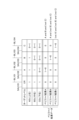
図7は、メモリセルトランジスタMTの閾値分布等を模式的に示す図である。図7の中段にある図は、メモリセルトランジスタMTの閾値電圧(横軸)と、メモリセルトランジスタMTの個数(縦軸)との対応関係を表している。 FIG. 7 is a diagram schematically showing the threshold distribution and the like of the memory cell transistor MT. The diagram in the middle of FIG. 7 shows the correspondence relationship between the threshold voltage of the memory cell transistor MT (horizontal axis) and the number of memory cell transistors MT (vertical axis).
本実施形態のようにTLC方式を採用した場合においては、複数のメモリセルトランジスタMTは、図7の中段に示されるように、8つの閾値分布を形成する。この8個の閾値分布(書き込みレベル)のことを、閾値電圧の低い方から順に“ER”レベル、“A”レベル、“B”レベル、“C”レベル、“D”レベル、“E”レベル、“F”レベル、“G”レベルと称する。 When the TLC method is adopted as in this embodiment, the plurality of memory cell transistors MT form eight threshold distributions as shown in the middle part of FIG. These eight threshold distributions (write levels) are defined as "ER" level, "A" level, "B" level, "C" level, "D" level, and "E" level in descending order of threshold voltage. , “F” level, and “G” level.
図7の上段にある表は、閾値電圧の上記各レベルのそれぞれに対応して、割り当てられるデータの例を表している。同表に示されるように、“ER”レベル、“A”レベル、“B”レベル、“C”レベル、“D”レベル、“E”レベル、“F”レベル、及び“G”レベルには、例えば以下に示すような、それぞれ異なる3ビットデータが割り当てられている。
“ER”レベル:“111”(“下位ビット/中位ビット/上位ビット”)
“A”レベル:“011”
“B”レベル:“001”
“C”レベル:“000”
“D”レベル:“010”
“E”レベル:“110”
“F”レベル:“100”
“G”レベル:“101”
The table in the upper part of FIG. 7 shows an example of data assigned corresponding to each level of the threshold voltage. As shown in the table, "ER" level, "A" level, "B" level, "C" level, "D" level, "E" level, "F" level, and "G" level have , are assigned different 3-bit data, for example, as shown below.
"ER" level: "111"("lower bit/middle bit/higher bit")
"A" level: "011"
"B" level: "001"
"C" level: "000"
"D" level: "010"
"E" level: "110"
"F" level: "100"
"G" level: "101"
このように、本実施形態におけるメモリセルトランジスタMTの閾値電圧は、予め設定された8つの候補レベルのうちの1つをとり得るものとなっており、それぞれの候補レベルに対応して、上記のようにデータが割り当てられている。 As described above, the threshold voltage of the memory cell transistor MT in this embodiment can take one of eight preset candidate levels. Data is assigned as follows.
互いに隣り合う一対の閾値分布の間には、それぞれ書き込み動作で使用されるベリファイ電圧が設定される。具体的には、“A”レベル、“B”レベル、“C”レベル、“D”レベル、“E”レベル、“F”レベル、及び“G”レベルにそれぞれ対応して、ベリファイ電圧VfyA、VfyB、VfyC、VfyD、VfyE、VfyF、及びVfyGが設定される。 A verify voltage used in the write operation is set between a pair of adjacent threshold distributions. Specifically, verify voltages VfyA, VfyA, VfyB, VfyC, VfyD, VfyE, VfyF, and VfyG are set.
ベリファイ電圧VfyAは、“ER”レベルにおける最大の閾値電圧と“A”レベルにおける最小の閾値電圧との間に設定される。ワード線WLにベリファイ電圧VfyAが印加されると、当該ワード線WLに繋がるメモリセルトランジスタMTのうち、閾値電圧が“ER”レベルに含まれるメモリセルトランジスタMTがオン状態になり、閾値電圧が“A”レベル以上の閾値分布に含まれるメモリセルトランジスタMTがオフ状態になる。 The verify voltage VfyA is set between the maximum threshold voltage at the "ER" level and the minimum threshold voltage at the "A" level. When the verify voltage VfyA is applied to the word line WL, among the memory cell transistors MT connected to the word line WL, the memory cell transistors MT whose threshold voltage is included in the "ER" level are turned on, and the threshold voltage becomes " The memory cell transistors MT included in the distribution of threshold values equal to or higher than the A″ level are turned off.
その他のベリファイ電圧VfyB、VfyC、VfyD、VfyE、VfyF、及びVfyGも、上記のベリファイ電圧VfyAと同様に設定される。ベリファイ電圧VfyBは、“A”レベルと“B”レベルとの間に設定され、ベリファイ電圧VfyCは、“B”レベルと“C”レベルとの間に設定され、ベリファイ電圧VfyDは、“C”レベルと“D”レベルとの間に設定され、ベリファイ電圧VfyEは、“D”レベルと“E”レベルとの間に設定され、ベリファイ電圧VfyFは、“E”レベルと“F”レベルとの間に設定され、ベリファイ電圧VfyGは、“F”レベルと“G”レベルとの間に設定される。 Other verify voltages VfyB, VfyC, VfyD, VfyE, VfyF, and VfyG are also set in the same manner as the above verify voltage VfyA. Verify voltage VfyB is set between "A" level and "B" level, verify voltage VfyC is set between "B" level and "C" level, and verify voltage VfyD is set between "C" level. level and "D" level, verify voltage VfyE is set between "D" level and "E" level, and verify voltage VfyF is set between "E" level and "F" level. The verify voltage VfyG is set between the "F" level and the "G" level.
例えば、ベリファイ電圧VfyAは0.8Vに、ベリファイ電圧VfyBは1.6Vに、ベリファイ電圧VfyCは2.4Vに、ベリファイ電圧VfyDは3.1Vに、ベリファイ電圧VfyEは3.8Vに、ベリファイ電圧VfyFは4.6Vに、ベリファイ電圧VfyGは5.6Vに、それぞれ設定してもよい。しかし、これに限定されることなく、ベリファイ電圧VfyA、VfyB、VfyC、VfyD、VfyE、VfyF、及びVfyGは、例えば、0V~7.0Vの範囲で、適宜、段階的に設定してもよい。 For example, the verify voltage VfyA is 0.8 V, the verify voltage VfyB is 1.6 V, the verify voltage VfyC is 2.4 V, the verify voltage VfyD is 3.1 V, the verify voltage VfyE is 3.8 V, and the verify voltage VfyF may be set to 4.6V, and the verify voltage VfyG may be set to 5.6V. However, without being limited to this, the verify voltages VfyA, VfyB, VfyC, VfyD, VfyE, VfyF, and VfyG may be appropriately set stepwise within the range of 0V to 7.0V, for example.
また、隣り合う閾値分布の間には、それぞれ読み出し動作で使用される読み出し電圧が設定される。「読み出し電圧」とは、読み出し動作時において、読み出し対象となるメモリセルトランジスタMTに繋がるワード線WL、すなわち選択ワード線に対し印加される電圧である。読み出し動作では、読み出し対象となるメモリセルトランジスタMTの閾値電圧が、印加された読み出し電圧よりも高いか否かの判定結果に基づいてデータが決定される。 Also, read voltages used in the read operation are set between adjacent threshold distributions. The “read voltage” is a voltage applied to the word line WL connected to the memory cell transistor MT to be read, that is, the selected word line during the read operation. In the read operation, data is determined based on the determination result of whether or not the threshold voltage of the memory cell transistor MT to be read is higher than the applied read voltage.
図7の下段の図において模式的に示されるように、具体的には、メモリセルトランジスタMTの閾値電圧が“ER”レベルに含まれるのか“A”レベル以上に含まれるのかを判定する読み出し電圧VrAは、“ER”レベルにおける最大の閾値電圧と“A”レベルにおける最小の閾値電圧との間に設定される。 As schematically shown in the lower diagram of FIG. 7, specifically, a read voltage for determining whether the threshold voltage of the memory cell transistor MT is included in the "ER" level or included in the "A" level or higher. VrA is set between the maximum threshold voltage at the "ER" level and the minimum threshold voltage at the "A" level.
その他の読み出し電圧VrB、VrC、VrD、VrE、VrF、及びVrGも、上記の読み出し電圧VrAと同様に設定される。読み出し電圧VrBは、“A”レベルと“B”レベルとの間に設定され、読み出し電圧VrCは、“B”レベルと“C”レベルとの間に設定され、読み出し電圧VrDは、“C”レベルと“D”レベルとの間に設定され、読み出し電圧VrEは、“D”レベルと“E”レベルとの間に設定され、読み出し電圧VrFは、“E”レベルと“F”レベルとの間に設定され、読み出し電圧VrGは、“F”レベルと“G”レベルとの間に設定される。 Other read voltages VrB, VrC, VrD, VrE, VrF, and VrG are set similarly to the read voltage VrA. The read voltage VrB is set between the "A" level and the "B" level, the read voltage VrC is set between the "B" level and the "C" level, and the read voltage VrD is set at the "C" level. The read voltage VrE is set between the "D" level and the "E" level, and the read voltage VrF is set between the "E" level and the "F" level. and the read voltage VrG is set between the "F" level and the "G" level.
そして、最も高い閾値分布(例えば“G”レベル)の最大の閾値電圧よりも高い電圧に、読み出しパス電圧VPASS_READが設定される。読み出しパス電圧VPASS_READがゲートに印加されたメモリセルトランジスタMTは、記憶するデータに依らずにオン状態になる。 Then, the read pass voltage VPASS_READ is set to a voltage higher than the maximum threshold voltage of the highest threshold distribution (for example, "G" level). The memory cell transistor MT to which the read pass voltage VPASS_READ is applied to the gate is turned on regardless of the data to be stored.
尚、ベリファイ電圧VfyA、VfyB、VfyC、VfyD、VfyE、VfyF、及びVfyGは、例えば、読み出し電圧VrA、VrB、VrC、VrD、VrE、VrF、及びVrGよりもそれぞれ高い電圧に設定される。つまり、ベリファイ電圧VfyA、VfyB、VfyC、VfyD、VfyE、VfyF、及びVfyGは、それぞれ“A”レベル、“B”レベル、“C”レベル、“D”レベル、“E”レベル、“F”レベル、及び“G”レベルの閾値分布の下裾近傍に設定される。 The verify voltages VfyA, VfyB, VfyC, VfyD, VfyE, VfyF, and VfyG are set higher than the read voltages VrA, VrB, VrC, VrD, VrE, VrF, and VrG, respectively. That is, the verify voltages VfyA, VfyB, VfyC, VfyD, VfyE, VfyF, and VfyG are respectively at "A" level, "B" level, "C" level, "D" level, "E" level, and "F" level. , and near the lower tail of the "G" level threshold distribution.
以上に説明したようなデータの割り付けが適用された場合、読み出し動作において下位ビットの1ページデータ(下位ページデータ)は、読み出し電圧VrA及びVrEを用いた読み出し結果によって確定させることができる。中位ビットの1ページデータ(中位ページデータ)は、読み出し電圧VrB、VrD、及びVrFを用いた読み出し結果によって確定させることができる。上位ビットの1ページデータ(上位ページデータ)は、読み出し電圧VrC及びVrGを用いた読み出し結果によって確定させることができる。このように、下位ページデータ、中位ページデータ、及び上位ページデータがそれぞれ、2回、3回、及び2回の読み出し動作によって確定するため、以上のようなデータの割り付けは“2-3-2コード”と称される。 When data allocation as described above is applied, one page data of lower bits (lower page data) in a read operation can be determined by a read result using read voltages VrA and VrE. One page data of middle bits (middle page data) can be determined by read results using read voltages VrB, VrD, and VrF. One page data of upper bits (upper page data) can be determined by the read result using the read voltages VrC and VrG. In this way, the lower page data, the middle page data, and the upper page data are determined by two, three, and two read operations, respectively. 2 code”.
尚、以上で説明したようなデータの割り付けはあくまで一例であり、実際のデータの割り付けはこれに限定されない。例えば、2ビット又は4ビット以上のデータが1つのメモリセルトランジスタMTに記憶されてもよい。また、データが割り付けられる閾値分布の数(つまり、上記の「候補レベル」の数)は7以下であってもよく、9以上であってもよい。例えば、“2-3-2コード”に代えて、“1-3-3コード”又は“1-2-4コード”を用いてもよい。また、例えば、下位ビット/中位ビット/上位ビットの割り当てを変更してもよい。より具体的には、例えば、“2-3-2コード”において、下位ページデータを読み出し電圧VrC及びVrBを用いた読み出し結果によって確定させ、中位ページデータを読み出し電圧VrB、VrD、及びVrFを用いた読み出し結果によって確定させ、上位ページデータを読み出し電圧VrA及びVrEを用いた読み出し結果によって確定させるようにデータを割り当ててもよい。すなわち、例えば、下位ビットと上位ビットの割り当てを入れ替えてもよい。この場合、閾値電圧の各レベルのそれぞれに対応して、以下のようにデータが割り当てられる。
“ER”レベル:“111”(“下位ビット/中位ビット/上位ビット”)
“A”レベル:“110”
“B”レベル:“100”
“C”レベル:“000”
“D”レベル:“010”
“E”レベル:“011”
“F”レベル:“001”
“G”レベル:“101”
The data allocation as described above is merely an example, and the actual data allocation is not limited to this. For example, 2-bit or 4-bit or more data may be stored in one memory cell transistor MT. Also, the number of threshold distributions to which data is allocated (that is, the number of "candidate levels" described above) may be seven or less, or nine or more. For example, instead of "2-3-2 code", "1-3-3 code" or "1-2-4 code" may be used. Also, for example, the assignment of low-order bits/middle-order bits/high-order bits may be changed. More specifically, for example, in the "2-3-2 code", the lower page data is determined by the read result using the read voltages VrC and VrB, and the middle page data is determined by the read voltages VrB, VrD, and VrF. The data may be assigned such that the read results are determined by the read results used, and the upper page data is determined by the read results using the read voltages VrA and VrE. That is, for example, the allocation of lower bits and upper bits may be exchanged. In this case, data are assigned as follows corresponding to each level of the threshold voltage.
"ER" level: "111"("lower bit/middle bit/higher bit")
"A" level: "110"
"B" level: "100"
"C" level: "000"
"D" level: "010"
"E" level: "011"
"F" level: "001"
"G" level: "101"
半導体記憶装置2において行われる書き込み動作について説明する。書き込み動作では、プログラム動作及びベリファイ動作が行われる。「プログラム動作」とは、一部のメモリセルトランジスタMTの電荷蓄積層336に電子を注入することにより、当該メモリセルトランジスタMTの閾値電圧を変化させる動作のことである。「ベリファイ動作」とは、上記のプログラム動作の後、データを読み出すことで、メモリセルトランジスタMTの閾値電圧がターゲットレベルまで達したか否かを判定し検証する動作である。閾値電圧がターゲットレベルまで達したメモリセルトランジスタMTは、その後、書き込み禁止とされる。ここでいう「ターゲットレベル」とは、先に述べた8つの候補レベルの中から、目標のレベルとして設定された特定の候補レベルのことである。
A write operation performed in the
書き込み動作では、以上のプログラム動作及びベリファイ動作が繰り返し実行される。これにより、メモリセルトランジスタMTの閾値電圧がターゲットレベルまで上昇する。 In the write operation, the above program operation and verify operation are repeatedly executed. This raises the threshold voltage of the memory cell transistor MT to the target level.
複数のワード線WLのうち、書き込み動作の対象(つまり、閾値電圧を変化させる対象)であるメモリセルトランジスタMTに繋がっているワード線WLのことを、以下では「選択ワード線」とも称する。また、書き込み動作の対象ではないメモリセルトランジスタMTに繋がっているワード線WLのことを、以下では「非選択ワード線」とも称する。書き込み対象であるメモリセルトランジスタMTのことを、以下では「選択メモリトランジスタ」とも称する。 Among the plurality of word lines WL, the word line WL connected to the memory cell transistor MT that is the target of the write operation (that is, the target of changing the threshold voltage) is hereinafter also referred to as the "selected word line". Further, the word line WL connected to the memory cell transistor MT that is not the target of the write operation is hereinafter also referred to as "unselected word line". The memory cell transistor MT to be written is hereinafter also referred to as a "selected memory transistor".
複数のストリングユニットSUのうち、書き込み動作の対象となるストリングユニットSUのことを、以下では「選択ストリングユニット」とも称する。また、書き込み動作の対象とはならないストリングユニットSUのことを、以下では「非選択ストリングユニット」とも称する。 Among the plurality of string units SU, the string unit SU targeted for the write operation is hereinafter also referred to as "selected string unit". Also, the string unit SU that is not the target of the write operation is hereinafter also referred to as "non-selected string unit".
選択ストリングユニットに含まれる各NANDストリングNSの導電体柱338、すなわち、選択ストリングユニットにおける各チャンネルのことを、以下では「選択チャンネル」とも称する。また、非選択ストリングユニットに含まれる各NANDストリングNSの導電体柱338、すなわち、非選択ストリングユニットにおける各チャンネルのことを、以下では「非選択チャンネル」とも称する。
The
複数のビット線BLのうち、選択メモリトランジスタに繋がっているビット線BLのことを、以下では「選択ビット線」とも称する。また、選択メモリトランジスタに繋がっていないビット線BLのことを、以下では「非選択ビット線」とも称する。 Among the plurality of bit lines BL, the bit line BL connected to the selected memory transistor is hereinafter also referred to as "selected bit line". A bit line BL that is not connected to a selected memory transistor is hereinafter also referred to as a "non-selected bit line".
プログラム動作について説明する。図8は、プログラム動作時における各配線の電位変化を示している。プログラム動作では、センスアンプ120が、プログラムデータに対応して各ビット線BLの電位を変化させる。プログラム対象の(閾値電圧を上昇させるべき)メモリセルトランジスタMTに繋がるビット線BLには、“L”レベルとして例えば接地電圧Vss(0V)が印加される。プログラム対象ではない(閾値電圧を維持させるべき)メモリセルトランジスタMTに繋がるビット線BLには、“H”レベルとして、例えば2.5Vが印加される。前者のビット線BLは、図8においては「BL(0)」と表記されている。後者のビット線BLは、図8においては「BL(1)」と表記されている。
Program operation will be described. FIG. 8 shows potential changes of each wiring during program operation. In the program operation, the
ロウデコーダ130は、書き込み動作の対象としていずれかのブロックBLKを選択し、更にいずれかのストリングユニットSUを選択する。より具体的には、選択されたストリングユニットSUにおけるセレクトゲート線SGD(選択セレクトゲート線SGDsel)には、電圧生成回路43からロウデコーダ130を介して例えば5Vが印加される。これにより、選択トランジスタST1はオン状態となる。他方で、セレクトゲート線SGSには、電圧生成回路43からロウデコーダ130を介して例えば電圧Vssが印加される。これにより、選択トランジスタST2はオフ状態となる。
The
また、選択ブロックBLKにおける非選択ストリングユニットSUのセレクトゲート線SGD(非選択セレクトゲート線SGDusel)には、電圧生成回路43からロウデコーダ130を介して例えば電圧5Vが印加される。これにより、選択トランジスタST1がオン状態となる。なお、各ブロックBLKに含まれるストリングユニットSUにおいて、セレクトゲート線SGSは共通に接続されている。従って、非選択ストリングユニットSUにおいても、選択トランジスタST2はオフ状態となる。
Also, a voltage of 5 V, for example, is applied from the
更に、非選択ブロックBLKにおけるセレクトゲート線SGD及びセレクトゲート線SGSには、電圧生成回路43からロウデコーダ130を介して例えば電圧Vssが印加される。これにより、選択トランジスタST1及び選択トランジスタST2はオフ状態となる。
Furthermore, the select gate line SGD and the select gate line SGS in the unselected block BLK are applied with, for example, a voltage Vss from the
ソース線SLは、セレクトゲート線SGSの電位よりも高い電位とされる。当該電位は、例えば1Vである。 The source line SL is set to a higher potential than the select gate line SGS. The potential is, for example, 1V.
その後、選択ブロックBLKにおける選択セレクトゲート線SGDselの電位を、例えば2.5Vとする。この電位は、上記の例で0Vが与えられたビット線BL(0)に対応する選択トランジスタST1はオンさせるが、2.5Vが与えられたビット線BL(1)に対応する選択トランジスタST1はカットオフさせる電圧である。これにより、選択ストリングユニットSUにおいては、ビット線BL(0)に対応する選択トランジスタST1はオンされ、2.5Vが与えられたビット線BL(1)に対応する選択トランジスタST1はカットオフされる。一方で、非選択セレクトゲート線SGDuselの電位を、例えば電圧Vssとする。これにより、非選択ストリングユニットSUにおいては、ビット線BL(0)及びビット線BL(1)の電位に関わらず、選択トランジスタST1はカットオフされる。 After that, the potential of the selected select gate line SGDsel in the selected block BLK is set to 2.5V, for example. This potential turns on the select transistor ST1 corresponding to the bit line BL(0) to which 0 V is applied in the above example, but the select transistor ST1 corresponding to the bit line BL(1) to which 2.5 V is applied is turned on. This is the voltage to cut off. As a result, in the selected string unit SU, the select transistor ST1 corresponding to the bit line BL(0) is turned on, and the select transistor ST1 corresponding to the bit line BL(1) to which 2.5 V is applied is cut off. . On the other hand, the potential of the unselected select gate line SGDusel is set to voltage Vss, for example. As a result, in the unselected string unit SU, the select transistor ST1 is cut off regardless of the potentials of the bit lines BL(0) and BL(1).
そしてロウデコーダ130は、選択ブロックBLKにおいて、書き込み動作の対象としていずれかのワード線WLを選択する。書き込み動作の対象となるワード線WL(選択ワード線WLsel)に、電圧生成回路43からロウデコーダ130を介して例えば電圧VPGMが印加される。一方で、その他のワード線WL(非選択ワード線WLusel)に、電圧生成回路43からロウデコーダ130を介して例えば電圧VPASS_PGMが印加される。電圧VPGMは、トンネル現象により電子を電荷蓄積層336に注入するための高電圧である。電圧VPASS_PGMは、ワード線WLに繋がるメモリセルトランジスタMTをONとする一方で、閾定電圧は変化させない程度の電圧である。VPGMはVPASS_PGMよりも高い電圧である。
Then, the
プログラム対象のビット線BL(0)に対応するNANDストリングNSでは、選択トランジスタST1がオン状態となる。そのため、選択ワード線WLselに接続されたメモリセルトランジスタMTのチャネル電位は0Vとなる。制御ゲートとチャネルとの間の電位差が大きくなり、その結果、電子が電荷蓄積層336に注入されるので、メモリセルトランジスタMTの閾値電圧が上昇される。
In the NAND string NS corresponding to the bit line BL(0) to be programmed, the select transistor ST1 is turned on. Therefore, the channel potential of the memory cell transistor MT connected to the selected word line WLsel becomes 0V. The potential difference between the control gate and the channel increases, and as a result, electrons are injected into the
プログラム対象ではないビット線BL(1)に対応するNANDストリングNSでは、選択トランジスタST1がカットオフ状態となる。そのため、選択ワード線WLselに接続されたメモリセルトランジスタMTのチャネルは電気的にフローティングとなり、ワード線WL等との容量カップリングによりチャネル電位は電圧VPGM近くまで上昇される。制御ゲートとチャネルとの間の電位差が小さくなり、その結果、電子は電荷蓄積層336に注入されないので、メモリセルトランジスタMTの閾値電圧は維持される。正確にいうと、閾値分布レベルがより高い分布に遷移するほどには、閾値電圧は変動しない。
In the NAND string NS corresponding to the bit line BL(1) that is not to be programmed, the selection transistor ST1 is cut off. Therefore, the channel of the memory cell transistor MT connected to the selected word line WLsel becomes electrically floating, and the channel potential rises to near the voltage VPGM due to capacitive coupling with the word line WL and the like. Since the potential difference between the control gate and the channel becomes smaller and as a result electrons are not injected into the
読み出し動作について説明する。尚、プログラム動作に続いて行われるベリファイ動作は、以下に説明する読み出し動作と同じである。図9は、読み出し動作時における各配線の電位変化を示している。読み出し動作では、読み出し動作の対象となるメモリセルトランジスタMT、を含むNANDストリングNSが選択される。あるいは、読み出し動作の対象となるページを含むストリングユニットSUが選択される。 A read operation will be described. The verify operation that follows the program operation is the same as the read operation described below. FIG. 9 shows potential changes of each wiring during read operation. In the read operation, a NAND string NS including memory cell transistors MT to be read is selected. Alternatively, the string unit SU containing the page targeted for the read operation is selected.
まず、選択セレクトゲート線SGDsel、非選択セレクトゲート線SGDusel及びセレクトゲート線SGSには、電圧生成回路43からロウデコーダ130を介して例えば5Vが印加される。これにより、選択ブロックBLKに含まれる選択トランジスタST1及び選択トランジスタST2はオン状態となる。また、選択ワード線WLsel及び非選択ワード線には、電圧生成回路43からロウデコーダ130を介して例えば読み出しパス電圧VPASS_READが印加される。読み出しパス電圧VPASS_READは、メモリセルトランジスタMTの閾値電圧にかかわらず、メモリセルトランジスタMTをONとすることができ、かつ、閾定電圧は変化させない程度の電圧である。これにより、選択ストリングユニットSUであるか非選択ストリングユニットSUであるかにかかわらず、選択ブロックBLKに含まれる全てのNANDストリングNSにおいて、電流が導通する。
First, 5V, for example, is applied from the
次に、読み出し動作の対象となるメモリセルトランジスタMTに繋がるワード線WL(選択ワード線WLsel)に対し、電圧生成回路43からロウデコーダ130を介して例えばVrAのような読み出し電圧Vrが印加される。それ以外のワード線(非選択ワード線WLusel)に対しては、読み出しパス電圧VPASS_READが印加される。
Next, a read voltage Vr such as VrA is applied from the
また、選択セレクトゲート線SGDsel及びセレクトゲート線SGSに印加する電圧は維持しつつ、非選択セレクトゲート線SGDuselには、電圧生成回路43からロウデコーダ130を介して例えば電圧Vssが印加される。これにより、選択ストリングユニットSUに含まれる選択トランジスタST1はオン状態を維持するが、非選択ストリングユニットSUに含まれる選択トランジスタST1はオフ状態となる。なお、選択ストリングユニットSUであるか非選択ストリングユニットSUであるかにかかわらず、選択ブロックBLKに含まれる選択トランジスタST2はオン状態となる。
Further, while maintaining the voltage applied to the selected select gate line SGDsel and the select gate line SGS, the voltage Vss, for example, is applied from the
これにより、非選択ストリングユニットSUに含まれるNANDストリングNSは、少なくとも選択トランジスタST1がオフ状態となるため、電流パスを形成しない。一方で、選択ストリングユニットSUに含まれるNANDストリングNSは、選択ワード線WLselに印加される読み出し電圧VrとメモリセルトランジスタMTの閾値電圧との関係に応じて、電流パスが形成され、または、形成されない。 As a result, the NAND string NS included in the unselected string unit SU does not form a current path because at least the selection transistor ST1 is turned off. On the other hand, in the NAND string NS included in the selected string unit SU, a current path is formed or formed according to the relationship between the read voltage Vr applied to the selected word line WLsel and the threshold voltage of the memory cell transistor MT. not.
センスアンプ120は、選択されたNANDストリングNSに繋がるビット線BLに対して電圧を印加する。この状態で、センスアンプ120は、当該ビット線BLを流れる電流の値に基づいてデータの読み出しを行う。具体的には、読み出し動作の対象となるメモリセルトランジスタMTの閾値電圧が、当該メモリセルトランジスタMTに印加された読み出し電圧よりも高いか否かを判定する。尚、データの読み出しは、ビット線BLを流れる電流の値に基づくのではなく、ビット線BLにおける電位の時間変化に基づいて行われてもよい。後者の場合、ビット線BLは、予め所定の電位となるようにプリチャージされる。
The
先に述べたベリファイ動作も、上記のような読み出し動作と同様に行われる。ベリファイ動作では、ベリファイの対象となるメモリセルトランジスタMTに繋がるワード線WLに対し、例えばVfyAのようなベリファイ電圧が電圧生成回路43からロウデコーダ130を介して印加されることとなる。
The verify operation described above is also performed in the same manner as the read operation described above. In the verify operation, a verify voltage such as VfyA is applied from the
なお、先に述べたプログラム動作の初期段階における選択セレクトゲート線SGDsel及び非選択セレクトゲート線SGDuselに5Vの電圧を印加する動作は、省略される場合がある。同様に、先に述べた読み出し動作(ベリファイ動作)の初期段階における非選択セレクトゲート線SGDuselに5Vの電圧を印加し選択ワード線WLselに読み出しパス電圧VPASS_READを印加する動作は、省略される場合がある。 Note that the operation of applying a voltage of 5 V to the selected select gate line SGDsel and the unselected select gate line SGDusel in the initial stage of the program operation described above may be omitted. Similarly, the operation of applying a voltage of 5 V to the unselected select gate line SGDusel and applying the read pass voltage VPASS_READ to the selected word line WLsel in the initial stage of the read operation (verify operation) described above may be omitted. be.
図10には、本実施形態における書き込み動作時における各配線の電位変化等が模式的に表されている。図10(A)に示されるのは、各ワード線WLの電位を変化させるために、電圧生成回路43からメモリセルアレイ110へと供給される電流の時間変化の例である。当該電流のことを、以下では「Icc」とも称する。
FIG. 10 schematically shows changes in the potential of each wiring during a write operation in this embodiment. FIG. 10A shows an example of temporal change in current supplied from the
図10(B)の線L01に示されるのは、選択セレクトゲート線SGDselにおける電位の時間変化の例である。当該電位のことを、以下では「V_SGD_sel」とも称する。また、図10(B)の線L02に示されるのは、非選択セレクトゲート線SGDuselにおける電位の時間変化の例である。当該電位のことを、以下では「V_SGD_usel」とも称する。 A line L01 in FIG. 10B shows an example of the potential change over time in the selected select gate line SGDsel. This potential is hereinafter also referred to as “V_SGD_sel”. Also, the line L02 in FIG. 10B shows an example of the potential change over time in the unselected select gate line SGDusel. This potential is hereinafter also referred to as “V_SGD_usel”.
図10(C)に示されるのは、選択ワード線WLselにおける電位の時間変化の例である。当該電位のことを、以下では「V_WL_sel」とも称する。図10(D)に示されるのは、非選択ワード線WLuselにおける電位の時間変化の例である。当該電位のことを、以下では「V_WL_usel」とも称する。 FIG. 10C shows an example of the potential change over time in the selected word line WLsel. This potential is hereinafter also referred to as “V_WL_sel”. FIG. 10D shows an example of the potential change over time on the unselected word line WLusel. This potential is hereinafter also referred to as “V_WL_usel”.
図10(E)に示されるのは、選択セレクトゲート線SGDselに対応する選択ストリングユニットに属する選択チャンネルにおける電位の時間変化の例である。当該電位のことを、以下では「V_Ch_sel」とも称する。このうち、線L11に示されるのは、選択チャンネルのうち、選択メモリトランジスタに繋がっていないもの(換言すれば、非選択ビット線に繋がっているもの)における電位の時間変化の例である。線L12に示されるのは、選択チャンネルのうち、選択メモリトランジスタに繋がるもの(換言すれば、選択ビット線に繋がっているもの)における電位の時間変化の例である。 FIG. 10(E) shows an example of the potential change over time in the selected channel belonging to the selected string unit corresponding to the selected select gate line SGDsel. This potential is hereinafter also referred to as “V_Ch_sel”. Among them, the line L11 shows an example of the time change of the potential in the selected channel that is not connected to the selected memory transistor (in other words, the channel that is connected to the unselected bit line). Line L12 shows an example of the potential change over time in the selected channel connected to the selected memory transistor (in other words, the selected bit line).
図10(F)に示されるのは、ビット線BLにおける電位の時間変化の例である。当該電位のことを、以下では「V_BL」とも称する。このうち、線L21に示されるのは、複数のビット線BLのうち非選択ビット線における電位の時間変化の例である。線L22に示されるのは、複数のビット線BLのうち選択ビット線における電位の時間変化の例である。 FIG. 10F shows an example of temporal change in the potential of the bit line BL. This potential is hereinafter also referred to as “V_BL”. Of these, the line L21 shows an example of the time change of the potential of the non-selected bit lines among the plurality of bit lines BL. Line L22 shows an example of a change in potential over time in a selected bit line out of a plurality of bit lines BL.
図10(G)に示されるのは、非選択セレクトゲート線SGDuselに対応する非選択ストリングユニットに属する非選択チャンネルにおける電位の時間変化の例である。当該電位のことを、以下では「V_Ch_usel」とも称する。このうち、線L31に示されるのは、非選択ビット線に繋がっている非選択チャンネルの電位の時間変化の例である。線L32に示されるのは、選択ビット線に繋がっている非選択チャンネルの電位の時間変化の例である。 FIG. 10(G) shows an example of time change of the potential in the unselected channel belonging to the unselected string unit corresponding to the unselected select gate line SGDusel. This potential is hereinafter also referred to as “V_Ch_usel”. Among them, the line L31 shows an example of the time change of the potential of the non-selected channel connected to the non-selected bit line. Line L32 shows an example of the potential change over time of the non-selected channel connected to the selected bit line.
図10の例では、時刻t1においてプログラム動作が開始される。シーケンサ41は、時刻t1から時刻t2までの期間において、V_SGD_sel(線L01)及びV_SGD_usel(線L02)を例えば0Vから5Vまで上昇させる。これにより、選択ストリングユニットの各選択トランジスタST1と非選択ストリングユニットの各選択トランジスタST1は、それぞれ、オン状態となる。
In the example of FIG. 10, the program operation starts at time t1. The
時刻t2において、シーケンサ41は、非選択ビット線の電位を、図10(F)の線L21のように2.5Vまで上昇させる。これにより、非選択ビット線に繋がっている選択チャンネルにおける電位は、図10(E)の線L11に示されるように2.5Vまで上昇する。尚、図示は省略するが、プログラム動作が行われている期間においては、選択トランジスタST2はオフ状態とされている。
At time t2, the
その後、シーケンサ41は、V_SGD_sel(線L01)を一旦低下させた後、時刻t3から時刻t4までの期間においてV_SGD_selを2.5Vに変化させるとともに、V_SGD_usel(線L02)を0Vに変化させる(図10(B))。
After that, the
図10(B)及び図10(F)に示されるように、時刻t4以降においては、V_SGD_selは非選択ビット線における電位(2.5V)と同電位となっている。このため、選択ストリングユニットにおいて非選択ビット線に繋がる選択トランジスタST1は、カットオフされてオフ状態となる。一方、V_SGD_sel(線L01)は選択ビット線における電位(0V)よりも高くなっている。このため、選択ストリングユニットにおいて選択ビット線に繋がる選択トランジスタST1はオン状態となる。なお、V_SGD_usel(線L02)は非選択ビット線における電位(2.5V)より低く、選択ビット線における電位(0V)と同電位であるため、非選択ストリングユニットにおける選択トランジスタST1は全てオフ状態となる。 As shown in FIGS. 10B and 10F, after time t4, V_SGD_sel is the same potential as the potential (2.5 V) of the unselected bit lines. Therefore, the select transistor ST1 connected to the unselected bit line in the selected string unit is cut off and turned off. On the other hand, V_SGD_sel (line L01) is higher than the potential (0V) on the selected bit line. Therefore, the select transistor ST1 connected to the selected bit line in the selected string unit is turned on. Note that V_SGD_usel (line L02) is lower than the potential (2.5 V) of the unselected bit lines and is the same as the potential (0 V) of the selected bit lines, so all the select transistors ST1 in the unselected string units are turned off. Become.
その結果、非選択ビット線に繋がっている選択チャンネルは、選択トランジスタST1がオフ状態となることにより、時刻t4以降においてフローティングの状態となる。一方、選択ビット線に繋がっている選択チャンネルは、選択トランジスタST1がオン状態となることにより、時刻t4以降において選択ビット線と導通した状態となる。 As a result, the selected channel connected to the non-selected bit line is in a floating state after time t4 due to the selection transistor ST1 being turned off. On the other hand, the selected channel connected to the selected bit line becomes conductive with the selected bit line after time t4 by turning on the select transistor ST1.
その後、時刻t5から時刻t6までの期間において、シーケンサは、ワード線WLのそれぞれの電位をVPASS_PGMまで上昇させる。VPASS_PGMは、メモリセルトランジスタMTの閾値電圧によることなく、メモリセルトランジスタMTをオン状態とするような大きさの電位であって、例えば10Vである。図10(C)及び図10(D)に示されるように、時刻t6においては、V_WL_sel及びV_WL_uselの両方がVPASS_PGMまで上昇した状態となる。図10(A)に示されるように、時刻t5以降においては、ワード線WLの電位を上昇させることに伴い、一時的にIccが上昇する。 After that, during the period from time t5 to time t6, the sequencer raises the potential of each word line WL to VPASS_PGM. VPASS_PGM is a potential, such as 10 V, that turns on the memory cell transistor MT regardless of the threshold voltage of the memory cell transistor MT. As shown in FIGS. 10(C) and 10(D), at time t6, both V_WL_sel and V_WL_usel rise to VPASS_PGM. As shown in FIG. 10A, after time t5, Icc temporarily rises as the potential of word line WL rises.
非選択ビット線に繋がっている選択チャンネルは、先に述べたようにフローティングの状態となっている。この状態で、それぞれのワード線WLの電位がVPASS_PGMまで上昇すると、ワード線WLと当該選択チャンネルとの間の容量カップリングにより、当該選択チャンネルの電位も上昇する。非選択ビット線に繋がっている選択チャンネルの電位V_Ch_selは、例えば、図10(E)の線L11に示されるように、V_IH1まで上昇している。V_IH1は、概ねVPASS_PGMと同程度の電位である。非選択ビット線に繋がっている非選択チャンネルの電位V_Ch_uselも、図10(G)の線L31に示されるように、V_IH1まで上昇している。すなわち、図10(G)の線L31に示される非選択ビット線に繋がっている非選択チャンネルの電位V_Ch_uselは、図10(E)の線L11に示される非選択ビット線に繋がっている選択チャンネルの電位V_Ch_selと概ね同様に変化する。 Selected channels connected to non-selected bit lines are in a floating state as described above. In this state, when the potential of each word line WL rises to VPASS_PGM, the potential of the selected channel also rises due to capacitive coupling between the word line WL and the selected channel. The potential V_Ch_sel of the selected channel connected to the non-selected bit line rises to V_IH1, as indicated by line L11 in FIG. 10(E), for example. V_IH1 is approximately the same potential as VPASS_PGM. The potential V_Ch_usel of the non-selected channel connected to the non-selected bit line also rises to V_IH1 as indicated by line L31 in FIG. 10(G). That is, the potential V_Ch_usel of the unselected channel connected to the unselected bit line indicated by line L31 in FIG. V_Ch_sel changes in substantially the same manner as the potential V_Ch_sel of .
なお、選択ビット線に繋がっている非選択チャンネルも、非選択ビット線に繋がっている非選択チャンネルと同様に、フローティングの状態となっている。この状態で、それぞれのワード線WLの電位がVPASS_PGMまで上昇すると、ワード線WLと当該非選択チャンネルとの間の容量カップリングにより、当該非選択チャンネルの電位も上昇する。選択ビット線に繋がっている非選択チャンネルの電位V_Ch_uselは、図10(G)の線L32に示されるように、V_IH2まで上昇している。V_IH2は、概ねVPASS_PGMと同程度の電位であるが、V_IH1より低い電位である。 The unselected channels connected to the selected bit lines are also in a floating state, like the unselected channels connected to the unselected bit lines. In this state, when the potential of each word line WL rises to VPASS_PGM, the potential of the non-selected channel also rises due to capacitive coupling between the word line WL and the non-selected channel. The potential V_Ch_usel of the unselected channel connected to the selected bit line rises to V_IH2 as shown by line L32 in FIG. 10(G). V_IH2 is approximately the same potential as VPASS_PGM, but lower than V_IH1.
選択ビット線に繋がっている選択チャンネルは、先に述べたように選択ビット線BLと導通した状態となっている。このため、それぞれのワード線WLの電位がVPASS_PGMまで上昇しても、当該選択チャンネルの電位は上昇せず、図10(E)の線L12に示されるように0Vのままとなる。 The selected channel connected to the selected bit line is in a conductive state with the selected bit line BL as described above. Therefore, even if the potential of each word line WL rises to VPASS_PGM, the potential of the selected channel does not rise and remains at 0 V as indicated by line L12 in FIG. 10(E).
時刻t6において、各ワード線WLの電位がVPASS_PGMまで上昇すると、シーケンサ41は、選択ワード線の電位であるV_WL_selを更にVPGMまで上昇させる。VPGMは、メモリセルトランジスタMTの閾値電圧を上昇させるような大きさの電位であって、例えば20Vである。非選択ワード線の電位はVPASS_PGMのまま維持される。
At time t6, when the potential of each word line WL rises to VPASS_PGM, the
図11には、このときにおけるNANDストリングNSの様子が等価回路図として示されている。図11に示される一対のNANDストリングNS1、NS2は、同一の選択ストリングユニットに属している。このうち、NANDストリングNS1は選択ビット線に繋がっており、NANDストリングNS2は非選択ビット線に繋がっている。図11の例では、NANDストリングNS1のメモリセルトランジスタMT3が、書き込み動作の対象となっている。 FIG. 11 shows the state of the NAND string NS at this time as an equivalent circuit diagram. A pair of NAND strings NS1, NS2 shown in FIG. 11 belong to the same selected string unit. Among them, the NAND string NS1 is connected to the selected bit line, and the NAND string NS2 is connected to the non-selected bit line. In the example of FIG. 11, the memory cell transistor MT3 of the NAND string NS1 is the target of the write operation.
時刻t7以降において、NANDストリングNS1では、選択トランジスタST1と、メモリセルトランジスタMTがオン状態となっており、選択トランジスタST2がオフ状態となっている。このため、選択ビット線に繋がっている選択チャンネルの電位V_Ch_selは0Vとなっている。 After time t7, in the NAND string NS1, the selection transistor ST1 and the memory cell transistor MT are on, and the selection transistor ST2 is off. Therefore, the potential V_Ch_sel of the selected channel connected to the selected bit line is 0V.
NANDストリングNS1のうち、書き込みの対象とはなっていないメモリセルトランジスタMT0~MT2、MT4~MT7においては、ゲートに接続された非選択ワード線(VPASS_PGM)と、その内側の選択チャンネル(0V)の間の電位差は10V程度である。このため、これらのメモリセルトランジスタMTは、オン状態となるだけであり、その閾値電圧は変化しない。 In the memory cell transistors MT0 to MT2 and MT4 to MT7 which are not subject to writing in the NAND string NS1, the unselected word line (VPASS_PGM) connected to the gate and the selected channel (0V) inside it are connected. The potential difference between them is about 10V. Therefore, these memory cell transistors MT are only turned on, and their threshold voltages do not change.
一方、NANDストリングNS1のうち、書き込みの対象となっているメモリセルトランジスタMT3においては、ゲートに接続された選択ワード線(VPGM)と、その内側の選択チャンネル(0V)との間の電位差は、比較的高い20Vとなっている。このため、メモリセルトランジスタMT3の閾値電圧は変化し、データが書き込まれる。 On the other hand, in the memory cell transistor MT3 to be written in the NAND string NS1, the potential difference between the selected word line (VPGM) connected to the gate and the selected channel (0 V) inside it is It is relatively high 20V. Therefore, the threshold voltage of the memory cell transistor MT3 changes and data is written.
非選択ビット線に繋がるNANDストリングNS2では、先に述べたように、選択トランジスタST1、ST2のいずれもがオフ状態となっている。このため、非選択ビット線に繋がっている選択チャンネルはフローティング状態となっている。各メモリセルトランジスタMTのゲートに繋がるワード線WL(VPASS_PGM又はVPGM)と、その内側にある選択チャンネル(V_IH1)との間の電位差は、概ね0V~10V程度の範囲に収まる。このため、これらのメモリセルトランジスタMTは、オン状態となるだけであり、その閾値電圧は変化しない。非選択ストリングユニットに属するNANDストリングNSにおいてもこれと同様であり、当該NANDストリングNSに含まれる各メモリセルトランジスタMTの閾値電圧は変化しない。 In the NAND string NS2 connected to the non-selected bit line, both of the select transistors ST1 and ST2 are off as described above. Therefore, selected channels connected to non-selected bit lines are in a floating state. The potential difference between the word line WL (VPASS_PGM or VPGM) connected to the gate of each memory cell transistor MT and the selection channel (V_IH1) inside thereof falls within a range of approximately 0V to 10V. Therefore, these memory cell transistors MT are only turned on, and their threshold voltages do not change. The same applies to NAND strings NS belonging to non-selected string units, and the threshold voltage of each memory cell transistor MT included in the NAND string NS does not change.
以上のように、プログラム動作が実行される際においては、選択ストリングユニットに含まれる複数の選択チャンネルは、0Vに維持されるものとV_IH1まで上昇するものとに分かれることとなる。0Vに維持されるチャンネル、すなわち、データが書き込まれるメモリセルトランジスタMTに繋がるチャンネルのことを、以下では「チャンネルPG」とも称する。また、V_IH1まで上昇するチャンネル、すなわち、データが書き込まれるメモリセルトランジスタMTに繋がっていないチャンネルのことを、以下では「チャンネルIH」とも称する。選択ストリングユニットに属するチャンネルPG及びチャンネルIHのそれぞれの数は、ページに書き込まれるデータや、後述のループ回数に応じて都度変化する。 As described above, when the program operation is executed, the plurality of selected channels included in the selected string unit are divided into those that are maintained at 0V and those that rise to V_IH1. A channel maintained at 0V, that is, a channel connected to a memory cell transistor MT to which data is written is hereinafter also referred to as "channel PG". Also, a channel that rises to V_IH1, that is, a channel that is not connected to the memory cell transistor MT to which data is written is hereinafter also referred to as "channel IH". The number of channels PG and channels IH belonging to the selected string unit changes each time according to the data written to the page and the number of loops described later.
尚、非選択ストリングユニットに含まれる複数の非選択チャンネルは、プログラム動作において、その全てが少なくともV_IH2まで上昇する。すなわち、プログラム動作において、選択ビット線に繋がっている非選択チャンネルの電位V_Ch_uselはV_IH2まで上昇し、非選択ビット線に繋がっている非選択チャンネルの電位V_Ch_uselは、V_IH2より高いV_IH1まで上昇する。非選択ストリングユニットに属するV_IH2まで電位が上昇する非選択チャンネル及びV_IH1まで電位が上昇する非選択チャンネルのそれぞれの数も、ページに書き込まれるデータや、ループ回数に応じて都度変化する。 It should be noted that the plurality of unselected channels included in the unselected string units all rise to at least V_IH2 in the program operation. That is, in the program operation, the potential V_Ch_usel of the unselected channels connected to the selected bit line rises to V_IH2, and the potential V_Ch_usel of the unselected channels connected to the unselected bit lines rises to V_IH1, which is higher than V_IH2. The number of unselected channels whose potential rises to V_IH2 belonging to unselected string units and the number of unselected channels whose potential rises to V_IH1 also changes each time according to the data written to the page and the number of loops.
図10に戻って説明を続ける。時刻t7において、選択ワード線の電位V_WL_selがVPGMとされると、上記のようにデータの書き込みが行われる。当該状態は、時刻t8までの一定期間継続される。時刻t8においてプログラム動作は終了し、以降はベリファイ動作が行われる。 Returning to FIG. 10, the description continues. At time t7, when the potential V_WL_sel of the selected word line is set to VPGM, data is written as described above. This state continues for a certain period of time until time t8. The program operation ends at time t8, and the verify operation is performed thereafter.
ベリファイ動作において、シーケンサ41は、セレクトゲート線SGDにおける電位V_SGDを、例えば5Vまで上昇させる(図10(B))。また、ビット線BLの電位V_BLを、例えば1Vに変化させる(図10(F))。尚、このようなV_BLの切り換えは、選択ビット線及び非選択ビット線の両方に対して行われる。
In the verify operation, the
上記と同時に、シーケンサ41は、選択ワード線における電位V_WL_selを、VPGMからVPASS_READまで変化させる。その後の時刻t9において、シーケンサ41は、選択ワード線における電位V_WL_selを、VPASS_READからVcgrvまで変化させる(図10(C))。Vcgrvは、ベリファイの対象となる候補レベルに応じて、図7のVfyAやVfyB等の中から選択される大きさの電位である。ベリファイの対象となる候補レベルがどのように設定されるかについては後に説明する。
At the same time as above, the
また、シーケンサ41は、非選択ワード線における電位V_WL_uselを、VPASS_PGMからVPASS_READまで変化させる(図10(D))。VPASS_READは、メモリセルトランジスタMTの閾値電圧によることなく、メモリセルトランジスタMTをオン状態とするような大きさの電位であって、例えば5Vである。
Also, the
以上のような各配線の電位の変更は、ベリファイ動作が開始された時刻t8以降の期間において、シーケンサ41によって概ね同時に行われる。
The change in the potential of each wiring as described above is performed substantially simultaneously by the
時刻t8の後の時刻t9には、シーケンサ41は、V_SGD_usel(線L02)を例えば5Vから0Vまで下降させる。時刻t9以降は、V_SGDが5Vに上昇したことに伴って選択トランジスタがON状態となり、それぞれのビット線BLと選択チャンネルとの間が導通した状態となる。このため、V_Ch_sel及びV_Ch_uselは、いずれも、ビット線BLの電位と同じ1Vとなるように変化する。
At time t9 after time t8, the
時刻t9の状態においては、ベリファイの対象となるメモリセルトランジスタMTの閾値電圧が、Vcgrvよりも高い場合には、当該メモリセルトランジスタMTはオフ状態となり、当該メモリセルトランジスタSTを含むチャンネルPGには電流が流れない。一方、ベリファイの対象となるメモリセルトランジスタMTの閾値電圧が、Vcgrvよりも低い場合には、当該メモリセルトランジスタSTはオン状態となり、当該メモリセルトランジスタMTを含むチャンネルPGには電流が流れる。それぞれの電流値は、センスアンプ120によって検知することができる。シーケンサ41は、チャンネルPGを流れる電流に基づいて、メモリセルトランジスタMTの閾値電圧がターゲットレベルに到達したかどうかを判定することができる。その後の時刻t10においてベリファイ動作が完了すると、シーケンサ41は、図10(B)のV_SGD_sel(線L01)を5Vから0Vまで下降させると共に、図10(C)のV_WL_selをVcgrvから0Vまで下降させる。
In the state of time t9, if the threshold voltage of the memory cell transistor MT to be verified is higher than Vcgrv, the memory cell transistor MT is turned off, and the channel PG including the memory cell transistor ST is Current cannot flow. On the other hand, when the threshold voltage of the memory cell transistor MT to be verified is lower than Vcgrv, the memory cell transistor ST is turned on and current flows through the channel PG including the memory cell transistor MT. Each current value can be sensed by
尚、図10の例は、ベリファイ動作が単一のレベルを対象として行われる例となっている。つまり、図10(C)に示されるV_WL_selは、時刻t9においてVcgrvに設定された後、当該電圧に対応した単一のレベルについてのみベリファイ動作が行われている。後に説明するように、時刻t9以降においては、Vcgrvが段階的に変化するように調整され、それぞれの段階に応じた複数のレベルについてベリファイ動作が行われることもある。 Note that the example of FIG. 10 is an example in which the verify operation is performed for a single level. That is, after V_WL_sel shown in FIG. 10C is set to Vcgrv at time t9, verify operation is performed only for a single level corresponding to the voltage. As will be described later, after time t9, Vcgrv is adjusted to change in stages, and verify operations may be performed for a plurality of levels corresponding to each stage.
書き込み動作の全体における具体的な流れについて説明する。書き込み動作では、データが正しく書き込まれたことが確認されるまで、上記のようなプログラム動作とベリファイ動作とが繰り返される。図12では、プログラム動作とベリファイ動作との組み合わせが19回繰り返されることによって、データが書き込まれる場合を例に示している。このように繰り返される各動作のことを、以下では「ループ」とも称する。
A specific flow of the entire write operation will be described. In the write operation, the above program operation and verify operation are repeated until it is confirmed that the data has been written correctly. FIG. 12 shows an example in which data is written by repeating a combination of program operation and verify
図12には、書き込み動作時における選択ワード線の電位変化の例が示されている。同図に示されるように、上記のループは最大で19回実行される。尚、図12に示される「VPGM1」とは、1回目のループにおいて選択ワード線に印加されるVPGMのことである。「VPGM2」とは、2回目のループにおいて選択ワード線に印加されるVPGMのことである。以下同様に、各回のループにおいて選択ワード線に印加されるVPGMが、図12においては「VPGM3」、「VPGM4」、・・・、「VPGM19」と表記されている。同図に示されるように、ループが繰り返される毎に、VPGMの値は次第に大きくなるようにステップアップされる。 FIG. 12 shows an example of potential change of the selected word line during write operation. As shown in the figure, the above loop is executed a maximum of 19 times. "VPGM1" shown in FIG. 12 is the VPGM applied to the selected word line in the first loop. "VPGM2" is the VPGM applied to the selected word line in the second loop. Similarly, the VPGM applied to the selected word line in each loop is denoted as "VPGM3", "VPGM4", . . . , "VPGM19" in FIG. As shown in the figure, each time the loop is repeated, the value of VPGM is stepped up to become larger.
図13には、各ループにおいて行われるベリファイ動作のターゲットレベルが示されている。また、図14には、各ループにおいて行われるプログラム動作のターゲットレベルが示されている。尚、図14に示される「1」は、当該レベルにおける書き込み動作が行われないことを意味しており、「0」は、当該レベルにおける書き込み動作が行わることを意味している。また、「0/1」は、当該レベルにおける書き込み動作が基本的には行われるが、前回の書き込み動作時においてベリファイをパスしていた場合には、書き込み動作が行われないことを意味している。 FIG. 13 shows the target level of the verify operation performed in each loop. Also shown in FIG. 14 is the target level of the program operations performed in each loop. Note that "1" shown in FIG. 14 means that the write operation is not performed at the level, and "0" means that the write operation is performed at the level. Also, "0/1" means that the write operation at the level is basically performed, but the write operation is not performed if the verify has been passed at the time of the previous write operation. there is
図12及び図13、14に示されるように、これらの例における1回目のループでは、プログラム動作において選択ワード線にVPGM1が印加された後、ベリファイ動作は“A”レベルのみを対象にして行われる。つまり、ベリファイ動作時において選択ワード線にはベリファイ電圧VfyAが印加され、ベリファイ電圧VfyB~VfyGは印加されない。 As shown in FIGS. 12, 13 and 14, in the first loop in these examples, after VPGM1 is applied to the selected word line in the program operation, the verify operation is performed only for the "A" level. will be In other words, the verify voltage VfyA is applied to the selected word line during the verify operation, and the verify voltages VfyB to VfyG are not applied.
尚、1回目のループにおいてプログラム対象となるメモリセルトランジスタMTは、閾値電圧が最終的に“A”レベル以上となるべき全てのメモリセルトランジスタMTである。一方、1回目のループにおいて“A”レベルのベリファイ対象となるメモリセルトランジスタMTは、閾値電圧が最終的に“A”レベルとなるメモリセルトランジスタMTである。閾値電圧が最終的に“B”レベル以上となるメモリセルトランジスタMTは、“A”レベルのベリファイ対象からは外される。 Note that the memory cell transistors MT to be programmed in the first loop are all the memory cell transistors MT whose threshold voltages should finally be the "A" level or higher. On the other hand, the memory cell transistor MT to be verified for "A" level in the first loop is the memory cell transistor MT whose threshold voltage finally becomes "A" level. A memory cell transistor MT whose threshold voltage is finally equal to or higher than the "B" level is excluded from verification targets of the "A" level.
2回目のループでは、選択ワード線にVPGM2が印加された後、1回目のループと同様のプログラム動作及びベリファイ動作が行われる。ただし、閾値電圧が最終的に“A”レベルとなるメモリセルトランジスタMTのうち、1回目のループにおいて“A”レベルのベリファイにパスしたものは、2回目のループにおけるプログラム動作及びベリファイ動作の対象からは外される。つまり、2回目のループでは、閾値電圧が最終的に“B”レベル以上となるメモリセルトランジスタMTと、前回のループにおいてベリファイにフェイルしたメモリセルトランジスタMTとが、プログラム動作の対象とされる。 In the second loop, after VPGM2 is applied to the selected word line, program and verify operations similar to those in the first loop are performed. However, among the memory cell transistors MT whose threshold voltage finally reaches the "A" level, those that have passed the "A" level verify in the first loop are the targets of the program operation and the verify operation in the second loop. removed from. In other words, in the second loop, the memory cell transistors MT whose threshold voltage finally reaches the "B" level or higher and the memory cell transistors MT whose verification failed in the previous loop are targeted for the program operation.
3回目のループでは、選択ワード線にVPGM3が印加されプログラム動作が行われた後、ベリファイ動作は“A”レベルと“B”レベルとを対象にして行われる。つまり、ベリファイ動作時において選択ワード線にはベリファイ電圧VfyA及びVfyBが順次印加され、ベリファイ電圧VfyC~VfyGは印加されない。 In the third loop, after VPGM3 is applied to the selected word line and the program operation is performed, the verify operation is performed for the "A" level and the "B" level. That is, during the verify operation, verify voltages VfyA and VfyB are sequentially applied to the selected word line, and verify voltages VfyC to VfyG are not applied.
尚、3回目のループにおいてプログラム対象となるメモリセルトランジスタMTは、閾値電圧が最終的に“B”レベル以上となるべき全てのメモリセルトランジスタMTと、これまでのループにおいてベリファイにフェイルしたメモリセルトランジスタMTである。また、3回目のループにおいて“A”レベルのベリファイ対象となるメモリセルトランジスタMTは、閾値電圧が最終的に“A”レベルとなるメモリセルトランジスタMTのうち、これまでのループにおいてベリファイにフェイルしたメモリセルトランジスタMTである。3回目のループにおいて“B”レベルのベリファイ対象となるメモリセルトランジスタMTは、閾値電圧が最終的に“B”レベルとなるメモリセルトランジスタMTである。 The memory cell transistors MT to be programmed in the third loop are all the memory cell transistors MT whose threshold voltages should finally reach the "B" level or higher, and the memory cells MT whose verification has failed in the previous loops. transistor MT. In the third loop, the memory cell transistors MT to be verified for the "A" level have failed to be verified in the previous loops among the memory cell transistors MT whose threshold voltage finally reaches the "A" level. memory cell transistor MT. In the third loop, the memory cell transistor MT to be verified for "B" level is the memory cell transistor MT whose threshold voltage finally becomes "B" level.
4回目のループでは、選択ワード線にVPGM4が印加された後、3回目のループと同様のプログラム動作及びベリファイ動作が行われる。ただし、閾値電圧が最終的に“A”レベルとなるメモリセルトランジスタMTのうち、3回目のループにおいて“A”レベルのベリファイにパスしたものは、2回目のループにおけるプログラム動作及びベリファイ動作の対象からは外される。同様に、3回目のループにおいて“B”レベルのベリファイにパスしたものは、4回目のループにおけるプログラム動作及びベリファイ動作の対象からは外される。つまり、4回目のループでは、閾値電圧が最終的に“C”レベル以上となるメモリセルトランジスタMTと、前回のループにおいてベリファイにフェイルしたメモリセルトランジスタMTとが、プログラム動作の対象とされる。 In the fourth loop, after VPGM4 is applied to the selected word line, program and verify operations similar to those in the third loop are performed. However, among the memory cell transistors MT whose threshold voltage finally reaches the "A" level, those that have passed the "A" level verify in the third loop are the targets of the program operation and the verify operation in the second loop. removed from. Similarly, those that pass the "B" level verify in the third loop are excluded from program and verify operations in the fourth loop. In other words, in the fourth loop, the memory cell transistors MT whose threshold voltage finally reaches the "C" level or higher and the memory cell transistors MT whose verification failed in the previous loop are targeted for the program operation.
以降のループにおいても同様に、プログラム動作の後、図7に示されるような各所定レベルのベリファイ動作が行われる。閾値電圧が最終的なターゲットレベルに到達したメモリセルトランジスタMTは、次回以降のループにおいて、プログラム動作及びベリファイ動作の対象からは外される。 Similarly, in subsequent loops, after the program operation, each predetermined level of verify operation as shown in FIG. 7 is performed. The memory cell transistor MT whose threshold voltage has reached the final target level is excluded from program and verify operations in subsequent loops.
ループが繰り返されて行くに従って、閾値電圧が最終的なターゲットレベルに到達したメモリセルトランジスタMTは増加して行くので、プログラム動作及びベリファイ動作の対象から外されるメモリセルトランジスタMTは次第に増加して行く。この点は、図14において、ループ回数の増加に伴って「1」と表記されたレベルの数が増加して行き、「0」と表記されたレベルの数が増加して行くことにも表れている。 As the loop is repeated, the number of memory cell transistors MT whose threshold voltage reaches the final target level increases, so the number of memory cell transistors MT excluded from program and verify operations gradually increases. go. This point is also shown in FIG. 14 that as the number of loops increases, the number of levels indicated as "1" increases and the number of levels indicated as "0" increases. ing.
尚、図13に示される例においては、“A”レベルを対象としたベリファイ動作は6回目のループで完了する。これは、例えば、事前に得られているメモリセルアレイ110の特性より、計6回のループ回数を経ることにより、“A”レベルへのデータの書き込みがほぼ完了することが分かっているからである。同様に、図13に示される例においては、“B”レベルを対象としたベリファイ動作は8回目のループで完了する。これは、3回目から8回目までの計6回のループ回数を経ることにより、“B”レベルへのデータの書き込みがほぼ完了することが分かっているからである。
In the example shown in FIG. 13, the verify operation for the "A" level is completed in the sixth loop. This is because, for example, it is known from the previously obtained characteristics of the
尚、各候補レベルへのデータの書き込みは、完全に完了していなくてもよい。例えば、最終的に閾値電圧を“A”レベルとすべきメモリセルトランジスタMTのうち、まだ閾値レベルが“A”レベルまで到達していないメモリセルトランジスタMTが残っていたとしても、当該メモリセルトランジスタMTの数が一定数よりも少なくなっていれば、当該メモリセルトランジスタMTに対するプログラム動作や、“A”レベルのベリファイ動作は行われなくなる。これは、メモリセルトランジスタMTの一部に、閾値電圧が目標の候補レベルに到達していないもの(つまり、データの書き込みが完全には完了していないもの)が残っていたとしても、その数が十分に少なければ、ECC回路14が行うエラー訂正により半導体記憶装置10は正常に動作し得るからである。
Note that the writing of data to each candidate level may not be completely completed. For example, even if there remain memory cell transistors MT whose threshold voltages have not yet reached the "A" level among the memory cell transistors MT whose threshold voltages should finally be set to the "A" level, the memory cell transistors MT If the number of MTs is less than a certain number, the program operation and the "A" level verify operation for the memory cell transistor MT are not performed. This means that even if some of the memory cell transistors MT do not reach the target candidate level in threshold voltage (that is, the data writing is not completely completed), the number of the memory cell transistors MT remains. is sufficiently small, the
それぞれの候補レベルについて、当該候補レベルのベリファイ動作を何回目のループから開始させるか、及び、当該候補レベルのベリファイ動作を何回目のループで完了させるかは、シーケンサ41が行うビットスキャン動作に応じて都度決定される。「ビットスキャン動作」とは、各ループにおけるベリファイ動作に続いて行われる動作であって、先のベリファイ動作において閾値電圧が候補レベルに到達していないと判定されたメモリセルトランジスタMTの数、を取得する動作である。
For each candidate level, the number of loops to start the verify operation of the candidate level and the number of loops to complete the verify operation of the candidate level depend on the bit scan operation performed by the
例えば、6回目のループにおいて、“A”レベル、“B”レベル、及び“C”レベルのベリファイ動作が行われた後は、これらの各レベルを対象としたビットスキャン動作が行われる。このビットスキャン動作によって、“A”レベルのベリファイ動作の際、閾値電圧が“A”レベルに到達していないと判定されたメモリセルトランジスタMTの数と、“B”レベルのベリファイ動作の際、閾値電圧が“B”レベルに到達していないと判定されたメモリセルトランジスタMTの数と、“C”レベルのベリファイ動作の際、閾値電圧が“C”レベルに到達していないと判定されたメモリセルトランジスタMTの数と、がそれぞれ個別に取得される。 For example, in the sixth loop, after the verify operations for the "A" level, "B" level, and "C" level are performed, bit scan operations are performed for each of these levels. Through this bit scan operation, the number of memory cell transistors MT for which it is determined that the threshold voltage has not reached the "A" level during the "A" level verify operation, and the number of memory cell transistors MT during the "B" level verify operation, The number of memory cell transistors MT whose threshold voltage has not reached the "B" level and the number of memory cell transistors MT whose threshold voltage has not reached the "C" level during the "C" level verify operation and the number of memory cell transistors MT are obtained individually.
シーケンサ41は、例えば、閾値電圧が“A”レベルに到達していないと判定されたメモリセルトランジスタMTの数が、予め設定された所定数を依然として上回っているような場合には、7回目のループにおいても“A”レベルのベリファイ動作を再度実行する。また、シーケンサ41は、例えば、閾値電圧が“B”レベルに到達していないと判定されたメモリセルトランジスタMTの数が、予め設定された所定数を下回っているような場合には、7回目以降のループにおいて“B”レベルのベリファイ動作を実行しなくなる。
For example, when the number of memory cell transistors MT whose threshold voltages have not reached the "A" level still exceeds the predetermined number, the
このように、シーケンサ41は、ビットスキャン動作の結果に基づいて、どの候補レベルについて次のベリファイ動作を行うかを決定する。換言すれば、シーケンサ41は、ビットスキャン動作の結果に基づいて、次のベリファイ動作で判定に用いる候補レベルを決定する。
Thus, the
後の説明に用いる図17の上段には、左から右側に向かう時間の流れに沿って、各候補レベルのベリファイ動作に続き、次のループのプログラム動作が行われることが示されている。図17に示されるプログラム動作が完了した後は、同じループにおけるベリファイ動作が行われる。同図に示されるように、ベリファイ動作に続いて行われるビットスキャン動作は、次のループにおけるプログラム動作と並行して行われる。具体的には、シーケンサ41は、ベリファイ動作が完了してから、次のループにおけるベリファイ動作を開始するまでの期間内において、ビットスキャン動作を行うように構成されている。図17に示されるプログラム動作の次に行われるベリファイ動作では、プログラム動作と並行して行われたビットスキャン動作の結果に基づいて、各レベルのベリファイ動作を継続すべきか否かが決定される。
The upper part of FIG. 17 used for later explanation shows that following the verify operation of each candidate level, the program operation of the next loop is performed along the flow of time from left to right. After the program operation shown in FIG. 17 is completed, verify operation is performed in the same loop. As shown in the figure, the bit scan operation following the verify operation is performed in parallel with the program operation in the next loop. Specifically, the
なお、ビットスキャン動作は、プログラム動作と並行して行わなくてもよい。例えば、ベリファイ動作に続けてビットスキャン動作を行い、当該ビットスキャン動作が完了した後に、次のループにおけるプログラム動作及びベリファイ動作を行ってもよい。 Note that the bit scan operation does not have to be performed in parallel with the program operation. For example, a verify operation may be followed by a bit scan operation, and after the bit scan operation is completed, program operation and verify operation in the next loop may be performed.
プログラム動作及びベリファイ動作の際における、センスアンプユニットSAUの具体的な動作について説明する。ここでは、センスアンプ120に含まれる複数のセンスアンプユニットSAUのうち、4つのセンスアンプユニットSAU101、SAU102、SAU103、SAU104について説明する。図15において模式的に示されるように、センスアンプユニットSAU101はビット線BL101に繋がっており、センスアンプユニットSAU102はビット線BL102に繋がっており、センスアンプユニットSAU103はビット線BL103に繋がっており、センスアンプユニットSAU104はビット線BL104に繋がっている。センスアンプユニットSAU101、SAU102、SAU103、SAU104、及びビット線BL101、BL102、BL103、BL104は模式的なものであり、実際のレイアウトとは関係ない。
Specific operations of the sense amplifier unit SAU during program and verify operations will be described. Here, four sense amplifier units SAU101, SAU102, SAU103, and SAU104 out of a plurality of sense amplifier units SAU included in
この例においては、これから行われるプログラム動作により、センスアンプユニットSAU101からビット線BL101を介して繋がるメモリセルトランジスタMTの閾値電圧が“ER”レベルとされ、センスアンプユニットSAU102からビット線BL102を介して繋がるメモリセルトランジスタMTの閾値電圧が“A”レベルとされ、センスアンプユニットSAU103からビット線BL103を介して繋がるメモリセルトランジスタMTの閾値電圧が“B”レベルとされ、センスアンプユニットSAU104からビット線BL104を介して繋がるメモリセルトランジスタMTの閾値電圧が“C”レベルとされるものとする。 In this example, by the program operation to be performed from now on, the threshold voltage of the memory cell transistor MT connected from the sense amplifier unit SAU101 via the bit line BL101 is set to the "ER" level, and from the sense amplifier unit SAU102 via the bit line BL102. The threshold voltage of the connected memory cell transistor MT is set to "A" level, the threshold voltage of the memory cell transistor MT connected from the sense amplifier unit SAU103 via the bit line BL103 is set to "B" level, and the bit line from the sense amplifier unit SAU104 is set to "B" level. It is assumed that the threshold voltage of the memory cell transistor MT connected via BL104 is set to "C" level.
この場合、プログラム動作に先立って、各センスアンプユニットSAUのラッチ回路には、目標の閾値電圧(つまりターゲットレベル)に対応したデータが予め保持される。例えば、センスアンプユニットSAU102は、メモリセルトランジスタMTの閾値電圧を“A”レベルに変化させるものであるから、センスアンプユニットSAU102のラッチ回路には、“A”レベルに対応した“011”(“下位ビット/中位ビット/上位ビット”)のデータが予め保持される。具体的には、ラッチ回路ADLには上位ビットに対応した“1”が保持され、ラッチ回路BDLには中位ビットに対応した“1”が保持され、ラッチ回路CDLには下位ビットに対応した“0”が保持される。その他のセンスアンプユニットSAUについても同様である。 In this case, data corresponding to a target threshold voltage (that is, a target level) is held in advance in the latch circuit of each sense amplifier unit SAU prior to the program operation. For example, since the sense amplifier unit SAU102 changes the threshold voltage of the memory cell transistor MT to the "A" level, the latch circuit of the sense amplifier unit SAU102 stores "011" (" Data of lower bits/middle bits/upper bits") are held in advance. Specifically, the latch circuit ADL holds "1" corresponding to the upper bit, the latch circuit BDL holds "1" corresponding to the middle bit, and the latch circuit CDL holds "1" corresponding to the lower bit. "0" is held. The same applies to other sense amplifier units SAU.
本実施形態に係る半導体記憶装置10のセンスアンプ120では、ラッチ回路ADL、BDL、CDLのいずれかに“0”が保持されているセンスアンプユニットSAUが、プログラム動作時において、これに繋がるビット線BLに0Vを印加する。つまり、メモリセルトランジスタMTの閾値電圧を上昇させる動作を行う。一方、ラッチ回路ADL、BDL、CDLのいずれにも“1”が保持されているセンスアンプユニットSAUは、プログラム動作時において、これに繋がるビット線BLに2.5Vを印加する。つまり、メモリセルトランジスタMTの閾値電圧を維持させる動作を行う。
In the
それぞれのセンスアンプユニットSAUが以上のような動作を行うように構成されているので、ラッチ回路に“111”が保持されたセンスアンプユニットSAUに繋がるメモリセルトランジスタMTでは、プログラム動作の前後において閾値電圧は変化しない。一方、ラッチ回路に“111”とは異なるデータが保持されたセンスアンプユニットSAUに繋がるメモリセルトランジスタMTでは、プログラム動作によって閾値電圧が上昇する。従って、図15に示される状態からプログラム動作が行われると、センスアンプユニットSAU101に繋がるメモリセルトランジスタMTの閾値電圧は維持され、センスアンプユニットSAU102、SAU103、SAU104に繋がるメモリセルトランジスタMTの閾値電圧はいずれも上昇する。 Since each sense amplifier unit SAU is configured to operate as described above, in the memory cell transistor MT connected to the sense amplifier unit SAU in which "111" is held in the latch circuit, before and after the program operation, the threshold value is Voltage does not change. On the other hand, in the memory cell transistor MT connected to the sense amplifier unit SAU in which data different from "111" is held in the latch circuit, the threshold voltage rises due to the program operation. Therefore, when the program operation is performed from the state shown in FIG. 15, the threshold voltage of the memory cell transistors MT connected to the sense amplifier unit SAU101 is maintained, and the threshold voltage of the memory cell transistors MT connected to the sense amplifier units SAU102, SAU103 and SAU104 is maintained. both rise.
先に述べたように、ベリファイ動作が行われ、閾値電圧がターゲットレベルまで達したと判定されたメモリセルトランジスタMTは、その後、書き込み禁止とされる。本実施形態では、当該メモリセルトランジスタMTに繋がるセンスアンプユニットSAUのラッチ回路に保持されているデータを、“ER”レベルに対応した“111”に書き換えることで、当該メモリセルトランジスタMTを書き込み禁止とする。 As described above, the verify operation is performed, and the memory cell transistors MT for which the threshold voltage is determined to have reached the target level are then disabled for writing. In this embodiment, the memory cell transistor MT is write-inhibited by rewriting the data held in the latch circuit of the sense amplifier unit SAU connected to the memory cell transistor MT to "111" corresponding to the "ER" level. and
図16には、上記のようなデータの書き換えの例が示されている。例えば、センスアンプユニットSAU102に繋がるメモリセルトランジスタMTにおいて、閾値電圧がターゲットレベルである“A”レベルに到達したことが、ベリファイ動作によって判定されると、センスアンプユニットSAU102のラッチ回路CDLに保持されているデータが“0”から“1”へと書き換えられる。また、例えば、センスアンプユニットSAU103に繋がるメモリセルトランジスタMTにおいて、閾値電圧がターゲットレベルである“B”レベルに到達したことが、ベリファイ動作によって判定されると、センスアンプユニットSAU103のラッチ回路BDLに保持されているデータ、及びラッチ回路CDLに保持されているデータのそれぞれが、“0”から“1”へと書き換えられる。 FIG. 16 shows an example of rewriting data as described above. For example, when it is determined by the verify operation that the threshold voltage of the memory cell transistor MT connected to the sense amplifier unit SAU102 has reached the "A" level, which is the target level, it is held in the latch circuit CDL of the sense amplifier unit SAU102. The stored data is rewritten from "0" to "1". Further, for example, when it is determined by the verify operation that the threshold voltage of the memory cell transistor MT connected to the sense amplifier unit SAU103 has reached the "B" level, which is the target level, the latch circuit BDL of the sense amplifier unit SAU103 Each of the held data and the data held in the latch circuit CDL is rewritten from "0" to "1".
ビットスキャン動作について説明する。先に述べたように、「ビットスキャン動作」とは、先のベリファイ動作において閾値電圧が候補レベルに到達していないと判定されたメモリセルトランジスタMTの数、を取得する動作である。ビットスキャン動作は、ベリファイ動作の判定に用いられたそれぞれの候補レベルについて行われる。例えば、図13に示される例の6回目のループが完了した後のビットスキャン動作は、“A”レベル、“B”レベル、及び“C”レベルのそれぞれについて行われる。 A bit scan operation will be described. As described above, the "bit scan operation" is an operation of obtaining the number of memory cell transistors MT for which the threshold voltage was determined not to have reached the candidate level in the previous verify operation. A bit scan operation is performed for each candidate level used to determine the verify operation. For example, bit scan operations after completion of the sixth loop of the example shown in FIG. 13 are performed for each of the "A" level, the "B" level, and the "C" level.
このビットスキャン動作により、ベリファイ動作において未だ閾値電圧が“A”レベルに到達していないと判定されたメモリセルトランジスタMTの数と、ベリファイ動作において未だ閾値電圧が“B”レベルに到達していないと判定されたメモリセルトランジスタMTの数と、ベリファイ動作において未だ閾値電圧が“C”レベルに到達していないと判定されたメモリセルトランジスタMTの数と、がそれぞれ個別に取得される。 With this bit scan operation, the number of memory cell transistors MT whose threshold voltage has not yet reached the "A" level in the verify operation and the number of memory cell transistors MT whose threshold voltage has not yet reached the "B" level in the verify operation and the number of memory cell transistors MT determined that the threshold voltage has not yet reached the “C” level in the verify operation are obtained individually.
ビットスキャン動作において、シーケンサ41は、第1処理及び第2処理からなる2つの処理を順に行う。
In the bit scan operation, the
第1処理では、ベリファイ結果データの作成が行われる。「ベリファイ結果データ」とは、メモリセルトランジスタMTのそれぞれが、追加のプログラム動作及び再度のベリファイ動作を必要とするか否かを示すデータ、のことである。ベリファイ結果データは、直前のベリファイ動作の判定に用いられた候補レベルのそれぞれについて個別に作成される。本実施形態では、追加のプログラム動作及び再度のベリファイ動作を必要とする場合には、ベリファイ結果データとして「1」が作成され、追加のプログラム動作及び再度のベリファイ動作を必要としない場合には、ベリファイ結果データとして「0」が作成される。 In the first process, verification result data is created. The “verify result data” is data indicating whether or not each memory cell transistor MT requires additional program operation and re-verify operation. The verify result data is individually created for each of the candidate levels used for the determination of the previous verify operation. In this embodiment, when an additional program operation and a second verify operation are required, "1" is created as the verify result data, and when an additional program operation and a second verify operation are not required, "0" is created as verification result data.
例えば、特定のメモリセルトランジスタMTについて、そのメモリセルトランジスタMTが、“A”レベルをターゲットレベルとしており、且つ、直前に行われたベリファイ動作では未だ閾値電圧が“A”レベルに到達していないと判定されたとする。この場合、当該メモリセルトランジスタMTの“A”レベルについては「1」のベリファイ結果データが作成される。一方、当該メモリセルトランジスタMTのその他の候補レベルについては「0」のベリファイ結果データが作成される。 For example, for a specific memory cell transistor MT, the memory cell transistor MT has the "A" level as the target level, and the threshold voltage has not yet reached the "A" level in the previous verify operation. Suppose that it was determined that In this case, verify result data of "1" is created for the "A" level of the memory cell transistor MT. On the other hand, verify result data of "0" is created for other candidate levels of the memory cell transistor MT.
図16の下段には、上記のように作成されるベリファイ結果データの例が示されている。図16に示される「ベリファイ結果A」とは、“A”レベルについて作成されるベリファイ結果データであり、「ベリファイ結果B」とは、“B”レベルについて作成されるベリファイ結果データであり、「ベリファイ結果C」とは、“C”レベルについて作成されるベリファイ結果データである。 The lower part of FIG. 16 shows an example of verification result data created as described above. The "verify result A" shown in FIG. 16 is the verify result data created for the "A" level, and the "verify result B" is the verify result data created for the "B" level. "Verify result C" is verify result data created for the "C" level.
例えば、“A”レベルをターゲットレベルとして動作するセンスアンプユニットSAU102について説明すると、センスアンプユニットSAU102のラッチ回路に保持されたデータが当初の“011”のままであるときには、“A”レベルについてはベリファイ結果データとして「1」が作成される。その後、ベリファイ動作により、センスアンプユニットSAU102に繋がるメモリセルトランジスタMTの閾値電圧が“A”レベルに到達したと判定された後は、“A”レベルのベリファイ結果データとして「0」が作成されるようになる。尚、ターゲットレベル以外の候補レベルについてベリファイ結果データを作成した場合には、いずれの候補レベルについても「0」のベリファイ結果データが作成される。図16に示される通り、その他のセンスアンプユニットSAUにおいても、上記と同様にベリファイ結果データが作成される。 For example, regarding the sense amplifier unit SAU102 operating with the "A" level as the target level, when the data held in the latch circuit of the sense amplifier unit SAU102 remains the original "011", the "A" level is "1" is created as verification result data. After that, after it is determined by the verify operation that the threshold voltage of the memory cell transistor MT connected to the sense amplifier unit SAU102 has reached the "A" level, "0" is created as the "A" level verify result data. become. When verification result data is generated for candidate levels other than the target level, verification result data of "0" is generated for any candidate level. As shown in FIG. 16, other sense amplifier units SAU also generate verify result data in the same manner as described above.
ここで、ラッチ回路ADLに保持されるデータを「A」と表記し、ラッチ回路BDLに保持されるデータを「B」と表記し、ラッチ回路CDLに保持されるデータを「C」と表記することとすれば、以上のような第1処理、すなわち、ベリファイ結果データの作成は、それぞれのセンスアンプユニットSAUにおいて、以下の論理演算を行うことで実現される。
ベリファイ結果A=A and B and (not(C))
ベリファイ結果B=A and (not(B)) and (not(C))
ベリファイ結果C=(not(A)) and (not(B)) and (not(C))
Here, data held in the latch circuit ADL is denoted as "A", data held in the latch circuit BDL is denoted as "B", and data held in the latch circuit CDL is denoted as "C". In other words, the above-described first processing, that is, creation of verify result data, is realized by performing the following logical operation in each sense amplifier unit SAU.
Verify result A=A and B and (not (C))
Verify result B=A and (not(B)) and (not(C))
Verify result C=(not(A)) and (not(B)) and (not(C))
第1処理において以上のように作成されたベリファイ結果データは、センスアンプユニットSAU内において一時的に保持される。ベリファイ結果データの保持は、例えば、センスアンプユニットSAUが備えるラッチ回路SDLやラッチ回路XDL等において行うことができる。 The verify result data created as described above in the first process is temporarily held in the sense amplifier unit SAU. The verification result data can be held, for example, in a latch circuit SDL, a latch circuit XDL, or the like provided in the sense amplifier unit SAU.
シーケンサ41は、それぞれのセンスアンプユニットSAUの動作を制御することにより、上記のような方法でベリファイ結果データを作成し、且つ、ベリファイ結果データをラッチ回路に保持させることができる。
By controlling the operation of each sense amplifier unit SAU, the
ベリファイ結果データの作成は、書き込み動作の対象となるセンスアンプユニットSAUの全てにおいて行われてもよいのであるが、一部のみにおいて行われてもよい。すなわち、一部のセンスアンプユニットSAUのラッチ回路が保持している情報をサンプリングすることで、全てのセンスアンプユニットSAUのラッチ回路が保持している情報を推定してもよい。例えば、図13に示される例の6回目のループが完了した時点で実行される第1処理においては、本実施形態では、複数のセンスアンプユニットSAUのうち一部のグループでは“A”レベルについてベリファイ結果データを作成し、他の一部のグループでは“B”レベルについてベリファイ結果データを作成し、更に他の一部のグループでは“C”レベルについてベリファイ結果データを作成するように、第1処理が行われる。 The generation of verify result data may be performed in all of the sense amplifier units SAU to be written, or may be performed in only some of them. That is, the information held by the latch circuits of all the sense amplifier units SAU may be estimated by sampling the information held by the latch circuits of some of the sense amplifier units SAU. For example, in the first process executed when the sixth loop in the example shown in FIG. verify result data is created, some other groups create verify result data for the "B" level, and some other groups create verify result data for the "C" level; processing takes place.
図6には、上記のグループ分けの例が示されている。同図において「GA」と示されたグループでは、それぞれのセンスアンプユニットSAUにおいて“A”レベルのベリファイ結果データが作成される。同様に、「GB」と示されたグループでは、それぞれのセンスアンプユニットSAUにおいて“B”レベルのベリファイ結果データが作成され、「GC」と示されたグループでは、それぞれのセンスアンプユニットSAUにおいて“C”レベルのベリファイ結果データが作成される。 FIG. 6 shows an example of the above grouping. In the group indicated by "GA" in the figure, "A" level verify result data is generated in each sense amplifier unit SAU. Similarly, in the group indicated by "GB", "B" level verify result data is generated in each sense amplifier unit SAU, and in the group indicated by "GC", each sense amplifier unit SAU generates "B" level verify result data. C'' level verification result data is created.
尚、上記の同じグループに属するセンスアンプユニットSAUは、1本または複数本の制御線CLに対し共通に接続されている。これにより、それぞれのセンスアンプユニットSAUが同様に動作し、同じ候補レベルについてのベリファイ結果データを作成し保持することが可能となる。 The sense amplifier units SAU belonging to the same group are commonly connected to one or a plurality of control lines CL. As a result, each sense amplifier unit SAU operates in the same manner, and it is possible to create and hold verify result data for the same candidate level.
この場合、例えば“A”レベルをターゲットレベルとする複数のメモリセルトランジスタMTのうち、一部についてはベリファイ結果データが作成されないこととなる。しかしながら、上記のように一部のみを対象として作成されたベリファイ結果データを参照すれば、閾値電圧が“A”レベルに到達していないと判定されたメモリセルトランジスタMTの総数を、統計的に推測することができる。その他の候補レベルについても同様である。 In this case, verify result data is not created for some of the plurality of memory cell transistors MT whose target level is, for example, the "A" level. However, by referring to the verify result data created for only a part of the data as described above, the total number of memory cell transistors MT whose threshold voltages have not reached the "A" level can be statistically can guess. The same applies to other candidate levels.
尚、以上においては、図13に示される例の6回目のループが完了した時点で実行される第1処理の例について説明したが、その他の時点で行われる第1処理も上記と同様に行われる。例えば、図13に示される例の16回目のループが完了した時点で第1処理が行われた場合には、一部の複数のセンスアンプユニットSAUのうち一部のグループでは“F”レベルのベリファイ結果データが作成され、他の一部のグループでは“G”レベルのベリファイ結果データが作成されることとなる。 In the above description, an example of the first process that is executed when the sixth loop in the example shown in FIG. will be For example, if the first process is performed when the 16th loop in the example shown in FIG. Verify result data is created, and "G" level verify result data is created for some other groups.
尚、複数のセンスアンプユニットSAUのグループ分けは、全てのセンスアンプユニットSAUを対象としてもよく、一部のセンスアンプユニットSAUのみを対象としてもよい。つまり、いずれのグループにも属さず、ベリファイ結果データの作成を行わないセンスアンプユニットSAUが存在してもよい。 Note that grouping of the plurality of sense amplifier units SAU may target all the sense amplifier units SAU, or may target only some of the sense amplifier units SAU. That is, there may be sense amplifier units SAU which do not belong to any group and do not generate verify result data.
以上のように、本実施形態のシーケンサ41は、第1処理において、複数のセンスアンプユニットSAUのうち、少なくとも一部を複数のグループに分類し、それぞれの前記グループ毎に、互いに異なるベリファイ結果データを作成させる。更に、本実施形態のシーケンサ41は、各グループにおけるベリファイ結果データの作成を、同時に並行して行わせる。換言すれば、本実施形態のシーケンサ41は、第1処理において、互いに異なる候補レベルのそれぞれについて、各ベリファイ結果データを並行して作成するように構成されている。これにより、短時間のうちに第1処理を完了させることができる。
As described above, in the first process, the
ビットスキャン動作に含まれるもう一つの処理、である第2処理は、第1処理で作成されたベリファイ結果データに基づいて、閾値電圧がターゲットレベルに到達していないメモリセルトランジスタMTの数を算出する処理である。第2処理において、シーケンサ41は、例えばビット検知用回路DTCTを介して、それぞれの候補レベル毎にベリファイ結果データの合計値を算出する。これにより、それぞれの候補レベルについて、閾値電圧が当該候補レベルに到達していないと判定されたメモリセルトランジスタMTの数を把握することが可能となる。更に、次のループでのベリファイ動作の判定に用いられる1つ又は複数の候補レベルを、適切に設定することも可能となる。
The second process, which is another process included in the bit scan operation, calculates the number of memory cell transistors MT whose threshold voltages have not reached the target level based on the verification result data created in the first process. It is a process to In the second process, the
図17には、ビットスキャン動作の具体的な処理の流れが示されている。図17の中段に示されるのは比較例に係るビットスキャン動作の例であり、下段に示されるは本実施形態に係るビットスキャン動作の例である。いずれの例も、図13の6回目のループが完了した時点、で開始されるビットスキャン動作の例となっている。つまり、図17には、“A”レベル、“B”レベル、及び“C”レベルのベリファイ動作が完了し、次の7回目のループのプログラム動作と並行してビットスキャン動作が開始される場合における、当該ビットスキャン動作の処理の流れが示されている。 FIG. 17 shows a specific processing flow of the bit scan operation. The middle part of FIG. 17 shows an example of the bit scan operation according to the comparative example, and the lower part shows an example of the bit scan operation according to the present embodiment. Both examples are examples of the bit scan operation that starts when the sixth loop in FIG. 13 is completed. That is, FIG. 17 shows the case where the verify operations of the "A" level, "B" level, and "C" level are completed and the bit scan operation is started in parallel with the program operation of the next 7th loop. , the flow of processing of the bit scan operation is shown.
まず、中段の比較例について説明する。この比較例において、6回目ループのベリファイ動作が完了すると、シーケンサ41は、“A”レベルのベリファイ結果データを作成する処理を行う。このベリファイ結果データの作成は、全てのセンスアンプユニットSAUを対象として行われてもよく、例えば図6の「GA」で示される範囲のような、一部のセンスアンプユニットSAUを対象として行われてもよい。図17においては、このように“A”レベルのベリファイ結果データが作成される期間、つまり第1処理が行われる期間が、期間TM11として示されている。
First, the middle comparative example will be described. In this comparative example, when the verify operation of the sixth loop is completed, the
期間TM11が終了し、“A”レベルのベリファイ結果データが作成されると、シーケンサ41は、当該ベリファイ結果データのうち値が1となっているデータの個数を算出する処理を行う。つまり、図16における「ベリファイ結果A」が1となったメモリセルトランジスタMTの個数を算出する処理を行う。図17においては、このようにベリファイ結果A=1となったメモリセルトランジスタMTの個数が算出される期間、つまり第2処理が行われる期間が、期間TM21として示されている。
When the period TM11 ends and the "A" level verification result data is created, the
期間TM21の第2処理が終了すると、シーケンサ41は、期間TM11と同様にして“B”レベルのベリファイ結果データを作成する処理を行う。図17においては、このように“B”レベルのベリファイ結果データが作成される期間、つまり第1処理が行われる期間が、期間TM12として示されている。
When the second process in the period TM21 ends, the
期間TM12が終了し、“B”レベルのベリファイ結果データが作成されると、シーケンサ41は、当該ベリファイ結果データのうち値が1となっているデータの個数を算出する処理を行う。つまり、図16における「ベリファイ結果B」が1となったメモリセルトランジスタMTの個数を算出する処理を行う。図17においては、このようにベリファイ結果B=1となったメモリセルトランジスタMTの個数が算出される期間、つまり第2処理が行われる期間が、期間TM22として示されている。
When the period TM12 ends and the "B" level verification result data is created, the
期間TM22の第2処理が終了すると、シーケンサ31は、期間TM11や期間TM12と同様にして“C”レベルのベリファイ結果データを作成する処理を行う。図17においては、このように“C”レベルのベリファイ結果データが作成される期間、つまり第1処理が行われる期間が、期間TM13として示されている。
When the second process in the period TM22 is completed, the
期間TM13が終了し、“C”レベルのベリファイ結果データが作成されると、シーケンサ41は、当該ベリファイ結果データのうち値が1となっているデータの個数を算出する処理を行う。つまり、図16における「ベリファイ結果C」が1となったメモリセルトランジスタMTの個数を算出する処理を行う。図17においては、このようにベリファイ結果C=1となったメモリセルトランジスタMTの個数が算出される期間、つまり第2処理が行われる期間が、期間TM23として示されている。
When the period TM13 ends and the "C" level verification result data is created, the
以上のように、この比較例においては、ベリファイ動作が行われたそれぞれの候補レベル毎に、当該候補レベルのベリファイ結果データを作成する第1処理と、ベリファイ結果データの値が1となっている個数を算出する第2処理と、が交互に繰り返される。このため、ビットスキャン動作の全体に要する期間は比較的長くなっている。 As described above, in this comparative example, for each candidate level on which the verify operation is performed, the first process for creating the verify result data of the candidate level and the value of the verify result data are set to 1. and the second process of calculating the number are alternately repeated. Therefore, the period required for the entire bit scan operation is relatively long.
続いて、図17の下段に示される本実施形態について説明する。本実施形態では、ビットスキャン動作の最初の第1処理として、“A”レベルのベリファイ結果データを作成する処理と、“B”レベルのベリファイ結果データを作成する処理と、“B”レベルのベリファイ結果データを作成する処理とが、順にではなく同時に並行して行われる。「“A”レベルのベリファイ結果データを作成する処理」は、例えば図6のグループGAに属するセンスアンプユニットSAUにおいて作成される。「“B”レベルのベリファイ結果データを作成する処理」は、例えば図6のグループGBに属するセンスアンプユニットSAUにおいて作成される。「“C”レベルのベリファイ結果データを作成する処理」は、例えば図6のグループGCに属するセンスアンプユニットSAUにおいて作成される。 Next, the present embodiment shown in the lower part of FIG. 17 will be described. In this embodiment, as the first process of the bit scan operation, the process of creating "A" level verify result data, the process of creating "B" level verify result data, and the process of creating "B" level verify result data. The process of creating result data is performed in parallel rather than sequentially. The "process for creating "A" level verify result data" is created, for example, in the sense amplifier unit SAU belonging to the group GA in FIG. The “process for creating “B” level verify result data” is created, for example, in the sense amplifier unit SAU belonging to group GB in FIG. The "process for creating "C" level verify result data" is created, for example, in the sense amplifier unit SAU belonging to the group GC in FIG.
つまり、本実施形態における第1処理では、ベリファイ動作の判定に用いられた複数の候補レベルのそれぞれについて、ベリファイ結果データが並行して作成される。図17においては、このように各候補レベルのベリファイ結果データが作成される第1処理の期間が、期間TM10として示されている。期間TM10の長さは、期間TM11、TM12、TM13のそれぞれの長さと概ね同じである。期間TM10が終了した時点では、“A”レベルのベリファイ結果データ、“B”レベルのベリファイ結果データ、及び“C”レベルのベリファイ結果データ、のいずれもが作成された状態となっている。つまり、本実施形態では、比較例の概ね1/3の期間で第1処理を終了することができる。 In other words, in the first process of the present embodiment, verify result data is generated in parallel for each of the plurality of candidate levels used for verification operation determination. In FIG. 17, the period of the first processing in which verification result data of each candidate level is thus created is shown as period TM10. The length of period TM10 is approximately the same as the length of each of periods TM11, TM12, and TM13. At the end of the period TM10, the "A" level verify result data, the "B" level verify result data, and the "C" level verify result data are all created. That is, in the present embodiment, the first process can be completed in approximately ⅓ of the period of the comparative example.
期間TM10が終了し、各候補レベルのベリファイ結果データが作成されると、シーケンサ41は、“A”レベルのベリファイ結果データのうち、値が1となっているデータの個数を算出する処理を行う。つまり、図16における「ベリファイ結果A」が1となったメモリセルトランジスタMTの個数を算出する処理を行う。図17の下段においては、このようにベリファイ結果A=1となったメモリセルトランジスタMTの個数が算出される期間、つまり第2処理が行われる期間が、中段の比較例と同様に期間TM21として示されている。
When the period TM10 ends and the verification result data of each candidate level is created, the
続いて、シーケンサ41は、“B”レベルのベリファイ結果データのうち、値が1となっているデータの個数を算出する処理を行う。つまり、図16における「ベリファイ結果B」が1となったメモリセルトランジスタMTの個数を算出する処理を行う。図17の下段においては、このようにベリファイ結果B=1となったメモリセルトランジスタMTの個数が算出される期間、つまり第2処理が行われる期間が、中段の比較例と同様に期間TM22として示されている。
Subsequently, the
続いて、シーケンサ41は、“C”レベルのベリファイ結果データのうち、値が1となっているデータの個数を算出する処理を行う。つまり、図16における「ベリファイ結果C」が1となったメモリセルトランジスタMTの個数を算出する処理を行う。図17の下段においては、このようにベリファイ結果C=1となったメモリセルトランジスタMTの個数が算出される期間、つまり第2処理が行われる期間が、中段の比較例と同様に期間TM23として示されている。
Subsequently, the
このように、本実施形態においては、各候補レベルについての第2処理が、間に第1処理を挟むことなく連続して行われる。第2処理に要する期間全体の長さ、すなわち、期間TM21、TM22、TM23を合計した長さは、比較例における長さと概ね同じである。 Thus, in the present embodiment, the second processing for each candidate level is performed continuously without interposing the first processing. The length of the entire period required for the second processing, that is, the total length of the periods TM21, TM22, and TM23 is approximately the same as the length in the comparative example.
以上のように、本実施形態で行われるビットスキャン動作では、複数の候補レベルについての第1処理を同時に並行して行うことにより、第1処理に要する期間を従来よりも短縮することができる。これにより、図17の上段に示されるプログラム動作が完了するよりも前の時点でビットスキャン動作を確実に終了させることができ、書き込み動作の遅延が生じることを防止することができる。 As described above, in the bit scan operation performed in this embodiment, the period required for the first processing can be shortened compared to the conventional method by simultaneously performing the first processing for a plurality of candidate levels. As a result, the bit scan operation can be reliably completed before the program operation shown in the upper part of FIG. 17 is completed, and the write operation can be prevented from being delayed.
尚、第1処理において作成されるベリファイ結果データは、以上の説明とは異なる仕様のデータであってもよく、以上の説明とは異なる方法で作成されてもよい。いずれの場合であっても、ベリファイ結果データは、データの書き込み対象であるメモリセルトランジスタMTのそれぞれが、追加のプログラム動作及び再度のベリファイ動作を必要とするか否かを、特定の候補レベルについて示すデータとなっていればよい。 The verification result data created in the first process may be data with specifications different from those described above, and may be created by a method different from those described above. In any case, the verify result data indicates whether or not each memory cell transistor MT to which data is to be written requires an additional program operation and a re-verify operation for a specific candidate level. It is acceptable if it is the data shown.
以上、具体例を参照しつつ本実施形態について説明した。しかし、本開示はこれらの具体例に限定されるものではない。これら具体例に、当業者が適宜設計変更を加えたものも、本開示の特徴を備えている限り、本開示の範囲に包含される。前述した各具体例が備える各要素およびその配置、条件、形状などは、例示したものに限定されるわけではなく適宜変更することができる。前述した各具体例が備える各要素は、技術的な矛盾が生じない限り、適宜組み合わせを変えることができる。 The present embodiment has been described above with reference to specific examples. However, the present disclosure is not limited to these specific examples. Design modifications to these specific examples by those skilled in the art are also included in the scope of the present disclosure as long as they have the features of the present disclosure. Each element included in each specific example described above and its arrangement, conditions, shape, etc. are not limited to those illustrated and can be changed as appropriate. As long as there is no technical contradiction, the combination of the elements included in the specific examples described above can be changed as appropriate.
2:半導体記憶装置、41:シーケンサ、110:メモリセルアレイ、MT:メモリセルトランジスタ。 2: semiconductor memory device, 41: sequencer, 110: memory cell array, MT: memory cell transistor.
Claims (6)
前記メモリセルアレイの動作を制御する制御回路と、を備え、
前記メモリセルトランジスタの閾値電圧は、予め設定された複数の候補レベルのうちの1つをとり得るものであり、
前記制御回路は、前記メモリセルアレイにデータを書き込むための書き込み動作において、一部の前記メモリセルトランジスタの閾値電圧を変化させるプログラム動作と、前記プログラム動作の後に、前記メモリセルアレイの閾値電圧が特定の前記候補レベルに到達したか否かを判定するベリファイ動作と、を含むループを複数回繰り返すものであり、
それぞれの前記ベリファイ動作に続いて、前記制御回路は、当該ベリファイ動作において閾値電圧が前記候補レベルに到達していないと判定された前記メモリセルトランジスタの数、を取得するビットスキャン動作を行うものであり、
前記ビットスキャン動作において、前記制御回路は、
前記ベリファイ動作の判定に用いられた前記候補レベルについて、
前記メモリセルトランジスタのそれぞれが、追加の前記プログラム動作及び当該候補レベルについての再度の前記ベリファイ動作を必要とするか否かを示すベリファイ結果データ、を作成する第1処理と、
前記ベリファイ結果データに基づいて、閾値電圧が当該候補レベルに到達していない前記メモリセルトランジスタの数を算出する第2処理と、を行い、
前記第1処理では、複数の前記候補レベルのそれぞれについて、前記ベリファイ結果データを並行して作成する、半導体記憶装置。 a memory cell array having a plurality of memory cell transistors;
a control circuit that controls the operation of the memory cell array,
the threshold voltage of the memory cell transistor can take one of a plurality of preset candidate levels;
In a write operation for writing data to the memory cell array, the control circuit performs a program operation for changing threshold voltages of some of the memory cell transistors, and after the program operation, the threshold voltage of the memory cell array is set to a specific value. A verify operation for determining whether or not the candidate level has been reached is repeated multiple times,
Following each verify operation, the control circuit performs a bit scan operation to obtain a number of the memory cell transistors for which the verify operation determined that the threshold voltage has not reached the candidate level. can be,
In the bit scan operation, the control circuit
For the candidate level used to determine the verify operation,
a first process of creating verify result data indicating whether each of the memory cell transistors requires the additional program operation and the verify operation for the candidate level again;
performing a second process of calculating the number of the memory cell transistors whose threshold voltages have not reached the candidate level based on the verification result data;
In the semiconductor memory device, in the first process, the verify result data are generated in parallel for each of the plurality of candidate levels.
前記制御回路は、前記センスアンプユニットの動作を制御することにより前記ベリファイ結果データを作成する、請求項1に記載の半導体記憶装置。 a sense amplifier unit connected to the memory cell transistor via a bit line;
2. The semiconductor memory device according to claim 1, wherein said control circuit creates said verify result data by controlling the operation of said sense amplifier unit.
前記第1処理において、前記制御回路は、
複数の前記センスアンプユニットのうち、少なくとも一部を複数のグループに分類し、それぞれの前記グループ毎に、互いに異なる前記ベリファイ結果データを作成させる、請求項2又は3に記載の半導体記憶装置。 a plurality of the sense amplifier units are provided according to the number of the memory cell transistors to be subjected to the write operation;
In the first process, the control circuit
4. The semiconductor memory device according to claim 2, wherein at least some of said plurality of sense amplifier units are classified into a plurality of groups, and said verify result data different from each other are created for each of said groups.
前記ビットスキャン動作の結果に基づいて、次の前記ベリファイ動作で判定に用いる前記候補レベルを決定する、請求項1乃至4のいずれか1項に記載の半導体記憶装置。 The control circuit is
5. The semiconductor memory device according to claim 1, wherein said candidate level used for determination in said next verify operation is determined based on the result of said bit scan operation.
前記ベリファイ動作が完了してから、次の前記ループにおける前記ベリファイ動作を開始するまでの期間内において、前記ビットスキャン動作を行う、請求項1乃至5のいずれか1項に記載の半導体記憶装置。 The control circuit is
6. The semiconductor memory device according to claim 1, wherein said bit scan operation is performed within a period from completion of said verify operation to start of said verify operation in said next loop.
Priority Applications (4)
| Application Number | Priority Date | Filing Date | Title |
|---|---|---|---|
| JP2021200707A JP2023086292A (en) | 2021-12-10 | 2021-12-10 | semiconductor storage device |
| TW111126295A TWI833283B (en) | 2021-12-10 | 2022-07-13 | semiconductor memory device |
| CN202210936327.4A CN116259345B (en) | 2021-12-10 | 2022-08-05 | semiconductor memory devices |
| US17/896,929 US12125528B2 (en) | 2021-12-10 | 2022-08-26 | Semiconductor memory device |
Applications Claiming Priority (1)
| Application Number | Priority Date | Filing Date | Title |
|---|---|---|---|
| JP2021200707A JP2023086292A (en) | 2021-12-10 | 2021-12-10 | semiconductor storage device |
Publications (1)
| Publication Number | Publication Date |
|---|---|
| JP2023086292A true JP2023086292A (en) | 2023-06-22 |
Family
ID=86681440
Family Applications (1)
| Application Number | Title | Priority Date | Filing Date |
|---|---|---|---|
| JP2021200707A Pending JP2023086292A (en) | 2021-12-10 | 2021-12-10 | semiconductor storage device |
Country Status (4)
| Country | Link |
|---|---|
| US (1) | US12125528B2 (en) |
| JP (1) | JP2023086292A (en) |
| CN (1) | CN116259345B (en) |
| TW (1) | TWI833283B (en) |
Family Cites Families (14)
| Publication number | Priority date | Publication date | Assignee | Title |
|---|---|---|---|---|
| KR100706245B1 (en) * | 2005-04-13 | 2007-04-11 | 삼성전자주식회사 | NOR flash memory device and its program method using bit scan method |
| KR100780773B1 (en) * | 2006-11-03 | 2007-11-30 | 주식회사 하이닉스반도체 | Program start bias setting method of flash memory device and program method using the same |
| TWI323895B (en) * | 2007-07-20 | 2010-04-21 | Macronix Int Co Ltd | Method for programming a multilevel cell (mlc) memory |
| JP2012155798A (en) * | 2011-01-27 | 2012-08-16 | Toshiba Corp | Nonvolatile semiconductor memory device |
| US20130031431A1 (en) * | 2011-07-28 | 2013-01-31 | Eran Sharon | Post-Write Read in Non-Volatile Memories Using Comparison of Data as Written in Binary and Multi-State Formats |
| US8830745B2 (en) * | 2012-07-17 | 2014-09-09 | Sandisk Technologies Inc. | Memory system with unverified program step |
| US9349476B2 (en) * | 2013-02-21 | 2016-05-24 | Sandisk Technologies Inc. | Methods, systems, and computer readable media for early detection of potential flash failures using an adaptive system level algorithm based on flash program verify |
| JP2014175025A (en) * | 2013-03-07 | 2014-09-22 | Toshiba Corp | Nonvolatile semiconductor memory device |
| CN105518793B (en) * | 2013-07-08 | 2019-06-04 | 东芝存储器株式会社 | semiconductor memory device |
| JP6490018B2 (en) | 2016-02-12 | 2019-03-27 | 東芝メモリ株式会社 | Semiconductor memory device |
| JP2020119618A (en) * | 2019-01-21 | 2020-08-06 | キオクシア株式会社 | Memory system |
| JP7239719B2 (en) * | 2019-08-28 | 2023-03-14 | 長江存儲科技有限責任公司 | flash memory device |
| JP2021044033A (en) * | 2019-09-09 | 2021-03-18 | キオクシア株式会社 | Semiconductor storage device |
| US11069412B2 (en) * | 2019-12-13 | 2021-07-20 | Micron Technology, Inc. | Managing pre-programming of a memory device for a reflow process |
-
2021
- 2021-12-10 JP JP2021200707A patent/JP2023086292A/en active Pending
-
2022
- 2022-07-13 TW TW111126295A patent/TWI833283B/en active
- 2022-08-05 CN CN202210936327.4A patent/CN116259345B/en active Active
- 2022-08-26 US US17/896,929 patent/US12125528B2/en active Active
Also Published As
| Publication number | Publication date |
|---|---|
| TWI833283B (en) | 2024-02-21 |
| CN116259345B (en) | 2025-10-10 |
| US20230186984A1 (en) | 2023-06-15 |
| TW202324419A (en) | 2023-06-16 |
| CN116259345A (en) | 2023-06-13 |
| US12125528B2 (en) | 2024-10-22 |
Similar Documents
| Publication | Publication Date | Title |
|---|---|---|
| US12183389B2 (en) | NAND flash programming and method of applying read pulse before end of program | |
| JP5242603B2 (en) | Semiconductor memory device | |
| TWI838805B (en) | Semiconductor memory devices | |
| US12033702B2 (en) | Semiconductor memory device | |
| US12211561B2 (en) | Semiconductor storage device acquiring voltage from dummy pillars | |
| TWI767789B (en) | semiconductor memory device | |
| US11423980B2 (en) | Semiconductor storage device | |
| US12125528B2 (en) | Semiconductor memory device | |
| US20240233838A1 (en) | Semiconductor storage device | |
| US12362020B2 (en) | Semiconductor memory device having a control circuit for changing a drive capability of an output circuit of the semiconductor memory device | |
| US20260038597A1 (en) | Semiconductor memory device | |
| JP2024136643A (en) | Semiconductor Device | |
| JP2022134271A (en) | semiconductor storage device | |
| CN121459889A (en) | Semiconductor memory devices |