[go: up one dir, main page]

JP2023049902A - Lighting device, processing device, and lighting system - Google Patents

Lighting device, processing device, and lighting system Download PDF

Info

Publication number
JP2023049902A
JP2023049902A JP2021159920A JP2021159920A JP2023049902A JP 2023049902 A JP2023049902 A JP 2023049902A JP 2021159920 A JP2021159920 A JP 2021159920A JP 2021159920 A JP2021159920 A JP 2021159920A JP 2023049902 A JP2023049902 A JP 2023049902A
Authority
JP
Japan
Prior art keywords
sequence number
lighting
control
information
network
Prior art date
Legal status (The legal status is an assumption and is not a legal conclusion. Google has not performed a legal analysis and makes no representation as to the accuracy of the status listed.)
Pending
Application number
JP2021159920A
Other languages
Japanese (ja)
Inventor
健佑 村木
Kensuke Muraki
Current Assignee (The listed assignees may be inaccurate. Google has not performed a legal analysis and makes no representation or warranty as to the accuracy of the list.)
Toshiba Lighting and Technology Corp
Original Assignee
Toshiba Lighting and Technology Corp
Priority date (The priority date is an assumption and is not a legal conclusion. Google has not performed a legal analysis and makes no representation as to the accuracy of the date listed.)
Filing date
Publication date
Application filed by Toshiba Lighting and Technology Corp filed Critical Toshiba Lighting and Technology Corp
Priority to JP2021159920A priority Critical patent/JP2023049902A/en
Publication of JP2023049902A publication Critical patent/JP2023049902A/en
Pending legal-status Critical Current

Links

Images

Classifications

    • YGENERAL TAGGING OF NEW TECHNOLOGICAL DEVELOPMENTS; GENERAL TAGGING OF CROSS-SECTIONAL TECHNOLOGIES SPANNING OVER SEVERAL SECTIONS OF THE IPC; TECHNICAL SUBJECTS COVERED BY FORMER USPC CROSS-REFERENCE ART COLLECTIONS [XRACs] AND DIGESTS
    • Y02TECHNOLOGIES OR APPLICATIONS FOR MITIGATION OR ADAPTATION AGAINST CLIMATE CHANGE
    • Y02BCLIMATE CHANGE MITIGATION TECHNOLOGIES RELATED TO BUILDINGS, e.g. HOUSING, HOUSE APPLIANCES OR RELATED END-USER APPLICATIONS
    • Y02B20/00Energy efficient lighting technologies, e.g. halogen lamps or gas discharge lamps
    • Y02B20/40Control techniques providing energy savings, e.g. smart controller or presence detection

Landscapes

  • Circuit Arrangement For Electric Light Sources In General (AREA)

Abstract

Figure 2023049902000001

【課題】制御装置が最新のシーケンス番号を用いて制御できる照明装置を提供する。
【解決手段】照明装置11は、記憶部23と、処理部26と、を備える。記憶部23は、シーケンス番号を記憶する。処理部26は、制御装置15から受信した信号に含まれるシーケンス番号と、記憶部23に記憶されたシーケンス番号と、を比較し、両シーケンス番号が所定の関係性を満たす場合に、制御装置15から送信された信号に含まれるシーケンス番号に関連付けられた制御信号を受け付けるとともに、記憶部23に記憶されたシーケンス番号を加算更新する。
【選択図】図12

Figure 2023049902000001

A lighting device that can be controlled by a control device using the latest sequence number is provided.
A lighting device (11) includes a storage section (23) and a processing section (26). Storage unit 23 stores the sequence number. The processing unit 26 compares the sequence number included in the signal received from the control device 15 and the sequence number stored in the storage unit 23, and if both sequence numbers satisfy a predetermined relationship, the control device 15 receives the control signal associated with the sequence number included in the signal transmitted from and adds and updates the sequence number stored in the storage unit 23 .
[Selection drawing] Fig. 12

Description

本発明の実施形態は、照明装置、処理装置および照明システムに関する。 Embodiments of the present invention relate to lighting devices, processing devices and lighting systems.

従来、照明装置を制御する照明システムでは、ネットワークが構築された照明装置を、ネットワークの外部からスマートフォンなどの制御装置により制御可能とするシステム構成がある。 2. Description of the Related Art Conventionally, in a lighting system for controlling a lighting device, there is a system configuration in which the lighting device on which a network is constructed can be controlled by a control device such as a smart phone from outside the network.

このシステム構成では、制御装置により照明装置を制御する際、セキュリティ性を向上させるためにシーケンス番号を用い、制御装置から送信された信号のシーケンス番号が、照明装置で記憶するシーケンス番号以上に新しい場合に、照明装置で信号を受け付けるように構成されている。 In this system configuration, when the lighting device is controlled by the control device, a sequence number is used to improve security. Additionally, the lighting device is configured to receive the signal.

しかし、新たに加えた制御装置で制御しようとする場合、または複数の制御装置で制御しようとする場合、照明装置を制御する際に、最新のシーケンス番号がわからないため、照明装置を制御することができないことがある。 However, when trying to control with a newly added control device, or when trying to control with a plurality of control devices, it is difficult to control the lighting device because the latest sequence number is not known when controlling the lighting device. Sometimes I can't.

特許第6796786号公報Japanese Patent No. 6796786

本発明が解決しようとする課題は、制御装置が最新のシーケンス番号を用いて制御できる照明装置、処理装置および照明システムを提供することにある。 A problem to be solved by the present invention is to provide a lighting device, a processing device, and a lighting system that can be controlled by a control device using the latest sequence number.

実施形態の照明装置は、記憶部と、処理部と、を備える。記憶部は、シーケンス番号を記憶する。処理部は、制御装置から受信した信号に含まれるシーケンス番号と、記憶部に記憶されたシーケンス番号と、を比較し、両シーケンス番号が所定の関係性を満たす場合に、制御装置から送信された信号に含まれるシーケンス番号に関連付けられた制御信号を受け付けるとともに、記憶部に記憶されたシーケンス番号を加算更新する。 A lighting device according to an embodiment includes a storage unit and a processing unit. The storage unit stores the sequence number. The processing unit compares the sequence number included in the signal received from the control device and the sequence number stored in the storage unit, and if both sequence numbers satisfy a predetermined relationship, The control signal associated with the sequence number included in the signal is accepted, and the sequence number stored in the storage unit is added and updated.

実施形態の照明装置によれば、制御装置が最新のシーケンス番号を用いて制御できる。 According to the lighting device of the embodiment, the control device can perform control using the latest sequence number.

一実施形態を示す照明システムの第1システム構成の構成図である。1 is a configuration diagram of a first system configuration of a lighting system showing an embodiment; FIG. 同上照明システムの第2システム構成の構成図である。It is a block diagram of the 2nd system configuration|structure of an illumination system same as the above. 同上照明システムの照明装置のブロック図である。It is a block diagram of the lighting device of the lighting system same as the above. 同上照明システムのスイッチのブロック図である。4 is a block diagram of a switch of the same lighting system; FIG. 同上照明システムのリモコンのブロック図である。It is a block diagram of the remote control of the lighting system same as the above. 同上照明システムの第1システム構成を形成するフローチャートである。4 is a flow chart forming a first system configuration of the lighting system; 同上照明システムの各機器に設定される設定情報の説明図である。FIG. 4 is an explanatory diagram of setting information set in each device of the illumination system; 同上照明システムの第2システム構成を形成するシーケンス図である。FIG. 4 is a sequence diagram forming a second system configuration of the lighting system; 同上照明システムの第2システム構成を形成する説明図である。It is explanatory drawing which forms the 2nd system configuration|structure of an illumination system same as the above. 同上照明システムの第2システム構成を形成する図9に続く説明図である。FIG. 10 is an explanatory diagram following FIG. 9 forming a second system configuration of the lighting system; 同上照明システムの第2システム構成を形成する図10に続く説明図である。FIG. 11 is an explanatory diagram following FIG. 10 forming a second system configuration of the lighting system; 同上照明システムのシーケンス番号を用いた通信処理のシーケンス図である。FIG. 4 is a sequence diagram of communication processing using sequence numbers in the lighting system;

以下、一実施形態を、図面を参照して説明する。 An embodiment will be described below with reference to the drawings.

図1に照明システム10の第1システム構成の構成図を示し、図2に照明システム10の第2システム構成の構成図を示し、照明システム10は第1システム構成と第2システム構成とのいずれでも対応可能とするとともにいずれにも変更可能とする。つまり、ある物件に照明システム10を導入する際に、第1システム構成で導入することも、第2システム構成で導入することも可能である。また、第1システム構成で導入した照明システム10を、第2システム構成に変更することが可能であり、第2システム構成で導入した照明システム10を、第2システム構成に変更することも可能である。 FIG. 1 shows a configuration diagram of a first system configuration of the lighting system 10, and FIG. 2 shows a configuration diagram of a second system configuration of the lighting system 10. The lighting system 10 has either the first system configuration or the second system configuration. However, it is possible to deal with it and change it to any of them. That is, when introducing the lighting system 10 into a certain property, it is possible to introduce it with the first system configuration or with the second system configuration. Further, the lighting system 10 introduced with the first system configuration can be changed to the second system configuration, and the lighting system 10 introduced with the second system configuration can be changed to the second system configuration. be.

図1に示す第1システム構成の照明システム10は、ローカル方式であり、複数の照明装置11と、スイッチ12と、リモコン13とを含む機器14を備えている。 A lighting system 10 having a first system configuration shown in FIG.

図2に示す第2システム構成の照明システム10は、オープン方式であり、複数の照明装置11と、スイッチ12と、リモコン13とを含む機器14に加えて、例えばスマートフォンやタブレット端末あるいはノートパソコンなどの制御装置15と、例えばクラウドやオンプレミスのサーバーなどの処理装置16と、を備えている。 The lighting system 10 of the second system configuration shown in FIG. and a processing device 16 such as a cloud or on-premises server.

図1および図2において、照明装置11は、例えば天井面や壁面あるいはその他の設置面などに設置される。照明装置11は、図1および図2に示す電球形ランプを用いた器具形態の他、天井直付形や天井埋込形などの器具形態でもよい。 1 and 2, the illumination device 11 is installed on, for example, a ceiling surface, a wall surface, or another installation surface. The illuminating device 11 may be in the form of a fixture using the bulb-shaped lamp shown in FIGS. 1 and 2, or in the form of a fixture directly attached to the ceiling or embedded in the ceiling.

そして、機器14は、電波による無線通信方式によりローカルネットワークであるネットワーク17を形成し、相互に無線通信可能とする。ネットワーク17は、例えばメッシュネットワークであり、直接通信可能範囲内にある例えば照明装置11間で相互に無線通信可能とするとともに、直接通信範囲外の離れた位置にある照明装置11との間では別の照明装置11が中継することで相互に通信可能とする。メッシュネットワークとしては、例えば、BLE(Bluetooth(登録商標) Low Energy)メッシュネットワークなどがある。 Then, the devices 14 form a network 17, which is a local network, by a wireless communication method using radio waves, so that they can wirelessly communicate with each other. The network 17 is, for example, a mesh network, which enables mutual wireless communication between, for example, the lighting devices 11 within the direct communication range, and separate communication with the lighting devices 11 at distant locations outside the direct communication range. are relayed by the illumination device 11, so that they can communicate with each other. Mesh networks include, for example, BLE (Bluetooth (registered trademark) Low Energy) mesh networks.

また、図3に照明装置11のブロック図を示す。照明装置11は、光源部20と、通信部21と、制御部22と、記憶部23と、状態切換部24と、電源部25と、を備えている。 3 shows a block diagram of the illumination device 11. As shown in FIG. The illumination device 11 includes a light source section 20 , a communication section 21 , a control section 22 , a storage section 23 , a state switching section 24 and a power supply section 25 .

光源部20は、例えばLEDや有機ELなどの固体発光素子や、ランプなどを含み、可視光、紫外光、赤外光のうち少なくともいずれかの光を照射する光源を備えている。光源部20は、照明状態を変更可能な照明機能を備えていてもよい。照明機能としては、例えば、明るさを変える調光に対応していたり、光色を変える調色に対応していたり、あるいは配光を変える配光制御などに対応していてもよい。調色については、赤、緑および青の例えばLEDを用い、それに加えてアンバー、シアン、ホワイトなどの例えばLEDを用い、個別に制御することで複数色の色を作り出すことが可能なカラー照明に対応していてもよい。 The light source unit 20 includes, for example, a solid light emitting device such as an LED or an organic EL, a lamp, or the like, and has a light source that emits at least one of visible light, ultraviolet light, and infrared light. The light source unit 20 may have a lighting function capable of changing the lighting state. The lighting function may be, for example, compatible with dimming that changes brightness, compatible with toning that changes light color, or compatible with light distribution control that changes light distribution. For toning, for example, red, green, and blue LEDs are used, and in addition, for example, amber, cyan, white, etc. LEDs are used, and by individually controlling them, it is possible to create multiple colors. It may correspond.

通信部21は、複数の機器14との間で所定の無線通信方式のネットワーク17を形成し、このネットワーク17に繋がる全ての機器14と相互に無線通信可能とする。通信部21の無線通信方式には、ネットワーク17の無線通信方式に対応した例えばBluetooth(登録商標)が用いられる。通信部21または制御部22は、各照明装置11の固有情報であるアドレスを有している。通信部21は、自己のアドレスとネットワーク情報とを用いて、他の機器14と相互に通信可能とする。ネットワーク情報には、セキュリティキー情報が含まれる。セキュリティキー情報は、例えば、ネットワークキー、アプリケーションキー、デバイスキーの3種類のキーの情報を含む。ネットワークキー情報は、ネットワーク17に接続される(参加する)全ての機器14(照明装置11、スイッチ12を含む)で共有されるキー情報であり、アプリケーションキー情報は、ネットワーク17に接続される(参加する)全てのアプリケーションで(例えば、照明、空調など)アプリケーション毎に共有されるキー情報であり、デバイスキーは、ネットワーク17に接続される(参加する)全ての機器14(照明装置11、スイッチ12を含む)に個別に割り振られ、例えば、スマートフォンやタブレット操作器などと通信するために使用されるキー情報である。 The communication unit 21 forms a network 17 of a predetermined wireless communication method with a plurality of devices 14 and enables mutual wireless communication with all the devices 14 connected to this network 17 . For the wireless communication method of the communication unit 21, for example, Bluetooth (registered trademark) compatible with the wireless communication method of the network 17 is used. The communication unit 21 or the control unit 22 has an address, which is unique information of each lighting device 11 . The communication unit 21 enables mutual communication with another device 14 using its own address and network information. The network information includes security key information. The security key information includes, for example, three types of key information: network key, application key, and device key. The network key information is key information shared by all devices 14 (including lighting devices 11 and switches 12) connected to (participating in) the network 17, and the application key information is key information connected to the network 17 ( The device key is key information shared for each application (for example, lighting, air conditioning, etc.) by all applications (participating), and the device key is all devices 14 (lighting device 11, switch 12), and is key information used to communicate with, for example, a smartphone or a tablet controller.

制御部22は、電源部25を制御し、電源部25による光源部20の点灯状態を制御する。制御部22は、スイッチ12またはリモコン13から送信されて通信部21で受信される制御信号を取得し、制御信号に基づいた照明状態に制御する。 The control unit 22 controls the power supply unit 25 and controls the lighting state of the light source unit 20 by the power supply unit 25 . The control unit 22 acquires a control signal transmitted from the switch 12 or the remote control 13 and received by the communication unit 21, and controls the lighting state based on the control signal.

記憶部23は、各種の設定情報を記憶する。設定情報には、初期設定であるプロビジョニングで使用したプロビジョニング情報、グループ化して照明装置11を一括して制御するための照明グループ情報、照明シーンに応じてどのような照明状態とするかを対応付けた照明シーン情報などが含まれる。プロビジョニング情報には、ネットワーク情報などが含まれる。また、記憶部23には、各機器14のアドレス情報が記憶されていてもよい。 The storage unit 23 stores various setting information. The setting information is associated with provisioning information used in provisioning, which is the initial setting, lighting group information for grouping and collectively controlling the lighting devices 11, and what kind of lighting state is to be set according to the lighting scene. lighting scene information, etc. The provisioning information includes network information and the like. Address information of each device 14 may be stored in the storage unit 23 .

状態切換部24は、照明装置11の状態を第1状態と第2状態のいずれか一方に切り換える。第1状態の場合、照明装置11はネットワーク17の外部からの情報を受付不可とし、また、第2状態の場合、照明装置11はネットワーク17の外部からの情報を受付可能とする。すなわち、例えば処理装置16をクラウドサーバーとした場合、状態切換部24は、処理装置16であるクラウドを使用/不使用とするクラウドオン/オフスイッチであり、第1状態はクラウドを使用しないオフ状態であり、第2状態はクラウドを使用するオン状態である。さらに、状態切換部24は、第1状態の場合にリモコン13からの照明装置11の設定情報を更新する信号を受付不可とし、第2状態の場合にリモコン13からの照明装置11の設定情報を更新する信号を受付可能とする。また、状態切換部24は、スイッチなどの物理的な切換スイッチで構成されていてもよいし、リモコン13で設定を切り換えられるソフトウエアで構成されていてもよい。 The state switching unit 24 switches the state of the lighting device 11 to either the first state or the second state. In the first state, the lighting device 11 cannot accept information from outside the network 17 , and in the second state, the lighting device 11 can accept information from outside the network 17 . That is, for example, when the processing device 16 is a cloud server, the state switching unit 24 is a cloud on/off switch for using/not using the cloud, which is the processing device 16, and the first state is the off state in which the cloud is not used. and the second state is the on state using the cloud. Further, the state switching unit 24 does not accept a signal for updating the setting information of the lighting device 11 from the remote controller 13 in the first state, and does not accept the setting information of the lighting device 11 from the remote controller 13 in the second state. Receipt of the signal to be updated is made possible. Moreover, the state switching unit 24 may be configured by a physical changeover switch such as a switch, or may be configured by software whose settings can be switched by the remote controller 13 .

電源部25は、制御部22による制御により、商用交流電源などの外部電源からの外部電力を光源部20が点灯する所定の点灯電力に変換して光源部20に供給し、光源部20を点灯させる。電源部25は、制御部22による制御により、制御可能な照明機能に応じて、光源部20に供給する点灯電力を調整して調光したり、光源部20の各光色のLEDに供給する点灯電力を調整して調色する。さらに、電源部25は、外部電力を通信部21、制御部22、記憶部23および状態切換部24が動作する所定の制御電力に変換して供給する。 Under the control of the control unit 22 , the power supply unit 25 converts external power from an external power supply such as a commercial AC power supply into predetermined lighting power for lighting the light source unit 20 and supplies the light source unit 20 with the predetermined lighting power to light the light source unit 20 . Let Under the control of the control unit 22, the power supply unit 25 adjusts the lighting power supplied to the light source unit 20 according to the controllable lighting function to adjust the lighting power, or supplies the lighting power to the LED of each light color of the light source unit 20. Toning by adjusting the lighting power. Furthermore, the power supply unit 25 converts the external power into predetermined control power for operating the communication unit 21, the control unit 22, the storage unit 23, and the state switching unit 24, and supplies the control power.

また、図4にスイッチ12のブロック図を示す。スイッチ12は、例えば壁面に設置される壁スイッチである。スイッチ12は、操作部30と、通信部31と、制御部32と、記憶部33と、状態切換部34と、グループアドレス設定部35と、電源部36と、を備えている。 4 shows a block diagram of the switch 12. As shown in FIG. The switch 12 is, for example, a wall switch installed on a wall surface. The switch 12 includes an operation section 30 , a communication section 31 , a control section 32 , a storage section 33 , a state switching section 34 , a group address setting section 35 and a power supply section 36 .

操作部30は、例えば操作ボタンや操作つまみなどを備え、照明装置11の点灯、消灯、調光あるいは調色を操作する。 The operation unit 30 includes, for example, operation buttons and operation knobs, and operates lighting, extinguishing, dimming, or toning of the lighting device 11 .

通信部31は、ネットワーク17に用いられる無線通信方式によりネットワーク17に接続され、ネットワーク17を形成する照明装置11およびリモコン13と相互に無線通信可能とする。通信部31または制御部32は、スイッチ12の固有情報であるアドレスを有している。通信部31は、自己のアドレスを用いて、他の機器14と相互に通信可能とする。 The communication unit 31 is connected to the network 17 by a wireless communication method used for the network 17 and enables mutual wireless communication with the lighting device 11 and the remote control 13 forming the network 17 . The communication unit 31 or the control unit 32 has an address that is unique information of the switch 12 . The communication unit 31 enables mutual communication with another device 14 using its own address.

制御部32は、状態切換部34やグループアドレス設定部35の設定に応じて、スイッチ12全体の動作を制御する。 The control unit 32 controls the operation of the switch 12 as a whole according to the settings of the state switching unit 34 and the group address setting unit 35 .

記憶部33は、制御部32が制御に用いる各種の設定情報を記憶する。設定情報には、初期設定情報であるプロビジョニング情報、スイッチ12で一括して制御する照明装置11の照明グループ情報などが含まれる。プロビジョニング情報には、ネットワーク情報などが含まれる。また、記憶部33には、各機器14のアドレス情報が記憶されていてもよい。 The storage unit 33 stores various setting information that the control unit 32 uses for control. The setting information includes provisioning information, which is initial setting information, lighting group information of the lighting devices 11 collectively controlled by the switch 12, and the like. The provisioning information includes network information and the like. Address information of each device 14 may be stored in the storage unit 33 .

状態切換部34は、スイッチ12の状態を第1状態と第2状態のいずれか一方に切り換える。第1状態の場合、スイッチ12はネットワーク17の外部からの情報を受付不可とし、また、第2状態の場合、スイッチ12はネットワーク17の外部からの情報を受付可能とする。すなわち、例えば処理装置16をクラウドサーバーとした場合、状態切換部34は、処理装置16であるクラウドを使用/不使用とするクラウドオン/オフスイッチであり、第1状態はクラウドを使用しないオフ状態であり、第2状態はクラウドを使用するオン状態である。状態切換部34は、スイッチなどの物理的な切換スイッチで構成されていてもよいし、リモコン13で設定を切り換えられるソフトウエアで構成されていてもよい。 The state switching unit 34 switches the state of the switch 12 between the first state and the second state. In the first state, the switch 12 cannot accept information from outside the network 17 , and in the second state, the switch 12 can accept information from outside the network 17 . That is, for example, when the processing device 16 is a cloud server, the state switching unit 34 is a cloud on/off switch for using/not using the cloud, which is the processing device 16, and the first state is the off state in which the cloud is not used. and the second state is the on state using the cloud. The state switching unit 34 may be configured by a physical changeover switch such as a switch, or may be configured by software whose settings can be switched by the remote controller 13 .

グループアドレス設定部35は、スイッチ12で一括して制御する照明装置11のグループを設定する。グループアドレス設定部35は、例えばディブスイッチなどの物理的な設定スイッチで構成されていてもよいし、リモコン13でグループの設定を切り換えられるソフトウエアで構成されていてもよい。 A group address setting unit 35 sets a group of lighting devices 11 that are collectively controlled by the switches 12 . The group address setting unit 35 may be composed of a physical setting switch such as a DIB switch, or may be composed of software for switching group settings with the remote controller 13 .

電源部36は、交換可能または充電可能な電池で構成されるか、商用交流電源などの外部電源からの外部電力を所定の動作電力に変換する電力変換部で構成されている。電源部36は、スイッチ12の各構成に対して所定の動作電力を供給する。 The power supply unit 36 is composed of a replaceable or rechargeable battery, or is composed of a power conversion unit that converts external power from an external power supply such as a commercial AC power supply into predetermined operating power. The power supply unit 36 supplies predetermined operating power to each component of the switch 12 .

また、図5にリモコン13のブロック図を示す。リモコン13は、携帯して持ち運び可能とする。リモコン13は、操作部40と、表示部41と、通信部42と、制御部43と、記憶部44と、状態切換部45と、電源部46と、を備えている。 5 shows a block diagram of the remote controller 13. As shown in FIG. The remote controller 13 is portable. The remote controller 13 includes an operation section 40 , a display section 41 , a communication section 42 , a control section 43 , a storage section 44 , a state switching section 45 and a power supply section 46 .

操作部40は、複数の操作ボタンを備えていてもよいし、表示部41とともにタッチパネルディスプレイで構成されていてもよい。 The operation unit 40 may have a plurality of operation buttons, or may be configured by a touch panel display together with the display unit 41 .

表示部41は、設定情報や制御情報などを含む各種の情報を表示する表示器で構成されていてもよいし、操作部40とともにタッチパネルディスプレイで構成されていてもよい。 The display unit 41 may be configured by a display device that displays various types of information including setting information and control information, or may be configured by a touch panel display together with the operation unit 40 .

通信部42は、ネットワーク17に用いられる無線通信方式によりネットワーク17に接続され、ネットワーク17を形成する照明装置11およびスイッチ12と相互に無線通信可能とする。 The communication unit 42 is connected to the network 17 by a wireless communication method used for the network 17 and enables mutual wireless communication with the lighting device 11 and the switch 12 forming the network 17 .

制御部43は、リモコン13全体の動作を制御する。 The control unit 43 controls the operation of the remote controller 13 as a whole.

記憶部44は、各種の設定情報を記憶する。設定情報には、初期設定であるプロビジョニングで使用したプロビジョニング情報、グループ化して照明装置11を一括して制御するための照明グループ情報、照明シーンと照明装置11の照明状態とを対応付けた照明シーン情報、機器である各照明装置11およびスイッチ12のアドレス情報などが含まれる。プロビジョニング情報には、ネットワーク情報や、各機器14のアドレス情報などが含まれる。なお、記憶部44は、ネットワーク17に接続された全ての機器14(照明装置11とスイッチ12を含む)のネットワーク情報であるセキュリティキー情報を記憶する。 The storage unit 44 stores various setting information. The setting information includes provisioning information used in provisioning, which is an initial setting, lighting group information for grouping and collectively controlling the lighting devices 11, and lighting scenes in which lighting scenes and lighting states of the lighting devices 11 are associated with each other. Information, address information of each lighting device 11 and switch 12 which are devices, and the like are included. The provisioning information includes network information, address information of each device 14, and the like. The storage unit 44 stores security key information, which is network information of all devices 14 (including the lighting device 11 and the switch 12) connected to the network 17. FIG.

状態切換部45は、リモコン13の状態を第1状態と第2状態のいずれか一方に切り換える。第1状態の場合、リモコン13はネットワーク17の外部からの情報を受付不可とし、また、第2状態の場合、リモコン13はネットワーク17の外部からの情報を受付可能とする。すなわち、例えば処理装置16をクラウドサーバーとした場合、状態切換部45は、処理装置16であるクラウドを使用/不使用とするクラウドオン/オフスイッチであり、第1状態はクラウドを使用しないオフ状態であり、第2状態はクラウドを使用するオン状態である。状態切換部45は、スイッチなどの物理的な切換スイッチで構成されていてもよいし、操作部40で設定を切り換えられるソフトウエアで構成されていてもよい。 The state switching unit 45 switches the state of the remote controller 13 between the first state and the second state. In the first state, the remote controller 13 cannot receive information from outside the network 17, and in the second state, the remote controller 13 can accept information from outside the network 17. FIG. That is, for example, when the processing device 16 is a cloud server, the state switching unit 45 is a cloud on/off switch for using/not using the cloud, which is the processing device 16, and the first state is the off state in which the cloud is not used. and the second state is the on state using the cloud. The state switching unit 45 may be configured by a physical changeover switch such as a switch, or may be configured by software whose settings are switched by the operation unit 40 .

電源部46は、交換可能または充電可能な電池で構成されている。電源部46は、リモコン13の各構成に所定の動作電力を供給する。 The power supply unit 46 is composed of a replaceable or rechargeable battery. The power supply unit 46 supplies predetermined operating power to each component of the remote controller 13 .

そして、図1に示す第1システム構成の照明システム10を導入する場合について、図6のフローチャートを参照して説明する。 Then, the case of introducing the illumination system 10 having the first system configuration shown in FIG. 1 will be described with reference to the flowchart of FIG.

第1システム構成の照明システム10ではクラウドを使用しないため、照明装置11の状態切換部24、スイッチ12の状態切換部34、およびリモコン13の状態切換部45は、クラウドを使用しない第1状態に設定される(ステップS1)。 Since the cloud is not used in the lighting system 10 having the first system configuration, the state switching unit 24 of the lighting device 11, the state switching unit 34 of the switch 12, and the state switching unit 45 of the remote control 13 are set to the first state in which the cloud is not used. is set (step S1).

複数の照明装置11およびスイッチ12を含む複数の機器14が設置された後、複数の機器14によるローカルのネットワーク17を構築するための初期設定であるプロビジョニングを実施する。 After a plurality of devices 14 including a plurality of lighting devices 11 and switches 12 are installed, provisioning, which is an initial setting for constructing a local network 17 by the plurality of devices 14, is performed.

プロビジョニングしようとする1台の照明装置11に最も近い位置でリモコン13を操作し、リモコン13から信号を送信して通信可能とする照明装置11を探す(ステップS2)。 The remote controller 13 is operated at a position closest to one lighting device 11 to be provisioned, and a signal is transmitted from the remote controller 13 to search for the lighting device 11 to be enabled for communication (step S2).

リモコン13から信号を受信した照明装置11は応答し、リモコン13と通信する。このとき、照明装置11は、例えば点滅し、応答してリモコン13と通信したことを報知してもよい。 The lighting device 11 that has received the signal from the remote controller 13 responds and communicates with the remote controller 13 . At this time, the lighting device 11 may blink, for example, to notify that it has communicated with the remote controller 13 in response.

プロビジョニングしようとする照明装置11との通信が確認されたら、リモコン13を操作し、照明装置11とリモコン13との間でプロビジョニング処理を実行する(ステップS3)。このプロビジョニング処理では、照明装置11とリモコン13との間で、リモコン13で生成されたネットワークキーを含むネットワーク情報の共有や、それぞれのアドレスの交換などが実行される。プロビジョニング処理が完了すると、照明装置11とリモコン13にプロビジョニング情報が記憶される(ステップS4)。 When communication with the lighting device 11 to be provisioned is confirmed, the remote controller 13 is operated to execute provisioning processing between the lighting device 11 and the remote controller 13 (step S3). In this provisioning process, the lighting device 11 and the remote controller 13 share network information including a network key generated by the remote controller 13, exchange their addresses, and the like. When the provisioning process is completed, the provisioning information is stored in the lighting device 11 and the remote control 13 (step S4).

このようにして、リモコン13により照明装置11を1台ずつ順にプロビジョニングを実施する。さらに、スイッチ12についても、スイッチ12にリモコン13を近付けた位置で、リモコン13により同様のプロビジョニングを実施する(ステップS5のNO)。 In this manner, provisioning is sequentially performed on the lighting devices 11 one by one using the remote controller 13 . Further, for the switch 12 as well, similar provisioning is performed by the remote controller 13 at a position where the remote controller 13 is brought close to the switch 12 (NO in step S5).

照明装置11とスイッチ12とリモコン13とを含む全ての機器14のプロビジョニングが完了すると(ステップS5のYES)、メッシュネットワークであるネットワーク17が構築される。ネットワーク17内の全ての機器14のプロビジョニング情報を含む設定情報はリモコン13に記憶される。 When the provisioning of all devices 14 including lighting devices 11, switches 12, and remote controllers 13 is completed (YES in step S5), network 17, which is a mesh network, is constructed. Configuration information including provisioning information for all devices 14 in network 17 is stored in remote controller 13 .

また、必要に応じて、一括して制御する照明装置11に対して、グループアドレスを設定する。リモコン13からグループアドレスを設定しようとする照明装置11に対して点滅信号を送り、照明装置11が点滅するのを確認して、リモコン13によりグループアドレスを照明装置11に送信して設定する。スイッチ12については、グループアドレス設定部35のディップスイッチでグループアドレスを設定する。なお、スイッチ12がグループアドレス設定部35を備えない場合、照明装置11と同様にグループアドレスを設定してもよい。 Also, if necessary, a group address is set for the lighting devices 11 to be collectively controlled. A blinking signal is sent from the remote controller 13 to the lighting device 11 to set the group address, and after confirming that the lighting device 11 blinks, the group address is transmitted to the lighting device 11 by the remote controller 13 and set. As for the switch 12 , the group address is set by the DIP switch of the group address setting section 35 . If the switch 12 does not have the group address setting section 35, the group address may be set in the same manner as the lighting device 11. FIG.

図7に示すように、プロビジョニングが完了した照明システム10においては、照明装置11には、設定情報として、プロビジョニング情報(ネットワーク情報などを含む)、照明シーン情報、照明グループ情報などが記憶される。スイッチ12には、設定情報として、プロビジョニング情報(ネットワーク情報などを含む)、照明グループ情報などが記憶される。リモコン13には、設定情報として、プロビジョニング情報(ネットワーク情報などを含む)、照明シーン情報、照明グループ情報などが記憶される。 As shown in FIG. 7, in the lighting system 10 for which provisioning has been completed, the lighting device 11 stores provisioning information (including network information and the like), lighting scene information, lighting group information, and the like as setting information. The switch 12 stores provisioning information (including network information and the like), lighting group information, and the like as setting information. The remote controller 13 stores provisioning information (including network information and the like), lighting scene information, lighting group information, and the like as setting information.

そして、ネットワーク17が構築された後は、スイッチ12またはリモコン13の操作により照明装置11の点灯状態を制御する。 After the network 17 is constructed, the lighting state of the lighting device 11 is controlled by operating the switch 12 or the remote controller 13 .

リモコン13から離れた位置の照明装置11を制御する場合、リモコン13に近い照明装置11またはスイッチ12がリモコン13から送信されるアドレス情報とともに制御信号を受信し、その制御信号などを他の照明装置11を中継して該当するアドレスの照明装置11に伝送し、該当するアドレスの照明装置11を制御する。そして、制御信号を受信した照明装置11とスイッチ12は、保有するネットワーク情報を用いて制御信号を処理する。 When controlling the lighting device 11 at a position away from the remote controller 13, the lighting device 11 or the switch 12 near the remote controller 13 receives the control signal together with the address information transmitted from the remote controller 13, and transmits the control signal and the like to other lighting devices. 11 is relayed to the lighting device 11 at the corresponding address, and the lighting device 11 at the corresponding address is controlled. After receiving the control signal, the lighting device 11 and the switch 12 process the control signal using the network information they possess.

そして、第1システム構成の照明システム10では、照明装置11の状態切換部24、スイッチ12の状態切換部34、およびリモコン13の状態切換部45が、処理装置16を使用しない第1状態にあるため、照明装置11およびスイッチ12はリモコン13以外からの設定の変更を受け付けない。そのため、ネットワーク17の外部からの情報を受け付けず、セキュリティ性の高いネットワーク17を実現した照明システム10を提供できる。 In the lighting system 10 having the first system configuration, the state switching section 24 of the lighting device 11, the state switching section 34 of the switch 12, and the state switching section 45 of the remote control 13 are in the first state in which the processing device 16 is not used. Therefore, the illumination device 11 and the switch 12 do not accept changes in settings from anything other than the remote controller 13 . Therefore, it is possible to provide the lighting system 10 that does not accept information from the outside of the network 17 and implements the network 17 with high security.

次に、図2に示す第2システム構成の照明システム10を導入する場合について説明する。 Next, a case of introducing the illumination system 10 having the second system configuration shown in FIG. 2 will be described.

第2システム構成の照明システム10に用いられる制御装置15は、例えばスマートフォンやタブレット端末あるいはノートパソコンなどであり、リモコン13と通信可能とする無線通信方式の第1通信部と、リモコン13と通信可能とする無線通信方式とは異なる無線通信方式で処理装置16と通信可能とする第2通信部とを備えている。第2通信部は、例えば4G(Generation)および5Gや、LTE(Long Term Evolution)などのモバイルデータ通信規格による無線通信方式、またはWiFi(登録商標)により例えばインターネットなどの公衆ネットワークを介して、処理装置16と相互に通信可能とする。 The control device 15 used in the lighting system 10 having the second system configuration is, for example, a smartphone, a tablet terminal, or a laptop computer, and can communicate with the remote controller 13 with a wireless communication method first communication unit that can communicate with the remote controller 13. and a second communication unit that enables communication with the processing device 16 by a wireless communication method different from the wireless communication method. The second communication unit, for example, 4G (Generation) and 5G, and LTE (Long Term Evolution) wireless communication system by mobile data communication standards such as, or WiFi (registered trademark) via a public network such as the Internet, for example, processing Communicate with the device 16 mutually.

制御装置15は、ネットワーク17の機器14にネットワーク情報を用いて通信可能とするとともに、ネットワーク17の外部の処理装置16と通信可能とし、処理装置16で生成された新しいネットワーク情報を受け付け、機器14のネットワーク情報を処理装置16で生成された新しいネットワーク情報に更新するように機器14と通信する機能を有している。 The control device 15 enables communication with the device 14 of the network 17 using the network information, enables communication with the processing device 16 outside the network 17, receives new network information generated by the processing device 16, and controls the device 14. network information to the new network information generated by the processing unit 16.

処理装置16は、例えばクラウドのサーバーであり、ローカルのネットワーク17の設定情報を管理し、制御できるようにする。 The processing device 16 is, for example, a cloud server, and manages and controls setting information of the local network 17 .

そして、最初から第2システム構成の照明システム10を導入する場合には、まず、上述した第1システム構成となるように、プロビジョニングを実施し、ローカルのネットワーク17を構築する。そして、この第2システム構成の照明システム10ではクラウドを使用するため、照明装置11の状態切換部24、スイッチ12の状態切換部34、およびリモコン13の状態切換部45は、クラウドを使用する第2状態に設定する。 When the lighting system 10 having the second system configuration is introduced from the beginning, first, provisioning is performed and the local network 17 is constructed so as to have the first system configuration described above. Since the lighting system 10 having the second system configuration uses the cloud, the state switching unit 24 of the lighting device 11, the state switching unit 34 of the switch 12, and the state switching unit 45 of the remote controller 13 are configured in the second system configuration using the cloud. Set to 2 state.

また、第1システム構成の照明システム10から、第2システム構成の照明システム10に変更する場合は、既にプロビジョニングが実施され、ローカルのネットワーク17が構築されているため、プロビジョニング作業は省略し、照明装置11の状態切換部24、スイッチ12の状態切換部34、およびリモコン13の状態切換部45を、クラウドを使用する第2状態に切り換える。 Further, when changing from the lighting system 10 having the first system configuration to the lighting system 10 having the second system configuration, provisioning has already been performed and the local network 17 has been constructed. The state switching unit 24 of the device 11, the state switching unit 34 of the switch 12, and the state switching unit 45 of the remote controller 13 are switched to the second state of using the cloud.

そして、図8に第2システム構成を形成するシーケンス図を示す。図9ないし図11に第2システム構成を形成する説明図を示す。 FIG. 8 shows a sequence diagram for forming the second system configuration. 9 to 11 show explanatory diagrams for forming the second system configuration.

制御装置15には、第2システム構成の照明システム10に対応するアプリケーションソフトがインストールされている。アプリケーションソフトを立ち上げた制御装置15は、処理装置16と通信する(ステップS10)。 Application software corresponding to the lighting system 10 having the second system configuration is installed in the control device 15 . The control device 15, which has started up the application software, communicates with the processing device 16 (step S10).

処理装置16は、処理装置16を含めたネットワーク構築するための新しいネットワーク情報(第2のネットワーク情報)を生成し、制御装置15に送信する(ステップS11)。なお、以下、ネットワーク17の各機器14にプロビジョニングによって既に設定されているネットワーク情報を第1のネットワーク情報といい、処理装置16で生成されたネットワーク情報を新しい第2のネットワーク情報という。 The processing device 16 generates new network information (second network information) for building a network including the processing device 16, and transmits it to the control device 15 (step S11). Note that the network information already set in each device 14 of the network 17 by provisioning is hereinafter referred to as first network information, and the network information generated by the processing device 16 is referred to as new second network information.

制御装置15は、処理装置16で生成された新しい第2のネットワーク情報を取得し、第1のネットワーク情報に加えて新しい第2のネットワーク情報を記憶する(ステップS12、図9)。つまり、制御装置15は、第1のネットワーク情報と第2のネットワーク情報とを記憶し、少なくとも第1のネットワーク情報と、第2のネットワーク情報と、を同時に記憶しているタイミングが存在することになる。 The control device 15 acquires the new second network information generated by the processing device 16, and stores the new second network information in addition to the first network information (step S12, FIG. 9). In other words, the control device 15 stores the first network information and the second network information, and there is a timing when at least the first network information and the second network information are stored at the same time. Become.

制御装置15は、第1のネットワーク情報を用いてリモコン13と、例えば、Bluetooth(登録商標)により通信し、第1のネットワーク情報を第2のネットワーク情報に更新するように更新情報を送信する(ステップS13)。制御装置15は、更新情報を送信した後、制御装置15が記憶する第1のネットワーク情報を新しい第2のネットワーク情報に更新する(ステップS14)。 The control device 15 communicates with the remote controller 13 using the first network information, for example, by Bluetooth (registered trademark), and transmits update information so as to update the first network information to the second network information ( step S13). After transmitting the update information, the control device 15 updates the first network information stored in the control device 15 to the new second network information (step S14).

リモコン13は、制御装置15から新しい第2のネットワーク情報の更新情報を取得すると、第1のネットワーク情報を用いてネットワーク17内の照明装置11およびスイッチ12と、例えば、BLE(Bluetooth(登録商標) Low Energy)メッシュネットワークにより通信し、第1のネットワーク情報を新しい第2のネットワーク情報に更新するように更新情報を送信する(ステップS15)。リモコン13は、更新情報を送信した後、リモコン13が記憶する第1のネットワーク情報を新しい第2のネットワーク情報に更新する(ステップS16)。 When the remote controller 13 acquires the new update information of the second network information from the control device 15, the remote controller 13 uses the first network information to connect the lighting device 11 and the switch 12 in the network 17 to, for example, BLE (Bluetooth (registered trademark)). Low Energy) communicates via a mesh network and transmits update information so as to update the first network information to the new second network information (step S15). After transmitting the update information, the remote controller 13 updates the first network information stored in the remote controller 13 to the new second network information (step S16).

照明装置11およびスイッチ12は、リモコン13から新しい第2のネットワーク情報の更新情報を取得すると、第1のネットワーク情報を用いて他の照明装置11またはスイッチ12に新しい第2のネットワーク情報の更新情報を送信する。照明装置11またはスイッチ12は、更新情報を送信すると、照明装置11およびスイッチ12が記憶する第1のネットワーク情報を新しい第2のネットワーク情報に更新する(ステップS17)。このように構成することで、全ての照明装置11において第2ネットワーク情報を更新する際に、第1ネットワーク情報を用いた更新情報の送信が行われる。既に第2ネットワーク情報に更新された照明機器11では、この更新情報は受信しても第1ネットワーク情報を持たないため処理が行われないが、まだ第2ネットワーク情報に更新されていない照明機器11では、この更新情報を受信し、更新処理が行われる。なお、照明装置11は、更新情報を規定回数受け取った場合に、ネットワーク情報を更新するように構成されていてもよい。また、照明装置11は、更新情報を一度に規定回数送信するように構成されてもよい。 When the lighting device 11 and the switch 12 acquire the new update information of the second network information from the remote control 13, the lighting device 11 and the switch 12 send the new update information of the second network information to the other lighting device 11 or the switch 12 using the first network information. to send. After transmitting the update information, lighting device 11 or switch 12 updates the first network information stored in lighting device 11 and switch 12 to the new second network information (step S17). With this configuration, when updating the second network information in all the lighting devices 11, the update information is transmitted using the first network information. The lighting equipment 11 that has already been updated to the second network information does not process the updated information because it does not have the first network information. Then, this update information is received and update processing is performed. Note that the lighting device 11 may be configured to update the network information when the update information is received a specified number of times. Also, the lighting device 11 may be configured to transmit the update information a specified number of times at a time.

全ての機器14のネットワーク情報の更新が完了した状態を図10に示す。ネットワーク17内の全ての機器14は、新しい第2のネットワーク情報に更新され、新しい第2のネットワーク情報を用いて機器14間で互いに通信可能となる。 FIG. 10 shows a state in which the network information of all devices 14 has been updated. All the devices 14 within the network 17 are updated with the new second network information, and the devices 14 can communicate with each other using the new second network information.

また、リモコン13は、リモコン13が記憶しているネットワーク17内の全ての機器14の設定情報を制御装置15に送信する(ステップS18)。ここでは、リモコン13は、Bluetooth(登録商標)により制御装置15と通信してもよいし、第2のネットワーク情報を用いてBLE(Bluetooth(登録商標) Low Energy)メッシュネットワークにより制御装置15と通信してもよい。これにより、リモコン13と制御装置15とが同じ設定情報を共有する。 Further, the remote controller 13 transmits the setting information of all devices 14 in the network 17 stored in the remote controller 13 to the control device 15 (step S18). Here, the remote controller 13 may communicate with the control device 15 via Bluetooth (registered trademark), or communicate with the control device 15 via a BLE (Bluetooth (registered trademark) Low Energy) mesh network using the second network information. You may Thereby, the remote controller 13 and the control device 15 share the same setting information.

図11に示すように、制御装置15は、処理装置16と通信し、リモコン13から取得した設定情報を処理装置16に送信する(ステップS19)。ここでは、制御装置15は、図8に示すフローチャートのステップS10で用いた方式と同じ方式を用いて処理装置16と通信してもよいし、第2のネットワーク情報を用いて処理装置16と通信してもよい。これにより、処理装置16は、ローカルのネットワーク17内の各機器14の設定情報を取得でき、ローカルのネットワーク17の機器14の管理、設定および制御が可能となる。また、異なる複数の制御装置15から、処理装置16へアクセスして、処理装置16からローカルのネットワーク17内の各機器14の設定情報をダウンロードすることも可能となる。 As shown in FIG. 11, the control device 15 communicates with the processing device 16 and transmits the setting information acquired from the remote controller 13 to the processing device 16 (step S19). Here, the control device 15 may communicate with the processing device 16 using the same method as that used in step S10 of the flowchart shown in FIG. 8, or communicate with the processing device 16 using the second network information. You may As a result, the processing device 16 can acquire the setting information of each device 14 in the local network 17 and can manage, set and control the devices 14 in the local network 17 . It is also possible to access the processing device 16 from a plurality of different control devices 15 and download the setting information of each device 14 in the local network 17 from the processing device 16 .

そして、制御装置15は、照明装置11を制御する場合、アプリケーションを立ち上げて操作することにより、リモコン13と通信して制御信号を送信し、リモコン13を経由して制御信号を照明装置11に送信し、照明装置11の照明状態を制御する。なお、制御装置15は、照明装置11と直接通信して制御信号を送信し、照明装置11の照明状態を制御してもよい。 When controlling the lighting device 11 , the control device 15 communicates with the remote controller 13 and transmits a control signal to the lighting device 11 via the remote controller 13 by starting up and operating an application. and controls the lighting state of the lighting device 11 . Note that the control device 15 may directly communicate with the lighting device 11 to transmit control signals and control the lighting state of the lighting device 11 .

また、第2システム構成の照明システム10では、制御装置15とは別のスマートフォンなどの制御装置(例えば、別人が保有するスマートフォン)を用いて、照明装置11の照明状態を制御できる。この場合、別の制御装置にアプリケーションをインストールする。そして、アプリケーションを立ち上げた別の制御装置は、処理装置16と通信し、処理装置16からネットワーク17の各機器14の設定情報を取得することにより、ネットワーク17に接続し、照明装置11の照明状態を制御可能となる。 Further, in the lighting system 10 having the second system configuration, the lighting state of the lighting device 11 can be controlled using a control device such as a smartphone other than the control device 15 (for example, a smartphone owned by another person). In this case, the application is installed on another controller. Then, another control device that has launched the application communicates with the processing device 16 and acquires the setting information of each device 14 of the network 17 from the processing device 16, thereby connecting to the network 17 and lighting the lighting device 11. state can be controlled.

次に、第2システム構成の照明システム10において、制御装置15により照明装置11を制御する際の通信処理について説明する。 Next, communication processing when the control device 15 controls the lighting device 11 in the lighting system 10 having the second system configuration will be described.

従来のネットワーク17では、制御装置15がネットワーク17の外部から内部の照明装置11を制御するので、セキュリティ性を向上させるためにシーケンス番号を用いて通信処理している。この通信処理では、制御装置15から送信された制御信号に含まれるシーケンス番号が、照明装置11で記憶するシーケンス番号以上の値の場合に、制御装置15から送信された制御信号を照明装置11で受け付けるように構成されている。そして、リプレイ攻撃などを防ぐために、制御装置15では信号を送信する度に、照明装置11では信号を受信する度に、シーケンス番号に+1を加算するインクリメント処理が実行される。 In the conventional network 17, the control device 15 controls the lighting device 11 inside the network 17 from outside the network 17, so the sequence number is used for communication processing in order to improve security. In this communication processing, when the sequence number included in the control signal transmitted from the control device 15 is equal to or greater than the sequence number stored in the lighting device 11, the control signal transmitted from the control device 15 is transmitted to the lighting device 11. configured to accept. Then, in order to prevent replay attacks and the like, each time the control device 15 transmits a signal and each time the lighting device 11 receives a signal, an increment process of adding +1 to the sequence number is performed.

ここで、新たに追加される制御装置15により照明装置11を制御する場合、または複数の制御装置15により照明装置11を制御する場合、新たに追加される制御装置15、または複数の制御装置15のうちのいずれかで送信を行った制御装置15以外の制御装置15では、照明装置11を制御可能とする最新のシーケンス番号がわからないため、照明装置11を制御することができないことになる。 Here, when the lighting device 11 is controlled by the newly added control device 15 or when the lighting device 11 is controlled by the plurality of control devices 15, the newly added control device 15 or the plurality of control devices 15 The control devices 15 other than the control device 15 that has transmitted the information cannot control the lighting device 11 because they do not know the latest sequence number that enables the lighting device 11 to be controlled.

このような場合でも、本実施形態の照明システム10では、制御装置15が最新のシーケンス番号を用いて照明装置11を制御できるように構成している。 Even in such a case, the lighting system 10 of the present embodiment is configured so that the control device 15 can control the lighting device 11 using the latest sequence number.

照明装置11は、制御装置15からの通信にシーケンス番号を用いるネットワーク17に接続され、シーケンス番号を記憶し、この記憶するシーケンス番号の信号を受け付け、受け付け後にシーケンス番号を加算更新して記憶する。シーケンス番号は、例えば、照明装置11が備える照明記憶部である記憶部23に記憶される。そして、シーケンス番号は、照明システム10を構成する照明装置11のうち、少なくとも1台以上で記憶される。シーケンス番号を複数台の照明装置11で記憶する場合は、シーケンス番号を記憶するそれぞれの照明装置11で通信を行い、最大値のシーケンス番号を、照明システム10のシーケンス番号としてそれぞれの照明装置11で記憶する構成とすることが望ましい。照明装置11は、制御装置15から受信した信号に含まれるシーケンス番号と、記憶部23に記憶されたシーケンス番号と、を比較し、両シーケンス番号が所定の関係性を満たす場合に、制御装置15から送信された信号に含まれるシーケンス番号に関連付けられた制御信号を受け付けるとともに、記憶部23に記憶されたシーケンス番号を加算更新する照明処理部である処理部26(図12参照)を備える。 The lighting device 11 is connected to a network 17 that uses a sequence number for communication from the control device 15, stores the sequence number, receives the signal of the stored sequence number, adds and updates the sequence number after the reception, and stores the signal. The sequence number is stored, for example, in the storage unit 23, which is an illumination storage unit included in the illumination device 11. FIG. The sequence number is stored in at least one or more of the lighting devices 11 forming the lighting system 10 . When sequence numbers are stored in a plurality of lighting devices 11, each lighting device 11 that stores the sequence numbers communicates with each other, and each lighting device 11 uses the maximum sequence number as the sequence number of the lighting system 10. It is desirable to set it as the structure which memorize|stores. The lighting device 11 compares the sequence number included in the signal received from the control device 15 and the sequence number stored in the storage unit 23, and if both sequence numbers satisfy a predetermined relationship, the control device 15 A processing unit 26 (see FIG. 12), which is an illumination processing unit that receives a control signal associated with the sequence number included in the signal transmitted from and adds and updates the sequence number stored in the storage unit 23, is provided.

制御装置15は、ネットワーク17の外部から照明装置11と通信可能とし、照明装置11を制御する際に照明装置11を制御可能とするシーケンス番号を取得し、取得したシーケンス番号を用いて信号を送信する。 The control device 15 enables communication with the lighting device 11 from outside the network 17, acquires a sequence number that enables the control of the lighting device 11 when controlling the lighting device 11, and transmits a signal using the acquired sequence number. do.

処理装置16は、通信部により制御装置15から送信されるシーケンス番号を取得して処理装置16が有する記憶部に加算更新し、制御装置15が照明装置11を制御する際に照明装置11を制御可能なシーケンス番号を取得するように、照明装置11を制御する制御装置15に対して加算更新したシーケンス番号を送信する。
処理装置16は、シーケンス番号を記憶する制御記憶部である記憶部50(図12参照)と、この記憶部50が記憶するシーケンス番号を制御装置15に送信後に、制御装置15から記憶部50が記憶するシーケンス番号を含む信号を受信した場合に、記憶部50が記憶するシーケンス番号を加算更新する制御処理部である処理部51(図12参照)を備えている。また、処理装置16は、自身からネットワーク17に対して制御信号を送信する際に、記憶したシーケンス番号を用いてもよい。
The processing device 16 acquires the sequence number transmitted from the control device 15 by the communication unit, adds and updates the storage unit of the processing device 16, and controls the lighting device 11 when the control device 15 controls the lighting device 11. The incremented sequence number is transmitted to the control device 15 that controls the lighting device 11 so as to obtain a possible sequence number.
The processing device 16 transmits the storage unit 50 (see FIG. 12), which is a control storage unit that stores the sequence number, and the sequence number stored in the storage unit 50 to the control device 15. A processing unit 51 (see FIG. 12) is provided as a control processing unit that adds and updates the sequence number stored in the storage unit 50 when a signal containing the sequence number to be stored is received. Further, the processing device 16 may use the stored sequence number when transmitting a control signal from itself to the network 17 .

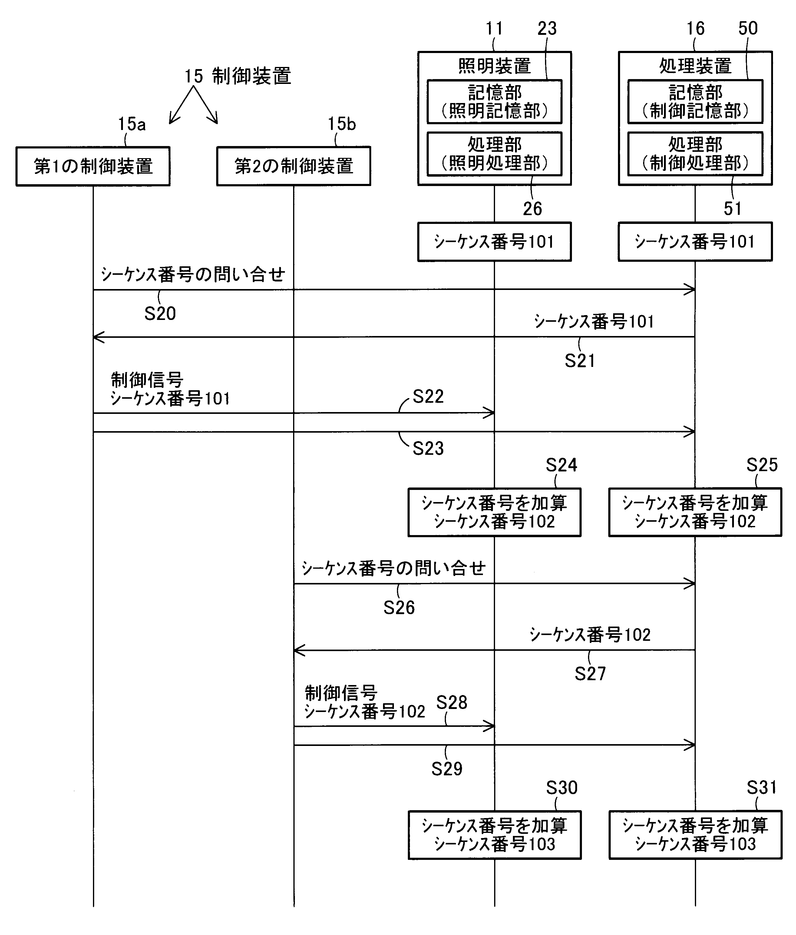
そして、図12に照明システム10のシーケンス番号を用いた通信処理のシーケンス図を示す。 FIG. 12 shows a sequence diagram of communication processing using the sequence numbers of the lighting system 10. As shown in FIG.

ここで、制御装置15は、第1の制御装置15aと第2の制御装置15bの2台であるとする。第1の制御装置15aと第2の制御装置15bは、異なる制御装置15である。ここでの異なる制御装置15とは、別体の制御装置15であることを表しており、第1の制御装置15aと第2の制御装置15bとが、同一型番の別体の制御装置15である場合は、その2つの制御装置15は異なる制御装置15である。また、照明装置11および処理装置16は、最新のシーケンス番号101をそれぞれ記憶しているものとする。照明装置11と処理装置16は、定期的に通信を行い、お互いが記憶するシーケンス番号が合致するか確認を行ってもよい。お互いが記憶するシーケンス番号が合致しない場合は、例えば、高い値のシーケンス番号に統一するように更新されてもよい。すなわち、照明装置11の記憶部23が記憶するシーケンス番号と、処理装置16の記憶部50が記憶するシーケンス番号と、が異なる場合は、両シーケンス番号のうちの一方の値の小さいシーケンス番号は、他方のシーケンス番号に書き換えられるようにしてもよい。 Here, it is assumed that there are two controllers 15, a first controller 15a and a second controller 15b. The first controller 15 a and the second controller 15 b are different controllers 15 . The different control device 15 here means that it is a separate control device 15, and the first control device 15a and the second control device 15b are separate control devices 15 of the same model number. In some cases, the two controllers 15 are different controllers 15 . Also, it is assumed that the illumination device 11 and the processing device 16 each store the latest sequence number 101 . The lighting device 11 and the processing device 16 may periodically communicate with each other to check whether the sequence numbers stored by them match. If the sequence numbers stored by each other do not match, for example, they may be updated to unify to a higher sequence number. That is, when the sequence number stored in the storage unit 23 of the lighting device 11 and the sequence number stored in the storage unit 50 of the processing device 16 are different, the sequence number with the smaller one of the two sequence numbers is It may be rewritten to the other sequence number.

第1の制御装置15aは、照明装置11を制御する際、処理装置16と通信して最新のシーケンス番号を問い合わせる(ステップS20)。 When controlling the lighting device 11, the first control device 15a communicates with the processing device 16 to inquire about the latest sequence number (step S20).

処理装置16は、第1の制御装置15aからの問い合わせに対して、記憶する最新のシーケンス番号101の情報を第1の制御装置15aに送信する(ステップS21)。 In response to the inquiry from the first control device 15a, the processing device 16 transmits information of the latest stored sequence number 101 to the first control device 15a (step S21).

第1の制御装置15aは、処理装置16から最新のシーケンス番号101の情報を取得すると、取得した最新のシーケンス番号101を用いて制御する照明装置11のアドレス情報および制御信号を含む信号を、ネットワーク17内の照明装置11に送信するとともに(ステップS22)、処理装置16に送信する(ステップS23)。第1の制御装置15aは、例えば、取得したシーケンス番号と、制御する照明装置11のアドレス情報と、制御信号と、を含む信号を、照明装置11に送信する。なお、第1の制御装置15aが処理装置16に送信する情報は、送信に用いたシーケンス番号101の情報のみでもよい。 When the first control device 15a acquires information on the latest sequence number 101 from the processing device 16, the first control device 15a sends a signal including the address information and the control signal of the lighting device 11 to be controlled using the acquired latest sequence number 101 to the network. 17 (step S22) and to the processing device 16 (step S23). The first control device 15 a transmits a signal including, for example, the acquired sequence number, address information of the lighting device 11 to be controlled, and a control signal to the lighting device 11 . The information that the first control device 15a transmits to the processing device 16 may be only the information of the sequence number 101 used for transmission.

第1の制御装置15aからネットワーク17内の照明装置11に送信された信号は、ネットワーク17内の全ての照明装置11に伝送される。 A signal sent from the first control device 15 a to the lighting devices 11 in the network 17 is transmitted to all the lighting devices 11 in the network 17 .

各照明装置11では、第1の制御装置15aから送信された、シーケンス番号を含む信号を受信すると、受信した信号に含まれるシーケンス番号が、記憶するシーケンス番号101以上の最新の番号か確認する。確認の結果、最新の番号であると判断したら、自身に向けて送信された信号の場合は受信した信号の処理を継続したり、自身に向けて送信された信号でない場合は他の照明装置11に対して信号を送信したりする。また、確認の結果、最新の番号ではないと判断したら、自身に向けて送信された信号の場合は受信した信号の処理は継続しない。また、自身に向けて送信された信号でない場合は他の照明装置11に対して信号を送信しないようにする。 When each lighting device 11 receives a signal including a sequence number transmitted from the first control device 15a, it checks whether the sequence number included in the received signal is the latest number greater than or equal to the stored sequence number 101. As a result of confirmation, if it is determined that the number is the latest, it continues processing the received signal if the signal was sent to itself, or to another lighting device 11 if the signal was not sent to itself. or send a signal to Also, if it is determined that the number is not the latest as a result of confirmation, processing of the received signal is not continued in the case of the signal transmitted to itself. Also, if the signal is not directed to itself, the signal is not transmitted to other lighting devices 11 .

最新のシーケンス番号101の信号を受け付けた照明装置11のうち、受信した信号が自己のアドレス情報のものである照明装置11は、信号を受け付け、制御信号に応じた照明状態に制御する。さらに、この照明装置11は、記憶するシーケンス番号101に+1を加算するインクリメント処理を実行し、最新となるシーケンス番号102に更新する(ステップS24)。 Of the lighting devices 11 that have received the signal with the latest sequence number 101, the lighting device 11 whose received signal is its own address information receives the signal and controls the lighting state according to the control signal. Further, the illumination device 11 performs an increment process of adding +1 to the stored sequence number 101, and updates it to the latest sequence number 102 (step S24).

最新のシーケンス番号101の信号を受け付けた照明装置11のうち、受信した信号が自己のアドレス情報以外のものである照明装置11は、信号を受け付けないが、記憶するシーケンス番号101に+1を加算するインクリメント処理を実行し、シーケンス番号102に更新する。 Of the lighting devices 11 that have received the signal with the latest sequence number 101, the lighting devices 11 whose received signal is other than their own address information do not receive the signal, but add +1 to the stored sequence number 101. Execute increment processing and update to sequence number 102 .

これらの、シーケンス番号を受け取った際の照明装置11の処理は、処理部26で実行される。処理部26は、信号を受け付けた場合は、通信部21にその信号を渡して、受け取った信号を再送信する。この再送信する信号は、自身が受け取った信号と同じ内容(シーケンス番号も同じ)である。また、処理部26が信号を受け付け、その信号が自身宛の信号だった場合は、処理部26は制御部22にその信号を渡し、光源部20が点灯制御される。 These processes of the lighting device 11 when the sequence number is received are executed by the processing unit 26 . When receiving the signal, the processing unit 26 passes the signal to the communication unit 21 and retransmits the received signal. The retransmitted signal has the same content (and the same sequence number) as the received signal. Further, when the processing unit 26 receives a signal and the signal is addressed to itself, the processing unit 26 passes the signal to the control unit 22, and the lighting of the light source unit 20 is controlled.

したがって、ネットワーク17内の全ての照明装置11のシーケンス番号が最新のシーケンス番号102に更新される。なお、他の照明装置11に対して信号を送信した時点で、自身が記憶するシーケンス番号は加算されているため、他の照明装置11から再度自身に向けて送信されてきた信号は、シーケンス番号が101のためシーケンス番号の条件不一致により、受け付けは行われない。 Therefore, the sequence numbers of all lighting devices 11 within the network 17 are updated to the latest sequence number 102 . It should be noted that since the sequence number stored in the self is added at the time when the signal is transmitted to the other lighting device 11, the signal transmitted to itself again from the other lighting device 11 has the sequence number is 101, the acceptance is not performed due to the condition mismatch of the sequence number.

また、第1の制御装置15aは、取得したシーケンス番号と、制御する照明装置11のアドレス情報と制御信号と、を別々に送信してもよい。このとき、第1の制御装置15aは、シーケンス番号を含む信号のみを先に照明装置11に送信し、その後、制御する照明装置11のアドレス情報と制御信号とを含む信号を照明装置11に送信する。そして、照明装置11では、先にシーケンス番号の確認を実施し、所定の関係性を満たしている場合は、シーケンス番号の送信先である第1の制御装置15aから送信された制御信号(もしくは、制御する照明装置11のアドレス情報と制御信号とを含む信号)の受け入れを許可する待機状態となる。 Further, the first control device 15a may separately transmit the acquired sequence number, the address information of the lighting device 11 to be controlled, and the control signal. At this time, the first control device 15a first transmits only the signal containing the sequence number to the lighting device 11, and then transmits the signal containing the address information of the lighting device 11 to be controlled and the control signal to the lighting device 11. do. Then, the lighting device 11 first confirms the sequence number, and if the predetermined relationship is satisfied, the control signal (or A signal containing address information and a control signal of the lighting device 11 to be controlled is in a standby state for permitting reception of the control signal.

一方、処理装置16では、第1の制御装置15aから送信されたシーケンス番号101の情報を取得すると、処理部51により、シーケンス番号101に+1を加算するインクリメント処理を実行し、最新となるシーケンス番号102に更新する(ステップS25)。 On the other hand, when the processing unit 16 acquires the information of the sequence number 101 transmitted from the first control unit 15a, the processing unit 51 executes an increment process of adding +1 to the sequence number 101 to obtain the latest sequence number. 102 (step S25).

また、第2の制御装置15bは、記憶するシーケンス番号が、以前の信号の送信に用いたシーケンス番号であり、第1の制御装置15aからの送信によって更新された最新のシーケンス番号102ではない。 Also, the sequence number stored by the second controller 15b is the sequence number used in the previous transmission of the signal, not the latest sequence number 102 updated by the transmission from the first controller 15a.

第2の制御装置15bは、照明装置11を制御する際、処理装置16と通信して最新のシーケンス番号を問い合わせる(ステップS26)。 When controlling the lighting device 11, the second control device 15b communicates with the processing device 16 to inquire about the latest sequence number (step S26).

処理装置16は、第2の制御装置15bからの問い合わせに対して、記憶する最新のシーケンス番号102の情報を第2の制御装置15bに送信する(ステップS27)。 In response to the inquiry from the second control device 15b, the processing device 16 transmits information of the latest stored sequence number 102 to the second control device 15b (step S27).

第2の制御装置15bは、処理装置16から最新のシーケンス番号102の情報を取得すると、取得した最新のシーケンス番号102を用いて制御する照明装置11のアドレス情報および制御信号を含む信号を、ネットワーク17内の照明装置11に送信するとともに(ステップS28)、処理装置16に送信する(ステップS29)。なお、第2の制御装置15bが処理装置16に送信する情報は、送信に用いたシーケンス番号102の情報のみでもよい。 When the second control device 15b acquires information on the latest sequence number 102 from the processing device 16, the second control device 15b transmits a signal including the address information and the control signal of the lighting device 11 to be controlled using the acquired latest sequence number 102 to the network. 17 (step S28) and to the processing device 16 (step S29). The information that the second control device 15b transmits to the processing device 16 may be only the information of the sequence number 102 used for transmission.

第2の制御装置15bからネットワーク17内の照明装置11に送信された信号は、ネットワーク17内の全ての照明装置11に伝送される。 A signal sent from the second control device 15 b to the lighting devices 11 in the network 17 is transmitted to all the lighting devices 11 in the network 17 .

各照明装置11では、第2の制御装置15bから送信された信号のシーケンス番号を受信すると、受信したシーケンス番号が、記憶するシーケンス番号102以上の最新の番号か確認する。確認の結果、最新の番号であると判断したら、受信した信号の処理を継続し、また、最新の番号ではないと判断したら、それ以降の受信した信号の処理は継続せず、つまり制御信号を受け付けない。 Upon receiving the sequence number of the signal transmitted from the second control device 15b, each lighting device 11 confirms whether the received sequence number is the newest sequence number greater than or equal to 102 to be stored. As a result of confirmation, if it is determined that the number is the latest, the processing of the received signal is continued, and if it is determined that the number is not the latest, the processing of the received signal after that is not continued, that is, the control signal is output. I do not accept.

最新のシーケンス番号102の信号を受け付けた照明装置11のうち、受信した信号が自己のアドレス情報のものである照明装置11は、信号を受け付け、制御信号に応じた照明状態に制御する。さらに、この照明装置11は、記憶するシーケンス番号102に+1を加算するインクリメント処理を実行し、最新となるシーケンス番号103を更新する(ステップS30)。 Of the lighting devices 11 that have received the signal with the latest sequence number 102, the lighting device 11 whose received signal is its own address information receives the signal and controls the lighting state according to the control signal. Further, the illumination device 11 performs an increment process of adding +1 to the stored sequence number 102 to update the latest sequence number 103 (step S30).

最新のシーケンス番号102の信号を受け付けた照明装置11のうち、受信した信号が自己のアドレス情報以外のものである照明装置11は、信号を受け付けないが、記憶するシーケンス番号102に+1を加算するインクリメント処理を実行し、最新となるシーケンス番号103を更新する。 Of the lighting devices 11 that have received the signal with the latest sequence number 102, the lighting devices 11 whose received signal is other than their own address information do not receive the signal, but add +1 to the stored sequence number 102. Increment processing is executed to update the latest sequence number 103 .

したがって、ネットワーク17内の全ての照明装置11のシーケンス番号が最新のシーケンス番号103に更新される。 Therefore, the sequence numbers of all lighting devices 11 in network 17 are updated to the latest sequence number 103 .

一方、処理装置16では、第2の制御装置15bから送信されたシーケンス番号102の情報を取得すると、処理部51により、シーケンス番号102に+1を加算するインクリメント処理を実行し、最新となるシーケンス番号103に更新する(ステップS31)。 On the other hand, in the processing device 16, when the information of the sequence number 102 transmitted from the second control device 15b is obtained, the processing unit 51 executes an increment process of adding +1 to the sequence number 102 to obtain the latest sequence number. 103 (step S31).

なお、処理装置16は、制御装置15との通信が確保された場合、最新のシーケンス番号を制御装置15に自動的に送信するようにし、また、処理装置16が記憶するシーケンス番号を更新する都度、最新のシーケンス番号を制御装置15に自動的に送信するようにしてもよい。 In addition, when the communication with the control device 15 is secured, the processing device 16 automatically transmits the latest sequence number to the control device 15, and every time the sequence number stored in the processing device 16 is updated, , the latest sequence number may be automatically sent to the control device 15 .

そして、本実施形態の照明システム10では、処理部51により、制御装置15から送信されるシーケンス番号を取得して加算更新し、制御装置15が照明装置11を制御する際に照明装置11を制御可能なシーケンス番号を取得するように、照明装置11を制御する制御装置15に対して加算更新したシーケンス番号を送信するため、制御装置15が最新のシーケンス番号を用いて照明装置11を制御できる。 In the lighting system 10 of the present embodiment, the processing unit 51 acquires and updates the sequence number transmitted from the control device 15 , and controls the lighting device 11 when the control device 15 controls the lighting device 11 . Since the incremented sequence number is transmitted to the control device 15 that controls the lighting device 11 so as to obtain a possible sequence number, the control device 15 can control the lighting device 11 using the latest sequence number.

なお、処理部51は、処理装置16が備える場合に限らず、照明装置11が備えていてもよいし、例えばリモコン13に設けるなど、ネットワーク17内に設けて制御装置15と通信可能に構成してもよい。 Note that the processing unit 51 is not limited to being provided in the processing device 16, and may be provided in the lighting device 11. For example, the processing unit 51 may be provided in the remote controller 13, or may be provided in the network 17 so as to be capable of communicating with the control device 15. may

また、上述した照明システム10では、受信した信号に含まれるシーケンス番号が、照明装置11や処理装置16が記憶するシーケンス番号以上に新しい場合に処理を実行するが、シーケンス番号の条件はこの形態に限定されるものではない。例えば、受信した信号に含まれるシーケンス番号が、照明装置11や処理装置16が記憶するシーケンス番号と一致するときのみ処理が実行されてもよい。また、受信した信号に含まれるシーケンス番号と、照明装置11や処理装置16が記憶するシーケンス番号と、の乖離が所定の値以内であれば処理が実行されるように構成されてもよい。 Further, in the lighting system 10 described above, processing is executed when the sequence number included in the received signal is newer than the sequence number stored in the lighting device 11 or the processing device 16. It is not limited. For example, the process may be executed only when the sequence number included in the received signal matches the sequence number stored by the lighting device 11 or the processing device 16 . Alternatively, the process may be executed if the difference between the sequence number included in the received signal and the sequence number stored in the lighting device 11 or the processing device 16 is within a predetermined value.

また、処理装置16が記憶するシーケンス番号と、照明装置11が記憶するシーケンス番号と、は一致することが望ましい。例えば、照明装置11と処理装置16は定期的にお互いが記憶(保有)するシーケンス番号を確認しており、処理装置16が記憶するシーケンス番号と、照明装置11が記憶するシーケンス番号と、が異なる場合は、大きい値のシーケンス番号に統一される。 Also, it is desirable that the sequence number stored by the processing device 16 and the sequence number stored by the lighting device 11 match. For example, the lighting device 11 and the processing device 16 periodically check the sequence numbers stored (held) by each other, and the sequence number stored by the processing device 16 and the sequence number stored by the lighting device 11 are different. are unified to a sequence number with a large value.

本発明のいくつかの実施形態を説明したが、これらの実施形態は、例として提示したものであり、発明の範囲を限定することは意図していない。これら新規な実施形態は、その他の様々な形態で実施されることが可能であり、発明の要旨を逸脱しない範囲で、種々の省略、置き換え、変更を行うことができる。これら実施形態やその変形は、発明の範囲や要旨に含まれるとともに、特許請求の範囲に記載された発明とその均等の範囲に含まれる。 While several embodiments of the invention have been described, these embodiments have been presented by way of example and are not intended to limit the scope of the invention. These novel embodiments can be implemented in various other forms, and various omissions, replacements, and modifications can be made without departing from the scope of the invention. These embodiments and modifications thereof are included in the scope and gist of the invention, and are included in the scope of the invention described in the claims and equivalents thereof.

10 照明システム
11 照明装置
15 制御装置
23 照明記憶部である記憶部
26 照明処理部である処理部
50 制御記憶部である記憶部
51 制御処理部である処理部
REFERENCE SIGNS LIST 10 lighting system 11 lighting device 15 control device 23 storage unit that is lighting storage unit 26 processing unit that is lighting processing unit 50 storage unit that is control storage unit 51 processing unit that is control processing unit

Claims (4)

シーケンス番号を記憶する記憶部と;
制御装置から受信した信号に含まれるシーケンス番号と、前記記憶部に記憶されたシーケンス番号と、を比較し、両シーケンス番号が所定の関係性を満たす場合に、前記制御装置から送信された信号に含まれるシーケンス番号に関連付けられた制御信号を受け付けるとともに、前記記憶部に記憶されたシーケンス番号を加算更新する処理部と;
を備える照明装置。
a storage unit that stores a sequence number;
The sequence number included in the signal received from the control device is compared with the sequence number stored in the storage unit, and if both sequence numbers satisfy a predetermined relationship, the signal transmitted from the control device a processing unit that receives a control signal associated with the included sequence number and adds and updates the sequence number stored in the storage unit;
A lighting device.
シーケンス番号を記憶する記憶部と;
制御装置へシーケンス番号を送信後に、前記制御装置からシーケンス番号を含む信号を受信した場合に、記憶するシーケンス番号を加算処理する処理部と;
を備える処理装置。
a storage unit that stores a sequence number;
a processing unit that adds a sequence number to be stored when a signal including a sequence number is received from the control device after the sequence number is transmitted to the control device;
A processing device comprising:
シーケンス番号を記憶する制御記憶部と、
前記制御記憶部が記憶するシーケンス番号を制御装置に送信後に、前記制御装置から前記制御記憶部が記憶するシーケンス番号を含む信号を受信した場合に、前記制御記憶部が記憶するシーケンス番号を加算更新する制御処理部と、
を備える処理装置と;
シーケンス番号を記憶する照明記憶部と、
前記制御装置から受信した前記制御記憶部が記憶するシーケンス番号と、前記照明記憶部に記憶されたシーケンス番号と、を比較し、両シーケンス番号が所定の関係性を満たす場合に、前記制御装置から送信されたシーケンス番号に関連付けられた制御信号を受け付けるとともに、前記照明記憶部に記憶されたシーケンス番号を加算更新する照明処理部と、
を備える照明装置と;
を具備する照明システム。
a control store that stores a sequence number;
When a signal including the sequence number stored in the control storage unit is received from the control device after the sequence number stored in the control storage unit is transmitted to the control device, the sequence number stored in the control storage unit is added and updated. a control processing unit for
a processing device comprising;
a lighting storage unit that stores a sequence number;
The sequence number stored in the control storage unit received from the control device is compared with the sequence number stored in the illumination storage unit, and if both sequence numbers satisfy a predetermined relationship, a lighting processing unit that receives a control signal associated with the transmitted sequence number and adds and updates the sequence number stored in the lighting storage unit;
a lighting device comprising;
A lighting system comprising:
前記制御記憶部が記憶するシーケンス番号と、前記照明記憶部が記憶するシーケンス番号と、が異なる場合は、両シーケンス番号のうちの一方の値の小さいシーケンス番号は、他方のシーケンス番号に書き換えられる
ことを特徴とする請求項3記載の照明システム。
When the sequence number stored in the control storage unit and the sequence number stored in the illumination storage unit are different, the sequence number with the smaller value of one of the two sequence numbers is overwritten with the other sequence number. 4. The lighting system of claim 3, characterized by:
JP2021159920A 2021-09-29 2021-09-29 Lighting device, processing device, and lighting system Pending JP2023049902A (en)

Priority Applications (1)

Application Number Priority Date Filing Date Title
JP2021159920A JP2023049902A (en) 2021-09-29 2021-09-29 Lighting device, processing device, and lighting system

Applications Claiming Priority (1)

Application Number Priority Date Filing Date Title
JP2021159920A JP2023049902A (en) 2021-09-29 2021-09-29 Lighting device, processing device, and lighting system

Publications (1)

Publication Number Publication Date
JP2023049902A true JP2023049902A (en) 2023-04-10

Family

ID=85802161

Family Applications (1)

Application Number Title Priority Date Filing Date
JP2021159920A Pending JP2023049902A (en) 2021-09-29 2021-09-29 Lighting device, processing device, and lighting system

Country Status (1)

Country Link
JP (1) JP2023049902A (en)

Citations (1)

* Cited by examiner, † Cited by third party
Publication number Priority date Publication date Assignee Title
US20200195420A1 (en) * 2018-12-13 2020-06-18 Leviton Manufacturing Co., Inc. Method for securely transmitting lighting scenes over a computer network with cloud setup and authentication

Patent Citations (1)

* Cited by examiner, † Cited by third party
Publication number Priority date Publication date Assignee Title
US20200195420A1 (en) * 2018-12-13 2020-06-18 Leviton Manufacturing Co., Inc. Method for securely transmitting lighting scenes over a computer network with cloud setup and authentication

Similar Documents

Publication Publication Date Title
KR101679056B1 (en) Updating scenes in remote controllers of a home control system
CN110460977B (en) Intelligent lighting equipment network distribution method based on Bluetooth MESH
CN106969302B (en) Lighting equipment and lighting systems
CN109828544A (en) A kind of intelligent home control system and its configuration method based on bluetooth mesh
US20120212140A1 (en) Apparatus and method for controlling lighting based on dali communication
EP3075206B1 (en) Zigbee light link network commissioning
JP6575871B2 (en) Lighting equipment and lighting system
US10568190B2 (en) Remote control, lighting system, and luminaire
JP6681585B2 (en) Wireless communicator and lighting system
JP2023049901A (en) lighting system
JP2023049902A (en) Lighting device, processing device, and lighting system
CN204046876U (en) A kind of control device of wireless, illuminator
JP6796786B2 (en) Lighting equipment and lighting systems
KR101976563B1 (en) Apparatus and method thereof for registrating lighting in lighting controlling system
JP2023049900A (en) lighting system
JP2021034258A (en) Management device, management method, and lighting system
JP6796785B2 (en) Lighting equipment and lighting systems
JP6803577B2 (en) Lighting equipment and lighting systems
CN104320894A (en) LED light string control method, WIFI controller and LED light string control system
JP7394378B2 (en) lighting system
JP2008235115A (en) Lighting control system
JP2024158773A (en) Lighting system, capture device, lighting system setting method, setting screen display method, and program
KR20200102316A (en) Method and apparatus for synchronizing operating time of a lighting device utilizing a mesh network
JP2023148045A (en) Lighting system, operating device, and lighting device
WO2025142306A1 (en) Lighting control system, lighting control method, program, and display method

Legal Events

Date Code Title Description
RD04 Notification of resignation of power of attorney

Free format text: JAPANESE INTERMEDIATE CODE: A7424

Effective date: 20240306

A621 Written request for application examination

Free format text: JAPANESE INTERMEDIATE CODE: A621

Effective date: 20240322

A977 Report on retrieval

Free format text: JAPANESE INTERMEDIATE CODE: A971007

Effective date: 20241127

A131 Notification of reasons for refusal

Free format text: JAPANESE INTERMEDIATE CODE: A131

Effective date: 20241204

A02 Decision of refusal

Free format text: JAPANESE INTERMEDIATE CODE: A02

Effective date: 20250423