[go: up one dir, main page]

JP2023034637A - Liquid discharge device and head driving circuit - Google Patents

Liquid discharge device and head driving circuit Download PDF

Info

Publication number
JP2023034637A
JP2023034637A JP2021140967A JP2021140967A JP2023034637A JP 2023034637 A JP2023034637 A JP 2023034637A JP 2021140967 A JP2021140967 A JP 2021140967A JP 2021140967 A JP2021140967 A JP 2021140967A JP 2023034637 A JP2023034637 A JP 2023034637A
Authority
JP
Japan
Prior art keywords
drive
circuit
drive circuit
wiring
driving
Prior art date
Legal status (The legal status is an assumption and is not a legal conclusion. Google has not performed a legal analysis and makes no representation as to the accuracy of the status listed.)
Granted
Application number
JP2021140967A
Other languages
Japanese (ja)
Other versions
JP7760866B2 (en
Inventor
陽一郎 近藤
Yoichiro Kondo
Current Assignee (The listed assignees may be inaccurate. Google has not performed a legal analysis and makes no representation or warranty as to the accuracy of the list.)
Seiko Epson Corp
Original Assignee
Seiko Epson Corp
Priority date (The priority date is an assumption and is not a legal conclusion. Google has not performed a legal analysis and makes no representation as to the accuracy of the date listed.)
Filing date
Publication date
Application filed by Seiko Epson Corp filed Critical Seiko Epson Corp
Priority to JP2021140967A priority Critical patent/JP7760866B2/en
Priority to CN202211033438.0A priority patent/CN115723428A/en
Priority to US17/898,521 priority patent/US12145364B2/en
Publication of JP2023034637A publication Critical patent/JP2023034637A/en
Application granted granted Critical
Publication of JP7760866B2 publication Critical patent/JP7760866B2/en
Active legal-status Critical Current
Anticipated expiration legal-status Critical

Links

Images

Classifications

    • BPERFORMING OPERATIONS; TRANSPORTING
    • B41PRINTING; LINING MACHINES; TYPEWRITERS; STAMPS
    • B41JTYPEWRITERS; SELECTIVE PRINTING MECHANISMS, i.e. MECHANISMS PRINTING OTHERWISE THAN FROM A FORME; CORRECTION OF TYPOGRAPHICAL ERRORS
    • B41J2/00Typewriters or selective printing mechanisms characterised by the printing or marking process for which they are designed
    • B41J2/005Typewriters or selective printing mechanisms characterised by the printing or marking process for which they are designed characterised by bringing liquid or particles selectively into contact with a printing material
    • B41J2/01Ink jet
    • B41J2/015Ink jet characterised by the jet generation process
    • B41J2/04Ink jet characterised by the jet generation process generating single droplets or particles on demand
    • B41J2/045Ink jet characterised by the jet generation process generating single droplets or particles on demand by pressure, e.g. electromechanical transducers
    • B41J2/04501Control methods or devices therefor, e.g. driver circuits, control circuits
    • B41J2/04588Control methods or devices therefor, e.g. driver circuits, control circuits using a specific waveform
    • BPERFORMING OPERATIONS; TRANSPORTING
    • B41PRINTING; LINING MACHINES; TYPEWRITERS; STAMPS
    • B41JTYPEWRITERS; SELECTIVE PRINTING MECHANISMS, i.e. MECHANISMS PRINTING OTHERWISE THAN FROM A FORME; CORRECTION OF TYPOGRAPHICAL ERRORS
    • B41J2/00Typewriters or selective printing mechanisms characterised by the printing or marking process for which they are designed
    • B41J2/005Typewriters or selective printing mechanisms characterised by the printing or marking process for which they are designed characterised by bringing liquid or particles selectively into contact with a printing material
    • B41J2/01Ink jet
    • B41J2/015Ink jet characterised by the jet generation process
    • B41J2/04Ink jet characterised by the jet generation process generating single droplets or particles on demand
    • B41J2/045Ink jet characterised by the jet generation process generating single droplets or particles on demand by pressure, e.g. electromechanical transducers
    • B41J2/04501Control methods or devices therefor, e.g. driver circuits, control circuits
    • B41J2/04541Specific driving circuit
    • BPERFORMING OPERATIONS; TRANSPORTING
    • B41PRINTING; LINING MACHINES; TYPEWRITERS; STAMPS
    • B41JTYPEWRITERS; SELECTIVE PRINTING MECHANISMS, i.e. MECHANISMS PRINTING OTHERWISE THAN FROM A FORME; CORRECTION OF TYPOGRAPHICAL ERRORS
    • B41J2/00Typewriters or selective printing mechanisms characterised by the printing or marking process for which they are designed
    • B41J2/005Typewriters or selective printing mechanisms characterised by the printing or marking process for which they are designed characterised by bringing liquid or particles selectively into contact with a printing material
    • B41J2/01Ink jet
    • B41J2/015Ink jet characterised by the jet generation process
    • B41J2/04Ink jet characterised by the jet generation process generating single droplets or particles on demand
    • B41J2/045Ink jet characterised by the jet generation process generating single droplets or particles on demand by pressure, e.g. electromechanical transducers
    • B41J2/04501Control methods or devices therefor, e.g. driver circuits, control circuits
    • B41J2/04581Control methods or devices therefor, e.g. driver circuits, control circuits controlling heads based on piezoelectric elements
    • BPERFORMING OPERATIONS; TRANSPORTING
    • B41PRINTING; LINING MACHINES; TYPEWRITERS; STAMPS
    • B41JTYPEWRITERS; SELECTIVE PRINTING MECHANISMS, i.e. MECHANISMS PRINTING OTHERWISE THAN FROM A FORME; CORRECTION OF TYPOGRAPHICAL ERRORS
    • B41J2/00Typewriters or selective printing mechanisms characterised by the printing or marking process for which they are designed
    • B41J2/005Typewriters or selective printing mechanisms characterised by the printing or marking process for which they are designed characterised by bringing liquid or particles selectively into contact with a printing material
    • B41J2/01Ink jet
    • B41J2/015Ink jet characterised by the jet generation process
    • B41J2/04Ink jet characterised by the jet generation process generating single droplets or particles on demand
    • B41J2/045Ink jet characterised by the jet generation process generating single droplets or particles on demand by pressure, e.g. electromechanical transducers
    • B41J2/04501Control methods or devices therefor, e.g. driver circuits, control circuits
    • B41J2/04593Dot-size modulation by changing the size of the drop
    • BPERFORMING OPERATIONS; TRANSPORTING
    • B41PRINTING; LINING MACHINES; TYPEWRITERS; STAMPS
    • B41JTYPEWRITERS; SELECTIVE PRINTING MECHANISMS, i.e. MECHANISMS PRINTING OTHERWISE THAN FROM A FORME; CORRECTION OF TYPOGRAPHICAL ERRORS
    • B41J2/00Typewriters or selective printing mechanisms characterised by the printing or marking process for which they are designed
    • B41J2/005Typewriters or selective printing mechanisms characterised by the printing or marking process for which they are designed characterised by bringing liquid or particles selectively into contact with a printing material
    • B41J2/01Ink jet
    • B41J2/135Nozzles
    • B41J2/14Structure thereof only for on-demand ink jet heads
    • B41J2/14201Structure of print heads with piezoelectric elements
    • B41J2/14233Structure of print heads with piezoelectric elements of film type, deformed by bending and disposed on a diaphragm
    • BPERFORMING OPERATIONS; TRANSPORTING
    • B41PRINTING; LINING MACHINES; TYPEWRITERS; STAMPS
    • B41JTYPEWRITERS; SELECTIVE PRINTING MECHANISMS, i.e. MECHANISMS PRINTING OTHERWISE THAN FROM A FORME; CORRECTION OF TYPOGRAPHICAL ERRORS
    • B41J2/00Typewriters or selective printing mechanisms characterised by the printing or marking process for which they are designed
    • B41J2/005Typewriters or selective printing mechanisms characterised by the printing or marking process for which they are designed characterised by bringing liquid or particles selectively into contact with a printing material
    • B41J2/01Ink jet
    • B41J2/015Ink jet characterised by the jet generation process
    • B41J2/04Ink jet characterised by the jet generation process generating single droplets or particles on demand
    • B41J2/045Ink jet characterised by the jet generation process generating single droplets or particles on demand by pressure, e.g. electromechanical transducers
    • B41J2/04501Control methods or devices therefor, e.g. driver circuits, control circuits
    • B41J2/04596Non-ejecting pulses
    • BPERFORMING OPERATIONS; TRANSPORTING
    • B41PRINTING; LINING MACHINES; TYPEWRITERS; STAMPS
    • B41JTYPEWRITERS; SELECTIVE PRINTING MECHANISMS, i.e. MECHANISMS PRINTING OTHERWISE THAN FROM A FORME; CORRECTION OF TYPOGRAPHICAL ERRORS
    • B41J2/00Typewriters or selective printing mechanisms characterised by the printing or marking process for which they are designed
    • B41J2/005Typewriters or selective printing mechanisms characterised by the printing or marking process for which they are designed characterised by bringing liquid or particles selectively into contact with a printing material
    • B41J2/01Ink jet
    • B41J2/135Nozzles
    • B41J2/14Structure thereof only for on-demand ink jet heads
    • B41J2002/14362Assembling elements of heads
    • BPERFORMING OPERATIONS; TRANSPORTING
    • B41PRINTING; LINING MACHINES; TYPEWRITERS; STAMPS
    • B41JTYPEWRITERS; SELECTIVE PRINTING MECHANISMS, i.e. MECHANISMS PRINTING OTHERWISE THAN FROM A FORME; CORRECTION OF TYPOGRAPHICAL ERRORS
    • B41J2/00Typewriters or selective printing mechanisms characterised by the printing or marking process for which they are designed
    • B41J2/005Typewriters or selective printing mechanisms characterised by the printing or marking process for which they are designed characterised by bringing liquid or particles selectively into contact with a printing material
    • B41J2/01Ink jet
    • B41J2/135Nozzles
    • B41J2/14Structure thereof only for on-demand ink jet heads
    • B41J2002/14419Manifold
    • BPERFORMING OPERATIONS; TRANSPORTING
    • B41PRINTING; LINING MACHINES; TYPEWRITERS; STAMPS
    • B41JTYPEWRITERS; SELECTIVE PRINTING MECHANISMS, i.e. MECHANISMS PRINTING OTHERWISE THAN FROM A FORME; CORRECTION OF TYPOGRAPHICAL ERRORS
    • B41J2/00Typewriters or selective printing mechanisms characterised by the printing or marking process for which they are designed
    • B41J2/005Typewriters or selective printing mechanisms characterised by the printing or marking process for which they are designed characterised by bringing liquid or particles selectively into contact with a printing material
    • B41J2/01Ink jet
    • B41J2/135Nozzles
    • B41J2/14Structure thereof only for on-demand ink jet heads
    • B41J2002/14491Electrical connection

Landscapes

  • Particle Formation And Scattering Control In Inkjet Printers (AREA)
  • Ink Jet (AREA)

Abstract

To provide a liquid discharge device that can radiate heat generated in a driving circuit more efficiently.SOLUTION: A liquid discharge device comprises a substrate having a first through-hole, a first driving circuit, a second driving circuit, a third driving circuit, a metallic frame, and a first screw that is inserted through the first through-hole to mount the metallic frame on the substrate. The first driving circuit outputs a first driving signal for driving a first piezoelectric element so that a discharge head discharges a first discharge amount of liquid. The second driving circuit outputs a second driving signal for driving the first piezoelectric element so that the discharge head discharges a second discharge amount of liquid. The third driving circuit outputs a third driving signal for driving the first piezoelectric element so that the discharge head does not discharge liquid. The first driving circuit, the second driving circuit and the third driving circuit are positioned side by side along one direction in this order in the substrate. The first through-hole is positioned between the first driving circuit and the second driving circuit in the one direction.SELECTED DRAWING: Figure 12

Description

本発明は、液体吐出装置、及びヘッド駆動回路に関する。 The present invention relates to a liquid ejecting apparatus and a head drive circuit.

液体としてのインクを吐出することで媒体に画像や文書を形成する液体吐出装置には、液体を吐出する複数のノズルのそれぞれに対応して設けられた駆動素子を有し、当該駆動素子が駆動されることで、対応するノズルからインクを吐出する構成が知られている。このような液体吐出装置に用いられる駆動素子は、複数のノズルのそれぞれに対応して設けられている。それ故に、駆動回路は、複数の駆動素子を同時に駆動することが可能な程度の充分な電流を含む駆動信号を出力する必要がある。特に、駆動素子として圧電素子を用いた液体吐出装置では、当該圧電素子が電気的にみればコンデンサーのような容量性負荷であるが故に、圧電素子を精度よく駆動させるとの観点において、圧電素子に十分な電流を供給する必要がある。 2. Description of the Related Art A liquid ejecting apparatus that forms an image or a document on a medium by ejecting ink as liquid has driving elements provided corresponding to each of a plurality of nozzles that eject liquid, and the driving elements drive the driving elements. A configuration is known in which ink is ejected from corresponding nozzles by being arranged. Driving elements used in such a liquid ejection device are provided corresponding to each of the plurality of nozzles. Therefore, the drive circuit needs to output a drive signal containing enough current to simultaneously drive a plurality of drive elements. In particular, in a liquid ejecting apparatus using a piezoelectric element as a drive element, the piezoelectric element is a capacitive load like a capacitor from an electrical point of view. sufficient current must be supplied to

しかしながら、駆動素子を駆動回路は、大電流を含む駆動信号を出力するが故に大きな熱を発生させる。このような駆動回路で生じた熱が吐出する液体に寄与すると、当該液体の物性が変化するおそれがある。また、駆動回路で生じた熱が、駆動回路が有する電子部品に寄与すると、当該電子部品の特性が変化するおそれもある。すなわち、駆動回路で生じた熱は、当該駆動回路の動作の安定性を低下させるおそれがあるとともに、液体の物性を変化させることで、液体吐出装置における液体の吐出特性を低下させるおそれもある。そのため、液体吐出装置では、駆動回路の熱を効率よく放出するための様々な放熱構造が検討されている。 However, the circuit for driving the driving element generates a large amount of heat because it outputs a driving signal containing a large amount of current. If the heat generated by such a drive circuit contributes to the liquid to be ejected, the physical properties of the liquid may change. Further, when the heat generated in the drive circuit contributes to the electronic components included in the drive circuit, the characteristics of the electronic components may change. That is, the heat generated in the drive circuit may reduce the stability of the operation of the drive circuit, and may also change the physical properties of the liquid, thereby deteriorating the liquid ejection characteristics of the liquid ejection apparatus. Therefore, in the liquid ejecting apparatus, various heat dissipation structures have been studied for efficiently dissipating the heat of the drive circuit.

例えば、特許文献1には、駆動素子としての圧電素子を駆動する駆動信号を出力する駆動回路が複数個配置された回路基板をケースに収納した液体吐出装置であって、複数の駆動回路の内、発熱量の大きな駆動回路を当該ケースの吸気口の近くに配置することで、駆動回路の熱の放出効率を高め、駆動回路の動作の安定性を高める技術が開示されている。 For example, Patent Document 1 discloses a liquid ejecting apparatus in which a circuit board on which a plurality of drive circuits for outputting drive signals for driving piezoelectric elements as drive elements are arranged is housed in a case. discloses a technique of arranging a drive circuit that generates a large amount of heat near the intake port of the case to improve the efficiency of heat dissipation of the drive circuit and improve the stability of the operation of the drive circuit.

特開2018-099835号公報JP 2018-099835 A

近年のインクの吐出速度のさらなる高速化の市場要求を受け、液体吐出装置では、駆動素子を駆動する駆動信号に含まれる駆動波形の短周期化が進むとともに、短周期化された駆動波形であっても十分なサイズのドット形成を実現するとの観点において、1つの駆動波形で吐出されるインクの吐出量が増加している。そのため、駆動信号の伝搬に伴い生じる電流量が増加し、駆動回路の発熱量も増加している。このような駆動回路の発熱量の増加に対して、特許文献1に記載の放熱手法のみでは十分ではなく、駆動回路で生じた熱をより効率よく放出するとの観点において、さらなる改善が求められている。 In recent years, in response to the market demand for further speeding up of the ink ejection speed, in the liquid ejection apparatus, the period of the drive waveform included in the drive signal for driving the drive element has been shortened, and the drive waveform has been shortened. From the standpoint of achieving formation of dots of a sufficient size even with a single driving waveform, the amount of ink ejected with one drive waveform is increasing. Therefore, the amount of current generated by the propagation of the driving signal increases, and the amount of heat generated by the driving circuit also increases. The heat dissipation method described in Patent Document 1 alone is not sufficient to deal with such an increase in the amount of heat generated by the drive circuit, and further improvements are required from the viewpoint of more efficiently dissipating the heat generated in the drive circuit. there is

本発明に係る液体吐出装置の一態様は、
第1圧電素子の駆動に応じて液体を吐出する吐出ヘッドと、
第1貫通孔を有する基板と、
前記基板に設けられた第1駆動回路、第2駆動回路、及び第3駆動回路と、
前記基板に取り付けられる金属製フレームと、
前記第1貫通孔を挿通し前記基板に前記金属製フレームを取り付ける第1ネジと、
を備え、
前記第1駆動回路は、前記吐出ヘッドが第1吐出量の液体を吐出するように前記第1圧電素子を駆動する第1駆動信号を出力し、
前記第2駆動回路は、前記吐出ヘッドが第2吐出量の液体を吐出するように前記第1圧電素子を駆動する第2駆動信号を出力し、
前記第3駆動回路は、前記吐出ヘッドが液体を吐出しないように前記第1圧電素子を駆動する第3駆動信号を出力し、
前記第1駆動回路、前記第2駆動回路、及び前記第3駆動回路は、前記基板において前記第1駆動回路、前記第2駆動回路、前記第3駆動回路の順に一方向に沿って並んで位置し、
前記第1貫通孔は、前記一方向において前記第1駆動回路と前記第2駆動回路との間に位置している。
One aspect of the liquid ejection device according to the present invention includes:
an ejection head that ejects liquid in response to driving of the first piezoelectric element;
a substrate having a first through hole;
a first drive circuit, a second drive circuit, and a third drive circuit provided on the substrate;
a metal frame attached to the substrate;
a first screw that is inserted through the first through hole and attaches the metal frame to the substrate;
with
The first drive circuit outputs a first drive signal for driving the first piezoelectric element so that the ejection head ejects a first ejection amount of liquid,
The second drive circuit outputs a second drive signal for driving the first piezoelectric element so that the ejection head ejects a second amount of liquid,
The third drive circuit outputs a third drive signal for driving the first piezoelectric element so that the ejection head does not eject the liquid,
The first driving circuit, the second driving circuit, and the third driving circuit are arranged along one direction in the order of the first driving circuit, the second driving circuit, and the third driving circuit on the substrate. death,
The first through hole is positioned between the first drive circuit and the second drive circuit in the one direction.

本発明に係るヘッド駆動回路の一態様は、
第1圧電素子の駆動に応じて液体を吐出する吐出ヘッドを駆動するヘッド駆動回路であって、
第1貫通孔を有する基板と、
前記基板に設けられた第1駆動回路、第2駆動回路、及び第3駆動回路と、
前記基板に取り付けられる金属製フレームと、
前記第1貫通孔を挿通し前記基板に前記金属製フレームを取り付ける第1ネジと、
を備え、
前記第1駆動回路は、前記吐出ヘッドが第1吐出量の液体を吐出するように前記第1圧電素子を駆動する第1駆動信号を出力し、
前記第2駆動回路は、前記吐出ヘッドが第2吐出量の液体を吐出するように前記第1圧電素子を駆動する第2駆動信号を出力し、
前記第3駆動回路は、前記吐出ヘッドが液体を吐出しないように前記第1圧電素子を駆動する第3駆動信号を出力し、
前記第1駆動回路、前記第2駆動回路、及び前記第3駆動回路は、前記基板において前記第1駆動回路、前記第2駆動回路、前記第3駆動回路の順に一方向に沿って並んで位置し、
前記第1貫通孔は、前記一方向において前記第1駆動回路と前記第2駆動回路との間に位置している。
One aspect of the head drive circuit according to the present invention includes:
A head drive circuit for driving an ejection head that ejects liquid according to driving of a first piezoelectric element,
a substrate having a first through hole;
a first drive circuit, a second drive circuit, and a third drive circuit provided on the substrate;
a metal frame attached to the substrate;
a first screw that is inserted through the first through hole and attaches the metal frame to the substrate;
with
The first drive circuit outputs a first drive signal for driving the first piezoelectric element so that the ejection head ejects a first ejection amount of liquid,
The second drive circuit outputs a second drive signal for driving the first piezoelectric element so that the ejection head ejects a second amount of liquid,
The third drive circuit outputs a third drive signal for driving the first piezoelectric element so that the ejection head does not eject the liquid,
The first driving circuit, the second driving circuit, and the third driving circuit are arranged along one direction in the order of the first driving circuit, the second driving circuit, and the third driving circuit on the substrate. death,
The first through hole is positioned between the first drive circuit and the second drive circuit in the one direction.

液体吐出装置の概略構成を示す図である。1 is a diagram showing a schematic configuration of a liquid ejection device; FIG. 吐出ユニットの概略構成を示す図である。It is a figure which shows schematic structure of a discharge unit. 駆動信号COMA,COMB,COMCの信号波形の一例を示す図である。FIG. 4 is a diagram showing an example of signal waveforms of drive signals COMA, COMB, and COMC; 駆動信号選択回路の機能構成を示す図である。3 is a diagram showing a functional configuration of a drive signal selection circuit; FIG. デコーダーにおけるデコード内容の一例を示す図である。FIG. 4 is a diagram showing an example of decoded contents in a decoder; 吐出部の1個分に対応する選択回路の構成の一例を示す図である。4 is a diagram showing an example of a configuration of a selection circuit corresponding to one ejection section; FIG. 駆動信号選択回路の動作を説明するための図である。FIG. 4 is a diagram for explaining the operation of the drive signal selection circuit; 駆動回路の構成を示す図である。3 is a diagram showing the configuration of a drive circuit; FIG. 液体吐出モジュールの構造を示す図である。FIG. 4 is a diagram showing the structure of a liquid ejection module; 吐出モジュールの構造の一例を示す図である。It is a figure which shows an example of the structure of an ejection module. 吐出モジュールの断面の一例を示す図である。It is a figure which shows an example of the cross section of a discharge module. ヘッド駆動モジュールの構造の一例を示す図である。It is a figure which shows an example of the structure of a head drive module. 複数の駆動回路が設けられる配線基板の断面構造の一例を示す図である。It is a figure which shows an example of the cross-sectional structure of a wiring board in which several drive circuits are provided. 配線基板の第1層の構成の一例を示す図である。FIG. 2 is a diagram showing an example of a configuration of a first layer of a wiring board; FIG. 配線基板の第2層に設けられた配線パターンの一例を示す図である。It is a figure which shows an example of the wiring pattern provided in the 2nd layer of a wiring board. 配線基板の第3層に設けられた配線パターンの一例を示す図である。It is a figure which shows an example of the wiring pattern provided in the 3rd layer of a wiring board. 配線基板の第4層に設けられた配線パターンの一例を示す図である。It is a figure which shows an example of the wiring pattern provided in the 4th layer of a wiring board. 第2実施形態の配線基板の第1層の構成の一例を示す図である。It is a figure which shows an example of a structure of the 1st layer of the wiring board of 2nd Embodiment. 第2実施形態の配線基板の第2層に設けられた配線パターンの一例を示す図である。FIG. 10 is a diagram showing an example of a wiring pattern provided on a second layer of a wiring board according to a second embodiment; 第2実施形態の配線基板の第3層に設けられた配線パターンの一例を示す図である。FIG. 10 is a diagram showing an example of a wiring pattern provided on the third layer of the wiring board of the second embodiment; 第2実施形態の配線基板の第4層に設けられた配線パターンの一例を示す図である。It is a figure which shows an example of the wiring pattern provided in the 4th layer of the wiring board of 2nd Embodiment. 第3実施形態の配線基板の第1層の構成の一例を示す図である。It is a figure which shows an example of a structure of the 1st layer of the wiring board of 3rd Embodiment. 第3実施形態の配線基板の第2層に設けられた配線パターンの一例を示す図である。It is a figure which shows an example of the wiring pattern provided in the 2nd layer of the wiring board of 3rd Embodiment. 第3実施形態の配線基板の第3層に設けられた配線パターンの一例を示す図である。It is a figure which shows an example of the wiring pattern provided in the 3rd layer of the wiring board of 3rd Embodiment. 第3実施形態の配線基板の第4層に設けられた配線パターンの一例を示す図である。It is a figure which shows an example of the wiring pattern provided in the 4th layer of the wiring board of 3rd Embodiment. 第3実施形態の変形例の配線基板の第1層の構成の一例を示す図である。FIG. 11 is a diagram showing an example of a configuration of a first layer of a wiring board according to a modification of the third embodiment;

以下、本発明の好適な実施形態について図面を用いて説明する。用いる図面は説明の便宜上のものである。なお、以下に説明する実施形態は、特許請求の範囲に記載された本発明の内容を不当に限定するものではない。また、以下で説明される構成の全てが本発明の必須構成要件であるとは限らない。 Preferred embodiments of the present invention will be described below with reference to the drawings. The drawings used are for convenience of explanation. It should be noted that the embodiments described below do not unduly limit the scope of the invention described in the claims. Moreover, not all the configurations described below are essential constituent elements of the present invention.

1.第1実施形態
1.1 液体吐出装置の構成
図1は、液体吐出装置1の概略構成を示す図である。図1に示すように、液体吐出装置1は、搬送ユニット4によって搬送される媒体Pに対して、所望のタイミングでインクを吐出することで、媒体Pに所望の画像を形成する所謂ライン方式のインクジェットプリンターである。ここで、以下の説明において、媒体Pが搬送される方向を搬送方向と称し、搬送される媒体Pの幅方向を主走査方向と称する場合がある。
1. First Embodiment 1.1 Configuration of Liquid Ejecting Apparatus FIG. 1 is a diagram showing a schematic configuration of a liquid ejecting apparatus 1 . As shown in FIG. 1, the liquid ejecting apparatus 1 is a so-called line type liquid ejecting apparatus that forms a desired image on the medium P by ejecting ink onto the medium P transported by the transport unit 4 at desired timing. It's an inkjet printer. Here, in the following description, the direction in which the medium P is transported may be referred to as the transport direction, and the width direction of the transported medium P may be referred to as the main scanning direction.

図1に示すように、液体吐出装置1は、制御ユニット2、液体容器3、搬送ユニット4、及び複数の吐出ユニット5を備える。 As shown in FIG. 1, the liquid ejection device 1 includes a control unit 2, a liquid container 3, a transport unit 4, and a plurality of ejection units 5. As shown in FIG.

制御ユニット2は、CPU(Central Processing Unit)やFPGA(Field Programmable Gate Array)等の処理回路と、半導体メモリ等の記憶回路とを含む。制御ユニット2は、液体吐出装置1の外部に設けられた不図示のホストコンピューター等の外部機器から供給される画像データに基づいて、液体吐出装置1の各要素を制御する信号を出力する。 The control unit 2 includes a processing circuit such as a CPU (Central Processing Unit) or an FPGA (Field Programmable Gate Array), and a storage circuit such as a semiconductor memory. The control unit 2 outputs signals for controlling each element of the liquid ejection device 1 based on image data supplied from an external device such as a host computer (not shown) provided outside the liquid ejection device 1 .

液体容器3には、吐出ユニット5に供給される液体の一例としてのインクが貯留されている。具体的には、液体容器3には、媒体Pに吐出される複数の色彩のインクであって、例えば、ブラック、シアン、マゼンタ、イエロー、レッド、グレー等のインクが貯留されている。 The liquid container 3 stores ink as an example of liquid to be supplied to the ejection unit 5 . Specifically, the liquid container 3 stores a plurality of colors of ink to be ejected onto the medium P, such as black, cyan, magenta, yellow, red, and gray inks.

搬送ユニット4は、搬送モーター41と搬送ローラー42とを有する。搬送ユニット4には、制御ユニット2が出力する搬送制御信号Ctrl-Tが入力される。そして、入力される搬送制御信号Ctrl-Tに基づいて搬送モーター41が動作するとともに、搬送モーター41の動作に伴い搬送ローラー42が回転駆動ことで、媒体Pが搬送方向に沿って搬送される。 The transport unit 4 has a transport motor 41 and transport rollers 42 . A transport control signal Ctrl-T output by the control unit 2 is input to the transport unit 4 . Then, the transport motor 41 operates based on the input transport control signal Ctrl-T, and the transport roller 42 is rotationally driven along with the operation of the transport motor 41, thereby transporting the medium P along the transport direction.

複数の吐出ユニット5は、それぞれがヘッド駆動モジュール10と液体吐出モジュール20とを有する。吐出ユニット5には、制御ユニット2が出力する画像情報信号IPが入力されるとともに、液体容器3に貯留されるインクが供給される。そして、制御ユニット2から入力される画像情報信号IPに基づいて、ヘッド駆動モジュール10が液体吐出モジュール20の動作を制御し、ヘッド駆動モジュール10の制御に従い、液体吐出モジュール20が液体容器3から供給されるインクを媒体Pに吐出する。 Each of the ejection units 5 has a head drive module 10 and a liquid ejection module 20 . The ejection unit 5 receives an image information signal IP output from the control unit 2 and is supplied with ink stored in the liquid container 3 . Based on the image information signal IP input from the control unit 2, the head drive module 10 controls the operation of the liquid ejection module 20, and the liquid ejection module 20 supplies the liquid from the liquid container 3 according to the control of the head drive module 10. ink is ejected onto the medium P.

第1実施形態における液体吐出装置1は、複数の吐出ユニット5のそれぞれが有する液体吐出モジュール20が、主走査方向に沿って、媒体Pの幅以上となるように並んで位置することで、搬送される媒体Pの幅方向の全領域に対してインクの吐出が可能な所謂ライン方式のインクジェットプリンターを構成する。なお、液体吐出装置1は、ライン方式のインクジェットプリンターに限られるものではない。 In the liquid ejection apparatus 1 according to the first embodiment, the liquid ejection modules 20 of each of the plurality of ejection units 5 are arranged side by side so as to be equal to or larger than the width of the medium P along the main scanning direction. A so-called line-type inkjet printer capable of ejecting ink onto the entire area of the medium P in the width direction is configured. Note that the liquid ejection device 1 is not limited to a line-type inkjet printer.

次に、吐出ユニット5の概略構成について説明する。図2は、吐出ユニット5の概略構成を示す図である。図2に示すように、吐出ユニット5は、ヘッド駆動モジュール10と液体吐出モジュール20とを有する。また、吐出ユニット5において、ヘッド駆動モジュール10と液体吐出モジュール20とは、配線部材30で電気的に接続されている。 Next, a schematic configuration of the ejection unit 5 will be described. FIG. 2 is a diagram showing a schematic configuration of the ejection unit 5. As shown in FIG. As shown in FIG. 2 , the ejection unit 5 has a head drive module 10 and a liquid ejection module 20 . Also, in the ejection unit 5 , the head drive module 10 and the liquid ejection module 20 are electrically connected by a wiring member 30 .

配線部材30は、ヘッド駆動モジュール10と液体吐出モジュール20とを電気的に接続するための可撓性の部材であって、例えば、フレキシブル配線基板(FPC:Flexible Printed Circuits)やフレキシブルフラットケーブル(FFC:Flexible Flat Cable)である。なお、ヘッド駆動モジュール10と液体吐出モジュール20とは、FPCやFFCを有さず、例えば、BtoB(Board to Board)コネクターで電気的に接続されてもよく、また、BtoBコネクターとFPC又はFFCとを併用することで電気的に接続されてもよい。 The wiring member 30 is a flexible member for electrically connecting the head drive module 10 and the liquid ejection module 20, and is, for example, a flexible printed circuit board (FPC) or a flexible flat cable (FFC). : Flexible Flat Cable). Note that the head drive module 10 and the liquid ejection module 20 may be electrically connected by, for example, a BtoB (Board to Board) connector without having an FPC or FFC. may be used together for electrical connection.

ヘッド駆動モジュール10は、制御回路100、駆動信号出力回路50-1~50-m、及び変換回路120を有する。 The head drive module 10 has a control circuit 100, drive signal output circuits 50-1 to 50-m, and a conversion circuit 120. FIG.

制御回路100は、CPUやFPGA等を有する。制御回路100には、制御ユニット2が出力する画像情報信号IPが入力される。制御回路100は、入力される画像情報信号IPに基づいて、吐出ユニット5の各要素を制御する信号を出力する。 The control circuit 100 has a CPU, an FPGA, and the like. An image information signal IP output from the control unit 2 is input to the control circuit 100 . The control circuit 100 outputs a signal for controlling each element of the ejection unit 5 based on the input image information signal IP.

制御回路100は、画像情報信号IPに基づいて液体吐出モジュール20の動作を制御するための基データ信号dDATAを生成し、変換回路120に出力する。変換回路120は、基データ信号dDATAをLVDS(Low Voltage Differential Signaling)等の差動信号に変換し、データ信号DATAとして液体吐出モジュール20に出力する。なお、変換回路120は、基データ信号dDATAをLVDS以外のLVPECL(Low Voltage Positive Emitter Coupled Logic)やCML(Current Mode Logic)等の高速転送方式の差動信号に変換し、データ信号DATAとして液体吐出モジュール20に出力してもよく、また、入力される基データ信号dDATAの一部、又は全部をシングルエンドのデータ信号DATAとして、液体吐出モジュール20に出力してもよい。 The control circuit 100 generates a base data signal dDATA for controlling the operation of the liquid ejection module 20 based on the image information signal IP and outputs it to the conversion circuit 120 . The conversion circuit 120 converts the base data signal dDATA into a differential signal such as LVDS (Low Voltage Differential Signaling) and outputs it to the liquid ejection module 20 as a data signal DATA. Note that the conversion circuit 120 converts the base data signal dDATA into a differential signal of a high-speed transfer method such as LVPECL (Low Voltage Positive Emitter Coupled Logic) or CML (Current Mode Logic) other than LVDS, and discharges the liquid as the data signal DATA. It may be output to the module 20, or part or all of the input basic data signal dDATA may be output to the liquid ejection module 20 as a single-ended data signal DATA.

また、制御回路100は、駆動信号出力回路50-1に基駆動信号dA1,dB1,dC1を出力する。駆動信号出力回路50-1は、駆動回路52a,52b,52cを有する。基駆動信号dA1は、駆動回路52aに入力される。駆動回路52aは、入力される基駆動信号dA1をデジタル/アナログ変換した後、D級増幅することで駆動信号COMA1を生成し、液体吐出モジュール20に出力する。基駆動信号dB1は、駆動回路52bに入力される。駆動回路52bは、入力される基駆動信号dB1をデジタル/アナログ変換した後、D級増幅することで駆動信号COMB1を生成し、液体吐出モジュール20に出力する。基駆動信号dC1は、駆動回路52cに入力される。駆動回路52cは、入力される基駆動信号dC1をデジタル/アナログ変換した後、D級増幅することで駆動信号COMC1を生成し、液体吐出モジュール20に出力する。 Further, the control circuit 100 outputs base drive signals dA1, dB1 and dC1 to the drive signal output circuit 50-1. The drive signal output circuit 50-1 has drive circuits 52a, 52b and 52c. The base drive signal dA1 is input to the drive circuit 52a. The drive circuit 52 a generates a drive signal COMA 1 by converting the input basic drive signal dA 1 from digital to analog and then amplifies it in class D, and outputs it to the liquid ejection module 20 . The base drive signal dB1 is input to the drive circuit 52b. The drive circuit 52b digital/analog-converts the input basic drive signal dB1, and then performs class D amplification to generate a drive signal COMB1 and output it to the liquid ejection module 20. FIG. The base drive signal dC1 is input to the drive circuit 52c. The drive circuit 52c digital/analog-converts the input basic drive signal dC1, and then performs class D amplification to generate the drive signal COMC1 and output it to the liquid ejection module 20. FIG.

ここで、駆動回路52a,52b,52cのそれぞれは、入力される基駆動信号dA1,dB1,dC1のそれぞれで規定される波形を増幅することで駆動信号COMA1,COMB1,COMC1を生成できればよく、D級増幅回路に替えて、若しくはD級増幅回路に加えてA級増幅回路、B級増幅回路、又はAB級増幅等回路等を含んでもよい。また、基駆動信号dA1,dB1,dC1のそれぞれは、対応する駆動信号COMA1,COMB1,COMC1の波形を規定できればよく、アナログ信号であってもよい。 Here, each of the drive circuits 52a, 52b, 52c is only required to generate the drive signals COMA1, COMB1, COMC1 by amplifying the waveforms defined by the input basic drive signals dA1, dB1, dC1. Instead of the class amplifier circuit or in addition to the class D amplifier circuit, a class A amplifier circuit, a class B amplifier circuit, a class AB amplifier circuit, or the like may be included. Further, each of the base drive signals dA1, dB1, dC1 may be an analog signal as long as it can define the waveforms of the corresponding drive signals COMA1, COMB1, COMC1.

また、駆動信号出力回路50-1は、基準電圧出力回路53を有する。基準電圧出力回路53は、液体吐出モジュール20が有する後述する圧電素子60の基準電位を示す一定電位の基準電圧信号VBS1を生成し、液体吐出モジュール20に出力する。この基準電圧信号VBS1は、例えば、グラウンド電位であってもよく、5.5Vや6V等の一定電位であってもよい。ここで、一定電位とは、周辺回路の動作に起因して生じる電位の変動、回路素子のばらつきに起因して生じる電位の変動、回路素子の温度特性に起因して生じる電位の変動等の各種変動を加味した場合に、略一定の電位であるとみなせる場合が含まれる。 Further, the drive signal output circuit 50-1 has a reference voltage output circuit 53. FIG. The reference voltage output circuit 53 generates a constant-potential reference voltage signal VBS1 that indicates the reference potential of a piezoelectric element 60 (described later) of the liquid ejection module 20 and outputs the reference voltage signal VBS1 to the liquid ejection module 20 . This reference voltage signal VBS1 may be, for example, a ground potential or a constant potential such as 5.5V or 6V. Here, the constant potential refers to potential fluctuations caused by the operation of peripheral circuits, potential fluctuations caused by variations in circuit elements, and potential fluctuations caused by temperature characteristics of circuit elements. This includes the case where the potential can be considered to be substantially constant when fluctuations are taken into account.

駆動信号出力回路50-2~50-mは、入力される信号及び出力する信号が異なるのみであり、駆動信号出力回路50-1と同様の構成である。すなわち、駆動信号出力回路50-j(jは、1~mのいずれか)は、それぞれが駆動回路52a,52b,52cに相当する回路と、基準電圧出力回路53に相当する回路とを含み、制御回路100から入力される基駆動信号dAj,dBj,dCjに基づいて駆動信号COMAj,COMBj,COMCjと基準電圧信号VBSjとを生成し、液体吐出モジュール20に出力する。 The driving signal output circuits 50-2 to 50-m differ only in the signals to be input and the signals to be output, and have the same configuration as the driving signal output circuit 50-1. That is, the drive signal output circuit 50-j (j is any one of 1 to m) includes circuits corresponding to the drive circuits 52a, 52b, and 52c and a circuit corresponding to the reference voltage output circuit 53, The driving signals COMAj, COMBj, COMCj and the reference voltage signal VBSj are generated based on the basic driving signals dAj, dBj, dCj input from the control circuit 100 and output to the liquid ejection module 20 .

ここで、駆動信号出力回路50-1に含まれる駆動回路52a,52b,52cと、駆動信号出力回路50-jに含まれる駆動回路52a,52b,52cとは、同様の構成であり、以下の説明において区別する必要がない場合、単に駆動回路52と称する場合がある。この場合において、駆動回路52は、基駆動信号doに基づいて駆動信号COMを生成し液体吐出モジュール20に出力するとして説明を行う。また、駆動信号出力回路50-1に含まれる駆動回路52a,52b,52cと、駆動信号出力回路50-jに含まれる駆動回路52a,52b,52cと、を区別して説明する場合、駆動信号出力回路50-1に含まれる駆動回路52a,52b,52cを、駆動回路52a1,52b1,52c1と称し、駆動信号出力回路50-jに含まれる駆動回路52a,52b,52cを、駆動回路52aj,52bj,52cjと称する場合がある。 Here, the drive circuits 52a, 52b, 52c included in the drive signal output circuit 50-1 and the drive circuits 52a, 52b, 52c included in the drive signal output circuit 50-j have the same configuration. If there is no need to distinguish them in the description, they may simply be referred to as drive circuit 52 . In this case, the drive circuit 52 will be described as generating the drive signal COM based on the base drive signal do and outputting it to the liquid ejection module 20 . Further, when the drive circuits 52a, 52b, and 52c included in the drive signal output circuit 50-1 and the drive circuits 52a, 52b, and 52c included in the drive signal output circuit 50-j are described separately, the drive signal output The drive circuits 52a, 52b and 52c included in the circuit 50-1 are referred to as drive circuits 52a1, 52b1 and 52c1, and the drive circuits 52a, 52b and 52c included in the drive signal output circuit 50-j are referred to as drive circuits 52aj and 52bj. , 52cj.

液体吐出モジュール20は、復元回路220と吐出モジュール23-1~23-mとを有する。 The liquid ejection module 20 has a restoration circuit 220 and ejection modules 23-1 to 23-m.

復元回路220は、データ信号DATAをシングルエンドの信号に復元するとともに、吐出モジュール23-1~23-mのそれぞれに対応する信号に分離し、対応する吐出モジュール23-1~23-mに出力する。 The restoration circuit 220 restores the data signal DATA to a single-ended signal, separates it into signals corresponding to the ejection modules 23-1 to 23-m, and outputs the signals to the corresponding ejection modules 23-1 to 23-m. do.

具体的には、復元回路220は、データ信号DATAを復元するとともに分離することで、吐出モジュール23-1に対応するクロック信号SCK1、印刷データ信号SI1、及びラッチ信号LAT1を生成し、吐出モジュール23-1に出力する。また、復元回路220は、データ信号DATAを復元するとともに分離することで、吐出モジュール23-jに対応するクロック信号SCKj、印刷データ信号SIj、及びラッチ信号LATjを生成し、吐出モジュール23-jに出力する。 Specifically, the restoration circuit 220 restores and separates the data signal DATA to generate a clock signal SCK1, a print data signal SI1, and a latch signal LAT1 corresponding to the ejection module 23-1. Output to -1. Further, the restoration circuit 220 restores and separates the data signal DATA to generate a clock signal SCKj, a print data signal SIj, and a latch signal LATj corresponding to the ejection module 23-j. Output.

以上のように復元回路220は、ヘッド駆動モジュール10が出力する差動信号のデータ信号DATAをシングルエンドの信号に復元するとともに、復元した信号を吐出モジュール23-1~23-mに対応する信号に分離し出力する。これにより、復元回路220は、吐出モジュール23-1~23-mのそれぞれに対応するクロック信号SCK1~SCKm、印刷データ信号SI1~SIm、及びラッチ信号LAT1~LATmを生成し、対応する吐出モジュール23-1~23-mに出力する。なお、復元回路220が出力する吐出モジュール23-1~23-mのそれぞれに対応するクロック信号SCK1~SCKm、印刷データ信号SI1~SIm、及びラッチ信号LAT1~LATmの内のいずれかが、吐出モジュール23-1~23-mに対する共通の信号であってもよい。 As described above, the restoration circuit 220 restores the differential data signal DATA output from the head drive module 10 to a single-ended signal, and outputs the restored signal to the ejection modules 23-1 to 23-m. are separated into and output. As a result, the restoration circuit 220 generates clock signals SCK1 to SCKm, print data signals SI1 to SIm, and latch signals LAT1 to LATm corresponding to the ejection modules 23-1 to 23-m, respectively. Output to -1 to 23-m. Note that any one of the clock signals SCK1 to SCKm, the print data signals SI1 to SIm, and the latch signals LAT1 to LATm corresponding to the ejection modules 23-1 to 23-m output by the restoration circuit 220 is the ejection module 23-1 to 23-m may be a common signal.

ここで、復元回路220が、データ信号DATAを復元するとともに分離することで、クロック信号SCK1~SCKm、印刷データ信号SI1~SIm、及びラッチ信号LAT1~LATmを生成する点に鑑みれば、制御回路100が出力するデータ信号DATAは、クロック信号SCK1~SCKm、印刷データ信号SI1~SIm、及びラッチ信号LAT1~LATmに対応する差動信号であって、また、データ信号DATAの基となる基データ信号dDATAには、クロック信号SCK1~SCKm、印刷データ信号SI1~SIm、及びラッチ信号LAT1~LATmのそれぞれに対応する信号が含まれる。すなわち、制御回路100は、液体吐出モジュール20が有する吐出モジュール23-1~23-mの動作を制御する信号として基データ信号dDATAを出力する。 Considering that the restoration circuit 220 restores and separates the data signal DATA to generate the clock signals SCK1 to SCKm, the print data signals SI1 to SIm, and the latch signals LAT1 to LATm, the control circuit 100 is a differential signal corresponding to the clock signals SCK1 to SCKm, the print data signals SI1 to SIm, and the latch signals LAT1 to LATm. includes signals corresponding to clock signals SCK1 to SCKm, print data signals SI1 to SIm, and latch signals LAT1 to LATm, respectively. That is, the control circuit 100 outputs the basic data signal dDATA as a signal for controlling the operations of the ejection modules 23-1 to 23-m included in the liquid ejection module 20. FIG.

吐出モジュール23-1は、駆動信号選択回路200と複数の吐出部600とを有する。また、複数の吐出部600のそれぞれは、圧電素子60を含む。すなわち、吐出モジュール23-1は、複数の吐出部600と同数の複数の圧電素子60を有する。 The ejection module 23 - 1 has a drive signal selection circuit 200 and a plurality of ejection sections 600 . Also, each of the plurality of ejection portions 600 includes a piezoelectric element 60 . That is, the ejection module 23-1 has the same number of piezoelectric elements 60 as the ejection portions 600. FIG.

吐出モジュール23-1には、駆動信号COMA1,COMB1,COMC1、基準電圧信号VBS1、クロック信号SCK1、印刷データ信号SI1、及びラッチ信号LAT1が入力される。駆動信号COMA1,COMB1,COMC1、クロック信号SCK1、印刷データ信号SI1、及びラッチ信号LAT1は、吐出モジュール23-1が有する駆動信号選択回路200に入力される。駆動信号選択回路200は、入力されるクロック信号SCK1、印刷データ信号SI1、及びラッチ信号LAT1に基づいて、駆動信号COMA1,COMB1,COMC1のそれぞれを選択又は非選択とすることで駆動信号VOUTを生成し、対応する吐出部600が有する圧電素子60の一端に供給する。このとき、圧電素子60の他端には、基準電圧信号VBS1が供給されている。そして、圧電素子60は、一端に供給される駆動信号VOUTと他端に供給される基準電圧信号VBS1との電位差により駆動する。その結果、対応する吐出部600からインクが吐出される。 Drive signals COMA1, COMB1, COMC1, reference voltage signal VBS1, clock signal SCK1, print data signal SI1, and latch signal LAT1 are input to ejection module 23-1. The drive signals COMA1, COMB1, COMC1, clock signal SCK1, print data signal SI1, and latch signal LAT1 are input to the drive signal selection circuit 200 of the ejection module 23-1. The drive signal selection circuit 200 generates the drive signal VOUT by selecting or deselecting each of the drive signals COMA1, COMB1, and COMC1 based on the input clock signal SCK1, print data signal SI1, and latch signal LAT1. and supplied to one end of the piezoelectric element 60 of the corresponding ejection section 600 . At this time, the other end of the piezoelectric element 60 is supplied with the reference voltage signal VBS1. The piezoelectric element 60 is driven by the potential difference between the drive signal VOUT supplied to one end and the reference voltage signal VBS1 supplied to the other end. As a result, ink is ejected from the corresponding ejection section 600 .

同様に、吐出モジュール23-jは、駆動信号選択回路200と複数の吐出部600とを有する。また、複数の吐出部600のそれぞれは、圧電素子60を含む。すなわち、吐出モジュール23-jは、複数の吐出部600と同数の複数の圧電素子60を有する。 Similarly, the ejection module 23 - j has a drive signal selection circuit 200 and a plurality of ejection sections 600 . Also, each of the plurality of ejection portions 600 includes a piezoelectric element 60 . That is, the ejection module 23 - j has the same number of piezoelectric elements 60 as the ejection portions 600 .

吐出モジュール23-jには、駆動信号COMAj,COMBj,COMCj、基準電圧信号VBSj、クロック信号SCKj、印刷データ信号SIj、及びラッチ信号LATjが入力される。駆動信号COMAj,COMBj,COMCj、クロック信号SCKj、印刷データ信号SIj、及びラッチ信号LATjは、吐出モジュール23-jが有する駆動信号選択回路200に入力される。駆動信号選択回路200は、入力されるクロック信号SCKj、印刷データ信号SIj、及びラッチ信号LATjに基づいて、駆動信号COMAj,COMBj,COMCjのそれぞれを選択又は非選択とすることで駆動信号VOUTを生成し、対応する吐出部600が有する圧電素子60の一端に供給する。このとき、圧電素子60の他端には、基準電圧信号VBSjが供給されている。そして、圧電素子60は、一端に供給される駆動信号VOUTと他端に供給される基準電圧信号VBSjとの電位差により駆動する。その結果、対応する吐出部600からインクが吐出される。 Drive signals COMAj, COMBj, COMCj, reference voltage signal VBSj, clock signal SCKj, print data signal SIj, and latch signal LATj are input to ejection module 23-j. The drive signals COMAj, COMBj, COMCj, clock signal SCKj, print data signal SIj, and latch signal LATj are input to the drive signal selection circuit 200 of the ejection module 23-j. The drive signal selection circuit 200 generates the drive signal VOUT by selecting or deselecting each of the drive signals COMAj, COMBj, and COMCj based on the input clock signal SCKj, print data signal SIj, and latch signal LATj. and supplied to one end of the piezoelectric element 60 of the corresponding ejection section 600 . At this time, the reference voltage signal VBSj is supplied to the other end of the piezoelectric element 60 . The piezoelectric element 60 is driven by the potential difference between the drive signal VOUT supplied to one end and the reference voltage signal VBSj supplied to the other end. As a result, ink is ejected from the corresponding ejection section 600 .

以上のように第1実施形態における液体吐出装置1は、制御ユニット2が不図示のホストコンピューター等から供給される画像データに基づいて、搬送ユニット4により媒体Pの搬送を制御するとともに、吐出ユニット5が有する液体吐出モジュール20からのインクの吐出を制御する。これにより、液体吐出装置1は、媒体Pの所望の位置に所望の量のインクを着弾させることができ、媒体Pに所望の画像を形成する。 As described above, in the liquid ejection apparatus 1 according to the first embodiment, the control unit 2 controls the transportation of the medium P by the transportation unit 4 based on image data supplied from a host computer (not shown) or the like, and the ejection unit 5 controls ink ejection from the liquid ejection module 20 . As a result, the liquid ejection device 1 can land a desired amount of ink on a desired position of the medium P, forming a desired image on the medium P. FIG.

ここで、液体吐出モジュール20が有する吐出モジュール23-1~23-mは、入力される信号が異なるのみであり、同様の構成である。そのため、以下の説明において、吐出モジュール23-1~23-mを区別する必要がない場合、単に吐出モジュール23と称する場合がある。また、この場合において、吐出モジュール23に入力される駆動信号COMA1~COMAmを駆動信号COMAと称し、駆動信号COMB1~COMBmを駆動信号COMBと称し、駆動信号COMC1~COMCmを駆動信号COMCと称し、基準電圧信号VBS1~VBSmを基準電圧信号VBSと称し、クロック信号SCK1~SCKmをクロック信号SCKと称し、印刷データ信号SI1~SImを印刷データ信号SIと称し、ラッチ信号LAT1~LATmをラッチ信号LATと称する場合がある。 Here, the ejection modules 23-1 to 23-m included in the liquid ejection module 20 have the same configuration except for the input signals. Therefore, in the following description, the discharge modules 23-1 to 23-m may be simply referred to as the discharge module 23 when there is no need to distinguish between them. In this case, the drive signals COMA1 to COMAm input to the ejection module 23 are referred to as drive signal COMA, the drive signals COMB1 to COMBm are referred to as drive signal COMB, and the drive signals COMC1 to COMCm are referred to as drive signal COMC. Voltage signals VBS1 to VBSm are referred to as reference voltage signal VBS, clock signals SCK1 to SCKm are referred to as clock signal SCK, print data signals SI1 to SIm are referred to as print data signal SI, and latch signals LAT1 to LATm are referred to as latch signal LAT. Sometimes.

1.2 駆動信号選択回路の機能構成
次に、吐出モジュール23が有する駆動信号選択回路200の構成及び動作について説明する。吐出モジュール23が有する駆動信号選択回路200の構成及び動作を説明するにあたり、まず、駆動信号選択回路200に入力される駆動信号COMA,COMB,COMCに含まれる信号波形の一例について説明する。
1.2 Functional Configuration of Drive Signal Selection Circuit Next, the configuration and operation of the drive signal selection circuit 200 included in the ejection module 23 will be described. Before describing the configuration and operation of the drive signal selection circuit 200 of the ejection module 23, first, examples of signal waveforms included in the drive signals COMA, COMB, and COMC input to the drive signal selection circuit 200 will be described.

図3は、駆動信号COMA,COMB,COMCの信号波形の一例を示す図である。図3に示すように、駆動信号COMAは、ラッチ信号LATが立ち上がってから次にラッチ信号LATが立ち上がるまでの周期Tに配された台形波形Adpを含む。台形波形Adpは、圧電素子60の一端に供給されることで、当該圧電素子60に対応する吐出部600から、所定の量のインクを吐出させる信号波形である。 FIG. 3 is a diagram showing an example of signal waveforms of drive signals COMA, COMB, and COMC. As shown in FIG. 3, the drive signal COMA includes a trapezoidal waveform Adp arranged in a cycle T from the rise of the latch signal LAT to the next rise of the latch signal LAT. The trapezoidal waveform Adp is a signal waveform that is supplied to one end of the piezoelectric element 60 to cause the ejection section 600 corresponding to the piezoelectric element 60 to eject a predetermined amount of ink.

駆動信号COMBは、周期Tに配された台形波形Bdpを含む。この台形波形Bdpは、電圧振幅が台形波形Adpよりも小さい信号波形であり、圧電素子60の一端に供給されることで、当該圧電素子60に対応する吐出部600から、所定の量よりも少量のインクを吐出させる信号波形である。 The drive signal COMB includes a trapezoidal waveform Bdp with a period T. This trapezoidal waveform Bdp is a signal waveform whose voltage amplitude is smaller than that of the trapezoidal waveform Adp. is a signal waveform for ejecting ink.

すなわち、圧電素子60に駆動信号COMAが供給された場合の圧電素子60の駆動量は、圧電素子60に駆動信号COMBが供給された場合の圧電素子60の駆動量よりも大きく、また、圧電素子60に駆動信号COMAが供給された場合に対応する吐出部600から吐出されるインクの量は、圧電素子60に駆動信号COMBが供給された場合に対応する吐出部600から吐出されるインクの量よりも多い。換言すれば、駆動信号COMAが圧電素子60に供給された場合に、圧電素子60に対応する吐出部600から吐出されるインク量は、駆動信号COMBが圧電素子60に供給された場合に、圧電素子60に対応する吐出部600から吐出されるインク量よりも多く、それ故に、駆動信号COMAの伝搬に伴い生じる電流量は、駆動信号COMBの伝搬に伴い生じる電流量よりも大きい。 That is, the drive amount of the piezoelectric element 60 when the drive signal COMA is supplied to the piezoelectric element 60 is greater than the drive amount of the piezoelectric element 60 when the drive signal COMB is supplied to the piezoelectric element 60. The amount of ink ejected from the ejection section 600 corresponding to the drive signal COMA supplied to the piezoelectric element 60 corresponds to the amount of ink ejected from the ejection section 600 corresponding to the drive signal COMB supplied to the piezoelectric element 60. more than In other words, when the driving signal COMA is supplied to the piezoelectric element 60 , the amount of ink ejected from the ejection section 600 corresponding to the piezoelectric element 60 is the same as when the driving signal COMB is supplied to the piezoelectric element 60 . The amount of ink ejected from the ejecting section 600 corresponding to the element 60 is larger, and therefore the amount of current caused by the propagation of the drive signal COMA is larger than the amount of current caused by the propagation of the drive signal COMB.

また、駆動信号COMCは、周期Tに配された台形波形Cdpを含む。この台形波形Cdpは、電圧振幅が台形波形Adp,Bdpよりも小さい信号波形であり、圧電素子60の一端に供給されることで、当該圧電素子60に対応する吐出部600からインクが吐出されない程度にノズル開孔部付近のインクを振動させる信号波形である。この台形波形Cdpは、圧電素子60に供給されることで、当該圧電素子60を含む吐出部600のノズル開孔部付近のインクを振動させる。これにより、ノズル開孔部付近のインクの粘度が増大するおそれが低減する。 In addition, the drive signal COMC includes a trapezoidal waveform Cdp arranged in a cycle T. This trapezoidal waveform Cdp is a signal waveform whose voltage amplitude is smaller than that of the trapezoidal waveforms Adp and Bdp. is a signal waveform that vibrates the ink near the nozzle opening. The trapezoidal waveform Cdp is supplied to the piezoelectric element 60 to vibrate the ink near the nozzle opening of the ejection section 600 including the piezoelectric element 60 . This reduces the possibility that the viscosity of the ink in the vicinity of the nozzle aperture increases.

すなわち、駆動信号COMA,COMBは、吐出部600からインクが吐出されるように対応する圧電素子60を駆動し、駆動信号COMCは、吐出部600からインクが吐出されないように対応する圧電素子60を駆動する。したがって、圧電素子60に駆動信号COMA,COMBが供給された場合の圧電素子60の駆動量は、圧電素子60に駆動信号COMCが供給された場合の圧電素子60の駆動量よりも大きく、それ故に、駆動信号COMA,COMBの伝搬に伴い生じる電流量は、駆動信号COMCの伝搬に伴い生じる電流量よりも大きい。 That is, the drive signals COMA and COMB drive the corresponding piezoelectric elements 60 so that ink is ejected from the ejection section 600, and the drive signal COMC drives the corresponding piezoelectric elements 60 so that the ejection section 600 does not eject ink. drive. Therefore, the drive amount of the piezoelectric element 60 when the drive signals COMA and COMB are supplied to the piezoelectric element 60 is greater than the drive amount of the piezoelectric element 60 when the drive signal COMC is supplied to the piezoelectric element 60. , the amount of current caused by the propagation of the drive signals COMA and COMB is larger than the amount of current caused by the propagation of the drive signal COMC.

また、台形波形Adp,Bdp,Cdpのそれぞれの開始タイミング及び終了タイミングにおいて、台形波形Adp,Bdp,Cdpの電圧値は、いずれも電圧Vcで共通である。換言すれば、台形波形Adp,Bdp,Cdpは、それぞれが電圧Vcで開始し電圧Vcで終了する信号波形である。 At the start timing and end timing of each of the trapezoidal waveforms Adp, Bdp, and Cdp, the voltage value of each of the trapezoidal waveforms Adp, Bdp, and Cdp is the voltage Vc in common. In other words, the trapezoidal waveforms Adp, Bdp, and Cdp are signal waveforms each starting and ending at voltage Vc.

ここで、以下の説明において、台形波形Adpが圧電素子60の一端に供給された場合に、当該圧電素子60に対応する吐出部600から吐出されるインクの量を大程度の量と称し、台形波形Bdpが圧電素子60の一端に供給された場合に、当該圧電素子60に対応する吐出部600から吐出されるインクの量を、大程度の量と異なる小程度の量と称する場合がある。また、台形波形Cdpが圧電素子60の一端に供給された場合に、当該圧電素子60に対応する吐出部600からインクが吐出されない程度にノズル開孔部付近のインクを振動させることを微振動と称する場合がある。 Here, in the following description, when the trapezoidal waveform Adp is supplied to one end of the piezoelectric element 60, the amount of ink ejected from the ejection section 600 corresponding to the piezoelectric element 60 is referred to as a large amount. When the waveform Bdp is supplied to one end of the piezoelectric element 60, the amount of ink ejected from the ejection section 600 corresponding to the piezoelectric element 60 may be referred to as a small amount different from the large amount. Further, when the trapezoidal waveform Cdp is supplied to one end of the piezoelectric element 60, vibrating the ink in the vicinity of the nozzle opening to such an extent that ink is not ejected from the ejection section 600 corresponding to the piezoelectric element 60 is defined as micro-vibration. sometimes referred to as

以上のように、第1実施形態の液体吐出装置1において、駆動回路52aは、吐出モジュール23が有する吐出部600が所定量であって大程度の量のインクを吐出するように圧電素子60を駆動する駆動信号COMAを出力し、駆動回路52bは、吐出モジュール23が有する吐出部600が所定量よりも少ない量であって小程度の量のインクを吐出するように圧電素子60を駆動する駆動信号COMBを出力し、駆動回路52cは、吐出モジュール23が有する吐出部600がインクを吐出しないように圧電素子60を駆動する駆動信号COMCを出力する。 As described above, in the liquid ejecting apparatus 1 of the first embodiment, the driving circuit 52a drives the piezoelectric element 60 so that the ejecting section 600 of the ejecting module 23 ejects a predetermined amount of ink. The drive circuit 52b outputs a drive signal COMA, and the drive circuit 52b drives the piezoelectric element 60 so that the ejection section 600 of the ejection module 23 ejects a small amount of ink, which is less than a predetermined amount. A signal COMB is output, and the drive circuit 52c outputs a drive signal COMC for driving the piezoelectric element 60 so that the ejection section 600 of the ejection module 23 does not eject ink.

なお、駆動信号COMA,COMB,COMCに含まれる信号波形は、図3に例示する信号波形に限られるものではなく、吐出部600から吐出されるインクの種類、駆動信号COMA,COMB,COMCにより駆動される圧電素子60の数、駆動信号COMA,COMB,COMCが伝搬する配線長等に応じて、様々な信号波形が用いられてもよい。すなわち、駆動信号COMA1~COMAmには、それぞれが異なる信号波形が含まれても良く、駆動信号COMA1が供給される圧電素子60を含む吐出部600から吐出されるインクの量と、駆動信号COMAjが供給される圧電素子60を含む吐出部600から吐出されるインクの量とが異なってもよい。同様に、駆動信号COMB1~COMBmには、それぞれが異なる信号波形が含まれても良く、駆動信号COMB1が供給される圧電素子60を含む吐出部600から吐出されるインクの量と、駆動信号COMBjが供給される圧電素子60を含む吐出部600から吐出されるインクの量とが異なってもよい。同様に、駆動信号COMC1~COMCmには、それぞれが異なる信号波形が含まれても良く、駆動信号COMC1が供給された場合に圧電素子60に生じる変位量と、駆動信号COMCjが供給された場合に圧電素子60に生じる変位量とが異なってもよい。 The signal waveforms included in the drive signals COMA, COMB, COMC are not limited to the signal waveforms illustrated in FIG. Various signal waveforms may be used depending on the number of piezoelectric elements 60 connected, the length of wiring through which the drive signals COMA, COMB, COMC are propagated, and the like. That is, the drive signals COMA1 to COMAm may include different signal waveforms, and the amount of ink ejected from the ejection section 600 including the piezoelectric element 60 to which the drive signal COMA1 is supplied and the drive signal COMAj. The amount of ink ejected from the ejection section 600 including the piezoelectric element 60 supplied may be different. Similarly, the drive signals COMB1 to COMBm may each include different signal waveforms, and the amount of ink ejected from the ejection section 600 including the piezoelectric element 60 to which the drive signal COMB1 is supplied and the drive signal COMBj may be different from the amount of ink ejected from the ejector 600 including the piezoelectric element 60 supplied with the ink. Similarly, the drive signals COMC1 to COMCm may include different signal waveforms, and the amount of displacement that occurs in the piezoelectric element 60 when the drive signal COMC1 is supplied and the amount of displacement that occurs when the drive signal COMCj is supplied. The amount of displacement generated in the piezoelectric element 60 may be different.

次に、駆動信号COMA,COMB,COMCのそれぞれを選択又は非選択とすることで駆動信号VOUTを出力する駆動信号選択回路200の構成及び動作について説明する。図4は、駆動信号選択回路200の機能構成を示す図である。図4に示すように、駆動信号選択回路200は、選択制御回路210及び複数の選択回路230を含む。 Next, the configuration and operation of the drive signal selection circuit 200 that outputs the drive signal VOUT by selecting or deselecting each of the drive signals COMA, COMB, and COMC will be described. FIG. 4 is a diagram showing the functional configuration of the drive signal selection circuit 200. As shown in FIG. As shown in FIG. 4 , the drive signal selection circuit 200 includes a selection control circuit 210 and multiple selection circuits 230 .

選択制御回路210には、印刷データ信号SI、ラッチ信号LAT、及びクロック信号SCKが入力される。また、選択制御回路210は、n個の吐出部600の各々に対応したシフトレジスター(S/R)212と、ラッチ回路214と、デコーダー216との組をn組有する。すなわち、駆動信号選択回路200は、吐出部600の総数と同じn個のシフトレジスター212と、n個のラッチ回路214と、n個のデコーダー216とを含む。 A print data signal SI, a latch signal LAT, and a clock signal SCK are input to the selection control circuit 210 . The selection control circuit 210 also has n sets of shift registers (S/R) 212 , latch circuits 214 , and decoders 216 corresponding to each of the n discharge sections 600 . In other words, the drive signal selection circuit 200 includes n shift registers 212, n latch circuits 214, and n decoders 216, which are the same as the total number of ejection units 600. FIG.

印刷データ信号SIは、クロック信号SCKに同期した信号であって、n個の吐出部600の各々から吐出されるインクにより形成されるドットサイズを「大ドットLD」、「小ドットSD」、「非吐出ND」、及び「微振動BSD」のいずれかで規定するための2ビットの印刷データ[SIH,SIL]を含む。この印刷データ信号SIは、2ビットの印刷データ[SIH,SIL]毎に吐出部600に対応したシフトレジスター212に保持される。 The print data signal SI is a signal synchronized with the clock signal SCK, and indicates dot sizes formed by ink ejected from each of the n ejection units 600 as "large dot LD", "small dot SD", and " 2-bit print data [SIH, SIL] for specifying either non-ejection ND" or "vibration BSD". This print data signal SI is held in the shift register 212 corresponding to the ejection unit 600 for each 2-bit print data [SIH, SIL].

具体的には、吐出部600に対応したn個のシフトレジスター212は、互いに縦続接続されている。シリアルで入力された印刷データ信号SIは、クロック信号SCKに従って縦続接続されたシフトレジスター212の後段に順次転送される。そして、クロック信号SCKの供給が停止することで、n個のシフトレジスター212には、当該シフトレジスター212に対応する吐出部600に対応した2ビットの印刷データ[SIH,SIL]が保持される。なお、図4では、縦続接続されたn個のシフトレジスター212を区別するために、印刷データ信号SIが入力される上流側から下流側に向かい1段、2段、…、n段と表記している。 Specifically, the n shift registers 212 corresponding to the discharge section 600 are cascade-connected to each other. The serially input print data signal SI is sequentially transferred to the rear stage of the cascaded shift registers 212 according to the clock signal SCK. By stopping the supply of the clock signal SCK, the n shift registers 212 hold 2-bit print data [SIH, SIL] corresponding to the ejection units 600 corresponding to the shift registers 212 . In FIG. 4, in order to distinguish between the n shift registers 212 connected in cascade, from the upstream side where the print data signal SI is input to the downstream side, they are denoted as 1 stage, 2 stages, . . . , n stages. ing.

n個のラッチ回路214の各々は、ラッチ信号LATの立ち上がりで対応するシフトレジスター212で保持された2ビットの印刷データ[SIH,SIL]を一斉にラッチする。 Each of the n latch circuits 214 simultaneously latches the 2-bit print data [SIH, SIL] held in the corresponding shift register 212 at the rise of the latch signal LAT.

n個のデコーダー216の各々は、対応するラッチ回路214によってラッチされた2ビットの印刷データ[SIH,SIL]をデコードし、周期T毎にデコード内容に応じた論理レベルの選択信号S1,S2,S3を出力する。図5は、デコーダー216におけるデコード内容の一例を示す図である。デコーダー216は、ラッチされた2ビットの印刷データ[SIH,SIL]と図5に示すデコード内容とで規定される論理レベルの選択信号S1,S2,S3を出力する。例えば、第1実施形態におけるデコーダー216に、対応するラッチ回路214によりラッチされた2ビットの印刷データ[SIH,SIL]が[1,0]が入力された場合、デコーダー216は、周期Tにおいて選択信号S1,S2,S3のそれぞれの論理レベルをL,H,Lレベルとする。 Each of the n decoders 216 decodes the 2-bit print data [SIH, SIL] latched by the corresponding latch circuit 214, and outputs logic level selection signals S1, S2, Output S3. FIG. 5 is a diagram showing an example of contents decoded by the decoder 216. As shown in FIG. The decoder 216 outputs logic level selection signals S1, S2 and S3 defined by the latched 2-bit print data [SIH, SIL] and the decoded contents shown in FIG. For example, when the 2-bit print data [SIH, SIL] latched by the corresponding latch circuit 214 is input to the decoder 216 in the first embodiment and is [1, 0], the decoder 216 selects Assume that the logic levels of the signals S1, S2, and S3 are L, H, and L levels, respectively.

選択回路230は、n個の吐出部600のそれぞれに対応して設けられている。すなわち、駆動信号選択回路200は、n個の選択回路230を有する。選択回路230には、同じ吐出部600に対応するデコーダー216が出力する選択信号S1,S2,S3と、駆動信号COMA,COMB,COMCと、が入力される。選択回路230は、選択信号S1,S2,S3と駆動信号COMA,COMB,COMCとに基づいて駆動信号COMA,COMB,COMCのそれぞれを選択又は非選択とすることで、駆動信号VOUTを生成し対応する吐出部600に出力する。 The selection circuit 230 is provided corresponding to each of the n ejection portions 600 . That is, the drive signal selection circuit 200 has n selection circuits 230 . Selection signals S1, S2, and S3 output from the decoder 216 corresponding to the same ejection section 600 and drive signals COMA, COMB, and COMC are input to the selection circuit 230 . The selection circuit 230 selects or deselects each of the drive signals COMA, COMB, and COMC based on the selection signals S1, S2, and S3 and the drive signals COMA, COMB, and COMC, thereby generating the drive signal VOUT. It outputs to the discharge part 600 which carries out.

図6は、吐出部600の1個分に対応する選択回路230の構成の一例を示す図である。図6に示すように、選択回路230は、インバーター232a,232b,232cと、トランスファーゲート234a,234b,234cと、を有する。 FIG. 6 is a diagram showing an example of the configuration of the selection circuit 230 corresponding to one ejection section 600. As shown in FIG. As shown in FIG. 6, the selection circuit 230 has inverters 232a, 232b, 232c and transfer gates 234a, 234b, 234c.

選択信号S1は、トランスファーゲート234aにおいて丸印が付されていない正制御端に入力される一方で、インバーター232aによって論理反転されてトランスファーゲート234aにおいて丸印が付された負制御端に入力される。また、トランスファーゲート234aの入力端には、駆動信号COMAが供給される。トランスファーゲート234aは、入力される選択信号S1がHレベルの場合、入力端と出力端との間を導通とし、入力される選択信号S1がLレベルの場合、入力端と出力端との間を非導通とする。すなわち、トランスファーゲート234aは、選択信号S1がHレベルの場合に駆動信号COMAを出力端に出力し、選択信号S1がLレベルの場合に駆動信号COMAを出力端に出力しない。 The selection signal S1 is input to the positive control terminal not marked with a circle in the transfer gate 234a, is logically inverted by the inverter 232a, and is input to the negative control terminal marked with a circle in the transfer gate 234a. . A drive signal COMA is supplied to the input terminal of the transfer gate 234a. The transfer gate 234a conducts between the input end and the output end when the input selection signal S1 is at H level, and connects between the input end and the output end when the input selection signal S1 is at L level. Non-conducting. That is, the transfer gate 234a outputs the driving signal COMA to the output terminal when the selection signal S1 is at H level, and does not output the driving signal COMA to the output terminal when the selection signal S1 is at L level.

選択信号S2は、トランスファーゲート234bにおいて丸印が付されていない正制御端に入力される一方で、インバーター232bによって論理反転されてトランスファーゲート234bにおいて丸印が付された負制御端に入力される。また、トランスファーゲート234bの入力端には、駆動信号COMBが供給される。トランスファーゲート234bは、入力される選択信号S2がHレベルの場合、入力端と出力端との間を導通とし、入力される選択信号S2がLレベルの場合、入力端と出力端との間を非導通とする。すなわち、トランスファーゲート234bは、選択信号S2がHレベルの場合に駆動信号COMBを出力端に出力し、選択信号S2がLレベルの場合に駆動信号COMBを出力端に出力しない。 The selection signal S2 is input to the positive control terminal not marked with a circle in the transfer gate 234b, is logically inverted by the inverter 232b, and is input to the negative control terminal marked with a circle in the transfer gate 234b. . A driving signal COMB is supplied to the input end of the transfer gate 234b. The transfer gate 234b establishes conduction between the input terminal and the output terminal when the input selection signal S2 is at H level, and conducts between the input terminal and the output terminal when the input selection signal S2 is at L level. Non-conducting. That is, the transfer gate 234b outputs the driving signal COMB to the output terminal when the selection signal S2 is at H level, and does not output the driving signal COMB to the output terminal when the selection signal S2 is at L level.

選択信号S3は、トランスファーゲート234cにおいて丸印が付されていない正制御端に入力される一方で、インバーター232cによって論理反転されてトランスファーゲート234cにおいて丸印が付された負制御端に入力される。また、トランスファーゲート234cの入力端には、駆動信号COMCが供給される。トランスファーゲート234cは、入力される選択信号S3がHレベルの場合、入力端と出力端との間を導通とし、入力される選択信号S3がLレベルの場合、入力端と出力端との間を非導通とする。すなわち、トランスファーゲート234cは、選択信号S3がHレベルの場合に駆動信号COMCを出力端に出力し、選択信号S3がLレベルの場合に駆動信号COMCを出力端に出力しない。 The selection signal S3 is input to the positive control terminal not marked with a circle in the transfer gate 234c, is logically inverted by the inverter 232c, and is input to the negative control terminal marked with a circle in the transfer gate 234c. . A driving signal COMC is supplied to the input terminal of the transfer gate 234c. The transfer gate 234c establishes conduction between the input terminal and the output terminal when the input selection signal S3 is at H level, and conducts between the input terminal and the output terminal when the input selection signal S3 is at L level. Non-conducting. That is, the transfer gate 234c outputs the drive signal COMC to its output terminal when the selection signal S3 is at H level, and does not output the drive signal COMC to its output terminal when the selection signal S3 is at L level.

トランスファーゲート234a,234b,234cの出力端は、共通に接続されている。すなわち、共通に接続されたトランスファーゲート234a,234b,234cの出力端には、選択信号S1,S2,S3によって選択又は非選択された駆動信号COMA,COMB,COMCが供給される。選択回路230は、この共通に接続された出力端に供給される信号を駆動信号VOUTとして対応する吐出部600に出力する。 The output terminals of the transfer gates 234a, 234b, 234c are commonly connected. That is, the drive signals COMA, COMB, COMC selected or not selected by the selection signals S1, S2, S3 are supplied to the output terminals of the commonly connected transfer gates 234a, 234b, 234c. The selection circuit 230 outputs the signal supplied to this commonly connected output terminal to the corresponding ejection section 600 as the drive signal VOUT.

駆動信号選択回路200の動作について説明する。図7は、駆動信号選択回路200の動作を説明するための図である。印刷データ信号SIは、クロック信号SCKに同期してシリアルで入力され、吐出部600に対応するシフトレジスター212で順次転送される。そして、クロック信号SCKの入力が停止することで、吐出部600の各々に対応した2ビットの印刷データ[SIH,SIL]が対応するシフトレジスター212に保持される。 The operation of the drive signal selection circuit 200 will be described. FIG. 7 is a diagram for explaining the operation of the drive signal selection circuit 200. FIG. The print data signal SI is serially input in synchronization with the clock signal SCK and sequentially transferred by the shift register 212 corresponding to the ejection section 600 . Then, by stopping the input of the clock signal SCK, the 2-bit print data [SIH, SIL] corresponding to each ejection unit 600 is held in the corresponding shift register 212 .

その後、ラッチ信号LATが立ち上がると、シフトレジスター212に保持されている2ビットの印刷データ[SIH,SIL]は、ラッチ回路214により一斉にラッチされる。なお、図7には、ラッチ回路214によってラッチされた1段、2段、…、n段のシフトレジスター212に対応する2ビットの印刷データ[SIH,SIL]をLT1、LT2、…、LTnとして図示している。 After that, when the latch signal LAT rises, the 2-bit print data [SIH, SIL] held in the shift register 212 are latched by the latch circuit 214 all at once. In FIG. 7, the 2-bit print data [SIH, SIL] corresponding to the 1st, 2nd, . Illustrated.

デコーダー216は、ラッチされた2ビットの印刷データ[SIH,SIL]で規定されるドットサイズに応じ論理レベルの選択信号S1,S2,S3を出力する。 The decoder 216 outputs logical level selection signals S1, S2, S3 according to the dot size defined by the latched 2-bit print data [SIH, SIL].

具体的には、デコーダー216は、印刷データ[SIH,SIL]が[1,1]の場合、周期Tにおいて、選択信号S1,S2,S3の論理レベルを、H,L,Lレベルとして選択回路230に出力する。その結果、選択回路230は、周期Tにおいて台形波形Adpを選択し、「大ドットLD」に対応する駆動信号VOUTを出力する。また、デコーダー216は、印刷データ[SIH,SIL]が[1,0]の場合、周期Tにおいて、選択信号S1,S2,S3の論理レベルを、L,H,Lレベルとして選択回路230に出力する。その結果、選択回路230は、周期Tにおいて台形波形Bdpを選択し、「小ドットSD」に対応する駆動信号VOUTを出力する。また、デコーダー216は、印刷データ[SIH,SIL]が[0,1]の場合、周期Tにおいて、選択信号S1,S2,S3の論理レベルを、L,L,Lレベルとして選択回路230に出力する。その結果、選択回路230は、周期Tにおいて台形波形Adp,Bdp,Cdpのいずれも選択せず、電圧Vcで一定の「非吐出ND」に対応する駆動信号VOUTを出力する。また、デコーダー216は、印刷データ[SIH,SIL]が[0,0]の場合、周期Tにおいて、選択信号S1,S2,S3の論理レベルを、L,L,Hレベルとして選択回路230に出力する。その結果、選択回路230は、周期Tにおいて台形波形Cdpを選択し、「微振動BSD」に対応する駆動信号VOUTを出力する。 Specifically, when the print data [SIH, SIL] is [1, 1], the decoder 216 sets the logic levels of the selection signals S1, S2, S3 to H, L, and L levels in the cycle T. 230. As a result, the selection circuit 230 selects the trapezoidal waveform Adp in the period T and outputs the drive signal VOUT corresponding to the "large dot LD". Further, when the print data [SIH, SIL] is [1, 0], the decoder 216 outputs the logic levels of the selection signals S1, S2, S3 to the selection circuit 230 as L, H, L levels in the cycle T. do. As a result, the selection circuit 230 selects the trapezoidal waveform Bdp in the period T and outputs the drive signal VOUT corresponding to the "small dot SD". Further, when the print data [SIH, SIL] is [0, 1], the decoder 216 outputs the logic levels of the selection signals S1, S2, S3 to the selection circuit 230 as L, L, and L levels in the cycle T. do. As a result, the selection circuit 230 selects none of the trapezoidal waveforms Adp, Bdp, and Cdp in the period T, and outputs the drive signal VOUT corresponding to the constant "non-ejection ND" at the voltage Vc. Further, when the print data [SIH, SIL] is [0, 0], the decoder 216 outputs the logic levels of the selection signals S1, S2, S3 to the selection circuit 230 as L, L, and H levels in the cycle T. do. As a result, the selection circuit 230 selects the trapezoidal waveform Cdp in the period T, and outputs the drive signal VOUT corresponding to "slight vibration BSD".

ここで、選択回路230が、台形波形Adp,Bdp,Cdpのいずれも選択しない場合、対応する圧電素子60の一端には、当該圧電素子60に直前に供給された電圧Vcが圧電素子60の容量成分により保持される。すなわち、選択回路230が電圧Vcで一定の駆動信号VOUTを出力するとは、駆動信号VOUTとして台形波形Adp,Bdp,Cdpのいずれも選択されていない場合に、圧電素子60の容量成分により保持された直前の電圧Vcが駆動信号VOUTとして圧電素子60に供給される場合が含まれる。 Here, when the selection circuit 230 selects none of the trapezoidal waveforms Adp, Bdp, and Cdp, the voltage Vc supplied to the piezoelectric element 60 immediately before is applied to one end of the corresponding piezoelectric element 60 . retained by the component. That is, when the selection circuit 230 outputs a constant drive signal VOUT at the voltage Vc, when none of the trapezoidal waveforms Adp, Bdp, and Cdp is selected as the drive signal VOUT, the capacitive component of the piezoelectric element 60 holds This includes the case where the immediately preceding voltage Vc is supplied to the piezoelectric element 60 as the driving signal VOUT.

以上のように、駆動信号選択回路200は、印刷データ信号SI、ラッチ信号LAT、及びクロック信号SCKに基づいて、駆動信号COMA,COMB,COMCを選択又は非選択とすることで、複数の吐出部600のそれぞれに対応した駆動信号VOUTを生成し、対応する吐出部600に出力する。これにより、複数の吐出部600のそれぞれから吐出されるインクの量が個別に制御される。 As described above, the drive signal selection circuit 200 selects or deselects the drive signals COMA, COMB, and COMC based on the print data signal SI, the latch signal LAT, and the clock signal SCK. A drive signal VOUT corresponding to each of 600 is generated and output to the corresponding ejection section 600 . As a result, the amount of ink ejected from each of the plurality of ejection units 600 is individually controlled.

1.3 駆動信号出力回路の構成
次に、駆動信号COMを出力する駆動回路52の構成及び動作について説明する。図8は、駆動回路52の構成を示す図である。駆動回路52は、集積回路500、増幅回路550、復調回路560、帰還回路570,572、及びその他の電子部品を有する。
1.3 Configuration of Drive Signal Output Circuit Next, the configuration and operation of the drive circuit 52 that outputs the drive signal COM will be described. FIG. 8 is a diagram showing the configuration of the drive circuit 52. As shown in FIG. Driver circuit 52 includes integrated circuit 500, amplifier circuit 550, demodulator circuit 560, feedback circuits 570 and 572, and other electronic components.

集積回路500は、端子In、端子Bst、端子Hdr、端子Sw、端子Gvd、端子Ldr、及び端子Gndを含む複数の端子を有する。集積回路500は、当該複数の端子を介して外部に設けられた不図示の基板と電気的に接続される。集積回路500は、DAC(Digital to Analog Converter)511、変調回路510、ゲートドライブ回路520、及び電源回路590を含む。 Integrated circuit 500 has a plurality of terminals including terminal In, terminal Bst, terminal Hdr, terminal Sw, terminal Gvd, terminal Ldr, and terminal Gnd. The integrated circuit 500 is electrically connected to an external substrate (not shown) through the plurality of terminals. The integrated circuit 500 includes a DAC (Digital to Analog Converter) 511 , a modulation circuit 510 , a gate drive circuit 520 and a power supply circuit 590 .

電源回路590は、電圧信号DAC_HVと電圧信号DAC_LVとを生成し、DAC511に供給する。DAC511は、入力される駆動信号COMの信号波形を規定するデジタルの基駆動信号doを、電圧信号DAC_HVと電圧信号DAC_LVとの間の電圧値のアナログ信号である基駆動信号aoに変換し、変調回路510に出力する。ここで、基駆動信号aoの電圧振幅の最大値は電圧信号DAC_HVで規定され、最小値は電圧信号DAC_LVで規定される。すなわち、電圧信号DAC_HVは、DAC511における高電圧側の基準電圧であり、電圧信号DAC_LVは、DAC511における低電圧側の基準電圧である。そして、DAC511が出力するアナログの基駆動信号aoが増幅された信号が駆動信号COMとなる。つまり、基駆動信号aoは、駆動信号COMの増幅前の目標となる信号に相当する。 The power supply circuit 590 generates a voltage signal DAC_HV and a voltage signal DAC_LV and supplies them to the DAC 511 . The DAC 511 converts a digital base drive signal do that defines the signal waveform of the input drive signal COM into a base drive signal ao that is an analog signal having a voltage value between the voltage signal DAC_HV and the voltage signal DAC_LV, and modulates it. Output to circuit 510 . Here, the maximum value of the voltage amplitude of the base drive signal ao is defined by the voltage signal DAC_HV, and the minimum value is defined by the voltage signal DAC_LV. That is, the voltage signal DAC_HV is the reference voltage on the high voltage side of the DAC 511 , and the voltage signal DAC_LV is the reference voltage on the low voltage side of the DAC 511 . A signal obtained by amplifying the analog base drive signal ao output from the DAC 511 becomes the drive signal COM. That is, the base drive signal ao corresponds to a target signal before amplification of the drive signal COM.

変調回路510は、基駆動信号aoを変調した変調信号Msを生成しゲートドライブ回路520に出力する。変調回路510は、加算器512,513、コンパレーター514、インバーター515、積分減衰器516、及び減衰器517を含む。 The modulation circuit 510 generates a modulated signal Ms obtained by modulating the base drive signal ao and outputs the modulated signal Ms to the gate drive circuit 520 . Modulation circuit 510 includes adders 512 and 513 , comparator 514 , inverter 515 , integrating attenuator 516 and attenuator 517 .

積分減衰器516は、端子Vfbを介して入力される駆動信号COMを減衰するとともに積分し加算器512の-側の入力端に供給する。また、加算器512の+側の入力端には基駆動信号aoが入力される。そして、加算器512は、+側の入力端に入力された電圧から-側の入力端に入力された電圧を差し引き積分した電圧を加算器513の+側の入力端に供給する。 The integral attenuator 516 attenuates and integrates the drive signal COM input via the terminal Vfb, and supplies it to the negative input terminal of the adder 512 . Also, the base drive signal ao is input to the + side input terminal of the adder 512 . The adder 512 subtracts and integrates the voltage input to the − side input terminal from the voltage input to the + side input terminal, and supplies the voltage to the + side input terminal of the adder 513 .

減衰器517は、端子Ifbを介して入力した駆動信号COMの高周波成分を減衰した電圧を、加算器513の-側の入力端に供給する。また、加算器513の+側の入力端には、加算器512から出力された電圧が入力される。そして、加算器513は、+側の入力端に入力された電圧から-側の入力端に入力された電圧を減算した電圧信号Osをコンパレーター514に出力する。 The attenuator 517 supplies a voltage obtained by attenuating the high-frequency component of the drive signal COM input via the terminal Ifb to the minus side input terminal of the adder 513 . Also, the voltage output from the adder 512 is input to the + side input terminal of the adder 513 . The adder 513 then outputs to the comparator 514 a voltage signal Os obtained by subtracting the voltage input to the − side input terminal from the voltage input to the + side input terminal.

コンパレーター514は、加算器513から出力される電圧信号Osをパルス変調した変調信号Msを出力する。具体的には、コンパレーター514は、加算器513から出力される電圧信号Osの電圧値が上昇している時であって、所定の閾値Vth1以上になった場合にHレベルとなり、電圧信号Osの電圧値が下降している時であって、所定の閾値Vth2を下回った場合にLレベルとなる変調信号Msを出力する。この閾値Vth1,Vth2は、閾値Vth1=>閾値Vth2という関係に設定されている。 A comparator 514 outputs a modulated signal Ms obtained by pulse-modulating the voltage signal Os output from the adder 513 . Specifically, when the voltage value of the voltage signal Os output from the adder 513 is rising and becomes equal to or greater than a predetermined threshold value Vth1, the comparator 514 becomes H level and the voltage signal Os When the voltage value of is falling and falls below a predetermined threshold value Vth2, a modulation signal Ms that becomes L level is output. The thresholds Vth1 and Vth2 are set to have a relationship of threshold Vth1=>threshold Vth2.

コンパレーター514から出力された変調信号Msは、ゲートドライブ回路520に含まれるゲートドライバー521に供給されるとともに、インバーター515により論理レベルが反転された後、ゲートドライブ回路520に含まれるゲートドライバー522に供給される。すなわち、ゲートドライバー521とゲートドライバー522とには、排他的な関係の論理レベルの信号が入力される。ここで、排他的な関係の論理レベルとは、厳密にいえば、ゲートドライバー521及びゲートドライバー522に供給される信号の論理レベルが同時にHレベルになることがないことを意味し、詳細には、後述する増幅回路550に含まれるトランジスターM1とトランジスターM2とが同時にオンすることがないことを意味する。したがって、変調回路510は、ゲートドライバー521に供給される変調信号Msとゲートドライバー522に供給される変調信号Msの論理レベルを反転した信号とのタイミングを制御するためのタイミング制御回路を含んでもよい。 The modulated signal Ms output from the comparator 514 is supplied to the gate driver 521 included in the gate drive circuit 520, and after the logic level is inverted by the inverter 515, is supplied to the gate driver 522 included in the gate drive circuit 520. supplied. That is, the gate driver 521 and the gate driver 522 are input with logical level signals having an exclusive relationship. Strictly speaking, the logic levels of the exclusive relation here means that the logic levels of the signals supplied to the gate drivers 521 and 522 do not become H level at the same time. , means that the transistor M1 and the transistor M2 included in the amplifier circuit 550, which will be described later, are not turned on at the same time. Therefore, the modulation circuit 510 may include a timing control circuit for controlling the timing of the modulation signal Ms supplied to the gate driver 521 and the inverted signal of the logic level of the modulation signal Ms supplied to the gate driver 522. .

ゲートドライブ回路520は、ゲートドライバー521とゲートドライバー522とを含む。ゲートドライバー521は、コンパレーター514から出力される変調信号Msをレベルシフトして、端子Hdrから増幅制御信号Hgdとして出力する。 Gate drive circuit 520 includes a gate driver 521 and a gate driver 522 . The gate driver 521 level-shifts the modulated signal Ms output from the comparator 514 and outputs it from the terminal Hdr as an amplification control signal Hgd.

具体的には、ゲートドライバー521の電源電圧のうちの高位側には端子Bstを介して電圧が供給され、低位側には端子Swを介して電圧が供給される。端子Bstは、コンデンサーC5の一端及び逆流防止用のダイオードD1のカソードに接続される。端子Swは、コンデンサーC5の他端に接続される。また、ダイオードD1のアノードは、不図示の電源回路から例えば7.5Vの直流電圧である電圧Vmが供給される端子Gvdに接続される。すなわち、ダイオードD1のアノードには、直流電圧である電圧Vmが供給される。したがって、端子Bstと端子Swとの電位差は、電圧Vmにおよそ等しくなる。その結果、ゲートドライバー521は、入力される変調信号Msに従い端子Swに対して電圧Vmだけ大きな電圧値の増幅制御信号Hgdを端子Hdrから出力する。 Specifically, of the power supply voltage of the gate driver 521, the voltage is supplied to the high side through the terminal Bst, and the voltage is supplied to the low side through the terminal Sw. The terminal Bst is connected to one end of the capacitor C5 and the cathode of the backflow prevention diode D1. Terminal Sw is connected to the other end of capacitor C5. Also, the anode of the diode D1 is connected to a terminal Gvd to which a voltage Vm, which is a DC voltage of 7.5V, for example, is supplied from a power supply circuit (not shown). That is, the voltage Vm, which is a DC voltage, is supplied to the anode of the diode D1. Therefore, the potential difference between the terminal Bst and the terminal Sw is approximately equal to the voltage Vm. As a result, the gate driver 521 outputs from the terminal Hdr an amplification control signal Hgd having a voltage value higher than that of the terminal Sw by the voltage Vm according to the input modulation signal Ms.

ゲートドライバー522は、ゲートドライバー521よりも低電位側で動作する。ゲートドライバー522は、コンパレーター514から出力された変調信号Msの論理レベルがインバーター515によって反転された信号をレベルシフトして、端子Ldrから増幅制御信号Lgdとして出力する。 The gate driver 522 operates on the lower potential side than the gate driver 521 does. The gate driver 522 level-shifts the signal obtained by inverting the logic level of the modulated signal Ms output from the comparator 514 by the inverter 515, and outputs the amplified control signal Lgd from the terminal Ldr.

具体的には、ゲートドライバー522の電源電圧のうちの高位側には電圧Vmが供給され、低位側には端子Gndを介して例えば0Vのグラウンド電位が供給される。そして、ゲートドライバー522は、入力される変調信号Msの論理レベルを反転した信号に従い端子Gndに対して電圧Vmだけ大きな電圧値の増幅制御信号Lgdを端子Ldrから出力する。 Specifically, the voltage Vm is supplied to the high side of the power supply voltage of the gate driver 522, and the ground potential of 0 V, for example, is supplied to the low side through the terminal Gnd. Then, the gate driver 522 outputs from the terminal Ldr an amplification control signal Lgd having a voltage value higher than the terminal Gnd by the voltage Vm in accordance with a signal obtained by inverting the logic level of the input modulation signal Ms.

増幅回路550は、トランジスターM1とトランジスターM2とを含む。 Amplifier circuit 550 includes a transistor M1 and a transistor M2.

トランジスターM1は、表面実装型のFET(Field Effect Transistor)であって、トランジスターM1のドレインには、増幅電圧としての例えば、42Vの直流電圧である電圧VHVが供給される。また、トランジスターM1のゲートは、抵抗R1の一端と電気的に接続され、抵抗R1の他端は、集積回路500の端子Hdrと電気的に接続されている。すなわち、トランジスターM1のゲートには、増幅制御信号Hgdが供給される。そして、トランジスターM1のソースは、集積回路500の端子Swと電気的に接続されている。 The transistor M1 is a surface-mounted FET (Field Effect Transistor), and the drain of the transistor M1 is supplied with a voltage VHV, which is a DC voltage of 42 V, for example, as an amplified voltage. A gate of the transistor M1 is electrically connected to one end of the resistor R1, and the other end of the resistor R1 is electrically connected to the terminal Hdr of the integrated circuit 500. FIG. That is, the amplification control signal Hgd is supplied to the gate of the transistor M1. A source of the transistor M1 is electrically connected to the terminal Sw of the integrated circuit 500 .

トランジスターM2は、表面実装型のFETであって、トランジスターM2のドレインは、集積回路500の端子Swと電気的に接続されている。すなわち、トランジスターM2のドレインとトランジスターM1のソースとは、互いに電気的に接続されている。トランジスターM2のゲートは、抵抗R2の一端と電気的に接続され、抵抗R2の他端は、集積回路500の端子Ldrと電気的に接続されている。すなわち、トランジスターM2のゲートには、増幅制御信号Lgdが供給される。そして、トランジスターM2のソースには、グラウンド電位が供給される。 The transistor M2 is a surface-mounted FET, and the drain of the transistor M2 is electrically connected to the terminal Sw of the integrated circuit 500 . That is, the drain of the transistor M2 and the source of the transistor M1 are electrically connected to each other. A gate of the transistor M2 is electrically connected to one end of the resistor R2, and the other end of the resistor R2 is electrically connected to the terminal Ldr of the integrated circuit 500. FIG. That is, the amplification control signal Lgd is supplied to the gate of the transistor M2. A ground potential is supplied to the source of the transistor M2.

すなわち、駆動回路52は、表面実装型のトランジスターM1,M2を含む。そして、以上のように構成された増幅回路550において、トランジスターM1がオフ、トランジスターM2がオンに制御されている場合、端子Swが接続されるノードの電位は、グラウンド電位となる。したがって、端子Bstには電圧Vmが供給される。一方、トランジスターM1がオン、トランジスターM2がオフに制御されている場合、端子Swが接続されるノードの電位は、電圧VHVとなる。したがって、端子Bstには電圧VHV+Vmの電位の電圧信号が供給される。すなわち、トランジスターM1を駆動させるゲートドライバー521は、コンデンサーC5をフローティング電源として、トランジスターM1及びトランジスターM2の動作に応じて、端子Swの電位が0V又は電圧VHVに変化することで、Lレベルが電圧VHVの電位であって、且つ、Hレベルが電圧VHV+電圧Vmの電位の増幅制御信号HgdをトランジスターM1のゲートに供給する。 That is, the drive circuit 52 includes surface-mounted transistors M1 and M2. In the amplifier circuit 550 configured as described above, when the transistor M1 is turned off and the transistor M2 is turned on, the potential of the node to which the terminal Sw is connected becomes the ground potential. Therefore, the voltage Vm is supplied to the terminal Bst. On the other hand, when the transistor M1 is controlled to be ON and the transistor M2 is controlled to be OFF, the potential of the node to which the terminal Sw is connected becomes the voltage VHV. Therefore, a voltage signal having a potential of voltage VHV+Vm is supplied to the terminal Bst. That is, the gate driver 521 that drives the transistor M1 uses the capacitor C5 as a floating power supply, and according to the operation of the transistors M1 and M2, the potential of the terminal Sw changes to 0 V or the voltage VHV, so that the L level becomes the voltage VHV. and whose H level is the potential of voltage VHV+voltage Vm is supplied to the gate of the transistor M1.

一方、トランジスターM2を駆動させるゲートドライバー522は、トランジスターM1及びトランジスターM2の動作に関係なく、Lレベルがグラウンド電位であって、且つ、Hレベルが電圧Vmの電位の増幅制御信号LgdをトランジスターM2のゲートに供給する。 On the other hand, the gate driver 522 that drives the transistor M2 outputs the amplification control signal Lgd whose L level is the ground potential and whose H level is the voltage Vm to the transistor M2 regardless of the operation of the transistors M1 and M2. feed the gate.

以上のように構成された増幅回路550は、トランジスターM1のソースとトランジスターM2のドレインとの接続点に、変調信号Msを電圧VHVに基づいて増幅した増幅変調信号AMsを生成する。そして、増幅回路550は、生成した増幅変調信号AMsを復調回路560に出力する。 The amplifier circuit 550 configured as described above generates an amplified modulation signal AMs by amplifying the modulation signal Ms based on the voltage VHV at the connection point between the source of the transistor M1 and the drain of the transistor M2. Then, amplifier circuit 550 outputs the generated amplified modulated signal AMs to demodulator circuit 560 .

復調回路560は、増幅回路550が出力する増幅変調信号AMsを復調することで、駆動信号COMを生成し、駆動回路52から出力する。復調回路560は、インダクターL1とコンデンサーC1とを含む。インダクターL1の一端は、コンデンサーC1の一端と接続されている。インダクターL1の他端には、増幅変調信号AMsが入力される。また、コンデンサーC1の他端には、グラウンド電位が供給されている。すなわち、復調回路560においてインダクターL1とコンデンサーC1とは、ローパスフィルター(Low Pass Filter)を構成する。そして、復調回路560は、当該ローパスフィルターによって増幅回路550から出力される増幅変調信号AMsを平滑することで復調し、復調した信号を駆動信号COMとして出力する。すなわち、駆動信号COMは、復調回路560に含まれるインダクターL1の一端から出力される。 The demodulation circuit 560 demodulates the amplified modulated signal AMs output from the amplification circuit 550 to generate the drive signal COM and output it from the drive circuit 52 . Demodulation circuit 560 includes inductor L1 and capacitor C1. One end of the inductor L1 is connected to one end of the capacitor C1. The amplified modulated signal AMs is input to the other end of the inductor L1. A ground potential is supplied to the other end of the capacitor C1. That is, in the demodulation circuit 560, the inductor L1 and the capacitor C1 form a low pass filter. Then, the demodulation circuit 560 demodulates the amplified modulated signal AMs output from the amplifier circuit 550 by smoothing it with the low-pass filter, and outputs the demodulated signal as the driving signal COM. That is, drive signal COM is output from one end of inductor L1 included in demodulation circuit 560 .

帰還回路570は、抵抗R3と抵抗R4とを含む。抵抗R3の一端には、駆動信号COMが供給され、他端は、端子Vfb及び抵抗R4の一端と接続されている。抵抗R4の他端には、電圧VHVが供給される。これにより、端子Vfbには、帰還回路570を通過した駆動信号COMが、電圧VHVでプルアップされた状態で帰還する。 Feedback circuit 570 includes a resistor R3 and a resistor R4. A drive signal COM is supplied to one end of the resistor R3, and the other end is connected to the terminal Vfb and one end of the resistor R4. A voltage VHV is supplied to the other end of the resistor R4. As a result, the driving signal COM that has passed through the feedback circuit 570 is fed back to the terminal Vfb while being pulled up at the voltage VHV.

帰還回路572は、コンデンサーC2,C3,C4と抵抗R5,R6とを含む。コンデンサーC2の一端には駆動信号COMが供給され、他端は抵抗R5の一端及び抵抗R6の一端と接続されている。抵抗R5の他端にはグラウンド電位が供給される。これにより、コンデンサーC2と抵抗R5とは、ハイパスフィルター(High Pass Filter)として機能する。このハイパスフィルターのカットオフ周波数は、例えば約9MHzに設定される。また、抵抗R6の他端は、コンデンサーC4の一端及びコンデンサーC3の一端と接続されている。コンデンサーC3の他端には、グラウンド電位が供給される。これにより、抵抗R6とコンデンサーC3とは、ローパスフィルターとして機能する。このローパスフィルターのカットオフ周波数は、例えば約160MHzに設定される。すなわち、帰還回路572は、ハイパスフィルターとローパスフィルターと含み、駆動信号COMに含まれる所定の周波数域の信号を通過させるバンドパスフィルター(Band Pass Filter)として機能する。 Feedback circuit 572 includes capacitors C2, C3, C4 and resistors R5, R6. A driving signal COM is supplied to one end of the capacitor C2, and the other end is connected to one end of the resistor R5 and one end of the resistor R6. A ground potential is supplied to the other end of the resistor R5. Thereby, the capacitor C2 and the resistor R5 function as a high pass filter. The cut-off frequency of this high-pass filter is set to approximately 9 MHz, for example. The other end of the resistor R6 is connected to one end of the capacitor C4 and one end of the capacitor C3. A ground potential is supplied to the other end of the capacitor C3. Thereby, the resistor R6 and the capacitor C3 function as a low-pass filter. The cut-off frequency of this low-pass filter is set to approximately 160 MHz, for example. That is, the feedback circuit 572 includes a high-pass filter and a low-pass filter, and functions as a band-pass filter that passes signals in a predetermined frequency range included in the drive signal COM.

そして、コンデンサーC4の他端は集積回路500の端子Ifbと接続されている。これにより、端子Ifbには、バンドパスフィルターとして機能する帰還回路572を通過した駆動信号COMの高周波成分のうち、直流成分がカットされた信号が帰還する。 The other end of capacitor C4 is connected to terminal Ifb of integrated circuit 500 . As a result, of the high-frequency components of the driving signal COM that has passed through the feedback circuit 572 functioning as a bandpass filter, a signal obtained by cutting the DC component is fed back to the terminal Ifb.

駆動信号COMは、基駆動信号doに基づく増幅変調信号AMsを復調回路560によって平滑された信号である。また、駆動信号COMは、端子Vfbを介して積分・減算された上で、加算器512に帰還される。これにより、駆動回路52は、帰還の遅延と帰還の伝達関数とで定まる周波数で自励発振する。ただし、端子Vfbを介した帰還経路は遅延量が大きく、それ故に、当該端子Vfbを介した帰還のみでは、駆動信号COMの精度を十分に確保できるほどに、自励発振の周波数を高くすることができない場合がある。そこで、図8に示すように端子Vfbを介した経路とは別に、端子Ifbを介して、駆動信号COMの高周波成分を帰還する経路を設けることで、回路全体でみた場合における遅延を小さくしている。これにより、電圧信号Osの周波数は、端子Ifbを介した経路が存在しない場合と比較して、駆動信号COMの精度を十分に確保できるほどに高くすることができる。 The drive signal COM is a signal obtained by smoothing the amplified modulated signal AMs based on the base drive signal do by the demodulation circuit 560 . Further, the drive signal COM is fed back to the adder 512 after being integrated and subtracted via the terminal Vfb. As a result, the drive circuit 52 self-oscillates at a frequency determined by the feedback delay and the feedback transfer function. However, the feedback path through the terminal Vfb has a large amount of delay. Therefore, the self-oscillation frequency must be increased to the extent that the accuracy of the drive signal COM can be sufficiently ensured only by the feedback through the terminal Vfb. may not be possible. Therefore, as shown in FIG. 8, by providing a path for feeding back the high-frequency component of the drive signal COM via the terminal Ifb in addition to the path via the terminal Vfb, the delay in the entire circuit can be reduced. there is As a result, the frequency of the voltage signal Os can be made high enough to ensure the accuracy of the drive signal COM compared to the case where there is no path via the terminal Ifb.

以上のように駆動回路52は、入力される基駆動信号doをデジタル/アナログ変換した後、当該アナログ信号をD級増幅することで駆動信号COMを生成し、生成した駆動信号COMを出力する。 As described above, the driving circuit 52 digital-to-analog converts the input base driving signal do, then class D-amplifies the analog signal to generate the driving signal COM, and outputs the generated driving signal COM.

1.4 液体吐出モジュールの構成
次に、液体吐出モジュール20の構造について図9~図11を用いて説明する。図9は、液体吐出モジュール20の構造を示す図である。ここで、液体吐出モジュール20の構造を説明するに際して、図9~図11には、互いに直行するX1方向、Y1方向、及びZ1方向を示す矢印を図示している。また、図9~図11の説明において、X1方向を示す矢印の起点側を-X1側、先端側を+X1側と称し、Y1方向を示す矢印の起点側を-Y1側、先端側を+Y1側と称し、Z1方向を示す矢印の起点側を-Z1側、先端側を+Z1側と称する場合がある。また、以下の説明において、第1実施形態における液体吐出装置1が備える液体吐出モジュール20は、6個の吐出モジュール23を有するとして説明を行う。そして、6個の吐出モジュール23のそれぞれを区別する場合、6個の吐出モジュール23のそれぞれを、吐出モジュール23-1~23-6と称する場合がある。
1.4 Structure of Liquid Ejection Module Next, the structure of the liquid ejection module 20 will be described with reference to FIGS. 9 to 11. FIG. FIG. 9 is a diagram showing the structure of the liquid ejection module 20. As shown in FIG. Here, in describing the structure of the liquid ejection module 20, FIGS. 9 to 11 show arrows indicating the X1 direction, the Y1 direction, and the Z1 direction, which are orthogonal to each other. 9 to 11, the starting point side of the arrow indicating the X1 direction is called the -X1 side, the tip side is called the +X1 side, the starting point side of the arrow indicating the Y1 direction is the -Y1 side, and the tip side is the +Y1 side. In some cases, the starting point side of the arrow indicating the Z1 direction is called the -Z1 side, and the tip side is called the +Z1 side. Also, in the following description, the liquid ejection module 20 included in the liquid ejection apparatus 1 according to the first embodiment will be described as having six ejection modules 23 . When distinguishing between the six ejection modules 23, each of the six ejection modules 23 may be referred to as ejection modules 23-1 to 23-6.

図9に示すように、液体吐出モジュール20は、筐体31、集合基板33、流路構造体34、ヘッド基板35、分配流路37、固定板39、及び吐出モジュール23-1~23-6を有する。液体吐出モジュール20において、流路構造体34、ヘッド基板35、分配流路37、及び固定板39は、Z1方向に沿って-Z1側から+Z1側に向かい、固定板39、分配流路37、ヘッド基板35、流路構造体34の順に積層されるとともに、筐体31が、流路構造体34、ヘッド基板35、分配流路37、及び固定板39を支持するように、流路構造体34、ヘッド基板35、分配流路37、及び固定板39の周囲に位置する。そして、集合基板33が、筐体31の+Z1側において、筐体31に保持された状態で立設するとともに、6個の吐出モジュール23が、分配流路37と固定板39との間において、一部が液体吐出モジュール20の外部に露出するように位置している。 As shown in FIG. 9, the liquid ejection module 20 includes a housing 31, a collective substrate 33, a channel structure 34, a head substrate 35, a distribution channel 37, a fixing plate 39, and ejection modules 23-1 to 23-6. have In the liquid ejection module 20, the flow path structure 34, the head substrate 35, the distribution flow path 37, and the fixed plate 39 are arranged from the -Z1 side to the +Z1 side along the Z1 direction, and the fixed plate 39, the distribution flow path 37, The flow path structure is laminated such that the head substrate 35 and the flow path structure 34 are stacked in this order, and the housing 31 supports the flow path structure 34, the head substrate 35, the distribution flow path 37, and the fixing plate 39. 34 , head substrate 35 , distribution channel 37 and fixed plate 39 . The collective substrate 33 is erected while being held by the housing 31 on the +Z1 side of the housing 31, and the six ejection modules 23 are arranged between the distribution flow path 37 and the fixed plate 39, A part of it is positioned so as to be exposed to the outside of the liquid ejection module 20 .

液体吐出モジュール20の構造を説明するにあたり、まず、液体吐出モジュール20が有する吐出モジュール23の構造について説明する。図10は、吐出モジュール23の構造の一例を示す図であり、図11は、吐出モジュール23の断面の一例を示す図である。ここで、図11は、吐出モジュール23を図10に示すA-a線で切断した場合の断面図であり、図10に示すA-a線は、吐出モジュール23が有する導入路661を通り、且つノズルN1及びノズルN2を通る仮想的な線分である。 Before describing the structure of the liquid ejection module 20, first, the structure of the ejection module 23 included in the liquid ejection module 20 will be described. 10 is a diagram showing an example of the structure of the discharge module 23, and FIG. 11 is a diagram showing an example of a cross section of the discharge module 23. As shown in FIG. Here, FIG. 11 is a cross-sectional view of the discharge module 23 taken along the line Aa shown in FIG. 10. The line Aa shown in FIG. It is also a virtual line segment passing through the nozzles N1 and N2.

図10及び図11に示すように、吐出モジュール23は、並設された複数のノズルN1と並設された複数のノズルN2とを有する。この吐出モジュール23が有するノズルN1とノズルN2との総数が、吐出モジュール23が有する吐出部600と同数のn個となる。なお、第1実施形態において、吐出モジュール23が有するノズルN1の数とノズルN2の数とは同数であるとして説明を行う。すなわち、吐出モジュール23は、n/2個のノズルN1とn/2個のノズルN2とを有するとして説明を行う。ここで、以下の説明においてノズルN1とノズルN2と区別する必要がない場合、単にノズルNと称する場合がある。 As shown in FIGS. 10 and 11, the discharge module 23 has a plurality of nozzles N1 arranged side by side and a plurality of nozzles N2 arranged side by side. The total number of nozzles N1 and nozzles N2 that the ejection module 23 has is n, which is the same number as the ejection units 600 that the ejection module 23 has. Note that in the first embodiment, the number of nozzles N1 and the number of nozzles N2 of the ejection module 23 are assumed to be the same. That is, the discharge module 23 is described as having n/2 nozzles N1 and n/2 nozzles N2. Here, in the following description, the nozzles N1 and N2 may simply be referred to as nozzles N when there is no need to distinguish between them.

吐出モジュール23は、配線部材388、ケース660、保護基板641、流路形成基板642、連通板630、コンプライアンス基板620、及びノズルプレート623を有する。 The ejection module 23 has a wiring member 388 , a case 660 , a protective substrate 641 , a flow path forming substrate 642 , a communication plate 630 , a compliance substrate 620 and a nozzle plate 623 .

流路形成基板642には、一方面側から異方性エッチングすることにより複数の隔壁によって区画された圧力室CB1がノズルN1に対応して並設されているとともに、一方面側から異方性エッチングすることにより複数の隔壁によって区画された圧力室CB2がノズルN2に対応して並設されている。ここで、以下の説明において、圧力室CB1と圧力室CB2とを区別する必要がない場合、単に圧力室CBと称する場合がある。 In the channel forming substrate 642, pressure chambers CB1 partitioned by a plurality of partition walls by anisotropically etching from one side are arranged in parallel corresponding to the nozzles N1. Pressure chambers CB2 partitioned by a plurality of partition walls by etching are arranged in parallel corresponding to the nozzles N2. Here, in the following description, when there is no need to distinguish between the pressure chambers CB1 and CB2, they may simply be referred to as pressure chambers CB.

ノズルプレート623は、流路形成基板642の-Z1側に位置している。ノズルプレート623には、n/2個のノズルN1により形成されたノズル列Ln1と、n/2個のノズルN2により形成されたノズル列Ln2とが設けられている。ここで、以下の説明において、ノズルNが開口するノズルプレート623の-Z1側の面を液体噴射面623aと称する場合がある。 The nozzle plate 623 is positioned on the −Z1 side of the flow path forming substrate 642 . The nozzle plate 623 is provided with a nozzle row Ln1 formed of n/2 nozzles N1 and a nozzle row Ln2 formed of n/2 nozzles N2. Here, in the following description, the -Z1 side surface of the nozzle plate 623 on which the nozzles N are opened may be referred to as a liquid ejection surface 623a.

流路形成基板642の-Z1側であって、ノズルプレート623の+Z1側には、連通板630が位置している。連通板630には、圧力室CB1とノズルN1とを連通するノズル連通路RR1と、圧力室CB2とノズルN2とを連通するノズル連通路RR2とが設けられている。また、連通板630には、圧力室CB1の端部とマニホールドMN1とを連通する圧力室連通路RK1と、圧力室CB2の端部とマニホールドMN2とを連通する圧力室連通路RK2とが、圧力室CB1,CB2のそれぞれに対応して独立して設けられている。 A communication plate 630 is positioned on the −Z1 side of the flow path forming substrate 642 and on the +Z1 side of the nozzle plate 623 . The communication plate 630 is provided with a nozzle communication passage RR1 that communicates the pressure chamber CB1 and the nozzle N1, and a nozzle communication passage RR2 that communicates the pressure chamber CB2 and the nozzle N2. In the communication plate 630, a pressure chamber communication passage RK1 communicating the end of the pressure chamber CB1 and the manifold MN1, and a pressure chamber communication passage RK2 communicating the end of the pressure chamber CB2 and the manifold MN2 are provided. It is provided independently corresponding to each of the chambers CB1 and CB2.

マニホールドMN1は、供給連通路RA1と接続連通路RX1とを含む。供給連通路RA1は、連通板630をZ1方向に沿って貫通して設けられ、接続連通路RX1は、連通板630をZ1方向に貫通することなく、連通板630のノズルプレート623側に開口してZ1方向の途中まで設けられている。同様に、マニホールドMN2は、供給連通路RA2と接続連通路RX2とを含む。供給連通路RA2は、連通板630をZ1方向に沿って貫通して設けられ、接続連通路RX2は、連通板630をZ1方向に貫通することなく、連通板630のノズルプレート623側に開口してZ1方向の途中まで設けられている。そして、マニホールドMN1に含まれる接続連通路RX1が圧力室連通路RK1によって対応する圧力室CB1と連通し、マニホールドMN2に含まれる接続連通路RX2が圧力室連通路RK2によって対応する圧力室CB2と連通する。 Manifold MN1 includes a supply communication path RA1 and a connection communication path RX1. The supply communication path RA1 is provided to pass through the communication plate 630 along the Z1 direction, and the connection communication path RX1 does not penetrate the communication plate 630 in the Z1 direction, but opens to the nozzle plate 623 side of the communication plate 630. is provided halfway in the Z1 direction. Similarly, manifold MN2 includes a supply communication path RA2 and a connection communication path RX2. The supply communication path RA2 is provided to pass through the communication plate 630 along the Z1 direction, and the connection communication path RX2 does not pass through the communication plate 630 in the Z1 direction, but opens to the nozzle plate 623 side of the communication plate 630. is provided halfway in the Z1 direction. The connection communication path RX1 included in the manifold MN1 communicates with the corresponding pressure chamber CB1 via the pressure chamber communication path RK1, and the connection communication path RX2 included in the manifold MN2 communicates with the corresponding pressure chamber CB2 via the pressure chamber communication path RK2. do.

ここで、以下の説明において、ノズル連通路RR1とノズル連通路RR2とを区別する必要がない場合、単にノズル連通路RRと称する場合があり、マニホールドMN1とマニホールドMN2とを区別する必要がない場合、単にマニホールドMNと称する場合があり、供給連通路RA1と供給連通路RA2とを区別する必要がない場合、単に供給連通路RAと称する場合があり、接続連通路RX1と接続連通路RX2とを区別する必要がない場合、単に接続連通路RXと称する場合がある。 Here, in the following description, when it is not necessary to distinguish between the nozzle communication passages RR1 and RR2, they may simply be referred to as nozzle communication passages RR, and when there is no need to distinguish between the manifolds MN1 and MN2. , may be simply referred to as a manifold MN, and when there is no need to distinguish between the supply communication path RA1 and the supply communication path RA2, the supply communication path RA may be simply referred to as the connection communication path RX1 and the connection communication path RX2. If there is no need to distinguish between them, they may simply be referred to as connection passages RX.

流路形成基板642の+Z1側の面には、振動板610が位置している。また、振動板610の+Z1側の面上には、ノズルN1,N2に対応して圧電素子60が2列で形成されている。圧電素子60の一方の電極、及び圧電体層は、圧力室CB毎に形成され、圧電素子60の他方の電極は、圧力室CBに対して共通の共通電極として構成されている。そして、圧電素子60の一方の電極に、駆動信号選択回路200から駆動信号VOUTが供給され、圧電素子60の他方の電極である共通電極に、基準電圧信号VBSが供給される。 A vibration plate 610 is positioned on the +Z1 side surface of the flow path forming substrate 642 . Also, on the +Z1 side surface of the vibration plate 610, the piezoelectric elements 60 are formed in two rows corresponding to the nozzles N1 and N2. One electrode of the piezoelectric element 60 and the piezoelectric layer are formed for each pressure chamber CB, and the other electrode of the piezoelectric element 60 is configured as a common electrode common to the pressure chambers CB. One electrode of the piezoelectric element 60 is supplied with the drive signal VOUT from the drive signal selection circuit 200, and the common electrode, which is the other electrode of the piezoelectric element 60, is supplied with the reference voltage signal VBS.

流路形成基板642の+Z1側の面には、保護基板641が接合されている。保護基板641は、圧電素子60を保護するための保護空間644を形成する。また、保護基板641には、Z1方向に沿って貫通する貫通孔643が設けられている。圧電素子60の電極から引き出されたリード電極611の端部は、この貫通孔643の内側に露出するように延設される。そして、貫通孔643の内側に露出するリード電極611の端部に配線部材388が電気的に接続される。 A protective substrate 641 is bonded to the surface of the channel forming substrate 642 on the +Z1 side. A protective substrate 641 forms a protective space 644 for protecting the piezoelectric element 60 . In addition, the protection substrate 641 is provided with a through hole 643 penetrating along the Z1 direction. The end of the lead electrode 611 drawn out from the electrode of the piezoelectric element 60 extends so as to be exposed inside the through hole 643 . A wiring member 388 is electrically connected to the end of the lead electrode 611 exposed inside the through hole 643 .

また、保護基板641及び連通板630には、複数の圧力室CBに連通するマニホールドMNの一部を画成するケース660が固定されている。ケース660は、保護基板641に接合されるとともに、連通板630にも接合されている。具体的には、ケース660は、-Z1側の面に流路形成基板642及び保護基板641が収容される凹部665を有する。凹部665は、保護基板641が流路形成基板642に接合された面よりも広い開口面積を有する。そして、凹部665に流路形成基板642等が収容された状態で凹部665の-Z1側の開口面が連通板630によって封止される。これにより、ケース660と流路形成基板642及び保護基板641とによって流路形成基板642の外周部に供給連通路RB1及び供給連通路RB2が画成される。ここで、供給連通路RB1と供給連通路RB2とを区別する必要がない場合、単に供給連通路RBと称する場合がある。 A case 660 is fixed to the protective substrate 641 and the communication plate 630 to define a part of the manifold MN communicating with the plurality of pressure chambers CB. The case 660 is joined to the protection substrate 641 and also joined to the communication plate 630 . Specifically, the case 660 has a concave portion 665 in which the flow path forming substrate 642 and the protection substrate 641 are housed on the surface on the -Z1 side. The recess 665 has an opening area larger than the surface where the protective substrate 641 is bonded to the flow path forming substrate 642 . Then, the communication plate 630 seals the −Z1 side opening surface of the recess 665 while the channel forming substrate 642 and the like are accommodated in the recess 665 . As a result, the case 660 , the flow path forming substrate 642 and the protection substrate 641 define the supply communication path RB<b>1 and the supply communication path RB<b>2 in the outer peripheral portion of the flow path forming substrate 642 . Here, when there is no need to distinguish between the supply communication path RB1 and the supply communication path RB2, they may simply be referred to as the supply communication path RB.

また、連通板630における供給連通路RA及び接続連通路RXが開口する面には、コンプライアンス基板620が設けられている。このコンプライアンス基板620により、供給連通路RAと接続連通路RXの開口が封止される。このようなコンプライアンス基板620は、封止膜621と固定基板622とを有する。封止膜621は、可撓性を有する薄膜等により形成され、固定基板622は、ステンレス鋼等の金属等の硬質の材料で形成される。 A compliance board 620 is provided on the surface of the communication plate 630 where the supply communication path RA and the connection communication path RX are opened. The compliance board 620 seals the openings of the supply communication path RA and the connection communication path RX. Such a compliance substrate 620 has a sealing film 621 and a fixed substrate 622 . The sealing film 621 is made of a flexible thin film or the like, and the fixed substrate 622 is made of a hard material such as metal such as stainless steel.

ケース660には、マニホールドMNにインクを供給するための導入路661が設けられている。また、ケース660には、保護基板641の貫通孔643に連通しZ1方向に沿って貫通する開口であって、配線部材388が挿通される接続口662が設けられている。 The case 660 is provided with an introduction path 661 for supplying ink to the manifold MN. Further, the case 660 is provided with a connection port 662 which is an opening communicating with the through hole 643 of the protective substrate 641 and penetrating along the Z1 direction, through which the wiring member 388 is inserted.

配線部材388は、吐出モジュール23とヘッド基板35とを電気的に接続するための可撓性の部材であって、例えば、FPCを用いることができる。また、配線部材388には、集積回路201がCOF(Chip On Film)実装されている。この集積回路201には、前述した駆動信号選択回路200の少なくとも一部が実装されている。 The wiring member 388 is a flexible member for electrically connecting the ejection module 23 and the head substrate 35, and for example, FPC can be used. Also, the integrated circuit 201 is mounted on the wiring member 388 by COF (Chip On Film). At least part of the drive signal selection circuit 200 described above is mounted on this integrated circuit 201 .

以上のように構成された吐出モジュール23では、駆動信号選択回路200が出力する駆動信号VOUTと、基準電圧信号VBSとが配線部材388を介して圧電素子60に供給される。そして、圧電素子60は、駆動信号VOUTと基準電圧信号VBSとの電位差の変化により駆動する。この圧電素子60の駆動に伴い、振動板610が上下方向に変位し、圧力室CBの内部圧力が変化する。そして、圧力室CBの内部圧力の変化により、圧力室CBの内部に貯留されるインクが対応するノズルNから吐出される。ここで、吐出モジュール23において、ノズルN、ノズル連通路RR、圧力室CB、圧電素子60、及び振動板610を含む構成が、前述した吐出部600に相当する。すなわち、吐出モジュール23は、圧電素子60を含み、圧電素子60の駆動に応じてインクを吐出する吐出部600を複数個有する。 In the ejection module 23 configured as described above, the drive signal VOUT output by the drive signal selection circuit 200 and the reference voltage signal VBS are supplied to the piezoelectric element 60 via the wiring member 388 . The piezoelectric element 60 is driven by a change in potential difference between the drive signal VOUT and the reference voltage signal VBS. As the piezoelectric element 60 is driven, the vibration plate 610 is vertically displaced, and the internal pressure of the pressure chamber CB changes. Then, the ink stored inside the pressure chamber CB is ejected from the corresponding nozzle N due to the change in the internal pressure of the pressure chamber CB. Here, in the ejection module 23, the configuration including the nozzle N, the nozzle communication passage RR, the pressure chamber CB, the piezoelectric element 60, and the vibration plate 610 corresponds to the ejection section 600 described above. That is, the ejection module 23 includes a piezoelectric element 60 and has a plurality of ejection units 600 that eject ink according to driving of the piezoelectric element 60 .

図9に戻り、固定板39は、吐出モジュール23の-Z1側に位置している。固定板39は、6個の吐出モジュール23を固定する。具体的には、固定板39は、固定板39をZ2方向に沿って貫通する6個の開口部391を有する。この6個の開口部391のそれぞれから吐出モジュール23の液体噴射面623aが露出する。すなわち、固定板39には、液体噴射面623aが対応する開口部391のそれぞれから露出するように6個の吐出モジュール23が固定される。 Returning to FIG. 9, the fixing plate 39 is located on the -Z1 side of the ejection module 23. As shown in FIG. A fixing plate 39 fixes the six ejection modules 23 . Specifically, the fixed plate 39 has six openings 391 passing through the fixed plate 39 along the Z2 direction. The liquid ejection surface 623 a of the ejection module 23 is exposed through each of the six openings 391 . That is, the six ejection modules 23 are fixed to the fixing plate 39 so that the liquid ejection surfaces 623a are exposed from the corresponding openings 391, respectively.

分配流路37は、吐出モジュール23の+Z1側に位置している。分配流路37の+Z1側の面には、4個の導入部373が設けられている。4個の導入部373は、分配流路37の+Z1側の面からZ1方向に沿って+Z1側に突出する流路管であって、流路構造体34の-Z1側の面に形成された不図示の流路孔と連通する。また、分配流路37の-Z1側の面には、4個の導入部373と連通する不図示の流路管が位置している。この分配流路37の-Z1側の面に位置する不図示の流路管が、6個の吐出モジュール23のそれぞれが有する導入路661と連通する。また、分配流路37は、Z1方向に沿って貫通する6個の開口部371を有する。この6個の開口部371には、6個の吐出モジュール23のそれぞれが有する配線部材388が挿通される。 The distribution channel 37 is located on the +Z1 side of the ejection module 23 . Four introduction portions 373 are provided on the +Z1 side surface of the distribution channel 37 . The four introduction portions 373 are channel pipes projecting along the Z1 direction from the +Z1 side surface of the distribution channel 37 toward the +Z1 side, and are formed on the −Z1 side surface of the channel structure 34. It communicates with a channel hole (not shown). Also, on the -Z1 side surface of the distribution channel 37, channel pipes (not shown) communicating with the four introduction portions 373 are positioned. A channel pipe (not shown) positioned on the −Z1 side of the distribution channel 37 communicates with the introduction channel 661 of each of the six discharge modules 23 . Also, the distribution channel 37 has six openings 371 penetrating along the Z1 direction. The wiring members 388 of the six discharge modules 23 are inserted through the six openings 371 .

ヘッド基板35は、分配流路37の+Z1側に位置している。ヘッド基板35には、後述する集合基板33と電気的に接続する配線部材FCが取り付けられている。また、ヘッド基板35には、4個の開口部351と切欠部352,353とが形成されている。4個の開口部351には、吐出モジュール23-2~23-5が有する配線部材388が挿通する。そして、4個の開口部351を挿通した吐出モジュール23-2~23-5のそれぞれの配線部材388は、はんだ等によってヘッド基板35と電気的に接続される。また、切欠部352には、吐出モジュール23-1が有する配線部材388が通過し、切欠部353には、吐出モジュール23-6が有する配線部材388が通過する。そして、切欠部352,353のそれぞれを通過した吐出モジュール23-1,23-6のそれぞれが有する配線部材388は、はんだ等によってヘッド基板35と電気的に接続される。 The head substrate 35 is positioned on the +Z1 side of the distribution channel 37 . A wiring member FC is attached to the head substrate 35 for electrical connection with a collective substrate 33 to be described later. Further, the head substrate 35 is formed with four openings 351 and notches 352 and 353 . Wiring members 388 of the ejection modules 23-2 to 23-5 are inserted through the four openings 351. As shown in FIG. Wiring members 388 of the ejection modules 23-2 to 23-5 inserted through the four openings 351 are electrically connected to the head substrate 35 by soldering or the like. Also, the wiring member 388 of the discharge module 23-1 passes through the notch 352, and the wiring member 388 of the discharge module 23-6 passes through the notch 353. The wiring members 388 of the ejection modules 23-1 and 23-6 passing through the notches 352 and 353 are electrically connected to the head substrate 35 by soldering or the like.

また、ヘッド基板35の四隅には4個の切欠部355が形成されている。4個の切欠部355には、導入部373が通過する。そして、切欠部355を通過した4個の導入部373は、ヘッド基板35の+Z1側に位置する流路構造体34に接続される。 Four notches 355 are formed in the four corners of the head substrate 35 . The introduction part 373 passes through the four notches 355 . The four introduction portions 373 passing through the notch portion 355 are connected to the flow path structure 34 located on the +Z1 side of the head substrate 35 .

流路構造体34は、流路プレートSu1及び流路プレートSu2を有する。流路プレートSu1及び流路プレートSu2は、+Z1側に流路プレートSu1が位置し、-Z1側に流路プレートSu2が位置した状態でZ1方向に沿って積層され、接着剤等により互いに接合されている。また、流路構造体34は、+Z1側の面にZ1方向に沿って+Z1側へ突出する4個の導入部341を有する。4個の導入部341は、流路構造体34の内部に形成されたインク流路を介して、流路構造体34の-Z1側の面に形成された不図示の流路孔と連通している。そして、流路構造体34の-Z1側の面に形成された不図示の流路孔と4個の導入部373とが連通する。さらに、流路構造体34には、Z1方向に沿って貫通する貫通孔343が形成されている。貫通孔343には、ヘッド基板35と電気的に接続する配線部材FCが挿通する。そして、流路構造体34の内部には、導入部341と、-Z1側の面に形成された不図示の流路孔と、を連通するインク流路に加えて、当該インク流路を流れるインクに含まれる異物を補足するためのフィルター等が設けられていてもよい。 The channel structure 34 has a channel plate Su1 and a channel plate Su2. The channel plate Su1 and the channel plate Su2 are stacked along the Z1 direction with the channel plate Su1 positioned on the +Z1 side and the channel plate Su2 positioned on the -Z1 side, and joined to each other with an adhesive or the like. ing. In addition, the channel structure 34 has four introduction portions 341 protruding to the +Z1 side along the Z1 direction on the +Z1 side surface. The four introduction portions 341 communicate with flow passage holes (not shown) formed on the -Z1 side surface of the flow passage structure 34 via ink flow passages formed inside the flow passage structure 34. ing. Then, channel holes (not shown) formed in the -Z1 side surface of the channel structure 34 communicate with the four introduction portions 373 . Furthermore, a through-hole 343 is formed in the flow path structure 34 so as to penetrate along the Z1 direction. A wiring member FC electrically connected to the head substrate 35 is inserted through the through hole 343 . Inside the flow path structure 34, in addition to an ink flow path communicating between the introduction portion 341 and a flow path hole (not shown) formed on the surface on the -Z1 side, ink flows through the flow path. A filter or the like may be provided for trapping foreign matter contained in the ink.

筐体31は、流路構造体34、ヘッド基板35、分配流路37、及び固定板39の周囲を覆うように位置し、流路構造体34、ヘッド基板35、分配流路37、及び固定板39を支持する。筐体31は、4個の開口部311、集合基板挿通部313、及び保持部材315を有する。 The housing 31 is positioned so as to cover the flow path structure 34, the head substrate 35, the distribution flow path 37, and the fixing plate 39, and the flow path structure 34, the head substrate 35, the distribution flow path 37, and the fixed plate Support plate 39 . The housing 31 has four openings 311 , an assembly board insertion portion 313 and a holding member 315 .

4個の開口部311のそれぞれには、流路構造体34が有する4個の導入部341が挿通される。そして、4個の開口部311を挿通した4個の導入部341には、不図示のチューブ等を介して液体容器3からインクが供給される。 Four introduction portions 341 of the flow path structure 34 are inserted through the four openings 311 respectively. Ink is supplied from the liquid container 3 to the four introduction portions 341 inserted through the four openings 311 through tubes or the like (not shown).

保持部材315は、集合基板33の一部が集合基板挿通部313を挿通した状態で集合基板33を挟持する。集合基板33には、接続部330が設けられている。接続部330には、ヘッド駆動モジュール10が出力するデータ信号DATA、駆動信号COMA,COMB,COMC、基準電圧信号VBS、及びその他の電源電圧等の各種信号が配線部材30を介して入力される。また、集合基板33には、ヘッド基板35が有する配線部材FCが電気的に接続される。これにより、集合基板33とヘッド基板35とが電気的に接続する。この集合基板33には、前述した復元回路220を含む半導体装置が設けられてもよい。なお、図9では、集合基板33が1個の接続部330を有している場合を図示しているが、液体吐出装置1が、複数の配線部材30を有し、ヘッド駆動モジュール10が出力するデータ信号DATA、駆動信号COMA,COMB,COMC、基準電圧信号VBS、及びその他の電源電圧等の各種信号が複数の配線部材30を介して集合基板33に入力される場合、集合基板33は、複数の配線部材30のそれぞれに対応する複数の接続部330を有してもよい。 The holding member 315 holds the aggregate substrate 33 while a part of the aggregate substrate 33 is inserted through the aggregate substrate insertion portion 313 . A connection portion 330 is provided on the collective substrate 33 . Various signals such as the data signal DATA, the drive signals COMA, COMB, COMC, the reference voltage signal VBS, and other power supply voltage output from the head drive module 10 are input to the connection portion 330 via the wiring member 30 . A wiring member FC of the head substrate 35 is electrically connected to the collective substrate 33 . Thereby, the collective substrate 33 and the head substrate 35 are electrically connected. The aggregate substrate 33 may be provided with a semiconductor device including the restoration circuit 220 described above. Although FIG. 9 illustrates a case where the collective substrate 33 has one connection portion 330, the liquid ejection device 1 has a plurality of wiring members 30, and the head drive module 10 outputs When various signals such as the data signal DATA, the drive signals COMA, COMB, COMC, the reference voltage signal VBS, and other power supply voltages are input to the collective board 33 via the plurality of wiring members 30, the collective board 33 A plurality of connection portions 330 corresponding to each of the plurality of wiring members 30 may be provided.

以上のように構成された液体吐出モジュール20では、液体容器3と導入部341とが不図示のチューブ等を介して連通することで液体容器3に貯留されたインクが供給される。そして、液体吐出モジュール20に供給されたインクは、流路構造体34の内部に形成されたインク流路を介して、流路構造体34の-Z1側の面に形成された不図示の流路孔に導かれた後、分配流路37が有する4個の導入部373に供給される。4個の導入部373を介して分配流路37に供給されたインクは、分配流路37の内部に形成された不図示のインク流路において6個の吐出モジュール23毎に対応して分配された後、対応する吐出モジュール23が有する導入路661に供給される。そして、導入路661を介して吐出モジュール23に供給されたインクが、吐出部600に含まれる圧力室CBに貯留される。 In the liquid ejection module 20 configured as described above, ink stored in the liquid container 3 is supplied by connecting the liquid container 3 and the introduction portion 341 via a tube or the like (not shown). Ink supplied to the liquid ejection module 20 passes through an ink flow path formed inside the flow path structure 34, and flows through a flow path (not shown) formed on the −Z1 side surface of the flow path structure 34. After being guided to the passage holes, the water is supplied to the four introduction portions 373 of the distribution channel 37 . The ink supplied to the distribution channel 37 through the four introduction portions 373 is distributed to each of the six ejection modules 23 in ink channels (not shown) formed inside the distribution channel 37 . After that, it is supplied to the introduction path 661 of the corresponding ejection module 23 . Ink supplied to the ejection module 23 through the introduction path 661 is stored in the pressure chamber CB included in the ejection section 600 .

また、ヘッド駆動モジュール10と液体吐出モジュール20とは、1又は複数の配線部材30で電気的に接続されている。これにより、液体吐出モジュール20には、ヘッド駆動モジュール10が出力する駆動信号COMA,COMB,COMC、基準電圧信号VBS、及びデータ信号DATAを含む各種信号が供給される。液体吐出モジュール20に入力された駆動信号COMA,COMB,COMC、基準電圧信号VBS、及びデータ信号DATAを含む各種信号は、集合基板33、ヘッド基板35を伝搬する。このとき、復元回路220が、データ信号DATAから、吐出モジュール23-1~23-6のそれぞれに対応するクロック信号SCK1~SCK6、印刷データ信号SI1~SI6、及びラッチ信号LAT1~LAT6を生成する。そして、配線部材388に設けられた駆動信号選択回路200を含む集積回路201によって、n個と吐出部600のそれぞれに対応する駆動信号VOUTが生成され、対応する吐出部600に含まれる圧電素子60に供給される。その結果、圧電素子60が駆動し、圧力室CBに貯留されるインクが吐出される。 Also, the head drive module 10 and the liquid ejection module 20 are electrically connected by one or more wiring members 30 . Accordingly, the liquid ejection module 20 is supplied with various signals including the drive signals COMA, COMB, COMC, the reference voltage signal VBS, and the data signal DATA output from the head drive module 10 . Various signals including the drive signals COMA, COMB, COMC, the reference voltage signal VBS, and the data signal DATA input to the liquid ejection module 20 propagate through the collective substrate 33 and the head substrate 35 . At this time, the restoration circuit 220 generates clock signals SCK1 to SCK6, print data signals SI1 to SI6, and latch signals LAT1 to LAT6 corresponding to the ejection modules 23-1 to 23-6, respectively, from the data signal DATA. Then, an integrated circuit 201 including a drive signal selection circuit 200 provided in the wiring member 388 generates a drive signal VOUT corresponding to each of the n ejection portions 600 and the piezoelectric element 60 included in the corresponding ejection portion 600. supplied to As a result, the piezoelectric element 60 is driven and the ink stored in the pressure chamber CB is ejected.

すなわち、液体吐出モジュール20は、圧電素子60を含み、圧電素子60の駆動に応じて液体を吐出する吐出部600をn個含む吐出モジュール23-1と、圧電素子60を含み、圧電素子60の駆動に応じて液体を吐出する吐出部600をn個含む吐出モジュール23-2と、圧電素子60を含み、圧電素子60の駆動に応じて液体を吐出する吐出部600をn個含む吐出モジュール23-3と、圧電素子60を含み、圧電素子60の駆動に応じて液体を吐出する吐出部600をn個含む吐出モジュール23-4と、圧電素子60を含み、圧電素子60の駆動に応じて液体を吐出する吐出部600をn個含む吐出モジュール23-5と、圧電素子60を含み、圧電素子60の駆動に応じて液体を吐出する吐出部600をn個含む吐出モジュール23-6と、を有する。換言すれば、液体吐出モジュール20は、吐出モジュール23-1が有する圧電素子60の駆動に応じて液体を吐出し、吐出モジュール23-2が有する圧電素子60の駆動に応じて液体を吐出し、吐出モジュール23-3が有する圧電素子60の駆動に応じて液体を吐出し、吐出モジュール23-4が有する圧電素子60の駆動に応じて液体を吐出し、吐出モジュール23-5が有する圧電素子60の駆動に応じて液体を吐出し、吐出モジュール23-6が有する圧電素子60の駆動に応じて液体を吐出する。 That is, the liquid ejection module 20 includes a piezoelectric element 60, an ejection module 23-1 including n ejection portions 600 for ejecting liquid in response to driving of the piezoelectric element 60, and a piezoelectric element 60. An ejection module 23-2 including n ejecting units 600 for ejecting liquid according to driving, and an ejection module 23-2 including piezoelectric elements 60 and n ejecting units 600 for ejecting liquid according to driving of the piezoelectric elements 60. -3, an ejection module 23-4 including a piezoelectric element 60 and n ejecting units 600 for ejecting liquid in accordance with driving of the piezoelectric element 60, and a piezoelectric element 60 in response to driving of the piezoelectric element 60. an ejection module 23-5 including n ejecting units 600 for ejecting liquid; an ejection module 23-6 including piezoelectric elements 60 and including n ejecting units 600 for ejecting liquid according to driving of the piezoelectric elements 60; have In other words, the liquid ejection module 20 ejects liquid according to driving of the piezoelectric element 60 of the ejection module 23-1, ejects liquid according to driving of the piezoelectric element 60 of the ejection module 23-2, Liquid is ejected according to driving of the piezoelectric element 60 of the ejection module 23-3, liquid is ejected according to driving of the piezoelectric element 60 of the ejection module 23-4, and piezoelectric element 60 of the ejection module 23-5. , and the liquid is ejected according to the driving of the piezoelectric element 60 of the ejection module 23-6.

1.5 ヘッド駆動モジュールの構造
次に、ヘッド駆動モジュール10の構造について図12を用いて説明する。ここで、図12には、前述したX1方向、Y1方向、及びZ1方向とは独立した方向であって、互いに直行するX2方向、Y2方向、及びZ2方向を示す矢印を図示している。また、以下の説明において、X2方向を示す矢印の起点側を-X2側、先端側を+X2側と称し、Y2方向を示す矢印の起点側を-Y2側、先端側を+Y2側と称し、Z2方向を示す矢印の起点側を-Z2側、先端側を+Z2側と称する場合がある。
1.5 Structure of Head Drive Module Next, the structure of the head drive module 10 will be described with reference to FIG. Here, FIG. 12 shows arrows indicating X2 direction, Y2 direction and Z2 direction which are directions independent of the X1 direction, Y1 direction and Z1 direction described above and which are orthogonal to each other. Further, in the following description, the starting point side of the arrow indicating the X2 direction is called the -X2 side, the tip side is called the +X2 side, the starting point side of the arrow indicating the Y2 direction is called the -Y2 side, the tip side is called the +Y2 side, and Z2 The starting point side of the arrow indicating the direction is sometimes called the -Z2 side, and the tip side is called the +Z2 side.

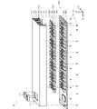
図12は、ヘッド駆動モジュール10の構造の一例を示す図である。図12に示すように、ヘッド駆動モジュール10は、駆動回路基板800、熱伝導部材群720、複数のネジ780、及び冷却ファン770を有する。 FIG. 12 is a diagram showing an example of the structure of the head driving module 10. As shown in FIG. As shown in FIG. 12, the head driving module 10 has a driving circuit board 800, a heat conducting member group 720, a plurality of screws 780, and a cooling fan 770. As shown in FIG.

駆動回路基板800は、前述した複数の駆動回路52が設けられる配線基板810を含み、液体吐出モジュール20に駆動信号COMを出力する。ヒートシンク710は、駆動回路基板800の+Z2側に位置し、複数のネジ780によって配線基板810に取り付けられる。熱伝導部材群720は、駆動回路基板800とヒートシンク710との間に位置し、配線基板810にヒートシンク710が取り付けられることで、配線基板810に設けられた複数の駆動回路52とヒートシンク710との双方と接触する。これにより、熱伝導部材群720は、配線基板810に設けられた複数の駆動回路52で生じた熱をヒートシンク710に伝導する。 The drive circuit board 800 includes a wiring board 810 provided with the plurality of drive circuits 52 described above, and outputs a drive signal COM to the liquid ejection module 20 . The heat sink 710 is located on the +Z2 side of the drive circuit board 800 and attached to the wiring board 810 with a plurality of screws 780 . The heat conducting member group 720 is positioned between the drive circuit board 800 and the heat sink 710 , and by attaching the heat sink 710 to the wiring board 810 , the plurality of drive circuits 52 provided on the wiring board 810 and the heat sink 710 are connected. contact both sides. Thereby, the heat conducting member group 720 conducts heat generated by the plurality of drive circuits 52 provided on the wiring board 810 to the heat sink 710 .

以上のように構成されたヘッド駆動モジュール10の構造の詳細について図面を用いて説明する。 Details of the structure of the head driving module 10 configured as described above will be described with reference to the drawings.

まず、ヘッド駆動モジュール10が有する駆動回路基板800の構造の具体例について説明する。図13は、複数の駆動回路52が設けられる配線基板810の断面構造の一例を示す図である。図13に示すように、配線基板810は、第1層831、第2層832、第3層833、第4層834、第5層835、及び複数の絶縁層840を有する。そして、第1層831、第2層832、第3層833、第4層834、及び第5層835が、Z2方向に沿って+Z2側から-Z2側に向かい第1層831、第2層832、第3層833、第4層834、第5層835の順に位置しているとともに、複数の絶縁層840が、Z2方向に沿って第1層831と第2層832との間、第2層832と第3層833との間、第3層833と第4層834との間、及び第4層834と第5層835との間に位置している。 First, a specific example of the structure of the drive circuit board 800 included in the head drive module 10 will be described. FIG. 13 is a diagram showing an example of a cross-sectional structure of a wiring substrate 810 provided with a plurality of drive circuits 52. As shown in FIG. As shown in FIG. 13, the wiring board 810 has a first layer 831 , a second layer 832 , a third layer 833 , a fourth layer 834 , a fifth layer 835 and a plurality of insulating layers 840 . Then, the first layer 831, the second layer 832, the third layer 833, the fourth layer 834, and the fifth layer 835 extend from the +Z2 side to the -Z2 side along the Z2 direction. 832 , a third layer 833 , a fourth layer 834 and a fifth layer 835 , and a plurality of insulating layers 840 are arranged along the Z2 direction between the first layer 831 and the second layer 832 and the third layer 832 . It is located between the second layer 832 and the third layer 833 , between the third layer 833 and the fourth layer 834 , and between the fourth layer 834 and the fifth layer 835 .

第1層831及び第5層835には、複数の駆動回路52を含む各種回路を構成する複数の電子部品が設けられる。また、第1層831、第2層832、第3層833、第4層834、及び第5層835には、第1層831及び第5層835に設けられた電子部品間を電気的に接続し、各種信号を伝搬する複数の配線パターンが形成されている。この第1層831、第2層832、第3層833、第4層834、及び第5層835のそれぞれに形成された複数の配線パターンは、電気伝導性に優れた材質であって、例えば、銅箔にエッチング処理を施すことにより形成されている。また、絶縁層840は、第1層831、第2層832、第3層833、第4層834、及び第5層835に形成された複数の配線パターンの相互間を絶縁する絶縁体層として機能する。このような絶縁層840としては、例えば、ガラス繊維の布にエポキシ樹脂をしみ込ませることで形成されたエポシキガラス等を用いることができる。 The first layer 831 and the fifth layer 835 are provided with a plurality of electronic components forming various circuits including a plurality of drive circuits 52 . In addition, in the first layer 831, the second layer 832, the third layer 833, the fourth layer 834, and the fifth layer 835, the electronic components provided on the first layer 831 and the fifth layer 835 are electrically connected. A plurality of wiring patterns for connecting and propagating various signals are formed. The plurality of wiring patterns formed in each of the first layer 831, the second layer 832, the third layer 833, the fourth layer 834, and the fifth layer 835 are made of a material having excellent electrical conductivity, such as , are formed by etching a copper foil. The insulating layer 840 serves as an insulating layer that insulates between a plurality of wiring patterns formed on the first layer 831, the second layer 832, the third layer 833, the fourth layer 834, and the fifth layer 835. Function. As such an insulating layer 840, for example, epoxy glass or the like formed by impregnating a glass fiber cloth with an epoxy resin can be used.

すなわち、第1実施形態における配線基板810は、第1層831、第2層832、第3層833、第4層834、及び第5層835を含む多層基板であって、第1層831及び第5層835が配線基板810の表層を構成し、第2層832、第3層833、及び第4層834が配線基板810の内層を構成する。なお、配線基板810には、絶縁層840をZ2方向に沿って貫通し、第1層831、第2層832、第3層833、第4層834、及び第5層835を相互に電気的に接続する不図示のスルーホールを有してもよい。また、以下の説明では、駆動回路基板800が有する複数の駆動回路52を含む各種回路を構成する電子部品が、第1層831に設けられているとして説明を行うが、駆動回路基板800が有する複数の駆動回路52を含む各種回路を構成する電子部品の一部が第5層835に設けられていてもよい。 That is, the wiring board 810 in the first embodiment is a multi-layer board including a first layer 831, a second layer 832, a third layer 833, a fourth layer 834, and a fifth layer 835. The fifth layer 835 constitutes the surface layer of the wiring board 810 , and the second layer 832 , the third layer 833 and the fourth layer 834 constitute the inner layers of the wiring board 810 . In the wiring board 810, the first layer 831, the second layer 832, the third layer 833, the fourth layer 834, and the fifth layer 835 are electrically connected through the insulating layer 840 along the Z2 direction. It may have a through hole (not shown) connected to the . Further, in the following description, it is assumed that electronic components constituting various circuits including the plurality of drive circuits 52 of the drive circuit board 800 are provided on the first layer 831. Some of the electronic components that constitute various circuits including the plurality of drive circuits 52 may be provided on the fifth layer 835 .

第1層831、第2層832、第3層833、及び第4層834の構成の詳細について、図14~図17を用いて説明する。図14は、配線基板810をZ2方向に沿ってZ2側から見た場合の第1層831の構成の一例を示す図である。 Details of the structures of the first layer 831, the second layer 832, the third layer 833, and the fourth layer 834 will be described with reference to FIGS. 14 to 17. FIG. FIG. 14 is a diagram showing an example of the configuration of the first layer 831 when the wiring board 810 is viewed from the Z2 side along the Z2 direction.

図14に示すように、配線基板810は、X2方向に沿って互いに向かい合う辺811,812と、Y2方向に沿って互いに向かい合う辺813,814とを含む略矩形状の多層基板である。具体的には、辺811は配線基板810の+X2側に位置し、辺812は配線基板810の-X2側に位置し、辺813は辺811,812の双方と交差するとともに配線基板810の+Y2側に位置し、辺814は辺811,812の双方と交差するとともに配線基板810の-Y2側に位置している。 As shown in FIG. 14, the wiring board 810 is a substantially rectangular multilayer board including sides 811 and 812 facing each other along the X2 direction and sides 813 and 814 facing each other along the Y2 direction. Specifically, the side 811 is located on the +X2 side of the wiring board 810, the side 812 is located on the -X2 side of the wiring board 810, and the side 813 intersects both sides 811 and 812 and is +Y2 of the wiring board 810. Side 814 intersects both sides 811 and 812 and is located on the −Y2 side of wiring board 810 .

配線基板810の第1層831には、接続部CN1,CN2と、集積回路101と、複数の駆動回路52とが設けられている。 The first layer 831 of the wiring substrate 810 is provided with the connection portions CN1 and CN2, the integrated circuit 101, and the plurality of drive circuits 52. As shown in FIG.

接続部CN1は、辺811に沿って位置し、制御ユニット2と電気的に接続されている。具体的には、接続部CN1には、制御ユニット2と電気的に接続される不図示のケーブルが取り付けられる。これにより、制御ユニット2が出力する画像情報信号IPを含む信号がヘッド駆動モジュール10に供給される。なお、接続部CN1は、ケーブルを介さずに制御ユニット2とヘッド駆動モジュール10との電気的接続を可能とするBtoB(Board to Board)コネクターであってもよい。 The connection portion CN1 is located along the side 811 and electrically connected to the control unit 2 . Specifically, a cable (not shown) electrically connected to the control unit 2 is attached to the connection portion CN1. As a result, a signal including the image information signal IP output from the control unit 2 is supplied to the head drive module 10 . The connection portion CN1 may be a BtoB (Board to Board) connector that enables electrical connection between the control unit 2 and the head drive module 10 without a cable.

接続部CN2は、配線基板810の辺812に沿って位置し、液体吐出モジュール20と電気的に接続される。具体的には、接続部CN2には、配線部材30の一端が取り付けられる。また、配線部材30の他端は、液体吐出モジュール20が有する接続部330に接続される。これにより、ヘッド駆動モジュール10が出力する駆動信号COMA1~COMA6,COMB1~COMB6,COMC1~COMC6、及びデータ信号DATAを含む信号が、接続部CN2、及び配線部材30を介して、接続部330から液体吐出モジュール20に供給される。すなわち、接続部CN2は、配線基板810に設けられ、配線基板810と液体吐出モジュール20とを電気的に接続することで、駆動信号COMA1~COMA6,COMB1~COMB6,COMC1~COMC6を、液体吐出モジュール20に伝搬する。ここで、接続部CN2,330は、ケーブル等を介さずに相互に電気的接続が可能なBtoBコネクターであってもよく、この場合、接続部CN2,330が配線部材30を構成する。 The connection portion CN2 is positioned along the side 812 of the wiring substrate 810 and electrically connected to the liquid ejection module 20 . Specifically, one end of the wiring member 30 is attached to the connection portion CN2. Also, the other end of the wiring member 30 is connected to the connection portion 330 of the liquid ejection module 20 . As a result, signals including the drive signals COMA1 to COMA6, COMB1 to COMB6, COMC1 to COMC6 and the data signal DATA output from the head drive module 10 are transferred from the connection portion 330 via the connection portion CN2 and the wiring member 30 to the liquid. It is supplied to the discharge module 20 . That is, the connection portion CN2 is provided on the wiring substrate 810, and electrically connects the wiring substrate 810 and the liquid ejection module 20 to connect the drive signals COMA1 to COMA6, COMB1 to COMB6, COMC1 to COMC6 to the liquid ejection module. 20. Here, the connection portions CN2 and 330 may be BtoB connectors that allow mutual electrical connection without cables or the like.

集積回路101は、接続部CN1の-X2側に位置している。集積回路101は、前述した制御回路100の一部又は全部を構成する。すなわち、集積回路101には、接続部CN1を介して画像情報信号IPが入力される。そして、集積回路101は、入力される画像情報信号IPに基づく各種信号を生成し出力する。ここで、集積回路101は、制御回路100に加えて変換回路120の一部又は全部を含んでもよい。なお、第1実施形態の液体吐出装置1では、集積回路101に制御回路100の全部、及び変換回路120の全部が含まれているとして説明を行うが、制御回路100の一部、又は変換回路120の一部が集積回路101の外部に構成されていてもよい。 The integrated circuit 101 is located on the -X2 side of the connection portion CN1. The integrated circuit 101 constitutes part or all of the control circuit 100 described above. That is, the image information signal IP is input to the integrated circuit 101 via the connection portion CN1. The integrated circuit 101 generates and outputs various signals based on the input image information signal IP. Here, the integrated circuit 101 may include part or all of the conversion circuit 120 in addition to the control circuit 100 . In the liquid ejecting apparatus 1 of the first embodiment, the integrated circuit 101 includes all of the control circuit 100 and all of the conversion circuit 120, but a part of the control circuit 100 or the conversion circuit A portion of 120 may be configured external to integrated circuit 101 .

ここで、図14では、集積回路101が複数の駆動回路52とともに配線基板810の第1層831に配置されている場合を例示しているが、集積回路101は、配線基板810とは異なる不図示の基板に配置されていてもよい。図14に示すように、集積回路101と複数の駆動回路52とを共通の基板に実装した場合、複数の駆動回路52と集積回路101との間で信号が伝搬される配線パターンを短くすることができる。これにより、複数の駆動回路52と集積回路101との間で伝搬する信号にノイズ等が重畳するおそれが低減する。一方で、複数の駆動回路52は、集積回路101と比較して発熱量が大きく、それ故に、複数の駆動回路52で生じた熱が集積回路101に寄与した場合、集積回路101の動作の安定性が低下するおそれがある。このような問題に対して、集積回路101が複数の駆動回路52と異なる基板に実装されることで、複数の駆動回路52で生じた熱が集積回路101に寄与するおそれを低減することができる。 Here, FIG. 14 exemplifies the case where the integrated circuit 101 is arranged on the first layer 831 of the wiring substrate 810 together with the plurality of driving circuits 52. It may be arranged on the illustrated substrate. As shown in FIG. 14, when the integrated circuit 101 and the plurality of drive circuits 52 are mounted on a common substrate, the wiring pattern for transmitting signals between the plurality of drive circuits 52 and the integrated circuit 101 can be shortened. can be done. This reduces the risk that noise or the like will be superimposed on signals propagating between the plurality of drive circuits 52 and the integrated circuit 101 . On the other hand, the plurality of drive circuits 52 generate a large amount of heat compared to the integrated circuit 101. Therefore, when the heat generated by the plurality of drive circuits 52 contributes to the integrated circuit 101, the operation of the integrated circuit 101 is stabilized. performance may decrease. To address such a problem, by mounting the integrated circuit 101 on a substrate different from that of the plurality of driver circuits 52, the possibility that heat generated by the plurality of driver circuits 52 will contribute to the integrated circuit 101 can be reduced. .

複数の駆動回路52は、集積回路101と接続部CN2との間に位置し、X2方向に沿って並んで設けられている。具体的には、複数の駆動回路52としての駆動回路52a1~52a6,52b1~52b6,52c1~52c6は、配線基板810の第1層831に設けられ、配線基板810の第1層831において、X2方向に沿って-X2側から+X2側に向かい駆動回路52a1,52b1,52a2,52b2,52a3,52b3,52a4,52b4,52a5,52b5,52a6,52b6,52c1,52c2,52c3,52c4,52c5,52c6の順に並んで位置している。 The plurality of drive circuits 52 are located between the integrated circuit 101 and the connection portion CN2 and arranged side by side along the X2 direction. Specifically, the drive circuits 52a1 to 52a6, 52b1 to 52b6, and 52c1 to 52c6 as the plurality of drive circuits 52 are provided on the first layer 831 of the wiring board 810, and the X2 From the -X2 side to the +X2 side along the direction, the They are located in order.

この場合において、複数の駆動回路52のそれぞれが有するトランジスターM1とトランジスターM2とは、X2方向に沿ってトランジスターM1が+X2側、トランジスターM2が-X2側となるように並んで位置し、インダクターL1は、X2方向に沿って並んで位置するトランジスターM1,M2の-Y2側に位置し、集積回路500は、X2方向に沿って並んで位置するトランジスターM1,M2の+Y2側に位置している。すなわち、駆動回路52が有する集積回路500、トランジスターM1,M2、インダクターL1は、配線基板810の第1層831において、辺813から辺814に向かう方向に沿って集積回路500、並設されたトランジスターM1,M2、インダクターL1の順に並んで位置している。 In this case, the transistors M1 and M2 included in each of the plurality of drive circuits 52 are arranged side by side in the X2 direction so that the transistor M1 is on the +X2 side and the transistor M2 is on the -X2 side. , the -Y2 side of the transistors M1 and M2 aligned along the X2 direction, and the integrated circuit 500 is located on the +Y2 side of the transistors M1 and M2 aligned along the X2 direction. That is, the integrated circuit 500, the transistors M1 and M2, and the inductor L1 included in the driving circuit 52 are arranged side by side along the direction from the side 813 to the side 814 on the first layer 831 of the wiring substrate 810. M1, M2, and inductor L1 are arranged in this order.

また、複数の駆動回路52のそれぞれが有する集積回路500は、X2方向に沿って並んで位置し、並設されたトランジスターM1,M2は、X2方向に沿って交互に並んで位置し、インダクターL1は、X2方向に沿って並んで位置している。すなわち、配線基板810の第1層831には、辺812から辺811に向かい並設する集積回路500の列と、辺812から辺811に向かい並設するトランジスターM1,M2の列と、辺812から辺811に向かい並設するインダクターL1の列とが構成されている。 In addition, the integrated circuits 500 included in each of the plurality of drive circuits 52 are arranged side by side along the X2 direction, the transistors M1 and M2 arranged side by side are arranged side by side along the X2 direction, and the inductor L1 are located side by side along the X2 direction. That is, on the first layer 831 of the wiring board 810, there are a row of the integrated circuits 500 arranged side by side from the side 812 to the side 811, a row of the transistors M1 and M2 arranged side by side from the side 812 to the side 811, and the side 812 A row of inductors L1 arranged side by side toward the side 811 is configured.

そして、第1実施形態の液体吐出装置1の配線基板810の第1層831において、駆動回路52a1,52a2,52b1,52b2,52c1,52c2は、駆動回路52a2が、X2方向に沿って、駆動回路52a1と駆動回路52c1との間に位置し、駆動回路52c2と駆動回路52c1との最短距離が、駆動回路52c2と駆動回路52a2との最短距離よりも短くなるように位置し、駆動回路52b1及び駆動回路52b2は、X2方向に沿って、駆動回路52a1と駆動回路52c1との間に位置し、且つ駆動回路52a1と駆動回路52c2との間に位置している。 In the first layer 831 of the wiring board 810 of the liquid ejection device 1 of the first embodiment, the drive circuits 52a1, 52a2, 52b1, 52b2, 52c1, and 52c2 are arranged along the X2 direction. 52a1 and the drive circuit 52c1, the shortest distance between the drive circuit 52c2 and the drive circuit 52c1 is shorter than the shortest distance between the drive circuit 52c2 and the drive circuit 52a2. The circuit 52b2 is located between the drive circuit 52a1 and the drive circuit 52c1 and between the drive circuit 52a1 and the drive circuit 52c2 along the X2 direction.

同様に、第1実施形態の液体吐出装置1の配線基板810の第1層831において、駆動回路52a3,52a4,52b3,52b4,52c3,52c4は、駆動回路52a4が、X2方向に沿って、駆動回路52a3と駆動回路52c3との間に位置し、駆動回路52c4と駆動回路52c3との最短距離が、駆動回路52c4と駆動回路52a4との最短距離よりも短くなるように位置し、駆動回路52b3及び駆動回路52b4は、X2方向に沿って、駆動回路52a3と駆動回路52c3との間に位置し、且つ駆動回路52a3と駆動回路52c4との間に位置している。 Similarly, in the first layer 831 of the wiring board 810 of the liquid ejecting apparatus 1 of the first embodiment, the driving circuits 52a3, 52a4, 52b3, 52b4, 52c3, and 52c4 are driven along the X2 direction. It is positioned between the circuit 52a3 and the drive circuit 52c3, and is positioned so that the shortest distance between the drive circuit 52c4 and the drive circuit 52c3 is shorter than the shortest distance between the drive circuit 52c4 and the drive circuit 52a4. The drive circuit 52b4 is located between the drive circuit 52a3 and the drive circuit 52c3 and between the drive circuit 52a3 and the drive circuit 52c4 along the X2 direction.

同様に、第1実施形態の液体吐出装置1の配線基板810の第1層831において、駆動回路52a5,52a6,52b5,52b6,52c5,52c6は、駆動回路52a6が、X2方向に沿って、駆動回路52a5と駆動回路52c5との間に位置し、駆動回路52c6と駆動回路52c5との最短距離が、駆動回路52c6と駆動回路52a6との最短距離よりも短くなるように位置し、駆動回路52b5及び駆動回路52b6は、X2方向に沿って、駆動回路52a5と駆動回路52c5との間に位置し、且つ駆動回路52a5と駆動回路52c6との間に位置している。 Similarly, in the first layer 831 of the wiring board 810 of the liquid ejection device 1 of the first embodiment, the drive circuits 52a5, 52a6, 52b5, 52b6, 52c5, and 52c6 are driven along the X2 direction. It is positioned between the circuit 52a5 and the drive circuit 52c5, and is positioned so that the shortest distance between the drive circuit 52c6 and the drive circuit 52c5 is shorter than the shortest distance between the drive circuit 52c6 and the drive circuit 52a6. The drive circuit 52b6 is located between the drive circuit 52a5 and the drive circuit 52c5 and between the drive circuit 52a5 and the drive circuit 52c6 along the X2 direction.

この場合において、吐出モジュール23-1が有する圧電素子60に、駆動信号COMA1を出力する駆動回路52a1と、駆動信号COMB1を出力する駆動回路52b1とは、X2方向に沿って隣り合って位置し、吐出モジュール23-2が有する圧電素子60に、駆動信号COMA2を出力する駆動回路52a2と、駆動信号COMB2を出力する駆動回路52b2とは、X2方向に沿って隣り合って位置し、吐出モジュール23-3が有する圧電素子60に、駆動信号COMA3を出力する駆動回路52a3と、駆動信号COMB3を出力する駆動回路52b3とは、X2方向に沿って隣り合って位置し、吐出モジュール23-4が有する圧電素子60に、駆動信号COMA4を出力する駆動回路52a4と、駆動信号COMB4を出力する駆動回路52b4とは、X2方向に沿って隣り合って位置し、吐出モジュール23-5が有する圧電素子60に、駆動信号COMA5を出力する駆動回路52a5と、駆動信号COMB5を出力する駆動回路52b5とは、X2方向に沿って隣り合って位置し、吐出モジュール23-6が有する圧電素子60に、駆動信号COMA6を出力する駆動回路52a6と、駆動信号COMB6を出力する駆動回路52b6とは、X2方向に沿って隣り合って位置している。 In this case, the drive circuit 52a1 that outputs the drive signal COMA1 and the drive circuit 52b1 that outputs the drive signal COMB1 to the piezoelectric element 60 of the ejection module 23-1 are positioned side by side along the X2 direction, A drive circuit 52a2 that outputs a drive signal COMA2 and a drive circuit 52b2 that outputs a drive signal COMB2 to the piezoelectric element 60 of the ejection module 23-2 are positioned side by side along the X2 direction. The drive circuit 52a3 for outputting the drive signal COMA3 and the drive circuit 52b3 for outputting the drive signal COMB3 to the piezoelectric element 60 of the ejection module 23-4 are positioned adjacent to each other along the X2 direction. The drive circuit 52a4 that outputs the drive signal COMA4 and the drive circuit 52b4 that outputs the drive signal COMB4 to the element 60 are positioned side by side along the X2 direction, and the piezoelectric element 60 of the ejection module 23-5 The drive circuit 52a5 that outputs the drive signal COMA5 and the drive circuit 52b5 that outputs the drive signal COMB5 are positioned adjacent to each other along the X2 direction, and apply the drive signal COMA6 to the piezoelectric element 60 of the ejection module 23-6. The drive circuit 52a6 that outputs and the drive circuit 52b6 that outputs the drive signal COMB6 are positioned adjacent to each other along the X2 direction.

詳細には、吐出モジュール23-1が有する吐出部600からインクが吐出されるように吐出モジュール23-1が有する圧電素子60を駆動するための駆動信号COMA1を出力する駆動回路52a1と、吐出モジュール23-1が有する吐出部600からインクが吐出されるように吐出モジュール23-1が有する圧電素子60を駆動するための駆動信号COMB1を出力する駆動回路52b1とは、配線基板810の第1層831においてX2方向に沿って、駆動回路52a1が-X2側、駆動回路52b1が+X2側となるように隣り合って位置している。 Specifically, a drive circuit 52a1 for outputting a drive signal COMA1 for driving the piezoelectric element 60 of the ejection module 23-1 so that ink is ejected from the ejection section 600 of the ejection module 23-1; The drive circuit 52b1 that outputs the drive signal COMB1 for driving the piezoelectric element 60 of the ejection module 23-1 so that ink is ejected from the ejection portion 600 of the ejection module 23-1 is the first layer of the wiring substrate 810. In 831, along the X2 direction, the driving circuit 52a1 is located adjacent to the -X2 side and the driving circuit 52b1 is located adjacent to the +X2 side.

吐出モジュール23-2が有する吐出部600からインクが吐出されるように吐出モジュール23-2が有する圧電素子60を駆動するための駆動信号COMA2を出力する駆動回路52a2と、吐出モジュール23-2が有する吐出部600からインクが吐出されるように吐出モジュール23-2が有する圧電素子60を駆動するための駆動信号COMB2を出力する駆動回路52b2とは、配線基板810の第1層831においてX2方向に沿って、駆動回路52b1の+X2側で、駆動回路52a2が-X2側、駆動回路52b2が+X2側となるように隣り合って位置している。 A drive circuit 52a2 for outputting a drive signal COMA2 for driving the piezoelectric element 60 of the ejection module 23-2 so that ink is ejected from the ejection section 600 of the ejection module 23-2, and the ejection module 23-2. The drive circuit 52b2 for outputting the drive signal COMB2 for driving the piezoelectric element 60 of the ejection module 23-2 so that ink is ejected from the ejection portion 600 is the first layer 831 of the wiring substrate 810, which is arranged in the X2 direction. along the +X2 side of the driving circuit 52b1, the driving circuit 52a2 is located adjacent to the -X2 side, and the driving circuit 52b2 is located adjacent to the +X2 side.

吐出モジュール23-3が有する吐出部600からインクが吐出されるように吐出モジュール23-3が有する圧電素子60を駆動するための駆動信号COMA3を出力する駆動回路52a3と、吐出モジュール23-3が有する吐出部600からインクが吐出されるように吐出モジュール23-3が有する圧電素子60を駆動するための駆動信号COMB3を出力する駆動回路52b3とは、配線基板810の第1層831においてX2方向に沿って、駆動回路52b2の+X2側で、駆動回路52a3が-X2側、駆動回路52b3が+X2側となるように隣り合って位置している。 A drive circuit 52a3 for outputting a drive signal COMA3 for driving the piezoelectric element 60 of the ejection module 23-3 so that ink is ejected from the ejection section 600 of the ejection module 23-3, and the ejection module 23-3. The drive circuit 52b3 for outputting the drive signal COMB3 for driving the piezoelectric element 60 of the ejection module 23-3 so that the ink is ejected from the ejection portion 600 is arranged in the first layer 831 of the wiring board 810 in the X2 direction. along the +X2 side of the driving circuit 52b2, the driving circuit 52a3 is on the -X2 side, and the driving circuit 52b3 is on the +X2 side.

吐出モジュール23-4が有する吐出部600からインクが吐出されるように吐出モジュール23-4が有する圧電素子60を駆動するための駆動信号COMA4を出力する駆動回路52a4と、吐出モジュール23-4が有する吐出部600からインクが吐出されるように吐出モジュール23-4が有する圧電素子60を駆動するための駆動信号COMB4を出力する駆動回路52b4とは、配線基板810の第1層831においてX2方向に沿って、駆動回路52b3の+X2側で、駆動回路52a4が-X2側、駆動回路52b4が+X2側となるように隣り合って位置している。 A drive circuit 52a4 for outputting a drive signal COMA4 for driving the piezoelectric element 60 of the ejection module 23-4 so that ink is ejected from the ejection section 600 of the ejection module 23-4, and the ejection module 23-4 are provided. The drive circuit 52b4 for outputting the drive signal COMB4 for driving the piezoelectric element 60 of the ejection module 23-4 so that the ink is ejected from the ejection portion 600 is arranged in the first layer 831 of the wiring board 810 in the X2 direction. along the +X2 side of the driving circuit 52b3, the driving circuit 52a4 is located adjacent to the -X2 side, and the driving circuit 52b4 is located adjacent to the +X2 side.

吐出モジュール23-5が有する吐出部600からインクが吐出されるように吐出モジュール23-5が有する圧電素子60を駆動するための駆動信号COMA5を出力する駆動回路52a5と、吐出モジュール23-5が有する吐出部600からインクが吐出されるように吐出モジュール23-5が有する圧電素子60を駆動するための駆動信号COMB5を出力する駆動回路52b5とは、配線基板810の第1層831においてX2方向に沿って、駆動回路52b4の+X2側で、駆動回路52a5が-X2側、駆動回路52b5が+X2側となるように隣り合って位置している。 A drive circuit 52a5 for outputting a drive signal COMA5 for driving the piezoelectric element 60 of the ejection module 23-5 so that ink is ejected from the ejection section 600 of the ejection module 23-5, and the ejection module 23-5 are provided. The drive circuit 52b5 for outputting the drive signal COMB5 for driving the piezoelectric element 60 of the ejection module 23-5 so that the ink is ejected from the ejection portion 600 is provided in the first layer 831 of the wiring board 810 in the X2 direction. along the +X2 side of the driving circuit 52b4, the driving circuit 52a5 is located adjacent to the -X2 side, and the driving circuit 52b5 is located adjacent to the +X2 side.

吐出モジュール23-6が有する吐出部600からインクが吐出されるように吐出モジュール23-6が有する圧電素子60を駆動するための駆動信号COMA6を出力する駆動回路52a6と、吐出モジュール23-6が有する吐出部600からインクが吐出されるように吐出モジュール23-6が有する圧電素子60を駆動するための駆動信号COMB6を出力する駆動回路52b6とは、配線基板810の第1層831においてX2方向に沿って、駆動回路52b5の+X2側で、駆動回路52a6が-X2側、駆動回路52b6が+X2側となるように隣り合って位置している。 A drive circuit 52a6 for outputting a drive signal COMA6 for driving the piezoelectric element 60 of the ejection module 23-6 so that ink is ejected from the ejection section 600 of the ejection module 23-6, and the ejection module 23-6. The drive circuit 52b6 for outputting the drive signal COMB6 for driving the piezoelectric element 60 of the ejection module 23-6 so that the ink is ejected from the ejection portion 600 is arranged in the first layer 831 of the wiring board 810 in the X2 direction. along the +X2 side of the driving circuit 52b5, the driving circuit 52a6 is on the -X2 side, and the driving circuit 52b6 is on the +X2 side.

また、吐出モジュール23-1が有する吐出部600からインクが吐出されないように吐出モジュール23-1が有する圧電素子60を駆動するための駆動信号COMC1を出力する駆動回路52c1は、配線基板810の第1層831においてX2方向に沿って、駆動回路52b6の+X2側に位置している。吐出モジュール23-2が有する吐出部600からインクが吐出されないように吐出モジュール23-2が有する圧電素子60を駆動するための駆動信号COMC2を出力する駆動回路52c2は、配線基板810の第1層831においてX2方向に沿って、駆動回路52c1の+X2側に位置している。吐出モジュール23-3が有する吐出部600からインクが吐出されないように吐出モジュール23-3が有する圧電素子60を駆動するための駆動信号COMC3を出力する駆動回路52c3は、配線基板810の第1層831においてX2方向に沿って、駆動回路52c2の+X2側に位置している。吐出モジュール23-4が有する吐出部600からインクが吐出されないように吐出モジュール23-4が有する圧電素子60を駆動するための駆動信号COMC4を出力する駆動回路52c4は、配線基板810の第1層831においてX2方向に沿って、駆動回路52c3の+X2側に位置している。吐出モジュール23-5が有する吐出部600からインクが吐出されないように吐出モジュール23-5が有する圧電素子60を駆動するための駆動信号COMC5を出力する駆動回路52c5は、配線基板810の第1層831においてX2方向に沿って、駆動回路52c4の+X2側に位置している。吐出モジュール23-6が有する吐出部600からインクが吐出されないように吐出モジュール23-6が有する圧電素子60を駆動するための駆動信号COMC6を出力する駆動回路52c6は、配線基板810の第1層831においてX2方向に沿って、駆動回路52c5の+X2側に位置している。 Further, the drive circuit 52c1 for outputting the drive signal COMC1 for driving the piezoelectric element 60 of the ejection module 23-1 so that ink is not ejected from the ejection section 600 of the ejection module 23-1 is connected to the first It is located on the +X2 side of the drive circuit 52b6 along the X2 direction in the first layer 831 . A drive circuit 52c2 for outputting a drive signal COMC2 for driving the piezoelectric element 60 of the ejection module 23-2 so that ink is not ejected from the ejection section 600 of the ejection module 23-2 is provided on the first layer of the wiring substrate 810. In 831, it is located on the +X2 side of the driving circuit 52c1 along the X2 direction. A drive circuit 52c3 for outputting a drive signal COMC3 for driving the piezoelectric element 60 of the ejection module 23-3 so that ink is not ejected from the ejection section 600 of the ejection module 23-3 is provided on the first layer of the wiring substrate 810. In 831, it is located on the +X2 side of the driving circuit 52c2 along the X2 direction. A drive circuit 52c4 for outputting a drive signal COMC4 for driving the piezoelectric element 60 of the ejection module 23-4 so that ink is not ejected from the ejection section 600 of the ejection module 23-4 is provided on the first layer of the wiring substrate 810. In 831, it is located on the +X2 side of the drive circuit 52c3 along the X2 direction. A drive circuit 52c5 for outputting a drive signal COMC5 for driving the piezoelectric element 60 of the ejection module 23-5 so that ink is not ejected from the ejection section 600 of the ejection module 23-5 is provided on the first layer of the wiring substrate 810. In 831, it is located on the +X2 side of the driving circuit 52c4 along the X2 direction. A drive circuit 52c6 that outputs a drive signal COMC6 for driving the piezoelectric element 60 of the ejection module 23-6 so that ink is not ejected from the ejection section 600 of the ejection module 23-6 is provided on the first layer of the wiring substrate 810. In 831, it is located on the +X2 side of the driving circuit 52c5 along the X2 direction.

すなわち、ヘッド駆動モジュール10において、インクを吐出するように圧電素子60を駆動する駆動信号COMA1~COMA6,COMB1~COMB6を出力する駆動回路52a1~52a6,52b1~52b6は、配線基板810の第1層831においてX2方向に沿って対応する吐出モジュール23毎に隣り合って位置し、インクを吐出しないように圧電素子60を駆動する駆動信号COMC1~COMC6を出力する駆動回路52c1~52c6は、配線基板810の第1層831においてX2方向に沿って、駆動回路52a1~52a6,52b1~52b6よりも+X2側において、駆動回路52c1,52c2,52c3,52c4,52c5,52c6の順に位置している。 That is, in the head drive module 10, the drive circuits 52a1 to 52a6 and 52b1 to 52b6 for outputting the drive signals COMA1 to COMA6 and COMB1 to COMB6 for driving the piezoelectric elements 60 to eject ink are arranged on the first layer of the wiring substrate 810. Drive circuits 52c1 to 52c6 are positioned adjacent to each corresponding ejection module 23 along the X2 direction in 831 and output drive signals COMC1 to COMC6 for driving the piezoelectric elements 60 so as not to eject ink. The drive circuits 52c1, 52c2, 52c3, 52c4, 52c5, and 52c6 are located in this order on the +X2 side of the drive circuits 52a1 to 52a6 and 52b1 to 52b6 along the X2 direction in the first layer 831 of .

以上のように構成された駆動回路基板800では、接続部CN1を介して入力される画像情報信号IPが集積回路101に供給される。そして、集積回路101が、入力される画像情報信号IPに基づいて、基駆動信号dA1~dA6,dB1~dB6,dC1~dC6、及びデータ信号DATAを生成し出力する。集積回路101が出力する基駆動信号dA1~dA6,dB1~dB6,dC1~dC6は、配線基板810が有する不図示の配線パターンを伝搬し、対応する駆動回路52に入力される。複数の駆動回路52は、入力される基駆動信号dA1~dA6,dB1~dB6,dC1~dC6に基づいて、駆動信号COMA1~COMA6,COMB1~COMB6,COMC1~COMC6を生成し出力する。そして、複数の駆動回路52のそれぞれが出力する駆動信号COMA1~COMA6,COMB1~COMB6,COMC1~COMC6と、集積回路101が出力するデータ信号DATAに基づく信号と、を含む複数の信号が、接続部CN2を介して、液体吐出モジュール20に供給される。 In the drive circuit board 800 configured as described above, the image information signal IP input through the connection portion CN1 is supplied to the integrated circuit 101. FIG. Based on the input image information signal IP, the integrated circuit 101 generates and outputs base drive signals dA1 to dA6, dB1 to dB6, dC1 to dC6 and data signal DATA. The base drive signals dA1 to dA6, dB1 to dB6, and dC1 to dC6 output by the integrated circuit 101 propagate through wiring patterns (not shown) of the wiring board 810 and are input to the corresponding drive circuits 52. FIG. A plurality of drive circuits 52 generate and output drive signals COMA1-COMA6, COMB1-COMB6, and COMC1-COMC6 based on the input base drive signals dA1-dA6, dB1-dB6, and dC1-dC6. A plurality of signals including drive signals COMA1 to COMA6, COMB1 to COMB6, and COMC1 to COMC6 output by the plurality of drive circuits 52 and a signal based on the data signal DATA output by the integrated circuit 101 are connected to the connection portion. It is supplied to the liquid ejection module 20 via CN2.

以上のようにヘッド駆動モジュール10から液体吐出モジュール20に供給される信号の内、複数の駆動回路52のそれぞれが出力する駆動信号COMA1~COMA6,COMB1~COMB6,COMC1~COMC6は、前述の通り、対応する圧電素子60に供給され、圧電素子60を駆動するためのアナログ信号である。このような駆動信号COMA1~COMA6,COMB1~COMB6,COMC1~COMC6に波形歪が生じた場合、対応する吐出部600からのインクの吐出状況に直接的に寄与する。すなわち、液体吐出モジュール20から吐出されるインクの吐出精度を向上させるとの観点において、駆動信号COMA1~COMA6,COMB1~COMB6,COMC1~COMC6に波形歪が生じるおそれを低減することが、液体吐出モジュール20から吐出されるインクの吐出精度向上の観点において、重要な1つの要素なる。 Among the signals supplied from the head drive module 10 to the liquid ejection module 20 as described above, the drive signals COMA1 to COMA6, COMB1 to COMB6, and COMC1 to COMC6 output by the plurality of drive circuits 52 are as described above. It is an analog signal that is supplied to the corresponding piezoelectric element 60 to drive the piezoelectric element 60 . When waveform distortion occurs in such drive signals COMA1 to COMA6, COMB1 to COMB6, and COMC1 to COMC6, it directly contributes to the state of ink ejection from the corresponding ejection section 600. FIG. That is, from the viewpoint of improving the ejection accuracy of the ink ejected from the liquid ejection module 20, it is important to reduce the risk of waveform distortion occurring in the drive signals COMA1 to COMA6, COMB1 to COMB6, and COMC1 to COMC6. This is an important factor from the viewpoint of improving the ejection accuracy of the ink ejected from 20 .

そこで、ヘッド駆動モジュール10において、駆動回路52a1~52a6,52b1~52b6,52c1~52c6のそれぞれが出力する駆動信号COMA1~COMA6,COMB1~COMB6,COMC1~COMC6が伝搬する配線パターンの構成の一例について、図15~図17を用いて説明する。 Therefore, in the head drive module 10, an example of the configuration of the wiring pattern through which the drive signals COMA1 to COMA6, COMB1 to COMB6, and COMC1 to COMC6 output by the drive circuits 52a1 to 52a6, 52b1 to 52b6, and 52c1 to 52c6 are transmitted. Description will be made with reference to FIGS. 15 to 17. FIG.

図15は、配線基板810の第2層832に設けられた配線パターンの一例を示す図であり、図16は、配線基板810の第3層833に設けられた配線パターンの一例を示す図であり、図17は、配線基板810の第4層834に設けられた配線パターンの一例を示す図である。ここで、第1実施形態のヘッド駆動モジュール10では、駆動信号COMA1~COMA6が伝搬する複数の配線パターンが配線基板810の第2層832に設けられ、駆動信号COMB1~COMB6が伝搬する複数の配線パターンが配線基板810の第3層833に設けられ、駆動信号COMC1~COMC6が伝搬する複数の配線パターンが配線基板810の第4層834に設けられているとして説明を行う。なお、図15~図17は、配線基板810をZ2方向に沿って+Z2側から-Z2側に見た場合の透視図であり、図15~図17には、配線基板810の第1層831に設けられている複数の駆動回路52、接続部CN1,CN2、及び集積回路101を破線で示している。 15 is a diagram showing an example of a wiring pattern provided on the second layer 832 of the wiring board 810, and FIG. 16 is a diagram showing an example of a wiring pattern provided on the third layer 833 of the wiring board 810. FIG. FIG. 17 is a diagram showing an example of wiring patterns provided on the fourth layer 834 of the wiring substrate 810. As shown in FIG. Here, in the head drive module 10 of the first embodiment, a plurality of wiring patterns for propagating the drive signals COMA1 to COMA6 are provided on the second layer 832 of the wiring substrate 810, and a plurality of wiring patterns for propagating the drive signals COMB1 to COMB6 are provided. It is assumed that a pattern is provided on the third layer 833 of the wiring board 810, and a plurality of wiring patterns for propagating the drive signals COMC1 to COMC6 are provided on the fourth layer 834 of the wiring board 810. FIG. 15 to 17 are perspective views when the wiring board 810 is viewed from the +Z2 side to the -Z2 side along the Z2 direction. A plurality of drive circuits 52, connection portions CN1 and CN2, and the integrated circuit 101 provided in FIG.

図14に示したように、駆動信号COMA1を出力する駆動回路52a1は、第1層831において接続部CN2の+X2側に位置している。そして、図15に示すように、駆動回路52a1が駆動信号COMA1を出力するインダクターL1の一端は、不図示のスルーホールを介して、第2層832に設けられた配線WA1の一端と電気的に接続している。配線WA1は、第2層832においてX2方向に沿って延在している。そして、配線WA1の他端が、不図示のスルーホールを介して、第1層831に設けられた接続部CN2と電気的に接続している。すなわち、配線基板810は、駆動回路52a1と接続部CN2とを電気的に接続し、駆動信号COMA1を伝搬する配線WA1を含む。これにより、駆動回路52a1が出力する駆動信号COMA1が、接続部CN2に伝搬される。 As shown in FIG. 14, the drive circuit 52a1 that outputs the drive signal COMA1 is located on the +X2 side of the connection portion CN2 in the first layer 831. As shown in FIG. As shown in FIG. 15, one end of the inductor L1 through which the drive circuit 52a1 outputs the drive signal COMA1 is electrically connected to one end of the wiring WA1 provided on the second layer 832 via a through hole (not shown). Connected. The wiring WA1 extends in the second layer 832 along the X2 direction. The other end of the wiring WA1 is electrically connected to the connection portion CN2 provided in the first layer 831 via a through hole (not shown). That is, wiring board 810 includes wiring WA1 that electrically connects drive circuit 52a1 and connection portion CN2 and propagates drive signal COMA1. As a result, the drive signal COMA1 output by the drive circuit 52a1 is propagated to the connection portion CN2.

また、図14に示したように、駆動信号COMB1を出力する駆動回路52b1は、第1層831において駆動回路52a1の+X2側に位置している。そして、図16に示すように、駆動回路52b1が駆動信号COMB1を出力するインダクターL1の一端は、不図示のスルーホールを介して、第3層833に設けられた配線WB1の一端と電気的に接続している。配線WB1は、第3層833においてX2方向に沿って延在している。そして、配線WB1の他端が、不図示のスルーホールを介して、第1層831に設けられた接続部CN2と電気的に接続している。すなわち、配線基板810は、駆動回路52b1と接続部CN2とを電気的に接続し、駆動信号COMB1を伝搬する配線WB1を含む。これにより、駆動回路52b1が出力する駆動信号COMB1が、接続部CN2に伝搬される。 14, the drive circuit 52b1 that outputs the drive signal COMB1 is located on the +X2 side of the drive circuit 52a1 in the first layer 831. As shown in FIG. As shown in FIG. 16, one end of the inductor L1 through which the drive circuit 52b1 outputs the drive signal COMB1 is electrically connected to one end of the wiring WB1 provided on the third layer 833 via a through hole (not shown). Connected. The wiring WB1 extends in the third layer 833 along the X2 direction. The other end of the wiring WB1 is electrically connected to the connection portion CN2 provided in the first layer 831 via a through hole (not shown). That is, wiring board 810 includes wiring WB1 that electrically connects drive circuit 52b1 and connection portion CN2 and propagates drive signal COMB1. As a result, the drive signal COMB1 output by the drive circuit 52b1 is propagated to the connection portion CN2.

また、図14に示したように、駆動信号COMA2を出力する駆動回路52a2は、第1層831において駆動回路52b1の+X2側に位置している。そして、図15に示すように、駆動回路52a2が駆動信号COMA2を出力するインダクターL1の一端は、不図示のスルーホールを介して、第2層832に設けられた配線WA2の一端と電気的に接続している。配線WA2は、第2層832においてX2方向に沿って延在している。そして、配線WA2の他端が、不図示のスルーホールを介して、第1層831に設けられた接続部CN2と電気的に接続している。すなわち、配線基板810は、駆動回路52a2と接続部CN2とを電気的に接続し、駆動信号COMA2を伝搬する配線WA2を含む。これにより、駆動回路52a2が出力する駆動信号COMA2が、接続部CN2に伝搬される。 14, the drive circuit 52a2 that outputs the drive signal COMA2 is located on the +X2 side of the drive circuit 52b1 in the first layer 831. As shown in FIG. As shown in FIG. 15, one end of the inductor L1 through which the drive circuit 52a2 outputs the drive signal COMA2 is electrically connected to one end of the wiring WA2 provided on the second layer 832 via a through hole (not shown). Connected. The wiring WA2 extends in the second layer 832 along the X2 direction. The other end of the wiring WA2 is electrically connected to the connection portion CN2 provided in the first layer 831 via a through hole (not shown). That is, wiring board 810 includes wiring WA2 that electrically connects drive circuit 52a2 and connection portion CN2 and propagates drive signal COMA2. As a result, the drive signal COMA2 output by the drive circuit 52a2 is propagated to the connection portion CN2.

また、図14に示したように、駆動信号COMB2を出力する駆動回路52b2は、第1層831において駆動回路52a2の+X2側に位置している。そして、図16に示すように、駆動回路52b2が駆動信号COMB2を出力するインダクターL1の一端は、不図示のスルーホールを介して、第3層833に設けられた配線WB2の一端と電気的に接続している。配線WB2は、第3層833においてX2方向に沿って延在している。そして、配線WB2の他端が、不図示のスルーホールを介して、第1層831に設けられた接続部CN2と電気的に接続している。すなわち、配線基板810は、駆動回路52b2と接続部CN2とを電気的に接続し、駆動信号COMB2を伝搬する配線WB2を含む。これにより、駆動回路52b2が出力する駆動信号COMB2が、接続部CN2に伝搬される。 14, the drive circuit 52b2 that outputs the drive signal COMB2 is located on the +X2 side of the drive circuit 52a2 in the first layer 831. As shown in FIG. As shown in FIG. 16, one end of the inductor L1 through which the drive circuit 52b2 outputs the drive signal COMB2 is electrically connected to one end of the wiring WB2 provided on the third layer 833 through a through hole (not shown). Connected. The wiring WB2 extends in the third layer 833 along the X2 direction. The other end of the wiring WB2 is electrically connected to the connecting portion CN2 provided in the first layer 831 via a through hole (not shown). That is, wiring board 810 includes wiring WB2 that electrically connects drive circuit 52b2 and connection portion CN2 and propagates drive signal COMB2. As a result, the drive signal COMB2 output by the drive circuit 52b2 is propagated to the connection portion CN2.

また、図14に示したように、駆動信号COMA3を出力する駆動回路52a3は、第1層831において駆動回路52b2の+X2側に位置している。そして、図15に示すように、駆動回路52a3が駆動信号COMA3を出力するインダクターL1の一端は、不図示のスルーホールを介して、第2層832に設けられた配線WA3の一端と電気的に接続している。配線WA3は、第2層832においてX2方向に沿って延在している。そして、配線WA3の他端が、不図示のスルーホールを介して、第1層831に設けられた接続部CN2と電気的に接続している。すなわち、配線基板810は、駆動回路52a3と接続部CN2とを電気的に接続し、駆動信号COMA3を伝搬する配線WA3を含む。これにより、駆動回路52a3が出力する駆動信号COMA3が、接続部CN2に伝搬される。 14, the drive circuit 52a3 that outputs the drive signal COMA3 is located on the +X2 side of the drive circuit 52b2 in the first layer 831. As shown in FIG. As shown in FIG. 15, one end of the inductor L1 through which the drive circuit 52a3 outputs the drive signal COMA3 is electrically connected to one end of the wiring WA3 provided on the second layer 832 via a through hole (not shown). Connected. The wiring WA3 extends in the second layer 832 along the X2 direction. The other end of the wiring WA3 is electrically connected to the connection portion CN2 provided in the first layer 831 via a through hole (not shown). That is, wiring board 810 includes wiring WA3 that electrically connects drive circuit 52a3 and connection portion CN2 and propagates drive signal COMA3. As a result, the drive signal COMA3 output by the drive circuit 52a3 is propagated to the connection portion CN2.

また、図14に示したように、駆動信号COMB3を出力する駆動回路52b3は、第1層831において駆動回路52a3の+X2側に位置している。そして、図16に示すように、駆動回路52b3が駆動信号COMB3を出力するインダクターL1の一端は、不図示のスルーホールを介して、第3層833に設けられた配線WB3の一端と電気的に接続している。配線WB3は、第3層833においてX2方向に沿って延在している。そして、配線WB3の他端が、不図示のスルーホールを介して、第1層831に設けられた接続部CN2と電気的に接続している。すなわち、配線基板810は、駆動回路52b3と接続部CN2とを電気的に接続し、駆動信号COMB3を伝搬する配線WB3を含む。これにより、駆動回路52b3が出力する駆動信号COMB3が、接続部CN2に伝搬される。 14, the drive circuit 52b3 that outputs the drive signal COMB3 is located on the +X2 side of the drive circuit 52a3 in the first layer 831. As shown in FIG. As shown in FIG. 16, one end of the inductor L1 through which the drive circuit 52b3 outputs the drive signal COMB3 is electrically connected to one end of the wiring WB3 provided on the third layer 833 via a through hole (not shown). Connected. The wiring WB3 extends in the third layer 833 along the X2 direction. The other end of the wiring WB3 is electrically connected to the connection portion CN2 provided in the first layer 831 via a through hole (not shown). That is, wiring board 810 includes wiring WB3 that electrically connects drive circuit 52b3 and connection portion CN2 and propagates drive signal COMB3. As a result, the drive signal COMB3 output by the drive circuit 52b3 is propagated to the connection portion CN2.

また、図14に示したように、駆動信号COMA4を出力する駆動回路52a4は、第1層831において駆動回路52b3の+X2側に位置している。そして、図15に示すように、駆動回路52a4が駆動信号COMA4を出力するインダクターL1の一端は、不図示のスルーホールを介して、第2層832に設けられた配線WA4の一端と電気的に接続している。配線WA4は、第2層832においてX2方向に沿って延在している。そして、配線WA4の他端が、不図示のスルーホールを介して、第1層831に設けられた接続部CN2と電気的に接続している。すなわち、配線基板810は、駆動回路52a4と接続部CN2とを電気的に接続し、駆動信号COMA4を伝搬する配線WA4を含む。これにより、駆動回路52a4が出力する駆動信号COMA4が、接続部CN2に伝搬される。 14, the drive circuit 52a4 that outputs the drive signal COMA4 is located on the +X2 side of the drive circuit 52b3 in the first layer 831. As shown in FIG. As shown in FIG. 15, one end of the inductor L1 through which the drive circuit 52a4 outputs the drive signal COMA4 is electrically connected to one end of the wiring WA4 provided on the second layer 832 via a through hole (not shown). Connected. The wiring WA4 extends in the second layer 832 along the X2 direction. The other end of the wiring WA4 is electrically connected to the connection portion CN2 provided in the first layer 831 via a through hole (not shown). That is, wiring board 810 includes wiring WA4 that electrically connects drive circuit 52a4 and connection portion CN2 and propagates drive signal COMA4. As a result, the drive signal COMA4 output by the drive circuit 52a4 is propagated to the connection portion CN2.

また、図14に示したように、駆動信号COMB4を出力する駆動回路52b4は、第1層831において駆動回路52a4の+X2側に位置している。そして、図16に示すように、駆動回路52b4が駆動信号COMB4を出力するインダクターL1の一端は、不図示のスルーホールを介して、第3層833に設けられた配線WB4の一端と電気的に接続している。配線WB4は、第3層833においてX2方向に沿って延在している。そして、配線WB4の他端が、不図示のスルーホールを介して、第1層831に設けられた接続部CN2と電気的に接続している。すなわち、配線基板810は、駆動回路52b4と接続部CN2とを電気的に接続し、駆動信号COMB4を伝搬する配線WB4を含む。これにより、駆動回路52b4が出力する駆動信号COMB4が、接続部CN2に伝搬される。 14, the drive circuit 52b4 that outputs the drive signal COMB4 is located on the +X2 side of the drive circuit 52a4 in the first layer 831. As shown in FIG. As shown in FIG. 16, one end of the inductor L1 through which the drive circuit 52b4 outputs the drive signal COMB4 is electrically connected to one end of the wiring WB4 provided on the third layer 833 via a through hole (not shown). Connected. The wiring WB4 extends in the third layer 833 along the X2 direction. The other end of the wiring WB4 is electrically connected to the connection portion CN2 provided in the first layer 831 via a through hole (not shown). That is, wiring board 810 includes wiring WB4 that electrically connects drive circuit 52b4 and connection portion CN2 and propagates drive signal COMB4. As a result, the drive signal COMB4 output by the drive circuit 52b4 is propagated to the connection portion CN2.

また、図14に示したように、駆動信号COMA5を出力する駆動回路52a5は、第1層831において駆動回路52b4の+X2側に位置している。そして、図15に示すように、駆動回路52a5が駆動信号COMA5を出力するインダクターL1の一端は、不図示のスルーホールを介して、第2層832に設けられた配線WA5の一端と電気的に接続している。配線WA5は、第2層832においてX2方向に沿って延在している。そして、配線WA5の他端が、不図示のスルーホールを介して、第1層831に設けられた接続部CN2と電気的に接続している。すなわち、配線基板810は、駆動回路52a5と接続部CN2とを電気的に接続し、駆動信号COMA5を伝搬する配線WA5を含む。これにより、駆動回路52a5が出力する駆動信号COMA5が、接続部CN2に伝搬される。 14, the drive circuit 52a5 that outputs the drive signal COMA5 is located on the +X2 side of the drive circuit 52b4 in the first layer 831. As shown in FIG. As shown in FIG. 15, one end of the inductor L1 through which the drive circuit 52a5 outputs the drive signal COMA5 is electrically connected to one end of the wiring WA5 provided on the second layer 832 via a through hole (not shown). Connected. The wiring WA5 extends in the second layer 832 along the X2 direction. The other end of the wiring WA5 is electrically connected to the connection portion CN2 provided in the first layer 831 via a through hole (not shown). That is, wiring board 810 includes wiring WA5 that electrically connects drive circuit 52a5 and connection portion CN2 and propagates drive signal COMA5. As a result, the drive signal COMA5 output by the drive circuit 52a5 is propagated to the connection portion CN2.

また、図14に示したように、駆動信号COMB5を出力する駆動回路52b5は、第1層831において駆動回路52a5の+X2側に位置している。そして、図16に示すように、駆動回路52b5が駆動信号COMB5を出力するインダクターL1の一端は、不図示のスルーホールを介して、第3層833に設けられた配線WB5の一端と電気的に接続している。配線WB5は、第3層833においてX2方向に沿って延在している。そして、配線WB5の他端が、不図示のスルーホールを介して、第1層831に設けられた接続部CN2と電気的に接続している。すなわち、配線基板810は、駆動回路52b5と接続部CN2とを電気的に接続し、駆動信号COMB5を伝搬する配線WB5を含む。これにより、駆動回路52b5が出力する駆動信号COMB5が、接続部CN2に伝搬される。 14, the drive circuit 52b5 that outputs the drive signal COMB5 is located on the +X2 side of the drive circuit 52a5 in the first layer 831. As shown in FIG. As shown in FIG. 16, one end of the inductor L1 through which the drive circuit 52b5 outputs the drive signal COMB5 is electrically connected to one end of the wiring WB5 provided on the third layer 833 through a through hole (not shown). Connected. The wiring WB5 extends in the third layer 833 along the X2 direction. The other end of the wiring WB5 is electrically connected to the connection portion CN2 provided in the first layer 831 via a through hole (not shown). That is, wiring board 810 includes wiring WB5 that electrically connects drive circuit 52b5 and connection portion CN2 and propagates drive signal COMB5. As a result, the drive signal COMB5 output by the drive circuit 52b5 is propagated to the connection portion CN2.

また、図14に示したように、駆動信号COMA6を出力する駆動回路52a6は、第1層831において駆動回路52b5の+X2側に位置している。そして、図15に示すように、駆動回路52a6が駆動信号COMA6を出力するインダクターL1の一端は、不図示のスルーホールを介して、第2層832に設けられた配線WA6の一端と電気的に接続している。配線WA6は、第2層832においてX2方向に沿って延在している。 14, the drive circuit 52a6 that outputs the drive signal COMA6 is located on the +X2 side of the drive circuit 52b5 in the first layer 831. As shown in FIG. As shown in FIG. 15, one end of the inductor L1 through which the drive circuit 52a6 outputs the drive signal COMA6 is electrically connected to one end of the wiring WA6 provided on the second layer 832 via a through hole (not shown). Connected. The wiring WA6 extends in the second layer 832 along the X2 direction.

そして、配線WA6の他端が、不図示のスルーホールを介して、第1層831に設けられた接続部CN2と電気的に接続している。すなわち、配線基板810は、駆動回路52a6と接続部CN2とを電気的に接続し、駆動信号COMA6を伝搬する配線WA6を含む。これにより、駆動回路52a6が出力する駆動信号COMA6が、接続部CN2に伝搬される。 The other end of the wiring WA6 is electrically connected to the connection portion CN2 provided in the first layer 831 via a through hole (not shown). That is, wiring substrate 810 includes wiring WA6 that electrically connects drive circuit 52a6 and connection portion CN2 and propagates drive signal COMA6. As a result, the drive signal COMA6 output by the drive circuit 52a6 is propagated to the connection portion CN2.

また、図14に示したように、駆動信号COMB6を出力する駆動回路52b6は、第1層831において駆動回路52a6の+X2側に位置している。そして、図16に示すように、駆動回路52b6が駆動信号COMB6を出力するインダクターL1の一端は、不図示のスルーホールを介して、第3層833に設けられた配線WB6の一端と電気的に接続している。配線WB6は、第3層833においてX2方向に沿って延在している。そして、配線WB6の他端が、不図示のスルーホールを介して、第1層831に設けられた接続部CN2と電気的に接続している。すなわち、配線基板810は、駆動回路52b6と接続部CN2とを電気的に接続し、駆動信号COMB6を伝搬する配線WB6を含む。これにより、駆動回路52b6が出力する駆動信号COMB6が、接続部CN2に伝搬される。 14, the drive circuit 52b6 that outputs the drive signal COMB6 is located on the +X2 side of the drive circuit 52a6 in the first layer 831. As shown in FIG. Then, as shown in FIG. 16, one end of the inductor L1 through which the drive circuit 52b6 outputs the drive signal COMB6 is electrically connected to one end of the wiring WB6 provided on the third layer 833 via a through hole (not shown). Connected. The wiring WB6 extends in the third layer 833 along the X2 direction. The other end of the wiring WB6 is electrically connected to the connection portion CN2 provided in the first layer 831 via a through hole (not shown). That is, wiring board 810 includes wiring WB6 that electrically connects drive circuit 52b6 and connection portion CN2 and propagates drive signal COMB6. As a result, the drive signal COMB6 output by the drive circuit 52b6 is propagated to the connection portion CN2.

また、図14に示したように、駆動信号COMC1を出力する駆動回路52c1は、第1層831において駆動回路52b6の+X2側に位置している。そして、図17に示すように、駆動回路52c1が駆動信号COMC1を出力するインダクターL1の一端は、不図示のスルーホールを介して、第4層834に設けられた配線WC1の一端と電気的に接続している。配線WC1は、第4層834においてX2方向に沿って延在している。そして、配線WC1の他端が、不図示のスルーホールを介して、第1層831に設けられた接続部CN2と電気的に接続している。すなわち、配線基板810は、駆動回路52c1と接続部CN2とを電気的に接続し、駆動信号COMC1を伝搬する配線WC1を含む。これにより、駆動回路52c1が出力する駆動信号COMC1が、接続部CN2に伝搬される。 14, the drive circuit 52c1 that outputs the drive signal COMC1 is located on the +X2 side of the drive circuit 52b6 in the first layer 831. As shown in FIG. As shown in FIG. 17, one end of the inductor L1 through which the drive circuit 52c1 outputs the drive signal COMC1 is electrically connected to one end of the wiring WC1 provided on the fourth layer 834 via a through hole (not shown). Connected. The wiring WC1 extends in the fourth layer 834 along the X2 direction. The other end of the wiring WC1 is electrically connected to the connection portion CN2 provided in the first layer 831 via a through hole (not shown). That is, wiring board 810 includes wiring WC1 that electrically connects drive circuit 52c1 and connection portion CN2 and propagates drive signal COMC1. As a result, the drive signal COMC1 output by the drive circuit 52c1 is propagated to the connection portion CN2.

また、図14に示したように、駆動信号COMC2を出力する駆動回路52c2は、第1層831において駆動回路52c1の+X2側に位置している。そして、図17に示すように、駆動回路52c2が駆動信号COMC2を出力するインダクターL1の一端は、不図示のスルーホールを介して、第4層834に設けられた配線WC2の一端と電気的に接続している。配線WC2は、第4層834においてX2方向に沿って延在している。そして、配線WC2の他端が、不図示のスルーホールを介して、第1層831に設けられた接続部CN2と電気的に接続している。すなわち、配線基板810は、駆動回路52c2と接続部CN2とを電気的に接続し、駆動信号COMC2を伝搬する配線WC2を含む。これにより、駆動回路52c2が出力する駆動信号COMC2が、接続部CN2に伝搬される。 14, the drive circuit 52c2 that outputs the drive signal COMC2 is located on the +X2 side of the drive circuit 52c1 in the first layer 831. As shown in FIG. Then, as shown in FIG. 17, one end of the inductor L1 through which the drive circuit 52c2 outputs the drive signal COMC2 is electrically connected to one end of the wiring WC2 provided on the fourth layer 834 via a through hole (not shown). Connected. The wiring WC2 extends in the fourth layer 834 along the X2 direction. The other end of the wiring WC2 is electrically connected to the connection portion CN2 provided in the first layer 831 via a through hole (not shown). That is, wiring board 810 includes wiring WC2 that electrically connects drive circuit 52c2 and connection portion CN2 and propagates drive signal COMC2. As a result, the drive signal COMC2 output by the drive circuit 52c2 is propagated to the connection portion CN2.

また、図14に示したように、駆動信号COMC3を出力する駆動回路52c3は、第1層831において駆動回路52c2の+X2側に位置している。そして、図17に示すように、駆動回路52c3が駆動信号COMC3を出力するインダクターL1の一端は、不図示のスルーホールを介して、第4層834に設けられた配線WC3の一端と電気的に接続している。配線WC3は、第4層834においてX2方向に沿って延在している。そして、配線WC3の他端が、不図示のスルーホールを介して、第1層831に設けられた接続部CN2と電気的に接続している。すなわち、配線基板810は、駆動回路52c3と接続部CN2とを電気的に接続し、駆動信号COMC3を伝搬する配線WC3を含む。これにより、駆動回路52c3が出力する駆動信号COMC3が、接続部CN2に伝搬される。 14, the drive circuit 52c3 that outputs the drive signal COMC3 is located on the +X2 side of the drive circuit 52c2 in the first layer 831. As shown in FIG. As shown in FIG. 17, one end of the inductor L1 through which the drive circuit 52c3 outputs the drive signal COMC3 is electrically connected to one end of the wiring WC3 provided on the fourth layer 834 via a through hole (not shown). Connected. The wiring WC3 extends in the fourth layer 834 along the X2 direction. The other end of the wiring WC3 is electrically connected to the connection portion CN2 provided in the first layer 831 via a through hole (not shown). That is, wiring board 810 includes wiring WC3 that electrically connects drive circuit 52c3 and connection portion CN2 and propagates drive signal COMC3. As a result, the drive signal COMC3 output by the drive circuit 52c3 is propagated to the connection portion CN2.

また、図14に示したように、駆動信号COMC4を出力する駆動回路52c4は、第1層831において駆動回路52c3の+X2側に位置している。そして、図17に示すように、駆動回路52c4が駆動信号COMC4を出力するインダクターL1の一端は、不図示のスルーホールを介して、第4層834に設けられた配線WC4の一端と電気的に接続している。配線WC4は、第4層834においてX2方向に沿って延在している。そして、配線WC4の他端が、不図示のスルーホールを介して、第1層831に設けられた接続部CN2と電気的に接続している。すなわち、配線基板810は、駆動回路52c4と接続部CN2とを電気的に接続し、駆動信号COMC4を伝搬する配線WC4を含む。これにより、駆動回路52c4が出力する駆動信号COMC4が、接続部CN2に伝搬される。 14, the drive circuit 52c4 that outputs the drive signal COMC4 is located on the +X2 side of the drive circuit 52c3 in the first layer 831. As shown in FIG. Then, as shown in FIG. 17, one end of the inductor L1 through which the drive circuit 52c4 outputs the drive signal COMC4 is electrically connected to one end of the wiring WC4 provided on the fourth layer 834 via a through hole (not shown). Connected. The wiring WC4 extends in the fourth layer 834 along the X2 direction. The other end of the wiring WC4 is electrically connected to the connection portion CN2 provided in the first layer 831 via a through hole (not shown). That is, wiring board 810 includes wiring WC4 that electrically connects drive circuit 52c4 and connection portion CN2 and propagates drive signal COMC4. As a result, the drive signal COMC4 output by the drive circuit 52c4 is propagated to the connection portion CN2.

また、図14に示したように、駆動信号COMC5を出力する駆動回路52c5は、第1層831において駆動回路52c4の+X2側に位置している。そして、図17に示すように、駆動回路52c5が駆動信号COMC5を出力するインダクターL1の一端は、不図示のスルーホールを介して、第4層834に設けられた配線WC5の一端と電気的に接続している。配線WC5は、第4層834においてX2方向に沿って延在している。そして、配線WC5の他端が、不図示のスルーホールを介して、第1層831に設けられた接続部CN2と電気的に接続している。すなわち、配線基板810は、駆動回路52c5と接続部CN2とを電気的に接続し、駆動信号COMC5を伝搬する配線WC5を含む。これにより、駆動回路52c5が出力する駆動信号COMC5が、接続部CN2に伝搬される。 14, the drive circuit 52c5 that outputs the drive signal COMC5 is located on the +X2 side of the drive circuit 52c4 in the first layer 831. As shown in FIG. As shown in FIG. 17, one end of the inductor L1 through which the drive circuit 52c5 outputs the drive signal COMC5 is electrically connected to one end of the wiring WC5 provided on the fourth layer 834 through a through hole (not shown). Connected. The wiring WC5 extends in the fourth layer 834 along the X2 direction. The other end of the wiring WC5 is electrically connected to the connection portion CN2 provided in the first layer 831 via a through hole (not shown). That is, wiring board 810 includes wiring WC5 that electrically connects drive circuit 52c5 and connection portion CN2 and propagates drive signal COMC5. As a result, the drive signal COMC5 output by the drive circuit 52c5 is propagated to the connection portion CN2.

また、図14に示したように、駆動信号COMC6を出力する駆動回路52c6は、第1層831において駆動回路52c5の+X2側に位置している。そして、図17に示すように、駆動回路52c6が駆動信号COMC6を出力するインダクターL1の一端は、不図示のスルーホールを介して、第4層834に設けられた配線WC6の一端と電気的に接続している。配線WC6は、第4層834においてX2方向に沿って延在している。そして、配線WC6の他端が、不図示のスルーホールを介して、第1層831に設けられた接続部CN2と電気的に接続している。すなわち、配線基板810は、駆動回路52c6と接続部CN2とを電気的に接続し、駆動信号COMC6を伝搬する配線WC6を含む。これにより、駆動回路52c6が出力する駆動信号COMC6が、接続部CN2に伝搬される。 14, the drive circuit 52c6 that outputs the drive signal COMC6 is located on the +X2 side of the drive circuit 52c5 in the first layer 831. As shown in FIG. Then, as shown in FIG. 17, one end of the inductor L1 through which the drive circuit 52c6 outputs the drive signal COMC6 is electrically connected to one end of the wiring WC6 provided on the fourth layer 834 via a through hole (not shown). Connected. The wiring WC6 extends in the fourth layer 834 along the X2 direction. The other end of the wiring WC6 is electrically connected to the connection portion CN2 provided in the first layer 831 via a through hole (not shown). That is, wiring board 810 includes wiring WC6 that electrically connects drive circuit 52c6 and connection portion CN2 and propagates drive signal COMC6. As a result, the drive signal COMC6 output by the drive circuit 52c6 is propagated to the connection portion CN2.

以上のように第1実施形態の液体吐出装置1では、ヘッド駆動モジュール10の駆動回路基板800が、複数の駆動回路52としての駆動回路52a1~52a6,52b1~52b6,52c1~52c6を備え、駆動回路基板800に有する配線基板810には、複数の駆動回路52のそれぞれと接続部CN2とを電気的に接続する複数の配線パターンとしての配線WA1~WA6,WB1~WB6,WC1~WC6が含まれる。そして、駆動回路52a1~52a6,52b1~52b6,52c1~52c6は、配線基板810において、X2方向に沿って+X2側から-X2側に向かって駆動回路52a1,52b1,52a2,52b2,52a3,52b3,52a4,52b4,52a5,52b5,52a6,52b6,52c1,52c2,52c3,52c4,52c5,52c6の順に並んで設けられている。 As described above, in the liquid ejecting apparatus 1 of the first embodiment, the drive circuit board 800 of the head drive module 10 includes the drive circuits 52a1 to 52a6, 52b1 to 52b6, and 52c1 to 52c6 as the plurality of drive circuits 52. A wiring board 810 included in the circuit board 800 includes wirings WA1 to WA6, WB1 to WB6, and WC1 to WC6 as a plurality of wiring patterns for electrically connecting each of the plurality of drive circuits 52 and the connection portion CN2. . The drive circuits 52a1, 52b1, 52a2, 52b2, 52a3, 52b3, 52a2, 52b2, 52a3, 52b3, 52a1, 52b1, 52a2, 52b2, 52a3, 52b3, 52a1, 52b1, 52a2, 52b2, 52a3, 52b3, 52a1, 52b1, 52b3, 52b3, 52a2, 52b3, 52b3, 52b3 52a4, 52b4, 52a5, 52b5, 52a6, 52b6, 52c1, 52c2, 52c3, 52c4, 52c5 and 52c6 are arranged in this order.

すなわち、吐出モジュール23-1が有する圧電素子60に駆動信号COMA1,COMB1,COMC1を出力する駆動回路52a1,52b1,52c1は、配線基板810の第1層831において、接続部CN2が位置する辺812から接続部CN1が位置する辺811に向かって、X2方向に沿って駆動回路52a1、駆動回路52b1、駆動回路52c1の順に位置している。したがって、駆動回路52a1と接続部CN2とを電気的に接続する配線WA1の長さは、駆動回路52b1と接続部CN2とを電気的に接続する配線WB1、及び駆動回路52c1と接続部CN2とを電気的に接続する配線WC1の長さよりも短く、駆動回路52b1と接続部CN2とを電気的に接続する配線WB1の長さは、駆動回路52c1と接続部CN2とを電気的に接続する配線WC1の長さよりも短い。すなわち、配線WB1は、配線WA1よりも長く、配線WC1よりも短い。 That is, the drive circuits 52a1, 52b1, and 52c1 that output the drive signals COMA1, COMB1, and COMC1 to the piezoelectric element 60 of the ejection module 23-1 are arranged on the first layer 831 of the wiring board 810 on the side 812 where the connection portion CN2 is located. Drive circuit 52a1, drive circuit 52b1, and drive circuit 52c1 are positioned in this order along the X2 direction from side 811 where connection portion CN1 is located. Therefore, the length of the wiring WA1 electrically connecting the driving circuit 52a1 and the connection portion CN2 is equal to the length of the wiring WB1 electrically connecting the driving circuit 52b1 and the connection portion CN2 and the length of the wiring WB1 electrically connecting the driving circuit 52c1 and the connection portion CN2. The length of the wiring WB1 electrically connecting the driving circuit 52b1 and the connection portion CN2 is shorter than the length of the wiring WC1 electrically connecting the driving circuit 52b1 and the connection portion CN2. shorter than the length of That is, the wiring WB1 is longer than the wiring WA1 and shorter than the wiring WC1.

また、吐出モジュール23-2が有する圧電素子60に駆動信号COMA2,COMB2,COMC2を出力する駆動回路52a2,52b2,52c2は、配線基板810の第1層831において、接続部CN2が位置する辺812から接続部CN1が位置する辺811に向かって、X2方向に沿って駆動回路52a2、駆動回路52b2、駆動回路52c2の順に位置している。したがって、駆動回路52a2と接続部CN2とを電気的に接続する配線WA2の長さは、駆動回路52b2と接続部CN2とを電気的に接続する配線WB2、及び駆動回路52c2と接続部CN2とを電気的に接続する配線WC2の長さよりも短く、駆動回路52b2と接続部CN2とを電気的に接続する配線WB2の長さは、駆動回路52c2と接続部CN2とを電気的に接続する配線WC2の長さよりも短い。すなわち、配線WB2は、配線WA2よりも長く、配線WC2よりも短い。 Further, the drive circuits 52a2, 52b2, and 52c2 for outputting the drive signals COMA2, COMB2, and COMC2 to the piezoelectric element 60 of the ejection module 23-2 are arranged on the first layer 831 of the wiring board 810 on the side 812 where the connection portion CN2 is located. Drive circuit 52a2, drive circuit 52b2, and drive circuit 52c2 are positioned in this order along the X2 direction from side 811 where connection portion CN1 is located. Therefore, the length of the wiring WA2 that electrically connects the drive circuit 52a2 and the connection portion CN2 is equal to the length of the wiring WB2 that electrically connects the drive circuit 52b2 and the connection portion CN2, and the length of the wiring WB2 that electrically connects the drive circuit 52b2 and the connection portion CN2. The length of the wiring WB2 that is shorter than the length of the wiring WC2 that electrically connects the drive circuit 52b2 and the connection portion CN2 is equal to the length of the wiring WC2 that electrically connects the drive circuit 52c2 and the connection portion CN2. shorter than the length of That is, the wiring WB2 is longer than the wiring WA2 and shorter than the wiring WC2.

また、吐出モジュール23-3が有する圧電素子60に駆動信号COMA3,COMB3,COMC3を出力する駆動回路52a3,52b3,52c3は、配線基板810の第1層831において、接続部CN2が位置する辺812から接続部CN1が位置する辺811に向かって、X2方向に沿って駆動回路52a3、駆動回路52b3、駆動回路52c3の順に位置している。したがって、駆動回路52a3と接続部CN2とを電気的に接続する配線WA3の長さは、駆動回路52b3と接続部CN2とを電気的に接続する配線WB3、及び駆動回路52c3と接続部CN2とを電気的に接続する配線WC3の長さよりも短く、駆動回路52b3と接続部CN2とを電気的に接続する配線WB3の長さは、駆動回路52c3と接続部CN2とを電気的に接続する配線WC3の長さよりも短い。すなわち、配線WB3は、配線WA3よりも長く、配線WC3よりも短い。 Further, the drive circuits 52a3, 52b3, and 52c3 that output the drive signals COMA3, COMB3, and COMC3 to the piezoelectric element 60 of the ejection module 23-3 are arranged on the first layer 831 of the wiring board 810 on the side 812 where the connection portion CN2 is located. Drive circuit 52a3, drive circuit 52b3, and drive circuit 52c3 are positioned in this order along the X2 direction from side 811 where connection portion CN1 is located. Therefore, the length of the wiring WA3 that electrically connects the drive circuit 52a3 and the connection portion CN2 is equal to the length of the wiring WB3 that electrically connects the drive circuit 52b3 and the connection portion CN2, and the length of the wiring WB3 that electrically connects the drive circuit 52b3 and the connection portion CN2. The length of the wiring WB3 that electrically connects the drive circuit 52b3 and the connection portion CN2 is shorter than the length of the wiring WC3 that electrically connects the drive circuit 52b3 and the connection portion CN2. shorter than the length of That is, the wiring WB3 is longer than the wiring WA3 and shorter than the wiring WC3.

また、吐出モジュール23-4が有する圧電素子60に駆動信号COMA4,COMB4,COMC4を出力する駆動回路52a4,52b4,52c4は、配線基板810の第1層831において、接続部CN2が位置する辺812から接続部CN1が位置する辺811に向かって、X2方向に沿って駆動回路52a4、駆動回路52b4、駆動回路52c4の順に位置している。したがって、駆動回路52a4と接続部CN2とを電気的に接続する配線WA4の長さは、駆動回路52b4と接続部CN2とを電気的に接続する配線WB4、及び駆動回路52c4と接続部CN2とを電気的に接続する配線WC4の長さよりも短く、駆動回路52b4と接続部CN2とを電気的に接続する配線WB4の長さは、駆動回路52c4と接続部CN2とを電気的に接続する配線WC4の長さよりも短い。すなわち、配線WB4は、配線WA4よりも長く、配線WC4よりも短い。 Further, the drive circuits 52a4, 52b4, and 52c4 for outputting the drive signals COMA4, COMB4, and COMC4 to the piezoelectric element 60 of the ejection module 23-4 are arranged on the first layer 831 of the wiring board 810 on the side 812 where the connection portion CN2 is located. The drive circuit 52a4, the drive circuit 52b4, and the drive circuit 52c4 are located in this order along the X2 direction from the side 811 where the connection portion CN1 is located. Therefore, the length of the wiring WA4 electrically connecting the driving circuit 52a4 and the connection portion CN2 is equal to the length of the wiring WB4 electrically connecting the driving circuit 52b4 and the connection portion CN2 and the length of the wiring WB4 electrically connecting the driving circuit 52b4 and the connection portion CN2. The length of the wiring WB4 that electrically connects the drive circuit 52b4 and the connection portion CN2 is shorter than the length of the wiring WC4 that electrically connects the drive circuit 52b4 and the connection portion CN2. shorter than the length of That is, the wiring WB4 is longer than the wiring WA4 and shorter than the wiring WC4.

また、吐出モジュール23-5が有する圧電素子60に駆動信号COMA5,COMB5,COMC5を出力する駆動回路52a5,52b5,52c5は、配線基板810の第1層831において、接続部CN2が位置する辺812から接続部CN1が位置する辺811に向かって、X2方向に沿って駆動回路52a5、駆動回路52b5、駆動回路52c5の順に位置している。したがって、駆動回路52a5と接続部CN2とを電気的に接続する配線WA5の長さは、駆動回路52b5と接続部CN2とを電気的に接続する配線WB5、及び駆動回路52c5と接続部CN2とを電気的に接続する配線WC5の長さよりも短く、駆動回路52b5と接続部CN2とを電気的に接続する配線WB5の長さは、駆動回路52c5と接続部CN2とを電気的に接続する配線WC5の長さよりも短い。すなわち、配線WB5は、配線WA5よりも長く、配線WC5よりも短い。 Further, the drive circuits 52a5, 52b5 and 52c5 for outputting the drive signals COMA5, COMB5 and COMC5 to the piezoelectric element 60 of the ejection module 23-5 are arranged on the first layer 831 of the wiring board 810 on the side 812 where the connection portion CN2 is located. Drive circuit 52a5, drive circuit 52b5, and drive circuit 52c5 are located in this order along the X2 direction from the side 811 where the connection portion CN1 is located. Therefore, the length of the wiring WA5 that electrically connects the drive circuit 52a5 and the connection portion CN2 is equal to the length of the wiring WB5 that electrically connects the drive circuit 52b5 and the connection portion CN2 and the length of the drive circuit 52c5 and the connection portion CN2. The length of the wiring WB5 that electrically connects the drive circuit 52b5 and the connection portion CN2 is shorter than the length of the wiring WC5 that electrically connects the drive circuit 52c5 and the connection portion CN2. shorter than the length of That is, the wiring WB5 is longer than the wiring WA5 and shorter than the wiring WC5.

また、吐出モジュール23-6が有する圧電素子60に駆動信号COMA6,COMB6,COMC6を出力する駆動回路52a6,52b6,52c6は、配線基板810の第1層831において、接続部CN2が位置する辺812から接続部CN1が位置する辺811に向かって、X2方向に沿って駆動回路52a6、駆動回路52b6、駆動回路52c6の順に位置している。したがって、駆動回路52a6と接続部CN2とを電気的に接続する配線WA6の長さは、駆動回路52b6と接続部CN2とを電気的に接続する配線WB6、及び駆動回路52c6と接続部CN2とを電気的に接続する配線WC6の長さよりも短く、駆動回路52b6と接続部CN2とを電気的に接続する配線WB6の長さは、駆動回路52c6と接続部CN2とを電気的に接続する配線WC6の長さよりも短い。すなわち、配線WB6は、配線WA6よりも長く、配線WC6よりも短い。 Further, the drive circuits 52a6, 52b6, and 52c6 that output the drive signals COMA6, COMB6, and COMC6 to the piezoelectric element 60 of the ejection module 23-6 are arranged on the first layer 831 of the wiring board 810 on the side 812 where the connection portion CN2 is located. , the drive circuit 52a6, the drive circuit 52b6, and the drive circuit 52c6 are positioned in this order along the X2 direction from the side 811 where the connection portion CN1 is located. Therefore, the length of the wiring WA6 electrically connecting the driving circuit 52a6 and the connection portion CN2 is equal to the length of the wiring WB6 electrically connecting the driving circuit 52b6 and the connection portion CN2 and the length of the wiring WB6 electrically connecting the driving circuit 52b6 and the connection portion CN2. The length of the wiring WB6 that electrically connects the drive circuit 52b6 and the connection portion CN2 is shorter than the length of the wiring WC6 that electrically connects the drive circuit 52b6 and the connection portion CN2. shorter than the length of That is, the wiring WB6 is longer than the wiring WA6 and shorter than the wiring WC6.

そして、図14に示すように、第1実施形態の液体吐出装置1では、配線基板810の第1層831において、接続部CN2が位置する辺812から接続部CN1が位置する辺811に向かって、吐出モジュール23-1が有する吐出部600からインクが吐出するように対応する圧電素子60を駆動する駆動信号COMA1,COMB1を出力する駆動回路52a1,52b1、吐出モジュール23-2が有する吐出部600からインクが吐出するように対応する圧電素子60を駆動する駆動信号COMA2,COMB2を出力する駆動回路52a2,52b2、吐出モジュール23-3が有する吐出部600からインクが吐出するように対応する圧電素子60を駆動する駆動信号COMA3,COMB3を出力する駆動回路52a3,52b3、吐出モジュール23-4が有する吐出部600からインクが吐出するように対応する圧電素子60を駆動する駆動信号COMA4,COMB4を出力する駆動回路52a4,52b4、吐出モジュール23-5が有する吐出部600からインクが吐出するように対応する圧電素子60を駆動する駆動信号COMA5,COMB5を出力する駆動回路52a5,52b5、吐出モジュール23-6が有する吐出部600からインクが吐出するように対応する圧電素子60を駆動する駆動信号COMA6,COMB6を出力する駆動回路52a6,52b6の順に位置し、インクが吐出しないように対応する圧電素子60を駆動する駆動信号COMC1~COMC6を出力する駆動回路52c1~52c6が、配線基板810の第1層831において駆動回路52a1~52a6,52b1~52b6+X2側に、接続部CN2が位置する辺812から接続部CN1が位置する辺811に向かい、駆動回路52c1,52c2,52c3,52c4,52c5,52c6の順に位置している。 As shown in FIG. 14, in the liquid ejection device 1 of the first embodiment, in the first layer 831 of the wiring board 810, from the side 812 where the connection portion CN2 is located toward the side 811 where the connection portion CN1 is located. , drive circuits 52a1 and 52b1 for outputting drive signals COMA1 and COMB1 for driving the corresponding piezoelectric elements 60 so that ink is ejected from the ejection section 600 of the ejection module 23-1, and the ejection section 600 of the ejection module 23-2. drive circuits 52a2 and 52b2 for outputting drive signals COMA2 and COMB2 for driving the corresponding piezoelectric elements 60 so that ink is ejected from the corresponding piezoelectric elements so that ink is ejected from the ejection section 600 of the ejection module 23-3. drive circuits 52a3 and 52b3 for outputting drive signals COMA3 and COMB3 for driving 60, and output drive signals COMA4 and COMB4 for driving the corresponding piezoelectric elements 60 so that ink is discharged from the ejection section 600 of the ejection module 23-4. drive circuits 52a4 and 52b4, drive circuits 52a5 and 52b5 for outputting drive signals COMA5 and COMB5 for driving the corresponding piezoelectric elements 60 so that ink is ejected from the ejection section 600 of the ejection module 23-5, ejection module 23- The drive circuits 52a6 and 52b6 for outputting the drive signals COMA6 and COMB6 for driving the corresponding piezoelectric elements 60 so that ink is ejected from the ejecting portions 600 of 6 are positioned in this order, and the corresponding piezoelectric elements 60 are arranged so as not to eject ink. drive circuits 52c1 to 52c6 that output drive signals COMC1 to COMC6 for driving the wiring board 810 are arranged on the first layer 831 of the wiring board 810 on the drive circuits 52a1 to 52a6, 52b1 to 52b6+X2 side from the side 812 where the connection portion CN2 is located to the connection portion Driving circuits 52c1, 52c2, 52c3, 52c4, 52c5 and 52c6 are located in this order toward the side 811 where CN1 is located.

すなわち、吐出モジュール23-1が有する吐出部600からインクが吐出されるように対応する圧電素子60を駆動する駆動信号COMA1を出力する駆動回路52a1が、X2方向に沿って配線基板810に並んで設けられた複数の駆動回路52の内、接続部CN2の最も近傍に位置し、吐出モジュール23-6が有する吐出部600からインクが吐出されないように対応する圧電素子60を駆動する駆動信号COMC6を出力する駆動回路52c6が、X2方向に沿って配線基板810に並んで設けられた複数の駆動回路52の内、接続部CN2から最も離れて位置している。 That is, drive circuits 52a1 for outputting drive signals COMA1 for driving the corresponding piezoelectric elements 60 so that ink is ejected from the ejection portions 600 of the ejection module 23-1 are arranged on the wiring substrate 810 along the X2 direction. Among the plurality of provided drive circuits 52, the drive signal COMC6 is positioned closest to the connection portion CN2 and drives the corresponding piezoelectric element 60 so that ink is not ejected from the ejection portion 600 of the ejection module 23-6. The drive circuit 52c6 for output is positioned farthest from the connection portion CN2 among the plurality of drive circuits 52 provided side by side on the wiring board 810 along the X2 direction.

したがって、駆動回路52a1と接続部CN2とを電気的に接続する配線WA1の長さは、駆動回路52a2~52a6,52b1~52b6,52c1~52c6のそれぞれと接続部CN2とを電気的に接続する配線WA2~WA6,WB1~WB6,WC1~WC6よりも短く、駆動回路52c6と接続部CN2とを電気的に接続する配線WC6の長さは、駆動回路52a1~52a6,52b1~52b6,52c1~52c5のそれぞれと接続部CN2とを電気的に接続する配線WA1~WA6,WB1~WB6,WC1~WC5よりも長い。すなわち、配線基板810は、複数の駆動回路52と接続部CN2とを電気的に接続する複数の配線パターンを含み、当該複数の配線パターンの内、駆動回路52a1と接続部CN2とを電気的に接続する配線WA1の長さが最も短く、駆動回路52c6と接続部CN2とを電気的に接続する配線WC6の長さが最も長い。 Therefore, the length of the wiring WA1 that electrically connects the drive circuit 52a1 and the connection portion CN2 is equal to the length of the wiring that electrically connects each of the drive circuits 52a2 to 52a6, 52b1 to 52b6, and 52c1 to 52c6 to the connection portion CN2. Wiring WC6, which is shorter than WA2 to WA6, WB1 to WB6, and WC1 to WC6 and electrically connects drive circuit 52c6 and connection portion CN2, has a length equal to that of drive circuits 52a1 to 52a6, 52b1 to 52b6, and 52c1 to 52c5. They are longer than the wirings WA1 to WA6, WB1 to WB6, and WC1 to WC5 that electrically connect each of them with the connection portion CN2. That is, the wiring board 810 includes a plurality of wiring patterns that electrically connect the plurality of drive circuits 52 and the connection portions CN2. The wiring WA1 for connection is the shortest, and the wiring WC6 for electrically connecting the drive circuit 52c6 and the connection portion CN2 is the longest.

以上のように構成されたヘッド駆動モジュール10では、前述の通り、駆動信号COMA1,COMB1の電圧振幅は、吐出モジュール23-1が有するノズルNからインクが吐出されるよう圧電素子60を駆動させるが故に、吐出モジュール23-1が有するノズルNからインクが吐出されないように圧電素子60を駆動させる駆動信号COMC1の電圧振幅よりも大きい。すなわち、駆動信号COMA1,COMB1の伝搬に伴い生じる電流量は、駆動信号COMC1の伝搬に伴い生じる電流量よりも大きく、それ故に、駆動信号COMA1,COMB1は、駆動信号COMC1と比較して、配線パターンに生じるインピーダンスの影響を受けやすい。このような配線パターンに生じるインピーダンスの影響を受けやすい駆動信号COMA1,COMB1が伝搬する配線WA1,WB1の配線長を、駆動信号COMC1が伝搬する配線WC1の配線長よりも短くすることで、インクの吐出に直接的に寄与する駆動信号COMA1,COMB1の波形精度を向上させることができる。その結果、液体吐出装置1におけるインクの吐出精度が向上する。 In the head drive module 10 configured as described above, the voltage amplitudes of the drive signals COMA1 and COMB1 drive the piezoelectric element 60 so that ink is ejected from the nozzles N of the ejection module 23-1, as described above. Therefore, it is larger than the voltage amplitude of the driving signal COMC1 for driving the piezoelectric element 60 so that ink is not ejected from the nozzle N of the ejection module 23-1. That is, the amount of current generated with the propagation of the drive signals COMA1 and COMB1 is larger than the amount of current generated with the propagation of the drive signal COMC1. It is susceptible to the impedance that occurs in By making the wiring lengths of the wirings WA1 and WB1 through which the drive signals COMA1 and COMB1, which are susceptible to the influence of the impedance generated in the wiring pattern, be shorter than the wiring length of the wiring WC1 through which the drive signal COMC1 is propagated, the ink can be It is possible to improve the waveform accuracy of the drive signals COMA1 and COMB1 that directly contribute to ejection. As a result, the ink ejection accuracy of the liquid ejection device 1 is improved.

さらに、駆動信号COMA1が圧電素子60に供給されることにより対応するノズルNから吐出されるインクの量は、駆動信号COMB1が圧電素子60に供給されることにより対応するノズルNから吐出されるインクの量よりも多く、それ故に、駆動信号COMA1の電圧振幅は、駆動信号COMB1の電圧振幅よりも大きく、駆動信号COMA1の伝搬に伴い生じる電流量は、駆動信号COMB1の伝搬に伴い生じる電流量よりも大きい。そのため、駆動信号COMA1が伝搬する配線WA1の配線長を、駆動信号COMB1が伝搬する配線WB1の配線長よりも短くすることで、配線パターンに生じるインピーダンスの影響により駆動信号COMA1の波形精度が低下するおそれが低減する。 Further, the amount of ink ejected from the corresponding nozzle N by supplying the drive signal COMA1 to the piezoelectric element 60 is the same as the amount of ink ejected from the corresponding nozzle N by supplying the drive signal COMB1 to the piezoelectric element 60. Therefore, the voltage amplitude of the drive signal COMA1 is larger than the voltage amplitude of the drive signal COMB1, and the amount of current caused by the propagation of the drive signal COMB1 is larger than the amount of current caused by the propagation of the drive signal COMB1. is also big. Therefore, by making the wiring length of the wiring WA1 through which the drive signal COMA1 propagates shorter than the wiring length of the wiring WB1 through which the drive signal COMB1 propagates, the waveform accuracy of the drive signal COMA1 is lowered due to the influence of impedance occurring in the wiring pattern. Fear is reduced.

同様に、吐出モジュール23-2が有する圧電素子60に供給される駆動信号COMA2,COMB2の伝搬に伴い生じる電流量は、駆動信号COMC2の伝搬に伴い生じる電流量よりも大きく、駆動信号COMA2の伝搬に伴い生じる電流量は、駆動信号COMB2の伝搬に伴い生じる電流量よりも大きい。それ故に、駆動信号COMA2,COMB2が伝搬する配線WA2,WB2の配線長を、駆動信号COMC2が伝搬する配線WC2の配線長よりも短くすることで、ヘッド駆動モジュール10から出力される駆動信号COMA2,COMB2の波形精度を向上させることができ、さらに、駆動信号COMA2が伝搬する配線WA2の配線長を、駆動信号COMB2が伝搬する配線WB2の配線長よりも短くすることで、駆動信号COMA2の波形精度が低下するおそれが低減し、液体吐出装置1におけるインクの吐出精度が向上する。 Similarly, the amount of current caused by the propagation of the drive signals COMA2 and COMB2 supplied to the piezoelectric element 60 of the ejection module 23-2 is greater than the amount of current caused by the propagation of the drive signal COMC2. is larger than the current amount caused by the propagation of the drive signal COMB2. Therefore, by making the wiring lengths of the wirings WA2 and WB2 through which the drive signals COMA2 and COMB2 propagate shorter than the wiring length of the wiring WC2 through which the drive signal COMC2 propagates, the drive signals COMA2 and COMB2 output from the head drive module 10 are shortened. The waveform accuracy of COMB2 can be improved, and the waveform accuracy of the drive signal COMA2 can be improved by making the wiring length of the wiring WA2 through which the drive signal COMB2 propagates shorter than the wiring length of the wiring WB2 through which the drive signal COMB2 propagates. is reduced, and the ink ejection accuracy of the liquid ejection device 1 is improved.

同様に、吐出モジュール23-3が有する圧電素子60に供給される駆動信号COMA3,COMB3の伝搬に伴い生じる電流量は、駆動信号COMC3の伝搬に伴い生じる電流量よりも大きく、駆動信号COMA3の伝搬に伴い生じる電流量は、駆動信号COMB3の伝搬に伴い生じる電流量よりも大きい。それ故に、駆動信号COMA3,COMB3が伝搬する配線WA3,WB3の配線長を、駆動信号COMC3が伝搬する配線WC3の配線長よりも短くすることで、ヘッド駆動モジュール10から出力される駆動信号COMA3,COMB3の波形精度を向上させることができ、さらに、駆動信号COMA3が伝搬する配線WA3の配線長を、駆動信号COMB3が伝搬する配線WB3の配線長よりも短くすることで、駆動信号COMA3の波形精度が低下するおそれが低減し、液体吐出装置1におけるインクの吐出精度が向上する。 Similarly, the amount of current caused by the propagation of the drive signals COMA3 and COMB3 supplied to the piezoelectric element 60 of the ejection module 23-3 is greater than the amount of current caused by the propagation of the drive signal COMC3. is larger than the current amount caused by the propagation of the drive signal COMB3. Therefore, by making the wiring lengths of the wirings WA3 and WB3 through which the drive signals COMA3 and COMB3 propagate shorter than the wiring length of the wiring WC3 through which the drive signal COMC3 propagates, the drive signals COMA3 and COMB3 output from the head drive module 10 are reduced. The waveform accuracy of COMB3 can be improved, and the waveform accuracy of the drive signal COMB3 can be improved by making the wiring length of the wiring WA3 through which the drive signal COMB3 propagates shorter than the wiring length of the wiring WB3 through which the drive signal COMB3 propagates. is reduced, and the ink ejection accuracy of the liquid ejection device 1 is improved.

同様に、吐出モジュール23-4が有する圧電素子60に供給される駆動信号COMA4,COMB4の伝搬に伴い生じる電流量は、駆動信号COMC4の伝搬に伴い生じる電流量よりも大きく、駆動信号COMA4の伝搬に伴い生じる電流量は、駆動信号COMB4の伝搬に伴い生じる電流量よりも大きい。それ故に、駆動信号COMA4,COMB4が伝搬する配線WA4,WB4の配線長を、駆動信号COMC4が伝搬する配線WC4の配線長よりも短くすることで、ヘッド駆動モジュール10から出力される駆動信号COMA4,COMB4の波形精度を向上させることができ、さらに、駆動信号COMA4が伝搬する配線WA4の配線長を、駆動信号COMB4が伝搬する配線WB4の配線長よりも短くすることで、駆動信号COMA4の波形精度が低下するおそれが低減し、液体吐出装置1におけるインクの吐出精度が向上する。 Similarly, the amount of current caused by the propagation of the drive signals COMA4 and COMB4 supplied to the piezoelectric element 60 of the ejection module 23-4 is larger than the amount of current caused by the propagation of the drive signal COMA4. is larger than the current amount caused by the propagation of the drive signal COMB4. Therefore, by making the wiring lengths of the wirings WA4 and WB4 through which the drive signals COMA4 and COMB4 propagate shorter than the wiring length of the wiring WC4 through which the drive signal COMC4 propagates, the drive signals COMA4 and COMB4 output from the head drive module 10 are reduced. The waveform accuracy of COMB4 can be improved, and the waveform accuracy of the drive signal COMA4 can be improved by making the wiring length of the wiring WA4 through which the drive signal COMB4 propagates shorter than the wiring length of the wiring WB4 through which the drive signal COMB4 propagates. is reduced, and the ink ejection accuracy of the liquid ejection device 1 is improved.

同様に、吐出モジュール23-5が有する圧電素子60に供給される駆動信号COMA5,COMB5の伝搬に伴い生じる電流量は、駆動信号COMC5の伝搬に伴い生じる電流量よりも大きく、駆動信号COMA5の伝搬に伴い生じる電流量は、駆動信号COMB5の伝搬に伴い生じる電流量よりも大きい。それ故に、駆動信号COMA5,COMB5が伝搬する配線WA5,WB5の配線長を、駆動信号COMC5が伝搬する配線WC5の配線長よりも短くすることで、ヘッド駆動モジュール10から出力される駆動信号COMA5,COMB5の波形精度を向上させることができ、さらに、駆動信号COMA5が伝搬する配線WA5の配線長を、駆動信号COMB5が伝搬する配線WB5の配線長よりも短くすることで、駆動信号COMA5の波形精度が低下するおそれが低減し、液体吐出装置1におけるインクの吐出精度が向上する。 Similarly, the amount of current caused by the propagation of the drive signals COMA5 and COMB5 supplied to the piezoelectric element 60 of the ejection module 23-5 is greater than the amount of current caused by the propagation of the drive signal COMC5. is larger than the current amount caused by the propagation of the drive signal COMB5. Therefore, by making the wiring lengths of the wirings WA5 and WB5 through which the drive signals COMA5 and COMB5 propagate shorter than the wiring length of the wiring WC5 through which the drive signal COMC5 propagates, the drive signals COMA5 and COMB5 output from the head drive module 10 are reduced. The waveform accuracy of COMB5 can be improved, and the waveform accuracy of the drive signal COMA5 can be improved by making the wiring length of the wiring WA5 through which the drive signal COMB5 propagates shorter than the wiring length of the wiring WB5 through which the drive signal COMB5 propagates. is reduced, and the ink ejection accuracy of the liquid ejection device 1 is improved.

同様に、吐出モジュール23-6が有する圧電素子60に供給される駆動信号COMA6,COMB6の伝搬に伴い生じる電流量は、駆動信号COMC6の伝搬に伴い生じる電流量よりも大きく、駆動信号COMA6の伝搬に伴い生じる電流量は、駆動信号COMB6の伝搬に伴い生じる電流量よりも大きい。それ故に、駆動信号COMA6,COMB6が伝搬する配線WA6,WB6の配線長を、駆動信号COMC6が伝搬する配線WC6の配線長よりも短くすることで、ヘッド駆動モジュール10から出力される駆動信号COMA6,COMB6の波形精度を向上させることができ、さらに、駆動信号COMA6が伝搬する配線WA6の配線長を、駆動信号COMB6が伝搬する配線WB6の配線長よりも短くすることで、駆動信号COMA6の波形精度が低下するおそれが低減し、液体吐出装置1におけるインクの吐出精度が向上する。 Similarly, the amount of current caused by the propagation of the drive signals COMA6 and COMB6 supplied to the piezoelectric element 60 of the ejection module 23-6 is larger than the amount of current caused by the propagation of the drive signal COMC6. is larger than the current amount caused by the propagation of the drive signal COMB6. Therefore, by making the wiring lengths of the wirings WA6 and WB6 through which the drive signals COMA6 and COMB6 propagate shorter than the wiring length of the wiring WC6 through which the drive signal COMC6 propagates, the drive signals COMA6 and COMB6 output from the head drive module 10 are reduced. The waveform accuracy of the drive signal COMB6 can be improved, and the waveform accuracy of the drive signal COMB6 can be improved by making the wiring length of the wire WA6 through which the drive signal COMB6 propagates shorter than the wire length of the wire WB6 through which the drive signal COMB6 propagates. is reduced, and the ink ejection accuracy of the liquid ejection device 1 is improved.

さらに、第1実施形態の液体吐出装置1では、吐出モジュール23-1~23-6が有する圧電素子60を対応するノズルNからインクが吐出するように駆動する駆動信号COMA1~COMA6,COMB1~COMB6を出力する駆動回路52a1~52a6,52b1~52b6が、吐出モジュール23-1~23-6が有する圧電素子60を対応するノズルNからインクが吐出しないように駆動する駆動信号COMC1~COMC6を出力する駆動回路52c1~52c6よりも接続部CN2の近傍に位置している。これにより、図15~図17に示すように、駆動回路52a1,52b1,52a2,52b2,52a3,52b3,52a4,52b4,52a5,52b5,52a6,52b6のそれぞれと接続部CN2とを電気的に接続し、駆動信号COMA1~COMA6,COMB1~COMB6を伝搬する配線WA1~WA6,WB1~WB6の配線長を、駆動回路52c1,52c2,52c3,52c4,52c5,52c6のそれぞれと接続部CN2とを電気的に接続し、駆動信号COMC1~COMC6を伝搬する配線WC1~WC6の配線長よりも短くすることができる。 Furthermore, in the liquid ejecting apparatus 1 of the first embodiment, the drive signals COMA1 to COMA6 and COMB1 to COMB6 drive the piezoelectric elements 60 of the ejection modules 23-1 to 23-6 so that ink is ejected from the corresponding nozzles N. output driving signals COMC1 to COMC6 for driving the piezoelectric elements 60 of the ejection modules 23-1 to 23-6 so that ink is not ejected from the corresponding nozzles N. It is positioned closer to the connection portion CN2 than the driving circuits 52c1 to 52c6. As a result, as shown in FIGS. 15 to 17, the drive circuits 52a1, 52b1, 52a2, 52b2, 52a3, 52b3, 52a4, 52b4, 52a5, 52b5, 52a6, and 52b6 are electrically connected to the connection portion CN2. The wiring lengths of the wirings WA1 to WA6 and WB1 to WB6 that propagate the drive signals COMA1 to COMA6 and COMB1 to COMB6 are set so that the drive circuits 52c1, 52c2, 52c3, 52c4, 52c5 and 52c6 are electrically , and can be made shorter than the wiring lengths of the wirings WC1 to WC6 that propagate the drive signals COMC1 to COMC6.

すなわち、伝搬に伴い生じる電流量の大きな駆動信号COMA1~COMA6,COMB1~COMB6が伝搬する配線WA1~WA6,WB1~WB6の配線長を、伝搬に伴い生じる電流量の小さな駆動信号COMC1~COMC6が伝搬する配線WC1~WC6の配線長よりも短くすることができる。その結果、インクの吐出に直接的に寄与する駆動信号COMA1~COMA6,COMB1~COMB6の波形精度をさらに向上させることができる。液体吐出装置1におけるインクの吐出精度がさらに向上する。 That is, the drive signals COMA1 to COMA6 and COMB1 to COMB6, which propagate large amounts of current, propagate through the wirings WA1 to WA6, WB1 to WB6, which propagate the drive signals COMC1 to COMC6, which propagate small amounts of current. The wiring length can be shorter than the wiring length of the wirings WC1 to WC6. As a result, it is possible to further improve the waveform accuracy of the drive signals COMA1 to COMA6 and COMB1 to COMB6 that directly contribute to ink ejection. Ink ejection accuracy in the liquid ejection device 1 is further improved.

ここで、第1実施形態の駆動回路基板800では、駆動回路52a1~52a6,52b1~52b6,52c1~52c6が配線基板810の第1層831に設けられ、駆動信号COMA1~COMA6を伝搬する配線WA1~WA6が配線基板810の第2層832に設けられ、駆動信号COMB1~COMB6を伝搬する配線WB1~WB6が第3層833に設けられ、駆動信号COMC1~COMC6を伝搬する配線WC1~WC6が第4層834に設けられているとして説明を行ったが、これに限るものではなく、例えば、駆動回路52a1~52a6,52b1~52b6,52c1~52c6の一部が第2層832、第3層833、第4層834、第5層835に設けられていてもよい。また、駆動信号COMA1~COMA6を伝搬する配線WA1~WA6、駆動信号COMB1~COMB6を伝搬する配線WB1~WB6、及び駆動信号COMC1~COMC6を伝搬する配線WC1~WC6の少なくとも一部が、同じ配線層に設けられていてもよい。さらに、第1実施形態の駆動回路基板800では、第2層832、第3層833、第4層834がZ2方向に沿って+Z2側から-Z2側に向かい第2層832、第3層833、第4層834の順に積層されている場合を図示しているが、配線基板810における積層順序は、これに限るものではない。さらに、第1実施形態では、配線基板810が内層として第2層832、第3層833、第4層834を有するとして説明を行ったが、配線基板810は、内層として基準電圧信号VBS1~VBS6が伝搬される層や、データ信号DATAを含む各種の制御信号が伝搬される層、グラウンド電位に保持された層等の複数の内層を含んでもよい。 Here, in the drive circuit board 800 of the first embodiment, the drive circuits 52a1 to 52a6, 52b1 to 52b6, and 52c1 to 52c6 are provided on the first layer 831 of the wiring board 810, and the wiring WA1 for propagating the drive signals COMA1 to COMA6. . Although the description has been given assuming that the driver circuits are provided in the four layers 834, the present invention is not limited to this. , the fourth layer 834 and the fifth layer 835 . At least some of the wirings WA1 to WA6 for propagating the drive signals COMA1 to COMA6, the wirings WB1 to WB6 for propagating the drive signals COMB1 to COMB6, and the wirings WC1 to WC6 for propagating the drive signals COMC1 to COMC6 are formed on the same wiring layer. may be provided in Furthermore, in the drive circuit board 800 of the first embodiment, the second layer 832, the third layer 833, and the fourth layer 834 are arranged along the Z2 direction from the +Z2 side toward the -Z2 side. , the fourth layer 834 are shown, but the order of lamination in the wiring substrate 810 is not limited to this. Furthermore, in the first embodiment, the wiring board 810 has the second layer 832, the third layer 833, and the fourth layer 834 as inner layers. , a layer through which various control signals including the data signal DATA are propagated, and a layer held at ground potential.

また、図14に示すように、配線基板810は、複数のネジ780が挿通する複数の貫通孔820を有する。複数の貫通孔820の内のいくつかは、配線基板810の辺813に沿って並設され、複数の貫通孔820の内の異なるいくつかは、配線基板810の辺814に沿って並設されている。すなわち、配線基板810は、X2方向に沿って2列で並設された複数の貫通孔820を有する。ここで、配線基板810の辺813に沿って並設されるとは、並設され複数の貫通孔820のそれぞれと、配線基板810の辺813との最短距離が、配線基板810の辺814との最短距離よりも短い状態で、複数の貫通孔820がX2方向に沿って並設されていることを意味し、配線基板810の辺814に沿って並設されるとは、並設され複数の貫通孔820のそれぞれと、配線基板810の辺814との最短距離が、配線基板810の辺813との最短距離よりも短い状態で、複数の貫通孔820がX2方向に沿って並設されていることを意味する。 Further, as shown in FIG. 14, the wiring board 810 has a plurality of through holes 820 through which a plurality of screws 780 are inserted. Some of the plurality of through holes 820 are arranged side by side along the side 813 of the wiring board 810, and some of the plurality of through holes 820 are arranged side by side along the side 814 of the wiring board 810. ing. That is, the wiring board 810 has a plurality of through holes 820 arranged in two rows along the X2 direction. Here, being arranged side by side along the side 813 of the wiring board 810 means that the shortest distance between each of the plurality of through holes 820 arranged side by side and the side 813 of the wiring board 810 is the side 814 of the wiring board 810 . It means that a plurality of through holes 820 are arranged side by side along the X2 direction in a state shorter than the shortest distance of . A plurality of through holes 820 are arranged side by side along the X2 direction in a state in which the shortest distance between each of the through holes 820 and the side 814 of the wiring board 810 is shorter than the shortest distance between the side 813 of the wiring board 810. means that

そして、配線基板810の辺813に沿って並設される複数の貫通孔820の内の少なくとも1つ、及び配線基板810の辺814に沿って並設される複数の貫通孔820の内の少なくとも1つは、接続部CN2と駆動回路52a1との間に位置している。すなわち、複数の貫通孔820の内の少なくとも1つは、X2方向に沿った方向において接続部CN2と駆動回路52a1との間に位置している。 At least one of the plurality of through holes 820 arranged along the side 813 of the wiring board 810 and at least one of the plurality of through holes 820 arranged along the side 814 of the wiring board 810 One is located between the connection portion CN2 and the drive circuit 52a1. That is, at least one of the plurality of through holes 820 is positioned between the connection portion CN2 and the drive circuit 52a1 in the direction along the X2 direction.

配線基板810の辺813に沿って並設される複数の貫通孔820の内の異なる少なくとも1つ、及び配線基板810の辺814に沿って並設される複数の貫通孔820の内の異なる少なくとも1つは、駆動回路52a1と駆動回路52b1との間に位置している。すなわち、複数の貫通孔820の内の少なくとも1つは、X2方向に沿った方向において駆動回路52a1と駆動回路52b1との間に位置している。 At least one of the plurality of through holes 820 arranged side by side 813 of the wiring board 810 and at least one different among the plurality of through holes 820 arranged side by side 814 of the wiring board 810 One is located between the drive circuit 52a1 and the drive circuit 52b1. That is, at least one of the plurality of through holes 820 is located between the drive circuit 52a1 and the drive circuit 52b1 in the direction along the X2 direction.

配線基板810の辺813に沿って並設される複数の貫通孔820の内の異なる少なくとも1つ、及び配線基板810の辺814に沿って並設される複数の貫通孔820の内の異なる少なくとも1つは、駆動回路52b1と駆動回路52a2との間に位置している。すなわち、複数の貫通孔820の内の少なくとも1つは、X2方向に沿った方向において駆動回路52b1と駆動回路52a2との間に位置している。 At least one of the plurality of through holes 820 arranged side by side along the side 813 of the wiring board 810 and at least one of the plurality of through holes 820 arranged side by side along the side 814 of the wiring board 810 are different. One is located between the drive circuit 52b1 and the drive circuit 52a2. That is, at least one of the plurality of through holes 820 is located between the drive circuit 52b1 and the drive circuit 52a2 in the direction along the X2 direction.

配線基板810の辺813に沿って並設される複数の貫通孔820の内の異なる少なくとも1つ、及び配線基板810の辺814に沿って並設される複数の貫通孔820の内の異なる少なくとも1つは、駆動回路52a2と駆動回路52b2との間に位置している。すなわち、複数の貫通孔820の内の少なくとも1つは、X2方向に沿った方向において駆動回路52a2と駆動回路52b2との間に位置している。 At least one of the plurality of through holes 820 arranged side by side along the side 813 of the wiring board 810 and at least one of the plurality of through holes 820 arranged side by side along the side 814 of the wiring board 810 are different. One is located between the drive circuit 52a2 and the drive circuit 52b2. That is, at least one of the plurality of through holes 820 is located between the drive circuit 52a2 and the drive circuit 52b2 in the direction along the X2 direction.

配線基板810の辺813に沿って並設される複数の貫通孔820の内の異なる少なくとも1つ、及び配線基板810の辺814に沿って並設される複数の貫通孔820の内の異なる少なくとも1つは、駆動回路52b2と駆動回路52a3との間に位置している。すなわち、複数の貫通孔820の内の少なくとも1つは、X2方向に沿った方向において駆動回路52b2と駆動回路52a3との間に位置している。 At least one of the plurality of through holes 820 arranged side by side 813 of the wiring board 810 and at least one different among the plurality of through holes 820 arranged side by side 814 of the wiring board 810 One is located between the drive circuit 52b2 and the drive circuit 52a3. That is, at least one of the plurality of through holes 820 is positioned between the drive circuit 52b2 and the drive circuit 52a3 in the direction along the X2 direction.

配線基板810の辺813に沿って並設される複数の貫通孔820の内の異なる少なくとも1つ、及び配線基板810の辺814に沿って並設される複数の貫通孔820の内の異なる少なくとも1つは、駆動回路52a3と駆動回路52b3との間に位置している。すなわち、複数の貫通孔820の内の少なくとも1つは、X2方向に沿った方向において駆動回路52a3と駆動回路52b3との間に位置している。 At least one of the plurality of through holes 820 arranged side by side 813 of the wiring board 810 and at least one different among the plurality of through holes 820 arranged side by side 814 of the wiring board 810 One is located between the drive circuit 52a3 and the drive circuit 52b3. That is, at least one of the plurality of through holes 820 is positioned between the drive circuit 52a3 and the drive circuit 52b3 in the direction along the X2 direction.

配線基板810の辺813に沿って並設される複数の貫通孔820の内の異なる少なくとも1つ、及び配線基板810の辺814に沿って並設される複数の貫通孔820の内の異なる少なくとも1つは、駆動回路52b3と駆動回路52a4との間に位置している。すなわち、複数の貫通孔820の内の少なくとも1つは、X2方向に沿った方向において駆動回路52b3と駆動回路52a4との間に位置している。 At least one of the plurality of through holes 820 arranged side by side 813 of the wiring board 810 and at least one different among the plurality of through holes 820 arranged side by side 814 of the wiring board 810 One is located between the drive circuit 52b3 and the drive circuit 52a4. That is, at least one of the plurality of through holes 820 is located between the drive circuit 52b3 and the drive circuit 52a4 in the direction along the X2 direction.

配線基板810の辺813に沿って並設される複数の貫通孔820の内の異なる少なくとも1つ、及び配線基板810の辺814に沿って並設される複数の貫通孔820の内の異なる少なくとも1つは、駆動回路52a4と駆動回路52b4との間に位置している。すなわち、複数の貫通孔820の内の少なくとも1つは、X2方向に沿った方向において駆動回路52a4と駆動回路52b4との間に位置している。 At least one of the plurality of through holes 820 arranged side by side along the side 813 of the wiring board 810 and at least one of the plurality of through holes 820 arranged side by side along the side 814 of the wiring board 810 are different. One is located between drive circuit 52a4 and drive circuit 52b4. That is, at least one of the plurality of through holes 820 is positioned between the drive circuit 52a4 and the drive circuit 52b4 in the direction along the X2 direction.

配線基板810の辺813に沿って並設される複数の貫通孔820の内の異なる少なくとも1つ、及び配線基板810の辺814に沿って並設される複数の貫通孔820の内の異なる少なくとも1つは、駆動回路52b4と駆動回路52a5との間に位置している。すなわち、複数の貫通孔820の内の少なくとも1つは、X2方向に沿った方向において駆動回路52b4と駆動回路52a5との間に位置している。 At least one of the plurality of through holes 820 arranged side by side along the side 813 of the wiring board 810 and at least one of the plurality of through holes 820 arranged side by side along the side 814 of the wiring board 810 are different. One is located between the drive circuit 52b4 and the drive circuit 52a5. That is, at least one of the plurality of through holes 820 is positioned between the drive circuit 52b4 and the drive circuit 52a5 in the direction along the X2 direction.

配線基板810の辺813に沿って並設される複数の貫通孔820の内の異なる少なくとも1つ、及び配線基板810の辺814に沿って並設される複数の貫通孔820の内の異なる少なくとも1つは、駆動回路52a5と駆動回路52b5との間に位置している。すなわち、複数の貫通孔820の内の少なくとも1つは、X2方向に沿った方向において駆動回路52a5と駆動回路52b5との間に位置している。 At least one of the plurality of through holes 820 arranged side by side 813 of the wiring board 810 and at least one different among the plurality of through holes 820 arranged side by side 814 of the wiring board 810 One is located between the drive circuit 52a5 and the drive circuit 52b5. That is, at least one of the plurality of through holes 820 is located between the drive circuit 52a5 and the drive circuit 52b5 in the direction along the X2 direction.

配線基板810の辺813に沿って並設される複数の貫通孔820の内の異なる少なくとも1つ、及び配線基板810の辺814に沿って並設される複数の貫通孔820の内の異なる少なくとも1つは、駆動回路52b5と駆動回路52a6との間に位置している。すなわち、複数の貫通孔820の内の少なくとも1つは、X2方向に沿った方向において駆動回路52b5と駆動回路52a6との間に位置している。 At least one of the plurality of through holes 820 arranged side by side along the side 813 of the wiring board 810 and at least one of the plurality of through holes 820 arranged side by side along the side 814 of the wiring board 810 are different. One is located between the drive circuit 52b5 and the drive circuit 52a6. That is, at least one of the plurality of through holes 820 is positioned between the drive circuit 52b5 and the drive circuit 52a6 in the direction along the X2 direction.

配線基板810の辺813に沿って並設される複数の貫通孔820の内の異なる少なくとも1つ、及び配線基板810の辺814に沿って並設される複数の貫通孔820の内の異なる少なくとも1つは、駆動回路52a6と駆動回路52b6との間に位置している。すなわち、複数の貫通孔820の内の少なくとも1つは、X2方向に沿った方向において駆動回路52a6と駆動回路52b6との間に位置している。 At least one of the plurality of through holes 820 arranged side by side 813 of the wiring board 810 and at least one different among the plurality of through holes 820 arranged side by side 814 of the wiring board 810 One is located between drive circuit 52a6 and drive circuit 52b6. That is, at least one of the plurality of through holes 820 is positioned between the drive circuit 52a6 and the drive circuit 52b6 in the direction along the X2 direction.

配線基板810の辺813に沿って並設される複数の貫通孔820の内の異なる少なくとも1つ、及び配線基板810の辺814に沿って並設される複数の貫通孔820の内の異なる少なくとも1つは、駆動回路52b6と駆動回路52c1との間に位置している。すなわち、複数の貫通孔820の内の少なくとも1つは、X2方向に沿った方向において駆動回路52b6と駆動回路52c1との間に位置している。 At least one of the plurality of through holes 820 arranged side by side 813 of the wiring board 810 and at least one different among the plurality of through holes 820 arranged side by side 814 of the wiring board 810 One is located between the drive circuit 52b6 and the drive circuit 52c1. That is, at least one of the plurality of through holes 820 is located between the drive circuit 52b6 and the drive circuit 52c1 in the direction along the X2 direction.

配線基板810の辺813に沿って並設される複数の貫通孔820の内の異なる少なくとも1つ、及び配線基板810の辺814に沿って並設される複数の貫通孔820の内の異なる少なくとも1つは、駆動回路52c3と駆動回路52c4との間に位置し、配線基板810の辺813に沿って並設される複数の貫通孔820の内の異なる少なくとも1つ、及び配線基板810の辺814に沿って並設される複数の貫通孔820の内の異なる少なくとも1つは、駆動回路52c6と集積回路101との間に位置し、配線基板810の辺813に沿って並設される複数の貫通孔820の内の異なる少なくとも1つ、及び配線基板810の辺814に沿って並設される複数の貫通孔820の内の異なる少なくとも1つは、集積回路101と接続部CN1との間に位置している。 At least one of the plurality of through holes 820 arranged side by side along the side 813 of the wiring board 810 and at least one of the plurality of through holes 820 arranged side by side along the side 814 of the wiring board 810 are different. One is located between the drive circuit 52c3 and the drive circuit 52c4, and at least one of the plurality of through holes 820 arranged along the side 813 of the wiring board 810 and the side of the wiring board 810. At least one of the plurality of through holes 820 arranged side by side along the line 814 is located between the driving circuit 52 c 6 and the integrated circuit 101 , and is arranged side by side 813 of the wiring board 810 . and at least one of the plurality of through holes 820 arranged along the side 814 of the wiring board 810 are provided between the integrated circuit 101 and the connection portion CN1. located in

すなわち、配線基板810には、吐出モジュール23-1からインクが吐出されるように圧電素子60を駆動する駆動信号COMA1,COMB1を出力する駆動回路52a1,52b1の間、吐出モジュール23-2からインクが吐出されるように圧電素子60を駆動する駆動信号COMA2,COMB2を出力する駆動回路52a2,52b2の間、吐出モジュール23-3からインクが吐出されるように圧電素子60を駆動する駆動信号COMA3,COMB3を出力する駆動回路52a3,52b3の間、吐出モジュール23-4からインクが吐出されるように圧電素子60を駆動する駆動信号COMA4,COMB4を出力する駆動回路52a4,52b4の間、吐出モジュール23-5からインクが吐出されるように圧電素子60を駆動する駆動信号COMA5,COMB5を出力する駆動回路52a5,52b5の間、及び吐出モジュール23-6からインクが吐出されるように圧電素子60を駆動する駆動信号COMA6,COMB6を出力する駆動回路52a1,52b1の間のそれぞれに、貫通孔820が位置している。 That is, on the wiring board 810, between the drive circuits 52a1 and 52b1 for outputting the drive signals COMA1 and COMB1 for driving the piezoelectric element 60 so that the ink is ejected from the ejection module 23-1, the ink from the ejection module 23-2 is provided. Between the drive circuits 52a2 and 52b2 that output the drive signals COMA2 and COMB2 that drive the piezoelectric element 60 to eject ink, the drive signal COMA3 that drives the piezoelectric element 60 to eject ink from the ejection module 23-3 is output. , COMB3, between the drive circuits 52a4 and 52b4 that output drive signals COMA4 and COMB4 for driving the piezoelectric element 60 so that ink is ejected from the ejection module 23-4, and between the ejection module 23-5 and between drive circuits 52a5 and 52b5 that output drive signals COMA5 and COMB5 for driving the piezoelectric element 60 so that ink is ejected from the piezoelectric element 60 and from the ejection module 23-6. Through-holes 820 are positioned between the drive circuits 52a1 and 52b1 that output drive signals COMA6 and COMB6 for driving the .

また、図14に示すような駆動信号COMA1,COMB1を出力する駆動回路52a1,52b1と、駆動信号COMA2,COMB2を出力する駆動回路52a2,52b2とが、X2方向に沿って隣り合って位置している場合、駆動回路52a1,52b1と駆動回路52a2,52b2との間にも貫通孔820が位置することが好ましい。同様に、駆動信号COMA2,COMB2を出力する駆動回路52a2,52b2と、駆動信号COMA3,COMB3を出力する駆動回路52a3,52b3とが、X2方向に沿って隣り合って位置している場合、駆動回路52a2,52b2と駆動回路52a3,52b3との間にも貫通孔820が位置することが好ましく、駆動信号COMA3,COMB3を出力する駆動回路52a3,52b3と、駆動信号COMA4,COMB4を出力する駆動回路52a4,52b4とが、X2方向に沿って隣り合って位置している場合、駆動回路52a3,52b3と駆動回路52a4,52b4との間にも貫通孔820が位置することが好ましく、駆動信号COMA4,COMB4を出力する駆動回路52a4,52b4と、駆動信号COMA5,COMB5を出力する駆動回路52a5,52b5とが、X2方向に沿って隣り合って位置している場合、駆動回路52a4,52b4と駆動回路52a5,52b5との間にも貫通孔820が位置することが好ましく、駆動信号COMA5,COMB5を出力する駆動回路52a5,52b5と、駆動信号COMA6,COMB6を出力する駆動回路52a6,52b6とが、X2方向に沿って隣り合って位置している場合、駆動回路52a5,52b5と駆動回路52a6,52b6との間にも貫通孔820が位置することが好ましい。 Further, drive circuits 52a1 and 52b1 for outputting drive signals COMA1 and COMB1 and drive circuits 52a2 and 52b2 for outputting drive signals COMA2 and COMB2 as shown in FIG. 14 are positioned side by side along the X2 direction. If so, it is preferable that the through holes 820 are also located between the drive circuits 52a1, 52b1 and the drive circuits 52a2, 52b2. Similarly, when drive circuits 52a2 and 52b2 that output drive signals COMA2 and COMB2 and drive circuits 52a3 and 52b3 that output drive signals COMA3 and COMB3 are positioned adjacent to each other along the X2 direction, the drive circuits Through holes 820 are also preferably positioned between 52a2, 52b2 and drive circuits 52a3, 52b3. , 52b4 are positioned adjacent to each other along the X2 direction, it is preferable that the through holes 820 are also positioned between the drive circuits 52a3, 52b3 and the drive circuits 52a4, 52b4, and the drive signals COMA4, COMB4 and the drive circuits 52a5 and 52b5 that output the drive signals COMA5 and COMB5 are located side by side along the X2 direction. 52b5, and drive circuits 52a5 and 52b5 for outputting drive signals COMA5 and COMB5 and drive circuits 52a6 and 52b6 for outputting drive signals COMA6 and COMB6 are arranged in the X2 direction. If they are located side by side, it is preferable that the through holes 820 are also located between the drive circuits 52a5, 52b5 and the drive circuits 52a6, 52b6.

図12に戻り、次に、ヘッド駆動モジュール10が有するヒートシンク710の構造の具体例について説明する。ヒートシンク710は、駆動回路基板800の+Z2側に位置している。ヒートシンク710は、底部711、側部712,713、突出部715,716,717、及び複数のフィン部718を含む。 Returning to FIG. 12, next, a specific example of the structure of the heat sink 710 included in the head drive module 10 will be described. The heat sink 710 is located on the +Z2 side of the drive circuit board 800 . The heat sink 710 includes a bottom portion 711 , side portions 712 and 713 , protrusions 715 , 716 and 717 and a plurality of fin portions 718 .

底部711は、配線基板810と向かい合って位置し、X2方向とY2方向とが成す平面に延在する略矩形である。側部712は、底部711の-Y2側の端部から-Z2側に向かい突出しているとともに、X2方向に沿って延在している。この側部712の-Z2側の端部の少なくとも一部は、配線基板810の-Y2側の端部と接触している。側部713は、底部711の+Y2側の端部から-Z2側に向かい突出しているとともに、X2方向に沿って延在している。この側部713の-Z2側の端部の少なくとも一部は、配線基板810の+Y2側の端部と接触している。すなわち、ヒートシンク710は、底部711と側部712,713とで、-Z2側で開口する収容空間を構成している。そして、ヒートシンク710が構成する収容空間に駆動回路基板800が有する複数の駆動回路52が収容される。換言すれば、ヒートシンク710は、配線基板810に取り付けられ、複数の駆動回路52を覆うように設けられている。 The bottom portion 711 is positioned to face the wiring substrate 810 and has a substantially rectangular shape extending on a plane defined by the X2 direction and the Y2 direction. The side portion 712 protrudes from the −Y2 side end of the bottom portion 711 toward the −Z2 side and extends along the X2 direction. At least part of the −Z2 side end of the side portion 712 is in contact with the −Y2 side end of the wiring board 810 . The side portion 713 protrudes from the +Y2 side end of the bottom portion 711 toward the −Z2 side and extends along the X2 direction. At least part of the −Z2 side end of the side portion 713 is in contact with the +Y2 side end of the wiring substrate 810 . That is, in the heat sink 710, the bottom portion 711 and the side portions 712 and 713 form an accommodation space that opens on the -Z2 side. A plurality of drive circuits 52 of the drive circuit board 800 are accommodated in the accommodation space formed by the heat sink 710 . In other words, the heat sink 710 is attached to the wiring substrate 810 and provided so as to cover the plurality of drive circuits 52 .

突出部715,716,717は、底部711と側部712,713とで構成された収容空間の内部において、配線基板810に設けられたインダクターL1、トランジスターM1,M2、及び集積回路500のそれぞれに対応して設けられている。突出部715は、配線基板810に設けられたインダクターL1に対応して位置し、底部711から-Z2側に向かい突出しているとともに、X2方向に沿って延在している。突出部716は、配線基板810に設けられたトランジスターM1,M2に対応して位置し、底部711から-Z2側に向かい突出しているとともに、X2方向に沿って延在している。突出部717は、配線基板810に設けられた集積回路500に対応して位置し、底部711から-Z2側に向かい突出しているとともに、X2方向に沿って延在している。 Protrusions 715, 716, and 717 protrude from inductor L1, transistors M1 and M2, and integrated circuit 500 provided on wiring substrate 810, respectively, inside the accommodation space formed by bottom portion 711 and side portions 712 and 713. are provided accordingly. The projecting portion 715 is positioned corresponding to the inductor L1 provided on the wiring board 810, projects from the bottom portion 711 toward the −Z2 side, and extends along the X2 direction. The projecting portion 716 is positioned corresponding to the transistors M1 and M2 provided on the wiring board 810, projects from the bottom portion 711 toward the −Z2 side, and extends along the X2 direction. The projecting portion 717 is positioned corresponding to the integrated circuit 500 provided on the wiring substrate 810, projects from the bottom portion 711 toward the −Z2 side, and extends along the X2 direction.

複数のフィン部718は、それぞれが、底部711から-Z2側に向かい突出しているとともに、X2方向に沿って延在し、Y2方向において互いに離間して位置している。ヒートシンク710が複数のフィン部718を有することで、ヒートシンク710の表面積が大きくなり、その結果、ヒートシンク710における放熱性能が向上する。このようなヒートシンク710が有するフィン部718の数は、駆動回路基板800で生じる熱をヒートシンク710が放出する熱量、フィン部718のZ2方向に沿った長さ、フィン部718に加わる気流等に応じて規定される最適な間隔に基づいて設定される。 The plurality of fin portions 718 each protrude from the bottom portion 711 toward the −Z2 side, extend along the X2 direction, and are positioned apart from each other in the Y2 direction. Since the heat sink 710 has a plurality of fin portions 718, the surface area of the heat sink 710 is increased, and as a result, the heat dissipation performance of the heat sink 710 is improved. The number of fin portions 718 that the heat sink 710 has depends on the amount of heat that the heat sink 710 releases from the heat generated in the drive circuit board 800, the length of the fin portions 718 along the Z2 direction, the airflow applied to the fin portions 718, and the like. set based on the optimum spacing defined in

以上のように構成されたヒートシンク710は、駆動回路基板800が有する配線基板810に取り付けられることで、配線基板810に設けられた複数の駆動回路52で生じた熱を放出する。すなわち、ヘッド駆動モジュール10は、配線基板810に取り付けられ、複数の駆動回路52の少なくともいずれかの熱を放出するヒートシンク710を備える。このようなヒートシンク710は、高い熱伝導性に加えて、駆動回路52を保護するための十分な剛性を有する物質であって、例えば、アルミニウム、鉄、銅等の金属を含んで構成される。 The heat sink 710 configured as described above is attached to the wiring substrate 810 of the driving circuit substrate 800 to release heat generated by the plurality of driving circuits 52 provided on the wiring substrate 810 . That is, the head drive module 10 includes a heat sink 710 attached to the wiring board 810 and emitting heat from at least one of the plurality of drive circuits 52 . The heat sink 710 is made of a material having high thermal conductivity and sufficient rigidity to protect the drive circuit 52, and includes metal such as aluminum, iron, copper, or the like.

さらに、第1実施形態のヘッド駆動モジュール10では、ヒートシンク710が、アルミニウム、鉄、銅等の金属を含んで構成されるとともに、複数の駆動回路52を覆うように設けられている。これにより、ヒートシンク710は、複数の駆動回路52で生じた熱を放出するとともに、複数の駆動回路52に外乱ノイズが寄与するおそれを低減する遮蔽材としても機能する。これにより、複数の駆動回路52が出力する駆動信号COMA1~COMA6,COMB1~COMB6,COMC1~COMC6の波形精度がさらに向上する。 Furthermore, in the head drive module 10 of the first embodiment, the heat sink 710 is configured to contain a metal such as aluminum, iron, or copper, and is provided so as to cover the plurality of drive circuits 52 . As a result, the heat sink 710 functions as a shielding material that radiates heat generated in the plurality of drive circuits 52 and reduces the possibility that disturbance noise will contribute to the plurality of drive circuits 52 . This further improves the waveform accuracy of the drive signals COMA1 to COMA6, COMB1 to COMB6, and COMC1 to COMC6 output by the plurality of drive circuits 52. FIG.

熱伝導部材群720は、Z2方向に沿った方向において駆動回路基板800とヒートシンク710との間に位置している。この熱伝導部材群720は、駆動回路基板800が有する発熱する電子部品とヒートシンク710との双方に接触することで、駆動回路基板800からヒートシンク710に伝導される熱の伝導効率を高める。このような熱伝導部材群720としては、熱伝導性に加えて、弾性、難燃性及び電気絶縁性を有する物質であることが好ましく、例えば、シリコーンやアクリル樹脂を含み、高い熱伝導性を有するゲルシートやゴムシートを用いることができる。これにより、熱伝導部材群720は、駆動回路基板800で生じた熱をヒートシンク710に伝導する熱伝導部材として機能するとともに、駆動回路基板800とヒートシンク710との間で電気絶縁性能を確保するための絶縁部材としての機能し、さらに、駆動回路基板800にヒートシンク710が取り付けられた際に生じる応力を緩和する緩衝部材としても機能する。 The thermal conduction member group 720 is positioned between the drive circuit board 800 and the heat sink 710 in the direction along the Z2 direction. The heat-conducting member group 720 is in contact with both the heat-generating electronic components of the drive circuit board 800 and the heat sink 710 , thereby increasing the efficiency of heat conduction from the drive circuit board 800 to the heat sink 710 . Such a heat-conducting member group 720 is preferably made of a substance having elasticity, flame retardancy, and electrical insulation in addition to heat conductivity. It is possible to use a gel sheet or a rubber sheet having a As a result, the heat-conducting member group 720 functions as a heat-conducting member that conducts heat generated in the drive circuit board 800 to the heat sink 710, and also ensures electrical insulation performance between the drive circuit board 800 and the heat sink 710. In addition, it also functions as a cushioning member that relieves the stress generated when the heat sink 710 is attached to the drive circuit board 800 .

熱伝導部材群720は、熱伝導部材730,740,750,760を含む。熱伝導部材730は、複数の駆動回路52のそれぞれが有するインダクターL1とヒートシンク710が有する突出部715との間に位置し、ヒートシンク710が駆動回路基板800に取り付けられた状態において、複数の駆動回路52のそれぞれが有するインダクターL1と突出部715との双方に接触する。これにより熱伝導部材730は、インダクターL1で生じた熱のヒートシンク710への伝導効率を高める。熱伝導部材740は、複数の駆動回路52のそれぞれが有するトランジスターM1とヒートシンク710が有する突出部716との間に位置し、ヒートシンク710が駆動回路基板800に取り付けられた状態において、複数の駆動回路52のそれぞれが有するトランジスターM1と突出部716との双方に接触する。これにより熱伝導部材740は、トランジスターM1で生じた熱のヒートシンク710への伝導効率を高める。熱伝導部材750は、複数の駆動回路52のそれぞれが有するトランジスターM2とヒートシンク710が有する突出部716との間に位置し、ヒートシンク710が駆動回路基板800に取り付けられた状態において、複数の駆動回路52のそれぞれが有するトランジスターM2と突出部716との双方に接触する。これにより熱伝導部材750は、トランジスターM2で生じた熱のヒートシンク710への伝導効率を高める。熱伝導部材760は、複数の駆動回路52のそれぞれが有する集積回路500とヒートシンク710が有する突出部717との間に位置し、ヒートシンク710が駆動回路基板800に取り付けられた状態において、複数の駆動回路52のそれぞれが有する集積回路500と突出部717との双方に接触する。これにより熱伝導部材760は、トランジスターM2で生じた熱のヒートシンク710への伝導効率を高める。 Thermally conductive member group 720 includes thermally conductive members 730 , 740 , 750 , and 760 . The heat conducting member 730 is positioned between the inductor L1 of each of the plurality of drive circuits 52 and the protrusion 715 of the heat sink 710. With the heat sink 710 attached to the drive circuit board 800, the heat conduction member 730 is positioned between the plurality of drive circuits 52 and the protrusion 715 of the heat sink 710. 52 has both the inductor L1 and the projection 715. Thereby, the heat conducting member 730 increases the efficiency of conducting heat generated in the inductor L1 to the heat sink 710 . The heat conducting member 740 is positioned between the transistor M1 of each of the plurality of drive circuits 52 and the protrusion 716 of the heat sink 710. With the heat sink 710 attached to the drive circuit board 800, the heat conduction member 740 is located between the plurality of drive circuits 52 and the protrusion 716 of the heat sink 710. 52 has both transistor M1 and protrusion 716. FIG. Accordingly, the heat conducting member 740 enhances the efficiency of conducting heat generated by the transistor M1 to the heat sink 710 . The heat conducting member 750 is positioned between the transistor M2 of each of the plurality of drive circuits 52 and the protrusion 716 of the heat sink 710. With the heat sink 710 attached to the drive circuit board 800, the heat conduction member 750 is positioned between the transistors M2 of the plurality of drive circuits 52 and the protrusions 716 of the heat sink 710. 52 has both the transistor M2 and the protrusion 716. As shown in FIG. Thereby, the heat conducting member 750 enhances the efficiency of conducting heat generated by the transistor M2 to the heat sink 710 . The heat conducting member 760 is positioned between the integrated circuit 500 of each of the plurality of drive circuits 52 and the protrusion 717 of the heat sink 710 . Both the integrated circuit 500 and the protrusion 717 of each circuit 52 are contacted. Thereby, the heat conducting member 760 enhances the efficiency of conducting heat generated by the transistor M2 to the heat sink 710 .

複数のネジ780のそれぞれは、鋼、鉄、アルミニウム、ステンレスなどの金属製であって、駆動回路基板800が有する配線基板810が有する複数の貫通孔820のそれぞれを-Z2側から+Z2側に向かい挿通するととともに、駆動回路基板800の+Z2側に位置するヒートシンク710に締め付けられることで、駆動回路基板800が有する配線基板810にヒートシンク710を取り付ける。 Each of the plurality of screws 780 is made of a metal such as steel, iron, aluminum, or stainless steel, and extends through each of the plurality of through holes 820 of the wiring board 810 of the drive circuit board 800 from the −Z2 side to the +Z2 side. The heat sink 710 is attached to the wiring board 810 of the drive circuit board 800 by being inserted and fastened to the heat sink 710 positioned on the +Z2 side of the drive circuit board 800 .

具体的には、複数のネジ780のいくつかは、配線基板810に形成された複数の貫通孔820の内の、接続部CN2と駆動回路52a1との間に位置する貫通孔820を挿通する。そして、ネジ780がヒートシンク710の側部712,713に締め付けられることで、配線基板810にヒートシンク710を取り付ける。 Specifically, some of the plurality of screws 780 are inserted through through-holes 820 positioned between the connection portion CN2 and the drive circuit 52a1 among the plurality of through-holes 820 formed in the wiring board 810 . The heat sink 710 is attached to the wiring board 810 by tightening the screws 780 to the side portions 712 and 713 of the heat sink 710 .

同様に、複数のネジ780のいくつかは、配線基板810の辺813に沿って並設されている貫通孔820の内の、駆動回路52a1と駆動回路52b1との間に位置する貫通孔820、駆動回路52b1と駆動回路52a2との間に位置する貫通孔820、駆動回路52a2と駆動回路52b2との間に位置する貫通孔820、駆動回路52b2と駆動回路52a3との間に位置する貫通孔820、駆動回路52a3と駆動回路52b3との間に位置する貫通孔820、駆動回路52b3と駆動回路52a4との間に位置する貫通孔820、駆動回路52a4と駆動回路52b4との間に位置する貫通孔820、駆動回路52b4と駆動回路52a5との間に位置する貫通孔820、駆動回路52a5と駆動回路52b5との間に位置する貫通孔820、駆動回路52b5と駆動回路52a6との間に位置する貫通孔820、駆動回路52a6と駆動回路52b6との間に位置する貫通孔820、駆動回路52b6と駆動回路52c1との間に位置する貫通孔820、駆動回路52c3と駆動回路52c4との間に位置する貫通孔820、駆動回路52c6と集積回路101との間に位置する貫通孔820、及び集積回路101と接続部CN1との間に位置する貫通孔820を挿通する。そして、ネジ780がヒートシンク710の側部712,713に締め付けられることで、配線基板810にヒートシンク710を取り付ける。 Similarly, some of the plurality of screws 780 are located between the drive circuits 52a1 and 52b1 among the through holes 820 arranged along the side 813 of the wiring board 810. Through-hole 820 positioned between drive circuit 52b1 and drive circuit 52a2, through-hole 820 positioned between drive circuit 52a2 and drive circuit 52b2, and through-hole 820 positioned between drive circuit 52b2 and drive circuit 52a3 , through-hole 820 positioned between drive circuit 52a3 and drive circuit 52b3, through-hole 820 positioned between drive circuit 52b3 and drive circuit 52a4, through-hole 820 positioned between drive circuit 52a4 and drive circuit 52b4 820, through hole 820 located between drive circuit 52b4 and drive circuit 52a5, through hole 820 located between drive circuit 52a5 and drive circuit 52b5, through hole located between drive circuit 52b5 and drive circuit 52a6 hole 820, through-hole 820 located between drive circuit 52a6 and drive circuit 52b6, through-hole 820 located between drive circuit 52b6 and drive circuit 52c1, drive circuit 52c3 and drive circuit 52c4 The through hole 820, the through hole 820 positioned between the drive circuit 52c6 and the integrated circuit 101, and the through hole 820 positioned between the integrated circuit 101 and the connection portion CN1 are inserted. The heat sink 710 is attached to the wiring board 810 by tightening the screws 780 to the side portions 712 and 713 of the heat sink 710 .

以上のように、複数のネジ780が、配線基板810が有する複数の貫通孔820を挿通し、側部712,713に締め付けられることで、側部712,713を含むヒートシンク710が、駆動回路基板800が有する配線基板810に取り付けられる。その結果、熱伝導部材730は、インダクターL1と突出部715との双方と密着し、熱伝導部材740は、トランジスターM1と突出部716との双方と密着し、熱伝導部材750は、トランジスターM2と突出部716との双方と密着し、熱伝導部材750は、集積回路500と突出部717との双方と密着する。すなわち、発熱量の大きなインダクターL1、トランジスターM1,M2、集積回路500とヒートシンク710との熱的な接効率が向上する。その結果、発熱量の大きなインダクターL1、トランジスターM1,M2、集積回路500の熱を、より効率よくヒートシンク710に伝導することができ、駆動回路基板800が有する駆動回路52の温度上昇が低減される。 As described above, the plurality of screws 780 are inserted through the plurality of through holes 820 of the wiring board 810 and tightened to the side portions 712 and 713, so that the heat sink 710 including the side portions 712 and 713 is attached to the drive circuit board. It is attached to a wiring substrate 810 of 800 . As a result, thermally conductive member 730 is in close contact with both inductor L1 and protrusion 715, thermally conductive member 740 is in close contact with both transistor M1 and protrusion 716, and thermally conductive member 750 is in close contact with transistor M2. The heat-conducting member 750 is in close contact with both the integrated circuit 500 and the protrusion 717 . That is, the thermal contact efficiency between the inductor L1, the transistors M1 and M2, the integrated circuit 500 and the heat sink 710, which generate a large amount of heat, is improved. As a result, the heat of the inductor L1, the transistors M1 and M2, and the integrated circuit 500, which generate a large amount of heat, can be conducted more efficiently to the heat sink 710, and the temperature rise of the drive circuit 52 of the drive circuit board 800 can be reduced. .

ここで、駆動回路52a1は、液体吐出モジュール20から大程度の量のインクが吐出するように吐出モジュール23-1が有する圧電素子60を駆動する駆動信号COMA1を出力し、駆動回路52b1は、液体吐出モジュール20から小程度の量のインクが吐出するように吐出モジュール23-1が有する圧電素子60を駆動する駆動信号COMB1を出力し、駆動回路52c1は、液体吐出モジュール20からインクが吐出しないように吐出モジュール23-1が有する圧電素子60を駆動する駆動信号COMC1を出力する。したがって、駆動回路52a1,52b1の発熱量は、駆動回路52c1の発熱量よりも大きく、また、駆動回路52a1の発熱量は、駆動回路52b1の発熱量よりも大きい。 Here, the drive circuit 52a1 outputs a drive signal COMA1 for driving the piezoelectric element 60 of the ejection module 23-1 so that the liquid ejection module 20 ejects a large amount of ink. A drive signal COMB1 for driving the piezoelectric element 60 of the ejection module 23-1 is output so that the ejection module 20 ejects a small amount of ink, and the drive circuit 52c1 controls the liquid ejection module 20 so that ink is not ejected. , a driving signal COMC1 for driving the piezoelectric element 60 of the ejection module 23-1 is output. Therefore, the amount of heat generated by drive circuits 52a1 and 52b1 is greater than the amount of heat generated by drive circuit 52c1, and the amount of heat generated by drive circuit 52a1 is greater than the amount of heat generated by drive circuit 52b1.

このような駆動回路52a1,52b1,52c1が、配線基板810の第1層831において、駆動回路52a1,52b1,52c1の順にX2方向に沿った方向に並んで位置するとともに、発熱量の大きな駆動回路52a1と駆動回路52b1との間にネジ780が挿通する貫通孔820が位置している。すなわち、ヒートシンク710は、インクを吐出するように圧電素子60を駆動する駆動信号COMA1を出力する駆動回路52a1と、インクを吐出するように圧電素子60を駆動する駆動信号COMB1を出力する駆動回路52b1との間において、金属製のネジ780によって配線基板810に取り付けられる。これにより、駆動回路52a1と駆動回路52b1とで生じた熱の内、配線基板810に伝導した熱が、金属製のネジ780を介してヒートシンク710に放出される。すなわち、駆動回路52a1と駆動回路52b1で生じた熱は、熱伝導部材730,740,750,760を介してヒートシンク710に伝導されるとともに、金属製のネジ780を介してもヒートシンク710に伝導される。これにより、発熱量の大きな駆動回路52a1,52b1の放熱効率が向上する。 Such drive circuits 52a1, 52b1, and 52c1 are arranged side by side in the order of the drive circuits 52a1, 52b1, and 52c1 in the direction along the X2 direction on the first layer 831 of the wiring substrate 810, and the drive circuits that generate a large amount of heat are arranged. A through hole 820 through which a screw 780 is inserted is located between 52a1 and drive circuit 52b1. That is, the heat sink 710 includes a drive circuit 52a1 that outputs a drive signal COMA1 that drives the piezoelectric element 60 to eject ink, and a drive circuit 52b1 that outputs a drive signal COMB1 that drives the piezoelectric element 60 to eject ink. is attached to the wiring board 810 with a metal screw 780 between them. As a result, of the heat generated by the drive circuits 52 a 1 and 52 b 1 , the heat conducted to the wiring board 810 is released to the heat sink 710 via the metal screws 780 . That is, the heat generated by the drive circuit 52a1 and the drive circuit 52b1 is conducted to the heat sink 710 via the heat conducting members 730, 740, 750, and 760, and also conducted to the heat sink 710 via the metal screw 780. be. This improves the heat dissipation efficiency of the drive circuits 52a1 and 52b1 that generate a large amount of heat.

同様に、駆動回路52a2,52b2の発熱量は、駆動回路52c2の発熱量よりも大きく、また、駆動回路52a2の発熱量は、駆動回路52b2の発熱量よりも大きい。このような駆動回路52a2,52b2,52c2が、配線基板810の第1層831において、駆動回路52a2,52b2,52c2の順にX2方向に沿った方向に並んで位置するとともに、駆動回路52a2と駆動回路52b2との間にネジ780が挿通する貫通孔820が位置している。これにより、駆動回路52a2と駆動回路52b2とで生じた熱の内、配線基板810に伝導した熱が、金属製のネジ780を介してヒートシンク710に放出される。すなわち、駆動回路52a2と駆動回路52b2とで生じた熱は、熱伝導部材730,740,750,760を介してヒートシンク710に伝導されるとともに、金属製のネジ780を介してもヒートシンク710に伝導される。これにより、発熱量の大きな駆動回路52a2,52b2の放熱効率が向上する。 Similarly, the amount of heat generated by drive circuits 52a2 and 52b2 is greater than the amount of heat generated by drive circuit 52c2, and the amount of heat generated by drive circuit 52a2 is greater than the amount of heat generated by drive circuit 52b2. Such drive circuits 52a2, 52b2, and 52c2 are arranged side by side in the order of the drive circuits 52a2, 52b2, and 52c2 in the X2 direction on the first layer 831 of the wiring substrate 810, and the drive circuits 52a2 and 52c2 are arranged in the X2 direction. A through-hole 820 through which the screw 780 is inserted is located between 52b2. As a result, of the heat generated by the drive circuits 52 a 2 and 52 b 2 , the heat conducted to the wiring substrate 810 is released to the heat sink 710 via the metal screws 780 . That is, the heat generated by the drive circuit 52a2 and the drive circuit 52b2 is conducted to the heat sink 710 via the heat conduction members 730, 740, 750, and 760, and also conducted to the heat sink 710 via the metal screw 780. be done. As a result, the heat dissipation efficiency of the drive circuits 52a2 and 52b2 that generate a large amount of heat is improved.

同様に、駆動回路52a3,52b3の発熱量は、駆動回路52c3の発熱量よりも大きく、また、駆動回路52a3の発熱量は、駆動回路52b3の発熱量よりも大きい。このような駆動回路52a3,52b3,52c3が、配線基板810の第1層831において、駆動回路52a3,52b3,52c3の順にX2方向に沿った方向に並んで位置するとともに、駆動回路52a3と駆動回路52b3との間にネジ780が挿通する貫通孔820が位置している。これにより、駆動回路52a3と駆動回路52b3とで生じた熱の内、配線基板810に伝導した熱が、金属製のネジ780を介してヒートシンク710に放出される。すなわち、駆動回路52a3と駆動回路52b3とで生じた熱は、熱伝導部材730,740,750,760を介してヒートシンク710に伝導されるとともに、金属製のネジ780を介してもヒートシンク710に伝導される。これにより、発熱量の大きな駆動回路52a3,52b3の放熱効率が向上する。 Similarly, the amount of heat generated by the drive circuits 52a3 and 52b3 is greater than that of the drive circuit 52c3, and the amount of heat generated by the drive circuit 52a3 is greater than that of the drive circuit 52b3. Such drive circuits 52a3, 52b3, and 52c3 are arranged side by side in the order of the drive circuits 52a3, 52b3, and 52c3 in the X2 direction on the first layer 831 of the wiring substrate 810, and the drive circuits 52a3 and 52c3 are arranged in the X2 direction. A through-hole 820 through which a screw 780 is inserted is located between 52b3. As a result, of the heat generated by the drive circuits 52 a 3 and 52 b 3 , the heat conducted to the wiring board 810 is released to the heat sink 710 via the metal screws 780 . That is, the heat generated by the drive circuit 52a3 and the drive circuit 52b3 is conducted to the heat sink 710 via the heat conducting members 730, 740, 750, and 760, and is also conducted to the heat sink 710 via the metal screw 780. be done. As a result, the heat dissipation efficiency of the drive circuits 52a3 and 52b3 that generate a large amount of heat is improved.

同様に、駆動回路52a4,52b4の発熱量は、駆動回路52c4の発熱量よりも大きく、また、駆動回路52a4の発熱量は、駆動回路52b4の発熱量よりも大きい。このような駆動回路52a4,52b4,52c4が、配線基板810の第1層831において、駆動回路52a4,52b4,52c4の順にX2方向に沿った方向に並んで位置するとともに、駆動回路52a4と駆動回路52b4との間にネジ780が挿通する貫通孔820が位置している。これにより、駆動回路52a4と駆動回路52b4とで生じた熱の内、配線基板810に伝導した熱が、金属製のネジ780を介してヒートシンク710に放出される。すなわち、駆動回路52a4と駆動回路52b4とで生じた熱は、熱伝導部材730,740,750,760を介してヒートシンク710に伝導されるとともに、金属製のネジ780を介してもヒートシンク710に伝導される。これにより、発熱量の大きな駆動回路52a4,52b4の放熱効率が向上する。 Similarly, the amount of heat generated by drive circuits 52a4 and 52b4 is greater than that of drive circuit 52c4, and the amount of heat generated by drive circuit 52a4 is greater than that of drive circuit 52b4. Such drive circuits 52a4, 52b4 and 52c4 are arranged side by side in the order of the drive circuits 52a4, 52b4 and 52c4 in the X2 direction on the first layer 831 of the wiring substrate 810, and the drive circuits 52a4 and 52c4 A through-hole 820 through which the screw 780 is inserted is located between 52b4. As a result, of the heat generated by the drive circuits 52 a 4 and 52 b 4 , the heat conducted to the wiring substrate 810 is released to the heat sink 710 via the metal screws 780 . That is, the heat generated by the driving circuit 52a4 and the driving circuit 52b4 is conducted to the heat sink 710 via the heat conducting members 730, 740, 750, and 760, and also conducted to the heat sink 710 via the metal screw 780. be done. This improves the heat dissipation efficiency of the drive circuits 52a4 and 52b4 that generate a large amount of heat.

同様に、駆動回路52a5,52b5の発熱量は、駆動回路52c5の発熱量よりも大きく、また、駆動回路52a5の発熱量は、駆動回路52b5の発熱量よりも大きい。このような駆動回路52a5,52b5,52c5が、配線基板810の第1層831において、駆動回路52a5,52b5,52c5の順にX2方向に沿った方向に並んで位置するとともに、駆動回路52a5と駆動回路52b5との間にネジ780が挿通する貫通孔820が位置している。これにより、駆動回路52a5と駆動回路52b5とで生じた熱の内、配線基板810に伝導した熱が、金属製のネジ780を介してヒートシンク710に放出される。すなわち、駆動回路52a5と駆動回路52b5とで生じた熱は、熱伝導部材730,740,750,760を介してヒートシンク710に伝導されるとともに、金属製のネジ780を介してもヒートシンク710に伝導される。これにより、発熱量の大きな駆動回路52a5,52b5の放熱効率が向上する。 Similarly, the amount of heat generated by the drive circuits 52a5 and 52b5 is greater than that of the drive circuit 52c5, and the amount of heat generated by the drive circuit 52a5 is greater than that of the drive circuit 52b5. Such drive circuits 52a5, 52b5 and 52c5 are arranged side by side in the order of the drive circuits 52a5, 52b5 and 52c5 in the X2 direction on the first layer 831 of the wiring substrate 810, and the drive circuits 52a5 and 52c5 A through-hole 820 through which a screw 780 is inserted is located between 52b5. As a result, of the heat generated by the drive circuits 52 a 5 and 52 b 5 , the heat conducted to the wiring board 810 is released to the heat sink 710 via the metal screws 780 . That is, the heat generated by the drive circuit 52a5 and the drive circuit 52b5 is conducted to the heat sink 710 via the heat conducting members 730, 740, 750, and 760, and also conducted to the heat sink 710 via the metal screw 780. be done. As a result, the heat dissipation efficiency of the drive circuits 52a5 and 52b5, which generate a large amount of heat, is improved.

同様に、駆動回路52a6,52b6の発熱量は、駆動回路52c6の発熱量よりも大きく、また、駆動回路52a6の発熱量は、駆動回路52b6の発熱量よりも大きい。このような駆動回路52a6,52b6,52c6が、配線基板810の第1層831において、駆動回路52a6,52b6,52c6の順にX2方向に沿った方向に並んで位置するとともに、駆動回路52a6と駆動回路52b6との間にネジ780が挿通する貫通孔820が位置している。これにより、駆動回路52a6と駆動回路52b6とで生じた熱の内、配線基板810に伝導した熱が、金属製のネジ780を介してヒートシンク710に放出される。すなわち、駆動回路52a6と駆動回路52b6とで生じた熱は、熱伝導部材730,740,750,760を介してヒートシンク710に伝導されるとともに、金属製のネジ780を介してもヒートシンク710に伝導される。これにより、発熱量の大きな駆動回路52a6,52b6の放熱効率が向上する。 Similarly, the amount of heat generated by drive circuits 52a6 and 52b6 is greater than that of drive circuit 52c6, and the amount of heat generated by drive circuit 52a6 is greater than that of drive circuit 52b6. Such drive circuits 52a6, 52b6 and 52c6 are arranged side by side in the order of the drive circuits 52a6, 52b6 and 52c6 in the direction along the X2 direction on the first layer 831 of the wiring substrate 810, and the drive circuits 52a6 and 52c6 are arranged side by side in the X2 direction. A through-hole 820 through which a screw 780 is inserted is located between 52b6. As a result, of the heat generated by the drive circuits 52 a 6 and 52 b 6 , the heat conducted to the wiring board 810 is released to the heat sink 710 via the metal screws 780 . That is, the heat generated by the drive circuit 52a6 and the drive circuit 52b6 is conducted to the heat sink 710 via the heat conducting members 730, 740, 750, and 760, and is also conducted to the heat sink 710 via the metal screw 780. be done. As a result, the heat dissipation efficiency of the drive circuits 52a6 and 52b6, which generate a large amount of heat, is improved.

さらに、第1実施形態における液体吐出装置1では、インクを吐出するように圧電素子60を駆動する駆動信号COMA1~COMA6,COMB1~COMB6を出力する駆動回路52a1~52a6,52b1~52b6が、配線基板810のX2方向に沿って対応する吐出モジュール23毎に隣り合って位置し、インクを吐出しないように圧電素子60を駆動する駆動信号COMC1~COMC6を出力する駆動回路52c1~52c6が、配線基板810のX2方向に沿って、駆動回路52a1~52a6,52b1~52b6よりも+X2側において、駆動回路52c1,52c2,52c3,52c4,52c5,52c6の順に隣り合って位置している。 Furthermore, in the liquid ejection device 1 of the first embodiment, the drive circuits 52a1 to 52a6 and 52b1 to 52b6 for outputting drive signals COMA1 to COMA6 and COMB1 to COMB6 for driving the piezoelectric elements 60 to eject ink are mounted on the wiring substrate. Drive circuits 52c1 to 52c6 are positioned adjacent to each of the corresponding ejection modules 23 along the X2 direction of 810 and output drive signals COMC1 to COMC6 for driving the piezoelectric elements 60 so as not to eject ink. The drive circuits 52c1, 52c2, 52c3, 52c4, 52c5, and 52c6 are positioned adjacent to each other in this order on the +X2 side of the drive circuits 52a1 to 52a6 and 52b1 to 52b6 along the X2 direction of .

このようなヘッド駆動モジュール10において、配線基板810が、駆動回路52b1と駆動回路52a2との間、駆動回路52b2と駆動回路52a3との間、駆動回路52b3と駆動回路52a4との間、駆動回路52b4と駆動回路52a5との間、駆動回路52b5と駆動回路52a6との間のそれぞれに貫通孔820を有するとともに、駆動回路52b1と駆動回路52a2との間、駆動回路52b2と駆動回路52a3との間、駆動回路52b3と駆動回路52a4との間、駆動回路52b4と駆動回路52a5との間、駆動回路52b5と駆動回路52a6との間のそれぞれに位置する貫通孔820を挿通するネジ780によって、配線基板810にヒートシンク710が取り付けられることで、発熱量の大きな駆動回路52a1~52a6,52b1~52b6が配線基板810において集中して配置される場合であっても、駆動回路52a1~52a6,52b1~52b6で生じた熱の放出効率をさらに高めることができる。 In this head drive module 10, the wiring substrate 810 is arranged between the drive circuits 52b1 and 52a2, between the drive circuits 52b2 and 52a3, between the drive circuits 52b3 and 52a4, and between the drive circuits 52b4. and the drive circuit 52a5, between the drive circuit 52b5 and the drive circuit 52a6, and between the drive circuit 52b1 and the drive circuit 52a2; Wiring substrate 810 is fixed by screws 780 inserted through through-holes 820 located between drive circuits 52b3 and 52a4, between drive circuits 52b4 and 52a5, and between drive circuits 52b5 and 52a6. By attaching the heat sink 710 to the drive circuits 52a1 to 52a6 and 52b1 to 52b6, even if the drive circuits 52a1 to 52a6 and 52b1 to 52b6 that generate a large amount of heat are concentrated on the wiring board 810, the heat generated in the drive circuits 52a1 to 52a6 and 52b1 to 52b6 It is possible to further improve the heat release efficiency.

ここで、ヘッド駆動モジュール10は、金属製の複数のネジ780に代えて、例えば、金属製のリベットを用いて駆動回路基板800にヒートシンク710を取り付けてもよく、また、ヒートシンク710の一部が貫通孔820を挿通するとともに、貫通孔820を挿通したヒートシンク710の一部が、はんだ等によって駆動回路基板800の金属部に取り付けられることで、駆動回路基板800にヒートシンク710が取り付けられてもよい。しかしながら、第1実施形態に示すような駆動回路基板800が有する複数の駆動回路52がヒートシンク710の内側に収容された構成の場合に、金属製のリベットやはんだ等を用いて駆動回路基板800にヒートシンク710を取り付けた場合、駆動回路基板800のメンテナンス性を低下させる。すなわち、駆動回路基板800のメンテナンス性を向上させるとの観点において、駆動回路基板800とヒートシンク710との容易な着脱が可能であって、優れた熱伝導性を有する金属製のネジ780を用いることが好ましい。 Here, the head drive module 10 may attach the heat sink 710 to the drive circuit board 800 using, for example, metal rivets instead of the plurality of metal screws 780, and a part of the heat sink 710 may be The heat sink 710 may be attached to the drive circuit board 800 by inserting the through hole 820 and attaching a part of the heat sink 710 inserted through the through hole 820 to the metal part of the drive circuit board 800 by soldering or the like. . However, in the case where a plurality of drive circuits 52 included in the drive circuit board 800 are accommodated inside the heat sink 710 as shown in the first embodiment, the drive circuit board 800 may be attached to the drive circuit board 800 using metal rivets, solder, or the like. When the heat sink 710 is attached, the maintainability of the drive circuit board 800 is lowered. That is, from the viewpoint of improving maintainability of the drive circuit board 800, it is possible to easily attach and detach the drive circuit board 800 and the heat sink 710, and to use metal screws 780 having excellent thermal conductivity. is preferred.

冷却ファン770は、ヒートシンク710の-Z2側に位置する。そして、冷却ファン770は、ヒートシンク710の+X2側の上部に設けられた開口部714を介して、ヘッド駆動モジュール10の内部に外気を導入する。 Cooling fan 770 is located on the −Z2 side of heat sink 710 . The cooling fan 770 introduces outside air into the head drive module 10 through an opening 714 provided on the +X2 side of the heat sink 710 .

具体的には、冷却ファン770は、開口部714を覆うように取り付けられる。開口部714は、ヒートシンク710をZ2方向に沿って貫通する貫通孔であって、ヒートシンク710が駆動回路基板800に取り付けられた場合に、ヘッド駆動モジュール10の内部と連通する。そして、冷却ファン770が動作すると、開口部714を介して、ヘッド駆動モジュール10の内部に外気が導入される。これにより、ヘッド駆動モジュール10の内部に漂う空気の循環効率が向上し、ヒートシンク710による駆動回路基板800で生じた熱の放出効率が向上する。 Specifically, cooling fan 770 is attached to cover opening 714 . The opening 714 is a through hole passing through the heat sink 710 along the Z2 direction, and communicates with the inside of the head drive module 10 when the heat sink 710 is attached to the drive circuit board 800 . When the cooling fan 770 operates, external air is introduced into the head drive module 10 through the opening 714 . As a result, the circulation efficiency of the air floating inside the head drive module 10 is improved, and the heat dissipation efficiency of the heat sink 710 generated in the drive circuit board 800 is improved.

ここで、冷却ファン770は、ヘッド駆動モジュール10の内部に漂う空気の循環効率を高めるように取り付けられていればよく、ヘッド駆動モジュール10の+X2側、-X2側、+Y2側、-Y2側のいずれかの側面に設けられてもよい。また、冷却ファン770がヘッド駆動モジュール10の内部に外気を導入するように動作するとは、冷却ファン770が、ヘッド駆動モジュール10の内部に外気を取り込むように動作することに限るものではなく、冷却ファン770が、ヘッド駆動モジュール10の内部に漂う空気を排出するように動作する場合も含まれる。 Here, the cooling fan 770 may be attached so as to increase the circulation efficiency of the air drifting inside the head drive module 10, and the cooling fan 770 is installed on the +X2 side, the -X2 side, the +Y2 side, and the -Y2 side of the head drive module 10. It may be provided on either side. Further, the operation of the cooling fan 770 to introduce outside air into the head drive module 10 is not limited to the operation of the cooling fan 770 to take in outside air into the head drive module 10 . A case where the fan 770 operates to exhaust the air drifting inside the head drive module 10 is also included.

以上のように構成された液体吐出装置1において、吐出モジュール23-1に含まれる圧電素子60が第1圧電素子の一例であり、吐出モジュール23-2に含まれる圧電素子60が第2圧電素子の一例であり、吐出モジュール23-1に含まれる圧電素子60、及び吐出モジュール23-1に含まれる圧電素子60の駆動に応じてインクを吐出する液体吐出モジュール20が吐出ヘッドの一例である。そして、液体吐出モジュール20を駆動するヘッド駆動モジュール10がヘッド駆動回路に相当する。 In the liquid ejection device 1 configured as described above, the piezoelectric element 60 included in the ejection module 23-1 is an example of a first piezoelectric element, and the piezoelectric element 60 included in the ejection module 23-2 is an example of a second piezoelectric element. An example of the ejection head is the piezoelectric element 60 included in the ejection module 23-1 and the liquid ejection module 20 that ejects ink according to the driving of the piezoelectric element 60 included in the ejection module 23-1. The head drive module 10 that drives the liquid ejection module 20 corresponds to a head drive circuit.

また、吐出モジュール23-1に含まれる圧電素子60を駆動する駆動信号COMA1が第1駆動信号の一例であり、駆動信号COMB1が第2駆動信号の一例であり、駆動信号COMC1が第3駆動信号の一例であり、駆動信号COMA1を出力する駆動回路52a1が第1駆動回路の一例であり、駆動信号COMB1を出力する駆動回路52b1が第2駆動回路の一例であり、駆動信号COMC1を出力する駆動回路52c1が第3駆動回路の一例である。そして、駆動信号COMA1が圧電素子60に供給された場合に吐出されるインクの量が第1吐出量の一例であり、駆動信号COMB1が圧電素子60に供給された場合に吐出されるインクの量が第2吐出量の一例である。 The drive signal COMA1 for driving the piezoelectric element 60 included in the ejection module 23-1 is an example of the first drive signal, the drive signal COMB1 is an example of the second drive signal, and the drive signal COMC1 is the third drive signal. The driving circuit 52a1 that outputs the driving signal COMA1 is an example of the first driving circuit, the driving circuit 52b1 that outputs the driving signal COMB1 is an example of the second driving circuit, and the driving circuit that outputs the driving signal COMC1 is an example. Circuit 52c1 is an example of a third drive circuit. The amount of ink ejected when the drive signal COMA1 is supplied to the piezoelectric element 60 is an example of the first ejection amount, and the amount of ink ejected when the drive signal COMB1 is supplied to the piezoelectric element 60 is an example. is an example of the second ejection amount.

また、吐出モジュール23-2に含まれる圧電素子60を駆動する駆動信号COMA2が第4駆動信号の一例であり、駆動信号COMB2が第5駆動信号の一例であり、駆動信号COMC2が第6駆動信号の一例であり、駆動信号COMA2を出力する駆動回路52a2が第4駆動回路の一例であり、駆動信号COMB2を出力する駆動回路52b2が第5駆動回路の一例であり、駆動信号COMC2を出力する駆動回路52c2が第6駆動回路の一例である。そして、駆動信号COMA2が圧電素子60に供給された場合に吐出されるインクの量が第3吐出量の一例であり、駆動信号COMB2が圧電素子60に供給された場合に吐出されるインクの量が第4吐出量の一例である。 Further, the drive signal COMA2 for driving the piezoelectric element 60 included in the ejection module 23-2 is an example of the fourth drive signal, the drive signal COMB2 is an example of the fifth drive signal, and the drive signal COMC2 is the sixth drive signal. The driving circuit 52a2 that outputs the driving signal COMA2 is an example of the fourth driving circuit, the driving circuit 52b2 that outputs the driving signal COMB2 is an example of the fifth driving circuit, and the driving circuit that outputs the driving signal COMC2 is an example. Circuit 52c2 is an example of a sixth drive circuit. The amount of ink ejected when the drive signal COMA2 is supplied to the piezoelectric element 60 is an example of the third ejection amount, and the amount of ink ejected when the drive signal COMB2 is supplied to the piezoelectric element 60 is an example. is an example of the fourth ejection amount.

また、駆動回路52a1,52b1,52c1,52a2,52b2,52c2が設けられた配線基板810が基板の一例であり、配線基板810において、駆動回路52a1,52b1,52c1,52a2,52b2,52c2が並ぶX2方向が一方向の一例である。そして、配線基板810に設けられた複数の貫通孔820の内、駆動回路52a1と駆動回路52b1との間に位置する貫通孔820が第1貫通孔の一例であり、当該第1貫通孔に相当する貫通孔820を挿通するネジ780が第1ネジの一例であり、配線基板810に設けられた複数の貫通孔820の内、駆動回路52b1と駆動回路52a2との間に位置する貫通孔820が第4貫通孔の一例であり、当該第4貫通孔に相当する貫通孔820を挿通するネジ780が第4ネジの一例であり、配線基板810に設けられた複数の貫通孔820の内、駆動回路52a2と駆動回路52b2との間に位置する貫通孔820が第5貫通孔の一例であり、当該第5貫通孔に相当する貫通孔820を挿通するネジ780が第5ネジの一例である。 Wiring board 810 provided with drive circuits 52a1, 52b1, 52c1, 52a2, 52b2, and 52c2 is an example of a board. The direction is an example of one direction. Among the plurality of through holes 820 provided in the wiring substrate 810, the through hole 820 located between the drive circuit 52a1 and the drive circuit 52b1 is an example of the first through hole, and corresponds to the first through hole. A screw 780 inserted through a through-hole 820 is an example of a first screw. An example of a fourth through hole is a screw 780 inserted through a through hole 820 corresponding to the fourth through hole. A through-hole 820 positioned between the circuit 52a2 and the drive circuit 52b2 is an example of a fifth through-hole, and a screw 780 inserted through the through-hole 820 corresponding to the fifth through-hole is an example of a fifth screw.

そして、ネジ780によって配線基板810に取り付けられるヒートシンク710が金属製フレームの一例である。 The heat sink 710 attached to the wiring board 810 with screws 780 is an example of the metal frame.

1.6 作用効果
以上のように構成された第1実施形態の液体吐出装置1において、ヘッド駆動モジュール10は、液体吐出モジュール20が大程度の量のインクを吐出するように圧電素子60を駆動する駆動信号COMA1を出力する駆動回路52a1と、液体吐出モジュール20が小程度の量のインクを吐出するように圧電素子60を駆動する駆動信号COMB1を出力する駆動回路52b1と、液体吐出モジュール20がインクを吐出しないように圧電素子60を駆動する駆動信号COMC1を出力する駆動回路52c1と、駆動回路52a1、駆動回路52b1、駆動回路52c1の順にX2方向に沿って並んで位置する配線基板810と、配線基板810に取り付けられるヒートシンク710とを有する。
1.6 Effects In the liquid ejection device 1 of the first embodiment configured as described above, the head drive module 10 drives the piezoelectric element 60 so that the liquid ejection module 20 ejects a large amount of ink. a drive circuit 52a1 that outputs a drive signal COMA1 that drives the liquid ejection module 20 to eject a small amount of ink; a drive circuit 52b1 that outputs a drive signal COMB1 that drives the piezoelectric element 60 so that the liquid ejection module 20 ejects a small amount of ink; a drive circuit 52c1 that outputs a drive signal COMC1 for driving the piezoelectric element 60 so as not to eject ink; and a heat sink 710 attached to the wiring board 810 .

このようなヘッド駆動モジュール10において、液体吐出モジュール20がインクを吐出するように圧電素子60を駆動する駆動信号COMA1,COMB1を出力する駆動回路52a1,52b1の発熱は、液体吐出モジュール20がインクを吐出しないように圧電素子60を駆動する駆動信号COMC1を出力する駆動回路52c1の発熱に対して大きく、発熱の大きな駆動回路52a1と駆動回路52b1との間に、配線基板810にヒートシンク710を取り付けるためのネジ780が挿通する貫通孔820が位置することで、駆動回路52a1及び駆動回路52b1で生じた熱の内、配線基板810に伝導した熱が、ネジ780を介してヒートシンク710に放出される。これにより、ヘッド駆動モジュール10で生じた熱をより効率よく放出することができる。 In the head drive module 10 as described above, heat generated by the drive circuits 52a1 and 52b1 that output the drive signals COMA1 and COMB1 for driving the piezoelectric element 60 so that the liquid ejection module 20 ejects ink causes the liquid ejection module 20 to eject ink. The heat sink 710 is attached to the wiring board 810 between the drive circuit 52a1 and the drive circuit 52b1, which generate a large amount of heat compared to the drive circuit 52c1 that outputs the drive signal COMC1 for driving the piezoelectric element 60 so as not to eject the ink. By positioning the through hole 820 through which the screw 780 is inserted, the heat conducted to the wiring substrate 810 among the heat generated by the drive circuit 52 a 1 and the drive circuit 52 b 1 is released to the heat sink 710 via the screw 780 . Thereby, the heat generated in the head drive module 10 can be released more efficiently.

また、ヘッド駆動モジュール10が、駆動回路52a1,52b1,52c1に加えて、液体吐出モジュール20がインクを吐出するように圧電素子60を駆動する駆動信号COMA2,COMB2を出力する駆動回路52a2,52b2と、液体吐出モジュール20がインクを吐出しないように圧電素子60を駆動する駆動信号COMC2を出力する駆動回路52c2と、を含む場合、駆動回路52a1と駆動回路52b1との間に加えて、駆動回路52a2と駆動回路52b2との間、及び駆動回路52b1と駆動回路52a2との間のそれぞれに、配線基板810にヒートシンク710を取り付けるためのネジ780が挿通する貫通孔820が位置することで、駆動回路52a1、駆動回路52b1、駆動回路52a2、及び駆動回路52b2で生じた熱の内、配線基板810に伝導した熱を、ネジ780を介してヒートシンク710に放出することができる。すなわち、ヘッド駆動モジュール10が異なる圧電素子60に駆動信号COMを供給する複数組の駆動回路52を有する場合であっても、ヘッド駆動モジュール10で生じた熱をより効率よく放出することができる。 In addition to the drive circuits 52a1, 52b1, and 52c1, the head drive module 10 also includes drive circuits 52a2 and 52b2 that output drive signals COMA2 and COMB2 that drive the piezoelectric elements 60 so that the liquid ejection module 20 ejects ink. , and a drive circuit 52c2 for outputting a drive signal COMC2 for driving the piezoelectric element 60 so that the liquid ejection module 20 does not eject ink, the drive circuit 52a2 is added between the drive circuit 52a1 and the drive circuit 52b1. and the drive circuit 52b2, and between the drive circuit 52b1 and the drive circuit 52a2. , the drive circuit 52b1, the drive circuit 52a2, and the drive circuit 52b2, the heat conducted to the wiring board 810 can be released to the heat sink 710 via the screw 780. FIG. That is, even if the head drive module 10 has a plurality of sets of drive circuits 52 that supply drive signals COM to different piezoelectric elements 60, the heat generated in the head drive module 10 can be released more efficiently.

さらに、本実施形態の液体吐出装置1では、ヘッド駆動モジュール10において、複数の駆動回路52で生じた熱の内、配線基板810に伝導した熱も効率よくヒートシンク710に伝導できるが故に、駆動回路52に含まれるトランジスターM1,M2が、多くの熱を配線基板810に伝導する表面実装型であっても、駆動回路52の発熱を効率よくヒートシンク710に伝導することができる。 Furthermore, in the liquid ejecting apparatus 1 of the present embodiment, among the heat generated by the plurality of drive circuits 52 in the head drive module 10, the heat conducted to the wiring substrate 810 can also be efficiently conducted to the heat sink 710. Even if the transistors M 1 and M 2 included in 52 are surface mount type transistors that conduct a large amount of heat to the wiring board 810 , the heat generated by the driving circuit 52 can be efficiently conducted to the heat sink 710 .

また、第1実施形態の液体吐出装置1において、ヘッド駆動モジュール10は、吐出モジュール23-1が有する圧電素子60を対応する吐出部600からインクが吐出するように駆動する駆動信号COMA1を出力する駆動回路52a1と、吐出モジュール23-1が有する圧電素子60を対応する吐出部600からインクが吐出しないように駆動する駆動信号COMC1を出力する駆動回路52c1と、吐出モジュール23-2が有する圧電素子60を対応する吐出部600からインクが吐出するように駆動する駆動信号COMA2を出力する駆動回路52a2と、吐出モジュール23-2が有する圧電素子60を対応する吐出部600からインクが吐出しないように駆動する駆動信号COMC2を出力する駆動回路52c2とを備える。 Further, in the liquid ejection apparatus 1 of the first embodiment, the head drive module 10 outputs the drive signal COMA1 for driving the piezoelectric element 60 of the ejection module 23-1 so that ink is ejected from the corresponding ejection section 600. A drive circuit 52a1, a drive circuit 52c1 that outputs a drive signal COMC1 for driving the piezoelectric element 60 of the ejection module 23-1 so that ink is not ejected from the corresponding ejection section 600, and a piezoelectric element of the ejection module 23-2. A drive circuit 52a2 for outputting a drive signal COMA2 for driving 60 so that ink is ejected from the corresponding ejection section 600, and a piezoelectric element 60 of the ejection module 23-2 so that ink is not ejected from the corresponding ejection section 600. and a drive circuit 52c2 that outputs a drive signal COMC2 for driving.

ここで、駆動回路52a1が出力する駆動信号COMA1の電圧振幅は、吐出モジュール23-1が有する圧電素子60を対応する吐出部600からインクが吐出するように駆動するが故に、吐出モジュール23-1が有する圧電素子60を対応する吐出部600からインクが吐出しないように駆動する駆動信号COMC1の電圧振幅よりも大きく、同様に、駆動回路52a2が出力する駆動信号COMA2の電圧振幅は、吐出モジュール23-2が有する圧電素子60を対応する吐出部600からインクが吐出するように駆動するが故に、吐出モジュール23-2が有する圧電素子60を対応する吐出部600からインクが吐出しないように駆動する駆動信号COMC2の電圧振幅よりも大きい。そのため、駆動回路52a1の発熱量は駆動回路52c1の発熱量よりも大きく、駆動回路52a2の発熱量は駆動回路52c2の発熱量よりも大きい。すなわち、第1実施形態の液体吐出装置1は、複数の駆動回路52として、発熱量の異なる駆動回路52a1,52c1,52a2,52c2を備える。 Here, the voltage amplitude of the drive signal COMA1 output by the drive circuit 52a1 drives the piezoelectric elements 60 of the ejection module 23-1 so that the corresponding ejection portions 600 eject ink. is greater than the voltage amplitude of the drive signal COMC1 for driving the piezoelectric element 60 of the corresponding ejection section 600 so that ink is not ejected from the ejection module 23. -2 is driven so that ink is ejected from the corresponding ejection section 600, the piezoelectric element 60 of the ejection module 23-2 is driven so that ink is not ejected from the corresponding ejection section 600. It is larger than the voltage amplitude of the drive signal COMC2. Therefore, the amount of heat generated by the drive circuit 52a1 is greater than that of the drive circuit 52c1, and the amount of heat generated by the drive circuit 52a2 is greater than that of the drive circuit 52c2. That is, the liquid ejection apparatus 1 of the first embodiment includes, as the plurality of drive circuits 52, drive circuits 52a1, 52c1, 52a2, and 52c2 that generate different amounts of heat.

このような第1実施形態の液体吐出装置1では、駆動回路52a2が、X2方向に沿って、駆動回路52a1と駆動回路52c1との間に位置し、駆動回路52c2と駆動回路52c1との最短距離が、駆動回路52c2と駆動回路52a2との最短距離よりも短くなるように、駆動回路52a1,52c1,52a2,52c2が、配線基板810においてX2方向に沿って並んで配置されている。すなわち、駆動回路52a1,52c1,52a2,52c2は、配線基板810のX2方向に沿った方向において、駆動回路52a1,52a2,52c1,52c2の順に並んで位置している。換言すれば、配線基板810において、発熱量の大きな駆動回路52a1と駆動回路52a2とが近傍に配置され、発熱量の小さな駆動回路52c1と駆動回路52c2とが近傍に配置されている。これにより、ヘッド駆動モジュール10において、駆動回路52の熱を放出するためのヒートシンク710等の放熱部材を、発熱量の大きな駆動回路52a1と駆動回路52a2とに集中的に配置することが容易となり、さらに、発熱量の小さな駆動回路52c1と駆動回路52c2と対して当該発熱部材を配置するか否かを、液体吐出装置1の使用環境や動作条件に応じて容易に選択することができる。すなわち、第1実施形態の液体吐出装置1では、発熱量の大きな駆動回路52を配線基板810にまとめて配置し、発熱量の小さな駆動回路52を配線基板810にまとめて配置することで、多数の駆動回路52を放熱するヒートシンク710等の放熱部材の構造が煩雑になるおそれを低減しつつ、多数の駆動回路52で生じた発熱量に応じて当該放熱部材を配置するか否かを適切に選択することができる。これにより、液体吐出装置1が多数の駆動回路52を備える場合であっても、当該多数の駆動回路52で生じる熱量に応じた最適な放熱構造を適用することができ、多数の駆動回路52で生じた熱を効率よく放出することができる。 In the liquid ejecting apparatus 1 of the first embodiment, the drive circuit 52a2 is positioned between the drive circuit 52a1 and the drive circuit 52c1 along the X2 direction, and the shortest distance between the drive circuit 52c2 and the drive circuit 52c1 is However, the drive circuits 52a1, 52c1, 52a2, and 52c2 are arranged side by side along the X2 direction on the wiring board 810 so that the shortest distance between the drive circuits 52c2 and 52a2 is shorter than the shortest distance. That is, the drive circuits 52a1, 52c1, 52a2 and 52c2 are arranged side by side in the order of the drive circuits 52a1, 52a2, 52c1 and 52c2 in the direction along the X2 direction of the wiring substrate 810. FIG. In other words, on the wiring board 810, the drive circuits 52a1 and 52a2 that generate large amounts of heat are arranged close to each other, and the drive circuits 52c1 and 52c2 that generate small amounts of heat are arranged close to each other. As a result, in the head drive module 10, it becomes easy to dispose the heat dissipation member such as the heat sink 710 for dissipating the heat of the drive circuit 52 intensively to the drive circuit 52a1 and the drive circuit 52a2, which generate a large amount of heat. Furthermore, it is possible to easily select whether or not to dispose the heat generating member for the drive circuit 52c1 and the drive circuit 52c2 that generate less heat depending on the operating environment and operating conditions of the liquid ejection apparatus 1. FIG. That is, in the liquid ejecting apparatus 1 of the first embodiment, the drive circuits 52 with large heat generation are collectively arranged on the wiring substrate 810, and the drive circuits 52 with small heat generation are collectively arranged on the wiring substrate 810. While reducing the risk of complicating the structure of the heat dissipation member such as the heat sink 710 that dissipates heat from the drive circuits 52, it is possible to appropriately determine whether or not to dispose the heat dissipation member according to the amount of heat generated by a large number of drive circuits 52. can be selected. As a result, even when the liquid ejection apparatus 1 includes a large number of drive circuits 52, it is possible to apply an optimum heat dissipation structure according to the amount of heat generated by the large number of drive circuits 52. The generated heat can be efficiently released.

また、第1実施形態の液体吐出装置1においてヘッド駆動モジュール10は、吐出モジュール23-1が有する圧電素子60を対応する吐出部600からインクが吐出するように駆動する駆動信号COMB1を出力する駆動回路52b1と、吐出モジュール23-2が有する圧電素子60を対応する吐出部600からインクが吐出するように駆動する駆動信号COMB2を出力する駆動回路52a2とを備える。これにより、吐出モジュール23-1から吐出されるインクの吐出量を、駆動信号COMA1とCOMB1とにより制御することができ、同様に、吐出モジュール23-2から吐出されるインクの吐出量を、駆動信号COMA2とCOMB2とにより制御することができる。すなわち、吐出モジュール23-1,23-2のそれぞれから吐出されるインクの吐出量のより詳細な制御が可能となり、媒体に形成される画像品質が向上する。 Further, in the liquid ejection apparatus 1 of the first embodiment, the head drive module 10 drives the piezoelectric element 60 of the ejection module 23-1 so that ink is ejected from the corresponding ejection section 600, and outputs the drive signal COMB1. It includes a circuit 52b1 and a drive circuit 52a2 that outputs a drive signal COMB2 that drives the piezoelectric element 60 of the ejection module 23-2 so that ink is ejected from the corresponding ejection section 600. FIG. As a result, the ejection amount of ink ejected from the ejection module 23-1 can be controlled by the drive signals COMA1 and COMB1. It can be controlled by signals COMA2 and COMB2. That is, it becomes possible to more precisely control the ejection amount of ink ejected from each of the ejection modules 23-1 and 23-2, thereby improving the image quality formed on the medium.

このような第1実施形態の液体吐出装置1において、駆動回路52b1が出力する駆動信号COMB1の電圧振幅は、吐出モジュール23-1が有する圧電素子60を対応する吐出部600からインクが吐出するように駆動するが故に、吐出モジュール23-1が有する圧電素子60を対応する吐出部600からインクが吐出しないように駆動する駆動信号COMC1の電圧振幅よりも大きく、同様に、駆動回路52b2が出力する駆動信号COMB2の電圧振幅は、吐出モジュール23-2が有する圧電素子60を対応する吐出部600からインクが吐出するように駆動するが故に、吐出モジュール23-2が有する圧電素子60を対応する吐出部600からインクが吐出しないように駆動する駆動信号COMC2の電圧振幅よりも大きい。そのため、駆動回路52b1の発熱量は、駆動回路52c1の発熱量よりも大きく、駆動回路52b2の発熱量は、駆動回路52c2の発熱量よりも大きい。 In the liquid ejecting apparatus 1 of the first embodiment, the voltage amplitude of the driving signal COMB1 output by the driving circuit 52b1 is set so that ink is ejected from the ejecting section 600 corresponding to the piezoelectric element 60 of the ejecting module 23-1. Therefore, the voltage amplitude of the drive signal COMC1 for driving the piezoelectric element 60 of the ejection module 23-1 so as not to eject ink from the corresponding ejection portion 600 is larger than the voltage amplitude of the drive signal COMC1. The voltage amplitude of the driving signal COMB2 drives the piezoelectric elements 60 of the ejection module 23-2 so that ink is ejected from the corresponding ejection portions 600. Therefore, the piezoelectric elements 60 of the ejection module 23-2 are driven to the corresponding ejection portions. It is larger than the voltage amplitude of the drive signal COMC2 that drives the unit 600 so that ink is not ejected. Therefore, the amount of heat generated by the drive circuit 52b1 is greater than that of the drive circuit 52c1, and the amount of heat generated by the drive circuit 52b2 is greater than that of the drive circuit 52c2.

第1実施形態の液体吐出装置1では、液体吐出装置1が吐出モジュール23-1が有する圧電素子60を対応する吐出部600からインクが吐出するように駆動する駆動信号COMB1を出力する駆動回路52b1と、吐出モジュール23-2が有する圧電素子60を対応する吐出部600からインクが吐出するように駆動する駆動信号COMB2を出力する駆動回路52a2とを備える場合、X2方向に沿って、駆動回路52b1及び駆動回路52b2が、駆動回路52a1と駆動回路52c1との間に位置し、且つ駆動回路52a1と駆動回路52c2との間に位置している。すなわち、発熱量の大きな駆動回路52b1,52b2は、発熱量の小さな駆動回路52c1,52c2の間に配置されない。 In the liquid ejection device 1 of the first embodiment, the drive circuit 52b1 outputs the drive signal COMB1 for driving the piezoelectric element 60 of the ejection module 23-1 of the liquid ejection device 1 so that ink is ejected from the corresponding ejection portion 600. and a drive circuit 52a2 that outputs a drive signal COMB2 for driving the piezoelectric element 60 of the ejection module 23-2 so that ink is ejected from the corresponding ejection section 600, the drive circuit 52b1 is arranged along the X2 direction. And the drive circuit 52b2 is located between the drive circuit 52a1 and the drive circuit 52c1 and between the drive circuit 52a1 and the drive circuit 52c2. That is, the drive circuits 52b1 and 52b2 that generate a large amount of heat are not arranged between the drive circuits 52c1 and 52c2 that generate a small amount of heat.

これにより、液体吐出装置1が吐出モジュール23-1が有する圧電素子60を対応する吐出部600からインクが吐出するように駆動する駆動信号COMB1を出力する駆動回路52b1と、吐出モジュール23-2が有する圧電素子60を対応する吐出部600からインクが吐出するように駆動する駆動信号COMB2を出力する駆動回路52a2とを備える場合であっても、発熱量の大きな駆動回路52を、配線基板810においてまとめて配置することができ、発熱量の小さな駆動回路52を配線基板810においてまとめて配置することができる。これにより、駆動回路52を放熱するヒートシンク710等の放熱部材の構造が煩雑になるおそれを低減しつつ、多数の駆動回路52で生じた発熱量に応じて配置するか否かを適切に選択することができ、その結果、液体吐出装置1が多数の駆動回路52を備える場合であっても、当該多数の駆動回路52で生じた熱を効率よく放出することができる。 As a result, the driving circuit 52b1 for outputting the driving signal COMB1 for driving the piezoelectric element 60 of the ejection module 23-1 so that ink is ejected from the ejection section 600 corresponding to the ejection module 23-1 and the ejection module 23-2 are connected to each other. Even in the case where the drive circuit 52 a 2 that outputs the drive signal COMB 2 for driving ink to be ejected from the ejection section 600 corresponding to the piezoelectric element 60 having the piezoelectric element 60 is provided, the drive circuit 52 that generates a large amount of heat is not mounted on the wiring board 810 . It is possible to collectively arrange the drive circuits 52 with a small amount of heat generation on the wiring board 810 . As a result, it is possible to reduce the possibility that the structure of the heat dissipation member such as the heat sink 710 that dissipates heat from the drive circuit 52 becomes complicated, and to appropriately select whether or not to dispose according to the amount of heat generated by the large number of drive circuits 52 . As a result, even when the liquid ejecting apparatus 1 includes a large number of drive circuits 52, the heat generated by the large number of drive circuits 52 can be efficiently released.

そして、第1実施形態における液体吐出装置1では、吐出モジュール23-1に供給される駆動信号COMA1,COMB1を出力する駆動回路52a1と駆動回路52b1とが配線基板810において隣り合って位置し、吐出モジュール23-2に供給される駆動信号COMA2,COMB2を出力する駆動回路52a2と駆動回路52b2とが配線基板810において隣り合って位置している。これにより、吐出モジュール23-1に供給される駆動信号COMA1が伝搬される配線長と、駆動信号COMB1が伝搬される配線長との差を小さくすることができ、同様に、吐出モジュール23-2に供給される駆動信号COMA2が伝搬される配線長と、駆動信号COMB2が伝搬される配線長との差を小さくすることができる。その結果、吐出モジュール23-1からインクを吐出すための駆動信号COMA1と駆動信号COMB1との間に信号伝搬に伴う時差が生じるおそれが低減し、同様に、吐出モジュール23-2からインクを吐出すための駆動信号COMA2と駆動信号COMB2との間に信号伝搬に伴う時差が生じるおそれが低減する。よって、吐出モジュール23-1,23-2から吐出されるインクの吐出精度がさらに向上する。 In the liquid ejecting apparatus 1 according to the first embodiment, the driving circuits 52a1 and 52b1 for outputting the drive signals COMA1 and COMB1 supplied to the ejection module 23-1 are positioned adjacent to each other on the wiring substrate 810, and the ejection A drive circuit 52a2 and a drive circuit 52b2 for outputting drive signals COMA2 and COMB2 supplied to the module 23-2 are located adjacent to each other on the wiring board 810. FIG. This makes it possible to reduce the difference between the wiring length through which the drive signal COMA1 supplied to the ejection module 23-1 is propagated and the wiring length through which the drive signal COMB1 is propagated. It is possible to reduce the difference between the wiring length through which the drive signal COMA2 to be supplied to and the wiring length through which the drive signal COMB2 is propagated. As a result, the possibility of a time difference due to signal propagation between the drive signal COMA1 and the drive signal COMB1 for ejecting ink from the ejection module 23-1 is reduced, and similarly, ink is ejected from the ejection module 23-2. This reduces the possibility that a time difference due to signal propagation will occur between the drive signal COMA2 and the drive signal COMB2. Therefore, the ejection accuracy of the ink ejected from the ejection modules 23-1 and 23-2 is further improved.

また、第1実施形態の液体吐出装置1において、ヘッド駆動モジュール10が有する駆動回路基板800は、吐出モジュール23-1が有する吐出部600が大程度の量のインクを吐出するように圧電素子60を駆動する駆動信号COMA1を出力する駆動回路52a1、吐出モジュール23-1が有する吐出部600がインクを吐出しないように圧電素子60を駆動する駆動信号COMC1を出力する駆動回路52c1、吐出モジュール23-6が有する吐出部600が大程度の量のインクを吐出するように圧電素子60を駆動する駆動信号COMA6を出力する駆動回路52a6、及び吐出モジュール23-6が有する吐出部600がインクを吐出しないように圧電素子60を駆動する駆動信号COMC6を出力する駆動回路52a6を含む複数の駆動回路52と、ヘッド駆動モジュール10と液体吐出モジュール20とを電気的に接続する接続部CN2と、複数の駆動回路52及び接続部CN2が設けられた配線基板810と、を備え、配線基板810は、駆動回路52a1から接続部CN2に駆動信号COMA1を伝搬する配線WA1と、駆動回路52c1から接続部CN2に駆動信号COMC1を伝搬する配線WC1と、駆動回路52a6から接続部CN2に駆動信号COMA6を伝搬する配線WA6と、駆動回路52a6から接続部CN2に駆動信号COMC6を伝搬する配線WA6と、を含み、さらに、複数の駆動回路52のそれぞれと接続部CN2とを電気的に接続する複数の配線パターンを含む。このようなヘッド駆動モジュール10において、駆動回路52a1,52c1,52a6,52c6は、配線WA1が、配線WC1,WA6,WC6よりも短く、配線WC6が、配線WA1,WC1,WA6よりも長くなるように配線基板810に設けられる。 Further, in the liquid ejecting apparatus 1 of the first embodiment, the driving circuit board 800 of the head driving module 10 includes the piezoelectric element 60 so that the ejection section 600 of the ejection module 23-1 ejects a large amount of ink. , a drive circuit 52c1 for outputting a drive signal COMC1 for driving the piezoelectric element 60 so that the ejection section 600 of the ejection module 23-1 does not eject ink, the ejection module 23- The drive circuit 52a6 outputs a drive signal COMA6 for driving the piezoelectric element 60 so that the ejection section 600 of the module 23-6 ejects a large amount of ink, and the ejection section 600 of the ejection module 23-6 does not eject ink. a plurality of drive circuits 52 including a drive circuit 52a6 for outputting a drive signal COMC6 for driving the piezoelectric element 60; a connection portion CN2 electrically connecting the head drive module 10 and the liquid ejection module 20; and a wiring board 810 provided with the circuit 52 and the connection portion CN2. a wiring WC1 that propagates the signal COMC1, a wiring WA6 that propagates the drive signal COMA6 from the drive circuit 52a6 to the connection portion CN2, and a wiring WA6 that propagates the drive signal COMC6 from the drive circuit 52a6 to the connection portion CN2; It includes a plurality of wiring patterns electrically connecting each of the plurality of drive circuits 52 and the connection portion CN2. In such a head drive module 10, the drive circuits 52a1, 52c1, 52a6 and 52c6 are configured such that the wiring WA1 is shorter than the wirings WC1, WA6 and WC6 and the wiring WC6 is longer than the wirings WA1, WC1 and WA6. It is provided on the wiring board 810 .

ここで、駆動信号COMA1は、吐出モジュール23-1が有する吐出部600が大程度の量のインクを吐出するように圧電素子60を駆動し、駆動信号COMC1は、吐出モジュール23-1が有する吐出部600がインクを吐出しないように圧電素子60を駆動する。それ故に、駆動信号COMA1が伝搬される際に生じる電流量は、駆動信号COMC1が伝搬される際に生じる電流量よりも大きい。また、駆動信号COMA6は、吐出モジュール23-6が有する吐出部600が大程度の量のインクを吐出するように圧電素子60を駆動し、駆動信号COMC6は、吐出モジュール23-6が有する吐出部600がインクを吐出しないように圧電素子60を駆動する。それ故に、駆動信号COMA6が伝搬される際に生じる電流量は、駆動信号COMC6が伝搬される際に生じる電流量よりも大きい。すなわち、第1実施形態における液体吐出装置1では、駆動信号COMが伝搬される際に生じる電流量の大きな信号が伝搬する配線長が、信号が伝搬される際に生じる電流量の小さな信号が伝搬する配線長よりも短い。これにより、伝搬に伴い大きな電流が生じ得る駆動信号COMA1,COMAが伝搬する配線WA1,WA6のインピーダンス成分の影響が小さくなり、その結果、駆動信号COMA1,COMA6に配線WA1,WA6のインピーダンス成分に起因した電圧降下が生じるおそれが低減する。すなわち、液体吐出モジュール20に供給される駆動信号COMA1,COMA6の波形精度が向上する。その結果、液体吐出モジュール20が有する吐出モジュール23-1,23-6におけるインクの吐出精度が向上する。 Here, the drive signal COMA1 drives the piezoelectric element 60 so that the ejection section 600 of the ejection module 23-1 ejects a large amount of ink, and the drive signal COMC1 drives the ejection unit 600 of the ejection module 23-1. The piezoelectric element 60 is driven so that the portion 600 does not eject ink. Therefore, the amount of current generated when the drive signal COMA1 is propagated is larger than the amount of current generated when the drive signal COMC1 is propagated. Further, the drive signal COMA6 drives the piezoelectric element 60 so that the ejection section 600 of the ejection module 23-6 ejects a large amount of ink, and the drive signal COMC6 drives the ejection section of the ejection module 23-6. The piezoelectric element 60 is driven so that 600 does not eject ink. Therefore, the amount of current generated when drive signal COMA6 is propagated is greater than the amount of current generated when drive signal COMC6 is propagated. That is, in the liquid ejecting apparatus 1 according to the first embodiment, the wiring length for propagating a signal with a large amount of current generated when the drive signal COM is propagated is equal to the length of the wiring for propagating a signal with a small amount of current generated when the signal is propagated. shorter than the wiring length. As a result, the influence of the impedance components of the wirings WA1 and WA6 through which the driving signals COMA1 and COMA propagate, which can generate a large current during propagation, is reduced. This reduces the possibility of a large voltage drop. That is, the waveform accuracy of the drive signals COMA1 and COMA6 supplied to the liquid ejection module 20 is improved. As a result, the ink ejection accuracy in the ejection modules 23-1 and 23-6 of the liquid ejection module 20 is improved.

また、第1実施形態の液体吐出装置1では、ヘッド駆動モジュール10が、駆動回路52a1,52c1,52a6,52c6に加えて、吐出モジュール23-1が有する吐出部600が小程度の量のインクを吐出するように圧電素子60を駆動する駆動信号COMB1を出力する駆動回路52b1と、吐出モジュール23-6が有する吐出部600が小程度の量のインクを吐出するように圧電素子60を駆動する駆動信号COMB6を出力する駆動回路52b6と、を備え、配線基板810が、駆動回路52b1から接続部CN2に駆動信号COMB1を伝搬する配線WB1と、駆動回路52b6から接続部CN2に駆動信号COMB6を伝搬する配線WB6とを含む。そして、ヘッド駆動モジュール10において、駆動回路52b1は、配線WB1が、配線WA1よりも長く、配線WC1よりも短くなるように配線基板810に設けられ、駆動回路52b6は、配線WB6が、配線WA6よりも長く、配線WC6よりも短くなるように配線基板810に設けられる。 Further, in the liquid ejection apparatus 1 of the first embodiment, the head drive module 10 includes the drive circuits 52a1, 52c1, 52a6, and 52c6, and the ejection section 600 of the ejection module 23-1 ejects a small amount of ink. A drive circuit 52b1 that outputs a drive signal COMB1 for driving the piezoelectric element 60 to eject ink, and a drive circuit that drives the piezoelectric element 60 to eject a small amount of ink from the ejection unit 600 of the ejection module 23-6. A wiring board 810 includes a wiring WB1 that propagates the drive signal COMB1 from the drive circuit 52b1 to the connection portion CN2, and a wiring WB1 that propagates the drive signal COMB6 from the drive circuit 52b6 to the connection portion CN2. and wiring WB6. In the head drive module 10, the drive circuit 52b1 is provided on the wiring substrate 810 so that the wiring WB1 is longer than the wiring WA1 and shorter than the wiring WC1. is longer than the wiring WC6, and is provided on the wiring substrate 810 so as to be shorter than the wiring WC6.

駆動信号COMB1が伝搬される際に生じる電流量は、吐出モジュール23-1が有する吐出部600が小程度の量のインクを吐出するように圧電素子60を駆動するが故に、駆動信号COMA1が伝搬される際に生じる電流量よりも小さく、駆動信号COMC1が伝搬される際に生じる電流量よりも大きい。また、駆動信号COMB6が伝搬される際に生じる電流量は、吐出モジュール23-6が有する吐出部600が小程度の量のインクを吐出するように圧電素子60を駆動するが故に、駆動信号COMA6が伝搬される際に生じる電流量よりも小さく、駆動信号COMC6が伝搬される際に生じる電流量よりも大きい。このようなヘッド駆動モジュール10において、駆動回路52b1は、配線WB1が、配線WA1よりも長く、配線WC1よりも短くなるように配線基板810に設けられ、駆動回路52b6は、配線WB6が、配線WA6よりも長く、配線WC6よりも短くなるように配線基板810に設けられることで、ヘッド駆動モジュール10が、駆動信号COMB1を出力する駆動回路52b1、及び駆動信号COMB6を出力する駆動回路52b6を含む場合であっても、駆動信号COMA1,COMA6に配線WA1,WA6のインピーダンス成分に起因した電圧降下が生じるおそれを低減できるとともに、駆動信号COMB1,COMB6に配線WB1,WB6のインピーダンス成分に起因した電圧降下が生じるおそれを低減できる。その結果、液体吐出モジュール20が有する吐出モジュール23-1,23-6におけるインクの吐出精度が向上する。 The amount of current generated when the drive signal COMB1 is propagated drives the piezoelectric element 60 so that the ejection section 600 of the ejection module 23-1 ejects a small amount of ink, so the drive signal COMA1 is propagated. is smaller than the amount of current generated when the drive signal COMC1 is propagated. In addition, the amount of current generated when the drive signal COMB6 is propagated drives the piezoelectric element 60 so that the ejection section 600 of the ejection module 23-6 ejects a small amount of ink. is smaller than the amount of current generated when the drive signal COMC6 is propagated, and is larger than the amount of current generated when the drive signal COMC6 is propagated. In the head drive module 10 as described above, the drive circuit 52b1 is provided on the wiring substrate 810 so that the wiring WB1 is longer than the wiring WA1 and shorter than the wiring WC1. When the head drive module 10 includes the drive circuit 52b1 that outputs the drive signal COMB1 and the drive circuit 52b6 that outputs the drive signal COMB6 by providing the wiring board 810 so as to be longer than the wire WC6 and shorter than the wire WC6. Even so, it is possible to reduce the risk of a voltage drop occurring in the drive signals COMA1 and COMA6 due to the impedance components of the wirings WA1 and WA6, and it is possible to reduce the voltage drop in the drive signals COMB1 and COMB6 due to the impedance components of the wirings WB1 and WB6. It is possible to reduce the possibility of occurrence. As a result, the ink ejection accuracy in the ejection modules 23-1 and 23-6 of the liquid ejection module 20 is improved.

2.第2実施形態
次に、第2実施形態の液体吐出装置1について説明する。第2実施形態の液体吐出装置1について説明するにあたり、第1実施形態の液体吐出装置1と同様の構成については、同じ符号を付し、その説明を簡略又は省略する。第2実施形態の液体吐出装置1では、配線基板810に設けられた複数の駆動回路52の配置が第1実施形態の液体吐出装置1とことなる。
2. Second Embodiment Next, a liquid ejecting apparatus 1 according to a second embodiment will be described. In describing the liquid ejection device 1 of the second embodiment, the same reference numerals are given to the same configurations as those of the liquid ejection device 1 of the first embodiment, and the description thereof will be simplified or omitted. In the liquid ejection device 1 of the second embodiment, the arrangement of the plurality of drive circuits 52 provided on the wiring substrate 810 is different from that of the liquid ejection device 1 of the first embodiment.

図18は、第2実施形態の液体吐出装置1が有する配線基板810の第1層831の構成の一例を示す図である。図18に示すように、第2実施形態の液体吐出装置1において、複数の駆動回路52は、集積回路101と接続部CN2との間に位置し、X2方向に沿って並んで設けられている。 FIG. 18 is a diagram showing an example of the configuration of the first layer 831 of the wiring board 810 included in the liquid ejection device 1 of the second embodiment. As shown in FIG. 18, in the liquid ejection device 1 of the second embodiment, the plurality of drive circuits 52 are positioned between the integrated circuit 101 and the connection portion CN2 and arranged side by side along the X2 direction. .

具体的には、吐出モジュール23-1から大程度の量のインクが吐出されるように圧電素子60を駆動するための駆動信号COMA1を出力する駆動回路52a1と、吐出モジュール23-2から大程度の量のインクが吐出されるように圧電素子60を駆動するための駆動信号COMA2を出力する駆動回路52a2と、がX2方向に沿って隣り合って位置し、駆動回路52a2と、吐出モジュール23-3から大程度の量のインクが吐出されるように圧電素子60を駆動するための駆動信号COMA3を出力する駆動回路52a3と、がX2方向に沿って隣り合って位置し、駆動回路52a3と、吐出モジュール23-4から大程度の量のインクが吐出されるように圧電素子60を駆動するための駆動信号COMA4を出力する駆動回路52a4と、がX2方向に沿って隣り合って位置し、駆動回路52a4と、吐出モジュール23-5から大程度の量のインクが吐出されるように圧電素子60を駆動するための駆動信号COMA5を出力する駆動回路52a5と、がX2方向に沿って隣り合って位置し、駆動回路52a5と、吐出モジュール23-6から大程度の量のインクが吐出されるように圧電素子60を駆動するための駆動信号COMA6を出力する駆動回路52a6と、がX2方向に沿って隣り合って位置している。 Specifically, the drive circuit 52a1 outputs a drive signal COMA1 for driving the piezoelectric element 60 so that a large amount of ink is ejected from the ejection module 23-1, and a large amount of ink is output from the ejection module 23-2. and a drive circuit 52a2 for outputting a drive signal COMA2 for driving the piezoelectric element 60 so that an amount of ink is ejected is located adjacent to the drive circuit 52a2 along the X2 direction. A drive circuit 52a3 for outputting a drive signal COMA3 for driving the piezoelectric element 60 so that a large amount of ink is ejected from 3 is positioned adjacent to the drive circuit 52a3 along the X2 direction. A drive circuit 52a4 for outputting a drive signal COMA4 for driving the piezoelectric element 60 so that a large amount of ink is ejected from the ejection module 23-4 is positioned adjacent to the X2 direction, and is driven. A circuit 52a4 and a drive circuit 52a5 that outputs a drive signal COMA5 for driving the piezoelectric element 60 so that a large amount of ink is ejected from the ejection module 23-5 are arranged side by side along the X2 direction. A drive circuit 52a5 and a drive circuit 52a6 for outputting a drive signal COMA6 for driving the piezoelectric element 60 so that a large amount of ink is ejected from the ejection module 23-6 are arranged along the X2 direction. are located next to each other.

また、吐出モジュール23-1から小程度の量のインクが吐出されるように圧電素子60を駆動するための駆動信号COMB1を出力する駆動回路52b1は、駆動回路52a6よりも+X2側に位置し、駆動回路52b1と、吐出モジュール23-2から小程度の量のインクが吐出されるように圧電素子60を駆動するための駆動信号COMB2を出力する駆動回路52b2と、がX2方向に沿って隣り合って位置し、駆動回路52b2と、吐出モジュール23-3から小程度の量のインクが吐出されるように圧電素子60を駆動するための駆動信号COMB3を出力する駆動回路52b3と、がX2方向に沿って隣り合って位置し、駆動回路52b3と、吐出モジュール23-4から小程度の量のインクが吐出されるように圧電素子60を駆動するための駆動信号COMB4を出力する駆動回路52b4と、がX2方向に沿って隣り合って位置し、駆動回路52b4と、吐出モジュール23-5から小程度の量のインクが吐出されるように圧電素子60を駆動するための駆動信号COMB5を出力する駆動回路52b5と、がX2方向に沿って隣り合って位置し、駆動回路52b5と、吐出モジュール23-6から小程度の量のインクが吐出されるように圧電素子60を駆動するための駆動信号COMB6を出力する駆動回路52b6と、がX2方向に沿って隣り合って位置している。 Further, the drive circuit 52b1 that outputs the drive signal COMB1 for driving the piezoelectric element 60 so that a small amount of ink is ejected from the ejection module 23-1 is located on the +X2 side of the drive circuit 52a6, A drive circuit 52b1 and a drive circuit 52b2 that outputs a drive signal COMB2 for driving the piezoelectric element 60 so that a small amount of ink is ejected from the ejection module 23-2 are adjacent to each other along the X2 direction. A drive circuit 52b2 and a drive circuit 52b3 for outputting a drive signal COMB3 for driving the piezoelectric element 60 so that a small amount of ink is ejected from the ejection module 23-3 are arranged in the X2 direction. a driving circuit 52b3 and a driving circuit 52b4 for outputting a driving signal COMB4 for driving the piezoelectric element 60 so that a small amount of ink is ejected from the ejection module 23-4; are positioned adjacent to each other along the X2 direction, and a drive circuit 52b4 and a drive signal COMB5 for driving the piezoelectric element 60 so that a small amount of ink is ejected from the ejection module 23-5 are output. A drive circuit 52b5 and a drive signal COMB6 for driving the piezoelectric element 60 so that a small amount of ink is ejected from the ejection module 23-6. are located adjacent to each other along the X2 direction.

すなわち、ヘッド駆動モジュール10において、大程度の量のインクを吐出するように圧電素子60を駆動する駆動信号COMA1~COMA6を出力する駆動回路52a1~52a6が配線基板810の第1層831において隣り合って位置し、小程度の量のインクを吐出するように圧電素子60を駆動する駆動信号COMB1~COMB6を出力する駆動回路52b1~52b6が配線基板810の第1層831において隣り合って位置している。 That is, in the head drive module 10, the drive circuits 52a1 to 52a6 that output the drive signals COMA1 to COMA6 for driving the piezoelectric elements 60 so as to eject a large amount of ink are arranged side by side on the first layer 831 of the wiring board 810. Drive circuits 52b1 to 52b6 for outputting drive signals COMB1 to COMB6 for driving the piezoelectric elements 60 so as to eject a small amount of ink are positioned adjacent to each other on the first layer 831 of the wiring substrate 810. there is

そして、インクを吐出しないように圧電素子60を駆動する駆動信号COMC1~COMC6を出力する駆動回路52c1~52c6は、駆動回路52b1~52b6よりも配線基板810の辺811側において、駆動回路52c1,52c2,52c3,52c4,52c5,52c6の順に辺812から辺811に向かうX2方向に沿って並んで位置している。 Further, the drive circuits 52c1 to 52c6 that output the drive signals COMC1 to COMC6 for driving the piezoelectric elements 60 so as not to eject ink are located on the side 811 side of the wiring substrate 810 relative to the drive circuits 52b1 to 52b6. , 52c3, 52c4, 52c5, and 52c6 are aligned along the X2 direction from the side 812 to the side 811 in that order.

すなわち、第2実施形態の液体吐出装置1では、大程度の量のインクを吐出するが故に発熱量の非常に大きな駆動回路52a1~52a6が配線基板810の第1層831においてまとまって配置され、小程度の量のインクを吐出するが故に発熱量の大きな駆動回路52b1~52b6が配線基板810の第1層831においてまとめて配置され、発熱量のさらに小さな駆動回路52c1~52c6が配線基板810の第1層831においてまとめて配置される。これにより、第1実施形態の液体吐出装置1と同様に、多数の駆動回路52を放熱するヒートシンク710等の放熱部材の構造が煩雑になるおそれを低減しつつ、多数の駆動回路52で生じた発熱量に応じて配置するか否かを適切に選択することができ、その結果、液体吐出装置1が多数の駆動回路52を備える場合であっても、当該多数の駆動回路52で生じた熱を効率よく放出することができる。 That is, in the liquid ejecting apparatus 1 of the second embodiment, the drive circuits 52a1 to 52a6, which eject a large amount of ink and therefore generate a large amount of heat, are collectively arranged on the first layer 831 of the wiring substrate 810. The drive circuits 52b1 to 52b6 that generate a large amount of heat because they eject a small amount of ink are collectively arranged on the first layer 831 of the wiring board 810, and the drive circuits 52c1 to 52c6 that generate a smaller amount of heat are arranged on the wiring board 810. They are arranged together in the first layer 831 . As a result, as in the liquid ejection apparatus 1 of the first embodiment, while reducing the possibility that the structure of the heat dissipation member such as the heat sink 710 for dissipating heat from the many drive circuits 52 becomes complicated, As a result, even if the liquid ejection apparatus 1 includes a large number of drive circuits 52, the heat generated by the large number of drive circuits 52 can be appropriately selected according to the amount of heat generated. can be released efficiently.

次に、第2実施形態の液体吐出装置1において、駆動信号COMA1~COMA6,COMB1~COMB6,COMC1~COMC6が伝搬する配線パターンの構成の一例について、図19~図21を用いて説明する。図19は、第2実施形態の配線基板810の第2層832に設けられた配線パターンの一例を示す図である。図20は、第2実施形態の配線基板810の第3層833に設けられた配線パターンの一例を示す図である。図21は、第2実施形態の配線基板810の第4層834に設けられた配線パターンの一例を示す図である。 Next, in the liquid ejecting apparatus 1 of the second embodiment, an example of the configuration of wiring patterns through which the drive signals COMA1 to COMA6, COMB1 to COMB6, and COMC1 to COMC6 are propagated will be described with reference to FIGS. 19 to 21. FIG. FIG. 19 is a diagram showing an example of wiring patterns provided on the second layer 832 of the wiring substrate 810 of the second embodiment. FIG. 20 is a diagram showing an example of wiring patterns provided on the third layer 833 of the wiring substrate 810 of the second embodiment. FIG. 21 is a diagram showing an example of wiring patterns provided on the fourth layer 834 of the wiring substrate 810 of the second embodiment.

図18に示すように第2実施形態の液体吐出装置1において複数の駆動回路52としての駆動回路52a1~52a6,52b1~52b6,52c1~52c6は、配線基板810の第1層831において、X2方向に沿って-X2側から+X2側に向かい駆動回路52a1,52a2,52a3,52a4,52a5,52a6,52b1,52b2,52b3,52b4,52b5,52b6,52c1,52c2,52c3,52c4,52c5,52c6の順に並んで設けられている。すなわち、第2実施形態における液体吐出装置1では、吐出モジュール23-1~23-6が有する圧電素子60を対応するノズルNから大程度の量のインクが吐出するように駆動する駆動信号COMA1~COMA6を出力する駆動回路52a1~52a6が接続部CN2の近傍にまとまって位置し、吐出モジュール23-1~23-6が有する圧電素子60を対応するノズルNから小程度の量のインクが吐出するように駆動する駆動信号COMB1~COMB6を出力する駆動回路52b1~52b6が駆動回路52a1~52a6よりも接続部CN2から離れてまとまって位置し、吐出モジュール23-1~23-6が有する圧電素子60を対応するノズルNからインクが吐出しないように駆動する駆動信号COMC1~COMC6を出力する駆動回路52c1~52c6が駆動回路52b1~52b6よりも接続部CN2から離れてまとまって位置している。 As shown in FIG. 18, the driving circuits 52a1 to 52a6, 52b1 to 52b6, and 52c1 to 52c6 as the plurality of driving circuits 52 in the liquid ejection device 1 of the second embodiment are arranged on the first layer 831 of the wiring board 810 in the X2 direction. From the -X2 side to the +X2 side along the are placed side by side. That is, in the liquid ejection apparatus 1 according to the second embodiment, the drive signals COMA1 to COMA1 to drive the piezoelectric elements 60 of the ejection modules 23-1 to 23-6 so as to eject a large amount of ink from the corresponding nozzles N. Drive circuits 52a1 to 52a6 for outputting COMA6 are collectively located in the vicinity of connection portion CN2, and a small amount of ink is ejected from nozzles N corresponding to piezoelectric elements 60 of ejection modules 23-1 to 23-6. The drive circuits 52b1 to 52b6 that output the drive signals COMB1 to COMB6 for driving are collectively located farther from the connection portion CN2 than the drive circuits 52a1 to 52a6. The drive circuits 52c1 to 52c6 that output the drive signals COMC1 to COMC6 for driving the corresponding nozzles N so that ink is not ejected are collectively located farther from the connection portion CN2 than the drive circuits 52b1 to 52b6.

これにより、第2実施形態の液体吐出装置1では、図19~図21に示すように、駆動回路52a1~52a6のそれぞれと接続部CN2とを電気的に接続し駆動信号COMA1~COMA6を伝搬する配線WA1~WA6の配線長を、駆動回路52b1~52b6のそれぞれと接続部CN2とを電気的に接続し駆動信号COMB1~COMB6を伝搬する配線WB1~WB6の配線長よりも短くすることができ、駆動回路52a1~52a6,52b1~52b6のそれぞれと接続部CN2とを電気的に接続し駆動信号COMA1~COMA6,COMB1~COMB6を伝搬する配線WA1~WA6,WB1~WB6の配線長を、駆動回路52c1~52c6のそれぞれと接続部CN2とを電気的に接続し駆動信号COMC1~COMC6を伝搬する配線WC1~WC6の配線長よりも短くすることができる。 Accordingly, in the liquid ejection apparatus 1 of the second embodiment, as shown in FIGS. 19 to 21, each of the drive circuits 52a1 to 52a6 is electrically connected to the connection portion CN2 to propagate the drive signals COMA1 to COMA6. The wiring lengths of the wirings WA1 to WA6 can be made shorter than the wiring lengths of the wirings WB1 to WB6 that electrically connect the drive circuits 52b1 to 52b6 and the connection portions CN2 and propagate the drive signals COMB1 to COMB6, The wiring lengths of the wirings WA1 to WA6 and WB1 to WB6 that electrically connect the driving circuits 52a1 to 52a6 and 52b1 to 52b6 to the connection portion CN2 and propagate the driving signals COMA1 to COMA6 and COMB1 to COMB6 are defined by the driving circuit 52c1. 52c6 and the connection portion CN2 can be made shorter than the wiring lengths of the wirings WC1 to WC6 that electrically connect the driving signals COMC1 to COMC6.

前述の通り、ヘッド駆動モジュール10において、駆動信号COMA1~COMA6の電圧振幅は、吐出モジュール23-1~23-6が有するノズルNから大程度の量のインクが吐出されるよう圧電素子60を駆動させるが故に、吐出モジュール23-1~23-6が有するノズルNから小程度の量のインクが吐出されないように圧電素子60を駆動させる駆動信号COMB1~COMB6の電圧振幅よりも大きく、駆動信号COMA1~COMA6,COMB1~COMB6の電圧振幅は、吐出モジュール23-1~23-6が有するノズルNからインクが吐出されるよう圧電素子60を駆動させるが故に、吐出モジュール23-1~23-6が有するノズルNからインクが吐出されないように圧電素子60を駆動させる駆動信号COMC1~COMC6の電圧振幅よりも大きい。 As described above, in the head drive module 10, the voltage amplitudes of the drive signals COMA1 to COMA6 drive the piezoelectric element 60 so that a large amount of ink is ejected from the nozzles N of the ejection modules 23-1 to 23-6. Therefore, the voltage amplitude of the drive signals COMB1 to COMB6 for driving the piezoelectric elements 60 is larger than the voltage amplitude of the drive signal COMB6 for driving the piezoelectric element 60 so that a small amount of ink is not discharged from the nozzles N of the discharge modules 23-1 to 23-6. . . COMA6 and COMB1 to COMB6 drive the piezoelectric element 60 so that ink is ejected from the nozzles N of the ejection modules 23-1 to 23-6. It is larger than the voltage amplitude of the drive signals COMC1 to COMC6 for driving the piezoelectric element 60 so that ink is not ejected from the nozzle N.

すなわち、駆動信号COMA1~COMA6の伝搬に伴い生じる電流量は、駆動信号COMB1~COMB6,COMC1~COMC6の伝搬に伴い生じる電流量よりも大きく、駆動信号COMB1~COMB6の伝搬に伴い生じる電流量は、駆動信号COMC1~COMC6の伝搬に伴い生じる電流量よりも大きい。それ故に、駆動信号COMA1~COMA6は、駆動信号COMB1~COMB6,COMC1~COMC6と比較して、配線パターンに生じるインピーダンスの影響を受けやすく、駆動信号COMB1~COMB6は、駆動信号COMC1~COMC6と比較して、配線パターンに生じるインピーダンスの影響を受けやすい。このような配線パターンに生じるインピーダンスの影響を受けやすい駆動信号COMA1~COMA6が伝搬する配線WA1~WA6の配線長を、駆動信号COMB1~COMB6,COMC1~COMC6が伝搬する配線WB1~WB6,WC1~WC6の配線長よりも短くし、且つ、駆動信号COMB1~COMB6が伝搬する配線WB1~WB6の配線長を、駆動信号COMC1~COMC6が伝搬する配線WC1~WC6の配線長よりも短くすることで、第1実施形態の液体吐出装置1と比較して、駆動信号COMA1~COMA6の波形精度をさらに向上させることができる。 That is, the amount of current generated with the propagation of the drive signals COMB1-COMB6 is greater than the amount of current generated with the propagation of the drive signals COMB1-COMB6 and COMB1-COMB6, and the amount of current generated with the propagation of the drive signals COMB1-COMB6 is It is larger than the amount of current caused by the propagation of the drive signals COMC1-COMC6. Therefore, compared to the drive signals COMB1 to COMB6 and COMC1 to COMC6, the drive signals COMA1 to COMA6 are more susceptible to the impedance occurring in the wiring pattern, and the drive signals COMB1 to COMB6 are less affected by the drive signals COMC1 to COMC6. Therefore, it is easily affected by the impedance generated in the wiring pattern. The wiring lengths of the wirings WA1 to WA6 through which the drive signals COMA1 to COMA6, which are susceptible to the influence of the impedance that occurs in such wiring patterns, are set to , and the wiring lengths of the wirings WB1 to WB6 through which the drive signals COMB1 to COMB6 are propagated are made shorter than the wiring lengths of the wirings WC1 to WC6 through which the drive signals COMC1 to COMC6 are propagated. The waveform accuracy of the drive signals COMA1 to COMA6 can be further improved compared to the liquid ejecting apparatus 1 of one embodiment.

また、図18に示すように、第2実施形態における液体吐出装置1において、配線基板810にヒートシンク710を取り付けるためのネジ780が挿通する複数の貫通孔820の内のいくつかが、隣り合って位置する駆動回路52a1と駆動回路52a2との間、隣り合って位置する駆動回路52a2と駆動回路52a3との間、隣り合って位置する駆動回路52a3と駆動回路52a4との間、隣り合って位置する駆動回路52a4と駆動回路52a5との間、隣り合って位置する駆動回路52a5と駆動回路52a6との間、隣り合って位置する駆動回路52a6と駆動回路52b1との間、隣り合って位置する駆動回路52b1と駆動回路52b2との間、隣り合って位置する駆動回路52b2と駆動回路52b3との間、隣り合って位置する駆動回路52b3と駆動回路52b4との間、隣り合って位置する駆動回路52b4と駆動回路52b5との間、及び隣り合って位置する駆動回路52b5と駆動回路52b6との間に位置している。 Further, as shown in FIG. 18, in the liquid ejection device 1 according to the second embodiment, some of the plurality of through-holes 820 through which the screws 780 for attaching the heat sink 710 to the wiring substrate 810 are inserted are adjacent to each other. Between the adjacent drive circuits 52a1 and 52a2, between the adjacent drive circuits 52a2 and 52a3, and between the adjacent drive circuits 52a3 and 52a4. Between the drive circuits 52a4 and 52a5, between the adjacent drive circuits 52a5 and 52a6, between the adjacent drive circuits 52a6 and 52b1, and between the adjacent drive circuits 52b1 and drive circuit 52b2, between adjacent drive circuits 52b2 and 52b3, between adjacent drive circuits 52b3 and 52b4, and between adjacent drive circuits 52b4 and 52b4. 52b5, and between adjacent drive circuits 52b5 and 52b6.

すなわち、配線基板810にヒートシンク710を取り付けた場合に、ネジ780は、配線基板810において並んで設けられた駆動回路52a1~52a6、及び駆動回路52b1~52b6のそれぞれの間に位置する。これにより、第1実施形態の液体吐出装置1と同様に、発熱量が大きな駆動回路52a1~52a6、及び駆動回路52b1~52b6で生じた熱の内、配線基板810に伝導した熱を、ネジ780を介してヒートシンク710に放出することができ、ヘッド駆動モジュール10で生じた熱の効率のよい放出が実現できる。 That is, when the heat sink 710 is attached to the wiring board 810, the screws 780 are positioned between the driving circuits 52a1 to 52a6 and the driving circuits 52b1 to 52b6 provided side by side on the wiring board 810, respectively. As a result, as in the liquid ejection apparatus 1 of the first embodiment, among the heat generated by the drive circuits 52a1 to 52a6 and the drive circuits 52b1 to 52b6, which generate a large amount of heat, the heat conducted to the wiring board 810 is transferred to the screw 780. The heat generated in the head driving module 10 can be released to the heat sink 710 through the heat sink 710, and the heat generated in the head driving module 10 can be efficiently released.

3.第3実施形態
次に、第3実施形態の液体吐出装置1について説明する。第3実施形態の液体吐出装置1について説明するにあたり、第1実施形態及び第2実施形態の液体吐出装置1と同様の構成については、同じ符号を付し、その説明を簡略又は省略する。第3実施形態の液体吐出装置1では、配線基板810に設けられた複数の駆動回路52の配置が第1実施形態及び第2実施形態の液体吐出装置1と異なる。図22は、第3実施形態の配線基板810をZ2方向に沿ってZ2側から見た場合の第1層831の構成の一例を示す図である。図23は、第3実施形態の配線基板810の第2層832に設けられた配線パターンの一例を示す図である。図24は、第3実施形態の配線基板810の第3層833に設けられた配線パターンの一例を示す図である。図25は、第3実施形態の配線基板810の第4層834に設けられた配線パターンの一例を示す図である。
3. Third Embodiment Next, a liquid ejecting apparatus 1 according to a third embodiment will be described. In describing the liquid ejection apparatus 1 of the third embodiment, the same reference numerals are given to the same configurations as those of the liquid ejection apparatus 1 of the first and second embodiments, and the description thereof will be simplified or omitted. The liquid ejection device 1 of the third embodiment differs from the liquid ejection devices 1 of the first and second embodiments in the arrangement of the plurality of drive circuits 52 provided on the wiring substrate 810 . FIG. 22 is a diagram showing an example of the configuration of the first layer 831 when the wiring board 810 of the third embodiment is viewed from the Z2 side along the Z2 direction. FIG. 23 is a diagram showing an example of wiring patterns provided on the second layer 832 of the wiring substrate 810 of the third embodiment. FIG. 24 is a diagram showing an example of wiring patterns provided on the third layer 833 of the wiring substrate 810 of the third embodiment. FIG. 25 is a diagram showing an example of wiring patterns provided on the fourth layer 834 of the wiring substrate 810 of the third embodiment.

図22に示すように第3実施形態の液体吐出装置1において複数の駆動回路52としての駆動回路52a1~52a6,52b1~52b6,52c1~52c6は、配線基板810の第1層831において、X2方向に沿って-X2側から+X2側に向かい駆動回路52a1,52b1,52c1,52a2,52b2,52c2,52a3,52b3,52c3,52a4,52b4,52c4,52a5,52b5,52c5,52a6,52b6,52c6の順に並んで設けられている。すなわち、第3実施形態における液体吐出装置1では、吐出モジュール23-1が有する圧電素子60を駆動する駆動信号COMA1,COMB1,COMC1を出力する駆動回路52a1,52b1,52c1が接続部CN2の近傍に位置し、駆動回路52a1,52b1,52c2の+X2側に、吐出モジュール23-2が有する圧電素子60を駆動する駆動信号COMA2,COMB2,COMC2を出力する駆動回路52a2,52b2,52c2が位置し、駆動回路52a2,52b2,52c2の+X2側に、吐出モジュール23-3が有する圧電素子60を駆動する駆動信号COMA3,COMB3,COMC3を出力する駆動回路52a3,52b3,52c3が位置し、駆動回路52a3,52b3,52c3の+X2側に、吐出モジュール23-4が有する圧電素子60を駆動する駆動信号COMA4,COMB4,COMC4を出力する駆動回路52a4,52b4,52c4が位置し、駆動回路52a4,52b4,52c4の+X2側に、吐出モジュール23-5が有する圧電素子60を駆動する駆動信号COMA5,COMB5,COMC5を出力する駆動回路52a5,52b5,52c5が位置し、駆動回路52a5,52b5,52c5の+X2側に、吐出モジュール23-6が有する圧電素子60を駆動する駆動信号COMA6,COMB6,COMC6を出力する駆動回路52a6,52b6,52c6が位置している。 As shown in FIG. 22, the driving circuits 52a1 to 52a6, 52b1 to 52b6, and 52c1 to 52c6 as the plurality of driving circuits 52 in the liquid ejection device 1 of the third embodiment are arranged on the first layer 831 of the wiring substrate 810 in the X2 direction. From the -X2 side to the +X2 side along the are placed side by side. That is, in the liquid ejection apparatus 1 according to the third embodiment, the drive circuits 52a1, 52b1, and 52c1 for outputting the drive signals COMA1, COMB1, and COMC1 for driving the piezoelectric element 60 of the ejection module 23-1 are arranged near the connection portion CN2. Driving circuits 52a2, 52b2, and 52c2 for outputting driving signals COMA2, COMB2, and COMC2 for driving the piezoelectric elements 60 of the ejection module 23-2 are located on the +X2 side of the driving circuits 52a1, 52b1, and 52c2. Drive circuits 52a3, 52b3 and 52c3 for outputting drive signals COMA3, COMB3 and COMC3 for driving the piezoelectric element 60 of the discharge module 23-3 are located on the +X2 side of the circuits 52a2, 52b2 and 52c2. , 52c3, drive circuits 52a4, 52b4 and 52c4 for outputting drive signals COMA4, COMB4 and COMC4 for driving the piezoelectric element 60 of the ejection module 23-4 are located on the +X2 side of the drive circuits 52a4, 52b4 and 52c4. Drive circuits 52a5, 52b5, and 52c5 for outputting drive signals COMA5, COMB5, and COMC5 for driving the piezoelectric element 60 of the ejection module 23-5 are located on the +X2 side of the drive circuits 52a5, 52b5, and 52c5. Drive circuits 52a6, 52b6 and 52c6 for outputting drive signals COMA6, COMB6 and COMC6 for driving the piezoelectric element 60 of the module 23-6 are located.

これにより、図23~図25に示すように駆動回路52a1と接続部CN2とを電気的に接続し、駆動信号COMA1を伝搬する配線WA1の配線長を、駆動回路52b1と接続部CN2とを電気的に接続し、駆動信号COMB1を伝搬する配線WB1の配線長よりも短くすることができ、また、配線WA1,WB1の配線長を、駆動回路52c1と接続部CN2とを電気的に接続し、駆動信号COMC1を伝搬する配線WC1の配線長よりも短くすることができる。 Thus, as shown in FIGS. 23 to 25, the drive circuit 52a1 and the connection portion CN2 are electrically connected, the wiring length of the wiring WA1 for propagating the drive signal COMA1 is changed, and the drive circuit 52b1 and the connection portion CN2 are electrically connected. can be made shorter than the wiring length of the wiring WB1 for propagating the drive signal COMB1. It can be made shorter than the wiring length of the wiring WC1 that propagates the drive signal COMC1.

同様に、駆動回路52a2と接続部CN2とを電気的に接続し、駆動信号COMA2を伝搬する配線WA2の配線長を、駆動回路52b2と接続部CN2とを電気的に接続し、駆動信号COMB2を伝搬する配線WB2の配線長よりも短くすることができ、配線WA2,WB2の配線長を、駆動回路52c2と接続部CN2とを電気的に接続し、駆動信号COMC2を伝搬する配線WC2の配線長よりも短くすることができる。 Similarly, the wiring length of the wiring WA2 that electrically connects the drive circuit 52a2 and the connection portion CN2 and propagates the drive signal COMA2 is set to the length of the wiring WA2 that electrically connects the drive circuit 52b2 and the connection portion CN2 and the drive signal COMB2 The wiring lengths of the wirings WA2 and WB2 can be set shorter than the wiring length of the wiring WB2 that propagates the driving signal COMC2. can be shorter than

同様に、駆動回路52a3と接続部CN2とを電気的に接続し、駆動信号COMA3を伝搬する配線WA3の配線長を、駆動回路52b3と接続部CN2とを電気的に接続し、駆動信号COMB3を伝搬する配線WB3の配線長よりも短くすることができ、配線WA3,WB3の配線長を、駆動回路52c3と接続部CN2とを電気的に接続し、駆動信号COMC3を伝搬する配線WC3の配線長よりも短くすることができる。 Similarly, the wiring length of the wiring WA3 that electrically connects the drive circuit 52a3 and the connection portion CN2 and that propagates the drive signal COMA3 is set to the length of the wiring WA3 that electrically connects the drive circuit 52b3 and the connection portion CN2 to transmit the drive signal COMB3. The wiring length of the wiring WB3 can be shorter than the wiring length of the wiring WB3 that propagates the driving signal COMC3. can be shorter than

同様に、駆動回路52a4と接続部CN2とを電気的に接続し、駆動信号COMA4を伝搬する配線WA4の配線長を、駆動回路52b4と接続部CN2とを電気的に接続し、駆動信号COMB4を伝搬する配線WB4の配線長よりも短くすることができ、配線WA4,WB4の配線長を、駆動回路52c4と接続部CN2とを電気的に接続し、駆動信号COMC4を伝搬する配線WC4の配線長よりも短くすることができる。 Similarly, the wiring length of the wiring WA4 that electrically connects the drive circuit 52a4 and the connection portion CN2 and propagates the drive signal COMA4 is set to the length of the wire WA4 that electrically connects the drive circuit 52b4 and the connection portion CN2 and the drive signal COMB4 The wiring lengths of the wirings WA4 and WB4 can be shorter than the wiring length of the wiring WC4 that electrically connects the driving circuit 52c4 and the connection portion CN2 and that propagates the driving signal COMC4. can be shorter than

同様に、駆動回路52a5と接続部CN2とを電気的に接続し、駆動信号COMA5を伝搬する配線WA5の配線長を、駆動回路52b5と接続部CN2とを電気的に接続し、駆動信号COMB5を伝搬する配線WB5の配線長よりも短くすることができ、配線WA5,WB5の配線長を、駆動回路52c5と接続部CN2とを電気的に接続し、駆動信号COMC5を伝搬する配線WC5の配線長よりも短くすることができる。 Similarly, the wiring length of the wiring WA5 that electrically connects the drive circuit 52a5 and the connection portion CN2 and that propagates the drive signal COMA5 is set to the length of the wire WA5 that electrically connects the drive circuit 52b5 and the connection portion CN2 to transmit the drive signal COMB5. The wiring lengths of the wirings WA5 and WB5 can be shorter than the wiring length of the wiring WB5 that propagates the driving signal COMC5. can be shorter than

同様に、駆動回路52a6と接続部CN2とを電気的に接続し、駆動信号COMA6を伝搬する配線WA6の配線長を、駆動回路52b6と接続部CN2とを電気的に接続し、駆動信号COMB6を伝搬する配線WB6の配線長よりも短くすることができ、配線WA6,WB6の配線長を、駆動回路52c6と接続部CN2とを電気的に接続し、駆動信号COMC6を伝搬する配線WC6の配線長よりも短くすることができる。 Similarly, the wiring length of the wiring WA6 that electrically connects the drive circuit 52a6 and the connection portion CN2 and that propagates the drive signal COMA6 is set to the length of the wiring WA6 that electrically connects the drive circuit 52b6 and the connection portion CN2 to transmit the drive signal COMB6. The wiring lengths of the wirings WA6 and WB6 can be shorter than the wiring length of the wiring WB6 that propagates the driving signal COMC6, and the wiring lengths of the wirings WA6 and WB6 are equal to the wiring length of the wiring WC6 that electrically connects the driving circuit 52c6 and the connection portion CN2 and that propagates the driving signal COMC6. can be shorter than

これにより、吐出モジュール23毎に、配線パターンに生じるインピーダンスの影響を受けやすい駆動信号COMA1~COMA6が伝搬する配線WA1~WA6の配線長を、駆動信号COMB1~COMB6,COMC1~COMC6が伝搬する配線WB1~WB6,WC1~WC6の配線長よりも短くし、駆動信号COMB1~COMB6が伝搬する配線WB1~WB6の配線長を、駆動信号COMC1~COMC6が伝搬する配線WC1~WC6の配線長よりも短くすることができ、吐出モジュール23毎に対するインクの吐出精度が向上する。 As a result, for each ejection module 23, the wiring lengths of the wirings WA1 to WA6 through which the drive signals COMA1 to COMA6, which are susceptible to the influence of the impedance occurring in the wiring pattern, are transmitted are reduced to the wiring lengths of the wirings WB1 through which the drive signals COMB1 to COMB6 and COMC1 to COMC6 are propagated. . . . WB6, WC1 to WC6, and make the wiring lengths of the wirings WB1 to WB6 through which the drive signals COMB1 to COMB6 propagate shorter than the wiring lengths of the wirings WC1 to WC6 through which the drive signals COMC1 to COMC6 propagate. As a result, the ink ejection accuracy for each ejection module 23 is improved.

さらに、第3実施形態における液体吐出装置1では、吐出モジュール23-1に駆動信号COMA1を供給する配線WA1の配線長と、駆動信号COMB1を供給する配線WB1の配線長と、駆動信号COMC1を供給する配線WC1の配線長との長さの差異を小さくすることができ、吐出モジュール23-1に供給される駆動信号COMA1,COMB1,COMC1に配線長の差異に起因して生じる得る供給誤差を低減することができる。 Further, in the liquid ejection apparatus 1 according to the third embodiment, the wiring length of the wiring WA1 that supplies the driving signal COMA1 to the ejection module 23-1, the wiring length of the wiring WB1 that supplies the driving signal COMB1, and the driving signal COMC1 are supplied. It is possible to reduce the difference in length from the wiring length of the wiring WC1 to be supplied to the discharge module 23-1, and reduce the supply error that may occur due to the wiring length difference in the drive signals COMA1, COMB1, COMC1 supplied to the ejection module 23-1. can do.

同様に、吐出モジュール23-2に駆動信号COMA2を供給する配線WA2の配線長と、駆動信号COMB2を供給する配線WB2の配線長と、駆動信号COMC2を供給する配線WC2の配線長との長さの差異を小さくすることができ、吐出モジュール23-3に駆動信号COMA3を供給する配線WA3の配線長と、駆動信号COMB3を供給する配線WB3の配線長と、駆動信号COMC3を供給する配線WC3の配線長との長さの差異を小さくすることができ、吐出モジュール23-4に駆動信号COMA4を供給する配線WA4の配線長と、駆動信号COMB4を供給する配線WB4の配線長と、駆動信号COMC4を供給する配線WC4の配線長との長さの差異を小さくすることができ、吐出モジュール23-5に駆動信号COMA5を供給する配線WA5の配線長と、駆動信号COMB5を供給する配線WB5の配線長と、駆動信号COMC5を供給する配線WC5の配線長との長さの差異を小さくすることができ、吐出モジュール23-6に駆動信号COMA6を供給する配線WA6の配線長と、駆動信号COMB6を供給する配線WB6の配線長と、駆動信号COMC6を供給する配線WC6の配線長との長さの差異を小さくすることができる。 Similarly, the wiring length of the wiring WA2 that supplies the driving signal COMA2 to the ejection module 23-2, the wiring length of the wiring WB2 that supplies the driving signal COMB2, and the wiring length of the wiring WC2 that supplies the driving signal COMC2. , the wiring length of the wiring WA3 that supplies the drive signal COMA3 to the discharge module 23-3, the wiring length of the wiring WB3 that supplies the drive signal COMB3, and the wiring length of the wiring WC3 that supplies the drive signal COMC3. It is possible to reduce the difference between the wiring length and the wiring length. can be reduced, and the wiring length of the wiring WA5 that supplies the driving signal COMA5 to the ejection module 23-5 and the wiring length of the wiring WB5 that supplies the driving signal COMB5 to the ejection module 23-5 can be reduced. The difference between the length of the wiring WC5 that supplies the drive signal COMC5 and the wiring length of the wiring WC5 that supplies the drive signal COMC5 can be reduced. It is possible to reduce the difference between the wiring length of the wiring WB6 that supplies the drive signal and the wiring length of the wiring WC6 that supplies the drive signal COMC6.

これにより、吐出モジュール23-1~23-6に入力される信号に配線長に起因したタイミング差が生じるおそれが低減し、吐出モジュール23毎に対するインクの吐出精度が向上する。 As a result, the possibility of a timing difference due to the wiring length occurring in the signals input to the ejection modules 23-1 to 23-6 is reduced, and the ink ejection accuracy for each ejection module 23 is improved.

また、図22に示すように、第3実施形態における液体吐出装置1において、配線基板810にヒートシンク710を取り付けるためのネジ780が挿通する複数の貫通孔820の内のいくつかは、隣り合って位置する駆動回路52a1と駆動回路52b1との間、隣り合って位置する駆動回路52a2と駆動回路52b2との間、隣り合って位置する駆動回路52a3と駆動回路52b3との間、隣り合って位置する駆動回路52a4と駆動回路52b4との間、隣り合って位置する駆動回路52a5と駆動回路52b5との間、隣り合って位置する駆動回路52a6と駆動回路52b6との間に位置している。 Further, as shown in FIG. 22, in the liquid ejection device 1 according to the third embodiment, some of the plurality of through holes 820 through which the screws 780 for attaching the heat sink 710 to the wiring board 810 are inserted are adjacent to each other. Between the adjacent drive circuits 52a1 and 52b1, between the adjacent drive circuits 52a2 and 52b2, and between the adjacent drive circuits 52a3 and 52b3. It is located between the driving circuits 52a4 and 52b4, between the adjacent driving circuits 52a5 and 52b5, and between the adjacent driving circuits 52a6 and 52b6.

すなわち、第3実施形態における液体吐出装置1は、駆動回路52a1~52a6、駆動回路52b1~52b6、及び駆動回路52c1~52c6は、配線基板810において駆動回路52a1,52b1,52c1,52a2,52b2,52c2,52a3,52b3,52c3,52a4,52b4,52c4,52a5,52b5,52c5,52a6,52b6,52c6の順にX2方向に沿って並んで位置し、配線基板810にヒートシンク710を取り付けるためのネジ780が挿通する貫通孔820は、X2方向において駆動回路52a1と駆動回路52b1との間、駆動回路52a2と駆動回路52b2との間、駆動回路52a3と駆動回路52b3との間、駆動回路52a4と駆動回路52b4との間、駆動回路52a5と駆動回路52b5との間、及び駆動回路52a6と駆動回路52b6との間に位置している。 That is, the liquid ejection device 1 according to the third embodiment includes the drive circuits 52a1 to 52a6, the drive circuits 52b1 to 52b6, and the drive circuits 52c1 to 52c6 on the wiring board 810. , 52a3, 52b3, 52c3, 52a4, 52b4, 52c4, 52a5, 52b5, 52c5, 52a6, 52b6, and 52c6 are arranged in this order along the X2 direction, and screws 780 for attaching the heat sink 710 to the wiring substrate 810 are inserted. The through holes 820 are formed between the drive circuits 52a1 and 52b1, between the drive circuits 52a2 and 52b2, between the drive circuits 52a3 and 52b3, and between the drive circuits 52a4 and 52b4 in the X2 direction. , between the driving circuit 52a5 and the driving circuit 52b5, and between the driving circuit 52a6 and the driving circuit 52b6.

以上のように構成された第3実施形態における液体吐出装置1であっても、第1実施形態、及び第2実施形態の液体吐出装置1と同様に、発熱量が大きな駆動回路52a1~52a6、及び駆動回路52b1~52b6で生じた熱の内、配線基板810に伝導した熱を、ネジ780を介してヒートシンク710に放出することができ、ヘッド駆動モジュール10で生じた熱の効率のよい放出が実現できる。 Even in the liquid ejection device 1 according to the third embodiment configured as described above, like the liquid ejection devices 1 according to the first and second embodiments, the drive circuits 52a1 to 52a6, which generate a large amount of heat, Of the heat generated in the drive circuits 52b1 to 52b6, the heat conducted to the wiring board 810 can be released to the heat sink 710 via the screw 780, and the heat generated in the head drive module 10 can be efficiently released. realizable.

ここで、第3実施形態における液体吐出装置1において、図26に示すように、X2方向に沿って、駆動回路52c1と駆動回路52a2との間、駆動回路52c2と駆動回路52a3との間、駆動回路52c3と駆動回路52a4との間、駆動回路52c4と駆動回路52a5との間、及び駆動回路52c5と駆動回路52a6との間に、配線基板810にヒートシンク710を取り付けるためのネジ780が挿通する複数の貫通孔820がさらに設けられていてもよい。図26は、第3実施形態の変形例の配線基板810をZ2方向に沿ってZ2側から見た場合の第1層831の構成の一例を示す図である。 Here, in the liquid ejection apparatus 1 according to the third embodiment, as shown in FIG. 26, along the X2 direction, between the drive circuit 52c1 and the drive circuit 52a2, between the drive circuit 52c2 and the drive circuit 52a3, and between the drive circuit 52c1 and the drive circuit 52a3. Between the circuit 52c3 and the drive circuit 52a4, between the drive circuit 52c4 and the drive circuit 52a5, and between the drive circuit 52c5 and the drive circuit 52a6, a plurality of screws 780 for attaching the heat sink 710 to the wiring board 810 are inserted. through holes 820 may be further provided. FIG. 26 is a diagram showing an example of the configuration of the first layer 831 when the wiring board 810 of the modification of the third embodiment is viewed from the Z2 side along the Z2 direction.

以上のように構成された第3実施形態の変形例における液体吐出装置1では、発熱量が特に大きな駆動回路52a1~52a6で生じた熱の内、配線基板810に伝導した熱を、2個のネジ780を介してヒートシンク710に放出することができ、ヘッド駆動モジュール10で生じた熱の放出効率をさらに高めることができる。 In the liquid ejecting apparatus 1 according to the modified example of the third embodiment configured as described above, among the heat generated by the drive circuits 52a1 to 52a6, which generate a particularly large amount of heat, the heat conducted to the wiring substrate 810 is transferred to two The heat generated in the head driving module 10 can be released to the heat sink 710 through the screws 780, and the efficiency of releasing the heat generated in the head driving module 10 can be further improved.

以上のように構成された第3実施形態の液体吐出装置1において、図22及び図26に示す配線基板810に設けられた複数の貫通孔820の内、駆動回路52a1と駆動回路52b1との間に位置する貫通孔820が第1貫通孔の一例であり、駆動回路52a2と駆動回路52b2との間に位置する貫通孔820が第2貫通孔の一例であり、駆動回路52c1と駆動回路52a2との間に位置する貫通孔820が第3貫通孔の一例である。そして、第1貫通孔に相当する貫通孔820を挿通するネジ780が第1ネジの一例であり、第2貫通孔に相当する貫通孔820を挿通するネジ780が第2ネジの一例であり、第3貫通孔に相当する貫通孔820を挿通するネジ780が第3ネジの一例である。 In the liquid ejection device 1 of the third embodiment configured as described above, among the plurality of through holes 820 provided in the wiring board 810 shown in FIGS. The through-hole 820 positioned between the drive circuit 52c1 and the drive circuit 52a2 is an example of the through-hole 820 positioned between the drive circuit 52a2 and the drive circuit 52b2. The through hole 820 positioned between is an example of the third through hole. The screw 780 inserted through the through-hole 820 corresponding to the first through-hole is an example of the first screw, and the screw 780 inserted through the through-hole 820 corresponding to the second through-hole is an example of the second screw. A screw 780 inserted through a through-hole 820 corresponding to the third through-hole is an example of a third screw.

以上、実施形態及び変形例について説明したが、本発明はこれらの実施形態に限られるものではなく、その要旨を逸脱しない範囲において種々の態様で実施することが可能である。例えば、上記の実施形態を適宜組み合わせることも可能である。 Although the embodiments and modifications have been described above, the present invention is not limited to these embodiments, and can be implemented in various ways without departing from the scope of the invention. For example, it is also possible to combine the above embodiments as appropriate.

本発明は、実施形態で説明した構成と実質的に同一の構成(例えば、機能、方法及び結果が同一の構成、あるいは目的及び効果が同一の構成)を含む。また、本発明は、実施形態で説明した構成の本質的でない部分を置き換えた構成を含む。また、本発明は、実施形態で説明した構成と同一の作用効果を奏する構成又は同一の目的を達成することができる構成を含む。また、本発明は、実施形態で説明した構成に公知技術を付加した構成を含む。 The present invention includes configurations that are substantially the same as the configurations described in the embodiments (for example, configurations that have the same function, method, and result, or configurations that have the same purpose and effect). Moreover, the present invention includes configurations in which non-essential portions of the configurations described in the embodiments are replaced. In addition, the present invention includes a configuration that achieves the same effects or achieves the same purpose as the configurations described in the embodiments. In addition, the present invention includes configurations obtained by adding known techniques to the configurations described in the embodiments.

上述した実施形態から以下の内容が導き出される。 The following content is derived from the embodiment described above.

液体吐出装置の一態様は、
第1圧電素子の駆動に応じて液体を吐出する吐出ヘッドと、
第1貫通孔を有する基板と、
前記基板に設けられた第1駆動回路、第2駆動回路、及び第3駆動回路と、
前記基板に取り付けられる金属製フレームと、
前記第1貫通孔を挿通し前記基板に前記金属製フレームを取り付ける第1ネジと、
を備え、
前記第1駆動回路は、前記吐出ヘッドが第1吐出量の液体を吐出するように前記第1圧電素子を駆動する第1駆動信号を出力し、
前記第2駆動回路は、前記吐出ヘッドが第2吐出量の液体を吐出するように前記第1圧電素子を駆動する第2駆動信号を出力し、
前記第3駆動回路は、前記吐出ヘッドが液体を吐出しないように前記第1圧電素子を駆動する第3駆動信号を出力し、
前記第1駆動回路、前記第2駆動回路、及び前記第3駆動回路は、前記基板において前記第1駆動回路、前記第2駆動回路、前記第3駆動回路の順に一方向に沿って並んで位置し、
前記第1貫通孔は、前記一方向において前記第1駆動回路と前記第2駆動回路との間に位置している。
One aspect of the liquid ejection device includes:
an ejection head that ejects liquid in response to driving of the first piezoelectric element;
a substrate having a first through hole;
a first drive circuit, a second drive circuit, and a third drive circuit provided on the substrate;
a metal frame attached to the substrate;
a first screw that is inserted through the first through hole and attaches the metal frame to the substrate;
with
The first drive circuit outputs a first drive signal for driving the first piezoelectric element so that the ejection head ejects a first ejection amount of liquid,
The second drive circuit outputs a second drive signal for driving the first piezoelectric element so that the ejection head ejects a second amount of liquid,
The third drive circuit outputs a third drive signal for driving the first piezoelectric element so that the ejection head does not eject the liquid,
The first driving circuit, the second driving circuit, and the third driving circuit are arranged along one direction in the order of the first driving circuit, the second driving circuit, and the third driving circuit on the substrate. death,
The first through hole is positioned between the first drive circuit and the second drive circuit in the one direction.

この液体吐出装置によれば、吐出ヘッドが第1吐出量の液体を吐出するように第1圧電素子を駆動する第1駆動信号を出力するが故に発熱量の大きな第1駆動回路と、吐出ヘッドが第2吐出量の液体を吐出するように第1圧電素子を駆動する第2駆動信号を出力するが故に発熱量の大きな第2駆動回路との間で、第1ネジが基板に金属製フレームを取り付けることで、第1駆動回路及び第2駆動回路で生じた熱の一部を、第1ネジを介してヒートシンクに伝導することができる。これにより、第1駆動回路、及び第2駆動回路で生じた熱の金属製フレームへの伝導効率が向上し、金属製フレームによる第1駆動回路及び第2駆動回路の放熱効率が向上する。 According to this liquid ejecting apparatus, the first drive circuit generates a large amount of heat because it outputs the first drive signal for driving the first piezoelectric element so that the ejection head ejects the first amount of liquid; outputs a second drive signal for driving the first piezoelectric element so as to eject a second amount of liquid. By attaching the , part of the heat generated by the first drive circuit and the second drive circuit can be conducted to the heat sink via the first screw. As a result, the efficiency of conduction of heat generated in the first drive circuit and the second drive circuit to the metal frame is improved, and the heat radiation efficiency of the first drive circuit and the second drive circuit by the metal frame is improved.

前記液体吐出装置の一態様において、
前記吐出ヘッドは、第2圧電素子を含み、
前記基板に設けられた第4駆動回路、第5駆動回路、及び第6駆動回路を備え、
前記第4駆動回路は、前記吐出ヘッドが第3吐出量の液体を吐出するように前記第2圧電素子を駆動する第4駆動信号を出力し、
前記第5駆動回路は、前記吐出ヘッドが第4吐出量の液体を吐出するように前記第2圧電素子を駆動する第5駆動信号を出力し、
前記第6駆動回路は、前記吐出ヘッドが液体を吐出しないように前記第2圧電素子を駆動する第6駆動信号を出力してもよい。
In one aspect of the liquid ejection device,
The ejection head includes a second piezoelectric element,
A fourth drive circuit, a fifth drive circuit, and a sixth drive circuit provided on the substrate,
The fourth drive circuit outputs a fourth drive signal for driving the second piezoelectric element so that the ejection head ejects a third amount of liquid,
The fifth drive circuit outputs a fifth drive signal for driving the second piezoelectric element so that the ejection head ejects a fourth amount of liquid,
The sixth drive circuit may output a sixth drive signal for driving the second piezoelectric element so that the ejection head does not eject liquid.

この液体吐出装置によれば、第2圧電素子に供給される第4駆動信号を出力する第4駆動回路、第5駆動信号を出力する第5駆動回路、及び第6駆動信号を出力する第6駆動回路を有する場合であっても、金属製フレームへの熱の伝導効率が向上しているが故に、金属製フレームを介した効率のよい放熱が実現できる。 According to this liquid ejecting apparatus, the fourth drive circuit outputs the fourth drive signal supplied to the second piezoelectric element, the fifth drive circuit outputs the fifth drive signal, and the sixth drive circuit outputs the sixth drive signal. Even in the case of having a drive circuit, efficient heat dissipation through the metal frame can be achieved because the efficiency of heat conduction to the metal frame is improved.

前記液体吐出装置の一態様において、
前記第1駆動回路、前記第2駆動回路、前記第3駆動回路、前記第4駆動回路、前記第5駆動回路、及び前記第6駆動回路は、前記基板において前記第1駆動回路、前記第2駆動回路、前記第3駆動回路、前記第4駆動回路、前記第5駆動回路、前記第6駆動回路の順に前記一方向に沿って並んで位置していてもよい。
In one aspect of the liquid ejection device,
The first driving circuit, the second driving circuit, the third driving circuit, the fourth driving circuit, the fifth driving circuit, and the sixth driving circuit are arranged on the substrate so that the first driving circuit, the second driving circuit, the The driving circuit, the third driving circuit, the fourth driving circuit, the fifth driving circuit, and the sixth driving circuit may be arranged along the one direction in this order.

前記液体吐出装置の一態様において、
前記基板は、第2貫通孔を有し、
前記第2貫通孔を挿通し前記基板に前記金属製フレームを取り付ける第2ネジを備え、
前記第2貫通孔は、前記一方向において前記第4駆動回路と前記第5駆動回路との間に位置してもよい。
In one aspect of the liquid ejection device,
The substrate has a second through hole,
a second screw that is inserted through the second through hole and attaches the metal frame to the substrate;
The second through hole may be positioned between the fourth drive circuit and the fifth drive circuit in the one direction.

この液体吐出装置によれば、吐出ヘッドが第3吐出量の液体を吐出するように第2圧電素子を駆動する第4駆動信号を出力するが故に発熱量の大きな第4駆動回路と、吐出ヘッドが第4吐出量の液体を吐出するように第2圧電素子を駆動する第5駆動信号を出力するが故に発熱量の大きな第5駆動回路との間で、第2ネジが基板に金属製フレームを取り付けることで、第4駆動回路及び第5駆動回路で生じた熱の一部を、第2ネジを介してヒートシンクに伝導することができる。これにより、第4駆動回路、及び第5駆動回路で生じた熱の金属製フレームへの伝導効率が向上し、金属製フレームによる第4駆動回路及び第5駆動回路の放熱効率が向上する。 According to this liquid ejecting apparatus, the fourth drive circuit generates a large amount of heat because it outputs the fourth drive signal for driving the second piezoelectric element so that the ejection head ejects the third amount of liquid; outputs a fifth drive signal for driving the second piezoelectric element so as to eject a fourth amount of liquid, so that the fifth drive circuit generates a large amount of heat. By attaching the , part of the heat generated by the fourth drive circuit and the fifth drive circuit can be conducted to the heat sink via the second screw. Thereby, the efficiency of conducting heat generated in the fourth drive circuit and the fifth drive circuit to the metal frame is improved, and the heat dissipation efficiency of the fourth drive circuit and the fifth drive circuit by the metal frame is improved.

前記液体吐出装置の一態様において、
前記基板は、第3貫通孔を有し、
前記第3貫通孔を挿通し前記基板に前記金属製フレームを取り付ける第3ネジを備え、
前記第3貫通孔は、前記一方向において前記第3駆動回路と前記第4駆動回路との間に位置してもよい。
In one aspect of the liquid ejection device,
The substrate has a third through hole,
a third screw that passes through the third through hole and attaches the metal frame to the substrate;
The third through hole may be positioned between the third drive circuit and the fourth drive circuit in the one direction.

この液体吐出装置によれば、第4駆動回路の両側において、第2ネジと第3ネジとが基板に金属製フレームを取り付けることで、第4駆動回路で生じた熱の一部を、第2ネジと第3ネジとを介してヒートシンクに伝導することができる。これにより、第4駆動回路で生じた熱の金属製フレームへの伝導効率がさらに向上し、金属製フレームによる第4駆動回路の放熱効率がさらに向上する。 According to this liquid ejection device, on both sides of the fourth drive circuit, the metal frame is attached to the substrate by the second screw and the third screw, so that part of the heat generated in the fourth drive circuit is It can be conducted to the heat sink through the screw and the third screw. As a result, the efficiency of conducting heat generated in the fourth drive circuit to the metal frame is further improved, and the heat radiation efficiency of the fourth drive circuit by the metal frame is further improved.

前記液体吐出装置の一態様において、
前記基板は、第4貫通孔及び第5貫通孔を有し、
前記第4貫通孔を挿通し前記基板に前記金属製フレームを取り付ける第4ネジと、
前記第5貫通孔を挿通し前記基板に前記金属製フレームを取り付ける第5ネジと、
を備え、
前記第1駆動回路、前記第2駆動回路、前記第3駆動回路、前記第4駆動回路、前記第5駆動回路、及び前記第6駆動回路は、前記基板において前記第1駆動回路、前記第2駆動回路、前記第4駆動回路、前記第5駆動回路、前記第3駆動回路、前記第6駆動回路の順に前記一方向に沿って並んで位置し、
前記第4貫通孔は、前記一方向において前記第2駆動回路と前記第4駆動回路との間に位置し、
前記第5貫通孔は、前記一方向において前記第4駆動回路と前記第5駆動回路との間に位置してもよい。
In one aspect of the liquid ejection device,
The substrate has a fourth through hole and a fifth through hole,
a fourth screw that is inserted through the fourth through hole and attaches the metal frame to the substrate;
a fifth screw for attaching the metal frame to the substrate through the fifth through-hole;
with
The first driving circuit, the second driving circuit, the third driving circuit, the fourth driving circuit, the fifth driving circuit, and the sixth driving circuit are arranged on the substrate so that the first driving circuit, the second driving circuit, the The drive circuit, the fourth drive circuit, the fifth drive circuit, the third drive circuit, and the sixth drive circuit are arranged in order along the one direction,
the fourth through hole is positioned between the second drive circuit and the fourth drive circuit in the one direction;
The fifth through hole may be located between the fourth drive circuit and the fifth drive circuit in the one direction.

この液体吐出装置によれば、吐出ヘッドが液体を吐出するように第1圧電素子を駆動する第1駆動信号を出力する第1駆動回路と、吐出ヘッドが液体を吐出するように第1圧電素子を駆動する第2駆動信号を出力する第2駆動回路と、吐出ヘッドが液体を吐出するように第2圧電素子を駆動する第4駆動信号を出力する第4駆動回路と、吐出ヘッドが液体を吐出するように第2圧電素子を駆動する第5駆動信号を出力する第5駆動回路と、が基板においてまとまって位置し、吐出ヘッドが液体を吐出しないように第1圧電素子を駆動する第3駆動信号を出力する第3駆動回路と、吐出ヘッドが液体を吐出しないように第2圧電素子を駆動する第6駆動信号を出力する第6駆動回路と、が基板においてまとまって位置するとともに、第1駆動回路と第2駆動回路との間で第1ネジが基板に金属製フレームを取り付け、第2駆動回路と第4駆動回路との間で第4ネジが基板に金属製フレームを取り付け、第4駆動回路と第5駆動回路との間で第5ネジが基板に金属製フレームを取り付けることで、第3駆動回路及び第6駆動回路に対して発熱量の大きな第1駆動回路、第2駆動回路、第4駆動回路、及び第5駆動回路で生じた熱を第1ネジ、第4ネジ、及び第5ネジを介してより効率よくヒートシンクに伝導することができる。これにより、第1駆動回路、第2駆動回路、第4駆動回路、及び第5駆動回路の金属製フレームによる放熱効率がさらに向上する。 According to this liquid ejecting apparatus, the first drive circuit outputs the first drive signal for driving the first piezoelectric element so that the ejection head ejects the liquid, and the first piezoelectric element causes the ejection head to eject the liquid. a fourth drive circuit that outputs a fourth drive signal that drives the second piezoelectric element so that the ejection head ejects the liquid; and and a fifth drive circuit for outputting a fifth drive signal for driving the second piezoelectric element to eject liquid, and a third drive circuit for driving the first piezoelectric element so that the ejection head does not eject the liquid. A third drive circuit for outputting a drive signal and a sixth drive circuit for outputting a sixth drive signal for driving the second piezoelectric element so that the ejection head does not eject liquid are collectively positioned on the substrate, A first screw attaches the metal frame to the substrate between the first drive circuit and the second drive circuit, a fourth screw attaches the metal frame to the substrate between the second drive circuit and the fourth drive circuit, and a fourth screw attaches the metal frame to the substrate between the second drive circuit and the fourth drive circuit. By attaching a metal frame to the substrate with the fifth screw between the 4th drive circuit and the 5th drive circuit, the 1st drive circuit and the 2nd drive circuit which generate more heat than the 3rd drive circuit and the 6th drive circuit. Heat generated in the circuit, the fourth drive circuit, and the fifth drive circuit can be more efficiently conducted to the heat sink via the first screw, the fourth screw, and the fifth screw. As a result, the heat dissipation efficiency of the metal frames of the first drive circuit, the second drive circuit, the fourth drive circuit, and the fifth drive circuit is further improved.

前記液体吐出装置の一態様において、
前記第1駆動回路は、表面実装型のトランジスターを含んでもよい。
In one aspect of the liquid ejection device,
The first drive circuit may include a surface-mounted transistor.

この液体吐出装置によれば、第1駆動回路で生じた発熱の内の一部が基板に伝導した場合であっても、第1ネジを介して基板に伝導した熱を金属製フレームに伝導することができるが故に、基板に伝導される熱量が大きな表面実装型のトランジスターを第1駆動回路が含んでいる場合であっても、第1駆動回路で生じた熱を、第1ネジを介してより効率よくヒートシンクに伝導することができる。 According to this liquid ejecting apparatus, even if part of the heat generated in the first driving circuit is conducted to the substrate, the heat conducted to the substrate through the first screw is conducted to the metal frame. Therefore, even if the first drive circuit includes a surface-mounted transistor that conducts a large amount of heat to the substrate, the heat generated in the first drive circuit can be transferred through the first screw. It can be conducted to the heat sink more efficiently.

前記液体吐出装置の一態様において、
前記金属製フレームは、前記第1駆動回路、前記第2駆動回路、及び前記第3駆動回路の少なくともいずれかの熱を放出するヒートシンクであってもよい。
In one aspect of the liquid ejection device,
The metal frame may be a heat sink that dissipates heat from at least one of the first drive circuit, the second drive circuit, and the third drive circuit.

この液体吐出装置によれば、金属製フレームが放熱を目的とするヒートシンクで構成されることで、第1駆動回路、及び第2駆動回路で生じた熱の放熱効率がさらに向上する。 According to this liquid ejecting apparatus, since the metal frame is composed of a heat sink for the purpose of heat dissipation, the heat dissipation efficiency of the heat generated in the first drive circuit and the second drive circuit is further improved.

ヘッド駆動回路の一態様は、
第1圧電素子の駆動に応じて液体を吐出する吐出ヘッドを駆動するヘッド駆動回路であって、
第1貫通孔を有する基板と、
前記基板に設けられた第1駆動回路、第2駆動回路、及び第3駆動回路と、
前記基板に取り付けられる金属製フレームと、
前記第1貫通孔を挿通し前記基板に前記金属製フレームを取り付ける第1ネジと、
を備え、
前記第1駆動回路は、前記吐出ヘッドが第1吐出量の液体を吐出するように前記第1圧電素子を駆動する第1駆動信号を出力し、
前記第2駆動回路は、前記吐出ヘッドが第2吐出量の液体を吐出するように前記第1圧電素子を駆動する第2駆動信号を出力し、
前記第3駆動回路は、前記吐出ヘッドが液体を吐出しないように前記第1圧電素子を駆動する第3駆動信号を出力し、
前記第1駆動回路、前記第2駆動回路、及び前記第3駆動回路は、前記基板において前記第1駆動回路、前記第2駆動回路、前記第3駆動回路の順に一方向に沿って並んで位置し、
前記第1貫通孔は、前記一方向において前記第1駆動回路と前記第2駆動回路との間に位置している。
One aspect of the head drive circuit is
A head drive circuit for driving an ejection head that ejects liquid according to driving of a first piezoelectric element,
a substrate having a first through hole;
a first drive circuit, a second drive circuit, and a third drive circuit provided on the substrate;
a metal frame attached to the substrate;
a first screw that is inserted through the first through hole and attaches the metal frame to the substrate;
with
The first drive circuit outputs a first drive signal for driving the first piezoelectric element so that the ejection head ejects a first ejection amount of liquid,
The second drive circuit outputs a second drive signal for driving the first piezoelectric element so that the ejection head ejects a second amount of liquid,
The third drive circuit outputs a third drive signal for driving the first piezoelectric element so that the ejection head does not eject the liquid,
The first driving circuit, the second driving circuit, and the third driving circuit are arranged along one direction in the order of the first driving circuit, the second driving circuit, and the third driving circuit on the substrate. death,
The first through hole is positioned between the first drive circuit and the second drive circuit in the one direction.

このヘッド駆動回路によれば、吐出ヘッドから第1吐出量の液体が吐出されるように第1圧電素子を駆動する第1駆動信号を出力するが故に発熱量の大きな第1駆動回路と、吐出ヘッドから第2吐出量の液体が吐出されるように第1圧電素子を駆動する第2駆動信号を出力するが故に発熱量の大きな第2駆動回路との間で、第1ネジが基板に金属製フレームを取り付けることで、第1駆動回路及び第2駆動回路で生じた熱の一部を、第1ネジを介してヒートシンクに伝導することができる。これにより、第1駆動回路、及び第2駆動回路で生じた熱の金属製フレームへの伝導効率が向上し、金属製フレームによる第1駆動回路及び第2駆動回路の放熱効率が向上する。 According to this head driving circuit, the first driving circuit generates a large amount of heat because it outputs the first driving signal for driving the first piezoelectric element so that the first amount of liquid is ejected from the ejection head; Since the second drive signal for driving the first piezoelectric element is output so that the second discharge amount of liquid is discharged from the head, the first screw is connected to the substrate by the metal and the second drive circuit generates a large amount of heat. By attaching the frame, part of the heat generated by the first drive circuit and the second drive circuit can be conducted to the heat sink via the first screw. As a result, the efficiency of conduction of heat generated in the first drive circuit and the second drive circuit to the metal frame is improved, and the heat radiation efficiency of the first drive circuit and the second drive circuit by the metal frame is improved.

1…液体吐出装置、2…制御ユニット、3…液体容器、4…搬送ユニット、5…吐出ユニット、10…ヘッド駆動モジュール、20…液体吐出モジュール、23…吐出モジュール、30…配線部材、31…筐体、33…集合基板、34…流路構造体、35…ヘッド基板、37…分配流路、39…固定板、41…搬送モーター、42…搬送ローラー、50-1~50-j…駆動信号出力回路、52,52a,52b,52c…駆動回路、53…基準電圧出力回路、60…圧電素子、100…制御回路、101…集積回路、120…変換回路、200…駆動信号選択回路、201…集積回路、210…選択制御回路、212…シフトレジスター、214…ラッチ回路、216…デコーダー、220…復元回路、230…選択回路、232a,232b,232c…インバーター、234a,234b,234c…トランスファーゲート、311…開口部、313…集合基板挿通部、315…保持部材、330…接続部、341…導入部、343…貫通孔、351…開口部、352,353,355…切欠部、371…開口部、373…導入部、388…配線部材、391…開口部、500…集積回路、510…変調回路、512,513…加算器、514…コンパレーター、515…インバーター、516…積分減衰器、517…減衰器、520…ゲートドライブ回路、521,522…ゲートドライバー、550…増幅回路、560…復調回路、570,572…帰還回路、590…電源回路、600…吐出部、610…振動板、611…リード電極、620…コンプライアンス基板、621…封止膜、622…固定基板、623…ノズルプレート、623a…液体噴射面、630…連通板、641…保護基板、642…流路形成基板、643…貫通孔、644…保護空間、660…ケース、661…導入路、662…接続口、665…凹部、710…ヒートシンク、711…底部、712,713…側部、714…開口部、715~717…突出部、718…フィン部、720…熱伝導部材群、730,740,750,760…熱伝導部材、770…冷却ファン、780…ネジ、800…駆動回路基板、810…配線基板、811~814…辺、820…貫通孔、831…第1層、832…第2層、833…第3層、834…第4層、835…第5層、840…絶縁層、C1~C5…コンデンサー、CB…圧力室、CN1,CN2…接続部、D1…ダイオード、FC…配線部材、L1…インダクター、Ln1,Ln2…ノズル列、M1,M2…トランジスター、MN…マニホールド、N…ノズル、P…媒体、R1~R6…抵抗、RA,RB…供給連通路、RK1,RK2…圧力室連通路、RR…ノズル連通路、RX…接続連通路、Su1,Su2…流路プレート、WA1~WA6,WB1~WB6,WC1~WC6…配線
DESCRIPTION OF SYMBOLS 1... Liquid ejection apparatus 2... Control unit 3... Liquid container 4... Transport unit 5... Ejection unit 10... Head drive module 20... Liquid ejection module 23... Ejection module 30... Wiring member 31... Case 33 Aggregate substrate 34 Channel structure 35 Head substrate 37 Distribution channel 39 Fixed plate 41 Conveyor motor 42 Conveyor roller 50-1 to 50-j Drive Signal output circuit 52, 52a, 52b, 52c Drive circuit 53 Reference voltage output circuit 60 Piezoelectric element 100 Control circuit 101 Integrated circuit 120 Conversion circuit 200 Drive signal selection circuit 201 Integrated circuit 210 Selection control circuit 212 Shift register 214 Latch circuit 216 Decoder 220 Restoration circuit 230 Selection circuit 232a, 232b, 232c Inverter 234a, 234b, 234c Transfer gate , 311... Opening 313... Assembly board insertion part 315... Holding member 330... Connection part 341... Introduction part 343... Through hole 351... Opening 352, 353, 355... Notch 371... Opening Part 373 Introduction part 388 Wiring member 391 Opening 500 Integrated circuit 510 Modulation circuit 512, 513 Adder 514 Comparator 515 Inverter 516 Integral attenuator 517 Attenuator 520 Gate drive circuit 521, 522 Gate driver 550 Amplifier circuit 560 Demodulator circuit 570, 572 Feedback circuit 590 Power supply circuit 600 Discharge section 610 Diaphragm 611 ... Lead electrode 620 ... Compliance substrate 621 ... Sealing film 622 ... Fixed substrate 623 ... Nozzle plate 623a ... Liquid ejection surface 630 ... Communication plate 641 ... Protection substrate 642 ... Flow path formation substrate 643 ... Through hole 644 Protective space 660 Case 661 Introduction path 662 Connection port 665 Recess 710 Heat sink 711 Bottom 712, 713 Side 714 Opening 715 to 717 Protruding portion 718 Fin portion 720 Heat conduction member group 730, 740, 750, 760 Heat conduction member 770 Cooling fan 780 Screw 800 Drive circuit board 810 Wiring board 811 to 814 Side 820 Through-hole 831 First layer 832 Second layer 833 Third layer 834 Fourth layer 835 Fifth layer 840 Insulating layer C1 to C5 Capacitor CB … pressure chamber, CN1 , CN2...connection portion, D1...diode, FC...wiring member, L1...inductor, Ln1, Ln2...nozzle row, M1, M2...transistor, MN...manifold, N...nozzle, P...medium, R1 to R6...resistor, RA, RB supply communication path RK1, RK2 pressure chamber communication path RR nozzle communication path RX connection communication path Su1, Su2 flow path plate WA1 to WA6, WB1 to WB6, WC1 to WC6 wiring

Claims (9)

第1圧電素子の駆動に応じて液体を吐出する吐出ヘッドと、
第1貫通孔を有する基板と、
前記基板に設けられた第1駆動回路、第2駆動回路、及び第3駆動回路と、
前記基板に取り付けられる金属製フレームと、
前記第1貫通孔を挿通し前記基板に前記金属製フレームを取り付ける第1ネジと、
を備え、
前記第1駆動回路は、前記吐出ヘッドが第1吐出量の液体を吐出するように前記第1圧電素子を駆動する第1駆動信号を出力し、
前記第2駆動回路は、前記吐出ヘッドが第2吐出量の液体を吐出するように前記第1圧電素子を駆動する第2駆動信号を出力し、
前記第3駆動回路は、前記吐出ヘッドが液体を吐出しないように前記第1圧電素子を駆動する第3駆動信号を出力し、
前記第1駆動回路、前記第2駆動回路、及び前記第3駆動回路は、前記基板において前記第1駆動回路、前記第2駆動回路、前記第3駆動回路の順に一方向に沿って並んで位置し、
前記第1貫通孔は、前記一方向において前記第1駆動回路と前記第2駆動回路との間に位置している、
ことを特徴とする液体吐出装置。
an ejection head that ejects liquid in response to driving of the first piezoelectric element;
a substrate having a first through hole;
a first drive circuit, a second drive circuit, and a third drive circuit provided on the substrate;
a metal frame attached to the substrate;
a first screw that is inserted through the first through hole and attaches the metal frame to the substrate;
with
The first drive circuit outputs a first drive signal for driving the first piezoelectric element so that the ejection head ejects a first ejection amount of liquid,
The second drive circuit outputs a second drive signal for driving the first piezoelectric element so that the ejection head ejects a second amount of liquid,
The third drive circuit outputs a third drive signal for driving the first piezoelectric element so that the ejection head does not eject the liquid,
The first driving circuit, the second driving circuit, and the third driving circuit are arranged along one direction in the order of the first driving circuit, the second driving circuit, and the third driving circuit on the substrate. death,
The first through hole is located between the first drive circuit and the second drive circuit in the one direction,
A liquid ejection device characterized by:
前記吐出ヘッドは、第2圧電素子を含み、
前記基板に設けられた第4駆動回路、第5駆動回路、及び第6駆動回路を備え、
前記第4駆動回路は、前記吐出ヘッドが第3吐出量の液体を吐出するように前記第2圧電素子を駆動する第4駆動信号を出力し、
前記第5駆動回路は、前記吐出ヘッドが第4吐出量の液体を吐出するように前記第2圧電素子を駆動する第5駆動信号を出力し、
前記第6駆動回路は、前記吐出ヘッドが液体を吐出しないように前記第2圧電素子を駆動する第6駆動信号を出力する、
ことを特徴とする請求項1に記載の液体吐出装置。
The ejection head includes a second piezoelectric element,
A fourth drive circuit, a fifth drive circuit, and a sixth drive circuit provided on the substrate,
The fourth drive circuit outputs a fourth drive signal for driving the second piezoelectric element so that the ejection head ejects a third amount of liquid,
The fifth drive circuit outputs a fifth drive signal for driving the second piezoelectric element so that the ejection head ejects a fourth amount of liquid,
The sixth drive circuit outputs a sixth drive signal for driving the second piezoelectric element so that the ejection head does not eject liquid.
2. The liquid ejecting apparatus according to claim 1, wherein:
前記第1駆動回路、前記第2駆動回路、前記第3駆動回路、前記第4駆動回路、前記第5駆動回路、及び前記第6駆動回路は、前記基板において前記第1駆動回路、前記第2駆動回路、前記第3駆動回路、前記第4駆動回路、前記第5駆動回路、前記第6駆動回路の順に前記一方向に沿って並んで位置している、
ことを特徴とする請求項2に記載の液体吐出装置。
The first driving circuit, the second driving circuit, the third driving circuit, the fourth driving circuit, the fifth driving circuit, and the sixth driving circuit are arranged on the substrate so that the first driving circuit, the second driving circuit, the The driving circuit, the third driving circuit, the fourth driving circuit, the fifth driving circuit, and the sixth driving circuit are arranged in order along the one direction,
3. The liquid ejecting apparatus according to claim 2, characterized in that:
前記基板は、第2貫通孔を有し、
前記第2貫通孔を挿通し前記基板に前記金属製フレームを取り付ける第2ネジを備え、
前記第2貫通孔は、前記一方向において前記第4駆動回路と前記第5駆動回路との間に位置する、
ことを特徴とする請求項3に記載の液体吐出装置。
The substrate has a second through hole,
a second screw that is inserted through the second through hole and attaches the metal frame to the substrate;
wherein the second through hole is positioned between the fourth drive circuit and the fifth drive circuit in the one direction;
4. The liquid ejecting apparatus according to claim 3, characterized in that:
前記基板は、第3貫通孔を有し、
前記第3貫通孔を挿通し前記基板に前記金属製フレームを取り付ける第3ネジを備え、
前記第3貫通孔は、前記一方向において前記第3駆動回路と前記第4駆動回路との間に位置する、
ことを特徴とする請求項3又は4に記載の液体吐出装置。
The substrate has a third through hole,
a third screw that passes through the third through hole and attaches the metal frame to the substrate;
the third through hole is positioned between the third drive circuit and the fourth drive circuit in the one direction;
5. The liquid ejecting apparatus according to claim 3, wherein:
前記基板は、第4貫通孔及び第5貫通孔を有し、
前記第4貫通孔を挿通し前記基板に前記金属製フレームを取り付ける第4ネジと、
前記第5貫通孔を挿通し前記基板に前記金属製フレームを取り付ける第5ネジと、
を備え、
前記第1駆動回路、前記第2駆動回路、前記第3駆動回路、前記第4駆動回路、前記第5駆動回路、及び前記第6駆動回路は、前記基板において前記第1駆動回路、前記第2駆動回路、前記第4駆動回路、前記第5駆動回路、前記第3駆動回路、前記第6駆動回路の順に前記一方向に沿って並んで位置し、
前記第4貫通孔は、前記一方向において前記第2駆動回路と前記第4駆動回路との間に位置し、
前記第5貫通孔は、前記一方向において前記第4駆動回路と前記第5駆動回路との間に位置する、
ことを特徴とする請求項2に記載の液体吐出装置。
The substrate has a fourth through hole and a fifth through hole,
a fourth screw that is inserted through the fourth through hole and attaches the metal frame to the substrate;
a fifth screw for attaching the metal frame to the substrate through the fifth through-hole;
with
The first driving circuit, the second driving circuit, the third driving circuit, the fourth driving circuit, the fifth driving circuit, and the sixth driving circuit are arranged on the substrate so that the first driving circuit, the second driving circuit, the The drive circuit, the fourth drive circuit, the fifth drive circuit, the third drive circuit, and the sixth drive circuit are arranged in order along the one direction,
the fourth through hole is positioned between the second drive circuit and the fourth drive circuit in the one direction;
wherein the fifth through hole is positioned between the fourth drive circuit and the fifth drive circuit in the one direction;
3. The liquid ejecting apparatus according to claim 2, characterized in that:
前記第1駆動回路は、表面実装型のトランジスターを含む、
ことを特徴とする請求項1乃至6のいずれか1項に記載の液体吐出装置。
wherein the first drive circuit includes a surface-mounted transistor;
7. The liquid ejecting apparatus according to any one of claims 1 to 6, characterized in that:
前記金属製フレームは、前記第1駆動回路、前記第2駆動回路、及び前記第3駆動回路の少なくともいずれかの熱を放出するヒートシンクである、
ことを特徴とする請求項1乃至7のいずれか1項に記載の液体吐出装置。
The metal frame is a heat sink that dissipates heat from at least one of the first drive circuit, the second drive circuit, and the third drive circuit.
8. The liquid ejecting apparatus according to any one of claims 1 to 7, characterized by:
第1圧電素子の駆動に応じて液体を吐出する吐出ヘッドを駆動するヘッド駆動回路であって、
第1貫通孔を有する基板と、
前記基板に設けられた第1駆動回路、第2駆動回路、及び第3駆動回路と、
前記基板に取り付けられる金属製フレームと、
前記第1貫通孔を挿通し前記基板に前記金属製フレームを取り付ける第1ネジと、
を備え、
前記第1駆動回路は、前記吐出ヘッドが第1吐出量の液体を吐出するように前記第1圧電素子を駆動する第1駆動信号を出力し、
前記第2駆動回路は、前記吐出ヘッドが第2吐出量の液体を吐出するように前記第1圧電素子を駆動する第2駆動信号を出力し、
前記第3駆動回路は、前記吐出ヘッドが液体を吐出しないように前記第1圧電素子を駆動する第3駆動信号を出力し、
前記第1駆動回路、前記第2駆動回路、及び前記第3駆動回路は、前記基板において前記第1駆動回路、前記第2駆動回路、前記第3駆動回路の順に一方向に沿って並んで位置し、
前記第1貫通孔は、前記一方向において前記第1駆動回路と前記第2駆動回路との間に位置している、
ことを特徴とするヘッド駆動回路。
A head drive circuit for driving an ejection head that ejects liquid according to driving of a first piezoelectric element,
a substrate having a first through hole;
a first drive circuit, a second drive circuit, and a third drive circuit provided on the substrate;
a metal frame attached to the substrate;
a first screw that is inserted through the first through hole and attaches the metal frame to the substrate;
with
The first drive circuit outputs a first drive signal for driving the first piezoelectric element so that the ejection head ejects a first ejection amount of liquid,
The second drive circuit outputs a second drive signal for driving the first piezoelectric element so that the ejection head ejects a second amount of liquid,
The third drive circuit outputs a third drive signal for driving the first piezoelectric element so that the ejection head does not eject the liquid,
The first driving circuit, the second driving circuit, and the third driving circuit are arranged along one direction in the order of the first driving circuit, the second driving circuit, and the third driving circuit on the substrate. death,
The first through hole is located between the first drive circuit and the second drive circuit in the one direction,
A head drive circuit characterized by:
JP2021140967A 2021-08-31 2021-08-31 Liquid ejection device and head drive circuit Active JP7760866B2 (en)

Priority Applications (3)

Application Number Priority Date Filing Date Title
JP2021140967A JP7760866B2 (en) 2021-08-31 2021-08-31 Liquid ejection device and head drive circuit
CN202211033438.0A CN115723428A (en) 2021-08-31 2022-08-26 Liquid ejecting apparatus and head driving circuit
US17/898,521 US12145364B2 (en) 2021-08-31 2022-08-30 Liquid discharge device and head drive circuit

Applications Claiming Priority (1)

Application Number Priority Date Filing Date Title
JP2021140967A JP7760866B2 (en) 2021-08-31 2021-08-31 Liquid ejection device and head drive circuit

Publications (2)

Publication Number Publication Date
JP2023034637A true JP2023034637A (en) 2023-03-13
JP7760866B2 JP7760866B2 (en) 2025-10-28

Family

ID=85288726

Family Applications (1)

Application Number Title Priority Date Filing Date
JP2021140967A Active JP7760866B2 (en) 2021-08-31 2021-08-31 Liquid ejection device and head drive circuit

Country Status (3)

Country Link
US (1) US12145364B2 (en)
JP (1) JP7760866B2 (en)
CN (1) CN115723428A (en)

Citations (3)

* Cited by examiner, † Cited by third party
Publication number Priority date Publication date Assignee Title
US6820959B1 (en) * 1998-06-03 2004-11-23 Lexmark International, In.C Ink jet cartridge structure
JP2019098596A (en) * 2017-11-30 2019-06-24 セイコーエプソン株式会社 Liquid discharge device and driving circuit
JP2020168772A (en) * 2019-04-02 2020-10-15 セイコーエプソン株式会社 Image forming device

Family Cites Families (2)

* Cited by examiner, † Cited by third party
Publication number Priority date Publication date Assignee Title
JP6772515B2 (en) * 2016-04-04 2020-10-21 セイコーエプソン株式会社 Liquid injection head and manufacturing method of liquid injection head
JP6766634B2 (en) 2016-12-21 2020-10-14 セイコーエプソン株式会社 Liquid discharge device

Patent Citations (3)

* Cited by examiner, † Cited by third party
Publication number Priority date Publication date Assignee Title
US6820959B1 (en) * 1998-06-03 2004-11-23 Lexmark International, In.C Ink jet cartridge structure
JP2019098596A (en) * 2017-11-30 2019-06-24 セイコーエプソン株式会社 Liquid discharge device and driving circuit
JP2020168772A (en) * 2019-04-02 2020-10-15 セイコーエプソン株式会社 Image forming device

Also Published As

Publication number Publication date
US12145364B2 (en) 2024-11-19
CN115723428A (en) 2023-03-03
JP7760866B2 (en) 2025-10-28
US20230067230A1 (en) 2023-03-02

Similar Documents

Publication Publication Date Title
US11890881B2 (en) Electronic device
US20230042550A1 (en) Electronic device
JP7707764B2 (en) LIQUID EJECTION DEVICE AND HEAD DRIVE CIRCUIT
JP7707765B2 (en) LIQUID EJECTION DEVICE AND HEAD DRIVE CIRCUIT
JP2023034637A (en) Liquid discharge device and head driving circuit
JP7533177B2 (en) Head unit and liquid ejection device
JP7540313B2 (en) Head unit and liquid ejection device
JP7533176B2 (en) Head unit and liquid ejection device
JP7533175B2 (en) Head unit and liquid ejection device
CN116021883B (en) Liquid ejection device and driving circuit substrate
EP4253059A1 (en) Liquid discharge device and wiring substrate
JP7753790B2 (en) liquid discharge device
JP7767828B2 (en) Liquid ejection device and drive circuit board
JP7533172B2 (en) HEAD UNIT AND LIQUID EJECTION APPARATUS
US12370792B2 (en) Liquid ejecting apparatus and cooling unit
JP2023030330A (en) Liquid ejection device

Legal Events

Date Code Title Description
RD04 Notification of resignation of power of attorney

Free format text: JAPANESE INTERMEDIATE CODE: A7424

Effective date: 20210917

RD03 Notification of appointment of power of attorney

Free format text: JAPANESE INTERMEDIATE CODE: A7423

Effective date: 20211104

A621 Written request for application examination

Free format text: JAPANESE INTERMEDIATE CODE: A621

Effective date: 20240729

A977 Report on retrieval

Free format text: JAPANESE INTERMEDIATE CODE: A971007

Effective date: 20250324

A131 Notification of reasons for refusal

Free format text: JAPANESE INTERMEDIATE CODE: A131

Effective date: 20250507

A521 Request for written amendment filed

Free format text: JAPANESE INTERMEDIATE CODE: A523

Effective date: 20250617

TRDD Decision of grant or rejection written
A01 Written decision to grant a patent or to grant a registration (utility model)

Free format text: JAPANESE INTERMEDIATE CODE: A01

Effective date: 20250916

A61 First payment of annual fees (during grant procedure)

Free format text: JAPANESE INTERMEDIATE CODE: A61

Effective date: 20250929

R150 Certificate of patent or registration of utility model

Ref document number: 7760866

Country of ref document: JP

Free format text: JAPANESE INTERMEDIATE CODE: R150