JP2023001511A - Inactivation system and method - Google Patents
Inactivation system and method Download PDFInfo
- Publication number
- JP2023001511A JP2023001511A JP2021102285A JP2021102285A JP2023001511A JP 2023001511 A JP2023001511 A JP 2023001511A JP 2021102285 A JP2021102285 A JP 2021102285A JP 2021102285 A JP2021102285 A JP 2021102285A JP 2023001511 A JP2023001511 A JP 2023001511A
- Authority
- JP
- Japan
- Prior art keywords
- reflector
- ultraviolet
- ultraviolet rays
- wavelength
- visible light
- Prior art date
- Legal status (The legal status is an assumption and is not a legal conclusion. Google has not performed a legal analysis and makes no representation as to the accuracy of the status listed.)
- Abandoned
Links
Images


Landscapes
- Apparatus For Disinfection Or Sterilisation (AREA)
- Disinfection, Sterilisation Or Deodorisation Of Air (AREA)
Abstract
【課題】人や動物に対して安全な紫外線を一度に広範囲に照射して、広範囲に存在する微生物および/またはウイルスを不活化することができる不活化システムおよび不活化方法を提供する。【解決手段】不活化システム1000は、空間内において紫外線を放射して、当該空間内に存在する微生物および/またはウイルスを不活化する。不活化システム1000は、微生物および/またはウイルスを不活化する第一波長域の紫外線を含む波長190nm以上400nm未満の波長域の紫外線を放射する紫外線光源と、紫外線光源を収容する筐体と、紫外線光源より放射された紫外線を筐体の外へ取り出す光放射面と、を備える紫外線照射装置を備える。また、不活化システム1000は、光放射面に対向して配置されて光放射面から放射される紫外線を反射する、複数の反射面が立体的に構成された反射体を備える。【選択図】 図2An inactivation system and an inactivation method capable of inactivating microorganisms and/or viruses present in a wide range by irradiating a wide range of ultraviolet rays safe to humans and animals at once. An inactivation system (1000) emits ultraviolet rays in a space to inactivate microorganisms and/or viruses existing in the space. The inactivation system 1000 includes an ultraviolet light source that emits ultraviolet light in a wavelength range of 190 nm or more and less than 400 nm including ultraviolet light in a first wavelength range that inactivates microorganisms and/or viruses, a housing that houses the ultraviolet light source, and ultraviolet light. and a light emitting surface for extracting the ultraviolet rays emitted from the light source to the outside of the housing. In addition, the deactivation system 1000 includes a reflector having a plurality of three-dimensionally configured reflecting surfaces that is disposed facing the light emitting surface and reflects ultraviolet rays emitted from the light emitting surface. [Selection drawing] Fig. 2
Description
本発明は、紫外線を照射して有害な微生物やウイルスを不活化する不活化システムおよび不活化方法に関する。 The present invention relates to an inactivation system and an inactivation method for inactivating harmful microorganisms and viruses by irradiating them with ultraviolet rays.
空間中または物体表面に存在する微生物(細菌、真菌等)やウイルスは、人や人以外の動物に対して感染症を引き起こすことがあり、感染症の拡大によって生活が脅かされることが懸念される。
従来、空間を浮遊する有害な微生物やウイルス、および床面、壁面等の表面に付着している有害な微生物やウイルスを、紫外線を照射して不活化させる技術が知られている。
Microorganisms (bacteria, fungi, etc.) and viruses that exist in space or on the surface of objects can cause infectious diseases in humans and animals other than humans, and there is concern that the spread of infectious diseases will threaten our lives. .
BACKGROUND ART Conventionally, there has been known a technique for inactivating harmful microorganisms and viruses floating in space and harmful microorganisms and viruses adhering to surfaces such as floors and walls by irradiating them with ultraviolet rays.
特許文献1、2には、ヒト細胞を害することなく、殺菌対象生物であるバクテリアやウイルスを選択的に不活化する装置が開示されている。この装置においては、バクテリアやウイルスが典型的にはヒト細胞より物理的にはるかに小さいことを考慮して、照射する紫外線の波長が適切に選択される。具体的には、放出光の中心波長が207nmのKrBrエキシマランプや放出光の中心波長が222nmのKrClエキシマランプなどの光源と、好ましい波長範囲(波長190nm~230nm)外の波長の紫外線の透過を阻止する光学フィルタとを用いることにより、ヒト細胞に対する危害を実質的に回避しながら、身体における殺菌対象部位に存在する殺菌対象生物やウイルスを不活化可能な紫外線を人間の身体に照射している。
上記特許文献1、2に記載の紫外線照射装置は、光放射面を特定方向に向けて配置されるため、例えば当該紫外線照射装置を室内に配置した場合、室内の一定領域にしか紫外線が照射されない。
室内全体に紫外線を照射するために、紫外線照射装置を首振り型にすることも考えられるが、首振り型の紫外線照射装置の場合、首振り角度の機械的な制限によっては紫外線が照射されない空間領域が生じ得る。さらには、各瞬間には首振り方向にしか紫外線が照射されないため、首が振られることで紫外線が照射されない時間が生じる。
Since the ultraviolet irradiation devices described in
In order to irradiate the entire room with ultraviolet rays, it is conceivable to use an oscillating type ultraviolet irradiator, but in the case of an oscillating type ultraviolet irradiator, there is a space where ultraviolet rays are not irradiated due to mechanical restrictions on the oscillating angle. regions can occur. Furthermore, since the ultraviolet rays are emitted only in the direction in which the head is swung at each instant, there is a period of time during which the ultraviolet rays are not emitted due to the shaking of the head.
そこで、本発明は、紫外線を一度に広範囲に照射して、広範囲に存在する微生物および/またはウイルスを不活化することができる不活化システムおよび不活化方法を提供することを課題としている。 Therefore, an object of the present invention is to provide an inactivation system and an inactivation method capable of inactivating microorganisms and/or viruses present in a wide range by irradiating a wide range of ultraviolet rays at once.
上記課題を解決するために、本発明に係る不活化システムの一態様は、空間内において紫外線を放射して、当該空間内に存在する微生物および/またはウイルスを不活化する不活化システムであって、前記微生物および/またはウイルスを不活化する第一波長域の紫外線を含む波長190nm以上400nm未満の波長域の紫外線を放射する紫外線光源と、前記紫外線光源を収容する筐体と、前記紫外線光源より放射された前記紫外線を前記筐体の外へ取り出す光放射面と、を備える紫外線照射装置と、前記光放射面に対向して配置されて前記光放射面から放射される紫外線を反射する、複数の反射面が立体的に構成された反射体と、を備える。
このように、紫外線照射装置の光放射面を複数の反射面が立体的に構成された反射体に対向させて配置し、光放射面から放射された紫外線を反射体によって反射させる。したがって、紫外線を空間全体に照射して、当該空間に存在する微生物やウイルスを適切に不活化することができる。
In order to solve the above problems, one aspect of the inactivation system according to the present invention is an inactivation system that emits ultraviolet rays in a space to inactivate microorganisms and/or viruses existing in the space. , an ultraviolet light source that emits ultraviolet light in a wavelength range of 190 nm or more and less than 400 nm including ultraviolet light in a first wavelength range that inactivates the microorganisms and/or viruses, a housing that houses the ultraviolet light source, and the ultraviolet light source a light emitting surface for extracting the emitted ultraviolet rays to the outside of the housing; and a reflector having a three-dimensionally configured reflecting surface.
In this manner, the light emitting surface of the ultraviolet irradiation device is arranged to face the reflector having a plurality of three-dimensional reflecting surfaces, and the ultraviolet rays emitted from the light emitting surface are reflected by the reflector. Therefore, it is possible to appropriately inactivate microorganisms and viruses present in the space by irradiating the entire space with ultraviolet rays.
また、上記の不活化システムにおいて、前記反射体は、前記第一波長域の紫外線として波長190nm以上240nm未満の紫外線を反射し、波長240nm以上の第二波長域の紫外線を透過または吸収してもよい。
この場合、反射体は、人に対して悪影響の少ない紫外線を反射し、人に対して悪影響を及ぼし得る紫外線を反射しないようにすることができる。したがって、人が居る空間において使用可能な不活化システムとすることができる。
Further, in the above deactivation system, the reflector reflects ultraviolet rays with a wavelength of 190 nm or more and less than 240 nm as ultraviolet rays in the first wavelength range, and transmits or absorbs ultraviolet rays in a second wavelength range of 240 nm or more. good.
In this case, the reflector can reflect ultraviolet rays that are less harmful to humans and not reflect ultraviolet rays that can adversely affect humans. Therefore, the inactivation system can be used in a space where people are present.
さらに、上記の不活化システムにおいて、前記反射体は、前記第二波長域の紫外線として、波長240nm以上300nm以下の紫外線を透過または吸収してもよい。
例えば、中心波長222nmの紫外線を放射するKrClエキシマランプや、中心波長207nmの紫外線を放射するKrBrエキシマランプは、人に対して悪影響のある波長240nm以上300nm以下の紫外線も僅かながら放射する。反射体は、この波長240nm以上300nm以下の紫外線を反射させないようにすることができる。
Furthermore, in the deactivation system described above, the reflector may transmit or absorb ultraviolet rays having a wavelength of 240 nm or more and 300 nm or less as the ultraviolet rays in the second wavelength range.
For example, a KrCl excimer lamp that emits ultraviolet rays with a central wavelength of 222 nm and a KrBr excimer lamp that emits ultraviolet rays with a central wavelength of 207 nm emit a small amount of ultraviolet rays with wavelengths of 240 nm to 300 nm, which are harmful to humans. The reflector can be made not to reflect ultraviolet rays with a wavelength of 240 nm or more and 300 nm or less.
また、上記の不活化システムにおいて、前記反射体は、板状の基材と、前記基材の前記光放射面に対向する側の表面に設けられた、前記第一波長域の紫外線を反射する紫外線反射膜と、を備えていてもよい。
この場合、比較的簡易に、第一波長域の紫外線を適切に反射する反射体を構成することができる。また、板状の基材の表面に紫外線反射膜を形成するので、設計通りの反射特性を実現しやすい。
Further, in the above deactivation system, the reflector is provided on a plate-shaped base material and a surface of the base material facing the light emitting surface, and reflects ultraviolet rays in the first wavelength range. and an ultraviolet reflective film.
In this case, it is possible to relatively easily configure a reflector that appropriately reflects ultraviolet rays in the first wavelength range. In addition, since the ultraviolet reflecting film is formed on the surface of the plate-shaped base material, it is easy to realize the designed reflection characteristics.
さらに、上記の不活化システムにおいて、前記基材は、前記第二波長域を吸収する部材により構成されていてもよい。
また、上記の不活化システムにおいて、前記反射体は、前記基材の前記表面とは反対側の面に設けられた、前記第二波長域を吸収する紫外線吸収膜をさらに備えていてもよい。
さらにまた、上記の不活化システムにおいて、前記反射体は、前記基材の前記表面とは反対側の面に対して離隔して配置された、前記第二波長域を吸収する紫外線吸収体をさらに備えていてもよい。
上記のいずれの場合も、反射体は、人に対して悪影響を及ぼし得る第二波長域の紫外線を適切に吸収することができる。したがって、反射体に入射した第二波長域の紫外線は、再び空間に放射されない。そのため、より安全性の高い不活化システムとすることができる。
Furthermore, in the inactivation system described above, the substrate may be composed of a member that absorbs the second wavelength band.
Further, in the deactivation system described above, the reflector may further include an ultraviolet absorbing film that absorbs the second wavelength region and is provided on the surface of the base material opposite to the surface.
Furthermore, in the above deactivation system, the reflector further includes an ultraviolet absorber that absorbs the second wavelength region and is spaced apart from the surface of the substrate opposite to the surface. may be provided.
In any of the above cases, the reflector can adequately absorb ultraviolet light in the second wavelength range that can have an adverse effect on humans. Therefore, the ultraviolet rays in the second wavelength band that have entered the reflector are not emitted into the space again. Therefore, an inactivation system with higher safety can be obtained.
また、上記の不活化システムは、前記反射体に対して前記紫外線照射装置が配置された側とは反対側に配置され、前記反射体に向けて可視光を放射する可視光光源をさらに備え、前記反射体は、可視光を透過してもよい。
この場合、反射体が可視光を放射するので、照明機能を有する不活化システムとすることができる。例えば反射体が中空構造を有する立体反射体である場合、可視光光源を反射体の内部に配置して、反射体を照明として用いることができる。
In addition, the inactivation system further comprises a visible light source arranged on the opposite side of the reflector from the side where the ultraviolet irradiation device is arranged and emitting visible light toward the reflector, The reflector may transmit visible light.
In this case, since the reflector emits visible light, it can be a deactivation system with an illumination function. For example, when the reflector is a three-dimensional reflector having a hollow structure, the visible light source can be arranged inside the reflector and the reflector can be used as illumination.
さらに、上記の不活化システムは、前記反射体に対して前記紫外線照射装置が配置された側に配置され、前記反射体に向けて可視光を放射する可視光光源をさらに備え、前記反射体は、可視光を反射してもよい。
この場合、反射体が可視光を放射するので、照明機能を有する不活化システムとすることができる。例えば、可視光光源を紫外線照射装置と並べてもしくは一体的に配置することもできる。
Furthermore, the deactivation system further includes a visible light source arranged on the side of the reflector on which the ultraviolet irradiation device is arranged and emitting visible light toward the reflector, wherein the reflector is , may reflect visible light.
In this case, since the reflector emits visible light, it can be a deactivation system with an illumination function. For example, the visible light source can be arranged side by side with or integrally with the ultraviolet irradiation device.
また、上記の不活化システムにおいて、前記反射体が回転可能、または、前記紫外線照射装置と前記反射体とが相対的に揺動可能に構成されていてもよい。
この場合、紫外線照射装置の光放射面と反射体の各反射面との向きを相対的に変化させ、反射体による光の反射方向を経時的に変化させることができる。
Further, in the deactivation system described above, the reflector may be rotatable, or the ultraviolet irradiation device and the reflector may be relatively swingable.
In this case, the directions of the light emitting surface of the ultraviolet irradiation device and the reflecting surfaces of the reflector can be changed relative to each other, and the direction of light reflected by the reflector can be changed over time.
さらに、上記の不活化システムにおいて、前記紫外線照射装置と前記反射体とは、持ち運び可能な共通の支持部材に支持されていてもよい。
この場合、紫外線照射装置および反射体を所望の場所に設置することができる。また、上方からでは紫外線が照射されないような机の下などに設置し、不活化を行うこともできる。
Furthermore, in the deactivation system described above, the ultraviolet irradiation device and the reflector may be supported by a common portable support member.
In this case, the ultraviolet irradiation device and the reflector can be installed at desired locations. Also, it can be inactivated by placing it under a desk where it is not irradiated with ultraviolet light from above.
また、本発明に係る不活化方法の一態様は、空間内において紫外線を放射して、当該空間内に存在する微生物および/またはウイルスを不活化する不活化方法であって、前記微生物および/またはウイルスを不活化する第一波長域の紫外線を含む波長190nm以上400nm未満の波長域の紫外線を放射する紫外線光源を備える紫外線照射装置から、複数の反射面が立体的に構成された反射体に向けて前記紫外線を放射するステップと、前記紫外線を前記反射体の前記複数の反射面によって反射させ、前記空間に広がりをもって放射するステップと、を含む。
これにより、紫外線を空間全体に照射して、当該空間に存在する微生物やウイルスを適切に不活化することができる。
Further, one aspect of the inactivation method according to the present invention is an inactivation method in which ultraviolet rays are emitted in a space to inactivate microorganisms and/or viruses present in the space, wherein the microorganisms and/or From an ultraviolet irradiation device equipped with an ultraviolet light source that emits ultraviolet rays in a wavelength range of 190 nm or more and less than 400 nm, including ultraviolet rays in a first wavelength band that inactivates viruses, toward a reflector having a plurality of three-dimensionally configured reflecting surfaces. and reflecting the ultraviolet rays from the plurality of reflective surfaces of the reflector and radiating them into the space with a spread.
This makes it possible to irradiate the entire space with ultraviolet rays and appropriately inactivate microorganisms and viruses existing in the space.
本発明の一つの態様によれば、紫外線を一度に広範囲に照射して、広範囲に存在する微生物および/またはウイルスを不活化することができる。 According to one aspect of the present invention, ultraviolet light can be applied to a wide area at once to inactivate microorganisms and/or viruses present in a wide area.
以下、本発明の実施形態を図面に基づいて説明する。
本実施形態では、空間内において紫外線照射を行い、当該空間内に存在する微生物やウイルスを不活化する不活化システムについて説明する。なお、本実施形態では不活化システムについて説明するが、不活化装置や不活化方法として、以下に説明する紫外線照射を行うものであってもよい。
ここで、本実施形態における「不活化」とは、微生物やウイルスを死滅させる(又は感染力や毒性を失わせる)ことを指すものである。また、上記空間は、施設内の空間や乗物内の空間を含む。
BEST MODE FOR CARRYING OUT THE INVENTION An embodiment of the present invention will be described below with reference to the drawings.
In this embodiment, an inactivation system that irradiates ultraviolet rays in a space to inactivate microorganisms and viruses existing in the space will be described. Although the inactivation system will be described in the present embodiment, the inactivation device or the inactivation method may be one that performs ultraviolet irradiation, which will be described below.
Here, "inactivation" in the present embodiment refers to killing (or losing infectivity or toxicity) microorganisms or viruses. In addition, the above-mentioned space includes a space in a facility and a space in a vehicle.
本実施形態では、人や動物が存在する空間において、人や動物の細胞への悪影響が少ない波長190nm以上240nm未満の紫外線を照射して、空間中や空間内の物体表面に存在する有害な微生物やウイルスを不活化する不活化システムについて説明する。ここで、上記物体は、人体、動物、物を含む。
なお、「人や動物が存在する空間」とは、実際に人や動物がいる空間に限定されず、人や動物が出入りする空間であって人や動物がいない空間を含む。
In this embodiment, in a space where humans and animals exist, ultraviolet rays with a wavelength of 190 nm or more and less than 240 nm, which has little adverse effect on cells of humans and animals, are irradiated to remove harmful microorganisms existing in the space or on the surface of objects in the space. and an inactivation system that inactivates viruses. Here, the objects include human bodies, animals, and objects.
It should be noted that the “space where people and animals exist” is not limited to spaces where people and animals actually exist, but includes spaces where people and animals enter and exit but where there are no people and animals.
紫外線は、波長によって細胞の貫通力が異なり、短波長ほど当該貫通力が小さい。例えば、約200nmといった短波長の紫外線は、非常に効率良く水を通過するものの、ヒト細胞の外側部分(細胞質)による吸収が大きく、紫外線に敏感なDNAを含む細胞核に到達するのに十分なエネルギーを有さない場合がある。そのため、上記の短波長の紫外線は、ヒト細胞に対する悪影響が少ない。一方で、波長240nm以上の紫外線は、ヒト細胞の外側部分(細胞質)による吸収が小さく、細胞への貫通力が大きいため、細胞内部にまで紫外線が到達し、ヒトの細胞核中のDNAにダメージを与えうる。また、波長190nm未満の紫外光が存在すると、大気中に存在する酸素分子が光分解されて酸素原子を多く生成し、酸素分子と酸素原子との結合反応によってオゾンを多く生成させてしまう。そのため、波長190nm未満の紫外光を大気中に照射させることは望ましくない。 Ultraviolet rays have different penetrating powers into cells depending on the wavelength, and the shorter the wavelength, the smaller the penetrating power. For example, short-wave UV light, around 200 nm, passes through water very efficiently, but is highly absorbed by the outer part of human cells (the cytoplasm) and has sufficient energy to reach the cell nucleus, which contains UV-sensitive DNA. may not have Therefore, the above short-wave ultraviolet rays have little adverse effect on human cells. On the other hand, ultraviolet rays with a wavelength of 240 nm or more are less absorbed by the outer part (cytoplasm) of human cells and have a greater penetrating power into the cells, so the ultraviolet rays reach the inside of the cells and damage the DNA in the human cell nuclei. can give In addition, when ultraviolet light with a wavelength of less than 190 nm exists, oxygen molecules present in the atmosphere are photolyzed to generate a large amount of oxygen atoms, and a bonding reaction between oxygen molecules and oxygen atoms generates a large amount of ozone. Therefore, it is not desirable to irradiate the atmosphere with ultraviolet light having a wavelength of less than 190 nm.
したがって、波長が190nm以上240nm未満の範囲内の紫外光は、人や動物に対する安全性が高い紫外光であるといえる。なお、人や動物に安全性をより高める観点から、空間内に照射される紫外光は、波長190nm以上237nm以下の範囲内であることが好ましく、波長190nm以上235nm以下の範囲内であることがより好ましく、波長190nm以上230nm以下の範囲内であることが特に好ましい。
さらに、大気中のオゾン発生をより効果的に抑制するためには、200nm以上にピーク波長を有する紫外線を利用することが望ましく、空間内に照射される紫外線は、波長200nm以上230nm以下の範囲内であることが特に好ましい。
Therefore, it can be said that ultraviolet light with a wavelength in the range of 190 nm or more and less than 240 nm is highly safe for humans and animals. In addition, from the viewpoint of further increasing safety for humans and animals, the ultraviolet light irradiated in the space preferably has a wavelength of 190 nm or more and 237 nm or less, and preferably has a wavelength of 190 nm or more and 235 nm or less. More preferably, the wavelength is in the range of 190 nm or more and 230 nm or less.
Furthermore, in order to more effectively suppress ozone generation in the atmosphere, it is desirable to use ultraviolet rays having a peak wavelength of 200 nm or more. is particularly preferred.
このように、波長190nm以上240nm未満の紫外線を用いることにより、人や動物の皮膚や目に紅斑や角膜炎を起こすことはなく、紫外光本来の殺菌、ウイルスの不活化能力を提供することができる。特に、従来の紫外光源とは異なり、有人環境で使用できるという特徴を生かし、屋内外の有人環境に設置することで、環境全体を照射することができ、空気と環境内設置部材表面のウイルス抑制・除菌を提供することができる。
このことは、国連が主導する持続可能な開発目標(SDGs)の目標3「あらゆる年齢の全ての人々が健康的な生活を確保し、福祉を促進する」に対応し、また、ターゲット3.3「2030年までに、エイズ、結核、マラリア及び顧みられない熱帯病といった伝染病を根絶すると共に、肝炎、水系感染症及びその他の感染症に対処する」に大きく貢献するものである。
Thus, by using ultraviolet rays with a wavelength of 190 nm or more and less than 240 nm, it is possible to provide the original sterilization and virus inactivation capabilities of ultraviolet light without causing erythema or keratitis in the skin or eyes of humans or animals. can. In particular, unlike conventional UV light sources, it can be used in manned environments. By installing it in manned indoor and outdoor environments, it is possible to irradiate the entire environment, suppressing viruses in the air and on the surfaces of members installed in the environment. • Can provide disinfection.
This corresponds to Goal 3 of the United Nations-led Sustainable Development Goals (SDGs), "Ensure healthy lives and promote well-being for all at all ages", and also to Target 3.3. It will make a significant contribution to “by 2030, end epidemics such as AIDS, tuberculosis, malaria and neglected tropical diseases, and combat hepatitis, water-borne diseases and other communicable diseases”.
(第一の実施形態)
図1は、本実施形態における不活化システムが備える紫外線照射装置100の外観イメージ図である。
図1に示すように、紫外線照射装置100は、筐体11を備える。筐体11には開口部11aが形成されており、開口部11aには、紫外線を放射する光放射面12が設けられている。光放射面12は、例えば石英ガラスからなる窓部材により構成されている。
筐体11内部には、紫外線光源として、エキシマランプ20が収容されている。エキシマランプ20は、例えば中心波長222nmの紫外線を放出するKrClエキシマランプとすることができる。
(First embodiment)
FIG. 1 is an external image diagram of an
As shown in FIG. 1 , the
An
なお、紫外線光源は、KrClエキシマランプに限定されるものではなく、微生物および/またはウイルスを不活化することができる第一波長域にある紫外線を含む190nm~400nmの波長域の紫外線を放射する光源であればよい。本実施形態では、上記第一波長域は、人や動物に対して安全性の高い波長190nm以上240nm以下の波長域とする。 The ultraviolet light source is not limited to the KrCl excimer lamp, and is a light source that emits ultraviolet light in a wavelength range of 190 nm to 400 nm, including ultraviolet light in the first wavelength range capable of inactivating microorganisms and/or viruses. If it is In this embodiment, the first wavelength range is a wavelength range of 190 nm or more and 240 nm or less, which is highly safe for humans and animals.
エキシマランプ20は、両端が気密に封止された直管状の放電容器21を備える。放電容器21は、例えば石英ガラスにより構成することができる。また、放電容器21の内部には、発光ガスとして希ガスとハロゲンとが封入されている。本実施形態では、発光ガスとして、塩化クリプトン(KrCl)ガスを用いる。この場合、得られる放射光のピーク波長は222nmである。
なお、発光ガスは上記に限定されない。例えば、発光ガスとして臭化クリプトン(KrBr)ガス等を用いることもできる。KrBrエキシマランプの場合、得られる放射光のピーク波長は207nmである。
また、図1では、紫外線照射装置100が複数(3本)の放電容器21を備えているが、放電容器21の数は特に限定されない。
The
Note that the luminescent gas is not limited to the above. For example, krypton bromide (KrBr) gas or the like can be used as the light emission gas. For KrBr excimer lamps, the peak wavelength of the resulting radiation is 207 nm.
Further, in FIG. 1, the
放電容器21の外表面には、一対の電極(第一電極22、第二電極23)が当接するように配置されている。第一電極22および第二電極23は、放電容器21における光取出し面とは反対側の側面(-Z方向の面)に、放電容器21の管軸方向(Y方向)に互いに離間して配置されている。
そして、放電容器21は、これら2つの電極22、22に接触しながら跨るように配置されている。具体的には、2つの電極22、23には凹溝が形成されており、放電容器21は、電極22、23の凹溝に嵌め込まれている。
A pair of electrodes (a
The
この一対の電極のうち、一方の電極(例えば第一電極22)が高圧側電極であり、他方の電極(例えば第二電極23)が低圧側電極(接地電極)である。第一電極22および第二電極23の間に高周波電圧を印加することで、ランプが点灯される。
Of this pair of electrodes, one electrode (for example, the first electrode 22) is the high voltage side electrode, and the other electrode (for example, the second electrode 23) is the low voltage side electrode (ground electrode). By applying a high frequency voltage between the
エキシマランプ20の光取出し面は、光放射面12に対向して配置される。そのため、エキシマランプ20から放射された光は、光放射面12を介して紫外線照射装置100から出射される。
ここで、電極22、23は、エキシマランプ21から放射される光に対して反射性を有する金属部材により構成されていてもよい。この場合、放電容器21から-Z方向に放射された光を反射して+Z方向に進行させることができる。
A light extraction surface of the
Here, the
エキシマランプ20がKrClエキシマランプである場合、エキシマランプ20から放射される光は、中心波長が222nmであって、波長が240nm以上300nm以下の波長域にある光を含む。つまり、光放射面12からは、微生物および/またはウイルスを不活化することができ、人や動物に対する安全性が高い波長190nm以上240nm未満の紫外線と、人や動物に対して悪影響を及ぼし得る波長240nm以上300nm以下の紫外線とが放射される。
When the
また、紫外線照射装置100は、図1に示すように、電源部15と、制御部16と、を備える。
電源部15は、電源からの電力が供給されるインバータ等の電源部材や、電源部材を冷却するためのヒートシンク等の冷却部材を含む。また、制御部16は、光源部を構成するエキシマランプ20の点灯を制御する。
Further, the
The
さらに、紫外線照射装置100は、人感センサ31や近接センサ32を備えていてもよい。人感センサ31および近接センサ32は、例えば、筐体11における光放射面12の近傍に配置することができる。
人感センサ31は、光放射面12から放射される紫外線が照射される領域(照射領域)内に存在する人を検知する。人感センサ31は、例えば、人体などから発する熱(赤外線)の変化を検知する焦電型赤外線センサとすることができる。人感センサ31は、人の所在を検知している場合、検知信号を制御部16に発信する。
Furthermore, the
The
近接センサ32は、光放射面12から所定の近接距離以内の領域である検知範囲に存在する物体を検知する。ここで、当該物体は、人、動物、物を含む。近接センサ32は、光放射面12に対して直交する方向における光放射面12から対象物体までの離間距離を検知することができる。
近接センサ32は、例えば、赤外LEDなどの赤外線発光素子とフォトダイオードなどの受光素子とを有し、赤外線発光素子から放射され対象物によって反射された赤外線を受光素子により受光することで対象物までの距離を検知する赤外線近接センサとすることができる。近接センサ32は、検知範囲内において物体を検知している場合、検知信号を制御部16に発信する。
なお、近接センサ32は、対象物が検知範囲に存在しているか否かを検知できればよく、上記の赤外線型に限定されるものではない。近接センサ32は、例えば、超音波型や電波型などであってもよい。
The
The
Note that the
制御部16は、人感センサ31および近接センサ32からの信号に基づき、エキシマランプ20から放射される紫外線量を制御することができる。例えば、制御部16は、人感センサ31から照射領域内に人の所在を検知していることを示す検知信号を受信しており、且つ、近接センサ32から検知範囲内に存在する物体を検知していることを示す検知信号を受信した場合に、検知範囲内に人が存在していると判定して、エキシマランプ20からの紫外線量を低減もしくは紫外線照射を停止するように制御してもよい。
The
ACGIH(American Conference of Governmental Industrial Hygienists:米国産業衛生専門家会議)やJIS Z 8812(有害紫外放射の測定方法)によれば、人体への1日(8時間)あたりの紫外線照射量は、波長ごとに許容限界値(TLV:Threshold Limit Value)が定められている。この許容限界値は、今後は改定されてゆく可能性もあるが、紫外線の照射量が所定の許容限界値を超えないようにすることが適切である。
したがって、制御部16は、上記許容限界値を考慮してエキシマランプ20における紫外線照射を制御してもよい。
According to ACGIH (American Conference of Governmental Industrial Hygienists) and JIS Z 8812 (measurement method of harmful ultraviolet radiation), the amount of ultraviolet irradiation to the human body per day (8 hours) is Threshold Limit Value (TLV) is defined in . Although this permissible limit value may be revised in the future, it is appropriate to ensure that the dose of ultraviolet rays does not exceed a predetermined permissible limit value.
Therefore, the
図2は、本実施形態における不活化システム1000の構成例である。
不活化システム1000は、空間200内に、図1に示す複数の紫外線照射装置100と反射体110とを備え、空間200内において紫外線を放射して、当該空間200内に存在する微生物および/またはウイルスを不活化する。
紫外線照射装置100は、光放射面12を反射体110に対向させて配置されており、反射体110に対して紫外線を放射する。複数の紫外線照射装置100は、それぞれ異なる方向から反射体110に向けて紫外線を放射してよい。この紫外線照射装置100の光放射面12から放射される紫外線は、上述したように、微生物および/またはウイルスを不活化することができ、人や動物に対する安全性が高い波長190nm以上240nm未満の紫外線と、人や動物に対して悪影響を及ぼし得る波長240nm以上、具体的には波長240nm以上300nm以下の紫外線とを含む。
FIG. 2 is a configuration example of an
The
The
反射体110は、紫外線照射装置100から放射された紫外線のうち、微生物および/またはウイルスを不活化する第一波長域の紫外線を反射し、当該第一波長域とは異なる第二波長域の紫外線は反射しない。本実施形態において、第一波長域は、波長190nm以上240nm未満の波長域であり、第二波長域は、波長240nm以上300nm以下の波長域である。
また、紫外線照射装置100から放射される紫外線は、平行光でなく発散光である。つまり、紫外線照射装置100が備える紫外線光源は、発散光源である。つまり、紫外線照射装置100から放射される発散光は、反射体110によって上記の第一波長域の紫外線のみが乱反射され、空間200内に広がりをもって放射される。
Moreover, the ultraviolet rays emitted from the
なお、紫外線照射装置100および反射体110の配置位置は、空間200内のいずれであってもよい。例えば、紫外線照射装置100および反射体110は、天井や壁に取り付けられていてもよいし、アーム等により支持されていてもよい。
ただし、紫外線照射装置100から放射される紫外線は、すべて反射体110に照射されるように構成されていることが好ましい。例えば、紫外線照射装置100と反射体110との位置関係や離間距離、紫外線照射装置100の光放射面12からの紫外線の配光角、反射体の大きさ等を適宜設定することで、紫外線照射装置100から放射される紫外線が、すべて反射体110に照射されるように構成することができる。
また、紫外線照射装置100および反射体110の数は、図2に示す数に限定されない。例えば、紫外線照射装置100は1つであってもよいし、3つ以上であってもよい。
The arrangement positions of the
However, it is preferable that all the ultraviolet rays emitted from the
Also, the number of
以下、反射体110の構成について具体的に説明する。
反射体110は、複数の反射面が立体的に構成された乱反射体であり、図3にその表面の部分拡大図を示すように、複数の四角形状の反射板110aが組み合わされて構成されている。
本実施形態では、これら複数の反射板110aは、反射面を外側にして組み合わされることで球体状の反射体110を構成している。つまり、反射体110は、内部に空間を有する中空構造となっている。
The configuration of the
The
In this embodiment, the plurality of
図4は、反射板110aの構成例を示す図である。
この図4に示すように、反射板110aは、板状の基材111と、基材111の表面に設けられた紫外線反射膜112と、を有する。ここで、基材111は、例えば石英ガラスよりなる平面状のガラス板である。また、基材111の表面とは、基材111の紫外線照射装置100の光放射面12に対向する側の面であり、本実施形態では、球体状の反射体110の外面側の面である。
複数の反射板110aは、図5に示すように、各反射板110aの法線Lが交差するように組み立てられている。各法線Lの交点は、反射体110の中心であってよい。
このような構成により、紫外線照射装置100から反射体110に向けて放射され、反射体110によって反射された紫外線は、広がりを持って空間200に放射される。
FIG. 4 is a diagram showing a configuration example of the
As shown in FIG. 4, the
As shown in FIG. 5, the
With such a configuration, the ultraviolet rays emitted from the
紫外線反射膜112は、第一波長域である波長190nm以上240nm未満の紫外線を反射する誘電体多層膜である。この紫外線反射膜112は、例えばAl2O3/SiO2、HfO2/SiO2、Y2O3/SiO2等の酸化膜や、AlF3/SiO2、BaF2/SiO2、SiO2/MgF2等のフッ化膜とすることができる。
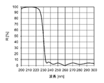
図6は、紫外線反射膜112の反射特性を示す図である。この図6において、横軸は波長、縦軸は反射率(R)である。
図6に示すように、紫外線反射膜112は、波長240nm未満、特に波長222nm以下の紫外線を良好に反射し、波長240nm以上の紫外線はほぼ反射しない。
The
FIG. 6 is a diagram showing the reflection characteristics of the
As shown in FIG. 6, the ultraviolet
したがって、図4に示す反射板110aにより構成された反射体110は、基材111として石英ガラスを用いた場合、人や動物に対して悪影響の少ない第一波長域の紫外線を反射し、人や動物に対して悪影響を及ぼしうる第二波長域の紫外線を透過することになる。
このように、当該反射体110は、波長240nm以上の有害波長の紫外線を透過し、空間200に反射させない。そのため、紫外線照射装置100から放射される紫外線に有害波長の紫外線が含まれる場合であっても、空間200全体には当該有害波長の紫外線は広がらない。したがって、紫外線照射装置100の例えば光放射面12等に、有害波長の紫外線をカットするフィルタを設けずとも、空間200全体に有害波長の紫外線が放射されることを抑制することができる。
Therefore, when quartz glass is used as the
In this way, the
以上説明したように、本実施形態における不活化システム1000は、紫外線照射装置100と、紫外線照射装置100の光放射面12に対向して配置され、当該光放射面から放射される紫外線を反射する反射体110と、を備える。ここで、反射体110は、複数の反射面が立体的に構成された反射体である。
このように、反射体110は、一定方向にのみ光を反射する一枚の平板状の反射体ではなく、例えば球体状のような立体的な反射体である。そのため、紫外線照射装置100から放射された紫外線は反射体110によって乱反射され、広がりをもって放射される。これにより、空間200全体に一度に紫外線を照射することができ、空間200に存在する微生物やウイルスを適切に不活化することができる。
As described above, the
As described above, the
また、反射体110は、第一波長域の紫外線を反射し、第二波長域の紫外線を透過する特性を有することができる。ここで、上記第一波長域は、微生物および/またはウイルスを不活化することができ、人や動物に対して安全な波長190nm以上240nm未満の波長域とすることができる。また、上記第二波長域は、人や動物に対して悪影響を及ぼし得る波長240nm以上の波長域とすることができる。
この場合、反射体110は有害波長である第二波長域の紫外線を反射しないため、人が居る空間において、人に対しても反射体110の反射光を照射して殺菌、不活化を行うことができる。また、反射体110において反射させる紫外線の波長を選択し、有害波長の紫外線を反射させないようにすることができるので、紫外線照射装置100に有害波長の紫外線をカットするフィルタを設ける必要がない。そのため、その分のコストを削減することができる。
In addition, the
In this case, since the
さらに、反射体110は、板状の基材111と、基材111の光放射面12に対向する側の表面に設けられた第一波長域の紫外線を反射する紫外線反射膜112と、を備える構成とすることができる。したがって、紫外線照射装置100の光放射面12から放射された紫外線に含まれる第一波長域の紫外線を、紫外線反射膜112によって適切に反射することができる。
また、基材111を平面状の板状部材とすれば、基材111の表面に、紫外線反射膜112を設計通りに形成することができる。なお、紫外線反射膜112の特性を設計通りに実現可能であれば、基材111表面は曲面であってもよい。
Further, the
Moreover, if the
また、反射体110は、例えば球体の中心軸を回転軸とする回転体であってもよい。この場合、回転軸の方向は問わない。反射体110が回転することにより、反射体110を構成する反射面の各々の向きを変化させることができ、紫外線の反射方向を経時的に変化させることができる。この場合、空間200全体に、より適切に紫外線を照射することができる。
また、紫外線照射装置100と反射体110とが相対的に揺動可能な構成であってもよい。この場合、紫外線照射装置100が反射体110に対して揺動してもよく、反射体110が紫外線照射装置100に対して揺動してもよく、紫外線照射装置100と反射体110とが共に揺動してもよい。この場合にも、反射体110が回転体である場合と同様の効果が得られる。
Further, the
Alternatively, the
なお、本実施形態では、基材111が石英ガラスにより構成される場合について説明したが、基材111の材料は上記に限定されるものではない。例えば基材111は、波長400nm以上の可視光は透過するが波長240nm以上の紫外線は吸収する部材、例えばホウケイ酸ガラスにより構成されていてもよい。
この場合、反射体110は、紫外線照射装置100から放射された紫外線のうち、人に対して安全な第一波長域の紫外線を紫外線反射膜112によって反射し、紫外線反射膜112を透過した有害波長である第二波長域の紫外線を基材111によって吸収することができる。これにより、反射体110から第二波長域の紫外線が空間200に放射されることを適切に抑制することができる。
In this embodiment, the case where the
In this case, the
また、基材111として有害波長を透過する石英ガラス等を用いた場合には、図7に示すように、基材111の裏面(紫外線反射膜112が設けられた面とは反対側の面)に、有害波長の紫外線を吸収する紫外線吸収膜113を設けてもよい。
この場合、反射体110は、紫外線照射装置100から放射された紫外線のうち、人に対して安全な第一波長域の紫外線を紫外線反射膜112によって反射し、紫外線反射膜112を透過した有害波長である第二波長域の紫外線を紫外線吸収膜113によって吸収することができる。したがって、この場合にも、反射体110から第二波長域の紫外線が空間200に放射されることを適切に抑制することができる。
ここで、紫外線吸収膜113は、波長240nm以上の紫外線を吸収する単層膜とすることができる。この紫外線吸収膜113は、例えばCeO2、Ta2O5、TiO2、ZrO2などにより構成することができる。
When quartz glass or the like that transmits harmful wavelengths is used as the
In this case, the
Here, the
なお、図7では、基材111の裏面に紫外線吸収膜113を設ける例を示しているが、例えば図8に示すように、基材111の裏面側に、基材111に対して離隔して、紫外線吸収膜113と同等の吸収特性を有する紫外線吸収体113aを配置してもよい。この紫外線吸収体113aは、例えば反射体110の内部の空間に配置することができる。この場合にも、反射体110から第二波長域の紫外線が空間200に放射されることを適切に抑制することができる。
上記した基材111自体を紫外線吸収体とする構成、基材111の裏面に紫外線吸収膜113を設ける構成、および、基材111の裏面側に紫外線吸収体113aを配置する構成のいずれにおいても、より人に対して安全性の高い不活化システム1000とすることができる。
7 shows an example in which the
In any of the configurations in which the
(第二の実施形態)
次に、本発明の第二の実施形態について説明する。
この第二の実施形態では、照明機能を有する不活化システムについて説明する。
図9は、本実施形態における不活化システム1000Aの構成例である。
この図9に示すように、不活化システム1000Aは、複数の紫外線照射装置100と、反射体110と、波長400nm以上の可視光を放射する可視光光源120と、を備える。ここで、紫外線照射装置100の構成は、上述した第一の実施形態と同様である。また、反射体110は、上述した第一の実施形態における反射体110と同様に、複数の反射面(反射板110a)が立体的に構成された乱反射体である。ただし、各反射板110aの構成は上述した第一の実施形態とは異なる。
(Second embodiment)
Next, a second embodiment of the invention will be described.
In this second embodiment, a deactivation system with illumination functionality is described.
FIG. 9 is a configuration example of an
As shown in FIG. 9, the
反射体110は、内部に空間を有する中空構造となっており、可視光光源120は、反射体110の内部に配置されて、反射体110の内面に向けて可視光を放射する。反射体110は、可視光光源120から放射される可視光を透過し、空間200内に放射する。
可視光光源120は、例えばハロゲンランプ、希ガス蛍光ランプ、LEDなどの固体発光光源とすることができる。可視光光源120は、必要に応じてリフレクタを取り付けるなど、効率良く反射体110の内面に可視光を照射できるように構成されていてもよい。
The
The visible
図10は、本実施形態における反射板110aの構成例を示す図である。
この図10に示すように、反射板110aは、板状の基材111と、基材111の表面に設けられた第一の実施形態と同様の紫外線反射膜112と、基材11の裏面に設けられた可視光透過膜114と、を有する。
ここで、基材111の表面とは、基材111の紫外線照射装置100の光放射面12に対向する側の面であり、球体状の反射体110の外面側の面である。また、基材111の裏面とは、基材111の可視光光源120に対向する側の面であり、球体状の反射体110の内面側の面である。
FIG. 10 is a diagram showing a configuration example of the
As shown in FIG. 10, the
Here, the surface of the
基材111は、例えば石英ガラスよりなるガラス板など、可視光を透過する材料により構成されている。
可視光透過膜114は、例えばCeO2/SiO2、Ta2O5/SiO2、TiO2/SiO2、ZrO2/SiO2などの誘電体多層膜とすることができる。
図11は、可視光透過膜114の透過特性を示す図である。この図11において、横軸は波長、縦軸は透過率(T)である。
図11に示すように、可視光透過膜114は、波長400nm以上の可視光を透過し、波長400nm未満の紫外線を吸収する特性を有する透過吸収膜である。
The
The visible
FIG. 11 is a diagram showing transmission characteristics of the visible
As shown in FIG. 11, the visible
このような構成により、反射体110は、当該反射体110の外部に配置された紫外線照射装置100から放射された紫外線のうち、人に対して安全な第一波長域の紫外線を紫外線反射膜112によって反射し、紫外線反射膜112を透過した有害波長である第二波長域の紫外線を可視光透過膜114によって吸収することができる。また、反射体110は、反射体110の内部に配置された可視光光源120から放射された可視光を透過し、反射体110の外部に放射することができる。
With such a configuration, the
以上説明したように、本実施形態における不活化システム1000Aは、紫外線照射装置100と、紫外線照射装置100の光放射面12に対向して配置された反射体110と、反射体110に対して紫外線照射装置100が配置された側とは反対側に配置された可視光光源120と、を備える。ここで、反射体110は、可視光を透過する特性を有する。また、反射体110は、有害波長である第二波長域の紫外線を吸収する特性を有していてもよい。
As described above, the
上記の構成により、本実施形態では、上述した第一の実施形態における反射体110と同様の効果が得られる。さらに、本実施形態では、反射体110から空間200に可視光を放射することができるので、反射体110を室内照明として用いることができる。
ここで、反射板110aの基材111は、表面にすりガラス加工が施されていてもよい。この場合、基材111を透過した可視光を発散させることができ、空間200に広がりを持って可視光を放射することができる。
With the above configuration, in this embodiment, the same effect as the
Here, the surface of the
なお、本実施形態では、反射体110が、可視光を透過して第二波長域の紫外線を吸収する可視光透過膜114を有する場合について説明したが、可視光透過膜114に替えて、反射体110の内部に、可視光を透過して第二波長域の紫外線を吸収する紫外線吸収体を配置してもよく、可視光光源のバルブ自体を、可視光を透過して第二波長域の紫外線を吸収する部材により構成してもよい。
また、反射板110aの基材111が、可視光を透過して第二波長域の紫外線を吸収する特性を有していてもよい。この場合、基材111は、例えば、ショット社製のネクストリーマ(登録商標)や日本電気硝子株式会社製のネオセラム(登録商標)などの珪酸、アルミナ、酸化リチウムなどを主成分とする結晶化ガラスにより構成することができる。このような結晶化ガラスは、概ね300nm以下の紫外線を吸収し、可視光を透過することができる。
In this embodiment, the case where the
Further, the
また、図9に示す不活化システム1000Aでは、反射体110の内部に可視光光源120を配置する場合について説明したが、可視光光源120の配置位置は上記に限定されない。
例えば図12に示す不活化システム1000Bのように、反射体110の外部に複数の可視光光源120を配置して、複数の可視光光源120から反射体110に向けて可視光を照射してもよい。複数の可視光光源120は、それぞれ異なる方向から反射体110に対して可視光を放射してよい。この場合、反射体110は、可視光を反射する特性を有する。
可視光光源120は、ハロゲンランプ、希ガス蛍光ランプ、LEDなどの固体発光光源であって、リフレクタを取り付けるなど、効率良く反射体110に可視光を照射できるように構成することが好ましい。
なお、可視光光源120の数は、図12に示す数に限定されるものではない。可視光光源120は1つであってもよいし、3つ以上であってもよい。
Also, in the
For example, as in the
The visible
Note that the number of visible
図13は、不活化システム1000Bが備える反射体110を構成する反射板110aの構成例を示す図である。
この図13に示すように、反射板110aは、板状の基材111と、基材111の表面に設けられた紫外線反射膜112と、基材111の裏面に設けられた可視光反射膜115と、を有する。
ここで、基材111は、例えば石英ガラスよりなるガラス板など、可視光を透過する材料により構成されている。
FIG. 13 is a diagram showing a configuration example of a
As shown in FIG. 13, the
Here, the
可視光反射膜115は、例えばCeO2/SiO2、Ta2O5/SiO2、TiO2/SiO2、ZrO2/SiO2などの誘電体多層膜とすることができる。
図14は、可視光反射膜115の反射特性を示す図である。この図14において、横軸は波長、縦軸は反射率(R)である。
図14に示すように、可視光反射膜115は、波長400nm以上の可視光を反射し、波長400nm未満の紫外線を吸収する特性を有する反射吸収膜である。
The visible
FIG. 14 is a diagram showing reflection characteristics of the visible
As shown in FIG. 14, the visible
このような構成により、反射体110は、当該反射体110の外部に配置された紫外線照射装置100から放射された紫外線のうち、人に対して安全な第一波長域の紫外線を紫外線反射膜112によって反射し、反射体110の外部に配置された可視光光源120から放射された可視光を、可視光反射膜115によって反射することができる。また、反射体110は、反射体110の外部に配置された紫外線照射装置100から放射された紫外線のうち、紫外線反射膜112および基材111を透過した有害波長である第二波長域の紫外線を、可視光反射膜115によって吸収することができる。
したがって、上述した不活化システム1000Aと同様の効果が得られる。
With such a configuration, the
Therefore, an effect similar to that of the
(第三の実施形態)
次に、本発明の第三の実施形態について説明する。
この第三の実施形態では、可搬式の不活化システム(不活化装置)について説明する。
図15は、本実施形態における不活化システム(不活化装置)1000Cの構成例である。
不活化装置1000Cは、紫外線照射装置100と反射体110とを共通のフレーム部材(支持部材)130によって支持した構成を有する。
(Third embodiment)
Next, a third embodiment of the invention will be described.
In this third embodiment, a portable inactivation system (inactivation device) will be described.
FIG. 15 is a configuration example of an inactivation system (inactivation device) 1000C in this embodiment.
The
ここで、紫外線照射装置100および反射体110は、上述した第一の実施形態や第二の実施形態と同様の構成であってよい。反射体110の内部には、図9に示す不活化システム1000Aの反射体110と同様に可視光光源120が配置されていてもよい。また、図12に示す不活化システム1000Bと同様に、反射体110の外部に可視光光源120が配置されていてもよく、この場合、当該可視光光源120は、フレーム部材130によって支持されていてもよい。
Here, the
フレーム部材130間は開口となっており、この開口を通して反射体110の反射面からの反射光が外部空間に広がりをもって放射される。
なお、フレーム部材130間は開口に限定されるものではなく、当該フレーム部材130間には、反射体110により反射された紫外線(波長190nm以上240nm未満の紫外線)や、反射体110を透過もしくは反射体110により反射された可視光が透過可能な部材が設けられていてもよい。
An opening is formed between the
Note that the space between the
また、図15に示すように、反射体110は、回転機構140により回転可能に構成されていてもよい。例えば図15に示す例の場合、反射体110は、鉛直方向を軸に回転機構140により回転される。これにより、反射体110を構成する反射面の各々の向きを変化させることができ、紫外線の反射方向を経時的に変化させることができる。したがって、空間200全体に、より適切に紫外線を照射することができる。
なお、ここでは反射体110を回転可能に構成する場合について説明したが、紫外線照射装置100と反射体110とが相対的に揺動可能な構成であってもよい。
Moreover, as shown in FIG. 15, the
In addition, although the case where the
さらに、フレーム部材130は、人が持ち運び可能な程度の大きさであってよい。このように、紫外線照射装置100と反射体110とを持ち運び可能なフレーム部材130によって支持することで、不活化装置1000Cを所望の場所に設置することができる。例えば、机の下や椅子の下などに不活化装置1000Cを設置すれば、上方からでは紫外線が照射されない空間を不活化することができる。
Further, the
(変形例)
上記各実施形態においては、反射体110が、複数の反射面を球体状に組み合わせた構成を有する場合について説明したが、反射体110の外形は上記に限定されるものではない。
つまり、反射体110は、図16(a)に示すように、四角形状の反射板110aを球体状に組み合わせた球面拡散鏡に限定されるものではなく、図16(b)に示すように、四角形状の反射板110aを半球体状に組み合わせた半球面拡散鏡であってもよい。また、反射板110aの形状は四角形に限定されるものではない。反射体110は、例えば図16(c)に示すように、正五角形と正六角形との反射板110aをサッカーボール形状に組み合わせた切頂二十面体拡散鏡であってもよいし、図16(d)に示すように、正三角形と正方形との反射板110aをスネークキューブ形状に組み合わせた斜方立法八面体拡散鏡であってもよいし、図16(e)に示すように、正三角形と正方形とを組み合わせた変形立方体拡散鏡であってもよい。
(Modification)
In each of the above-described embodiments, the
In other words, the
さらに、反射体110の外形は、図16(a)~図16(e)に示すような多面体に限定されるものではない。反射体110のそれぞれの反射板110aは、平面板に限定されるものではなく、若干曲面状であってもよい。
また、反射体110は、立体に限定されるものではなく、複数の反射板110aにより立体的な面が形成されていればよい。
また、反射体110は、紫外線照射装置100の光放射面12に対向する面が、当該光放射面12が配置された側とは反対側に凹んだ凹面鏡であってもよい。例えば図17に示すように、紫外線照射装置100と、当該紫外線照射装置100に対向する面が凹面状である反射体110とを対向配置させた不活化装置1000Dとすることもできる。このような不活化装置1000Dは、デンタル照明として使用することもできる。なお、照明機能を有する不活化システム(不活化装置)の場合、当該照明は無影灯であってもよい。
Furthermore, the outer shape of the
Moreover, the
Further, the
また、上記実施形態においては、紫外線光源であるエキシマランプ20は、図1に示すように放電容器21の一方の側面に一対の電極22、23を配置した構成である場合について説明した。しかしながら、エキシマランプの構成は上記に限定されるものではない。
例えば、長尺な放電容器の両端部に、一対の環状の電極(第一電極、第二電極)が配置された構成であってもよい。また、長尺な放電容器の内部に内側電極(第一電極)を有し、放電容器の外壁面にメッシュ状(網目形状)または線形状の外側電極(第二電極)を有する構成であってもよい。さらに、別の例として、扁平状の放電容器の向かい合う2つの外側面上に、それぞれ第一電極および第二電極を有してなる、いわゆる「扁平管構造」を採用してもよい。また、円筒状の外側管と円筒状の内側管とからなる、いわゆる「二重管構造」を採用してもよい。この場合、外側管の外側面および内側管の内側面に、それぞれ網状の第一電極(外部電極)および膜状の第二電極(内部電極)が配置された構成とすることができる。
In the above embodiment, the
For example, a configuration in which a pair of annular electrodes (a first electrode and a second electrode) are arranged at both ends of an elongated discharge vessel may be used. In addition, the long discharge vessel has an inner electrode (first electrode) inside, and the outer wall surface of the discharge vessel has a mesh-like (mesh shape) or linear outer electrode (second electrode). good too. Furthermore, as another example, a so-called "flat tube structure" may be employed in which a first electrode and a second electrode are provided on two opposite outer surfaces of a flat discharge vessel. Also, a so-called "double tube structure" consisting of a cylindrical outer tube and a cylindrical inner tube may be employed. In this case, a mesh-like first electrode (external electrode) and a film-like second electrode (internal electrode) can be arranged on the outer surface of the outer tube and the inner surface of the inner tube, respectively.
さらに、上記実施形態においては、紫外線光源としてエキシマランプを用いる場合について説明したが、紫外線光源としてLEDを用いることもできる。
LEDとしては、例えば窒化アルミニウムガリウム(AlGaN)系LED、酸化マグネシウム亜鉛(MgZnO)系LED等を採用することができる。
ここで、AlGaN系LEDとしては、中心波長が190~235nmの範囲内となるようにAlの組成を調整することが好ましい。また、MgZnO系LEDは、Mgの組成を調整することで、中心波長が222nmである紫外線を放出することができる。
中心波長222nmの紫外線を放出するように調整したAlGaN系LEDおよびMgZnO系LEDは、中心波長222nmからある程度広がりを有する波長範囲の紫外線を放出し、当該LEDから放出される光には、僅かながら人や動物に安全ではない波長の紫外線(有害波長の紫外線)も含まれる。そのため、紫外線光源がエキシマランプである場合と同様に、反射体110とともに使用されることで、紫外線照射装置としては有害波長の紫外線をカットする誘電体多層膜フィルタ(光学フィルタ)を用いることなく、人や動物に安全な紫外線を空間内に照射する不活化システムとすることができる。
Furthermore, in the above embodiment, the case of using an excimer lamp as the ultraviolet light source has been described, but an LED can also be used as the ultraviolet light source.
As the LED, for example, an aluminum gallium nitride (AlGaN)-based LED, a magnesium zinc oxide (MgZnO)-based LED, or the like can be employed.
Here, for the AlGaN-based LED, it is preferable to adjust the Al composition so that the center wavelength is within the range of 190 to 235 nm. Also, the MgZnO-based LED can emit ultraviolet light with a center wavelength of 222 nm by adjusting the composition of Mg.
AlGaN-based LEDs and MgZnO-based LEDs adjusted to emit ultraviolet rays with a central wavelength of 222 nm emit ultraviolet rays in a wavelength range that spreads to some extent from the central wavelength of 222 nm. and UV light at wavelengths that are not safe for animals (harmful wavelength UV light). Therefore, as in the case where the ultraviolet light source is an excimer lamp, by using it together with the
なお、上記実施形態においては、微生物および/またはウイルスを不活化する第一波長域の紫外線として、人や動物に対して安全な190nm~240nmの波長範囲の紫外線を用いる場合について説明したが、波長190nm~280nmの紫外線であれば不活化用途として用いることができる。すなわち、紫外線光源は、上述したエキシマランプやLEDに限定されるものではなく、例えば波長253.7nmの紫外線を放出する低圧水銀ランプであってもよい。この場合にも、反射体によって上記紫外線を空間に広がりをもって反射させることで、空間全体に紫外線を照射し、空間全体を不活化することができるという効果が得られる。ただし、波長253.7nmの紫外線は人に悪影響を及ぼす光であるため、この場合には、反射体によって反射された紫外線が人に照射されないように、人を検知したら紫外線照射を停止または紫外線が照射されないように遮光することが好ましい。 In the above embodiment, the case of using ultraviolet light in the wavelength range of 190 nm to 240 nm, which is safe for humans and animals, as the ultraviolet light in the first wavelength range for inactivating microorganisms and/or viruses has been described. UV light from 190 nm to 280 nm can be used for inactivation. That is, the ultraviolet light source is not limited to the excimer lamps and LEDs described above, and may be, for example, a low-pressure mercury lamp that emits ultraviolet rays with a wavelength of 253.7 nm. In this case as well, by reflecting the ultraviolet rays into the space with the reflector, it is possible to irradiate the entire space with the ultraviolet rays and inactivate the entire space. However, since ultraviolet rays with a wavelength of 253.7 nm are harmful to humans, in this case, the ultraviolet irradiation should be stopped or the ultraviolet rays emitted when a person is detected so that the ultraviolet rays reflected by the reflector do not irradiate the person. It is preferable to shield from light so as not to be irradiated.
11…筐体、12…光放射面、15…電源部、16…制御部、20…紫外線光源、31…人感センサ、32…近接センサ、100…紫外線照射装置、110…反射体、110a…反射板、111…基材、112…紫外線反射膜、113…紫外線吸収膜、113a…紫外線吸収体、114…可視光透過膜、115…可視光反射膜、120…可視光光源、130…フレーム部材(支持部材)、140…回転機構、1000…不活化システム
DESCRIPTION OF
Claims (12)
前記微生物および/またはウイルスを不活化する第一波長域の紫外線を含む波長190nm以上400nm未満の波長域の紫外線を放射する紫外線光源と、前記紫外線光源を収容する筐体と、前記紫外線光源より放射された前記紫外線を前記筐体の外へ取り出す光放射面と、を備える紫外線照射装置と、
前記光放射面に対向して配置されて前記光放射面から放射される紫外線を反射する、複数の反射面が立体的に構成された反射体と、を備えることを特徴とする不活化システム。 An inactivation system that emits ultraviolet rays in a space to inactivate microorganisms and/or viruses present in the space,
An ultraviolet light source that emits ultraviolet light in a wavelength range of 190 nm or more and less than 400 nm including ultraviolet light in a first wavelength range that inactivates microorganisms and/or viruses, a housing that houses the ultraviolet light source, and radiation from the ultraviolet light source. an ultraviolet irradiation device comprising: a light emitting surface for extracting the emitted ultraviolet rays to the outside of the housing;
A deactivation system, comprising: a reflector having a plurality of three-dimensionally configured reflecting surfaces arranged opposite to the light emitting surface and reflecting ultraviolet rays emitted from the light emitting surface.
前記反射体は、可視光を透過することを特徴とする請求項2から7のいずれか1項に記載の不活化システム。 further comprising a visible light source disposed on the side opposite to the side on which the ultraviolet irradiation device is disposed with respect to the reflector and emitting visible light toward the reflector;
8. The deactivation system of any one of claims 2-7, wherein the reflector is transparent to visible light.
前記反射体は、可視光を反射することを特徴とする請求項2から7のいずれか1項に記載の不活化システム。 further comprising a visible light source arranged on the side of the reflector on which the ultraviolet irradiation device is arranged and emitting visible light toward the reflector;
8. The deactivation system of any one of claims 2-7, wherein the reflector reflects visible light.
前記微生物および/またはウイルスを不活化する第一波長域の紫外線を含む波長190nm以上400nm未満の波長域の紫外線を放射する紫外線光源を備える紫外線照射装置から、複数の反射面が立体的に構成された反射体に向けて前記紫外線を放射するステップと、
前記紫外線を前記反射体の前記複数の反射面によって反射させ、前記空間に広がりをもって放射するステップと、を含むことを特徴とする不活化方法。 An inactivation method for inactivating microorganisms and/or viruses present in a space by emitting ultraviolet rays in the space,
A plurality of reflecting surfaces are three-dimensionally configured from an ultraviolet irradiation device provided with an ultraviolet light source that emits ultraviolet rays in a wavelength range of 190 nm or more and less than 400 nm including ultraviolet rays in a first wavelength range that inactivates the microorganisms and/or viruses. radiating said ultraviolet light towards a reflector;
and a step of reflecting the ultraviolet rays by the plurality of reflecting surfaces of the reflector and radiating them into the space with a spread.
Priority Applications (1)
| Application Number | Priority Date | Filing Date | Title |
|---|---|---|---|
| JP2021102285A JP2023001511A (en) | 2021-06-21 | 2021-06-21 | Inactivation system and method |
Applications Claiming Priority (1)
| Application Number | Priority Date | Filing Date | Title |
|---|---|---|---|
| JP2021102285A JP2023001511A (en) | 2021-06-21 | 2021-06-21 | Inactivation system and method |
Publications (1)
| Publication Number | Publication Date |
|---|---|
| JP2023001511A true JP2023001511A (en) | 2023-01-06 |
Family
ID=84688820
Family Applications (1)
| Application Number | Title | Priority Date | Filing Date |
|---|---|---|---|
| JP2021102285A Abandoned JP2023001511A (en) | 2021-06-21 | 2021-06-21 | Inactivation system and method |
Country Status (1)
| Country | Link |
|---|---|
| JP (1) | JP2023001511A (en) |
-
2021
- 2021-06-21 JP JP2021102285A patent/JP2023001511A/en not_active Abandoned
Similar Documents
| Publication | Publication Date | Title |
|---|---|---|
| CN111265706B (en) | Human-machine coexistence UV LED irradiation system for air sterilization in upper space | |
| US20220125963A1 (en) | Sterilization apparatus using uv light source harmless to human body | |
| JP7015485B1 (en) | Ultraviolet light irradiation device, how to use the ultraviolet light irradiation device, and how to irradiate ultraviolet light | |
| JP2022082620A (en) | How to use the ultraviolet light irradiation device and the ultraviolet light irradiation device | |
| US20230293745A1 (en) | Inactivation device for bacteria and/or viruses | |
| WO2022074944A1 (en) | Ultraviolet light irradiation device, use method for ultraviolet light irradiation device, and irradiation method of ultraviolet light | |
| JP2021029502A (en) | Sterilizer and indoor sterilization system | |
| EP4238585A1 (en) | Ultraviolet ray irradiation device and ultraviolet ray irradiation method | |
| JP7759546B2 (en) | Ultraviolet light irradiation device, method of using ultraviolet light irradiation device, and ultraviolet light irradiation method | |
| WO2022234813A1 (en) | Ultraviolet-ray irradiation device and ultraviolet-ray irradiation method | |
| JP2023001511A (en) | Inactivation system and method | |
| EP4460338B1 (en) | A radiation generating system comprising an optical arrangement for a far uv light source minimizing the impact of unfiltered undesired wavelengths | |
| JP2022043880A (en) | Spotlight type light source and spotlight type light source for illumination | |
| JP7517587B2 (en) | Disaster prevention system and ultraviolet irradiation system | |
| CN113694240A (en) | Man-machine coexisting air virus inactivation device | |
| JP2022176043A (en) | Bacteria or Virus Inactivation Apparatus and Bacteria or Virus Inactivation Method | |
| WO2022220157A1 (en) | Ultraviolet light irradiation device | |
| EP4348108B1 (en) | A dual-reflector lighting device | |
| CN114452431A (en) | Ultraviolet-ultrasonic combined disinfection and sterilization device and method harmless to human body | |
| JP7261205B2 (en) | Lighting device with near-ultraviolet irradiation function | |
| JP2023057668A (en) | Ultraviolet light irradiation device and ultraviolet light irradiation method | |
| WO2023026691A1 (en) | Ultraviolet light irradiation device | |
| EP4166163A1 (en) | Sterilization device | |
| JP2022054721A (en) | Ultraviolet lamp | |
| WO2022239445A1 (en) | Bacteria or virus inactivation apparatus and bacteria or virus inactivation treatment method |
Legal Events
| Date | Code | Title | Description |
|---|---|---|---|
| A621 | Written request for application examination |
Free format text: JAPANESE INTERMEDIATE CODE: A621 Effective date: 20240319 |
|
| A762 | Written abandonment of application |
Free format text: JAPANESE INTERMEDIATE CODE: A762 Effective date: 20241011 |