JP2022544681A - Biaxial adjustable spinal system with fusion device and interbody fusion device - Google Patents
Biaxial adjustable spinal system with fusion device and interbody fusion device Download PDFInfo
- Publication number
- JP2022544681A JP2022544681A JP2022509637A JP2022509637A JP2022544681A JP 2022544681 A JP2022544681 A JP 2022544681A JP 2022509637 A JP2022509637 A JP 2022509637A JP 2022509637 A JP2022509637 A JP 2022509637A JP 2022544681 A JP2022544681 A JP 2022544681A
- Authority
- JP
- Japan
- Prior art keywords
- fusion device
- interbody fusion
- fixation plate
- drive shaft
- fastener
- Prior art date
- Legal status (The legal status is an assumption and is not a legal conclusion. Google has not performed a legal analysis and makes no representation as to the accuracy of the status listed.)
- Granted
Links
- 230000004927 fusion Effects 0.000 title claims abstract description 535
- 238000011065 in-situ storage Methods 0.000 claims abstract description 28
- 238000013508 migration Methods 0.000 claims abstract description 18
- 230000005012 migration Effects 0.000 claims abstract description 18
- 230000000087 stabilizing effect Effects 0.000 claims abstract description 9
- 230000007246 mechanism Effects 0.000 claims description 166
- 208000007623 Lordosis Diseases 0.000 claims description 73
- 230000006835 compression Effects 0.000 claims description 33
- 238000007906 compression Methods 0.000 claims description 33
- 239000000463 material Substances 0.000 claims description 12
- 206010023509 Kyphosis Diseases 0.000 claims description 11
- 238000003780 insertion Methods 0.000 claims description 9
- 230000037431 insertion Effects 0.000 claims description 9
- 230000013011 mating Effects 0.000 claims description 9
- 230000000717 retained effect Effects 0.000 claims description 8
- 238000004873 anchoring Methods 0.000 claims description 4
- 230000002452 interceptive effect Effects 0.000 claims description 3
- 230000000295 complement effect Effects 0.000 claims 4
- 230000002093 peripheral effect Effects 0.000 claims 1
- 238000000034 method Methods 0.000 description 28
- 210000000988 bone and bone Anatomy 0.000 description 21
- 238000001356 surgical procedure Methods 0.000 description 19
- 238000013459 approach Methods 0.000 description 16
- 206010061246 Intervertebral disc degeneration Diseases 0.000 description 14
- 210000003484 anatomy Anatomy 0.000 description 14
- 208000018180 degenerative disc disease Diseases 0.000 description 14
- 208000021600 intervertebral disc degenerative disease Diseases 0.000 description 14
- 208000007103 Spondylolisthesis Diseases 0.000 description 12
- 230000001045 lordotic effect Effects 0.000 description 9
- 239000007943 implant Substances 0.000 description 8
- 230000006641 stabilisation Effects 0.000 description 8
- 238000011105 stabilization Methods 0.000 description 8
- 208000020307 Spinal disease Diseases 0.000 description 7
- 230000008901 benefit Effects 0.000 description 7
- 238000004519 manufacturing process Methods 0.000 description 6
- 230000006870 function Effects 0.000 description 5
- 208000014674 injury Diseases 0.000 description 5
- 229910052751 metal Inorganic materials 0.000 description 5
- 239000002184 metal Substances 0.000 description 5
- 238000013461 design Methods 0.000 description 4
- 230000008569 process Effects 0.000 description 4
- 238000012360 testing method Methods 0.000 description 4
- 206010028980 Neoplasm Diseases 0.000 description 3
- 230000003213 activating effect Effects 0.000 description 3
- 230000008878 coupling Effects 0.000 description 3
- 238000010168 coupling process Methods 0.000 description 3
- 238000005859 coupling reaction Methods 0.000 description 3
- 238000010586 diagram Methods 0.000 description 3
- 210000004705 lumbosacral region Anatomy 0.000 description 3
- 210000005036 nerve Anatomy 0.000 description 3
- 239000010935 stainless steel Substances 0.000 description 3
- 229910001220 stainless steel Inorganic materials 0.000 description 3
- 238000013519 translation Methods 0.000 description 3
- 230000008733 trauma Effects 0.000 description 3
- 208000032170 Congenital Abnormalities Diseases 0.000 description 2
- 239000004696 Poly ether ether ketone Substances 0.000 description 2
- RTAQQCXQSZGOHL-UHFFFAOYSA-N Titanium Chemical compound [Ti] RTAQQCXQSZGOHL-UHFFFAOYSA-N 0.000 description 2
- 208000027418 Wounds and injury Diseases 0.000 description 2
- 208000037873 arthrodesis Diseases 0.000 description 2
- 230000000712 assembly Effects 0.000 description 2
- 238000000429 assembly Methods 0.000 description 2
- 230000008602 contraction Effects 0.000 description 2
- 238000007796 conventional method Methods 0.000 description 2
- 230000001054 cortical effect Effects 0.000 description 2
- 230000006378 damage Effects 0.000 description 2
- 238000009826 distribution Methods 0.000 description 2
- 238000009863 impact test Methods 0.000 description 2
- 238000009434 installation Methods 0.000 description 2
- 229910001092 metal group alloy Inorganic materials 0.000 description 2
- 150000002739 metals Chemical class 0.000 description 2
- 238000012986 modification Methods 0.000 description 2
- 230000004048 modification Effects 0.000 description 2
- 230000037361 pathway Effects 0.000 description 2
- 229920001652 poly(etherketoneketone) Polymers 0.000 description 2
- 229920002530 polyetherether ketone Polymers 0.000 description 2
- 238000004513 sizing Methods 0.000 description 2
- 239000010936 titanium Substances 0.000 description 2
- 229910052719 titanium Inorganic materials 0.000 description 2
- 206010002091 Anaesthesia Diseases 0.000 description 1
- 206010016654 Fibrosis Diseases 0.000 description 1
- 206010027677 Fractures and dislocations Diseases 0.000 description 1
- 208000003618 Intervertebral Disc Displacement Diseases 0.000 description 1
- 229920008285 Poly(ether ketone) PEK Polymers 0.000 description 1
- 208000002607 Pseudarthrosis Diseases 0.000 description 1
- 210000001015 abdomen Anatomy 0.000 description 1
- 230000000735 allogeneic effect Effects 0.000 description 1
- 229910045601 alloy Inorganic materials 0.000 description 1
- 239000000956 alloy Substances 0.000 description 1
- 230000037005 anaesthesia Effects 0.000 description 1
- 239000008280 blood Substances 0.000 description 1
- 210000004369 blood Anatomy 0.000 description 1
- 230000008468 bone growth Effects 0.000 description 1
- 238000010276 construction Methods 0.000 description 1
- 230000000694 effects Effects 0.000 description 1
- 230000004761 fibrosis Effects 0.000 description 1
- 238000007499 fusion processing Methods 0.000 description 1
- 238000002513 implantation Methods 0.000 description 1
- 230000007794 irritation Effects 0.000 description 1
- 230000014759 maintenance of location Effects 0.000 description 1
- 238000005259 measurement Methods 0.000 description 1
- 230000000306 recurrent effect Effects 0.000 description 1
- 230000009467 reduction Effects 0.000 description 1
- 230000004044 response Effects 0.000 description 1
- 230000037390 scarring Effects 0.000 description 1
- 206010039722 scoliosis Diseases 0.000 description 1
- 125000006850 spacer group Chemical group 0.000 description 1
- 229910052715 tantalum Inorganic materials 0.000 description 1
- GUVRBAGPIYLISA-UHFFFAOYSA-N tantalum atom Chemical compound [Ta] GUVRBAGPIYLISA-UHFFFAOYSA-N 0.000 description 1
- 238000012800 visualization Methods 0.000 description 1
- 210000002517 zygapophyseal joint Anatomy 0.000 description 1
Images


Classifications
-
- A—HUMAN NECESSITIES
- A61—MEDICAL OR VETERINARY SCIENCE; HYGIENE
- A61F—FILTERS IMPLANTABLE INTO BLOOD VESSELS; PROSTHESES; DEVICES PROVIDING PATENCY TO, OR PREVENTING COLLAPSING OF, TUBULAR STRUCTURES OF THE BODY, e.g. STENTS; ORTHOPAEDIC, NURSING OR CONTRACEPTIVE DEVICES; FOMENTATION; TREATMENT OR PROTECTION OF EYES OR EARS; BANDAGES, DRESSINGS OR ABSORBENT PADS; FIRST-AID KITS
- A61F2/00—Filters implantable into blood vessels; Prostheses, i.e. artificial substitutes or replacements for parts of the body; Appliances for connecting them with the body; Devices providing patency to, or preventing collapsing of, tubular structures of the body, e.g. stents
- A61F2/02—Prostheses implantable into the body
- A61F2/30—Joints
- A61F2/44—Joints for the spine, e.g. vertebrae, spinal discs
- A61F2/4455—Joints for the spine, e.g. vertebrae, spinal discs for the fusion of spinal bodies, e.g. intervertebral fusion of adjacent spinal bodies, e.g. fusion cages
- A61F2/447—Joints for the spine, e.g. vertebrae, spinal discs for the fusion of spinal bodies, e.g. intervertebral fusion of adjacent spinal bodies, e.g. fusion cages substantially parallelepipedal, e.g. having a rectangular or trapezoidal cross-section
-
- A—HUMAN NECESSITIES
- A61—MEDICAL OR VETERINARY SCIENCE; HYGIENE
- A61F—FILTERS IMPLANTABLE INTO BLOOD VESSELS; PROSTHESES; DEVICES PROVIDING PATENCY TO, OR PREVENTING COLLAPSING OF, TUBULAR STRUCTURES OF THE BODY, e.g. STENTS; ORTHOPAEDIC, NURSING OR CONTRACEPTIVE DEVICES; FOMENTATION; TREATMENT OR PROTECTION OF EYES OR EARS; BANDAGES, DRESSINGS OR ABSORBENT PADS; FIRST-AID KITS
- A61F2/00—Filters implantable into blood vessels; Prostheses, i.e. artificial substitutes or replacements for parts of the body; Appliances for connecting them with the body; Devices providing patency to, or preventing collapsing of, tubular structures of the body, e.g. stents
- A61F2/02—Prostheses implantable into the body
- A61F2/30—Joints
- A61F2/30721—Accessories
- A61F2/30749—Fixation appliances for connecting prostheses to the body
-
- A—HUMAN NECESSITIES
- A61—MEDICAL OR VETERINARY SCIENCE; HYGIENE
- A61F—FILTERS IMPLANTABLE INTO BLOOD VESSELS; PROSTHESES; DEVICES PROVIDING PATENCY TO, OR PREVENTING COLLAPSING OF, TUBULAR STRUCTURES OF THE BODY, e.g. STENTS; ORTHOPAEDIC, NURSING OR CONTRACEPTIVE DEVICES; FOMENTATION; TREATMENT OR PROTECTION OF EYES OR EARS; BANDAGES, DRESSINGS OR ABSORBENT PADS; FIRST-AID KITS
- A61F2/00—Filters implantable into blood vessels; Prostheses, i.e. artificial substitutes or replacements for parts of the body; Appliances for connecting them with the body; Devices providing patency to, or preventing collapsing of, tubular structures of the body, e.g. stents
- A61F2/02—Prostheses implantable into the body
- A61F2/30—Joints
- A61F2/44—Joints for the spine, e.g. vertebrae, spinal discs
- A61F2/442—Intervertebral or spinal discs, e.g. resilient
- A61F2/4425—Intervertebral or spinal discs, e.g. resilient made of articulated components
-
- A—HUMAN NECESSITIES
- A61—MEDICAL OR VETERINARY SCIENCE; HYGIENE
- A61F—FILTERS IMPLANTABLE INTO BLOOD VESSELS; PROSTHESES; DEVICES PROVIDING PATENCY TO, OR PREVENTING COLLAPSING OF, TUBULAR STRUCTURES OF THE BODY, e.g. STENTS; ORTHOPAEDIC, NURSING OR CONTRACEPTIVE DEVICES; FOMENTATION; TREATMENT OR PROTECTION OF EYES OR EARS; BANDAGES, DRESSINGS OR ABSORBENT PADS; FIRST-AID KITS
- A61F2/00—Filters implantable into blood vessels; Prostheses, i.e. artificial substitutes or replacements for parts of the body; Appliances for connecting them with the body; Devices providing patency to, or preventing collapsing of, tubular structures of the body, e.g. stents
- A61F2/02—Prostheses implantable into the body
- A61F2/30—Joints
- A61F2/44—Joints for the spine, e.g. vertebrae, spinal discs
- A61F2/4455—Joints for the spine, e.g. vertebrae, spinal discs for the fusion of spinal bodies, e.g. intervertebral fusion of adjacent spinal bodies, e.g. fusion cages
-
- A—HUMAN NECESSITIES
- A61—MEDICAL OR VETERINARY SCIENCE; HYGIENE
- A61F—FILTERS IMPLANTABLE INTO BLOOD VESSELS; PROSTHESES; DEVICES PROVIDING PATENCY TO, OR PREVENTING COLLAPSING OF, TUBULAR STRUCTURES OF THE BODY, e.g. STENTS; ORTHOPAEDIC, NURSING OR CONTRACEPTIVE DEVICES; FOMENTATION; TREATMENT OR PROTECTION OF EYES OR EARS; BANDAGES, DRESSINGS OR ABSORBENT PADS; FIRST-AID KITS
- A61F2/00—Filters implantable into blood vessels; Prostheses, i.e. artificial substitutes or replacements for parts of the body; Appliances for connecting them with the body; Devices providing patency to, or preventing collapsing of, tubular structures of the body, e.g. stents
- A61F2/02—Prostheses implantable into the body
- A61F2/30—Joints
- A61F2002/30001—Additional features of subject-matter classified in A61F2/28, A61F2/30 and subgroups thereof
- A61F2002/30316—The prosthesis having different structural features at different locations within the same prosthesis; Connections between prosthetic parts; Special structural features of bone or joint prostheses not otherwise provided for
- A61F2002/30329—Connections or couplings between prosthetic parts, e.g. between modular parts; Connecting elements
- A61F2002/30405—Connections or couplings between prosthetic parts, e.g. between modular parts; Connecting elements made by screwing complementary threads machined on the parts themselves
- A61F2002/30411—Connections or couplings between prosthetic parts, e.g. between modular parts; Connecting elements made by screwing complementary threads machined on the parts themselves having two threaded end parts connected by a threaded central part with opposite threads at its opposite ends, i.e. for adjusting the distance between both end parts by rotating the central part
-
- A—HUMAN NECESSITIES
- A61—MEDICAL OR VETERINARY SCIENCE; HYGIENE
- A61F—FILTERS IMPLANTABLE INTO BLOOD VESSELS; PROSTHESES; DEVICES PROVIDING PATENCY TO, OR PREVENTING COLLAPSING OF, TUBULAR STRUCTURES OF THE BODY, e.g. STENTS; ORTHOPAEDIC, NURSING OR CONTRACEPTIVE DEVICES; FOMENTATION; TREATMENT OR PROTECTION OF EYES OR EARS; BANDAGES, DRESSINGS OR ABSORBENT PADS; FIRST-AID KITS
- A61F2/00—Filters implantable into blood vessels; Prostheses, i.e. artificial substitutes or replacements for parts of the body; Appliances for connecting them with the body; Devices providing patency to, or preventing collapsing of, tubular structures of the body, e.g. stents
- A61F2/02—Prostheses implantable into the body
- A61F2/30—Joints
- A61F2002/30001—Additional features of subject-matter classified in A61F2/28, A61F2/30 and subgroups thereof
- A61F2002/30316—The prosthesis having different structural features at different locations within the same prosthesis; Connections between prosthetic parts; Special structural features of bone or joint prostheses not otherwise provided for
- A61F2002/30329—Connections or couplings between prosthetic parts, e.g. between modular parts; Connecting elements
- A61F2002/30433—Connections or couplings between prosthetic parts, e.g. between modular parts; Connecting elements using additional screws, bolts, dowels, rivets or washers e.g. connecting screws
-
- A—HUMAN NECESSITIES
- A61—MEDICAL OR VETERINARY SCIENCE; HYGIENE
- A61F—FILTERS IMPLANTABLE INTO BLOOD VESSELS; PROSTHESES; DEVICES PROVIDING PATENCY TO, OR PREVENTING COLLAPSING OF, TUBULAR STRUCTURES OF THE BODY, e.g. STENTS; ORTHOPAEDIC, NURSING OR CONTRACEPTIVE DEVICES; FOMENTATION; TREATMENT OR PROTECTION OF EYES OR EARS; BANDAGES, DRESSINGS OR ABSORBENT PADS; FIRST-AID KITS
- A61F2/00—Filters implantable into blood vessels; Prostheses, i.e. artificial substitutes or replacements for parts of the body; Appliances for connecting them with the body; Devices providing patency to, or preventing collapsing of, tubular structures of the body, e.g. stents
- A61F2/02—Prostheses implantable into the body
- A61F2/30—Joints
- A61F2002/30001—Additional features of subject-matter classified in A61F2/28, A61F2/30 and subgroups thereof
- A61F2002/30316—The prosthesis having different structural features at different locations within the same prosthesis; Connections between prosthetic parts; Special structural features of bone or joint prostheses not otherwise provided for
- A61F2002/30329—Connections or couplings between prosthetic parts, e.g. between modular parts; Connecting elements
- A61F2002/30476—Connections or couplings between prosthetic parts, e.g. between modular parts; Connecting elements locked by an additional locking mechanism
- A61F2002/30505—Connections or couplings between prosthetic parts, e.g. between modular parts; Connecting elements locked by an additional locking mechanism spring biased
-
- A—HUMAN NECESSITIES
- A61—MEDICAL OR VETERINARY SCIENCE; HYGIENE
- A61F—FILTERS IMPLANTABLE INTO BLOOD VESSELS; PROSTHESES; DEVICES PROVIDING PATENCY TO, OR PREVENTING COLLAPSING OF, TUBULAR STRUCTURES OF THE BODY, e.g. STENTS; ORTHOPAEDIC, NURSING OR CONTRACEPTIVE DEVICES; FOMENTATION; TREATMENT OR PROTECTION OF EYES OR EARS; BANDAGES, DRESSINGS OR ABSORBENT PADS; FIRST-AID KITS
- A61F2/00—Filters implantable into blood vessels; Prostheses, i.e. artificial substitutes or replacements for parts of the body; Appliances for connecting them with the body; Devices providing patency to, or preventing collapsing of, tubular structures of the body, e.g. stents
- A61F2/02—Prostheses implantable into the body
- A61F2/30—Joints
- A61F2002/30001—Additional features of subject-matter classified in A61F2/28, A61F2/30 and subgroups thereof
- A61F2002/30316—The prosthesis having different structural features at different locations within the same prosthesis; Connections between prosthetic parts; Special structural features of bone or joint prostheses not otherwise provided for
- A61F2002/30329—Connections or couplings between prosthetic parts, e.g. between modular parts; Connecting elements
- A61F2002/30518—Connections or couplings between prosthetic parts, e.g. between modular parts; Connecting elements with possibility of relative movement between the prosthetic parts
- A61F2002/30523—Connections or couplings between prosthetic parts, e.g. between modular parts; Connecting elements with possibility of relative movement between the prosthetic parts by means of meshing gear teeth
- A61F2002/30525—Worm gears
-
- A—HUMAN NECESSITIES
- A61—MEDICAL OR VETERINARY SCIENCE; HYGIENE
- A61F—FILTERS IMPLANTABLE INTO BLOOD VESSELS; PROSTHESES; DEVICES PROVIDING PATENCY TO, OR PREVENTING COLLAPSING OF, TUBULAR STRUCTURES OF THE BODY, e.g. STENTS; ORTHOPAEDIC, NURSING OR CONTRACEPTIVE DEVICES; FOMENTATION; TREATMENT OR PROTECTION OF EYES OR EARS; BANDAGES, DRESSINGS OR ABSORBENT PADS; FIRST-AID KITS
- A61F2/00—Filters implantable into blood vessels; Prostheses, i.e. artificial substitutes or replacements for parts of the body; Appliances for connecting them with the body; Devices providing patency to, or preventing collapsing of, tubular structures of the body, e.g. stents
- A61F2/02—Prostheses implantable into the body
- A61F2/30—Joints
- A61F2002/30001—Additional features of subject-matter classified in A61F2/28, A61F2/30 and subgroups thereof
- A61F2002/30316—The prosthesis having different structural features at different locations within the same prosthesis; Connections between prosthetic parts; Special structural features of bone or joint prostheses not otherwise provided for
- A61F2002/30535—Special structural features of bone or joint prostheses not otherwise provided for
- A61F2002/30537—Special structural features of bone or joint prostheses not otherwise provided for adjustable
- A61F2002/30538—Special structural features of bone or joint prostheses not otherwise provided for adjustable for adjusting angular orientation
-
- A—HUMAN NECESSITIES
- A61—MEDICAL OR VETERINARY SCIENCE; HYGIENE
- A61F—FILTERS IMPLANTABLE INTO BLOOD VESSELS; PROSTHESES; DEVICES PROVIDING PATENCY TO, OR PREVENTING COLLAPSING OF, TUBULAR STRUCTURES OF THE BODY, e.g. STENTS; ORTHOPAEDIC, NURSING OR CONTRACEPTIVE DEVICES; FOMENTATION; TREATMENT OR PROTECTION OF EYES OR EARS; BANDAGES, DRESSINGS OR ABSORBENT PADS; FIRST-AID KITS
- A61F2/00—Filters implantable into blood vessels; Prostheses, i.e. artificial substitutes or replacements for parts of the body; Appliances for connecting them with the body; Devices providing patency to, or preventing collapsing of, tubular structures of the body, e.g. stents
- A61F2/02—Prostheses implantable into the body
- A61F2/30—Joints
- A61F2002/30001—Additional features of subject-matter classified in A61F2/28, A61F2/30 and subgroups thereof
- A61F2002/30316—The prosthesis having different structural features at different locations within the same prosthesis; Connections between prosthetic parts; Special structural features of bone or joint prostheses not otherwise provided for
- A61F2002/30535—Special structural features of bone or joint prostheses not otherwise provided for
- A61F2002/30537—Special structural features of bone or joint prostheses not otherwise provided for adjustable
- A61F2002/30556—Special structural features of bone or joint prostheses not otherwise provided for adjustable for adjusting thickness
-
- A—HUMAN NECESSITIES
- A61—MEDICAL OR VETERINARY SCIENCE; HYGIENE
- A61F—FILTERS IMPLANTABLE INTO BLOOD VESSELS; PROSTHESES; DEVICES PROVIDING PATENCY TO, OR PREVENTING COLLAPSING OF, TUBULAR STRUCTURES OF THE BODY, e.g. STENTS; ORTHOPAEDIC, NURSING OR CONTRACEPTIVE DEVICES; FOMENTATION; TREATMENT OR PROTECTION OF EYES OR EARS; BANDAGES, DRESSINGS OR ABSORBENT PADS; FIRST-AID KITS
- A61F2/00—Filters implantable into blood vessels; Prostheses, i.e. artificial substitutes or replacements for parts of the body; Appliances for connecting them with the body; Devices providing patency to, or preventing collapsing of, tubular structures of the body, e.g. stents
- A61F2/02—Prostheses implantable into the body
- A61F2/30—Joints
- A61F2002/30001—Additional features of subject-matter classified in A61F2/28, A61F2/30 and subgroups thereof
- A61F2002/30316—The prosthesis having different structural features at different locations within the same prosthesis; Connections between prosthetic parts; Special structural features of bone or joint prostheses not otherwise provided for
- A61F2002/30535—Special structural features of bone or joint prostheses not otherwise provided for
- A61F2002/30565—Special structural features of bone or joint prostheses not otherwise provided for having spring elements
- A61F2002/30566—Helical springs
- A61F2002/30568—Multiple spring systems including two or more helical springs
-
- A—HUMAN NECESSITIES
- A61—MEDICAL OR VETERINARY SCIENCE; HYGIENE
- A61F—FILTERS IMPLANTABLE INTO BLOOD VESSELS; PROSTHESES; DEVICES PROVIDING PATENCY TO, OR PREVENTING COLLAPSING OF, TUBULAR STRUCTURES OF THE BODY, e.g. STENTS; ORTHOPAEDIC, NURSING OR CONTRACEPTIVE DEVICES; FOMENTATION; TREATMENT OR PROTECTION OF EYES OR EARS; BANDAGES, DRESSINGS OR ABSORBENT PADS; FIRST-AID KITS
- A61F2/00—Filters implantable into blood vessels; Prostheses, i.e. artificial substitutes or replacements for parts of the body; Appliances for connecting them with the body; Devices providing patency to, or preventing collapsing of, tubular structures of the body, e.g. stents
- A61F2/02—Prostheses implantable into the body
- A61F2/30—Joints
- A61F2002/30001—Additional features of subject-matter classified in A61F2/28, A61F2/30 and subgroups thereof
- A61F2002/30316—The prosthesis having different structural features at different locations within the same prosthesis; Connections between prosthetic parts; Special structural features of bone or joint prostheses not otherwise provided for
- A61F2002/30535—Special structural features of bone or joint prostheses not otherwise provided for
- A61F2002/30576—Special structural features of bone or joint prostheses not otherwise provided for with extending fixation tabs
- A61F2002/30578—Special structural features of bone or joint prostheses not otherwise provided for with extending fixation tabs having apertures, e.g. for receiving fixation screws
-
- A—HUMAN NECESSITIES
- A61—MEDICAL OR VETERINARY SCIENCE; HYGIENE
- A61F—FILTERS IMPLANTABLE INTO BLOOD VESSELS; PROSTHESES; DEVICES PROVIDING PATENCY TO, OR PREVENTING COLLAPSING OF, TUBULAR STRUCTURES OF THE BODY, e.g. STENTS; ORTHOPAEDIC, NURSING OR CONTRACEPTIVE DEVICES; FOMENTATION; TREATMENT OR PROTECTION OF EYES OR EARS; BANDAGES, DRESSINGS OR ABSORBENT PADS; FIRST-AID KITS
- A61F2/00—Filters implantable into blood vessels; Prostheses, i.e. artificial substitutes or replacements for parts of the body; Appliances for connecting them with the body; Devices providing patency to, or preventing collapsing of, tubular structures of the body, e.g. stents
- A61F2/02—Prostheses implantable into the body
- A61F2/30—Joints
- A61F2002/30001—Additional features of subject-matter classified in A61F2/28, A61F2/30 and subgroups thereof
- A61F2002/30316—The prosthesis having different structural features at different locations within the same prosthesis; Connections between prosthetic parts; Special structural features of bone or joint prostheses not otherwise provided for
- A61F2002/30535—Special structural features of bone or joint prostheses not otherwise provided for
- A61F2002/30579—Special structural features of bone or joint prostheses not otherwise provided for with mechanically expandable devices, e.g. fixation devices
-
- A—HUMAN NECESSITIES
- A61—MEDICAL OR VETERINARY SCIENCE; HYGIENE
- A61F—FILTERS IMPLANTABLE INTO BLOOD VESSELS; PROSTHESES; DEVICES PROVIDING PATENCY TO, OR PREVENTING COLLAPSING OF, TUBULAR STRUCTURES OF THE BODY, e.g. STENTS; ORTHOPAEDIC, NURSING OR CONTRACEPTIVE DEVICES; FOMENTATION; TREATMENT OR PROTECTION OF EYES OR EARS; BANDAGES, DRESSINGS OR ABSORBENT PADS; FIRST-AID KITS
- A61F2/00—Filters implantable into blood vessels; Prostheses, i.e. artificial substitutes or replacements for parts of the body; Appliances for connecting them with the body; Devices providing patency to, or preventing collapsing of, tubular structures of the body, e.g. stents
- A61F2/02—Prostheses implantable into the body
- A61F2/30—Joints
- A61F2002/30001—Additional features of subject-matter classified in A61F2/28, A61F2/30 and subgroups thereof
- A61F2002/30316—The prosthesis having different structural features at different locations within the same prosthesis; Connections between prosthetic parts; Special structural features of bone or joint prostheses not otherwise provided for
- A61F2002/30535—Special structural features of bone or joint prostheses not otherwise provided for
- A61F2002/30604—Special structural features of bone or joint prostheses not otherwise provided for modular
-
- A—HUMAN NECESSITIES
- A61—MEDICAL OR VETERINARY SCIENCE; HYGIENE
- A61F—FILTERS IMPLANTABLE INTO BLOOD VESSELS; PROSTHESES; DEVICES PROVIDING PATENCY TO, OR PREVENTING COLLAPSING OF, TUBULAR STRUCTURES OF THE BODY, e.g. STENTS; ORTHOPAEDIC, NURSING OR CONTRACEPTIVE DEVICES; FOMENTATION; TREATMENT OR PROTECTION OF EYES OR EARS; BANDAGES, DRESSINGS OR ABSORBENT PADS; FIRST-AID KITS
- A61F2/00—Filters implantable into blood vessels; Prostheses, i.e. artificial substitutes or replacements for parts of the body; Appliances for connecting them with the body; Devices providing patency to, or preventing collapsing of, tubular structures of the body, e.g. stents
- A61F2/02—Prostheses implantable into the body
- A61F2/30—Joints
- A61F2/30767—Special external or bone-contacting surface, e.g. coating for improving bone ingrowth
- A61F2/30771—Special external or bone-contacting surface, e.g. coating for improving bone ingrowth applied in original prostheses, e.g. holes or grooves
- A61F2002/30772—Apertures or holes, e.g. of circular cross section
- A61F2002/30784—Plurality of holes
-
- A—HUMAN NECESSITIES
- A61—MEDICAL OR VETERINARY SCIENCE; HYGIENE
- A61F—FILTERS IMPLANTABLE INTO BLOOD VESSELS; PROSTHESES; DEVICES PROVIDING PATENCY TO, OR PREVENTING COLLAPSING OF, TUBULAR STRUCTURES OF THE BODY, e.g. STENTS; ORTHOPAEDIC, NURSING OR CONTRACEPTIVE DEVICES; FOMENTATION; TREATMENT OR PROTECTION OF EYES OR EARS; BANDAGES, DRESSINGS OR ABSORBENT PADS; FIRST-AID KITS
- A61F2/00—Filters implantable into blood vessels; Prostheses, i.e. artificial substitutes or replacements for parts of the body; Appliances for connecting them with the body; Devices providing patency to, or preventing collapsing of, tubular structures of the body, e.g. stents
- A61F2/02—Prostheses implantable into the body
- A61F2/30—Joints
- A61F2/44—Joints for the spine, e.g. vertebrae, spinal discs
- A61F2/442—Intervertebral or spinal discs, e.g. resilient
- A61F2/4425—Intervertebral or spinal discs, e.g. resilient made of articulated components
- A61F2002/443—Intervertebral or spinal discs, e.g. resilient made of articulated components having two transversal endplates and at least one intermediate component
-
- A—HUMAN NECESSITIES
- A61—MEDICAL OR VETERINARY SCIENCE; HYGIENE
- A61F—FILTERS IMPLANTABLE INTO BLOOD VESSELS; PROSTHESES; DEVICES PROVIDING PATENCY TO, OR PREVENTING COLLAPSING OF, TUBULAR STRUCTURES OF THE BODY, e.g. STENTS; ORTHOPAEDIC, NURSING OR CONTRACEPTIVE DEVICES; FOMENTATION; TREATMENT OR PROTECTION OF EYES OR EARS; BANDAGES, DRESSINGS OR ABSORBENT PADS; FIRST-AID KITS
- A61F2/00—Filters implantable into blood vessels; Prostheses, i.e. artificial substitutes or replacements for parts of the body; Appliances for connecting them with the body; Devices providing patency to, or preventing collapsing of, tubular structures of the body, e.g. stents
- A61F2/02—Prostheses implantable into the body
- A61F2/30—Joints
- A61F2/46—Special tools for implanting artificial joints
- A61F2/4603—Special tools for implanting artificial joints for insertion or extraction of endoprosthetic joints or of accessories thereof
- A61F2002/4625—Special tools for implanting artificial joints for insertion or extraction of endoprosthetic joints or of accessories thereof with relative movement between parts of the instrument during use
- A61F2002/4627—Special tools for implanting artificial joints for insertion or extraction of endoprosthetic joints or of accessories thereof with relative movement between parts of the instrument during use with linear motion along or rotating motion about the instrument axis or the implantation direction, e.g. telescopic, along a guiding rod, screwing inside the instrument
Landscapes
- Health & Medical Sciences (AREA)
- Engineering & Computer Science (AREA)
- Biomedical Technology (AREA)
- Orthopedic Medicine & Surgery (AREA)
- Neurology (AREA)
- Heart & Thoracic Surgery (AREA)
- Oral & Maxillofacial Surgery (AREA)
- Transplantation (AREA)
- Cardiology (AREA)
- Vascular Medicine (AREA)
- Life Sciences & Earth Sciences (AREA)
- Animal Behavior & Ethology (AREA)
- General Health & Medical Sciences (AREA)
- Public Health (AREA)
- Veterinary Medicine (AREA)
- Prostheses (AREA)
- Surgical Instruments (AREA)
Abstract
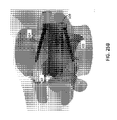
【課題】装置またはシステムが、隣接する椎体の間に配置される椎体間固定術デバイスを安定化させてその遊動を防止するために、および/または隣接する椎体の捕捉的な固定術装置を提供するために、固定組立体を採用する。【解決手段】固定組立体が、in situで椎体間固定術デバイスに挿入可能であって取り付け可能であるモジュール式の固定プレートを有することができる。特定の実施形態で、固定組立体が、in situで椎体間固定術デバイスに挿入可能でありおよび/または取り付け可能である単一の固定プレートを有することができる。特定の実施形態で、固定プレートが椎体間固定術デバイスに一体に形成される。【選択図】図2BA device or system for stabilizing and preventing migration of an interbody fusion device placed between adjacent vertebral bodies and/or for captive fusion of adjacent vertebral bodies. A fixation assembly is employed to provide the device. A fixation assembly can have a modular fixation plate that is insertable and attachable to an interbody fusion device in situ. In certain embodiments, the fixation assembly can have a single fixation plate that is insertable and/or attachable to the interbody fusion device in situ. In certain embodiments, the fixation plate is integrally formed with the interbody fusion device. [Selection drawing] Fig. 2B
Description
[0001]本開示は、概して、脊椎疾患を治療するための装置、システム、および方法に関する。詳細には、モジュール式の一体化される固定術装置を用いる、二軸の調整可能な脊椎システムおよび二軸の椎体間固定術デバイスの種々の実施形態が説明される。 [0001] The present disclosure relates generally to devices, systems, and methods for treating spinal disorders. In particular, various embodiments of biaxial adjustable spinal systems and biaxial interbody fusion devices using modular integrated fusion devices are described.
[0002]脊椎固定術は、変性円板疾患(DDD:degenerative disc disease)、脊椎すべり症、反復性の椎間板ヘルニア(recurrent disc herniation)などの、ヒトの脊椎に関連する問題を矯正するための外科手技である。脊椎固定術は、一般に、隣接する脊椎骨の間の損傷した椎間板および骨を取り除くこと、および骨成長を促進する骨グラフト材料を挿入することを伴う。骨が成長すると、隣接する脊椎骨が一体に接合または結合する。骨を一体に結合することが、脊椎の特定のエリアをより安定させるのを支援することができ、固定部位における神経の刺激に関連する問題を低減するのを支援することができる。固定術は脊椎の1つまたは複数のセグメントにおいて行われ得る。 [0002] Spinal fusion is a surgical procedure to correct problems associated with the human spine, such as degenerative disc disease (DDD), spondylolisthesis, and recurrent disc herniation. It's a skill. Spinal fusion generally involves removing damaged discs and bone between adjacent vertebrae and inserting bone graft material to promote bone growth. As bone grows, adjacent vertebrae join or join together. Bonding the bones together can help make certain areas of the spine more stable and can help reduce problems associated with nerve irritation at the fixation site. Fusion can be performed in one or more segments of the spine.
[0003]椎体間固定術手技では、損傷ポイントで椎間板を構成する髄核および/または線維輪が取り除かれ、適切な形状および寸法で構成されるインプラントが、隣接する脊椎骨の間の距離を適切な状態に復元するために椎間板隙内に配置される。椎体間固定術を実施するための外科的アプローチは多様であり、患者の脊柱へのアクセスが腹部または背中を通して行われ得る。低侵襲的に腰部脊椎固定術を達成するための1つの外科的方法が、後部側の小さい切開部を通して脊柱にアクセスすることを伴い、ここでは、外科医が脊椎骨の後部(back)および側部(side)の骨および関節の一部分を取り除く。骨および関節のこれらのセクションは、それぞれ、椎弓板および面関節と呼ばれる。この手技は経椎間孔腰椎体間固定術またはラテラル腰椎体間固定術(lateral lumbar interbody fusion)として知られる。このテクニックは、神経根を強制的に開創するのを必要とすることなく、一方側からのアプローチにより側方から、外科医が骨グラフトおよびスペーサを椎間板隙に挿入するのを可能にし、それにより、より従来的な後方手技と比較して神経根の周りでの負傷および瘢痕化を低減することができる。 [0003] In an interbody fusion procedure, the nucleus pulposus and/or annulus fibrosis that make up the intervertebral disc at the point of injury are removed, and an implant configured with the appropriate shape and size creates the proper distance between the adjacent vertebrae. It is placed in the intervertebral disc space to restore it to its normal state. Surgical approaches to performing interbody fusion are varied, and access to the patient's spinal column may be through the abdomen or back. One surgical method for achieving minimally invasive lumbar spinal fusion involves accessing the spinal column through a small posterior incision in which the surgeon makes the posterior (back) and lateral (lateral) vertebral bones of the vertebrae. side) bones and part of the joint are removed. These sections of bone and joint are called lamina and facet joints respectively. This procedure is known as transforaminal lumbar interbody fusion or lateral lumbar interbody fusion. This technique allows the surgeon to insert bone grafts and spacers into the intervertebral disc space laterally through a unilateral approach without the need for forced retraction of the nerve root, thereby Injury and scarring around the nerve root can be reduced compared to more traditional posterior procedures.
[0004]従来、椎間板が身体から取り除かれると、通常、隣接する脊椎骨の間に適切な距離を維持するためのインプラントのサイズを決定するために、外科医が特定の領域の椎体の間に多様なトライアルインプラントを押し入れる。さらに、例えば脊柱前弯症などの脊椎の自然な湾曲を受け入れるために、椎体の間の適切な角度が維持されなければならない。したがって、移植のための固定術デバイスの選択中、椎間板の高さおよび脊柱前弯症の両方を考慮しなければならない。従来のインプラントデバイスは、しばしば、脊椎の自然な湾曲を受け入れるための頂面および底面の角度を有するように予め構成される。オペレーション前にこれらの値を正確に決定し得ることは可能性が低いことであるかまたは困難である。さらに、椎体間固定術デバイスをサイズ決定して幾何学的構成のための標的領域の中に嵌め込むためのトライアンドエラーのアプローチを実施するとき、患者が有意な侵襲的作業を受けることになる。大きい脊柱前弯(hyperlordotic)の矢状面プロフィール構成(≧20°)が設定されるかまたは腰仙骨レベルのための捕捉的な固定術装置が所望される場合、外科医は、椎間板隙内での固定術デバイスの可能性のある移動または遊動(migration)を防止するためにならびに/あるいは関節固定術を行うまでの脊椎固定術プロセス中に一時的な前方脊柱安定化を実現するために、追加のプレート・ねじ組立体などの脊椎構成物を前方脊柱固定術装置の形態で配置する可能性がある。これにより、外科医が固定術デバイスを配置した後に二次手術を実施することが必要となる可能性があり、それにより全体の手術時間が延び、患者のより多くの潜在的な失血および麻酔に伴う合併症を引き起こす。 [0004] Conventionally, when an intervertebral disc is removed from the body, it is common for surgeons to perform various measurements between the vertebral bodies in specific regions to determine the size of the implant to maintain the proper distance between the adjacent vertebrae. push in the trial implant. In addition, proper angles between vertebral bodies must be maintained to accommodate the natural curvature of the spine, such as lordosis. Therefore, both disc height and lordosis must be considered during selection of a fusion device for implantation. Conventional implant devices are often preconfigured with top and bottom angles to accommodate the natural curvature of the spine. It is unlikely or difficult to be able to accurately determine these values prior to operation. Furthermore, the patient undergoes significant invasive work when performing a trial-and-error approach to size and fit the interbody fusion device within the target area for geometric configuration. Become. When a high hyperlordotic sagittal profile configuration (≧20°) is established or a captive fusion device for the lumbosacral level is desired, the surgeon may perform To prevent possible movement or migration of the fusion device and/or to provide temporary anterior spinal stabilization during the spinal fusion process pending arthrodesis, additional There is the possibility of deploying spinal constructs such as plate and screw assemblies in the form of an anterior spinal fusion device. This may require the surgeon to perform a secondary surgery after placement of the fusion device, thereby extending the overall operative time and associated with more potential blood loss and anesthesia for the patient. cause complications.
[0005]装置の実施形態が椎体間固定術デバイスおよび固定組立体を備える。固定組立体が、その場(in situ)で椎体間固定術デバイスまで挿入可能であり取り付け可能である1つまたは複数のモジュール式の固定プレートと、隣接する椎体の間で椎体間固定術デバイスを安定化させてその遊動を防止するための1つまたは複数の固定具と、を有することができる。 [0005] Apparatus embodiments comprise an interbody fusion device and a fixation assembly. A fixation assembly includes one or more modular fixation plates insertable and attachable to an interbody fusion device in situ and interbody fusion between adjacent vertebral bodies. and one or more fixtures to stabilize the surgical device and prevent its movement.
[0006]システムの実施形態が椎体間固定術デバイスおよび固定組立体を備える。固定組立体が、in situで椎体間固定術デバイスまで挿入可能であり取り付け可能である単一の固定プレートと、隣接する椎体の間で椎体間固定術デバイスを安定化させてその遊動を防止するための2つ以上の固定具と、を有することができる。任意選択で、単一の固定プレートが隣接する脊椎骨の捕捉的な固定術装置を実現する。 [0006] An embodiment of a system comprises an interbody fusion device and a fixation assembly. A fixation assembly includes a single fixation plate insertable and attachable to the interbody fusion device in situ and stabilizes the interbody fusion device between adjacent vertebral bodies to allow its movement. can have two or more fasteners to prevent Optionally, a single fixation plate provides a captive fixation device for adjacent vertebrae.
[0007]システムの実施形態が椎体間固定術デバイスおよび固定組立体を備える。固定組立体が、in situで椎体間固定術デバイスまで挿入可能であり取り付け可能である単一の固定プレートと、隣接する椎体の間で椎体間固定術デバイスを安定化させてその遊動を防止するための2つ以上の固定具と、を有することができる。単一の固定プレートがin situで椎体間固定術デバイスを基準として回転させられ得るかまたは角度を付けられ得、隣接する脊椎骨の捕捉的な固定術装置を実現することができる。 [0007] An embodiment of a system comprises an interbody fusion device and a fixation assembly. A fixation assembly includes a single fixation plate insertable and attachable to the interbody fusion device in situ and stabilizes the interbody fusion device between adjacent vertebral bodies to allow its movement. can have two or more fasteners to prevent A single fixation plate can be rotated or angled in situ relative to the interbody fusion device to provide a captive fusion device of adjacent vertebrae.
[0008]装置の実施形態が、椎体間固定術デバイスと、隣接する椎体の間で椎体間固定術デバイスを安定化させてその遊動を防止するための固定組立体と、を備える。固定組立体が、椎体間固定術デバイスと一体に形成される1つまたは複数の固定プレートと、1つまたは複数の固定具と、を有することができる。 [0008] Apparatus embodiments comprise an interbody fusion device and a fixation assembly for stabilizing the interbody fusion device between adjacent vertebral bodies to prevent migration thereof. A fixation assembly can have one or more fixation plates and one or more fasteners integrally formed with the interbody fusion device.
[0009]本概要は選択した実施形態を単純化した形態で紹介するために提供されるものであり、特許請求される主題の重要な特徴または本質的な特性を特定することを意図されず、また、特許請求される主題の範囲を決定するのを補助するものとして使用されることを意図されない。選択される実施形態は単に、本発明のとり得る特定の形態の概説を読者に提供するために提示されるものであり、本発明の範囲を限定することを意図されない。本開示の他の態様および実施形態が発明を実施するための形態で説明される。 [0009] This summary is provided to introduce selected embodiments in simplified form and is not intended to identify key features or essential characteristics of the claimed subject matter; Nor is it intended to be used as an aid in determining the scope of claimed subject matter. The selected embodiments are presented merely to provide the reader with an overview of certain forms that the invention can take, and are not intended to limit the scope of the invention. Other aspects and embodiments of the disclosure are described in the detailed description.
[0010]添付図面と併せて以下の詳細な説明および添付の特許請求の範囲を読むことにより、本開示のこれらの特徴および利点ならびに種々の他の特徴および利点がより良好に理解され得る。 [0010] These and various other features and advantages of the present disclosure may be better understood upon reading the following detailed description and appended claims in conjunction with the accompanying drawings.
[0042]次に、同様の参照符号が同様の部分を示している図1A~31Bを参照して、固定術装置を用いる、脊椎システムおよび椎体間固定術デバイスの種々の実施形態を説明する。これらの図が単に実施形態の説明を容易にすることを意図されており、包括的な説明であることまたは本開示の範囲を限定することを意図されていないことに留意されたい。さらに、本開示の種々の実施形態を徹底的に理解するのを可能にするために特定の具体的な細部が図に示される。特許請求される発明がこれらの細部なしでも実施され得ることを当業者であれば理解するであろう。また、本開示の実施形態の説明を不必要に不明瞭にするのを回避するために、本開示の装置、システム、および方法に関連する、よく知られている構成要素、構造、またはステップが詳細には示されたりまたは説明されたりしない可能性がある。さらに、具体的な実施形態と併せて説明される特定の態様または特徴が必ずしもこの実施形態のみに限定されるわけではなく、任意の他の実施形態でも実施され得ることに留意されたい。 [0042] Various embodiments of spinal systems and interbody fusion devices using fusion devices will now be described with reference to FIGS. 1A-31B, where like reference numerals indicate like parts. . Note that these diagrams are merely intended to facilitate the description of the embodiments and are not intended to be a comprehensive description or limit the scope of the present disclosure. Moreover, certain specific details are shown in the figures to facilitate a thorough understanding of the various embodiments of the disclosure. One skilled in the art will understand that the claimed invention may be practiced without these details. Also, to avoid unnecessarily obscuring the description of the disclosed embodiments, well-known components, structures, or steps associated with the disclosed apparatus, systems, and methods may be described in Details may not be shown or described. Furthermore, it should be noted that certain aspects or features that are described in conjunction with a particular embodiment are not necessarily limited to that embodiment only, but may also be practiced in any other embodiment.
[0043]一般に、脊椎疾患を治療するための装置またはシステムの種々の実施形態が、椎体間固定術デバイスおよび固定組立体を備える。椎体間固定術デバイスが、患者の脊柱の領域において隣接する脊椎骨の間に配置され得る。椎体間固定術デバイスの構成が、例えば、患者の治療に適する、膨張構成、脊柱前弯構成、脊柱後弯構成、大きい脊柱前弯構成、または大きい脊柱後弯構成を実現するために、調整され得る。固定組立体が安定化を実現し、安全なbody fusionを促進するために膨張構成および/または脊柱前弯調整構成において椎体間固定術デバイスの遊動を防止する。別法としてまたは加えて、固定組立体が、特定の脊椎疾患を治療するのに必要となる可能性がある、隣接する脊椎骨を定位置で保持するための矯正支援または捕捉的な固定術装置を実現する。本開示の説明を容易にするために、椎体間固定術デバイスと、椎体間固定術デバイスを安定化させてその遊動を防止するための固定組立体と、を有する装置を示すのに、「固定術装置を用いる椎体間固定術デバイス」というフレーズが使用され得;椎体間固定術デバイスと、椎体間固定術デバイスを安定化させてその遊動を防止するためのおよび/または隣接する脊椎骨を定位置で保持することを目的とした捕捉的な固定術装置を実現するための固定組立体と、を有するシステムを示すのに、「脊椎システム」というフレーズが使用され得る。 [0043] Generally, various embodiments of devices or systems for treating spinal disorders comprise interbody fusion devices and fixation assemblies. An interbody fusion device may be placed between adjacent vertebrae in the region of the patient's spine. The configuration of the interbody fusion device may be adjusted to achieve, for example, an expanded configuration, a lordosis configuration, a kyphosis configuration, a large lordosis configuration, or a large kyphosis configuration to treat the patient. can be A fixation assembly provides stabilization and prevents movement of the interbody fusion device in the expanded configuration and/or the lordotic adjustment configuration to promote safe body fusion. Alternatively or additionally, the fixation assembly may be an orthodontic assist or a captive fixation device for holding adjacent vertebrae in place that may be required to treat certain spinal disorders. come true. To facilitate the description of the present disclosure, to show an apparatus having an interbody fusion device and a fixation assembly for stabilizing the interbody fusion device and preventing its migration, The phrase "interbody fusion device using a fusion device" may be used; the interbody fusion device and the interbody fusion device for stabilizing the interbody fusion device and preventing its migration and/or adjacent and a fixation assembly for implementing a captive fixation device intended to hold the vertebral bones in place.
[0044]二軸の調整可能な椎体間固定術デバイス
[0045]本開示の脊椎システムおよび装置に含まれる椎体間固定術デバイスは任意適切な固定術デバイスであってよい。本開示の特定の実施形態によると、椎体間固定術デバイスが二軸の調整可能な固定術デバイスであってよい。二軸の調整可能な椎体間固定術デバイスが、患者を治療するのに適する高さおよび/または形状を有する椎体間固定術デバイスの構成を調整するために、in situで、別個に、独立して、または同時に、動作させられ得る2つの駆動機構を有する。例えば、患者の所望の矢状面バランスを達成するためにまたは患者の矢状面インバランスを矯正するために患者の前側および/または後側にそれぞれ沿って2つの駆動機構を動作させることにより、隣接する脊椎骨の間に配置される二軸の椎体間固定術デバイスの構成が調整され得る。患者の所望の冠状面バランスを達成するためにまたは患者の冠状面インバランスを矯正するために患者の外側および/または対側に沿って駆動機構を動作させることにより、隣接する脊椎骨の間に配置される二軸の調整可能な椎体間固定術デバイスの構成が調整され得る。
[0044] Biaxial adjustable interbody fusion device
[0045] The interbody fusion device included in the spinal systems and apparatus of the present disclosure may be any suitable fusion device. According to certain embodiments of the present disclosure, the interbody fusion device may be a biaxial adjustable fusion device. the biaxial adjustable interbody fusion device has a height and/or shape suitable for treating a patient, in situ and separately to adjust the interbody fusion device configuration; It has two drive mechanisms that can be operated independently or simultaneously. For example, by operating two drive mechanisms along each anterior and/or posterior side of the patient to achieve a desired sagittal balance in the patient or to correct a sagittal imbalance in the patient. The configuration of a biaxial interbody fusion device that is placed between adjacent vertebrae can be adjusted. Positioned between adjacent vertebrae by operating a drive mechanism along the lateral and/or contralateral side of the patient to achieve desired coronal balance in the patient or to correct coronal imbalance in the patient The configuration of the biaxial adjustable interbody fusion device that is used can be adjusted.
[0046]例示の二軸の調整可能な椎体間固定術デバイスが、ハウジングと、第1のウェッジ部材と、第2のウェッジ部材と、第1の駆動シャフトと、第2の駆動シャフトとを有することができる。ハウジングが第1のシェル部材および第2のシェル部材を有することができる。第1および第2のシェル部材が、ハウジングの第1のラテラルエリアに沿って第1のウェッジ部材に係合され得、ハウジングの第2のラテラルエリアに沿って第2のウェッジ部材に係合され得る。第1のウェッジ部材が、第1の駆動シャフトを通過させるのを可能にするように構成される貫通開口部を装備することができる。第2のウェッジ部材が、第2の駆動シャフトを通過させるのを可能にするように構成される貫通開口部を装備することができる。第1および第2のウェッジ部材がテーパ状部材であってよい。例示のテーパ状部材には、限定しないが、回転可能なテーパねじおよび摺動可能なテーパ状プレートが含まれる。 [0046] An exemplary biaxial adjustable interbody fusion device includes a housing, a first wedge member, a second wedge member, a first drive shaft, and a second drive shaft. can have A housing can have a first shell member and a second shell member. First and second shell members may be engaged with the first wedge member along a first lateral area of the housing and engaged with the second wedge member along a second lateral area of the housing. obtain. The first wedge member may be equipped with a through opening configured to allow passage of the first drive shaft. The second wedge member may be equipped with a through opening configured to allow passage of the second drive shaft. The first and second wedge members may be tapered members. Exemplary tapered members include, but are not limited to, rotatable tapered screws and slidable tapered plates.
[0047]第1の駆動シャフトが、ハウジングの第1のラテラルエリアに沿って第1のウェッジ部材を駆動するように動作可能であってよく、第2の駆動シャフトが、ハウジングの第2のラテラルエリアに沿って第2のウェッジ部材を駆動するように動作可能であってよく、それにより、第1および第2のシェル部材が互いに対して移動するようになり、それにより椎体間固定術デバイスを膨張させる。第1および第2の駆動シャフトが、第1および第2のウェッジ部材を異なる位置まで駆動するように独立して動作させられ得、それにより、ハウジングの第2のラテラルエリアに沿う椎体間固定術デバイスの膨張の程度とは異なる程度での、ハウジングの第1のラテラルエリアに沿う椎体間固定術デバイスの膨張を引き起こす。 [0047] A first drive shaft may be operable to drive the first wedge member along a first lateral area of the housing, and a second drive shaft may be operable to drive the first wedge member along a second lateral area of the housing. It may be operable to drive the second wedge member along the area to cause the first and second shell members to move relative to each other thereby forming an interbody fusion device. inflate. The first and second drive shafts are independently operable to drive the first and second wedge members to different positions to thereby effect interbody fusion along the second lateral area of the housing. causing expansion of the interbody fusion device along the first lateral area of the housing to a degree different from the degree of expansion of the surgical device.
[0048]第1および第2のウェッジ部材が、椎体間固定術デバイスを膨張または収縮させるために、ハウジングの第1および第2のラテラル側に沿って摺動するように構成されるテーパ状部材であってよい。別法として、第1および第2のウェッジ部材が、椎体間固定術デバイスを膨張または収縮させるために、回転するように、およびハウジングの第1および第2のラテラル側に沿って移動するように、構成される、ねじ山を有するねじ部材であってよい。例えば、椎体間固定術デバイスが、第1の対のねじ部材、および第2の対のねじ部材を備えることができる。第1のシェル部材が複数の個別のライザー部材を備えることができ、第2のシェル部材が複数の個別のライザー部材を備えることができる。第1のシェル部材の複数の個別のライザー部材および第2のシェル部材の複数の個別のライザー部材が、ハウジングの第1のラテラルエリアに沿う第1のトラッキングラン、およびハウジングの第2のラテラルエリアに沿う第2のトラッキングランを画定することができる。第1の駆動シャフトが第1の対のねじ部材を回転させるように動作可能であってよく、それにより、第1の対のねじ部材が第1の駆動シャフトに沿って進み第1のトラッキングラン上を移動することが可能となる。第2の駆動シャフトが第2の対のねじ部材を回転させるように動作可能であってよく、それにより、第2の対のねじ部材が第2の駆動シャフトに沿って進み第2のトラッキングラン上を移動することが可能となる。 [0048] The first and second wedge members are tapered configured to slide along the first and second lateral sides of the housing to expand or contract the interbody fusion device. It may be a member. Alternatively, the first and second wedge members rotate and move along the first and second lateral sides of the housing to expand or contract the interbody fusion device. It may be a screw member having a thread, which is configured as follows. For example, an interbody fusion device can include a first pair of screw members and a second pair of screw members. The first shell member can comprise a plurality of individual riser members and the second shell member can comprise a plurality of individual riser members. A plurality of discrete riser members of the first shell member and a plurality of discrete riser members of the second shell member form a first tracking run along a first lateral area of the housing and a second lateral area of the housing. A second tracking run can be defined along the . A first drive shaft may be operable to rotate the first pair of threaded members such that the first pair of threaded members advances along the first drive shaft to the first tracking run. It is possible to move up. A second drive shaft may be operable to rotate the second pair of threaded members such that the second pair of threaded members advances along the second drive shaft to the second tracking run. It is possible to move up.
[0049]椎体間固定術デバイスの種々の実施形態が、米国特許第9,889,019号、米国特許第10,188,527号、および「Expandable and Adjustable Lordosis Interbody Fusion System」と題される、2019年9月12日に出願した米国特許出願第16/569,621号で説明されている。米国特許第9,889,019号、米国特許第10,188,527号、および米国特許出願第16/569,621号の開示は、参照によりその全体が本明細書に組み込まれている。 [0049] Various embodiments of interbody fusion devices are entitled U.S. Patent No. 9,889,019, U.S. Patent No. 10,188,527, and "Expandable and Adjustable Lordosis Interbody Fusion System." , in US patent application Ser. No. 16/569,621, filed September 12, 2019. The disclosures of US Patent No. 9,889,019, US Patent No. 10,188,527, and US Patent Application No. 16/569,621 are hereby incorporated by reference in their entireties.
[0050]図1A~1Cが、本開示の実施形態による脊椎システムまたは装置で使用され得る例示の二軸の調整可能な椎体間固定術デバイス10を示す。示されるように、二軸の調整可能な椎体間固定術デバイス10が、膨張可能ハウジング12と、第1の対のねじ部材14a、14bと、第2の対のねじ部材16a、16bと、第1の駆動シャフト24と、第2の駆動シャフト26とを有する。第1の対のねじ部材14a、14bが、各々、第1の駆動シャフト24を通過させて第1の対のねじ部材14a、14bに係合させるのを可能にするように構成される貫通開口部を装備することができる。第2の対のねじ部材16a、16bが、各々、第2の駆動シャフト26を通過させて第2の対のねじ部材16a、16bに係合させるのを可能にするように構成される貫通開口部を装備することができる。
[0050] FIGS. 1A-1C illustrate an exemplary biaxial adjustable
[0051]ハウジング12が、第1のすなわち下方シェル部材32および第2のすなわち上方シェル部材34を有することができる。下方シェル部材32が複数の個別のライザー部材42を有することができる(図1B)。上方シェル部材34が複数の個別のライザー部材44を有することができる(図1B)。下方シェル部材32および上方シェル部材34の複数の個別のライザー部材42、44が、ハウジング12の第1のラテラルエリア13に沿う第1のステップトラッキングラン46、およびハウジング12の第2のラテラルエリア15に沿う第2のステップトラッキングラン48を画定することができる(図1C)。複数の個別のライザー部材42、44の高さが第1のステップトラッキングラン46および第2のステップトラッキングラン48に沿って変化することができる。例えば、第1のステップトラッキングラン46および第2のステップトラッキングラン48の各々の複数の個別のライザー部材42、44の高さが、中央部分50から遠位側に延在するステップトラッキングの中央部分から増大することができる。第1および第2の対のねじ部材14a~14bおよび16a~16bが、各々、隣接する個別のライザー部材の間の隙間の中に嵌め込まれるように構成される厚さを有する螺旋ねじ山を備えることができる。
[0051] The
[0052]第1の駆動シャフト24が第1の対のねじ部材14a、14bを回転させるように動作可能であり、それにより、第1の対のねじ部材14a、14bが第1のステップトラッキングラン46に沿って個別のライザー部材42、44上を移動することになる。第2の駆動シャフト26が第2の対のねじ部材16a、16bを回転させるように動作可能であり、それにより、第2の対のねじ部材16a、16bが第2のステップトラッキングライン48に沿って個別のライザー部材42、44上で移動することになる。第1の対のねじ部材14a~14bおよび第2の対のねじ部材16a~16bの回転に反応して、上方シェル部材32および下方シェル部材34が互いに対して移動することができ、それにより、ハウジング12の膨張を実現するか、あるいは第1および/または第2の対のねじ部材の回転を逆にすることによりハウジング12を膨張状態から収縮させる。第1および第2の駆動シャフト24、26が互いに独立して動作可能であってよい。したがって、第1のセットのねじ部材14a~14bおよび第2のセットのねじ部材16a~16bが第1のステップトラッキングラン46および第2のステップトラッキングラン48上の異なる位置まで独立して回転させられるとき、ハウジング12の第1のラテラルエリア13の膨張または収縮の程度がハウジング12の第2のラテラルエリア15の膨張または収縮の程度を基準として独立して調整可能である。
[0052] A
[0053]下方シェル部材32上での複数の個別のライザー部材42の位置が、上方シェル部材34上での複数の個別のライザー部材44の位置からオフセットされるように構成され得、その結果、ハウジング12が収縮構成である場合、下方シェル部材32の複数の個別のライザー部材42が上方シェル部材34の複数の個別のライザー部材44と相互噛合することができるようになる。
[0053] The positions of the plurality of
[0054]第1の対のねじ部材14a~14bおよび第2の対のねじ部材16a~16bが、各々、テーパ状の構成を有することができ、螺旋ねじ山を備えることができる。第1の対のねじ部材14a~14bが、第1の対の第1のねじ部材14aの螺旋ねじ山の方向性(directional orientation)を第1の対の第2のねじ部材14bの方向性と反対にするように、構成または配置され得、その結果、第1の駆動シャフト24の回転時に第1の対の第1および第2のねじ部材14a~14bが第1のステップトラッキングラン46内で互いに対して反対方向に移動することになる。同様に、第2の対のねじ部材16a~16bが、第2の対の第1のねじ部材16aの螺旋ねじ山の方向性を第1の対の第2のねじ部材16bの方向性と反対にするように、構成または配置され得、その結果、第2の駆動シャフト26の回転時に第2の対の第1および第2のねじ部材16a~16bが第2のステップトラッキングラン48で互いに対して反対方向に移動することになる。
[0054] The first pair of threaded
[0055]例えば、第1の対のねじ部材14a~14bおよび第2の対のねじ部材16a~16bが、第1の駆動シャフト24の例えば時計回り方向である第1の方向の回転時に第1の対のねじ部材14a~14bをそれぞれ第1のステップトラッキングラン46に沿わせて中央部分50から遠位側に移動させることになるように、および第2の駆動シャフト26の例えば反時計回り方向である第1の方向と反対の第2の方向の回転時に第2の対のねじ部材16a~16bをそれぞれ第2のステップトラッキングラン48に沿わせて中央部分50から遠位側に移動させることになるように、構成され得る。第1の対のねじ部材14a~14bおよび第2の対のねじ部材16a~16bが、第1の駆動シャフト414の第1の方向の回転時に第1の対のねじ部材14a、14bをそれぞれ第1のステップトラッキングラン46に沿わせて中央部分50から遠位側に移動させることになるように、および第2の駆動シャフト26の第1の方向と同じ第2の方向の回転時に第2の対のねじ部材16a~16bをそれぞれ第2のステップトラッキングラン48に沿わせて中央部分50から遠位側に移動させることになるように、構成され得る。
[0055] For example, the first pair of threaded
[0056]第1の駆動シャフト24および第2の駆動シャフト26が、各々、手術器具に接続されるためのおよび手術器具内のドライバーを受けて係合されるための構造部をそれらの端部分のところに有することができる。例えば、第1の駆動シャフト24および第2の駆動シャフト26の各々の端部分が、手術器具に接続されるための雄ねじ25と、手術器具内のドライバーを受けて係合されるための雌ねじ27とを装備することができる(図1A)。
[0056] The
[0057]二軸の調整可能な椎体間固定術デバイス10が、下方シェル部材32および上方シェル部材34を結合する1つまたは複数の引張ばね52、54を有することができる。引張ばね52、54がデバイス全体を一体に留めるのを保証することができる。極端な冠状面インバランスまたは矢状面インバランスが患者に生じている可能性があり、それにより患者に移植されているときの椎体間固定術デバイスに対して適用される力分布が非一様になる可能性がある。内部機構に対しての非一様な力分布により固定術デバイスが切り離される可能性がある。さらに、引張ばね52、54が固定術装置に対しての反対の力を維持するように機能することができる。デバイスの上方シェル部材および下方シェル部材に圧力が適用されると、固定術デバイスの内部の機構が膨張および/または脊柱前弯調整を受けることができる。機構を効率的にかつ正確に移動させるためには等しい反対の力が必要となる可能性がある。引張ばね52、54が機構に対しての初期張力を発生させることができ、それにより、例えば、患者の椎体がデバイスに接触していない場合に機構が膨張することが可能となり、および/または例えば患者の椎体がデバイスに接触していない場合に脊柱前弯を調整することが可能となる。
[0057] The biaxial adjustable
[0058]椎体間固定術デバイス10が、駆動シャフト24、26のその長手方向軸を中心とした回転を可能にしながら駆動シャフト24、26の望ましくない軸方向のおよび/または横方向の移動を制限するように構成される1つまたは複数の推力軸受60を有することができる。推力軸受60が、骨グラフト材料を担持する器具をデバイスハウジング12内に誘導するのを可能にする傾斜幾何形状62(図1A)を有するように設計され得る。さらに、この傾斜幾何形状が、後でより詳細に説明されるように隣接する脊椎骨内に配置される椎体間固定術デバイスを安定化させてその遊動を防止するために、固定プレートを椎体間固定術デバイスの中に挿入するのを可能にすることができる。
[0058] The
[0059]ハウジング12の下方シェル部材32および上方シェル部材34が、骨グラフト材料を受け入れるためのまたは固定術を実施するときに骨を通過させるのを可能にするための1つまたは複数の開口部または窓を有することができる。適切な骨グラフト材料には、限定しないが、例えば、海綿骨グラフトおよび/または皮質海綿骨グラフトを含む自家移植のおよび/または同種異系の骨グラフト材料が含まれる。骨グラフト材料が、椎体の間に配置される前に、椎体間固定術デバイス10の中に詰められ得、ならびに/あるいは、椎体の間で椎体間固定術デバイス10を適切な構成にするために膨張させたおよび/または脊柱前弯の調整を行った後で、追加され得る。下方シェル部材32および上方シェル部材34の側部または縁部が、患者の解剖学的構造の中への椎体間固定術デバイスの挿入を容易にするための面取り部分または丸みのある部分を有することができる。下方シェル部材32および上方シェル部材34の表面が、デバイスの遊動を防止するのをおよびより良好な保持を実現するのを支援するための、鋸歯、歯、凹部、窪みなどの、種々の構造部を有することができる。
[0059]
[0060]椎体間固定術デバイス10または椎体間固定術デバイス10の一部分が、チタン、タンタル、ステンレス鋼、任意の他の生体用金属、または合金などの、金属を含む材料から構築され得る。椎体間固定術デバイス10または椎体間固定術デバイス10の一部分が、ポリエーテルエーテルケトン(PEEK)、ポリエーテルケトンケトン(PEKK)、およびポリエーテルケトン(PEK)などの、高分子材料から構築されてもよい。
[0060]
[0061]椎体間固定術デバイス10が脊椎固定術手技のために適する任意のサイズを有することができる。例えば、駆動シャフト24、26の方向に沿うデバイスの近位端から遠位端までの距離(「長さ」)が30ミリメートル(mm)から60ミリメートルの範囲であってよい。デバイスの一方のラテラル側から反対のラテラル側までの距離(「幅」)が10mmから30mmの範囲であってよい。デバイスが、例えば幅において2mmの増分および長さにおいて5mmの増分といったように多様な増分で多様な長さおよび幅を有する多数の提供物で製造され得る。完全な収縮構成における椎体間固定術デバイスの下方シェル部材の表面から上方シェル部材の表面までの距離(「ベース高さ」)が、5mmから10mmの範囲であってよい。本開示の実施形態による二軸の駆動機構が、同時に一体に動作させられるときには例えば0mmから8mmの範囲のまたは互いに独立して動作させられるときには例えば0~9mmの範囲の高さ調整における連続的な膨張を実現することができる。本開示の実施形態による二軸の駆動機構が、0~30度の範囲の、下方シェル部材の表面と上方シェル部材の表面との間の連続的な角度付け(「脊柱前弯」)を実現することができる。上記の具体的な寸法は本開示の種々の態様を徹底的に理解するために提供されるものであり、特許請求の範囲を限定することを意図されないことに留意されたい。
[0061] The
[0062]モジュール式の固定術装置を用いる二軸の調整可能な椎体間固定術デバイス
[0063]次いで、図2A~11Bを参照して、本開示による、モジュール式の固定術装置を用いる二軸の調整可能な椎体間固定術デバイス、または装置100の実施形態が説明される。1つまたは複数のモジュール式の固定プレートを使用することにより、椎体間固定術デバイスを隣接する脊椎骨内で所望の構成にするように調整した後で、in situで固定組立体を椎体間固定術デバイスに取り付けるのを可能にし、椎体間固定術デバイスの安定化を実現して椎体間固定術デバイスの遊動を防止する。
[0062] Biaxial adjustable interbody fusion device with modular fusion device
[0063] Referring now to Figures 2A-11B, an embodiment of a biaxial adjustable interbody fusion device, or
[0064]図2A~2Bに示されるように、装置100が、概して、椎体間固定術デバイス10と、1つまたは複数のモジュール式の固定プレート120、140ならびに脊椎アンカー構成要素122および142を有する固定組立体110とを備える。椎体間固定術デバイス10が、図1A~1Cに関連させて上述した例示の二軸の椎体間固定術デバイス10と同じであってよいかまたはこれに類似してよい。別法として、椎体間固定術デバイス10が、固定組立体110と共に使用されるようにさらに適合または修正され得る種々の製造業者から市販される任意適切な二軸の調整可能な椎体間固定術デバイスであってよい。
[0064] As shown in FIGS. 2A-2B,
[0065]固定組立体110が、少なくとも、第1のすなわち下方固定プレート120、および、少なくとも、第1の脊椎アンカー構成要素または固定具122を備える。加えてまたは別法として、固定組立体110が、第2のすなわち上方固定プレート140、および第2の脊椎アンカー構成要素または固定具142を備える。本明細書で使用される「固定プレート」という用語は、プレート部材と、プレート部材およびプレート部材に組み付けられる他の部品または機構を備えるプレート組立体とを意味することも含む。本開示の実施形態によると、下方固定プレート120がモジュール式であり、椎体間固定術デバイス10に取り付け可能となるように構成される。本明細書で使用される「モジュール式」という用語は、椎体間固定術デバイスを実装する前にまたはその後で椎体間固定術デバイスに組み付けられ得る、ユニットとして構築される固定プレートの実施形態を意味する。固定組立体内のモジュール式の固定プレートが、置き換えられるプレートと同じ構造である別のモジュール式の固定プレートによって置き換えられ得る。下方固定プレート120が、そこを通して第1の固定具122を第1のすなわち下方椎体まで挿入するように構成されるアパーチャ124を装備することができる。同様に、本開示の特定の実施形態によると、上方固定プレート140がモジュール式であり、椎体間固定術デバイス10に取り付け可能となるように構成される。上方固定プレート140が、そこを通して第2の固定具142を第2のすなわち上方椎体まで挿入するように構成されるアパーチャ144を装備することができる。第1の固定具122および/または第2の固定具142に適する例示の固定具またはアンカー構成要素には、限定しないが、脊椎拡張ヘッドスクリュー、脊椎ロックねじ、脊椎自己ロックねじ、脊椎シャフトねじ、脊椎ネイル、spinal barb、脊椎フック、あるいは椎体に係止され得るねじ切りされた部材または非ねじ部材が含まれる。図2Bに示される組立図では、モジュール式の下方固定プレート120および上方固定プレート140が椎体間固定術デバイス10に取り付けられており、ここでは、第1の固定具122および第2の固定具142が下方固定プレート120および上方固定プレート140内のアパーチャを通して挿入されている。使用時、モジュール式の下方固定プレート120および上方固定プレート140が、in situで、つまり、椎体間固定術デバイス10を隣接する椎体の間に配置して所望の構成にするように調整した後で、椎体間固定術デバイス10に取り付けられ得ることに留意されたい。モジュール式の下方固定プレート120および上方固定プレート140が、所望される場合、椎体間固定術デバイスの実装前に椎体間固定術デバイス10に取り付けられてもよい。後でより詳細に説明される図10A~10Bが、隣接する脊椎骨の間で椎体間固定術デバイス10を適切な構成にするように配置して、膨張させて、および/またはその脊柱前弯の調整を行った後で、手術器具70を用いてモジュール式の上方固定プレート140およびモジュール式の下方固定プレート120が椎体間固定術デバイス10に取り付けられる、ことを示している。
[0065] The
[0066]図3A~3Dを参照すると、モジュール式の下方固定プレート120が椎体間固定術デバイス10に取り付け可能となるように構成され得、隣接する脊椎骨内で椎体間固定術デバイス10の安定化を実現して椎体間固定術デバイス10の遊動を防止するように機能する。本開示の特定の実施形態によると、モジュール式の下方固定プレート120が、例えば椎体間固定術デバイス10の後方駆動シャフト24などである駆動シャフトの望ましくない回転を防止するために椎体間固定術デバイス10に取り付けられるように構成される幾何学的構造部を装備することができる。例えば、下方固定プレート140が、椎体間固定術デバイス10の後方駆動シャフト24の端部分内の雌型幾何形状27の中に挿入されるように構成される雄型幾何形状126(図3C)を有することができる。例えば、下方固定プレート120内の雄型幾何形状126が、駆動シャフトの望ましくない回転を防止するために後方駆動シャフト24の端部分内の雌型ヘキサローブ構造部27の中で堅固に対合することができる雄型ヘキサローブ構造部を有することができる。雄型幾何形状126の周りの円形溝127が、後方駆動シャフト24の端部分を受け入れるために提供され得る。後でより詳細に説明される図5A~5Dおよび6A~6Dが、椎体間固定術デバイス10に対しての下方固定プレート120の取り付けを示しており、ここでは、下方固定プレート120内の雄型幾何形状126が後方駆動シャフト24の端部分内の雌型幾何形状27の中で堅固に対合する。
[0066] Referring to FIGS. 3A-3D, a modular
[0067]図3A~3Dを参照すると、下方固定プレート120が、椎体間固定術デバイス10の後方駆動シャフト24の端部分内の雌型幾何形状27の中で下方固定プレート120内の雄型幾何形状126を対合させる前に椎体間固定術デバイス10を基準とした下方固定プレート120の枢動を可能にする幾何学的構造部を装備することができる。例えば、下方固定プレート120が、例えば椎体間固定術デバイス10の前方駆動シャフト26の端部分を受け入れるように構成されるチャネル幾何形状128を有することができる。チャネル幾何形状128が、前方駆動シャフト26の端部分をチャネル幾何形状128内で受け入れることにより、前方駆動シャフト26に干渉することなく下方固定プレート120が後方駆動シャフト24を中心として「枢動」するのを可能にする。下方固定プレート120を枢動させるこの能力が、例えば椎体間固定術デバイス10の膨張構成および/または脊柱前弯調整構成に従って、下方固定プレート120内のアパーチャ124の位置を調整するのを可能にし、それにより、固定具のための、椎体を基準としたアパーチャの最適な位置が提供される。図7A~7Dが、椎体間固定術デバイス10に取り付けられた下方固定プレート120内のチャネル幾何形状128を示す。チャネル幾何形状128が第1の端部129aから第2の端部129bまで延在し、前方駆動シャフト26の端部分をチャネル128内で受け入れることにより、後方駆動シャフト24を中心として下方固定プレート120を「枢動」させるのを可能にし、これは例えば、椎体間固定術デバイス10が膨張構成であるが非脊柱前弯調整構成である場合には第1の端部129aにおいてであり(図7A~7B)、椎体間固定術デバイス10が大きい脊柱前弯の調整構成である場合には第2の端部129bにおいてであり(図7C~7D)、椎体間固定術デバイス10が非脊柱前弯調整構成と大きい脊柱前弯の調整構成との間の構成である場合にはこの間の任意の位置においてである。
[0067] Referring to FIGS. A geometry can be provided that allows pivoting of the
[0068]図3A~3Dを参照すると、下方固定プレート120が、椎体間固定術デバイス10に対しての下方固定プレート120の取り付けを固定するために椎体間固定術デバイス10をロックするように係合可能である取り付けロック機構130を有することができる。本開示の特定の実施形態によると、取り付けロック機構130が、ロックハウジング130a、棒130b、棒130b上に装填されてロックハウジング130a内で保持される圧縮ばね130c、および棒130bの遠位側端部分に結合されるラッチ130dを有することができる。棒130bの近位側端部分が、取り付けロック機構130を作動させるための駆動ツールを受けるための構造部を有することができる。例えば、棒130bの近位側端部分が、トルクスドライバーを受けるための雌型ヘキサローブ構造部を装備することができる。使用時、使用者が、棒130bの遠位側端部分に結合されるラッチ130dを変位させるためにドライバーを用いて棒130bを押すことができ、それにより、ラッチ130dを回転させて椎体間固定術デバイス10内の構成要素に掛合させるのを可能にする。棒130b上に装填される圧縮ばね130cがラッチ130dに力を適用し、ドライバーの解除後に、ラッチ130dが、椎体間固定術デバイス10に対しての下方固定プレート120の取り付けを強化するか、または椎体間固定術デバイス10を下方固定プレート120に対してロックする。ロックハウジング130aが、手術器具に接続されるように構成されるねじ山などの構造部を装備することができる。図5A~5Dが、アンロック状態にある取り付けロック機構130のラッチ130dを示す。図6A~6Cがロック状態にある取り付けロック機構130のラッチ130dを示しており、ここでは、ラッチ130dが後方駆動シャフト24の端部分内の雄ねじに干渉し、つまりこの雄ねじを定位置で保持し、それにより後方駆動シャフト24の望ましくない回転を防止する。
[0068] Referring to FIGS. 3A-3D, the
[0069]さらに図3A~3Dを参照すると、下方固定プレート120が、固定後にアパーチャ124から第1の固定具122が後退するのを防止するように構成される固定具ロック機構132を有することができる。本開示の特定の実施形態によると、固定具ロック機構132が、下方固定プレート120内の固定具アパーチャ124に隣接する凹部132b内で受けられるロック構成要素132aと、ロック構成要素132aの一部分の上に装填される圧縮ばね132cと、ロック構成要素132aの一部分に接続されるリテーナ132dとを備えることができる。リテーナ132dがロック構成要素132a上の装填される圧縮ばねを介して凹部132b内でロック構成要素132aを保持し、下方固定プレート120を基準としてロック棒132aと共に摺動可能である。固定具ロック機構132が、下方固定プレート120内のアパーチャ124の上でロック構成要素132aを部分的に延在させるのを可能にするために圧縮ばね132cが自由状態すなわち延伸状態であるときのロック状態と、下方固定プレート120内のアパーチャ124から離れる方向にロック構成要素132aを押し込むために圧縮ばね132cが圧縮状態であるときのアンロック状態と、を有する。使用時、固定具122がアパーチャ124の中に挿入される場合、ばね荷重式のロック構成要素132aがアパーチャ124から離れる方向に押し込まれ、それにより、固定具122を駆動するかまたは椎体の中にねじ込むことが可能となる。固定具122が最後まで駆動されて固定具122の頭部がアパーチャ124のカウンターシンク内で受けられて固定プレート120の表面と面一となるかまたはその下方にくると、ばね荷重式のロック構成要素132aが固定具頭部の上で少なくとも部分的にスプリングバックし、それにより固定具122を後退させるのを防止する。固定具ロック機構132が「ゼロステップ」のロックを可能にする。その理由は、外科医が、固定具頭部を後退させないように維持するために固定具頭部を覆うために、追加の器具を一切必要としないかまたは固定具ロック機構132に係合されるためのステップを一切必要としないからである。さらに分かり易いように、図15A~15Bが、後で説明される、固定プレート220内にある例示の固定具ロック機構242を示す。下方固定プレート120内の固定具ロック機構132が、図15A~15Bに示される固定プレート220内の固定具ロック機構242と同じであってよいかまたはこれに類似してよい。別法として、下方固定プレート120内の固定具ロック機構132が、図27A~27Bに関連させて説明される固定具ロック機構446と同じであってよいかまたはこれに類似してよい。
[0069] Still referring to Figures 3A-3D, the
[0070]次いで、図4A~4Dを参照すると、モジュール式の上方固定プレート140が椎体間固定術デバイス10に取り付け可能となるように構成され得、隣接する脊椎骨内に配置された椎体間固定術デバイス10を安定化させて椎体間固定術デバイス10の遊動を防止するように機能する。本開示の特定の実施形態によると、モジュール式の上方固定プレート140が、椎体間固定術デバイス10の中に挿入可能となるように構成される突出部分146を有することができる。突出部分146が、椎体間固定術デバイス10の望ましくない移動を制限するために椎体間固定術デバイス10の内部構成要素と堅固に対合するように構成される幾何形状を有することができる。例えば、突出部分146が、上方シェル部材34の内側表面内のチャネルの中にまたはその間に堅固に配置され得る概して長方形角柱の形状の幾何形状を有することができる。したがって、上方固定プレート140を基準とした椎体間固定術デバイス10の横方向、後ろ方向、および/または前方向の平行移動が防止され得るかまたは最小にされ得る。突出部分146が任意適切な他の形状または形態であってもよい。図8A~8Bが、椎体間固定術デバイス10に挿入された上方固定プレート140を示す。
[0070] Referring now to FIGS. 4A-4D, a modular
[0071]図4A~4Dを参照すると、上方固定プレート140が、椎体間固定術デバイス10に対しての上方固定プレート140の取り付けを固定するようにまたは椎体間固定術デバイス10をロックするように係合可能である取り付けロック機構150を有することができる。上方固定プレート140の取り付けロック機構150が、多くの点において、下方固定プレート120の取り付けロック機構130と同じであってよいかまたはこれに類似してよい。補完的に説明すると、上方固定プレート140の取り付けロック機構150が、ロックハウジング150a、棒150b、棒150b上に装填されてロックハウジング150a内で保持される圧縮ばね150c、および棒150bの遠位側端部分に結合されるラッチ150dを有することができる。図8Aがアンロック状態にある取り付けロック機構150を示しており、ここでは、上方固定プレート140が椎体間固定術デバイス10に挿入されている。図8Bがロック状態にある取り付けロック機構150を示しており、上方固定プレート140が椎体間固定術デバイス10に挿入されてロックされている。
[0071] Referring to FIGS. 4A-4D, the
[0072]さらに図4A~4Dを参照すると、上方固定プレート140が、上方固定プレート140内のアパーチャ144から第2の固定具142が後退するのを防止するように構成される固定具ロック機構152をさらに有することができる。上方固定プレート140の固定具ロック機構152が、多くの点において、下方固定プレート120の固定具ロック機構132と同じであるかまたはこれに類似することから、その詳細な説明は本明細書で省略される。
[0072] Still referring to FIGS. 4A-4D, the
[0073]図2A~2Bを再び参照すると、モジュール式の下方固定プレート120および上方固定プレート140が、椎体間固定術デバイス10に取り付けられているときに2つの固定プレートを少なくとも部分的に相互噛合させるのを可能にするように、成形および/またはサイズ決定されるか、あるいは構成される。例えば、下方固定プレート120が凹形プロフィール121を有する縁部分を備えることができ、上方固定プレート140が凸形プロフィール141を有する縁部分を備えることができる。下方固定プレート120の凹形の縁部分121および上方固定プレート140の凸形の縁部分141が少なくとも部分的に相互噛合するのを可能にし、それにより、椎体間固定術デバイス10が低程度の収縮構成または膨張構成にあるときに、下方固定プレート120および上方固定プレート140を椎体間固定術デバイス10に取り付けるのを可能にする。さらに、下方固定プレート120の凹形の縁部分121および上方固定プレート140の凸形の縁部分141の丸みのあるプロフィールまたはスカロップ(scalloped)プロフィールが、椎体間固定術デバイス10が脊柱前弯調整構成または大きい脊柱前弯調整構成にあるときに(例えば、20度から30度の脊柱前弯)、下方固定プレート120および上方固定プレート140を椎体間固定術デバイス10に取り付けるのを可能にする。図9A~9Cが、それぞれ、収縮構成、完全な膨張構成、および脊柱前弯調整構成における、椎体間固定術デバイス10に対しての下方固定プレート120および上方固定プレート140ならびに固定具122、142の取り付けを示す。説明および例示を容易にするために、以下に記載される寸法は、ラテラル腰椎体間固定術(LLIF:lateral lumbar interbody fusion)手技を介して、二軸の調整可能な椎体間固定術10が隣接する脊椎骨の間に配置され、患者の矢状面バランスに適する構成を達成するため患者の前側および/または後側にそれぞれ沿って2つの駆動機構を動作させることにより、膨張させられ、および/または脊柱前弯を調整される、実施形態を参照するものである。椎体間固定術デバイスが、前方腰椎体間固定術(ALIF:anterior lumbar interbody fusion)手技または後方腰椎体間固定術(PLIF:posterior lumbar interbody fusion)手技を介しても配置され得、患者の所望の矢状面バランスを達成するためにまたは患者の矢状面インバランスを矯正するために患者の外側および/または対側に沿って駆動機構を動作させることによっても、膨張されるかまたは脊柱前弯を調整される、ことを当業者であれば認識するであろう。
[0073] Referring again to FIGS. 2A-2B, modular
[0074]図9Aが、8.4mmである前側の高さ(「前側高さ」)、8.4mmである後側の高さ(「後側高さ」)、および0度である上方シェル部材と下方シェル部材との間の角度(「脊柱前弯」)、を有する構成まで椎体間固定術デバイス10が収縮される実施形態を示す。縁部分の凹形プロフィールおよび凸形プロフィールが、モジュール式の下方固定プレート120および上方固定プレート140をそれぞれ椎体間固定術デバイス10に挿入して取り付けるのを可能にする。図9Bが、椎体間固定術デバイス10が、16.1mmである前側高さ、16.1mmである後側高さ、および0度である脊柱前弯、を有する完全な膨張構成にある実施形態を示す。椎体間固定術デバイス10に取り付けられるモジュール式の下方固定プレート120および上方固定プレート140が、完全な膨張構成にある椎体間固定術デバイス10を安定化させることができ、その遊動を防止することができる。図9Cが、椎体間固定術デバイス10が、17.1mmである前側高さ、7.2mmである後側高さ、および30度である脊柱前弯、を有する大きい脊柱前弯調整構成にある実施形態を示す。椎体間固定術デバイス10に取り付けられるモジュール式の下方固定プレート120および上方固定プレート140が、大きい脊柱前弯調整構成にある椎体間固定術デバイス10を安定化させることができ、その遊動を防止することができる。図9Cを図9Bと比較すると、下方固定プレート120内のチャネル幾何形状が、最終的な取り付け(下方固定プレート120内のチャネル幾何形状内での前側駆動シャフト26の異なる位置に注目されたい)の前に下方固定プレート120を、後方駆動シャフト24を中心として「枢動」させるのを可能にし、それにより、椎体間固定術デバイス10を基準とした下方固定プレート120の角度付けを可能にし、下方固定プレート120内のアパーチャの最適な位置を提供しひいては最適な固定具の経路を提供する。さらに、下方固定プレート120および上方固定プレート140内のアパーチャが、図16A~16Bに関連させてより詳細に説明されるように、下方固定プレートおよび上方固定プレートからそれぞれアパーチャの軸を角度付けするのを可能にするように、構成または機械加工され得る。下方固定プレート120および上方固定プレート140内の角度を付けられたアパーチャにより、ならびに、固定具の選択により(例えば、固定具の頭部分が丸みを有する)、固定具122、142が、図9A~9Cにそれぞれ示されるように、例えば尾方向または頭方向に0度から15度といったような、可変の経路を有することが可能となる。上記で提示される具体的な寸法および角度が本開示の種々の実施形態を徹底的に理解するためのものであるが、特許請求の範囲を限定することを意図されないことに留意されたい。
[0074] FIG. 9A shows the front height ("front height") being 8.4 mm, the rear height ("back height") being 8.4 mm, and the upper shell being 0 degrees. 10 illustrates an embodiment in which interbody
[0075]モジュール式の固定術装置を用いる二軸の調整可能な椎体間固定術デバイスまたは装置100が、限定しないが、変性円板疾患(DDD)、脊椎すべり症、および後方脊椎すべり症(グレード1)を含めた、種々の脊椎疾患の治療に使用され得る。図10A~10Bに示されるように、使用時、モジュール式の下方固定プレート120および上方固定プレート140がin situで椎体間固定術デバイス10に挿入されて取り付けられ得る。例えば、収縮構成にある椎体間固定術デバイス10が、最初に、適切な外科手技を介して、手術器具70を使用して隣接する脊椎骨72、74の間に挿入されて配置され得る。椎体間固定術デバイス10を配置するための適切な外科手技には、ラテラル腰椎体間固定術(LLIF)手技、前方腰椎体間固定術(ALIF)手技、後方腰椎体間固定術(PLIF)手技、および腰椎内でまたは脊柱の他の領域内で実施される他の任意適切な外科手技が含まれる。種々の適切な手術器具が、「Surgical Operating Instrument for Expandable and Adjustable Lordosis Interbody Fusion Systems」と題される、2017年7月17日に出願した米国特許出願第15/661,435号、および「Surgical Operating Instrument for Expandable and Adjustable Lordosis Interbody Fusion Systems」と題される、2018年7月15日に出願した米国特許出願第16/035,637号で説明されており、それらのすべての開示は、全体として参照により本明細書に組み込まれている。椎体間固定術デバイス10が、手術器具70を使用して膨張させられ得および/または脊柱前弯を調整され得、それにより隣接する脊椎骨72、74の間に適切な構成を形成する。例えば、手術器具70が後方駆動シャフト24および前方駆動シャフト26の端部分上の雄ねじ25を介して椎体間固定術デバイス10に接続され得、雌型構造部27を後方駆動シャフト24および前方駆動シャフト26の端部分に係合させることにより(図1A)、椎体間固定術デバイス10を膨張させることができるかまたはその脊柱前弯を調整することができる。
[0075] A biaxial adjustable interbody fusion device or
[0076]次いで、モジュール式の上方固定プレート140が、椎体間固定術デバイス10を配置する場合と同じ外科的アプローチを介して、標的エリアに導入され得、椎体間固定術デバイス10に取り付けられ得る。本開示の実施形態によると、椎体間固定術デバイス10を配置して動作させるのに使用される手術器具70が、モジュール式の上方固定プレート140を挿入して取り付けるのにも使用され得る。例えば、外科医が、取り付けロック機構150(図4A~4D)のロックハウジング150aのところに設けられるねじ山を介して、上方固定プレート140を手術器具70に接続することができ、同じ外科的アプローチを介して上方固定プレート140を標的エリアに導入することができ、上方固定プレート140の突出部分を椎体間固定術デバイス10の中に挿入することができる。椎体間固定術デバイス10が、手術器具70を使用して、取り付けロック機構150を作動させることにより、上方固定プレート140に対してロックされ得る。
[0076] A modular
[0077]モジュール式の上方固定プレート140を挿入して取り付けた後でまたはその前に、モジュール式の下方固定プレート120が標的エリアに導入され得、同じ手術器具70を使用して、椎体間固定術デバイス10を配置する場合と同じ外科的アプローチを介して、椎体間固定術デバイス10に取り付けられ得る。例えば、外科医が、ロック取り付け機構130(図3A~3D)のロックハウジング130aのところに設けられるねじ山を介して、下方固定プレート120を手術器具70に接続することができ、同じ外科的アプローチを介して下方固定プレート120を標的エリアに導入することができ、下方固定プレート120内の雄型幾何形状126を後方駆動シャフト24の端部分内の雌型幾何形状27の中に挿入することができる。任意選択で、後方駆動シャフト24の雌型幾何形状27に対しての下方固定プレート120の雄型幾何形状126の最終的な係合の前で、下方固定プレート120が後方駆動シャフト24を中心として枢動させられ得、それにより、最適な固定具の経路のために下方固定プレート120内のアパーチャ124の最適な位置を調整または提供することができる。次いで、椎体間固定術デバイス10が、手術器具70を使用して、取り付けロック機構130を作動させることにより、下方固定プレート120に対してさらにロックされ得る。
[0077] After or before inserting and attaching the modular
[0078]次いで、背骨ねじなどの固定具122、142が、上方固定プレート120および下方固定プレート140内のアパーチャを通して挿入され得、第1の椎体72および第2の椎体74の中にそれぞれねじ込まれ得る。固定具122、142が最後まで駆動されて固定具の頭部が固定プレート内のアパーチャのカウンターシンク内で受けられると、上方固定プレート120および下方固定プレート140内の固定具ロック機構が自動で作動し、固定具122、142を後退させるのを防止する。椎体間固定術デバイス10が、図11A~11Bに示されるように、安定化され得、椎体72、74内で遊動することが防止される。
[0078]
[0079]図2A~11Bに関連して、モジュール式の固定術装置100を用いる二軸の調整可能な椎体間固定術デバイスが説明される。有益には、モジュール式の固定術装置100を用いて椎体間固定術デバイスが、高度に膨張した構成および/または大きい脊柱前弯構成にある椎体間固定術デバイスの安定化を実現することができ、その遊動を防止することができ、それにより隣接する椎体の間での固定術装置を安全に促進する。モジュール式の上方固定プレートおよび下方固定プレートが、椎体間固定術デバイスを調整した後で、いずれかのまたは両方のプレートを任意適切なサイズまたは構成の椎体間固定術デバイスにin situで取り付けるのを可能にし、さらには、実装前に椎体間固定術デバイスに取り付けるという選択肢を可能にする。モジュール式の固定プレートが、単一の外科的アプローチを介して、単一の患者体位で、椎体間固定術デバイスに対して挿入可能および取り付け可能であり、それにより患者の解剖学的構造に対しての混乱を最小にする。さらに、このモジュール式のデザインにより、手術中に固定組立体を使用するという選択肢、または椎体間構成を追加した後で所望される場合に終了するという選択肢が外科に与えられる。モジュール式の下方固定プレート120および上方固定プレート140が、それぞれ0度~15度である椎体間固定術デバイス10の下方シェル部材32および上方シェル部材34の前方および後方の角度付けに従い、つまりモジュール式の下方固定プレートの中心からモジュール式の上方固定プレートの中心までで測定して0度~30度の角度付けに従い、それにより所望のねじの経路および所望される形での皮質骨内への配置を可能にする。
[0079] With reference to Figures 2A-11B, a biaxial adjustable interbody fusion device using a
[0080]固定術装置100を用いる椎体間固定術デバイスが、特には、高度に膨張した構成においては任意の高さを有するように、および大きい脊柱前弯調整構成ではあらゆる患者において20°~30°の間の任意の角度を有するように、洗練された構成で椎体間固定術デバイスを外科医が設置するのを可能にし、ここでは、独立したねじ・プレートシステムの場合に必要となるような追加の手術によって発生する患者の解剖学的構成に対してのさらなる混乱が生じない。脊柱後弯(負の脊柱前弯)調整が所望されない可能性があるが、固定術装置100を用いる椎体間固定術デバイスが脊椎の腰仙セグメントのために脊柱後弯または大きい脊柱後弯の角度構成への調整能力を有する。したがって、固定術装置100を用いる椎体間固定術デバイスが患者のための完全なパーソナライゼーションを実現することができ、それにより、外科医が患者の脊椎バランスプロフィールのために必要となる任意の独自の高さおよび/または角度(例えば、23.4°)へと椎体間固定術デバイスを調整することが可能となる。従来のテクニックは、20°、25°、30°などのわずかな数の異なる脊柱前弯構成のみに椎体間固定術デバイスを設定することしか可能にすることができず、脊柱前弯構成において固定術デバイスを安定化させるために追加の手術を通して別個のねじ・プレートシステムを使用することが必要となる。
[0080] An interbody fusion device using the
[0081]さらに、固定術装置100を用いる椎体間固定術デバイスが外科効率を向上させることができる。従来、特定の患者のために必要となるインプラントのサイズを決定するためには、外科医が影響の大きい試験またはインプラントのサイズ決定を実施することが必要となる。本開示の実施形態によると、椎体間固定術デバイスがより小さい収縮状態での高さから開始され得、in situで高さを増大させることができる。これにより、試験プロセスを簡素化することまたは試験プロセスを大幅に低減することが可能となり、それにより、試験プロセスに付随する非洗練さおよび不正確さによる影響を低減することができる。大きい脊柱前弯構成に対してモジュール式の固定プレートが使用され得、それにより、椎体間固定術デバイスから独立する追加の固定プレートおよび骨ねじのセットを配置して必要性が低減される。モジュール式の固定プレートを使用することにより、患者の解剖学的構成に対しての混乱が低減される。外科医が、例えば矢状面バランスプロフィールなどの患者の独自の脊椎プロフィール、椎間板の高さ、および脊柱前弯に合わせるように椎体間固定術デバイスを調整すると、モジュール式の固定プレートが同じ外科的アプローチを介して挿入され得、固定術デバイスに取り付けら得、それにより、別個のプレート・ねじ固定システムを脊椎に後方から配置するための追加の外科的アプローチの必要とすることなく、固定術デバイスを椎体に固着することが可能となる。
[0081] Additionally, an interbody fusion device using the
[0082]さらに、固定組立体のこのモジュール式のデザインは、製造および病院管理に関連する利益を提供する。これにより商品構成の幅を低減することができる。単一のセットの下方固定プレートおよび上方固定プレートが任意のサイズおよび任意の製作構成の二軸の椎体間固定術デバイスと共に機能し、それにより製造コストおよび運用コストを大幅に低減することができる。任意のサイズおよび構成の二軸の椎体間固定術デバイスと共に単一のセットの下方固定プレートおよび上方固定プレートを使用することにより、病院または手術室において1つのセットの固定プレートのみを追跡するようになることで、追跡の必要性が単純化される。 [0082] In addition, this modular design of the fixation assembly provides benefits related to manufacturing and hospital management. This makes it possible to reduce the range of product configurations. A single set of inferior and superior fixation plates can work with biaxial interbody fusion devices of any size and fabrication configuration, thereby significantly reducing manufacturing and operating costs. . Use a single set of inferior and superior fixation plates with any size and configuration of biaxial interbody fusion device to track only one set of fixation plates in a hospital or operating room simplifies the need for tracking.
[0083]二軸の調整可能な連結式脊椎システム
[0084]次いで、図12A~19Bを参照して、本開示の実施形態による例示の二軸の調整可能な脊椎システム200が説明される。脊椎システム内で単一の固定プレートを使用することにより、隣接する脊椎骨の間で椎体間固定術デバイスを所望の構成にするように調整した後でin situで椎体間固定術デバイスに対して固定組立体を取り付けることが可能となる。単一の固定プレートが、椎体間固定術デバイスの安定化を実現してその遊動を防止することに加えて矯正支援または捕捉的な固定術装置を実現するために、チタン、ステンレス鋼、あるいは他の金属または金属合金などの、十分な強度を有する材料から構築され得る。本明細書で使用される「捕捉的な固定術装置」という用語は、隣接する脊椎骨を定位置で保持することができるかまたは関節固定(骨固定術)を行うまで隣接する椎体の動きを固定することができる矯正器具として機能する単一の固定プレートの実施形態を意味する。
[0083] Biaxial Adjustable Articulated Spinal System
[0084] Referring now to Figures 12A-19B, an exemplary biaxial adjustable
[0085]図12A~12Eに示されるように、脊椎システム200が、椎体間固定術デバイス10、および固定組立体210を備える。椎体間固定術デバイス10が、図1A~1Cに関連して上述したデバイス10と同じであってよいかまたはこれに類似してよい。別法として、椎体間固定術デバイス10が、固定組立体210と共に使用されるようにさらに適合または修正され得る種々の製造業者から市販される任意適切な二軸の調整可能な椎体間固定術デバイスであってよい。
[0085] As shown in FIGS.
[0086]固定組立体210が、単一の固定プレート220、少なくとも、第1の固定具222および第2の固定具224を備える。単一の固定プレート220が、椎体間固定術デバイス10に取り付け可能となるように構成される。単一の固定プレート220が、少なくとも、第1の椎体に固着されるようにそこを通して第1の固定具226を挿入するように構成される第1のアパーチャ226と、第2の椎体に固着されるようにそこを通して第2の固定具を挿入するように構成される第2のアパーチャ228とを装備する。本明細書で使用される「単一」という用語は、2つの隣接する椎体の間で椎体間固定術デバイスを安定化させることができる少なくとも2つの2つの固定具を挿入するための少なくとも2つのアパーチャを装備する1つの固定プレートを意味する。しかし、「単一」という用語を使用することは、ロックすることなどの他の機能を実施するための固定プレートに組み付けられる他の部品を排除するわけではない。本明細書で使用される「固定プレート」という用語は、プレート部材と、プレート部材およびプレート部材に組み付けられる他の部品または機構を備えるプレート組立体とを意味することも含む。例示のために単一の固定プレート内にある2つの固定具および2つのアパーチャが示されるが、他の実施形態が固定プレート内に3つ以上の固定具および3つ以上のアパーチャを有することもできる。さらに、図12C~12Dが脊椎システム200の組立図を示しており、ここでは、単一の固定プレート220が椎体間固定術デバイス10に取り付けられており、第1の固定具222および第2の固定具224が固定プレート内のアパーチャを通して挿入されている。使用時、単一の固定プレート220がin situで椎体間固定術デバイス10に取り付けられ得るか、または椎体間固定術デバイス10が患者の中に挿入されており隣接する椎体の間に配置されていることに留意されたい。さらに、椎体間固定術デバイスが実装前に調整される場合、単一の固定プレート220が所望される場合に実装前に椎体間固定術デバイス10に取り付けられてもよい。後でより詳細に説明される図18Aが、椎体間固定術デバイスが配置されて隣接する脊椎骨の間で適切な構成となるように膨張させられたおよび/またはその脊柱前弯を調整された後で、単一の固定プレート220が患者の中に挿入されて手術器具を用いて椎体間固定術デバイスに取り付けられている、ことを示す。
[0086] The
[0087]図13A~13Fを参照すると、単一の固定プレート220が椎体間固定術デバイス10に取り付け可能となるように構成され得る。例えば、単一の固定プレート220が、椎体間固定術デバイス10に取り付けられるようにならびに椎体間固定術デバイス10の駆動シャフト24および26の望ましくない回転を防止するように構成される幾何学的構造部を装備することができる。本開示の特定の実施形態によると、背中側(back side)の単一の固定プレート220が、互いに離間される第1の雄型幾何形状230および第2の雄型幾何形状232を有することができる(図13Cおよび13F)。第1の雄型幾何形状230および第2の雄型幾何形状232が、椎体間固定術デバイス10の第1の(例えば、後方)駆動シャフト24および第2の(例えば、前方)駆動シャフト26のそれぞれの端部分内にある雌型幾何形状27の中に挿入されるように構成され得る。例えば、第1の雄型幾何形状230および第2の雄型幾何形状232が、第1の駆動シャフト24および第2の駆動シャフト26の望ましくない回転を防止するために第1の駆動シャフト24および第2の駆動シャフト26の端部分内の雌型ヘキサローブ構造部27の中で堅固に対合することができる雄型ヘキサローブ構造部を有することができる。第1および第2の雄型幾何形状が他の対合構造部を有することもできる。上記のヘキサローブの実施例は例示のために提供されるものである。各々の第1の雄型幾何形状230および第2の雄型幾何形状232の周りに、円形溝231、233が、椎体間固定術デバイス10に対して単一の固定プレート220が取り付けられている場合に椎体間固定術デバイス10の第1の駆動シャフト24および第2の駆動シャフト26の端部分を受けるまたは受け入れるために提供され得る。図12Eが椎体間固定術デバイス10に対しての単一の固定プレート220の取り付けを示しており、ここでは、単一の固定プレート220内の第1の雄型幾何形状230および第2の雄型幾何形状232が、それぞれ、第1の駆動シャフト24および第2の駆動シャフト26の端部分内の雌型幾何形状27内で受けられ、第1の駆動シャフト24および第2の駆動シャフト26の端部分が単一の固定プレート230内の円形溝に嵌め込まれる。
[0087] Referring to FIGS. 13A-13F, a
[0088]図13C~13Fを参照すると、単一の固定プレート220が、別法としてまたは加えて、隣接する脊椎骨の間に配置される椎体間固定術デバイス10を安定化させてその遊動を防止するために椎体間固定術デバイス10の中に挿入可能となるように構成される突出部分234を有することができる。本開示の特定の実施形態によると、単一の固定プレート220内の突出部分234が、椎体間固定術デバイス10の望ましくない移動を制限するために椎体間固定術デバイス10の内部構成要素と堅固に対合するように構成される幾何形状を有することができる。例えば、突出部分234が、椎体間固定術デバイス10の推力軸受60(図1A)の傾斜幾何形状に堅固に挿入され得る概して長方形角柱の形状の幾何形状を有することができる。したがって、椎体間固定術デバイス10の横方向、後ろ方向、および前方向の望ましくない平行移動が防止され得るかまたは最小にされ得る。突出部分234が、立方体、半円筒、または多角形角柱形状などの、任意適切な他の形状または形態であってもよい。図14A~14Bが、椎体間固定術デバイス10に挿入された単一の固定プレート220の突出部分234と、後でさらに説明されるアンロック状態(図14A)およびロック状態(図14B)にある取り付けロック機構240とを示す。
[0088] Referring to Figures 13C-13F, a
[0089]図13A~13Fを参照すると、単一の固定プレート220が、椎体間固定術デバイス10をロックするためにまたは椎体間固定術デバイス10の単一の固定プレート220の取り付けを固定するために係合可能である取り付けロック機構240を有することができる。本開示の特定の実施形態によると、取り付けロック機構240が、図3A~3Dに示される取り付けロック機構130または図4A~4Dに示される取り付けロック機構150と同じであってよいかまたはこれに類似してよい。補完的に説明すると、単一の固定プレート220内の取り付けロック機構240が、ロックハウジング240a、棒240b、棒240b上に装填されてロックハウジング240a内で保持される圧縮ばね240c、および棒の遠位側端部分に結合されるラッチ240dを有することができる。ロック棒240bの近位端部分が、取り付けロック機構240を作動させるための駆動ツールを受けるための構造部を有することができる。例えば、棒240bの近位端部分が、雄型ヘキサローブ構造部を有するドライバーを受けるための雌型ヘキサローブ構造部を装備することができる。使用時、使用者が、棒240bの遠位側端部分に結合されるラッチ240dを変位させるためにドライバーを用いて棒240bを押すことができ、それにより、ラッチを回転させて椎体間固定術デバイス10内の構成要素に掛合させるのを可能にする。棒240b上に装填される圧縮ばね240cがラッチ240dに力を適用し、ドライバーの解除後に、ラッチ240dが、椎体間固定術デバイス10に対しての下方固定プレート220の取り付けを強化するか、または椎体間固定術デバイス10を単一の固定プレート220に対してロックする。取り付けロック機構240のハウジング240aが、取り付けロック機構240を作動させるためにおよび/または単一の固定プレートを患者の解剖学的構造に配置するために、手術器具に接続されるように構成されるねじ山などの構造部を装備することができる。図14Aがアンロック状態にある取り付けロック機構240を示しており、ここでは、ラッチ240dがアンロック位置にある。図14Bがロック状態にある取り付けロック機構240を示しており、ここでは、ラッチ240dが、椎体間固定術デバイス10の構成要素(例えば、推力軸受)に掛合されるロック位置にある。
[0089] Referring to FIGS. 13A-13F, a
[0090]図13A~13Bを参照すると、単一の固定プレート220が、第1の固定具ロック機構242および第2の固定具ロック機構244をさらに有することができる。単一の固定プレート220内の第1および第2の固定具ロック機構が、図3A~3Dに示される固定具ロック機構132および図4A~4Dに示される固定具ロック機構152と同じであってよいかまたはこれに類似してよい。補完的に説明すると、単一の固定プレート220内の第1の固定具ロック機構242が、第1のアパーチャ226に隣接する凹部242b内で受けられるロック構成要素242aと、ロック構成要素242aの一部分の上に装填される圧縮ばね242cと、ロック構成要素242aの一部分に接続されるリテーナ242dと、を備えることができる。リテーナ242dが、ロック構成要素242a上に装填される圧縮ばねを介して凹部242b内でロック構成要素242aを保持し、単一の固定プレート220を基準としてロック構成要素242aと共に摺動可能であり、それにより、使用時にロック構成要素242aをアパーチャ226の上で延在させることおよび/またはロック構成要素242aをアパーチャ226から後退させるのを可能にする。第2の固定具ロック機構244が第1の固定具ロック機構242と同じであってよいかまたはこれに類似してよい。別法として、第1および第2の固定具ロック機構242、244が、図27A~27Bに関連させて説明される固定プレート420および440内の固定具ロック機構426および446と同じであるかまたはこれに類似する。
[0090] Referring to FIGS. 13A-13B, a
[0091]図15A~15Bが単一の固定プレート220内の第1の固定具ロック機構242の一部の態様をより明瞭に描いている。圧縮ばねの圧縮状態および延伸(自由)状態は、ばね荷重式のロック構成要素242aがアンロック位置/開位置およびロック位置をそれぞれ有することを可能にする。圧縮ばねの延伸状態または自由状態では、ロック構成要素242aが固定プレート220内のアパーチャ226の上を部分的に延在する。固定具222がドライバーによりアパーチャ226の中に挿入される場合、ばね荷重式のロック構成要素242aがアパーチャ226から離れる方向に押し込まれ、それにより固定具222を椎体の中に例えばねじ込むといったように固定するのを可能にする。固定具222が最後までねじ込まれて固定具222の頭部が固定プレート220の表面と面一となるかまたはその下方にくると、ばね荷重式のロック構成要素242aが固定具頭部の上で少なくとも部分的にスプリングバックし、それにより固定具222を後退させるのを防止する。本開示の固定具ロック機構242が「ゼロステップ」のロックを可能にする。その理由は、外科医が、固定具頭部を、例えば椎体から外さないようにするために、後退させないように維持するため固定具頭部を覆うために、外科器具を一切必要としないかまたは固定具ロック機構242に係合されるためのステップを一切必要としないからである。
[0091] FIGS. 15A-15B more clearly depict some aspects of the first
[0092]図16Aおよび16Bが、単一の固定プレート220内の第1のアパーチャ226および第2のアパーチャ268が角度を付けられ得ることを示す。例えば、第1のアパーチャ226の中心線227が、固定プレートの表面に平行である基準面などの基準面を基準として0度~15度で角度を付けられ得る。同様に、第2のアパーチャ228の中心線229が、単一の固定プレートの表面に平行である基準面などの基準面を基準として0度~15度で角度を付けられ得る。角度を付けられたアパーチャは、そこを通して挿入される固定具が角度を付けた経路を有することを可能にし、それにより椎体に対しての固定具の効果を最適化することができる。第1のアパーチャ226および第2のアパーチャ228は、例えば尾方向または頭方向のそれぞれにおいて、または任意の他の方向において、第1の固定具222および第2の固定具224が0度~15度の角度を有することを可能にする。第1のアパーチャ226および第2のアパーチャ228が、第1および第2の固定具の頭部を受けるように構成されるカウンターボア部分またはカウンターシンク部分を有することができる。固定具の頭部が、図15A~15Bに示される球形状、あるいはテーパ形状または円筒形状などの他の任意適切な形状を有することができる。固定具の例には、限定しないが、脊椎拡張ヘッドスクリュー、脊椎ロックねじ、脊椎自己ロックねじ、脊椎シャフトねじ、脊椎ネイル、spinal barb、脊椎フック、および任意の他のねじ切りされた部材または非ねじ部材が含まれるが含まれる。
[0092] Figures 16A and 16B show that the
[0093]図17A~17Cが、膨張構成、完全な膨張構成、および脊柱前弯または大きい脊柱前弯構成を含めた、種々の構成において、単一の固定プレート220が椎体間固定術デバイス10に取り付けられることを示す。脊椎の腰仙セグメントの場合に脊柱後弯(負の脊柱前弯)調整が所望されない可能性があるが、椎体間固定術デバイス10が脊柱後弯または大きい脊柱後弯の角度構成において単一の固定プレート組立体に接続され得る。椎体間固定術デバイス10がラテラル外科手技を介して隣接する脊椎骨の間に配置される場合の例として、図17Aが、8.4mmである前側高さ、8.4mmである後側高さ、および0度である脊柱前弯、を有する収縮構成において、単一の固定プレート220が椎体間固定術デバイス10に取り付けられることを示す。図17Bが、16.1mmである前側高さ、16.1mmである後側高さ、および0度である脊柱前弯、を有する完全な膨張構成において、単一の固定プレート220が椎体間固定術デバイス10に取り付けられる実施例を示す。図17Cが、17.1mmである前側高さ、7.2mmである後側高さ、および30度である脊柱前弯、を有する大きい脊柱前弯調整構成において、単一の固定プレート220が椎体間固定術デバイス10に取り付けられる実施例を示す。単一の固定プレート220内の角度を付けられた第1および第2のアパーチャが、図17B~17Cに示されるように、尾方向および頭方向のそれぞれにおいて、最大15度のねじの角度付けを可能にする。
[0093] Figures 17A-17C show that a
[0094]二軸の調整可能な脊椎システム200が、限定しないが、変性円板疾患(DDD)、脊椎すべり症、後方脊椎すべり症、外傷、腫瘍、変形、偽関節、および以前に失敗した固定術など、を含めた種々の脊椎疾患の治療に使用され得る。使用時、図18に示されるように、単一の固定プレート220がin situで椎体間固定術デバイス10に挿入されて取り付けられる。例えば、収縮構成にある椎体間固定術デバイス10が、最初に、適切な外科手技を介して、手術器具70を使用して隣接する脊椎骨72、74の間に挿入されて配置され得る。椎体間固定術デバイス10を患者の解剖学的構造に導入するための適切な外科手技には、適切な外科手技には、ラテラル腰椎体間固定術(LLIF)手技、前方腰椎体間固定術(ALIF)手技、後方腰椎体間固定術(PLIF)手技、および腰椎内でまたは脊柱の他の領域内で実施される他の任意適切な外科手技が含まれる。種々の適切な手術器具が、「Surgical Operating Instrument for Expandable and Adjustable Lordosis Interbody Fusion Systems」と題される、2017年7月17日に出願した米国特許出願第15/661,435号、および「Surgical Operating Instrument for Expandable and Adjustable Lordosis Interbody Fusion Systems」と題される、2018年7月15日に出願した米国特許出願第16/035,637号で説明されており、これらのすべてはすべて、その開示の全体が参照により本明細書に組み込まれている。椎体間固定術デバイス10が、手術器具70を使用して膨張させられ得および/またはその脊柱前弯を調整され得、それにより隣接する脊椎骨72、74の間に適切な構成を形成する。例えば、手術器具70が後方駆動シャフト24および前方駆動シャフト26の端部分上の雄ねじ25を介して椎体間固定術デバイス10に接続され得、雌型構造部27を後方駆動シャフト24および前方駆動シャフト26の端部分に係合させることにより(図1A)、椎体間固定術デバイス10を膨張させることができるかまたはその脊柱前弯を調整することができる。椎体間固定術デバイス10が、患者を治療するのに適する構成まで膨張させられ得および/またはその脊柱前弯を調整され得る。
[0094] The biaxial adjustable
[0095]次いで、単一の固定プレート220が、椎体間固定術デバイス10を挿入して配置する場合と同じ外科的アプローチを介して、標的エリアに導入され得、椎体間固定術デバイス10に取り付けられ得る。本開示の実施形態によると、椎体間固定術デバイス10を配置して動作させるのに使用される手術器具70が、単一の固定プレート220を挿入して取り付けるのにも使用され得る。例えば、外科医が、ロック取り付け機構240のロックハウジング240aのところに設けられるねじ山を介して単一の固定プレート220を手術器具70に接続することができ、同じ外科手技を介して単一の固定プレート220を標的エリアに導入することができ、第1の雄型幾何形状230および第2の雄型幾何形状232を椎体間固定術デバイス10の後方駆動シャフト24および後方駆動シャフト26の端部分内の雌型幾何形状27に位置合わせすることができ、単一の固定プレート220を椎体間固定術デバイス10まで挿入することができる。椎体間固定術デバイス10がさらに、手術器具70を使用して、取り付けロック機構240を作動させることにより、単一の固定プレート220に対してロックされ得る。
[0095] A
[0096]次いで、骨ねじなどの固定具222、224が、単一の固定プレート220内のアパーチャを通して挿入され得、第1の椎体72および第2の椎体74の中にそれぞれねじ込まれ得る。固定具222、224が最後まで駆動されて固定具222、224の頭部が単一の固定プレート220内のアパーチャ内で受けられると、単一の固定プレート220内の固定具ロック機構242、244が自動で作動し、固定具222、224を後退させるのを防止する。椎体間固定術デバイス10が、図19A~19Bに示されるように、安定化され得、椎体72、74内で遊動することが防止される。加えて、単一の固定プレート220が、隣接する椎体72および74を定位置で保持するかまたは安全なbody fusion を促進するために隣接する脊椎骨の移動を固定する捕捉的な固定術装置を実現するために、ステンレス鋼、あるいは他の金属または金属合金などの、十分な強度を有する材料から構築され得る。
[0096]
[0097]図12A~19Bに関連させて、単一の固定プレートを備える二軸の調整可能な脊椎システム200の実施形態が説明される。有益には、脊椎システム200が、変性円板疾患(DDD)、脊椎すべり症、および後方脊椎すべり症(グレード1)を治療するときに、捕捉的な後方固定術装置をさらに必要とすることなく、安定化を実現することができ、隣接する椎体の間の固定術を促進することができる。単一の固定プレートが、矯正支援または捕捉的な固定術装置を実現するための十分な強度を有するように構築され得る。単一の固定プレート220が、単一の外科的アプローチを介して、単一の患者体位で、椎体間固定術デバイスに取り付けられるように移植可能および構成可能であり、それにより患者の解剖学的構造に対しての混乱を最小にする。単一の固定プレート内の雄型幾何形状などの幾何形状が、二軸の椎体間固定術デバイスのための補助的な安全ロックとして機能することができる。単一の固定プレートがあらゆる設置面積および構成の椎体間固定術デバイスに取り付け可能である。
[0097] An embodiment of a biaxial adjustable
[0098]装置100の他の実施形態と同様に、脊椎システム200は、特には、高度に膨張した構成においては任意の高さを有するように、および大きい脊柱前弯構成ではあらゆる患者において20°~30°の間の任意の角度を有するように、洗練された構成で椎体間固定術デバイスを外科医が設置するのを可能にし、ここでは、独立したねじ・プレートシステムの場合に必要となるような追加の手術によって発生する患者の解剖学的構成に対してのさらなる混乱が生じない。したがって、脊椎システム200が患者のための完全なパーソナライゼーションを実現することができ、それにより、外科医が患者の脊椎バランスプロフィールのために必要となる任意の独自の高さおよび/または角度(例えば、23.4°)へと椎体間固定術デバイスを調整することが可能となる。従来のテクニックは、20°、25°、30°などのわずかな数の所定の脊柱前弯構成のみに椎体間固定術デバイスを設定することしか可能にすることができず、脊柱前弯構成において固定術デバイスを安定化させるために追加の手術を通して別個のねじ・プレートシステムを使用することが必要となる。
[0098] As with the other embodiments of
[0099]さらに、脊椎システム200が外科効率を向上させることができる。従来、特定の患者のために必要となるインプラントのサイズを決定するためには、外科医が影響の大きい試験またはインプラントのサイズ決定を実施することが必要となる。本開示の実施形態によると、椎体間固定術デバイスがより小さい収縮状態での高さから開始され得、in situで高さを増大させることができる。これにより、試験プロセスを簡素化することまたは試験プロセスを大幅に低減することが可能となり、それにより、試験プロセスに付随する非洗練さおよび不正確さによる影響を低減することができる。外科医が、例えば矢状面バランスプロフィールなどの患者の独自の脊椎プロフィール、椎間板の高さ、および脊柱前弯に合わせるように椎体間固定術デバイスを調整すると、単一の固定プレートが同じ外科的アプローチを介して挿入され得、椎体間固定術デバイスに取り付けら得、それにより、固定術デバイスを椎体に固着するのを可能にし、それにより、患者の解剖学的構造に対しての混乱を低減することできる。さらに、単一の固定プレートが捕捉的な固定術装置を実現することができ、患者の脊椎への別個の外科的アプローチを介する別個のプレート・ねじ固定システムの必要性を排除する。
[0099] Further, the
[00100]さらに、脊椎システム200は、製造および病院管理に関連する利益を提供する。これにより商品構成の幅を低減することができる。単一のセットの固定プレートが任意のサイズおよび任意の製作構成の二軸の調整可能な椎体間固定術デバイスと共に機能し、それにより製造コストおよび運用コストを大幅に低減することができる。任意の二軸の椎体間固定術デバイスのサイズおよび構成と共に単一のセットの固定プレートを使用することにより、病院または手術室において1つのセットの固定プレートのみを追跡するようになることで、追跡の必要性が単純化される。
[00100] In addition,
[00101]二軸の調整可能な可変脊椎システム
[00102]次いで、図20A~25Bを参照して、本開示の実施形態による例示の二軸の調整可能な脊椎システム300が説明される。図20A~25Bに示される脊椎システム300が、多くの点において、図12A~19Bに関連させて上述した脊椎システム200に類似する。例えば、脊椎システム300が、椎体間固定術デバイスを隣接する脊椎骨内で所望の構成にするように調整した後で、in situで椎体間固定術デバイスに取り付けられるための単一の固定プレートを備える。単一の固定プレートが、椎体間固定術デバイスの安定化を実現してその遊動を防止することに加えて捕捉的な固定術装置を実現するために十分な強度を有する材料から構築され得る。脊椎システム300のいくつかの独自の態様が以下に記載される。
[00101] Biaxial Adjustable Variable Spinal System
[00102] Referring now to FIGS. 20A-25B, an exemplary biaxial adjustable
[00103]図20A~20Dを参照すると、脊椎システム300が椎体間固定術デバイス10および固定組立体310を備える。椎体間固定術デバイス10が、図1A~1Cに関連させて上述したデバイス10と同じであってよいかまたはこれに類似してよい。固定組立体310が、単一の固定プレート320、少なくとも、第1の固定具322、および少なくとも、第2の固定具324を備える。単一の固定プレート310が、少なくとも、第1の椎体に固着されるようにそこを通して第1の固定具322を挿入するように構成される第1のアパーチャ326と、第2の椎体に固着されるようにそこを通して第2の固定具324を挿入するように構成される第2のアパーチャ328とを装備する。単一の固定プレート320が椎体間固定術デバイス10まで挿入可能となるように構成され、それにより、単一の固定プレート320をin situで椎体間固定術デバイス10に取り付けることが可能となる。さらに、椎体間固定術デバイスが実装前に調整される場合、単一の固定プレート320が所望される場合に実装前に椎体間固定術デバイス10に取り付けられてもよい。単一の固定プレート320が、椎体間固定術デバイス10に対しての単一の固定プレート320の取り付けを固定するように構成される取り付けロック機構340を有することができる。特定の実施形態によると、単一の固定プレート320が、図20Dに示されるように、時計回りまたは反時計回りのいずれかで、椎体間固定術デバイス10を基準として回転可能である。椎体間固定術デバイス10を基準として単一の固定プレート320を回転させるこの能力が、椎体を基準として第1のアパーチャ326および第2のアパーチャ328のロケーションを調整することが可能となり、それにより、椎体に対しての固定具の効果を増大させるために固定具の経路を最適化することができる。
[00103] Referring to FIGS.
[00104]図21A~21Fを参照すると、単一の固定プレート320が、多くの点で、図13A~13Fに関連させて上述した単一の固定プレート210に類似する。例えば、単一の固定プレート320が、取り付けロック機構340と、第1の固定具ロック機構342と、第2の固定具ロック機構344とを有することができる。取り付けロック機構340ならびに固定具ロック機構342および344の構成および動作は、図13A~13Fに示される単一の固定プレート210内の取り付けロック機構240ならびに固定具ロック機構242および244と同じであるかまたはこれに類似する。したがって、分かり易いように、その詳細な説明は本明細書では省略される。
[00104] Referring to Figures 21A-21F, a
[00105]図21C~21Fを参照すると、単一の固定プレート320がさらに、椎体間固定術デバイス10の中に挿入可能となるようにまたは単一の固定プレート320を椎体間固定術デバイス10に取り付けるのを可能にするように構成される突出部分334を有することができ、それにより、隣接する脊椎骨の間に配置される椎体間固定術デバイス10を安定化させ、および/またはその遊動を防止する。椎体間固定術デバイス10に対して単一の固定プレート320が取り付けられることにより、横方向、前方方向、および後ろ方向のいずれかにおける椎体間固定術デバイス10の望ましくない平行移動が制限される。椎体間固定術デバイス10に対しての単一の固定プレート320の取り付けが、図22A~22Bに示されるように、取り付けロック機構340によって固定され得るかまたはロックされ得る。図22Aが、椎体間固定術デバイス10に対しての単一の固定プレート320の取り付け、およびアンロック状態にある取り付けロック機構340を示す。図22Bが、椎体間固定術デバイス10に対しての単一の固定プレート320の取り付け、およびロック状態にある取り付けロック機構340を示しており、ここでは、取り付けロック機構340のラッチ340dが椎体間固定術デバイス10内の構成要素(例えば、推力軸受)に掛合される。
[00105] Referring to FIGS. 21C-21F, the
[00106]本開示の特定の実施形態によると、突出部分334が、椎体間固定術デバイス10を基準として単一の固定プレート320を回転可能にするのを可能にするように構成される。例えば、突出部分334が、椎体間固定術デバイス10の上方シェル部材34の内側表面に組み入れられるチャネル幾何形状などの内部構成要素内で受けられ得る概して半円筒形状の幾何形状を有することができる。突出部分334の半円筒の幾何形状が椎体間固定術デバイス10を基準として単一の固定プレート320を回転可能にするのを可能にし、それにより、椎体に対して固定される前に単一の固定プレート320の向きまたは角度を調整することが可能となる。本開示の特定の実施形態によると、単一の固定プレート320が、第1の駆動シャフト24および第2の駆動シャフト26を包含する仮想面を基準として0度~11度の角度で時計回りまたは反時計回りに回転することができる。図23Aが、椎体間固定術デバイス10を基準とした単一の固定プレート320の角度付けを示す端面図である。図23Bが、椎体間固定術デバイス10を基準とした単一の固定プレート320の角度付けを示す断面図である。単一の固定プレート320のラテラル側が、椎体間固定術デバイス10を基準として単一の固定プレート320を回転させるときに椎体間固定術デバイス10の第1の駆動シャフト24および第2の駆動シャフト26を受け入れるように構成され得る。図21A~21Fに示されるように、椎体間固定術デバイス10を基準とした単一の固定プレート320の角度付けを可能にするために単一の固定プレート320のラテラル側に、凹部、切欠部、または同様のもの346が設けられ得る。図23C~23Dが、椎体間固定術デバイス10内の駆動シャフト24に干渉することなく単一の固定プレート320の角度付けを可能にする、単一の固定プレート320内にある凹部または切欠部346を示す等角図である。
[00106] According to certain embodiments of the present disclosure,
[00107]図24A~24Dが、それぞれ、収縮構成、完全な膨張構成、および脊柱前弯調整構成または大きい脊柱前弯調整構成を含めた、種々の構成において、単一の固定プレート320が椎体間固定術デバイス10に取り付けられ得ることを示す。ラテラル外科手技を介して隣接する椎体の間に椎体間固定術デバイス10が配置される場合の例として、図24Aが、8.4mmである前側高さ、8.4mmである後側高さ、および0度である脊柱前弯、を有する収縮構成において、単一の固定プレート320が椎体間固定術デバイス10に取り付けられることを示す。図24Bが、16.1mmである後側高さ、および0度である脊柱前弯、を有する完全な膨張構成において、単一の固定プレート320が椎体間固定術デバイス10に取り付けられる実施例を示す。図24Cが、17.1mmである前側高さ、7.2mmである後側高さ、および30度である脊柱前弯、を有する大きい脊柱前弯調整構成において、単一の固定プレート320が椎体間固定術デバイス10に取り付けられる実施例を示す。図24Dが、17.1mmである前側高さ、7.2mmである後側高さ、および30度である脊柱前弯、を有する大きい脊柱前弯調整構成にある椎体間固定術デバイス10の実施例を示す。図24Dを図24Cと比較すると、図24Dの単一の固定プレート320が、第1および第2の駆動シャフトを包含する仮想面を基準として11度の角度で回転させられる。単一の固定プレート320の角度付けにより、例えば、椎体間固定術デバイス10の膨張構成および/または脊柱前弯調整構成に従って、単一の固定プレート320内のアパーチャ326、328の位置を調整することが可能となり、それにより、椎体までの固定具の最適な経路を提供する。
[00107] Figures 24A-24D illustrate, respectively, that a
[00108]二軸の調整可能な脊椎システム300が、限定しないが、変性円板疾患(DDD)、脊椎すべり症、および後方脊椎すべり症(グレード1)を含めた、種々の脊椎疾患の治療に使用され得る。さらに、固定組立体310が、変性円板疾患(DDD)、脊椎すべり症、外傷(骨折および脱臼)、湾曲の変形(脊柱側弯、脊柱後弯、および/または脊柱前弯)、腫瘍、偽関節、および以前に失敗した固定術、外傷、腫瘍、変形、偽関節、ならびに以前に失敗した固定術など、の治療において捕捉的な固定術装置を実現するのにも使用され得る。単一の固定プレート300の使用、利益、および利点は、図12A~19Bに関連させて上述した脊椎システム200によって提供される使用、利益、および利点に類似する。したがって、分かり易いように本明細書では詳細な説明が省略される。1つの独自性は、脊椎システム300内で単一の固定プレート320が変化可能であるという点である。駆動シャフト内の雌型幾何形状と対合する雄型幾何形状が存在しないことにより、単一の固定プレート320がin situで椎体間固定術デバイス10を基準として回転することができ、それにより、単一の固定プレート320内のアパーチャのロケーションを調整することが可能となる。図25A~25Bが、単一の固定プレート320により椎体間固定術デバイス10が椎体72および74内で固着される実施形態を示す。
[00108] The biaxial adjustable
[00109]一体化される固定術装置を用いる二軸の調整可能な椎体間固定術デバイス
[00110]次いで、図26A~31Bを参照して、本開示による、一体化される固定術装置または装置400を用いる二軸の調整可能な椎体間固定術デバイスの実施形態が説明される。この一体化されるデザインにより、固定プレートを椎体間固定術デバイスと共に移植することが可能となり、in situでの椎体間固定術デバイスの膨張および/または調整により固定プレートの角度が調整されることが可能となり、それにより、椎体内での椎体間固定術デバイスの安定化を実現し、その遊動を防止する。
[00109] Biaxial adjustable interbody fusion device with integrated fusion device
[00110] Referring now to Figures 26A-31B, an embodiment of a biaxial adjustable interbody fusion device using an integrated fusion device or
[00111]図26A~26Dに示されるように、装置400が、概して、椎体間固定術デバイス10および固定組立体410を備える。椎体間固定術デバイス10が、図1A~1Cに関連させて上述した例示の二軸の調整可能な椎体間固定術デバイス10と同じであってよいかまたはこれに類似していてよい。別法として、固定術デバイス10が、固定組立体410と共に使用されるようにさらに適合または修正され得る種々の製造業者から市販される任意の他の二軸の調整可能な椎体間固定術デバイスであってよい。
[00111]
[00112]固定組立体410が、第1のすなわち下方固定プレート420および第2のすなわち上方固定プレート440を備える。固定組立体410が第1の固定具424および第2の固定具442をさらに備える。本開示の特定の実施形態によると、下方固定プレート420が下方シェル部材32に結合され、椎体間固定術デバイス10を用いて配置されるように構成される。同様に、上方固定プレート440が上方シェル部材34に結合され、椎体間固定術デバイス10を用いて配置されるように構成される。特定の実施形態で、下方固定プレート420が下方シェル部材32と一体に形成され得る。例えば、下方固定プレート420および下方シェル部材32が単一の部品として形成され得るか、または下方固定プレート420が別個の部片として作られて下方シェル部材32に溶接され得るまたは下方シェル部材32に一体化され得る。別法として、下方固定プレート420が別個の部品として形成され得、締まり嵌め、ねじ結合、または任意適切な他の手段により、下方シェル部材32に結合され得る。同様に、上方固定プレート440が、例えば単一の部片として作られることにより、または別個の部片として作られて一体に溶接されることにより、上方シェル部材34と一体に形成され得る。別法として、上方固定プレート440が別個の部品として形成され得、締まり嵌め、ねじ結合、任意適切な他の手段により、上方シェル部材34に結合され得る。この一体化されるデザインにより、下方シェル部材420および上方固定プレート440を椎体間固定術デバイス10と共に移植することが可能となる。下方シェル部材32に対して下方固定プレート420を結合することにより、および上方シェル部材34に対して上方固定プレート440を結合することにより、in situでの椎体間固定術デバイス10の膨張および/または調整により下方固定プレート420および上方固定プレート440の角度が調整されることが可能となる。
[00112] The
[00113]下方固定プレート420が、第1の椎体に固着するためにそこを通して第1の固定具422を挿入するように構成されるアパーチャ424を装備する。上方固定プレート440が、第2の椎体に固着するためにそこを通して第2の固定具442を挿入するように構成されるアパーチャ444を装備する。本開示の特定の実施形態によると、下方固定プレート420および上方固定プレート440のいずれかまたは両方が、固定プレートのプロフィールを最小にするかまたは低減するようにサイズ決定され得、および/または成形され得る。さらに、下方固定プレート420および/または上方固定プレート440のプロフィールが低減されることにより、特には側方アプローチを介して移植される場合に側方から見る場合に、患者の中での装置400の可視化を改善することが可能となる。さらに、下方固定プレート420および/または上方固定プレート440のプロフィールが低減されることにより、患者の解剖学的構造に装置400を挿入して配置することが容易になる。例えば、下方固定プレート420および上方固定プレート440のいずれかまたは両方がねじループまたはブラケットの形態であってよく、ここでは、固定具アパーチャ424および/または444が下方固定プレート420および/または上方固定プレート440の周縁部に隣接して形成されるかまたはこの周縁部に隣接して位置し、その結果、下方固定プレート420および上方固定プレート440の全体のプロフィールが最小にされ得る。
[00113] An
[00114]本開示の特定の実施形態によると、下方固定プレート420内のアパーチャ424および上方固定プレート440内のアパーチャ442が、図26C~26Dに示されるように、第1の固定具422および第2の固定具442の経路を尾方向または頭方向において調整可能にするのを可能にするように構成され得る。例えば、下方固定プレート420内のアパーチャ424および上方固定プレート440内のアパーチャ444が、図16A~16Bに関連させて上述したように、アパーチャ424および444の中心線により例えば下方シェル部材または上方シェル部材などの基準面を基準として0度~15度の角度を形成することになるように、切り込まれ得る。別法としてまたは加えて、第1の固定具422および第2の固定具442が、固定具の経路を調整可能にするのを可能にするようにサイズ決定および成形され得る。例えば、第1の固定具422および第2の固定具442が図28に示されるように球形状またはテーパ形状の頭部分を有することができ、それにより固定具の経路を調整可能にすることが可能となる。一般に、第1の固定具422および第2の固定具442の経路が、尾方向または頭方向において、下方シェル部材32または上方シェル部材34をそれぞれ基準として0度~15度で角度を付けられ得、それにより、椎体に対しての固定具の効果を最大にするかまたは増大させるために固定具の経路を最適化することができる。
[00114] According to certain embodiments of the present disclosure,
[00115]図26A~26Dを参照すると、下方固定プレート420が、固定具422を後退させるのを防止するためのロック機構426を有することができる。同様に、上方固定プレート440が、固定具442を後退させるのを防止するためのロック機構446を有することができる。下方固定プレート420内のロック機構426が、上方固定プレート440内のロック機構446と同じであってよいかまたはこれに類似してよい。例えば、上方固定プレート440内のロック機構446が、上方固定プレート440内のアパーチャ444に隣接する凹部446b内で受けられるロック棒446aと、ロック棒を凹部内で保持してロック棒を旋回させるのを可能にするためにロック棒446aの端部に溶接されるかまたは取り付けられるアダプタ446cとを有することができる。図27A~27Bでより良好に見ることができるように、ロック棒446aの頭部が、丸みを有する側部分446a-1と、平坦な側部分446a-2と、ロック機構446を作動させるためのドライバーを受けるように構成される構造部を有する端部446a-3とを有することができる。ロック機構446をアンロック状態または開状態に設定するためにロック棒446aが旋回させられると、頭部の平坦側部分446a-2が図27Aに示されるように固定プレート440内のアパーチャ444の方を向くようになり、アパーチャ444を開状態にし、それによりそこを通して固定具442を挿入するのを可能にする。固定具442が椎体の中の最後まで駆動されて図27Bに示されるように固定具頭部がアパーチャのカウンターシンク内で受けられると、ロック棒446aがロック機構446をロック状態に設定するように旋回させられ得、ここでは、頭部の丸みを有する側部分446a-1がアパーチャ444の少なくとも一部分の上をまたは固定具442の上を延在し、それにより固定具442が後退することが防止される。本開示のロック機構446はクイック「ワンステップ」ロッキングを可能にし、ここでは、固定具をロックまたはロック解除するために駆動ツールを用いてロック棒446aを1回のみ旋回させることが必要となる。さらに、「ワンステップ」ロック機構を使用することにより、固定プレートのプロフィールを単純化するかまたは低減することが可能となり、これは、患者の解剖学的構造に装置を挿入して配置することにおいて有利である。
[00115] Referring to Figures 26A-26D, the
[00116]次に、図29A~29Bを参照すると、本開示の一体化される固定プレート420、440が、隣接する脊椎骨内で任意の膨張構成または調整構成である椎体間固定術デバイス10を安定化させてその遊動を防止することができる。図29Aが、16.1mmである前側高さ、16.1mmである後側高さ、および0度である脊柱前弯、を有する完全な膨張構成にある例示の椎体間固定術デバイス10の実施形態を示す。図29Bが、17.1mmである前側高さ、7.2mmである後側高さ、および30度である脊柱前弯、を有する大きい脊柱前弯調整構成にある例示の椎体間固定術デバイス10の実施形態を示す。脊椎の腰仙セグメントの場合に脊柱後弯(負の脊柱前弯)調整が所望されない可能性があるが、椎体間固定術デバイス10がその脊柱前弯を調整され得る。椎体間固定術デバイス10の膨張中および/または脊柱前弯調整中、下方固定プレート420および上方固定プレート440が下方シェル部材32および上方シェル部材34と共に移動し、それにより、下方固定プレート420および上方固定プレート440内のアパーチャの位置および/または角度を自動で調整することが可能となる。図29A~29Bに示されるデバイス構成のいずれかで、固定具の経路が、例えば尾方向または頭方向において、0度から15度の角度でさらに変化することができ、それにより、椎体に対しての固定具の効果を最大にするかまたは増大させるために固定具の経路を最適化することができる。図26Bが、8.4mmである前側高さ、8.4mmである後側高さ、および0度である脊柱前弯、を有する収縮構成にある椎体間固定術デバイス10の実施形態を示す。
[00116] Referring now to FIGS. 29A-29B, the integrated
[00117]一体化される固定術装置400を用いる二軸の調整可能な椎体間固定術デバイスが、限定しないが、変性円板疾患(DDD)、脊椎すべり症、および後方脊椎すべり症(グレード1)を含めた、種々の脊椎疾患の治療に使用され得る。図30を参照すると、使用時、収縮構成にある、一体化される固定術装置400を用いる椎体間固定術デバイスが、適切な手術器具70を使用して、患者の解剖学的構造に挿入され得、隣接する脊椎骨72、74の間に配置され得る。椎体間固定術デバイスを患者の解剖学的構造に導入するための適切な外科手技には、ラテラル腰椎体間固定術(LLIF)手技、前方腰椎体間固定術(ALIF)手技、後方腰椎体間固定術(PLIF)手技、および腰椎内でまたは脊柱の他の領域内で実施される他の任意適切な外科手技が含まれる。種々の適切な手術器具が、「Surgical Operating Instrument for Expandable and Adjustable Lordosis Interbody Fusion Systems」と題される、2017年7月17日に出願した米国特許出願第15/661,435号、および「Surgical Operating Instrument for Expandable and Adjustable Lordosis Interbody Fusion Systems」と題される、2018年7月15日に出願した米国特許出願第16/035,637号で説明されており、これらのすべてはすべて、その開示の全体が参照により本明細書に組み込まれている。椎体間固定術デバイス10が、手術器具70を使用して膨張させられ得および/またはその脊柱前弯を調整され得、それにより隣接する脊椎骨72、74の間に適切な構成を形成する。
[00117] Biaxial adjustable interbody fusion devices using
[00118]次いで、骨ねじ422、442などの固定具が、下方固定プレート420および上方固定プレート440内のアパーチャを通して挿入され得、第1の椎体72および第2の椎体74の中にそれぞれ駆動され得る。固定具422、442が最後まで駆動されて固定具の頭部が固定プレート内のアパーチャ内で受けられると、下方固定プレート420および上方固定プレート440内の「ワンステップ」ロック機構が手術器具70を使用して作動され得、それにより後退するのを防止するように固定具422、442がロックされる。次いで、図31A~31Bに示されるように、椎体間固定術デバイス10が安定化され得、椎体72、74内での遊動を防止され得る。
[00118] Fasteners, such as bone screws 422, 442, can then be inserted through apertures in the lower and
[00119]図26A~31Bに関連させて、一体化される固定術装置400を用いる二軸の調整可能な椎体間固定術デバイスの実施形態が説明される。有益には、一体化される固定術装置400を用いる椎体間固定術デバイスが、低程度の膨張構成から完全な膨張構成および/または大きい脊柱前弯調整構成までの任意の構成における椎体間固定術デバイスを安定化させることができ、その遊動を防止することができ、それにより、2つの隣接する椎体の間の固定術を安全に促進する。任意のサイズおよび構成の椎体間固定術デバイスが本開示の固定プレートと一体化され得、単一の外科的アプローチを介して、単一の患者体位で、挿入可能となるように構成され得、それにより患者の解剖学的構造に対しての混乱を最小にする。下方固定プレートおよび上方固定プレートを椎体間固定術デバイスに一体化することにより、固定具アパーチャの角度付けおよびひいては固定具の経路を、0度~15度の任意の角度で、椎体間固定術デバイスの下方シェル部材および上方シェル部材の角度付けにそれぞれ従わせることが可能となり、それにより固定具の理想的な経路および配置が実現する。他の利益および利点は、図2A~11Bの説明に関連して上述したモジュール式の固定術装置100を用いる椎体間固定術デバイスによって提供される利益および利点と同じであるかまたはこれに類似する。したがって、その詳細な説明は本明細書では省略される。
[00119] An embodiment of a biaxial adjustable interbody fusion device using an
[00120]本開示の実施形態によると、装置100および400内のまたはシステム200および300内の椎体間固定術デバイス10の第1の駆動シャフト24および第2の駆動シャフト26が、ハウジングの第1および/または第2のラテラルエリアにおける下方シェル部材32と上方シェル部材34との間の距離を継続的に変化可能にするのを可能にするために継続的に動作可能となり得、それにより、椎体間固定術デバイス10の膨張構成の高さを継続的に変化させることが可能となる。例えば、椎体間固定術デバイス10の高さが0ミリメートルから10ミリメートルだけ継続的に変化することができる。加えてまたは別法として、装置100および400内のまたはシステム200および300内の椎体間固定術デバイス10の第1の駆動シャフト24および第2の駆動シャフト26が、下方シェル部材32と上方シェル部材34との間の角度を継続的に変化可能とするように継続的に動作可能となり得、それにより椎体間固定術デバイス10の膨張構成の脊柱前弯を継続的に変化させるのを可能にする。例えば、椎体間固定術デバイス10の脊柱前弯が0度から30度で継続的に変化することができる。
[00120] According to embodiments of the present disclosure,
[00121]本明細書で使用されるすべての技術用語および科学用語は、特に明記しない限り、当業者によって一般に理解される意味を有する。本記述および添付の特許請求の範囲で使用される単数形「a」、「an」および「the」は、文脈で特に明記しない限り、複数形も含む。「または」という用語は、文脈で特に明記しない限り、非排他的な「または」を意味する。「第1」または「第2」という用語は、種々の類似の要素を説明することにおいて1つの要素を別の要素から区別するのに使用されるものであり、文脈で特に明記しない限り、任意の特定の順序として解釈されるべきではない。 [00121] All technical and scientific terms used herein have the meaning commonly understood by one of ordinary skill in the art, unless otherwise specified. As used in this description and the appended claims, the singular forms "a," "an," and "the" include plural forms unless the context clearly dictates otherwise. The term "or" means a non-exclusive "or" unless the context clearly indicates otherwise. The terms "first" or "second" are used to distinguish one element from another in describing various similar elements and are optional unless the context clearly dictates otherwise. should not be construed as any particular order of
[00122]多様な他の修正形態も作られ得ることを当業者であれば認識するであろう。これらのまたは他のすべての変形形態および修正形態は、本発明者らにより、本発明の範囲内で、企図されるものである。 [00122] Those skilled in the art will recognize that various other modifications can also be made. All these and other variations and modifications are contemplated by the inventors and are within the scope of the invention.
10 二軸の調整可能な椎体間固定術デバイス
12 膨張可能ハウジング
13 第1のラテラルエリア
14a ねじ部材
14b ねじ部材
15 第2のラテラルエリア
16a ねじ部材
16b ねじ部材
24 第1の駆動シャフト
25 雄ねじ
26 第2の駆動シャフト
27 雌ねじ
32 下方シェル部材
34 上方シェル部材
42 ライザー部材
44 ライザー部材
46 第1のステップトラッキングラン
48 第2のステップトラッキングラン
50 中央部分
52 引張ばね
54 引張ばね
60 推力軸受
62 傾斜幾何形状
70 手術器具
72 脊椎骨
74 脊椎骨
100 装置
110 固定組立体
120 固定プレート
122 脊椎アンカー要素
124 アパーチャ
126 雄型幾何形状
127 円形溝
128 チャネル幾何形状
129a 第1の端部
129b 第2の端部
130 取り付けロック機構
130a ロックハウジング
130b 棒
130c 圧縮ばね
130d ラッチ
132 固定具ロック機構
132a ロック構成要素
132b 凹部
132c 圧縮ばね
132d リテーナ
140 固定プレート
142 脊椎アンカー要素
144 アパーチャ
146 突出部分
150 取り付けロック機構
150a ロックハウジング
150b 棒
150c 圧縮ばね
150d ラッチ
152 固定具ロック機構
200 脊椎システム
210 固定組立体
220 単一の固定プレート
222 第2の固定具
224 第2の固定具
226 第1のアパーチャ
227 中心線
228 第2のアパーチャ
229 中心線
230 第1の雄型幾何形状
232 第2の雄型幾何形状
234 突出部分
240 取り付けロック機構
240a ロックハウジング
240b 棒
240c 圧縮ばね
240d ラッチ
242 固定具ロック機構
242a ロック構成要素
242b 凹部
242c 圧縮ばね
242d リテーナ
244 固定具ロック機構
300 脊椎システム
310 固定組立体
320 単一の固定プレート
322 第1の固定具
324 第2の固定具
326 第1のアパーチャ
328 第2のアパーチャ
334 突出部分
340 取り付けロック機構
340d ラッチ
342 固定具ロック機構
344 固定具ロック機構
400 装置
410 固定組立体
420 下方固定組立体
414 第1の駆動シャフト
420 固定プレート
422 第1の固定具
426 固定具ロック機構
440 上方固定プレート
442 第1の固定具
442 第2の固定具
444 アパーチャ
446 固定具ロック機構
446a ロック棒
446a-1 丸みを有する側部分
446a-2 平坦な側部分
446a-3 端部
446b 凹部
446c アダプタ
10 biaxial adjustable interbody fusion device 12 expandable housing 13 first lateral area 14a threaded member 14b threaded member 15 second lateral area 16a threaded member 16b threaded member 24 first drive shaft 25 external threads 26 Second Drive Shaft 27 Internal Thread 32 Lower Shell Member 34 Upper Shell Member 42 Riser Member 44 Riser Member 46 First Step Tracking Run 48 Second Step Tracking Run 50 Middle Section 52 Tension Spring 54 Tension Spring 60 Thrust Bearing 62 Tilt Geometry Shape 70 Surgical Instrument 72 Vertebra 74 Vertebra 100 Apparatus 110 Fixation Assembly 120 Fixation Plate 122 Spinal Anchor Element 124 Aperture 126 Male Geometry 127 Circular Groove 128 Channel Geometry 129a First End 129b Second End 130 Mounting Lock Mechanism 130a Lock housing 130b Rod 130c Compression spring 130d Latch 132 Fixture locking mechanism 132a Locking component 132b Recess 132c Compression spring 132d Retainer 140 Fixation plate 142 Spinal anchor element 144 Aperture 146 Protrusion 150 Mounting locking mechanism 150a Lock housing Compressionc Rod 150 Spring 150d Latch 152 Fixator Locking Mechanism 200 Spinal System 210 Fixation Assembly 220 Single Fixation Plate 222 Second Fixation 224 Second Fixation 226 First Aperture 227 Centerline 228 Second Aperture 229 Centerline 230 First Male Geometry 232 Second Male Geometry 234 Protrusion 240 Attachment Lock Mechanism 240a Lock Housing 240b Rod 240c Compression Spring 240d Latch 242 Fixture Lock Mechanism 242a Lock Component 242b Recess 242c Compression Spring 242d Retainer 244 Fixation Instrument Locking Mechanism 300 Spinal System 310 Fixation Assembly 320 Single Fixation Plate 322 First Fixation 324 Second Fixation 326 First Aperture 328 Second Aperture 334 Protruding Portion 340 Attachment Locking Mechanism 340d Latch 342 Fixation locking mechanism 344 fixture lock Lock Mechanism 400 Apparatus 410 Fixation Assembly 420 Lower Fixation Assembly 414 First Drive Shaft 420 Fixation Plate 422 First Fixture 426 Fixture Locking Mechanism 440 Upper Fixation Plate 442 First Fixation 442 Second Fixation 444 Aperture 446 Fixture Lock Mechanism 446a Lock Bar 446a-1 Rounded Side 446a-2 Flat Side 446a-3 End 446b Recess 446c Adapter
Claims (78)
前記椎体間固定術デバイスが、ハウジングと、第1のウェッジ部材と、第2のウェッジ部材と、第1の駆動シャフトと、第2の駆動シャフトとを備え、
前記ハウジングが第1のシェル部材および第2のシェル部材を有し、前記第1のシェル部材および前記第2のシェル部材が前記ハウジングの第1のラテラルエリアに沿って前記第1のウェッジ部材に係合され、前記ハウジングの第2のラテラルエリアに沿って前記第2のウェッジ部材に係合され、
前記第1のウェッジ部材が前記第1の駆動シャフトを通過させるのを可能にするように構成される貫通開口部を装備し、前記第2のウェッジ部材が前記第2の駆動シャフトを通過させるのを可能にするように構成される貫通開口部を装備し、
前記第1の駆動シャフトが、前記ハウジングの前記第1のラテラルエリアに沿って前記第1のウェッジ部材を駆動するように動作可能であり、前記第2の駆動シャフトが、前記ハウジングの前記第2のラテラルエリアに沿って第2のウェッジ部材を駆動するように動作可能であり、それにより、前記第1および第2のシェル部材が互いに対して移動するようになり、それにより前記椎体間固定術デバイスの膨張構成を提供し、
前記固定組立体が第1の固定具の挿入のための第1のアパーチャを有する第1の固定プレートを備え、
前記第1の固定プレートが前記椎体間固定術デバイスに取り付け可能となるように構成されるモジュール式であり、それにより、前記椎体間固定術デバイスを安定化させるおよび/または前記椎体間固定術デバイスの遊動を防止するために、前記第1の固定プレートをin situで前記膨張構成である前記椎体間固定術デバイスに取り付けることおよび第1の椎体に固定することが可能となる
装置。 An apparatus comprising an interbody fusion device and a fixation assembly, comprising:
the interbody fusion device comprising a housing, a first wedge member, a second wedge member, a first drive shaft and a second drive shaft;
The housing has a first shell member and a second shell member, the first shell member and the second shell member extending along the first lateral area of the housing to the first wedge member. engaged and engaged to said second wedge member along a second lateral area of said housing;
The first wedge member includes a through opening configured to allow the first drive shaft to pass therethrough, and the second wedge member includes a through opening configured to allow the second drive shaft to pass therethrough. Equipped with a through opening configured to allow
The first drive shaft is operable to drive the first wedge member along the first lateral area of the housing, and the second drive shaft is operable to drive the second wedge member of the housing. and is operable to drive a second wedge member along a lateral area of the vertebral body to cause said first and second shell members to move relative to each other, thereby providing said interbody fusion. providing an expansion configuration for the surgical device;
the fixation assembly comprising a first fixation plate having a first aperture for insertion of a first fastener;
The first fixation plate is modular and configured to be attachable to the interbody fusion device, thereby stabilizing the interbody fusion device and/or interbody stability. The first fixation plate can be attached in situ to the interbody fusion device in the expanded configuration and secured to a first vertebral body to prevent migration of the fusion device. Device.
前記第1のシェル部材が複数の個別のライザー部材を備え、前記第2のシェル部材が複数の個別のライザー部材を備え、前記第1のシェル部材の前記複数の個別のライザー部材および前記第2のシェル部材の前記複数の個別のライザー部材が、前記ハウジングの前記第1のラテラルエリアに沿う第1のトラッキングランおよび前記ハウジングの前記第2のラテラルエリアに沿う第2のトラッキングランを画定し、
前記第1の駆動シャフトが前記第1の対のねじ部材を回転させるように動作可能であり、それにより、前記第1の対のねじ部材が前記第1の駆動シャフトに沿って進み前記第1のトラッキングラン上を移動することが可能となり、前記第2の駆動シャフトが前記第2の対のねじ部材を回転させるように動作可能であり、それにより、前記第2の対のねじ部材が前記第2の駆動シャフトに沿って進み前記第2のトラッキングラン上を移動することが可能となる、請求項14に記載の装置。 said first wedge member comprising a first pair of threaded members and said second wedge member comprising a second pair of threaded members;
The first shell member comprises a plurality of discrete riser members, the second shell member comprises a plurality of discrete riser members, and the plurality of discrete riser members of the first shell member and the second defining a first tracking run along the first lateral area of the housing and a second tracking run along the second lateral area of the housing;
The first drive shaft is operable to rotate the first pair of threaded members such that the first pair of threaded members advances along the first drive shaft to the first threaded member. and said second drive shaft is operable to rotate said second pair of threaded members, whereby said second pair of threaded members is adapted to move said 15. Apparatus according to claim 14, capable of traveling along said second tracking run along a second drive shaft.
前記椎体間固定術デバイスが、ハウジングと、第1のウェッジ部材と、第2のウェッジ部材と、第1の駆動シャフトと、第2の駆動シャフトとを備え、
前記ハウジングが第1のシェル部材および第2のシェル部材を有し、前記第1のシェル部材および前記第2のシェル部材が前記ハウジングの第1のラテラルエリアに沿って前記第1のウェッジ部材に係合され、前記ハウジングの第2のラテラルエリアに沿って前記第2のウェッジ部材に係合され、
前記第1のウェッジ部材が前記第1の駆動シャフトを通過させるのを可能にするように構成される貫通開口部を装備し、前記第2のウェッジ部材が前記第2の駆動シャフトを通過させるのを可能にするように構成される貫通開口部を装備し、
前記第1の駆動シャフトが、前記ハウジングの前記第1のラテラルエリアに沿って前記第1のウェッジ部材を駆動するように動作可能であり、前記第2の駆動シャフトが、前記ハウジングの前記第2のラテラルエリアに沿って前記第2のウェッジ部材を駆動するように動作可能であり、それにより、前記第1および第2のシェル部材が互いに対して移動するようになり、それにより前記椎体間固定術デバイスの膨張構成を提供し、
前記固定組立体が、単一の固定プレート、第1の固定具、および第2の固定具を備え、
前記単一の固定プレートが前記膨張構成において前記椎体間固定術デバイスに取り付け可能となるように構成され、そこを通して前記第1の固定具を第1の椎体まで挿入するための第1のアパーチャと、そこを通して前記第2の固定具を第2の椎体まで挿入するための第2のアパーチャとを装備し、それにより、前記単一の固定プレートをin situで前記椎体間固定術デバイスに取り付けて前記第1および第2の椎体に固着するのを可能にし、それにより前記椎体間固定術デバイスを安定化させるおよび/または前記椎体間固定術デバイスの遊動を防止する
脊椎システム。 A spinal system comprising an interbody fusion device and a fixation assembly, comprising:
the interbody fusion device comprising a housing, a first wedge member, a second wedge member, a first drive shaft and a second drive shaft;
The housing has a first shell member and a second shell member, the first shell member and the second shell member extending along the first lateral area of the housing to the first wedge member. engaged and engaged to said second wedge member along a second lateral area of said housing;
The first wedge member includes a through opening configured to allow the first drive shaft to pass therethrough, and the second wedge member includes a through opening configured to allow the second drive shaft to pass therethrough. Equipped with a through opening configured to allow
The first drive shaft is operable to drive the first wedge member along the first lateral area of the housing, and the second drive shaft is operable to drive the second wedge member of the housing. operable to drive the second wedge member along a lateral area of the vertebral body to cause the first and second shell members to move relative to each other, thereby moving the interbody providing an expansion configuration for the fusion device;
said fixation assembly comprising a single fixation plate, a first fixture and a second fixture;
The single fixation plate is configured to be attachable to the interbody fusion device in the expanded configuration and includes a first fastener for inserting the first fastener therethrough to a first vertebral body. an aperture and a second aperture for inserting the second fixation device therethrough to a second vertebral body, thereby performing the interbody fusion in situ on the single fixation plate; A vertebra attached to a device to enable anchoring to said first and second vertebral bodies, thereby stabilizing said interbody fusion device and/or preventing migration of said interbody fusion device. system.
前記第1のシェル部材が複数の個別のライザー部材を備え、前記第2のシェル部材が複数の個別のライザー部材を備え、前記第1のシェル部材の前記複数の個別のライザー部材および前記第2のシェル部材の前記複数の個別のライザー部材が、前記ハウジングの前記第1のラテラルエリアに沿う第1のトラッキングランおよび前記ハウジングの前記第2のラテラルエリアに沿う第2のトラッキングランを画定し、
前記第1の駆動シャフトが前記第1の対のねじ部材を回転させるように動作可能であり、それにより、前記第1の対のねじ部材が前記第1の駆動シャフトに沿って進み前記第1のトラッキングラン上を移動することが可能となり、前記第2の駆動シャフトが前記第2の対のねじ部材を回転させるように動作可能であり、それにより、前記第2の対のねじ部材が前記第2の駆動シャフトに沿って進み前記第2のトラッキングラン上を移動することが可能となる、請求項32に記載のシステム。 said first wedge member comprising a first pair of threaded members and said second wedge member comprising a second pair of threaded members;
The first shell member comprises a plurality of discrete riser members, the second shell member comprises a plurality of discrete riser members, and the plurality of discrete riser members of the first shell member and the second defining a first tracking run along the first lateral area of the housing and a second tracking run along the second lateral area of the housing;
The first drive shaft is operable to rotate the first pair of threaded members such that the first pair of threaded members advances along the first drive shaft to the first threaded member. and said second drive shaft is operable to rotate said second pair of threaded members, whereby said second pair of threaded members is adapted to move said 33. The system of claim 32, capable of advancing along a second drive shaft to move on said second tracking run.
前記椎体間固定術デバイスが、ハウジングと、第1のウェッジ部材と、第2のウェッジ部材と、第1の駆動シャフトと、第2の駆動シャフトとを備え、
前記ハウジングが第1のシェル部材および第2のシェル部材を有し、前記第1のシェル部材および前記第2のシェル部材が前記ハウジングの第1のラテラルエリアに沿って前記第1のウェッジ部材に係合され、前記ハウジングの第2のラテラルエリアに沿って前記第2のウェッジ部材に係合され、
前記第1のウェッジ部材が前記第1の駆動シャフトを通過させるのを可能にするように構成される貫通開口部を装備し、前記第2のウェッジ部材が前記第2の駆動シャフトを通過させるのを可能にするように構成される貫通開口部を装備し、
前記第1の駆動シャフトが、前記ハウジングの前記第1のラテラルエリアに沿って前記第1のウェッジ部材を駆動するように動作可能であり、前記第2の駆動シャフトが、前記ハウジングの前記第2のラテラルエリアに沿って前記第2のウェッジ部材を駆動するように動作可能であり、それにより、前記第1および第2のシェル部材が互いに対して移動するようになり、それにより前記椎体間固定術デバイスの膨張構成を提供し、
前記固定組立体が、単一の固定プレート、第1の固定具、および第2の固定具を備え、前記単一の固定プレートが、そこを通して前記第1の固定具を第1の椎体まで挿入するための第1のアパーチャと、そこを通して前記第2の固定具を第2の椎体まで挿入するための第2のアパーチャとを装備し、
前記単一の固定プレートがin situで前記椎体間固定術デバイスの中に挿入可能であり、前記椎体間固定術デバイスを基準として回転可能であり、それにより、前記単一の固定プレート内での前記第1のアパーチャおよび前記第2のアパーチャのポジショニングをin situで調整することが可能となり、前記単一の固定プレートが、前記第1および第2の椎体の捕捉的な固定術装置を実現することが可能となるように構築される
脊椎システム。 A spinal system comprising an interbody fusion device and a fixation assembly, comprising:
the interbody fusion device comprising a housing, a first wedge member, a second wedge member, a first drive shaft and a second drive shaft;
The housing has a first shell member and a second shell member, the first shell member and the second shell member extending along the first lateral area of the housing to the first wedge member. engaged and engaged to said second wedge member along a second lateral area of said housing;
The first wedge member includes a through opening configured to allow the first drive shaft to pass therethrough, and the second wedge member includes a through opening configured to allow the second drive shaft to pass therethrough. Equipped with a through opening configured to allow
The first drive shaft is operable to drive the first wedge member along the first lateral area of the housing, and the second drive shaft is operable to drive the second wedge member of the housing. operable to drive the second wedge member along a lateral area of the vertebral body to cause the first and second shell members to move relative to each other, thereby moving the interbody providing an expansion configuration for the fusion device;
The fixation assembly includes a single fixation plate, a first fastener, and a second fastener, the single fixation plate through which the first fastener is secured to the first vertebral body. provided with a first aperture for insertion and a second aperture for inserting said second fastener therethrough to a second vertebral body;
The single fixation plate is insertable in situ into the interbody fusion device and is rotatable relative to the interbody fusion device, thereby providing a in situ adjustment of the positioning of the first aperture and the second aperture at , wherein the single fixation plate provides a captive fixation device for the first and second vertebral bodies; A spinal system constructed to enable the realization of
前記第1のシェル部材が複数の個別のライザー部材を備え、前記第2のシェル部材が複数の個別のライザー部材を備え、前記第1のシェル部材の前記複数の個別のライザー部材および前記第2のシェル部材の前記複数の個別のライザー部材が、前記ハウジングの前記第1のラテラルエリアに沿う第1のトラッキングランおよび前記ハウジングの前記第2のラテラルエリアに沿う第2のトラッキングランを画定し、
前記第1の駆動シャフトが前記第1の対のねじ部材を回転させるように動作可能であり、それにより、前記第1の対のねじ部材が前記第1の駆動シャフトに沿って進み前記第1のトラッキングラン上を移動することが可能となり、前記第2の駆動シャフトが前記第2の対のねじ部材を回転させるように動作可能であり、それにより、前記第2の対のねじ部材が前記第2の駆動シャフトに沿って進み前記第2のトラッキングラン上を移動することが可能となる、請求項51に記載のシステム。 said first wedge member comprising a first pair of threaded members and said second wedge member comprising a second pair of threaded members;
The first shell member comprises a plurality of discrete riser members, the second shell member comprises a plurality of discrete riser members, and the plurality of discrete riser members of the first shell member and the second defining a first tracking run along the first lateral area of the housing and a second tracking run along the second lateral area of the housing;
The first drive shaft is operable to rotate the first pair of threaded members such that the first pair of threaded members advances along the first drive shaft to the first threaded member. and said second drive shaft is operable to rotate said second pair of threaded members, whereby said second pair of threaded members is adapted to move said 52. The system of claim 51, capable of traveling along the second drive shaft to move on the second tracking run.
前記椎体間固定術デバイスが、ハウジングと、第1のウェッジ部材と、第2のウェッジ部材と、第1の駆動シャフトと、第2の駆動シャフトとを備え、
前記ハウジングが第1のシェル部材および第2のシェル部材を有し、前記第1のシェル部材および前記第2のシェル部材が前記ハウジングの第1のラテラルエリアに沿って前記第1のウェッジ部材に係合され、前記ハウジングの第2のラテラルエリアに沿って前記第2のウェッジ部材に係合され、
前記第1のウェッジ部材が前記第1の駆動シャフトを通過させるのを可能にするように構成される貫通開口部を装備し、前記第2のウェッジ部材が前記第2の駆動シャフトを通過させるのを可能にするように構成される貫通開口部を装備し、
前記第1の駆動シャフトが、前記ハウジングの前記第1のラテラルエリアに沿って前記第1のウェッジ部材を駆動するように動作可能であり、前記第2の駆動シャフトが、前記ハウジングの前記第2のラテラルエリアに沿って前記第2のウェッジ部材を駆動するように動作可能であり、それにより、前記第1および第2のシェル部材が互いに対して移動するようになり、それにより前記椎体間固定術デバイスの膨張構成を提供し、
前記固定組立体が、第1の固定具の挿入のための第1のアパーチャを有する第1の固定プレート、および第2の固定具の挿入のための第2のアパーチャを有する第2の固定プレートを備え、
前記第1の固定プレートが前記第1のシェル部材に結合され、前記第2の固定プレートが前記第2のシェル部材に結合され、それにより、前記第1および第2の固定プレートが、前記椎体間固定術デバイスと共に移植されること、前記第1のシェル部材および/または前記第2のシェル部材の移動によりin situで角度を調整されること、ならびに前記椎体間固定術デバイスを安定化させるためにおよび/またはその遊動を防止するために隣接する椎体に固定されること、が可能となる
装置。 An apparatus comprising an interbody fusion device and a fixation assembly, comprising:
the interbody fusion device comprising a housing, a first wedge member, a second wedge member, a first drive shaft and a second drive shaft;
The housing has a first shell member and a second shell member, the first shell member and the second shell member extending along the first lateral area of the housing to the first wedge member. engaged and engaged to said second wedge member along a second lateral area of said housing;
The first wedge member includes a through opening configured to allow the first drive shaft to pass therethrough, and the second wedge member includes a through opening configured to allow the second drive shaft to pass therethrough. Equipped with a through opening configured to allow
The first drive shaft is operable to drive the first wedge member along the first lateral area of the housing, and the second drive shaft is operable to drive the second wedge member of the housing. operable to drive the second wedge member along a lateral area of the vertebral body to cause the first and second shell members to move relative to each other, thereby moving the interbody providing an expansion configuration for the fusion device;
The fixation assembly includes a first fixation plate having a first aperture for insertion of a first fastener and a second fixation plate having a second aperture for insertion of a second fastener. with
The first fixation plate is coupled to the first shell member and the second fixation plate is coupled to the second shell member, whereby the first and second fixation plates are coupled to the vertebrae. implanted with an interbody fusion device; being angled in situ by movement of said first shell member and/or said second shell member; and stabilizing said interbody fusion device. A device capable of being fixed to adjacent vertebral bodies to allow and/or prevent its migration.
前記第1のシェル部材が複数の個別のライザー部材を備え、前記第2のシェル部材が複数の個別のライザー部材を備え、前記第1のシェル部材の前記複数の個別のライザー部材および前記第2のシェル部材の前記複数の個別のライザー部材が、前記ハウジングの前記第1のラテラルエリアに沿う第1のトラッキングランおよび前記ハウジングの前記第2のラテラルエリアに沿う第2のトラッキングランを画定し、
前記第1の駆動シャフトが前記第1の対のねじ部材を回転させるように動作可能であり、それにより、前記第1の対のねじ部材が前記第1の駆動シャフトに沿って進み前記第1のトラッキングラン上を移動することが可能となり、前記第2の駆動シャフトが前記第2の対のねじ部材を回転させるように動作可能であり、それにより、前記第2の対のねじ部材が前記第2の駆動シャフトに沿って進み前記第2のトラッキングラン上を移動することが可能となる、請求項69に記載の装置。 said first wedge member comprising a first pair of threaded members and said second wedge member comprising a second pair of threaded members;
The first shell member comprises a plurality of discrete riser members, the second shell member comprises a plurality of discrete riser members, and the plurality of discrete riser members of the first shell member and the second defining a first tracking run along the first lateral area of the housing and a second tracking run along the second lateral area of the housing;
The first drive shaft is operable to rotate the first pair of threaded members such that the first pair of threaded members advances along the first drive shaft to the first threaded member. and said second drive shaft is operable to rotate said second pair of threaded members, whereby said second pair of threaded members is adapted to move said 70. Apparatus according to claim 69, capable of traveling along said second tracking run along a second drive shaft.
Applications Claiming Priority (3)
| Application Number | Priority Date | Filing Date | Title |
|---|---|---|---|
| US201962887198P | 2019-08-15 | 2019-08-15 | |
| US62/887,198 | 2019-08-15 | ||
| PCT/US2020/046259 WO2021030645A1 (en) | 2019-08-15 | 2020-08-14 | Dual-axis adjustable spinal systems and interbody fusion devices with fixation |
Publications (3)
| Publication Number | Publication Date |
|---|---|
| JP2022544681A true JP2022544681A (en) | 2022-10-20 |
| JPWO2021030645A5 JPWO2021030645A5 (en) | 2023-08-09 |
| JP7623354B2 JP7623354B2 (en) | 2025-01-28 |
Family
ID=74568559
Family Applications (1)
| Application Number | Title | Priority Date | Filing Date |
|---|---|---|---|
| JP2022509637A Active JP7623354B2 (en) | 2019-08-15 | 2020-08-14 | Biaxial adjustable spinal system and interbody fusion device using a fusion apparatus - Patents.com |
Country Status (7)
| Country | Link |
|---|---|
| US (2) | US11660205B2 (en) |
| EP (1) | EP4013357A4 (en) |
| JP (1) | JP7623354B2 (en) |
| CN (1) | CN114502109A (en) |
| AU (1) | AU2020331030A1 (en) |
| TW (1) | TWI851790B (en) |
| WO (1) | WO2021030645A1 (en) |
Families Citing this family (27)
| Publication number | Priority date | Publication date | Assignee | Title |
|---|---|---|---|---|
| US12193948B2 (en) | 2013-03-13 | 2025-01-14 | Life Spine, Inc. | Expandable implant assembly |
| US10426632B2 (en) | 2013-03-13 | 2019-10-01 | Life Spine, Inc. | Expandable spinal interbody assembly |
| US20150112444A1 (en) * | 2013-10-18 | 2015-04-23 | Camber Spine Technologies, LLC | Sacroiliac Joint Implants and Implantation Methods |
| US11896494B2 (en) | 2017-07-10 | 2024-02-13 | Life Spine, Inc. | Expandable implant assembly |
| US11806250B2 (en) | 2018-02-22 | 2023-11-07 | Warsaw Orthopedic, Inc. | Expandable spinal implant system and method of using same |
| WO2020251943A1 (en) | 2019-06-10 | 2020-12-17 | Life Spine, Inc. | Expandable implant assembly with compression features |
| US12042395B2 (en) | 2019-06-11 | 2024-07-23 | Life Spine, Inc. | Expandable implant assembly |
| US11660205B2 (en) * | 2019-08-15 | 2023-05-30 | Adcura, Inc. | Dual-axis adjustable spinal systems and interbody fusion devices with fixation |
| WO2021062068A1 (en) * | 2019-09-24 | 2021-04-01 | Astura Medical Inc. | Standalone anterior lumber interbody spacer |
| KR102106024B1 (en) * | 2019-10-11 | 2020-04-29 | 주식회사 엔닥 | Variable type cage for vertebra |
| US11857432B2 (en) | 2020-04-13 | 2024-01-02 | Life Spine, Inc. | Expandable implant assembly |
| US11602439B2 (en) * | 2020-04-16 | 2023-03-14 | Life Spine, Inc. | Expandable implant assembly |
| US11602440B2 (en) | 2020-06-25 | 2023-03-14 | Life Spine, Inc. | Expandable implant assembly |
| US11554020B2 (en) | 2020-09-08 | 2023-01-17 | Life Spine, Inc. | Expandable implant with pivoting control assembly |
| US12171439B2 (en) | 2020-11-05 | 2024-12-24 | Warsaw Orthopedic, Inc. | Protected drill |
| US11564724B2 (en) | 2020-11-05 | 2023-01-31 | Warsaw Orthopedic, Inc. | Expandable inter-body device, system and method |
| US11376134B1 (en) | 2020-11-05 | 2022-07-05 | Warsaw Orthopedic, Inc. | Dual expanding spinal implant, system, and method of use |
| US12121453B2 (en) | 2020-11-05 | 2024-10-22 | Warsaw Orthopedic, Inc. | Dual wedge expandable implant with eyelets, system, and method of use |
| US11963881B2 (en) | 2020-11-05 | 2024-04-23 | Warsaw Orthopedic, Inc. | Expandable inter-body device, system, and method |
| US11517443B2 (en) | 2020-11-05 | 2022-12-06 | Warsaw Orthopedic, Inc. | Dual wedge expandable implant, system and method of use |
| US11833059B2 (en) | 2020-11-05 | 2023-12-05 | Warsaw Orthopedic, Inc. | Expandable inter-body device, expandable plate system, and associated methods |
| US11638653B2 (en) | 2020-11-05 | 2023-05-02 | Warsaw Orthopedic, Inc. | Surgery instruments with a movable handle |
| US11395743B1 (en) | 2021-05-04 | 2022-07-26 | Warsaw Orthopedic, Inc. | Externally driven expandable interbody and related methods |
| US11612499B2 (en) | 2021-06-24 | 2023-03-28 | Warsaw Orthopedic, Inc. | Expandable interbody implant |
| US20230137358A1 (en) * | 2021-11-01 | 2023-05-04 | Warsaw Orthopedic, Inc. | Expandable interbody implant and breakoff screw |
| WO2023114506A1 (en) * | 2021-12-17 | 2023-06-22 | Life Spine, Inc. | Implant assembly with expandable implant and plate |
| AU2023270750A1 (en) * | 2022-05-19 | 2025-01-09 | Medos International Sarl | Securement plate for intervertebral implant |
Family Cites Families (62)
| Publication number | Priority date | Publication date | Assignee | Title |
|---|---|---|---|---|
| EP0571555B1 (en) | 1991-02-22 | 1996-03-27 | PISHARODI, Madhavan | Middle expandable intervertebral disk implant |
| US5171278A (en) | 1991-02-22 | 1992-12-15 | Madhavan Pisharodi | Middle expandable intervertebral disk implants |
| US5665122A (en) | 1995-01-31 | 1997-09-09 | Kambin; Parviz | Expandable intervertebral cage and surgical method |
| US5653763A (en) | 1996-03-29 | 1997-08-05 | Fastenetix, L.L.C. | Intervertebral space shape conforming cage device |
| FR2753368B1 (en) | 1996-09-13 | 1999-01-08 | Chauvin Jean Luc | EXPANSIONAL OSTEOSYNTHESIS CAGE |
| US6641614B1 (en) | 1997-05-01 | 2003-11-04 | Spinal Concepts, Inc. | Multi-variable-height fusion device |
| FR2782632B1 (en) | 1998-08-28 | 2000-12-29 | Materiel Orthopedique En Abreg | EXPANSIBLE INTERSOMATIC FUSION CAGE |
| US6193757B1 (en) | 1998-10-29 | 2001-02-27 | Sdgi Holdings, Inc. | Expandable intervertebral spacers |
| BR9805340B1 (en) | 1998-12-14 | 2009-01-13 | variable expansion insert for spinal stabilization. | |
| US6183517B1 (en) | 1998-12-16 | 2001-02-06 | Loubert Suddaby | Expandable intervertebral fusion implant and applicator |
| US6159244A (en) | 1999-07-30 | 2000-12-12 | Suddaby; Loubert | Expandable variable angle intervertebral fusion implant |
| US7128760B2 (en) | 2001-03-27 | 2006-10-31 | Warsaw Orthopedic, Inc. | Radially expanding interbody spinal fusion implants, instrumentation, and methods of insertion |
| JP3629557B2 (en) | 2001-04-28 | 2005-03-16 | 李 春澤 | Spinal fusion transfer |
| US7018415B1 (en) | 2002-09-23 | 2006-03-28 | Sdgi Holdings, Inc. | Expandable spinal fusion device and methods of promoting spinal fusion |
| US7094257B2 (en) | 2003-02-14 | 2006-08-22 | Zimmer Spine, Inc. | Expandable intervertebral implant cage |
| US7112222B2 (en) | 2003-03-31 | 2006-09-26 | Depuy Spine, Inc. | Anterior lumbar interbody fusion cage with locking plate |
| US7753958B2 (en) | 2003-08-05 | 2010-07-13 | Gordon Charles R | Expandable intervertebral implant |
| US7569074B2 (en) | 2003-12-11 | 2009-08-04 | Warsaw Orthopedic, Inc. | Expandable intervertebral implant |
| AU2005299397A1 (en) | 2004-10-25 | 2006-05-04 | Alphaspine, Inc. | Expandable intervertebral spacer method and apparatus |
| US7655046B2 (en) | 2005-01-20 | 2010-02-02 | Warsaw Orthopedic, Inc. | Expandable spinal fusion cage and associated instrumentation |
| US7674296B2 (en) | 2005-04-21 | 2010-03-09 | Globus Medical, Inc. | Expandable vertebral prosthesis |
| US7655043B2 (en) | 2005-04-29 | 2010-02-02 | Warsaw Orthopedic, Inc. | Expandable spinal implant and associated instrumentation |
| US7985256B2 (en) | 2005-09-26 | 2011-07-26 | Coalign Innovations, Inc. | Selectively expanding spine cage, hydraulically controllable in three dimensions for enhanced spinal fusion |
| US8357181B2 (en) | 2005-10-27 | 2013-01-22 | Warsaw Orthopedic, Inc. | Intervertebral prosthetic device for spinal stabilization and method of implanting same |
| ES2339472T3 (en) | 2006-11-23 | 2010-05-20 | Biedermann Motech Gmbh | EXPANSIBLE INTERVERTEBRAL IMPLANT. |
| US7967867B2 (en) | 2007-05-31 | 2011-06-28 | Spine Wave, Inc. | Expandable interbody fusion device |
| US20090210062A1 (en) | 2008-02-20 | 2009-08-20 | John Thalgott | Orthopaedic Implants and Prostheses |
| US20100145455A1 (en) | 2008-12-10 | 2010-06-10 | Innvotec Surgical, Inc. | Lockable spinal implant |
| US8267939B2 (en) | 2008-02-28 | 2012-09-18 | Stryker Spine | Tool for implanting expandable intervertebral implant |
| WO2009124269A1 (en) | 2008-04-05 | 2009-10-08 | Synthes Usa, Llc | Expandable intervertebral implant |
| US20100082109A1 (en) | 2008-09-22 | 2010-04-01 | Stout Medical Group, L.P. | Expandable intervertebral implant |
| WO2010078520A2 (en) | 2008-12-31 | 2010-07-08 | Jimenez, Omar, F. | Flexible joint arrangement incorporating flexure members |
| US9358125B2 (en) | 2009-07-22 | 2016-06-07 | Spinex Tec, Llc | Coaxial screw gear sleeve mechanism |
| US8062375B2 (en) | 2009-10-15 | 2011-11-22 | Globus Medical, Inc. | Expandable fusion device and method of installation thereof |
| US8636746B2 (en) | 2009-12-31 | 2014-01-28 | Spinex Tec, Llc | Methods and apparatus for insertion of vertebral body distraction and fusion devices |
| US8398713B2 (en) | 2010-09-03 | 2013-03-19 | Globus Medical, Inc. | Expandable fusion device and method of installation thereof |
| US9566168B2 (en) | 2010-09-03 | 2017-02-14 | Globus Medical, Inc. | Expandable fusion device and method of installation thereof |
| CN201861800U (en) | 2010-11-02 | 2011-06-15 | 北京市富乐科技开发有限公司 | Adjustable expansion fusion device |
| EP2693989B1 (en) | 2011-02-14 | 2017-09-20 | Imds Llc | Expandable intervertebral implants |
| EP2706933B1 (en) * | 2011-05-10 | 2021-10-20 | Synthes GmbH | Facet interference cage |
| US9549824B2 (en) | 2011-06-17 | 2017-01-24 | Globus Medical, Inc. | Expandable spinal implant and flexible driver |
| US9326861B2 (en) | 2012-08-03 | 2016-05-03 | Globus Medical, Inc. | Stabilizing joints |
| US9974664B2 (en) | 2013-01-24 | 2018-05-22 | Biospine, Llc | Adjustable interbody fusion device and method of use |
| DE102013102451A1 (en) | 2013-03-12 | 2014-09-18 | Heinrich Böhm | Spreadable implant for the spine |
| WO2015021217A1 (en) | 2013-08-07 | 2015-02-12 | Globus Medical, Inc. | Expandable fusion device and method of installation thereof |
| ES2882166T3 (en) * | 2013-08-29 | 2021-12-01 | Spineex Inc | Expandable and adjustable lordosis intervertebral fusion system |
| CN204158475U (en) * | 2014-10-27 | 2015-02-18 | 上海三友医疗器械有限公司 | A kind of fusion device and clamping device thereof |
| US10376377B2 (en) * | 2015-07-17 | 2019-08-13 | Globus Medical, Inc. | Intervertebral spacer and plate |
| US10925747B2 (en) | 2016-10-19 | 2021-02-23 | Imds Llc | Intervertebral cage |
| US11033401B2 (en) * | 2017-01-10 | 2021-06-15 | Integrity Implants Inc. | Expandable intervertebral fusion device |
| US10398563B2 (en) * | 2017-05-08 | 2019-09-03 | Medos International Sarl | Expandable cage |
| US11344424B2 (en) * | 2017-06-14 | 2022-05-31 | Medos International Sarl | Expandable intervertebral implant and related methods |
| US11058552B2 (en) | 2017-06-21 | 2021-07-13 | NVision Biomedical Technologies, LLC | Anterior lumbar interbody fusion cage and plate |
| CN111698968A (en) * | 2018-02-22 | 2020-09-22 | 华沙整形外科股份有限公司 | Expandable spinal implant system and method of use |
| JP7572857B2 (en) * | 2018-03-01 | 2024-10-24 | インテグリティ インプランツ インコーポレイテッド | Expandable Fusion Device with Independent Deployment System |
| CN110013366B (en) * | 2019-04-04 | 2020-04-07 | 珠海维尔康生物科技有限公司 | Intervertebral fusion device with bone grafting height adjustable |
| US11660205B2 (en) * | 2019-08-15 | 2023-05-30 | Adcura, Inc. | Dual-axis adjustable spinal systems and interbody fusion devices with fixation |
| US11564724B2 (en) * | 2020-11-05 | 2023-01-31 | Warsaw Orthopedic, Inc. | Expandable inter-body device, system and method |
| US11285014B1 (en) * | 2020-11-05 | 2022-03-29 | Warsaw Orthopedic, Inc. | Expandable inter-body device, system, and method |
| US11833059B2 (en) * | 2020-11-05 | 2023-12-05 | Warsaw Orthopedic, Inc. | Expandable inter-body device, expandable plate system, and associated methods |
| US11717419B2 (en) * | 2020-12-10 | 2023-08-08 | Neurostructures, Inc. | Expandable interbody spacer |
| US11752007B2 (en) * | 2021-01-05 | 2023-09-12 | FloSpine, LLC | Expandable intervertebral implant system and method |
-
2020
- 2020-08-14 US US16/993,265 patent/US11660205B2/en active Active
- 2020-08-14 CN CN202080069442.5A patent/CN114502109A/en active Pending
- 2020-08-14 WO PCT/US2020/046259 patent/WO2021030645A1/en unknown
- 2020-08-14 EP EP20852067.6A patent/EP4013357A4/en active Pending
- 2020-08-14 JP JP2022509637A patent/JP7623354B2/en active Active
- 2020-08-14 AU AU2020331030A patent/AU2020331030A1/en active Pending
- 2020-08-17 TW TW109127937A patent/TWI851790B/en active
-
2023
- 2023-04-17 US US18/301,867 patent/US20230363926A1/en active Pending
Also Published As
| Publication number | Publication date |
|---|---|
| US11660205B2 (en) | 2023-05-30 |
| TWI851790B (en) | 2024-08-11 |
| TW202116258A (en) | 2021-05-01 |
| US20230363926A1 (en) | 2023-11-16 |
| US20210045892A1 (en) | 2021-02-18 |
| WO2021030645A1 (en) | 2021-02-18 |
| AU2020331030A1 (en) | 2022-03-03 |
| CN114502109A (en) | 2022-05-13 |
| EP4013357A1 (en) | 2022-06-22 |
| EP4013357A4 (en) | 2023-09-06 |
| JP7623354B2 (en) | 2025-01-28 |
Similar Documents
| Publication | Publication Date | Title |
|---|---|---|
| JP7623354B2 (en) | Biaxial adjustable spinal system and interbody fusion device using a fusion apparatus - Patents.com | |
| TWI854004B (en) | Translating dual axis adjustable interbody fusion spinal system | |
| US11944551B2 (en) | Expandable vertebral implant | |
| EP1737365B1 (en) | Bone fixation plate | |
| US12156680B2 (en) | Interspinous process fusion device and method of use | |
| JP6918771B2 (en) | Intervertebral spacers and plates | |
| US9561060B2 (en) | Interspinous implants with adjustable height spacer | |
| US20060212034A1 (en) | Polyaxial orhtopedic fastening apparatus with independent locking modes | |
| EP2166993A1 (en) | Interbody fusion device, integral retention device, and associated methods |
Legal Events
| Date | Code | Title | Description |
|---|---|---|---|
| A521 | Request for written amendment filed |
Free format text: JAPANESE INTERMEDIATE CODE: A523 Effective date: 20230801 |
|
| A621 | Written request for application examination |
Free format text: JAPANESE INTERMEDIATE CODE: A621 Effective date: 20230801 |
|
| A977 | Report on retrieval |
Free format text: JAPANESE INTERMEDIATE CODE: A971007 Effective date: 20240416 |
|
| A131 | Notification of reasons for refusal |
Free format text: JAPANESE INTERMEDIATE CODE: A131 Effective date: 20240423 |
|
| A601 | Written request for extension of time |
Free format text: JAPANESE INTERMEDIATE CODE: A601 Effective date: 20240723 |
|
| A521 | Request for written amendment filed |
Free format text: JAPANESE INTERMEDIATE CODE: A523 Effective date: 20241023 |
|
| TRDD | Decision of grant or rejection written | ||
| A01 | Written decision to grant a patent or to grant a registration (utility model) |
Free format text: JAPANESE INTERMEDIATE CODE: A01 Effective date: 20241220 |
|
| A61 | First payment of annual fees (during grant procedure) |
Free format text: JAPANESE INTERMEDIATE CODE: A61 Effective date: 20250116 |
|
| R150 | Certificate of patent or registration of utility model |
Ref document number: 7623354 Country of ref document: JP Free format text: JAPANESE INTERMEDIATE CODE: R150 |